Embed Size (px)
Citation preview

5UG-F8199-14LIT-11626-20-64
READ THIS MANUAL CAREFULLY!It contains important safety information.
YXR66FW
OWNER’S MANUAL
DIC2342

EBU00776

EVU00010
INTRODUCTION
Congratulations on your purchase of the Yamaha YXR66FW. It represents the result of manyyears of Yamaha experience in the production of fine sporting, touring, and pace-setting racingvehicles. With the purchase of this Yamaha, you can now appreciate the high degree of crafts-manship and reliability that have made Yamaha a leader in these fields.This manual will provide you with a good basic understanding of the features and operation of thisvehicle. It also includes basic maintenance and inspection procedures. If you have any questionsregarding the operation or maintenance of your vehicle, please consult a Yamaha dealer.
WARNINGPlease read this manual carefully before operating this vehicle. Do not attempt to operatethis vehicle until you have attained adequate knowledge of its controls and operating fea-tures. Regular inspections and careful maintenance, along with good operating tech-niques, will help ensure that you safely enjoy the capabilities and reliability of this vehicle.
EE.book Page 1 Friday, August 3, 2007 4:52 PM

EVU00021
ON
UAL CAN RESULT IN SE-
following notations:
o alert you to potentialssages that follow this
n which, if not avoided,
that must be taken torty.
dures easier or clearer.
EE.book Page 1 Friday, August 3, 2007 4:52 PM
IMPORTANT MANUAL INFORMATI
FAILURE TO FOLLOW THE WARNINGS CONTAINED IN THIS MANRIOUS INJURY OR DEATH.Particularly important information is distinguished in this manual by the
*Product and specifications are subject to change without notice.
This is the safety alert symbol. It is used tpersonal injury hazards. Obey all safety mesymbol to avoid possible injury or death.
WARNING A WARNING indicates a hazardous situatiocould result in death or serious injury.
NOTICE A NOTICE indicates special precautions avoid damage to the vehicle or other prope
TIP A TIP provides key information to make proce

ORTANT NOTE ABOUT USE
nd manufactured for off-road use only. Use on public streets,only illegal in most areas, it also increases the risk of an acci-les. This vehicle does not meet federal motor vehicle safety.tions in force before choosing where to operate this vehicle.ehicle on public lands where vehicles its size are prohibited.
level and spark arrester
EE.book Page 2 Friday, August 3, 2007 4:52 PM
EVU00030
IMP
� This vehicle is designed aroads, or highways is not dent involving other vehicstandards for on-road use
� Check the laws and regulaIt is illegal to operate this v
� This vehicle complies witlaws and regulations.
©2
Alun
h almost all state off-highway noise
YXR66FWOWNER’S MANUAL
007 by Yamaha Motor Corporation, U.S.A.
1st edition, July 2007l rights reserved. Any reprinting or authorized use without the written
permission of Yamaha Motor Corporation,
U.S.A. is expressly prohibited. Printed in U.S.A.
P/N LIT-11626-20-64

EVU00050
Brake pedal ..................................... 4-9
....................................4-14rtment .......................4-14
....................................4-15ar shock absorber ...................................4-17bracket and ....................................4-18 jack............................4-19
AFETY – TION CHECKS ............5-1ar brakes ......................5-3......................................5-4......................................5-6......................................5-7l ....................................5-7ear oil ...........................5-7edal.............................5-8
......................................5-8
......................................5-8fasteners ......................5-8......................................5-9......................................5-9
EE.book Page 1 Friday, August 3, 2007 4:52 PM
Parking brake lever ....................... 4-10Drive select lever........................... 4-11Fuel tank cap................................. 4-11Starter (choke)............................... 4-12Doors ............................................. 4-12Seats ............................................. 4-13
Accelerator pSeat belts ...Steering......Fittings and Lights..........Switches.....
CONTENTS
LOCATION OF THE WARNING AND SPECIFICATION LABELS....... 1-1
SAFETY INFORMATION.................. 2-1
DESCRIPTION ................................. 3-1
INSTRUMENT AND CONTROL FUNCTIONS ..................................... 4-1Main switch...................................... 4-1Indicator and warning lights ............ 4-2Multi-function meter unit .................. 4-4Switches .......................................... 4-7Accelerator pedal ............................ 4-9
1
2
3
4
Seat belts ...Glove compaCargo bed ..Front and readjustment
Trailer hitch receiver ....
Auxiliary DC
FOR YOUR SPRE-OPERAFront and reFuel ............Engine oil ...Coolant.......Final gear oiDifferential g
5

.......................................7-9handholds......................7-9p restraints ..................7-10.....................................7-11eel...............................7-11 TO OPERATE HICLE..........................7-12otective equipment......7-12 new Rhino users ........7-13y to ride......................7-14
.....................................7-15...................................7-16
.....................................7-16ing...............................7-16 vehicle........................7-17a flat area ....................7-17a slope.........................7-17.....................................7-18n different surfaces s..................................7-18
.....................................7-19
.....................................7-20
.....................................7-21
EE.book Page 2 Friday, August 3, 2007 4:52 PM
Control cables ................................. 5-9Tires ................................................ 5-9
OPERATION..................................... 6-1Engine break-in............................... 6-1Starting a cold engine ..................... 6-2Starting a warm engine................... 6-5Warming up..................................... 6-5Drive select lever operation and reverse driving............................... 6-6
On-Command four-wheel-drive switch and differential gear lock switch ............................................ 6-8
Parking .......................................... 6-10Loading ......................................... 6-11
BASIC GUIDE FOR SAFE USE....... 7-1KNOW YOUR VEHICLE................. 7-1Driver requirements ........................ 7-3Passenger requirements................. 7-4Occupant protection system ........... 7-4Protective structure ......................... 7-6Seat belts ........................................ 7-6
Doors ........Passenger Seat and hiFloorboardSteering whLEARNINGYOUR VE
Personal prPractice forGetting readTurning......AcceleratingBraking......Engine brakLeaving theParking on Parking on Loading.....Operation oand terrain
Hills ...........Uphill.........Downhill ....
6
7

lever box check ....................................8-29g duct check hose......8-30rain plug ....................8-30 spark arrester ...........8-31djustment ...................8-32djustment....................8-33nce .............................8-34....................................8-34pad check...................8-34ad check....................8-35 brake fluid level........8-36placement .................8-37 brake pedal..............8-37e lever free play ...................................8-38witch adjustment ........8-39tion and lubrication....8-40and accelerator ation...........................8-41 upper and lower tion............................8-41ft lubrication ...............8-42
EE.book Page 3 Friday, August 3, 2007 4:52 PM
Rough terrain................................. 7-22Pavement ...................................... 7-22Water ............................................. 7-22Loose terrain/slippery terrain......... 7-23Brush or wooded areas ................. 7-24Encountering obstacles................. 7-24
PERIODIC MAINTENANCE AND ADJUSTMENT.................................. 8-1Owner’s manual and tool kit............ 8-2Periodic maintenance chart for the emission control system.......... 8-4
General maintenance and lubrication chart ............................. 8-5
Hood ................................................ 8-7Console ........................................... 8-9Engine oil and oil filter cartridge .... 8-10Final gear oil .................................. 8-15Differential gear oil......................... 8-17Coolant .......................................... 8-19Axle boots...................................... 8-20Spark plug inspection.................... 8-21Cleaning the air filter elements...... 8-24
Drive select hose .........
V-belt coolinV-belt case dCleaning theCarburetor aIdle speed aValve clearaBrakes........Front brake Rear brake pChecking theBrake fluid reChecking theParking brakadjustment
Brake light sCable inspecBrake pedal pedal lubric
Rear knucklepivot lubrica
Steering sha
8

NCE RECORD ...........11-5OTOR TION, U.S.A. E VEHICLE LIMITED
TY................................11-6XTENDED SERVICE .....................................11-7
EE.book Page 4 Friday, August 3, 2007 4:52 PM
Wheel removal .............................. 8-42Tire replacement ........................... 8-43Wheel installation.......................... 8-44Battery........................................... 8-45Battery maintenance..................... 8-46Jump-starting ................................ 8-47Fuse replacement ......................... 8-49Replacing a headlight bulb ........... 8-51Headlight beam adjustment .......... 8-54Tail/brake light bulb replacement ................................ 8-54
Troubleshooting ............................ 8-56Troubleshooting charts ................. 8-58
CLEANING AND STORAGE............ 9-1A. Cleaning...................................... 9-1B. Storage ....................................... 9-2
SPECIFICATIONS ......................... 10-1
CONSUMER INFORMATION........ 11-1Identification number records ....... 11-1NOISE REGULATION .................. 11-4
MAINTENAYAMAHA M
CORPORASIDE × SIDWARRAN
YAMAHA E(Y.E.S.) ...
9
10
11

EVU00060
D
7
65
EE.book Page 1 Friday, August 3, 2007 4:52 PM
1-1
1-LOCATION OF THE WARNING ANSPECIFICATION LABELS
5
8
1
3
2
3
4

1
2
3
4
5
6
7
8
9
10
11
12
13
14
portant information for safe
lt to read or comes off, a re-
5B4-K8483-00
on door or hip restraint y, keep hands completelyby holding the steering s.
ARNING
EE.book Page 2 Friday, August 3, 2007 4:52 PM
1-2
Read and understand all of the labels on your vehicle. They contain imand proper operation of your vehicle.Never remove any labels from your vehicle. If a label becomes difficuplacement label is available from your Yamaha dealer.1 2 3
Any part of your body (arms, legs, or head) outside ofthe vehicle can be crushed by the cage/frame.
If you think or feel that the vehicle may tip or roll, brace your feet on the floorboards, and keep your hands on the handholds.
Do not try to stop avehicle tipoverusing your arm or leg.
5B4-K7762-00
WARNING!
Any part of your body (arms, legs, or head) outside ofthe vehicle can be crushed by the cage/frame.
If you think or feel that the vehicle may tip or roll, brace your feet on the floorboards, and keep your hands on the steering wheel.
Do not try to stop avehicle tipoverusing your arm or leg.
5B4-K7761-00
WARNING!
YAMAHA
Do not rest handsbar. To avoid injurinside the vehicle wheel or handhold
W!
ands, body, and other away from pinch points owering bed. Do not hold e/frame while closing bed.
5B4-K7764-00
ARNING
EE.book Page 3 Friday, August 3, 2007 4:52 PM
1-3
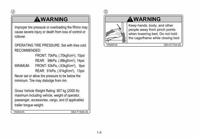
4 5
Improper tire pressure or overloading the Rhino may
cause severe injury or death from loss of control or
rollover.
OPERATING TIRE PRESSURE: Set with tires cold.
RECOMMENDED:
FRONT: 70kPa, (.70kgf/cm2), 10psi
REAR: 98kPa, (.98kgf/cm2), 14psi
MINIMUM: FRONT: 63kPa, (.63kgf/cm2), 9psi
REAR: 91kPa, (.91kgf/cm2), 13psi
Never set or allow tire pressure to be below the
minimum. Tire may dislodge from rim.
Gross Vehicle Weight Rating: 907 kg (2000 lb)
maximum including vehicle, weight of operator,
passenger, accessories, cargo, and (if applicable)
trailer tongue weight.
YAMAHA 5B4-F1696-00
WARNING!Keep hpeoplewhen lthe cag
YAMAHA
W!

5UG-F151J-00
MAX 7.3 INCH(185MM)
EE.book Page 4 Friday, August 3, 2007 4:52 PM
1-4
6 7
Improper use of cargo bed or cage/frame can result in
severe injury or death from loss of control, overturn or
other accidents.
� Do not carry passengers in cargo bed.
� Maximum load in cargo bed: 181 kg (400 lb).
� Load or trailer may affect handling and stability:
� Secure cargo so that it will not shift � a loose load
could change handling unexpectedly or be thrown
forward and strike occupants.
� Keep weight in the cargo bed centered side to side,
and as low and as far forward as possible. Top-
heavy loads increase the risk of overturn.
� Do not tow or pull objects from any point other than
the trailer hitch bracket or winch (if installed).
� When loaded with cargo or towing a trailer:
� Reduce speed and allow more room to stop.
� Turn gradually and go slowly.
� Avoid hills and rough terrain.
� Read Owner�s Manual before loading, towing, or pulling
objects.
YAMAHA 5B4-F4897-00
WARNING!
YAMAHA

5B4-F1558-00
o Toehecklist
eye protection.d protective clothing.le and holding the
or steering wheel.rd, ready to brace,
osed.
EE.book Page 5 Monday, August 6, 2007 6:58 PM
1-5
8 9
YAMAHA
Head tSafety C
ü Head Helmet andü Body Seatbelt anü Hands Inside vehic
handholds ü Feet On floorboa
and door cl

EE.book Page 6 Friday, August 3, 2007 4:52 PM
1-6
0
� Passenger and driver must be able toplace both feet flat on the floorboard whileseated upright with their backs against theseat backs.
• Do not drive or ride as passenger afterusing drugs or alcohol.
• Do not operate on public roads.
Avoid Rollovers and Crushing Injuries• Use care when turning:
o Turning the steering wheel too far or too fastcan result in a rollover or loss of control.
o Slow down before entering a turn.o When making tight turns from a stop or at slowspeeds, avoid sudden or hard acceleration.
o Avoid sideways sliding, skidding, or fishtailing,and never do donuts.
• Drive straight up and down inclines, not acrossthem. If crossing a hill is unavoidable, drive slowlyand turn downhill immediately if you feel thevehicle may tip.
• Avoid paved surfaces. Turn gradually and goslowly if you must drive on pavement. This vehicleis designed for off-road use only.
If you think or feel the Rhino may tip or roll:
• Brace yourself by pressing your feet firmly on thefloorboards and keep a firm grip on the steeringwheel or handholds.
• Do not put your hands or feet outside of thevehicle for any reason.
Be Qualified and Responsible
• This vehicle is intended for useonly by an operator 16 or olderwith a valid motor vehicle license.
Read the Owner�s Manual
To reduce risk of accidents and injury or death:
Genuine Yamaha Doors and
a Handhold/Strap are
available for free installation
or replacement. Yamaha
recommends these features to
help keep occupants from
sticking arms or legs out of the
vehicle during a rollover.
Contact your dealer or visitwww.yamaha-motor.com/rhino
Be Prepared• Wear seat belt, motorcycle helmet,eye protection and protective gear.
• Keep your body completely insidethe vehicle at all times. Keep bothhands on the steering wheel. Besure passenger is seated, belted,and holding onto the handholds.
Abrupt maneuvers or
aggressive driving have
caused rollovers � even on
flat, open areas.DRIVERUNDER
16
YAMAHA 5B4-F1568-01
WARNING!

EVU00070
r operation of your Rhino.wnership, be sure to readhino. Also use these two
passengers. Do not allownsure that he/she is willing
Vs, go-carts, golf-cars andk of an accident and to re-
EE.book Page 1 Friday, August 3, 2007 4:52 PM
2-1
SAFETY INFORMATION
Be a responsible ownerAs the vehicle’s owner, you are responsible for the safe and propeWhile understanding all parts of this manual are important for vehicle othis chapter and the instructions in Chapter 7 before operating the Rchapters and the labels on the vehicle to instruct new operators andanyone else to operate your vehicle or ride as a passenger if you are uand able to follow these instructions.
Get to know your vehicleThis off-road vehicle will handle and maneuver differently from cars, ATgrounds-keeping vehicles. Follow these instructions to reduce your risduce the risk of serious injury or death in the event of an accident.
1
2
3
4
5
6
7
8
9
10
11
12
13
14
with a valid motor vehicle li-
Never carry passengers in
the floorboard while seatedt be able to reach and hold
le helmet that fits properly.(goggles or a face shield),ng pants.
EE.book Page 2 Friday, August 3, 2007 4:52 PM
2-2
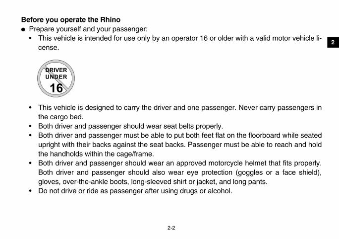
Before you operate the Rhino� Prepare yourself and your passenger:
• This vehicle is intended for use only by an operator 16 or older cense.
• This vehicle is designed to carry the driver and one passenger.the cargo bed.
• Both driver and passenger should wear seat belts properly.• Both driver and passenger must be able to put both feet flat on
upright with their backs against the seat backs. Passenger musthe handholds within the cage/frame.
• Both driver and passenger should wear an approved motorcycBoth driver and passenger should also wear eye protection gloves, over-the-ankle boots, long-sleeved shirt or jacket, and lo
• Do not drive or ride as passenger after using drugs or alcohol.
DRIVERUNDER
16

ke sure it is in safe operat-es the possibility of an ac-
ation checks.
tability, and risk of overturn
or cargo bed load limit. Re-
and as far forward as pos-
andling unexpectedly or be
EE.book Page 3 Friday, August 3, 2007 4:52 PM
2-3
Prepare your vehiclePerform the pre-operation checks each time you use the vehicle to maing condition. Failure to inspect or maintain the vehicle properly increascident or equipment damage. See pages 5-1–5-2 for a list of pre-oper
Prepare your load or trailerCarrying loads, towing a trailer, or pulling objects can affect handling, sor other accidents.
• Read Chapter 6 before loading, towing, or pulling objects.• Do not overload the vehicle or trailer. Refer to label in cargo bed f
fer to label next to hitch for tongue weight and trailer load limits.• Keep weight in the cargo bed centered side to side, and as low
sible.• Secure cargo so that it will not shift – a loose load could change h
thrown forward and strike occupants.

both hands on the steeringandholds. Close doors be-
he vehicle can be struck bye in a rollover accident.
ehicle., can cause loss of control,ther features to handle rug- other vehicles may not.
EE.book Page 4 Friday, August 3, 2007 4:52 PM
2-4
While using the Rhino� Keep your body completely inside the vehicle at all times. Keep
wheel. Be sure passenger is seated, belted, and holding onto the hfore driving. Any part of your body (arms, legs, and head) outside tobjects your vehicle is passing or crushed by the vehicle cage/fram
� Watch for branches, brush, or other hazards that could enter the v� Abrupt maneuvers or aggressive driving, even on flat, open areas
including rollovers. The Rhino has higher ground clearance and oged terrain, and, as a result, can overturn in situations where some

lover.onuts.turn. sudden or hard accelera-
EE.book Page 5 Friday, August 3, 2007 4:52 PM
2-5
� Avoid rollovers:• Use care when turning:
• Turning the steering wheel too far or too fast can result in a rol• Avoid sideways sliding, skidding, or fishtailing, and never do d• Slow down before entering a turn and avoid hard braking in a • When making tight turns from a stop or at slow speeds, avoid
tion.

a hill is unavoidable, drive tip.drive on pavement. This ve-
ompletely inside the protec-
nd keep a firm grip on the
n. Your arm or leg could be
even if dirt or gravel.n 33 cm (13 in). If you mustvoid sharp drop-offs, large
fast-flowing water can leadher injuries, use care when
EE.book Page 6 Friday, August 3, 2007 4:52 PM
2-6
• Drive straight up and down inclines, not across them. If crossingslowly and turn downhill immediately if you feel the vehicle may
• Avoid paved surfaces. Turn gradually and go slowly if you must hicle is designed for off-road use only.
� If you think or feel that the vehicle may tip or roll, keep your body ctive structure of the vehicle:• Brace yourself by pressing your feet firmly on the floorboards a
steering wheel or handholds.• Do not put your hands or feet outside of the vehicle for any reaso
crushed.• Do not try to stop a vehicle tipover using your arm or leg.
� Do not operate this vehicle on any public street, road, or highway, � Do not operate the vehicle in fast-flowing water or water deeper tha
cross shallow, slow-moving water, choose your path carefully to arocks, or slippery surfaces. Operating this vehicle through deep orto loss of control or overturn. To reduce your risk of drowning or otcrossing through water.

stop. or carrying a load on in-
the trailer hitch bracket or
EE.book Page 7 Friday, August 3, 2007 4:52 PM
2-7
� When loaded with cargo or towing a trailer:• Reduce speed, operate in low gear only, and allow more room to• Avoid hills and rough terrain. Use extreme caution when towing
clines.• Load trailer properly and use extra care when towing or pulling.
� Do not tow or pull objects from any part of the vehicle other than winch (if installed).

hing carbon monoxide canentually death.
e present even if you do notcan collect rapidly and you
levels of carbon monoxide you experience any symp- fresh air, and SEEK MEDI-
aust with fans or open win-vels.such as barns, garages, or
to a building through open-
EE.book Page 8 Friday, August 3, 2007 4:52 PM
2-8
Avoid carbon monoxide poisoningAll engine exhaust contains carbon monoxide, a deadly gas. Breatcause headaches, dizziness, drowsiness, nausea, confusion, and ev
Carbon monoxide is a colorless, odorless, tasteless gas which may bsee or smell any engine exhaust. Deadly levels of carbon monoxide can quickly be overcome and unable to save yourself. Also, deadlycan linger for hours or days in enclosed or poorly-ventilated areas. Iftoms of carbon monoxide poisoning, leave the area immediately, getCAL TREATMENT.� Do not run engine indoors. Even if you try to ventilate engine exh
dows and doors, carbon monoxide can rapidly reach dangerous le� Do not run engine in poorly ventilated or partially enclosed areas
carports.� Do not run engine outdoors where engine exhaust can be drawn in
ings such as windows and doors.

ine Yamaha Accessories,, tested, and approved by
accessories or offer otherthe products that these af-e nor recommend the use
ecommended by Yamaha,
o genuine Yamaha Acces-re not suitable because ofs or having other modifica-r operation characteristics
are responsible for injuries
EE.book Page 9 Friday, August 3, 2007 4:52 PM
2-9
Genuine Yamaha AccessoriesChoosing accessories for your Rhino is an important decision. Genuwhich are available only from a Yamaha dealer, have been designedYamaha for use on your Rhino.
Many companies with no connection to Yamaha manufacture parts andmodifications for Yamaha vehicles. Yamaha is not in a position to test termarket companies produce. Therefore, Yamaha can neither endorsof accessories not sold by Yamaha or modifications not specifically reven if sold and installed by a Yamaha dealer.
Aftermarket parts, accessories, and modificationsWhile you may find aftermarket products similar in design and quality tsories, recognize that some aftermarket accessories or modifications apotential safety hazards to you or others. Installing aftermarket producttions performed to your Rhino that change any of the vehicle’s design ocan put you and others at greater risk of serious injury or death. You related to changes in the vehicle.

h the performance capabili-fort. Other tires, rims, sizes,5 for tire specifications and
EE.book Page 10 Friday, August 3, 2007 4:52 PM
2-10
Aftermarket tires and rimsThe tires and rims that came with your Rhino were designed to matcties and to provide the best combination of handling, braking, and comand combinations may not be appropriate. Refer to pages 8-42–8-4more information on replacing your tires.

EVU00080
lt
ld
IH JK L M
CN
F G
EE.book Page 1 Friday, August 3, 2007 4:52 PM
1. H2. Fr3. Br4. Ai5. V-6. D7. D8. C9. Ta
10. R11. C12. Sp13. D
3-1
belt caseriver seatriver seat beltargo bedil/brake lights
ear shock absorber assembly spring preload adjusting ringargo bed release leversark plug
oor
18. Passenger handho19. Engine oil filler cap20. Battery21. Fuses22. Coolant reservoir23. Radiator cap24. Fuel tank cap
1-DESCRIPTION
eadlightsont shock absorber assembly spring preload adjusting ringake fluid reservoirr filter elements (engine and air intake duct)
C
14. Spark arrester15. Passenger seat be16. Passenger seat17. Oil filter cartridge
E
D

1
2
3
4
5
6
7
8
9
10
11
12
13
14
ave purchased may differ shown in the figures of this
EE.book Page 2 Friday, August 3, 2007 4:52 PM
3-2
25. Light switch26. Steering wheel27. Starter (choke)28. Main switch29. On-Command four-wheel-drive and differential gear lock switches30. Multi-function meter unit31. Auxiliary DC jack32. Drive select lever33. Parking brake lever34. Accelerator pedal35. Brake pedal
The vehicle you hslightly from thosemanual.
O P Q R S T U
Y X W
V
H

EVU00130
spective switch positions
l circuits are supplied with the headlights and tail- on when the light switch is
l circuits are switched off.n be removed in this posi-
c starter is engaged by holding the key in this po-ase the key when the en-
EE.book Page 1 Friday, August 3, 2007 4:52 PM
4-1
1-INSTRUMENT AND CONTROL FUNCTIONS
EVU00140
Main switch
1. Main switch
Functions of the reare as follows:ON:
All electricapower, andlights comeon.
OFF:All electricaThe key cation.
START:The electriturning andsition. Relegine starts.
OFF ONSTART
OFFON
START
1
2
3
4
5
6
7
8
9
10
11
12
13
14
ferential gear lock indica-CK”
and the On-Command dif-k indicator in the display On-Command differential
set to the “LOCK” position.
is set to “LOCK”, the On-tial gear lock indicator lightifferential gear is locked.
tor light “L”t comes on when the drivee “L” position.
tor light “H”t comes on when the drivee “H” position.
EE.book Page 2 Friday, August 3, 2007 4:52 PM
4-2
EVU00150
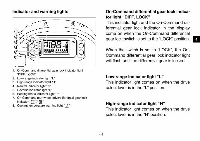
Indicator and warning lights
1. On-Command differential gear lock indicator light “DIFF. LOCK”
2. Low-range indicator light “L”3. High-range indicator light “H”4. Neutral indicator light “N”5. Reverse indicator light “R”6. Parking brake indicator light “P”7. On-Command four-wheel-drive/differential gear lock
indicator “ ”/“ ”8. Coolant temperature warning light “ ”
EVU01131
On-Command diftor light “DIFF. LOThis indicator lightferential gear loccome on when thegear lock switch is
When the switch Command differenwill flash until the d
EVU01140
Low-range indicaThis indicator lighselect lever is in th
EVU01150
High-range indicaThis indicator lighselect lever is in th
DIFF.LOCK

EVU00170 EVU01161
r-wheel-drive/differentialr “ ”/“ ” four-wheel-drive indicatoren the On-Command four- is set to the “4WD” posi-
differential gear lock indi-On-Command four-wheel- comes on when the On-tial gear lock switch is settion.
ronizing mechanism in thecase, the four-wheel-drivet come on until the vehicle
ommand differential geart to “LOCK”, the indicatorntil the differential gear is
DIFF.LOCK
EE.book Page 3 Friday, August 3, 2007 4:52 PM
4-3
Neutral indicator light “N”This indicator light comes on when the driveselect lever is in the “N” position.
EVU00161
Reverse indicator light “R”This indicator light comes on when the driveselect lever is in the “R” reverse position.Furthermore, this indicator light flashes whenthe engine is being raced for 10 seconds ormore.
If the indicator light flashes under any othercircumstances or the speedometer does notshow the speed while riding, have a Yamahadealer check the speed sensor circuit.
EVU00210
Parking brake indicator light “P”This indicator light comes on when the park-ing brake is applied.
On-Command fougear lock indicatoThe On-Command“ ” comes on whwheel-drive switchtion.
The On-Commandcator “ ” in the drive indicator alsoCommand differento the “LOCK” posi
� Due to the synchdifferential gear indicator may nostarts moving.
� When the On-Clock switch is se“ ” will flash ulocked.
DIFF.LOCK
DIFF.LOCK

ter unit
2. Fuel meter4. “M” button
/Tripmeter B8. Clock/Hour button “ / ”
meter unit is equipped with
(which shows the riding
hich shows the total dis-
EE.book Page 4 Friday, August 3, 2007 4:52 PM
4-4
EVU00181
Coolant temperature warning light “ ”If the coolant temperature reaches a specifiedlevel, this light comes on to warn that the cool-ant temperature is too hot. If the light comeson during operation, stop the engine as soonas it is safe to do so and allow the engine tocool down for about 10 minutes.(See page 8-59.)
NOTICE� The engine may overheat if the vehicle
is overloaded. If this happens, reducethe load to specification.
� After restarting, make sure that the lightis out. Continuous use while the light ison may cause damage to the engine.
EVU01630
Multi-function me
1. Speedometer3. “H” button5. Clock/Hour meter6. Odometer/Tripmeter A7. “TRIP/ODO” button
The multi-functionthe following:� a speedometer
speed)� an odometer (w
tance traveled)

meter modesODO” button switches thee odometer mode “ODO”odes “A” and “B” in the fol-
TRIP B → ODOr, select it by pushing the, and then hold the “TRIP/ least three seconds. Theused to estimate the dis-aveled with a full tank of fu-n will enable you to plan
IP/ODO” button and then“ON” switches the display “km/h”.
EE.book Page 5 Friday, August 3, 2007 4:52 PM
4-5
� two tripmeters (which show the distancetraveled since they were last set to zero)
� a clock� an hour meter (which shows the total time
the key has been turned to “ON”)� a fuel meter
Odometer and tripPushing the “TRIP/display between thand the tripmeter mlowing order:ODO → TRIP A →To reset a tripmete“TRIP/ODO” buttonODO” button for attripmeters can be tance that can be trel. This informatiofuture fuel stops.Holding in the “TRturning the key to between “mph” and
icates the amount of fuel inisplay segments of the fuel
from “F” (full) towards “E”l level decreases. When theppears and the fuel levelflashes, refuel as soon as
icator3. “E” segment
EE.book Page 6 Friday, August 3, 2007 4:52 PM
4-6
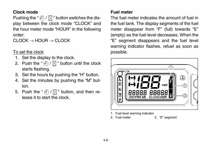
Clock modePushing the “ / ” button switches the dis-play between the clock mode “CLOCK” andthe hour meter mode “HOUR” in the followingorder:CLOCK → HOUR → CLOCK
To set the clock1. Set the display to the clock.2. Push the “ / ” button until the clock
starts flashing.3. Set the hours by pushing the “H” button.4. Set the minutes by pushing the “M” but-
ton.5. Push the “ / ” button, and then re-
lease it to start the clock.
Fuel meterThe fuel meter indthe fuel tank. The dmeter disappear (empty) as the fue“E” segment disawarning indicator possible.
1. Fuel level warning ind2. Fuel meter

EVU00230
adlights with the engineextended period of time.discharge to the point
motor will not operateshould happen, removecharge it.
EE.book Page 7 Friday, August 3, 2007 4:52 PM
4-7
SwitchesEVU00240
Light switch “OFF/ / ”
1. Light switch “OFF/ / ”
Set the switch to “ ” to turn on the low beamand the taillights.Set the switch to “ ” to turn on the highbeam and the taillights.Set the switch to “OFF” to turn off all the lights.
NOTICEDo not use the heturned off for an The battery may that the starter properly. If this the battery and re
L H
L H
L
H

e (“4WD”): Power is sup- and front wheels.e with the differential gearOCK”): Power is suppliedfront wheels with the differ-ed. Unlike the 4WD mode,at the same speed regard-
EE.book Page 8 Friday, August 3, 2007 4:52 PM
4-8
EVU01183
On-Command four-wheel-drive and differ-ential gear lock switches
1. On-Command four-wheel-drive switch “2WD”/“4WD”2. On-Command differential gear lock switch “4WD”/“LOCK”
This vehicle is equipped with an On-Com-mand four-wheel-drive switch “2WD”/“4WD”and a differential gear lock switch “4WD”/“LOCK”. Select the appropriate drive accord-ing to terrain and conditions.� Two-wheel drive (“2WD”): Power is sup-
plied to the rear wheels only.
� Four-wheel drivplied to the rear
� Four-wheel drivlocked (“4WD-Lto the rear and ential gear lockall wheels turn less of traction.
EVU00260 EVU00270
dal to slow or stop the ve-
EE.book Page 9 Friday, August 3, 2007 4:52 PM
4-9
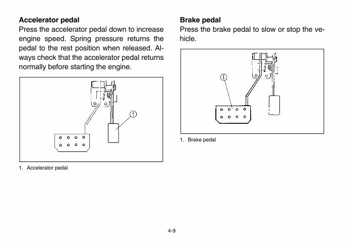
Accelerator pedalPress the accelerator pedal down to increaseengine speed. Spring pressure returns thepedal to the rest position when released. Al-ways check that the accelerator pedal returnsnormally before starting the engine.
1. Accelerator pedal
Brake pedalPress the brake pehicle.
1. Brake pedal

2. Release button
EE.book Page 10 Friday, August 3, 2007 4:52 PM
4-10
EVU00280
Parking brake leverThe parking brake lever is located at the rightside of the driver’s seat. It will help keep thevehicle from moving while parked.To set the parking brake, pull the lever upcompletely.To release the parking brake, pull up on thelever, press the release button, and then pushthe lever all the way down.Spring pressure helps return the lever to thereleased position.
1. Parking brake lever
EVU00290 EVU00300
nk cap by turning it coun-
EE.book Page 11 Friday, August 3, 2007 4:52 PM
4-11
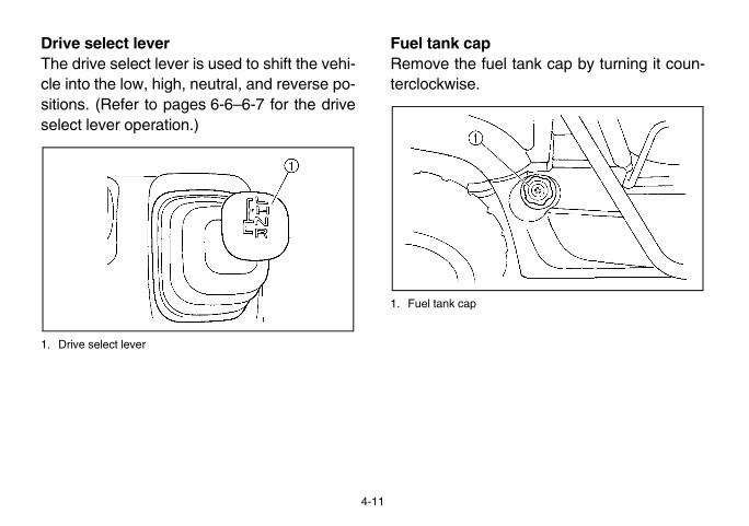
Drive select leverThe drive select lever is used to shift the vehi-cle into the low, high, neutral, and reverse po-sitions. (Refer to pages 6-6–6-7 for the driveselect lever operation.)
1. Drive select lever
Fuel tank capRemove the fuel taterclockwise.
1. Fuel tank cap
mply pull the latch outward.ush or pull the door inwardatched. Be sure the door isHED AFTER CLOSING IT.
2. Door
EE.book Page 12 Friday, August 3, 2007 4:52 PM
4-12
EVU00320
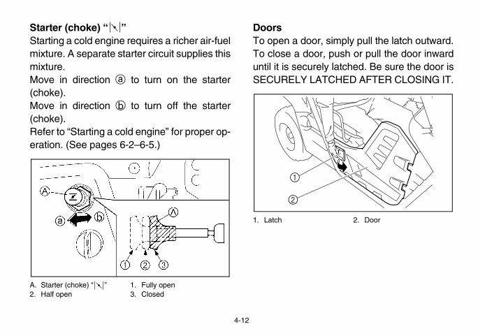
Starter (choke) “ ”Starting a cold engine requires a richer air-fuelmixture. A separate starter circuit supplies thismixture.Move in direction a to turn on the starter(choke).Move in direction b to turn off the starter(choke).Refer to “Starting a cold engine” for proper op-eration. (See pages 6-2–6-5.)
A. Starter (choke) “ ” 1. Fully open2. Half open 3. Closed
DoorsTo open a door, siTo close a door, puntil it is securely lSECURELY LATC
1. Latch
1
2

EVU00330
sert the projections on the the seat holders and pusht the front. Make sure the
y latched. WARNING! A cause the operator touse the operator or pas-
EE.book Page 13 Friday, August 3, 2007 4:52 PM
4-13
SeatsTo remove a seat, pull its seat lock lever up-ward, lift the front of the seat, and then slidethe seat forward and up.
1. Driver seat 2. Passenger seat3. Seat lock lever (× 2)
To install a seat, inrear of the seat intodown on the seat aseats are securelloose seat couldlose control, or casenger to fall.

ent
amage, do not put metalls or sharply edged prod-he glove compartment. Ifred, wrap them in appro- material.
b. Open.
EE.book Page 14 Friday, August 3, 2007 4:52 PM
4-14
EVU00340
Seat beltsThis vehicle is equipped with three-point seatbelts for both the operator and the passenger.Always wear the seat belts properly whileriding in the vehicle. See pages 7-6–7-8 formore information.
EVU01191
Glove compartm
NOTICETo protect from dproducts, like tooucts, directly in tthey must be stopriate cushioning
a. Unlock.

EVU00351
ing the tailgate
2. Latch (× 2)
s, and then lower the tail-
the original position, andes.
EE.book Page 15 Friday, August 3, 2007 4:52 PM
4-15
Cargo bed
1. Cargo bed 2. Tailgate3. Cargo hook (× 4)
For additional loading information, see pages6-11–6-13.
Opening and clos
1. Tailgate
To openUnhook the latchegate.
To closePlace the tailgate inthen hook the latch
Maximum load limit: 181 kg (400 lb)

ngers clear of pinch points,d slowly to its original posi- it is locked into place. hands, body, and other pinch points when low-
hold onto the cage/frame bed.
EE.book Page 16 Friday, August 3, 2007 4:52 PM
4-16
Lifting and lowering the cargo bed
1. Cargo bed release lever
To liftPush down the cargo bed release lever on theleft or right side of the vehicle, and then slowlylift up the cargo bed until it stops.
To lowerWith hands and filower the cargo betion and be sureWARNING! Keeppeople away fromering bed. Do notwhile closing the

EVU00360
eload as follows:ring preload, turn the ad-
tion a.ring preload, turn the ad-
tion b.
g ring
EE.book Page 17 Friday, August 3, 2007 4:52 PM
4-17
Front and rear shock absorber adjustmentThe spring preload can be adjusted to suit theoperating conditions. You can reduce preloadfor a softer ride, or increase preload if frequentbottoming occurs or when carrying loads.
WARNINGAlways adjust the shock absorbers on theleft and right sides to the same setting. Un-even adjustment can cause poor handlingand loss of stability, which could lead toan accident.
NOTICEFrequent or severe bottoming can causeincreased wear or damage to the vehicle.
Adjust the spring prTo increase the spjusting ring in direcTo decrease the spjusting ring in direc
1. Spring preload adjustin2. Position indicator

ket and receiveruipped with a trailer hitch (2 in) receiver for a stan-
Trailer towing equipmentat a Yamaha dealer. (Seeor precaution information.)
2. Receiver
EE.book Page 18 Friday, August 3, 2007 4:52 PM
4-18
A special wrench can be obtained at aYamaha dealer to make this adjustment.
1. Special wrench
EVU00370
Trailer hitch bracThis vehicle is eqbracket and a 5 cmdard trailer hitch.can be obtained pages 6-11–6-13 f
1. Trailer hitch bracket
Standard position: BA- Minimum (soft)E- Maximum (hard)
21
EVU00380
iliary DC jack is not beingith the cap.
apacity for the auxiliary
(10 A)
EE.book Page 19 Friday, August 3, 2007 4:52 PM
4-19
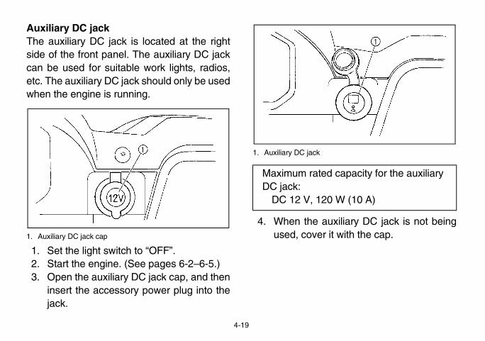
Auxiliary DC jackThe auxiliary DC jack is located at the rightside of the front panel. The auxiliary DC jackcan be used for suitable work lights, radios,etc. The auxiliary DC jack should only be usedwhen the engine is running.
1. Auxiliary DC jack cap
1. Set the light switch to “OFF”.2. Start the engine. (See pages 6-2–6-5.)3. Open the auxiliary DC jack cap, and then
insert the accessory power plug into thejack.
1. Auxiliary DC jack
4. When the auxused, cover it w
Maximum rated cDC jack:
DC 12 V, 120 W

EE.book Page 20 Friday, August 3, 2007 4:52 PM
4-20
NOTICE� Do not use accessories requiring more
than the maximum capacity statedabove. This may overload the circuitand cause the fuse to blow.
� If accessories are used without the en-gine running, the battery will lose itscharge and engine starting may becomedifficult.
� Do not use an automotive cigarettelighter or other accessories with a plugthat gets hot, because the jack can bedamaged.

EVU01200
CHECKS
n safe operating condition.les described in the Own-
ossibility of an accidenty problem. If a problemave the vehicle inspect-
PAGE
e. 5-3, 8-34–8-37, 8-39–8-40
8-38–8-39
5-4–5-5
5-6, 8-10–8-14
5-7, 8-19–8-20
EE.book Page 1 Friday, August 3, 2007 4:52 PM
5-1
1-FOR YOUR SAFETY – PRE-OPERATION
Inspect your vehicle each time you use it to make sure the vehicle is iAlways follow the inspection and maintenance procedures and scheduer’s Manual.
WARNINGFailure to inspect or maintain the vehicle properly increases the por equipment damage. Do not operate the vehicle if you find ancannot be corrected by the procedures provided in this manual, hed by a Yamaha dealer.
Before using this vehicle, check the following points:
ITEM ROUTINE
Brakes • Check operation, free play, fluid level, and fluid leakag• Fill with DOT 4 brake fluid if necessary.
Parking brake • Check for proper operation, condition, and free play.
Fuel • Check fuel level.• Fill with fuel if necessary.
Engine oil • Check oil level.• Fill with oil to proper level if necessary.
Coolant reservoir • Check coolant level.• Fill with coolant if necessary.

1
2
3
4
5
6
7
8
9
10
11
12
13
14
5-7, 8-15–8-18
5-8
5-8
5-8
5-8
5-9, 8-51–8-56
5-9–5-11, 8-42–8-45
8-20
PAGE
EE.book Page 2 Friday, August 3, 2007 4:52 PM
5-2
Final gear oil/Differential gear oil • Check for leakage.
Accelerator pedal • Check for proper accelerator pedal operation.
Seat belts • Check for proper operation and belt wear.
Steering • Check for proper operation.
Fittings and fasteners • Check all fittings and fasteners.
Lights and switches • Check for proper operation.
Wheels and tires • Check tire pressure and for wear and damage.
Axle boots • Check for damage.
ITEM ROUTINE
EVU00390
e brake fluid is leaking out ofe brake fluid reservoir. Ap-y for one minute. If there isthe vehicle inspected by a
n of the brakes at the start the brakes at slow speed make sure they are work-rakes do not provide prop-ance, inspect the brake
s 8-34–8-35, 8-37–8-40.)
EE.book Page 3 Friday, August 3, 2007 4:52 PM
5-3
Front and rear brakes
Brake pedalCheck for correct brake pedal free play. If thebrake pedal free play is incorrect, have aYamaha dealer adjust it. (See page 8-37.)Check the operation of the brake pedal. Itshould move smoothly and there should be afirm feeling when the brakes are applied. Ifnot, have the vehicle inspected by a Yamahadealer.
Brake fluid levelCheck the brake fluid level. Add fluid if neces-sary. (See pages 8-36–8-37.)
Brake fluid leakagCheck to see if anythe pipe joints or thply the brakes firmlany leakage, have Yamaha dealer.
Brake operationCheck the operatioof every ride. Testafter starting out toing properly. If the ber braking performsystem. (See page
Recommended brake fluid: DOT 4

uel tank cap is closed se-
nous and can cause inju-ndle gasoline with care.soline by mouth. If youome gasoline or inhale apor, or get some gasoline your doctor immediately. on your skin, wash withIf gasoline spills on your your clothes.
EE.book Page 4 Friday, August 3, 2007 4:52 PM
5-4
EVU00400
FuelMake sure there is sufficient gasoline in thetank.
WARNINGGasoline and gasoline vapors are ex-tremely flammable. To avoid fires and ex-plosions and to reduce the risk of injurywhen refueling, follow these instructions.
1. Before refueling, turn off the engine andbe sure that driver and passenger areoutside the vehicle. Never refuel while smoking, or while inthe vicinity of sparks, open flames, or oth-er sources of ignition such as the pilotlights of water heaters and clothes dry-ers.
2. Do not overfill the fuel tank. Because fuelexpands when it heats up, heat from theengine or the sun can cause fuel to spillout of the fuel tank.
3. Wipe up any spilled fuel immediately.
4. Be sure the fcurely.
WARNINGGasoline is poisory or death. HaNever siphon gashould swallow slot of gasoline vain your eyes, seeIf gasoline spillssoap and water. clothing, change

ainersble gas can in the bed of to secure it with the capiving the vehicle.table gas container on theg it. Before removing thech the container with thezle. Keep gas dispenserith container inlet when fill-ver refill a fuel container
vehicle. Fire may resultof static electricity. Thebuild-up while refueling and ignite the gasoline.
uel:line onlyy:p gal, 7.93 US gal)
EE.book Page 5 Friday, August 3, 2007 4:52 PM
5-5
Your Yamaha engine has been designed touse regular unleaded gasoline with a pumpoctane number ([R+M]/2) of 86 or higher, orresearch octane number of 91 or higher. Ifknocking or pinging occurs, use a differentbrand of gasoline or premium unleaded fuel.Unleaded fuel will give you longer spark pluglife and reduced maintenance cost.
GasoholThere are two types of gasohol: gasohol con-taining ethanol and that containing methanol.Gasohol containing ethanol can be used ifethanol content does not exceed 10%. Gaso-hol containing methanol is not recommendedby Yamaha because it may cause fuel systemdamage or vehicle performance problems.
Portable gas contIf you carry a portathe Rhino, be suretightened before drAlways place a porground before fillincontainer cap, tougas dispenser noznozzle in contact wing. WARNING! Nein the bed of anyfrom a build-up discharge of this can cause a spark
Recommended fUnleaded gaso
Fuel tank capacit30.0 L (6.60 Im
2. “ENERGY CONSERVING II”
engine oil type and
.
1
2
EE.book Page 6 Friday, August 3, 2007 4:52 PM
5-6
EVU00410
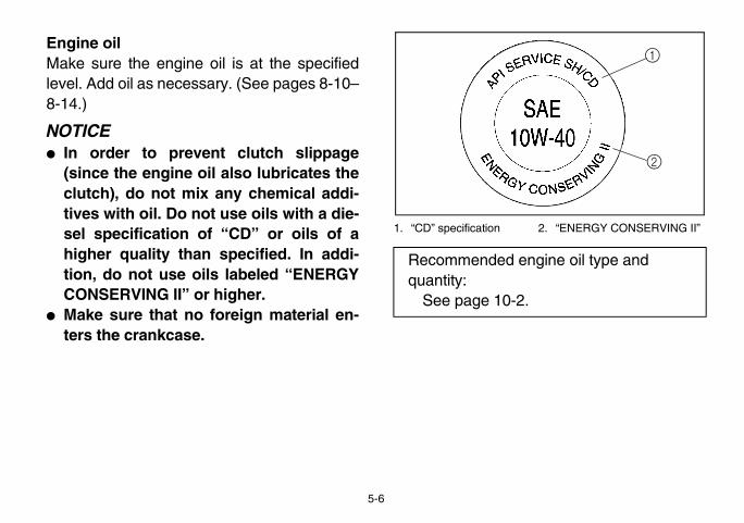
Engine oilMake sure the engine oil is at the specifiedlevel. Add oil as necessary. (See pages 8-10–8-14.)
NOTICE� In order to prevent clutch slippage
(since the engine oil also lubricates theclutch), do not mix any chemical addi-tives with oil. Do not use oils with a die-sel specification of “CD” or oils of ahigher quality than specified. In addi-tion, do not use oils labeled “ENERGYCONSERVING II” or higher.
� Make sure that no foreign material en-ters the crankcase.
1. “CD” specification
Recommended quantity:
See page 10-2

EVU00420 EVU00430
gear oil is at the specifiedessary. (See pages 8-15–
0W90 hypoid gear oil mayitions.
nd additive rating; GL-5 orear oils may also be used.
ilerential gear oil is at thed oil as necessary. (Seer details.)
il:-4 Hypoid gear oil
il:-5 Hypoid gear oil
EE.book Page 7 Friday, August 3, 2007 4:52 PM
5-7
CoolantCheck the coolant level in the coolant reser-voir when the engine is cold (the coolant levelwill vary with engine temperature).
The coolant level is satisfactory if it is betweenthe minimum and maximum level marks onthe coolant reservoir. If the coolant level is ator below the minimum level mark, add addi-tional coolant to bring the level up to maxi-mum level mark. If coolant is not available,add distilled water. Change the coolant everytwo years. (See pages 8-19–8-20 for details.)
NOTICEHard water or salt water is harmful to theengine. You may use soft water if you can-not get distilled water.
Final gear oilMake sure the finallevel. Add oil as nec8-16 for details.)
If desired, an SAE 8be used for all cond
TIPTIP
GL-4 is a quality aGL-6 rated hypoid g
EVU00440
Differential gear oMake sure the diffspecified level. Adpages 8-17–8-18 fo
Coolant reservoir capacity(up to the maximum level mark):
0.35 L (0.31 Imp qt, 0.37 US qt)
Recommended oSAE 80 API GL
Recommended oSAE 80 API GL

ge the restraint systems inamaged restraint system
protect the person using it, injury or death in a crash. your restraint systems arefter a crash, have them in- necessary replacementspossible.
nd. Turn the steering wheelck for excessive free play,or a rough feeling. Have aair as necessary for proper
nerstightness of chassis fittingsre a ride. Take the vehicleler or refer to the Service tightening torque.
EE.book Page 8 Friday, August 3, 2007 4:52 PM
5-8
EVU00450
Accelerator pedalCheck to see that the accelerator pedal oper-ates correctly. It must operate smoothly andspring back to the idle position fully when re-leased. Have a Yamaha dealer repair as nec-essary for proper operation.EVU00460
Seat beltsMake sure that the seat belts are not frayed,torn, stretched, or damaged. Each seat beltmust move smoothly when pulled out and re-tract on its own when released. It must alsolock up when quickly pulled out. The latchplate should click securely into the buckle andrelease when the release button is pushedfirmly. Wash off any dirt or mud that could af-fect operation. Have a Yamaha dealer repairas necessary for proper operation.
A crash can damayour vehicle. A dmay not properly resulting in seriousTo help make sureworking properly aspected and anymade as soon as EVU01230
SteeringPark on level grouright and left. Cheabnormal noises, Yamaha dealer repoperation.EVU00470
Fittings and fasteAlways check the and fasteners befoto a Yamaha deaManual for correct

EVU00480 EVU00500
regularly to make sure itnded specifications. Also damage.
re gauge to check and ad-hen the tires are cold. Tiree equal on both sides.tion of this vehicle withsure may cause severem loss of control or roll-re below the minimumso cause the tire to dis-im under severe riding
EE.book Page 9 Friday, August 3, 2007 4:52 PM
5-9
LightsCheck the headlights and tail/brake lights tomake sure they are in working condition. Re-pair as necessary for proper operation.EVU00490
SwitchesCheck the operation of all switches. Have aYamaha dealer repair as necessary for properoperation.
Control cablesWhen riding in cold weather, always makesure all control cables work smoothly beforeyou begin riding. WARNING! Control cablescan freeze in cold weather and you couldbe unable to control the vehicle.
TiresCheck tire pressureis at the recommecheck for wear andEVU00510
Tire pressureUse the tire pressujust tire pressures wpressures must bWARNING! Operaimproper tire presinjury or death froover. Tire pressuspecified could allodge from the rconditions.

EE.book Page 10 Friday, August 3, 2007 4:52 PM
5-10
Set tire pressures to the following specifica-tions:ACE-02E
The tire pressure gauge is included as stan-dard equipment. Make two measurements ofthe tire pressure and use the second reading.Dust or dirt in the gauge could cause the firstreading to be incorrect.
1. Tire pressure gauge
Recommended pressure
Minimum Maximum
Front70 kPa
(0.70 kgf/cm2, 10 psi)
63 kPa (0.63 kgf/cm2,
9 psi)
77 kPa (0.77 kgf/cm2,
11 psi)
Rear98 kPa
(0.98 kgf/cm2, 14 psi)
91 kPa (0.91 kgf/cm2,
13 psi)
105 kPa (1.05 kgf/cm2,
15 psi)

EVU00520
EE.book Page 11 Friday, August 3, 2007 4:52 PM
5-11
Tire wear limitWhen the tire groove decreases to 3 mm(0.12 in) due to wear, replace the tire.
a. Tire wear limit

1
2
3
4
5
6
7
8
9
10
11
12
13
14
ore important period in the than the period between
.
e ask that you read the fol-refully. Because the engine must not put an excessiveirst several hours of opera-first 20 hours, the variouse wear and polish them-
the correct operating clear-
prolonged full-throttle oper-tion that might result in ex-eating must be avoided.tary (2–3 seconds maxi-
operation under load doese.
EE.book Page 1 Friday, August 3, 2007 4:52 PM
6-1
EVU00530
1-OPERATION
Read the Owner’s Manual carefully to be-come familiar with all controls. If there is acontrol or function you do not understand, askyour Yamaha dealer.
WARNINGFailure to familiarize yourself with the con-trols can lead to loss of control, whichcould cause an accident or injury.
Engine break-inThere is never a mlife of your vehiclezero and 20 hours
For this reason, wlowing material cais brand new, youload on it for the ftion. During the parts in the enginselves to achieve ances.
During this period,ation or any condicessive engine hHowever, momenmum) full-throttle not harm the engin

EVU00540
ginee pedal.select lever into the neutral
rive select lever is in theition, the neutral indicator come on. If the neutral in- does not come on, ask aaler to inspect the electric
can be started in any gear is applied. However, it ised to shift into neutral be- the engine.
EE.book Page 2 Friday, August 3, 2007 4:52 PM
6-2
Each full-throttle acceleration sequenceshould be followed with a substantial rest pe-riod for the engine, by cruising at lower r/minso the engine can rid itself of the temporarybuild-up of heat. If any abnormality is noticedduring this period, consult a Yamaha dealer.
0–10 hours:Avoid continuous operation above half-throt-tle. Allow a cooling-off period of five to tenminutes after every hour of operation. Varythe speed of the vehicle from time to time. Donot operate it at one set throttle position.
10–20 hours:Avoid prolonged operation above three-quar-ter throttle.
After break-in:The vehicle may now be operated normally.
Starting a cold en1. Apply the brak2. Shift the drive
position.� When the d
neutral poslight shoulddicator lightYamaha decircuit.
� The engineif the brakerecommendfore starting
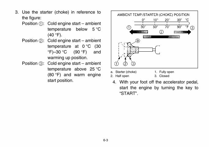
1. Fully open3. Closed
t off the accelerator pedal,ine by turning the key to
EE.book Page 3 Friday, August 3, 2007 4:52 PM
6-3
3. Use the starter (choke) in reference tothe figure:Position 1: Cold engine start – ambient
temperature below 5 °C(40 °F).
Position 2: Cold engine start – ambienttemperature at 0 °C (30°F)–30 °C (90 °F) andwarming up position.
Position 3: Cold engine start – ambienttemperature above 25 °C(80 °F) and warm enginestart position.
a. Starter (choke)2. Half open
4. With your foostart the eng“START”.
ld engine may increases up to cause the vehi-
own while the choke isot get out of the vehicleis running and the driveny gear. movement can causeeath, and it may be dan-
op the vehicle. The park-t keep the vehicle from
is started with the starterition1, the starter (choke)rned to position2 to warm If the engine is started withoke) in position2, keephoke) in this position tongine.
EE.book Page 4 Friday, August 3, 2007 4:52 PM
6-4
If the engine fails to start, release the key, andthen try starting it again. Wait a few secondsbefore the next attempt. Each attempt shouldbe as short as possible, to preserve batteryenergy. NOTICE: Do not crank the enginemore than 5 seconds on each attempt, orstarter damage could occur. Wait at least 5seconds between each operation of theelectric starter to let it cool.
Do not turn the key to the “START” positionwith the engine running, or damage to theelectric starter may result.
WARNINGThe speed of a coenough as it warmcle to move on itsbeing used. Do nwhile the engine select lever is in aUnwanted vehicleserious injury or dgerous to try to sting brake may noaccelerating.
5. If the engine (choke) in posshould be retuup the engine.the starter (chthe starter (cwarm up the e

ngine life, always warm upstarting off. To see whetheris warm, check for smoothwith the vehicle in neutraloke) turned off.
ard with a cold engine!
EE.book Page 5 Friday, August 3, 2007 4:52 PM
6-5
6. With the vehicle still in neutral, continuewarming up the engine until it idlessmoothly, and return the starter (choke)to position3 before riding. Failure to doso may result in poor performance andpremature wearing of the rear brake andV-belt.
EVU00550
Starting a warm engineTo start a warm engine, refer to the “Starting acold engine” section. The starter (choke)should not be used. Press the acceleratorpedal slightly.
EVU00561
Warming upTo get maximum ethe engine before or not the engine throttle response and the starter (ch
Never accelerate h

e pedal, then shift by mov-elect lever along the shift
ure that the drive select le-ly shifted into position.
rake pedal and press thedal gradually.
EE.book Page 6 Friday, August 3, 2007 4:52 PM
6-6
Drive select lever operation and reverse driving
NOTICEDo not shift without coming to a completestop and waiting for the engine to return tonormal idle speed. Damage to the engineor drive train may occur.
Shifting: neutral to high and high to low1. Stop the vehicle. Take your foot off the
accelerator pedal.
2. Apply the braking the drive sguide. Make sver is complete
1. Drive select lever
3. Release the baccelerator pe

the vehicle for people ord then release the brake
celerator pedal gradually to watch to the rear while
EE.book Page 7 Friday, August 3, 2007 4:52 PM
6-7
Shifting: neutral to reverse
WARNINGBefore you shift into reverse, make surethere are no obstacles or people behindyou. When it is safe to proceed, go slowly.Hitting an obstacle or person could resultin serious injury or death.
1. Stop the vehicle. Take your foot off theaccelerator pedal and check behind you.
2. Apply the brake pedal.3. Shift from neutral to reverse or vice versa
by moving the drive select lever along theshift guide.� When in reverse, the reverse indicator
light should be on. Due to the synchro-nizing mechanism in the engine, thelight may not come on until the vehiclestarts moving.
� If the light does not come on, ask aYamaha dealer to inspect the reverseindicator light electrical circuit.
1. Drive select lever
4. Check behindobstacles, anpedal.
5. Press the acand continuebacking.

EVU01183
D to 4WD, stop the vehi-e switch to “4WD”. WhenD, the four-wheel-drive in-me on in the multi-function from 4WD to 2WD, stop
e the differential gear lockition a, and then set the
EE.book Page 8 Friday, August 3, 2007 4:52 PM
6-8
On-Command four-wheel-drive switch and differential gear lock switchYou may notice that the vehicle handles dif-ferently in 2WD, 4WD, and 4WD-LOCK(“DIFF. LOCK”). For example, you should ex-pect that the vehicle will require more effort toturn in 4WD-LOCK (“DIFF. LOCK”). Alwaysstop the vehicle before changing between2WD and 4WD or 4WD and 4WD-LOCK(“DIFF-LOCK”).
1. Differential gear lock lever2. On-Command four-wheel-drive switch “2WD”/“4WD”
“2WD”/“4WD”To change from 2Wcle, and then set ththe vehicle is in 4Wdicator “ ” will codisplay. To changethe vehicle, be surlever is set to posswitch to “2WD”.

ntial gear in 4WD, stop there the On-Command four- is set to “4WD”, move theck lever to position b, andh to “LOCK”. When the dif-cked, the differential gear (“DIFF. LOCK”) will comedifferential gear lock indica-ulti-function display. To re-ntial gear lock, stop the switch to “4WD”.h is set to “LOCK”, the dif-ck indicator and indicatorntil the differential gear is
ator and indicator light are the steering wheel backlp the differential gear lock
EE.book Page 9 Friday, August 3, 2007 4:52 PM
6-9
On-Command differential gear lock switch“4WD”/“LOCK”
1. On-Command differential gear lock switch “4WD”/“LOCK” 2. Differential gear lock lever
To lock the differevehicle, make suwheel-drive switchdifferential gear lothen set the switcferential gear is lolock indicator lighton along with the tor “ ” in the mlease the differevehicle and set the� When the switc
ferential gear lolight will flash ulocked.
� When the indicflashing, turningand forth will heto engage.
DIFF.LOCK

EVU01210
p the engine and shift theto the neutral position. Ap-e to help prevent the vehi-ee pages 7-17–7-18 for
n parking and parking on a
EE.book Page 10 Friday, August 3, 2007 4:52 PM
6-10
� Driving before the differential gear lock isproperly engaged (e.g., when the indicatorand indicator light are flashing) will causethe engine speed to be limited until en-gagement is complete.
ParkingWhen parking, stodrive select lever inply the parking brakcle from rolling. Smore information oslope.
ed the maximum tongue
e load does not interfereontrol or ability to seee going.go in the trailer securely.argo in the trailer cannotd. A shifting load canident.
EE.book Page 11 Friday, August 3, 2007 4:52 PM
6-11
EVU00630
LoadingTake extra precautions when driving with aload or trailer. Follow these instructions andalways use common sense and good judg-ment when carrying cargo or towing a trailer.
Prepare your load or trailer
WARNINGImproper loading or towing can increasethe risk of loss of control, an overturn, orother accident:
� Do not exceed the Maximum LoadingLimits for the vehicle (see box or vehi-cle labeling).
� Keep weight in the cargo bed centeredside to side, and as low and as far for-ward as possible. Top-heavy loads in-crease the risk of overturn. Be surecargo is secured – a loose load couldchange handling unexpectedly orstrike occupants.
� Do not exceweight.
� Make sure thwith your cwhere you ar
� Tie down carMake sure cmove arouncause an acc

ING LIMIT limit (total weight of
r, passenger and d tongue weight):
)1 kg (400 lb)
tal weight of trailer and (1,212 lb)t (vertical weight on trailer kg (110 lb)
EE.book Page 12 Friday, August 3, 2007 4:52 PM
6-12
Use the hooks equipped on the cargo bed totie down loads.
Choose a trailer hitch drawbar designed foruse with a 5 cm (2 in) receiver. (See page4-18 for more information.)
You can measure tongue weight with a bath-room scale. Put the tongue of the loaded trail-er on the scale with the tongue at hitch height.Adjust the load in the trailer, if necessary, toreduce the weight on hitch. If you are carryingcargo and towing a trailer, include the tongueweight in the maximum vehicle load limit.
MAXIMUM LOAD� Vehicle loading
cargo, operatoaccessories an393 kg (866 lb
� Cargo bed: 18� Trailer hitch:
Pulling load (tocargo): 550 kgTongue weighhitch point): 50
g other than a trailernds that loads be transport-in a trailer. If you need toshort distance use a winchch manufacturer’s instruc-
se something other than ae caution, follow the manu-ons for that product, andhitch or hitch bracket of the! Improperly pulling canjury or death. Never ex- Load limit of the Rhino.inclines.
the ground can be morelling a trailer. It may be dif- the load will affect vehicle
fect could also change de-in or what obstacles mightath.
EE.book Page 13 Friday, August 3, 2007 4:52 PM
6-13
Operating when loaded with cargo or tow-ing a trailerDrive more slowly than you would without aload. The more weight you carry, the sloweryou should go. Although conditions vary, it isgood practice to keep the vehicle in low gearwhenever you are carrying heavier loads orwhen towing a trailer.
WARNINGCarrying loads or towing a trailer can in-crease the risk of loss of control, an over-turn, or other accident. To reduce the riskof an accident:
� Reduce speed, operate in low gearonly, and allow more room to stop. Aheavier vehicle takes longer to stop.
� Avoid hills and rough terrain. Chooseterrain carefully. Use extreme cautionwhen towing or carrying a load on in-clines.
� Turn gradually and go slowly.
Pulling somethinYamaha recommeed in the bed or move an object a and follow the wintions.
If you choose to uwinch use extremfacturer’s instructionly attach to the Rhino. WARNINGcause serious inceed the PullingAvoid pulling on
Pulling objects onhazardous than puficult to predict howoperation. That efpending upon terrabe in the object’s p

5UG14004
ICLEle will handle and maneu-cars, ATVs, go-carts, golf-s-keeping vehicles. Theround clearance and otherrugged terrain, and, as a in situations where somehis would include vehiclesr pavement, roads, im-rounds-keeping. If you doneuvering the Rhino, you
over even on flat, open ar-
EE.book Page 1 Friday, August 3, 2007 4:52 PM
7-1
1- BASIC GUIDE FOR SAFE USE
As a Rhino owner you are responsible for thesafe and proper operation of this vehicle.Read this chapter and review the safety in-structions in Chapter 2 before operating thevehicle. Use these chapters and the labels onthe vehicle to instruct new operators and pas-sengers. Do not allow anyone else to operatethe vehicle or ride as a passenger if you areunsure that he/she is willing and able to followthese instructions.
WARNINGFollow these instructions to reduce yourrisk of an accident and to reduce the riskof serious injury or death in the event of anaccident.
KNOW YOUR VEHThis off-road vehicver differently from cars and groundRhino has higher gfeatures to handle result, can overturnvehicles may not. Tmade primarily foproved paths, or gnot use care in macan cause it to roll eas.

1
2
3
4
5
6
7
8
9
10
11
12
13
14
EE.book Page 2 Friday, August 3, 2007 4:52 PM
7-2
Doing things with a Rhino that some peopledo for thrills in other vehicles (such as side-ways sliding, skidding, fishtailing, or donuts)have led to side rollovers. These rollovers canresult in crushed limbs and other serious inju-ries or death to drivers or passengers.
As the owner/operator, it is your responsibilityto protect yourself and your passenger fromaccidents, including rollovers. The Rhino hasmany features, including a protective struc-ture and seat belts, to help protect occupants,but the best way to avoid injuries is to avoidaccidents. There is a risk of injury or death inany accident, even with these safety features.
implemented new motorquirements for young driv-ments are in response toely high rate of crashes in-vers. As with automobiles,ving behaviors, you shouldnd consider setting rulesn how, when, and where
sed.
EE.book Page 3 Friday, August 3, 2007 4:52 PM
7-3
Driver requirements� This vehicle is intended for use only by an
operator 16 or older with a valid motor vehi-cle license.
� The driver must be able to place both feetflat on the floorboard while seated uprightwith his/her back against the seat back.
� Do not drive after using drugs or alcohol.Remove the ignition key when the vehicle isnot in use to prevent unauthorized use of themachine.
Parents:Many states havevehicle licensing reers. These requirethe disproportionatvolving youthful drito promote safe drisupervise drivers aand putting limits othe Rhino can be u
DRIVERUNDER
16

tion system
2. Seat belt
2
3
1
EE.book Page 4 Friday, August 3, 2007 4:52 PM
7-4
Passenger requirementsThis vehicle is designed for the operator andone passenger. Carrying passengers improp-erly can lead to serious injury or death. As theoperator, you are responsible for your pas-senger.� Your passenger must be able to place both
feet on the floorboard while seated uprightwith his/her back against the seat back.
� Allow only one passenger in the vehicleand only in the passenger seat. Do not car-ry any other passengers. Do not carry pas-sengers in the cargo bed.
� Do not allow someone to ride as a passen-ger who has been using drugs or alcohol.
Occupant protec
1. Passenger handhold3. Door
1. Door
1
2

ges to the occupant pro- you install aftermarket your vehicle modified,elf and others at greater
ury or death. You are re- such changes to the ve-
ith a variety of features tok of driver and passengerures work together, andd, these features will helpnts in the event of an acci-res are not used properly,ry.
EE.book Page 5 Friday, August 3, 2007 4:52 PM
7-5
1. Passenger handhold
WARNINGDo not make chantection system. Ifproducts or haveyou may put yoursrisk of serious injsponsible for anyhicle.
The Rhino comes whelp reduce the risinjury. These featwhen properly useprotect the occupadent. If these featuthey can cause inju
1

be worn by both driver and must be sure that the pas-fore driving.
seat belt is not twisted, iscross the hips and chest, securely.
he lap belt across the abdo-ch.e shoulder belt behind the
t belts properly may lead tohood and severity of injury.
EE.book Page 6 Friday, August 3, 2007 4:52 PM
7-6
Protective structureThe vehicle cage/frame provides a protectivestructure that helps limit intrusions by branch-es or other objects and may reduce your riskof injury in accidents. The protective structurewill not protect occupants in all rollovers or ac-cidents.
Body parts outside of vehicle can be struck bypassing objects or crushed during vehicle roll-over. Do not put your hands or feet outside ofthe vehicle for any reason. Do not hold ontothe door, cage/frame or hip restraint bar.Wear your seat belt and helmet.
If you think or feel that the vehicle may tip orroll, do not put your hands or feet outside thevehicle for any reason. You will not be able tostop the vehicle from tipping over using yourbody. Any part of your body (arms, legs, orhead) outside of the vehicle can be crushedby the vehicle cage/frame.
Seat beltsSeat belts should passenger. Driversenger is belted be
� Be sure the close-fitting aand is latched
� Do not wear tmen or stoma
� Do not put thback.
Failure to use seaan increased likeli

2. Latch plate (× 2)
elt properly, do the follow-
plate as you pull the belt and chest. Make sure theted and is not caught onthe vehicle, your clothing,ent you are carrying.
EE.book Page 7 Friday, August 3, 2007 4:52 PM
7-7
An unbelted occupant may strike the interiorof the vehicle, the protective structure, or oth-er objects in an accident or during operation.You may also fall completely out or be partial-ly ejected from the vehicle, which may lead tobeing crushed between the ground and thevehicle. Wearing the seat belt helps you re-main in the vehicle – the doors and handholdsare not a substitute for using a seat belt.
A crash can damage the restraint systems inyour vehicle. A damaged restraint systemmay not properly protect the person using it,resulting in serious injury or death in a crash.To help make sure your restraint systems areworking properly after a crash, have them in-spected and any necessary replacementsmade as soon as possible.
1. Seat belt (× 2)3. Buckle (× 2)
To wear the seat bing:1. Hold the latch
across your lapbelt is not twisany portion of or any equipm

rtion of the belt low on youron the shoulder part so thecross your hips.
shoulder belt over your across your chest. Thet should fit against yourose, pull the belt out all the
let it retract. buckle, firmly press the re-
EE.book Page 8 Friday, August 3, 2007 4:52 PM
7-8
2. If the latch plate is not positioned in thecorrect location along the seat belt,squeeze the latch plate ends togetheralong its long edges in order to more eas-ily adjust its location up or down along thelength of the belt.
3. Push the latch plate into the buckle until itclicks. Pull up on the latch plate to makesure it is secure.
1. Buckle 2. Latch plate
4. Put the lap pohips. Pull up belt is snug a
5. Position the shoulder andshoulder belchest. If it is loway and then
6. To release thelease button.

oldsvided to grip during opera-per position and balance.andholds helps to reducehe passenger puts a hand if the vehicle begins to tip.dholds on the protectiveandholds on the passen-e right and left hands.
ake sure the passenger isandholds with both handse vehicle.
EE.book Page 9 Friday, August 3, 2007 4:52 PM
7-9
DoorsThe doors are designed to reduce the likeli-hood that you will stick your leg out to stop thevehicle from tipping over or for any other rea-son in a rollover. The doors may also reduceintrusion of objects into the occupant area.Make sure the doors are securely latched be-fore operation. Do not place your arm or handon the door during operation. Your hand orarm may be struck by objects or crushedagainst outside objects or the ground during arollover.
Passenger handhHandholds are protion to maintain proHolding onto the hthe likelihood that toutside the vehicleThere are two hanstructure and two hger’s left side, for th
The driver should mholding onto the hbefore operating th
raints restraints are designed toe vehicle. Do not hold ontohen the vehicle is moving.may be struck by objects ortside objects or the ground
EE.book Page 10 Friday, August 3, 2007 4:52 PM
7-10
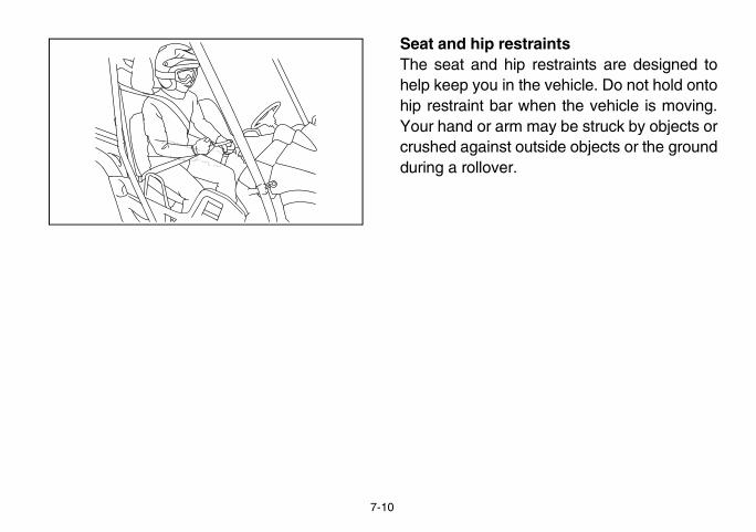
Seat and hip restThe seat and hiphelp keep you in thhip restraint bar wYour hand or arm crushed against ouduring a rollover.

n the steering wheel. Dog wheel with your thumbsp your palms on the out-
wheel. Similar to other off-e Rhino hits a deep rut orsteering wheel could brief-on or back and forth as thespond to the obstacle. Thisinjure your thumbs or wristnd(s) are inside the steer-e steering wheel so thatt be hit by the spokes. Ase illustration.
EE.book Page 11 Friday, August 3, 2007 4:52 PM
7-11
FloorboardThe floorboard allows you to brace your feet,which helps you keep your body in the vehiclein the event of an accident or rollover. Keepyour feet on the floorboard during operation.
Steering wheelKeep both hands onot hold the steerininside the rim. Keeside of the steeringroad vehicles, if thlarge obstacle, the ly jerk in one directitires and vehicle requick motion could if your thumbs or haing wheel. Grip thyour thumbs will noan example, see th

PERATE YOUR VEHICLE
ve equipment
helmet3. Long-sleeved shirt or jacket5. Long pants
2
3
4
5
6
EE.book Page 12 Friday, August 3, 2007 4:52 PM
7-12
LEARNING TO O
Personal protecti
1. Approved motorcycle2. Eye protection4. Gloves6. Over-the-ankle boots
CORRECT GRIP EXAMPLE
INCORRECT GRIP EXAMPLE
1

n when operating or ridinge the risk of a serious ac- protection, such as a faceay reduce the risk of for-
g in your eyes and helpn.
hino userse familiar with the perfor-ics of the vehicle in a large, of obstacles and other ve-ontrolling the acceleratorring, and drive select lever.ds with gradual accelera-ractice smooth throttle ap- slowing down beforeaintaining a steady throttle
void higher speeds until familiar with the operationemember, driving aggres-brupt maneuvers even on cause side rollovers.
EE.book Page 13 Friday, August 3, 2007 4:52 PM
7-13
Both driver and passenger should wear thefollowing to reduce risk of injury in an acci-dent:� Approved motorcycle helmet that fits prop-
erly� Eye protection (goggles, helmet face
shield, or protective eyewear)� Over-the-ankle boots, gloves, long-sleeved
shirt or jacket, and long pants
An approved helmet and other personal pro-tective equipment can help in a variety ofways, including:� Reduce the severity of injuries if any part of
you is outside the vehicle cage/frame pro-tective structure during a rollover.
� Help protect you if outside objects intrudeinside the vehicle during operation.
� Help protect you in the event of vehicle im-pact with an obstacle.
Wear eye protectiothe vehicle to reduccident or injury. Eyeshield or goggles, meign material gettinprevent loss of visio
Practice for new RYou should becommance characteristflat area that is freehicles. Practice cpedal, brakes, steeDrive at slow speetion and turning. Pplication. Practiceturning. Practice mthrough the turn. Ayou are thoroughlyof your vehicle. Rsively or making aflat, open areas can

rideperation Checks on pagesthe instructions starting on the engine. Once it hasou have turned the choke to begin driving your vehi-
EE.book Page 14 Friday, August 3, 2007 4:52 PM
7-14
Become familiar with the way the vehicle feelsin low and high ranges, first in two-wheel drive(2WD) and then in four-wheel drive (4WD)and four-wheel drive with the differentiallocked (DIFF. LOCK). Steering may takemore effort in 4WD with the differential locked(DIFF. LOCK). Also practice driving in re-verse.
Take the time to learn basic operation of thevehicle before attempting more difficult ma-neuvers.
Getting ready to Perform the Pre-O5-1–5-11. Follow page 6-2 to startwarmed up and yoff, you are readycle.

that the vehicle may tip or completely inside the pro-the vehicle:y pressing your feet firmlys and keep a firm grip on
el or handholds.ands or feet outside of theason. Do not try to stop ar arm or leg.
EE.book Page 15 Friday, August 3, 2007 4:52 PM
7-15
TurningUse care in turns – turning the steering wheeltoo far or too fast can result in loss of controlor a rollover. Slow down before entering turns.When making tight turns from a standstill or atslow speeds, avoid sudden or hard accelera-tion. Driving aggressively or making abruptmaneuvers even on flat, open areas cancause side rollovers. Avoid sideways sliding,skidding, or fishtailing, and never do donuts. Ifyou feel the Rhino begin to slide sideways orfishtail during a turn, steer into the direction ofthe slide, if possible, and gradually let off theaccelerator pedal to regain directional controland avoid rollover. For example, if you feel theback of the vehicle start to slide to your right,steer to the right.
If you think or feel roll, keep your bodytective structure of � Brace yourself b
on the floorboardthe steering whe
� Do not put your hvehicle for any retipover using you
wn or stopping, take yourrator pedal and press thethly. Improper use of the
the tires to lose traction, re-the vehicle and increasingn accident.
ffected by type of terrain. Inal application of the brakesan abrupt braking, particu-faces, such as gravel. Al-eater braking distance onippery surfaces.
ion braking is designed tooperating your Rhino off-ture, the engine helps slowafter you take your foot offngine braking is more no-pplication of vehicle brakesl stopping power.
EE.book Page 16 Friday, August 3, 2007 4:52 PM
7-16
AcceleratingWith the engine idling in neutral and your footon the brake, shift the drive select lever intolow or high. NOTICE: Do not shift from lowto high or vice versa without coming to acomplete stop and waiting for the engineto return to normal idle speed – damage tothe engine or drive train may occur. Thenrelease the parking brake. Press the accel-erator pedal slowly and smoothly. The centrif-ugal clutch will engage and the vehicle willbegin to accelerate.
Avoid higher speeds and sudden or hard ac-celeration until you are thoroughly familiarwith the operation of your vehicle. Avoid sud-den or hard acceleration in any turn.
BrakingWhen slowing dofoot off the accelebrake pedal smoobrakes can cause ducing control of the possibility of a
Braking ability is amost cases, graduis more effective thlarly on loose surways allow for grrough, loose, or sl
Engine brakingEngine compressassist you when road. With this feathe vehicle down the accelerator. Eticeable in 4WD. Aprovides additiona

rea flat area, stop the engineelect lever into the neutralparking brake to help pre-m rolling.
ee acts only on the rearD. For the parking brake toour wheels, shift to 4WDopping the engine.
l that is too steep the vehi-ontrol. Never park on hills
you cannot walk up them park on an incline follow
le to a stop by applying the
in 4WD Diff. Lock.e off.
EE.book Page 17 Friday, August 3, 2007 4:52 PM
7-17
Leaving the vehicleDo not get out of the vehicle while the engineis running and the drive select lever is in anygear. There is a risk of injury because:� The speed of a cold engine may increase
enough as it warms up to cause the vehicleto move on its own while the choke is beingused.
� Children or others may accidentally pressthe accelerator pedal.
� Objects tossed into the vehicle may strikethe accelerator pedal.
� The parking brake may not keep the vehi-cle from accelerating.
Unwanted vehicle movement can cause seri-ous injury or death, and it may be dangerousto try to stop the vehicle.
Parking on a flat aWhen parking on aand shift the drive sposition. Apply the vent the vehicle fro
Parking on a slopThe parking brakwheels when in 2Wtake effect on all fDiff. Lock before st
If you park on a hilcle may roll out of cthat are so steep easily. If you mustthese instructions:1. Bring the vehic
brakes.2. Put the vehicle3. Turn the engin

erent surfaces and
ceed with caution when op-familiar surface or terrain.handle differently in certainr on certain surfaces. Youhidden rocks, bumps, or
ugh time to react. To avoidrollover, always be alert to or terrain when operating
her ground clearance andhandle rugged terrain, andverturn in situations wherey not. Abrupt maneuvers or can cause loss of control, – even on flat, open areas.an result in crushed limbsinjuries or death to drivers
EE.book Page 18 Friday, August 3, 2007 4:52 PM
7-18
4. With the brake pedal applied, set theparking brake.
5. Block the front and rear wheels withrocks or other objects.
LoadingThe total weight of operator, passenger, ac-cessories, cargo, trailer tongue weight, andthe vehicle itself must not exceed 907 kg(2,000 lb). Vehicle loading can affect han-dling. See “Loading” on pages 6-11–6-13.
Operation on diffterrainsGo slowly and proerating on an unThis vehicle may types of terrains omay come upon holes without enoloss of control or changing surfacesthe vehicle.
The Rhino has higother features to as a result, can osome vehicles maaggressive drivingincluding rolloversThese rollovers cand other serious or passengers.

hich hills you attempt tovoid hills with slippery sur-re you will not be able toead of you. Use commoner that some hills are toob or descend. Use proper
to avoid rearward, forward,rs on hills and slopes.
and down inclines, notssing a hill is unavoidable,ownhill immediately if you
y tip.
el the Rhino may tip or
y pressing your feet firmlys and keep a firm grip on
el or handholds.ands or feet outside of theason.
EE.book Page 19 Friday, August 3, 2007 4:52 PM
7-19
HillsChoose carefully wclimb or descend. Afaces or those whesee far enough ahsense and remembsteep for you to climdriving techniques or sideways rollove
Drive straight up across them. If crodrive slowly. Turn dfeel the vehicle ma
If you think or feroll:� Brace yourself b
on the floorboardthe steering whe
� Do not put your hvehicle for any re

ou reach the crest of the hillclearly what is on the other be another person, an ob-drop-off.
se traction or momentumd decide you will be unablee brakes to stop. Do not at-vehicle around. With your
pedal, look behind you and. Shift the drive select lever can use engine braking to
. Release the brake and be-the hill. Use engine brakingsible, gently applying thessary.
EE.book Page 20 Friday, August 3, 2007 4:52 PM
7-20
UphillDo not attempt to climb hills until you havemastered basic maneuvers on flat ground.Drive straight up hills, and avoid crossing theside of a hill, which increases your risk of roll-over. Practice first on gentle slopes before at-tempting steeper hills. Always check theterrain carefully before attempting any hill.
To climb a hill, you need traction, momentum,and steady throttle. For more traction andcontrol for climbing steeper and/or rougherslopes, shift into low gear and select 4WD or4WD Diff. Lock. Travel fast enough to main-tain momentum, but not so fast that you can-not react to changes in the terrain as youclimb.
Slow down when yif you cannot see side – there couldstacle, or a sharp
If you start to lowhen climbing, anto continue, use thtempt to turn the foot on the brake plan your descentinto reverse so youslow your descentgin to coast down as much as posbrakes when nece

skidding, try to steer in thee is sliding, to regain con-if you feel the back of thee to your right, steer to the
the hill to avoid an obsta-nd carefully. If the vehicleiately steer in the downhill no obstacles in your path.
er balance, gradually steern you want to go.
EE.book Page 21 Friday, August 3, 2007 4:52 PM
7-21
DownhillCheck the terrain carefully before goingdownhill. When possible, choose a path thatlets you drive your vehicle straight downhill.Choose your path carefully and drive slowlyenough to be able to react to obstacles thatyou encounter.
For more traction and control, before goingdown steeper and/or rougher slopes, shift intolow gear and select 4WD or 4WD Diff. Lock.Engine braking will help you go downhill slow-ly. Go as slowly as possible. If you begin to gotoo fast, apply the brakes gently. Avoid hardapplication of the brakes, which could causethe vehicle to slide.
If you are sliding ordirection the vehicltrol. For example, vehicle start to slidright.
If you must turn oncle, do so slowly astarts to tip, immeddirection if there areAs you regain propagain in the directio

hallow, slow-moving waterf the vehicle’s floorboards, carefully to avoid sharp
ocks, or slippery surfacese vehicle to overturn. Nev- water deeper than 33 cming water. Choose a pathntrance into and exit point gradual incline. Determined currents before crossing.
icle through deep or fast- lead to loss of control ore your risk of drowning orse care when crossing
ave reduced effectiveness.water, test your brakes. Ifthe brakes several times tohe linings.
EE.book Page 22 Friday, August 3, 2007 4:52 PM
7-22
Rough terrainOperation over rough terrain should be donewith caution.� Look for and avoid obstacles that could
cause damage to the vehicle or could leadto a rollover or accident.
� Do not drive in a way that will get the Rhinoairborne, as injury, loss of control, anddamage to the vehicle could occur.
PavementThis vehicle is designed for off-road use only.Avoid paved surfaces. Turn gradually and goslowly if you must drive on pavement.
WaterIf you must cross sup to the depth ochoose your pathdrop-offs, large rthat could cause ther operate through(13 in) or fast-flowwhere both your efrom the water is athe water depth an
Operating this vehflowing water canoverturn. To reducother injuries, uthrough water.
Wet brakes may hAfter leaving the necessary, apply let friction dry out t
pery terrainslippery terrain, includingonditions, as well as loosehat you could begin skid-avoid loss of control, slowhino in 4WD before drivingce and plan your path tot maneuvers.
begin to slide sideways or, steer into the direction of, to regain directional con-if you feel the back of thee to your right, steer to the
EE.book Page 23 Friday, August 3, 2007 4:52 PM
7-23
NOTICEAfter driving your vehicle in water, be sureto drain the trapped water by removing thecheck hose at the bottom of the air filtercase, the V-belt cooling duct check hose,the drive select lever box check hose andthe V-belt case drain plug. Wash the vehi-cle in fresh water if it has been operated insalt water or muddy conditions.
Loose terrain/slipWhen driving on wet, muddy, or icy cgravel, be aware tding or sliding. To down and put the Ron a slippery surfaavoid making abrup
If you feel the Rhinofishtail during a turnthe slide if possibletrol. For example, vehicle start to slidright.

staclesround an obstacle, such asitch, stop the vehicle where Set the parking brake and the area thoroughly. Lookroach side and exit side. If
an continue safely, choosellow you to get over the ob-ose to a right angle as pos-ehicle tipping. Go only fast
in your momentum but stilly of time to react to chang-
estion about your ability toover the obstacle, you
if the ground is flat and youack up until you find a less
EE.book Page 24 Friday, August 3, 2007 4:52 PM
7-24
Brush or wooded areasWhen operating in areas with brush or trees,watch carefully on both sides and above thevehicle for obstacles such as branches thatthe vehicle might hit, causing an accident.Watch for brush that might enter the vehicleas you pass and strike you or the passenger.Never hold onto the cage/frame. The passen-ger should always hold onto the handholdswith both hands.
The muffler and other engine parts becomeextremely hot during operation and remainhot after the engine has stopped. To reducethe risk of fire during operation or after leavingthe vehicle, do not let brush, grass and othermaterials collect under the vehicle, near themuffler or exhaust pipe, or next to other hotparts. Check under the vehicle after operatingin areas where combustible materials mayhave collected. Do not idle or park the vehiclein long dry grass or other dry ground cover.
Encountering obIf you cannot go aa fallen tree or a dit is safe to do so.get out to inspectfrom both your appyou believe you cthe path that will astacle and at as clsible to minimize venough to maintagive yourself plentes in conditions.
If there is any qumaneuver safely should turn aroundhave the room or bdifficult path.

EVU00650
e when performing main-herwise specified.gine has moving parts on body parts or cloth-
ical parts that can causes.engine while servicing
ye injury, burns, fire, orxide poisoning – possi- death. See page 2-8 fortion about carbon mon-
EE.book Page 1 Friday, August 3, 2007 4:52 PM
8-1
1-PERIODIC MAINTENANCE AND ADJUSTMENT
Periodic inspection, adjustment, and lubrica-tion will keep your vehicle in the safest andmost efficient condition possible.Safety is an obligation of the vehicle owner/operator. The most important points of vehicleinspection, adjustment, and lubrication are ex-plained on the following pages.
WARNINGFailure to properly maintain the vehicle orperforming maintenance activities incor-rectly may increase your risk of injury ordeath during service or while using the ve-hicle. If you are not familiar with vehicleservice, have a Yamaha dealer performservice.
WARNINGTurn off the engintenance unless ot
� A running enthat can catching and electrshocks or fire
� Running the can lead to ecarbon monobly leading tomore informaoxide.

1
2
3
4
5
6
7
8
9
10
11
12
13
14
2. Tire pressure gauge
ation included in this man-rovide you, the owner, withrmation for completing youraintenance and minor re-
in the owner’s tool kit arerpose, except that a torque
cessary to properly tighten
EE.book Page 2 Friday, August 3, 2007 4:52 PM
8-2
EVU00660
Owner’s manual and tool kitYou are recommended to put this owner’smanual in the vinyl bag and always carry it un-derneath the driver seat as shown. Put theowner’s tool kit and tire pressure gauge in thespace beside the battery.
1. Owner’s manual
1. Owner’s tool kit
The service informual is intended to pthe necessary infoown preventive mpairs.The tools providedsufficient for this puwrench is also nenuts and bolts.

EE.book Page 3 Friday, August 3, 2007 4:52 PM
8-3
If you do not have a torque wrench availableduring a service operation requiring one, takeyour vehicle to a Yamaha dealer to check thetorque settings and adjust them as necessary.

the month maintenance in-
e km (mi) or hours mainte-d for a long period of time,
dealer as they require spe-
INITIAL EVERY3 6 6 12
1,200 (750)
2,400 (1,500)
2,400 (1,500)
4,800 (3,000)
75 150 150 300
EE.book Page 4 Friday, August 3, 2007 4:52 PM
8-4
EVU01640
Periodic maintenance chart for the emission control system� For vehicles not equipped with an odometer or hour meter, follow
tervals.� For vehicles equipped with an odometer or an hour meter, follow th
nance intervals. However, keep in mind that if the vehicle isn’t usethe month maintenance intervals should be followed.
� Items marked with an asterisk should be performed by a Yamaha cial tools, data and technical skills.
ITEM ROUTINEWhichever comes first
month 1km(mi)
320 (200)
hours 20
Fuel line* • Check fuel hose for cracks or damage.• Replace if necessary.
Valves* • Check valve clearance.• Adjust if necessary.
Spark plug• Check condition.• Adjust gap and clean.• Replace if necessary.
Carburetor* • Check idle speed/starter operation.• Adjust if necessary.
Crankcase breather system*
• Check breather hose for cracks or damage.• Replace if necessary.
Exhaust system*• Check for leakage.• Tighten if necessary.• Replace gasket(s) if necessary.
Spark arrester • Clean.

EVU01650
INITIAL EVERY3 6 6 12
1,200 (750)
2,400 (1,500)
2,400 (1,500)
4,800 (3,000)
75 150 150 300
Every 20–40 hours ore often in wet or dusty areas.)
EE.book Page 5 Friday, August 3, 2007 4:52 PM
8-5
General maintenance and lubrication chart
ITEM ROUTINEWhichever comes first
month 1km(mi)
320 (200)
hours 20
Cooling system• Check coolant leakage.• Repair if necessary.• Replace coolant every 24 months.
Air filter elements (engine and air intake duct)
• Clean.• Replace if necessary. (M
Engine oil • Replace (warm engine before draining).Engine oil filter cartridge • Replace.Final gear oil • Check oil level/oil leakage.
• Replace.Differential gear oil
Front brake* • Check operation/brake pad wear/fluid leakage/see page 8-6.• Correct if necessary. Replace pads if worn to the limit.
Rear brake* • Check operation/brake pad wear/fluid leakage/see page 8-6.• Correct if necessary. Replace pads if worn to the limit.
Accelerator pedal* • Check operation and free play.
V-belt* • Check operation.• Check for wear, cracks, or damage.
Wheels* • Check balance/damage/runout.• Repair if necessary.
Wheel bearings* • Check bearing assemblies for looseness/damage.• Replace if damaged.
Front and rear suspension*
• Check operation and for leakage.• Correct if necessary.
Steering system* • Check operation and for looseness/Replace if damaged.• Check toe-in/Adjust if necessary.
Rear upper and lower knuckle pivots* • Lubricate with lithium-soap-based grease.

caliper.
caliper every two years.d.
INITIAL EVERY3 6 6 12
1,200 (750)
2,400 (1,500)
2,400 (1,500)
4,800 (3,000)
75 150 150 300
EE.book Page 6 Friday, August 3, 2007 4:52 PM
8-6
Recommended brake fluid: DOT 4Brake fluid replacement:� Replace the brake fluid when disassembling the master cylinder or� Check the brake fluid level regularly and add fluid as required.� Replace the oil seals on the inner parts of the master cylinder and � Replace the brake hoses every four years, or if cracked or damage
Drive shaft universal joint* • Lubricate with lithium-soap-based grease.
Engine mount* • Check for cracks or damage.• Check bolt tightness.
Front and rear axle boots* • Check operation.• Replace if damaged.
Stabilizer bushings* • Check for cracks or damage.
Fittings and fasteners* • Check all chassis fittings and fasteners.• Correct if necessary.
ITEM ROUTINEWhichever comes first
month 1km(mi)
320 (200)
hours 20

EVU00680
EE.book Page 7 Friday, August 3, 2007 4:52 PM
8-7
Hood
To openUnhook the hood latches, and then slowly tiltthe hood up until it stops.
1. Latch (× 2)
1. Hood

t all cables and wires areclosing the hood.he vehicle with the hoodd, or removed.
EE.book Page 8 Friday, August 3, 2007 4:52 PM
8-8
To closeLower the hood slowly to its original position,and then hook the hood latches. Secure pro-jections 1 on the rear of the hood into slots2on the back of the instrument panel. Secureslots3 on the side of the hood aroundprojections4 on the frame.
1. Projection (× 2) 2. Slot (× 2)3. Slot (× 2) 4. Projection (× 2)
NOTICE� Make sure tha
in place when � Do not drive t
open, unlatche

EVU00691
ole in its original position.ing brake lever boot.s.
the console, be sure notles or wires.
the groove at the bottomrake lever boot and thever boot fits securelye of the hole in the con-
EE.book Page 9 Friday, August 3, 2007 4:52 PM
8-9
Console
To remove1. Remove the seats. (See page 4-13 for
seat removal and installation proce-dures.)
2. Remove the parking brake lever boot.3. Pull the console upward (the drive select
lever boot will come loose).
1. Console
To install1. Place the cons2. Install the park3. Install the seat
NOTICE� When installing
to pinch the cab� Make sure that
of the parking bdrive select learound the edgsole.

stick in the oil filler holeing it in), and then removeck the oil level. The enginebetween the minimum andel marks.
2. Minimum level mark4. Engine oil filler cap
oil is at or below the mini-rk, add sufficient oil of the
d type to raise it to the cor-
EE.book Page 10 Friday, August 3, 2007 4:52 PM
8-10
EVU00701
Engine oil and oil filter cartridgeCheck engine oil level before each operation.In addition, change the oil and the oil filter car-tridge at the intervals specified in the periodicmaintenance and lubrication chart.
To check the engine oil level1. Park the vehicle on a level surface.2. Remove the console. (See page 8-9 for
console removal and installation proce-dures.)
3. Check the engine oil level on a cold en-gine. If the engine was started beforechecking the oil level, be sure to warm upthe engine sufficiently, and then wait atleast ten minutes until the oil settles foran accurate reading.
4. Remove the engine oil filler cap and wipeoff the dipstick with a clean rag.
5. Insert the dip(without screwit again to cheoil should be maximum lev
1. Maximum level mark3. Dipstick
6. If the engine mum level marecommenderect level.

gine oil (with or withoutreplacement)onsole. (See page 8-9 foral and installation proce-
e, warm it up for severalhen turn it off.n under the engine to col-il, and then remove the en-p.
ngine oil drain bolt to drain crankcase.
EE.book Page 11 Friday, August 3, 2007 4:52 PM
8-11
7. Insert the dipstick into the oil filler hole,and then tighten the oil filler cap.
8. Reinstall the console.
To change the enoil filter cartridge 1. Remove the c
console removdures.)
2. Start the enginminutes, and t
3. Place an oil palect the used ogine oil filler ca
4. Remove the ethe oil from the
1. Engine oil drain bolt

coat of clean engine oil tothe new oil filter cartridge. O-ring is seated properly.
oil filter cartridge with anh, and then tighten it to theue with a torque wrench.
e:ge:
m·kgf, 12 ft·lbf)
EE.book Page 12 Friday, August 3, 2007 4:52 PM
8-12
Skip steps 5–7 if the oil filter cartridge is notbeing replaced.
5. Remove the oil filter cartridge with an oilfilter wrench. An oil filter wrench is avail-able from a Yamaha dealer.
1. Oil filter cartridge 2. Oil filter wrench
6. Apply a light the O-ring of Make sure the
1. O-ring
7. Install the newoil filter wrencspecified torq
Tightening torquOil filter cartrid
17 Nm (1.7

ied amount of recommend-and then reinstall the en-p and tighten it. NOTICE:pe off spilled oil on anye engine and exhaust
cooled down.
ngine oil:.
r cartridge replacement: Imp qt, 2.01 US qt)rtridge replacement:
Imp qt, 2.11 US qt)
EE.book Page 13 Friday, August 3, 2007 4:52 PM
8-13
1. Oil filter cartridge 2. Torque wrench
8. Reinstall the engine oil drain bolt, andthen tighten it to the specified torque.
9. Add the specifed engine oil, gine oil filler caBe sure to wiparts after thsystem have
Tightening torque:Engine oil drain bolt:
30 Nm (3.0 m·kgf, 22 ft·lbf)
Recommended eSee page 10-2
Oil quantity:Without oil filte
1.90 L (1.67With oil filter ca
2.00 L (1.76

ine, and then let it idle fores while checking it for oilis leaking, immediately turn and check for the cause.ne off, wait at least ten min- check the oil level and cor-sary.onsole.
EE.book Page 14 Friday, August 3, 2007 4:52 PM
8-14
NOTICE� In order to prevent clutch slippage
(since the engine oil also lubricates theclutch), do not mix any chemical addi-tives with oil. Do not use oils with a die-sel specification of “CD” or oils of ahigher quality than specified. In addi-tion, do not use oils labeled “ENERGYCONSERVING II” or higher.
� Make sure that no foreign material en-ters the crankcase.
1. “CD” specification 2. “ENERGY CONSERVING II”
10. Start the engseveral minutleakage. If oil the engine off
11. Turn the engiutes, and thenrect it if neces
12. Reinstall the c
1
2
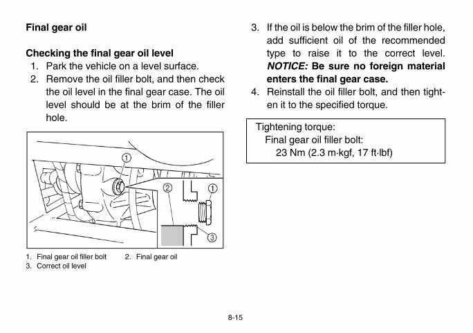
EVU00710
w the brim of the filler hole,oil of the recommended
it to the correct level.sure no foreign materialal gear case.il filler bolt, and then tight-cified torque.
:ller bolt:
·kgf, 17 ft·lbf)
EE.book Page 15 Friday, August 3, 2007 4:52 PM
8-15
Final gear oil
Checking the final gear oil level1. Park the vehicle on a level surface.2. Remove the oil filler bolt, and then check
the oil level in the final gear case. The oillevel should be at the brim of the fillerhole.
1. Final gear oil filler bolt 2. Final gear oil3. Correct oil level
3. If the oil is beloadd sufficient type to raiseNOTICE: Be enters the fin
4. Reinstall the oen it to the spe
Tightening torqueFinal gear oil fi
23 Nm (2.3 m

mended final gear oil up toe filler hole. NOTICE: Be
ign material enters the fi-.
oil filler bolt, and then tight-ecified torque.
leakage. If oil leakage isfor the cause.
oil:L-4 Hypoid gear oil
p qt, 0.26 US qt)
e:iller bolt: m·kgf, 17 ft·lbf)
EE.book Page 16 Friday, August 3, 2007 4:52 PM
8-16
Changing the final gear oil1. Park the vehicle on a level surface.2. Place a container under the final gear
case to collect the used oil.3. Remove the oil filler bolt and the drain
bolt to drain the oil.
1. Final gear oil drain bolt
4. Reinstall the drain bolt, and then tighten itto the specified torque.
5. Add the recomthe brim of thsure no forenal gear case
6. Reinstall the en it to the sp
7. Check for oilfound, check
Tightening torque:Final gear oil drain bolt:
20 Nm (2.0 m·kgf, 14 ft·lbf)
Recommended SAE 80 API G
Oil quantity:0.25 L (0.22 Im
Tightening torquFinal gear oil f
23 Nm (2.3

EVU00721
ifferential gear oil filler bolt,n it to the specified torque.
rential gear oille on a level surface.iner under the differentialollect the used oil.ifferential gear oil filler boltl gear oil drain bolt to drain
:r oil filler bolt:·kgf, 17 ft·lbf)
EE.book Page 17 Friday, August 3, 2007 4:52 PM
8-17
Differential gear oil
Checking the differential gear oil level1. Park the vehicle on a level surface.2. Remove the differential gear oil filler bolt
and check the oil level. It should be up tothe brim of the filler hole. If the level islow, add sufficient oil of the recommend-ed type to raise it to the specified level.NOTICE: Be sure no foreign materialenters the differential gear case.
1. Differential gear oil filler bolt2. Correct oil level 3. Differential gear oil
3. Reinstall the dand then tighte
Changing the diffe1. Park the vehic2. Place a conta
gear case to c3. Remove the d
and differentiathe oil.
Tightening torqueDifferential gea
23 Nm (2.3 m

ifferential gear oil filler bolt,en it to the specified torque.
leakage. If oil leakage isfor the cause.
oil:L-5 Hypoid gear oil
p qt, 0.34 US qt)
e:ar oil filler bolt: m·kgf, 17 ft·lbf)
EE.book Page 18 Friday, August 3, 2007 6:35 PM
8-18
1. Differential gear oil drain bolt
4. Reinstall the differential gear oil drainbolt, and tighten it to the specified torque.
5. Fill the differential gear case with the rec-ommended oil. NOTICE: Be sure no for-eign material enters the differentialgear case.
6. Reinstall the dand then tight
7. Check for oilfound, check
Tightening torque:Differential gear oil drain bolt:
9.8 Nm (0.98 m·kgf, 7.1 ft·lbf)
Recommended SAE 80 API G
Oil quantity:0.32 L (0.28 Im
Tightening torquDifferential ge
23 Nm (2.3
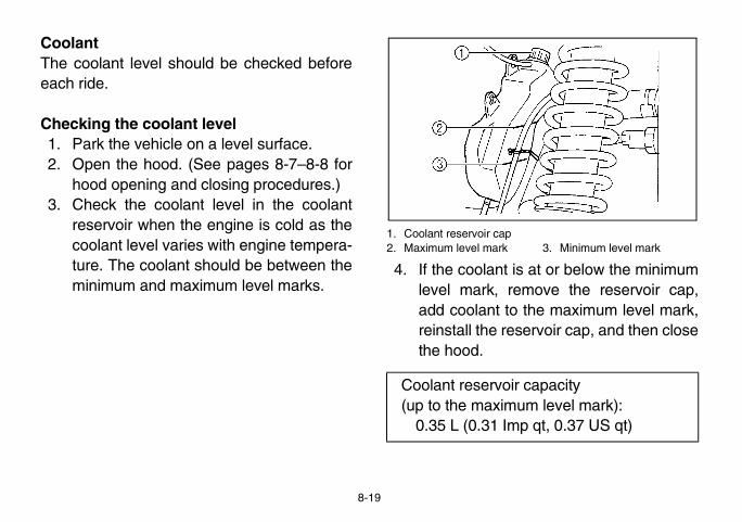
EVU00732
3. Minimum level mark
s at or below the minimummove the reservoir cap, the maximum level mark,ervoir cap, and then close
capacityum level mark):p qt, 0.37 US qt)
EE.book Page 19 Friday, August 3, 2007 4:52 PM
8-19
CoolantThe coolant level should be checked beforeeach ride.
Checking the coolant level1. Park the vehicle on a level surface.2. Open the hood. (See pages 8-7–8-8 for
hood opening and closing procedures.)3. Check the coolant level in the coolant
reservoir when the engine is cold as thecoolant level varies with engine tempera-ture. The coolant should be between theminimum and maximum level marks.
1. Coolant reservoir cap2. Maximum level mark
4. If the coolant ilevel mark, readd coolant toreinstall the resthe hood.
Coolant reservoir(up to the maxim
0.35 L (0.31 Im

ve boots for holes or tears.found, have them replaceder.
ach side)
EE.book Page 20 Friday, August 3, 2007 4:52 PM
8-20
Changing the coolantThe coolant must be changed by a Yamahadealer at the intervals specified in the periodicmaintenance and lubrication chart.Adding water instead of coolant lowers theantifreeze content of the coolant. If water isused instead of coolant, have a Yamaha deal-er check the antifreeze content of the coolantas soon as possible.The radiator fan is automatically switched onor off according to the coolant temperature inthe radiator.
NOTICEMix antifreeze with distilled water only.However, if distilled water is not available,soft water may be used for refilling.
If your vehicle overheats, see page 8-59 forinstructions.
EVU00740
Axle bootsCheck the protectiIf any damage is by a Yamaha deal
1. Front axle boot (× 2 e

5UG14001
tion
ed up. (See pages 4-15– bed lifting and lowering
ark plug cap.
plug wrench in the tool kitspark plug as shown.
EE.book Page 21 Friday, August 3, 2007 4:52 PM
8-21
1. Rear axle boot (× 2 each side)
Spark plug inspec
Removal1. Lift the cargo b
4-16 for cargoprocedures.)
2. Remove the sp
1. Spark plug cap
3. Use the sparkto remove the

n important engine compo-o inspect. The condition ofn indicate the condition of
of the porcelain insulator electrode is a medium-to-cle that is being ridden nor-
ically remove and inspectause heat and deposits willlug to slowly break down
trode erosion becomes ex-on and other deposits areould replace the spark plugplug.
plug:GK)
EE.book Page 22 Friday, August 3, 2007 4:52 PM
8-22
1. Spark plug wrench
InspectionThe spark plug is anent and is easy tthe spark plug cathe engine.The ideal color around the centerlight tan for a vehimally.You should periodthe spark plug beccause the spark pand erode. If eleccessive, or if carbexcessive, you shwith the specified
Specified spark DPR8EA-9 (N

k plug and tighten it to thee. If a torque wrench is notn you are installing theood estimate of the correct-quarter to one-half turnht. Have the spark pluge specified torque as soon
k plug cap.o bed.
:
5 m·kgf, 12.7 ft·lbf)
EE.book Page 23 Friday, August 3, 2007 4:52 PM
8-23
Installation1. Measure the electrode gap with a wire
thickness gauge and, if necessary, adjustthe gap to specification.
a. Spark plug gap
2. Clean the surface of the spark plug gas-ket and its mating surface, and then wipeoff any grime from the spark plugthreads.
3. Install the sparspecified torquavailable whespark plug, a gtorque is onepast finger tigtightened to thas possible.
4. Install the spar5. Lower the carg
Spark plug gap:0.8–0.9 mm (0.031–0.035 in)
Tightening torqueSpark plug:
17.5 Nm (1.7

ir filter element from the airill by pulling it out as shown.
2. Air intake duct grill
large particles from the airby hand.lter element to remove asd dirt as possible.
EE.book Page 24 Friday, August 3, 2007 4:52 PM
8-24
5UG14002
Cleaning the air filter elements
Cleaning the intake duct air filter element1. Remove the air intake duct grill by remov-
ing the quick fastener screws.
1. Quick fastener screw (× 4)2. Air intake duct grill
2. Remove the aintake duct gr
1. Air filter element
3. Remove any filter element
4. Tap the air fimuch dust an

ne air filter elementse at the bottom of the air
or water collects in thisse and clean the air filterr case.
se
eats. (See page 4-13 for and installation proce-
onsole. (See page 8-9 foral and installation proce-
EE.book Page 25 Friday, August 3, 2007 4:52 PM
8-25
5. Reinstall the air filter element into the airintake duct grill.
6. Reinstall the air intake duct grill by install-ing the quick fastener screws.
Cleaning the engiThere is a check hofilter case. If dusthose, empty the hoelement and air filte
1. Air filter case check ho
1. Remove the sseat removaldures.)
2. Remove the cconsole removdures.)

ir filter element.
EE.book Page 26 Friday, August 3, 2007 4:52 PM
8-26
3. Remove the air filter case cover by un-hooking the holders.
1. Air filter case cover holder (× 4) 2. Air filter case cover
4. Remove the a
1. Air filter element
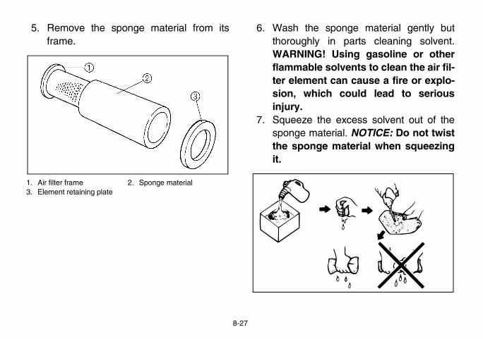
onge material gently but parts cleaning solvent.sing gasoline or otherlvents to clean the air fil-an cause a fire or explo-could lead to serious
excess solvent out of theal. NOTICE: Do not twistaterial when squeezing
EE.book Page 27 Friday, August 3, 2007 4:52 PM
8-27
5. Remove the sponge material from itsframe.
1. Air filter frame 2. Sponge material3. Element retaining plate
6. Wash the spthoroughly inWARNING! Uflammable soter element csion, which injury.
7. Squeeze the sponge materithe sponge mit.
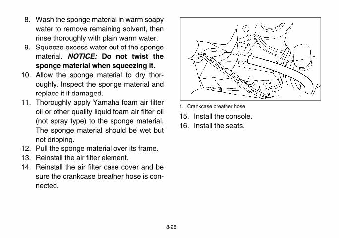
ose
sole.ts.
EE.book Page 28 Friday, August 3, 2007 4:52 PM
8-28
8. Wash the sponge material in warm soapywater to remove remaining solvent, thenrinse thoroughly with plain warm water.
9. Squeeze excess water out of the spongematerial. NOTICE: Do not twist thesponge material when squeezing it.
10. Allow the sponge material to dry thor-oughly. Inspect the sponge material andreplace it if damaged.
11. Thoroughly apply Yamaha foam air filteroil or other quality liquid foam air filter oil(not spray type) to the sponge material.The sponge material should be wet butnot dripping.
12. Pull the sponge material over its frame.13. Reinstall the air filter element.14. Reinstall the air filter case cover and be
sure the crankcase breather hose is con-nected.
1. Crankcase breather h
15. Install the con16. Install the sea

2P512001
box check hoseer box check hose is locat-le. (See page 8-9 for con-installation procedures.) Ifts in the drive select levermove the hose and clean
heck hose
EE.book Page 29 Friday, August 3, 2007 4:52 PM
8-29
The air filter element should be cleaned every20–40 hours. It should be cleaned and lubri-cated more often if the vehicle is operated inextremely dusty areas. Each time air filter ele-ment maintenance is performed, check the airinlet to the air filter case for obstructions.Check the air filter element rubber joint to thecarburetor and manifold fittings for an airtightseal. Tighten all fittings securely to avoid thepossibility of unfiltered air entering the engine.
NOTICENever operate the engine with the air filterelement removed. This will allow unfilteredair to enter, causing rapid engine wear andpossible engine damage. Additionally, op-eration without the air filter element will af-fect carburetor jetting with subsequentpoor performance and possible engineoverheating.
Drive select lever The drive select leved under the consosole removal and dust or water collecbox check hose, reit.
1. Drive select lever box c

plugrain plug is located underee page 4-13 for seat re-
tion procedures.)r deep enough to allow wa-elt case, remove the drainater from the case.
m the V-belt case after re-lug, have a Yamaha dealere, as the water may affect.
EE.book Page 30 Friday, August 3, 2007 4:52 PM
8-30
5UG14003
V-belt cooling duct check hoseThe V-belt cooling duct check hose is locatedunder the driver seat. (See page 4-13 for seatremoval and installation procedures.) If dustor water collects in the V-belt cooling ductcheck hose, remove the hose and clean it.
1. V-belt cooling duct check hose
EVU00780
V-belt case drainThe V-belt case dthe driver seat. (Smoval and installaAfter riding in wateter to enter the V-bplug to drain any wIf water drains fromoving the drain pinspect the vehiclother engine parts
1. V-belt case drain plug
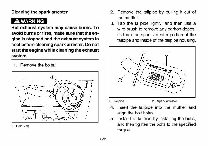
EVU00792
ailpipe by pulling it out of
e lightly, and then use aemove any carbon depos-ark arrester portion of theide of the tailpipe housing.
2. Spark arrester
pipe into the muffler andoles.ipe by installing the bolts,n the bolts to the specified
EE.book Page 31 Friday, August 3, 2007 4:52 PM
8-31
Cleaning the spark arrester
WARNINGHot exhaust system may cause burns. Toavoid burns or fires, make sure that the en-gine is stopped and the exhaust system iscool before cleaning spark arrester. Do notstart the engine while cleaning the exhaustsystem.
1. Remove the bolts.
1. Bolt (× 3)
2. Remove the tthe muffler.
3. Tap the tailpipwire brush to rits from the sptailpipe and ins
1. Tailpipe
4. Insert the tailalign the bolt h
5. Install the tailpand then tightetorque.

tment vital part of the engine andisticated adjustment. Moste left to a Yamaha dealerssional knowledge and ex- However, the idling speede performed by the ownerual maintenance routine.
as set at the Yamaha fac-tests. If the settings are
eone without sufficientdge, poor engine perfor-ge may result.
EE.book Page 32 Friday, August 3, 2007 4:52 PM
8-32
EVU00800
Carburetor adjusThe carburetor is arequires very sophadjusting should bwho has the profeperience to do so.adjustment may bas a part of the us
NOTICEThe carburetor wtory after many disturbed by somtechnical knowlemance and dama
Tightening torque:Tailpipe bolt:
9.5 Nm (0.95 m·kgf, 6.9 ft·lbf)

EVU00810
onsole.eats.
ed:min
EE.book Page 33 Friday, August 3, 2007 4:52 PM
8-33
Idle speed adjustmentA diagnostic tachometer must be used for thisprocedure.1. Start the engine and warm it up for a few
minutes at approximately 1,000 to2,000 r/min. Occasionally rev the engineto 4,000 to 5,000 r/min. The engine iswarm when it responds quickly to thethrottle with the choke off.
2. Remove the seats. (See page 4-13 forseat removal and installation proce-dures.)
3. Remove the console. (See page 8-9 forconsole removal and installation proce-dures.)
4. Connect the tachometer to the spark pluglead, and then set the idle to the specifiedidling speed by adjusting the throttle stopscrew. Turn the screw in direction a toincrease the engine speed, and in direc-tion b to decrease the engine speed.
1. Throttle stop screw
5. Reinstall the c6. Reinstall the s
Specified idle spe1,450–1,550 r/

rake components requiresledge. Brake service should Yamaha dealer.
properly serviced or ad-uld lead to a loss in brak- accident.
heck provided with wear indica-h allow you to check theithout having to disassem-check the brake pad wear,dicator grooves. If a brakee point that the wear indica-lmost disappeared, have aplace the brake pads as a
EE.book Page 34 Friday, August 3, 2007 4:52 PM
8-34
Valve clearanceThe correct valve clearance changes withuse, resulting in improper fuel/air supply orengine noise. To prevent this, the valve clear-ance must be adjusted regularly. This adjust-ment however, should be left to a professionalYamaha service technician.
BrakesReplacement of bprofessional knowbe performed by a
WARNINGOperating with imjusted brakes coing ability and an
EVU00830
Front brake pad cEach brake pad istor grooves, whicbrake pad wear wble the brake. To check the wear inpad has worn to thtor grooves have aYamaha dealer reset.

EVU00840
eckprovided with wear indica- allow you to check thethout having to disassem-heck the brake pad wear,icator grooves. If a brake point that the wear indica-
lmost disappeared, have alace the brake pads as a
tor groove
EE.book Page 35 Friday, August 3, 2007 4:52 PM
8-35
The wheels need to be removed to check thebrake pads. (See pages 8-42–8-45 for wheelremoval and installation procedures.)
1. Brake pad wear indicator groove
Rear brake pad chEach brake pad is tor grooves, whichbrake pad wear wible the brake. To ccheck the wear indpad has worn to thetor grooves have aYamaha dealer repset.
1. Brake pad wear indica

servoir is located under the 8-7–8-8 for hood openingures.)cautions: the fluid level, make sureake fluid reservoir is level.commended quality brake, the rubber seals may de-g leakage and poor braking
me type of brake fluid. Mix-esult in a harmful chemicalad to poor braking perfor-
water does not enter thervoir when refilling. Water lower the boiling point ofy result in vapor lock.
brake fluid: DOT 4
EE.book Page 36 Friday, August 3, 2007 4:52 PM
8-36
EVU00850
Checking the brake fluid level
1. Minimum level mark
Insufficient brake fluid may allow air to enterthe brake system, possibly causing thebrakes to become ineffective.Before riding, check that the brake fluid isabove the minimum level mark and replenish,if necessary. A low brake fluid level may indi-cate worn brake pads and/or brake systemleakage. If the brake fluid level is low, be sureto check the brake pads for wear and thebrake system for leakage.
The brake fluid rehood. (See pagesand closing procedObserve these pre� When checking
the top of the br� Use only the re
fluid. Otherwiseteriorate, causinperformance.
� Refill with the saing fluids may rreaction and lemance.
� Be careful thatbrake fluid resewill significantlythe fluid and ma
Recommended

EVU01220
e pedalealer check the brakes atied in the periodic mainte-on chart. There should be brake pedal. The brakesothly and there should be
the brakes feel soft or indicate air in the brakeamaha dealer check theessary.
EE.book Page 37 Friday, August 3, 2007 4:52 PM
8-37
� Brake fluid may deteriorate painted surfac-es or plastic parts. Always clean up spilledfluid immediately.
� Have a Yamaha dealer inspect the brakesystem if the brake fluid level goes down.
EVU00860
Brake fluid replacementComplete fluid replacement should be doneonly by trained Yamaha service personnel.Have a Yamaha dealer replace the followingcomponents during periodic maintenance orwhen they are damaged or leaking.� Replace the oil seals every two years.� Replace the brake hoses every four years.
Checking the brakHave a Yamaha dthe intervals specifnance and lubricatino free play in theshould operate smono brake drag. Ifspongy, this couldsystem. Have a Ybrake system if nec
1. Brake pedal

ee play
brake lever must be re-checking and adjusting the lever free play.cknut.
EE.book Page 38 Friday, August 3, 2007 4:52 PM
8-38
EVU00870
Parking brake lever free play adjustmentPeriodically check the parking brake lever freeplay and adjust it if necessary.1. Shift the drive select lever into low gear
“L”.2. Remove the seats. (See page 4-13 for
seat removal and installation proce-dures.)
3. Remove the console. (See page 8-9 forconsole removal and installation proce-dures.)
4. Check the parking brake lever free play.The maximum free play is equal to oneclick of the parking brake lever. If neces-sary, adjust the free play as follows.
a. Parking brake lever fr
5. The parking leased when parking brake
6. Loosen the lo

EVU00880
adjustmentitch, which is activated byroperly adjusted when then just before braking takesy, adjust the brake light
d. (See pages 8-7–8-8 forand closing procedures.)ting nut while holding the
itch in place. To make thee on earlier, turn the ad-
direction a. To make thee on later, turn the adjust-tion b..
EE.book Page 39 Friday, August 3, 2007 4:52 PM
8-39
1. Locknut 2. Adjusting nut
7. Turn the adjusting nut in direction a toincrease the free play or in direction b todecrease the free play.
8. Tighten the locknut.9. Reinstall the console.
10. Reinstall the seats.
Brake light switchThe brake light swthe brake pedal, is pbrake light comes oeffect. If necessarswitch as follows.1. Open the hoo
hood opening 2. Turn the adjus
brake light swbrake light comjusting nut in brake light coming nut in direc
3. Close the hood

and lubrication
could restrict operation, an accident or injury. In-bles frequently and re-cables. Corrosion can
outer covering of control damaged. Cables caned or kinked.
e ends. If the cables do not ask a Yamaha dealer to re-
lubricant:based grease
EE.book Page 40 Friday, August 3, 2007 4:52 PM
8-40
1. Brake light switch 2. Adjusting nut
EVU00890
Cable inspection
WARNINGDamaged cableswhich may causespect control caplace damaged result when the cables becomesalso become fray
Lubricate the cabloperate smoothly,place them.
Recommended Lithium-soap-
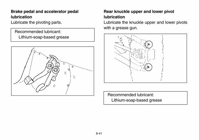
EVU00900 EVU00910
er and lower pivot
le upper and lower pivots
bricant:ased grease
EE.book Page 41 Friday, August 3, 2007 4:52 PM
8-41
Brake pedal and accelerator pedal lubricationLubricate the pivoting parts.
Rear knuckle upplubricationLubricate the knuckwith a grease gun.
Recommended lubricant:Lithium-soap-based grease
Recommended luLithium-soap-b

heel nuts.ehicle and place a suitablee frame.uts from the wheel.heel.
EE.book Page 42 Friday, August 3, 2007 4:52 PM
8-42
EVU00920
Steering shaft lubricationLubricate the pivot points.
EVU00930
Wheel removal1. Loosen the w2. Elevate the v
stand under th3. Remove the n4. Remove the w
1. Nut (× 4)
Recommended lubricant:Lithium-soap-based grease

w have been approved bynufacturing Corporation ofdel.
Size Type
25 × 8-12NHS M951Y
25 × 10-12NHS M952Y
EE.book Page 43 Friday, August 3, 2007 4:52 PM
8-43
Tire replacementAlways use the same size and type of tiresrecommended in this owner’s manual. Thetires that came with your Rhino were de-signed to match the performance capabilitiesand to provide the best combination of han-dling, braking, and comfort. It is best to re-place all four tires at the same time. If that isnot possible, you must replace the tires inpairs (front or rear) with tires of the same sizeand type as the originals. Never replace justone tire.
WARNINGInstalling improper tires on your Rhinocan affect handling and stability. This cancause a loss of control.
The tires listed beloYamaha Motor MaAmerica for this mo
Manufacturer
Front MAXXIS
Rear MAXXIS

EE.book Page 44 Friday, August 3, 2007 4:52 PM
8-44
EVU00940
Wheel installation1. Install the wheel and the nuts.
� The arrow mark on the tire mustpoint toward the rotating direction ofthe wheel.
� Tapered nuts are used for both thefront and rear wheels. Install the nutwith its tapered side towards thewheel.
2. Lower the vehicle so that the wheel is onthe ground.
3. Tighten the wheel nuts to the specifiedtorque.
WARNINGDo not reverse the rims on the Rhino towiden the track width. Installing wheelsimproperly increases the risk of wheel fail-ure and accidents.
1. Arrow mark
1. Tapered nut

EVU00950
ipped with a sealed-typet is not necessary to checkd distilled water in the bat-
s to have discharged, con-ler.
ove the sealing caps ofou may damage the bat-
EE.book Page 45 Friday, August 3, 2007 4:52 PM
8-45
BatteryThis vehicle is equbattery. Therefore ithe electrolyte or adtery.If the battery seemsult a Yamaha dea
NOTICEDo not try to remthe battery cells. Ytery.
Wheel nut torque:Front: 55 Nm (5.5 m·kgf, 40 ft·lbf)Rear: 55 Nm (5.5 m·kgf, 40 ft·lbf)

ncewill not be used for a monthove the battery and store it
ark place. Completely re-ttery before reinstallation.
charger (constant volt-constant voltage) is re-harging a sealed-typea conventional batteryrten the battery life.
sure the connections areputting the battery back in
EE.book Page 46 Friday, August 3, 2007 4:52 PM
8-46
WARNINGAvoid battery contact with skin, eyes, orclothing. Shield eyes when working nearbatteries. Keep out of reach of children.You could be poisoned or severely burnedby the sulfuric acid in battery electrolyte.In case of accidental contact with batteryelectrolyte:EXTERNAL: Flush with water.INTERNAL: Drink large quantities of wateror milk. Follow with milk of magnesia,beaten egg, or vegetable oil. Get promptmedical attention.EYES: Flush with water for 15 minutes andget prompt medical attention.
WARNINGBatteries may produce explosive gases.Ventilate when charging or using in aclosed space. Keep batteries away fromsparks, flames, cigarettes, or other sourc-es of ignition.
EVU00960
Battery maintena1. If the vehicle
or longer, remin a cool, dcharge the ba
NOTICE_
A special batteryage/ampere or quired for recbattery. Using charger may sho_
2. Always makecorrect when the vehicle.

ehicle should be avoided. be removed and charged
xplosion and/or seriousctrical system:ect the negative lead ofble to the negative termi-ery the positive lead of theto the negative lead.rse the polarity of the when connecting to the
EE.book Page 47 Friday, August 3, 2007 4:52 PM
8-47
1. Negative battery lead (black)2. Positive battery lead (red)
Jump-startingJump-starting the vThe battery shouldinstead.
WARNINGTo avoid battery edamage to the ele
� Do not connthe jumper canal of the batt
� Do not touchjumper cable
� Do not revejumper cablesbatteries.

leade lead
egative lead of the jumper negative terminal of thery and the other end of the to an unpainted metal sur-hicle to be started.
EE.book Page 48 Friday, August 3, 2007 4:52 PM
8-48
However, if the vehicle must be jump-started,proceed as follows.1. Turn the key to “OFF”.2. Open the hood. (See pages 8-7–8-8 for
hood opening and closing procedures.)3. Remove the battery compartment cover.4. Using a charged 12-volt battery, connect
the positive lead of the jumper cable tothe positive terminal of the battery in thevehicle and the other end of the positivelead to the positive terminal of thecharged battery.
1. Jumper cable positive2. Jumper cable negativ
5. Connect the ncable to thecharged battenegative leadface of the ve

EVU00970
the fuse box are locatedee pages 8-7–8-8 for hoodg procedures.)rn off the main switch andf the specified amperage.eplace it as follows.attery compartment covernd pulling it out.
over
EE.book Page 49 Friday, August 3, 2007 4:52 PM
8-49
6. Start the engine. (Refer to “Starting acold engine” on pages 6-2–6-5.)
7. After the engine starts, disconnect thenegative lead of the jumper cable fromthe vehicle and charged battery, andthen disconnect the positive lead of thejumper cable from the charged batteryand the battery in the vehicle.
8. Reinstall the battery compartment cover.9. Close the hood.
Fuse replacementThe main fuse andunder the hood. (Sopening and closinIf a fuse is blown, tuinstall a new fuse oIf a fuse is blown, r1. Remove the b
by lifting it up a
1. Battery compartment c
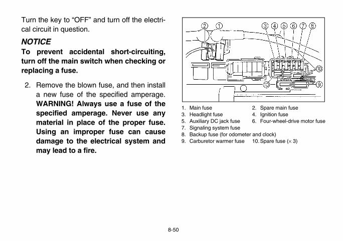
2. Spare main fuse4. Ignition fuse6. Four-wheel-drive motor fuse
eter and clock)se 10.Spare fuse (× 3)
EE.book Page 50 Friday, August 3, 2007 4:52 PM
8-50
Turn the key to “OFF” and turn off the electri-cal circuit in question.
NOTICETo prevent accidental short-circuiting,turn off the main switch when checking orreplacing a fuse.
2. Remove the blown fuse, and then installa new fuse of the specified amperage.WARNING! Always use a fuse of thespecified amperage. Never use anymaterial in place of the proper fuse.Using an improper fuse can causedamage to the electrical system andmay lead to a fire.
1. Main fuse3. Headlight fuse5. Auxiliary DC jack fuse7. Signaling system fuse8. Backup fuse (for odom9. Carburetor warmer fu

EVU01670
ight bulburns out, replace it as fol-
p. (See pages 8-7–8-8 forand closing procedures.)cover at the rear of theulling it off.
headlight
EE.book Page 51 Friday, August 3, 2007 4:52 PM
8-51
3. Turn the key to “ON” and turn on theelectrical circuit in question to check if thedevice operates.
4. If the fuse blows again immediately, havea Yamaha dealer check the electricalsystem.
5. Reinstall the battery compartment cover.6. Close the hood.
Replacing a headlIf a headlight bulb blows.1. Lift the hood u
hood opening 2. Remove the
headlight by p
1. Cover at the rear of the
Specified fuses:Main fuse: 30.0 AHeadlight fuse: 15.0 AIgnition fuse: 10.0 AAuxiliary DC jack fuse: 10.0 ASignaling system fuse: 10.0 ACarburetor warmer fuse: 10.0 AFour-wheel-drive motor fuse: 3.0 ABackup fuse: 10.0 A

headlight bulb holder bynd turning it counterclock-
EE.book Page 52 Friday, August 3, 2007 4:52 PM
8-52
3. Remove the headlight bulb holder coverby pulling it off.
1. Headlight bulb holder cover
4. Remove the pushing it in awise.
1. Headlight bulb holder

ulb holder by pushing it inlockwise.ulb holder cover and the
rear of the headlight.e sure the headlight bulbs securely fitted over thend seated properly..
dlight beam if necessary.
EE.book Page 53 Friday, August 3, 2007 4:52 PM
8-53
5. Wait for the headlight bulb to cool beforetouching or removing it. Remove the bulbby pulling it out.
6. Insert a new headlight bulb into the bulbholder by pushing it in.
1. Do not touch the glass part of the bulb.
7. Reinstall the band turning it cReinstall the bcover at theNOTICE: Makholder cover ibulb holder a
8. Close the hood9. Adjust the hea

ulb replacementbulb burns out, replace it as
quick fastener screws andnel A (if replacing the left
t bulb) or panel B (if replac-il/brake light bulb).
EE.book Page 54 Friday, August 3, 2007 4:52 PM
8-54
EVU00990
Headlight beam adjustment
NOTICEIt is advisable to have a Yamaha dealermake this adjustment.
To raise the beam, turn the adjusting screw indirection a.To lower the beam, turn the adjusting screw indirection b.
1. Headlight beam adjusting screw
EVU01000
Tail/brake light bIf a tail/brake light follows:1. Remove the
bolts from patail/brake lighing the right ta
1. Panel A

ed up. (See page 4-16 foring and lowering proce-
anel.ulb holder (together with
rning it counterclockwise.
lder
ctive bulb in and turn itise to remove it from the
lb in and turn it clockwise bulb holder.
EE.book Page 55 Friday, August 3, 2007 4:52 PM
8-55
1. Panel B
1. Quick fastener screw (× 8) 2. Bolt (× 2)3. Panel A
2. Lift the cargo bcargo bed liftdures.)
3. Remove the p4. Remove the b
the bulb) by tu
1. Tail/brake light bulb ho
5. Push the defecounterclockwbulb holder.
6. Push a new buto install in the

vehicles receive an inspec-nt from the factory, trouble
operation. Any problem inion, or ignition systems cang and loss of power. Theart describes a quick, easying checks. If your vehicler, take it to a Yamaha deal-
cians at a Yamaha dealer-ls, experience, and know-rvice your vehicle. Use onlyarts on your vehicle. Imita-
ok like Yamaha parts, butferior. Consequently, theyvice life and can lead to ex-.
EE.book Page 56 Friday, August 3, 2007 4:52 PM
8-56
7. Reinstall the bulb holder (together withthe bulb) by turning it clockwise.
8. Install the panel.9. Lower the cargo bed.
10. Reinstall the quick fastener screws andbolts, and then tighten the bolts to thespecified torque.
EVU01010
TroubleshootingAlthough Yamahation before shipmemay occur duringthe fuel, compresscause poor startintroubleshooting chprocedure for makrequires any repaier.The skilled techniship have the toohow to properly segenuine Yamaha ption parts may lothey are often inhave a shorter serpensive repair bills
Tightening torque:Panel bolt:
6.5 Nm (0.65 m·kgf, 4.7 ft·lbf)

EE.book Page 57 Friday, August 3, 2007 4:52 PM
8-57
WARNINGWhen checking the fuel system, do notsmoke and make sure there are no openflames or sparks in the area, including pi-lot lights from water heaters or furnaces.Gasoline or gasoline vapors can ignite orexplode, causing severe injury or propertydamage.

Fuel pump isclogged.
park is good.Ignition system isnormal.
park is weak.
Adjust the spark plug gapor replace the spark plug.
o spark.
a Yamaha dealer topect.
Ask a Yamaha dealer toinspect.
EE.book Page 58 Friday, August 3, 2007 4:52 PM
8-58
EVU01020
Troubleshooting chartsStarting problems or poor engine performance
1. Fuel
Check if there is fuelin the fuel tank.
There is fuel. No fuel.
Restart the engine.No fuel. Supply fuel.
2. Compression
Use the electricstarter to see if there is compression.
There is compression. Compression normal.
No compression. Ask a Yamaha dealer toinspect.
3. Ignition
Remove the spark plug and check the electrodes.
Wet Wipe clean with dry cloth.
DryAttach spark plug cap andground to chassis.
Use theelectric starter.
S
S
N
Askins
4. Battery
Use the electric starter.
Engine turns overquickly. Battery is good.
Engine turns overslowly.
Check the connections,recharge.
Check the fuel flow.
Remove the fuel hosefrom the fuel pump.

ING! If the engine is notblow out under pressurewly to allow any remaining
temporarily, provided that
e.
e.Ask a Yamaha dealer to inspect and repair the cooling system.
Add coolant. (See the text below.)
. If the engine overheats again, ask a inspect and/or repair the cooling system.
EE.book Page 59 Friday, August 3, 2007 4:52 PM
8-59
Engine overheatingWait for the engine to cool before removing the radiator cap. WARNcool when removing the radiator cap, hot fluid and steam could and burn you. Place a thick rag over the cap and remove the cap slopressure to escape.
If it is difficult to get the recommended coolant, tap water can be usedit is changed to the recommended coolant as soon as possible.
Wait until the engine has cooled.
Check the coolant level in the coolant reservoir and/or radiator.
Level is OK.
Level is low, check the cooling system for leakage.
No leakag
Leakag
Restart the engineYamaha dealer to

1
2
3
4
5
6
7
8
9
10
11
12
13
14
t and degreaser off with a Use only enough pressureb. WARNING! Test ther washing. Apply theral times at slow speeds dry out the linings. Wethave reduced stoppingsing the chance of an ac-ICE: Excessive watery cause water seepage
ation of wheel bearings,mission seals and elec-
s. Many expensive repairresulted from impropere detergent applications,e available in coin-oper-
hers.
EE.book Page 1 Friday, August 3, 2007 4:52 PM
9-1
EVU01030
1-CLEANING AND STORAGE
A. CleaningFrequent, thorough cleaning of your vehiclewill not only enhance its appearance but willimprove its general performance and extendthe useful life of many components.1. Before cleaning the vehicle:
a. Block off the end of the exhaust pipeto prevent water entry. A plastic bagand strong rubber band may be used.
b. Make sure the spark plug and all fillercaps are properly installed.
2. If the engine case is excessively greasy,apply degreaser with a paint brush. Donot apply degreaser to the wheel axles.
3. Rinse the dirgarden hose.to do the jobrakes aftebrakes seveto let frictionbrakes may ability, increacident. NOTpressure maand deteriorbrakes, transtrical devicebills have high-pressursuch as thosated car was

EVU01041
(60 days or more) of your some preventive proce-ainst deterioration. Makeirs before storing the vehi-
aning the vehicle, prepares:k with fresh fuel and add
amount of Yamaha FuelConditioner or equivalentte the vehicle for at leastdistribute treated fuel
l system. from the carburetor floata clean container by loos- bolt; this will help preventrom building up. Pour theto the fuel tank.
t:r to each gallon of fuel (or
izer to each liter of fuel)
EE.book Page 2 Friday, August 3, 2007 4:52 PM
9-2
4. Once the majority of the dirt has beenhosed off, wash all surfaces with warmwater and mild, detergent-type soap. Anold toothbrush or bottle brush is handy forhard-to-get-at places.
5. Rinse the vehicle off immediately withclean water and dry all surfaces with aclean chamois towel or soft, absorbentcloth.
6. Clean the seats with a vinyl upholsterycleaner to keep the covers pliable andglossy.
7. Automotive-type wax may be applied toall painted and chrome-plated surfaces.Avoid combination cleaner-waxes. Manycontain abrasives which may scratch thepaint or protective finish. When finished,start the engine and let it idle for severalminutes.
B. StorageLong term storage vehicle will requiredures to guard agany necessary repacle.After thoroughly clefor storage as follow1. Fill the fuel tan
the specified Stabilizer and product. Opera5 minutes to through the fue
2. Drain the fuelchamber into ening the drainfuel deposits fdrained fuel in
Specified amoun1 oz of stabilize7.5 ml of stabil

attery and charge it. Storece and recharge it once at store the battery in an ex-m or cold place [less thanr more than 30 °C (90 °F)].
izer and conditioner elimi-drain the fuel system. Con-ler if the fuel system needs
EE.book Page 3 Friday, August 3, 2007 4:52 PM
9-3
3. Remove the spark plug, pour about onetablespoon of SAE 10W-40 or 20W-50motor oil in the spark plug hole and rein-stall the spark plug. Ground the sparkplug wire and turn the engine over sever-al times to coat the cylinder wall with oil.
4. Lubricate all control cables.5. Block up the frame to raise all wheels off
the ground.6. Tie a plastic bag over the exhaust pipe
outlet to prevent moisture from entering.7. If storing in a humid or salt-air atmo-
sphere, coat all exposed metal surfaceswith a light film of oil. Do not apply oil toany rubber parts or the seat covers.
8. Remove the bit in a dry plamonth. Do nocessively war0 °C (30 °F) o
Use of fuel stabilnates the need to sult a Yamaha deato be drained.

EVU01050
XR66FW
SOHC cylinder
× 3.31 in)
EE.book Page 1 Friday, August 3, 2007 4:52 PM
10-1
1-SPECIFICATIONS
Model Y
Dimensions:Overall length 2,885 mm (113.6 in)
Overall width 1,385 mm (54.5 in)Overall height 1,853 mm (73.0 in)Seat height 818 mm (32.2 in)
Wheelbase 1,910 mm (75.2 in)Ground clearance 280 mm (11.0 in)Minimum turning radius 3,900 mm (154 in)
Basic weight:With oil and full fuel tank 514.0 kg (1,133 lb)
Engine:
Engine type Liquid cooled 4-stroke,Cylinder arrangement Forward-inclined singleDisplacement 660.0 cm3
Bore × stroke 100.0 × 84.0 mm (3.94Compression ratio 9.10:1Starting system Electric starter
Lubrication system Wet sump

1
2
3
4
5
6
7
8
9
10
11
12
13
14
r higher, JASO standard MA
.01 US qt)
.11 US qt)
YXR66FW
0 70 90 110 130 ˚F
0 20 30 40 50 ˚C
0W-40) or SAE 10W-40
) or SAE 5W-30
LUBE 4 (20W-50) or SAE 20W-50
lutch slippage (since the en-s the clutch), do not mix anyth oil. Do not use oils with a “CD” or oils of a higher qual-addition, do not use oils la-
SERVING II” or higher.
EE.book Page 2 Friday, August 3, 2007 4:52 PM
10-2
Engine oil:Type:
Recommended engine oil classification API service SG type o
Quantity:Without oil filter cartridge replacement 1.90 L (1.67 Imp qt, 2With oil filter cartridge replacement 2.00 L (1.76 Imp qt, 2
Model
0 10 30 5
-20 -10 0 1
YAMALUBE 4 (1
YAMALUBE 4-CW (5W-30
YAMA
NOTICEIn order to prevent cgine oil also lubricatechemical additives widiesel specification ofity than specified. In beled “ENERGY CON

id gear oil6 US qt)
id gear oil4 US qt)
4 US qt)
.93 US gal)
35 in)atic
XR66FW
EE.book Page 3 Friday, August 3, 2007 4:52 PM
10-3
Final gear case oil:Type SAE 80 API GL-4 HypoQuantity 0.25 L (0.22 Imp qt, 0.2
Differential gear case oil:Type SAE 80 API GL-5 HypoQuantity 0.32 L (0.28 Imp qt, 0.3
Radiator capacity (including all routes): 2.50 L (2.20 Imp qt, 2.6Air filter:
Engine Wet element
Intake duct Dry elementFuel:
Type Unleaded gasoline only
Fuel tank capacity 30.0 L (6.60 lmp gal, 7Carburetor:
Type/quantity BSR42/1
Manufacturer MIKUNISpark plug:
Type/manufacturer DPR8EA-9/NGK
Spark plug gap 0.8–0.9 mm (0.031–0.0Clutch type: Wet, centrifugal autom
Model Y

9.544)
YXR66FW
EE.book Page 4 Friday, August 3, 2007 4:52 PM
10-4
Transmission:Primary reduction system V-beltSecondary reduction system Shaft drive
Secondary reduction ratio 41/21 × 24/18 × 33/9 (Transmission type V-belt automaticOperation Right hand operation
Reverse gear 25/17 (1.471)Sub transmission ratio low 35/17 (2.058)
high 28/19 (1.473)
Chassis:Frame type Steel tube frameCaster angle 5.0°
Trail 26.0 mm (1.02 in)Tire:
Type Tubeless
Size front 25 × 8-12NHSrear 25 × 10-12NHS
Model

XR66FW
EE.book Page 5 Friday, August 3, 2007 4:52 PM
10-5
Brakes:System Front and rear unifiedType front Dual disc brake
rear Single disc brakeOperation Foot operation
Suspension:
Front suspension Double wishboneRear suspension Double wishbone
Shock absorber:
Front shock absorber Coil spring/oil damperRear shock absorber Coil spring/oil damper
Wheel travel:
Front wheel travel 185 mm (7.3 in)Rear wheel travel 185 mm (7.3 in)
Electrical:
Ignition system DC CDIGenerator system AC magnetoBattery type U1L-11
Battery capacity 12 V 28.0 AhHeadlight type: Krypton bulb
Model Y

22
YXR66FW
EE.book Page 6 Friday, August 3, 2007 4:52 PM
10-6
Bulb voltage, wattage × quantity:Headlight 12 V 30.0 W/30.0 W ×Tail/brake light 12 V 5.0 W/21.0 W ×
Indicator lights:Neutral indicator light LEDReverse indicator light LED
Coolant temperature warning light LEDParking brake indicator light LEDOn-Command four-wheel-drive/differential gear lock indicator LCDOn-Command differential gear lock indicator light LED
High-range indicator light LEDLow-range indicator light LED
Specified fuses:
Main fuse 30.0 AHeadlight fuse 15.0 AIgnition fuse 10.0 A
Auxiliary DC jack fuse 10.0 AFour-wheel-drive motor fuse 3.0 ACarburetor warmer fuse 10.0 A
Signaling system fuse 10.0 ABackup fuse 10.0 A
Model

CATION NUMBER:
NTIFICATION NUMBER:
L INFORMATION:
EE.book Page 1 Friday, August 3, 2007 4:52 PM
11-1
1-CONSUMER INFORMATIONEVU00090
Identification number recordsRecord the key identification number, vehicleidentification number, and model label infor-mation in the spaces provided for assistancewhen ordering spare parts from a Yamahadealer or for reference, in case the vehicle isstolen.
1. KEY IDENTIFIACA-02E
2. VEHICLE IDEACA-02E
3. MODEL LABEACA-01E

1
2
3
4
5
6
7
8
9
10
11
12
13
14
tion numberfication number is stamped
number
fication number is used tole.
EE.book Page 2 Friday, August 3, 2007 4:52 PM
11-2
EVU00100
Key identification numberThe key identification number is stamped onthe key, as shown in the following illustration.This number can be used for ordering a newkey.
1. Key identification number
EVU00110
Vehicle identificaThe vehicle identiinto the frame.
1. Vehicle identification
The vehicle identiidentify your vehic

EVU00121
EE.book Page 3 Friday, August 3, 2007 4:52 PM
11-3
Model labelThe model label is affixed to the frame underthe driver seat. Record the information on thislabel in the space provided. This informationwill be needed to order spare parts from yourYamaha dealer.
1. Model label

removal or rendering inop-, or replacement of any de-rpose of noise control prior) the use of the vehicle afterperative by any person.
G ARE THE ACTS LISTED
ation, removal, etc.
EE.book Page 4 Friday, August 3, 2007 4:52 PM
11-4
EVU01060
NOISE REGULATIONTAMPERING WITH NOISE CONTROL SYSTEM PROHIBITED:Federal law prohibits the following acts or the causing thereof: (1) Theerative by any person other than for purposes of maintenance, repairvice or element of design incorporated into any new vehicle for the puto its sale or delivery to the ultimate purchaser or while it is in use or (2such device or element of design has been removed or rendered ino
“AMONG THOSE ACTS PRESUMED TO CONSTITUTE TAMPERINBELOW.”These acts include tampering with the following systems; i.e., modific
Exhaust systemMufflerExhaust pipeSilencer
Intake systemAir cleaner caseAir cleaner elementIntake duct

EVU01070
ll will be required to docu-low is printed only as a re-
able proof of maintenance
REMARKS
EE.book Page 5 Friday, August 3, 2007 4:52 PM
11-5
MAINTENANCE RECORDCopies of work orders and/or receipts for parts you purchase and instament maintenance done in accordance with the warranty. The chart beminder to you that the maintenance work is required. It is not acceptwork.
MAINTENANCE INTERVAL DATE OF
SERVICEMILEAGE
SERVICING DEALER NAME AND ADDRESS
month km (mi) hours
1 320 (200) 20
3 1,200 (750) 75
6 2,400 (1,500) 150
12 4,800 (3,000) 300
18 7,200 (4,500) 450
24 9,600 (6,000) 600
30 12,000 (7,500) 750
36 14,400 (9,000) 900
42 16,800 (10,500) 1,050
48 19,200 (12,000) 1,200
54 21,600 (13,500) 1,350
60 24,000 (15,000) 1,500

LIMITED WARRANTYHA MOTOR CORPORATION, U.S.A. MAKES HER WARRANTY OF ANY KIND, EXPRESSED PLIED. ALL IMPLIED WARRANTIES OF
HANTABILITY AND FITNESS FOR A CULAR PURPOSE WHICH EXCEED THE ATIONS AND TIME LIMITS STATED IN THIS ANTY ARE HEREBY DISCLAIMED BY HA MOTOR CORPORATION, U.S.A. AND DED FROM THIS WARRANTY.
STATES DO NOT ALLOW LIMITATIONS ON LONG AN IMPLIED WARRANTY LASTS, SO BOVE LIMITATION MAY NOT APPLY TO YOU. EXCLUDED FROM THIS WARRANTY ARE CIDENTAL OR CONSEQUENTIAL DAMAGES DING LOSS OF USE. SOME STATES DO LLOW THE EXCLUSION OR LIMITATION OF
ENTAL OR CONSEQUENTIAL DAMAGES, SO BOVE EXCLUSION MAY NOT APPLY TO YOU. WARRANTY GIVES YOU SPECIFIC LEGAL S, AND YOU MAY ALSO HAVE OTHER S WHICH VARY FROM STATE TO STATE.
EE.book Page 6 Friday, August 3, 2007 4:52 PM
11-6
EVU01081
YAMAHA MOTOR CORPORATION, U.S.A. SIDE × SIDE VEHICLEYamaha Motor Corporation, U.S.A. hereby warrants that new Yamaha Side × Side vehicles purchased from an authorized Yamaha Side × Side Vehicle dealer in the continental United States will be free from defects in material and workmanship for the period of time stated herein, subject to certain stated limitations.
GENERAL EXCLUSIONS from this warranty shall include any failures caused by: a.b.
c.d.e.f.g.
Competition or racing use.Installation of parts or accessories that are not qualitatively equivalent to genuine Yamaha parts.Abnormal strain, neglect, or abuse.Lack of proper maintenance.Accident or collision damage.Modification to original parts.Damage due to improper transportation.
YAMANO OTOR IMMERCPARTIOBLIGWARRYAMAEXCLU
SOMEHOW THE AALSOANY ININCLUNOT AINCIDTHE ATHIS RIGHTRIGHT
THE PERIOD OF WARRANTY for YXR OR YXP Yamaha Side × Side vehicles shall be six (6) months from the date of purchase, with no mileage limitation.
MODELS EXCLUDED FROM WARRANTY include those used for non-Yamaha-authorized renting, leasing, or other commercial purposes.
DURING THE PERIOD OF WARRANTY any authorized Yamaha Side × Side Vehicle dealer will for free of charge, repair or replace, at Yamaha’s option, any part adjudged defective by Yamaha due to faulty workmanship or material from the factory. Parts used in warranty repairs will be warranted for the balance of the product’s warranty period. All parts replaced under warranty become property of Yamaha Motor Corporation, U.S.A.
SPECIFIC EXCLUSIONS from this warranty shall include parts replaced due to normal wear or routine maintenance; such as spark plugs, oil, oil filter, air filter, and brake pads.
Operate and maintain the Side × Side vehicle as specified in the appropriate Owner’s Manual, andGive notice to an authorized Yamaha Side × Side Vehicle dealer of any and all apparent defects within ten (10) days after discovery, and make the machine available at that time for inspection and repairs at such dealer’s place of business.
THE CUSTOMER’S RESPONSIBILITY under this warranty shall be to:
WARRANTY TRANSFER: To transfer the warranty from the original purchaser to any subsequent purchaser(s), it is imperative that the Side × Side vehicle be inspected and registered for warranty by an authorized Yamaha Side × Side Vehicle dealer. In order for this warranty to remain in effect, this inspection and registration must take place within ten (10) days after transfer of ownership to the subsequent purchaser. A reasonable dealer-imposed fee may be charged for this inspection.
EMISSION CONTROL SYSTEM WARRANTYYamaha Motor Corporation, U.S.A. also warrants to the ultimate purchaser and each subsequent purchaser of each 2006 and later model Yamaha Side × Side vehicle covered by this warranty that the vehicle is designed, built, and equipped so as to conform at the time of sale with all U.S. emissions standards applicable at the time of manufacture and that it is free from defects in materials and workmanship which would cause it not to meet these standards within the period listed immediately below. Failures other than those resulting from defects in material or workmanship which arise solely as a result of owner abuse and/or lack of proper maintenance are not covered by thiswarranty.
ALL MODELSThirty (30) months from the original purchase date
1.
2.

EVU01090
EE.book Page 7 Friday, August 3, 2007 4:52 PM
11-7
YAMAHA EXTENDED SERVICE (Y.E.S.)

EE.book Page 8 Friday, August 3, 2007 4:52 PM
11-8

B6-yoko.fm Page 1 Wednesday, March 8, 2006 10:46 AM

B6-yoko.fm Page 1 Wednesday, March 8, 2006 10:46 AM

PRINTED IN USA2007.08-1.3×1 CR
(E)
DIC2342
YAMAHA MOTOR CO., LTD.