Embed Size (px)
Citation preview

1340-2349-1951-12/03
EBI Logger System
User ’s M anua l
f o r t h e W I N L O G 2 0 0 0 S o f t w a r e
Programming and readout software
for EBI data loggers of the series
EBI-2
EBI-3
EBI-85 X
EBI-125 X
Release 1.21
ebro Electronic GmbH & Co. KG Peringerstrasse 10 D-85055 Ingolstadt GERMANY • Tel.: +49 841-95478-0 • Fax: +49 841-95478-80 • E-Mail [email protected] • Hotline: +49 841-95478-0
© Copyright 1999-2002 by ebro Electronic GmbH & Co. KG

WINLOG 2000
Notes for this manual
Page 2 1340-2349-1851-12/03
WINLOG 2000
Notes for this manual
1340-2349-1851-12/03 Page 3
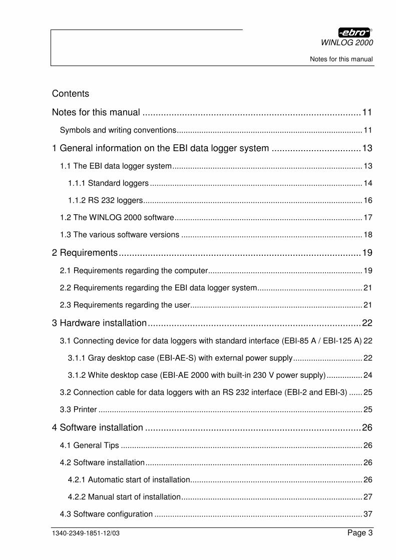
Contents
Notes for this manual ...................................................................................11
Symbols and writing conventions................................................................................... 11
1 General information on the EBI data logger system ..................................13
1.1 The EBI data logger system..................................................................................... 13
1.1.1 Standard loggers ............................................................................................... 14
1.1.2 RS 232 loggers.................................................................................................. 16
1.2 The WINLOG 2000 software.................................................................................... 17
1.3 The various software versions ................................................................................. 18
2 Requirements............................................................................................19
2.1 Requirements regarding the computer..................................................................... 19
2.2 Requirements regarding the EBI data logger system............................................... 21
2.3 Requirements regarding the user............................................................................. 21
3 Hardware installation.................................................................................22
3.1 Connecting device for data loggers with standard interface (EBI-85 A / EBI-125 A) 22
3.1.1 Gray desktop case (EBI-AE-S) with external power supply............................... 22
3.1.2 White desktop case (EBI-AE 2000 with built-in 230 V power supply)................ 24
3.2 Connection cable for data loggers with an RS 232 interface (EBI-2 and EBI-3) ...... 25
3.3 Printer ...................................................................................................................... 25
4 Software installation ..................................................................................26
4.1 General Tips ............................................................................................................ 26
4.2 Software installation................................................................................................. 26
4.2.1 Automatic start of installation............................................................................. 26
4.2.2 Manual start of installation................................................................................. 27
4.3 Software configuration ............................................................................................. 37
WINLOG 2000
Notes for this manual
Page 4 1340-2349-1851-12/03
4.3.1 Language selection........................................................................................... 37
4.3.2 Selection of the serial interface ......................................................................... 38
4.3.3 Entering your company data ............................................................................. 40
4.3.4 Converting old EBI files into new format ........................................................... 41
4.4 Software registration................................................................................................ 43
5 Working with WINLOG 2000 – S (Standard) ............................................. 46
5.1 Starting the software................................................................................................ 46
5.2 Help ......................................................................................................................... 47
5.2.1 Tips and Tricks.................................................................................................. 47
5.2.2 Online help........................................................................................................ 48
5.3 The menu ................................................................................................................ 50
5.3.1 Menu File .......................................................................................................... 51
5.3.2 Menu View ........................................................................................................ 55
5.3.3 Menu Edit.......................................................................................................... 55
5.3.4 Menu ? .............................................................................................................. 62
5.3.5 Buttons.............................................................................................................. 63
5.3.6 Settings ............................................................................................................. 64
5.3.7 Printer setup...................................................................................................... 65
5.3.8 Logger on COM1............................................................................................... 68
5.4 Tool bar ................................................................................................................... 77
6 Logger programming................................................................................. 80
6.1 Requirements .......................................................................................................... 80
6.1.1 Connection of series EBI 85A or EBI 125 A loggers ......................................... 80
6.1.2 Connection of series EBI 2 and EBI 3 loggers .................................................. 80
6.2 Programming dialog ................................................................................................ 81
WINLOG 2000
Notes for this manual
1340-2349-1851-12/03 Page 5
6.2.1 System data ...................................................................................................... 84
6.2.2 Limit values ....................................................................................................... 90
6.2.3 Interval and measuring mode............................................................................ 93
6.3 Starting the logger.................................................................................................. 100
7 Logger read-out.......................................................................................103
7.1 Premises................................................................................................................ 103
7.2 Logger read out...................................................................................................... 104
7.2.1 Starting the read out........................................................................................ 104
7.2.2 Readout of system, user and measured data.................................................. 105
7.3 Saving the data ...................................................................................................... 105
7.3.1 Folder .............................................................................................................. 106
7.3.2 File name......................................................................................................... 107
7.4 Printing measured data.......................................................................................... 108
7.5 Exporting measured values.................................................................................... 110
8 Processing of measured values...............................................................111
8.1 The time/measured values diagram....................................................................... 111
8.2 Changing the diagram via tool bars ....................................................................... 112
8.2.1 Selecting curves .............................................................................................. 113
8.2.2 Horizontal toolbar (Diagram functions) ............................................................ 116
8.2.3 Vertical toolbar (Diagram properties)............................................................... 119
8.3 Context menu......................................................................................................... 125
8.3.1 Active .............................................................................................................. 126
8.3.2 Manual scaling of axes… ................................................................................ 126
8.3.3 Go to position ….............................................................................................. 127
8.3.4 Select range manually..................................................................................... 128
WINLOG 2000
Notes for this manual
Page 6 1340-2349-1851-12/03
8.3.5 Copying marked range to the clipboard .......................................................... 128
8.3.6 Curve color...................................................................................................... 128
8.3.7 Line width........................................................................................................ 129
8.3.8 Inserting a legend ........................................................................................... 129
8.3.9 Displaying limit values..................................................................................... 129
8.3.10 Displaying the marker ................................................................................... 130
8.3.11 Histogram...................................................................................................... 130
8.3.12 Limit value histogram .................................................................................... 132
8.3.13 Automatic splitting ......................................................................................... 134
8.3.14 Save as… ..................................................................................................... 135
8.4 Work space............................................................................................................ 136
8.4.1 Save the work space as .................................................................................. 136
8.4.2 Open the work space ...................................................................................... 137
9 Working with WINLOG 2000 - P (Professional) ....................................... 138
9.1 Purchasing the Professional version ..................................................................... 138
9.2 Upgrading to the Professional version................................................................... 138
9.3 Additional functions compared to the Standard version......................................... 139
9.3.1 Password request ........................................................................................... 139
9.3.2 Input screen .................................................................................................... 140
9.3.3 User administration ......................................................................................... 148
9.3.4 User-defined functions .................................................................................... 153
9.3.5 Archiving measured data ................................................................................ 167
9.3.6 Measurement units administration .................................................................. 173
9.3.7 Real-time monitoring ....................................................................................... 177
10 Working with WINLOG 2000 – B (BUS) ................................................ 179
WINLOG 2000
Notes for this manual
1340-2349-1851-12/03 Page 7
10.1 Purchase of the WINLOG 2000 - B version ......................................................... 179
10.2 Purchase and installation of the BUS program module........................................ 179
10.3 Installation of the hardware.................................................................................. 180
10.3.1 EBI-AE-BUS Connecting device for up to 30 data loggers (Gray desktop case with external power supply EBI-PS 40) .................................................................... 180
10.3.2 EBI-AE-BUS-63 Connecting device for up to 63 data loggers (Black wall-mount case with external power supply) ............................................................................. 182
10.3.3 Logger types.................................................................................................. 183
10.3.4 BUS installation ............................................................................................. 183
10.3.5 Printer............................................................................................................ 184
10.4 Additional functions compared to the Standard version ....................................... 184
10.4.1 Password request.......................................................................................... 184
10.4.2 Input screen................................................................................................... 186
10.4.3 Scheduler ...................................................................................................... 187
10.4.4 Settings ......................................................................................................... 188
10.5 Setting up a BUS system ..................................................................................... 189
10.5.1 General.......................................................................................................... 189
10.5.2 Assigning a node address to a logger ........................................................... 190
10.5.3 Inserting a new logger ................................................................................... 193
10.6 Working in a BUS system .................................................................................... 194
10.6.1 Determining the BUS configuration ............................................................... 194
10.6.2 Representing the BUS system on the screen................................................ 196
10.6.3 Logger detection............................................................................................ 198
10.6.4 Fetching actual measured data ..................................................................... 198
10.6.5 Status symbols and their signification ........................................................... 199
10.6.6 Readout and programming of loggers in the BUS......................................... 199
WINLOG 2000
Notes for this manual
Page 8 1340-2349-1851-12/03
10.6.7 Setting up a group of loggers ........................................................................ 201
10.7 Monitoring the BUS with the Scheduler ............................................................... 202
10.7.1 General ......................................................................................................... 202
10.7.2 Functions of the Scheduler ........................................................................... 203
10.7.3 Alarm control................................................................................................. 208
10.7.4 Editing tasks.................................................................................................. 213
10.7.5 Activating/deactivating tasks ......................................................................... 215
10.7.6 Task properties ............................................................................................. 216
10.7.7 Executing a task............................................................................................ 217
10.7.8 Protocol file of the task.................................................................................. 218
11 Working with WINLOG 2000 - V (21 CFR Part 11)................................ 223
11.1 Introduction.......................................................................................................... 223
11.2 The meaning of the 21 CFR Part 11 guidelines................................................... 223
11.3 Implementation of the 21 CFR Part 11 guidelines ............................................... 225
11.3.1 User administration ....................................................................................... 225
11.3.2 Logon and password strategies .................................................................... 225
11.3.3 Audit trails ..................................................................................................... 226
11.3.4 Electronic signatures..................................................................................... 227
11.3.5 Requirements towards the user of WINLOG 2000 – V.................................. 228
11.4 General issues on the validation of systems........................................................ 230
11.5 Summary ............................................................................................................. 231
11.6 Installing the software .......................................................................................... 231
11.6.1 Hardware requirements................................................................................. 231
11.6.2 Software setup .............................................................................................. 231
11.7 Using WINLOG 2000 - V ..................................................................................... 232
WINLOG 2000
Notes for this manual
1340-2349-1851-12/03 Page 9
11.7.1 Logging in...................................................................................................... 232
11.7.2 Settings ......................................................................................................... 233
11.7.3 User and password management.................................................................. 238
11.7.4 Programming and reading loggers ................................................................ 245
12 Appendix ...............................................................................................251
12.1 Error messages.................................................................................................... 251
12.1.1 Error messages during the installation .......................................................... 252
12.1.2 Error messages during the configuration....................................................... 252
12.1.3 Error in the logger system ............................................................................. 253
12.1.4 Logger error................................................................................................... 255
12.2 Update of WINLOG 2000..................................................................................... 263
12.2.1 Connection with the Internet.......................................................................... 263
12.2.2 Selection of the Software section .................................................................. 265
12.2.3 News ............................................................................................................. 266
12.2.4 Downloads..................................................................................................... 269
12.2.5 Help............................................................................................................... 273
12.3 ebro hotline .......................................................................................................... 275
13 License agreement................................................................................276
14 Contents of figures ................................................................................281
15 Technical data of loggers ......................................................................293
15.1 Standard loggers.................................................................................................. 293
15.2 RS 232 loggers ................................................................................................... 296
15.3 BUS loggers......................................................................................................... 297
16 Index .....................................................................................................298
WINLOG 2000
Notes for this manual
Page 10 1340-2349-1851-12/03
Preface
Congratulations on the purchase of the EBI data logger system.
First, we would like to inform you that the WINLOG 2000 software is available in different versions, all based on the Standard version (WINLOG 2000 - S). For more information please go to chapter 1.3.
In this manual’s structure the functions of the Standard software version are explained first. Since all of these functions are also available in the higher versions of WINLOG 2000, you can always refer to the previous chapters.
The additional functions of the Professional version (WINLOG 2000 - P) are described in chapter 9. Chapter 10 deals with the BUS version (WINLOG 2000 - B), and Chapter 11 explains the 21 CFR Part 11 version (WINLOG 2000 - V).
Please read this manual carefully. Here you’ll find answers to most questions which may arise during your work with WINLOG 2000. Also keep in mind that there is an online help function available within the software, which you can call up at any time by pressing the F1 key.
The main advantages of the WINLOG 2000 software are:
• One software for all EBI-xx-A, EBI-2, and EBI-3 logger models
• Updates and patches available through the internet
• Up to 32 curves can be displayed simultaneously
• Intuitive and self-explanatory operation
• Different versions for different applications
WINLOG 2000
Notes for this manual
1340-2349-1851-12/03 Page 11
Notes for this manual
Symbols and writing conventions
For a better orientation the notes, tips, etc. are marked as follows:
Helpful notes, information and examples are marked with this symbol. The paragraphs marked this way are useful for the easier understanding and the correct handling of the EBI logger system.
Important functions and recommendations are marked with this symbol.
The paragraphs marked this way must absolutely be considered and observed, in order to ensure the proper functioning of the logger system.
Disregarding these paragraphs can cause data loss!!!
Bold print Important notes or statements are printed in bold letters, in order to point out their importance.
Bold italic print All names of software commands, buttons, dialogs, option and text boxes are printed in bold italics.
WINLOG 2000
Notes for this manual
Page 12 1340-2349-1851-12/03
Keyboard Keys of the keyboard are represented as framed capitals. When you are asked to press a key, this will be repre-sented in this way: CRTL (for example).
If several keys must be pressed simultaneously, this will be represented by a plus-sign between the keys, like for instance: CRTL + K. Consequently, this means that while
keeping the CRTL key pressed, the K key must also be pressed.
Mouse-keys: Following strings are used to visualize mouse actions: <LMC> for a left mouse click; <RMC> for a right mouse click; <DMC> for a double click with the left mouse key.
ebro If this logo appears in the manual, it refers to the company ebro Electronic GmbH & Co. KG. The address and tele-phone number are indicated on the front page of this manual.
[email protected] Internet or E-mail addresses are indicated by underlined text.
• text
• text
• text
A paragraph containing these enumeration marks is an instruction which must be executed in this order.
WINLOG 2000
General information on the EBI data logger system
1340-2349-1851-12/03 Page 13
1 General information on the EBI data logger system
1.1 The EBI data logger system
The EBI data logger system consists of at least one data logger, a connect-ing device (interface) or a connector cable, and the software WINLOG 2000.
WINLOG 2000 works with all loggers of the model families EBI- 85A, EBI-125A, EBI-2 and EBI-3. It automatically detects the type of the connected logger, and adapts to its specifications. For instance, the axes in the diagrams will automatically bear the correct units.
Please be aware that WINLOG 2000 will not work with data loggers of the discontinued series EBI 85 and EBI 125 (without the appendix “A”). For these loggers, you will need to use one of the previous EBRO software packages like WINLOG 1.5 E, WINFWERT 1.5 E, WINDRUCK 1.5 E, WINTRUCK 1.5 E, WINBUS 1.5 E or WINFEUCHTE 1.5 E.
Mainly, the EBI loggers are divided in two basic types, which differ in the method of data exchange.
The so-called standard loggers always need an interface to communicate with the computer.
The so-called RS-232 loggers can connect directly to the computer through a data cable.
WINLOG 2000
General information on the EBI data logger system
Page 14 1340-2349-1851-12/03
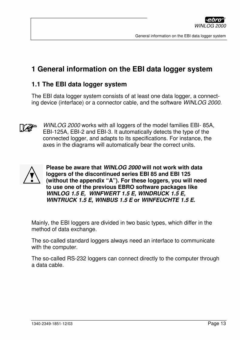
1.1.1 Standard loggers
This name describes the round stainless steel loggers of the EBI-85 A and
EBI-125 A series. These loggers require an interface for programming and
reading (see Chapter 3.1).
Fig. 1 Standard logger EBI-85 A
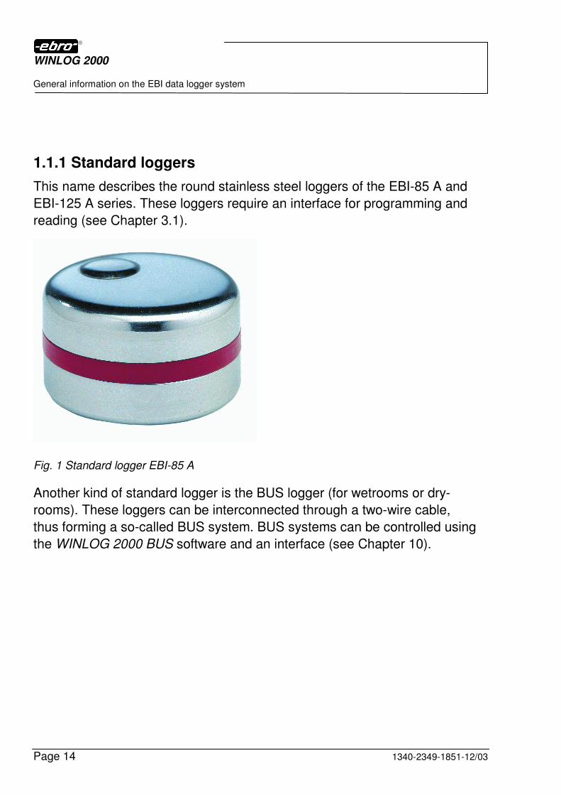
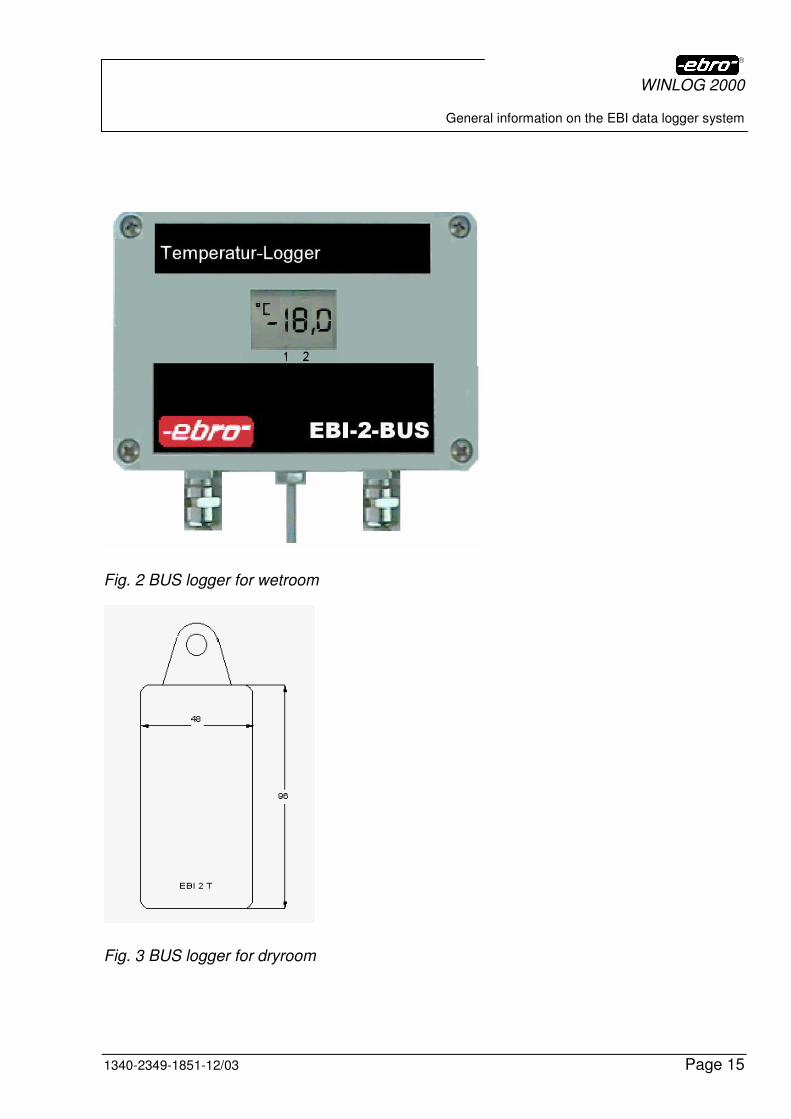
Another kind of standard logger is the BUS logger (for wetrooms or dry-
rooms). These loggers can be interconnected through a two-wire cable,
thus forming a so-called BUS system. BUS systems can be controlled using
the WINLOG 2000 BUS software and an interface (see Chapter 10).
WINLOG 2000
General information on the EBI data logger system
1340-2349-1851-12/03 Page 15
Fig. 2 BUS logger for wetroom
Fig. 3 BUS logger for dryroom
WINLOG 2000
General information on the EBI data logger system
Page 16 1340-2349-1851-12/03
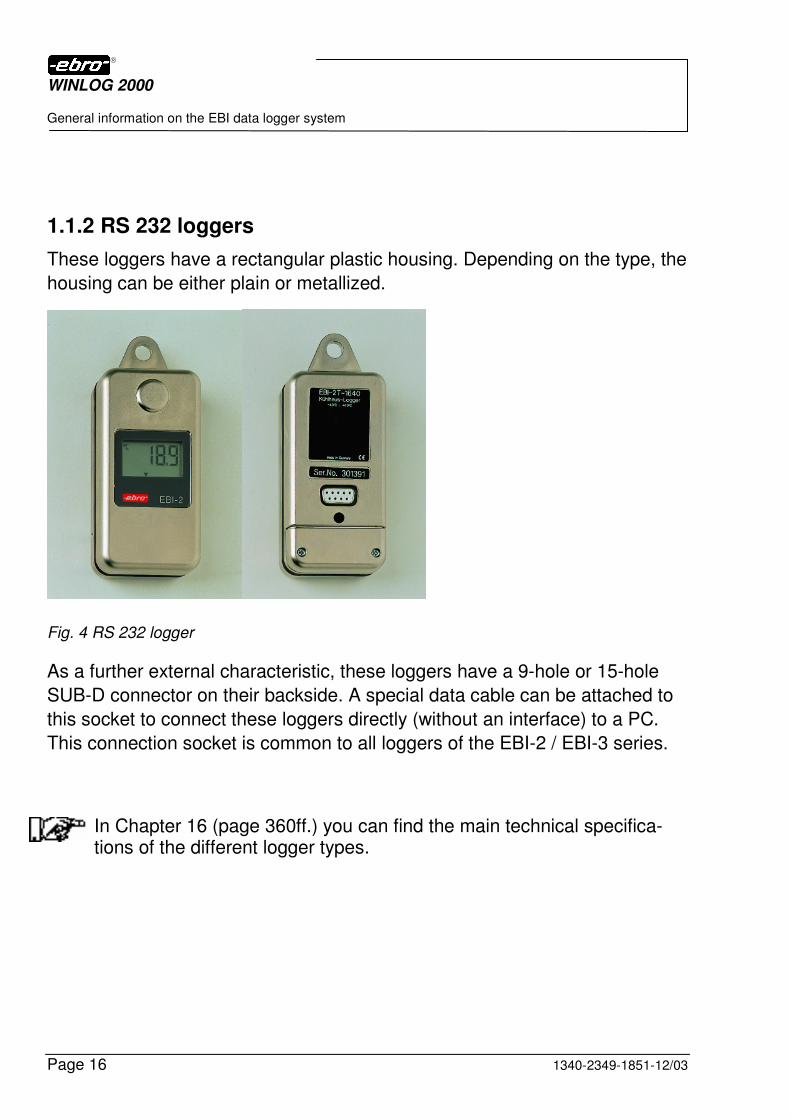
1.1.2 RS 232 loggers
These loggers have a rectangular plastic housing. Depending on the type, the
housing can be either plain or metallized.
Fig. 4 RS 232 logger
As a further external characteristic, these loggers have a 9-hole or 15-hole
SUB-D connector on their backside. A special data cable can be attached to
this socket to connect these loggers directly (without an interface) to a PC.
This connection socket is common to all loggers of the EBI-2 / EBI-3 series.
In Chapter 16 (page 360ff.) you can find the main technical specifica-tions of the different logger types.

WINLOG 2000
General information on the EBI data logger system
1340-2349-1851-12/03 Page 17
Data logger functional structure
The data logger is built up as follows, independently of the type:
A microprocessor with the necessary peripheral equipment is supplied with energy from a built-in lithium battery. Due to this, the logger is completely autonomous from the environment. An internal processor firmware controls the microprocessor and takes the necessary actions. The values measured by the logger’s internal or external sensors are recorded and stored in an EEPROM memory.
Up to 2 x 15 user-defined text lines can be stored in each EBI logger. Also, you can set two limit values per channel for control purposes.
The measurement data stored in the logger memory can be transferred to a PC by connection cable or interface. There they can be saved to a harddisk or a floppy/CD-R.
1.2 The WINLOG 2000 software
This software was developped by ebro in order to make the readout and programming of the EBI data loggers as easy as possible for you.
You only need one software for all purposes.
All specified ebro data loggers can be administrated with this software, no matter which purpose they are meant for (temperature, truck, cold storage house, pressure, humidity, accompanying goods, high temperature, voltage or amperage input).
In other words: you can program and read all models of the families:
� EBI-85 A � EBI-125 A � EBI-2 � EBI-3
WINLOG 2000
General information on the EBI data logger system
Page 18 1340-2349-1851-12/03
1.3 The various software versions
WINLOG 2000 is available in 4 versions with different levels of functionality:
• WINLOG 2000-S (Standard version) - for everyday use - for everyday duties such as graphic and numeric representations of the measured values of temperature/pressure/humidity etc. - self-explanatory, can be operated immediately, with online help
• WINLOG 2000-P (Professional version) - for professional use - calculation of various parameters based on the existing measured values (F-value, PE-value etc.) - formula editor - document management with Windows Explorer look-and-feel
• WINLOG 2000-B (BUS version) - for your networked BUS loggers - automatic administration of all measuring points - automatic storage of the data on a computer - automatic alarm when limits are exceeded
• WINLOG 2000-V (21 CFR Part 11 version) - for the pharmaceutical industry - electronic signature - Audit Trail - enhanced user management
With WINLOG 2000, you buy only the software you need. Since all versions are already contained on your setup CD-ROM, you can easily upgrade to a higher version when you require it. All you need is a new registration key you can obtain from ebro.
Our products are under continuous development. Therefore, the latest hardware or software implementations may not be documented in this manual as yet.
Last minute changes diferring from the descriptions in this manual are documented in the README.TXT file on the setup CD-ROM. Please check your CD-ROM for this file and consult it before use.

WINLOG 2000
Requirements
1340-2349-1851-12/03 Page 19
2 Requirements
2.1 Requirements regarding the computer
Minimal requirements
• Pentium 350 MHz CPU
• 64 MB RAM
• VGA graphic card
• Monitor
• Serial interface (RS 232 C)
• Mouse
• CD-ROM drive
- One of the following operating systems must be installed on the com-puter: Windows® 9.x, ME, NT® 4.0, 2000 oder XP
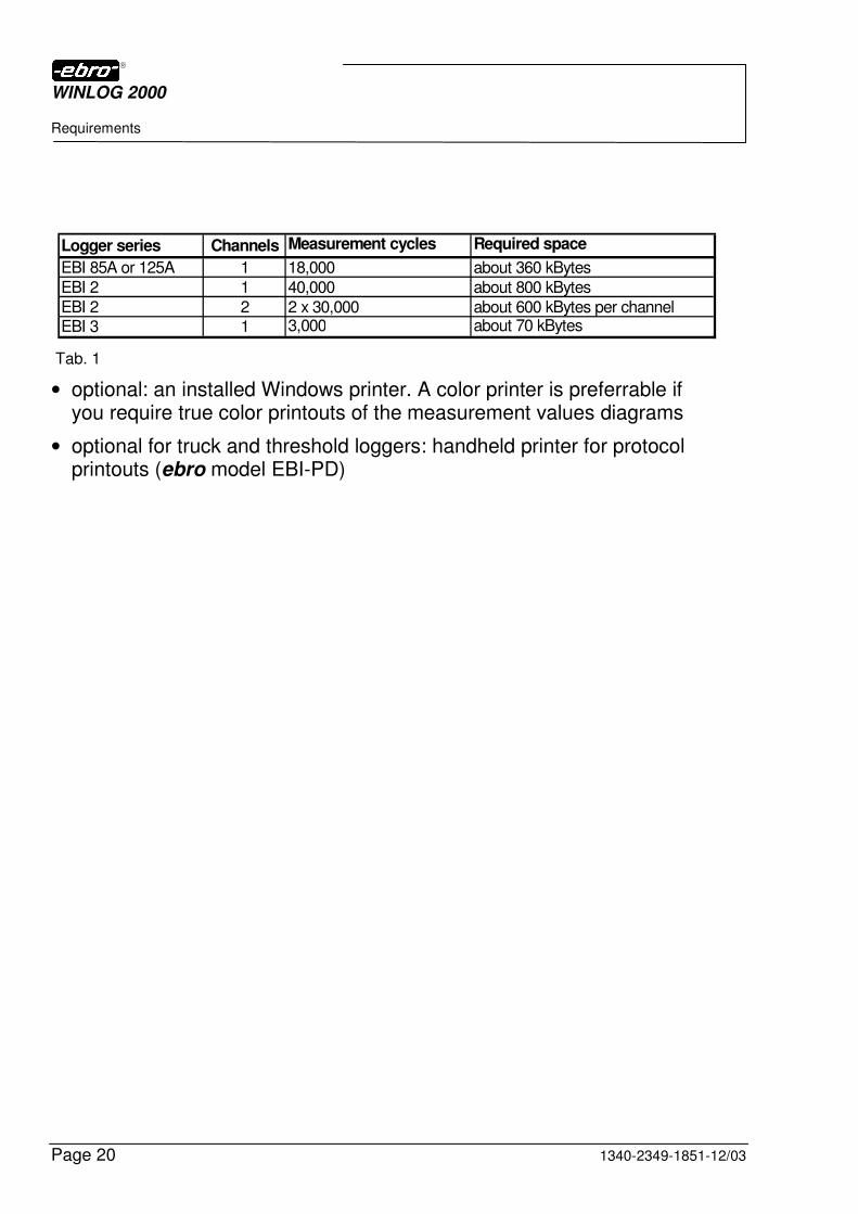
• Hard disk with 100 Mbytes minimum free capacity. The software requires about 30 MB. Depending on your purposes, you may need to save a high amount of logger data on your disk. The following table (Tab. 1) shows the hard disk space required for one saved document. Please keep in mind that most probably you will need to save more than just one file.
WINLOG 2000
Requirements
Page 20 1340-2349-1851-12/03
Tab. 1
• optional: an installed Windows printer. A color printer is preferrable if you require true color printouts of the measurement values diagrams
• optional for truck and threshold loggers: handheld printer for protocol printouts (ebro model EBI-PD)
Logger series Channels Measurement cycles Required space
EBI 85A or 125A 1 18,000 about 360 kBytes
EBI 2 1 40,000 about 800 kBytes
EBI 2 2 2 x 30,000 about 600 kBytes per channelEBI 3 1 3,000 about 70 kBytes

WINLOG 2000
Requirements
1340-2349-1851-12/03 Page 21
2.2 Requirements regarding the EBI data logger system
Minimum requirements:
� Data logger � Interface with corresponding power supply � Data cable
2.3 Requirements regarding the user
The user(s) of this software should have at least a basic knowledge of the Microsoft Windows operating system installed on the computer. The basic knowledge should cover:
• Starting and shutting off the computer
• Knowledge of the basic functions of the operating system
• Overview of the different storage drives
• Checking and editing the computer time and date (internal real-time clock)
• Using the Windows Explorer file manager
• Installation of user software
• Starting programs
• Creation of folders (directories)
• Saving files
• Opening and closing files
WINLOG 2000
Hardware installation
Page 22 1340-2349-1851-12/03
3 Hardware installation
The installation of the BUS interface is described in chapter 10.3.
3.1 Connecting device for data loggers with standard interface (EBI-85 A / EBI-125 A)
In the course of time, different types of interfaces have been developed. Currently, there are two variants. Identify your interface and install it as described hereafter (chapters 3.1.1 to 3.2).
The serial ports of the computer are either directly labeled (COM 1, 2 ..) or can be identified using the manual of the PC. It is recommended you use COM1 or COM2 to connect the interface cable. You will need the EBI-Int-K9 cable for a 9-pin port or, the EBI-Int-K25 cable for a 25-pin port.
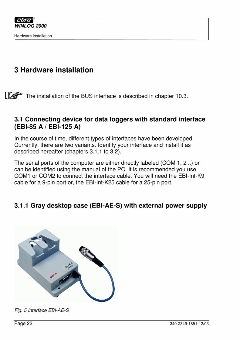
3.1.1 Gray desktop case (EBI-AE-S) with external power supply
Fig. 5 Interface EBI-AE-S

WINLOG 2000
Hardware installation
1340-2349-1851-12/03 Page 23
• Connect the type EBI-AE-S interface with a free serial port (COM1, COM2, etc.) of the computer using the cables EBI-Int-K9 (for a 9-pin connector) or EBI-Int-K25 (for a 25-pin connector) and secure the connection with the two connector screws using a small screwdriver.
• The 9-pin end of the data cable must always be connected to the interface. In order to prevent an inadvertent disconnection, please also tighten the two screws of the 9-pin socket of the data cable with a screwdriver.
• Please connect the included desktop power supply with the interface using the power adaptor cable. Carefully insert the 5-pole connector of this cable into the corresponding socket of the interface and lock it by fastening the coupling ring of this connector.
• Make sure that your mains voltage corresponds to the inscription on the type plate of the power supply (e.g. 230 V). Now plug the mains cable of the power supply into an earthed 230 V socket.
WINLOG 2000
Hardware installation
Page 24 1340-2349-1851-12/03
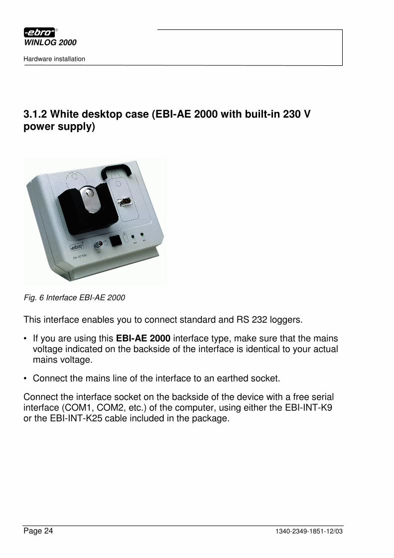
3.1.2 White desktop case (EBI-AE 2000 with built-in 230 V power supply)
Fig. 6 Interface EBI-AE 2000
This interface enables you to connect standard and RS 232 loggers.
• If you are using this EBI-AE 2000 interface type, make sure that the mains voltage indicated on the backside of the interface is identical to your actual mains voltage.
• Connect the mains line of the interface to an earthed socket.
Connect the interface socket on the backside of the device with a free serial interface (COM1, COM2, etc.) of the computer, using either the EBI-INT-K9 or the EBI-INT-K25 cable included in the package.
WINLOG 2000
Hardware installation
1340-2349-1851-12/03 Page 25
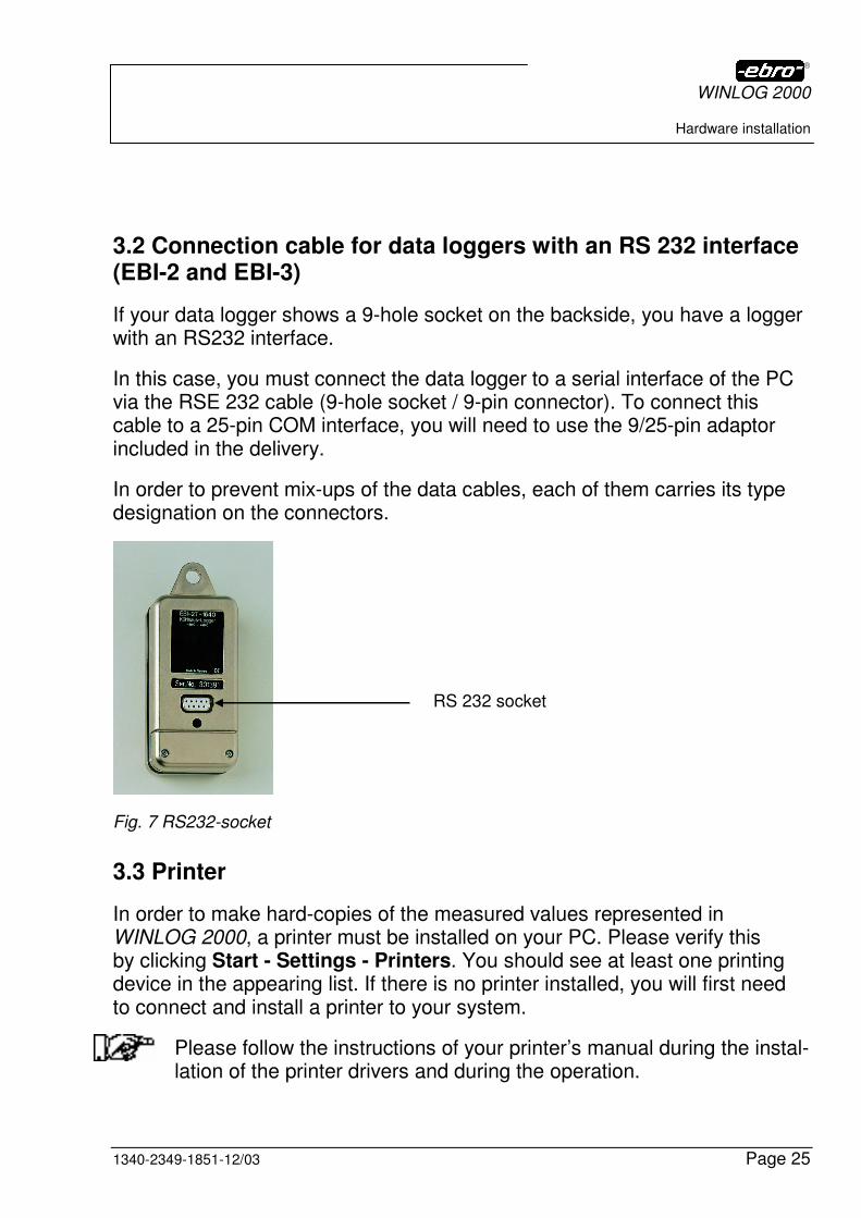
3.2 Connection cable for data loggers with an RS 232 interface (EBI-2 and EBI-3)
If your data logger shows a 9-hole socket on the backside, you have a logger with an RS232 interface.
In this case, you must connect the data logger to a serial interface of the PC via the RSE 232 cable (9-hole socket / 9-pin connector). To connect this cable to a 25-pin COM interface, you will need to use the 9/25-pin adaptor included in the delivery.
In order to prevent mix-ups of the data cables, each of them carries its type designation on the connectors.
Fig. 7 RS232-socket
3.3 Printer
In order to make hard-copies of the measured values represented in WINLOG 2000, a printer must be installed on your PC. Please verify this by clicking Start - Settings - Printers. You should see at least one printing device in the appearing list. If there is no printer installed, you will first need to connect and install a printer to your system.
Please follow the instructions of your printer’s manual during the instal-lation of the printer drivers and during the operation.
RS 232 socket
WINLOG 2000
Software installation
Page 26 1340-2349-1851-12/03
4 Software installation
The user software is shipped on a CD-ROM, together with the logger system.
4.1 General Tips
You may find a leaflet called INFORMATION inside of this manual.
Please read this leaflet, since it contains the latest information on the software or hardware and possible changes to the printed manual.
4.2 Software installation
To install WINLOG 2000, start your computer and wait until Windows is fully loaded. Please don’t start any other applications on your computer before or during WINLOG 2000 setup.
Insert your WINLOG 2000 CD-ROM into the drive. Close the drive tray.
4.2.1 Automatic start of installation
The installation program starts automatically if this feature is activated in your Windows settings. Following picture will appear on the screen.
WINLOG 2000
Software installation
1340-2349-1851-12/03 Page 27
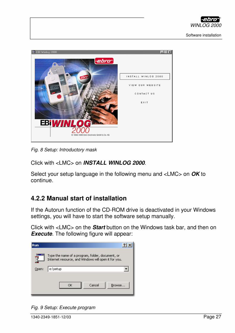
Fig. 8 Setup: Introductory mask
Click with <LMC> on INSTALL WINLOG 2000.
Select your setup language in the following menu and <LMC> on OK to continue.
4.2.2 Manual start of installation
If the Autorun function of the CD-ROM drive is deactivated in your Windows settings, you will have to start the software setup manually.
Click with <LMC> on the Start button on the Windows task bar, and then on Execute. The following figure will appear:
Fig. 9 Setup: Execute program
WINLOG 2000
Software installation
Page 28 1340-2349-1851-12/03
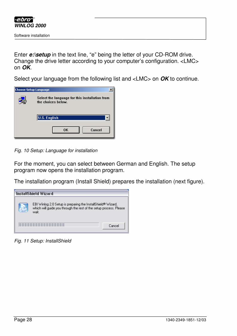
Enter e:\setup in the text line, “e” being the letter of your CD-ROM drive. Change the drive letter according to your computer’s configuration. <LMC> on OK.
Select your language from the following list and <LMC> on OK to continue.
Fig. 10 Setup: Language for installation
For the moment, you can select between German and English. The setup program now opens the installation program.
The installation program (Install Shield) prepares the installation (next figure).
Fig. 11 Setup: InstallShield
WINLOG 2000
Software installation
1340-2349-1851-12/03 Page 29
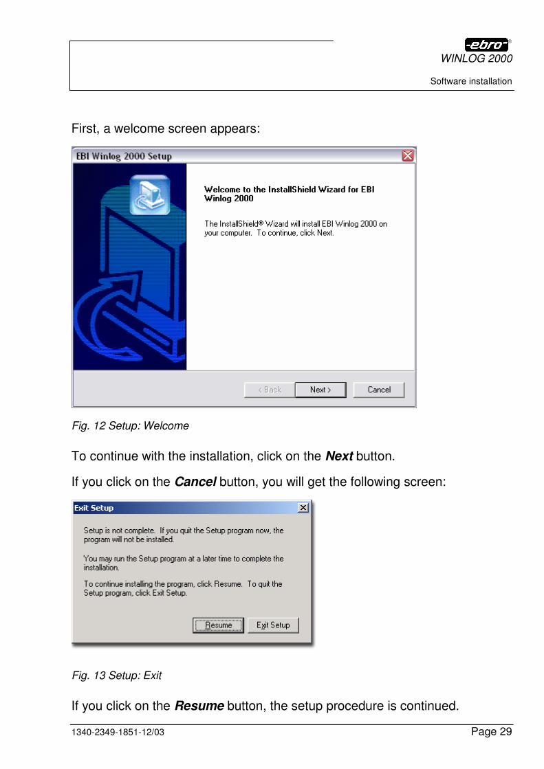
First, a welcome screen appears:
Fig. 12 Setup: Welcome
To continue with the installation, click on the Next button.
If you click on the Cancel button, you will get the following screen:
Fig. 13 Setup: Exit
If you click on the Resume button, the setup procedure is continued.
WINLOG 2000
Software installation
Page 30 1340-2349-1851-12/03
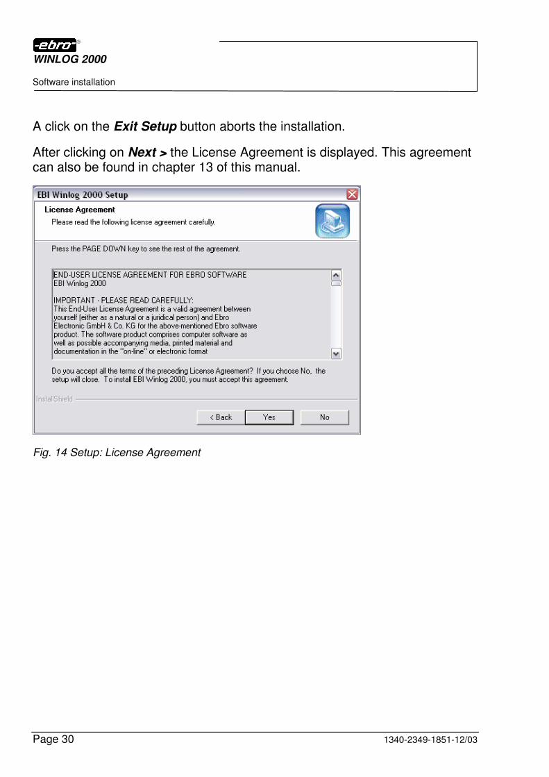
A click on the Exit Setup button aborts the installation.
After clicking on Next > the License Agreement is displayed. This agreement can also be found in chapter 13 of this manual.
Fig. 14 Setup: License Agreement
WINLOG 2000
Software installation
1340-2349-1851-12/03 Page 31
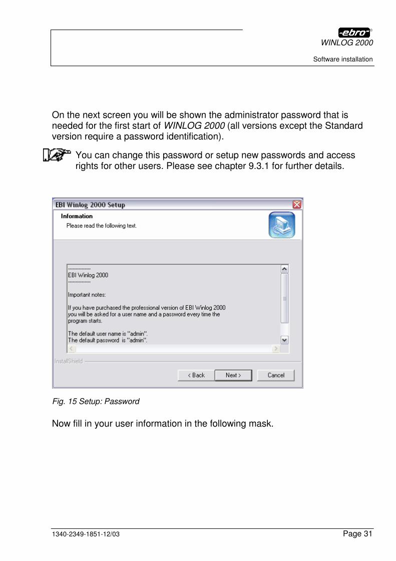
On the next screen you will be shown the administrator password that is needed for the first start of WINLOG 2000 (all versions except the Standard version require a password identification).
You can change this password or setup new passwords and access rights for other users. Please see chapter 9.3.1 for further details.
Fig. 15 Setup: Password
Now fill in your user information in the following mask.
WINLOG 2000
Software installation
Page 32 1340-2349-1851-12/03
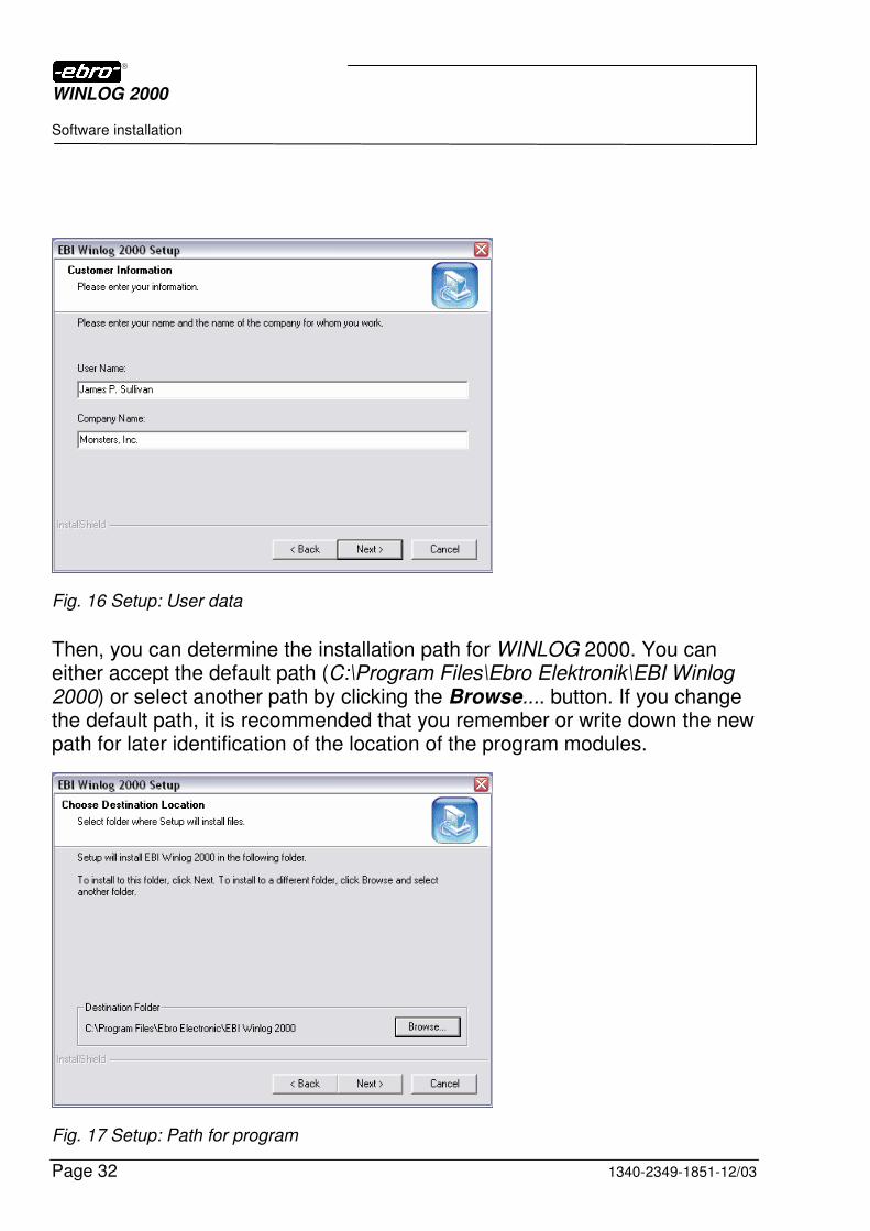
Fig. 16 Setup: User data
Then, you can determine the installation path for WINLOG 2000. You can either accept the default path (C:\Program Files\Ebro Elektronik\EBI Winlog 2000) or select another path by clicking the Browse.... button. If you change the default path, it is recommended that you remember or write down the new path for later identification of the location of the program modules.
Fig. 17 Setup: Path for program
WINLOG 2000
Software installation
1340-2349-1851-12/03 Page 33
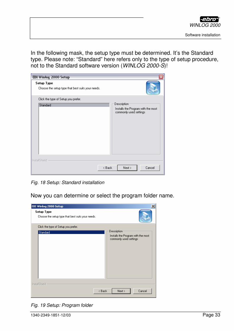
In the following mask, the setup type must be determined. It’s the Standard type. Please note: “Standard” here refers only to the type of setup procedure, not to the Standard software version (WINLOG 2000-S)!
Fig. 18 Setup: Standard installation
Now you can determine or select the program folder name.
Fig. 19 Setup: Program folder
WINLOG 2000
Software installation
Page 34 1340-2349-1851-12/03
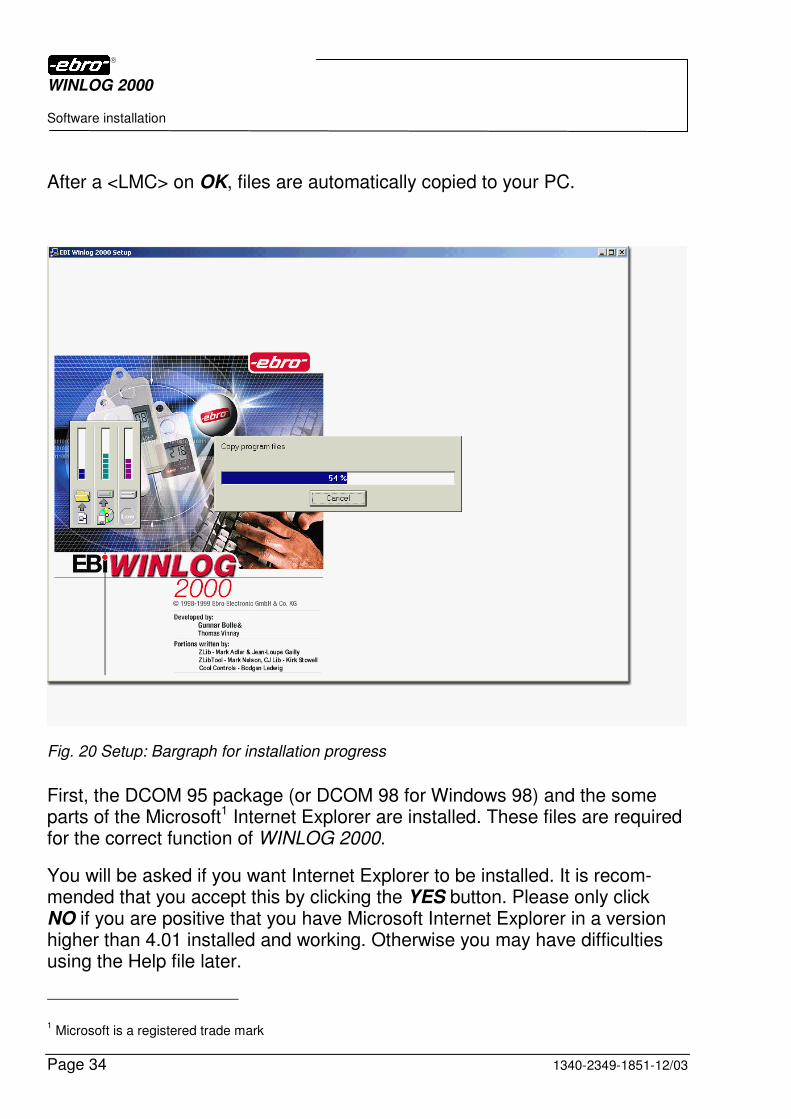
After a <LMC> on OK, files are automatically copied to your PC.
Fig. 20 Setup: Bargraph for installation progress
First, the DCOM 95 package (or DCOM 98 for Windows 98) and the some parts of the Microsoft1 Internet Explorer are installed. These files are required for the correct function of WINLOG 2000.
You will be asked if you want Internet Explorer to be installed. It is recom-mended that you accept this by clicking the YES button. Please only click NO if you are positive that you have Microsoft Internet Explorer in a version higher than 4.01 installed and working. Otherwise you may have difficulties using the Help file later.
1 Microsoft is a registered trade mark

WINLOG 2000
Software installation
1340-2349-1851-12/03 Page 35
Fig. 21 Setup: Installation of Internet Explorer
Fig. 22 Setup: Installation of the Internet Explorer core
When this is finished, the computer must be restarted, as stated by the message which appears now.
Fig. 23 Setup: Restart of PC
WINLOG 2000
Software installation
Page 36 1340-2349-1851-12/03
Confirm with <LMC> on Yes, I want to restart my computer now and then OK. The computer runs itself down and also restarts automatically.
I you choose No, I will restart my computer later, the installation will be aborted for now and will resume on the next start of Windows.
After reboot, the installation language screen (“Fig. 10 Setup: Language for installation”) reappears and the installation procedure can be continued by <LMC> on OK.
With a click on Cancel, the installation is aborted.
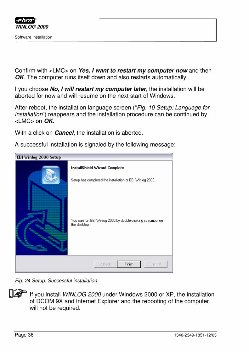
A successful installation is signaled by the following message:
Fig. 24 Setup: Successful installation
If you install WINLOG 2000 under Windows 2000 or XP, the installation of DCOM 9X and Internet Explorer and the rebooting of the computer will not be required.
WINLOG 2000
Software installation
1340-2349-1851-12/03 Page 37
4.3 Software configuration
These first steps must be carried out only once after the installation.
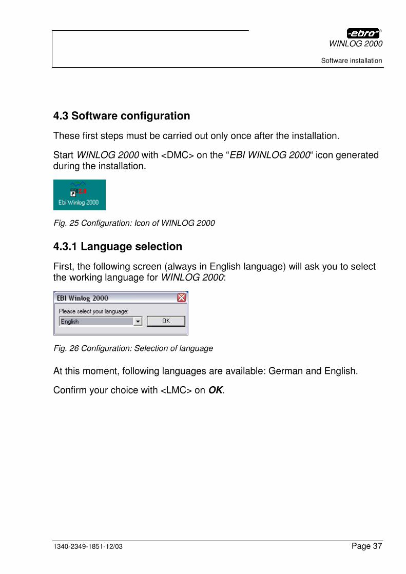
Start WINLOG 2000 with <DMC> on the “EBI WINLOG 2000“ icon generated during the installation.
Fig. 25 Configuration: Icon of WINLOG 2000
4.3.1 Language selection
First, the following screen (always in English language) will ask you to select the working language for WINLOG 2000:
Fig. 26 Configuration: Selection of language
At this moment, following languages are available: German and English.
Confirm your choice with <LMC> on OK.
WINLOG 2000
Software installation
Page 38 1340-2349-1851-12/03
4.3.2 Selection of the serial interface
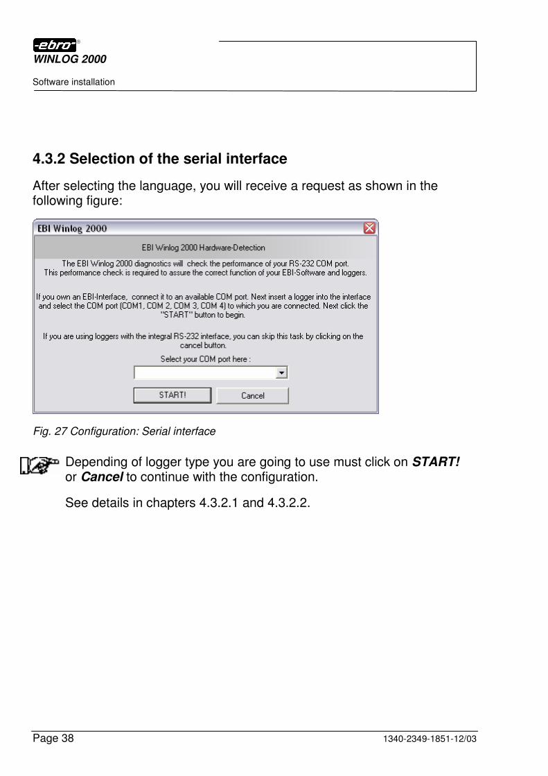
After selecting the language, you will receive a request as shown in the following figure:
Fig. 27 Configuration: Serial interface
Depending of logger type you are going to use must click on START! or Cancel to continue with the configuration.
See details in chapters 4.3.2.1 and 4.3.2.2.
WINLOG 2000
Software installation
1340-2349-1851-12/03 Page 39
4.3.2.1 Using EBI-2 and EBI-3 loggers exclusively
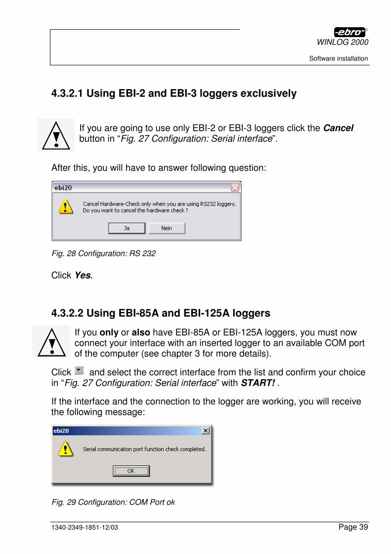
If you are going to use only EBI-2 or EBI-3 loggers click the Cancel button in “Fig. 27 Configuration: Serial interface”.
After this, you will have to answer following question:
Fig. 28 Configuration: RS 232
Click Yes.
4.3.2.2 Using EBI-85A and EBI-125A loggers
If you only or also have EBI-85A or EBI-125A loggers, you must now connect your interface with an inserted logger to an available COM port of the computer (see chapter 3 for more details).
Click and select the correct interface from the list and confirm your choice in “Fig. 27 Configuration: Serial interface” with START! .
If the interface and the connection to the logger are working, you will receive the following message:
Fig. 29 Configuration: COM Port ok
WINLOG 2000
Software installation
Page 40 1340-2349-1851-12/03
If you click with <LMC> to OK your configuration is done.
If you get error messages during installation have a look at chapter 12.1.2, where the messages are explained.
The COM interface doesn’t need to be configured. WINLOG 2000 sets the parameters automatically at each start of the software.
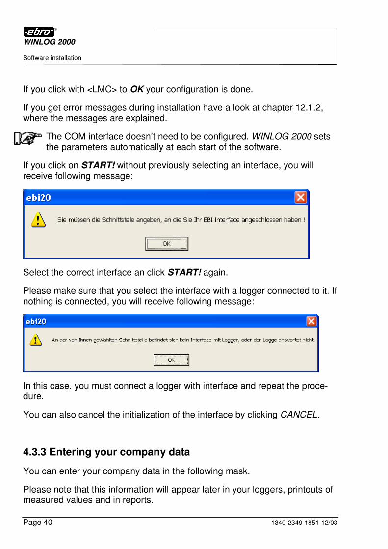
If you click on START! without previously selecting an interface, you will receive following message:
Select the correct interface an click START! again.
Please make sure that you select the interface with a logger connected to it. If nothing is connected, you will receive following message:
In this case, you must connect a logger with interface and repeat the proce-dure.
You can also cancel the initialization of the interface by clicking CANCEL.
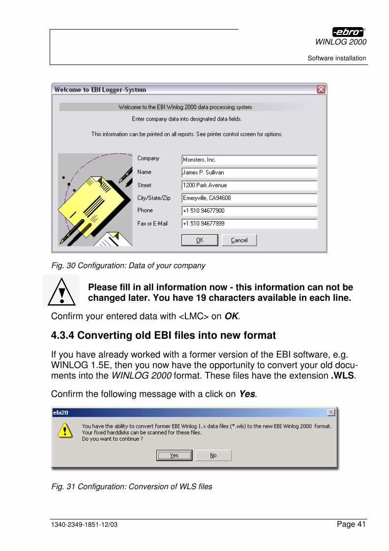
4.3.3 Entering your company data
You can enter your company data in the following mask.
Please note that this information will appear later in your loggers, printouts of measured values and in reports.
WINLOG 2000
Software installation
1340-2349-1851-12/03 Page 41
Fig. 30 Configuration: Data of your company
Please fill in all information now - this information can not be changed later. You have 19 characters available in each line.
Confirm your entered data with <LMC> on OK.
4.3.4 Converting old EBI files into new format
If you have already worked with a former version of the EBI software, e.g. WINLOG 1.5E, then you now have the opportunity to convert your old docu-ments into the WINLOG 2000 format. These files have the extension .WLS.
Confirm the following message with a click on Yes.
Fig. 31 Configuration: Conversion of WLS files
WINLOG 2000
Software installation
Page 42 1340-2349-1851-12/03
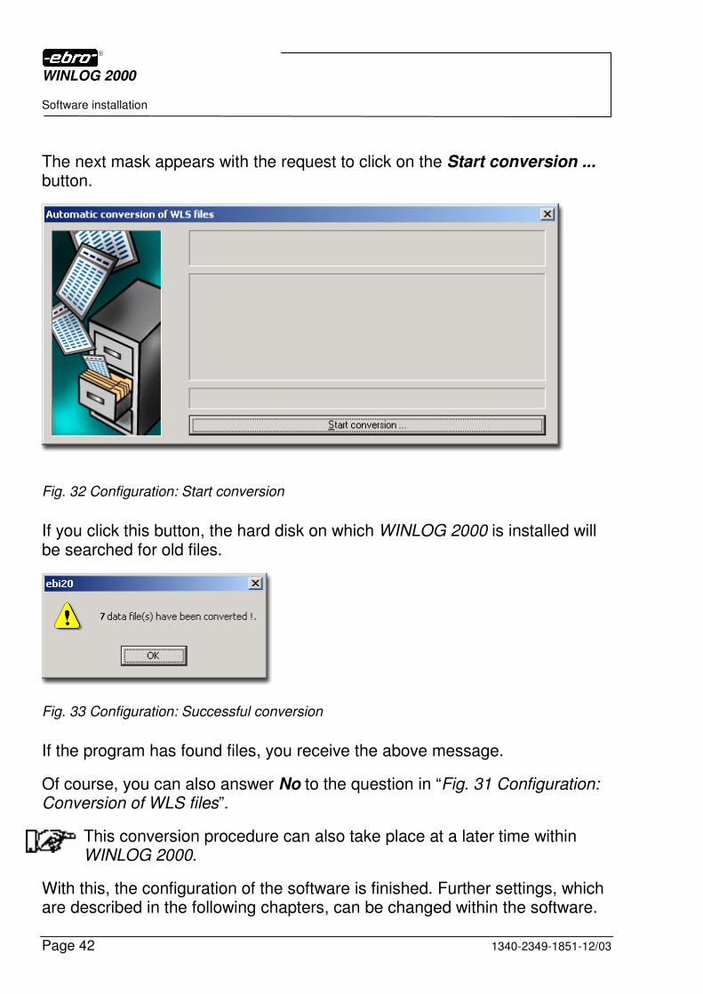
The next mask appears with the request to click on the Start conversion ... button.
Fig. 32 Configuration: Start conversion
If you click this button, the hard disk on which WINLOG 2000 is installed will be searched for old files.
Fig. 33 Configuration: Successful conversion
If the program has found files, you receive the above message.
Of course, you can also answer No to the question in “Fig. 31 Configuration: Conversion of WLS files”.
This conversion procedure can also take place at a later time within WINLOG 2000.
With this, the configuration of the software is finished. Further settings, which are described in the following chapters, can be changed within the software.
WINLOG 2000
Software installation
1340-2349-1851-12/03 Page 43
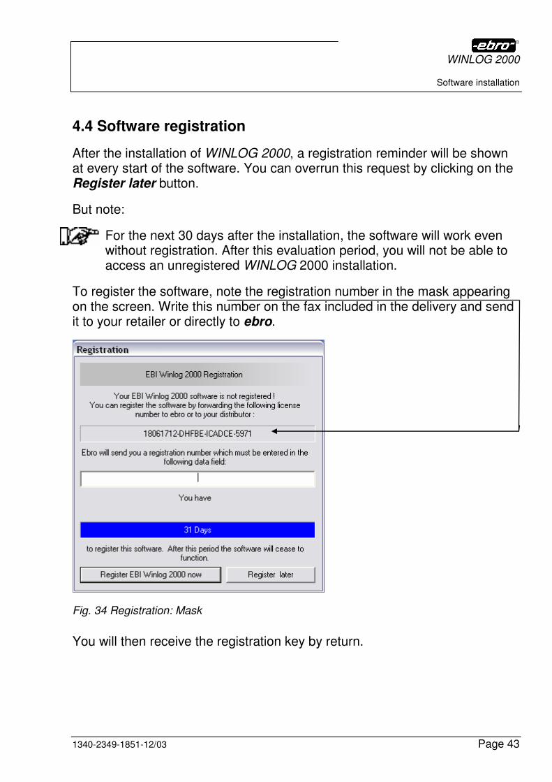
4.4 Software registration
After the installation of WINLOG 2000, a registration reminder will be shown at every start of the software. You can overrun this request by clicking on the Register later button.
But note:
For the next 30 days after the installation, the software will work even without registration. After this evaluation period, you will not be able to access an unregistered WINLOG 2000 installation.
To register the software, note the registration number in the mask appearing on the screen. Write this number on the fax included in the delivery and send it to your retailer or directly to ebro.
Fig. 34 Registration: Mask
You will then receive the registration key by return.
WINLOG 2000
Software installation
Page 44 1340-2349-1851-12/03
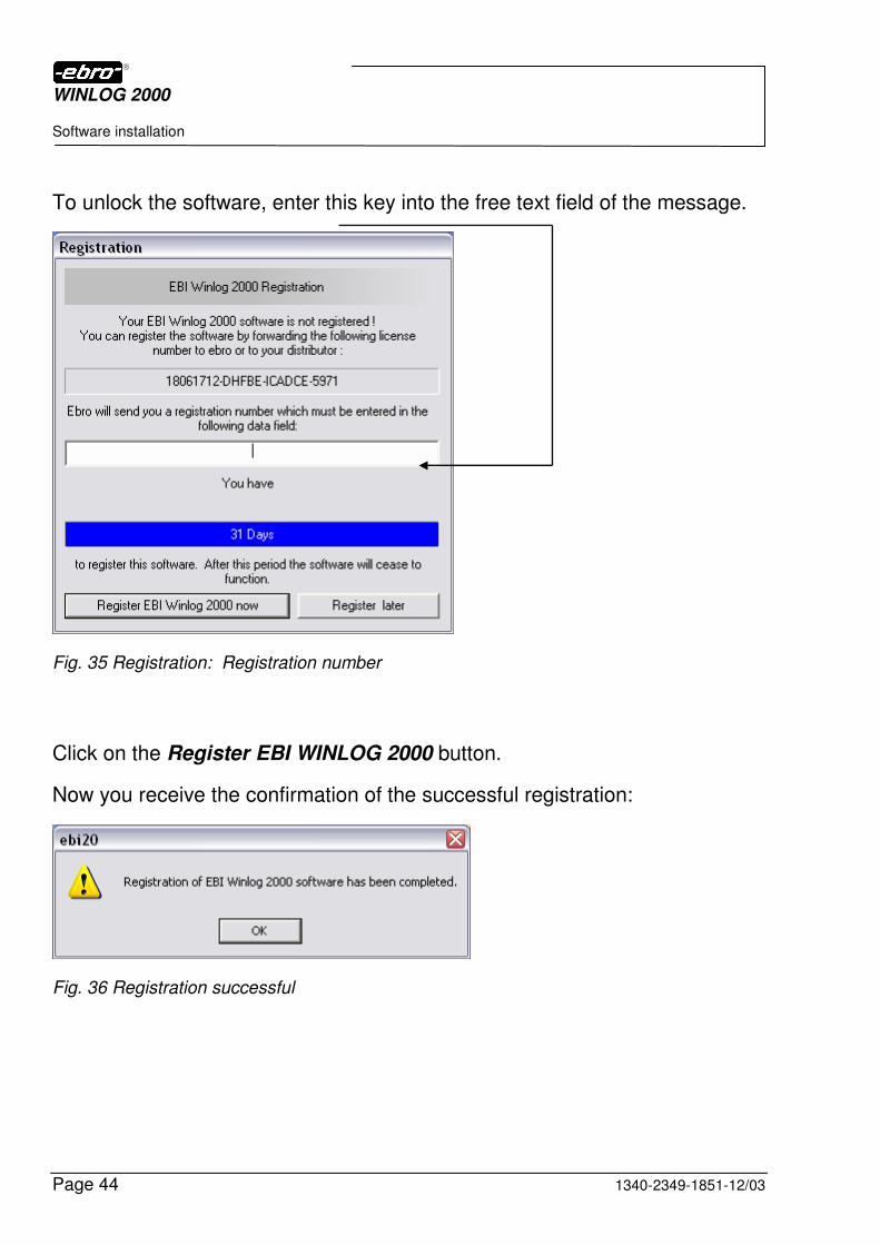
To unlock the software, enter this key into the free text field of the message.
Fig. 35 Registration: Registration number
Click on the Register EBI WINLOG 2000 button.
Now you receive the confirmation of the successful registration:
Fig. 36 Registration successful
WINLOG 2000
Software installation
1340-2349-1851-12/03 Page 45
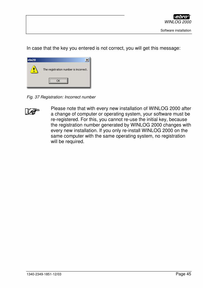
In case that the key you entered is not correct, you will get this message:
Fig. 37 Registration: Incorrect number
Please note that with every new installation of WINLOG 2000 after a change of computer or operating system, your software must be re-registered. For this, you cannot re-use the initial key, because the registration number generated by WINLOG 2000 changes with every new installation. If you only re-install WINLOG 2000 on the same computer with the same operating system, no registration will be required.
WINLOG 2000
Working with WINLOG 2000 – S (Standard)
Page 46 1340-2349-1851-12/03
5 Working with WINLOG 2000 – S (Standard)
ATTENTION – Check your PC’s date and time!
The correct logger programming and data recording requires a precisely set date and time on the PC running WINLOG 2000.
This is especially important if your country is using daylight-saving time.
5.1 Starting the software
Start the WINLOG 2000 software by double-clicking the “EBI WINLOG 2000“ icon on your desktop.
Fig. 38 Icon for WINLOG 2000
Following startup screen will show for a few seconds:
Fig. 39 Standard version: Input screen
WINLOG 2000
Working with WINLOG 2000 – S (Standard)
1340-2349-1851-12/03 Page 47
After a few more seconds, the main panel of this application appears:
Fig. 40 Standard version: Main panel
5.2 Help
5.2.1 Tips and Tricks
At every start of WINLOG 2000, a Tips and Tricks window will be displayed in the foreground of the application. It is certainly useful to read them for a while.
Fig. 41 Standard version: Tips + Tricks

WINLOG 2000
Working with WINLOG 2000 – S (Standard)
Page 48 1340-2349-1851-12/03
Later on, you can switch off this display by un-checking the Display tips on startup box.
You can reactivate this help by opening the menu point ? in the main panel
(“
Fig. 40 Standard version: Main panel”) and checking the item Tips and Tricks.
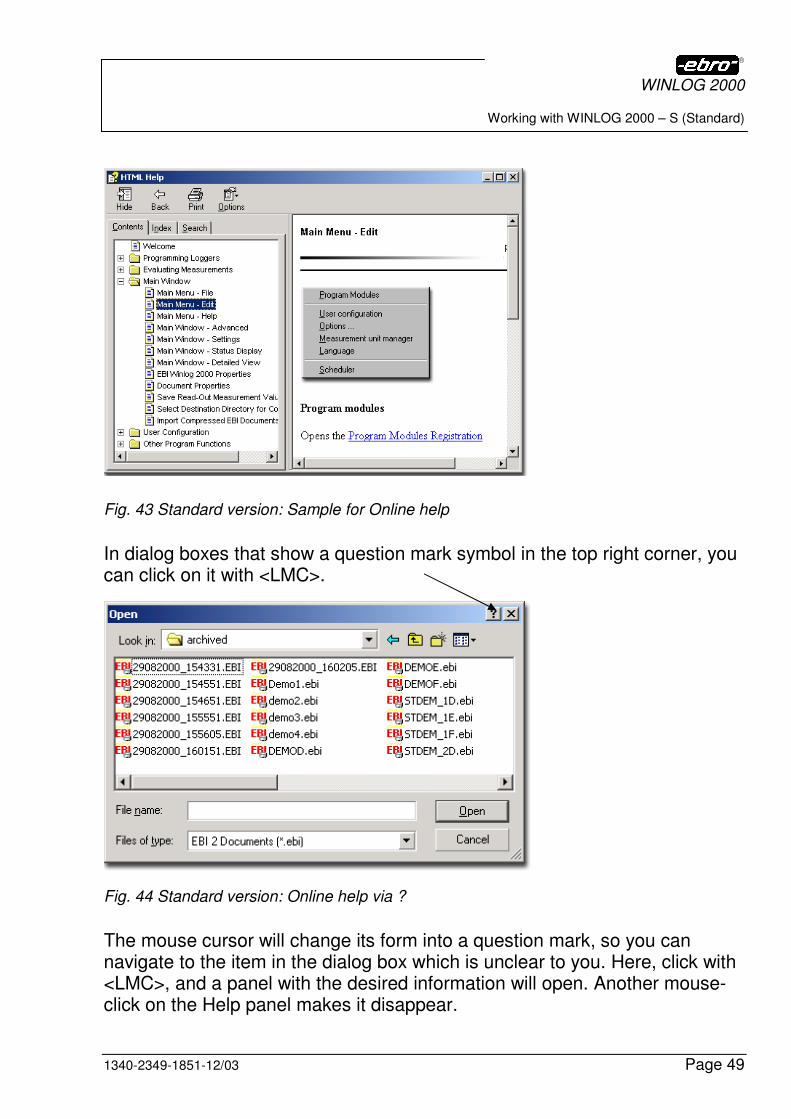
5.2.2 Online help
In this application you can call up the Online Help by pressing the F1 key at any time. In this help file you can carry out a targeted search for a solution to your problem.
You can also access the Help function with a <LMC> on the Help icon (purple book icon).
Fig. 42 Standard version: Icon for Online help
WINLOG 2000
Working with WINLOG 2000 – S (Standard)
1340-2349-1851-12/03 Page 49
Fig. 43 Standard version: Sample for Online help
In dialog boxes that show a question mark symbol in the top right corner, you can click on it with <LMC>.
Fig. 44 Standard version: Online help via ?
The mouse cursor will change its form into a question mark, so you can navigate to the item in the dialog box which is unclear to you. Here, click with <LMC>, and a panel with the desired information will open. Another mouse-click on the Help panel makes it disappear.
WINLOG 2000
Working with WINLOG 2000 – S (Standard)
Page 50 1340-2349-1851-12/03
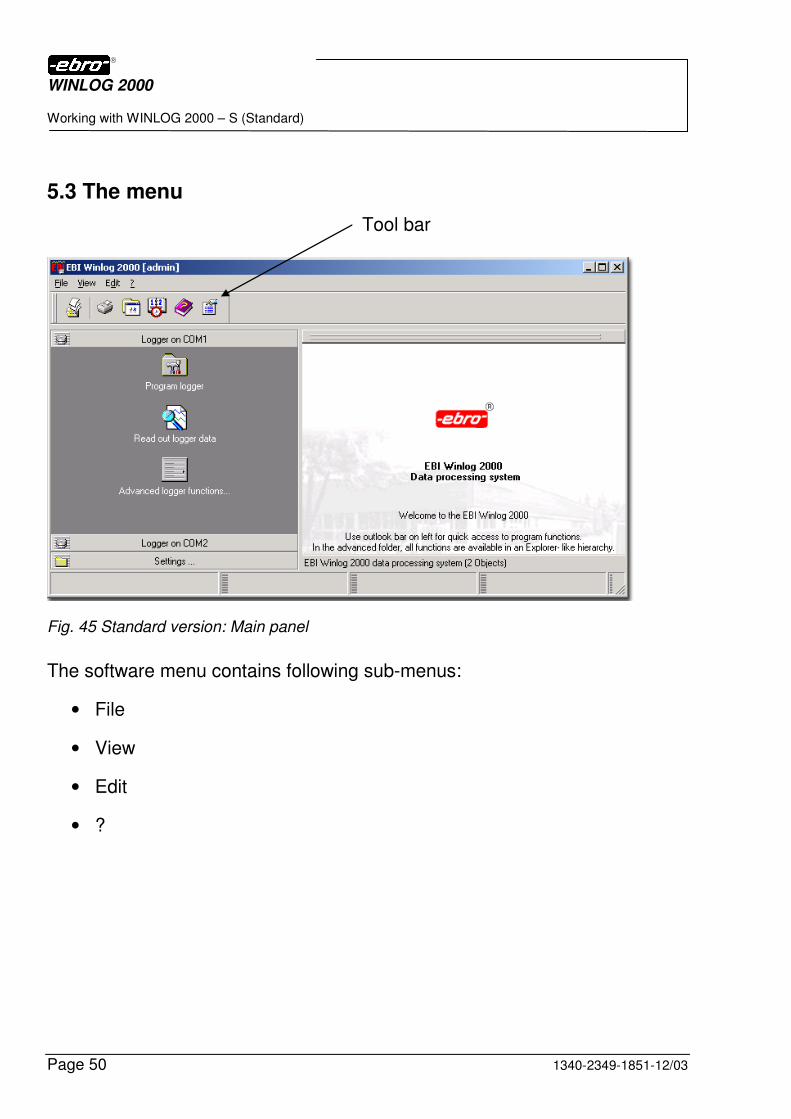
5.3 The menu
Fig. 45 Standard version: Main panel
The software menu contains following sub-menus:
• File
• View
• Edit
• ?
Tool bar
WINLOG 2000
Working with WINLOG 2000 – S (Standard)
1340-2349-1851-12/03 Page 51
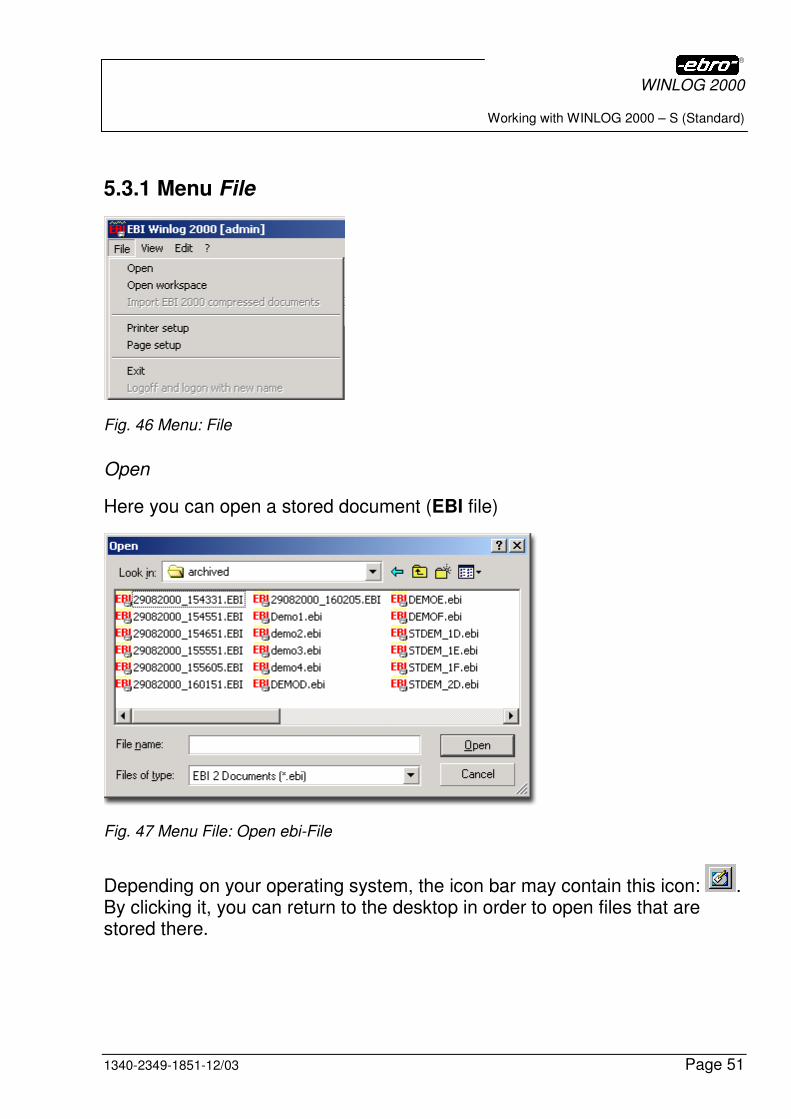
5.3.1 Menu File
Fig. 46 Menu: File
Open
Here you can open a stored document (EBI file)
Fig. 47 Menu File: Open ebi-File
Depending on your operating system, the icon bar may contain this icon: . By clicking it, you can return to the desktop in order to open files that are stored there.
WINLOG 2000
Working with WINLOG 2000 – S (Standard)
Page 52 1340-2349-1851-12/03
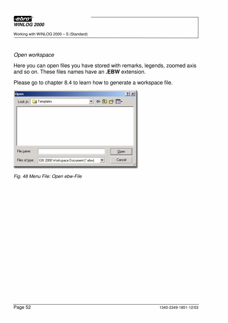
Open workspace
Here you can open files you have stored with remarks, legends, zoomed axis and so on. These files names have an .EBW extension.
Please go to chapter 8.4 to learn how to generate a workspace file.
Fig. 48 Menu File: Open ebw-File
WINLOG 2000
Working with WINLOG 2000 – S (Standard)
1340-2349-1851-12/03 Page 53
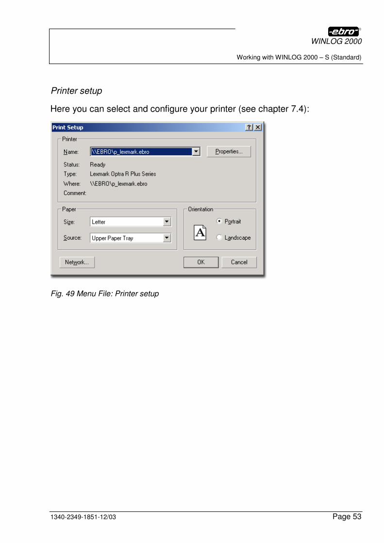
Printer setup
Here you can select and configure your printer (see chapter 7.4):
Fig. 49 Menu File: Printer setup
WINLOG 2000
Working with WINLOG 2000 – S (Standard)
Page 54 1340-2349-1851-12/03
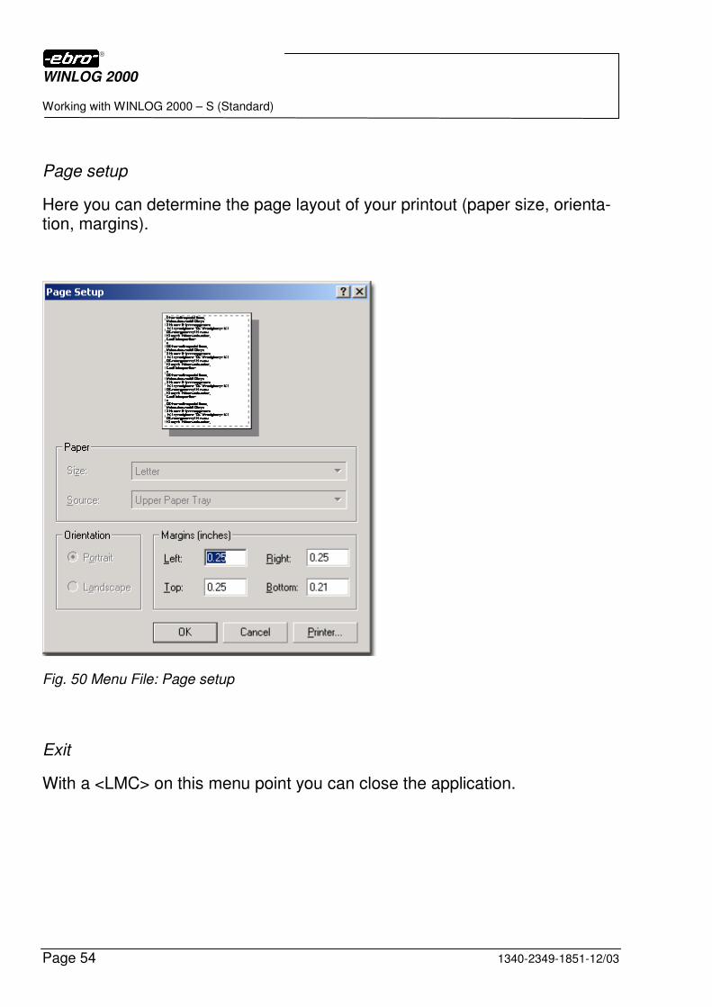
Page setup
Here you can determine the page layout of your printout (paper size, orienta-tion, margins).
Fig. 50 Menu File: Page setup
Exit
With a <LMC> on this menu point you can close the application.
WINLOG 2000
Working with WINLOG 2000 – S (Standard)
1340-2349-1851-12/03 Page 55
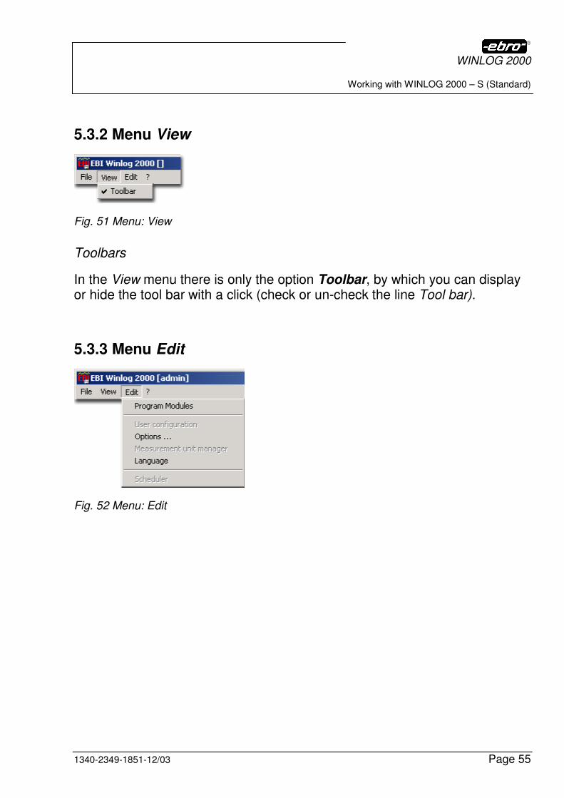
5.3.2 Menu View
Fig. 51 Menu: View
Toolbars
In the View menu there is only the option Toolbar, by which you can display or hide the tool bar with a click (check or un-check the line Tool bar).
5.3.3 Menu Edit
Fig. 52 Menu: Edit
WINLOG 2000
Working with WINLOG 2000 – S (Standard)
Page 56 1340-2349-1851-12/03
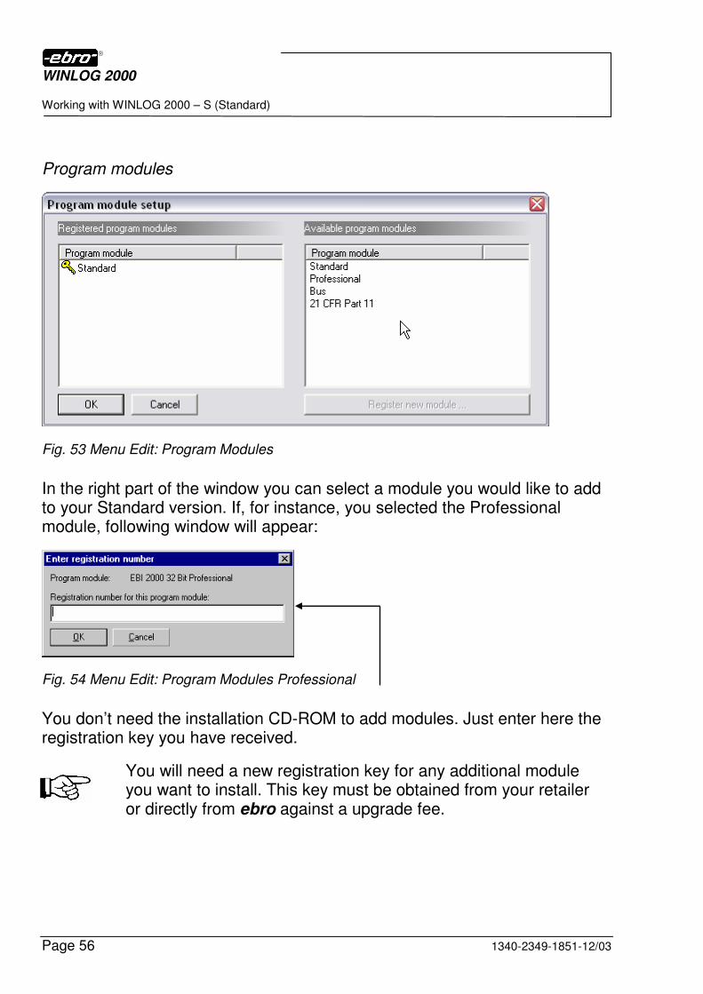
Program modules
Fig. 53 Menu Edit: Program Modules
In the right part of the window you can select a module you would like to add to your Standard version. If, for instance, you selected the Professional module, following window will appear:
Fig. 54 Menu Edit: Program Modules Professional
You don’t need the installation CD-ROM to add modules. Just enter here the registration key you have received.
You will need a new registration key for any additional module you want to install. This key must be obtained from your retailer or directly from ebro against a upgrade fee.
WINLOG 2000
Working with WINLOG 2000 – S (Standard)
1340-2349-1851-12/03 Page 57
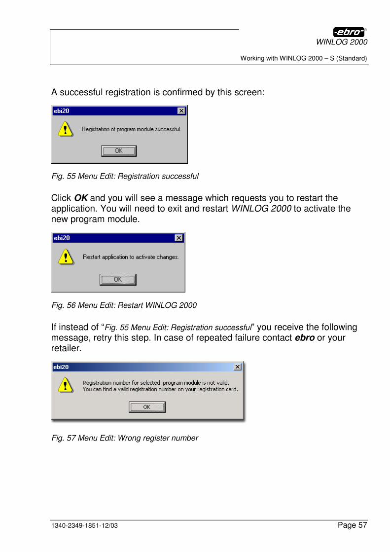
A successful registration is confirmed by this screen:
Fig. 55 Menu Edit: Registration successful
Click OK and you will see a message which requests you to restart the application. You will need to exit and restart WINLOG 2000 to activate the new program module.
Fig. 56 Menu Edit: Restart WINLOG 2000
If instead of “Fig. 55 Menu Edit: Registration successful” you receive the following message, retry this step. In case of repeated failure contact ebro or your retailer.
Fig. 57 Menu Edit: Wrong register number
WINLOG 2000
Working with WINLOG 2000 – S (Standard)
Page 58 1340-2349-1851-12/03
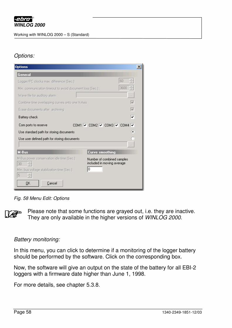
Options:
Fig. 58 Menu Edit: Options
Please note that some functions are grayed out, i.e. they are inactive. They are only available in the higher versions of WINLOG 2000.
Battery monitoring:
In this menu, you can click to determine if a monitoring of the logger battery should be performed by the software. Click on the corresponding box.
Now, the software will give an output on the state of the battery for all EBI-2 loggers with a firmware date higher than June 1, 1998.
For more details, see chapter 5.3.8.
WINLOG 2000
Working with WINLOG 2000 – S (Standard)
1340-2349-1851-12/03 Page 59
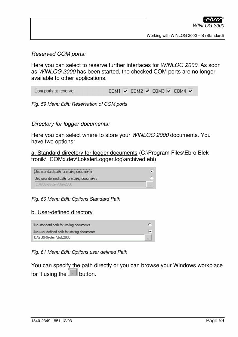
Reserved COM ports:
Here you can select to reserve further interfaces for WINLOG 2000. As soon as WINLOG 2000 has been started, the checked COM ports are no longer available to other applications.
Fig. 59 Menu Edit: Reservation of COM ports
Directory for logger documents:
Here you can select where to store your WINLOG 2000 documents. You have two options:
a. Standard directory for logger documents (C:\Program Files\Ebro Elek-tronik\_COMx.dev\LokalerLogger.log\archived.ebi)
Fig. 60 Menu Edit: Options Standard Path
b. User-defined directory
Fig. 61 Menu Edit: Options user defined Path
You can specify the path directly or you can browse your Windows workplace
for it using the button.
WINLOG 2000
Working with WINLOG 2000 – S (Standard)
Page 60 1340-2349-1851-12/03
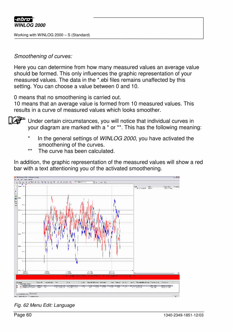
Smoothening of curves:
Here you can determine from how many measured values an average value should be formed. This only influences the graphic representation of your measured values. The data in the *.ebi files remains unaffected by this setting. You can choose a value between 0 and 10.
0 means that no smoothening is carried out. 10 means that an average value is formed from 10 measured values. This results in a curve of measured values which looks smoother.
Under certain circumstances, you will notice that individual curves in your diagram are marked with a * or **. This has the following meaning:
* In the general settings of WINLOG 2000, you have activated the smoothening of the curves. ** The curve has been calculated.
In addition, the graphic representation of the measured values will show a red bar with a text attentioning you of the activated smoothening.
Fig. 62 Menu Edit: Language
WINLOG 2000
Working with WINLOG 2000 – S (Standard)
1340-2349-1851-12/03 Page 61
If you have selected the curve smoothening, you must be aware that this also influences the representation of the histogram and the limit histogram, as well as the export of measured values. The exported values will differ from the original values (they are smoothed).
Language
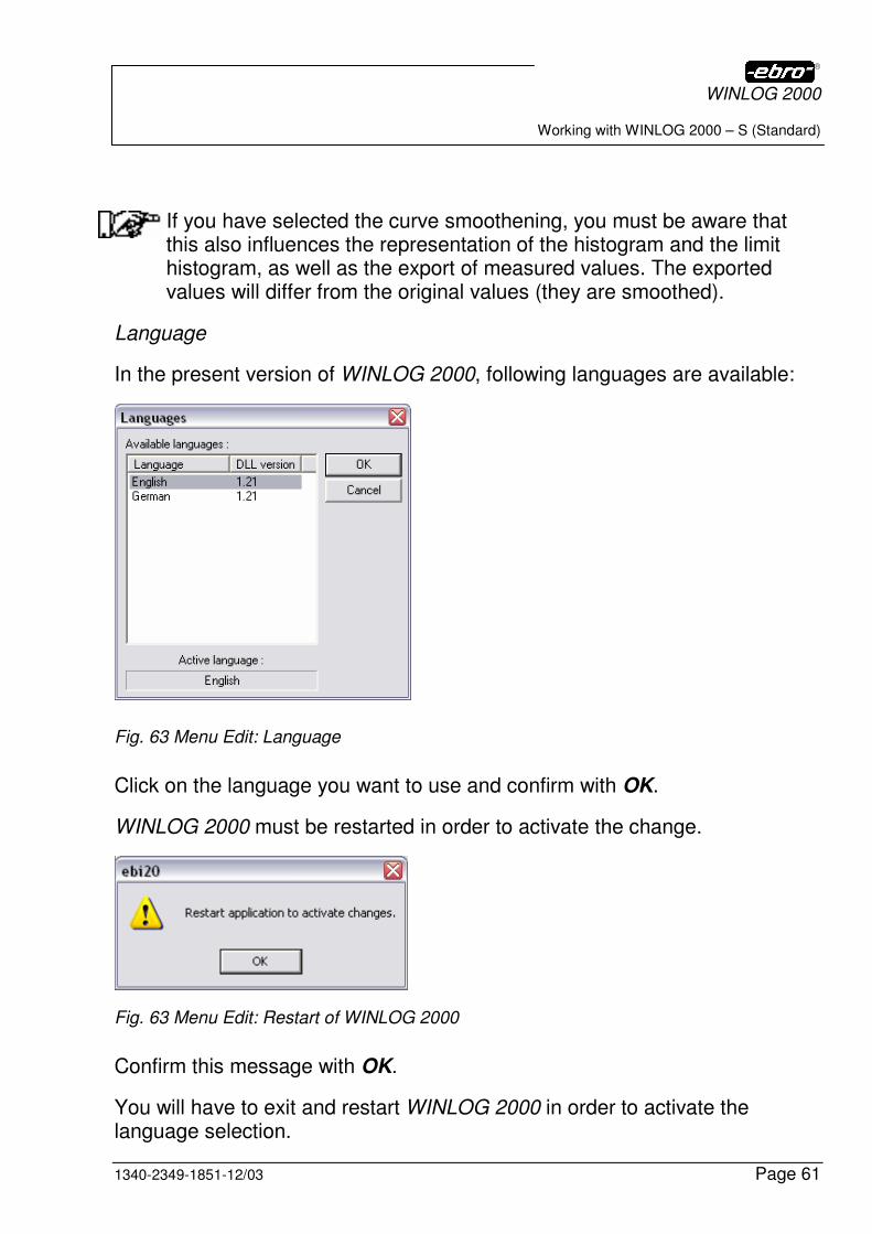
In the present version of WINLOG 2000, following languages are available:
Fig. 63 Menu Edit: Language
Click on the language you want to use and confirm with OK.
WINLOG 2000 must be restarted in order to activate the change.
Fig. 63 Menu Edit: Restart of WINLOG 2000
Confirm this message with OK.
You will have to exit and restart WINLOG 2000 in order to activate the language selection.
WINLOG 2000
Working with WINLOG 2000 – S (Standard)
Page 62 1340-2349-1851-12/03
5.3.4 Menu ?
Fig. 64 Menu ?
Tips and Tricks
With a click on this menu point, the Tips and Tricks window becomes visible again, as shown in figure 41.
Here, by checking or un-checking Display Tips on startup, you can deter-mine if the Tips and Tricks window should appear at every start of the soft-ware.
About EBI WINLOG 2000
If you click on this submenu, you will get the display already shown in Fig 39.
Bug Report
A click on this submenu opens a report form in WordPad, the Windows text editor. In this form, you can report the errors you have discovered. Print the report and send it to ebro.
We would appreciate your making use of this offer. This would help us to improve our software.
Suggestions for improvements
Here, another form is opened in WordPad. You can write down your sugges-tions, criticism or other remarks and send this form to ebro or your retailer.
WINLOG 2000
Working with WINLOG 2000 – S (Standard)
1340-2349-1851-12/03 Page 63
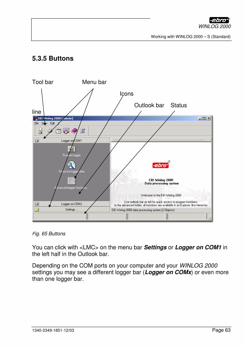
5.3.5 Buttons
Tool bar Menu bar
Icons
Outlook bar Status line
Fig. 65 Buttons
You can click with <LMC> on the menu bar Settings or Logger on COM1 in the left half in the Outlook bar.
Depending on the COM ports on your computer and your WINLOG 2000 settings you may see a different logger bar (Logger on COMx) or even more than one logger bar.
WINLOG 2000
Working with WINLOG 2000 – S (Standard)
Page 64 1340-2349-1851-12/03
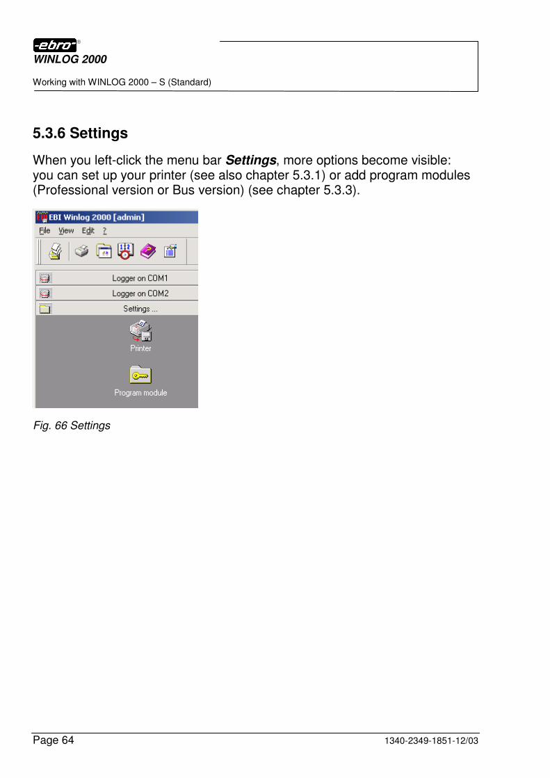
5.3.6 Settings
When you left-click the menu bar Settings, more options become visible: you can set up your printer (see also chapter 5.3.1) or add program modules (Professional version or Bus version) (see chapter 5.3.3).
Fig. 66 Settings
WINLOG 2000
Working with WINLOG 2000 – S (Standard)
1340-2349-1851-12/03 Page 65
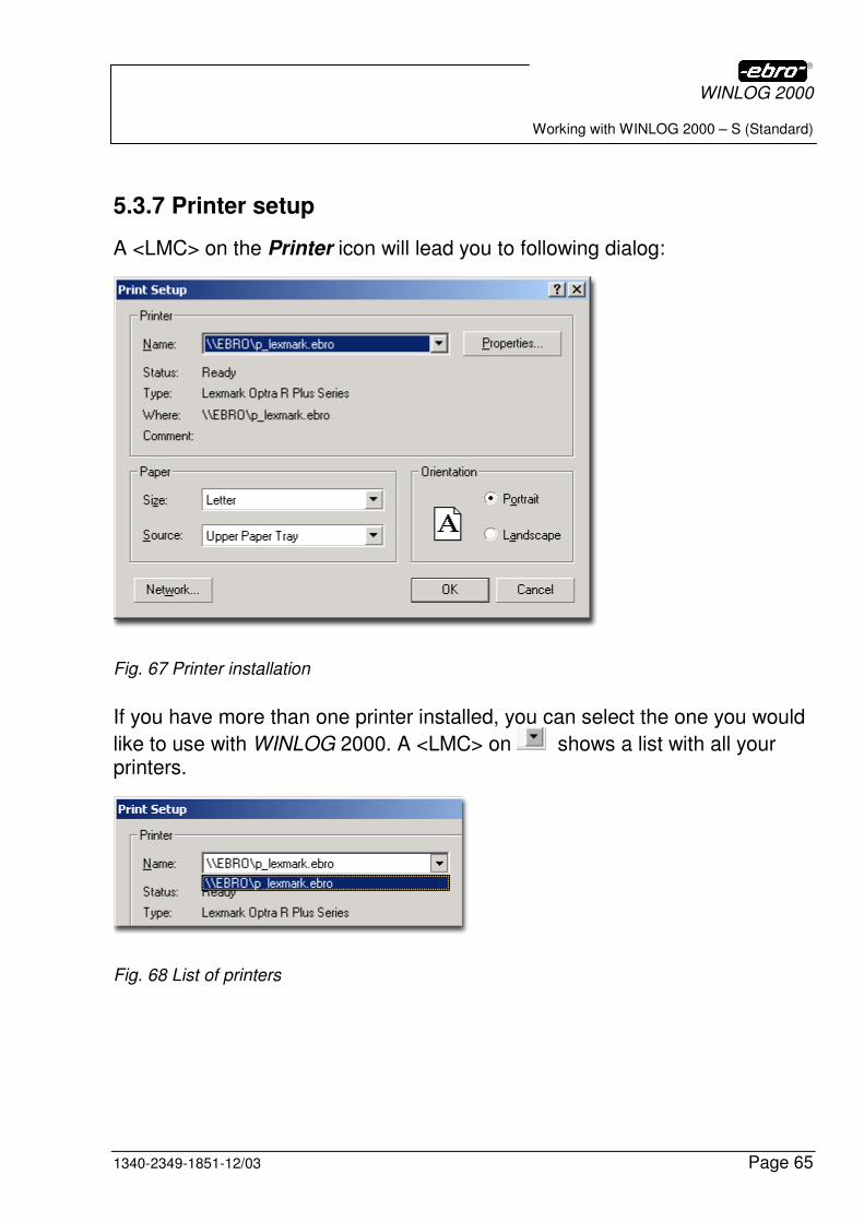
5.3.7 Printer setup
A <LMC> on the Printer icon will lead you to following dialog:
Fig. 67 Printer installation
If you have more than one printer installed, you can select the one you would
like to use with WINLOG 2000. A <LMC> on shows a list with all your printers.
Fig. 68 List of printers
WINLOG 2000
Working with WINLOG 2000 – S (Standard)
Page 66 1340-2349-1851-12/03
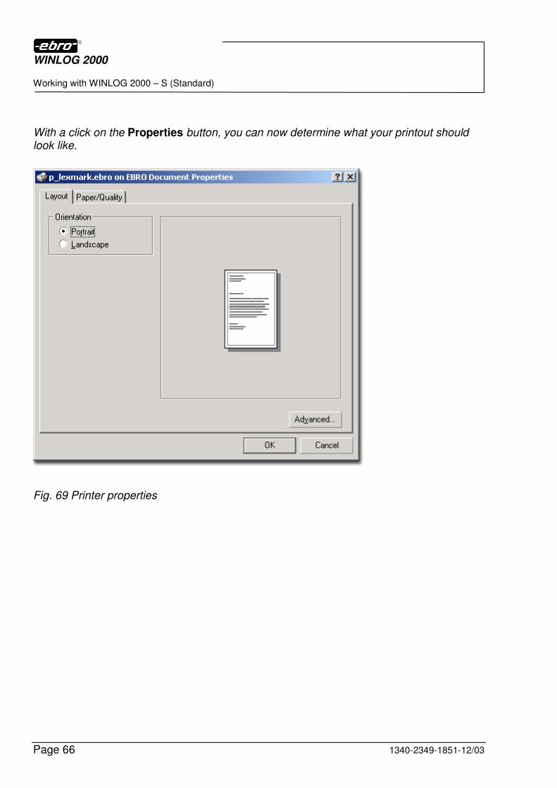
With a click on the Properties button, you can now determine what your printout should look like.
Fig. 69 Printer properties
WINLOG 2000
Working with WINLOG 2000 – S (Standard)
1340-2349-1851-12/03 Page 67
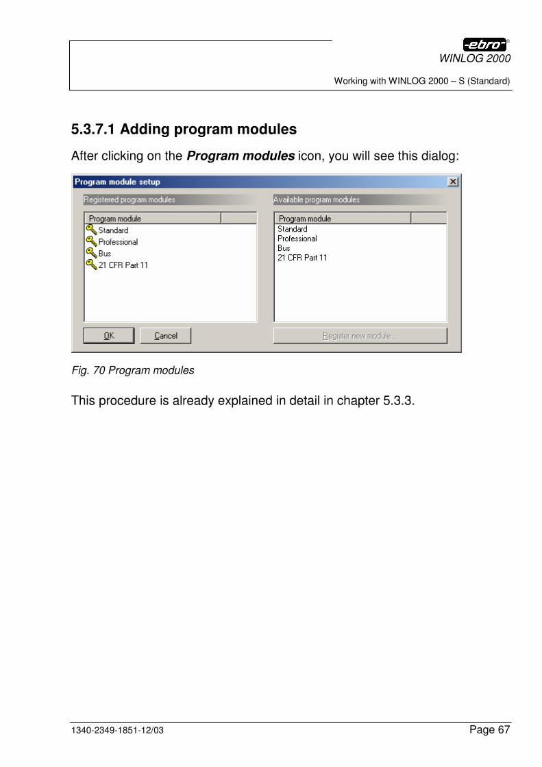
5.3.7.1 Adding program modules
After clicking on the Program modules icon, you will see this dialog:
Fig. 70 Program modules
This procedure is already explained in detail in chapter 5.3.3.
WINLOG 2000
Working with WINLOG 2000 – S (Standard)
Page 68 1340-2349-1851-12/03
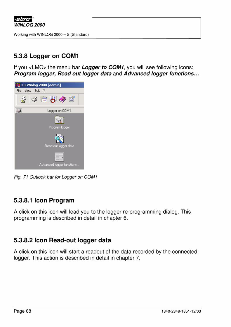
5.3.8 Logger on COM1
If you <LMC> the menu bar Logger to COM1, you will see following icons: Program logger, Read out logger data and Advanced logger functions…
Fig. 71 Outlook bar for Logger on COM1
5.3.8.1 Icon Program
A click on this icon will lead you to the logger re-programming dialog. This programming is described in detail in chapter 6.
5.3.8.2 Icon Read-out logger data
A click on this icon will start a readout of the data recorded by the connected logger. This action is described in detail in chapter 7.
WINLOG 2000
Working with WINLOG 2000 – S (Standard)
1340-2349-1851-12/03 Page 69
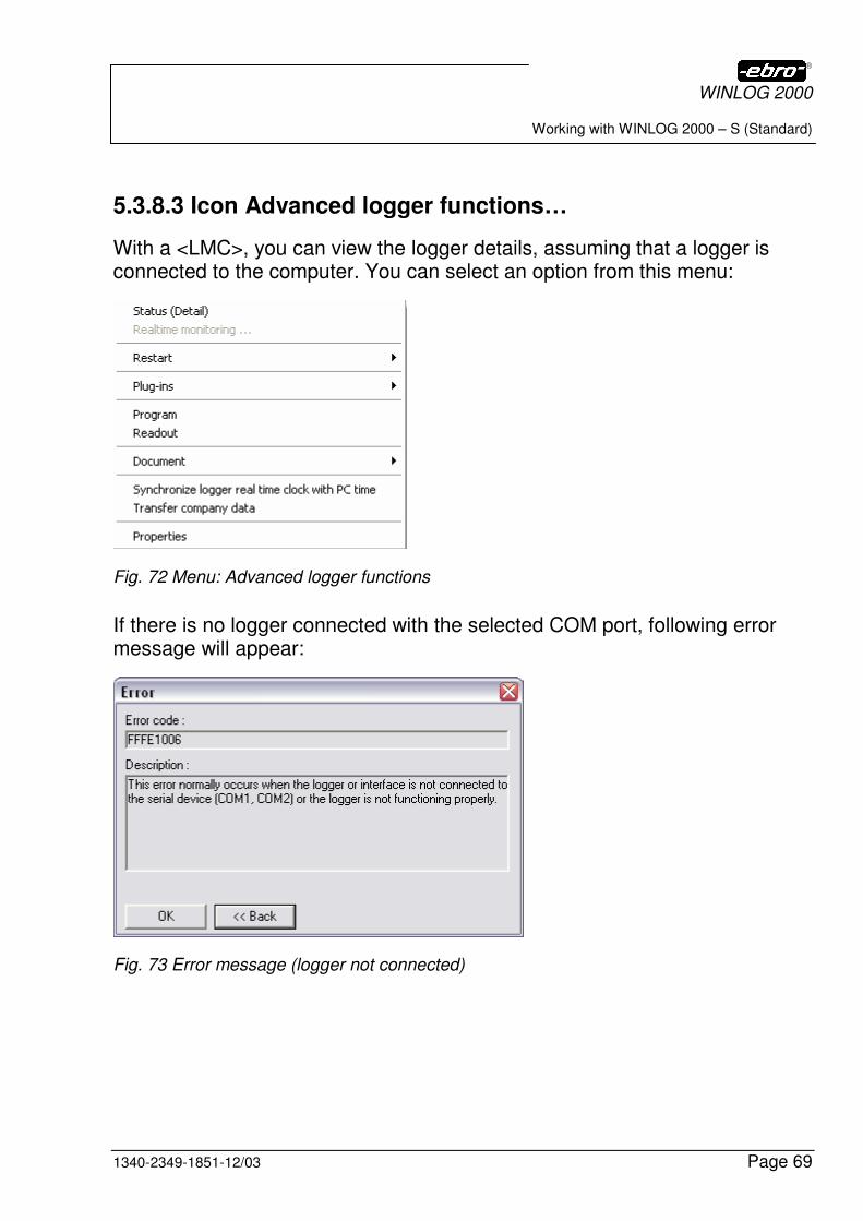
5.3.8.3 Icon Advanced logger functions…
With a <LMC>, you can view the logger details, assuming that a logger is connected to the computer. You can select an option from this menu:
Fig. 72 Menu: Advanced logger functions
If there is no logger connected with the selected COM port, following error message will appear:
Fig. 73 Error message (logger not connected)
WINLOG 2000
Working with WINLOG 2000 – S (Standard)
Page 70 1340-2349-1851-12/03
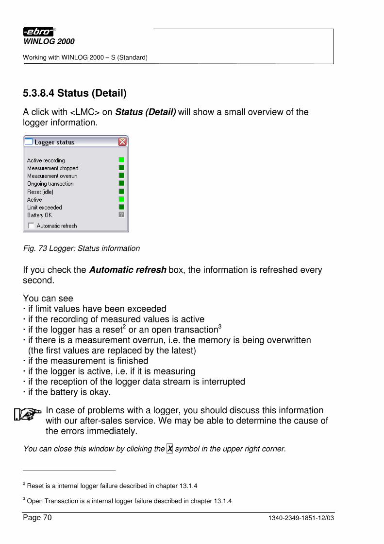
5.3.8.4 Status (Detail)
A click with <LMC> on Status (Detail) will show a small overview of the logger information.
Fig. 73 Logger: Status information
If you check the Automatic refresh box, the information is refreshed every second.
You can see � if limit values have been exceeded � if the recording of measured values is active � if the logger has a reset2 or an open transaction3 � if there is a measurement overrun, i.e. the memory is being overwritten (the first values are replaced by the latest) � if the measurement is finished � if the logger is active, i.e. if it is measuring � if the reception of the logger data stream is interrupted � if the battery is okay.
In case of problems with a logger, you should discuss this information with our after-sales service. We may be able to determine the cause of the errors immediately.
You can close this window by clicking the X symbol in the upper right corner.
2 Reset is a internal logger failure described in chapter 13.1.4
3 Open Transaction is a internal logger failure described in chapter 13.1.4
WINLOG 2000
Working with WINLOG 2000 – S (Standard)
1340-2349-1851-12/03 Page 71
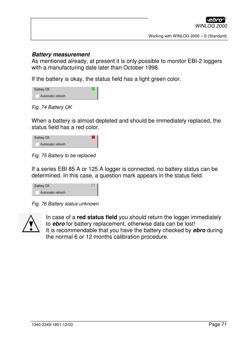
Battery measurement As mentioned already, at present it is only possible to monitor EBI-2 loggers with a manufacturing date later than October 1998.
If the battery is okay, the status field has a light green color.
Fig. 74 Battery OK
When a battery is almost depleted and should be immediately replaced, the status field has a red color.
Fig. 75 Battery to be replaced
If a series EBI 85 A or 125 A logger is connected, no battery status can be determined. In this case, a question mark appears in the status field.
Fig. 76 Battery status unknown
In case of a red status field you should return the logger immediately to ebro for battery replacement, otherwise data can be lost! It is recommendable that you have the battery checked by ebro during the normal 6 or 12 months calibration procedure.
WINLOG 2000
Working with WINLOG 2000 – S (Standard)
Page 72 1340-2349-1851-12/03
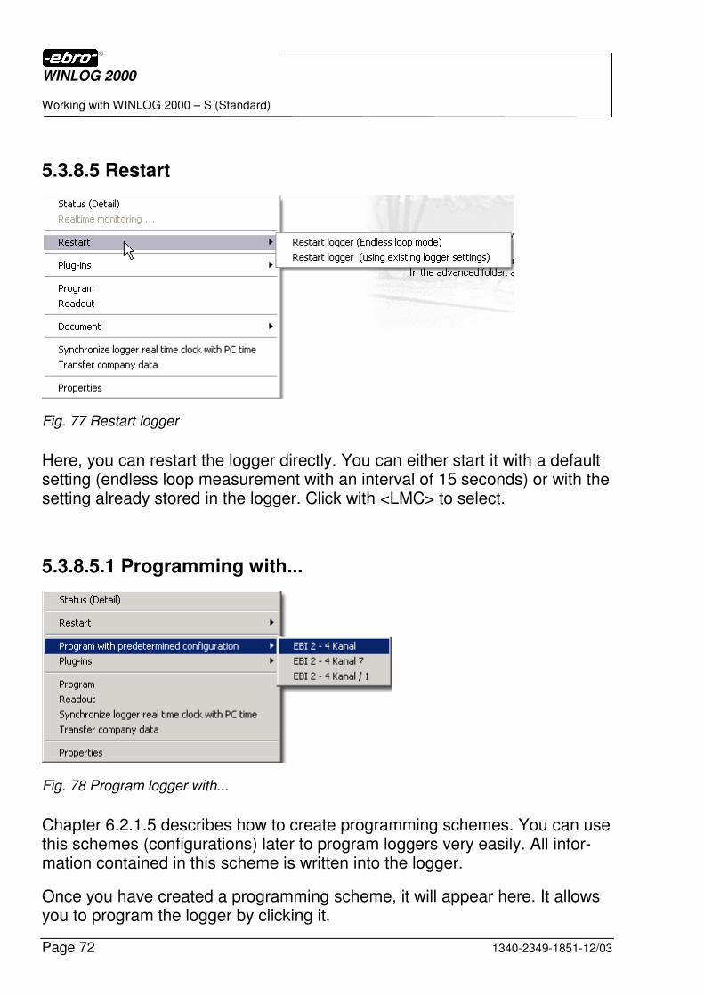
5.3.8.5 Restart
Fig. 77 Restart logger
Here, you can restart the logger directly. You can either start it with a default setting (endless loop measurement with an interval of 15 seconds) or with the setting already stored in the logger. Click with <LMC> to select.
5.3.8.5.1 Programming with...
Fig. 78 Program logger with...
Chapter 6.2.1.5 describes how to create programming schemes. You can use this schemes (configurations) later to program loggers very easily. All infor-mation contained in this scheme is written into the logger.
Once you have created a programming scheme, it will appear here. It allows you to program the logger by clicking it.
WINLOG 2000
Working with WINLOG 2000 – S (Standard)
1340-2349-1851-12/03 Page 73
5.3.8.5.2 Plug-ins
The so-called plug-ins are additional pieces of software which are integrated in WINLOG 2000 in order to enable you to execute optional functions.
5.3.8.5.3 Programming
This menu item will call up the programming dialog, which is described in detail in chapter 6.
5.3.8.5.4 Readout
This function starts the readout of the logger’s measurement values.
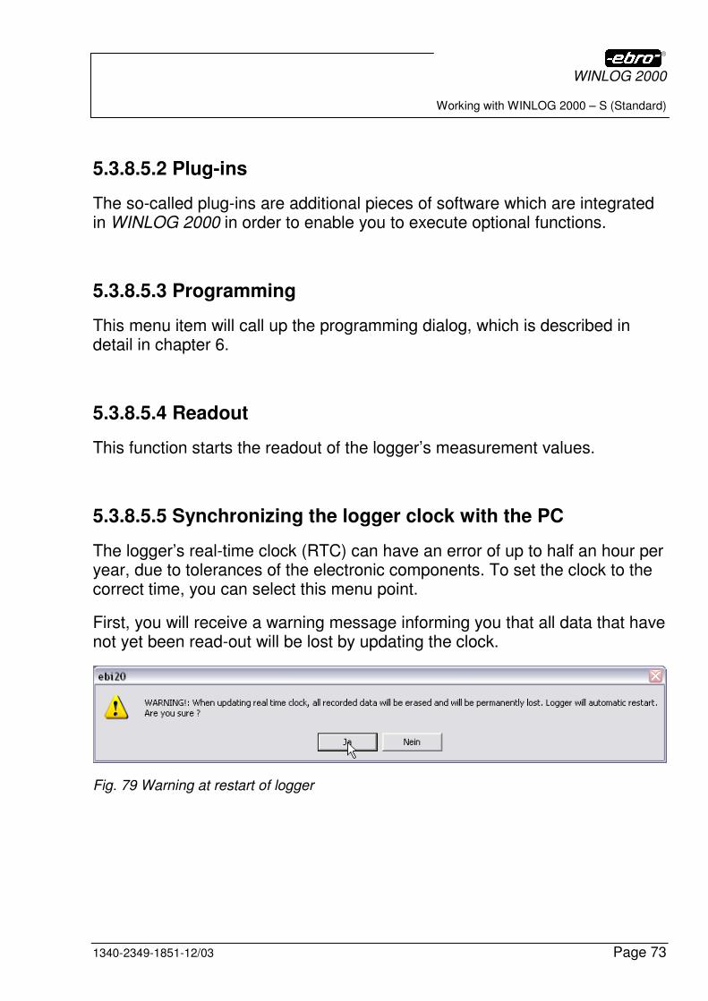
5.3.8.5.5 Synchronizing the logger clock with the PC
The logger’s real-time clock (RTC) can have an error of up to half an hour per year, due to tolerances of the electronic components. To set the clock to the correct time, you can select this menu point.
First, you will receive a warning message informing you that all data that have not yet been read-out will be lost by updating the clock.
Fig. 79 Warning at restart of logger
WINLOG 2000
Working with WINLOG 2000 – S (Standard)
Page 74 1340-2349-1851-12/03
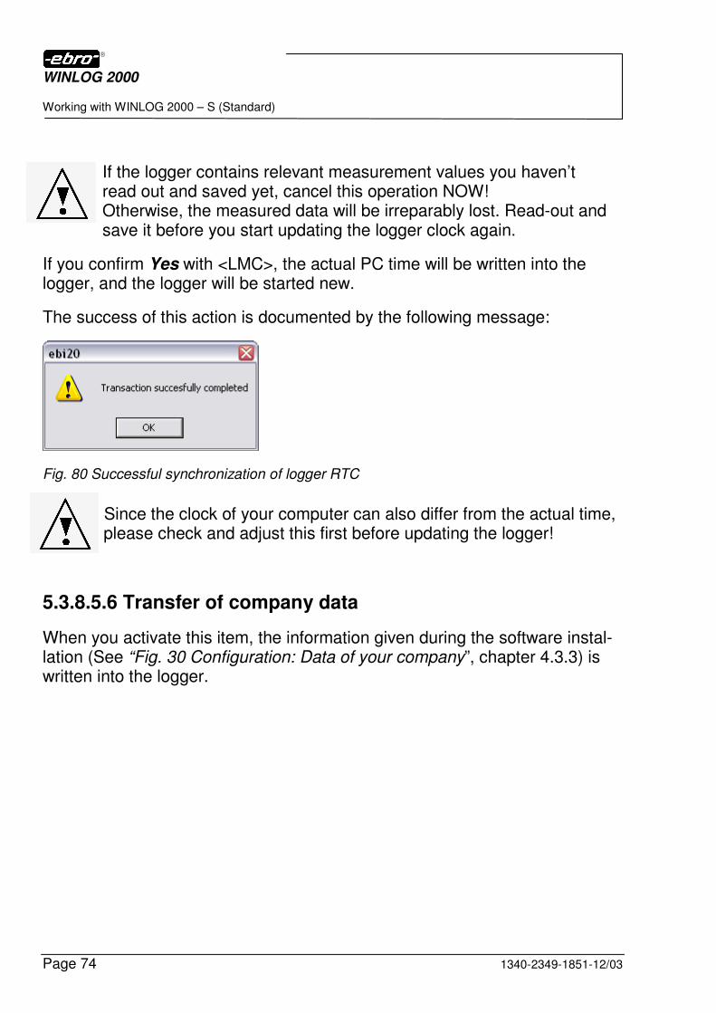
If the logger contains relevant measurement values you haven’t read out and saved yet, cancel this operation NOW! Otherwise, the measured data will be irreparably lost. Read-out and save it before you start updating the logger clock again.
If you confirm Yes with <LMC>, the actual PC time will be written into the logger, and the logger will be started new.
The success of this action is documented by the following message:
Fig. 80 Successful synchronization of logger RTC
Since the clock of your computer can also differ from the actual time, please check and adjust this first before updating the logger!
5.3.8.5.6 Transfer of company data
When you activate this item, the information given during the software instal-lation (See “Fig. 30 Configuration: Data of your company”, chapter 4.3.3) is written into the logger.
WINLOG 2000
Working with WINLOG 2000 – S (Standard)
1340-2349-1851-12/03 Page 75
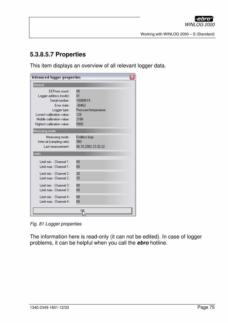
5.3.8.5.7 Properties
This item displays an overview of all relevant logger data.
Fig. 81 Logger properties
The information here is read-only (it can not be edited). In case of logger problems, it can be helpful when you call the ebro hotline.
WINLOG 2000
Working with WINLOG 2000 – S (Standard)
Page 76 1340-2349-1851-12/03
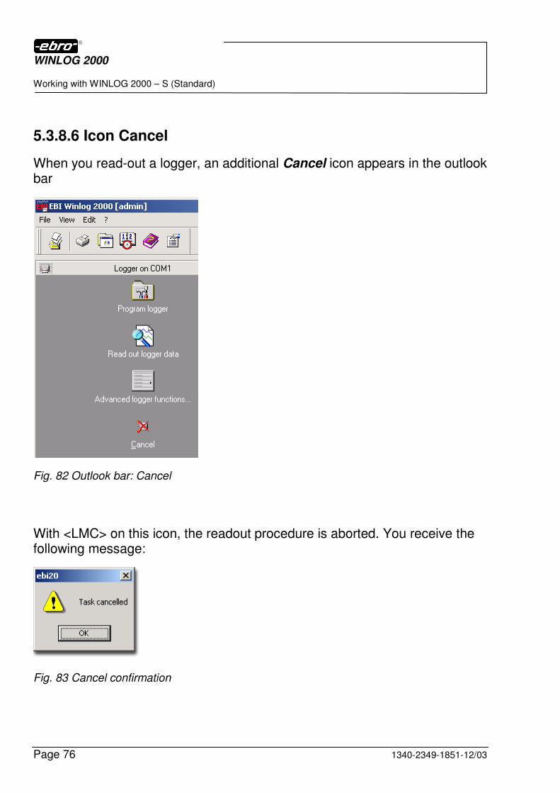
5.3.8.6 Icon Cancel
When you read-out a logger, an additional Cancel icon appears in the outlook bar
Fig. 82 Outlook bar: Cancel
With <LMC> on this icon, the readout procedure is aborted. You receive the following message:
Fig. 83 Cancel confirmation
WINLOG 2000
Working with WINLOG 2000 – S (Standard)
1340-2349-1851-12/03 Page 77
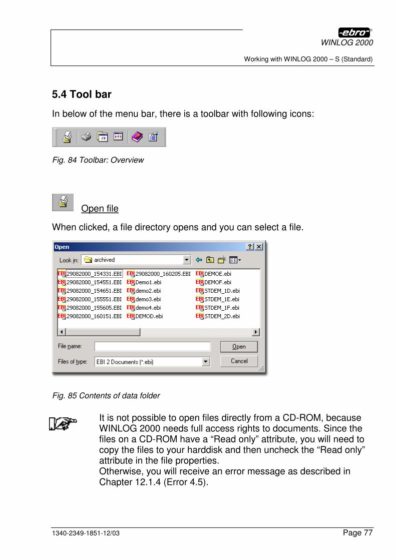
5.4 Tool bar
In below of the menu bar, there is a toolbar with following icons:
Fig. 84 Toolbar: Overview
Open file
When clicked, a file directory opens and you can select a file.
Fig. 85 Contents of data folder
It is not possible to open files directly from a CD-ROM, because WINLOG 2000 needs full access rights to documents. Since the files on a CD-ROM have a “Read only” attribute, you will need to copy the files to your harddisk and then uncheck the “Read only” attribute in the file properties. Otherwise, you will receive an error message as described in Chapter 12.1.4 (Error 4.5).

WINLOG 2000
Working with WINLOG 2000 – S (Standard)
Page 78 1340-2349-1851-12/03
Printer
When clicked, the printer setup opens.
Version
A <LMC> on this button will show you following box containing information on the WINLOG 2000 version you are using.
Fig. 86 Version information
Version
This is the official release number of the software.
Build number
This is the internal release number of the software.
Serial number
This is the serial number of the software.

WINLOG 2000
Working with WINLOG 2000 – S (Standard)
1340-2349-1851-12/03 Page 79
It is important for you to know these numbers when you contact the ebro hotline. You will be asked for them by our support team.
Registered by
This is the name you stated during the registration procedure.
Registered program modules
These are the program modules (software versions) you have registered. You can add further modules as needed.
You can close the version information window by clicking on the X symbol in the upper right corner.
You can find more information in the chapters 10 and 11.
Add program modules
This will lead you to the registration menu for new program modules, de-scribed in chapter 5.3.3.
Help
With a <LMC> on this icon, the Online Help is opened.
You can also press the function key F1 to call the help function.

WINLOG 2000
Logger programming
Page 80 1340-2349-1851-12/03
6 Logger programming
6.1 Requirements
In order to be able to record measured data with a logger, it is necessary to write certain information into the logger. This procedure is called “program-ming“.
Measuring interval, measurement duration, limit values, texts etc. are infor-mation that is required for correct measurement.
A logger can only be programmed if it is connected with the PC. Depending on the logger type, the corresponding powered interface or data cable must be connected to the PC (see also chapters 3.1 and 3.2).
The WINLOG 2000 software must also be running.
6.1.1 Connection of series EBI 85A or EBI 125 A loggers
Place the logger (series EBI 85A or EBI 125A types) into the interface.
6.1.2 Connection of series EBI 2 and EBI 3 loggers
Loggers with an RS 232 interface (series EBI-2 and EBI-3 types): first remove the protection cap from the RS 232 socket on the backside of the logger. Then, connect the data cable with the logger and with the PC.
Don’t forget to replace the protection cap to the RS 232 connector of logger once you have disconnected it from the cable. This is essential to assure the watertightness of the logger.
WINLOG 2000
Logger programming
1340-2349-1851-12/03 Page 81
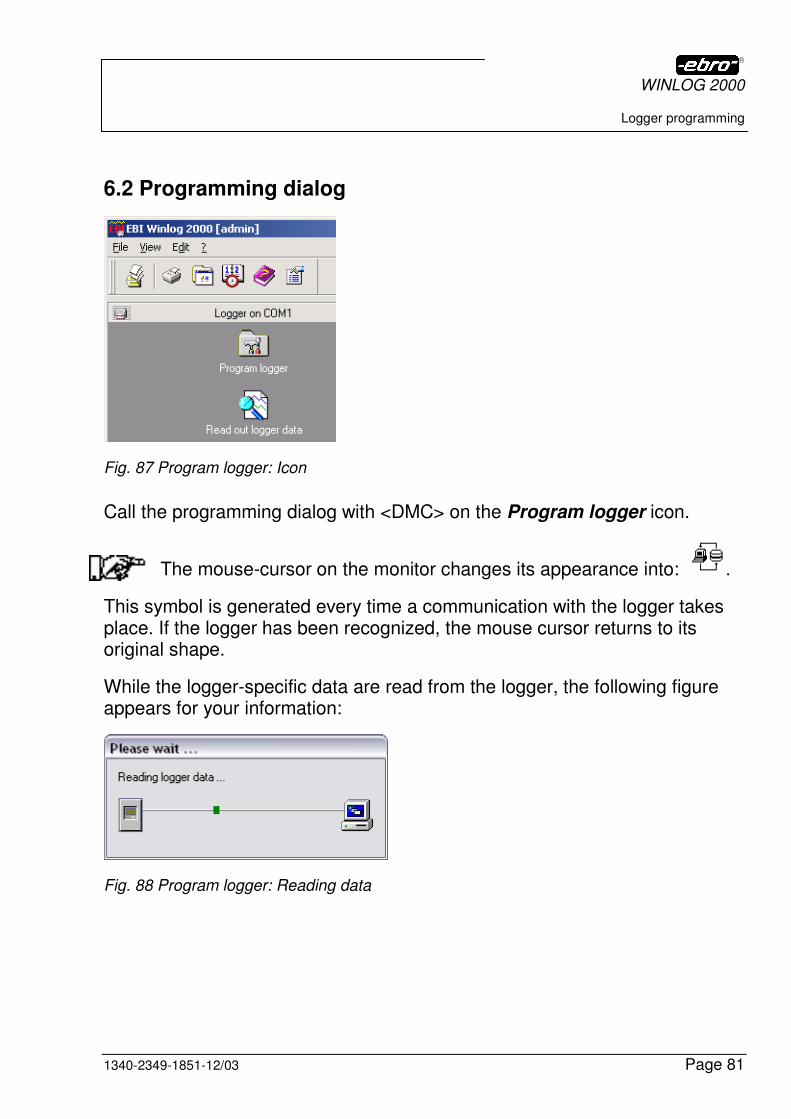
6.2 Programming dialog
Fig. 87 Program logger: Icon
Call the programming dialog with <DMC> on the Program logger icon.
The mouse-cursor on the monitor changes its appearance into: .
This symbol is generated every time a communication with the logger takes place. If the logger has been recognized, the mouse cursor returns to its original shape.
While the logger-specific data are read from the logger, the following figure appears for your information:
Fig. 88 Program logger: Reading data
WINLOG 2000
Logger programming
Page 82 1340-2349-1851-12/03
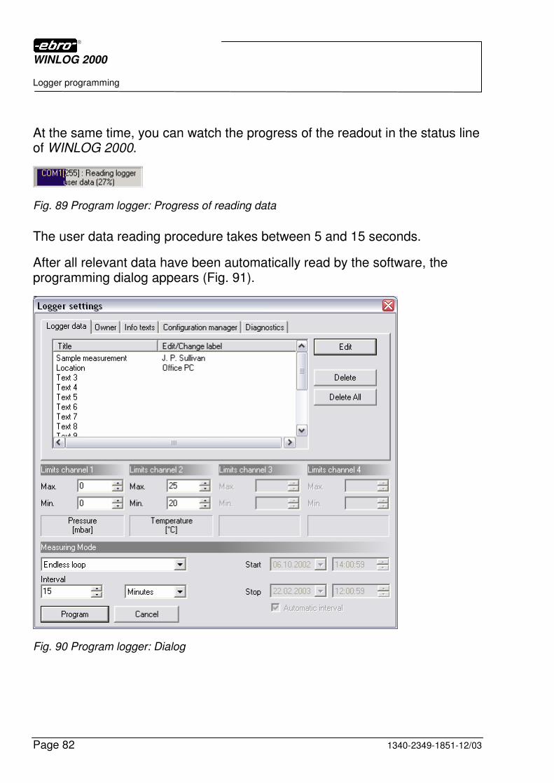
At the same time, you can watch the progress of the readout in the status line of WINLOG 2000.
Fig. 89 Program logger: Progress of reading data
The user data reading procedure takes between 5 and 15 seconds.
After all relevant data have been automatically read by the software, the programming dialog appears (Fig. 91).
Fig. 90 Program logger: Dialog

WINLOG 2000
Logger programming
1340-2349-1851-12/03 Page 83
This screen is divided into three parts.
The upper third contains several programming views as labeled (logger data, owner data, date/time, information texts and configuration manager).
The middle third indicates the number and type of the measuring channels, and the limit values of the individual channels.
The lower third of the screen displays the measuring mode and the measur-ing interval.
The exact description can be found in the following sub-chapters.
WINLOG 2000
Logger programming
Page 84 1340-2349-1851-12/03
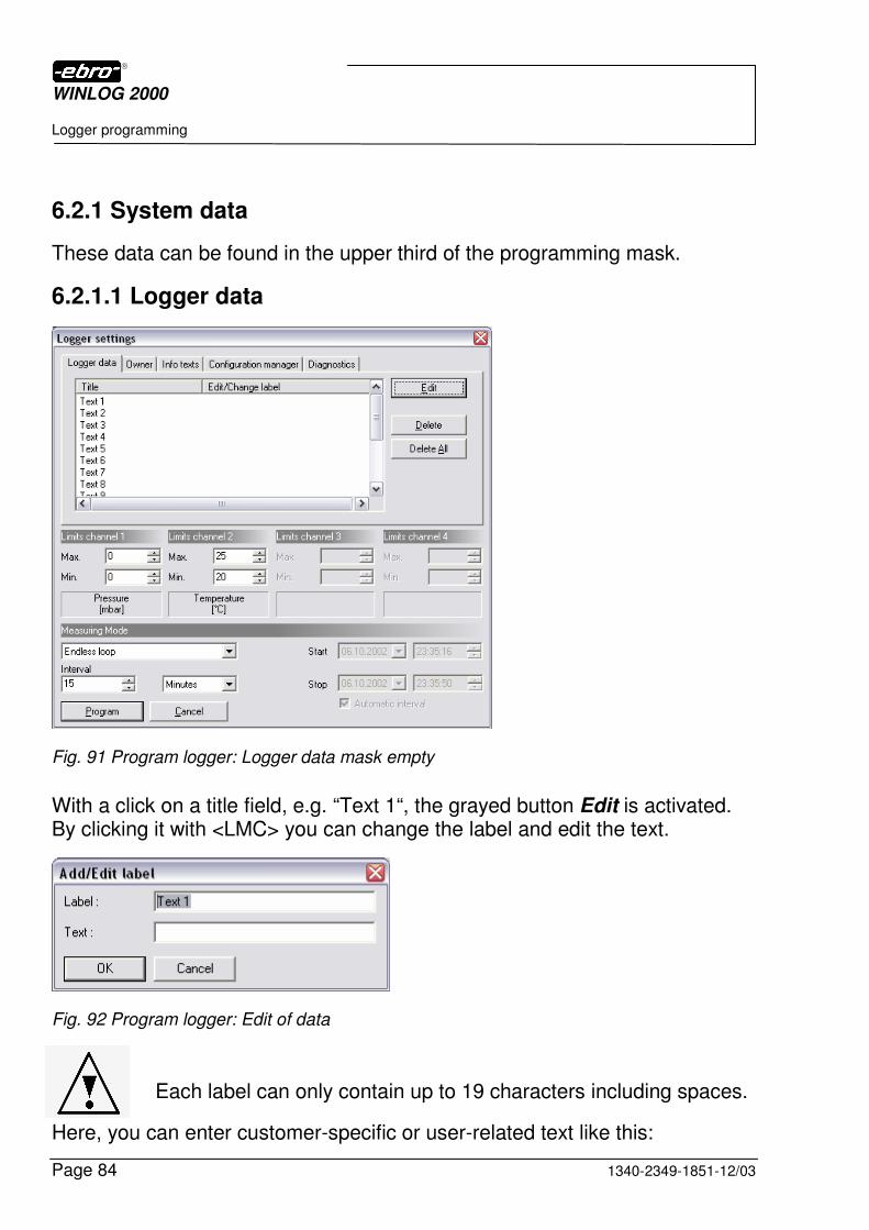
6.2.1 System data
These data can be found in the upper third of the programming mask.
6.2.1.1 Logger data
Fig. 91 Program logger: Logger data mask empty
With a click on a title field, e.g. “Text 1“, the grayed button Edit is activated. By clicking it with <LMC> you can change the label and edit the text.
Fig. 92 Program logger: Edit of data
Each label can only contain up to 19 characters including spaces.
Here, you can enter customer-specific or user-related text like this:
WINLOG 2000
Logger programming
1340-2349-1851-12/03 Page 85
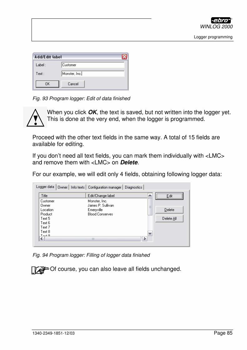
Fig. 93 Program logger: Edit of data finished
When you click OK, the text is saved, but not written into the logger yet. This is done at the very end, when the logger is programmed.
Proceed with the other text fields in the same way. A total of 15 fields are available for editing.
If you don’t need all text fields, you can mark them individually with <LMC> and remove them with <LMC> on Delete.
For our example, we will edit only 4 fields, obtaining following logger data:
Fig. 94 Program logger: Filling of logger data finished
Of course, you can also leave all fields unchanged.
WINLOG 2000
Logger programming
Page 86 1340-2349-1851-12/03
6.2.1.2 Owner data
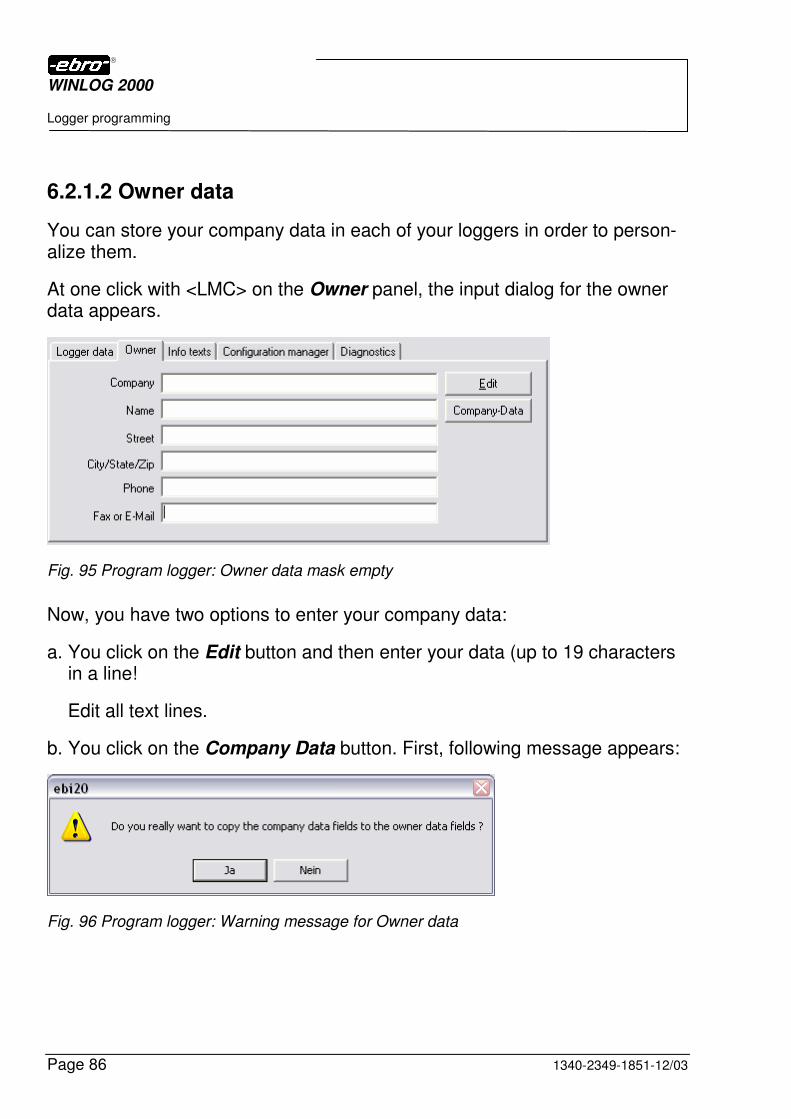
You can store your company data in each of your loggers in order to person-alize them.
At one click with <LMC> on the Owner panel, the input dialog for the owner data appears.
Fig. 95 Program logger: Owner data mask empty
Now, you have two options to enter your company data:
a. You click on the Edit button and then enter your data (up to 19 characters in a line!
Edit all text lines.
b. You click on the Company Data button. First, following message appears:
Fig. 96 Program logger: Warning message for Owner data
WINLOG 2000
Logger programming
1340-2349-1851-12/03 Page 87
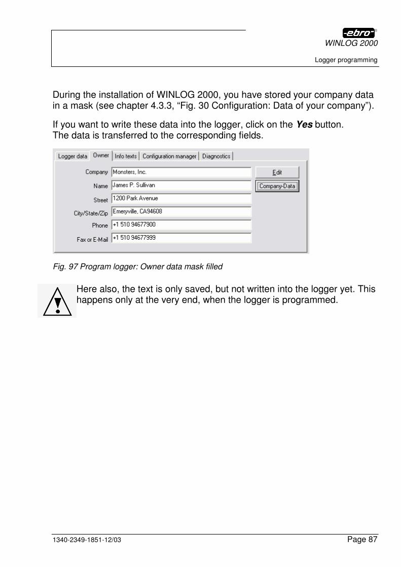
During the installation of WINLOG 2000, you have stored your company data in a mask (see chapter 4.3.3, “Fig. 30 Configuration: Data of your company”).
If you want to write these data into the logger, click on the Yes button. The data is transferred to the corresponding fields.
Fig. 97 Program logger: Owner data mask filled
Here also, the text is only saved, but not written into the logger yet. This happens only at the very end, when the logger is programmed.
WINLOG 2000
Logger programming
Page 88 1340-2349-1851-12/03
6.2.1.3 Information text
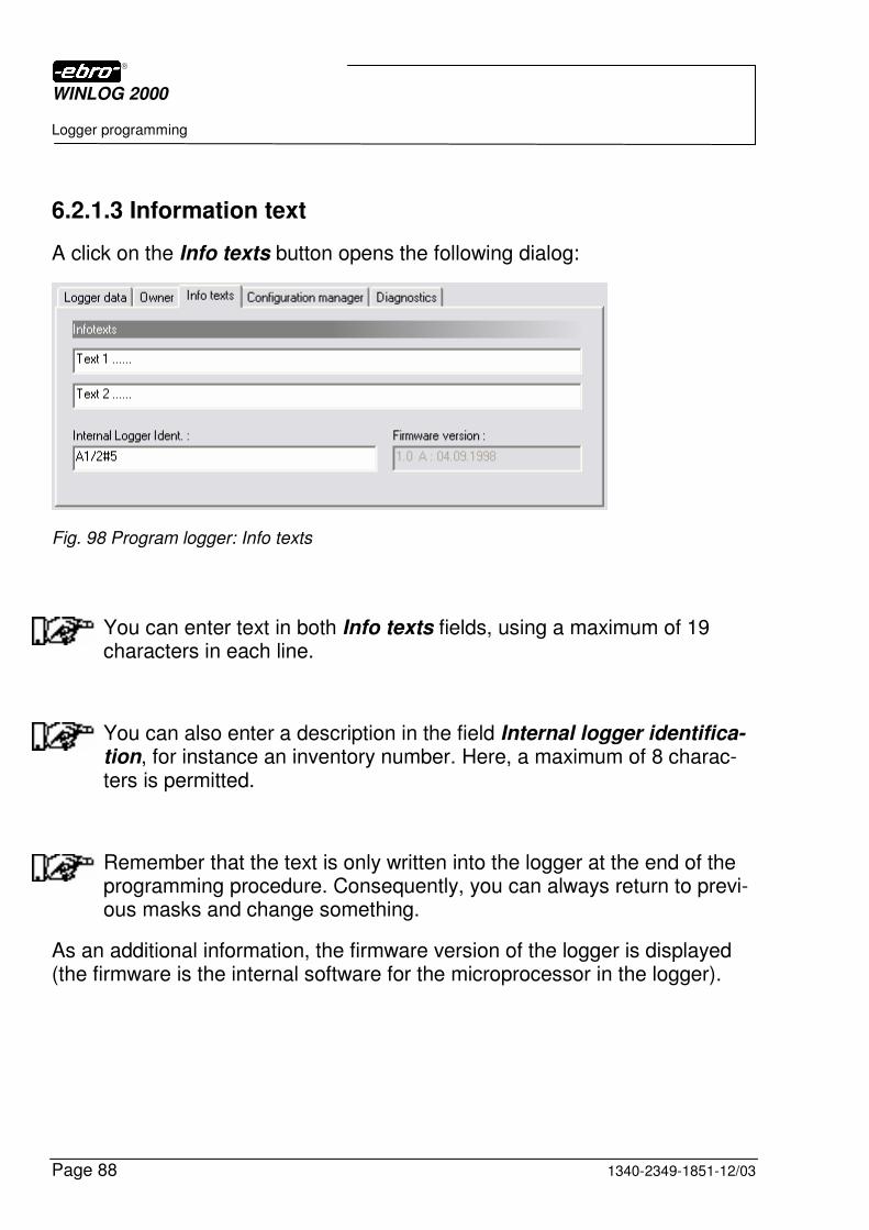
A click on the Info texts button opens the following dialog:
Fig. 98 Program logger: Info texts
You can enter text in both Info texts fields, using a maximum of 19 characters in each line.
You can also enter a description in the field Internal logger identifica-tion, for instance an inventory number. Here, a maximum of 8 charac-ters is permitted.
Remember that the text is only written into the logger at the end of the programming procedure. Consequently, you can always return to previ-ous masks and change something.
As an additional information, the firmware version of the logger is displayed (the firmware is the internal software for the microprocessor in the logger).
WINLOG 2000
Logger programming
1340-2349-1851-12/03 Page 89
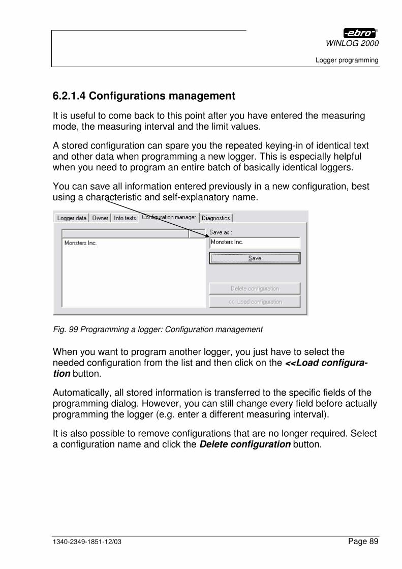
6.2.1.4 Configurations management
It is useful to come back to this point after you have entered the measuring mode, the measuring interval and the limit values.
A stored configuration can spare you the repeated keying-in of identical text and other data when programming a new logger. This is especially helpful when you need to program an entire batch of basically identical loggers.
You can save all information entered previously in a new configuration, best using a characteristic and self-explanatory name.
Fig. 99 Programming a logger: Configuration management
When you want to program another logger, you just have to select the needed configuration from the list and then click on the <<Load configura-tion button.
Automatically, all stored information is transferred to the specific fields of the programming dialog. However, you can still change every field before actually programming the logger (e.g. enter a different measuring interval).
It is also possible to remove configurations that are no longer required. Select a configuration name and click the Delete configuration button.
WINLOG 2000
Logger programming
Page 90 1340-2349-1851-12/03
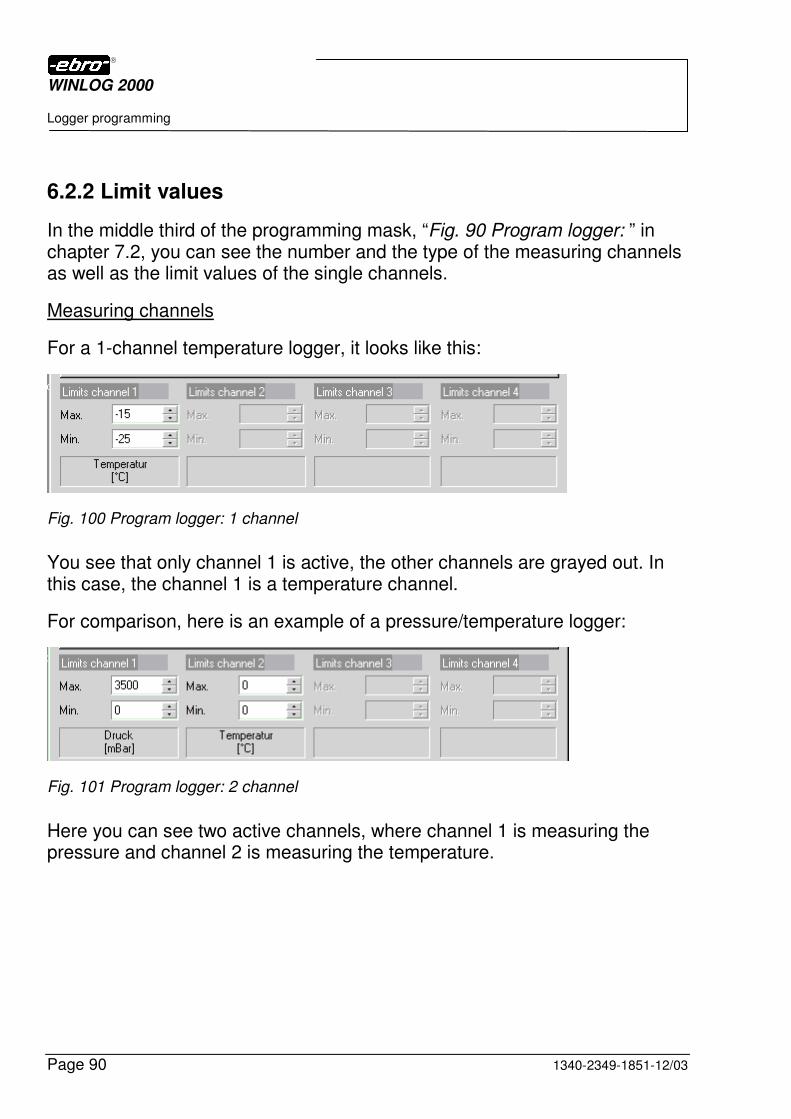
6.2.2 Limit values
In the middle third of the programming mask, “Fig. 90 Program logger: ” in chapter 7.2, you can see the number and the type of the measuring channels as well as the limit values of the single channels.
Measuring channels
For a 1-channel temperature logger, it looks like this:
Fig. 100 Program logger: 1 channel
You see that only channel 1 is active, the other channels are grayed out. In this case, the channel 1 is a temperature channel.
For comparison, here is an example of a pressure/temperature logger:
Fig. 101 Program logger: 2 channel
Here you can see two active channels, where channel 1 is measuring the pressure and channel 2 is measuring the temperature.
WINLOG 2000
Logger programming
1340-2349-1851-12/03 Page 91
Limit values
In the graphic representation of the measured values, the limits are displayed as horizontal lines. This way, you can immediately see if all measured values have been within the preset tolerance.
You can enter an upper and a lower limit value for each measuring channel.
In BUS systems consisting of EBI data loggers, these limit values can be permanently monitored. If the upper or the lower limit value is ex-ceeded, an alarm can be generated (see chapter 11 for details).
On some of the EBI-2 series loggers the display blinks when a limit is violated. Check your logger’s manual for details.
Fig. 102 Program logger: diologbox for limits
Generally limits only can be edited in the basic (native) unit of the logger. This means that you cannot edit limits in derived units (like °F, for instance).
In the dialog you can see the basic unit of each channel. When you start editing the limit values you will get the following reminder message.
Fig. 103 Program logger: Edit limits in basic unit
WINLOG 2000
Logger programming
Page 92 1340-2349-1851-12/03
There are two ways of setting the limit values:
a. Mark the default limit with the mouse and key in the new value.
You can only use integer values for limits!
b. You click on the buttons with the mouse, until the correct value appears.
The maximum limit value must be greater than the minimum value.
Example: OK Max: +30°C Min: -10°C
or Max: -15°C Min: -18°C
Not OK Max: +30°C Min: +40°C
or Max: -18°C Min: -15°C
If you disregard this rule you will be reminded to change the values by the following message, when you start to program the logger.
Fig. 104 Program logger: Incorrect limit
WINLOG 2000
Logger programming
1340-2349-1851-12/03 Page 93
6.2.3 Interval and measuring mode
The measurements the logger is meant to perform and to store should be adapted to the measuring task. It doesn’t make sense to measure a top-opening freezer in 1-second intervals or a heating-up phase in 15-minutes intervals.
In order to adapt to your task, you can freely choose the interval and the measuring mode.
6.2.3.1 Measuring interval
In the lower third of the programming dialog you can determine the measuring interval.
Fig. 105 Program logger: Measuring interval
When you click on the symbol next to “Minutes“, the following panel opens:
Fig. 106 Program logger: Measuring rate - Minutes
Select a time unit with <LMC>.
WINLOG 2000
Logger programming
Page 94 1340-2349-1851-12/03
Enter a value in the Interval field directly with the keyboard or change the
default value using the buttons.
6.2.3.2 Measuring mode
In the lower third of the programming dialog you can determine the measuring mode.
Fig. 107 Program logger: Measuring mode
Click on the symbol next to “Endless loop“ to display an options list:
Fig. 108 Program logger: Measuring mode endless
Select one of the three measuring modes from the list by clicking with <LMC>. The measuring modes are described in the following sub-chapters.

WINLOG 2000
Logger programming
1340-2349-1851-12/03 Page 95
6.2.3.2.1 Endless loop measurement
Fig. 109 Program logger: Measuring mode endless loop
In this mode, the logger is measuring continuously. You don’t need a start and stop point here. The logger starts measuring immediately after program-ming ans doesn’t stop until it is re-programmed. The values are written into memory by the FIFO method (first in – first out). When the memory is full, the first values are overwritten with new values.
Therefor you can only change the measuring interval. All other fields are inactive.
WINLOG 2000
Logger programming
Page 96 1340-2349-1851-12/03
6.2.3.2.2 Start-stop measurement
If you have selected the start-stop measurement, you’ll see the following:
Fig. 110 Program logger: Measuring mode Start-Stop
In this mode, there are two options:
a. Automatic interval Here, the Interval field is inactive. This means that the logger tries to com-pletely fill its memory for the preset period of time. The appropriate measur-ing interval is determined automatically. To achieve this, check the box Automatic Interval.
b. Variable interval
If you want to make a measurement with a fixed interval and certain start and stop points, un-check the box Automatic interval. You can now set both interval and start/stop points:
Fig. 111 Program logger: Measuring mode Automatic interval
WINLOG 2000
Logger programming
1340-2349-1851-12/03 Page 97
To set the start and stop times, proceed as follows:
Entering the date:
If you click on the symbol next to “Start“ or “Stop", the following panel opens:
Fig. 112 Program logger: Entering date
Select the date to start measuring.
You can turn the pages of the calendar with the buttons to change the month.
Entering the time:
If you want to set the time, mark the hours with the mouse, as shown in the
next figure. With the buttons, you can set the hours to the desired values.
Fig. 113 Program logger: Entering time
Proceed in the same way with the minutes and seconds. This applies both to the start time and the stop time.
WINLOG 2000
Logger programming
Page 98 1340-2349-1851-12/03
Loggers programmed in this measuring mode will begin measuring and recording at the start time entered. The recording continues until the stop time has been reached.
6.2.3.2.3 Start time and interval measurement
If you have chosen the start time and interval measurement, you will see this:
Fig. 114 Program logger: Start-interval measurement
You can edit only the interval and the start time.
Loggers programmed in this measuring mode will begin measuring and recording at the start time entered. The recording will continue until the logger memory runs out of space. The calculated stop time is displayed in the inactive stop field.
To set the start time, proceed as follows:
Entering the date:
If you click on the symbol next to “Start“, the following panel opens:
Fig. 115 Program logger: Entering start date
WINLOG 2000
Logger programming
1340-2349-1851-12/03 Page 99
Select a day to start measuring.
You can turn the pages of the calendar with the buttons to change the month.
Entering the time:
If you want to set the time, mark the hours with <LMC>, as shown in the next
figure. With the buttons, you can set the hours to the desired values.
Fig. 116 Program logger: Entering start time
Proceed in the same way with the minutes and seconds.
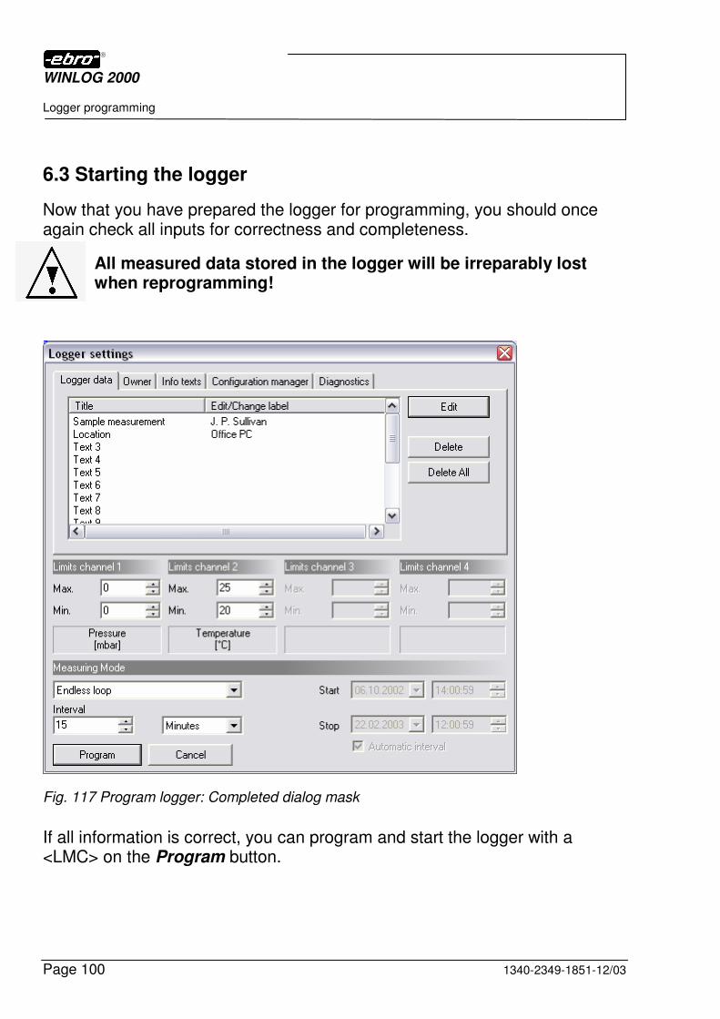
WINLOG 2000
Logger programming
Page 100 1340-2349-1851-12/03
6.3 Starting the logger
Now that you have prepared the logger for programming, you should once again check all inputs for correctness and completeness.
All measured data stored in the logger will be irreparably lost when reprogramming!
Fig. 117 Program logger: Completed dialog mask
If all information is correct, you can program and start the logger with a <LMC> on the Program button.

WINLOG 2000
Logger programming
1340-2349-1851-12/03 Page 101
First, a safety inquiry appears:
Fig. 118 Program logger: Safety interrogation
If you are not sure, click on the “No“ button. Now you can decide what applies to you.
Fig. 119 Program logger: Read logger data?
If you answer Yes, the logger will be read-out, and you can store the meas-ured data. Immediately after the storage, the logger is automatically pro-grammed.
If you answer No, the program returns to the programming dialog.
However, if you are sure you want to program the logger after the safety inquiry, click on Yes in the message in “Fig. 118 Program logger: Safety interrogation”.
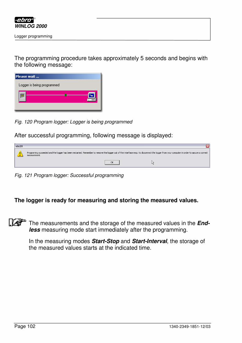
WINLOG 2000
Logger programming
Page 102 1340-2349-1851-12/03
The programming procedure takes approximately 5 seconds and begins with the following message:
Fig. 120 Program logger: Logger is being programmed
After successful programming, following message is displayed:
Fig. 121 Program logger: Successful programming
The logger is ready for measuring and storing the measured values.
The measurements and the storage of the measured values in the End-less measuring mode start immediately after the programming.
In the measuring modes Start-Stop and Start-Interval, the storage of the measured values starts at the indicated time.

WINLOG 2000
Logger read-out
1340-2349-1851-12/03 Page 103
7 Logger read-out
7.1 Premises
In order to be able to evaluate the measured data recorded with a logger, it is necessary to read out the contents of the logger memory.
The logger memory contains the entered owner data, the text fields and the measured values.
For the readout, this logger must be connected with the PC. Depending on the logger type, the corresponding interface or data cable must be connected to the PC (see chapters 3.1, 3.2, and 7.1).
Connection of series EBI 85A or EBI 125A loggers
Place standard loggers (series EBI 85A or EBI 125A types) into the interface.
Connection of series EBI 2 and EBI 3 loggers
With loggers using an RS 232 interface (series EBI-2 and EBI-3 types), first remove the protection cap from the RS 232 socket on the backside of the logger. Now connect the data cable to both logger and PC.
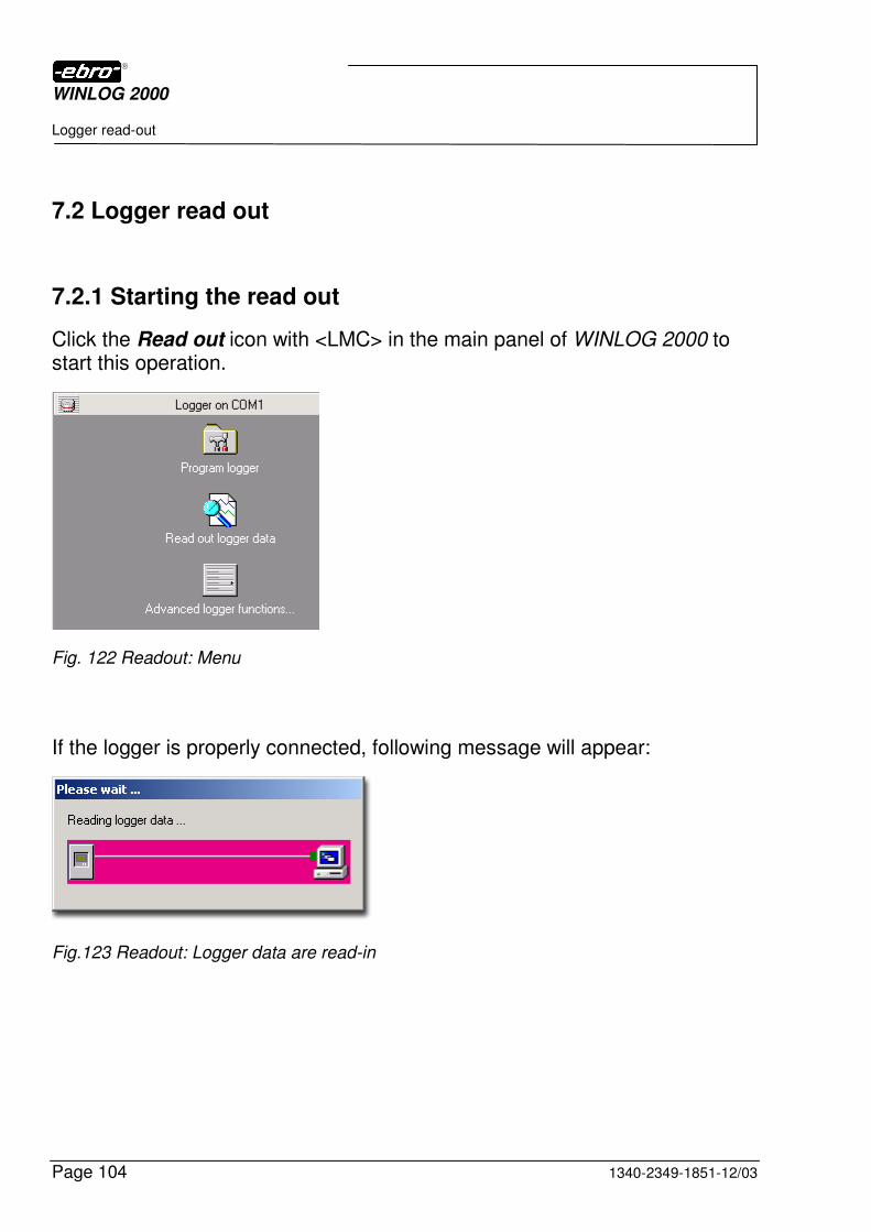
WINLOG 2000
Logger read-out
Page 104 1340-2349-1851-12/03
7.2 Logger read out
7.2.1 Starting the read out
Click the Read out icon with <LMC> in the main panel of WINLOG 2000 to start this operation.
Fig. 122 Readout: Menu
If the logger is properly connected, following message will appear:
Fig.123 Readout: Logger data are read-in
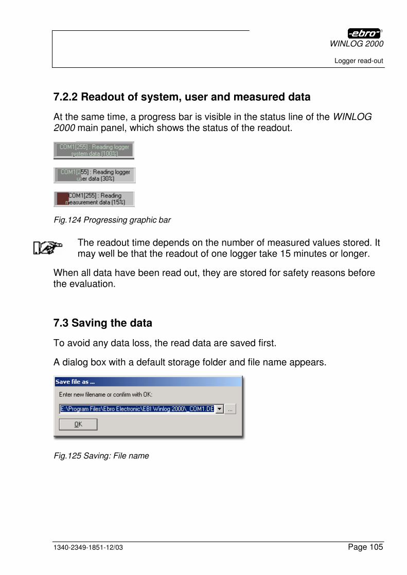
WINLOG 2000
Logger read-out
1340-2349-1851-12/03 Page 105
7.2.2 Readout of system, user and measured data
At the same time, a progress bar is visible in the status line of the WINLOG 2000 main panel, which shows the status of the readout.
Fig.124 Progressing graphic bar
The readout time depends on the number of measured values stored. It may well be that the readout of one logger take 15 minutes or longer.
When all data have been read out, they are stored for safety reasons before the evaluation.
7.3 Saving the data
To avoid any data loss, the read data are saved first.
A dialog box with a default storage folder and file name appears.
Fig.125 Saving: File name
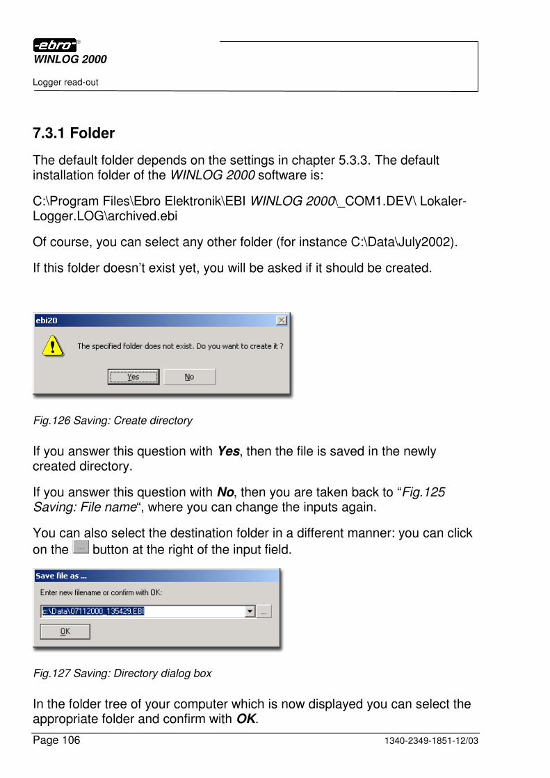
WINLOG 2000
Logger read-out
Page 106 1340-2349-1851-12/03
7.3.1 Folder
The default folder depends on the settings in chapter 5.3.3. The default installation folder of the WINLOG 2000 software is:
C:\Program Files\Ebro Elektronik\EBI WINLOG 2000\_COM1.DEV\ Lokaler-Logger.LOG\archived.ebi
Of course, you can select any other folder (for instance C:\Data\July2002).
If this folder doesn’t exist yet, you will be asked if it should be created.
Fig.126 Saving: Create directory
If you answer this question with Yes, then the file is saved in the newly created directory.
If you answer this question with No, then you are taken back to “Fig.125 Saving: File name“, where you can change the inputs again.
You can also select the destination folder in a different manner: you can click
on the button at the right of the input field.
Fig.127 Saving: Directory dialog box
In the folder tree of your computer which is now displayed you can select the appropriate folder and confirm with OK.
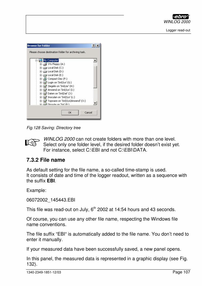
WINLOG 2000
Logger read-out
1340-2349-1851-12/03 Page 107
Fig.128 Saving: Directory tree
WINLOG 2000 can not create folders with more than one level. Select only one folder level, if the desired folder doesn’t exist yet. For instance, select C:\EBI and not C:\EBI\DATA.
7.3.2 File name
As default setting for the file name, a so-called time-stamp is used. It consists of date and time of the logger readout, written as a sequence with the suffix EBI.
Example:
06072002_145443.EBI
This file was read-out on July, 6th 2002 at 14:54 hours and 43 seconds.
Of course, you can use any other file name, respecting the Windows file name conventions.
The file suffix “EBI“ is automatically added to the file name. You don’t need to enter it manually.
If your measured data have been successfully saved, a new panel opens.
In this panel, the measured data is represented in a graphic display (see Fig. 132).
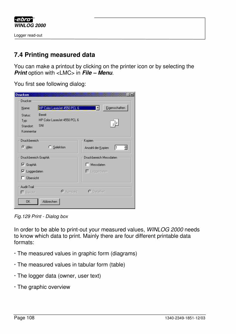
WINLOG 2000
Logger read-out
Page 108 1340-2349-1851-12/03
7.4 Printing measured data
You can make a printout by clicking on the printer icon or by selecting the Print option with <LMC> in File – Menu.
You first see following dialog:
Fig.129 Print - Dialog box
In order to be able to print-out your measured values, WINLOG 2000 needs to know which data to print. Mainly there are four different printable data formats:
� The measured values in graphic form (diagrams)
� The measured values in tabular form (table)
� The logger data (owner, user text)
� The graphic overview

WINLOG 2000
Logger read-out
1340-2349-1851-12/03 Page 109
You must now select which data are to be printed and how they should be arranged.
Printer
Select your printer here. With a click on Properties, you can set printer-related properties (see chapter 5.4.1.1).
Printing range
Select All for printing all open documents, or Selection for printing only the document selected at present.
Printing range Graphics
Select one or more of the following options, in order to adapt the graphic printout to your requirements:
Graphics: Select this option if you want the measured values to be printed as a diagram.
Logger data: Select this option if you want the logger data (owner data, user text, ...) to be printed in addition to the measured values on the same sheet.
Overview: This option is only active if you have checked the All field in the printing range field. If you select this option, an overview of all available curves is printed on an extra sheet in addition to the diagrams.
Printing range Measured data
Measured data: Choose this option, if you want to print the measured values as a table.
Logger data: Select this option if, in addition to the measured values, you want to print the logger data (owner data, user texts, ...) on the same sheet.
Copies
Enter here the number of copies you need.
Audit trail
This option is described in chapter 12.3.3 (CFR 21 Part 11 version).

WINLOG 2000
Logger read-out
Page 110 1340-2349-1851-12/03
7.5 Exporting measured values
This option is described in detail in chapter 9.3.15.

WINLOG 2000
Processing of measured values
1340-2349-1851-12/03 Page 111
8 Processing of measured values
After saving the measured data, you now have their graphic display on the screen.
8.1 The time/measured values diagram
The diagram represents the curves of all measured documents opened.
WINLOG 2000 is capable of representing up to 32 curves at the same time. However, it is only possible to work with a maximum of 4 X-axes and a maximum of 4 Y-axes. This means that the curves to be repre-sented should, if possible, all have the same time and unit references.
In the diagram, the Y-axis is the measured value axis, whereas the X-axis is the time axis.
Due to the internal logger identification, the Y-axis is automatically labelled with the correct unit.
In chapter 10.3.6 you will see that in the Professional version of WINLOG 2000 it is possible to use and administrate other units.
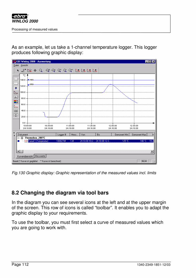
WINLOG 2000
Processing of measured values
Page 112 1340-2349-1851-12/03
As an example, let us take a 1-channel temperature logger. This logger produces following graphic display:
Fig.130 Graphic display: Graphic representation of the measured values incl. limits
8.2 Changing the diagram via tool bars
In the diagram you can see several icons at the left and at the upper margin of the screen. This row of icons is called “toolbar”. It enables you to adapt the graphic display to your requirements.
To use the toolbar, you must first select a curve of measured values which you are going to work with.
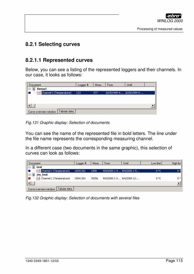
WINLOG 2000
Processing of measured values
1340-2349-1851-12/03 Page 113
8.2.1 Selecting curves
8.2.1.1 Represented curves
Below, you can see a listing of the represented loggers and their channels. In our case, it looks as follows:
Fig.131 Graphic display: Selection of documents
You can see the name of the represented file in bold letters. The line under the file name represents the corresponding measuring channel.
In a different case (two documents in the same graphic), this selection of curves can look as follows:
Fig.132 Graphic display: Selection of documents with several files

WINLOG 2000
Processing of measured values
Page 114 1340-2349-1851-12/03
8.2.1.2 Statistical values
In this overview of curves, you can see various information regarding the logger (start of measurement, end of measurement, logger number, limit values, and some statistical information).
Here is an overview of the displayed information:
Logger # The serial number of the logger which generated this document of measured values.
Measured values How many measured values are displayed.
From The start time of the measurement.
To The stop time of the measurement.
Minimum limit The minimum limit value during the measurement.
Maximum limit The maximum limit value during the measurement.
Minimum The lowest measured value during the complete measurement.
Maximum The highest measured value during the complete measurement.
Average The calculated arithmetic average of all measured values.
Variance The calculated variance of all measured values.
Standard deviation The calculated standard deviation of all measured values.

WINLOG 2000
Processing of measured values
1340-2349-1851-12/03 Page 115
Max. diff. The difference between Minimum and Maximum.
Period of time (Max. diff.) Period of time between the reaching of Minimum and Maximum.
Time above Maximum Period of time during which the measured values were above the maximum limit.
Period of the measurement The total period of time of the measurement.
The calculated and displayed statistical values always refer to the saved curve, and not to the one displayed. If you change them by zooming, the statistical values remain unchanged.
As soon as a range of the curve has been marked, all statistical values in the curve overview refer only to the marked range.
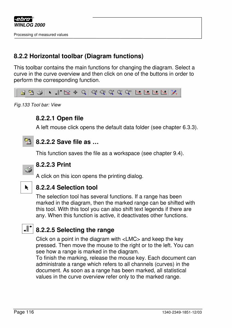
WINLOG 2000
Processing of measured values
Page 116 1340-2349-1851-12/03
8.2.2 Horizontal toolbar (Diagram functions)
This toolbar contains the main functions for changing the diagram. Select a curve in the curve overview and then click on one of the buttons in order to perform the corresponding function.
Fig.133 Tool bar: View
8.2.2.1 Open file
A left mouse click opens the default data folder (see chapter 6.3.3).
8.2.2.2 Save file as …
This function saves the file as a workspace (see chapter 9.4).
8.2.2.3 Print
A click on this icon opens the printing dialog.
8.2.2.4 Selection tool
The selection tool has several functions. If a range has been marked in the diagram, then the marked range can be shifted with this tool. With this tool you can also shift text legends if there are any. When this function is active, it deactivates other functions.
8.2.2.5 Selecting the range
Click on a point in the diagram with <LMC> and keep the key pressed. Then move the mouse to the right or to the left. You can see how a range is marked in the diagram. To finish the marking, release the mouse key. Each document can administrate a range which refers to all channels (curves) in the document. As soon as a range has been marked, all statistical values in the curve overview refer only to the marked range.
WINLOG 2000
Processing of measured values
1340-2349-1851-12/03 Page 117
8.2.2.6 Scanning the curve
This tool serves to scan the diagram for measured values.
In the diagram appears a vertical line, which indicates the position of the cursor, and a panel, which displays the measured values for all channels of the document at this position.
The cursor can be moved with the mouse or with the transport bar
. In addition, the present position of the cursor is displayed in the table of measured values.
8.2.2.7 Dynamic shifting
The dynamic shifting enables you to shift all curves according to the movement of the mouse to the left, to the right, upwards or downwards with a left mouse click in the diagram (do not release the mouse key!).
8.2.2.8 Zooming
With this function, you can select a range to enlarge.
For this purpose, click on a point in the diagram with <LMC> and keep the mouse key pressed. Then move the mouse in order to define a rectangular selection range (symbolized with a dashed line). When the left mouse key is released, the selected range is enlarged.
8.2.2.9 Enlarging the curve size on the X-axis
This tool serves to enlarge the momentarily selected curve in the X-direction.
8.2.2.10 Reducing the curve size on the X-axis
This tool serves to compress the momentarily selected curve in the X-direction.
WINLOG 2000
Processing of measured values
Page 118 1340-2349-1851-12/03
8.2.2.11 Enlarging the curve size on the Y-axis
This tool serves to enlarge the momentarily selected curve in the Y-direction.
8.2.2.12 Reducing the curve size on the Y-axis
With this tool, the momentarily selected curve is reduced in the Y-direction.
8.2.2.13 Re-establishing the original size
This tool serves to display all curves in their original size.
8.2.2.14 Shifting curve to the right
8.2.2.15 Shifting curve to the left
This tool serves to shift the momentarily selected curve to the right or to the left.
8.2.2.16 Shifting curve upwards
8.2.2.17 Shiffting curve downwards
This tool serves to shift the momentarily selected curve upwards or downwards.
8.2.2.18 Units
This tool enables you to administrate measurement units. It is only available with the Professional, the BUS, and the CFR 21 Part 11 versions (see chapter 10.3.6).
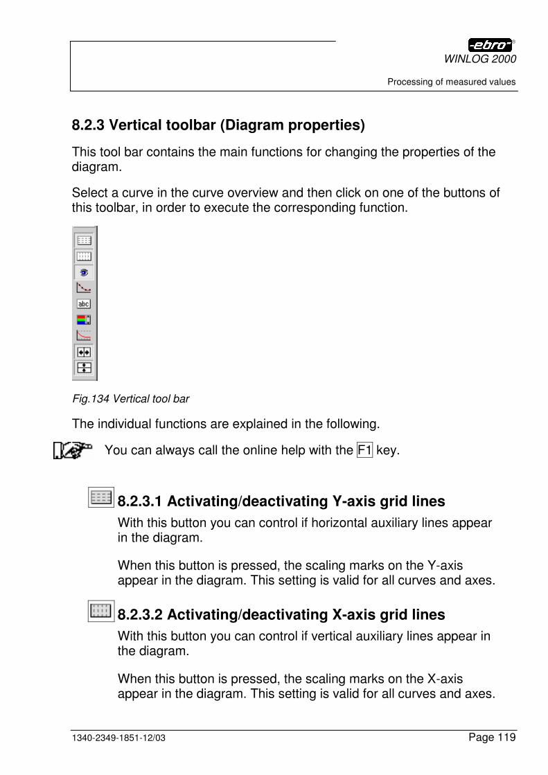
WINLOG 2000
Processing of measured values
1340-2349-1851-12/03 Page 119
8.2.3 Vertical toolbar (Diagram properties)
This tool bar contains the main functions for changing the properties of the diagram.
Select a curve in the curve overview and then click on one of the buttons of this toolbar, in order to execute the corresponding function.
Fig.134 Vertical tool bar
The individual functions are explained in the following.
You can always call the online help with the F1 key.
8.2.3.1 Activating/deactivating Y-axis grid lines
With this button you can control if horizontal auxiliary lines appear in the diagram.
When this button is pressed, the scaling marks on the Y-axis appear in the diagram. This setting is valid for all curves and axes.
8.2.3.2 Activating/deactivating X-axis grid lines
With this button you can control if vertical auxiliary lines appear in the diagram.
When this button is pressed, the scaling marks on the X-axis appear in the diagram. This setting is valid for all curves and axes.
WINLOG 2000
Processing of measured values
Page 120 1340-2349-1851-12/03
8.2.3.3 Activating/deactivating the curve
With this button (eye symbol) you can control whether a curve of measured values is visible in the diagram or not.
For activating or deactivating a curve, select the corresponding curve in the curve overview.
Click on this button to display or to hide the curve.
This function has no effect on the table of measured values. Even the hidden curves appear in the table of measured values.
8.2.3.4 Displaying/blinding out limit values
This function enables you display the limit values of the document in the diagram.
For this purpose, select the curve which you want to work with. Then click on this button to show or hide the limit values.
8.2.3.5 Activating/deactivating the curve marker
With this function you can set so-called markers on the individual curves.
Markers are symbols drawn on the curve in equal distances, which enable you to better distinguish the individual curves (when several curves are simultaneously displayed in one diagram).
This is particularly useful if you want to print the diagram, but you don’t have a color printer.
For activating or deactivating the curve markers, select the corre-sponding curve in the curve overview.
Click on this button, in order to display or hide the markers.
WINLOG 2000
Processing of measured values
1340-2349-1851-12/03 Page 121
8.2.3.6 Activating/deactivating the autoscaling of the X-axis
As a standard, the scaling of an axis is set such that even values appear if possible (e.g. 18:00, 19:00, 20:00 or 50°C, 60°C, 70°C).
When zooming or shifting a curve, WINLOG 2000 also tries to use even values for scaling, if possible.
If this behavior is not desired, you can switch on or off the autoscal-ing separately for the X- and Y-axis.
This button activates/deactivates the autoscaling for the X-axis.
8.2.3.7 Activating/deactivating the autoscaling of the Y-axis
Here also, the scaling of an axis is set such that even values are visible, if possible.
When zooming or shifting a curve, WINLOG 2000 tries to use even values for scaling, if possible.
If this behavior is not desired, you can switch on or off the autoscal-ing.
This button activates/deactivates the autoscaling for the Y-axis.
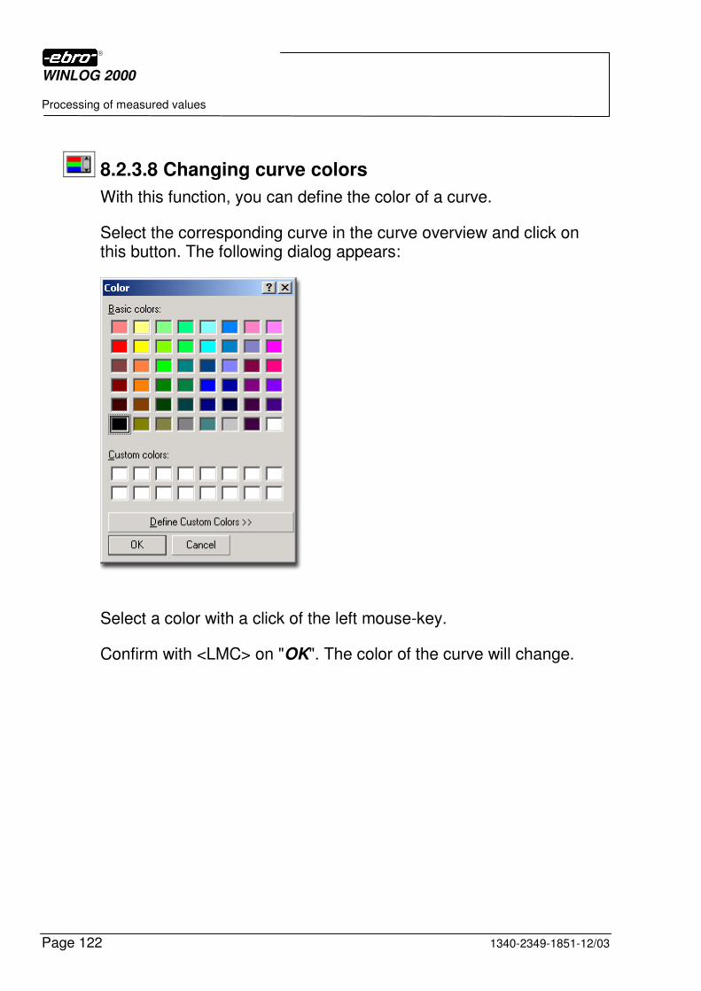
WINLOG 2000
Processing of measured values
Page 122 1340-2349-1851-12/03
8.2.3.8 Changing curve colors
With this function, you can define the color of a curve.
Select the corresponding curve in the curve overview and click on this button. The following dialog appears:
Select a color with a click of the left mouse-key.
Confirm with <LMC> on "OK". The color of the curve will change.
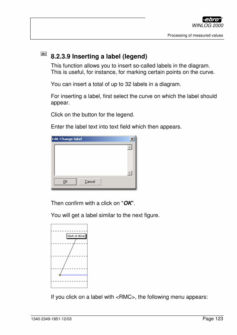
WINLOG 2000
Processing of measured values
1340-2349-1851-12/03 Page 123
8.2.3.9 Inserting a label (legend)
This function allows you to insert so-called labels in the diagram. This is useful, for instance, for marking certain points on the curve.
You can insert a total of up to 32 labels in a diagram.
For inserting a label, first select the curve on which the label should appear.
Click on the button for the legend.
Enter the label text into text field which then appears.
Then confirm with a click on "OK".
You will get a label similar to the next figure.
If you click on a label with <RMC>, the following menu appears:
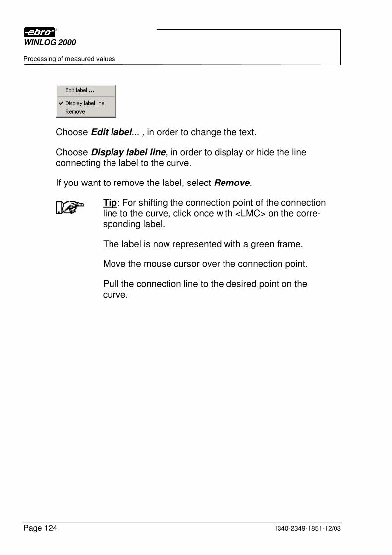
WINLOG 2000
Processing of measured values
Page 124 1340-2349-1851-12/03
Choose Edit label... , in order to change the text.
Choose Display label line, in order to display or hide the line connecting the label to the curve.
If you want to remove the label, select Remove.
Tip: For shifting the connection point of the connection line to the curve, click once with <LMC> on the corre-sponding label.
The label is now represented with a green frame.
Move the mouse cursor over the connection point.
Pull the connection line to the desired point on the curve.
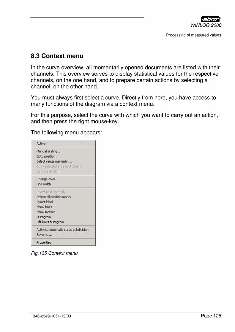
WINLOG 2000
Processing of measured values
1340-2349-1851-12/03 Page 125
8.3 Context menu
In the curve overview, all momentarily opened documents are listed with their channels. This overview serves to display statistical values for the respective channels, on the one hand, and to prepare certain actions by selecting a channel, on the other hand.
You must always first select a curve. Directly from here, you have access to many functions of the diagram via a context menu.
For this purpose, select the curve with which you want to carry out an action, and then press the right mouse-key.
The following menu appears:
Fig.135 Context menu
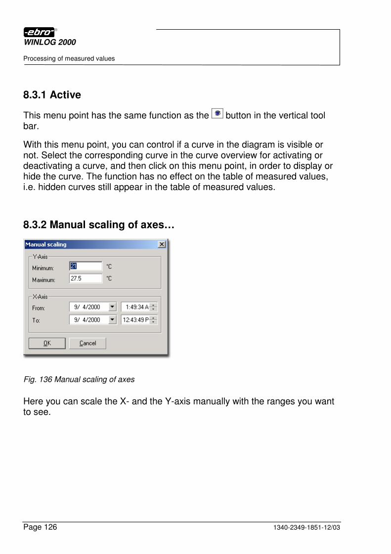
WINLOG 2000
Processing of measured values
Page 126 1340-2349-1851-12/03
8.3.1 Active
This menu point has the same function as the button in the vertical tool bar.
With this menu point, you can control if a curve in the diagram is visible or not. Select the corresponding curve in the curve overview for activating or deactivating a curve, and then click on this menu point, in order to display or hide the curve. The function has no effect on the table of measured values, i.e. hidden curves still appear in the table of measured values.
8.3.2 Manual scaling of axes…
Fig. 136 Manual scaling of axes
Here you can scale the X- and the Y-axis manually with the ranges you want to see.

WINLOG 2000
Processing of measured values
1340-2349-1851-12/03 Page 127
8.3.3 Go to position …
This function allows you to place the scan cursor on a certain point of the curve. This dialog appears for the selection of the point:
In this dialog, you can exactly position the trace cursor on a certain point of your curve of measured values.
For this purpose, select your option with the mouse and then click on OK.
Fig.137 Positioning of the cursor
Start Places the cursor on the first measured value.
End Places the cursor on the last measured value.
Minimum WINLOG 2000 searches for the minimum of this curve and places the cursor on this point.
Maximum WINLOG 2000 searches for the maximum of this curve and places the cursor on this point.
Position Places the cursor on the position you have indicated.
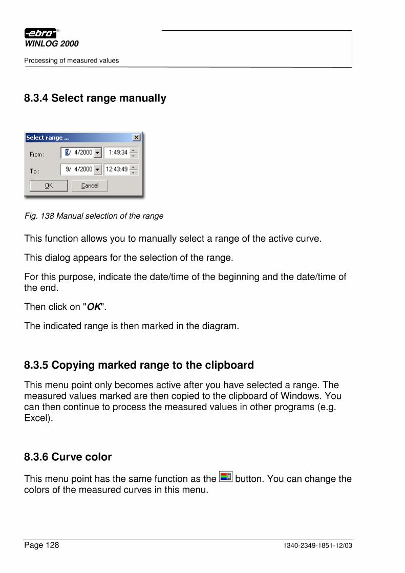
WINLOG 2000
Processing of measured values
Page 128 1340-2349-1851-12/03
8.3.4 Select range manually
Fig. 138 Manual selection of the range
This function allows you to manually select a range of the active curve.
This dialog appears for the selection of the range.
For this purpose, indicate the date/time of the beginning and the date/time of the end.
Then click on "OK".
The indicated range is then marked in the diagram.
8.3.5 Copying marked range to the clipboard
This menu point only becomes active after you have selected a range. The measured values marked are then copied to the clipboard of Windows. You can then continue to process the measured values in other programs (e.g. Excel).
8.3.6 Curve color
This menu point has the same function as the button. You can change the colors of the measured curves in this menu.
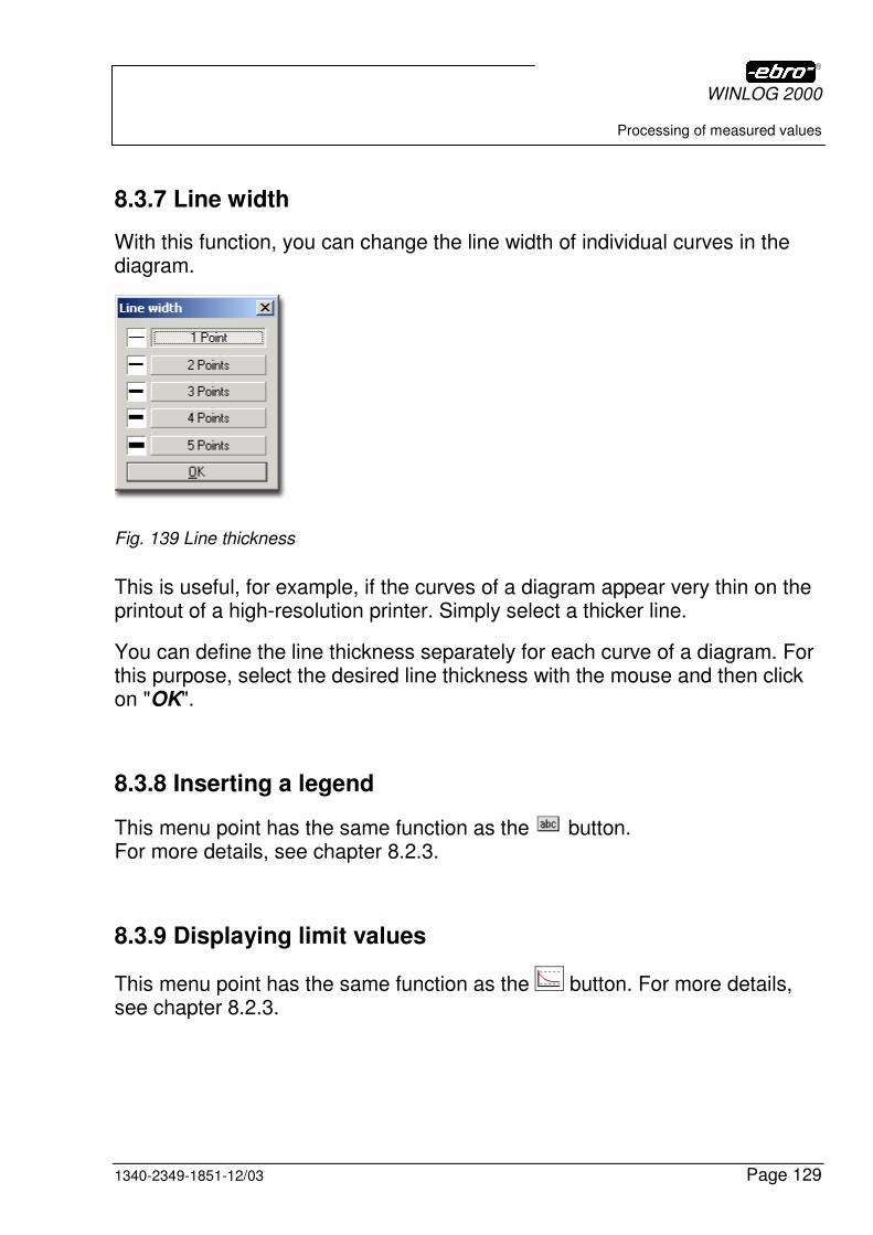
WINLOG 2000
Processing of measured values
1340-2349-1851-12/03 Page 129
8.3.7 Line width
With this function, you can change the line width of individual curves in the diagram.
Fig. 139 Line thickness
This is useful, for example, if the curves of a diagram appear very thin on the printout of a high-resolution printer. Simply select a thicker line.
You can define the line thickness separately for each curve of a diagram. For this purpose, select the desired line thickness with the mouse and then click on "OK".
8.3.8 Inserting a legend
This menu point has the same function as the button. For more details, see chapter 8.2.3.
8.3.9 Displaying limit values
This menu point has the same function as the button. For more details, see chapter 8.2.3.

WINLOG 2000
Processing of measured values
Page 130 1340-2349-1851-12/03
8.3.10 Displaying the marker
This menu point has the same function as the button. For more details, see chapter 8.2.3.
8.3.11 Histogram
When calling this menu point, a histogram appears. The histogram gives you the possibility, to evaluate the statistical distribution (occurrence diagram) of your measured values.
You can use the histogram to obtain a classification and a clear representa-tion of large data volumes which normally occur when working with loggers.
The histogram in WINLOG 2000 shows the relative (percentage above the bar) and absolute (Y-axis) frequency of measured values within the calcu-lated classes (intervals). You have no possibility of selectively influencing the number of the represented classes (intervals), since WINLOG 2000 automati-cally calculates the optimum representation. By enlarging or reducing the size of the panel, however, you can change this representation.
Fig.140 Histogram

WINLOG 2000
Processing of measured values
1340-2349-1851-12/03 Page 131
This representation is to be understood as follows:
� The range -22.2°C to -15.6°C comprises 70.3% of the measured values � The range -15.6°C to -9.0°C comprises 16.3% of the measured values � etc.
If you stretch the graphic display with the mouse, you obtain a different distribution of the temperatures.
For this purpose, move the mouse cursor onto the right vertical margin of the display.
The mouse cursor is transformed into this symbol: ↔
With the left mouse-key, you can pull the margin to the right.
Thereby, you obtain an enlargement of the histogram and a different distribu-tion of the sections.
Fig.141 Enlarged histogram
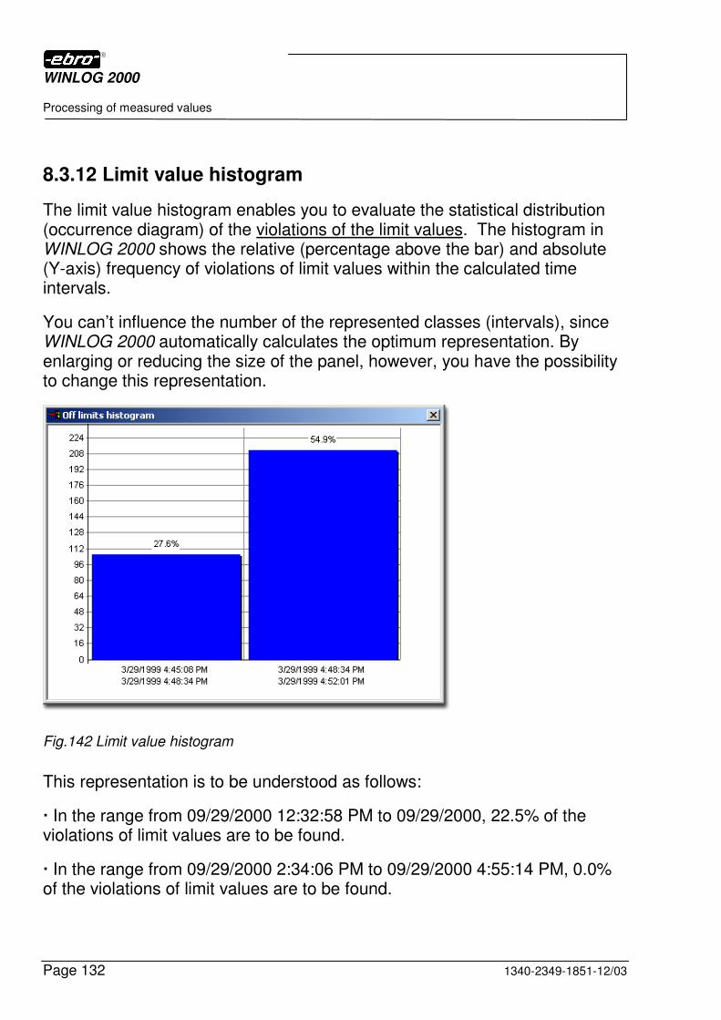
WINLOG 2000
Processing of measured values
Page 132 1340-2349-1851-12/03
8.3.12 Limit value histogram
The limit value histogram enables you to evaluate the statistical distribution (occurrence diagram) of the violations of the limit values. The histogram in WINLOG 2000 shows the relative (percentage above the bar) and absolute (Y-axis) frequency of violations of limit values within the calculated time intervals.
You can’t influence the number of the represented classes (intervals), since WINLOG 2000 automatically calculates the optimum representation. By enlarging or reducing the size of the panel, however, you have the possibility to change this representation.
Fig.142 Limit value histogram
This representation is to be understood as follows:
� In the range from 09/29/2000 12:32:58 PM to 09/29/2000, 22.5% of the violations of limit values are to be found.
� In the range from 09/29/2000 2:34:06 PM to 09/29/2000 4:55:14 PM, 0.0% of the violations of limit values are to be found.
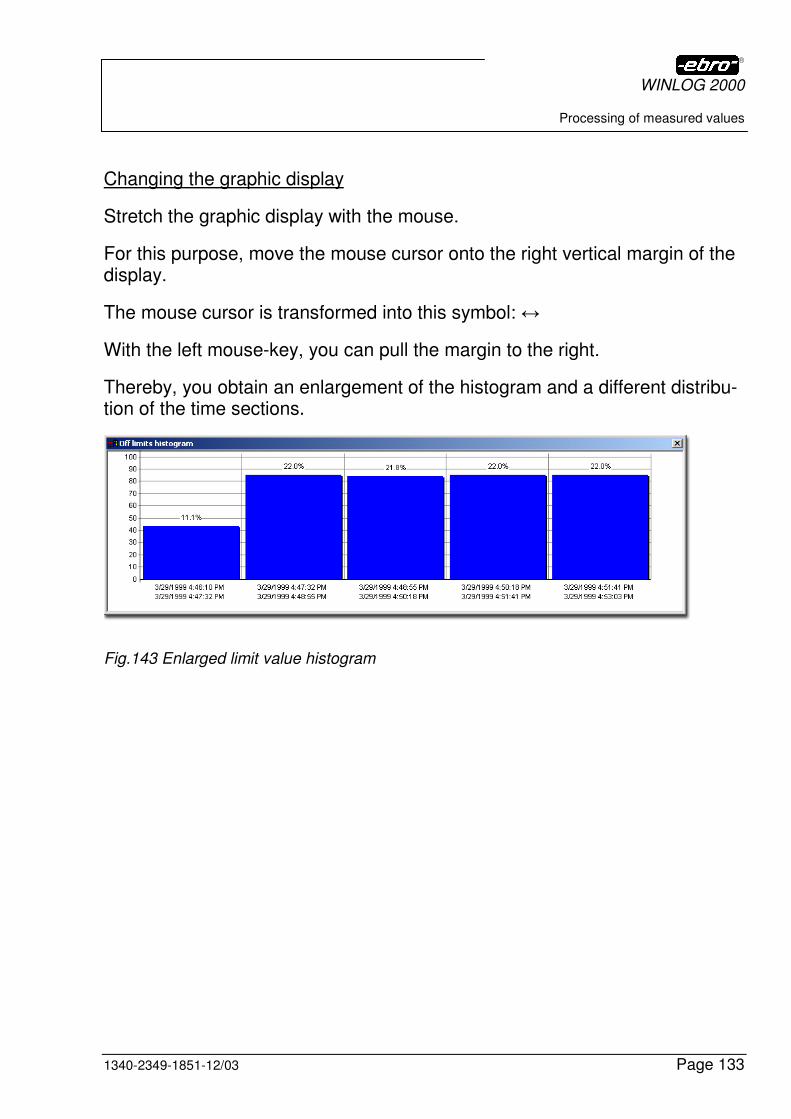
WINLOG 2000
Processing of measured values
1340-2349-1851-12/03 Page 133
Changing the graphic display
Stretch the graphic display with the mouse.
For this purpose, move the mouse cursor onto the right vertical margin of the display.
The mouse cursor is transformed into this symbol: ↔
With the left mouse-key, you can pull the margin to the right.
Thereby, you obtain an enlargement of the histogram and a different distribu-tion of the time sections.
Fig.143 Enlarged limit value histogram
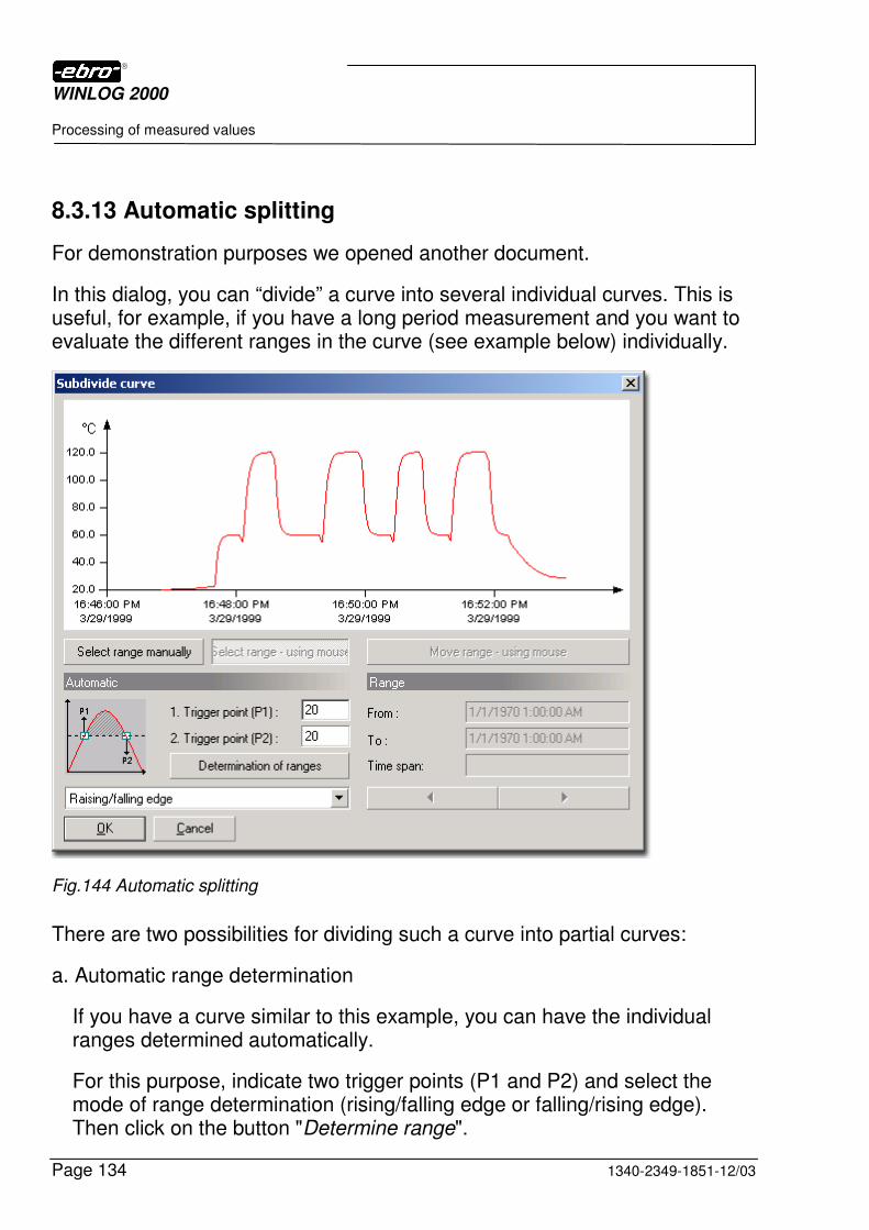
WINLOG 2000
Processing of measured values
Page 134 1340-2349-1851-12/03
8.3.13 Automatic splitting
For demonstration purposes we opened another document.
In this dialog, you can “divide” a curve into several individual curves. This is useful, for example, if you have a long period measurement and you want to evaluate the different ranges in the curve (see example below) individually.
Fig.144 Automatic splitting
There are two possibilities for dividing such a curve into partial curves:
a. Automatic range determination
If you have a curve similar to this example, you can have the individual ranges determined automatically.
For this purpose, indicate two trigger points (P1 and P2) and select the mode of range determination (rising/falling edge or falling/rising edge). Then click on the button "Determine range".

WINLOG 2000
Processing of measured values
1340-2349-1851-12/03 Page 135
WINLOG 2000 then scans the curve from left to right and checks if the momentary measured value is greater or smaller than the value defined in P1 (depending on the mode of the range determination).
If WINLOG 2000 finds such a value, it marks it as the start value for the range. Then, the scan is continued to determine if the value in P2 has been reached.
If this value is also found, then the WINLOG 2000 software marks this value as the end of the range and searches the curve for further ranges.
When the check is finished, you can see in the "Range" section, how many ranges WINLOG 2000 has found.
Using the left arrow or the right arrow, you can have the ranges displayed.
b. Manual range determination
You can also define a range in the curve manually. For this purpose, mark a range in the curve with the mouse.
After defining the ranges, click on "OK". Then the curve is decomposed into the number of defined ranges.
For each range, a new file is created. The naming convention for these range files is: original file name plus a figure between 1 and 255.
Example:
You define 10 ranges in a curve.
The original file is named "test.ebi".
The individual files created thereupon are named “test1.ebi", "test2.ebi", etc.
8.3.14 Save as…
You have the possibility to save each of the opened documents.
This function refers to the document, of which you have selected the curve.
You can save the document as EBI (*.EBI), in Excel format (*.XLS) or as a text file (*.TXT).
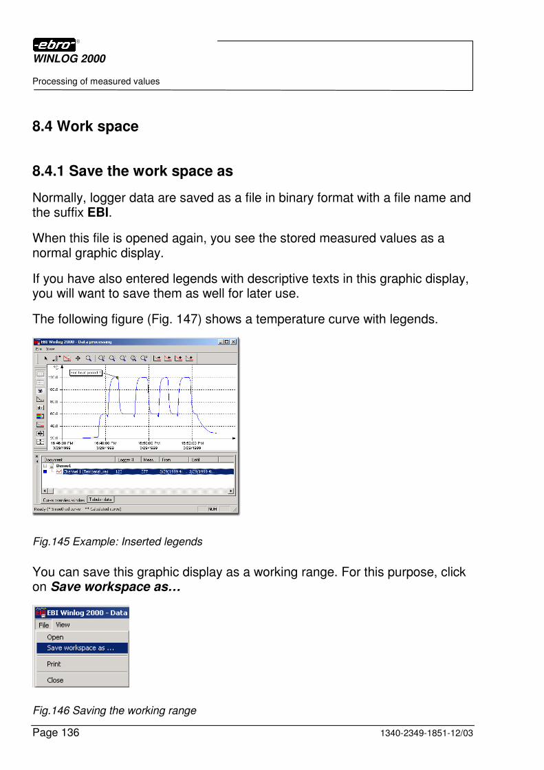
WINLOG 2000
Processing of measured values
Page 136 1340-2349-1851-12/03
8.4 Work space
8.4.1 Save the work space as
Normally, logger data are saved as a file in binary format with a file name and the suffix EBI.
When this file is opened again, you see the stored measured values as a normal graphic display.
If you have also entered legends with descriptive texts in this graphic display, you will want to save them as well for later use.
The following figure (Fig. 147) shows a temperature curve with legends.
Fig.145 Example: Inserted legends
You can save this graphic display as a working range. For this purpose, click on Save workspace as…
Fig.146 Saving the working range
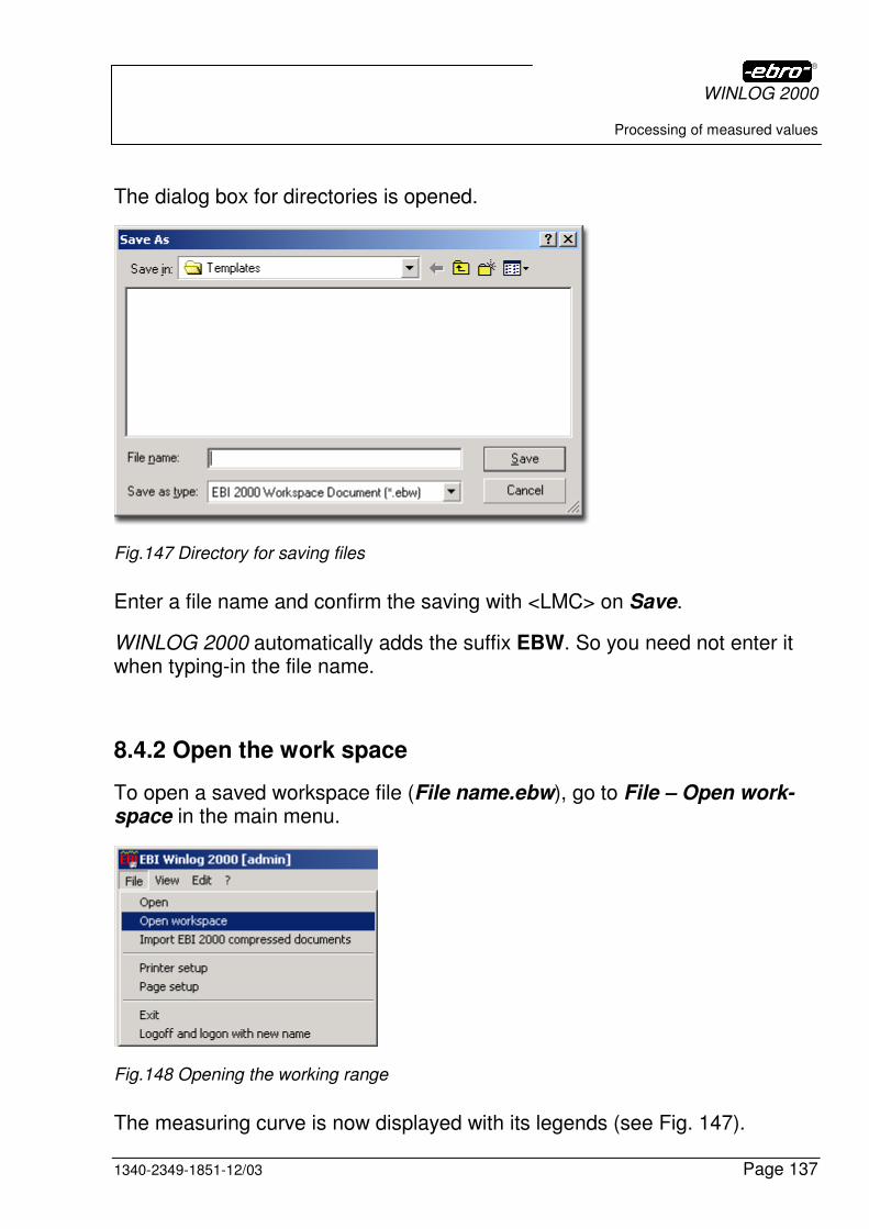
WINLOG 2000
Processing of measured values
1340-2349-1851-12/03 Page 137
The dialog box for directories is opened.
Fig.147 Directory for saving files
Enter a file name and confirm the saving with <LMC> on Save.
WINLOG 2000 automatically adds the suffix EBW. So you need not enter it when typing-in the file name.
8.4.2 Open the work space
To open a saved workspace file (File name.ebw), go to File – Open work-space in the main menu.
Fig.148 Opening the working range
The measuring curve is now displayed with its legends (see Fig. 147).

WINLOG 2000
Working with WINLOG 2000 - P (Professional)
Page 138 1340-2349-1851-12/03
9 Working with WINLOG 2000 - P (Professional)
The functions described in this chapter are only available in this version and in the higher versions (WINLOG 2000-B and WINLOG 2000-V). They are extensions of the standard software.
Purchase and installation of the Professional version
This software version can be purchased or installed in two different ways.
9.1 Purchasing the Professional version
You have decided to purchase the Professional version from the start.
In this case, install the software as described in chapter 4.
After the installation, the Professional version is available on your computer. You can now use all the additional functions described in this chapter.
Of course, all functions of the Standard software are still available.
9.2 Upgrading to the Professional version
You have already familiarized yourself with the Standard version of WINLOG 2000 and now you would like to upgrade to the Professional version.
You need to purchase the activation code for the installation of the “Profes-sional version” program module from ebro or your retailer.

WINLOG 2000
Working with WINLOG 2000 - P (Professional)
1340-2349-1851-12/03 Page 139
Since you have already installed the Standard version of WINLOG 2000, you can register the new program module very easily.
The procedure is very precisely described in chapter “5.4.1.2 Adding program modules“.
9.3 Additional functions compared to the Standard version
9.3.1 Password request
In the Professional version, but also in the BUS and 21 CFR Part 11 versions, the access to the software is protected with a password. At the program start, you will see following dialog box:
Fig.149 Password request: Dialog box
Enter “admin“ for User name and for Password as well, both times without the quotation marks and in small letters.
By confirming with a click on OK, you can access the program.
Cancel ends the program.
The user can be attributed a new name and new rights, as described in chapter 9.3.3.
A maximum of eight user names can be entered.
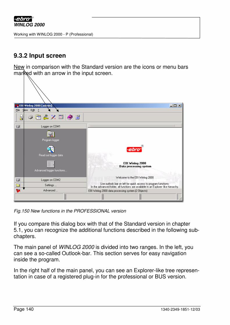
WINLOG 2000
Working with WINLOG 2000 - P (Professional)
Page 140 1340-2349-1851-12/03
9.3.2 Input screen
New in comparison with the Standard version are the icons or menu bars marked with an arrow in the input screen.
Fig.150 New functions in the PROFESSIONAL version
If you compare this dialog box with that of the Standard version in chapter 5.1, you can recognize the additional functions described in the following sub-chapters.
The main panel of WINLOG 2000 is divided into two ranges. In the left, you can see a so-called Outlook-bar. This section serves for easy navigation inside the program.
In the right half of the main panel, you can see an Explorer-like tree represen-tation in case of a registered plug-in for the professional or BUS version.
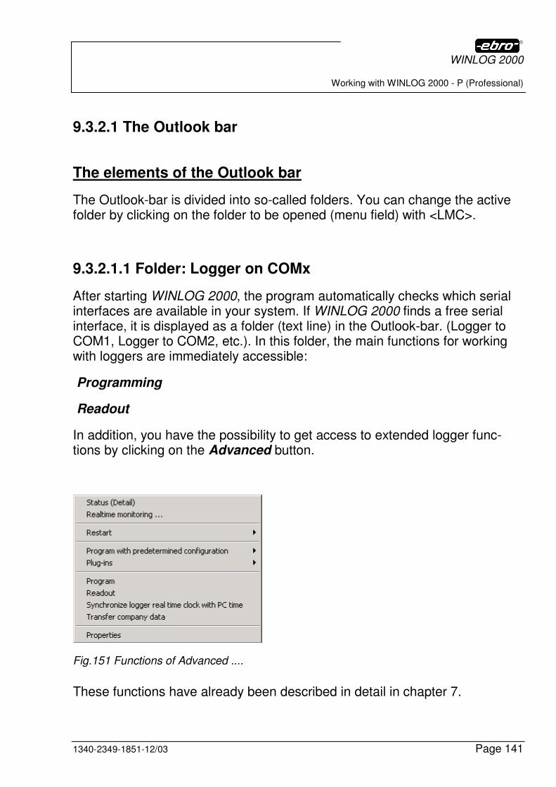
WINLOG 2000
Working with WINLOG 2000 - P (Professional)
1340-2349-1851-12/03 Page 141
9.3.2.1 The Outlook bar
The elements of the Outlook bar
The Outlook-bar is divided into so-called folders. You can change the active folder by clicking on the folder to be opened (menu field) with <LMC>.
9.3.2.1.1 Folder: Logger on COMx
After starting WINLOG 2000, the program automatically checks which serial interfaces are available in your system. If WINLOG 2000 finds a free serial interface, it is displayed as a folder (text line) in the Outlook-bar. (Logger to COM1, Logger to COM2, etc.). In this folder, the main functions for working with loggers are immediately accessible:
Programming
Readout
In addition, you have the possibility to get access to extended logger func-tions by clicking on the Advanced button.
Fig.151 Functions of Advanced ....
These functions have already been described in detail in chapter 7.
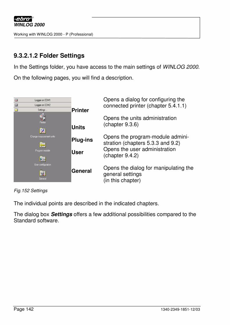
WINLOG 2000
Working with WINLOG 2000 - P (Professional)
Page 142 1340-2349-1851-12/03
9.3.2.1.2 Folder Settings
In the Settings folder, you have access to the main settings of WINLOG 2000.
On the following pages, you will find a description.
Printer
Units Plug-ins User General
Opens a dialog for configuring the connected printer (chapter 5.4.1.1) Opens the units administration (chapter 9.3.6) Opens the program-module admini-stration (chapters 5.3.3 and 9.2) Opens the user administration (chapter 9.4.2) Opens the dialog for manipulating the general settings (in this chapter)
Fig.152 Settings
The individual points are described in the indicated chapters.
The dialog box Settings offers a few additional possibilities compared to the Standard software.
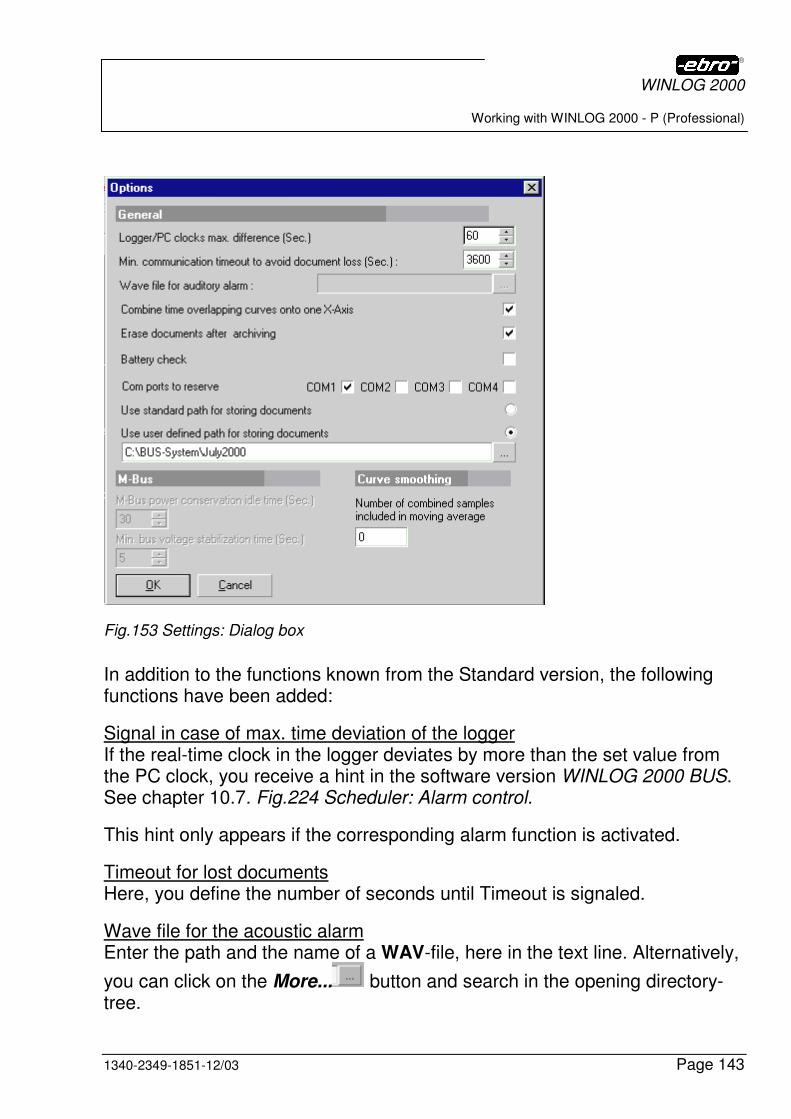
WINLOG 2000
Working with WINLOG 2000 - P (Professional)
1340-2349-1851-12/03 Page 143
Fig.153 Settings: Dialog box
In addition to the functions known from the Standard version, the following functions have been added:
Signal in case of max. time deviation of the logger If the real-time clock in the logger deviates by more than the set value from the PC clock, you receive a hint in the software version WINLOG 2000 BUS. See chapter 10.7. Fig.224 Scheduler: Alarm control.
This hint only appears if the corresponding alarm function is activated.
Timeout for lost documents Here, you define the number of seconds until Timeout is signaled.
Wave file for the acoustic alarm Enter the path and the name of a WAV-file, here in the text line. Alternatively,
you can click on the More... button and search in the opening directory-tree.
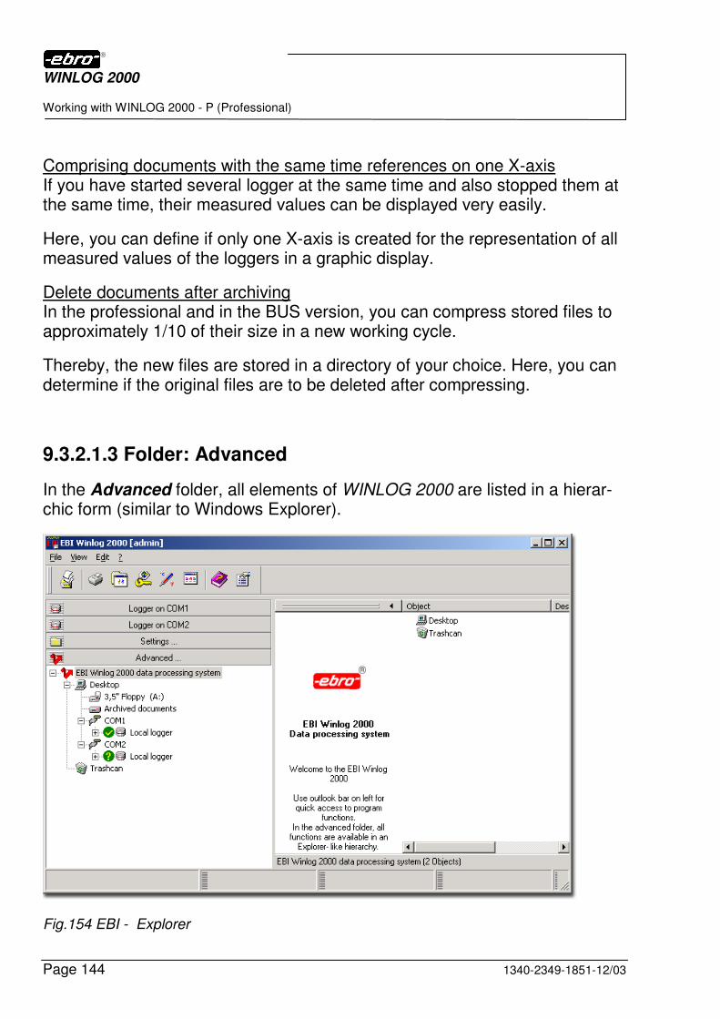
WINLOG 2000
Working with WINLOG 2000 - P (Professional)
Page 144 1340-2349-1851-12/03
Comprising documents with the same time references on one X-axis If you have started several logger at the same time and also stopped them at the same time, their measured values can be displayed very easily.
Here, you can define if only one X-axis is created for the representation of all measured values of the loggers in a graphic display.
Delete documents after archiving In the professional and in the BUS version, you can compress stored files to approximately 1/10 of their size in a new working cycle.
Thereby, the new files are stored in a directory of your choice. Here, you can determine if the original files are to be deleted after compressing.
9.3.2.1.3 Folder: Advanced
In the Advanced folder, all elements of WINLOG 2000 are listed in a hierar-chic form (similar to Windows Explorer).
Fig.154 EBI - Explorer
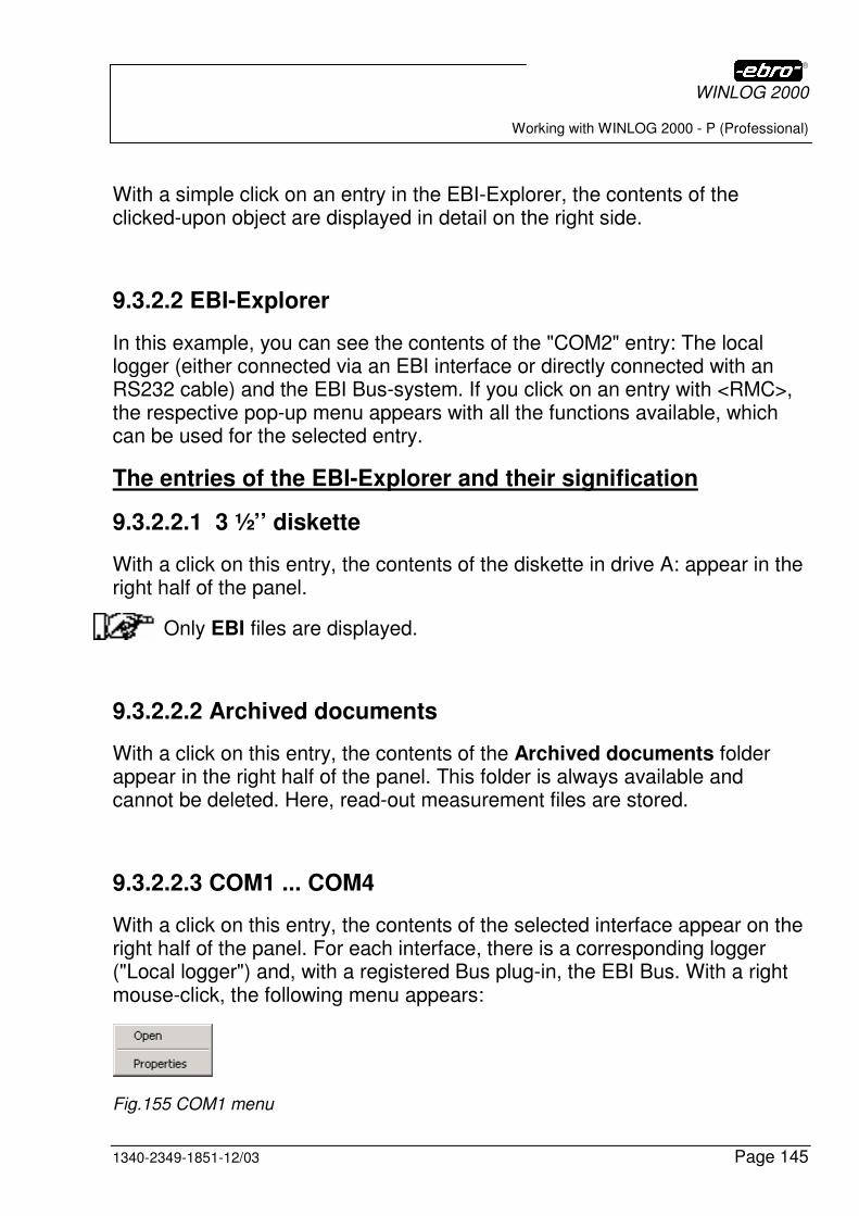
WINLOG 2000
Working with WINLOG 2000 - P (Professional)
1340-2349-1851-12/03 Page 145
With a simple click on an entry in the EBI-Explorer, the contents of the clicked-upon object are displayed in detail on the right side.
9.3.2.2 EBI-Explorer
In this example, you can see the contents of the "COM2" entry: The local logger (either connected via an EBI interface or directly connected with an RS232 cable) and the EBI Bus-system. If you click on an entry with <RMC>, the respective pop-up menu appears with all the functions available, which can be used for the selected entry.
The entries of the EBI-Explorer and their signification
9.3.2.2.1 3 ½’’ diskette
With a click on this entry, the contents of the diskette in drive A: appear in the right half of the panel.
Only EBI files are displayed.
9.3.2.2.2 Archived documents
With a click on this entry, the contents of the Archived documents folder appear in the right half of the panel. This folder is always available and cannot be deleted. Here, read-out measurement files are stored.
9.3.2.2.3 COM1 ... COM4
With a click on this entry, the contents of the selected interface appear on the right half of the panel. For each interface, there is a corresponding logger ("Local logger") and, with a registered Bus plug-in, the EBI Bus. With a right mouse-click, the following menu appears:
Fig.155 COM1 menu
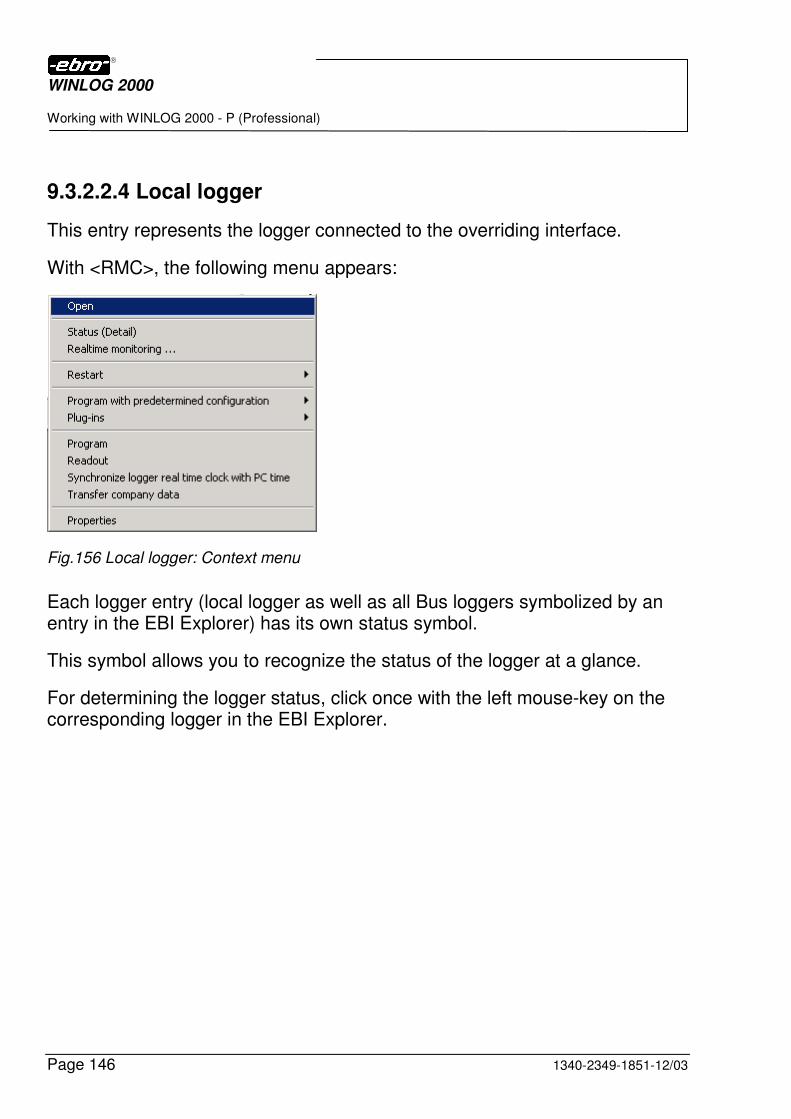
WINLOG 2000
Working with WINLOG 2000 - P (Professional)
Page 146 1340-2349-1851-12/03
9.3.2.2.4 Local logger
This entry represents the logger connected to the overriding interface.
With <RMC>, the following menu appears:
Fig.156 Local logger: Context menu
Each logger entry (local logger as well as all Bus loggers symbolized by an entry in the EBI Explorer) has its own status symbol.
This symbol allows you to recognize the status of the logger at a glance.
For determining the logger status, click once with the left mouse-key on the corresponding logger in the EBI Explorer.
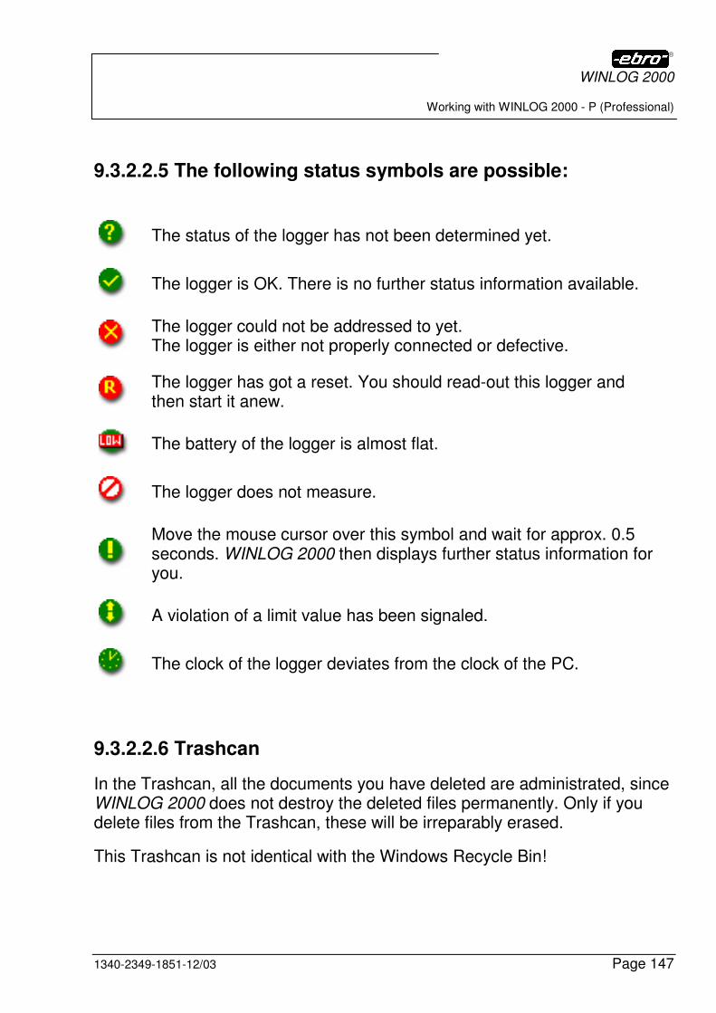
WINLOG 2000
Working with WINLOG 2000 - P (Professional)
1340-2349-1851-12/03 Page 147
9.3.2.2.5 The following status symbols are possible:
The status of the logger has not been determined yet.
The logger is OK. There is no further status information available.
The logger could not be addressed to yet. The logger is either not properly connected or defective.
The logger has got a reset. You should read-out this logger and then start it anew.
The battery of the logger is almost flat.
The logger does not measure.
Move the mouse cursor over this symbol and wait for approx. 0.5 seconds. WINLOG 2000 then displays further status information for you.
A violation of a limit value has been signaled.
The clock of the logger deviates from the clock of the PC.
9.3.2.2.6 Trashcan
In the Trashcan, all the documents you have deleted are administrated, since WINLOG 2000 does not destroy the deleted files permanently. Only if you delete files from the Trashcan, these will be irreparably erased.
This Trashcan is not identical with the Windows Recycle Bin!
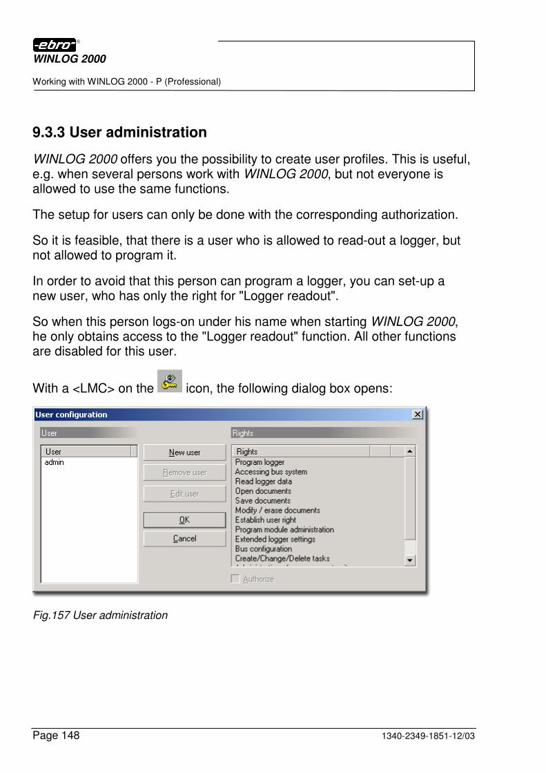
WINLOG 2000
Working with WINLOG 2000 - P (Professional)
Page 148 1340-2349-1851-12/03
9.3.3 User administration
WINLOG 2000 offers you the possibility to create user profiles. This is useful, e.g. when several persons work with WINLOG 2000, but not everyone is allowed to use the same functions.
The setup for users can only be done with the corresponding authorization.
So it is feasible, that there is a user who is allowed to read-out a logger, but not allowed to program it.
In order to avoid that this person can program a logger, you can set-up a new user, who has only the right for "Logger readout".
So when this person logs-on under his name when starting WINLOG 2000, he only obtains access to the "Logger readout" function. All other functions are disabled for this user.
With a <LMC> on the icon, the following dialog box opens:
Fig.157 User administration
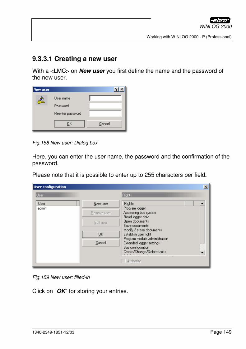
WINLOG 2000
Working with WINLOG 2000 - P (Professional)
1340-2349-1851-12/03 Page 149
9.3.3.1 Creating a new user
With a <LMC> on New user you first define the name and the password of the new user.
Fig.158 New user: Dialog box
Here, you can enter the user name, the password and the confirmation of the password.
Please note that it is possible to enter up to 255 characters per field.
Fig.159 New user: filled-in
Click on "OK" for storing your entries.
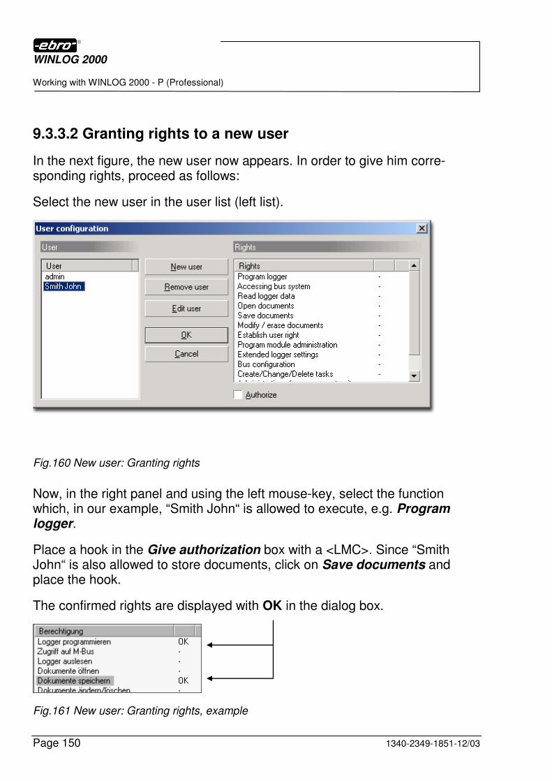
WINLOG 2000
Working with WINLOG 2000 - P (Professional)
Page 150 1340-2349-1851-12/03
9.3.3.2 Granting rights to a new user
In the next figure, the new user now appears. In order to give him corre-sponding rights, proceed as follows:
Select the new user in the user list (left list).
Fig.160 New user: Granting rights
Now, in the right panel and using the left mouse-key, select the function which, in our example, “Smith John“ is allowed to execute, e.g. Program logger.
Place a hook in the Give authorization box with a <LMC>. Since “Smith John“ is also allowed to store documents, click on Save documents and place the hook.
The confirmed rights are displayed with OK in the dialog box.
Fig.161 New user: Granting rights, example
WINLOG 2000
Working with WINLOG 2000 - P (Professional)
1340-2349-1851-12/03 Page 151
With a click on OK, the rights are taken over.
Mr. “Smith John“ can now log-on in WINLOG 2000 with his password.
9.3.3.3 Changing the rights of an user
For this purpose, call the user administration with a <LMC> on . See “Fig.150 New functions in the PROFESSIONAL version“.
Click on the corresponding right in the right function field, and activate or deactivate it with the hook next to Give authorization.
You can confirm the changes with a <LMC> on OK.
9.3.3.4 Deleting an user
Choose a user in the user list (left list).
Then confirm with <LMC> on Delete user . The user is then deleted.
Attention: It is not possible to delete the first user (admin) from the list.
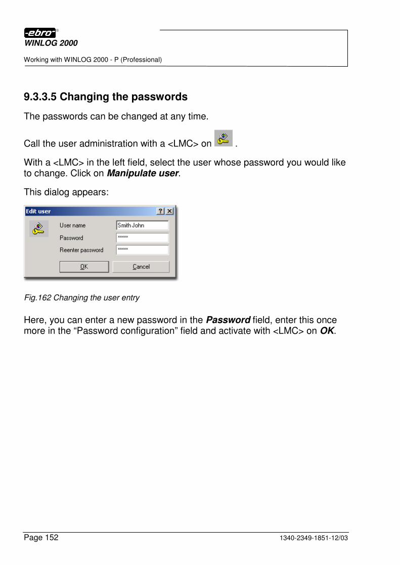
WINLOG 2000
Working with WINLOG 2000 - P (Professional)
Page 152 1340-2349-1851-12/03
9.3.3.5 Changing the passwords
The passwords can be changed at any time.
Call the user administration with a <LMC> on .
With a <LMC> in the left field, select the user whose password you would like to change. Click on Manipulate user.
This dialog appears:
Fig.162 Changing the user entry
Here, you can enter a new password in the Password field, enter this once more in the “Password configuration” field and activate with <LMC> on OK.
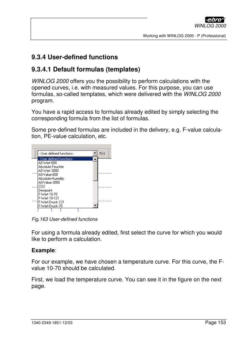
WINLOG 2000
Working with WINLOG 2000 - P (Professional)
1340-2349-1851-12/03 Page 153
9.3.4 User-defined functions
9.3.4.1 Default formulas (templates)
WINLOG 2000 offers you the possibility to perform calculations with the opened curves, i.e. with measured values. For this purpose, you can use formulas, so-called templates, which were delivered with the WINLOG 2000 program.
You have a rapid access to formulas already edited by simply selecting the corresponding formula from the list of formulas.
Some pre-defined formulas are included in the delivery, e.g. F-value calcula-tion, PE-value calculation, etc.
Fig.163 User-defined functions
For using a formula already edited, first select the curve for which you would like to perform a calculation.
Example:
For our example, we have chosen a temperature curve. For this curve, the F-value 10-70 should be calculated.
First, we load the temperature curve. You can see it in the figure on the next page.
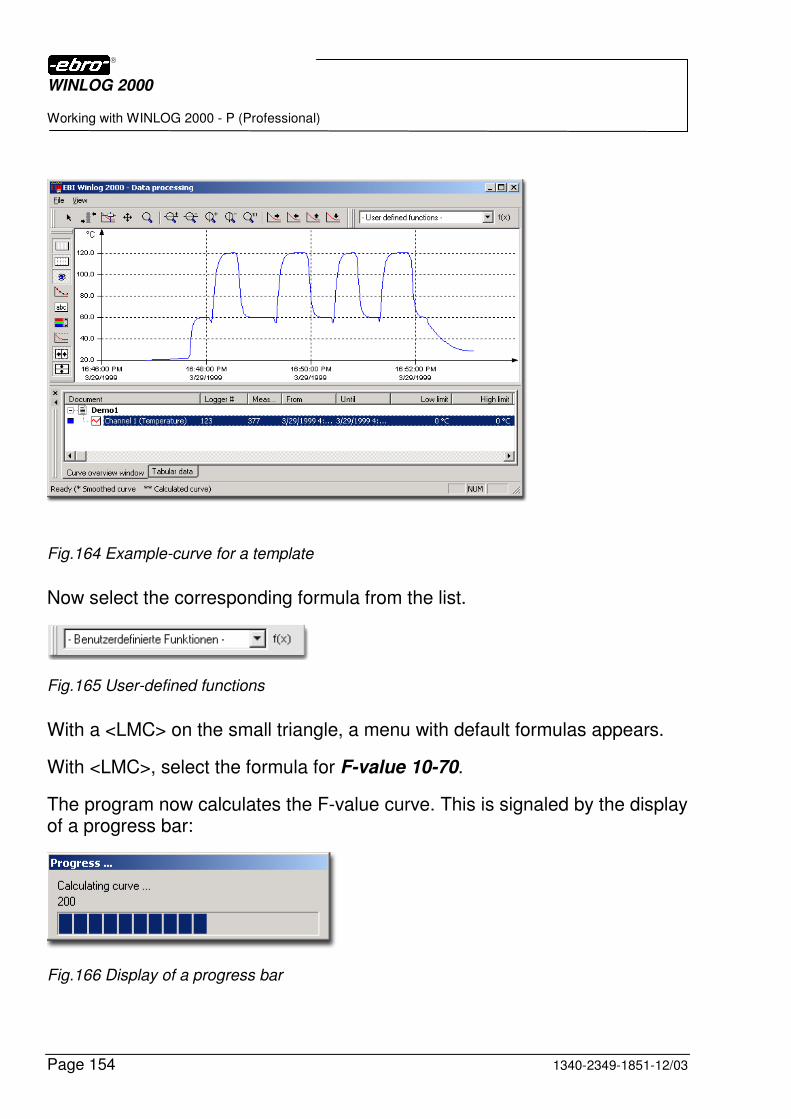
WINLOG 2000
Working with WINLOG 2000 - P (Professional)
Page 154 1340-2349-1851-12/03
Fig.164 Example-curve for a template
Now select the corresponding formula from the list.
Fig.165 User-defined functions
With a <LMC> on the small triangle, a menu with default formulas appears.
With <LMC>, select the formula for F-value 10-70.
The program now calculates the F-value curve. This is signaled by the display of a progress bar:
Fig.166 Display of a progress bar
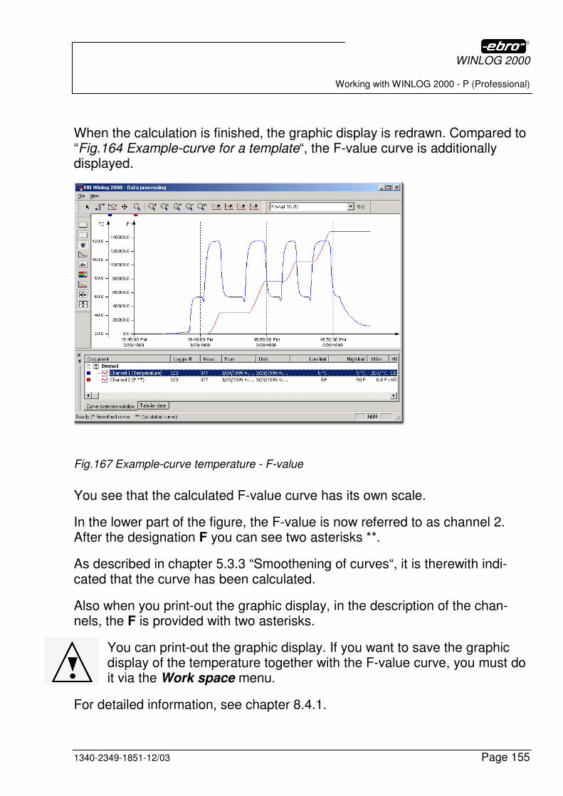
WINLOG 2000
Working with WINLOG 2000 - P (Professional)
1340-2349-1851-12/03 Page 155
When the calculation is finished, the graphic display is redrawn. Compared to “Fig.164 Example-curve for a template“, the F-value curve is additionally displayed.
Fig.167 Example-curve temperature - F-value
You see that the calculated F-value curve has its own scale.
In the lower part of the figure, the F-value is now referred to as channel 2. After the designation F you can see two asterisks **.
As described in chapter 5.3.3 “Smoothening of curves“, it is therewith indi-cated that the curve has been calculated.
Also when you print-out the graphic display, in the description of the chan-nels, the F is provided with two asterisks.
You can print-out the graphic display. If you want to save the graphic display of the temperature together with the F-value curve, you must do it via the Work space menu.
For detailed information, see chapter 8.4.1.
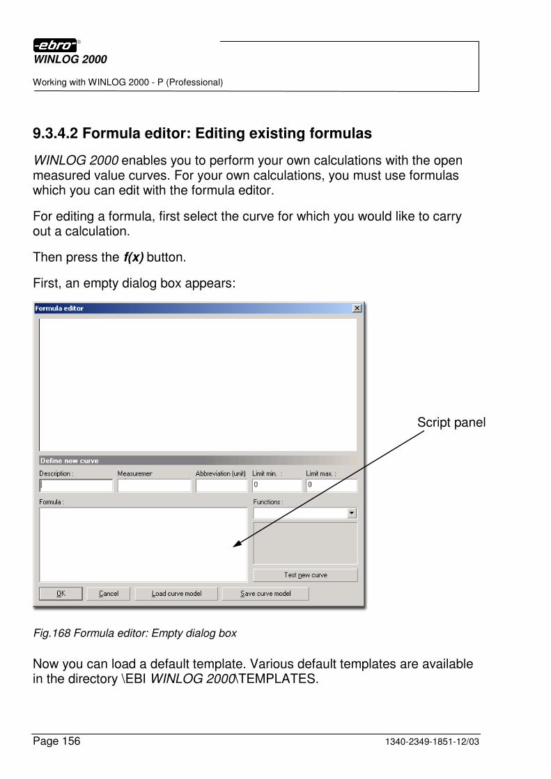
WINLOG 2000
Working with WINLOG 2000 - P (Professional)
Page 156 1340-2349-1851-12/03
9.3.4.2 Formula editor: Editing existing formulas
WINLOG 2000 enables you to perform your own calculations with the open measured value curves. For your own calculations, you must use formulas which you can edit with the formula editor.
For editing a formula, first select the curve for which you would like to carry out a calculation.
Then press the f(x) button.
First, an empty dialog box appears:
Fig.168 Formula editor: Empty dialog box
Now you can load a default template. Various default templates are available in the directory \EBI WINLOG 2000\TEMPLATES.
Script panel
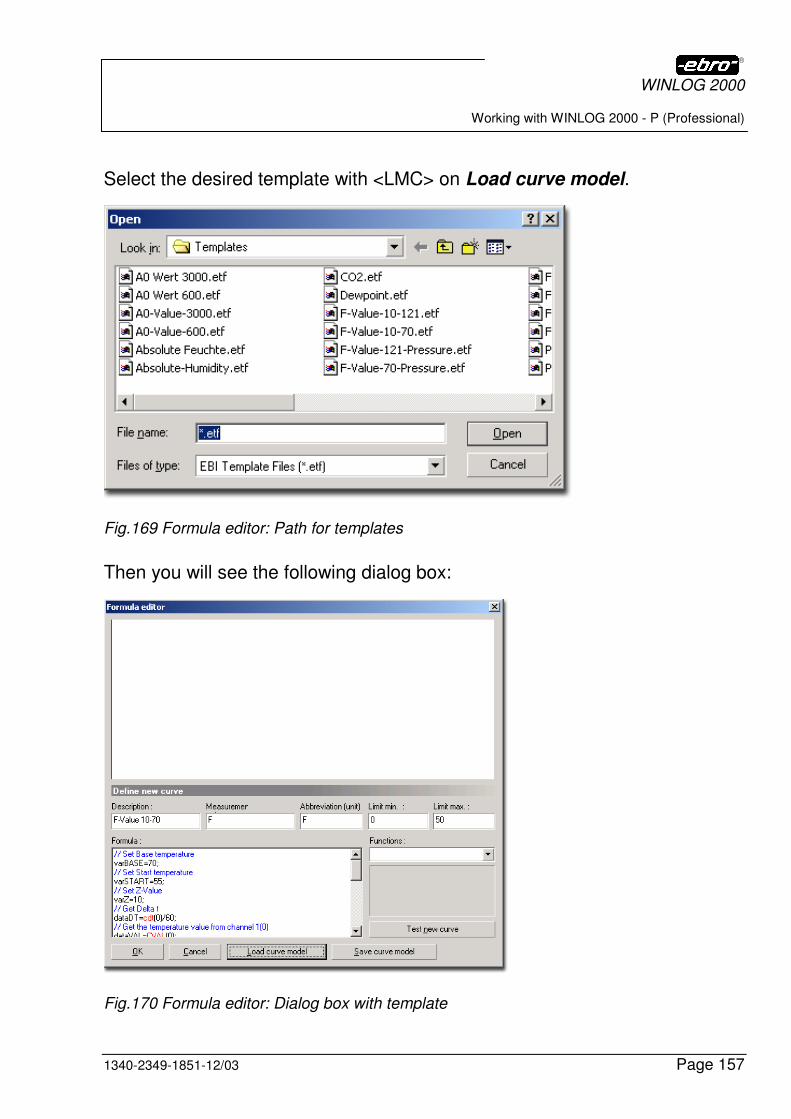
WINLOG 2000
Working with WINLOG 2000 - P (Professional)
1340-2349-1851-12/03 Page 157
Select the desired template with <LMC> on Load curve model.
Fig.169 Formula editor: Path for templates
Then you will see the following dialog box:
Fig.170 Formula editor: Dialog box with template

WINLOG 2000
Working with WINLOG 2000 - P (Professional)
Page 158 1340-2349-1851-12/03
If, for example, you want to change values for the start of the calculation or temperature thresholds, you can do this in the lower left panel (the so-called script panel).
Additionally, the following fields can be filled-in:
Designation Enter a designation for your calculation formula, here.
Unit Enter the desired unit of the created curve, here.
Unit (Grammalog) Enter the grammalog of the unit, here. This grammalog then appears next to the Y-axis of the calculated curve.
Limit value min. You can use the limit values for prescribing set-values for your calculated curve.
So it is for example feasible, that you indicate the value 500 as the min. limit value for an F-value formula.
You can then recognize at a glance on the graphic display, if the calculated F-value exceeds this limit.
Limit value max. See limit value min.
Functions In this list, all mathematical functions available are listed.
A description and explanation of these functions can be found in chapter 9.3.4.3.1.
If you select one of these functions, the select function is inserted at the present cursor position in the formula panel.
OK Calculates the new curve and inserts it in the diagram.
Cancel Cancels this dialog without creating a new curve.
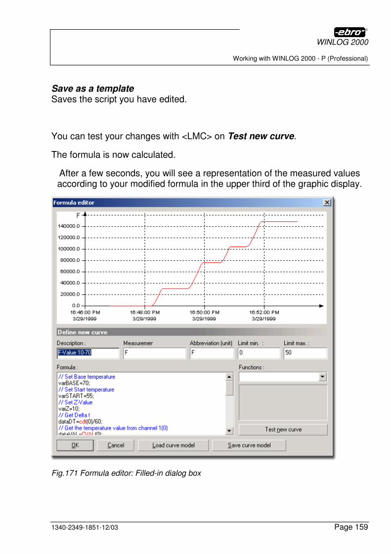
WINLOG 2000
Working with WINLOG 2000 - P (Professional)
1340-2349-1851-12/03 Page 159
Save as a template Saves the script you have edited.
You can test your changes with <LMC> on Test new curve.
The formula is now calculated.
After a few seconds, you will see a representation of the measured values according to your modified formula in the upper third of the graphic display.
Fig.171 Formula editor: Filled-in dialog box
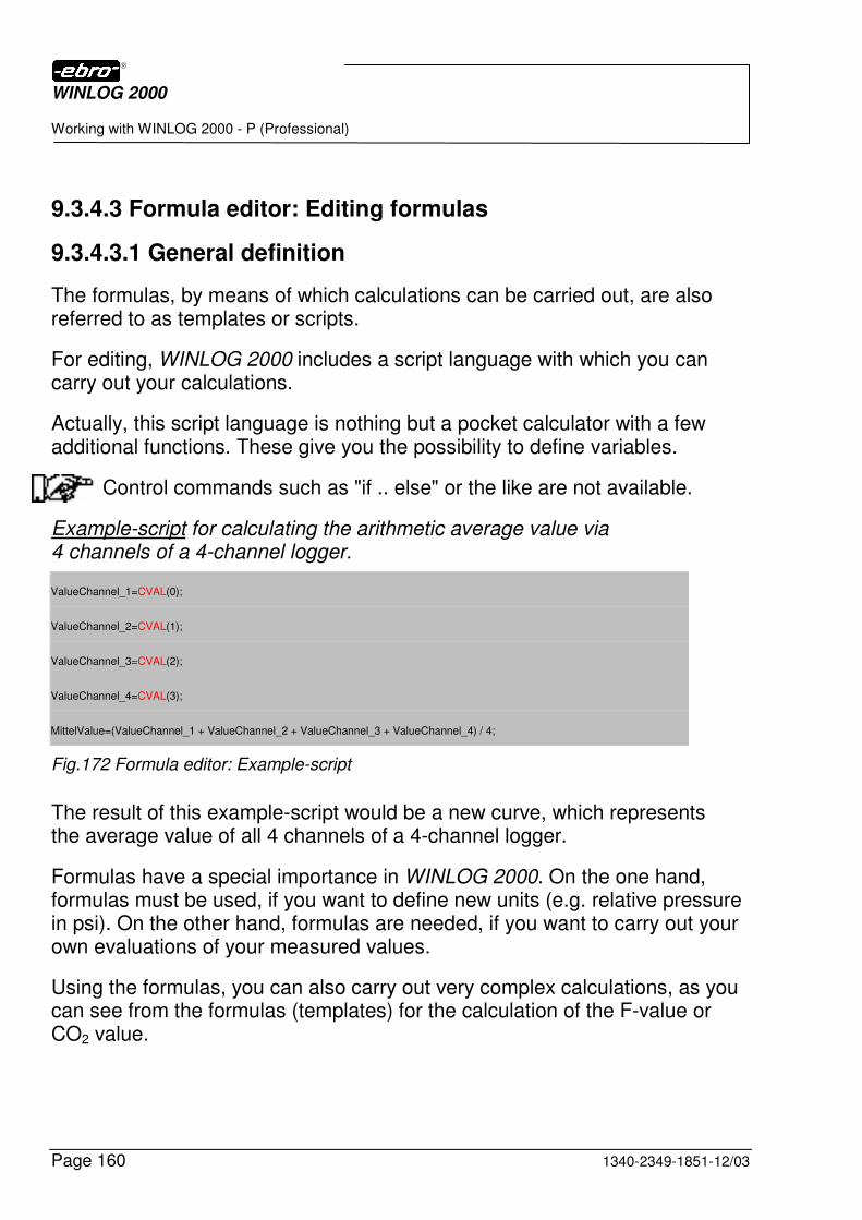
WINLOG 2000
Working with WINLOG 2000 - P (Professional)
Page 160 1340-2349-1851-12/03
9.3.4.3 Formula editor: Editing formulas
9.3.4.3.1 General definition
The formulas, by means of which calculations can be carried out, are also referred to as templates or scripts.
For editing, WINLOG 2000 includes a script language with which you can carry out your calculations.
Actually, this script language is nothing but a pocket calculator with a few additional functions. These give you the possibility to define variables.
Control commands such as "if .. else" or the like are not available.
Example-script for calculating the arithmetic average value via 4 channels of a 4-channel logger.
ValueChannel_1=CVAL(0);
ValueChannel_2=CVAL(1);
ValueChannel_3=CVAL(2);
ValueChannel_4=CVAL(3);
MittelValue=(ValueChannel_1 + ValueChannel_2 + ValueChannel_3 + ValueChannel_4) / 4;
Fig.172 Formula editor: Example-script
The result of this example-script would be a new curve, which represents the average value of all 4 channels of a 4-channel logger.
Formulas have a special importance in WINLOG 2000. On the one hand, formulas must be used, if you want to define new units (e.g. relative pressure in psi). On the other hand, formulas are needed, if you want to carry out your own evaluations of your measured values.
Using the formulas, you can also carry out very complex calculations, as you can see from the formulas (templates) for the calculation of the F-value or CO2 value.
WINLOG 2000
Working with WINLOG 2000 - P (Professional)
1340-2349-1851-12/03 Page 161
9.3.4.3.2 Limitations to editing formulas
When editing new formulas, some important points must be considered.
1. Numerical values must not be greater than 107 (10,000,000).
Greater values cannot be correctly represented in the diagram and are therefore not permitted.
WINLOG 2000 then sets such values to zero and marks them with a #INF in the table of measured values.
2. When editing the formula, take care that no undefined results can oc-cur.
So CVAL(0)/CMIN(0), for example, would create an undefined result for a minimum of 0, since a division by zero cannot deliver any result.
If such an error should still appear, WINLOG 2000 will signal it and suppress the display of the diagram.
3. Typing errors or syntactic errors when editing formulas are not signaled as errors. Instead, the result of the formula is set to zero.
Example: "10*(CVAL(0)-CMAX(0)" would deliver zero as a result, since the right closing bracket is missing.
4. The longer and the more complex the formula is, the more time WINLOG 2000 needs for calculating this formula.
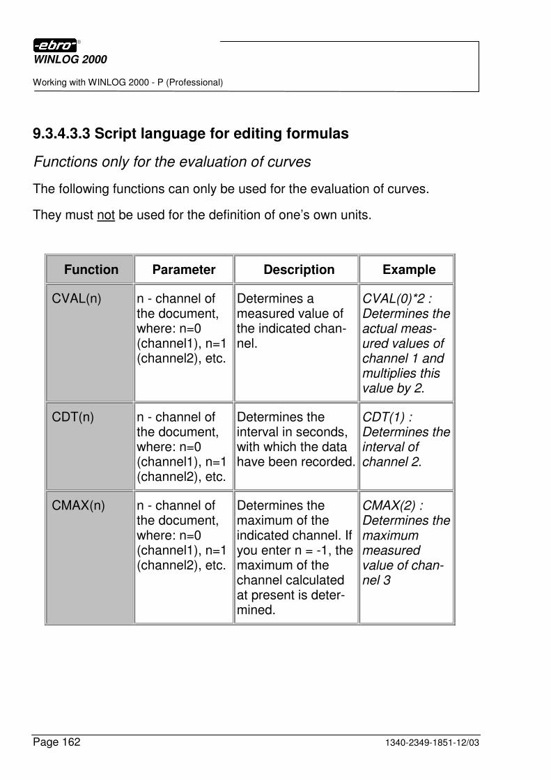
WINLOG 2000
Working with WINLOG 2000 - P (Professional)
Page 162 1340-2349-1851-12/03
9.3.4.3.3 Script language for editing formulas
Functions only for the evaluation of curves
The following functions can only be used for the evaluation of curves.
They must not be used for the definition of one’s own units.
Function Parameter Description Example
CVAL(n) n - channel of the document, where: n=0 (channel1), n=1 (channel2), etc.
Determines a measured value of the indicated chan-nel.
CVAL(0)*2 : Determines the actual meas-ured values of channel 1 and multiplies this value by 2.
CDT(n) n - channel of the document, where: n=0 (channel1), n=1 (channel2), etc.
Determines the interval in seconds, with which the data have been recorded.
CDT(1) : Determines the interval of channel 2.
CMAX(n) n - channel of the document, where: n=0 (channel1), n=1 (channel2), etc.
Determines the maximum of the indicated channel. If you enter n = -1, the maximum of the channel calculated at present is deter-mined.
CMAX(2) : Determines the maximum measured value of chan-nel 3
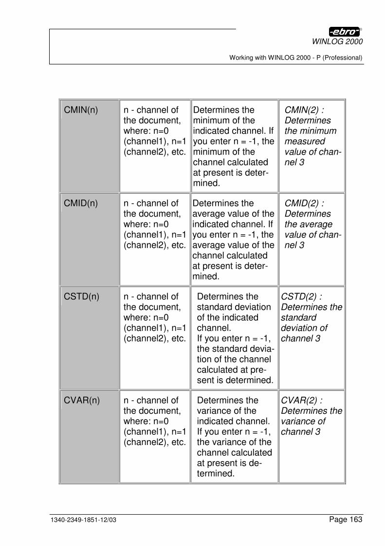
WINLOG 2000
Working with WINLOG 2000 - P (Professional)
1340-2349-1851-12/03 Page 163
CMIN(n) n - channel of the document, where: n=0 (channel1), n=1 (channel2), etc.
Determines the minimum of the indicated channel. If you enter n = -1, the minimum of the channel calculated at present is deter-mined.
CMIN(2) : Determines the minimum measured value of chan-nel 3
CMID(n) n - channel of the document, where: n=0 (channel1), n=1 (channel2), etc.
Determines the average value of the indicated channel. If you enter n = -1, the average value of the channel calculated at present is deter-mined.
CMID(2) : Determines the average value of chan-nel 3
CSTD(n) n - channel of the document, where: n=0 (channel1), n=1 (channel2), etc.
Determines the standard deviation of the indicated channel. If you enter n = -1, the standard devia-tion of the channel calculated at pre-sent is determined.
CSTD(2) : Determines the standard deviation of channel 3
CVAR(n) n - channel of the document, where: n=0 (channel1), n=1 (channel2), etc.
Determines the variance of the indicated channel. If you enter n = -1, the variance of the channel calculated at present is de-termined.
CVAR(2) : Determines the variance of channel 3
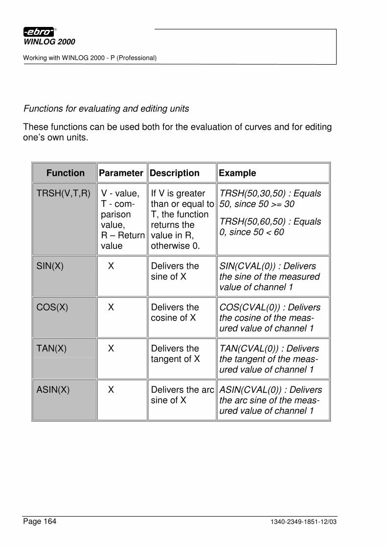
WINLOG 2000
Working with WINLOG 2000 - P (Professional)
Page 164 1340-2349-1851-12/03
Functions for evaluating and editing units
These functions can be used both for the evaluation of curves and for editing one’s own units.
Function Parameter Description Example
TRSH(V,T,R) V - value, T - com-parison value, R – Return value
If V is greater than or equal to T, the function returns the value in R, otherwise 0.
TRSH(50,30,50) : Equals 50, since 50 >= 30
TRSH(50,60,50) : Equals 0, since 50 < 60
SIN(X) X Delivers the sine of X
SIN(CVAL(0)) : Delivers the sine of the measured value of channel 1
COS(X) X Delivers the cosine of X
COS(CVAL(0)) : Delivers the cosine of the meas-ured value of channel 1
TAN(X) X Delivers the tangent of X
TAN(CVAL(0)) : Delivers the tangent of the meas-ured value of channel 1
ASIN(X) X Delivers the arc sine of X
ASIN(CVAL(0)) : Delivers the arc sine of the meas-ured value of channel 1
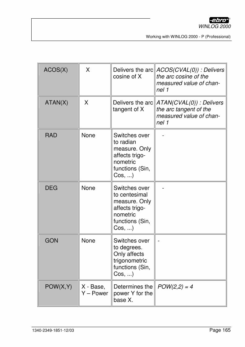
WINLOG 2000
Working with WINLOG 2000 - P (Professional)
1340-2349-1851-12/03 Page 165
ACOS(X) X Delivers the arc cosine of X
ACOS(CVAL(0)) : Delivers the arc cosine of the measured value of chan-nel 1
ATAN(X) X Delivers the arc tangent of X
ATAN(CVAL(0)) : Delivers the arc tangent of the measured value of chan-nel 1
RAD None Switches over to radian measure. Only affects trigo-nometric functions (Sin, Cos, ...)
-
DEG None Switches over to centesimal measure. Only affects trigo-nometric functions (Sin, Cos, ...)
-
GON None Switches over to degrees. Only affects trigonometric functions (Sin, Cos, ...)
-
POW(X,Y) X - Base, Y – Power
Determines the power Y for the base X.
POW(2,2) = 4
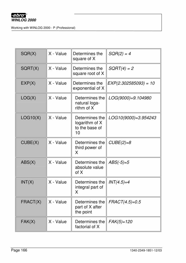
WINLOG 2000
Working with WINLOG 2000 - P (Professional)
Page 166 1340-2349-1851-12/03
SQR(X) X - Value Determines the square of X
SQR(2) = 4
SQRT(X) X - Value Determines the square root of X
SQRT(4) = 2
EXP(X) X - Value Determines the exponential of X
EXP(2.302585093) = 10
LOG(X) X - Value Determines the natural loga-rithm of X
LOG(9000)=9.104980
LOG10(X) X - Value Determines the logarithm of X to the base of 10
LOG10(9000)=3.954243
CUBE(X) X - Value Determines the third power of X
CUBE(2)=8
ABS(X) X - Value Determines the absolute value of X
ABS(-5)=5
INT(X) X - Value Determines the integral part of X
INT(4.5)=4
FRACT(X) X - Value Determines the part of X after the point
FRACT(4.5)=0.5
FAK(X) X - Value Determines the factorial of X
FAK(5)=120
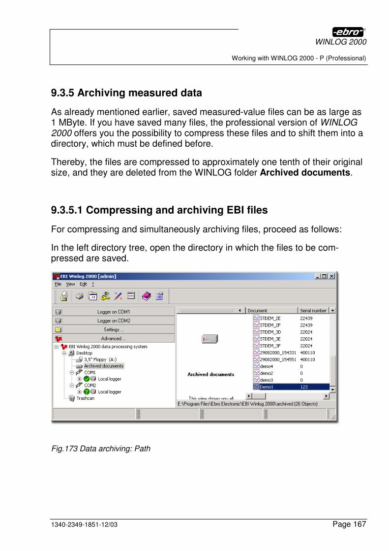
WINLOG 2000
Working with WINLOG 2000 - P (Professional)
1340-2349-1851-12/03 Page 167
9.3.5 Archiving measured data
As already mentioned earlier, saved measured-value files can be as large as 1 MByte. If you have saved many files, the professional version of WINLOG 2000 offers you the possibility to compress these files and to shift them into a directory, which must be defined before.
Thereby, the files are compressed to approximately one tenth of their original size, and they are deleted from the WINLOG folder Archived documents.
9.3.5.1 Compressing and archiving EBI files
For compressing and simultaneously archiving files, proceed as follows:
In the left directory tree, open the directory in which the files to be com-pressed are saved.
Fig.173 Data archiving: Path
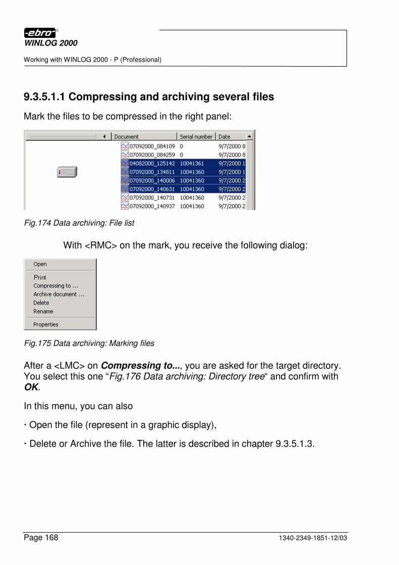
WINLOG 2000
Working with WINLOG 2000 - P (Professional)
Page 168 1340-2349-1851-12/03
9.3.5.1.1 Compressing and archiving several files
Mark the files to be compressed in the right panel:
Fig.174 Data archiving: File list
With <RMC> on the mark, you receive the following dialog:
Fig.175 Data archiving: Marking files
After a <LMC> on Compressing to..., you are asked for the target directory. You select this one “Fig.176 Data archiving: Directory tree“ and confirm with OK.
In this menu, you can also
� Open the file (represent in a graphic display),
� Delete or Archive the file. The latter is described in chapter 9.3.5.1.3.
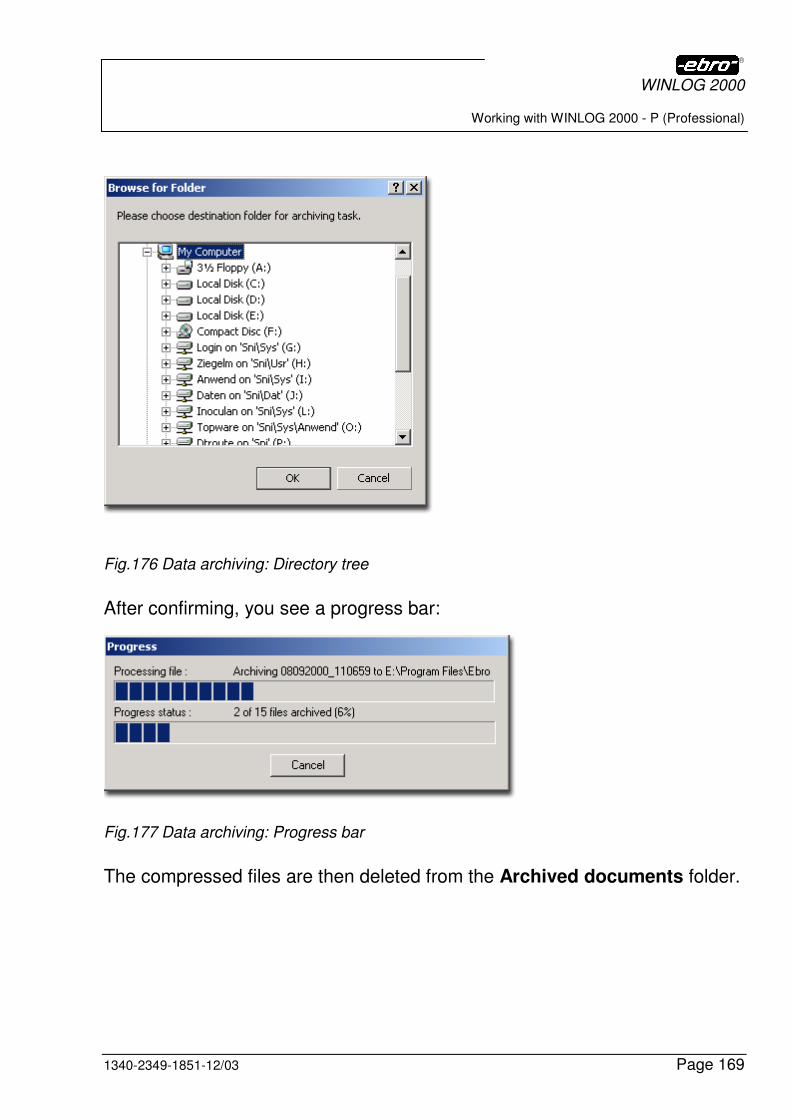
WINLOG 2000
Working with WINLOG 2000 - P (Professional)
1340-2349-1851-12/03 Page 169
Fig.176 Data archiving: Directory tree
After confirming, you see a progress bar:
Fig.177 Data archiving: Progress bar
The compressed files are then deleted from the Archived documents folder.

WINLOG 2000
Working with WINLOG 2000 - P (Professional)
Page 170 1340-2349-1851-12/03
9.3.5.1.2 Compressing and archiving single files
If you want to compress and simultaneously archive only one file, you must mark it. If you now make a right mouse-click on the marked file, you receive
this dialog:
Fig.178 Data archiving: Context menu
It differs from the dialog when compressing several files, in the additional possibility of renaming the file and displaying the properties of the file.
The properties of the file are displayed as follows:
Fig.179 Data archiving: File properties
WINLOG 2000
Working with WINLOG 2000 - P (Professional)
1340-2349-1851-12/03 Page 171
9.3.5.1.3 Archiving EBI files
If you only want to archive measured value files, you have the possibility to copy the marked file or files to the main folder Archived documents “Fig.173 Data archiving: Path“.
This means that the files are not compressed and that they remain in the master folder.
Should the desired file be already archived, you receive, of course, a warning message:
Fig.180 Data archiving: Safety interrogation
9.3.5.2 Import of compressed files
In the professional version of WINLOG 2000, you have the possibility to re-import compressed files and to represent them as a graphic display.
Fig.181 Data archiving: Menu for file
For this purpose, click on File - Import EBI 2000 compressed documents in the main menu.
This opens a file selection dialog.
WINLOG 2000
Working with WINLOG 2000 - P (Professional)
Page 172 1340-2349-1851-12/03
Fig.182 Data archiving: Directory
Fig.183 Data archiving: File selection
Select one or more compressed WINLOG 2000 files (*.ebz) to import.
You can import up to 1024 files.
Imported files appear in the Explorer view in the branch "Archived docu-ments" in “Fig.173 Data archiving: Path“.
Here the files, which now have the ebi suffix, can be opened and displayed as usually.
WINLOG 2000
Working with WINLOG 2000 - P (Professional)
1340-2349-1851-12/03 Page 173
9.3.6 Measurement units administration
WINLOG 2000 offers you the possibility to use any imaginable unit for the representation of measured values.
As a standard, WINLOG 2000 is delivered with the most usual units for pressure, temperature, humidity etc.. However, you also have the possibility to edit your own units or to change existing units.
Fig.184 Administration of measured variables:
This dialog field is divided into 3 ranges:
In the upper left range, all existing "basic units" are listed. These are fixed and cannot be changed. Basic units are those units, with which the EBI loggers work internally. So an EBI 85 A logger, by principle, measures the temperature in degrees Celsius. When a logger is read-out, then it delivers its data in this "basic unit", which is then converted into the momentarily active, derived unit by WINLOG 2000.
In the upper right range, all derived units available are listed. These are the units which are used for displaying data in WINLOG 2000.
WINLOG 2000
Working with WINLOG 2000 - P (Professional)
Page 174 1340-2349-1851-12/03
Example:
You read-out an EBI 85 A logger, which delivers its data in the basic unit of degrees Celsius (°C).
As an active derived unit, you have selected degrees Kelvin (°K).
WINLOG 2000 now converts all measured values into degrees Kelvin and uses this unit for every representation of temperature data.
For changing the active derived unit, you only need to click in the box next to the corresponding unit, with the mouse. The respective active unit is marked with a hook.
In the lower range, you can enter new units or change existing units.
For creating a new derived unit, click on the New button.
Then you have the possibility to enter a new derived unit into the lower range
Fig.185 Administration of measured variables: Example
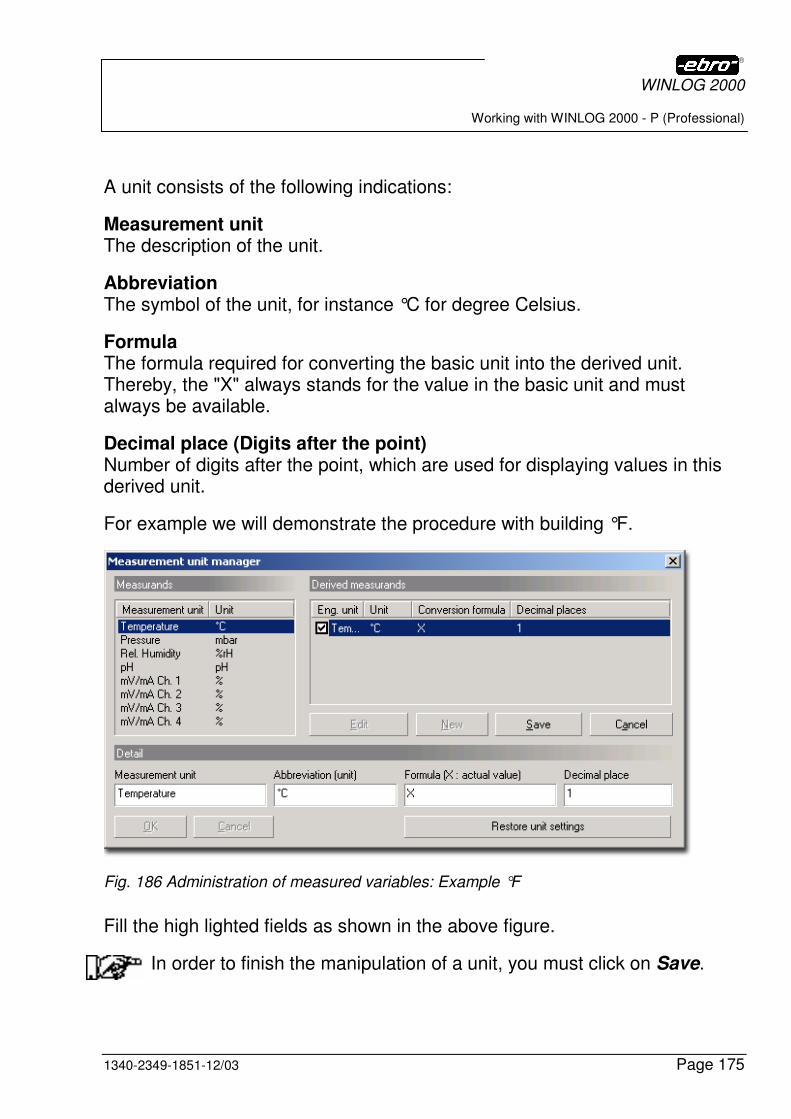
WINLOG 2000
Working with WINLOG 2000 - P (Professional)
1340-2349-1851-12/03 Page 175
A unit consists of the following indications:
Measurement unit The description of the unit.
Abbreviation The symbol of the unit, for instance °C for degree Celsius.
Formula The formula required for converting the basic unit into the derived unit. Thereby, the "X" always stands for the value in the basic unit and must always be available.
Decimal place (Digits after the point) Number of digits after the point, which are used for displaying values in this derived unit.
For example we will demonstrate the procedure with building °F.
Fig. 186 Administration of measured variables: Example °F
Fill the high lighted fields as shown in the above figure.
In order to finish the manipulation of a unit, you must click on Save.
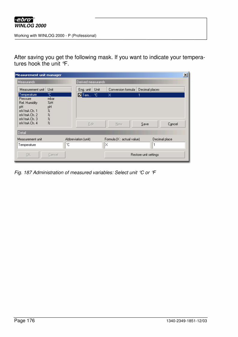
WINLOG 2000
Working with WINLOG 2000 - P (Professional)
Page 176 1340-2349-1851-12/03
After saving you get the following mask. If you want to indicate your tempera-tures hook the unit °F.
Fig. 187 Administration of measured variables: Select unit °C or °F
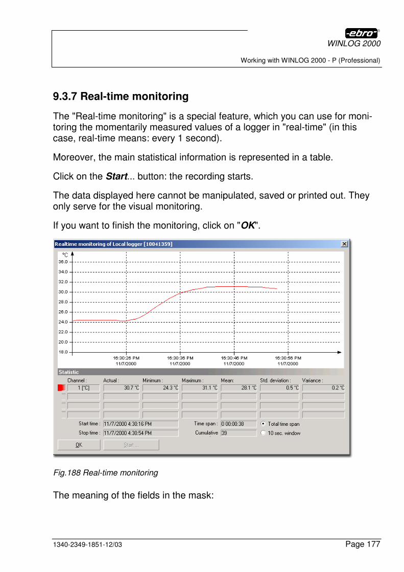
WINLOG 2000
Working with WINLOG 2000 - P (Professional)
1340-2349-1851-12/03 Page 177
9.3.7 Real-time monitoring
The "Real-time monitoring" is a special feature, which you can use for moni-toring the momentarily measured values of a logger in "real-time" (in this case, real-time means: every 1 second).
Moreover, the main statistical information is represented in a table.
Click on the Start... button: the recording starts.
The data displayed here cannot be manipulated, saved or printed out. They only serve for the visual monitoring.
If you want to finish the monitoring, click on "OK".
Fig.188 Real-time monitoring
The meaning of the fields in the mask:
WINLOG 2000
Working with WINLOG 2000 - P (Professional)
Page 178 1340-2349-1851-12/03
Channel Here, the measuring-channel number and the measuring unit (°C, °F, mbar, ...) of the respective channel are displayed.
Momentary The momentarily recorded measured value.
Minimum The smallest measured value recorded during the real-time monitoring.
Maximum The greatest measured value recorded during the real-time monitoring.
Average value Arithmetic average value. It is calculated from all measured values recorded during the real-time monitoring.
Standard deviation Standard deviation. It is calculated from all measured values recorded during the real-time monitoring.
Variance Calculated from all measured values recorded during real-time monitoring.
Measurement start Moment when the monitoring starts.
Measurement end Actual time.
Period Total monitoring period, displayed as Days:Hours:Minutes:Seconds.
Measuring points Number of measured values recorded during the monitoring.
Total period Activate this option, if you desire a graphic representation of all measured values recorded during the monitoring.
10-second panel Activate this option, if you desire a graphic representation of the measured values recorded during the last 10 seconds.
WINLOG 2000
Working with WINLOG 2000 – B (BUS)
1340-2349-1851-12/03 Page 179
10 Working with WINLOG 2000 – B (BUS)
Of course, this version comprises all functions of the Standard version and of the professional version of WINLOG 2000.
In order to be able to work properly with the WINLOG 2000 - B version, it is indispensable that you have already made experiences with the professional version.
Work through the chapters 5 to 10 most attentively! You thus save yourself many questions.
Purchase and installation of the WINLOG 2000 - B software
This software version can be purchased or installed in two different ways.
10.1 Purchase of the WINLOG 2000 - B version
You have decided to buy the WINLOG 2000 - B version from the start.
In this case, install the software as described in chapter 4.
After the installation, WINLOG 2000 - B is available on your computer. You can now use all the additional functions described in this chapter.
Of course, you can also dispose of all functions of the Standard (-S) and of the Professional (- P) software.
10.2 Purchase and installation of the BUS program module
You already work with the Standard or Professional version of WINLOG 2000 and would like to change to WINLOG 2000 - B .
Buy the releasing code for the installation of the BUS-version program mod-ule from ebro or your retailer.
Since you have already installed a version of WINLOG 2000, you can register the program module very easily. The procedure is very pre-cisely described in chapter “5.4.1.2 Adding program modules“.
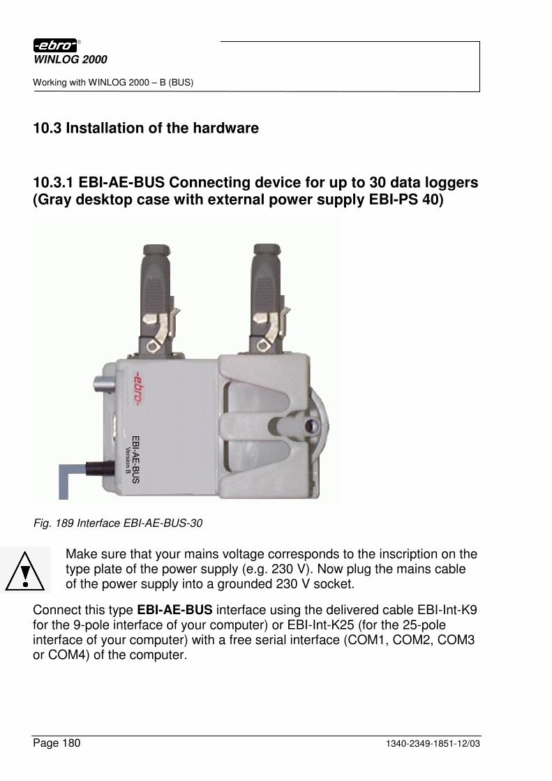
WINLOG 2000
Working with WINLOG 2000 – B (BUS)
Page 180 1340-2349-1851-12/03
10.3 Installation of the hardware
10.3.1 EBI-AE-BUS Connecting device for up to 30 data loggers (Gray desktop case with external power supply EBI-PS 40)
Fig. 189 Interface EBI-AE-BUS-30
Make sure that your mains voltage corresponds to the inscription on the type plate of the power supply (e.g. 230 V). Now plug the mains cable of the power supply into a grounded 230 V socket.
Connect this type EBI-AE-BUS interface using the delivered cable EBI-Int-K9 for the 9-pole interface of your computer) or EBI-Int-K25 (for the 25-pole interface of your computer) with a free serial interface (COM1, COM2, COM3 or COM4) of the computer.
WINLOG 2000
Working with WINLOG 2000 – B (BUS)
1340-2349-1851-12/03 Page 181
Screw the cable with the two screws located on the connector to the in-terface socket by means of a small screw-driver, in order to prevent an unintended loosening of the cable.
The 9-pole socket of the data cable must always be plugged into the inter-face.
In order to prevent that the cable is inadvertently pulled out, please also tighten the two screws of the 9-pole socket of the data cable with a screw driver.
Please connect the EBI-PS 40 table power-supply, included in the delivery of the evaluation system, with the interface using the adaptor cable (power supply) as described:
Carefully insert the connector of this cable into the corresponding socket of the interface and lock it by fastening the coupling ring of this connector.
You thus prevent an undesired loosening of this connection.
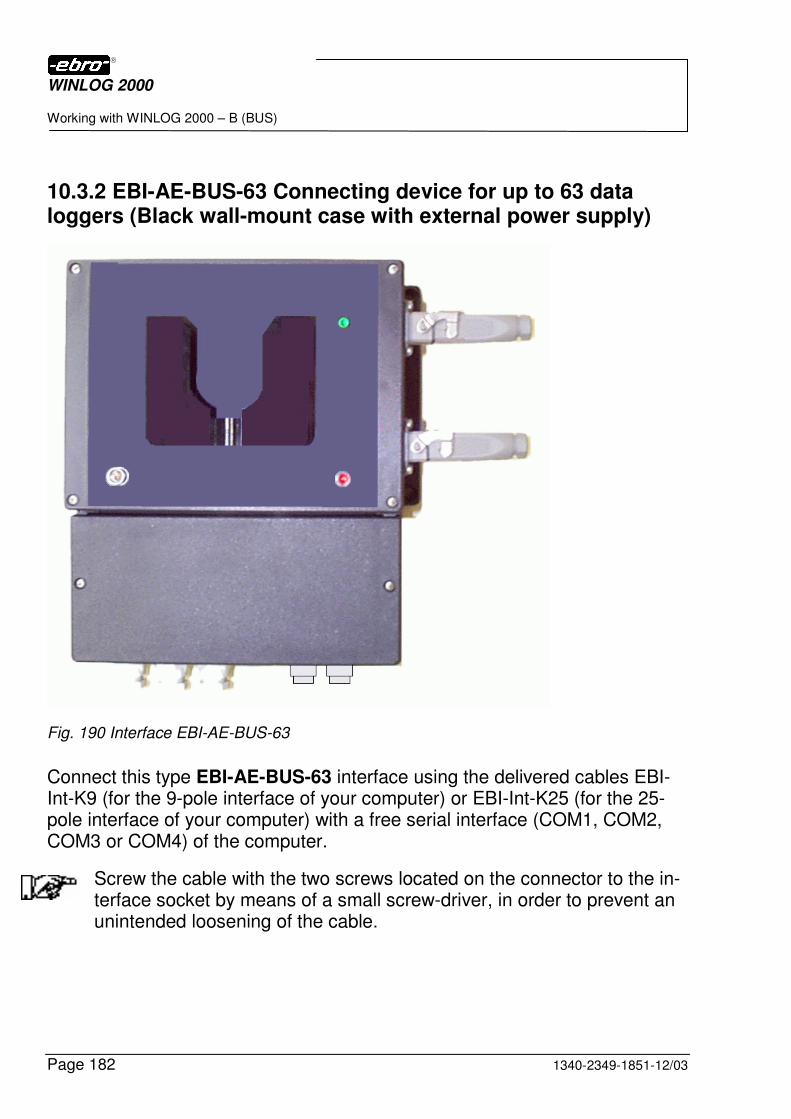
WINLOG 2000
Working with WINLOG 2000 – B (BUS)
Page 182 1340-2349-1851-12/03
10.3.2 EBI-AE-BUS-63 Connecting device for up to 63 data loggers (Black wall-mount case with external power supply)
Fig. 190 Interface EBI-AE-BUS-63
Connect this type EBI-AE-BUS-63 interface using the delivered cables EBI-Int-K9 (for the 9-pole interface of your computer) or EBI-Int-K25 (for the 25-pole interface of your computer) with a free serial interface (COM1, COM2, COM3 or COM4) of the computer.
Screw the cable with the two screws located on the connector to the in-terface socket by means of a small screw-driver, in order to prevent an unintended loosening of the cable.

WINLOG 2000
Working with WINLOG 2000 – B (BUS)
1340-2349-1851-12/03 Page 183
The 9-pole socket of the data cable must always be plugged into the inter-face.
In order to prevent that the cable is inadvertently pulled out, please also tighten the two screws of the 9-pole socket of the data cable with a screw driver.
The wall-mounted power supply contained in the delivery of the evaluation system is already connected to the interface via the adaptor cable.
Make sure that your mains voltage corresponds to the inscription on the type plate of the power supply (e.g. 230 V). Now plug the mains cable of the power supply into a grounded 230 V socket.
Switch-on the power supply.
10.3.3 Logger types
The following loggers are suited for use in BUS systems:
Wet-room loggers of series EBI-2T-7xx
Dry-room loggers of series EBI-2T-7xx
Pictures of these loggers you can see in “Fig. 2 BUS logger for wetroom” and “Fig. 3 BUS logger for dryroom”.
10.3.4 BUS installation
For the first set-up or extension of a BUS system, you should contact the service department of ebro.
The proper function of a system greatly depends on the BUS wiring. The cable used and the way it has been laid are very important.
In any case, you should consider the installation instructions for the BUS system available at ebro.
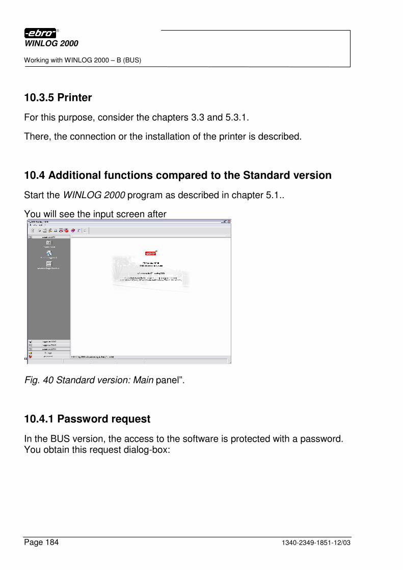
WINLOG 2000
Working with WINLOG 2000 – B (BUS)
Page 184 1340-2349-1851-12/03
10.3.5 Printer
For this purpose, consider the chapters 3.3 and 5.3.1.
There, the connection or the installation of the printer is described.
10.4 Additional functions compared to the Standard version
Start the WINLOG 2000 program as described in chapter 5.1..
You will see the input screen after
“
Fig. 40 Standard version: Main panel”.
10.4.1 Password request
In the BUS version, the access to the software is protected with a password. You obtain this request dialog-box:
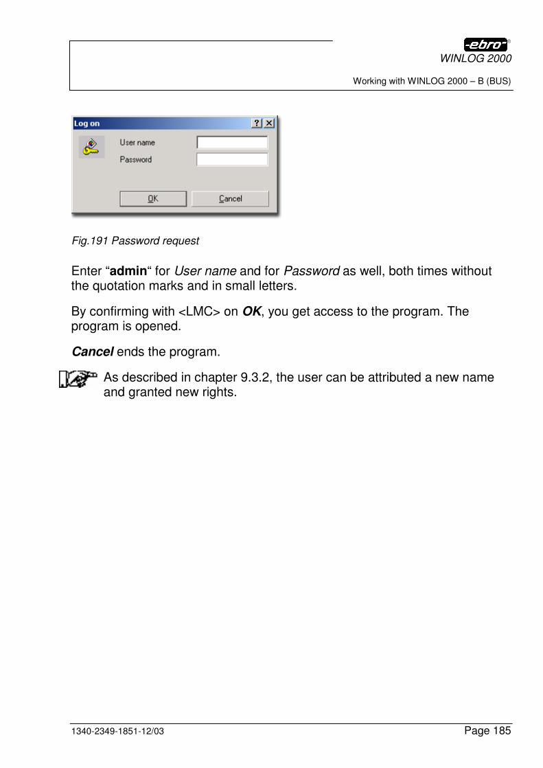
WINLOG 2000
Working with WINLOG 2000 – B (BUS)
1340-2349-1851-12/03 Page 185
Fig.191 Password request
Enter “admin“ for User name and for Password as well, both times without the quotation marks and in small letters.
By confirming with <LMC> on OK, you get access to the program. The program is opened.
Cancel ends the program.
As described in chapter 9.3.2, the user can be attributed a new name and granted new rights.
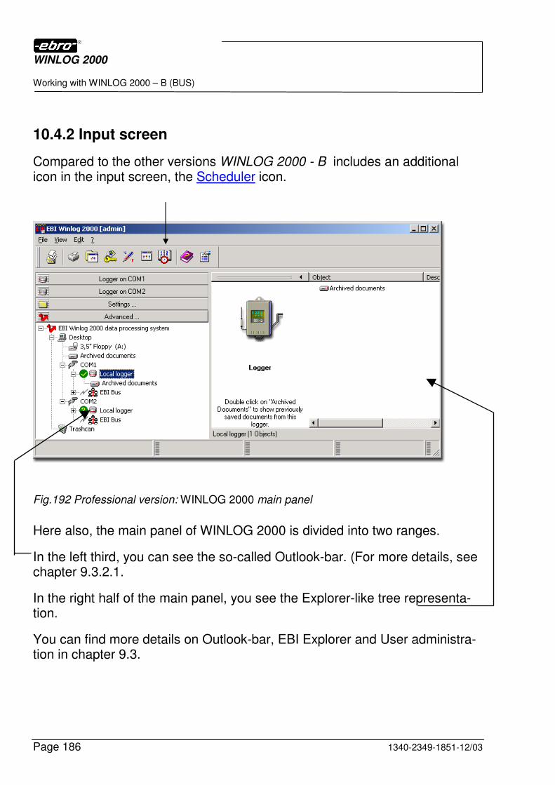
WINLOG 2000
Working with WINLOG 2000 – B (BUS)
Page 186 1340-2349-1851-12/03
10.4.2 Input screen
Compared to the other versions WINLOG 2000 - B includes an additional icon in the input screen, the Scheduler icon.
Fig.192 Professional version: WINLOG 2000 main panel
Here also, the main panel of WINLOG 2000 is divided into two ranges.
In the left third, you can see the so-called Outlook-bar. (For more details, see chapter 9.3.2.1.
In the right half of the main panel, you see the Explorer-like tree representa-tion.
You can find more details on Outlook-bar, EBI Explorer and User administra-tion in chapter 9.3.
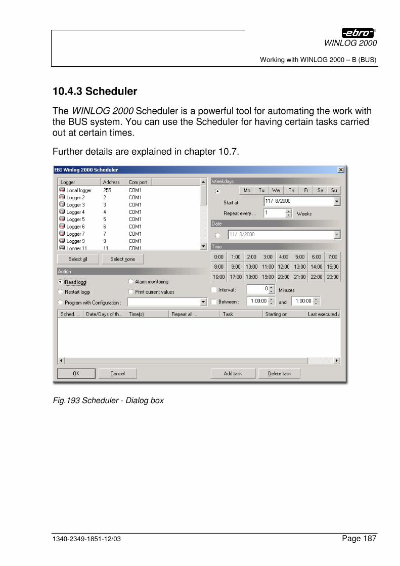
WINLOG 2000
Working with WINLOG 2000 – B (BUS)
1340-2349-1851-12/03 Page 187
10.4.3 Scheduler
The WINLOG 2000 Scheduler is a powerful tool for automating the work with the BUS system. You can use the Scheduler for having certain tasks carried out at certain times.
Further details are explained in chapter 10.7.
Fig.193 Scheduler - Dialog box
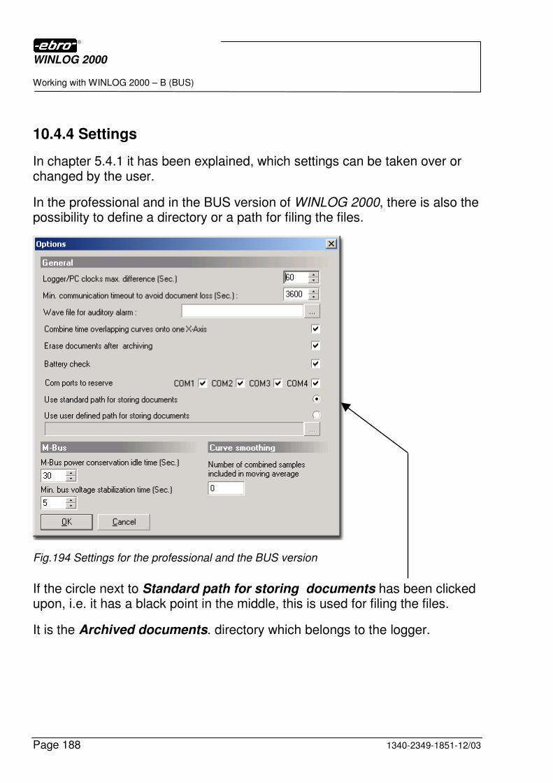
WINLOG 2000
Working with WINLOG 2000 – B (BUS)
Page 188 1340-2349-1851-12/03
10.4.4 Settings
In chapter 5.4.1 it has been explained, which settings can be taken over or changed by the user.
In the professional and in the BUS version of WINLOG 2000, there is also the possibility to define a directory or a path for filing the files.
Fig.194 Settings for the professional and the BUS version
If the circle next to Standard path for storing documents has been clicked upon, i.e. it has a black point in the middle, this is used for filing the files.
It is the Archived documents. directory which belongs to the logger.
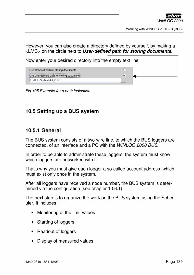
WINLOG 2000
Working with WINLOG 2000 – B (BUS)
1340-2349-1851-12/03 Page 189
However, you can also create a directory defined by yourself, by making a <LMC> on the circle next to User-defined path for storing documents.
Now enter your desired directory into the empty text line.
Fig.195 Example for a path indication
10.5 Setting up a BUS system
10.5.1 General
The BUS system consists of a two-wire line, to which the BUS loggers are connected, of an interface and a PC with the WINLOG 2000 BUS.
In order to be able to administrate these loggers, the system must know which loggers are networked with it.
That’s why you must give each logger a so-called account address, which must exist only once in the system.
After all loggers have received a node number, the BUS system is deter-mined via the configuration (see chapter 10.6.1).
The next step is to organize the work on the BUS system using the Sched-uler. It includes:
• Monitoring of the limit values
• Starting of loggers
• Readout of loggers
• Display of measured values
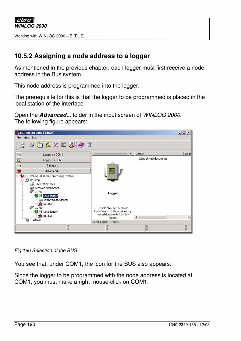
WINLOG 2000
Working with WINLOG 2000 – B (BUS)
Page 190 1340-2349-1851-12/03
10.5.2 Assigning a node address to a logger
As mentioned in the previous chapter, each logger must first receive a node address in the Bus system.
This node address is programmed into the logger.
The prerequisite for this is that the logger to be programmed is placed in the local station of the interface.
Open the Advanced... folder in the input screen of WINLOG 2000. The following figure appears:
Fig.196 Selection of the BUS
You see that, under COM1, the icon for the BUS also appears.
Since the logger to be programmed with the node address is located at COM1, you must make a right mouse-click on COM1.
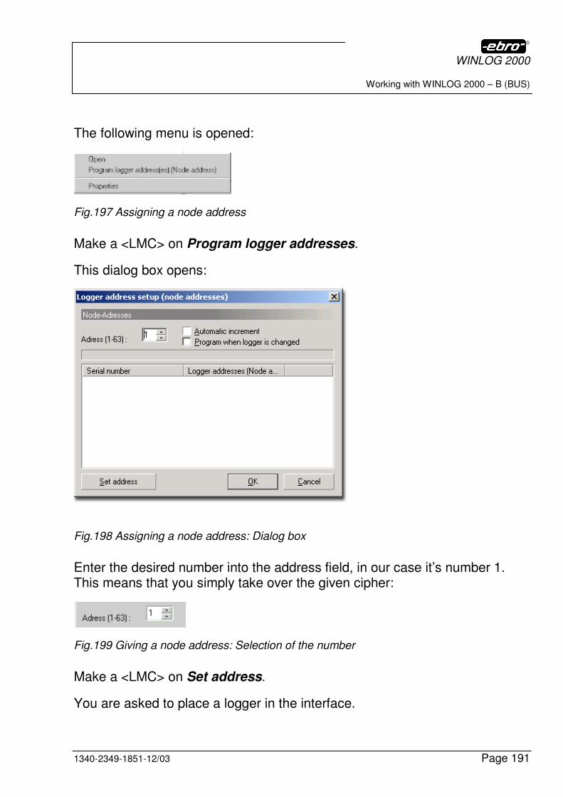
WINLOG 2000
Working with WINLOG 2000 – B (BUS)
1340-2349-1851-12/03 Page 191
The following menu is opened:
Fig.197 Assigning a node address
Make a <LMC> on Program logger addresses.
This dialog box opens:
Fig.198 Assigning a node address: Dialog box
Enter the desired number into the address field, in our case it’s number 1. This means that you simply take over the given cipher:
Fig.199 Giving a node address: Selection of the number
Make a <LMC> on Set address.
You are asked to place a logger in the interface.
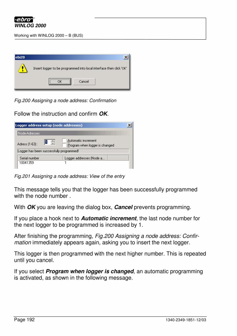
WINLOG 2000
Working with WINLOG 2000 – B (BUS)
Page 192 1340-2349-1851-12/03
Fig.200 Assigning a node address: Confirmation
Follow the instruction and confirm OK.
Fig.201 Assigning a node address: View of the entry
This message tells you that the logger has been successfully programmed with the node number .
With OK you are leaving the dialog box, Cancel prevents programming.
If you place a hook next to Automatic increment, the last node number for the next logger to be programmed is increased by 1.
After finishing the programming, Fig.200 Assigning a node address: Confir-mation immediately appears again, asking you to insert the next logger.
This logger is then programmed with the next higher number. This is repeated until you cancel.
If you select Program when logger is changed, an automatic programming is activated, as shown in the following message.
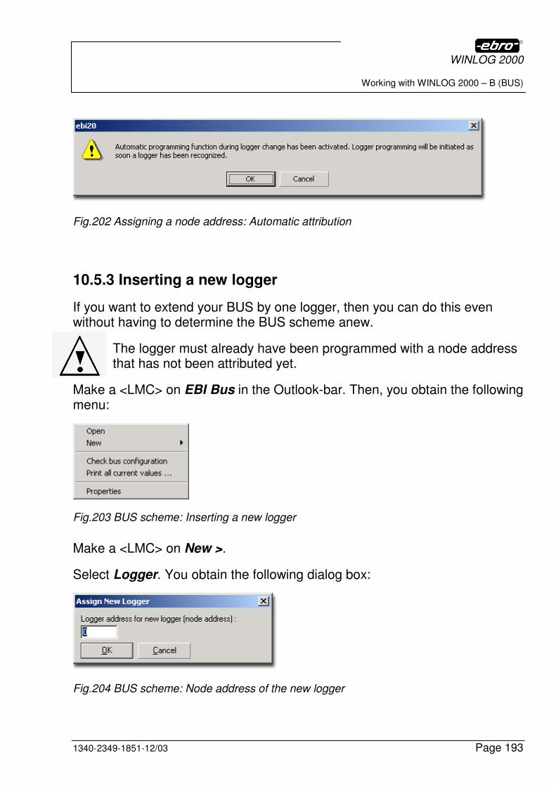
WINLOG 2000
Working with WINLOG 2000 – B (BUS)
1340-2349-1851-12/03 Page 193
Fig.202 Assigning a node address: Automatic attribution
10.5.3 Inserting a new logger
If you want to extend your BUS by one logger, then you can do this even without having to determine the BUS scheme anew.
The logger must already have been programmed with a node address that has not been attributed yet.
Make a <LMC> on EBI Bus in the Outlook-bar. Then, you obtain the following menu:
Fig.203 BUS scheme: Inserting a new logger
Make a <LMC> on New >.
Select Logger. You obtain the following dialog box:
Fig.204 BUS scheme: Node address of the new logger
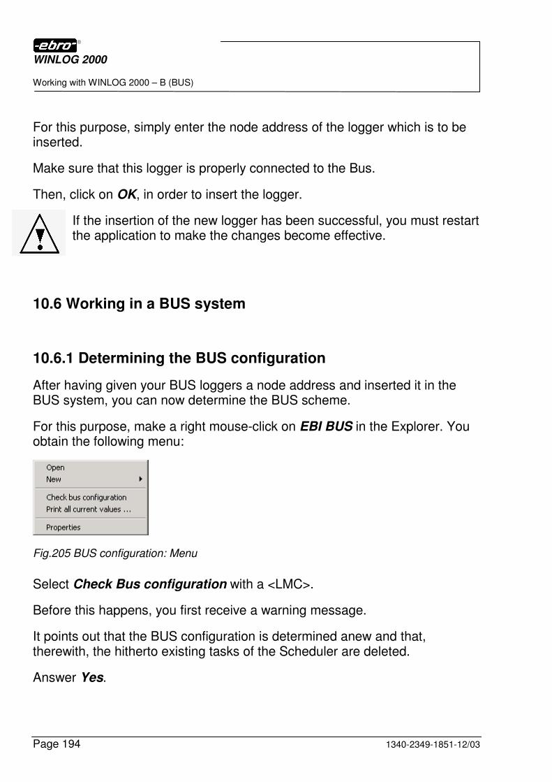
WINLOG 2000
Working with WINLOG 2000 – B (BUS)
Page 194 1340-2349-1851-12/03
For this purpose, simply enter the node address of the logger which is to be inserted.
Make sure that this logger is properly connected to the Bus.
Then, click on OK, in order to insert the logger.
If the insertion of the new logger has been successful, you must restart the application to make the changes become effective.
10.6 Working in a BUS system
10.6.1 Determining the BUS configuration
After having given your BUS loggers a node address and inserted it in the BUS system, you can now determine the BUS scheme.
For this purpose, make a right mouse-click on EBI BUS in the Explorer. You obtain the following menu:
Fig.205 BUS configuration: Menu
Select Check Bus configuration with a <LMC>.
Before this happens, you first receive a warning message.
It points out that the BUS configuration is determined anew and that, therewith, the hitherto existing tasks of the Scheduler are deleted.
Answer Yes.
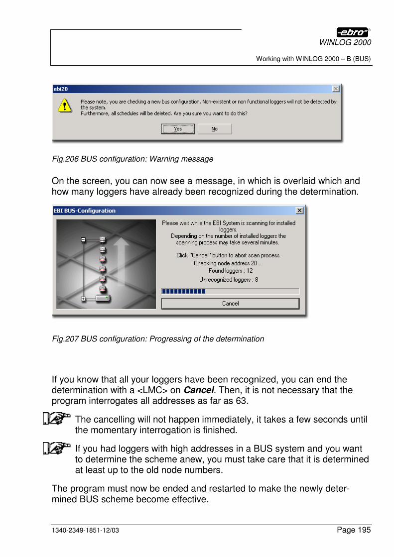
WINLOG 2000
Working with WINLOG 2000 – B (BUS)
1340-2349-1851-12/03 Page 195
Fig.206 BUS configuration: Warning message
On the screen, you can now see a message, in which is overlaid which and how many loggers have already been recognized during the determination.
Fig.207 BUS configuration: Progressing of the determination
If you know that all your loggers have been recognized, you can end the determination with a <LMC> on Cancel. Then, it is not necessary that the program interrogates all addresses as far as 63.
The cancelling will not happen immediately, it takes a few seconds until the momentary interrogation is finished.
If you had loggers with high addresses in a BUS system and you want to determine the scheme anew, you must take care that it is determined at least up to the old node numbers.
The program must now be ended and restarted to make the newly deter-mined BUS scheme become effective.
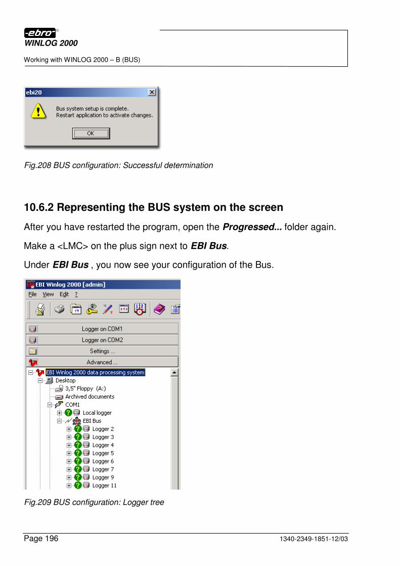
WINLOG 2000
Working with WINLOG 2000 – B (BUS)
Page 196 1340-2349-1851-12/03
Fig.208 BUS configuration: Successful determination
10.6.2 Representing the BUS system on the screen
After you have restarted the program, open the Progressed... folder again.
Make a <LMC> on the plus sign next to EBI Bus.
Under EBI Bus , you now see your configuration of the Bus.
Fig.209 BUS configuration: Logger tree
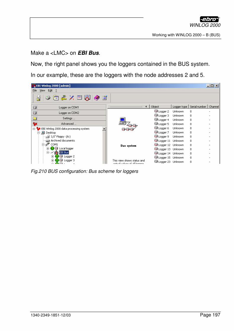
WINLOG 2000
Working with WINLOG 2000 – B (BUS)
1340-2349-1851-12/03 Page 197
Make a <LMC> on EBI Bus.
Now, the right panel shows you the loggers contained in the BUS system.
In our example, these are the loggers with the node addresses 2 and 5.
Fig.210 BUS configuration: Bus scheme for loggers
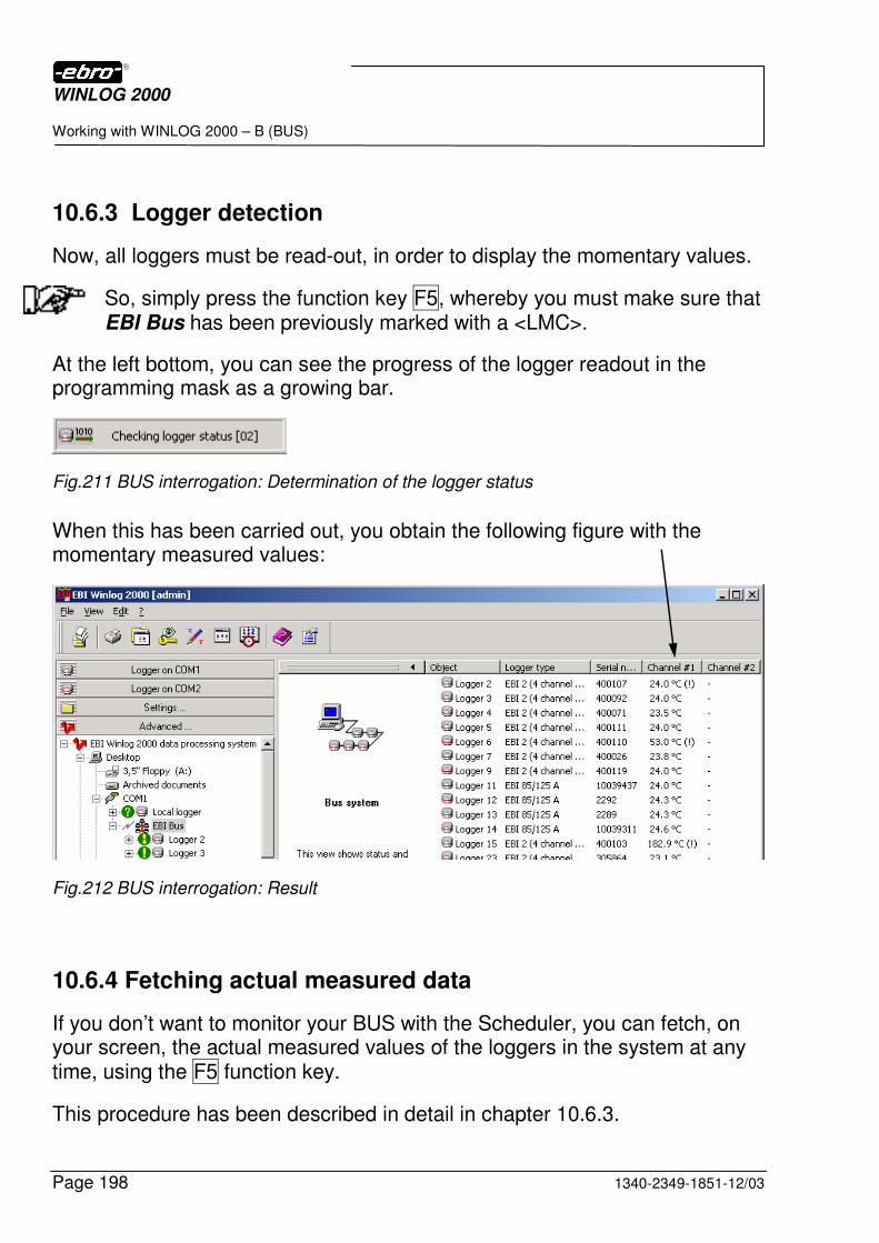
WINLOG 2000
Working with WINLOG 2000 – B (BUS)
Page 198 1340-2349-1851-12/03
10.6.3 Logger detection
Now, all loggers must be read-out, in order to display the momentary values.
So, simply press the function key F5, whereby you must make sure that EBI Bus has been previously marked with a <LMC>.
At the left bottom, you can see the progress of the logger readout in the programming mask as a growing bar.
Fig.211 BUS interrogation: Determination of the logger status
When this has been carried out, you obtain the following figure with the momentary measured values:
Fig.212 BUS interrogation: Result
10.6.4 Fetching actual measured data
If you don’t want to monitor your BUS with the Scheduler, you can fetch, on your screen, the actual measured values of the loggers in the system at any time, using the F5 function key.
This procedure has been described in detail in chapter 10.6.3.
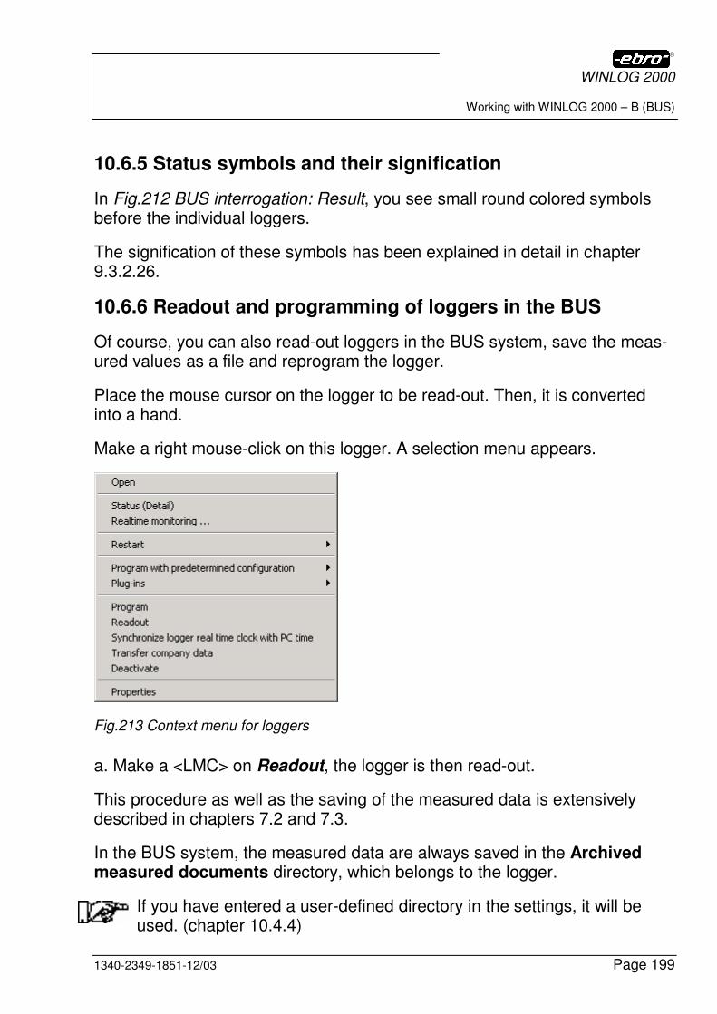
WINLOG 2000
Working with WINLOG 2000 – B (BUS)
1340-2349-1851-12/03 Page 199
10.6.5 Status symbols and their signification
In Fig.212 BUS interrogation: Result, you see small round colored symbols before the individual loggers.
The signification of these symbols has been explained in detail in chapter 9.3.2.26.
10.6.6 Readout and programming of loggers in the BUS
Of course, you can also read-out loggers in the BUS system, save the meas-ured values as a file and reprogram the logger.
Place the mouse cursor on the logger to be read-out. Then, it is converted into a hand.
Make a right mouse-click on this logger. A selection menu appears.
Fig.213 Context menu for loggers
a. Make a <LMC> on Readout, the logger is then read-out.
This procedure as well as the saving of the measured data is extensively described in chapters 7.2 and 7.3.
In the BUS system, the measured data are always saved in the Archived measured documents directory, which belongs to the logger.
If you have entered a user-defined directory in the settings, it will be used. (chapter 10.4.4)
WINLOG 2000
Working with WINLOG 2000 – B (BUS)
Page 200 1340-2349-1851-12/03
This also applies when all BUS loggers are read-out via Scheduler.
Fig.214 Directory: Archived measured documents
b. If you select Program with a <LMC> in the context menu, the logger is programmed with an interval of 15 seconds in the endless mode.
If you select Program with a <LMC> in the context menu, the logger is programmed with an interval stored in a configuration.
Fig.215 Programming with...
The programming and readout of loggers is described in detail in chap-ters 6 and 7 of this manual.
WINLOG 2000
Working with WINLOG 2000 – B (BUS)
1340-2349-1851-12/03 Page 201
10.6.7 Setting up a group of loggers
If you have already installed a BUS system, you have the possibility to com-bine the multitude of the installed loggers in one or more groups.
For instance, one can imagine that you name one group 1st floor, another group 2nd floor. The corresponding loggers should be placed in this group.
For creating a group, proceed as follows:
Open the Progressed folder.
Make a right mouse-click on EBI Bus.
In the appearing dialog, select New > and Grouping with a <LMC>. A new folder named New grouping is created, which you can easily rename.
Fig.216 BUS scheme: New grouping
Double-click on the folder and edit the new name.
Fig.217 BUS scheme: Naming the new grouping
With the mouse, point to the logger that should be in the new folder, and pull it into the folder via drag & drop.
Proceed in the same manner with the other loggers as well.
If you have dragged all loggers into the suitable folder, your directory tree could look as follows:
WINLOG 2000
Working with WINLOG 2000 – B (BUS)
Page 202 1340-2349-1851-12/03
Fig.218 Example for a BUS scheme
Remember:
A plus sign before a directory means that there are more directories in this directory. With a <LMC> on the plus sign, you open the directory.
10.7 Monitoring the BUS with the Scheduler
10.7.1 General
The WINLOG 2000 Scheduler is a tool, with which you can automate the work with the BUS system. Its main task is to automatically execute certain tasks at certain times.
You can create several tasks and also run them simultaneously.
If you determine the BUS scheme anew, all created tasks are deleted!
The Scheduler automatically finds all loggers of the BUS system, as well as the local station with the local logger, even if they are distrib-uted in different groupings, like in our example.
WINLOG 2000
Working with WINLOG 2000 – B (BUS)
1340-2349-1851-12/03 Page 203
10.7.2 Functions of the Scheduler
The Scheduler is started with a <LMC> on the icon in the icon bar of the input screen of WINLOG 2000. Then, you obtain the following dialog box:
Fig.219 Scheduler: Dialog box
The individual functions are explained with an example in the following section.
The logger list In this list, you select the logger(s), with which you want to carry out an action.
The desired loggers must be marked.
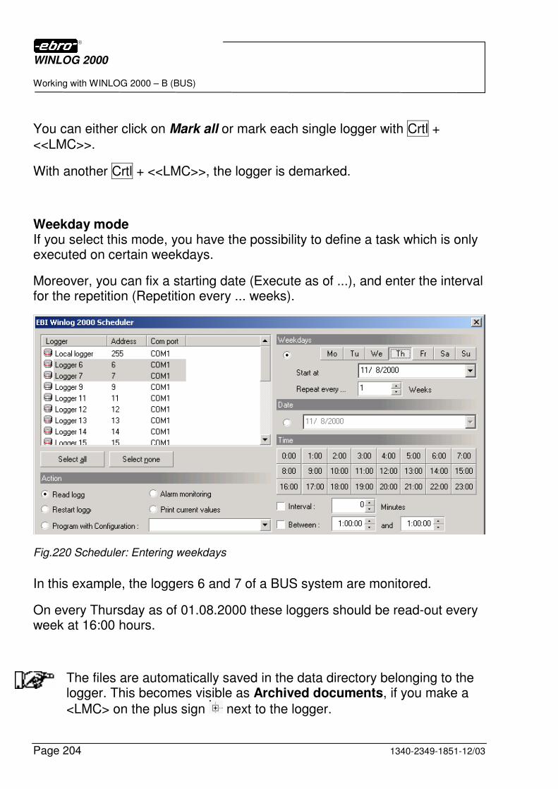
WINLOG 2000
Working with WINLOG 2000 – B (BUS)
Page 204 1340-2349-1851-12/03
You can either click on Mark all or mark each single logger with Crtl + <<LMC>>.
With another Crtl + <<LMC>>, the logger is demarked.
Weekday mode If you select this mode, you have the possibility to define a task which is only executed on certain weekdays.
Moreover, you can fix a starting date (Execute as of ...), and enter the interval for the repetition (Repetition every ... weeks).
Fig.220 Scheduler: Entering weekdays
In this example, the loggers 6 and 7 of a BUS system are monitored.
On every Thursday as of 01.08.2000 these loggers should be read-out every week at 16:00 hours.
The files are automatically saved in the data directory belonging to the logger. This becomes visible as Archived documents, if you make a
<LMC> on the plus sign next to the logger.
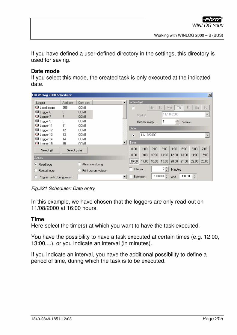
WINLOG 2000
Working with WINLOG 2000 – B (BUS)
1340-2349-1851-12/03 Page 205
If you have defined a user-defined directory in the settings, this directory is used for saving.
Date mode If you select this mode, the created task is only executed at the indicated date.
Fig.221 Scheduler: Date entry
In this example, we have chosen that the loggers are only read-out on 11/08/2000 at 16:00 hours.
Time Here select the time(s) at which you want to have the task executed.
You have the possibility to have a task executed at certain times (e.g. 12:00, 13:00,...), or you indicate an interval (in minutes).
If you indicate an interval, you have the additional possibility to define a period of time, during which the task is to be executed.
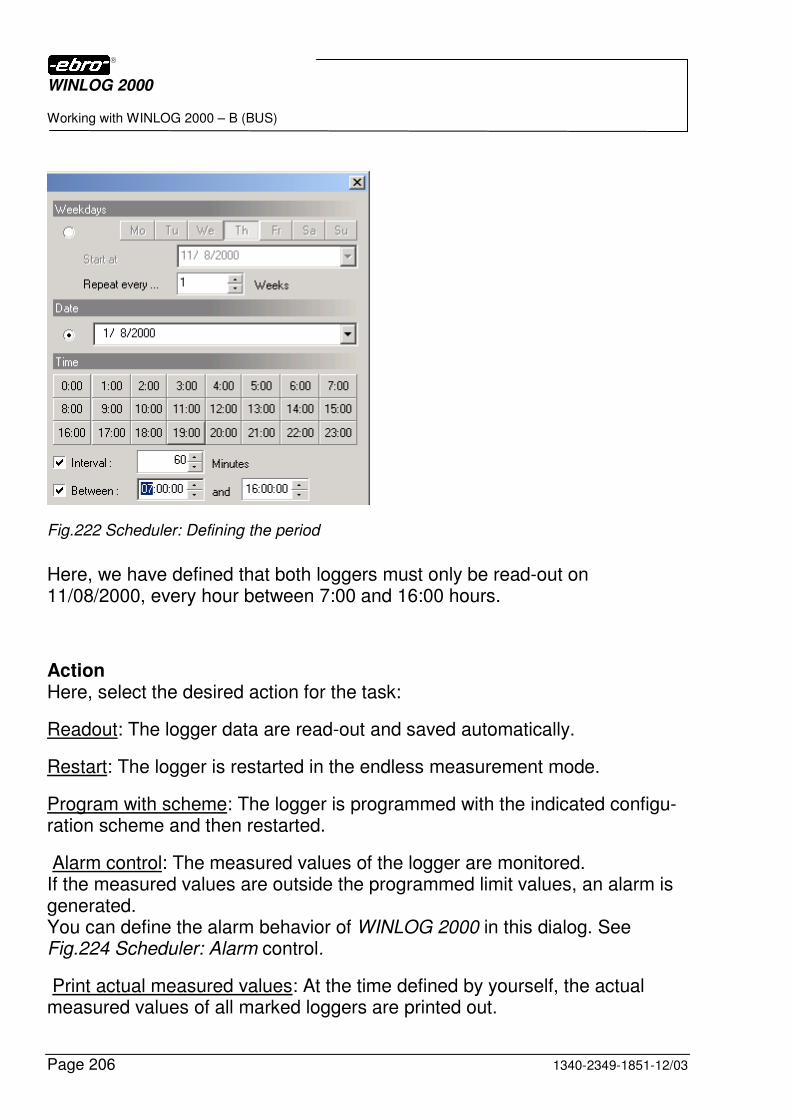
WINLOG 2000
Working with WINLOG 2000 – B (BUS)
Page 206 1340-2349-1851-12/03
Fig.222 Scheduler: Defining the period
Here, we have defined that both loggers must only be read-out on 11/08/2000, every hour between 7:00 and 16:00 hours.
Action Here, select the desired action for the task:
Readout: The logger data are read-out and saved automatically.
Restart: The logger is restarted in the endless measurement mode.
Program with scheme: The logger is programmed with the indicated configu-ration scheme and then restarted.
Alarm control: The measured values of the logger are monitored. If the measured values are outside the programmed limit values, an alarm is generated. You can define the alarm behavior of WINLOG 2000 in this dialog. See Fig.224 Scheduler: Alarm control.
Print actual measured values: At the time defined by yourself, the actual measured values of all marked loggers are printed out.
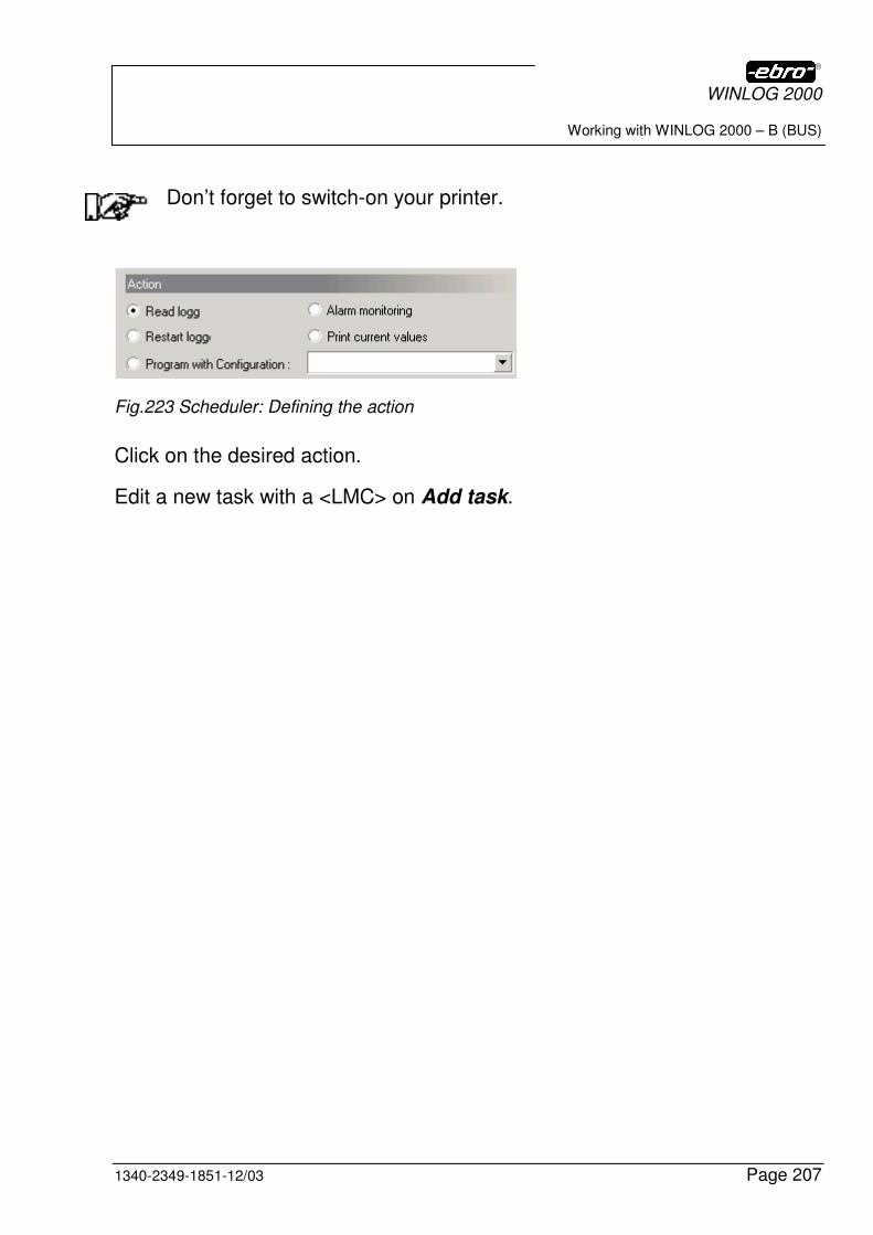
WINLOG 2000
Working with WINLOG 2000 – B (BUS)
1340-2349-1851-12/03 Page 207
Don’t forget to switch-on your printer.
Fig.223 Scheduler: Defining the action
Click on the desired action.
Edit a new task with a <LMC> on Add task.
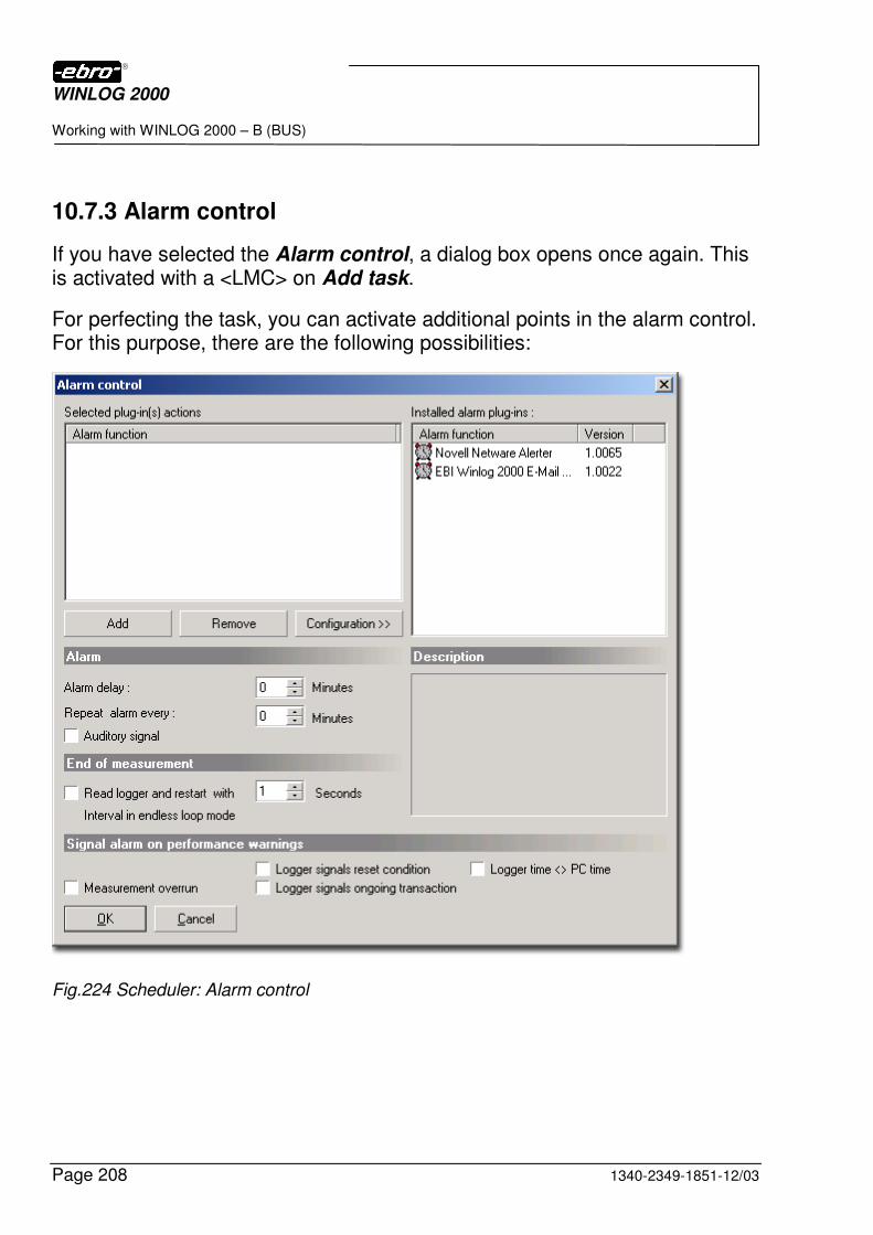
WINLOG 2000
Working with WINLOG 2000 – B (BUS)
Page 208 1340-2349-1851-12/03
10.7.3 Alarm control
If you have selected the Alarm control, a dialog box opens once again. This is activated with a <LMC> on Add task.
For perfecting the task, you can activate additional points in the alarm control. For this purpose, there are the following possibilities:
Fig.224 Scheduler: Alarm control
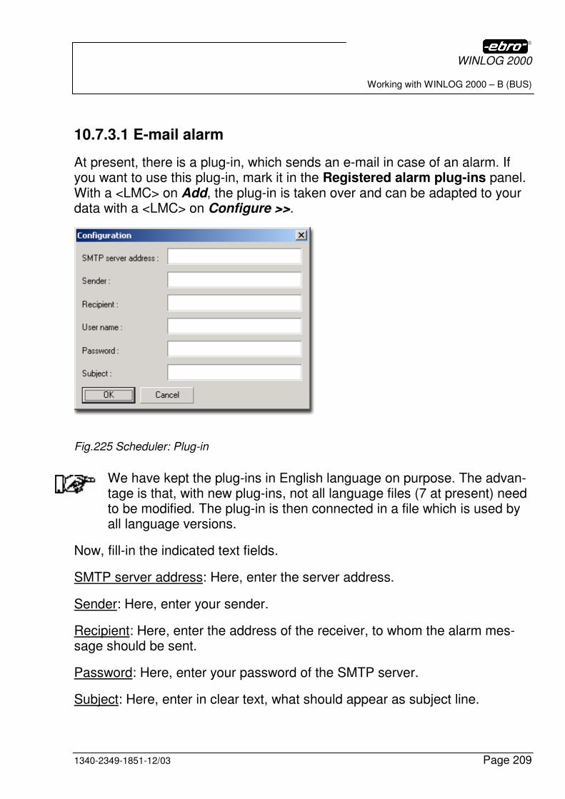
WINLOG 2000
Working with WINLOG 2000 – B (BUS)
1340-2349-1851-12/03 Page 209
10.7.3.1 E-mail alarm
At present, there is a plug-in, which sends an e-mail in case of an alarm. If you want to use this plug-in, mark it in the Registered alarm plug-ins panel. With a <LMC> on Add, the plug-in is taken over and can be adapted to your data with a <LMC> on Configure >>.
Fig.225 Scheduler: Plug-in
We have kept the plug-ins in English language on purpose. The advan-tage is that, with new plug-ins, not all language files (7 at present) need to be modified. The plug-in is then connected in a file which is used by all language versions.
Now, fill-in the indicated text fields.
SMTP server address: Here, enter the server address.
Sender: Here, enter your sender.
Recipient: Here, enter the address of the receiver, to whom the alarm mes-sage should be sent.
Password: Here, enter your password of the SMTP server.
Subject: Here, enter in clear text, what should appear as subject line.
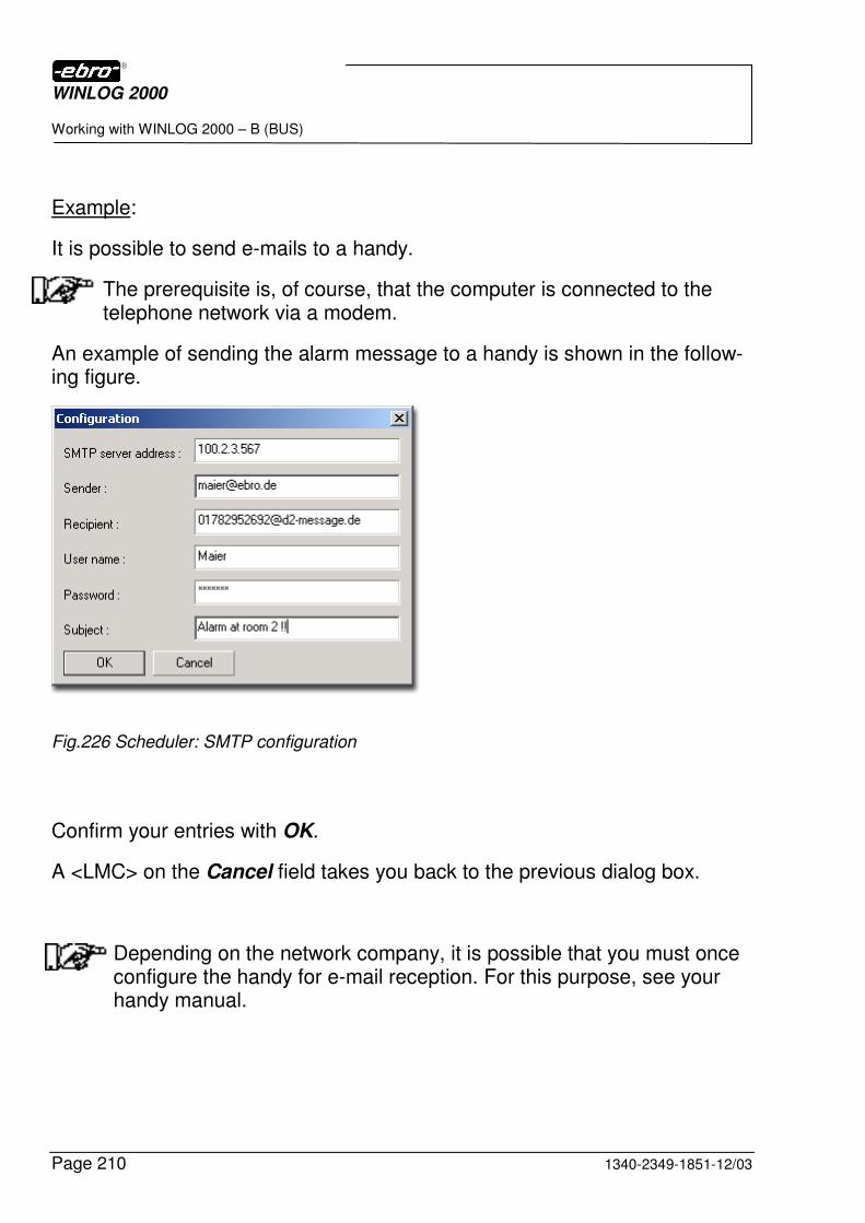
WINLOG 2000
Working with WINLOG 2000 – B (BUS)
Page 210 1340-2349-1851-12/03
Example:
It is possible to send e-mails to a handy.
The prerequisite is, of course, that the computer is connected to the telephone network via a modem.
An example of sending the alarm message to a handy is shown in the follow-ing figure.
Fig.226 Scheduler: SMTP configuration
Confirm your entries with OK.
A <LMC> on the Cancel field takes you back to the previous dialog box.
Depending on the network company, it is possible that you must once configure the handy for e-mail reception. For this purpose, see your handy manual.
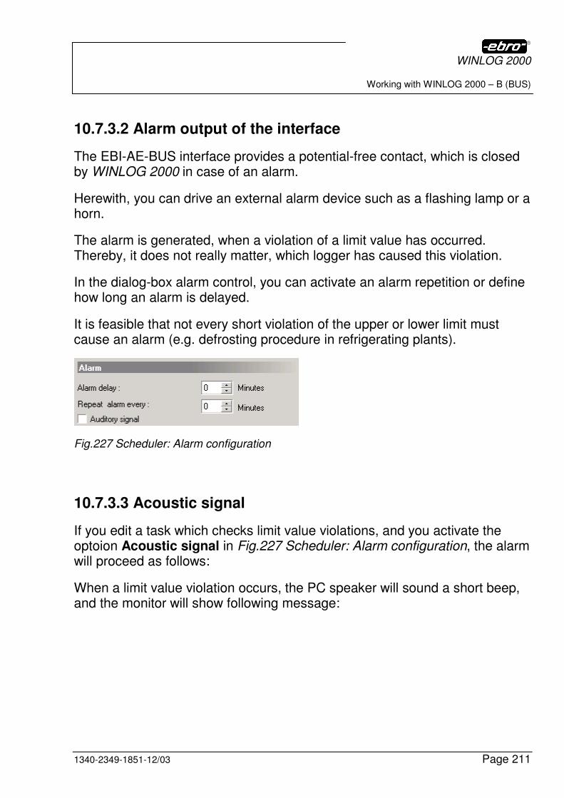
WINLOG 2000
Working with WINLOG 2000 – B (BUS)
1340-2349-1851-12/03 Page 211
10.7.3.2 Alarm output of the interface
The EBI-AE-BUS interface provides a potential-free contact, which is closed by WINLOG 2000 in case of an alarm.
Herewith, you can drive an external alarm device such as a flashing lamp or a horn.
The alarm is generated, when a violation of a limit value has occurred. Thereby, it does not really matter, which logger has caused this violation.
In the dialog-box alarm control, you can activate an alarm repetition or define how long an alarm is delayed.
It is feasible that not every short violation of the upper or lower limit must cause an alarm (e.g. defrosting procedure in refrigerating plants).
Fig.227 Scheduler: Alarm configuration
10.7.3.3 Acoustic signal
If you edit a task which checks limit value violations, and you activate the optoion Acoustic signal in Fig.227 Scheduler: Alarm configuration, the alarm will proceed as follows:
When a limit value violation occurs, the PC speaker will sound a short beep, and the monitor will show following message:
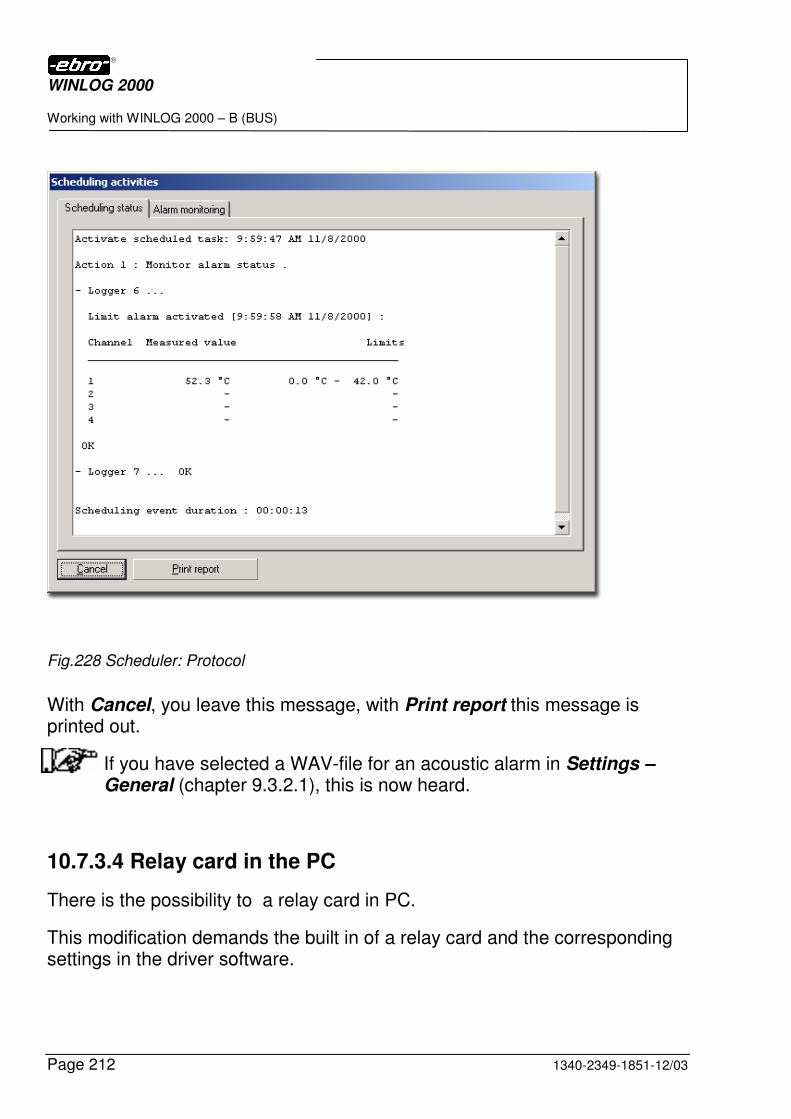
WINLOG 2000
Working with WINLOG 2000 – B (BUS)
Page 212 1340-2349-1851-12/03
Fig.228 Scheduler: Protocol
With Cancel, you leave this message, with Print report this message is printed out.
If you have selected a WAV-file for an acoustic alarm in Settings – General (chapter 9.3.2.1), this is now heard.
10.7.3.4 Relay card in the PC
There is the possibility to a relay card in PC.
This modification demands the built in of a relay card and the corresponding settings in the driver software.
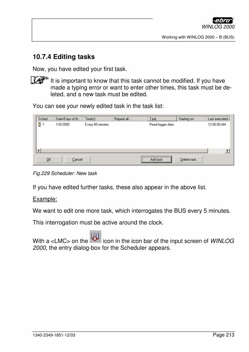
WINLOG 2000
Working with WINLOG 2000 – B (BUS)
1340-2349-1851-12/03 Page 213
10.7.4 Editing tasks
Now, you have edited your first task.
It is important to know that this task cannot be modified. If you have made a typing error or want to enter other times, this task must be de-leted, and a new task must be edited.
You can see your newly edited task in the task list:
Fig.229 Scheduler: New task
If you have edited further tasks, these also appear in the above list.
Example:
We want to edit one more task, which interrogates the BUS every 5 minutes.
This interrogation must be active around the clock.
With a <LMC> on the icon in the icon bar of the input screen of WINLOG 2000, the entry dialog-box for the Scheduler appears.
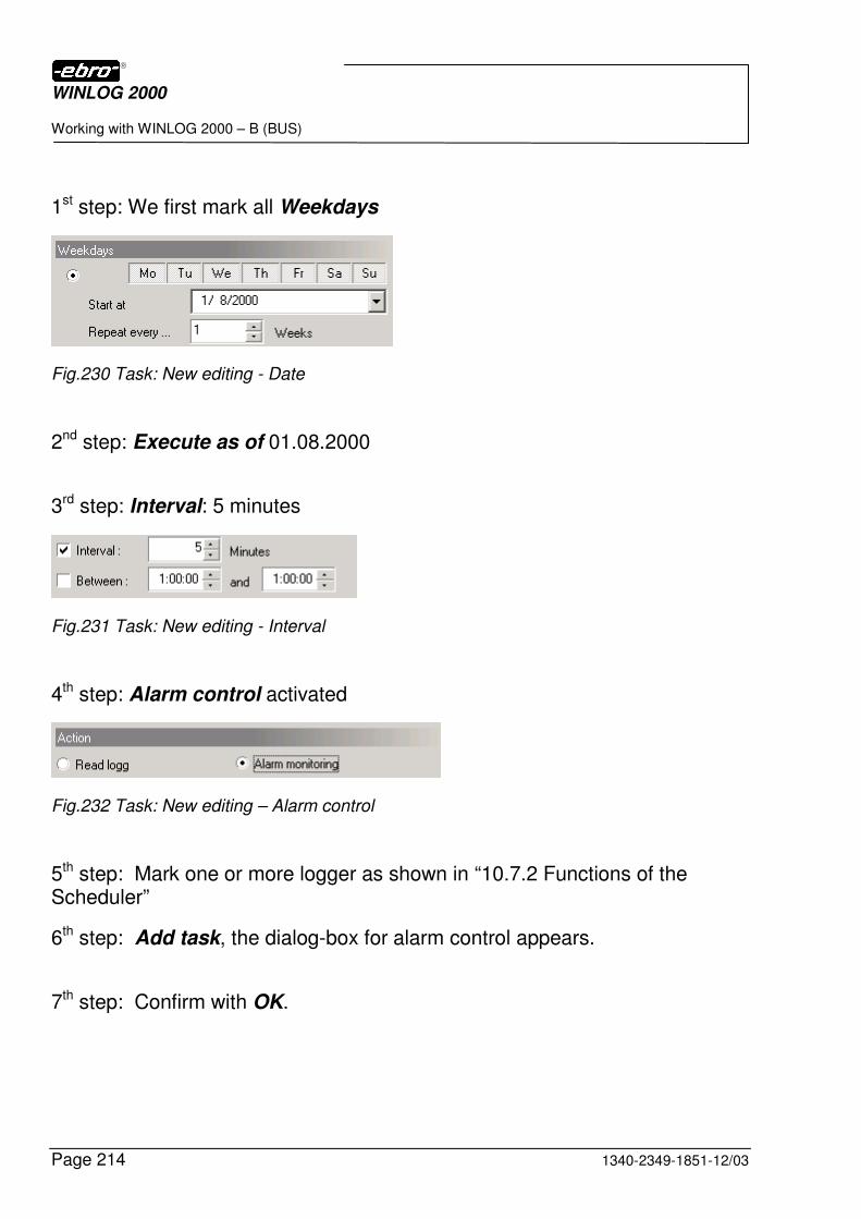
WINLOG 2000
Working with WINLOG 2000 – B (BUS)
Page 214 1340-2349-1851-12/03
1st step: We first mark all Weekdays
Fig.230 Task: New editing - Date
2nd step: Execute as of 01.08.2000
3rd step: Interval: 5 minutes
Fig.231 Task: New editing - Interval
4th step: Alarm control activated
Fig.232 Task: New editing – Alarm control
5th step: Mark one or more logger as shown in “10.7.2 Functions of the Scheduler”
6th step: Add task, the dialog-box for alarm control appears.
7th step: Confirm with OK.
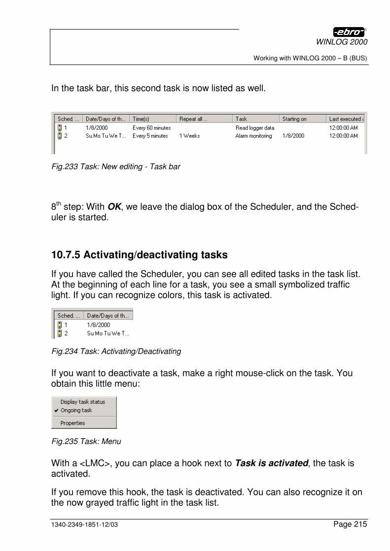
WINLOG 2000
Working with WINLOG 2000 – B (BUS)
1340-2349-1851-12/03 Page 215
In the task bar, this second task is now listed as well.
Fig.233 Task: New editing - Task bar
8th step: With OK, we leave the dialog box of the Scheduler, and the Sched-uler is started.
10.7.5 Activating/deactivating tasks
If you have called the Scheduler, you can see all edited tasks in the task list. At the beginning of each line for a task, you see a small symbolized traffic light. If you can recognize colors, this task is activated.
Fig.234 Task: Activating/Deactivating
If you want to deactivate a task, make a right mouse-click on the task. You obtain this little menu:
Fig.235 Task: Menu
With a <LMC>, you can place a hook next to Task is activated, the task is activated.
If you remove this hook, the task is deactivated. You can also recognize it on the now grayed traffic light in the task list.
WINLOG 2000
Working with WINLOG 2000 – B (BUS)
Page 216 1340-2349-1851-12/03
Fig.236 Task deactivated
Example:
For our example, we have only activated task 2.
10.7.6 Task properties
You can later mark a task in the task list. With a right mouse-click, the menu appears, where you can select the properties.
Fig.237 Task: Menu properties
Click on Properties, in order to be able to see them.
Fig.238 Task: Properties
WINLOG 2000
Working with WINLOG 2000 – B (BUS)
1340-2349-1851-12/03 Page 217
10.7.7 Executing a task
Since task 2 is activated, the BUS is interrogated every 5 minutes. Thereby, the following protocol box appears on the screen:
Fig.239 Task: Protocol box
Here, you can see on-line, that task no. 2 is executed. In this example the logger is read out.
WINLOG 2000
Working with WINLOG 2000 – B (BUS)
Page 218 1340-2349-1851-12/03
10.7.8 Protocol file of the task
Each task writes its results into a protocol file. This file is saved in the WINLOG 2000 directory.
Fig.240 Task: Protocol files
When a new task is opened and executed, it creates a protocol file. The name of this file is composed of “T“, the year, the month, the day and the time of the creation. The file suffix “log” is added automatically.
You can open this file with every editor, e.g. Notepad.
Another possibility is via the Scheduler. Make a right mouse-click on the desired task. In the opening menu, click on Display task status.
Fig.241 Task: Status in the protocol box
With Print report you can print-out the protocol, with Cancel you leave the protocol.
WINLOG 2000
Working with WINLOG 2000 – B (BUS)
1340-2349-1851-12/03 Page 219
10.7.8.1 Alarm list
On a second page of the protocol, there is the alarm list in which all alarms are registered.
For this purpose, click on the Alarm monitoring panel.
Fig.242 Alarm monitoring
You obtain a list of the occurred alarms.
Fig.243 Alarm list
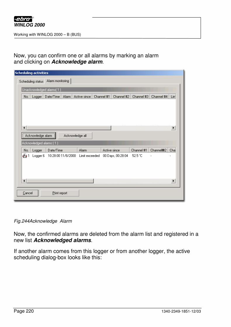
WINLOG 2000
Working with WINLOG 2000 – B (BUS)
Page 220 1340-2349-1851-12/03
Now, you can confirm one or all alarms by marking an alarm and clicking on Acknowledge alarm.
Fig.244Acknowledge Alarm
Now, the confirmed alarms are deleted from the alarm list and registered in a new list Acknowledged alarms.
If another alarm comes from this logger or from another logger, the active scheduling dialog-box looks like this:
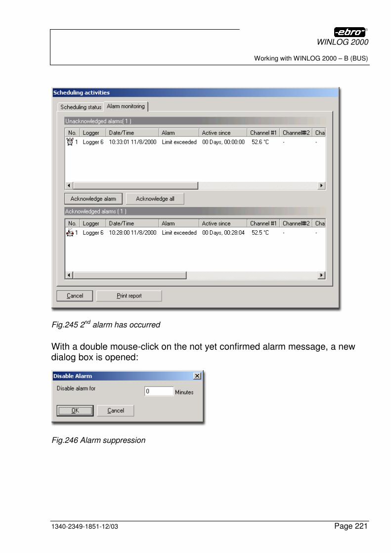
WINLOG 2000
Working with WINLOG 2000 – B (BUS)
1340-2349-1851-12/03 Page 221
Fig.245 2nd alarm has occurred
With a double mouse-click on the not yet confirmed alarm message, a new dialog box is opened:
Fig.246 Alarm suppression
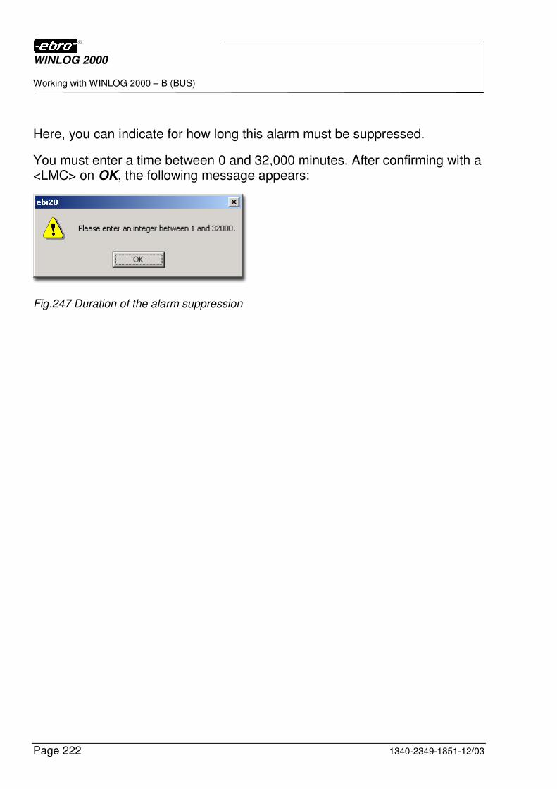
WINLOG 2000
Working with WINLOG 2000 – B (BUS)
Page 222 1340-2349-1851-12/03
Here, you can indicate for how long this alarm must be suppressed.
You must enter a time between 0 and 32,000 minutes. After confirming with a <LMC> on OK, the following message appears:
Fig.247 Duration of the alarm suppression

WINLOG 2000
Working with WINLOG 2000 - V (21 CFR Part 11)
1340-2349-1851-12/03 Page 223
11 Working with WINLOG 2000 - V (21 CFR Part 11)
11.1 Introduction
WINLOG 2000 - V includes all functions of the Professional version. In addition to this, it also contains features which ensure the full compliance with the guidelines on electronic datasets and electronic signatures in 21 CFR Part 11.
In the following chapters we will explain the quite complex Part 11 of the FDA guidelines 21 CFR, as well as the functionality of this software.
Please also read Chapter 11.3.5 regarding the requirements towards the end user of this software version!
11.2 The meaning of the 21 CFR Part 11 guidelines
In 1997, the Food and Drug Administration of the United States (FDA) released the guideline 21 CFR Part 11, which defines the requirements towards documentation in electronic form.
To ensure the full compliance with 21 CFR Part 11 it is important to implement Standard Operating Procedures (SOPs). They are meant as an addition to the functions of the WINLOG 2000 - V.
In order to comply with the requirements of 21 CFR Part 11, following features have been implemented:
Password strategies
There are numerous password options as for instance a minimal pass-word length, a limited duration of passwords, and security procedures in case of wrong password entries.
User administration
In order to prevent the software access of unauthorized persons, the user rights can be defined in a differentiated way. By using a rights structure in connection with password protected access
WINLOG 2000
Working with WINLOG 2000 - V (21 CFR Part 11)
Page 224 1340-2349-1851-12/03
it can be ensured that only authorized users have access to relevant software functions.
Electronic signatures
All measurement value files generated by WINLOG 2000 as well as the changes performed on them can be related to a specific user by way of electronic signatures. The signatures are saved with the document and can’t be deleted or edited. Additional security can be gained by generat-ing a second electronic signature by a supervising person.
Audit trails
All changes performed on a WINLOG 2000-generated document, start-ing with its creation and including every modification due to the use of formulas or user-specific units, are documented in chronological order with date and time, user name and type of action. This documentation is saved in the respective data file and can neighter be edited nor deleted. So, all manipulation on the measurement data can be traced.
Data security
The measurement data read by WINLOG 2000 are stored in a binary, non-editable form. All additional information like audit trail and electronic signatures are also coded and can only be read with WINLOG 2000.
The manipulation of measurement data files on operating system level by deletion, copying or moving can not be traced or pre-vented by WINLOG 2000. Therefore it is necessary that the em-ployed operating system be equipped with professional file secu-rity mechanisms and that a suitable rights structure be imple-mented. Recommended operating systems are Microsoft Win-dows NT 4, Windows 2000, or Windows XP.
WINLOG 2000
Working with WINLOG 2000 - V (21 CFR Part 11)
1340-2349-1851-12/03 Page 225
11.3 Implementation of the 21 CFR Part 11 guidelines
11.3.1 User administration
WINLOG 2000 – V integrates a user administration tool which enables the administrator to create user accounts with defined rights of access to the software functions. Each user is assigned a unique user name and password. This ensures the compliance with paragraph 11.300:
(a) Maintaining the uniqueness of each combined identification code and password, such that no two individuals have the same combination of identification code and password.
11.3.2 Logon and password strategies
In order to use the WINLOG 2000 – V software, a user must log on. The password functions implemented in this software, together with the Standard Operating Procedures (SOP), comply with the paragraphs 11.10, 11.100, 11.200, and 11.300 of the 21 CFR Part 11.
The validity of the passwords in WINLOG 2000 – V can be limited to a de-fined period of time, thus complying with paragraph 11.300:
(b) Ensuring that identification code and password issuances are periodically checked, recalled, or revised (e.g. to cover such events as password aging).
The combination of unique and expiring passwords prevents the usage of the same password more than once.
Also, the number of denied login requests can be limited with WINLOG 2000 – V. You can define this number according to your company’s SOPs. When this number is exceeded, the respective user account can be blocked, and a warning E-mail message can be issued to an authorized person. By this measure, conformity with paragraph 11.300 is attained:
WINLOG 2000
Working with WINLOG 2000 - V (21 CFR Part 11)
Page 226 1340-2349-1851-12/03
(c) Use of transaction safeguards to prevent unauthorized use of pass-words and/or identification codes, and to detect and report in an imme-diate and urgent manner any attempts at their unauthorized use to sys-tem security unit, and, as appropriate, to organizational management.
11.3.3 Audit trails
WINLOG 2000 – V implements Audit Trails, which record the creation and modifications of measurement data files with time and date, user name and type of action in chronological order. The Audit Trail is part of the measurement data file and can neither be edited nor deleted.
A full compliance with the guideline of paragraph 11.10 is achieved by the use of the Audit Trail in conjunction with an access control on file level as provided in the Windows NT 4, 2000, and XP operating systems:
(e) Use of secure, computer-generated, time-stamped Audit-Trails to in-dependently record the date and time of operator entries and actions that create, modify, or delete electronic records. Record changes shall not obscure previously recorded information. Such Audit-Trail documentation shall be retained for a period at least as long as that required for the electronic records and shall be available for agency review and copying.
The contents of an Audit Trail can be viewed on screen and can also be printed together with the measurement data. If WINLOG files are transferred to another computer and opened there with WINLOG 2000 – V, all informa-tions of the Audit Trail will be still available, as requested by paragraoh 11.10:
(b) The ability to generate accurate and complete copies of records in both human readable and electronic form suitale for inspection, review, and copying by the agency. Persons should contact the agency if there are any questions regarding the ability of the agency to perform such a review and copying of the electronic records.
WINLOG 2000
Working with WINLOG 2000 - V (21 CFR Part 11)
1340-2349-1851-12/03 Page 227
11.3.4 Electronic signatures
Documents generated from measurement values by WINLOG 2000 - V can be digitally signed by the user. The signature consists of the user name and the corresponding password.
§ 11.200 Electronic signatures components and controls
(a) Electronic signatures that are not based upon biometrics shall:
(1) Employ at least two distinct identification components such as an identification code and password.
(i) When an individual executes a series of signings during a single, continuous period of controlled system access, the first signing shall be executed using all electronic signature components; sub-sequent signings shall be executed using at least one electronic signature component that is only executable by, and designed to be used only by, the individual.
(ii) When an individual executes one or more signings not performed during a single continuous period of controlled system access, each signing shall be executed using all of the electronic signature components.
Electronic signatures must appear both in the screen display and the print-outs of the measurement data, as requested by paragraph 11.50:
(a) Signed electronic records shall contain information associated with the signing that clearly indicates all of the following:
(1) The printed name of the signer;
(2) The date and time when the signature was executed; and
(3) The meaning (such as review, approval, responsibility, or authorship) associated with the signature.
(b) The items identified in paragraphs (a) (1), (a) (2), and (a) (3) of this sec-tion shall be subject to the same controls as for electronic records and shall be included as part of any human readable form of the electronic record (such as electronic display or printout).
WINLOG 2000
Working with WINLOG 2000 - V (21 CFR Part 11)
Page 228 1340-2349-1851-12/03
Due to the fact that the information of the Audit Trail of WINLOG 2000 - V is securely integrated in a measurement data file and can not be edited or deleted, the paragraph 11.70 guideline is implemented:
Electronic signatures and handwritten signatures executed to electronic records shall be linked to their respective electronic records to ensure that the signatures cannot be excised, copied, or otherwise transferred to falsify an electronic record by ordinary means.
11.3.5 Requirements towards the user of WINLOG 2000 – V
In order to comply with the FDA regulations, certain additional procedures need to be established and implemented by the user working with ebro data loggers and WINLOG 2000 – V.
Subpart C – Electronic Signatures
§ 11.10 Controls for closed systems
(a) When a data logger is used to monitor a process in order to evaluate this process on the basis of the recorded data, it must be ensured that the data reflect the monitored process. With other words, data recorded during the transport of the logger to and from the measuring location must easily be identified as not related to the monitored process. A re-moval of the logger from the measuring location, as well as any other manipulation of the logger must be also prevented. In addition to an adequate operation, battery-powered electronic meas-uring instruments require periodical calibration and maintenance, in or-der to provide correct measurement values. Normally, they are part of a test tool management system, which regulates the operating conditions and the calibration and maintenance intervals (e.g. battery exchange). Like any other software application, WINLOG 2000 – V also uses and depends on the resources and functionality of the operating system on which it is running. Therefore, the user must implement procedures which ensure that the OS is also compliant with FDA 21 Part 11 (e.g. system time, user access rights etc.)
WINLOG 2000
Working with WINLOG 2000 - V (21 CFR Part 11)
1340-2349-1851-12/03 Page 229
(b) WINLOG 2000 allows the archiving of measurement data documents (*.ebi) into compressed files (*.ebz). The archival periods and the way of data storage must be regulated by additional procedures.
(c) WINLOG 2000 can only comply with the FDA regulations if it runs on operating systems which include a user and password management (e.g. Windows NT 4.0, 2000, or XP). The procedures of access control must be established by the user.
(i) The owner of the software must make sure that all users working with the system receive adequate trainings. Trainings must be regularly repeated and documented. Also, it must be made clear (by way of SOPs) that the functionality of WINLOG 2000 is being used in conformance to the FDA regulations.
(j) The owner of the software must implement guidelines documenting the responsibility and liability of each user of the system.
(k) WINLOG 2000 is being shipped with detailed manuals containing information on the operation and maintenance of the system. It is possible to create SOPs based on these manuals. The owner of the software is responsible for the distribution and utilization of the documentation.
§ 11.100 General requirements
(b) Before assigning an electronic signature to a person, its identity must be verified
(c) Persons using electronic signatures must “certify to the agency (FDA) that the electronic signatures in their system are intended to be the le-gally binding equivalent of traditional handwritten signatures”.
§ 11.200 Electronic signature components and controls
(a) The user must ensure by adequate procedures that the identification components (identification code and password) are used only by their genuine owners and that they are administered and employed in a way that ensures that “attempted use of an individual’s electronic signature by anyone other than its genuine owner requires collaboration of two or more individuals.”
WINLOG 2000
Working with WINLOG 2000 - V (21 CFR Part 11)
Page 230 1340-2349-1851-12/03
§ 11.300 Controls for identification codes / passwords
(b) WINLOG 2000 allows a limitation of the password validity to a certain period of time. It can also enforce a password change on log-on. The owner of the software must document that “identification code and password issuances are periodically checked, recalled, or revised (e.g., to cover such events as password aging)”.
(c) The owner of the software must implement “loss management proce-dures to electronically deauthorize lost, stolen, missing, or otherwise potentially compromised tokens, cards, and other devices to bear or generate identification code or password information, and to issue temporary or permanent replacement using suitable, rigorous controls.”
(d) WINLOG 2000 enables a user account or system lock-up on detection of attempts of unauthorized use of passwords and/or identification codes. It can also send alert messages by e-mail to the system admin-istrator to inform of any breach of security. The owner of the software must document all attempts of unauthorized use and ensure the secu-rity of passwords and identification codes by written agreements.
11.4 General issues on the validation of systems
A validation is a clear certification that procedures, processes, equipment, materials, operations, or systems lead to the expected results. Validations minimize the error probability and ensure a high level of confidence and security.
Every validation needs to be performed by a validation plan containing its target and a flow diagram of the activities and responsabilities involved.
The system validation of WINLOG 2000 only makes sense in conjunction with the operating system, the printer driver, the peripheral hardware, etc. Therefore, the validation must not be limited to the software alone, but must include all other system components. Special attention must be paid to the interfaces of the system to other systems (e.g. a potential security breach caused by a connection to the internet on the computer running WINLOG).
WINLOG 2000
Working with WINLOG 2000 - V (21 CFR Part 11)
1340-2349-1851-12/03 Page 231
11.5 Summary
WINLOG 2000 - V has been developed in conformance with the requirements of 21 CFR Part 11. It is meant to support the user in the implementation of the FDA guidelines on the use of electronic datasets and electronic signatures. It has been designed and tested in cooperation with leading experts in this field. More information on 21 CFR Part 11 can be found on www.fda.gov.
11.6 Installing the software
11.6.1 Hardware requirements
For the WINLOG 2000 – V version, the same prerequisites as described in chapter 2.1 apply.
The only exception regards the operating system. As already mentioned, we strongly recommend the use of Microsoft Windows NT 4.0, Windows 2000, or Windows XP. The security level needed for the proper use of this WINLOG version can only be reached with one of these operating systems.
11.6.2 Software setup
A detailed description of the setup procedure can be found in chapter 5.
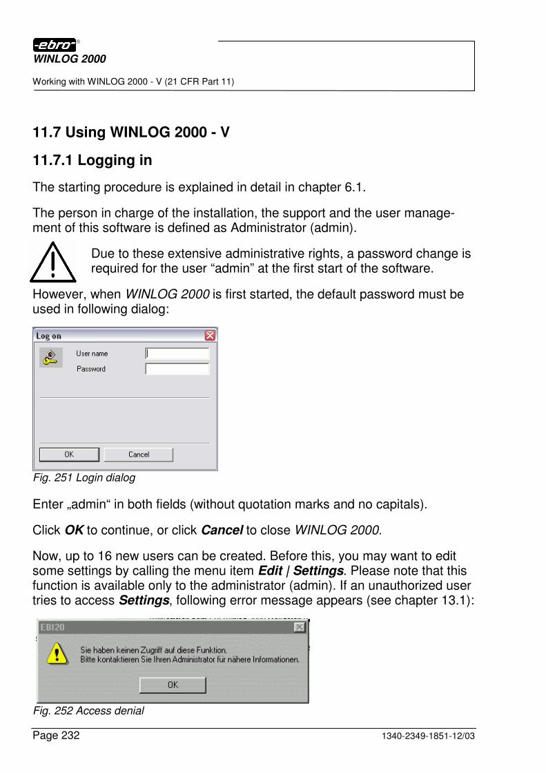
WINLOG 2000
Working with WINLOG 2000 - V (21 CFR Part 11)
Page 232 1340-2349-1851-12/03
11.7 Using WINLOG 2000 - V
11.7.1 Logging in
The starting procedure is explained in detail in chapter 6.1.
The person in charge of the installation, the support and the user manage-ment of this software is defined as Administrator (admin).
Due to these extensive administrative rights, a password change is required for the user “admin” at the first start of the software.
However, when WINLOG 2000 is first started, the default password must be used in following dialog:
Fig. 251 Login dialog
Enter „admin“ in both fields (without quotation marks and no capitals).
Click OK to continue, or click Cancel to close WINLOG 2000.
Now, up to 16 new users can be created. Before this, you may want to edit some settings by calling the menu item Edit | Settings. Please note that this function is available only to the administrator (admin). If an unauthorized user tries to access Settings, following error message appears (see chapter 13.1):
Fig. 252 Access denial

WINLOG 2000
Working with WINLOG 2000 - V (21 CFR Part 11)
1340-2349-1851-12/03 Page 233
11.7.2 Settings
By selecting the item Options in the Edit menu, you will receive following dialog box:
Fig 253 Options window
This box is identical to the one described in chapter 6.3.3, but for following button:
Fig 254 Security button
A <LMC> on this button opens a further dialog box where you can edit vari-ous security related settings:
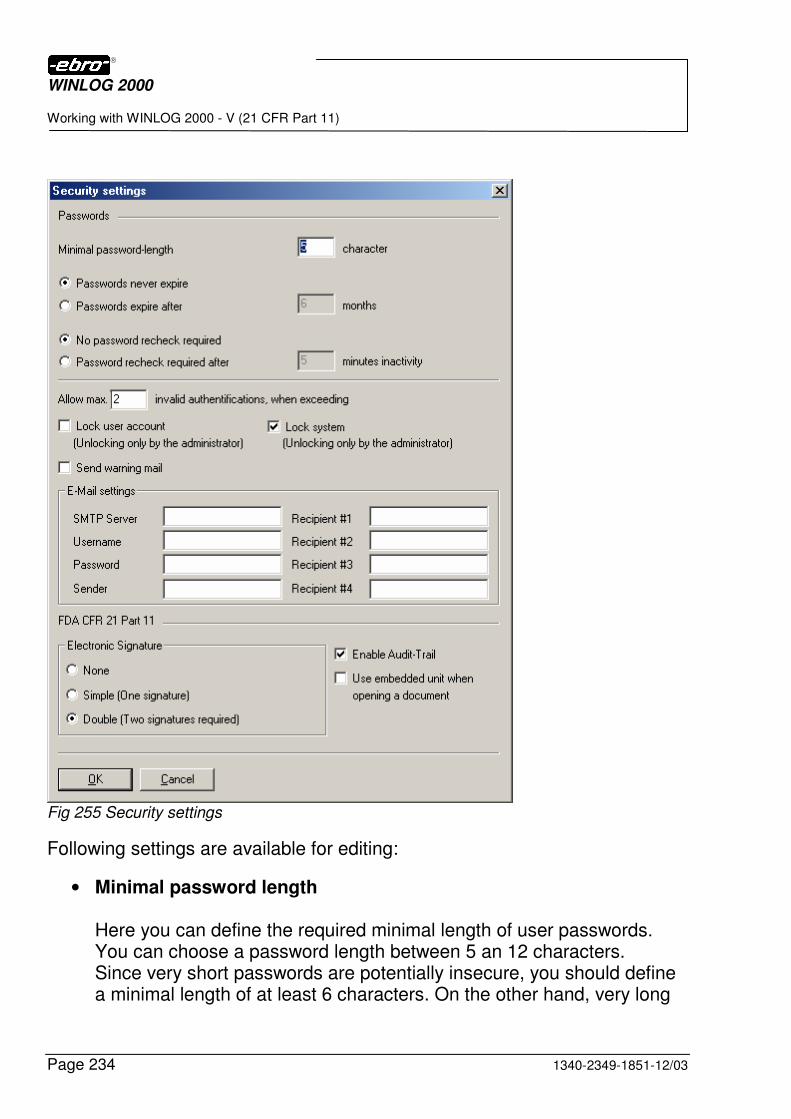
WINLOG 2000
Working with WINLOG 2000 - V (21 CFR Part 11)
Page 234 1340-2349-1851-12/03
Fig 255 Security settings
Following settings are available for editing:
• Minimal password length Here you can define the required minimal length of user passwords. You can choose a password length between 5 an 12 characters. Since very short passwords are potentially insecure, you should define a minimal length of at least 6 characters. On the other hand, very long
WINLOG 2000
Working with WINLOG 2000 - V (21 CFR Part 11)
1340-2349-1851-12/03 Page 235
passwords should also be avoided. Because they are hard to remem-ber, users tend to write them down, thus rendering them worthless.
• Password expiration To increase security, the validity of passwords can be limited to a cer-tain period of time. You have two options with regard to the password expiration: - Passwords never expire The validity of passwords is not limited to a certain period of time. - Passwords expire after … months You can select a period between 3 and 6 months, after which passwords expire. When a password expires, the user receives a message requesting him to change the password. The predefined duration period applies to every newly created password.
When a password is changed, previously used passwords can’t be used again.
• Password recheck Here, an additional security feature can be activated. When WINLOG 2000 receives no user input during a certain period of time (e.g. if the user is taking a break), it is able to log off the user automatically in order to prevent unauthorized use of the software. Thus, the user is forced to log in again before resuming his activity. You have two administrative options: - No password recheck required A user is never logged off when inactivity is detected. - Password recheck required after … minutes inactivity
WINLOG 2000
Working with WINLOG 2000 - V (21 CFR Part 11)
Page 236 1340-2349-1851-12/03
You can enter a period of inactivity between 5 and 60 minutes, after which the system is locked and can only be reactivated by a new login.
• Invalid authentification You can restrict the number of invalid logins (when a wrong password is used) to make an unauthorized access to the software more difficult. When a maximal number of invalid authentifications is entered, there are three possible actions available: - Lock user account When this option is checked, the user account where a repeated use of wrong passwords is detected is locked after the specified number of invalid attempts. The respective user won’t be able to access the system even when the correct password is used. The lock of this account can only be removed by the administrator. - Lock system With this option active, not only the user account, but the complete system is locked after the specified number of unsuccessful login attempts. WINLOG 2000 will remain active, but no further user input will be allowed until the administrator unlocks the system. - Send warning mail As an additional consequence to repeated invalid authentifications, WINLOG 2000 can automatically send warning mails to up to 4 E-mail addresses.
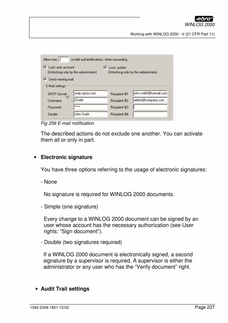
WINLOG 2000
Working with WINLOG 2000 - V (21 CFR Part 11)
1340-2349-1851-12/03 Page 237
Fig 256 E-mail notification
The described actions do not exclude one another. You can activate them all or only in part.
• Electronic signature You have three options referring to the usage of electronic signatures: - None No signature is required for WINLOG 2000 documents. - Simple (one signature) Every change to a WINLOG 2000 document can be signed by an user whose account has the necessary authorization (see User rights: “Sign document”).
- Double (two signatures required) If a WINLOG 2000 document is electronically signed, a second signature by a supervisor is required. A supervisor is either the administrator or any user who has the “Verify document” right.
• Audit Trail settings
WINLOG 2000
Working with WINLOG 2000 - V (21 CFR Part 11)
Page 238 1340-2349-1851-12/03
Following options are available: - Enable Audit Trail When this option is checked, all modifications to a WINLOG 2000 document are recorded within the document. - Use embedded unit when opening a document The WINLOG 2000 unit administration permits the creation of user defined measurement units. If applied, these units are saved within the measurement data documents. The above option defines which units are going to be active when a stored document is opened. If this option is checked, user defined units are displayed. If this option is not checked, the default units apply.
After you have edited the security settings, save your changes with a <LMC> on OK.
11.7.3 User and password management
On the way toward an optimal security, the user rights management is of the same importance as the password definition.
User accounts can be set up or deleted only by the administrator. Also, only the administrator can grant or revoke user rights.
The user access management function of WINLOG 2000 - V can be ac-cessed via the specific icon or via the menu Edit – User configu-ration.
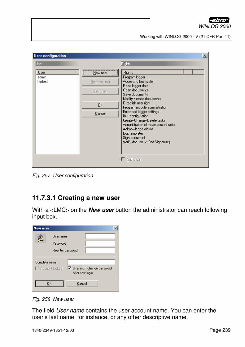
WINLOG 2000
Working with WINLOG 2000 - V (21 CFR Part 11)
1340-2349-1851-12/03 Page 239
Fig. 257 User configuration
11.7.3.1 Creating a new user
With a <LMC> on the New user button the administrator can reach following input box.
Fig. 258 New user
The field User name contains the user account name. You can enter the user’s last name, for instance, or any other descriptive name.
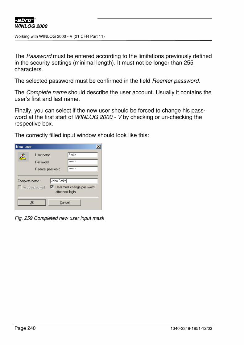
WINLOG 2000
Working with WINLOG 2000 - V (21 CFR Part 11)
Page 240 1340-2349-1851-12/03
The Password must be entered according to the limitations previously defined in the security settings (minimal length). It must not be longer than 255 characters.
The selected password must be confirmed in the field Reenter password.
The Complete name should describe the user account. Usually it contains the user’s first and last name.
Finally, you can select if the new user should be forced to change his pass-word at the first start of WINLOG 2000 - V by checking or un-checking the respective box.
The correctly filled input window should look like this:
Fig. 259 Completed new user input mask

WINLOG 2000
Working with WINLOG 2000 - V (21 CFR Part 11)
1340-2349-1851-12/03 Page 241
If the entries are OK, they must be confirmed with a <LMC> on OK in order to create the new user. After this, a new entry will appear on the left side of the User Configuration window.
Fig 260 New user created
11.7.3.2 Granting or revoking user rights
When you highlight a name in the user list on the left side of the User Con-figuration window, you can immediately see which rights are available to this user: they appear marked with “OK” on the list on the right side of the win-dow. A newly created user usually doesn’t have any rights until the Adminis-trator grants him some.
To grant rights to a user, mark one of the rights in the list and check the field Authorize. An “OK” will now appear next to the selected right.
You can also mark all the rights you want to grant to the user by holding the <CTRL> button while clicking on the different rights. When the selected rights are highlighted, check Authorize to grant them to the user.
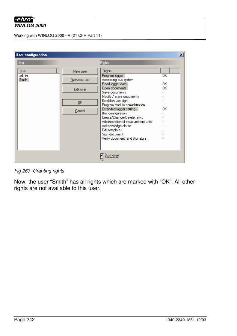
WINLOG 2000
Working with WINLOG 2000 - V (21 CFR Part 11)
Page 242 1340-2349-1851-12/03
Fig 263 Granting rights
Now, the user “Smith” has all rights which are marked with “OK”. All other rights are not available to this user.
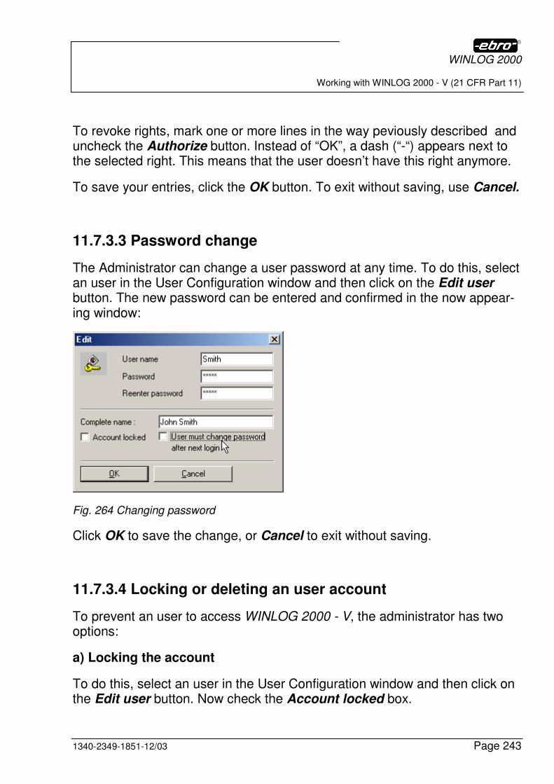
WINLOG 2000
Working with WINLOG 2000 - V (21 CFR Part 11)
1340-2349-1851-12/03 Page 243
To revoke rights, mark one or more lines in the way peviously described and uncheck the Authorize button. Instead of “OK”, a dash (“-“) appears next to the selected right. This means that the user doesn’t have this right anymore.
To save your entries, click the OK button. To exit without saving, use Cancel.
11.7.3.3 Password change
The Administrator can change a user password at any time. To do this, select an user in the User Configuration window and then click on the Edit user button. The new password can be entered and confirmed in the now appear-ing window:
Fig. 264 Changing password
Click OK to save the change, or Cancel to exit without saving.
11.7.3.4 Locking or deleting an user account
To prevent an user to access WINLOG 2000 - V, the administrator has two options:
a) Locking the account
To do this, select an user in the User Configuration window and then click on the Edit user button. Now check the Account locked box.
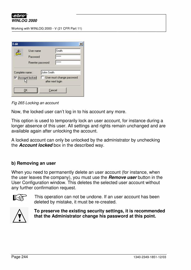
WINLOG 2000
Working with WINLOG 2000 - V (21 CFR Part 11)
Page 244 1340-2349-1851-12/03
Fig 265 Locking an account
Now, the locked user can’t log in to his account any more.
This option is used to temporarily lock an user account, for instance during a longer absence of this user. All settings and rights remain unchanged and are available again after unlocking the account.
A locked account can only be unlocked by the administrator by unchecking the Account locked box in the described way.
b) Removing an user
When you need to permanently delete an user account (for instance, when the user leaves the company), you must use the Remove user button in the User Configuration window. This deletes the selected user account without any further confirmation request.
This operation can not be undone. If an user account has been deleted by mistake, it must be re-created.
To preserve the existing security settings, it is recommended that the Administrator change his password at this point.
WINLOG 2000
Working with WINLOG 2000 - V (21 CFR Part 11)
1340-2349-1851-12/03 Page 245
11.7.4 Programming and reading loggers
11.7.4.1 Starting a logger
This procedure is described in detail in chapter 7.
11.7.4.2 Reading a logger
This procedure is described in detail in chapter 8.
11.7.4.3 Reading saved measurement data
Of course, all measurement data files (documents) recorded with any version of WINLOG 2000 (that is, Standard, Professional, or BUS), can be viewed with WINLOG 2000 - V.
WINLOG 2000 - V can’t open WLS files. These are files created with a previous release of WINLOG (e.g. 1.5E).
11.7.4.4 Tabular view of measurement values
This procedure is described in detail in chapter 9.
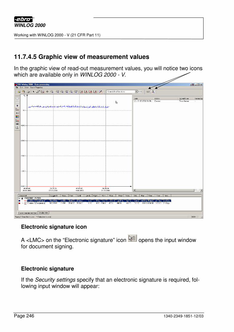
WINLOG 2000
Working with WINLOG 2000 - V (21 CFR Part 11)
Page 246 1340-2349-1851-12/03
11.7.4.5 Graphic view of measurement values
In the graphic view of read-out measurement values, you will notice two icons which are available only in WINLOG 2000 - V.
Electronic signature icon
A <LMC> on the “Electronic signature” icon opens the input window for document signing.
Electronic signature
If the Security settings specify that an electronic signature is required, fol-lowing input window will appear:
WINLOG 2000
Working with WINLOG 2000 - V (21 CFR Part 11)
1340-2349-1851-12/03 Page 247
Fig 267 Electronic signature (simple)
Here, the user may enter his user name and password, as well as an op-tional remark, which will be displayed later in the Audit Trail.
If the Security settings specify that two signatures are required, the input window will look like this:
WINLOG 2000
Working with WINLOG 2000 - V (21 CFR Part 11)
Page 248 1340-2349-1851-12/03
Fig 268 Electronic signature (Double)
Here, two authorized users must enter their names and passwords.
A <LMC> on OK saves the signature(s) to the document. Cancel closes this window without saving.
Audit Trail icon
With a <LMC> on the “Audit Trail” icon the graphic view changes its appearance in order to display the Audit Trail report on the right side.
Audit Trail report
Once the Audit Trail display is active, your window will look like this:
WINLOG 2000
Working with WINLOG 2000 - V (21 CFR Part 11)
1340-2349-1851-12/03 Page 249
Fig 269 Audit Trail display
The first line shows the time and date of creation of this document.
The second line shows that the document was signed by two users. Printing an Audit Trail report
If required, an Audit Trail report can also be printed. The printing procedure is described in detail in chapter 8.4 (see figure 124).
The Audit Trail print must be activated by checking Report. Also, the type of the print-out can be selected.
Fig 270 Audit Trail report print-out selection
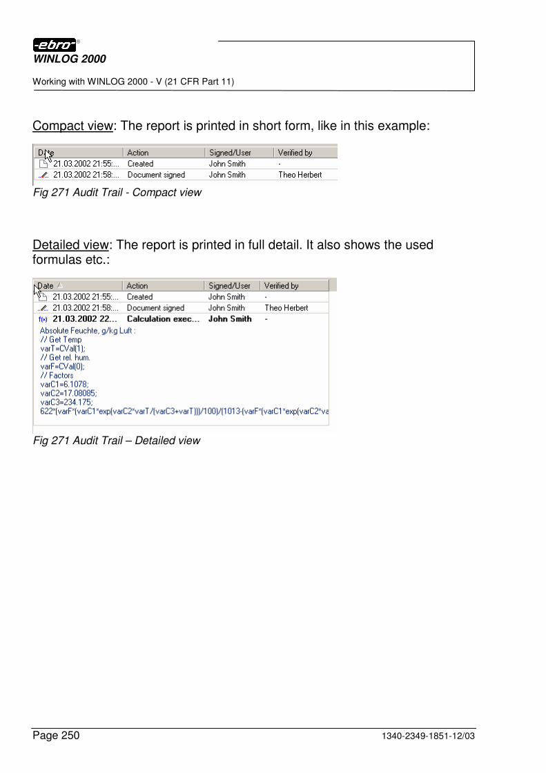
WINLOG 2000
Working with WINLOG 2000 - V (21 CFR Part 11)
Page 250 1340-2349-1851-12/03
Compact view: The report is printed in short form, like in this example:
Fig 271 Audit Trail - Compact view
Detailed view: The report is printed in full detail. It also shows the used formulas etc.:
Fig 271 Audit Trail – Detailed view
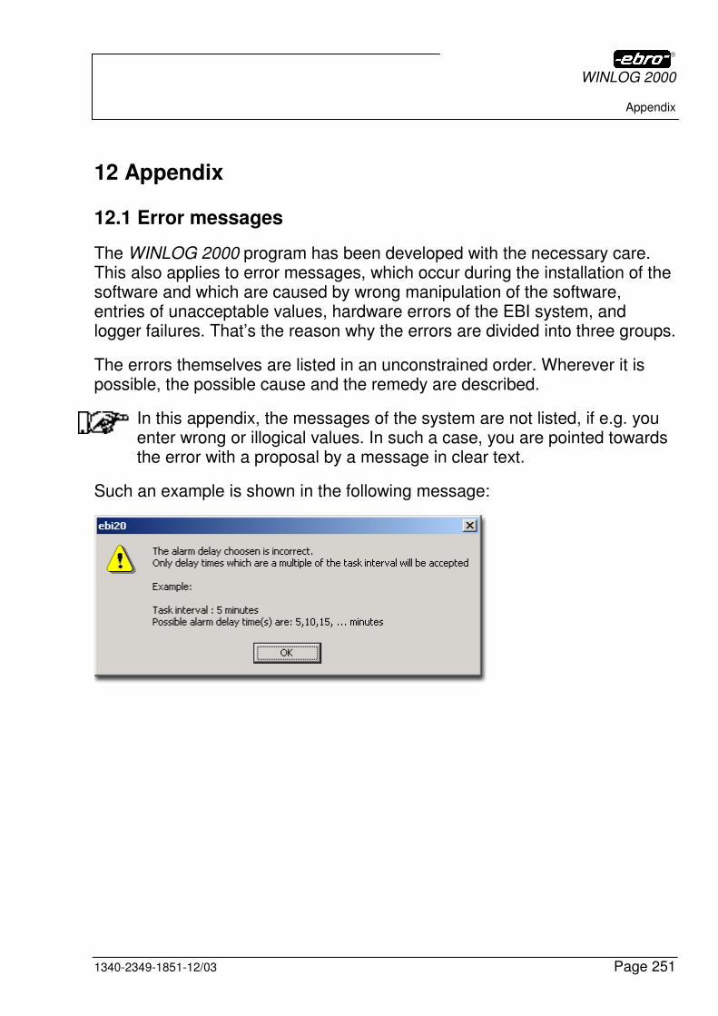
WINLOG 2000
Appendix
1340-2349-1851-12/03 Page 251
12 Appendix
12.1 Error messages
The WINLOG 2000 program has been developed with the necessary care. This also applies to error messages, which occur during the installation of the software and which are caused by wrong manipulation of the software, entries of unacceptable values, hardware errors of the EBI system, and logger failures. That’s the reason why the errors are divided into three groups.
The errors themselves are listed in an unconstrained order. Wherever it is possible, the possible cause and the remedy are described.
In this appendix, the messages of the system are not listed, if e.g. you enter wrong or illogical values. In such a case, you are pointed towards the error with a proposal by a message in clear text.
Such an example is shown in the following message:
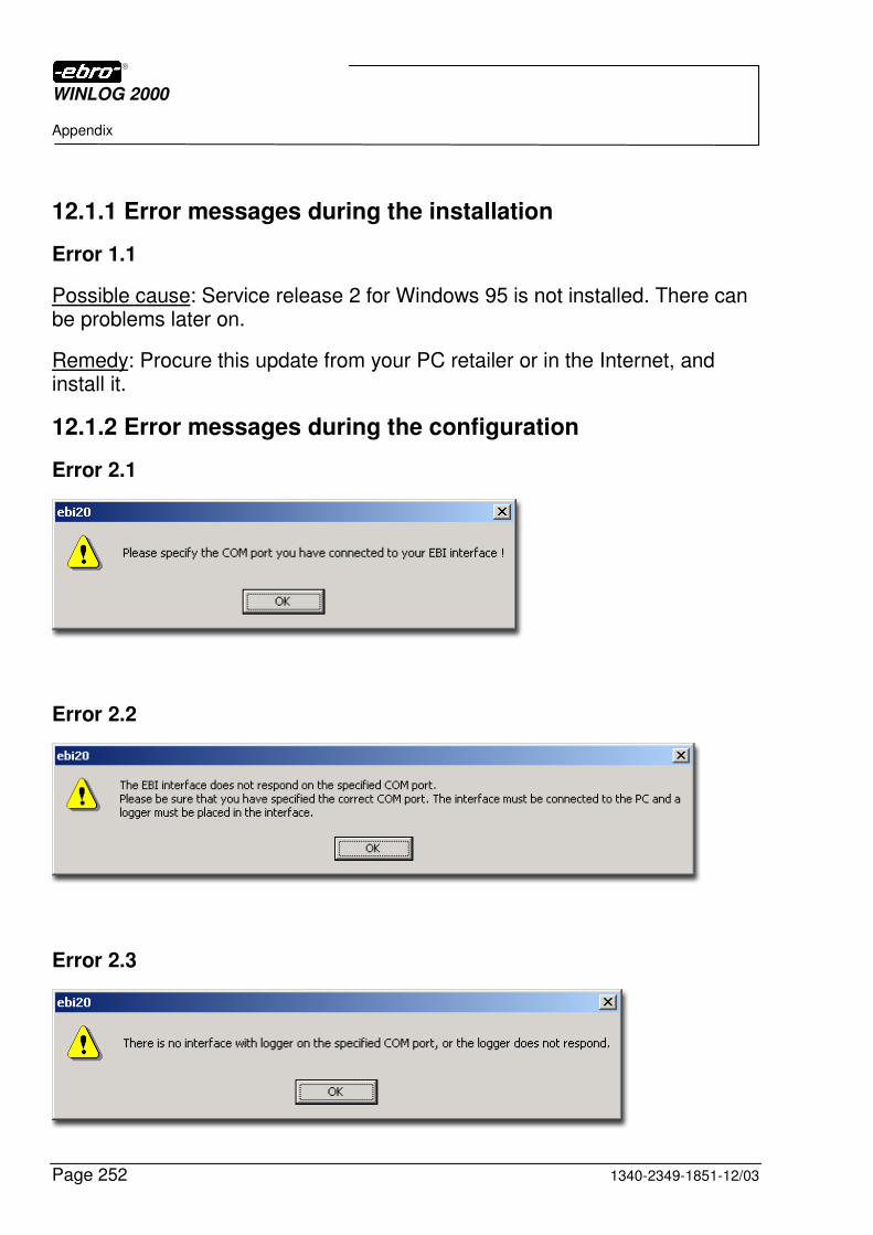
WINLOG 2000
Appendix
Page 252 1340-2349-1851-12/03
12.1.1 Error messages during the installation
Error 1.1
Possible cause: Service release 2 for Windows 95 is not installed. There can be problems later on.
Remedy: Procure this update from your PC retailer or in the Internet, and install it.
12.1.2 Error messages during the configuration
Error 2.1
Error 2.2
Error 2.3
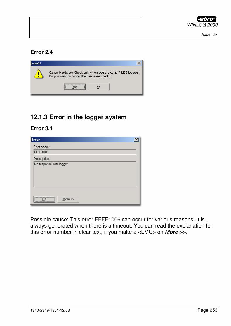
WINLOG 2000
Appendix
1340-2349-1851-12/03 Page 253
Error 2.4
12.1.3 Error in the logger system
Error 3.1
Possible cause: This error FFFE1006 can occur for various reasons. It is always generated when there is a timeout. You can read the explanation for this error number in clear text, if you make a <LMC> on More >>.
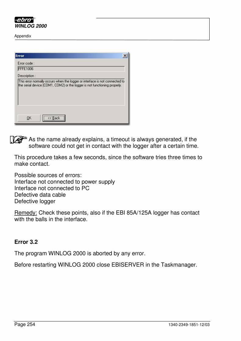
WINLOG 2000
Appendix
Page 254 1340-2349-1851-12/03
As the name already explains, a timeout is always generated, if the software could not get in contact with the logger after a certain time.
This procedure takes a few seconds, since the software tries three times to make contact.
Possible sources of errors: Interface not connected to power supply Interface not connected to PC Defective data cable Defective logger
Remedy: Check these points, also if the EBI 85A/125A logger has contact with the balls in the interface.
Error 3.2
The program WINLOG 2000 is aborted by any error.
Before restarting WINLOG 2000 close EBISERVER in the Taskmanager.
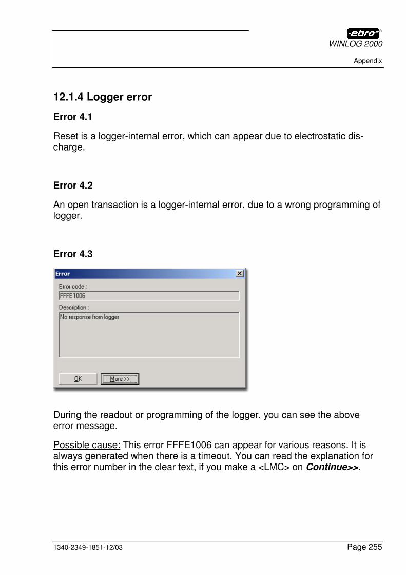
WINLOG 2000
Appendix
1340-2349-1851-12/03 Page 255
12.1.4 Logger error
Error 4.1
Reset is a logger-internal error, which can appear due to electrostatic dis-charge.
Error 4.2
An open transaction is a logger-internal error, due to a wrong programming of logger.
Error 4.3
During the readout or programming of the logger, you can see the above error message.
Possible cause: This error FFFE1006 can appear for various reasons. It is always generated when there is a timeout. You can read the explanation for this error number in the clear text, if you make a <LMC> on Continue>>.
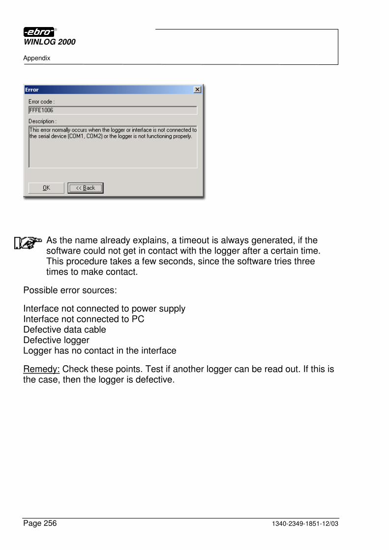
WINLOG 2000
Appendix
Page 256 1340-2349-1851-12/03
As the name already explains, a timeout is always generated, if the software could not get in contact with the logger after a certain time. This procedure takes a few seconds, since the software tries three times to make contact.
Possible error sources:
Interface not connected to power supply Interface not connected to PC Defective data cable Defective logger Logger has no contact in the interface
Remedy: Check these points. Test if another logger can be read out. If this is the case, then the logger is defective.
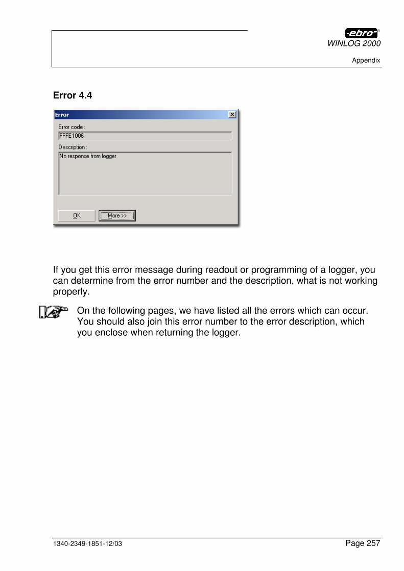
WINLOG 2000
Appendix
1340-2349-1851-12/03 Page 257
Error 4.4
If you get this error message during readout or programming of a logger, you can determine from the error number and the description, what is not working properly.
On the following pages, we have listed all the errors which can occur. You should also join this error number to the error description, which you enclose when returning the logger.
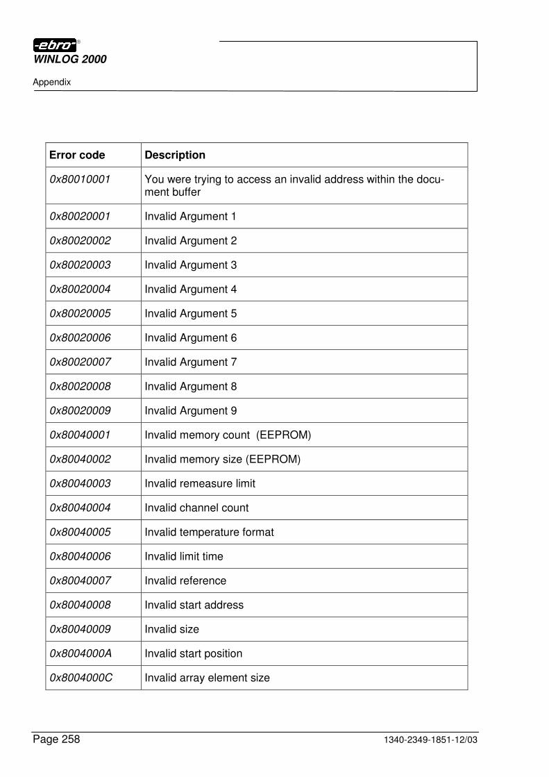
WINLOG 2000
Appendix
Page 258 1340-2349-1851-12/03
Error code Description
0x80010001 You were trying to access an invalid address within the docu-ment buffer
0x80020001 Invalid Argument 1
0x80020002 Invalid Argument 2
0x80020003 Invalid Argument 3
0x80020004 Invalid Argument 4
0x80020005 Invalid Argument 5
0x80020006 Invalid Argument 6
0x80020007 Invalid Argument 7
0x80020008 Invalid Argument 8
0x80020009 Invalid Argument 9
0x80040001 Invalid memory count (EEPROM)
0x80040002 Invalid memory size (EEPROM)
0x80040003 Invalid remeasure limit
0x80040004 Invalid channel count
0x80040005 Invalid temperature format
0x80040006 Invalid limit time
0x80040007 Invalid reference
0x80040008 Invalid start address
0x80040009 Invalid size
0x8004000A Invalid start position
0x8004000C Invalid array element size
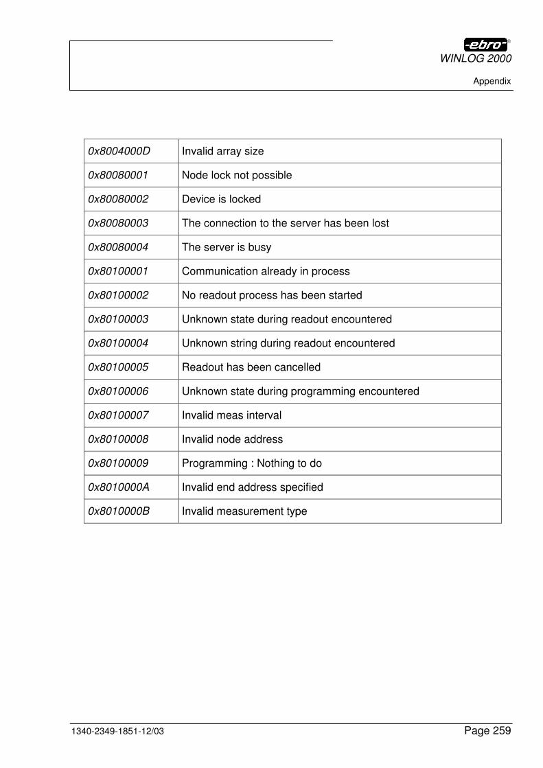
WINLOG 2000
Appendix
1340-2349-1851-12/03 Page 259
0x8004000D Invalid array size
0x80080001 Node lock not possible
0x80080002 Device is locked
0x80080003 The connection to the server has been lost
0x80080004 The server is busy
0x80100001 Communication already in process
0x80100002 No readout process has been started
0x80100003 Unknown state during readout encountered
0x80100004 Unknown string during readout encountered
0x80100005 Readout has been cancelled
0x80100006 Unknown state during programming encountered
0x80100007 Invalid meas interval
0x80100008 Invalid node address
0x80100009 Programming : Nothing to do
0x8010000A Invalid end address specified
0x8010000B Invalid measurement type
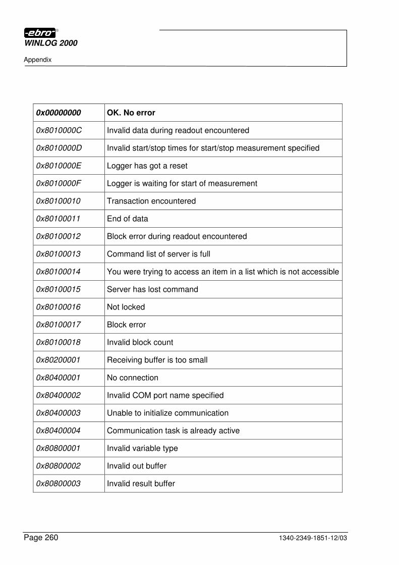
WINLOG 2000
Appendix
Page 260 1340-2349-1851-12/03
0x00000000 OK. No error
0x8010000C Invalid data during readout encountered
0x8010000D Invalid start/stop times for start/stop measurement specified
0x8010000E Logger has got a reset
0x8010000F Logger is waiting for start of measurement
0x80100010 Transaction encountered
0x80100011 End of data
0x80100012 Block error during readout encountered
0x80100013 Command list of server is full
0x80100014 You were trying to access an item in a list which is not accessible
0x80100015 Server has lost command
0x80100016 Not locked
0x80100017 Block error
0x80100018 Invalid block count
0x80200001 Receiving buffer is too small
0x80400001 No connection
0x80400002 Invalid COM port name specified
0x80400003 Unable to initialize communication
0x80400004 Communication task is already active
0x80800001 Invalid variable type
0x80800002 Invalid out buffer
0x80800003 Invalid result buffer
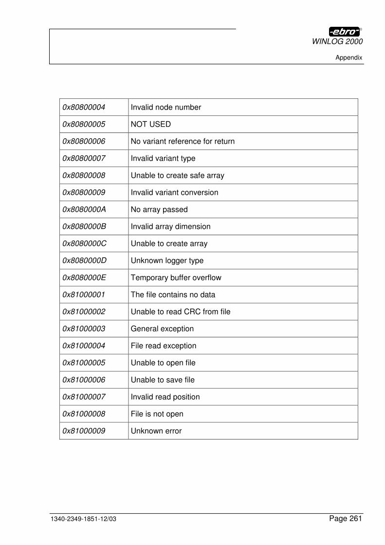
WINLOG 2000
Appendix
1340-2349-1851-12/03 Page 261
0x80800004 Invalid node number
0x80800005 NOT USED
0x80800006 No variant reference for return
0x80800007 Invalid variant type
0x80800008 Unable to create safe array
0x80800009 Invalid variant conversion
0x8080000A No array passed
0x8080000B Invalid array dimension
0x8080000C Unable to create array
0x8080000D Unknown logger type
0x8080000E Temporary buffer overflow
0x81000001 The file contains no data
0x81000002 Unable to read CRC from file
0x81000003 General exception
0x81000004 File read exception
0x81000005 Unable to open file
0x81000006 Unable to save file
0x81000007 Invalid read position
0x81000008 File is not open
0x81000009 Unknown error
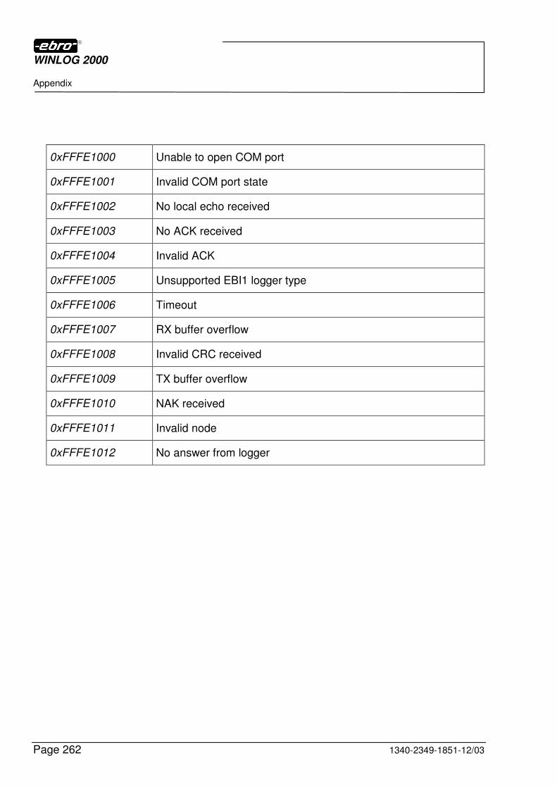
WINLOG 2000
Appendix
Page 262 1340-2349-1851-12/03
0xFFFE1000 Unable to open COM port
0xFFFE1001 Invalid COM port state
0xFFFE1002 No local echo received
0xFFFE1003 No ACK received
0xFFFE1004 Invalid ACK
0xFFFE1005 Unsupported EBI1 logger type
0xFFFE1006 Timeout
0xFFFE1007 RX buffer overflow
0xFFFE1008 Invalid CRC received
0xFFFE1009 TX buffer overflow
0xFFFE1010 NAK received
0xFFFE1011 Invalid node
0xFFFE1012 No answer from logger
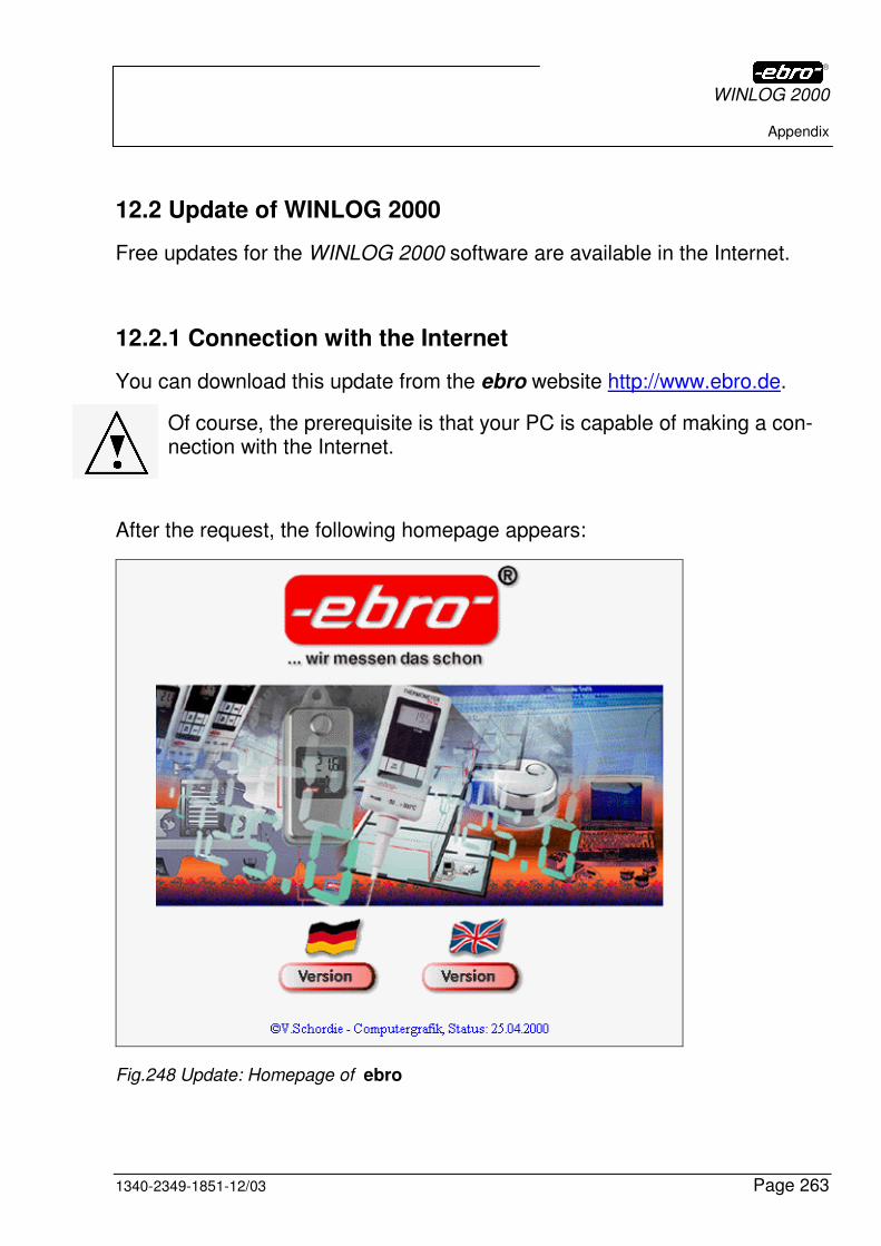
WINLOG 2000
Appendix
1340-2349-1851-12/03 Page 263
12.2 Update of WINLOG 2000
Free updates for the WINLOG 2000 software are available in the Internet.
12.2.1 Connection with the Internet
You can download this update from the ebro website http://www.ebro.de.
Of course, the prerequisite is that your PC is capable of making a con-nection with the Internet.
After the request, the following homepage appears:
Fig.248 Update: Homepage of ebro
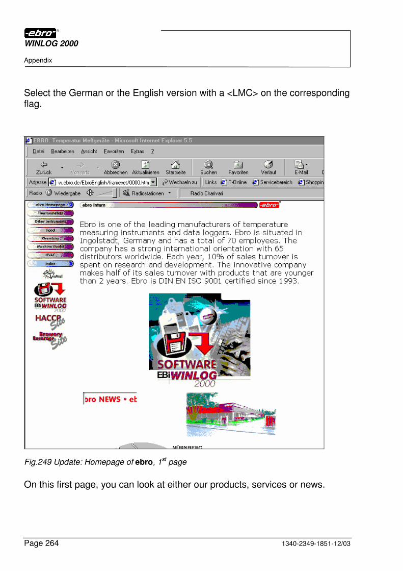
WINLOG 2000
Appendix
Page 264 1340-2349-1851-12/03
Select the German or the English version with a <LMC> on the corresponding flag.
Fig.249 Update: Homepage of ebro, 1st page
On this first page, you can look at either our products, services or news.
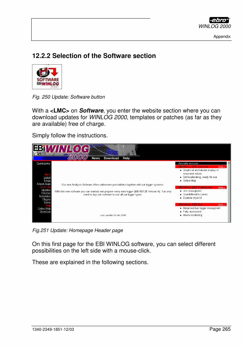
WINLOG 2000
Appendix
1340-2349-1851-12/03 Page 265
12.2.2 Selection of the Software section
Fig. 250 Update: Software button
With a <LMC> on Software, you enter the website section where you can download updates for WINLOG 2000, templates or patches (as far as they are available) free of charge.
Simply follow the instructions.
Fig.251 Update: Homepage Header page
On this first page for the EBI WINLOG software, you can select different possibilities on the left side with a mouse-click.
These are explained in the following sections.
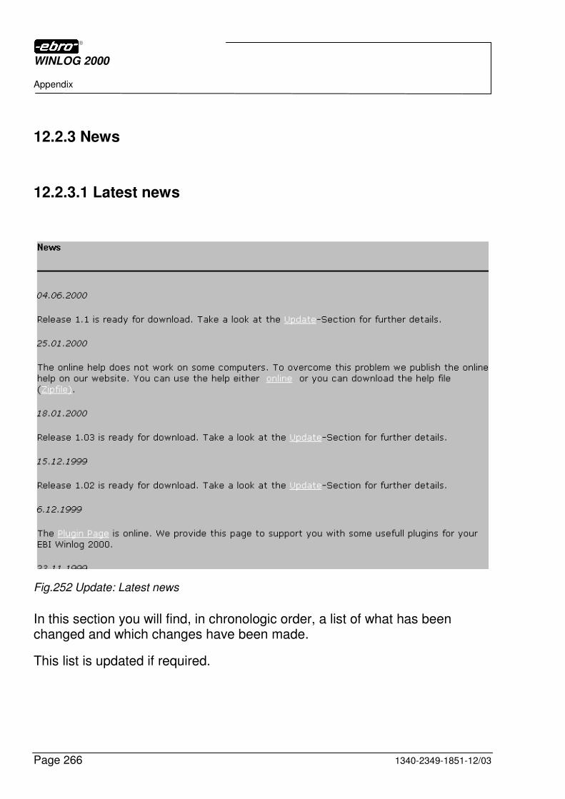
WINLOG 2000
Appendix
Page 266 1340-2349-1851-12/03
12.2.3 News
12.2.3.1 Latest news
Fig.252 Update: Latest news
In this section you will find, in chronologic order, a list of what has been changed and which changes have been made.
This list is updated if required.
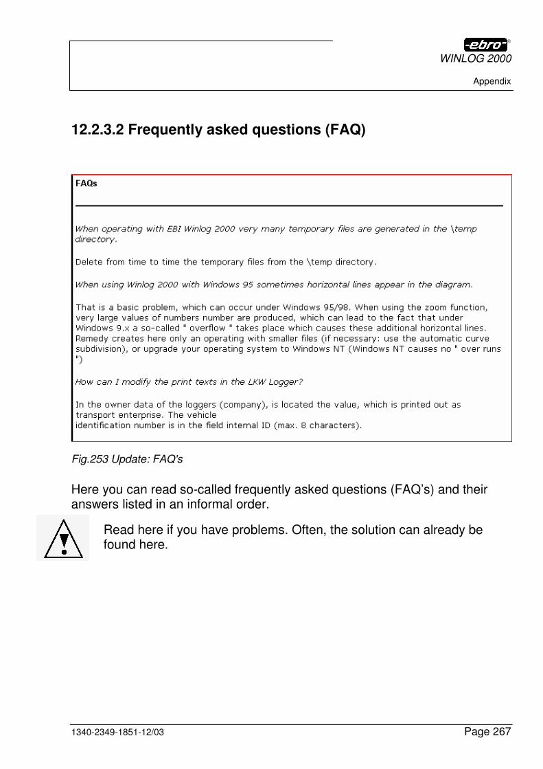
WINLOG 2000
Appendix
1340-2349-1851-12/03 Page 267
12.2.3.2 Frequently asked questions (FAQ)
Fig.253 Update: FAQ's
Here you can read so-called frequently asked questions (FAQ’s) and their answers listed in an informal order.
Read here if you have problems. Often, the solution can already be found here.
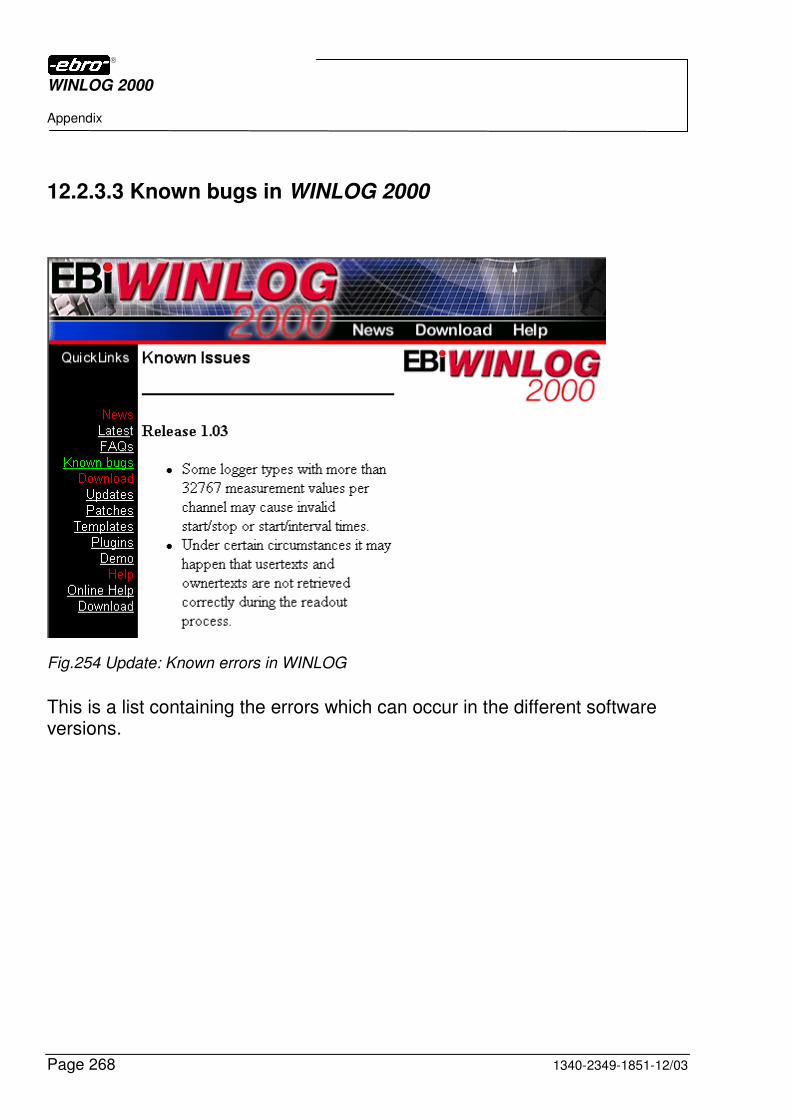
WINLOG 2000
Appendix
Page 268 1340-2349-1851-12/03
12.2.3.3 Known bugs in WINLOG 2000
Fig.254 Update: Known errors in WINLOG
This is a list containing the errors which can occur in the different software versions.

WINLOG 2000
Appendix
1340-2349-1851-12/03 Page 269
12.2.4 Downloads
12.2.4.1 Updates
In order to reduce your download times, all updates have been splitted in two parts. First download the language version which corresponds to your country, and then the core -update.
Fig.255 Update: Download language file
Click on the corresponding language version, in order to start the download.
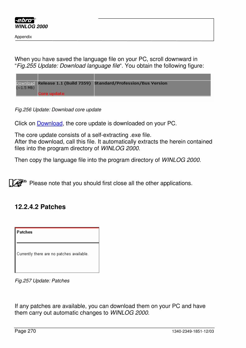
WINLOG 2000
Appendix
Page 270 1340-2349-1851-12/03
When you have saved the language file on your PC, scroll downward in “Fig.255 Update: Download language file“. You obtain the following figure:
Fig.256 Update: Download core update
Click on Download, the core update is downloaded on your PC.
The core update consists of a self-extracting .exe file. After the download, call this file. It automatically extracts the herein contained files into the program directory of WINLOG 2000.
Then copy the language file into the program directory of WINLOG 2000.
Please note that you should first close all the other applications.
12.2.4.2 Patches
Fig.257 Update: Patches
If any patches are available, you can download them on your PC and have them carry out automatic changes to WINLOG 2000.
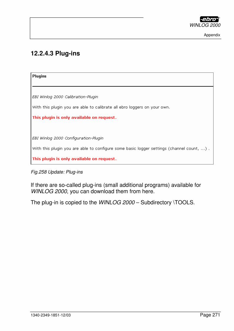
WINLOG 2000
Appendix
1340-2349-1851-12/03 Page 271
12.2.4.3 Plug-ins
Fig.258 Update: Plug-ins
If there are so-called plug-ins (small additional programs) available for WINLOG 2000, you can download them from here.
The plug-in is copied to the WINLOG 2000 – Subdirectory \TOOLS.
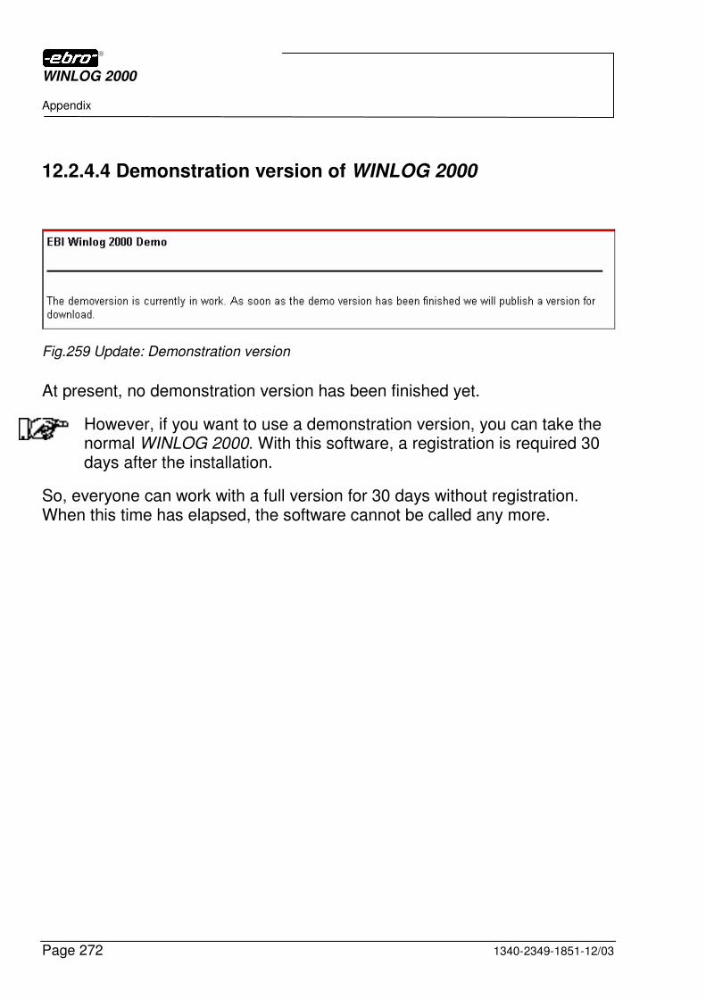
WINLOG 2000
Appendix
Page 272 1340-2349-1851-12/03
12.2.4.4 Demonstration version of WINLOG 2000
Fig.259 Update: Demonstration version
At present, no demonstration version has been finished yet.
However, if you want to use a demonstration version, you can take the normal WINLOG 2000. With this software, a registration is required 30 days after the installation.
So, everyone can work with a full version for 30 days without registration. When this time has elapsed, the software cannot be called any more.
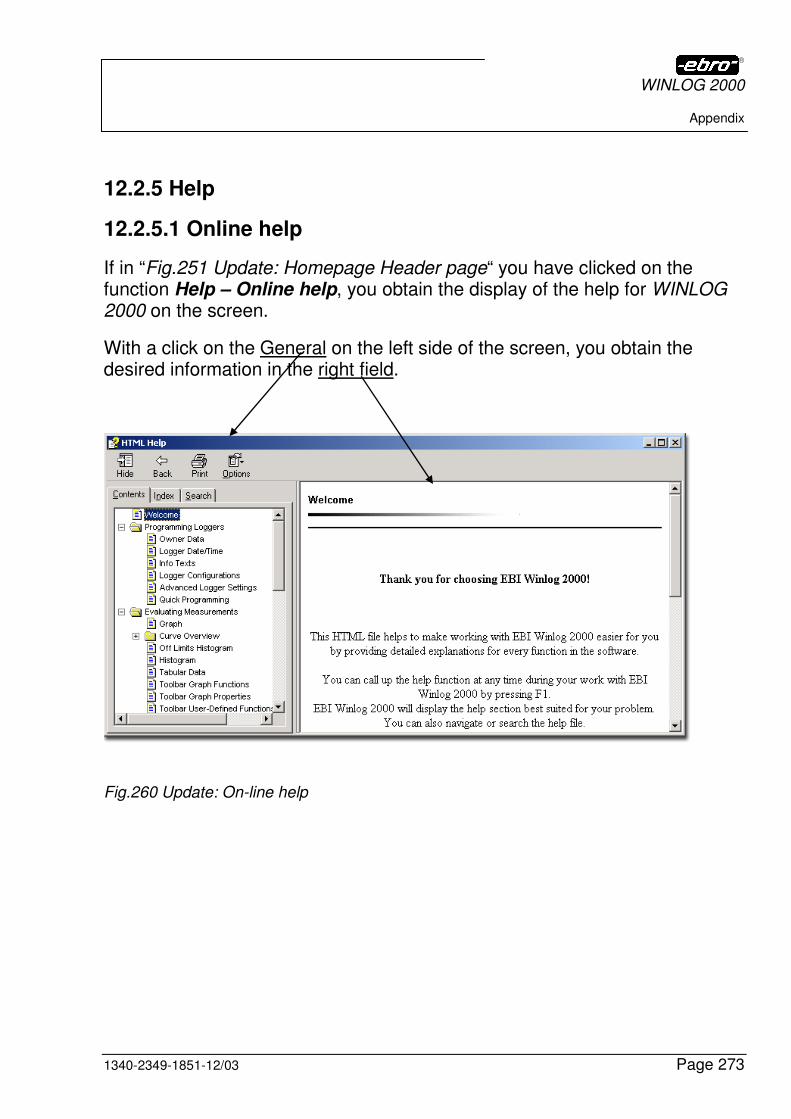
WINLOG 2000
Appendix
1340-2349-1851-12/03 Page 273
12.2.5 Help
12.2.5.1 Online help
If in “Fig.251 Update: Homepage Header page“ you have clicked on the function Help – Online help, you obtain the display of the help for WINLOG 2000 on the screen.
With a click on the General on the left side of the screen, you obtain the desired information in the right field.
Fig.260 Update: On-line help
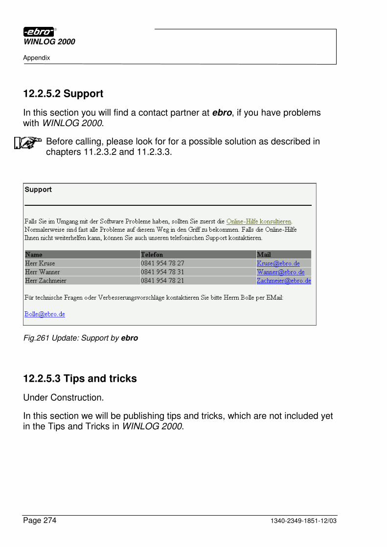
WINLOG 2000
Appendix
Page 274 1340-2349-1851-12/03
12.2.5.2 Support
In this section you will find a contact partner at ebro, if you have problems with WINLOG 2000.
Before calling, please look for for a possible solution as described in chapters 11.2.3.2 and 11.2.3.3.
Fig.261 Update: Support by ebro
12.2.5.3 Tips and tricks
Under Construction.
In this section we will be publishing tips and tricks, which are not included yet in the Tips and Tricks in WINLOG 2000.
WINLOG 2000
1340-2349-1851-12/03 Page 275
12.3 ebro hotline
If you have problems with the WINLOG 2000 software or with loggers, you are welcome to use our hotline during the general office hours.
The telephone number is +49 841-95478-0. This is our telephone exchange, from where you will be put through to a competent person. See also chapter 12.2.5.2.
However, before contacting ebro, please check your software and hardware installation of the system one more time.
If you still have no success, tell us your problem. Describe your problem to our hotline with the following indications.
� Computer configuration (e.g. Pentium III, 800 x 600 pixels etc.)
� Your operating system (e.g. Windows 95 C)
� The version number of WINLOG 2000 (see chapter 5.5)
� Your problem
WINLOG 2000
License agreement
Page 276 1340-2349-1851-12/03
13 License agreement
END-USER LICENSE AGREEMENT FOR ebro SOFTWARE WINLOG 2000
IMPORTANT - PLEASE READ CAREFULLY!
This End-User License Agreement is a valid agreement between yourself (either as a natural or a juridical person) and ebro Electronic GmbH & Co. KG for the above-mentioned ebro software product.
The software product comprises computer software as well as possible accompanying media, printed material and documentation in the "on-line" or electronic format ("SOFTWARE PRODUCT"). By installing, copying or using the SOFTWARE PRODUCT in a different way, you agree to be bound by the regulations of the license agreement. If you do not agree with the regulations of this license agreement, you are not authorized to install or to use the SOFTWARE PRODUCT. However, you can return it, with restitution of the purchase price, to the distributor from whom you have bought it.
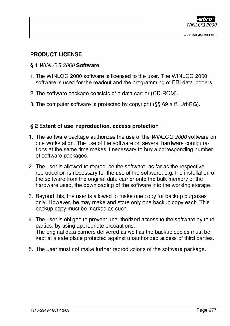
WINLOG 2000
License agreement
1340-2349-1851-12/03 Page 277
PRODUCT LICENSE
§ 1 WINLOG 2000 Software
1. The WINLOG 2000 software is licensed to the user. The WINLOG 2000 software is used for the readout and the programming of EBI data loggers.
2. The software package consists of a data carrier (CD-ROM).
3. The computer software is protected by copyright (§§ 69 a ff. UrhRG).
§ 2 Extent of use, reproduction, access protection
1. The software package authorizes the use of the WINLOG 2000 software on one workstation. The use of the software on several hardware configura-tions at the same time makes it necessary to buy a corresponding number of software packages.
2. The user is allowed to reproduce the software, as far as the respective reproduction is necessary for the use of the software, e.g. the installation of the software from the original data carrier onto the bulk memory of the hardware used, the downloading of the software into the working storage.
3. Beyond this, the user is allowed to make one copy for backup purposes only. However, he may make and store only one backup copy each. This backup copy must be marked as such.
4. The user is obliged to prevent unauthorized access to the software by third parties, by using appropriate precautions. The original data carriers delivered as well as the backup copies must be kept at a safe place protected against unauthorized access of third parties.
5. The user must not make further reproductions of the software package.

WINLOG 2000
License agreement
Page 278 1340-2349-1851-12/03
§ 3 Use in a network
1. The user may use the software on any hardware available to him. If the user changes the hardware, he must erase the software on the hardware used until then, in order to ensure the use on one hardware configuration. A simultaneous storing, keeping on stock or using of more than only one hardware is inadmissible.
2. The use of the purchased software within a network or any other multi-station computer system is allowed, if and as far as the possibility of si-multaneous multiple use of the software is prevented. If the user wants to use the software within a network or any other multi-station computer system, he must prevent a simultaneous multiple use by means of access protection mechanisms or purchase a corresponding network version of the software package.
§ 4 Recompiling, software changes
1. The recompiling of the purchased software code into other code forms as well as other types of going back to the different production levels of the software including a software change are generally not allowed.
2. Copyright marks, serial numbers as well as other marks serving as a software identification must in no case be removed or modified.
§ 5 Passing on to others
1. The user may transfer the software to a third party, if the buying third party agrees on the continuation of the present contract conditions, also in the relation between himself and ebro Electronic GmbH & Co. KG. In case of passing on the software, the user must hand over all software copies including possibly existing backup copies to the new user, or de-stroy the copies not handed over. In case of passing on, the right of the old user to use the software expires. The user will communicate the name and the complete address of the user in writing to the selling party.
WINLOG 2000
License agreement
1340-2349-1851-12/03 Page 279
2. The user may leave the software to a third party for a period of time, if the third party agrees on the continuation of the present contract conditions between himself and ebro Electronic GmbH & Co. KG, and the leaving user hands over all software copies including possibly existing backup cop-ies to the third party, or destroys the copies not handed over. During the time of leaving the software to the third party, the leaving user has no right to use the software himself.
§ 6 Warranty
1. Defects of the delivered software will be eliminated by the vendor after a corresponding notification from the user. This is done only by repair or compensation delivery, depending on the choice of the supplier.
2. If the vendor is not willing or not capable of repair or compensation deliv-ery, then the buyer has the right to claim alteration or reduction. The claim for damages is excluded. In case of alteration, the user must return the WINLOG 2000 software to the vendor, and erase it, if it has been installed on the hardware of the user.
3. The vendor is liable for damages due to legal incorrectness, especially those due to violations of copyrights of third parties. The vendor is not liable for damages which have not occurred on the delivered software itself; nor does he accept any liability for data loss or any other subsequent damages.
4. The liability of the vendor is limited to intention and great negligence; as far as there is an obligation for compensating the damages, it is limited to damages occurring typically.
5. Later modification wishes of the user regarding the extent of functions or other features of the software need not be considered by the vendor.
§ 7 Obligation of examination and claim
1. The user will examine the delivered software within 18 working days after delivery, in particular with regard to the operativeness of fundamental soft-ware functions.
WINLOG 2000
License agreement
Page 280 1340-2349-1851-12/03
2. Defects, which are hereby identified or which are detectable, must be communicated to the vendor within 5 working days (giving a detailed de-scription of the defects).
3. Defects, which are not detectable in the scope of the described regular examination, must be claimed within 5 working days after discovery, giving a detailed description of the defects.
§ 8 Other things
1. The user has rights of settling the accounts with regard to the vendor, only if his counter-claim is legal or uncontested.
2. All agreements which contain a modification, supplement or realization of these contract conditions, as well as special promises and arrangements, must be made in writing.
3. Competency of court for all disputes arising in relation with this agreement is Ingolstadt, if the user is a tradesman.
4. The vendor reserves the property of the software delivered to the user, until its complete payment.
5. If individual regulations of this agreement should be or become ineffective, the validity of the remaining regulations will thereby not be affected. In this case, the invalid regulation must be replaced with a valid regulation, which corresponds to or approaches best the intention and purpose of the inva-lid regulation. The same applies, if a deficiency that requires completion appears during the execution of this agreement.
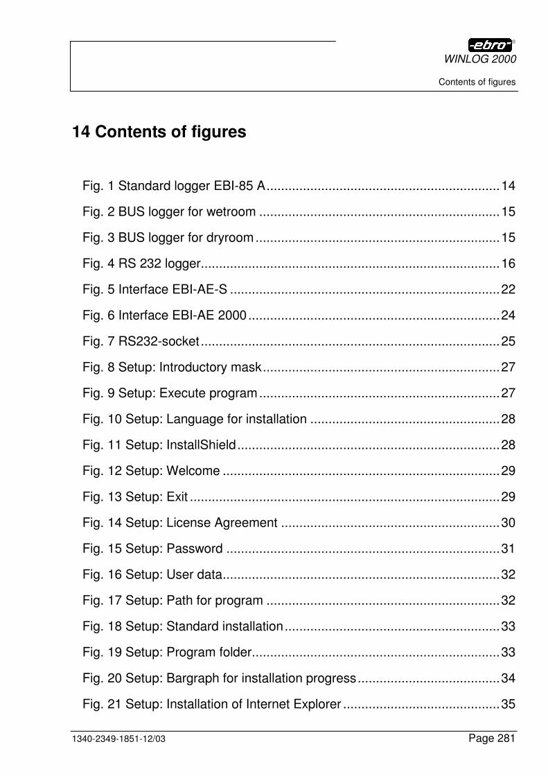
WINLOG 2000
Contents of figures
1340-2349-1851-12/03 Page 281
14 Contents of figures
Fig. 1 Standard logger EBI-85 A................................................................14
Fig. 2 BUS logger for wetroom ..................................................................15
Fig. 3 BUS logger for dryroom...................................................................15
Fig. 4 RS 232 logger..................................................................................16
Fig. 5 Interface EBI-AE-S ..........................................................................22
Fig. 6 Interface EBI-AE 2000.....................................................................24
Fig. 7 RS232-socket ..................................................................................25
Fig. 8 Setup: Introductory mask.................................................................27
Fig. 9 Setup: Execute program..................................................................27
Fig. 10 Setup: Language for installation ....................................................28
Fig. 11 Setup: InstallShield........................................................................28
Fig. 12 Setup: Welcome ............................................................................29
Fig. 13 Setup: Exit .....................................................................................29
Fig. 14 Setup: License Agreement ............................................................30
Fig. 15 Setup: Password ...........................................................................31
Fig. 16 Setup: User data............................................................................32
Fig. 17 Setup: Path for program ................................................................32
Fig. 18 Setup: Standard installation...........................................................33
Fig. 19 Setup: Program folder....................................................................33
Fig. 20 Setup: Bargraph for installation progress.......................................34
Fig. 21 Setup: Installation of Internet Explorer ...........................................35
WINLOG 2000
Contents of figures
Page 282 1340-2349-1851-12/03
Fig. 22 Setup: Installation of the Internet Explorer core ............................. 35
Fig. 23 Setup: Restart of PC ..................................................................... 35
Fig. 24 Setup: Successful installation........................................................ 36
Fig. 25 Configuration: Icon of WINLOG 2000 ............................................ 37
Fig. 26 Configuration: Selection of language............................................. 37
Fig. 27 Configuration: Serial interface ....................................................... 38
Fig. 28 Configuration: RS 232 ................................................................... 39
Fig. 29 Configuration: COM Port ok .......................................................... 39
Fig. 30 Configuration: Data of your company ............................................ 41
Fig. 31 Configuration: Conversion of WLS files ......................................... 41
Fig. 32 Configuration: Start conversion ..................................................... 42
Fig. 33 Configuration: Successful conversion............................................ 42
Fig. 34 Registration: Mask......................................................................... 43
Fig. 35 Registration: Registration number ................................................ 44
Fig. 36 Registration successful.................................................................. 44
Fig. 37 Registration: Incorrect number ...................................................... 45
Fig. 38 Icon for WINLOG 2000.................................................................. 46
Fig. 39 Standard version: Input screen...................................................... 46
Fig. 40 Standard version: Main panel ........................................................ 47
Fig. 41 Standard version: Tips + Tricks ..................................................... 47
Fig. 42 Standard version: Icon for Online help........................................... 48
Fig. 43 Standard version: Sample for Online help ..................................... 49
Fig. 44 Standard version: Online help via ?............................................... 49
WINLOG 2000
Contents of figures
1340-2349-1851-12/03 Page 283
Fig. 45 Standard version: Main panel ........................................................50
Fig. 46 Menu: File......................................................................................51
Fig. 47 Menu File: Open ebi-File ...............................................................51
Fig. 48 Menu File: Open ebw-File..............................................................52
Fig. 49 Menu File: Printer setup.................................................................53
Fig. 50 Menu File: Page setup...................................................................54
Fig. 51 Menu: View....................................................................................55
Fig. 52 Menu: Edit .....................................................................................55
Fig. 53 Menu Edit: Program Modules ........................................................56
Fig. 54 Menu Edit: Program Modules Professional ....................................56
Fig. 55 Menu Edit: Registration successful ................................................57
Fig. 56 Menu Edit: Restart WINLOG 2000.................................................57
Fig. 57 Menu Edit: Wrong register number ................................................57
Fig. 58 Menu Edit: Options ........................................................................58
Fig. 59 Menu Edit: Reservation of COM ports ...........................................59
Fig. 60 Menu Edit: Options Standard Path.................................................59
Fig. 61 Menu Edit: Options user defined Path ...........................................59
Fig. 62 Menu Edit: Language.....................................................................60
Fig. 63 Menu Edit: Restart of WINLOG 2000.............................................61
Fig. 64 Menu ? ..........................................................................................62
Fig. 65 Buttons ..........................................................................................63
Fig. 66 Settings .........................................................................................64
Fig. 67 Printer installation ..........................................................................65
WINLOG 2000
Contents of figures
Page 284 1340-2349-1851-12/03
Fig. 68 List of printers................................................................................ 65
Fig. 69 Printer properties........................................................................... 66
Fig. 70 Program modules .......................................................................... 67
Fig. 71 Outlook bar for Logger on COM1 .................................................. 68
Fig. 72 Menu: Advanced logger functions ................................................. 69
Fig. 73 Logger: Status information ............................................................ 70
Fig. 74 Battery OK..................................................................................... 71
Fig. 75 Battery to be replaced ................................................................... 71
Fig. 76 Battery status unknown ................................................................. 71
Fig. 77 Restart logger................................................................................ 72
Fig. 78 Program logger with... ................................................................... 72
Fig. 79 Warning at restart of logger ........................................................... 73
Fig. 80 Successful synchronization of logger RTC .................................... 74
Fig. 81 Logger properties .......................................................................... 75
Fig. 82 Outlook bar: Cancel....................................................................... 76
Fig. 83 Cancel confirmation....................................................................... 76
Fig. 84 Toolbar: Overview ......................................................................... 77
Fig. 85 Contents of data folder .................................................................. 77
Fig. 86 Version information ....................................................................... 78
Fig. 87 Program logger: Icon..................................................................... 81
Fig. 88 Program logger: Reading data....................................................... 81
Fig. 89 Program logger: Progress of reading data..................................... 82
Fig. 90 Program logger: Dialog.................................................................. 82
WINLOG 2000
Contents of figures
1340-2349-1851-12/03 Page 285
Fig. 91 Program logger: Logger data mask empty.....................................84
Fig. 92 Program logger: Edit of data..........................................................84
Fig. 93 Program logger: Edit of data finished.............................................85
Fig. 94 Program logger: Filling of logger data finished...............................85
Fig. 95 Program logger: Owner data mask empty .....................................86
Fig. 96 Program logger: Warning message for Owner data .......................86
Fig. 97 Program logger: Owner data mask filled........................................87
Fig. 98 Program logger: Info texts .............................................................88
Fig. 99 Programming a logger: Configuration management.......................89
Fig. 100 Program logger: 1 channel...........................................................90
Fig. 101 Program logger: 2 channel...........................................................90
Fig. 102 Program logger: diologbox for limits.............................................91
Fig. 103 Program logger: Edit limits in basic unit .......................................91
Fig. 104 Program logger: Incorrect limit.....................................................92
Fig. 105 Program logger: Measuring interval .............................................93
Fig. 106 Program logger: Measuring rate - Minutes...................................93
Fig. 107 Program logger: Measuring mode................................................94
Fig. 108 Program logger: Measuring mode endless ..................................94
Fig. 109 Program logger: Measuring mode endless loop...........................95
Fig. 110 Program logger: Measuring mode Start-Stop...............................96
Fig. 111 Program logger: Measuring mode Automatic interval ..................96
Fig. 112 Program logger: Entering date.....................................................97
Fig. 113 Program logger: Entering time .....................................................97
WINLOG 2000
Contents of figures
Page 286 1340-2349-1851-12/03
Fig. 114 Program logger: Start-interval measurement ............................... 98
Fig. 115 Program logger: Entering start date............................................. 98
Fig. 116 Program logger: Entering start time............................................. 99
Fig. 117 Program logger: Completed dialog mask................................... 100
Fig. 118 Program logger: Safety interrogation......................................... 101
Fig. 119 Program logger: Read logger data?........................................... 101
Fig. 120 Program logger: Logger is being programmed .......................... 102
Fig. 121 Program logger: Successful programming................................. 102
Fig. 122 Readout: Menu.......................................................................... 104
Fig.123 Readout: Logger data are read-in............................................... 104
Fig.124 Progressing graphic bar ............................................................. 105
Fig.125 Saving: File name....................................................................... 105
Fig.126 Saving: Create directory ............................................................. 106
Fig.127 Saving: Directory dialog box....................................................... 106
Fig.128 Saving: Directory tree................................................................. 107
Fig.129 Print - Dialog box........................................................................ 108
Fig.130 Graphic display: Graphic representation of the measured values incl. limits................................................................................................ 112
Fig.131 Graphic display: Selection of documents.................................... 113
Fig.132 Graphic display: Selection of documents with several files......... 113
Fig.133 Tool bar: View ............................................................................ 116
Fig.134 Vertical tool bar .......................................................................... 119
Fig.135 Context menu............................................................................. 125
Fig. 136 Manual scaling of axes .............................................................. 126
WINLOG 2000
Contents of figures
1340-2349-1851-12/03 Page 287
Fig.137 Positioning of the cursor .............................................................127
Fig. 138 Manual selection of the range....................................................128
Fig. 139 Line thickness............................................................................129
Fig.140 Histogram ...................................................................................130
Fig.141 Enlarged histogram.....................................................................131
Fig.142 Limit value histogram..................................................................132
Fig.143 Enlarged limit value histogram....................................................133
Fig.144 Automatic splitting ......................................................................134
Fig.145 Example: Inserted legends .........................................................136
Fig.146 Saving the working range ...........................................................136
Fig.147 Directory for saving files .............................................................137
Fig.148 Opening the working range.........................................................137
Fig.149 Password request: Dialog box ....................................................139
Fig.150 New functions in the PROFESSIONAL version ..........................140
Fig.151 Functions of Advanced .... ..........................................................141
Fig.152 Settings ......................................................................................142
Fig.153 Settings: Dialog box....................................................................143
Fig.154 EBI - Explorer ............................................................................144
Fig.155 COM1 menu ...............................................................................145
Fig.156 Local logger: Context menu........................................................146
Fig.157 User administration.....................................................................148
Fig.158 New user: Dialog box..................................................................149
Fig.159 New user: filled-in .......................................................................149
WINLOG 2000
Contents of figures
Page 288 1340-2349-1851-12/03
Fig.160 New user: Granting rights........................................................... 150
Fig.161 New user: Granting rights, example............................................ 150
Fig.162 Changing the user entry ............................................................. 152
Fig.163 User-defined functions................................................................ 153
Fig.164 Example-curve for a template..................................................... 154
Fig.165 User-defined functions................................................................ 154
Fig.166 Display of a progress bar............................................................ 154
Fig.167 Example-curve temperature - F-value ........................................ 155
Fig.168 Formula editor: Empty dialog box ............................................... 156
Fig.169 Formula editor: Path for templates ............................................. 157
Fig.170 Formula editor: Dialog box with template.................................... 157
Fig.171 Formula editor: Filled-in dialog box............................................. 159
Fig.172 Formula editor: Example-script................................................... 160
Fig.173 Data archiving: Path ................................................................... 167
Fig.174 Data archiving: File list ............................................................... 168
Fig.175 Data archiving: Marking files....................................................... 168
Fig.176 Data archiving: Directory tree ..................................................... 169
Fig.177 Data archiving: Progress bar ...................................................... 169
Fig.178 Data archiving: Context menu .................................................... 170
Fig.179 Data archiving: File properties .................................................... 170
Fig.180 Data archiving: Safety interrogation............................................ 171
Fig.181 Data archiving: Menu for file....................................................... 171
Fig.182 Data archiving: Directory ............................................................ 172
WINLOG 2000
Contents of figures
1340-2349-1851-12/03 Page 289
Fig.183 Data archiving: File selection ......................................................172
Fig.184 Administration of measured variables: ........................................173
Fig.185 Administration of measured variables: Example .........................174
Fig. 186 Administration of measured variables: Example °F....................175
Fig. 187 Administration of measured variables: Select unit °C or °F........176
Fig.188 Real-time monitoring...................................................................177
Fig. 189 Interface EBI-AE-BUS-30 ..........................................................180
Fig. 190 Interface EBI-AE-BUS-63 ..........................................................182
Fig.191 Password request.......................................................................185
Fig.192 Professional version: WINLOG 2000 main panel........................186
Fig.193 Scheduler - Dialog box ...............................................................187
Fig.194 Settings for the professional and the BUS version......................188
Fig.195 Example for a path indication......................................................189
Fig.196 Selection of the BUS...................................................................190
Fig.197 Assigning a node address ..........................................................191
Fig.198 Assigning a node address: Dialog box........................................191
Fig.199 Giving a node address: Selection of the number ........................191
Fig.200 Assigning a node address: Confirmation ....................................192
Fig.201 Assigning a node address: View of the entry ..............................192
Fig.202 Assigning a node address: Automatic attribution ........................193
Fig.203 BUS scheme: Inserting a new logger..........................................193
Fig.204 BUS scheme: Node address of the new logger ..........................193
Fig.205 BUS configuration: Menu............................................................194
WINLOG 2000
Contents of figures
Page 290 1340-2349-1851-12/03
Fig.206 BUS configuration: Warning message........................................ 195
Fig.207 BUS configuration: Progressing of the determination ................. 195
Fig.208 BUS configuration: Successful determination ............................. 196
Fig.209 BUS configuration: Logger tree .................................................. 196
Fig.210 BUS configuration: Bus scheme for loggers ............................... 197
Fig.211 BUS interrogation: Determination of the logger status ................ 198
Fig.212 BUS interrogation: Result ........................................................... 198
Fig.213 Context menu for loggers ........................................................... 199
Fig.214 Directory: Archived measured documents .................................. 200
Fig.215 Programming with... ................................................................... 200
Fig.216 BUS scheme: New grouping....................................................... 201
Fig.217 BUS scheme: Naming the new grouping .................................... 201
Fig.218 Example for a BUS scheme........................................................ 202
Fig.219 Scheduler: Dialog box ................................................................ 203
Fig.220 Scheduler: Entering weekdays ................................................... 204
Fig.221 Scheduler: Date entry................................................................. 205
Fig.222 Scheduler: Defining the period ................................................... 206
Fig.223 Scheduler: Defining the action.................................................... 207
Fig.224 Scheduler: Alarm control ............................................................ 208
Fig.225 Scheduler: Plug-in ...................................................................... 209
Fig.226 Scheduler: SMTP configuration .................................................. 210
Fig.227 Scheduler: Alarm configuration................................................... 211
Fig.228 Scheduler: Protocol .................................................................... 212
WINLOG 2000
Contents of figures
1340-2349-1851-12/03 Page 291
Fig.229 Scheduler: New task...................................................................213
Fig.230 Task: New editing - Date ............................................................214
Fig.231 Task: New editing - Interval ........................................................214
Fig.232 Task: New editing – Alarm control ..............................................214
Fig.233 Task: New editing - Task bar ......................................................215
Fig.234 Task: Activating/Deactivating......................................................215
Fig.235 Task: Menu.................................................................................215
Fig.236 Task deactivated ........................................................................216
Fig.237 Task: Menu properties ................................................................216
Fig.238 Task: Properties .........................................................................216
Fig.239 Task: Protocol box......................................................................217
Fig.240 Task: Protocol files .....................................................................218
Fig.241 Task: Status in the protocol box..................................................218
Fig.242 Alarm monitoring ........................................................................219
Fig.243 Alarm list.....................................................................................219
Fig.244Acknowledge Alarm....................................................................220
Fig.245 2nd alarm has occurred ...............................................................221
Fig.246 Alarm suppression......................................................................221
Fig.247 Duration of the alarm suppression ..............................................222
Fig.248 Update: Homepage of ebro .......................................................263
Fig.249 Update: Homepage of ebro, 1st page .........................................264
Fig. 250 Update: Software button ............................................................265
Fig.251 Update: Homepage Header page ...............................................265
WINLOG 2000
Contents of figures
Page 292 1340-2349-1851-12/03
Fig.252 Update: Latest news................................................................... 266
Fig.253 Update: FAQ's............................................................................ 267
Fig.254 Update: Known errors in WINLOG ............................................. 268
Fig.255 Update: Download language file................................................. 269
Fig.256 Update: Download core update .................................................. 270
Fig.257 Update: Patches......................................................................... 270
Fig.258 Update: Plug-ins......................................................................... 271
Fig.259 Update: Demonstration version .................................................. 272
Fig.260 Update: On-line help................................................................... 273
Fig.261 Update: Support by ebro............................................................ 274
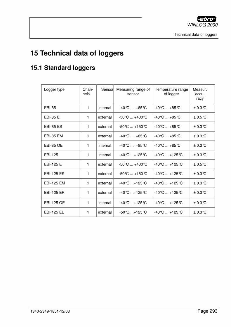
WINLOG 2000
Technical data of loggers
1340-2349-1851-12/03 Page 293
15 Technical data of loggers
15.1 Standard loggers
Logger type Chan-nels
Sensor Measuring range of sensor
Temperature range of logger
Measur.accu-racy
EBI-85 1 internal -40°C ... +85°C -40°C ... +85°C ± 0.3°C
EBI-85 E 1 external -50°C ... +400°C -40°C ... +85°C ± 0.5°C
EBI-85 ES 1 external -50°C ... +150°C -40°C ... +85°C ± 0.3°C
EBI-85 EM 1 external -40°C ... +85°C -40°C ... +85°C ± 0.3°C
EBI-85 OE 1 internal -40°C ... +85°C -40°C ... +85°C ± 0.3°C
EBI-125 1 internal -40°C ...+125°C -40°C ... +125°C ± 0.3°C
EBI-125 E 1 external -50°C ... +400°C -40°C ... +125°C ± 0.5°C
EBI-125 ES 1 external -50°C ... +150°C -40°C ... +125°C ± 0.3°C
EBI-125 EM 1 external -40°C ...+125°C -40°C ... +125°C ± 0.3°C
EBI-125 ER 1 external -40°C ...+125°C -40°C ... +125°C ± 0.3°C
EBI-125 OE 1 internal -40°C ...+125°C -40°C ... +125°C ± 0.3°C
EBI-125 EL 1 external -50°C ...+125°C -40°C ... +125°C ± 0.3°C
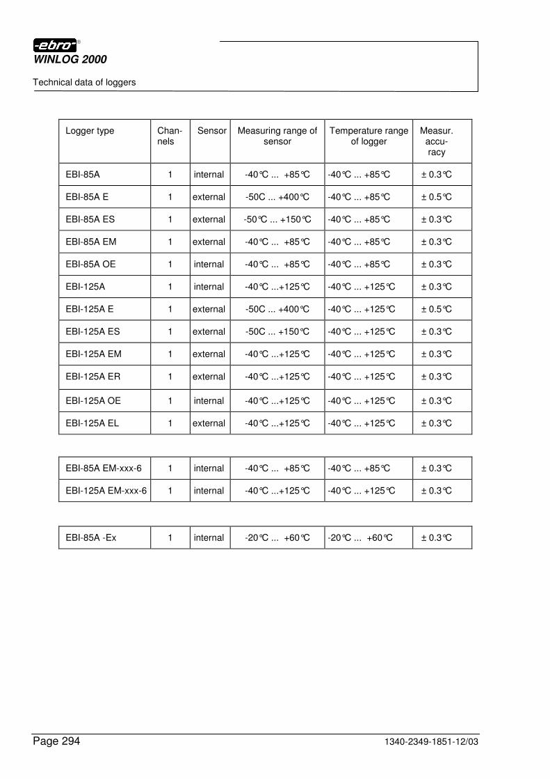
WINLOG 2000
Technical data of loggers
Page 294 1340-2349-1851-12/03
Logger type Chan-nels
Sensor Measuring range of sensor
Temperature range of logger
Measur. accu-racy
EBI-85A 1 internal -40°C ... +85°C -40°C ... +85°C ± 0.3°C
EBI-85A E 1 external -50C ... +400°C -40°C ... +85°C ± 0.5°C
EBI-85A ES 1 external -50°C ... +150°C -40°C ... +85°C ± 0.3°C
EBI-85A EM 1 external -40°C ... +85°C -40°C ... +85°C ± 0.3°C
EBI-85A OE 1 internal -40°C ... +85°C -40°C ... +85°C ± 0.3°C
EBI-125A 1 internal -40°C ...+125°C -40°C ... +125°C ± 0.3°C
EBI-125A E 1 external -50C ... +400°C -40°C ... +125°C ± 0.5°C
EBI-125A ES 1 external -50C ... +150°C -40°C ... +125°C ± 0.3°C
EBI-125A EM 1 external -40°C ...+125°C -40°C ... +125°C ± 0.3°C
EBI-125A ER 1 external -40°C ...+125°C -40°C ... +125°C ± 0.3°C
EBI-125A OE 1 internal -40°C ...+125°C -40°C ... +125°C ± 0.3°C
EBI-125A EL 1 external -40°C ...+125°C -40°C ... +125°C ± 0.3°C
EBI-85A EM-xxx-6 1 internal -40°C ... +85°C -40°C ... +85°C ± 0.3°C
EBI-125A EM-xxx-6 1 internal -40°C ...+125°C -40°C ... +125°C ± 0.3°C
EBI-85A -Ex 1 internal -20°C ... +60°C -20°C ... +60°C ± 0.3°C
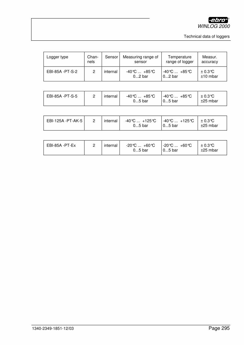
WINLOG 2000
Technical data of loggers
1340-2349-1851-12/03 Page 295
Logger type Chan-nels
Sensor Measuring range of sensor
Temperature range of logger
Measur. accuracy
EBI-85A -PT-S-2 2 internal -40°C ... +85°C 0...2 bar
-40°C ... +85°C 0...2 bar
± 0.3°C ±10 mbar
EBI-85A -PT-S-5 2 internal -40°C ... +85°C 0...5 bar
-40°C ... +85°C 0...5 bar
± 0.3°C ±25 mbar
EBI-125A -PT-AK-5 2 internal -40°C ... +125°C 0...5 bar
-40°C ... +125°C 0...5 bar
± 0.3°C ±25 mbar
EBI-85A -PT-Ex 2 internal -20°C ... +60°C 0...5 bar
-20°C ... +60°C 0...5 bar
± 0.3°C ±25 mbar
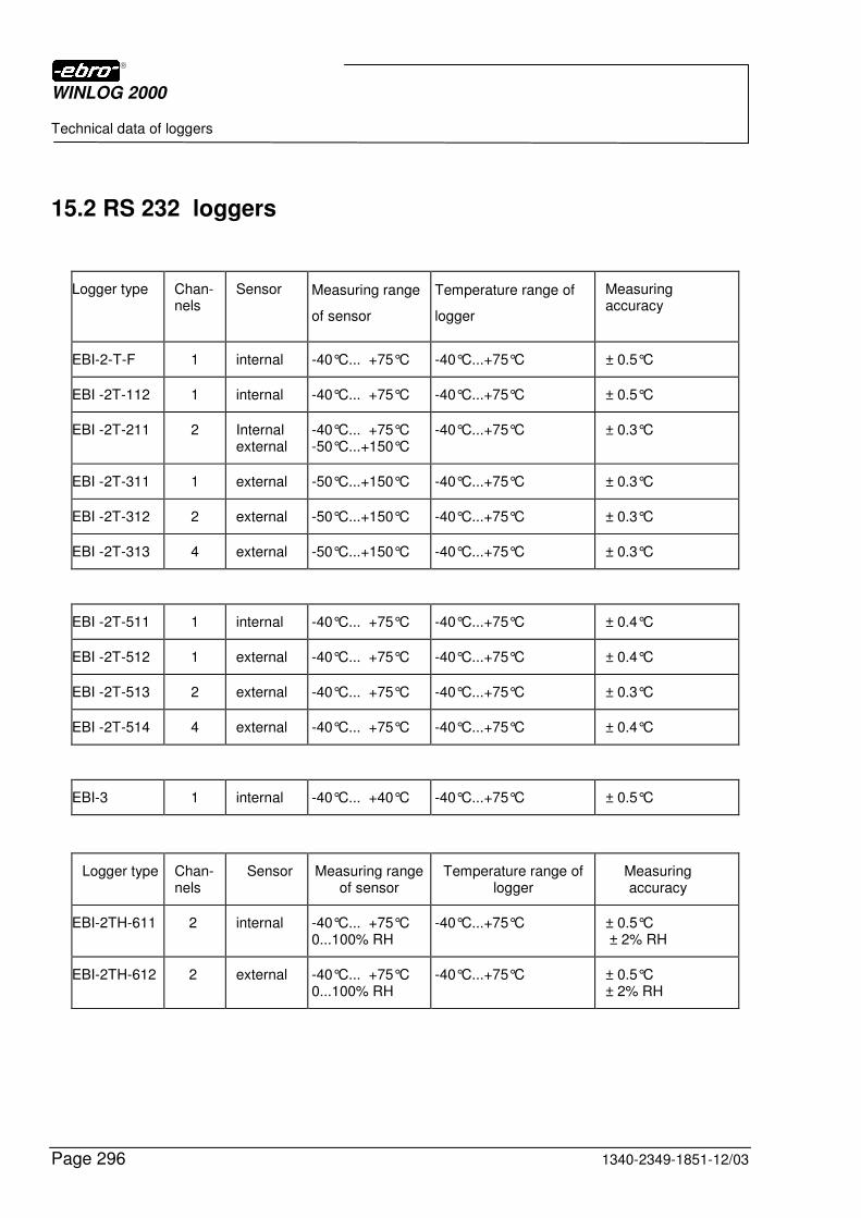
WINLOG 2000
Technical data of loggers
Page 296 1340-2349-1851-12/03
15.2 RS 232 loggers
Logger type Chan-nels
Sensor Measuring range
of sensor
Temperature range of
logger
Measuring accuracy
EBI-2-T-F 1 internal -40°C... +75°C -40°C...+75°C ± 0.5°C
EBI -2T-112 1 internal -40°C... +75°C -40°C...+75°C ± 0.5°C
EBI -2T-211 2 Internal external
-40°C... +75°C -50°C...+150°C
-40°C...+75°C ± 0.3°C
EBI -2T-311 1 external -50°C...+150°C -40°C...+75°C ± 0.3°C
EBI -2T-312 2 external -50°C...+150°C -40°C...+75°C ± 0.3°C
EBI -2T-313 4 external -50°C...+150°C -40°C...+75°C ± 0.3°C
EBI -2T-511 1 internal -40°C... +75°C -40°C...+75°C ± 0.4°C
EBI -2T-512 1 external -40°C... +75°C -40°C...+75°C ± 0.4°C
EBI -2T-513 2 external -40°C... +75°C -40°C...+75°C ± 0.3°C
EBI -2T-514 4 external -40°C... +75°C -40°C...+75°C ± 0.4°C
EBI-3 1 internal -40°C... +40°C -40°C...+75°C ± 0.5°C
Logger type Chan-nels
Sensor Measuring range of sensor
Temperature range of logger
Measuring accuracy
EBI-2TH-611 2 internal -40°C... +75°C 0...100% RH
-40°C...+75°C ± 0.5°C ± 2% RH
EBI-2TH-612 2 external -40°C... +75°C 0...100% RH
-40°C...+75°C ± 0.5°C ± 2% RH
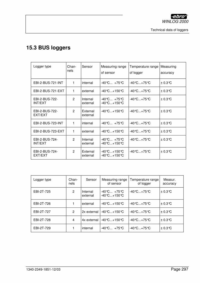
WINLOG 2000
Technical data of loggers
1340-2349-1851-12/03 Page 297
15.3 BUS loggers
Logger type Chan-
nels
Sensor Measuring range
of sensor
Temperature range
of logger
Measuring
accuracy
EBI-2-BUS-721-INT 1 internal -40°C... +75°C -40°C...+75°C ± 0.3°C
EBI-2-BUS-721-EXT 1 external -40°C...+150°C -40°C...+75°C ± 0.3°C
EBI-2-BUS-722-INT/EXT
2 Internal external
-40°C... +75°C -40°C...+150°C
-40°C...+75°C ± 0.3°C
EBI-2-BUS-722-EXT/EXT
2 External external
-40°C...+150°C -40°C...+75°C ± 0.3°C
EBI-2-BUS-723-INT 1 internal -40°C... +75°C -40°C...+75°C ± 0.3°C
EBI-2-BUS-723-EXT 1 external -40°C...+150°C -40°C...+75°C ± 0.3°C
EBI-2-BUS-724-INT/EXT
2 Internal external
-40°C... +75°C -40°C...+150°C
-40°C...+75°C ± 0.3°C
EBI-2-BUS-724-EXT/EXT
2 External external
-40°C...+150°C -40°C...+150°C
-40°C...+75°C ± 0.3°C
Logger type Chan-nels
Sensor Measuring range of sensor
Temperature range of logger
Measur. accuracy
EBI-2T-725 2 Internal external
-40°C... +75°C -40°C...+150°C
-40°C...+75°C ± 0.3°C
EBI-2T-726 1 external -40°C...+150°C -40°C...+75°C ± 0.3°C
EBI-2T-727 2 2x external -40°C...+150°C -40°C...+75°C ± 0.3°C
EBI-2T-728 4 4x external -40°C...+150°C -40°C...+75°C ± 0.3°C
EBI-2T-729 1 internal -40°C... +75°C -40°C...+75°C ± 0.3°C
WINLOG 2000
Index
Page 298 1340-2349-1851-12/03
16 Index
2
2-wire cable....................................................................................................................... 14
3
3 ½’’ diskette ................................................................................................................... 145 30-day period .................................................................................................................... 43
9
9-pole socket............................................................................................... 23, 25, 181, 183
A
Abbreviation .................................................................................................................... 175 ABS(X) ............................................................................................................................ 166 ACOS(X) ......................................................................................................................... 165 Action .............................................................................................................................. 206 Activating/deactivating tasks ........................................................................................... 215 Add task .......................................................................................................... 207, 208, 214 Advanced logger functions.......................................................................................... 68, 69 Alarm........................................................................143, 206, 208, 211, 214, 219, 220, 221 Alarm XE "Alarm" control ........................................................................143, 206, 208, 214 Alarm XE "Alarm" list...................................................................................................... 219 Appendix ......................................................................................................................... 251 Archived documents.........................................................145, 167, 169, 171, 172, 188, 204 ASIN(X)........................................................................................................................... 164 ATAN(X).......................................................................................................................... 165 Automatic increment ....................................................................................................... 192 Automatic Interval ............................................................................................................. 96 Automatic range determination ....................................................................................... 134 Automatic refresh .............................................................................................................. 70 Automatic Start of installation............................................................................................ 26 Average .................................................................................................................. 114, 178
B
Bargraph ........................................................................................................................... 34 Basic unit ........................................................................................................................ 173 Battery......................................................................................................................... 58, 71 Battery XE "Battery" monitoring ....................................................................................... 58 Browse .............................................................................................................................. 32 Bug Report ........................................................................................................................ 62
WINLOG 2000
Index
1340-2349-1851-12/03 Page 299
BUS configuration.................................................................................... 194, 195, 196, 197 BUS installation ............................................................................................................... 183 BUS logger .................................................................... 14, 15, 18, 183, 189, 194, 200, 297 BUS system........................................91, 183, 187, 189, 194, 195, 196, 197, 199, 201, 202 BUS version .................................................18, 58, 138, 139, 140, 144, 179, 184, 186, 188 BUS wiring....................................................................................................................... 183 Buttons .............................................................................................................................. 63
C
Calculation......................................................................................................................... 18 Cancel ..............................................29, 36, 39, 76, 139, 158, 185, 192, 195, 210, 212, 218 CD-ROM.................................................................................................. 18, 26, 27, 28, 277 CDT(n)............................................................................................................................. 162 Click.27, 39, 44, 57, 61, 72, 97, 99, 116, 120, 122, 123, 149, 151, 152, 177, 207, 216, 269,
270 CMAX(n).......................................................................................................................... 162 CMID(n)........................................................................................................................... 163 CMIN(n)........................................................................................................................... 163 COM1.........................................................23, 24, 39, 63, 68, 106, 141, 145, 180, 182, 190 COM2.......................................................................................... 23, 24, 141, 145, 180, 182 COM3.......................................................................................................... 23, 24, 180, 182 COM4.................................................................................................. 23, 24, 145, 180, 182 company data.................................................................................................. 40, 74, 86, 87 Configuration ................................................................................. 37, 38, 39, 41, 42, 74, 87 Configuration of the software............................................................................................. 37 Confirm alarm.................................................................................................................. 220 Contents of figures .......................................................................................................... 281 Context menu .......................................................................................... 125, 146, 170, 199 Conversion of WLS files .............................................................................................. 41, 42 Converting of EBI files ....................................................................................................... 41 COS(X)............................................................................................................................ 164 CRTL................................................................................................................................. 12 CSTD(n) .......................................................................................................................... 163 CUBE(X).......................................................................................................................... 166 Curve color ...................................................................................................................... 128 CVAL(n)........................................................................................................................... 162 CVAR(n) .......................................................................................................................... 163
D
Date......................................................................................................................... 205, 214 Date XE "Date" mode ..................................................................................................... 205 DCOM 95 .......................................................................................................................... 34 Diagram functions............................................................................................................ 116 Diagram properties.......................................................................................................... 119 Dialog box ............................................................... 108, 139, 143, 149, 157, 187, 191, 203
WINLOG 2000
Index
Page 300 1340-2349-1851-12/03
Directory for logger documents ......................................................................................... 59 DMC................................................................................................................ 12, 37, 46, 81 Downloads ...................................................................................................................... 269 Dynamic shifting.............................................................................................................. 117
E
ebi ... 1, 10, 11, 13, 14, 16, 17, 20, 21, 22, 23, 24, 25, 37, 39, 41, 44, 46, 51, 58, 62, 71, 80, 91, 103, 106, 107, 135, 136, 144, 145, 146, 156, 167, 171, 173, 174, 180, 181, 182, 183, 186, 193, 194, 196, 197, 198, 201, 211, 251, 254, 265, 277, 293, 294, 295, 296, 297
EBI data logger system ......................................................................................... 10, 13, 21 EBI-125 A.................................................................................................................... 14, 17 EBI-2 ........................................1, 10, 13, 16, 17, 25, 39, 58, 71, 80, 91, 103, 183, 296, 297 EBI-2T............................................................................................................. 183, 296, 297 EBI-3 ..........................................................................1, 10, 13, 16, 17, 25, 39, 80, 103, 296 EBI-85 A...................................................................................................................... 14, 17 EBI-AE 2000 ..................................................................................................................... 24 EBI-AE-BUS interface ............................................................................................. 180, 211 EBI-AE-S........................................................................................................................... 23 EBI-Explorer.................................................................................................................... 145 EBI-Int-K25 cable .............................................................................................................. 22 EBI-XX-A........................................................................................................................... 10 ebro Electronic GmbH & Co. KG............................................................1, 12, 276, 278, 279 EBW.......................................................................................................................... 52, 137 Edit...................................................50, 55, 56, 57, 58, 59, 60, 61, 84, 85, 86, 91, 123, 207 EEPROM................................................................................................................... 17, 258 E-mail alarm.................................................................................................................... 209 Endless loop................................................................................................................ 94, 95 Error code ....................................................................................................................... 258 Error messages....................................................................................................... 251, 252 Excel ....................................................................................................................... 128, 135 EXP(X) ............................................................................................................................ 166 Explorer........................................18, 21, 34, 35, 36, 48, 140, 144, 145, 146, 172, 186, 194
F
f(x)................................................................................................................................... 156 F1 key ................................................................................................................. 10, 48, 119 FAK(X) ............................................................................................................................ 166 FAQ................................................................................................................................. 267 File ............................. 50, 51, 52, 53, 54, 105, 106, 107, 108, 137, 168, 170, 171, 172, 261 File name .................................................................................................105, 106, 107, 137 File XE "File" properties ................................................................................................. 170 Formula......................................................................................18, 156, 157, 159, 160, 175 Formula editor ....................................................................................18, 156, 157, 159, 160 FRACT(X) ....................................................................................................................... 166
WINLOG 2000
Index
1340-2349-1851-12/03 Page 301
F-value .............................................................................. 18, 137, 153, 154, 155, 158, 160
G
GON ................................................................................................................................ 165 Graphics .......................................................................................................................... 109
H
Hard disk ..................................................................................................................... 19, 20 Help ......................................................................................................... 47, 48, 49, 79, 273 Histogram ........................................................................................................................ 130 Homepage............................................................................................... 263, 264, 265, 273 Hotline ................................................................................................................................. 1
I
Icon.......................................................................................... 37, 46, 48, 68, 69, 76, 77, 81 Index................................................................................................................................ 298 Information texts ................................................................................................................ 88 Install Shield ...................................................................................................................... 28 Install WINLOG 2000......................................................................................................... 27 INSTALL WINLOG 2000 ................................................................................................... 27 Installation ......................................................................................... 21, 22, 26, 35, 36, 180 Installation of the Hardware............................................................................................... 22 INT(X).............................................................................................................................. 166 Interface ...................................................................................... 23, 24, 180, 182, 254, 256 Internet .......................................................................................... 34, 35, 36, 252, 263, 274 Internet Explorer.................................................................................................... 34, 35, 36 Interval............................................................................................. 93, 94, 96, 98, 102, 214
K
Kelvin............................................................................................................................... 174 Keyboard ........................................................................................................................... 12
L
Language .............................................................................................................. 28, 36, 61 License agreement.......................................................................................................... 276 License Agreement.................................................................................................... 30, 276 limit value ....17, 18, 20, 70, 80, 83, 89, 90, 91, 92, 114, 120, 129, 132, 133, 147, 158, 189,
206, 211 Limit value ................................................................................................... 90, 91, 132, 158 Limit value histogram....................................................................................................... 132 Limit value XE "limit value" s ....................................................................................... 90, 91 Line width ........................................................................................................................ 129
WINLOG 2000
Index
Page 302 1340-2349-1851-12/03
LMC .... 12, 27, 28, 34, 36, 37, 39, 40, 41, 48, 49, 54, 58, 61, 63, 65, 69, 70, 72, 74, 76, 78, 79, 84, 85, 86, 93, 99, 100, 104, 108, 116, 117, 122, 123, 137, 141, 150, 151, 152, 154, 157, 159, 168, 185, 189, 191, 193, 194, 195, 196, 197, 198, 199, 200, 201, 202, 203, 204, 207, 208, 209, 210, 213, 215, 222, 253, 255, 264, 265
Local logger............................................................................................................. 145, 146 LOG(X)............................................................................................................................ 166 LOG10(X)........................................................................................................................ 166 Logger data....................................................................................................... 84, 104, 109
M
Main panel..................................................................................................... 47, 48, 50, 184 Manual range determination............................................................................................ 135 Manual scaling ................................................................................................................ 126 Manual start of installation ................................................................................................ 27 Mask ..................................................................................................................... 43, 82, 90 Measured data ................................................................................................................ 109 Measured value............................................................................................................... 114 Measuring channel............................................................................................................ 90 Measuring interval............................................................................................................. 93 Measuring mode ................................................................................................... 94, 95, 96 Measuring points............................................................................................................. 178 Menu .... 51, 52, 53, 54, 55, 56, 57, 58, 59, 60, 61, 62, 63, 69, 104, 108, 171, 194, 215, 216 Menu bar........................................................................................................................... 63 Mouse ................................................................................................................... 12, 19, 20 Mouse-key......................................................................................................................... 12
N
News ............................................................................................................................... 266
O
Online help.......................................................................................................... 48, 49, 273 Options........................................................................................................................ 58, 59 Outlook bar............................................................................................................ 63, 68, 76 Owner data.................................................................................................................. 86, 87
P
Page setup........................................................................................................................ 54 Parameter ............................................................................................................... 162, 164 Password ...................................................................................31, 139, 152, 184, 185, 209 Password XE "Password" request ................................................................. 139, 184, 185 Patches ........................................................................................................................... 270 Path..............................................................................................32, 59, 157, 167, 171, 172
WINLOG 2000
Index
1340-2349-1851-12/03 Page 303
PC .....16, 18, 19, 21, 22, 25, 26, 34, 35, 36, 73, 74, 80, 103, 106, 143, 147, 189, 211, 212, 252, 254, 256, 263, 265, 270
Pentium ............................................................................................................... 19, 20, 275 Personal Computer............................................................................................................ 19 PE-value.................................................................................................................... 18, 153 Plug-in ............................................................................................................... 73, 142, 271 POW(X,Y)........................................................................................................................ 165 Preface .............................................................................................................................. 10 Printer................................................................................ 25, 53, 65, 66, 78, 109, 142, 184 Printer XE "Printer" properties .......................................................................................... 66 Printer XE "Printer" setup ................................................................................................. 53 Printing range .................................................................................................................. 109 Professional software ...................................................................................................... 138 Professional version .......................................................................................... 18, 138, 186 Program logger68, 72, 81, 82, 84, 85, 86, 87, 88, 89, 90, 91, 92, 93, 94, 95, 96, 97, 98, 99,
100, 101, 102, 150, 191 Program module.......................................................................................................... 56, 67 Programming mask ........................................................................................................... 81 Protocol ........................................................................................................... 212, 217, 218 Protocol XE "Protocol" file .............................................................................................. 218
R
RAD................................................................................................................................. 165 Read-out............................................................................................................................ 68 Readout of a logger ......................................................................................................... 103 Real-time monitoring ....................................................................................................... 177 Registration number .......................................................................................................... 44 Registration of the software............................................................................................... 43 Relay card ....................................................................................................................... 212 Requirements ........................................................................................................ 19, 21, 80 Reserved COM ports......................................................................................................... 59 Reset ......................................................................................................................... 70, 255 Restart logger.................................................................................................................... 72 RMC .................................................................................................. 12, 123, 145, 146, 168 RS 232 logger ............................................................................................................. 16, 24 RS232 interface................................................................................................................. 25 RSE 232 cable .................................................................................................................. 25 RTC............................................................................................................................. 73, 74
S
Safety interrogation ................................................................................................. 101, 171 scanning .................................................................................................................. 117, 127 Scheduler .........................143, 187, 203, 204, 205, 206, 207, 208, 209, 210, 211, 212, 213 Script ............................................................................................................................... 162 Select a curve.......................................................................................................... 116, 119
WINLOG 2000
Index
Page 304 1340-2349-1851-12/03
Selection tool................................................................................................................... 116 Serial interface ................................................................................................ 19, 20, 38, 39 Settings ........................................................................................63, 64, 142, 143, 188, 212 Setup............................................................................27, 28, 29, 30, 31, 32, 33, 34, 35, 36 SIN(X) ............................................................................................................................. 164 Smoothening of curves ............................................................................................. 60, 155 SMTP ...................................................................................................................... 209, 210 SQR(X) ........................................................................................................................... 166 SQRT(X) ......................................................................................................................... 166 Standard deviation .................................................................................................. 114, 178 Standard logger......................................................................................................... 14, 293 Standard version ..........................................................................18, 46, 47, 48, 49, 50, 184 Starting the logger........................................................................................................... 100 Start-interval measurement............................................................................................... 98 Start-stop measurement.................................................................................................... 96 Statistical values ............................................................................................................. 114 Status.......................................................................................................... 63, 70, 199, 218 Status line ......................................................................................................................... 63 SUB-D............................................................................................................................... 16 Support ........................................................................................................................... 274 Synchronizing the logger clock.......................................................................................... 73 System data ...................................................................................................................... 84
T
TAN(X) ............................................................................................................................ 164 Temperature.............................................................................136, 293, 294, 295, 296, 297 Time ........................................................................................................................ 115, 205 Tips and Tricks.............................................................................................. 47, 48, 62, 274 Tool bar............................................................................................................... 55, 63, 116 Transaction ............................................................................................................... 70, 260 Trashcan ......................................................................................................................... 147 TRSH(V,T,R)................................................................................................................... 164 TXT ........................................................................................................................... 18, 135
U
Unit.................................................................................................................................. 158 Updates.............................. 10, 263, 264, 265, 266, 267, 268, 269, 270, 271, 272, 273, 274 User .................................................1, 32, 59, 139, 142, 148, 153, 154, 185, 186, 189, 276
V
Variable interval ................................................................................................................ 96 Variance ................................................................................................................. 114, 178 Variant................................................................................................................... 10, 22, 96 View ............................................................................................................ 50, 55, 116, 192
WINLOG 2000
Index
1340-2349-1851-12/03 Page 305
W
WAV-file .................................................................................................................. 143, 212 Weekday mode ............................................................................................................... 204 Windows 2000....................................................................................................... 19, 20, 36 Windows 9................................................................................................... 19, 20, 252, 275 Windows 95................................................................................................. 19, 20, 252, 275 Windows 98................................................................................................................. 19, 20 WINLOG 2000 BUS................................................................................... 14, 143, 179, 189 WINLOG 2000 software .................................. 10, 17, 46, 80, 106, 135, 138, 263, 277, 279 WordPad ........................................................................................................................... 62
X
X-axis .............................................................................................................................. 111 XLS.................................................................................................................................. 135
Y
Y-axis .............................................................................................................................. 111

WINLOG 2000
Index
Page 306 1340-2349-1851-12/03


![Data Logger System › Downloads › Data Logger System.pdfData Logger System Micro processor based Embedded system, DIGITAL INPUTS : 512 to 4096 [optically isolated] - two data loggers](https://img.pdfslide.us/doc/110x75/5f0e51607e708231d43ea8ad/data-logger-system-a-downloads-a-data-logger-systempdf-data-logger-system-micro.jpg)