Embed Size (px)
Citation preview
Driver Instructions
Eaton Hybrid Transmissions TRDR1000 EN-USOctober 2013
EH-8E406A-U/PEH-8E406A-UPEH-8E406A-UPGEH-8E406A-CDEH-8E406A-CDGEH-8E406A-CDREH-8E406A-TEH-6E706B-CDEH-6E706B-PEH-6E706B-UPG
MY09 PEC Models
EH-8E306A-U/PEH-8E306A-UPEH-8E306A-UPGEH-8E306A-CDEH-6E606B-CDEH-8E306A-TEH-8E306A-CDR
MY08 PEC ModelsEH-8FA0706A-CDEH-8FA0706A-PEH-8FA0806A-UPEH-8FA0806A-UPGEH-8FA0706A-TEH-6FL0706B-CDEH-8FA0806A-CDGEH-8FA0706A-CDREH-6FL0806B-UPGEH-8FA0406A-PSB
Alternative PEC Models
EH-11NA1206A-PBD4-Battery PEC Models
i
Warnings and Cautions
Warnings & Cautions
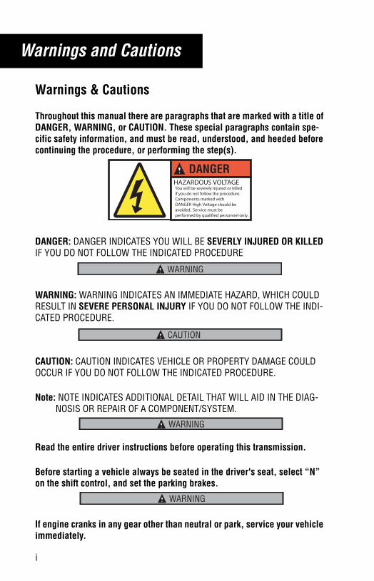
Throughout this manual there are paragraphs that are marked with a title of DANGER, WARNING, or CAUTION. These special paragraphs contain spe-cific safety information, and must be read, understood, and heeded before continuing the procedure, or performing the step(s).
DANGER: DANGER INDICATES YOU WILL BE SEVERLY INJURED OR KILLED IF YOU DO NOT FOLLOW THE INDICATED PROCEDURE
WARNING: WARNING INDICATES AN IMMEDIATE HAZARD, WHICH COULD RESULT IN SEVERE PERSONAL INJURY IF YOU DO NOT FOLLOW THE INDI-CATED PROCEDURE.
CAUTION: CAUTION INDICATES VEHICLE OR PROPERTY DAMAGE COULD OCCUR IF YOU DO NOT FOLLOW THE INDICATED PROCEDURE.
Note: NOTE INDICATES ADDITIONAL DETAIL THAT WILL AID IN THE DIAG-NOSIS OR REPAIR OF A COMPONENT/SYSTEM.
Read the entire driver instructions before operating this transmission.
Before starting a vehicle always be seated in the driver's seat, select “N” on the shift control, and set the parking brakes.
If engine cranks in any gear other than neutral or park, service your vehicle immediately.
DANGERHAZARDOUS VOLTAGEYou will be severely injured or killedif you do not follow the procedure.Components marked with DANGER High Voltage should be avoided. Service must be performed by qualified personnel only.
WARNING
CAUTION
WARNING
WARNING
trdr1000.book Page i Thursday, October 10, 2013 4:16 PM
ii
Warnings and Cautions
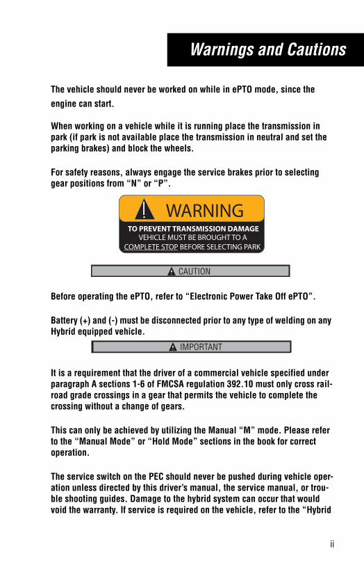
The vehicle should never be worked on while in ePTO mode, since the engine can start.
When working on a vehicle while it is running place the transmission in park (if park is not available place the transmission in neutral and set the parking brakes) and block the wheels.
For safety reasons, always engage the service brakes prior to selecting gear positions from “N” or “P”.
Before operating the ePTO, refer to “Electronic Power Take Off ePTO”.
Battery (+) and (-) must be disconnected prior to any type of welding on any Hybrid equipped vehicle.
It is a requirement that the driver of a commercial vehicle specified under paragraph A sections 1-6 of FMCSA regulation 392.10 must only cross rail-road grade crossings in a gear that permits the vehicle to complete the crossing without a change of gears.
This can only be achieved by utilizing the Manual “M” mode. Please refer to the “Manual Mode” or “Hold Mode” sections in the book for correct operation.
The service switch on the PEC should never be pushed during vehicle oper-ation unless directed by this driver’s manual, the service manual, or trou-ble shooting guides. Damage to the hybrid system can occur that would void the warranty. If service is required on the vehicle, refer to the “Hybrid
WARNINGTO PREVENT TRANSMISSION DAMAGE
VEHICLE MUST BE BROUGHT TO ACOMPLETE STOP BEFORE SELECTING PARK
CAUTION
IMPORTANTIMPORTANT
trdr1000.book Page ii Thursday, October 10, 2013 4:16 PM
iii
Warnings and Cautions
Service Shutdown” procedure found in TRSM1000 located on www.road-ranger.com.
High-Voltage Warnings & Cautions
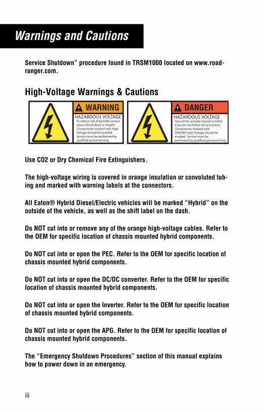
Use CO2 or Dry Chemical Fire Extinguishers.
The high-voltage wiring is covered in orange insulation or convoluted tub-ing and marked with warning labels at the connectors.
All Eaton® Hybrid Diesel/Electric vehicles will be marked “Hybrid” on the outside of the vehicle, as well as the shift label on the dash.
Do NOT cut into or remove any of the orange high-voltage cables. Refer to the OEM for specific location of chassis mounted hybrid components.
Do NOT cut into or open the PEC. Refer to the OEM for specific location of chassis mounted hybrid components.
Do NOT cut into or open the DC/DC converter. Refer to the OEM for specific location of chassis mounted hybrid components.
Do NOT cut into or open the Inverter. Refer to the OEM for specific location of chassis mounted hybrid components.
Do NOT cut into or open the APG. Refer to the OEM for specific location of chassis mounted hybrid components.
The “Emergency Shutdown Procedures” section of this manual explains how to power down in an emergency.
WARNINGTo reduce risk of possible serious injury (Shock, Burn or Death): Components marked with High Voltage should be avoided. Service must be performed by qualified personnel only.
HAZARDOUS VOLTAGE
DANGERHAZARDOUS VOLTAGEYou will be severely injured or killedif you do not follow the procedure.Components marked with DANGER High Voltage should be avoided. Service must be performed by qualified personnel only.
trdr1000.book Page iii Thursday, October 10, 2013 4:16 PM
Table of Contents
Warnings & Cautions . . . . . . . . . . . . . . . . . . . . . . . . . . . . . . . . iHigh-Voltage Warnings & Cautions . . . . . . . . . . . . . . . . . . . . . . iii
Emergency ProceduresEmergency Shutdown Procedures . . . . . . . . . . . . . . . . . . . . . . . 1Emergency Procedure in Case of Fire . . . . . . . . . . . . . . . . . . . . 2Emergency Procedure in Case of Accident. . . . . . . . . . . . . . . . . 3
High-Voltage Safety Features . . . . . . . . . . . . . . . . . . . . . . . . 4
OperationPush Button Shift Console Positions . . . . . . . . . . . . . . . . . . . . . 5Cable Shifter Positions. . . . . . . . . . . . . . . . . . . . . . . . . . . . . . . . 6Start-up and Power Down . . . . . . . . . . . . . . . . . . . . . . . . . . . . . 7Integrated Dash/Gear Display. . . . . . . . . . . . . . . . . . . . . . . . . . . 9Park Mode . . . . . . . . . . . . . . . . . . . . . . . . . . . . . . . . . . . . . . . . . 10Reverse Mode . . . . . . . . . . . . . . . . . . . . . . . . . . . . . . . . . . . . . . 11Drive Mode . . . . . . . . . . . . . . . . . . . . . . . . . . . . . . . . . . . . . . . . 12MANUAL Mode . . . . . . . . . . . . . . . . . . . . . . . . . . . . . . . . . . . . . 13Hold Mode . . . . . . . . . . . . . . . . . . . . . . . . . . . . . . . . . . . . . . . . . 14LOW or 1 Mode . . . . . . . . . . . . . . . . . . . . . . . . . . . . . . . . . . . . . 15Auxiliary Power Generator (APG) Mode . . . . . . . . . . . . . . . . . . . 16Electric Power Take-Off (ePTO) . . . . . . . . . . . . . . . . . . . . . . . . . 18Vehicle Braking/Regenerative Mode. . . . . . . . . . . . . . . . . . . . . . 19Clutch Abuse and Motor/Generator Over-Speed . . . . . . . . . . . . 20
FeaturesGeneral Model Information . . . . . . . . . . . . . . . . . . . . . . . . . . . . 21
Service & MaintenanceTroubleshooting. . . . . . . . . . . . . . . . . . . . . . . . . . . . . . . . . . . . . 22Proper Lubrication . . . . . . . . . . . . . . . . . . . . . . . . . . . . . . . . . . . 25PEC Air Filter . . . . . . . . . . . . . . . . . . . . . . . . . . . . . . . . . . . . . . . 26Hybrid Cooling System . . . . . . . . . . . . . . . . . . . . . . . . . . . . . . . 27Vehicle Towing and Jumpstarting . . . . . . . . . . . . . . . . . . . . . . . 28
trdr1000.book Page iv Thursday, October 10, 2013 4:16 PM

Table of Contents
trdr1000.book Page v Thursday, October 10, 2013 4:16 PM
1
Emergency Procedures
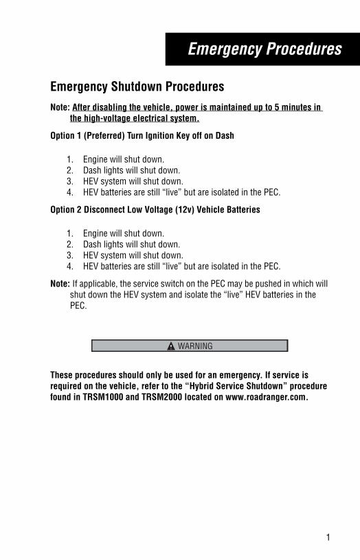
Emergency Shutdown ProceduresNote: After disabling the vehicle, power is maintained up to 5 minutes in
the high-voltage electrical system.
Option 1 (Preferred) Turn Ignition Key off on Dash
1. Engine will shut down.2. Dash lights will shut down.3. HEV system will shut down.4. HEV batteries are still “live” but are isolated in the PEC.
Option 2 Disconnect Low Voltage (12v) Vehicle Batteries
1. Engine will shut down.2. Dash lights will shut down.3. HEV system will shut down.4. HEV batteries are still “live” but are isolated in the PEC.
Note: If applicable, the service switch on the PEC may be pushed in which will shut down the HEV system and isolate the “live” HEV batteries in the PEC.
These procedures should only be used for an emergency. If service is required on the vehicle, refer to the “Hybrid Service Shutdown” procedure found in TRSM1000 and TRSM2000 located on www.roadranger.com.
WARNING
trdr1000.book Page 1 Thursday, October 10, 2013 4:16 PM
2
Emergency Procedures
Emergency Procedure in Case of Fire
If the vehicle becomes involved in a fire:
• Use CO2 or Dry Chemical Fire Extinguishers.
The high-voltage wiring is covered in orange insulation or convoluted tub-ing and marked with warning labels at the connectors.
All Eaton® Hybrid Diesel/Electric vehicles will be marked 'Hybrid' on the outside of the vehicle, along with the shift label on the dash.
Do NOT cut into or remove any of the orange high-voltage cables. Refer to the OEM for specific location of chassis mounted hybrid components.
Do NOT cut into or open the PEC. Refer to the OEM for specific location of chassis mounted hybrid components.
Do NOT cut into or open the DC/DC converter. Refer to the OEM for specific location of chassis mounted hybrid components.
Do NOT cut into or open the Inverter. Refer to the OEM for specific location of chassis mounted hybrid components.
Do NOT cut into or open the APG. Refer to the OEM for specific location of chassis mounted hybrid components.
WARNING
trdr1000.book Page 2 Thursday, October 10, 2013 4:16 PM
3
Emergency Procedures
Emergency Procedure in Case of AccidentVehicles Not Equipped With Park Mechanism
1. Apply the parking brake2. Push “N” on the shift console3. Turn the key to the “OFF” position4. Exit the vehicle if it is safe to do so
Vehicles Equipped With Park Mechanism
1. Apply the service brake2. Select “P” on the shift lever3. Turn the key to the “OFF” position4. Exit the vehicle if it is safe to do so
The high-voltage wiring is covered in orange insulation or convoluted tub-ing and marked with warning labels at the connectors.
All Eaton® Hybrid Diesel/Electric vehicles will be marked 'Hybrid' on the outside of the vehicle, along with the shift label on the dash.
Do NOT cut into or remove any of the orange high-voltage cables. Refer to the OEM for specific location of chassis mounted hybrid components.
Do NOT cut into or open the PEC. Refer to the OEM for specific location of chassis mounted hybrid components.
Do NOT cut into or open the DC/DC converter. Refer to the OEM for specific location of chassis mounted hybrid components.
Do NOT cut into or open the Inverter. Refer to the OEM for specific location of chassis mounted hybrid components.
WARNING
trdr1000.book Page 3 Thursday, October 10, 2013 4:16 PM
4
High-Voltage Safety Features
High-Voltage Safety Features
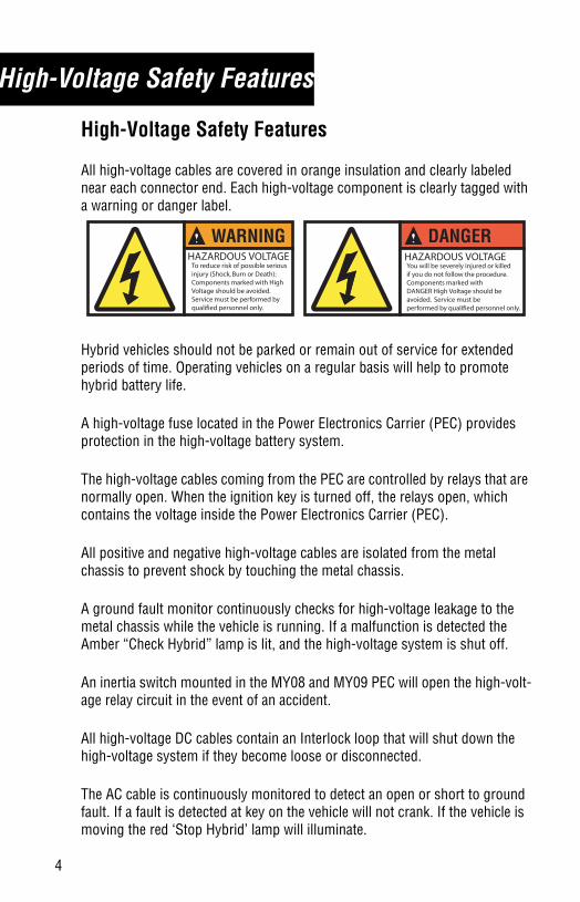
All high-voltage cables are covered in orange insulation and clearly labeled near each connector end. Each high-voltage component is clearly tagged with a warning or danger label.
Hybrid vehicles should not be parked or remain out of service for extended periods of time. Operating vehicles on a regular basis will help to promote hybrid battery life.
A high-voltage fuse located in the Power Electronics Carrier (PEC) provides protection in the high-voltage battery system.
The high-voltage cables coming from the PEC are controlled by relays that are normally open. When the ignition key is turned off, the relays open, which contains the voltage inside the Power Electronics Carrier (PEC).
All positive and negative high-voltage cables are isolated from the metal chassis to prevent shock by touching the metal chassis.
A ground fault monitor continuously checks for high-voltage leakage to the metal chassis while the vehicle is running. If a malfunction is detected the Amber “Check Hybrid” lamp is lit, and the high-voltage system is shut off.
An inertia switch mounted in the MY08 and MY09 PEC will open the high-volt-age relay circuit in the event of an accident.
All high-voltage DC cables contain an Interlock loop that will shut down the high-voltage system if they become loose or disconnected.
The AC cable is continuously monitored to detect an open or short to ground fault. If a fault is detected at key on the vehicle will not crank. If the vehicle is moving the red ‘Stop Hybrid’ lamp will illuminate.
DANGERHAZARDOUS VOLTAGEYou will be severely injured or killedif you do not follow the procedure.Components marked with DANGER High Voltage should be avoided. Service must be performed by qualified personnel only.
WARNINGTo reduce risk of possible serious injury (Shock, Burn or Death): Components marked with High Voltage should be avoided. Service must be performed by qualified personnel only.
HAZARDOUS VOLTAGE
trdr1000.book Page 4 Thursday, October 10, 2013 4:16 PM
5
Operation
Push Button Shift Console Positions
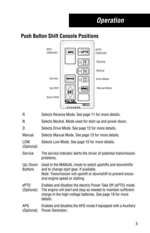
R Selects Reverse Mode. See page 11 for more details.
N Selects Neutral. Mode used for start up and power down.
D Selects Drive Mode. See page 12 for more details.
Manual Selects Manual Mode. See page 13 for more details.
LOW(Optional)
Selects Low Mode. See page 15 for more details.
Service The service indicator alerts the driver of potential transmission problems.
Up / Down Buttons
Used in the MANUAL mode to select upshifts and downshifts and to change start gear, if available. Note: Transmission will upshift or downshift to prevent exces-sive engine speed or stalling.
ePTO (Optional)
Enables and disables the electric Power Take Off (ePTO) mode. The engine will start and stop as needed to maintain sufficient charge in the high-voltage batteries. See page 18 for more details.
APG (Optional)
Enables and disables the APG mode if equipped with a Auxiliary Power Generator.
ePTO(Optional)
Reverse
Neutral
Drive Mode
Manual ModeUp Shift
Down Shift
Service
APG(Optional)
trdr1000.book Page 5 Thursday, October 10, 2013 4:16 PM
6
Operation
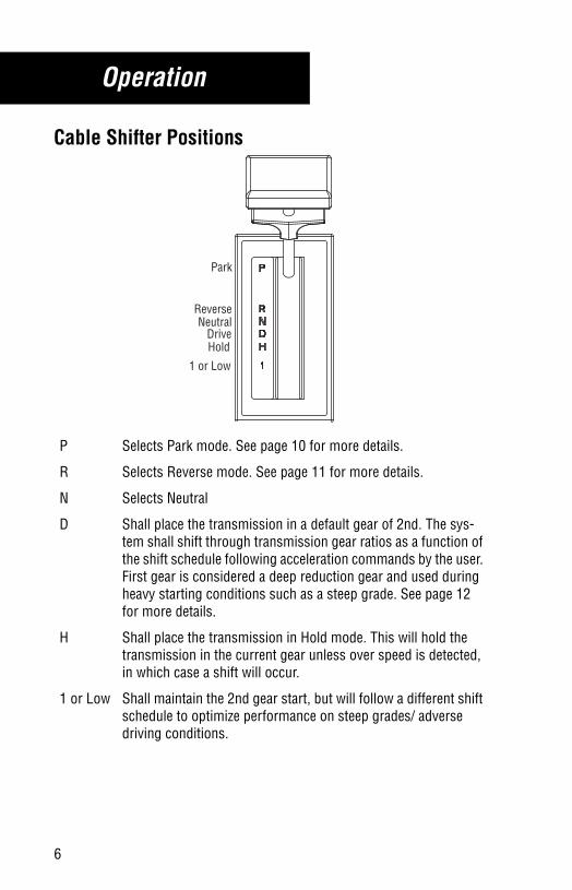
Cable Shifter Positions
P Selects Park mode. See page 10 for more details.
R Selects Reverse mode. See page 11 for more details.
N Selects Neutral
D Shall place the transmission in a default gear of 2nd. The sys-tem shall shift through transmission gear ratios as a function of the shift schedule following acceleration commands by the user. First gear is considered a deep reduction gear and used during heavy starting conditions such as a steep grade. See page 12 for more details.
H Shall place the transmission in Hold mode. This will hold the transmission in the current gear unless over speed is detected, in which case a shift will occur.
1 or Low Shall maintain the 2nd gear start, but will follow a different shift schedule to optimize performance on steep grades/ adverse driving conditions.
Park
HoldDrive
NeutralReverse
1 or Low
trdr1000.book Page 6 Thursday, October 10, 2013 4:16 PM
7
Operation
Start-up and Power Down
Start-up1. Turn the ignition key to “ON” and allow the Hybrid system to power
up. 2. Confirm that the parking brake is set and the gear display/integrated
dash displays a solid “N” or the vehicle is in park and the gear dis-play/integrated dash displays a solid “P” if equipped with a park mechanism.
3. Start the engine.
Note: The engine will crank after a brief delay.
Note: The primary cranking system is the hybrid drive motor. The back-up cranking system is the standard 12-volt starter on the engine. If the Hybrid System is offline or the hybrid batteries are not sufficiently charged, the truck will automatically default to the 12-volt cranking sys-tem and crank in a standard fashion.
4. Apply service brake. 5. Release the vehicle parking brakes.6. Continue to press the service brake pedal, then select the desired
mode “R”, “D”, Manual or Low on the shift console.
Note: If you attempt to select a mode other than neutral without depressing the service brakes the transmission will not shift into gear. You will need to return to neutral and depress the service brakes before selecting the desired mode.
7. Slowly release the service brake. The truck will begin creeping for-ward much like an automatic automotive transmission. This is called “urge to move”.
Note: The vehicle may be powered by the electric motor or the diesel engine depending on the battery state of charge and the demand for driveline torque. If the motor alone is powering the driveline, the diesel engine will stay at idle.
The batteries cannot move the truck for long distances at highway speeds. In the event of a diesel engine failure the truck should be moved to a safe location as quickly as possible.
CAUTION
trdr1000.book Page 7 Thursday, October 10, 2013 4:16 PM
8
Operation
The transmission is not intended to provide hill-hold capability. It should only be used to assist in starting on an incline. The service brakes should be used to stop and hold the vehicle on an incline. The clutch may become excessively hot if the transmission is used for hill hold for a long period of time. Repeated heating of the clutch can lead to premature failure.
Power DownVehicles Not Equipped With Park Mechanism
1. Select Neutral on the shift control.a. If gear display does not show solid “N”, neutral has not yet been
obtained.
2. Set the vehicle parking brakes.
Note: Neutral should always be reached before turning the key off except in cases of emergency.
3. Turn the ignition key off and allow the engine to shut down.
Vehicles Equipped With Park Mechanism
1. Select Park on the shift lever.a. If gear display does not show solid “P”, park has not yet been
obtained.
Note: Park should always be reached before turning the key off except in cases of emergency.
2. Turn the ignition key off and allow the engine to shut down.
CAUTION
trdr1000.book Page 8 Thursday, October 10, 2013 4:16 PM
9
Operation
Integrated Dash/Gear Display
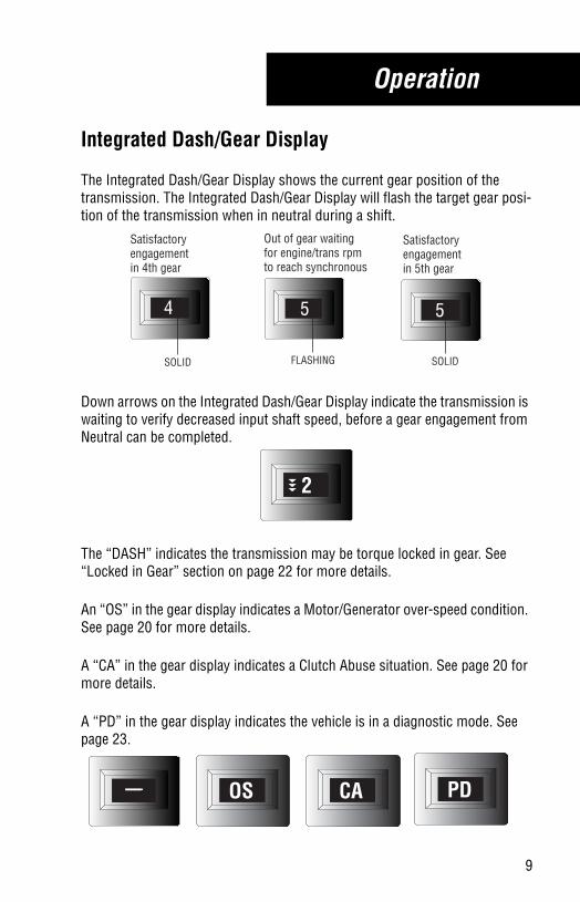
The Integrated Dash/Gear Display shows the current gear position of the transmission. The Integrated Dash/Gear Display will flash the target gear posi-tion of the transmission when in neutral during a shift.
Down arrows on the Integrated Dash/Gear Display indicate the transmission is waiting to verify decreased input shaft speed, before a gear engagement from Neutral can be completed.
The “DASH” indicates the transmission may be torque locked in gear. See “Locked in Gear” section on page 22 for more details.
An “OS” in the gear display indicates a Motor/Generator over-speed condition. See page 20 for more details.
A “CA” in the gear display indicates a Clutch Abuse situation. See page 20 for more details.
A “PD” in the gear display indicates the vehicle is in a diagnostic mode. See page 23.
4
Satisfactory engagement in 4th gear
Out of gear waiting for engine/trans rpm to reach synchronous
Satisfactory engagement in 5th gear
SOLID FLASHING SOLID
55
2
OS CA PD
trdr1000.book Page 9 Thursday, October 10, 2013 4:16 PM
10
Operation
Park Mode
Park Mode is a secondary system to prevent unwanted vehicle movement. The vehicle parking brake system is the primary system to prevent unwanted vehicle movement.
The vehicle must be at a complete stop before “Park” mode is selected.
Selecting Park mode “P” on the shifter will engage the mechanical parking mechanism and prevent the vehicle from moving. Any other selection on the mechanical shifter will release the parking pawl and allow the vehicle to move.
Note: If you attempt to select a mode from Park without first depressing the service brakes the transmission will not shift into gear. You will need to return to Park and depress the service brakes before selecting the desired mode.
To disengage “Park” mode the vehicle foot brake must be pressed before “Drive” or “Reverse” is selected.
WARNING
trdr1000.book Page 10 Thursday, October 10, 2013 4:16 PM
11
Operation
Reverse ModeReverse Mode selects R1.
The vehicle will not engage Reverse above 2 mph.
Note: If you attempt to select a mode other than neutral without depressing the service brakes the transmission will not shift into gear. You will need to return to neutral and depress the service brakes before selecting the desired mode.
trdr1000.book Page 11 Thursday, October 10, 2013 4:16 PM
12
Operation
Drive Mode
Drive mode automatically selects the default start gear (see note below). This start gear can be changed between 2nd and 1st by using the up/down buttons (not available on vehicles equipped with park mechanism and shift lever).
If the start gear is changed using the up/down buttons it will remain as the default gear until the vehicle is powered down or the selection is changed with the up/down buttons.
Drive mode automatically performs all up and down shifts.
Note: If you attempt to select a mode other than neutral without depressing the service brakes the transmission will not shift into gear. You will need to return to neutral and depress the service brakes before selecting the desired mode.
trdr1000.book Page 12 Thursday, October 10, 2013 4:16 PM
13
Operation
MANUAL Mode
Driver manually selects the start gear and uses the up/down buttons to shift (see note below).
The system holds the current gear unless otherwise prompted by using the up/down shift buttons except for the “Transmission Override” conditions noted below.
The system will automatically shift or inhibit shifts to prevent over-speed or under-speed of the engine.
Note: If you attempt to select a mode other than neutral without depressing the service brakes the transmission will not shift into gear. You will need to return to neutral and depress the service brakes before selecting the desired mode.
Transmission Override:
• If the vehicle is being back driven and the electric Motor/Generator is approaching a higher than normal level the hybrid system will over-ride the manual position and perform an upshift.
Note: Only available on vehicles equipped with push button shift controller
trdr1000.book Page 13 Thursday, October 10, 2013 4:16 PM
14
Operation
Hold ModeHold mode should be used when the driver wants to hold the current gear instead of letting the UltraShift select them automatically. For example, when the driver is moving around the yard, over railroad tracks, on steep grades, or slippery sur-faces.
Selecting Hold from Neutral:
• If Hold mode is selected from a stop, the starting gear is maintained - no automatic shifts are performed, except for conditions noted below.
• 1st gear is the only start gear available for medium-duty transmissions.
Selecting Hold from Drive or LOW while moving:
• If Hold mode is selected while moving, the current gear is maintained - no shifts are performed, except for conditions noted below.
Some engines do not use the Eaton engine overspeed protection.
Transmission Hold Override:• If the vehicle is being back driven (vehicle coasting and being pushed by
the load) and the engine is approaching a higher than normal level (approximately 300 rpm above rated speed), the UltraShift overrides the Hold position and performs an upshift to prevent engine damage.
• If the gear being maintained is higher than the starting gear, and the driver depresses the throttle pedal, the UltraShift system will override the Hold mode and shift to the best available gear if the engine lugs excessively.
Note: Only available on vehicles equipped with “T-handle” cable shifters.
WARNING
trdr1000.book Page 14 Thursday, October 10, 2013 4:16 PM
15
Operation
LOW or 1 Mode
Selects the lowest available gear as the start gear. See note below. the starting gear cannot be changed in Low or 1 mode.
If Low or 1 mode is selected upshifts and downshifts are performed. Down-shifts are performed at higher rpm’s than normal to enhance engine braking. The downshift point is chosen so the engine speed after the shift is below engine rated speed. Upshifts are performed at higher rpm’s than normal to provide maximum engine power.
Transmission Override:
• If the vehicle is being back driven and the motor/generator is approaching a higher than normal level the transmission system will override the Low or 1 position and perform an upshift.
Note: If you attempt to select a mode other than neutral without depressing the service brakes the transmission will not shift into gear. You will need to return to neutral and depress the service brakes before selecting the desired mode.
trdr1000.book Page 15 Thursday, October 10, 2013 4:16 PM
16
Operation
Auxiliary Power Generator (APG) Mode
The Auxiliary Power Generator (APG) is a 5kW/5kVA DC/AC inverter that is connected to the high-voltage DC bus of the Eaton Hybrid electric vehicle sys-tem, and generates 60Hz single-phase 120V AC power for utility applications.
If the hybrid batteries become depleted, the diesel engine will automatically start and recharge the batteries, while allowing APG operation. Once the bat-teries are fully charged, the engine will shut down automatically.
The default modes of operation for the APG are Work Site Operations Only and Exclusive APG/ePTO operations. The APG and ePTO can not be operated at the same time unless properly configured. For deviations to these default modes and operating conditions outside the default settings, see your Eaton repre-sentative.
APG Start-up Procedure:
1. Turn key to “On” position if engine off or leave engine running if on.2. Set 'Parking Brake'.3. Push and release APG button on push-button shift control. An
orange light will illuminate below the APG button.• The engine automatically shuts down if it’s on from step 1.• APG will not operate with ePTO engaged unless properly
configured.• If the Hybrid Control Module or the vehicle Body Controller feel
conditions are not acceptable to operate the APG, the APG light will blink and audible tone will sound.
4. On APG power panel turn On/Off switch to “On” position, if applicable.
5. Green light in switch will illuminate in 10-15 seconds.6. 120V AC power is now ready to use.
APG Shutdown Procedure:
1. Turn off components plugged into APG power panel.2. On APG power panel turn On/Off switch to 'Off' position, if
applicable.3. Push and release APG button on push-button shift control. The
orange light under the APG button will go out.4. APG has now been disabled.
trdr1000.book Page 16 Thursday, October 10, 2013 4:16 PM

17
Operation
DC/DC Converter:
• Converts high-voltage DC to 12-volt DC. The converter will maintain the 12-volt batteries during extended periods of engine off APG oper-ation. The converter can provide a maximum of 1.5 kW of power to the Low Voltage battery system.
• DC/DC converters are standard on vehicles equipped with an APG.
Note: Alternator failure will not be detected in APG mode since the DC/DC Converter will continue to provide electricity to the truck. It may be noticed/detected by a larger than normal amount of “Engine On” time.
trdr1000.book Page 17 Thursday, October 10, 2013 4:16 PM
18
Operation
Electric Power Take-Off (ePTO)
The ePTO provides standard hydraulic functions without continuous diesel engine operation. The PTO drive power is provided by the hybrid motor and hybrid batteries. If the hybrid batteries become depleted, the diesel engine will automatically start to recharge the batteries, while providing PTO drive power. Once the batteries are fully charged, the engine will shut down automatically.
ePTO Startup Procedure
1. Ensure the vehicle parking brake is set.2. Turn key to ON position. Do NOT start the engine.3. Push and release “ePTO” on shift console.4. Use the hydraulic controls in the normal manner.
Note: Refer to Truck Equipment Manufacturer/Body Company manuals for proper use of PTO tools and equipment.
Note: The electric motor powering the ePTO is activated by a hydraulic demand signal generated by the hydraulic system. It will start and stop with hydraulic usage.
ePTO Shutdown Procedure
1. Shutdown and return PTO driven equipment to storage position.2. Push “ePTO” button on shift console once to shut down electric
power take-off.3. Turn key to “off” position to shutdown vehicle or turn key to “start”
position to start engine for driving.
DC/DC Converter
• Converts high-voltage DC to 12-volt DC. The converter will maintain the 12-volt batteries during extended periods of engine off ePTO operation. The converter can provide a maximum of 1.5 Kw of power.
• DC/DC converters are standard on vehicles equipped with an ePTO.
Note: Alternator failure will not be detected in ePTO mode since the DC/DC Converter will continue to provide electricity to the truck.
trdr1000.book Page 18 Thursday, October 10, 2013 4:16 PM
19
Features
Vehicle Braking/Regenerative Mode
The hybrid system on this truck uses regenerative braking to charge the hybrid batteries. When the throttle is at idle while coasting, or the service brake is depressed to slow the vehicle the hybrid system charges the batter-ies. The regeneration will feel as if the brake is being lightly applied. This charging helps slow down the vehicle. The full power of the service brake is always available to the driver. The regenerative braking is available in addition to the standard service brake.
The Eaton Hybrid Control Unit will automatically shut off regenerative braking when the batteries are fully charged. This will occur after continuous braking (long grades, mountain driving) has charged the batteries to their maximum capacity. The chassis service brakes are always available.
Regenerative braking is automatically shut off during an ABS (anti-lock brake) event; i.e. skidding on black ice while trying to brake the vehicle.
trdr1000.book Page 19 Thursday, October 10, 2013 4:16 PM
20
Features
Clutch Abuse and Motor/Generator Over-Speed
Clutch Abuse
This vehicle has no clutch pedal however using the throttle to hold the vehicle on an incline will create clutch slippage and clutch heat.
A “CA” in the gear display indicates the HCM is detecting a clutch abuse situa-tion. If the vehicle detects a clutch abuse situation it will first tone the Push Button Shift Control and flash a “CA” in the gear display. If the clutch abuse situation continues the Hybrid system will only allow an electric launch in addition to continuing the tone and the “CA.” If the clutch abuse continues the Hybrid system will open the clutch once vehicle speed is below 5mph and allow the clutch to cool.
Motor/Generator Over-Speed
An “OS” in the gear display indicates the HCM is detecting a motor over-speed situation. The vehicle will upshift in Drive and Low automatically. If the vehicle is in Manual the system will limit torque to prevent an over-speed situation and upshift when necessary.
If the vehicle is descending a long steep grade in top gear you may see an “OS” in the gear display. If you see the “OS” you need to depress the service brake pedal to slow the vehicle until the “OS” is no longer displayed.
trdr1000.book Page 20 Thursday, October 10, 2013 4:16 PM
21
Service & Maintenance
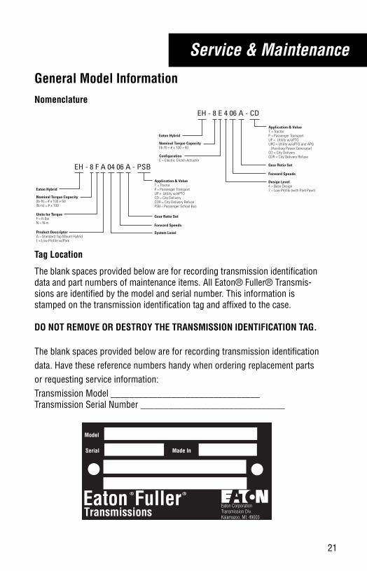
General Model InformationNomenclature
Tag Location
The blank spaces provided below are for recording transmission identification data and part numbers of maintenance items. All Eaton® Fuller® Transmis-sions are identified by the model and serial number. This information is stamped on the transmission identification tag and affixed to the case.
DO NOT REMOVE OR DESTROY THE TRANSMISSION IDENTIFICATION TAG.
The blank spaces provided below are for recording transmission identificationdata. Have these reference numbers handy when ordering replacement partsor requesting service information:Transmission Model ________________________________Transmission Serial Number _______________________________
EH - 8 E 4 06 A - CD
Nominal Torque Capacity(lb-ft) = # x 100 + 60
Forward Speeds
Design Level4 = Base Design7 = Low Profile (with Park Pawl)
Gear Ratio Set
Application & ValueT = TractorP = Passenger TransportUP = Utility w/ePTOUPG = Utility w/ePTO and APG (Auxiliary Power Generator)CD = City DeliveryCDR = City Delivery RefuseConfiguration
E = Electric Clutch Actuator
Eaton Hybrid
EH - 8 F A 04 06 A - PSB
Nominal Torque Capacity(lb-ft) = # x 100 + 60(N-m) = # x 100
Forward Speeds
System Level
Gear Ratio Set
Application & ValueT = TractorP = Passenger TransportUP = Utility w/ePTOCD = City DeliveryCDR = City Delivery RefusePSB = Passenger School Bus
Units for TorqueF = ft-lbsN = N-m
Product DescriptorA = Standard Top Mount HybridL = Low Profile w/Park
Eaton Hybrid
Model
Serial
EatonTransmissions
R
Made In
Eaton CorporationTransmission Div.Kalamazoo, MI. 49003
Fuller R
trdr1000.book Page 21 Thursday, October 10, 2013 4:16 PM
22
Service & Maintenance
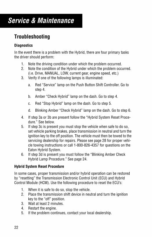
TroubleshootingDiagnostics
In the event there is a problem with the Hybrid, there are four primary tasks the driver should perform:
1. Note the driving condition under which the problem occurred.2. Note the condition of the Hybrid under which the problem occurred.
(i.e. Drive, MANUAL, LOW, current gear, engine speed, etc.)3. Verify if one of the following lamps is illuminated:
a. Red “Service” lamp on the Push Button Shift Controller. Go to step 4.
b. Amber “Check Hybrid” lamp on the dash. Go to step 4.
c. Red “Stop Hybrid” lamp on the dash. Go to step 5.
d. Blinking Amber “Check Hybrid” lamp on the dash. Go to step 6.
4. If step 3a or 3b are present follow the “Hybrid System Reset Proce-dure.” See below.
5. If step 3c is present you must stop the vehicle when safe to do so, set vehicle parking brakes, place transmission in neutral and turn the ignition key to the off position. The vehicle must then be towed to the servicing dealership for repairs. Please see page 28 for proper vehi-cle towing instructions or call 1-800-826-4357 for questions on the Eaton Hybrid System.
6. If step 3d is present you must follow the “Blinking Amber Check Hybrid Lamp Procedure.” See page 24.
Hybrid System Reset Procedure
In some cases, proper transmission and/or hybrid operation can be restored by “resetting” the Transmission Electronic Control Unit (ECU) and Hybrid Control Module (HCM). Use the following procedure to reset the ECU’s:
1. When it is safe to do so, stop the vehicle.2. Place the transmission shift device in neutral and turn the ignition
key to the “off” position.3. Wait at least 2 minutes.4. Restart the engine.5. If the problem continues, contact your local dealership.
trdr1000.book Page 22 Thursday, October 10, 2013 4:16 PM
23
Service & Maintenance
Product Diagnostic Mode “PD”In the event the transmission is put in Product Diagnostic Mode, a “PD” will display on the gear display and the truck will not start. Use the following pro-cedure to exit Product Diagnostic Mode:
1. Select neutral “N” and turn the key off.2. Wait at least 2 minutes.3. Turn the key on and power up the system.4. Verify there is a “N” on the gear display.5. Start the engine.
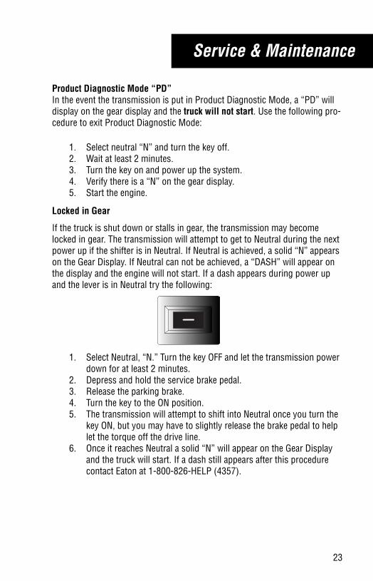
Locked in Gear
If the truck is shut down or stalls in gear, the transmission may become locked in gear. The transmission will attempt to get to Neutral during the next power up if the shifter is in Neutral. If Neutral is achieved, a solid “N” appears on the Gear Display. If Neutral can not be achieved, a “DASH” will appear on the display and the engine will not start. If a dash appears during power up and the lever is in Neutral try the following:
1. Select Neutral, “N.” Turn the key OFF and let the transmission power down for at least 2 minutes.
2. Depress and hold the service brake pedal.3. Release the parking brake.4. Turn the key to the ON position.5. The transmission will attempt to shift into Neutral once you turn the
key ON, but you may have to slightly release the brake pedal to help let the torque off the drive line.
6. Once it reaches Neutral a solid “N” will appear on the Gear Display and the truck will start. If a dash still appears after this procedure contact Eaton at 1-800-826-HELP (4357).
trdr1000.book Page 23 Thursday, October 10, 2013 4:16 PM
24
Service & Maintenance
Blinking Amber “Check Hybrid” Lamp Procedure
If the amber “Check Hybrid” lamp is blinking it indicates that the service switch may be pushed in on the Power Electronics Carrier (PEC). The follow-ing procedure should be used if the amber “Check Hybrid” lamp is blinking:
1. Key off.2. Pull out the red service switch on the front of the PEC.3. Wait 1 minute.4. Key on.5. If the amber “Check Hybrid” lamp continues to blink contact Eaton at
1-800-826-4357.
Hybrid High-Voltage System
Hybrid vehicles should not be parked or remain out of service for extended periods of time. Operating vehicles on a regular basis will help to promote hybrid battery life.
IMPORTANT
trdr1000.book Page 24 Thursday, October 10, 2013 4:16 PM
25
Service & Maintenance
Proper Lubrication
Proper lubrication procedures are key to a good all-around maintenance pro-gram. If the lubricant is not doing its job or if the lubricant level is ignored, all the maintenance procedures in the world are not going to keep the transmis-sion running or assure long transmission life.
Eaton® Fuller® Transmissions are designed so the internal parts operate in an oil bath circulated by the motion of the gears and shafts.
Thus, all parts are amply lubricated if these procedures are closely followed:
1. Maintain lubricant level and inspect regularly.2. Follow maintenance interval chart.3. Use the correct grade and type of lubricant.4. Buy lubricant from an approved dealer.
Mixing of Oil Types
Never mix engine oils & gear oils in the same transmission.
Engine oils and gear oils may not be compatible; mixing can cause breakdown of the lubricant and affect component performance. When switching between types of lubricants, all areas of each affected component must be thoroughly flushed.
Note: For a list of Eaton Approved Synthetic Lubricants, see TCMT0021 or call 1-800-826-HELP (4357).
Note: Additives and friction modifiers must not be introduced.
CAUTION
trdr1000.book Page 25 Thursday, October 10, 2013 4:16 PM
26
Service & Maintenance
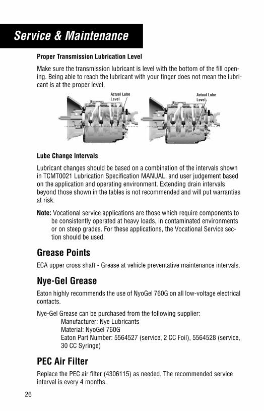
Proper Transmission Lubrication Level
Make sure the transmission lubricant is level with the bottom of the fill open-ing. Being able to reach the lubricant with your finger does not mean the lubri-cant is at the proper level.
Lube Change Intervals
Lubricant changes should be based on a combination of the intervals shown in TCMT0021 Lubrication Specification MANUAL, and user judgement based on the application and operating environment. Extending drain intervals beyond those shown in the tables is not recommended and will put warranties at risk.
Note: Vocational service applications are those which require components to be consistently operated at heavy loads, in contaminated environments or on steep grades. For these applications, the Vocational Service sec-tion should be used.
Grease PointsECA upper cross shaft - Grease at vehicle preventative maintenance intervals.
Nye-Gel GreaseEaton highly recommends the use of NyoGel 760G on all low-voltage electrical contacts.
Nye-Gel Grease can be purchased from the following supplier:Manufacturer: Nye LubricantsMaterial: NyoGel 760GEaton Part Number: 5564527 (service, 2 CC Foil), 5564528 (service, 30 CC Syringe)
PEC Air FilterReplace the PEC air filter (4306115) as needed. The recommended service interval is every 4 months.
Actual Lube Level
Actual Lube Level
trdr1000.book Page 26 Thursday, October 10, 2013 4:16 PM
27
Service & Maintenance
Hybrid Cooling SystemReservoirThe Hybrid cooling system reservoir must have the proper coolant level. Checking the level varies by OEM. Please refer to the OEM owners manual for procedures on how to properly check the coolant level.
Refer to your owners manual for the capacity and location of the reservoir.
Coolant TypeThe Hybrid cooling system requires extended life coolant mixed 50/50 with distilled water.
Note: Refill only with extended life coolant and check the coolant level before each trip.
trdr1000.book Page 27 Thursday, October 10, 2013 4:16 PM
28
Service & Maintenance
Vehicle Towing and Jumpstarting
Towing
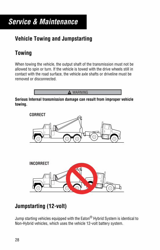
When towing the vehicle, the output shaft of the transmission must not be allowed to spin or turn. If the vehicle is towed with the drive wheels still in contact with the road surface, the vehicle axle shafts or driveline must be removed or disconnected.
Serious Internal transmission damage can result from improper vehicle towing.
Jumpstarting (12-volt)
Jump starting vehicles equipped with the Eaton® Hybrid System is identical to Non-Hybrid vehicles, which uses the vehicle 12-volt battery system.
WARNING
CORRECT
INCORRECT
trdr1000.book Page 28 Thursday, October 10, 2013 4:16 PM

Copyright Eaton, 2013.Eaton hereby grant their customers,vendors, or distributors permissionto freely copy, reproduce and/ordistribute this document in printedformat. It may be copied only inits entirety without any changes ormodifications. THIS INFORMATIONIS NOT INTENDED FOR SALE ORRESALE, AND THIS NOTICE MUSTREMAIN ON ALL COPIES.
Note: Features and specificationslisted in this document are subject tochange without notice and representthe maximum capabilities of thesoftware and products with all optionsinstalled. Although every attempt hasbeen made to ensure the accuracy ofinformation contained within, Eatonmakes no representation about thecompleteness, correctness or accuracyand assumes no responsibility forany errors or omissions. Features andfunctionality may vary depending onselected options.
For spec’ing or service assistance, call 1-800-826-HELP (4357) or visit www.eaton.com/roadranger.In Mexico, call 001-800-826-4357.
EatonVehicle GroupP.O. Box 4013Kalamazoo, MI 49003 USA800-826-HELP (4357)www.eaton.com/roadranger
Printed in USA
Roadranger: Eaton and trusted partners providing the best products and services in the industry, ensuring more time on the road.