Embed Size (px)
Citation preview

Installation Guide
Eaton Automated TransmissionsTRIG0020July 2007
EH-8E406A-CDEH-6E706B-CDEH-6E706B-PEH-8E406A-PEH-8E406A-UPEH-8E406A-UPGEH-8E406A-TEH-8E406A-CDGEH-8E406A-CDREH-8FA0406A-PSB

for pdf
1
Table ofContents
List of Illustrations . . . . . . . . . . . . . . . . . . . . . . . . . . . . . . . . . . . . . . . . . . 3
Foreword . . . . . . . . . . . . . . . . . . . . . . . . . . . . . . . . . . . . . . . . . . . . . . . . . 5
Special Tool Requirements . . . . . . . . . . . . . . . . . . . . . . . . . . . . . . . . . . . 6
Line Inspection . . . . . . . . . . . . . . . . . . . . . . . . . . . . . . . . . . . . . . . . . . . . 7
Checklist InstructionsPre-Start Checks . . . . . . . . . . . . . . . . . . . . . . . . . . . . . . . . . . . . . . . . . . . . . . . . . .8Post-Start Checks . . . . . . . . . . . . . . . . . . . . . . . . . . . . . . . . . . . . . . . . . . . . . . . . .8Dyno/Road Test . . . . . . . . . . . . . . . . . . . . . . . . . . . . . . . . . . . . . . . . . . . . . . . . . . .9Optional Features . . . . . . . . . . . . . . . . . . . . . . . . . . . . . . . . . . . . . . . . . . . . . . . . . .9
Flywheel Installation . . . . . . . . . . . . . . . . . . . . . . . . . . . . . . . . . . . . . . . 10
Flywheel Housing Sealing RequirementsStarter & Engine Crankshaft Sealing Requirements . . . . . . . . . . . . . . . . . . . . . . .13
Transmission MountingHandling . . . . . . . . . . . . . . . . . . . . . . . . . . . . . . . . . . . . . . . . . . . . . . . . . . . . . . .16Mounting To Engine . . . . . . . . . . . . . . . . . . . . . . . . . . . . . . . . . . . . . . . . . . . . . . .16
Transmission Support RequirementsUsing Rear Supports . . . . . . . . . . . . . . . . . . . . . . . . . . . . . . . . . . . . . . . . . . . . . .19Using Transmission Nodal Mounts . . . . . . . . . . . . . . . . . . . . . . . . . . . . . . . . . . .19
Throttle Sensor Mounting . . . . . . . . . . . . . . . . . . . . . . . . . . . . . . . . . . . 23
Fuel Interrupt MountingAir Throttle/Electro-Pneumatic System . . . . . . . . . . . . . . . . . . . . . . . . . . . . . . . .27Fuel Interrupt Functional Test (AT Models) . . . . . . . . . . . . . . . . . . . . . . . . . . . . .28
Cooler RequirementsGeneral Requirements: . . . . . . . . . . . . . . . . . . . . . . . . . . . . . . . . . . . . . . . . . . . . .30Cooler Application Guidelines . . . . . . . . . . . . . . . . . . . . . . . . . . . . . . . . . . . . . . .30Transmission Cooling System Without Remote Bypass . . . . . . . . . . . . . . . . . . .31Transmission Cooling System With Remote Bypass . . . . . . . . . . . . . . . . . . . . . .32External Transmission Filters . . . . . . . . . . . . . . . . . . . . . . . . . . . . . . . . . . . . . . . .33Transmission Temperature Gauge/Alarm/Sender . . . . . . . . . . . . . . . . . . . . . . . . .35Cooler Flow Verification . . . . . . . . . . . . . . . . . . . . . . . . . . . . . . . . . . . . . . . . . . . .39
Dipstick and Dipstick Tube Information . . . . . . . . . . . . . . . . . . . . . . . . . 40Dipstick Validation . . . . . . . . . . . . . . . . . . . . . . . . . . . . . . . . . . . . . . . . . . . . . . . .43
Lubrication Requirements . . . . . . . . . . . . . . . . . . . . . . . . . . . . . . . . . . . 46Oil Fill Procedure . . . . . . . . . . . . . . . . . . . . . . . . . . . . . . . . . . . . . . . . . . . . . . . . .47Lube Recommendations . . . . . . . . . . . . . . . . . . . . . . . . . . . . . . . . . . . . . . . . . . .48
Air Supply/Dryer Requirements . . . . . . . . . . . . . . . . . . . . . . . . . . . . . . . 49

2
Table ofContents
Shift Control System (Electric)Shift Control Installation (Electronic Shifter) . . . . . . . . . . . . . . . . . . . . . . . . . . . .51
Power Take-OffOverview—Available PTO Locations and Requirements . . . . . . . . . . . . . . . . . . .71Power Take-Off Availability w/Low Profile Oil Pan Option . . . . . . . . . . . . . . . . . .74PTO Selection . . . . . . . . . . . . . . . . . . . . . . . . . . . . . . . . . . . . . . . . . . . . . . . . . . .758-Bolt Position and 6-Bolt Position . . . . . . . . . . . . . . . . . . . . . . . . . . . . . . . . . . .76Chart of Recommended Vocations . . . . . . . . . . . . . . . . . . . . . . . . . . . . . . . . . . . .77Electrical Interface Requirements . . . . . . . . . . . . . . . . . . . . . . . . . . . . . . . . . . . . .78PTO Space Claims . . . . . . . . . . . . . . . . . . . . . . . . . . . . . . . . . . . . . . . . . . . . . . . .81PTO Manufacturer's Information . . . . . . . . . . . . . . . . . . . . . . . . . . . . . . . . . . . . .83
General Electrical System Requirements . . . . . . . . . . . . . . . . . . . . . . . . 84
Electrical Requirements For J-1922 Communications Link . . . . . . . . . . 99
Engine Brake Interface . . . . . . . . . . . . . . . . . . . . . . . . . . . . . . . . . . . . . 105
Oil Pan Options/Space Claims . . . . . . . . . . . . . . . . . . . . . . . . . . . . . . . 106
Appendix IInstallation Requirements . . . . . . . . . . . . . . . . . . . . . . . . . . . . . . . . . . . . . . . . .110Installation Quick Reference . . . . . . . . . . . . . . . . . . . . . . . . . . . . . . . . . . . . . . . .114Torque Specifications . . . . . . . . . . . . . . . . . . . . . . . . . . . . . . . . . . . . . . . . . . . .116Publications and Drawings . . . . . . . . . . . . . . . . . . . . . . . . . . . . . . . . . . . . . . . . .117Line Inspection Form . . . . . . . . . . . . . . . . . . . . . . . . . . . . . . . . . . . . . . . . . . . . .118Vendor List . . . . . . . . . . . . . . . . . . . . . . . . . . . . . . . . . . . . . . . . . . . . . . . . . . . .122Troubleshooting . . . . . . . . . . . . . . . . . . . . . . . . . . . . . . . . . . . . . . . . . . . . . . . . .123
Appendix IIElectronic Shift Lever . . . . . . . . . . . . . . . . . . . . . . . . . . . . . . . . . . . . . . . . . . . . .124Protective Boot Accessory . . . . . . . . . . . . . . . . . . . . . . . . . . . . . . . . . . . . . . . . .124
Appendix IIIWiring Harness . . . . . . . . . . . . . . . . . . . . . . . . . . . . . . . . . . . . . . . . . . . . . . . . .125Specifications for Wiring Harness . . . . . . . . . . . . . . . . . . . . . . . . . . . . . . . . . . .126Wire Harness Application Form . . . . . . . . . . . . . . . . . . . . . . . . . . . . . . . . . . . . .129
Appendix IVFuel Control Functional Test (For Mechanically Governed Engines) . . . . . . . . . .130"AT" Model Without Power Synchronizer . . . . . . . . . . . . . . . . . . . . . . . . . . . . . .131
Appendix VCEEMAT Application Guidelines . . . . . . . . . . . . . . . . . . . . . . . . . . . . . . . . . . . . .132
Appendix VIBody Builder Guide For Tapping Into Electrical Systems . . . . . . . . . . . . . . . . . .133Ceemat Inputs and Outputs . . . . . . . . . . . . . . . . . . . . . . . . . . . . . . . . . . . . . . . .134
3
List ofIllustrations
Air Supply/Dryer RequirementsAir Supply/Dryer Requirements . . . . . . . . . . . . . . . . . . . . . . . . . . . . . . . . . . . . . . 50
Appendix IIElectronic Shift Lever Protective Boot Accessory . . . . . . . . . . . . . . . . . . . . . . . . 124
Appendix IIIElectrical Shifter — Single Station . . . . . . . . . . . . . . . . . . . . . . . . . . . . . . . . . . . 127Electronic Shifter — Dual Station . . . . . . . . . . . . . . . . . . . . . . . . . . . . . . . . . . . 128Wiring Harness . . . . . . . . . . . . . . . . . . . . . . . . . . . . . . . . . . . . . . . . . . . . . . . . . 125
Appendix IV"AT" Model Without Power Synchronizer . . . . . . . . . . . . . . . . . . . . . . . . . . . . . . 131
Cooler RequirementsCooling Requirements Oil To Air . . . . . . . . . . . . . . . . . . . . . . . . . . . . . . . . . . . . . 34Cooling Requirements Oil To Water . . . . . . . . . . . . . . . . . . . . . . . . . . . . . . . . . . . 31Oil Cooler Return Options For Low-Profile Oil Pan . . . . . . . . . . . . . . . . . . . . . . . . 38Temperature Control Module . . . . . . . . . . . . . . . . . . . . . . . . . . . . . . . . . . . . . . . . 37Temperature Gauge . . . . . . . . . . . . . . . . . . . . . . . . . . . . . . . . . . . . . . . . . . . . . . . 35Transmission Temperature Module Circuit . . . . . . . . . . . . . . . . . . . . . . . . . . . . . 36
Dipstick and Dipstick Tube InformationDipstick Tube Mounting . . . . . . . . . . . . . . . . . . . . . . . . . . . . . . . . . . . . . . . . . . . . 45Dipstick Validation . . . . . . . . . . . . . . . . . . . . . . . . . . . . . . . . . . . . . . . . . . . . . . . . 43Dipstick Validation Rotated Pan . . . . . . . . . . . . . . . . . . . . . . . . . . . . . . . . . . . . . . 44Dipstick Validation Standard Low Profile Oil Pan . . . . . . . . . . . . . . . . . . . . . . . . . 44Standard Aluminum (Deep) Stick - 5501004 . . . . . . . . . . . . . . . . . . . . . . . . . . . . 41Standard Aluminum (Deep) Tube - 5500503 . . . . . . . . . . . . . . . . . . . . . . . . . . . . 41Standard Low Profile Oil Pan Dipstick - 5501016 . . . . . . . . . . . . . . . . . . . . . . . . 42Standard Low Profile Oil Pan Dipstick Tube - 5500511 . . . . . . . . . . . . . . . . . . . . 42
Electrical Requirements For J-1922 CommunicationsJ-1922 Communication Link . . . . . . . . . . . . . . . . . . . . . . . . . . . . . . . . . . . . . . . . 99Location of J-1922 Control Data Link on Detroit Diesel DDECII . . . . . . . . . . . . . 103Location of the J-1922 Control Data Link on Cummins Engines . . . . . . . . . . . . 100Location of the J-1922 Control Data Link on Detroit Diesel DDECIII . . . . . . . . . 104Location of the J-1922 Control Data Link on the Caterpillar Engines . . . . . 101, 102
Engine Brake InterfacePressure Switch Location For Optional Engine Brake . . . . . . . . . . . . . . . . . . . . . 105
Flywheel Housing Sealing RequirementsFlywheel Housing Sealing Requirements . . . . . . . . . . . . . . . . . . . . . . . . . . . 14, 15
Flywheel InstallationBolt-On Drive Ring With Pilot Adaptor . . . . . . . . . . . . . . . . . . . . . . . . . . . . . . . . . 11Single Piece Flywheel Assembly . . . . . . . . . . . . . . . . . . . . . . . . . . . . . . . . . . . . . 12
Fuel Interrupt MountingDefuel Control Wiring Diagram . . . . . . . . . . . . . . . . . . . . . . . . . . . . . . . . . . . . . . 29Fuel Interrupt Mounting (Air/Throttle) . . . . . . . . . . . . . . . . . . . . . . . . . . . . . . . . . 28
General Electrical System RequirementsAuxiliary Inputs and Outputs . . . . . . . . . . . . . . . . . . . . . . . . . . . . . . . . . . . . . . . . 96Auxiliary Inputs and Outputs Wiring Diagram . . . . . . . . . . . . . . . . . . . . . . . . . . . 97Brake Switch Connections . . . . . . . . . . . . . . . . . . . . . . . . . . . . . . . . . . . . . . . . . . 90Brake Switch Wiring Diagram . . . . . . . . . . . . . . . . . . . . . . . . . . . . . . . . . . . . . . . 91Diagnostic Connections . . . . . . . . . . . . . . . . . . . . . . . . . . . . . . . . . . . . . . . . . . . . 94Ground & Battery Connections . . . . . . . . . . . . . . . . . . . . . . . . . . . . . . . . . . . . . . 88J-1587 Diagnostic Connector Diagram . . . . . . . . . . . . . . . . . . . . . . . . . . . . . . . . 95Power Circuits Wiring Diagram . . . . . . . . . . . . . . . . . . . . . . . . . . . . . . . . . . . . . . 87Power Lead Connections . . . . . . . . . . . . . . . . . . . . . . . . . . . . . . . . . . . . . . . . . . . 86Quick To Neutral Feature . . . . . . . . . . . . . . . . . . . . . . . . . . . . . . . . . . . . . . . . . . . 98Transmission Neutral Output Feature . . . . . . . . . . . . . . . . . . . . . . . . . . . . . . . . . . 98
4
List ofIllustrations
General Electrical System Requirements (con't)Transmission Service Light Using Eaton Service Light . . . . . . . . . . . . . . . . . . . . 92Transmission Service Light Wiring Diagram . . . . . . . . . . . . . . . . . . . . . . . . . . . . 93Typical Wire Harness . . . . . . . . . . . . . . . . . . . . . . . . . . . . . . . . . . . . . . . . . . . . . . 84Wiring Diagram . . . . . . . . . . . . . . . . . . . . . . . . . . . . . . . . . . . . . . . . . . . . . . . . . . 85
Oil Pan Options/Space Claims"AT" Rotated Pan — Rear View . . . . . . . . . . . . . . . . . . . . . . . . . . . . . . . . . . . . . 106Front View . . . . . . . . . . . . . . . . . . . . . . . . . . . . . . . . . . . . . . . . . . . . . . . . . . . . . 108Left View . . . . . . . . . . . . . . . . . . . . . . . . . . . . . . . . . . . . . . . . . . . . . . . . . . . . . . 107Rear View . . . . . . . . . . . . . . . . . . . . . . . . . . . . . . . . . . . . . . . . . . . . . . . . . . . . . . 107Right View . . . . . . . . . . . . . . . . . . . . . . . . . . . . . . . . . . . . . . . . . . . . . . . . . . . . . 108Rotated Pan — Right Side View . . . . . . . . . . . . . . . . . . . . . . . . . . . . . . . . . . . . 106Shift Lever . . . . . . . . . . . . . . . . . . . . . . . . . . . . . . . . . . . . . . . . . . . . . . . . . . . . . 109
Power Take-OffCountershaft Driven PTO’s . . . . . . . . . . . . . . . . . . . . . . . . . . . . . . . . . . . . . . . . . . 78Countershaft PTO Wiring Diagram . . . . . . . . . . . . . . . . . . . . . . . . . . . . . . . . . . . . 79Engine Driven PTO's . . . . . . . . . . . . . . . . . . . . . . . . . . . . . . . . . . . . . . . . . . . . . . 73Mechanically Governed Engines / CEEMAT AT . . . . . . . . . . . . . . . . . . . . . . . . . . . 71Model ATE (Electronic Engine) PTO Locations . . . . . . . . . . . . . . . . . . . . . . . . . . . 72Model ATE Inertia Brake Locations . . . . . . . . . . . . . . . . . . . . . . . . . . . . . . . . . . . 76Power Take-Off Availability w/Low Profile Oil Pan . . . . . . . . . . . . . . . . . . . . . . . . 74PTO Selection . . . . . . . . . . . . . . . . . . . . . . . . . . . . . . . . . . . . . . . . . . . . . . . . . . . 75Split-Shaft PTO Wiring Diagram . . . . . . . . . . . . . . . . . . . . . . . . . . . . . . . . . . . . . 80Transmission Countershaft Driven PTO's . . . . . . . . . . . . . . . . . . . . . . . . . . . . . . 82Transmission Mounted - Engine Driven PTO . . . . . . . . . . . . . . . . . . . . . . . . . . . . 81
Shift Control System (Electric)Auto Neutral Feature . . . . . . . . . . . . . . . . . . . . . . . . . . . . . . . . . . . . . . . . . . . . . . 62Auxiliary Inputs and Outputs . . . . . . . . . . . . . . . . . . . . . . . . . . . . . . . . . . . . . . . . 61Dimmer Control Input . . . . . . . . . . . . . . . . . . . . . . . . . . . . . . . . . . . . . . . . . . . . . 60Electronic Shifter . . . . . . . . . . . . . . . . . . . . . . . . . . . . . . . . . . . . . . . . . . . . . . . . . 52Electronic Shifter — Dual Station . . . . . . . . . . . . . . . . . . . . . . . . . . . . . . . . . . . . 66Electronic Shifter — Single Station . . . . . . . . . . . . . . . . . . . . . . . . . . . . . . . . . . . 55Electronic Shifter Communication Enable Pin . . . . . . . . . . . . . . . . . . . . . . . . . . . 63ESL_ENABLE For Dual Station . . . . . . . . . . . . . . . . . . . . . . . . . . . . . . . . . . . . . . . 68J-1922 Data Link (Electronically Governed Engines) . . . . . . . . . . . . . . . . . . . . . . 65J-1922 Data Link . . . . . . . . . . . . . . . . . . . . . . . . . . . . . . . . . . . . . . . . . . . . . . . . . 64Power Lead Connections . . . . . . . . . . . . . . . . . . . . . . . . . . . . . . . . . . . . . . . . . . . 57Reverse Relay . . . . . . . . . . . . . . . . . . . . . . . . . . . . . . . . . . . . . . . . . . . . . . . . . . . 59Reverse Relay For Dual Station . . . . . . . . . . . . . . . . . . . . . . . . . . . . . . . . . . . . . . 70Start Enable Relay . . . . . . . . . . . . . . . . . . . . . . . . . . . . . . . . . . . . . . . . . . . . . . . . 58Start Enable Relay For Dual Station . . . . . . . . . . . . . . . . . . . . . . . . . . . . . . . . . . . 69Trans In Gear Output . . . . . . . . . . . . . . . . . . . . . . . . . . . . . . . . . . . . . . . . . . . . . . 62Wire Diagram Dual Station . . . . . . . . . . . . . . . . . . . . . . . . . . . . . . . . . . . . . . . . . . 67Wire Diagram For Electronic Shifter . . . . . . . . . . . . . . . . . . . . . . . . . . . . . . . . . . . 56
Throttle Sensor MountingAir Throttle Position Sensor Interface . . . . . . . . . . . . . . . . . . . . . . . . . . . . . . . . . 25Linear Throttle Position Sensor Installation . . . . . . . . . . . . . . . . . . . . . . . . . . . . . 24Throttle Position Sensor Wiring Diagram . . . . . . . . . . . . . . . . . . . . . . . . . . . . . . . 26
Transmission MountingTransmission Mounting Typical Lift Points . . . . . . . . . . . . . . . . . . . . . . . . . . . . . 17Transmission To Flywheel Assembly . . . . . . . . . . . . . . . . . . . . . . . . . . . . . . . . . . 18
Transmission Support RequirementsNodal Mount Dimensions . . . . . . . . . . . . . . . . . . . . . . . . . . . . . . . . . . . . . . . . . . . 22Typical Rear Support Designs . . . . . . . . . . . . . . . . . . . . . . . . . . . . . . . . . . . . . . . 20Using Transmission Nodal Mounts . . . . . . . . . . . . . . . . . . . . . . . . . . . . . . . . . . . 21
5
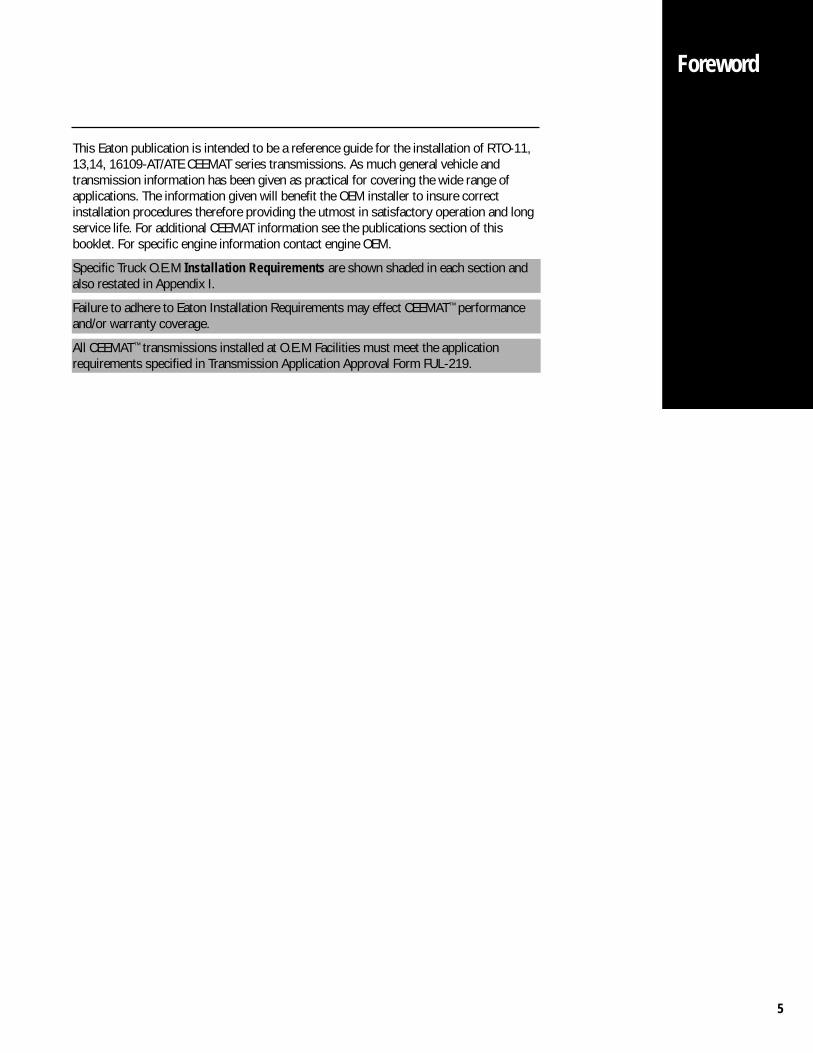
This Eaton publication is intended to be a reference guide for the installation of RTO-11,13,14, 16109-AT/ATE CEEMAT series transmissions. As much general vehicle andtransmission information has been given as practical for covering the wide range ofapplications. The information given will benefit the OEM installer to insure correctinstallation procedures therefore providing the utmost in satisfactory operation and longservice life. For additional CEEMAT information see the publications section of thisbooklet. For specific engine information contact engine OEM.
Specific Truck O.E.M Installation Requirements are shown shaded in each section andalso restated in Appendix I.
Failure to adhere to Eaton Installation Requirements may effect CEEMAT™ performanceand/or warranty coverage.
All CEEMAT™ transmissions installed at O.E.M Facilities must meet the applicationrequirements specified in Transmission Application Approval Form FUL-219.
Foreword
6
SpecialTool
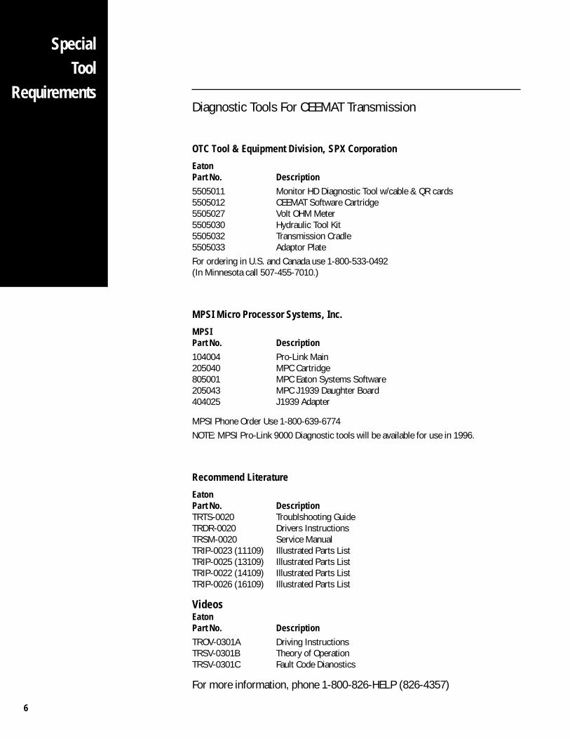
RequirementsDiagnostic Tools For CEEMAT Transmission
OTC Tool & Equipment Division, SPX Corporation
EatonPart No. Description5505011 Monitor HD Diagnostic Tool w/cable & QR cards5505012 CEEMAT Software Cartridge5505027 Volt OHM Meter5505030 Hydraulic Tool Kit5505032 Transmission Cradle5505033 Adaptor PlateFor ordering in U.S. and Canada use 1-800-533-0492(In Minnesota call 507-455-7010.)
MPSI Micro Processor Systems, Inc.
MPSIPart No. Description104004 Pro-Link Main205040 MPC Cartridge805001 MPC Eaton Systems Software205043 MPC J1939 Daughter Board404025 J1939 Adapter
MPSI Phone Order Use 1-800-639-6774NOTE: MPSI Pro-Link 9000 Diagnostic tools will be available for use in 1996.
Recommend Literature
EatonPart No. DescriptionTRTS-0020 Troublshooting GuideTRDR-0020 Drivers InstructionsTRSM-0020 Service ManualTRIP-0023 (11109) Illustrated Parts ListTRIP-0025 (13109) Illustrated Parts ListTRIP-0022 (14109) Illustrated Parts ListTRIP-0026 (16109) Illustrated Parts List
VideosEatonPart No. DescriptionTROV-0301A Driving InstructionsTRSV-0301B Theory of OperationTRSV-0301C Fault Code Dianostics
For more information, phone 1-800-826-HELP (826-4357)
7
The CEEMAT™ Line Inspection checklist, found in Appendix III, was developed as aninstallation tool for line personnel to insure the correct operation of each vehicle and toassist the vehicle O.E.M to identify transmission quality related issues as well as O.E.Mline quality issues. Used correctly, this checklist identifies transmission issues and aids intracking the problem until corrected.
The recommended use of the checklist is as follows:
1. A separate checklist should be filled out for each vehicle built with a CEEMAT.
2. The section, identified as PRE-START CHECKS should be performed prior to theinitial start-up of the vehicle. This section insures the CEEMAT has the correctpower supplies, air supply, sufficient oil for transmission function, and can beoperated safely when the engine is started. You will find instructions on page 8.
3. The section POST-START CHECKS should be performed after the engine is firststarted to insure the transmission is filled with oil to the correct level and to insureproper operation of the interface systems prior to actually driving the vehicle. Youwill find instructions on page 8.
4. At this point the checklist should be reviewed and if necessary corrective actiontaken prior to the dyno or road test.
5. The DYNO/ROAD TEST section is used to verify that all CEEMAT systems arefunctional, the driver information is supplied in the cab, and to insure that allassembly related fault codes have been cleared. You will find instructions on page 9.
6. The O.E.M now has a record of transmission related information and repairs madeto each unit and is able to track and correct repeated quality issues.
7. A copy of the checklist should be supplied to Eaton Automated Products Applicationdepartment for installation history. O.E.M line personnel should become familiarwith the checklist and the CEEMAT hand-held diagnostic tool operation prior to ascheduled build. Eaton Automated Products Applications department can coordinatetraining and information to expedite this process.
This checklist represents a generic system which can be tailored to the individual O.E.Mto achieve the best possible method of CEEMAT installation. Eaton recommends the useof this system to maintain the utmost in satisfactory operation and long service life.
Each CEEMAT installed at the O.E.M must pass the on-line checklist requirements perEaton CEEMAT™ Line Inspection Form, Appendix III, prior to shipment from the O.E.Mplant.
LineInspection
8
Refer to the CEEMAT Line Inspection form in Appendix III while performing the followingprocedure:
Pre-Start Checks1. To verify CEEMAT Battery Power and Ignition Power are correctly wired to the
appropriate source. The shift lever must be in NEUTRAL, turn the key switch on,then turn it to the off position and wait 15 seconds. An audible click or clunk soundshould be heard from the top of the transmission as it powers down.
If this condition does not occur then check power @ Main transmission harnesswith voltmeter.
Using standard volt/ohm meter, disconnect transmission main 19 pin harnessconnector and touch black lead to Pin B and red lead to Pin K, meter reading shouldbe within .,6 volts of battery voltage (with the key on only). Now touch black leadto Pin C and red lead to Pin L, meter reading should be within .6 volts of batteryvoltage (with key on or off).
2. Visually verify the CEEMAT Battery Power is protected by a 30 AMP in line fuse.Visually verify the Ignition Power is protected by a Automatic resetting circuitbreaker, 15 AMP for 12 volt power supply and 10 AMP for 24 volt supply.
3. Air Supply - Visually verify that the CEEMAT air supply (Minimum 3/8" ID.) isplumbed directly from the front or rear service brake air tank (A or B tank) and notto the wet tank or tee’d into another component's supply line. CEEMAT minimum airrequirement - 90 PSI. An air drier is required.
4. Oil Fill - Verify that a minimum of 7 gallons of CEEMAT approved oil has been addedto the CEEMAT before attempting to start the engine. Failure to add sufficient oilcould damage the transmission.
5. Hand-held tool checks - Attach the CEEMAT diagnostic tool to the transmissiondiagnostic port in the dash and turn the key switch to the “on” position but do notstart the engine. Follow the instructions called out on the screen, push number 1 toget to the main menu. Now, using the down arrows, select the appropriate test fromthe checklist. Perform each pre-start test per procedures specified in the CEEMATTroubleshooting Guide, TRTS-0020, to verify proper operation.
6. Service Light - Verify that the transmission service light momentarily lights up whenthe key switch is turned on. It should light up for 1 second then go off unless anactive code is present. The service light may also light up when the starter button isdepressed if so equipped. This is acceptable.
ChecklistInstructions
Post-Start Checks7. Oil Fill - As soon as possible, following initial vehicle start-up, the transmission should be filled with the remaining oil required to
arrive at the correct operating level. This process must be done with the engine running at idle. Slowly add oil to obtain the properoil level at the appropriate temperature band on the dipstick. Reference Drivers Instruction TRDR-0020 for additional information.
NOTE: Do not place the CEEMAT shift lever in drive gear position until the transmission oil fill is at the minimum fill level mark on thedipstick.
8. Hand-held Tool checks with the engine running - Attach the hand-held tool to the transmission diagnostic port mounted in thedash and proceed to the appropriate test specified on the post-start checklist. Perform the tests per procedures specified in theCEEMAT Troubleshooting Guide, TRTS-0020.
9
Dyno/Road Test9. With the engine not running, place the shift control in drive and attempt to start the engine. Repeat for
each of the drive and reverse gear positions to verify the engine will not start.
10. With the engine running, depress the service brake pedal and select each drive gear position and verifythat engagement is felt for each position. Use hand-held in Monitor Mode to verify top gear (9th).
11. Verify through normal operation that the transmission temperature gauge is functional.
12. Check transmission oil level with the engine idling and the transmission in neutral to verify the correctlevel at the proper temperature band.
13. Visually check for oil drips or residue on the transmission and related cooler lines.
14. Make sure that CEEMAT dash label is present and that a CEEMAT driver's instruction booklet is includedwith other vehicle information.
15. Attach the hand-held tool to the transmission diagnostic port in the dash and proceed to CLEARINTERMITTENT CODES which may have appeared during the build process.
Optional FeaturesThe OEM must provide the appropriate wire/s from the 19 pin transmission connector and deadhead theother end into a connector. If the OEM or Body Builder is responsible for completely wiring one or more ofthese features then follow the appropriate sections in the Installation Guide pertaining to each feature.
16. Neutral Output 19 Pin Transmission Connector Pin V (Software not required)
This is a 12V output signal directly from the transmission, which is generated only when the transmis-sion is in neutral. This feature is used extensively in vocational applications where a neutral signal isrequired to activate or enable a remote throttle.
17. Auto Neutral 24 Way Electronic Shift Lever Pin B10 (Software not required)
This feature uses the electronic shifter auxiliary input to neutralize the transmission. This is accom-plished when this input is grounded. This function is usually tied into the parking brake via a pressureswitch. When the park brake is applied, the input is grounded, thus neutralizing the transmission. Tode-active Auto Neutral, the operator must release the parking brake while the lever is in neutral.
18. Quick to Neutral QTN Transmission Connector Pin R (Software required)
Sometimes called forced neutral, this function uses a 12V input to the transmission to neutralize thetransmission disengaging the torque converter, leaving the gearbox engaged. Once the signal isswitched off, the converter can engage. For engagement, the engine must be below 1000 rpm and theengagement must be within 5 seconds from release of the brake signal. If this time window is sur-passed, the operator must select neutral and then place the lever back in gear. This feature is for specialvocational applications where frequent stopping is required without movement of the shift lever.Activation of this circuit is usually controlled by a "enable" switch located on the dash panel. Note thatthis function is only operational at road speeds below 6 mph.
Pump Model Transmission Connector Pin R (Software required)
This feature is used in conjunction with split shaft PTO operation. The CEEMAT senses engagement ofthe PTO via a spare electrical input to the transmission, and thus will engage high range direct gearwhen the shift lever is placed in "D".
19. Engine Brake Disable Output Pin F (Software not required)
This is a 12V output signal directly from the transmission, verify through normal operation that theengine brake functions (if equipped) correctly per manufacturers requirements. AT Only. The normallyclosed contacts of the relay must be used. Refer to Page 105 for more information.
ChecklistInstructions
10
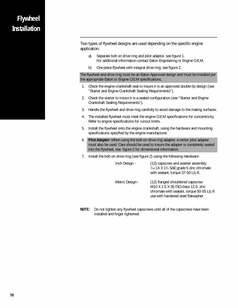
Two types of flywheel designs are used depending on the specific engineapplication:
a) Separate bolt on drive ring and pilot adaptor, see figure 1.For additional information contact Eaton Engineering or Engine O.E.M.
b) One piece flywheel with integral drive ring, see figure 2.
The flywheel and drive ring must be an Eaton Approved design and must be installed perthe appropriate Eaton or Engine O.E.M specifications.
1. Check the engine crankshaft seal to insure it is an approved double lip design (see“Starter and Engine Crankshaft Sealing Requirements”).
2. Check the starter to insure it is a sealed configuration (see “Starter and EngineCrankshaft Sealing Requirements”).
3. Handle the flywheel and drive ring carefully to avoid damage to the mating surfaces.
4. The installed flywheel must meet the engine O.E.M specifications for concentricity.Refer to engine specifications for runout limits.
5. Install the flywheel onto the engine crankshaft, using the hardware and mountingspecifications specified by the engine manufacturer.
6. Pilot Adapter: When using the bolt-on drive ring adapter, a center pilot adaptermust also be used. Care should be used to insure the adapter is completely seatedinto the flywheel, see figure 2 for dimensional information.
7. Install the bolt-on drive ring (see figure 2) using the following Hardware:
Inch Design - (12) capscrew and washer assembly7⁄16-14 X 11⁄4 SAE grade 5 zinc chromatewith sealant, torque 37-50 Lbf·ft.
Metric Design - (12) flanged shouldered capscrewM10 X 1.5 X 35 ISO class 12.9 zincchromate with sealant, torque 50-55 Lbf·ftuse with hardened steel flatwasher
NOTE: Do not tighten any flywheel capscrews until all of the capscrews have beeninstalled and finger tightened.
FlywheelInstallation
11
FlywheelInstallation
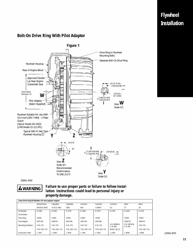
Bolt-On Drive Ring With Pilot Adaptor
Figure 1
20001-4/92
WARNING Failure to use proper parts or failure to follow instal-lation instructions could lead to personal injury orproperty damage.
9.00 [228.6]Minimum I.D. W
ViewScale 2/1
.62 [15.7] Min
2.008 [51.003]2.005 [50.927]
.03 [0.8] x45° CHAM
ø
.10 [2.5]
Z
30°17.159 [435.839]17.156 [435.762]ø 2.50 [63.5]
ViewScale 2/1
ZY
2.625 [66.68]
Flywheel Housing
Drive Ring to FlywheelMounting Bolts
Separate Bolt-On Drive Ring
Rear of Engine Block
Flywheel Suitable For Use With15.5 Inch [393.7 MM] - 2 PlateClutch(Spicer Model AS-1552)(LIPE Model 15 1/2-2PL)
Typical SAE #1 Wet TypeFlywheel Housing 1
W
ViewScale 4/1RecommendedConformanceTo SAE J1172 Y
Pilot Adapter(Eaton Supplied)
Approved DoubleLip Rear EngineCrankshaft Seal
Eaton Drive Ring Kit Numbers for most popular engines
Detroit Diesel Caterpillar Caterpillar Cummins Cummins Cummins Mack Mack
DDS60 & 8V92 3176 & 3406 3306 N14 L10/M11 8.3 E7 E6
Kit Number K-2404 K-2304 K-2753 K-2404 K-2753 K-2195 K-2365 K-2752
Kit Includes:
Drive Ring 23599 23599 23599 23599 23599 23599 23599
Pilot Adaptor 4301169 4300741 4301946 4301169 4301946 4300197 4300197
Mounting Hardware X-8L-722 X-8L-722 X-8L-722 X-8L-722 X-8L-722 X-8-1000M & X-10-606
X-8-1001M & X-3-700
X-8L-722
7/16-14X1-1/4 7/16-14X1-1/4 7/16-14X1-1/4 7/16-14X1-1/4 7/16-14X1-1/4 M10X1.38 LG. 7/16-14X1-1/4
Instruction Letter L-1891 L-2490 L-3593 L-1891 L-3593 L-2590 L-4690 L-4690 22006-8/95
12
FlywheelInstallation
ViewScale 2/1
.10 [2.5]
30°
ViewScale 4/1RecommendedConformanceTo SAE J1172
.62 [15.7] Min
2.008 [51.003]2.005 [50.927]
.03 [0.8] x45° CHAM
2.625 [66.68]
ø
W
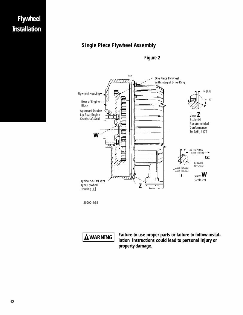
Flywheel Housing
Rear of EngineBlock
Approved DoubleLip Rear EngineCrankshaft Seal
One Piece FlywheelWith Integral Drive Ring
Z
WTypical SAE #1 WetType FlywheelHousing 1 Z
20000-4/92
Single Piece Flywheel Assembly
Figure 2
Failure to use proper parts or failure to follow instal-lation instructions could lead to personal injury orproperty damage.
WARNING
13
FlywheelHousingSealingRequirements
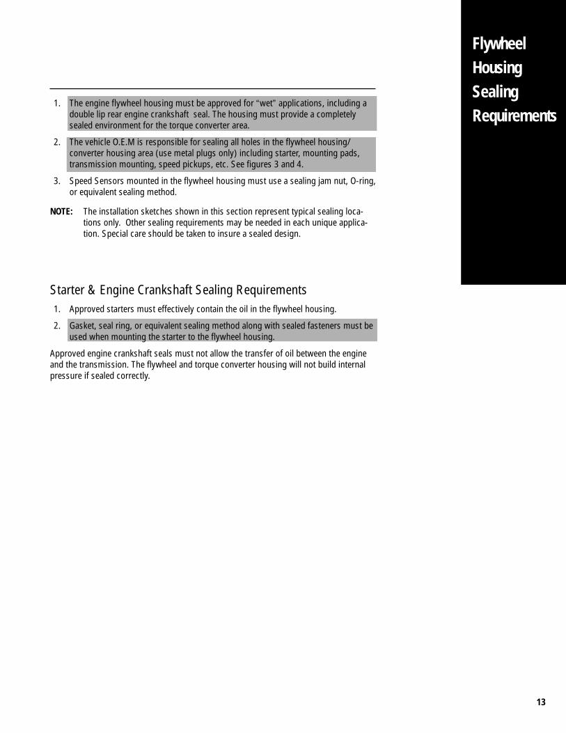
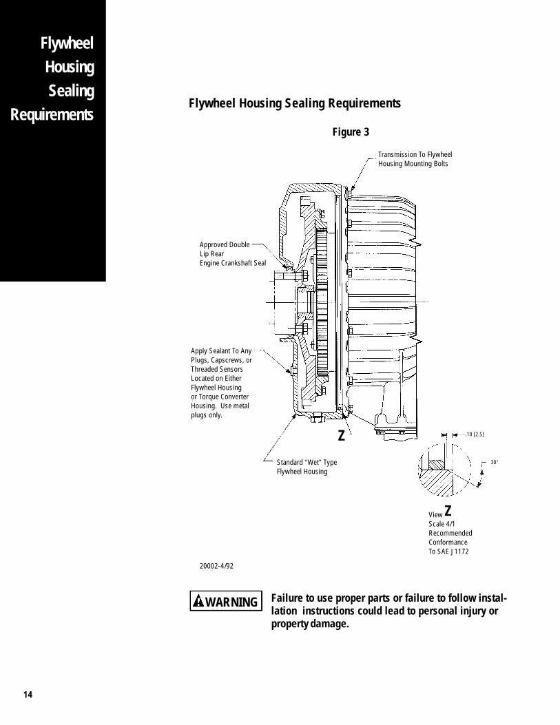
1. The engine flywheel housing must be approved for “wet” applications, including adouble lip rear engine crankshaft seal. The housing must provide a completelysealed environment for the torque converter area.
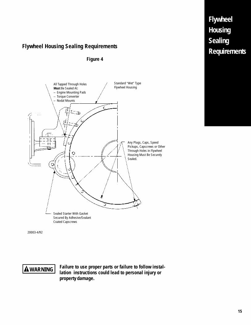
2. The vehicle O.E.M is responsible for sealing all holes in the flywheel housing/converter housing area (use metal plugs only) including starter, mounting pads,transmission mounting, speed pickups, etc. See figures 3 and 4.
3. Speed Sensors mounted in the flywheel housing must use a sealing jam nut, O-ring,or equivalent sealing method.
NOTE: The installation sketches shown in this section represent typical sealing loca-tions only. Other sealing requirements may be needed in each unique applica-tion. Special care should be taken to insure a sealed design.
Starter & Engine Crankshaft Sealing Requirements1. Approved starters must effectively contain the oil in the flywheel housing.
2. Gasket, seal ring, or equivalent sealing method along with sealed fasteners must beused when mounting the starter to the flywheel housing.
Approved engine crankshaft seals must not allow the transfer of oil between the engineand the transmission. The flywheel and torque converter housing will not build internalpressure if sealed correctly.
14
FlywheelHousingSealing
RequirementsFlywheel Housing Sealing Requirements
Figure 3
Standard “Wet” TypeFlywheel Housing
Z
Z
30°
.10 [2.5]
Apply Sealant To AnyPlugs, Capscrews, orThreaded SensorsLocated on EitherFlywheel Housingor Torque ConverterHousing. Use metalplugs only.
Approved DoubleLip RearEngine Crankshaft Seal
ViewScale 4/1RecommendedConformanceTo SAE J1172
Transmission To FlywheelHousing Mounting Bolts
Failure to use proper parts or failure to follow instal-lation instructions could lead to personal injury orproperty damage.
WARNING
20002-4/92
15
FlywheelHousingSealingRequirements
Any Plugs, Caps, SpeedPickups, Capscrews or OtherThrough Holes in FlywheelHousing Must Be SecurelySealed.
Standard “Wet” TypeFlywheel Housing
Sealed Starter With GasketSecured By Adhesive/SealantCoated Capscrews
Flywheel Housing Sealing Requirements
Figure 4
All Tapped Through HolesMust Be Sealed At:– Engine Mounting Pads– Torque Converter– Nodal Mounts
Failure to use proper parts or failure to follow instal-lation instructions could lead to personal injury orproperty damage.
WARNING
20003-4/92
16
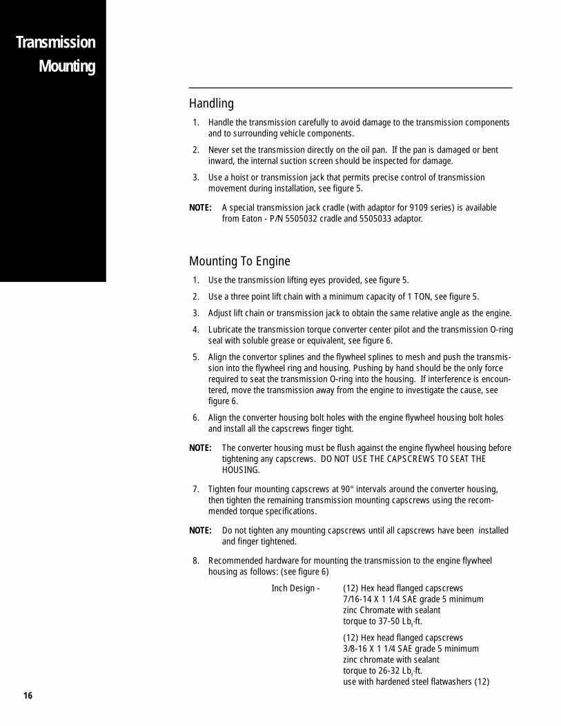
Handling1. Handle the transmission carefully to avoid damage to the transmission components
and to surrounding vehicle components.
2. Never set the transmission directly on the oil pan. If the pan is damaged or bentinward, the internal suction screen should be inspected for damage.
3. Use a hoist or transmission jack that permits precise control of transmissionmovement during installation, see figure 5.
NOTE: A special transmission jack cradle (with adaptor for 9109 series) is availablefrom Eaton - P/N 5505032 cradle and 5505033 adaptor.
Mounting To Engine1. Use the transmission lifting eyes provided, see figure 5.
2. Use a three point lift chain with a minimum capacity of 1 TON, see figure 5.
3. Adjust lift chain or transmission jack to obtain the same relative angle as the engine.
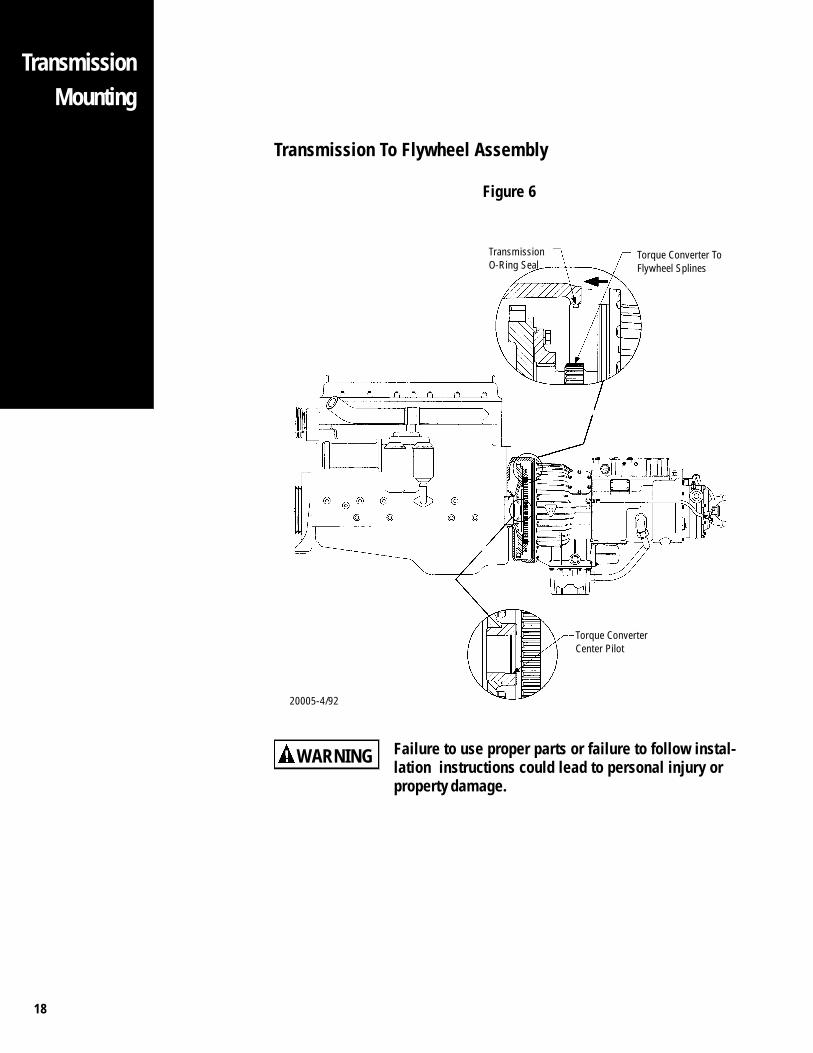
4. Lubricate the transmission torque converter center pilot and the transmission O-ringseal with soluble grease or equivalent, see figure 6.
5. Align the convertor splines and the flywheel splines to mesh and push the transmis-sion into the flywheel ring and housing. Pushing by hand should be the only forcerequired to seat the transmission O-ring into the housing. If interference is encoun-tered, move the transmission away from the engine to investigate the cause, seefigure 6.
6. Align the converter housing bolt holes with the engine flywheel housing bolt holesand install all the capscrews finger tight.
NOTE: The converter housing must be flush against the engine flywheel housing beforetightening any capscrews. DO NOT USE THE CAPSCREWS TO SEAT THEHOUSING.
7. Tighten four mounting capscrews at 90° intervals around the converter housing,then tighten the remaining transmission mounting capscrews using the recom-mended torque specifications.
NOTE: Do not tighten any mounting capscrews until all capscrews have been installedand finger tightened.
8. Recommended hardware for mounting the transmission to the engine flywheelhousing as follows: (see figure 6)
Inch Design - (12) Hex head flanged capscrews7/16-14 X 1 1/4 SAE grade 5 minimumzinc Chromate with sealanttorque to 37-50 Lbf·ft.
(12) Hex head flanged capscrews3/8-16 X 1 1/4 SAE grade 5 minimumzinc chromate with sealanttorque to 26-32 Lbf·ft.use with hardened steel flatwashers (12)
TransmissionMounting
17
TransmissionMounting
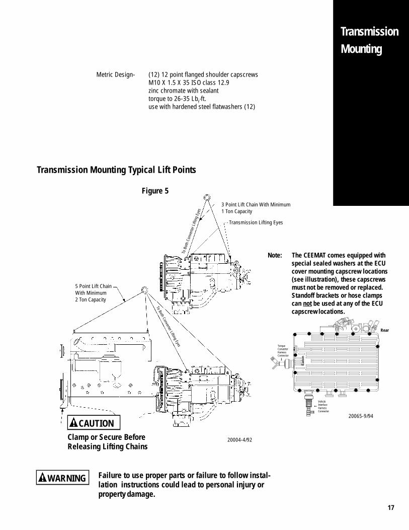
Metric Design- (12) 12 point flanged shoulder capscrewsM10 X 1.5 X 35 ISO class 12.9zinc chromate with sealanttorque to 26-35 Lbf·ft.use with hardened steel flatwashers (12)
Clamp or Secure BeforeReleasing Lifting Chains
Transmission Mounting Typical Lift Points
Figure 5
3 Point Lift Chain With Minimum1 Ton Capacity
To Both Converter Lifting Eyes
To B
oth
Conv
erte
r Lift
ing
Eyes
Failure to use proper parts or failure to follow instal-lation instructions could lead to personal injury orproperty damage.
WARNING
CAUTION
5 Point Lift ChainWith Minimum2 Ton Capacity
Transmission Lifting Eyes
20004-4/92
Note: The CEEMAT comes equipped withspecial sealed washers at the ECUcover mounting capscrew locations(see illustration), these capscrewsmust not be removed or replaced.Standoff brackets or hose clampscan not be used at any of the ECUcapscrew locations.
SO
FT
WA
RE
NO
.
Eat
on
Rear
➞
➞
Torque Converter HarnessConnector
Vehicle Interface HarnessConnector
20065-9/94
18
TransmissionMounting
Transmission To Flywheel Assembly
Figure 6
Torque Converter ToFlywheel Splines
TransmissionO-Ring Seal
Torque ConverterCenter Pilot
Failure to use proper parts or failure to follow instal-lation instructions could lead to personal injury orproperty damage.
WARNING
20005-4/92
19
TransmissionSupportRequirements
Using Rear Supports1. A rear transmission support is required for all installations where the nodal mount
supports are not used. The O.E.M is responsible for this design.
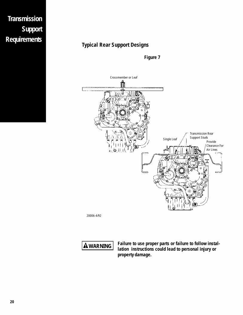
2. Many O.E.M rear support designs are already being used for standard EatonRoadranger transmissions. These same rear supports can be used with theCEEMAT system. Eaton recommends the vehicle O.E.M follow SAE Guidelines forrear support design (Reference SAE SP-479). See figure 7 for typical rear supportdesigns.
3. Optional long or short rear support studs are available when ordering the CEEMAT,see figure 7.
4. Rear support should be mounted in a way as not to interfere with transmission airhoses.
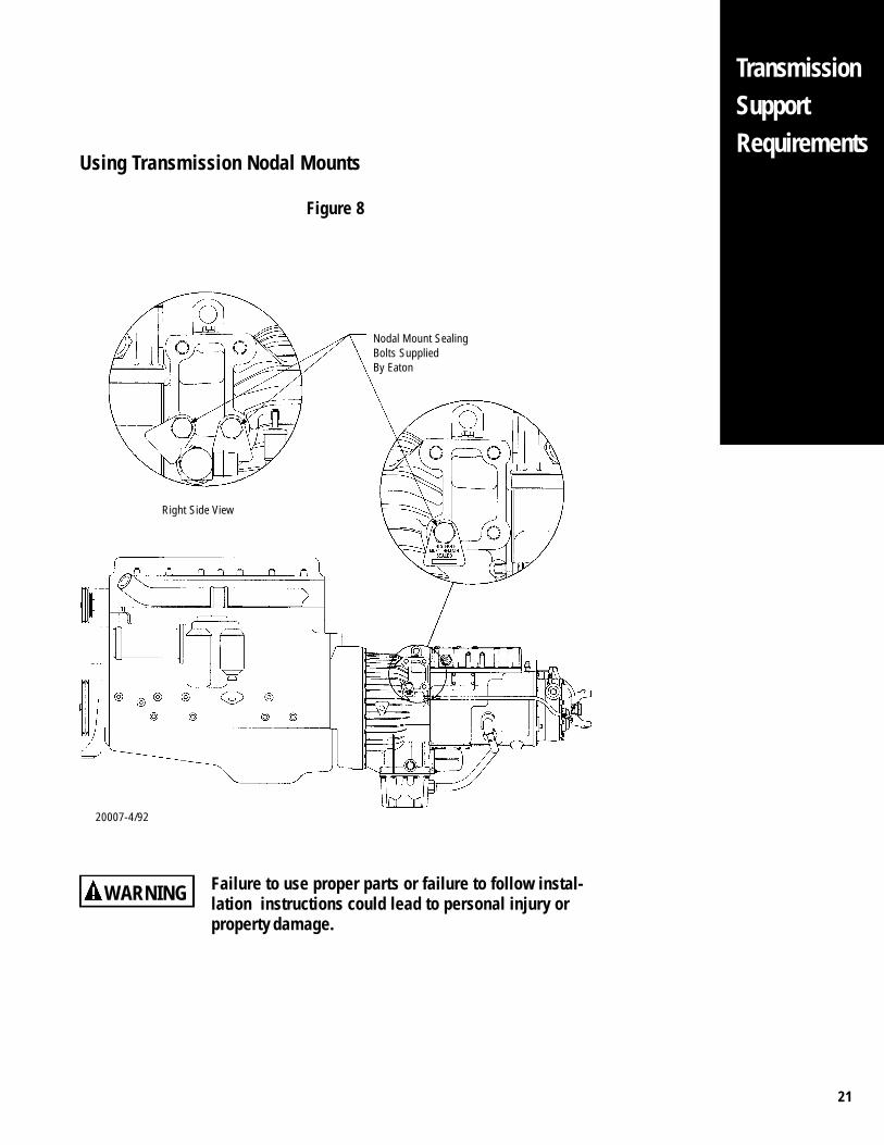
Using Transmission Nodal Mounts1. The transmission nodal mounting pads are approved to be used as a rear engine
support location. Using these support pads requires special sealing requirementswhen installing the mounting capscrews. See figure 8.
2. The nodal mount tapped holes must be sealed if used. The CEEMAT comes equippedwith sealed capscrews at the required location along with warning labels to remindthe technician that these locations require capscrews with thread sealant if replaced,see figure 8.
Recommended sealant for nodal mount capscrews is Loctite® #567 pipe sealant(teflon type) or equivalent.
3. The O.E.M is responsible for the nodal mount design and sealing the requiredcapscrews at the nodal mount location. See figure 8.
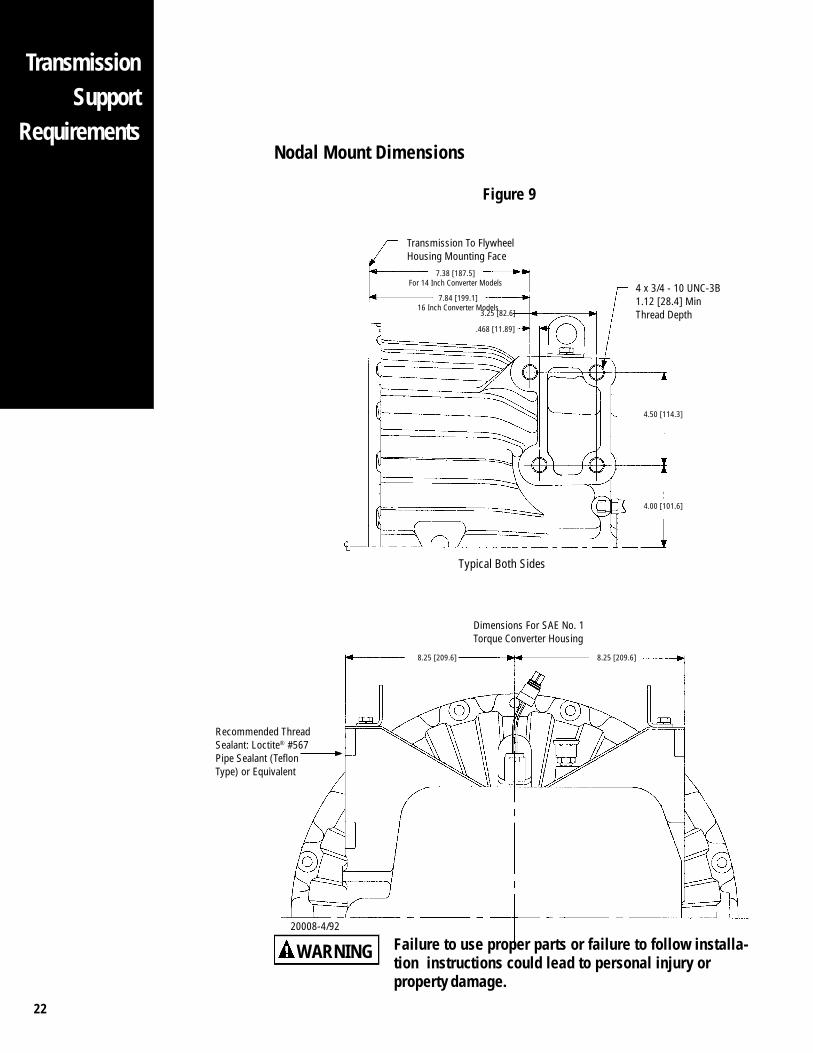
4. See figure 9 for nodal mount dimensions for SAE NO.1 Torque Converter housing.
5. Torque transmission nodal mount capscrews (3/4-10 UNC) to 180-190 Lbf·ft oftorque.
20
Typical Rear Support Designs
Figure 7
Crossmember or Leaf
Transmission RearSupport StudsSingle Leaf
Failure to use proper parts or failure to follow instal-lation instructions could lead to personal injury orproperty damage.
WARNING
ProvideClearance ForAir Lines
TransmissionSupport
Requirements
20006-4/92
21
TransmissionSupportRequirements
Using Transmission Nodal Mounts
Figure 8
Nodal Mount SealingBolts SuppliedBy Eaton
Right Side View
Failure to use proper parts or failure to follow instal-lation instructions could lead to personal injury orproperty damage.
WARNING
20007-4/92
22
Nodal Mount Dimensions
Figure 9
Transmission To FlywheelHousing Mounting Face
7.38 [187.5]For 14 Inch Converter Models
3.25 [82.6]
.468 [11.89]
4 x 3/4 - 10 UNC-3B1.12 [28.4] MinThread Depth
4.50 [114.3]
4.00 [101.6]
Typical Both Sides
8.25 [209.6] 8.25 [209.6]
7.84 [199.1]16 Inch Converter Models
Failure to use proper parts or failure to follow installa-tion instructions could lead to personal injury orproperty damage.
WARNING
Dimensions For SAE No. 1Torque Converter Housing
Recommended ThreadSealant: Loctite® #567Pipe Sealant (TeflonType) or Equivalent
TransmissionSupport
Requirements
20008-4/92
23
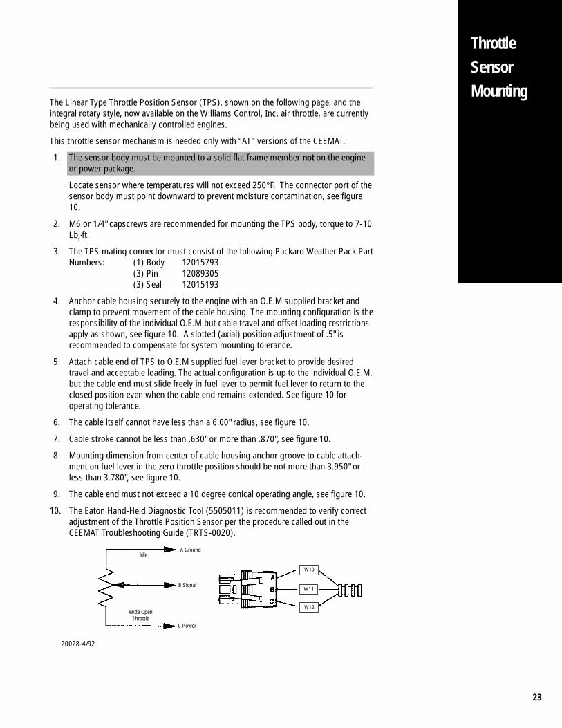
The Linear Type Throttle Position Sensor (TPS), shown on the following page, and theintegral rotary style, now available on the Williams Control, Inc. air throttle, are currentlybeing used with mechanically controlled engines.
This throttle sensor mechanism is needed only with “AT” versions of the CEEMAT.
1. The sensor body must be mounted to a solid flat frame member not on the engineor power package.
Locate sensor where temperatures will not exceed 250°F. The connector port of thesensor body must point downward to prevent moisture contamination, see figure10.
2. M6 or 1/4" capscrews are recommended for mounting the TPS body, torque to 7-10Lbf·ft.
3. The TPS mating connector must consist of the following Packard Weather Pack PartNumbers: (1) Body 12015793
(3) Pin 12089305(3) Seal 12015193
4. Anchor cable housing securely to the engine with an O.E.M supplied bracket andclamp to prevent movement of the cable housing. The mounting configuration is theresponsibility of the individual O.E.M but cable travel and offset loading restrictionsapply as shown, see figure 10. A slotted (axial) position adjustment of .5" isrecommended to compensate for system mounting tolerance.
5. Attach cable end of TPS to O.E.M supplied fuel lever bracket to provide desiredtravel and acceptable loading. The actual configuration is up to the individual O.E.M,but the cable end must slide freely in fuel lever to permit fuel lever to return to theclosed position even when the cable end remains extended. See figure 10 foroperating tolerance.
6. The cable itself cannot have less than a 6.00" radius, see figure 10.
7. Cable stroke cannot be less than .630" or more than .870", see figure 10.
8. Mounting dimension from center of cable housing anchor groove to cable attach-ment on fuel lever in the zero throttle position should be not more than 3.950" orless than 3.780", see figure 10.
9. The cable end must not exceed a 10 degree conical operating angle, see figure 10.
10. The Eaton Hand-Held Diagnostic Tool (5505011) is recommended to verify correctadjustment of the Throttle Position Sensor per the procedure called out in theCEEMAT Troubleshooting Guide (TRTS-0020).
ThrottleSensorMounting
20028-4/92
A Ground
B Signal
C Power
Wide OpenThrottle
W10
W11
W12
Idle
24
ThrottleSensor
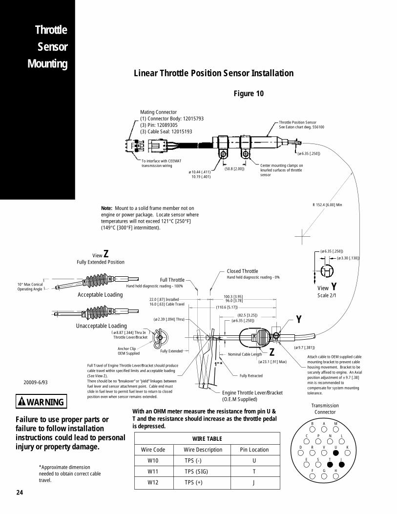
MountingLinear Throttle Position Sensor Installation
Figure 10
D R V U K
B A M
F G H
TransmissionConnector
C P N L
E S T J
With an OHM meter measure the resistance from pin U &T and the resistance should increase as the throttle pedalis depressed.
Failure to use proper parts orfailure to follow installationinstructions could lead to personalinjury or property damage.
WARNING
10° Max ConicalOperating Angle
Acceptable Loading
Unacceptable Loading
View ZFully Extended Position
20009-6/93
ø 8.87 [.344] Thru InThrottle Lever/Bracket
Fully Extended
( )
Anchor ClipOEM Supplied
22.0 [.87] Installed16.0 [.63] Cable Travel
(ø 2.39 [.094] Thru)
Engine Throttle Lever/Bracket(O.E.M Supplied)
(ø 9.7 [.381])
Nominal Cable Length
Fully Retracted
(ø 6.35 [.250])
(110.6 [5.17])
100.3 [3.95]96.0 [3.78]
Z(ø 23.1 [.91] Max)
Closed ThrottleHand held diagnostic reading - 0%
Full Travel of Engine Throttle Lever/Bracket should producecable travel within specified limits and acceptable loading(See View Z).There should be no "breakover" or "yield" linkages betweenfuel lever and sensor attachment point. Cable end mustslide in fuel lever to permit fuel lever to return to closedposition even when sensor remains extended.
Attach cable to OEM supplied cablemounting bracket to prevent cablehousing movement. Bracket to besecurely affixed to engine. An Axialposition adjustment of ± 9.7 [.38]min is recommended tocompensate for system mountingtolerance.
Full ThrottleHand held diagnostic reading - 100%
Note: Mount to a solid frame member not onengine or power package. Locate sensor wheretemperatures will not exceed 121°C [250°F](149°C [300°F] intermittent).
(ø 6.35 [.250])
(ø 3.30 [.130])
View YScale 2/1
Y
WIRE TABLE
Wire Code Wire Description Pin Location
W10 TPS (-) U
W11 TPS (SIG) T
W12 TPS (+) J
(82.5 [3.25])
R 152.4 [6.00] Min
(ø 6.35 [.250])
Throttle Position SensorSee Eaton chart dwg. 556100
ø 10.44 (.411) 10.19 (.401)
Center mounting clamps onknurled surfaces of throttlesensor
To interface with CEEMATtransmission wiring
(50.8 [2.00])
Mating Connector(1) Connector Body: 12015793(3) Pin: 12089305(3) Cable Seal: 12015193
*Approximate dimensionneeded to obtain correct cabletravel.
1" *
25
ThrottleSensorMounting
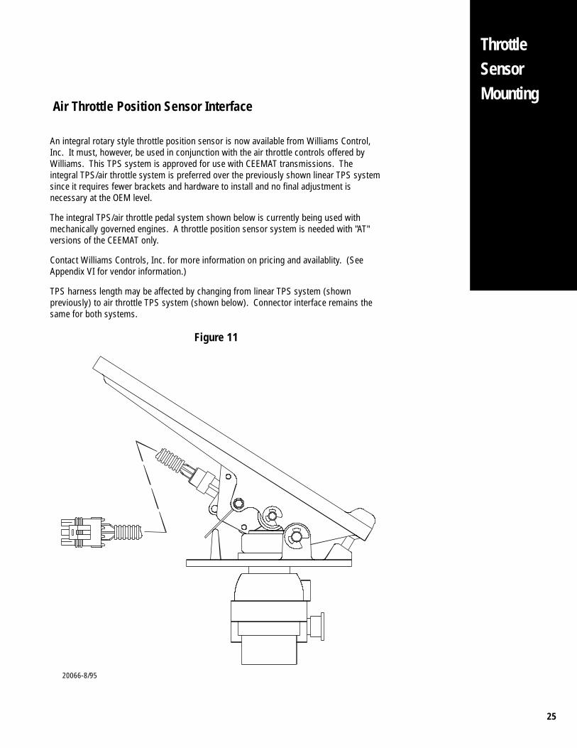
Air Throttle Position Sensor Interface
20066-8/95
An integral rotary style throttle position sensor is now available from Williams Control,Inc. It must, however, be used in conjunction with the air throttle controls offered byWilliams. This TPS system is approved for use with CEEMAT transmissions. Theintegral TPS/air throttle system is preferred over the previously shown linear TPS systemsince it requires fewer brackets and hardware to install and no final adjustment isnecessary at the OEM level.
The integral TPS/air throttle pedal system shown below is currently being used withmechanically governed engines. A throttle position sensor system is needed with "AT"versions of the CEEMAT only.
Contact Williams Controls, Inc. for more information on pricing and availablity. (SeeAppendix VI for vendor information.)
TPS harness length may be affected by changing from linear TPS system (shownpreviously) to air throttle TPS system (shown below). Connector interface remains thesame for both systems.
Figure 11
26
ThrottleSensor
Mounting
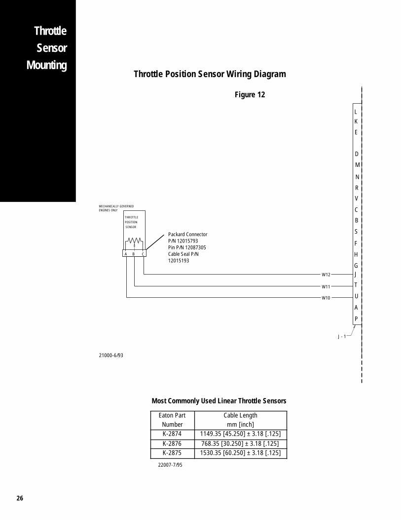
Packard ConnectorP/N 12015793Pin P/N 12087305Cable Seal P/N12015193
Most Commonly Used Linear Throttle Sensors
ENGINES ONLYMECHANICALLY GOVERNED
SENSOR
POSITION
THROTTLE
A B C
LK
E
D
M
N
R
V
C
B
S
F
H
GJ
T
U
A
P
W12
W11
W10
J - 1
21000-6/93
Eaton Part Cable LengthNumber mm [inch]K-2874 1149.35 [45.250] ± 3.18 [.125]K-2876 768.35 [30.250] ± 3.18 [.125]K-2875 1530.35 [60.250] ± 3.18 [.125]
Throttle Position Sensor Wiring Diagram
Figure 12
22007-7/95

27
FuelInterruptMounting
The purpose of the CEEMAT defuel system is to momentarily interrupt fuel supply duringa transmission shift sequence to allow for synchronization of the mechanical gear box.
The defuel control is a necessity on “AT” CEEMAT’S with mechanical engines. The defuelcontrol is not necessary on “ATE” CEEMAT’S with electronic engines.
1. If required, the engine defuel system must be Eaton or Engine O.E.M approved.
2. Air Throttle control must be installed per Williams Control, Inc. specifications andthis manual.
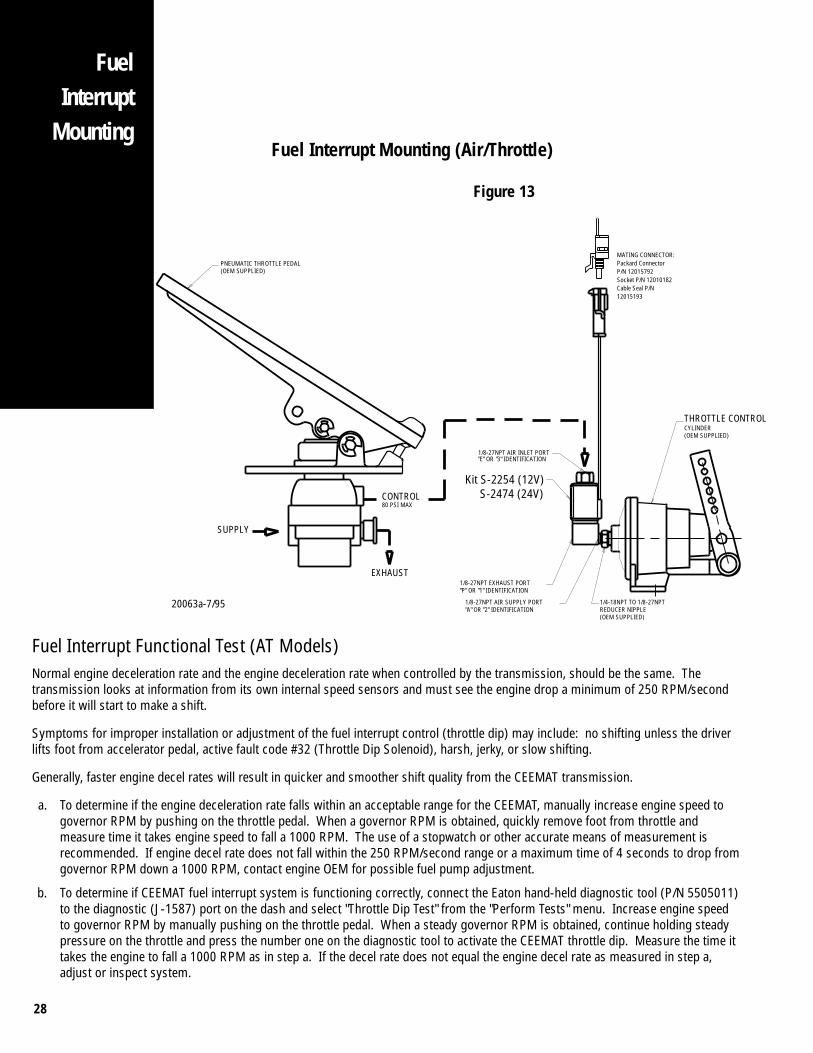
Air Throttle/Electro-Pneumatic SystemThe Air Throttle Defuel system shown in Figure 15 is the preferred defuel system since itrequires no additional bracketry to install and no final adjustment is required.
This system must be used with an air throttle control. The electronically controlled valvemomentarily interrupts the driver throttle input by quickly exhausting the throttle controlair allowing the pump to return to the idle position.
1. The engine or vehicle OEM is responsible for mounting the interrupt valve on thethrottle control cylinder. Fitting size and port identification are shown in Figure 15.
2. Pedal supply air must be non-regulated (full system pressure).
3. Minimum throttle control air line size when used with CEEMAT defuel system is 1/4"I.D. Air line must be installed with no sharp bends or tie wraps that restrict air flow.
4. The throttle control air line length when used with CEEMAT defuel should be asshort as possible with a maximum length of 30'.
5. OEM throttle return springs must be mounted securely to the engine fuel pumpthrottle arm, not on the throttle control or linkage.
6. When using the air throttle defuel system shown in Figure 15, the integral throttleposition sensor system must also be used to insure proper shift quality. Referencepage 31.
7. Reference manufacturers specifications for installing air throttle control system.
28
Fuel Interrupt Functional Test (AT Models)Normal engine deceleration rate and the engine deceleration rate when controlled by the transmission, should be the same. Thetransmission looks at information from its own internal speed sensors and must see the engine drop a minimum of 250 RPM/secondbefore it will start to make a shift.
Symptoms for improper installation or adjustment of the fuel interrupt control (throttle dip) may include: no shifting unless the driverlifts foot from accelerator pedal, active fault code #32 (Throttle Dip Solenoid), harsh, jerky, or slow shifting.
Generally, faster engine decel rates will result in quicker and smoother shift quality from the CEEMAT transmission.
a. To determine if the engine deceleration rate falls within an acceptable range for the CEEMAT, manually increase engine speed togovernor RPM by pushing on the throttle pedal. When a governor RPM is obtained, quickly remove foot from throttle andmeasure time it takes engine speed to fall a 1000 RPM. The use of a stopwatch or other accurate means of measurement isrecommended. If engine decel rate does not fall within the 250 RPM/second range or a maximum time of 4 seconds to drop fromgovernor RPM down a 1000 RPM, contact engine OEM for possible fuel pump adjustment.
b. To determine if CEEMAT fuel interrupt system is functioning correctly, connect the Eaton hand-held diagnostic tool (P/N 5505011)to the diagnostic (J-1587) port on the dash and select "Throttle Dip Test" from the "Perform Tests" menu. Increase engine speedto governor RPM by manually pushing on the throttle pedal. When a steady governor RPM is obtained, continue holding steadypressure on the throttle and press the number one on the diagnostic tool to activate the CEEMAT throttle dip. Measure the time ittakes the engine to fall a 1000 RPM as in step a. If the decel rate does not equal the engine decel rate as measured in step a,adjust or inspect system.
(OEM SUPPLIED)
Kit S-2254 (12V) S-2474 (24V)
(OEM SUPPLIED)REDUCER NIPPLE
(OEM SUPPLIED)
CONTROL
EXHAUST
80 PSI MAX
SUPPLY
CYLINDERTHROTTLE CONTROL
MATING CONNECTOR:Packard ConnectorP/N 12015792Socket P/N 12010182Cable Seal P/N12015193
PNEUMATIC THROTTLE PEDAL
1/4-18NPT TO 1/8-27NPT
"E" OR "3" IDENTIFICATION1/8-27NPT AIR INLET PORT
"A" OR "2" IDENTIFICATION1/8-27NPT AIR SUPPLY PORT
"P" OR "1" IDENTIFICATION1/8-27NPT EXHAUST PORT
20063a-7/95
Fuel Interrupt Mounting (Air/Throttle)
Figure 13
FuelInterrupt
Mounting
29
FuelInterruptMounting
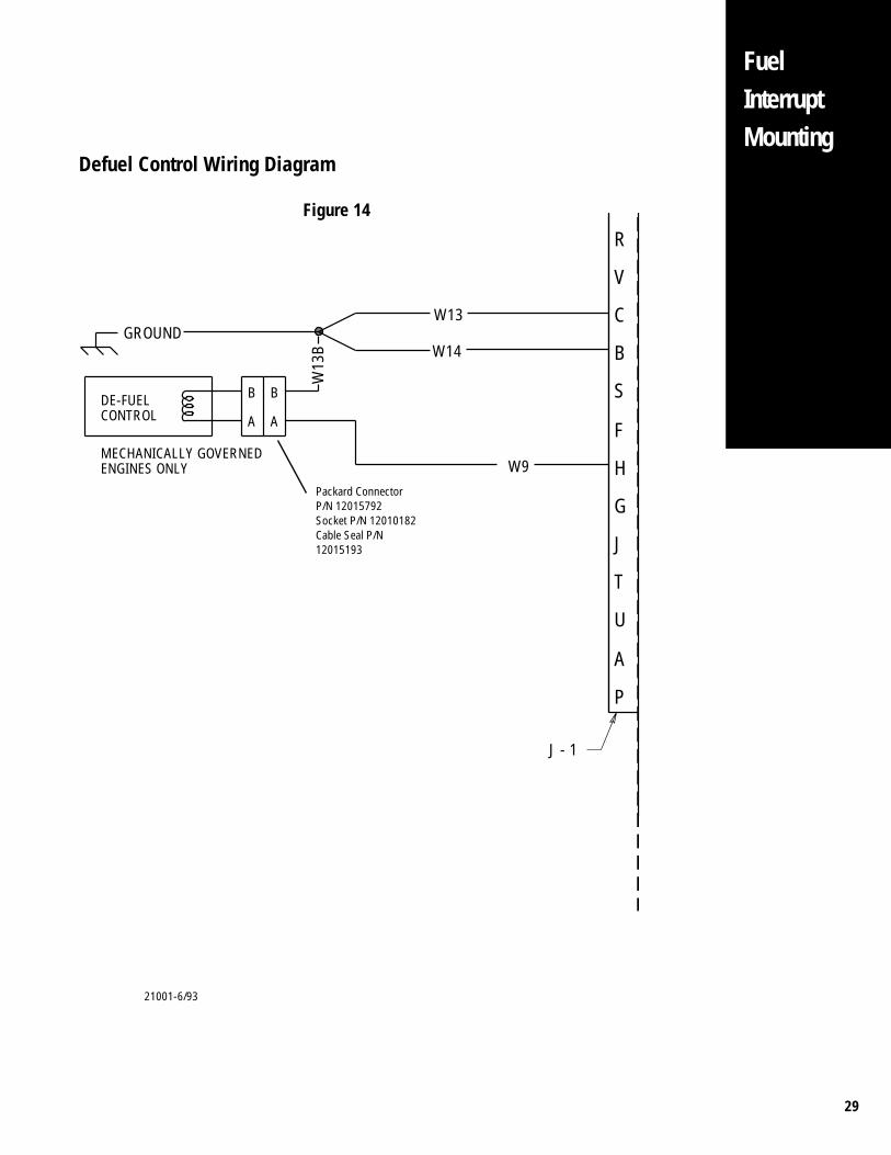
Defuel Control Wiring Diagram
Figure 14
21001-6/93
R
B
C
G
H
F
S
V
P
A
U
T
W13
W14
W9
B
AA
B
W13
B
J
ENGINES ONLYMECHANICALLY GOVERNED
GROUND
CONTROLDE-FUEL
J - 1
Packard ConnectorP/N 12015792Socket P/N 12010182Cable Seal P/N12015193
30
CoolerRequirements
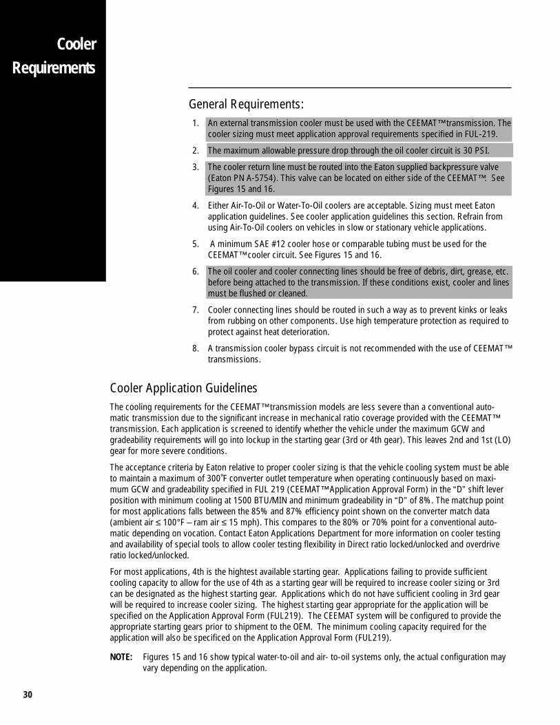
General Requirements:1. An external transmission cooler must be used with the CEEMAT™ transmission. The
cooler sizing must meet application approval requirements specified in FUL-219.
2. The maximum allowable pressure drop through the oil cooler circuit is 30 PSI.
3. The cooler return line must be routed into the Eaton supplied backpressure valve(Eaton PN A-5754). This valve can be located on either side of the CEEMAT™. SeeFigures 15 and 16.
4. Either Air-To-Oil or Water-To-Oil coolers are acceptable. Sizing must meet Eatonapplication guidelines. See cooler application guidelines this section. Refrain fromusing Air-To-Oil coolers on vehicles in slow or stationary vehicle applications.
5. A minimum SAE #12 cooler hose or comparable tubing must be used for theCEEMAT™ cooler circuit. See Figures 15 and 16.
6. The oil cooler and cooler connecting lines should be free of debris, dirt, grease, etc.before being attached to the transmission. If these conditions exist, cooler and linesmust be flushed or cleaned.
7. Cooler connecting lines should be routed in such a way as to prevent kinks or leaksfrom rubbing on other components. Use high temperature protection as required toprotect against heat deterioration.
8. A transmission cooler bypass circuit is not recommended with the use of CEEMAT™transmissions.
Cooler Application GuidelinesThe cooling requirements for the CEEMAT™ transmission models are less severe than a conventional auto-matic transmission due to the significant increase in mechanical ratio coverage provided with the CEEMAT™transmission. Each application is screened to identify whether the vehicle under the maximum GCW andgradeability requirements will go into lockup in the starting gear (3rd or 4th gear). This leaves 2nd and 1st (LO)gear for more severe conditions.
The acceptance criteria by Eaton relative to proper cooler sizing is that the vehicle cooling system must be ableto maintain a maximum of 300˚F converter outlet temperature when operating continuously based on maxi-mum GCW and gradeability specified in FUL 219 (CEEMAT™ Application Approval Form) in the “D” shift leverposition with minimum cooling at 1500 BTU/MIN and minimum gradeability in “D” of 8%. The matchup pointfor most applications falls between the 85% and 87% efficiency point shown on the converter match data(ambient air ≤ 100°F – ram air ≤ 15 mph). This compares to the 80% or 70% point for a conventional auto-matic depending on vocation. Contact Eaton Applications Department for more information on cooler testingand availability of special tools to allow cooler testing flexibility in Direct ratio locked/unlocked and overdriveratio locked/unlocked.
For most applications, 4th is the hightest available starting gear. Applications failing to provide sufficientcooling capacity to allow for the use of 4th as a starting gear will be required to increase cooler sizing or 3rdcan be designated as the highest starting gear. Applications which do not have sufficient cooling in 3rd gearwill be required to increase cooler sizing. The highest starting gear appropriate for the application will bespecified on the Application Approval Form (FUL219). The CEEMAT system will be configured to provide theappropriate starting gears prior to shipment to the OEM. The minimum cooling capacity required for theapplication will also be specificed on the Application Approval Form (FUL219).
NOTE: Figures 15 and 16 show typical water-to-oil and air- to-oil systems only, the actual configuration mayvary depending on the application.
31
CoolerRequirements
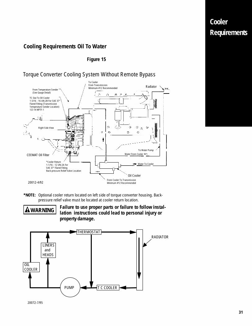
Cooling Requirements Oil To Water
Figure 15
TC Out To Oil Cooler1-5/16 - 16 UN-2B For SAE 37°Flared Fitting (TransmissionTemperature Sender Location)1/2-14 NPTF-1
*Cooler Return1-1/16 - 12 UN-2A ForSAE 37° Flared FittingBack-pressure Relief Valve Location
Water From Cooler
To Water Pump
To CoolerFrom TransmissionMinimum #12 Recommended Radiator
*NOTE: Optional cooler return located on left side of torque converter housing. Back-pressure relief valve must be located at cooler return location.
Right Side View
From Temperature Sender(See Gauge Detail)
From Cooler To TransmissionMinimum #12 Recommended
CEEMAT Oil Filter
Water To Cooler
20012-4/92
Oil Cooler
Torque Converter Cooling System Without Remote Bypass
Failure to use proper parts or failure to follow instal-lation instructions could lead to personal injury orproperty damage.
WARNING
THERMOSTAT
OILCOOLER
T C COOLERPUMP
RADIATOR
LINERS andHEADS
20072-7/95
32
CoolerRequirements
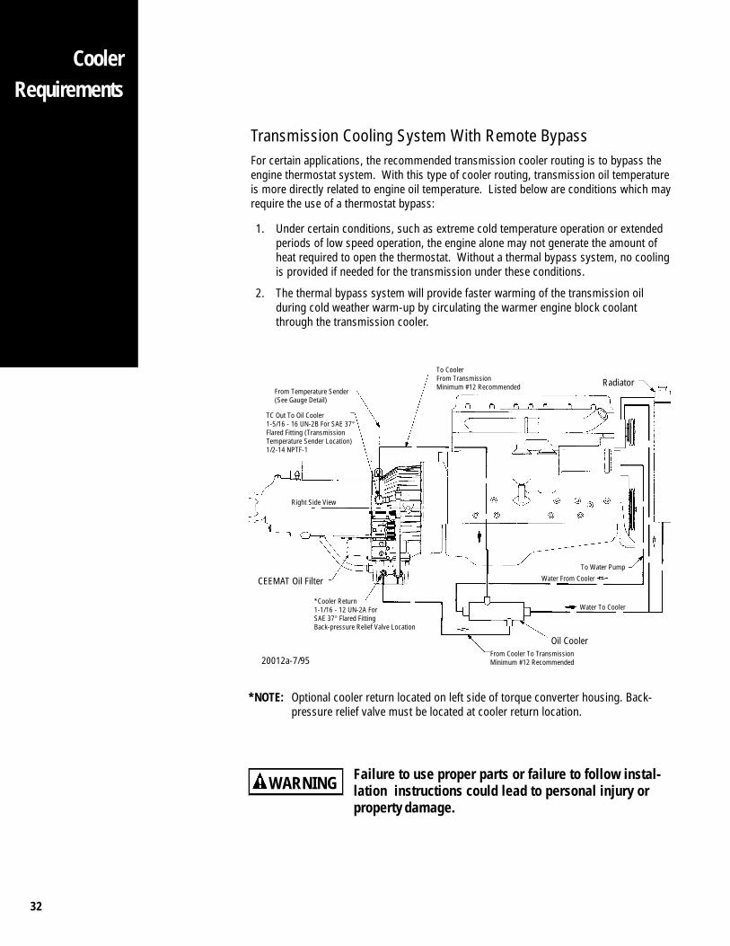
Transmission Cooling System With Remote BypassFor certain applications, the recommended transmission cooler routing is to bypass theengine thermostat system. With this type of cooler routing, transmission oil temperatureis more directly related to engine oil temperature. Listed below are conditions which mayrequire the use of a thermostat bypass:
1. Under certain conditions, such as extreme cold temperature operation or extendedperiods of low speed operation, the engine alone may not generate the amount ofheat required to open the thermostat. Without a thermal bypass system, no coolingis provided if needed for the transmission under these conditions.
2. The thermal bypass system will provide faster warming of the transmission oilduring cold weather warm-up by circulating the warmer engine block coolantthrough the transmission cooler.
Failure to use proper parts or failure to follow instal-lation instructions could lead to personal injury orproperty damage.
TC Out To Oil Cooler1-5/16 - 16 UN-2B For SAE 37°Flared Fitting (TransmissionTemperature Sender Location)1/2-14 NPTF-1
*Cooler Return1-1/16 - 12 UN-2A ForSAE 37° Flared FittingBack-pressure Relief Valve Location
Water From Cooler
To Water Pump
To CoolerFrom TransmissionMinimum #12 Recommended Radiator
*NOTE: Optional cooler return located on left side of torque converter housing. Back-pressure relief valve must be located at cooler return location.
Right Side View
From Temperature Sender(See Gauge Detail)
From Cooler To TransmissionMinimum #12 Recommended
WARNING
CEEMAT Oil Filter
Water To Cooler
20012a-7/95
Oil Cooler
33
CoolerRequirements
THERMOSTAT
OILCOOLER
T C COOLERPUMP
RADIATOR
REMOTEBYPASS
LINERS andHEADS
20071-7/95
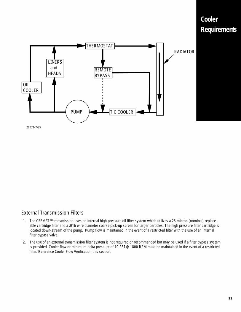
External Transmission Filters1. The CEEMAT™ transmission uses an internal high pressure oil filter system which utilizes a 25 micron (nominal) replace-
able cartridge filter and a .016 wire diameter coarse pick-up screen for larger particles. The high pressure filter cartridge islocated down-stream of the pump. Pump flow is maintained in the event of a restricted filter with the use of an internalfilter bypass valve.
2. The use of an external transmission filter system is not required or recommended but may be used if a filter bypass systemis provided. Cooler flow or minimum delta pressure of 10 PSI @ 1800 RPM must be maintained in the event of a restrictedfilter. Reference Cooler Flow Verification this section.
34
CoolerRequirements
Failure to use proper parts or failure to follow instal-lation instructions could lead to personal injury orproperty damage.
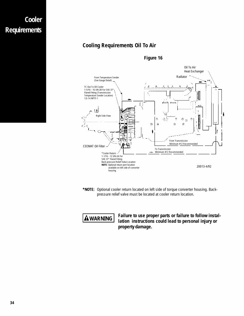
Cooling Requirements Oil To Air
Figure 16
*NOTE: Optional cooler return located on left side of torque converter housing. Back-pressure relief valve must be located at cooler return location.
WARNING
TC Out To Oil Cooler1-5/16 - 16 UN-2B For SAE 37°Flared Fitting (TransmissionTemperature Sender Location)1/2-14 NPTF-1
From Temperature Sender(See Gauge Detail)
Right Side View
Radiator
Oil To AirHeat Exchanger
20013-4/92
*Cooler Return1-1/16 - 12 UN-2A ForSAE 37° Flared FittingBack-pressure Relief Valve LocationNOTE: Optional return port location
available on left side of converterhousing
CEEMAT Oil Filter
Minimum #12 RecommendedTo Transmission
Minimum #12 RecommendedFrom Transmission
35
CoolerRequirements
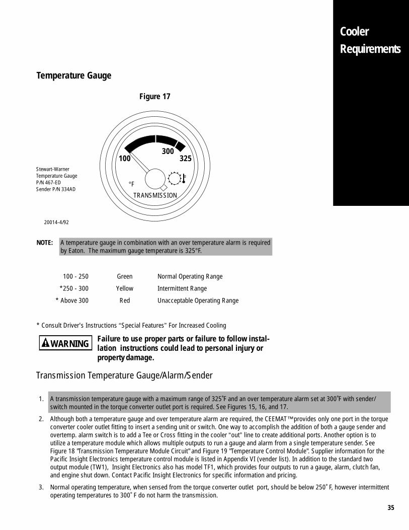
Temperature Gauge
Figure 17
Stewart-WarnerTemperature GaugeP/N 467-EDSender P/N 334AD
100 325300
°F
TRANSMISSION
NOTE: A temperature gauge in combination with an over temperature alarm is requiredby Eaton. The maximum gauge temperature is 325°F.
100 - 250 Green Normal Operating Range
*250 - 300 Yellow Intermittent Range
* Above 300 Red Unacceptable Operating Range
* Consult Driver's Instructions “Special Features” For Increased Cooling
Failure to use proper parts or failure to follow instal-lation instructions could lead to personal injury orproperty damage.
WARNING
20014-4/92
Transmission Temperature Gauge/Alarm/Sender
1. A transmission temperature gauge with a maximum range of 325˚F and an over temperature alarm set at 300˚F with sender/switch mounted in the torque converter outlet port is required. See Figures 15, 16, and 17.
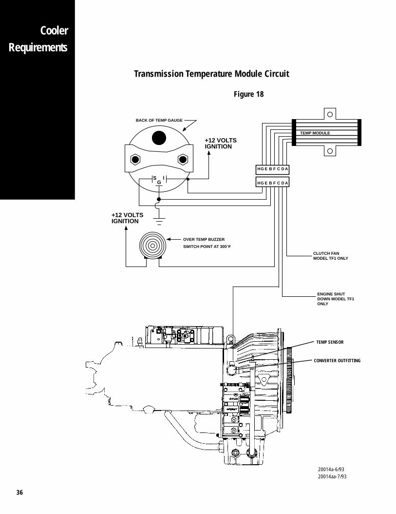
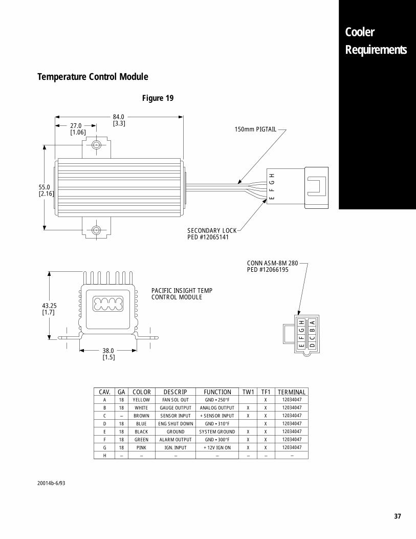
2. Although both a temperature gauge and over temperature alarm are required, the CEEMAT™ provides only one port in the torqueconverter cooler outlet fitting to insert a sending unit or switch. One way to accomplish the addition of both a gauge sender andovertemp. alarm switch is to add a Tee or Cross fitting in the cooler “out” line to create additional ports. Another option is toutilize a temperature module which allows multiple outputs to run a gauge and alarm from a single temperature sender. SeeFigure 18 "Transmission Temperature Module Circuit" and Figure 19 "Temperature Control Module". Supplier information for thePacific Insight Electronics temperature control module is listed in Appendix VI (vender list). In addition to the standard twooutput module (TW1), Insight Electronics also has model TF1, which provides four outputs to run a gauge, alarm, clutch fan,and engine shut down. Contact Pacific Insight Electronics for specific information and pricing.
3. Normal operating temperature, when sensed from the torque converter outlet port, should be below 250˚ F, however intermittentoperating temperatures to 300˚ F do not harm the transmission.
36
CoolerRequirements
Transmission Temperature Module Circuit
Figure 18
TEMP SENSOR
CONVERTER OUTFITTING
S lG
BACK OF TEMP GAUGE
+12 VOLTSIGNITION
TEMP MODULE
OVER TEMP BUZZER
SWITCH POINT AT 300°F
HG E B F C D A
HG E B F C D A
+12 VOLTSIGNITION
CLUTCH FANMODEL TF1 ONLY
ENGINE SHUTDOWN MODEL TF1 ONLY
20014a-6/9320014aa-7/93
37
CoolerRequirements
Temperature Control Module
Figure 19
20014b-6/93
84.0[3.3]27.0
[1.06]
55.0[2.16]
150mm PIGTAIL
SECONDARY LOCKPED #12065141
EF
GH
HG
FE
AB
CD
CONN ASM-8M 280PED #12066195
43.25[1.7]
38.0[1.5]
PACIFIC INSIGHT TEMPCONTROL MODULE
CAV. GA COLOR DESCRIP FUNCTIONA
B
C
D
E
F
G
H
18
18
–
18
18
18
18
–
YELLOW
WHITE
BROWN
BLUE
BLACK
GREEN
PINK
–
FAN SOL OUT
GAUGE OUTPUT
SENSOR INPUT
ENG SHUT DOWN
GROUND
ALARM OUTPUT
IGN. INPUT
–
GND • 250°F
ANALOG OUTPUT
+ SENSOR INPUT
GND • 310°F
SYSTEM GROUND
GND • 300°F
+ 12V IGN ON
–
TW1
X
X
X
X
X
–
TERMINAL12034047
12034047
12034047
12034047
12034047
12034047
12034047
–
TF1X
X
X
X
X
X
X
–
38
CoolerRequirements
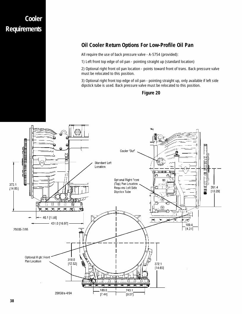
Oil Cooler Return Options For Low-Profile Oil Pan
All require the use of back pressure valve - A-5754 (provided):
1) Left front top edge of oil pan - pointing straight up (standard location)
2) Optional right front oil pan location - points toward front of trans. Back pressure valvemust be relocated to this position.
3) Optional right front top edge of oil pan - pointing straight up, only available if left sidedipstick tube is used. Back pressure valve must be relocated to this position.
Figure 20
39
R
CoolerRequirements
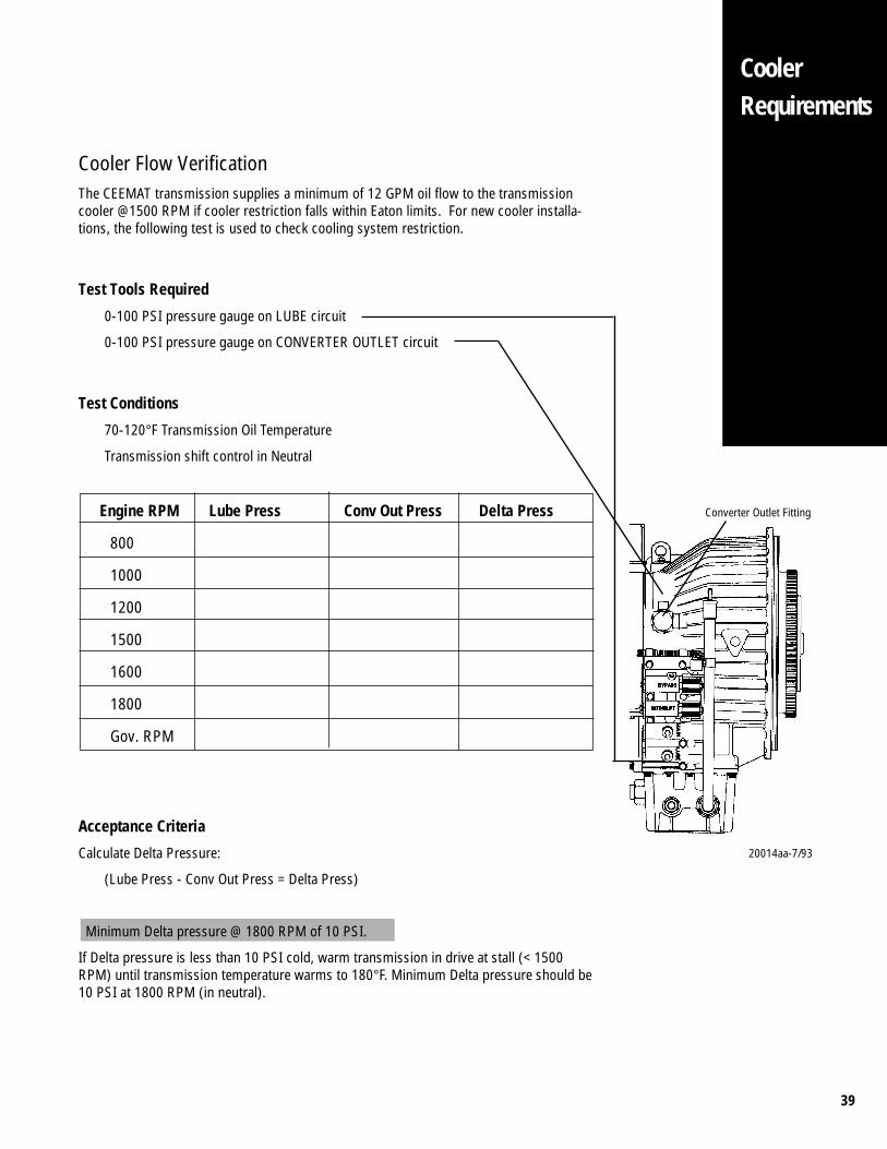
Cooler Flow VerificationThe CEEMAT transmission supplies a minimum of 12 GPM oil flow to the transmissioncooler @1500 RPM if cooler restriction falls within Eaton limits. For new cooler installa-tions, the following test is used to check cooling system restriction.
Test Tools Required
0-100 PSI pressure gauge on LUBE circuit
0-100 PSI pressure gauge on CONVERTER OUTLET circuit
Test Conditions
70-120°F Transmission Oil Temperature
Transmission shift control in Neutral
Engine RPM Lube Press Conv Out Press Delta Press
800
1000
1200
1500
1600
1800
Gov. RPM
Acceptance Criteria
Calculate Delta Pressure:
(Lube Press - Conv Out Press = Delta Press)
Minimum Delta pressure @ 1800 RPM of 10 PSI.
If Delta pressure is less than 10 PSI cold, warm transmission in drive at stall (< 1500RPM) until transmission temperature warms to 180°F. Minimum Delta pressure should be10 PSI at 1800 RPM (in neutral).
Converter Outlet Fitting
20014aa-7/93
40
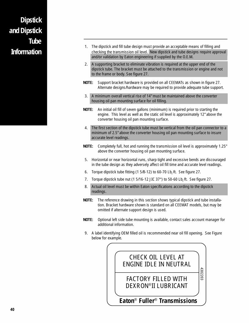
1. The dipstick and fill tube design must provide an acceptable means of filling andchecking the transmission oil level. New dipstick and tube designs require approvaland/or validation by Eaton engineering if supplied by the O.E.M.
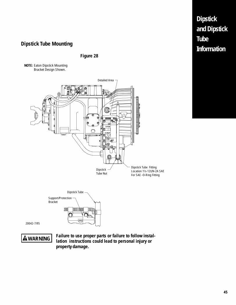
2. A supporting bracket to eliminate vibration is required at the upper end of thedipstick tube. The bracket must be attached to the transmission or engine and notto the frame or body. See figure 27.
NOTE: Support bracket hardware is provided on all CEEMATs as shown in figure 27.Alternate designs/hardware may be required to provide adequate tube support.
3. A minimum overall vertical rise of 14" must be maintained above the converterhousing oil pan mounting surface for oil filling.
NOTE: An initial oil fill of seven gallons (minimum) is required prior to starting theengine. This level as well as the static oil level is approximately 12" above theconverter housing oil pan mounting surface.
4. The first section of the dipstick tube must be vertical from the oil pan connector to aminimum of 2.5" above the converter housing oil pan mounting surface to insureaccurate level readings.
NOTE: Completely full, hot and running the transmission oil level is approximately 1.25"above the converter housing oil pan mounting surface.
5. Horizontal or near horizontal runs, sharp tight and excessive bends are discouragedin the tube design as they adversely affect oil fill time and accurate level readings.
6. Torque dipstick tube fitting (1 5/8-12) to 60-70 Lbf·ft. See figure 27.
7. Torque dipstick tube nut (1 5/16-12 JIC 37°) to 50-60 Lbf·ft. See figure 27.
8. Actual oil level must be within Eaton specifications according to the dipstickreadings.
NOTE: The reference drawing in this section shows typical dipstick and tube installa-tion. Bracket hardware shown is standard on all CEEMAT models, but may beomitted if alternate support design is used.
NOTE: Optional left side tube mounting is available, contact sales account manager foradditional information.
9. A label identifying OEM filled oil is recommended near oil fill opening. See Figurebelow for example.
Eaton® Fuller® Transmissions
CHECK OIL LEVEL ATENGINE IDLE IN NEUTRAL
FACTORY FILLED WITHDEXRON®II LUBRICANT
4302203
Dipstickand Dipstick
TubeInformation
41
20054-7/93
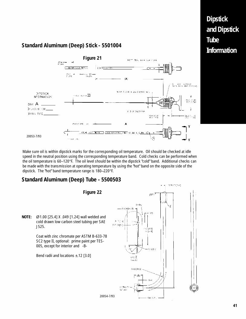
NOTE: Ø 1.00 [25.4] X .049 [1.24] wall welded andcold drawn low carbon steel tubing per SAEJ525.
Coat with zinc chromate per ASTM B-633-78SC2 type II, optional: prime paint per TES-005, except for interior and -B-
Bend radii and locations ±.12 [3.0]
Dipstickand DipstickTubeInformation
Standard Aluminum (Deep) Stick - 5501004
Figure 21
Standard Aluminum (Deep) Tube - 5500503
Figure 22
Make sure oil is within dipstick marks for the corresponding oil temperature. Oil should be checked at idlespeed in the neutral position using the corresponding temperature band. Cold checks can be performed whenthe oil temperature is 60–120°F. The oil level should be within the dipstick "cold" band. Additional checks canbe made with the transmission at operating temperature by using the "hot" band on the opposite side of thedipstick. The "hot" band temperature range is 180–220°F.
20053-7/93
42
Dipstickand Dipstick
TubeInformation
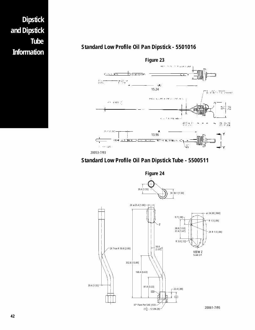
Standard Low Profile Oil Pan Dipstick - 5501016
Figure 23
Standard Low Profile Oil Pan Dipstick Tube - 5500511
Figure 24
20053-7/93
15.24
13.96
39.4 [1.55]
2X True R 50.8 [2.00]
352.8 [13.89]
168.4 [6.63]
81.8 [3.22]22.4 [.88]
37° Flare Per SAE J533
(1 - 12 UN-28)516
50.0[1.97]
R 3.0 [.12]
9.7 [.38]
ø 24.38 [.960]
R 1.5 [.06]
2X R 1.5 [.06]38.8 [1.53]37.4 [1.47]
VIEW ZScale 2/1
39.4 [1.55]
2X ø 25.4 [1.00]
3X 38.1 [1.50]
20061-7/95
43
Dipstickand DipstickTubeInformation
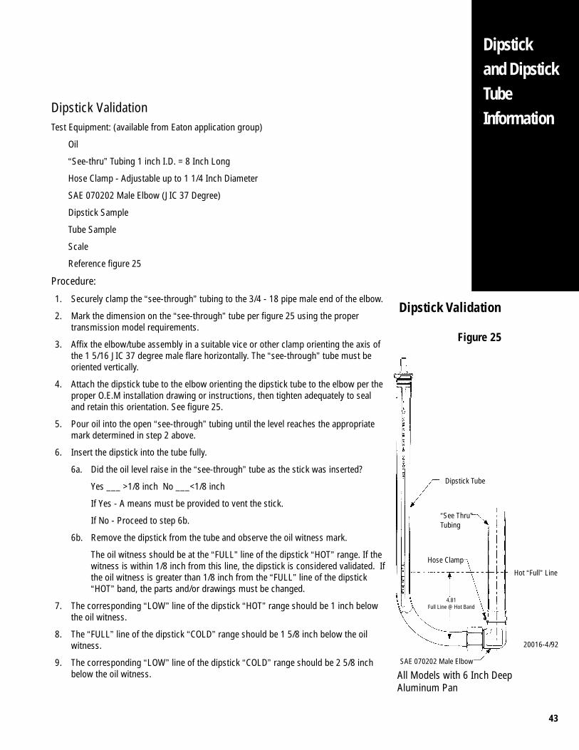
Dipstick ValidationTest Equipment: (available from Eaton application group)
Oil
“See-thru” Tubing 1 inch I.D. = 8 Inch Long
Hose Clamp - Adjustable up to 1 1/4 Inch Diameter
SAE 070202 Male Elbow (JIC 37 Degree)
Dipstick Sample
Tube Sample
Scale
Reference figure 25
Procedure:
1. Securely clamp the “see-through” tubing to the 3/4 - 18 pipe male end of the elbow.
2. Mark the dimension on the “see-through” tube per figure 25 using the propertransmission model requirements.
3. Affix the elbow/tube assembly in a suitable vice or other clamp orienting the axis ofthe 1 5/16 JIC 37 degree male flare horizontally. The “see-through” tube must beoriented vertically.
4. Attach the dipstick tube to the elbow orienting the dipstick tube to the elbow per theproper O.E.M installation drawing or instructions, then tighten adequately to sealand retain this orientation. See figure 25.
5. Pour oil into the open “see-through” tubing until the level reaches the appropriatemark determined in step 2 above.
6. Insert the dipstick into the tube fully.
6a. Did the oil level raise in the “see-through” tube as the stick was inserted?
Yes ___ >1/8 inch No ___<1/8 inch
If Yes - A means must be provided to vent the stick.
If No - Proceed to step 6b.
6b. Remove the dipstick from the tube and observe the oil witness mark.
The oil witness should be at the “FULL” line of the dipstick “HOT” range. If thewitness is within 1/8 inch from this line, the dipstick is considered validated. Ifthe oil witness is greater than 1/8 inch from the “FULL” line of the dipstick“HOT” band, the parts and/or drawings must be changed.
7. The corresponding “LOW” line of the dipstick “HOT” range should be 1 inch belowthe oil witness.
8. The “FULL” line of the dipstick “COLD” range should be 1 5/8 inch below the oilwitness.
9. The corresponding “LOW” line of the dipstick “COLD” range should be 2 5/8 inchbelow the oil witness.
Dipstick Tube
4.81Full Line @ Hot Band
SAE 070202 Male Elbow
All Models with 6 Inch DeepAluminum Pan
Hose Clamp
“See Thru”Tubing
20016-4/92
Dipstick Validation
Figure 25
Hot “Full” Line
44
Dipstickand Dipstick
TubeInformation
FULL
2.8 [.11]
35.3
COLD
25.4
FULL
25.4 [1.00]
HOT
[1.39]
[1.00]
ADD
20062-4/94
Minimum Fill Level
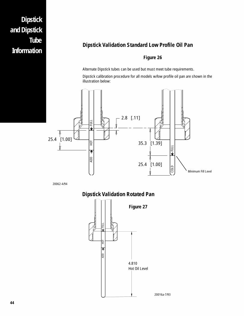
Dipstick Validation Standard Low Profile Oil Pan
Figure 26
Alternate Dipstick tubes can be used but must meet tube requirements.
Dipstick calibration procedure for all models w/low profile oil pan are shown in theillustration below:
Dipstick Validation Rotated Pan
Figure 27
20016a-7/93
FULL
4.810Hot Oil Level
HOT
ADD
45
Dipstickand DipstickTubeInformation
Failure to use proper parts or failure to follow instal-lation instructions could lead to personal injury orproperty damage.
Dipstick Tube Mounting
Figure 28
WARNING
20042-7/95
NOTE: Eaton Dipstick MountingBracket Design Shown.
Detailed Area
Dipstick Tube FittingLocation 15⁄8-12UN-2A SAEFor SAE -O-Ring Fitting
DipstickTube Nut
Dipstick Tube
Support/ProtectionBracket
46
LubricationRequirements
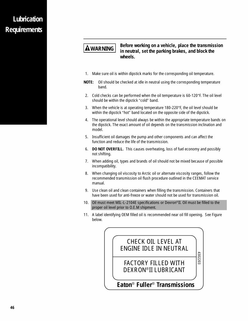
Before working on a vehicle, place the transmissionin neutral, set the parking brakes, and block thewheels.
1. Make sure oil is within dipstick marks for the corresponding oil temperature.
NOTE: Oil should be checked at idle in neutral using the corresponding temperatureband.
2. Cold checks can be performed when the oil temperature is 60-120°F. The oil levelshould be within the dipstick “cold” band.
3. When the vehicle is at operating temperature 180-220°F, the oil level should bewithin the dipstick “hot” band located on the opposite side of the dipstick.
4. The operational level should always be within the appropriate temperature bands onthe dipstick. The exact amount of oil depends on the transmission inclination andmodel.
5. Insufficient oil damages the pump and other components and can affect thefunction and reduce the life of the transmission.
6. DO NOT OVERFILL. This causes overheating, loss of fuel economy and possiblynot shifting.
7. When adding oil, types and brands of oil should not be mixed because of possibleincompatibility.
8. When changing oil viscosity to Arctic oil or alternate viscosity ranges, follow therecommended transmission oil flush procedure outlined in the CEEMAT servicemanual.
9. Use clean oil and clean containers when filling the transmission. Containers thathave been used for anti-freeze or water should not be used for transmission oil.
10. Oil must meet MIL-L-2104E specifications or Dexron®II. Oil must be filled to theproper oil level prior to O.E.M shipment.
11. A label identifying OEM filled oil is recommended near oil fill opening. See Figurebelow.
WARNING
Eaton® Fuller® Transmissions
CHECK OIL LEVEL ATENGINE IDLE IN NEUTRAL
FACTORY FILLED WITHDEXRON®II LUBRICANT
4302203
47
LubricationRequirements
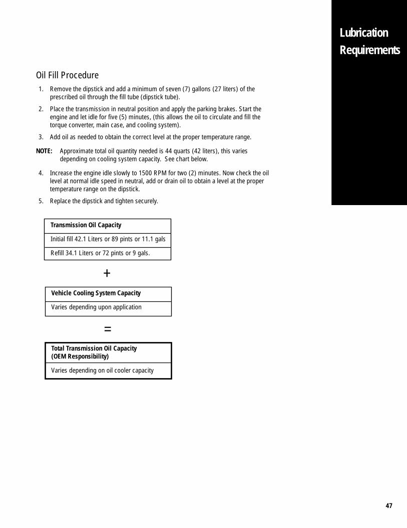
Oil Fill Procedure1. Remove the dipstick and add a minimum of seven (7) gallons (27 liters) of the
prescribed oil through the fill tube (dipstick tube).
2. Place the transmission in neutral position and apply the parking brakes. Start theengine and let idle for five (5) minutes, (this allows the oil to circulate and fill thetorque converter, main case, and cooling system).
3. Add oil as needed to obtain the correct level at the proper temperature range.
NOTE: Approximate total oil quantity needed is 44 quarts (42 liters), this variesdepending on cooling system capacity. See chart below.
4. Increase the engine idle slowly to 1500 RPM for two (2) minutes. Now check the oillevel at normal idle speed in neutral, add or drain oil to obtain a level at the propertemperature range on the dipstick.
5. Replace the dipstick and tighten securely.
Transmission Oil Capacity
Initial fill 42.1 Liters or 89 pints or 11.1 gals
Refill 34.1 Liters or 72 pints or 9 gals.
Vehicle Cooling System Capacity
Varies depending upon application
+
=Total Transmission Oil Capacity(OEM Responsibility)
Varies depending on oil cooler capacity

48
LubricationRequirements
Lubrication Change and InspectionHIGHWAY USE
First 1,000 to 1,500 miles Change transmission oil, filter,and strainer on new units.
Every 2,500 miles Inspect lubrication level.Check for leaks.
Every 50,000 miles or 1 year Change transmission lubricant and filter.
Check the strainer for dirt.
OFF-HIGHWAY USEFirst 30 hours Change transmission oil, filter,
and strainer on new units.
Every 40 hours Inspect lubrication level.Check for leaks.
Every 500 hours Change transmission lubricant and filterwhere severe dirt conditions exist.
Every 1,000 hours Change transmission lubricant and filter.(Normal off-highway use.)
Recommended LubricantType Grade Fahrenheit (Celsius)
(SAE) AmbientTemperature
C4 Type 10W Above 0°F (-32°C)MIL-L-2104E
Dexron® II Above 0°F (-32°C)
Arctic Oil 0W-20 Below 0°F (-32°C)
0°F-17.78°C
(Degrees F)
Minimum Temperature For Operating Transmission
-50 -40 -30 -20 -10 0 10 20 30 40 50 Above50
-25°F-31.67°C
SAE 10W or Dexron® II
SAE 0W-20
Lube Recommendations
& III
49
AirSupply/DryerRequirements
1. A high quality commercially available air dryer is required in the air supply linebefore the CEEMAT transmission.
2. Minimum air requirement for the CEEMAT transmission is 90 PSI.
3. A minimum of 3/8 inch diameter air supply line is required for the CEEMAT.
4. The CEEMAT air supply is required to be routed from the air tank which supplies airto either the front or rear vehicle service brakes with a gauge indicator in the cab.See figure 29.
5. Transmission air lines should not be routed or attached to bottom air tank fittings toavoid any chance of ingesting moisture.
6. Care must be used when routing the air supply to avoid kinks and close contact toheat sources.
7. The CEEMAT air supply must be connected to the air filter/regulator mounted on theECU cover, see figure 29.
NOTE: The filter/regulator should not be removed during installation.
8. Air additives such as alcohol or deicer should not be permitted to enter the CEEMATair supply. Additives could cause damage to air system components which couldlead to degraded transmission performance.
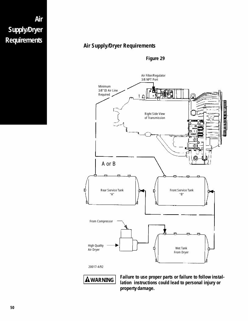
50
AirSupply/Dryer
Requirements
Failure to use proper parts or failure to follow instal-lation instructions could lead to personal injury orproperty damage.
Air Supply/Dryer Requirements
Figure 29
Rear Service Tank“A”
Front Service Tank“B”
Wet TankFrom Dryer
Air Filter/Regulator3/8 NPT Port
Right Side Viewof Transmission
High QualityAir Dryer
From Compressor
WARNING
20017-4/92
Minimum3/8" ID Air LineRequired
A or B
51
Shift Control Installation (Electronic Shifter)The CEEMAT Electronic Shifter provides many benefits over conventional mechanical(cable) systems. Along with simplified installation and the elimination of adjustmentproblems, the CEEMAT Electronic Shifter provides several features such as: dual stationcapability, automatic neutral (quick-to-neutral), and application specific inputs andoutputs such as auto pac mode for refuse trucks.
1. The CEEMAT Electronic Shifter should be situated in the cab in a functional, easilyaccessible location in relation to the driver.
2. The shift tower and shift lever should not interfere with other vehicle relatedcontrols or accessory features located on the dash or surrounding area.
3. The CEEMAT Electronic Shifter was designed to fit into existing common shiftcontrol towers. The dimensions for the CEEMAT Electronic Shifter are shown onthe next page.
4. The OEM is responsible for providing the electrical wiring harness for the CEEMATElectronic Shifter. Harness requirements are listed throughout the followingsection. Key requirements are repeated in Appendix I.
ShiftControlSystem(Electric)

52
ShiftControlSystem
(Electric)Electronic Shifter
Figure 30
20068-10/94
Packard 24-Way ConnectorMating Connector Parts No. 12110088Secondary Lock Part No. 12047900Secondary Lock Part No. 12047901Terminal Part No. 12089649
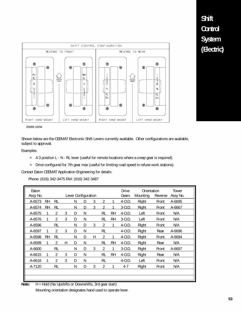
53
ShiftControlSystem(Electric)
20069-10/94
Shown below are the CEEMAT Electronic Shift Levers currently available. Other configurations are available,subject to approval.
Examples:
> A 3 position L - N - RL lever (useful for remote locations where a creep gear is required).
> Drive configured for 7th gear max (useful for limiting road speed in refuse work stations).
Contact Eaton CEEMAT Application Engineering for details:
Phone: (616) 342-3475 FAX: (616) 342-3487
Eaton Drive Orientation TowerAssy No. Lever Configuration Gears Mounting Reverse Assy No.A-6573 RH RL N D 3 2 1 4-O.D. Right Front A-6695A-6574 RH RL N D 3 2 1 3-O.D. Right Front A-6667A-6575 1 2 3 D N RL RH 4-O.D. Left Front N/AA-6576 1 2 3 D N RL RH 3-O.D. Left Front N/AA-6596 RL N D 3 2 1 4-O.D. Right Front N/AA-6597 1 2 3 D N RL 4-O.D. Right Rear A-6696A-6598 RH RL N D H 2 1 4-O.D. Right Front A-6694A-6599 1 2 H D N RL RH 4-O.D. Right Rear N/AA-6600 RL N D 3 2 1 3-O.D. Right Front A-6697A-6615 1 2 3 D N RL RH 4-O.D. Right Rear N/AA-6616 1 2 3 D N RL 4-O.D. Left Front N/AA-7120 RL N D 3 2 1 4-7 Right Front N/A
Note: H = Hold (No Upshifts or Downshifts, 3rd gear start)Mounting orientation designates hand used to operate lever.
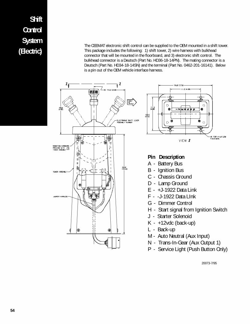
54
ShiftControlSystem
(Electric)The CEEMAT electronic shift control can be supplied to the OEM mounted in a shift tower.This package includes the following: 1) shift tower, 2) wire harness with bulkheadconnector that will be mounted in the floorboard, and 3) electronic shift control. Thebulkhead connector is a Deutsch (Part No. HD36-18-14PN). The mating connector is aDeutsch (Part No. HD34-18-14SN) and the terminal (Part No. 0462-201-16141). Belowis a pin out of the OEM vehicle interface harness.
Pin DescriptionA - Battery BusB - Ignition BusC - Chassis GroundD - Lamp GroundE - +J-1922 Data LinkF - -J-1922 Data LInkG - Dimmer ControlH - Start signal from Ignition SwitchJ - Starter SolenoidK - +12vdc (back-up)L - Back-upM - Auto Neutral (Aux Input)N - Trans-In-Gear (Aux Output 1)P - Service Light (Push Button Only)
20073-7/95
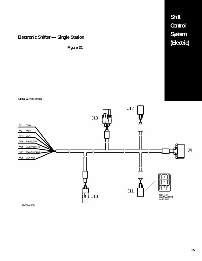
55
ShiftControlSystem(Electric)
Electronic Shifter — Single Station
Figure 31
W28
W27
J10
J4
J13
J12
AUTO NEUTRAL
VIGN
W25
W24
W13
W2
W1
LAMP_GND
VBAT
GND
AUX_OUT
TRANS IN GEAR
J112
SCALE 2/1AS VIEW FROMWIRE SIDE
4
3
5
1
Typical Wiring Harness
20060a-9/94
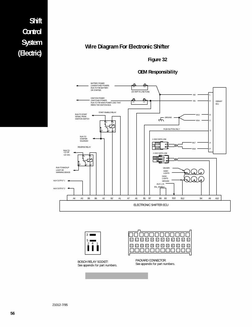
56
W17
W18
W13
W14
W2
W1
L
K
A
P
B
C
BAT AUX
BAT AUX CEEMATECU
1
24
3
5
GAUGES
LIGHTSDASH
LIGHTSDASH
GROUNDAUX 3_IN
NOTE: ALL WIRES ARE TO BE 16 GAUGE GXL
BATTERY POWER(UNSWITCHED POWER)RUN TO THE BATTERY OR STARTER.
(30 AMP IN-LINE FUSE)
START ENABLE RELAY
GROUND
PUSH BUTTON ONLY
J-1922 DATA LINK
RUN TO STARTSIGNAL FROMIGNITION SWITCH
RUN TO STARTERSOLENOID
REVERSE RELAY
RUN TO +12 OR+24 VDC
RUN TO BACKUPLIGHT ORWARNING DEVICE
AUX OUTPUT 1
AUX OUTPUT 2
J-1922 DATA LINK
IGNITION POWER(SWITCHED POWER)RUN TO THE MAIN POWER LEAD THATFEEDS THE IGNITION BUS.
ELECTRONIC SHIFTER ECU
PACKARD CONNECTOR:See appendix for part numbers.
142
3
5
BOSCH RELAY SOCKET:See appendix for part numbers.
1
24
3
5
ESL_ENABLE
A10A9B1A5A7A2 A1B2B6B5 B4B12B10B9 B3A3A4
G
B7
B10B11B12 B1B2B3B4B5B6B7B8B9
A10A11A12 A1A2A3A4A5A6A7A8A9
ShiftControlSystem
(Electric)Wire Diagram For Electronic Shifter
Figure 32
OEM Responsibility
21012-7/95
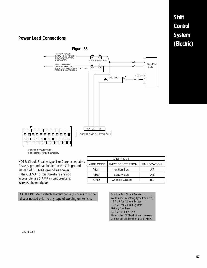
57
W13
W14
W2
W1
L
K
B
C
BAT AUX
BAT AUX
CEEMATECU
B1A5A7
BATTERY POWER
(30 AMP IN LINE FUSE)
(UNSWITCHED POWER)RUN TO THE BATTERYOR STARTER.
GROUND
IGNITION POWER(SWITCHED POWER)RUN TO THE MAIN POWER LEAD THATFEEDS THE IGNITION BUS.
ELECTRONIC SHIFTER ECU
NOTE: Circuit Breaker type 1 or 2 are acceptable. Chassis ground can be tied to the Cab groundinstead of CEEMAT ground as shown. If the CEEMAT circuit breakers are not accessible use 5 AMP circuit breakers. Wire as shown above.
Ignition Bus Circuit Breakers (Automatic Resetting Type Required)15 AMP for 12 Volt System 10 AMP for 24 Volt System Battery Bus Fuse 30 AMP In Line FuseUnless the CEEMAT circuit breakers are not accessible then use 5 AMP.
CAUTION: Main vehicle battery cable (+) or (-) must be disconnected prior to any type of welding on vehicle.
WIRE TABLE
WIRE CODE WIRE DESCRIPTION PIN LOCATION
Vign Ignition Bus A7
Vbat Battery Bus A5
GND Chassis Ground B1
PACKARD CONNECTOR:See appendix for part numbers.
B10B11B12 B1B2B3B4B5B6B7B8B9
A10A11A12 A1A2A3A4A5A6A7A8A9
Power Lead Connections
Figure 33
ShiftControlSystem(Electric)
21013-7/95
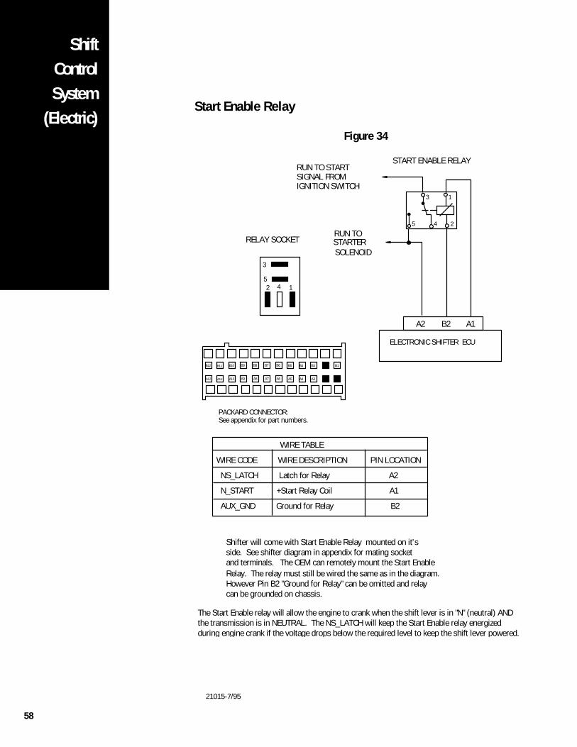
58
ShiftControlSystem
(Electric)Start Enable Relay
Figure 34
Shifter will come with Start Enable Relay mounted on it'sside. See shifter diagram in appendix for mating socketand terminals. The OEM can remotely mount the Start EnableRelay. The relay must still be wired the same as in the diagram.However Pin B2 "Ground for Relay" can be omitted and relay can be grounded on chassis.
142
3
5
RELAY SOCKET
A2 A1B2
STARTERSOLENOID
RUN TO START SIGNAL FROM IGNITION SWITCH
RUN TO
START ENABLE RELAY
ELECTRONIC SHIFTER ECU
The Start Enable relay will allow the engine to crank when the shift lever is in "N" (neutral) AND the transmission is in NEUTRAL. The NS_LATCH will keep the Start Enable relay energized during engine crank if the voltage drops below the required level to keep the shift lever powered.
1
24
3
5
WIRE TABLE
WIRE CODE WIRE DESCRIPTION PIN LOCATION
NS_LATCH Latch for Relay A2
N_START +Start Relay Coil A1
AUX_GND Ground for Relay B2
PACKARD CONNECTOR:See appendix for part numbers.
B10B11B12 B1B2B3B4B5B6B7B8B9
A10A11A12 A1A2A3A4A5A6A7A8A9
21015-7/95
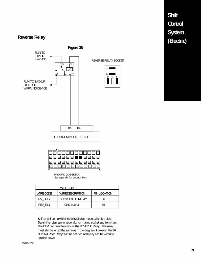
59
ShiftControlSystem(Electric)
Reverse Relay
Figure 35
21016-7/95
142
3
5
REVERSE RELAY SOCKET
Shifter will come with REVERSE Relay mounted on it's side.See shifter diagram in appendix for mating socket and terminals.The OEM can remotely mount the REVERSE Relay. The relaymust still be wired the same as in the diagram. However Pin B6"+ POWER for Relay" can be omitted and relay can be wired toignition power.
B6B5
ELECTRONIC SHIFTER ECU
RUN TO BACKUPLIGHT ORWARNING DEVICE
RUN TO+12 OR+24 VDC
1
24
3
5
WIRE TABLE
WIRE CODE WIRE DESCRIPTION PIN LOCATION
RV_SPLY + 12VDC FOR RELAY B6
REV_RLY GND output B5
PACKARD CONNECTOR:See appendix for part numbers.
B10B11B12 B1B2B3B4B5B6B7B8B9
A10A11A12 A1A2A3A4A5A6A7A8A9

60
ShiftControlSystem
(Electric)Dimmer Control Input
Figure 36
21017-7/95
GAUGES
B4B12
ELECTRONIC SHIFTER ECU
DASH LIGHTS
DASH LIGHTSGROUND.
Connect VDASH to the dash lights. This input willdim the light on the shift lever. Pin B12 "LAMP_GND"can be omited if the shift lever chassis is grounded.
WIRE TABLE
WIRE CODE WIRE DESCRIPTION PIN LOCATION
VDASH Dimmer Control B4
LAMP_GND Lamp ground B12
PACKARD CONNECTOR:See appendix for part numbers.
B10B11B12 B1B2B3B4B5B6B7B8B9
A10A11A12 A1A2A3A4A5A6A7A8A9
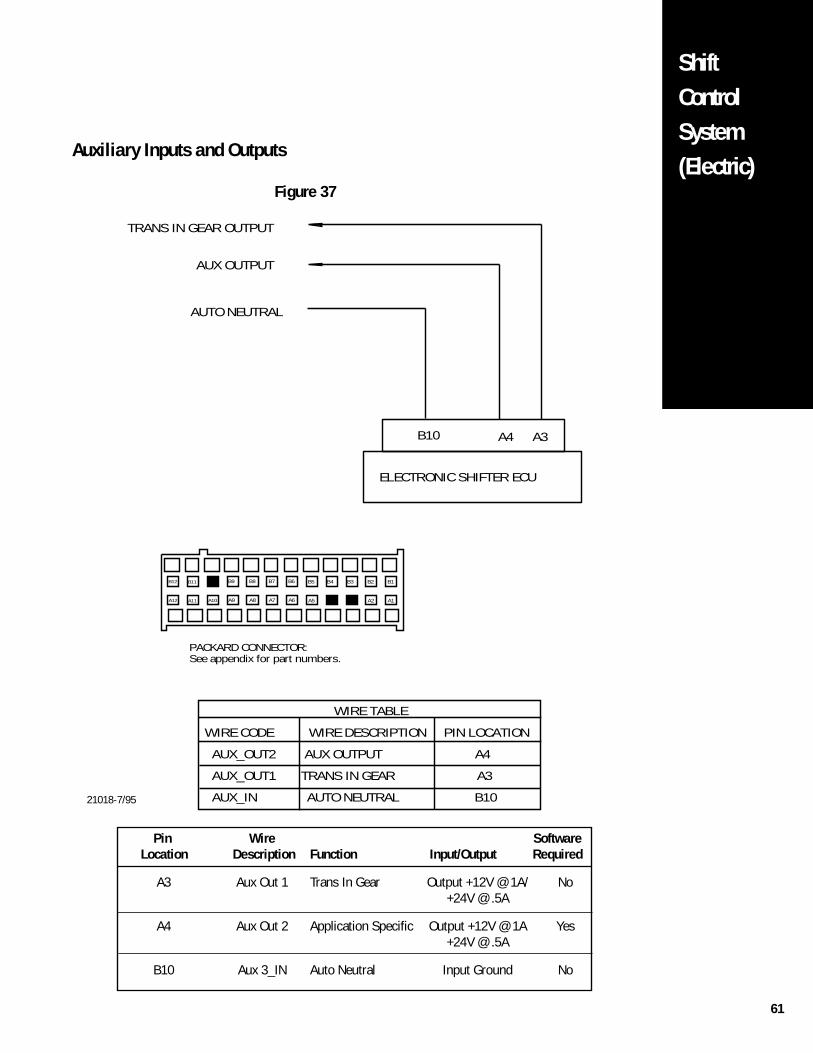
61
ShiftControlSystem(Electric)
Pin Wire Software Location Description Function Input/Output Required
A3 Aux Out 1 Trans In Gear Output +12V @ 1A/ No+24V @ .5A
A4 Aux Out 2 Application Specific Output +12V @ 1A Yes+24V @ .5A
B10 Aux 3_IN Auto Neutral Input Ground No
TRANS IN GEAR OUTPUT
AUX OUTPUT
B10
AUTO NEUTRAL
A3A4
ELECTRONIC SHIFTER ECU
WIRE TABLE
WIRE CODE WIRE DESCRIPTION PIN LOCATION
AUX_OUT2 AUX OUTPUT A4
AUX_OUT1 TRANS IN GEAR A3
AUX_IN AUTO NEUTRAL B10
PACKARD CONNECTOR:See appendix for part numbers.
B10B11B12 B1B2B3B4B5B6B7B8B9
A10A11A12 A1A2A3A4A5A6A7A8A9
21018-7/95
Auxiliary Inputs and Outputs
Figure 37
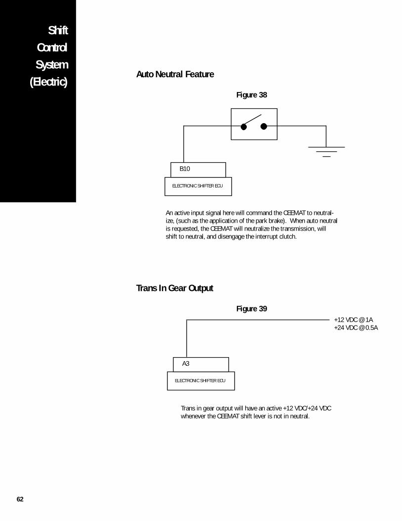
62
ShiftControlSystem
(Electric)Auto Neutral Feature
Figure 38
Trans In Gear Output
Figure 39
ELECTRONIC SHIFTER ECU
A3
+12 VDC @ 1A+24 VDC @ 0.5A
Trans in gear output will have an active +12 VDC/+24 VDCwhenever the CEEMAT shift lever is not in neutral.
ELECTRONIC SHIFTER ECU
B10
An active input signal here will command the CEEMAT to neutral-ize, (such as the application of the park brake). When auto neutralis requested, the CEEMAT will neutralize the transmission, willshift to neutral, and disengage the interrupt clutch.
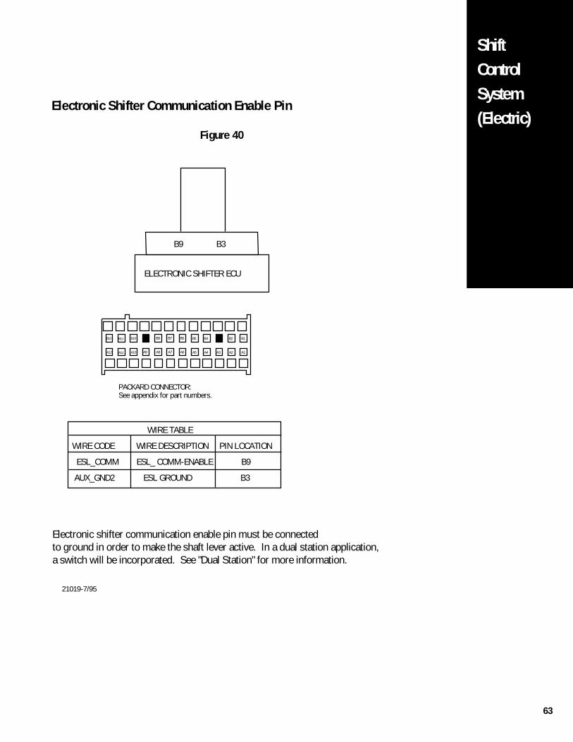
63
ShiftControlSystem(Electric)
Electronic Shifter Communication Enable Pin
Figure 40
B9 B3
ELECTRONIC SHIFTER ECU
WIRE TABLE
WIRE CODE WIRE DESCRIPTION PIN LOCATION
ESL_COMM ESL_ COMM-ENABLE B9
AUX_GND2 ESL GROUND B3
Electronic shifter communication enable pin must be connectedto ground in order to make the shaft lever active. In a dual station application,a switch will be incorporated. See "Dual Station" for more information.
PACKARD CONNECTOR:See appendix for part numbers.
B10B11B12 B1B2B3B4B5B6B7B8B9
A10A11A12 A1A2A3A4A5A6A7A8A9
21019-7/95
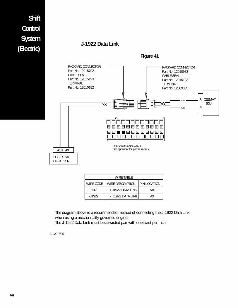
64
ShiftControlSystem
(Electric)J-1922 Data Link
Figure 41
W17
W18
PACKARD CONNECTORPart No. 12015792CABLE SEALPart No. 12015193TERMINALPart No. 12010182
A10 A9
ELECTRONICSHIFTLEVER
PACKARD CONNECTORPart No. 12010973CABLE SEALPart No. 12015193TERMINALPart No. 12089305
A
P
CEEMAT ECU
WIRE TABLE
WIRE CODE WIRE DESCRIPTION PIN LOCATION
+J1922 + J1922 DATA LINK A10
-J1922 - J1922 DATA LINK A9
The diagram above is a recommended method of connecting the J-1922 Data Linkwhen using a mechanically governed engine.The J-1922 Data Link must be a twisted pair with one twist per inch.
PACKARD CONNECTOR:See appendix for part numbers.
B10B11B12 B1B2B3B4B5B6B7B8B9
A10A11A12 A1A2A3A4A5A6A7A8A9
21020-7/95
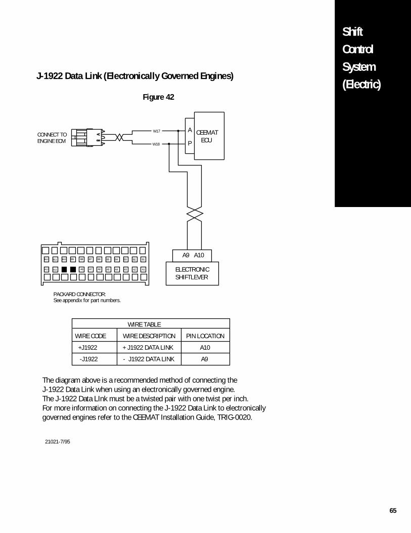
65
ShiftControlSystem(Electric)
W17
W18
A
P
CEEMAT ECU
A9 A10
ELECTRONICSHIFTLEVER
WIRE TABLE
WIRE CODE WIRE DESCRIPTION PIN LOCATION
+J1922 + J1922 DATA LINK A10
-J1922 - J1922 DATA LINK A9
The diagram above is a recommended method of connecting the J-1922 Data Link when using an electronically governed engine.The J-1922 Data LInk must be a twisted pair with one twist per inch.For more information on connecting the J-1922 Data Link to electronicallygoverned engines refer to the CEEMAT Installation Guide, TRIG-0020.
PACKARD CONNECTOR:See appendix for part numbers.
B10B11B12 B1B2B3B4B5B6B7B8B9
CONNECT TO ENGINE ECM
A10A11A12 A1A2A3A4A5A6A7A8A9
J-1922 Data Link (Electronically Governed Engines)
Figure 42
21021-7/95
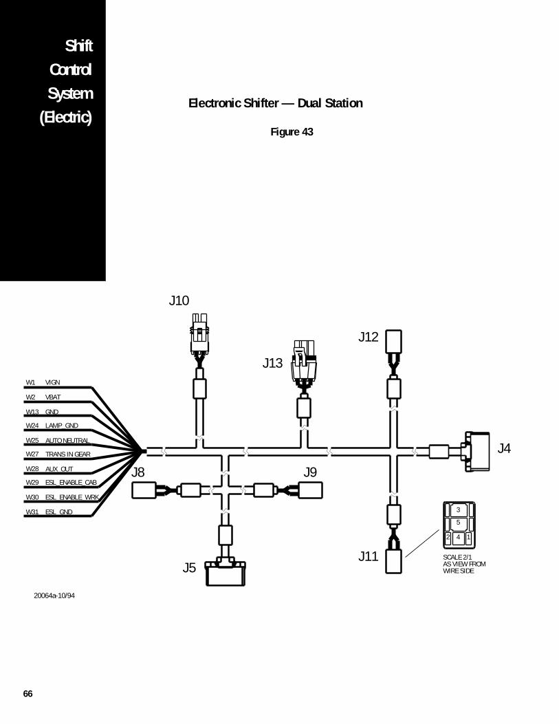
66
ShiftControlSystem
(Electric)Electronic Shifter — Dual Station
Figure 43
J4
12
WIRE SIDEAS VIEW FROMSCALE 2/1
4
3
5
J9
J13
J12
GND
VIGN
W25
W28
W27
J8
W24
W13
W2
W1
J10
LAMP_GND
VBAT
J11
ESL_GNDW31
W30
W29
J5
ESL_ENABLE_CAB
ESL_ENABLE_WRK
AUTO NEUTRAL
AUX_OUT
TRANS IN GEAR
20064a-10/94
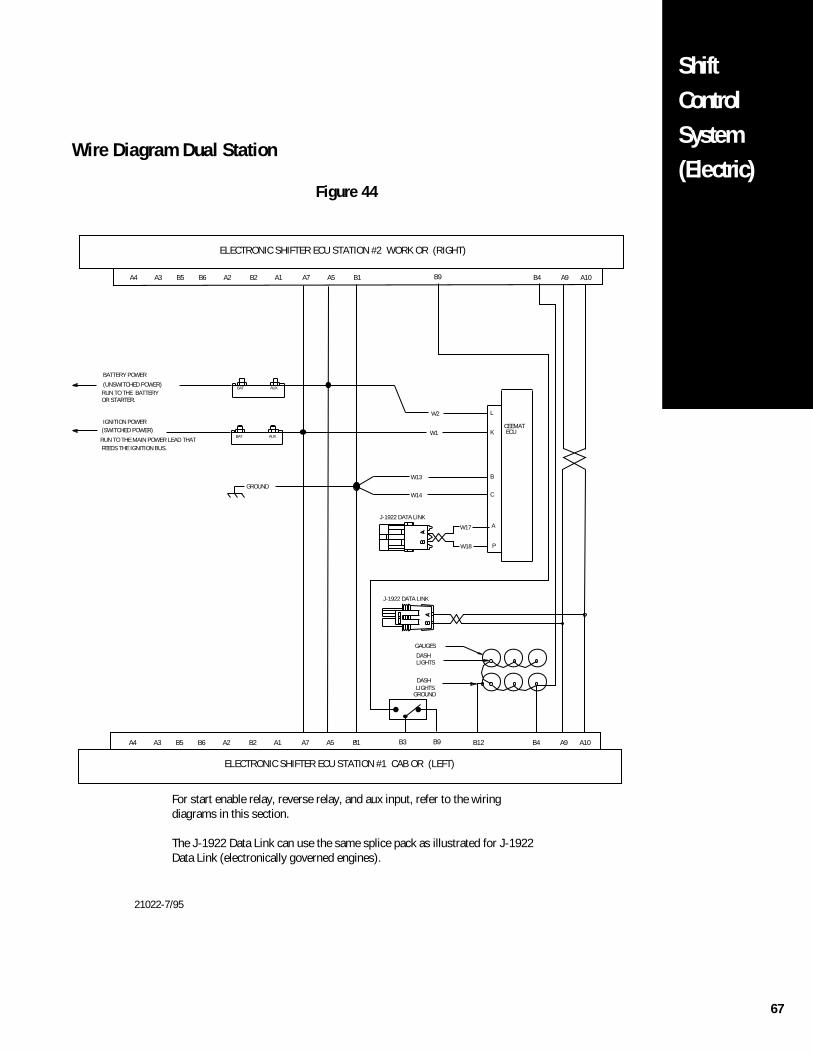
67
ShiftControlSystem(Electric)
Wire Diagram Dual Station
Figure 44
W17
W18
W13
W14
W2
W1
L
K
A
P
B
C
BAT AUX
BAT AUX
CEEMATECU
GAUGES
LIGHTSDASH
LIGHTSDASH
GROUND
BATTERY POWER
(UNSWITCHED POWER)RUN TO THE BATTERYOR STARTER.
GROUND
J-1922 DATA LINK
IGNITION POWER(SWITCHED POWER)
RUN TO THE MAIN POWER LEAD THATFEEDS THE IGNITION BUS.
ELECTRONIC SHIFTER ECU STATION #1 CAB OR (LEFT)
ELECTRONIC SHIFTER ECU STATION #2 WORK OR (RIGHT)
J-1922 DATA LINK
For start enable relay, reverse relay, and aux input, refer to the wiringdiagrams in this section.
The J-1922 Data Link can use the same splice pack as illustrated for J-1922Data Link (electronically governed engines).
A10A9B1A5A7A2 A1B2B6B5 B4B12B3 B9A3A4
A10A9B1A5A7A2 A1B2B6B5 B4B9A3A4
21022-7/95
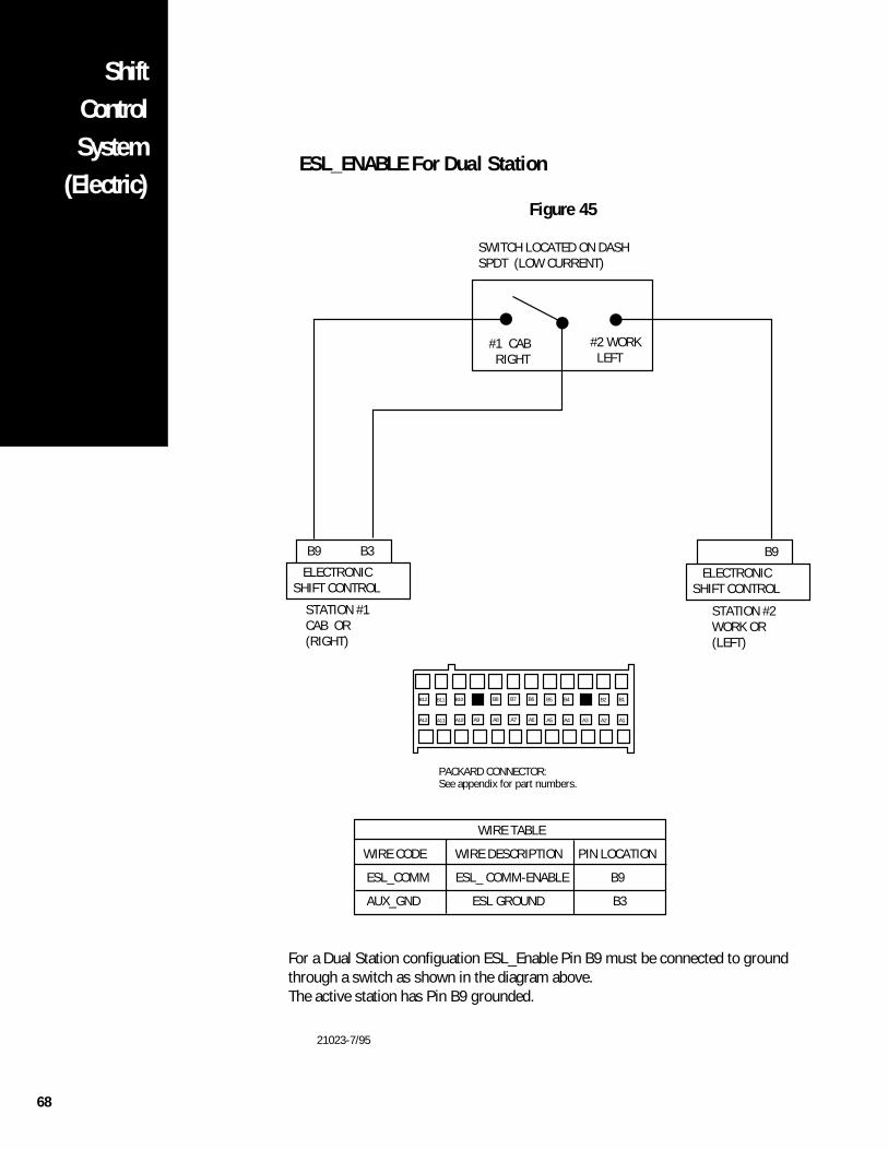
68
ShiftControlSystem
(Electric)ESL_ENABLE For Dual Station
Figure 45
ELECTRONICSHIFT CONTROL
B9 B3
ELECTRONICSHIFT CONTROL
B9
SWITCH LOCATED ON DASHSPDT (LOW CURRENT)
STATION #1CAB OR(RIGHT)
STATION #2WORK OR(LEFT)
#2 WORK LEFT
#1 CAB RIGHT
WIRE TABLE
WIRE CODE WIRE DESCRIPTION PIN LOCATION
ESL_COMM ESL_ COMM-ENABLE B9
AUX_GND ESL GROUND B3
For a Dual Station configuation ESL_Enable Pin B9 must be connected to groundthrough a switch as shown in the diagram above.The active station has Pin B9 grounded.
PACKARD CONNECTOR:See appendix for part numbers.
B10B11B12 B1B2B3B4B5B6B7B8B9
A10A11A12 A1A2A3A4A5A6A7A8A9
21023-7/95
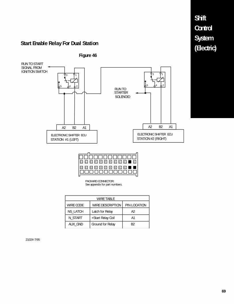
69
ShiftControlSystem(Electric)
STARTERSOLENOID
RUN TO START SIGNAL FROM IGNITION SWITCH
RUN TO
A2 A1B2
ELECTRONIC SHIFTER ECU
1
24
3
5
A2 A1B2
ELECTRONIC SHIFTER ECU
1
24
3
5
STATION #1 (LEFT) STATION #2 (RIGHT)
WIRE TABLE
WIRE CODE WIRE DESCRIPTION PIN LOCATION
NS_LATCH Latch for Relay A2
N_START +Start Relay Coil A1
AUX_GND Ground for Relay B2
PACKARD CONNECTOR:See appendix for part numbers.
B10B11B12 B1B2B3B4B5B6B7B8B9
A10A11A12 A1A2A3A4A5A6A7A8A9
Start Enable Relay For Dual Station
Figure 46
21024-7/95
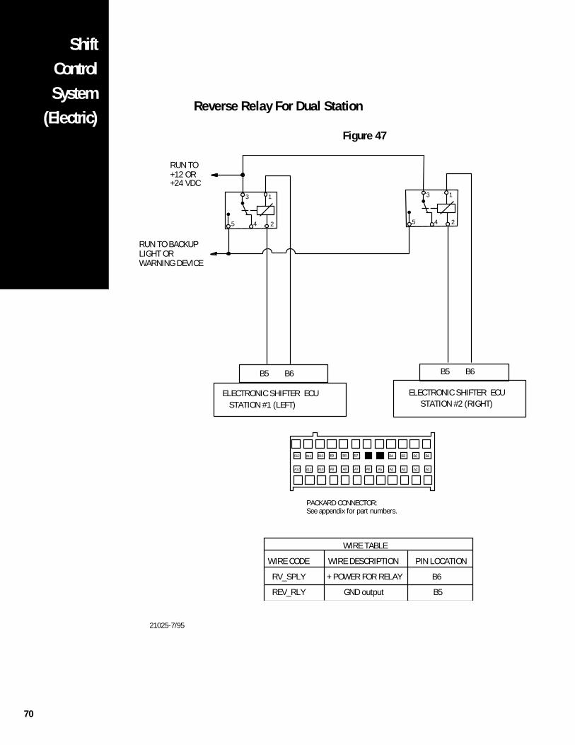
70
ShiftControlSystem
(Electric)Reverse Relay For Dual Station
Figure 47
B6B5
ELECTRONIC SHIFTER ECU
RUN TO BACKUPLIGHT ORWARNING DEVICE
RUN TO+12 OR+24 VDC
1
24
3
5
WIRE TABLE
WIRE CODE WIRE DESCRIPTION PIN LOCATION
RV_SPLY + POWER FOR RELAY B6
REV_RLY GND output B5
B6B5
ELECTRONIC SHIFTER ECU
1
24
3
5
STATION #1 (LEFT) STATION #2 (RIGHT)
PACKARD CONNECTOR:See appendix for part numbers.
B10B11B12 B1B2B3B4B5B6B7B8B9
A10A11A12 A1A2A3A4A5A6A7A8A9
21025-7/95
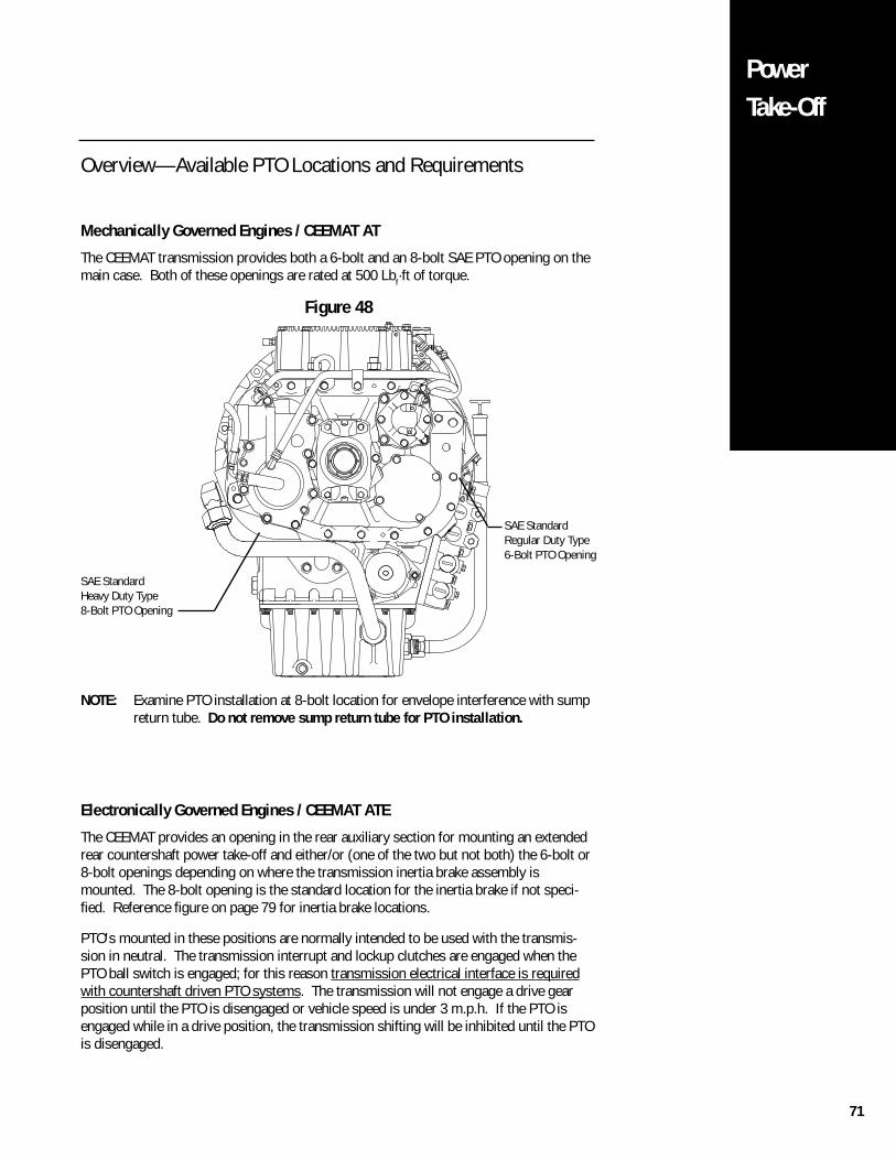
71
PowerTake-Off
Overview—Available PTO Locations and Requirements
Mechanically Governed Engines / CEEMAT AT
The CEEMAT transmission provides both a 6-bolt and an 8-bolt SAE PTO opening on themain case. Both of these openings are rated at 500 Lbf·ft of torque.
Figure 48
NOTE: Examine PTO installation at 8-bolt location for envelope interference with sumpreturn tube. Do not remove sump return tube for PTO installation.
Electronically Governed Engines / CEEMAT ATE
The CEEMAT provides an opening in the rear auxiliary section for mounting an extendedrear countershaft power take-off and either/or (one of the two but not both) the 6-bolt or8-bolt openings depending on where the transmission inertia brake assembly ismounted. The 8-bolt opening is the standard location for the inertia brake if not speci-fied. Reference figure on page 79 for inertia brake locations.
PTO's mounted in these positions are normally intended to be used with the transmis-sion in neutral. The transmission interrupt and lockup clutches are engaged when thePTO ball switch is engaged; for this reason transmission electrical interface is requiredwith countershaft driven PTO systems. The transmission will not engage a drive gearposition until the PTO is disengaged or vehicle speed is under 3 m.p.h. If the PTO isengaged while in a drive position, the transmission shifting will be inhibited until the PTOis disengaged.
SAE StandardHeavy Duty Type8-Bolt PTO Opening
SAE StandardRegular Duty Type6-Bolt PTO Opening
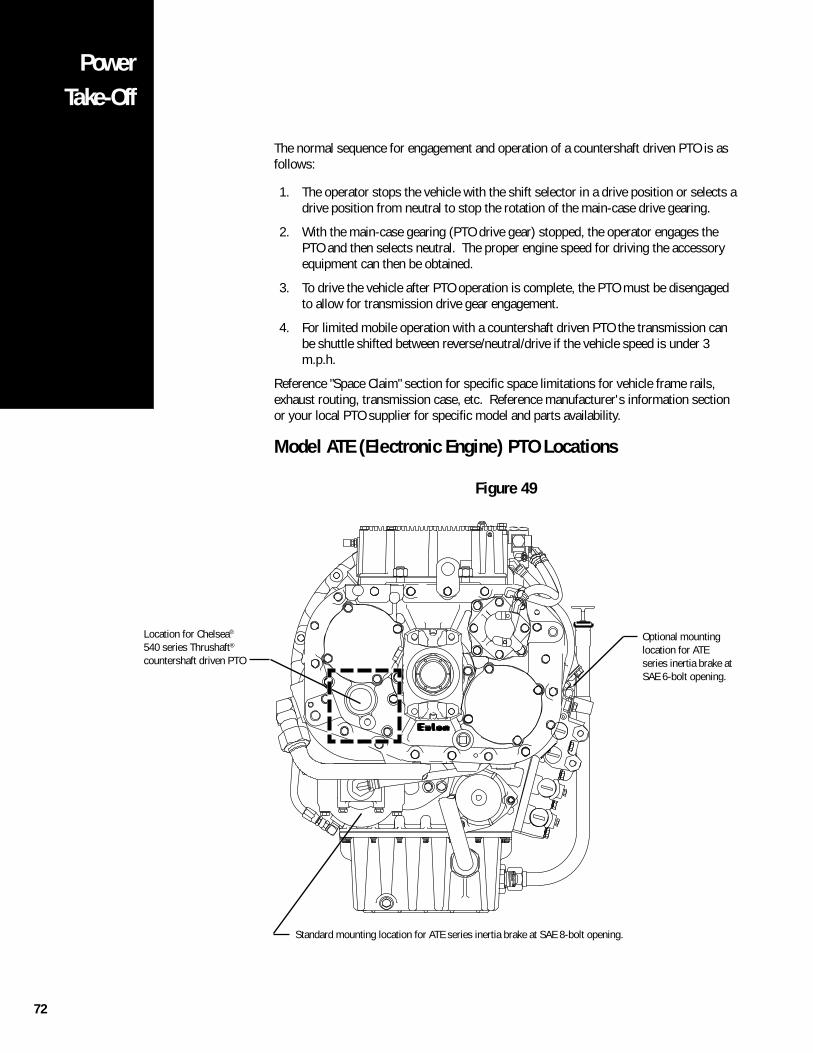
72
PowerTake-Off
Model ATE (Electronic Engine) PTO Locations
Figure 49
The normal sequence for engagement and operation of a countershaft driven PTO is asfollows:
1. The operator stops the vehicle with the shift selector in a drive position or selects adrive position from neutral to stop the rotation of the main-case drive gearing.
2. With the main-case gearing (PTO drive gear) stopped, the operator engages thePTO and then selects neutral. The proper engine speed for driving the accessoryequipment can then be obtained.
3. To drive the vehicle after PTO operation is complete, the PTO must be disengagedto allow for transmission drive gear engagement.
4. For limited mobile operation with a countershaft driven PTO the transmission canbe shuttle shifted between reverse/neutral/drive if the vehicle speed is under 3m.p.h.
Reference "Space Claim" section for specific space limitations for vehicle frame rails,exhaust routing, transmission case, etc. Reference manufacturer's information sectionor your local PTO supplier for specific model and parts availability.
Location for Chelsea®
540 series Thrushaft®
countershaft driven PTO
Optional mountinglocation for ATEseries inertia brake atSAE 6-bolt opening.
Standard mounting location for ATE series inertia brake at SAE 8-bolt opening.
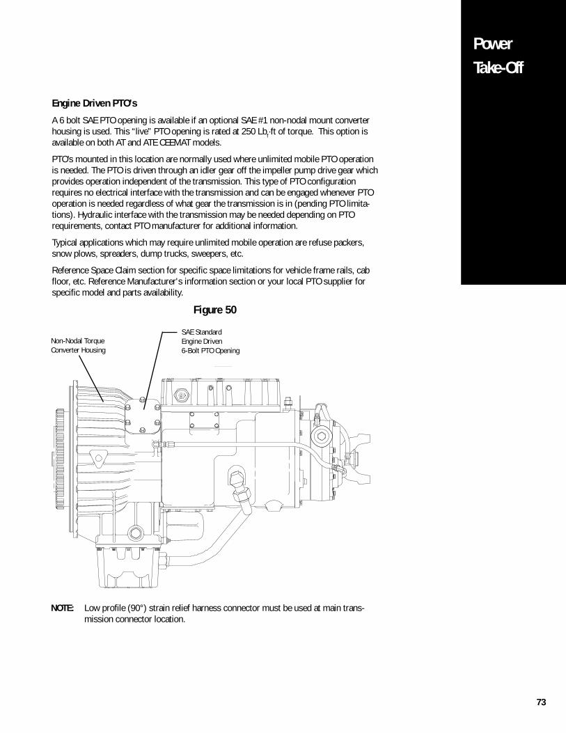
73
PowerTake-Off
Engine Driven PTO's
A 6 bolt SAE PTO opening is available if an optional SAE #1 non-nodal mount converterhousing is used. This “live” PTO opening is rated at 250 Lbf·ft of torque. This option isavailable on both AT and ATE CEEMAT models.
PTO’s mounted in this location are normally used where unlimited mobile PTO operationis needed. The PTO is driven through an idler gear off the impeller pump drive gear whichprovides operation independent of the transmission. This type of PTO configurationrequires no electrical interface with the transmission and can be engaged whenever PTOoperation is needed regardless of what gear the transmission is in (pending PTO limita-tions). Hydraulic interface with the transmission may be needed depending on PTOrequirements, contact PTO manufacturer for additional information.
Typical applications which may require unlimited mobile operation are refuse packers,snow plows, spreaders, dump trucks, sweepers, etc.
Reference Space Claim section for specific space limitations for vehicle frame rails, cabfloor, etc. Reference Manufacturer's information section or your local PTO supplier forspecific model and parts availability.
Figure 50
SAE StandardEngine Driven6-Bolt PTO Opening
Non-Nodal TorqueConverter Housing
NOTE: Low profile (90°) strain relief harness connector must be used at main trans-mission connector location.
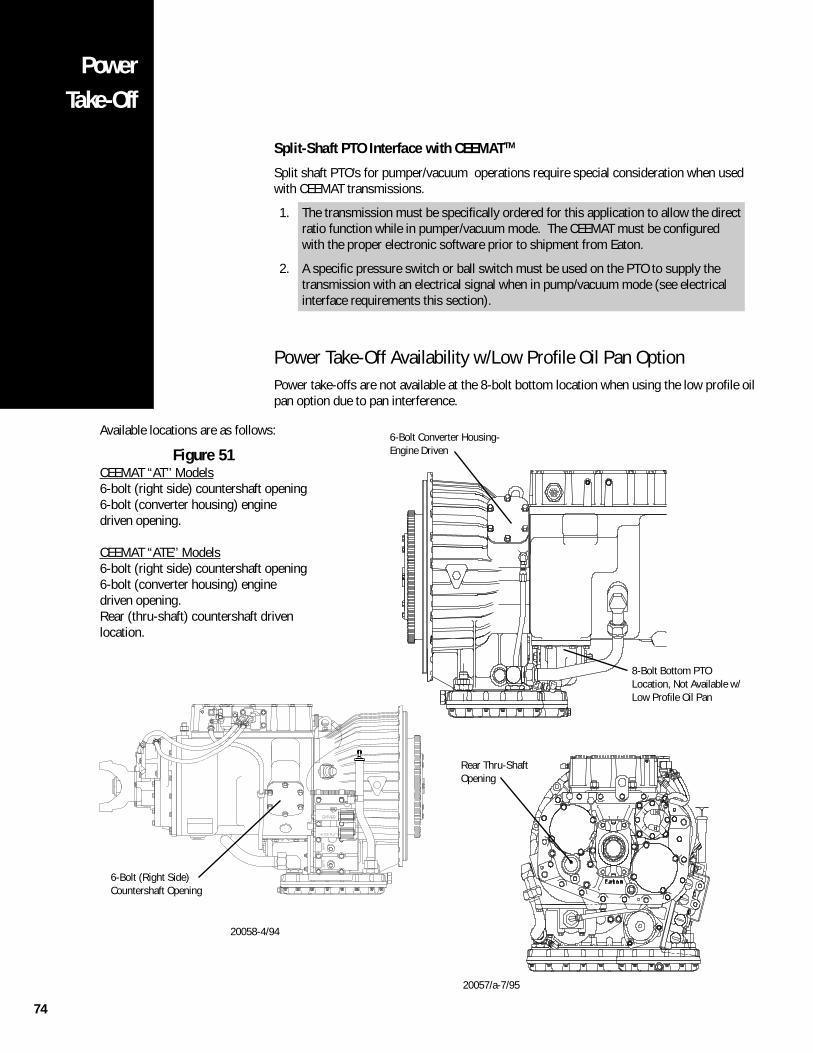
74
PowerTake-Off
Split-Shaft PTO Interface with CEEMATTM
Split shaft PTO’s for pumper/vacuum operations require special consideration when usedwith CEEMAT transmissions.
1. The transmission must be specifically ordered for this application to allow the directratio function while in pumper/vacuum mode. The CEEMAT must be configuredwith the proper electronic software prior to shipment from Eaton.
2. A specific pressure switch or ball switch must be used on the PTO to supply thetransmission with an electrical signal when in pump/vacuum mode (see electricalinterface requirements this section).
Power Take-Off Availability w/Low Profile Oil Pan OptionPower take-offs are not available at the 8-bolt bottom location when using the low profile oilpan option due to pan interference.
6-Bolt (Right Side)Countershaft Opening
20058-4/94
Rear Thru-ShaftOpening
8-Bolt Bottom PTOLocation, Not Available w/Low Profile Oil Pan
6-Bolt Converter Housing-Engine Driven
20057/a-7/95
Available locations are as follows:
Figure 51CEEMAT “AT’’ Models6-bolt (right side) countershaft opening6-bolt (converter housing) enginedriven opening.
CEEMAT “ATE’’ Models6-bolt (right side) countershaft opening6-bolt (converter housing) enginedriven opening.Rear (thru-shaft) countershaft drivenlocation.
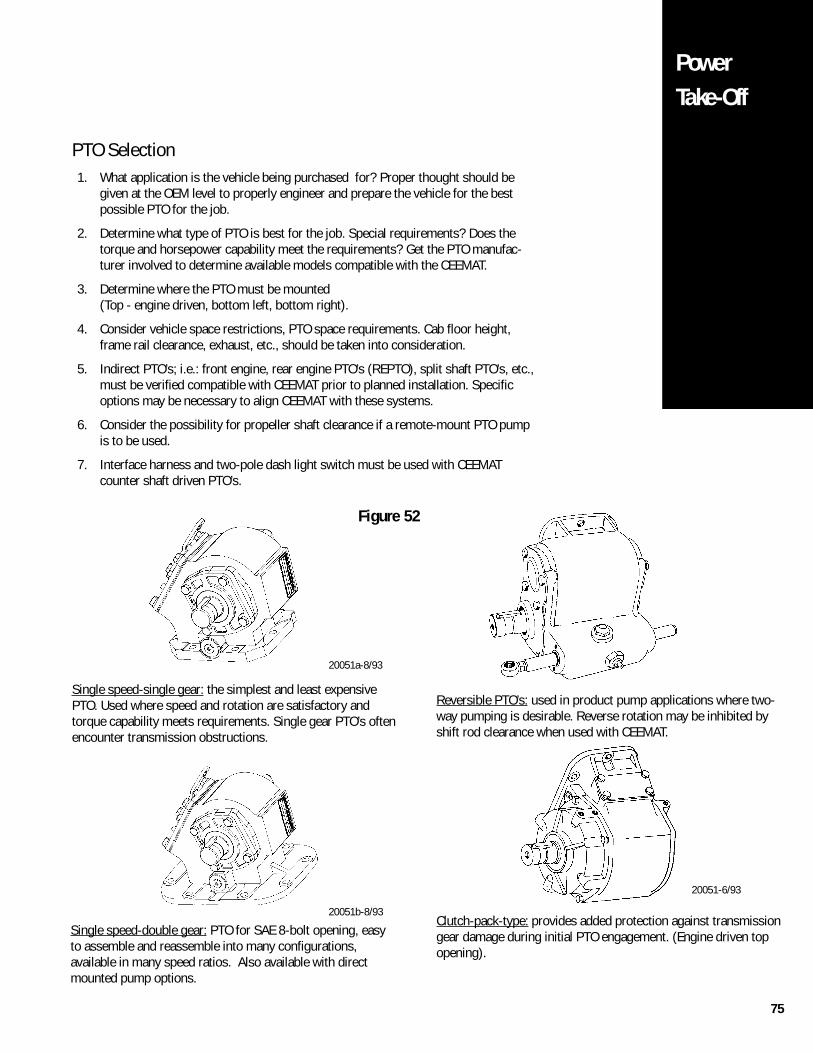
75
PowerTake-Off
Clutch-pack-type: provides added protection against transmissiongear damage during initial PTO engagement. (Engine driven topopening).
Reversible PTO’s: used in product pump applications where two-way pumping is desirable. Reverse rotation may be inhibited byshift rod clearance when used with CEEMAT.
20051-6/93
20051a-8/93
20051b-8/93
Figure 52
Single speed-single gear: the simplest and least expensivePTO. Used where speed and rotation are satisfactory andtorque capability meets requirements. Single gear PTO’s oftenencounter transmission obstructions.
Single speed-double gear: PTO for SAE 8-bolt opening, easyto assemble and reassemble into many configurations,available in many speed ratios. Also available with directmounted pump options.
PTO Selection1. What application is the vehicle being purchased for? Proper thought should be
given at the OEM level to properly engineer and prepare the vehicle for the bestpossible PTO for the job.
2. Determine what type of PTO is best for the job. Special requirements? Does thetorque and horsepower capability meet the requirements? Get the PTO manufac-turer involved to determine available models compatible with the CEEMAT.
3. Determine where the PTO must be mounted(Top - engine driven, bottom left, bottom right).
4. Consider vehicle space restrictions, PTO space requirements. Cab floor height,frame rail clearance, exhaust, etc., should be taken into consideration.
5. Indirect PTO’s; i.e.: front engine, rear engine PTO’s (REPTO), split shaft PTO’s, etc.,must be verified compatible with CEEMAT prior to planned installation. Specificoptions may be necessary to align CEEMAT with these systems.
6. Consider the possibility for propeller shaft clearance if a remote-mount PTO pumpis to be used.
7. Interface harness and two-pole dash light switch must be used with CEEMATcounter shaft driven PTO’s.
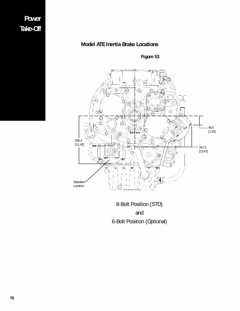
76
PowerTake-Off
Model ATE Inertia Brake Locations
Figure 53
48.5[1.91]
347.3[13.67]
290.2[11.42]
StandardLocation
8-Bolt Position (STD)
and
6-Bolt Position (Optional)
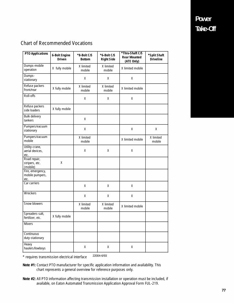
77
PowerTake-Off
22004-6/93
PTO Applications 6-Bolt Engine Driven
*8-Bolt C/S Bottom
*6-Bolt C/S Right Side
*Thru-Shaft C/S Rear Mounted
(ATE Only)
*Split Shaft Driveline
Dumps-mobile operation X fully mobile X limited
mobileX limited mobile X limited mobile
Dumps- stationary X X X
Refuse packers front/rear X fully mobile X limited
mobileX limited mobile X limited mobile
Roll-offsX X X
Refuse packers side loaders X fully mobile
Bulk delivery tankers X
Pumpers/vacuum stationary X X X
Pumpers/vacuum mobile
X limited mobile X limited mobile X limited
mobile
Utility-crane, aerial devices, etc.
X X X
Road repair, stripers, etc. (mobile)
X
Fire, emergency, mobile pumpers, etc.Car carriers
X X X
WreckersX X X
Snow blowers X limited mobile
X limited mobile X limited mobile
Spreaders-salt, fertilizer, etc. X fully mobile
Mixers
Continuous duty-stationary
Heavy haulers/lowboys X X X
* requires transmission electrical interface
Note #1: Contact PTO manufacturer for specific application information and availability. Thischart represents a general overview for reference purposes only.
Note #2: All PTO information affecting transmission installation or operation must be included, ifavailable, on Eaton Automated Transmission Application Approval Form FUL-219.
Chart of Recommended Vocations
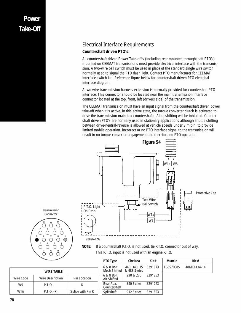
78
PowerTake-Off
W1a W5
Two WireBall Switch
W1a
W5
P.T.O. LightOn Dash
20026-4/92
Protective Cap
NOTE: If a countershaft P.T.O. is not used, tie P.T.O. connector out of way.This P.T.O. input is not used with an engine P.T.O.
Electrical Interface RequirementsCountershaft driven PTO’s:
All countershaft driven Power Take-off’s (including rear mounted throughshaft PTO’s)mounted on CEEMAT transmissions must provide electrical interface with the transmis-sion. A two-wire ball switch must be used in place of the standard single wire switchnormally used to signal the PTO dash light. Contact PTO manufacturer for CEEMATinterface switch kit. Reference figure below for countershaft driven PTO electricalinterface diagram.
A two wire transmission harness extension is normally provided for countershaft PTOinterface. This connector should be located near the main transmission interfaceconnector located at the top, front, left (drivers side) of the transmission.
The CEEMAT transmission must have an input signal from the countershaft driven powertake-off when it is active. In this active state, the torque converter clutch is activated todrive the transmission main box countershafts. All upshifting will be inhibited. Counter-shaft driven PTO’s are normally used in stationary applications although shuttle shiftingbetween drive-neutral-reverse is allowed at vehicle speeds under 3 m.p.h. to providelimited mobile operation. Incorrect or no PTO interface signal to the transmission willresult in no torque converter engagement and therefore no PTO operation.
Figure 54
WIRE TABLE
Wire Code Wire Description Pin Location
W5 P.T.O. D
W1A P.T.O. (+) Splice with Pin K
D R V U K
B A M
C P N L
E S T J
F G H
TransmissionConnector
PTO Type Chelsea Kit # Muncie Kit #
6 & 8 Bolt 440, 340, 35 329107X TG6S/TG8S 48MK1434-14Mech Shifted & 488 Series6 & 8 Bolt 230 & 270 329135XAir ShiftedRear Aux. 540 Series 329107XCountershaftSplitshaft 912 Series 329185X

79
PowerTake-Off
21010-6/93
L
E
K
R
N
M
D
B
C
G
H
F
S
V
P
A
U
T
W5
W1AUX
A W1AA
B
BATT
COUNTERSHAFT P.T.O. BALL SWITCH N.O.
B
J
J - 1
IGNITION POWER(SWITCHED POWER)RUN TO MAIN POWER LEAD THATFEEDS THE IGNITION BUS
Countershaft PTO Wiring Diagram
Figure 55
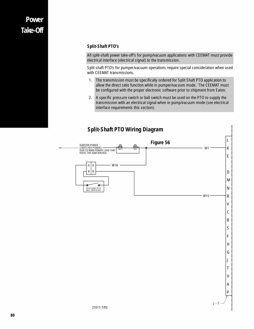
80
PowerTake-Off
Split-Shaft PTO's
All split-shaft power take-off’s for pump/vacuum applications with CEEMAT must provideelectrical interface (electrical signal) to the transmission.
Split shaft PTO’s for pumper/vacuum operations require special consideration when usedwith CEEMAT transmissions.
1. The transmission must be specifically ordered for Split Shaft PTO application toallow the direct ratio function while in pumper/vacuum mode. The CEEMAT mustbe configured with the proper electronic software prior to shipment from Eaton.
2. A specific pressure switch or ball switch must be used on the PTO to supply thetransmission with an electrical signal when in pump/vacuum mode (see electricalinterface requirements this section).
21011-7/93
Split-Shaft PTO Wiring Diagram
Figure 56 L
E
K
R
N
M
D
B
C
G
H
F
S
V
P
A
U
T
W1
W15
AUX
A W1AA
B
BATT
SPLIT-SHAFT P.T.O. BALL SWITCH N.O.
B
J
J - 1
IGNITION POWER(SWITCHED POWER)RUN TO MAIN POWER LEAD THATFEEDS THE IGNITION BUS
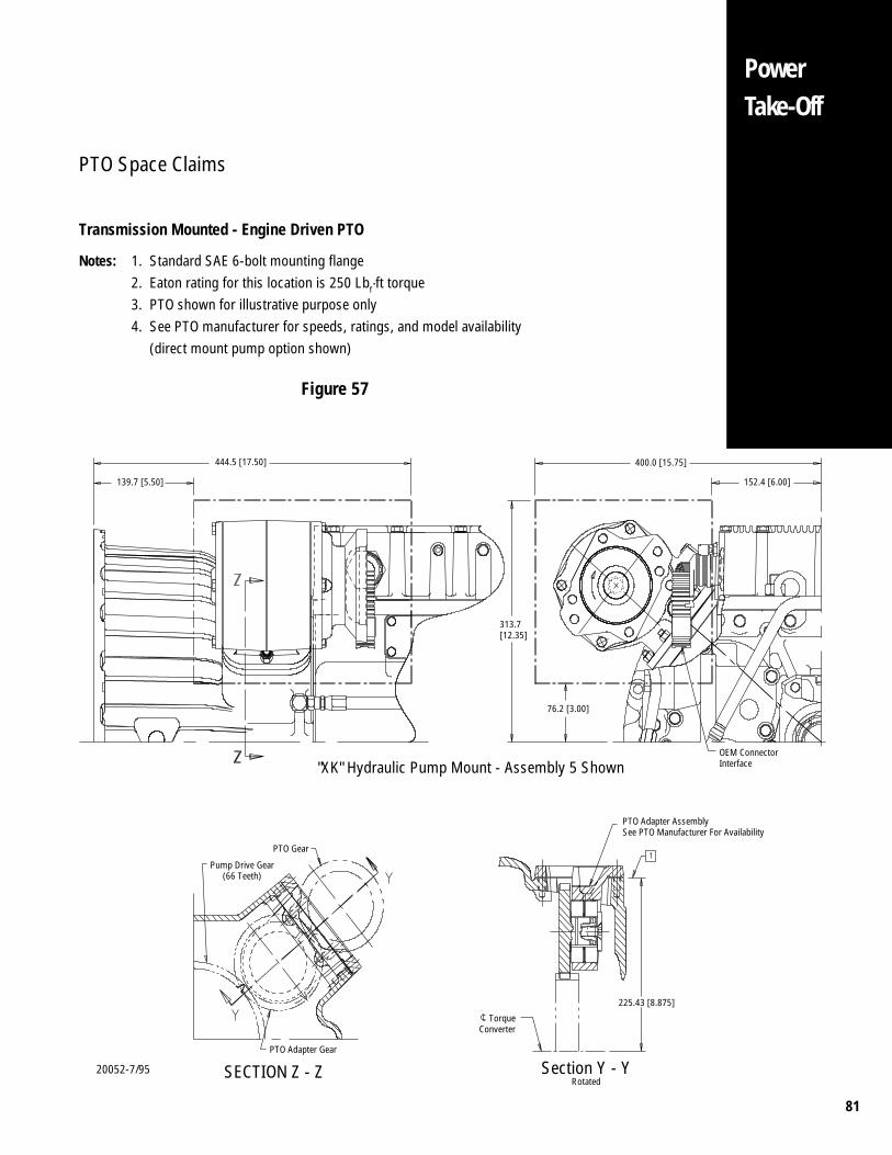
81
PowerTake-Off
PTO Space Claims
Transmission Mounted - Engine Driven PTO
Notes: 1. Standard SAE 6-bolt mounting flange2. Eaton rating for this location is 250 Lbf·ft torque3. PTO shown for illustrative purpose only4. See PTO manufacturer for speeds, ratings, and model availability (direct mount pump option shown)
Figure 57
20052-7/95
444.5 [17.50]
139.7 [5.50]
"XK" Hydraulic Pump Mount - Assembly 5 Shown
PTO Gear
313.7[12.35]
76.2 [3.00]
400.0 [15.75]
152.4 [6.00]
OEM ConnectorInterface
PTO Adapter AssemblySee PTO Manufacturer For Availability
225.43 [8.875]
TorqueConverter
Section Y - YRotated
Pump Drive Gear(66 Teeth)
PTO Adapter Gear
SECTION Z - Z
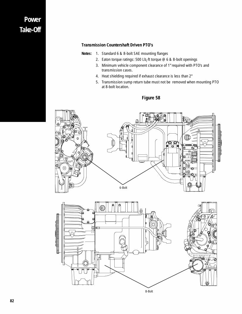
82
PowerTake-Off
6-Bolt
Transmission Countershaft Driven PTO's
Notes: 1. Standard 6 & 8-bolt SAE mounting flanges2. Eaton torque ratings: 500 Lbf·ft torque @ 6 & 8-bolt openings3. Minimum vehicle component clearance of 1" required with PTO’s and
transmission cases.4. Heat shielding required if exhaust clearance is less than 2"5. Transmission sump return tube must not be removed when mounting PTO
at 8-bolt location.
Figure 58
8-Bolt
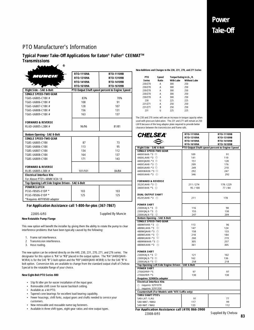
83
PowerTake-Off
PTO Manufacturer's InformationTypical Power Take-Off Applications for Eaton® Fuller® CEEMATTM
Transmissions
New Additions and Changes to the 230, 231, 270, and 271 Series
PTO Speed Torque Rating in Lb.f·ft.Series Ratio With Lube Without Lube
230/270 A 300 250230/270 A 300 250230/270 A 300 250230/270 A 300 250230/270 A 300 250
230 U 225 225231/271 A 250 250231/271 B 250 250
231 U 225 225
The 230 and 270 series will see an increase in torque capacity whenused with pressure lubrication. The 231 and 271 will remain at 250Lbf·ft because of the long adaptor plate required to provide betterclearance between the transmission and frame rails.
New Rotatable Pump Flange
This new option will benefit the installer by giving them the ability to rotate the pump to clearinterference problems that have been typically caused by the following:
1. Frame rail interference.2 Transmission interference.3. Hose routing.
The new option can be ordered directly on the 440, 230, 231, 270, 271, and 276 series. Thedesignator for this option is "RA" or "RB" placed in the output option. The "RA" (440XQAHX-W3RA) is for the SAE "B" 2-bolt option and the "RB" (440XQAHX-W3RB) is for the SAE "B" 4-bolt option. Conversion kits are available to change from the standard output shaft of ChelseaSpecial to the rotatable flange of your choice.
New Eight-Bolt PTO Series 880
• Slip fit idler pin for easier installation of the input gear.• Removable shift cover for easier backlash setting.• Available as a kit PTO.• Tapered cone bearings for excellent load bearing capability.• Fewer housings, shift forks, output gears and shafts needed to service your
customers.• New removable and reusaable name tag fasteners.• Available in three shift types, eight gear ratios and nine output types.
Supplied By Muncie22005-6/93
Supplied By Chelsea22008-8/93
RTO-11109A RTO-11109B RTO-13109A RTO-13109B RTO-14109A RTO-14109B RTO-16109A RTO-16109BRight Side - SAE 6-Bolt PTO Output Shaft speed percent to Engine SpeedSINGLE SPEED-TWO GEAR440XFAHX-*3 109 91440XLAHX-*3 141 119440XQAHX-*3 151 128440XSAHX-*3 209 176440XUAHX-*3 249 210440XWAHX-*3 292 247440XXAHX-*3 346 292 FORWARD & REVERSE352XSAHX-*3 211 / 274 178 / 229340XFAHX-*5 95 / 100 77 / 84
DUAL OUTPUT SHAFT452XSAHX-*3 211 178
POWER SHIFT230XKAJX-*3 116 98230XQAJX-*3 155 130230XUAJX-*3 247 209Bottom Opening - SAE 8-Bolt SINGLE SPEED-TWO GEAR488WFAHX-*3 113 96488WLAHX-*3 147 124488WQAHX-*3 158 133488WSAHX-*3 218 184488WUAHX-*3 260 219488WWAHX-*3 305 257488WXAHX-*3 361 305
POWER SHIFT230XKAJX-*3 121 102230XQAJX-*3 162 136230XUAJX-*3 258 218Top Opening Left Side Engine Driven - SAE 6-BoltPOWER SHIFT270XDFRP-*5 97 97270XKFRP-*5 130 130Requires 329083x adaptorElectrical Interface Kits requires 329107X requires 329135XCountershaft (For Models with "ATE Suffix only)THRU SHAFT PTO's540-LAT / LAU 91 77540-MAT / MAU 117 99540-NAT / NAU 133 112
1
1
1
1
1
1
2
2
2
1
1
1
2
2
2
1
2
For Application Assistance call (419) 866-3900
1
1
1
1
1
1
1
1
RTO-11109A RTO-11109B RTO-13109A RTO-13109B RTO-14109A RTO-14109B RTO-16109A RTO-16109BRight Side - SAE 6-Bolt PTO Output Shaft speed percent to Engine SpeedSINGLE SPEED-TWO GEARTG6S-U6805-C1BX # 83% 70%TG6S-U6806-C1BX # 108 91TG6S-U6807-C1BX # 128 107TG6S-U6808-C1BX # 156 131TG6S-U6809-C1BX # 163 137
FORWARD & REVERSERL6D-U6805-L3BK # 96/96 81/81
Bottom Opening - SAE 8-Bolt SINGLE SPEED-TWO GEARTG8S-U6805-C1BX 87 73TG8S-U6806-C1BX 113 95TG8S-U6807-C1BX 134 112TG8S-U6808-C1BX 164 137TG8S-U6809-C1BX 171 143
FORWARD & REVERSERL8S-U6805-L3BX # 101/101 84/84Electrical Interface KitsFor Above PTO's 48MK1434-14Top Opening Left Side Engine Driven - SAE 6-BoltPOWERCLUTCHPC6S-F8505-E1DP * 103 103PC6S-F8506-E1DP * 125 125*Requires 40TF8500 adaptor
For Application Assistance call 1-800-for-ptos (367-7867)
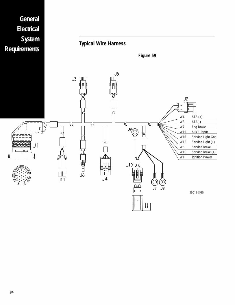
84
GeneralElectrical
SystemRequirements
Typical Wire Harness
Figure 59
20019-8/95
W4 ATA (+)W3 ATA(-)W7 Eng BrakeW15 Aux 1 InputW16 Service Light GndW1B Service Light (+)W6 Service BrakeW1C Service Brake (+)W1 Ignition Power
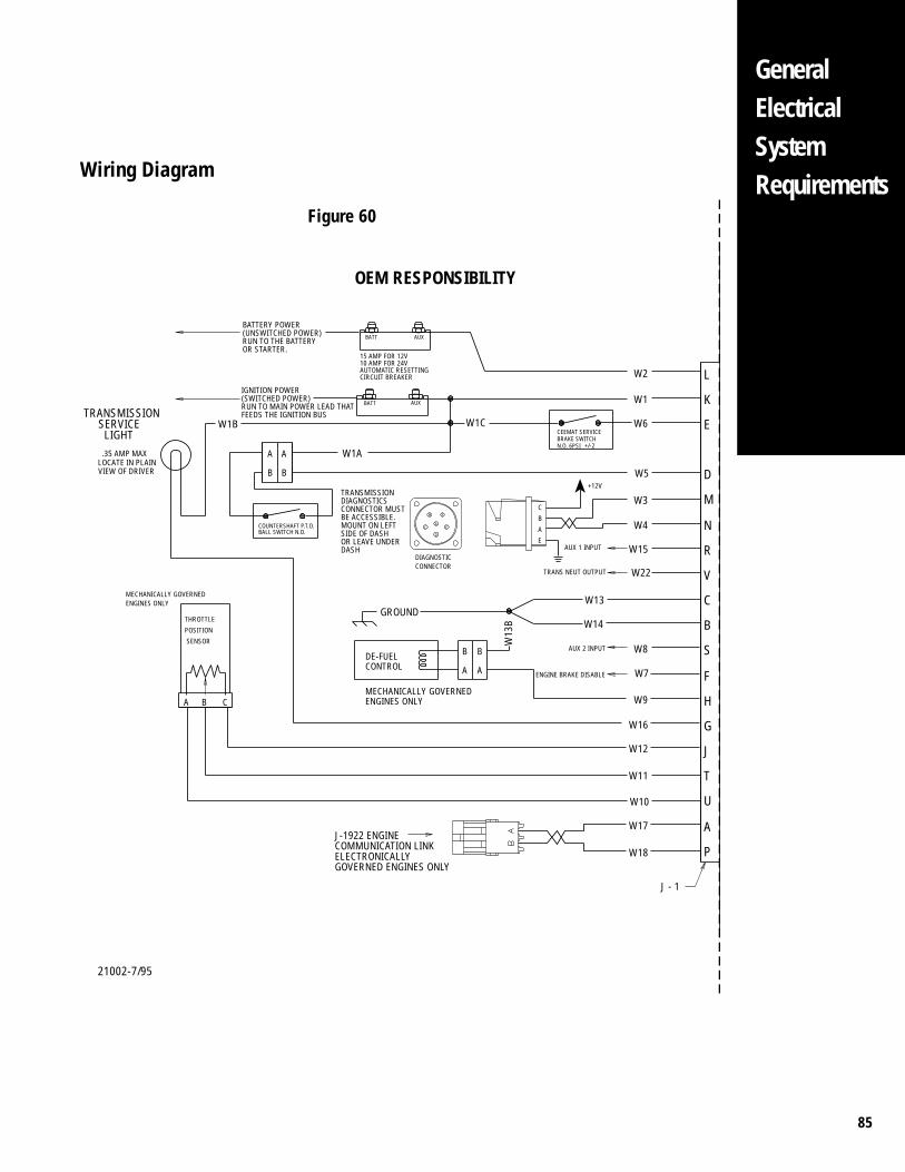
85
GeneralElectricalSystemRequirements
OEM RESPONSIBILITY
21002-7/95
L
E
K
R
N
M
D
B
C
G
H
F
S
V
P
A
U
T
AUX
W2
C
E
W5
2+/-
CEEMAT SERVICEBRAKE SWITCHN.O. 6PSI
AUX 1 INPUT
W1
W6
W4
W3
W15
A
B
W1C
DIAGNOSTIC
AUX
FB
AEC
D
BATT
A W1AA
B
BATT
COUNTERSHAFT P.T.O. BALL SWITCH N.O.
B
TRANSMISSION
LIGHT
LOCATE IN PLAIN .35 AMP MAX
VIEW OF DRIVER
W22TRANS NEUT OUTPUT
W13
W14
W9
W16
W8
W7ENGINE BRAKE DISABLE
AUX 2 INPUT
W1B SERVICE
B
AA
B
W13
B
W10
W17
W18
W11
ENGINES ONLYMECHANICALLY GOVERNED
SENSOR
POSITION
THROTTLE
CBA
W12 J
ENGINES ONLYMECHANICALLY GOVERNED
GROUND
CONTROLDE-FUEL
CONNECTOR
J - 1
BATTERY POWER(UNSWITCHED POWER)RUN TO THE BATTERYOR STARTER.
IGNITION POWER(SWITCHED POWER)RUN TO MAIN POWER LEAD THATFEEDS THE IGNITION BUS
TRANSMISSIONDIAGNOSTICSCONNECTOR MUSTBE ACCESSIBLE.MOUNT ON LEFTSIDE OF DASHOR LEAVE UNDERDASH
J-1922 ENGINECOMMUNICATION LINKELECTRONICALLYGOVERNED ENGINES ONLY
15 AMP FOR 12V10 AMP FOR 24VAUTOMATIC RESETTINGCIRCUIT BREAKER
+12V
Wiring Diagram
Figure 60
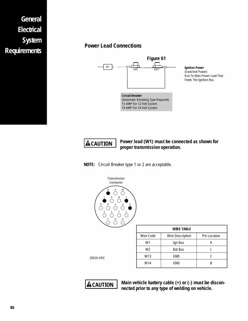
86
GeneralElectrical
SystemRequirements
Power Lead Connections
Figure 61
W1AUX BATT Ignition Power
(Switched Power)Run To Main Power Lead ThatFeeds The Ignition Bus.
Main vehicle battery cable (+) or (-) must be discon-nected prior to any type of welding on vehicle.
CAUTION
Power lead (W1) must be connected as shown forproper transmission operation.
CAUTION
NOTE: Circuit Breaker type 1 or 2 are acceptable.
D R V U K
B A M
C P N L
E S T J
F G H
WIRE TABLE
Wire Code Wire Description Pin Location
W1 Ign Bus K
W2 Bat Bus L
W13 GND C
W14 GND B
TransmissionConnector
20020-4/92
Circuit Breaker(Automatic Resetting Type Required)15 AMP For 12 Volt System10 AMP For 24 Volt System
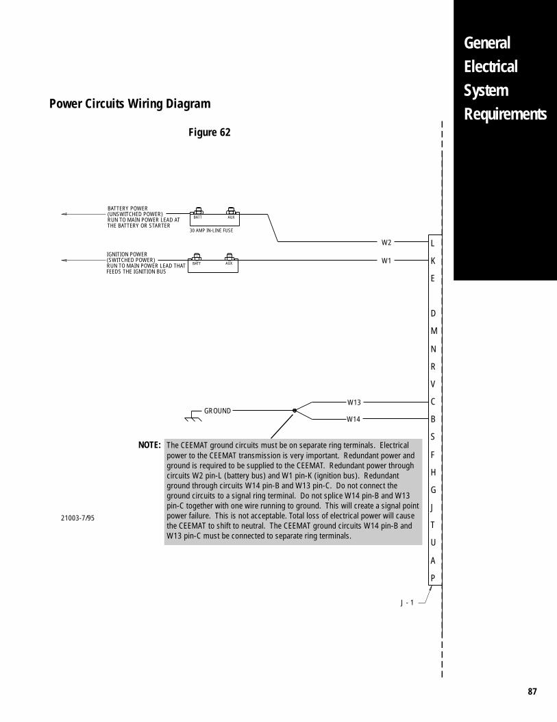
87
GeneralElectricalSystemRequirements
21003-7/95
Power Circuits Wiring Diagram
Figure 62
L
E
K
R
N
M
D
B
C
G
H
F
S
V
P
A
U
T
AUX
W2
W1AUX
BATT
BATT
J
J - 1
BATTERY POWER(UNSWITCHED POWER)RUN TO MAIN POWER LEAD ATTHE BATTERY OR STARTER
IGNITION POWER(SWITCHED POWER)RUN TO MAIN POWER LEAD THATFEEDS THE IGNITION BUS
30 AMP IN-LINE FUSE
W13
W14GROUND
NOTE: The CEEMAT ground circuits must be on separate ring terminals. Electricalpower to the CEEMAT transmission is very important. Redundant power andground is required to be supplied to the CEEMAT. Redundant power throughcircuits W2 pin-L (battery bus) and W1 pin-K (ignition bus). Redundantground through circuits W14 pin-B and W13 pin-C. Do not connect theground circuits to a signal ring terminal. Do not splice W14 pin-B and W13pin-C together with one wire running to ground. This will create a signal pointpower failure. This is not acceptable. Total loss of electrical power will causethe CEEMAT to shift to neutral. The CEEMAT ground circuits W14 pin-B andW13 pin-C must be connected to separate ring terminals.
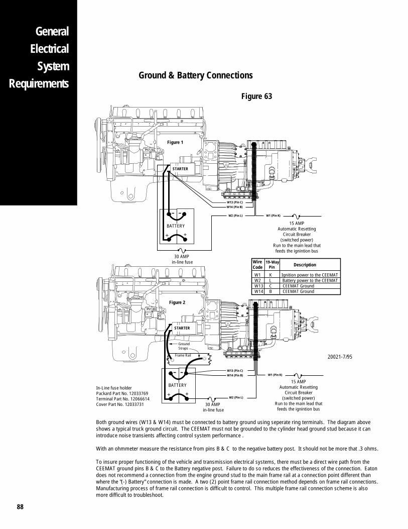
88
GeneralElectrical
SystemRequirements
Ground & Battery Connections
Figure 63
+ +
- -
STARTER
BATTERY
W13 (Pin C)W14 (Pin B)
W2 (Pin L)
30 AMPin-line fuse
15 AMPAutomatic Resetting
Circuit Breaker(switched power)
Run to the main lead thatfeeds the ignintion bus
W1 (Pin K)
+ +
- -
STARTER
BATTERY
W13 (Pin C)W14 (Pin B)
W2 (Pin L)
30 AMPin-line fuse
15 AMPAutomatic Resetting
Circuit Breaker(switched power)
Run to the main lead thatfeeds the ignintion bus
W1 (Pin K)
Figure 1
Figure 2
In-Line fuse holderPackard Part No. 12033769Terminal Part No. 12066614Cover Part No. 12033731
Frame Rail
GroundStraps
W1 K Ignition power to the CEEMATW2 L Battery power to the CEEMATW13 C CEEMAT GroundW14 B CEEMAT Ground
WireCode
19-Way Pin Description
Both ground wires (W13 & W14) must be connected to battery ground using seperate ring terminals. The diagram above shows a typical truck ground circuit. The CEEMAT must not be grounded to the cylinder head ground stud because it canintroduce noise transients affecting control system performance .
With an ohmmeter measure the resistance from pins B & C to the negative battery post. It should not be more that .3 ohms.
To insure proper functioning of the vehicle and transmission electrical systems, there must be a direct wire path from the CEEMAT ground pins B & C to the Battery negative post. Failure to do so reduces the effectiveness of the connection. Eatondoes not recommend a connection from the engine ground stud to the main frame rail at a connection point different than where the "(-) Battery" connection is made. A two (2) point frame rail connection method depends on frame rail connections. Manufacturing process of frame rail connection is difficult to control. This multiple frame rail connection scheme is also more difficult to troubleshoot.
20021-7/95
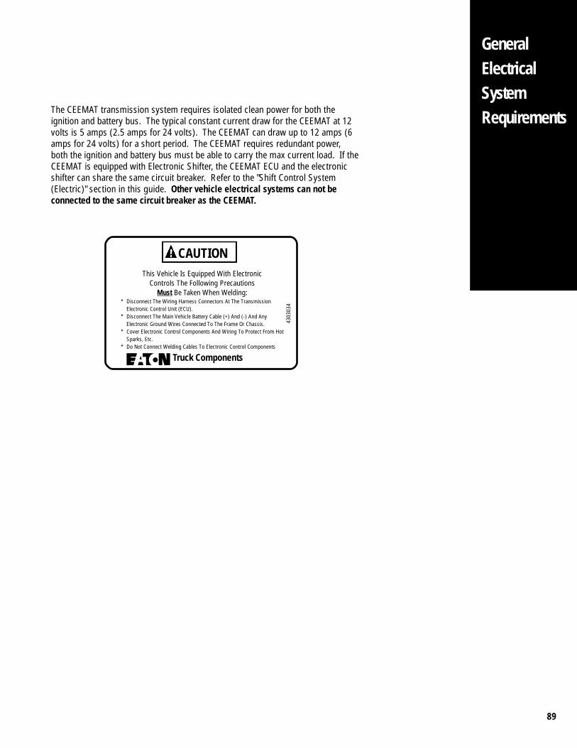
89
The CEEMAT transmission system requires isolated clean power for both theignition and battery bus. The typical constant current draw for the CEEMAT at 12volts is 5 amps (2.5 amps for 24 volts). The CEEMAT can draw up to 12 amps (6amps for 24 volts) for a short period. The CEEMAT requires redundant power,both the ignition and battery bus must be able to carry the max current load. If theCEEMAT is equipped with Electronic Shifter, the CEEMAT ECU and the electronicshifter can share the same circuit breaker. Refer to the "Shift Control System(Electric)" section in this guide. Other vehicle electrical systems can not beconnected to the same circuit breaker as the CEEMAT.
CAUTIONThis Vehicle Is Equipped With Electronic
Controls The Following PrecautionsMust Be Taken When Welding:
* Disconnect The Wiring Harness Connectors At The TransmissionElectronic Control Unit (ECU).
* Disconnect The Main Vehicle Battery Cable (+) And (-) And AnyElectronic Ground Wires Connected To The Frame Or Chassis.
* Cover Electronic Control Components And Wiring To Protect From HotSparks, Etc.
* Do Not Connect Welding Cables To Electronic Control Components
Truck Components
4303
034
GeneralElectricalSystemRequirements
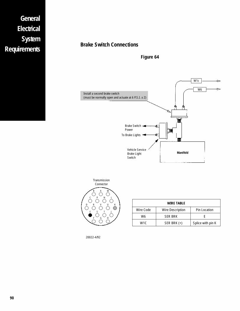
90
GeneralElectrical
SystemRequirements
Brake Switch Connections
Figure 64
Brake SwitchPower
To Brake Lights
Vehicle ServiceBrake LightSwitch
Manifold
W1c
D R V U K
C P N L
E S T J
B A M
F G H
WIRE TABLE
Wire Code Wire Description Pin Location
W6 SER BRK E
W1C SER BRK (+) Splice with pin K
W6
TransmissionConnector
Install a second brake switch(must be normally open and actuate at 6 P.S.I. ± 2)
20022-4/92

91
L
E
K
R
N
M
D
B
C
G
H
F
S
V
P
A
U
T
2+/-
CEEMAT SERVICEBRAKE SWITCHN.O. 6PSI
W1
W6W1C
AUXBATT
J
J - 1
IGNITION POWER(SWITCHED POWER)RUN TO MAIN POWER LEAD THATFEEDS THE IGNITION BUS
21005-6/93
Brake Switch Wiring Diagram
Figure 65
GeneralElectricalSystemRequirements
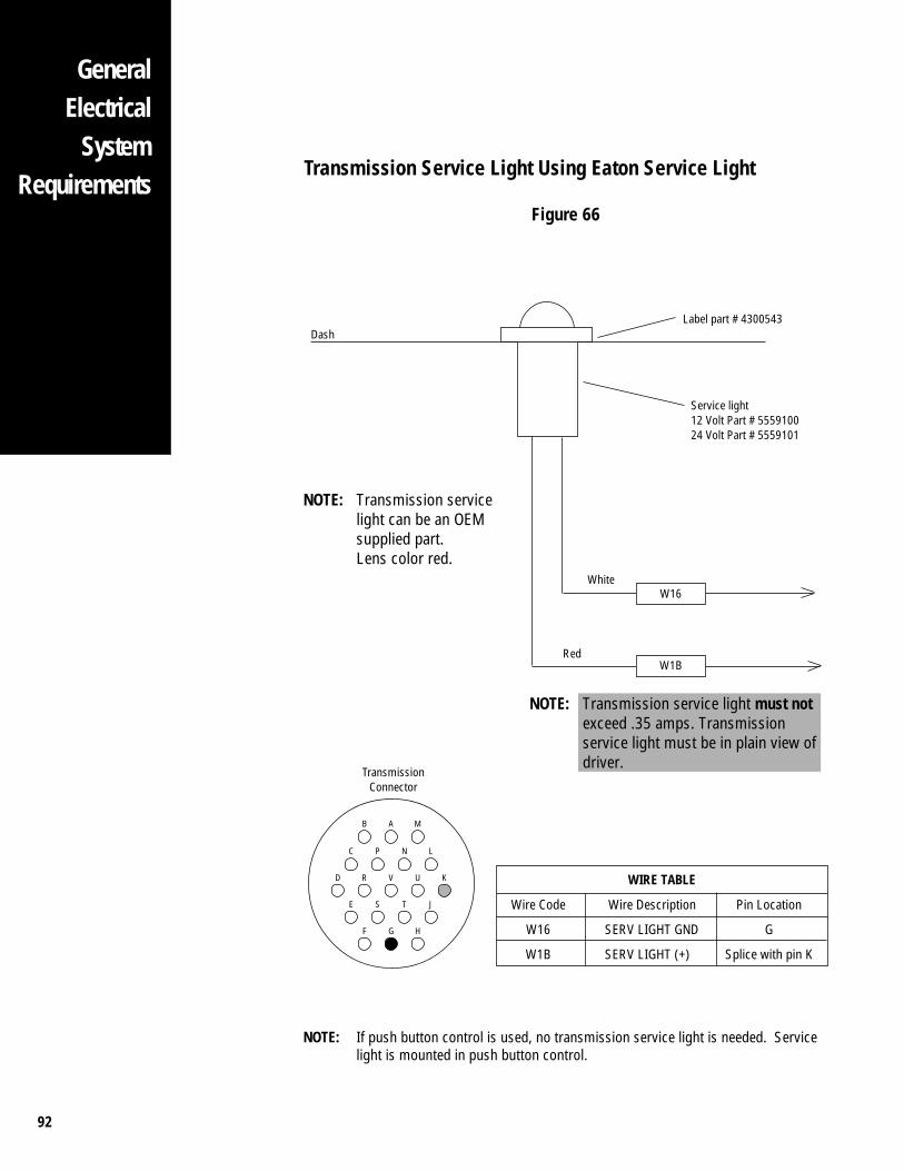
92
GeneralElectrical
SystemRequirements
Transmission Service Light Using Eaton Service Light
Figure 66
D R V U K
B A M
C P N L
E S T J
F G H
DashLabel part # 4300543
Service light12 Volt Part # 555910024 Volt Part # 5559101
W1B
NOTE: Transmission service light must notexceed .35 amps. Transmissionservice light must be in plain view ofdriver.
WIRE TABLE
Wire Code Wire Description Pin Location
W16 SERV LIGHT GND G
W1B SERV LIGHT (+) Splice with pin K
TransmissionConnector
NOTE: Transmission servicelight can be an OEMsupplied part.Lens color red.
NOTE: If push button control is used, no transmission service light is needed. Servicelight is mounted in push button control.
W16White
Red
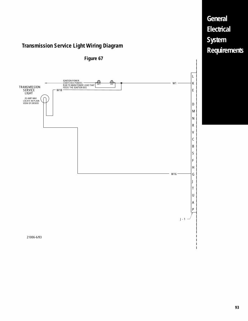
93
GeneralElectricalSystemRequirements
Transmission Service Light Wiring Diagram
Figure 67
L
E
K
R
N
M
D
B
C
G
H
F
S
V
P
A
U
T
W1AUXBATT
TRANSMISSION
LIGHT
LOCATE IN PLAIN .35 AMP MAX
VIEW OF DRIVER
W16
W1B SERVICE
J
J - 1
IGNITION POWER(SWITCHED POWER)RUN TO MAIN POWER LEAD THATFEEDS THE IGNITION BUS
21006-6/93
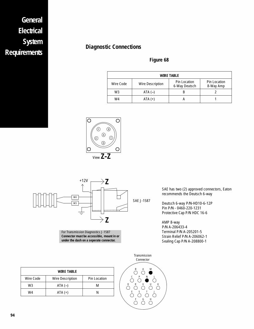
94
GeneralElectrical
SystemRequirements
WIRE TABLE
Wire Code Wire Description Pin Location
W3 ATA (–) M
W4 ATA (+) N
W4
W3
D R V U K
B A M
C P N L
E S T J
F G H
SAE J-1587
For Transmission Diagnostics J-1587Connector must be accessible, mount in orunder the dash on a seperate connector.
TransmissionConnector
SAE has two (2) approved connectors, Eatonrecommends the Deutsch 6-way
Deutsch 6-way P/N-HD10-6-12PPin P/N - 0460-220-1231Protective Cap P/N HDC 16-6
AMP 8-wayP/N A-206433-4Terminal P/N A-205201-5Strain Relief P/N A-206062-1Sealing Cap P/N A-208800-1
+12V Z
Z
Diagnostic Connections
Figure 68
Pin Location6-Way Deutsch
WIRE TABLE
Wire Code Wire Description
W3 ATA (–) B 2
W4 ATA (+) A 1
Pin Location8-Way Amp
F
AE
B
D
C
View Z-Z
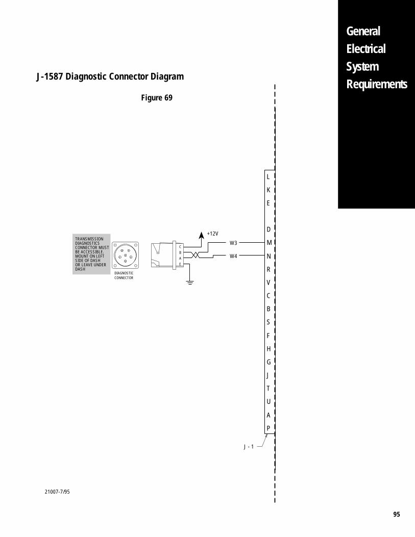
95
L
E
K
R
N
M
D
B
C
G
H
F
S
V
P
A
U
T
C
E
W4
W3
A
B
DIAGNOSTIC
FB
AEC
D
J
CONNECTOR
J - 1
TRANSMISSIONDIAGNOSTICSCONNECTOR MUSTBE ACCESSIBLE.MOUNT ON LEFTSIDE OF DASHOR LEAVE UNDERDASH
+12V
GeneralElectricalSystemRequirements
J-1587 Diagnostic Connector Diagram
Figure 69
21007-7/95
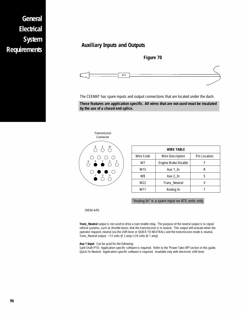
96
GeneralElectrical
SystemRequirements
Auxiliary Inputs and Outputs
Figure 70
C P N L
E S T J
W15
WIRE TABLE
Wire Code Wire Description Pin Location
W7 Engine Brake Disable F
W15 Aux 1_In R
W8 Aux 2_In S
W22 Trans_Neutral V
W11 Analog In T
The CEEMAT has spare inputs and output connections that are located under the dash.
These features are application specific. All wires that are not used must be insulatedby the use of a closed end splice.
TransmissionConnector
“Analog In” is a spare input on ATE units only
20030-4/92
D R V U K
B A M
F G H
Trans_Neutral output is not used to drive a start enable relay. The purpose of the neutral output is to signalvehicle systems, such as throttle boost, that the transmission is in neutral. This output will activate when theoperator requests neutral (via the shift lever or QUICK TO NEUTRAL) and the transmission mode is neutral.Trans_Neutral output: +12 volts @ 2 amp (+24 volts @ 1 amp)
Aux 1 Input: Can be used for the following:Split-Shaft PTO: Application specific software is required. Refer to the "Power Take-Off" section in this guide.Quick-To-Neutral: Application specific software is required. Available only with electronic shift lever.
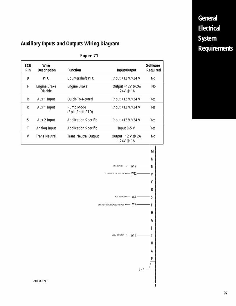
97
GeneralElectricalSystemRequirements
21008-6/93
ECU Wire SoftwarePin Description Function Input/Output Required
D PTO Countershaft PTO Input +12 V/+24 V No
F Engine Brake Engine Brake Output +12V @2A/ NoDisable +24V @ 1A
R Aux 1 Input Quick-To-Neutral Input +12 V/+24 V Yes
R Aux 1 Input Pump Mode Input +12 V/+24 V Yes(Split Shaft PTO)
S Aux 2 Input Application Specific Input +12 V/+24 V Yes
T Analog Input Application Specific Input 0-5 V Yes
V Trans Neutral Trans Neutral Output Output +12 V @ 2A No+24V @ 1A
R
N
M
B
C
G
H
F
S
V
P
A
U
T
AUX 1 INPUT W15
W22TRANS NEUTRAL OUTPUT
W8
W7ENGINE BRAKE DISABLE OUTPUT
AUX 2 INPUT
W11
J
J - 1
ANALOG INPUT
Auxiliary Inputs and Outputs Wiring Diagram
Figure 71
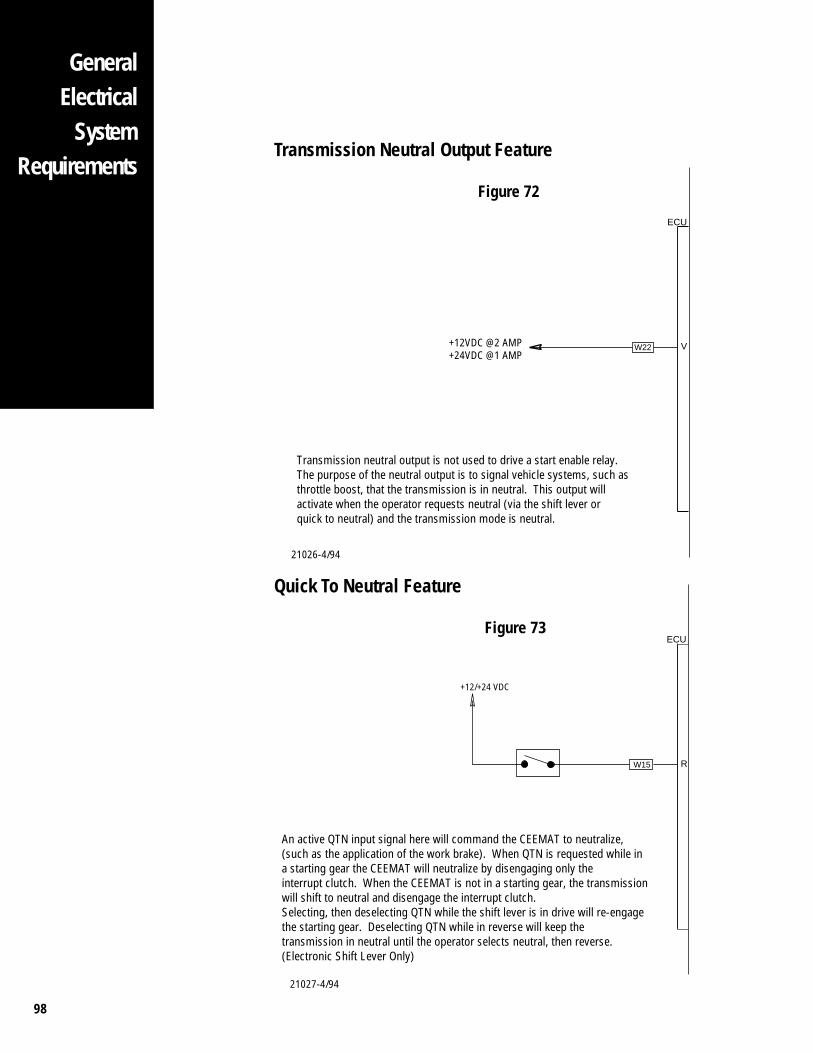
98
GeneralElectricalSystemRequirements
GeneralElectrical
SystemRequirements
Transmission Neutral Output Feature
Figure 72
Quick To Neutral Feature
Figure 73
21027-4/94
21026-4/94
W22 V
ECU
+12VDC @2 AMP+24VDC @1 AMP
Transmission neutral output is not used to drive a start enable relay.The purpose of the neutral output is to signal vehicle systems, such asthrottle boost, that the transmission is in neutral. This output willactivate when the operator requests neutral (via the shift lever orquick to neutral) and the transmission mode is neutral.
W15 R
ECU
+12/+24 VDC
An active QTN input signal here will command the CEEMAT to neutralize,(such as the application of the work brake). When QTN is requested while ina starting gear the CEEMAT will neutralize by disengaging only the interrupt clutch. When the CEEMAT is not in a starting gear, the transmissionwill shift to neutral and disengage the interrupt clutch.Selecting, then deselecting QTN while the shift lever is in drive will re-engagethe starting gear. Deselecting QTN while in reverse will keep thetransmission in neutral until the operator selects neutral, then reverse.(Electronic Shift Lever Only)
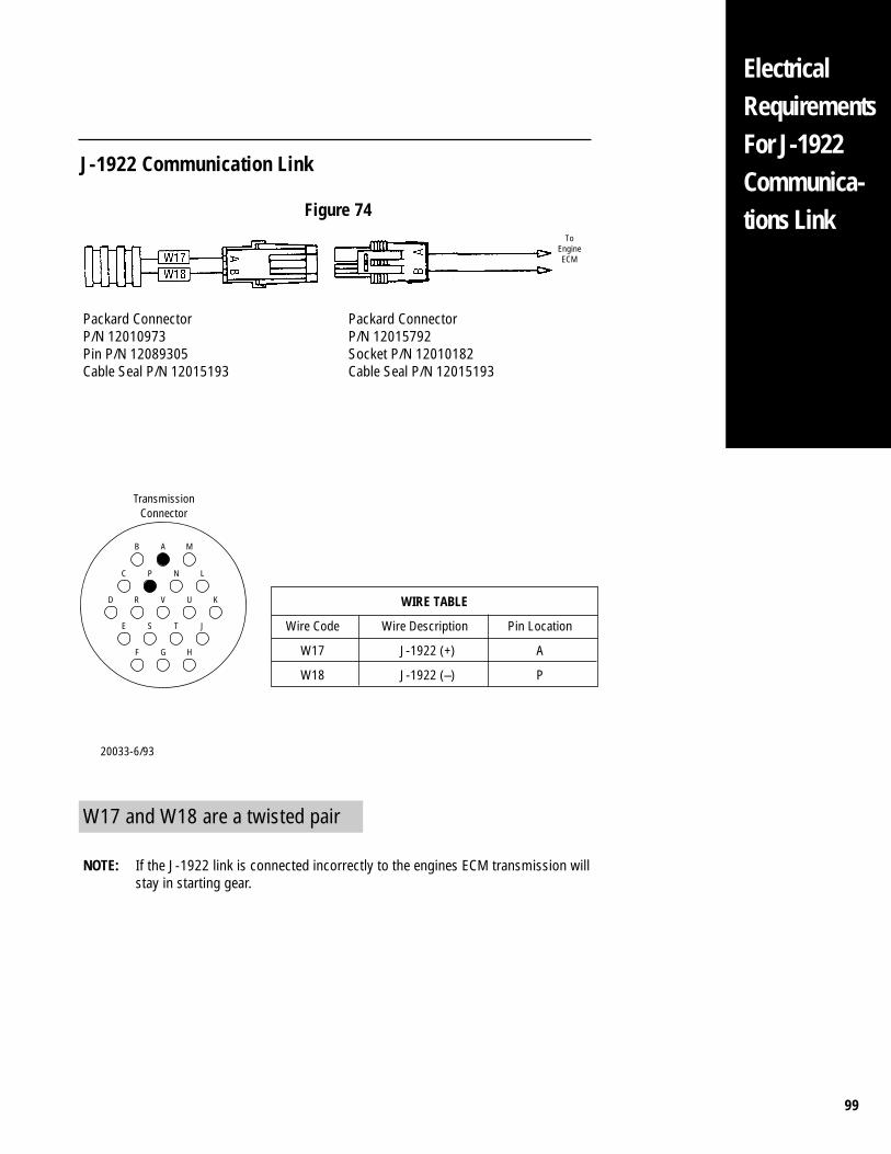
99
ElectricalRequirementsFor J-1922Communica-tions Link
J-1922 Communication Link
Figure 74
Packard ConnectorP/N 12010973Pin P/N 12089305Cable Seal P/N 12015193
Packard ConnectorP/N 12015792Socket P/N 12010182Cable Seal P/N 12015193
D R V U K
B A M
C P N L
E S T J
F G H
WIRE TABLE
Wire Code Wire Description Pin Location
W17 J-1922 (+) A
W18 J-1922 (–) P
TransmissionConnector
20033-6/93
ToEngineECM
W17 and W18 are a twisted pair
NOTE: If the J-1922 link is connected incorrectly to the engines ECM transmission willstay in starting gear.
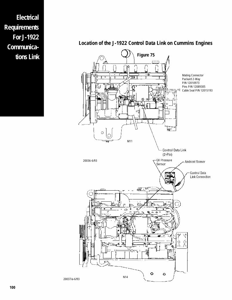
100
ElectricalRequirements
For J-1922Communica-
tions Link
Location of the J-1922 Control Data Link on Cummins Engines
Figure 75
20036-6/93
Mating ConnectorPackard 2-WayP/N 12010973Pins P/N 12089305Cable Seal P/N 12015193
M11
20037/a-6/93N14
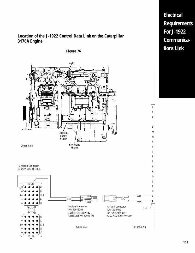
101
ElectricalRequirementsFor J-1922Communica-tions Link
Location of the J-1922 Control Data Link on the Caterpillar3176A Engine
Figure 76
21009-6/9320039-6/93
L
E
K
R
N
M
D
B
C
G
H
F
S
V
P
A
U
T
W17
W18
J
J - 1Packard ConnectorP/N 12010973Pin P/N 12089305Cable Seal P/N 12015193
6 36
7 37
8 38
9 39
10 40
20 30
16 26
15 25
5 35
4 34
3 33
2 32
1 31
11 21
Packard ConnectorP/N 12015792Socket P/N 12010182Cable Seal P/N 12015193
AB
J7 Mating ConnectorDeutsch DRC 16-405A
20038-6/93
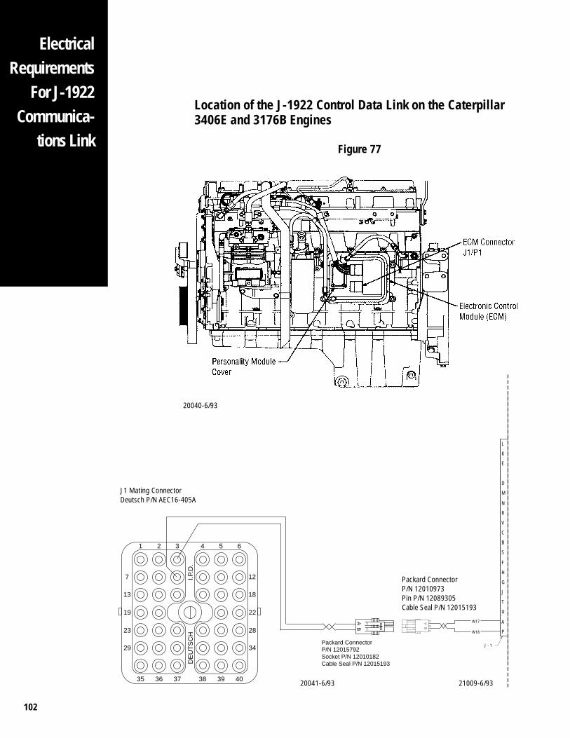
102
ElectricalRequirements
For J-1922Communica-
tions Link
Location of the J-1922 Control Data Link on the Caterpillar3406E and 3176B Engines
Figure 77
L
E
K
R
N
M
D
B
C
G
H
F
S
V
P
A
U
T
W17
W18
J
J - 1
J1 Mating ConnectorDeutsch P/N AEC16-405A
19
1 2 3 4 5 6
7
13
23
29
22
12
18
28
34
35 36 37 38 39 40
DE
UT
SC
HI.P
.D.
Packard ConnectorP/N 12015792Socket P/N 12010182Cable Seal P/N 12015193
AB
20041-6/93 21009-6/93
Packard ConnectorP/N 12010973Pin P/N 12089305Cable Seal P/N 12015193
20040-6/93
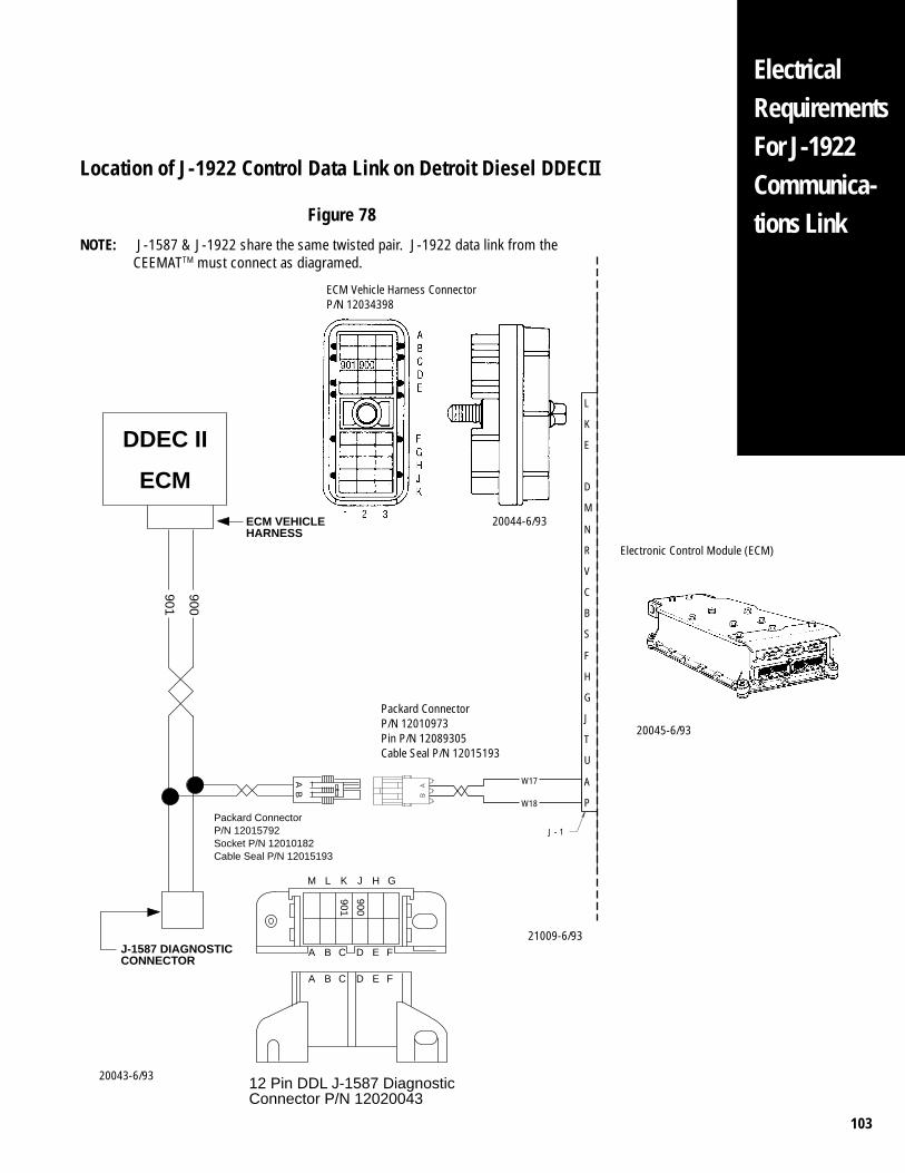
103
ElectricalRequirementsFor J-1922Communica-tions Link
Location of J-1922 Control Data Link on Detroit Diesel DDECII
Figure 78
901
900
J-1587 DIAGNOSTICCONNECTOR
Packard ConnectorP/N 12015792Socket P/N 12010182Cable Seal P/N 12015193
ECM VEHICLEHARNESS
DDEC II
ECM
M L K J H G
900
901
12 Pin DDL J-1587 Diagnostic Connector P/N 12020043
A B C D E F
A B C D E F
AB
L
E
K
R
N
M
D
B
C
G
H
F
S
V
P
A
U
T
W17
W18
J
J - 1
21009-6/93
Packard ConnectorP/N 12010973Pin P/N 12089305Cable Seal P/N 12015193
20043-6/93
20045-6/93
Electronic Control Module (ECM)
NOTE: J-1587 & J-1922 share the same twisted pair. J-1922 data link from theCEEMATTM must connect as diagramed.
20044-6/93
ECM Vehicle Harness ConnectorP/N 12034398
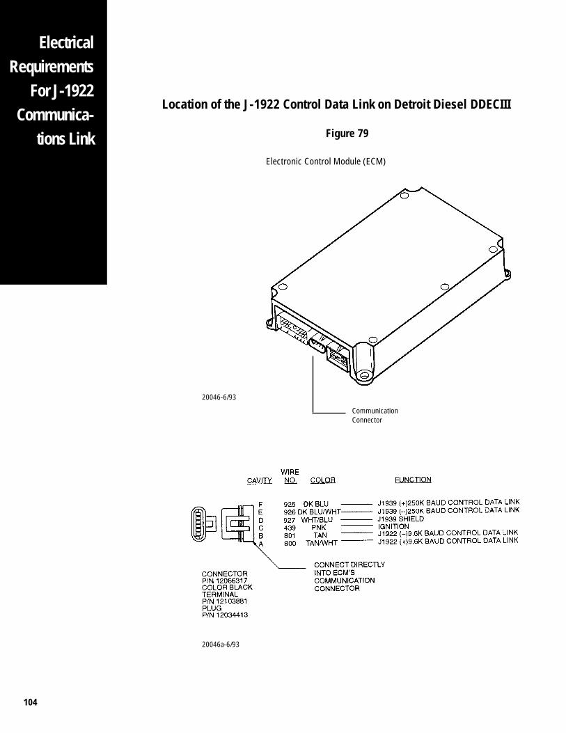
104
ElectricalRequirements
For J-1922Communica-
tions LinkElectronic Control Module (ECM)
CommunicationConnector
20046-6/93
20046a-6/93
Location of the J-1922 Control Data Link on Detroit Diesel DDECIII
Figure 79
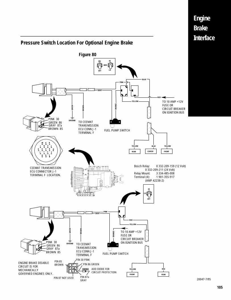
105
EngineBrakeInterface
Pressure Switch Location For Optional Engine Brake
Figure 80
YELLOW
REAR CENTER FRONT
YELLOW YELLOWBLUE
BLUEPINK
RED
TO 10 AMP +12VFUSE OR CIRCUIT BREAKERON IGNITION BUS
GREE
N
BROW
N
GROUND
GRAY
TO CEEMATTRANSMISSIONECU CONN J-1TERMINAL F
PINK 30GREEN 86GRAY 87aBROWN 85 �
��
����� ���
FUEL PUMP SWITCH
�OR
ANGE
YELLOW
REARFRONT
YELLOW RED
PINK
TO 10 AMP +12VFUSE OR CIRCUIT BREAKERON IGNITION BUS
OFF
LO
HI
GREE
N
BROW
N
GROUND
GRAY
TO CEEMATTRANSMISSIONECU CONN J-1TERMINAL F
PINK 30GREEN 86GRAY 87aBROWN 85 �
��
����� ���
FUEL PUMP SWITCH
�ORANGE
RED
MED
OFF LO
ON HI
AM
L
K
J
H G F
E
D
C
B
PN
U
T S
RV
CEEMAT TRANSMISSIONECU CONNECTOR J-1TERMINAL F LOCATION.
ENGINE BRAKE DISABLE CIRCUIT IS FOR MECHANICALLYGOVERNED ENGINES ONLY.
PIN 30 PINK
PIN 87aGRAY
PIN 85BROWN PIN 86 GREEN
PIN 87 NOT USED
DIODE ADD DIODE FORCIRCUIT PROTECTION
Bosch Relay: 0 332-209-159 (12 Volt)0 332-209-211 (24 Volt)
Relay Mount: 3 334-485-008Terminal (4): 1 901-355-917
(AMP 42238-2)
20047-7/95

106
Oil PanOptions/
SpaceClaims
Rotated Pan — Right Side View
Figure 81
20055-7/93
NOTE: Model ATE — PTO only available at thru-shaft location and engine driven.
Model AT — PTO only available at 8-bolt and engine driven location.
"AT" Rotated Pan — Rear View
Figure 82
20056-7/93
NOTE: Shown with sideslot kit (mountedin 6-bolt PTOlocation)
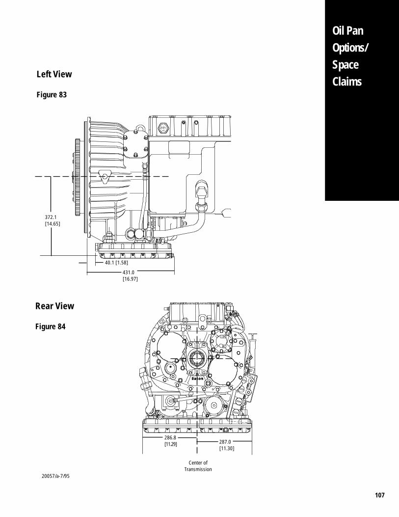
107
Left View
Figure 83
Oil PanOptions/SpaceClaims
372.1[14.65]
40.1 [1.58]
431.0[16.97]
286.8[11.29] 287.0
[11.30]
Center ofTransmission
20057/a-7/95
Rear View
Figure 84
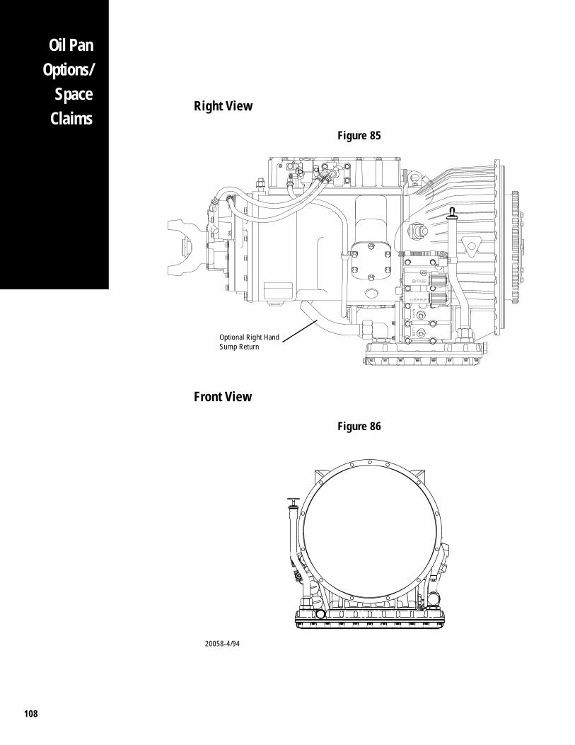
108
Oil PanOptions/
SpaceClaims
Right View
Figure 85
Front View
Figure 86
Optional Right HandSump Return
20058-4/94
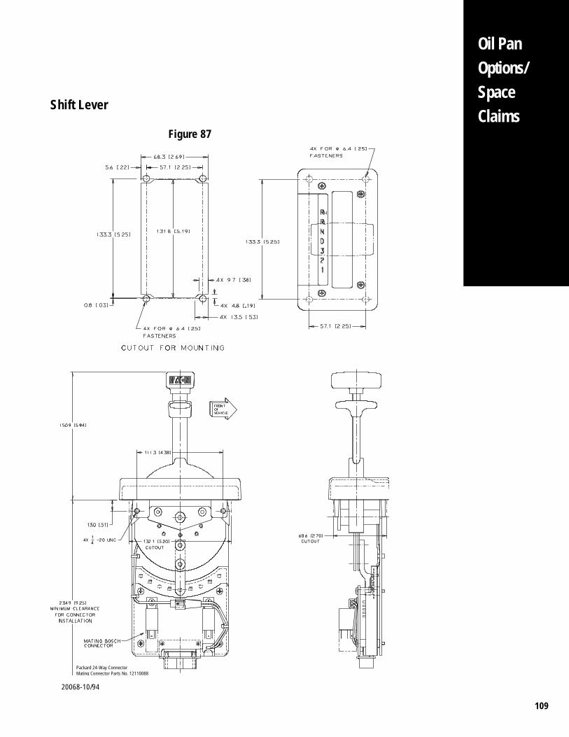
109
Oil PanOptions/SpaceClaims
Shift Lever
Figure 87
Packard 24-Way ConnectorMating Connector Parts No. 12110088
20068-10/94
110
Appendix I
Installation RequirementsAll CEEMAT™ transmissions installed at OEM Facilities must meet the applicationrequirements specified in Transmission Application Approval Form FUL-219.
Line Inspection
1. Each CEEMAT installed at the OEM must pass the on-line checklist requirements perEaton CEEMAT™ Line Inspection Form, Appendix I, prior to shipment from the OEMplant.
Flywheel Installation
1. The flywheel and drive ring must be an Eaton approved design and must beinstalled per the appropriate Eaton or Engine OEM specifications.
2. Pilot Adapter: When using the bolt-on drive ring adapter, a center pilot adaptermust also be used. Care should be used to insure the adapter is completely seatedinto the flywheel, see figure 2 for dimensional information.
Flywheel Housing Sealing Requirements
1. The engine flywheel housing must be approved for “wet” applications, including adouble lip rear engine crankshaft seal. The housing must provide a completelysealed environment for the torque converter area.
2. The vehicle OEM is responsible for sealing all holes in the flywheel housing/converter housing area including starter, mounting pads, transmission mounting,speed pickups, etc.
3. Gasket, seal ring, or equivalent sealing method along with sealed fasteners must beused when mounting the starter to the flywheel housing.
Transmission Mounting
1. The CEEMAT comes equipped with special sealed washers at the ECU covermounting capscrew locations (see illustration), these capscrews must not beremoved or replaced. Standoff brackets or hose clamps can not be used at any ofthe ECU capscrew locations.
Transmission Support Requirements
1. A rear transmission support is required for all installations where the transmissionnodal mount supports are not used.
2. The CEEMAT comes equipped with special sealed washers at the ECU covermounting capscrew locations. These capscrews must not be removed or replaced.Standoff brackets or hose clamps can not be used at any of the ECU capscrewlocations.
Throttle Sensor Mounting
1. The sensor body must be mounted to a solid flat frame member; not on the engineor power package.
Fuel Interrupt Mounting
1. If required, the engine defuel system must be Eaton or Engine OEM approved.
2. Electro-Pneumatic control must be installed per specifications in this manual.
3. Electro-Hydraulic control must be installed per engine OEM specifications and thismanual.
111
Appendix I
4. Air Throttle control must be installed per Williams Control, Inc. specifications andthis manual.
5. Pedal supply air must be non-regulated (full system pressure).
6. Minimum throttle control air line size when used with CEEMAT defuel system is 1/4"I.D. Air line must be installed with no sharp bends or tie wraps that restrict air flow.
7. The throttle control air line length, when used with CEEMAT defuel, should be asshort as possible with a maximum length of 30'.
8. OEM throttle return springs must be mounted securely to the engine fuel pumpthrottle arm, not on the throttle control or linkage.
9. When using the air throttle defuel system shown in Figures 11 and 15, the integralthrottle position sensor system must also be used to insure proper shift quality.Reference page 25.
Cooler Requirements
1. An external transmission cooler must be used with the CEEMAT™ transmission. Thecooler sizing must meet application approval requirements specified in FUL-219.
2. A minimum pressure drop through the transmission of 10 PSI @ 1800 RPM isrequired (converter lube apply pressure - converter lube outlet pressure) seereference "Cooler Requirements" section.
3. The cooler return line must be routed into the Eaton supplied back-pressure valve(Eaton P/N A-5754). This valve can be located on either side of the CEEMAT.
4. The oil cooler and cooler connecting lines should be free of debris, dirt, grease, etc.before being attached to the transmission. If these conditions exist, cooler and linesmust be flushed or cleaned.
5. A temperature gauge with a maximum range of 325°F and an over temperature alarmset at 300°F is required. Sensors for the gauge and alarm must be located in thetorque converter outlet stream before the cooler.
Dipstick and Dipstick Tube Information
1. New dipstick and tube designs are required to be approved and/or validated by Eatonengineering if supplied by the OEM.
2. A supporting bracket to eliminate vibration is required at the upper end of thedipstick tube. The bracket must be attached to the transmission or engine and notthe frame or body. See figure 29.
3. A minimum overall vertical rise of 14" must be maintained above the converterhousing oil pan mounting surface for oil filling.
4. The first section of the dipstick tube must be vertical from the oil pan connector to aminimum of 2.5" above the converter housing oil pan mounting surface to insureaccurate level readings.
5. Actual oil level must be within Eaton specifications according to the dipstick read-ings.
Lubrication Requirements
1. Oil must meet MIL-L-2104E specifications or Dexron®II. Oil must be filled to theproper oil level prior to OEM shipment.
112
Air Supply/Dryer Requirements
1. A high quality commercially available air dryer is required in the air supply linebefore the CEEMAT transmission.
2. Minimum air requirement for the CEEMAT Transmission is 90 PSI.
3. A minimum 3/8 inch diameter air supply line is required for the transmission.
4. The CEEMAT air supply is required to be routed from the air tank which supplies airto either the front or rear vehicle service brakes with a gauge indicator in the cab.See figure 30.
Shift Control System (Cable)
1. Maximum installed system (cable and control combined) backlash must not exceed± .175 from center.
2. 5⁄16" diameter (60 Series) cable must be used of cable length > 96". 1⁄4" diametercable can be used if cable length ≤ 96".
Power Take-Off
1. All split-shaft power take-off’s for pump/vacuum applications with CEEMAT mustprovide electrical interface (electrical signal) to the transmission.
2. The transmission must be specifically ordered for Split Shaft PTO application toallow the direct ratio function while in pumper/vacuum mode. The CEEMAT mustbe configured with the proper electronic software prior to shipment from Eaton.
3. A specific pressure switch or ball switch must be used on the PTO to supply thetransmission with an electrical signal when in pump/vacuum mode (see electricalinterface requirements this section).
General Electrical System Requirements
1. The CEEMAT transmission system requires isolated clean power for both theignition and battery bus. The typical constant current draw for the CEEMAT at 12volts is 5 amps (2.5 amps for 24 volts). The CEEMAT can draw up to 12 amps (6amps for 24 volts) for a short period. The CEEMAT requires redundant power, boththe ignition and battery bus must be able to carry the max current load. If theCEEMAT is equipped with Electronic Shifter, the CEEMAT ECU and the electronicshifter can share the same circuit breaker. Refer to the "Shift Control System(Electric)" section in this guide. Other vehicle electrical systems can not beconnected to the same circuit breaker as the CEEMAT.
2. The CEEMAT ground circuits must be on separate ring terminals. Electrical powerto the CEEMAT transmission is very important. Redundant power and ground isrequired to be supplied to the CEEMAT. Redundant power through circuits W2 pin-L (battery bus) and W1 pin-K (ignition bus). Redundant ground through circuitsW14 pin-B and W13 pin-C. Do not connect the ground circuits to a signal ringterminal. Do not splice W14 pin-B and W13 pin-C together with one wire runningto ground. This will create a single point power failure. This is not acceptable.Total loss of electrical power will cause the CEEMAT to shift to neutral. TheCEEMAT ground circuits W14 pin-B and W13 pin-C must be connected to separatering terminals.
3. All wires to transmission must be 14 gage (SXL). All wires to shift lever must be16 gage (SXL).
Appendix I
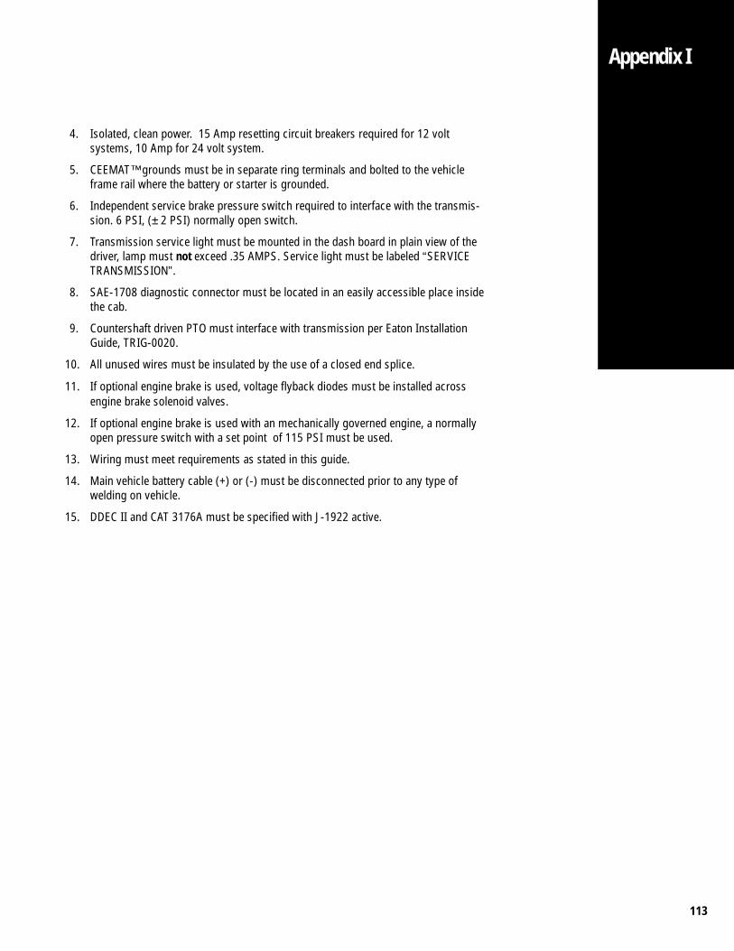
113
Appendix I
4. Isolated, clean power. 15 Amp resetting circuit breakers required for 12 voltsystems, 10 Amp for 24 volt system.
5. CEEMAT™ grounds must be in separate ring terminals and bolted to the vehicleframe rail where the battery or starter is grounded.
6. Independent service brake pressure switch required to interface with the transmis-sion. 6 PSI, (± 2 PSI) normally open switch.
7. Transmission service light must be mounted in the dash board in plain view of thedriver, lamp must not exceed .35 AMPS. Service light must be labeled “SERVICETRANSMISSION”.
8. SAE-1708 diagnostic connector must be located in an easily accessible place insidethe cab.
9. Countershaft driven PTO must interface with transmission per Eaton InstallationGuide, TRIG-0020.
10. All unused wires must be insulated by the use of a closed end splice.
11. If optional engine brake is used, voltage flyback diodes must be installed acrossengine brake solenoid valves.
12. If optional engine brake is used with an mechanically governed engine, a normallyopen pressure switch with a set point of 115 PSI must be used.
13. Wiring must meet requirements as stated in this guide.
14. Main vehicle battery cable (+) or (-) must be disconnected prior to any type ofwelding on vehicle.
15. DDEC II and CAT 3176A must be specified with J-1922 active.
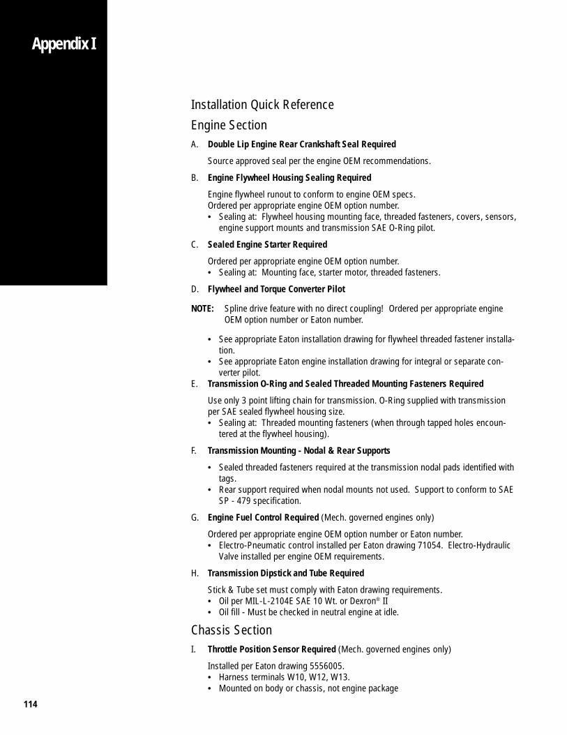
114
Appendix I
Installation Quick Reference
Engine SectionA. Double Lip Engine Rear Crankshaft Seal Required
Source approved seal per the engine OEM recommendations.
B. Engine Flywheel Housing Sealing Required
Engine flywheel runout to conform to engine OEM specs.Ordered per appropriate engine OEM option number.• Sealing at: Flywheel housing mounting face, threaded fasteners, covers, sensors,
engine support mounts and transmission SAE O-Ring pilot.
C. Sealed Engine Starter Required
Ordered per appropriate engine OEM option number.• Sealing at: Mounting face, starter motor, threaded fasteners.
D. Flywheel and Torque Converter Pilot
NOTE: Spline drive feature with no direct coupling! Ordered per appropriate engineOEM option number or Eaton number.
• See appropriate Eaton installation drawing for flywheel threaded fastener installa-tion.
• See appropriate Eaton engine installation drawing for integral or separate con-verter pilot.
E. Transmission O-Ring and Sealed Threaded Mounting Fasteners Required
Use only 3 point lifting chain for transmission. O-Ring supplied with transmissionper SAE sealed flywheel housing size.• Sealing at: Threaded mounting fasteners (when through tapped holes encoun-
tered at the flywheel housing).
F. Transmission Mounting - Nodal & Rear Supports
• Sealed threaded fasteners required at the transmission nodal pads identified withtags.
• Rear support required when nodal mounts not used. Support to conform to SAESP - 479 specification.
G. Engine Fuel Control Required (Mech. governed engines only)
Ordered per appropriate engine OEM option number or Eaton number.• Electro-Pneumatic control installed per Eaton drawing 71054. Electro-Hydraulic
Valve installed per engine OEM requirements.
H. Transmission Dipstick and Tube Required
Stick & Tube set must comply with Eaton drawing requirements.• Oil per MIL-L-2104E SAE 10 Wt. or Dexron® II• Oil fill - Must be checked in neutral engine at idle.
Chassis SectionI. Throttle Position Sensor Required (Mech. governed engines only)
Installed per Eaton drawing 5556005.• Harness terminals W10, W12, W13.• Mounted on body or chassis, not engine package
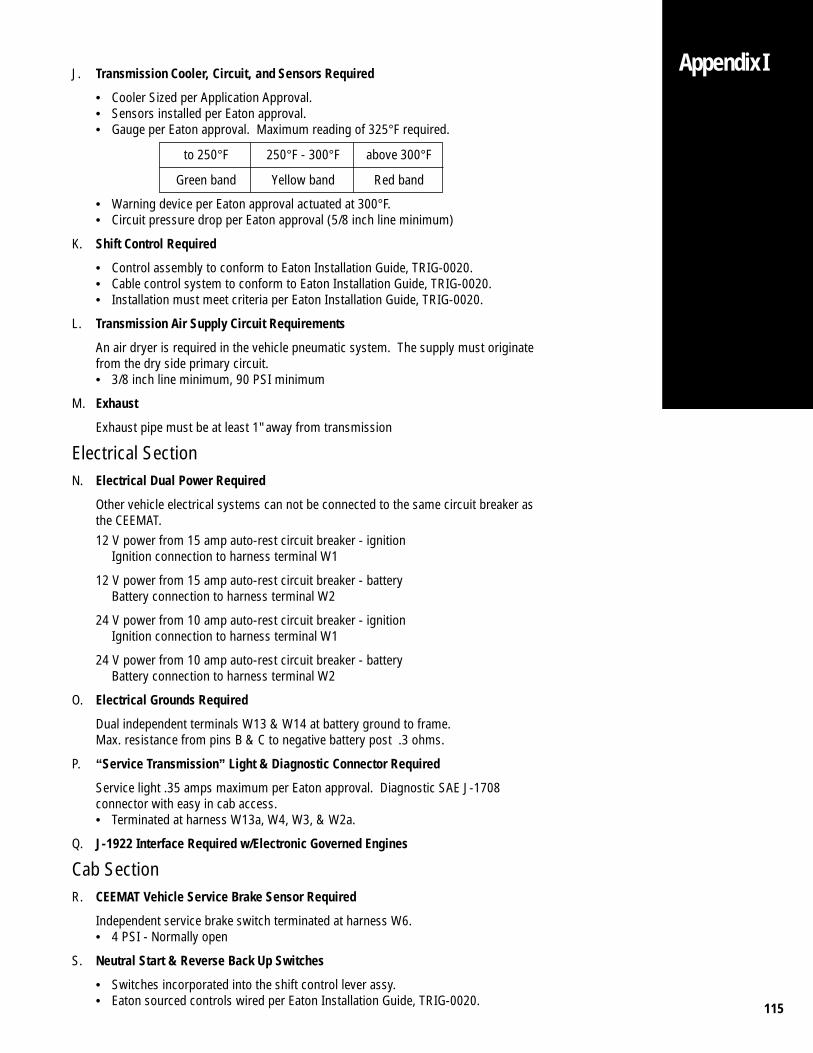
115
Appendix IJ. Transmission Cooler, Circuit, and Sensors Required
• Cooler Sized per Application Approval.• Sensors installed per Eaton approval.• Gauge per Eaton approval. Maximum reading of 325°F required.
to 250°F 250°F - 300°F above 300°F
Green band Yellow band Red band
• Warning device per Eaton approval actuated at 300°F.• Circuit pressure drop per Eaton approval (5/8 inch line minimum)
K. Shift Control Required
• Control assembly to conform to Eaton Installation Guide, TRIG-0020.• Cable control system to conform to Eaton Installation Guide, TRIG-0020.• Installation must meet criteria per Eaton Installation Guide, TRIG-0020.
L. Transmission Air Supply Circuit Requirements
An air dryer is required in the vehicle pneumatic system. The supply must originatefrom the dry side primary circuit.• 3/8 inch line minimum, 90 PSI minimum
M. Exhaust
Exhaust pipe must be at least 1" away from transmission
Electrical SectionN. Electrical Dual Power Required
Other vehicle electrical systems can not be connected to the same circuit breaker asthe CEEMAT.12 V power from 15 amp auto-rest circuit breaker - ignition
Ignition connection to harness terminal W1
12 V power from 15 amp auto-rest circuit breaker - batteryBattery connection to harness terminal W2
24 V power from 10 amp auto-rest circuit breaker - ignitionIgnition connection to harness terminal W1
24 V power from 10 amp auto-rest circuit breaker - batteryBattery connection to harness terminal W2
O. Electrical Grounds Required
Dual independent terminals W13 & W14 at battery ground to frame.Max. resistance from pins B & C to negative battery post .3 ohms.
P. “Service Transmission” Light & Diagnostic Connector Required
Service light .35 amps maximum per Eaton approval. Diagnostic SAE J-1708connector with easy in cab access.• Terminated at harness W13a, W4, W3, & W2a.
Q. J-1922 Interface Required w/Electronic Governed Engines
Cab SectionR. CEEMAT Vehicle Service Brake Sensor Required
Independent service brake switch terminated at harness W6.• 4 PSI - Normally open
S. Neutral Start & Reverse Back Up Switches
• Switches incorporated into the shift control lever assy.• Eaton sourced controls wired per Eaton Installation Guide, TRIG-0020.

116
Appendix I
Torque Specificationsa. Flywheel Adaptor Ring bolts:
inch design (7/16-14) - 37-50 Lbf·ft metric design (M10-35) - 50-55 Lbf·ft
b. Flywheel bolts (with integrated drive ring):
follow engine manufacturers specifications
c. Transmission-to-engine bolts:
* * inch design (7/16-14) - 37-50 Lbf·ft* * inch design (3/8-16) - 25-32 Lbf·ft* * metric design (M10-35) - 26-35 Lbf·ft
d. Transmission nodal mount bolts: (3/4-10 UNC) - 180-190 Lbf·ft
(nonpermanent thread sealant at through hole locations required. Use Loctite #567pipe sealant or equivalent.)
e. Output yoke nut - 450-500 Lbf·ft
f. PTO mounting bolts:
6-bolt opening - 20-25 Lbf·ft 8-bolt opening - 50-65 Lbf·ft
g. Torque converter outlet fitting (1 5/8-12) - 60-70 Lbf·ft
h. Oil cooler line fittings (1 1/16-12) - 50-60 Lbf·ft
i. Oil cooler line nut (1 1/16-12 JIC 37°) - 45-55 Lbf·ft
j. Dipstick tube fitting (1 5/8-12) - 60-70 Lbf·ft
k. Dipstick tube nut (1 5/16-12 JIC 37°) - 50-60 Lbf·ft
l. Speedometer body in rear cover - 35-50 Lbf·ft
m. Speedometer drive cable nut - 50 Lbf·in
n. Speedometer electronic sensor (3/4-16) - 10-15 Lbf·ft
o. Oil drain plugs:
converter pan (1/2-20 std. thd. with washer) - 15-20 Lbf·ft converter pan (3/8 NPT) - 20-25 Lbf·ft main case (3/4 NPT) - 45-55 Lbf·ft
p. Oil temperature sensor (1/2-14 NPTF) - 16-20 Lbf·ft
q. Lifting bracket bolts (3/8-16) - 25-32 Lbf·ft
r. Throttle position sensor mounting bolts (1/4-20) - 7-10 Lbf·ft
s. Shift cable u-bolt nuts (1/4-20) - 8-14 Lbf·ft
t. Shift cable swivel nut (5/16-24) - 8-14 Lbf·ft
u. Rear support nuts (5/8-18) - 170-185 Lbf·ft
v. Hydraulic Valve mounting bolts (3/8 - 16 grade 5) 35-45 Lbf·ft
* * THREAD ADHESIVE/SEALANT REQUIRED

117
Publications and DrawingsPublications
TRTS-0020 CEEMAT Troubleshooting GuideTRDR-0020 CEEMAT Drivers InstructionsTRSM-0020 CEEMAT Service ManualTRIP-0023 Illustrated Parts List - 11109TRIP-0025 Illustrated Parts List - 13109TRIP-0022 Illustrated Parts List - 14109TRIP-0026 Illustrated Parts List - 16109Item #0838 Ordering And Shipping Information for Diagnostic ToolsTCFM-0018 Product Literature Order FormTRIG-0020 CEEMAT OEM Installation GuideOSP-100 Product Literature - Eaton® Fuller® CEEMAT™
Drawing Numbers
AT-AD RTO 11/13/14109A-ATAT-AD RTO 11/13/14109B-ATATE-AD RTO 11/13/14109A-ATEATE-AD RTO 11/13/14109B-ATE5504000 Shift Control Chart drawing5503500 Shift Cable drawing71052 Installation drawing. Shift Control5500503 Dipstick Tube Detail-SAE #1 Applications5501004 Dipstick Detail - Std on SAE #1 Applications
Miscellaneous Drawings
4300315 90 Degree Torque Converter Outlet Fitting4302573 45 Degree Torque Converter Outlet Fitting4300809 Straight Torque Converter Outlet Fitting5556035 Pneumatic Defuel Kit53400 Electro/Hydraulic Defuel Valve5561000 Linear Throttle Position Sensor5556005 Installation Instructions for Linear TPS5556020 CEEMAT Yoke Options5556031 Low Profile Oil Pan Installation5556015 Rotated Oil Pan Installation5504200 Electronic Shift Lever Options5504300 ESL Tower Assembly Options
Appendix I

118
Appendix I
Line Inspection Form
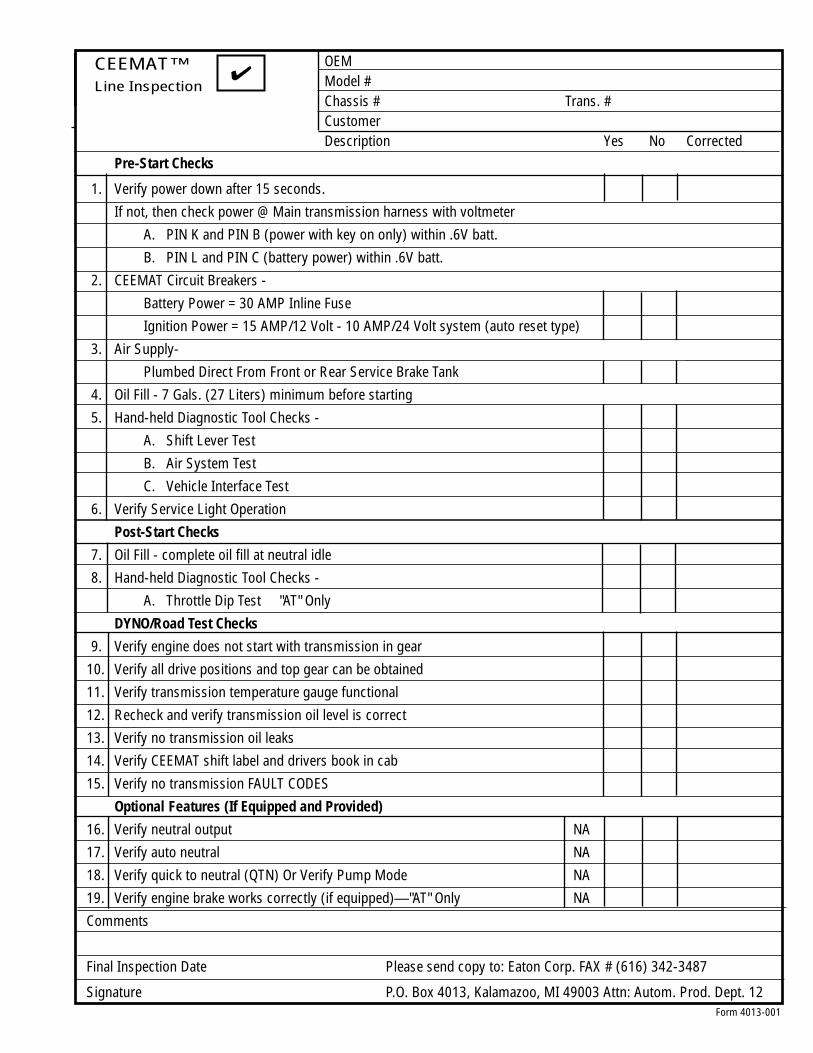
119Form 4013-001
CEEMAT™Line Inspection
✔OEMModel #Chassis # Trans. #CustomerDescription Yes No Corrected
Pre-Start Checks
1. Verify power down after 15 seconds.
If not, then check power @ Main transmission harness with voltmeter
A. PIN K and PIN B (power with key on only) within .6V batt.
B. PIN L and PIN C (battery power) within .6V batt.
2. CEEMAT Circuit Breakers -
Battery Power = 30 AMP Inline Fuse
Ignition Power = 15 AMP/12 Volt - 10 AMP/24 Volt system (auto reset type)
3. Air Supply-
Plumbed Direct From Front or Rear Service Brake Tank
4. Oil Fill - 7 Gals. (27 Liters) minimum before starting
5. Hand-held Diagnostic Tool Checks -
A. Shift Lever Test
B. Air System Test
C. Vehicle Interface Test
6. Verify Service Light Operation
Post-Start Checks
7. Oil Fill - complete oil fill at neutral idle
8. Hand-held Diagnostic Tool Checks -
A. Throttle Dip Test "AT" Only
DYNO/Road Test Checks
9. Verify engine does not start with transmission in gear
10. Verify all drive positions and top gear can be obtained
11. Verify transmission temperature gauge functional
12. Recheck and verify transmission oil level is correct
13. Verify no transmission oil leaks
14. Verify CEEMAT shift label and drivers book in cab
15. Verify no transmission FAULT CODES
Optional Features (If Equipped and Provided)
16. Verify neutral output NA
17. Verify auto neutral NA
18. Verify quick to neutral (QTN) Or Verify Pump Mode NA
19. Verify engine brake works correctly (if equipped)—"AT" Only NA
Comments
Final Inspection Date Please send copy to: Eaton Corp. FAX # (616) 342-3487
Signature P.O. Box 4013, Kalamazoo, MI 49003 Attn: Autom. Prod. Dept. 12

120
Appendix I
Line Inspection Form
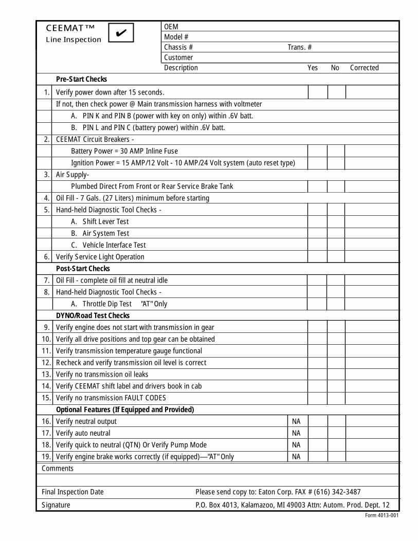
121Form 4013-001
CEEMAT™Line Inspection
✔OEMModel #Chassis # Trans. #CustomerDescription Yes No Corrected
Pre-Start Checks
1. Verify power down after 15 seconds.
If not, then check power @ Main transmission harness with voltmeter
A. PIN K and PIN B (power with key on only) within .6V batt.
B. PIN L and PIN C (battery power) within .6V batt.
2. CEEMAT Circuit Breakers -
Battery Power = 30 AMP Inline Fuse
Ignition Power = 15 AMP/12 Volt - 10 AMP/24 Volt system (auto reset type)
3. Air Supply-
Plumbed Direct From Front or Rear Service Brake Tank
4. Oil Fill - 7 Gals. (27 Liters) minimum before starting
5. Hand-held Diagnostic Tool Checks -
A. Shift Lever Test
B. Air System Test
C. Vehicle Interface Test
6. Verify Service Light Operation
Post-Start Checks
7. Oil Fill - complete oil fill at neutral idle
8. Hand-held Diagnostic Tool Checks -
A. Throttle Dip Test "AT" Only
DYNO/Road Test Checks
9. Verify engine does not start with transmission in gear
10. Verify all drive positions and top gear can be obtained
11. Verify transmission temperature gauge functional
12. Recheck and verify transmission oil level is correct
13. Verify no transmission oil leaks
14. Verify CEEMAT shift label and drivers book in cab
15. Verify no transmission FAULT CODES
Optional Features (If Equipped and Provided)
16. Verify neutral output NA
17. Verify auto neutral NA
18. Verify quick to neutral (QTN) Or Verify Pump Mode NA
19. Verify engine brake works correctly (if equipped)—"AT" Only NA
Comments
Final Inspection Date Please send copy to: Eaton Corp. FAX # (616) 342-3487
Signature P.O. Box 4013, Kalamazoo, MI 49003 Attn: Autom. Prod. Dept. 12

122
Appendix I
Vendor List
AMP Incorporated(Terminals)P.O. Box 3608Harrisburg, PA 17105-36081-800-522-6752
Armada Tube(Dipstick Tubes)74000 Cryderman Rd.Armada, MI 48005(313) 784-9191
DANAChelsea PTO Division5800 Sibley Rd.Chelsea, MI 48118(313) 475-8641
Deutsch(Connectors)Industrial Products Division37140 Industrial Ave.Hemet, CA 92545(909) 765-2250
FuronFelstead Division(Shift Controls and Cables)P.O. Box 68Holmesville, OH 44633(216) 279-3711
Quadrastat CorporationQuadco Electrohydraulics Division(Shift Controls and Cables)1701 Pearl St-Unit 7Waukesha, WI 53186(414) 544-4204
Raychem(Heat Shrink Boot)Deanco Inc.Meag Division25W 624 St. Charles RoadWheaton, IL 60188(708) 665-6214
Robert Bosch Corporation2800 South 25th AvenueBroadview, IL 60153(708) 865-5301
SPX CorporationKent-Moore Division(Diagnostic Tool)29784 Little MackRoseville, MI 48066-22981-800-328-6657
Stewart-Warner Hobbs Corporation(Pressure Switch)Yale Boulevard and Ash StreetSpringfield, IL 62705(217) 753-7791
Stewart Warner Instrument Corporation(Temperature Gauge)580 Slawin CourtMount Prospect, IL 60056-2183(708) 803-0200
Unlimited Services(Caps & Buss Bars)170 Evergreen RoadOconto, WI 54153(414) 834-4418
Williams Controls, Inc.(Air Throttle)14100 SW 72nd AvenuePortland, OR 97224(503) 684-8608
Glenair Strain Reliefs1211 AirwayGlendale, CA 91201-2497(818) 247-6000
Grote & Hartman(Terminals)32036 EdwardMadison Heights, MI 48021(313) 588-1022
IMOMorse Controls Division(Shift Controls and Cables)21 Clinton St.Hudson, OH 44236(216) 653-7739
Kysor of Cadillac(Temperature Switches)1100 Wright StreetCadillac, MI 49601(616) 779-7500
Muncie Power Products(Power Take-Offs)342 N. Pershing Dr.Muncie, IN 47305(317) 284-7721
Pacific Insight Electronics Corp.(Temperature Module)
624 Lakeside Dr.Nelson, B.C. V1L 5S7(604) 354-1155
Packard Electric(Connectors)Pioneer-Standard Electronics, Inc.Packard Branch5440 Naiman ParkwaySolon, OH 441391-800-PACKARD
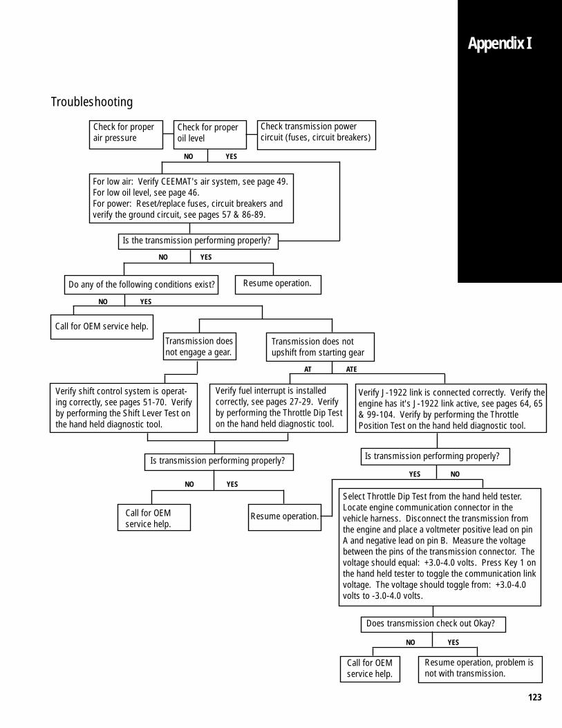
123
Troubleshooting
Check for properoil level
Check transmission powercircuit (fuses, circuit breakers)
Check for properair pressure
For low air: Verify CEEMAT's air system, see page 49.For low oil level, see page 46.For power: Reset/replace fuses, circuit breakers andverify the ground circuit, see pages 57 & 86-89.
Is the transmission performing properly?
YESNO
Do any of the following conditions exist? Resume operation.
YESNO
Call for OEM service help.
YESNO
Transmission doesnot engage a gear.
Transmission does notupshift from starting gear
Verify fuel interrupt is installedcorrectly, see pages 27-29. Verifyby performing the Throttle Dip Teston the hand held diagnostic tool.
Verify J-1922 link is connected correctly. Verify theengine has it's J-1922 link active, see pages 64, 65& 99-104. Verify by performing the ThrottlePosition Test on the hand held diagnostic tool.
Is transmission performing properly?
Call for OEMservice help.
Resume operation.
Select Throttle Dip Test from the hand held tester.Locate engine communication connector in thevehicle harness. Disconnect the transmission fromthe engine and place a voltmeter positive lead on pinA and negative lead on pin B. Measure the voltagebetween the pins of the transmission connector. Thevoltage should equal: +3.0-4.0 volts. Press Key 1 onthe hand held tester to toggle the communication linkvoltage. The voltage should toggle from: +3.0-4.0volts to -3.0-4.0 volts.
Does transmission check out Okay?
YESNO
ATEAT
Is transmission performing properly?
NOYES
Resume operation, problem isnot with transmission.
Call for OEMservice help.
YESNO
Verify shift control system is operat-ing correctly, see pages 51-70. Verifyby performing the Shift Lever Test onthe hand held diagnostic tool.
Appendix I

124
Appendix II
Electronic Shift LeverProtective Boot Accessory
20074-7/95
20023-8/95
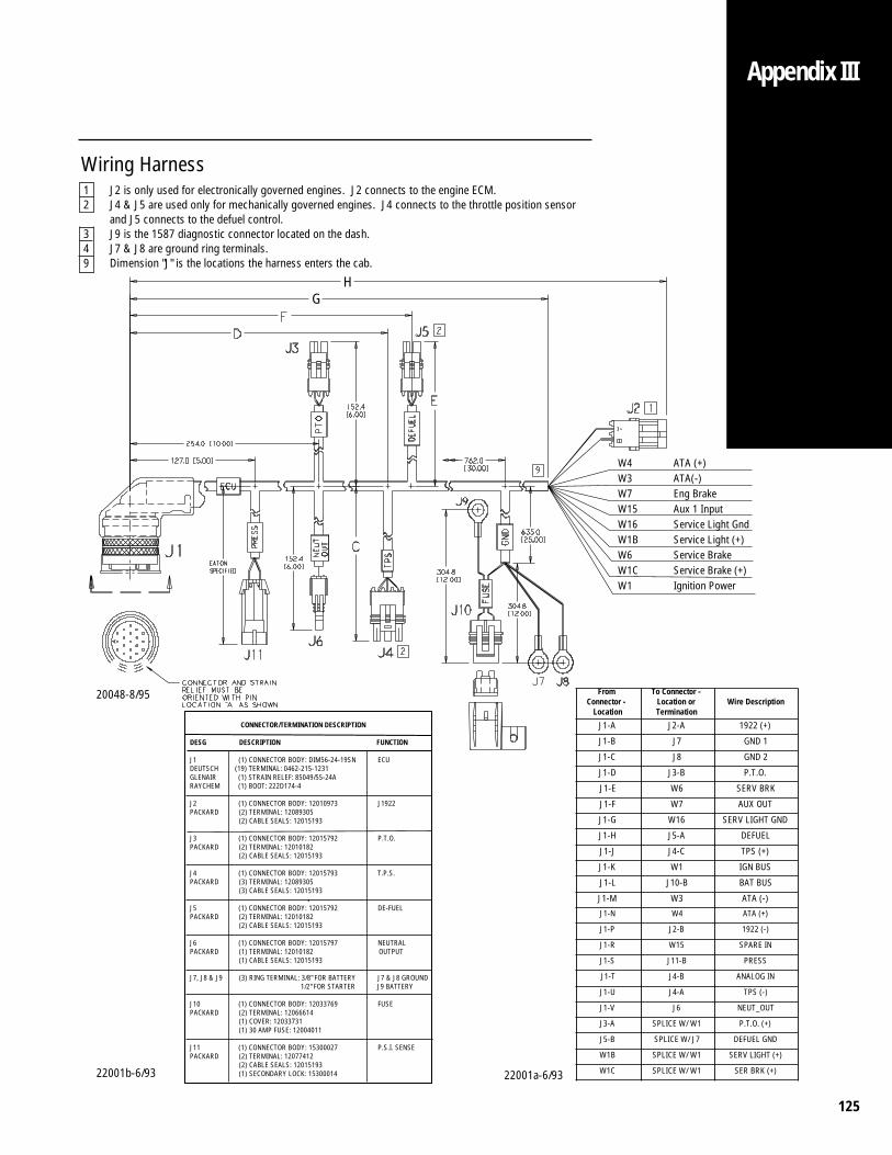
125
Appendix III
Wiring Harness1 J2 is only used for electronically governed engines. J2 connects to the engine ECM.2 J4 & J5 are used only for mechanically governed engines. J4 connects to the throttle position sensor
and J5 connects to the defuel control.3 J9 is the 1587 diagnostic connector located on the dash.4 J7 & J8 are ground ring terminals.9 Dimension "J" is the locations the harness enters the cab.
CONNECTOR/TERMINATION DESCRIPTION
DESG DESCRIPTION FUNCTION
J1 (1) CONNECTOR BODY: DIM56-24-19SN ECUDEUTSCH (19) TERMINAL: 0462-215-1231GLENAIR (1) STRAIN RELEF: 85049/55-24ARAYCHEM (1) BOOT: 222D174-4
J2 (1) CONNECTOR BODY: 12010973 J1922PACKARD (2) TERMINAL: 12089305 (2) CABLE SEALS: 12015193
J3 (1) CONNECTOR BODY: 12015792 P.T.O.PACKARD (2) TERMINAL: 12010182 (2) CABLE SEALS: 12015193
J4 (1) CONNECTOR BODY: 12015793 T.P.S.PACKARD (3) TERMINAL: 12089305 (3) CABLE SEALS: 12015193
J5 (1) CONNECTOR BODY: 12015792 DE-FUELPACKARD (2) TERMINAL: 12010182 (2) CABLE SEALS: 12015193
J6 (1) CONNECTOR BODY: 12015797 NEUTRALPACKARD (1) TERMINAL: 12010182 OUTPUT (1) CABLE SEALS: 12015193
J7, J8 & J9 (3) RING TERMINAL: 3/8" FOR BATTERY J7 & J8 GROUND 1/2" FOR STARTER J9 BATTERY J10 (1) CONNECTOR BODY: 12033769 FUSEPACKARD (2) TERMINAL: 12066614 (1) COVER: 12033731 (1) 30 AMP FUSE: 12004011
J11 (1) CONNECTOR BODY: 15300027 P.S.I. SENSEPACKARD (2) TERMINAL: 12077412 (2) CABLE SEALS: 12015193 (1) SECONDARY LOCK: 15300014
From Connector -
Location
To Connector - Location or Termination
Wire Description
J1-A J2-A 1922 (+)
J1-B J7 GND 1
J1-C J8 GND 2
J1-D J3-B P.T.O.
J1-E W6 SERV BRK
J1-F W7 AUX OUT
J1-G W16 SERV LIGHT GND
J1-H J5-A DEFUEL
J1-J J4-C TPS (+)
J1-K W1 IGN BUS
J1-L J10-B BAT BUS
J1-M W3 ATA (-)
J1-N W4 ATA (+)
J1-P J2-B 1922 (-)
J1-R W15 SPARE IN
J1-S J11-B PRESS
J1-T J4-B ANALOG IN
J1-U J4-A TPS (-)
J1-V J6 NEUT_OUT
J3-A SPLICE W/ W1 P.T.O. (+)
J5-B SPLICE W/ J7 DEFUEL GND
W1B SPLICE W/ W1 SERV LIGHT (+)
W1C SPLICE W/ W1 SER BRK (+)
20048-8/95
22001b-6/93 22001a-6/93
W4 ATA (+)W3 ATA(-)W7 Eng BrakeW15 Aux 1 InputW16 Service Light GndW1B Service Light (+)W6 Service BrakeW1C Service Brake (+)W1 Ignition Power
HG
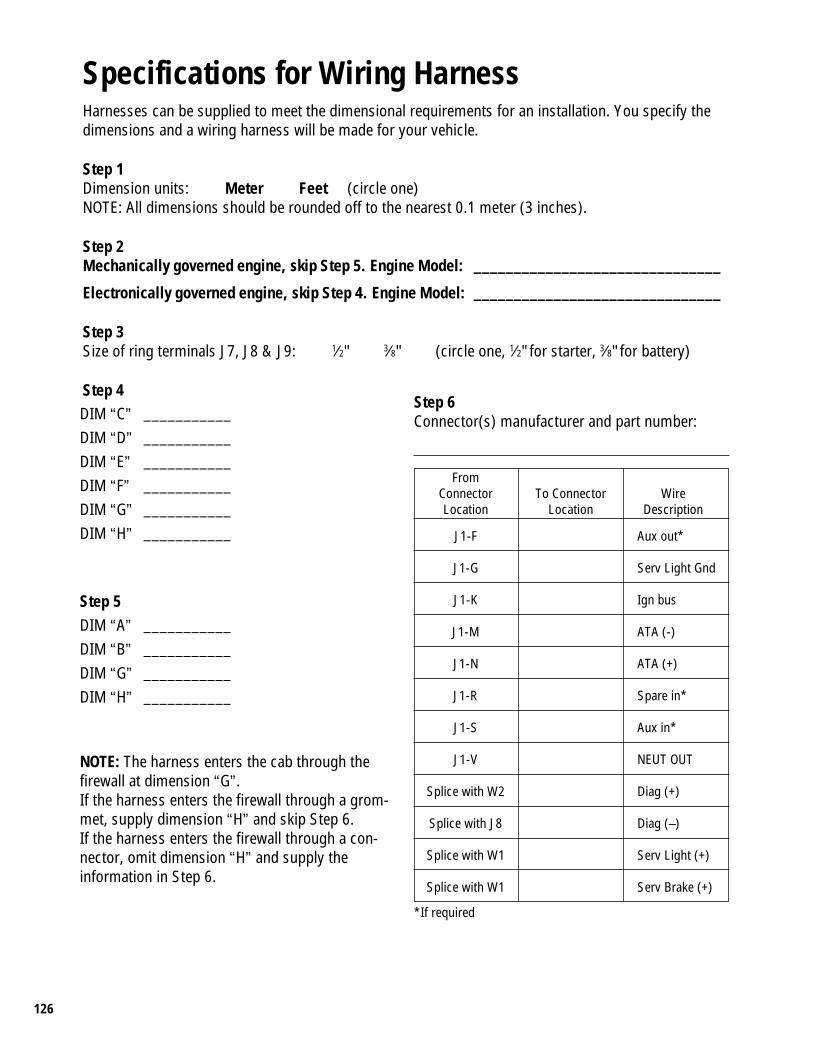
126
Specifications for Wiring HarnessHarnesses can be supplied to meet the dimensional requirements for an installation. You specify thedimensions and a wiring harness will be made for your vehicle.
Step 1Dimension units: Meter Feet (circle one)NOTE: All dimensions should be rounded off to the nearest 0.1 meter (3 inches).
Step 2Mechanically governed engine, skip Step 5. Engine Model: _______________________________
Electronically governed engine, skip Step 4. Engine Model: _______________________________
Step 3Size of ring terminals J7, J8 & J9: 1⁄2" 3⁄8" (circle one, 1⁄2" for starter, 3⁄8" for battery)
Step 4DIM “C” ___________DIM “D” ___________DIM “E” ___________DIM “F” ___________DIM “G” ___________DIM “H” ___________
Step 5DIM “A” ___________DIM “B” ___________DIM “G” ___________DIM “H” ___________
NOTE: The harness enters the cab through thefirewall at dimension “G”.If the harness enters the firewall through a grom-met, supply dimension “H” and skip Step 6.If the harness enters the firewall through a con-nector, omit dimension “H” and supply theinformation in Step 6.
Step 6Connector(s) manufacturer and part number:
FromConnector To Connector WireLocation Location Description
J1-F Aux out*
J1-G Serv Light Gnd
J1-K Ign bus
J1-M ATA (-)
J1-N ATA (+)
J1-R Spare in*
J1-S Aux in*
J1-V NEUT OUT
Splice with W2 Diag (+)
Splice with J8 Diag (–)
Splice with W1 Serv Light (+)
Splice with W1 Serv Brake (+)
*If required
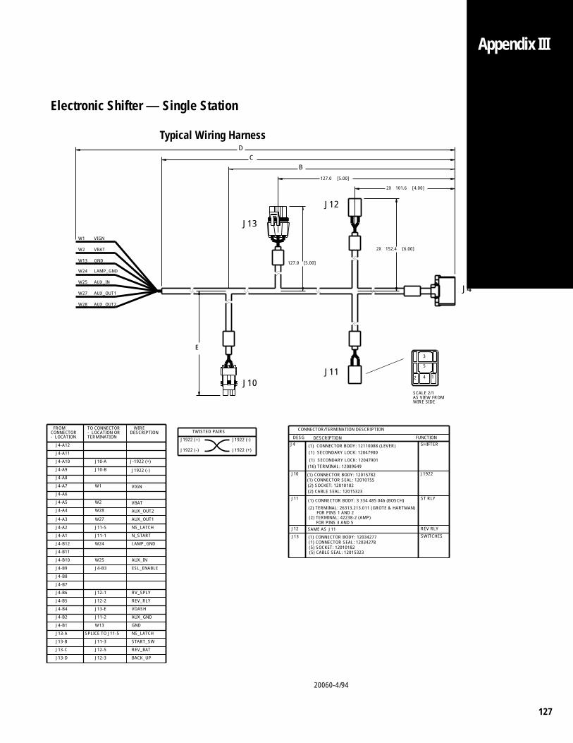
127
20060-4/94
Appendix III
Electronic Shifter — Single Station
Typical Wiring Harness
W28
W27
J10
J4
127.0 [5.00]
152.4 [6.00]2X
101.6 [4.00]
J13
J12
AUX_IN
VIGN
W25
W24
W13
W2
W1
LAMP_GND
VBAT
GND
E
AUX_OUT2
AUX_OUT1
J11
2X
CD
B
127.0 [5.00]
2
SCALE 2/1AS VIEW FROMWIRE SIDE
TWISTED PAIRS
J1922 (+)
J1922 (-)
J1922 (-)
J1922 (+)
4
3
5
1
J1922 (-)
J4-A11
J12-1
J12-2
W28
J4-A10
J4-A9
J4-A8
J4-A12
J10-A
W1
W2
J13-E
J4-B1
J11-2
J13-A
J12-3
W27
W25
J10-B
J11-5
J13-D
J12-5
W13
J4-B9
J4-B8
J4-B7
J4-B6
J4-B5
J4-B4
J4-B2
TO CONNECTOR- LOCATION ORTERMINATION
BACK_UP
REV_BAT
J11-1
W24
J4-B3
J13-B
J13-C
J11-3
J-1922 (+)
J4-A7
J4-A6
VIGN
ESL_ENABLE
VDASH
GND
RV_SPLY
START_SW
NS_LATCH
LAMP_GND
FROMCONNECTOR
N_START
AUX_OUT2
VBAT
SPLICE TO J11-5
J4-A5
J4-A4
J4-A3
J4-A2
J4-A1
J4-B12
J4-B11
J4-B10
AUX_GND
REV_RLY
AUX_IN
WIREDESCRIPTION
- LOCATION
NS_LATCH
AUX_OUT1
CONNECTOR/TERMINATION DESCRIPTION
SHIFTER
J10
REV RLY
ST RLY
J12
J11 (1) CONNECTOR BODY: 3 334 485 046 (BOSCH)
(2) TERMINAL: 26313.213.011 (GROTE & HARTMAN)FOR PINS 1 AND 2
(2) TERMINAL: 42238-2 (AMP) FOR PINS 3 AND 5
(1) CONNECTOR BODY: 12015782
(1) CONNECTOR SEAL: 12010155(2) SOCKET: 12010182(2) CABLE SEAL: 12015323
(1) CONNECTOR BODY: 12110088 (LEVER)(1) SECONDARY LOCK: 12047900
(1) SECONDARY LOCK: 12047901(16) TERMINAL: 12089649
SAME AS
J11
SWITCHES
DESG DESCRIPTION
J1922
J4FUNCTION
J13
(5) CABLE SEAL: 12015323(5) SOCKET: 12010182(1) CONNECTOR SEAL: 12034278(1) CONNECTOR BODY: 12034277
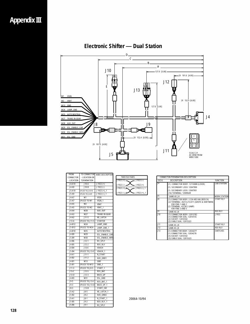
128
20064-10/94
Appendix III
Electronic Shifter — Dual Station
[4.00]
J4
152.4 [6.00]
12
WIRE SIDEAS VIEW FROMSCALE 2/1
4
3
5
CB
A
J9
2X
127.0
127.0 [5.00]
2X
J13
J12
[5.00]
D
FUNCTIONCAB STATION
WORK STATIONSTART RLY
GND
AUTO NEUTRAL
VIGN
W25
AUX_OUT
TRANS IN GEAR
W28
W27
J8
W24
W13
W2
W1
J10
LAMP_GND
VBAT
E
2X
F
J11
152.4 [6.00]
TWISTED PAIRSJ1922 (-)
J1922 (+)J1922 (-)_1
J1922 (+)_1
ESL_GNDW31
W30
W29
101.6 [4.00]2X
J5
ESL_ENABLE_CAB
DESCRIPTIONJ4
J8J5
DESG
SAME AS
J4
ESL_ENABLE_WRK
VIGNJ4-A7
J-1922 (-)
J-1922 (-)_1
TERMINATIONLOCATION OR
WIRE DESCRIPTION
W1
J10-BJ10-A J-1922 (+)
SPLICE TO J4-A10J5-A10SPLICE TO J4-A9J5-A9
J-1922 (+)_1
SAME AS
SAME AS
J8
J9
J11J12
J10
J13J8
J8
SWITCHES
J1922
REV RLY
REV RLY
START RLY
J4-A9J4-A10
-TO CONNECTOR
LOCATION-CONNECTOR FROM
SPLICE TO W2
SPLICE TO W24
W25
W2
W28
J13-A
W27
SPLICE TO W1
J4-A4
J4-A3J4-A2
J5-B12
J4-B10
SAME AS
W29
W30
J11-5
W24
J5-A5
J5-B9
SPLICE TO J11-5 STARTERLAMP_GND
TRANS IN GEARNS_LATCH
VIGN_1J5-A7
J4-B12
J4-B9
J4-A5 VBAT
LAMP_GND_1
AUX_OUTVBAT_1
ESL_ENABLE_CAB
AUTO NEUTRAL
ESL_ENABLE_WRK
START_1
GND_1
J13-E
J11-3
J5-B4
J12-1
J12-2
SPLICE TO W13
SPLICE TO J8-5
J4-A1J11-2J11-1
J5-B1W13
J4-B6
J4-B5J4-B4
J8-1J9-2J9-1
VDASH_1
GND
VDASHREV_RLY
AUX_GND1
RV_SPLY
J4-B2
J4-B1
SPLICE TO J13-EN_START
SPLICE TO J13-C
SPLICE TO J13-DSTART_SW
REV_RLY_1
RV_SPLY
J5-A1J5-B5J5-B6
J5-B2
J13-D
J8-5
J4-B3J9-5
J9-3
BACK_UPESL_GND
REV_BAT_1BACK_UP_1
NS_LATCH_1AUX_GND2
N_START_1
J1922 (+)_1
J1922 (+)
J1922 (-)
J1922 (-)_1
J13-B
J8-2
J8-3
J5-A2
J12-3W31
(2) TERMINAL: 26313.213.011 (GROTE & HARTMAN)(1) CONNECTOR BODY: 3 334 485 046 (BOSCH)
101.6
REV_BATJ13-C J12-5
(2) SOCKET: 12010182(1) CONNECTOR SEAL: 12010155(1) CONNECTOR BODY: 12015782
(5) CABLE SEAL: 12015323(5) SOCKET: 12010182(1) CONNECTOR SEAL: 12034278
(16) TERMINAL: 12089649(1) SECONDARY LOCK: 12047901(1) SECONDARY LOCK: 12047900(1) CONNECTOR BODY: 12110088 (LEVER)
CONNECTOR/TERMINATION DESCRIPTION
FOR PINS 3 AND 5(2) TERMINAL: 42238-2 (AMP)
FOR PINS 1 AND 2
(1) CONNECTOR BODY: 12034277
(2) CABLE SEAL: 12015323
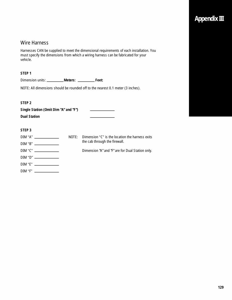
129
Wire HarnessHarnesses CAN be supplied to meet the dimensional requirements of each installation. Youmust specify the dimensions from which a wiring harness can be fabricated for yourvehicle.
STEP 1
Dimension units: Meters: Feet:
NOTE: All dimensions should be rounded off to the nearest 0.1 meter (3 inches).
STEP 2
Single Station (Omit Dim "A" and "F")
Dual Station
STEP 3
DIM “A”
DIM “B”
DIM “C”
DIM “D”
DIM “E”
DIM “F”
NOTE: Dimension “C” is the location the harness exitsthe cab through the firewall.
Dimension "A" and "F" are for Dual Station only.
Appendix III
130
Appendix IV
Fuel Control Functional Test(For Mechanically Governed Engines)
Normal engine acceleration and deceleration rates and the engine acceleration/ decelera-tion rates when controlled by the transmission should be the same. The transmissionlooks at information from its own internal speed sensors and must see the engine drop aminimum of 250 RPM/second before it will start to make a shift.
Symptoms of improper installation of the fuel control (throttle dip and throttle boostsolenoids) may include: no shifting unless the driver lifts his foot from the acceleratorpedal, an active fault code #35, (engine control failed), harsh, jerky, or slow shifting.
Generally, faster engine acceleration and deceleration rates will result in quicker andsmoother shift quality from the CEEMAT transmission.
a. To determine if the engine deceleration and acceleration rates fall within acceptableranges for the CEEMAT (the use of a stopwatch or other accurate means of mea-surement is recommended):
1. Manually increase the engine speed to governed rpm by depressing the throttlepedal. When a steady governed rpm is obtained, quickly remove foot from thethrottle and measure the time it takes for the engine speed to decrease by 1000rpm. If the engine speed does not drop 1000 RPM in less than 4 seconds (250rpm/sec), contact engine OEM for possible fuel pump adjustment.
2. Starting at idle, fully depress the throttle pedal. Measure the time required forthe engine to reach governed speed.
b. To determine if the CEEMAT fuel control system is functioning properly, connect theEaton hand-held diagnostic tool (P/N 5505011) to the J1587 diagnostic port on thedash and select “Throttle Control Test” (or “Throttle DIp”) from the “Perform Tests”menu, and perform the following:
1. Increase engine speed to governed rpm by manually pushing on the throttlepedal. When a steady governed rpm is obtained, continue holding steady pressureon the throttle and press and hold the number “1” on the diagnostic tool to activateCEEMAT throttle dip. Measure the time it takes the engine speed to decrease 1000RPM as in step a. Release the “1” key.
2. With no pressure on the throttle pedal (engine at idle) press and hold thenumber “1” on the diagnostic tool to activate CEEMAT throttle boost. Measure thetime it takes for the engine to reach governed speed. Release the “1” key.
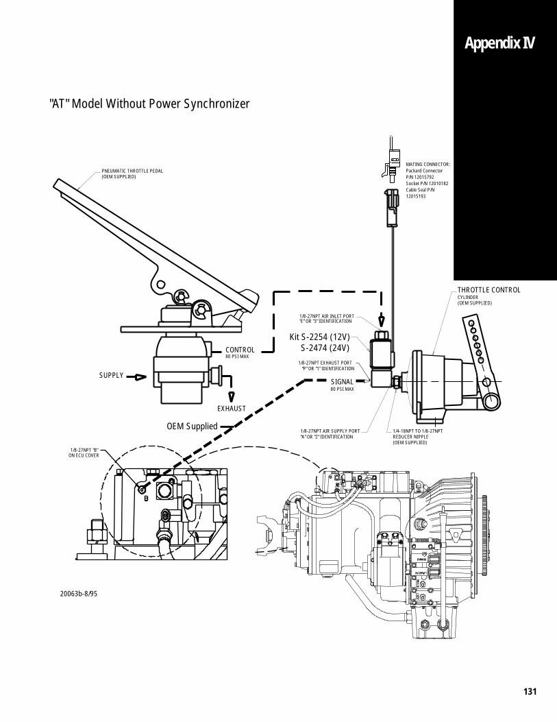
131
Appendix IV
"AT" Model Without Power Synchronizer
20063b-8/95
(OEM SUPPLIED)
Kit S-2254 (12V) S-2474 (24V)
(OEM SUPPLIED)REDUCER NIPPLE
(OEM SUPPLIED)
CONTROL
EXHAUST
SIGNAL
80 PSI MAX
SUPPLY
CYLINDERTHROTTLE CONTROL
MATING CONNECTOR:Packard ConnectorP/N 12015792Socket P/N 12010182Cable Seal P/N12015193
PNEUMATIC THROTTLE PEDAL
1/4-18NPT TO 1/8-27NPT
"E" OR "3" IDENTIFICATION1/8-27NPT AIR INLET PORT
"A" OR "2" IDENTIFICATION1/8-27NPT AIR SUPPLY PORT
"P" OR "1" IDENTIFICATION1/8-27NPT EXHAUST PORT
ON ECU COVER1/8-27NPT "B"
80 PSI MAX
OEM Supplied
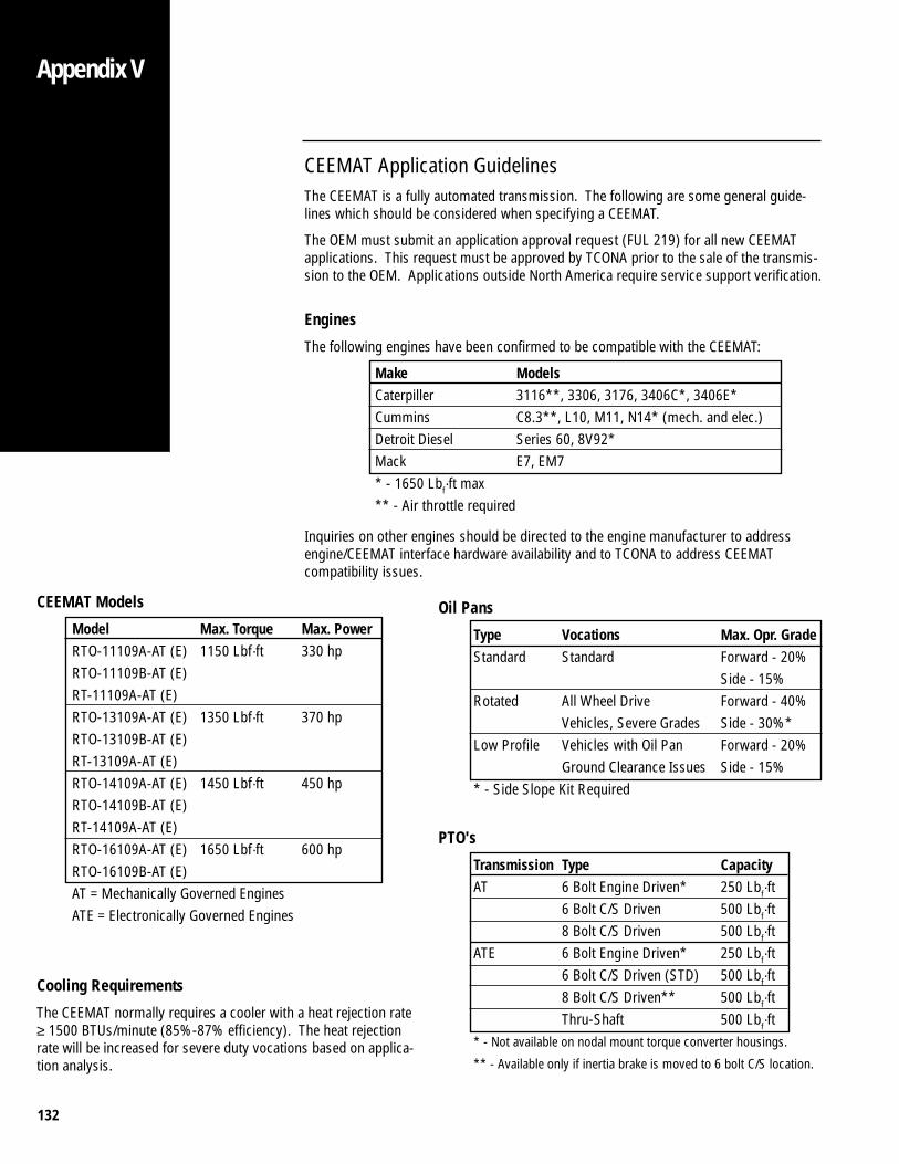
132
CEEMAT Application GuidelinesThe CEEMAT is a fully automated transmission. The following are some general guide-lines which should be considered when specifying a CEEMAT.
The OEM must submit an application approval request (FUL 219) for all new CEEMATapplications. This request must be approved by TCONA prior to the sale of the transmis-sion to the OEM. Applications outside North America require service support verification.
Engines
The following engines have been confirmed to be compatible with the CEEMAT:
Make ModelsCaterpiller 3116**, 3306, 3176, 3406C*, 3406E*Cummins C8.3**, L10, M11, N14* (mech. and elec.)Detroit Diesel Series 60, 8V92*Mack E7, EM7* - 1650 Lbf·ft max** - Air throttle required
Inquiries on other engines should be directed to the engine manufacturer to addressengine/CEEMAT interface hardware availability and to TCONA to address CEEMATcompatibility issues.
CEEMAT Models
Model Max. Torque Max. PowerRTO-11109A-AT (E) 1150 Lbf·ft 330 hpRTO-11109B-AT (E)RT-11109A-AT (E)RTO-13109A-AT (E) 1350 Lbf·ft 370 hpRTO-13109B-AT (E)RT-13109A-AT (E)RTO-14109A-AT (E) 1450 Lbf·ft 450 hpRTO-14109B-AT (E)RT-14109A-AT (E)RTO-16109A-AT (E) 1650 Lbf·ft 600 hpRTO-16109B-AT (E)AT = Mechanically Governed EnginesATE = Electronically Governed Engines
Oil Pans
Type Vocations Max. Opr. GradeStandard Standard Forward - 20%
Side - 15%Rotated All Wheel Drive Forward - 40%
Vehicles, Severe Grades Side - 30%*Low Profile Vehicles with Oil Pan Forward - 20%
Ground Clearance Issues Side - 15%* - Side Slope Kit Required
PTO's
Transmission Type CapacityAT 6 Bolt Engine Driven* 250 Lbf·ft
6 Bolt C/S Driven 500 Lbf·ft8 Bolt C/S Driven 500 Lbf·ft
ATE 6 Bolt Engine Driven* 250 Lbf·ft6 Bolt C/S Driven (STD) 500 Lbf·ft8 Bolt C/S Driven** 500 Lbf·ftThru-Shaft 500 Lbf·ft
* - Not available on nodal mount torque converter housings.
** - Available only if inertia brake is moved to 6 bolt C/S location.
Cooling Requirements
The CEEMAT normally requires a cooler with a heat rejection rate≥ 1500 BTUs/minute (85%-87% efficiency). The heat rejectionrate will be increased for severe duty vocations based on applica-tion analysis.
Appendix V
133
Body Builder Guide For Tapping Into Electrical SystemsBody builder electrical systems that are to be interconnected with the CEEMAT electricalsystem should adhere to the latest recommendations of SAE J1292. In addition to SAEJ1292, the following recommendations should be followed:
1. All wiring terminals should be properly insulated to prevent “short circuits”. Allterminals should be of insulation grip design to provide a reliable connection and toprevent terminal fatigue.
2. Terminals and splices that are connected outside the body should be moistureresistant design. Molded insulator for ring terminals should be used. Moldedconnector/insulators are recommended for use with blade or pin type terminals.
3. Wires must be routed to provide at least 75mm [3.00"] clearance to moving parts,unless positively fastened or protected by conduit.
4. Wire routing should avoid areas where temperatures exceed 80 degrees C [180degrees F] and a minimum clearance of 150mm [6.00"] should be maintained fromexhaust system components. Where compliance with this requirement is notpossible, heat insulation and heat shields are required.
5. Wire routing and component mounting (switches, relays, etc.) should be located tobe easily removed for service. Do not surround the components with body struc-ture that will prevent removal for service.
6. Wiring to all circuit components (switches, relays, etc.) in exposed locations shallprovide a drip loop to prevent moisture from being conducted into the device via thewire connection.
7. Routing wiring into wheel splash areas should be avoided. When such routingcannot be avoided, adequate clipping or protective shielding is required to protectwiring from stone and ice damage.
8. Routing wires under the frame side-members or at points lower than the bottomframe flange should be avoided to prevent damage to the wires in off-road opera-tions.
9. The wire retainers and grommets installed by the assembly plant are designed toaccommodate only the OEM installed wires. Additional wiring or tubing must beretained by additional clips. When added wires to tubes are routed through sheetmetal panels, new holes must be used (with adequate wire protection and sealing).
10. All wiring connections to components of the factory-installed system must beaccomplished by using the correct mating wire termination. (Connections on studsand ground connections must use ring type terminations).
11. When it is necessary to splice wires, the splice must be adequately crimped toprovide a good mechanical and electrical connection. And double wall heat shrinktubing should be used where the outer wall will provide adequate electrical insula-tion and the inner wall melts and seals the splice from the environment.
Appendix VI
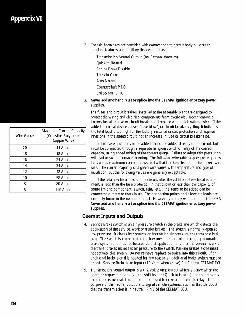
134
Appendix VI
Maximum Current CapacityWire Gauge (Crosslink Polythlene
Copper Wire)
20 14 Amps18 18 Amps16 24 Amps14 34 Amps12 42 Amps10 58 Amps8 80 Amps6 110 Amps
12. Chassis harnesses are provided with connections to permit body builders tointerface features and ancillary devices such as:
Transmission Neutral Output (for Remote throttles)Quick to NeutralEngine Brake DisableTrans in GearAuto NeutralCountershaft P.T.O.Split-Shaft P.T.O.
13. Never add another circuit or splice into the CEEMAT ignition or battery powersupplies.
The fuses and circuit breakers installed at the assembly plant are designed toprotect the wiring and electrical components from overloads. Never remove afactory installed fuse or circuit breaker and replace with a high value device. If theadded electrical device causes “fuse blow”, or circuit breaker cycling, it indicatesthe total load is too high for the factory-installed circuit protection and requiresrevisions in the added circuit; not an increase in fuse or circuit breaker size.
In this case, the items to be added cannot be added directly to the circuit, butmust be connected through a separate hang-on switch or relay of the correctcapacity, using added wiring of the correct gauge. Failure to adopt this precautionwill lead to switch contacts burning. The following wire table suggest wire gaugesfor various maximum current draws and will aid in the selection of the correct wiresize. The current capacity of a given wire varies with temperature and type ofinsulation, but the following values are generally acceptable.
If the total electrical load on the circuit, after the addition of electrical equip-ment, is less than the fuse protection in that circuit or less than the capacity ofsome limiting component (switch, relay, etc.), the items to be added can beconnected directly to that circuit. The connection points and allowable loads arenormally found in the owners manual. However, you may want to contact the OEM.Never add another circuit or splice into the CEEMAT ignition or battery powersupplies.
Ceemat Inputs and Outputs14. Service Brake switch is an air pressure switch in the brake line which detects the
application of the service, work or trailer brakes. The switch is normally open atlow pressure. It closes its contacts on increasing air pressure; the threshold is 4psig. The switch is connected to the low pressure control side of the pneumaticbrake system and must be located so that application of either the service, work orthe trailer brakes increases air pressure to the switch. Parking brakes alone mustnot activate this switch. Do not remove replace or spice into this circuit. If anadditional brake signal is needed for any reason an additional brake switch must beadded. Service Brake is an input (+12 Volts when active) Pin E of the CEEMAT ECU.
15. Transmission Neutral output is a +12 Volt 2 Amp output which is active when theoperator requests neutral (via the shift lever or Quick to Neutral) and the transmis-sion mode is neutral. This output is not used to drive a start enable relay. Thepurpose of the neutral output is to signal vehicle systems, such as throttle boost,that the transmission is in neutral. Pin V of the CEEMAT ECU.
Appendix VI
135
Appendix VIAppendix VI
16. Trans In Gear is a 12 Volt 1 Amp output which is active whenever the CEEMAT shiftlever is not in neutral. Pin 10 of the Electronic Shift Lever (ESL). Pin A3 of the PushButton Control.
17. Countershaft P.T.O. is ether a two (2) wire ball switch or an air pressure switch whichis normally open. The switch must close when ever the P.T.O. is engaged. This is aninput (+12 Volts when active). When this input is active the CEEMAT will hold currentgear and turn on the lock-up and interrupt clutches in the torque converter. Pin D ofthe CEEMAT ECU.
18. Split-Shaft P.T.O. is ether a two (2) wire ball switch or an air pressure switch which isNormally open. The switch must close when ever the P.T.O. is engaged. This is aninput (+12 Volts when active). When this input is active the CEEMAT will shift to directwhen the shift lever is moved to “D” and turn on the lock-up and interrupt clutches inthe torque converter. The CEEMAT will shift to neutral only when the shift lever ismoved to “N”. Pin R of the CEEMAT ECU. This feature must be enabled at the factory.
19. Engine Driven P.T.O. that utilizes the 6-bolt opening on the torque converter does notrequire any electrical interface to the CEEMAT transmission.
20. Quick to Neutral switch is an air pressure switch in the brake line which detects theapplication of the work brakes. The switch is normally open at low pressure andcloses its contacts on increasing air pressure; the threshold is 4 psig. The switch isconnected to the low pressure control side of the pneumatic work brake system andmust be located so that application of the work brakes increases air pressure to theswitch. Parking brakes alone could be used to activate this switch. In some systems atoggle switch wired in series may be used to disable Quick to Neutral while using thework station. When QTN is active it will keep the CEEMAT in gear while disengagingthe interrupt clutch. The Interrupt clutch is the main clutch, it connects the impeller ofthe torque converter to the input shaft causing torque transfer to transmission outputshaft. Quick to Neutral is an input (+12 Volts when active). If Quick to Neural is usedan additional pressure switch must be used. DO NOT use the service brake switch forthis feature. Pin R of the CEEMAT ECU. This feature must be enabled at the factory.
21. Auto Neutral switch is an air pressure switch in the parking brake line which detectsthe application of the parking brakes. The switch is normally closed at low pressureand opens its contacts on increasing air pressure; the threshold is 4 psig. The switchis connected to the low pressure control side of the parking brake system and must belocated so that application of the parking brakes decreases air pressure to the switch.When Auto Neutral is active it will Disengage the Interrupt clutch and shift the CEEMATto neutral. Auto Neutral is an input (grounded when active) Pin 15 of the ElectronicShift Lever (ESL). Pin B10 of the Push Button Control.
22. Engine Brake Disable is a +12 Volt 2 Amp output which is active when ever theCEEMAT is in neutral or the torque converter is not in lock up. Engine Brake Discon-nect would turn on a relay to disconnect the engine brake. The normally closedcontacts of the relay would be wired in series with the engine brake system. EngineBrake Disconnect would only be used with mechanically governed engines. EngineBrake Disconnect would eliminate the need for a pressure switch in the lock-up port ofthe torque converter and a pressure switch on the air throttle system as illustrated inthe CEEMAT Installation Guide TRIG 0020. Pin F of the CEEMAT ECU.

for pdf

for pdf
Eaton Corporation1111 Superior Ave.Cleveland, OH 44114
Copyright Eaton Corporation, 2012. Eaton hereby grant their customers, vendors, or distributors permission to freely copy, reproduce and/or distribute this document in printed format. It may be copied only in its entirety without any changes or modifications. THIS INFORMATION IS NOT INTENDED FOR SALE OR RESALE, AND THIS NOTICE MUST REMAIN ON ALL COPIES.
Note: Features and specifications listed in this document are subject to change without notice and represent the maximum capabilities of the software and products with all options installed. Although every attempt has been made to ensure the accuracy of information contained within, Eaton makes no representation about the completeness, correctness or accuracy and assumes no responsibility for any errors or omissions. Features and functionality may vary depending on selected options.
For spec’ing or service assistance, call 1-800-826-HELP (4357) or visit our web site at:
www.roadranger.com. In Mexico, call 001-800-826-4357.