Embed Size (px)
Citation preview
B-9
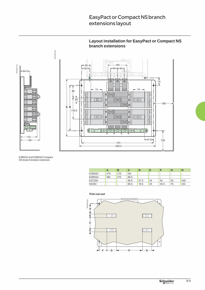
Layout installation for EasyPact or Compact NS branch extensions
DB
1164
38.e
ps
DB
1164
37.e
ps
EZBNS2 and EZBNS4 Compact NS branch breaker extension.
A B C D E F G H
EZBNS2 270 175 NA - - - - -EZBNS4 384 275 85.5 - - - - -EZC250 - - 90.5 57.5 24 61 52 249NS250 - - 85.5 78.5 29 45.5 76 232
Trim cut-out
DB106569
DB
1164
39.e
ps
EasyPact or Compact NS branch extensions layout
Book general.indb 9 01/04/2011 13:32:25

B-10
Book general.indb 10 01/04/2011 13:32:25
C-1
EasyPact
Presentation IIFunctions and characteristics A-1Busbars B-1
Dimensions EasyPact 100 C-2EasyPact 100 A with plug-in C-4EasyPact 250 - EZC250/EZCV250 C-6EasyPact 250 A with plug-in C-8EasyPact 400 C-10EasyPact 100 accessories C-12EasyPact 250 accessories C-13EasyPact 400 accessories C-14
Safety clearances and minimum distances C-15
Temperature derating C-17
Tripping curves C-18
Current-limiting curves C-20
Cascading C-21
Cascading tables C-22
Motor protection C-24
Capacitor protection C-26
Catalogue numbers D-1
Installation guide
Book general.indb 1 01/04/2011 13:32:25
C-2
Installation guide
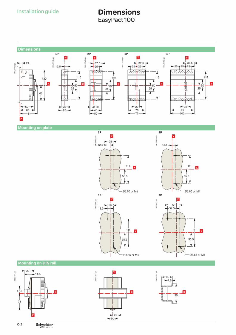
Dimensions1P 2P 3P 4P
Z
X
DB
1164
43.e
ps
YY
X
DB
1257
48.e
ps
X
Y
DB
1257
49.e
ps Y
X
DB
1257
50.e
ps Y
X
DB
1257
51.e
ps
Mounting on plate
1P 2PY
X
DB
1164
48.e
ps
or
Y
X
DB
1164
49.e
ps
3P 4PY
X
DB
1164
50.e
ps
or
x
YY
X
DB
1164
51.e
ps
Mounting on DIN rail
xX
Z
DB
1164
54.e
ps
x
YY
X
DB
1164
52.e
ps
xX
DB
1164
53.e
ps
DimensionsEasyPact 100
Book general.indb 2 01/04/2011 13:32:27
C-3
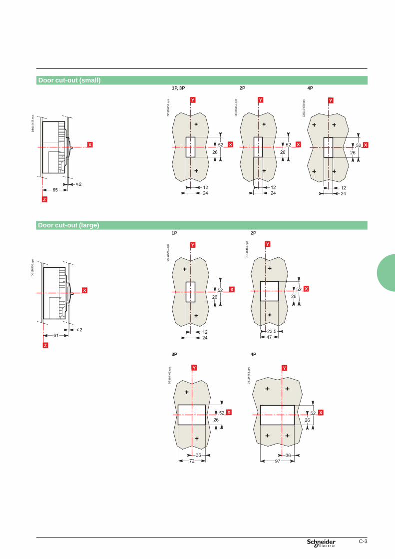
Door cut-out (small)1P, 3P 2P 4P
X
Z
DB
1164
55.e
ps
YY
X
DB
1164
57.e
ps YY
X
DB
1164
57.e
ps YY
X
DB
1164
58.e
ps
Door cut-out (large)
1P 2P
xX
Z
DB
1164
59.e
ps
x
YY
X
DB
1164
60.e
ps
x
YY
X
DB
1164
61.e
ps
3P 4P
x
YY
X
DB
1164
62.e
ps
x
YY
X
DB
1164
63.e
ps
Book general.indb 3 01/04/2011 13:32:29
C-4
Dimensions
DB
1275
36.e
ps
Z
XD
B12
7538
.eps
X
Y
DB
1275
39.e
ps
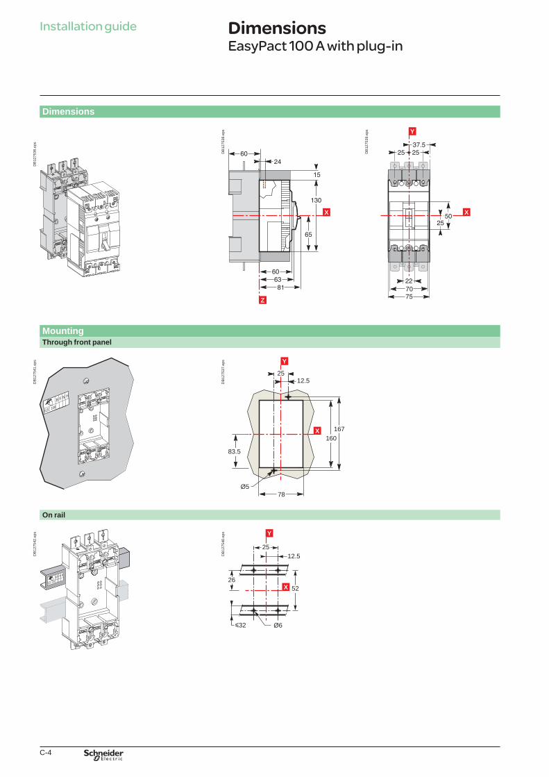
DimensionsEasyPact 100 A with plug-in
Installation guide
MountingThrough front panel
F N H
EZC 100
B
DB
1275
41.e
ps
2512.5
78Ø5
160167
Y
X
83.5
DB
1275
37.e
ps
On rail
F N H
EZC 100
B
DB
1275
42.e
ps
2512.5
y32
Y
26
Ø6
52X
DB
1275
40.e
ps
Book general.indb 4 01/04/2011 13:32:30
C-5
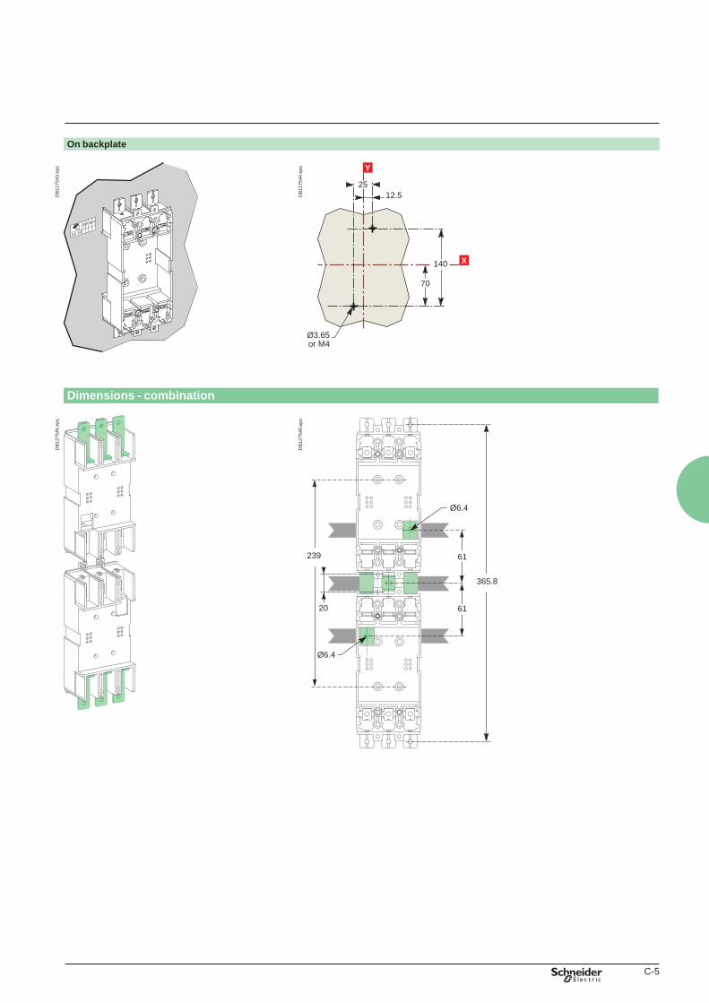
On backplate
F N H
EZC 100
B
DB
1275
43.e
ps
70
Ø3.65
12.5
or M4
Y
25
140 X
DB
1275
44.e
ps
Dimensions - combination
DB
1275
45.e
ps
365.8
239
20 61
61
Ø6.4
Ø6.4
DB
1275
46.e
ps
Book general.indb 5 01/04/2011 13:32:31
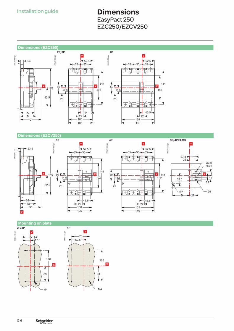
C-6
Installation guide
Dimensions (EZC250)2P, 3P 4P
X
Z
DB
1164
64.e
ps
19.550
102
144
4422
100105
??35 35
52.5
25
YY
X
DB
1164
65.e
ps YY
X
DB
1164
66.e
ps
Dimensions (EZCV250)
3P 4P 3P, 4P ELCB
X
Z
DB
1164
67.e
ps
YY
X
DB
1164
68.e
ps
x
YY
X
DB
1164
69.e
ps YY
X
DB
1164
70.e
ps
Mounting on plate
2P, 3P 4PY
xX
DB
1164
71.e
ps
x
YY
X
DB
1164
72.e
ps
Dimensions EasyPact 250 EZC250/EZCV250
Book general.indb 6 01/04/2011 13:32:33
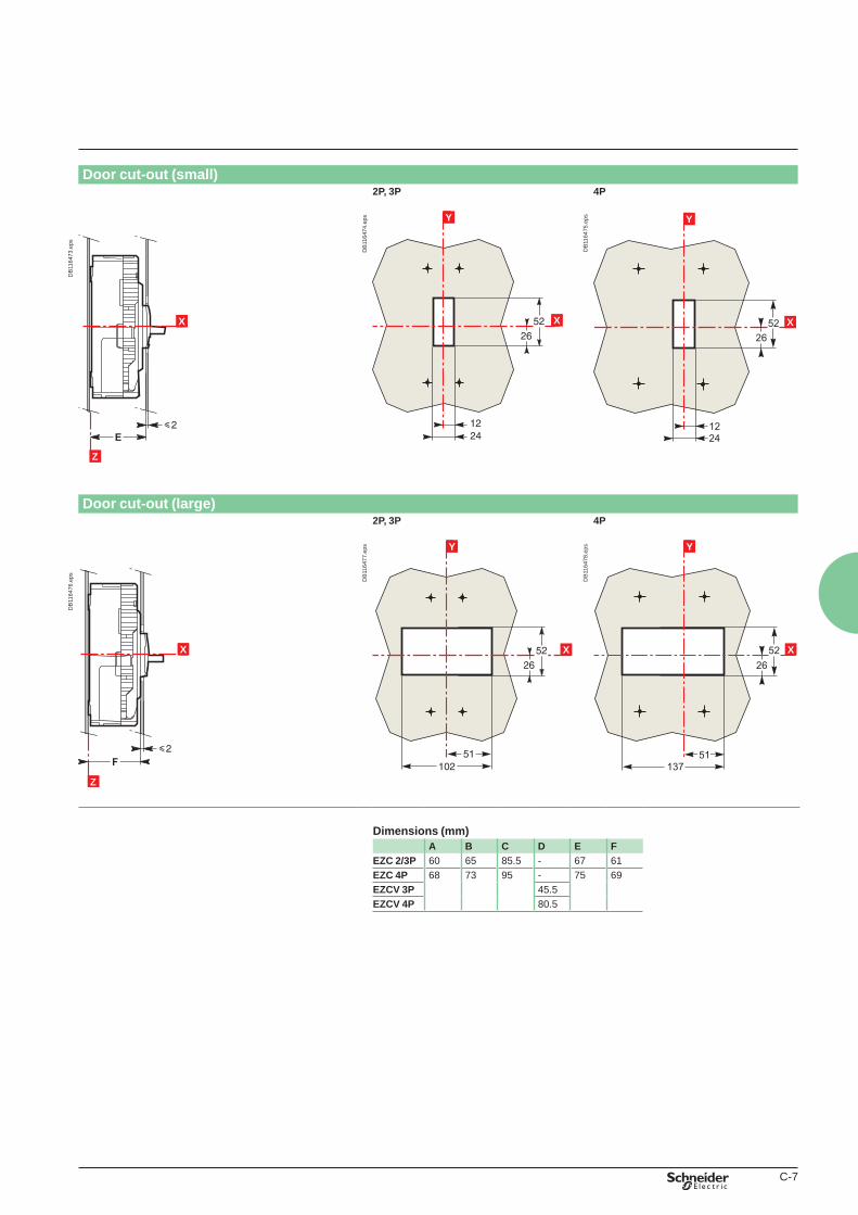
C-7
Door cut-out (small)2P, 3P 4P
DB
1164
73.e
ps
xX
Z
x
YY
X
DB
1164
74.e
ps YY
X
DB
1164
75.e
ps
Door cut-out (large)
2P, 3P 4P
xX
Z
DB
1164
76.e
ps
x
YY
X
DB
1164
77.e
ps
x
YY
X
DB
1164
78.e
ps
Dimensions (mm)A B C D E F
EZC 2/3P 60 65 85.5 - 67 61EZC 4P 68 73 95 - 75 69EZCV 3P 45.5EZCV 4P 80.5
Book general.indb 7 01/04/2011 13:32:33
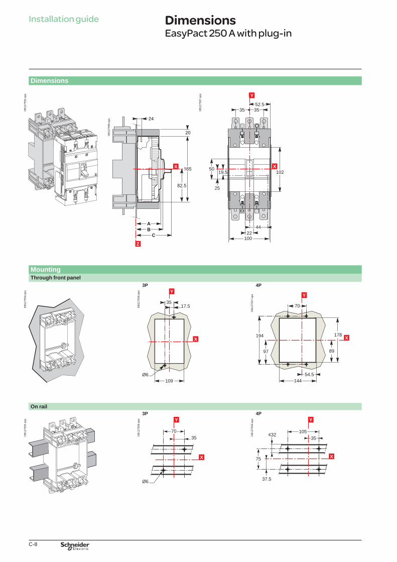
C-8
Dimensions
DB
1275
50.e
ps
X
Z
DB
1275
86.e
ps
19.550
102
??35 35
52.5
25
YY
X19.5
50102
144
4422
100105
??35 35
52.5
25
YY
X
4422
100105
DB
1275
87.e
ps
DimensionsEasyPact 250 A with plug-in
Installation guide
MountingThrough front panel
3P 4P
DB
1275
54.e
ps
3517.5
109Ø6
Y
X
DB
1275
56.e
ps
194
97
178
89
144
X
70
Y
54.5
DB
1275
57.e
ps
On rail3P 4P
DB
1275
55.e
ps Y
Ø6
3570
X
DB
1275
58.e
ps Y
105y32
37.5
75 X
35
DB
1275
59.e
ps
Book general.indb 8 01/04/2011 13:32:35
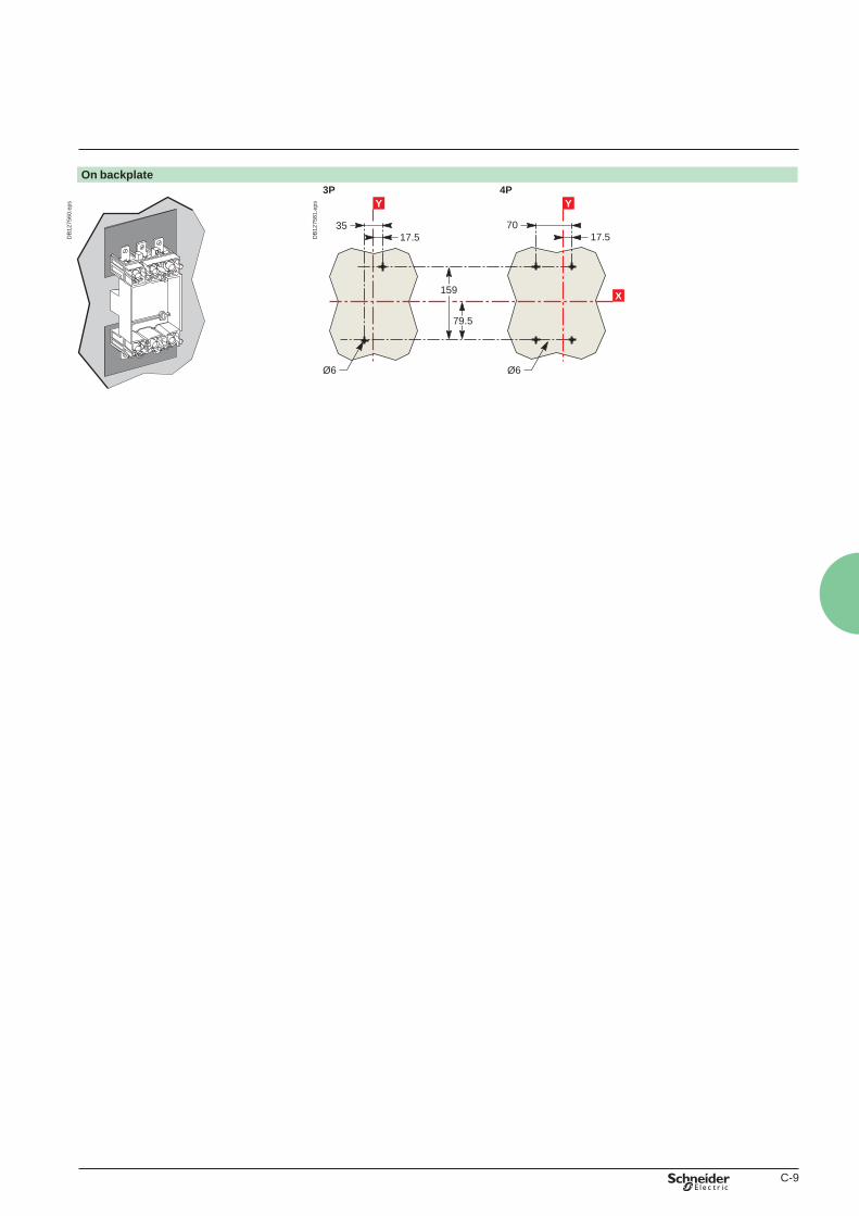
C-9
On backplate3P 4P
DB
1275
60.e
ps YY
3517.5
159
7017.5
79.5
Ø6 Ø6
XD
B12
7581
.eps
Book general.indb 9 01/04/2011 13:32:36

C-10
Installation guide
Dimensions 3P 4P
X
Z
DB
1164
79.e
ps
x
Y
X
DB
1164
80.e
ps YY
X
DB
1164
81.e
ps
Mounting on plate3P 4P
x
YY
X
DB
1164
82.e
ps
x
YY
X
DB
1164
83.e
ps
Dimensions EasyPact 400
Book general.indb 10 01/04/2011 13:32:36
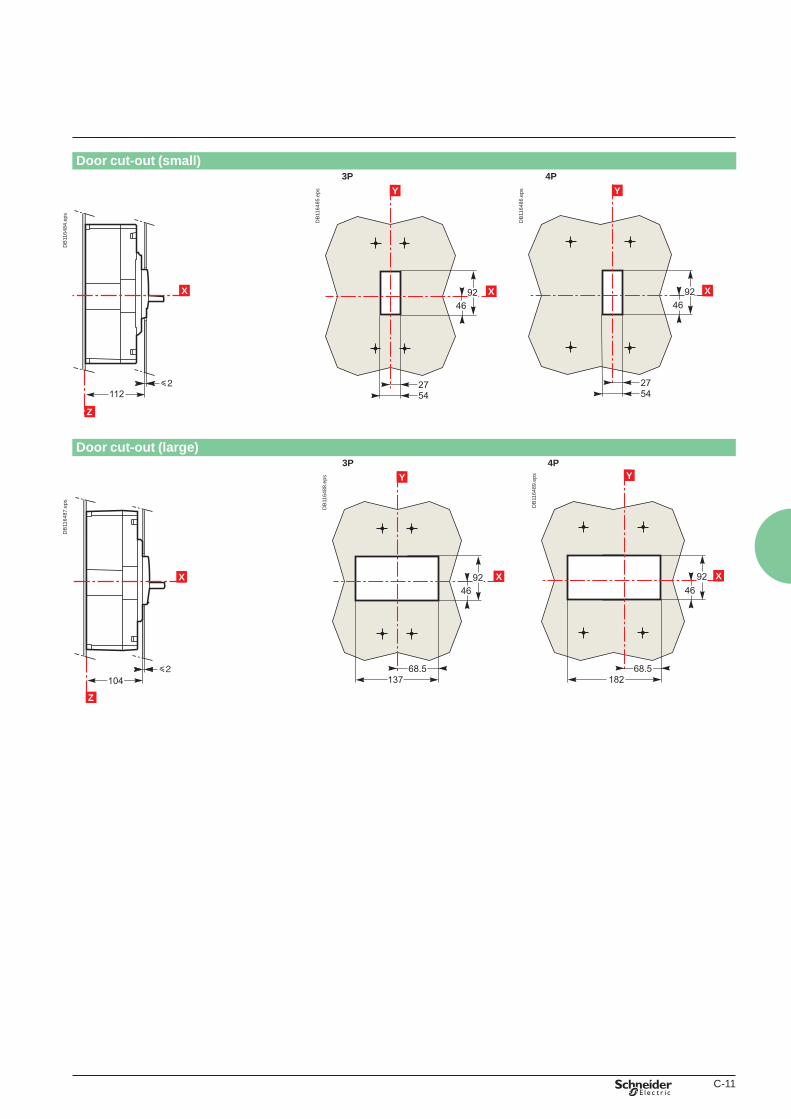
C-11
Door cut-out (small) 3P 4P
X
Z
DB
1164
84.e
ps
YY
X
DB
1164
85.e
ps
x
Y
X
DB
1164
86.e
ps
Door cut-out (large)
3P 4P
xX
Z
DB
1164
87.e
ps
x
YY
X
DB
1164
88.e
ps
x
YY
X
DB
1164
89.e
ps
Book general.indb 11 01/04/2011 13:32:37
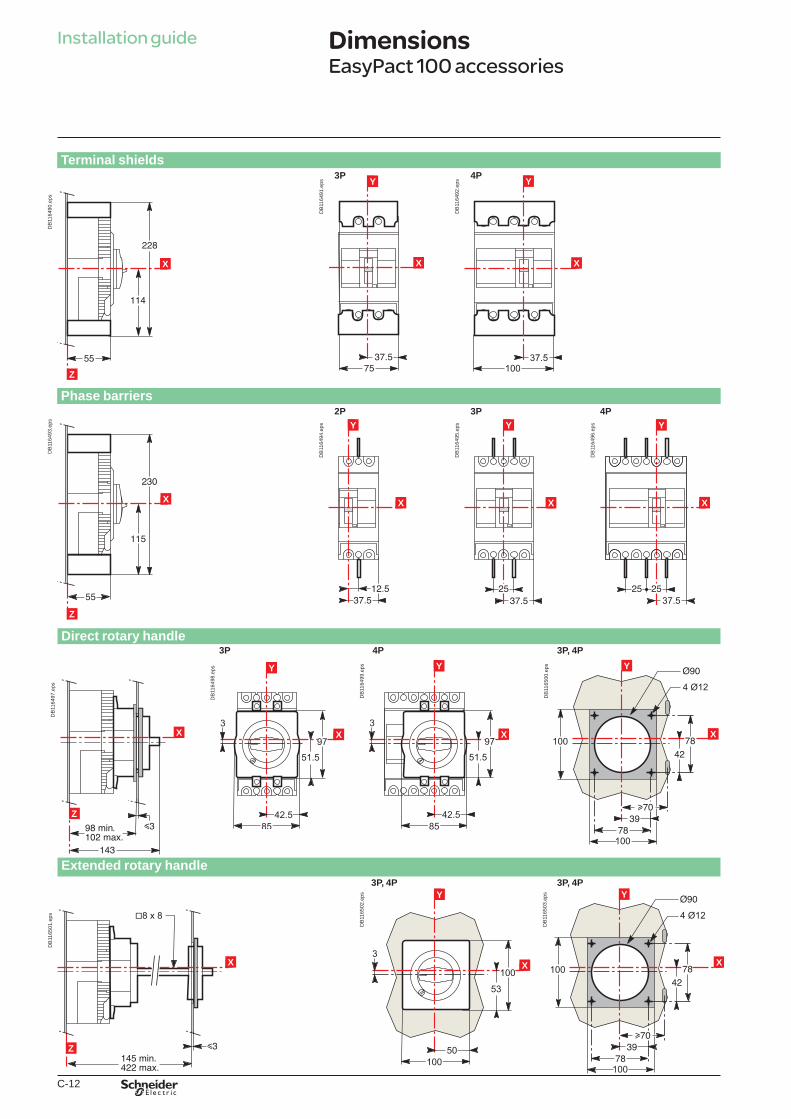
C-12
Installation guide
Terminal shields
xX
Z
DB
1164
90.e
ps
3P 4P
Phase barriers 2P 3P 4P
xX
Z
DB
1164
93.e
ps
x
YY
X
DB
1164
94.e
ps
x
YY
X
DB
1164
95.e
ps
x
YY
X
DB
1164
96.e
ps
Direct rotary handle 3P 4P 3P, 4P
xX
Z
DB
1164
97.e
ps
x
YY
X
DB
1164
98.e
ps
x
YY
X
DB
1164
99.e
ps
X
Y
DB
1165
00.e
ps
Extended rotary handle 3P, 4P 3P, 4P
xX
Z
DB
1165
01.e
ps
x
YY
X
DB
1165
02.e
ps
xX
Y
DB
1165
03.e
ps
DimensionsEasyPact 100 accessories
x
YY
X
DB
1164
92.e
psYY
X
DB
1164
91.e
ps
Book general.indb 12 01/04/2011 13:32:39
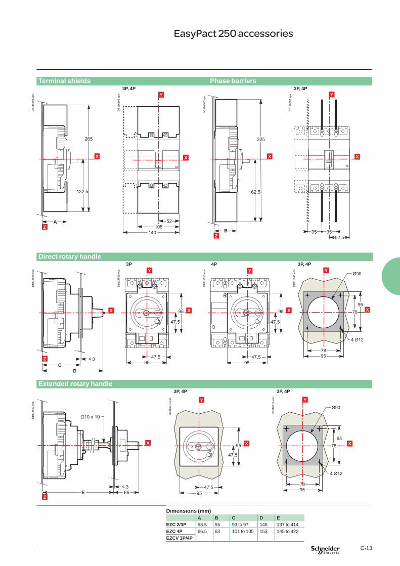
C-13
Terminal shields Phase barriers3P, 4P 3P, 4P
xX
Z
DB
1165
04.e
ps
x
YY
X
DB
1165
05.e
ps
xX
Z
DB
1165
06.e
ps
x
Y
X
DB
1165
07.e
ps
Direct rotary handle
3P 4P 3P, 4P
xX
Z
DB
1165
08.e
ps YY
X
DB
1165
09.e
ps YY
X
DB
1165
10.e
ps
x
YY
X
DB
1165
11.e
ps
Extended rotary handle
3P, 4P 3P, 4P
xX
Z
DB
1165
12.e
ps
Y
X
DB
1165
13.e
ps
x
Y
X
DB
1165
14.e
ps
Dimensions (mm)A B C D E
EZC 2/3P 58.5 55 93 to 97 145 137 to 414EZC 4P 66.5 63 101 to 105 153 145 to 422EZCV 3P/4P
EasyPact 250 accessories
Book general.indb 13 01/04/2011 13:32:41
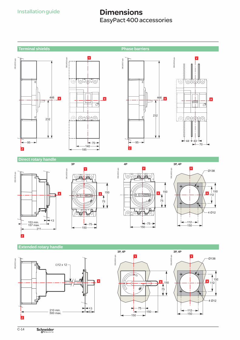
C-14
Installation guide
Terminal shields Phase barriers
xX
Z
DB
1165
15.e
ps
x
YY
X
DB
1165
16.e
ps
xX
Z
DB
1165
17.e
ps
x
YY
X
DB
1165
18.e
ps
Direct rotary handle 3P 4P 3P, 4P
xX
Z
DB
1165
19.e
ps
x
YY
X
DB
1165
20.e
ps
x
Y
X
DB
1165
21.e
ps
x
YY
X
DB
1165
22.e
ps
Extended rotary handle
3P, 4P 3P, 4P
xX
Z
DB
1165
23.e
ps
YY
X
DB
1165
24.e
ps
x
YY
X
DB
1165
25.e
ps
Dimensions EasyPact 400 accessories
Book general.indb 14 01/04/2011 13:32:42
C-15
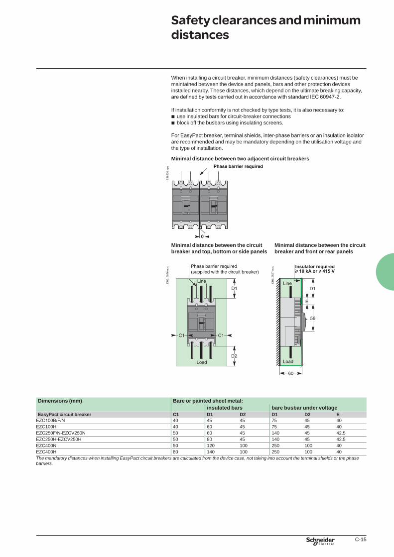
Safety clearances and minimum distances
When installing a circuit breaker, minimum distances (safety clearances) must be maintained between the device and panels, bars and other protection devices installed nearby. These distances, which depend on the ultimate breaking capacity, are defined by tests carried out in accordance with standard IEC 60947-2.
If installation conformity is not checked by type tests, it is also necessary to:b use insulated bars for circuit-breaker connectionsb block off the busbars using insulating screens.
For EasyPact breaker, terminal shields, inter-phase barriers or an insulation isolator are recommended and may be mandatory depending on the utilisation voltage and the type of installation.
Minimal distance between two adjacent circuit breakersE
8823
0.ep
s
Minimal distance between the circuit breaker and top, bottom or side panels
Minimal distance between the circuit breaker and front or rear panels
DB
1165
26.e
ps
DB
1165
27.e
ps
Dimensions (mm) Bare or painted sheet metal:insulated bars bare busbar under voltage
EasyPact circuit breaker C1 D1 D2 D1 D2 EEZC100B/F/N 40 45 45 75 45 40EZC100H 40 60 45 75 45 40EZC250F/N-EZCV250N 50 60 45 140 45 42.5EZC250H-EZCV250H 50 80 45 140 45 42.5EZC400N 50 120 100 250 100 40EZC400H 80 140 100 250 100 40The mandatory distances when installing EasyPact circuit breakers are calculated from the device case, not taking into account the terminal shields or the phase barriers.
Book general.indb 15 01/04/2011 13:32:43

C-16
Safety clearances and minimum distances
Installation guideE
4445
8.ep
s
Installation in an enclosureEasyPact circuit breakers can be installed in a metal enclosure together with other devices (contactors, motor-protection circuit breakers, LEDs, etc.).Minimum enclosure dimensions (3P)Circuit breakers Height (mm) Depth (mm) (1) Width (mm)
EZC100B/F/N 200 90 155EZC100H 215 90 155EZC250F/N-EZCV250N 270 90 205EZC250H-EZCV250H 290 90 205EZC400N 480 160 240EZC400H 500 160 300
Installation in an enclosure. (1) With front door.
Book general.indb 16 01/04/2011 13:32:43
C-17
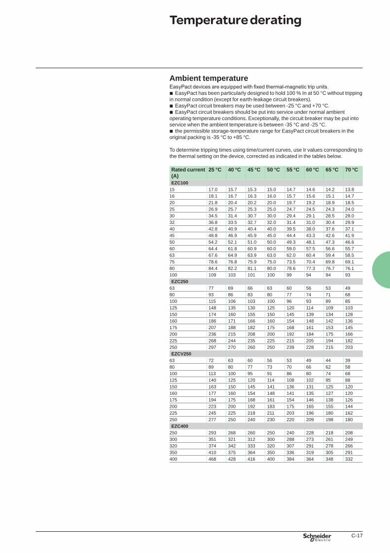
Ambient temperatureEasyPact devices are equipped with fixed thermal-magnetic trip units.b EasyPact has been particularly designed to hold 100 % In at 50 °C without tripping in normal condition (except for earth-leakage circuit breakers).b EasyPact circuit breakers may be used between -25 °C and +70 °C.b EasyPact circuit breakers should be put into service under normal ambient operating temperature conditions. Exceptionally, the circuit breaker may be put into service when the ambient temperature is between -35 °C and -25 °C.b the permissible storage-temperature range for EasyPact circuit breakers in the original packing is -35 °C to +85 °C.
To determine tripping times using time/current curves, use Ir values corresponding to the thermal setting on the device, corrected as indicated in the tables below.
Rated current (A)
25 °C 40 °C 45 °C 50 °C 55 °C 60 °C 65 °C 70 °C
EZC10015 17.0 15.7 15.3 15.0 14.7 14.6 14.2 13.816 18.1 16.7 16.3 16.0 15.7 15.6 15.1 14.720 21.8 20.4 20.2 20.0 19.7 19.2 18.9 18.525 26.9 25.7 25.3 25.0 24.7 24.5 24.3 24.030 34.5 31.4 30.7 30.0 29.4 29.1 28.5 28.032 36.8 33.5 32.7 32.0 31.4 31.0 30.4 29.940 42.8 40.9 40.4 40.0 39.5 38.0 37.6 37.145 48.8 46.9 45.9 45.0 44.4 43.3 42.6 41.950 54.2 52.1 51.0 50.0 49.3 48.1 47.3 46.660 64.4 61.8 60.9 60.0 59.0 57.5 56.6 55.763 67.6 64.9 63.9 63.0 62.0 60.4 59.4 58.575 78.6 76.8 75.9 75.0 73.5 70.4 69.8 69.180 84.4 82.2 81.1 80.0 78.6 77.3 76.7 76.1100 109 103 101 100 99 94 94 93EZC250
63 77 69 66 63 60 56 53 4980 93 86 83 80 77 74 71 68100 115 106 103 100 96 93 89 85125 148 135 130 125 120 114 109 103150 174 160 155 150 145 139 134 128160 186 171 166 160 154 148 142 136175 207 188 182 175 168 161 153 145200 236 215 208 200 192 184 175 166225 268 244 235 225 215 205 194 182250 297 270 260 250 239 228 215 203EZCV250
63 72 63 60 56 53 49 44 3980 89 80 77 73 70 66 62 58100 113 100 95 91 86 80 74 68125 140 125 120 114 108 102 95 88150 163 150 145 141 136 131 125 120160 177 160 154 148 141 135 127 120175 194 175 168 161 154 146 138 126200 223 200 192 183 175 165 155 144225 245 225 218 211 203 196 180 162250 277 250 240 230 220 209 198 180EZC400
250 293 268 260 250 240 228 218 208300 351 321 312 300 288 273 261 249320 374 342 333 320 307 291 278 266350 410 375 364 350 336 319 305 291400 468 428 416 400 384 364 348 332
Temperature derating
Book general.indb 17 01/04/2011 13:32:43
C-18
Installation guide
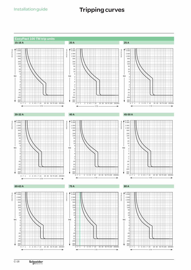
EasyPact 100 TM trip units15-16 A 20 A 25 A
.5 .7 .71 10 20 30 50 70 100 2003002 3 4 5
I / Ir
.005
.002
.001
.01
.1
1
1020
50100200
5001 0002 000
5 00010 000
2
5
.2
.5
.02
.05
t(s)
DB
1157
30.e
ps
.5 .7 .71 10 20 30 50 70 100 2003002 3 4 5
I / Ir
.005
.002
.001
.01
.1
1
1020
50100200
5001 0002 000
5 00010 000
2
5
.2
.5
.02
.05
t(s)
DB
1157
31.e
ps
.5 .7 .71 10 20 30 50 70 100 2003002 3 4 5
I / Ir
.005
.002
.001
.01
.1
1
1020
50100200
5001 0002 000
5 00010 000
2
5
.2
.5
.02
.05
t(s)
DB
1157
32.e
ps
30-32 A 40 A 45-50 A
.5 .7 .71 10 20 30 50 70 100 2003002 3 4 5
I / Ir
.005
.002
.001
.01
.1
1
1020
50100200
5001 0002 000
5 00010 000
2
5
.2
.5
.02
.05
t(s)
DB
1157
33.e
ps
.5 .7 .71 10 20 30 50 70 100 2003002 3 4 5
I / Ir
.005
.002
.001
.01
.1
1
1020
50100200
5001 0002 000
5 00010 000
2
5
.2
.5
.02
.05
t(s)
DB
1157
34.e
ps
.5 .7 .71 10 20 30 50 70 100 2003002 3 4 5
I / Ir
.005
.002
.001
.01
.1
1
1020
50100200
5001 0002 000
5 00010 000
2
5
.2
.5
.02
.05
t(s)
DB
1157
35.e
ps
60-63 A 75 A 80 A
.5 .7 .71 10 20 30 50 70 100 2003002 3 4 5
I / Ir
.005
.002
.001
.01
.1
1
1020
50100200
5001 0002 000
5 00010 000
2
5
.2
.5
.02
.05
t(s)
DB
1157
36.e
ps
.5 .7 .71 10 20 30 50 70 100 2003002 3 4 5
I / Ir
.005
.002
.001
.01
.1
1
1020
50100200
5001 0002 000
5 00010 000
2
5
.2
.5
.02
.05
t(s)
DB
1157
37.e
ps
.5 .7 .71 10 20 30 50 70 100 2003002 3 4 5
I / Ir
.005
.002
.001
.01
.1
1
1020
50100200
5001 0002 000
5 00010 000
2
5
.2
.5
.02
.05
t(s)
DB
1157
38.e
ps
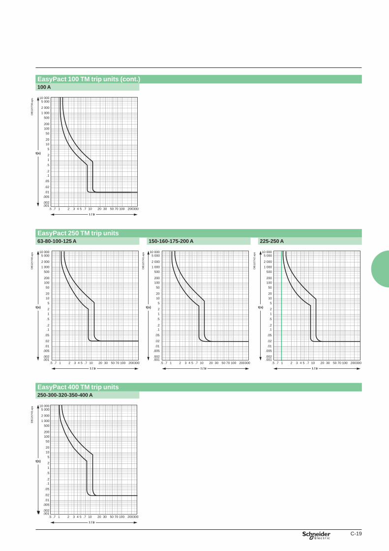
Tripping curves
Book general.indb 18 01/04/2011 13:32:45
C-19
EasyPact 100 TM trip units (cont.)100 A
.7 .71 10 20 30 50 70 100 2003002 3 4 5
I / Ir.5
.005
.002
.001
.01
.1
1
1020
50100200
5001 0002 000
5 00010 000
2
5
.2
.5
.02
.05
t(s)
DB
1157
39.e
ps
EasyPact 250 TM trip units63-80-100-125 A 150-160-175-200 A 225-250 A
.5 .7 .71 10 20 30 50 70 100 2003002 3 4 5
I / Ir
.005
.002
.001
.01
.1
1
1020
50100200
5001 0002 000
5 00010 000
2
5
.2
.5
.02
.05
t(s)
DB
1157
40.e
ps
.5 .7 .71 10 20 30 50 70 100 2003002 3 4 5
I / Ir
.005
.002
.001
.01
.1
1
1020
50100200
5001 0002 000
5 00010 000
2
5
.2
.5
.02
.05
t(s)
DB
1157
41.e
ps
.5 .7 .71 10 20 30 50 70 100 2003002 3 4 5
I / Ir
.005
.002
.001
.01
.1
1
1020
50100200
5001 0002 000
5 00010 000
2
5
.2
.5
.02
.05
t(s)
DB
1157
42.e
ps
EasyPact 400 TM trip units 250-300-320-350-400 A
.5 .7 .71 10 20 30 50 70 100 2003002 3 4 5
I / Ir
.005
.002
.001
.01
.1
1
1020
50100200
5001 0002 000
5 00010 000
2
5
.2
.5
.02
.05
t(s)
DB
1157
43.e
ps
Book general.indb 19 01/04/2011 13:32:45
C-20
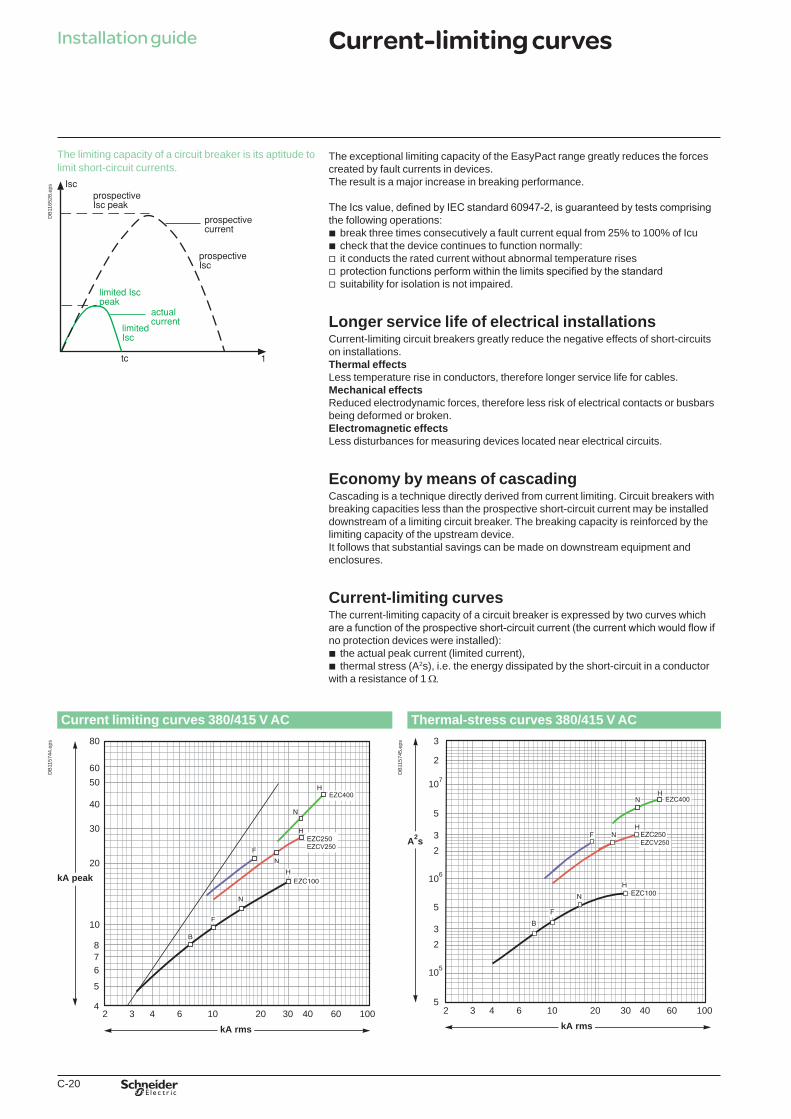
The exceptional limiting capacity of the EasyPact range greatly reduces the forces created by fault currents in devices.The result is a major increase in breaking performance.
The Ics value, defined by IEC standard 60947-2, is guaranteed by tests comprising the following operations:b break three times consecutively a fault current equal from 25% to 100% of Icub check that the device continues to function normally:v it conducts the rated current without abnormal temperature risesv protection functions perform within the limits specified by the standardv suitability for isolation is not impaired.
Longer service life of electrical installationsCurrent-limiting circuit breakers greatly reduce the negative effects of short-circuits on installations.Thermal effectsLess temperature rise in conductors, therefore longer service life for cables.Mechanical effectsReduced electrodynamic forces, therefore less risk of electrical contacts or busbars being deformed or broken.Electromagnetic effectsLess disturbances for measuring devices located near electrical circuits.
Economy by means of cascadingCascading is a technique directly derived from current limiting. Circuit breakers with breaking capacities less than the prospective short-circuit current may be installed downstream of a limiting circuit breaker. The breaking capacity is reinforced by the limiting capacity of the upstream device.It follows that substantial savings can be made on downstream equipment and enclosures.
Current-limiting curvesThe current-limiting capacity of a circuit breaker is expressed by two curves which are a function of the prospective short-circuit current (the current which would flow if no protection devices were installed):b the actual peak current (limited current),b thermal stress (A2s), i.e. the energy dissipated by the short-circuit in a conductor with a resistance of 1 W.
Current limiting curves 380/415 V AC Thermal-stress curves 380/415 V AC
2 3 4 6 10 20 60 10030 404
5
678
10
20
30
40
80
5060
kA rms
kA peak
DB
1157
44.e
ps
5
5
32
105
5
32
106
3
2
107
2 3 4 6 10 20 60 10030 40kA rms
A2s
DB
1157
45.e
ps
Installation guide
The limiting capacity of a circuit breaker is its aptitude to limit short-circuit currents.
DB
1165
28.e
psCurrent-limiting curves
Book general.indb 20 01/04/2011 13:32:46
C-21
What is cascading?Cascading is the use of the current limiting capacity of circuit breakers at a given point to permit installation of lower-rated and therefore lower-cost circuit breakers downstream.The upstream compact circuit breakers acts as a barrier against short-circuit currents. In this way, downstream circuit breakers with lower breaking capacities than the prospective short-circuit (at their point of installation) operate under their normal breaking conditions.Since the current is limited throughout the circuit controlled by the limiting circuit breaker, cascading applies to all switchgear downstream. It is not restricted to two consecutive devices.
General use of cascadingWith cascading, the devices can be installed in different switchboards. Thus, in general, cascading refers to any combination of circuit breakers where a circuit breaker with a breaking capacity less than the prospective Isc at its point of installation can be used. Of course, the breaking capacity of the upstream circuit breaker must be greater than or equal to the prospective short-circuit current at its point of installation.The combination of two circuit breakers in cascading configuration is covered by the IEC 60947-2.
Coordination between circuit breakersThe use of a protective device possessing a breaking capacity less than the prospective short-circuit current at its installation point is permitted as long as another device is installed upstream with at least the necessary breaking capacity.In this case, the characteristics of the two devices must be coordinated in such a way that the energy let through by the upstream device is not more than that which can be withstood by the downstream device and the cables protected by these devices without damage.Cascading can only be checked by laboratory tests and the possible combinations can be specified only by the circuit breaker manufacturer.
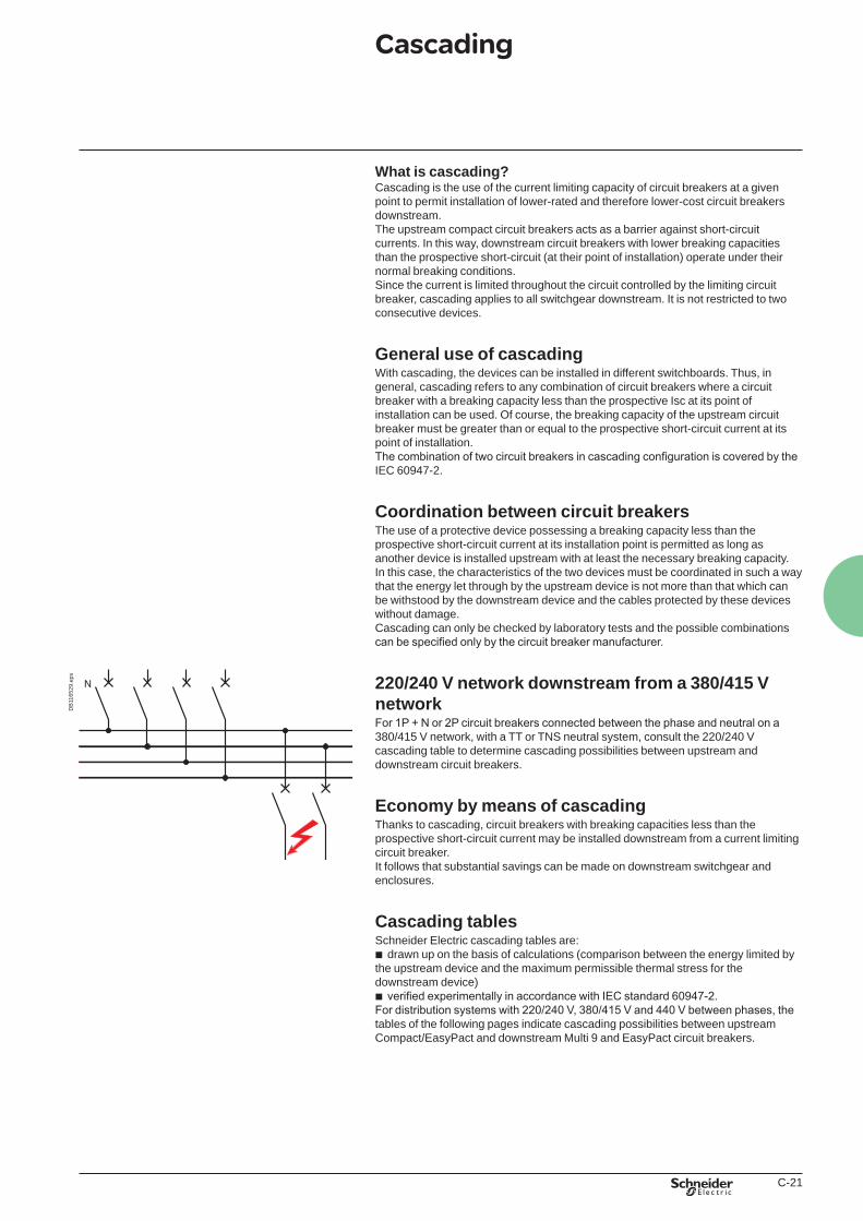
220/240 V network downstream from a 380/415 V networkFor 1P + N or 2P circuit breakers connected between the phase and neutral on a 380/415 V network, with a TT or TNS neutral system, consult the 220/240 V cascading table to determine cascading possibilities between upstream and downstream circuit breakers.
Economy by means of cascadingThanks to cascading, circuit breakers with breaking capacities less than the prospective short-circuit current may be installed downstream from a current limiting circuit breaker.It follows that substantial savings can be made on downstream switchgear and enclosures.
Cascading tablesSchneider Electric cascading tables are:b drawn up on the basis of calculations (comparison between the energy limited by the upstream device and the maximum permissible thermal stress for the downstream device)b verified experimentally in accordance with IEC standard 60947-2.For distribution systems with 220/240 V, 380/415 V and 440 V between phases, the tables of the following pages indicate cascading possibilities between upstream Compact/EasyPact and downstream Multi 9 and EasyPact circuit breakers.
DB
1165
29.e
ps
Cascading
Book general.indb 21 01/04/2011 13:32:46
C-22
Installation guideD
B12
7584
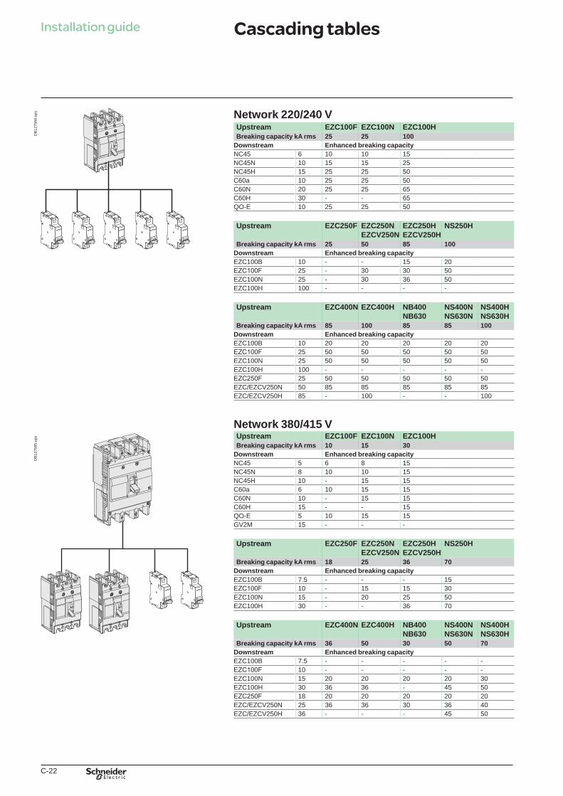
.eps Network 220/240 V
Upstream EZC100F EZC100N EZC100HBreaking capacity kA rms 25 25 100
Downstream Enhanced breaking capacityNC45 6 10 10 15NC45N 10 15 15 25NC45H 15 25 25 50C60a 10 25 25 50C60N 20 25 25 65C60H 30 - - 65QO-E 10 25 25 50
Upstream EZC250F EZC250NEZCV250N
EZC250HEZCV250H
NS250H
Breaking capacity kA rms 25 50 85 100Downstream Enhanced breaking capacityEZC100B 10 - - 15 20EZC100F 25 - 30 30 50EZC100N 25 - 30 36 50EZC100H 100 - - - -
Upstream EZC400N EZC400H NB400NB630
NS400NNS630N
NS400HNS630H
Breaking capacity kA rms 85 100 85 85 100Downstream Enhanced breaking capacityEZC100B 10 20 20 20 20 20EZC100F 25 50 50 50 50 50EZC100N 25 50 50 50 50 50EZC100H 100 - - - - -EZC250F 25 50 50 50 50 50EZC/EZCV250N 50 85 85 85 85 85EZC/EZCV250H 85 - 100 - - 100
Network 380/415 V
DB
1275
85.e
ps Upstream EZC100F EZC100N EZC100HBreaking capacity kA rms 10 15 30
Downstream Enhanced breaking capacityNC45 5 6 8 15NC45N 8 10 10 15NC45H 10 - 15 15C60a 6 10 15 15C60N 10 - 15 15C60H 15 - - 15QO-E 5 10 15 15GV2M 15 - - -
Upstream EZC250F EZC250NEZCV250N
EZC250HEZCV250H
NS250H
Breaking capacity kA rms 18 25 36 70Downstream Enhanced breaking capacityEZC100B 7.5 - - - 15EZC100F 10 - 15 15 30EZC100N 15 - 20 25 50EZC100H 30 - - 36 70
Upstream EZC400N EZC400H NB400NB630
NS400NNS630N
NS400HNS630H
Breaking capacity kA rms 36 50 30 50 70Downstream Enhanced breaking capacityEZC100B 7.5 - - - - -EZC100F 10 - - - - -EZC100N 15 20 20 20 20 30EZC100H 30 36 36 - 45 50EZC250F 18 20 20 20 20 20EZC/EZCV250N 25 36 36 30 36 40EZC/EZCV250H 36 - - - 45 50
Cascading tables
Book general.indb 22 01/04/2011 13:32:47
C-23
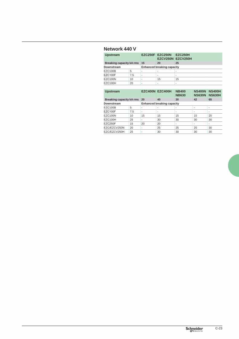
Network 440 VUpstream EZC250F EZC250N
EZCV250NEZC250HEZCV250H
Breaking capacity kA rms 15 20 25Downstream Enhanced breaking capacityEZC100B 5 - - -EZC100F 7.5 - - -EZC100N 10 - 15 15EZC100H 20 - - -
Upstream EZC400N EZC400H NB400NB630
NS400NNS630N
NS400HNS630H
Breaking capacity kA rms 20 40 30 42 65Downstream Enhanced breaking capacityEZC100B 5 - - - - -EZC100F 7.5 - - - - -EZC100N 10 15 15 15 15 25EZC100H 25 - 30 30 30 30EZC250F 15 20 20 - - -EZC/EZCV250N 20 - 25 25 25 30EZC/EZCV250H 25 - 30 30 30 30
Book general.indb 23 01/04/2011 13:32:47
C-24
Installation guide
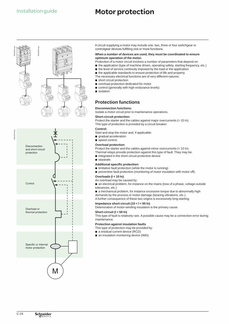
A circuit supplying a motor may include one, two, three or four switchgear or controlgear devices fulfilling one or more functions.
When a number of devices are used, they must be coordinated to ensure optimum operation of the motor.Protection of a motor circuit involves a number of parameters that depend on:b the application (type of machine driven, operating safety, starting frequency, etc.)b the level of service continuity imposed by the load or the applicationb the applicable standards to ensure protection of life and property.The necessary electrical functions are of very different natures:b short circuit protectionb overload protection dedicated for motorb control (generally with high endurance levels)b isolation.
Protection functionsDisconnection functions:Isolate a motor circuit prior to maintenance operations.Short-circuit protection:Protect the starter and the cables against major overcurrents (> 10 In).This type of protection is provided by a circuit breaker.Control:Start and stop the motor and, if applicable:b gradual accelerationb speed control.Overload protection:Protect the starter and the cables against minor overcurrents (< 10 In).Thermal relays provide protection against this type of fault. They may be:b integrated in the short-circuit protective deviceb separate.Additional specific protection:b limitative fault protection (while the motor is running)b preventive fault protection (monitoring of motor insulation with motor off).Overloads (I < 10 In)An overload may be caused by:b an electrical problem, for instance on the mains (loss of a phase, voltage outside tolerances, etc.)b a mechanical problem, for instance excessive torque due to abnormally high demands by the process or motor damage (bearing vibrations, etc.).A further consequence of these two origins is excessively long starting.Impedance short-circuit (10 < I < 50 In)Deterioration of motor-winding insulation is the primary cause.Short-circuit (I > 50 In)This type of fault is relatively rare. A possible cause may be a connection error during maintenance.Protection against insulation faultsThis type of protection may be provided by:b a residual current device (RCD)b an insulation monitoring device (IMD).
DB
1165
32.e
ps
DB
1165
33.e
ps
DB
1165
34.e
psMotor protection
Book general.indb 24 01/04/2011 13:32:47