Embed Size (px)
Citation preview

Eastern Mediterranean Eastern Mediterranean UniversityUniversity
PIR SENSOR for controlling PIR SENSOR for controlling stepper motor. stepper motor.
byby
Falah Al HassanFalah Al Hassan
Ammar T.Najeeb Ammar T.Najeeb
Supervisor: Supervisor: Reza Abrishambaf Reza Abrishambaf

Presentation OutlinePresentation Outline• Introduction : PIR sensor and application
and Specifications
• Microcontroller 8051 and code .
• Power supply circuit
• Stepper motor .
• Driver and indexer
• Project circuit .
• Conclusion.
Presentation OutlinePresentation Outline

IntroductionIntroduction
Block diagram
8051
MICROCONTROLLER
MOTOR1
MOTOR2
REGULATEDPOWER SUPPLY
PIR SENSOR UNIT

IntroductionIntroduction• PIR sensor and application.
• Passive Infrared Sensors
• Burglar alarm / Security
• Motions activated lighting
• Lighting control systems
• Environmental control systems
Specifications• Power input: 3.6 ± 0.5 VDC
• Current drain: 10 uA
• Infrared sensor: Dual element, low noise, high sensitivity
• Detection range
• Ceiling: 5 m dia. at 2.4 m high, 25°C
• Wall: 10 m, 90° wide at 25°C

Microcontroller 8051 and code
• Optimized 8 bit CPU for control applications and processing capabilities.
• 64K Program Memory address space.
• 64K Data Memory address space.
• 128 bytes of on chip Data Memory.
• 32 Bi-directional and individually addressable I/O lines.
• Two 16 bit timer/counters.• 6-source / 5-vector
interrupt.• On chip clock oscillator.

Code language and exampleCode language and example
Assembly or C languageAssembly or C language
MOV A, R3 ; Move the value of R3 to accumulator ADD A, R4 ; add the value of R4 MOV R5, A ; Store the result in R5 MOV A, R1 ; Move the value of R1 to Acc ADD A, R2 ; add the value of R2 with A

Power supply circuit
5 v

Stepper motorStepper motorA stepper motor is a brushless, synchronous electric motor that converts digital pulses
into mechanical shaft rotation (movements) which are called steps
Stepper Motor Advantages
1- The rotation angle of the motor is proportional to the input pulse.
2- The motor has full torque at standstill (if the windings are energized).
3- Precise positioning and repeatability of movement since good stepper motors have an accuracy of 3 to 5% of a step and this error is non-cumulative from one step to the next.
4- Excellent response to starting/stopping/reversing.
5- Very reliable since there are no contact brushes in the motor. Therefore the life of the step motor is simply dependant on the life of the bearing.
There are three main types of stepper motors:
1. Permanent Magnet Stepper
2. Variable Reluctance Stepper
3. Hybrid Synchronous Stepper


How they work • Hybrid Synchronous Stepper
Examples :

Driver Technology Overview
Indexer Overview (8051)Indexer Overview (8051)The indexer, or controller, provides step and The indexer, or controller, provides step and direction outputs to the driver. Most applications direction outputs to the driver. Most applications require that the indexer manage other control require that the indexer manage other control functions as well, including acceleration, functions as well, including acceleration, deceleration, steps per second and distance. deceleration, steps per second and distance. The indexer can also interface to and control The indexer can also interface to and control many other external signals. many other external signals.
Communication to the indexer is through an RS-Communication to the indexer is through an RS-232 serial port and in some cases an RS485 232 serial port and in some cases an RS485 port. In either case, the indexer is capable of port. In either case, the indexer is capable of receiving high-level commands from a host receiving high-level commands from a host computer and generating the necessary step computer and generating the necessary step and direction pulses to the driver. and direction pulses to the driver.
The indexer includes auxiliary I/O for monitoring The indexer includes auxiliary I/O for monitoring inputs from external sources such as a Go, Jog, inputs from external sources such as a Go, Jog, Home or Limit switch. It can also initiate other Home or Limit switch. It can also initiate other machine functions through the I/O output pins. machine functions through the I/O output pins.
Programmable Step Motor Indexer/Drive

Multi-Axis Control
Many motion applications have more than one stepper motor to control. In such cases a multi-axis control system is available. A HUB 444 networking hub, for example, may have up to four stepper drives connected to it, with each drive connected to a separate stepper motor. The networking hub provides coordinated movement for applications requiring a high degree of synchronization, such as circular or linear interpolation.
• Many motion applications have more than one stepper motor to control. In such cases a multi-axis control system is available. A HUB 444 networking hub, for example, may have up to four stepper drives connected to it, with each drive connected to a separate stepper motor. The networking hub provides coordinated movement for applications requiring a high degree of synchronization, such as circular or linear interpolation.
Multi-Axis Control ( multi step-motor control )

Stand alone operation In a stand-alone mode the indexer can operate independent of the host computer. Once downloaded to the non-volatile memory, motion programs can be initiated from various types of operator interfaces, such as a keypad or touch screen, or from a switch through the auxiliary I/O inputs. A stand-alone stepper motor control system is often packaged with a driver and power supply and optional encoder feedback for "closed loop" applications that require stall detection and exact motor position compensation.

The following C source shows how I drive the motor. This is a very simple loop that uses the delay library to pause for 20 ms between each pulse. The order to pulse the coils is stored in the step array. To cause the shaft to rotate, the coils must be pulsed as follows: Step 1 Step 2 Step 3 Step 4Coil A ON ON OFF OFFCoil B OFF OFF ON ONCoil C ON OFF OFF ONCoil D OFF ON ON OFFIn this code , I assume that the motor coils are connected to PORT B./* * stepper .c * * Drive a stepper motor connected to port B * RB1: Coil 1 * RB2: Coil 2 * RB3: Coil 3 * RB4: Coil 4 * * Continually rotates motor */ char step[ ] = {5, 9, 10, 6}; void main(void) { char I ; set_bit(STATUS, RP0); /* select the register bank 1 */ set_tris_b(0); /* PORT B is all output */ clear_bit(STATUS, RP0); i = 0; while(1) { output_port_b(step[i]); delay_ms(20);

i++; if( i == 4) i = 0; }}
Example 2 - sweep back and forth Following on from the previous example, this code will rotate the motor back and forth 180 degrees each turn./* * stepper2.c * * Drive a stepper motor connected to port B * * RB1: Coil 1 * RB2: Coil 2 * RB3: Coil 3 * RB4: Coil 4 * * Continually sweeps back and forth, rotating 180 deg each pass * * */
#define DELAY 50 #define SWEEP 12 #define NUMSTEPS 4 char step[ ] = {5, 9, 10, 6};char stepPos = 0; /* pulse the motor with the current coil setting * and then wait for delay mS */void pulseMotor(char delay) { output_port_b(step[stepPos]); delay_ms(delay);} /* Advance the coil settings forward by one step * stepPos is left pointing to the *next* code to output to move forward */void stepMotorForw(void) { stepPos++; if(stepPos == NUMSTEPS) stepPos = 0;}

/* Advance the motor backward by one step * stepPos is left pointing to the *next* code to output to move backward */void stepMotorBack(void) { /* advance stepPos to before where we were */ /* do wrap around */ if(stepPos == 0) { stepPos = NUMSTEPS-1; } else { stepPos--; }} void main(void) { char i; set_bit(STATUS, RP0); /* select the register bank 1 */ set_tris_b(0); /* PORT B is all output */ clear_bit(STATUS, RP0); while(1) { for(i=0; i < SWEEP; i++) { pulseMotor(DELAY); stepMotorForw(); }
delay_s(3); for(i=0; i < SWEEP; i++) { stepMotorBack(); pulseMotor(DELAY); } delay_s(3); }}

Below is an example of a program that performs half-stepping and can be used to drive a stepper motor. The code turns the motor a number of steps (100 half-steps) in one direction, and then turns the motor back the same number of steps in the opposite direction. One of the advantages of the code below is that it can be easily modified to keep track of a motor’s position. It also has the advantage of having the port states stored in sequential order in an array. Simply cycling through the states sequentially and placing the state values on port pins will cause a stepper motor to move. This is written in C. #define NUM_OF_STATES 8 // There are 8 different states in this particular example.#define DELAY_MAX 2000 //The maximum # of counts used to create a time delay. void main(void){/*******************CREATE VARIABLES*******************/int i; //Used in a for loopchar state_array[NUM_OF_STATES] = {0x06, 0x02, 0x0A, 0x08, 0x09, 0x01, 0x05, 0x04}; int steps_to_move; char next_state;/********************SET UP PORT U********************/
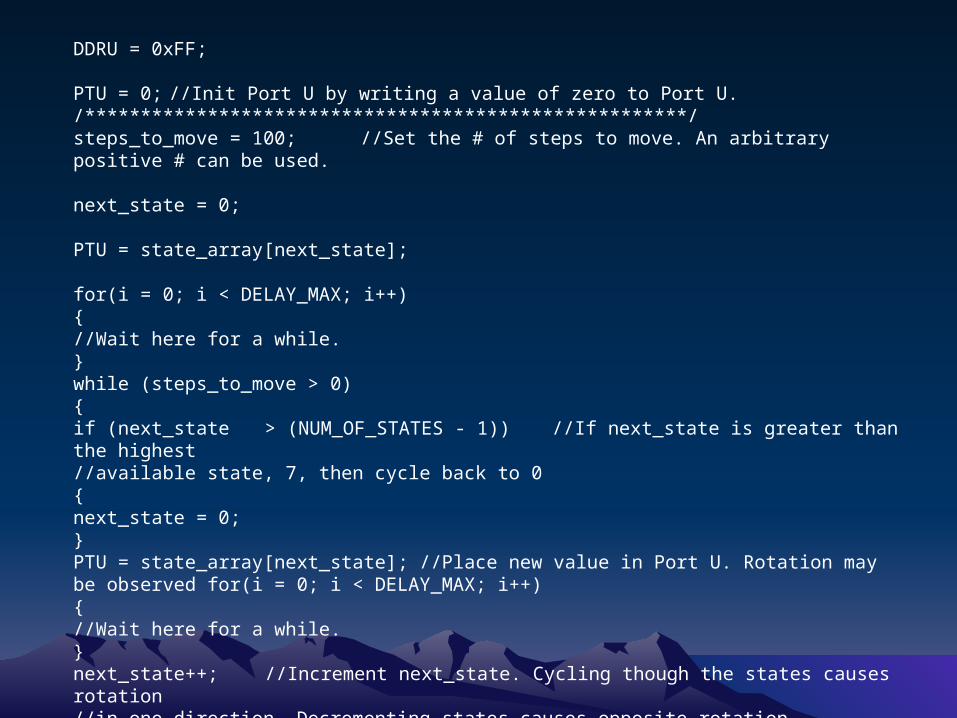
DDRU = 0xFF; PTU = 0; //Init Port U by writing a value of zero to Port U./******************************************************/steps_to_move = 100; //Set the # of steps to move. An arbitrary positive # can be used. next_state = 0; PTU = state_array[next_state]; for(i = 0; i < DELAY_MAX; i++){//Wait here for a while.}while (steps_to_move > 0){if (next_state > (NUM_OF_STATES - 1)) //If next_state is greater than the highest//available state, 7, then cycle back to 0{next_state = 0;}PTU = state_array[next_state]; //Place new value in Port U. Rotation may be observed for(i = 0; i < DELAY_MAX; i++){//Wait here for a while.}next_state++; //Increment next_state. Cycling though the states causes rotation//in one direction. Decrementing states causes opposite rotation.

steps_to_move--; //Subtract 1 from the total # of steps remaining to be moved.} //The following code rotates the motor back in the opposite direction. steps_to_move = 100;while (steps_to_move > 0){if (next_state < 0){next_state = (NUM_OF_STATES - 1);}PTU = state_array[next_state];for(i = 0; i < DELAY_MAX; i++){//Wait here for a while. next_state--; } steps_to_move--;}} //End of Main

Project Circuit Project Circuit

CONCLUSIONCONCLUSION
PIR sensor is used internally to excellent performance infrared sensor for use in robot. And it is also used for alarm burglar systems, visitor presence monitoring, light switches. These compact, easy to use sensors can be easily implemented in the design.

REFERENCESREFERENCES
• http://www.posey.com/files/M6183.pd
• http://www.makingthings.com/teleo/teleo/cookbook/nightlight/index.htm
• http://www.electronica-pt.com/circuitos/en/pics/87-motion-detector.html
• http://www.active-robots.com/pir-sensor.html
• http://www.omega.com

Thank You!Thank You!
QuestionsQuestions