Embed Size (px)
Citation preview
NfwBa>Bildge org - F.ast Span Design Basics http //www newbaybridge.org/the_bridge/east_span_design_basics html
,=.21«1%13 I ' . -
N tiBrid,eWhat's Coming .1 1.lnks 11 Abo,9 /his Sit
r 4 1 '11 = - E---9, '.€ ,t,1 '4:orgi -«»m i -- - fil
The Bridge The Builders The Projects Photo Galleries H istory Bridge To Classroom«Home > The Bridge > East Span Design Basics
The Bridge East Span Design Basics
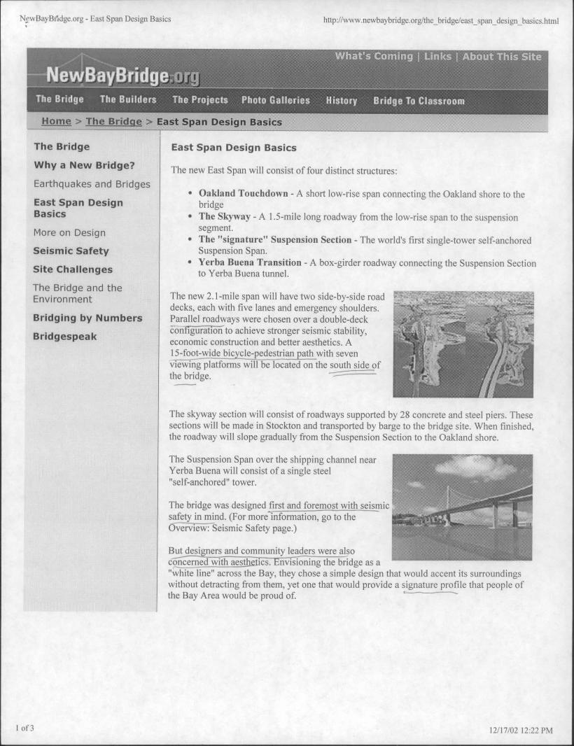
Why a New Bridge? The new East Span will consist of four distinct structures:
Earthquakes and Bridges• Oakland Touchdown - A short low-rise span connecting the Oakland shore to the
East Span Design bridgeBasics • The Skyway -A 1.5-mile long roadway from the low-rise span to the suspension
segment.More on Design • The "signature" Suspension Section - The world's first single-tower self-anchoredSeismic Safety Suspension Span.
• Yerba Buena Transition - A box-girder roadway connecting the Suspension SectionSite Challenges to Yerba Buena tunnel.The Bridge and theEnvironment The new 2.1-mile span will have two side-by-side road '0.7SI:E:51:: =-3 2-·31..;..4.ffi r- <:&.41:, ---fdecks, each with five lanes and emergency
shoulders. --- '.=,,1 -- 1.. -f.Bridging by Numbers Parallel roadways were chosen over a double-deck 6#4&4..6 dif Ajoconfigurationto achieve stronger seismic stability,Bridgespeak .19"* r 731'1#. .,t.Jeconomic construction and better aesthetics. A liwilily* ':/..../1/lill///1 17.../,.
15-foot-wide bicycle-pedestrian path with seven 2': 161>Alviewing platforms wiff-be located on the south side of .v.7 -6-.-.--- . /# --9 ,ill*, 'izza the bridge. --
IWill j ori.1,11·im......miThe skyway section will consist of roadways supported by 28 concrete and steel piers. Thesesections will be made in Stockton and transported by barge to the bridge site. When finished,the roadway will slope gradually from the Suspension Section to the Oakland shore.
--- "11'„.//4-3The Suspension Span over the shipping channel near 1, -7 - : - - , 111"!-1 --A1 1.'3Yerba Buena will consist ofa single steel
"self-anchored" tower. . --
f - - - 091 ' 11
The bridge was designed first and foremost with seismic 'safetyin_mind. (For more information, go to the -4(--'91,13Overview: Seismic Safety page.) Mimr#le= .1,1,7.............,-"-17.6( =f='ll
1· t..•.bl" *IC*-* ',it.'.: ,·..'·, 'le/**14==Butdesigners and community leaders were alsoconcerned with aest*ics.Envisioning the bridge as a"white line" across the Bay, they chose a simple design that would accent its surroundingswithout detracting from them, yet one that would provide a signature profile that people of
---I-the Bay Area would be proud of.
1 of3 12/17/02 12 22 PM

Ne\\·BayBridge.org - East Span Design Basics http:Uwww.newbaybridge.org/the_bridge/east_span_design_basics.html
In keeping with that idea, the skyway section has a I ' iv i r-' . _1 -7. i™gplp -
-
1, 7,--- clean, linear profile. An asymmetrical Suspension1{" ''1 , ''1-f .11 · 3,(: - - -Section was chosen to provide a distinctive gateway to 3*1, I- 34 74 . 11 ..* 4 -- AF L- - = -the East Bay and to mirror the lines of the western span1'1 1 ' - 9.1 i\42$ I _ .:,00of the Bay Bridge and the Golden Gate Bridge. To
provide a unique silhouette, the Suspension Section willhave a longer eastern span from the tower than thewestern side.
All vertical elements, including the tower, piers, andlight standards have been designed to emphasize the lean lines of the bridge. Unique lightpoles and railings will be used to join the designs ofeach bridge segment and create aunified appearance.
Alignment
Several alignments were considered for the new East Span, but since the existing bridgemust carry vehicle traffic while the new bridge is constructed, the new bridge must be builteither north or south ofthe existing bridge. After extensive environmental review andgeologic testing, Caltrans identified a northern alignment as the preferred route.
From the west, this route begins just north oftheexisting bridge, bows out, then rejoins the existing .'I. .- IiI(, bridge route at Yerba Buena.
The northern alignment avoids portions ofthe Bay .r iy.» .... where geologic conditions would increase construction #Ebaff*P':"Rthcomplexity and cost. It also allows for easier access to «- '··. $' 1bedrock to construct the main span tower. Thealignment also accommodates the East Bay Regional . -7Park District's planned Gateway Park on the Oaklandshore and minimizes conflicts with facilities and operations of the U.S. Coast Guard, theEast Bay Municipal Utility District's sewer outfall and the Port of Oakland's expansion plans.
The northern alignment also creates the best eastbound "gateway" to Oakland whileexpanding vistas toward the Golden Gate, Mt. Tainalpais and portions of the San Franciscoskyline for westbound motorists.
A word about the design process
The design for the new East Span was developed under guidelines established by Caltransand Gov. Gray Davis. The governor mandated that the new East Span be a "life line" bridgecapable of being reopened within 24 hours of a major earthquake.
vio«..t I; ii:3:5tmong Caltrans requirements: The Suspension tower should not be of a height that would
C 'A v Xe r./ 4 overwhelm the towers on the western side; the bridge should not have two decks; the design
i 47- \ should include a signature span; the approach to the span should be a skyway structure.
,»»»« The design was also influenced by input from several other organizations and the public. TheMetropolitan Transportation Commission (MTC), which oversees transportation planningand financing in the Bay Area, created two advisory committees specifically for this project:The Bay Bridge Design Task Force (BBDTF) and the Engineering and Design AdvisoryPanel (EDAP). The BBDTF has reviewed the East Span Project from the initial stages ofchoosing the bridge design materials and alignment through detailed development ofelements such as lighting and a bicycle/pedestrian path.
The contract for the design was awarded to a joint venture of T.Y. Lin international and the
2 of 3 12/17/02 12:22 PM

N*·## Ha> Bridge.org - liast Span Design Basics http://www.ne,#·h.i> bridge.org/the_bridge/cast_span_desigii_basics.htnil
firm Moffatt & Nichol.
T.Y. Lin engineers and personnel designed the Suspension and Skyway sections. Moffatt &Nichol designed the foundations for the main span and viaducts, ship collision measures, anddesign of the YB1 viaducts, YBI detours, YBI Transition structure and the Oakland shorestructures.
The Bridge I The Builders I The Projects I Photo Galleries I History I BridgeTo ClassroomWhat's Coming I Links I About Tliis Site
3 01' 3 12/17'0212 22 PM

NewBayBridge.org - More on Design http://www.newbaybridge.org/the_bridge/more_on_design.html
9%'Drt, "-0, «- -
The Bridge The Builders The Projects Photo Galleries History Bridge To Classroom
Home > The Bridge'>xMore on Design.'5=«
The Bridge For the Extremely Curious: More on Design
Why a New Bridge? Tlie following excerpt is froin an article that first appeared in the Sept. 2000 edition of Civil
Earthquakes and Bridges Engineering magazine, a pitblication of the American Society of Civil Engineers. Theauthors are Man-Chung Tang, P,E., Rafael Manzanarez, P.E., Manvan Nader, P.E., Sajid
East Span Design Abbas, P.E., and George Baker, P.E.Basics
The self-anchored suspension bridge consists of a 385More on Design m. main span and a 180 m back span. The tower will be · 7. · . · ' 'Seismic Safety 160 m tall and will comprise four steel shafts connected
with intermittent steel shear links along its height (seeSite Challenges figure 4). The shafts are tapered stiffened box members
/ " + :,;:,#'.2 1 .ijmade of grade 50 steel. The tower will be supported on _.·144/1/M*#EN.*=IlThe Bridge and thesteel pipe piles socketed into rock with concrete. The ·· ..33 '"'"70 --- '' -lITl Environmenteast pier will be supported on steel pipe piles founded · ·
#0 1
Bridging by Numbers on the Alameda Formation and the west pier will be : ,·A, 1· f. i t.'h, · 1
supported on 12.5 m deep gravity foundations.Bridgespeak
In the design, the 0.78 m diameter cable is anchored to the deck at the east bent and loopedaround the west bent through deviation saddles. Unlike traditional suspension bridgeschemes, these deviation saddles are fixed to the west bent and the cable force on either sideare balanced during construction using a jacking saddle. These saddles are supported by aprestressed cap beam that is designed to carry the differential stresses arising during serviceand seismic loads. The weight ofthis cap beam is designed to balance the dead load uplift atthe west bent that results from the asymmetry of the bridge. The cables at the tower do notcross and are secured in a single saddle. The saddle at the east pier is supported by the boxgirders and is designed to move so that it can balance the cable forces on either side. Thesuspenders are splayed to the exterior sides ofthe box girders and are spaced 1 O m apart.
The superstructure consists of dual, hollow orthotropic steel boxes. These boxes are incompression (supporting the cable tension forces) and are a part of the gravity load system.
Diaphragms spaced 5 m apart support the orthotropic deck and distribute the suspender loadsto the box. The box girders are connected together by 1 O m wide by 5.5 m deep crossbeamsspaced 30 m apart. These crossbeams carry the transverse loads between the suspenders (at a
span of 72 m) and ensure that the dual boxes act compositely during wind and seismic loads.
The self-anchored suspension bridge consists of a 385 m main span and a 180 m back span.The tower will be 160 m tall and will comprise four steel shafts connected with intermittentsteel shear links along its height.
The eccentric load caused by the pedestrian path on the south side is balanced by a
counterweight on the north side. At the west bent, the box girders frame into the cap beam,which serves as the box girder at that location. The connection between the orthotropic steel
box girders and the concrete cap beam is subjected to the compressive forces of the cables.Additional prestress is added through looped posttension strands connected at each rib toensure that the steel box yields before the connection fails.
The east piers are reinforced-concrete columns with added prestressing to avoid shear failurein tension when subjected to seismic loading. They are supported on 16 steel shell pipe piles
1 0 f 4 12/17/02 12:23 PM

NewBayBridge.org - More on Design http://www.newbaybridge.org/the_bridge/more_on_design.html
2.5 m in diameter. These piles are 100 m long and are filled with earth up to 55 m from thetop; the rest is filled with concrete. The west piers are reinforced-concrete columns enclosedby a steel shell to improve ductility. The columns are made monolithic with the prestressed
cap beam, forming the west bent, and are supported on rock through a 12.5 m deep gravityfooting.
At the west pier, a tie-down system, designed to resist a seismic uplift, consists of 28 staycables, each with 61 strands 15 mm in diameter. The stay cables are anchored into thefooting. At the east piers, the box girders are supported on bearings. Shear keys and tie rodsare provided to carry lateral loads and uplifts, respectively. The box girders are supported atthe east and the west pier for lateral loads and are "floating" at the tower.
The transition spans between the skyway, thesuspension bridge, and the YBI structure each have a r 12: : e
hinge. These hinges are designed to allow the structures Cl<t. Ull> 5".1 i 1.B: tri... :i +to move relative to each other in the longitudinal f ,-rie,< 306..... ..1
direction only, which helps to ensure that the four **J# 13/2,11L•elements of the bridge will maintain their differentdynamic responses to a seismic event, thus improvingthe bridge's integrity. r-f--9,7 »»-
1....1 1 1 1 I i. : t. 1. ti4 1' 1·. 42
r. 1: L..... »» . 6/. ... - L;Balanced-cantilever cast-in-place (CIP) and precastsegmental construction erection is being evaluated for the skyway. Concrete of normalweight will be used for the superstructure except for the side inclined panel or webs, wherelightweight concrete will be used. The 28-day concrete strength for both the lightweight andnormal-weight concrete is 50 MPa. The box girder is a single cell with two main verticalwebs.
The width at the bottom slab, or soffit, is 8.5 m, a dimension that is optimum from theseismic standpoint of pier column design. The 25 m width accommodates deck overhangs of8.3 m on each side. Inclined girder panels or webs posttensioned both longitudinally andtransversely were considered the most effective design to carry the eccentric bike pathloading. Vertical posttensioning is used to control the shear stresses in the main webs of thegirder.
The 160 m spans are arranged in frame units ofthree or four piers per frame with a girderdepth of 5.5 m at the midspan and 9 m at the pier. Midspan hinges between the frames allowlongitudinal expansion and contraction caused by creep, shrinkage, and temperaturechanges. An internal steel beam assembly at the hinge provides shear transfer and momentresistance in addition to controlling deflections at the cantilever end of each frame. Thesebeams are rigidly connected to the box girder at one end and slide on bearings at the boxgirder at the other end of the cantilever.
The foundation and piers are designed to resist loads -7 -0-
arising from elastic and plastic deformations of thesuperstructure, including creep, shrinkage, and itemperature drop. This loading is critical for the ...'.1
.
1. ..t.1proposed concrete superstructure for the sections with Ii:'i 'i Upper 1short piers near the Oakland shore. Steel tubular piles f; U
AN'ingda
41 9 Formationwere found to be best suited for the skyway foundations , ·,because oftheir strength and ductility as well as their | i. Low*r
Alamedapotential ease of installation. These piles will be driven rotmatkn
to the lower Alameda Formation and are 90 to 100 m inlength.
The piers of the skyway are about 50 m in height and stand in water depths of 15 m. This,added to the presence of a 1 5 m layer of young bay mud, establishes a very flexible structure.
2 of4 12/17/02 12:23 PM

NewBayBridge.org - More on Design http://www.newbaybridge.org/the_bridge/more_on_design.html
The design approach for such piers was to adopt a stiff foundation system, thereby confiningthe elastic displacements of the pile caps to acceptable levels and minimizing the potentialfor permanent offsets. A relatively stiff foundation system for the tall, flexible piers wasachieved by using large-diameter battered steel piles filled with concrete.
The thickness of the pile shells was determined by the required flexural capacity of the pile,the ductility capacity ofthe pile, corrosion allowances, and drivability. In particular, theflexural demands governed the thickness at the upper regions of the piles, and drivabilitygoverned the thickness in the lower regions of the shells. The thicknesses ranged from 40 to70 mm. To ensure the proper transfer of loads from the concrete fill to the steel shell, shear
ring plates will be welded to the inside of the steel shell in the concrete-filled section.
The pile cap will be approximately 6 m deep, with 2 m LO) _Shear Unk11 (Typical)
exposed above mean sea level. The pile cap's structuralsystem will be a moment-resisting steel frame 1 lili
Elev. + Bev. +54.33minterconnected with the steel piles and the pier 1111--i.ireinforcement (see figure 2). In
The YBI transition structures are technically and 1.,1
logistically challenging because of the roadwaygeometry, the positioning of future on- and off-ramps,the island's topography. structures of historicalimportance, and temporary detours. The eastbound and westbound transition structuresconnect the main-span structure to the existing viaduct section near the Yerba Buena tunnel'seast portal. The two structures are carried on separate single-column bents, except near theviaduct end, where they are supported on outrigger bents. The separate transition structurescurrently merge into the existing double-deck viaduct structure.
The length of each transition structure is approximately 467 m. The westbound structure hasan overall deck width of 25 m and varies in depth from 1.6 m at the viaduct end to 4.5 m atthe main-span hinge support. The height of both structures varies from 8 m at the viaductend to 46 m above grade at the main-span end. Most bents are located in overburden sandand are supported on cast-in-drilled-hole piles.
The superstructure ofthe transition structures consists of cast-in-place reinforced-concretebox girders near the outrigger bents and cast-in-place prestressed-concrete box girders overthe single-column bents. The shape ofthe box girders has been determined primarily byaesthetics to match the streamlined girder shape of the main-span superstructure and skyway.
The Oakland shore approach presented its own set of challenges. The westbound structureextends from the tip of the Oakland Mole to the point where the proposed westbound Route
80 joins the existing Route 80, connecting the Oakland shore to the skyway. The total lengthof the westbound approach structure is about 660 m, which is subdivided into two sections.an elevated structure and one that is essentially at grade. The eastbound approach structure isan elevated two-span frame 105 m long. The eastbound structure and the westerly portion ofthe structure are elevated and consist of a cast-in-place, prestressed-concrete box girdersuperstructure supported on reinforced-concrete piers, reinforced- concrete footings, andprestressed-concrete piles or small-diameter pipe piles. For the westbound at-grade structure,a flat-slab-on-piles option was selected.
Man-Chung Tang, Ph.D., P.E., is the chairman of the board of T.Y. Lin International, SanFrancisco. Rafael Manzanarez, PE, is a vice president at T.Y. Lin, and Marwan Nader,Ph.D., PE, and Sajid Abbas, Ph.D., PE, are both principals ofthe company. George Baker,PE, is a senior engineer at Weidlinger Associates, Inc., in New York City.
-- Reprinted with permission of the American Society of Civil Engineers
3 44 12/17/02 12:23 PM
NowBayBridge.org - Seismic Safety http://www.newbaybridge.org/the_bridge/seismic_safety.html
- Whatis Coming I Links I Ab it3Thi Site» F & -* 4, # *, f r k
4 L .,-- - 0e Bay ridgem*d 11 '
It
The Bridge The Builders The Projects Photo Galleries History Bridge To Classroomu ./.- m -=.... ».»'.,-
Home > The Bridge > Seismic Safety
The Bridge Seismic Safety
Why a New Bridge? -/..4-- . -SAN P#%%0.,ER„W*D;.1:kz . . . -
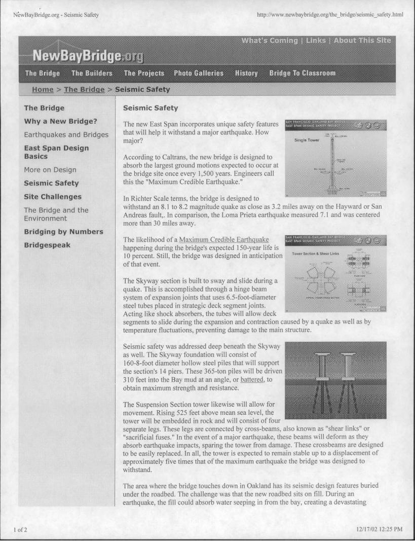
The new East Span incorporates unique safety features ,/*, ;541,mie·w,i, CinD· -53 ZI re.\-„....... - , . . .Earthquakes and Bridges that will help it withstand a major earthquake. How ---
.... 1........
major? S,4,1Jle To:.r i East Span Design 4
Basics According to Caltrans, the new bridge is designed to 111.....111
More on Designabsorb the largest ground motions expected to occur at ' '_-- ' tz:3i.- .., sthe bridge site once every 1,500 years. Engineers call =AK- K'.
11 i
-t)*1...1 "
Seismic Safety this the "Maximum Credible Earthquake."i di ......
3..:.:/ -.--.5-..1 r,Site Challenges In Richter Scale terms, the bridge is designed to .,.. . .. . .. , .... ..... . . „:- .-,-:*.»4
The Bridge and the withstand an 8.1 to 8.2 magnitude quake as close as 3.2 miles away on the Hayward or San
Environment Andreas fault,. In comparison, the Loma Prieta earthquake measured 7.1 and was centeredmore than 30 miles away.
Bridging by NumbersThe likelihood of a Maximum Credible Earthquake --60,2-3
Bridgespeak - - -happening during the bridge's expected 150-year life isTower Section & Shear Unks r -- 1.10 percent. Still, the bridge was designed in anticipation :-t#of that event.
.<'1»4 ) ·-s- i.„S·.-The Skyway section is built to sway and slide during a -r.':-SE ; 18% .I-quake. This is accomplished through a hinge beam 4 .1 : 3. Ic:6 il,tiE»,41«system ofexpansion joints that uses 6.5-foot-diameter *w-C,06*SEC 04 1 1 '....i
E..At* 4steel tubes placed in strategic deck segment joints. ..., #........... -I.-.*#.I
Acting like shock absorbers, the tubes will allow deck "- - ' - " - - - - - -segments to slide during the expansion and contraction caused by a quake as well as bytemperature fluctuations, preventing damage to the main structure.
Seismic safety was addressed deep beneath the Skyway ,,as well. The Skyway foundation will consist of160-8-foot diameter hollow steel piles that will supportthe section's 14 piers. These 365-ton piles will be driven310 feet into the Bay mud at an angle, or battered, toobtain maximum strength and resistance.
993&1191'.1'«-' 1 .'4 ine. ..--:..:1%''MThe Suspension Section tower likewise will allow formovement. Rising 525 feet above mean sea level, thetower will be embedded in rock and will consist of fourseparate legs. These legs are connected by cross-beams, also known as "shear links" or"sacrificial fuses." In the event of a major earthquake, these beams will deform as theyabsorb earthquake impacts, sparing the tower from damage. These crossbeams are designedto be easily replaced. In all, the tower is expected to remain stable up to a displacement ofapproximately five times that ofthe maximum earthquake the bridge was designed towithstand.
The area where the bridge touches down in Oakland has its seismic design features buriedunder the roadbed. The challenge was that the new roadbed sits on fill. During anearthquake, the fill could absorb water seeping in from the bay, creating a devastating
1 0 f 2 12/17/02 12:25 PM

NJwBayBridge.org - Seismic Safety http://www.newbaybridge.org/the_bridge/seismic_safety.html
condition known as liquefaction. When soil liquefies, it acts like quivering gelatin, causing ahost of settling and buckling problems.
As a preventative measure, hundreds of fabric wickdrains and 4-inch flexible pipes were driven into the fillarea to draw invading water up from the substrate into a ...2..gravel layer, through which the water would flow back « «--
--2: f '
to the bay.f., a.-- 5*:
(For an animation of how the wick drains were driven .*'
into the filllayer and more information on how the EastSpan touchdown area was built, visit the Geofill page.) 14%25
In addition to these features. some of the bridge piers with footings below the water willhave access casings that will allow inspectors to walk down on the top of the pilings andcheck for damage after an earthquake.
A seismic monitoring system will also be installed at key locations on the bridge to helpidentify potential structural changes more quickly.
The Bridge I The Builders I The Projects I Photo Galleries I History I BridgeTo ClassroomWhat's Coming I Links I About This Site
2 of' 2 12/17/02 12:25 PM

Box 4, Folder 6
Item 4
ACCNO_000281