Embed Size (px)
Citation preview


Maximize protectionMiCOM series 10, 20, 30, 40Comprehensive range of digital protection relays
Make the most of your energy

02
03
Increaseenergy availability
Fast response Maximum dependability
Your electrical equipment is under control.With MiCOM protection relays, you get maximum energy availability for your process.
100% availableenergy
Maximize energy availability and the profits generated by your installation while protecting life and property.
1999 Launch of first MiCOM relay protection
2013Over 500,000 MiCOM units installed around the world
The MiCOM range of relays offers scalable levels of functionality and hardware options to best suit your protection requirements, and allows you to choose the most cost effective solution for your application.The MiCOM protection relay range provides the capability for a wide variety of protection, control, measurement, monitoring and communication. The versatile hardware and common relay management software (MiCOM S1 studio) allows a simple configuration and installation in different applications. A standard and simple user interface across the entire range makes MiCOM ideal in any environment, from the more complex bay level control with mimic, to the most simple LCD display with menu interrogation.
Keep informed to manage better
Every MiCOM relay provides you with intuitive access to all system information in your own language so that so that you can manage your electrical installation effectively.If a problem occurs, clear and complete information puts you in a position to make the right decisions immediately. The electrical supply is restored without delay.
Maintain installation availability
MiCOM relays maintain high energy availability thanks to their diagnostics function that continuously monitors the network status. In-depth analysis capabilities and high reliability ensure that the equipment is de-energised only when absolutely necessary. Risks are minimised and servicing time reduced by programming maintenance operations.

series 20 series 30 series 10 series 40
Prefered application
Feeder P11x P12x P13x P14x
Motor P21x P22x P24x
Generator P34x
Distance P43x P44x
Line differential P52x P53x P54x
Transformer P63x P64x
Busbar P72x P74x
Breaker Failure P821 P84x
Voltage and frequency
P92x
From cost effective to high end protection and control, the comprehensive MiCOM series allows complete optimisation of your solution.
Increase your capabilities...
MiCOM series 10 Fulfils the basic requirements of Buildings and small Industries applications with particular focus on overcurrent and motor protection. Two families are available.• Auxiliary powered • Self powered / dual powered.
0504
MiCOM series 20 Fulfils the basic/medium requirements of Industrial, Utility and Building applications providing simplicity and ease of use in a wide range of installations.• Scalable solutions where type and quantity of protection features is model
dependent• Flexible logic equations available on most models• Compact hardware options for easy installation• Common functions throughout the range• Multi-language HMI• Advanced protection functions
MiCOM series 30 Fulfils the protection requirements of Utility and Industrial applications with particular focus on integrated feeder control and provides dedicated railway protection devices.• Protection with bay level control options to facilitate feeder management• Input/Output quantity selectable based on requirements• Numerous rear port communication hardware options available with a wide
range of protocols selectable via software• Protection functions available for isolated/Petersen coil earthed systems• Surface and flush mounted (including detachable HMI option) as well as
compact case models available in the range• Full Programmable Scheme Logic (PSL) and function keys
MiCOM series 40Fulfils the protection requirements for a wide market of Utility and Industrial application and offers a wide range of protection functions.
• Full Programmable Scheme Logic available with graphic configuration tool for easy setting
• Scalable Input/Output hardware depending on requirements• Operating voltage selectable via software for opto inputs• Hardware accessories available for easy mounting in racks or
panels.
MiCOM relays fulfil the requirements at all voltage levels:
... with a comprehensive range

Automatic hardware description
06
Setting file ready to be downloaded to MiCOM relay
Configuration
The MiCOM S1 Studio programming and operating software provides a single environment for the entire range. The result is a simple, user-friendly approach for fast commissioning.
ProtectionactivationEnable protection functions
Summary of functionsEasily and quickly apply protection, control and monitoring settings
download
export
1 to 5 minutes 5 minutes 20 minutes
EquipmentsetupUpload data on-line from the relay or off-line from a data model template
Complete peace of mind during operation
Operation
Analysis of waveform captureDisplay, analysis and printing of disturbance recording data.
Real-time supervisionSupervision of the status of all the relays in the electrical installation
Management of alarms and events
Fine tune capability
Application compliance
Straightforward facility for
commissioning
07
Save time... ... with a simple operating software
08 09
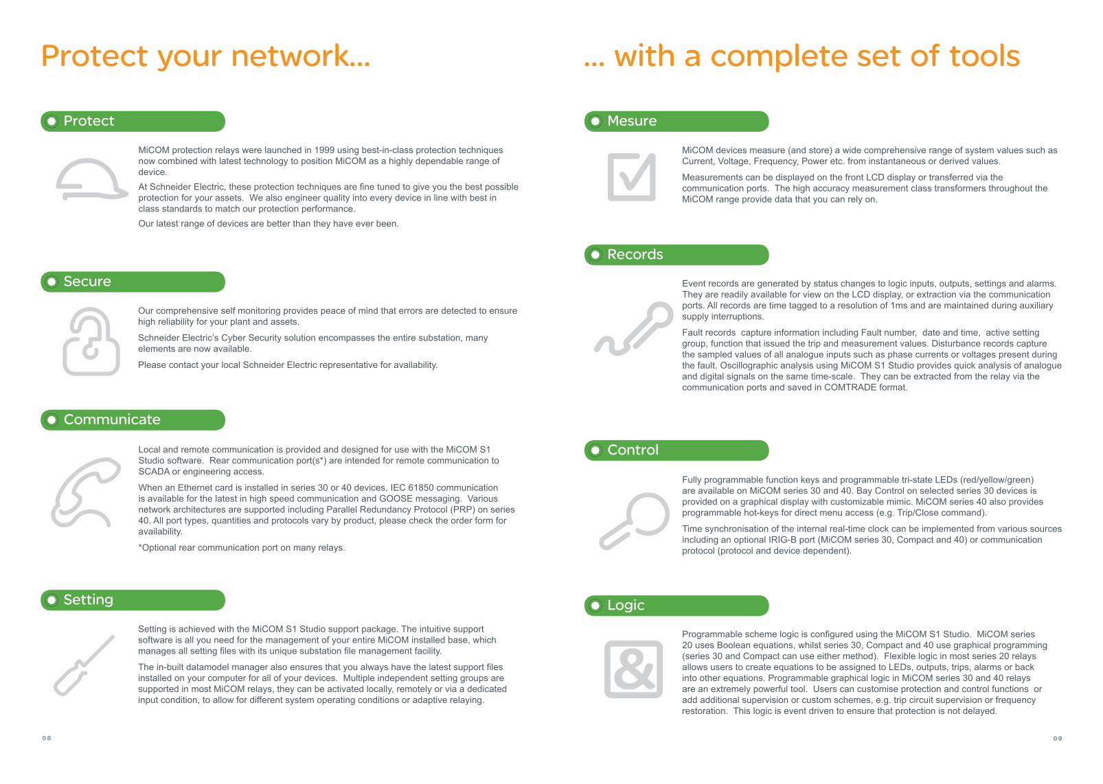
Protect your network... ... with a complete set of tools
Programmable scheme logic is configured using the MiCOM S1 Studio. MiCOM series 20 uses Boolean equations, whilst series 30, Compact and 40 use graphical programming (series 30 and Compact can use either method). Flexible logic in most series 20 relays allows users to create equations to be assigned to LEDs, outputs, trips, alarms or back into other equations. Programmable graphical logic in MiCOM series 30 and 40 relays are an extremely powerful tool. Users can customise protection and control functions or add additional supervision or custom schemes, e.g. trip circuit supervision or frequency restoration. This logic is event driven to ensure that protection is not delayed.
MiCOM protection relays were launched in 1999 using best-in-class protection techniques now combined with latest technology to position MiCOM as a highly dependable range of device. At Schneider Electric, these protection techniques are fine tuned to give you the best possible protection for your assets. We also engineer quality into every device in line with best in class standards to match our protection performance.Our latest range of devices are better than they have ever been.
Protect
Our comprehensive self monitoring provides peace of mind that errors are detected to ensure high reliability for your plant and assets.
Schneider Electric’s Cyber Security solution encompasses the entire substation, many elements are now available.
Please contact your local Schneider Electric representative for availability.
Secure
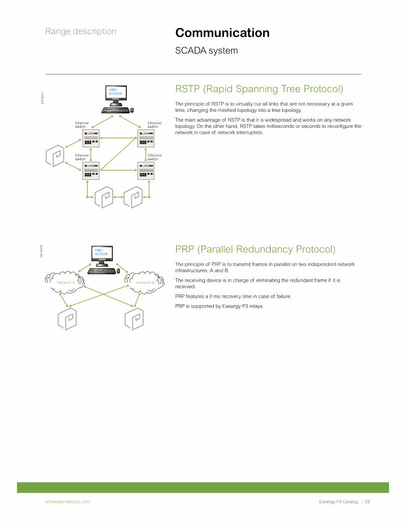
Local and remote communication is provided and designed for use with the MiCOM S1 Studio software. Rear communication port(s*) are intended for remote communication to SCADA or engineering access.
When an Ethernet card is installed in series 30 or 40 devices, IEC 61850 communication is available for the latest in high speed communication and GOOSE messaging. Various network architectures are supported including Parallel Redundancy Protocol (PRP) on series 40. All port types, quantities and protocols vary by product, please check the order form for availability.
*Optional rear communication port on many relays.
Communicate
Setting is achieved with the MiCOM S1 Studio support package. The intuitive support software is all you need for the management of your entire MiCOM installed base, which manages all setting files with its unique substation file management facility.
The in-built datamodel manager also ensures that you always have the latest support files installed on your computer for all of your devices. Multiple independent setting groups are supported in most MiCOM relays, they can be activated locally, remotely or via a dedicated input condition, to allow for different system operating conditions or adaptive relaying.
Setting
MiCOM devices measure (and store) a wide comprehensive range of system values such as Current, Voltage, Frequency, Power etc. from instantaneous or derived values.
Measurements can be displayed on the front LCD display or transferred via the communication ports. The high accuracy measurement class transformers throughout the MiCOM range provide data that you can rely on.
Mesure
Event records are generated by status changes to logic inputs, outputs, settings and alarms. They are readily available for view on the LCD display, or extraction via the communication ports. All records are time tagged to a resolution of 1ms and are maintained during auxiliary supply interruptions.
Fault records capture information including Fault number, date and time, active setting group, function that issued the trip and measurement values. Disturbance records capture the sampled values of all analogue inputs such as phase currents or voltages present during the fault. Oscillographic analysis using MiCOM S1 Studio provides quick analysis of analogue and digital signals on the same time-scale. They can be extracted from the relay via the communication ports and saved in COMTRADE format.
Records
Fully programmable function keys and programmable tri-state LEDs (red/yellow/green) are available on MiCOM series 30 and 40. Bay Control on selected series 30 devices is provided on a graphical display with customizable mimic. MiCOM series 40 also provides programmable hot-keys for direct menu access (e.g. Trip/Close command).
Time synchronisation of the internal real-time clock can be implemented from various sources including an optional IRIG-B port (MiCOM series 30, Compact and 40) or communication protocol (protocol and device dependent).
Control
Logic

The user interface and menu text is available in English, French, German and Spanish as a standard. Other languages such as for example Russian and Chinese are supported on some relays depending on the market requirements.The ability to customize the menu text and alarm descriptions is also supported on series 30 and 40. The front panel user interfaces comprises:
A back-lit liquid crystal display (series 10, 20, 30, 40) Graphic LCD display (series 30)
3 fixed function LEDS (series 10) 4 fixed function LEDs (series 20, 40) 5 fixed function LEDs (series 30)
Up to 4 user programmable LEDs (series 20) Up to 18 user programmable LEDs (series 30) Up to 8 user programmable LEDs (series 40)
Menu navigation and data entry keys
10 11
Simplify your operation...
User language options that provide true global convenience
“READ” and “CLEAR” keys for viewing and reset of alarms
Front communication port
Facility for fitting a security seal
Programmable Function keys (compact case, series 30 and 40)
Switchgear control keys up to 6 bays control (series 30)
MiCOM series 20 and 40
1
7
2
3
4
5
2
3
4
1
8
MiCOM series 30 in compact case MiCOM series 30 with bay control
1
76
5
2
34
9
MiCOM series 10
1
2
3
4
6
7
8
9
2
3
6
4
1
6
5
6
5
5
... with a user friendly interface

E
A
A (in
cludin
g bra
cket
s)
C
D
B
E
B
A
E
C
A
B
TRI P
ALARM
O UT O F SERVI CE
HEALTHY
EDI T M O DE
A
B
OK
D
D
Fro
nt
Vie
wS
ide
Vie
w
B
A
A B C D E
series 10
Compact 1 106.5 106.5 113 118 101.5
Compact 2 184 157 110 140 150
series 20
20TE177
103 240 (incl. wiring)
270 (incl. wiring) 157.5
30TE 155 139.8 223
166.4 249.6
155.2 156
series 30
24TE
184,5
186.4
227.9 253.6 177.540TE 260.2
84TE 481.6
40TE Surface 260.2257.1 177.5
84TE Surface 481.6
series 40
40TE
177
206
240 (incl. wiring)
270 (incl. wiring) 157.5 max
60TE 309.6
80TE 413.2
80TE Rack 483
series 30Compact
Compact 294.4 175.6 88.5 253
12
Case constructionThe MiCOM series are housed in specially designed cases which provide a high density of functionality within the product. Communication ports and model/serial number information is concealed by upper and lower covers on certains models.
Physical protection of the front panel user interface and prevention of casual access is provided by an optional transparent front cover (selected models only), which can be fitted or omitted, since the front panel has been designed to IP52 protection against dust and water.
The cases are suitable for either rack or panel mounting.
An option for surface mounting and a compact case is also supported on the series 30 for installations with space limitations.
The differing case widths of relays can be combined with or without the use of standard blanking plates to form a complete 19” mounting. This saves space and allows for a neat installation.
Note: Maximum sizes for guidance only, for specific product information please check the relevant product documentation. (All dimensions in mm)
Dimensions
Compact case
Compact case
series 20, 30 & 40
series 40
Typical case dimensions
Mechanical description
13
series 10
series 20
series 30
series 10
WiringExternal connections are made via ring type terminal except on the compact case. These take pin type terminals along with the series 30 relays as an option.

Power supplies A wide range of power supply options are available at the ordering stage.
Nominal VoltageVnom.
Operate Range (V) dc ac
series 10
24-60Vdc/ac 19–72 19-66
60-250 Vdc / 90-240 Vac 48-300 71-265
series 20
24-250 Vdc / 48-240 Vac 19.2-300 38.4-264
48-250 Vdc / 48-240 Vac 38.4-300 38.4-264
series 30
24-60 Vdc 19-72 -
60-250 Vdc / 100-230 Vac 48-300 100-230
series 40
24-48 Vdc 19-65 -
48-110 Vdc / 40-100 Vac 37-150 32-110
110-250 Vdc / 100-240 Vac 87-300 80-265
General series data
14 15
Technical data description
Digital InputsA wide range of opto input voltages are supported throughout the range
* CT thermal ratings continuous: 4 In/10s & 30 In/1s & 100 In** model dependent
Auxiliary Voltage Thresholds (V)
series 10
> 24 Vdc/ac > 19.2 Vdc/ac
> 90 Vac > 71 Vac
> 90 Vdc > 77 Vdc
series 20
24- 250 Vdc / 48-240 Vac > 19.2 Vdc/ac (Variant code”Z”)
48- 250 Vdc / 48-240 Vac
> 19.2 Vdc/ac (Variant code”Z”)> 105 Vdc (Variant code “H”)
> 77V (70% of Uaux. 110 Vdc; Variant code “V”)> 154V (70% of Uaux. 220 Vdc; Variant code “W”)
series 30
ThresholdsStandard Variant
> 18 (Uaux. 24-250 Vdc)Further Options
> 73 V (67% of Uaux. 110 Vdc)> 90 V (60-70% of Uaux. 125/150 Vdc)
> 146 V (67% of Uaux. 220 Vdc)> 155 V (60-70% of Uaux. 220/250 Vdc)
series 40
Universal programmable voltage thresholds
24/27, 30/34, 48/54, 110/125 and 220/250 Vdc
series 10
series 20
series 30 series
40 Standard case Compact case
Frequency 50/60Hz
Dual rated 1A/5A *
Opto inputs max 8 max 12 max 82 2 max 64
Output contacts max 8 max 9 max 48 8 max 60
Continuous carry 5A 5A 5A 5A 10A
Make and carry 25A for 3s 30A for 3s 30A for 0.5s 30A for 0.5s 30A for 3s
High break contacts
LED indication (freely programmable)
8 (6) 8 (4) 29 (24) 17 (12) 22 (18)
Function keys / Hot keys No No 6 4 10/2 **
Settings groups up to 2 up to 8 4 4 4 (2)
Fault records 20 25 8 8 5
Event records 200 250 1000 200 250-512
Disturbance records 5 (6s max) 5 (15s max) 8 (16.4s max) 8 (16.4s max) 75 s max.
Programmable logic No Flexible logic **Fully
programmableFully
programmable Fully
programmable
IRIG B No Option Option Option Option
LCD display Alphanumeric Alphanumeric Alphanumeric /
Graphical **Alphanumeric Alphanumeric
Front port USB (RS 232 RS 232 RS 232 RS 232
Rear Port/2nd rear port Yes/No Yes/Option Yes/Option Yes/Option Yes/Option
Courier No EIA(RS)485 **EIA(RS)485
or fibre EIA(RS)485
or fibre K-Bus/ EIA(RS) 485 or fibre**
Modbus Yes EIA(RS)485 EIA(RS)485
or fibre EIA(RS)485
or fibre EIA(RS) 485
or fibre**
IEC 60870-5-103 Yes EIA(RS)485 EIA(RS)485
or fibre EIA(RS)485
or fiber EIA(RS) 485
or fibre **
IEC 60870-5-101 No No EIA(RS)485
or fibre EIA(RS)485
or fibre No
DNP3.0 No EIA(RS)485 **EIA(RS)485
or fibre EIA(RS)485
or fibre EIA(RS) 485
or fibre**
IEC 61850 No No With Ethernet No With Ethernet
One box bay controlwith mimic
No No Yes ** No No
Terminals Pin or Ring ** Ring Pin or Ring Pin Ring

Feeder management and overcurrent relays
16 17
MiCOM series descriptionFeeder management relays
30 40 series
P130C P132 P139 P141 P142 P143 P145 model
Compact 24, 40 or 84TE 40 or 84TE 40TE 40TE 60 or 80TE 60TE Case size
4 4 4 5 5 5 5 CT Inputs
3 4 or 5 4 or 5 3 3 3 or 4 3 or 4 VT Inputs
2 70 70 8 16 32 32 Opto Inputs ( max)
8 32 28 8 15 30 32 Output Contacts (max)
Output for striker triggering
Magnetic flags (max)
10 10 RTDs (max. option)
1/2 1/2 Analogue Input / Output (max)
Function Keys/Hotkeys
Bay Control & Monitoring
- with Mimic
Interlocking logic
ANSI PROTECTION FUNCTION
25 Check synchronising
32 Directional power
34 Master sequence device
37 Undercurrent
46 Negative sequence overcurrent
46BC Broken conductor
47 Negative sequence overvoltage
48 Incomplete sequence relay
49 Thermal overload
50/51N Ground fault
50/51P 3 Phase overcurrent
50/51P/N 1 Phase or earth overcurrent
50BF Circuit breaker failure
51LR Motor
51V Voltage controled overcurrent
59/27 Over/Under voltage
59N Residual over voltage
64 Restricted earthfault
66 Startup monitoring
67N Ground fault directional
67N Sensitive directional earthfault
67P Phase directional
67W Wattmetric earthfault
79 Autoreclose
81 Under/Over frequency
81R Rate of change of frequency
85 Protective signalling
86 Lock-out
CTS Current transformer supervision
SOTF Switch on to fault
TCS Trip circuit supervision
VTS Voltage transformer supervision
YN Neutral admittance
Circuit breaker monitoring
Cold load pick-up
Inrush blocking
InterMiCOM
Limit value monitoring
series 10 20model P111 P114D P115 P116 P120 P121 P122 P123 P125 P126 P127
Case size 20TE 20TE 20TE 20TE 30TE 30TE 30TE
CT Inputs 4 4 4 4 1 4 4 4 1 4 4
VT Inputs 1 1 3
Opto Inputs ( max) 8 2 2 6 2 2 3 5 4 7 12
Output Contacts (max) 8 4 4 7 5 5 7 9 7 9 9
Output for striker triggering 1 1 1
Magnetic flags (max) 5
RTDs (max. option)
Analogue Input/ Output (max)
Function Keys/Hotkeys
Bay Control & Monitoring
- with Mimic
Interlocking logic
PROTECTION FUNCTION ANSI
Check synchronising 25
Directional power 32
Master sequence device 34
Undercurrent 37
Negative sequence overcurrent 46
Broken conductor 46BC
Negative sequence overvoltage 47
Incomplete sequence relay 48
Thermal overload 49
Ground fault 50/51N
3 Phase overcurrent 50/51P
1 Phase or earth overcurrent 50/51P/N
Circuit breaker failure 50BF
Motor 51LR
Voltage controled overcurrent 51V
Over/Under voltage 59/27
Residual over voltage 59N
Restricted earthfault 64
Startup monitoring 66
Ground fault directional 67N
Sensitive directional earthfault 67N
Phase directional 67P
Wattmetric earthfault 67W
Autoreclose 79
Under/Over frequency 81
Rate of change of frequency 81R
Protective signalling 85
Lock-out 86
Current transformer supervision CTS
Switch on to fault SOTF
Trip circuit supervision TCS
Voltage transformer supervision VTS
Neutral admittance YN
Circuit breaker monitoring
Cold load pick-up
Inrush blocking
InterMiCOMLimit value monitoring

18 19
Motor management relays Generator management relays
series 40model P342 P343 P344 P345
Case size 40 or 60TE
60 or 80TE 80TE 80TE
CT Inputs 5 8 8 9
VT Inputs 4 4 5 7
Opto Inputs (max) 24 32 32 32
Output Contacts (max) 24 32 32 32
RTDs 10 10 10 10
Analogue Input/Output (max) 4/4 4/4 4/4 4/4
Function keys
Interlocking logic
PROTECTION FUNCTION ANSI
Underimpedance 21
Overfluxing 24
Check synchronising 25
100 % stator earth fault (3rd) 27TN/59TN
Directional power 32L/O/R
Thermal overload 38/49
Loss of field 40
Negative sequence overcurrent 460C
Negative sequence thermal 46T
Negative sequence over voltage 47
Thermal overload 49T
Unintentional energisation 50/27
Phase overcurrent 50/51P
Circuit breaker failure 50BF
Ground fault 50N/51N
Interturn/split phase 50DT
Voltage dependent O/C 51V
Under/over voltage 59/27
Residual over voltage 59N
Restricted earth fault 64
Wattmetric earth fault 64N/32N
Rotor earth fault (MiCOM P391 option) 64R
100 % stator earth fault (low frequ.) 64S
Sensitive directional earth fault 67N
Phase directional 67P
Wattmetric sensitive earth fault 67W
Pole slipping 78
Turbine abnormal frequency 81AB
Under/Over frequency 81
Generator Differential 87G/87GT
Current transformer supervision CTS
Trip circuit supervision TCS
Voltage transformer supervision VTS
Circuit breaker monitoring
series 10 20 30 40model P211 P220 P225 P130C P132 P139 P241 P242 P243
Case size - 30TE 30TE Com-pact
24, 40 or 84TE
40 or 84TE 40TE 60TE 80TE
CT Inputs 4 4 4 4 4 4 4 4 7
VT Inputs 1 or 3 3 4 or 5 4 or 5 3 3 3
Opto Inputs (max) 4 5 11 2 70 70 8 16 16
Output Contacts (max) 4 6 6 8 32 28 7 16 16
RTDs / Thermistors 6/0 or 4/2
10/3 or 0/0 10/0 10/0 10/0 10/0 10/0
Analogue Input/Output (max) 0/1 0/2 1/2 1/2 4/4 4/4 4/4
Function keys
Interlocking logic
PROTECTION FUNCTION ANSI
Speed switch input 14
Check synchronising 25
Reacceleration 27LV
Unballance/Lock out 30/46/86
Directional power 32L/O/R
Reverse power 32R
Loss of load 37
Undercurrent 37P/37N
Thermal overload 38/49
Loss of field 40
Negative sequence overcurrent 46
Negative sequence over voltage 47
Neutral over voltage 47N
Phase overcurrent 50/51P
Circuit breaker failure 50BF
Ground fault 50N/51N
Locked rotor 50S/51LR/51S
Out of step 55
Under/Over voltage 59/27
Residual over voltage 59N
Wattmetric earth fault 64N/32N
Startup monitoring 66/48/51
Ground fault directional 67N
Sensitive directional earth fault 67N
Phase directional 67P
Over frequency 81O
Under frequency 81U
Rate of change of frequency 81R
Motor differential 87M
Current transformer supervision CTS
Trip circuit supervision TCS
Voltage transformer supervision VTS
Anti Backspin
Circuit breaker monitoring

Distance protection relays Line differential protection relays
series 30 40model P430C P433 P435 P437 P439 P441 P442 P443 P444 P445 P446
Case size Compact 40 or 84TE
40 or 84TE 84TE 40 or
84TE 40TE 60TE 80TE 80TE 40 or 60TE 80TE
CT Inputs 4 4 4 4 or 5 4 4 4 5 4 4 8
VT Inputs 3 4 or 5 4 or 5 4 or 5 4 or 5 4 4 4 4 4 5
Opto Inputs (max) 2 70 82 36 70 8 16 32 24 16 24
Output Contacts (max) 8 32 48 48 28 14 21 32 46 16 32
RTDs (option) 1 1 1 1
Analogue Input/Output (max) 1/2 1/2 1/2 1/2
Function keys/hotkeys
Bay control & monitoring with Mimic
Interlocking logic
PROTECTION FUNCTION ANSI
Distance 21/21N
Check synchronising 25
Directional power 32
Negative sequence overcurrent
46
Directional negative sequence 46/67
Broken conductor 46BC
Thermal overload 49
Switch on-to fault 50/27
Earth fault 50/51N
Phase overcurrent 50/51P
Stub bus protection 50ST
Over/Undervoltage 59/27
Residual overvoltage 59N
Circuit breaker failure 62/50BF
Earth fault directional 67N
Transient earth fault directional
67N
Phase directional 67P
Wattmetric earth fault 67W
Out of step tripping 68
Power swing blocking 78
Autoreclose 79 3 pole 3 pole 1/3 pole 1/3 pole 3 pole 3 pole 1/3 pole 1/3 pole 1/3 pole 3 pole 1/3 pole
Over/Under frequency 81
Rate of change of frequency 81R
Channel aided scheme logic 85
Capacitive voltage transformer supervision
CVTS
Trip Circuit Supervision TCS
Voltage/Current transformersupervision
VTS/CTS
Delta directional comparison l/V
Neutral admittance YN
InterMiCOM
Mutual compensation
20 21
series 20 30 40model P521 P530C P532 P541 P542 P543 P544 P545 P546 P547
Case size 30TE Compact 40 or 84TE 40TE 60TE 60TE 60TE 80TE 80TE 80TE
CT Inputs 4 4 4 4 4 5 8 5 8 5
VT Inputs 3 4 or 5 4 5 4 5 4
Opto Inputs (max) 5 2 46 8 16 16 16 32 24 24
Output Contacts (max) 8 8 30 7 14 14 14 32 32 32
Function Keys/Hotkeys
Interlocking logic
PROTECTION FUNCTION ANSI
Distance 21
Check synchronising 25
Loss of load/Undercurrent 37
Negative sequence overcurrent
46
Thermal overload 49
Earth fault 50/51N
Phase overcurrent 50/51P
Circuit breaker failure 50BF
Over/Under voltage 59/27
Wattmetric earth fault 64W
Earth fault directional 67N
Sensitive directional earth fault
67N
Phase directional 67P
Power swing blocking 78
Autoreclose 79 3 pole 3 pole 3 pole 1/3 pole 1/3 pole 1/3 pole 1/3 pole 1/3 pole
Under/Over frequency 81
Line differential (terminal) 87L 2 2 2 2/3 2/3 2/3 2/3 2/3 2/3
Phase comparison 87L
CT supervision CTS
Trip Circuit Supervision TCS
2 breaker configuration
2nd harmonic restraint
Copper wire signalling
Direct/Permissive intertripping
FO signalling
In Zone transformer
PLC signalling
SDH/Sonet networks
Vector Compensation

Transformer protection relays Busbar protection relays
Voltage, frequency, and ancillary protection relays
22 23
series 20 30 40model P721 P630C P631 P632 P633 P634 P642 P643 P645
Case size 20TE Compact 40TE 40 or 84TE 40 or 84TE 84TE 40TE 60TE 60 or 80TE
CT Inputs 2 6 6 8 12 15 8 12 18
VT Inputs 1 1 1 1 or 2 1 or 4 1 or 4
Opto Inputs (max) 2 2 4 34 40 34 12 24 24
Output Contacts (max) 4 8 14 22 30 22 12 24 24
Analogue Input/Output (max ) 1/2 1/2 1/2 4/4 4/4 4/4
RTDs (option) 1 1 1 10 10 10
Function Keys/Hotkeys
Interlocking logic
PROTECTION FUNCTION ANSI
Overexcitation 24
Negative sequence overcurrent
46
Negative sequence overvoltage
47
Thermal overload 49
Ground fault 50/51N
Phase overcurrent 50/51P
Circuit breaker failure 50BF
Over/Under voltage 59/27
Ground fault directional 67N
Phase directional 67P
Under/Over frequency 81
Restricted earth fault 87G/64 1 2 3 3 2 3 3
Transformer diff. (windings) 87T 2 2 2 3 4 2 3 3
CT supervision CTS
Trip Circuit Supervision TCS
VT supervision VTS
2 nd harmonic restraint
Overfluxing/ 5th harmonic
series 20 40Device P723 P741 P742 P743 P746
Case size 20TE 80TE 40TE 60TE 80TE
CT Inputs 8 4 4 18
VT Inputs 3
Opto Inputs (max) 5 8 16 24 40
Output Contacts (max) 8 8 8 21 32
Function Keys/Hotkeys
PROTECTION FUNCTION ANSI
Ground fault 50/51N
Phase overcurrent 50/51P
Circuit breaker failure 50BF
Busbar 87BB
Check Zones 87CZ
Phase segregated differential 87P 8 zones 2 zones
Sensitive earth fault differential 87P 8 zones
CT supervision CTS
Trip Circuit Supervision TCS
VT supervision VTS
Phase comparison
Central unit (Nbr of feeders) No limit up to 28
Peripheral units 8 zones
CT supervision
CT saturation detection
series 20 40model P821 P921 P922 P923 P341 P841 P849
Dimensions 20TE 20TE 20TE 20TE 40 TE or 60TE 60TE or 80 TE 80TE
CT Inputs 4 4 5 or 8
VT Inputs 4 4 4 4 4 or 5
Opto Inputs (max) 5 2 5 5 16 16 or 24 64
Output Contacts (max) 9 4 8 8 15 14 or 32 60
PROTECTION FUNCTION ANSI
Check synchronising 25 1 or 2
Undervoltage 27
Phase sequence voltage 47/27D
Breaker failure protection 50BF 1 or 2
Overvoltage 59
Residual overvoltage 59N
Restricted earth fault 64
Wattmetric earth fault 64N/32N
Phase directional with DLR option 67P
Autoreclose 79 1 or 1/2
Under/Over frequency 81
Rate of change of frequency (df/dt+t) 81R
Frequency supervised average rate of change of frequency (f+f/t)
81RAV
Frequency supervised rate of change of frequency (f+df/dt)
81RF
Voltage vector shift dVq
Trip circuit supervision TCS
3 pole tripping
Ferroresonance detection
High speed contact

10-2013 AR
T838
325
© 2
013
Sch
neid
er E
lect
ric In
dust
ries
SA
S -
All
right
s re
serv
ed
As standards, specifications and designs change from time to time, please ask for confirmation of the information given in this publication.
Design: Schneider Electric Industries SASPhotos: Schneider Electric Industries SAS Printed: Altavia Connexion - Made in France
NRJED111010EN
This document has been printed on recycled paper.
Schneider Electric Industries SAS
35, rue Joseph Monier CS 30323 F - 92506 Rueil Malmaison Cedex (France)Tel.: +33 (0) 1 41 29 70 00RCS Nanterre 954 503 439 Capital social 896 313 776 €www.schneider-electric.com
Rail protection relays
series 30model P138 P436 P438 P638
Case size 40 or 84TE 40 or 84TE 40 or 84TE 84TE
CT Inputs 2 3 3 5
VT Inputs 1 2 2 1
Opto Inputs (max) 22 28 28 38
Output Contacts (max) 48 46 46 64
RTDs (option) 1 1 1 1
Analogue Input/ Output (max) 1/2 1/2 1/2 1/2
Function Keys/Hotkeys
PROTECTION FUNCTION ANSI
Distance 21/21N
Over/Under voltage 27/59
Thermal overload 49
Switch on-to fault 50/27
High current supervision 50H
High current earth fault (tank protection) 50/51N
Phase overcurrent 50/51P
Circuit breaker failure 62/50BF
Phase directional 67P
Under/Over frequency 81
Lock-out 86
Transformer differential (windings) 87T 2
Train startups di/dt,dv/dt,dΦ/dt
Rail catenary protection Hz 16 2/3 25/50/60
Trip circuit supervision TCS
Current transformer supervision CTS
Voltage transformer supervision VTS
2nd harmonic restraint
Defrost protection
High impedance fault detection
InterMiCOM
Training is available worldwide near you. For more information on products and services: www.schneider-electric.com/energy-automation