Embed Size (px)
Citation preview
easergy.schneider-electric.com
2017 Catalog
Easergy T300Remote Terminal Unit
Feeder Automation

schneider-electric.com2 | Easergy T300 Catalog
General Contents
General presentation 6
Functions and description 18
Cabinet and Smart RMU Solution 96
Accessories 104
Commercial references 112
schneider-electric.com | 3Easergy T300 Catalog

schneider-electric.com4 | Easergy T300 Catalog
Answer the challenges of today. And tomorrow.Electrical distribution networks must transition to next-generation technology in order to face the challenges of modern grid applications, such as growing energy demand, stricter emission limits, and tight constraints on operational expenditure (OpEx).
Grid evolution
Support the integration of distributed
energy resources (DER) and electric
vehicles (EVs).
Downtime tolerance
Minimize power supply interruptions
and manage increasing energy demand.
Quality requirements
Ensure grid performance meets customer
and regulatory needs.
Cost optimisation
Maintain aging infrastructure while
expanding installations and operations.
Need for efficiency
Manage base and peak load consumption
effectively.
Cyber threats
Comply with the latest standards and help
protect your business from cyber attacks.
PM
1044
99
Easergy feeder automation solutions can help any distribution network answer these challenges.
schneider-electric.com | 5Easergy T300 Catalog
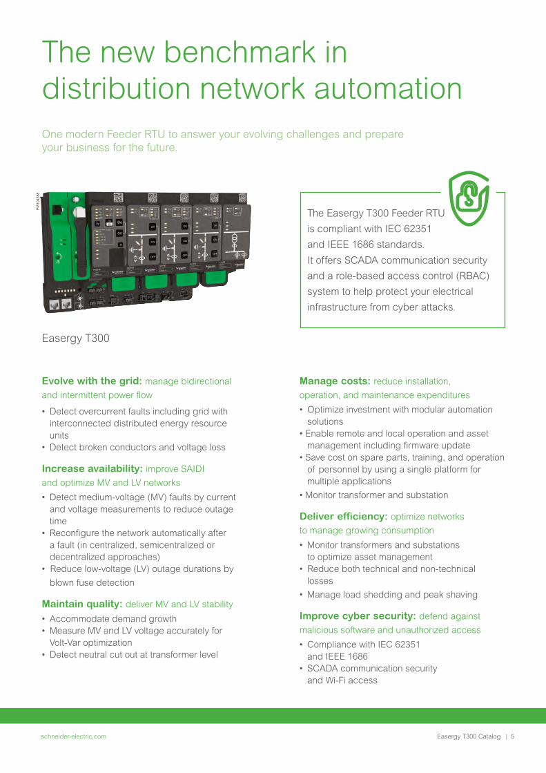
The new benchmark in distribution network automationOne modern Feeder RTU to answer your evolving challenges and prepare your business for the future.
Easergy T300
Evolve with the grid: manage bidirectional
and intermittent power flow
• Detect overcurrent faults including grid with interconnected distributed energy resource units
• Detect broken conductors and voltage loss
Increase availability: improve SAIDI
and optimize MV and LV networks
• Detect medium-voltage (MV) faults by current and voltage measurements to reduce outage time
• Reconfigure the network automatically after a fault (in centralized, semicentralized or decentralized approaches)
• Reduce low-voltage (LV) outage durations by
blown fuse detection
Maintain quality: deliver MV and LV stability
• Accommodate demand growth• Measure MV and LV voltage accurately for
Volt-Var optimization• Detect neutral cut out at transformer level
Manage costs: reduce installation,
operation, and maintenance expenditures
• Optimize investment with modular automation solutions
• Enable remote and local operation and asset management including firmware update
• Save cost on spare parts, training, and operation of personnel by using a single platform for multiple applications
• Monitor transformer and substation
Deliver efficiency: optimize networks
to manage growing consumption
• Monitor transformers and substations to optimize asset management
• Reduce both technical and non-technical losses
• Manage load shedding and peak shaving
Improve cyber security: defend against
malicious software and unauthorized access
• Compliance with IEC 62351 and IEEE 1686
• SCADA communication security and Wi-Fi access
The Easergy T300 Feeder RTU
is compliant with IEC 62351
and IEEE 1686 standards.
It offers SCADA communication security
and a role-based access control (RBAC)
system to help protect your electrical
infrastructure from cyber attacks.
PM
1043
88

schneider-electric.com6 | Easergy T300 Catalog
General presentation
General presentation
Main applications 8
Applications 10
Network control applications 10
Typical applications 11
Product overview 12
Modules 12
Configurable solutions 15
Installation and update 16
Lifecycle tools 17
schneider-electric.com | 7Easergy T300 Catalog
schneider-electric.com8 | Easergy T300 Catalog
General presentation
Main applications
G
G G
DM
1013
17
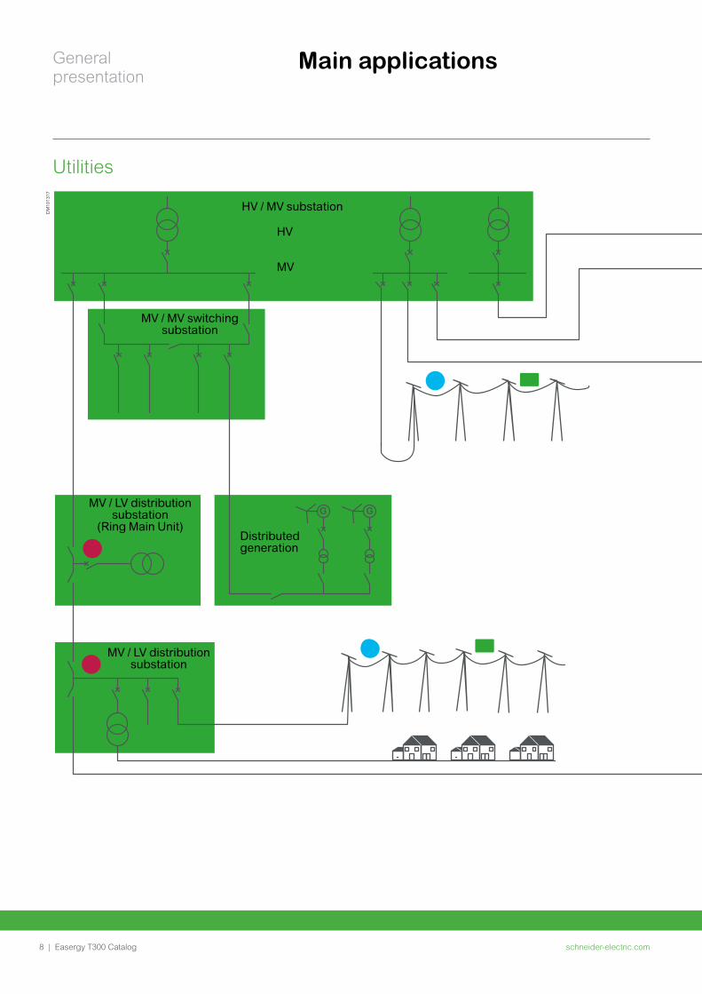
MV
HV
MV / MV switching substation
MV / LV distribution substation
(Ring Main Unit)
MV / LV distribution substation
Distributed generation
HV / MV substation
Utilities
schneider-electric.com | 9Easergy T300 Catalog
General presentation
Main applications
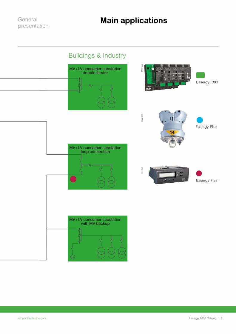
Easergy T300
PM
1043
88
Easergy Flite
SC
H01
773
Easergy Flair
PE
4158
48
G
G G
MV / LV consumer substation double feeder
MV / LV consumer substation loop connection
MV / LV consumer substation with MV backup
G
G G
Buildings & Industry
schneider-electric.com10 | Easergy T300 Catalog
General presentation
Operating an electrical distribution grid is an increasingly complex business. The challenges posed by growing demand, integration of distributed generation resources, and aging infrastructure – to name just a few – each affect overall grid reliability and customer satisfaction.
Therefore, an efficient control and monitoring solution must
improve power availability, voltage management and asset
management.
Grid operators face these challenges in order to boost efficiency, help protect their customers and avoid regulatory scrutiny, but it’s not easy.
Deployment of network controls that require large capital expenditures is problematic. Also problematic is the speedy replacement or motorizing of existing, outdated substations.
ApplicationsNetwork control application
Control Center
DM
1013
14
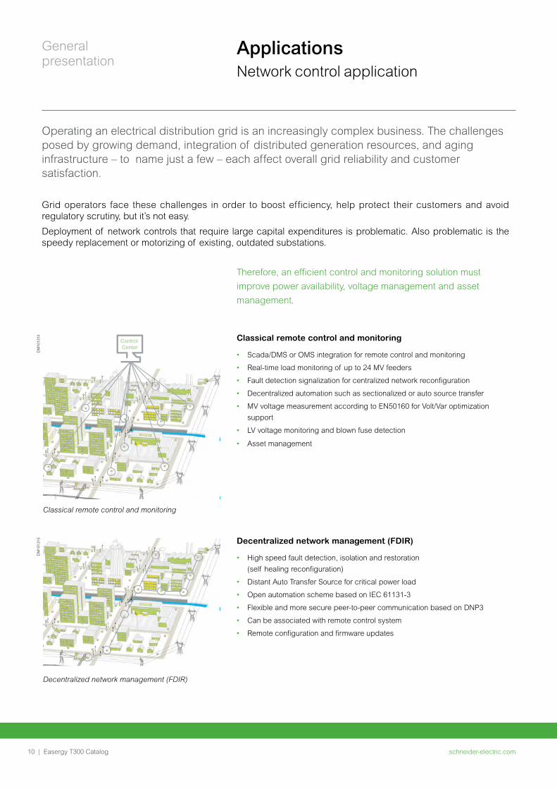
Classical remote control and monitoring
DM
1013
15
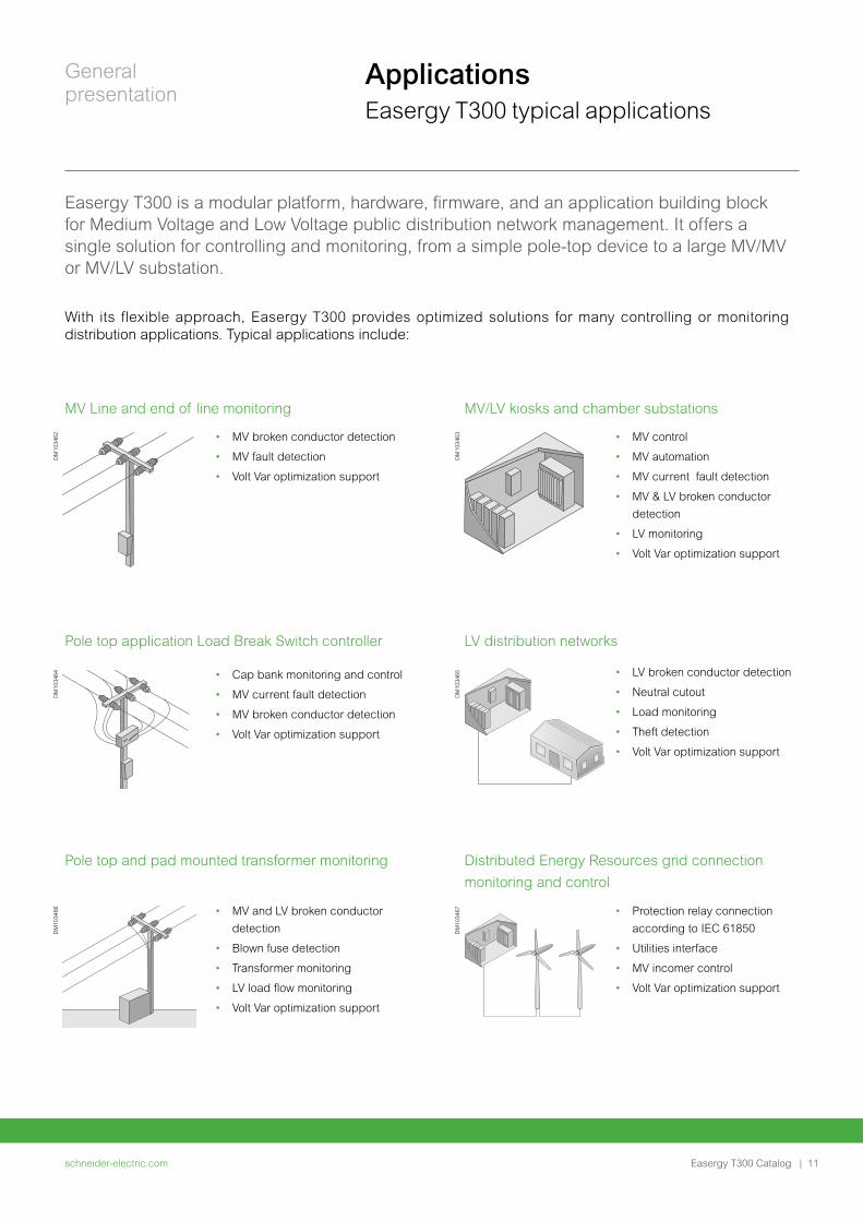
Decentralized network management (FDIR)
Classical remote control and monitoring
• Scada/DMS or OMS integration for remote control and monitoring
• Real-time load monitoring of up to 24 MV feeders
• Fault detection signalization for centralized network reconfiguration
• Decentralized automation such as sectionalized or auto source transfer
• MV voltage measurement according to EN50160 for Volt/Var optimization
support
• LV voltage monitoring and blown fuse detection
• Asset management
Decentralized network management (FDIR)
• High speed fault detection, isolation and restoration
(self healing reconfiguration)
• Distant Auto Transfer Source for critical power load
• Open automation scheme based on IEC 61131-3
• Flexible and more secure peer-to-peer communication based on DNP3
• Can be associated with remote control system
• Remote configuration and firmware updates
schneider-electric.com | 11Easergy T300 Catalog
General presentation
Easergy T300 is a modular platform, hardware, firmware, and an application building block for Medium Voltage and Low Voltage public distribution network management. It offers a single solution for controlling and monitoring, from a simple pole-top device to a large MV/MV or MV/LV substation.
With its flexible approach, Easergy T300 provides optimized solutions for many controlling or monitoring distribution applications. Typical applications include:
MV Line and end of line monitoring MV/LV kiosks and chamber substations
• MV broken conductor detection
• MV fault detection
• Volt Var optimization support
• MV control
• MV automation
• MV current fault detection
• MV & LV broken conductor
detection
• LV monitoring
• Volt Var optimization support
Pole top application Load Break Switch controller LV distribution networks
Pole top and pad mounted transformer monitoring Distributed Energy Resources grid connection
monitoring and control
• MV and LV broken conductor
detection
• Blown fuse detection
• Transformer monitoring
• LV load flow monitoring
• Volt Var optimization support
• Protection relay connection
according to IEC 61850
• Utilities interface
• MV incomer control
• Volt Var optimization support
• Cap bank monitoring and control
• MV current fault detection
• MV broken conductor detection
• Volt Var optimization support
• LV broken conductor detection
• Neutral cutout
• Load monitoring
• Theft detection
• Volt Var optimization support
DM
1034
62
DM
1034
63
DM
1034
64
DM
1034
65
DM
1034
66
DM
1034
67
ApplicationsEasergy T300 typical applications
schneider-electric.com12 | Easergy T300 Catalog
General presentation
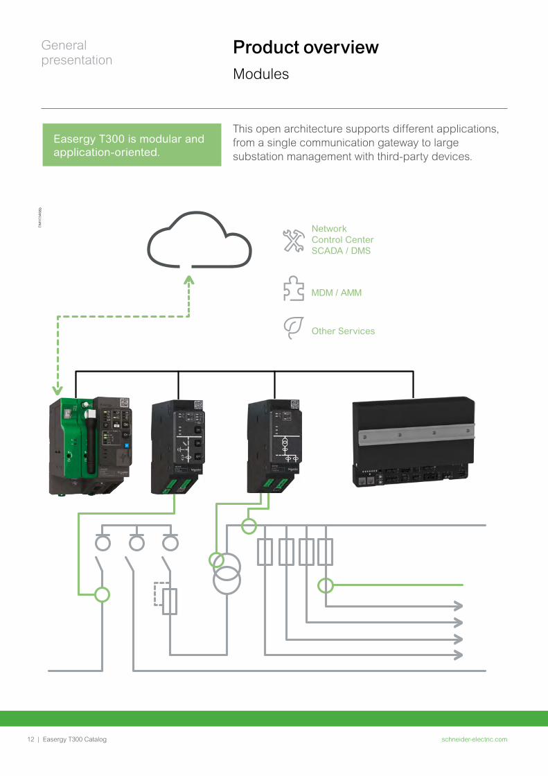
Easergy T300 is modular and application-oriented.
This open architecture supports different applications, from a single communication gateway to large substation management with third-party devices.
Product overview
Modules
DM
1034
68b
Network Control Center SCADA / DMS
Other Services
MDM / AMM
schneider-electric.com | 13Easergy T300 Catalog
General presentation
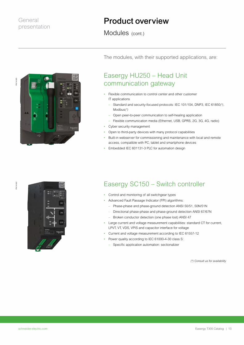
The modules, with their supported applications, are:
Easergy HU250 – Head Unit communication gateway• Flexible communication to control center and other customer
IT applications
– Standard and security-focused protocols: IEC 101/104, DNP3, IEC 61850(*),
Modbus(*)
– Open peer-to-peer communication to self-healing application
– Flexible communication media (Ethernet, USB, GPRS, 2G, 3G, 4G, radio)
• Cyber security management
• Open to third-party devices with many protocol capabilities
• Built-in webserver for commissioning and maintenance with local and remote
access, compatible with PC, tablet and smartphone devices
• Embedded IEC 601131-3 PLC for automation design
Easergy SC150 – Switch controller• Control and monitoring of all switchgear types
• Advanced Fault Passage Indicator (FPI) algorithms:
– Phase-phase and phase-ground detection ANSI 50/51, 50N/51N
– Directional phase-phase and phase-ground detection ANSI 67/67N
– Broken conductor detection (one phase lost) ANSI 47
• Large current and voltage measurement capabilities: standard CT for current,
LPVT, VT, VDS, VPIS and capacitor interface for voltage
• Current and voltage measurement according to IEC 61557-12
• Power quality according to IEC 61000-4-30 class S:
– Specific application automation: sectionalizer
PM
1043
85P
M10
4382
Product overview
Modules (cont.)
(*) Consult us for availability
schneider-electric.com14 | Easergy T300 Catalog
General presentation
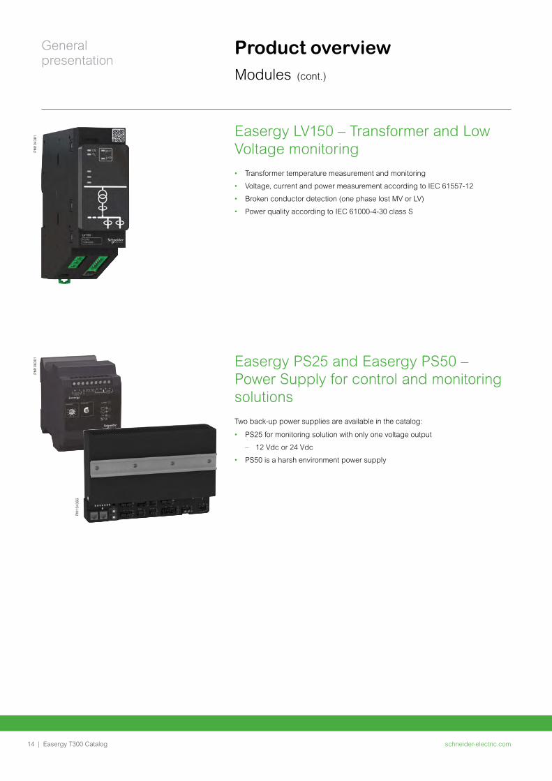
Easergy LV150 – Transformer and Low Voltage monitoring • Transformer temperature measurement and monitoring
• Voltage, current and power measurement according to IEC 61557-12
• Broken conductor detection (one phase lost MV or LV)
• Power quality according to IEC 61000-4-30 class S
Easergy PS25 and Easergy PS50 – Power Supply for control and monitoring solutionsTwo back-up power supplies are available in the catalog:
• PS25 for monitoring solution with only one voltage output
– 12 Vdc or 24 Vdc
• PS50 is a harsh environment power supply
PM
1043
81P
M10
6301
PM
1043
66
Product overview Modules (cont.)
schneider-electric.com | 15Easergy T300 Catalog
General presentation
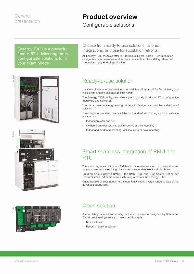
Smart seamless integration of RMU and RTUThe smart ring main unit (smart RMU) is an innovative solution that makes it easier for you to answer the evolving challenges of secondary electrical distribution.
Building on our proven RMUs – the RM6, FBX, and Ringmaster, Schneider Electric’s smart RMUs are seamlessly integrated with the Easergy T300.
Customizable to your needs, the smart RMU offers a wide range of basic and advanced capabilities.
Open solutionA completely tailored and configured solution can be designed by Schneider Electric engineering centers to meet specific needs.
• New enclosure
• Retrofit in existing cabinet
Choose from ready-to-use solutions, tailored integrations, or those for substation retrofits. All Easergy T300 modules offer DIN rail mounting for flexible RTUs integration design. Many accessories and sensors, available in the catalog, allow fast integration in any kind of application.
Ready-to-use solutionA variety of ready-to-use solutions are available off-the-shelf for fast delivery and installation, and are also available for retrofit.
The Easergy T300 configurator allows you to quickly build your RTU configuration (hardware and software).
You can consult our engineering centers to design or customize a dedicated solution.
Three types of enclosure are available as standard, depending on the installation environment:
• Indoor controller cabinet
• Outdoor controller cabinet, wall mounting or pole mounting
• Indoor and outdoor monitoring, wall mounting or pole mounting
PM
1060
98P
M10
4388
Product overview Configurable solutions
Easergy T300 is a powerful feeder RTU delivering three configurable solutions to fit your exact needs.
PM
1063
31
schneider-electric.com16 | Easergy T300 Catalog
General presentation
Product overview Installation and update
Easergy T300 benefits
• Easy and fast ordering and delivery
• Ease of installation and commissioning
• Very small foot-print for small substations and switchgear cabinets
• Flexible solution adapted to your requirements
• One hardware and software platform for all applications
• Easy on-site updating
PM
1043
88
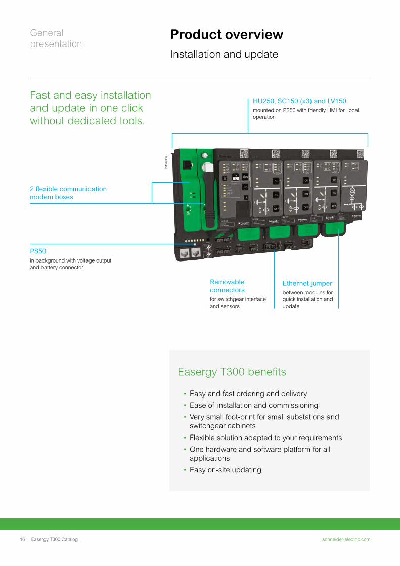
HU250, SC150 (x3) and LV150 mounted on PS50 with friendly HMI for local operation
2 flexible communication modem boxes
Ethernet jumper between modules for quick installation and update
Removable connectors
for switchgear interface and sensors
PS50
in background with voltage output and battery connector
Fast and easy installation and update in one click without dedicated tools.
schneider-electric.com | 17Easergy T300 Catalog
General presentation
Product overview Lifecycle tools
Easergy T300 is supplied in a standard configuration or a dedicated customer configuration.
Commissioning and maintenance do not require special tools, only a web browser on a PC, tablet or smartphone.
Easergy Builder for engineering teamsEasergy Builder is used by expert engineering teams to modify or design new data-bases off line:
• Import new automation desiged in IEC 61131-3 PLC workshop
• Configure new communication channels
• Integrate new third part IEDs
• Design new databases
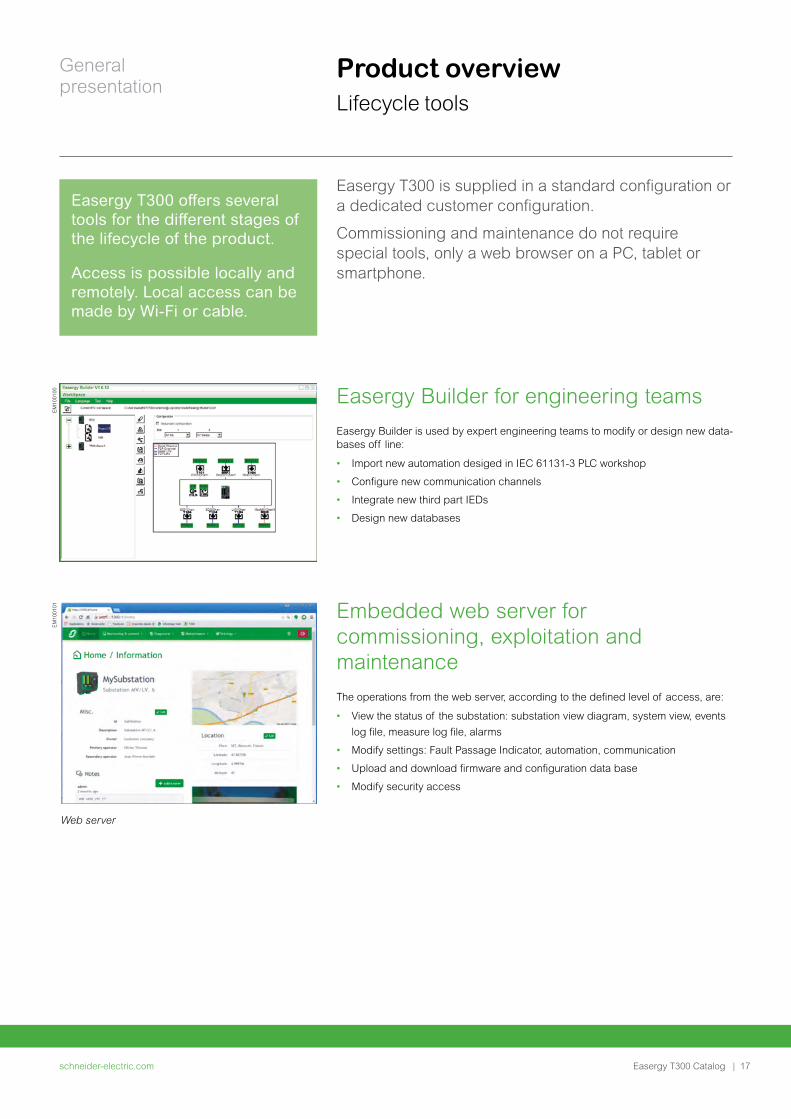
Embedded web server for commissioning, exploitation and maintenanceThe operations from the web server, according to the defined level of access, are:
• View the status of the substation: substation view diagram, system view, events
log file, measure log file, alarms
• Modify settings: Fault Passage Indicator, automation, communication
• Upload and download firmware and configuration data base
• Modify security access
Web server
EM
1001
01E
M10
0100
Easergy T300 offers several tools for the different stages of the lifecycle of the product.
Access is possible locally and remotely. Local access can be made by Wi-Fi or cable.
schneider-electric.com18 | Easergy T300 Catalog
Functions and description
schneider-electric.com | 19Easergy T300 Catalog
Functions and description
Easergy HU250 Head Unit Communication 20
General description 21
Communication ports 25
Protocols and communication architecture 26
Time synchro and sequence of events 29
Cyber security 30
Open programmable logic controller 31
Communication ports characteristics 33
Characteristics 34
Configuration tools 36
Easergy SC150 Switch controller 40
General description 41
Switchgear control 45
Voltage measurement 47
Current measurement 50
Fault current detection 52
Fault Passage Indicator 57
Network monitoring 58
Power measurement and power quality 61
Sectionalizer automation 64
Characteristics 65
Easergy LV150 Low Voltage monitoring 68
General description 69
Connection 72
Network monitoring 73
Characteristics 75
Easergy PS50 - PS25 80General description 81
Power supply selection guide 83
Battery autonomy 87
Characteristics 90
Easergy PS50 for controller solution 94
Easergy HU250Head Unit Communication
schneider-electric.com20 |
Functions and description
Easergy T300 Catalog
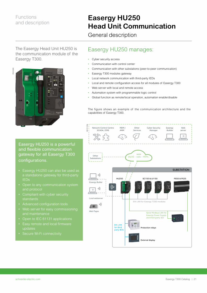
Easergy HU250 manages:
• Cyber security access
• Communication with control center
• Communication with other substations (peer-to-peer communication)
• Easergy T300 modules gateway
• Local network communication with third-party IEDs
• Local and remote configuration access for all modules of Easergy T300
• Web server with local and remote access
• Automation system with programmable logic control
• Global function as remote/local operation, automation enable/disable
PM
1043
85
The figure shows an example of the communication architecture and the capabilities of Easergy T300.
@
@
@
Easergy Builder
Local webserver
Web Pages
SUBSTATION
Network Control CentreSCADA / EMS
Other Services
Easergy Builder
Cyber SecurityManager
WAN2G/3G – radio – PSTN…
Eth LAN for Easergy T300 modules
Eth LAN for third party IEDs
Serial Modbus LAN for Easergy Power Supply and third-party IED
Webserver
OtherSubstations
MDM / AMM
HU250 SC150 & LV150
Protection relays
External display
PS50 & PS25
DM
1013
16b
The Easergy Head Unit HU250 is the communication module of the Easergy T300.
Easergy HU250 Head Unit Communication General description
Easergy HU250 is a powerful and flexible communication gateway for all Easergy T300 configurations.
• Easergy HU250 can also be used as a standalone gateway for third-party IEDs
• Open to any communication system and protocol
• Compliant with cyber security standards
• Advanced configuration tools
• Web server for easy commissioning and maintenance
• Open to IEC 61131 applications
• Easy remote and local firmware updates
• Secure Wi-Fi connectivity
schneider-electric.com | 21
Functions and description
Easergy T300 Catalog
Network control centersThis includes several types of remote control center from an entry-level SCADA like Easergy L500 to advanced ADMS systems.
MDM/AMMMeter Data Management system/Advanced Meter Management: Easergy T300 can transfer some data as Low Voltage measurements to the metering system.
Cyber security managerOne aspect of the cyber security objective is to secure all control and data acquisition for the operation of its electric system.
The Schneider Electric SAT is a security configuration tool to define/configure the security policy of the devices. It allows to create user account with password and role allocated.
Other services Easergy T300 can also communicate with others services, such as field services for maintenance management, load prediction, and advanced news services.
Easergy BuilderEasergy Builder is a PC-based engineering tool for Easergy T300 customization and design. Easergy Builder can be used locally via Wi-Fi or wired connection, or remotely via the WAN with a secure connection.
Remote and local webserverRemote access is available through the WAN network to embedded Easergy T300 web apps from a standard browser. This application can be used for data consultation, software update, configuration upload and maintenance.
Local access can be achieved via Wi-Fi or wired connection.
Protection relay The catalog of master protocol of Easergy T300 allows an ease protection relay integration with Easergy Builder engineering tool.
External displayThe Easergy T300 can also support an external HMI such as a touch cabinet or an advanced display. This integration requires a dedicated configuration using Easergy Builder and can be incorporated by Schneider Engineering on request.
Extended I/O with PLCAn external Programmable Logic Controller can be used to extend the Easergy T300 capacity or for dedicated applications.
This integration requires the use of Easergy Builder and can be incorporated by Schneider Engineering center on demand.
Part Number
Reference Description
HU250
EMS59000 Easergy HU250 Head Unit gateway
EMS59150 Empty modem box for HU250
Modem
EMS59151 RS232-485 box for HU250
EMS59152 2G/3G modem box for HU250
EMS591544G US standard modem box for HU250
EMS591554G EU standard modem box for HU250
Easergy HU250 Head Unit Communication General description (cont.)
schneider-electric.com22 |
Functions and description
Easergy T300 Catalog
Easergy HU250 Head Unit Communication General description (cont.)
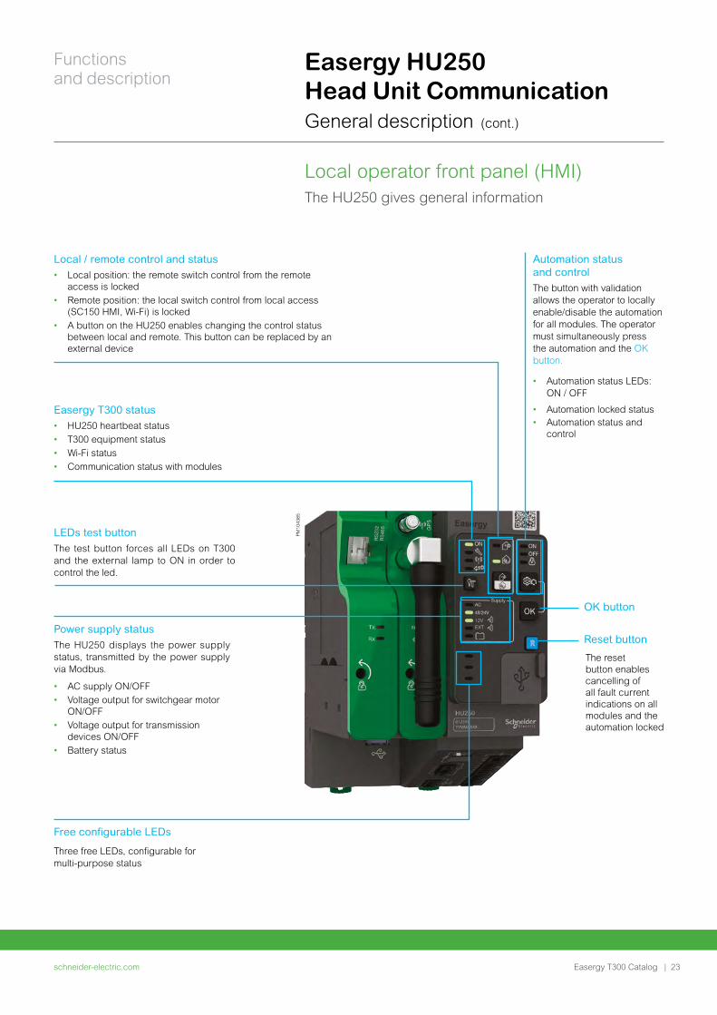
Local operator front panel (HMI)
PM
1043
85
Free configurable LEDs
Three free LEDs, configurable for multi-purpose status
OK button
Reset button
LEDs test buttonThe test button forces all LEDs on T300 and the external lamp to ON in order to control the led.
Power supply statusThe HU250 displays the power supply status, transmitted by the power supply via Modbus.
• AC supply ON/OFF• Voltage output for switchgear motor
ON/OFF• Voltage output for transmission
devices ON/OFF• Battery status
Easergy T300 status• HU250 heartbeat status • T300 equipment status• Wi-Fi status• Communication status with modules
Automation status and controlThe button with validation allows the operator to locally enable/disable the automation for all modules. The operator must simultaneously press the automation and the OK button.
• Automation status LEDs: ON / OFF
• Automation locked status• Automation status and
control
Local / remote control and status• Local position: the remote switch control from the remote
access is locked• Remote position: the local switch control from local access
(SC150 HMI, Wi-Fi) is locked• A button on the HU250 enables changing the control status
between local and remote. This button can be replaced by an external device
The HU250 gives general information
The reset button enables cancelling of all fault current indications on all modules and the automation locked
schneider-electric.com | 23
Functions and description
Easergy T300 Catalog
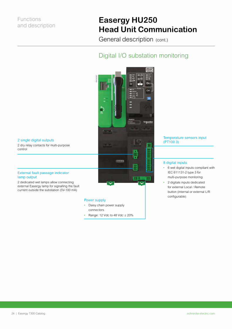
Digital I/O substation monitoring
Easergy HU250 Head Unit Communication General description (cont.)
PM
1043
57
External fault passage indicator lamp output2 dedicated wet lamps allow connecting external Easergy lamp for signalling the fault current outside the substation (5V-100 mA)
Temperature sensors input (PT100 3)2 single digital outputs
2 dry relay contacts for multi-purpose control
Power supply• Daisy chain power supply
connectors
• Range: 12 Vdc to 48 Vdc ± 20%
8 digital inputs • 6 wet digital inputs compliant with
IEC 611131-2 type 3 for
multi-purpose monitoring
• 2 digitals inputs dedicated
for external Local / Remote
button (internal or external L/R
configurable)
schneider-electric.com24 |
Functions and description
Easergy T300 Catalog
Wi-Fi management with security• Wi-Fi activity: Enable / Disable
• Activation mode: From SCADA, Web, HMI Local / Remote button
• SSID visibility: Enable / Disable
• SSID value
• Passphrase value
• Disconnection: Automatic disconnection by timeout
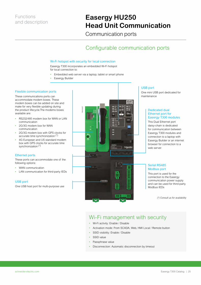
Configurable communication ports
Easergy HU250 Head Unit Communication Communication ports
PM
1043
57
Flexible communication ports
These communications ports can accommodate modem boxes. These modem boxes can be added on site and make for very flexible updating during the product lifecycle.The modems boxes available are:
• RS232/485 modem box for WAN or LAN communication
• 2G/3G modem box for WAN communication
• 2G/3G modem box with GPS clocks for accurate time synchronization (*)
• 4G European and US standard modem box with GPS clocks for accurate time synchronization (*)
Ethernet portsThese ports can accommodate one of the following options:
• WAN communication • LAN communication for third-party IEDs
Dedicated dual Ethernet port for Easergy T300 modulesThis Dual Ethernet port daisy-chain is dedicated for communication between Easergy T300 modules and connection to a laptop with Easergy Builder or an internet browser for connection to a web server.
Wi-Fi hotspot with security for local connection
Easergy T300 incorporates an embedded Wi-Fi hotspot for local connection to:
• Embedded web server via a laptop, tablet or smart phone• Easergy Builder
Serial RS485 Modbus port
This port is used for the connection to the Easergy communication power supply and can be used for third-party Modbus IEDs
USB port
One mini USB port dedicated for maintenance
USB port
One USB host port for multi-purpose use
(*) Consult us for availability
schneider-electric.com | 25
Functions and description
Easergy T300 Catalog
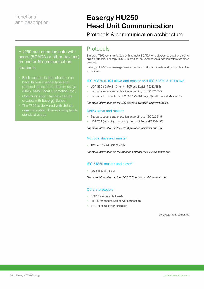
Protocols Easergy T300 communicates with remote SCADA or between substations using open protocols. Easergy HU250 may also be used as data concentrators for slave devices.
Easergy HU250 can manage several communication channels and protocols at the
same time.
IEC 60870-5-104 slave and master and IEC 60870-5-101 slave
• UDP (IEC 60870-5-101 only), TCP and Serial (RS232/485)
• Supports secure authentication according to IEC 62351-5
• Redundant connections (IEC 60870-5-104 only (3)) with several Master IPs
For more information on the IEC 60870-5 protocol, visit www.iec.ch.
DNP3 slave and master
• Supports secure authentication according to IEC 62351-5
• UDP, TCP (including dual end point) and Serial (RS232/485)
For more information on the DNP3 protocol, visit www.dnp.org.
Modbus slave and master
• TCP and Serial (RS232/485)
For more information on the Modbus protocol, visit www.modbus.org.
IEC 61850 master and slave(*)
• IEC 61850-8-1 ed 2
For more information on the IEC 61850 protocol, visit www.iec.ch.
Others protocols
• SFTP for secure file transfer
• HTTPS for secure web server connection
• SNTP for time synchronization
(*) Consult us for availability
Easergy HU250 Head Unit Communication Protocols & communication architecture
HU250 can communicate with peers (SCADA or other devices) on one or N communication channels.
• Each communication channel can have its own channel type and protocol adapted to different usage (DMS, AMM, local automation, etc.)
• Communication channels can be created with Easergy Builder
• The T300 is delivered with default communication channels adapted to standard usage
schneider-electric.com26 |
Functions and description
Easergy T300 Catalog
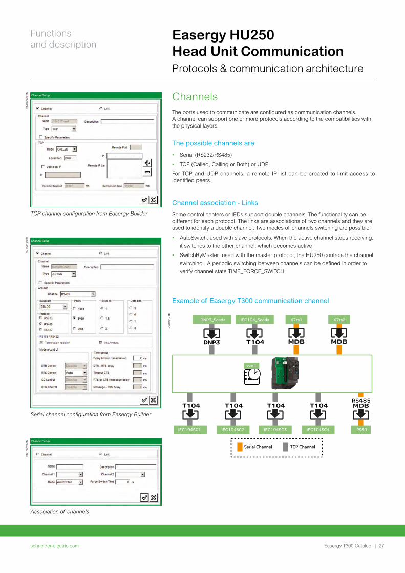
ChannelsThe ports used to communicate are configured as communication channels. A channel can support one or more protocols according to the compatibilities with the physical layers.
The possible channels are:
• Serial (RS232/RS485)
• TCP (Called, Calling or Both) or UDP
For TCP and UDP channels, a remote IP list can be created to limit access to identified peers.
Channel association - Links
Some control centers or IEDs support double channels. The functionality can be different for each protocol. The links are associations of two channels and they are used to identify a double channel. Two modes of channels switching are possible:
• AutoSwitch: used with slave protocols. When the active channel stops receiving,
it switches to the other channel, which becomes active
• SwitchByMaster: used with the master protocol, the HU250 controls the channel
switching. A periodic switching between channels can be defined in order to
verify channel state TIME_FORCE_SWITCH
Example of Easergy T300 communication channel
EM
1000
57E
N
TCP channel configuration from Easergy Builder
EM
1000
59E
N
Association of channels
EM
1000
58E
N
Serial channel configuration from Easergy Builder
DNP3 T104 MDB MDB
MDBT104T104T104T104RS485
DNP3_Scada IEC104_Scada K7rs1 K7rs2
IEC104SC1
Serial Channel TCP Channel
IEC104SC2 IEC104SC3 IEC104SC4 PS50
event
DM
1034
71b
Easergy HU250 Head Unit Communication Protocols & communication architecture
schneider-electric.com | 27
Functions and description
Easergy T300 Catalog
Easergy HU250 Head Unit Communication Protocols & communication architecture
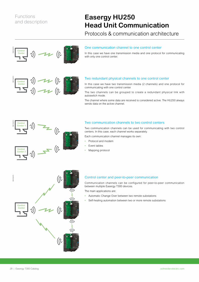
One communication channel to one control center
In this case we have one transmission media and one protocol for communicating with only one control center.
Control Center
Two redundant physical channels to one control center
In this case we have two transmission media (2 channels) and one protocol for communicating with one control center.
The two channels can be grouped to create a redundant physical link with autoswitch mode.
The channel where some data are received is considered active. The HU250 always sends data on the active channel.
Control Center
DM
1034
73
Two communication channels to two control centers
Two communication channels can be used for communicating with two control centers. In this case, each channel works separately.
Each communication channel manages its own:
• Protocol and modem
• Event tables
• Mapping protocol
Control Center 1
Control Center 2
DM
1034
74
Control center and peer-to-peer communication
Communication channels can be configured for peer-to-peer communication between multiple Easergy T300 devices.
The main applications are:
• Automatic Change Over between two remote substations
• Self-healing automation between two or more remote substations
Control Center
DM
1034
75D
M10
3472
schneider-electric.com28 |
Functions and description
Easergy T300 Catalog
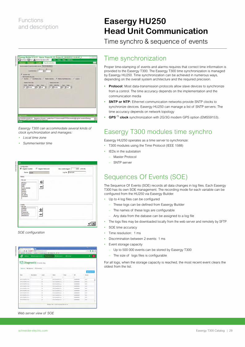
Time synchronizationProper time-stamping of events and alarms requires that correct time information is provided to the Easergy T300. The Easergy T300 time synchronization is managed by Easergy HU250. Time synchronization can be achieved in numerous ways, depending on the overall system architecture and the required precision.
• Protocol: Most data-transmission protocols allow slave devices to synchronize
from a control. The time accuracy depends on the implementation and the
communication media
• SNTP or NTP: Ethernet communication networks provide SNTP clocks to
synchronize devices. Easergy HU250 can manage a list of SNTP servers: The
time accuracy depends on network topology
• GPS (*) clock synchronization with 2G/3G modem GPS option (EMS59153).
Easergy T300 modules time synchroEasergy HU250 operates as a time server to synchronize:
• T300 modules using the Time Protocol (IEEE 1588)
• IEDs in the substation
– Master Protocol
– SNTP server
Sequences Of Events (SOE)The Sequence Of Events (SOE) records all data changes in log files. Each Easergy T300 has its own SOE management. The recording mode for each variable can be configured from the HU250 via Easergy Builder.
• Up to 4 log files can be configured
– These logs can be defined from Easergy Builder
– The names of these logs are configurable
– Any data from the dabase can be assigned to a log file
• The logs files may be downloaded locally from the web server and remotely by SFTP
• SOE time accuracy
• Time resolution: 1 ms
• Discrimination between 2 events: 1 ms
• Event storage capacity
– Up to 500 000 events can be stored by Easergy T300
– The size of logs files is configurable
For all logs, when the storage capacity is reached, the most recent event clears the oldest from the list.
Easergy T300 can accommodate several kinds of clock synchronization and manages:
• Local time zone
• Summer/winter time
SOE configuration
Web server view of SOE
EM
1000
60E
NE
M10
0061
EN
EM
1000
62E
N
Easergy HU250 Head Unit Communication Time synchro & sequence of events
schneider-electric.com | 29
Functions and description
Easergy T300 Catalog
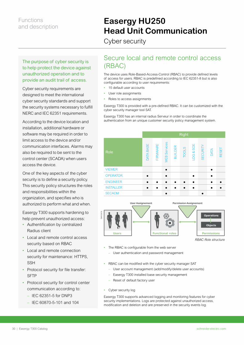
Secure local and remote control access (RBAC) The device uses Role-Based-Access-Control (RBAC) to provide defined levels of access for users. RBAC is predefined according to IEC 62351-8 but is also configurable according to user requirements:
• 15 default user accounts
• User role assignments
• Roles to access assignments
Easergy T300 is provided with a pre-defined RBAC. It can be customized with the cyber security manager tool SAT.
Easergy T300 has an internal radius Serveur in order to coordinate the authentication from an unique customer security policy management system.
Right
RoleD
ATA
BA
SE
FIR
MW
AR
E
WE
B S
ervi
ces
BU
ILD
ER
TOO
LS
LOG
& S
OE
SE
CU
RIT
Y
DA
TA
RE
SE
T
VIEWER
OPERATOR
ENGINEER
INSTALLER
SECADM
RBAC Role structure
Operations
Objects
PermissionsFunctional roles
User Assignement Permission Assignement
Users
• The RBAC is configurable from the web server
– User authentication and password management
• RBAC can be modified with the cyber security manager SAT
– User account management (add/modify/delete user accounts)
– Easergy T300 installed base security management
– Reset of default factory user
• Cyber security log
Easergy T300 supports advanced logging and monitoring features for cyber security implementations. Logs are protected against unauthorized access, modification and deletion and are preserved in the security events log.
DM
1034
76
The purpose of cyber security is to help protect the device against unauthorized operation and to provide an audit trail of access.
Cyber security requirements are
designed to meet the international
cyber security standards and support
the security systems necessary to fulfill
NERC and IEC 62351 requirements.
According to the device location and
installation, additional hardware or
software may be required in order to
limit access to the device and/or
communication interfaces. Alarms may
also be required to be sent to the
control center (SCADA) when users
access the device.
One of the key aspects of the cyber
security is to define a security policy.
This security policy structures the roles
and responsibilities within the
organization, and specifies who is
authorized to perform what and when.
Easergy T300 supports hardening to
help prevent unauthorized access:
• Authentification by centralized
Radius client
• Local and remote control access
security based on RBAC
• Local and remote connection
security for maintenance: HTTPS,
SSH
• Protocol security for file transfer:
SFTP
• Protocol security for control center
communication according to:
– IEC 62351-5 for DNP3
– IEC 60870-5-101 and 104
Easergy HU250 Head Unit Communication Cyber security
schneider-electric.com30 |
Functions and description
Easergy T300 Catalog
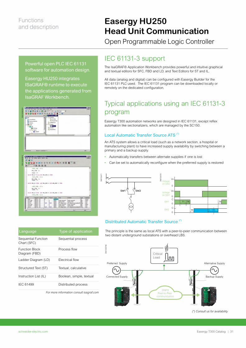
IEC 61131-3 support The IsaGRAF® Application Workbench provides powerful and intuitive graphical and textual editors for SFC, FBD and LD, and Text Editors for ST and IL.
All data (analog and digital) can be configured with Easergy Builder for the IEC 61131 PLC used. The IEC 61131 program can be downloaded locally or remotely on the dedicated configuration.
Typical applications using an IEC 61131-3 programEasergy T300 automation networks are designed in IEC 61131, except reflex automation like sectionalizers, which are managed by the SC150.
Local Automatic Transfer Source ATS (*)
An ATS system allows a critical load (such as a network section, a hospital or manufacturing plant) to have increased supply availability by switching between a primary and a backup supply.
• Automatically transfers between alternate supplies if one is lost
• Can be set to automatically reconfigure when the preferred supply is restored
(*) Consult us for availability
Distributed Automatic Transfer Source (*)
The principle is the same as local ATS with a peer-to-peer communication between two distant underground substations or overhead LBS.
DNP3Peer-to-Peer
communication
Alternative Supply
Backup Supply
Preferred Supply
Connected Supply
Critical Load
Powerful open PLC IEC 61131 software for automation design.
Easergy HU250 integrates ISaGRAF® runtime to execute the applications generated from IsaGRAF Workbench.
EM
1000
63E
NE
M10
0064
EN
DM
1034
79b
SW1 SW2
Voltage on SW2
Vn
0
Vn
0C
0
C
0
Voltage on SW1
SW1 T1 TR
TR TRT1
TR
SW2
DM
1034
77
DM
1034
78
Easergy HU250 Head Unit Communication Open Programmable Logic Controller
Language Type of application
Sequential Function Chart (SFC)
Sequential process
Function Block Diagram (FBD)
Process flow
Ladder Diagram (LD) Electrical flow
Structured Text (ST) Textual, calculative
Instruction List (IL) Boolean, simple, textual
IEC 61499 Distributed process
For more information consult isagraf.com
schneider-electric.com | 31
Functions and description
Easergy T300 Catalog
Easergy HU250 Head Unit Communication Open Programmable Logic Controller
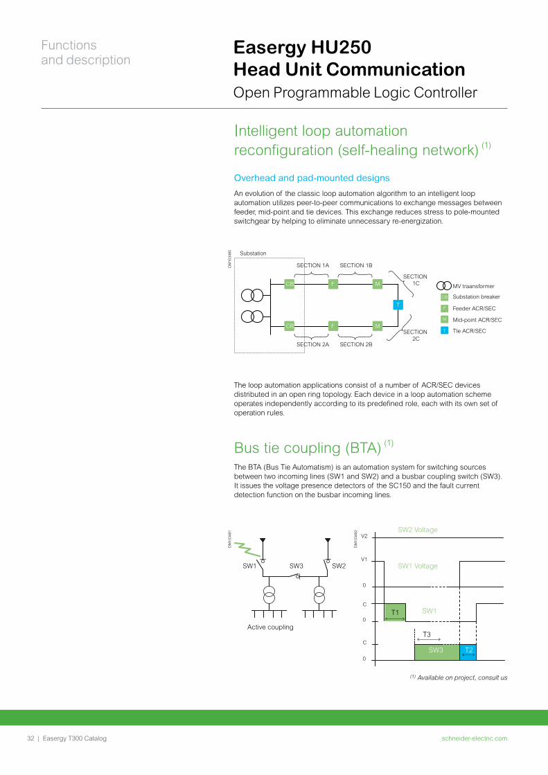
Intelligent loop automation reconfiguration (self-healing network) (1)
Overhead and pad-mounted designs
An evolution of the classic loop automation algorithm to an intelligent loop automation utilizes peer-to-peer communications to exchange messages between feeder, mid-point and tie devices. This exchange reduces stress to pole-mounted switchgear by helping to eliminate unnecessary re-energization.
The loop automation applications consist of a number of ACR/SEC devices distributed in an open ring topology. Each device in a loop automation scheme operates independently according to its predefined role, each with its own set of operation rules.
Bus tie coupling (BTA) (1)
The BTA (Bus Tie Automatism) is an automation system for switching sources between two incoming lines (SW1 and SW2) and a busbar coupling switch (SW3). It issues the voltage presence detectors of the SC150 and the fault current detection function on the busbar incoming lines.
SW1 SW3
Active coupling
SW2
SW2 Voltage
SW1 Voltage
SW1
SW3
V2
V1
0
C
0
C
0
T1
T2
T3
(1) Available on project, consult us
Substation
MV traansformer
Substation breaker
Feeder ACR/SEC
Mid-point ACR/SEC
TIe ACR/SEC
SECTION 1A
CB
CB
F
F
M
TCB
F
M
TM
SECTION 1B
SECTION 1C
SECTION 2C
SECTION 2A SECTION 2B
DM
1034
80D
M10
3481
DM
1034
82
schneider-electric.com32 |
Functions and description
Easergy T300 Catalog
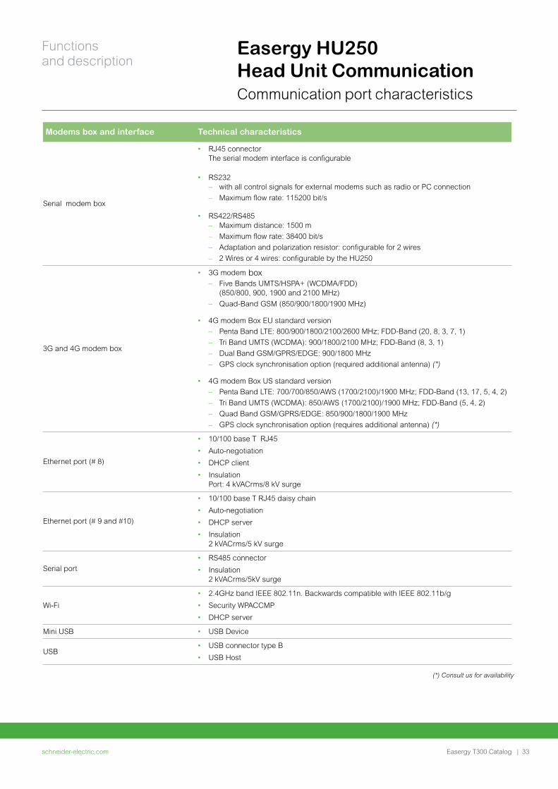
Easergy HU250 Head Unit Communication Communication port characteristics
Modems box and interface Technical characteristics
Serial modem box
• RJ45 connector The serial modem interface is configurable
• RS232 – with all control signals for external modems such as radio or PC connection
– Maximum flow rate: 115200 bit/s
• RS422/RS485 – Maximum distance: 1500 m
– Maximum flow rate: 38400 bit/s
– Adaptation and polarization resistor: configurable for 2 wires
– 2 Wires or 4 wires: configurable by the HU250
3G and 4G modem box
• 3G modem box – Five Bands UMTS/HSPA+ (WCDMA/FDD)
(850/800, 900, 1900 and 2100 MHz)
– Quad-Band GSM (850/900/1800/1900 MHz)
• 4G modem Box EU standard version
– Penta Band LTE: 800/900/1800/2100/2600 MHz; FDD-Band (20, 8, 3, 7, 1)
– Tri Band UMTS (WCDMA): 900/1800/2100 MHz; FDD-Band (8, 3, 1)
– Dual Band GSM/GPRS/EDGE: 900/1800 MHz
– GPS clock synchronisation option (required additional antenna) (*)
• 4G modem Box US standard version
– Penta Band LTE: 700/700/850/AWS (1700/2100)/1900 MHz; FDD-Band (13, 17, 5, 4, 2)
– Tri Band UMTS (WCDMA): 850/AWS (1700/2100)/1900 MHz; FDD-Band (5, 4, 2)
– Quad Band GSM/GPRS/EDGE: 850/900/1800/1900 MHz
– GPS clock synchronisation option (requires additional antenna) (*)
Ethernet port (# 8)
• 10/100 base T RJ45
• Auto-negotiation
• DHCP client
• Insulation Port: 4 kVACrms/8 kV surge
Ethernet port (# 9 and #10)
• 10/100 base T RJ45 daisy chain
• Auto-negotiation
• DHCP server
• Insulation 2 kVACrms/5 kV surge
Serial port• RS485 connector
• Insulation 2 kVACrms/5kV surge
Wi-Fi
• 2.4GHz band IEEE 802.11n. Backwards compatible with IEEE 802.11b/g
• Security WPACCMP
• DHCP server
Mini USB • USB Device
USB• USB connector type B
• USB Host
(*) Consult us for availability
schneider-electric.com | 33
Functions and description
Easergy T300 Catalog
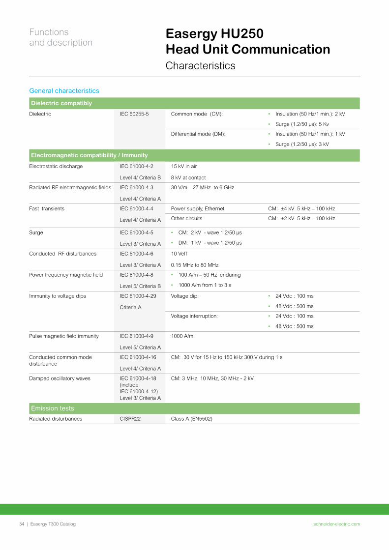
Easergy HU250 Head Unit Communication Characteristics
General characteristics
Dielectric compatibly
Dielectric IEC 60255-5 Common mode (CM): • Insulation (50 Hz/1 min.): 2 kV
• Surge (1.2/50 μs): 5 Kv
Differential mode (DM): • Insulation (50 Hz/1 min.): 1 kV
• Surge (1.2/50 μs): 3 kV
Electromagnetic compatibility / Immunity
Electrostatic discharge IEC 61000-4-2
Level 4/ Criteria B
15 kV in air
8 kV at contact
Radiated RF electromagnetic fields IEC 61000-4-3
Level 4/ Criteria A
30 V/m – 27 MHz to 6 GHz
Fast transients IEC 61000-4-4
Level 4/ Criteria A
Power supply, Ethernet CM: ±4 kV 5 kHz – 100 kHz
Other circuits CM: ±2 kV 5 kHz – 100 kHz
Surge IEC 61000-4-5
Level 3/ Criteria A
• CM: 2 kV - wave 1,2/50 µs
• DM: 1 kV - wave 1,2/50 µs
Conducted RF disturbances IEC 61000-4-6
Level 3/ Criteria A
10 Veff
0.15 MHz to 80 MHz
Power frequency magnetic field IEC 61000-4-8
Level 5/ Criteria B
• 100 A/m – 50 Hz enduring
• 1000 A/m from 1 to 3 s
Immunity to voltage dips IEC 61000-4-29
Criteria A
Voltage dip: • 24 Vdc : 100 ms
• 48 Vdc : 500 ms
Voltage interruption: • 24 Vdc : 100 ms
• 48 Vdc : 500 ms
Pulse magnetic field immunity IEC 61000-4-9
Level 5/ Criteria A
1000 A/m
Conducted common mode disturbance
IEC 61000-4-16
Level 4/ Criteria A
CM: 30 V for 15 Hz to 150 kHz 300 V during 1 s
Damped oscillatory waves IEC 61000-4-18 (include IEC 61000-4-12) Level 3/ Criteria A
CM: 3 MHz, 10 MHz, 30 MHz - 2 kV
Emission tests
Radiated disturbances CISPR22 Class A (EN5502)
schneider-electric.com34 |
Functions and description
Easergy T300 Catalog
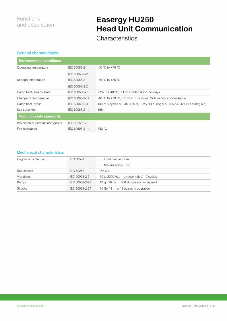
Easergy HU250 Head Unit Communication Characteristics
Mechanical characteristics
Degree of protection IEC 60529 • Front cabinet: IP4x
• Module body: IP2x
Robustness IEC 62262 IK7 2 J
Vibrations IEC 60068-2-6 10 to 2000 Hz / 1 g (peak value) 10 cycles
Bumps IEC 60068-2-29 10 g / 16 ms / 1000 Bumps non energized
Shocks IEC 60068-2-27 10 Gn / 11 ms / 3 pulses in operation
General characteristics
Environmental conditions
Operating temperature IEC 60068-2-1
IEC 60068-2-2
-40 °C to +70 °C
Storage temperature IEC 60068-2-1
IEC 60068-2-2
-40° C to +85 °C
Damp heat, steady state IEC 60068-2-78 93% RH, 40 °C, RH no condensation, 56 days
Change of temperature IEC 60068-2-14 -40 °C to +70° C, 5 °C/min, 10 Cycles, 27 h without condensation
Damp heat, cyclic IEC 60068-2-30 144 h: 6 cycles of 24h (+55 °C, 93% HR during 9 h; +25 °C, 95% HR during 6 h)
Salt spray test IEC 60068-2-11 168 h
Product safety standards
Protection of persons and goods. IEC 60255-27
Fire resistance IEC 60695-2-11 850 °C
schneider-electric.com | 35
Functions and description
Easergy T300 Catalog

T300 Web Server - Commissioning, operation and maintenanceHU250 includes an embedded Web Server as HMI interface and local supervision of the substation for the user.
Basic configuration, operation and diagnosis are carried out by connecting a laptop, tablet or smartphone to the T300 Web Server. This web server can be accessed:
• Locally via ETH port
(laptop directly connected to one of the T300 Ethernet ports)
• Locally via Wi-Fi access
• Remotely via LAN network
• Remotely via 2G, 3G, Ethernet
• The menu on the home page enables the user to select the language
• The web data server’s HTML format pages includes different pages and
subpages:
– Home page: local map, GPS coordinates, photos and notes to identify the
substation
– Monitoring and control page: physical view of the system, data view
including display of status and analogs, control of commands and set
points
– Diagnostic page: to consult and export.csv file (events log, cyber security
log and system log)
– Maintenance page: user settings, clock synchronization, IP configuration
settings, device status, software version update, configuration download
– Settings page: setting per module (HU250, SC150, etc.). These settings
per module include the configuration of functional parameters for
communication, protocol, switch control, measurement and detection, etc.
Operation and control
Alongside operation and control of the network from the SCADA system, it is possible to operate the equipment locally or remotely using data pages:
• Displaying status and measurement
• Issuing commands: switches, automation system on/off, fault detector reset
and other digital outputs, which is made more secure by a selection and
confirmation process
• Consultation of archived data
– On-screen consultation of archive logs
– Extraction of logs on a PC as a .csv file for analysis
Easergy HU250 Head Unit Communication Configuration tools
Monitoring / Data / Status
Diagnostic / Events
EM
1001
01E
M10
0102
EM
1001
03
Home
schneider-electric.com36 |
Functions and description
Easergy T300 Catalog
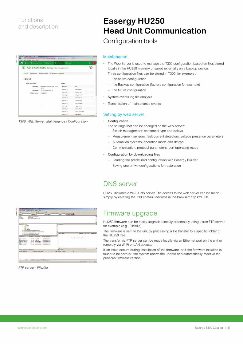
Easergy HU250 Head Unit Communication Configuration tools
Maintenance
• The Web Server is used to manage the T300 configuration based on files stored
locally in the HU250 memory or saved externally on a backup device.
Three configuration files can be stored in T300, for exemple :
– the active configuration
– the Backup configuration (factory configuration for example)
– the future configuration
• System events log file analysis
• Transmission of maintenance events
Setting by web server
• Configuration
The settings that can be changed on the web server:
– Switch management: command type and delays
– Measurement sensors, fault current detectors, voltage presence parameters
– Automation systems: operation mode and delays
– Communication: protocol parameters, port operating mode
• Configuration by downloading files
– Loading the predefined configuration with Easergy Builder
– Saving one or two configurations for restoration
DNS serverHU250 includes a Wi-Fi DNS server. The access to the web server can be made simply by entering the T300 default address in the browser: https://T300.
Firmware upgradeHU250 firmware can be easily upgraded locally or remotely using a free FTP server for exemple (e.g., Filezilla).
The firmware is sent to the unit by processing a file transfer to a specific folder of the HU250 tree.
The transfer via FTP server can be made locally via an Ethernet port on the unit or remotely via Wi-Fi or LAN access.
If an issue occurs during installation of the firmware, or if the firmware installed is found to be corrupt, the system aborts the update and automatically reactive the previous firmware version.
FTP server - Filezilla
T300 Web Server: Maintenance / Configuration
EM
1001
04E
M10
0105
schneider-electric.com | 37
Functions and description
Easergy T300 Catalog
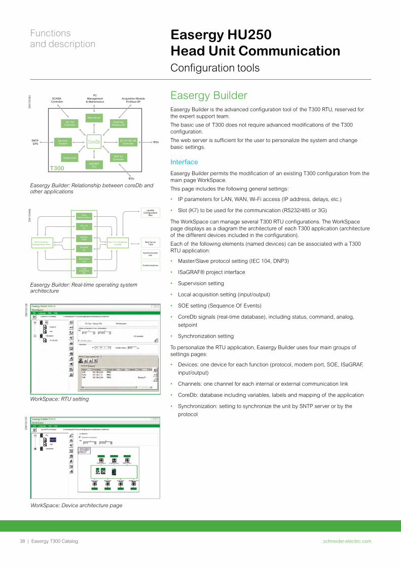
Easergy BuilderEasergy Builder is the advanced configuration tool of the T300 RTU, reserved for the expert support team.
The basic use of T300 does not require advanced modifications of the T300 configuration.
The web server is sufficient for the user to personalize the system and change basic settings.
Interface
Easergy Builder permits the modification of an existing T300 configuration from the main page WorkSpace.
This page includes the following general settings:
• IP parameters for LAN, WAN, Wi-Fi access (IP address, delays, etc.)
• Slot (K7) to be used for the communication (RS232/485 or 3G)
The WorkSpace can manage several T300 RTU configurations. The WorkSpace page displays as a diagram the architecture of each T300 application (architecture of the different devices included in the configuration).
Each of the following elements (named devices) can be associated with a T300 RTU application:
• Master/Slave protocol setting (IEC 104, DNP3)
• ISaGRAF® project interface
• Supervision setting
• Local acquisition setting (input/output)
• SOE setting (Sequence Of Events)
• CoreDb signals (real-time database), including status, command, analog,
setpoint
• Synchronization setting
To personalize the RTU application, Easergy Builder uses four main groups of settings pages:
• Devices: one device for each function (protocol, modem port, SOE, ISaGRAF,
input/output)
• Channels: one channel for each internal or external communication link
• CoreDb: database including variables, labels and mapping of the application
• Synchronization: setting to synchronize the unit by SNTP server or by the
protocol
Web Server
PCManagement
& MaintenanceAcquisition Module
Profibus-DPSCADA
Controller
SNTP, GPS
IEDs
IEDs
T300ISaGRAF
PLC
CoreDb
ControllerProfibus DP
IEC 104Controller
Synchro-nisation
IEC 101 / IEC 104Controller
DNP 3.0Controller
Supervision
Easergy Builder: Relationship between coreDb and other applications
DM
1034
84
coreDbConfiguration
files
Web Server T300
Synchronisationthm
Communications
OtherBinControllers
BinControllersConfiguration Files
Real Time DatabasecoreDb
IEC 104i4e
ModBusmdbe
ISaGRAFisg
Supervisionsup
Local Acquisition
laq
Easergy Builder: Real-time operating system architecture
DM
1034
84
WorkSpace: Device architecture page
EM
1001
00
WorkSpace: RTU setting
EM
1001
06
Easergy HU250 Head Unit Communication Configuration tools
schneider-electric.com38 |
Functions and description
Easergy T300 Catalog
Easergy HU250 Head Unit Communication Configuration tools
Calculation formula
The calculation formulas are used to carry out math, combinational logic operations
or others on T300 data in order to perform specific personalized functions.
These Calculation formulas can be created via Easergy Builder.
The list of operations available are given in the Easergy Builder User Manual.
Refer to this document for more information related to the calculation formulae.
IEC 61131-3 PLC
An IEC 61131-3 programming tool (IsaGRAF® platform) is available with the T300
for developing PLC programs.
This IsaGRAF® platform is an external software tool to be installed on a PC.
It is used to develop specific custom applications in the following programming
languages:
• SFC: Sequential Function Chart
• FBD: Function Block Diagram
• LD: Ladder Diagram
• ST: Structured Text
• IL: Instruction List
Management of RBAC and security policyThe T300 is provided with a standard security policy and a default RBAC (roles assigned to a number of predefined users).
The T300 security policy is managed by a special tool - SAT (Security Administration Tool).
The SAT can be used during the engineering phase to redefine or change the system access restrictions, including the access rights and responsibilities, via an RBAC (Role-Based Access Control) model.
Once the security policy is established in the SAT, the commissioning phase done in the Web server will be only limited to adding or deleting users, to modify their associated passwords, and to assign or modify one or more of the roles pre-defined in the SAT to these users.
See the Managing Users and Roles section for more information on how to set these parameters.
Instructions on how to configure the security policy in the SAT are given in the SAT User Manual. Refer to this document for more information.
schneider-electric.com | 39
Functions and description
Easergy T300 Catalog
Easergy SC150Switch Controller Unit
schneider-electric.com40 |
Functions and description
Easergy T300 Catalog
Easergy SC150 Switch Controller Unit General description
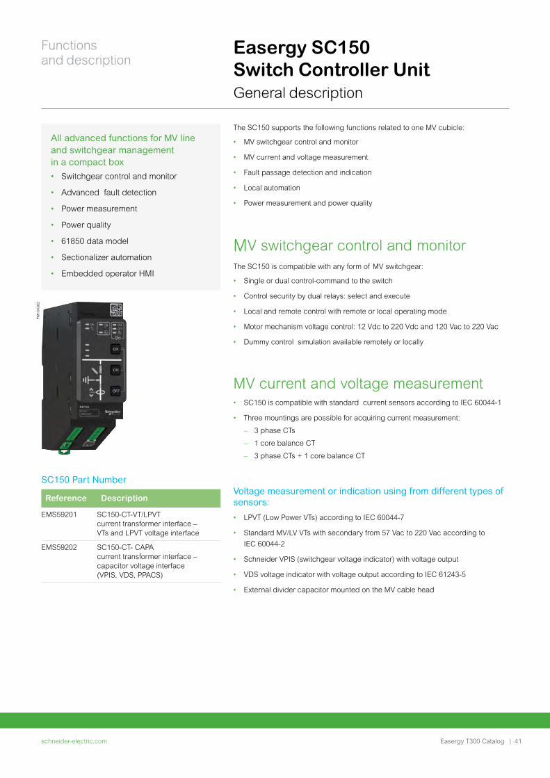
The SC150 supports the following functions related to one MV cubicle:
• MV switchgear control and monitor
• MV current and voltage measurement
• Fault passage detection and indication
• Local automation
• Power measurement and power quality
MV switchgear control and monitor The SC150 is compatible with any form of MV switchgear:
• Single or dual control-command to the switch
• Control security by dual relays: select and execute
• Local and remote control with remote or local operating mode
• Motor mechanism voltage control: 12 Vdc to 220 Vdc and 120 Vac to 220 Vac
• Dummy control simulation available remotely or locally
MV current and voltage measurement• SC150 is compatible with standard current sensors according to IEC 60044-1
• Three mountings are possible for acquiring current measurement:
– 3 phase CTs
– 1 core balance CT
– 3 phase CTs + 1 core balance CT
Voltage measurement or indication using from different types of sensors:
• LPVT (Low Power VTs) according to IEC 60044-7
• Standard MV/LV VTs with secondary from 57 Vac to 220 Vac according to
IEC 60044-2
• Schneider VPIS (switchgear voltage indicator) with voltage output
• VDS voltage indicator with voltage output according to IEC 61243-5
• External divider capacitor mounted on the MV cable head
All advanced functions for MV line and switchgear management in a compact box
• Switchgear control and monitor
• Advanced fault detection
• Power measurement
• Power quality
• 61850 data model
• Sectionalizer automation
• Embedded operator HMI
SC150 Part Number
Reference Description
EMS59201 SC150-CT-VT/LPVT current transformer interface – VTs and LPVT voltage interface
EMS59202 SC150-CT- CAPA current transformer interface – capacitor voltage interface (VPIS, VDS, PPACS)
PM
1043
82
schneider-electric.com | 41
Functions and description
Easergy T300 Catalog
Easergy SC150 Switch Controller Unit General description
Fault Passage Indicator (FPI) The fault current detections are compatible with all existing ground neutral systems with or without presence of distributed generation. The fault detection is based on international standards of ANSI codes:
• Phase overcurrent fault detection (ANSI 50/51)
• Ground (earth) fault detection (ANSI 50N/51N)
• Negative sequence overvoltage/broken conductor detection (ANSI 47)
• Directional phase overcurrent fault detection (ANSI 67)
• Directional ground (earth) fault detection (ANSI 67N)
Three ammetric fault detection instances and two directional fault detection instances, each with their specific settings and detection mode, can operate separately or simultaneously on the fault detector and for each SC150 channel. The first instance that checks the fault condition activates the detector and the corresponding indicator on the T300.
The ability to combine instances allows the T300 to adapt to the characteristics and type of protection used upstream in line with the MV network characteristics. This also enables adjustment based on the fault current values measured by the measurement sensors.
For example, one instance can be defined for overload detection (typically an IDMT curve) and another instance can be defined for short-circuit detection (typically a DT curve).
Each instance includes 2 groups of settings. These 2 groups correspond to 2 sets of thresholds and time delays that are typically linked to 2 upstream protection settings.
MV Power measurements and power quality Advanced power measurement and power quality are available on each SC150 in accordance with EN50160 directive:
• Power measurements according to the principles of IEC 61557-12
• Voltage power quality according to the principles of IEC 61000-4-30 class S
Automation systems The automation systems concerning several switchgear and MV network systems such as Automatic Transfer Source (ATS), self healing, etc., are hosted in HU250 and are designed in a IEC 61131-3 PLC workbench.
The sectionalizer automation (SEC) concerning one switchgear is managed by the SC150 module. This automation is factory predefined but configurable on site (setting).
Sectionalizer (SEC): Automatic control for opening the MV switch following detection of a number of fault currents in the source substation reset cycle.
schneider-electric.com42 |
Functions and description
Easergy T300 Catalog
Easergy SC150 Switch Controller Unit General description
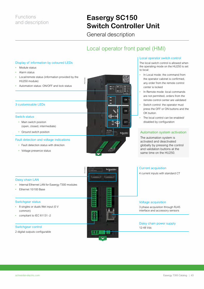
Automation system activation
The automation system is activated and deactivated globally by pressing the control and validation buttons at the same time on the HU250.
Local operator switch control
The local switch control is allowed when the operating mode on the HU250 is set to local:
• In Local mode: the command from
the operator cabinet is confirmed,
any order from the remote control
center is locked
• In Remote mode: local commands
are not permitted, orders from the
remote control center are validated
• Switch control: the operator must
press the OFF or ON buttons and the
OK button.
• The local control can be enabled/
disabled by configuration
Local operator front panel (HMI)
PM
1043
82
Display of information by coloured LEDs
• Module status
• Alarm status
• Local/remote status (information provided by the
HU250 module)
• Automation status: ON/OFF and lock status
3 customisable LEDs
Switch status
• Main switch position
(open, closed, intermediate)
• Ground switch position
Fault detection and voltage indications
• Fault detection status with direction
• Voltage presence status
PM
1043
63
Daisy chain LAN
• Internal Ethernet LAN for Easergy T300 modules
• Ethernet 10/100 Base
Current acquisition
4 current inputs with standard CT
Voltage acquisition
3 phase acquisition through RJ45 interface and accessory sensors
Daisy chain power supply 12-48 Vdc
Switchgear status
• 8 singles or duals Wet input (0 V
common)
• compliant to IEC 61131 -2
Switchgear control
2 digital outputs configurable
schneider-electric.com | 43
Functions and description
Easergy T300 Catalog
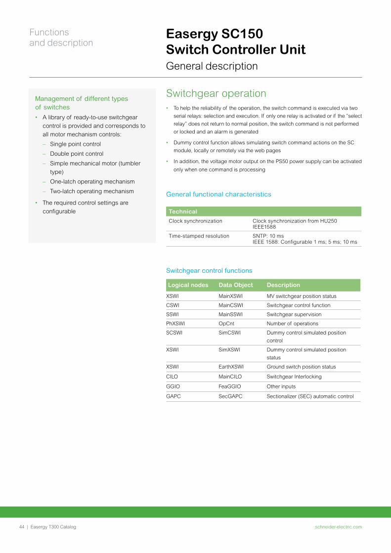
Switchgear operation • To help the reliability of the operation, the switch command is executed via two
serial relays: selection and execution. If only one relay is activated or if the “select
relay” does not return to normal position, the switch command is not performed
or locked and an alarm is generated
• Dummy control function allows simulating switch command actions on the SC
module, locally or remotely via the web pages
• In addition, the voltage motor output on the PS50 power supply can be activated
only when one command is processing
General functional characteristics
Technical
Clock synchronization Clock synchronization from HU250 IEEE1588
Time-stamped resolution SNTP: 10 msIEEE 1588: Configurable 1 ms; 5 ms; 10 ms
Switchgear control functions
Logical nodes Data Object Description
XSWI MainXSWI MV switchgear position status
CSWI MainCSWI Switchgear control function
SSWI MainSSWI Switchgear supervision
PhXSWI OpCnt Number of operations
SCSWI SimCSWI Dummy control simulated position
control
XSWI SimXSWI Dummy control simulated position
status
XSWI EarthXSWI Ground switch position status
CILO MainCILO Switchgear Interlocking
GGIO FeaGGIO Other inputs
GAPC SecGAPC Sectionalizer (SEC) automatic control
Easergy SC150 Switch Controller Unit General description
Management of different types of switches
• A library of ready-to-use switchgear
control is provided and corresponds to
all motor mechanism controls:
– Single point control
– Double point control
– Simple mechanical motor (tumbler
type)
– One-latch operating mechanism
– Two-latch operating mechanism
• The required control settings are
configurable
schneider-electric.com44 |
Functions and description
Easergy T300 Catalog
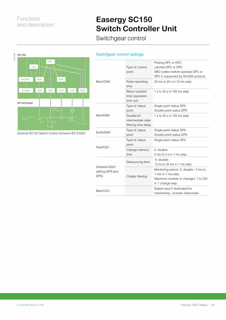
General SC150 Switch Control Scheme IEC 61850
SimXSWI XSWI XSWI TCTR TVTR GGIO
SimCSWI CSWI
CILO
GAPC
IHMI
SC150
MVIncomer MV
Switch GroundSwitch
CurrentTransformer
Voltage Transformer
MV Switchgear
DM
1012
96
Easergy SC150 Switch Controller Unit Switchgear control
Switchgear control settings
MainCSWI
Type of control
point
Pulsing SPC or DPC
Latched SPC or DPC
SBO (select before operate) SPC or
DPC if supported by SCADA protocol
Pulse operating
time
50 ms to 20 s in 10 ms step
Return position
time (operation
time out)
1 s to 30 s in 100 ms step
MainXSWI
Type of status
point
Single point status SPS
Double point status DPS
Double-bit
intermediate state
filtering time delay
1 s to 30 s in 100 ms step
EarthXSWIType of status
point
Single point status SPS
Double point status DPS
FeaGGIO
Type of status
point
Single point status SPS
Change memory
time
0: disable
5 ms to 2 s in 1 ms step
General GGIO
setting (SPS and
DPS)
Debouncing time 0: disable
5 ms to 30 ms in 1 ms step
Chatter filtering
Monitoring period: 0: disable - 5 ms to
1 min in 1 ms step
Maximum number of changes: 1 to 255
in 1 change step
MainCILODigital input 5 dedicated for
interlocking : activate /deactivate
schneider-electric.com | 45
Functions and description
Easergy T300 Catalog
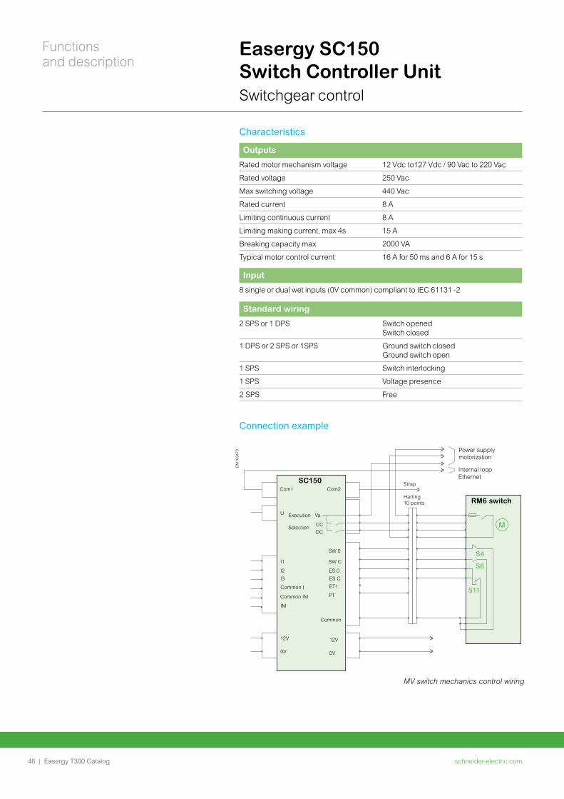
Characteristics
Outputs
Rated motor mechanism voltage 12 Vdc to127 Vdc / 90 Vac to 220 Vac
Rated voltage 250 Vac
Max switching voltage 440 Vac
Rated current 8 A
Limiting continuous current 8 A
Limiting making current, max 4s 15 A
Breaking capacity max 2000 VA
Typical motor control current 16 A for 50 ms and 6 A for 15 s
Input
8 single or dual wet inputs (0V common) compliant to IEC 61131 -2
Standard wiring
2 SPS or 1 DPS Switch opened Switch closed
1 DPS or 2 SPS or 1SPS Ground switch closed Ground switch open
1 SPS Switch interlocking
1 SPS Voltage presence
2 SPS Free
Connection example
MV switch mechanics control wiring
Easergy SC150 Switch Controller Unit Switchgear control
•
•
••••••
•
•
•
•
•••
•
••••
•••
••
•
•
••
••
•
•••
•
••
•
•
• • • ••••
••••
•
Power supply motorization
Internal loop Ethernet
Strap
Harting10 points RM6 switch
Com1 Com2SC150
Execution
Selection
Common I
Common IM
Common
12V
0V
12V
0V
Va
ES 0
PT
I1
I2
IM
ES C
U
CCOC
SW 0
SW C
ET1I3
DM
1034
70
S4
S6
S11
M
schneider-electric.com46 |
Functions and description
Easergy T300 Catalog
DM
1012
98
L1
L2
L3
L1
L2
L3
L1
L2
L3
Single phase VT
Single phase LPVT3 phases LPVT 3 phases VT
L1
L2
L3
PPACS 3 phases
L1
L2
L3
3 phases from VPIS or VDS
VPIS or VDS
Easergy T300voltage adapter
Va
Vc
Vb
SC
15
0
RJ45 connector
L1L2
L3
SC
15
0 Va
VcVref
Vb
SC
15
0
SC
15
0
SC
15
0Va
VcVref
VbVa
VcVref
Vb
SC
15
0 Va
VcVref
Vb
Va
Vc
Vb
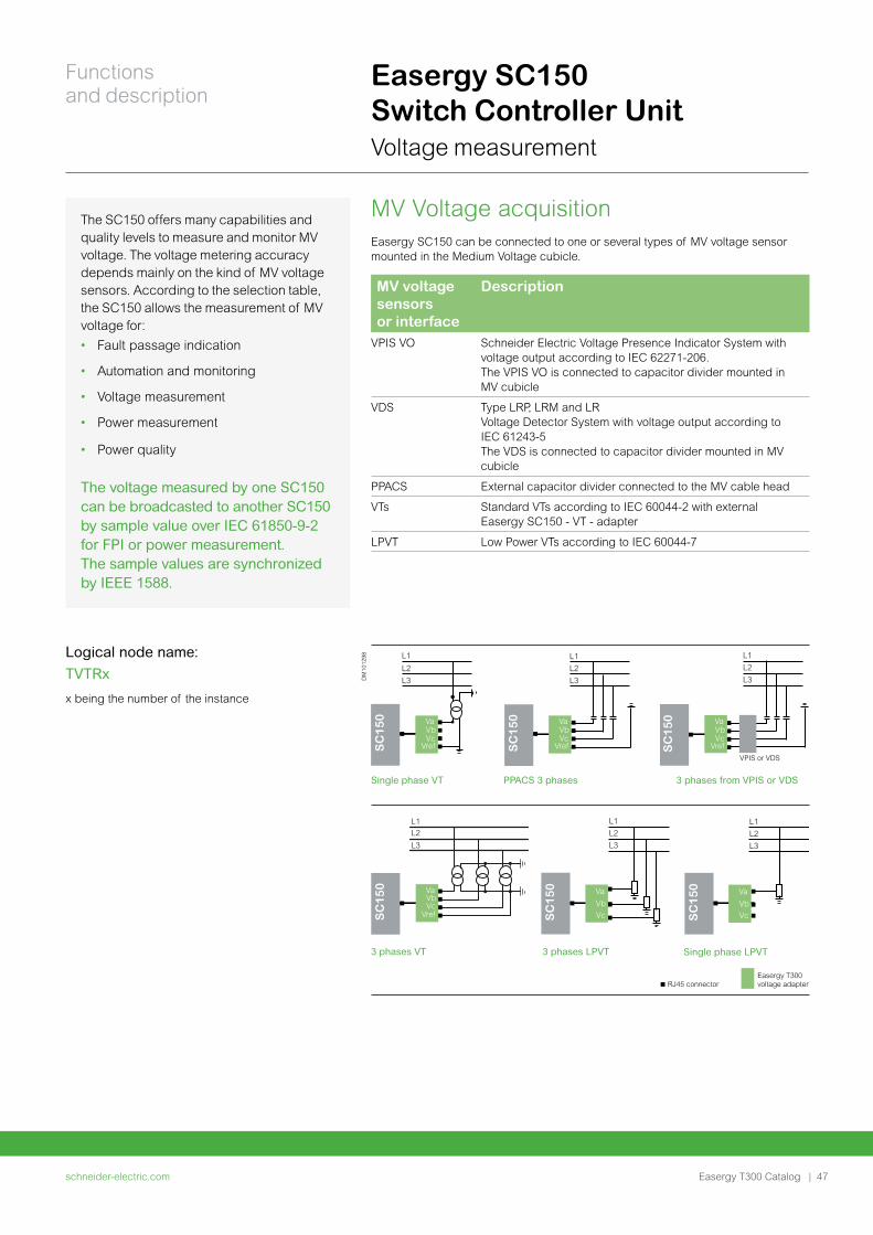
Easergy SC150 Switch Controller Unit Voltage measurement
MV Voltage acquisitionEasergy SC150 can be connected to one or several types of MV voltage sensor mounted in the Medium Voltage cubicle.
MV voltage sensors or interface
Description
VPIS VO Schneider Electric Voltage Presence Indicator System with voltage output according to IEC 62271-206. The VPIS VO is connected to capacitor divider mounted in MV cubicle
VDS Type LRP, LRM and LR Voltage Detector System with voltage output according to IEC 61243-5 The VDS is connected to capacitor divider mounted in MV cubicle
PPACS External capacitor divider connected to the MV cable head
VTs Standard VTs according to IEC 60044-2 with external Easergy SC150 - VT - adapter
LPVT Low Power VTs according to IEC 60044-7
Logical node name:
TVTRx
x being the number of the instance
The SC150 offers many capabilities and quality levels to measure and monitor MV voltage. The voltage metering accuracy depends mainly on the kind of MV voltage sensors. According to the selection table, the SC150 allows the measurement of MV voltage for:
• Fault passage indication
• Automation and monitoring
• Voltage measurement
• Power measurement
• Power quality
The voltage measured by one SC150 can be broadcasted to another SC150 by sample value over IEC 61850-9-2 for FPI or power measurement. The sample values are synchronized by IEEE 1588.
schneider-electric.com | 47
Functions and description
Easergy T300 Catalog
Easergy SC150 Switch Controller Unit Voltage measurement
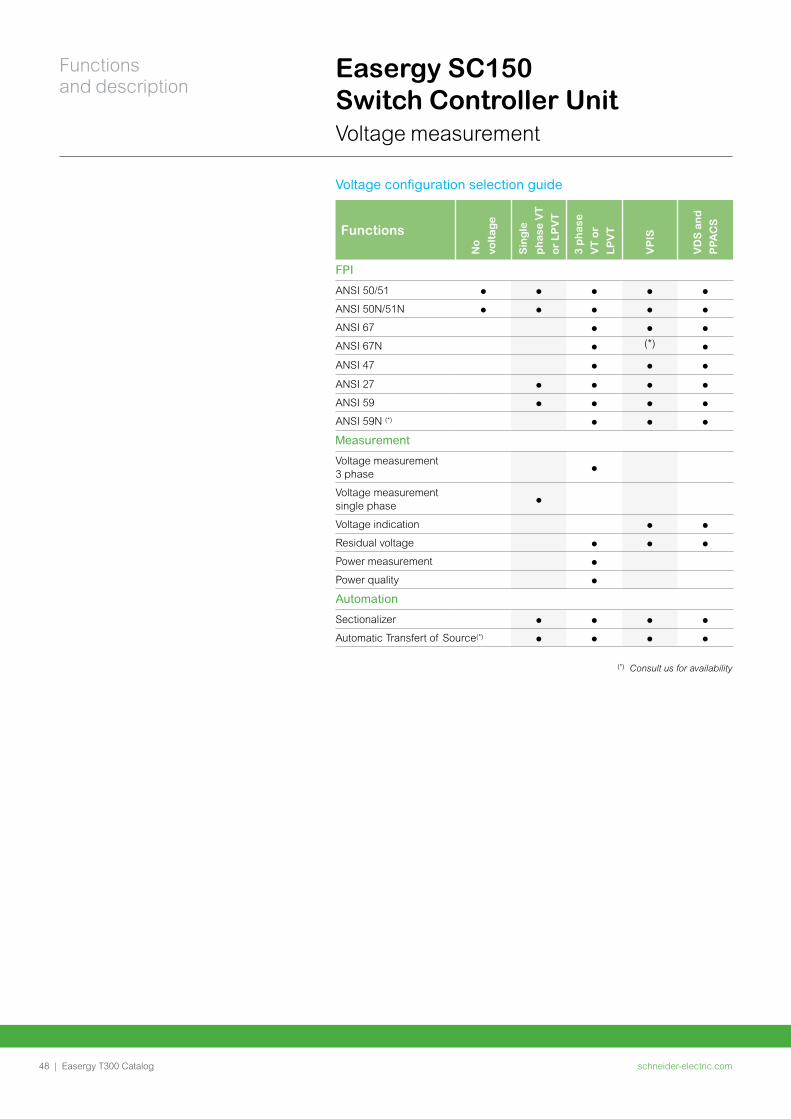
Voltage configuration selection guide
Functions
No
volt
age
Sin
gle
ph
ase
VT
or
LP
VT
3 p
ha
se
VT
or
LP
VT
VP
IS
VD
S a
nd
PPA
CS
FPI
ANSI 50/51
ANSI 50N/51N
ANSI 67
ANSI 67N (*)
ANSI 47
ANSI 27
ANSI 59
ANSI 59N (*)
Measurement
Voltage measurement 3 phase
Voltage measurement single phase
Voltage indication
Residual voltage
Power measurement
Power quality
Automation
Sectionalizer
Automatic Transfert of Source(*)
(*) Consult us for availability
schneider-electric.com48 |
Functions and description
Easergy T300 Catalog
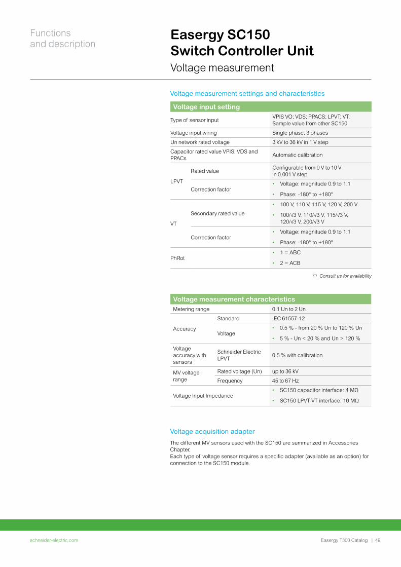
Voltage input setting
Type of sensor inputVPIS VO; VDS; PPACS; LPVT; VT; Sample value from other SC150
Voltage input wiring Single phase; 3 phases
Un network rated voltage 3 kV to 36 kV in 1 V step
Capacitor rated value VPIS, VDS and PPACs
Automatic calibration
LPVT
Rated valueConfigurable from 0 V to 10 V in 0.001 V step
Correction factor• Voltage: magnitude 0.9 to 1.1
• Phase: -180° to +180°
VT
Secondary rated value
• 100 V, 110 V, 115 V, 120 V, 200 V
• 100/√3 V, 110/√3 V, 115/√3 V, 120/√3 V, 200/√3 V
Correction factor• Voltage: magnitude 0.9 to 1.1
• Phase: -180° to +180°
PhRot• 1 = ABC
• 2 = ACB
(*) Consult us for availability
Easergy SC150 Switch Controller Unit Voltage measurement
Voltage acquisition adapter
The different MV sensors used with the SC150 are summarized in Accessories Chapter. Each type of voltage sensor requires a specific adapter (available as an option) for connection to the SC150 module.
Voltage measurement settings and characteristics
Voltage measurement characteristics Metering range 0.1 Un to 2 Un
Accuracy
Standard IEC 61557-12
Voltage • 0.5 % - from 20 % Un to 120 % Un
• 5 % - Un < 20 % and Un > 120 %
Voltage accuracy with sensors
Schneider Electric LPVT
0.5 % with calibration
MV voltage range
Rated voltage (Un) up to 36 kV
Frequency 45 to 67 Hz
Voltage Input Impedance • SC150 capacitor interface: 4 MΩ
• SC150 LPVT-VT interface: 10 MΩ
schneider-electric.com | 49
Functions and description
Easergy T300 Catalog
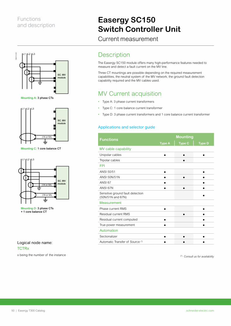
Easergy SC150 Switch Controller Unit Current measurement
FunctionsMounting
Type A Type C Type D
MV cable capability
Unipolar cables
Tripolar cables
FPI
ANSI 50/51
ANSI 50N/51N
ANSI 67
ANSI 67N
Sensitive ground fault detection (50N/51N and 67N)
Measurement
Phase current RMS
Residual current RMS
Residual current computed
True power measurement
Automation
Sectionalizer
Automatic Transfer of Source (*)
DescriptionThe Easergy SC150 module offers many high-performance features needed to measure and detect a fault current on the MV line.
Three CT mountings are possible depending on the required measurement capabilities, the neutral system of the MV network, the ground fault detection capability required and the MV cables used.
MV Current acquisition• Type A: 3 phase current transformers
• Type C: 1 core balance current transformer
• Type D: 3 phase current transformers and 1 core balance current transformer
DM
1013
01 L1 L2 L3
Mounting A: 3 phase CTs
SC. MV module
SC. MV module
SC. MV module
L1 L2 L3
Mounting C: 1 core balance CT
(1A or 5A)
L1 L2 L3
Mounting D: 3 phase CTs + 1 core balance CT
(1A or 5A)
(1A or 5A)
Logical node name:
TCTRx
x being the number of the instance
Applications and selector guide
(*) Consult us for availability
schneider-electric.com50 |
Functions and description
Easergy T300 Catalog
Easergy SC150 Switch Controller Unit Current measurement
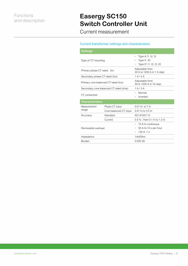
Settings
Type of CT mounting
• Type A I1, I2, I3
• Type C: IO
• Type D: I1, I2, I3, IO
Primary phase CT rated (In)Adjustable from:50 A to 1250 A in 1 A step
Secondary phase CT rated (Ins) 1 A / 5 A
Primary core balanced CT rated (Ino)Adjustable from:50 to 1250 A in 1A step
Secondary core balanced CT rated (Inos) 1 A / 5 A
CT connection• Normal
• Inverted
Characteristics
Measurement range
Phase CT input 0.01 In to 7 In
Core balanced CT input 0.01 In to 3.5 In
Accuracy Standard IEC 61557-12
Current 0.5 % : from 0.1 In to 1.2 In
Permissible overload
• 10 A In continuous
• 50 A In-10 s per hour
• 120 A -1 s
Impedance 1miliOhm
Burden 0.025 VA
Current transformer settings and characteristics
schneider-electric.com | 51
Functions and description
Easergy T300 Catalog
Easergy SC150 Switch Controller Unit Fault current detection
Advanced Fault Passage Indicator based on IEC 61850 data model and ANSI code
•
MV switchgear SC150
Current Transformer
Voltage Transformer
MV feeder
TCTR
TVTR
MMXU
PTOV
PTUV
SCPI
SVPI
IHMI
IHMISFPI
Other SC150Sample value
PTOC
PTOC
PTOC
PTUCOutputfor lampindicator
HU250
DM
1013
03
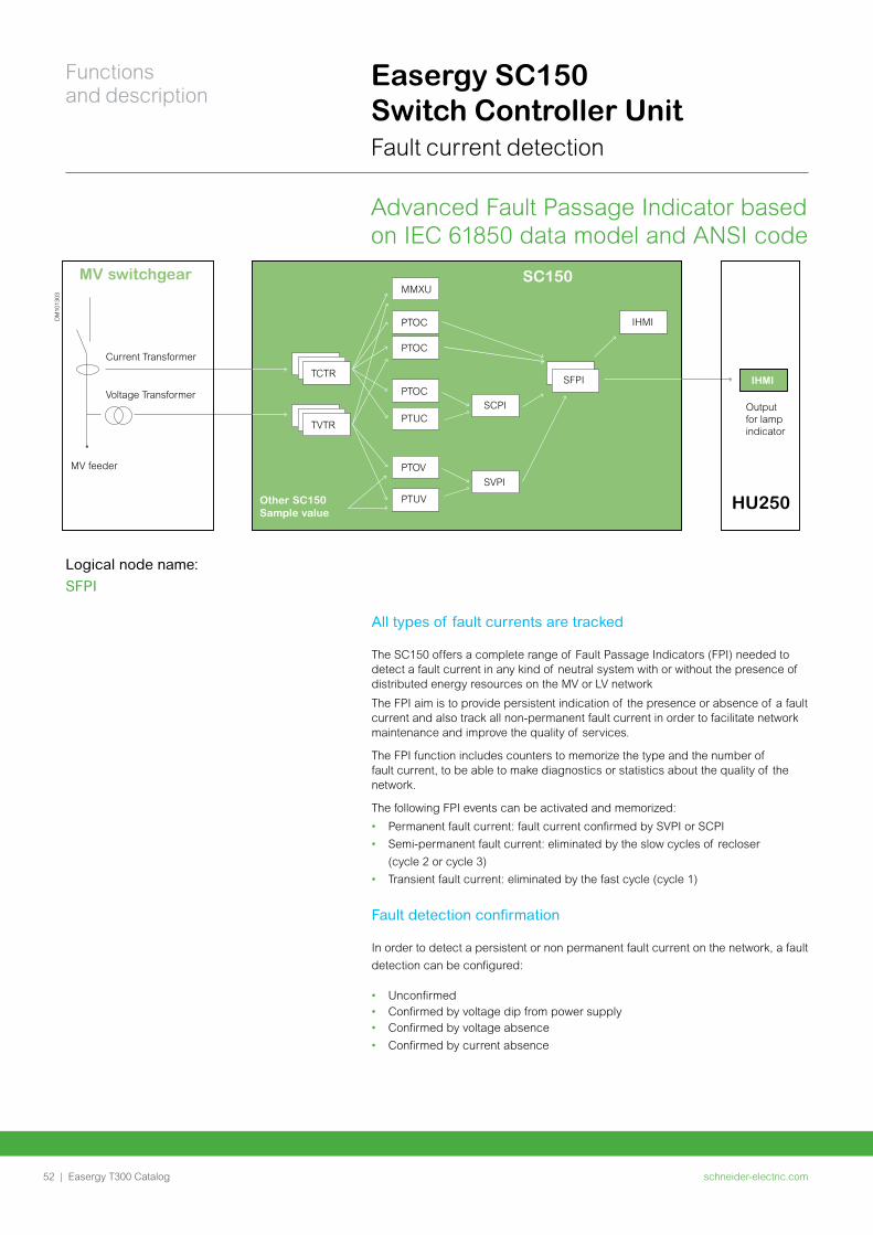
Logical node name:
SFPI
All types of fault currents are tracked
The SC150 offers a complete range of Fault Passage Indicators (FPI) needed to detect a fault current in any kind of neutral system with or without the presence of distributed energy resources on the MV or LV network
The FPI aim is to provide persistent indication of the presence or absence of a fault current and also track all non-permanent fault current in order to facilitate network maintenance and improve the quality of services.
The FPI function includes counters to memorize the type and the number of fault current, to be able to make diagnostics or statistics about the quality of the network.
The following FPI events can be activated and memorized:
• Permanent fault current: fault current confirmed by SVPI or SCPI
• Semi-permanent fault current: eliminated by the slow cycles of recloser
(cycle 2 or cycle 3)
• Transient fault current: eliminated by the fast cycle (cycle 1)
Fault detection confirmation
In order to detect a persistent or non permanent fault current on the network, a fault
detection can be configured:
• Unconfirmed• Confirmed by voltage dip from power supply• Confirmed by voltage absence
• Confirmed by current absence
schneider-electric.com52 |
Functions and description
Easergy T300 Catalog
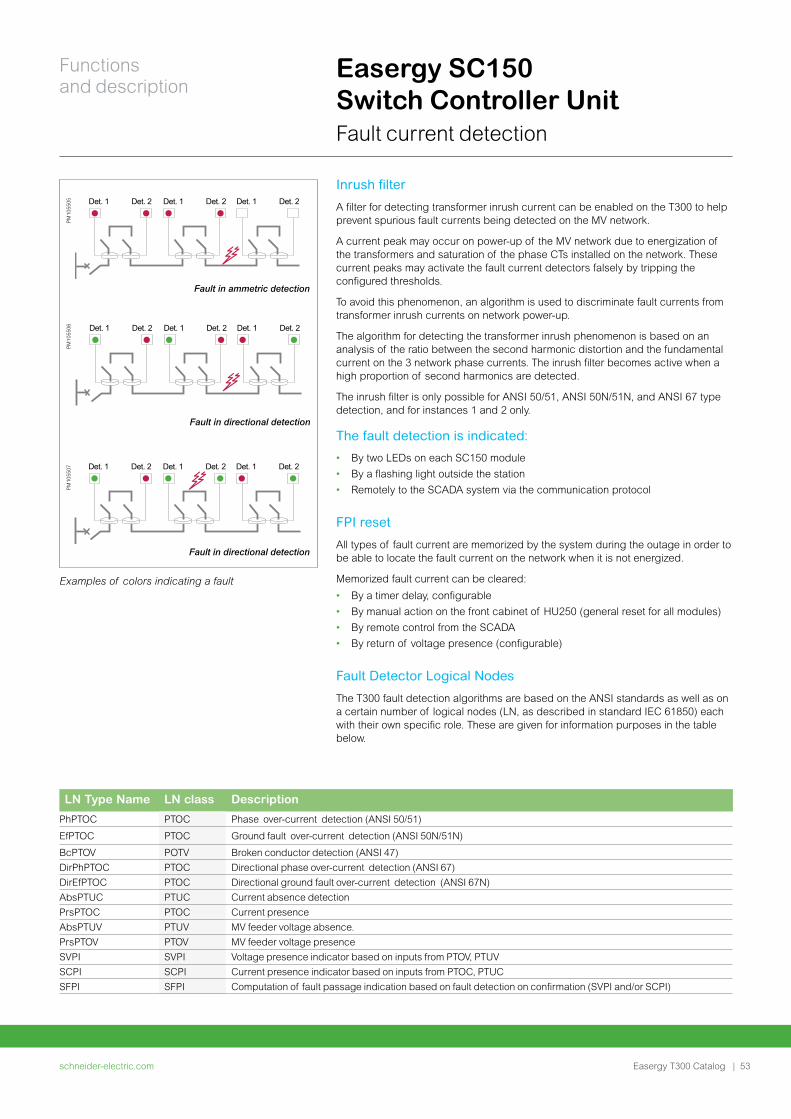
LN Type Name LN class Description
PhPTOC PTOC Phase over-current detection (ANSI 50/51)
EfPTOC PTOC Ground fault over-current detection (ANSI 50N/51N)
BcPTOV POTV Broken conductor detection (ANSI 47)
DirPhPTOC PTOC Directional phase over-current detection (ANSI 67)
DirEfPTOC PTOC Directional ground fault over-current detection (ANSI 67N)
AbsPTUC PTUC Current absence detection
PrsPTOC PTOC Current presence
AbsPTUV PTUV MV feeder voltage absence.
PrsPTOV PTOV MV feeder voltage presence
SVPI SVPI Voltage presence indicator based on inputs from PTOV, PTUV
SCPI SCPI Current presence indicator based on inputs from PTOC, PTUC
SFPI SFPI Computation of fault passage indication based on fault detection on confirmation (SVPI and/or SCPI)
Easergy SC150 Switch Controller Unit Fault current detection
Inrush filter
A filter for detecting transformer inrush current can be enabled on the T300 to help prevent spurious fault currents being detected on the MV network.
A current peak may occur on power-up of the MV network due to energization of the transformers and saturation of the phase CTs installed on the network. These current peaks may activate the fault current detectors falsely by tripping the configured thresholds.
To avoid this phenomenon, an algorithm is used to discriminate fault currents from transformer inrush currents on network power-up.
The algorithm for detecting the transformer inrush phenomenon is based on an analysis of the ratio between the second harmonic distortion and the fundamental current on the 3 network phase currents. The inrush filter becomes active when a high proportion of second harmonics are detected.
The inrush filter is only possible for ANSI 50/51, ANSI 50N/51N, and ANSI 67 type detection, and for instances 1 and 2 only.
The fault detection is indicated:
• By two LEDs on each SC150 module
• By a flashing light outside the station
• Remotely to the SCADA system via the communication protocol
FPI reset
All types of fault current are memorized by the system during the outage in order to be able to locate the fault current on the network when it is not energized.
Memorized fault current can be cleared:
• By a timer delay, configurable
• By manual action on the front cabinet of HU250 (general reset for all modules)
• By remote control from the SCADA
• By return of voltage presence (configurable)
Fault Detector Logical Nodes
The T300 fault detection algorithms are based on the ANSI standards as well as on a certain number of logical nodes (LN, as described in standard IEC 61850) each with their own specific role. These are given for information purposes in the table below.
Examples of colors indicating a fault
PM
1055
05 Det. 1 Det. 2 Det. 1 Det. 2 Det. 1 Det. 2
Fault in ammetric detection
PM
1055
06 Det. 1 Det. 2 Det. 1 Det. 2 Det. 1 Det. 2
Fault in directional detection
PM
1055
07 Det. 1 Det. 2 Det. 1 Det. 2 Det. 1 Det. 2
Fault in directional detection
schneider-electric.com | 53
Functions and description
Easergy T300 Catalog
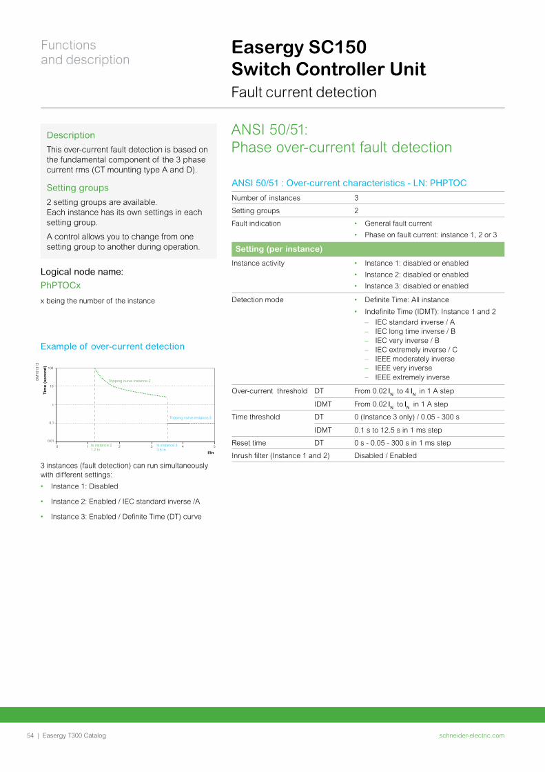
Easergy SC150 Switch Controller Unit Fault current detection
ANSI 50/51: Phase over-current fault detection
Example of over-current detection
ANSI 50/51 : Over-current characteristics - LN: PHPTOC
Number of instances 3
Setting groups 2
Fault indication • General fault current
• Phase on fault current: instance 1, 2 or 3
Setting (per instance)
Instance activity • Instance 1: disabled or enabled
• Instance 2: disabled or enabled
• Instance 3: disabled or enabled
Detection mode • Definite Time: All instance
• Indefinite Time (IDMT): Instance 1 and 2
– IEC standard inverse / A – IEC long time inverse / B – IEC very inverse / B – IEC extremely inverse / C – IEEE moderately inverse – IEEE very inverse – IEEE extremely inverse
Over-current threshold DT From 0.02 to 4 in 1 A step
IDMT From 0.02 to in 1 A step
Time threshold DT 0 (Instance 3 only) / 0.05 - 300 s
IDMT 0.1 s to 12.5 s in 1 ms step
Reset time DT 0 s - 0.05 - 300 s in 1 ms step
Inrush filter (Instance 1 and 2) Disabled / Enabled1 2 3 4 5
0,1
1
10
100
0,01
0
Tripping curve instance 2
Tripping curve instance 3
Is instance 21.2 In
Is instance 33.5 In
I/In
Tim
e (
sec
on
d)
DM
1013
13
Description
This over-current fault detection is based on the fundamental component of the 3 phase current rms (CT mounting type A and D).
Setting groups
2 setting groups are available. Each instance has its own settings in each setting group.
A control allows you to change from one setting group to another during operation.
Logical node name:
PhPTOCx
x being the number of the instance
3 instances (fault detection) can run simultaneously with different settings:
• Instance 1: Disabled
• Instance 2: Enabled / IEC standard inverse /A
• Instance 3: Enabled / Definite Time (DT) curve
schneider-electric.com54 |
Functions and description
Easergy T300 Catalog
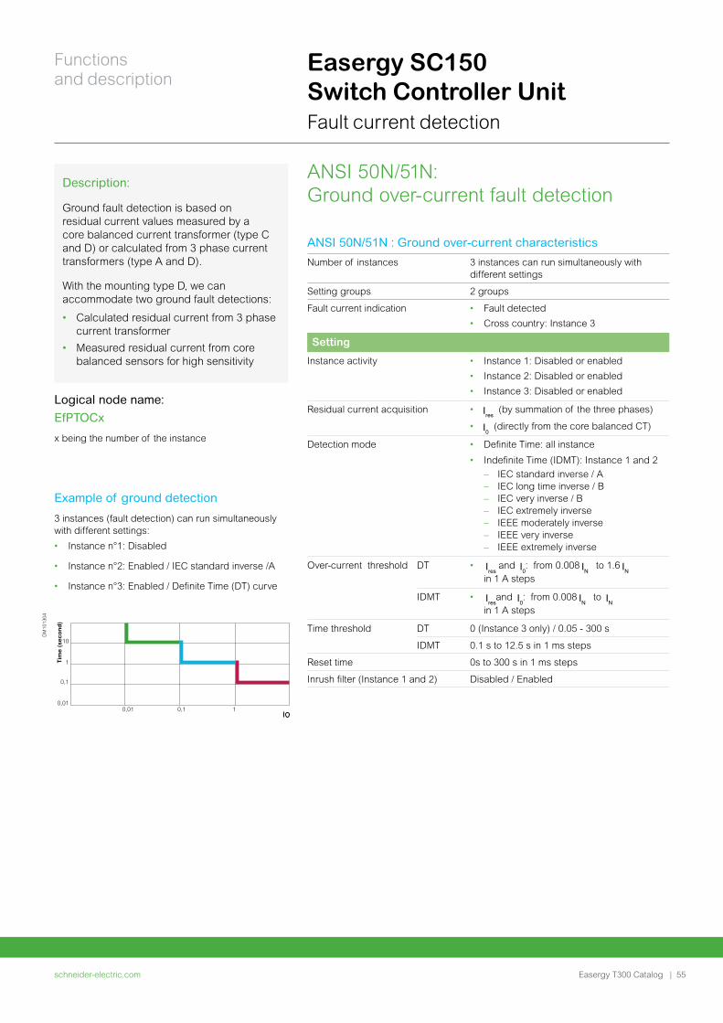
Easergy SC150 Switch Controller Unit Fault current detection
ANSI 50N/51N: Ground over-current fault detection
Description:
Ground fault detection is based on residual current values measured by a core balanced current transformer (type C and D) or calculated from 3 phase current transformers (type A and D).
With the mounting type D, we can accommodate two ground fault detections:
• Calculated residual current from 3 phase current transformer
• Measured residual current from core balanced sensors for high sensitivity
Logical node name:
EfPTOCx
x being the number of the instance
Example of ground detection
3 instances (fault detection) can run simultaneously with different settings:
• Instance n°1: Disabled
• Instance n°2: Enabled / IEC standard inverse /A
• Instance n°3: Enabled / Definite Time (DT) curve
10
1
0,1
0,010,01 0,1 1
Tim
e (
sec
on
d)
DM
1013
04
ANSI 50N/51N : Ground over-current characteristics
Number of instances 3 instances can run simultaneously with different settings
Setting groups 2 groups
Fault current indication • Fault detected
• Cross country: Instance 3
Setting
Instance activity • Instance 1: Disabled or enabled
• Instance 2: Disabled or enabled
• Instance 3: Disabled or enabled
Residual current acquisition • (by summation of the three phases)
• (directly from the core balanced CT)
Detection mode • Definite Time: all instance
• Indefinite Time (IDMT): Instance 1 and 2
– IEC standard inverse / A – IEC long time inverse / B – IEC very inverse / B – IEC extremely inverse – IEEE moderately inverse – IEEE very inverse – IEEE extremely inverse
Over-current threshold DT • and : from 0.008 to 1.6 in 1 A steps
IDMT • and : from 0.008 to in 1 A steps
Time threshold DT 0 (Instance 3 only) / 0.05 - 300 s
IDMT 0.1 s to 12.5 s in 1 ms steps
Reset time 0s to 300 s in 1 ms steps
Inrush filter (Instance 1 and 2) Disabled / Enabled
schneider-electric.com | 55
Functions and description
Easergy T300 Catalog
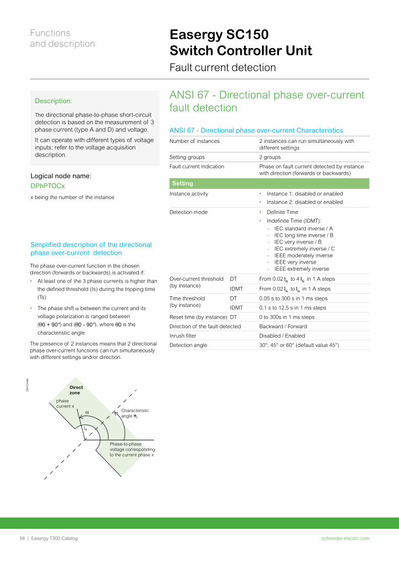
Easergy SC150 Switch Controller Unit Fault current detection
ANSI 67 - Directional phase over-current fault detection
Logical node name:
DPhPTOCx
x being the number of the instance
Simplified description of the directional phase over-current detection
Direct zone
phasecurrent x
Is
Characteristicangle 00
Phase-to-phasevoltage correspondingto the current phase x
DM
1034
86
Description:
The directional phase-to-phase short-circuit detection is based on the measurement of 3 phase current (type A and D) and voltage.
It can operate with different types of voltage inputs: refer to the voltage acquisition description.
ANSI 67 - Directional phase over-current Characteristics
Number of instances 2 instances can run simultaneously with different settings
Setting groups 2 groups
Fault current indication Phase on fault current detected by instance with direction (forwards or backwards)
Setting
Instance activity • Instance 1: disabled or enabled
• Instance 2: disabled or enabled
Detection mode • Definite Time
• Indefinite Time (IDMT):
– IEC standard inverse / A – IEC long time inverse / B – IEC very inverse / B – IEC extremely inverse / C – IEEE moderately inverse – IEEE very inverse – IEEE extremely inverse
Over-current threshold (by instance)
DT From 0.02 to 4 in 1 A steps
IDMT From 0.02 to in 1 A steps
Time threshold (by instance)
DT 0.05 s to 300 s in 1 ms steps
IDMT 0,1 s to 12,5 s in 1 ms steps
Reset time (by instance) DT 0 to 300s in 1 ms steps
Direction of the fault detected Backward / Forward
Inrush filter Disabled / Enabled
Detection angle 30°; 45° or 60° (default value 45°)
The phase over-current function in the chosen direction (forwards or backwards) is activated if:
• At least one of the 3 phase currents is higher than
the defined threshold (Is) during the tripping time
(Ts)
• The phase shift α between the current and its
voltage polarization is ranged between
( ) and ( ), where is the
characteristic angle
The presence of 2 instances means that 2 directional phase over-current functions can run simultaneously with different settings and/or direction.
schneider-electric.com56 |
Functions and description
Easergy T300 Catalog
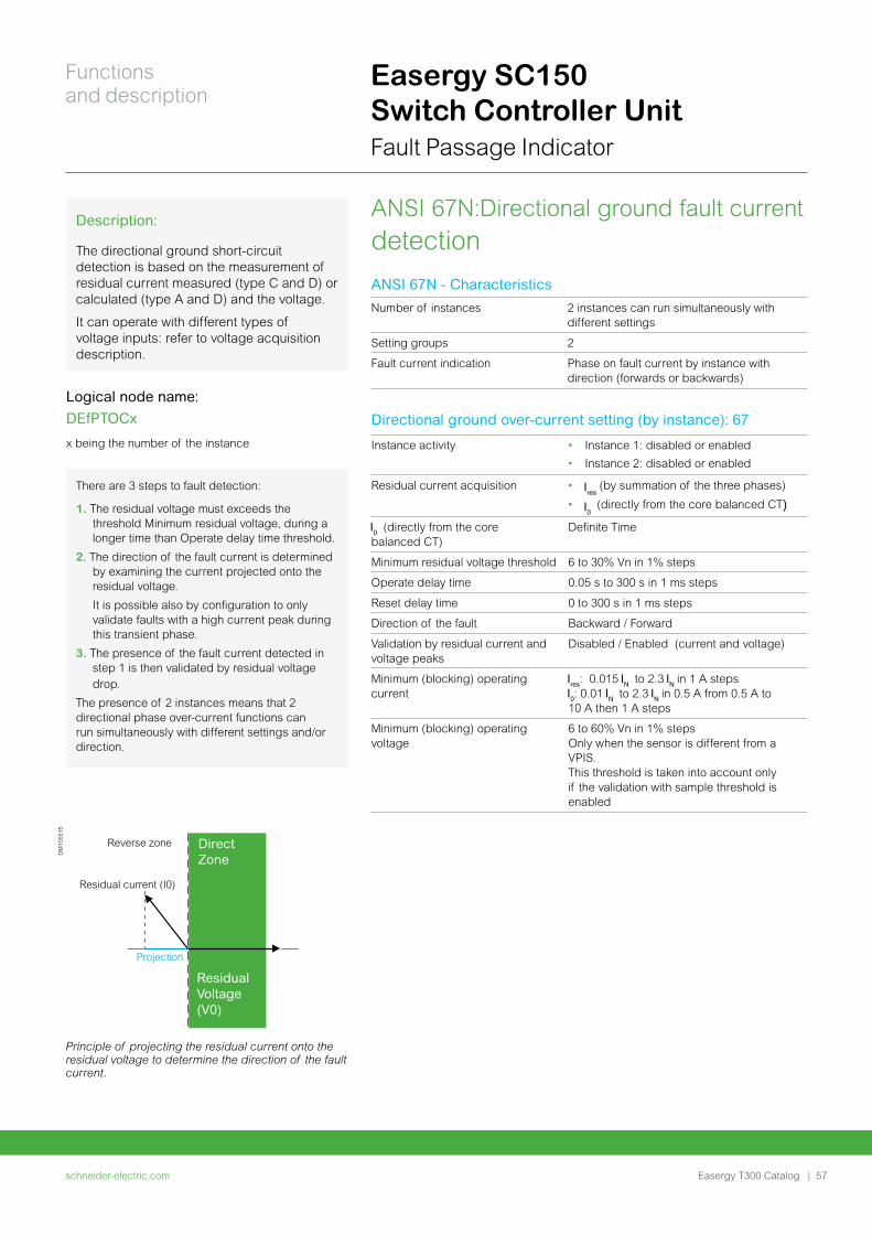
Direct Zone
Reverse zone
Residual current (I0)
Projection
ResidualVoltage(V0)
DM
1055
15
ANSI 67N:Directional ground fault current detection
Description:
The directional ground short-circuit detection is based on the measurement of residual current measured (type C and D) or calculated (type A and D) and the voltage.
It can operate with different types of voltage inputs: refer to voltage acquisition description.
There are 3 steps to fault detection:
1. The residual voltage must exceeds the threshold Minimum residual voltage, during a longer time than Operate delay time threshold.
2. The direction of the fault current is determined by examining the current projected onto the residual voltage.
It is possible also by configuration to only validate faults with a high current peak during this transient phase.
3. The presence of the fault current detected in step 1 is then validated by residual voltage drop.
The presence of 2 instances means that 2 directional phase over-current functions can run simultaneously with different settings and/or direction.
Logical node name:
DEfPTOCx
x being the number of the instance
Easergy SC150 Switch Controller Unit Fault Passage Indicator
ANSI 67N - Characteristics
Number of instances 2 instances can run simultaneously with different settings
Setting groups 2
Fault current indication Phase on fault current by instance with direction (forwards or backwards)
Instance activity • Instance 1: disabled or enabled
• Instance 2: disabled or enabled
Residual current acquisition • (by summation of the three phases)
• (directly from the core balanced CT)
(directly from the core balanced CT)
Definite Time
Minimum residual voltage threshold 6 to 30% Vn in 1% steps
Operate delay time 0.05 s to 300 s in 1 ms steps
Reset delay time 0 to 300 s in 1 ms steps
Direction of the fault Backward / Forward
Validation by residual current and voltage peaks
Disabled / Enabled (current and voltage)
Minimum (blocking) operating current
: 0.015 to 2.3 in 1 A steps: 0.01 to 2.3 in 0.5 A from 0.5 A to
10 A then 1 A steps
Minimum (blocking) operating voltage
6 to 60% Vn in 1% steps Only when the sensor is different from a VPIS. This threshold is taken into account only if the validation with sample threshold is enabled
Directional ground over-current setting (by instance): 67
Principle of projecting the residual current onto the residual voltage to determine the direction of the fault current.
schneider-electric.com | 57
Functions and description
Easergy T300 Catalog
ANSI 47 – Negative sequence overvoltage
(Voltage broken conductor detection)
Description:
Detection of phase balances resulting from phase inversion or unbalanced supply, detected by the measurement of negative sequence voltage.
It allows detecting a loss of one or two phases on medium voltage network (broken conductor) and sends an alarm to the control center.
Associated with ANSI 47, detection on the LV side with LV150, Easergy T300 can detect a blown fuse in the substation (forwards and backwards of the MV/LV transformer).
Logical node name:
BcPTOV x
x being the number of the instance
Easergy SC150 Switch Controller Unit Network monitoring
Voltage broken conductor characteristics
Number of instances 2 instances can run simultaneously with different settings
Setting groups 2
Fault current indication Fault current detected
Broken conductor setting (by instance)
Instance activity • Instance 1: disabled or enabled
• Instance 2: disabled or enabled
Phase voltage detection threshold 2 to 30% Vn in 1% step
Operating time delay: 0 to 300 s in 10 ms step
Fault detection reset • Reset voltage threshold: 2 to 30% Vn
• Reset time delay: 0 to 300 s in 10 ms step
schneider-electric.com58 |
Functions and description
Easergy T300 Catalog
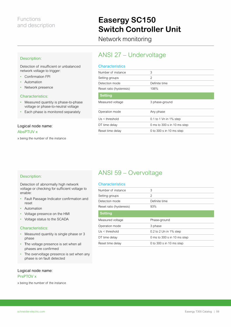
ANSI 27 – UndervoltageDescription:
Detection of insufficient or unbalanced network voltage to trigger:
• Confirmation FPI
• Automation
• Network presence
Characteristics:
• Measured quantity is phase-to-phase voltage or phase-to-neutral voltage
• Each phase is monitored separately
Logical node name:
AbsPTUV x
x being the number of the instance
Easergy SC150 Switch Controller Unit Network monitoring
Characteristics
Number of instance 3
Setting groups 2
Detection mode Definite time
Reset ratio (hysteresis) 106%
Setting
Measured voltage 3 phase-ground
Operation mode Any phase
Us < threshold 0.1 to 1 Vn in 1% step
DT time delay 0 ms to 300 s in 10 ms step
Reset time delay 0 to 300 s in 10 ms step
ANSI 59 – Overvoltage Description:
Detection of abnormally high network voltage or checking for sufficient voltage to enable:
• Fault Passage Indicator confirmation and reset
• Automation
• Voltage presence on the HMI
• Voltage status to the SCADA
Characteristics:
• Measured quantity is single phase or 3 phase
• The voltage presence is set when all phases are confirmed
• The overvoltage presence is set when any phase is on fault detected
Logical node name:
PrsPTOV x
x being the number of the instance
Characteristics
Number of instance 3
Setting groups 2
Detection mode Definite time
Reset ratio (hysteresis) 93%
Setting
Measured voltage Phase-ground
Operation mode 3 phase
Us < threshold 0.2 to 2 Un in 1% step
DT time delay 0 ms to 300 s in 10 ms step
Reset time delay 0 to 300 s in 10 ms step
schneider-electric.com | 59
Functions and description
Easergy T300 Catalog
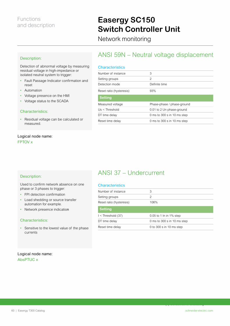
(1) Consult us for availability
Easergy SC150 Switch Controller Unit Network monitoring
ANSI 37 – UndercurrentDescription:
Used to confirm network absence on one phase or 3 phases to trigger:
• FPI detection confirmation
• Load shedding or source transfer automation for example.
• Network presence indication
Characteristics:
• Sensitive to the lowest value of the phase currents
Logical node name:
AbsPTUC x
Characteristics
Number of instance 3
Setting groups 2
Reset ratio (hysteresis) 106%
Setting
I < Threshold (37) 0.05 to 1 In in 1% step
DT time delay 0 ms to 300 s in 10 ms step
Reset time delay 0 to 300 s in 10 ms step
ANSI 59N – Neutral voltage displacementDescription:
Detection of abnormal voltage by measuring residual voltage in high-impedance or isolated neutral system to trigger:
• Fault Passage Indicator confirmation and reset
• Automation
• Voltage presence on the HMI
• Voltage status to the SCADA
Characteristics:
• Residual voltage can be calculated or measured.
Logical node name:
FPTOV x
Characteristics
Number of instance 3
Setting groups 2
Detection mode Definite time
Reset ratio (hysteresis) 93%
Setting
Measured voltage Phase-phase / phase-ground
Us < Threshold 0.01 to 2 Un phase-ground
DT time delay 0 ms to 300 s in 10 ms step
Reset time delay 0 ms to 300 s in 10 ms step
schneider-electric.com60 |
Functions and description
Easergy T300 Catalog
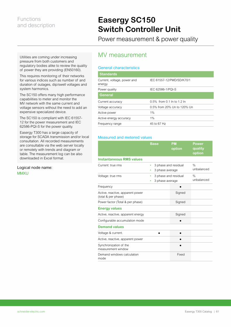
Easergy SC150 Switch Controller Unit Power measurement & power quality
MV measurementUtilities are coming under increasing pressure from both customers and regulatory bodies alike to review the quality of power they are providing (EN50160).
This requires monitoring of their networks for various indices such as number of and duration of outages, dip/swell voltages and system harmonics.
The SC150 offers many high performance capabilities to meter and monitor the MV network with the same current and voltage sensors without the need to add an expensive specialized device.
The SC150 is compliant with IEC 61557-12 for the power measurement and IEC 62586-PQI-S for the power quality.
Easergy T300 has a large capacity of storage for SCADA transmission and/or local consultation. All recorded measurements are consultable via the web server locally or remotely with trends and diagram or table. The measurement log can be also downloaded in Excel format.
Logical node name:
MMXU
General characteristics
Standards
Current, voltage, power and energy
IEC 61557-12/PMD/SD/K70/1
Power quality IEC 62586-1/PQI-S
General
Current accuracy 0.5% from 0.1 In to 1.2 In
Voltage accuracy 0.5% from 20% Un to 120% Un
Active power 1%
Active energy accuracy 1%
Frequency range 45 to 67 Hz
Measured and metered values
Base PM option
Power quality option
Instantaneous RMS values
Current: true rms • 3 phase and residual
• 3 phase average
% unbalanced
Voltage: true rms • 3 phase and residual
• 3 phase average
% unbalanced
Frequency
Active, reactive, apparent power (total & per phase)
Signed
Power factor (Total & per phase) Signed
Energy values
Active, reactive, apparent energy Signed
Configurable accumulation mode
Demand values
Voltage & current.
Active, reactive, apparent power
Synchronization of the measurement window
Demand windows calculation mode
Fixed
schneider-electric.com | 61
Functions and description
Easergy T300 Catalog
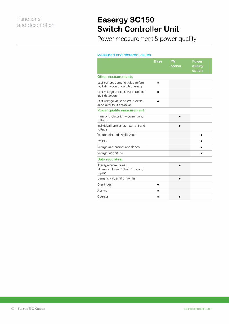
Easergy SC150 Switch Controller Unit Power measurement & power quality
Measured and metered values
Base PM option
Power quality option
Other measurements
Last current demand value before fault detection or switch opening
Last voltage demand value before fault detection
Last voltage value before broken conductor fault detection
Power quality measurement
Harmonic distortion – current and voltage
Individual harmonics – current and voltage
Voltage dip and swell events
Events
Voltage and current unbalance
Voltage magnitude
Data recording
Average current rms Min/max : 1 day, 7 days, 1 month, 1 year
Demand values at 3 months
Event logs
Alarms
Counter
schneider-electric.com62 |
Functions and description
Easergy T300 Catalog
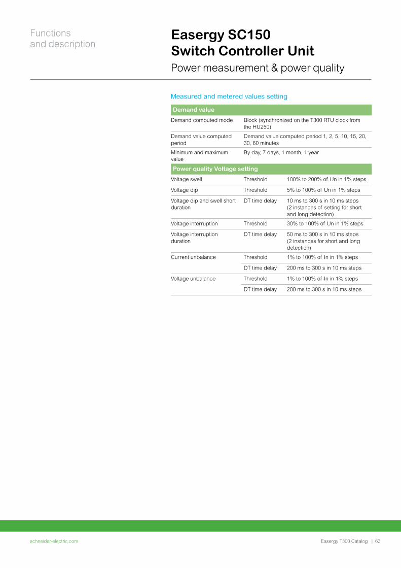
Easergy SC150 Switch Controller Unit Power measurement & power quality
Measured and metered values setting
Demand value
Demand computed mode Block (synchronized on the T300 RTU clock from the HU250)
Demand value computed period
Demand value computed period 1, 2, 5, 10, 15, 20, 30, 60 minutes
Minimum and maximum value
By day, 7 days, 1 month, 1 year
Power quality Voltage setting
Voltage swell Threshold 100% to 200% of Un in 1% steps
Voltage dip Threshold 5% to 100% of Un in 1% steps
Voltage dip and swell short duration
DT time delay 10 ms to 300 s in 10 ms steps (2 instances of setting for short and long detection)
Voltage interruption Threshold 30% to 100% of Un in 1% steps
Voltage interruption duration
DT time delay 50 ms to 300 s in 10 ms steps (2 instances for short and long detection)
Current unbalance Threshold 1% to 100% of In in 1% steps
DT time delay 200 ms to 300 s in 10 ms steps
Voltage unbalance Threshold 1% to 100% of In in 1% steps
DT time delay 200 ms to 300 s in 10 ms steps
schneider-electric.com | 63
Functions and description
Easergy T300 Catalog
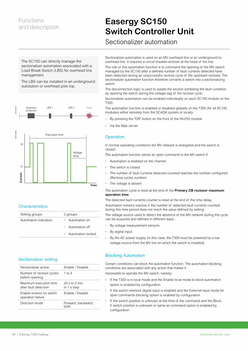
Sectionalizer automation is used on an MV overhead line or an underground to overhead line. It requires a circuit breaker-recloser at the head of the line.
The role of this automation function is to command the opening of the MV switch managed by the SC150 after a defined number of fault currents detected have been detected during an unsuccessful reclose cycle of the upstream recloser. The sectionalizer automation function therefore converts a switch into a sectionalizing switch.
The disconnection logic is used to isolate the section exhibiting the fault condition by opening the switch during the voltage sag of the reclose cycle.
Sectionalizer automation can be enabled individually on each SC150 module on the T300.
The automation function is enabled or disabled globally on the T300 (for all SC150 modules) either remotely from the SCADA system or locally:
• By pressing the "ON" button on the front of the HU250 module
• Via the Web server
Operation
In normal operating conditions the MV network is energized and the switch is closed.
The automation function sends an open command to the MV switch if:
• Automation is enabled on the channel
• The switch is closed
• The number of fault currents detected counted reaches the number configured (Reclose cycles number)
• The voltage is absent
The automation cycle is reset at the end of the Primary CB recloser maximum operation time.
The detected fault currents counter is reset at the end of this time delay.
Automation remains inactive if the number of detected fault currents counted during this time period does not reach the value defined by setting.
The voltage source used to detect the absence of the MV network during the cycle can be acquired and defined in different ways :
• By voltage measurement sensors
• By digital input
• By the AC power supply (in this case, the T300 must be powered by a low
voltage source from the MV line on which the switch is installed)
Blocking Automation
Certain conditions can block the automation function. The automation blocking conditions are associated with any action that makes it
impossible to operate the MV switch, namely:
• If the T300 is in local mode and the Enable local mode to block automation
option is enabled by configuration
• If the switch interlock digital input is enabled and the External input mode for open commands blocking option is enabled by configuration
• If the switch position is unknown at the time of the command and the Block if switch position is unknown or same as command option is enabled by configuration
Upstreamprotection
LBS 1 LBS 2 Fault
DM
1034
87
Execution time
Cur
rent
Id
In
Time
Voltagedrop
DM
1034
88
Easergy SC150 Switch Controller Unit Sectionalizer automation
The SC150 can directly manage the sectionalizer automation associated with a Load Break Switch (LBS) for overhead line management.
The LBS can be installed in an underground substation or overhead pole top.
Setting groups 2 groups
Automation indication • Automation on
• Automation off
• Automation locked
Characteristics
Sectionalizer active Enable / Disable
Number of reclose cycles before opening
1 to 4
Maximum execution time after fault detection
20 s to 5 min in 1 s step
Enable lockout on switch operation failure
Enable / Disable
Direction mode Forward, backward, both
Sectionalizer setting
schneider-electric.com64 |
Functions and description
Easergy T300 Catalog
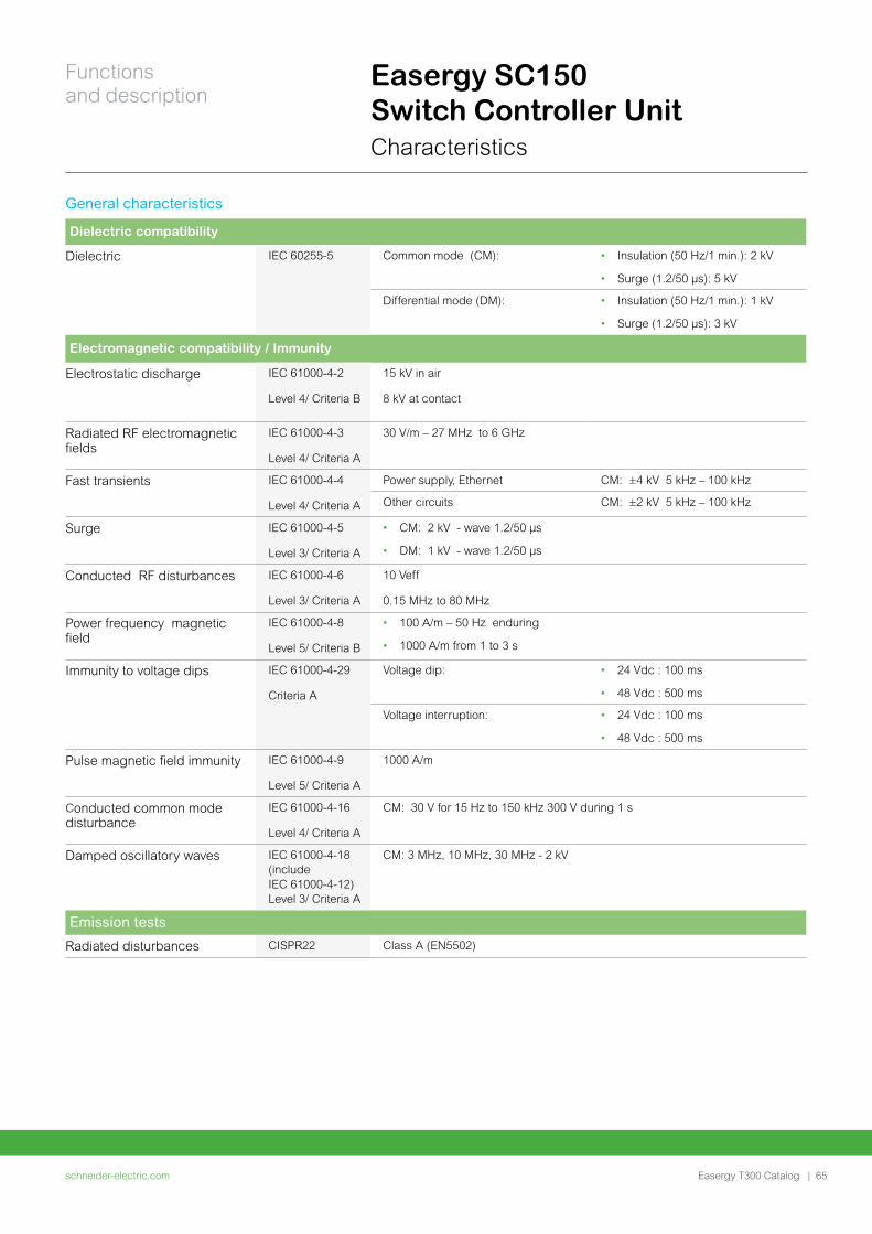
Easergy SC150 Switch Controller Unit Characteristics
General characteristics
Dielectric compatibility
Dielectric IEC 60255-5 Common mode (CM): • Insulation (50 Hz/1 min.): 2 kV
• Surge (1.2/50 μs): 5 kV
Differential mode (DM): • Insulation (50 Hz/1 min.): 1 kV
• Surge (1.2/50 μs): 3 kV
Electromagnetic compatibility / Immunity
Electrostatic discharge IEC 61000-4-2
Level 4/ Criteria B
15 kV in air
8 kV at contact
Radiated RF electromagnetic fields
IEC 61000-4-3
Level 4/ Criteria A
30 V/m – 27 MHz to 6 GHz
Fast transients IEC 61000-4-4
Level 4/ Criteria A
Power supply, Ethernet CM: ±4 kV 5 kHz – 100 kHz
Other circuits CM: ±2 kV 5 kHz – 100 kHz
Surge IEC 61000-4-5
Level 3/ Criteria A
• CM: 2 kV - wave 1.2/50 µs
• DM: 1 kV - wave 1.2/50 µs
Conducted RF disturbances IEC 61000-4-6
Level 3/ Criteria A
10 Veff
0.15 MHz to 80 MHz
Power frequency magnetic field
IEC 61000-4-8
Level 5/ Criteria B
• 100 A/m – 50 Hz enduring
• 1000 A/m from 1 to 3 s
Immunity to voltage dips IEC 61000-4-29
Criteria A
Voltage dip: • 24 Vdc : 100 ms
• 48 Vdc : 500 ms
Voltage interruption: • 24 Vdc : 100 ms
• 48 Vdc : 500 ms
Pulse magnetic field immunity IEC 61000-4-9
Level 5/ Criteria A
1000 A/m
Conducted common mode disturbance
IEC 61000-4-16
Level 4/ Criteria A
CM: 30 V for 15 Hz to 150 kHz 300 V during 1 s
Damped oscillatory waves IEC 61000-4-18 (include IEC 61000-4-12) Level 3/ Criteria A
CM: 3 MHz, 10 MHz, 30 MHz - 2 kV
Emission tests
Radiated disturbances CISPR22 Class A (EN5502)
schneider-electric.com | 65
Functions and description
Easergy T300 Catalog
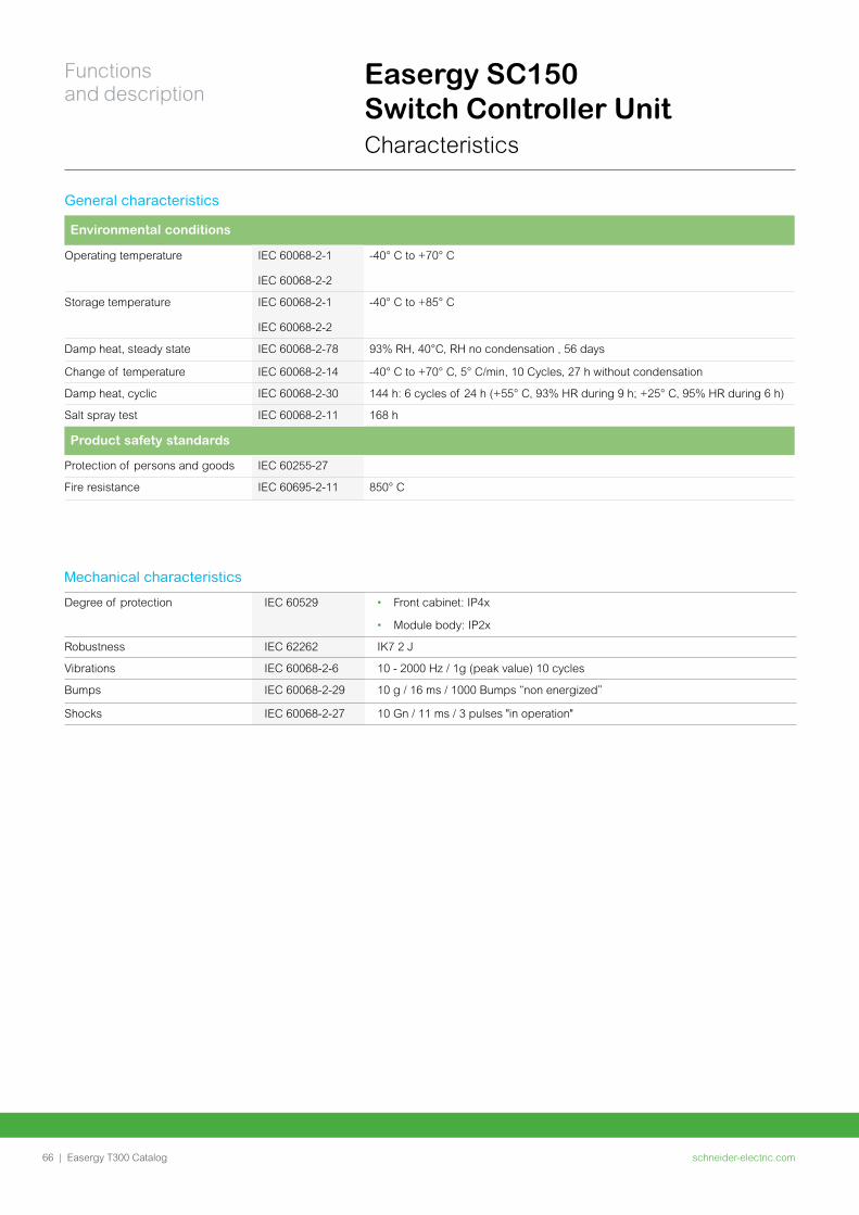
Easergy SC150 Switch Controller Unit Characteristics
Mechanical characteristics
Degree of protection IEC 60529 • Front cabinet: IP4x
• Module body: IP2x
Robustness IEC 62262 IK7 2 J
Vibrations IEC 60068-2-6 10 - 2000 Hz / 1g (peak value) 10 cycles
Bumps IEC 60068-2-29 10 g / 16 ms / 1000 Bumps “non energized”
Shocks IEC 60068-2-27 10 Gn / 11 ms / 3 pulses "in operation"
General characteristics
Environmental conditions
Operating temperature IEC 60068-2-1
IEC 60068-2-2
-40° C to +70° C
Storage temperature IEC 60068-2-1
IEC 60068-2-2
-40° C to +85° C
Damp heat, steady state IEC 60068-2-78 93% RH, 40°C, RH no condensation , 56 days
Change of temperature IEC 60068-2-14 -40° C to +70° C, 5° C/min, 10 Cycles, 27 h without condensation
Damp heat, cyclic IEC 60068-2-30 144 h: 6 cycles of 24 h (+55° C, 93% HR during 9 h; +25° C, 95% HR during 6 h)
Salt spray test IEC 60068-2-11 168 h
Product safety standards
Protection of persons and goods IEC 60255-27
Fire resistance IEC 60695-2-11 850° C
schneider-electric.com66 |
Functions and description
Easergy T300 Catalog

Notes
schneider-electric.com | 67Easergy T300 Catalog
Easergy LV150Low Voltage monitoring
schneider-electric.com68 |
Functions and description
Easergy T300 Catalog
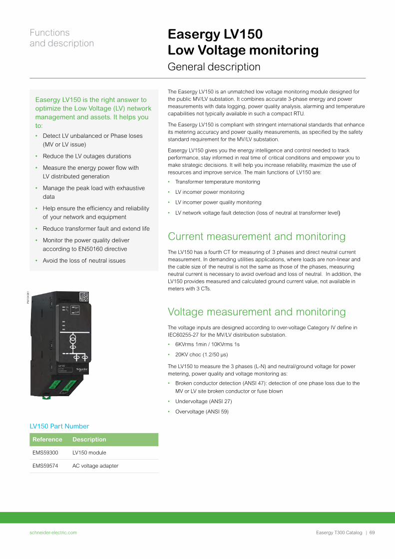
Easergy LV150 is the right answer to optimize the Low Voltage (LV) network management and assets. It helps you to:
• Detect LV unbalanced or Phase loses
(MV or LV issue)
• Reduce the LV outages durations
• Measure the energy power flow with
LV distributed generation
• Manage the peak load with exhaustive
data
• Help ensure the efficiency and reliability
of your network and equipment
• Reduce transformer fault and extend life
• Monitor the power quality deliver
according to EN50160 directive
• Avoid the loss of neutral issues
Easergy LV150 Low Voltage monitoring General description
The Easergy LV150 is an unmatched low voltage monitoring module designed for the public MV/LV substation. It combines accurate 3-phase energy and power measurements with data logging, power quality analysis, alarming and temperature capabilities not typically available in such a compact RTU.
The Easergy LV150 is compliant with stringent international standards that enhance its metering accuracy and power quality measurements, as specified by the safety standard requirement for the MV/LV substation.
Easergy LV150 gives you the energy intelligence and control needed to track performance, stay informed in real time of critical conditions and empower you to make strategic decisions. It will help you increase reliability, maximize the use of resources and improve service. The main functions of LV150 are:
• Transformer temperature monitoring
• LV incomer power monitoring
• LV incomer power quality monitoring
• LV network voltage fault detection (loss of neutral at transformer level)
Current measurement and monitoringThe LV150 has a fourth CT for measuring of 3 phases and direct neutral current measurement. In demanding utilities applications, where loads are non-linear and the cable size of the neutral is not the same as those of the phases, measuring neutral current is necessary to avoid overload and loss of neutral. In addition, the LV150 provides measured and calculated ground current value, not available in meters with 3 CTs.
Voltage measurement and monitoringThe voltage inputs are designed according to over-voltage Category IV define in IEC60255-27 for the MV/LV distribution substation.
• 6KVrms 1min / 10KVrms 1s
• 20KV choc (1.2/50 µs)
The LV150 to measure the 3 phases (L-N) and neutral/ground voltage for power metering, power quality and voltage monitoring as:
• Broken conductor detection (ANSI 47): detection of one phase loss due to the
MV or LV site broken conductor or fuse blown
• Undervoltage (ANSI 27)
• Overvoltage (ANSI 59)
LV150 Part Number
Reference Description
EMS59300 LV150 module
EMS59574 AC voltage adapter
PM
1043
81
schneider-electric.com | 69
Functions and description
Easergy T300 Catalog
Easergy LV150 Low Voltage monitoring General description
Power measurements according to IEC 61557-12/PMD/SD/K70/1
• Voltage and current RMS values
• Min/max current RMS on 1 day, 7 days,1month 1 year)
• Real, apparent and reactive power in four quadrants for knowing the energy
power flow with distributed generation
• Energy value received and delivered
• THD on voltage and current per phase
• Individual harmonics tension and current including neutral that can harm
transformer and cable connection.
• Demand value for following peak demands with time stamping.
Power quality according to IEC 62586-1/PQI-S (IEC61000-4-30 class S)
• Power quality monitoring with supply magnitude, voltage dip and swell, voltage
unbalance and harmonic voltage.
• Voltage unbalance
• Voltage magnitude
Transformer monitoring • Temperature monitoring and alarm
• Peak load measurement
schneider-electric.com70 |
Functions and description
Easergy T300 Catalog
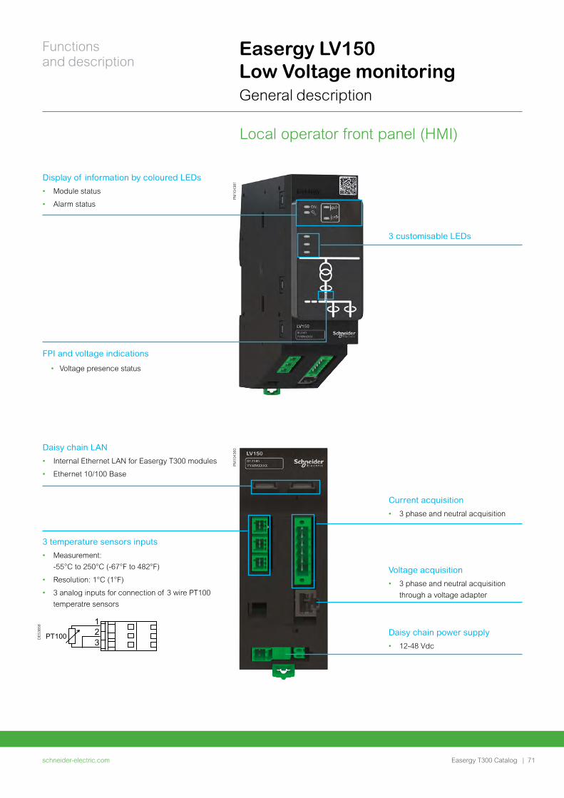
Easergy LV150 Low Voltage monitoring General description
Local operator front panel (HMI)
PM
1043
81
Display of information by coloured LEDs
• Module status
• Alarm status
3 customisable LEDs
FPI and voltage indications
• Voltage presence status
PM
1043
60
Daisy chain LAN
• Internal Ethernet LAN for Easergy T300 modules
• Ethernet 10/100 Base
3 temperature sensors inputs
• Measurement:
-55°C to 250°C (-67°F to 482°F)
• Resolution: 1°C (1°F)
• 3 analog inputs for connection of 3 wire PT100
temperatre sensors
Current acquisition
• 3 phase and neutral acquisition
Voltage acquisition
• 3 phase and neutral acquisition
through a voltage adapter
Daisy chain power supply
• 12-48 Vdc
DE
5385
8
PT100
123
schneider-electric.com | 71
Functions and description
Easergy T300 Catalog
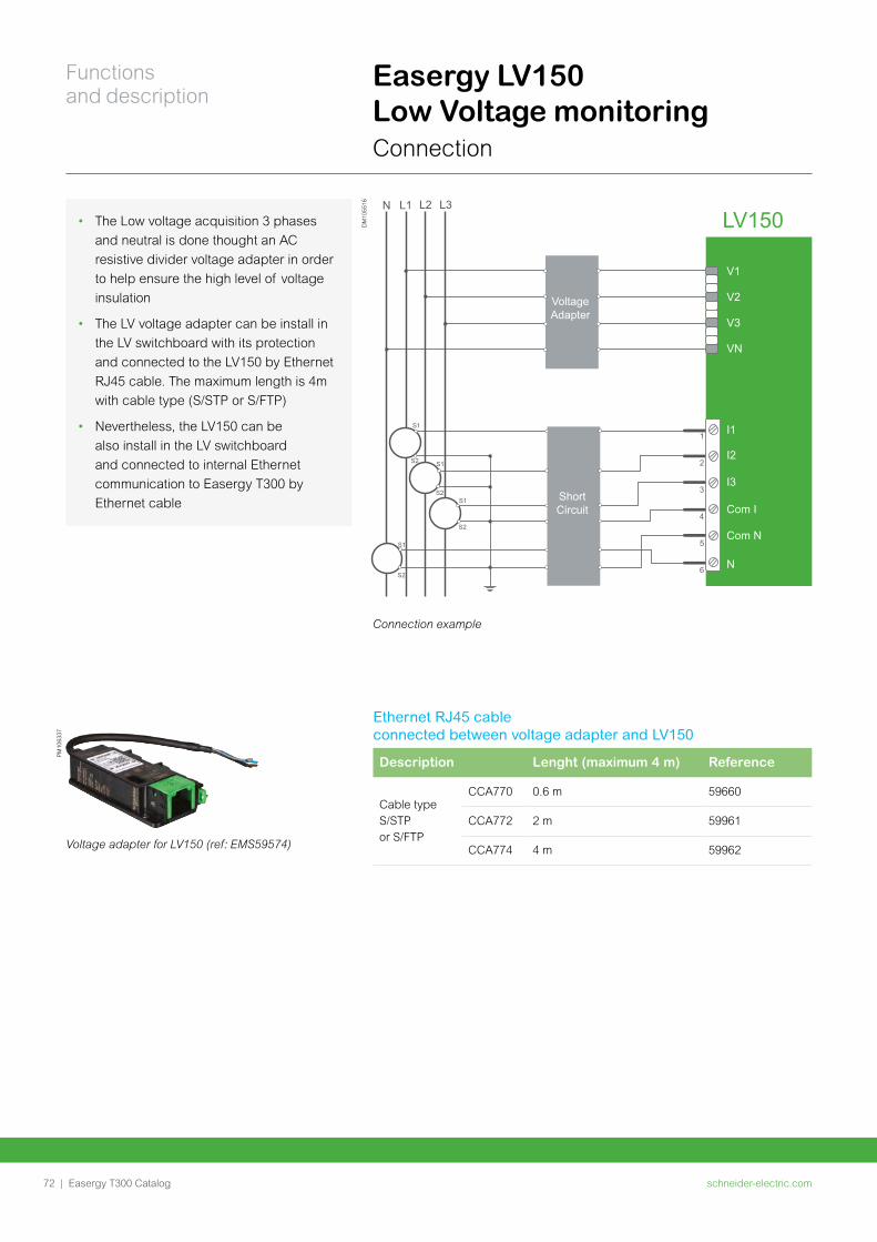
Voltage Adapter
N L1 L3L2
LV150
V1
V2
V3
VN
1
2
3
4
5
6
Short Circuit
S1
S2 S1
S2S1
S2
S1
S2
I1
I2
I3
Com I
Com N
N
DM
1055
16
PM
1063
37
Easergy LV150 Low Voltage monitoring Connection
Ethernet RJ45 cable connected between voltage adapter and LV150
Description Lenght (maximum 4 m) Reference
Cable type S/STP or S/FTP
CCA770 0.6 m 59660
CCA772 2 m 59961
CCA774 4 m 59962
• The Low voltage acquisition 3 phases
and neutral is done thought an AC
resistive divider voltage adapter in order
to help ensure the high level of voltage
insulation
• The LV voltage adapter can be install in
the LV switchboard with its protection
and connected to the LV150 by Ethernet
RJ45 cable. The maximum length is 4m
with cable type (S/STP or S/FTP)
• Nevertheless, the LV150 can be
also install in the LV switchboard
and connected to internal Ethernet
communication to Easergy T300 by
Ethernet cable
Connection example
Voltage adapter for LV150 (ref: EMS59574)
schneider-electric.com72 |
Functions and description
Easergy T300 Catalog
Easergy LV150 Low Voltage monitoring Network monitoring
ANSI 27 – UndervoltageDescription:
Detection of insufficient or unbalanced network voltage to trigger:
• Control center alarm
• Automation
• Network presence
Characteristics:
• Measured quantity is phase-to-phase voltage or phase-to-neutral voltage.
• Each phase is monitored separately.
Logical node name:
AbsPTUV x
x being the number of the instance
Characteristics
Number of instance 3
Setting groups 2
Detection mode Definite time
Reset ratio (hysteresis) 106%
Setting
Measured voltage 3 phase-ground
Operation mode Any phase
Us < threshold 0.1 to 1 Vn in 1% step
DT time delay 0 ms to 300 s in 10 ms step
Reset time delay 0 to 300 s in 10 ms step
ANSI 47 – Negative sequence overvoltage
(Voltage broken conductor detection)
Description:
Detection of phase balances resulting from phase inversion or unbalanced supply, detected by the measurement of negative sequence voltage.
It allows detecting a loss of one or two phases on medium voltage network (broken conductor) and sends an alarm to the control center.
Associated with ANSI 47, detection on the MV side with SC150 , Easergy T300 can detect a blown fuse in the substation (forwards and backwards MV/LV transformer)
Logical node name:
BcPTOV x
x being the number of the instance
Voltage broken conductor characteristics
Number of instances 2 instances can run simultaneously with different settings
Setting groups 2
Fault indication Fault detected
Broken conductor setting (by instance)
Instance activity • Instance 1: disabled or enabled
• Instance 2: disabled or enabled
Phase voltage detection threshold 2 to 30% Vn in 1% step
Operating time delay: 0 to 300 s in 10 ms step
Fault detection reset • Reset voltage threshold: 2 to 30% Vn
• Reset time delay: 0 to 300 s in 10 ms step
schneider-electric.com | 73
Functions and description
Easergy T300 Catalog
Easergy LV150 Low Voltage monitoring Network monitoring
ANSI 37 – UndercurrentDescription:
Used to confirm network absence on one phase or 3 phases to trigger:
• Neutral "cut-out"
• One phase fuse blown
• Network presence indication
Characteristics:
• Sensitive to the lowest value of the phase currents
Logical node name:
AbsPTUC x
Characteristics
Number of instance 3
Setting groups 2
Reset ratio (hysteresis) 106%
Setting
I < Threshold (37) 0.05 to 1 In in 1% step
DT time delay 0 ms to 300 s in 10 ms step
Reset time delay 0 to 300 s in 10 ms step
ANSI 59 – Overvoltage Description:
Detection of abnormally high network voltage or checking for sufficient voltage to enable:
• Control center alarm
• Automation
Characteristics:
• Measured quantity is single phase or 3 phase
• The voltage presence is set when all phases are confirmed
• The overvoltage presence is set when any phase is on fault current detection
Logical node name:
PrsPTOV x
x being the number of the instance
Characteristics
Number of instance 3
Setting groups 2
Detection mode Definite time
Reset ratio (hysteresis) 93%
Setting
Measured voltage Phase-ground
Operation mode 3 phase
Us < threshold 0.2 to 2 Un in 1% step
DT time delay 0 ms to 300 s in 10 ms step
Reset time delay 0 to 300 s in 10 ms step
schneider-electric.com74 |
Functions and description
Easergy T300 Catalog
Easergy LV150 Low Voltage monitoring Characteristics
Electrical characteristics
Input-voltage (with voltage adapter)
Network 3 phases and neutral
Nominal voltage L - L : 190 to 400 Vac
Frequency 45 to 67Hz
Impedance 10 MΩ
Input-current
Nb of current input 4 current inputs: 3 phases and neutral with different setting for phase and neutral
Primary rated value 50 to 3000 A
Rated nominal current 1A or 5A
Current measurement range 0.01 to 7 In (rated nominal current)
Permissible overload • 10 A In continuous
• 50 A In-10s per hour
• 120A -1s
Impedance 1 milliohm
Burden 0.025 VA
Input-analog
Type 3 analog 3 wire PT100 temperature sensors
Measurement range -55 to 250°C (-67°F to 482°F)
Resolution 1°C (1°F)
Accuracy 1%
Power supply
Voltage input 12V to 48V dc (-15%, +20%)
Burden 3 VA; max typical: 1,5 VA
Current acquisition setting
Input-current setting
Primary phase CT rated Adjustable from 50 A to 3000 A in 1A step
Primary neutral CT rated Adjustable from 50 A to 3000 A in 1A step
schneider-electric.com | 75
Functions and description
Easergy T300 Catalog
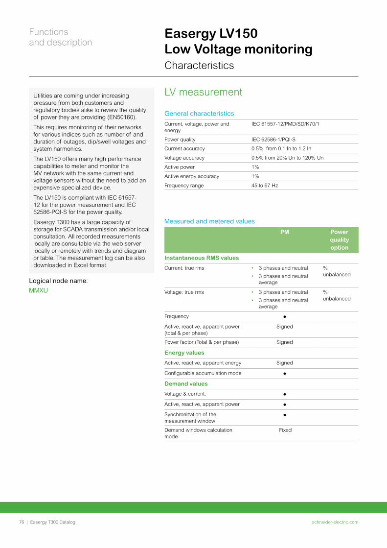
Easergy LV150 Low Voltage monitoring Characteristics
LV measurementUtilities are coming under increasing pressure from both customers and regulatory bodies alike to review the quality of power they are providing (EN50160).
This requires monitoring of their networks for various indices such as number of and duration of outages, dip/swell voltages and system harmonics.
The LV150 offers many high performance capabilities to meter and monitor the MV network with the same current and voltage sensors without the need to add an expensive specialized device.
The LV150 is compliant with IEC 61557-12 for the power measurement and IEC 62586-PQI-S for the power quality.
Easergy T300 has a large capacity of storage for SCADA transmission and/or local consultation. All recorded measurements locally are consultable via the web server locally or remotely with trends and diagram or table. The measurement log can be also downloaded in Excel format.
Logical node name:
MMXU
General characteristics
Current, voltage, power and energy
IEC 61557-12/PMD/SD/K70/1
Power quality IEC 62586-1/PQI-S
Current accuracy 0.5% from 0.1 In to 1.2 In
Voltage accuracy 0.5% from 20% Un to 120% Un
Active power 1%
Active energy accuracy 1%
Frequency range 45 to 67 Hz
Measured and metered values
PM Power quality option
Instantaneous RMS values
Current: true rms • 3 phases and neutral
• 3 phases and neutral average
% unbalanced
Voltage: true rms • 3 phases and neutral
• 3 phases and neutral average
% unbalanced
Frequency
Active, reactive, apparent power (total & per phase)
Signed
Power factor (Total & per phase) Signed
Energy values
Active, reactive, apparent energy Signed
Configurable accumulation mode
Demand values
Voltage & current.
Active, reactive, apparent power
Synchronization of the measurement window
Demand windows calculation mode
Fixed
schneider-electric.com76 |
Functions and description
Easergy T300 Catalog
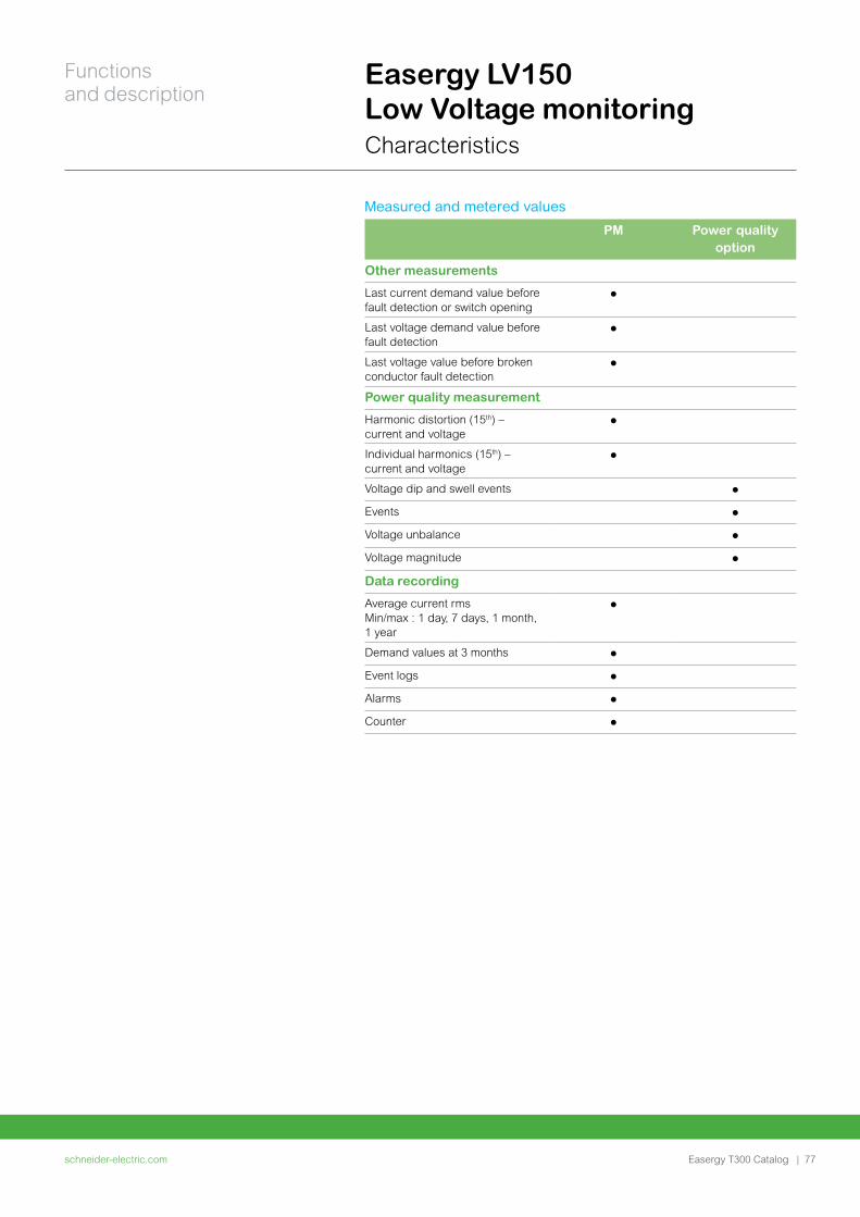
Easergy LV150 Low Voltage monitoring Characteristics
Measured and metered values
PM Power quality option
Other measurements
Last current demand value before fault detection or switch opening
Last voltage demand value before fault detection
Last voltage value before broken conductor fault detection
Power quality measurement
Harmonic distortion (15th) – current and voltage
Individual harmonics (15th) – current and voltage
Voltage dip and swell events
Events
Voltage unbalance
Voltage magnitude
Data recording
Average current rms Min/max : 1 day, 7 days, 1 month, 1 year
Demand values at 3 months
Event logs
Alarms
Counter
schneider-electric.com | 77
Functions and description
Easergy T300 Catalog
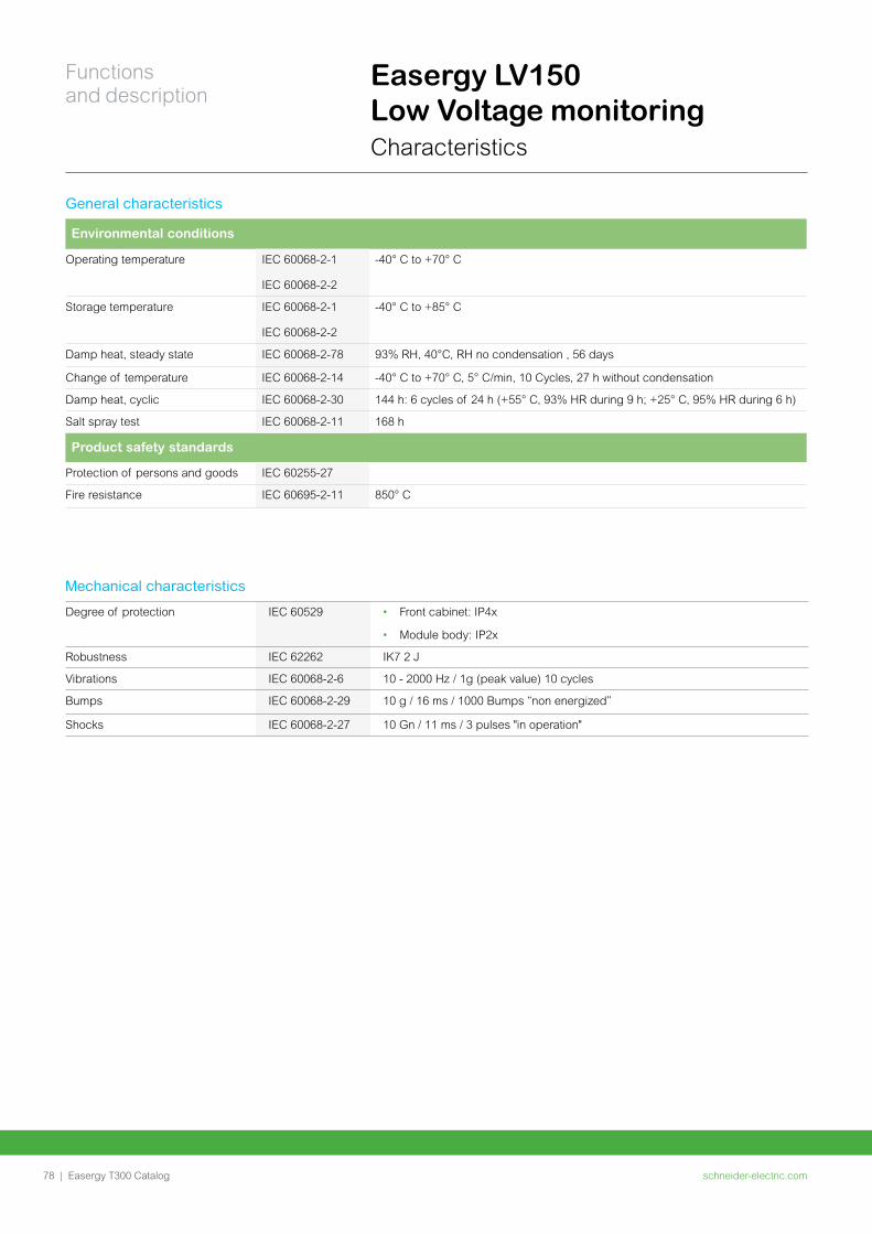
Easergy LV150 Low Voltage monitoring Characteristics
Mechanical characteristics
Degree of protection IEC 60529 • Front cabinet: IP4x
• Module body: IP2x
Robustness IEC 62262 IK7 2 J
Vibrations IEC 60068-2-6 10 - 2000 Hz / 1g (peak value) 10 cycles
Bumps IEC 60068-2-29 10 g / 16 ms / 1000 Bumps “non energized”
Shocks IEC 60068-2-27 10 Gn / 11 ms / 3 pulses "in operation"
General characteristics
Environmental conditions
Operating temperature IEC 60068-2-1
IEC 60068-2-2
-40° C to +70° C
Storage temperature IEC 60068-2-1
IEC 60068-2-2
-40° C to +85° C
Damp heat, steady state IEC 60068-2-78 93% RH, 40°C, RH no condensation , 56 days
Change of temperature IEC 60068-2-14 -40° C to +70° C, 5° C/min, 10 Cycles, 27 h without condensation
Damp heat, cyclic IEC 60068-2-30 144 h: 6 cycles of 24 h (+55° C, 93% HR during 9 h; +25° C, 95% HR during 6 h)
Salt spray test IEC 60068-2-11 168 h
Product safety standards
Protection of persons and goods IEC 60255-27
Fire resistance IEC 60695-2-11 850° C
schneider-electric.com78 |
Functions and description
Easergy T300 Catalog
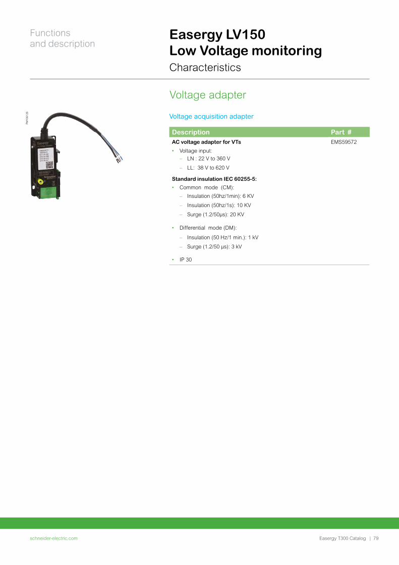
Easergy LV150 Low Voltage monitoring Characteristics
Voltage adapter
Voltage acquisition adapter
Description Part #AC voltage adapter for VTs
• Voltage input:
– LN : 22 V to 360 V
– LL: 38 V to 620 V
Standard insulation IEC 60255-5:
• Common mode (CM):
– Insulation (50hz/1min): 6 KV
– Insulation (50hz/1s): 10 KV
– Surge (1.2/50μs): 20 KV
• Differential mode (DM):
– Insulation (50 Hz/1 min.): 1 kV
– Surge (1.2/50 μs): 3 kV
• IP 30
EMS59572
PM
1061
26
schneider-electric.com | 79
Functions and description
Easergy T300 Catalog

Easergy PS50, PS25Power Supply
schneider-electric.com80 |
Functions and description
Easergy T300 Catalog
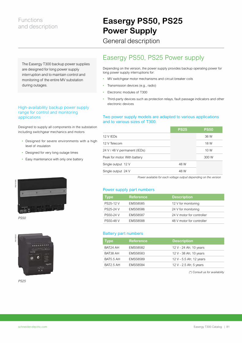
Easergy PS50, PS25 Power SupplyGeneral description
Easergy PS50, PS25 Power supply Depending on the version, the power supply provides backup operating power for long power supply interruptions for:
• MV switchgear motor mechanisms and circuit breaker coils
• Transmission devices (e.g., radio)
• Electronic modules of T300
• Third-party devices such as protection relays, fault passage indicators and other
electronic devices
Two power supply models are adapted to various applications and to various sizes of T300:
PS25 PS50
12 V IEDs 36 W
12 V Telecom 18 W
24 V / 48 V permanent (IEDs) 10 W
Peak for motor. With battery 300 W
Single output 12 V 48 W
Single output 24 V 48 W
Power available for each voltage output depending on the version
Power supply part numbers
Type Reference Description
PS25-12 V EMS58585 12 V for monitoring
PS25-24 V EMS58586 24 V for monitoring
PS50-24 V EMS58587 24 V motor for controller
PS50-48 V EMS58588 48 V motor for controller
Battery part numbers
Type Reference Description
BAT24 AH EMS58582 12 V - 24 Ah; 10 years
BAT38 AH EMS58583 12 V - 38 Ah; 10 years
BAT5.5 AH EMS58589 12 V - 5.5 Ah; 12 years
BAT2.5 AH EMS58584 12 V - 2.5 Ah; 5 years
PM
1043
66
The Easergy T300 backup power supplies
are designed for long power supply
interruption and to maintain control and
monitoring of the entire MV substation
during outages.
High-availability backup power supply range for control and monitoring applications
Designed to supply all components in the substation
including switchgear mechanics and motors
• Designed for severe environments with a high
level of insulation
• Designed for very long outage times
• Easy maintenance with only one battery
PM
1063
01
PS25
PS50
(*) Consult us for availability
schneider-electric.com | 81
Functions and description
Easergy T300 Catalog
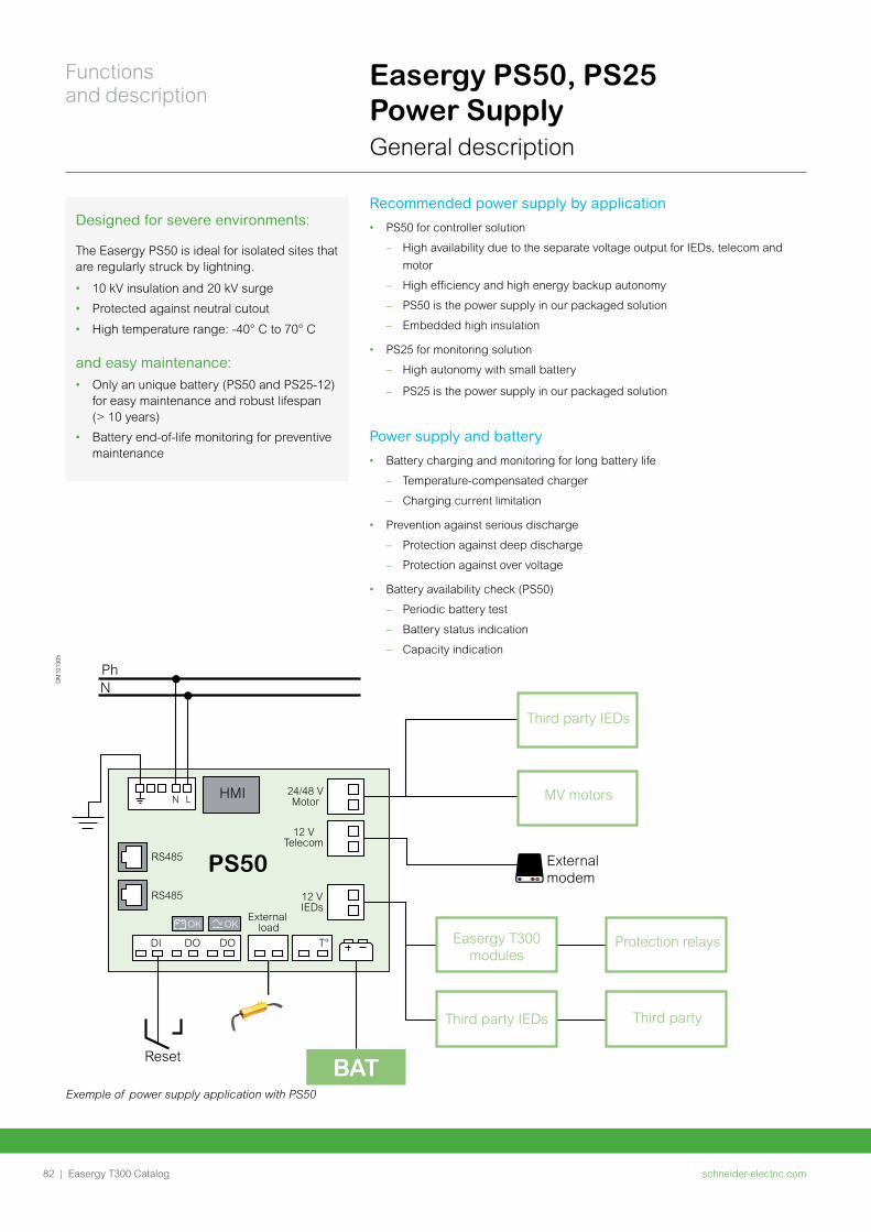
Recommended power supply by application
• PS50 for controller solution
– High availability due to the separate voltage output for IEDs, telecom and
motor
– High efficiency and high energy backup autonomy
– PS50 is the power supply in our packaged solution
– Embedded high insulation
• PS25 for monitoring solution
– High autonomy with small battery
– PS25 is the power supply in our packaged solution
Power supply and battery
• Battery charging and monitoring for long battery life
– Temperature-compensated charger
– Charging current limitation
• Prevention against serious discharge
– Protection against deep discharge
– Protection against over voltage
• Battery availability check (PS50)
– Periodic battery test
– Battery status indication
– Capacity indication
Exemple of power supply application with PS50
HMI
Easergy T300 modules
Third party IEDs
Protection relays
Third party
MV motors
Third party IEDs
PhN
PS50 External modem
Reset
External load
12 VIEDs
12 VTelecom
24/48 VMotor
RS485
RS485
N L
OK OK
DI DO DO T°
BAT
DM
1013
05
Designed for severe environments:
The Easergy PS50 is ideal for isolated sites that are regularly struck by lightning.
• 10 kV insulation and 20 kV surge
• Protected against neutral cutout
• High temperature range: -40° C to 70° C
and easy maintenance: • Only an unique battery (PS50 and PS25-12)
for easy maintenance and robust lifespan (> 10 years)
• Battery end-of-life monitoring for preventive maintenance
Easergy PS50, PS25 Power SupplyGeneral description
schneider-electric.com82 |
Functions and description
Easergy T300 Catalog
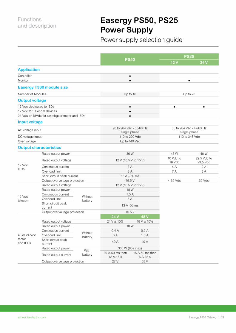
Easergy PS50, PS25 Power SupplyPower supply selection guide
PS50PS25
12 V 24 V
Application
Controller
Monitor
Easergy T300 module size
Number of Modules Up to 16 Up to 20
Output voltage
12 Vdc dedicated to IEDs
12 Vdc for Telecom devices
24 Vdc or 48Vdc for switchgear motor and IEDs
Input voltage
AC voltage input 90 to 264 Vac - 50/60 Hz
single phase85 to 264 Vac - 47/63 Hz
single phase
DC voltage input 110 to 220 Vdc 110 to 345 Vdc
Over voltage Up to 440 Vac
Output characteristics
12 Vdc IEDs
Rated output power 36 W 48 W 48 W
Rated output voltage 12 V (10.5 V to 15 V)10 Vdc to
16 Vdc22.5 Vdc to
29.5 Vdc
Continuous current 3 A 4 A 2 A
Overload limit 8 A 7 A 3 A
Short circuit peak current 13 A – 50 ms
Output overvoltage protection 15.5 V < 35 Vdc 35 Vdc
12 Vdc telecom
Rated output voltage 12 V (10.5 V to 15 V)
Rated output power
Without battery
18 W
Continuous current 1.5 A
Overload limit 8 A
Short circuit peak current
13 A -50 ms
Output overvoltage protection 15.5 V
48 or 24 Vdc motor and IEDs
24 V 48 VRated output voltage 24 V ± 10% 48 V ± 10%
Rated output power
Without battery
10 W
Continuous current 0.4 A 0.2 A
Overload limit 3 A 1.5 A
Short circuit peak current
40 A 40 A
Rated output power With
battery
300 W (60s max)
Rated output current30 A-50 ms then
12 A-15 s15 A-50 ms then
6 A-15 s
Output overvoltage protection 27 V 55 V
schneider-electric.com | 83
Functions and description
Easergy T300 Catalog
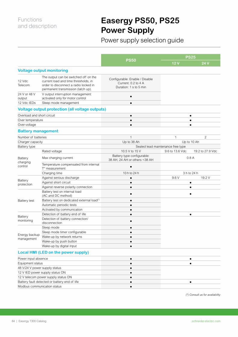
PS50PS25
12 V 24 V
Voltage output monitoring
12 Vdc Telecom
The output can be switched off on the current load and time thresholds, in order to disconnect a radio locked in permanent transmission (latch up).
Configurable: Enable / Disable Current: 0.2 to 4 A
Duration: 1 s to 5 min
24 V or 48 V output
V output interruption management: activated only for motor control
12 Vdc IEDs Sleep mode management
Voltage output protection (all voltage outputs)
Overload and short circuit
Over temperature
Over-voltage
Battery management
Number of batteries 1 1 2
Charger capacity Up to 38 Ah Up to 10 Ah
Battery type Sealed lead maintenance free type
Battery charging control
Rated voltage 10.5 V to 15 V 9.6 to 13.6 Vdc 19.2 to 27.9 Vdc
Max charging currentBattery type configurable:
38 AH, 24 AH or others <38 AH0.8 A
Temperature compensated from internal T° measurement
Charging time 10 h to 24 h 3 h to 24 h
Battery protection
Against serious discharge 9.6 V 19.2 V
Against short circuit
Against reverse polarity connection
Battery test
Battery test on internal load (AC and DC method)
Battery test on dedicated external load(*)
Automatic periodic tests
Activated by communication
Battery monitoring
Detection of battery end of life
Detection of battery connection/disconnection
Energy backup management
Sleep mode
Sleep mode timer configurable
Wake-up by network returns
Wake-up by push button
Wake-up by digital input
Local HMI (LED on the power supply)
Power input absence
Equipment status
48 V/24 V power supply status
12 V IED power supply status ON
12 V telecom power supply status ON
Battery fault detected or battery end of life
Modbus communication status
Easergy PS50, PS25 Power SupplyPower supply selection guide
(*) Consult us for availability
schneider-electric.com84 |
Functions and description
Easergy T300 Catalog
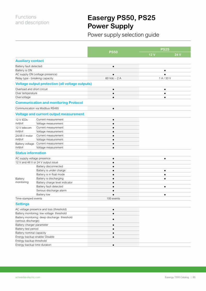
Easergy PS50, PS25 Power SupplyPower supply selection guide
PS50PS25
12 V 24 V
Auxiliary contact
Battery fault detected
Battery is ON
AC supply ON (voltage presence)
Relay type - breaking capacity 60 Vdc – 2 A 1 A / 30 V
Voltage output protection (all voltage outputs)
Overload and short circuit
Over temperature
Overvoltage
Communication and monitoring Protocol
Communication via Modbus RS485
Voltage and current output measurement
12 V IEDs output
Current measurement
Voltage measurement
12 V telecom output
Current measurement
Voltage measurement
24/48 V motor output
Current measurement
Voltage measurement
Battery voltage output
Current measurement
Voltage measurement
Status information
AC supply voltage presence
12 V and 48 V or 24 V output issue
Battery monitoring
Battery disconnected
Battery is under charge
Battery is in float mode
Battery is discharging
Battery charge level indicator
Battery fault detected
Serious discharge alarm
Battery low
Time-stamped events 100 events
Settings
AC voltage presence and loss (threshold)
Battery monitoring: low voltage threshold
Battery monitoring: deep discharge threshold (serious discharge)
Battery charger parameter
Battery test period
Battery nominal capacity
Energy backup enable/ Disable
Energy backup threshold
Energy backup time duration
schneider-electric.com | 85
Functions and description
Easergy T300 Catalog
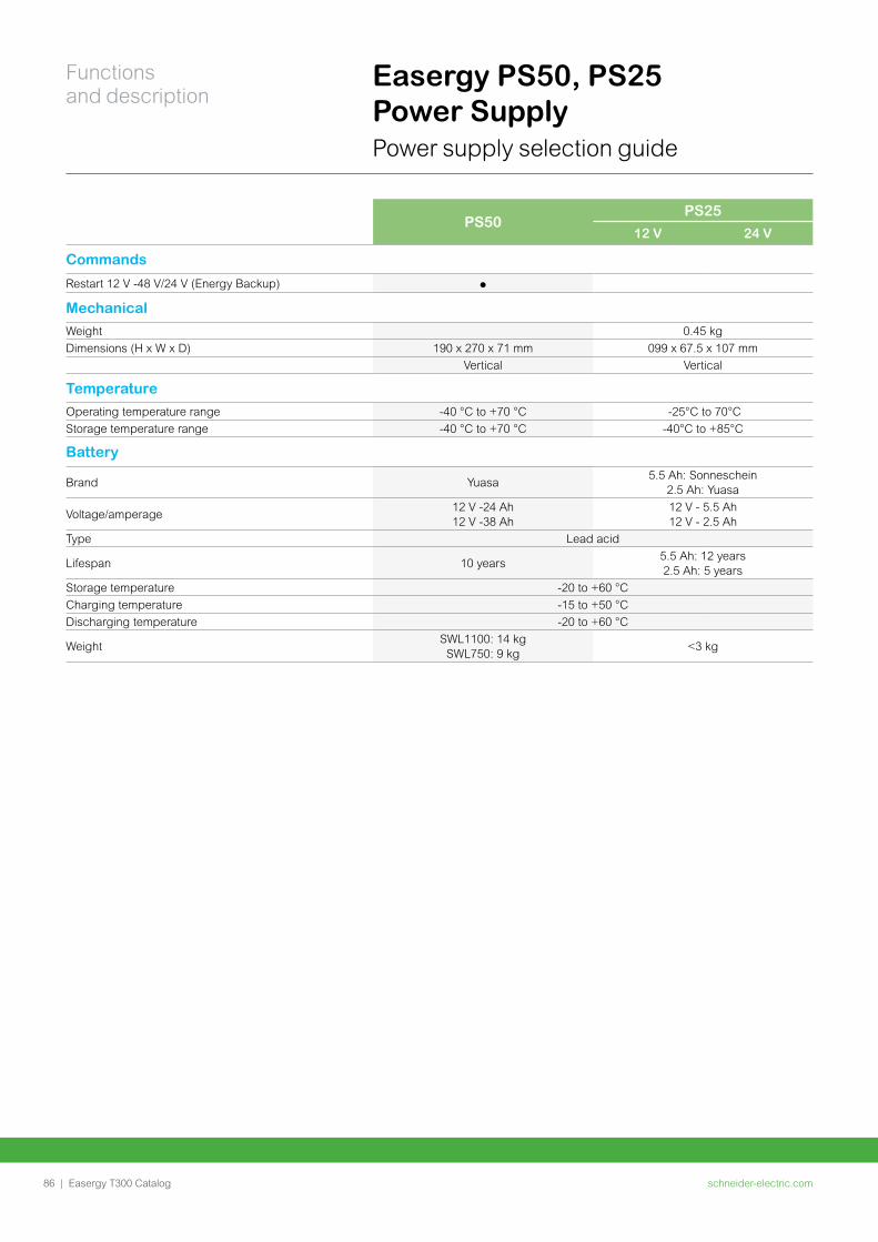
PS50PS25
12 V 24 V
Commands
Restart 12 V -48 V/24 V (Energy Backup)
Mechanical
Weight 0.45 kg
Dimensions (H x W x D) 190 x 270 x 71 mm 099 x 67.5 x 107 mm
Vertical Vertical
Temperature
Operating temperature range -40 °C to +70 °C -25°C to 70°C
Storage temperature range -40 °C to +70 °C -40°C to +85°C
Battery
Brand Yuasa5.5 Ah: Sonneschein
2.5 Ah: Yuasa
Voltage/amperage12 V -24 Ah 12 V -38 Ah
12 V - 5.5 Ah12 V - 2.5 Ah
Type Lead acid
Lifespan 10 years5.5 Ah: 12 years2.5 Ah: 5 years
Storage temperature -20 to +60 °C
Charging temperature -15 to +50 °C
Discharging temperature -20 to +60 °C
WeightSWL1100: 14 kg SWL750: 9 kg
<3 kg
Easergy PS50, PS25 Power SupplyPower supply selection guide
schneider-electric.com86 |
Functions and description
Easergy T300 Catalog
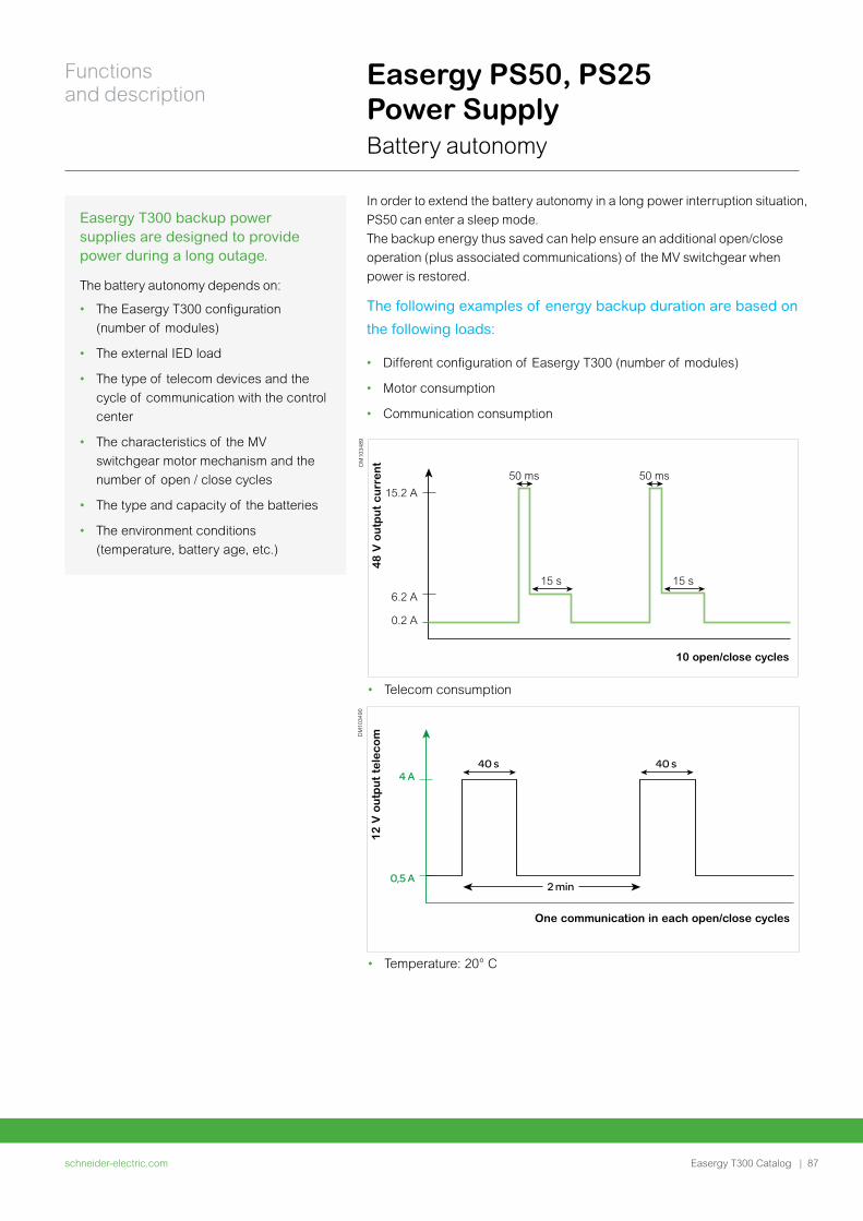
Easergy PS50, PS25 Power SupplyBattery autonomy
Easergy T300 backup power supplies are designed to provide power during a long outage.
The battery autonomy depends on:
• The Easergy T300 configuration
(number of modules)
• The external IED load
• The type of telecom devices and the
cycle of communication with the control
center
• The characteristics of the MV
switchgear motor mechanism and the
number of open / close cycles
• The type and capacity of the batteries
• The environment conditions
(temperature, battery age, etc.)
The following examples of energy backup duration are based on
the following loads:
• Different configuration of Easergy T300 (number of modules)
• Motor consumption
• Communication consumption
15.2 A
6.2 A
0.2 A
48
V o
utp
ut
cu
rre
nt
10 open/close cycles
15 s 15 s
50 ms 50 ms
DM
1034
89
12 V
ou
tpu
t te
leco
m
One communication in each open/close cycles
4 A
0,5 A
40 s
2 min
40 s
DM
1034
90
• Telecom consumption
• Temperature: 20° C
In order to extend the battery autonomy in a long power interruption situation,
PS50 can enter a sleep mode.
The backup energy thus saved can help ensure an additional open/close
operation (plus associated communications) of the MV switchgear when
power is restored.
schneider-electric.com | 87
Functions and description
Easergy T300 Catalog
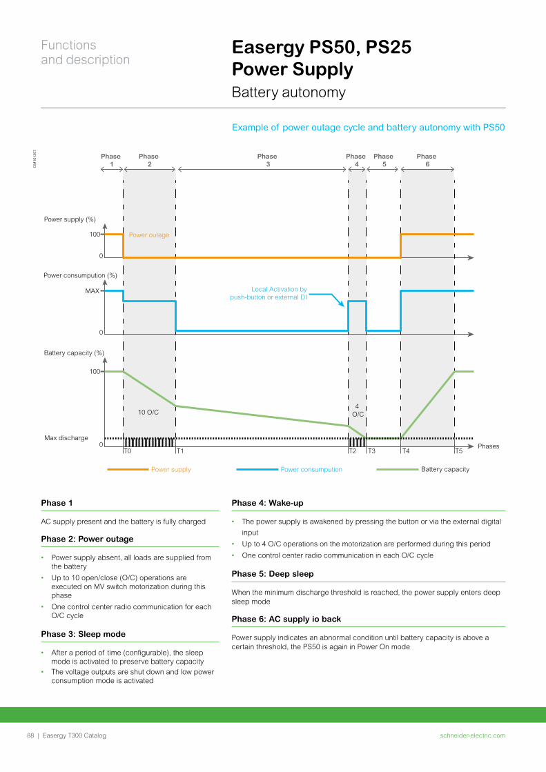
10 O/C
Max discharge
Battery capacity (%)
100
Power consumpution (%)
Power supply (%)
MAX
100
0
0
0
4 O/C
T0 T1 T2 T3 T4 T5Phases
Local Activation by push-button or external DI
Battery capacityPower consumputionPower supply
Power outage
Phase 6
Phase 5
Phase 4
Phase 3
Phase 2
Phase 1D
M10
1307
Example of power outage cycle and battery autonomy with PS50
Easergy PS50, PS25 Power SupplyBattery autonomy
Phase 1
AC supply present and the battery is fully charged
Phase 2: Power outage
• Power supply absent, all loads are supplied from the battery
• Up to 10 open/close (O/C) operations are executed on MV switch motorization during this phase
• One control center radio communication for each O/C cycle
Phase 3: Sleep mode
• After a period of time (configurable), the sleep mode is activated to preserve battery capacity
• The voltage outputs are shut down and low power consumption mode is activated
Phase 4: Wake-up
• The power supply is awakened by pressing the button or via the external digital
input
• Up to 4 O/C operations on the motorization are performed during this period
• One control center radio communication in each O/C cycle
Phase 5: Deep sleep
When the minimum discharge threshold is reached, the power supply enters deep sleep mode
Phase 6: AC supply io back
Power supply indicates an abnormal condition until battery capacity is above a certain threshold, the PS50 is again in Power On mode
schneider-electric.com88 |
Functions and description
Easergy T300 Catalog
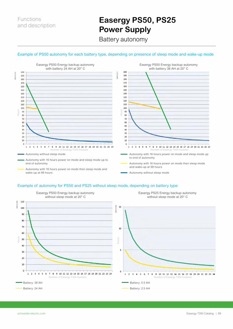
Easergy PS50, PS25 Power SupplyBattery autonomy
Example of PS50 autonomy for each battery type, depending on presence of sleep mode and wake-up mode
Example of autonomy for PS50 and PS25 without sleep mode, depending on battery type
DM
1013
09
DM
1013
08
DM
1013
10
DM
1013
11
Easergy PS50 Energy backup autonomy with battery 24 AH at 20° C
Easergy PS50 Energy backup autonomy with battery 38 AH at 20° C
Autonomy with 16 hours power on mode and sleep mode up to end of autonomy
Autonomy with 16 hours power on mode then sleep mode and wake-up at 98 hours
Autonomy without sleep mode
Autonomy without sleep mode
Autonomy with 16 hours power on mode and sleep mode up to end of autonomy
Autonomy with 16 hours power on mode then sleep mode and wake-up at 98 hours
Battery: 38 AH
Battery: 24 AH
Easergy PS50 Energy backup autonomy without sleep mode at 20° C
Easergy PS25 Energy backup autonomy without sleep mode at 20° C
Battery: 5.5 AH
Battery: 2.5 AH
Ho
urs
Ho
urs
Number of Easergy T300 modulesNumber of Easergy T300 modules
Ho
urs
Number of Easergy T300 modules
Ho
urs
Number of Easergy T300 modules
schneider-electric.com | 89
Functions and description
Easergy T300 Catalog
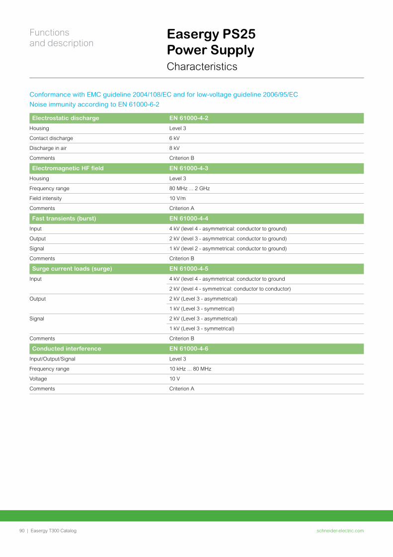
Easergy PS25 Power SupplyCharacteristics
Conformance with EMC guideline 2004/108/EC and for low-voltage guideline 2006/95/EC
Noise immunity according to EN 61000-6-2
Electrostatic discharge EN 61000-4-2
Housing Level 3
Contact discharge 6 kV
Discharge in air 8 kV
Comments Criterion B
Electromagnetic HF field EN 61000-4-3
Housing Level 3
Frequency range 80 MHz ... 2 GHz
Field intensity 10 V/m
Comments Criterion A
Fast transients (burst) EN 61000-4-4
Input 4 kV (level 4 - asymmetrical: conductor to ground)
Output 2 kV (level 3 - asymmetrical: conductor to ground)
Signal 1 kV (level 2 - asymmetrical: conductor to ground)
Comments Criterion B
Surge current loads (surge) EN 61000-4-5
Input 4 kV (level 4 - asymmetrical: conductor to ground
2 kV (level 4 - symmetrical: conductor to conductor)
Output 2 kV (Level 3 - asymmetrical)
1 kV (Level 3 - symmetrical)
Signal 2 kV (Level 3 - asymmetrical)
1 kV (Level 3 - symmetrical)
Comments Criterion B
Conducted interference EN 61000-4-6
Input/Output/Signal Level 3
Frequency range 10 kHz ... 80 MHz
Voltage 10 V
Comments Criterion A
schneider-electric.com90 |
Functions and description
Easergy T300 Catalog
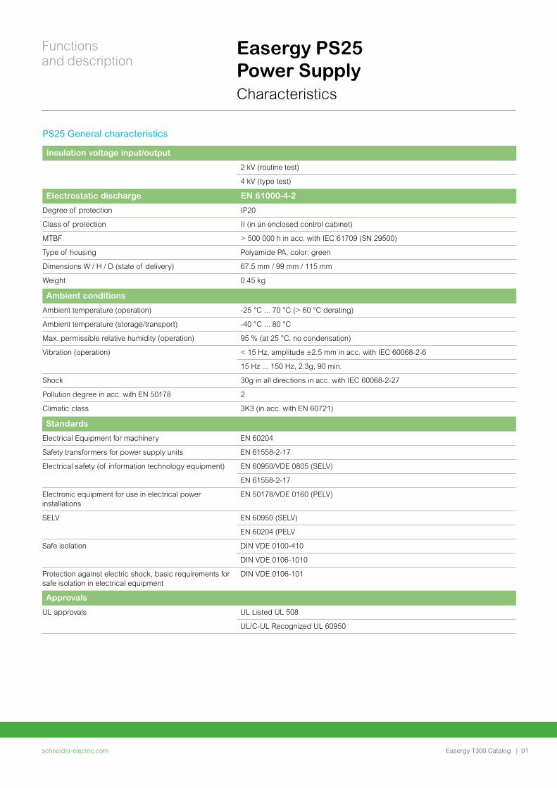
Easergy PS25 Power SupplyCharacteristics
PS25 General characteristics
Insulation voltage input/output
2 kV (routine test)
4 kV (type test)
Electrostatic discharge EN 61000-4-2
Degree of protection IP20
Class of protection II (in an enclosed control cabinet)
MTBF > 500 000 h in acc. with IEC 61709 (SN 29500)
Type of housing Polyamide PA, color: green
Dimensions W / H / D (state of delivery) 67.5 mm / 99 mm / 115 mm
Weight 0.45 kg
Ambient conditions
Ambient temperature (operation) -25 °C ... 70 °C (> 60 °C derating)
Ambient temperature (storage/transport) -40 °C ... 80 °C
Max. permissible relative humidity (operation) 95 % (at 25 °C, no condensation)
Vibration (operation) < 15 Hz, amplitude ±2.5 mm in acc. with IEC 60068-2-6
15 Hz ... 150 Hz, 2.3g, 90 min.
Shock 30g in all directions in acc. with IEC 60068-2-27
Pollution degree in acc. with EN 50178 2
Climatic class 3K3 (in acc. with EN 60721)
Standards
Electrical Equipment for machinery EN 60204
Safety transformers for power supply units EN 61558-2-17
Electrical safety (of information technology equipment) EN 60950/VDE 0805 (SELV)
EN 61558-2-17
Electronic equipment for use in electrical power installations
EN 50178/VDE 0160 (PELV)
SELV EN 60950 (SELV)
EN 60204 (PELV
Safe isolation DIN VDE 0100-410
DIN VDE 0106-1010
Protection against electric shock, basic requirements for safe isolation in electrical equipment
DIN VDE 0106-101
Approvals
UL approvals UL Listed UL 508
UL/C-UL Recognized UL 60950
schneider-electric.com | 91
Functions and description
Easergy T300 Catalog
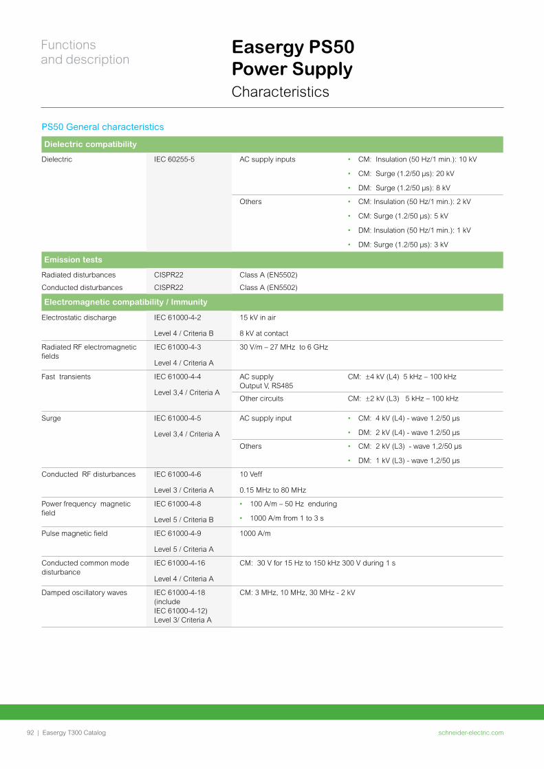
Easergy PS50 Power SupplyCharacteristics
PS50 General characteristics
Dielectric compatibility
Dielectric IEC 60255-5 AC supply inputs • CM: Insulation (50 Hz/1 min.): 10 kV
• CM: Surge (1.2/50 μs): 20 kV
• DM: Surge (1.2/50 μs): 8 kV
Others • CM: Insulation (50 Hz/1 min.): 2 kV
• CM: Surge (1.2/50 μs): 5 kV
• DM: Insulation (50 Hz/1 min.): 1 kV
• DM: Surge (1.2/50 μs): 3 kV
Emission tests
Radiated disturbances CISPR22 Class A (EN5502)
Conducted disturbances CISPR22 Class A (EN5502)
Electromagnetic compatibility / Immunity
Electrostatic discharge IEC 61000-4-2
Level 4 / Criteria B
15 kV in air
8 kV at contact
Radiated RF electromagnetic fields
IEC 61000-4-3
Level 4 / Criteria A
30 V/m – 27 MHz to 6 GHz
Fast transients IEC 61000-4-4
Level 3,4 / Criteria A
AC supply Output V, RS485
CM: ±4 kV (L4) 5 kHz – 100 kHz
Other circuits CM: ±2 kV (L3) 5 kHz – 100 kHz
Surge IEC 61000-4-5
Level 3,4 / Criteria A
AC supply input • CM: 4 kV (L4) - wave 1.2/50 µs
• DM: 2 kV (L4) - wave 1.2/50 µs
Others • CM: 2 kV (L3) - wave 1,2/50 µs
• DM: 1 kV (L3) - wave 1,2/50 µs
Conducted RF disturbances IEC 61000-4-6
Level 3 / Criteria A
10 Veff
0.15 MHz to 80 MHz
Power frequency magnetic field
IEC 61000-4-8
Level 5 / Criteria B
• 100 A/m – 50 Hz enduring
• 1000 A/m from 1 to 3 s
Pulse magnetic field IEC 61000-4-9
Level 5 / Criteria A
1000 A/m
Conducted common mode disturbance
IEC 61000-4-16
Level 4 / Criteria A
CM: 30 V for 15 Hz to 150 kHz 300 V during 1 s
Damped oscillatory waves IEC 61000-4-18 (include IEC 61000-4-12) Level 3/ Criteria A
CM: 3 MHz, 10 MHz, 30 MHz - 2 kV
schneider-electric.com92 |
Functions and description
Easergy T300 Catalog
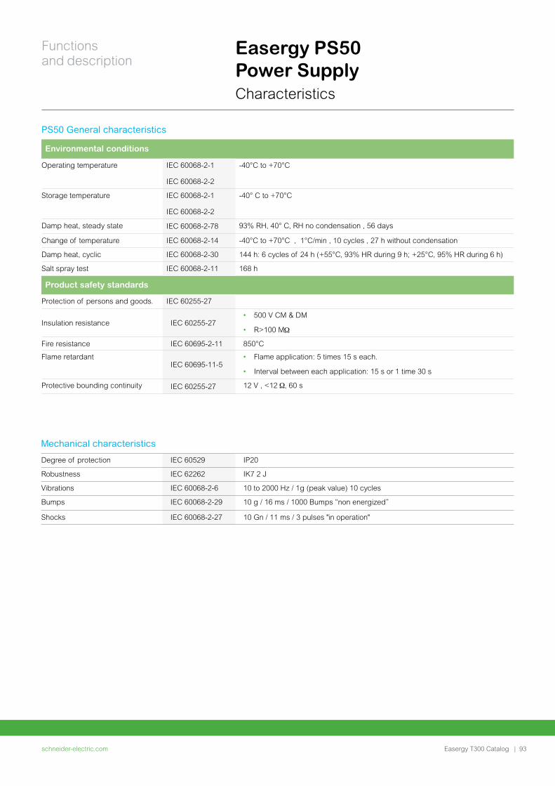
Easergy PS50 Power SupplyCharacteristics
Mechanical characteristics
Degree of protection IEC 60529 IP20
Robustness IEC 62262 IK7 2 J
Vibrations IEC 60068-2-6 10 to 2000 Hz / 1g (peak value) 10 cycles
Bumps IEC 60068-2-29 10 g / 16 ms / 1000 Bumps “non energized”
Shocks IEC 60068-2-27 10 Gn / 11 ms / 3 pulses "in operation"
PS50 General characteristics
Environmental conditions
Operating temperature IEC 60068-2-1
IEC 60068-2-2
-40°C to +70°C
Storage temperature IEC 60068-2-1
IEC 60068-2-2
-40° C to +70°C
Damp heat, steady state IEC 60068-2-78 93% RH, 40° C, RH no condensation , 56 days
Change of temperature IEC 60068-2-14 -40°C to +70°C , 1°C/min , 10 cycles , 27 h without condensation
Damp heat, cyclic IEC 60068-2-30 144 h: 6 cycles of 24 h (+55°C, 93% HR during 9 h; +25°C, 95% HR during 6 h)
Salt spray test IEC 60068-2-11 168 h
Product safety standards
Protection of persons and goods. IEC 60255-27
Insulation resistance IEC 60255-27• 500 V CM & DM
• R>100 M
Fire resistance IEC 60695-2-11 850°C
Flame retardantIEC 60695-11-5
• Flame application: 5 times 15 s each.
• Interval between each application: 15 s or 1 time 30 s
Protective bounding continuity IEC 60255-27 12 V , <12 , 60 s
schneider-electric.com | 93
Functions and description
Easergy T300 Catalog
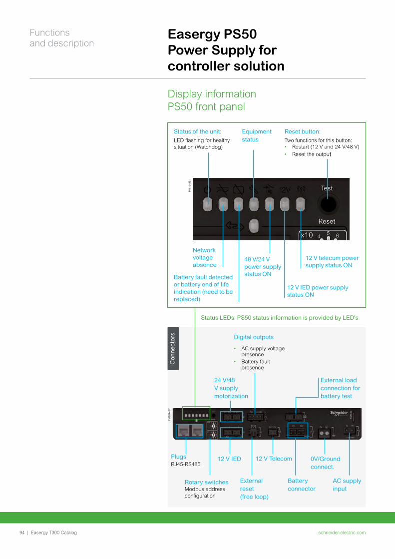
Display information PS50 front panel
Con
nect
ors
Easergy PS50 Power Supply for controller solution
Status LEDs: PS50 status information is provided by LED's
PM
1045
51
Status of the unit: LED flashing for healthy situation (Watchdog)
Network voltage absence
Battery fault detected or battery end of life indication (need to be replaced)
Equipment status
48 V/24 V power supply status ON
12 V IED power supply status ON
12 V telecom power supply status ON
Reset button: Two functions for this button: • Restart (12 V and 24 V/48 V)• Reset the output
PM
1044
97
24 V/48 V supply motorization
External load connection for battery test
Digital outputs
• AC supply voltage presence
• Battery fault presence
Plugs RJ45-RS485
12 V IED 12 V Telecom 0V/Ground connect.
Rotary switches Modbus address configuration
External reset (free loop)
Battery connector
AC supply input
schneider-electric.com94 |
Functions and description
Easergy T300 Catalog
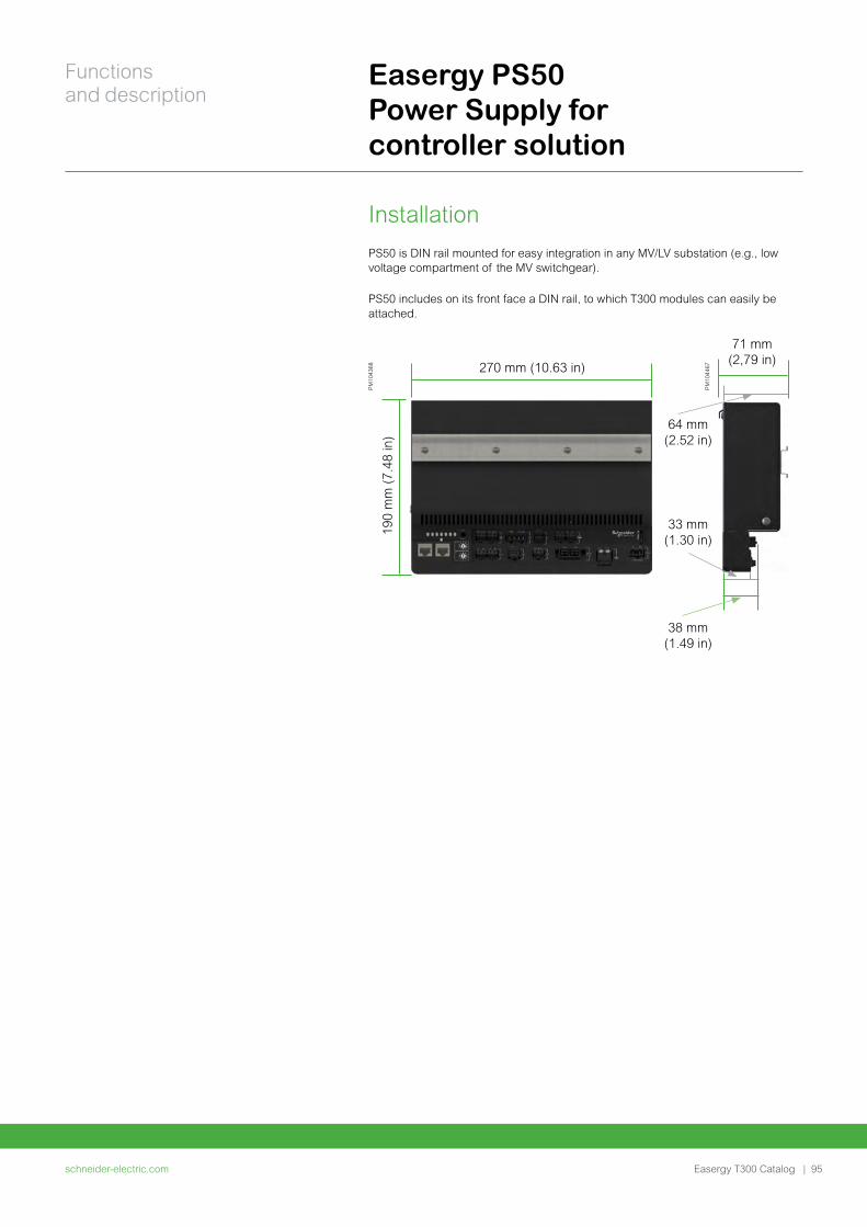
InstallationPS50 is DIN rail mounted for easy integration in any MV/LV substation (e.g., low voltage compartment of the MV switchgear).
PS50 includes on its front face a DIN rail, to which T300 modules can easily be attached.
Easergy PS50 Power Supply for controller solution
190
mm
(7.
48 in
)
71 mm (2,79 in)
270 mm (10.63 in)
64 mm (2.52 in)
33 mm (1.30 in)
38 mm (1.49 in)
PM
1043
68
PM
1044
67
schneider-electric.com | 95
Functions and description
Easergy T300 Catalog
schneider-electric.com96 | Easergy T300 Catalog
Cabinet and Smart RMU Solution
schneider-electric.com | 97Easergy T300 Catalog
Cabinet and Smart RMU
Solution
Ready-to-use solution Catalog 98
General description 98
T300-IV1 cabinet 99
T300-OVR cabinet 100
T300-OM1 cabinet 101
Smart RMU offer 102
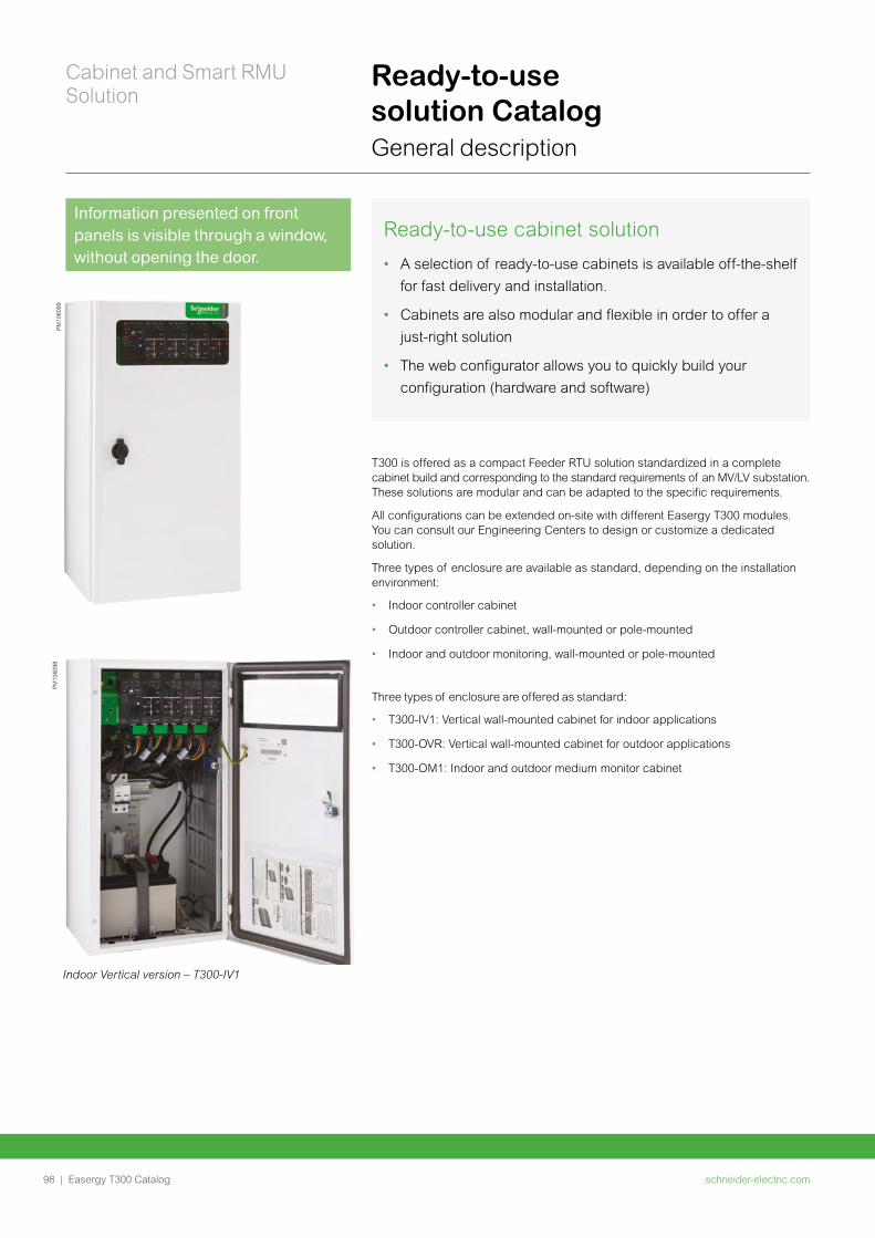
schneider-electric.com98 |
Cabinet and Smart RMU Solution
Easergy T300 Catalog
Ready-to-use solution CatalogGeneral description
Ready-to-use cabinet solution
• A selection of ready-to-use cabinets is available off-the-shelf
for fast delivery and installation.
• Cabinets are also modular and flexible in order to offer a
just-right solution
• The web configurator allows you to quickly build your
configuration (hardware and software)
T300 is offered as a compact Feeder RTU solution standardized in a complete cabinet build and corresponding to the standard requirements of an MV/LV substation. These solutions are modular and can be adapted to the specific requirements.
All configurations can be extended on-site with different Easergy T300 modules. You can consult our Engineering Centers to design or customize a dedicated solution.
Three types of enclosure are available as standard, depending on the installation environment:
• Indoor controller cabinet
• Outdoor controller cabinet, wall-mounted or pole-mounted
• Indoor and outdoor monitoring, wall-mounted or pole-mounted
Three types of enclosure are offered as standard:
• T300-IV1: Vertical wall-mounted cabinet for indoor applications
• T300-OVR: Vertical wall-mounted cabinet for outdoor applications
• T300-OM1: Indoor and outdoor medium monitor cabinet
PM
1060
99P
M10
6098
Information presented on front panels is visible through a window, without opening the door.
Indoor Vertical version – T300-IV1
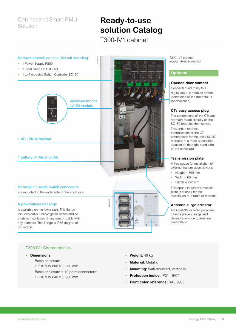
schneider-electric.com | 99
Cabinet and Smart RMU Solution
Easergy T300 Catalog
Ready-to-use solution CatalogT300-IV1 cabinet
Reserved for one LV150 module
• Weight: 40 kg
• Material: Metallic
• Mounting: Wall-mounted, vertically
• Protection indice: IP31 - IK07
• Paint color reference: RAL 9003
• Dimensions
– Basic enclosure:
H 310 x W 600 x D 250 mm
– Basic enclosure + 10 point connectors:
H 310 x W 640 x D 250 mm
T300-IV1 Characteristics
T300-IV1 cabinet Indoor Vertical version
PM
1061
07
Terminal 10 points switch connectors are mounted to the underside of the enclosure.
A pre-configured flange
is available on the lower part. This flange includes cut-out cable gland plates and so enables installation of any size of cable with any diameter. This flange is IP65 degree of protection.
PM
1060
98Modules assembled on a DIN rail including:
• 1 Power Supply PS50
• 1 Front Head Unit HU250
• 1 to 4 modules Switch Controller SC150
1 AC 1Ph+N breaker
1 battery 24 Ah or 38 Ah
Optional
Opened door contactConnected internally to a
digital input, it enables remote indications of the door status (open/closed).
CTs easy access plugThe connections of the CTs are normally made directly on the SC150 modules themselves.
This option enables centralization of the CT connections for the unit's SC150 modules in a more accessible location on the right-hand side of the enclosure.
Transmission plate A free space for installation of external transmission devices
• Height = 300 mm
• Width = 60 mm
• Depth = 220 mm
This space includes a metallic plate (optional) for the installation of a radio or modem.
Antenna surge arrestor For GSM/3G or radio purposes, it helps prevent surge and deterioration due to antenna overvoltage.
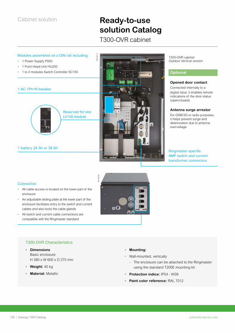
schneider-electric.com100 |
Cabinet solution
Easergy T300 Catalog
Ready-to-use solution CatalogT300-OVR cabinet
• Mounting:
• Wall-mounted, vertically
– The enclosure can be attached to the Ringmaster
using the standard T200E mounting kit
• Protection indice: IP54 - IK09
• Paint color reference: RAL 7012
• Dimensions Basic enclosure:
H 380 x W 600 x D 275 mm
• Weight: 40 kg
• Material: Metallic
T300-OVR Characteristics
PM
1061
10Modules assembled on a DIN rail including:
• 1 Power Supply PS50
• 1 Front Head Unit HU250
• 1 to 4 modules Switch Controller SC150
1 AC 1Ph+N breaker
1 battery 24 Ah or 38 Ah
T300-OVR cabinet Outdoor Vertical version
Optional
Opened door contactConnected internally to a
digital input, it enables remote indications of the door status (open/closed).
Antenna surge arrestor For GSM/3G or radio purposes, it helps prevent surge and deterioration due to antenna overvoltage.
Reserved for one LV150 module
Ringmaster specific AMP switch and current transformer connectors
Connection
• All cable access is located on the lower part of the
enclosure
• An adjustable sliding plate at the lower part of the
enclosure facilitates entry to the switch and current
cables and also locks the cable glands
• All switch and current cable connections are
compatible with the Ringmaster standard
PM
1061
08
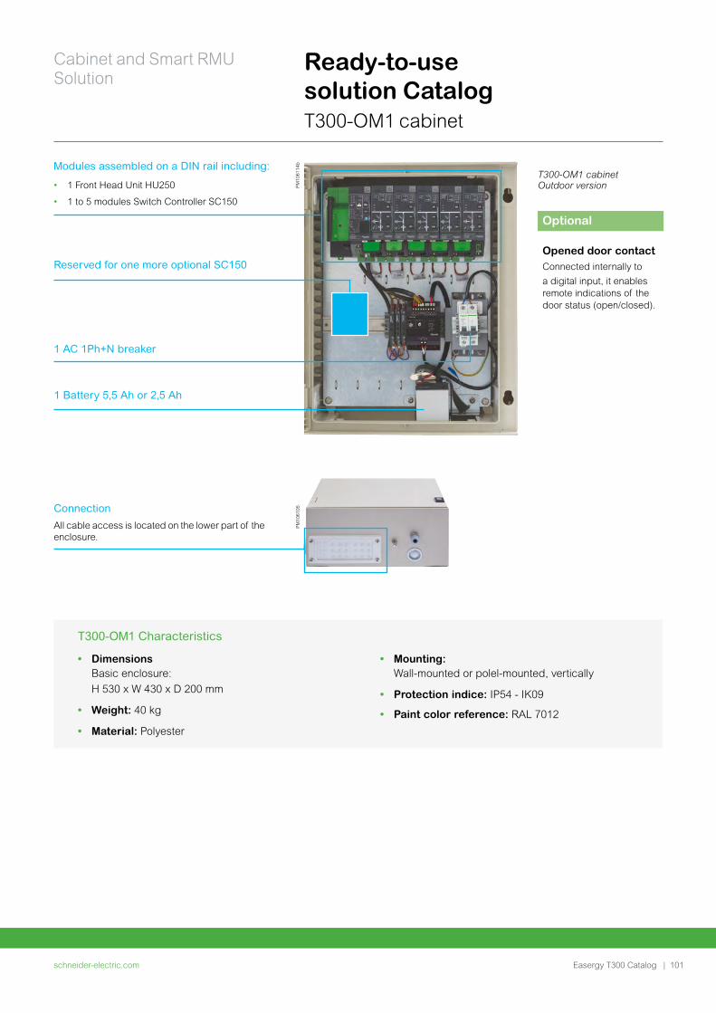
schneider-electric.com | 101
Cabinet and Smart RMU Solution
Easergy T300 Catalog
Ready-to-use solution CatalogT300-OM1 cabinet
• Dimensions Basic enclosure:
H 530 x W 430 x D 200 mm
• Weight: 40 kg
• Material: Polyester
T300-OM1 Characteristics
• Mounting: Wall-mounted or polel-mounted, vertically
• Protection indice: IP54 - IK09
• Paint color reference: RAL 7012
PM
1061
14b
1 Battery 5,5 Ah or 2,5 Ah
T300-OM1 cabinet Outdoor version
Optional
Opened door contactConnected internally to
a digital input, it enables remote indications of the door status (open/closed).
Modules assembled on a DIN rail including:
• 1 Front Head Unit HU250
• 1 to 5 modules Switch Controller SC150
1 AC 1Ph+N breaker
Reserved for one more optional SC150
PM
1061
05Connection
All cable access is located on the lower part of the enclosure.
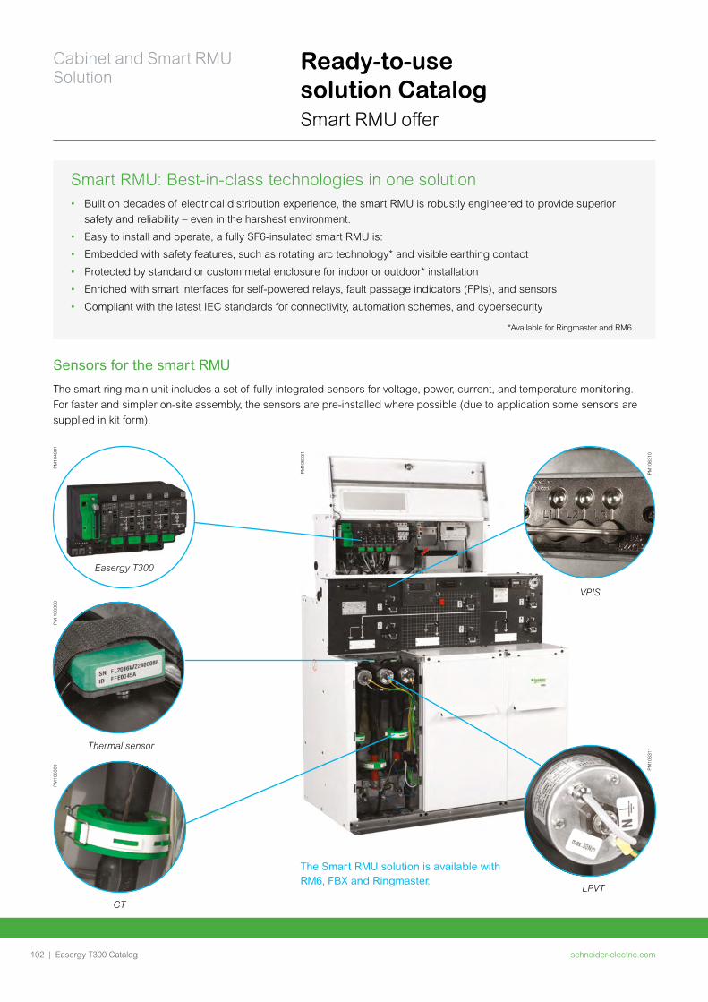
schneider-electric.com102 |
Cabinet and Smart RMU Solution
Easergy T300 Catalog
Ready-to-use solution CatalogSmart RMU offer
Smart RMU: Best-in-class technologies in one solution• Built on decades of electrical distribution experience, the smart RMU is robustly engineered to provide superior
safety and reliability – even in the harshest environment.
• Easy to install and operate, a fully SF6-insulated smart RMU is:
• Embedded with safety features, such as rotating arc technology* and visible earthing contact
• Protected by standard or custom metal enclosure for indoor or outdoor* installation
• Enriched with smart interfaces for self-powered relays, fault passage indicators (FPIs), and sensors
• Compliant with the latest IEC standards for connectivity, automation schemes, and cybersecurity
*Available for Ringmaster and RM6
The smart ring main unit includes a set of fully integrated sensors for voltage, power, current, and temperature monitoring.
For faster and simpler on-site assembly, the sensors are pre-installed where possible (due to application some sensors are
supplied in kit form).
The Smart RMU solution is available with RM6, FBX and Ringmaster.
Sensors for the smart RMU
Easergy T300
PM
1048
81
VPIS
PM
1063
10
PM
1063
31
LPVT
PM
1063
11
Thermal sensor
PM
106
308
CT
PM
1063
09

Notes
schneider-electric.com | 103Easergy T300 Catalog

schneider-electric.com104 | Easergy T300 Catalog
Accessories
schneider-electric.com | 105Easergy T300 Catalog
Accessories
Voltage adapter 106
CT current transformer 108
Installation accessories 109
Commissioning and Maintenance accessories 110
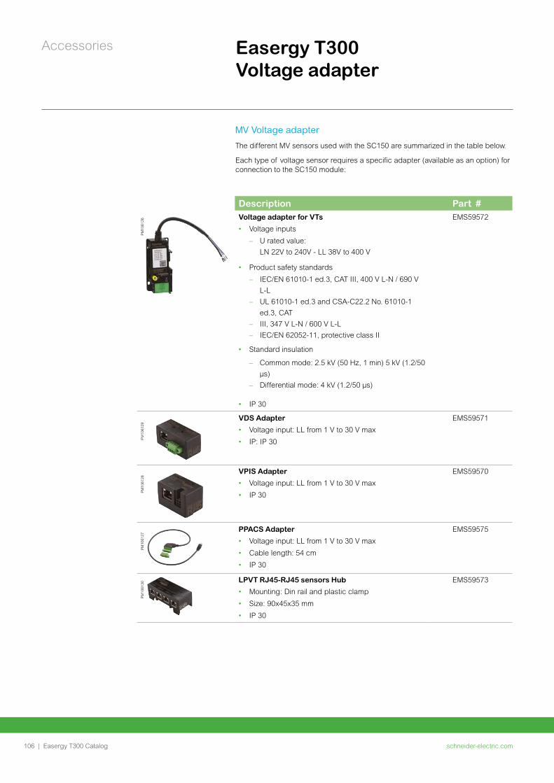
schneider-electric.com106 |
Accessories
Easergy T300 Catalog
Easergy T300 Voltage adapter
MV Voltage adapter
The different MV sensors used with the SC150 are summarized in the table below.
Each type of voltage sensor requires a specific adapter (available as an option) for connection to the SC150 module:
Description Part #
PM
1061
26
Voltage adapter for VTs
• Voltage inputs
– U rated value:
LN 22V to 240V - LL 38V to 400 V
• Product safety standards
– IEC/EN 61010-1 ed.3, CAT III, 400 V L-N / 690 V
L-L
– UL 61010-1 ed.3 and CSA-C22.2 No. 61010-1
ed.3, CAT
– III, 347 V L-N / 600 V L-L
– IEC/EN 62052-11, protective class II
• Standard insulation
– Common mode: 2.5 kV (50 Hz, 1 min) 5 kV (1.2/50
µs)
– Differential mode: 4 kV (1.2/50 µs)
• IP 30
EMS59572
PM
1061
29
VDS Adapter
• Voltage input: LL from 1 V to 30 V max
• IP: IP 30
EMS59571
PM
1061
28
VPIS Adapter
• Voltage input: LL from 1 V to 30 V max
• IP 30
EMS59570
PM
1061
27
PPACS Adapter
• Voltage input: LL from 1 V to 30 V max
• Cable length: 54 cm
• IP 30
EMS59575
PM
1061
30
LPVT RJ45-RJ45 sensors Hub
• Mounting: Din rail and plastic clamp
• Size: 90x45x35 mm
• IP 30
EMS59573
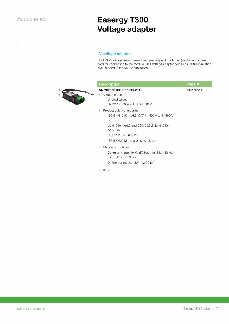
schneider-electric.com | 107
Accessories
Easergy T300 Catalog
Easergy T300 Voltage adapter
LV Voltage adapter
The LV150 voltage measurement requires a specific adapter (available in spare part) for connection to the module. This Voltage adapter helps ensure the insulation level needed in the MV/LV substation.
Description Part #
PM
1063
37 AC Voltage adapter for LV150
• Voltage inputs
– U rated value:
LN 22V to 240V - LL 38V to 400 V
• Product safety standards
– IEC/EN 61010-1 ed.3, CAT III, 400 V L-N / 690 V
L-L
– UL 61010-1 ed.3 and CSA-C22.2 No. 61010-1
ed.3, CAT
– III, 347 V L-N / 600 V L-L
– IEC/EN 62052-11, protective class II
• Standard insulation
– Common mode: 10 kV (50 Hz, 1 s), 6 kV (50 Hz, 1
min) 5 kV (1.2/50 μs)
– Differential mode: 4 kV (1.2/50 μs)
• IP 30
EMS59574
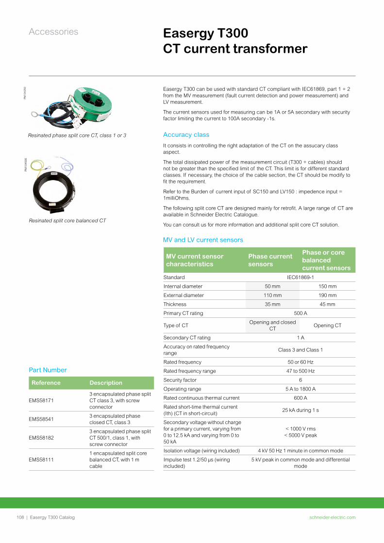
schneider-electric.com108 |
Accessories
Easergy T300 Catalog
PM
1045
00P
M10
4250
MV and LV current sensors
MV current sensor characteristics
Phase current sensors
Phase or core balanced current sensors
Standard IEC61869-1
Internal diameter 50 mm 150 mm
External diameter 110 mm 190 mm
Thickness 35 mm 45 mm
Primary CT rating 500 A
Type of CTOpening and closed
CTOpening CT
Secondary CT rating 1 A
Accuracy on rated frequency range
Class 3 and Class 1
Rated frequency 50 or 60 Hz
Rated frequency range 47 to 500 Hz
Security factor 6
Operating range 5 A to 1800 A
Rated continuous thermal current 600 A
Rated short-time thermal current (Ith) (CT in short-circuit)
25 kA during 1 s
Secondary voltage without charge for a primary current, varying from 0 to 12.5 kA and varying from 0 to 50 kA
< 1000 V rms < 5000 V peak
Isolation voltage (wiring included) 4 kV 50 Hz 1 minute in common mode
Impulse test 1.2/50 μs (wiring included)
5 kV peak in common mode and differential mode
Resinated phase split core CT, class 1 or 3
Resinated split core balanced CT
Part Number
Reference Description
EMS581713 encapsulated phase split CT class 3, with screw connector
EMS585413 encapsulated phase closed CT, class 3
EMS581823 encapsulated phase split CT 500/1, class 1, with screw connector
EMS581111 encapsulated split core balanced CT, with 1 m cable
Easergy T300 CT current transformer
Easergy T300 can be used with standard CT compliant with IEC61869, part 1 + 2 from the MV measurement (fault current detection and power measurement) and LV measurement.
The current sensors used for measuring can be 1A or 5A secondary with security factor limiting the current to 100A secondary -1s.
Accuracy class
It consists in controlling the right adaptation of the CT on the assucary class aspect.
The total dissipated power of the measurement circuit (T300 + cables) should not be greater than the specified limit of the CT. This limit is for different standard classes. If necessary, the choice of the cable section, the CT should be modify to fit the requirement.
Refer to the Burden of current input of SC150 and LV150 : impedence input = 1milliOhms.
The following split core CT are designed mainly for retrofit. A large range of CT are available in Schneider Electric Catalogue.
You can consult us for more information and additional split core CT solution.
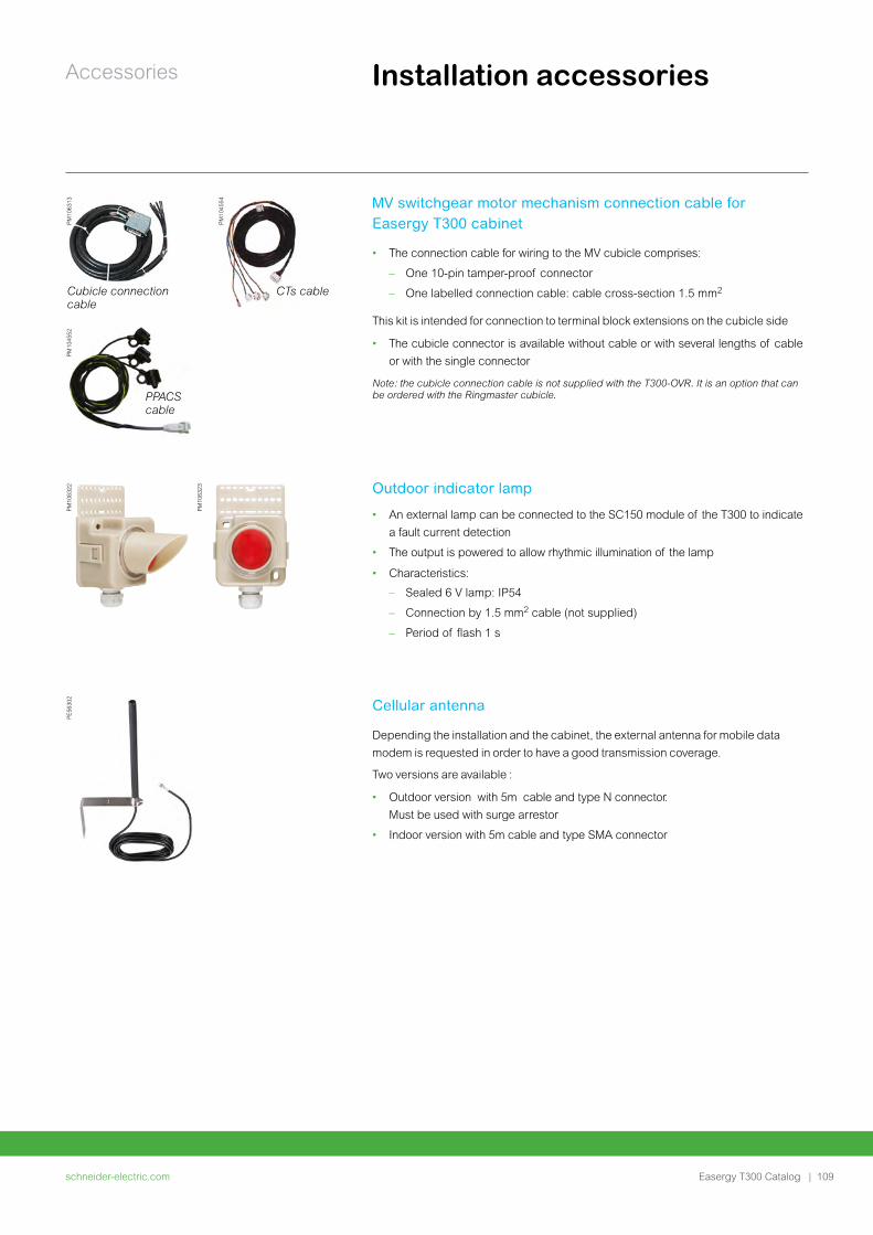
schneider-electric.com | 109
Accessories
Easergy T300 Catalog
Installation accessories
Cubicle connection cable
PM
1063
13
PPACS cable
PM
1045
52
PM
1045
54
CTs cable
MV switchgear motor mechanism connection cable for Easergy T300 cabinet
• The connection cable for wiring to the MV cubicle comprises:
– One 10-pin tamper-proof connector
– One labelled connection cable: cable cross-section 1.5 mm2
This kit is intended for connection to terminal block extensions on the cubicle side
• The cubicle connector is available without cable or with several lengths of cable
or with the single connector
Note: the cubicle connection cable is not supplied with the T300-OVR. It is an option that can be ordered with the Ringmaster cubicle.
PM
1063
22
PM
1063
23 Outdoor indicator lamp • An external lamp can be connected to the SC150 module of the T300 to indicate
a fault current detection
• The output is powered to allow rhythmic illumination of the lamp
• Characteristics:
– Sealed 6 V lamp: IP54
– Connection by 1.5 mm2 cable (not supplied)
– Period of flash 1 s
P
E56
302
Cellular antenna Depending the installation and the cabinet, the external antenna for mobile data
modem is requested in order to have a good transmission coverage.
Two versions are available :
• Outdoor version with 5m cable and type N connector.
Must be used with surge arrestor
• Indoor version with 5m cable and type SMA connector
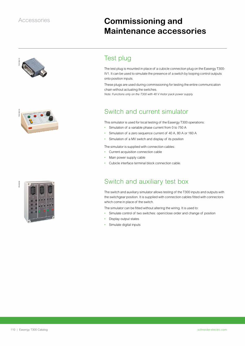
schneider-electric.com110 |
Accessories
Easergy T300 Catalog
Commissioning and Maintenance accessories
PM
1063
15 Test plug The test plug is mounted in place of a cubicle connection plug on the Easergy T300-
IV1. It can be used to simulate the presence of a switch by looping control outputs
onto position inputs.
These plugs are used during commissioning for testing the entire communication
chain without actuating the switches. Note: Functions only on the T300 with 48 V motor pack power supply.
PM
1063
16 Switch and current simulator This simulator is used for local testing of the Easergy T300 operations:
• Simulation of a variable phase current from 0 to 750 A
• Simulation of a zero sequence current of 40 A, 80 A or 160 A
• Simulation of a MV switch and display of its position
The simulator is supplied with connection cables:
• Current acquisition connection cable
• Main power supply cable
• Cubicle interface terminal block connection cable.
PE
4063
6 Switch and auxiliary test box The switch and auxiliary simulator allows testing of the T300 inputs and outputs with
the switchgear position. It is supplied with connection cables fitted with connectors
which come in place of the switch.
The simulator can be fitted without altering the wiring. It is used to:
• Simulate control of two switches: open/close order and change of position
• Display output states
• Simulate digital inputs

Notes
schneider-electric.com | 111Easergy T300 Catalog
schneider-electric.com112 | Easergy T300 Catalog
Commercial references
schneider-electric.com | 113Easergy T300 Catalog
Commercial references
Digital configuration and ordering tools 114
Easergy T300 115
Easergy HU250: Head unit and communication interfaces 115
Easergy SC150: Switchgear controller and option 116
Easergy LV150 : Low Voltage monitoring 116
Easergy PS50/PS25: Power supply 116
Cabinet integration 117
Accessories 118
Voltage sensors and adapter 118
Communication accessories 118
Current sensors 119
Switchgear connection kit 119
Outdoor indicator lamp 119
Simulator 119
Tools 120
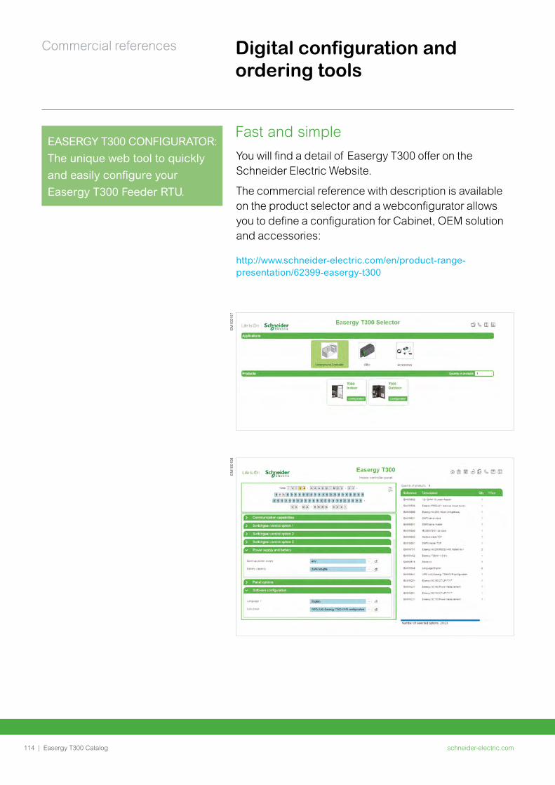
schneider-electric.com114 |
Commercial references
Easergy T300 Catalog
EASERGY T300 CONFIGURATOR: The unique web tool to quickly and easily configure your Easergy T300 Feeder RTU.
Fast and simpleYou will find a detail of Easergy T300 offer on the Schneider Electric Website.
The commercial reference with description is available on the product selector and a webconfigurator allows you to define a configuration for Cabinet, OEM solution and accessories:
http://www.schneider-electric.com/en/product-range-presentation/62399-easergy-t300
EM
1001
07E
M10
0108
Digital configuration and ordering tools
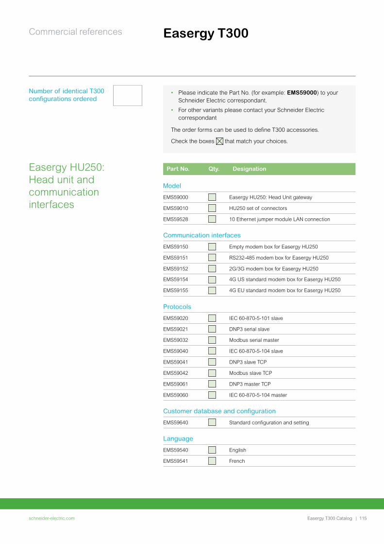
schneider-electric.com | 115
Commercial references
Easergy T300 Catalog
Easergy T300
• Please indicate the Part No. (for example: EMS59000) to your Schneider Electric correspondant.
• For other variants please contact your Schneider Electric correspondant
Number of identical T300 configurations ordered
The order forms can be used to define T300 accessories.
Check the boxes that match your choices.
Part No. Qty. Designation
Model
EMS59000 Easergy HU250: Head Unit gateway
EMS59010 HU250 set of connectors
EMS59528 10 Ethernet jumper module LAN connection
Communication interfaces
EMS59150 Empty modem box for Easergy HU250
EMS59151 RS232-485 modem box for Easergy HU250
EMS59152 2G/3G modem box for Easergy HU250
EMS59154 4G US standard modem box for Easergy HU250
EMS59155 4G EU standard modem box for Easergy HU250
Protocols
EMS59020 IEC 60-870-5-101 slave
EMS59021 DNP3 serial slave
EMS59032 Modbus serial master
EMS59040 IEC 60-870-5-104 slave
EMS59041 DNP3 slave TCP
EMS59042 Modbus slave TCP
EMS59061 DNP3 master TCP
EMS59060 IEC 60-870-5-104 master
Customer database and configuration
EMS59640 Standard configuration and setting
Language
EMS59540 English
EMS59541 French
Easergy HU250: Head unit and communication interfaces
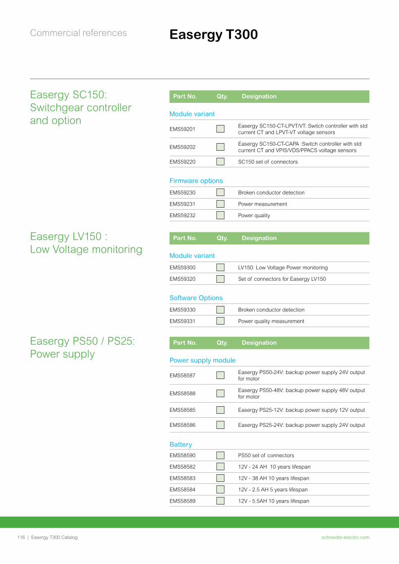
schneider-electric.com116 |
Commercial references
Easergy T300 Catalog
Part No. Qty. Designation
Power supply module
EMS58587Easergy PS50-24V: backup power supply 24V output for motor
EMS58588Easergy PS50-48V: backup power supply 48V output for motor
EMS58585 Easergy PS25-12V: backup power supply 12V output
EMS58586 Easergy PS25-24V: backup power supply 24V output
Battery
EMS58590 PS50 set of connectors
EMS58582 12V - 24 AH 10 years lifespan
EMS58583 12V - 38 AH 10 years lifespan
EMS58584 12V - 2.5 AH 5 years lifespan
EMS58589 12V - 5.5AH 10 years lifespan
Easergy PS50 / PS25: Power supply
Easergy T300
Part No. Qty. Designation
Module variant
EMS59201Easergy SC150-CT-LPVT/VT: Switch controller with std current CT and LPVT-VT voltage sensors
EMS59202Easergy SC150-CT-CAPA :Switch controller with std current CT and VPIS/VDS/PPACS voltage sensors
EMS59220 SC150 set of connectors
Firmware options
EMS59230 Broken conductor detection
EMS59231 Power measurement
EMS59232 Power quality
Part No. Qty. Designation
Module variant
EMS59300 LV150: Low Voltage Power monitoring
EMS59320 Set of connectors for Easergy LV150
Software Options
EMS59330 Broken conductor detection
EMS59331 Power quality measurement
Easergy SC150: Switchgear controller and option
Easergy LV150 : Low Voltage monitoring
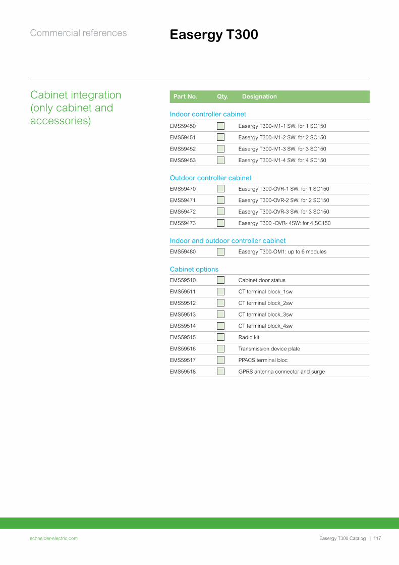
schneider-electric.com | 117
Commercial references
Easergy T300 Catalog
Part No. Qty. Designation
Indoor controller cabinet
EMS59450 Easergy T300-IV1-1 SW: for 1 SC150
EMS59451 Easergy T300-IV1-2 SW: for 2 SC150
EMS59452 Easergy T300-IV1-3 SW: for 3 SC150
EMS59453 Easergy T300-IV1-4 SW: for 4 SC150
Outdoor controller cabinet
EMS59470 Easergy T300-OVR-1 SW: for 1 SC150
EMS59471 Easergy T300-OVR-2 SW: for 2 SC150
EMS59472 Easergy T300-OVR-3 SW: for 3 SC150
EMS59473 Easergy T300 -OVR- 4SW: for 4 SC150
Indoor and outdoor controller cabinet
EMS59480 Easergy T300-OM1: up to 6 modules
Cabinet options
EMS59510 Cabinet door status
EMS59511 CT terminal block_1sw
EMS59512 CT terminal block_2sw
EMS59513 CT terminal block_3sw
EMS59514 CT terminal block_4sw
EMS59515 Radio kit
EMS59516 Transmission device plate
EMS59517 PPACS terminal bloc
EMS59518 GPRS antenna connector and surge
Cabinet integration (only cabinet and accessories)
Easergy T300
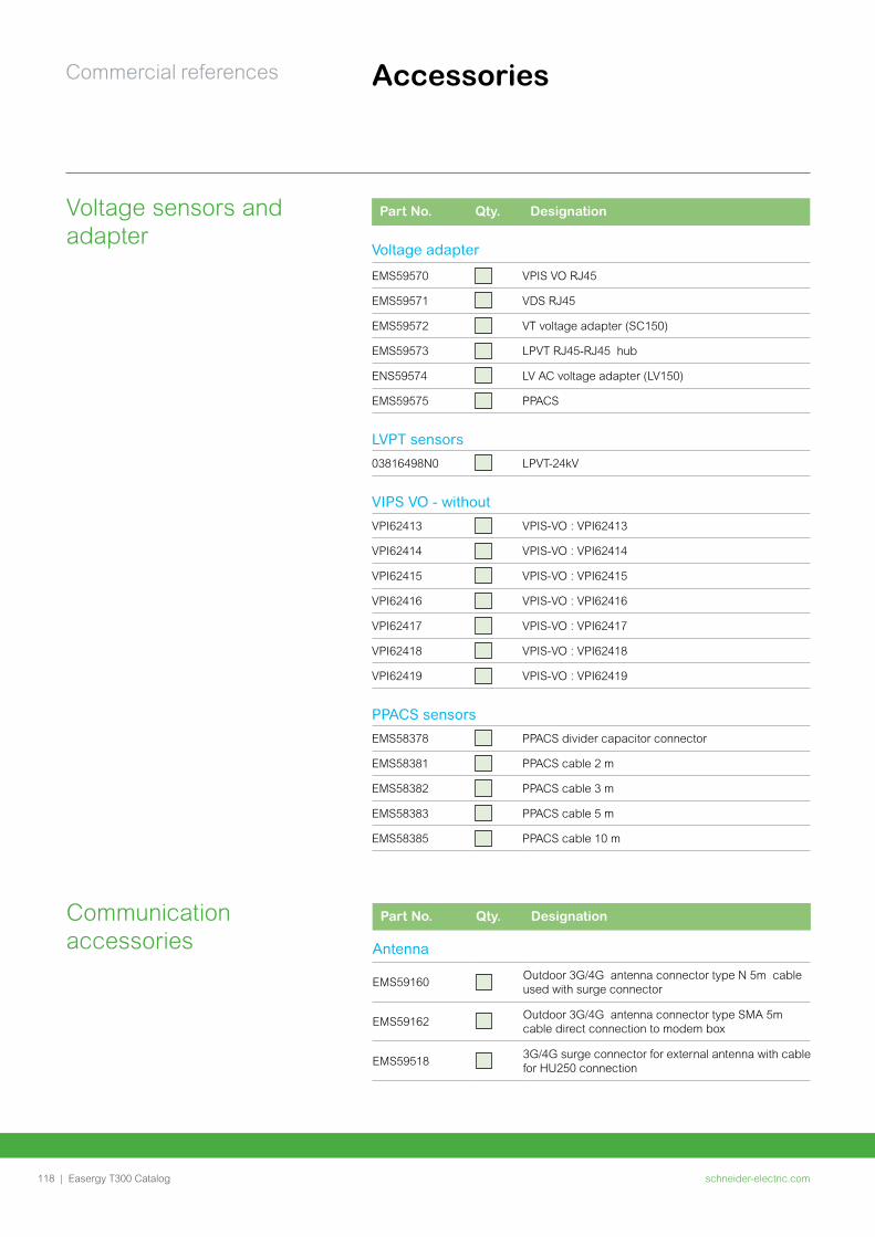
schneider-electric.com118 |
Commercial references
Easergy T300 Catalog
Part No. Qty. Designation
Voltage adapter
EMS59570 VPIS VO RJ45
EMS59571 VDS RJ45
EMS59572 VT voltage adapter (SC150)
EMS59573 LPVT RJ45-RJ45 hub
ENS59574 LV AC voltage adapter (LV150)
EMS59575 PPACS
LVPT sensors
03816498N0 LPVT-24kV
VIPS VO - without
VPI62413 VPIS-VO : VPI62413
VPI62414 VPIS-VO : VPI62414
VPI62415 VPIS-VO : VPI62415
VPI62416 VPIS-VO : VPI62416
VPI62417 VPIS-VO : VPI62417
VPI62418 VPIS-VO : VPI62418
VPI62419 VPIS-VO : VPI62419
PPACS sensors
EMS58378 PPACS divider capacitor connector
EMS58381 PPACS cable 2 m
EMS58382 PPACS cable 3 m
EMS58383 PPACS cable 5 m
EMS58385 PPACS cable 10 m
Voltage sensors and adapter
Accessories
Part No. Qty. Designation
Antenna
EMS59160Outdoor 3G/4G antenna connector type N 5m cable used with surge connector
EMS59162Outdoor 3G/4G antenna connector type SMA 5m cable direct connection to modem box
EMS595183G/4G surge connector for external antenna with cable for HU250 connection
Communication accessories
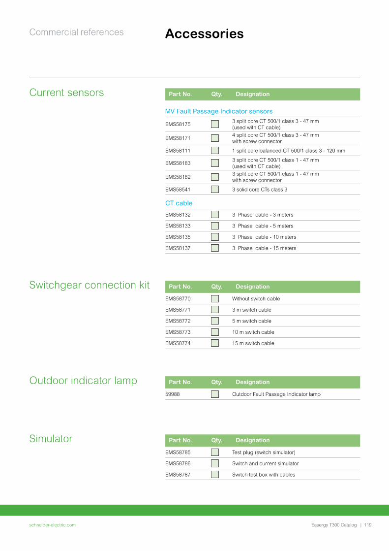
schneider-electric.com | 119
Commercial references
Easergy T300 Catalog
Accessories
Part No. Qty. Designation
MV Fault Passage Indicator sensors
EMS581753 split core CT 500/1 class 3 - 47 mm (used with CT cable)
EMS581714 split core CT 500/1 class 3 - 47 mm with screw connector
EMS58111 1 split core balanced CT 500/1 class 3 - 120 mm
EMS581833 split core CT 500/1 class 1 - 47 mm (used with CT cable)
EMS581823 split core CT 500/1 class 1 - 47 mm with screw connector
EMS58541 3 solid core CTs class 3
CT cable
EMS58132 3 Phase cable - 3 meters
EMS58133 3 Phase cable - 5 meters
EMS58135 3 Phase cable - 10 meters
EMS58137 3 Phase cable - 15 meters
Current sensors
Part No. Qty. Designation
59988 Outdoor Fault Passage Indicator lamp
Outdoor indicator lamp
Part No. Qty. Designation
EMS58770 Without switch cable
EMS58771 3 m switch cable
EMS58772 5 m switch cable
EMS58773 10 m switch cable
EMS58774 15 m switch cable
Switchgear connection kit
Part No. Qty. Designation
EMS58785 Test plug (switch simulator)
EMS58786 Switch and current simulator
EMS58787 Switch test box with cables
Simulator

schneider-electric.com120 | Easergy T300 Catalog120 |120 |
This international web site allows you to access all the Schneider Electric solutions and product information via:• Comprehensive descriptions• Range datasheets• A download area• Product selectors
You can also access information dedicated to your business and contact your Schneider Electric country support.
PM
1036
87
TOOLS

schneider-electric.com | 121Easergy T300 Catalog
Web selector
Training
This site allows you to access Schneider Electric products in just two clicks via a comprehensive range of datasheets, with direct links to:• Complete libraries: technical documents, catalogs,
FAQs, brochures• Selection guides from the e-catalog• Product discovery sites and their animationsYou will also find illustrated overviews, news to which you can subscribe, and a list of country contacts
Training allows you to acquire the expertise (installation design, working with power on, etc.) to increase efficiency and improve customer service.
The training catalog includes beginner’s courses in electrical distribution, knowledge of MV and LV switchgear, operation and maintenance of installations, and design of LV installations, to give a few examples.
TOOLS

NRJED314621EN20, July, 2017
©2017 Schneider Electric SE. All rights reserved. All Schneider Electric trademarks and service marks are the property of Schneider Electric SE, its subsidiaries and affiliated companies.
35 rue Joseph Monier92500 Rueil-Malmaison, FranceTel : +33 (0)1 41 29 70 00
Schneider Electric Industries SAS