Embed Size (px)
Citation preview

PB84-241074
EARTHQUAKE RESISTANCE OF HIGH-RISE SYSTEMS
({))]F TAJL]L JBUJI]LJD) JING §Y§TJEM§
BY
DANIEL W, FALCONERLYNN S, BEEDLE
JUNE 1984
442,3
Lehigh IJniver~dty Inmstitute fot" the Study of the High Rise Habitat
M 7 + *'. N751
•
DCOonl'\lIf'l:1"l nv
.'pm" "·C7. d • •

BIBLIOGRAPHIC DATA 11• Report No.SHEET LEHIGH/fEL /442.3
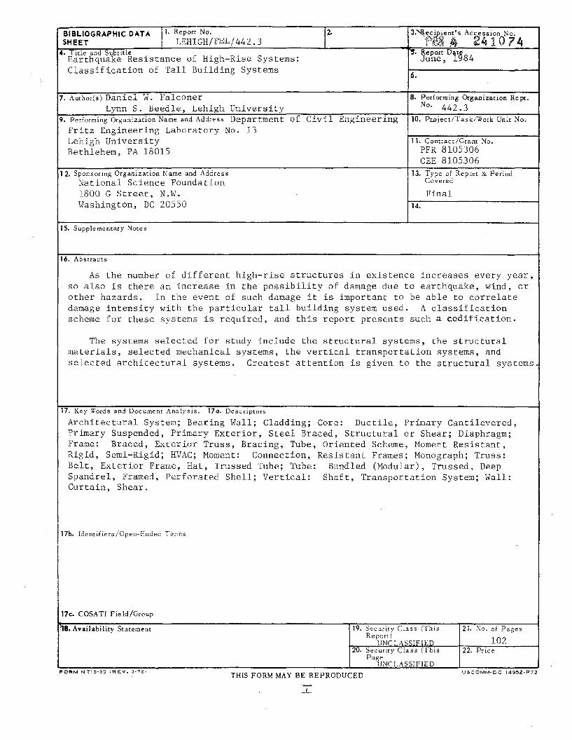
4. Title and SybtitleEarthquake Resistance of High-Rise Systems:Classification of Tall Building Systems
7. Author(s) Daniel W. FalconerLynn S. Beedle, Lehigh University
9. Performing Organizarion Name and Address Department of Civil EngineeringFritz Engineering Laboratory No. 13Lehigh UniversityBethlehem, PA 18015
12. Sponsoring Organization Name and AddressNational Science Foundation1800 G Street, N.W.Washington, DC 20550
15. Supplementary Notes
16. Abstracts
3.~e.cjJ',.. .ient·s Accession No.'P~34~ ~ 24 10 74
-,.. Report Dat~June, 1':184
6.
8. Performing Organization Re pt.No. 442.3 .
10. Pwject/Task/Work Unit No.
11. Contract/Grant No.PFR 8105306CEE 8105306
13. Type of Report & PeriodCovered
Final14.
As the number of different high-rise structures in existence increases every year,so also is there an increase in the possibility of damage due to earthquake, wind, orother hazards. In the event of such damage it is important to be able to correlatedamage intensity with the particular tall building system used. A classificationscheme for these systems is required, and this report presents such a codification.
The systems selected for study include the structural systems, the structuralmaterials, selected mechanical systems, the vertical transportation systems, andselected architectural systems. Greatest attention is given to the structural systems.
17. Key Words and Document Analysis. 170. Descriptors
Architectural System; Bearing Wall; Cladding; Core: Ductile, Primary Cantilevered,Primary Suspended, Primary Exterior, Steel Braced, Structural or Shear; Diaphragm;Frame: Braced, Exterior Truss, Bracing, Tube, Oriented Scheme, Moment Resistant,Rigid, Semi-Rigid; HVAC; Moment: Connection, Resistant Frames; Monograph; Truss:Belt, Exterior Frame, Hat, Trussed Tube; Tube: Bundled (Modular), Trussed, DeepSpandrel, Framed, Perforated Shell; Vertical: Shaft, Transportation System; Wall:Curtain, Shear.
17b. Identifiers/Open-Ended Terms
17c. COSATI Field/Group
1~8. Availability Statement
FORM NTIS-35 (REV. 3-72)
19. Security Class (ThisReport)
-T'NCT A<;STFTEO
20. Security Class (ThisPage
UNCLASSIFIED
TH[S FORM MAY BE REPRODUCED
21. :\0. of Pages
10222. Price
USCOMM·OC 14952·P72

EARTHQUAKE RESISTANCE OF HIGH-RISE SYSTEMS
CLASSIFICATION OF TALL BUILDING SYSTEMS
by
Daniel W. Falconer
Lynn S. Beedle
This work has been carried out as part ofan investigation sponsored by the NationalScience Foundation, Grant No. PFR 8105306,
and Grand No. CEE 8105306
Department of Civil Engineering
Fritz Engineering LaboratoryLehigh University
Bethlehem, Pennsylvania 18015
20 May 1984
Fritz Engineering Laboratory Report 442.3

442.3
Table of Contents
ABSTRACT
1. INTRODUCTION
2. NEED FOR A CLASSIFICATION SCH~ffi
3. TALL BUILDINGS AND THEIR SYSTEMS
4. STRUCTURAL SYSTEMS
4.1 Alternative Classification Schemes
4.2 Proposed Classification Scheme
5. STRUCTURAL MATERIAL SYSTEMS
6. MECHANICAL SYSTEMS
6.1 Heating, Ventilation, ?nd Air Conditioning
6.2 Plumbing Systems
7. VERTICAL TRANSPORTATION
8. ARCHITECTURAL SYSTEMS
8.1 Cladding
8.2 Partitions and Walls
9. UTILIZATION OF CLASSIFICATION SCHEMES
10. FURTHER STUDIES
11. SUMMARY
ACKNOWLEDGEMENTS
GLOSSARY
TABLES
FIGURES
REFERENCES/BIBLIOGRAPHY
1
2
3
5
8
9
14
19
20
20
25
29
31
31
32
34
35
36
37
38
44
71
93

442.3
ABSTRACT
As the number of different high-rise structures in existenceincreases every year, so also is th~re an increase in thepossibility of damage due to earthquake, wind, or other hazards. Inthe event of such damage it is important to be able to correlatedamage intensity with the particular tall building system used. Aclassification scheme for these systems is required, and this reportpresents such a codification.
The systems selected for study include the structuralthe structural materials, selected mechanical systems, thetransportation systems, and selected architecturalGreatest attention is given to the structural systems.
systems,verticalsystems.
Of the various alternatives, a framing-oriented scheme ischosen as a means of classifying structural systems. Thefundamental systems within it are bearing wall, core, tube, andframe, together with the appropriate mixtures of these systems. AnumericaJ. designation system prOVides opportunity to catalog thespecific details of the system in a computer data base. This inturn opens the way to the study of possible correlation of anyobserved damage with the system or subsystem.
1

442.3
1. INTRODUCTION
The object of this report is to develop a classification schemefor some of the more important tall building systems. The systemschosen for classification are the structural system, structuralmateriaJ.s and selected mechanical and architectural systems. Themajor emphasis is placed upon the structural system.
Tall. buildings are highly sophisticated engineering projects.Due to the complexity of the structures, the most advancedengineering design techniques are needed in tall buildings. Todevelop these techniques, new and existing research and empiricalstudies need to be documented in a usable and accessible form.
By definition, a classification system imposes order on a largebody or information. If there were only a few tall bUildings in theworld, codification schemes would not be needed. However, tallbuildings exist all over the world, and their numbers are increasingevery year.
In order to design better tall buildings, information must becollected on the performance of existing tall buildings. Theclassification helps create a structured order in which to storeinformation collected about high-rise bUildings.
In the past, it was not uncommon to totally separate thestructural engineering from the mechanical and architectural aspectsof tall building planning and design. Today, however, the tallbuilding is more commonly designed from a "team" approach, withinteraction between the key professionals. In keeping with thisphilosophy, the tall building classification systems are extendedbeyond the structural classification to encompass selectedmechanical and architectural systems.
'y
Preceding page blank2
442.3
2. NEED FOR A CLASSIFICATION SCHEME
It is important to realize that a significant amount ofconstruction will be required in the next 50 years -- enough toservice twice the present world population according to someconservative estimates (Keyfitz) -- and a large percentage of thatwill be in the high-rise environment. Since in both present andfuture buildings the design ultimate load could, in fact, beattained, it is important to know how the various systems performand which ones perform the best.
In the following chapters, fundamentally representativeclassification schemes for tall building systems will be presented.Why are they needed? Towards what use can these schemes be applied?
The answers to these questions go back to the need to determinethe extent to which present analytical approaches adequatelyrepresent behavior in actual buildings under normal and extremeloads (such as earthquakes, strong winds, and other hazards) andunder service situations and use. The basic question is this: is itpossible to establish a correlation between the particular systemsor subsystems used in tall buildings and the way in which thesesystems respond under extreme and service loads?
If the response can be predicted and confirmed in anappropriate sample of the large number of tall buildings throughoutthe world -- in other words if a correlation can be establishedbetween a particular system or subsystem and its behavior inspecific applications then this information will be offundamental importance in new designs. It will be of equal
·importance in assessing the probable performance of existingbuilaings that have not yet encountered such loading and serviceconditions. Necessary steps for correction of any majorshortcomings can then be recommended. In case a bUilding is to berenovated for other reasons, those with less-favorable systems canreceive the appropriate attention.
This type of research will require as complete anidentification as possible of the tall buildings around the worldand the details of the systems that are used therein. It willrequire documentation of the performance of these systems. Toachieve this, a comprehensive worldwide survey 'must be made of tallbuildings and their systems. A logical and consistent format isessential if meaningfu~ results are to be obtained, and this studyof tall building classification aims to provide such order and
3
442.3
structure.
Another major potential benefit of acquiring a large body ofinformation about tall buildings, especially in earthquake-proneregions, is that a real-life laboratory is created. When anearthquake strikes, there would be a wide range of easily accessibleinformation available to investigators and researchers. The varioustall building systems (structural, mechanical, etc.) could becompared as to their ability to function during and after anearthquake. Interaction between different tall bUilding systemscould be studied to determine the combinations of systems thatfunction well together and those that do not (Sun, 1979) •Responsible authorities and private assessors could more quicklyevaluate monetary and property losses by having prior knowledge ofthe damaged buildings. Projections could be made of future possiblelosses. It cOUld assist damage evaluation teams as they prepare forsite Visits, and an inventory that includes the professionalsinvolved would facilitate procurement of needed supplementaryinformation.
4
442.3
3. TALL BUILDINGS AND THEIR SYSTEMS
The term, "high-rise", is defined in Webster's dictionary as a"building of many stories". This serves to illustrate the term'ssubjectivity. Do any clear and precise definitions exist, and onwhat basis are they founded?
Many local fire codes in the USA base their defini tion of atall building on the height to which their fire ladders will reachfrom the street. Depending on the city, this could range from 6 to10 stories in the USA. Som~ plumbing engineers would argue thatonly when a building has more than 25 stories do design conceptsrequire modification for plumbing systems. Other professionalsargue from other perspectives.
The defini tion of a tall building was one of the first topicsto come under discussion by the Council on Tall Buildings and UrbanHabitat, an international group sponsored by engineering,archictectural, and planning professionals, that was established tostudy and report on all aspects of the planning, design,construction, and operation of tall buildings. As described in itsMonograph (Council, 1978-1981), it is not so much a matter of alimiting height or number of stories. Rather, "The importantcriterion is whether or not the design is influenced by some aspectof tallness." A suggested definition, then, might be "a building inwhich tallness strongly influences planning, design and use"; or "abuilding whose height creates different conditions in the design,construction, and use than those that exist in common buildings of acertain region and period". For purposes of standardization, inconnection with its survey of tall building characteristics, theCouncil collects information on buildings that are nine stories ormore in height.
Four different categories of building systems have beenidentified (Beedle, 1980). These are Loading Systems, PhysicalSystems, Functional Systems, and Building Implementation Systems.They are shown in detail in Fig. 1. Under the "Physical Systems"heading are such items as foundation systems, structural framework,mechanical and service systems, and electrical systems. Thebuilding systems this report will classify are· the structural,material, mechanical, vertical transportation, and architecturalsystems.
In general, the structural system of a building is athree- dimensional complex assemblage of interconnected structural
5
442.3
elements (Council, Committee 3, 1980). The primary function of thestructural system is to effectively and safely carryall the loadswhich act upon the building, and to resist sway by providingadequate stiffness. The structural system physically supports theentire building, and with it, all the other various bUildingsystems.
The mechanical systems studied in this report are the heating,ventilation and air conditioning (HVAC) system, and the plumbingsystems. Among other needs, the HVAC system in a tall bUilding mustbe responsive to environmental requirements, energy consumption, andsmoke and fire management. The plumbing system must be able to meetthe water demand of the high-rise (both supply and discharge) underall service and emergency conditions. The vertical transportationsystem must respond to the user promptly, since its function is thatof a time and labor saving device. By gaining a few seconds foreach passenger on every trip, effective elevator service can savevaluable man-hours (Adler, 1970).
The architectural systems examined in this report are thepartition system and the cladding (curtain wall) system. Thefunction of partitions in a building is the separation of largespace into smaller areas for privacy or safety. The function of thecladding (curtain wall) system is to regulate the passage of light,moisture, temperature transfer, dirt, and, of course, people throughthe building's "skin". It must also serve to provide acousticalcontrol from outside noise and to assist in fire control (Council,Committee 2A, 1980).
The systems identified above were chosen because they generallymeet the following criteria: during a natural disaster (earthquake,strong wind, fire) would the failure of these systems most likelylead to possible loss of life? The failure of even a part of thestructural system is an obvious threat to anyone in a tall buildingat the time of a disaster, and usually leads to failure of themechanical and architectural systems attached and supported at thosepoints. The loss of the mechanical systems in a tall bU~lding mayconstitute a threat to life. The ventilation system is vital duringa fire, Decause of the smoke that must be removed. Similarly, theplumbing system is also of great importance in fighting fire in tallbuildings since it delivers water to the sprinklers and fire hoses.The failure of the vertical transportation system could trap people.
The failure of the cladding or parti tion systems can alsoconstitute a hazard to life. The cladding system must be able tofunction during a strong wind to-protect the occupants and contents
6
442.3
of the building. Its attachment to the framework must assure thatit does not fragment during an earthquake or storm. In many tallbuildings, the partition system is an integral part of the fireprotection system by providing what is known as"compartmentalization" thus helping to prevent the spread of fire(Council, Committee 2B, 1980).
7
442.3
4. STRUCTURAL SYSTEMS
This chapter presents the different types of tall bUildingstructural systems, and the various methods of classifYing them. Itincludes a summary of the previous work that has been done in thisfield.
The structural system of a bUilding must resist both gravityand lateral loads due to such phenomena as wind and earthquakes. Asthe height of the building increases, the lateral loads begin todominate the structural design. Figure 2 (Khan, 1974) schematicallycompares some frequently used steel and concrete structural systemson the bas.1S of structural efficiency (as measured by weight persquare foot of the system versus height of the building).
Bearing wall structures could be used in high-rise buildings upto 20 stories. A tUbe structure is commonly employed in the tallestbuildings built to date (1984).
Lateral loads due to wind and earthquake produce lateralaccelerations. As people normally perceive these accelerations atmuch lower levels than the structural safety limit, stiffness ratherthan strength tends to become the dominant factor in buildings ofgreat height.
Four over-all groupings of structural systems have beenidentified. These are the bearing wall system, the core system, theframe system, and the tUbe system. Each system has inherentlydifferent lateral load resistant properties and thus tends to be"efficient" over different height regions.
The bearing wall system due to the self weight of thestructural components (solid concrete or masonry), usually becomesinefficient (cost of the structural system versus its height) abovethe 15-30 story range of height.
The concrete core system has the same disadvantage as thebearing wall system, namely self weight of solid concrete or masonryas a limiting factor.
The efficiency of the frame system depends upon the rigidity ofthe connections and. the amount of bracing. Stiffening can beachieved through a solid core, shear walls or diagonal bracing. As
8
442.3
more bracing is incorporated into the spatial frame, the range ofefficient height is increased. The upper limit is in the range of60 stories.
The tube system can be thought of as a spatial frame with allthe vertical elements positioned at the exterior. The range ofheight efficiency is influenced by the type and amount of bracingemployed in the tube, but in general, a tube structure is consideredthe most efficient for the tallest buildings (60 stories andgreater) •
4.1 Alternative Classification Schemes
It is difficult to create a classification system that succeedsin isolating consistent criteria for tall building structuralsystems. This is due to the large number of possible variables suchas the number of stories, building material, framing system, andload resistance properties. Tall buildings themselves are diverse1"n nature of usage, location, geometric shape and architecturaldesign. Thus there are difficulties in arriving at a comprehensivemethod for classifying them.
The literature suggests that there are three general approachesto structural classification schemes. First there are loadingoriented classification schemes, a listing of tall buildingstructural members and subsystems by the loads they resist. Secondare the material-oriented classifications, a listing of tallbUilding structural systems by the main structural material(s) used.Third, there is the framing-oriented classification system, alisting of tall bUilding structural systems by their framing method.
In the following sections the different approaches and theappropriate classifications are grouped and discussed. Generaladvantages and disadvantages to each approach are also presented.
A. Loading-Oriented Classification
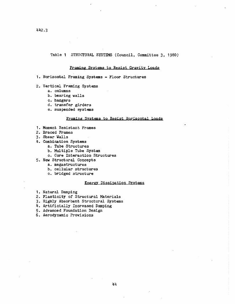
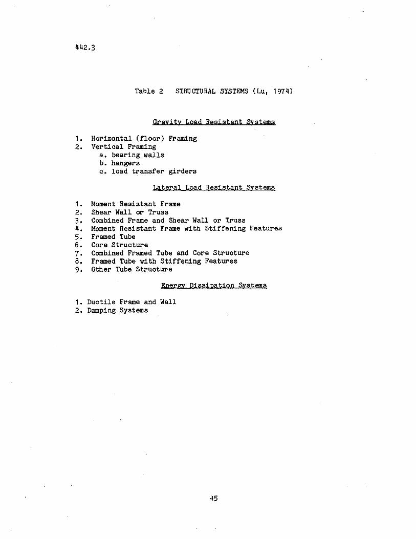
The loading-oriented classification scheme organizes thestructural components and subsystems according to the type of loadthat is resisted whether gravity, lateral, or energy·dissipation(Council, Committee 3, 1980). Tables 1 and 2 are examplesof this approach.
9
442.3
.The components and members that make up the load resistinggroups can be thought of as structural "building blocks" from whichall tall building structures are constructed. One way to categorizea structural system is to define the combinations of elementarystructural bUilding blocks that are employed in the structuralsystem. In fact, this is how to classify a structure by theloading-oriented approach. These building blocks are, of course,not arranged haphazardly, but are integrated in such a way as toprovide the most adequate support and stiffness while conforming tothe architectural plan and maintaining overall economy.
The classification procedure for this type of approach is togroup all of the structural components and subsystems presently inuse in tall buildings by load resistance characteristics; and toeach bUilding that is to be classified, assign various items fromeach group to define that particular structural system.
The classification that was developed by Committee 3 of theCouncil on Tall Buildings and Urban Habitat (1980) is such aloading-oriented classification. It groups "bUilding blocks" basedon a listing of vertical load-resisting members, horizontal loadresisting subsystems, and energy dissipation systems (see Table 1).The items grouped together to form the vertical resisting membersinclude columns, bearing walls, hangers, and transfer girders. Theitems that form the lateral load resisting members include momentresisting frame, braced frame, shear walls, and combination systems.Items grouped under combination systems are tubes and coreinteractive structures, and are called "combination" because theyusually resist both lateral and vertical loads.
Lu (1974) has presented a classification method using the samebasic approach, namely, a listing of vertical load-resistingmembers, horizontal load-resisting subsystems, and energydissipation systems. This arrangement is shown in Table 2. A moredetailed listing of lateral load resisting subsystems is inclUded,which clearly indicates the many combinations of lateral loadresisting subsystems employed in the design of tall buildings.
Generally, the main advantagesclassification are:
of a loading-oriented
1. It provides a strong lead to the structural design. Whendesigning a tall building structure, a loading-orientedclassification suggests which structural components andsybsystems are available and which loads they generally
10
442.3
resist.
2. It accommodates the many geometric forms andconfigurations without defining them specificialJ.Y, andthus can be applied to virtually any tall building.
The main disadvantages of this type of classification are:
1. It cannot render a consistant physical description of thebuilding. This is due to the many and varied ways thesebuilding blocks can be integrated to create a particularstructural system.
2. It implies that certain structural members resist onlyone particular loading condition. In reality, theobjective is to have all members resist loads from asmany sources as possible and thus create a more efficientstructural system.
B. Material-Oriented Classification
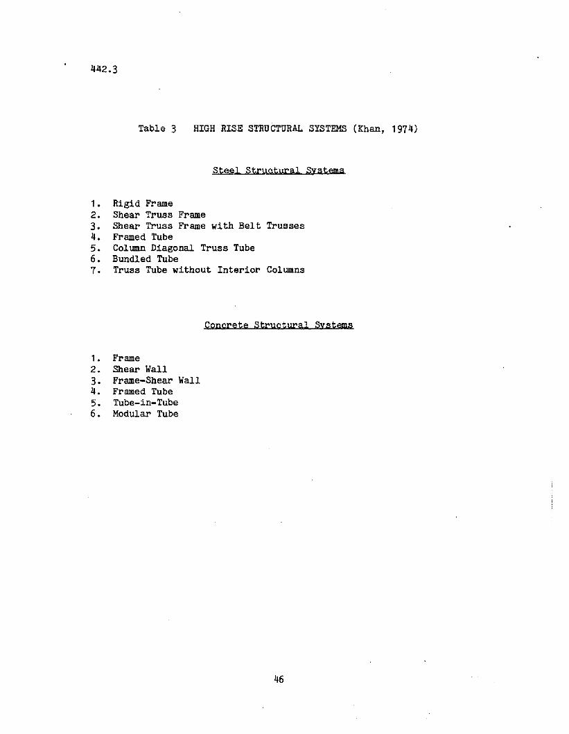
A second method of classifying structures is a materialoriented classification. This method separates structural systemson the basis of structural material (concrete, steel, masonry, orwood, or mixed). These distinctions are obvious and valid becausemany structural systems differ significantly depending on whichstructural material is used. The variables associated with concretestructures might be the ultimate strength of concrete, the slump ofthe mix, curing time, amount of pretension, or placement ofreinforcing bars, most of which are not applicable to steel,masonry, or wood structures. The variables for a steel or masonrystructure are also unique to those particular structural materials.Tables 3 through 0 list classification schemes that use thisapproach.
Khan (1974) used a material-oriented classification to discussthe different responses of various steel, concrete, and mixedstuctural systems to lateral loads (see Table 3).
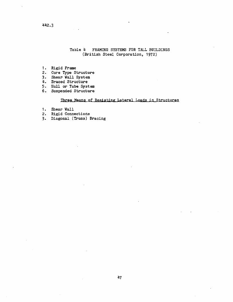
This approach is also used by the Bri tish Steel Corpora tion(1972) as seen in Table 4 for the classification of tall steelstructures.
A classification of tall bUilding structural subsytems based on
11
442.3
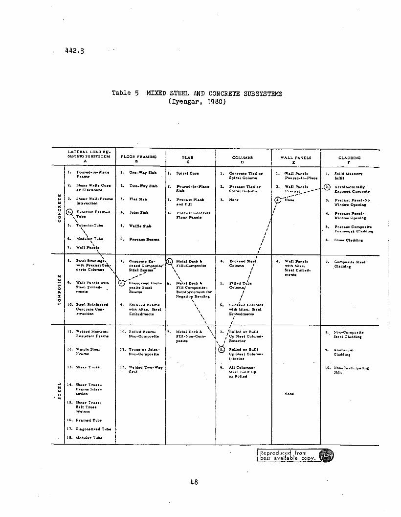
the lateral resistance of different construction materials wasdeveloped by Iyengar (1980), and the subsystems are shown in Table5.
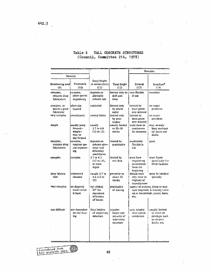
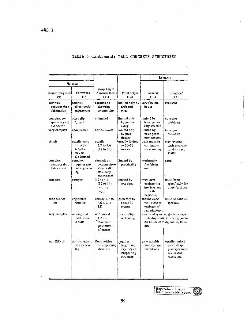
Committee 21A of the Council on Tall Buildings and UrbanHabitat also has developed what could be called a material-orientedclassification, subdivided according to framing type and applicableto tall concrete structures. This classification is shown in Table6. A major advantage of this particular classification scheme isthat each concrete structural system is examined in chart form. Bydoing this, a logical comparison of the similarities and differencesof each system can be achieved, which helps to give a lffeel lf foreach type of system. The three main parameters examined in thischart are the difficulty of engineering, architecture, andconstruction of the various structural systems.
The main advantage of a material-oriented classification isthat it illustrates the differences that exist between structuralsystems created from different materials.
The main disadvantage is the possible redundancy because manygeometric structural schemes are not limited to one constructionmaterial. For example, a frame structure can be made of concrete,of steel, or of a combination of both.
C. Framing-Oriented Classification
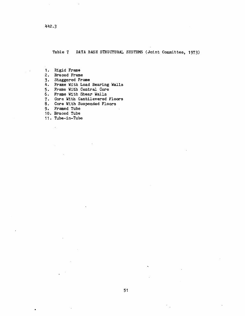
A third classification system is the framing-oriented or"descriptive lf scheme. This aPIlroach attempts to classify tallbuilding structural systems according to a description of thestructural framing system. Tables 7 through 11 give examples of theuse of this approach.
The classification scheme shown in Table 7 was used in anextensive worldwide survey of tall bUildings and theircharacteristics conducted by the Council (Beedle et. al., 1980).The system consists of a word or phrase which (traditionally)represents a certain type of structural system. In Schueller's(1977) classification shown in Table 8, primary emphasis is given tovisual and descriptive analysis of the structural systems. He lists14 separate tall building structural systems •
. The Applied Technology Council (1978) groups structural systemson the basis of similar lateral drift characteristics and natural
12
442.3
frequencies. The numerical coefficients developed for eachstructural system are for use in the ATe "equivalent lateral forceprocedure and model analysis". This document is applicable to allstructures and is not restricted to tall buildings.
Drosdov and Lishak (1978) developed a classification schemethat categorizes the different structural systems into four primaryloadbearing systems and six secondary (combination or hybrid)loadbearing structures (see Table 10 and Fig. 3). The six secondarysystems are, in fact, combinations of the four primary structures.This classification is part of a study of the dynamic response ofdifferent tall building structures.
Table 11 contains a structural classification scheme developedat an early stage of the project which separated the structure intothree categories: the structural framing system, the "augmentative"structural subsystem, and the floor framing system (Falconer, 1981).The structural framing system is defined as the primary loadresisting system of the structure. The augmentative structuralsubsystems are the subsystems which are "added" to the primary loadresisting system to create a stronger and/or stiffer totalstructure. The floor framing system transmits the occupancy loadsto the structural framing system, and may also serve to transmitlateral loads along its length between the vertical members.
The basis for classifying structures by this approach is asfollows:
1. There is one and only one primary load resisting systemin a tall building.
2. The number of augmentative structural subsystems in astructure vary from case to case.
3. There is one floor framing system that can be identifiedper building.
The main advantages of a framing-orientedclassification scheme are as follows:
structural
1. It groups together structures that, by virtue of theirframing system, respond similarly to a load (Le., frame,tube, bearing wall, etc.). This is important when onewants to compare the performance of various systems and
13
442.3
their response to load.
2. It avoids the redundancies inherent in the otherapproaches. The loading-oriented approach is redundantbecause one member can resist more than one loadingsystem; and the material oriented appproach is redundantif one system is constructed from different materials.
The main disadvantage is also a point in its favor: it bothrequires details for, and yet accommodates, the many differentcombinations of systems and subsystems that can be incorporated intoa structure.
4.2 Proposed Classification Scheme
After consideration of the various systems identified in theliterature and a consideration of the advantages and disadvantagesof each, the framing-oriented clasification scheme contained inTable 12 was selected and further developed to meet the followingconditions:
1. The classification scheme must be simple in concept andapplication, yet detailed enough so that usefulcomparisons can be made.
2. The classification must be broad in scope in order to beusable in further stUdies, specifically, a comparison ofthe responses of different high rise structural ·systemsto earthquakes and other loads.
3. The classification should be compatible with a computeroriented system for storing information, retrieving it,and making comparison between the response of similarsystems.
This framing-oriented classification scheme is one thatseparates the structure into four major categories: the structuralframing system, the bracing system, the floor framing system, andthe building configuration system. In the discussion that follows,these categories are identified as "Levels", the major subgroupsbeing identified in Fig 4.
As noted earlier and illustrated in Fig. 3, the structuralframing system consists of four major or prime groups:
14
442.3
1. the bearing wall system (identified as "wall")
2. the core system
3. the frame system
4. the tUbe system.
These four prime groups are shown in Table 12 as a "Level A" inthe structural system hierarchy. The hybrids and the varia tions ofeach of these structural systems have been listed in an organizedway beneath each of the above four primary structural systems. Thenumerical designations are intended to provide a basis for groupinglike systems and subsystems together for the purpose of analysis andevaluation. The primary systems are further described as follows:
1. A bearing wall structure is comprised of planar,vertical elements, which form all or part of the exteriorwalls and in many instances the interior walls as well.They resist both vertical and horizontal loads. Examplesare shown in Fig.5.
2. A ~ structure is comprised of load-bearing wallsarranged in a closed form, usually with the mechanicalana vertical transportation systems concentrated in thisvertical shaft, allowing the building flexible spacebeyond the core. The core can be designed to resistvertical and/or horizontal load. Examples are shown inFig. 6. In one group, shown in the upper part of thefigure, there is a central core from which floors areeither suspended or cantilevered. In the other group(lower part of Fig. 6) the cores are separated. They aretubes that are not bundled.
3. A frame structure is usually comprised of columns,beams, and/or floor slabs arranged to resist bothhorizontal and vertical loads. The frame is perhaps themost adaptable structural form with regard to materialand shape, due to the many ways of combining structuralelements to adequately support the loads. Examples areshown in Fig. 7.
4. A~ structure is usually comprised of closely spacedexterior structural elements, arranged to r~spond to alateral load as a whole, rather than as separateelements. Alternate schemes could include braced tubesand framed tUbes or more widely spaced columns with deep
15
442.3
spandrels. The system allows for more flexibility ininterior space use, due to the lack of vertical interiorstructural elements. Examples are shown in Fig. 8.
"Level Bn in the hierarchy covers the bracing subsystems andare shown in Table 12. They categorize (1) what type of bracing isemployed in the building (K-bracing, diagonal bracing, etc.), (2)whether the bracing is for the frame or the core, and (3) what typeof hat or. belt truss is employed in the bUilding, if any.
There are five digits in Level B. The first two digits show thetype of bracing in plane 1. The next two digits show the type ofbracing in plane 2. The last digit is for hat and/or belt truss.
Under the bracing subsystems there are five categories. Thefirst category (numbers 10-16, 20-22) refers to the bracing of theframe. Core bracing is divided into two categories, steel corebracing (numbers 30-36, 40-42) and concrete core bracing (numbers80-85). The next category refers to the moment resisting frame(numbers 50-53). The last category refers to the shear wall bracing(numbers 60-65).
"Level C" in Table 12 covers the floor framing subsystem. Thefloor system transmits occupancy loads to the framing system, and itmay also serve to transfer lateral forces, acting as a diaphram andas an integral part of the framing system. The basic categorizationis according to material and construction method.
"Level Dn in Table 12 covers the building 'configurationsubsystem. By this is meant the vertical and horizontal structuralsymmetry or discontinuity. It uses the ATC classification systemwith regard to regularity (ATC,1978) but also identifies the various
. above-grade load transfer systems most commonly employed in tallbuil<1ings.
The methodology for arriving at a classification number for anystructure is as follows:
1. Identify which of the four prime systems (wall, core,frame, or tube) describes the structure.
2. Scan Table 12, Level A (and the corresponding figure) forthe specific structural system used. (For example, aframe with solid core is No. 58.) The numbers that
16
442.3
correspond to that system are the first two digits of theclassification number: ftFrame 58ft
3. Scan Level B in Table 12 (and the illustrations in Fig.10) for the specific bracing subsystem used. (Example:frame bracing, double diagonal bracing is identified asft12ft and no hat or belt truss is identified as ftOft)
4. Scan Level C in Table 12 for the specific floor framingsubsystem used. (Example: concrete beam· and slab,identified by the number ft24ft)
5. Scan Level D in Table 12 with regard to vertical andhorizontal regularity and symmetry. (Example:Irregularity in both plan and elevation configurationsand load transfer girder, identified by No. 01011)
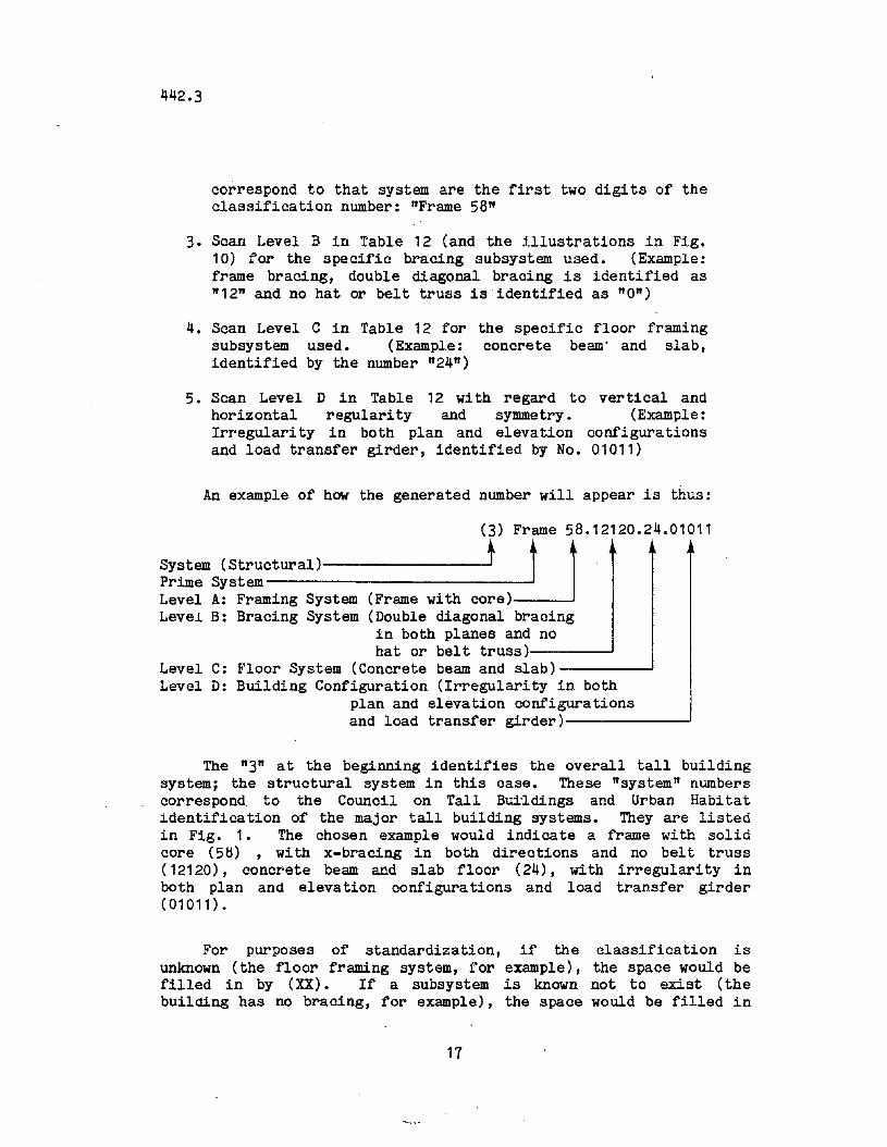
An example of how the generated number will appear is thus:
(3) Frame 58.12120.24.01011
System (Structural) t LJPrime System------------Level A: Framing System (Frame with core)Level B: Bracing System (Double diagonal bracing
in both planes and nohat or belt truss)----~
Level C: Floor System (Concrete beam and slab)-------~
Level D: Building Configuration (Irregularity in bothplan and elevation configurationsand load transfer girder)------~
The ft3ft at the beginning identifies the overall tall buildingsystem; the structural system in this case. These ftsystem ft numberscorrespond. to the Council on Tall Buildings and Urban Habitatldentification of the major tall building systems. They are listedin Fig. 1. The chosen example would indicate a frame with solidcore (58) , with x-bracing in both directions and no belt truss(12120), concrete beam and slab floor (24), with irregularity inboth plan and elevation configurations and load transfer girder(01011).
For purposes of standardization, if the classification isunknown (the floor framing system, for example), the space would befilled in by (XX). If a subsystem is known not to exist (thebuilding has no bracing, for example), the space would be filled in
17
442.3
with zeros (00). If it is not known whether an element is there ornot, use (17).
Figure 9 is a sample classification chart, with some samplebUilaings classified. The numbers shown in Fig. 9 corresponding tothe structural system are retrieved from Table 12. The numbereddesignations are intended to provide a basis for grouping likesystems and subsystems together along the lines shown in Table12 and the example structures shown in Figs. 5 through 8.
18
442.3
5. STRUCTURAL MATERIAL SYSTEMS
Since the beginning of high-rise construction, structuralmaterial concepts have been changing constantly. In the nineteenthcentury the two most commonly used structural materials were masonryand iron. It was soon discovered that the type of structural systemfor which masonry is best suited (the bearing wall system) is notvery efficient when applied to tall bUildings. A remarkable use ofmasonry was in the 16-story Monadnock BUilding (1891) in Chicago, inwhich the lower walls were designed to be more than six feet thick(Khan, 1973).
Frame systems became more and more prevalent in tall structuresaround the turn of the century. This type of system was first madepossible by using iron, and later, steel. The first example of atalJ. building totally supported by an iron framework was in 1883,wi th the start of construction of the la-story Home InsuranceBuilding. Reinforced concrete became a common structural materialduring this period. In 1903, the 16 story Ingalls Building wasconstructed of reinforced concrete (Schueller, 1975).
Today, the main high-rise structural materials are steel,reinforced concrete, prestressed concrete, masonry (reinforced ornot) , and composite (steel and concrete). Many structurescontaining structural cores use a different material for the corethan for the framing. Therefore, when classifying the material of astructure, two digits are needed. The first represents the mainframing system (wall, core, frame, or tUbe), and the secondrepresents the structural core (if applicable, as in the case of aframe and core or a tube-in-tube system). Table 13 contains aclassification of the material system.
19
442.3
6. MECHANICAL SYSTEMS
This chapter will identify and categorize the major factorscommon to high-rise mechanical systems: heating, ventilating, andair-conditioning (HVAC), and plumbing. A preliminary classificationscheme is presented in Table 14 (for HVAC) and in Table 15 (forplumbing). The subject of vertical transportation is covered in thefollowing chapter.
The invention and improvement of tall building mechanicalsystems have made it possible for the high-rise to become anattractive, livable environment. In tall buildings erected beforethe general adoption of air conditioning, perimeter spaces werenecessary for natural ventilation from openable windows. Dead airspaces in the interior were possible, and the general efficiency oftotal usable space was compromised. After forced air HV AC systemsoecame accepted, the entire floor plan became the usable ot'ficespace, and the efficiency of the floor space was improved (ASHRAE,1976),
Plumbing system concepts in tall bUildings went unchangedlonger than any other mechanical system. The method used almostexclusively until the late 1950's and early 1960's to increase waterpressure was that of single speed pumps carrying water to variousgravity tanks. It is known as the gravity tank system (Council,Committee 2B, 1980). At that time, variable speed pumps and pumpcontrols were developed to a point where booster pump systemsstarted to replace gravity tank systems. Today, the booster pumpsystem is specified almost exclusively (Steele, 1975).
6.1 Heating, Ventilation, and Air Conditioning
The primary purpose of a heating, ventilation, and airconditioning system is to prOVide a specific set of pre-determinedenvironmental conditions.
Table 14 lists the different types of HVAC systems that areavailable (ASHRAE, 1976). Most of the requirements of a particularbuilding can be met by. anyone of several possible systems. Thefour general heating systems categories are forced air, steamheating, water heating, and electric panels.
The cooling system categorieswater, multiple unit systems (air
20
are all-air, air-water,conditioners in windows)
alland
442.3
combinations of these.
A. Heating Systems
1. Forced Air Heating
In forced air systems, the air circulation is accomplished bymotor driven centrifugal fans (blowers). The generally citedadvantages of forced air heating are as follows (ASHRAE, 1976):
1. The unit may be placed anywhere in the structure
2. Circulation of air is positive, and air may be cleanedwith fil ters
3. Humidity control is readily obtained
4. The same air distribution may be used for cooling if sodesigned.
2. Steam Heating
A steam heating system uses the vapor phase of water to supplyheat, connecting a source of steam to a suitabre terminal heattransfer unit. Steam heating systems are also referred to ascentral or district heating systems. The generally cited advantagesof steam heating are as follows:
1. Steam pipes are smaller than air ducts, and thus are moreflexible with regard to space requirements.
2. Individual terminal heat control is possible.
3. The installation is less expensive to build and maintainthan fixed air or water heating systems.
3. Water Heating System
A water system is one in which hot water is used to convey heatto terminal transfer units. The generally cited advantages are asfollows:
21
442.3
1. It provides a simple means of perimeter heating, byintroducing heating along entire outdoor exposuresthrough the use of baseboard, finned radiation, orradiant cycling panels.
2. It requires fewer specialists for maintenance.
3. The same water distribution system can be used forcooling, if so desired.
4. Electric Heating
An electric heating system uses electrical resistance to meetspace heating requirements. The usually cited advantages ofelectric heating are as follows:
1. It is clean, compact, and safe.
2. It is simple to distribute and control.
3. It has a low initial cost.
4. It can be used to supplement other heating systems.
A typical example of mechanical system designator is asfollows:
(2f) 2.1System (Mechanical) ~tHeating System (steam)Cooling System (all air)
The first digit after the parethetical designator representsthe heating subsystem and the second digit represents the coolingsystem.
B. Cooling Systems
1. All-Air Systems
An all-air system is defined as a system providing completecooling capacity by an air stream supplied by the system. It isusually accomplished by forced air (ASHRAE, 1976). All-air systems
22
442.3
may be classified into two basic categories:
1. Single path systems -- those which contain the mainheating and cooling coils in a series flow path, usingcommon duct distribution to feed all terminals.
2. Dual path systems -- those which contain the main heatingand cooling coils in a parallel flow path, using one ductfor heating and one duct for cooling.
The usually cited advantages of an all-air system are:
1. Centralized location of major equipment
2. Wide choice of placement options
3. Ready. adaptation of heat recovery systems
4. Adaptable to winter humidification
5. Design freedom for optimum air distribution.
The usually cited disadvantages of an all-air system are:
1. The additional duct clearance requirements
2. The long.hours of fan operation in cold weather requiredby perimeter heating.
2. Air-Water Systems
In the all-air system, the building space is cooled solely byair. In contrast, the air-water system is one in which both air andwater are distributed to perform the cooling function. Air-watersystems are categorized as follows:
1. The two-pipe system -- a system which consists of onesupply pipe and one return pipe, along with condi tionedair from a central sour~e.
2. The three-pipe system -- a system which consists of onehot supply pipe, one cold supply pipe, and a common
23
442.3
return pipe.
3. The four-pipe system -- a system which consists of aseparate hot loop and cold loop.
The air-water system has the following advantages:
1. Because of the greater specific heat and much greaterdensi ty of water compared to air, the cross sectionalarea required for the distribution pipes is much less forthe same cooling task.
2. Individual room thermostat control is possible.
3. With all-air. systems, the size of central airconditioning apparatus is reduced.
The air-water system has the following disadvantages:
1. Controls tend to be complex.
2. The system is not applicable to spaces with high exhaustrequirements, and/or high dehumidification requirements.
3. All-Water Systems
All-water systems accomplish cooling solely by the distributionof chilled water to terminal units located throughout the building.All-water systems are categorized as follows:
1. Two-pipe systems
2. Three-pipe systems
3. Four-pipe systems
The all-water system has the following advantages:
1. No ventilation ductwork space is required.
2. Individual room thermostats are possible.
24
442.3
The all-water system has the following disadvantages:
1. Total lack of humidity control.
2. Dependence on natural ventilation.
6.2 Plumbing Systems
The primary purpose of the plumbing system is to provideadequate water pressure at all times to all parts of the building.This entails delivering the water at the correct pressure to alllocations and reqUires the handling of the discharge. Plumbingsystems can be classified into three categories: the pressureboosting system, the hot water system, and the chilled water system.(The classification system is given in Table 15.)
A. Pressure Boosting System
1• Grayity Tank System
The gravity tank system consists of an elevated tank ofadequate capacity for which single speed pumps are used to raise thewater to fill the tank. When the water level in the tank drops to apredetermined level, the pumps bring water up until the tank is full(Steele, 1975).
Compared to other pressure boosting systems, the gravity tanksystem has the following advantages:
1. No sophisticated controls are required
2. It is most reliable in case of power failures
3. It requires minimum maintenance
4. It provides additional reserve capacity for fireprotection
5. Pump head is less than is required in other systems, andtherefore uses less energy
6. There are minimum pressure variations in the distributionsystem.
25
442.3
The gravity tank system has the following disadvantages:
1. The tank must be elevated
2. The weight of the tank and water may increase structuralcosts
3. The tanks require interior maintenance
4. If there is a tank failure, large quantities of waterwill be released.
2. Hydropneumatic Tank System
The hydropneumatic tank system consists of a series of tanks atvarious locations in the building with pumps to raise the water tothe tanks. The hydropneumatic tanks are also known as pressuretanks, because the tanks use compressed air to achieve the deSiredpressure in the line. They are smaller than i:;he gravity tanks.
Compared to the gravity system, the hydropneumatic tank systemhas the following advantages:
1. The tanks do not have to be elevated
2. Tanks can be located anywhere in the bUilding
It has the following disadvantages:
1. There is the possibility of inside corrosion of the tankdue to the addition of air in the tank
2. There can be significant pressure variations (up to 20psi)
3. Pumps of a higher head are required.
3. Booster PumP System
The booster pump system varies the speed of continuouslyrunning pumps to hold a constant discharge pressure under varyingflow ~onditions.
26
442.3
The advantages of a booster system are:
1. Much smaller tanks are required.
2. Usually there is a lower initial cost.
The disadvantages of a booster system are:
1. More sophisticated controls are necessary
2. The constantly running pumps can create a noise problem
3. There is no emergency water supply should the pumpsbecome inoperable
4. Operating costs are high because the pumps do not operateat maximum efficiency.
AI.L of the pressure boosting systems rely on pumps to deliverthe required water pressure. Pumps can be either mechanical(combustion type) or electrical, and either single speed or multiplespeed. As shown in Table 15, the pumps are included as a part ofthe pressure boosting system.
B. Hot Water Supply System
The hot water circulating system requires water lines, waterheaters, and frequently, pumps which are independent of the mainwater supply system. A high-rise building plumbing system isusually zoned vertically to maintain' pressures wi thin tolerances.For hot and chilled water circulation, these zones can becategorized by the source of pressure. If the pressure source is atthe top of the zone (either pump or gravity), it is known as adownfeed zone. The same logic applies to upfeed zones andcombination upfeed and downfeed zones (Steele, 1975).
C. Chilled Water Supply System
The chilled water supply system is categorized in a mannersimilar to the hot water supply system, with upfeed, downfeed andcombination zones. See Fig. 11. In addition, however, some highrise buildings use two other means to supply chilled water. Thefirst is that of bottled water supplied through self containedunits. The other method is to have factory assembled refrigeration
27
442.3
systems installed separately as drinking fountains.
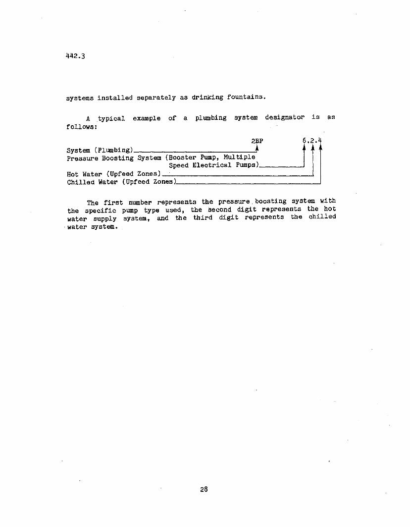
A typical example of a plumbing system designator is asfollows:
2BP 6.2.4System (Plumbing) --'~~Pressure Boosting System (Booster Pump, Multiple
Speed Electrical Pumps)Hot Water (Upfeed Zones) __~-------------------------------lChilled Water (Upfeed Zones) ~
The first number represents the pressure. boosting system withthe specific pump type used, the second digit represents the hotwater supply system, and the third digit represents the chilled
. water system.
28
442.3
7. VERTICAL TRANSPORTATION
Vertical transportation systems can be separated into threecategories: elevators, escalators, and material movers (see Table16) • Elevators and escalators are vertical "people movers". Thesubject is treated in Chapter SC-4 of the Monograph on the Planningand Design of Tall Buildings (Council, Committee 2A, 1980).
A. Eleyators
The invention and development of the passenger elevator(1853-1900) meant that the height of the building was no longerlimited by the occupants I willingness or ability to climb stairs.The elevator industry played a major role in setting the stage forthe increased size and height of buildings in the early decades ofthe twentieth century. The increasing demand on elevator capacityand speed brought about further innovations such as multiple batchsystems, local and express elevators, and double deck elevators(Adler, 1970).
Basic factors that are considered when designing the elevatorsystem include the number of passengers per minute, theirdistribution to the floors, the times of arrival and departure, andthe floor-to-floor movement. In order to more easily classifyelevator systems, four subsystems are defined: the drive, the shaftarrangement, the car arrangement, and traffic flow. Hydraulicelevators are not usually employed in high-rise bUildings andtherefore are not included.
The drive subsystem consists either of geared or gearlesstraction elevators. Both geared and gearless traction elevatorsconsist of a car with hoisting rope or cable running over grooves,which is connected to the elevator drive sheave, and attached to acounter weight.
The shaft arrangement can be ei ther in-line (shafts arrangedside-by-side) or opposite (shafts separated by passenger lobby).See Figs. 12 , 13, 14 •
The car arrangement can be either single deck (one car pershaft) or double deck (two compartments per car), each servingalternate floors. See Fig. 15.
29
442.3
The traffic flow of the cars can be local (each car can stop atany and all floors), or express (different cars operate as a localonly over a certain range of floors), or sky lobby (a shuttleelevator that goes from ground level to a lobby, where local and/orexpress elevators are available for access to other levels). SeeFig. 16.
B. Escalators
An escalator is a continuously running, unidirectional vehicleproviding vertical transportation along an incline (Strakosh, 1967).The two general arrangements of escalators are "parallel" and"crisscross" as shown in Fig. 17. A third possible arrangement,which is called multiple parallel, consists of a number ofescalators side by side, serving more traffic than a usualarrangement could handle. Flexibility in handling heavy traffic isprovided by operating all units except one in the same direction.
C. Material Movers
Material movers are separated into two categories; pnuematicmessage tubes and tote box selective vertical conveyors (Council,Committee 2A, 1980). Delivery~of more bulky materials is usuallyhandled by service elevators.
30
442.3
8. ARCHITECTURAL SYSTEMS
The two architectural systems considered in this report are thecladding systems and the partition 'systems (Council, Committee 12Aand 12B, 1980, and Time-Saver Standards, 1974).
The building known as the "first skyscaper" was the Home LifeInsurance Building in Chicago. One of the major reasons for thisdesignation was that it was the first to employ nonloadbearingexterior walls. The cladding was a curtain wall -- so calledbecause it hung on the framework. The cladding systems discussed inthis report will be limited to the nonloadbearing type.
In tall buildings extra consideration is given those aspects topartitions that affect acoustics, fire protection, the covering ofelevator shafts, and the response to lateral sway of the building.
8 •1 Cladding
For the purpose of classification, cladding systems can begrouped into a number of subsystems: cladding type, material,installation method, material, and glass iotill subsystem. (SeeTable 17.)
There are two general types of cladding systems: customcladding (designed specifically for one bUilding) and standardcladding (components and details are standardized by the industry).
There are five general installation methods: stick wallsystem, unit system, unit and mullion system, panel system, andcolumn-and-spandrel system. (See Table 17 and Figs. 18, 19, 20, 21,22. )
In the stick wall system the components are installed piece bypiece, with vertical members (mullions), horizontal members, andwindows as the pieces. The advantage of this system is its ease ofshipping and the ability to make dimensional adjustments to siteconditions. The disadvantage of this system is the necessity ofassembly in the field.
The unit system is a preassembled module, usually one floor inheight. The unit and mullion system is installed mullions first,
31
442.3
with the preassembled units placed between them. The advantage ofthe unit system is that good quality control can be maintained atthe shop. The disadvantage is that units are usually bulky totransport.
The panel installation system is similar to the unit system,but with the jointing between panels kept to a minimum. Theadvantages and disadvantages are basically the same as with the unitsystem.
The column cover and spandrel installation system consists ofcolumn and spandrel cover sections, and infilled windows or glazedunits. The advantages of this system are relatively easy shippingand latitude of use with any column and spandrel spacing. Thedisadvantage of this system is the large amount of field workinvolved with its assemblage.
There are several available structural materials used incurtain walls. They are structural carbon steel, stainless steel,aluminum, bronze, stone, brick, and ceramic tile. These structuralmaterials are required to provide the necessary support andstiffness for the glass infills •
.Glass can be classified according to the amount of light thatpasses through it. Clear glass allows the maximum possible light topass, and opaque allows the least. Tinted glass is intermediate andis designed to allow a certain specified amount of light into thebuilding. In other cases glass is colored to reflect light forarchitectural effect.
8.2 Partitions and Walls
The primary function of the parti tion system in high-risebuildings is the separation of large spaces into smaller ones forprivacy, for the organization of work functions, and for fireprotection (Council, Committee 12B, 1980).
The classification of partition systems is according to movable(demountable) partitions and solid (permanent) partitions. SeeTable 18. All partitions referred to in this section arenonloadbearing.
The solid partitions are categorized according to their
32
442.3
construction material (either brick, stone, or concrete) as shown inTable 18, Level A. The demountable partitions are categorizedaccording to their support scheme, either post and infill, post andoverlay, or postless. The postless partitions must reach fromceiling to floor for support, whereas the post supported partitionscan be of any height.
33
442.3
9. UTILIZATION OF CLASSIFICATION SCHEMES
As noted earlier in this report, at present there is nosystematic method of making a correlation between the variousbuilding systems and the performance of those systems. Theclassification scheme presented in the previous chapters is aimed atrationally identifying the systems, and with this accomplished, asystem-by-system damage correlation can be carried out for pastdisastrous events and can be applied to future events.
A sample of the kind of information being collected is shown inTables 19 and 20. Table 19 identifies "Field Tests andObservations" and Table 20 lists the "Case Studies". The majorsystems involved in the study or event are shown using the numericaldesignation of Fig. 1. But within -these systems a furtherdefinition and refinement is required, and this is the function ofthe classification schemes of Tables 11-18.
Tables 21 and 22 illustrate how the numerical system will beused for those cases in which a building is involved in an event ora field test. For every building that is involved in an event -- anearthquake, a tornado, a field test -- certain systems will beinvolved. For example, the San Francisco Chronicle Building in the1906 earthquake involved the structural system (3) and the claddingsystem (12A) (Table 21). But what is the particular structuralsystem? The particular cladding system? They have to be designatedin a sufficiently detailed way so that the systems can be recognizedand then correlated with damage as shown in Table 22.
Table 23 is a sample of the systematic identification andarrangement of the data that is anticipated at the present writing,making use of the classification schemes of Tables 12 through 18.The Mori-Sada Building was used for illustration.
34
442.3
10. FURTHER STUDIES
In future work on this subject, the classification schemes needto be reviewed with practicing engineers, sUitably modified, andthen applied on a trial basis. Such application would use availableinformation on file for existing buildings.
After further refinement, the scheme would then be used in thefurther surveys that would be made by the Institute for the Study ofthe High-Rise Habitat in cooperation with the Council of TallBuilding to collect information on systems and their response.
35
442.3
11. SUMMARY
A summary of this study is as follows:
1. The tall building systems are identified as the loadingsystems, the functional systems, the physical systems,. and thebUilding implementation systems (Fig. 1). The systems that havebeen examined in this report from the viewpoint of· classificationare the structural, material, mechanical, vertical transportation,and selected architectural systems, all of which are subsystems ofthe physical systems. Primary attention has been given in thisreport to the structural system.
2. A variety of structural categorizations and classificationswere identified from the literatures. Three alternativeclassification approaches were examined, a loading-orientedapproach, a material-oriented approach, and a framing-orientedapproach.
3. The framing-oriented approach was selected for use in thesuggested structural system classification scheme (See Table 12).The major systems and subsystems in the structural classificationscheme are the framing system, the bracing subsystem, the floorframing subsystem, and the building configuration subsystem.
4. A classification number is assigned to each system andsubsystem as a basis for computerizing specific information aboutindividual buildings. The numerical designators assist in groupinglike systems together for the purpose of comparisons of the responseof the various systems to loading.
36
442.3
ACKNOWLEDGEMENTS
The library research was conducted at Fritz EngineeringLaboratory and at Mart Science Library, both at Lehigh University,Bethlehem, Pennsylvania. This work was carried out as part of aresearch program at the Fritz Engineering Laboratory. The thesisresearch upon which the report is based was a part of the firstnamed author's civil engineering degree work, which was supervisedby the second-named author.
The research was supported in part by a National ScienceFoundation grant. Acknowledgement is due Dr. George C. Driscoll,Dr. Le-Wu Lu, Dr. Peter Mueller, Dr. Ti Huang, and George Mikroudisfor advice as well as Lois M. Nase, Sharon L. Seigler, and JeanM. Johnson, Mart Reference Librarians, for their help in collectingsome of the literature used in this report. The Study of earthquakedamage by Mikiroudi and Mueller (1984) was particularly helpful inthat it provided subsegment revision of the system. The authors arealso thankful to Mr. David Beedle, Mr. Pierre Engel, and Mr. ShiunnJang Wang for their help in preparing the manuscript.
37
442.3
GLOSSARY
Architectural System. Defines the internal and externalpartitioning of the building.
Beam. A structural member in which the internal stresses on atransverse cross section may be resolved into a resul tantshear and bending moment.
Bearing Wall. A structure composed of planar, vertical elementswhich usually form the exterior and interior walls.(Example: Monadnock Building, Chicago, IL)
Belt Truss. A truss similar to a hat truss except locatedbetween ground level and the top story.
Braced Frame. A frame that relies almost totally on a bracingsystem for lateral stability.
Bundled (Modular) Tube. A structure that is composed of severalframed tubes rigidly attached to form an extremely stiffstructure. (Example: Sears Tower~ Chicago)
Cladding. The opaque areas of an exterior window wall orcurtain wall; i.e., the column cladding or spandrel claddingof a building.
Compartmentalization.smaller spaces.
Action of dividing a large space into
Core. A~ structure is comprised of load-bearing wallsarranged in a closed form, usually with the mechanical andvertical transportation systems concentrated in thisvertical shaft, allowing the building flexible space beyondthe core.
Curtain Wall. A building exterior wall, of any material, whichcarries no superimposed loads.
38
442.3
Deep Spandrel Tube. A structure with more widely spaced columnsand much deeper spandrels than a typical framed tube, butwhich achieves tube-like stiffness. (Example: M.L.C.Centre, Sydney, Australia)
Diaphragm. Floor slab possessing a large in-plane shearstiffness.
Ductile Core.load.
A core which behave in a ductile manner under
Earthquake-prone Region.occur.
Regions where most severe earthquake
Electrical SysteJllS. Equipment that uses electricity inproviding services.
Exterior Truss Frme. A frame that has truss members on theexterior to provide lateral stability and stiffness.(Example: Alcoa Building, Pittsburgh)
Fire Codes. The rules that define the fire regulation for thehigh-rise buildings. Frme. A structure composed ofcolumns, beams and/or slabs arranged in a three-dimensionalgrid to resist both horizontal and vertical loads.Frequently it has a bracing system to help provide lateralstability.
Frame Bracing. Usually a series of structural elements withpinned ends, arranged to deform axially (usually a diagonal,K, or double diagonal) that provide lateral stability andstiffness to the structure.
Framed Tube. A structure that has closely spaced columnsrigidly connected to spandrel beams with no interiorcolumns. (Example: World Trade Center, New York)
Framing Oriented Soheme. Includes bearing wall, core, tube andframe, together with the appropriate mixtures of these
39
442.3
systems.
RiAe. Heating, yentilating, and air conditioning.
Hat Truss. A horizontal truss at the top story of a buildingwhich rigidly connects the interior core with the exteriorstructure (usually a frame or tube).
High-rise Building. A building that has occupied floors abovethe normal operation of an aerial ladder fire truck. This isusually all buildings with the top floor higher than 20m(70ft) above the adjacent street level permitting truckaccess.
Joist. One of a series of closely spaced horizontal structuralmembers interacting with or supporting a deck.
Mechanical Systems. Those systems required for introducing,circulating, or removing, solids, and air.
Moment Connection. A rigid connection capable of tr-.ansmittingthe bending moment imposed on it.
Moment Resistant Frames. An integrated system of structuralelements possessing continui ty and hence capable ofresisting bending forces. (These frames usually developminor axial forces.)
Monograph. Treatise or tall building(five volumes) produced bythe Council.
Partition. A divider of space within the interior of thebuilding. It can be bearing or nonbearing and it can extendfrom floor to floor or from floor to ceiling.
Perrorated Shell Tube. A structure that resembles a solid shellwith exterior windows "punched" out.
40
442.3
Primary Core Cantilevered. A primary core supporting floorsthrough cantilever action.
Primary Core Suspended. A primary core supporting floors bysuspending them from top. (Example: Federal Reserve Bank,Minneapolis, MN, Torres Colon, Madrid, Spain)
Primary Core. A structure whose predominant stiffness andstrength is provided by one or more cores (bearing wallsarranged in a closed form).
Primary Exterior Cores. Primary cores located on the exteriorof the structure and floor framed between the cores.(Example: Knights of Columbus, Hew Haven)
Rigid Frame. A frame with full moment connections to providelateral stiffness. (Example: Latino Americana Tower, Mexico,City)
Semi-rigid Fra.e. A frame that provides lateral stiffnessthrough connections. Although not fully rigid, lateralstiffness in increased if bracing is added. (Example:Empire State Building, New York)
Shear Wall. A concrete or masonery wall (which or withoutwindow openings) resisting the shear, as distinct from apanel with crossed diagonals.
Skin of Building. Outside surfaces: walls, windows, roof.
Sprinkler System. A system of p~p~ng and sprinkler headconnected to one or more sources of water supply.
Steel Braced Core. Frame bracing arranged to form an open,partially closed, or fully closed box structure thatprovides lateral stiffness and stability.
Structural (or Shear). Core. An assembly or group of shear walls
41
442.3
joined together to form an open, partially closed, or fullyclosed box structure, that provides resistance to shearforces resulting from lateral loads.
Structural (or Shear) Wall. A concrete or masonry wall which inits own plane carries shear forces resulting from lateralloads.
Structural Materials. The materials used in the structuralsystem, usually steel, concrete, and masonery.
Structural System. The structural system provides for thestrength and stability of the building. The performance ofstructures is mainly defined by their structuralcharacteristics.
System Approach. A concept of design that takes intoconsidera tion the effect of all the environmental and humanfactors and phenomena that affect the operation of thatpiece of equipment or that system.
Transfer Girder. A horizontal framing member which transfersvertical loads, for example, at one of the lower floorswhere some of the columns need to be eliminated to createlarger open spaces.
Trussed Tube. A tube that has truss members on the exterior toprovide cantilever action with no interior" columns.
Tube. A structure that responds to lateral force throughcantilever action. A tube is usually comprised of closelyspaced rigidly connected exterior elements, al thoughalternate schemes include more widely spaced columns withdeep spandrels.
Tube. A~ structure is usually comprised of closely spacedexterior structural elements, arranged to respond to alateral load as a whole, rather than as separate elements.
42
442.3
Vertical Shaft. Space in the heart of the bUilding for themechanical systems and elevators.
Vertical Transportation Systems. The elevators and otherlifting devices for vertical movement of personnel andmaterials include exterior maintenance systems for thecleaning of the building.
43
442.3
Table 1 STRUCTURAL SYSTEMS (Council, Committee 3, 1980)
Framing Systems to Resist Gravity Loads
1. Horizontal Framing Systems - Floor Structures
2. Vertical Framing Systemsa. columnsb. bearing wallsc. hangersd. transfer girderse. suspended systems
Framing Systems to Resist Horizontal Loads
1. Moment Resistant Frames2. Braced Frames3. Shear Walls4. Combination Systems
a. Tube Structuresb. Multiple Tube Systemc. Core Interaction Structures
5. New Structural Conceptsa. megastructuresb. cellular structuresc. bridged structure
Energy Dissipation Systems
1. Natural Damping2. Plasticity of Structural Materials3. Highly Absorbant Structural Systems4. Artificially Increased Damping5. Advanced Foundation Design6. Aerodynamic Provisions
44
442.3
Table 2 STRU CTURAL SYSTEMS (Lu, 1974)
Grayity Load Resistant Systems
1- Horizontal (floor) Framing2. Vertical Framing
a. bearing wallsb. hangersc. load transfer girders
Lateral Load Resistant Systems
1. Moment Resistant Frame2. Shear Wall or Truss3. Combined Frame and Shear Wall or Truss4. Moment Resistant Frame with Stiffening Features5. Framed Tube6. Core Structure7. Combined Framed Tube and Core Structure8. Framed Tube with Stiffening Features9. Other Tube Structure
Energy Dissipation Systems
1. Ductile Frame and Wall2. Damping Systems
45
442.3
Table 3 HIGH RISE STRUCTURAL SYSTEMS (Khan, 1974)
Steel Structural Systems
1• Rigid Frame2. Shear Truss Frame3. Shear Truss Frame with Belt Trusses4. Framed Tube5. Column Diagonal Truss Tube6. Bundled Tube7. Truss Tube without Interior Columns
Concrete Structural Systems
1. Frame2. Shear Wall3. Frame-Shear Wall4. Framed Tube5. Tube-in-Tube6• Modular Tube
46
442.3
Table 4 FRAMING SYSTEMS FOR TALL BUILDINGS(British Steel Corporation, 1972)
1. Rigid Frame2. Core Type Structure3. Shear Wall System4. Braced Structure5. Hull or Tube System6. Suspended Structure
Three Means of Resisting Lateral Loads in Structures
1. Shear Wall2. Rigid Connections3. Diagonal (Truss) Bracing
47
442.3
Table 5 MIXED STEEL AND CONCRETE SUBSYSTEMS(Iyengar, 1980)
LATERAL LOAD RE-SISTINe SUBSYSTEM FLOOR FRAMlNel SLAB COLUMNS WALL PANELS CLAOOINel
It. B C 0 E F
I. Poured-tn-Place I. On••Way Slab I. Splral Cor. I. Cone rete Tied or I. ·Wall Pane" I. Solid Ma.onryFrame Spiral Col...."'" Poured-ln-Place Intlll
2. Shear Wall. Core 2. Two.Way Slab 2. Pou.red.ln-Place 2. Pr.ca.t Tied 01' 2. Wan P.neh ..@ ArchitecturaUy01' £1&.""1\.... Slab Spiral Columa Prec•• r: _---- Expo.ed Cone rete--10I CEJ-N;:.. ,. Sh•• r Wall.Fralne ,. nat Slab ). Prlca.t Piaok ). None ). Preea.t PAnel· No
10I loter.ctlan and FlI1 , Window Openion.
'" ,0 0 £xterlor Framed. 4. Joht Slab 4. Preca.t Concrete
,4. Preca.t Panel.;l:
a , Tube noor Panell Window Openlnl0 , ,
5. Tube-La-TuM 5. Waen. Slab ,5. Preca.t Compo.ite, I Formwork Cb,ddinl,
I,I6. Modular T!olH 6. Prec••t Beam. I 6. Ston.. Claddlnl,
I7. Wall Paa'.1e I\ I
\ Ia. St••l Br.c1nl~\ 7. Conel'de Ea.- ~ Motal O.ck • 4. Ene••ed St••1 4. Wan Panel. 7. Compo.h. St••l
:~:~.P~:~':~~OIl"ca. ••d compo..:lt..... , FII1-Compoolt. Columll I with Mlae. .claddlnl
I St•• l Emb.d.SUe1~~am. ,I\ , menta10I 1\. .. .. , I..
@'~n.nca ••d Com. M~ta1 Deck" 5. FlI10d Tub•- ,. WaU Panela _itb 6.VI Steel Embed. Fill Campedt... Columa/0 poaite St••l
'" m.nt. Beam. aelnforcement for I::r NelaUvtt Bendin. I
I0 ,Enei.ed Column.0 10. Steel Reinforced ,. Ene.led Beam. , 6.
Cone rete Coa. with. Mlle. Ste",
with Mlle. Ste.l,at ruction Embedmea.t. , Embedment., I, I
\,'aolled or Bullt11. Welded Moment. 10. Rolled Beam... 7. Metal Deck 1& , 7. B. Non-Campo.lte
Reaiatant Fra.me Non_Campo_itl FIlI-Non-Com.,
, Up Steel Column. Steel Claddin.po.lte , I Exterlor
12. Simple St.el 11. Tru•• or Joiet ... (9 Rolled 01' BllUe 9. AluminumFrame Non-Compollte Up Steel Column. Claddinl
Interior
13. She.r Trul. 12. Welded Two_Way ,. All Columna. 10. Non. Partie lpalLnaGrid St.ol Built Up Skin
or Roll.d
..l 14. Shear Tru....10I Fram. Inter.101
actlon None..VI
15. Shear T ru•••Belt True.Syetem
16. Framed Tube
17. OtaaoneUzed Tube
18. Modular Tube
Reproduced frombest availa ble copy.
48
442.3
Table 6 TALL CONCRETE STRUCTURES(Council, Committee 21A, 1978)
Remarks
Material
Reinforcing steellStory height,
Formwork in meters (feet) Total height General Interfacea
(9) (10) (11) (12) (13) (14)
complex, omplex, depends on limited only by very flexible excellentrequires shop often special allowable drift and in usefabrication engineering column size sway
complex, re- often slip unlimited limited only ; limited by no majorquires a good formed by practi- basic geom- problemsfabricator cality ctTY selected
very complex complicated normal limits limited only limited by no majorby prac- basic geom- problemsticality etry selected
simple usually jump usually usually limited I walls must be may severelyformcd- 3.7 to 4.6 to 20-30 continuous limit mechanl-simple- (12 to IS) stories for economy cal ducts andmay be shaftsslip formed
complex, complex, depends on limited by moderately goodrequires shop requires spe- column size- practicality flexible infabrication cial engineer- shear wall use
ing efficiencycontributes
complex complex 3.7 to 4.3 limited by must have must frame(12 to 14), test data engineering specifically foror truss involvement these facilitiesdepth from the
I beginningshop fabrica- engineered usually 3.7 to presently to should work must be handled
tion reusable 4.6 (12 to about 30 very close to specially15) stories engineer of
manufacturervery complex on diagonal not critical practicality variety of systems. single or mul-
itself-other -450 for of bracing tiple diagonals, K bracing (vertl-is basic maximum cal or horizontal), lanice, knee,
efficiency etc.of braces
not difficult not dependent floor heights r.equires only suitable usually limitedon any brac- of supporting height and with certain to small ap-ing structure capacity of conditions pendages such
supporting as elevatorstructure shafts, etc.
Reproduced frombest available copy. 49
442.3
Table 6 continued: TALL CONCRETE STRUCTURES
Remarks
Material
Reinforcing steellStory height,
Formwork in meters (feet) Total height General Interfacea
(9) (10) (11) (12) (13) (14)
complex, !complex, depends on limited only by very flexible excellentrequires shop often special allowable drift and in usefabrication engineering column size sway
complex, re- often slip unlimited limited only ,limited by no majorquires a good formed by practi- basic geom- problemsfabricator cality etry selected
very complex complicatcd normal limits limited only limited by no majorby prae- basic geom- problemstieality etry selected
simple usually jump usually usually limited I walls must be ma~' severelyformed- 3.7 to 4.6 to 20-30 continuous limit mcchani-simple- (12 to 15) stories for economy cal ducts andmay be shaftsslip formed
complex, complex, depends on limited by moderately goodrequires shop requires spe- column size- practicality flexible infabrication cial engineer- shear wall use
ing efficiencycontributes
complex complex 3.7t04.3 limited by must have must frame(12 to 14), test data engineering specifically foror truss in\'olvement these facilitiesdepth from the
I beginningshop fabrica- engineered usually 3.7 to presently to should work must be handled
tion reusable 4.6 (12. to about 30 very close to specially15) stories engineer of
manufacturervery complex on diagonal not critical practicality variety of systems. single or mul-
itself-other 45° for of bracing tiple diagonals. l-: bracing (verti-is basic -'maximum cal or horizontal), lattice, knee,
~fficiency etc.of braces
not difficult not dependent floor hei~ts r,equires only suitable usually limitedon any brao- of supporting height and with certain to small ap-ing structure capacity of conditions pendages such
supporting as elevatorstructure shafts, etc.
Reproduced frombest available copy.
50
442.3
Table 7 DATA BASE STRUCTURAL SYSTEMS (Joint Committee, 1973)
1• Rigid Frame2. Braced Frame3. Staggered Frame4. Frame With Load Bearing Walls5. Frame With Central Core6. Frame With Shear Walls7. Core With Cantilevered Floors8. Core With Suspended Floors9. Framed Tube10. Braced Tube11. Tube-in-Tube
51
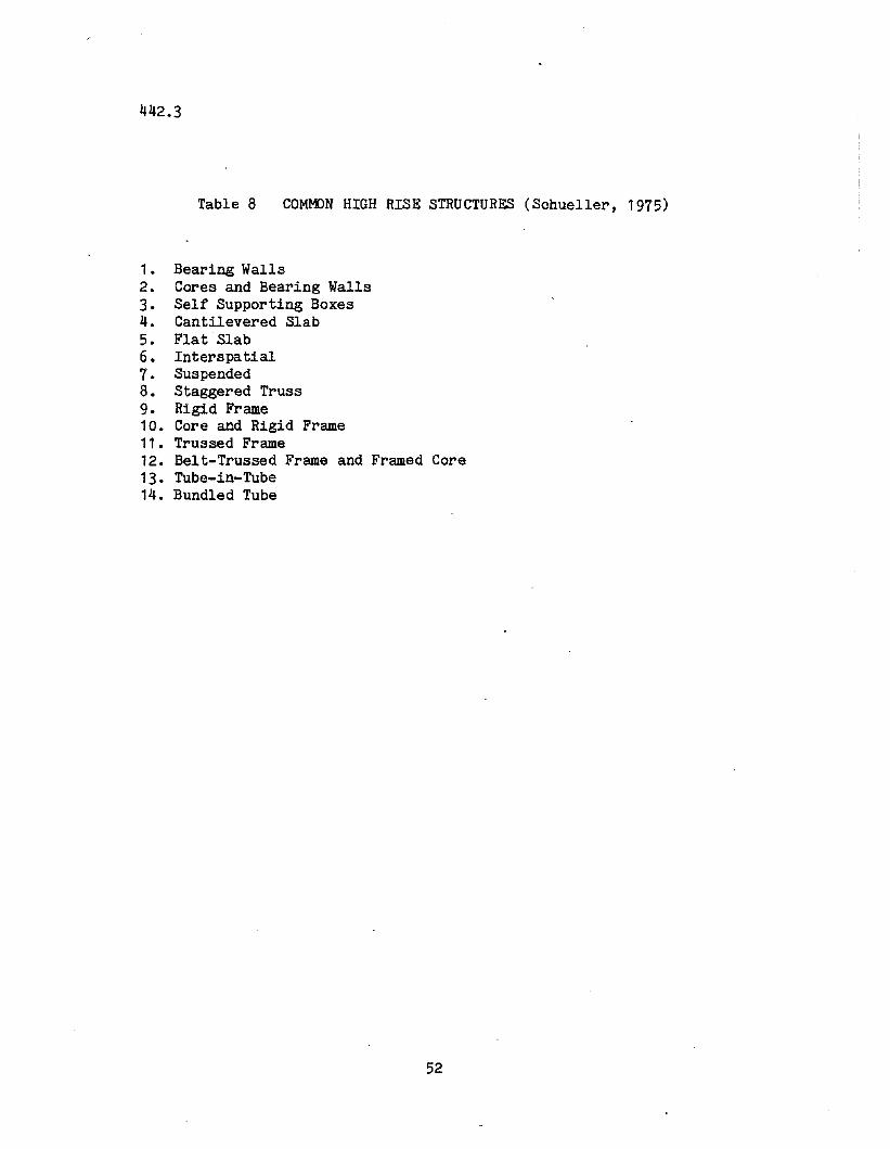
442.3
Table 8 COMMON HIGH RISE STRUCTURES (Schueller, 1975)
1. Bearing Walls2. Cores and Bearing Walls3. Self Supporting Boxes4. Cantilevered Slab5. Flat Slab6. Interspatial7. Suspended8. Staggered Truss9. Rigid Frame10. Core and Rigid Frame11. Trussed Frame12. Belt-Trussed Frame and Framed Core13. Tube-in-Tube14. Bundled Tube
52
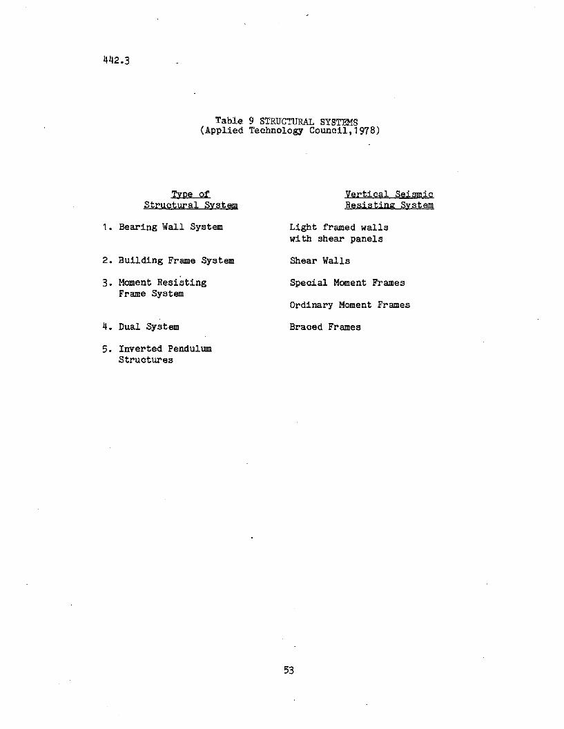
442.3
Table 9 STRUCTURAL SYSTEMS(Applied Technology Council,1978)
Type of Vertical SeismicStructural System Resisting System
1. Bearing Wall System Light framed wallswith shear panels
2. Building Frame System Shear Walls
3. Moment Resisting Special Moment FramesFrame System
Ordinary Moment Frames
4. Dual System Braced Frames
5. Inverted PendulumStructures
53
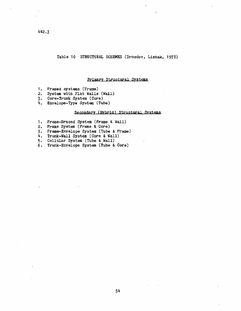
442.3
Table 10 STRUCTURAL SCHEMES (Drosdov, Lishak, 1978)
Primary Structural Systems
1. Framed systems (Frame)2. System with Flat Walls (Wall)3. Core-Trunk System (Core)4. Envelope-Type System (Tube)
Secondary (Hybrid) Structural Systems
1. Frame-Braced System (Frame & Wall)2. Frame System (Frame &Core)3. Frame-Envelope System (Tube & Frame)4. Trunk-Wall System (Core &Wall)5. Cellular System (Tube &Wall)6. Trunk-Envelope System (Tube & Core)
54
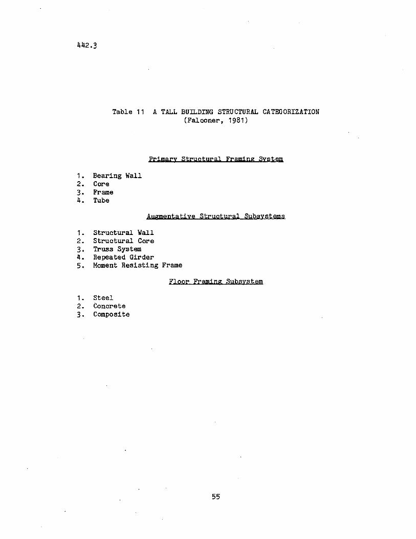
442.3
Table 11 A TALL BUILDING STRUCTURAL CATEGORIZATION(Falconer, 1981)
Primary Structural Framjng System
1• Bearing Wall2. Core3. Frame4. Tube
Augmentatiye Structural Subsystems
1• Structural Wall2. Structural Core3. Truss System4. Repeated Girder5. Moment Resisting Frame
Floor Framing Subsystem
1. Steel2. Concrete3. Composite
55
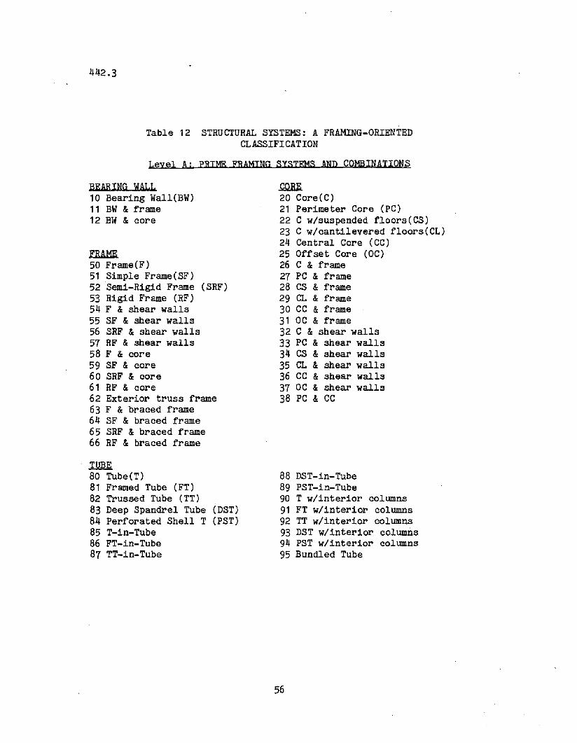
442.3
,Table 12 STRUCTURAL SYSTEMS: A FRAMING-ORIENTED
CLASSIFICATION
Leyel A: PRIME FRAMING SYSTEMS AND COMBINATIONS
BEARING WALL10 Bearing Wall(BW)11 BW & frame12 BW & core
FRAME50 Frame(F)51 Simple Frame(SF)52 Semi-Rigid Frame (SRF)53 Rigid Frame (RF)54 F & shear walls55 SF & shear walls56 SRF &shear walls57 RF & shear walls58 F & core59 SF & core60 SRF & core61 RF & core62 Exterior truss frame63 F & braced frame64 SF & braced frame65 SRF & braced frame66 RF & braced frame
TUBE80 Tube(T)81 Framed Tube (FT)82 Trussed Tube (TT)83 Deep Spandrel Tube (DST)84 Perforated Shell T (PST)85 T-in-Tube86 FT-in-Tube87 TT-in-Tube
.QQM.20 Core(C)21 Perimeter Core (PC)22 C w/suspended floors(CS)23 C w/cantilevered floors(CL)24 Central Core (CC)25 Offset Core (OC)26 C & frame27 PC & frame28 CS & frame29 CL & frame30 CC &frame31 OC & frame32 C & shear walls33 PC & shear walls34 CS & shear walls35 CL & shear walls36 CC & shear walls37 OC & shear walls38 PC & CC
88 DST-in-Tube89 PST-in-Tube90 T w/interior columns91 FT w/interior columns92 TT w/interior columns93 DST w/interior columns94 PST w/interior columns95 Bundled Tube
56
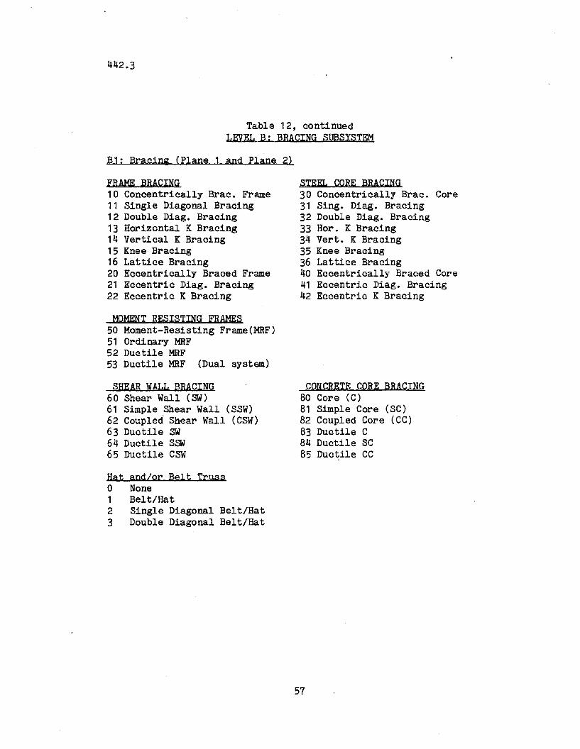
442.3
Table 12, continuedLEVEL B: BRACING SUBSYSTEM
B1: Bracing (Plane 1 and Plane 2)
FRAME BRACING10 Concentrically Brae. Frame11 Single Diagonal Bracing12 Double Diag. Bracing13 Horizontal K Bracing14 Vertical K Bracing15 Knee Bracing16 Lattice Bracing20 Eccentrically Braced Frame21 Eccentric Diag. Bracing22 Eccentric K Bracing
MOMENT RESISTING FRAMES50 Moment-Resisting Frame(MRF)51 Ordinary MRF52 Ductile MRF53 Ductile MRF (Dual system)
SHEAR WALL BRACING60 Shear Wall (SW)61 Simple Shear Wall (SSW)62 Coupled Shear Wall (CSW)63 Ductile SW64 Ductile SSW65 Ductile CSW
Hat and/or Belt Trusso None1 Belt/Hat2 Single Diagonal Belt/Hat3 Double Diagonal Belt/Hat
STEEL CORE BRACING30 Concentrically Brae. Core31 Sing. Diag. Bracing32 Double Diag. Bracing33 Hor. K Bracing34 Vert. K Bracing35 Knee Bracing36 Lattice Bracing40 Eccentrically Braced Core41 Eccentric Diag. Bracing42 Eccentric K Bracing
CONCRETE CORE BRACING80 Core (C)81 Simple Core (SC)82 Coupled Core (CC)83 Ductile C84 Ductile SC85 Ductile CC
57
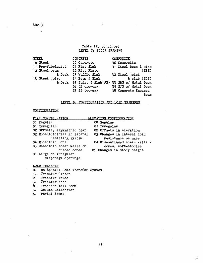
442.3
Table 12, continuedLEVEL C; FLOOR FRAMING
COMPOSITE30 Composite31 Steel beam & slab
(SBS)32 Steel joist
& slab (SJS)SBS wi Metal DeckSJS wi Metal DeckConcrete Encased
Beam
CONCRETE20 Concrete21 Flat Slab22 Flat Plate23 Waffle Slab24 Beam & Slab25 Joist & Slab(JS) 3326 JS one-way 3427 JS two-way 35
STEEL10 Steel11 Pre-fabricated12 Steel beam
& Deck13 Steel joist
&Deck
LEVEL D; CONFIGURATION AND LOAD TRANSFER
CONFIGURATION
PLAN CONFIGURATION00 Regular01 Irregular02 Offsets, asymmetric plan03 Eccentricit~es in lateral
resisting system04 Eccentric Core05 Eccentric shear walls or
braced cores06 Large or irregular
diaphragm openings
ELEVATION CONFIGURATION00 Regular01 IrregulaI"02 Offsets in elevation03 Changes in lateral load
resistance or mass04 Discontinued shear walls /
cores, soft-stories05 Changes in story height
LOAD TRANSFERO. No Special Load Transfer System1. Transfer Girder2. Transfer Truss3. Transfer Arch4. Transfer Wall Beam5. Column Collection6. Portal Frame
58
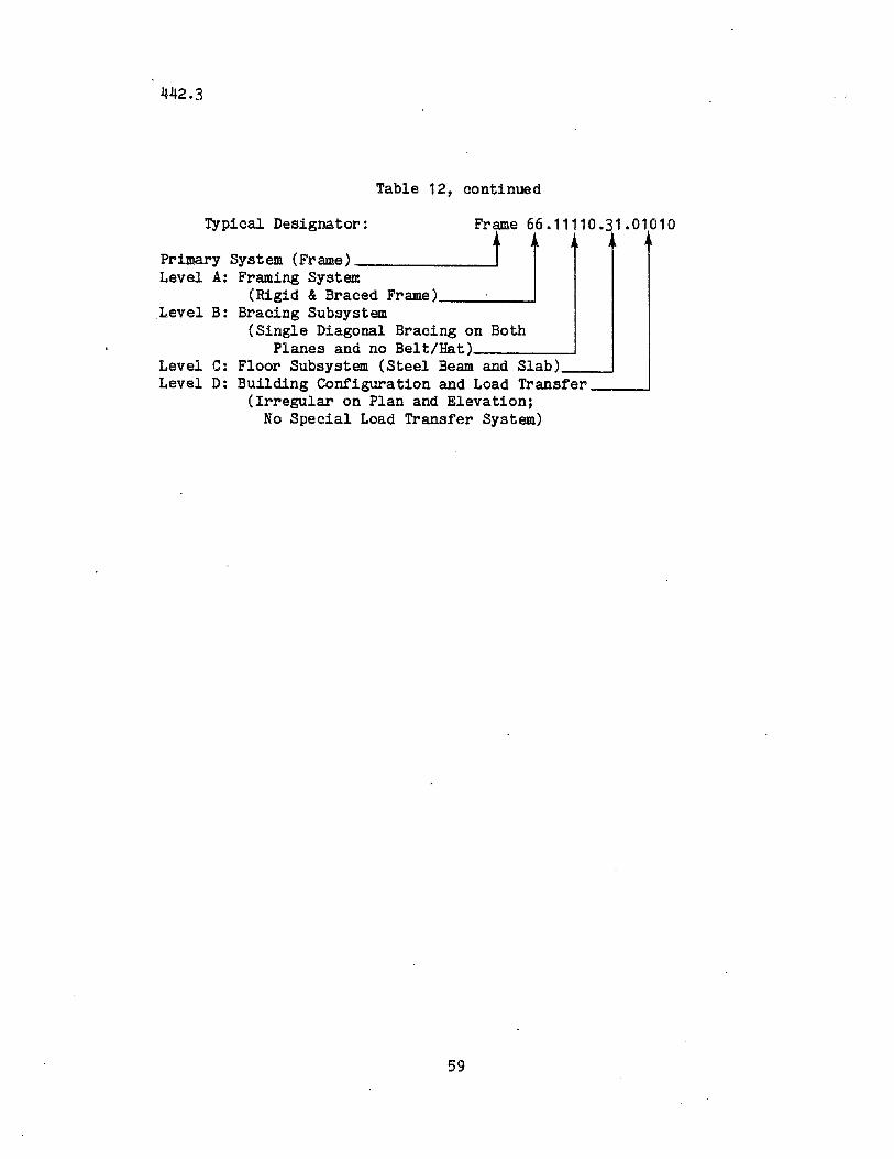
442.3
Table 12, continued
Typical Designator: Frame 66.11110.31.01010
Primary System (Frame) ~Level A: Framing System
(Rigid &Braced Frame) .Level B: Bracing SUbsystem
(Single Diagonal Bracing on BothPlanes and no Belt/Hat) ~
Level C: Floor Subsystem (Steel Beam and Slab) ~
Level D: Building Configuration and Load Transfer ~
(Irregular on Plan and Elevation;No Special Load Transfer System)
59
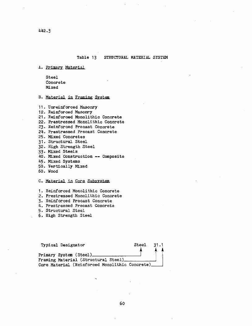
442.3
Table 13
A. Primary Material
SteelConcreteMixed
STRUCTURAL MATERIAL SYSTEM
B. Material ~ Framing System
11. Unreinforced Masonry12. Reinforced Masonry21. Reinforced Monolithic Concrete22. Prestressed Monolithic Concrete23. Reinforced Precast Concrete24. Prestressed Precast Concrete25. Mixed Concretes31. Structural Steel32. High Strength Steel33. Mixed Steels40. Mixed Construction Composite45. Mixed Systems50. Vertically Mixed60. Wood
C. Material in.~ Subsystem
1. Reinforced Monolithic Concrete2. Prestressed Monolithic Concrete3. Reinforced Precast Concrete4. Prestressed Precast Concrete5. Structural Steel6. High Strength Steel
Typical Designator Steel 31.1
Primary System (Steel) t dJFraming Material (Stru-c-t-ur--al--S-t-e-e-l-)------ JCore Material (Reinforced Monolithic Concrete)
60
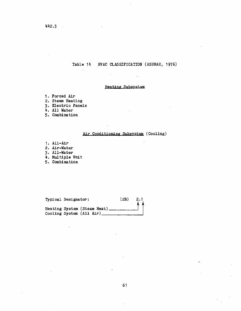
442.3
Table 14 .HVAC CLASSIFICATION (ASHRAE, 1976)
Heating Subsystem
1. Forced Air2. Steam Heating3. Electric Panels4. All Water5. Combiml.tion
Air Conditioning Subsystem (Cooling)
1. All-Air2. Air-Water3. All-Water4. Multiple Unit5. Combi nation
Typical Designator: (2B) 2.1
Heating System (Steam Heat) t t,Cooling System (All Air) .
61
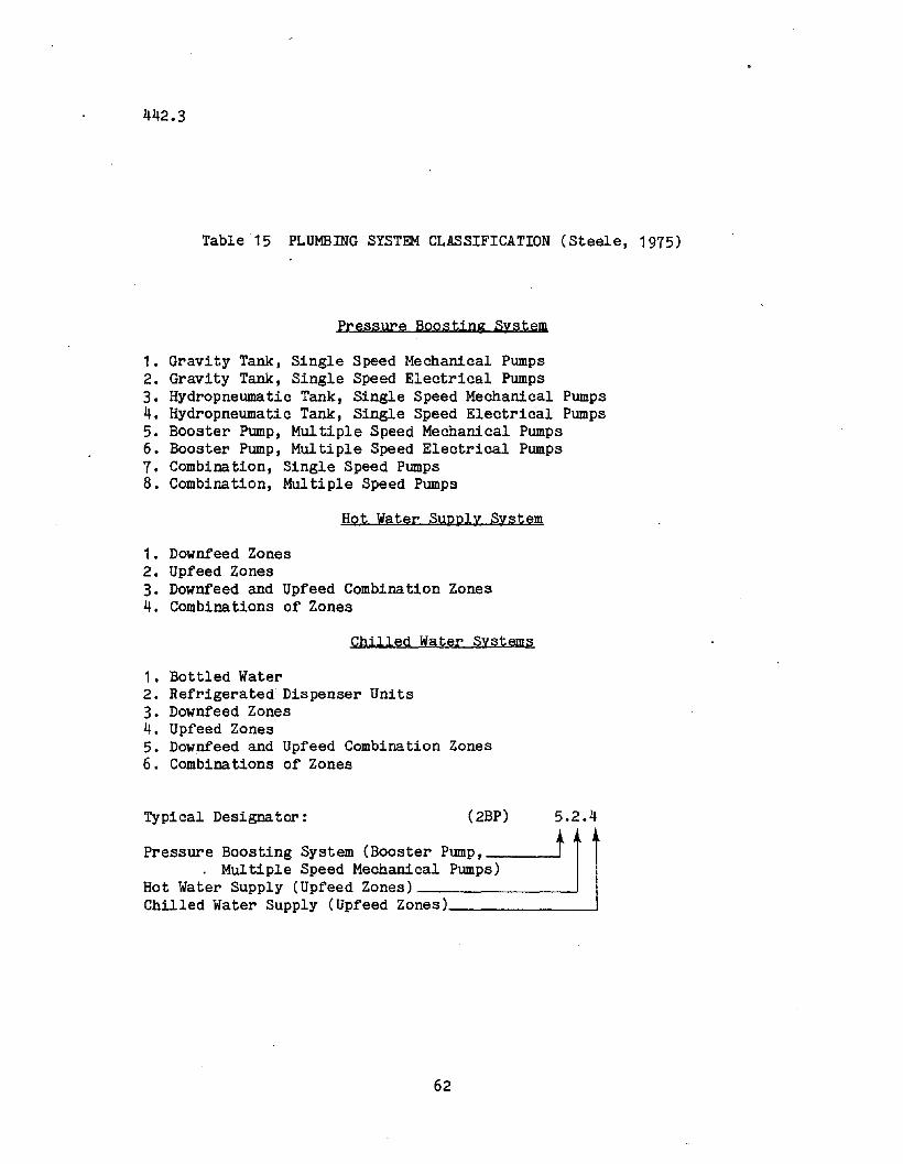
442.3
Table 15 PLUMBING SYSTEM CLASSIFICATION (Steele, 1975)
Pressure Boosting System
1. Gravity Tank, Single Speed Mechanical Pumps2. Gravity Tank, Single Speed Electrical Pumps3. Hydropneumatic Tank, Single Speed Mechanical Pumps4. Hydropneumatic Tank, Single Speed Electrical Pumps5. Booster Pump, Multiple Speed Mechanical Pumps6. Booster Pump, Multiple Speed Electrical Pumps7. Combination, Single Speed Pumps8. Combination, Multiple Speed Pumps
Hot water Supply System
1. Downfeed Zones2. Upfeed Zones3. Downfeed and Upfeed Combination Zones4. Combinations of Zones
Chilled Water Systems
1. Bottled Water2. Refrigerated Dispenser Units3. Downfeed Zones4. Upfeed Zones5. Downfeed and Upfeed Combination Zones6. Combinations of Zones
(2BP)Typical Designator: 5.2.4
Pressure Boosting System (Booster pump, t. Mul tipIe Speed Mechanical Pumps)
Hot Water Supply (Upfeed Zones) ~
Chilled Water Supply (Upfeed Zones) ~
62
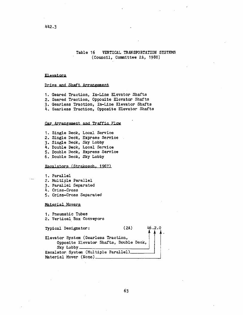
442.3
Table 16 VERTICAL TRANSPORTATION SYSTEMS(Council, Committee 2A, 1980)
Elevators
Drive and Shaft Arrangement
1. Geared Traction, In-Line Elevator Shafts2. Geared Traction, Opposite Elevator Shafts3. Gearless Traction, In-Line Elevator Shafts4. Gearless Traction, Opposite Elevator Shafts
Car Arrangement and Traffic FlOW
1. Single Deck, Local Service2. Single Deck, Express Service3. Single Deck, Sky Lobby4. Double Deck, Local Service5. Double Deck, Express Service6. Double Deck, Sky Lobby
Escalators (Strakosch, 1967)
1. Parallel2. Multiple Parallel3. Parallel Separated4. Criss-Cross5. Criss-Cross Separated
Material Moyers
1. Pneumatic Tubes2. Vertical Box Conveyors
Typical Designator: (2A) 46.2.0
Elevator System (Gearless Traction,Opposite Elevator Shafts, Double Deck,Sky Lobby---- ---J
Escalator. System (Multiple Parallel) ~
Material Mover (None) ~
63
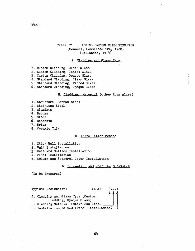
442.3
Table 17 CLADDING SYSTEM CLASSIFICATION(Council, Committee 12A, 1980)
(Callender, 1974)
A. Cladding and Glass Type
1. Custom Cladding, Clear Glass2. Custom Cladding, Tinted Glass3. Custom Cladding, Opaque Glass4. Standard Cladding, Clear Glass5. Standard Cladding, Tinted Glass6. Standard Cladding, Opaque Glass
B. Cladding Material (other than glass)
1. Structural Carbon Steel2. Stainless Steel3. Aluminum4. Bronze5. Stone6. Concrete7. Brick8. Ceramic Tile
C. Installation Method
1. Stick Wall Installation2. Unit Installation3. Unit and Mullion Installation4. Panel Installation5. Column and Spandrel Cover Installation
D. Connection~ Jointing Subsystem
(To be Prepared)
Typical Designator: (12A) 3.2.4
A. Cladding and Glass Type (Custom ttlCladding, Opaque Glass)
B. Cladding Material (Stainless Steel)C. Installation Method (Panel Installation)
64
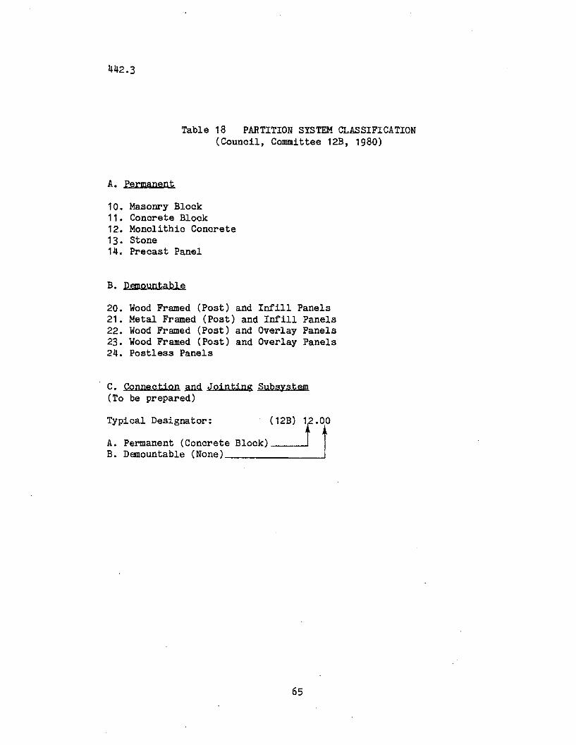
442.3
Table 18 PARTITION SYSTEM CLASSIFICATION(Council, Committee 12B, 1980)
A. Permanent
10. Masonry Block11. Concrete Block12. Monolithic Concrete13. Stone14. Precast Panel
B. DemQuntable
20. Wood Framed (Post) and Intill Panels21. Metal Framed (Post) and Intill Panels22. Wood Framed (Post) and Overlay Panels23. Wood Framed (Post) and Overlay Panels24. Postless Panels
C. Connection~ Jointing Subsystem(To be prepared)
Typical Designator:
A. Permanent (ConcreteB. Demountable (None)
(12B) r.ooBlock) !
65
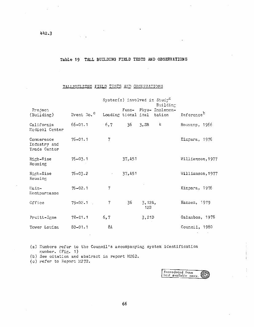
442.3
Table 19 TALL BUILDING FIELD TESTS AND OBSERVATIONS
TAI.I.PIFI.DING~ TESTS AND OBSERVATIONS
Systerr:(s) involved in St ud"aJ
BuildincProject Func- Phys- Impler:1Cn-
(Building) Event Ho. c Loading tional ical tation Reference b
California 66-01.1 ·6,7 36 3,SB 4 Bouh'3np, 1966l!edical Center
COmT.1erence 76-01. 1 7 Kin:para, 1976Industry andTrade Center
High-Rise 76-03. 1 37, A51 Hilliamson,1977Housing
HiGh-Rise 76-03.2 37,A51 Hilliamson,1977HousinG
11ain- 76-02. 1 7 Kin:para, 1976l';ontparnasse
Office 79-02.1 7 36 3,12A, Hansen, 197912B
Pruitt-Igoe 78-01.1 6,7 3,21D Galanbos, 1978
Tower Louisa 80-01.1 8A Council, 1980
(a) Numbers refer to the Council's accompanying system identificationnumber. (Fig. 1)
(b) See citation and abstract in report M262.(0) refer to Report M272.
Reproduced frombest available copy.
66
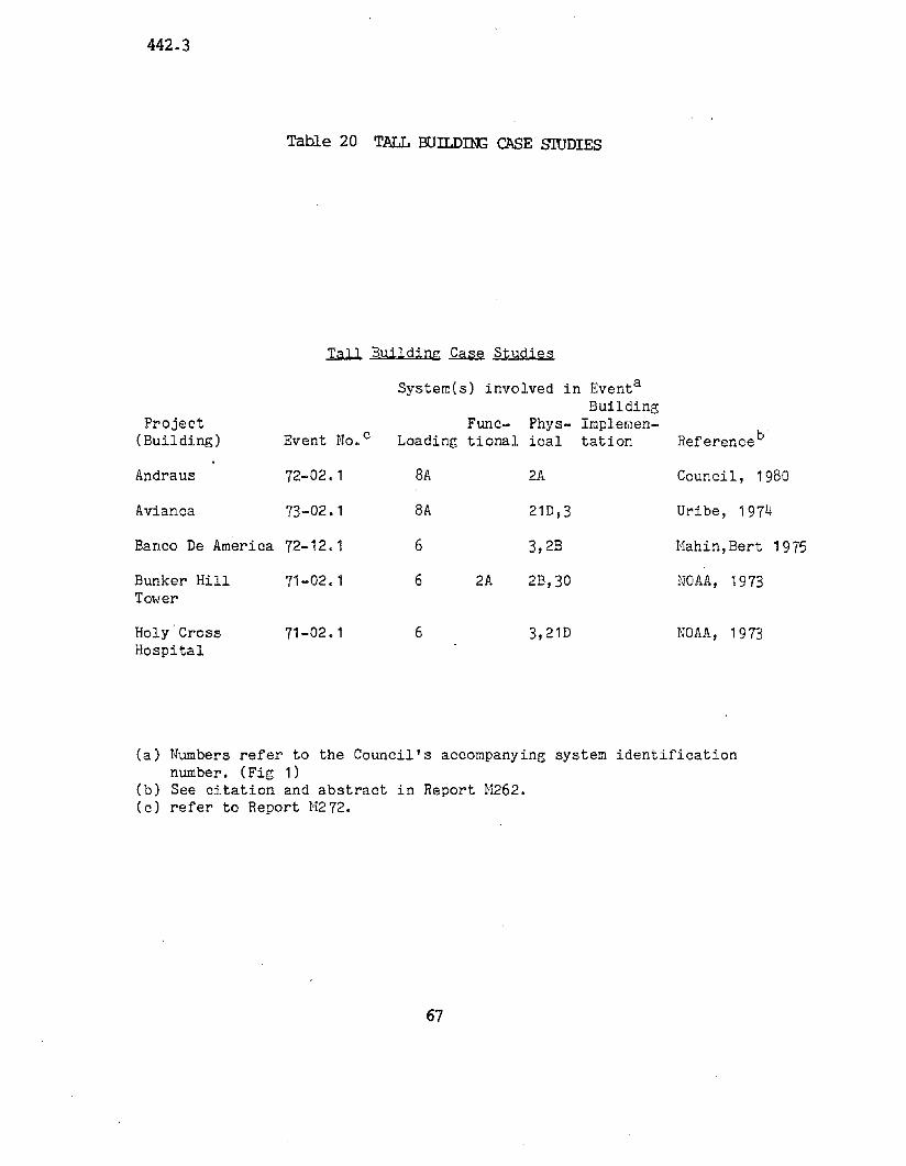
442.3
Table 20 TALL BUILDThG CASE muDIES
1.all. Building~ Studies
Syste~(s) involved in Eventa
BuildingProject Func- Phys- Impleraen-
(Building) Event No. c Loading tional ical tation Reference b·
Andraus 72-02.1 8A 2A Council, 1980
Avianca 73-02.1 8A 21D,3 Uribe, 1974
Banco De America 72-12.1 6 3,2B Mahin, Bert 1975
Bunker Hill 71-02.1 6 2A 2B,30 NOAA, 1973Tower
Holy·Cross 71-02.1 6 3,21D NOAA, 1973Hospital
(a) Numbers refer to the Council's accompanying system identificationnumber. (Fig 1)
(b) See citation and abstract in Report M262.(c) refer to Report M272.
67
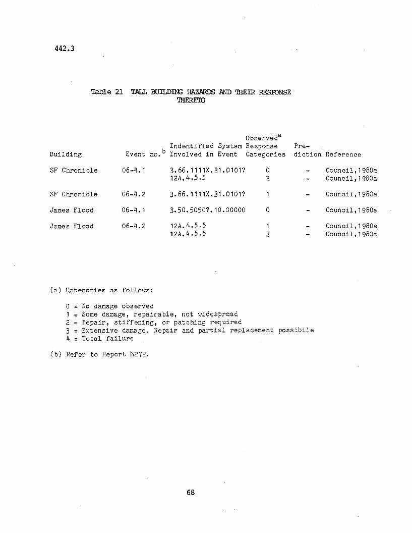
442.3
Table 21 TALL BUILDIN; HAZARDS AND rmEIR RESOONSE'IHEREro
Observeda
Indentified System Response Pre-Building Event no. b Involved in Event Categories diction Reference
SF Chronicle 06-4. 1 3.66.1111X.31.01011 0 Council, 1g80a12A.4.5.5 3 Council, 1g80a
SF Chronicle 06-4.2 3.66.1111X.31.01011 Council, 1g80a
James Flood .06-4.1 3.50.50501.10.00000 0 Council, 1g80a
James Flood 06-4.2 12A.4.5.5 1 Council,1g80a12A.4.5.5 3 Council, 1g80a
(a) Categories as follows:
o = No damage observed1 = Some damage, repairable, not widespread2 = Repair, stiffening, or patching required3 = Extensive damage. Repair and partial replacement possibile4 = Total failure
(b) Refer to Report 11272.
68
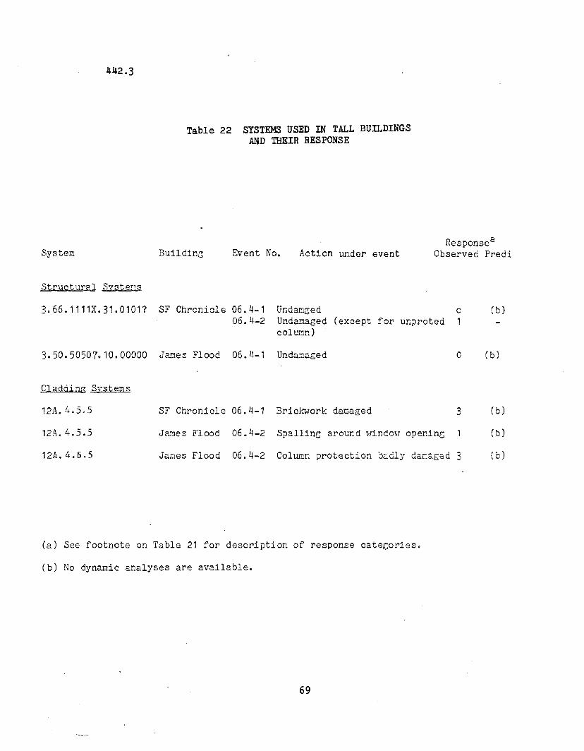
442.3
Table 22 SYSTEMS USED IN TALL BUILDINGSAND THEIR RESPONSE
System
Structural Syste~s
BuildinG Event No. Action under eventResponsea
Observed Predi
3.66.1111X.31.0101? SF Chronicle 06.4-106.4-2
Undar.leedUndamaged (except for unprotedcolumn)
o1
(b)
3.50.50507.10.00000 James Flood 06.4-1 Undamaged
Cladding Systems
o (b)
Ja~es Flood 06.4-2 Column protection b~dly damaged 3
12A.4.5.5
12A.4.5.5
12A.4.5.5
SF Chronicle 06.4-1 Brickwork damaged
James Flood 06.4-2 Spalling around \-lindm, opening
3 (b)
(b)
(b)
(a) See footnote on Table 21 for description of response categories.
(b) No dynamic analyses are available.
69
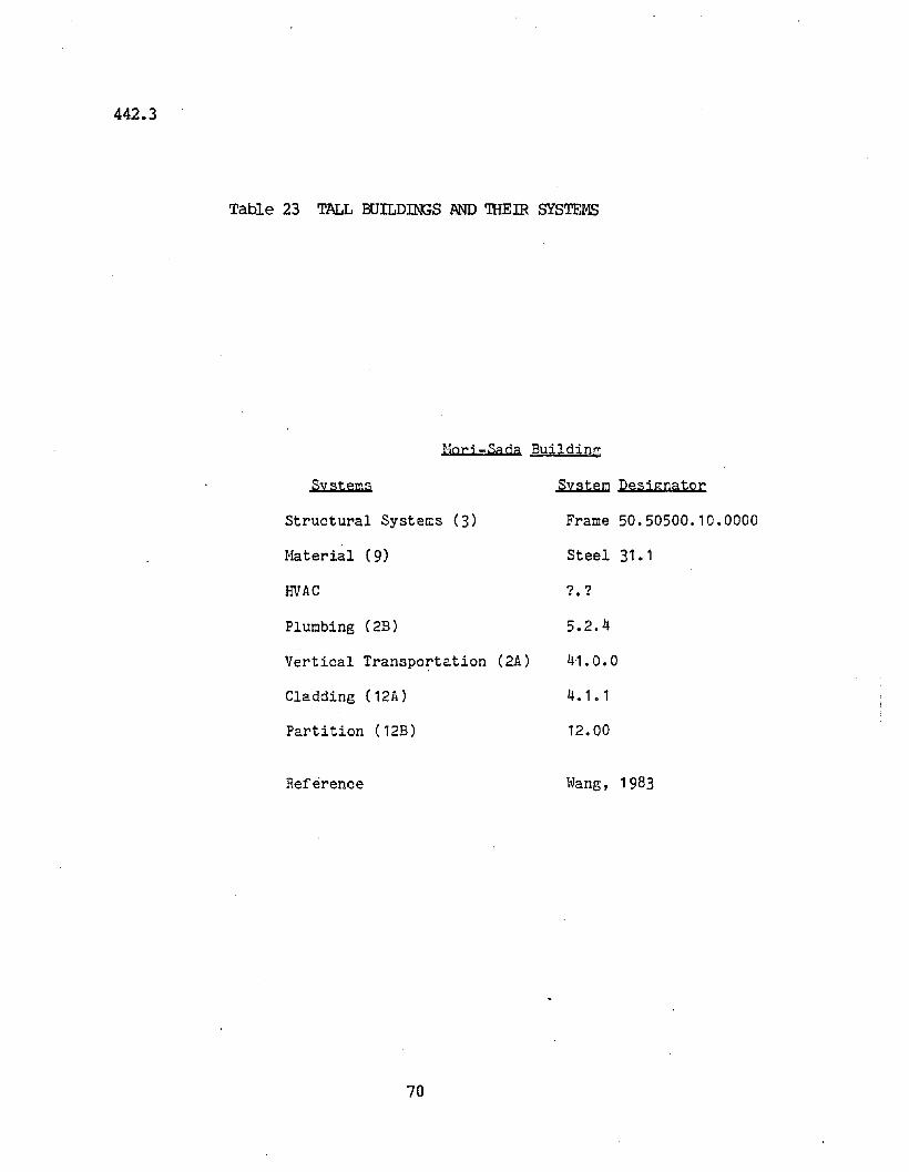
442.3
Table 23 TALL BUILDINGS .AND 'lHEIR SYSTEMS
Horj -Sada BUildin~
Systems
Structural Systems (3)
Haterial (9)
HVAC
Plumbing (2B)
Vertical Transpo~tation (2A)
Cladding (12A)
Partition (12B)
Reference
70
System Designator
Frame 50.50500.10.0000
Steel 31.1
? ?...5.2.4
41. 0.0
4.1. 1
12.00
lvang, 1983
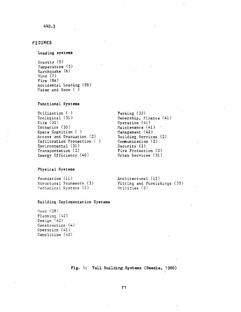
442.3
FIGURES
Loading systems
Gravity (5)Temperature (5)Earthquake (6)~oJind (7)Fire (8A)Accidental Loading (SB)Water and Snow ( )
Functional Systems
Utilization ( )Ecological (1)Site (1)
Esthetics (30)Space Cognition ( )Access and Evacuation (2)Infiltration ProtectionEnvironnental (31)Transportation (2)Energy Efficiency (40)
Physical Systems
Foundation (1)Structural Fr~nework (3)~~echanical Systems (Z)
Building Implementation Systems
!leed (28)Planning (4Z)
Design (4Z)
Construction (4)Operation (41)Deno1ition (42)
Parking (33)Ownership, Finance (41)Operation (41)Haintenance (41)Hanagement (42)Building Services (2)Communication (2)Security (2)Fire Protection (2)Urban Services (31)
Architectural (lZ)Fitting and Furnishin~s (30)Utili~ies (Z)
Fig. 1: Tall Building Systems (Beedle, 1980)
71
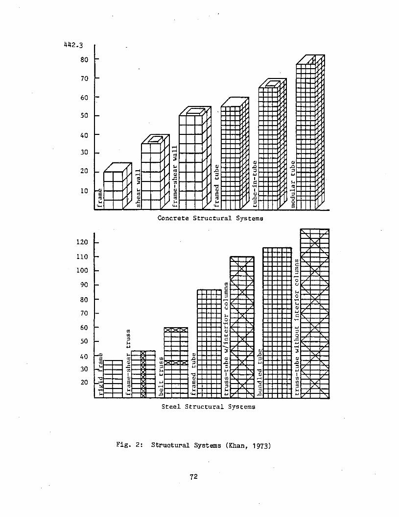
NW
.p
Oa
a.....
....V
I0
\,,0
0\0
0N
00
00
a0
0a
..... aN a
W a.p
o
VI a
0\ a
"a
~ ~ I\.l .
(Xl
wa
'z:l ..... O
Il . I\.l .. C/)
c1"
"'$en
~rt
QCD
c1"
CD~
...."'$ ~
en rt-:j
t1C
/)t::
I\.l
«n
[/J
rtc1
"t::
mt1 III
[/J
.........
..en
?'l
'<:;:
,'U
lIII
rt::s
CD~
8 Ul
..... \0 -:j W ~
rip'
~dra
mb
II
II
II
II
fram
e-s
hear
tru
ss
belt
tru
ss
fram
edtu
be
tru
ss-t
ub
ew
/in
teri
or
colu
mn
s1/
VI'
V[\.
VV
>c~
><~
><I><
t\.1/
I'.
bu
nd
led
tub
e
tru
ss-t
ub
ew
ith
ou
tin
teri
or
colu
mn
sI\.
/:.1i':
V'I
'./
'\1'
.V
v'\
'\I\.
//
//
KV
'v/
V/
'\/
1/1'
.'\
/r--..
v\.
/\.
/'\
1/'\
1/1'\
,"-
,1/
1/1
'\/
1/
1/
(') o ~ n t1 CD rt CD en rt t1 t:: n rt t:: t1 III .... cn '< Ul
rt ~ CIl
fram
bI
II
I.
II
I
'\
'"'" "
'\.
'\.
'\.
shear
wall
~
.....J
"'\
.'\
.'\
.'"
.....'\
......
fram
e-s
hear
wall
~ l'\
.'\
.,
,'\
...
..:
,,
,,"'"
''"
fram
edtu
be
r'\
'" tub
e-i
n-t
ub
e
~ ~'\
. mo
du
lar
tub
e
"- ~,
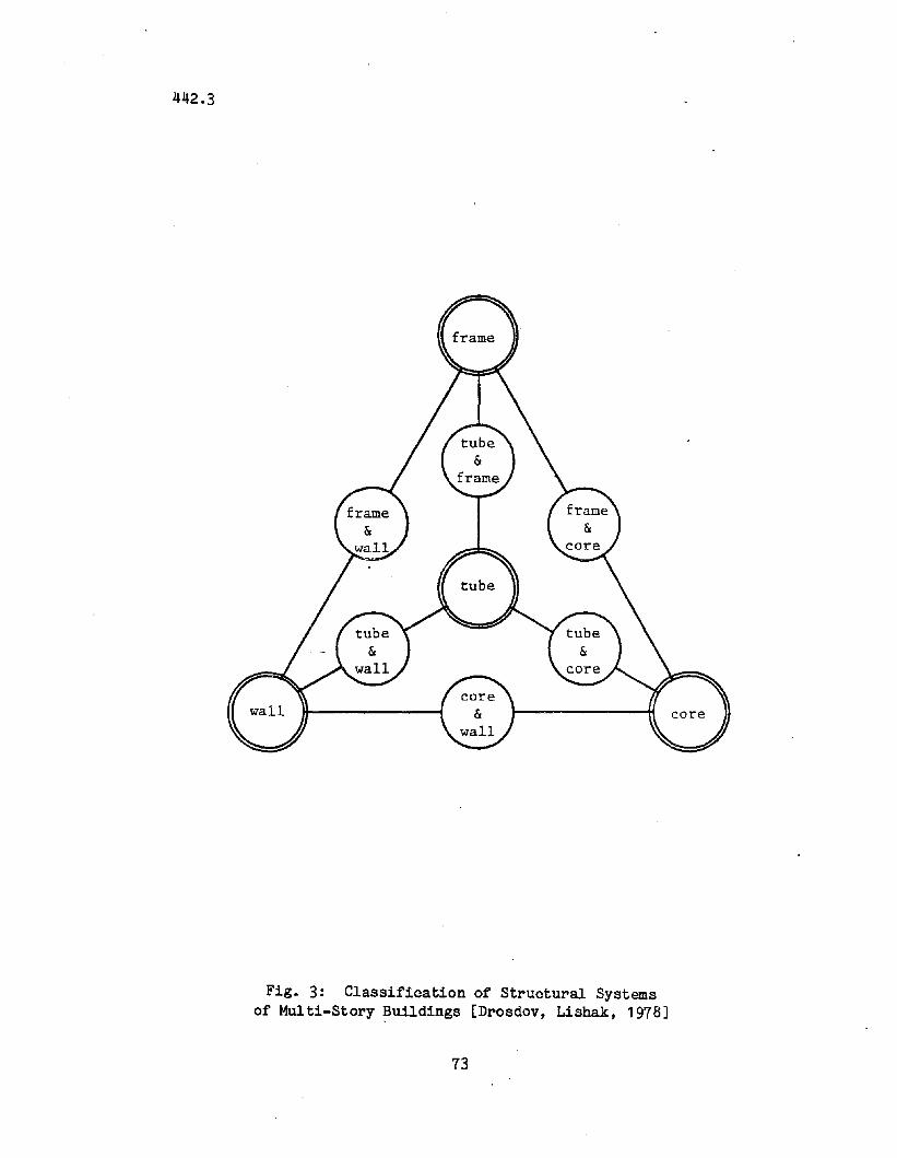
442.3
Fig. 3: Classification of Structural Systemsof Multi-Story Buildings [Drosdov, Lishak, 1978]
73
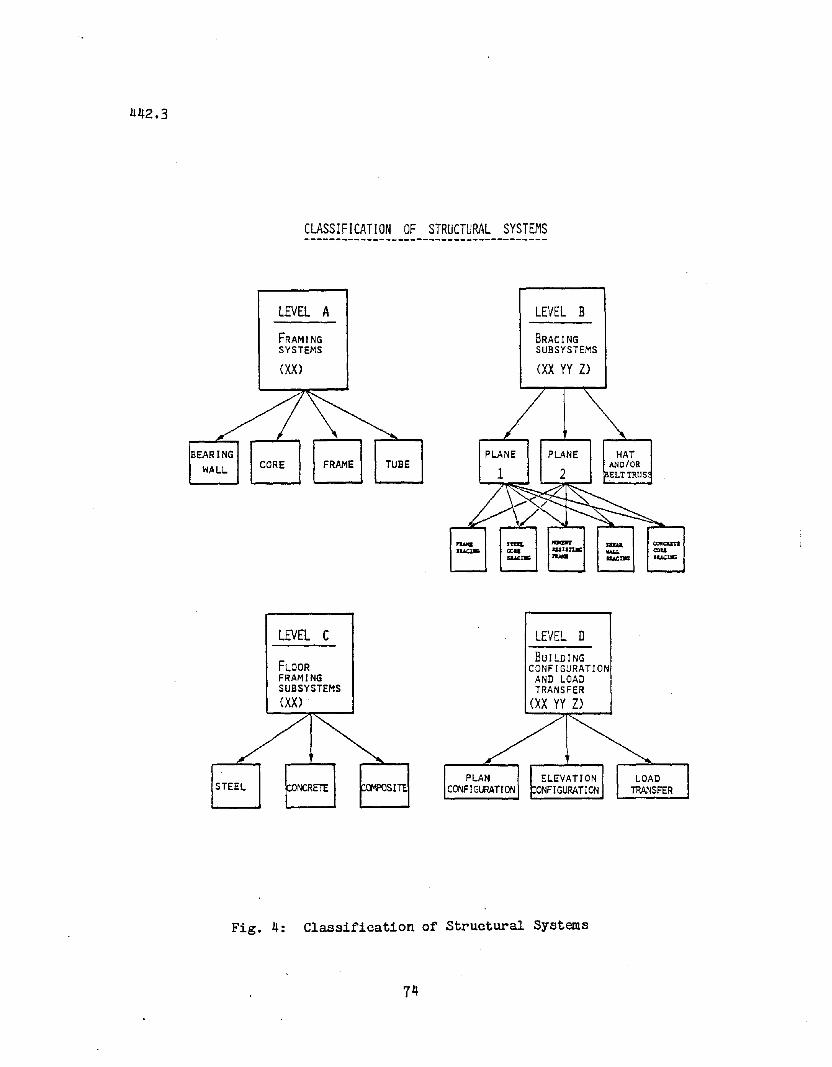
CLASSIFICATION OF STRUCTURAL SYSTEMS
BEARINGWALL
LEVEL A
FRAMINGSYSTEMS
(XX>
CORE
LEVEL C
FLOORFRAMINGSUBSYSTEMS(XX>
TUBE
LEVEL B
BRACINGSUBSYSTEMS
(XX YY Z>
LEVEL DBUILDING
CONFIGURATIONAND LOADTRANSFER
(XX YY Z>
STEEL
Fig. 4: Classification of Structural Systems
74
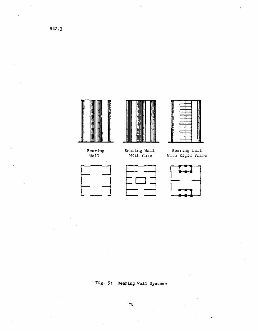
442.3
BearingWall
Bearing Wall\oJ'ith Core
Bearing HallWith Rigid Frame
Fig. 5: Bearip.g Wall Systems
75
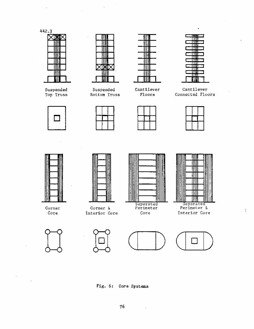
442.3
SuspendedTop Truss
SuspendedBottom Truss
CantileverFloors
CantileverConnected Floors
eparatePerimeter &
Interior Core
SeparatePerimeter
CoreCorner &
Interior CoreCorner
Core
EI 0
Fig. 6: Core Systems
76
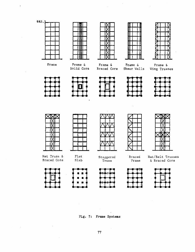
FraI:le
x x
)C
Hat Truss &Braced Core
Frame &Solid Core
I 0
FlatSlab
)(
)(
)(
)(
)(
)(
:xX
Frame &Braced Core
;....;I • I
~
StaggeredTruss
Frame &Shear ~.[alls
...
-
/!"..1/f'\.V!"..V
'"Braced
Frame
"'"VI'
1.1'
Frame &~'ling Trusses
-II
I
I
y ~y
)(
':1<' x
'x
Hat/Belt Trusses& Braced Core
1'i9I,W
•••
II -
II--
~I I
b1.
Fig. 7: Frame Systems
77
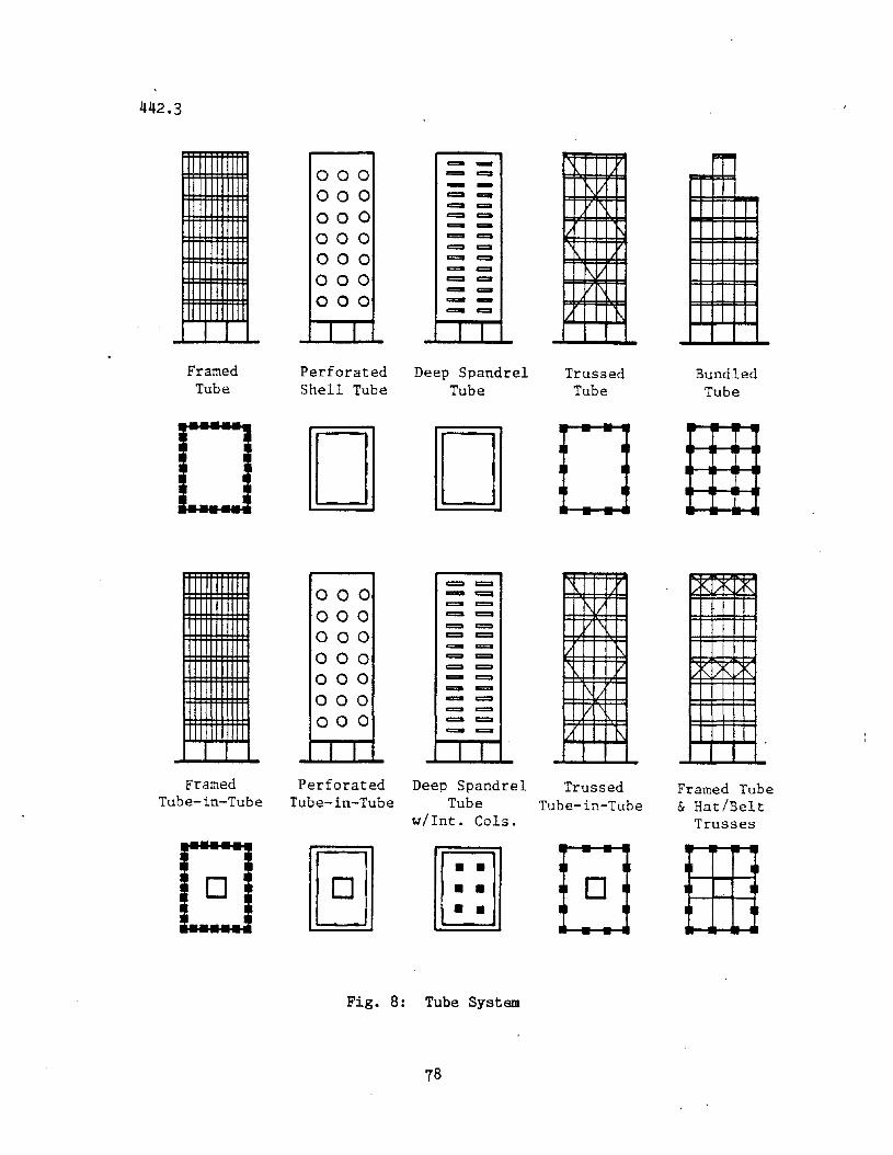
DO
442.3
FramedTube
000000000000000000000
I I
PerforatedShell Tube
000000000000000000000
I I
- -0::= 0==- -~ -c:::II c:::::a0::= .....- .....~ c:::::a0::= ......c::=I ......c:::II -c::=I ........... ......- -c=a .....
I I
Deep SpandrelTube
== c:=- .......==0 ==0
~ c:=
== ==== c::==- 0::=
~ ==== ==c:::II ==- c::o- =::0
==0 0::=
c:::II =::0- c::o
I I
\
r--.V1\
1/
I\V1\
11
TrussedTube
I
I
I
1\/V
1/ 1\
V
1\
'/ t\
BundledTube
Framed Perforated Deep Spandrel TrussedTube-in-Tube Tube-in-Tube Tube Tube-in-Tube
w/lnt. eols.._---
8 [ill- -
I
0 I 0I I
Fig. 8: Tube System
78
Framed Tube& Hat/Belt
Trusses
I 1
I I
I ..
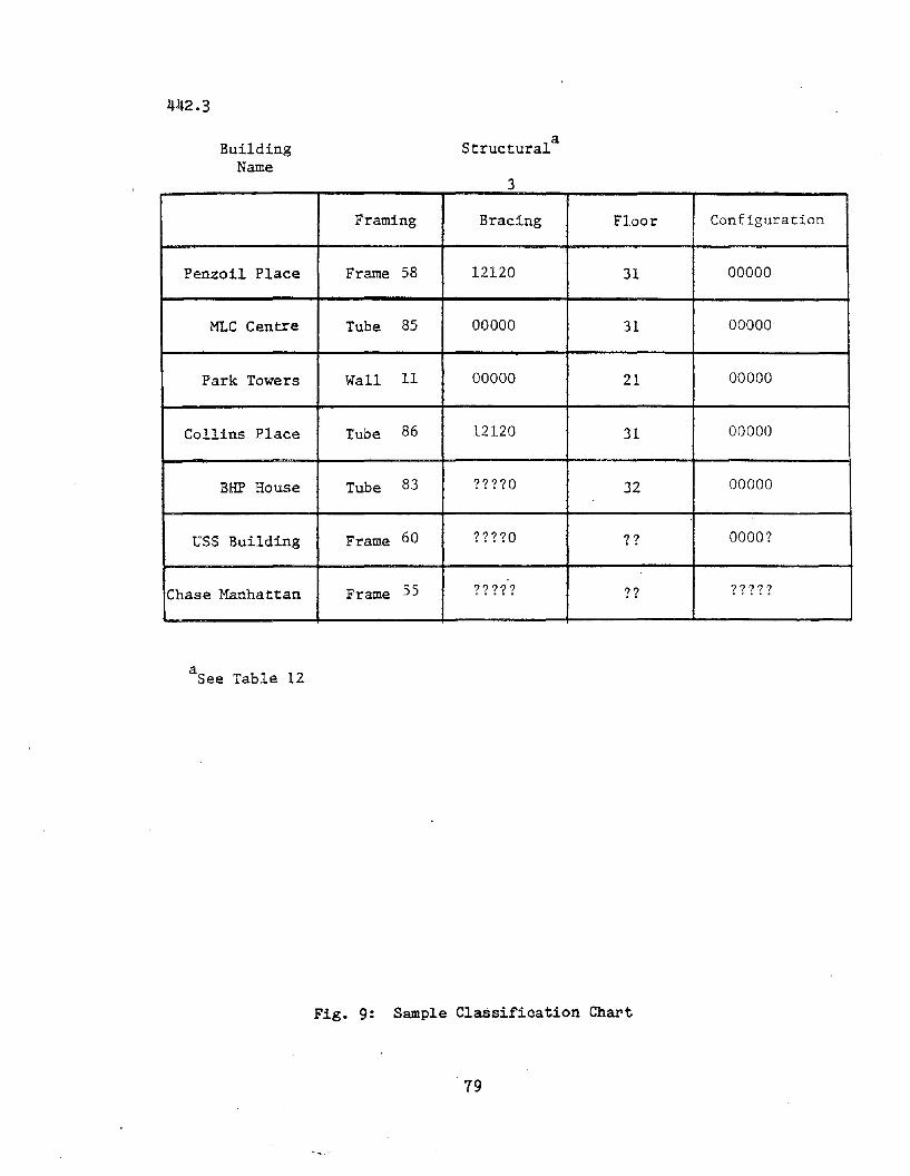
442.3
BuildingName
aStructural
3
Framing Bracing Floor Configuration
Penzoil Place Frame 58 12120 31 00000
MLC Centre Tube 85 00000 31 00000
Park Towers Wall 11 00000 21 00000
Collins Place Tube 86 12120 31 00000
BHP House Tube 83 ????O 32 00000
USS Building Frame 60 ????O ?? OOOO?
Chase Manhattan Frame 55 ????? ?? ?????
aSee Table 12
Fig. 9: Sample Classification Chart
79
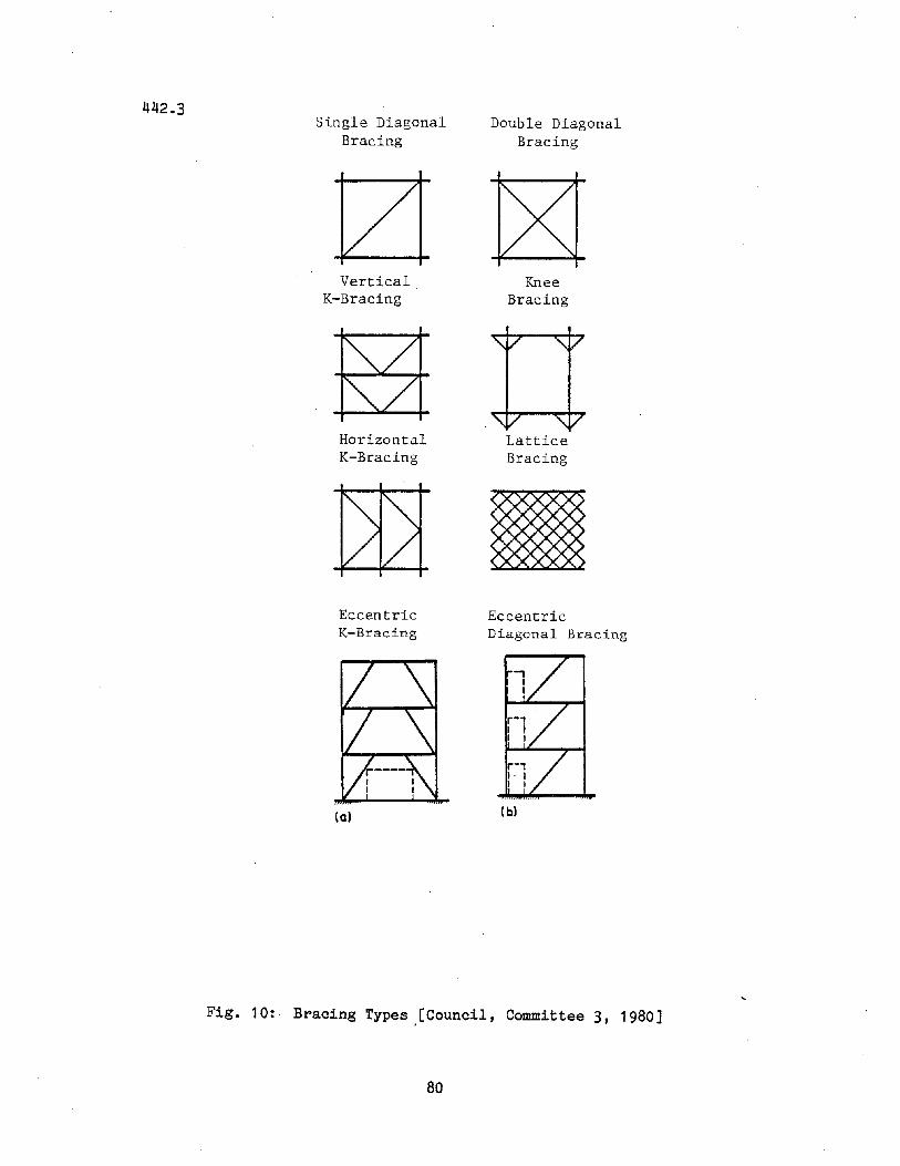
442.3Single Diagonal
Bracing
Vertical.K-Bracing
HorizontalK-Bracing
EccentricK-Bracing
(a)
Double DiagonalBracing
KneeBracing
LatticeBracing
EccentricDiagonal Bracing
( b)
Fig. 10: Bracing Types ,[Council, Committee 3, 1980]
80
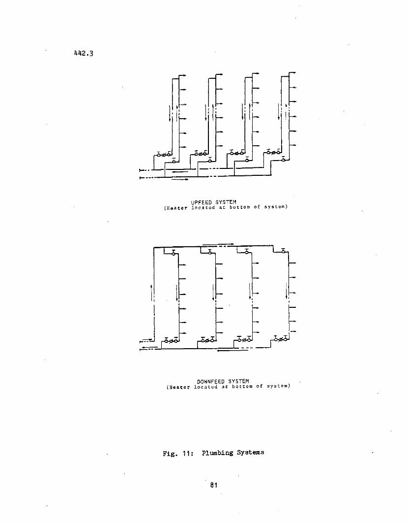
442.3
l~ l~ l~ l~1-- • ..J-_I, "-I1- -'- -.1-_
UPFEED SYSTEM(Heater located at bottom of system)
~__ =....L ---"__";:::::===-=:..=
DOWNFEED SYSTEM(Heater located at bottom of system)
Fig. 11: Plumbing Systems
81
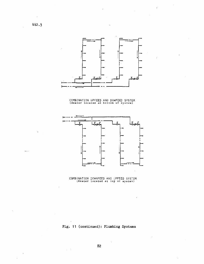
442.3
I----~I---Jt--- - -----..1--
COMBINATION UPFEED AND DOWFEED SYSTEM(Heater located at bottom of system)
~ -- - -===---.-----------,
~--T--:r=II
COMBINATION DOWNFEED AND UPFEED SYSTEM(Heater located at top of system)
Fig. 11 (continued): Plumbing Systems
82
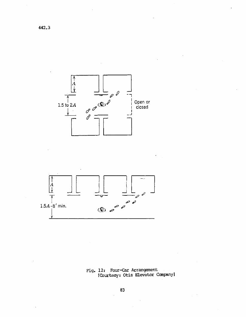
442.3
nnr c;a ,p 00
-l
15 t 2A ~')lJ I Open or. LO AJ I closed. 0° (/ I
LJLJ. .
nnnnT 0 ~
I • ,piP1.5A -8 min. -Et. 00 rf?j EID 0
0
Fig. 12: Four~r Arrangement·[Courtesy: Otis Elevator canpany]
83
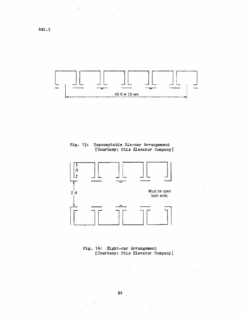
442.3
nnnnnn- I, -- ~ .40~sec ~ -- .1 -
Fig. 13: Unacceptable Six-car Arrangement[Courtesy: Otis Elevator Company]
2A Must be openboth ends
Fig. 14: Eight-car Arrangement[Courtesy: Otis Elevator Company]
84
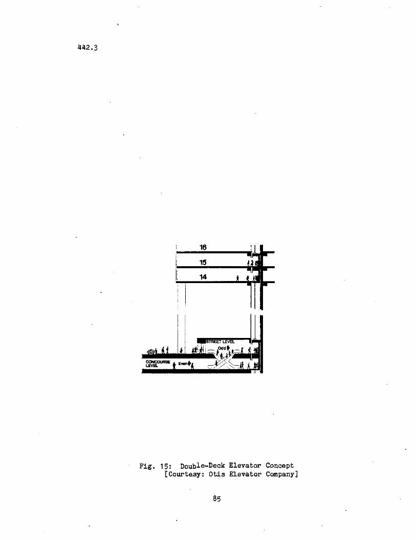
442.3
16
15
14
Fig. 15: Double-Deck Elevator Concept[Courtesy: Otis Elevator Company]
85
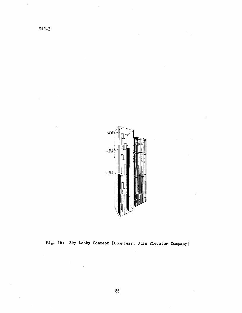
442.3
l10ftlflOOR
78 Ito.flOOR
.... thFlOOR
Fig. 16: Sky Lobby Concept [Courtesy: Otis Elevator Company]
86
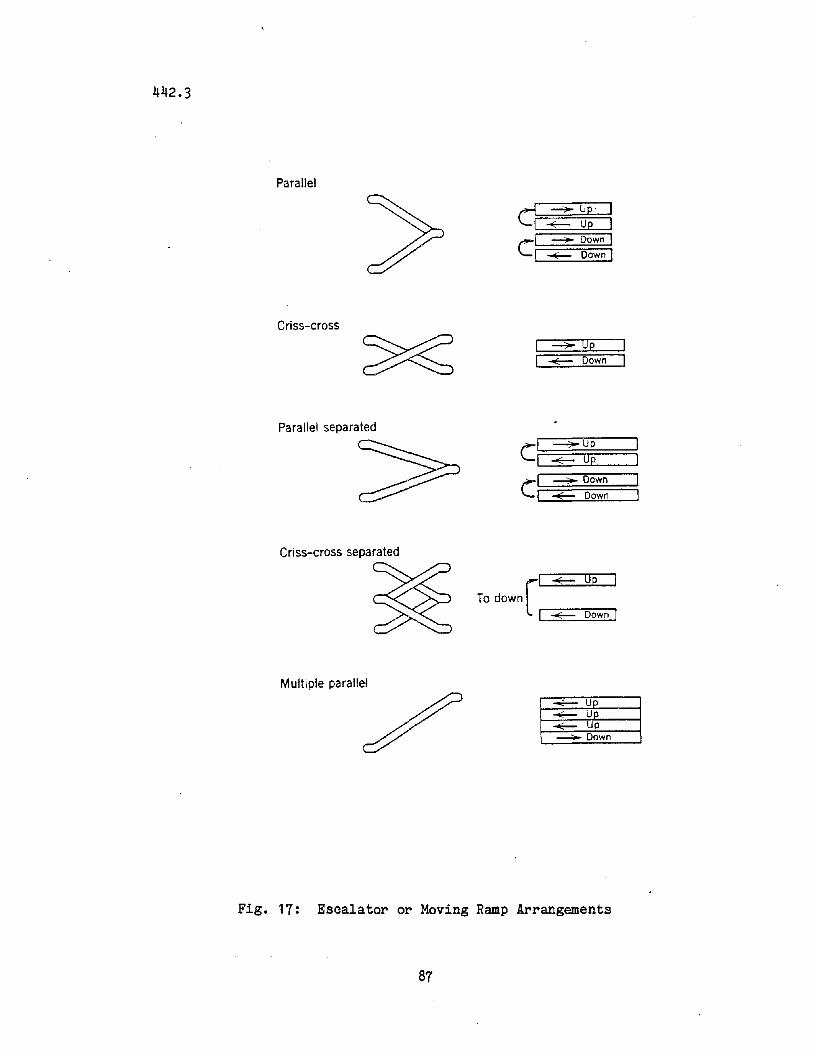
442.3
Parallel
>Criss-cross
Parallel separated
Criss-cross separated
~Multiple parallel
/
<:1 ~ Down I
I ~ Down I
~Up
~ Down
c':==;:=~:::;:U~P=~I ~ Up
CI:==::;:::~==;D~ow=n==::::::::;I ~ Down
r'~ UpTo down
'-1-~"""---':::D-ow-n""'l
-.f-- Up-.f-- UP~ Up---"""" Down
Fig. 17: Escalator or Moving Ramp Arrangements
87
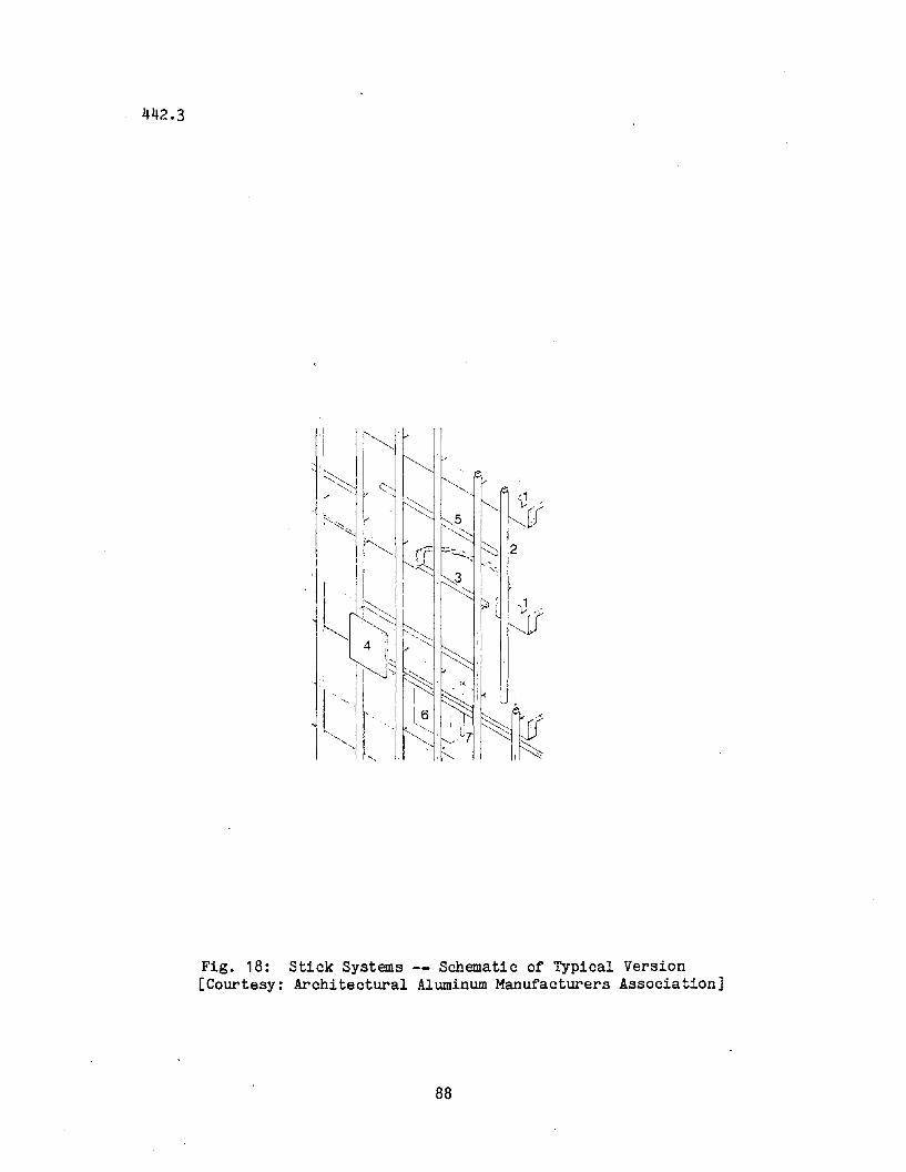
442.3
Fig. 18: Stick Systems -- Schematic of Typical Version[Courtesy: Architectural Aluminum Manufacturers Association]
88
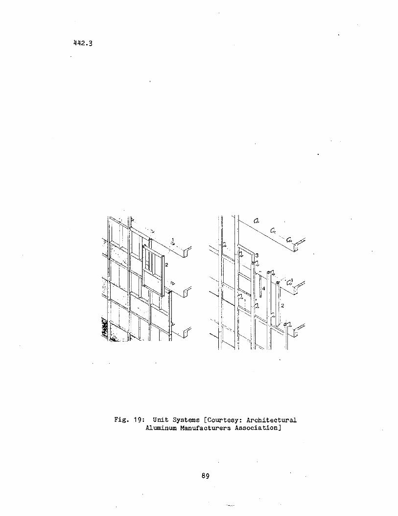
442.3
Fig. 19: Unit Systems [Courtesy: ArchitecturalAluminum Manufacturers Association]
89
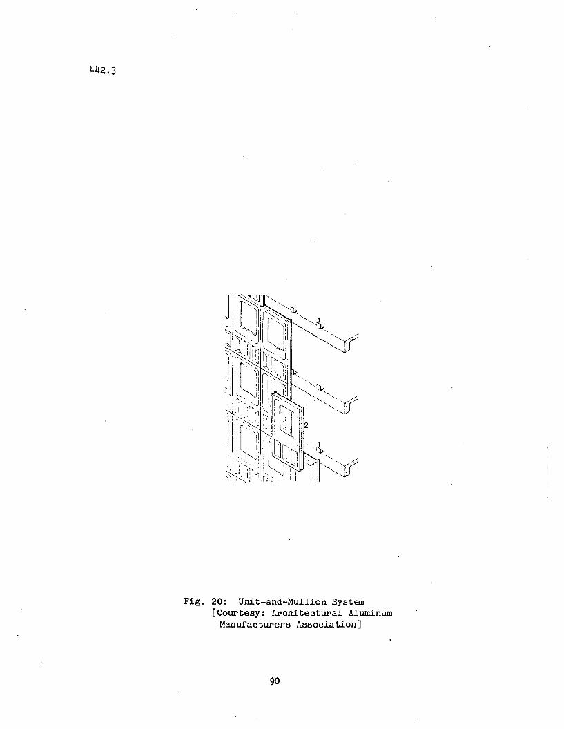
442.3
Fig. 20: Unit-and-Mullion System[Courtesy: Architectural Aluminum
Manufacturers Association]
90
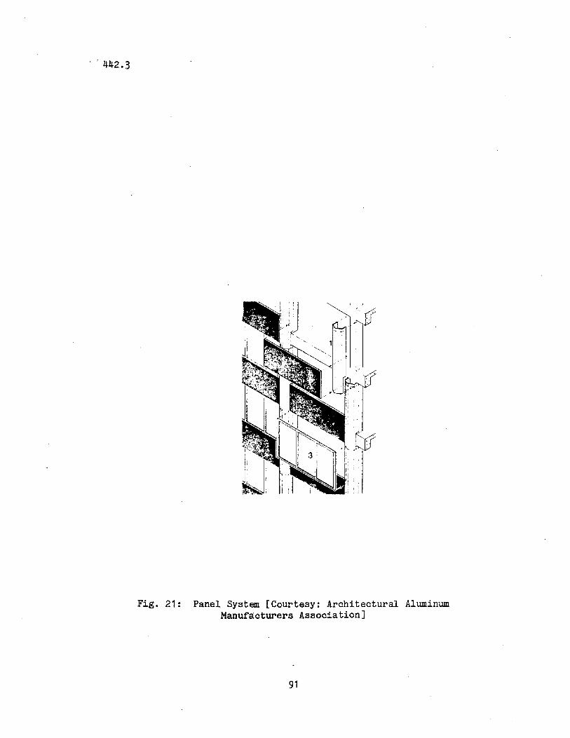
." 442.3
Fig. 21: Panel System [Courtesy: Architectural AluminumManufacturers Association]
91
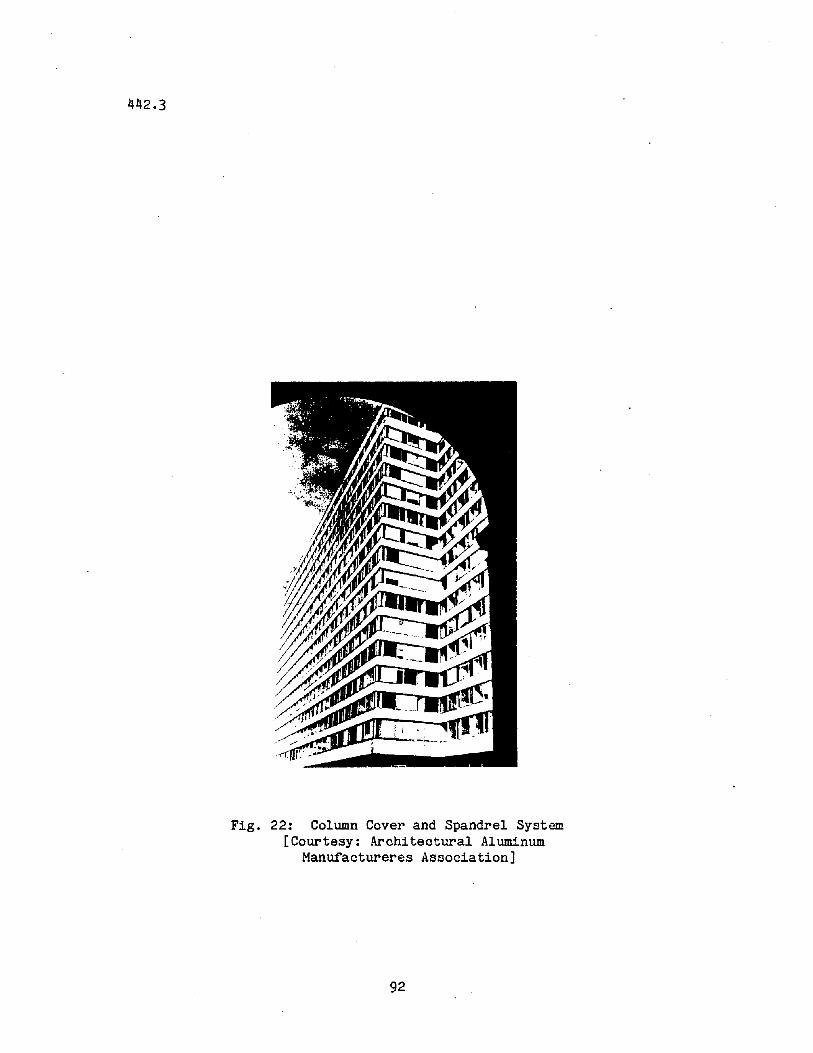
442.3
Fig. 22: Column Cover and Spandrel System[Courtesy: Architectural Aluminum
Manufactureres Association]
92
442.3
REFEREHCES/BIBLIOGRAPHY
ASHRAE, 1976ASHRAE HANDBOOK & PRODUCT DIRECTORY, American
Society of Heating, Refrigerating and AirConditioning Engineers, Inc., New York.
ATC, 1978TENTATIVE PROVISIONS FOR THE DEVELOPMENT OF
SEISMIC REGULATIONS FOR BUILDINGS, AppliedTechnology Council, Washington D.C ••
Abdallah, N., 1973THE M.L.C. CENTRE, Planning and Design of
Tall Buildings, (Proceedings of Conferencehe14 in Sydney, Australia, August 13-17),Lehigh University, Bethlehem, pp. 316-331.
Adler, R. R., 1970VERTICAL TRANSPORTATION FOR BUILDINGS,
American Elsevier Publishing Co., Inc.,New York.
Bandel, H., 1973STRUCTURAL SYSTEMS FOR VERY TALL
BUILDINGS, Planning and Design of TallBuildings, (Proceedings of Conferenceheld at Lehigh University, August,1972), Vol. la, ASCE, New York,pp. 627-631.
Beedle, L. S., Ed., 1980TALL BUILDING SYSTEMS IDENTIFIED,
The Times, Vol. 11, No.2, p. 2.
Beedle, L. S., Driscoll, G. C., Aydinoglu, N.,and Anderson, B., 1980
HIGH-RISE BUILDING DATA BASE, FritzLaboratory Report No. 442.2, LehighUniversity, Bethlehem.
93
442.3
British Steel Corporation, 1972FRAMES FOR TALL BUILDINGS, Building
With Steel, Volume 12, pp. 14-18,November.
Callender, J. H., Ed., 1974TIME-SAVER STANDARDS FOR
ARCHITECTURAL DESIGN DATA,Fifth Edition, McGraw-HillBook Company, New York.
Christiansen, J., 1973. CAST IN PLACE REINFORCED CONCRETE
SYSTEMS, Planning and Design of TallBuildings, (Proceedings of Conferenceheld at Lehigh University, August,1972), Vol. la, ASCE, New York,pp. 437-452.
Colaco, J. P. and Banavalkar, P. V., 1975STRUCTURAL CONCEPTS FOR MID-RISE
STRUCTURES, Pan Pacific TallBuildings Conference Proceedings,(Conference held in Honolulu,Hawaii, January), University ofHawaii, pp. 136-150.
Colaco, J. P. and Banavalkar, P. V., 1974PENZOIL PLACE - A NEW SLANT IN
STRUCTURAL SYSTEMS, Proceedingsof the Regional Conference on TallBuildings, (Conference held inBangkok, Thailand, January 23-25),Asian Institute of Technology,Bangkok, pp. 17-32.
Coull, A. and Subedi, N. K., 1971FRAMED TUBE STRUCTURE FOR HIGH
RISE BUILDINGS, Journal of theStructural Division, ASCE,Vol. 98, No. ST-8, pp. 20972105, August.
Council on Tall Buildings, 1978-1981PLANNING AND DESIGN OF TALL BUILDINGS,
A Monograph, 5 volumes, ASCE, NewYork.
94
442.3
Council on Tall Buildings, Committee 2A, 1980VERTICAL AND HORIZONTAL TRANSPORTATION,
Chapter SC-4, Volume SC of Monographon Planning and Design of TallBuildings, ASCE, New York.
Council on Tall BUildings, Committee 2B, 1980MECHANICAL AND SERVICE SYSTEMS,
Chapter SC-2, Volume SC of Monograph onPlanning and Design of Tall Buildings,ASCE, New York.
Council on Tall Buildings, Committee 3, 1980STRUCTURAL SYSTEMS, Chapter SC-1,
Volume SC of Monograph on Planning andDesign of Tall Buildings, ASCE, NewYork.
Council on Tall Buildings, Committee 2A, 1980CLADDING, Chapter SC-5, Volume SC of
Monograph on Planning and Design ofTall Buildings, ASCE, New York.
Council on Tall Buildings, Co~ttee 2B, 1980PARTITIONS, WALLS, AND CEILINGS, Chapter
SC-6, Volume SC of Monograph on Planningand Design of Tall Buildings, ASCE.New York.
Council on Tall Buildings, Committee 21A, 1978CONCRETE FRAMING SYSTEMS FOR TALL BUILDINGS,
Chapter CB-3, Volume CB of Monograph onPlanning and Design of Tall Buildings,ASCE, New York.
Dowrick, D. J., 1977EARTHQUAKE RESISTANT DESIGN, John
Wiley &Sons, Inc., New York.
Drosdov, P. F. and Lishak, V. I., 1978SPATIAL RIGIDITY & STABILITY OF TALL
BUILDINGS OF DIFFERENT STRUCTURAL SCHEMES,Prefabricated MUlti-Storey Buildings,(Proceedings of Conference held inMoscow, October 1976), Central Researhand Design Institute for Dwellings,Moscow, pp. 27-35.
95
442.3
Engel, H., 1967STRUCTURE SYSTEMS, Praeger Publishers,
New York.
Fleming, J. F., 1974LATERAL TRUSS SYSTEMS IN HIGH-
RISE BUILDINGS, Proceedings ofthe Regional Conference on TallBUildings, (Conference held inBangkok, Thailand, January 23-25),Asian Institute of Technology,Bangkok, pp. 33-48.
Fowler, J. R., 1973B.H.P. HOUSE, MELBOURNE, Planning and
Design of Tall Buildings, (Proceedingsof Conference held in Sydney, Australia,August 13-17), Lehigh University,Bethlehem, pp. 363-377.
Garnett, M. W., 1973A.M.P. CENTRE, SYDNEY, Planning and
Design of Tall Buildings (Proceedingsof Conference held in Sydney, Australia,August 13-17), Lehigh University,Bethlehem, pp. 394-409.
Handler, A. B., 1970SYSTEMS APPROACH TO ARCHITECTURE,
American Elsevier Publishing Co., Inc.,New York.
Hisatoku, T. and Nishikawa, F., 1973MIXED AND COMPOSITE CONCRETE AND STEEL
SYSTEMS, Planning and Design of TallBuildings, (Proceedings of Conferenceheld at Lehigh University, August,1972), Vol. la, ASCE, New York,pp. 501-514.
96
442.3
Iyengar, S. H., 1973STRUCTURAL SYSTEM FOR TWO ULTRA HIGH-
RISE STRUCTURES, Planning and Design ofTall Buildings, (Pro~eedings of Conferenceheld in Sydney, Australia, August 13-17),Lehigh University, Bethlehem, pp. 528-543.
Iyengar, S. H., 1980SYSTEMS CRITERIA FOR MIXED STEEL-CONCRETE
SYSTEMS, Developments in Composite andMixed Construction, (Proceedings of theUSA-Japan Seminar on Composite Structuresand Mixed Structure Systems, held in Tokyo,Japan, January 12-14, 1978), GihadoShuppan Company, Tokyo, pp. 283-307.
Iyengar, S. H. and Amin, N. R., 1976STEEL-CONCRETE COMPOSITE SYSTEMS FOR
TALL BUILDINGS, Proceedings of theRegional Conference on Tall Buildings,(Conference held in Hong Kong, September),Shum Shing Printing Company, Hong Kong,pp. 5-25.
Joint Committee on Tall Buildings, L. S. Beedleand L. W. Lu, Eds., 1973
PLANNING AND DESIGN OF TALL BUILDINGS,(Proceedings of ASCE-IABSE InternationalConference held at Lehigh University, August,1972), ASCE, New York, (5 volumes).
Kato, B. and Lu, L. W., Eds., 1980DEVELOPMENTS IN COMPOSITE AND MIXED
CONSTRUCTION, (Proceedings of the USAJapan Seminar on Composite Structuresand Mixed Structural Systems held inTokyo, Japan, January 12-14, 1978),Gihado Shuppan Company, Tokyo.
Keyfitz, N., in pressPOPULATION OF THE WORLD AND ITS
REGIONS 1975-2030, IndustrialInstitute for Applied SystemsAnalysis, Luxenberg, Austria.
97
442.3
Khan, F. R., 1967CURRENT TRENDS IN CONCRETE HIGH-RISE
BUILDINGS, Tall Buildings, A. Coull andB. S. Smith, Eds., Pergamon Press,London, pp. 571-590.
Khan, F. R., 1973RECENT DEVELOPMENT AND FUTURE OF HIGH-
RISE BUILDINGS, National Conference onTall Buildings, (Proceedings of Conferenceheld in New Delhi, India, January), IndianNational Group of the IABSE, New Delhi,pp. 105-128.
Khan, F. R., 1974NEW STRUCTURAL SYSTEMS FOR TALL BUILDINGS
AND THEIR SCALE EFFECTS ON CITIES, TallBuildings Planning, Design and Construction,(Proceedings of Symposium held at VanderbiltUniversity, Nashville, Tennessee, November14-15), Civil Engineering Program, Vanderbilt University, Nashville, pp. 99-129.
Konig, G., 1973CAST-IN-PLACE REINFORCED CONCRETE SYSTEMS,
Planning and Design of Tall Buildings,(Proceedings of Conference held at LehighUniversity, August, 1972), Vol. Ia, ASCE,New York, pp 515-536.
Kozak, J., 1973STRUCTURAL SYSTEMS OF TALL BUILDINGS WITH
CORE STRUCTURES, Planning and Design ofTall Buildings, (Proceedings of Conferenceheld at Lehigh University, August, 1972),Vol. Ia, ASCE, New York, pp. 537-565.
Liauw, T. C., 1974EVOLUTION OF NEW STRUCTURAL SYSTEMS
FOR TALL BUILDINGS, Proceedings of theRegional Conference on Tall Buildings,(Conference held in Bangkok, Thailand,January, 23-25), Asian Institute of Technology, Bangkok, pp. 115-126.
98
442.3
Libbey, R., 1975PACIFIC TRADE CENTER - A 30 STORY OFFICE
TOWER, Pan Pacific Tall Buildings Conference Proceedings, (Conference held inHonolulu, Hawaii, January), University ofHawaii, Honolulu, pp. 279-290.
Lu, L. W., 1974STRUCTURAL SYSTEMS, Modern Engineering and
Technology Seminar 1974, Vol. IX, Buildingand Architecture Session, Modern Engineeringand Technology Seminar Committee, Taipei,Taiwan, pp. 15-46.
McMillan, C. M., 1975AFRICAN EAGLE LIFE CENTRE - A HIGH-RISE
PRECAST LOAD BEARING FACADE. Pan PacificTall Buildings Conference Proceedings,(Conference held in Honolulu, Hawaii,January), University of Hawaii, Honolulu,pp. 258-266.
Miller, P.O., 1973QUANTAS CENTRE, Planning and Design of
Tall Buildings, (Proceedings of Conference held in Sydney, Australia, August13-17), Lehigh University, Bethlehem,pp. 410-423.
Mikroudis, George K. and Mueller, Peter, 1983DIGEST OF CASE STUDY OF TALL BUILDINGS DAMAGED
IN EARTHQUAKES, Fritz Laboratory Report No. '474.6,Lehigh University, Bethlehem.
Ng, P. K., Chong, S. C., and Rahulan, G., 1914STRUCTURAL SYSTEMS OF SOME OF THE TALL
BUILDINGS IN SINGAPORE AND KUALA LUMPUR,Proceedings of the Regional Conference onTall Buildings, (Conference held inBangkok, Thailand, January 23-25),Asian Institute of Technology, Bangkok,pp. 97-114.
99
442.3
Peyton, J., 1973COLLINS PLACE PROJECT, MELBOURNE, Planning
and Design of Tall Buildings, (Proceedingsof Conference held in Sydney, AustraliaAugust 13-17), Lehigh University,Bethlehem, pp. 347-362.
Peyton, J., 1974FLINDERS GATE - A DEVELOPMENT OVER RAILWAYS,
Proceedings, Conference on Tall Buildings,(Conference held in Kuala Lumpur, Malaysia,December 2-5), Institution of Engineers,Kuala Lumpur, pp. 9-21 - 9-26.
Peyton, J., 1974COLLINS-WALES PROJECT - A 500-FOOT TOWER IN
SIMPLE· HYBRID CONSTRUCTION, Proceedings,Conference on Tall Buildings, (Conferenceheld in Kuala Lumpur, Malaysia, December2-5), Institution of Engineers, KualaLumpur, pp. 9-52 - 9-57.
Rahulan, G., 1974TUNAS BUILDING - STRUCTURAL DESIGN OF A SLENDER
BUILDING, Proceedings, Conference on TallBuildings, (Conference held in Kuala Lumpur,Malaysia, December 2~5), Institution ofEngineers, Kuala Lumpur, pp. 9-15 - 9-20.
Ranada, B., 1975DESIGN AND CONSTRUCTION OF THE HONOLULU
MUNICIPAL BUILDING, Pan Pacific TallBuildings Conference Proceedings(Conference held in Honolulu, Hawaii,January), University of Hawaii, Honolulu,pp. 161-174.
Ruderman, J., 1965COMPARING THE HIGH-RISE STRUCTURAL
SYSTEMS, Architecture and EngineeringNews, Vol. 7, pp. 74-79, September.
Rush, Richard, 1980STRUCTURE AND CIRCUMSTANCE, Progressive
ArChitecture, Vol. 61, No. 12,pp. 50-57, December.
100
442.3 "
Schueller, W., 1977HIGH-RISE BUILDING STRUCTURES, Wiley
Interscience, New York.
smith, I. C., 1973BANK OF NEW ZEALAND, CONCEPT AND DESIGN,
Planning and Design of "Tall Buildings,(Proceedings of Conference held inSydney, Australia, August 13-17),Lehigh University, Bethlehem, pp. 424444.
Strakosch, G. R., 1967VERTICAL TRANSPORTATION: ELEVATORS AND ESCALATORS,
J.Wiley and Sons, Inc., New York.
Steele, A., 1975HIGHRISE PLUMBING DESIGN, Marimar Publishing
Company, Los Angeles.
Sun, T., 1979"MECHANICAL-STRUCTURAL INTERFACE IN BUILDING DESIGN
Journal of Structural Division, ASCE, Vol. 105,No.3, pp. 539-546, March.
Sung, M., 1974A TRANSFER BOWL OF 20 STORY BLOCK,
Proceedings, Conference on Tall Buildings,(Conference held in Kuala Lumpur, Malaysia,December 2-5), Institution of Engineers,Kuala Lumpur, pp. 9-68 - 9-72.
Taylor, D., 1973PARK TOWERS, MELBOURNE, Planning and
Design of Tall Buildings, (Proceedingsof Conference held in Sydney, Australia,August 13-17), Lehigh University,Bethlehem, pp. 332-346.
101
442.3
Thompson, P., 1973O.C.B.C. CENTER, SINGAPORE, Planning and
Design of Tall Buildings, (Proceedingsof Conference held in Sydney, Australia,August 13-17), Lehigh University,Bethlehem, pp. 379-389.
Wargon, A., 1973CENTERPOINT PROJECT, SYDNEY, Planning
and Design of Tall BUildings, (Proceedingsof Conference held in Sydney, Australia,August 13-17)~ Lehigh University,Bethlehem, pp. 445-477.
Weinberg, B. E., 1962MARINA CITY TOWERS, Civil Engineering,
Vol. 32, No. 12, pp. 64-67, December.
Wells, F. R., 1974STRUCTURAL SYSTEMS OF THREE SYDNEY HIGH
RISE BUILDINGS, Proceedings, Conferenceon Tall Buildings, (Conference held inKuala Lumpur, Malaysia, December 2-5),Institution of Engineers, Kuala Lumpur,pp. 9-1 - 9-14.
Whyte, L. L., Wilson, A. G., Wilson, D., Eds., 1969HIERARCHICAL STRUCTURES, American Elsevier
Publishing Company, Inc., New York.
102