Embed Size (px)
Citation preview
3385 SCOTT BLVDSANTA CLARA, CA 95054
PeRT3 Eagle System User Manual
User Manual Version 1.6
January 2010

Version 1.6 PeRT3 Eagle User Manual
Document DisclaimerThe information in this document has been carefully checked and is believed to be reliable. However, no responsibility can be assumed for inaccuracies that may not have been detected.
LeCroy reserves the right to revise the information in this document without notice or penalty.
Trademarks and ServicemarksLeCroy and PeRT3 are trademarks of LeCroy.
Microsoft, WIndows, Windows XP, and WIndows Vista are registered trademarks of Microsoft Inc.
PCI Express, PCIe and PCI-SIG are registered trademarks of the PCI-SIG.
All other trademarks are property of their respective companies.
CopyrightCopyright © 2010, LeCroy; All Rights Reserved.
This document may be printed and reproduced without additional permission, but all copies should contain this copyright notice.
Part number 917989-xx
LeCroy Corporation
PeRT3 Eagle User Manual Version 1.6
Table of ContentsChapter 1 Overview 1
System Configurations. . . . . . . . . . . . . . . . . . . . . . . . . . . . . . . . . . 2Software Test Suites . . . . . . . . . . . . . . . . . . . . . . . . . . . . . . . . 2Upgrades and Main- tenance . . . . . . . . . . . . . . . . . . . . . . . . . 2Connection to Device Under Test . . . . . . . . . . . . . . . . . . . . . . 2
Chapter 2 Quick Start Guide 3Unpacking the System . . . . . . . . . . . . . . . . . . . . . . . . . . . . . . . . . . 3Requirements for the Host PC . . . . . . . . . . . . . . . . . . . . . . . . . . . . 3Back Panel Connections . . . . . . . . . . . . . . . . . . . . . . . . . . . . . . . . 4Initial System Setup . . . . . . . . . . . . . . . . . . . . . . . . . . . . . . . . . . . . 4Connecting to the PeRT3 Eagle. . . . . . . . . . . . . . . . . . . . . . . . . . . 5
Overview of Connection . . . . . . . . . . . . . . . . . . . . . . . . . . . . . 5Steps to Connect . . . . . . . . . . . . . . . . . . . . . . . . . . . . . . . . . . . 6
Connecting the Device Under Test . . . . . . . . . . . . . . . . . . . . . . . . 8Selecting and Running a Test . . . . . . . . . . . . . . . . . . . . . . . . . . . . 9Modifying a Test . . . . . . . . . . . . . . . . . . . . . . . . . . . . . . . . . . . . . . 10
Chapter 3 Basic Principles of Operation 13Introduction of Stress into Waveform . . . . . . . . . . . . . . . . . . . . . . 14
Amplitude Modulation . . . . . . . . . . . . . . . . . . . . . . . . . . . . . . 14Pre- Emphasis . . . . . . . . . . . . . . . . . . . . . . . . . . . . . . . . . . . . 15Random Jitter . . . . . . . . . . . . . . . . . . . . . . . . . . . . . . . . . . . . 15Sinusoidal Jitter . . . . . . . . . . . . . . . . . . . . . . . . . . . . . . . . . . . 15
Chapter 4 Software Overview 17Starting the PeRT3 Program . . . . . . . . . . . . . . . . . . . . . . . . . . . . 17Main Application Window. . . . . . . . . . . . . . . . . . . . . . . . . . . . . . . 18Main Library Window . . . . . . . . . . . . . . . . . . . . . . . . . . . . . . . . . . 19File Menu . . . . . . . . . . . . . . . . . . . . . . . . . . . . . . . . . . . . . . . . . . . 19
New . . . . . . . . . . . . . . . . . . . . . . . . . . . . . . . . . . . . . . . . . . . . 19Import... . . . . . . . . . . . . . . . . . . . . . . . . . . . . . . . . . . . . . . . . . 20Export... . . . . . . . . . . . . . . . . . . . . . . . . . . . . . . . . . . . . . . . . . 20Print . . . . . . . . . . . . . . . . . . . . . . . . . . . . . . . . . . . . . . . . . . . . 21Exit. . . . . . . . . . . . . . . . . . . . . . . . . . . . . . . . . . . . . . . . . . . . . 21
Chapter 5 Manual Testing 23System Control Ribbon - Main Tab . . . . . . . . . . . . . . . . . . . . . . . 23System Control Ribbon -- Channel Tabs . . . . . . . . . . . . . . . . . . . 25
Signal Generation and Introduction of Distortion. . . . . . . . . . 26System Control Ribbon -- Analysis Tab . . . . . . . . . . . . . . . . . . . . 33System Control Ribbon -- Pattern Tab . . . . . . . . . . . . . . . . . . . . . 33System Control Ribbon -- Options Tab . . . . . . . . . . . . . . . . . . . . 33
Chapter 6 Main Library Window 37Chapter 7 Creating a New Test Script 39
Starting a New Test Script . . . . . . . . . . . . . . . . . . . . . . . . . . . . . . 40
LeCroy Corporation iii
Version 1.6 PeRT3 Eagle User Manual
Test Script Data Block . . . . . . . . . . . . . . . . . . . . . . . . . . . . . . . . . 41Building a Test Script Block-by-Block. . . . . . . . . . . . . . . . . . . . . . 42Reset/ Initialize Block. . . . . . . . . . . . . . . . . . . . . . . . . . . . . . . . . . 42Receiver Test Case Block . . . . . . . . . . . . . . . . . . . . . . . . . . . . . . 43Adding, Inserting and Deleting Test Cases . . . . . . . . . . . . . . . . . 44
Chapter 8 Creating Test Patterns 45Creating a New Test Pattern . . . . . . . . . . . . . . . . . . . . . . . . . . . . 45
Pattern Editor Tab Controls . . . . . . . . . . . . . . . . . . . . . . . . . . 46Adding Frames to Patterns . . . . . . . . . . . . . . . . . . . . . . . . . . 49Adding Data to Patterns . . . . . . . . . . . . . . . . . . . . . . . . . . . . 50Modifying Data Within a Pattern . . . . . . . . . . . . . . . . . . . . . . 51
Chapter 9 Analysis and Reports 53System Control Ribbon -- Analysis Tab . . . . . . . . . . . . . . . . . . . . 53Analysis Graph Types . . . . . . . . . . . . . . . . . . . . . . . . . . . . . . . . . 55
Log View . . . . . . . . . . . . . . . . . . . . . . . . . . . . . . . . . . . . . . . . 55Spreadsheet View . . . . . . . . . . . . . . . . . . . . . . . . . . . . . . . . . 56Errors vs. Time . . . . . . . . . . . . . . . . . . . . . . . . . . . . . . . . . . . 56Single Parameter. . . . . . . . . . . . . . . . . . . . . . . . . . . . . . . . . . 57Multi Single Parameter . . . . . . . . . . . . . . . . . . . . . . . . . . . . . 58Two Parameter . . . . . . . . . . . . . . . . . . . . . . . . . . . . . . . . . . . 58Scatter Chart . . . . . . . . . . . . . . . . . . . . . . . . . . . . . . . . . . . . . 59Test Report . . . . . . . . . . . . . . . . . . . . . . . . . . . . . . . . . . . . . . 59
Chapter 10 Control of Screen Appearance 61Customizing the Quick Access Toolbar . . . . . . . . . . . . . . . . . . . . 61The System Control Ribbon. . . . . . . . . . . . . . . . . . . . . . . . . . . . . 64Customizing the Main Library and Output Windows . . . . . . . . . . 66Selecting the Style Color Theme . . . . . . . . . . . . . . . . . . . . . . . . . 67Limited Hardware Warranty . . . . . . . . . . . . . . . . . . . . . . . . . . . . . 69
Appendix A Specifications 73Specifications . . . . . . . . . . . . . . . . . . . . . . . . . . . . . . . . . . . . . . . . 73
Generator Data Out . . . . . . . . . . . . . . . . . . . . . . . . . . . . . . . . 73Generator Clock Out . . . . . . . . . . . . . . . . . . . . . . . . . . . . . . . 73Protocols Supported . . . . . . . . . . . . . . . . . . . . . . . . . . . . . . . 73Generator Jitter Stress. . . . . . . . . . . . . . . . . . . . . . . . . . . . . . 74Error Detector Data In . . . . . . . . . . . . . . . . . . . . . . . . . . . . . . 74Power Require- ments. . . . . . . . . . . . . . . . . . . . . . . . . . . . . . 74Environ- mental Conditions . . . . . . . . . . . . . . . . . . . . . . . . . . 74
Miscellaneous Information . . . . . . . . . . . . . . . . . . . . . . . . . . . . . . 75
Index
iv LeCroy Corporation

PeRT3 Eagle User Manual Version 1.6
Chapter 1: OverviewThe LeCroy PeRT3 Eagle Test System is a new tool for testing of transceivers and other serial data communication devices and systems. Verifying device performance to current serial data standards normally requires multiple tools and multiple test setups, in order to test the devices over the entire range of requirements, from signal quality and BER testing through to protocol level error rate verification. With the LeCroy PeRT3 Eagle, this entire process can be accomplished quickly and easily, using a single tool and a single experimental setup, on multiple lanes of a serial communication link.
The PeRT3 Eagle System is the first “protocol enabled” transceiver tester, allowing the system to run not only electrical testing and error ratio testing, but also to control the device under test during test operation. This allows further testing under live traffic conditions since the PeRT3 Eagle can communicate directly with the device, generating actual traffic to exercise the device, which then can be used to measure protocol-level error ratios.
PeRT3 stands for Protocol enabled Receiver and Transmitter Tolerance Tester.
The PeRT3 Eagle combines the electrical test properties of jitter testers, the bit error ratio testing of BERTs, and the high level protocol packet error ratio testing of protocol exercisers. All of this is accomplished with a single system and single setup.
The PeRT3 Eagle System has an integrated design, combining digital electronics and signal processing with an analog front end. The PeRT3 Eagle digital subsystem provides programmability, protocol awareness, and digital test pattern generation. The analog front end provides advanced high quality signal generation with precise timing control, and the ability to produce a controlled signal waveform with user-controlled jitter levels, amplitude modulation and other electrical stress generation. The analog front end superimposes these signal impairments on the outgoing signal to exercise and test the receiver channel of the device under test.
The PeRT3 Eagle System provides the ability to control and modulate the outgoing test signal. Test capabilities include modulation of clock noise and jitter, signal shaping (such as amplitude control, rise/fall generation), pre- and de-emphasis, and also the ability to monitor the signal quality of the traffic returned from the test device.
The “protocol-enabled” capabilities of the PeRT3 Eagle also allow the system to manage protocol-specific issues that confuse less sophisticated test systems. An example is the resynchronization of clocks in SATA systems through the use of the ALIGN primitives. The PeRT3 Eagle can monitor and record protocol-level errors such as CRC errors, and protocol-specific errors such as R_ERR in SATA.
LeCroy Corporation 1
Version 1.6 PeRT3 Eagle User Manual
The PeRT3 Eagle is able to: (1) generate patterns which produce standardized tests such as PRBS; (2) generate protocol-level commands, which can be used both to control the device under test (e.g., to put the device into a loop-back self-test mode, or request information from the device on errors detected by the device); and (3) provide testing under live traffic conditions while the PeRT3 Eagle exercises the device under test.
The unique combination of abilities provided by the PeRT3 Eagle allows the user, with a single system and setup, to run through an entire range of tests to verify the total performance of the device under test. The result is an economical, efficient and easy-to-use system for any developer working on serial data communication designs or devices.
System ConfigurationsThe PeRT3 Eagle System is available in the following hardware configurations:
• PeRT3 Eagle System -- 1 channel
• PeRT3 Eagle System -- 2 channel
• PeRT3 Eagle System -- 4 channel
Software Test Suites
The software test suites are configured by protocol support desired, with the following options available:
• Eagle Receiver Tolerance Test Suite, which is a general purpose suite without specific protocol support
• Eagle SAS Receiver Tolerance Test Suite, which supports SAS protocol
• Eagle SATA Receiver Tolerance Test Suite, which supports SATA
• Eagle PCI Express Receiver Tolerance Test Suite, which supports PCI Express
• Eagle USB 3.0 Receiver Tolerance Test Suite, which supports USB 3.0
Upgrades and Main- tenance
Hardware upgrades are available to upgrade 1- or 2-channel systems to add additional channel capability.
Maintenance agreements are available to provide extended support.
Note: PeRT3 Eagle systems require calibration on an annual basis to maintain performance within factory specifications. The LeCroy maintenance agreements normally include annual calibration of the system.
Connection to Device Under Test
The PeRT3 Eagle provides coaxial SMA connectors to maintain signal integrity between the device under test (DUT) and the test system. A separate SMA connector is provided for each conductor in the differential pair (i.e., two connectors per line, four connectors per bi-directional channel). The nature of the connection to the DUT will vary depending on the specifics of the DUT, but close attention must be paid to maintaining signal integrity in design and implementation of the connections.
2 LeCroy Corporation

PeRT3 Eagle User Manual Version 1.6
Chapter 2: Quick Start GuideThis chapter describes how to set up the PeRT3 Eagle and perform a test on a device using a pre-programmed test script.
Unpacking the SystemThe PeRT3 Eagle is shipped with the following components:
• PeRT3 Eagle Hardware Platform
• PeRT3 System Software CD
• AC Power Cord
• USB Cable to connect Host PC to PeRT3 Eagle
Unpack the system and verify that all system components are present. If any components are missing, contact LeCroy Service at 1-800-909-7112 (or 408-653-1260).
Requirements for the Host PCA host PC system must be supplied to work with the Eagle system with the following minimum requirements:
• Intel Pentium 4, AMD Athlon/AMD Duron, or newer compatible processor with clock speed of at least 2 GHz.
• Microsoft Windows XP or Windows Vista.
• Minimum of 1 GB of RAM.
• Minimum of 25 MB of free hard disk space. Additional space is required for operation of applications and storing recorded results.
• Display resolution of at least 1280 x 800 with 24-bit color depth is highly recommended. Application can be run on 800 x 600 monitor, but user experience is much better with the higher screen resolution.
• USB 2.0 port.
LeCroy Corporation 3
Version 1.6 PeRT3 Eagle User Manual
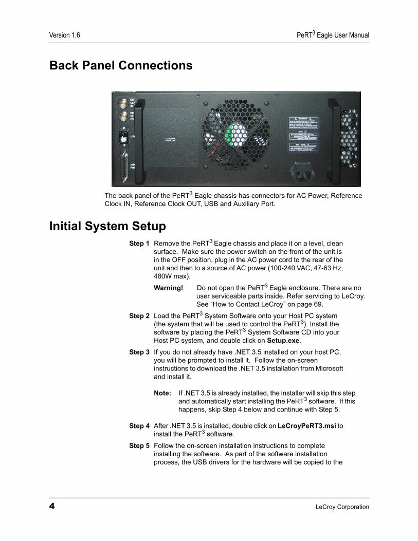
Back Panel Connections
The back panel of the PeRT3 Eagle chassis has connectors for AC Power, Reference Clock IN, Reference Clock OUT, USB and Auxiliary Port.
Initial System SetupStep 1 Remove the PeRT3 Eagle chassis and place it on a level, clean
surface. Make sure the power switch on the front of the unit is in the OFF position, plug in the AC power cord to the rear of the unit and then to a source of AC power (100-240 VAC, 47-63 Hz, 480W max).
Warning! Do not open the PeRT3 Eagle enclosure. There are no user serviceable parts inside. Refer servicing to LeCroy. See “How to Contact LeCroy” on page 69.
Step 2 Load the PeRT3 System Software onto your Host PC system (the system that will be used to control the PeRT3). Install the software by placing the PeRT3 System Software CD into your Host PC system, and double click on Setup.exe.
Step 3 If you do not already have .NET 3.5 installed on your host PC, you will be prompted to install it. Follow the on-screen instructions to download the .NET 3.5 installation from Microsoft and install it.
Note: If .NET 3.5 is already installed, the installer will skip this step and automatically start installing the PeRT3 software. If this happens, skip Step 4 below and continue with Step 5.
Step 4 After .NET 3.5 is installed, double click on LeCroyPeRT3.msi to install the PeRT3 software.
Step 5 Follow the on-screen installation instructions to complete installing the software. As part of the software installation process, the USB drivers for the hardware will be copied to the
4 LeCroy Corporation
PeRT3 Eagle User Manual Version 1.6
standard driver directory on your PC.
Step 6 When the software installation is complete, connect the USB cable from the host PC to the PeRT3 Eagle chassis.
Step 7 Turn on the PeRT3 system.
Step 8 The operating system will prompt you to install the USB drivers for the PeRT3 system. Follow the on-screen prompts to install the USB drivers. You will be prompted to install a USB driver for both the Eagle R6 and for the Eagle FE6. Follow the same procedure for both.
Note: Do NOT let the operating system connect to the Internet to search for drivers.
Note: Allow the operating system to automatically install the drivers.
Note: If for some reason the operating system does not automatically find the drivers, you can manually browse to C:\Program Files\LeCroy\PeRT3\drivers (or other directory if you did not select the default directory on installation) and have the operating system install the drivers from there.
Step 9 Restart the host computer system.
Connecting to the PeRT3 EagleOverview of Connection
The PeRT3 Eagle System allows the user to be directly connected to the PeRT3 system in use, or connected remotely via a network. This latter method is very useful when the system is located in a lab or other remote location, and the user wishes to conduct testing from their office (or home).
To support this flexibility, the software application includes both a client, which contains the user interface displayed to the user, and a server, which communicates directly with the PeRT3 hardware. The server must exist on the PC directly connected to the hardware, the client may exist on any PC that has a network connection to the server. By default, the PeRT3 installer installs both client and server programs.
When the client is launched, it will first search for a PeRT3 server on the local PC. If it finds a server, it will display "LOCALHOST(local)" in the PeRT3 field of the PeRT3 Selection panel on the Main tab. It then attempts to connect to the local hardware attached to the PC.
LeCroy Corporation 5
Version 1.6 PeRT3 Eagle User Manual
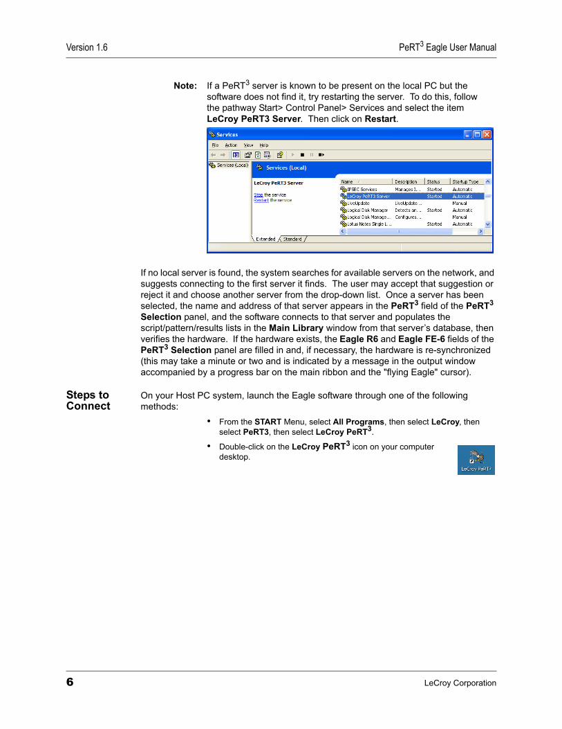
Note: If a PeRT3 server is known to be present on the local PC but the software does not find it, try restarting the server. To do this, follow the pathway Start> Control Panel> Services and select the item LeCroy PeRT3 Server. Then click on Restart.
If no local server is found, the system searches for available servers on the network, and suggests connecting to the first server it finds. The user may accept that suggestion or reject it and choose another server from the drop-down list. Once a server has been selected, the name and address of that server appears in the PeRT3 field of the PeRT3 Selection panel, and the software connects to that server and populates the script/pattern/results lists in the Main Library window from that server’s database, then verifies the hardware. If the hardware exists, the Eagle R6 and Eagle FE-6 fields of the PeRT3 Selection panel are filled in and, if necessary, the hardware is re-synchronized (this may take a minute or two and is indicated by a message in the output window accompanied by a progress bar on the main ribbon and the "flying Eagle" cursor).
Steps to Connect
On your Host PC system, launch the Eagle software through one of the following methods:
• From the START Menu, select All Programs, then select LeCroy, then select PeRT3, then select LeCroy PeRT3.
• Double-click on the LeCroy PeRT3 icon on your computer desktop.
6 LeCroy Corporation
PeRT3 Eagle User Manual Version 1.6
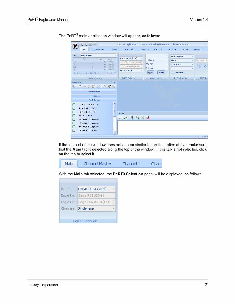
The PeRT3 main application window will appear, as follows:
If the top part of the window does not appear similar to the illustration above, make sure that the Main tab is selected along the top of the window. If this tab is not selected, click on the tab to select it.
With the Main tab selected, the PeRT3 Selection panel will be displayed, as follows:
LeCroy Corporation 7
Version 1.6 PeRT3 Eagle User Manual
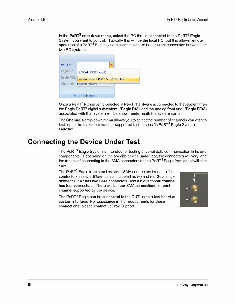
In the PeRT3 drop-down menu, select the PC that is connected to the PeRT3 Eagle System you want to control. Typically this will be the local PC, but this allows remote operation of a PeRT3 Eagle system as long as there is a network connection between the two PC systems.
Once a PeRT3 PC server is selected, if PeRT3 hardware is connected to that system then the Eagle PeRT3 digital subsystem ("Eagle R6") and the analog front end ("Eagle FE6") associated with that system will be shown underneath the system name.
The Channels drop-down menu allows you to select the number of channels you wish to test, up to the maximum number supported by the specific PeRT3 Eagle System selected.
Connecting the Device Under TestThe PeRT3 Eagle System is intended for testing of serial data communication links and components. Depending on the specific device under test, the connectors will vary, and the means of connecting to the SMA connectors on the PeRT3 Eagle front panel will also vary.
The PeRT3 Eagle front panel provides SMA connectors for each of the conductors in each differential pair, labeled as (+) and (-). So a single differential pair has two SMA connectors, and a bidirectional channel has four connectors. There will be four SMA connections for each channel supported by the device.
The PeRT3 Eagle can be connected to the DUT using a test board or custom interface. For assistance in the requirements for these connections, please contact LeCroy Support.
8 LeCroy Corporation
PeRT3 Eagle User Manual Version 1.6
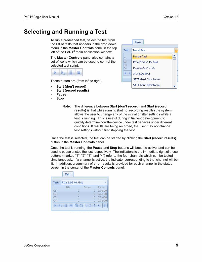
Selecting and Running a TestTo run a predefined test, select the test from the list of tests that appears in the drop down menu in the Master Controls panel in the top left of the PeRT3 main application window.
The Master Controls panel also contains a set of icons which can be used to control the selected test script.
These button are (from left to right):
• Start (don’t record)• Start (record results)• Pause• Stop
Note: The difference between Start (don’t record) and Start (record results) is that while running (but not recording results) the system allows the user to change any of the signal or jitter settings while a test is running. This is useful during initial test development to quickly determine how the device under test behaves under different conditions. If results are being recorded, the user may not change test settings without first stopping the test.
Once the test is selected, the test can be started by clicking the Start (record results) button in the Master Controls panel.
Once the test is running, the Pause and Stop buttons will become active, and can be used to pause or stop the test respectively. The indicators to the immediate right of these buttons (marked "1", "2", "3", and "4") refer to the four channels which can be tested simultaneously. If a channel is active, the indicator corresponding to that channel will be lit. In addition, a summary of error results is provided for each channel in the status screen in the center of the Master Controls panel.
LeCroy Corporation 9
Version 1.6 PeRT3 Eagle User Manual
In addition, as the test is running, the Output window at the bottom of the main application window will provide a log of test conditions and results.
If the test was started with the Start (record results) button, the results are automatically saved in the Test Results library while the test is running.
An alternate way to select and run a test is to click on the test within the Test Scripts tab of the Main Library window, then either click the Run Test icon at the top of the window or right-click on the test name and select Run Test.
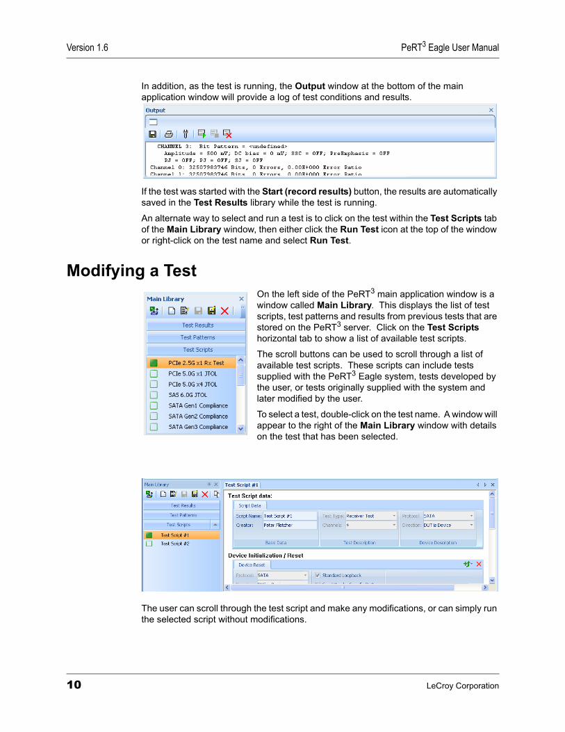
Modifying a TestOn the left side of the PeRT3 main application window is a window called Main Library. This displays the list of test scripts, test patterns and results from previous tests that are stored on the PeRT3 server. Click on the Test Scripts horizontal tab to show a list of available test scripts.
The scroll buttons can be used to scroll through a list of available test scripts. These scripts can include tests supplied with the PeRT3 Eagle system, tests developed by the user, or tests originally supplied with the system and later modified by the user.
To select a test, double-click on the test name. A window will appear to the right of the Main Library window with details on the test that has been selected.
The user can scroll through the test script and make any modifications, or can simply run the selected script without modifications.
10 LeCroy Corporation

PeRT3 Eagle User Manual Version 1.6
Note that if you want to create a copy of the test script prior to modification, single click on the script you want to copy and click on the Copy icon at the top of the window, or right click on the script you want to copy and select Copy from the menu that appears.
To create a new test script or to modify an existing test script, see “Creating a New Test Script” on page 39.
LeCroy Corporation 11

Version 1.6 PeRT3 Eagle User Manual
12 LeCroy Corporation

PeRT3 Eagle User Manual Version 1.6
Chapter 3: Basic Principles of OperationThe PeRT3 Eagle generates a serial bit stream for testing of receivers through a two-stage process. In the first stage, the bit stream is developed in accordance with the protocol being used (if selected) and the test patterns selected. This bit stream is originally generated to be as clean and precise as possible.
In the second step, the clean bit stream generated in the first step is passed through a series of stages which introduce controlled distortions into the signal. There are many choices for type of distortion, each type has many possible levels, and multiple types of distortion can be overlapped to produce complex, but controllable, irregularities in the signal generated. The system is designed to allow the user to test signal distortions along many different axes (types and combinations of signal degradation), and allows the user to establish either a simple PASS/FAIL test at a given level of distortion, or to explore the performance envelope of a receiver by multiple tests, each of which introduces increasing levels of distortion along different axes until predefined bit error levels are exceeded.
In the process of testing a receiver, the device containing the receiver is first connected to the system, then the device may go through an initialization phase, after which the device is placed into a test mode (e.g., a simple loopback mode) which returns the signal to the PeRT3 Eagle for analysis using a clean (distortion free) return path. This allows the PeRT3 Eagle to monitor the bit error ratios encountered by the receiver with minimal interference from the return path.
LeCroy Corporation 13
Version 1.6 PeRT3 Eagle User Manual
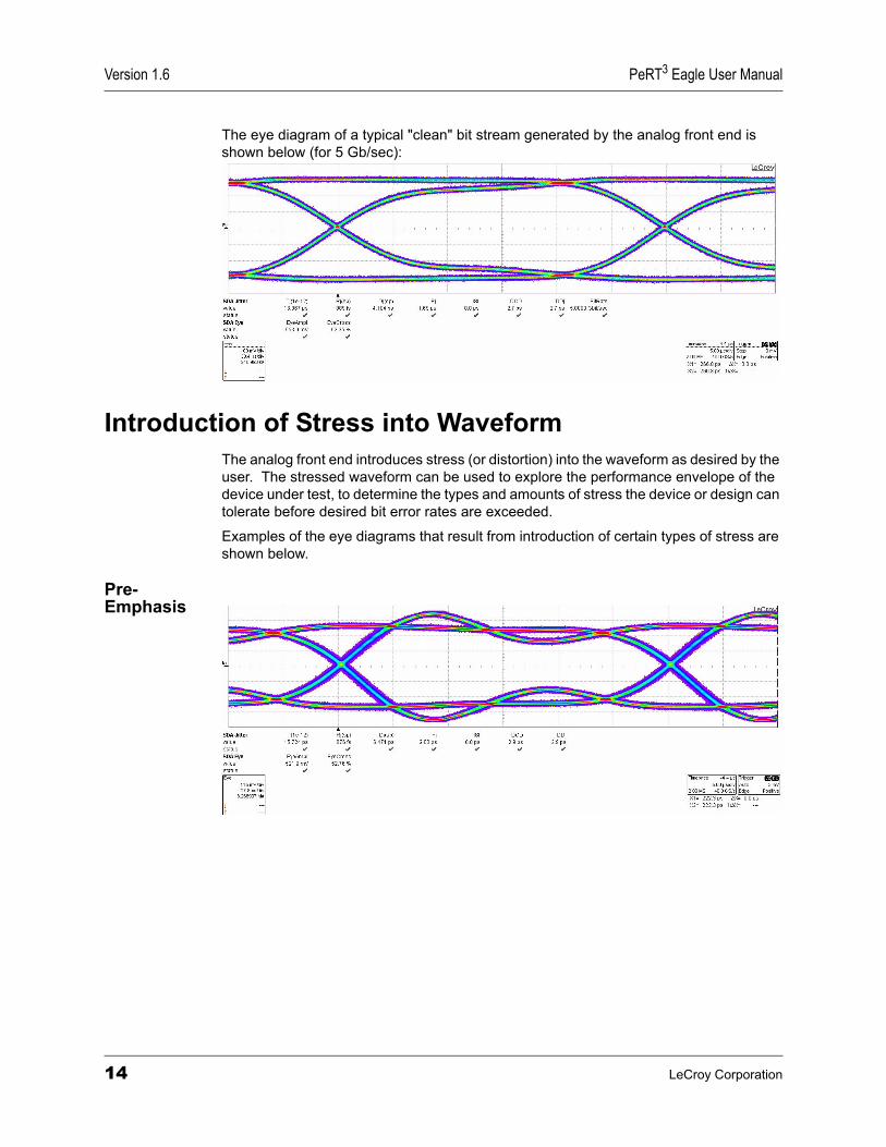
The eye diagram of a typical "clean" bit stream generated by the analog front end is shown below (for 5 Gb/sec):
Introduction of Stress into WaveformThe analog front end introduces stress (or distortion) into the waveform as desired by the user. The stressed waveform can be used to explore the performance envelope of the device under test, to determine the types and amounts of stress the device or design can tolerate before desired bit error rates are exceeded.
Examples of the eye diagrams that result from introduction of certain types of stress are shown below.
Pre- Emphasis
14 LeCroy Corporation
PeRT3 Eagle User Manual Version 1.6
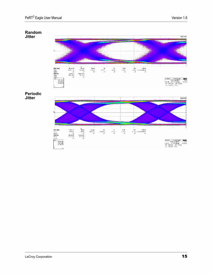
Random Jitter
Periodic Jitter
LeCroy Corporation 15

Version 1.6 PeRT3 Eagle User Manual
16 LeCroy Corporation
PeRT3 Eagle User Manual Version 1.6
Chapter 4: Software OverviewThe PeRT3 application allows the user to control the PeRT3 Eagle Test System, to develop test scripts for the system, to run saved test scripts, to run manual tests, and to review results of the current or previous tests. When reviewing the results of previous tests, the Host PC running the PeRT3 application does not need to be connected to the PeRT3 Eagle System hardware. This allows users to share test results with other engineers without requiring those users to have hardware connected.
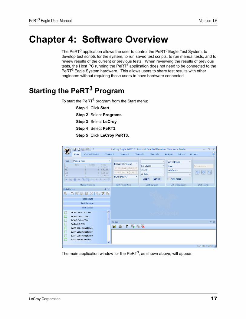
Starting the PeRT3 ProgramTo start the PeRT3 program from the Start menu:
Step 1 Click Start.Step 2 Select Programs.
Step 3 Select LeCroy.
Step 4 Select PeRT3.
Step 5 Click LeCroy PeRT3.
The main application window for the PeRT3, as shown above, will appear.
LeCroy Corporation 17
Version 1.6 PeRT3 Eagle User Manual
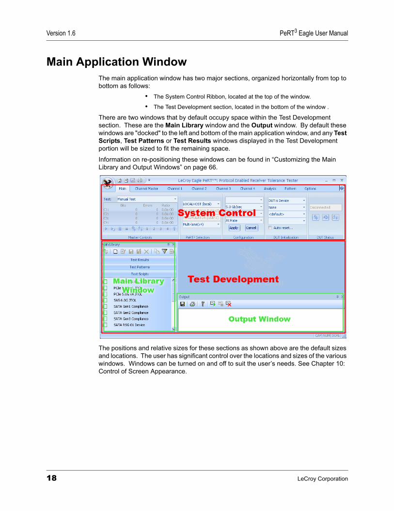
Main Application WindowThe main application window has two major sections, organized horizontally from top to bottom as follows:
• The System Control Ribbon, located at the top of the window.
• The Test Development section, located in the bottom of the window .
There are two windows that by default occupy space within the Test Development section. These are the Main Library window and the Output window. By default these windows are "docked" to the left and bottom of the main application window, and any Test Scripts, Test Patterns or Test Results windows displayed in the Test Development portion will be sized to fit the remaining space.
Information on re-positioning these windows can be found in “Customizing the Main Library and Output Windows” on page 66.
The positions and relative sizes for these sections as shown above are the default sizes and locations. The user has significant control over the locations and sizes of the various windows. Windows can be turned on and off to suit the user’s needs. See Chapter 10: Control of Screen Appearance.
18 LeCroy Corporation
PeRT3 Eagle User Manual Version 1.6
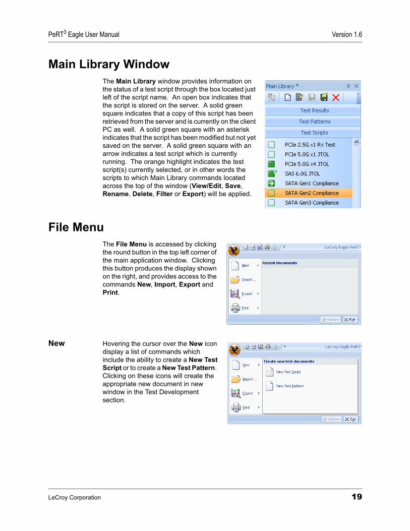
Main Library WindowThe Main Library window provides information on the status of a test script through the box located just left of the script name. An open box indicates that the script is stored on the server. A solid green square indicates that a copy of this script has been retrieved from the server and is currently on the client PC as well. A solid green square with an asterisk indicates that the script has been modified but not yet saved on the server. A solid green square with an arrow indicates a test script which is currently running. The orange highlight indicates the test script(s) currently selected, or in other words the scripts to which Main Library commands located across the top of the window (View/Edit, Save, Rename, Delete, Filter or Export) will be applied.
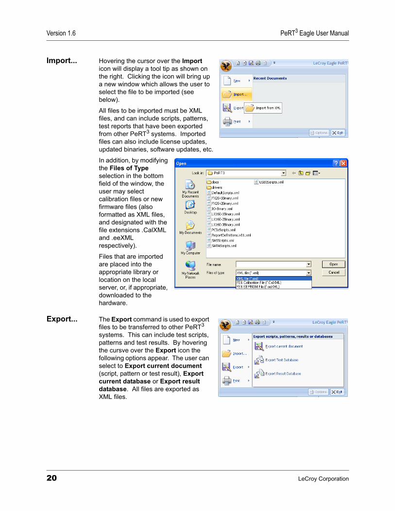
File MenuThe File Menu is accessed by clicking the round button in the top left corner of the main application window. Clicking this button produces the display shown on the right, and provides access to the commands New, Import, Export and Print.
New Hovering the cursor over the New icon display a list of commands which include the ability to create a New Test Script or to create a New Test Pattern. Clicking on these icons will create the appropriate new document in new window in the Test Development section.
LeCroy Corporation 19
Version 1.6 PeRT3 Eagle User Manual
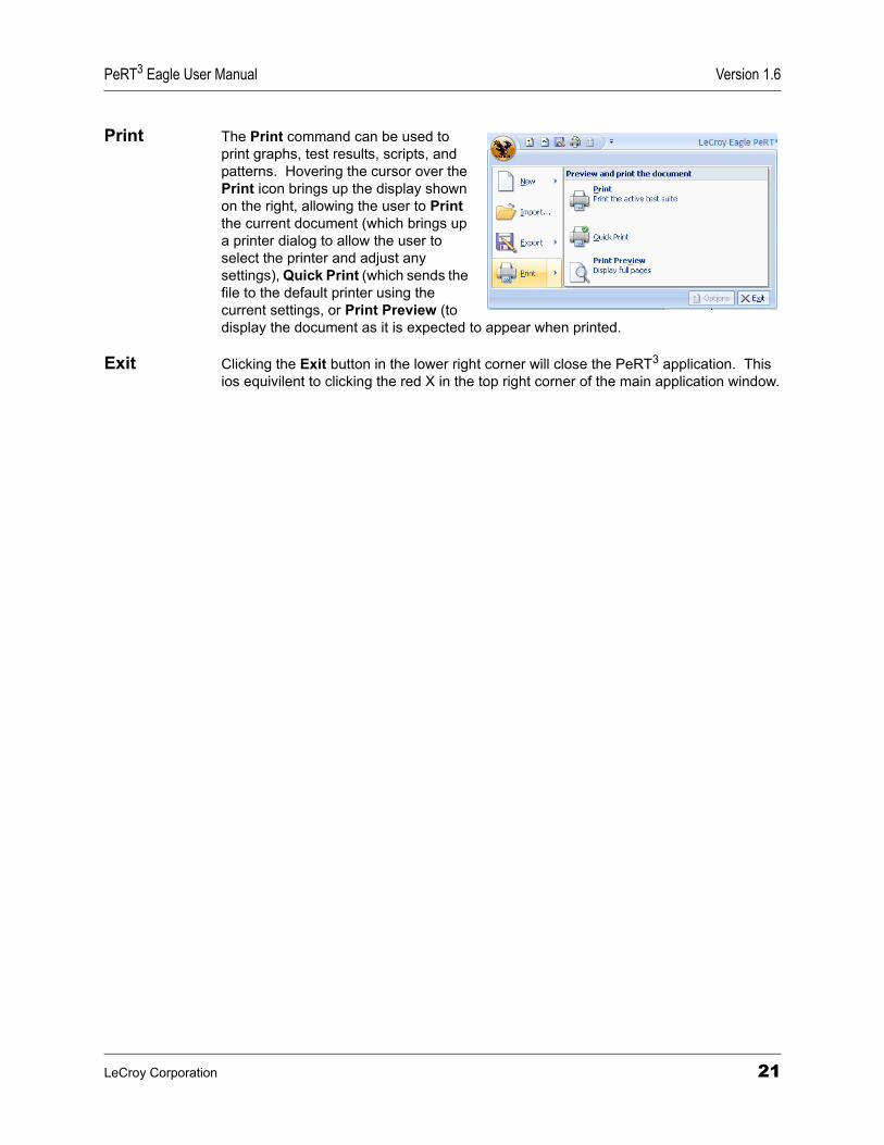
Import... Hovering the cursor over the Import icon will display a tool tip as shown on the right. Clicking the icon will bring up a new window which allows the user to select the file to be imported (see below).
All files to be imported must be XML files, and can include scripts, patterns, test reports that have been exported from other PeRT3 systems. Imported files can also include license updates, updated binaries, software updates, etc.
In addition, by modifying the Files of Type selection in the bottom field of the window, the user may select calibration files or new firmware files (also formatted as XML files, and designated with the file extensions .CalXML and .eeXML respectively).
Files that are imported are placed into the appropriate library or location on the local server, or, if appropriate, downloaded to the hardware.
Export... The Export command is used to export files to be transferred to other PeRT3 systems. This can include test scripts, patterns and test results. By hovering the cursve over the Export icon the following options appear. The user can select to Export current document (script, pattern or test result), Export current database or Export result database. All files are exported as XML files.
20 LeCroy Corporation
PeRT3 Eagle User Manual Version 1.6
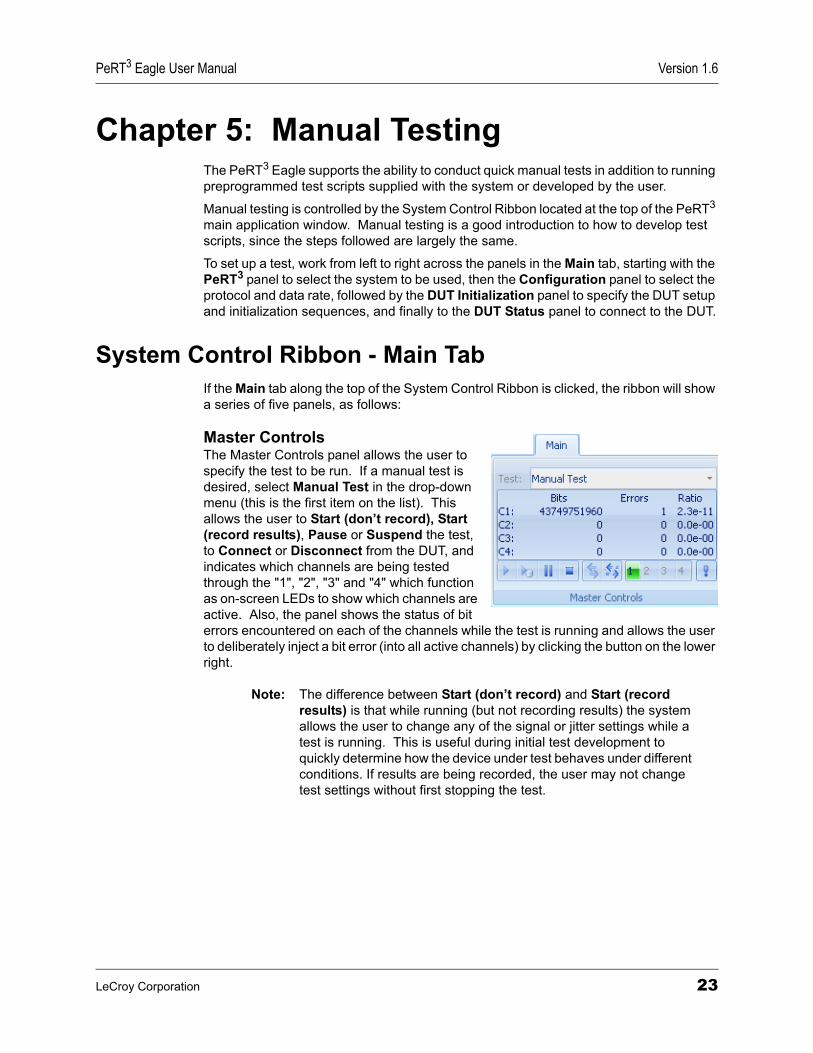
Print The Print command can be used to print graphs, test results, scripts, and patterns. Hovering the cursor over the Print icon brings up the display shown on the right, allowing the user to Print the current document (which brings up a printer dialog to allow the user to select the printer and adjust any settings), Quick Print (which sends the file to the default printer using the current settings, or Print Preview (to display the document as it is expected to appear when printed.
Exit Clicking the Exit button in the lower right corner will close the PeRT3 application. This ios equivilent to clicking the red X in the top right corner of the main application window.
LeCroy Corporation 21

Version 1.6 PeRT3 Eagle User Manual
22 LeCroy Corporation
PeRT3 Eagle User Manual Version 1.6
Chapter 5: Manual TestingThe PeRT3 Eagle supports the ability to conduct quick manual tests in addition to running preprogrammed test scripts supplied with the system or developed by the user.
Manual testing is controlled by the System Control Ribbon located at the top of the PeRT3 main application window. Manual testing is a good introduction to how to develop test scripts, since the steps followed are largely the same.
To set up a test, work from left to right across the panels in the Main tab, starting with the PeRT3 panel to select the system to be used, then the Configuration panel to select the protocol and data rate, followed by the DUT Initialization panel to specify the DUT setup and initialization sequences, and finally to the DUT Status panel to connect to the DUT.
System Control Ribbon - Main TabIf the Main tab along the top of the System Control Ribbon is clicked, the ribbon will show a series of five panels, as follows:
Master ControlsThe Master Controls panel allows the user to specify the test to be run. If a manual test is desired, select Manual Test in the drop-down menu (this is the first item on the list). This allows the user to Start (don’t record), Start (record results), Pause or Suspend the test, to Connect or Disconnect from the DUT, and indicates which channels are being tested through the "1", "2", "3" and "4" which function as on-screen LEDs to show which channels are active. Also, the panel shows the status of bit errors encountered on each of the channels while the test is running and allows the user to deliberately inject a bit error (into all active channels) by clicking the button on the lower right.
Note: The difference between Start (don’t record) and Start (record results) is that while running (but not recording results) the system allows the user to change any of the signal or jitter settings while a test is running. This is useful during initial test development to quickly determine how the device under test behaves under different conditions. If results are being recorded, the user may not change test settings without first stopping the test.
LeCroy Corporation 23
Version 1.6 PeRT3 Eagle User Manual
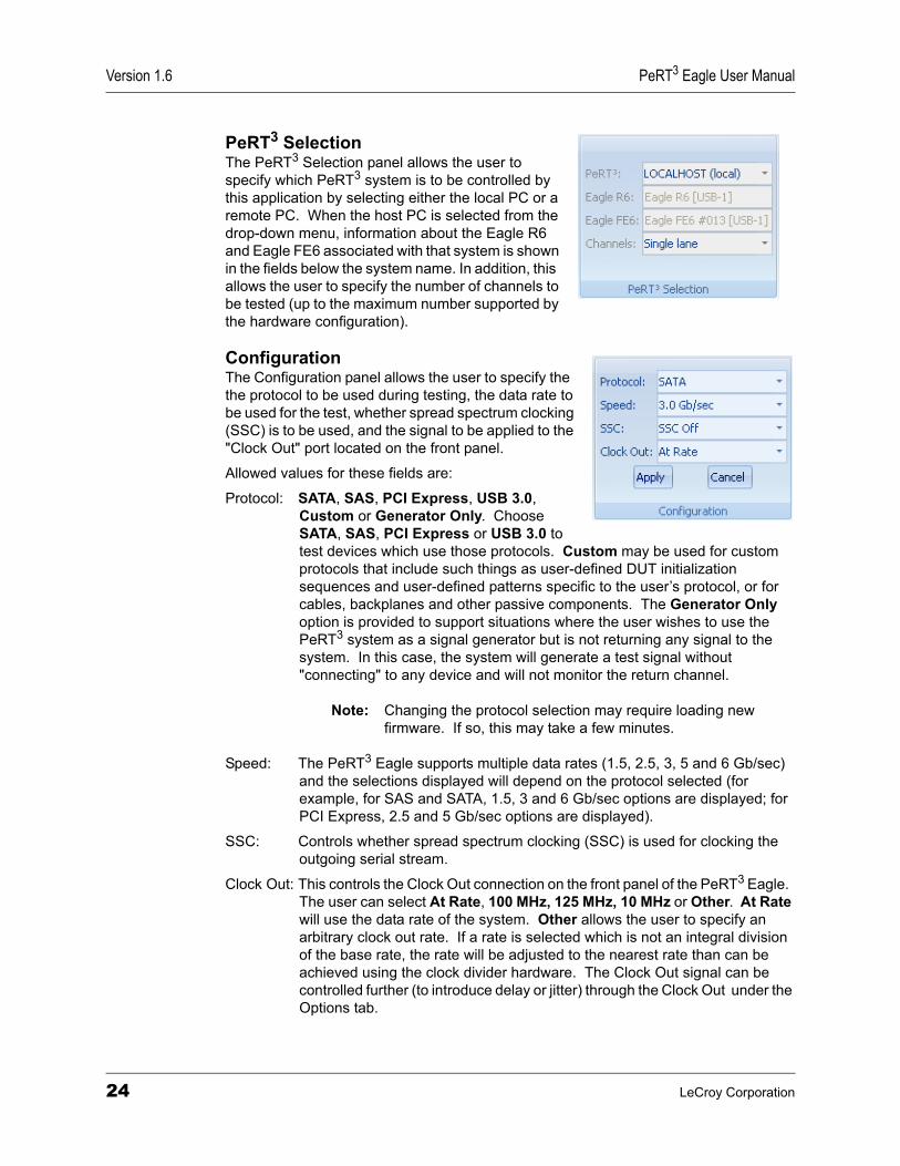
PeRT3 SelectionThe PeRT3 Selection panel allows the user to specify which PeRT3 system is to be controlled by this application by selecting either the local PC or a remote PC. When the host PC is selected from the drop-down menu, information about the Eagle R6 and Eagle FE6 associated with that system is shown in the fields below the system name. In addition, this allows the user to specify the number of channels to be tested (up to the maximum number supported by the hardware configuration).
ConfigurationThe Configuration panel allows the user to specify the the protocol to be used during testing, the data rate to be used for the test, whether spread spectrum clocking (SSC) is to be used, and the signal to be applied to the "Clock Out" port located on the front panel.
Allowed values for these fields are:
Protocol: SATA, SAS, PCI Express, USB 3.0, Custom or Generator Only. Choose SATA, SAS, PCI Express or USB 3.0 to test devices which use those protocols. Custom may be used for custom protocols that include such things as user-defined DUT initialization sequences and user-defined patterns specific to the user’s protocol, or for cables, backplanes and other passive components. The Generator Only option is provided to support situations where the user wishes to use the PeRT3 system as a signal generator but is not returning any signal to the system. In this case, the system will generate a test signal without "connecting" to any device and will not monitor the return channel.
Note: Changing the protocol selection may require loading new firmware. If so, this may take a few minutes.
Speed: The PeRT3 Eagle supports multiple data rates (1.5, 2.5, 3, 5 and 6 Gb/sec) and the selections displayed will depend on the protocol selected (for example, for SAS and SATA, 1.5, 3 and 6 Gb/sec options are displayed; for PCI Express, 2.5 and 5 Gb/sec options are displayed).
SSC: Controls whether spread spectrum clocking (SSC) is used for clocking the outgoing serial stream.
Clock Out: This controls the Clock Out connection on the front panel of the PeRT3 Eagle. The user can select At Rate, 100 MHz, 125 MHz, 10 MHz or Other. At Rate will use the data rate of the system. Other allows the user to specify an arbitrary clock out rate. If a rate is selected which is not an integral division of the base rate, the rate will be adjusted to the nearest rate than can be achieved using the clock divider hardware. The Clock Out signal can be controlled further (to introduce delay or jitter) through the Clock Out under the Options tab.
24 LeCroy Corporation
PeRT3 Eagle User Manual Version 1.6
Changing any of these parameters does not change the system configuration until the Apply button is clicked. The two buttons (Apply and Cancel) allow the user to set a complete configuration before applying it to the system.
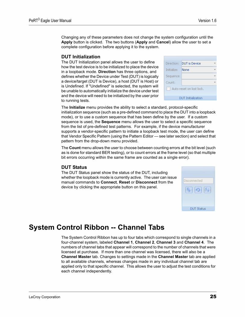
DUT InitializationThe DUT Initialization panel allows the user to define how the test device is to be initialized to place the device in a loopback mode. Direction has three options, and defines whether the Device under Test (DUT) is logically a device/target (DUT is Device), a host (DUT is Host) or is Undefined. If "Undefined" is selected, the system will be unable to automatically initialize the device under test and the device will need to be initialized by the user prior to running tests.
The Initialize menu provides the ability to select a standard, protocol-specific initialization sequence (such as a pre-defined command to place the DUT into a loopback mode), or to use a custom sequence that has been define by the user. If a custom sequence is used, the Sequence menu allows the user to select a specific sequence from the list of pre-defined test patterns. For example, if the device manufacturer supports a vendor-specific pattern to initiate a loopback test mode, the user can define that Vendor Specific Pattern (using the Pattern Editor — see later section) and select that pattern from the drop-down menu provided.
The Count menu allows the user to choose between counting errors at the bit level (such as is done for standard BER testing), or to count errors at the frame level (so that multiple bit errors occurring within the same frame are counted as a single error).
DUT StatusThe DUT Status panel show the status of the DUT, including whether the loopback mode is currently active. The user can issue manual commands to Connect, Reset or Disconnect from the device by clicking the appropriate button on this panel.
System Control Ribbon -- Channel TabsThe System Control Ribbon has up to four tabs which correspond to single channels in a four-channel system, labeled Channel 1, Channel 2, Channel 3 and Channel 4. The numbers of channel tabs that appear will correspond to the number of channels that were licensed at purchase. If more than one channel was licensed, there will also be a Channel Master tab. Changes to settings made in the Channel Master tab are applied to all available channels, whereas changes made in any individual channel tab are applied only to that specific channel. This allows the user to adjust the test conditions for each channel independently.
LeCroy Corporation 25
Version 1.6 PeRT3 Eagle User Manual
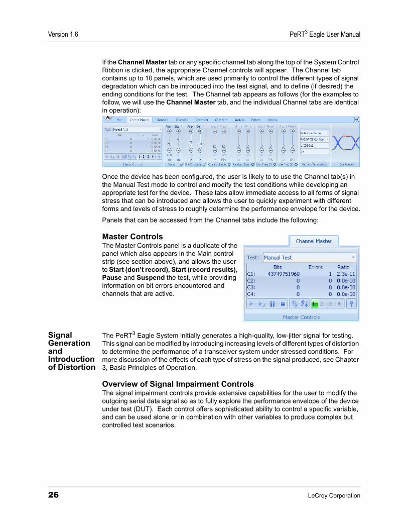
If the Channel Master tab or any specific channel tab along the top of the System Control Ribbon is clicked, the appropriate Channel controls will appear. The Channel tab contains up to 10 panels, which are used primarily to control the different types of signal degradation which can be introduced into the test signal, and to define (if desired) the ending conditions for the test. The Channel tab appears as follows (for the examples to follow, we will use the Channel Master tab, and the individual Channel tabs are identical in operation):
Once the device has been configured, the user is likely to to use the Channel tab(s) in the Manual Test mode to control and modify the test conditions while developing an appropriate test for the device. These tabs allow immediate access to all forms of signal stress that can be introduced and allows the user to quickly experiment with different forms and levels of stress to roughly determine the performance envelope for the device.
Panels that can be accessed from the Channel tabs include the following:
Master ControlsThe Master Controls panel is a duplicate of the panel which also appears in the Main control strip (see section above), and allows the user to Start (don’t record), Start (record results), Pause and Suspend the test, while providing information on bit errors encountered and channels that are active.
Signal Generation and Introduction of Distortion
The PeRT3 Eagle System initially generates a high-quality, low-jitter signal for testing. This signal can be modified by introducing increasing levels of different types of distortion to determine the performance of a transceiver system under stressed conditions. For more discussion of the effects of each type of stress on the signal produced, see Chapter 3, Basic Principles of Operation.
Overview of Signal Impairment ControlsThe signal impairment controls provide extensive capabilities for the user to modify the outgoing serial data signal so as to fully explore the performance envelope of the device under test (DUT). Each control offers sophisticated ability to control a specific variable, and can be used alone or in combination with other variables to produce complex but controlled test scenarios.
26 LeCroy Corporation
PeRT3 Eagle User Manual Version 1.6
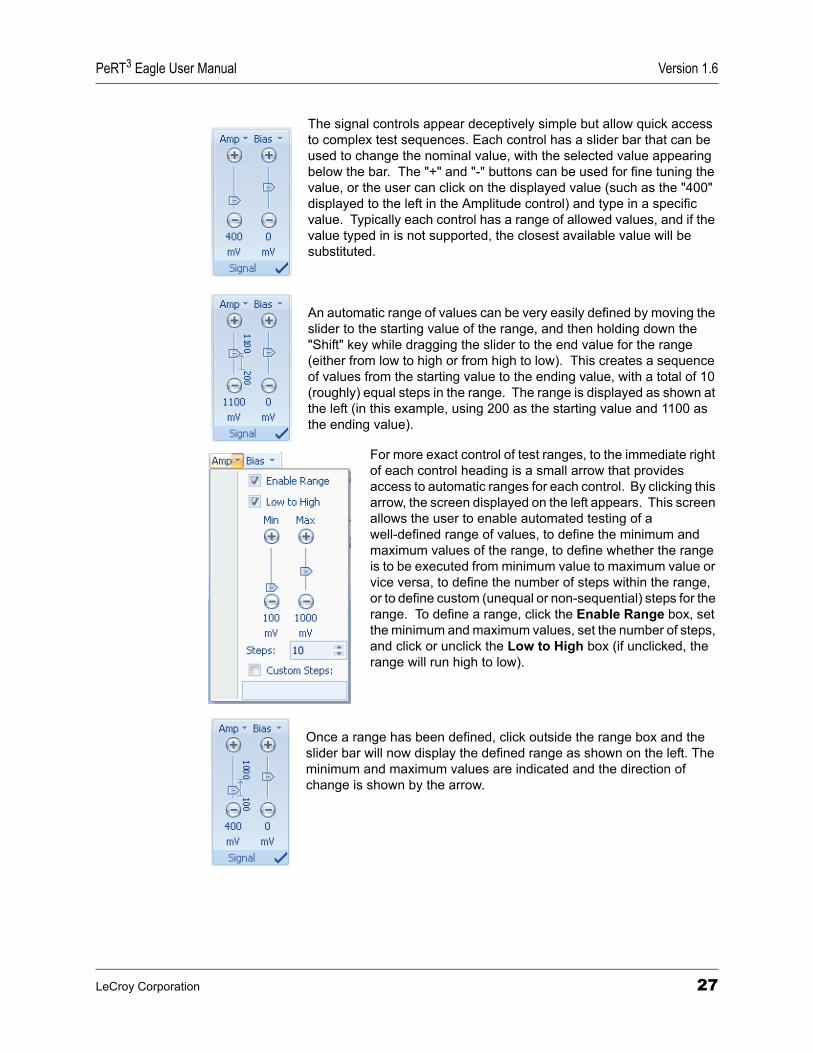
The signal controls appear deceptively simple but allow quick access to complex test sequences. Each control has a slider bar that can be used to change the nominal value, with the selected value appearing below the bar. The "+" and "-" buttons can be used for fine tuning the value, or the user can click on the displayed value (such as the "400" displayed to the left in the Amplitude control) and type in a specific value. Typically each control has a range of allowed values, and if the value typed in is not supported, the closest available value will be substituted.
An automatic range of values can be very easily defined by moving the slider to the starting value of the range, and then holding down the "Shift" key while dragging the slider to the end value for the range (either from low to high or from high to low). This creates a sequence of values from the starting value to the ending value, with a total of 10 (roughly) equal steps in the range. The range is displayed as shown at the left (in this example, using 200 as the starting value and 1100 as the ending value).
For more exact control of test ranges, to the immediate right of each control heading is a small arrow that provides access to automatic ranges for each control. By clicking this arrow, the screen displayed on the left appears. This screen allows the user to enable automated testing of a well-defined range of values, to define the minimum and maximum values of the range, to define whether the range is to be executed from minimum value to maximum value or vice versa, to define the number of steps within the range, or to define custom (unequal or non-sequential) steps for the range. To define a range, click the Enable Range box, set the minimum and maximum values, set the number of steps, and click or unclick the Low to High box (if unclicked, the range will run high to low).
Once a range has been defined, click outside the range box and the slider bar will now display the defined range as shown on the left. The minimum and maximum values are indicated and the direction of change is shown by the arrow.
LeCroy Corporation 27
Version 1.6 PeRT3 Eagle User Manual
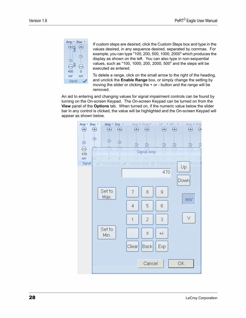
If custom steps are desired, click the Custom Steps box and type in the values desired, in any sequence desired, separated by commas. For example, you can type "100, 200, 500, 1000, 2000" which produces the display as shown on the left. You can also type in non-sequential values, such as "100, 1000, 200, 2000, 500" and the steps will be executed as entered.
To delete a range, click on the small arrow to the right of the heading, and unclick the Enable Range box, or simply change the setting by moving the slider or clicking the + or - button and the range will be removed.
An aid to entering and changing values for signal impairment controls can be found by turning on the On-screen Keypad. The On-screen Keypad can be turned on from the View panel of the Options tab. When turned on, if the numeric value below the slider bar in any control is clicked, the value will be highlighted and the On-screen Keypad will appear as shown below.
28 LeCroy Corporation

PeRT3 Eagle User Manual Version 1.6
SignalThe Signal panel allows the user to control the amplitude and bias of the differential signal. By default, the Signal panel is inactive (turned off) when the system is first turned on, as shown by the circle in the lower right corner of the panel. Before any testing can take place, the user must turn this on (click to change to a check mark) and specify the desired signal characteristics.
Signal amplitude (Amp) can be controlled over the range from 100 mV to 2200 mV in increments of 5 mV. Signal amplitude is the nominal voltage of the differential signal, and is a measure of the overall signal power. Low signal amplitude can be used to test for the limits of receiver sensitivity (additional losses due to connectors and cables should be taken into account). High signal amplitudes can be used to test for receiver saturation or even damage limits to electronics.
Signal bias can be controlled over the range -1800 mV to +1800 mV in increments of 5 mV. Signal bias is the offset (from ground) that is applied to the differential signal, or in other words, the DC component of the signal.
Note: All signal impairment controls are turned off by default. All controls must first be turned on by clicking the circle in the bottom right corner of each panel. When the control is active, the circle will change to a check mark
Pre-EmphasisThe Pre-Emphasis panel allows the user to control the amplitude and duration of the pre-emphasis applied to the signal. By default, Pre-Emphasis is turned off.
Pre-emphasis amplitude (Amp) can be controlled over the range 0 to 15 (nominal values). Pre-emphasis amplitude is used to adjust the amplitude of the overshoot and undershoot on transitions, and can be manually adjusted (while examining the signal on an oscilloscope) to obtain a desired waveform. Pre-emphasis is not usually needed if the SMA cables connecting to the DUT are short and trace lengths on any test fixtures used are minimal.
Pre-emphasis duration ("Dur") can be controlled over the range from 0 to 15 (again, nominal values). Pre-emphasis duration is used in combination with pre-emphasis amplitude to control the overshoot on electrical transitions in the bit stream.
LeCroy Corporation 29

Version 1.6 PeRT3 Eagle User Manual
Random JitterThe Random Jitter panel allows the user to introduce and control random jitter into the signal.
Random jitter can be low frequency (LF), high frequency (HF) or a combination of the two. Random jitter (either LF or HF) can be controlled over the range from a minimum available value (established by calibration of the system) to 12 ps in increments of 0.1 ps. The value selected is the root-mean-square (RMS) of the jitter introduced.
When used in this context, jitter is the variation in pulse position in the time domain. In an ideal jitter-free system, each electrical transition would occur at precise intervals defined by the data rate of the bit stream (e.g., 6 Gb/sec). In practice, there is always some level of jitter as subsequent pulse edges vary slightly from the ideal, and as this variation becomes appreciable relative to the length of each pulse, the receiver has more challenge to correctly determine the value of the bit.
Since random jitter is specified in picoseconds (ps), the degree to which the bit stream is degraded through the introduction of random jitter will also depend on the data rate. For a data rate of 1.5 Gb/sec, the width of each bit is 667 ps, so an RMS jitter of 6 ps would introduce an average variation of approximately 1% of the pulse width (or unit interval). For a data rate of 6 Gb/sec, the pulse width is 167 ps, and the same 6 ps RMS jitter is an average variation of approximately 4% of the pulse width (or unit interval).
The random jitter is generated by a physical noise source with a roughly Gaussian distribution, so while the RMS of the random jitter to 4% of the unit interval, a small number of transitions will have considerably larger jitter. On average one in a trillion (1012) transitions will have 14 times as much jitter (or 56% of the unit interval in the case of 4% RMS).
The Low Frequency Random Jitter is generated by passing the random source through a low pass filter as called for in the PCIe compliance specification. The resulting jitter is bandwidth limited and will not necessarily be measured as "random" jitter on many scopes or other jitter measurement tools and packages that define random jitter as jitter with a flat frequency spectrum and use frequency analysis to separate random jitter from deterministic jitter. The High Frequency Random Jitter source, on the other hand, is not frequency limited and will appear as random jitter when measured by such instruments.
30 LeCroy Corporation
PeRT3 Eagle User Manual Version 1.6
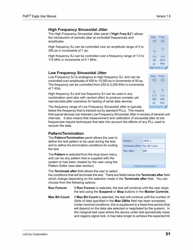
High Frequency Sinusoidal JitterThe High Frequency Sinusoidal Jitter panel ("High Freq SJ") allows the introduction of periodic jitter at controlled frequencies and amplitudes.
High frequency SJ can be controlled over an amplitude range of 0 to 290 ps in increments of 1 ps.
High frequency SJ can be controlled over a frequency range of 1.0 to 115 MHz in increments of 0.1 MHz.
Low Frequency Sinusoidal JitterLow Frequency SJ is analogous to high frequency SJ, and can be controlled over amplitudes of 400 to 10,000 ps in increments of 50 ps. The frequency can be controlled from 250 to 2,000 KHz in increments of 1 KHz.
High frequency SJ and low frequency SJ can be used in any combination (and also with random jitter) to produce complex yet reproducible jitter scenarios for testing of serial data devices.
The frequency range of Low Frequency Sinusoidal Jitter is typically below the frequency that is tracked out by standard PLLs. This means that typical devices can tolerate Low Frequency Sinusoidal Jitter in excess of several unit intervals. It also means that measurement and calibration of sinusoidal jitter at low frequencies require techniques that take into account the effects of any PLL used to recover the data.
Pattern/TerminationThe Pattern/Termination panel allows the user to define the test pattern to be used during the test, and to define the termination conditions for ending the test.
The Pattern is selected from the drop-down menu, and can be any pattern that is supplied with the system or has been created by the user using the Pattern Editor (see later section).
The Terminate after field allows the user to select the conditions that will terminate the test. There are fields below the Terminate after field which change depending on the selection made in the Terminate after field. You can choose from the following options:
Run Forever If Run Forever is selected, the test will continue until the user stops the test using the Suspend or Stop buttons in the Master Controls .
Max Bit Count If Max Bit Count is selected, the test will continue until the number of Gbits of data specified in the Max GBits field has been exceeded. Under nominal conditions, this is equilavent to a fixed time period (that will depend on the data rate selected or negotiated by the system). In the marginal test case where the device under test sporadically loses and regains signal lock, it may take longer to achieve the expected bit
LeCroy Corporation 31
Version 1.6 PeRT3 Eagle User Manual
count than the equivalent time period. In the event the device totally loses signal lock and stops transmitting, the test case will eventually time out even if the maximum bit count is never achieved.
Elapsed Time If Elapsed Time is selected, the test will continue for the time specified, then terminate.
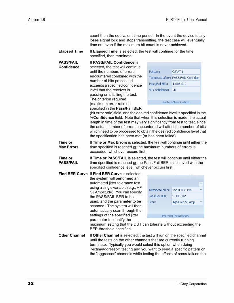
PASS/FAIL If PASS/FAIL Confidence isConfidence selected, the test will continue
until the numbers of errors encountered combined with the number of bits processed exceeds a specified confidence level that the receiver is passing or is failing the test. The criterion required (maximum error ratio) is specified in the Pass/Fail BER (bit error ratio) field, and the desired confidence level is specified in the %Confidence field. Note that when this selection is made, the actual length in time of the test may vary significantly from test to test, since the actual number of errors encountered will affect the number of bits which need to be processed to obtain the desired confidence level that the specification has been met (or has been failed).
Time or If Time or Max Errors is selected, the test will continue until either theMax Errors time specified is reached or the maximum numbers of errors is
exceeded, whichever occurs first.
Time or If Time or PASS/FAIL is selected, the test will continue until either thePASS/FAIL time specified is reached or the Pass/Fail BER is achieved with the
specified confidence level, whichever occurs first.
Find BER Curve If Find BER Curve is selected, the system will performed an automated jitter tolerance test using a single variable (e.g., HF SJ Amplitude). You can specify the PASS/FAIL BER to be used, and the parameter to be scanned. The system will then automatically scan through the settings of the specified jitter parameter to identify the maximum setting that the DUT can tolerate without exceeding the BER threshold specified.
Other Channel If Other Channel is selected, the test will run on the specified channel until the tests on the other channels that are currently running terminate. Typically you would select this option when doing "victim/aggressor" testing and you want to send a specific pattern on the "aggressor" channels while testing the effects of cross-talk on the
32 LeCroy Corporation
PeRT3 Eagle User Manual Version 1.6
"victim" channel. At least one active channel should have a specific termination criteria. Setting all channels to terminate on Other Channel would be the equivalent of specifying Run Forever.
Note: The test termination conditions can be channel-specific. If different termination conditions are selected on different channels, the test will continue to run until all termination conditions on all channels have been met.
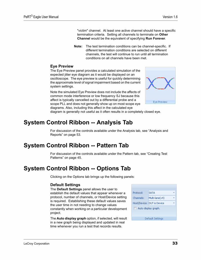
Eye PreviewThe Eye Preview panel provides a calculated simulation of the expected jitter eye diagram as it would be displayed on an oscilloscope. The eye preview is useful for quickly determining the approximate level of signal impairment based on the current system settings.
Note the simulated Eye Preview does not include the affects of common mode interference or low frequency SJ because this affect is typically cancelled out by a differential probe and a scope PLL and does not generally show up on most scope eye diagrams. Also, including this affect in the calculated eye diagram is generally not useful as it often results in a completely closed eye.
System Control Ribbon -- Analysis TabFor discussion of the controls available under the Analysis tab, see “Analysis and Reports” on page 53.
System Control Ribbon -- Pattern TabFor discussion of the controls available under the Pattern tab, see “Creating Test Patterns” on page 45.
System Control Ribbon -- Options TabClicking on the Options tab brings up the following panels:
Default SettingsThe Default Settings panel allows the user to establish the default values that appear whenever a protocol, number of channels, or Host/Device setting is required. Establishing these default values saves the user time in not needing to change values constantly when working on a particular development project.
The Auto display graph option, if selected, will result in a new graph being displayed and updated in real time whenever you run a test that records results.
LeCroy Corporation 33
Version 1.6 PeRT3 Eagle User Manual
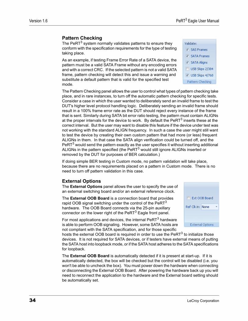
Pattern CheckingThe PeRT3 system normally validates patterns to ensure they conform with the specification requirements for the type of testing taking place.
As an example, if testing Frame Error Rate of a SATA device, the pattern must be a valid SATA Frame without any encoding errors and with a correct CRC. If the selected pattern is not a valid SATA frame, pattern checking will detect this and issue a warning and substitute a default pattern that is valid for the specified test mode.
The Pattern Checking panel allows the user to control what types of pattern checking take place, and in rare instances, to turn off the automatic pattern checking for specific tests. Consider a case in which the user wanted to deliberately send an invalid frame to test the DUT's higher level protocol handling logic. Deliberately sending an invalid frame should result in a 100% frame error rate as the DUT should reject every instance of the frame that is sent. Similarly during SATA bit error ratio testing, the pattern must contain ALIGNs at the proper intervals for the device to work. By default the PeRT3 inserts these at the correct interval. But the user may want to disable this feature if the device under test was not working with the standard ALIGN frequency. In such a case the user might still want to test the device by creating their own custom pattern that had more (or less) frequent ALIGNs in them. In that case the SATA align verification could be turned off, and the PeRT3 would send the pattern exactly as the user specifies it without inserting additional ALIGNs in the pattern specified (the PeRT3 would still ignore ALIGNs inserted or removed by the DUT for purposes of BER calculation.)
If doing simple BER testing in Custom mode, no pattern validation will take place, because there are no requirements placed on a pattern in Custom mode. There is no need to turn off pattern validation in this case.
External OptionsThe External Options panel allows the user to specify the use of an external switching board and/or an external reference clock.
The External OOB Board is a connection board that provides rapid OOB signal switching under the control of the PeRT3 hardware. The OOB Board connects via the 25-pin auxillary connector on the lower right of the PeRT3 Eagle front panel.
For most applications and devices, the internal PeRT3 hardware is able to perform OOB signaling. However, some SATA hosts are not compliant with the SATA specification, and for those specific hosts the external OOB board is required in order to use the PeRT3 to initialize those devices. It is not required for SATA devices, or if testers have external means of putting the SATA host into loopback mode, or if the SATA host adheres to the SATA specifications for loopback.
The External OOB Board is automatically detected if it is present at start-up. If it is automatically detected, the box will be checked but the control will be disabled (i.e. you won't be able to uncheck the box). You must power down the hardware when connecting or disconnecting the External OOB Board. After powering the hardware back up you will need to reconnect the application to the hardware and the External board setting should be automatically set.
34 LeCroy Corporation
PeRT3 Eagle User Manual Version 1.6
If no board is detected (either because none is present or because in some older systems the hardware doesn't support automatic detection) then the Ext OOB Board box will not be checked, but the user will be allowed to check or uncheck it to indicate the presence or absence of the board. If the board is connected it is vital that this box be checked, otherwise signal amplitude and OOB signaling will not function properly.
The Ref Clk in allows the user to provide an external clock for the system and specify the nominal frequency of this clock signal, which is supplied via the Reference Clock In connector on the back panel of the system.
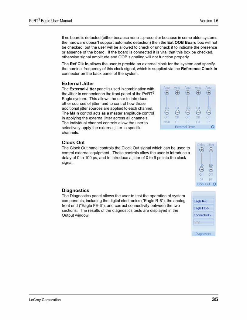
External JitterThe External Jitter panel is used in combination with the Jitter In connector on the front panel of the PeRT3 Eagle system. This allows the user to introduce other sources of jitter, and to control how those additional jitter sources are applied to each channel. The Main control acts as a master amplitude control in applying the external jitter across all channels. The individual channel controls allow the user to selectively apply the external jitter to specific channels.
Clock OutThe Clock Out panel controls the Clock Out signal which can be used to control external equipment. These controls allow the user to introduce a delay of 0 to 100 ps, and to introduce a jitter of 0 to 6 ps into the clock signal.
DiagnosticsThe Diagnostics panel allows the user to test the operation of system components, including the digital electronics ("Eagle R-6"), the analog front end ("Eagle FE-6"), and correct connectivity between the two sections. The results of the diagnostics tests are displayed in the Output window.
LeCroy Corporation 35
Version 1.6 PeRT3 Eagle User Manual
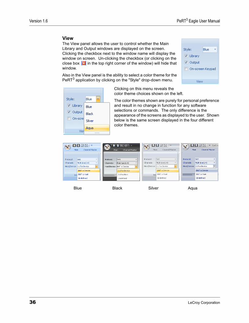
ViewThe View panel allows the user to control whether the Main Library and Output windows are displayed on the screen. Clicking the checkbox next to the window name will display the window on screen. Un-clicking the checkbox (or clicking on the close box in the top right corner of the window) will hide that window.
Also in the View panel is the ability to select a color theme for the PeRT3 application by clicking on the "Style" drop-down menu.
Clicking on this menu reveals the color theme choices shown on the left.
The color themes shown are purely for personal preference and result in no change in function for any software selections or commands. The only difference is the appearance of the screens as displayed to the user. Shown below is the same screen displayed in the four different color themes.
Blue Black Silver Aqua
36 LeCroy Corporation
PeRT3 Eagle User Manual Version 1.6
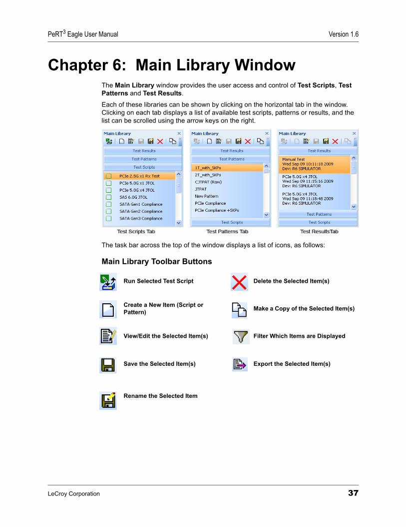
Chapter 6: Main Library WindowThe Main Library window provides the user access and control of Test Scripts, Test Patterns and Test Results.
Each of these libraries can be shown by clicking on the horizontal tab in the window. Clicking on each tab displays a list of available test scripts, patterns or results, and the list can be scrolled using the arrow keys on the right.
The task bar across the top of the window displays a list of icons, as follows:
Main Library Toolbar Buttons
Run Selected Test Script Delete the Selected Item(s)
Create a New Item (Script or Pattern) Make a Copy of the Selected Item(s)
View/Edit the Selected Item(s) Filter Which Items are Displayed
Save the Selected Item(s) Export the Selected Item(s)
Rename the Selected Item
LeCroy Corporation 37
Version 1.6 PeRT3 Eagle User Manual
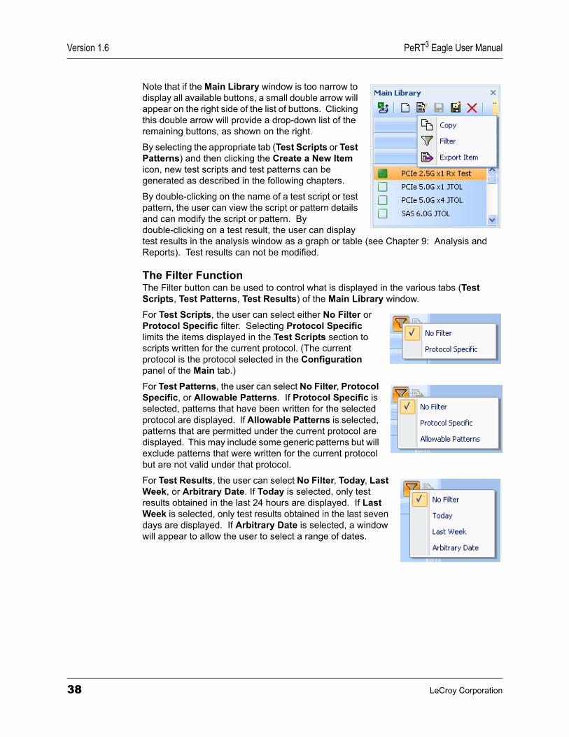
Note that if the Main Library window is too narrow to display all available buttons, a small double arrow will appear on the right side of the list of buttons. Clicking this double arrow will provide a drop-down list of the remaining buttons, as shown on the right.
By selecting the appropriate tab (Test Scripts or Test Patterns) and then clicking the Create a New Item icon, new test scripts and test patterns can be generated as described in the following chapters.
By double-clicking on the name of a test script or test pattern, the user can view the script or pattern details and can modify the script or pattern. By double-clicking on a test result, the user can display test results in the analysis window as a graph or table (see Chapter 9: Analysis and Reports). Test results can not be modified.
The Filter FunctionThe Filter button can be used to control what is displayed in the various tabs (Test Scripts, Test Patterns, Test Results) of the Main Library window.
For Test Scripts, the user can select either No Filter or Protocol Specific filter. Selecting Protocol Specific limits the items displayed in the Test Scripts section to scripts written for the current protocol. (The current protocol is the protocol selected in the Configuration panel of the Main tab.)
For Test Patterns, the user can select No Filter, Protocol Specific, or Allowable Patterns. If Protocol Specific is selected, patterns that have been written for the selected protocol are displayed. If Allowable Patterns is selected, patterns that are permitted under the current protocol are displayed. This may include some generic patterns but will exclude patterns that were written for the current protocol but are not valid under that protocol.
For Test Results, the user can select No Filter, Today, Last Week, or Arbitrary Date. If Today is selected, only test results obtained in the last 24 hours are displayed. If Last Week is selected, only test results obtained in the last seven days are displayed. If Arbitrary Date is selected, a window will appear to allow the user to select a range of dates.
38 LeCroy Corporation
PeRT3 Eagle User Manual Version 1.6
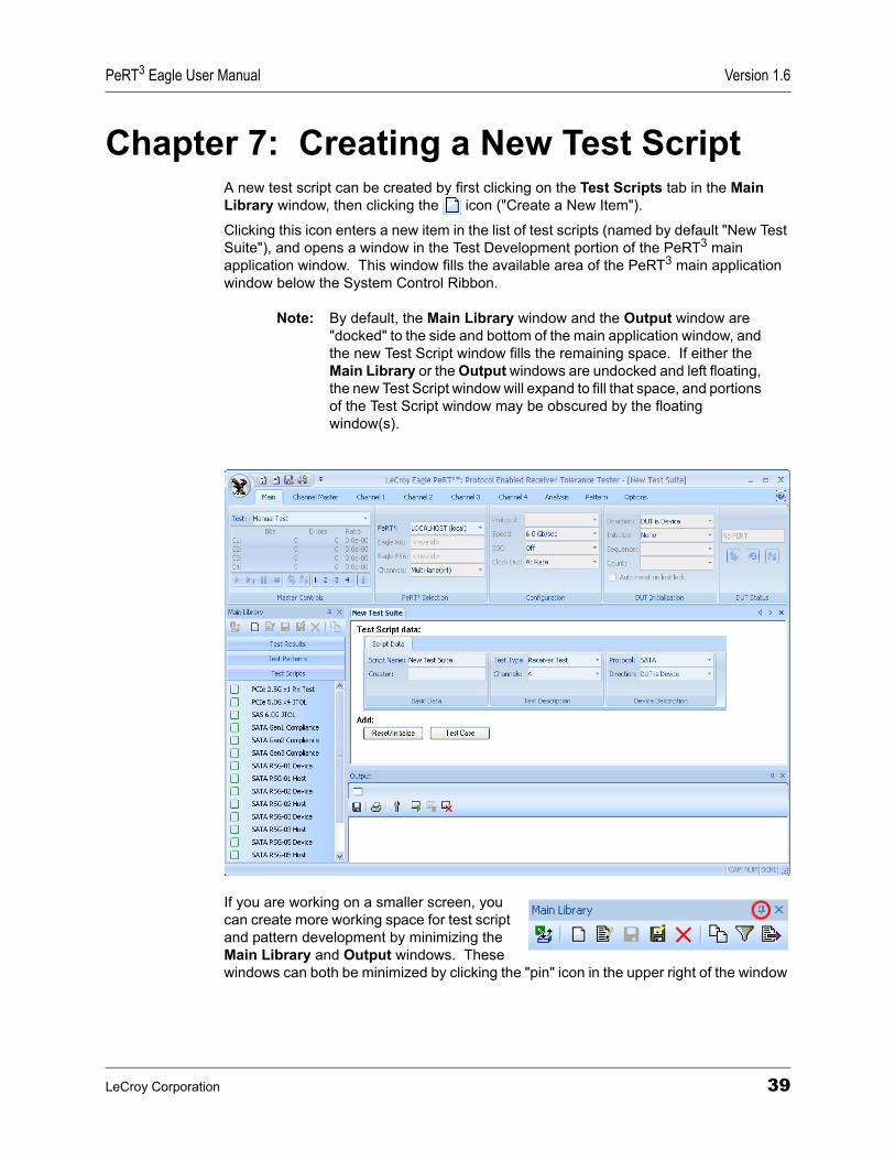
Chapter 7: Creating a New Test ScriptA new test script can be created by first clicking on the Test Scripts tab in the Main Library window, then clicking the icon ("Create a New Item").
Clicking this icon enters a new item in the list of test scripts (named by default "New Test Suite"), and opens a window in the Test Development portion of the PeRT3 main application window. This window fills the available area of the PeRT3 main application window below the System Control Ribbon.
Note: By default, the Main Library window and the Output window are "docked" to the side and bottom of the main application window, and the new Test Script window fills the remaining space. If either the Main Library or the Output windows are undocked and left floating, the new Test Script window will expand to fill that space, and portions of the Test Script window may be obscured by the floating window(s).
If you are working on a smaller screen, you can create more working space for test script and pattern development by minimizing the Main Library and Output windows. These windows can both be minimized by clicking the "pin" icon in the upper right of the window
LeCroy Corporation 39
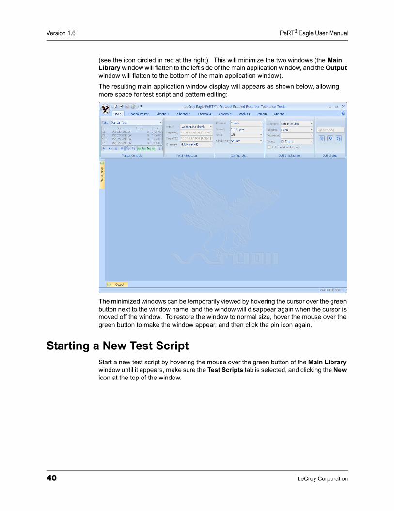
Version 1.6 PeRT3 Eagle User Manual
(see the icon circled in red at the right). This will minimize the two windows (the Main Library window will flatten to the left side of the main application window, and the Output window will flatten to the bottom of the main application window).
The resulting main application window display will appears as shown below, allowing more space for test script and pattern editing:
The minimized windows can be temporarily viewed by hovering the cursor over the green button next to the window name, and the window will disappear again when the cursor is moved off the window. To restore the window to normal size, hover the mouse over the green button to make the window appear, and then click the pin icon again.
Starting a New Test ScriptStart a new test script by hovering the mouse over the green button of the Main Library window until it appears, make sure the Test Scripts tab is selected, and clicking the New icon at the top of the window.
40 LeCroy Corporation
PeRT3 Eagle User Manual Version 1.6
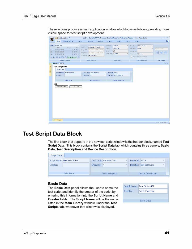
These actions produce a main application window which looks as follows, providing more visible space for test script development:
Test Script Data BlockThe first block that appears in the new test script window is the header block, named Test Script Data. This block contains the Script Data tab, which contains three panels, Basic Data, Test Description and Device Description.
Basic Data The Basic Data panel allows the user to name the test script and identify the creator of the script by entering this information into the Script Name and Creator fields. The Script Name will be the name listed in the Main Library window, under the Test Scripts tab, whenever that window is displayed.
LeCroy Corporation 41
Version 1.6 PeRT3 Eagle User Manual
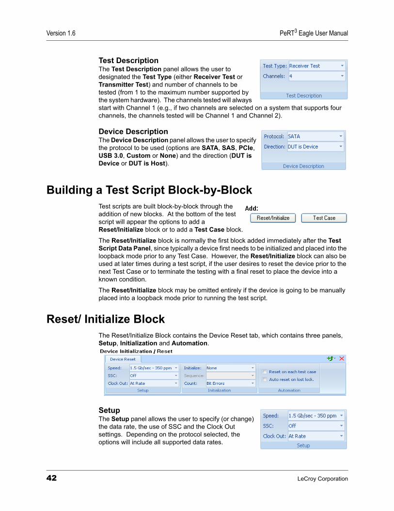
Test Description The Test Description panel allows the user to designated the Test Type (either Receiver Test or Transmitter Test) and number of channels to be tested (from 1 to the maximum number supported by the system hardware). The channels tested will always start with Channel 1 (e.g., if two channels are selected on a system that supports four channels, the channels tested will be Channel 1 and Channel 2).
Device Description The Device Description panel allows the user to specify the protocol to be used (options are SATA, SAS, PCIe, USB 3.0, Custom or None) and the direction (DUT is Device or DUT is Host).
Building a Test Script Block-by-BlockTest scripts are built block-by-block through the addition of new blocks. At the bottom of the test script will appear the options to add a Reset/Initialize block or to add a Test Case block.
The Reset/Initialize block is normally the first block added immediately after the Test Script Data Panel, since typically a device first needs to be initialized and placed into the loopback mode prior to any Test Case. However, the Reset/Initialize block can also be used at later times during a test script, if the user desires to reset the device prior to the next Test Case or to terminate the testing with a final reset to place the device into a known condition.
The Reset/Initialize block may be omitted entirely if the device is going to be manually placed into a loopback mode prior to running the test script.
Reset/ Initialize BlockThe Reset/Initialize Block contains the Device Reset tab, which contains three panels, Setup, Initialization and Automation.
Setup The Setup panel allows the user to specify (or change) the data rate, the use of SSC and the Clock Out settings. Depending on the protocol selected, the options will include all supported data rates.
42 LeCroy Corporation
PeRT3 Eagle User Manual Version 1.6
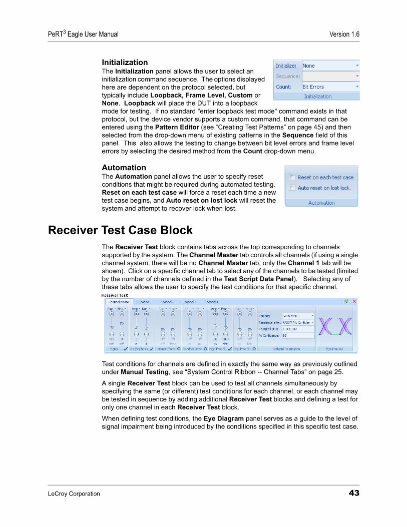
Initialization The Initialization panel allows the user to select an initialization command sequence. The options displayed here are dependent on the protocol selected, but typically include Loopback, Frame Level, Custom or None. Loopback will place the DUT into a loopback mode for testing. If no standard "enter loopback test mode" command exists in that protocol, but the device vendor supports a custom command, that command can be entered using the Pattern Editor (see “Creating Test Patterns” on page 45) and then selected from the drop-down menu of existing patterns in the Sequence field of this panel. This also allows the testing to change between bit level errors and frame level errors by selecting the desired method from the Count drop-down menu.
Automation The Automation panel allows the user to specify reset conditions that might be required during automated testing. Reset on each test case will force a reset each time a new test case begins, and Auto reset on lost lock will reset the system and attempt to recover lock when lost.
Receiver Test Case BlockThe Receiver Test block contains tabs across the top corresponding to channels supported by the system. The Channel Master tab controls all channels (if using a single channel system, there will be no Channel Master tab, only the Channel 1 tab will be shown). Click on a specific channel tab to select any of the channels to be tested (limited by the number of channels defined in the Test Script Data Panel). Selecting any of these tabs allows the user to specify the test conditions for that specific channel.
Test conditions for channels are defined in exactly the same way as previously outlined under Manual Testing, see “System Control Ribbon -- Channel Tabs” on page 25.
A single Receiver Test block can be used to test all channels simultaneously by specifying the same (or different) test conditions for each channel, or each channel may be tested in sequence by adding additional Receiver Test blocks and defining a test for only one channel in each Receiver Test block.
When defining test conditions, the Eye Diagram panel serves as a guide to the level of signal impairment being introduced by the conditions specified in this specific test case.
LeCroy Corporation 43
Version 1.6 PeRT3 Eagle User Manual
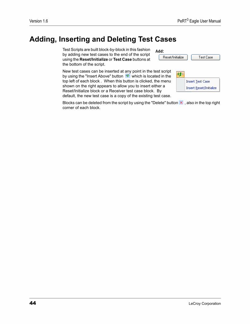
Adding, Inserting and Deleting Test CasesTest Scripts are built block-by-block in this fashion by adding new test cases to the end of the script using the Reset/Initialize or Test Case buttons at the bottom of the script.
New test cases can be inserted at any point in the test script by using the "Insert Above" button which is located in the top left of each block . When this button is clicked, the menu shown on the right appears to allow you to insert either a Reset/Initialize block or a Receiver test case block. By default, the new test case is a copy of the existing test case.
Blocks can be deleted from the script by using the "Delete" button , also in the top right corner of each block.
44 LeCroy Corporation
PeRT3 Eagle User Manual Version 1.6
Chapter 8: Creating Test PatternsThe PeRT3 Eagle System includes a library of predefined test patterns, that for many users may fully satisfy their requirements.
Some users may wish to create additional test patterns or to modify the patterns supplied with the system. A simple example of the need to create a test pattern is when the user’s device has a vendor-specific command which is required to place the device into a test loopback mode. In this case, the vendor-specific command can be created using the Pattern Editor and then selected in the DUT Initialization panel of the Main tab in the System Control Ribbon (see “DUT Initialization” on page 25).
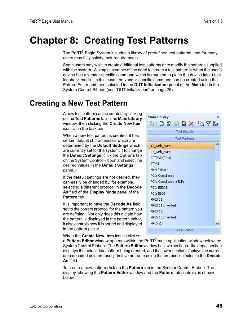
Creating a New Test PatternA new test pattern can be created by clicking on the Test Patterns tab in the Main Library window, then clicking the Create New Item icon in the task bar.
When a new test pattern is created, it has certain default characteristics which are determined by the Default Settings which are currently set for the system. (To change the Default Settings, click the Options tab on the System Control Ribbon and select the desired values in the Default Settings panel.)
If the default settings are not desired, they can easily be changed by, for example, selecting a different protocol in the Decode As field of the Display Mode panel of the Pattern tab.
It is important to have the Decode As field set to the correct protocol for the pattern you are defining. Not only does this dictate how the pattern is displayed in the pattern editor, it also controls how it is sorted and displayed in the pattern picker.
When the Create New Item icon is clicked, a Pattern Editor window appears within the PeRT3 main application window below the System Control Ribbon. The Pattern Editor window has two sections: the upper section displays the actual data pattern being created, and the lower section displays the current data decoded as a protocol primitive or frame using the protocol selected in the Decode As field.
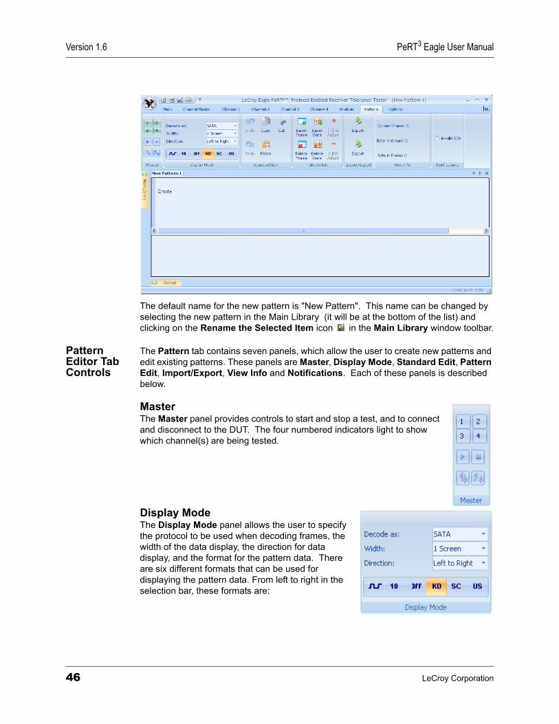
To create a new pattern click on the Pattern tab in the System Control Ribbon. The display, showing the Pattern Editor window and the Pattern tab controls, is shown below:
LeCroy Corporation 45
Version 1.6 PeRT3 Eagle User Manual
The default name for the new pattern is "New Pattern". This name can be changed by selecting the new pattern in the Main Library (it will be at the bottom of the list) and clicking on the Rename the Selected Item icon in the Main Library window toolbar.
Pattern Editor Tab Controls
The Pattern tab contains seven panels, which allow the user to create new patterns and edit existing patterns. These panels are Master, Display Mode, Standard Edit, Pattern Edit, Import/Export, View Info and Notifications. Each of these panels is described below.
Master The Master panel provides controls to start and stop a test, and to connect and disconnect to the DUT. The four numbered indicators light to show which channel(s) are being tested.
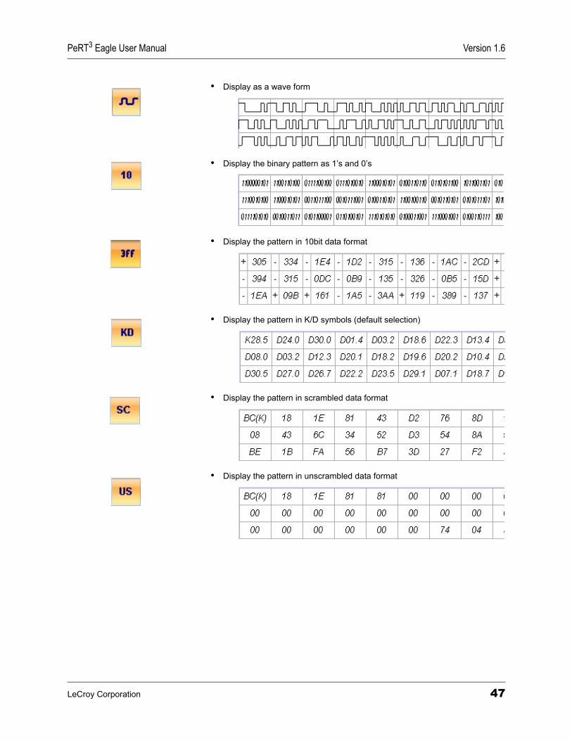
Display Mode The Display Mode panel allows the user to specify the protocol to be used when decoding frames, the width of the data display, the direction for data display, and the format for the pattern data. There are six different formats that can be used for displaying the pattern data. From left to right in the selection bar, these formats are:
46 LeCroy Corporation
PeRT3 Eagle User Manual Version 1.6
• Display as a wave form
• Display the binary pattern as 1’s and 0’s
• Display the pattern in 10bit data format
• Display the pattern in K/D symbols (default selection)
• Display the pattern in scrambled data format
• Display the pattern in unscrambled data format
LeCroy Corporation 47
Version 1.6 PeRT3 Eagle User Manual
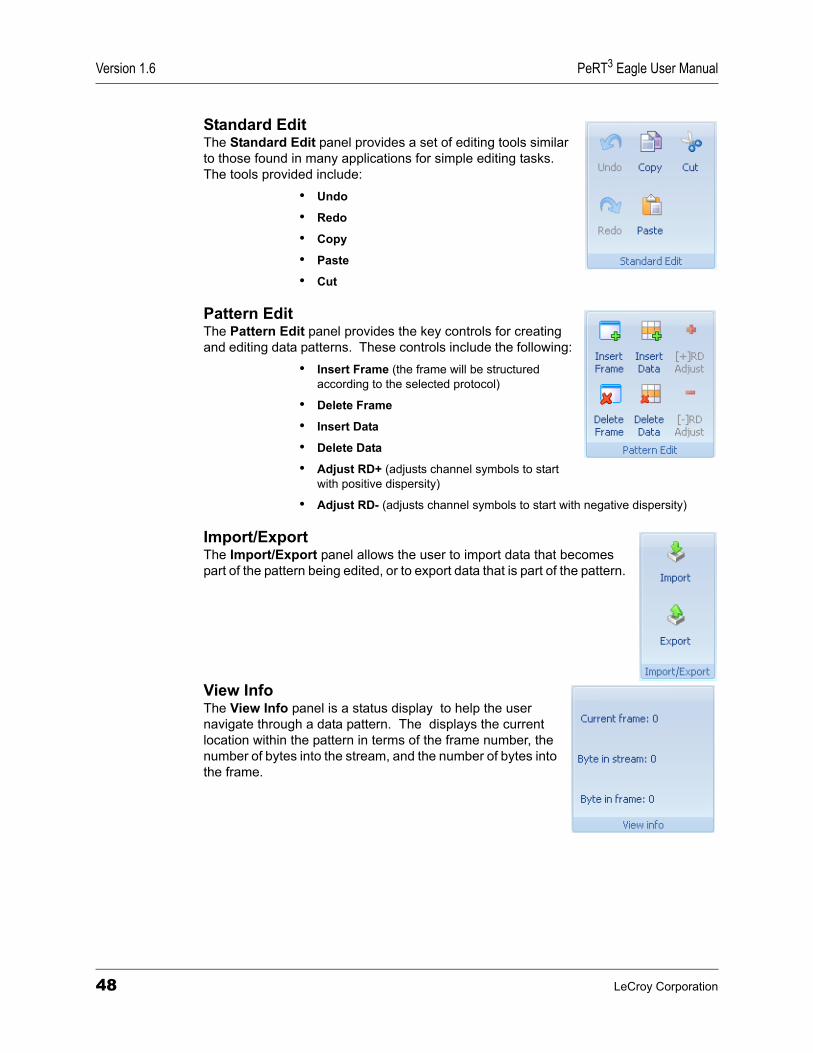
Standard Edit The Standard Edit panel provides a set of editing tools similar to those found in many applications for simple editing tasks. The tools provided include:
• Undo
• Redo
• Copy
• Paste
• Cut
Pattern Edit The Pattern Edit panel provides the key controls for creating and editing data patterns. These controls include the following:
• Insert Frame (the frame will be structured according to the selected protocol)
• Delete Frame
• Insert Data
• Delete Data
• Adjust RD+ (adjusts channel symbols to start with positive dispersity)
• Adjust RD- (adjusts channel symbols to start with negative dispersity)
Import/Export The Import/Export panel allows the user to import data that becomes part of the pattern being edited, or to export data that is part of the pattern.
View Info The View Info panel is a status display to help the user navigate through a data pattern. The displays the current location within the pattern in terms of the frame number, the number of bytes into the stream, and the number of bytes into the frame.
48 LeCroy Corporation
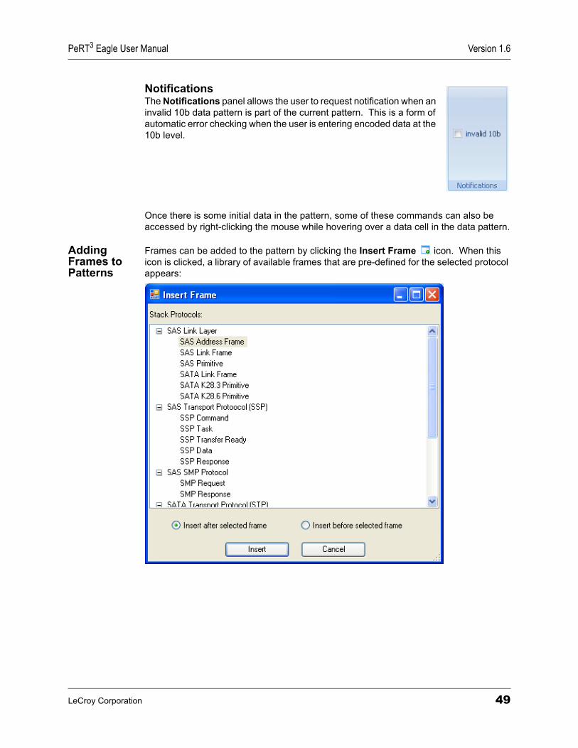
PeRT3 Eagle User Manual Version 1.6
Notifications The Notifications panel allows the user to request notification when an invalid 10b data pattern is part of the current pattern. This is a form of automatic error checking when the user is entering encoded data at the 10b level.
Once there is some initial data in the pattern, some of these commands can also be accessed by right-clicking the mouse while hovering over a data cell in the data pattern.
Adding Frames to Patterns
Frames can be added to the pattern by clicking the Insert Frame icon. When this icon is clicked, a library of available frames that are pre-defined for the selected protocol appears:
LeCroy Corporation 49
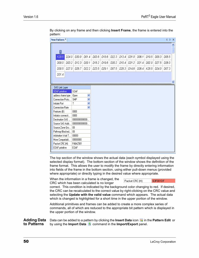
Version 1.6 PeRT3 Eagle User Manual
By clicking on any frame and then clicking Insert Frame, the frame is entered into the pattern:
The top section of the window shows the actual data (each symbol displayed using the selected display format). The bottom section of the window shows the definition of the frame format. This allows the user to modify the frame by directly entering information into fields of the frame in the bottom section, using either pull-down menus (provided where appropriate) or directly typing in the desired value where appropriate.
When the information in a frame is changed, the CRC which has been calculated is no longer correct. This condition is indicated by the background color changing to red. If desired, the CRC can be recalculated to the correct value by right-clicking on the CRC value and selecting the Update with the valid value command which appears. The actual data which is changed is highlighted for a short time in the upper portion of the window.
Additional primitives and frames can be added to create a more complex series of commands, all of which are reduced to the appropriate bit pattern which is displayed in the upper portion of the window.
Adding Data to Patterns
Data can be added to a pattern by clicking the Insert Data icon in the Pattern Edit or by using the Import Data command in the Import/Export panel.
50 LeCroy Corporation
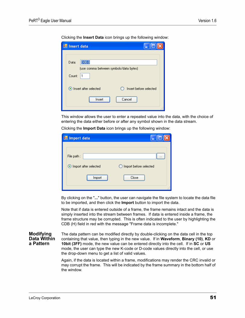
PeRT3 Eagle User Manual Version 1.6
Clicking the Insert Data icon brings up the following window:
This window allows the user to enter a repeated value into the data, with the choice of entering the data either before or after any symbol shown in the data stream.
Clicking the Import Data icon brings up the following window:
By clicking on the "..." button, the user can navigate the file system to locate the data file to be imported, and then click the Import button to import the data.
Note that if data is entered outside of a frame, the frame remains intact and the data is simply inserted into the stream between frames. If data is entered inside a frame, the frame structure may be corrupted. This is often indicated to the user by highlighting the CDB (H) field in red with the message "Frame data is incomplete."
Modifying Data Within a Pattern
The data pattern can be modified directly by double-clicking on the data cell in the top containing that value, then typing in the new value. If in Waveform, Binary (10), KD or 10bit (3FF) mode, the new value can be entered directly into the cell. If in SC or US mode, the user can type the new K-code or D-code values directly into the cell, or use the drop-down menu to get a list of valid values.
Again, if the data is located within a frame, modifications may render the CRC invalid or may corrupt the frame. This will be indicated by the frame summary in the bottom half of the window.
LeCroy Corporation 51

Version 1.6 PeRT3 Eagle User Manual
52 LeCroy Corporation
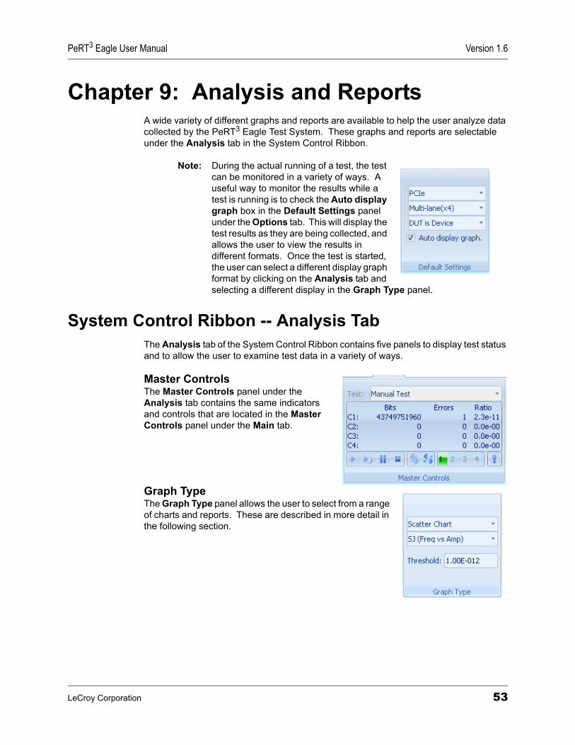
PeRT3 Eagle User Manual Version 1.6
Chapter 9: Analysis and ReportsA wide variety of different graphs and reports are available to help the user analyze data collected by the PeRT3 Eagle Test System. These graphs and reports are selectable under the Analysis tab in the System Control Ribbon.
Note: During the actual running of a test, the test can be monitored in a variety of ways. A useful way to monitor the results while a test is running is to check the Auto display graph box in the Default Settings panel under the Options tab. This will display the test results as they are being collected, and allows the user to view the results in different formats. Once the test is started, the user can select a different display graph format by clicking on the Analysis tab and selecting a different display in the Graph Type panel.
System Control Ribbon -- Analysis TabThe Analysis tab of the System Control Ribbon contains five panels to display test status and to allow the user to examine test data in a variety of ways.
Master ControlsThe Master Controls panel under the Analysis tab contains the same indicators and controls that are located in the Master Controls panel under the Main tab.
Graph TypeThe Graph Type panel allows the user to select from a range of charts and reports. These are described in more detail in the following section.
LeCroy Corporation 53
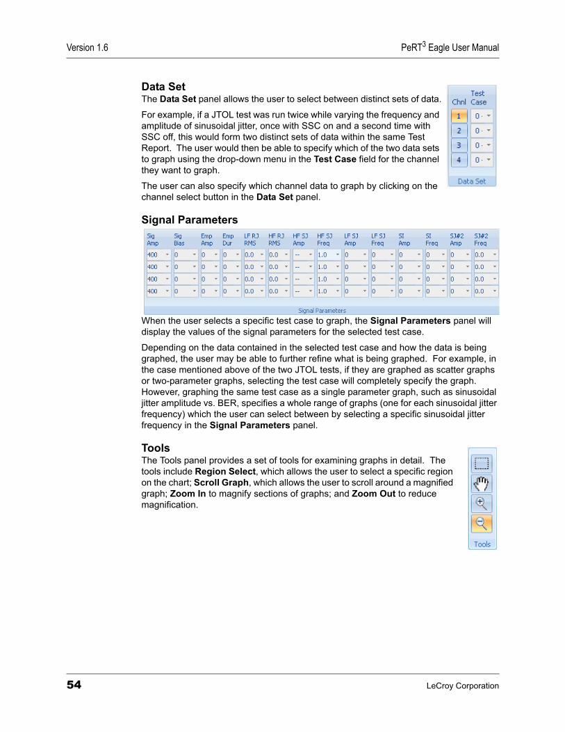
Version 1.6 PeRT3 Eagle User Manual
Data SetThe Data Set panel allows the user to select between distinct sets of data.
For example, if a JTOL test was run twice while varying the frequency and amplitude of sinusoidal jitter, once with SSC on and a second time with SSC off, this would form two distinct sets of data within the same Test Report. The user would then be able to specify which of the two data sets to graph using the drop-down menu in the Test Case field for the channel they want to graph.
The user can also specify which channel data to graph by clicking on the channel select button in the Data Set panel.
Signal Parameters
When the user selects a specific test case to graph, the Signal Parameters panel will display the values of the signal parameters for the selected test case.
Depending on the data contained in the selected test case and how the data is being graphed, the user may be able to further refine what is being graphed. For example, in the case mentioned above of the two JTOL tests, if they are graphed as scatter graphs or two-parameter graphs, selecting the test case will completely specify the graph. However, graphing the same test case as a single parameter graph, such as sinusoidal jitter amplitude vs. BER, specifies a whole range of graphs (one for each sinusoidal jitter frequency) which the user can select between by selecting a specific sinusoidal jitter frequency in the Signal Parameters panel.
ToolsThe Tools panel provides a set of tools for examining graphs in detail. The tools include Region Select, which allows the user to select a specific region on the chart; Scroll Graph, which allows the user to scroll around a magnified graph; Zoom In to magnify sections of graphs; and Zoom Out to reduce magnification.
54 LeCroy Corporation
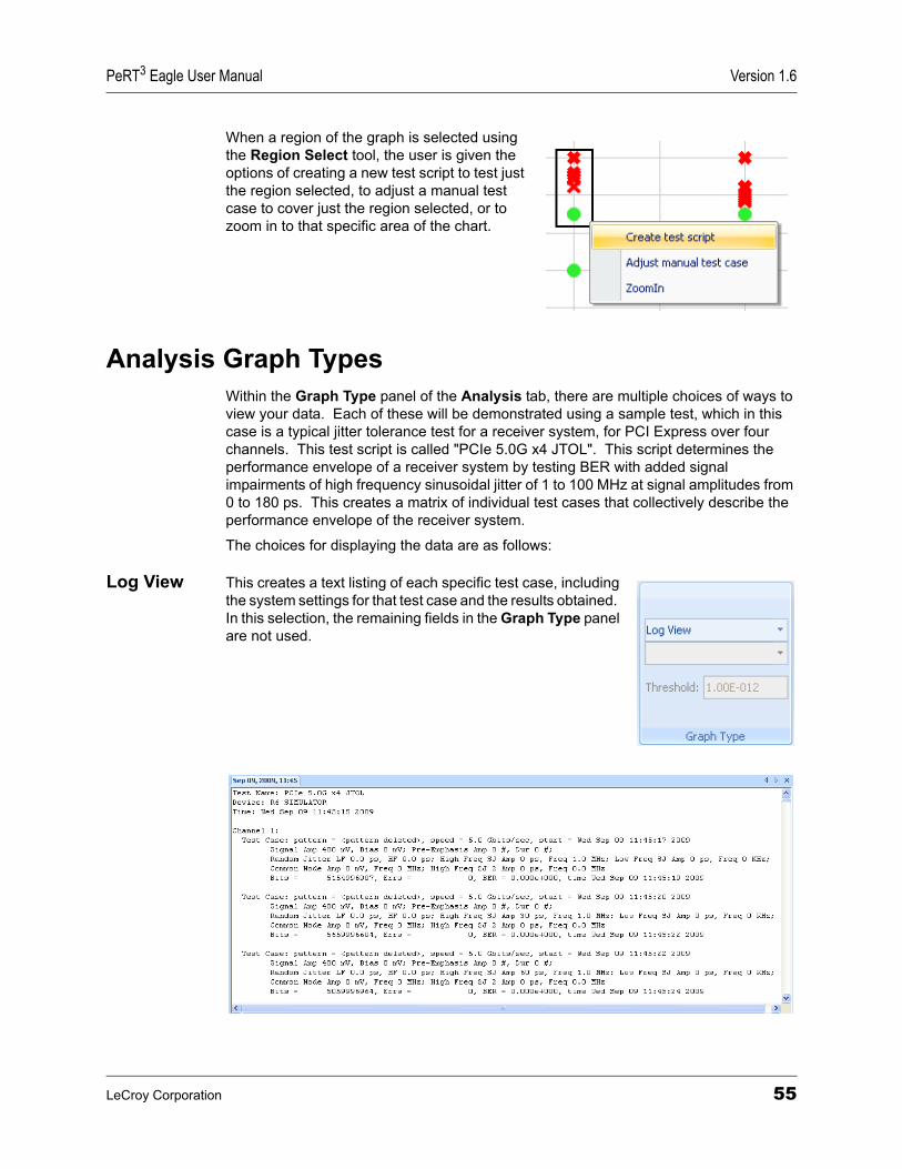
PeRT3 Eagle User Manual Version 1.6
When a region of the graph is selected using the Region Select tool, the user is given the options of creating a new test script to test just the region selected, to adjust a manual test case to cover just the region selected, or to zoom in to that specific area of the chart.
Analysis Graph TypesWithin the Graph Type panel of the Analysis tab, there are multiple choices of ways to view your data. Each of these will be demonstrated using a sample test, which in this case is a typical jitter tolerance test for a receiver system, for PCI Express over four channels. This test script is called "PCIe 5.0G x4 JTOL". This script determines the performance envelope of a receiver system by testing BER with added signal impairments of high frequency sinusoidal jitter of 1 to 100 MHz at signal amplitudes from 0 to 180 ps. This creates a matrix of individual test cases that collectively describe the performance envelope of the receiver system.
The choices for displaying the data are as follows:
Log View This creates a text listing of each specific test case, including the system settings for that test case and the results obtained. In this selection, the remaining fields in the Graph Type panel are not used.
LeCroy Corporation 55
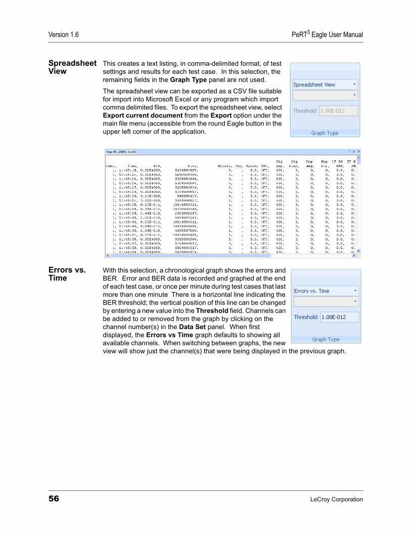
Version 1.6 PeRT3 Eagle User Manual
Spreadsheet View
This creates a text listing, in comma-delimited format, of test settings and results for each test case. In this selection, the remaining fields in the Graph Type panel are not used.
The spreadsheet view can be exported as a CSV file suitable for import into Microsoft Excel or any program which import comma delimited files. To export the spreadsheet view, select Export current document from the Export option under the main file menu (accessible from the round Eagle button in the upper left corner of the application.
Errors vs. Time
With this selection, a chronological graph shows the errors and BER. Error and BER data is recorded and graphed at the end of each test case, or once per minute during test cases that last more than one minute There is a horizontal line indicating the BER threshold; the vertical position of this line can be changed by entering a new value into the Threshold field. Channels can be added to or removed from the graph by clicking on the channel number(s) in the Data Set panel. When first displayed, the Errors vs Time graph defaults to showing all available channels. When switching between graphs, the new view will show just the channel(s) that were being displayed in the previous graph.
56 LeCroy Corporation
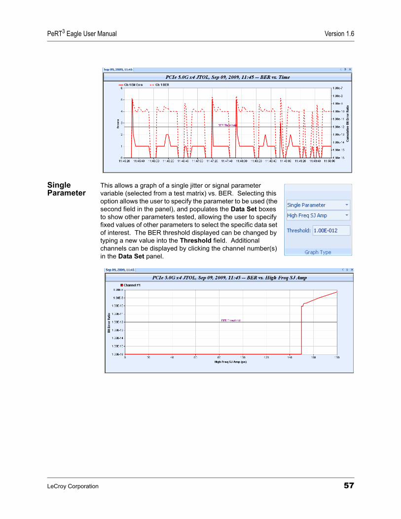
PeRT3 Eagle User Manual Version 1.6
Single Parameter
This allows a graph of a single jitter or signal parameter variable (selected from a test matrix) vs. BER. Selecting this option allows the user to specify the parameter to be used (the second field in the panel), and populates the Data Set boxes to show other parameters tested, allowing the user to specify fixed values of other parameters to select the specific data set of interest. The BER threshold displayed can be changed by typing a new value into the Threshold field. Additional channels can be displayed by clicking the channel number(s) in the Data Set panel.
LeCroy Corporation 57
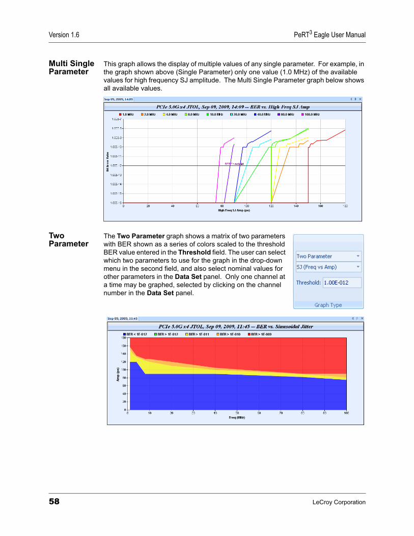
Version 1.6 PeRT3 Eagle User Manual
Multi Single Parameter
This graph allows the display of multiple values of any single parameter. For example, in the graph shown above (Single Parameter) only one value (1.0 MHz) of the available values for high frequency SJ amplitude. The Multi Single Parameter graph below shows all available values.
Two Parameter
The Two Parameter graph shows a matrix of two parameters with BER shown as a series of colors scaled to the threshold BER value entered in the Threshold field. The user can select which two parameters to use for the graph in the drop-down menu in the second field, and also select nominal values for other parameters in the Data Set panel. Only one channel at a time may be graphed, selected by clicking on the channel number in the Data Set panel.
58 LeCroy Corporation
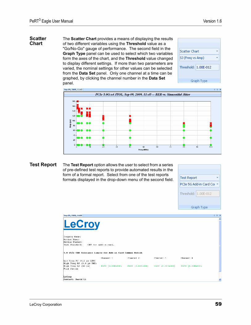
PeRT3 Eagle User Manual Version 1.6
Scatter Chart
The Scatter Chart provides a means of displaying the results of two different variables using the Threshold value as a "Go/No-Go" gauge of performance. The second field in the Graph Type panel can be used to select which two variables form the axes of the chart, and the Threshold value changed to display different settings. If more than two parameters are varied, the nominal settings for other values can be selected from the Data Set panel. Only one channel at a time can be graphed, by clicking the channel number in the Data Set panel.
Test Report The Test Report option allows the user to select from a series of pre-defined test reports to provide automated results in the form of a formal report. Select from one of the test reports formats displayed in the drop-down menu of the second field.
LeCroy Corporation 59

Version 1.6 PeRT3 Eagle User Manual
60 LeCroy Corporation

PeRT3 Eagle User Manual Version 1.6
Chapter 10: Control of Screen AppearanceThe PeRT3 application allows the user to customize the appearance of the main application window to suit that user’s preferences and application. As settings are changed, the application will remember the new settings, and the next time the application is launched the windows will reappear in the same locations as previously defined.
Customizing the Quick Access ToolbarThe Quick Access Toolbar is a series of icons that appear (by default) just above the System Control Ribbon, at the top of the application . By default, the Quick Access Toolbar includes the commands File (the round Eagle button), New Test Script, New Test Pattern, Export Current Document, and Quick Print and appears as follows:
"Tool Tips" are supported throughout the PeRT3 application and can provide a short cut reminder of the meaning of different icons. By hovering the mouse pointer over the icon for 1-2 seconds, the tool tip will appear:
The Quick Access Toolbar can be customized to support any of the following functions:
Quick Access Toolbar Buttons
New Test Script: Creates a new Test Script
Print Preview: Provides a preview on screen of the information to be printed
New Test Pattern: Creates a new Test Pattern
Quick Print: Prints the current document directly to the default printer
Export Current Document: Saves the current document as an XML file
Import from XML: Imports a test view previously saved as XML file
Options: Brings up the Options tab (same as pressing the Options tab in the System Control Ribbon)
LeCroy Corporation 61
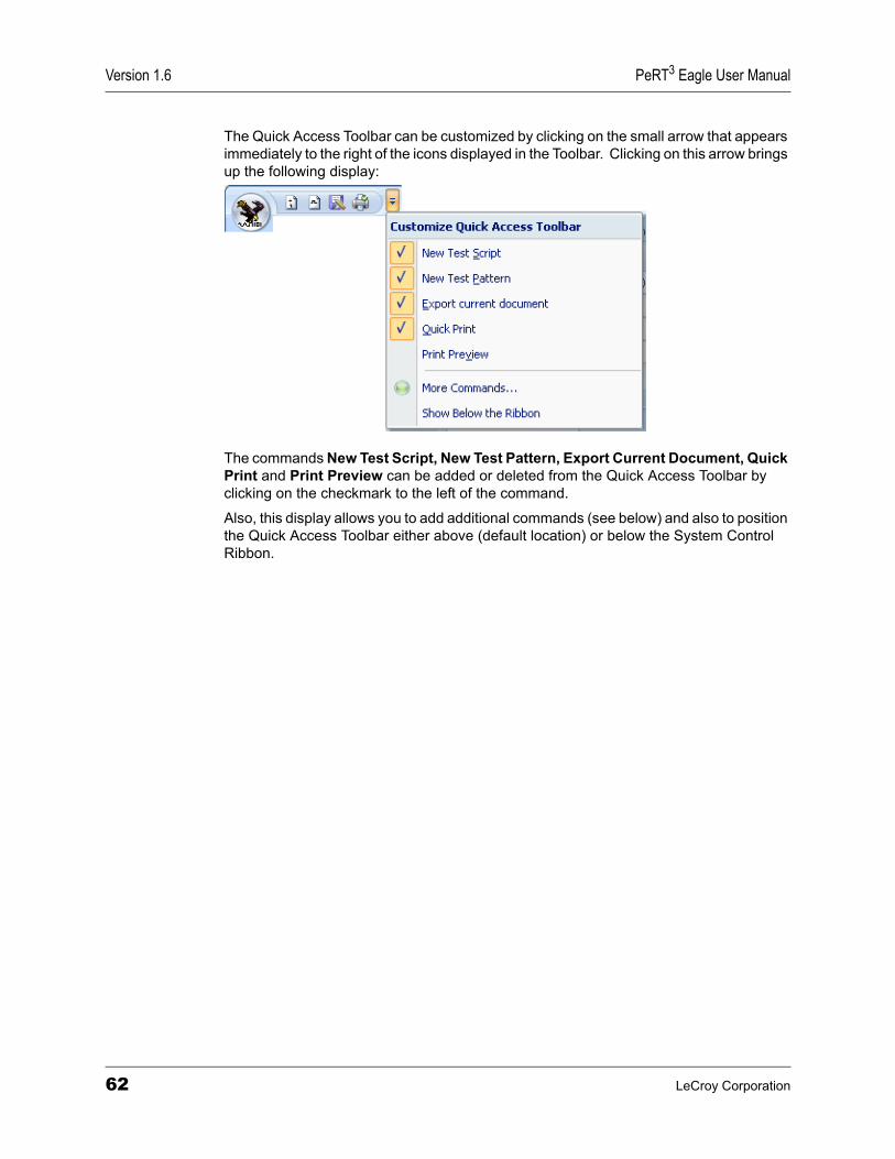
Version 1.6 PeRT3 Eagle User Manual
The Quick Access Toolbar can be customized by clicking on the small arrow that appears immediately to the right of the icons displayed in the Toolbar. Clicking on this arrow brings up the following display:
The commands New Test Script, New Test Pattern, Export Current Document, Quick Print and Print Preview can be added or deleted from the Quick Access Toolbar by clicking on the checkmark to the left of the command.
Also, this display allows you to add additional commands (see below) and also to position the Quick Access Toolbar either above (default location) or below the System Control Ribbon.
62 LeCroy Corporation
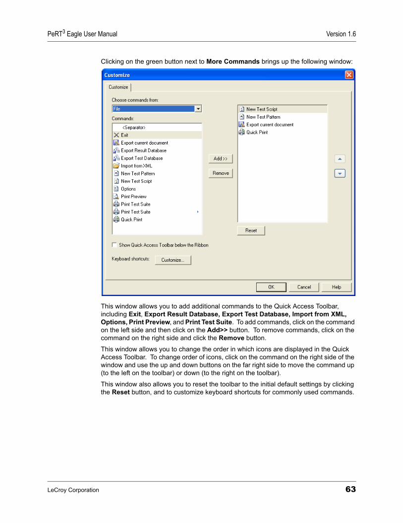
PeRT3 Eagle User Manual Version 1.6
Clicking on the green button next to More Commands brings up the following window:
This window allows you to add additional commands to the Quick Access Toolbar, including Exit, Export Result Database, Export Test Database, Import from XML, Options, Print Preview, and Print Test Suite. To add commands, click on the command on the left side and then click on the Add>> button. To remove commands, click on the command on the right side and click the Remove button.
This window allows you to change the order in which icons are displayed in the Quick Access Toolbar. To change order of icons, click on the command on the right side of the window and use the up and down buttons on the far right side to move the command up (to the left on the toolbar) or down (to the right on the toolbar).
This window also allows you to reset the toolbar to the initial default settings by clicking the Reset button, and to customize keyboard shortcuts for commonly used commands.
LeCroy Corporation 63
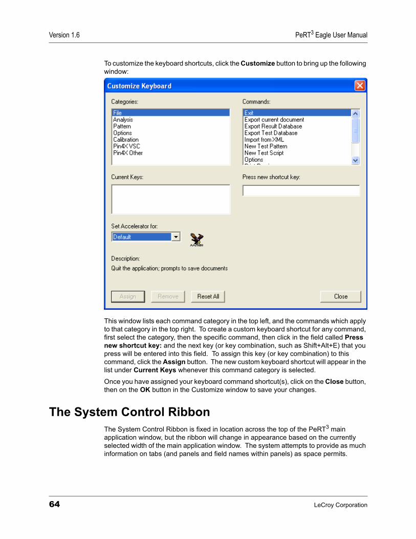
Version 1.6 PeRT3 Eagle User Manual
To customize the keyboard shortcuts, click the Customize button to bring up the following window:
This window lists each command category in the top left, and the commands which apply to that category in the top right. To create a custom keyboard shortcut for any command, first select the category, then the specific command, then click in the field called Press new shortcut key: and the next key (or key combination, such as Shift+Alt+E) that you press will be entered into this field. To assign this key (or key combination) to this command, click the Assign button. The new custom keyboard shortcut will appear in the list under Current Keys whenever this command category is selected.
Once you have assigned your keyboard command shortcut(s), click on the Close button, then on the OK button in the Customize window to save your changes.
The System Control RibbonThe System Control Ribbon is fixed in location across the top of the PeRT3 main application window, but the ribbon will change in appearance based on the currently selected width of the main application window. The system attempts to provide as much information on tabs (and panels and field names within panels) as space permits.
64 LeCroy Corporation
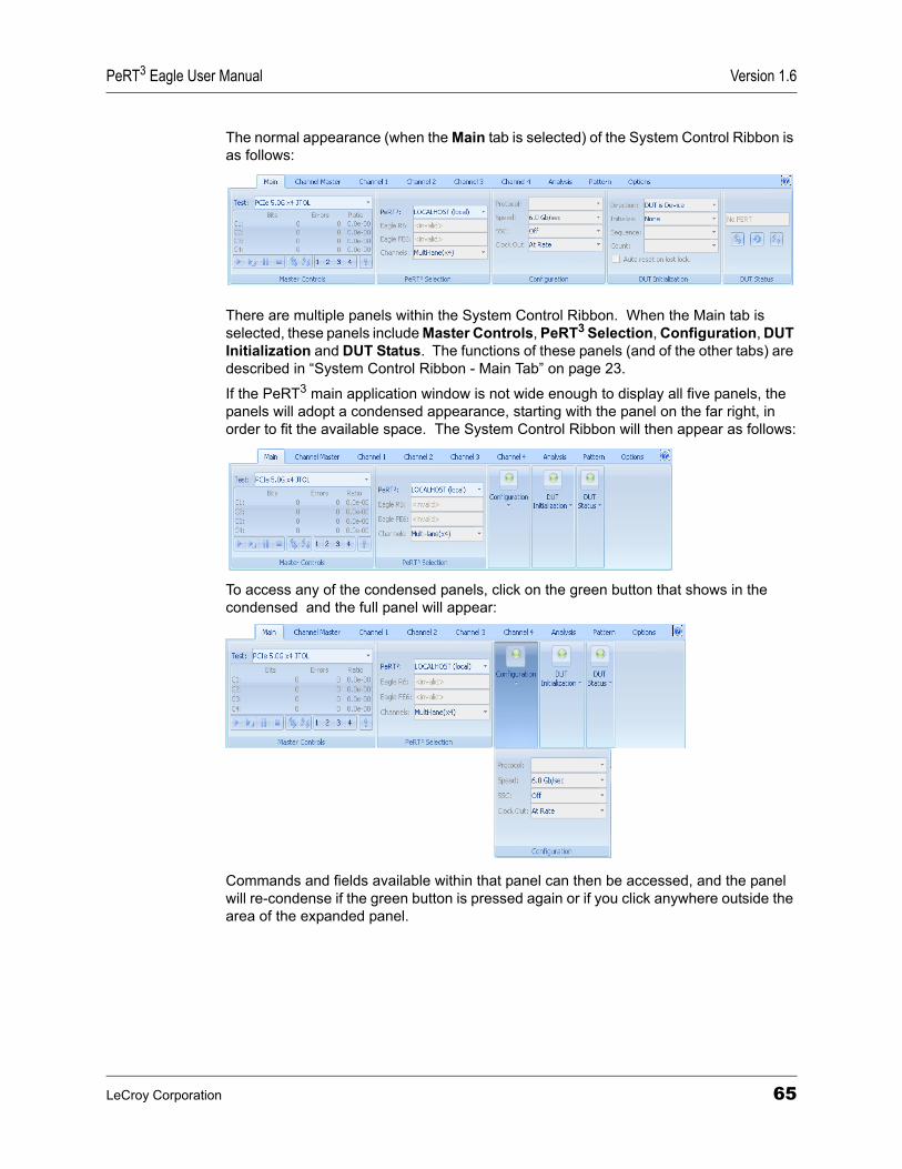
PeRT3 Eagle User Manual Version 1.6
The normal appearance (when the Main tab is selected) of the System Control Ribbon is as follows:
There are multiple panels within the System Control Ribbon. When the Main tab is selected, these panels include Master Controls, PeRT3 Selection, Configuration, DUT Initialization and DUT Status. The functions of these panels (and of the other tabs) are described in “System Control Ribbon - Main Tab” on page 23.
If the PeRT3 main application window is not wide enough to display all five panels, the panels will adopt a condensed appearance, starting with the panel on the far right, in order to fit the available space. The System Control Ribbon will then appear as follows:
To access any of the condensed panels, click on the green button that shows in the condensed and the full panel will appear:
Commands and fields available within that panel can then be accessed, and the panel will re-condense if the green button is pressed again or if you click anywhere outside the area of the expanded panel.
LeCroy Corporation 65
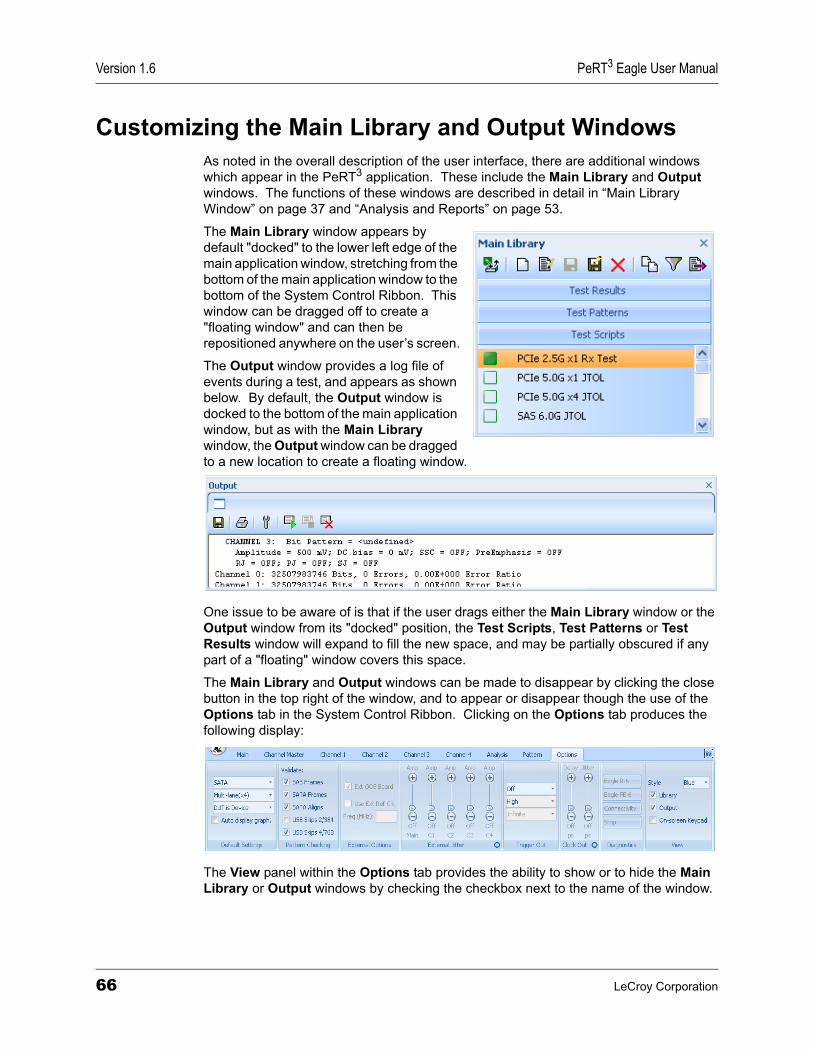
Version 1.6 PeRT3 Eagle User Manual
Customizing the Main Library and Output WindowsAs noted in the overall description of the user interface, there are additional windows which appear in the PeRT3 application. These include the Main Library and Output windows. The functions of these windows are described in detail in “Main Library Window” on page 37 and “Analysis and Reports” on page 53.
The Main Library window appears by default "docked" to the lower left edge of the main application window, stretching from the bottom of the main application window to the bottom of the System Control Ribbon. This window can be dragged off to create a "floating window" and can then be repositioned anywhere on the user’s screen.
The Output window provides a log file of events during a test, and appears as shown below. By default, the Output window is docked to the bottom of the main application window, but as with the Main Library window, the Output window can be dragged to a new location to create a floating window.
One issue to be aware of is that if the user drags either the Main Library window or the Output window from its "docked" position, the Test Scripts, Test Patterns or Test Results window will expand to fill the new space, and may be partially obscured if any part of a "floating" window covers this space.
The Main Library and Output windows can be made to disappear by clicking the close button in the top right of the window, and to appear or disappear though the use of the Options tab in the System Control Ribbon. Clicking on the Options tab produces the following display:
The View panel within the Options tab provides the ability to show or to hide the Main Library or Output windows by checking the checkbox next to the name of the window.
66 LeCroy Corporation
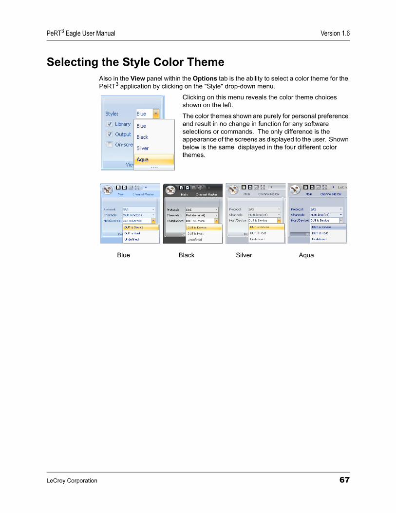
PeRT3 Eagle User Manual Version 1.6
Selecting the Style Color ThemeAlso in the View panel within the Options tab is the ability to select a color theme for the PeRT3 application by clicking on the "Style" drop-down menu.
Clicking on this menu reveals the color theme choices shown on the left.
The color themes shown are purely for personal preference and result in no change in function for any software selections or commands. The only difference is the appearance of the screens as displayed to the user. Shown below is the same displayed in the four different color themes.
Blue Black Silver Aqua
LeCroy Corporation 67

Version 1.6 PeRT3 Eagle User Manual
68 LeCroy Corporation

PeRT3 Eagle User Manual Version 1.6
Limited Hardware WarrantyHow to Contact LeCroy
Limited Hardware WarrantySo long as you or your authorized representative ("you" or "your"), fully complete and return the registration card provided with the applicable hardware product or peripheral hardware products (each a "Product") within fifteen days of the date of receipt from LeCroy or one of its authorized representatives, LeCroy warrants that the Product will be free from defects in materials and workmanship for the warranty period stated in the product datasheet which is current at the time of purchase (the "Warranty Period"). You may also complete your registration form via the internet by visiting http://www.lecroy.com/support/register/. The Warranty Period commences on the earlier of the date of delivery by LeCroy of a Product to a common carrier for shipment to you or to LeCroy's authorized representative from whom you purchase the Product.
What this Warranty Does Not CoverThis warranty does not cover damage due to external causes including accident, damage during shipment after delivery to a common carrier by LeCroy, abuse, misuse, problems with electrical power, including power surges and outages, servicing not authorized by LeCroy, usage or operation not in accordance with Product instructions, failure to perform required preventive maintenance, software related problems (whether or not provided by LeCroy), problems caused by use of accessories, parts or components not supplied by LeCroy, Products that have been modified or altered by someone other than LeCroy, Products with missing or altered service tags or serial numbers, and Products for which LeCroy has not received payment in full.
Coverage During Warranty PeriodDuring the Warranty Period, LeCroy or its authorized representatives will repair or replace Products, at LeCroy's sole discretion, covered under this limited warranty that are returned directly to LeCroy's facility or through LeCroy's authorized representatives.
Type of Service ContactCall for technical support…
US and Canada:
1 (800) 909-2282
Worldwide: 1 (408) 653-1260Fax your questions… Worldwide: 1 (408) 727-6622Write a letter… LeCroy
Protocol Solutions Group Customer Support 3385 Scott Blvd. Santa Clara, CA 95054USA
Send e-mail… [email protected] LeCroy’s web site… http://www.lecroy.com/
LeCroy Corporation 69

Version 1.6 PeRT3 Eagle User Manual
How to Obtain Warranty ServiceTo request warranty service, you must complete and return the registration card or register via the internet within the fifteen day period described above and report your covered warranty claim by contacting LeCroy Technical Support or its authorized representative. LeCroy Technical Support can be reached at 800-909-7112 or via email at [email protected]. You may also refer to LeCroy's website at http://www.lecroy.com for more information on how to contact an authorized representative in your region. If warranty service is required, LeCroy or its authorized representative will issue a Return Material Authorization Number. You must ship the Product back to LeCroy or its authorized representative, in its original or equivalent packaging, prepay shipping charges, and insure the shipment or accept the risk of loss or damage during shipment. LeCroy must receive the Product prior to expiration of the Warranty Period for the repair(s) to be covered. LeCroy or its authorized representative will thereafter ship the repaired or replacement Product to you freight prepaid by LeCroy if you are located in the continental United States. Shipments made outside the continental United States will be sent freight collect.Please remove any peripheral accessories or parts before you ship the Product. LeCroy does not accept liability for lost or damaged peripheral accessories, data or software.LeCroy owns all parts removed from Products it repairs. LeCroy may use new and/or reconditioned parts, at its sole discretion, made by various manufacturers in performing warranty repairs. If LeCroy repairs or replaces a Product, the Warranty Period for the Product is not extended.If LeCroy evaluates and determines there is "no trouble found" in any Product returned or that the returned Product is not eligible for warranty coverage, LeCroy will inform you of its determination. If you thereafter request LeCroy to repair the Product, such labor and service shall be performed under the terms and conditions of LeCroy's then current repair policy. If you chose not to have the Product repaired by LeCroy, you agree to pay LeCroy for the cost to return the Product to you and that LeCroy may require payment in advance of shipment.General ProvisionsTHIS LIMITED WARRANTY GIVES YOU SPECIFIC LEGAL RIGHTS. YOU MAY HAVE ADDITIONAL RIGHTS THAT VARY BY JURISDICTION. LECROY'S RESPONSIBILITY FOR DEFECTS IN MATERIALS AND WORKMANSHIP IS LIMITED TO REPAIR AND REPLACEMENT AS SET FORTH IN THIS LIMITED WARRANTY STATEMENT. EXCEPT AS EXPRESSLY STATED IN THIS WARRANTY STATEMENT, LECROY DISCLAIMS ALL EXPRESS AND IMPLIED WARRANTIES FOR ANY PRODUCT INCLUDING, BUT NOT LIMITED TO, ANY IMPLIED WARRANTIES OF AND CONDITIONS OF MERCHANTABILITY AND FITNESS FOR A PARTICULAR PURPOSE, AND ANY WARRANTIES THAT MAY ARISE FROM ANY COURSE OF DEALING, COURSE OF PERFORMANCE OR TRADE USAGE. SOME JURISDICTIONS MAY NOT ALLOW LIMITATIONS ON HOW LONG AN IMPLIED WARRANTY LASTS, SO THE PRECEDING LIMITATION MAY NOT APPLY TO YOU.
LECROY DOES NOT ACCEPT LIABILITY BEYOND THE REMEDIES SET FORTH IN THIS LIMITED WARRANTY STATEMENT OR FOR INCIDENTAL OR CONSEQUENTIAL DAMAGES INCLUDING, WITHOUT LIMITATION, ANY LIABILITY FOR THIRD PARTY CLAIMS AGAINST YOU FOR DAMAGES, PRODUCTS NOT
70 LeCroy Corporation

PeRT3 Eagle User Manual Version 1.6
BEING AVAILABLE FOR USE, OR FOR LOST DATA OR SOFTWARE. LECROY'S LIABILITY TO YOU MAY NOT EXCEED THE AMOUNT YOU PAID FOR THE PRODUCT THAT IS THE SUBJECT OF A CLAIM. SOME JURISDICTIONS DO NOT ALLOW THE EXCLUSION OR LIMITATION OF INCIDENTAL OR CONSEQUENTIAL DAMAGES, SO THE PRECEDING EXCLUSION OR LIMITATION MAY NOT APPLY TO YOU.
The limited warranty on a Product may be transferred for the remaining term if the then current owner transfers ownership of the Product and notifies LeCroy of the transfer. You may notify LeCroy of the transfer by writing to Technical Support at LeCroy, 3385 Scott Blvd., Santa Clara, CA 95054 USA or by email at: [email protected]. Please include the transferring owner's name and address, the name and address of the new owner, the date of transfer, and the Product serial number.
LeCroy Corporation 71

Version 1.6 PeRT3 Eagle User Manual
72 LeCroy Corporation

PeRT3 Eagle User Manual Version 1.6
Appendix A: SpecificationsSpecificationsGenerator Data Out
Bit Rate............................................................................................................ 1 to 6 Gb/s
Data Format ................................................................................ NRZ, nornal or inverted
Rise/Fall Time (20-80%)............................................................................34 psec typical
Programmable Rise/Fall Time .....................................................................................Yes
Max. Rise/Fall Time Mismatch .............................................................................. 0.05 UI
Differential Amplitude Range................................................. 50 mV to 1.8 V, 5 mV steps
Voltage Offset .......................................................................................... -2.5 V to +2.5 V
Maximum AC Common Mode Voltage ................................................................... 20 mV
Maximum Intrinsic Jitte............................................................................<20 psec typical
Tri-state Outputs..........................................................................................................Yes
Electrical Idle Generation ............................................................................................Yes
SSC Support ...............................................................................................................Yes
Pre/De-emphasis Support ...........................................................................................Yes
Return Loss SDD11 and S11...................................<-10 dB over entire frequency range
Generator Clock Out
Frequency Range................................................................................100 MHz to 6 GHz
Rise/Fall Time (20-80%)............................................................................34 psec typical
Voltage Rails ..................................................................................................AC coupled
Jitter....................................................................................................1 psec RMS typical
Amplitude Range.......................................................................................................CML
Sub-rate Clock.........................Divide by 1, or divide by any number between 8 and 511(and multiplied by 1, 2, 4, or 8)
Jitter Stress................................................................................................................. Yes
Protocols Supported
PCI Express ............................................................................................. 2.5 and 5 Gb/s
SAS ...................................................................................................... 1.5, 3 and 6 Gb/s
SATA..................................................................................................... 1.5, 3 and 6 Gb/s
USB 3.0 ................................................................................................................. 5 Gb/s
LeCroy Corporation 73
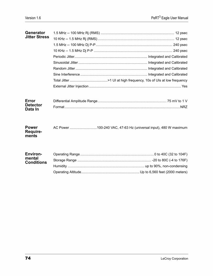
Version 1.6 PeRT3 Eagle User Manual
Generator Jitter Stress
1.5 MHz -- 100 MHz Rj (RMS) ............................................................................ 12 psec
10 KHz -- 1.5 MHz Rj (RMS) ............................................................................... 12 psec
1.5 MHz -- 100 MHz Dj P-P............................................................................... 240 psec
10 KHz -- 1.5 MHz Dj P-P ................................................................................. 240 psec
Periodic Jitter........................................................................... Integrated and Calibrated
Sinusoidal Jitter ....................................................................... Integrated and Calibrated
Random Jitter .......................................................................... Integrated and Calibrated
Sine Interference ..................................................................... Integrated and Calibrated
Total Jitter .......................................>1 UI at high frequency, 10s of UIs at low frequency
External Jitter Injection ............................................................................................... Yes
Error Detector Data In
Differential Amplitude Range....................................................................... 75 mV to 1 V
Format .......................................................................................................................NRZ
Power Require- ments
AC Power ............................100-240 VAC, 47-63 Hz (universal input), 480 W maximum
Environ- mental Conditions
Operating Range ............................................................................0 to 40C (32 to 104F)
Storage Range ............................................................................ -20 to 80C (-4 to 176F)
Humidity ............................................................................... up to 90%, non-condensing
Operating Altitude............................................................ Up to 6,560 feet (2000 meters)
74 LeCroy Corporation

PeRT3 Eagle User Manual Version 1.6
Miscellaneous InformationThe following tables are supplied in compliance with China’s Restriction of Hazardous Substances (China RoHS) requirements:
LeCroy Corporation 75

Version 1.6 PeRT3 Eagle User Manual
76 LeCroy Corporation
PeRT3 Eagle User Manual Version 1.6
IndexSymbols%Confidence 32.NET 3.5 installation 4
AAC Power 4Adding data to patterns 50Adjust RD- 48Adjust RD+ 48Allowable Patterns 38Analysis tab 33, 53, 55Annual calibration 2Apply 25Arbitrary Date 38Auto display graph 33, 53Auto reset on lost lock 43Automatic range 27Automation panel 43Auxiliary Port 4, 35
BBack Panel Connections 4Basic Data panel 41BER threshold 57Building a Test Script 42
CCancel 25CDB (H) field 51Channel Master tab 25, 26, 43Channel Tab 25Channel tab 25, 26Channels 33Channels drop-down menu 8Clock Out 24, 35, 42Clock Out panel 35color 67Color theme 36, 67Configuration panel 23, 24, 38, 65Connect 23, 25Connecting remotely 5Contact LeCroy 69
Copy 48Copy icon 11Count 25CRC errors 1CRC value 1, 50, 51Create New Item 45Creating a new test pattern 45Creating test patterns 45Creator 41CSV file 56Custom protocol 24Custom Steps 28Customize keyboard 64Cut 48
DData 59Data outside of a frame 51Data Set 57Data Set panel 54, 56, 57, 58, 59Decode As 45Decode Buttons 37, 61Default Settings 45Default Settings panel 33, 53Delete 19Delete Data 48Delete Frame 48Device Description panel 42Diagnostics panel 35Direction 25Disconnect 23, 25Display Mode panel 45, 46DUT initialization 24DUT Initialization panel 23, 25, 45, 65DUT is Device 42DUT is Host 42DUT Status panel 23, 25, 65
EElapsed Time 32Enable Range 27, 28Errors vs. Time 56Exact control of test ranges 27Exit 21, 63Export 19, 56Export current database 20Export Current Document 56, 61, 62Export current document 20, 56Export Result Database 63
LeCroy Corporation Index
Version 1.6 PeRT3 Eagle User Manual
Export result database 20Export Test Database 63Exporting files (scripts, patterns, test reports) 20External Jitter panel 35External OOB Board 34, 35External Options panel 34Eye diagram 14Eye Diagram panel 43Eye Preview panel 33
FFile Menu 19Filter 19Filter button 38Find BER Curve 32Floating window 39, 66Frame Level 43
GGenerator Only 24Graph Type panel 53, 55, 56, 59Graphs and reports 53
HHardware configurations 2Hardware upgrades 2Hardware Warranty 69Hide Buttons 37, 61High Frequency Random Jitter 30High Frequency Sinusoidal Jitter panel 31Host PC 3, 17
minimum requirements 3Host PC system 3Host/Device 33
IImport Data 50, 51Import from XML 61, 63Import/Export panel 48, 50Importing new files 20Initialization command sequence 43Initialization panel 43Initialize 25Insert Above 44Insert Data 48, 50, 51Insert Frame 48, 49, 50Installation 3Introduction of Distortion 14, 26
Introduction of Stress 14
JJitter eye diagram 33Jitter In connector 35
LLog View 55LoopBack 43Loopback 25, 43Low Frequency Random Jitter 30Low Frequency Sinusoidal Jitter panel 31Low to High 27
MMagnification 54Main 35Main application window 7, 10, 17, 21, 23, 39, 40, 41, 45, 61, 64, 65Main Library Toolbar 37Main Library window 6, 10, 18, 19, 36, 37, 38, 39, 40, 41, 45, 46, 66Main tab 7, 23, 38, 45, 65Maintenance agreements 2Manual Test 23, 26Manual Testing 23Manual testing 23Master Controls pane 53Master Controls panel 9, 23, 26, 31, 53, 65Master Controls tab 31Master panel 46Max Bit Count 31Max GBits 31Minimum system requirements 3Modifying a Test 10Multi Single Parameter 58
NNew Test Pattern 19, 61, 62New Test Script 19, 61, 62Notifications panel 49
OOn-screen Keypad 28On-screen LEDs 23Options 61, 63Options tab 28, 33, 45, 53, 66, 67
Index LeCroy Corporation

PeRT3 Eagle User Manual Version 1.6
Other Channel 32, 33Output window 10, 18, 36, 39, 40, 66
PPass/Fail BER 32PASS/FAIL Confidence 32Paste 48Pattern 31, 33Pattern Checking panel 34Pattern Edit panel 48Pattern Editor 25, 31, 45Pattern Editor window 45Pattern tab 33, 45, 46Pattern/Termination pane 31Pattern/Termination panel 31Pause 9, 23, 26PeRT3 client 5PeRT3 Eagle front panel 8PeRT3 panel 23PeRT3 Selection panel 7, 24, 65PeRT3 server 5, 6PeRT3 System Software 4Power Requirements 75Predefined test patterns 45Pre-emphasis amplitude 29Pre-emphasis duration 29Pre-Emphasis panel 29Pre-programmed test script 3Principles of Operation 13Print command 21Print Preview 21, 61, 62, 63Print Test Suite 63Protocol 33Protocol Specific filter 38Protocol-enabled 1Protocol-specific errors 1
QQuick Access Toolbar 61, 62Quick Print 21, 61, 62
RRandom Jitter panel 30Receiver Test 42Receiver Test block 43Redo 48Ref Clk in 35Reference Clock 4Reference Clock In 35
Region Select 54, 55Rename 19Rename the Selected Item 46Reports 53Reset 25Reset on each test case 43Reset/Initialize 42, 44Run Forever 31, 33Running a Test 9
SSave 19Scatter Chart 59Script Data block 41Script Data tab 41Script Name 41Scroll Graph 54Sequence 25, 43Setup panel 42Signal amplitude 29Signal bias 29Signal Generation 26Signal generator 24Signal impairment 43Signal impairment controls 26, 27Signal panel 29Signal Parameters panel 54Single Parameter 57Sinusoidal interference 30SMA cables 29SMA connectors 8Small screens 39Software test suites 2Specifications 73Spread spectrum clocking 24, 42Spreadsheet View 56Standard Edit panel 48Start (don’t record) 9, 23, 26Start (record results) 9, 23, 26Starting a new test script 40Stop 9, 31Style 67Suspend 23, 26, 31System components 3System Control Ribbon 18, 23, 25, 26, 39, 45, 53, 64, 65, 66System control ribbon 39
LeCroy Corporation Index

Version 1.6 PeRT3 Eagle User Manual
TTechnical Support
Email 69Phone Numbers 69Web Site 69
Terminate after 31Test Case 42, 44, 54Test Case field 54Test Description panel 42Test Development 39Test Development section 18Test Patterns 18, 37, 38Test Patterns tab 45Test Report 59Test Results 18, 37Test Results library 10Test Script Data Panel 43Test Script window 39Test Scripts 18, 37, 38, 39, 44Test Scripts tab 10, 40, 41Test Type 42Threshold 56, 57, 58, 59Time or Max Errors 32Time or PASS/FAIL 32Tool Tips 61Tools panel 54Trademarks iiTransmitter Test 42Two Parameter graph 58
UUndo 48Update with the valid value 50USB drivers 4, 5USB port 4User-defined patterns 24
VVendor Specific Pattern 25Vendor-specific command 45Victim/aggressor testing 32View Info panel 48View panel 28, 36, 66, 67View/Edit 19
WWarranty 69Working on a smaller screen 39
ZZoom In 54Zoom Out 54
Index LeCroy Corporation