Embed Size (px)
Citation preview

EAGLE DITCHEROPERATOR'S MANUAL
Eagle Ditcher

ERICKSON MANUFACTURING INC.
WARRANTY
Erickson Mfg. Co., Inc. warrants only to the Original Purchaser that this equipment, under normal use and service, will be free from defects in material and workmanship for one year from date of purchase provid-ing this equipment is purchased for individual and not for commercial use. This warranty does not apply to normal wear items: wear bar, paddle, door skin on deflector door and dirt directional door, cutting edge, and shroud ring or any items which has been damaged or which has been subjected to abuse, negligence, alterations, tampering, operation beyond rated capacity (150 to 200 HP) or failure to follow operating instruc-tions. Hoses, tube lines, hub and spindles, cylinders, gearboxes, PTO shafts and pole jacks are limited to the warranties made by the respective manufacturers of those components.
Under this warranty, the manufacturer will repair or replace any part that the manufacturer determines has failed during the period of the warranty due to defects in material or workmanship. After written approval by the manufacturer, the equipment or defective parts must be returned freight prepaid to Erickson Mfg. Co., Inc., 13946 86th St. SE, Milnor, ND 58060-9750 within (30) thirty days.
Warranty coverage and performance is expressly conditioned upon the return of the completed registration form to Erickson Mfg. Co., Inc., 13946 86th St. Milnor, ND 58060-9750.
PUrCHASEr'S ExClUSIvE rEMEDy fOr brEACH Of WArrANTy, OTHEr DEfECT, Or CONDUCT gIvINg rISE TO lIAbIlITy SHAll bE THE rEPAIr Or rEPlACEMENT Of THE PrODUCT SOlD, AND THE MANUfACTUrEr UNDEr NO CIrCUMSTANCES SHAll bE lIAblE fOr ECONOMIC lOSS Or INCIDENTAl CONSEqUENTIAl DAMAgES. EffECTIvE UPON THE ExPIrATION Of THIS lIM-ITED WArrANTy (ONE yEAr frOM THE DATE Of PUrCHASE), THE MANUfACTUrEr DEClAIMS All IMPlIED WArrANTIES, INClUDINg THE WArrANTy Of MErCHANTAbIlITy AND fITNESS.
Erickson Mfg. Co., Inc. reserves the right to make improvements and changes in specifications without no-tice or obligation to modify previously sold units.
WARRANTY LABOR
In the event a unit does require a warranty update or replacement, Erickson Mfg. Co., Inc. will allow a war-ranty labor charge that is pre-authorized by the company. Contact your Eagle Ditcher representative or Erickson Mfg. Co., Inc. for details.
TRACTOR REQUIREMENT
The Eagle Ditcher requires a minimum of 3 remote hydraulic outlets (4 if optional deflector is ordered) with a minimum of 15 gPM and a working pressure of 2500 PSI. valve multipliers are available from your dealer if necessary.
Tractor horsepower required is 150 minimum to 200 HP maximum. Drive lines and gear boxes can be seriously damaged if excessive horsepower is used. Use only 12 mm grade 8.8 replacement bolts when replacing shear bolts.
WARRANTY VOID IF NOT REGISTERED
Serial Number
Production Year
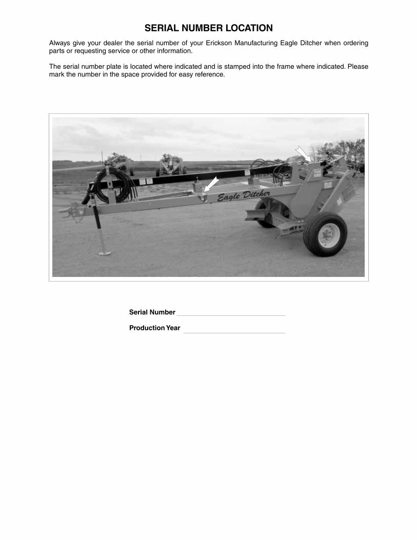
SERIAL NUMBER LOCATIONAlways give your dealer the serial number of your Erickson Manufacturing Eagle Ditcher when ordering parts or requesting service or other information.
The serial number plate is located where indicated and is stamped into the frame where indicated. Please mark the number in the space provided for easy reference.

TABLE OF CONTENTS
SECTION DESCRIPTION PAGE
1 Introduction ......................................................... 1
2 Safety .................................................................... 2
2.1 general Safety ....................................................... 3
2.2 Safety Training ....................................................... 4
2.3 Safety Signs ........................................................... 4
2.4 Preparation Safety ................................................. 5
2.5 Operating Safety .................................................... 5
2.6 Operating Hazard Area .......................................... 6
2.7 Maintenance Safety ............................................... 6
2.8 Hydraulic Safety ..................................................... 7
2.9 Transport Safety ..................................................... 7
2.10 Storage Safety ....................................................... 8
2.11 Tire Safety .............................................................. 8
2.12 Sign-Off form ........................................................ 9
3 Safety Sign Locations ........................................11
4 Operation ............................................................ 15
4.1 To the New Operator or Owner ............................ 15
4.2 Machine Components .......................................... 16
4.3 Machine break-In ................................................. 17
4.4 Pre-Operation Checklist ....................................... 17
4.5 Equipment Matching ............................................ 18
4.6 Attaching/Unhooking ............................................ 19
4.7 field Operation .................................................... 25
4.8 Transporting ......................................................... 43
4.9 Storage ................................................................ 44
5 Service and Maintenance .................................. 45
5.1 Service ................................................................. 45
5.2 Maintenance ........................................................ 53
6 Trouble Shooting ............................................... 59
7 Specifications .................................................... 61
7.1 Mechanical ........................................................... 61
7.2 bolt Torque ........................................................... 62
7.3 Hydraulic fitting Torque ........................................ 63
8 Index ................................................................... 65

1
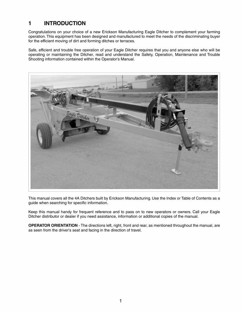
1 INTRODUCTIONCongratulations on your choice of a new Erickson Manufacturing Eagle Ditcher to complement your farming operation. This equipment has been designed and manufactured to meet the needs of the discriminating buyer for the efficient moving of dirt and forming ditches or terraces.
Safe, efficient and trouble free operation of your Eagle Ditcher requires that you and anyone else who will be operating or maintaining the Ditcher, read and understand the Safety, Operation, Maintenance and Trouble Shooting information contained within the Operator's Manual.
This manual covers all the 4A Ditchers built by Erickson Manufacturing. Use the Index or Table of Contents as a guide when searching for specific information.
Keep this manual handy for frequent reference and to pass on to new operators or owners. Call your Eagle Ditcher distributor or dealer if you need assistance, information or additional copies of the manual.
OPERATOR ORIENTATION - The directions left, right, front and rear, as mentioned throughout the manual, are as seen from the driver's seat and facing in the direction of travel.
2
If you have any questions not answered in this manual or require additional copies or the manual is dam-aged, please contact your dealer or ERICKSON Manufacturing Co., Inc., 13946 86th Street S.E., Milnor, North Dakota, USA, 58060-9750, Phone (701) 427-5831, Toll Free 1 (888) 427-5944, Fax (701) 427-5531 or Email [email protected]
2 SAFETY
SAFETY ALERT SYMBOL
Why is SAFETY important to you?
The Safety Alert symbol identifies important safety messages on the Erickson Eagle Ditcher and in the manual. When you see this symbol, be alert to the possibility of personal injury or death. Follow the instructions in the safety message.
This Safety Alert symbol means ATTENTION! BECOME ALERT! YOUR SAFETY IS INVOLVED!
Accidents Disable and Kill Accidents Cost Accidents Can Be Avoided
3 Big Reasons
DANGER - Indicates an imminently hazardous situation that, if not avoided, will result in death or serious injury. This signal word is to be limited to the most ex-treme situations typically for machine components which, for functional pur-poses, cannot be guarded.
WARNING - Indicates a potentially hazardous situ-ation that, if not avoided, could result in death or serious injury, and includes hazards that are exposed when guards are removed. It may also be used to alert against unsafe practices.
CAUTION - Indicates a potentially hazardous situ-ation that, if not avoided, may result in minor or moderate injury. It may also be used to alert against unsafe prac-tices.
SIGNAL WORDS:
Note the use of the signal words DANGER, WARNING and CAUTION with the safety mes-sages. The appropriate signal word for each message has been selected using the following guide-lines:
3
SAFETYYOU are responsible for the SAFE operation and maintenance of your Erickson Manufacturing Eagle Ditcher. YOU must ensure that you and anyone else who is going to operate, maintain or work around the Eagle Ditcher be familiar with the operating and main-tenance procedures and related SAFETY information contained in this manual. This manual will take you step-by-step through your working day and alerts you to all good safety practices that should be adhered to while operating the Ditcher.
Remember, YOU are the key to safety. Good safety practices not only protect you but also the people around you. Make these practices a working part of your safety program. Be certain that EVERYONE operating this equipment is familiar with the recom-mended operating and maintenance procedures and follows all the safety precautions. Most accidents can be prevented. Do not risk injury or death by ignoring good safety practices.
• Ditcher ownersmust give operating instructionsto operators or employees before allowing them to operate the machine, and at least annually thereafter.
• Themost importantsafetydeviceon thisequip-ment is a SAFE operator. It is the operator’s re-sponsibility to read and understand ALL Safety and Operating instructions in the manual and to follow them. All accidents can be avoided.
• A person who has not read and understood alloperating and safety instructions is not qualified to operate the machine. An untrained operator ex-poses himself and bystanders to possible serious injury or death.
• Do not modify the equipment in any way.Unauthorized modification may impair the func-tion and/or safety and could affect the life of the equipment.
• ThinkSAFETY!WorkSAFELY!
2.1 GENERAL SAFETY 1. Read and understand the
Operator’s Manual and all safe-ty signs before operating, main-taining, adjusting or unplugging the Ditcher.
2. Only trained competent persons shall operate the Ditcher. An untrained operator is not qualified to operate the machine.
3. Have a first-aid kit available for use should the need arise and know how to use it.
4. Provide a fire extinguisher for use in case of an accident. Store in a highly visible place.
5. Do not allow riders.
6. Do not allow children, spectators or bystanders within hazard area of machine.
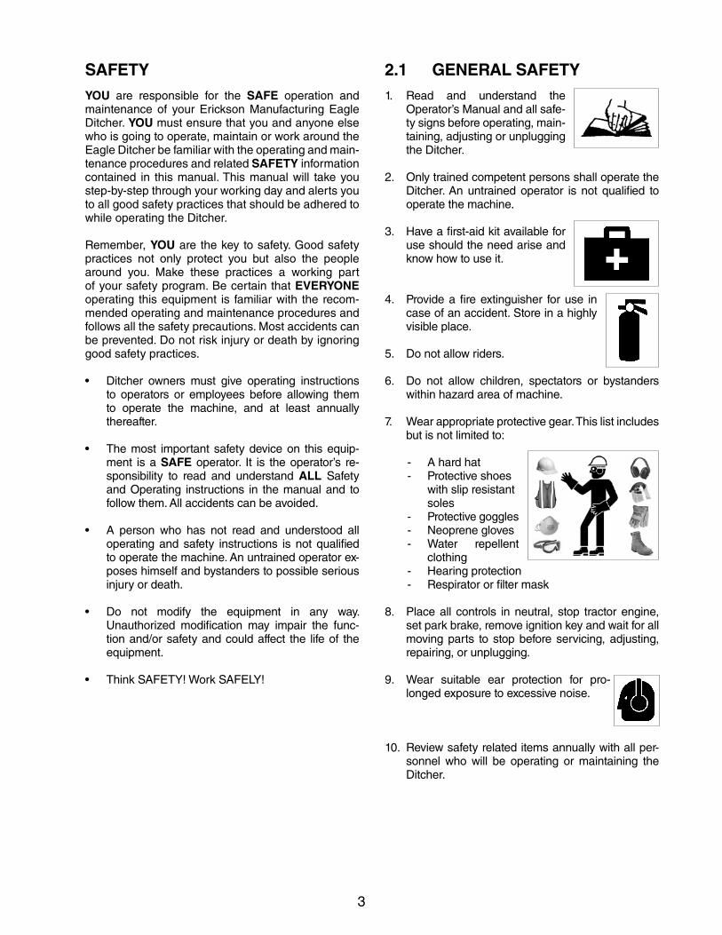
7. Wear appropriate protective gear. This list includes but is not limited to:
- A hard hat- Protective shoes with slip resistant soles- Protective goggles- Neoprene gloves- Water repellent
clothing- Hearing protection- Respirator or filter mask
8. Place all controls in neutral, stop tractor engine, set park brake, remove ignition key and wait for all moving parts to stop before servicing, adjusting, repairing, or unplugging.
9. Wear suitable ear protection for pro-longed exposure to excessive noise.
10. Review safety related items annually with all per-sonnel who will be operating or maintaining the Ditcher.
4
2.2 SAFETY TRAINING1. Safety is a primary concern in the design and man-
ufacture of our products. Unfortunately, our efforts to provide safe equipment can be wiped out by a single careless act of an operator or bystander.
2. In addition to the design and configuration of equipment, hazard control and accident preven-tion are dependent upon the awareness, con-cern, prudence and proper training of personnel involved in the operation, transport, maintenance and storage of this equipment.
3. It has been said, "The best safety feature is an informed, careful op-erator." We ask you to be that kind of an operator. It is the operator's responsibilitytoreadandunderstandALLSafetyand Operating instructions in the manual and to follow these. Accidents can be avoided.
4. Working with unfamiliar equipment can lead to careless injuries. Read this manual, and the manual for your auxiliary equipment, before assembly or operating, to acquaint yourself with the machines. If this machine is used by any person other than yourself. It is the ma-chine owner's responsibility to make certain that the operator, prior to operating:
a. Reads and understands the operator's manuals.
b. Is instructed in safe and proper use.
5. Know your controls and how to stop the tractor, ditcher and any other auxiliary equipment quickly in an emergency. Read this manual and the one provided with your other equipment.
6. Train all new personnel and review instructions frequently with existing workers. Be certain only a properly trained and physically able person will operate the machinery. A person who has not read and understood all operating and safety instruc-tions is not qualified to operate the machine. An untrained operator exposes himself and bystand-ers to possible serious injury or death. If the elder-ly are assisting with work, their physical limitations need to be recognized and accommodated.
2.3 SAFETY SIGNS1. Keep safety signs clean and legible at all times.
2. Replace safety signs that are missing or have be-come illegible.
3. Replaced parts that displayed a safety sign should also display the current sign.
4. Safety signs are available from your authorized Distributor or Dealer Parts Department or the factory.
How to Install Safety Signs:
• Besurethattheinstallationareaiscleananddry.
• Besuretemperatureisabove50°F(10°C).
• Determineexactpositionbeforeyou remove thebacking paper. (See Section 3).
• Removethesmallestportionofthesplitbackingpaper.
• Alignthesignoverthespecifiedareaandcareful-ly press the small portion with the exposed sticky backing in place.
• Slowlypeelback the remainingpaperandcare-fully smooth the remaining portion of the sign in place.
• Smallairpocketscanbepiercedwithapinandsmoothed out using the piece of sign backing paper.
5
2.4 PREPARATION1. Never operate the tractor and machine until you
have read and completely understand this manu-al, the auxiliary equipment Operator's Manual, and each of the Safety Messages found on the safety signs on the ditcher and auxiliary equipment.
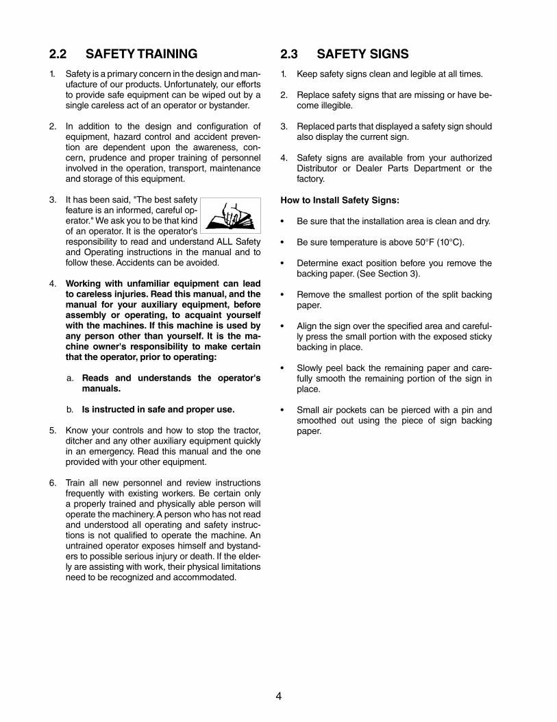
2. Personal protection equipment including hard hat, safety glass-es, safety shoes, and gloves are recommend-ed during assembly, installation, operation, adjustment, maintain-ing, repairing, removal, or moving the implement. Do not allow long hair, loose fitting clothing or jew-elery to be around equipment.
3. PROLONGED EXPOSURE TO LOUD NOISE MAY CAUSE PERMANENT HEARING LOSS!
Motors or equipment attached can of-ten be noisy enough to cause permanent, partial hearing loss. We recommend that you wear hear-ing protection on a full-time basis if the noise in the Operator's position exceeds 80db. Noise over 85db on a long-term basis can cause severe hear-ing loss. Noise over 90db adjacent to the Operator over a long-term basis may cause permanent, total hearing loss. NOTE: Hearing loss from loud noise (from tractors, chain saws, radios, and other such sources close to the ear) is cumulative over a lifetime without hope of natural recovery.
4. Operate machine only with a tractor equipped with an approved Roll-Over-Protective-Structure (ROPS). Always wear your seatbelt. Serious injury or death could result from falling off the tractor - particularly during a turn-over when the operator could be pinned under the ROPS or the tractor.
5. Clear working area of debris, trash or hidden ob-stacles that might be hooked or snagged, causing injury, damage or tripping.
6. Do not operate ditcher where there is a chance of buried utilities. Check with local authorities on location of utilities before ditching.
7. Operate only in daylight or good artificial light.
8. Be sure machine is properly anchored, adjusted and in good operating condition.
9. Ensure that all safety shielding and safety signs are properly installed and in good condition.
2.5 OPERATING SAFETY1. Read and understand the Operator’s Manual and
all safety signs before operating, servicing, adjust-ing, repairing or unplugging.
2. Do not allow riders.
3. Install and secure all guards and shields before starting or operating.
4. Keep hands, feet, hair and clothing away from all moving and/or rotating parts.
5. Place all controls in neutral, stop tractor engine, set park brake, remove ignition key and wait for all moving parts to stop before servicing, adjusting, repairing or unplugging.
6. Clear the area of bystanders, especially small chil-dren, before starting.
7. Stay away from machine hazard area when trac-tor engine or machine are running. Keep others away.
8. Keep all hydraulic lines, fittings and couplers tight and free of leaks before using.
9. Clean reflectors, SMV and lights before transporting.
10. Use hazard flashers on tractor when transporting.
11. Do not put hands or feet under machine while tractor engine or machine are running.
12. Objects can be thrown out from under machine with sufficient force to severely injure people. Stay away from machine when it is running. Keep oth-ers away.
13. Always know the area you are ditching. Never op-erate ditcher in an area that has hidden obstacles. Do not operate ditcher where there is a chance of buried utilities. Check with local authorities on location of utilities before ditching.
14. Never exceed the limits of a piece of machinery. If its ability to do a job, or to do so safely is in ques-tion, DO NOT ATTEMPT TO DO THE JOB.
15. Review safety instructions with all operators annually.
6
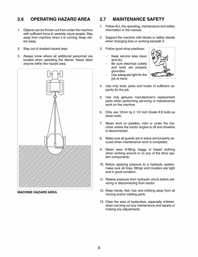
2.6 OPERATING HAZARD AREA
1. Objects can be thrown out from under the machine with sufficient force to severely injure people. Stay away from machine when it is running. Keep oth-ers away.
2. Stay out of shaded hazard area.
3. Always know where all additional personnel are located when operating the ditcher. Never allow anyone within the hazard area.
MACHINE HAZARD AREA
2.7 MAINTENANCE SAFETY1. FollowALLtheoperating,maintenanceandsafety
information in the manual.
2. Support the machine with blocks or safety stands when changing tires or working beneath it.
3. Follow good shop practices:
- Keep service area clean and dry.
- Be sure electrical outlets and tools are properly grounded.
- Use adequate light for the job at hand.
4. Use only tools, jacks and hoists of sufficient ca-pacity for the job.
5. Use only genuine manufacturer's replacement parts when performing servicing or maintenance work on the machine.
6. Only use 12mm by 2 1/2 inch Grade 8.8 bolts as shear bolts.
7. Never work on paddles, rotor or under the ma-chine unless the tractor engine is off and driveline is disconnected.
8. Make sure all guards are in place and properly se-cured when maintenance work is completed.
9. Never wear ill-fitting, baggy or frayed clothing when working around or on any of the drive sys-tem components.
10. Before applying pressure to a hydraulic system, make sure all lines, fittings and couplers are tight and in good condition.
11. Relieve pressure from hydraulic circuit before ser-vicing or disconnecting from tractor.
12. Keep hands, feet, hair and clothing away from all moving and/or rotating parts.
13. Clear the area of bystanders, especially children, when carrying out any maintenance and repairs or making any adjustments.
7
2.8 HYDRAULIC SAFETY
1. Make sure that all components in the hydraulic system are kept in good condition and are clean.
2. Replace any worn, cut, abraded, flattened or crimped hoses and metal lines.
3. Relieve pressure before working on hydraulic system.
4. Do not attempt any makeshift repairs to the hy-draulic lines, fittings or hoses by using tape, clamps or cements. The hydraulic system oper-ates under extremely high-pressure. Such repairs will fail suddenly and create a hazardous and un-safe condition.
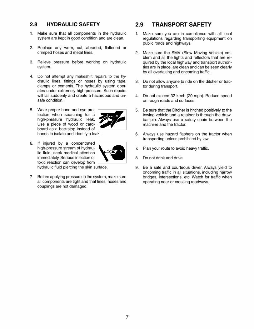
5. Wear proper hand and eye pro-tection when searching for a high-pressure hydraulic leak. Use a piece of wood or card-board as a backstop instead of hands to isolate and identify a leak.
6. If injured by a concentrated high-pressure stream of hydrau-lic fluid, seek medical attention immediately. Serious infection or toxic reaction can develop from hydraulic fluid piercing the skin surface.
7. Before applying pressure to the system, make sure all components are tight and that lines, hoses and couplings are not damaged.
2.9 TRANSPORT SAFETY1. Make sure you are in compliance with all local
regulations regarding transporting equipment on public roads and highways.
2. Make sure the SMV (Slow Moving Vehicle) em-blem and all the lights and reflectors that are re-quired by the local highway and transport authori-ties are in place, are clean and can be seen clearly by all overtaking and oncoming traffic.
3. Do not allow anyone to ride on the ditcher or trac-tor during transport.
4. Do not exceed 32 km/h (20 mph). Reduce speed on rough roads and surfaces.
5. Be sure that the Ditcher is hitched positively to the towing vehicle and a retainer is through the draw-bar pin. Always use a safety chain between the machine and the tractor.
6. Always use hazard flashers on the tractor when transporting unless prohibited by law.
7. Plan your route to avoid heavy traffic.
8. Do not drink and drive.
9. Be a safe and courteous driver. Always yield to oncoming traffic in all situations, including narrow bridges, intersections, etc. Watch for traffic when operating near or crossing roadways.
8
2.10 STORAGE SAFETY1. Store the unit in an area away from human activity.
2. Do not permit children to play on or around the stored machine.
3. Store the unit in a dry, level area. Support the frame with planks if required.
2.11 TIRE SAFETY1. Failure to follow proper procedures when mount-
ing a tire on a wheel or rim can produce an explo-sion which may result in serious injury or death.
2. Do not attempt to mount a tire unless you have the proper equipment and experience to do the job.
3. Have a qualified tire dealer or repair service per-form required tire maintenance.
4. When replacing worn tires, make sure they meet the original tire specifications. Never undersize.

9
2.12 SIGN-OFF FORMErickson Manufacturing Co. Inc. follow the general Safety Standards specified by the American Society of Agricultural and Biological Engineers (ASABE) and the Occupational Safety and Health Administration (OSHA). Anyonewhowillbeoperatingand/ormaintaining theDitchermust readandclearlyunderstandALLSafety, Operating and Maintenance information presented in this manual.
Do not operate or allow anyone else to operate this equipment until such information has been reviewed. Annu-ally review this information before the season start-up.
Make these periodic reviews of SAFETY and OPERATION a standard practice for all of your equipment. We feel that an untrained operator is unqualified to operate this machine.
A sign-off sheet is provided for your record keeping to show that all personnel who will be working with the equipment have read and understand the information in the Operator’s Manual and have been instructed in the operation of the equipment.
SIGN-OFF FORM
DATE EMPLOYEE'S SIGNATURE EMPLOYER'S SIGNATURE

10
11
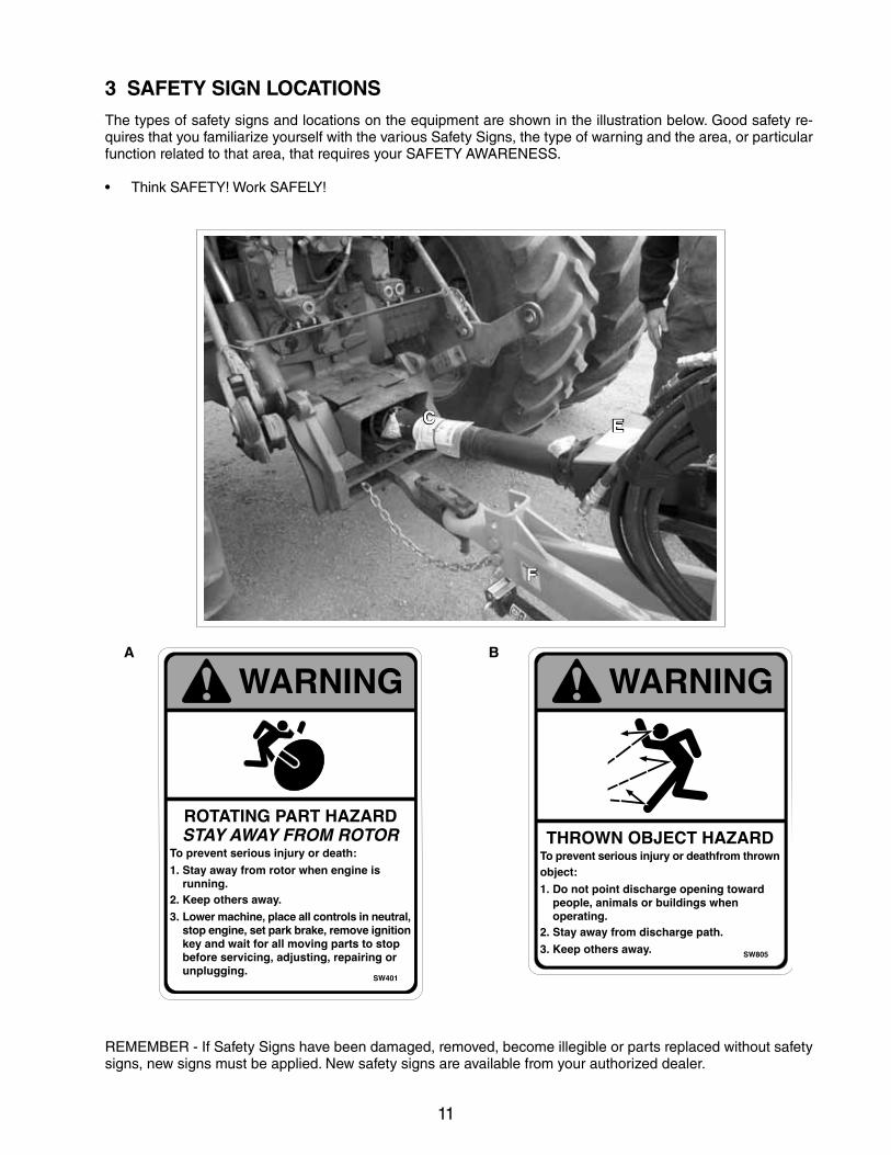
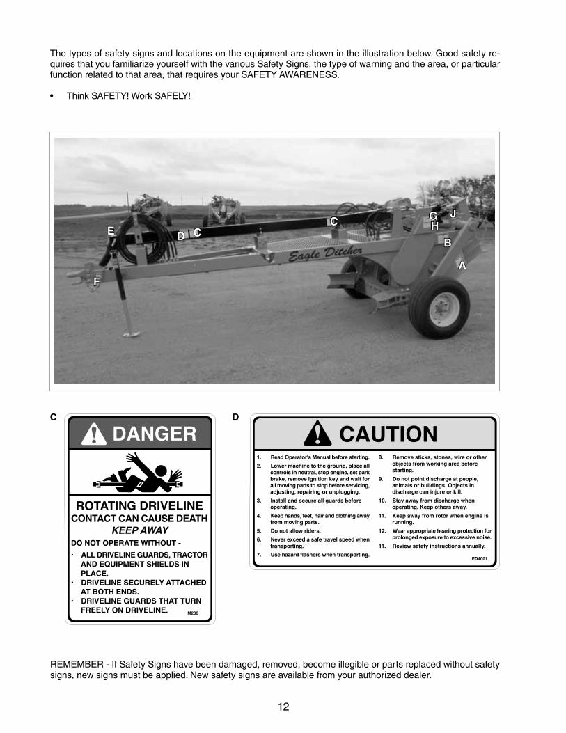
3 SAFETY SIGN LOCATIONSThe types of safety signs and locations on the equipment are shown in the illustration below. Good safety re-quires that you familiarize yourself with the various Safety Signs, the type of warning and the area, or particular function related to that area, that requires your SAFETY AWARENESS.
• ThinkSAFETY!WorkSAFELY!
REMEMBER - If Safety Signs have been damaged, removed, become illegible or parts replaced without safety signs, new signs must be applied. New safety signs are available from your authorized dealer.
A B
EC
F
12
DC
REMEMBER - If Safety Signs have been damaged, removed, become illegible or parts replaced without safety signs, new signs must be applied. New safety signs are available from your authorized dealer.
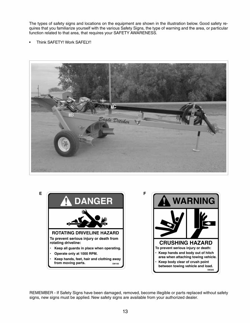
The types of safety signs and locations on the equipment are shown in the illustration below. Good safety re-quires that you familiarize yourself with the various Safety Signs, the type of warning and the area, or particular function related to that area, that requires your SAFETY AWARENESS.
• ThinkSAFETY!WorkSAFELY!
C
A
BD
F
E HC G J
13
FE
REMEMBER - If Safety Signs have been damaged, removed, become illegible or parts replaced without safety signs, new signs must be applied. New safety signs are available from your authorized dealer.
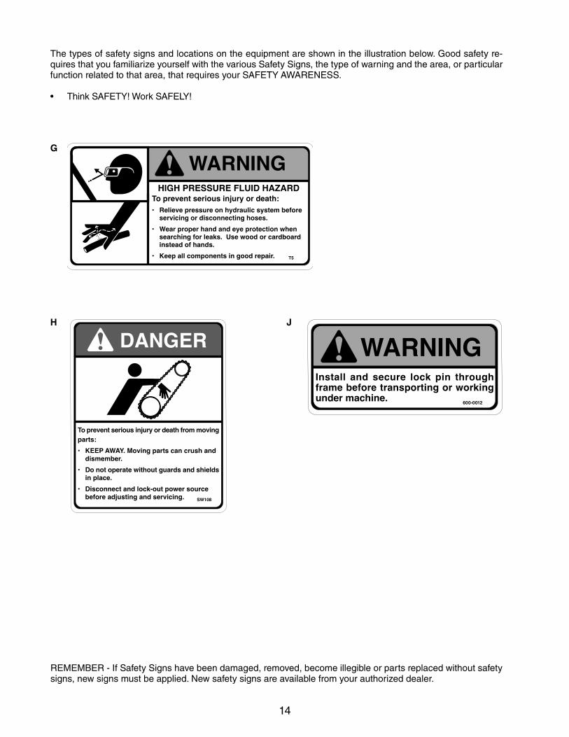
The types of safety signs and locations on the equipment are shown in the illustration below. Good safety re-quires that you familiarize yourself with the various Safety Signs, the type of warning and the area, or particular function related to that area, that requires your SAFETY AWARENESS.
• ThinkSAFETY!WorkSAFELY!
C
B
J
14
G
H
REMEMBER - If Safety Signs have been damaged, removed, become illegible or parts replaced without safety signs, new signs must be applied. New safety signs are available from your authorized dealer.
The types of safety signs and locations on the equipment are shown in the illustration below. Good safety re-quires that you familiarize yourself with the various Safety Signs, the type of warning and the area, or particular function related to that area, that requires your SAFETY AWARENESS.
• ThinkSAFETY!WorkSAFELY!
J
600-0012
15
4 OPERATION
OPERATING SAFETY• ReadandunderstandtheOperator’sManualand
all safety signs before operating, servicing, ad-justing, repairing or unplugging.
• Donotallowriders.
• Installandsecureallguardsandshieldsbeforestarting or operating.
• Keephands,feet,hairandclothingawayfromallmoving and/or rotating parts.
• Placeallcontrolsinneutral,stoptractorengine,set park brake, remove ignition key and wait for all moving parts to stop before servicing, adjust-ing, repairing or unplugging.
• Clear the area of bystanders, especially smallchildren, before starting.
• Stayawayfrommachinehazardareawhentrac-tor engine or machine are running. Keep others away.
• Keepallhydrauliclines,fittingsandcouplerstightand free of leaks before using.
• Clean reflectors, SMV and lights beforetransporting.
• Use hazard flashers on tractor whentransporting.
• Donotputhandsor feetundermachinewhiletractor engine or machine are running.
• Objectscanbethrownoutfromundermachinewith sufficient force to severely injure people. Stay away from machine when it is running. Keep oth-ers away.
• Always know the area you are ditching. Neveroperate ditcher in an area that has hidden ob-stacles. Do not operate ditcher where there is a chance of buried utilities. Check with local au-thorities on location of utilities before ditching.
• Neverexceedthelimitsofapieceofmachinery.If its ability to do a job, or to do so safely is in question, DO NOT ATTEMPT TO DO THE JOB.
• Review safety instructions with all operatorsannually.
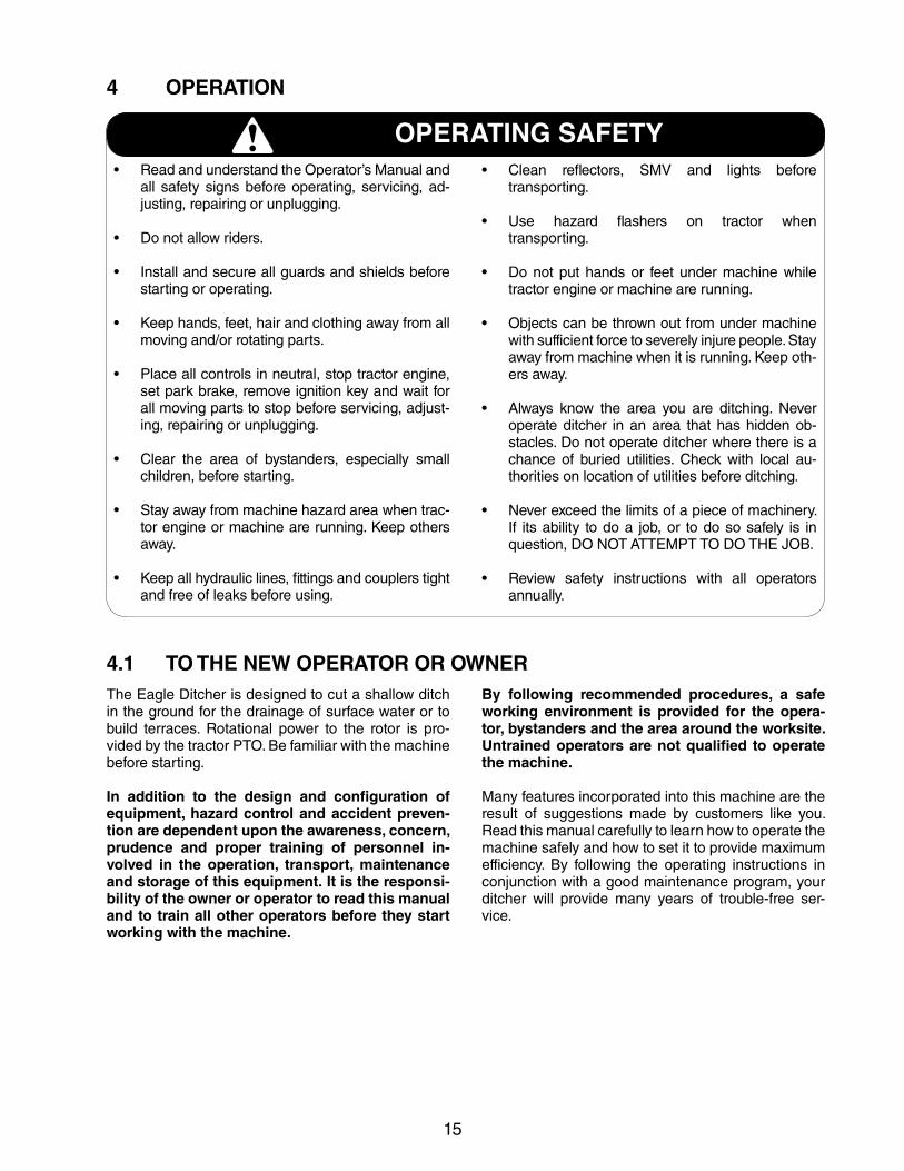
4.1 TO THE NEW OPERATOR OR OWNERThe Eagle Ditcher is designed to cut a shallow ditch in the ground for the drainage of surface water or to build terraces. Rotational power to the rotor is pro-vided by the tractor PTO. Be familiar with the machine before starting.
In addition to the design and configuration of equipment, hazard control and accident preven-tion are dependent upon the awareness, concern, prudence and proper training of personnel in-volved in the operation, transport, maintenance and storage of this equipment. It is the responsi-bility of the owner or operator to read this manual and to train all other operators before they start working with the machine.
By following recommended procedures, a safe working environment is provided for the opera-tor, bystanders and the area around the worksite. Untrained operators are not qualified to operate the machine.
Many features incorporated into this machine are the result of suggestions made by customers like you. Read this manual carefully to learn how to operate the machine safely and how to set it to provide maximum efficiency. By following the operating instructions in conjunction with a good maintenance program, your ditcher will provide many years of trouble-free ser-vice.
16
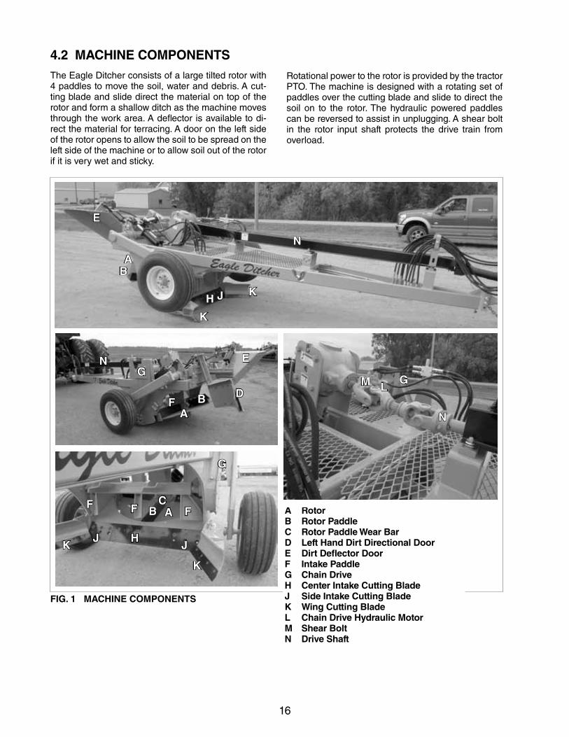
4.2 MACHINE COMPONENTSThe Eagle Ditcher consists of a large tilted rotor with 4 paddles to move the soil, water and debris. A cut-ting blade and slide direct the material on top of the rotor and form a shallow ditch as the machine moves through the work area. A deflector is available to di-rect the material for terracing. A door on the left side of the rotor opens to allow the soil to be spread on the left side of the machine or to allow soil out of the rotor if it is very wet and sticky.
FIG. 1 MACHINE COMPONENTS
A RotorB Rotor PaddleC Rotor Paddle Wear BarD Left Hand Dirt Directional DoorE Dirt Deflector DoorF Intake PaddleG Chain DriveH Center Intake Cutting BladeJ Side Intake Cutting BladeK Wing Cutting BladeL Chain Drive Hydraulic MotorM Shear BoltN Drive Shaft
Rotational power to the rotor is provided by the tractor PTO. The machine is designed with a rotating set of paddles over the cutting blade and slide to direct the soil on to the rotor. The hydraulic powered paddles can be reversed to assist in unplugging. A shear bolt in the rotor input shaft protects the drive train from overload.
A
AB
B
C
D
E
E
F F
GG
HK
K
M
J
L
N
N
AB
G
F
F
HJJK
K
N
17
4.3 MACHINE BREAK-INAlthough there are no operational restrictions on the Ditcher when used for the first time, it is recommend-ed that the following mechanical items be checked:
A. After operating for 1/2 hour and 5 hours, the following MUST be followed or war- ranty will be void:
1. Tighten wheel bolts and other fasteners to their specified torque levels.
2. Check that the rotor and paddles are in good condition.
3. Check that the PTO driveline shield turns free-ly and telescopes easily.
4. Lubricateallgreasepoints.
5. Check tension in chain drive system. Adjust as required.
6. Check for and remove all entangled material.
B. After operating for 10 hours:
1. Repeat items 1 through 6 of Section A.
2. Then go to the regular service schedule as defined in Section 5.
4.4 PRE-OPERATION CHECKLISTEfficient and safe operation of the Ditcher requires that each operator reads and understands the oper-ating procedures and all related safety precautions outlined in this section. A pre-operation checklist is provided for the operator. It is important for both the personal safety and maintaining the good mechani-cal condition of the Ditcher that this checklist is fol-lowed.
Before operating the Ditcher and each time thereaf-ter, the following areas should be checked off:
1. Lubricatethemachineperthescheduleoutlinedin Section 5 Service and Maintenance.
2. Use only a tractor of adequate power and weight to pull the machine.
3. Check that the machine is properly attached to the tractor. Be sure a retainer is used through the drawbar pin and a safety chain around the draw-bar cage.
4. Check that the PTO driveline shield turns freely and that the driveline can telescope easily.
5. Check the tire pressure. Bring to the specified level.
6. Check the paddles. Be sure they are not damaged or broken and are securely fastened to the rotor. Tighten or replace as required.
7. Remove entangled material from rotating compo-nents. Material caught next to bearings will cause seal damage.
8. Inspect all hydraulic lines, hoses, couplers and fittings. Tighten, repair or replace any leaking or damaged components.
9. Install and secure all guards, doors and covers be-fore starting.
18
Table 1 Recommended Horspower:
Model Horsepower
1000 RPM 200 MAX
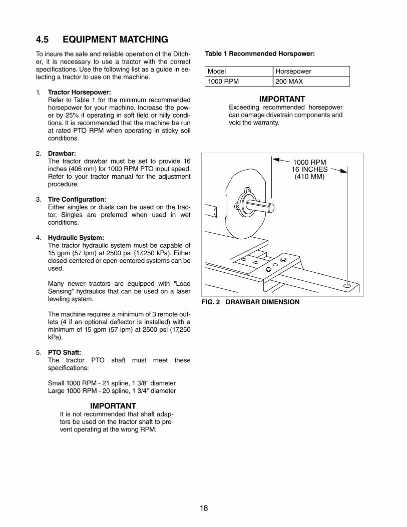
IMPORTANTExceeding recommended horsepower can damage drivetrain components and void the warranty.
4.5 EQUIPMENT MATCHINGTo insure the safe and reliable operation of the Ditch-er, it is necessary to use a tractor with the correct specifications. Use the following list as a guide in se-lecting a tractor to use on the machine.
1. Tractor Horsepower: Refer to Table 1 for the minimum recommended
horsepower for your machine. Increase the pow-er by 25% if operating in soft field or hilly condi-tions. It is recommended that the machine be run at rated PTO RPM when operating in sticky soil conditions.
2. Drawbar: The tractor drawbar must be set to provide 16
inches (406 mm) for 1000 RPM PTO input speed. Refer to your tractor manual for the adjustment procedure.
3. Tire Configuration: Either singles or duals can be used on the trac-
tor. Singles are preferred when used in wet conditions.
4. Hydraulic System: The tractor hydraulic system must be capable of
15 gpm (57 lpm) at 2500 psi (17,250 kPa). Either closed-centered or open-centered systems can be used.
Many newer tractors are equipped with "LoadSensing" hydraulics that can be used on a laser leveling system.
The machine requires a minimum of 3 remote out-lets (4 if an optional deflector is installed) with a minimum of 15 gpm (57 lpm) at 2500 psi (17,250 kPa).
5. PTO Shaft: The tractor PTO shaft must meet these
specifications:
Small 1000 RPM - 21 spline, 1 3/8" diameter Large1000RPM-20spline,13/4"diameter
IMPORTANTIt is not recommended that shaft adap-tors be used on the tractor shaft to pre-vent operating at the wrong RPM.
FIG. 2 DRAWBAR DIMENSION
19
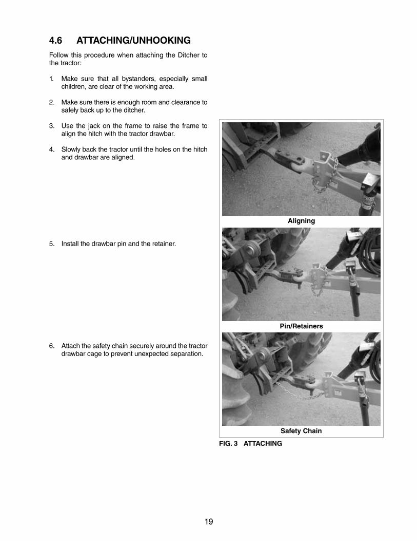
4.6 ATTACHING/UNHOOKING Follow this procedure when attaching the Ditcher to the tractor:
1. Make sure that all bystanders, especially small children, are clear of the working area.
2. Make sure there is enough room and clearance to safely back up to the ditcher.
3. Use the jack on the frame to raise the frame to align the hitch with the tractor drawbar.
4. Slowly back the tractor until the holes on the hitch and drawbar are aligned.
5. Install the drawbar pin and the retainer.
6. Attach the safety chain securely around the tractor drawbar cage to prevent unexpected separation.
Aligning
Pin/Retainers
Safety Chain
FIG. 3 ATTACHING
20
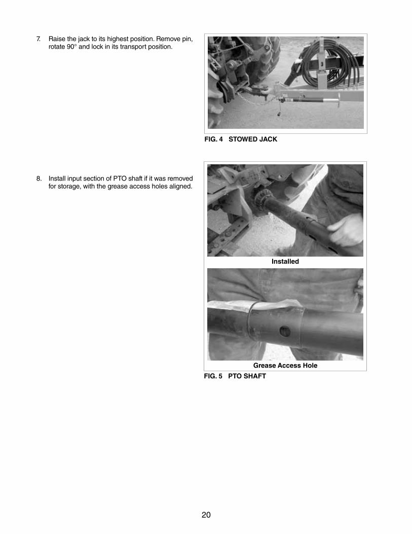
7. Raise the jack to its highest position. Remove pin, rotate90°andlockinitstransportposition.
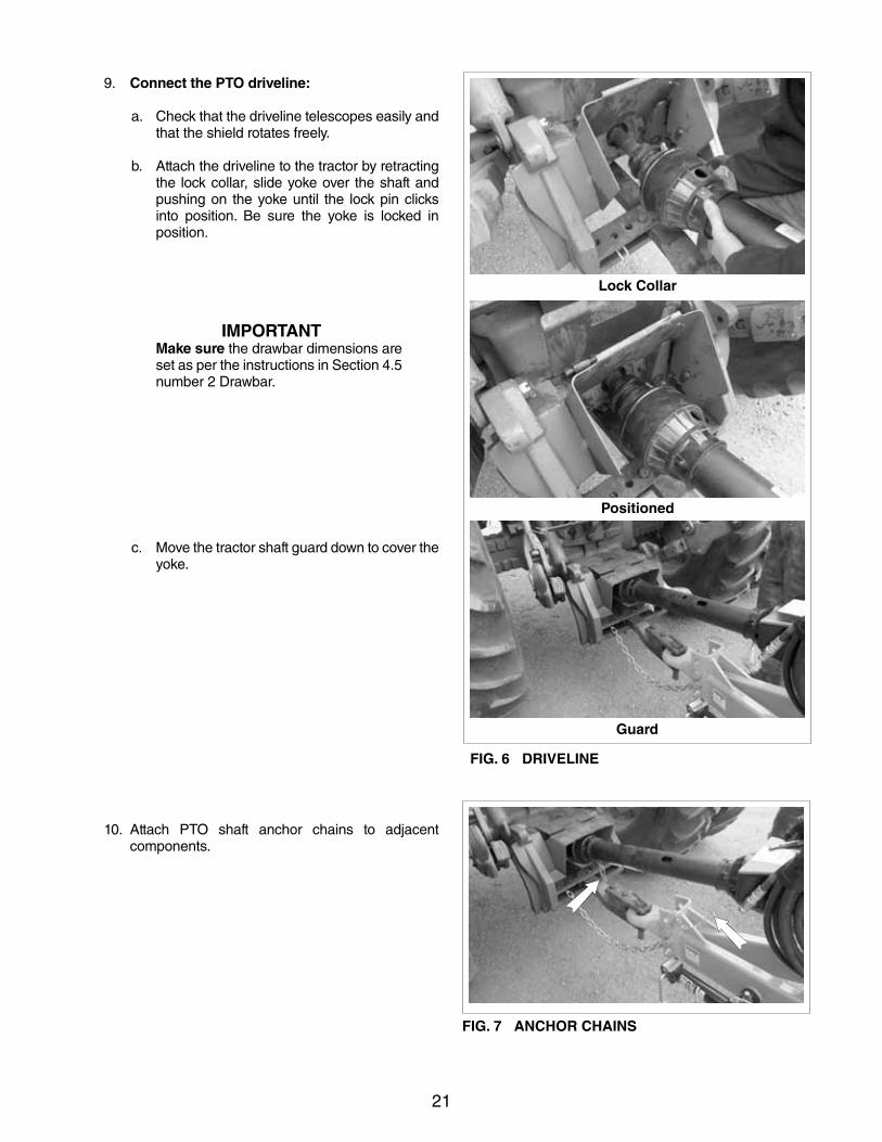
8. Install input section of PTO shaft if it was removed for storage, with the grease access holes aligned.
FIG. 4 STOWED JACK
Installed
Grease Access Hole
FIG. 5 PTO SHAFT
21
Lock Collar
Positioned
Guard
FIG. 6 DRIVELINE
FIG. 7 ANCHOR CHAINS
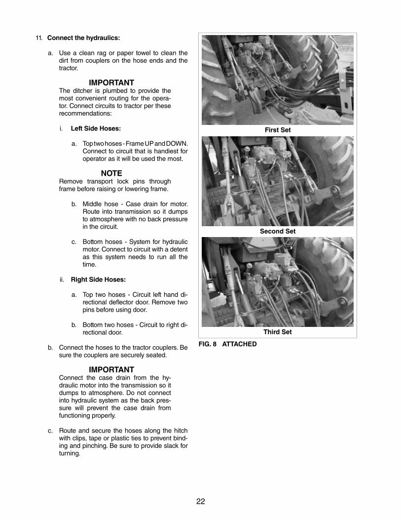
9. Connect the PTO driveline:
a. Check that the driveline telescopes easily and that the shield rotates freely.
b. Attach the driveline to the tractor by retracting the lock collar, slide yoke over the shaft and pushing on the yoke until the lock pin clicks into position. Be sure the yoke is locked in position.
IMPORTANTMake sure the drawbar dimensions are set as per the instructions in Section 4.5 number 2 Drawbar.
c. Move the tractor shaft guard down to cover the yoke.
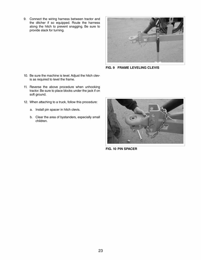
10. Attach PTO shaft anchor chains to adjacent components.
22
11. Connect the hydraulics:
a. Use a clean rag or paper towel to clean the dirt from couplers on the hose ends and the tractor.
IMPORTANTThe ditcher is plumbed to provide the most convenient routing for the opera-tor. Connect circuits to tractor per these recommendations:
i. Left Side Hoses:
a. Top two hoses - Frame UP and DOWN. Connect to circuit that is handiest for operator as it will be used the most.
NOTERemove transport lock pins through frame before raising or lowering frame.
b. Middle hose - Case drain for motor. Route into transmission so it dumps to atmosphere with no back pressure in the circuit.
c. Bottom hoses - System for hydraulic motor. Connect to circuit with a detent as this system needs to run all the time.
ii. Right Side Hoses:
a. Top two hoses - Circuit left hand di-rectional deflector door. Remove two pins before using door.
b. Bottom two hoses - Circuit to right di-rectional door.
b. Connect the hoses to the tractor couplers. Be sure the couplers are securely seated.
IMPORTANTConnect the case drain from the hy-draulic motor into the transmission so it dumps to atmosphere. Do not connect into hydraulic system as the back pres-sure will prevent the case drain from functioning properly.
c. Route and secure the hoses along the hitch with clips, tape or plastic ties to prevent bind-ing and pinching. Be sure to provide slack for turning.
First Set
Second Set
Third Set
FIG. 8 ATTACHED
23
FIG. 9 FRAME LEVELING CLEVIS
9. Connect the wiring harness between tractor and the ditcher if so equipped. Route the harness along the hitch to prevent snagging. Be sure to provide slack for turning.
10. Be sure the machine is level. Adjust the hitch clev-is as required to level the frame.
11. Reverse the above procedure when unhooking tractor. Be sure to place blocks under the jack if on soft ground.
12. When attaching to a truck, follow this procedure:
a. Install pin spacer in hitch clevis.
b. Clear the area of bystanders, especially small children.
FIG. 10 PIN SPACER
24
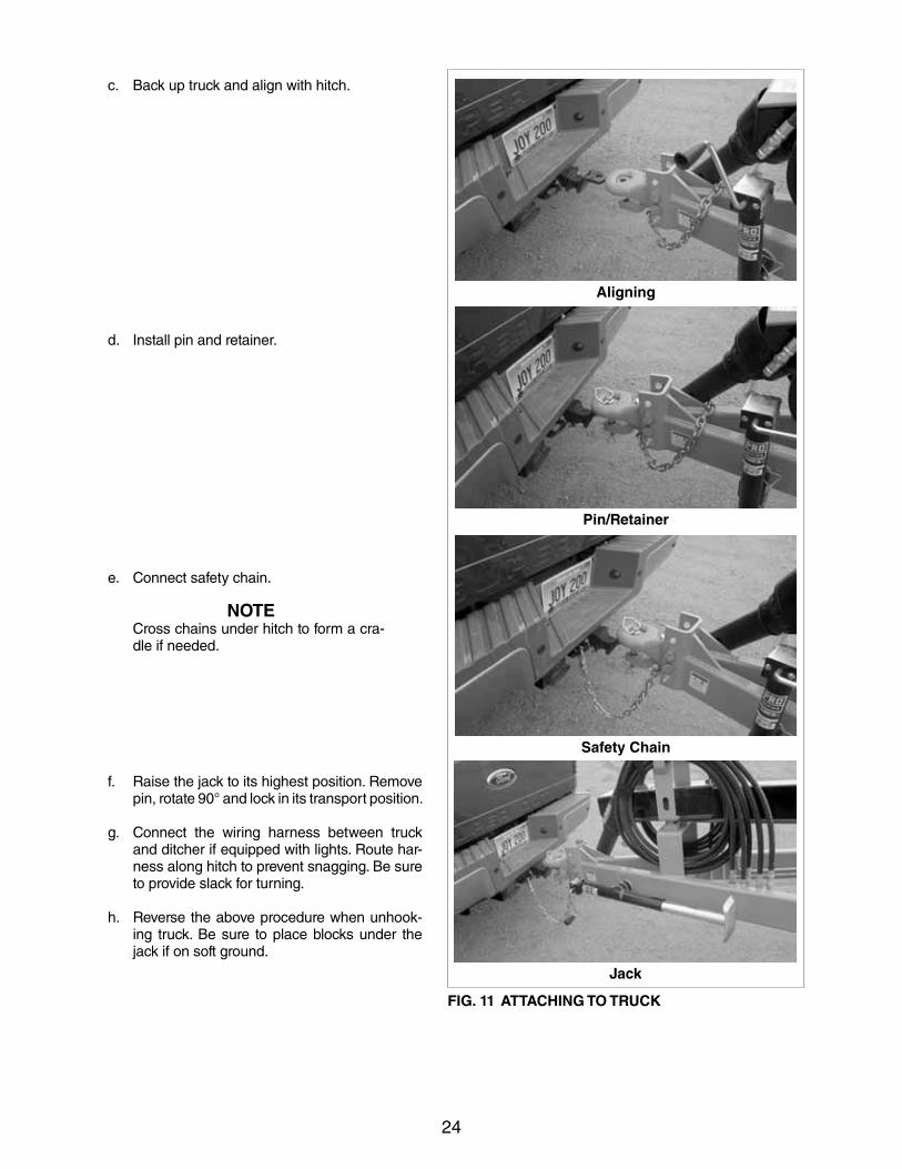
c. Back up truck and align with hitch.
d. Install pin and retainer.
e. Connect safety chain.
NOTECross chains under hitch to form a cra-dle if needed.
f. Raise the jack to its highest position. Remove pin,rotate90°andlockinitstransportposition.
g. Connect the wiring harness between truck and ditcher if equipped with lights. Route har-ness along hitch to prevent snagging. Be sure to provide slack for turning.
h. Reverse the above procedure when unhook-ing truck. Be sure to place blocks under the jack if on soft ground.
Pin/Retainer
Aligning
Safety Chain
Jack
FIG. 11 ATTACHING TO TRUCK
25
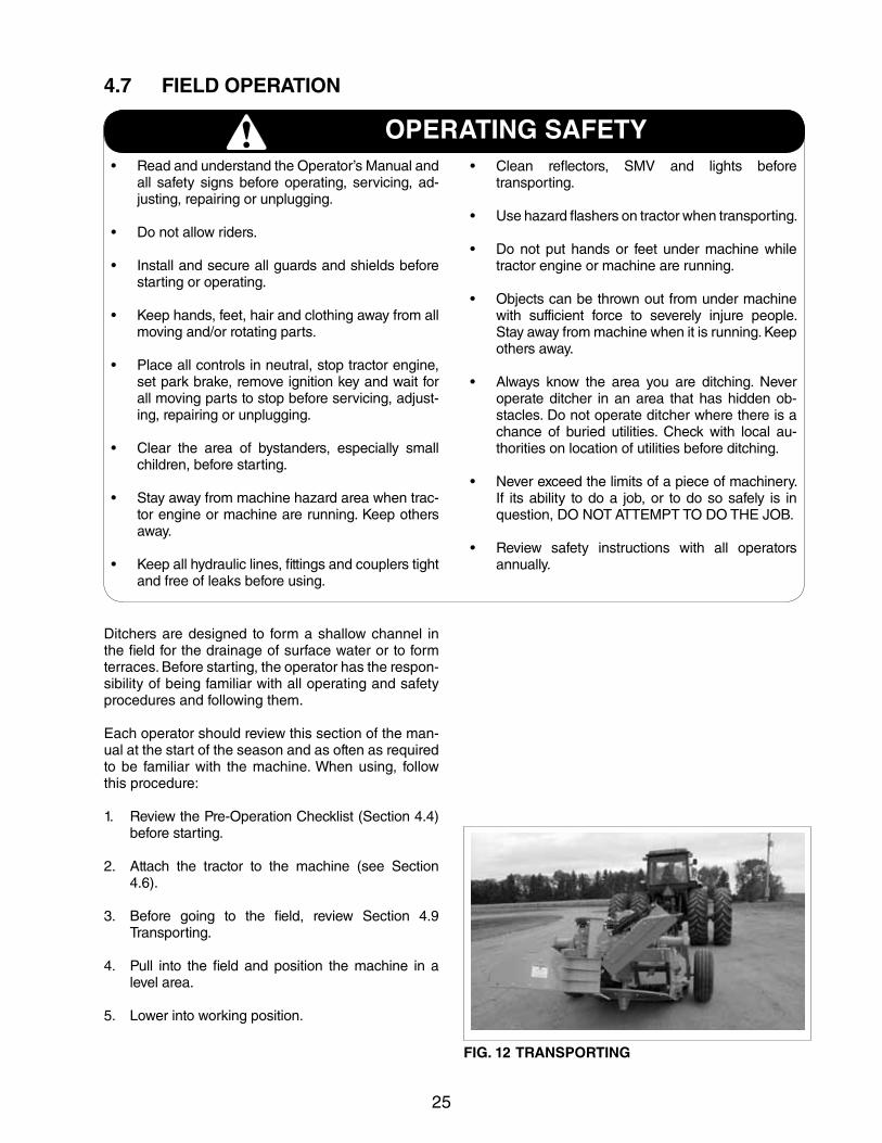
4.7 FIELD OPERATION
Ditchers are designed to form a shallow channel in the field for the drainage of surface water or to form terraces. Before starting, the operator has the respon-sibility of being familiar with all operating and safety procedures and following them.
Each operator should review this section of the man-ual at the start of the season and as often as required to be familiar with the machine. When using, follow this procedure:
1. Review the Pre-Operation Checklist (Section 4.4) before starting.
2. Attach the tractor to the machine (see Section 4.6).
3. Before going to the field, review Section 4.9 Transporting.
4. Pull into the field and position the machine in a level area.
5. Lowerintoworkingposition.
OPERATING SAFETY• ReadandunderstandtheOperator’sManualand
all safety signs before operating, servicing, ad-justing, repairing or unplugging.
• Donotallowriders.
• Installandsecureallguardsandshieldsbeforestarting or operating.
• Keephands,feet,hairandclothingawayfromallmoving and/or rotating parts.
• Placeallcontrolsinneutral,stoptractorengine,set park brake, remove ignition key and wait for all moving parts to stop before servicing, adjust-ing, repairing or unplugging.
• Clear the area of bystanders, especially smallchildren, before starting.
• Stayawayfrommachinehazardareawhentrac-tor engine or machine are running. Keep others away.
• Keepallhydrauliclines,fittingsandcouplerstightand free of leaks before using.
• Clean reflectors, SMV and lights beforetransporting.
• Usehazardflashersontractorwhentransporting.
• Donotputhandsor feetundermachinewhiletractor engine or machine are running.
• Objectscanbethrownoutfromundermachinewith sufficient force to severely injure people. Stay away from machine when it is running. Keep others away.
• Always know the area you are ditching. Neveroperate ditcher in an area that has hidden ob-stacles. Do not operate ditcher where there is a chance of buried utilities. Check with local au-thorities on location of utilities before ditching.
• Neverexceedthelimitsofapieceofmachinery.If its ability to do a job, or to do so safely is in question, DO NOT ATTEMPT TO DO THE JOB.
• Review safety instructions with all operatorsannually.
FIG. 12 TRANSPORTING
26
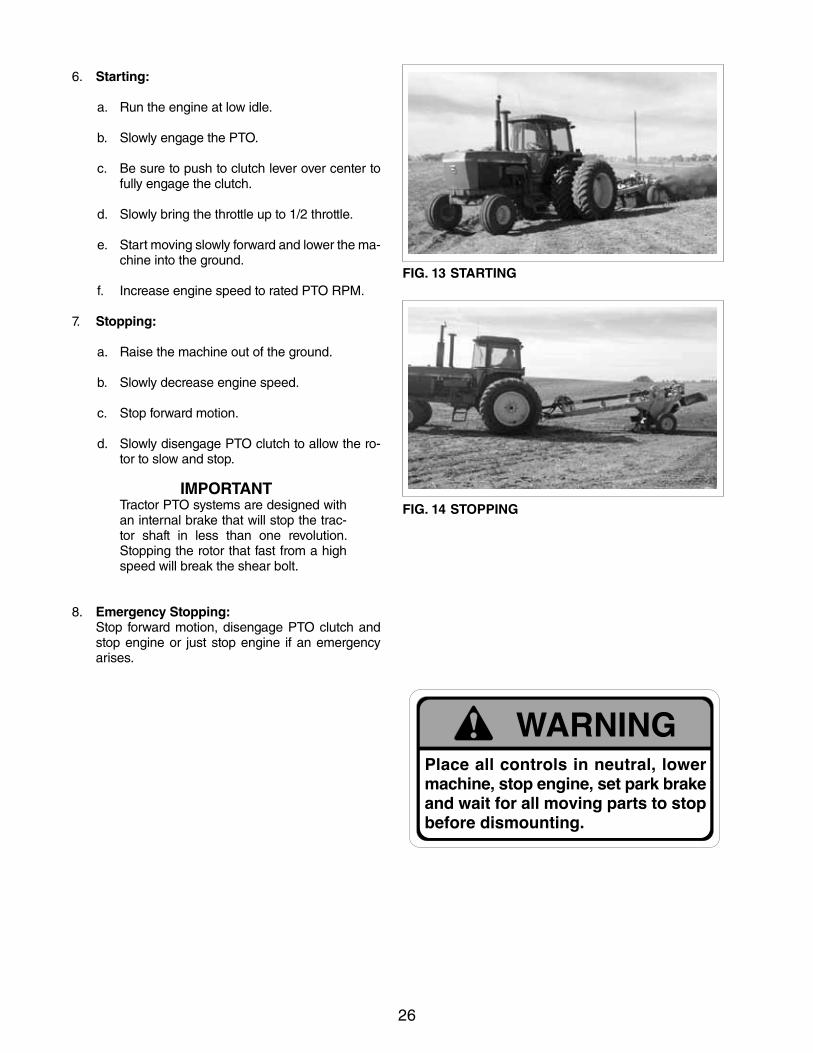
6. Starting:
a. Run the engine at low idle.
b. Slowly engage the PTO.
c. Be sure to push to clutch lever over center to fully engage the clutch.
d. Slowly bring the throttle up to 1/2 throttle.
e. Start moving slowly forward and lower the ma-chine into the ground.
f. Increase engine speed to rated PTO RPM.
7. Stopping:
a. Raise the machine out of the ground.
b. Slowly decrease engine speed.
c. Stop forward motion.
d. Slowly disengage PTO clutch to allow the ro-tor to slow and stop.
IMPORTANTTractor PTO systems are designed with an internal brake that will stop the trac-tor shaft in less than one revolution. Stopping the rotor that fast from a high speed will break the shear bolt.
8. Emergency Stopping: Stop forward motion, disengage PTO clutch and
stop engine or just stop engine if an emergency arises.
FIG. 13 STARTING
FIG. 14 STOPPING
27
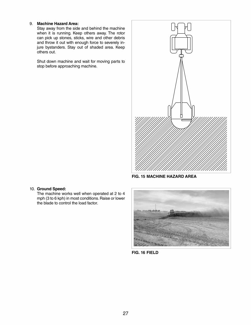
9. Machine Hazard Area: Stay away from the side and behind the machine
when it is running. Keep others away. The rotor can pick up stones, sticks, wire and other debris and throw it out with enough force to severely in-jure bystanders. Stay out of shaded area. Keep others out.
Shut down machine and wait for moving parts to stop before approaching machine.
10. Ground Speed: The machine works well when operated at 2 to 4
mph (3 to 6 kph) in most conditions. Raise or lower the blade to control the load factor.
FIG. 15 MACHINE HAZARD AREA
FIG. 16 FIELD
28
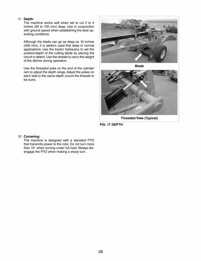
11. Depth: The machine works well when set to cut 2 to 4
inches (50 to 100 mm) deep. Use in conjunction with ground speed when establishing the best op-erating conditions.
Although the blade can go as deep as 16 inches (400 mm), it is seldom used that deep in normal applications. Use the tractor hydraulics to set the position/depth of the cutting blade by placing the circuit in detent. Use the wheels to carry the weight of the ditcher during operation.
Use the threaded yoke on the end of the cylinder ram to adjust the depth range. Adjust the yokes on each side to the same depth (count the threads to be sure).
12. Cornering: The machine is designed with a standard PTO
that transmits power to the rotor. Do not turn more than15°whenturningunderfullload.Alwaysdis-engage the PTO when making a sharp turn.
Blade
FIG. 17 DEPTH
Threaded Yoke (Typical)
29
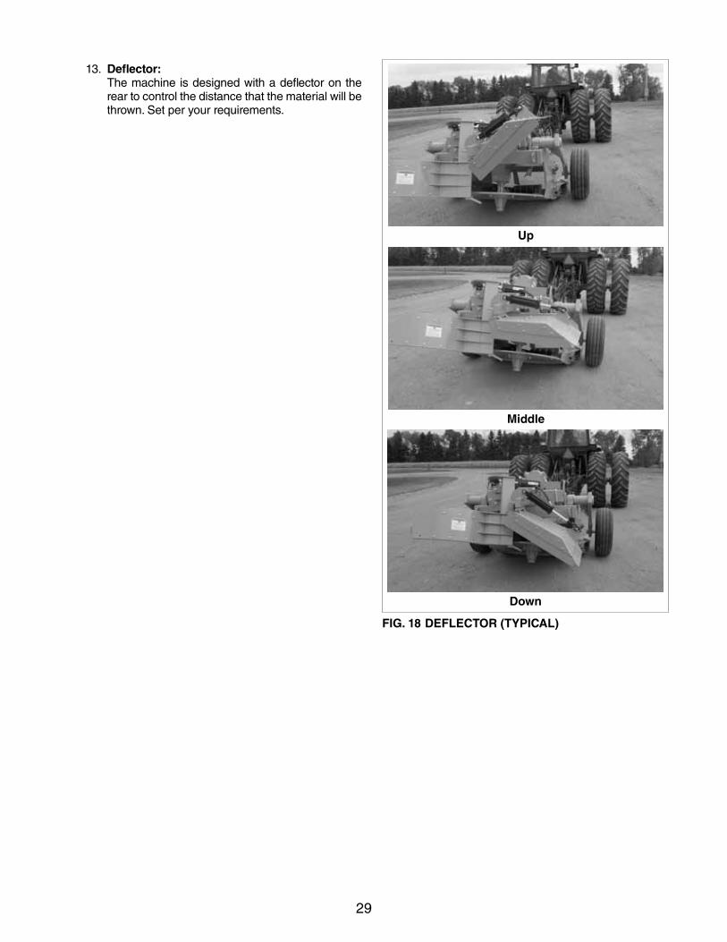
13. Deflector: The machine is designed with a deflector on the
rear to control the distance that the material will be thrown. Set per your requirements.
Up
Middle
Down
FIG. 18 DEFLECTOR (TYPICAL)
30
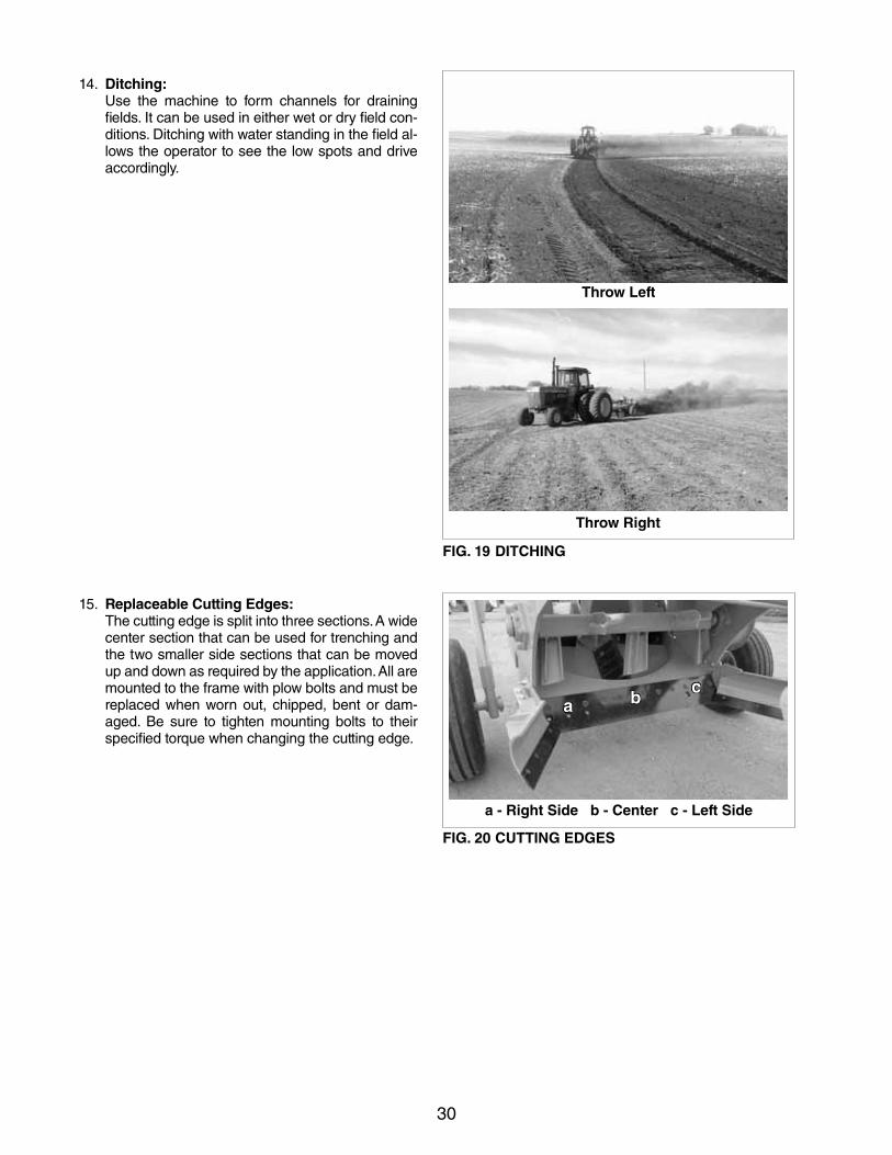
14. Ditching: Use the machine to form channels for draining
fields. It can be used in either wet or dry field con-ditions. Ditching with water standing in the field al-lows the operator to see the low spots and drive accordingly.
15. Replaceable Cutting Edges: The cutting edge is split into three sections. A wide
center section that can be used for trenching and the two smaller side sections that can be moved up and down as required by the application. All are mounted to the frame with plow bolts and must be replaced when worn out, chipped, bent or dam-aged. Be sure to tighten mounting bolts to their specified torque when changing the cutting edge.
Throw Left
FIG. 19 DITCHING
Throw Right
FIG. 20 CUTTING EDGES
a - Right Side b - Center c - Left Side
a bc
31
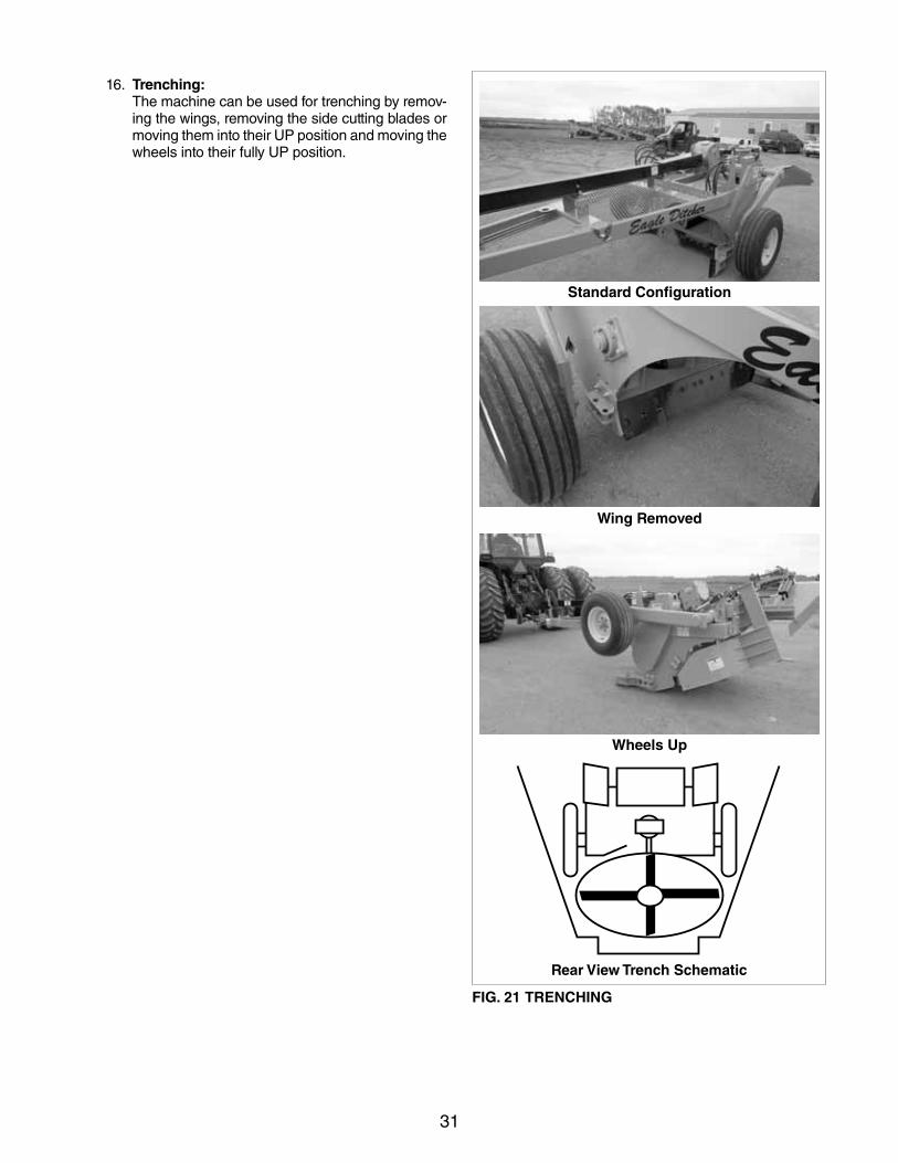
Wing Removed
Standard Configuration
Wheels Up
Rear View Trench Schematic
FIG. 21 TRENCHING
16. Trenching: The machine can be used for trenching by remov-
ing the wings, removing the side cutting blades or moving them into their UP position and moving the wheels into their fully UP position.
32
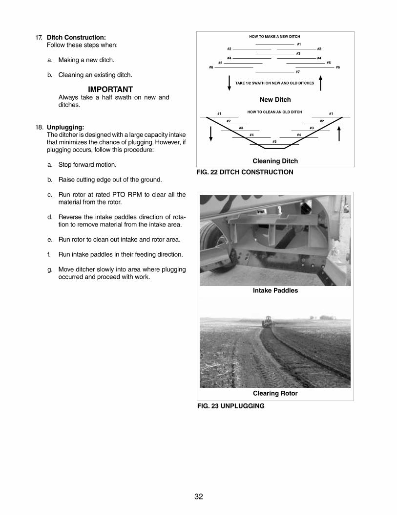
17. Ditch Construction: Follow these steps when:
a. Making a new ditch.
b. Cleaning an existing ditch.
IMPORTANTAlways take a half swath on new and ditches.
18. Unplugging: The ditcher is designed with a large capacity intake
that minimizes the chance of plugging. However, if plugging occurs, follow this procedure:
a. Stop forward motion.
b. Raise cutting edge out of the ground.
c. Run rotor at rated PTO RPM to clear all the material from the rotor.
d. Reverse the intake paddles direction of rota-tion to remove material from the intake area.
e. Run rotor to clean out intake and rotor area.
f. Run intake paddles in their feeding direction.
g. Move ditcher slowly into area where plugging occurred and proceed with work.
FIG. 22 DITCH CONSTRUCTION
New Ditch
Cleaning Ditch
Intake Paddles
FIG. 23 UNPLUGGING
Clearing Rotor
33
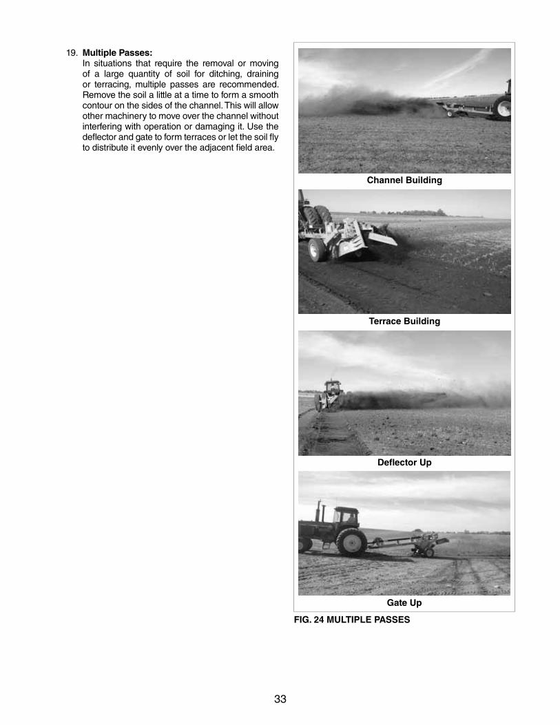
19. Multiple Passes: In situations that require the removal or moving
of a large quantity of soil for ditching, draining or terracing, multiple passes are recommended. Remove the soil a little at a time to form a smooth contour on the sides of the channel. This will allow other machinery to move over the channel without interfering with operation or damaging it. Use the deflector and gate to form terraces or let the soil fly to distribute it evenly over the adjacent field area.
Terrace Building
Channel Building
Deflector Up
Gate Up
FIG. 24 MULTIPLE PASSES
34
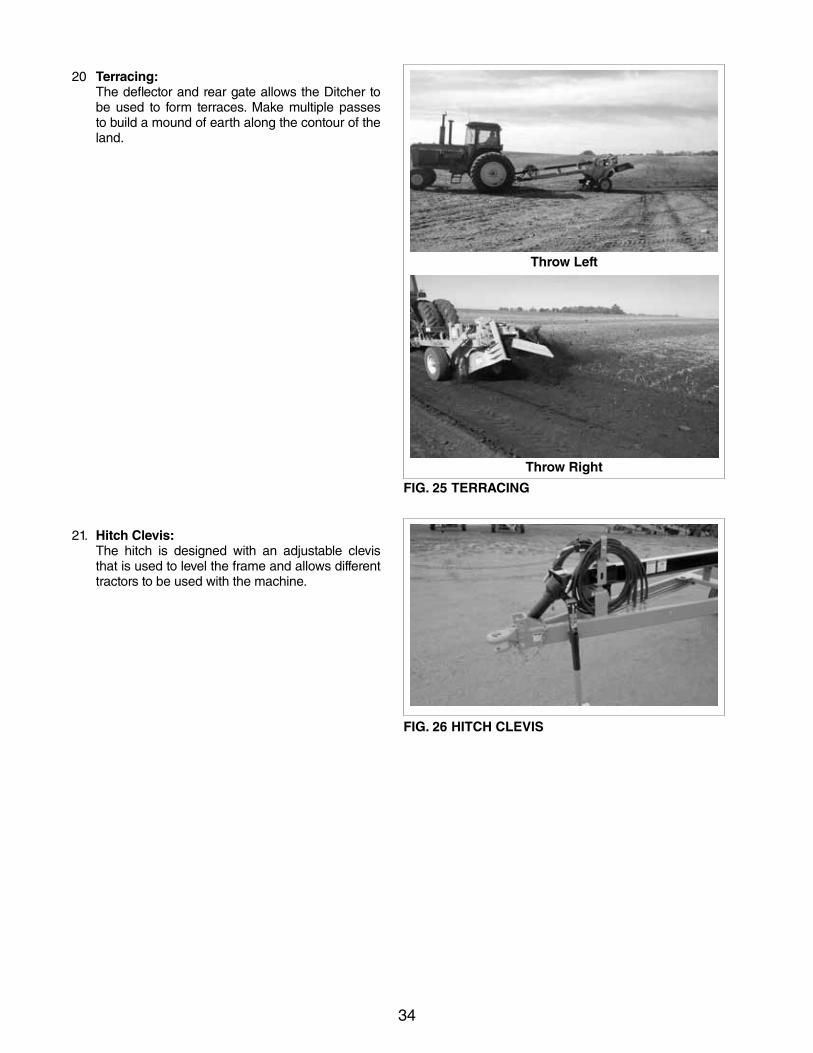
20 Terracing: The deflector and rear gate allows the Ditcher to
be used to form terraces. Make multiple passes to build a mound of earth along the contour of the land.
21. Hitch Clevis: The hitch is designed with an adjustable clevis
that is used to level the frame and allows different tractors to be used with the machine.
FIG. 26 HITCH CLEVIS
Throw Left
Throw Right
FIG. 25 TERRACING
35
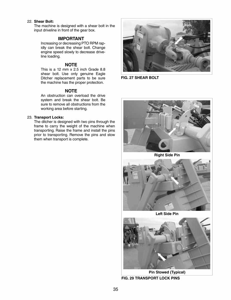
FIG. 27 SHEAR BOLT
22. Shear Bolt: The machine is designed with a shear bolt in the
input driveline in front of the gear box.
IMPORTANTIncreasing or decreasing PTO RPM rap-idly can break the shear bolt. Change engine speed slowly to decrease drive-line loading.
NOTEThis is a 12 mm x 2.5 inch Grade 8.8 shear bolt. Use only genuine Eagle Ditcher replacement parts to be sure the machine has the proper protection.
NOTEAn obstruction can overload the drive system and break the shear bolt. Be sure to remove all obstructions from the working area before starting.
23. Transport Locks: The ditcher is designed with two pins through the
frame to carry the weight of the machine when transporting. Raise the frame and install the pins prior to transporting. Remove the pins and stow them when transport is complete.
Left Side Pin
Right Side Pin
Pin Stowed (Typical)
FIG. 29 TRANSPORT LOCK PINS
36
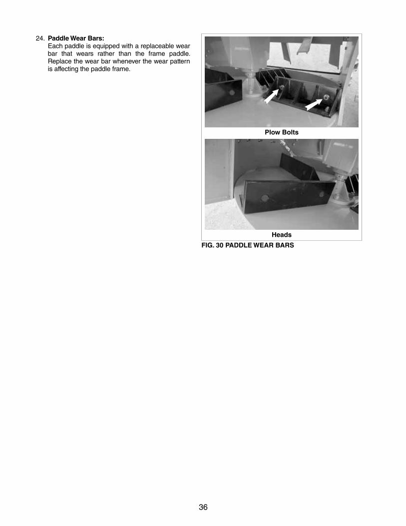
24. Paddle Wear Bars: Each paddle is equipped with a replaceable wear
bar that wears rather than the frame paddle. Replace the wear bar whenever the wear pattern is affecting the paddle frame.
Plow Bolts
Heads
FIG. 30 PADDLE WEAR BARS
37
Rotor Housing
Deflector Door
Left Hand Dirt Directional Door
FIG. 31 WEAR PLATES
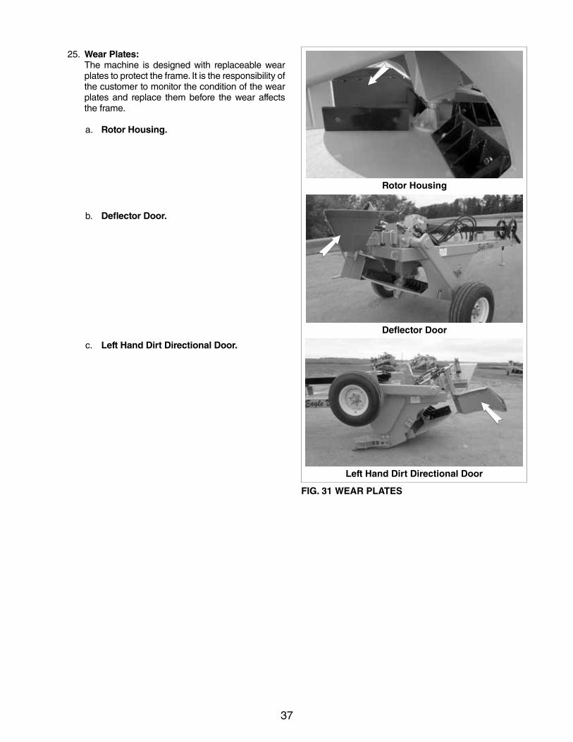
25. Wear Plates: The machine is designed with replaceable wear
plates to protect the frame. It is the responsibility of the customer to monitor the condition of the wear plates and replace them before the wear affects the frame.
a. Rotor Housing.
b. Deflector Door.
c. Left Hand Dirt Directional Door.
38
Rear
FIG. 32 CHAIN DRIVE
Front
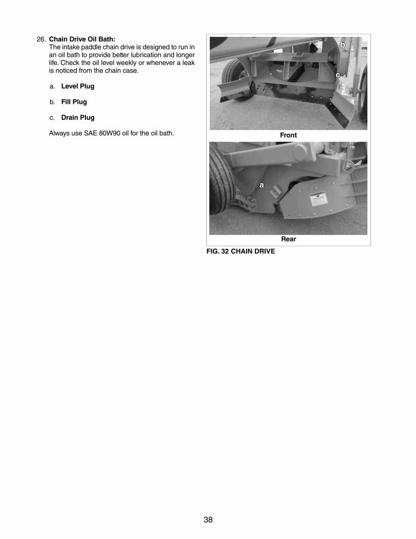
26. Chain Drive Oil Bath: The intake paddle chain drive is designed to run in
an oil bath to provide better lubrication and longer life. Check the oil level weekly or whenever a leak is noticed from the chain case.
a. Level Plug
b. Fill Plug
c. Drain Plug
Always use SAE 80W90 oil for the oil bath.
a
b
c
39
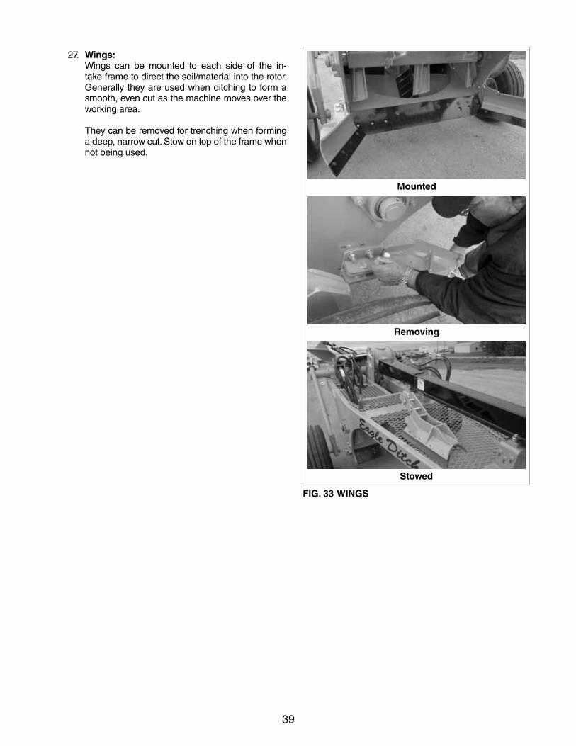
27. Wings: Wings can be mounted to each side of the in-
take frame to direct the soil/material into the rotor. Generally they are used when ditching to form a smooth, even cut as the machine moves over the working area.
They can be removed for trenching when forming a deep, narrow cut. Stow on top of the frame when not being used.
Mounted
Removing
Stowed
FIG. 33 WINGS
40
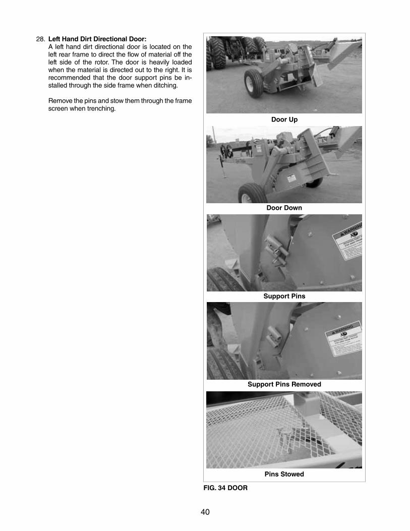
28. Left Hand Dirt Directional Door: A left hand dirt directional door is located on the
left rear frame to direct the flow of material off the left side of the rotor. The door is heavily loaded when the material is directed out to the right. It is recommended that the door support pins be in-stalled through the side frame when ditching.
Remove the pins and stow them through the frame screen when trenching.
Door Down
Door Up
Support Pins
Support Pins Removed
Pins Stowed
FIG. 34 DOOR
41
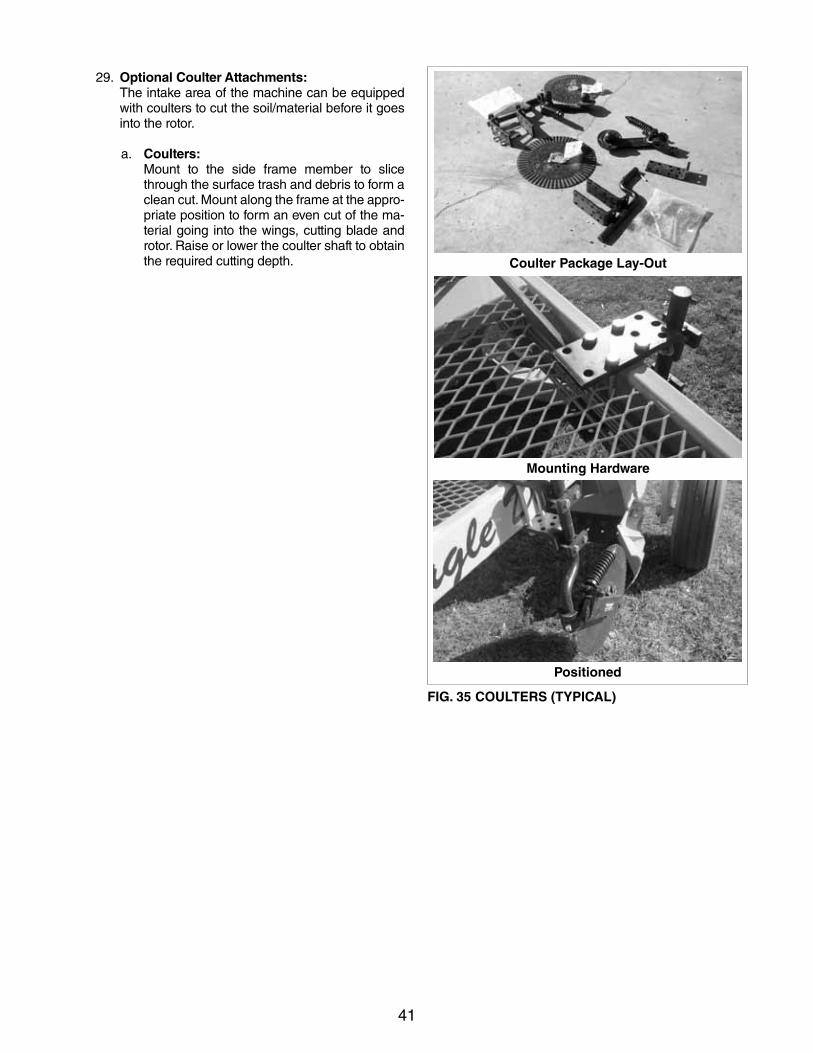
29. Optional Coulter Attachments: The intake area of the machine can be equipped
with coulters to cut the soil/material before it goes into the rotor.
a. Coulters: Mount to the side frame member to slice
through the surface trash and debris to form a clean cut. Mount along the frame at the appro-priate position to form an even cut of the ma-terial going into the wings, cutting blade and rotor. Raise or lower the coulter shaft to obtain the required cutting depth. Coulter Package Lay-Out
Mounting Hardware
Positioned
FIG. 35 COULTERS (TYPICAL)
42
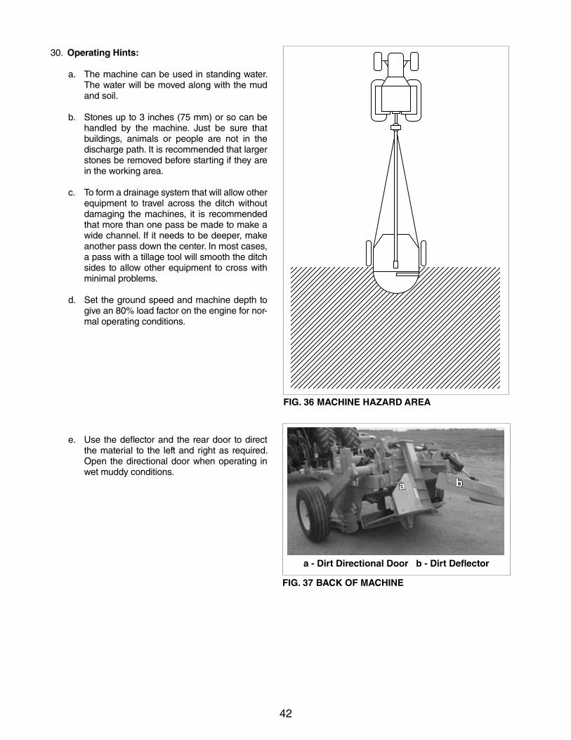
30. Operating Hints:
a. The machine can be used in standing water. The water will be moved along with the mud and soil.
b. Stones up to 3 inches (75 mm) or so can be handled by the machine. Just be sure that buildings, animals or people are not in the discharge path. It is recommended that larger stones be removed before starting if they are in the working area.
c. To form a drainage system that will allow other equipment to travel across the ditch without damaging the machines, it is recommended that more than one pass be made to make a wide channel. If it needs to be deeper, make another pass down the center. In most cases, a pass with a tillage tool will smooth the ditch sides to allow other equipment to cross with minimal problems.
d. Set the ground speed and machine depth to give an 80% load factor on the engine for nor-mal operating conditions.
e. Use the deflector and the rear door to direct the material to the left and right as required. Open the directional door when operating in wet muddy conditions.
FIG. 36 MACHINE HAZARD AREA
FIG. 37 BACK OF MACHINE
a b
a - Dirt Directional Door b - Dirt Deflector
43
4.8 TRANSPORTING
TRANSPORT SAFETY
• Make sure youare in compliancewithall localregulations regarding transporting equipment on public roads and highways.
• MakesuretheSMV(SlowMovingVehicle)em-blem and all the lights and reflectors that are required by the local highway and transport au-thorities are in place, are clean and can be seen clearly by all overtaking and oncoming traffic.
When transporting the machine, review and follow these instructions:
1. Be sure all bystanders are clear of the machine.
2. Be sure the rotor drive is disengaged and has stopped turning.
3. Be sure that the machine is securely attached to the tractor and a retainer pin and safety chain are installed.
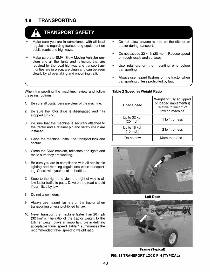
4. Raise the machine, install the transport lock and secure.
5. Clean the SMV emblem, reflectors and lights and make sure they are working.
6. Be sure you are in compliance with all applicable lighting and marking regulations when transport-ing. Check with your local authorities.
7. Keep to the right and yield the right-of-way to al-low faster traffic to pass. Drive on the road should if permitted by law.
8. Do not allow riders.
9. Always use hazard flashers on the tractor when transporting unless prohibited by law.
10. Never transport the machine faster than 20 mph (32 km/h). The ratio of the tractor weight to the Ditcher weight plays an important role in defining acceptable travel speed. Table 1 summarizes the recommended travel speed to weight ratio.
Table 2 Speed vs Weight Ratio
• Do not allow anyone to ride on the ditcher ortractor during transport.
• Donotexceed32kmh(20mph).Reducespeedon rough roads and surfaces.
• Use retainers on the mounting pins beforetransporting.
• Alwaysusehazardflashersonthetractorwhentransporting unless prohibited by law.
Road Speed
Weight of fully equipped or loaded implement(s)
relative to weight of towing machine
Up to 32 kph(20 mph) 1 to 1, or less
Up to 16 kph(10 mph) 2 to 1, or less
Do not tow More than 2 to 1
Frame (Typical)
FIG. 38 TRANSPORT LOCK PIN (TYPICAL)
Left Door
44
4.9 STORAGE
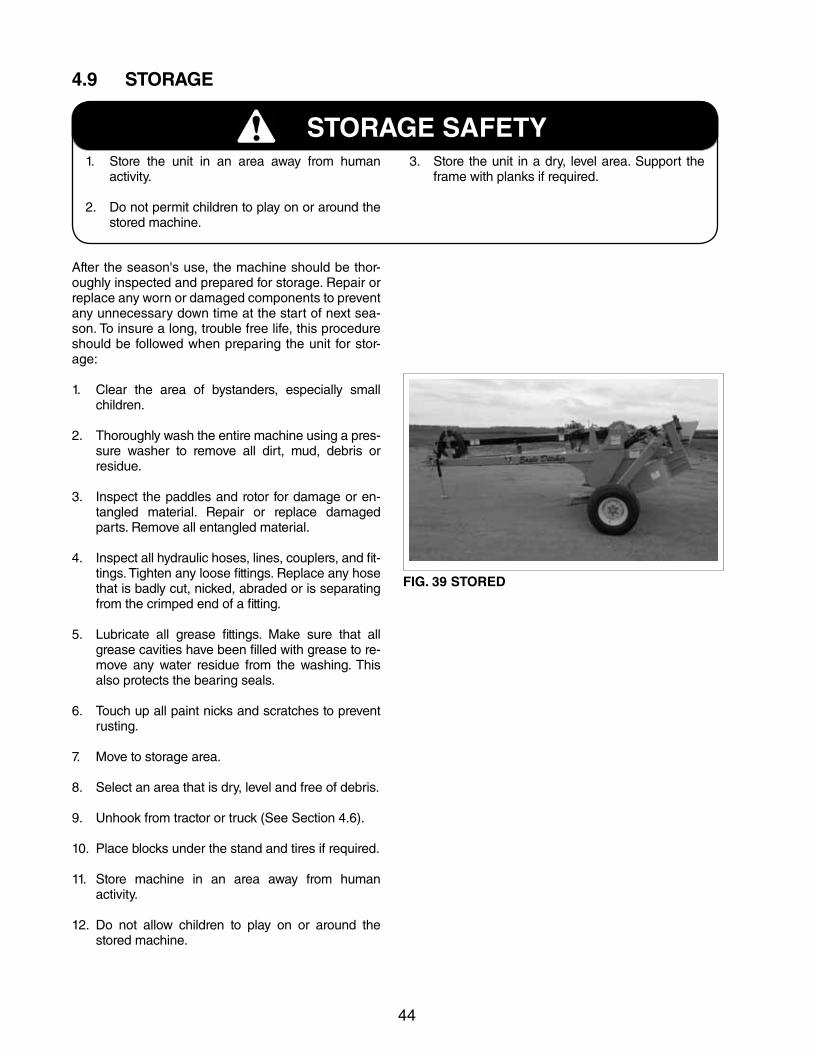
After the season's use, the machine should be thor-oughly inspected and prepared for storage. Repair or replace any worn or damaged components to prevent any unnecessary down time at the start of next sea-son. To insure a long, trouble free life, this procedure should be followed when preparing the unit for stor-age:
1. Clear the area of bystanders, especially small children.
2. Thoroughly wash the entire machine using a pres-sure washer to remove all dirt, mud, debris or residue.
3. Inspect the paddles and rotor for damage or en-tangled material. Repair or replace damaged parts. Remove all entangled material.
4. Inspect all hydraulic hoses, lines, couplers, and fit-tings. Tighten any loose fittings. Replace any hose that is badly cut, nicked, abraded or is separating from the crimped end of a fitting.
5. Lubricate all grease fittings. Make sure that allgrease cavities have been filled with grease to re-move any water residue from the washing. This also protects the bearing seals.
6. Touch up all paint nicks and scratches to prevent rusting.
7. Move to storage area.
8. Select an area that is dry, level and free of debris.
9. Unhook from tractor or truck (See Section 4.6).
10. Place blocks under the stand and tires if required.
11. Store machine in an area away from human activity.
12. Do not allow children to play on or around the stored machine.
STORAGE SAFETY1. Store the unit in an area away from human
activity.
2. Do not permit children to play on or around the stored machine.
3. Store the unit in a dry, level area. Support the frame with planks if required.
FIG. 39 STORED
45
5.0 SERVICE AND MAINTENANCE
MAINTENANCE SAFETY
1. Follow ALL the operating, maintenance andsafety information in the manual.
2. Support the machine with blocks or safety stands when changing tires or working beneath it.
3. Follow good shop practices: - Keep service area clean and dry.- Be sure electrical outlets and tools are
properly grounded.- Use adequate light for the job at hand.
4. Use only tools, jacks and hoists of sufficient ca-pacity for the job.
5. Never work on paddles, rotor or under the ma-chine unless the tractor engine is off and drive-line is disconnected.
6. Make sure all guards are in place and properly secured when maintenance work is completed.
7. Never wear ill-fitting, baggy or frayed clothing when working around or on any of the drive sys-tem components.
8. Before applying pressure to a hydraulic system, make sure all lines, fittings and couplers are tight and in good condition.
9. Relieve pressure from hydraulic circuit before servicing or disconnecting from tractor.
10. Keep hands, feet, hair and clothing away from all moving and/or rotating parts.
11. Clear the area of bystanders, especially chil-dren, when carrying out any maintenance and repairs or making any adjustments.
5.1 SERVICE
5.1.1 FLUIDS AND LUBRICANTS1. Grease: Use an SAE multi-purpose high temperature
grease with extreme pressure (EP) performance. Also acceptable is an SAE multi-purpose lithium based grease.
2. Gear Box Oil: Use an SAE 85W90 gear oil for all operating
conditions.
Capacity:2qts.(2L.).
2. Storing Lubricants: Your machine can operate at top efficiency only if
clean lubricants are used. Use clean containers to handle all lubricants. Store them in an area protect-ed from dust, moisture and other contaminants.
5.1.2 GREASINGUse the Maintenance Checklist provided to keep a record of all scheduled maintenance.
1. Use a hand-held grease gun for all greasing.
2. Wipe grease fitting with a clean cloth before greas-ing, to avoid injecting dirt and grit.
3. Replace and repair broken fittings immediately.
4. If fittings will not take grease, remove and clean thoroughly. Also clean lubricant passageway. Replace fitting if necessary.
46
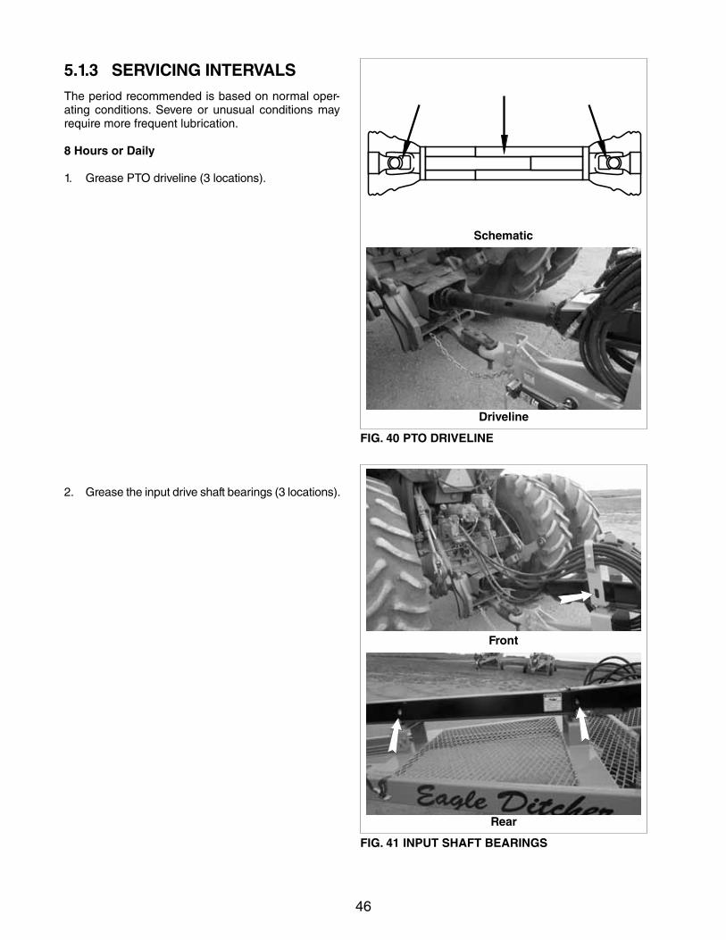
5.1.3 SERVICING INTERVALSThe period recommended is based on normal oper-ating conditions. Severe or unusual conditions may require more frequent lubrication.
8 Hours or Daily
1. Grease PTO driveline (3 locations).
2. Grease the input drive shaft bearings (3 locations).
Driveline
Rear
FIG. 40 PTO DRIVELINE
FIG. 41 INPUT SHAFT BEARINGS
Schematic
Front
47
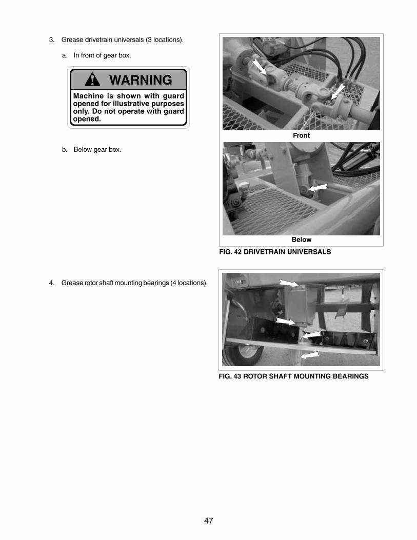
3. Grease drivetrain universals (3 locations).
a. In front of gear box.
b. Below gear box.
4. Grease rotor shaft mounting bearings (4 locations).
Below
FIG. 42 DRIVETRAIN UNIVERSALS
Front
FIG. 43 ROTOR SHAFT MOUNTING BEARINGS
48
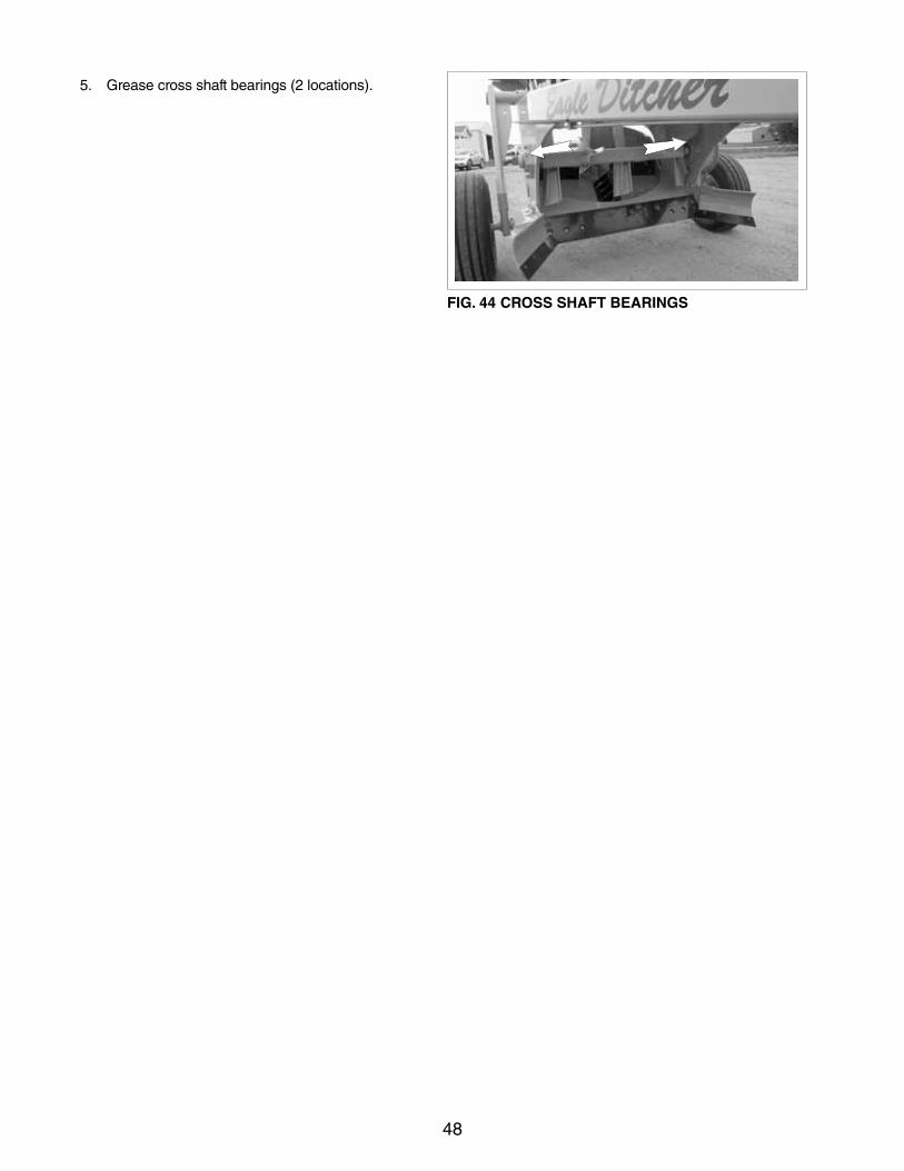
5. Grease cross shaft bearings (2 locations).
FIG. 44 CROSS SHAFT BEARINGS
49
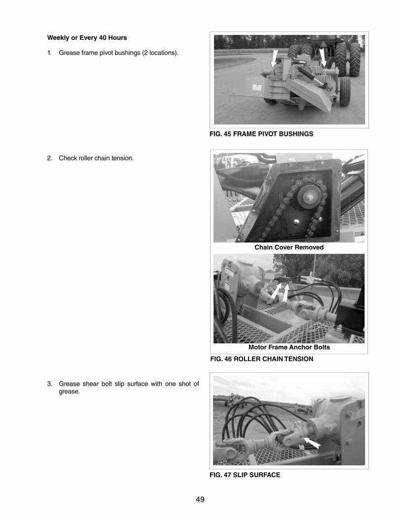
Weekly or Every 40 Hours
1. Grease frame pivot bushings (2 locations).
2. Check roller chain tension.
3. Grease shear bolt slip surface with one shot of grease.
FIG. 45 FRAME PIVOT BUSHINGS
Motor Frame Anchor Bolts
FIG. 46 ROLLER CHAIN TENSION
Chain Cover Removed
FIG. 47 SLIP SURFACE
50
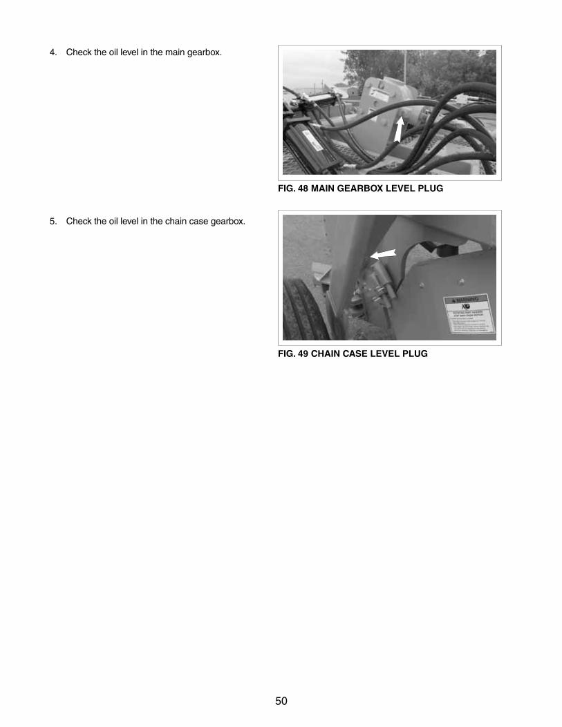
FIG. 48 MAIN GEARBOX LEVEL PLUG
4. Check the oil level in the main gearbox.
5. Check the oil level in the chain case gearbox.
FIG. 49 CHAIN CASE LEVEL PLUG
51
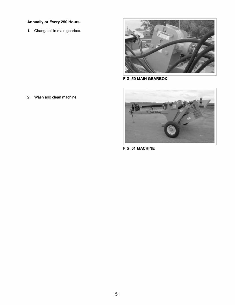
Annually or Every 250 Hours
1. Change oil in main gearbox.
2. Wash and clean machine.
FIG. 50 MAIN GEARBOX
FIG. 51 MACHINE
52
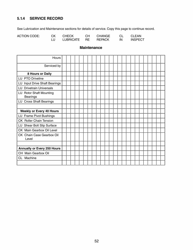
5.1.4 SERVICE RECORD
SeeLubricationandMaintenancesectionsfordetailsofservice.Copythispagetocontinuerecord.
ACTIONCODE: CK CHECK CH CHANGE CL CLEAN LU LUBRICATE RE REPACK IN INSPECT
Maintenance
Hours
Serviced by
8 Hours or Daily
LUPTODriveline
LUInputDriveShaftBearings
LUDrivetrainUniversals
LURotorShaftMounting Bearings
LUCrossShaftBearings
Weekly or Every 40 Hours
LUFramePivotBushings
CK Roller Chain Tension
LUShearBoltSlipSurface
CKMainGearboxOilLevel
CK Chain Case Gearbox Oil Level
Annually or Every 250 Hours
CH Main Gearbox Oil
CLMachine
53
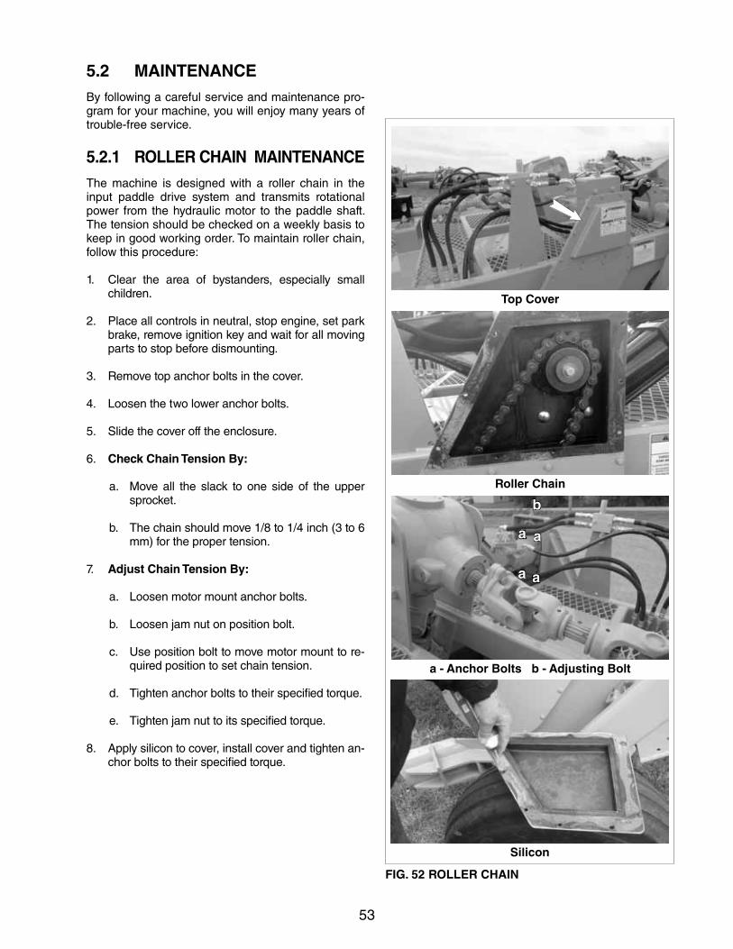
5.2 MAINTENANCEBy following a careful service and maintenance pro-gram for your machine, you will enjoy many years of trouble-free service.
5.2.1 ROLLER CHAIN MAINTENANCEThe machine is designed with a roller chain in the input paddle drive system and transmits rotational power from the hydraulic motor to the paddle shaft. The tension should be checked on a weekly basis to keep in good working order. To maintain roller chain, follow this procedure:
1. Clear the area of bystanders, especially small children.
2. Place all controls in neutral, stop engine, set park brake, remove ignition key and wait for all moving parts to stop before dismounting.
3. Remove top anchor bolts in the cover.
4. Loosenthetwoloweranchorbolts.
5. Slide the cover off the enclosure.
6. Check Chain Tension By:
a. Move all the slack to one side of the upper sprocket.
b. The chain should move 1/8 to 1/4 inch (3 to 6 mm) for the proper tension.
7. Adjust Chain Tension By:
a. Loosenmotormountanchorbolts.
b. Loosenjamnutonpositionbolt.
c. Use position bolt to move motor mount to re-quired position to set chain tension.
d. Tighten anchor bolts to their specified torque.
e. Tighten jam nut to its specified torque.
8. Apply silicon to cover, install cover and tighten an-chor bolts to their specified torque.
Roller Chain
Top Cover
a - Anchor Bolts b - Adjusting Bolt
Silicon
FIG. 52 ROLLER CHAIN
a a
a a
b
54
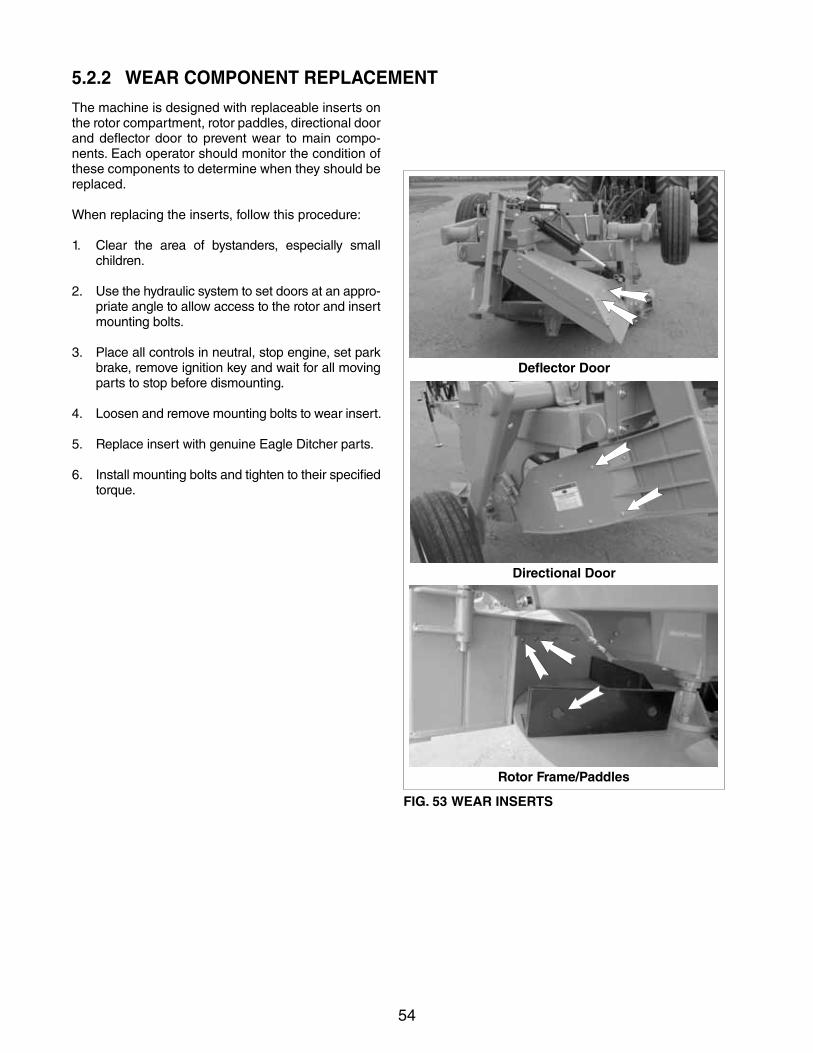
5.2.2 WEAR COMPONENT REPLACEMENT
The machine is designed with replaceable inserts on the rotor compartment, rotor paddles, directional door and deflector door to prevent wear to main compo-nents. Each operator should monitor the condition of these components to determine when they should be replaced.
When replacing the inserts, follow this procedure:
1. Clear the area of bystanders, especially small children.
2. Use the hydraulic system to set doors at an appro-priate angle to allow access to the rotor and insert mounting bolts.
3. Place all controls in neutral, stop engine, set park brake, remove ignition key and wait for all moving parts to stop before dismounting.
4. Loosenandremovemountingboltstowearinsert.
5. Replace insert with genuine Eagle Ditcher parts.
6. Install mounting bolts and tighten to their specified torque.
Deflector Door
Directional Door
Rotor Frame/Paddles
FIG. 53 WEAR INSERTS
55
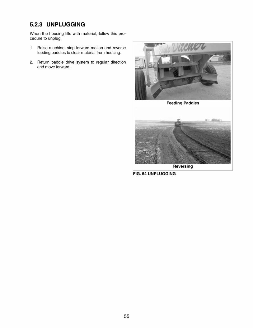
5.2.3 UNPLUGGINGWhen the housing fills with material, follow this pro-cedure to unplug:
1. Raise machine, stop forward motion and reverse feeding paddles to clear material from housing.
2. Return paddle drive system to regular direction and move forward.
Reversing
FIG. 54 UNPLUGGING
Feeding Paddles
56
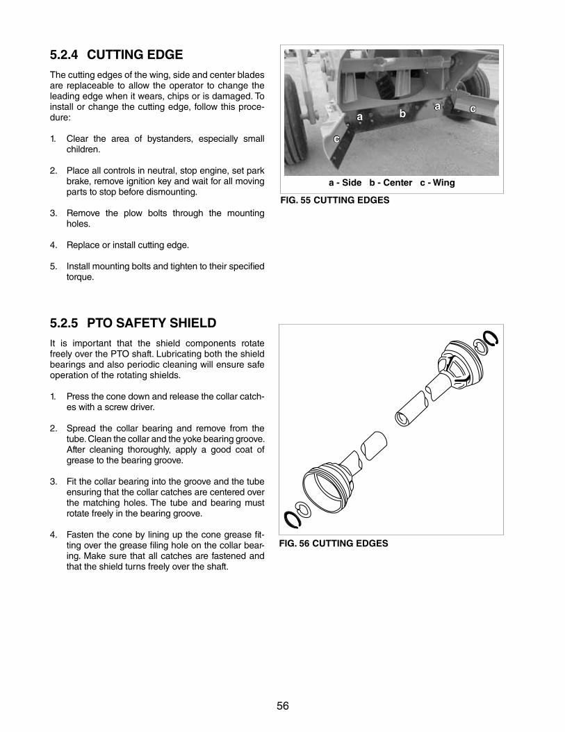
5.2.4 CUTTING EDGEThe cutting edges of the wing, side and center blades are replaceable to allow the operator to change the leading edge when it wears, chips or is damaged. To install or change the cutting edge, follow this proce-dure:
1. Clear the area of bystanders, especially small children.
2. Place all controls in neutral, stop engine, set park brake, remove ignition key and wait for all moving parts to stop before dismounting.
3. Remove the plow bolts through the mounting holes.
4. Replace or install cutting edge.
5. Install mounting bolts and tighten to their specified torque.
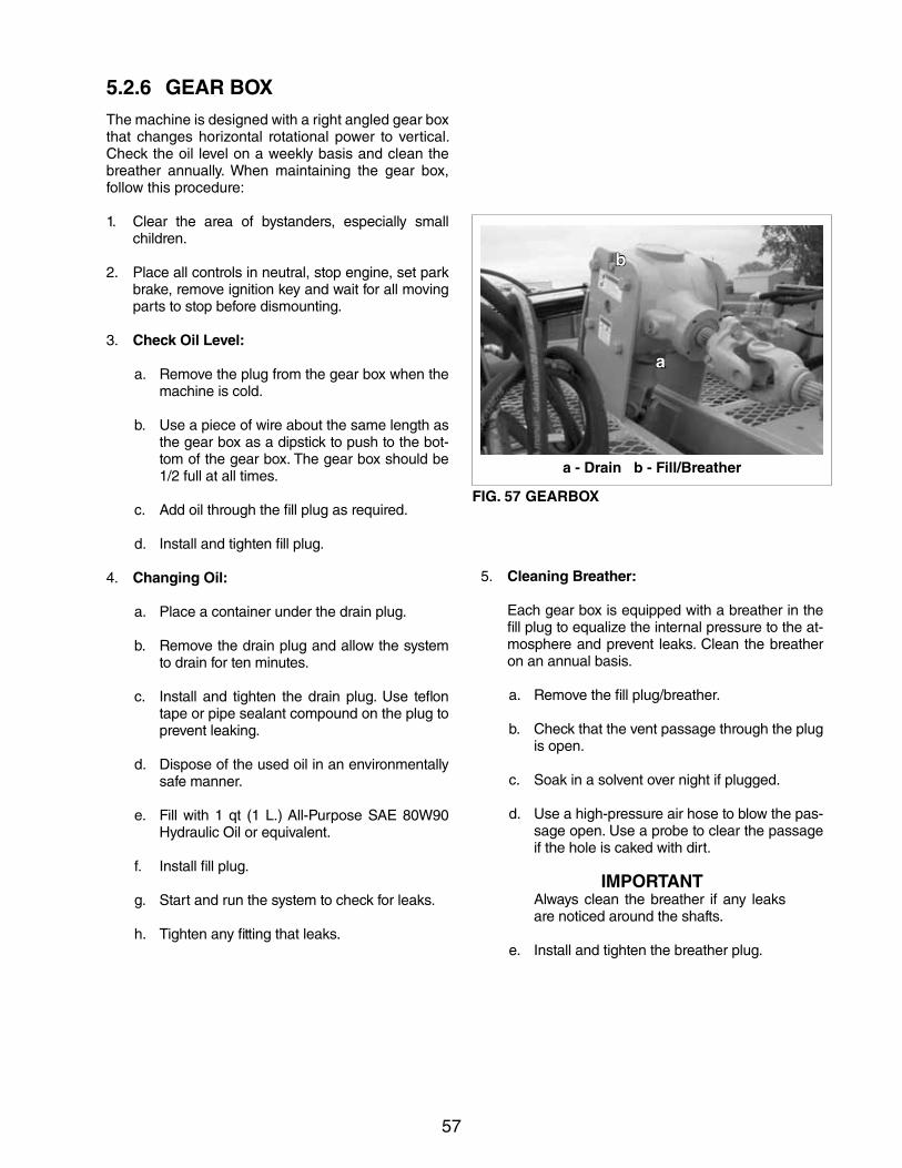
5.2.5 PTO SAFETY SHIELDIt is important that the shield components rotate freelyoverthePTOshaft.Lubricatingboththeshieldbearings and also periodic cleaning will ensure safe operation of the rotating shields.
1. Press the cone down and release the collar catch-es with a screw driver.
2. Spread the collar bearing and remove from the tube. Clean the collar and the yoke bearing groove. After cleaning thoroughly, apply a good coat of grease to the bearing groove.
3. Fit the collar bearing into the groove and the tube ensuring that the collar catches are centered over the matching holes. The tube and bearing must rotate freely in the bearing groove.
4. Fasten the cone by lining up the cone grease fit-ting over the grease filing hole on the collar bear-ing. Make sure that all catches are fastened and that the shield turns freely over the shaft.
FIG. 55 CUTTING EDGES
a - Side b - Center c - Wing
a b c
c
a
FIG. 56 CUTTING EDGES
57
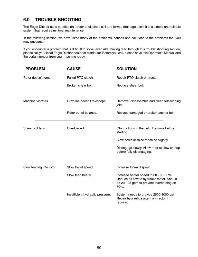
5.2.6 GEAR BOXThe machine is designed with a right angled gear box that changes horizontal rotational power to vertical. Check the oil level on a weekly basis and clean the breather annually. When maintaining the gear box, follow this procedure:
1. Clear the area of bystanders, especially small children.
2. Place all controls in neutral, stop engine, set park brake, remove ignition key and wait for all moving parts to stop before dismounting.
3. Check Oil Level:
a. Remove the plug from the gear box when the machine is cold.
b. Use a piece of wire about the same length as the gear box as a dipstick to push to the bot-tom of the gear box. The gear box should be 1/2 full at all times.
c. Add oil through the fill plug as required.
d. Install and tighten fill plug.
4. Changing Oil:
a. Place a container under the drain plug.
b. Remove the drain plug and allow the system to drain for ten minutes.
c. Install and tighten the drain plug. Use teflon tape or pipe sealant compound on the plug to prevent leaking.
d. Dispose of the used oil in an environmentally safe manner.
e. Fillwith1qt (1L.)All-PurposeSAE80W90Hydraulic Oil or equivalent.
f. Install fill plug.
g. Start and run the system to check for leaks.
h. Tighten any fitting that leaks.
FIG. 57 GEARBOX
5. Cleaning Breather: Each gear box is equipped with a breather in the
fill plug to equalize the internal pressure to the at-mosphere and prevent leaks. Clean the breather on an annual basis.
a. Remove the fill plug/breather.
b. Check that the vent passage through the plug is open.
c. Soak in a solvent over night if plugged.
d. Use a high-pressure air hose to blow the pas-sage open. Use a probe to clear the passage if the hole is caked with dirt.
IMPORTANTAlways clean the breather if any leaks are noticed around the shafts.
e. Install and tighten the breather plug.
a - Drain b - Fill/Breather
a
b

58
5.2.7 SHEAR BOLTA shear bolt is provided at the yoke to the gearbox to protect the drive system during an overload.
To change the shear bolt, follow this procedure:
1. Clear the area of bystanders, especially small children.
2. Place all controls in neutral, stop engine, set park brake, remove ignition key and wait for all moving parts to stop before dismounting.
3. Turn PTO shaft by hand to locate the shear bolt holes.
4. Carefully remove remaining shear bolts using a hammer and punch if necessary. Be careful not to enlarge the holes.
5. Install the new shear bolts and tighten to their specified torque. Do not overtighten.
IMPORTANTUse only genuine Erickson 12 mm x 2 1/2 inch Grade 8.8 replacement bolts for all operating conditions.
6. Do not operate at more than 200 horsepower. This power level exceeds the shearing strength of the bolt and will result in frequent bolt failures.
FIG. 58 SHEAR BOLT
59
6.0 TROUBLE SHOOTINGThe Eagle Ditcher uses paddles on a rotor to displace soil and form a drainage ditch. It is a simple and reliable system that requires minimal maintenance.
In the following section, we have listed many of the problems, causes and solutions to the problems that you may encounter.
If you encounter a problem that is difficult to solve, even after having read through this trouble shooting section, please call your local Eagle Ditcher dealer or distributor. Before you call, please have this Operator's Manual and the serial number from your machine ready.
PROBLEM CAUSE SOLUTION
Rotor doesn't turn. Failed PTO clutch. Repair PTO clutch on tractor.
Broken shear bolt. Replace shear bolt.
Machine vibrates. Driveline doesn't telescope. Remove, disassemble and clean telescoping joint.
Rotor out of balance. Replace damaged or broken anchor bolt.
Shear bolt fails. Overloaded. Obstructions in the field. Remove before starting.
Slow down or raise machine slightly.
Disengage slowly. Allow rotor to slow or stop before fully disengaging.
Slow feeding into rotor. Slow travel speed. Increase forward speed.
Slow feed beater. Increase beater speed to 60 - 65 RPM. Reduce oil flow to hydraulic motor. Should be 20 - 25 gpm to prevent overbeating on 60%.
Insufficient hydraulic pressure. System needs to provide 2500-3000 psi. Repair hydraulic system on tractor if required.

60

61
7 SPECIFICATIONS
7.1 MECHANICAL
Length: 18' 6"
Width 7' 6"
Height 5' 8"
Weight 4480 lbs
Input Speed: 1000 RPM
Tires 11.5L 15 @ 60 psi
The Eagle Ditcher requires a minimum of 3 remote hydraulic outlets (4 if optional deflector is ordered) with a minimum of 15 GPM and a working pressure of 2500 PSI. Valve multipliers are available from your dealer if necessary.
Tractor horsepower required is 150 HP minimum to a 200 HP maximum. Drive lines and gear boxes can be seriously damaged if excessive horsepower is used. Use only 12 mm x 2 1/2 inch Grade 8.8 replacement bolts when replacing shear bolts.
SPECIFICATIONS SUBJECT TO CHANGE WITHOUT NOTICE
62
7.2 BOLT TORQUE
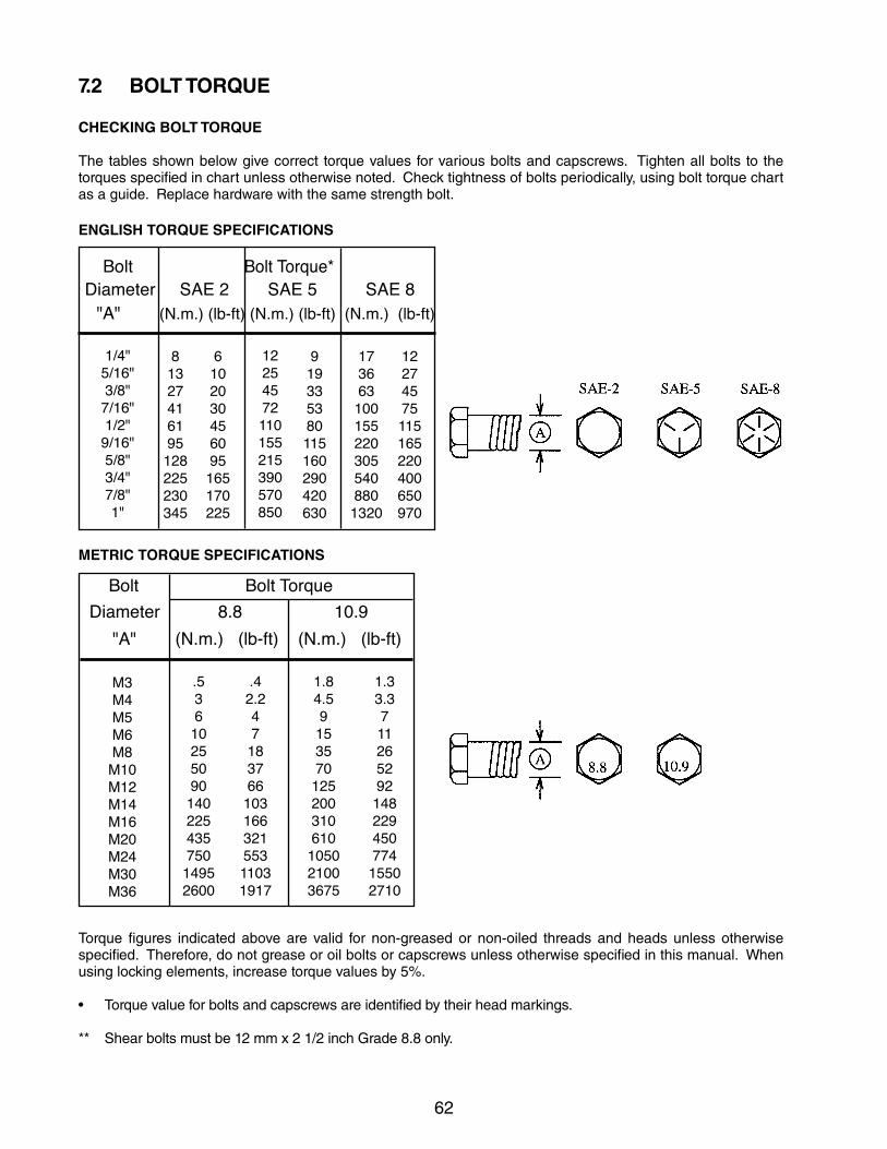
Torque figures indicated above are valid for non-greased or non-oiled threads and heads unless otherwise specified. Therefore, do not grease or oil bolts or capscrews unless otherwise specified in this manual. When using locking elements, increase torque values by 5%.
• Torquevalueforboltsandcapscrewsareidentifiedbytheirheadmarkings.
** Shear bolts must be 12 mm x 2 1/2 inch Grade 8.8 only.
CHECKING BOLT TORQUE
The tables shown below give correct torque values for various bolts and capscrews. Tighten all bolts to the torques specified in chart unless otherwise noted. Check tightness of bolts periodically, using bolt torque chart as a guide. Replace hardware with the same strength bolt.
Diameter SAE 2 SAE 5 SAE 8
1/4"5/16"3/8"7/16"1/2"9/16"5/8"3/4"7/8"1"
81327416195128225230345
6102030456095165170225
12254572110155215390570850
919335380115160290420630
1736631001552203055408801320
12274575115165220400650970
ENGLISH TORQUE SPECIFICATIONS
"A" (N.m.) (lb-ft) (N.m.) (lb-ft)
M3M4M5M6M8M10M12M14M16M20M24M30M36
1.33.371126529214822945077415502710
.5361025509014022543575014952600
.42.24718376610316632155311031917
1.84.59153570125200310610105021003675
Bolt Bolt Torque Diameter 8.8 10.9
METRIC TORQUE SPECIFICATIONS
"A" (N.m.) (lb-ft) (N.m.) (lb-ft) (N.m.) (lb-ft)
Bolt Bolt Torque*
63
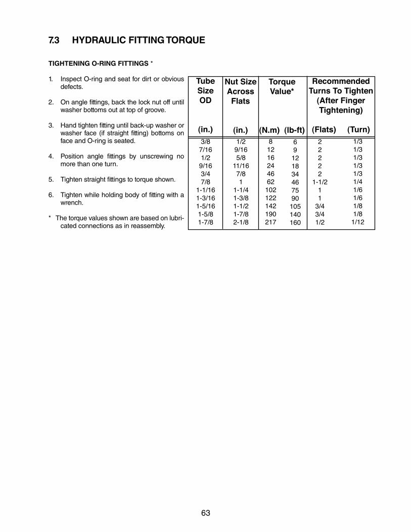
TIGHTENING O-RING FITTINGS *
1. Inspect O-ring and seat for dirt or obvious defects.
2. On angle fittings, back the lock nut off until washer bottoms out at top of groove.
3. Hand tighten fitting until back-up washer or washer face (if straight fitting) bottoms on face and O-ring is seated.
4. Position angle fittings by unscrewing no more than one turn.
5. Tighten straight fittings to torque shown.
6. Tighten while holding body of fitting with a wrench.
* The torque values shown are based on lubri-cated connections as in reassembly.
7.3 HYDRAULIC FITTING TORQUE
RecommendedTurns To Tighten
(After Finger Tightening)
(Flats) (Turn)
TubeSizeOD
(in.)
Nut SizeAcrossFlats
(in.)
Torque Value*
(N.m) (lb-ft)69121834467590105140160
1/29/165/8
11/167/81
1-1/41-3/81-1/21-7/82-1/8
3/87/161/29/163/47/8
1-1/161-3/161-5/161-5/81-7/8
81216244662102122142190217
22222
1-1/211
3/43/41/2
1/31/31/31/31/31/41/61/61/81/8
1/12

64
65
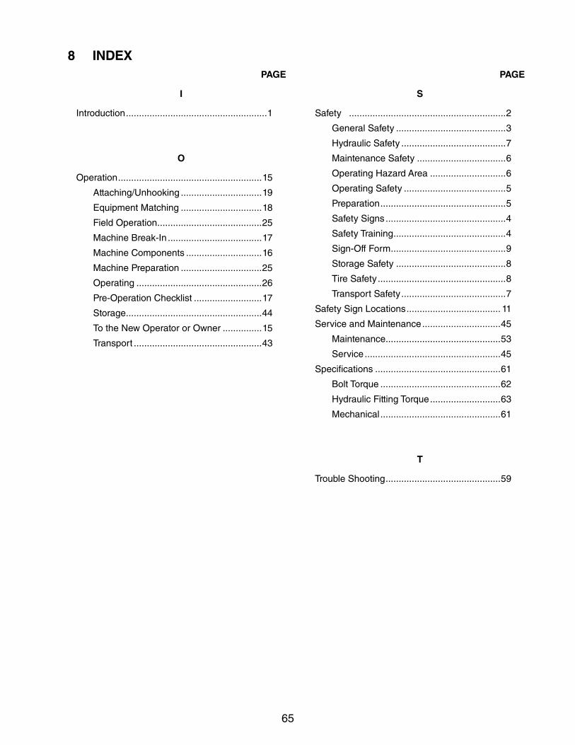
8 INDEXPAGE PAGE
S
Safety ............................................................2
General Safety ..........................................3
Hydraulic Safety ........................................7
Maintenance Safety ..................................6
Operating Hazard Area .............................6
Operating Safety .......................................5
Preparation ................................................5
Safety Signs ..............................................4
Safety Training ...........................................4
Sign-Off Form ............................................9
Storage Safety ..........................................8
Tire Safety .................................................8
Transport Safety ........................................7
SafetySignLocations .................................... 11
Service and Maintenance ..............................45
Maintenance ............................................53
Service ....................................................45
Specifications ................................................61
Bolt Torque ..............................................62
Hydraulic Fitting Torque ...........................63
Mechanical ..............................................61
T
Trouble Shooting ............................................59
I
Introduction ......................................................1
O
Operation .......................................................15
Attaching/Unhooking ...............................19
Equipment Matching ...............................18
Field Operation ........................................25
Machine Break-In ....................................17
Machine Components .............................16
Machine Preparation ...............................25
Operating ................................................26
Pre-Operation Checklist ..........................17
Storage ....................................................44
To the New Operator or Owner ...............15
Transport .................................................43


ERICKSON MANUFACTURING CO., INC.
13946 86TH STREET SEMILNOR, NORTH DAKOTA
USA, 58060-9750PHONE (701) 427-5900
TOLL FREE 1 (888) 427-5944FAX (701) 427-5531
or EMAIL [email protected]
PRINTED IN USAREVISION 1, DATE: FEBRUARY 2015 PART NUMBER: 603-2-0090