Embed Size (px)
Citation preview
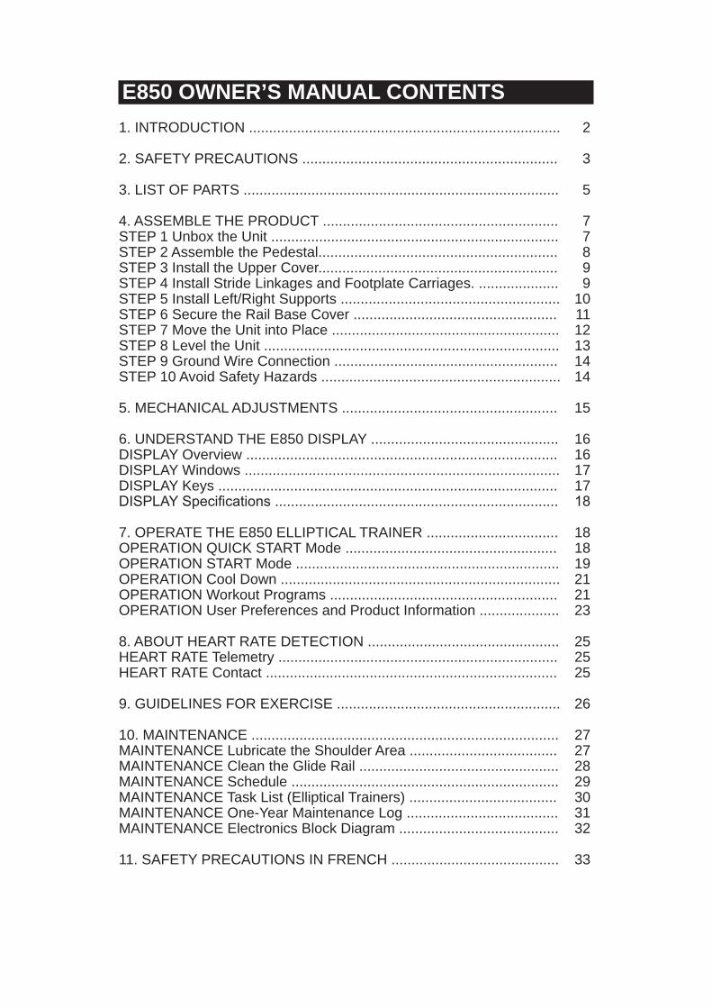
E850 OWNER’S MANUAL CONTENTS1. INTRODUCTION .............................................................................. 2
2. SAFETY PRECAUTIONS ................................................................ 3
3. LIST OF PARTS ............................................................................... 5
4. ASSEMBLE THE PRODUCT ........................................................... 7STEP 1 Unbox the Unit ........................................................................ 7STEP 2 Assemble the Pedestal............................................................ 8STEP 3 Install the Upper Cover............................................................ 9STEP 4 Install Stride Linkages and Footplate Carriages. .................... 9STEP 5 Install Left/Right Supports ....................................................... 10STEP 6 Secure the Rail Base Cover ................................................... 11STEP 7 Move the Unit into Place ......................................................... 12STEP 8 Level the Unit .......................................................................... 13STEP 9 Ground Wire Connection ........................................................ 14STEP 10 Avoid Safety Hazards ............................................................ 14
5. MECHANICAL ADJUSTMENTS ...................................................... 15
6. UNDERSTAND THE E850 DISPLAY ............................................... 16DISPLAY Overview .............................................................................. 16DISPLAY Windows ............................................................................... 17DISPLAY Keys ..................................................................................... 17DISPLAY Specifications ....................................................................... 18
7. OPERATE THE E850 ELLIPTICAL TRAINER ................................. 18OPERATION QUICK START Mode ..................................................... 18OPERATION START Mode .................................................................. 19OPERATION Cool Down ...................................................................... 21OPERATION Workout Programs ......................................................... 21OPERATION User Preferences and Product Information .................... 23
8. ABOUT HEART RATE DETECTION ................................................ 25HEART RATE Telemetry ...................................................................... 25HEART RATE Contact ......................................................................... 25
9. GUIDELINES FOR EXERCISE ........................................................ 26
10. MAINTENANCE ............................................................................. 27MAINTENANCE Lubricate the Shoulder Area ..................................... 27MAINTENANCE Clean the Glide Rail .................................................. 28MAINTENANCE Schedule ................................................................... 29MAINTENANCE Task List (Elliptical Trainers) ..................................... 30MAINTENANCE One-Year Maintenance Log ...................................... 31MAINTENANCE Electronics Block Diagram ........................................ 32
11. SAFETY PRECAUTIONS IN FRENCH .......................................... 33
2
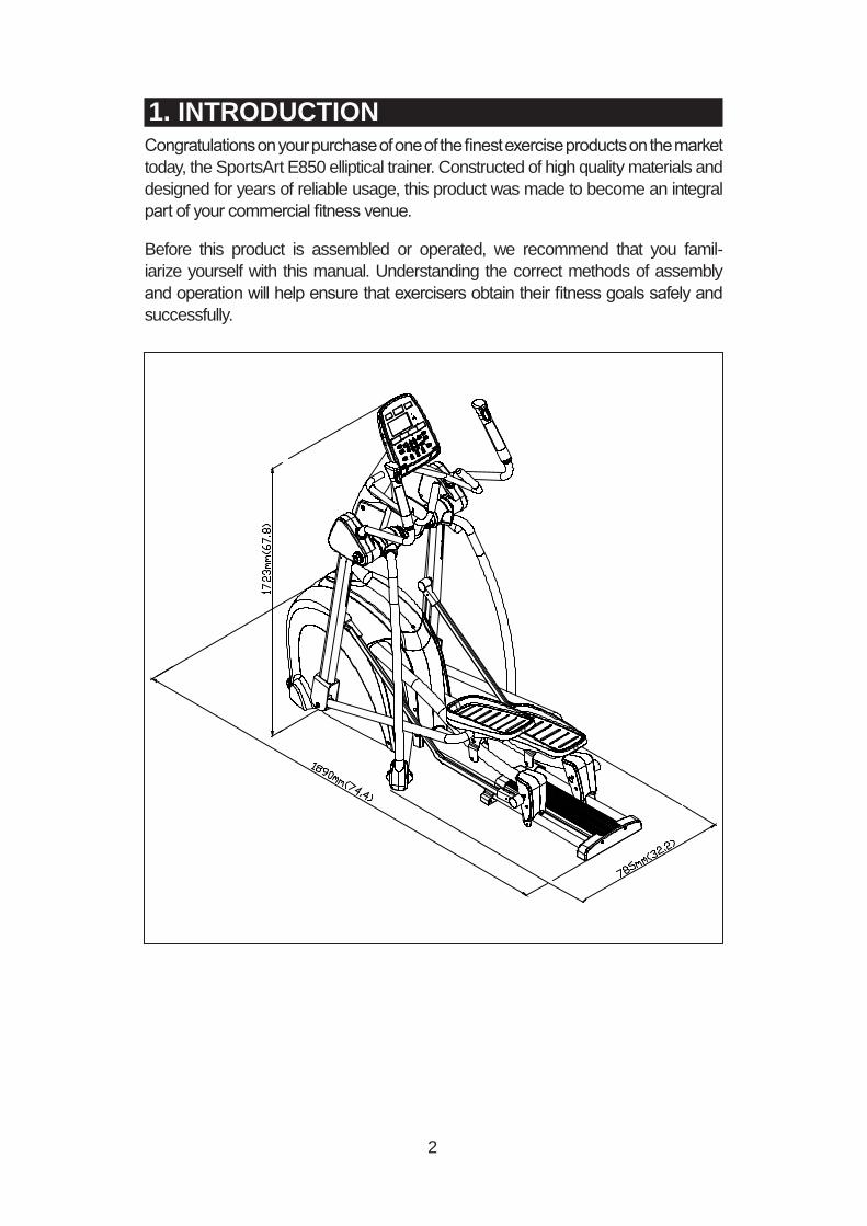
1. INTRODUCTIONCongratulations on your purchase of one of the finest exercise products on the market today, the SportsArt E850 elliptical trainer. Constructed of high quality materials and designed for years of reliable usage, this product was made to become an integral part of your commercial fitness venue.
Before this product is assembled or operated, we recommend that you famil-iarize yourself with this manual. Understanding the correct methods of assembly and operation will help ensure that exercisers obtain their fitness goals safely and successfully.

3
2. SAFETY PRECAUTIONS This product was designed and built for optimum safety. However certain precau-tions apply during the use of this product. Please note the following safety precautions:
• Please read the entire manual before assembly and operation. Make sure the product is installed and operated as instructed in this manual.• Assemble and operate the product on a solid, level surface. Do not use outdoors or near water, including pools and saunas.• Check the product before every use. Make sure all parts are assem-bled, and all fasteners are tightened. Do not use the product if it is disas-sembled in any way.• Wear proper workout clothing. Do not wear loose clothing. Do not wear shoes with leather soles or high heels. Tie all long hair back. Do not go barefoot on this product.• Keep away from moving parts. Moving parts may or may not stop imme-diately if an object becomes caught or impedes normal motion.• Use this product only for its intended purpose as described in this manual.• Be careful when mounting and dismounting the unit.• Never operate this product if it has been damaged in any way. If it is not working properly, or has been dropped or damaged, contact a service technician for repairs.• Do not use accessories that are not specifically recommended by the manufacturer. Such parts might cause injuries or cause the unit to fail.• Keep all air ventilation areas free of blockage. Never drop or insert any object into any opening.• Do not operate where aerosol (spray) products are being used or where oxygen is being administered.• This product is not intended for use by persons (including children) with reduced physical, sensory, or mental capabilities, or by people who are otherwise deficient in product knowlege or experience. If such people use this product, they should be given training and be supervised at all times by someone responsible for their safety. • Children should be supervised to ensure that they do not play on or near the product. • The user weight limit for this product is 180 kg, 400 lb. At maximum resistance, level 20, this product meets standards for users up to 150 kg, 330 lb.
CAUTION: If you feel any pain or abnormal sensations, STOP YOUR WORKOUT and consult your physician immediately. Work within your recommended exercise level. DO NOT work to exhaustion. Before beginning any exercise program, you should consult with your doctor. It is recommended that you undergo a complete physical examination.
WARNING! Heart rate monitoring systems may be inaccurate. Too much exercise may result in serious injury or death. If you feel faint, stop exercising immediately.

4
2. SAFETY PRECAUTIONS (CONTINUED)Note: This equipment has been tested and found to comply with the limits for a Class B digital device, pursuant to part 15 of the FCC Rules. These limits are designed to provide reasonable protection against harmful interference in a residential instal-lation. This equipment generates, uses and can radiate radio frequency energy and, if not installed and used in accordance with the instructions, may cause harmful interference to radio communications. However, there is no guarantee that inter-ference will not occur in a particular installation. If the user desires to correct the interference, it is at the user’s own expense.
WARNING! Only qualified technicians should be allowed to contact electrical components such as circuit boards. Some components carry an electrical charge even after use has been discontinued or the product has been unplugged. For products with power cords, turn off unit power, wait five minutes, then disconnect the power cord from the power socket. For products without power cords, let the unit sit without use for five minutes. Only after taking such precautions should covers be removed and electrical components be accessed.
5
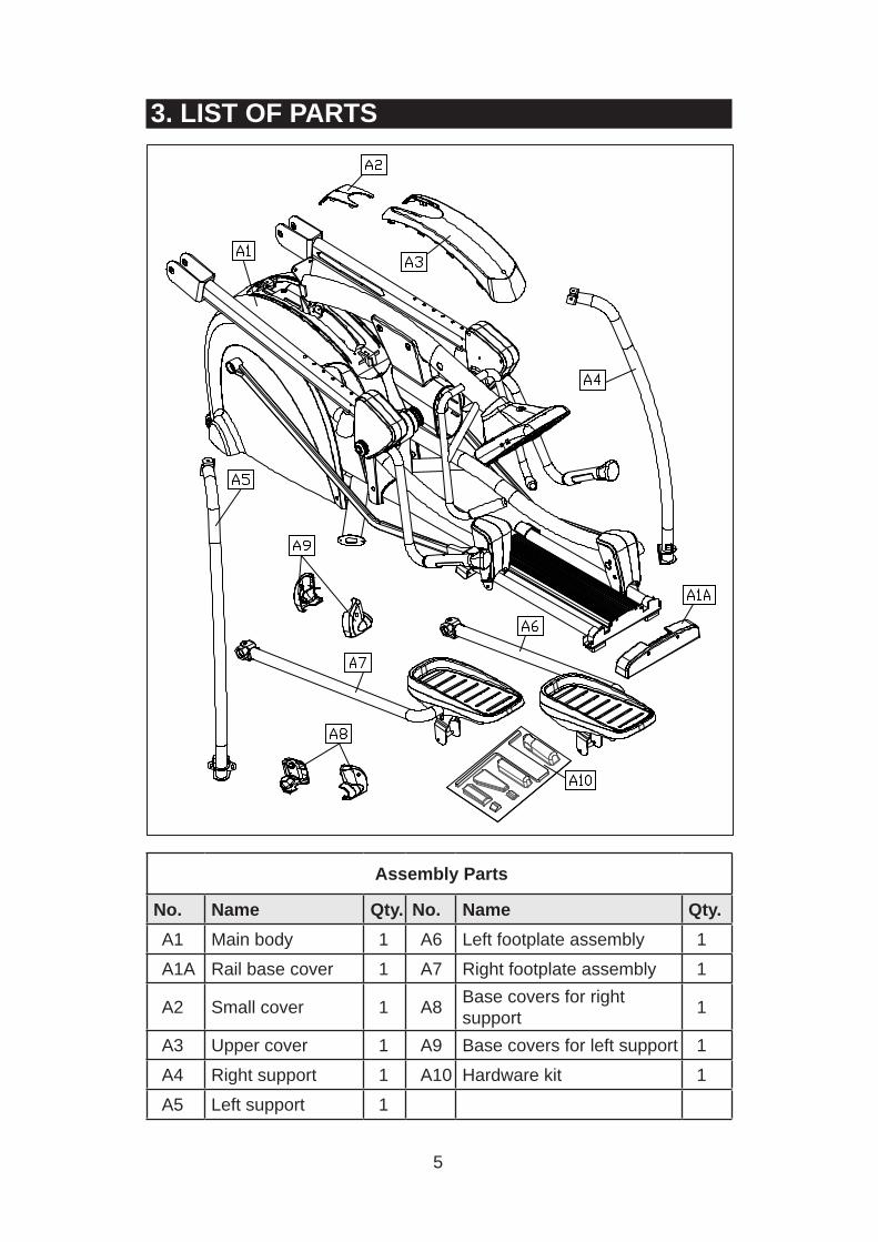
3. LIST OF PARTS
Assembly Parts
No. Name Qty. No. Name Qty.A1 Main body 1 A6 Left footplate assembly 1
A1A Rail base cover 1 A7 Right footplate assembly 1
A2 Small cover 1 A8 Base covers for right support 1
A3 Upper cover 1 A9 Base covers for left support 1
A4 Right support 1 A10 Hardware kit 1
A5 Left support 1

6
Components on the Product
No. Name Specification Notes
41Inner hex screw M8*L20 Spring washer M8Serrated washer D18*d8.5*t2.0*19T
42 Mushroom top Phillips screw M4*L16
43Inner hex screw M8*L25Spring washer M8Washer D17*d8.3*t1.0
44Inner hex screw M6*L15
Serrated washer D20*d6.2*t2.0*19T
45Inner hex screw 5/16”*L2-1/4 inchSeat roller washer D17*d8*t2.0
46Roller axleFlat washer D21*d10.5*t2Lock nut M10
47
PU sheath D12*D8*L45Axle M5*L71Flat washer D17*d8.3*t1Mushroom top inner hex screw M5*6
Components in the Hardware Kit
No. Name Qty. Specification Notes33 Mushroom top Phillips screw 6 M4*L16
34 Phillips screw 4 M5*P0.8*L10
35 Left/right adjustment rod cover 2
36 Screw insert 4
37 M10 nut cap 2
38 Screw cap 2
L-shaped Allen wrench 1 M6
L-shaped Allen wrench 2 M4
Double open-end wrench 1 8*17
Double open-end wrench 1 13*19T-shaped Allen wrench 1 M5Screwdriver shank 1 flat and PhillipsScrewdriver handle 1 green
7
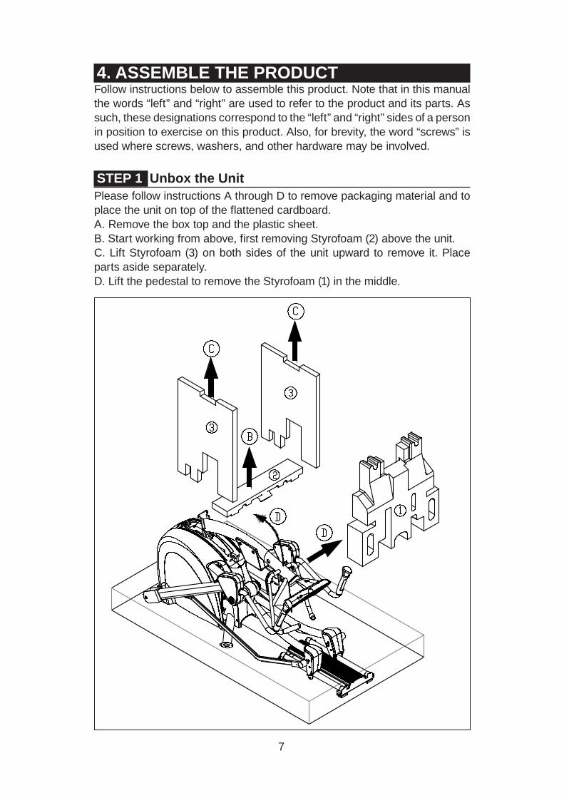
4. ASSEMBLE THE PRODUCTFollow instructions below to assemble this product. Note that in this manual the words “left” and “right” are used to refer to the product and its parts. As such, these designations correspond to the “left” and “right” sides of a person in position to exercise on this product. Also, for brevity, the word “screws” is used where screws, washers, and other hardware may be involved.
STEP 1 Unbox the UnitPlease follow instructions A through D to remove packaging material and to place the unit on top of the flattened cardboard.A. Remove the box top and the plastic sheet.B. Start working from above, first removing Styrofoam (2) above the unit.C. Lift Styrofoam (3) on both sides of the unit upward to remove it. Place parts aside separately.D. Lift the pedestal to remove the Styrofoam (1) in the middle.

8
STEP 2 Assemble the PedestalPlease follow instructions (a) through (b) to assemble the pedestal.(a) First, remove screws (41) from the pedestal mount on the main body (A1).(b) Push the pedestal up to the vertical position while preventing the data cable from getting pinched.(c) Secure screws (41), first in area (A), then in area (B).
9
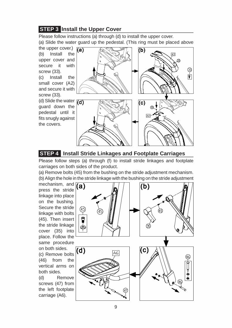
STEP 3 Install the Upper CoverPlease follow instructions (a) through (d) to install the upper cover.(a) Slide the water guard up the pedestal. (This ring must be placed above the upper cover.)(b) Install the upper cover and secure it with screw (33).(c) Install the small cover (A2) and secure it with screw (33).(d) Slide the water guard down the pedestal until it fits snugly against the covers.
STEP 4 Install Stride Linkages and Footplate CarriagesPlease follow steps (a) through (f) to install stride linkages and footplate carriages on both sides of the product.(a) Remove bolts (45) from the bushing on the stride adjustment mechanism.(b) Align the hole in the stride linkage with the bushing on the stride adjustment mechanism, and press the stride linkage into place on the bushing. Secure the stride linkage with bolts (45). Then insert the stride linkage cover (35) into place. Follow the same procedure on both sides.(c) Remove bolts (46) from the vertical arms on both sides.(d) Remove screws (47) from the left footplate carriage (A6).

10
STEP 5 Install Left/Right SupportsPlease follow instructions (a) through (f) to install left and right supports.(a) Remove screws and remove covers from the top of the left and right supports.(b) Remove screws (43)(44) from both sides.(c) Put left and right supports (A4,A5) into place and loosely secure screws (43) at the top. Do not fully secure these screws yet.(d) First, secure screws (44) at the base of the supports (A4,A5). Then go back to the top and secure screws (43).
STEP 4 Install Linkages/Carriages (Continued)(e) Insert the front of the footplate carriage into the vertical arm. Align it with the hole and use bolt (46) to secure it into place. Then insert caps (37, 38) into place.(f). Lubricate the area where the rod contacts the bushing, hold the footplate carriage into place, and secure it with screw (47). Perform the same actions on both sides of the product.
11
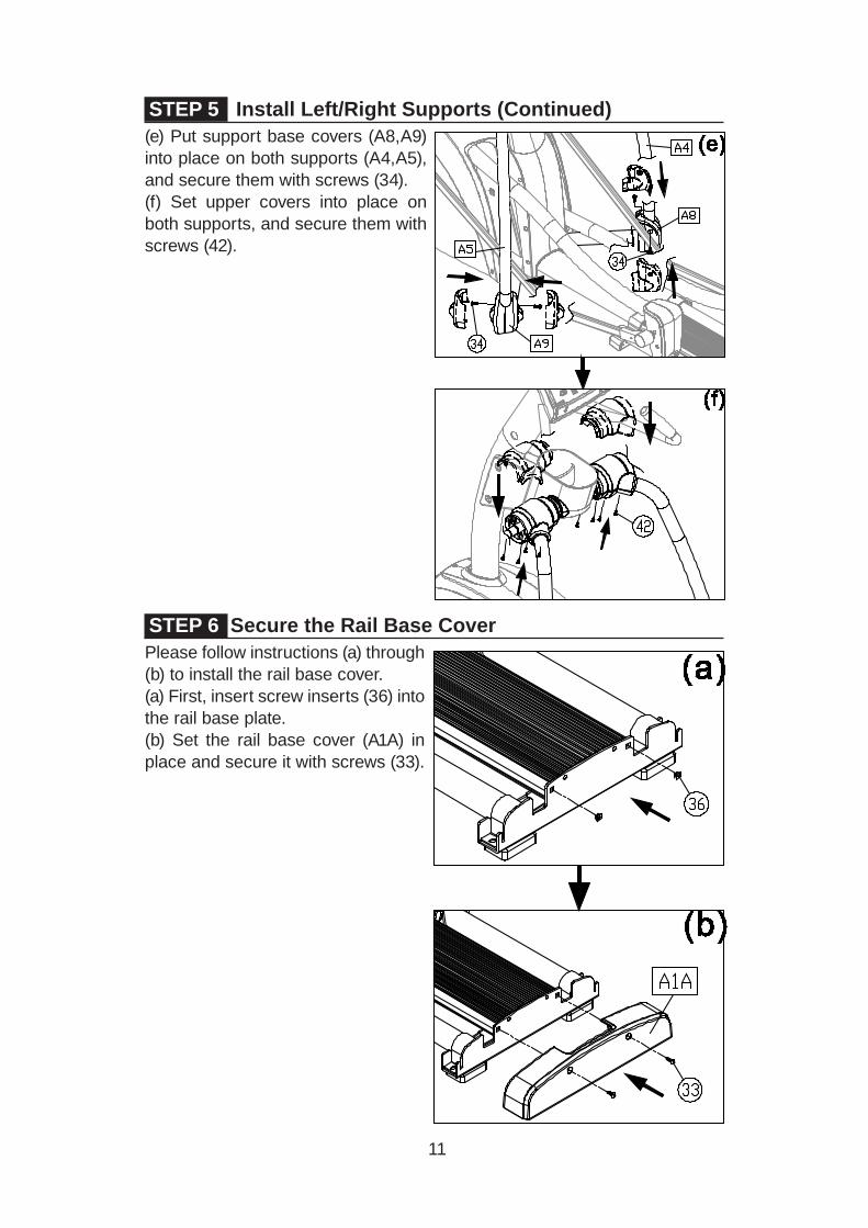
STEP 6 Secure the Rail Base CoverPlease follow instructions (a) through (b) to install the rail base cover.(a) First, insert screw inserts (36) into the rail base plate.(b) Set the rail base cover (A1A) in place and secure it with screws (33).
STEP 5 Install Left/Right Supports (Continued)(e) Put support base covers (A8,A9) into place on both supports (A4,A5), and secure them with screws (34).(f) Set upper covers into place on both supports, and secure them with screws (42).

12
STEP 7 Move the Unit into PlaceFollow steps (a) through (c) to move the unit into place for use.(a) Stand behind the unit. Grasp the glide track rods as shown.(b) Lift up. (To avoid injury, always use proper lifting techniques.)(c) Push while using the transport wheels to roll the unit into place.

13
STEP 8 Level the UnitIf the unit does not rest flat on the floor, please follow steps (a) through (b) to level it.(a) Under the front of the unit, rotate the leveler nut upward to enable adjustment of the leveler foot. Then screw the leveler foot downward until it touches the floor. Rotate the leveler nut against the product frame to secure this position. Carry out these instructions on both sides of the product.(b) Under the support, rotate the leveler nut upward to enable adjustment of the leveler foot. Then screw the leveler foot downward until it touches the floor. Rotate the leveler nut against the product frame to secure this position.
14
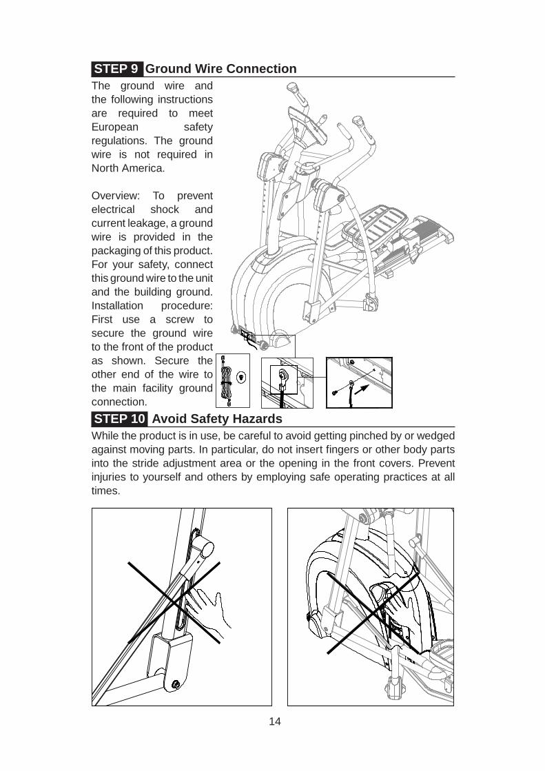
STEP 10 Avoid Safety Hazards While the product is in use, be careful to avoid getting pinched by or wedged against moving parts. In particular, do not insert fingers or other body parts into the stride adjustment area or the opening in the front covers. Prevent injuries to yourself and others by employing safe operating practices at all times.
STEP 9 Ground Wire ConnectionThe ground wire and the following instructions are required to meet European safety regulations. The ground wire is not required in North America.
Overview: To prevent electrical shock and current leakage, a ground wire is provided in the packaging of this product. For your safety, connect this ground wire to the unit and the building ground. Installation procedure: First use a screw to secure the ground wire to the front of the product as shown. Secure the other end of the wire to the main facility ground connection.

15
5. MECHANICAL ADJUSTMENTSDesigned to suit exercisers of different heights, the E850 elliptical trainer has an adjustable stride length. To modify the stride length, pull the adjustment handle toward yourself. Then lift the handle up or down to the desired position. Make sure that the pin on the other side of the handle snaps into place, extending outward from the hole in the vertical arm.

16
6. UNDERSTAND THE E850 DISPLAYDISPLAY OverviewThe E850 elliptical trainer is designed for user convenience. With better feedback about your workout, you get better results. The following explains the display key and window functions. Please read this manual, understand the display functions, and thereby get optimum enjoyment and benefit from this product.
Weight loss target heart rate
Actual heart rate
Cardio target heart rate
Workout program keys
Resistance level keys
Workoutillustrationwindow
Pulse indicator
Workout feedbackwindow
Feedback row control

17
DISPLAY Windows ● The 65% target heart rate window shows the optimum heart rate zone
for weight loss.
● The heart rate window shows actual heart rate.
● The 80% target heart rate window shows the optimim heart rate zone for cardio conditioning.
● The workout illustration window shows workout illustrations and workout prompts.
● The exercise feedback window shows workout prompts and information.
● LED indicators light to indicate active programs, scan mode, selection confirmations, and heart rate.
DISPLAY KeysCHANGE – Press the CHANGE key while exercising to view different workout feedback. Active feedback indicators light up. Top row: WORKOUT LEVEL, CALORIES, TIME, WATTS. Bottom row: DISTANCE, CAL/HR, STRIDES/MIN, TOTAL STRIDES. In SCAN mode, a different row of feedback is displayed every six seconds, and the scan indicator flashes every second. If not in scan mode, the SCAN indicator will remain lit.
QUICK START – Press this key to start exercising without first entering user infor-mation such as age and weight. In QUICK START mode, time counts upward; time values accumulate.
START – Press this key to start exercising after inputting user information.
WORKOUT PROGRAMS – When these indicators flash, or during a workout, simply press any one of these keys to activate the corresponding workout program. The workout’s associated LED will light to indicate its activation.
ENTER – After making a selection, press this key to confirm your choice.
▲/▼ -- Press ▲/▼ keys to set USER, AGE, WEIGHT, TIME and LEVEL values.
STOP/HOLD TO RESET – This key has two functions--pause and reset--the activation of which depends, in part, on how you began exercising. If you pressed the QUICK START key to start your workout, press the STOP key to exit the current workout. If you pressed the START key and began a workout, press the STOP key to return to the “SELECT PROGRAM” prompt. Workout program indicators will flash, prompting you to select a workout program. Under any circumstance, holding the STOP key down for three seconds will allow you to leave the workout and return to the startup banner screen.
18
DISPLAY SpecificationsWORKOUT LEVEL (resistance): 1 to 20TIME: 00:00 to 99:59 (accumulated workout time or time remaining)DISTANCE: 0.01-9999 km or mile CALORIES: 0 to 9999 kcal (expenditure)CAL/Hr: 0.0 - 999.9 kcalSTRIDES/MIN : 0 to 160 strides per minuteWATTS: 0 to 9999 TOTAL STRIDES : 0 to 9999
7. OPERATE THE E850 ELLIPTICAL TRAINERThere are three ways to activate the E850 elliptical trainer. (1) Press the QUICK START key to start exercising without first inputting user information such as age and weight. (2) Press the START key to start exercising after inputting user infor-mation such as age and weight. (3) Or simply start exercising at twenty or more strides per minute. When activated, the display will light up, and the startup banner screen “SPORTSART-E850” will appear.
QUICK START and START modes of operation are explained below.
OPERATION QUICK START ModePress the QUICK START key if you want to begin exercising immediately, without first entering age and weight values.
QUICK START mode has the following characteristics:
In QUICK START mode, calorie and target heart rate values are calculated based on the assumption that the exerciser is 35 years old and weighs 75 kg, 165 lb. Time counts upward. The resistance setting begins at level one and can be changed at any time.
Workout programs, including ZONE TRAINER, can be activated at any time. In workout programs activated via the QUICK START key, time counts upward, and the resistance setting can be changed at any time.
If no one exercises on the product, the message “STEP TO START” will scroll across the display every four seconds. If no one exercises on the product for 15 seconds, a power saving mode will be activated. All lights on the display will extinguish except for four flashing lines in the exercise feedback window. If someone exercises at 20 strides per minute or faster, lights on the display will appear again. If not, after two minutes, lights on the display will extinguish.

19
OPERATION START ModePress the START key to take advantage of stored user information. User age and weight values are used to calculate target heart rates and calorie expenditures respectively. This provides more accurate target heart rate and calorie expenditure values. And having user information saved in the product’s memory allows you to view workout records. Each time that you exercise your workout time, distance, and calorie expenditure values can be automatically committed to the product’s memory. You can view this information when you activate your user ID.
To establish a user ID, follow the instructions below.
1. At the startup banner screen (when “SPORTSART-E850” appears), press the START key. The message window will show the previous user’s ID and accumulated workout data. Every six seconds, one of the following messages will appear:
USER - 1
TIME - 25:05
DIST - 15.8
CALS - 1020
Note: The values that appear on the product will probably differ from those shown above.
Press ▲/▼ keys to select one of four user IDs (1, 2, 3, or 4). Then press the ENTER key to confirm your choice.
2. Rather than having a user ID number, you can create your own user name with up to 11 alphabetical characters. To do so, follow the instructions below. (You can skip this step if desired.) While the user ID number appears, press and hold the CHANGE key for three seconds. This activates the user name setting mode. “ENTER NAME” will appear on the product display.
E N T E R N A M E Press ▲/▼ keys to select alphabetical characters. When your preference appears, press the ENTER key to confirm your choice. Use this method to select up to 11 characters. When your user ID name has been completed, hold the ENTER key for three seconds. The display will show the “USER ID” prompt.
20
OPERATION START Mode (Continued)To modify or delete a user ID name, complete the following procedure. As the user name appears, hold the CHANGE key for three seconds. The user name will disappear. Then create a new user name as explained above.
To delete user data (accumulated workout time, strides, and distance), while the user ID appears, simultaneously press the STOP and START keys.
3. Follow instructions below to input user age and weight information. The “AGE” prompt will appear on the display. The age setting range is 10 to 99 years with a default age of 35 years. Press ▲/▼ keys to select an age value. The age value is used to calculate heart rate target values. Press the ENTER key to confirm the age setting and proceed to the weight setting.
The “WEIGHT” prompt will appear on the display. The weight range is 30 to 180 kg, 66 to 400 lb., with a default value of 75 kg, 165 lb. Press ▲/▼ keys to select a weight value. The weight value is used to calculate calorie expenditure. Press the ENTER key to confirm the weight setting and proceed to the program setting.
4. Follow instructions below to select a workout program. Press the workout program key of your choice. The workout program indicator LED will become lit. Press the ENTER key to confirm your choice and procedd to the time setting.
Note: The ZONE TRAINER program can only be activated via another workout and after a heart rate value has been obtained.
5. Follow instructions below to establish the duration of your workout. Press ▲/▼ keys to select a time value. Then press the ENTER key to confirm the time settting and begin the workout.
Workout programs have the following characteristics in common: ● When a workout is selected, its corresponding illustration appears on the
display. In the workout illustration, the flashing LED represents the exer-ciser’s current position in the workout.
● If a different program is selected while time is counting upward, the time value will continue to accrue from the new segment.
● If a different program is selected while time is counting down in a user ID-activated program, values accumulate from that segment.
● Note that ZONE TRAINER differs from other programs. Refer to Pro-grams below for information about that particular workout.
21
OPERATION Cool DownWhen the workout time goal has been obtained, accumulated workout data known as “ACCU DATA”will appear on the display.User’s workout time, distance, calories, average heart rate will appear, after which a “cool down” mode will begin.During cool down mode, time counts downward from two to zero minutes. When the time count reaches 0:00, the cool down mode will end. “SELECT PROGRAM” will appear on the message window. Program indicator LEDs will flash. You can begin a new workout by pressing the QUICK START or START key.
OPERATION Workout ProgramsInformation about specific workout programs appears below.
TRACKThe track function could also be called manual. Directly presss level keys to control resistance. One lap on the track represents 400 meters or 1/4 mile.
GLUTEThis set of hill-based workouts exercise the gluteus muscles. Choose from three different glute programs. Each time the GLUTE key is pressed a different glute workout illustration appears. When your preferred workout illustration appears, press the ENTER key to confirm your choice.
RANDOM A near infinite number of randomly generated workout programs appear each time the RANDOM key is pressed. When your preferred workout illustration appears, press the ENTER key to confirm your choice and start your workout.
INTERVAL (1:1, 1:2)Interval programs include a work segment and a rest segment. For each segment, you select a different resistance level. There are two interval programs: 1:1 indicates one minute of work, followed by one minute of rest; 1:2 indicates one minute of work, followed by two minutes of rest. A different interval program appears each time the INTERVAL key is pressed. While your preferred workout appears on screen, press the ENTER key to select that workout. Follow prompts to establish segment settings. Once a workout begins, you can change the resistance level of a segement. After that, the new resistance valuewill appear each time that particular segment is activated.
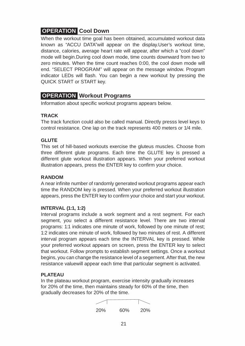
PLATEAUIn the plateau workout program, exercise intensity gradually increases for 20% of the time, then maintains steady for 60% of the time, then gradually decreases for 20% of the time.
20% 60% 20%
22
OPERATION Workout Programs (Continued)After you select the PLATEAU program, the previous time setting will appear.Once the workout time period elapses, the workout will end and a cool down period will begin.
WT LOSS/CARDIO In these heart rate control programs, the resistance level automatically changes to maintain an optimum heart rate to obtain a particular workout goal.Optimum heart rates are calculated as a maximum heart rate for a particular age, multiplied by a percentage deemed appropriate for that exercise goal. The weight loss target heart rate is calculated as (220 - AGE) × 65%. The cardio conditioning target heart rate is calculated as (220 - AGE) × 80%.
For these programs to operate, a heart rate transmitter must be worn on the exerciser’s chest. If no heart rate signal is detected, the following message will appear on the product display: “NO HEART RATE READING, PLEASE CHECK TRANSMITTER”. With no heart rate signal reception, the product cannot automatically adjust resistance. In such cases, resistance can only be operated manually, by pressing resistance level keys.
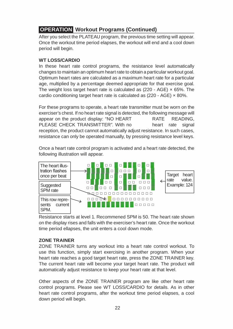
Once a heart rate control program is activated and a heart rate detected, the following illustration will appear.
Resistance starts at level 1. Recommened SPM is 50. The heart rate shown on the display rises and falls with the exerciser’s heart rate. Once the workout time period ellapses, the unit enters a cool down mode.
ZONE TRAINER ZONE TRAINER turns any workout into a heart rate control workout. To use this function, simply start exercising in another program. When your heart rate reaches a good target heart rate, press the ZONE TRAINER key. The current heart rate will become your target heart rate. The product will automatically adjust resistance to keep your heart rate at that level.
Other aspects of the ZONE TRAINER program are like other heart rate control programs. Please see WT LOSS/CARDIO for details. As in other heart rate control programs, after the workout time period elapses, a cool down period will begin.
Target heart rate value. Example: 124
The heart illus-tration flashes once per beat
Suggested SPM rate
This row repre-sents current SPM.
□ ▓ □ ▓ □ □ ▓ □ ▓ ▓ ▓ □ ▓ □ ▓ ▓ ▓ ▓ ▓ ▓ □ ▓ □ □ □ ▓ □ ▓ □ ▓ ▓ ▓ ▓ ▓ ▓ □ ▓ □ ▓ ▓ ▓ □ ▓ ▓ ▓ □ ▓ ▓ ▓ □ □ ▓ □ ▓ □ □ □ □ □ ▓ □ □ ▓ □ □ □ ▓ □ ▓ ▓ ▓ □ □ □ ▓□ □ □ □ □ □ □ □ □ □ □ □ □ □ □ □□ □ □ □ □ ▓ □ □ □ □ □ □ □ □ □ □
▓ ▓ ▓ ▓ ▓ ▓ ▓ ▓ ▓ ▓ □ □ □ □ □

23
OPERATION Workout Programs (Continued)A unique aspect of ZONE TRAINER is that it can only be activated from another workout while a heart rate value is visible. Unlike other workout programs, ZONE TRAINER cannot be activated directly after you press START or QUICK START keys.
OPERATION User Preferences and Product InformationThis product allows you to change its internal unit of measure (metric/imperial) and view time, distance, and component versions—simply by pressing one key. Follow instructions below to access this function.
At the startup banner screen (while “SPORTSART—E850” appears) hold the CHANGE key for three seconds to access user preferences and product information. One of the following lines will appear in the exercise feedback window:
U N I T - L B
U N I T - K G
Press ▲/▼ keys to toggle between the two settings. When your preferred units of measurement appear, press the ENTER key to confirm your selection.
The total time of operation will appear on the exercise feedback window as follows:
T I M E - X X X X X X H O U R Note that X marks shown here represent what will be numbers on the product. Press the ENTER key to proceed to see total distance.
D I S T - X X X X X X X X K M
Press the ENTER key to proceed to user settings. At this step, the user mode can be activated or deactivated.The following message will scroll across the display:
PRESS UP/DN TO ACTIVATE OR DEACTIVATE 4 USER SETTING Press ▲/▼ keys to toggle between the two settings—either activating or deactivating user setting capability.
U S E R I D - O N
U S E R I D - O F F

24
OPERATION User Preferences/Product Information (Cont.)While the user function activation setting of your preference appears, press the ENTER key to confirm your choice and proceed to view the display program version.
The 14-segment window will show the display version in the following format, XXXXX – XX, for example, as E850H - 1A.
Press the ENTER key to return to the startup banner screen. If six seconds pass without any keys being pressed,the following message will appear in the exercise feedback window:
P R E S S E N T E R
This completes user setting and product information mode.

25
8. ABOUT HEART RATE DETECTIONHeart rate detection functions are selected at the time of purchase. Not every product has every type of heart rate detection. The following explains factors that influence the performance of two of the most common types of heart rate detection devices.
HEART RATE TelemetryThe words “telemetry heart rate” refer to the detection of heart rate via a device worn on the exerciser and transmitted over the air to a circuit board built into the product. Telemetry heart rate devices are commonly worn on the exerciser’s chest, where the pulse is strongest and relatively easy to detect.
The following explains conditions that affect the performance of the telemetry heart rate function in all fitness products.
● The telemetry heart rate transmitter emits a wireless 5 kHz signal that is harmless to the human body. Inside the transmitter is a 3 V battery (CR2032). If the battery voltage is too low, either the reception distance shortens or there will be no reception whatsoever.
● Secure the telemetry heart rate transmitter on your chest so that it stays in place without making you feel uncomfortable. Moisten the skin for better contact.
● Because the telemetry heart rate signal varies in strength from 20 Hz to 20 KHz, environmental interference can block signal reception. Physical vibration and electronic devices, including stereos, TVs, and even fluores-cent lights, can interfere with signal reception. For best results, install fitness products in an area free from such interference.
● Space fitness products apart by at least 39 inches (100 cm) to avoid hav-ing the heart rate value from one exerciser appear on a neighboring fitness product.
HEART RATE ContactThe words “contact heart rate” refer to the detection of the heart rate via sensors on the fitness product. By holding the sensors, the exerciser can view his or her heart rate on the product display. Like telemetry heart rate, contact heart rate can be influenced by several factors. The following list includes some of these factors.
● A weak pulse makes it difficult to detect heart rate.
● Low systolic blood pressure makes it difficult to detect heart rate.
● Dry, course palms impede heart rate detection. For best results, moisten your palms. But do not apply hand lotion immediately prior to your workout, because hand lotion can gum up the contact pads.
Heart rate devices built into this fitness product are not medical devices. Heart rate values are for reference only. Do not use them for medical diagnostic or treatment work.
26
CAUTION: Heart rate detection and transmission devices have been known to interfere with the operation of pacemakers, possibly endangering human life. If you have a pacemaker, exercise under your doctor’s supervision; take a test to ensure your safety during the simultaneous use of the pacemaker and heart rate detection devices. The use of such devices must be undertaken at your own risk.
Note that in dry areas in particular, static electricity can interfere with unit operation and shock people. To discharge static electricity from your body, touch something else before touching metal on the fitness product.
9. GUIDELINES FOR EXERCISEHOW HARD SHOULD I EXERCISE?
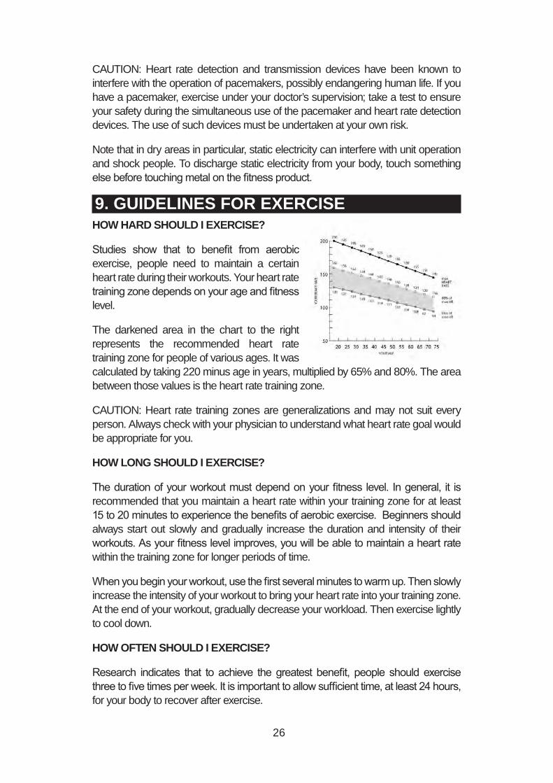
Studies show that to benefit from aerobic exercise, people need to maintain a certain heart rate during their workouts. Your heart rate training zone depends on your age and fitness level.
The darkened area in the chart to the right represents the recommended heart rate training zone for people of various ages. It was calculated by taking 220 minus age in years, multiplied by 65% and 80%. The area between those values is the heart rate training zone.
CAUTION: Heart rate training zones are generalizations and may not suit every person. Always check with your physician to understand what heart rate goal would be appropriate for you.
HOW LONG SHOULD I EXERCISE?
The duration of your workout must depend on your fitness level. In general, it is recommended that you maintain a heart rate within your training zone for at least 15 to 20 minutes to experience the benefits of aerobic exercise. Beginners should always start out slowly and gradually increase the duration and intensity of their workouts. As your fitness level improves, you will be able to maintain a heart rate within the training zone for longer periods of time.
When you begin your workout, use the first several minutes to warm up. Then slowly increase the intensity of your workout to bring your heart rate into your training zone. At the end of your workout, gradually decrease your workload. Then exercise lightly to cool down.
HOW OFTEN SHOULD I EXERCISE?
Research indicates that to achieve the greatest benefit, people should exercise three to five times per week. It is important to allow sufficient time, at least 24 hours, for your body to recover after exercise.
27
10. MAINTENANCEMaintenance topics are presented below in the following order: lubrication of the shoulder area, glide rail cleaning, maintenance schedule, task list, one-year maintenance log, and electronics block diagram.
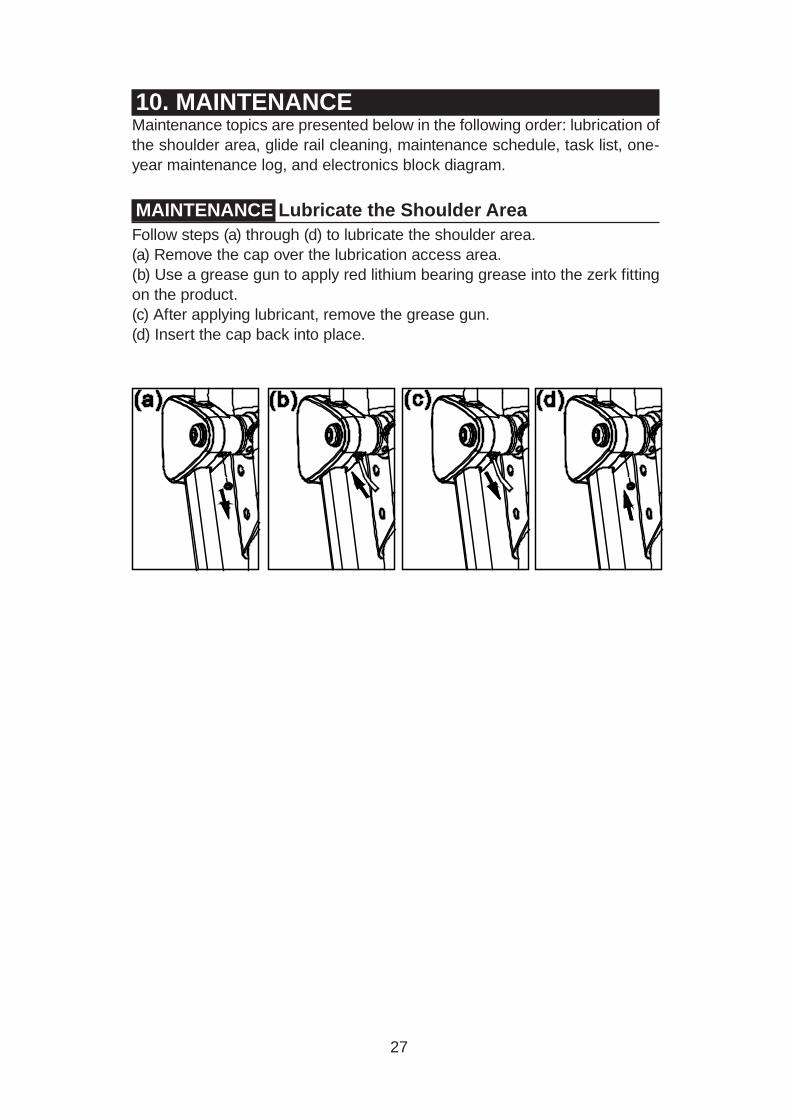
MAINTENANCE Lubricate the Shoulder AreaFollow steps (a) through (d) to lubricate the shoulder area.(a) Remove the cap over the lubrication access area.(b) Use a grease gun to apply red lithium bearing grease into the zerk fitting on the product. (c) After applying lubricant, remove the grease gun.(d) Insert the cap back into place.
28
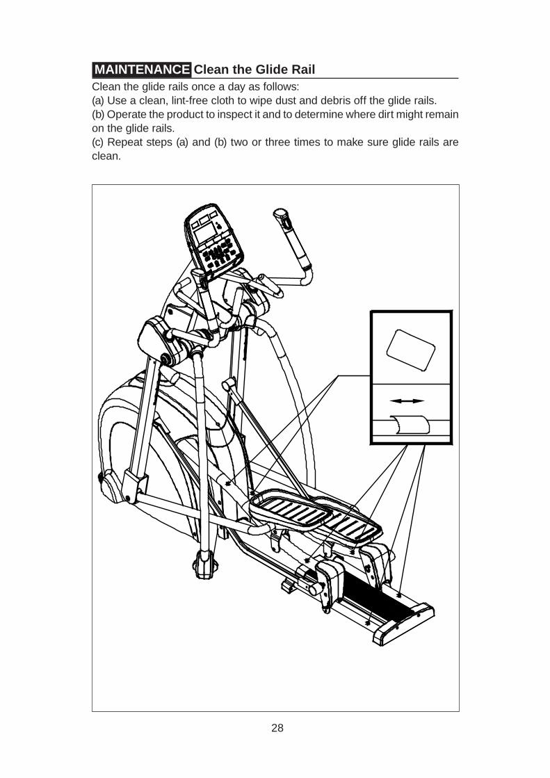
MAINTENANCE Clean the Glide RailClean the glide rails once a day as follows:(a) Use a clean, lint-free cloth to wipe dust and debris off the glide rails. (b) Operate the product to inspect it and to determine where dirt might remain on the glide rails.(c) Repeat steps (a) and (b) two or three times to make sure glide rails are clean.
29
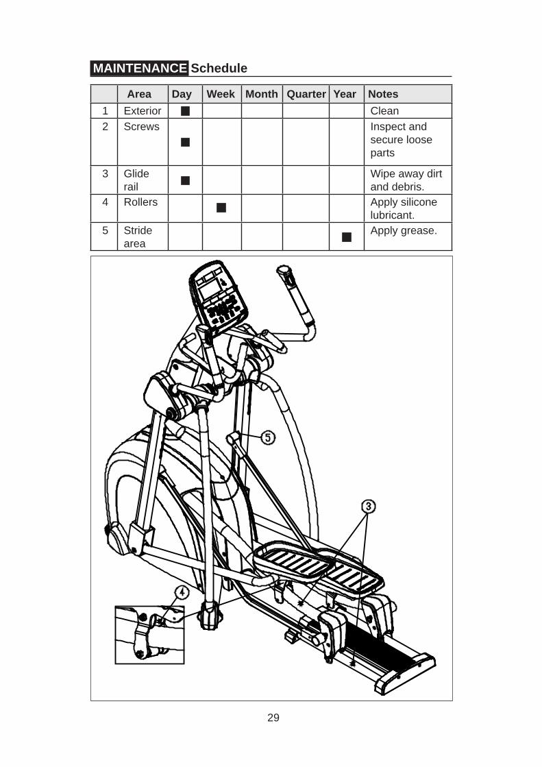
MAINTENANCE Schedule
Area Day Week Month Quarter Year Notes1 Exterior Clean2 Screws Inspect and
secure loose parts
3 Gliderail
Wipe away dirt and debris.
4 Rollers Apply silicone lubricant.
5 Stridearea
Apply grease.
30
MAINTENANCE Task List (Elliptical Trainers)Like cars, fitness products require maintenance. Regular maintenance extends product life, and failure to maintain products can void the manufacturer’s warranty. Copy the maintenance log sheet, and record maintenance work for each fitness product.
Daily tasks1. Use a clean, lint-free towel, dampened with a mixture of Simple Green® all-purpose cleaner and water, to thoroughly clean the product exterior.2. Inspect parts for looseness, and secure all loose screws. Make sure that the product is safe for operation. If safety issues arise, place an “Out of Order” sign on the product, and call for service.3. Wipe dirt and debris off the glide rails. Use a clean, lint-free towel, dampened with a mixture of Simple Green® all-purpose cleaner and water.
Weekly tasks1. Clean rollers. Use a clean, lint-free towel, dampened with a mixture of Simple Green® all-purpose cleaner and water. Apply a small amount of silicone lubricant onto the rollers.
Yearly tasks1. Apply grease to the stride mechanism.2. Apply SportsArt 66A lubricant to the cushion.
Caution ● Please follow standard safety precautions when working on this product.
● Electronic components can carry an electrical charge even after the prod-uct has been turned off. For safety, turn off unit power. Wait five minutes to allow capacitors to discharge. Then disconnect the power cord from the wall socket (if applicable). Only after such steps have been completed should covers be removed and electronic components accessed.
● Do NOT use cleaners with alcohol, ammonia, or other damaging chemi-cals. The use of such chemicals can damage the product and void the war-ranty. Never spray or pour any liquid directly onto the product. Doing so can damage electronic components and void the warranty.
● This product has moving parts that can be hazardous. Exercise caution when maintaining, operating, or moving this product.
31
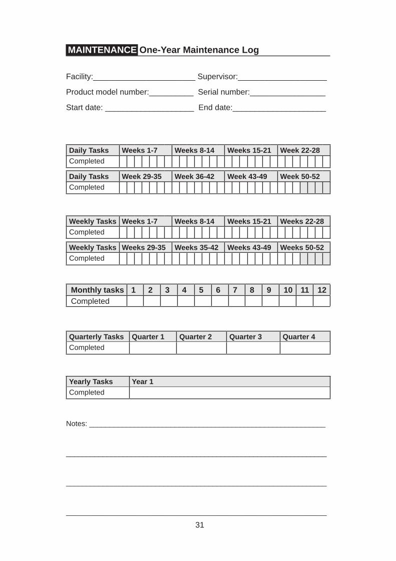
Daily Tasks Weeks 1-7 Weeks 8-14 Weeks 15-21 Week 22-28Completed
Daily Tasks Week 29-35 Week 36-42 Week 43-49 Week 50-52Completed
Weekly Tasks Weeks 1-7 Weeks 8-14 Weeks 15-21 Weeks 22-28Completed
Weekly Tasks Weeks 29-35 Weeks 35-42 Weeks 43-49 Weeks 50-52Completed
Monthly tasks 1 2 3 4 5 6 7 8 9 10 11 12Completed
Quarterly Tasks Quarter 1 Quarter 2 Quarter 3 Quarter 4Completed
Yearly Tasks Year 1Completed
Notes: __________________________________________________________
________________________________________________________________
________________________________________________________________
________________________________________________________________
MAINTENANCE One-Year Maintenance Log
Facility:_______________________ Supervisor:____________________
Product model number:__________ Serial number:_________________
Start date: ____________________ End date:_____________________

32
MAINTENANCE Electronics Block Diagram
C531 CTL board
HTR board
(L) (R) Heart rate contacts
Workout level switch
Polar board 板
Battery
Alternator
Optic sensor
Electromagnet
DC adapter jack 板
E850 DRV board
CON3 CON47
CON5
CON6 CON1 CON2
6V
CON3
CON1
CON2
CSAFE/USB board
:Connector :Converge
Fuse 5A 250 VAC

33
11. SAFETY PRECAUTIONS IN FRENCHCONSIGNES DE SÉCURITÉ IMPORTANTES• Votre vélo SportsArt a été conçu et fabriqué afin d’assurer une sécurité optimale. Cependant certaines précautions s’appliquent chaque fois que vous utilisez votre vélo de course.• Lisez entièrement le manuel avant l’assemblage et l’utilisation. Veuillez aussi noter les consignes de sécurité suivantes:• Veuillez lire attentivement les instructions et installer le vélo de course selon les instructions.• Assemblez et faites fonctionner le vélo sur une surface solide et plane; NE PAS l’utiliser à l’extérieur ou près de l’eau.• En aucun cas, ne laissez des enfants à proximité ou sur le vélo.• Vérifiez le vélo de course avant chaque utilisation. Assurez-vous que toutes les pièces sont assemblées, et que tous les éléments de fixation sont serrés. NE PAS utiliser le vélo de course si l’appareil est démonté de quelque façon.• Gardez vos mains loin des pièces mobiles.• Portez des vêtements d’entraînement appropriés; NE PORTEZ PAS de vêtements amples. NE PORTEZ PAS de chaussures à semelles en cuir ou à talons hauts. Attachez les cheveux longs. Ne marchez pas pieds nus sur l’appareil.• Soyez prudent lors du montage et démontage de l’appareil.• Le vélo peut s’arrêter ou ne s’arrêter pas immédiatement si quelque chose obstacle le mouvement.• NE PAS utiliser d’accessoire non spécifiquement recommandé par le fabricant. Car cela pourraient provoquer des blessures ou entraîner une panne de l’appareil. • Une surveillance étroite est nécessaire quand le vélo est utilisé par ou à proximité d’enfants, de malades ou de personnes handicapées.• Utilisez le vélo de course uniquement pour l’usage prévu dans ce man-uel.• N’utilisez jamais le vélo de course s’il a été endommagé de quelque façon que ce soit. S’il ne fonctionne pas correctement, ou s’il est tombé ou endommagé, contactez votre vendeur.• Veillez à ce qu’aucun orifice de ventilation ne soit obstrué.• Ne faites jamais tomber ou n’insérez jamais d’objet dans les orifices.• NE PAS l’utiliser là où des produits aérosols (vaporisés) sont utilisés ou lorsque de l’oxygène est administré.• La limite de poids de l’utilisateur pour cet vélo est de 180 kg, 400 lb. Remarquez que la résistance de 20 convient jusqu’à 150 kg, 330 lb. • NE PAS transporter le vélo de course par le cordon d’alimentation et n’utilisez pas le cordon comme poignée. • Maintenez le cordon éloigné de toute surface chaude. • Débranchez l’appareil de la prise avant l’entretien ou la suppression de toute pièce. • Pour diminuer le risque de choc électrique, débranchez toujours ce vélo de course de la prise de courant, immédiatement après utilisation et avant le nettoyage.

34
Ce vélo n’est pas destiné à être utilisé par des personnes (y compris des enfants) dont les capacités physiques, sensorielles ou mentales sont réduites ou qui ne disposent pas de l’expérience ou du savoir nécessaires, sauf si celles-ci ont au préalable été formées eu égard à l’utilisation de ce vélo par une personne respon-sable de leur sécurité. Les enfants doivent être encadrés afin d’empêcher qu’ils ne jouent avec le vélo.
ATTENTION
Si vous ressentez une douleur ou si vous avez une sensation anormale, ARRÊTEZ VOTRE ENTRAÎNEMENT et consultez immédiatement votre médecin. Entraînez-vous à votre niveau d’exercice recommandé. NE PAS s’entraîner jusqu’à l’épuisement.
Avant de commencer un programme d’exercice, vous devriez consulter votre médecin. Il est recommandé de faire un examen physique complet.
Remarque: Ce matériel a été testé et déclaré conforme aux normes des appareils digitaux de Classe B, conformément à la partie 15 du Règlement de la FCC. Ces limites sont conçues pour offrir une protection raisonnable contre les interférences nuisibles dans une installation résidentielle. Cet appareil génère, utilise, et peut diffuser des signaux radioélectriques, et, s’il n’est pas installé et utilisé conformément aux instructions, peut provoquer des interférences nuisibles aux communications radio. Cependant, il n’y a aucune garantie que des interférences ne se produiront pas dans une installation particulière.
Si l’utilisateur désire corriger les interférences, ces corrections seront à la charge de l’utilisateur.
Dans ce manuel, les mots “gauche” et “droit” sont utilisés en référence aux pièces et au produit. Comme tels, les mots “gauche” et “droit” font respectivement référence aux côtés gauche et droit de l’exerciseur. De même pour plus de concision, le mot est utilisé dans certains cas où des rondelles, des vis et autres matériels sont associés.
ATTENTION!
Les systèmes de surveillance de la fréquence cardiaque peuvent s’avérer imprécis. Un entraînement excessif risque de nuire sérieusement à la santé ou d’entraîner la mort. En cas d’étourdissement, arrêtez immédiatement l’entraînement.
• Un branchement incorrect du connecteur de mise à la terre de l’équipement risque d’entraîner un choc électrique. En cas de doute sur la mise à la terre correcte de vélo, faites appel à un technicien ou un élec-tricien qualifié. NE PAS modifier la fiche fournie avec l’elliptique, si elle ne correspond pas à la prise, faites installer une prise adéquate par un tech-nicien qualifié.• Les enfants doivent être encadrés afin d’empêcher qu’ils ne jouent avec le vélo.