Embed Size (px)
Citation preview

E7 Drive Parameter Access Technical Manual
Drive Models: CIMR-E7U* Document Number TM.E7.11


i
Warnings and Cautions This Section provides warnings and cautions pertinent to this product, that if not heeded, may result in personal injury, fatality, or equipment damage. Yaskawa is not responsible for consequences of ignoring these instructions.
WARNING
YASKAWA manufactures component parts that can be used in a wide variety of industrial applications. The selection and application of YASKAWA products remains the responsibility of the equipment designer or end user. YASKAWA accepts no responsibility for the way its products are incorporated into the final system design. Under no circumstances should any YASKAWA product be incorporated into any product or design as the exclusive or sole safety control. Without exception, all controls should be designed to detect faults dynamically and to fail safely under all circumstances. All products designed to incorporate a component part manufactured by YASKAWA must be supplied to the end user with appropriate warnings and instructions as to that part’s safe use and operation. Any warnings provided by YASKAWA must be promptly provided to the end user. YASKAWA offers an express warranty only as to the quality of its products in conforming to standards and specifications published in the YASKAWA manual. NO OTHER WARRANTY, EXPRESS OR IMPLIED, IS OFFERED. YASKAWA assumes no liability for any personal injury, property damage, losses, or claims arising from misapplication of its products.
WARNING
■ Read and understand this manual before installing, operating, or servicing this drive. All warnings, cautions, and instructions must be followed. All activity must be performed by qualified personnel. The drive must be installed according to this manual and local codes.
■ Do not connect or disconnect wiring while the power is on. Do not remove covers or touch circuit boards while the power is on. Do not remove or insert the digital operator while power is on.
■ Before servicing, disconnect all power to the equipment. The internal capacitor remains charged even after the power supply is turned off. Status indicator LEDs and Digital Operator display will be extinguished when the DC bus voltage is below 50 VDC. To prevent electric shock, wait at least 5 minutes after all indicators are OFF and measure DC bus voltage and verify that it is at a safe level.
■ Do not perform a withstand voltage test on any part of the unit. This equipment uses sensitive devices and may be damaged by high voltage.
■ The drive is not suitable for circuits capable of delivering more than the specified RMS symmetrical amperes. Install adequate branch short circuit protection per applicable codes. Refer to the specification. Failure to do so may result in equipment damage and/or personal injury.
■ Do not connect unapproved LC or RC interference suppression filters, capacitors, or over voltage protection devices to the output of the drive. Capacitors may generate peak currents that exceed drive specifications.
■ To avoid unnecessary fault displays, caused by contactors or output switches placed between drive and motor, auxiliary contacts must be properly integrated into the control logic circuit.
■ YASKAWA is not responsible for any modification of the product made by the user, doing so will void the warranty. This product must not be modified.
■ Verify that the rated voltage of the drive matches the voltage of the incoming power supply before applying power.
■ To meet CE directives, proper line filters and proper installation are required.
■ Some drawings in this manual may be shown with protective covers or shields removed, to describe details. These must be replaced before operation.
■ Observe Electrostatic Discharge Procedures when handling the drive and drive components to prevent ESD damage.
■ The attached equipment may start unexpectedly upon application of power to the drive. Clear all personnel from the drive, motor and machine area prior to applying power. Secure covers, couplings, shaft keys, machine beds and all safety equipment before energizing the drive.
■ Do not attempt to disassemble this unit. There are no user serviceable parts. Disassembling this unit will void any and all warranties.

ii
Introduction This manual is intended as a parameter access quick reference guide for the Yaskawa model E7 drive. It describes how to connect the E7 drive to an RS232, RS422 or RS485 network and access parameters and their values. It lists the available parameters, their addresses, limits, available selections and default values. Refer to the E7 Drive Programming Manual for detailed parameter information.
This document pertains to the E7 drive. In this document, the word “inverter”, “ac drive” and “drive” may be used interchangeably.
For details on installation and operation of the E7 drive, refer to the E7 Drive User Manual. All manuals and support files are available on the CD that came with the E7 drive and are also available for download at www.drives.com.
E7 Drive User Manual document reference TM.E7.01
E7 Drive Programming Manual document reference TM.E7.02
E7 Drive Parameter Access Technical Manual document reference TM.E7.11
GPD is a trademark of Yaskawa, Inc.
MODBUS® is a registered trademark of Schneider Automation, Inc.
All trademarks are the property of their respective owners.

iii
Table of Contents Chapter 1 Connections ........................................................................ 1-1
Connection Check Sheet .................................................................................... 1-3 Verify Operation .................................................................................................. 1-5 Serial Network Connections ............................................................................... 1-6 Communications Parameters ............................................................................. 1-8 Operation Method and Frequency Reference .................................................. 1-10 Verify Communications ..................................................................................... 1-11
Chapter 2 Message Formats ............................................................... 2-1 Protocol .............................................................................................................. 2-3 Read Multiple Registers – Function Code 03H .................................................. 2-4 Write Single Register – Function Code 06H ....................................................... 2-6 Loop-Back Test – Function Code 08H ................................................................ 2-8 Write Multiple Registers – Function Code 10H ................................................. 2-10 No Response .................................................................................................... 2-12 Error Codes ...................................................................................................... 2-12 CRC-16 Calculations ........................................................................................ 2-13
Chapter 3 Troubleshooting ................................................................. 3-1 General Information ............................................................................................ 3-3 RS232 Communications ..................................................................................... 3-4 RS422/RS485 Communications ......................................................................... 3-6 RS422/RS485 Self-Test ...................................................................................... 3-9
Chapter 4 E7 Drive Parameters .......................................................... 4-1 Command Registers (Read / Write) ................................................................... 4-3 Simultaneous Broadcast Registers (Write only) ................................................. 4-4 Monitor Registers (Read only) ............................................................................ 4-5 Parameters (Read/Write) .................................................................................. 4-11 ENTER/ACCEPT Command (Write Only) ........................................................ 4-21 Parameter Dependencies ................................................................................. 4-22
Chapter 5 User Notes .......................................................................... 5-2 Parameter Record .............................................................................................. 5-4 Notes ................................................................................................................ 5-11 Hex/Dec Conversion Table ............................................................................... 5-12

iv
This page intentionally left blank.

Connections 1-1
Chapter 1 Connections This chapter describes how to connect the E7 drive to an RS232, RS422 or RS485 network
Connection Check Sheet........................................................ 1 – 3 Verify Operation ...................................................................... 1 - 5 Serial Network Connections .................................................. 1 - 6 Communications Parameters ................................................ 1 - 8 Operation Method and Frequency Reference .................... 1 – 10 Verify Communications ......................................................... 1 - 11

Connections 1-2
This page intentionally left blank
Connections 1-3
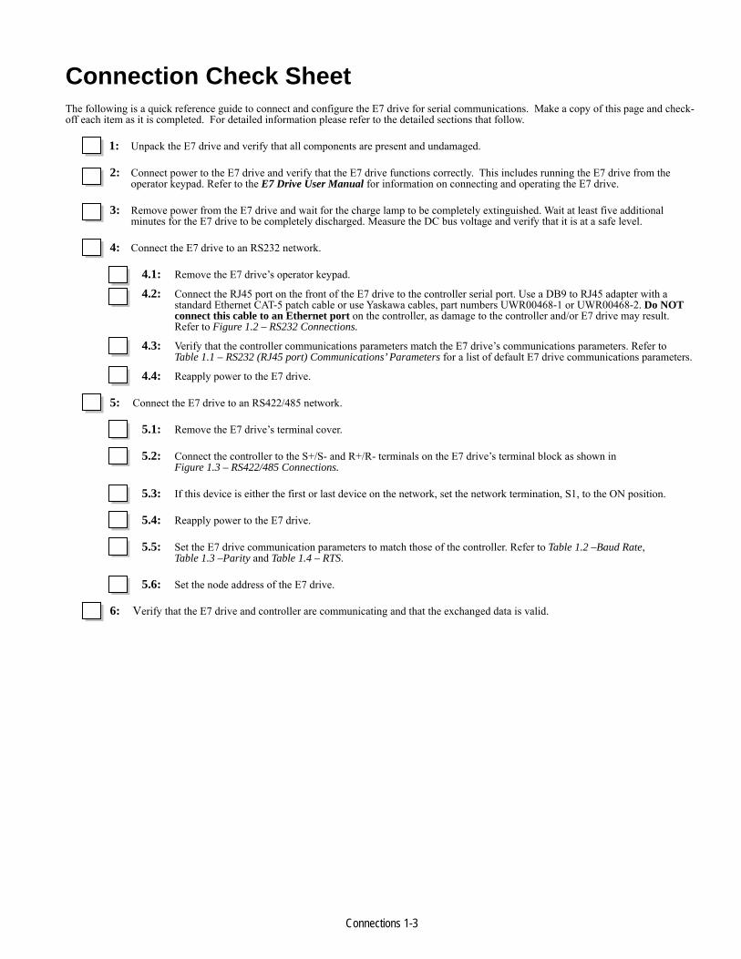
Connection Check Sheet The following is a quick reference guide to connect and configure the E7 drive for serial communications. Make a copy of this page and check-off each item as it is completed. For detailed information please refer to the detailed sections that follow.
1: Unpack the E7 drive and verify that all components are present and undamaged.
2: Connect power to the E7 drive and verify that the E7 drive functions correctly. This includes running the E7 drive from the operator keypad. Refer to the E7 Drive User Manual for information on connecting and operating the E7 drive.
3: Remove power from the E7 drive and wait for the charge lamp to be completely extinguished. Wait at least five additional minutes for the E7 drive to be completely discharged. Measure the DC bus voltage and verify that it is at a safe level.
4: Connect the E7 drive to an RS232 network.
4.1: Remove the E7 drive’s operator keypad. 4.2: Connect the RJ45 port on the front of the E7 drive to the controller serial port. Use a DB9 to RJ45 adapter with a
standard Ethernet CAT-5 patch cable or use Yaskawa cables, part numbers UWR00468-1 or UWR00468-2. Do NOT connect this cable to an Ethernet port on the controller, as damage to the controller and/or E7 drive may result. Refer to Figure 1.2 – RS232 Connections.
4.3: Verify that the controller communications parameters match the E7 drive’s communications parameters. Refer to Table 1.1 – RS232 (RJ45 port) Communications’ Parameters for a list of default E7 drive communications parameters.
4.4: Reapply power to the E7 drive.
5: Connect the E7 drive to an RS422/485 network.
5.1: Remove the E7 drive’s terminal cover.
5.2: Connect the controller to the S+/S- and R+/R- terminals on the E7 drive’s terminal block as shown in Figure 1.3 – RS422/485 Connections.
5.3: If this device is either the first or last device on the network, set the network termination, S1, to the ON position.
5.4: Reapply power to the E7 drive.
5.5: Set the E7 drive communication parameters to match those of the controller. Refer to Table 1.2 –Baud Rate, Table 1.3 –Parity and Table 1.4 – RTS.
5.6: Set the node address of the E7 drive.
6: Verify that the E7 drive and controller are communicating and that the exchanged data is valid.

Connections 1-4
This page intentionally left blank.

Connections 1-5
Verify Operation Connect power to the E7 drive and verify that the E7 drive functions properly. This includes running the E7 drive from the operator keypad. Refer to the E7 Drive User Manual, for information on connecting and operating the E7 drive.
Remove power from the E7 drive and wait for the charge lamp to be completely extinguished. Wait at least five additional minutes for the E7 drive to be completely discharged. Measure the DC bus voltage and verify that it is at a safe level.
Remove the operator keypad and terminal cover.
Figure 1.1 – Connector Diagram
Connections 1-6
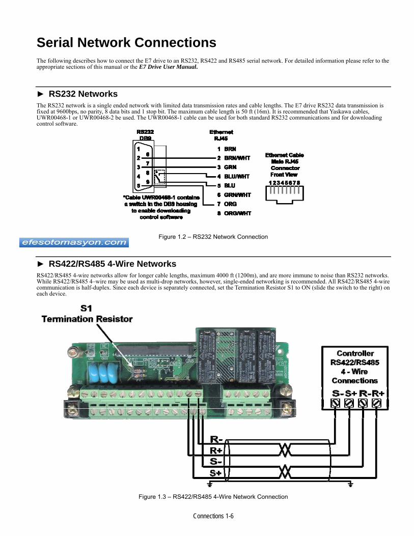
Serial Network Connections The following describes how to connect the E7 drive to an RS232, RS422 and RS485 serial network. For detailed information please refer to the appropriate sections of this manual or the E7 Drive User Manual.
► RS232 Networks The RS232 network is a single ended network with limited data transmission rates and cable lengths. The E7 drive RS232 data transmission is fixed at 9600bps, no parity, 8 data bits and 1 stop bit. The maximum cable length is 50 ft (16m). It is recommended that Yaskawa cables, UWR00468-1 or UWR00468-2 be used. The UWR00468-1 cable can be used for both standard RS232 communications and for downloading control software.
Figure 1.2 – RS232 Network Connection
► RS422/RS485 4-Wire Networks RS422/RS485 4-wire networks allow for longer cable lengths, maximum 4000 ft (1200m), and are more immune to noise than RS232 networks. While RS422/RS485 4–wire may be used as multi-drop networks, however, single-ended networking is recommended. All RS422/RS485 4-wire communication is half-duplex. Since each device is separately connected, set the Termination Resistor S1 to ON (slide the switch to the right) on each device.
Figure 1.3 – RS422/RS485 4-Wire Network Connection

Connections 1-7
► RS485 2-Wire Networks RS485 2-wire networks can be either single or multi-drop networks, with each slave device on the network assigned a unique node address. A maximum of 31 devices may reside on any network segment before a repeater is required. Terminating resistors must be installed on the first and last devices on each network segment. The maximum segment length is 4000ft (1200m). All RS485 communications are half-duplex
Figure 1.4 – RS485 2–Wire Network Connection

Connections 1-8
Communications Parameters These communications parameters affect serial communications through RS232, RS422 and RS485. The RS232 communications parameters cannot be changed. Also, the node address is ignored when communicating via RS232.
All serial communications parameters can only be changed via the operator keypad.
► RS232 Communications The RS232 communications’ parameters are fixed at the values shown below. Although the node address is ignored, a node address of 1 is typically used by the master when communicating to the E7 drive in this method.
Table 1.1 – RS232 (RJ45 port) Communications’ Parameters Value Description
Baud rate 9600 Parity None Stop Bits 1 Node Address N/A
► RS422/RS485 Communications ■ Node Address – H5-01
The node address is set through E7 drive parameter H5-01. When communicating via RS422 or RS485, a unique node address between 0 and 20h (32 dec), inclusive, must be entered. The default E7 drive address is 1Fh (31 dec). The address is always entered as a hexadecimal number (refer to the conversion chart in Chapter 4). Address 0 is typically reserved for global messages.
■ Baud rate – H5-02
Select the baud rate that matches the controller’s serial configuration. The default baud rate is 9600 (3).
Table 1.2 – Baud Rate – Parameter H5-02Value Description
0 1200 1 2400 2 4800 3 9600 4 19200
■ Parity – H5-03
Select the parity that matches the controller’s serial configuration. The default parity is None (0).
Table 1.3 – Parity – Parameter H5-03Value Description
0 None 1 Even 2 Odd
■ Serial Communications Send Delay – H5-06
A delay can be inserted before the E7 drive responds to a command message. This allows for slower communications devices to switch transceiver state in order to get ready to receive a message. A value of 5 ~ 65 ms can be inserted, 5ms being the default.

Connections 1-9
■ RTS Control – H5-07
This parameter determines whether RTS is continually asserted (disabled) or asserted only during send (enabled). RTS must be enabled for use with RS422/485 communications. The default is disabled (0).
Table 1.4 – RTS – Parameter H5-07Value Description
0 Disable (always ON) 1 Enable (ON only during send)
■ Communication Method – H5-08
This parameter determines which communication protocol is used. This manual deals with the Memobus (MODBUS RTU) protocol. The default values is Memobus (0).
Table 1.5 – RTS – Parameter H5-08Value Description
0 Memobus(Modbus) 1 N2 (Metasys) 2 FLN (APOGEE)

Connections 1-10
Operation Method and Frequency Reference The Run/Stop and Frequency Reference commands can originate from serial communication, the operator keypad, external terminals, or an option card. Parameter b1-01 (Operation Method Selection) allows the selection of the origin of the Run/Stop command. Parameter b1-02 (Reference Selection) allows the selection of the origin of the Frequency Reference command. The Run/Stop and Frequency Reference commands may have different origins. For example, the Run/Stop command may be set to External Terminals (b1-01 = 1) while the Frequency Reference command may be set Serial Communications (b1-02=2).
► Operation Method Table 1.5 – Operation Method Selection
b1-01 Operation Method Selection (Run/Stop)0 Operator keypad 1 External Terminals (Default setting is 1)2 Serial Communication 3 Option Card
► Frequency Reference Source Table 1.6 – Frequency Reference Source Selection
b1-02 Frequency Reference Selection0 Operator keypad 1 External Terminals (Default setting is 1)2 Serial Communications (Parameter Access)3 Option Card

Connections 1-11
Verify Communications The following is a quick reference guide for serial communications to the E7 drive. Make a copy of this page and check-off each item as it is completed. For detailed information please refer to the detailed sections that follow.
1: RS232 communication
1.1: Verify that the correct cable is used to connect the controller to the E7 drive.
1.2: Verify that the controller is set for RS232 communications and that the communication’s cable is connected to the correct communications port.
1.3: Record the controller communications’ parameters
Baud Rate Parity Data Bits Stop Bits Protocol
1.4: Record the E7 drive communications’ parameters (H5-02, H5-03, H5-07, H5-08)
Baud Rate Parity Data Bits Stop Bits Protocol
1.5: Verify that the communications’ parameters match.
2: RS422/RS485 communications.
2.1: Verify that the E7 drive is connected correctly.
2.2: Verify that the controller is set for RS422/RS485 communications and that the communication’s cable is connected to the correct communications’ port.
2.3: Record the controller communications’ parameters
Baud Rate Parity Data Bits Stop Bits Protocol
2.4: Record the E7 drive communications’ parameters (H5-01, H5-02, H5-03, H5-07, H5-08)
Baud Rate Parity Data Bits Stop Bits Protocol
2.5: Verify that the communications’ parameters match.
2.6: Verify that parameter H5-07 (RTS) is set to enable.
2.7: Verify that parameter H5-01 (Node Address) is set to the correct, unique, hexadecimal value and that it matches the node address required by the controller.
Controller Node Address E7 Drive Node Address

Connections 1-12
3: Send a command message to the E7 drive from the controller and verify the data of the command and response messages.
3.1: Verify the contents of the command message.
[ ] [ ] [ ] [ ] [ ] [ ] [ ] [ ] [ ] [ ]
[ ] [ ] [ ] [ ] [ ] [ ] [ ] [ ] [ ] [ ]
[ ] [ ] [ ] [ ] [ ] [ ] [ ] [ ] [ ] [ ]
[ ] [ ] [ ] [ ] [ ] [ ] [ ] [ ] [ ] [ ]
3.2: Verify the contents of the response message.
[ ] [ ] [ ] [ ] [ ] [ ] [ ] [ ] [ ] [ ]
[ ] [ ] [ ] [ ] [ ] [ ] [ ] [ ] [ ] [ ]
[ ] [ ] [ ] [ ] [ ] [ ] [ ] [ ] [ ] [ ]
[ ] [ ] [ ] [ ] [ ] [ ] [ ] [ ] [ ] [ ]
Notes:

Connections 1-13
This page intentionally left blank

Message Formats 2-1
Chapter 2 Message Formats This chapter provides information on the message (telegram) contents and configuration.
Protocol ................................................................................... 2 - 3 Read Multiple Registers – Function Code 03H ..................... 2 – 4 Write Single Registers – Function Code 06H ....................... 2 – 6 Loop-Back Test – Function Code 08H ................................... 2 - 8 Write Multiple Registers – Function Code 10H .................. 2 – 10 No Response ......................................................................... 2 – 12 Error Codes ........................................................................... 2 - 12 CRC Calculations .................................................................. 2 - 13

Message Formats 2-2
This page intentionally left blank

Message Formats 2-3
Protocol The parameter access method supported by the Yaskawa E7 drive is a subset of the MODBUS® communication protocol. The E7 drive supports functions 3, 6, 8 and 10h. The message format varies depending upon the function code of the message. For each function code, there is a command message from the master and a response message from the slave. The following sections review the format of the command and response messages for each function.
► Message Functions Supported The following table lists the function codes available and their minimum and maximum lengths.
Table 2.1 - Supported Function Codes
Function Code Function Command Message Response Message (Normal)min. (bytes) max. (bytes) min. (bytes) max. (bytes)
3h (3 dec) Read Multiple Registers 8 8 7 216h (6 dec) Write Single Register 8 8 8 88h (8 dec) Loop-Back test 8 8 8 8
10h (16 dec) Write Multiple Registers 11 41 8 8

Message Formats 2-4
Read Multiple Registers – Function Code 03H The Read Multiple Register message is used to read the contents of from one to eight consecutive registers. The formats of the read command and response messages are shown below.
► Read Multiple Registers Command Message Table 2.2 - Read Command Message
Description DataSlave Address 02hFunction Code 03h
Starting Register Upper 00hLower 20h
Quantity Upper 00hLower 04h
CRC-16 Upper 45hLower F0h
Each E7 drive slave address is set via. parameter H5-01. Valid slave addresses must be in the range of 1 to 20 hex (1 to 32 dec) and entered as a hexadecimal number. No two slaves may have the same address. The master addresses the slave by placing the slave address in the Slave Address field of the message. In the command message above, the slave is addressed at 02h. Broadcast address 0 is not valid for register read commands.
The function code of this message is 03h (read multiple registers).
The starting register is the address of the first register to be read. In the command message above the starting register address is 20h (0020h).
The quantity indicates how many consecutive registers are to be read. The quantity may range from 1 to 8 registers. If an invalid quantity is entered, error code 03h is returned in a fault response message. In this example, four consecutive registers are to be read: 20h, 21h, 22h and 23h.
A CRC-16 value is generated from a calculation including the message slave address, function code, starting register and quantity. The procedure for calculating a CRC-16 is described at the end of this chapter. When the slave receives the command message it calculates a CRC-16 value and compares it to the CRC-16 of the command message. If the two CRC-16 values are identical and the Slave Address is correct, the slave processes command message. If the two CRC-16 values are not identical, the slave will discard the command message and not respond.
If the command message has a valid slave address, function code, starting register, and quantity, the slave will respond with a normal response message. If the command message has an invalid function code, starting register, and/or quantity, the slave will respond with a fault response message. If the command message has an invalid slave address or CRC-16, no response will be returned.

Message Formats 2-5
► Read Multiple Registers Normal Response Message Table 2.3 - Read Normal Response Message
Description DataSlave Address 02hFunction Code 03hNumber of Data Bytes 08h
Starting Register Upper 17hLower 70h
Next Register Upper 17hLower 70h
Next Register Upper 01hLower 09h
Last Register Upper 00hLower 00h
CRC-16 Upper 38hLower ACh
The normal response message contains the same slave address and function code as the command message, indicating to the master, which slave is responding and to what type of function it is responding.
The Number Of Data Bytes is the number of data bytes returned in the response message. The number of data bytes is actually the number of registers read times 2, since there are two bytes of data in each register.
The starting register is the address of the first register read.
The data section of the response message contains the data for the registers requested read. In this case registers 20h, 21h, 22h and 23h. Their data is 20h = 1770h, 21h = 1770h, 22h = 0109h and 23h = 0h.
► Read Multiple Registers Fault Response Message Table 2.4 - Read Fault Response Message
Description DataSlave Address 02hFunction Code 83hError Code 02h
CRC-16 Upper 30hLower F1h
The fault response message contains the same slave address as the command message, indicating to the master, which slave is responding.
The function code of a fault response message is the logical OR of 80h and the original function code of 03h. This indicates to the master that the message is a fault response message, instead of a normal response message.
The error code indicates where the error occurred in the command message. The value of 02h in the error code field of this fault response message indicates that the command message requested data be read from an invalid register. Refer to section Error Codes, Table 2-14, for more information on returned error codes.

Message Formats 2-6
Write Single Register – Function Code 06H The Write Single Register function allows the writing of data to one register only.
► Write Single Register Command Message Table 2.5 - Write Command Message
Description DataSlave Address 01hFunction Code 06h
Register Address Upper 00hLower 01h
Data Upper 00hLower 03h
CRC-16 Upper 98hLower H0B
Each E7 drive slave address is set via. parameter H5-01. Valid slave addresses must be in the range of 1 to 20 hex (1 to 32 dec) and entered as a hexadecimal number. No two slaves may have the same address. The master addresses the slave by placing the slave address in the Slave Address field of the message. In the command message above, the slave is addressed at 01h. Broadcast address 0 is valid for register write commands.
By setting the slave address to zero (0) in the command message, the master can send a message to all the slaves on the network simultaneously. This is called simultaneous broadcasting. In a simultaneous broadcast message there is no response message.
The function code of this message is 06h (write single register).
In the command message above the register address is 01h (0001h).
The data section contains the data to be that written.
A CRC-16 value is generated from a calculation including the message slave address, function code, starting register, quantity, number of data bytes and all register data. The procedure for calculating a CRC-16 is described at the end of this chapter. When the slave receives the command message it calculates a CRC-16 value and compares it to the CRC-16 of the command message. If the two CRC-16 values are identical and the slave address is correct, the slave processes command message. If the two CRC-16 values are not identical, the slave will discard the command message and not respond.
If the command message has a valid slave address, function code, register address and data, the slave will respond with a normal response message. If the command message has an invalid function code, register address and/or data, the slave will respond with a fault response message. If the command message has an invalid slave address or CRC-16, no response will be returned.

Message Formats 2-7
► Write Single Register Normal Response Message Table 2.6 - Write Registers Normal Response Message
Description DataSlave Address 01hFunction Code 06h
Register Address Upper 00hLower 01h
Data Upper 00hLower 03h
CRC-16 Upper 98hLower 0Bh
The normal response message contains the same slave address, function code, register address and data as the command message, indicating to the master, which slave is responding and to what type of function it is responding.
In the response message above the register address is 01h (0001h).
► Write Single Register Fault Response Message Table 2.7 - Write Registers Fault Response Message
Description DataSlave Address 01hFunction Code 86hError Code 21h
CRC-16 Upper 82hLower 78h
The fault response message contains the same slave address as the command message, indicating to the master which slave is responding.
The function code of a fault response message is the logical OR of 80h and the original function code of 06h. This indicates to the master that the message is a fault response message, instead of a normal response message.
The error code indicates where the error occurred in the command message. The value of 21h in the error code field of this fault response message indicates that the command message data to be written was invalid for that register. Refer to the section Error Codes, Table 2-14, for more information on returned error codes.
Message Formats 2-8
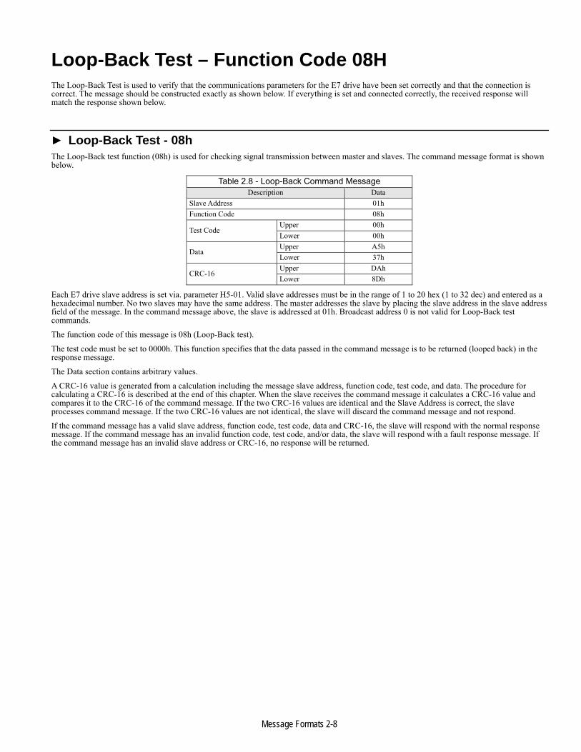
Loop-Back Test – Function Code 08H The Loop-Back Test is used to verify that the communications parameters for the E7 drive have been set correctly and that the connection is correct. The message should be constructed exactly as shown below. If everything is set and connected correctly, the received response will match the response shown below.
► Loop-Back Test - 08h The Loop-Back test function (08h) is used for checking signal transmission between master and slaves. The command message format is shown below.
Table 2.8 - Loop-Back Command MessageDescription Data
Slave Address 01hFunction Code 08h
Test Code Upper 00hLower 00h
Data Upper A5hLower 37h
CRC-16 Upper DAhLower 8Dh
Each E7 drive slave address is set via. parameter H5-01. Valid slave addresses must be in the range of 1 to 20 hex (1 to 32 dec) and entered as a hexadecimal number. No two slaves may have the same address. The master addresses the slave by placing the slave address in the slave address field of the message. In the command message above, the slave is addressed at 01h. Broadcast address 0 is not valid for Loop-Back test commands.
The function code of this message is 08h (Loop-Back test).
The test code must be set to 0000h. This function specifies that the data passed in the command message is to be returned (looped back) in the response message.
The Data section contains arbitrary values.
A CRC-16 value is generated from a calculation including the message slave address, function code, test code, and data. The procedure for calculating a CRC-16 is described at the end of this chapter. When the slave receives the command message it calculates a CRC-16 value and compares it to the CRC-16 of the command message. If the two CRC-16 values are identical and the Slave Address is correct, the slave processes command message. If the two CRC-16 values are not identical, the slave will discard the command message and not respond.
If the command message has a valid slave address, function code, test code, data and CRC-16, the slave will respond with the normal response message. If the command message has an invalid function code, test code, and/or data, the slave will respond with a fault response message. If the command message has an invalid slave address or CRC-16, no response will be returned.

Message Formats 2-9
► Loop-Back Normal Response The normal Loop-Back Test response is identical the command message.
Table 2.9 - Loop-Back Normal Response MessageDescription Data
Slave Address 01hFunction Code 08h
Test Code Upper 00hLower 00h
Data Upper A5hLower 37h
CRC-16 Upper DAhLower 8Dh
► Loop-Back Fault Response Table 2.10 - Loop-Back Fault Response Message
Description DataSlave Address 01hFunction Code 88hError Code 01h
CRC-16 Upper 87hLower C0h
The fault response message contains the same slave address as the command message, indicating to the master which slave is responding. The function code of a fault response message is the logical OR of 80h and the original function code of 08h. This indicates to the master that the message is a fault response message, instead of a normal response message.
The error code indicates where the error occurred in the command message. Refer to the section Error Codes, Table 2-14, for more information on returned error codes.

Message Formats 2-10
Write Multiple Registers – Function Code 10H The Write Multiple Register function allows the writing of data to from one to sixteen consecutive registers.
► Write Multiple Registers Command Message Table 2.11 - Write Command Message
Description DataSlave Address 01hFunction Code 10h
Starting Register Upper 00hLower 01h
Quantity Upper 00hLower 02h
Number of Data Bytes 04h
First Register Data Upper 00hLower 01h
Next Register Data Upper 02hLower 58h
CRC-16 Upper 63hLower 39h
Each E7 drive slave address is set via. parameter H5-01. Valid slave addresses must be in the range of 1 to 20 hex (1 to 32 dec) and entered as a hexadecimal number. No two slaves may have the same address. The master addresses the slave by placing the slave address in the Slave Address field of the message. In the command message above, the slave is addressed at 01h. Broadcast address 0 is valid for register write commands.
By setting the slave address to zero (0) in the command message, the master can send a message to all the slaves on the network simultaneously. This is called simultaneous broadcasting. In a simultaneous broadcast message there is no response message.
The function code of this message is 10h (write multiple registers).
The starting register is the address of the first register to be written. In the command message above the starting register address is 01h (0001h).
The quantity indicates how many consecutive registers are to be written. The quantity may range from 1 to 16 registers. If an invalid quantity is entered, error code of 03h is returned in a fault response message. In this command message there are two consecutive registers to be written: 01h (Operation Command) and 02h (Frequency Reference).
The Number Of Data Bytes is the number of bytes of data to be written. The Number Of Data Bytes is actually the quantity multiplied by 2, since there are two bytes of data in each register.
The data section contains the data for each register to be that written in the order in which they are to be written.
A CRC-16 value is generated from a calculation including the message slave address, function code, starting register, quantity, number of data bytes and all register data. The procedure for calculating a CRC-16 is described at the end of this chapter. When the slave receives the command message it calculates a CRC-16 value and compares it to the CRC-16 of the command message. If the two CRC-16 values are identical and the slave address is correct, the slave processes command message. If the two CRC-16 values are not identical, the slave will discard the command message and not respond.
If the command message has a valid slave address, function code, starting register, quantity, number of data bytes and data, the slave will respond with a normal response message. If the command message has an invalid function code, starting register, quantity, number of data bytes and/or data, the slave will respond with a fault response message. If the command message has an invalid slave address or CRC-16, no response will be returned.

Message Formats 2-11
► Write Multiple Registers Normal Response Message Table 2.12 - Write Registers Normal Response Message
Description DataSlave Address 01hFunction Code 10h
Starting Register Upper 00hLower 01h
Quantity Upper 00hLower 02h
CRC-16 Upper 10hLower 08h
The normal response message contains the same slave address, function code, starting register and quantity as the command message, indicating to the master which slave is responding and to what type of function it is responding.
The starting register is the address of the first register written. In the response message above the starting register address is 01h (0001h).
The quantity indicates how many consecutive registers were written. In this case the quantity is 2.
► Write Multiple Registers Fault Response Message Table 2.13 - Write Registers Fault Response Message
Description DataSlave Address 01hFunction Code 90hError Code 02h
CRC-16 Upper CDhLower C1h
The fault response message contains the same slave address as the command message, indicating to the master which slave is responding.
The function code of a fault response message is the logical OR of 80h and the original function code of 10h. This indicates to the master that the message is a fault response message, instead of a normal response message.
The error code indicates where the error occurred in the command message. The value of 02h in the error code field of this fault response message indicates that the command message requested data to be written to an invalid register. Refer to the section Error Codes, Table 2-14, for more information on returned error codes.

Message Formats 2-12
No Response The slave disregards the command message and does not return a response message in the following cases:
1. In simultaneous broadcasting of data (slave address field is 0), all slaves execute.
2. When a communication error (overrun, framing, parity, or CRC-16) is detected in the command message.
3. When the slave address in the command message does not coincide with the address set in the slave.
4. When it takes longer than 2 seconds to send a message.
5. When the time interval between characters exceeds 3.5ms
6. When the command message data length is not proper.
Error Codes
Table 2-14 – Fault CodesCode Fault Description
1 Function error Invalid or unsupported function code in command message2 Invalid Register Invalid register address3 Invalid Number of Registers Invalid command message quantity21 Data Limits Exceeded The write command message data is out range for the requested register 22 Write Failure The register to be written is write protected

Message Formats 2-13
CRC-16 Calculations The last two bytes of a message contain the CRC-16 (Cyclical Redundancy Check). The CRC-16 is one method for verifying the validity of the message contents and is part of the protocol. The CRC-16 field checks the contents of the entire message, regardless of any parity check method used for the individual characters of the message.
The CRC-16 field is a 16-bit binary value consisting of two 8 bit bytes. The CRC-16 value is calculated by the transmitting device, which appends the CRC-16 to the message. The receiving device recalculates a CRC-16 during receipt of the message, and compares this calculated value to the value received in the transmitted CRC-16 field. If the two values are not equal, the entire message is invalid.
Detailed examples of a CRC-16 generation using Quick Basic and C are shown below.
► CRC-16 Calculation Example in Basic crcsum# = &HFFFF& crcshift# = &H0& crcconst# = &HA001& CLS PRINT “***************************************************” PRINT PRINT “ CRC-16 calculator” PRINT PRINT “***************************************************” PRINT “If entering data in hex, preceed the data with ‘&H’” PRINT “ Example: 32decimal = 20hex = &H20” PRINT “***************************************************” PRINT INPUT “Enter the number of bytes in the message: “, maxbyte FOR bytenum = 1 TO maxbyte STEP 1
PRINT “Enter byte “; bytenum; “:”: INPUT byte& byte& = byte& AND &HFF& crcsum# = (crcsum# XOR byte&) AND &HFFFF& FOR shift = 1 TO 8 STEP 1
crcshift# = (INT(crcsum# / 2)) AND &H7FFF& IF crcsum# AND &H1& THEN
crcsum# = crcshift# XOR crcconst# ELSE
crcsum# = crcshift# END IF
NEXT shift NEXT bytenum lower& = crcsum# AND &HFF& upper& = (INT(crcsum# / 256)) AND &HFF& PRINT “Lower byte (1st) = “, HEX$(lower&) PRINT “Upper byte (2nd) = “, HEX$(upper&)
Figure 2.1 – CRC-16 Calculation in Quick Basic

Message Formats 2-14
► CRC-16 Calculation Example - C void getMBCRC(char *, int, char *) // function prototype void getMBCRC(char *buf, int bufLen, char *crc) { // Function name and parameter list returning a void
// *buf pointer to character array used to calculate CRC // bufLen number of characters to calculate CRC for // *crc pointer to the array that contains the calculated CRC
unsigned long crc_0 = 0xffff; // Declare and initialize variables unsigned long crc_1 = 0x0000; // Declare and initialize variables int i,j; // Declare and initialize variables for (i=0; i<bufLen; i++) { // Loop through characters of input array crc_0 ^= ((unsigned long)buf[i] & 0x00ff); // XOR current character with 0x00ff for (j=0;j<8;j++) { // Loop through characters bits crc_1 = (crc_0 >> 1) & 0x7fff; // shift result right one place and store if (crc_0 & 0x0001) // if pre-shifted value bit 0 is set crc_0 = (crc_1 ^ 0xa001); // XOR the shifted value with 0xa001 else // if pre-shifted value bit 0 is not set crc_0 = crc_1; // set the pre-shifted value equal to the shifted value } // End for loop - Loop through characters bits } // End for loop - Loop through characters of input array crc[0] = (unsigned char)((crc_0/256) & 0x00ff); // Hi byte crc[1] = (unsigned char)(crc_0 & 0x00ff); // Lo byte return; // Return to calling function } // End of CRC calculation function
Figure 2.2 – CRC-16 Calculation in C

Troubleshooting 3-1
Chapter 3 Troubleshooting This chapter describes some basic troubleshooting methods for serial communications
General Information ............................................................... 3 - 3 RS232 Communications ......................................................... 3 - 4 RS422/RS485 Communications ............................................. 3 - 6 RS422/RS485 Self-Test .......................................................... 3 - 9

Troubleshooting 3-2
This page intentionally left blank.

Troubleshooting 3-3
General Information Please fill-in the information on this and the following pages prior to contacting customer support. If customer support is necessary, please have the information below available.
1: E7 Drive Model 5: Flash ID (U1-14)
2: Input VAC Hz 6: Initialization Type (2/3 wire control)
3: Serial Number 7: Specification Type (o2-09)
4: Control Board ETC-
Please provide a sketch of the network connections in the space below.
Figure 3.1 - Connection Sketch

Troubleshooting 3-4
RS232 Communications The following is a quick reference guide for troubleshooting RS232 serial communications to the E7 drive. Make a copy of the following pages and check-off each item as it is completed. For detailed information on the RS232 standard please refer to EIA RS-232-C. or later revision. For information on the E7 drive RS232 interface, refer to previous sections of this manual.
1: For RS232 communications
1.1: Verify that the correct cable is used to connect the controller to the E7 drive.
1.2: Verify that the controller is set for RS232 communications and that the communication’s cable is connected to the correct communications port.
1.3: Record the controller communications’ parameters
Baud Rate Parity Data Bits Stop Bits Protocol
1.4: Record the E7 drive communications’ parameters (H5-02, H5-03, H5-07, H5-08)
Baud Rate Parity Data Bits Stop Bits Protocol
1.5: Verify that the communications’ parameters match.
2: Check the controller RS232 wiring requirements
2.1: CTS(Clear to Send)/RTS(Ready to Send) jumper required on the controller end?
2.2: DTR(Data Terminal ready)/DSR(Data Set Ready)/RLSD(Receive Line Signal Detector) jumper required on the controller end?
2.3: TxD(Transmit Data)/RxD(Receive Data) connections are made correctly.
3: Send a message from the controller to the E7 drive.
3.1: Connect an oscilloscope between the E7 drive RxD and GND.
3.1.1: Verify that the message pulse train exists and contains the correct number of pulses. Refer to the chapter Message Formats for information on the message contents.
3.1.2: Verify that he signal levels adhere to the RS232 standard.
3.2: Insert a data analyzer in the RS232 circuit and capture the message sent by the controller in a hexadecimal format. Record the command message below.
[ ] [ ] [ ] [ ] [ ] [ ] [ ] [ ] [ ] [ ]
[ ] [ ] [ ] [ ] [ ] [ ] [ ] [ ] [ ] [ ]
[ ] [ ] [ ] [ ] [ ] [ ] [ ] [ ] [ ] [ ]
[ ] [ ] [ ] [ ] [ ] [ ] [ ] [ ] [ ] [ ]

Troubleshooting 3-5
3.3: Verify that the contents of the message adheres to the protocol format as described previously.
3.3.1: Verify that the node address is valid.
3.3.2: Verify that the function code is valid
3.3.3: Verify that the register address is valid
3.3.4: Verify that the number of data bytes is correct is valid
3.3.5: Verify that the CRC is correctly calculated.
3.3.6: Verify that the message requires a response.
4: Verify the contents of the response message.
4.1: Connect an oscilloscope between the controller RxD and GND.
4.1.1: Verify that the message pulse train exists and contains the correct number of pulses. Refer to the chapter Message Formats for information on the message contents.
4.1.2: Verify that he signal levels adhere to the RS232 standard.
4.2: Capture the response message sent by the controller in a hexadecimal format and record it below.
[ ] [ ] [ ] [ ] [ ] [ ] [ ] [ ] [ ] [ ]
[ ] [ ] [ ] [ ] [ ] [ ] [ ] [ ] [ ] [ ]
[ ] [ ] [ ] [ ] [ ] [ ] [ ] [ ] [ ] [ ]
[ ] [ ] [ ] [ ] [ ] [ ] [ ] [ ] [ ] [ ]
4.3: Verify that the contents of the message adheres to the protocol format as described previously.
4.3.1: Verify that the node address is valid.
4.3.2: Verify that the function code is valid
4.3.4: Verify that the number of data bytes is correct is valid
4.3.3: Verify that the register address is valid
4.3.4: Verify that the CRC is correctly calculated.

Troubleshooting 3-6
RS422/RS485 Communications
The following is a quick reference guide for troubleshooting RS422/RS485 serial communications to the E7 drive. Make a copy of the following pages and check-off each item as it is completed. For detailed information on the RS422/RS485 standard please refer to EIA RS-4222-A or later revision. For information on the E7 drive RS422/RS485 interface, refer to previous sections of this manual.
1: For RS422/RS485 communications
1.1: Verify that the correct cable is used to connect the controller to the E7 drive.
1.2: Verify that the controller is set for RS422 or RS485 communications and that the communication’s cable is connected to the correct communications port.
1.3: Record the controller communications’ parameters
1.4: Verify that the polarity of the signal wires is correct (+ to + and - to -).
Baud Rate Parity Data Bits Stop Bits Protocol
1.5: Record the E7 drive communications parameters (H5-01, H5-02, H5-03, H5-07, H5-08)
Baud Rate Parity Data Bits Stop Bits Protocol
1.6: Verify that the communications’ parameters match.
1.7: Verify that E7 drive parameter H5-07 (RTS) is set to Enable.
1.8: Verify that E7 drive parameter H5-01 (Node Address) is set to the correct, unique, hexadecimal value and that it matches the node address required by the controller.
2: Check the controller RS422/RS485 wiring requirements
2.1: The controller transmit terminals are connected to the E7 drive receive terminals and the receive terminals connected to the E7 drive transmit terminals.
2.2: The transmit and receive connection polarities are correct.
2.3: The controller either asserts RTS when transmitting or utilizes send detect circuitry.
2.4: The network is terminated only at the beginning and end of each network segment.
2.5: `There are no more than 31 devices on any network segment, including the controller and repeater
3: Verify that the E7 drive passes the self-test as described in the following section.

Troubleshooting 3-7
4: Send a message from the controller to the E7 drive.
4.1: Connect an oscilloscope between the E7 drive’s R+ and R- terminals for RS422/RS485 4-wire networks or between terminals R+/S+ and R-/S- for RS485 2-wire networks.
4.1.1: Verify that the message pulse train exists and contains the correct number of pulses. Refer to the chapter Message Formats for information on the message contents.
4.1.2: Verify that the signal levels adhere to the RS422/RS485 standard.
4.2: Insert a data analyzer in the RS422/RS485 circuit and capture the message sent by the controller in a hexadecimal format Record the command message below.
[ ] [ ] [ ] [ ] [ ] [ ] [ ] [ ] [ ] [ ]
[ ] [ ] [ ] [ ] [ ] [ ] [ ] [ ] [ ] [ ]
[ ] [ ] [ ] [ ] [ ] [ ] [ ] [ ] [ ] [ ]
[ ] [ ] [ ] [ ] [ ] [ ] [ ] [ ] [ ] [ ]
4.3: Verify that the contents of the message adheres to the MODBUS format as described previously.
4.3.1: Verify that the node address is valid.
4.3.2: Verify that the function code is valid
4.3.3: Verify that the register address is valid
4.3.4: Verify that the number of data bytes is correct is valid
4.3.5: Verify that the CRC is correctly calculated.
4.3.6: Verify that the message requires a response.

Troubleshooting 3-8
5: Verify the contents of the response message.
5.1: Connect an oscilloscope between the controller R+ and R- terminals for RS422 and RS485 4-Wire networks or between terminals R+/S+ and R-/S- for RS485 2-wire networks.
5.1.1: Verify that the message pulse train exists and contains the correct number of pulses. Refer to the chapter Message Formats for information on the message contents.
5.1.2: Verify that he signal levels adhere to the RS422/RS485 standard.
5.2: Capture the response message in hexadecimal format and record it below.
[ ] [ ] [ ] [ ] [ ] [ ] [ ] [ ] [ ] [ ]
[ ] [ ] [ ] [ ] [ ] [ ] [ ] [ ] [ ] [ ]
[ ] [ ] [ ] [ ] [ ] [ ] [ ] [ ] [ ] [ ]
[ ] [ ] [ ] [ ] [ ] [ ] [ ] [ ] [ ] [ ]
5.3: Verify that the contents of the message adheres to the MODBUS format as described previously.
5.3.1: Verify that the node address is valid.
5.3.2: Verify that the function code is valid
5.3.3: Verify that the register address is valid
5.3.4: Verify that the number of data bytes is correct is valid
5.3.5: Verify that the CRC is correctly calculated.

Troubleshooting 3-9
RS422/RS485 Self-Test The E7 drive can perform a self-test of the communications interface. To perform the self-test:
■ Apply power to the E7 drive.
■ Set parameter H1-01 to 67h (self-test).
■ Remove power from the E7 drive and wait for the charge lamp to be completely extinguished. Wait at least five additional minutes for the E7 drive to be completely discharged. Measure the DC bus voltage and verify that it is at a safe level.
■ Connect jumper wires to the E7 drive terminals as shown below.
■ Reapply power to the E7 drive.
The frequency reference is displayed on the digital operator if the communications interface is functioning normally.
If the communications interface is not functioning, a “CE” fault is displayed on the digital operator, the E7 drive fault signal will be ON and the E7 drive ready signal will be OFF.
Figure 3.2 – RS422/RS485 Self-Test

Troubleshooting 3-10
This page intentionally left blank.

E7 Drive Parameters 4-1
Chapter 4 E7 Drive Parameters This chapter describes the E7 drive parameters, their addressing, limits and dependencies
Command Registers (Read / Write) ....................................... 4 – 3 Simultaneous Broadcast Registers (Write Only) .................. 4 – 4 Monitor Registers (Read only) ............................................... 4 – 5 Parameters (Read/Write) ...................................................... 4 – 11 ENTER/ACCEPT Command ................................................ 4 – 21 Parameter Dependencies .................................................... 4 – 22

E7 Drive Parameters 4-2
This page intentionally left blank.

E7 Drive Parameters 4-3
Command Registers (Read / Write) Command registers are those registers used to control the operation of the E7 drive either through a network interface (option card) or via serial communications. These registers are available during an active Run command. It should be noted that serially commanded multi-function inputs are logically OR’d with their external input terminal counterpart.
The “Addr” column contains the register address in hexadecimal format. E7 drive registers are always referred to in hexadecimal format. The “Function” column contains the register name. The “Bit” and “Description” columns contain the list of available bits for that register and a short description of each. If the “Bit” column is empty, the register contains word data and individual bits are meaningless.
Table 4.1 – Command Registers (Read / Write)Addr Function Bit Description0000h Reserved Reserved
0001h Command
0h 0 = Stop 1 = Run1h 0 = Forward 1 = Reverse2h External Fault3h Fault reset4h ComNet (0 = b1-01 = pre-selected source -- 1 = b1-01 = 3 (serial communications)) 5h ComCtrl (0 = b1-02 = pre-selected source -- 1 = b1-02 = 3 (serial communications)) 6h Multi-Function Input 1 @ S3 Function set by setting of H1-01 7h Multi-Function Input 2 @ S4 Function set by setting of H1-02 8h Multi-Function Input 3 @ S5 Function set by setting of H1-03 9h Multi-Function Input 4 @ S6 Function set by setting of H1-04 Ah Multi-Function Input 5 @ S7 Function set by setting of H1-05 Bh ReservedCh ReservedDh ReservedEh ReservedFh Reserved
0002h Frequency Reference Dependent on setting of o3-020003h Reserved Reserved0004h Reserved Reserved0005h Reserved Reserved0006h PID Setpoint 0007h Analog Output 1 Setting (-11 ~ 11)/726 Vdc0008h Analog Output 2 Setting (-11 ~ 11)/726 Vdc
0009h Outputs
0h Multi-Function Output 11h Multi-Function Output 22h Multi-Function Output 33h Reserved4h Reserved5h Reserved6h Fault Relay Output7h Fault Relay N.C.
8h-Fh Reserved000Ah Reserved Reserved000Bh Reserved Reserved000Ch Reserved Reserved000Dh Reserved Reserved000Eh Reserved Reserved
000Fh Command Selection
0h Reserved1h PID Value 0006h is used
2h–Bh ReservedCh Simultaneous Broadcast Data Terminal S5 Enable*Dh Simultaneous Broadcast Data Terminal S6 Enable*Eh Simultaneous Broadcast Data Terminal S7 Enable*Fh Reserved
Note: * These bits must be set in order to use the Simultaneous Broadcast Register multi-function inputs 3, 4, 5 and 6 (bits 0Ch, 0Dh, 0Eh and 0Fh respectively).
Refer to Table 4.2 - Simultaneous Broadcast Registers (Write only).

E7 Drive Parameters 4-4
Simultaneous Broadcast Registers (Write only) Simultaneous Broadcast Registers are those registers used to control the simultaneous operation of multiple devices either through a network interface (option card) or via serial communications. These registers are available during drive RUN.
The “Addr” column contains the register address in hexadecimal format. Drive registers are always referenced in hexadecimal format. The “Function” column contains the register name. The “Bit” and “Description” columns contain the list of available bits for that register and a short description of each. If the “Bit” column is empty, the register contains word data and individual bits are meaningless.
Table 4.2 – Simultaneous Broadcast Registers (Write only)Addr Function Bit Description 0000h Reserved Reserved
0001h Command
0h 0 = Stop 1 = Run1h 0 = Forward 1 = Reverse2h3h4h5h Multi-Function Input 1 @ S3 (default = External Fault) Function set by setting of H1-016h Multi-Function Input 2 @ S4 (default = Fault Reset) Function set by setting of H1-027h8h9hAhBhCh Multi-Function Input 3 @ S5* Function set by setting of H1-03 Dh Multi-Function Input 4 @ S6* Function set by setting of H1-04 Eh Multi-Function Input 5 @ S7* Function set by setting of H1-05 Fh Reserved
0002h Frequency Reference 30000/100%** Note: * Use of these bits is dependent on the setting of register 0Fh bits 0Ch, 0Dh and 0Eh. Refer to Table 4.1 – Command Registers (Read / Write). ** This value must be sent to the drive as a hexadecimal value. Example: 4096 = 1000h.
The scaling is fixed at 30000/100%. and is not affected by parameter o1-03. It is affected by the maximum frequency of the drive receiving the command. Simply it is ((decimal freq ref)/30000)* (drive’s maximum frequency). Example: Send 1000h to drive. 1000h = 4096 decimal. (4096*100%)/30000 = 13.65%. If drive’s maximum frequency is 60Hz, then the frequency reference command to the drive is 60*13.65% or 8.19Hz.

E7 Drive Parameters 4-5
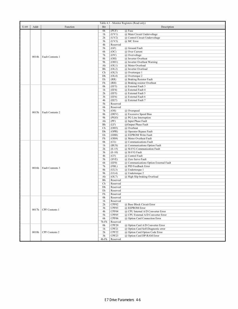
Monitor Registers (Read only) The following table lists monitor parameters for the E7 drive. These parameters are used to monitor E7 drive information and cannot be written.
■ The “U-##” column contains the reference, if it exists, to the “U”, monitor, parameter displayed via the operator keypad.
■ The “Addr” column contains the register addresses for that parameter in hexadecimal format. E7 drive registers are always referred to in hexadecimal format.
■ The “Function” column contains the register name.
■ The “Bit” column contains the list of available bits for that register. If the “Bit” column is empty, the register contains word data and the individual bits are meaningless.
■ The “Description” column contains a short description of each register or register bit.
■ Reserved registers and data are meaningless and should be ignored
Table 4.3 - Monitor Registers (Read only)U-## Addr Function Bit Description
0010h Inverter Status
0h @ RUN1h Reserved2h Reserved3h @ Reset Signal4h @ Speed Agree5h @ Inverter Ready6h @ Minor Fault7h @ Major Fault
8h-Dh ReservedEh @ ComRefFh @ ComCtrl
0011h Operator Status
0 @ OPE1 @ ERR2 @ PRG Mode
3 0: Operator1: PC
4h-Fh Reserved
0012h OPE
0h Reserved1h OPE1 @ E7 drive kVA Setting Error2h OPE2 @ Parameter Setting Out of Range3h OPE3 @ Multi-Function Input Selection4h Reserved5h OPE5 @ Run Command Selection Error - Option board missing 6h OPE6 @ Control Method Selection Error - PG Opt Missing 7h OPE7 @ Multi-Function Analog Input Select Error 8h OPE8 @ Function Selection Error for current control mode 9h OPE9 @ PID Control Setup ErrorAh OPE10 @ V/F Parameter/Pattern Setting Error Bh OPE11 @ Carrier Frequency Parameter Setting Error Ch ReservedDh ReservedEh ReservedFh Reserved
0013h Inverter Product Code
0000h: G51000: V72010: E72020: E7C (YEC)2030: E7A (YEG)2040: E7U (YEA)2050: G7C (YEC)2060: G7A (YEG)2070: G7U (YEA)2080: VG72130: P7
E7 Drive Parameters 4-6
Table 4.3 - Monitor Registers (Read only)U-## Addr Function Bit Description
0014h Fault Contents 1
0h (PUF) @ Fuse1h (UV1) @ Main Circuit Undervoltage2h (UV2) @ Control Circuit Undervoltage3h (UV3) @ MC Error4h Reserved5h (GF) @ Ground Fault6h (OC) @ Over Current7h (OV) @ Overvoltage8h (OH) @ Inverter Overheat9h (OH1) @ Inverter Overheat WarningAh (OL1) @ Motor OverloadBh (OL2) @ Inverter OverloadCh (OL3) @ Overtorque 1Dh (OL4) @ Overtorque 2Eh (RR) @ Braking Resistor FaultFh (RH) @ Braking resistor Overheat
0015h Fault Contents 2
0h (EF3) @ External Fault 3 1h (EF4) @ External Fault 42h (EF5) @ External Fault 53h (EF6) @ External Fault 64h (EE7) @ External Fault 75h Reserved6h Reserved7h (OS) @ Overspeed8h (DEV) @ Excessive Speed Bias9h (PGO) @ PG Line InterruptionAh (PF) @ Input Phase FaultBh (LF) @Output Phase FaultCh (OH3) @ OverheatDh (OPR) @ Operator Bypass FaultEh (ERR) @ EEPROM Write FaultFh (OH4) @ Motor Overheat Fault
0016h Fault Contents 3
0h (CE) @ Communications Fault1h (BUS) @ Communications Option Fault2h (E-15) @ SI-F/G Communication Fault3h (E-10) @ SI-F/G Fault4h (CF) @ Control Fault5h (SVE) @ Zero Servo Fault6h (EF0) @ Communications Option External Fault 7h (FBL) @ PID Feedback Error8h (UL3) @ Undertorque 19h (UL4) @ Undertorque 2Ah (OL7) @ High Slip braking OverloadBh ReservedCh ReservedDh ReservedEh ReservedFh Reserved
0017h CPF Contents 1
0h Reserved1h Reserved2h CPF02 @ Base Block Circuit Error3h CPF03 @ EEPROM Error4h CPF04 @ CPU Internal A/D Converter Error5h CPF05 @ CPU External A/D Converter Error6h CPF06 @ Option Card Connection Error
7h-Fh Reserved
0018h CPF Contents 2
0h CPF20 @ Option Card A/D Converter Error1h CPF21 @ Option Card Self-Diagnostic error 2h CPF22 @ Option Card Option Code Error3h CPF23 @ Option Card DP-RAM Error
4h-Fh Reserved

E7 Drive Parameters 4-7
Table 4.3 - Monitor Registers (Read only)U-## Addr Function Bit Description
0019h Minor Fault Contents 1
0h (UV) @ Undervoltage1h (OV) @ Overvoltage2h (OH) @ Inverter Overheat3h (OH2) @ Inverter Overheat Warning4h (OL3) @ Overtorque 15h (OL4) @ Overtorque 26h (EF) @ 2-wire Sequence Input Fault7h (BB) @ Baseblock8h (EF3) @ External Fault 3 9h (EF4) @ External Fault 4Ah (EF5) @ External Fault 5Bh (EF6) @ External Fault 6Ch (EE7) @ External Fault 7Dh ReservedEh ReservedFh (OS) @ Overspeed
001Ah Minor Fault Contents 2
0h (DEV) @ Excessive Speed Bias1h (PGO) @ PG Line Interruption2h (OPR) @ Operator Bypass Fault3h (CE) @ Communications Fault4h (BUS) @ Communications Option Fault5h (CALL) @ Waiting for Communications6h (OL1) @ Motor Overload7h (OL2) @ Inverter Overload8h (E-15) @ SI-F/G Communication Fault9h (E-10) @ SI-F/G FaultAh @ Motor Switch Bh (FBL) @ PID Feedback ErrorCh (CALL) @ Waiting for CommunicationsDh (UL3) @ Undertorque 1Eh (UL4) @ Undertorque 2Fh @ Communication Test Fault
001Bh Minor Fault Contents 3
0h (OH3) @ Motor Overheat Alarm1h (DNE) @ E7 drive Not Enabled2h Reserved3h Reserved4h Reserved
5h-Fh Reserved 001Ch Reserved Reserved 001Dh Reserved Reserved 001Eh Reserved Reserved 001Fh Reserved Reserved
0020h Inverter Status
0h @ RUN1h @ Reverse2h @ Inverter Ready3h @ Fault4h @ Data Setting Error5h Multi-Function Output 16h Multi-Function Output 27h Multi-Function Output 38h Reserved9h Reserved
Ah-Fh Reserved
0021h Fault Contents
0h (OC) or (GF) @ Overcurrent/Ground Fault 1h (OV) @ Overvoltage 2h (OL2) @ Inverter Overload 3h (OH1) or (OH2) @ Overheat Fault 4h (RR) or (RH) @ Braking Resistor Fault 5h (PUF) @ Fuse Fault 6h (FBL) @ PID Feedback Fault 7h (EF#) @ External Fault 8h (CPF) @ Hardware Fault 9h (OL1) or (OL3) or (OL4) @ Overload/Overtorque Ah (PGO) or (OS) or (DEV) @ Excessive Speed Deviation Bh (UV) @ Undervoltage Ch (UV1) or (UV2) or (UV3) or Power OffDh (SPI) or (SPO) @ Input/Output Phase Fault Eh (CE) @ Communications Error Fh (OPR) @ Operator Error
0022h Data Link Status
0 @ Data Writing1 Reserved2 Reserved3 @ Data Limit Fault4 @ Data Compatibility fault
5h-Fh Reserved 0023h Frequency Reference See U1-01

E7 Drive Parameters 4-8
Table 4.3 - Monitor Registers (Read only)U-## Addr Function Bit Description
0024h Output Frequency See U1-02 0025h Reserved Reserved 0026h Reserved Reserved 0027h Output Power See U1-08 0028h Torque Command See U1-09 0029h Reserved Reserved 002Ah Reserved Reserved
002Bh Sequence Input Status
0h Terminal 1 Closed1h Terminal 2 Closed2h Terminal 3 Closed3h Terminal 4 Closed4h Terminal 5 Closed5h Terminal 6 Closed6h Terminal 7 Closed7h Reserved8h Reserved9h ReservedAh ReservedBh Reserved
Ch-Fh Reserved
002Ch Inverter Status
0h @ RUN1h @ Zero Speed2h @ Speed Agree3h @ Random Speed Agree4h @ Frequency Detect 15h @ Frequency Detect 26h @ Inverter Ready7h @ Undervoltage8h @ Baseblock9h @ Frequency Reference Not From Communications Ah @ Command Reference Not From Communications Bh @ OvertorqueCh @ Loss of Frequency referenceDh @ Fault RetryEh @ FaultFh @ Communications Timeout
002Dh Multi-Function Output Status
0h Multi-Function Output 11h Multi-Function Output 22h Multi-Function Output 33h Reserved4h Reserved
5h-Fh Reserved 002Eh Reserved Reserved 002Fh Reserved Reserved 0030h Reserved Reserved 0031h Main Circuit DC Voltage 0032h Torque 0033h Output Power See U1-08 0034h Reserved Reserved 0035h Reserved Reserved 0036h Reserved Reserved 0037h Reserved Reserved 0038h PID Feedback Level 0039h PID Input Level 003Ah PID Output Level 003Bh CPU CPU Revision 003Ch Flash ID Software Revision
003Dh Communications Error
0h @ CRC Error1h @ Data Length Error2h Reserved3h @ Parity Error4h @ Overrun Error5h @ Framing Error6h @ Timeout
7h-Fh Reserved 003Eh kVA Setting See Parameter o2-04 003Fh Reserved Reserved
U1-01 0040h Frequency Reference Units 0.01HzU1-02 0041h Output Frequency Units 0.01HzU1-03 0042h Output Current Units 0.1AU1-06 0045h Output Voltage Units 0.1VacU1-07 0046h DC Bus Voltage Units 1.0VdcU1-08 0047h Output Power Units 0.1kW

E7 Drive Parameters 4-9
Table 4.3 - Monitor Registers (Read only)U-## Addr Function Bit Description
U1-10 0049h Input Terminal Status
0h Fwd Run (Terminal S1)1h Rev Run (Terminal S2)2h Terminal S33h Terminal S44h Terminal S55h Terminal S66h Terminal S77h Reserved8h Reserved9h ReservedAh ReservedBh Reserved
Ch-Fh Reserved
U1-11 004Ah Output Terminal Status
0h Multi-function Output 11h Multi-function Output 22h Multi-function Output 33h Reserved4h Reserved5h Reserved6h Reserved7h Fault Output
8h - Fh Reserved
U1-12 004Bh E7 drive Operation Status
0h @ FWD RUN1h @ Zero Speed2h @ REV RUN3h @ Reset4h @ Speed Agree5h @ E7 drive Ready6h @ Minor Fault7h @ Major Fault
8h - Fh ReservedU1-13 004Ch Elapsed Time Units 1.0hrU1-14 004Dh Flash ID Software RevisionU1-15 004Eh Terminal A1 Input Voltage Units 0.1%U1-16 04Fh Terminal A2 Input Voltage Units 0.1%U1-18 0051h Motor Secondary Current (Iq) Units 0.1%U1-20 0053h Output Frequency After Soft Start Units 0.01HzU1-24 0057h PID Feedback Value Units 0.01%U1-28 005Bh CPU Number CPU RevisionU1-29 005Ch kWh Units 1.0kWhU1-30 005Dh MWh Units 1.0MWhU1-34 0061h First Parameter Causing an OPE Fault U1-36 0063h PID Input Units 0.1%U1-37 0064h PID Output Units 0.1%U1-38 0065h PID Setpoint Units 0.1%
U1-39 0066h Communication Error Code
0 CRC Error1 Data Length Error2 Reserved3 Parity Error4 Over-run Error5 Framing Error6 Timeout Error
7h - Fh ReservedU1-40 0067h FAN Elapsed Time Units 1HU1-41 0068h Actual Fin Temp Units Deg CU1-51 0072h AUTO Mode Fref Units 0.1%U1-52 0073h HAND Mode Fref Units 0.1%U1-53 0074h PI Feedback 2 Units 0.1%U2-01 0080h Current Fault U2-02 0081h Previous Fault U2-03 0082h Frequency Reference @ Previous Fault Units 0.01HzU2-04 0083h Output Frequency @ Previous Fault Units 0.01HzU2-05 0084h Output Current @ Previous Fault Units 0.1AU2-07 0086h Output Voltage @t Previous Fault Units 0.1VU2-08 0087h DC Bus Voltage @ Previous Fault Units 1.0VdcU2-09 0088h Output Power @ Previous Fault Units 0.1kWU2-10 0089h Torque Reference @ Previous Fault Units 0.1%U2-11 008Ah Input Terminal Status @ Previous Fault (See U1-10 Description)U2-12 008Bh Output Terminal Status @ Previous Fault (See U1-11 Description)U2-13 008Ch E7 drive Operation Status @ Previous Fault (See U1-12 Description)U2-14 008Dh Elapsed Time @ Previous Fault Units 1.0hr

E7 Drive Parameters 4-10
Table 4.3 - Monitor Registers (Read only)U-## Addr Function Bit Description U3-01 0800h Most Recent Fault Also @ 0090H See o2-09 U3-02 0801h 2nd Most Recent Fault Also @ 0091H See o2-09 U3-03 0802h 3rd Most Recent Fault Also @ 0092H See o2-09 U3-04 0803h 4th Most Recent Fault Also @ 0093H See o2-09 U3-05 080Ah Elapsed Time @ Most Recent Fault Units 1.0hr Also @ 0094H See o2-09 U3-06 080Bh Elapsed Time @ 2nd Most Recent Fault Units 1.0hr Also @ 0095H See o2-09 U3-07 080Ch Elapsed Time @ 3rd Most Recent Fault Units 1.0hr Also @ 0096H See o2-09 U3-08 080Dh Elapsed Time @ 4th Most Recent Fault Units 1.0hr Also @ 0097H See o2-09 U3-09 0804h 5th Most Recent Fault See o2-09 U3-10 0805h 6th Most Recent Fault See o2-09 U3-11 0806h 7th Most Recent Fault See o2-09 U3-12 0807h 8th Most Recent Fault See o2-09 U3-13 0808h 9th Most Recent Fault See o2-09 U3-14 0809h 10th Most Recent Fault See o2-09 U3-15 080Eh Elapsed Time @ 5th Most Recent Fault Units 1.0hr See o2-09 U3-16 080Fh Elapsed Time @ 6th Most Recent Fault Units 1.0hr See o2-09 U3-17 0810h Elapsed Time @ 7th Most Recent Fault Units 1.0hr See o2-09 U3-18 0811h Elapsed Time @ 8th Most Recent Fault Units 1.0hr See o2-09 U3-19 0812h Elapsed Time @ 9th Most Recent Fault Units 1.0hr See o2-09 U3-20 0813h Elapsed Time @ 10th Most Recent Fault Units 1.0hr See o2-09

E7 Drive Parameters 4-11
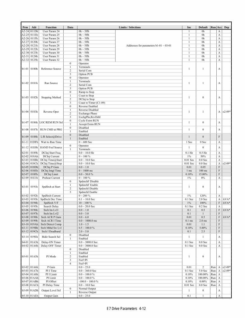
Parameters (Read/Write) The following table lists user accessible parameters for the F7 drive.
■ The “Prm” column contains the parameter name. ■ The “Addr” column contains the register address in hexadecimal format. F7 drive registers are always referred in hexadecimal format. ■ The “Data” column contains the available selections for those parameters whose value is selected from a list. If the Data column is
empty, that parameter’s value is entered as a number within the limits shown in the “± Limits / Selection” ■ The “+/- Limits / Selection” column contains:
▪ The name of the selection if the Data column is not empty ▪ The upper and lower limits of the data that can be entered for that parameter
■ The “Inc” column describes the smallest increment with which the parameter value may be changed. Since all parameter values are sent and received as whole numbers, the “Inc” value also describes how that value should be scaled.
■ The “RUN” column describes whether the parameter is able to be written while the RUN command is active. ▪ “Y” - the parameter is writable during RUN
■ The “Acs” columns describe the accessibility ▪ “A” - the parameter requires Advanced access (A1-01 = 2) ▪ “O” - the parameter has Operation access (A1-01 = 0) ▪ “F” – the parameter requires factory access ▪ “N” – the parameter is not accessible
■ The “Dep” column shows whether the value, definition or function of the selected parameter is dependent on the setting of another parameter. If there is an “*” in the “Dep” column, refer to the appropriate table at the end of this section.
Notes:
■ Factory parameters are shown shaded and are included here for information purposes only
■ Parameter defaults are listed for the F7U drive.
■ All parameters are sent and received as whole numbers regardless of how they are represented in the “+/- Limits / Selection” column or their increment. For example, parameter b4-01, Delay-ON Timer, has limits of 0.0 ~ 3000.0 seconds with an increment of 0.1 seconds. If parameter b4-01 is read and a value of 600 returned, the actual value is 60.0 seconds. If parameter b4-01 is to be set to 30 seconds, a value of 300 (30.0 seconds) must be sent.
Prm Adr Function Data Limits / Selections Inc Default Run Acs Dep
A1-00 0100h Select Language
0 English
1 0 Run O
1 Japanese 2 Deutsch 3 Français 4 Italiano 5 Español 6 Português
A1-01 0101h Access Level 0 Operation Only
1 2 Run A 2 Advanced Level 616 Factory Level
A1-03 0103h Init Parameters 0 No Initialize
1 0 A 2220 2-Wire Initial 3330 3-Wire Initial
A1-04 0104h Enter Password 0 ~ 9999 1 0 OA2-01 0106h User Param 1 0h ~ 5ffh
Addresses for parameters b1-01 ~ 03-01
1 0h AA2-02 0107h User Param 2 0h ~ 5ffh 1 0h AA2-03 0108h User Param 3 0h ~ 5ffh 1 0h AA2-04 0109h User Param 4 0h ~ 5ffh 1 0h AA2-05 010Ah User Param 5 0h ~ 5ffh 1 0h AA2-06 010Bh User Param 6 0h ~ 5ffh 1 0h AA2-07 010Ch User Param 7 0h ~ 5ffh 1 0h AA2-08 010Dh User Param 8 0h ~ 5ffh 1 0h AA2-09 010Eh User Param 9 0h ~ 5ffh 1 0h AA2-10 010Fh User Param 10 0h ~ 5ffh 1 0h AA2-11 0110h User Param 11 0h ~ 5ffh 1 0h AA2-12 0111h User Param 12 0h ~ 5ffh 1 0h AA2-13 0112h User Param 13 0h ~ 5ffh 1 0h AA2-14 0113h User Param 14 0h ~ 5ffh 1 0h AA2-15 0114h User Param 15 0h ~ 5ffh 1 0h AA2-16 0115h User Param 16 0h ~ 5ffh 1 0h AA2-17 0116h User Param 17 0h ~ 5ffh 1 0h AA2-18 0117h User Param 18 0h ~ 5ffh 1 0h AA2-19 0118h User Param 19 0h ~ 5ffh 1 0h AA2-20 0119h User Param 20 0h ~ 5ffh 1 0h AA2-21 011Ah User Param 21 0h ~ 5ffh 1 0h AA2-22 011Bh User Param 22 0h ~ 5ffh 1 0h AA2-23 011Ch User Param 23 0h ~ 5ffh 1 0h A
E7 Drive Parameters 4-12
Prm Adr Function Data Limits / Selections Inc Default Run Acs DepA2-24 011Dh User Param 24 0h ~ 5ffh
Addresses for parameters b1-01 ~ 03-01
1 0h AA2-25 011Eh User Param 25 0h ~ 5ffh 1 0h AA2-26 011Fh User Param 26 0h ~ 5ffh 1 0h AA2-27 0120h User Param 27 0h ~ 5ffh 1 0h AA2-28 0121h User Param 28 0h ~ 5ffh 1 0h AA2-29 0122h User Param 29 0h ~ 5ffh 1 0h AA2-30 0123h User Param 30 0h ~ 5ffh 1 0h AA2-31 0124h User Param 31 0h ~ 5ffh 1 0h AA2-32 0125h User Param 32 0h ~ 5ffh 1 0h A
b1-01 0180h Reference Source
0 Operator
1 1 A 1 Terminals 2 Serial Com 3 Option PCB
b1-02 0181h Run Source
0 Operator
1 1 A 1 Terminals 2 Serial Com 3 Option PCB
b1-03 0182h Stopping Method
0 Ramp to Stop
1 0 A 1 Coast to Stop 2 DCInj to Stop 3 Coast w/Timer (C1-09)
b1-04 0183h Reverse Oper
0 Reverse Enabled
1 1 A o2-09*1 Reverse Disabled 2 Exchange Phase 3 ExchgPhs,RevDsbl
b1-07 0186h LOC/REM RUN Sel 0 Cycle Extrn RUN 1 0 A 1 Accept Extrn RUN
b1-08 0187h RUN CMD at PRG 0 Disabled 1 0 A 1 Enabled
b1-09 0188h L/R Select@Drive 0 Disabled 1 0 F 1 Enabled b1-11 01DFh Wait to Run Time 0 ~ 600 Sec 1 Sec 0 Sec A
b1-12 01E0h HAND Fref Source 0 Operator 1 0 A 1 Terminals b2-01 0189h DCInj Start Freq 0.0 ~ 10.0 Hz 0.1 Hz 0.5 Hz Ab2-02 018Ah DCInj Current 0 ~ 100 % 1% 50% Ab2-03 018Bh DCInj Time@Start 0.0 ~ 10.0 Sec 0.01 Sec 0.0 Sec Ab2-04 018Ch DCInj Time@Stop 0.0 ~ 10.0 Sec 0.01 Sec 0.0 Sec A o2-09*b2-05 018Dh DCInj P Gain 0.0 ~ 1.0 0.01 0.05 Fb2-06 018Eh DCInj Intgl Time 0 ~ 1000 ms 1 ms 100 ms Fb2-07 018Fh DCInj Limit 0.0 ~ 30.0 % 0.10% 15.00% Fb2-09 01E1h Preheat Current 0 ~ 100 % 1% 0% A
b3-01 0191h SpdSrch at Start
0 SpdsrchF Disable
1 0 A 1 SpdsrchF Enable 2 SpdsrchI Disable 3 SpdsrchI Enable
b3-02 0192h SpdSrch Current 0 ~ 200 % 1% 120% Ab3-03 0193h SpdSrch Dec Time 0.1 ~ 10.0 Sec 0.1 Sec 2.0 Sec A kVA*b3-04 0194h SpdSrch V/F 10 ~ 100 % 1% 100% F kVA*b3-05 0195h Search Delay 0.0 ~ 20.0 Sec 0.1 Sec 0.2 Sec Ab3-06 0196h Srch Im Lvl1 0.0 ~ 1.0 0.1 0.5 F kVA*b3-07 0197h Srch Im Lvl2 0.0 ~ 3.0 0.1 1 Fb3-08 0198h Srch ACR P Gain 0.0 ~ 6.0 0.01 0.5 F kVA*b3-09 0199h Srch ACR I Time 0.0 ~ 1000.0 ms 0.1 ms 2.0 ms Fb3-10 019Ah Srch Detect Comp 1.0 ~ 1.5 0.01 1.1 Fb3-11 019Bh Srch Mthd Sw Lvl 0.5 ~ 100.0 % 0.10% 5.00% Fb3-12 019Ch Srch I Deadband 2.0 ~ 5.0 0.1 2.5 F
b3-14 019Eh Bidir Search Sel 0 Disabled 1 1 A 1 Enabled b4-01 01A3h Delay-ON Timer 0.0 ~ 3000.0 Sec 0.1 Sec 0.0 Sec Ab4-02 01A4h Delay-OFF Timer 0.0 ~ 3000.0 Sec 0.1 Sec 0.0 Sec A
b5-01 01A5h PI Mode
0 Disabled
1 0 A 1 Enabled 2 Enabled 3 Fref+PI 4 Fref+PI
b5-02 01A6h P Gain 0.0 ~ 25.0 0.01 2 Run A o2-09*b5-03 01A7h PI I Time 0.0 ~ 360.0 Sec 0.1 Sec 5.0 Sec Run A o2-09*b5-04 01A8h PI I Limit 0.0 ~ 100.0 % 0.10% 100.00% Run Ab5-06 01AAh PI Limit 0.0 ~ 100.0 % 0.10% 100.00% Run Ab5-07 01ABh PI Offset -100.0 ~ 100.0 % 0.10% 0.00% Run Ab5-08 01ACh PI Delay Time 0.0 ~ 10.0 Sec 0.01 Sec 0.0 Sec Run A
b5-09 01ADh Output Level Sel 0 Normal Output 1 0 A 1 Reverse Output b5-10 01AEh Output Gain 0.0 ~ 25.0 0.1 1 A

E7 Drive Parameters 4-13
Prm Adr Function Data Limits / Selections Inc Default Run Acs Dep
b5-11 01AFh Output Rev Sel 0 0 limit 1 0 A 1 Reverse
b5-12 01B0h Fb los Det Sel 0 Disabled
1 0 A 1 Alarm 2 Fault
b5-13 01B1h Fb los Det Lvl 0 ~ 100 % 1% 0% Ab5-14 01B2h Fb los Det Time 0.0 ~ 25.5 Sec 0.1 Sec 1.0 Sec Ab5-15 01B3h Sleep Level 0.0 ~ 200.0 Hz 0.1 Hz 0.0 Hz Ab5-16 01B4h Sleep Time 0.0 ~ 25.5 Sec 0.1 Sec 0.0 Sec Ab5-17 01B5h Acc/Dec Time 0.0 ~ 25.5 Sec 0.1 Sec 0.0 Sec A
b5-18 01DCh PI Setpoint Sel 0 Disabled 1 0 A 1 Enabled b5-19 01DDh PI Setpoint 0.0 ~ 100.0 % 0.10% 0.00% Run Ab5-20 01E2h Setpoint Scaling 0 ~ 39999 1 1 A
b5-21 01E3h PI Sleep Source 0 SFS Input
1 1 A 1 PI Setpoint 2 Snooze
b5-22 01E4h Snooze Level 0 ~ 100 % 1% 0% Run Ab5-23 01E5h Snooze DelayTime 0 ~ 3600 Sec 1 Sec 0 Sec Ab5-24 01E6h Wake-Up Level 0 ~ 100 % 1% 0% Ab5-25 01E7h Setpoint Boost 0 ~ 100 % 1% 0% Ab5-26 01E8h Max Boost Time 0 ~ 3600 Sec 1 Sec 0 Sec Ab5-27 01E9h Snooze Feedback 0 ~ 100 % 1% 60% A
b5-28 01EAh PI Feedback SqRt 0 Disabled 1 0 A 1 Enabled b5-29 01EBh PI Fb SqRt Gain 0.0 ~ 2.0 0.01 0 A
b5-30 01ECh PI Out Moni SqRt 0 Disabled 1 0 A 1 Enabled
b8-01 01CCh Energy Save Sel 0 Disabled 1 0 A 1 Enabled b8-04 01CFh Energy Save COEF 0.0 ~ 655.0 0.01 288.2 A kVA*b8-05 01D0h kW Filter Time 0 ~ 2000 ms 1 ms 20 ms Ab8-06 01D1h Search V Limit 0 ~ 100 % 1% 0% Ab8-07 01D2h E-Sav V Low Lim1 0 ~ 100 % 1% 50% Fb8-08 01D3h E-Sav V Low Lim2 0 ~ 25 % 1% 12% Fb8-09 01D4h E-Sav V Up Lim1 0 ~ 120 % 1% 120% Fb8-10 01D5h E-Sav V Up Lim2 0 ~ 25 % 1% 16% Fb8-11 01D6h Srch V Step 100% 0.1 ~ 10.0 % 0.10% 0.50% Fb8-12 01D7h Srch V Step 5% 0.1 ~ 10.0 % 0.10% 0.20% Fb8-13 01D8h Srch V Avg Time 1 ~ 5000 ms 1 ms 25 ms Fb8-14 01D9h Srch kW Hold Wth 0 ~ 100 % 1% 10% FC1-01 0200h Accel Time 1 0.0 ~ 6000.0 Sec 0.1 Sec 30.0 Sec Run A o2-09*C1-02 0201h Decel Time 1 0.0 ~ 6000.0 Sec 0.1 Sec 30.0 Sec Run A o2-09*C1-03 0202h Accel Time 2 0.0 ~ 6000.0 Sec 0.1 Sec 30.0 Sec Run A o2-09*C1-04 0203h Decel Time 2 0.0 ~ 6000.0 Sec 0.1 Sec 30.0 Sec Run A o2-09*C1-09 0208h Fast Stop Time 0.0 ~ 6000.0 Sec 0.1 Sec 30.0 Sec AC1-11 020Ah Acc/Dec SW Freq 0.0 ~ 200.0 Hz 0.1 Hz 0.0 Hz AC2-01 020Bh SCrv Acc @ Start 0.0 ~ 2.5 Sec 0.01 Sec 0.2 Sec AC2-02 020Ch SCrv Acc @ End 0.0 ~ 2.5 Sec 0.01 Sec 0.2 Sec AC4-01 0215h Torq Comp Gain 0.0 ~ 2.5 0.01 1 Run AC4-02 0216h Torq Comp Time 0 ~ 10000 ms 1 ms 200 ms A
C6-01 0223h Normal Duty Sel 0 Heavy Duty
1 2 F o2-09*1 Normal Duty 1 2 Normal Duty 2
C6-02 0224h CarrierFreq Sel
0h Low Noise
1 6h A kVA*
1h Fc=2.0kHz 2h Fc=5.0kHz 3h Fc=8.0kHz 4h Fc=10.0kHz 5h Fc=12.5kHz 6h Fc=15.0kHz
7h~Eh Reserved Fh Program
C6-03 0225h CarrierFreq Max 0.4 ~ 15.0 kHz 0.1 kHz 2.0 kHz A
C6-04 0226h CarrierFreq Min 0 Heavy Duty 0.1 kHz 2.0 kHz A 1 Normal Duty C6-05 0227h CarrierFreq Gain 0 ~ 99 1 0 A
C6-06 0228h PWM Method
0 2/3 Pha Auto-Mod
1 0 F
1 2 Phase Modulate2 3 Phase Modulate3 Motor Audible 1 4 Motor Audible 2 5 Motor Audible 3 6 Motor Audible 4
C6-07 0229h Phase SW level 0.5 ~ 3.0 0.1 1.5 FC6-08 022Ah PWM on Time 1.0 ~ 5.0 0.1 3 F

E7 Drive Parameters 4-14
Prm Adr Function Data Limits / Selections Inc Default Run Acs Depd1-01 0280h Reference 1 0.0 ~ 400.0 Hz 0.01 Hz 0.0 Hz Run A o2-09*d1-02 0281h Reference 2 0.0 ~ 400.0 Hz 0.01 Hz 0.0 Hz Run Ad1-03 0282h Reference 3 0.0 ~ 400.0 Hz 0.01 Hz 0.0 Hz Run Ad1-04 0283h Reference 4 0.0 ~ 400.0 Hz 0.01 Hz 0.0 Hz Run Ad1-17 0292h Jog Reference 0.0 ~ 400.0 Hz 0.01 Hz 6.0 Hz Run Ad2-01 0289h Ref Upper Limit 0.0 ~ 110.0 % 0.10% 100.00% Ad2-02 028Ah Ref Lower Limit 0.0 ~ 110.0 % 0.10% 0.00% Ad2-03 0293h Ref1 Lower Limit 0.0 ~ 110.0 % 0.10% 0.00% Ad3-01 0294h Jump Freq 1 0.0 ~ 200.0 Hz 0.1 Hz 0.0 Hz Ad3-02 0295h Jump Freq 2 0.0 ~ 200.0 Hz 0.1 Hz 0.0 Hz Ad3-03 0296h Jump Freq 3 0.0 ~ 200.0 Hz 0.1 Hz 0.0 Hz Ad3-04 0297h Jump Bandwidth 0.0 ~ 20.0 Hz 0.1 Hz 1.0 Hz A
d4-01 0298h MOP Ref Memory 0 Disabled 1 0 A 1 Enabled d4-02 0299h Trim Control Lvl 0 ~ 100 % 1% 10% A
E1-01 0300h Input Voltage 155 ~ 255 VAC 1 VAC 240 VAC A KVA*o2-09*
E1-03 0302h V/F Selection
0h 50 Hz
1 0Fh A
1h 60 Hz Saturation 2h 50 Hz Saturation 3h 72 Hz 4h 50 Hz VT1 5h 50 Hz VT2 6h 60 Hz VT1 7h 60 Hz VT2 8h 50 Hz HST1 9h 50 Hz HST2 Ah 60 Hz HST1 Bh 60 Hz HST2 Ch 90 Hz Dh 120 Hz Eh 180 Hz Fh Custom V/F 10h Custom w/o limit
E1-04 0303h Max Frequency 0.0 ~ 200.0 Hz 0.1 Hz 60.0 Hz A E1-03*
E1-05 0304h Max Voltage 0.0 ~ 255.0 VAC (200/240VAC drives) 0.0 ~ 555.0VAC (400/480VAC drives) 0.1 VAC 240.0 VAC A
E1-03*kVA
o2-09*E1-06 0305h Base Frequency 0.0 ~ 200.0 Hz 0.1 Hz 60.0 Hz A E1-03*E1-07 0306h Mid Frequency A 0.0 ~ 200.0 Hz 0.1 Hz 3.0 Hz A E1-03*
E1-08 0307h Mid Voltage A 0.0 ~ 255.0 VAC (200/240VAC drives) 0.0 ~ 555.0VAC (400/480VAC drives) 0.1 VAC 13.0 VAC A E1-03*
kVAE1-09 0308h Min Frequency 0.0 ~ 200.0 Hz 0.1 Hz 1.5 Hz A E1-03*
E1-10 0309h Min Voltage 0.0 ~ 255.0 VAC (200/240VAC drives) 0.0 ~ 555.0VAC (400/480VAC drives) 0.1 VAC 9.0 VAC A E1-03*
kVAE1-11 030Ah Mid Frequency B 0.0 ~ 200.0 Hz 0.1 Hz 0.0 Hz A E1-03*
E1-12 030Bh Mid Voltage B 0.0 ~ 255.0 VAC (200/240VAC drives) 0.0 ~ 555.0VAC (400/480VAC drives) 0.1 VAC 0.0 VAC A E1-03*
kVA
E1-13 030Ch Base Voltage 0.0 ~ 255.0 VAC (200/240VAC drives) 0.0 ~ 555.0VAC (400/480VAC drives) 0.1 VAC 240.0 VAC A E1-03*
kVAE2-01 030Eh Motor Rated FLA 0.1 ~ 1500.0 A 0.1 A 14.0 A A kVA*E2-02 030Fh Motor Rated Slip 0.0 ~ 20.0 Hz 0.01 Hz 3.3 Hz F kVA*E2-03 0310h No-Load Current 0.0 ~ 1500.0 A 0.1 A 4.5 A A kVA*E2-05 0312h Term Resistance 0.0 ~ 65.0 Ohm 0.001 Ohm 0.771 Ohm A kVA*E2-10 0317h Tcomp Iron Loss 0 ~ 65535 W 1 W 0 W FE2-11 0318h Mtr Rated Power 0.0 ~ 650.0 kW 0.01 kW 0.4 kW F
F6-01 03A2h Comm Bus Flt Sel
0 Ramp to Stop
1 0 A 1 Coast to Stop 2 Fast-Stop 3 Alarm Only
F6-02 03A3h EF0 Detection 0 Always Detected 1 0 A 1 Only During Run
F6-03 03A4h EF0 Fault Action
0 Ramp to Stop
1 1 A 1 Coast to Stop 2 Fast-Stop 3 Alarm Only
F6-05 03A6h 0 ~ 1 1 0 A

E7 Drive Parameters 4-15
Prm Adr Function Data Limits / Selections Inc Default Run Acs Dep
H1-01 0400h Terminal S3 Sel
0h 3-Wire Control
1 24h A
1h Local/Remote Sel2h Option/Inv Sel 3h Multi-Step Ref 1 4h Multi-Step Ref 2 6h Jog Freq Ref 7h Multi-Acc/Dec 1 8h Ext BaseBlk N.O.9h Ext BaseBlk N.C.Ah Acc/Dec RampHoldCh Term A2 Enable Fh Term Not Used 10h MOP Increase 11h MOP Decrease 12h Forward Jog 13h Reverse Jog 14h Fault Reset 15h Fast-Stop N.O. 17h Fast-Stop N.C. 18h Timer Function 19h PI Disable 1Bh Program Lockout 1Ch TrimCtl Increase 1Dh TrimCtl Decrease1Eh Ref Sample Hold 20h NO/Always Det Ramp to Stop21h NC/Always Det Ramp to Stop22h NO/During RUN Ramp to Stop23h NC/During RUN Ramp to Stop24h NO/Always Det Coast to Stop25h NC/Always Det Coast to Stop26h NO/During RUN Coast to Stop27h NC/During RUN Coast to Stop28h NO/Always Det Fast Stop29h NC/Always Det Fast Stop2Ah NO/During RUN Fast Stop2Bh NC/During RUN Fast Stop2Ch NO/Always Det Alarm Only2Dh NC/Always Det Alarm Only2Eh NO/During RUN Alarm Only2Fh NC/During RUN Alarm Only30h PI Intgrl Reset 31h PI Intgrl Hold 34h PI SFS Cancel 35h Input Level Sel 36h Option/Inv Sel 2 60h Motor Preheat 61h Speed Search 1 62h Speed Search 2 64h Speed Search 3 67h Comm Test Mode68h HighSlipBraking 69h JOG2 6Ah Drive Enable 6Bh Com/Inv Sel 6Ch Com/Inv Sel 2 6Dh AUTO Mode Sel 6Eh HAND Mode Sel 70h Bypass Drv Enbl
H1-02 0401h Terminal S4 Sel See H4-01 1 14h AH1-03 0402h Terminal S5 Sel See H4-01 1 03h AH1-04 0403h Terminal S6 Sel See H4-01 1 04h AH1-05 0404h Terminal S7 Sel See H4-01 1 06h A

E7 Drive Parameters 4-16
Prm Adr Function Data Limits / Selections Inc Default Run Acs Dep
H2-01 040Bh Term M1-M2 Sel
0h During RUN 1
1 0h A
1h Zero Speed 2h Fref/Fout Agree1 3h Fref/Set Agree 1 4h Freq Detect 1 5h Freq Detect 2 6h Inverter Ready 7h DC Bus Undervolt8h BaseBlk 1 9h Option ReferenceAh Remote/Auto OperBh Trq Det 1 N.O. Ch Loss of Ref Dh DB Overheat Eh Fault Fh Not Used 10h Minor Fault 11h Reset Cmd Active12h Timer Output 17h Trq Det 1 N.C. 1Eh Restart Enabled 1Fh Overload (OL1) 20h OH Prealarm 38h Drive Enable 39h Waiting to Run 3Ah OH Freq Reduce 3Bh Run Src Com/Opt
H2-02 040Ch Term M3-M4 Sel See H2-01 1 0Ah A o2-09*H3-02 0411h Terminal A1 Gain 0.0 ~ 1000.0 % 0.10% 100.00% Run AH3-03 0412h Terminal A1 Bias -100.0 ~ 100.0 % 0.10% 0.00% Run A
H3-08 0417h Term A2 Signal
0 0-10 VDC
1 2 A 1 -10 +10 VDC 2 4-20 mA 3 0-20 mA
H3-09 0418h Terminal A2 Sel
0h Frequency Bias
1 2h A o2-09*
2h Aux Reference Bh PI Feedback Dh Frequency Bias 2 Eh MotorTemperature16h PI Differential 1Fh Reserved
H3-10 0419h Terminal A2 Gain 0.0 ~ 1000.0 % 0.10% 100.00% Run AH3-11 041Ah Terminal A2 Bias -100.0 ~ 100.0 % 0.10% 0.00% Run AH3-12 041Bh Filter Avg Time 0.0 ~ 2.0 Sec 0.01 Sec 0.3 Sec A
H3-13 041Ch TA1/A2 Select 0 Main Fref TA1 1 0 A 1 Main Fref TA2
H4-01 041Dh Terminal FM Sel
1h Frequency Ref
1 02h A
2h Output Freq 3h Output Current 6h Output Voltage 7h DC Bus Voltage 8h Output kWatts 15h Term A1 Level 16h Term A2 Level 18h Mot SEC Current20h SFS Output 24h PI Feedback 31h Not Used 36h PI Input 37h PI Output 38h PI Setpoint 41h Actual Fin Temp 51h Auto Mode Fref 52h Hand Mode Fref 53h PI Feedback 2
H4-02 041Eh Terminal FM Gain 0.0 ~ 1000.0 % 0.10% 100.00% Run AH4-03 041Fh Terminal FM Bias -110.0 ~ 110.0 % 0.10% 0.00% Run AH4-04 0420h Terminal AM Sel See H4-01 1 08h AH4-05 0421h Terminal AM Gain 0.0 ~ 1000.0 % 0.10% 50.00% Run AH4-06 0422h Terminal AM Bias -110.0 ~ 110.0 % 0.10% 0.00% Run A
H4-07 0423h AO Level Select1 0 0-10 VDC
1 0 A 1 -10 +10 VDC 2 4-20 mA
H4-08 0424h AO Level Select2 0 0-10 VDC
1 0 A 1 -10 +10 VDC 2 4-20 mA

E7 Drive Parameters 4-17
Prm Adr Function Data Limits / Selections Inc Default Run Acs DepH5-01 0425h Serial Comm Adr 0h ~ 20h 1 1fh A
H5-02 0426h Serial Baud Rate
0 1200 Baud
1 3 A 1 2400 Baud 2 4800 Baud 3 9600 Baud 4 19200 Baud
H5-03 0427h Serial Com Sel 0 No Parity
1 0 A 1 Even Parity 2 Odd Parity
H5-04 0428h Serial Fault Sel
0 Ramp to Stop
1 3 A 1 Coast to Stop 2 Fast-Stop 3 Alarm Only 4 Run at D1-04
H5-05 0429h Serial Flt Dtct 0 Disabled 1 1 A 1 Enabled H5-06 042Ah Transmit WaitTIM 5 ~ 65 ms 1 ms 5 ms A
H5-07 042Bh RTS Control Sel 0 Disabled 1 1 A 1 Enabled
H5-08 0434h Protocol Select 0 Memobus(Modbus)
1 0 A 1 N2 (Metasys) 2 FLN (APOGEE)
H5-09 0435h CE Detect Time 0.0 ~ 10.0 Sec 0.1 Sec 2.0 Sec A
L1-01 0480h MOL Fault Select 0 Disabled 1 1 A 1 Std Fan Cooled L1-02 0481h MOL Time Const 0.1 ~ 20.0 min 0.1 min 8.0 min A o2-09*
L1-03 0482h Mtr OH Alarm Sel
0 Ramp to Stop
1 3 A 1 Coast to Stop 2 Fast-Stop 3 Alarm Only
L1-04 0483h Mtr OH Fault Sel 0 Ramp to Stop
1 1 A 1 Coast to Stop 2 Fast-Stop
L1-05 0484h Mtr Temp Filter 0.0 ~ 10.0 Sec 0.01 Sec 0.2 Sec A
L2-01 0485h PwrL Selection 0 Disabled
1 2 A o2-09*1 PwrL RideThru t 2 CPU Power Active
L2-02 0486h PwrL Ridethru t 0.0 ~ 25.5 Sec 0.1 Sec 0.1 Sec A kVA*L2-03 0487h PwrL Baseblock t 0.1 ~ 5.0 Sec 0.1 Sec 0.5 Sec A kVA*L2-04 0488h PwrL V/F Ramp t 0.0 ~ 5.0 Sec 0.1 Sec 0.3 Sec A kVA*L2-05 0489h PUV Det Level 150 ~ 210 VDC 1 VDC 190 VDC A
L3-01 048Fh StallP Accel Sel 0 Disabled
1 1 A 1 General Purpose 2 Intelligent
L3-02 0490h StallP Accel Lvl 0 ~ 200 % 1% 120% AL3-03 0491h StallP CHP Lvl 0 ~ 100 % 1% 50% F
L3-04 0492h StallP Decel Sel
0 Disabled
1 1 A 1 General Purpose 2 Intelligent 3 Stall prev w/R
L3-05 0493h StallP Run Sel 0 Disabled
1 1 A 1 Decel Time 1 2 Decel Time 2
L3-06 0494h StallP Run Level 30 ~ 200 % 1% 120% AL3-07 0495h StallP Gain 0.1 ~ 2.0 0.01 1 FL3-08 0496h StallP Intg Time 10 ~ 250 ms 1 ms 100 ms FL3-09 0497h Decel Time Coef 1.0 ~ 5.0 0.1 1 FL3-10 0498h StallP Decel Lvl 80 ~ 95 % 1% 92% FL4-01 0499h Spd Agree Level 0.0 ~ 200.0 Hz 0.1 Hz 0.0 Hz AL4-02 049Ah Spd Agree Width 0.0 ~ 20.0 Hz 0.1 Hz 2.0 Hz A
L4-05 049Dh Ref Loss Sel 0 Stop 1 1 A 1 Run@ 80% PrevRefL4-06 04C2h Fref at Floss 0.0 ~ 100.0 % 0.10% 80.00% AL5-01 049Eh Num of Restarts 0 ~ 10 1 0 A
L5-02 049Fh Restart Sel 0 No Flt Relay 1 0 A 1 Flt Relay Active L5-03 04A0h Max Restart Time 0.5 ~ 180.0 Sec 0.1 Sec 180.0 Sec A o2-09*
L5-04 04C3h Restart Mode Sel 0 Wait Time Mode 1 0 F o2-09*1 Max Time Mode

E7 Drive Parameters 4-18
Prm Adr Function Data Limits / Selections Inc Default Run Acs Dep
L6-01 04A1h Torq Det 1 Sel
0 Disabled
1 0 A o2-09*
1 OL@SpdAgree-Alm2 OL At RUN - Alm3 OL@SpdAgree-Flt4 OL At RUN - Flt 5 UL@SpdAgree-Alm6 UL At RUN - Alm7 UL@SpdAgree-Flt8 UL At RUN - Flt
L6-02 04A2h Torq Det 1 Lvl 0 ~ 300 % 1% 15% AL6-03 04A3h Torq Det 1 Time 0.0 ~ 10.0 Sec 0.1 Sec 10.0 Sec A
L8-01 04ADh DB Resistor Prot 0 Not Provided 1 0 F 1 Provided L8-02 04AEh OH Pre-Alarm Lvl 50 ~ 130 Deg 1 Deg 95 Deg A kVA*
L8-03 04AFh OH Pre-Alarm Sel
0 Ramp to Stop
1 4 A 1 Coast to Stop 2 Fast-Stop 3 Alarm Only 4 OH Alarm&Reduce
L8-04 04B0h OH1 Fault Level 50 ~ 130 Deg 1 Deg 105 Deg F kVA*
L8-05 04B1h Ph Loss In Sel 0 Disabled 1 1 F o2-09*1 Enabled L8-06 04B2h Ph Loss In Lvl 0.0 ~ 25.0 % 0.10% 7.50% A kVA*
L8-07 04B3h Ph Loss Out Sel 0 Disabled 1 1 F o2-09*1 Enabled L8-08 04B4h Ph Loss Out Lvl 0.0 ~ 20.0 % 0.10% 5.00% F
L8-09 04B5h Ground Fault Sel 0 Disabled 1 1 A 1 Enabled
L8-10 04B6h Fan On/Off Sel 0 Fan On-Run Mode 1 0 A 1 Fan Always On
L8-11 04B7h Fan Delay Time 0 Disabled 1 Sec 300 Sec A 1 Enabled L8-12 04B8h Ambient Temp 45 ~ 60 Deg 1 Deg 45 Deg A
L8-13 04B9h UV3 Detect 0 Disabled 1 1 F 1 Enabled
L8-14 04BAh Inverter OL Sel 0 Disabled 1 0 F 1 Enabled
L8-15 04BBh OL2 Sel @ L-Spd 0 Disabled L8-16 must be set to enable this parameter 1 1 A L8-161 Enabled
L8-16 04BCh Low Spd OL2 Freq 0 Disabled 0.1 Hz 0.1 Hz F 1 Enabled
L8-17 04BDh OL2 0Hz Gain 0 Disabled 1% 60% F 1 Enabled
L8-18 04BEh Soft CLA Sel 0 Disabled 1 1 A 1 Enabled L8-19 04BFh Fref During OH 0.0 ~ 100.0 % 0.10% 20.00% A
n1-01 0580h Hunt Prev Select 0 Disabled 1 1 A 1 Enabled n1-02 0581h Hunt Prev Gain 0.0 ~ 2.5 0.01 1 An1-03 0582h Hunt Prev Time 0 ~ 500 ms 1 ms 10 ms F kVA*n1-04 0583h Hunt Prev Limit 0 ~ 100 % 1% 5% Fn3-01 0588h HSB Decel Width 1 ~ 20 % 1% 5% An3-02 0589h HSB Current Ref 100 ~ 200 % 1% 150% An3-03 058Ah HSB DwelTim@Stp 0.0 ~ 10.0 Sec 0.1 Sec 1.0 Sec An3-04 058Bh HSB OL Time 30 ~ 1200 Sec 1 Sec 40 Sec An3-05 058Ch HSB V/F Gain 1 ~ 50 % 1% 5% Fn3-06 058Dh Spd Agr Current 0 ~ 100 % 1% 50% Fn3-07 058Eh Spd Agree Time 100 ~ 2000 ms 1 ms 800 ms Fn3-08 058Fh HSB V Lvl1 80 ~ 90 % 1% 87% Fn3-09 0590h HSB V Lvl2 90 ~ 95 % 1% 92% Fn3-10 0591h HSB RI Comp Coef 20 ~ 100 % 1% 50% Fn3-11 0592h HSB RI Comp Tim 10 ~ 1000 ms 1 ms 200 ms Fn3-12 0593h Prohib HSB Decel 0 ~ 20 Hz 1 Hz 6 Hz Fn9-01 05D0h Inv Rate Current 0.0 ~ 1500.0 A 0.1 A 0.0 A F kVA*n9-02 05D1h DCCT Gain 0.0 ~ 2.0 0.001 0 F kVA*
n9-09 05D8h AVR Selection 0 Disabled
1 1 F 1 Enabled 2 Stabilize
n9-10 05D9h AVR Time 0.0 ~ 100.0 ms 0.1 ms 1.0 ms Fn9-11 05DAh ON-Delay Time 2.5 ~ 18.0 us 0.1 us 3.0 us F kVA*n9-12 05DBh ON-Delay Comp 0.0 ~ 20.0 us 0.1 us 3.0 us F kVA*n9-13 05DCh IGBT Volt Drop 0.0 ~ 10.0 VDC 0.1 VDC 0.0 VDC Fn9-14 05DDh Pwr Angle Filt 1 0 ~ 1000 ms 1 ms 5 ms F kVA*n9-15 05DEh Pwr Angle Filt 2 0 ~ 1000 ms 1 ms 5 ms Fn9-19 05E2h DCCT Filter Time -1000 ~ 1000 us 1 us 0 us F
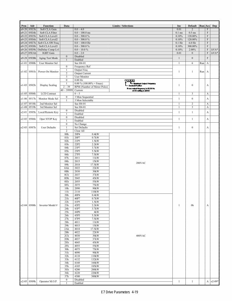
E7 Drive Parameters 4-19
Prm Adr Function Data Limits / Selections Inc Default Run Acs Depn9-20 05E3h Soft CLA Gain 0.0 ~ 4.0 0.01 2 Fn9-21 05E4h Soft CLA Filter 0.0 ~ 100.0 ms 0.1 ms 0.5 ms Fn9-22 05E5h Soft CLA Level1 0.0 ~ 300.0 % 0.10% 120.00% Fn9-23 05E6h Soft CLA Level2 0.0 ~ 300.0 % 0.10% 120.00% Fn9-24 05E7h Soft CLA SW Freq 0.0 ~ 100.0 Hz 0.1 Hz 6.0 Hz Fn9-25 05E8h Soft CLA Level3 0.0 ~ 300.0 % 0.10% 300.00% Fn9-26 05E9h OnDelay Comp Lvl 0.0 ~ 10.0 % 0.10% 2.00% F kVA*n9-27 05EAh IGBT Gain 0.0 ~ 2.0 0.01 0 F kVA*
n9-28 05EBh Aging Test Mode 0 Disabled 1 0 F 1 Enabled o1-01 0500h User Monitor Sel See H4-01 1 6 Run A
o1-02 0501h Power-On Monitor
0 Frequency Ref
1 1 Run A 1 Output Freq 2 Output Current 3 User Monitor
o1-03 0502h Display Scaling
0 0.00 Hz
1 0 A 1 0.00 % (100.00% = Fmax)2 ~ 39 RPM (Number of Motor Poles)
40 ~ 39999 Custom o1-05 0504h LCD Contrast 0 ~ 5 1 3 A
o1-06 0517h Monitor Mode Sel 0 3 Mon Sequential 1 0 A 1 3 Mon Selectable o1-07 0518h 2nd Monitor Sel See H4-01 1 2 Ao1-08 0519h 3rd Monitor Sel See H4-01 1 3 A
o2-01 0505h Local/Remote Key 0 Disabled 1 1 A 1 Enabled
o2-02 0506h Oper STOP Key 0 Disabled 1 1 A 1 Enabled
o2-03 0507h User Defaults 0 No Change
1 0 A 1 Set Defaults 2 Clear All
o2-04 0508h Inverter Model #
00h 20P4 0.4kW
200VAC
1 0h A
01h 20P7 0.7kW02h 21P5 1.5kW03h 22P2 2.2kW04h 23P7 3.7kW05h 25P5 5.5kW06h 27P5 7.5kW07h 2011 11kW08h 2015 15kW09h 2018 17.5kW0Ah 2022 22kW0Bh 2030 30kW0Ch 2037 37kW0Dh 2045 45kW0Eh 2055 55kW0Fh 2075 75kW10h 2090 90kW11h 2110 110kW20h 40P4 0.4kW
400VAC
21h 40P7 0.7kW22h 41P5 1.5kW23h 42P2 2.2kW24h 43P7 3.7kW25h 44P0 4kW26h 45P5 5.5kW27h 47P5 7.5kW28h 4011 11kW29h 4015 15kW2Ah 4018 17.5kW2Bh 4022 22kW2Ch 4030 30kW2Dh 4037 37kW2Eh 4045 45kW2Fh 4055 55kW30h 4075 75kW31h 4090 90kW32h 4110 110kW33h 4132 132kW34h 4160 160kW35h 4185 185kW3Eh 4200 200kW36h 4220 220kW37h 4300 300kW
o2-05 0509h Operator M.O.P. 0 Disabled 1 1 A o2-09*1 Enabled

E7 Drive Parameters 4-20
Prm Adr Function Data Limits / Selections Inc Default Run Acs Dep
o2-06 050Ah Oper Detection 0 Disabled 1 1 A o2-09*1 Enabled o2-07 050Bh Elapsed Time Set 0 ~ 65535 H 1 H 0 H A
o2-08 050Ch Elapsed Time Run 0 Power-On Time 1 1 A o2-09*1 Running Time
o2-09 050Dh Init Mode Sel
0 Japanese spec
1 1 A o2-09*1 American spec 2 European spec 4 PV-A spec 5 PV-E spec
o2-10 050Eh Fan ON Time Set 0 ~ 65535 H 1 H 0 H A
o2-12 0510h FLT Trace Init 0 Disabled 1 0 A 1 Enabled
o2-13 0511h PUF Cont det Sel 0 Disabled 1 1 F 1 Enabled
o2-14 0512h kWh MonitorClear 0 No Change 1 0 A 1 Clear All
o2-15 0513h Oper HAND Key 0 Disabled 1 1 A o2-09*1 Enabled
o3-01 0515h Copy Funtion Sel
0 COPY SELECT
1 0 A 1 INV~OP READ 2 OP~INV WRITE 3 OP~INV VERIFY
o3-02 0516h Read Allowable 0 Disabled 1 0 A 1 Enabled
T1-01 0701h Tuning Mode Sel 0 Motor Setup(REV)
1 0 A 1 Tune w/o Rotate 2 Term Resistance
T1-02 0702h Mtr Rated Power 0.0 ~ 650.0 kW 0.01 kW 0.0 kW AT1-04 0704h Rated Current 0.0 ~ 1500.0 A 0.1 A 0.0 A A
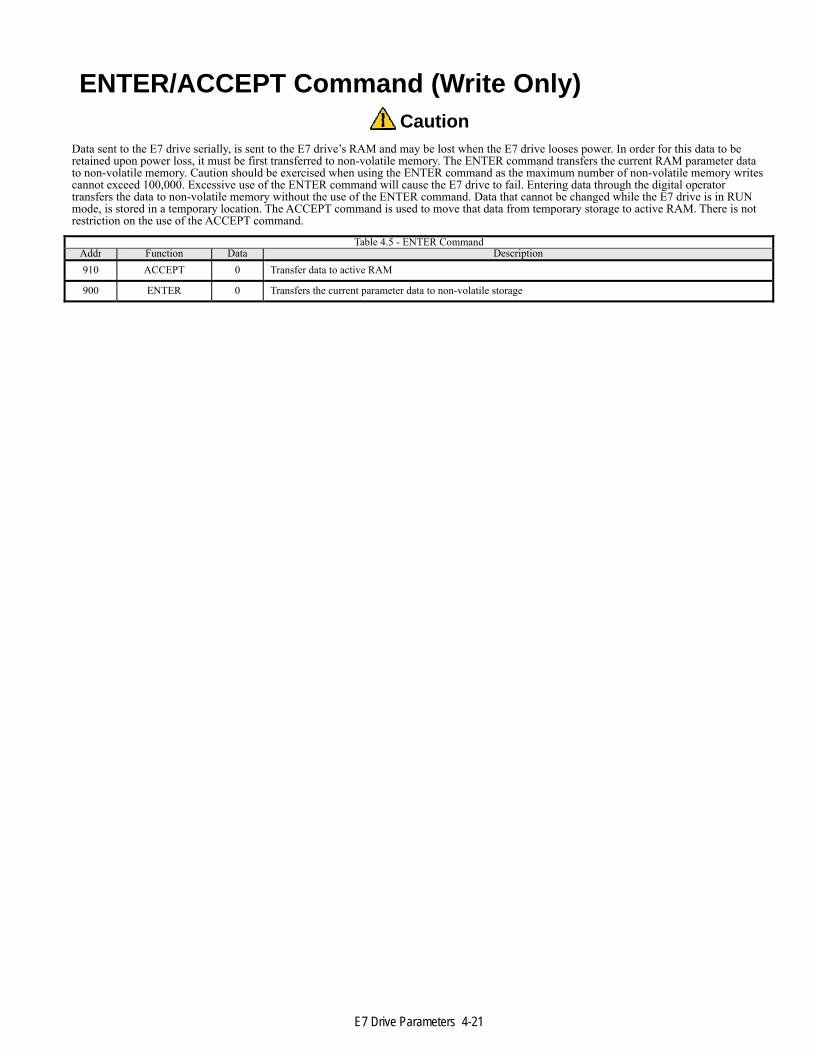
E7 Drive Parameters 4-21
ENTER/ACCEPT Command (Write Only) Caution
Data sent to the E7 drive serially, is sent to the E7 drive’s RAM and may be lost when the E7 drive looses power. In order for this data to be retained upon power loss, it must be first transferred to non-volatile memory. The ENTER command transfers the current RAM parameter data to non-volatile memory. Caution should be exercised when using the ENTER command as the maximum number of non-volatile memory writes cannot exceed 100,000. Excessive use of the ENTER command will cause the E7 drive to fail. Entering data through the digital operator transfers the data to non-volatile memory without the use of the ENTER command. Data that cannot be changed while the E7 drive is in RUN mode, is stored in a temporary location. The ACCEPT command is used to move that data from temporary storage to active RAM. There is not restriction on the use of the ACCEPT command.
Table 4.5 - ENTER CommandAddr Function Data Description910 ACCEPT 0 Transfer data to active RAM
900 ENTER 0 Transfers the current parameter data to non-volatile storage

E7 Drive Parameters 4-22
Parameter Dependencies Certain E7 drive parameters, Master parameters, can affect the default values, range of values and accessibility of other, dependent, parameters. When a Master parameter’s value is changed via serial communications (RS232, RS485, DeviceNet, Ethernet, etc.,), the associated dependent parameters are not automatically updated and must be updated serially. For example, parameter d2-02 (frequency lower limit) affects the range of values for all frequency reference parameters (d1-01 through d1-17). If d2-02 is changed to 5.0Hz serially, all frequency reference parameters with values below 5.0Hz must be updated serially to have current values of 5.0Hz or greater. An E7 drive fault may occur if a dependent parameter’s values are not updated.
The standard sequence for changing E7 drive parameters is
■ Set A1-01 to 2 - Set the access value to Advanced
■ Set Master parameter to desired value
■ Send ENTER command
■ Set any dependent parameter values
■ Send ENTER command.
► Master Parameter Sequence Numbers Some E7 drive parameters may be dependent on more than one Master parameter. For example o2-04 (kVA) and o2-09 (specification) affect a number of parameters together. In these cases it is necessary that the parameter with the lowest sequence number be changed first. The sequence table is shown below. Sequence numbers range from 1 through 9 with lower sequence parameters being changed before parameters with higher sequence numbers. In all cases the parameter access level (A1-02) should be changed to 2 first. Shaded parameters are factory set and are provided for information purposes only.
Table 4.6 – Master Parameter Sequence NumbersPrm Seq Name Action after parameter change
o2-04 1 kVA or E7 drive Model Send ENTER command, power cycle E7 drive, change dependent parameters, send ENTERIf o2-09 is also going to be changed, set o2-09 before setting dependent or slave parameter values
o2-09 2 Initialization Mode
Send ENTER Change dependent parameters Send ENTER
C6-01 4 Heavy/Normal Duty C6-02 5 Carrier Frequency d2-01 5 Freq Upper Limit d2-02 5 Freq Lower Limit E1-01 5 Input Voltage

E7 Drive Parameters 4-23
► o2-04 kVA Parameter Dependencies E7 drive kVA or model is set at the factory and should NOT be changed. These values are included for information purposes only. Shaded parameters are factory set and are provided for information purposes only.
Table 4.7 – kVA DependenciesModel 20P4 20P7 21P5 22P2 23P7 25P5 27P5 2011 2015 2018 2022 2030 2037 2045 2055 2075 2090
kW 0.4 0.75 1.5 2.2 3.7 5.5 7.5 11 15 18.5 22 30 37 45 55 75 90 Min VAC 155 155 155 155 155 155 155 155 155 155 155 155 155 155 155 155 155 Max VAC 255 255 255 255 255 255 255 255 255 255 255 255 255 255 255 255 255
Param Units 0 1 2 3 4 5 6 7 8 9 0A 0B 0C 0D 0E 0F 10
b3-03 Sec 2.0 2.0 2.0 2.0 2.0 2.0 2.0 2.0 2.0 2.0 2.0 2.0 2.0 2.0 2.0 2.0 2.0 b3-04 % 100 100 100 100 100 100 100 100 100 100 100 80 80 80 80 80 80 b3-06 0.5 0.5 0.5 0.5 0.5 0.5 0.5 0.5 0.5 0.5 0.5 0.5 0.5 0.5 0.5 0.7 0.7 b3-08 5.0 5.0 5.0 5.0 5.0 5.0 5.0 5.0 5.0 5.0 5.0 5.0 5.0 5.0 5.0 5.0 5.0 b8-04 288.20 223.70 169.40 156.80 122.90 94.75 72.69 70.44 63.13 57.87 51.79 46.27 38.16 35.78 31.35 23.10 20.65C6-02 6 6 6 6 6 6 6 6 6 6 6 4 3 3 3 2 2
C6-02 VT2 4 4 4 3 4 6 6 3 4 4 4 4 2 2 3 1 1 C6-03 U-lim 15.0 15.0 15.0 15.0 15.0 15.0 15.0 15.0 15.0 15.0 15.0 15.0 10.0 10.0 10.0 10.0 10.0
E2-01 A 1.9 3.3 6.2 8.5 14.0 19.6 26.6 39.7 53.0 65.8 77.2 105.0 131.0 160.0 190.0 260.0 260.0E2-02 Hz 2.90 2.50 2.60 2.90 2.73 1.50 1.30 1.70 1.60 1.67 1.70 1.80 1.33 1.60 1.43 1.39 1.39E2-03 A 1.2 1.8 2.8 3.0 4.5 5.1 8.0 11.2 15.2 15.7 18.5 21.9 38.2 44.0 45.6 72.0 72.0E2-05 Ohm 9.842 5.156 1.997 1.601 0.771 0.399 0.288 0.230 0.138 0.101 0.079 0.064 0.039 0.030 0.022 0.023 0.023L2-02 Sec 0.1 0.1 0.2 0.3 0.5 1.0 1.0 1.0 2.0 2.0 2.0 2.0 2.0 2.0 2.0 2.0 2.0 L2-03 Sec 0.1 0.2 0.3 0.4 0.5 0.6 0.7 0.8 0.9 1.0 1.0 1.1 1.1 1.2 1.2 1.3 1.5 L2-04 Sec 0.3 0.3 0.3 0.3 0.3 0.3 0.3 0.3 0.3 0.6 0.6 0.6 0.6 0.6 1.0 1.0 1.0 L8-02 Deg C 95 95 95 100 95 95 95 95 90 100 90 90 95 100 105 110 100 L8-04 Deg C 105 105 105 110 105 105 105 105 100 110 100 100 105 110 115 120 110 L8-06 % 5.0 7.5 10.0 12.0 12.0 10.0 17.0 21.0 17.0 15.0 24.0 20.0 18.0 20.0 17.0 16.0 18.0n1-03 ms 10 10 10 10 10 10 10 10 10 10 10 10 10 10 10 10 100 n9-01 A 3.2 4.1 7.0 9.6 15.0 23.0 31.0 45.0 58.0 71.0 85.0 115.0 145.0 180.0 215.0 283.0 346.0
n9-01 VT2 A 3.6 4.6 7.8 10.8 16.8 23.0 31.0 46.2 59.4 74.8 88.0 115.0 162.0 192.0 215.0 312.0 360.0n9-02 1.002 1.283 1.167 1.202 1.251 1.273 1.149 1.273 1.214 1.076 1.064 1.213 1.116 1.125 1.174 1.249 1.154n9-11 us 2.0 2.0 2.0 2.0 2.0 2.0 2.0 2.0 2.0 2.0 2.0 2.0 3.0 3.0 3.0 3.0 3.0
n9-11 L-lim us 1.5 1.5 1.5 1.5 1.5 1.5 1.5 1.5 1.5 1.5 1.5 1.5 2.5 2.5 2.5 2.5 2.5 n9-12 us 2.6 2.6 2.6 2.6 2.6 2.6 2.6 2.3 2.3 2.3 2.3 2.3 3.4 2.5 2.5 3.2 2.0 n9-14 ms 20 20 20 20 20 20 20 20 20 20 20 20 20 20 20 20 20 n9-26 % 15.0 15.0 15.0 15.0 15.0 15.0 15.0 15.0 15.0 15.0 15.0 15.0 15.0 15.0 15.0 15.0 15.0n9-27 0.45 0.58 0.66 0.68 0.71 0.65 0.58 0.85 0.82 0.67 0.60 0.81 0.68 0.64 0.76 0.67 0.61

E7 Drive Parameters 4-24
Table 4.8 – kVA DependenciesModel 2110 40P4 40P7 41P5 42P4 43P7 44P0 45P5 47P5 4011 4015 4018 4022 4030 4037 4045 4055
kW 110 0.4 0.75 1.5 2.2 3.7 4 5.5 7.5 11 15 18.5 22 30 37 45 55 Min VAC 155 355 355 355 355 355 355 355 355 355 355 355 355 355 355 355 355 Max VAC 255 555 555 555 555 555 555 555 555 555 555 555 555 555 555 555 555
Param Units 11 20 21 22 23 24 25 26 27 28 29 2A 2B 2C 2D 2E 2F
b3-03 Sec 2.0 2.0 2.0 2.0 2.0 2.0 2.0 2.0 2.0 2.0 2.0 2.0 2.0 2.0 2.0 2.0 2.0 b3-04 % 80 100 100 100 100 100 100 100 100 100 100 100 100 100 100 100 80 b3-06 0.7 0.5 0.5 0.5 0.5 0.5 0.5 0.5 0.5 0.5 0.5 0.5 0.5 0.5 0.5 0.5 0.5 b3-08 5.0 5.0 5.0 5.0 5.0 5.0 5.0 5.0 5.0 5.0 5.0 5.0 5.0 5.0 5.0 5.0 5.0 b8-04 18.12 576.40 447.40 338.80 313.60 245.80 236.44 189.50 145.38 140.88 126.26 115.74 103.58 92.54 76.32 71.56 67.20C6-02 1 6 6 6 6 6 6 6 6 6 6 6 6 4 4 4 4
C6-02 VT2 1 6 6 6 6 6 6 6 6 3 4 4 4 3 3 3 2 C6-03 U-lim 2.5 15.0 15.0 15.0 15.0 15.0 15.0 15.0 15.0 15.0 15.0 15.0 15.0 15.0 15.0 15.0 15.0
E2-01 A 260.0 1.0 1.6 3.1 4.2 7.0 7.0 9.8 13.3 19.9 26.5 32.9 38.6 52.3 65.6 79.7 95.0 E2-02 Hz 1.39 2.90 2.60 2.50 3.00 2.70 2.70 1.50 1.30 1.70 1.60 1.67 1.70 1.80 1.33 1.60 1.46 E2-03 A 72.0 0.6 0.8 1.4 1.5 2.3 2.3 2.6 4.0 5.6 7.6 7.8 9.2 10.9 19.1 22.0 24.0 E2-05 Ohm 0.023 38.198 22.459 10.100 6.495 3.333 3.333 1.595 1.152 0.922 0.550 0.403 0.316 0.269 0.155 0.122 0.088L2-02 Sec 2.0 0.1 0.1 0.2 0.3 0.5 0.5 0.8 0.8 1.0 2.0 2.0 2.0 2.0 2.0 2.0 2.0 L2-03 Sec 1.7 0.1 0.2 0.3 0.4 0.5 0.6 0.6 0.7 0.8 0.9 1.0 1.0 1.1 1.1 1.2 1.2 L2-04 Sec 1.0 0.3 0.3 0.3 0.3 0.3 0.3 0.3 0.3 0.3 0.3 0.6 0.6 0.6 0.6 0.6 1.0 L8-02 Deg C 110 95 95 95 90 95 95 95 90 95 95 98 78 85 85 90 90 L8-04 Deg C 120 105 105 105 100 105 105 105 100 105 105 108 88 95 95 100 100 L8-06 % 20.0 0.50 0.75 10.0 10.0 12.0 10.0 10.0 20.0 23.0 17.0 17.0 20.0 20.0 20.0 20.0 20.0 n1-03 ms 100 10 10 10 10 10 10 10 10 10 10 10 10 10 10 10 30 n9-01 A 415.0 1.8 2.1 3.7 5.3 7.6 8.7 12.5 17.0 24.0 31.0 39.0 45.0 60.0 75.0 91.0 112.0
n9-01 VT2 A 4150 1.8 2.1 3.7 5.3 7.6 8.7 12.5 17.0 27.0 34.0 40.0 50.4 67.2 77.0 96.0 125.0n9-02 1.093 0.529 0.617 1.087 1.106 1.224 0.966 1.136 1.133 1.143 1.149 1.146 1.074 1.255 1.155 1.139 1.180n9-11 us 4.0 2.0 2.0 2.0 2.0 2.0 2.0 2.0 2.0 2.0 2.0 2.0 2.0 2.0 2.0 2.0 2.0
n9-11 L-lim us 3.5 1.5 1.5 1.5 1.5 1.5 1.5 1.5 1.5 1.5 1.5 1.5 1.5 1.5 1.5 1.5 1.5 n9-12 us 2.6 2.3 2.3 2. 2.5 2.5 2.2 2.2 2.2 2.2 2.4 2.4 2.4 2.4 2.9 2.9 2.9 n9-14 ms 20 20 20 20 20 20 20 20 20 20 20 20 20 20 20 20 20 n9-26 % 0.0 40.0 40.0 40.0 40.0 40.0 70.0 70.0 70.0 30.0 30.0 30.0 30.0 30.0 15.0 15.0 15.0 n9-27 0.49 0.25 0.30 0.52 0.75 0.72 0.49 0.71 0.69 0.68 0.58 0.74 0.64 0.85 0.71 0.64 0.79

E7 Drive Parameters 4-25
Table 4.9 – kVA DependenciesModel 4075 4090 4110 4132 4160 4185 4220 4300 4200
kW 75 90 110 132 160 185 220 300 200 Min VAC 355 355 355 355 355 355 355 355 355 Max VAC 555 555 555 555 555 555 555 555 555
Param Units 30 31 32 33 34 35 36 37 3E
b3-03 Sec 2.0 2.0 2.0 2.0 2.0 2.0 2.0 2.0 2.0 b3-04 % 60 60 60 60 60 60 60 60 60 b3-06 0.7 0.7 0.7 0.7 0.7 0.7 0.7 0.7 0.7 b3-08 8.0 8.0 8.0 8.0 8.0 8.0 8.0 8.0 8.0 b8-04 46.20 38.91 36.23 32.79 30.13 30.57 27.13 21.76 0 C6-02 3 3 3 2 2 2 1 1 1
C6-02 VT2 2 3 2 2 2 1 1 1 1 C6-03 U-lim 10.0 10.0 10.0 10.0 10.0 5.0 2.5 2.5 2.0
E2-01 A 130.0 156.0 190.0 223.0 270.0 310.0 370.0 500.0 370.0 E2-02 Hz 1.39 1.40 1.40 1.38 1.35 1.30 1.30 1.25 1.30 E2-03 A 36.0 40.0 49.0 58.0 70.0 81.0 96.0 130.0 96.0 E2-05 Ohm 0.092 0.056 0.046 0.035 0.029 0.025 0.020 0.014 0.020 L2-02 Sec 2.0 2.0 2.0 2.0 2.0 2.0 2.0 2.0 2.0 L2-03 Sec 1.3 1.5 1.7 1.7 1.8 1.9 2.0 2.1 2.0 L2-04 Sec 1.0 1.0 1.0 1.0 1.0 1.0 1.0 1.0 1.0 L8-02 Deg C 98 108 100 110 108 95 100 108 95 L8-04 Deg C 108 118 110 120 118 105 110 118 105 L8-06 % 16.0 16.0 16.0 16.0 14.0 15.0 15.0 15.0 N/A n1-03 ms 30 30 30 30 30 30 30 30 30 n9-01 A 150.0 180.0 216.0 260.0 304.0 370.0 506.0 675.0 414.0
n9-01 VT2 A 156.0 180.0 240.0 260.0 304.0 414.0 515.0 675.0 414.0 n9-02 11.69 10.91 11.38 10.85 11.27 11.39 10.73 10.31 11.92 n9-11 us 3.0 3.0 3.0 3.0 3.0 3.0 3.0 3.0 3.0
n9-11 L-lim us 2.5 2.5 2.5 2.5 2.5 2.5 2.5 2.5 2.5 n9-12 us 2.2 2.0 2.0 1.8 2.0 2.5 3.3 3.7 4.0 n9-14 ms 20 20 20 20 20 4 4 4 4 n9-26 % 15.0 15.0 15.0 15.0 15.0 15.0 15.0 15.0 15.0 n9-27 0.71 0.64 0.76 0.61 0.72 0.65 0.60 0.80 1.00

E7 Drive Parameters 4-26
► o2-09 Specification After the kVA parameters, these are the most important and are the next highest of the sequence numbers. The table below lists those parameters that are affected by setting parameter o2-09.
The “Other” column
■ N/A - that parameter is not available under that specification
■ Shaded - parameter is factory accessible and shown for information purposes only Table 4.10 – specification Dependencies
Parameter Units F7A E7U E7C PV-A PV-Eb1-04 0 1 0 1 0b2-04 Sec 0.50 0.0 0.50 0.0 0.50b5-02 1.00 2.00 1.00 2.00 1.00b5-03 Sec 1.0 5.0 1.0 5.0 1.0C1-01 Sec 10.0 30.0 10.0 30.0 10.0C1-02 Sec 10.0 30.0 10.0 30.0 10.0C1-03 Sec 10.0 30.0 10.0 30.0 10.0C1-04 Sec 10.0 30.0 10.0 30.0 10.0C6-01 1 2 1 2 1d1-01 Hz 0.0 0.0 0.0 0.0 0.0E1-01 VAC 200 240 200 240 200E1-05 VAC 200.0 240.0 200.0 240.0 200.0H2-02 1 0Ah 1 0Ah 1H3-09 0 2 0 2 0L1-02 min 1.0 8.0 1.0 8.0 1.0L2-01 0 2 0 2 0L5-03 Sec 10.0 180.0 10.0 180.0 10.0L5-04 1 0 1 0 1L6-01 0 0 6 0 6L8-05 0 1 1 1 1L8-07 0 1 0 1 0o2-05 0 1 0 1 0o2-06 0 1 0 1 0o2-08 0 1 1 1 1o2-09 0 1 2 4 5o2-15 0 1 0 1 0

E7 Drive Parameters 4-27
► E1-03 V/f Pattern Selection
The relationship of the parameters in the V/f patterns is shown below. For custom settings make sure that
E1-09 ≤ E1-07 ≤ E1-06 ≤ E1-11 ≤ E1-04
Table 4.12 – E1-03 V/f Pattern Selection200VAC
E1-03 E1-04 E1-05 E1-06 E1-07 E1-08 E1-09 E1-10 E1-11 E1-12 E1-1300H 50.0 20.00 50.0 2.5 15.0 1.3 9.0 0.0 0.0 0.001H 60.0 20.00 60.0 3.0 15.0 1.5 9.0 0.0 0.0 0.002H 60.0 20.00 50.0 3.0 15.0 1.5 9.0 0.0 0.0 0.003H 72.0 20.00 60.0 3.0 15.0 1.5 9.0 0.0 0.0 0.004H 50.0 20.00 50.0 25.0 35.0 1.3 8.0 0.0 0.0 0.005H 50.0 20.00 50.0 25.0 50.0 1.3 9.0 0.0 0.0 0.006H 60.0 20.00 60.0 30.0 35.0 1.5 8.0 0.0 0.0 0.007H 60.0 20.00 60.0 30.0 50.0 1.5 9.0 0.0 0.0 0.008H 50.0 20.00 50.0 2.5 19.0 1.3 11.0 0.0 0.0 0.009H 50.0 20.00 50.0 2.5 24.0 1.3 13.0 0.0 0.0 0.00AH 60.0 20.00 60.0 3.0 19.0 1.5 11.0 0.0 0.0 0.00BH 60.0 20.00 60.0 3.0 24.0 1.5 15.0 0.0 0.0 0.00CH 90.0 20.00 60.0 3.0 15.0 1.5 9.0 0.0 0.0 0.00DH 120.0 20.00 60.0 3.0 15.0 1.5 9.0 0.0 0.0 0.00EH 180.0 20.00 60.0 3.0 15.0 1.5 9.0 0.0 0.0 0.00FH 60.0 20.00 60.0 30. 15.0 1.5 9.0 0.0 0.0 0.0
400VACE1-03 E1-04 E1-05 E1-06 E1-07 E1-08 E1-09 E1-10 E1-11 E1-12 E1-1300H 50.0 20.00 50.0 25 14.0 1.3 7.0 0.0 0.0 0.001H 60.0 20.00 60.0 3.0 14.0 1.5 7.0 0.0 0.0 0.002H 60.0 20.00 50.0 3.0 14.0 1.5 7.0 0.0 0.0 0.003H 72.0 20.00 60.0 3.0 14.0 1.5 7.0 0.0 0.0 0.004H 50.0 20.00 50.0 25.0 35.0 1.3 6.0 0.0 0.0 0.005H 50.0 20.00 50.0 25.0 50.0 1.3 7.0 0.0 0.0 0.006H 60.0 20.00 60.0 30.0 35.0 1.5 6.0 0.0 0.0 0.007H 60.0 20.00 60.0 30.0 50.0 1.5 7.0 0.0 0.0 0.008H 50.0 20.00 50.0 2.5 18.0 1.3 9.0 0.0 0.0 0.009H 50.0 20.00 50.0 2.5 23.0 1.3 11.0 0.0 0.0 0.00AH 60.0 20.00 60.0 3.0 18.0 1.5 9.0 0.0 0.0 0.00BH 60.0 20.00 60.0 3.0 23.0 1.5 13.0 0.0 0.0 0.00CH 90.0 20.00 60.0 3.0 14.0 1.5 7.0 0.0 0.0 0.00DH 120.0 20.00 60.0 3.0 14.0 1.5 7.0 0.0 0.0 0.00EH 180.0 20.00 60.0 3.0 14.0 1.5 7.0 0.0 0.0 0.00FH 60.0 20.00 60.0 3.0 14.0 1.5 7.0 0.0 0.0 0.0

E7 Drive Parameters 4-28
This page intentionally left blank.

User Notes 5-2
Chapter 5 User Notes This chapter allows the user to enter information specific to their application
Parameter Record .................................................................... 5 - 3 Notes ...................................................................................... 5 - 11 Hex/Dec Conversion Table .................................................... 5 – 12

User Notes 5-3
This page intentionally left blank.
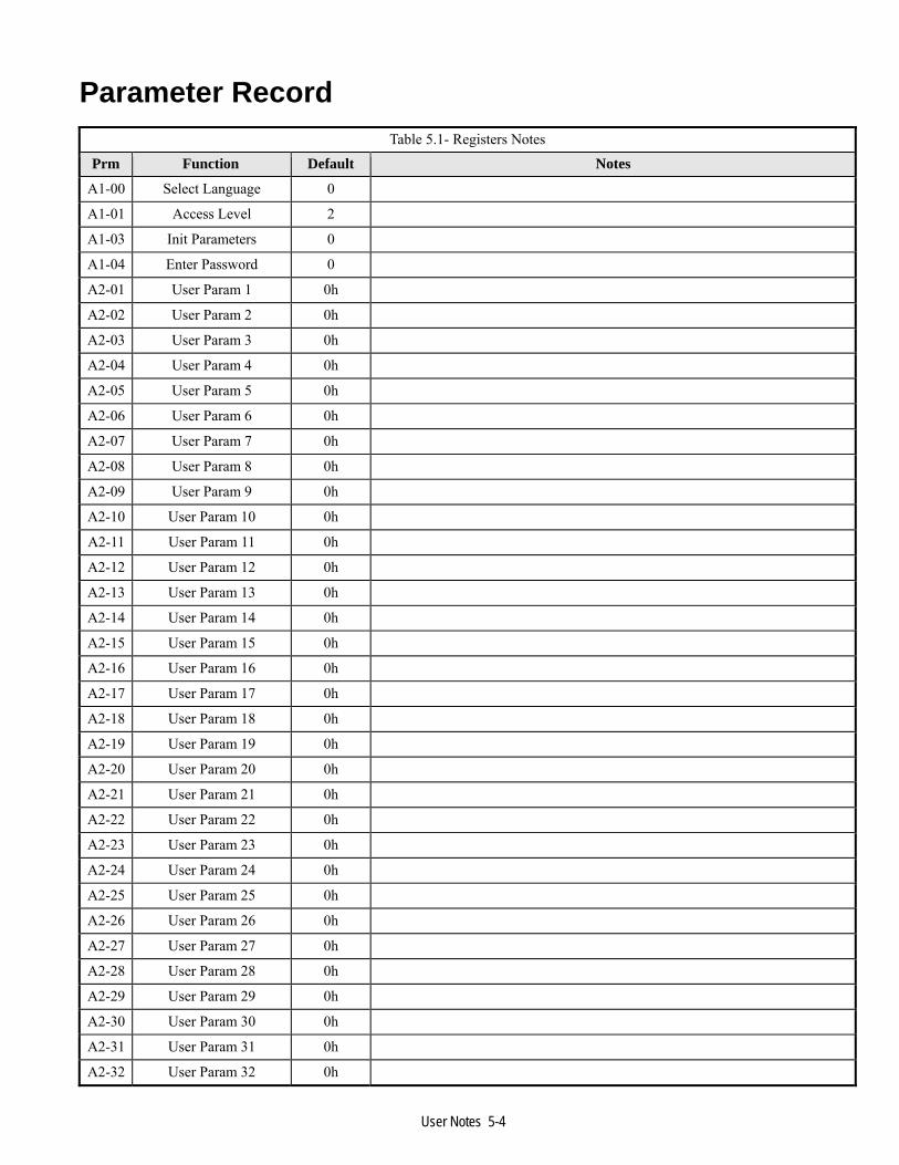
User Notes 5-4
Parameter Record Table 5.1- Registers Notes
Prm Function Default Notes
A1-00 Select Language 0
A1-01 Access Level 2
A1-03 Init Parameters 0
A1-04 Enter Password 0
A2-01 User Param 1 0h
A2-02 User Param 2 0h
A2-03 User Param 3 0h
A2-04 User Param 4 0h
A2-05 User Param 5 0h
A2-06 User Param 6 0h
A2-07 User Param 7 0h
A2-08 User Param 8 0h
A2-09 User Param 9 0h
A2-10 User Param 10 0h
A2-11 User Param 11 0h
A2-12 User Param 12 0h
A2-13 User Param 13 0h
A2-14 User Param 14 0h
A2-15 User Param 15 0h
A2-16 User Param 16 0h
A2-17 User Param 17 0h
A2-18 User Param 18 0h
A2-19 User Param 19 0h
A2-20 User Param 20 0h
A2-21 User Param 21 0h
A2-22 User Param 22 0h
A2-23 User Param 23 0h
A2-24 User Param 24 0h
A2-25 User Param 25 0h
A2-26 User Param 26 0h
A2-27 User Param 27 0h
A2-28 User Param 28 0h
A2-29 User Param 29 0h
A2-30 User Param 30 0h
A2-31 User Param 31 0h
A2-32 User Param 32 0h

User Notes 5-5
Table 5.1- Registers Notes
Prm Function Default Notes
b1-01 Reference Source 1
b1-02 Run Source 1
b1-03 Stopping Method 0
b1-04 Reverse Oper 1
b1-07 LOC/REM RUN Sel 0
b1-08 RUN CMD at PRG 0
b1-11 Wait to Run Time 0 Sec
b1-12 HAND Fref Source 0
b2-01 DCInj Start Freq 0.5 Hz
b2-02 DCInj Current 50%
b2-03 DCInj Time@Start 0.0 Sec
b2-04 DCInj Time@Stop 0.0 Sec
b2-09 Preheat Current 0%
b3-01 SpdSrch at Start 0
b3-02 SpdSrch Current 120%
b3-03 SpdSrch Dec Time 2.0 Sec
b3-05 Search Delay 0.2 Sec
b3-14 Bidir Search Sel 1
b4-01 Delay-ON Timer 0.0 Sec
b4-02 Delay-OFF Timer 0.0 Sec
b5-01 PI Mode 0
b5-02 P Gain 2
b5-03 PI I Time 5.0 Sec
b5-04 PI I Limit 100.00%
b5-06 PI Limit 100.00%
b5-07 PI Offset 0.00%
b5-08 PI Delay Time 0.0 Sec
b5-09 Output Level Sel 0
b5-10 Output Gain 1
b5-11 Output Rev Sel 0
b5-12 Fb los Det Sel 0
b5-13 Fb los Det Lvl 0%
b5-14 Fb los Det Time 1.0 Sec
b5-15 Sleep Level 0.0 Hz
b5-16 Sleep Time 0.0 Sec
b5-17 Acc/Dec Time 0.0 Sec
b5-18 PI Setpoint Sel 0
b5-19 PI Setpoint 0.00%

User Notes 5-6
Table 5.1- Registers Notes
Prm Function Default Notes
b5-20 Setpoint Scaling 1
b5-21 PI Sleep Source 1
b5-22 Snooze Level 0%
b5-23 Snooze DelayTime 0 Sec
b5-24 Wake-Up Level 0%
b5-25 Setpoint Boost 0%
b5-26 Max Boost Time 0 Sec
b5-27 Snooze Feedback 60%
b5-28 PI Feedback SqRt 0
b5-29 PI Fb SqRt Gain 0
b5-30 PI Out Moni SqRt 0
b8-01 Energy Save Sel 0
b8-04 Energy Save COEF 288.2
b8-05 kW Filter Time 20 ms
b8-06 Search V Limit 0%
C1-01 Accel Time 1 30.0 Sec
C1-02 Decel Time 1 30.0 Sec
C1-03 Accel Time 2 30.0 Sec
C1-04 Decel Time 2 30.0 Sec
C1-09 Fast Stop Time 30.0 Sec
C1-11 Acc/Dec SW Freq 0.0 Hz
C2-01 SCrv Acc @ Start 0.2 Sec
C2-02 SCrv Acc @ End 0.2 Sec
C4-01 Torq Comp Gain 1
C4-02 Torq Comp Time 200 ms
C6-02 CarrierFreq Sel 6h
C6-03 CarrierFreq Max 2.0 kHz
C6-04 CarrierFreq Min 2.0 kHz
C6-05 CarrierFreq Gain 0
d1-01 Reference 1 0.0 Hz
d1-02 Reference 2 0.0 Hz
d1-03 Reference 3 0.0 Hz
d1-04 Reference 4 0.0 Hz
d1-17 Jog Reference 6.0 Hz
d2-01 Ref Upper Limit 100.00%
d2-02 Ref Lower Limit 0.00%
d2-03 Ref1 Lower Limit 0.00%
d3-01 Jump Freq 1 0.0 Hz

User Notes 5-7
Table 5.1- Registers Notes
Prm Function Default Notes
d3-02 Jump Freq 2 0.0 Hz
d3-03 Jump Freq 3 0.0 Hz
d3-04 Jump Bandwidth 1.0 Hz
d4-01 MOP Ref Memory 0
d4-02 Trim Control Lvl 10%
E1-01 Input Voltage 240 VAC
E1-03 V/F Selection 0Fh
E1-04 Max Frequency 60.0 Hz
E1-05 Max Voltage 240.0 VAC
E1-06 Base Frequency 60.0 Hz
E1-07 Mid Frequency A 3.0 Hz
E1-08 Mid Voltage A 13.0 VAC
E1-09 Min Frequency 1.5 Hz
E1-10 Min Voltage 9.0 VAC
E1-11 Mid Frequency B 0.0 Hz
E1-12 Mid Voltage B 0.0 VAC
E1-13 Base Voltage 240.0 VAC
E2-01 Motor Rated FLA 14.0 A
E2-03 No-Load Current 4.5 A
E2-05 Term Resistance 0.771 Ohm
F6-01 Comm Bus Flt Sel 0
F6-02 EF0 Detection 0
F6-03 EF0 Fault Action 1
F6-05 0
H1-01 Terminal S3 Sel 24h
H1-02 Terminal S4 Sel 14h
H1-03 Terminal S5 Sel 03h
H1-04 Terminal S6 Sel 04h
H1-05 Terminal S7 Sel 06h
H2-01 Term M1-M2 Sel 0h
H2-02 Term M3-M4 Sel 0Ah
H3-02 Terminal A1 Gain 100.00%
H3-03 Terminal A1 Bias 0.00%
H3-08 Term A2 Signal 2
H3-09 Terminal A2 Sel 2h
H3-10 Terminal A2 Gain 100.00%
H3-11 Terminal A2 Bias 0.00%
H3-12 Filter Avg Time 0.3 Sec

User Notes 5-8
Table 5.1- Registers Notes
Prm Function Default Notes
H3-13 TA1/A2 Select 0
H4-01 Terminal FM Sel 02h
H4-02 Terminal FM Gain 100.00%
H4-03 Terminal FM Bias 0.00%
H4-04 Terminal AM Sel 08h
H4-05 Terminal AM Gain 50.00%
H4-06 Terminal AM Bias 0.00%
H4-07 AO Level Select1 0
H4-08 AO Level Select2 0
H5-01 Serial Comm Adr 1fh
H5-02 Serial Baud Rate 3
H5-03 Serial Com Sel 0
H5-04 Serial Fault Sel 3
H5-05 Serial Flt Dtct 1
H5-06 Transmit WaitTIM 5 ms
H5-07 RTS Control Sel 1
H5-08 Protocol Select 0
H5-09 CE Detect Time 2.0 Sec
L1-01 MOL Fault Select 1
L1-02 MOL Time Const 8.0 min
L1-03 Mtr OH Alarm Sel 3
L1-04 Mtr OH Fault Sel 1
L1-05 Mtr Temp Filter 0.2 Sec
L2-01 PwrL Selection 2
L2-02 PwrL Ridethru t 0.1 Sec
L2-03 PwrL Baseblock t 0.5 Sec
L2-04 PwrL V/F Ramp t 0.3 Sec
L2-05 PUV Det Level 190 VDC
L3-01 StallP Accel Sel 1
L3-02 StallP Accel Lvl 120%
L3-04 StallP Decel Sel 1
L3-05 StallP Run Sel 1
L3-06 StallP Run Level 120%
L4-01 Spd Agree Level 0.0 Hz
L4-02 Spd Agree Width 2.0 Hz
L4-05 Ref Loss Sel 1
L4-06 Fref at Floss 80.00%
L5-01 Num of Restarts 0
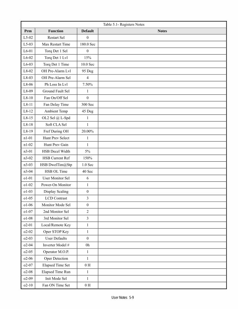
User Notes 5-9
Table 5.1- Registers Notes
Prm Function Default Notes
L5-02 Restart Sel 0
L5-03 Max Restart Time 180.0 Sec
L6-01 Torq Det 1 Sel 0
L6-02 Torq Det 1 Lvl 15%
L6-03 Torq Det 1 Time 10.0 Sec
L8-02 OH Pre-Alarm Lvl 95 Deg
L8-03 OH Pre-Alarm Sel 4
L8-06 Ph Loss In Lvl 7.50%
L8-09 Ground Fault Sel 1
L8-10 Fan On/Off Sel 0
L8-11 Fan Delay Time 300 Sec
L8-12 Ambient Temp 45 Deg
L8-15 OL2 Sel @ L-Spd 1
L8-18 Soft CLA Sel 1
L8-19 Fref During OH 20.00%
n1-01 Hunt Prev Select 1
n1-02 Hunt Prev Gain 1
n3-01 HSB Decel Width 5%
n3-02 HSB Current Ref 150%
n3-03 HSB DwelTim@Stp 1.0 Sec
n3-04 HSB OL Time 40 Sec
o1-01 User Monitor Sel 6
o1-02 Power-On Monitor 1
o1-03 Display Scaling 0
o1-05 LCD Contrast 3
o1-06 Monitor Mode Sel 0
o1-07 2nd Monitor Sel 2
o1-08 3rd Monitor Sel 3
o2-01 Local/Remote Key 1
o2-02 Oper STOP Key 1
o2-03 User Defaults 0
o2-04 Inverter Model # 0h
o2-05 Operator M.O.P. 1
o2-06 Oper Detection 1
o2-07 Elapsed Time Set 0 H
o2-08 Elapsed Time Run 1
o2-09 Init Mode Sel 1
o2-10 Fan ON Time Set 0 H

User Notes 5-10
Table 5.1- Registers Notes
Prm Function Default Notes
o2-12 FLT Trace Init 0
o2-14 kWh MonitorClear 0
o2-15 Oper HAND Key 1
o3-01 Copy Funtion Sel 0
o3-02 Read Allowable 0
T1-01 Tuning Mode Sel 0
T1-02 Mtr Rated Power 0.0 kW
T1-04 Rated Current 0.0 A

User Notes 5-11
Notes Enter the current application parameter data and any relevant notes.
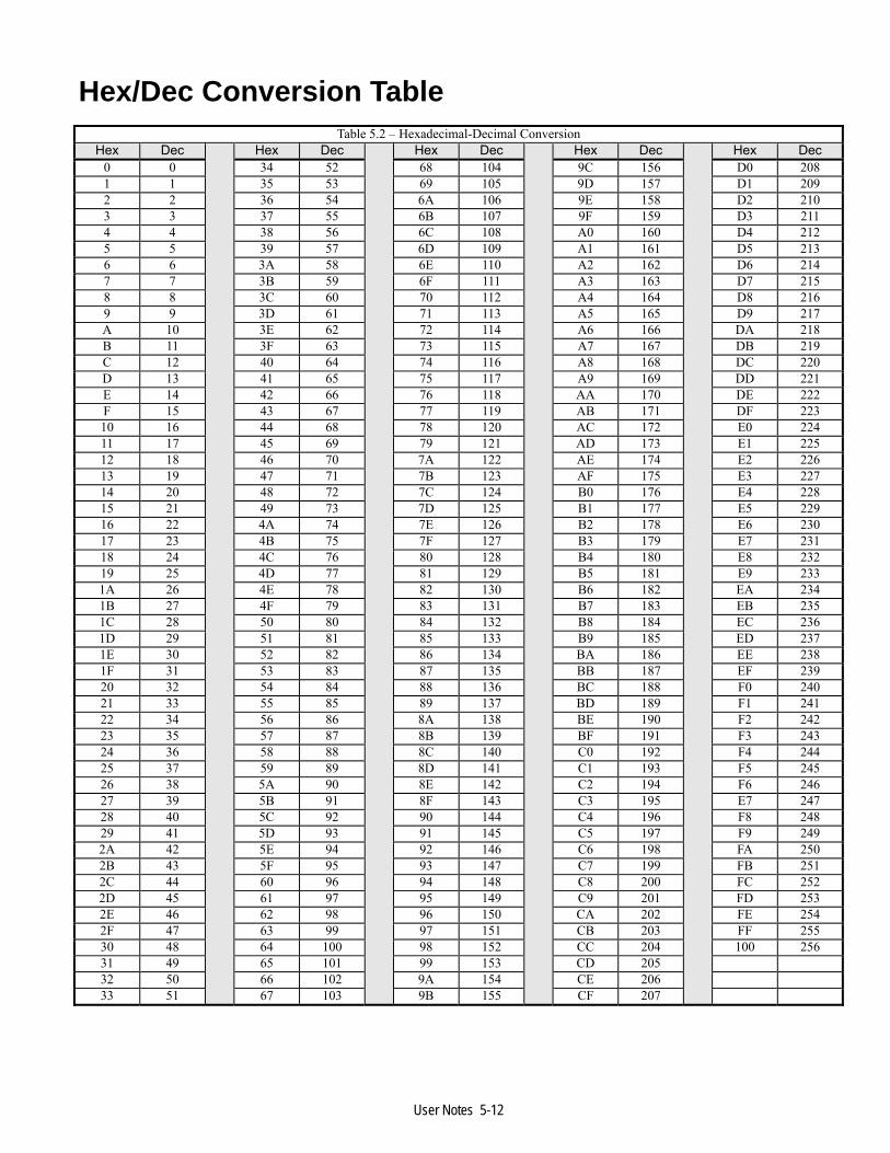
User Notes 5-12
Hex/Dec Conversion Table Table 5.2 – Hexadecimal-Decimal Conversion
Hex Dec
Hex Dec
Hex Dec
Hex Dec
Hex Dec0 0 34 52 68 104 9C 156 D0 2081 1 35 53 69 105 9D 157 D1 2092 2 36 54 6A 106 9E 158 D2 2103 3 37 55 6B 107 9F 159 D3 2114 4 38 56 6C 108 A0 160 D4 2125 5 39 57 6D 109 A1 161 D5 2136 6 3A 58 6E 110 A2 162 D6 2147 7 3B 59 6F 111 A3 163 D7 2158 8 3C 60 70 112 A4 164 D8 2169 9 3D 61 71 113 A5 165 D9 217A 10 3E 62 72 114 A6 166 DA 218B 11 3F 63 73 115 A7 167 DB 219C 12 40 64 74 116 A8 168 DC 220D 13 41 65 75 117 A9 169 DD 221E 14 42 66 76 118 AA 170 DE 222F 15 43 67 77 119 AB 171 DF 22310 16 44 68 78 120 AC 172 E0 22411 17 45 69 79 121 AD 173 E1 22512 18 46 70 7A 122 AE 174 E2 22613 19 47 71 7B 123 AF 175 E3 22714 20 48 72 7C 124 B0 176 E4 22815 21 49 73 7D 125 B1 177 E5 22916 22 4A 74 7E 126 B2 178 E6 23017 23 4B 75 7F 127 B3 179 E7 23118 24 4C 76 80 128 B4 180 E8 23219 25 4D 77 81 129 B5 181 E9 2331A 26 4E 78 82 130 B6 182 EA 2341B 27 4F 79 83 131 B7 183 EB 2351C 28 50 80 84 132 B8 184 EC 2361D 29 51 81 85 133 B9 185 ED 2371E 30 52 82 86 134 BA 186 EE 2381F 31 53 83 87 135 BB 187 EF 23920 32 54 84 88 136 BC 188 F0 24021 33 55 85 89 137 BD 189 F1 24122 34 56 86 8A 138 BE 190 F2 24223 35 57 87 8B 139 BF 191 F3 24324 36 58 88 8C 140 C0 192 F4 24425 37 59 89 8D 141 C1 193 F5 24526 38 5A 90 8E 142 C2 194 F6 24627 39 5B 91 8F 143 C3 195 E7 24728 40 5C 92 90 144 C4 196 F8 24829 41 5D 93 91 145 C5 197 F9 2492A 42 5E 94 92 146 C6 198 FA 2502B 43 5F 95 93 147 C7 199 FB 2512C 44 60 96 94 148 C8 200 FC 2522D 45 61 97 95 149 C9 201 FD 2532E 46 62 98 96 150 CA 202 FE 2542F 47 63 99 97 151 CB 203 FF 25530 48 64 100 98 152 CC 204 100 25631 49 65 101 99 153 CD 205 32 50 66 102 9A 154 CE 206 33 51 67 103 9B 155 CF 207

E7 Drive Parameter Access
YASKAWA ELECTRIC AMERICA, INC. E7 drives Division 16555 W. Ryerson Rd., New Berlin, WI 53151, U.S.A. Phone: (800) YASKAWA (800-927-5292) Fax: (262) 782-3418 Internet: http://www.E7 drives.com YASKAWA ELECTRIC AMERICA, INC. Chicago-Corporate Headquarters 2121 Norman E7 drive South, Waukegan, IL 60085, U.S.A. Phone: (800) YASKAWA (800-927-5292) Fax: (847) 887-7310 Internet: http://www.yaskawa.com MOTOMAN INC. 805 Liberty Lane, West Carrollton, OH 45449, U.S.A. Phone: (937) 847-6200 Fax: (937) 847-6277 Internet: http://www.motoman.com YASKAWA ELECTRIC CORPORATION New Pier Takeshiba South Tower, 1-16-1, Kaigan, Minatoku, Tokyo, 105-0022, Japan Phone: 81-3-5402-4511 Fax: 81-3-5402-4580 Internet: http://www.yaskawa.co.jp YASKAWA ELETRICO DO BRASIL COMERCIO LTDA. Avenida Fagundes Filho, 620 Bairro Saude Sao Paolo-SP, Brasil CEP: 04304-000 Phone: 55-11-5071-2552 Fax: 55-11-5581-8795 Internet: http://www.yaskawa.com.br YASKAWA ELECTRIC EUROPE GmbH Am Kronberger Hang 2, 65824 Schwalbach, Germany Phone: 49-6196-569-300 Fax: 49-6196-888-301 MOTOMAN ROBOTICS AB Box 504 S38525, Torsas, Sweden Phone: 46-486-48800 Fax: 46-486-41410 MOTOMAN ROBOTEC GmbH Kammerfeldstrabe 1, 85391 Allershausen, Germany Phone: 49-8166-900 Fax: 49-8166-9039 YASKAWA ELECTRIC UK LTD. 1 Hunt Hill Orchardton Woods Cumbernauld, G68 9LF, Scotland, United Kingdom Phone: 44-12-3673-5000 Fax: 44-12-3645-8182
YASKAWA ELECTRIC KOREA CORPORATION Paik Nam Bldg. 901 188-3, 1-Ga Euljiro, Joong-Gu, Seoul, Korea Phone: 82-2-776-7844 Fax: 82-2-753-2639 YASKAWA ELECTRIC (SINGAPORE) PTE. LTD. Head Office: 151 Lorong Chuan, #04-01, New Tech Park Singapore 556741, Singapore Phone: 65-282-3003 Fax: 65-289-3003 TAIPEI OFFICE (AND YATEC ENGINEERING CORPORATION) 10F 146 Sung Chiang Road, Taipei, Taiwan Phone: 886-2-2563-0010 Fax: 886-2-2567-4677 YASKAWA JASON (HK) COMPANY LIMITED Rm. 2909-10, Hong Kong Plaza, 186-191 Connaught Road West, Hong Kong Phone: 852-2803-2385 Fax: 852-2547-5773 BEIJING OFFICE Room No. 301 Office Building of Beijing International Club, 21 Jianguomanwai Avenue, Beijing 100020, China Phone: 86-10-6532-1850 Fax: 86-10-6532-1851 SHANGHAI OFFICE 27 Hui He Road Shanghai 200437 China Phone: 86-21-6553-6600 Fax: 86-21-6531-4242 SHANGHAI YASKAWA-TONJI M & E CO., LTD. 27 Hui He Road Shanghai 200437 China Phone: 86-21-6533-2828 Fax: 86-21-6553-6677 BEIJING YASKAWA BEIKE AUTOMATION ENGINEERING CO., LTD. 30 Xue Yuan Road, Haidian, Beijing 100083 China Phone: 86-10-6232-9943 Fax: 86-10-6234-5002 SHOUGANG MOTOMAN ROBOT CO., LTD. 7, Yongchang-North Street, Beijing Economic & Technological Development Area, Beijing 100076 China Phone: 86-10-6788-0551 Fax: 86-10-6788-2878 YEA, TAICHUNG OFFICE IN TAIWAIN B1, 6F, No.51, Section 2, Kung-Yi Road, Taichung City, Taiwan, R.O.C. Phone: 886-4-2320-2227 Fax:886-4-2320-2239
YEA Document Number: TM.E7.11 5/31/2004 Rev 3016 Data subject to change without notice. Yaskawa Electric America, Inc.