Embed Size (px)
Citation preview
E246 Electronics & Instrumentation
Lecture 1: Introduction and Review of Basic Electronics

Course Personnel
Instructor:Yi GuoOffice: Burchard 207Office Hours: Tuesday & Thursday 2-3pmPh: (201) 216-5658Email: [email protected]
Textbook
Essentials of Electrical and Computer Engineering, by David V. Kerns and J. David Irwin, Pearson Prentice Hall., ISBN 0-13-923970-7, 2004.
Reference Books
R. C. Dorf and J. A. Svoboda, Introduction to Electric Circuits, 6/e, John Wiley & Sons, 2004.
J. W. Nilsson and S. A. Riedel, Electric Circuits, 6/e, Prentice Hall, 2000.
G. Rizzoni, Principles and Applications of Electrical Engineering, 3/e, McGraw Hill, 2000.
Reference Books
Allan R. Hambley, Electronics, 2nd Ed. Prentice Hall, 2000Smith and Dorf, Circuits, Devices and Systems, 5th Ed. John Wiley & Sons, 1992.Bobrow, Fundamentals of Electrical Engineering, 2nd Ed. Oxford University Press, 1994.Horowitz and Hill, The Art of Electronics, 2nd Ed. Cambridge University Press, 1989.
Today’s Plan
Introduction to Electrical EngineeringElectric circuit variablesElectric circuit elements: resistor, independent and dependent sources, voltmeters and ammeters, switchesKirchhoff’s LawSections in textbook: 1.1~1.2,2.1~2.3
The Subject
Electrical engineering is the profession concerned with systems that produce, transmit, and measure electric signals.It combines the physicist’s models of natural phenomena with the mathematician’s tools for manipulating those models to produce systems that meet practical needs.
Five Major Classifications of Electrical Systems
Communication systemsComputer systemsControl systemsPower systemsSignal-processing systems
Circuit Theory
An electric circuit is a mathematical modelthat approximates the behavior of an actual electrical system.The models, the mathematical techniques, and the language of circuit theory will form the intellectual framework for your future engineering endeavors.
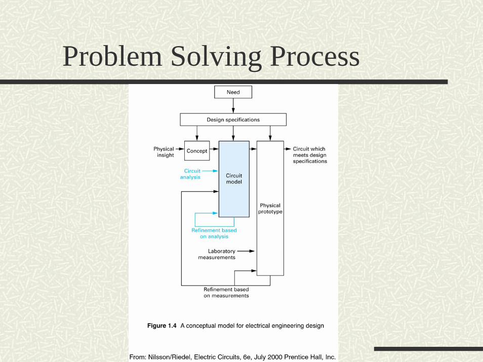
Problem Solving Process
What is Electric Circuit?
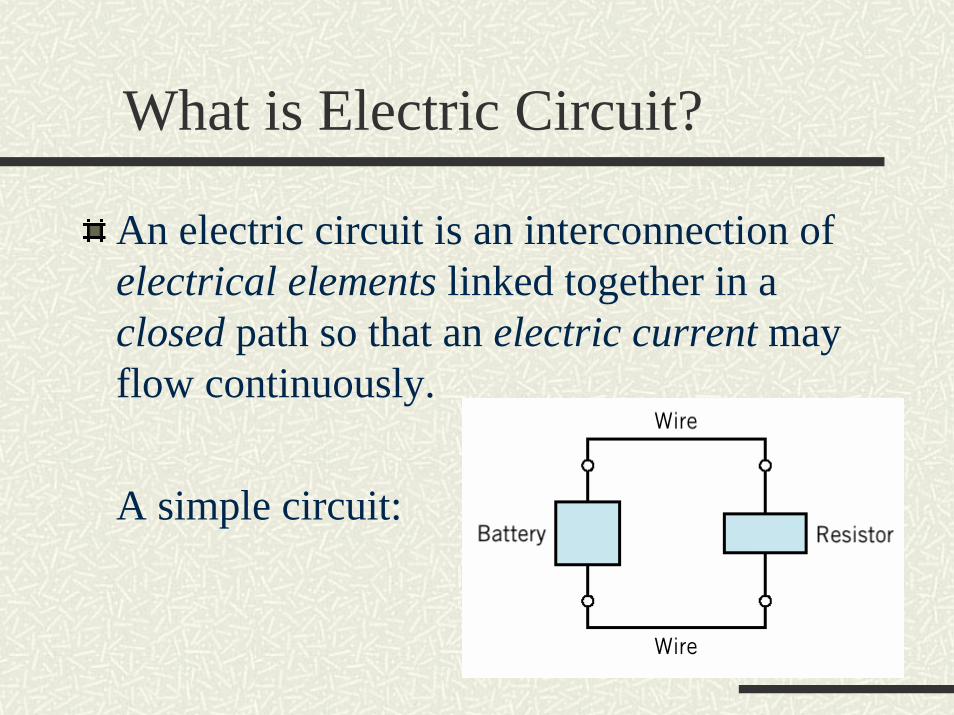
An electric circuit is an interconnection of electrical elements linked together in a closed path so that an electric current may flow continuously.
A simple circuit:
Basic Circuit Variables
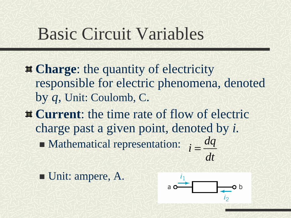
Charge: the quantity of electricity responsible for electric phenomena, denoted by q, Unit: Coulomb, C.Current: the time rate of flow of electric charge past a given point, denoted by i.
Mathematical representation:
Unit: ampere, A.
dqidt
=
Current
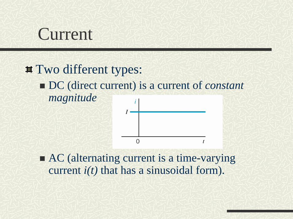
Two different types:DC (direct current) is a current of constant magnitude
AC (alternating current is a time-varying current i(t) that has a sinusoidal form).
Time-Varying Current
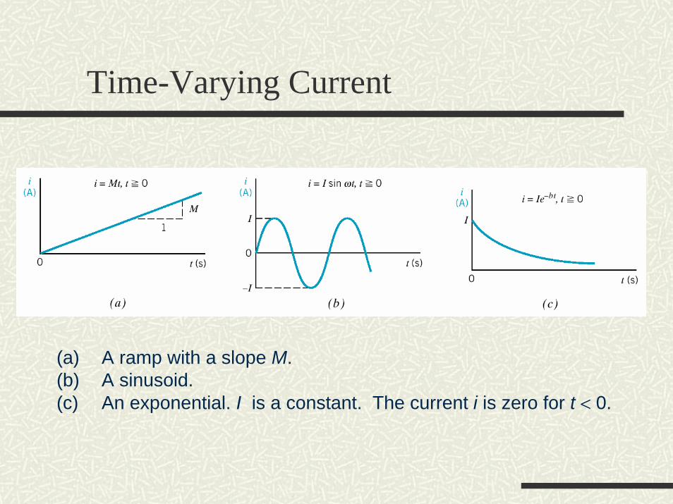
(a) A ramp with a slope M. (b) A sinusoid. (c) An exponential. I is a constant. The current i is zero for t < 0.
Voltage
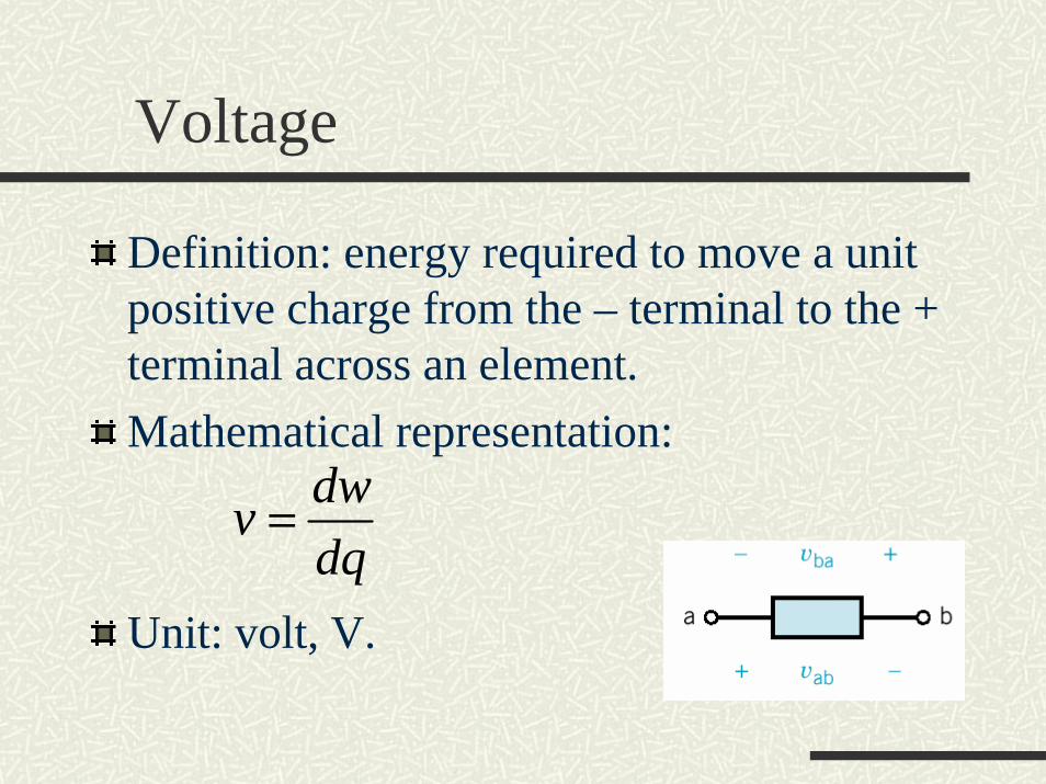
Definition: energy required to move a unit positive charge from the – terminal to the + terminal across an element. Mathematical representation:
Unit: volt, V.
dwvdq
=

Voltage
The direction of a voltage is given by its polarities:
The voltage vab is proportional to the work required to move a positive charge from terminal a to terminal b.The voltage vba is proportional to the work required to move a positive charge from terminal b to terminal a.
vab is read as “the voltage at terminal a with respect to terminal b”; or, “the voltage drop from terminal a to terminal b”.
baab vv −=
Power
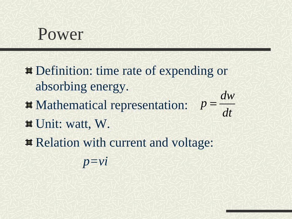
Definition: time rate of expending or absorbing energy.Mathematical representation:Unit: watt, W.Relation with current and voltage:
p=vi
dwpdt
=
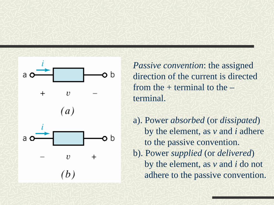
Passive convention: the assigneddirection of the current is directedfrom the + terminal to the –terminal.
a). Power absorbed (or dissipated)by the element, as v and i adhereto the passive convention.
b). Power supplied (or delivered)by the element, as v and i do notadhere to the passive convention.
Concepts
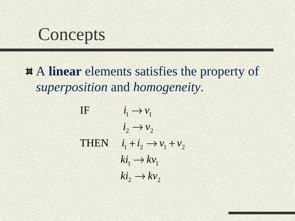
A linear elements satisfies the property of superposition and homogeneity.
22
11
2121
22
11
THEN
IF
kvkikvki
vviivivi
→→
+→+→→
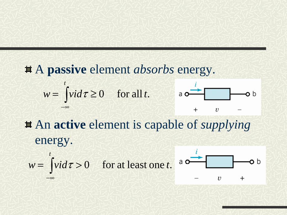
A passive element absorbs energy.
An active element is capable of supplying energy.
. allfor 0 tvidwt
∫∞−
≥= τ
. oneleast at for 0 tvidwt
∫∞−
>= τ
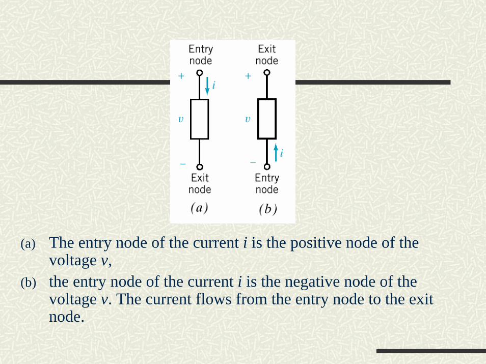
(a) The entry node of the current i is the positive node of the voltage v,
(b) the entry node of the current i is the negative node of the voltage v. The current flows from the entry node to the exit node.
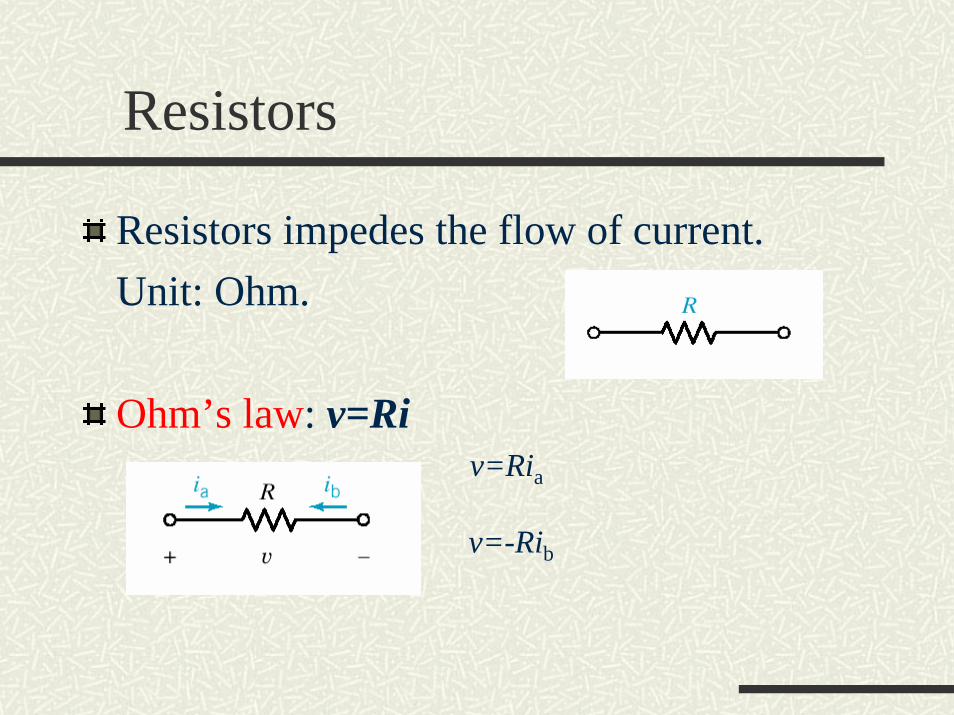
Resistors
Resistors impedes the flow of current.Unit: Ohm.
Ohm’s law: v=Riv=Ria
v=-Rib
Power delivered to a resistor:
p=vi=v(v/R)=v2/R
p=vi=(iR)i=i2R
Independent Sources
Sources: voltage or current generator capable of supplying energy to a circuit.
Independent sources: sources not dependent on other circuit variables.
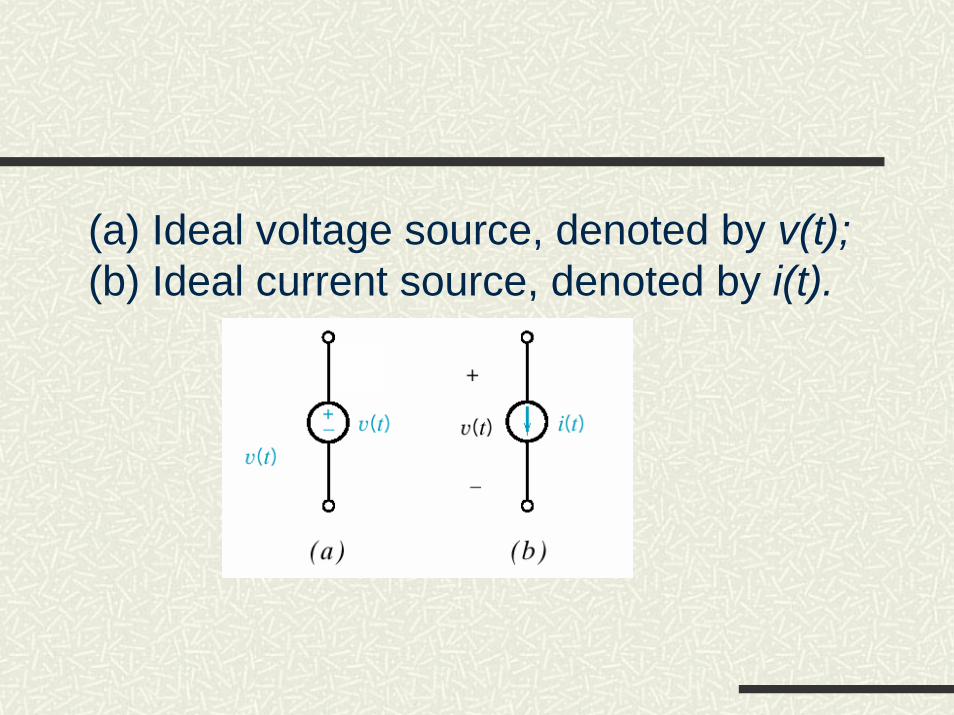
(a) Ideal voltage source, denoted by v(t); (b) Ideal current source, denoted by i(t).
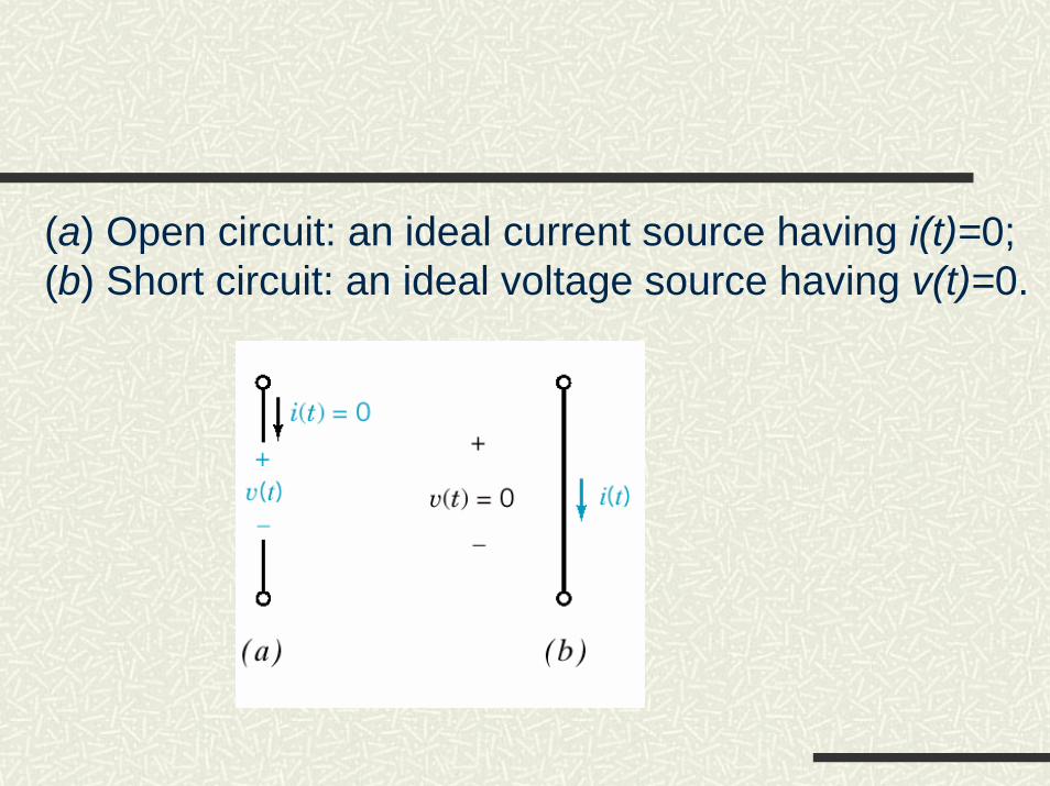
(a) Open circuit: an ideal current source having i(t)=0;(b) Short circuit: an ideal voltage source having v(t)=0.
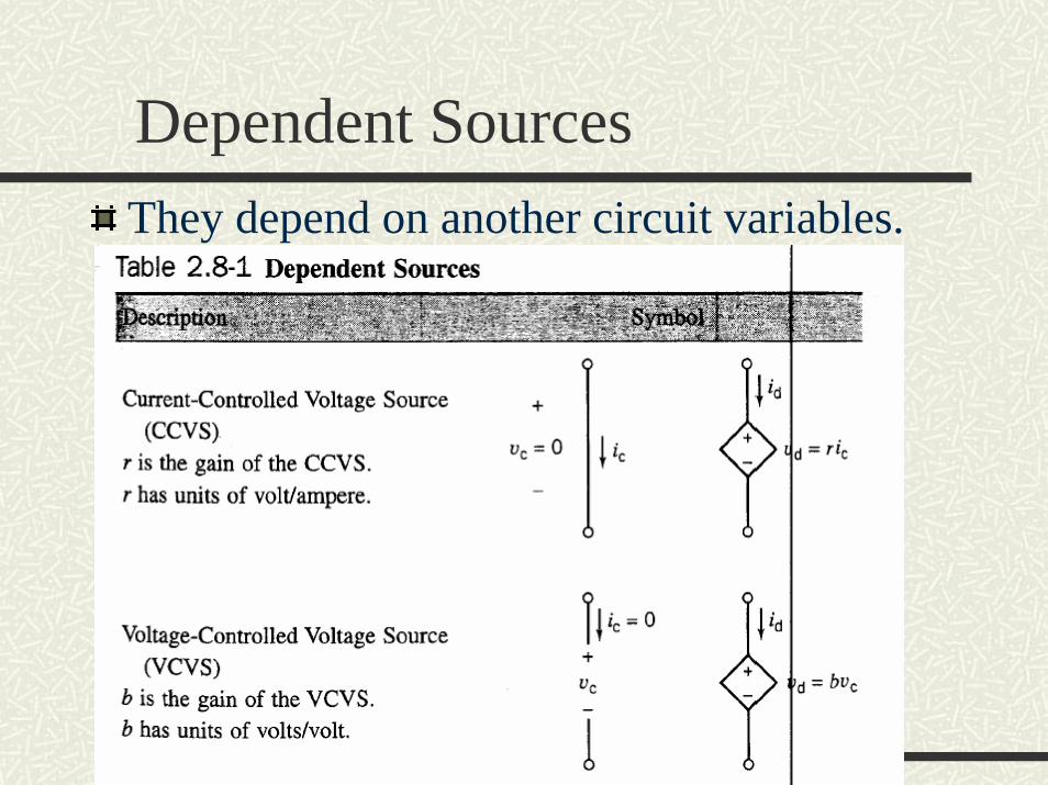
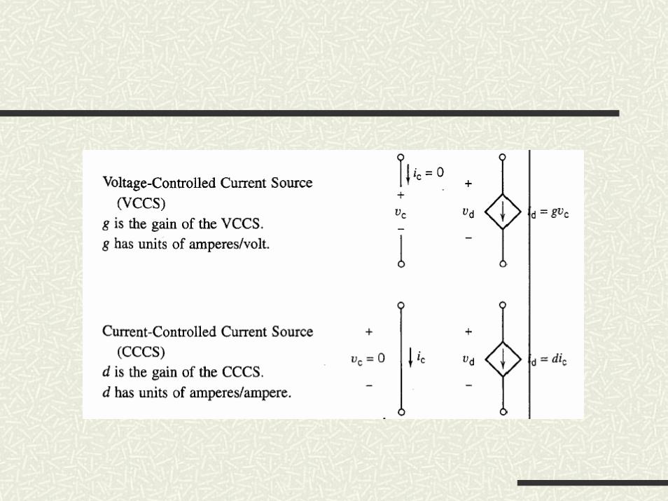
Dependent SourcesThey depend on another circuit variables.
Voltmeters
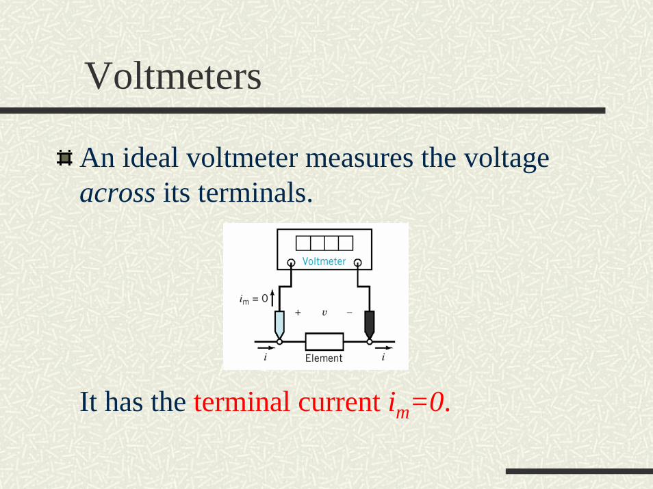
An ideal voltmeter measures the voltage across its terminals.
It has the terminal current im=0.
Ammeters
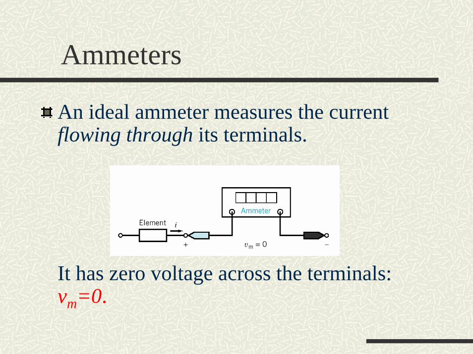
An ideal ammeter measures the current flowing through its terminals.
It has zero voltage across the terminals:vm=0.
Voltmeters and Ammeters
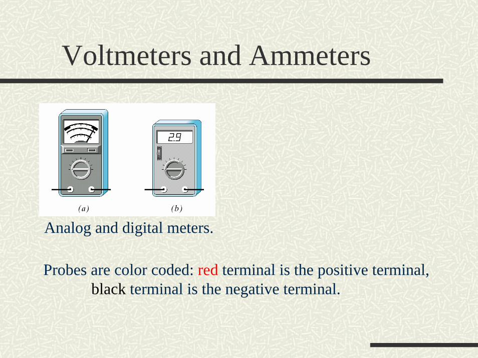
Analog and digital meters.
Probes are color coded: red terminal is the positive terminal,black terminal is the negative terminal.
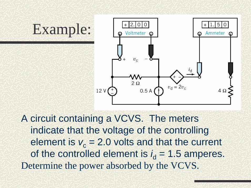
Example:
A circuit containing a VCVS. The meters indicate that the voltage of the controlling element is vc = 2.0 volts and that the current of the controlled element is id = 1.5 amperes.
Determine the power absorbed by the VCVS.
Switches
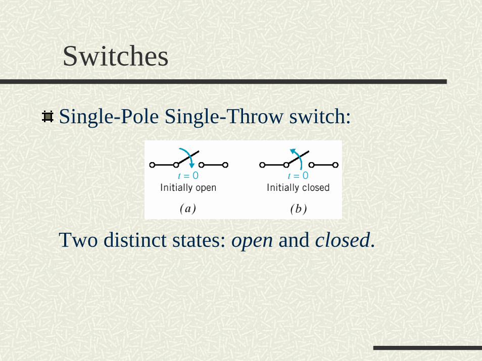
Single-Pole Single-Throw switch:
Two distinct states: open and closed.
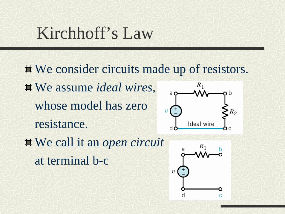
Kirchhoff’s Law
We consider circuits made up of resistors.We assume ideal wires, whose model has zero resistance. We call it an open circuitat terminal b-c
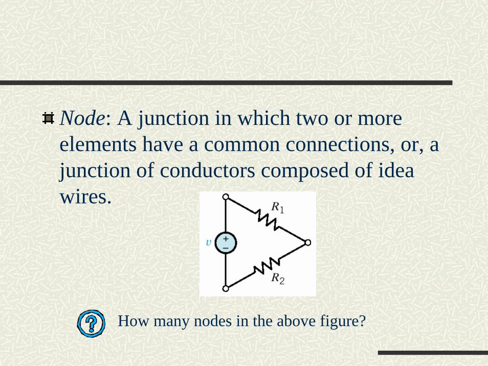
Node: A junction in which two or more elements have a common connections, or, a junction of conductors composed of idea wires.
How many nodes in the above figure?
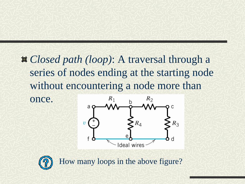
Closed path (loop): A traversal through a series of nodes ending at the starting node without encountering a node more than once.
How many loops in the above figure?
Kirchhoff’s Current Law
The algebraic sum of the currents into a node at any instant is zero.
i.e. the sum of currents entering the node is equal to the sum of currents leaving the node.
Reason: Charge cannot accumulate at a node, as node is a perfect conductor.
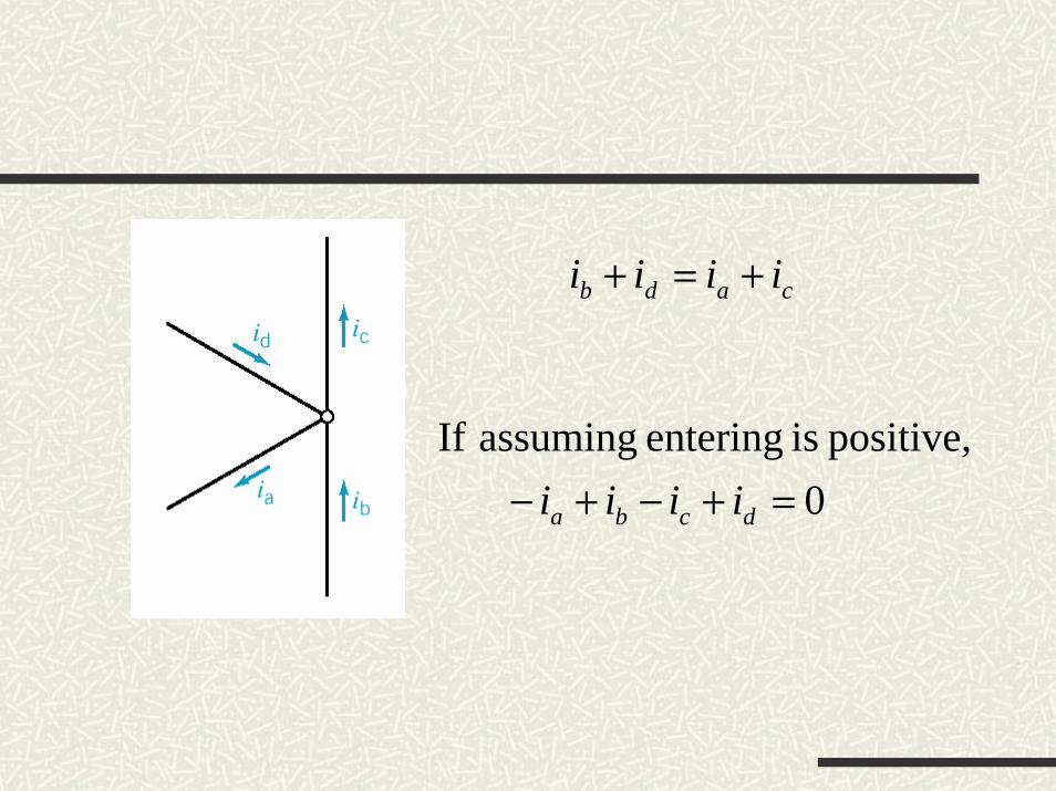
0 positive,isentering assumingIf
=+−+− dcba iiii
cadb iiii +=+
Kirchhoff’s Voltage Law
The algebraic sum of the voltages around any closed path in a circuit is zero for all time.
i.e. the voltage rise is equal to the voltage drop in the tracing direction around a closed path.
Reason: Recall that the voltage is work per unit charge.A circuit loop is a conservative system, and the energy required to move a charge around a closed path is zero.
Assign an algebraic sign (reference direction) to each voltage in the loopA common convention is to use the voltage sign on the first terminal of an element encountered as we traverse a path.
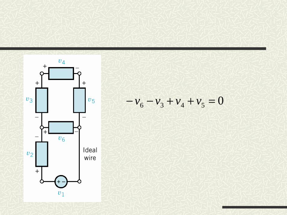
05436 =++−− vvvv