Embed Size (px)
Citation preview
CPE 390: Microprocessor SystemsSpring 2018
Lecture 4Introduction to HCS12
1
Bryan AcklandDepartment of Electrical and Computer Engineering
Stevens Institute of TechnologyHoboken, NJ 07030
Adapted from HCS12/9S12 An Introduction to Software and Hardware Interfacing Han-Way Huang, 2010
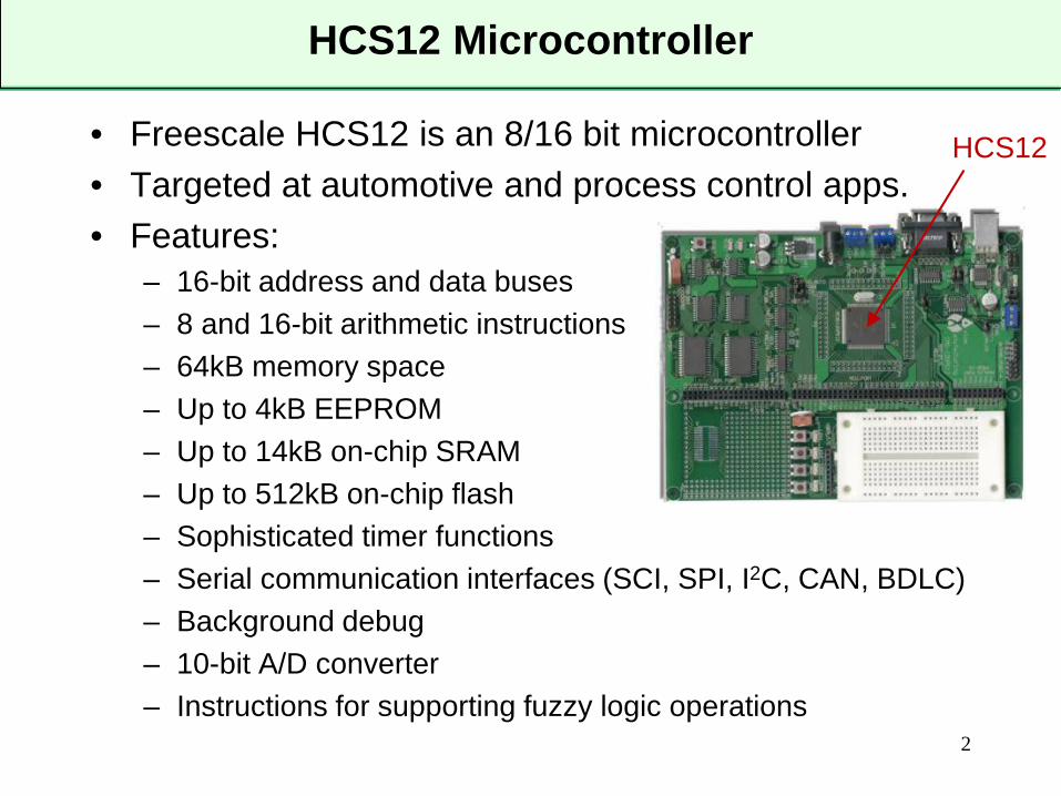
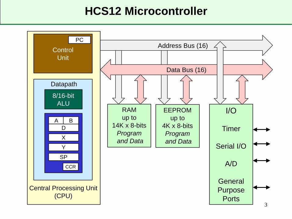
HCS12 Microcontroller
• Freescale HCS12 is an 8/16 bit microcontroller• Targeted at automotive and process control apps.• Features:
– 16-bit address and data buses– 8 and 16-bit arithmetic instructions– 64kB memory space– Up to 4kB EEPROM– Up to 14kB on-chip SRAM– Up to 512kB on-chip flash– Sophisticated timer functions – Serial communication interfaces (SCI, SPI, I2C, CAN, BDLC)– Background debug– 10-bit A/D converter– Instructions for supporting fuzzy logic operations
2
HCS12
HCS12 Microcontroller
3
Address Bus (16)Control Unit
8/16-bit ALU
Datapath
Central Processing Unit(CPU)
RAMup to
14K x 8-bitsProgramand Data
Data Bus (16)
PC
AD
B
X
Y
SPCCR
EEPROMup to
4K x 8-bitsProgramand Data
I/O
Timer
Serial I/O
A/D
GeneralPurpose
Ports
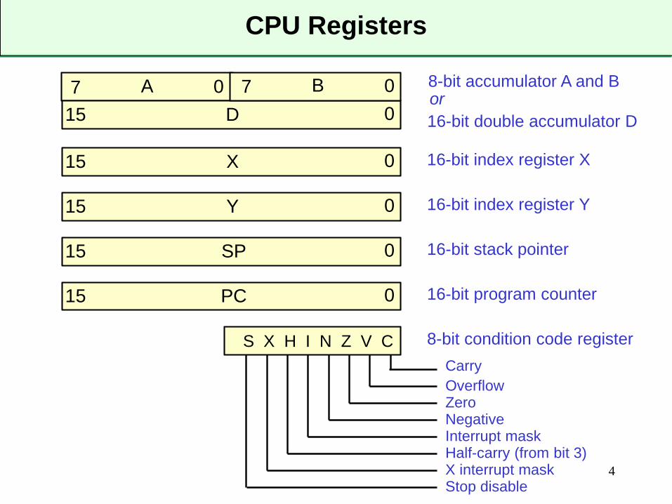
CPU Registers
4
7 0A 7 0B15 0D
8-bit accumulator A and Bor16-bit double accumulator D
15 0X 16-bit index register X
15 0Y 16-bit index register Y
15 0SP 16-bit stack pointer
15 0PC 16-bit program counter
S X H I N Z V C 8-bit condition code registerCarryOverflowZeroNegativeInterrupt maskHalf-carry (from bit 3)X interrupt maskStop disable
More on Registers
• General purpose accumulators A and B– A and B are 8-bit (byte) registers– Most arithmetic performed on these two registers– Some instructions see these as a single 16-bit accumulator D
• Index registers X and Y– 16-bit registers used mainly for forming operand addresses– Also used in several arithmetic operations
• Stack pointer (SP)– Stack is last-in first out data structure in memory used to facilitate
parameter passing and local variable storage in subroutine calls– Stack grows from higher to lower addresses– 16-bit SP points to the top (lowest address) of stack
• Program Counter– 16-bit PC holds address of next instruction to be executed– After instruction is executed, PC is incremented by number of bytes
of executed instruction5
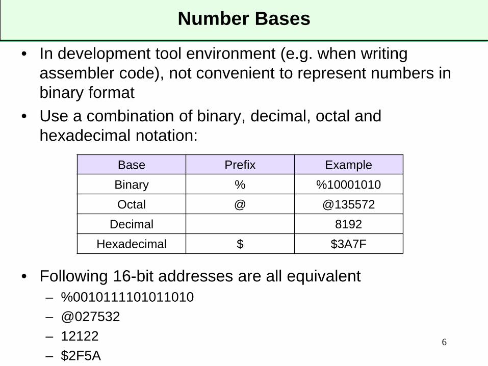
Number Bases
• In development tool environment (e.g. when writing assembler code), not convenient to represent numbers in binary format
• Use a combination of binary, decimal, octal and hexadecimal notation:
• Following 16-bit addresses are all equivalent– %0010111101011010– @027532– 12122– $2F5A
6
Base Prefix ExampleBinary % %10001010Octal @ @135572
Decimal 8192Hexadecimal $ $3A7F
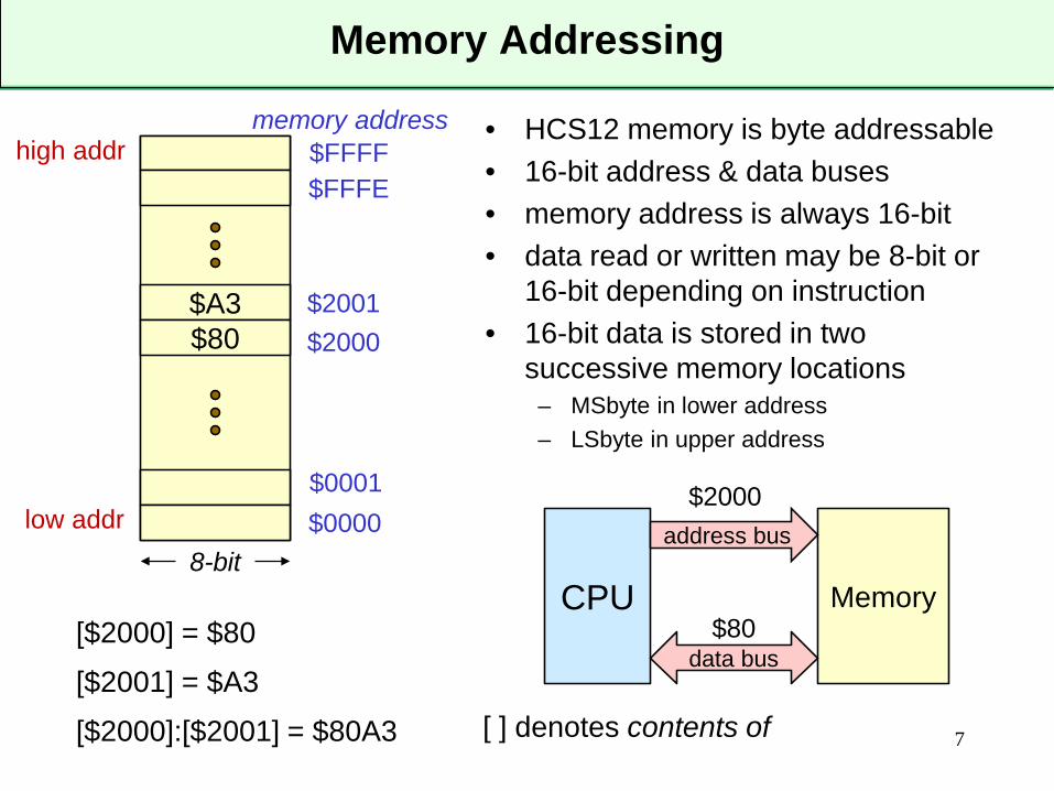
• HCS12 memory is byte addressable• 16-bit address & data buses• memory address is always 16-bit• data read or written may be 8-bit or
16-bit depending on instruction• 16-bit data is stored in two
successive memory locations– MSbyte in lower address– LSbyte in upper address
Memory Addressing
7
CPU Memory
address bus
data bus
$2000
$80
$A3$80
low addr
high addr
$0000$0001
$2000$2001
$FFFE$FFFF
8-bit
[$2000] = $80[$2001] = $A3[$2000]:[$2001] = $80A3
memory address
[ ] denotes contents of
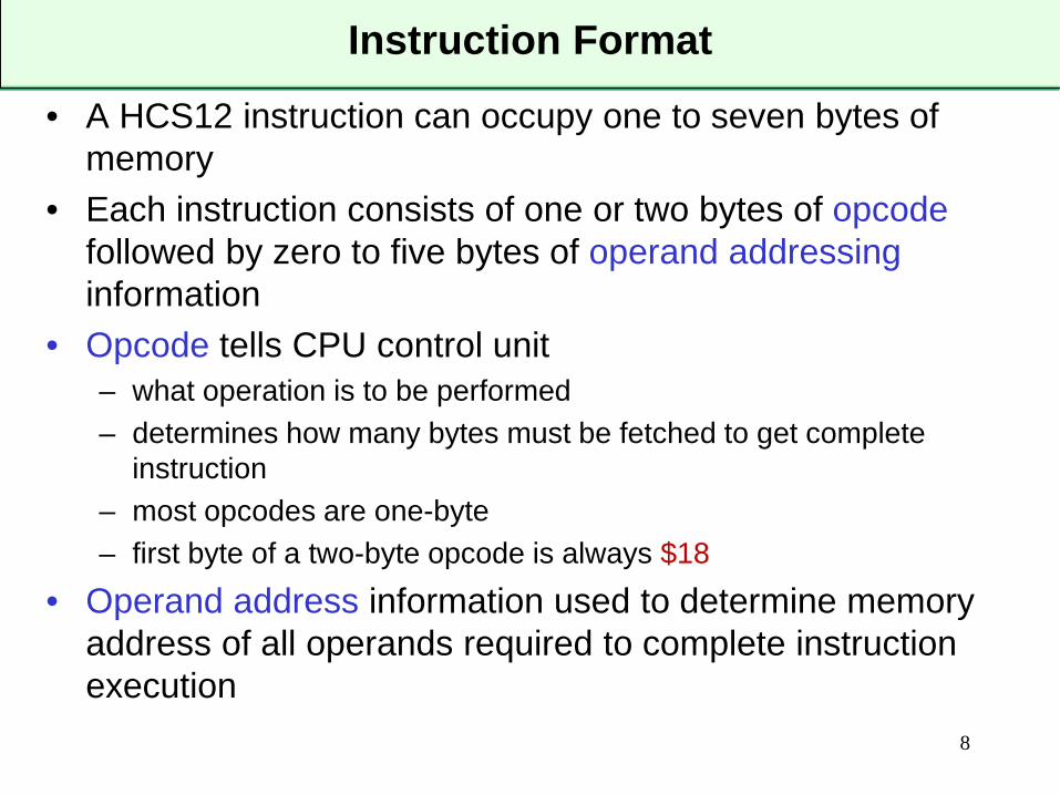
• A HCS12 instruction can occupy one to seven bytes of memory
• Each instruction consists of one or two bytes of opcodefollowed by zero to five bytes of operand addressinginformation
• Opcode tells CPU control unit – what operation is to be performed– determines how many bytes must be fetched to get complete
instruction– most opcodes are one-byte– first byte of a two-byte opcode is always $18
• Operand address information used to determine memory address of all operands required to complete instruction execution
Instruction Format
8
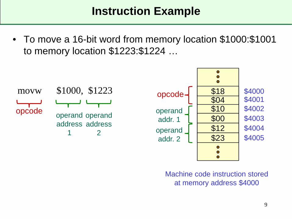
• To move a 16-bit word from memory location $1000:$1001 to memory location $1223:$1224 …
Instruction Example
9
movw $1000, $1223
opcode operandaddress
1
operandaddress
2
$10$00
$4000$04$18
$12$23
$4001$4002$4003$4004$4005
opcode
operandaddr. 1
operandaddr. 2
Machine code instruction stored at memory address $4000
• Operand memory addresses need to be specified in a variety of different ways to facilitate writing efficient, compact, flexible code
• For example:– is the address of a piece of data in a fixed (at time of writing code)
location or does its location depend on program execution?– is the value of a piece of data constant throughout the execution of
the program or does it change?– do you want to branch to an absolute (fixed) memory address or to
an address that is relative to the current value of the PC?– does the memory location you are accessing contain the data you
require or the address of the data you require?– can the memory address of your data be specified using one byte
or does it require a two-byte address?• HCS12 supports a number of different operand addressing
modes to support both assembly and compiled code
Operand Addressing
10
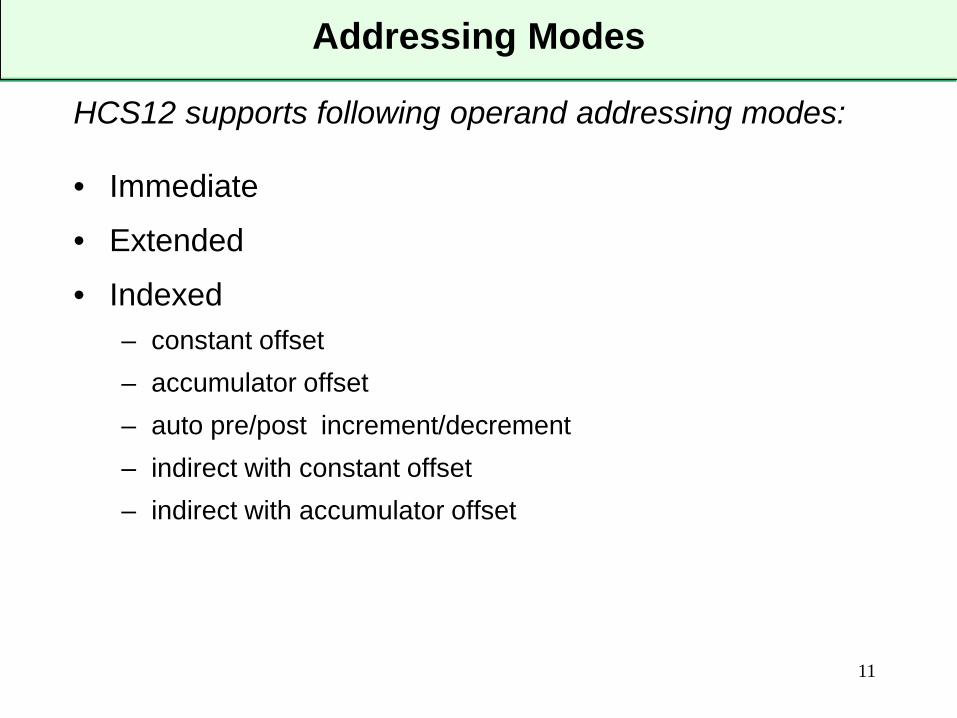
HCS12 supports following operand addressing modes:
• Immediate• Extended• Indexed
– constant offset– accumulator offset– auto pre/post increment/decrement– indirect with constant offset– indirect with accumulator offset
Addressing Modes
11
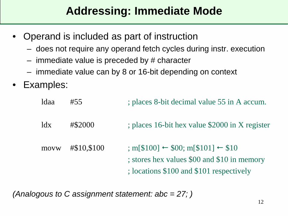
Addressing: Immediate Mode
• Operand is included as part of instruction– does not require any operand fetch cycles during instr. execution– immediate value is preceded by # character– immediate value can by 8 or 16-bit depending on context
• Examples:
ldaa #55 ; places 8-bit decimal value 55 in A accum.
ldx #$2000 ; places 16-bit hex value $2000 in X register
movw #$10,$100 ; m[$100] $00; m[$101] $10; stores hex values $00 and $10 in memory; locations $100 and $101 respectively
(Analogous to C assignment statement: abc = 27; )12
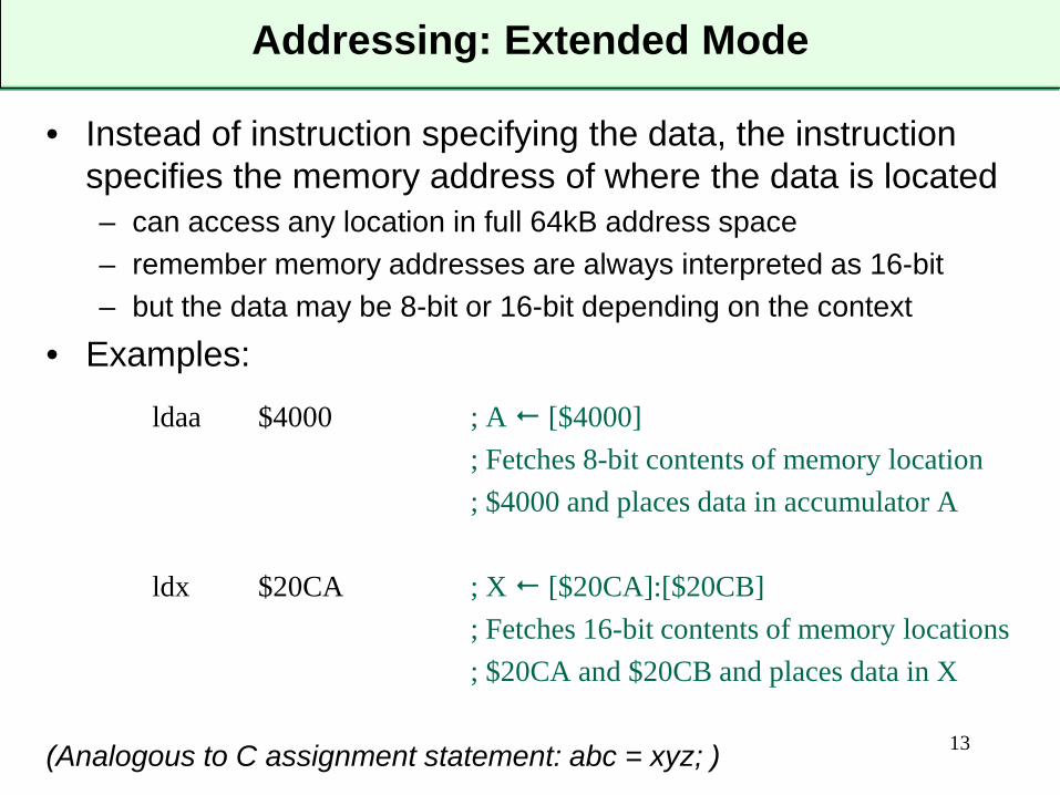
Addressing: Extended Mode
• Instead of instruction specifying the data, the instruction specifies the memory address of where the data is located– can access any location in full 64kB address space– remember memory addresses are always interpreted as 16-bit– but the data may be 8-bit or 16-bit depending on the context
• Examples:
ldaa $4000 ; A [$4000]; Fetches 8-bit contents of memory location ; $4000 and places data in accumulator A
ldx $20CA ; X [$20CA]:[$20CB]; Fetches 16-bit contents of memory locations; $20CA and $20CB and places data in X
(Analogous to C assignment statement: abc = xyz; ) 13
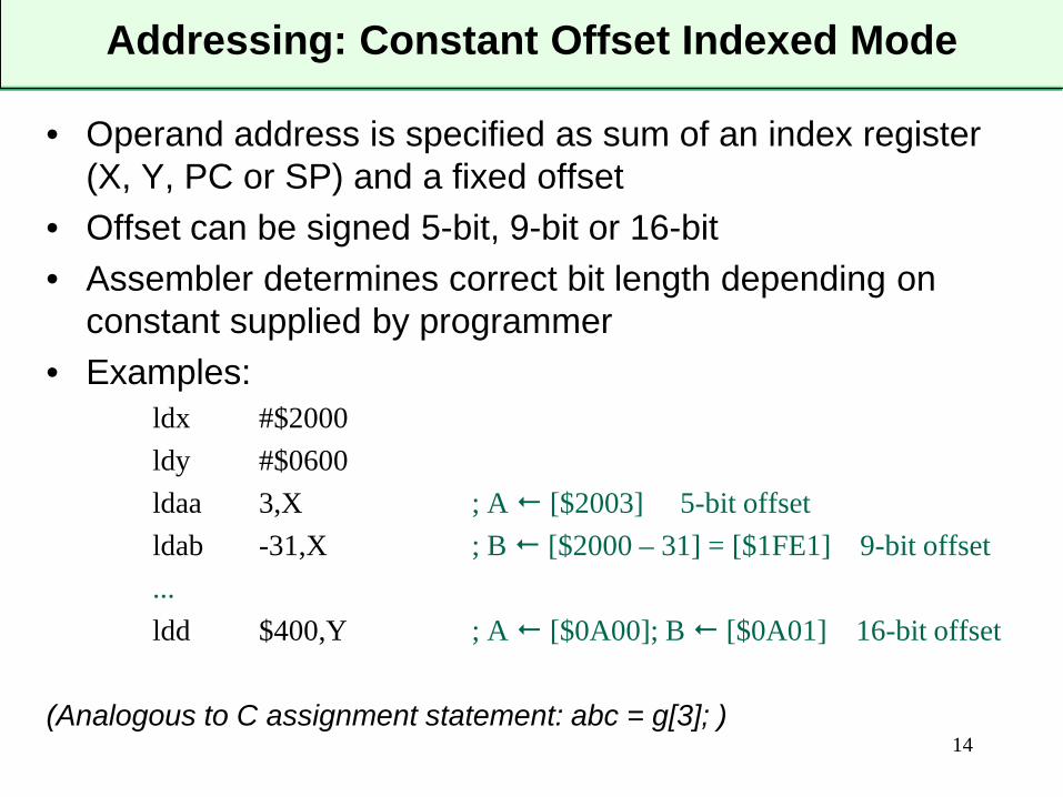
Addressing: Constant Offset Indexed Mode
• Operand address is specified as sum of an index register (X, Y, PC or SP) and a fixed offset
• Offset can be signed 5-bit, 9-bit or 16-bit• Assembler determines correct bit length depending on
constant supplied by programmer• Examples:
ldx #$2000ldy #$0600ldaa 3,X ; A [$2003] 5-bit offsetldab -31,X ; B [$2000 – 31] = [$1FE1] 9-bit offset...ldd $400,Y ; A [$0A00]; B [$0A01] 16-bit offset
(Analogous to C assignment statement: abc = g[3]; )14
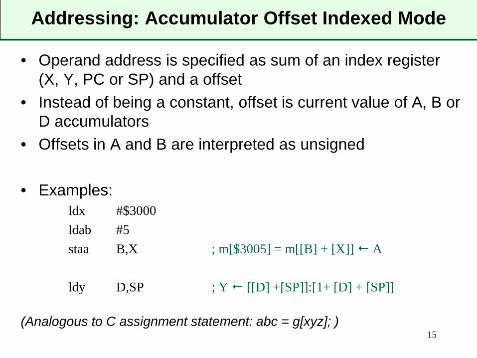
Addressing: Accumulator Offset Indexed Mode
• Operand address is specified as sum of an index register (X, Y, PC or SP) and a offset
• Instead of being a constant, offset is current value of A, B or D accumulators
• Offsets in A and B are interpreted as unsigned
• Examples:ldx #$3000ldab #5staa B,X ; m[$3005] = m[[B] + [X]] A
ldy D,SP ; Y [[D] +[SP]]:[1+ [D] + [SP]]
(Analogous to C assignment statement: abc = g[xyz]; )15
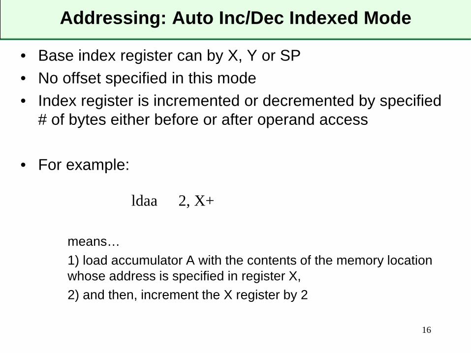
Addressing: Auto Inc/Dec Indexed Mode
• Base index register can by X, Y or SP• No offset specified in this mode• Index register is incremented or decremented by specified
# of bytes either before or after operand access
• For example:
means…1) load accumulator A with the contents of the memory location whose address is specified in register X,2) and then, increment the X register by 2
16
ldaa 2, X+
Addressing: Auto Inc/Dec Indexed Mode
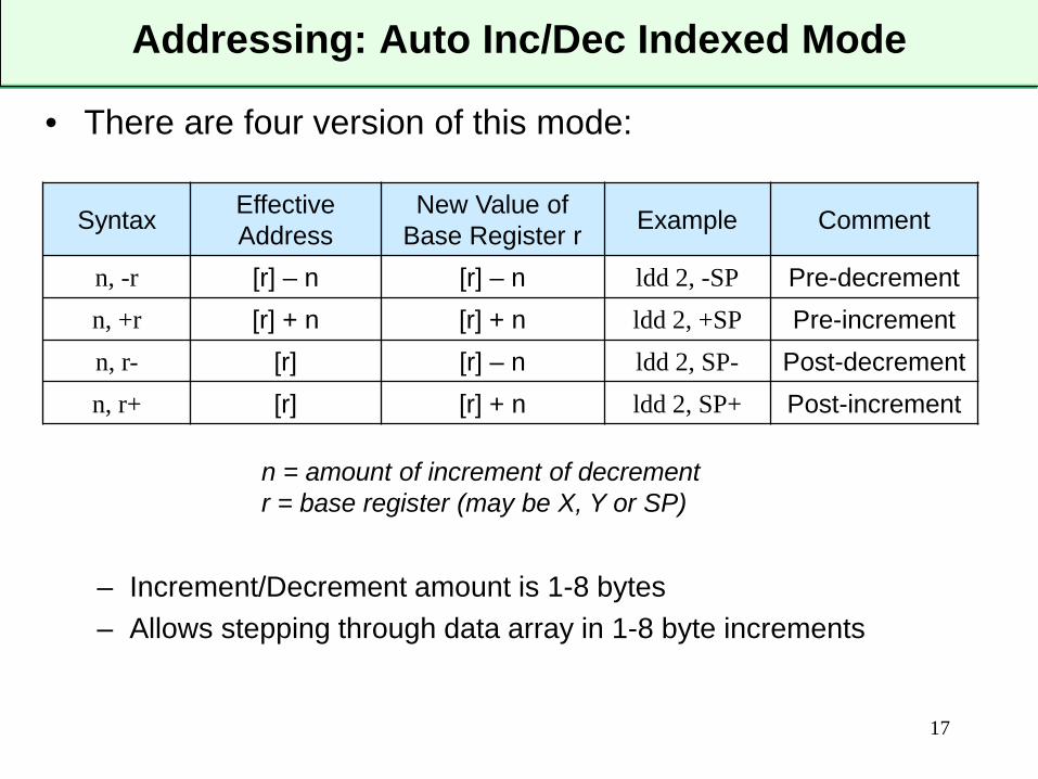
• There are four version of this mode:
– Increment/Decrement amount is 1-8 bytes– Allows stepping through data array in 1-8 byte increments
17
Syntax EffectiveAddress
New Value of Base Register r Example Comment
n, -r [r] – n [r] – n ldd 2, -SP Pre-decrementn, +r [r] + n [r] + n ldd 2, +SP Pre-incrementn, r- [r] [r] – n ldd 2, SP- Post-decrementn, r+ [r] [r] + n ldd 2, SP+ Post-increment
n = amount of increment of decrementr = base register (may be X, Y or SP)
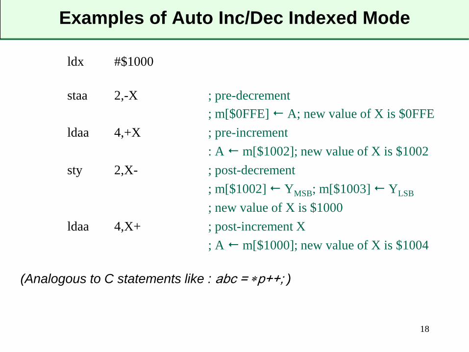
Examples of Auto Inc/Dec Indexed Mode
ldx #$1000
staa 2,-X ; pre-decrement; m[$0FFE] A; new value of X is $0FFE
ldaa 4,+X ; pre-increment: A m[$1002]; new value of X is $1002
sty 2,X- ; post-decrement; m[$1002] YMSB; m[$1003] YLSB
; new value of X is $1000ldaa 4,X+ ; post-increment X
; A m[$1000]; new value of X is $1004
(Analogous to C statements like : abc = ∗p++; )
18
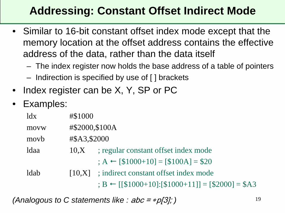
Addressing: Constant Offset Indirect Mode
• Similar to 16-bit constant offset index mode except that the memory location at the offset address contains the effective address of the data, rather than the data itself– The index register now holds the base address of a table of pointers– Indirection is specified by use of [ ] brackets
• Index register can be X, Y, SP or PC• Examples:
ldx #$1000movw #$2000,$100Amovb #$A3,$2000ldaa 10,X ; regular constant offset index mode
; A [$1000+10] = [$100A] = $20ldab [10,X] ; indirect constant offset index mode
; B [[$1000+10]:[$1000+11]] = [$2000] = $A3
(Analogous to C statements like : abc = ∗p[3]; ) 19
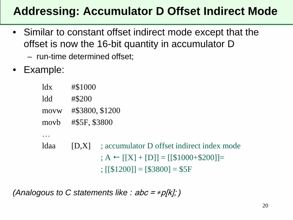
Addressing: Accumulator D Offset Indirect Mode
• Similar to constant offset indirect mode except that the offset is now the 16-bit quantity in accumulator D– run-time determined offset;
• Example:
ldx #$1000ldd #$200movw #$3800, $1200movb #$5F, $3800…ldaa [D,X] ; accumulator D offset indirect index mode
; A [[X] + [D]] = [[$1000+$200]]=; [[$1200]] = [$3800] = $5F
(Analogous to C statements like : abc = ∗p[k]; )20
Instruction Examples
• Following slides will give some examples of commonly used HCS12 instructions
• Start with some data transfer instructions
21
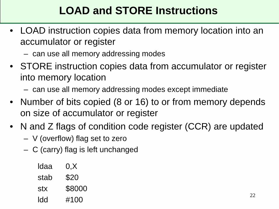
LOAD and STORE Instructions
• LOAD instruction copies data from memory location into an accumulator or register– can use all memory addressing modes
• STORE instruction copies data from accumulator or register into memory location– can use all memory addressing modes except immediate
• Number of bits copied (8 or 16) to or from memory depends on size of accumulator or register
• N and Z flags of condition code register (CCR) are updated– V (overflow) flag set to zero– C (carry) flag is left unchanged
ldaa 0,Xstab $20stx $8000ldd #100 22
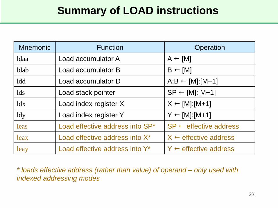
Summary of LOAD instructions
23
Mnemonic Function Operationldaa Load accumulator A A [M]ldab Load accumulator B B [M]ldd Load accumulator D A:B [M]:[M+1]lds Load stack pointer SP [M]:[M+1]ldx Load index register X X [M]:[M+1]ldy Load index register Y Y [M]:[M+1]leas Load effective address into SP* SP effective addressleax Load effective address into X* X effective addressleay Load effective address into Y* Y effective address
* loads effective address (rather than value) of operand – only used with indexed addressing modes
Summary of STORE instructions
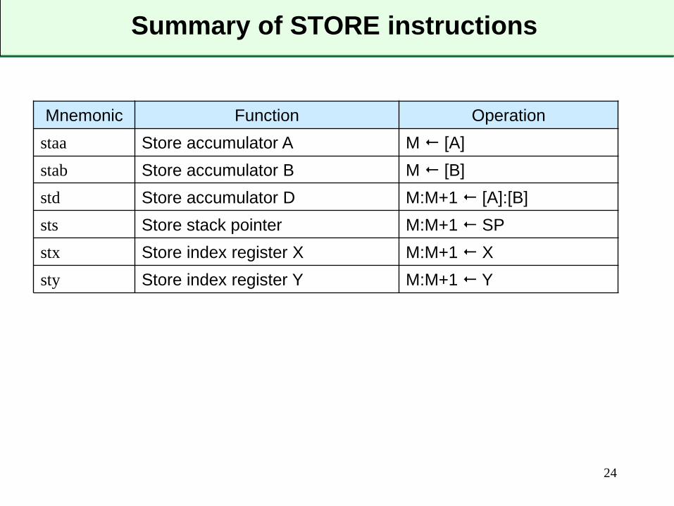
24
Mnemonic Function Operationstaa Store accumulator A M [A]stab Store accumulator B M [B]std Store accumulator D M:M+1 [A]:[B]sts Store stack pointer M:M+1 SPstx Store index register X M:M+1 Xsty Store index register Y M:M+1 Y
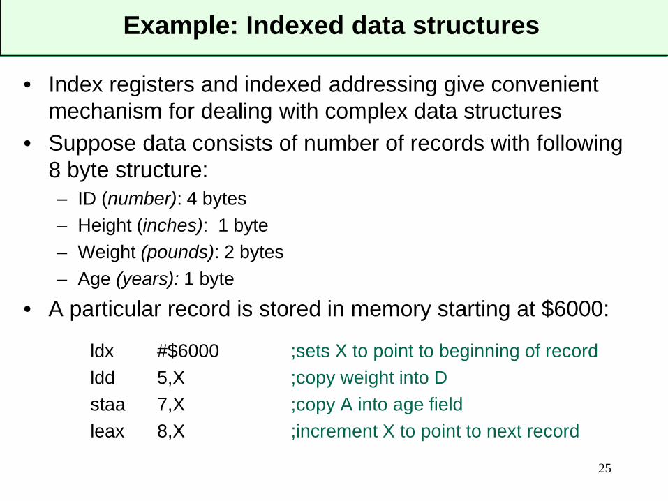
Example: Indexed data structures
• Index registers and indexed addressing give convenient mechanism for dealing with complex data structures
• Suppose data consists of number of records with following 8 byte structure:– ID (number): 4 bytes– Height (inches): 1 byte– Weight (pounds): 2 bytes– Age (years): 1 byte
• A particular record is stored in memory starting at $6000:
ldx #$6000 ;sets X to point to beginning of recordldd 5,X ;copy weight into Dstaa 7,X ;copy A into age fieldleax 8,X ;increment X to point to next record
25
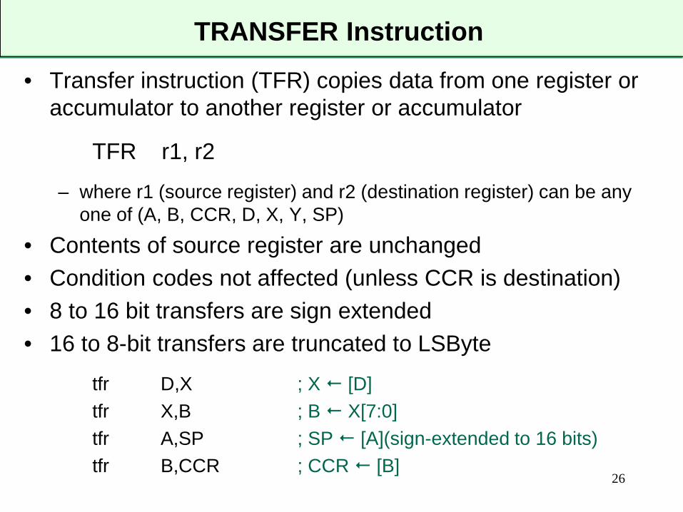
TRANSFER Instruction
• Transfer instruction (TFR) copies data from one register or accumulator to another register or accumulator
TFR r1, r2
– where r1 (source register) and r2 (destination register) can be any one of (A, B, CCR, D, X, Y, SP)
• Contents of source register are unchanged• Condition codes not affected (unless CCR is destination)• 8 to 16 bit transfers are sign extended• 16 to 8-bit transfers are truncated to LSByte
tfr D,X ; X [D]tfr X,B ; B X[7:0]tfr A,SP ; SP [A](sign-extended to 16 bits)tfr B,CCR ; CCR [B]
26
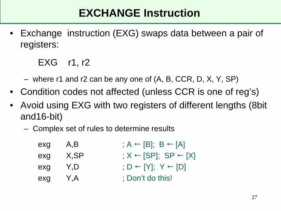
EXCHANGE Instruction
• Exchange instruction (EXG) swaps data between a pair of registers:
EXG r1, r2
– where r1 and r2 can be any one of (A, B, CCR, D, X, Y, SP)• Condition codes not affected (unless CCR is one of reg’s)• Avoid using EXG with two registers of different lengths (8bit
and16-bit)– Complex set of rules to determine results
exg A,B ; A [B]; B [A]exg X,SP ; X [SP]; SP [X]exg Y,D ; D [Y]; Y [D]exg Y,A ; Don’t do this!
27
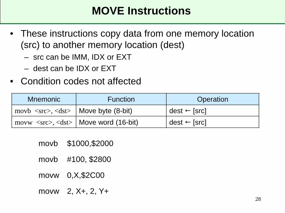
MOVE Instructions
• These instructions copy data from one memory location (src) to another memory location (dest)– src can be IMM, IDX or EXT– dest can be IDX or EXT
• Condition codes not affected
movb $1000,$2000
movb #100, $2800
movw 0,X,$2C00
movw 2, X+, 2, Y+28
Mnemonic Function Operationmovb <src>, <dst> Move byte (8-bit) dest [src]movw <src>, <dst> Move word (16-bit) dest [src]
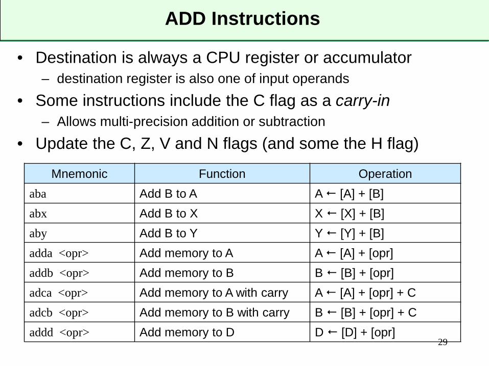
ADD Instructions
• Destination is always a CPU register or accumulator– destination register is also one of input operands
• Some instructions include the C flag as a carry-in– Allows multi-precision addition or subtraction
• Update the C, Z, V and N flags (and some the H flag)
29
Mnemonic Function Operationaba Add B to A A [A] + [B]abx Add B to X X [X] + [B]aby Add B to Y Y [Y] + [B]adda <opr> Add memory to A A [A] + [opr]addb <opr> Add memory to B B [B] + [opr]adca <opr> Add memory to A with carry A [A] + [opr] + Cadcb <opr> Add memory to B with carry B [B] + [opr] + Caddd <opr> Add memory to D D [D] + [opr]
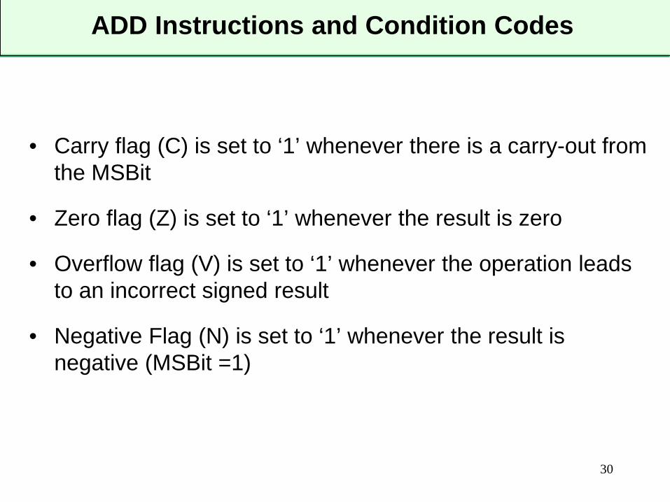
ADD Instructions and Condition Codes
• Carry flag (C) is set to ‘1’ whenever there is a carry-out from the MSBit
• Zero flag (Z) is set to ‘1’ whenever the result is zero
• Overflow flag (V) is set to ‘1’ whenever the operation leads to an incorrect signed result
• Negative Flag (N) is set to ‘1’ whenever the result is negative (MSBit =1)
30
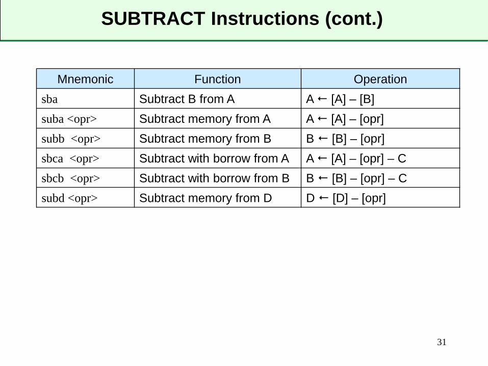
SUBTRACT Instructions (cont.)
31
Mnemonic Function Operationsba Subtract B from A A [A] – [B]suba <opr> Subtract memory from A A [A] – [opr]subb <opr> Subtract memory from B B [B] – [opr]sbca <opr> Subtract with borrow from A A [A] – [opr] – Csbcb <opr> Subtract with borrow from B B [B] – [opr] – Csubd <opr> Subtract memory from D D [D] – [opr]
Example Code 1
• Write an instruction sequence to add 5 to the data in memory location $20
32
Example Code 2
• Write an instruction sequence to add the byte in memory location pointed to by the X register and the following byte and place the sum in the memory location pointed to by the Y register
33
Example Code 3
• Write an instruction sequence to add the numbers stored at $1000, $1001 and $1002 and store the sum in location $1004
34
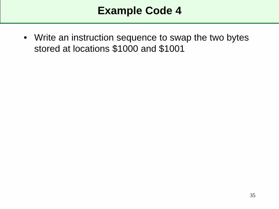
Example Code 4
• Write an instruction sequence to swap the two bytes stored at locations $1000 and $1001
35
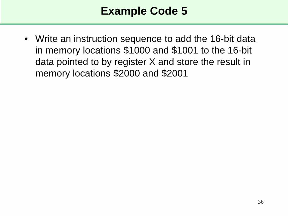
Example Code 5
• Write an instruction sequence to add the 16-bit data in memory locations $1000 and $1001 to the 16-bit data pointed to by register X and store the result in memory locations $2000 and $2001
36