Embed Size (px)
Citation preview
US010196885B2
( 12 ) United States Patent ( 10 ) Patent No . : US 10 , 196 , 885 B2 ( 45 ) Date of Patent : * Feb . 5 , 2019 Sharma et al .
( 54 ) DOWNHOLE INDUCTION HEATER FOR OIL AND GAS WELLS
( 58 ) Field of Classification Search CPC . . . . . . . . E21B 36 / 04 ; E21B 37 / 00 ; E21B 43 / 121 ;
E21B 43 / 2401 ; HO5B 2214 / 03 ; HO5B 6 / 108 ; HO5B 6 / 109 ; H05B 6 / 62
See application file for complete search history . ( 71 ) Applicant : The Board of Regents of The
University of Texas System , Austin , TX ( US )
( 72 ) Inventors : Mukul M . Sharma , Austin , TX ( US ) ; Raymond C . Zowarka , Austin , TX ( US ) ; Siddharth Pratap , Orange , CA ( US )
( 56 ) References Cited U . S . PATENT DOCUMENTS
5 , 070 , 533 A * 12 / 1991 Bridges 5 , 465 , 789 A * 11 / 1995 Evans . . . . . . . . . . . . . . .
E21B 36 / 04 166 / 60
E21B 43 / 2401 166 / 248
( 73 ) Assignee : Board of Regents of the University of Texas System , Austin , TX ( US )
( Continued ) ( * ) Notice : FOREIGN PATENT DOCUMENTS
Subject to any disclaimer , the term of this patent is extended or adjusted under 35 U . S . C . 154 ( b ) by 320 days . This patent is subject to a terminal dis claimer .
WO 2010 / 114180 1 0 / 2010
OTHER PUBLICATIONS ( 21 ) Appl . No . : 15 / 042 , 771 International Search Report / Written Opinion for PCT Application
No . PCT / US2016 / 017749 dated Apr . 22 , 2016 . ( 22 ) Filed : Feb . 12 , 2016 ( 65 ) Prior Publication Data
US 2016 / 0265325 A1 Sep . 15 , 2016
Primary Examiner — Robert E Fuller Assistant Examiner — Christopher J Sebesta ( 74 ) Attorney , Agent , or Firm — Meyertons , Hood , Kivlin , Kowert & Goetzel , P . C . ; Mark R . DeLuca
( 51 ) Int . Cl . E21B 43 / 24 ( 2006 . 01 ) E21B 37 / 00 ( 2006 . 01 ) E21B 43 / 12 ( 2006 . 01 ) H05B 6 / 62 ( 2006 . 01 ) E21B 36 / 04 ( 2006 . 01 ) H05B 6 / 10 ( 2006 . 01 )
( 52 ) U . S . CI . CPC . . . . . . . . . . E21B 43 / 2401 ( 2013 . 01 ) ; E21B 36 / 04
( 2013 . 01 ) ; E21B 37 / 00 ( 2013 . 01 ) ; E21B 43 / 121 ( 2013 . 01 ) ; H05B 6 / 108 ( 2013 . 01 ) ;
H05B 6 / 109 ( 2013 . 01 ) ; H05B 6 / 62 ( 2013 . 01 ) ; H05B 2214 / 03 ( 2013 . 01 )
( 57 ) ABSTRACT Described herein are methods and system that use electro magnetic heating to heat wellbores and the fluids therein . The heating is achieved by placing one or more permanent magnets in the wellbore and moving a metallic component and / or the one or more permanent magnets relative to each other . This generates eddy currents in the metallic compo nent , which heat the metallic component . This heat is transferred to the fluids in the wellbore from the metallic component by convection .
11 Claims , 13 Drawing Sheets
Tubing String
D
-
L Heater Section with Permanent Magnets
Sucker Rod LIII 1ST - Pump Section
US 10 , 196 , 885 B2 Page 2
( 56 ) References Cited U . S . PATENT DOCUMENTS
6 , 011 , 245 A * 6 , 285 , 014 B1 * 6 , 297 , 484 B1 6 , 353 , 706 B1 *
2009 / 0160445 A1 *
1 / 2000 Bell . . . . . . . . . . . . . . . . . . . . . F24J 3 / 00 219 / 629
9 / 2001 Beck E21B 36 / 04 166 / 248
10 / 2001 Usui et al . 3 / 2002 Bridges . . . . . . . . . . . . . . . . . . . E21B 36 / 04
166 / 302 6 / 2009 Hall GOIV 3 / 28
324 / 339 4 / 2010 Wideman . . . . . . . . . . . . . . E21B 7 / 14
166 / 272 . 1 11 / 2011 Berdut - Teruel . . . . . . . . H05B 6 / 108
219 / 672 8 / 2013 Freese . . . . . . . . . . . . . . . . F16L 55 / 00
137 / 13
2010 / 0089574 A1 * 2011 / 0272399 Al * 2013 / 0192682 A1 *
* cited by examiner
1
.
.
I
I
I
.
I
I
.
.
I
.
.
.
.
.
.
.
. .
.
.
.
.
I
.
.
. . .
.
.
.
I
. . . .
.
.
I
.
.
I .
. . . .
.
. . .
.
. . . .
.
. .
. . .
.
.
.
. . . .
. . . .
. .
.
.
.
. . .
. . .
.
.
.
.
.
. . . .
. .
. .
. .
.
.
.
.
.
.
.
. . . .
. . .
.
-
.
.
.
.
I
.
.
.
.
.
.
.
.
.
. . . . . . . . .
.
. . . . .
. . . . . . . . . .
. . .
. . .
.
.
.
.
. . .
. . . .
.
.
.
.
.
.
.
.
. . . .
.
.
.
. . .
.
.
.
.
.
.
.
.
.
.
.
.
.
.
.
.
.
.
. . .
.
.
.
.
.
. . . .
. . . .
. . . . .
.
.
.
. . . .
.
.
.
.
.
.
.
. . . .
.
.
. . . .
. . .
. . . . . .
.
.
.
.
.
.
. . . .
.
. . .
.
.
.
.
.
.
.
.
.
.
. . .
. .
.
.
.
.
.
.
.
.
.
.
.
.
. .
. . . . .
.
.
.
.
.
.
.
.
. . . . . .
. .
.
. . .
.
.
.
. . . . .
.
.
.
.
.
.
.
.
. . . . . . .
. . . .
.
.
.
. . . .
.
.
.
. . .
. .
. . .
. .
.
.
. . .
.
.
.
.
.
.
.
.
.
.
.
.
.
.
.
.
.
.
.
.
.
.
.
.
. .
.
.
I
.
.
.
.
.
.
.
.
.
.
.
. . . .
. III . .
I .
II .
III .
I
.
II . . .
. . .
.
.
. . .
.
.
.
. .
. .
. . .
. . . . .
.
.
. . .
.
.
.
.
. . .
. . .
.
.
. .
. .
.
.
.
.
. . .
. .
U . S . Patent
.
.
.
.
.
.
.
.
.
.
.
.
.
.
.
.
.
.
.
.
.
.
. . .
. .
. .
.
.
.
.
. . .
.
.
.
.
. . .
.
.
.
.
.
.
.
.
.
.
.
.
.
.
.
.
.
.
.
.
.
.
.
.
.
.
.
.
. . .
. .
. . .
.
.
.
.
.
.
.
.
.
.
.
.
.
.
.
.
.
.
.
. . - I
.
I
.
.
.
.
. .
.
E
.
.
.
.
.
.
.
.
.
.
.
.
.
.
. . . . .
.
.
.
.
E
.
.
.
. . . .
. . . . . . . . . . . . . . . . . . . . . . . . . . . . . . . . . . . . . . . . . . . . . . .
. . . V E . . . . .
. . . . . .
. . . . . . . . . . . . . . . . . . . . . . . . . . .
.
.
. . . .
. . . . . . . . . .
. . . . . . . . . 1
. . . . . . . . . . . . . . . .
. . . . . . . . . . . . . . . . . . . . . . . . . . . . . . . . . . . . . . . . . . . . . . . . . . . . . .
I . IIIIIIIIIIIIIIIIIIIIIIIIIIIIIIIII . . . II . IIIIII . . IIIIIIIIIIIIII
.
.
.
.
.
I
I
IIIIIIIIIIIIIIIIIIIIIIIIIIIIIIIIIIIIIIIIIIIIIIIIIIIIIIIIII . .
.
. .
. . . . . . . . .
. . . . . . . . . . . . . . .
. . . . . . . . . . . . . . . . .
: . .
.
. L .
.
. .
.
.
.
:
:
:
.
:
. .
:
.
.
.
. . .
.
.
.
.
.
.
.
.
.
.
. .
. . . .
.
.
.
. .
.
.
.
.
.
.
.
. . .
. .
.
.
.
.
. .
.
.
.
.
.
.
+ .
.
atent
.
.
.
.
.
.
.
. .
. .
.
.
.
.
.
. L . I
.
. .
.
. . . . . . .
. I
.
. . . .
I
.
.
. I
.
. . .
. . .
.
.
. . . . . .
. .
. . . .
.
.
.
. . :
. . . . . . .
. :
. . .
E
.
. .
.
:
. . .
. . . .
. : .
. . . .
. .
: . . . . . .
.
. . . .
.
. . .
. . . . . .
. . .
.
.
.
. . .
. . .
.
.
.
. . .
. . . . .
. . .
. . . . . . .
. . . .
.
.
.
.
.
.
.
.
.
.
. . .
.
.
L
I
.
.
.
.
.
.
.
.
.
.
.
.
.
.
.
1
.
.
.
. .
. . .
.
.
. . .
.
.
.
.
. .
. .
. .
.
. .
.
. .
.
. .
.
.
.
.
.
.
.
.
.
. .
.
.
.
.
. .
.
.
.
.
.
.
.
.
.
. .
.
. .
.
.
.
.
.
.
. . .
.
.
.
.
.
. .
.
.
.
.
.
.
.
.
.
.
.
.
.
.
.
.
.
.
.
.
.
.
.
.
.
.
.
.
.
.
.
.
.
.
.
.
.
.
.
.
.
.
.
.
.
.
.
.
.
.
.
.
.
.
.
.
.
.
. . .
.
.
.
.
.
.
.
.
.
.
.
.
.
.
.
.
.
.
.
.
.
.
.
.
.
.
.
.
.
.
.
.
.
.
.
.
.
.
.
.
.
.
.
.
.
.
.
.
.
.
.
.
.
.
.
.
.
.
.
.
.
.
.
.
.
.
.
.
.
.
.
.
.
.
.
.
.
.
.
.
.
.
.
.
.
.
.
.
.
.
.
.
.
.
.
.
.
.
.
.
.
.
.
.
.
.
.
.
.
.
.
.
.
.
.
.
.
.
.
.
.
.
.
.
.
.
.
.
.
.
.
.
.
.
.
.
.
.
.
.
.
.
.
.
.
.
.
.
.
.
.
.
.
.
.
Www
SINO
WIR WERTVINDIVIDU . NOW
.
. . .
. .
W
www
120
BV
Y
' y '
TYTTYAT
Feb . 5 , 2019
Fimin
*
1 . 30
6 trivite
0000
* * 9069
Cavitve une
1717171756FOT
* * * * * * *
* * * *
MA
UN
FIG . 1
OOOO OOO
0000 0000
Sheet 1 of 13
femininiwimming
* * * * * * *
or401419
*
M10109164
wwy
132
A
* AH
ALLA
* * *
X
XXX
EHITEVINETTS .
SLUH
AN
. . .
. . .
.
.
.
.
.
.
. .
.
.
.
. .
.
.
.
.
.
.
.
.
. . . . .
. .
. . . . . .
.
. . . .
.
. . . . .
. . .
. . .
.
. . .
. .
.
.
.
.
.
.
.
.
. . .
.
.
.
. .
. .
. . .
. .
. . .
. .
. .
. .
.
.
.
. . .
.
.
.
.
.
.
.
.
. . . . .
. .
. .
. .
.
. . . . . . . . . . . .
. . . . . . . . . . . . .
. . . . . . . . . . .
. . .
. . . . . . . . . . . . .
1 . IIIIIIIIIIIII
.
. . .
.
. . . . . . . . . . . . .
. . . . . .
. . . . .
. .
.
.
.
.
.
.
.
.
. .
.
.
.
. . . . .
.
.
. .
. .
.
.
. . . .
. . . . . . .
. . .
.
.
. . .
. .
.
.
. . .
.
. . . . .
.
. . .
. .
.
. . .
.
. . .
.
.
. . . . .
. .
. . . . .
.
. . . . .
.
.
. . . . .
.
.
.
. .
.
.
.
. . .
. . . . . . .
. . . . . .
. . . . . . . . .
.
.
.
. . . . . .
.
.
. . . .
. . . . .
. . .
. . . . .
.
. . . .
. .
. .
. . . . .
. .
. . .
. . . . . . .
. . .
.
.
.
.
.
.
!
.
.
.
.
. .
.
.
.
.
.
.
. .
.
.
. .
. .
.
.
.
.
.
.
.
.
.
.
. .
.
.
. .
.
.
. . .
.
. . .
.
.
.
.
.
.
.
.
.
. .
. .
.
.
. .
. . .
.
.
. . .
.
.
.
. . .
.
. . . .
.
i
. .
.
.
. .
.
.
.
.
.
1
.
.
.
.
.
.
.
.
.
.
.
. . .
.
.
.
.
.
.
.
.
.
.
.
.
.
.
.
.
.
.
.
. . .
.
.
. . .
.
. .
.
.
.
.
.
.
.
.
. .
-
L
O
.
.
.
.
.
.
.
.
.
.
.
.
.
.
.
.
.
.
.
.
.
.
.
.
.
. .
.
.
. . .
.
.
. .
.
.
. .
.
.
.
.
. . .
.
.
.
.
.
.
.
.
.
.
.
1
.
.
.
. .
. .
. . . . .
.
.
. . .
. .
. .
?
.
.
.
.
.
.
110 . .
. .
.
.
.
.
.
.
. .
.
.
.
. . .
.
.
.
.
.
.
.
.
.
.
.
. .
.
.
.
.
.
.
.
.
.
.
.
.
. . .
.
.
.
.
.
.
.
.
.
.
. . .
.
.
.
.
.
. . .
. .
. .
. . .
.
.
.
. .
.
.
.
.
.
.
.
.
. .
.
.
.
.
. .
.
.
.
.
.
.
. .
.
.
.
i . .
.
.
.
.
.
.
. . .
. .
.
.
. . .
.
. .
.
.
I
I
I
. I
.
.
. .
.
.
. .
. . . .
.
.
. .
.
. .
.
.
. .
.
.
.
.
. .
.
.
.
.
.
.
.
. .
.
i
N
.
1
*
I
:
•
•
•
•
•
•
•
•
•
•
•
•
•
•
•
•
•
•
•
•
•
•
•
•
•
•
•
•
•
•
•
•
•
•
•
•
•
•
•
•
•
•
•
•
•
•
•
•
•
•
•
•
•
•
•
•
•
•
•
•
•
•
•
•
•
•
. .
.
.
. .
.
.
.
.
.
.
.
.
.
.
.
.
.
.
.
.
.
.
.
.
.
.
.
.
.
.
.
. . .
.
.
.
.
.
.
.
.
.
US 10 , 196 , 885 B2
L
I
S .
.
.
.
.
.
.
.
.
.
.
.
.
.
.
.
.
.
.
.
.
.
.
.
.
.
.
.
.
.
.
.
.
.
.
.
.
.
.
.
.
.
.
.
.
. .
.
.
.
.
.
.
.
.
.
.
.
.
.
.
.
.
.
.
.
.
. .
. .
.
.
. . ii
.
i
i
i
.
i
. iu
r
.
.
.
. .
.
.
. .
.
.
.
.
. .
.
. . .
.
.
.
.
.
.
.
.
.
.
.
.
.
.
.
.
.
.
.
.
.
.
.
.
.
.
.
.
.
.
.
.
.
.
.
.
.
.
.
. . .
.
.
.
. .
.
.
.
.
. . .
.
.
. . .
. . .
.
.
.
.
.
.
.
.
.
.
.
.
.
.
.
.
.
.
.
.
.
.
. . .
.
.
.
.
.
.
.
.
.
. .
.
.
. . .
.
.
.
. .
.
.
.
.
.
.
.
. . .
.
.
.
.
.
.
.
.
.
.
.
.
.
.
.
.
.
.
.
US 10 , 196 , 885 B2
Heater Section with Permanent Magnets
Sheet 2 of 13
Pump Section
h
.
.
.
.
.
.
.
.
.
.
.
.
.
.
.
.
.
.
.
.
.
.
.
.
.
.
.
.
.
.
.
.
.
.
.
.
.
.
.
.
.
.
.
.
.
.
.
.
.
.
.
.
.
.
.
.
.
.
.
.
.
.
.
.
.
.
.
.
.
.
.
.
.
.
.
.
.
.
.
.
.
.
.
.
.
.
.
.
.
.
.
.
.
.
.
.
.
.
.
.
.
.
.
.
.
.
.
.
.
.
.
C
FIG . 2
WW
Feb . 5 , 2019
Tubing String
Sucker Rod
atent
atent Feb . 5 , 2019 Sheet 3 of 13 US 10 , 196 , 885 B2
* * * * * * *
FIG . 2A FIG . 2B
atent Feb . 5 , 2019 Sheet 4 of 13 US 10 , 196 , 885 B2
- 1 . Casing
9 . Sucker Rod - 2 . Tubing
11 . Sucker Rod to lead - Screw Coupling
3 . Tubing Coupling
HE7 . Integrated Drive Member 12 . Nut with Integrated
Centralizer * *
* - - - - 8 . Drive Pins
_ 10 . Lead Screw ( threads not shown ) _ _ _ _
6 . Bearings - - 5 . Spinning Tube Member
13 . Oil Flow Path - 4 . Magnets Epoxied to Stationary Tubing
FIG . 3
atent Feb . 5 , 2019 Sheet 5 of 13 US 10 , 196 , 885 B2
Tubing to which Magnets are Bonded K
Rotating Tubing Heated by Eddy
Currents
Magnets
- - 03 . 364
3 . 200 - 4 . 000
- Oil Annulus
- 2 . 000
W - $ 2 . 500 2 . 500
0 1 . 500 Sucker Rod
FIG . 4
atent Feb . 5 , 2019 Sheet 6 of 13 US 10 , 196 , 885 B2
150 Tubing to
which Magnets are Bonded
8 Pole Design using Arc Segment Magnets
Rotating Tubing Heated by Eddy
Currents
. ?
Ø 85 . 446 ?? . ?? . ? 101 . 600 ??
??
Ø 84 VIN ?
Oil Annulus 0 68
- 50 . 800
063 . 500
Sucker 038 . 100 Rod
FIG . 5
atent Feb . 5 , 2019 Sheet 7 of 13 US 10 , 196 , 885 B2
Tubing to which Magnets
are Bonded Arc Segment Magnets - -
Rotating Tubing Heated by Eddy
Currents
- Oil Annulus
Sucker Rod
FIG . 5A

atent Feb . 5 , 2019 Sheet 8 of 13 US 10 , 196 , 885 B2
Tubing to which Magnets
are Bonded Arc Segment Magnets
Rotating Tubing Heated by Eddy
Currents
Oil Annulus
Sucker Rod
FIG . 5B
U . S . Patent atent Feb . 5 , 2019 Sheet 9 of 13 US 10 , 196 , 885 B2
Sucker Rod ustuwwwwwwwwwwwwwwwwwwwwwwwwww - Tubing t
tutu
tututu u
tert
M MMMMMMMMMMMMMMMMMMMMMMMMMMMOOOOOOOOOOOOOOOOOOOOOOOO Magnet Rotor torretratura turetumeturetur tertur turut
Casing
u
Magnet Housing - MMMMMMMM M
A
SUURUMUNURUTUTUNUT MUUTUNUMURUMUNAUTAI Rotary Clutch
Pump Section
ITALI Spiral Drive Traveling Valve
Perforations
Standing Valve
FIG . 6
atent Feb . 5 , 2019 Sheet 10 of 13 US 10 , 196 , 885 B2
winning
Torque tube to which magnets are bonded Magnets Conducting tube
rotated with lathe wwwwwwwwwwwwwwwwww TI
Www
wwwwwwwwwwwwwwwwww w wwwwwwwwwwww ANNNNNNNNNNNNNNNNNNNNN
* * * * * * * * * * * * * * * * * * * * * * * * * * * * * * * * * * * * * * * * *
????????????????
WOWROORRORRORROR MO T ORRORROR AAAAAAAAAAAAAAAAAAAAAAAAAAAAAAAAAAAAAAAAAAAAAAAAAAAAAAAAAAAAAAAAAAAAAAAAA
FIG . 7
atent Feb . 5 , 2019 Sheet 11 of 13 US 10 , 196 , 885 B2
Torque vs . Speed 47 . 5 M
Measured 1 - - . Predicted
Torque ( ft - lbf )
Torque ( N - m )
6 . 8
L0 . 0 0 100 200 300 400
Rotational Velocity ( rpm ) 500 600
FIG . 8
atent Feb . 5 , 2019 Sheet 12 of 13 US 10 , 196 , 885 B2
30 ( mm ) B { tesla ) 1 . 7382e + 000 1 . 6296e + 000 1 . 5209e + 000 1 . 4123e + 000 1 . 3037e + 000 1 . 1950e + 000 1 . 0864e + 000 9 . 77758 - 001 8 . 6911e - 001 7 . 60472 - 001 6 . 5184e - 001 5 . 4320e - 001 4 . 3456e - 001 3 . 2592e - 001 2 . 1728e - 001 1 . 0864e - 001 1 . 6247e - 017
FIG . 9
U . S . Patent Feb . 5 , 2019 Sheet 13 of 13 US 10 , 196 , 885 B2
- Pavg _ 900W - Pavg 1500W
. . . . . . . . . . . . . . . . . . . . . . . . . . . . . . Temperature ( °C ] mmmmmmmmmmmmmmmmmmmmmmmmmmmmmmmmmmmmmmmmmmmmmmmmmmmmmmmmmmmmmmmmmmmmed + + + + + + + + + + + + + + + + + + + + + + + + + + + + + + + + + + + + + + + + + + + + + + + + +
- 50 - 40 - 30 - 20 20 30 40 50 - 10 0 10 Axial Length ( in )
FIG . 10
US 10 , 196 , 885 B2
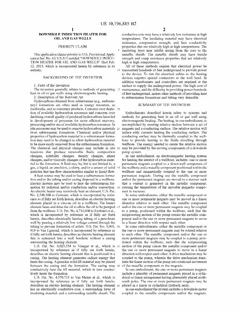
DOWNHOLE INDUCTION HEATER FOR conductive core may have a relatively low resistance at high OIL AND GAS WELLS temperatures . The insulating material may have electrical
resistance , compressive strength , and heat conductivity PRIORITY CLAIM properties that are relatively high at high temperatures . The
5 insulating layer may inhibit arcing from the core to the This application claims priority to U . S . Provisional Appli - metallic sheath . The metallic sheath may have tensile
cation Ser . No . 62 / 115 , 513 entitled “ DOWNHOLE INDUC strength and creep resistance properties that are relatively TION HEATER FOR OIL AND GAS WELLS ” filed Feb . high at high temperatures . 12 , 2015 , which is incorporated herein by reference in its All of these methods require that electrical power be entirety . 10 transmitted hundreds of feet underground to provide power
to the device . To run the electrical cables to the heating BACKGROUND OF THE INVENTION devices requires special connectors at the well head . In
addition transformers and controllers are required at the 1 . Field of the Invention surface to supply the underground power . The high cost of The invention generally relates to methods of generating 15 maintenance , and the difficulty in providing power hundreds
heat in oil or gas wells using electromagnetic heating . of feet underground , makes other methods of providing heat 2 . Description of the Relevant Art to subterranean formations and tubing very desirable . Hydrocarbons obtained from subterranean ( e . g . , sedimen
tary ) formations are often used as energy resources , as SUMMARY OF THE INVENTION feedstocks , and as consumer products . Concerns over deple - 20 tion of available hydrocarbon resources and concerns over Embodiments described herein relate to systems and declining overall quality of produced hydrocarbons have led methods for generating heat in an oil or gas well using to development of processes for more efficient recovery , electromagnetic heating . The heating , in one embodiment , is processing and / or use of available hydrocarbon resources . In accomplished by creating relative motion between a set of situ processes may be used to remove hydrocarbon materials 25 magnets and a conducting surface . The relative motion will from subterranean formations . Chemical and / or physical induce eddy currents heating the conducting surface . The properties of hydrocarbon material in a subterranean forma conducting surface may be thermally coupled to the well tion may need to be changed to allow hydrocarbon material bore to provide heating to the fluids travelling through to be more easily removed from the subterranean formation . wellbore . The energy needed to create the relative motion The chemical and physical changes may include in situ 30 may be provided by the moving components of a downhole reactions that produce removable fluids , composition pump system . changes , solubility changes , density changes , phase In one embodiment , an electromagnetic heating system changes , and / or viscosity changes of the hydrocarbon mate - for heating the interior of a wellbore , includes : one or more rial in the formation . A fluid may be , but is not limited to , a permanent magnets coupled to a down - well component of gas , a liquid , an emulsion , a slurry , and / or a stream of solid 35 the wellbore and a metallic component positioned within the particles that has flow characteristics similar to liquid flow . wellbore and magnetically coupled to the one or more
A heat source may be used to heat a subterranean forma permanent magnets . During use the metallic component tion and / or the tubing and / or casing disposed in a wellbore . and / or the permanent magnets are moved in a manner such Electric heaters may be used to heat the subterranean for that a current is generated in the metallic component , mation by radiation and / or conduction and / or convection . 40 causing the temperature of the movable magnetic compo An electric heater may resistively heat an element . U . S . Pat . nent to increase . No . 2 , 548 , 360 to Germain , which is incorporated by refer - In some embodiments , either the metallic component or ence as if fully set forth herein , describes an electric heating one or more permanent magnets may be moved in a linear element placed in a viscous oil in a wellbore . The heater direction relative to each other . The metallic component element heats and thins the oil to allow the oil to be pumped 45 and / or the one or more permanent magnets may be coupled from the wellbore . U . S . Pat . No . 4 , 716 , 960 to Eastlund et al . , to a pump , positioned within the wellbore , such that the which is incorporated by reference as if fully set forth reciprocating motion of the pump causes the metallic com herein , describes electrically heating tubing of a petroleum ponent and / or the one or more permanent magnets to move well by passing a relatively low voltage current through the in a linear direction with respect each other . tubing to prevent formation of solids . U . S . Pat . No . 5 , 065 , 50 In some embodiments , either the metallic component or 818 to Van Egmond , which is incorporated by reference as the one or more permanent magnets may be rotated relative if fully set forth herein , describes an electric heating element to each other . The metallic component and / or the one or that is cemented into a well borehole without a casing more permanent magnets may be coupled to a pump , posi surrounding the heating element . tioned within the wellbore , such that the reciprocating
U . S . Pat . No . 6 , 023 , 554 to Vinegar et al . , which is 55 motion of the pump causes the metallic component and / or incorporated by reference as if fully set forth herein , the one or more permanent magnets to move in a linear describes an electric heating element that is positioned in a direction with respect each other . A drive mechanism may be casing . The heating element generates radiant energy that coupled to the pump , wherein the drive mechanism trans heats the casing . A granular solid fill material may be placed lates the linear motion of the pump into rotational movement between the casing and the formation . The casing may 60 of the metallic component or the magnets . conductively heat the fill material , which in turn conduc - In one embodiment , the one or more permanent magnets tively heats the formation . include a plurality of permanent magnets placed in a cylin
U . S . Pat . No . 4 , 570 , 715 to Van Meurs et al . , which is drical or linear arrangement having alternately placed north incorporated by reference as if fully set forth herein , south poles . The one or more permanent magnets may be describes an electric heating element . The heating element 65 placed in a linear or cylindrical Halbach array . has an electrically conductive core , a surrounding layer of In one embodiment the system includes a downhole motor insulating material , and a surrounding metallic sheath . The coupled to the metallic components and / or the magnets ,
US 10 , 196 , 885 B2
wherein the downhole motor moves the metallic component thereof are shown by way of example in the drawings and and / or the permanent magnets in a manner such that a will herein be described in detail . The drawings may not be current is generated in the metallic component . to scale . It should be understood , however , that the drawings
In another embodiment , a drive mechanism is coupled to and detailed description thereto are not intended to limit the the metallic component and / or the permanent magnets , 5 invention to the particular form disclosed , but to the con wherein the drive mechanism utilizes fluid pressures within trary , the intention is to cover all modifications , equivalents , the wellbore to move the metallic component and / or the and alternatives falling within the spirit and scope of the permanent magnets in a manner such that a current is present invention as defined by the appended claims . generated in the metallic component .
In another embodiment , a drive mechanism coupled to the 10 DETAILED DESCRIPTION OF THE metallic component and / or the permanent magnets , wherein PREFERRED EMBODIMENTS the drive mechanism utilizes fluid velocities within the wellbore to move the metallic component and / or the per It is to be understood the present invention is not limited manent magnets in a manner such that a current is generated to particular devices or methods , which may , of course , vary . in the metallic component . It is also to be understood that the terminology used herein In one embodiment , the one or more permanent magnets is for the purpose of describing particular embodiments only , are coupled to a tubing string of a downhole pump . In and is not intended to be limiting . As used in this specifi another embodiment , the one or more permanent magnets are magnetically coupled to a casing of a wellbore . cation and the appended claims , the singular forms “ a ” ,
In an embodiment , a method of heating components 20 an ts 20 " an ” , and “ the ” include singular and plural referents unless within a wellbore comprises : placing an electromagnetic the content clearly dictates otherwise . Furthermore , the word heating system as described above into a wellbore and “ may ” is used throughout this application in a permissive moving the metallic component and / or the permanent mag - sense ( i . e . , having the potential to , being able to ) , not in a nets in a manner such that a current is generated in the mandatory sense ( i . e . , must ) . The term “ include , " and deri metallic component . 25 vations thereof , mean “ including , but not limited to . ” The
term “ coupled ” means directly or indirectly connected . BRIEF DESCRIPTION OF THE DRAWINGS The following description generally relates to systems and
methods for extracting hydrocarbons from subterranean Advantages of the present invention will become apparent formations .
to those skilled in the art with the benefit of the following 30 " Hydrocarbons ” are generally defined as molecules detailed description of embodiments and upon reference to formed primarily by carbon and hydrogen atoms . Hydro the accompanying drawings in which : carbons may also include other elements such as , but not
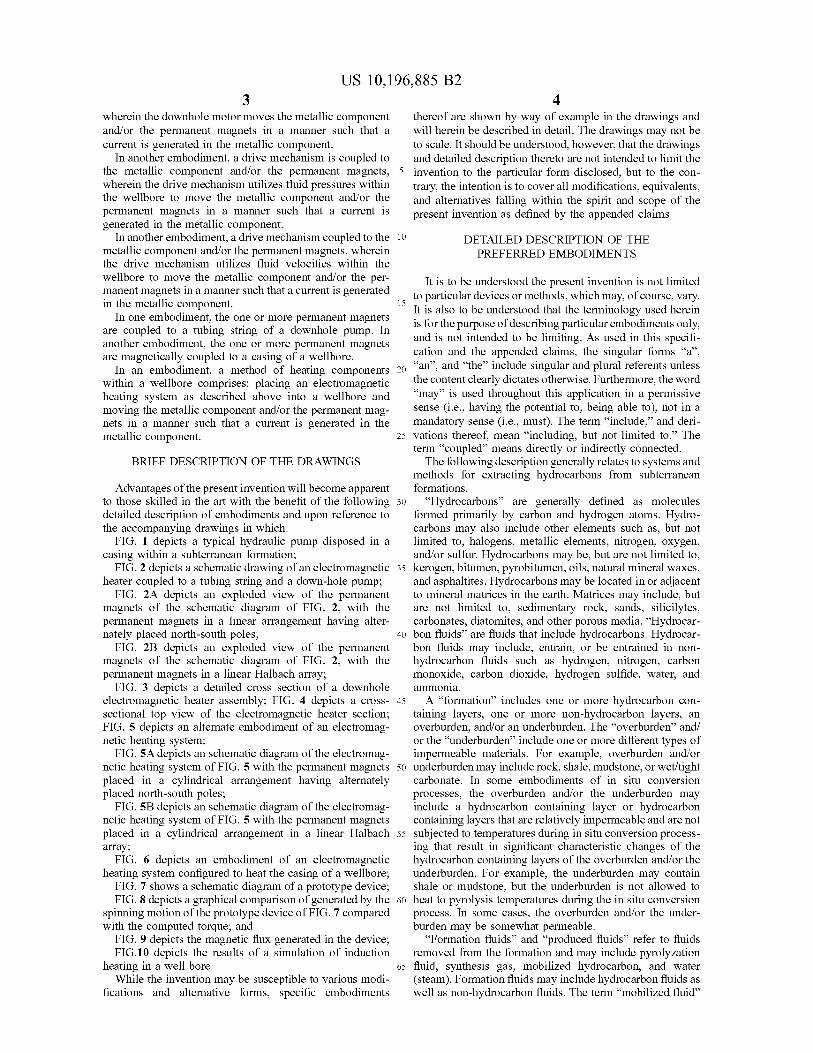
FIG . 1 depicts a typical hydraulic pump disposed in a limited to , halogens , metallic elements , nitrogen , oxygen , casing within a subterranean formation ; and / or sulfur . Hydrocarbons may be , but are not limited to ,
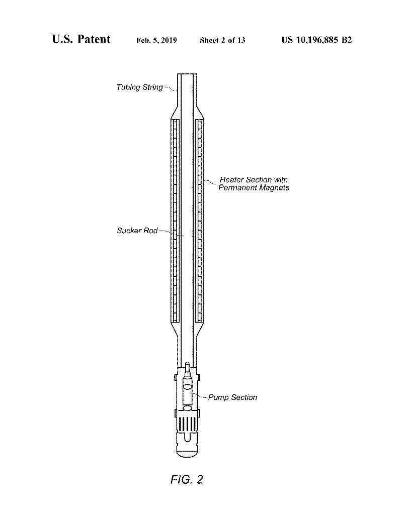
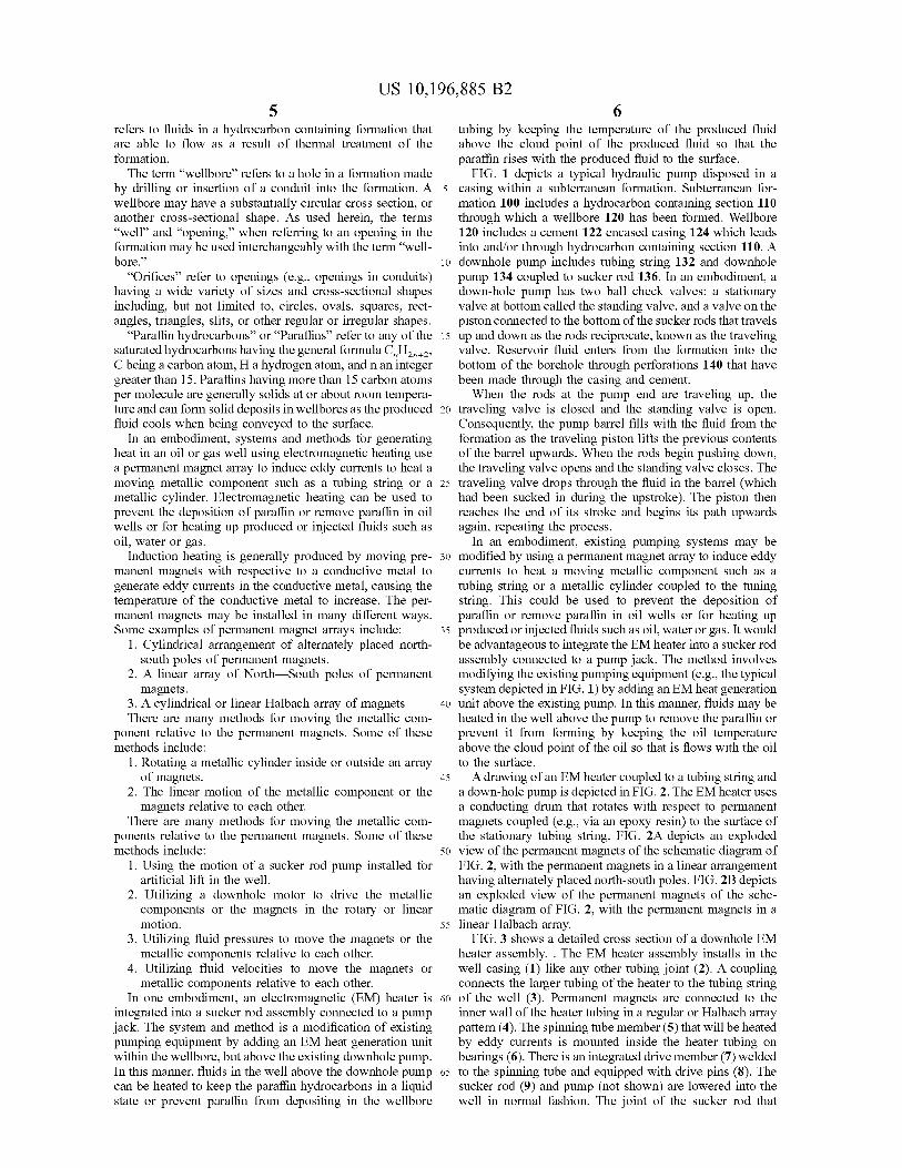
FIG . 2 depicts a schematic drawing of an electromagnetic 35 kerogen , bitumen , pyrobitumen , oils , natural mineral waxes , heater coupled to a tubing string and a down - hole pump ; and asphaltites . Hydrocarbons may be located in or adjacent
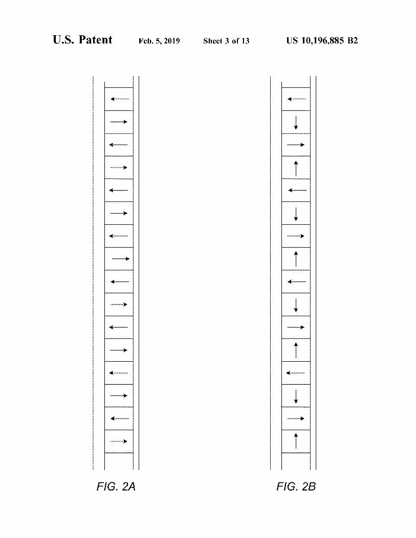
FIG . 2A depicts an exploded view of the permanent to mineral matrices in the earth . Matrices may include , but magnets of the schematic diagram of FIG . 2 , with the are not limited to , sedimentary rock , sands , silicilytes , permanent magnets in a linear arrangement having alter - carbonates , diatomites , and other porous media . “ Hydrocar nately placed north - south poles ; 40 bon fluids ” are fluids that include hydrocarbons . Hydrocar
FIG . 2B depicts an exploded view of the permanent bon fluids may include , entrain , or be entrained in non magnets of the schematic diagram of FIG . 2 , with the hydrocarbon fluids such as hydrogen , nitrogen , carbon permanent magnets in a linear Halbach array ; monoxide , carbon dioxide , hydrogen sulfide , water , and
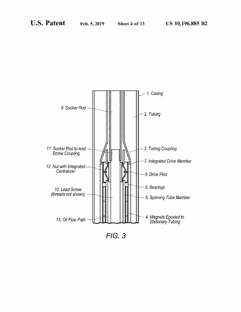
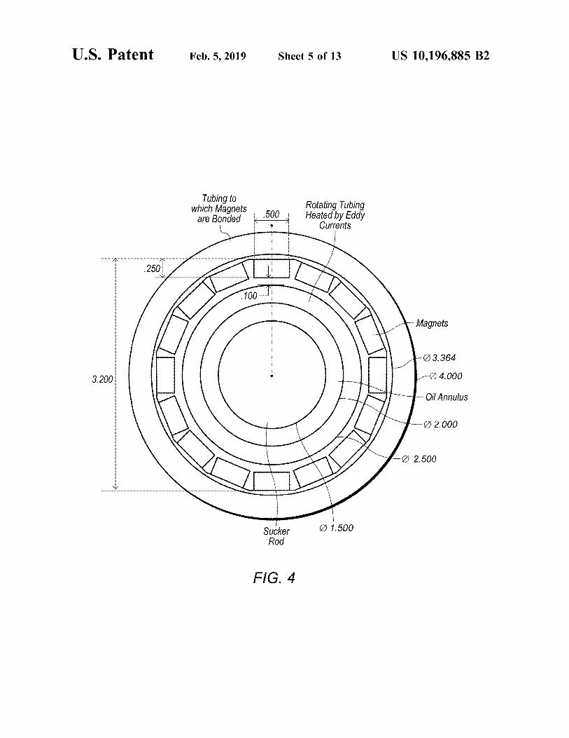
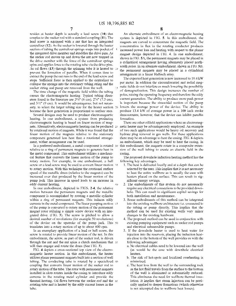
FIG . 3 depicts a detailed cross section of a downhole ammonia . electromagnetic heater assembly ; FIG . 4 depicts a cross - 45 A " formation ” includes one or more hydrocarbon con sectional top view of the electromagnetic heater section ; taining layers , one or more non - hydrocarbon layers , an FIG . 5 depicts an alternate embodiment of an electromag - overburden , and / or an underburden . The " overburden ” and / netic heating system ; or the “ underburden ” include one or more different types of
FIG . 5A depicts an schematic diagram of the electromag - impermeable materials . For example , overburden and / or netic heating system of FIG . 5 with the permanent magnets 50 underburden may include rock , shale , mudstone , or wet / tight placed in a cylindrical arrangement having alternately c arbonate . In some embodiments of in situ conversion placed north - south poles ; processes , the overburden and / or the underburden may
FIG . 5B depicts an schematic diagram of the electromag - include a hydrocarbon containing layer or hydrocarbon netic heating system of FIG . 5 with the permanent magnets containing layers that are relatively impermeable and are not placed in a cylindrical arrangement in a linear Halbach 55 subjected to temperatures during in situ conversion process array ; ing that result in significant characteristic changes of the
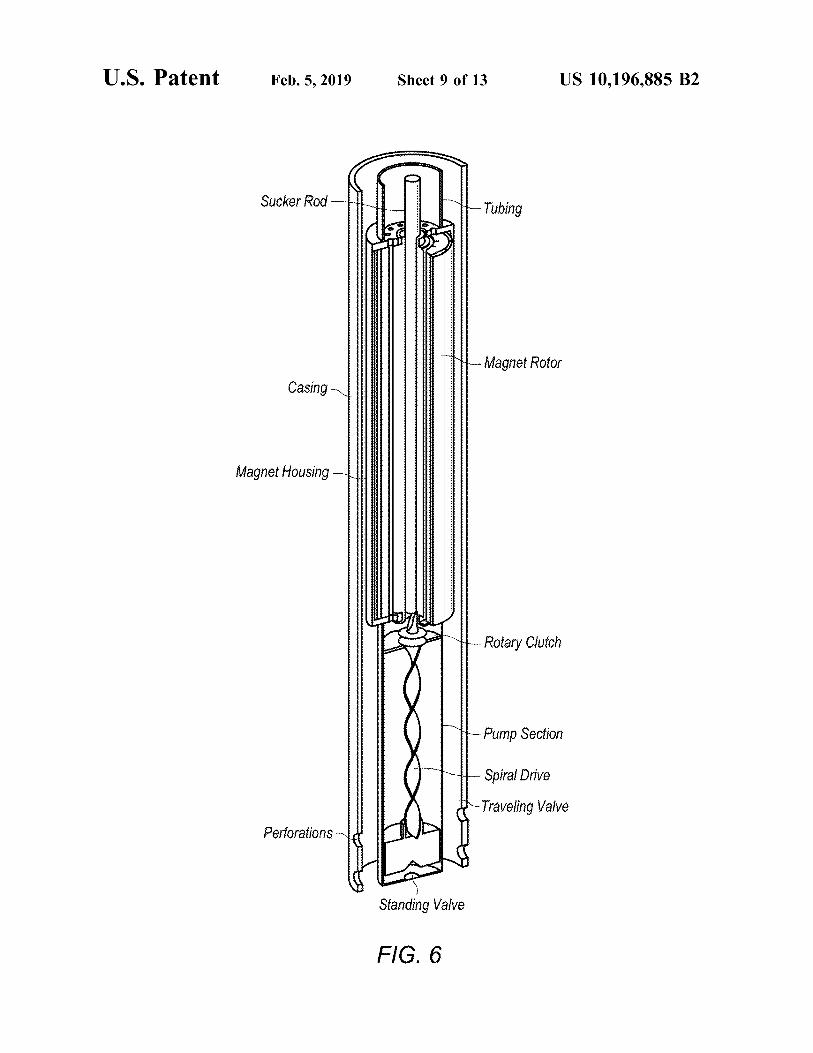
FIG . 6 depicts an embodiment of an electromagnetic hydrocarbon containing layers of the overburden and / or the heating system configured to heat the casing of a wellbore ; underburden . For example , the underburden may contain
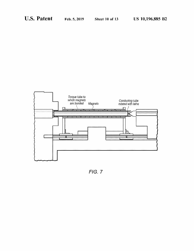
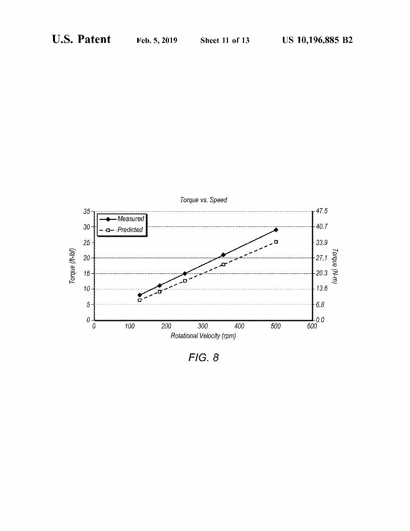
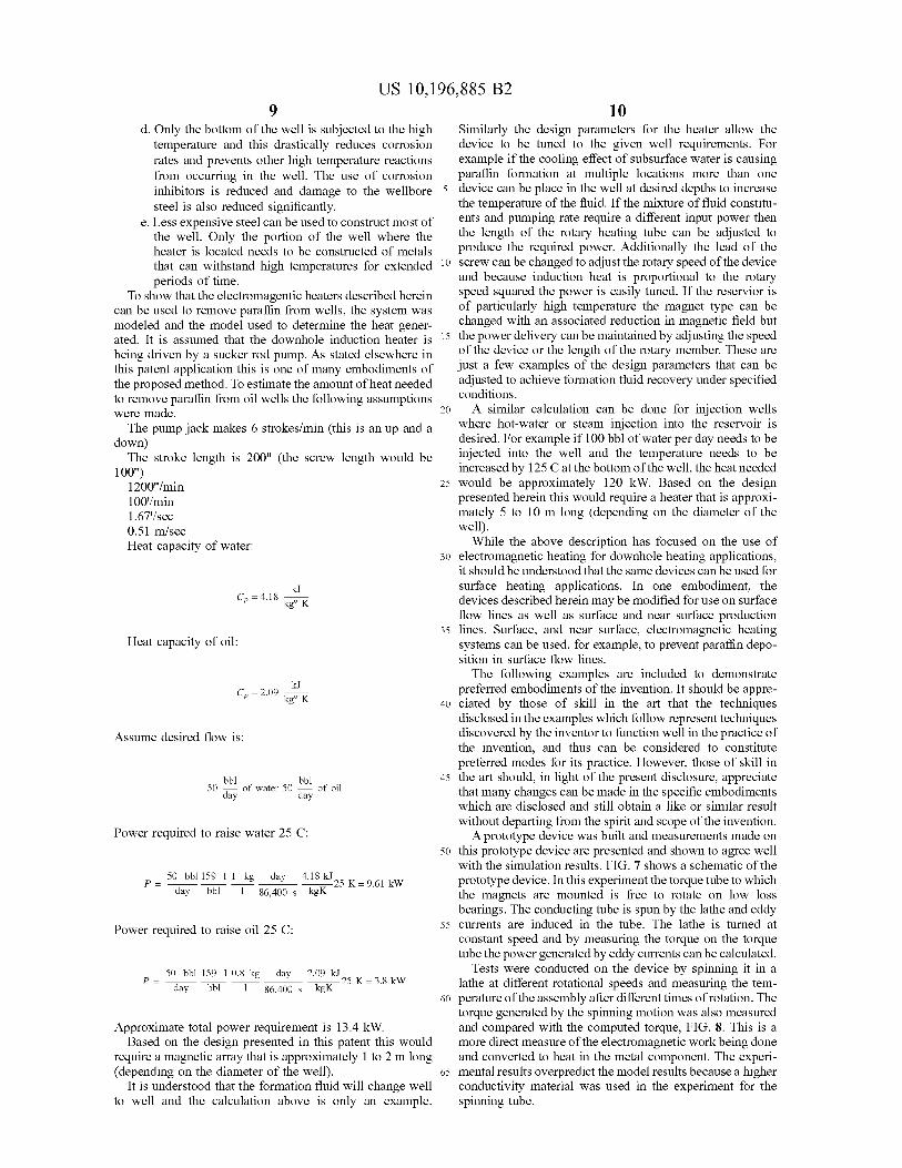
FIG . 7 shows a schematic diagram of a prototype device ; shale or mudstone , but the underburden is not allowed to FIG . 8 depicts a graphical comparison of generated by the 60 heat to pyrolysis temperatures during the in situ conversion
spinning motion of the prototype device of FIG . 7 compared process . In some cases , the overburden and / or the under with the computed torque ; and burden may be somewhat permeable .
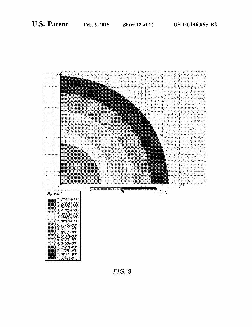
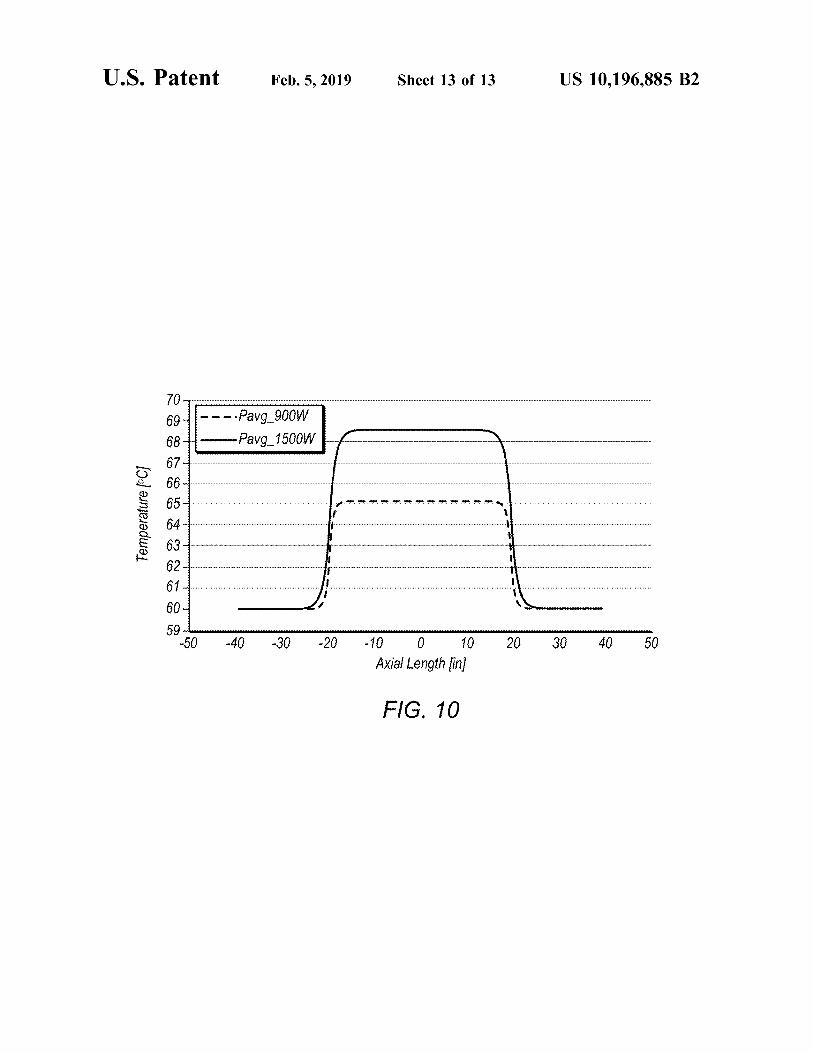
FIG . 9 depicts the magnetic flux generated in the device ; “ Formation fluids ” and “ produced fluids ” refer to fluids FIG . 10 depicts the results of a simulation of induction removed from the formation and may include pyrolyzation
heating in a well bore . 65 fluid , synthesis gas , mobilized hydrocarbon , and water While the invention may be susceptible to various modi - ( steam ) . Formation fluids may include hydrocarbon fluids as
fications and alternative forms , specific embodiments well as non - hydrocarbon fluids . The term “ mobilized fluid ”
US 10 , 196 , 885 B2
refers to fluids in a hydrocarbon containing formation that tubing by keeping the temperature of the produced fluid are able to flow as a result of thermal treatment of the above the cloud point of the produced fluid so that the formation . paraffin rises with the produced fluid to the surface .
The term “ wellbore ” refers to a hole in a formation made FIG . 1 depicts a typical hydraulic pump disposed in a by drilling or insertion of a conduit into the formation . A 5 casing within a subterranean formation . Subterranean for wellbore may have a substantially circular cross section , or m ation 100 includes a hydrocarbon containing section 110 another cross - sectional shape . As used herein , the terms through which a wellbore 120 has been formed . Wellbore “ well ” and “ opening , " when referring to an opening in the 120 includes a cement 122 encased casing 124 which leads formation may be used interchangeably with the term “ well - into and / or through hydrocarbon containing section 110 . A bore . ” 10 downhole pump includes tubing string 132 and downhole
" Orifices ” refer to openings ( e . g . , openings in conduits ) pump 134 coupled to sucker rod 136 . In an embodiment , a having a wide variety of sizes and cross - sectional shapes down - hole pump has two ball check valves : a stationary including , but not limited to , circles , ovals , squares , rect - valve at bottom called the standing valve , and a valve on the angles , triangles , slits , or other regular or irregular shapes . piston connected to the bottom of the sucker rods that travels
“ Paraffin hydrocarbons ” or “ Paraffins ” refer to any of the 15 up and down as the rods reciprocate , known as the traveling saturated hydrocarbons having the general formula C , H n , valve . Reservoir fluid enters from the formation into the C being a carbon atom , H a hydrogen atom , and n an integer bottom of the borehole through perforations 140 that have greater than 15 . Paraffins having more than 15 carbon atoms been made through the casing and cement . per molecule are generally solids at or about room tempera When the rods at the pump end are traveling up , the ture and can form solid deposits in wellbores as the produced 20 traveling valve is closed and the standing valve is open . fluid cools when being conveyed to the surface . Consequently , the pump barrel fills with the fluid from the
In an embodiment , systems and methods for generating formation as the traveling piston lifts the previous contents heat in an oil or gas well using electromagnetic heating use of the barrel upwards . When the rods begin pushing down , a permanent magnet array to induce eddy currents to heat a the traveling valve opens and the standing valve closes . The moving metallic component such as a tubing string or a 25 traveling valve drops through the fluid in the barrel ( which metallic cylinder . Electromagnetic heating can be used to had been sucked in during the upstroke ) . The piston then prevent the deposition of paraffin or remove paraffin in oil reaches the end of its stroke and begins its path upwards wells or for heating up produced or injected fluids such as again , repeating the process . oil , water or gas . In an embodiment , existing pumping systems may be
Induction heating is generally produced by moving pre - 30 modified by using a permanent magnet array to induce eddy manent magnets with respective to a conductive metal to currents to heat a moving metallic component such as a generate eddy currents in the conductive metal , causing the tubing string or a metallic cylinder coupled to the tuning temperature of the conductive metal to increase . The per - string . This could be used to prevent the deposition of manent magnets may be installed in many different ways . paraffin or remove paraffin in oil wells or for heating up Some examples of permanent magnet arrays include : 35 produced or injected fluids such as oil , water or gas . It would
1 . Cylindrical arrangement of alternately placed north - be advantageous to integrate the EM heater into a sucker rod south poles of permanent magnets . assembly connected to a pump jack . The method involves
2 . A linear array of North - South poles of permanent modifying the existing pumping equipment ( e . g . , the typical magnets . system depicted in FIG . 1 ) by adding an EM heat generation
3 . A cylindrical or linear Halbach array of magnets 40 unit above the existing pump . In this manner , fluids may be There are many methods for moving the metallic com - heated in the well above the pump to remove the paraffin or
ponent relative to the permanent magnets . Some of these prevent it from forming by keeping the oil temperature methods include : above the cloud point of the oil so that is flows with the oil
1 . Rotating a metallic cylinder inside or outside an array to the surface . of magnets . 45 A drawing of an EM heater coupled to a tubing string and
2 . The linear motion of the metallic component or the a down - hole pump is depicted in FIG . 2 . The EM heater uses magnets relative to each other . a conducting drum that rotates with respect to permanent
There are many methods for moving the metallic com - magnets coupled ( e . g . , via an epoxy resin ) to the surface of ponents relative to the permanent magnets . Some of these the stationary tubing string . FIG . 2A depicts an exploded methods include : 50 view of the permanent magnets of the schematic diagram of
1 . Using the motion of a sucker rod pump installed for FIG . 2 , with the permanent magnets in a linear arrangement artificial lift in the well . having alternately placed north - south poles . FIG . 2B depicts
2 . Utilizing a downhole motor to drive the metallic an exploded view of the permanent magnets of the sche components or the magnets in the rotary or linear matic diagram of FIG . 2 , with the permanent magnets in a motion . 55 linear Halbach array .
FIG . 3 shows a detailed cross section of a downhole EM metallic components relative to each other . heater assembly . . The EM heater assembly installs in the
4 . Utilizing fluid velocities to move the magnets or w ell casing ( 1 ) like any other tubing joint ( 2 ) . A coupling metallic components relative to each other . connects the larger tubing of the heater to the tubing string
In one embodiment , an electromagnetic ( EM ) heater is 60 of the well ( 3 ) . Permanent magnets are connected to the integrated into a sucker rod assembly connected to a pump inner wall of the heater tubing in a regular or Halbach array jack . The system and method is a modification of existing pattern ( 4 ) . The spinning tube member ( 5 ) that will be heated pumping equipment by adding an EM heat generation unit by eddy currents is mounted inside the heater tubing on within the wellbore , but above the existing downhole pump . bearings ( 6 ) . There is an integrated drive member ( 7 ) welded In this manner , fluids in the well above the downhole pump 65 to the spinning tube and equipped with drive pins ( 8 ) . The can be heated to keep the paraffin hydrocarbons in a liquid sucker rod ( 9 ) and pump ( not shown ) are lowered into the state or prevent paraffin from depositing in the wellbore well in normal fashion . The joint of the sucker rod that
essu Ston
US 10 , 196 , 885 B2
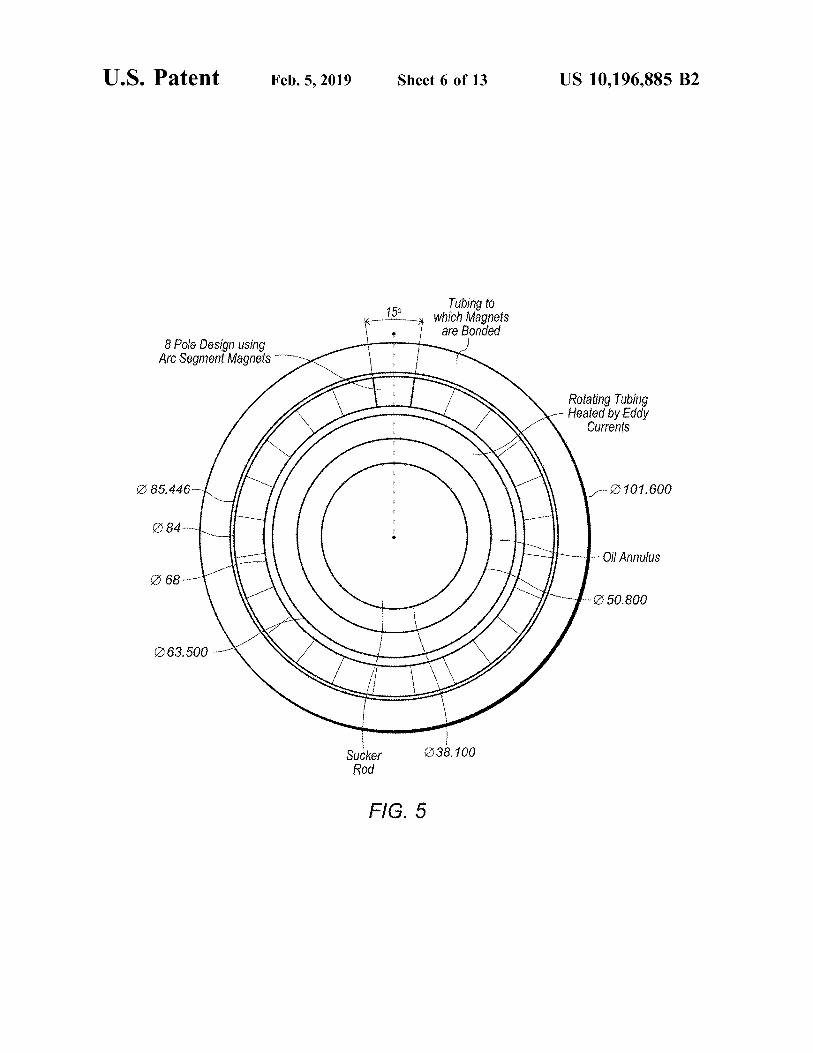
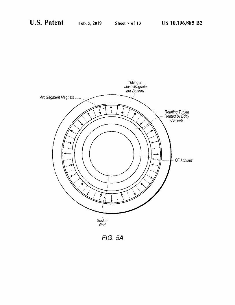
resides at heater depth is actually a lead screw ( 10 ) that An alternate embodiment of an electromagnetic heating couples to the sucker rod with a standard coupling ( 11 ) . The system is depicted in FIG . 5 . In this embodiment , the lead screw is equipped with a nut that has an integrated magnets are curved to concentrate the magnetic field . The centralizer ( 12 ) . As the sucker is lowered through the heater concentration in flux in the rotating conductor produces section of tubing the centralizer springs snaps into pocket of 5 increased power loss and heating with respect to the planar the integrated drive member and straddles the drive pins . As magnet design depicted in FIG . 4 . In one embodiment , the sucker rod moves up and down the nut now trapped in shown in FIG . 5A , the permanent magnets may be placed in the drive member with the force of the centralizer springs a cylindrical arrangement having alternately placed north spins and applies force to the rotating tube via the drive pins . south poles . In an alternate embodiment , shown in FIG . 5B , As oil flows ( 13 ) through the spinning tube it is heated to 10 the permanent magnets may be placed in a cylindrical prevent the formation of paraffin . When it comes time to arrangement in a linear Halbach array . extract the pump the nut runs to the end of the lead screw and stops . Sufficient force is then applied to the centralizer to The expected heat generation is now increased to 10 . 4 kW collapse the springs into the stationary tubing string and the per meter . In addition the circumferential and radial mag sucker string and pump are removed from the well . 15 netic fields do not interfere as much lowering the possibility
The time change of the magnetic field within the tubing of demagnetization . This design increases the number of causes the electromagnetic heating . Typical tubing diam - poles , raising the operating frequency and therefore the eddy eters found in the literature are 23 / 8 " ( 6 cm ) , 27 / 8 " ( 7 . 5 cm ) , current generation . The ability to produce more peak power and 31 / 2 " ( 9 cm ) . It would be advantageous , but not neces - is important because the sinusoidal motion of the pump sary , to select the larger tubing size for the heater section 20 lowers the average power of the device . The ability to because the heat generation is proportional to surface area . produce 13 . 4 kW of average power in a 100 inch stroke
Several designs may be used to produce electromagnetic demonstrates , however , that the device can inhibit paraffin heating . In one embodiment , a system from producing formation . electromagnetic heating is based on linear motion of mag There are other oilfield applications where an electromag nets . Alternatively , electromagnetic heating can be produced 25 netic heater may be advantageously employed . An example by rotational motion of magnets . While it was found that the of two such applications would be heavy oil recovery and linear motion of the magnets relative to the stationary hydrate plug removal in gas wells . For these applications component generated less heat than a rotational arrange there may be an advantage to heat the casing . FIG . 6 depicts ment , wither arrangement can be used . an embodiment , which may be used to heat the casing . In
In a preferred embodiment , a metal component is rotated 30 this embodiment , the magnets rotate in a composite exten relative to a ring of permanent magnets to generate heat in sion of the well tubing to create an electric field in the the metal component . This embodiment utilizes a mechani - casing . cal feature that converts the linear motion of the pump to The proposed downhole induction heating method has the rotary motion . For example , in one embodiment , a ball following key advantages . screw or a lead screw may be used to convert linear motion 35 1 . The heat is delivered locally and at a depth that can be to rotary motion . With this technique the rotational surface selected by the user . This implies that it is not necessary speed of the metallic drum ( relative to the magnets ) can be to heat the entire wellbore as is usually the case with increased over that produced by the linear motion of the heaters placed on the surface . This can result in sig pump jack . This increase in speed leads to an increase in nificant energy savings . eddy current heating . 40 2 . The embodiments of this system do not necessarily
In one embodiment , depicted in FIGS . 2 - 4 , the relative require any electrical connections to be provided down motion between the permanent magnets and the metallic hole . This can result in significant capital savings for component is accomplished by rotating a metallic cylinder both installation and maintenance . within a ring of permanent magnets . This induces eddy 3 . Some embodiments of this method can be integrated currents in the metal component . The linear pumping motion 45 into the existing wellbore architecture i . e . connected to of the pump is converted to rotary motion of the permanent the tubing or pump directly . This implies that the magnet rotor utilizing a simple screw device with an inte method can be used for existing wells very minor grated drive . ( FIG . 3 ) . The screw is pitched to allow a changes to the existing hardware . desired number of revolutions ( for example 50 revolutions ) 4 . The proposed method can be used in conjunction with of the device on the upstroke of the pump jack . This 50 existing pumping equipment such as sucker rod pumps translates into a rotary motion of up to about 600 rpm . and electrical submersible pumps .
In an exemplary application of a lead or ball screw , the 5 . If the downhole heater is used to heat water for screw is rotated to provide linear motion of the nut . In this injection into the reservoir , placing the induction heat embodiment , the screw , as part of the sucker rod , is driven ers close to the bottom of the well provides us with the through the nut and the nut spins a clutch mechanism that 55 following advantages : will then engage and rotate the drum ( See FIG . 3 ) . a . No electrical cables need to be lowered into the well
FIG . 4 depicts a cross - sectional top view of the electro ( as would be the case with downhole electrical magnetic heater section . In this embodiment , the heater heaters . utilizes planar permanent magnets built into a section of well b . The risk of hot - spots and localized overheating is tubing . The conducting tube is rotated by a specialized 60 minimized . coupling that converts linear motion of the sucker rod to c . The heat loss from the well to the surrounding rock rotary motion of the tube . The rotor with permanent magnets as the hot fluid travels from the surface to the bottom installed in slots rotates inside the casing to introduce eddy of the well is eliminated or substantially reduced . currents in the rotating metal cylinder and provide the This eliminates the need for wellbore thermal insu thermal heating . Oil flows between the sucker rod and the 65 lation . It implies that steam injection can be prati rotating tube and is heated by the eddy current losses in the cally applied to deeper formations ( which otherwise tube . is not attempted due to wellbore heat losses ) .
US 10 , 196 , 885 B2 10
d . Only the bottom of the well is subjected to the high Similarly the design parameters for the heater allow the temperature and this drastically reduces corrosion device to be tuned to the given well requirements . For rates and prevents other high temperature reactions example if the cooling effect of subsurface water is causing from occurring in the well . The use of corrosion paraffin formation at multiple locations more than one inhibitors is reduced and damage to the wellbore 5 device can be place in the well at desired depths to increase steel is also reduced significantly . the temperature of the fluid . If the mixture of fluid constitu
e . Less expensive steel can be used to construct most of ents and pumping rate require a different input power then the well . Only the portion of the well where the the length of the rotary heating tube can be adjusted to heater is located needs to be constructed of metals produce the required power . Additionally the lead of the that can withstand high temperatures for extended 10 screw can be changed to adjust the rotary speed of the device periods of time . and because induction heat is proportional to the rotary
To show that the electromagentic heaters described herein speed squared the power is easily tuned . If the reservior is can be used to remove paraffin from wells , the system was of particularly high temperature the magnet type can be modeled and the model used to determine the heat gener changed with an associated reduction in magnetic field but ated . It is assumed that the downhole induction heater is 15 the power delivery can be maintained by adjusting the speed being driven by a sucker rod pump . As stated elsewhere in of the device or the length of the rotary member . These are this patent application this is one of many embodiments of just a few examples of the design parameters that can be the proposed method . To estimate the amount of heat needed adjusted to achieve formation fluid recovery under specified to remove paraffin from oil wells the following assumptions conditions . were made . 20 A similar calculation can be done for injection wells
The pump jack makes 6 strokes / min ( this is an up and a where hot - water or steam injection into the reservoir is down ) desired . For example if 100 bbl of water per day needs to be
The stroke length is 200 " ( the screw length would be injected into the well and the temperature needs to be 100 " ) increased by 125 C at the bottom of the well , the heat needed
1200 " / min would be approximately 120 kW . Based on the design 100 / min presented herein this would require a heater that is approxi 1 . 67 ' / sec mately 5 to 10 m long ( depending on the diameter of the 0 . 51 m / sec well ) . Heat capacity of water : While the above description has focused on the use of
30 electromagnetic heating for downhole heating applications , it should be understood that the same devices can be used for surface heating applications . In one embodiment , the
Cp = 4 . 18 – devices described herein may be modified for use on surface flow lines as well as surface and near surface production lines . Surface , and near surface , electromagnetic heating
Heat capacity of oil : systems can be used , for example , to prevent paraffin depo sition in surface flow lines .
The following examples are included to demonstrate preferred embodiments of the invention . It should be appre
40 ciated by those of skill in the art that the techniques disclosed in the examples which follow represent techniques
Assume desired flow is : discovered by the inventor to function well in the practice of the invention , and thus can be considered to constitute preferred modes for its practice . However , those of skill in
bbl bbl 45 the art should , in light of the present disclosure , appreciate 50 Jos of water 50 00 that many changes can be made in the specific embodiments
which are disclosed and still obtain a like or similar result without departing from the spirit and scope of the invention .
Power required to raise water 25 C : A prototype device was built and measurements made on 50 this prototype device are presented and shown to agree well
with the simulation results . FIG . 7 shows a schematic of the 50 bbl 159 11 kg day 4 . 18 kJ . 25 K = 9 . 61 kW prototype device . In this experiment the torque tube to which day bbl 1 86 , 400 s kgK the magnets are mounted is free to rotate on low loss
bearings . The conducting tube is spun by the lathe and eddy currents are induced in the tube . The lathe is turned at Power required to raise oil 25 C : constant speed and by measuring the torque on the torque tube the power generated by eddy currents can be calculated .
50 bbl 159 10 . 8 kg day 2 . 09 kJ Tests were conducted on the device by spinning it in a — 25 K = 3 . 8 kW day bbl 1 86 , 400 s kgK lathe at different rotational speeds and measuring the tem
60 perature of the assembly after different times of rotation . The torque generated by the spinning motion was also measured
Approximate total power requirement is 13 . 4 kW . and compared with the computed torque , FIG . 8 . This is a Based on the design presented in this patent this would more direct measure of the electromagnetic work being done
require a magnetic array that is approximately 1 to 2 m long and converted to heat in the metal component . The experi ( depending on the diameter of the well ) . 65 mental results overpredict the model results because a higher
It is understood that the formation fluid will change well conductivity material was used in the experiment for the to well and the calculation above is only an example . spinning tube .
kJ kgº K
kJ C , = 2 . 09 kgº K p = 200
day of oil
P = -
P =

US 10 , 196 , 885 B2 11 12
To estimate the heat generated by the proposed induction magnets generates a current in the metallic component , heater , simulation models were built to compute the extent causing the temperature of the wellbore and the fluids of heating that may be expected with different configurations therein to increase . of permanent magnets and metal components moving rela - 2 . The system of claim 1 , wherein the one or more tive to the magnets . An electromagnetic simulator was used 5 permanent magnets comprises a plurality of permanent to numerically simulate the heat generated by the preferred magnets placed in a cylindrical arrangement having alter embodiment . The results of this simulation are depicted in nately placed north - south poles . FIG . 9 . In addition to the electromechanical modeling , a 3 . The system of claim 1 , wherein the one or more thermal model was built to estimate the temperature increase permanent magnets comprises a plurality of permanent caused by the induction heater . Both these models were run " magnets placed in a Halbach array . for different configuration of magnets and the moving metal - 4 . The system of claim 1 , wherein the one or more lic component as well as fluid velocities in the annulus . permanent magnets comprises a plurality of permanent Of importance is the ability of the spinning heated tube to magnets placed in a linear arrangement having alternately
heat the oil . Under steady state conditions the rise in 15 placed north - south poles . temperature of the surface of the heater tube with a mixture 5 . The system of claim 1 , wherein the one or more of 50 bbl / day of oil and 50 bbl / day of brine flowing over the permanent magnets are coupled to a tubing string of a tube surface is shown in FIG . 10 . The heater may be placed downhole pump . in the tubing string at different locations to boost the 6 . The system of claim 1 , the one or more permanent temperature of the pumped fluid to keep it above the cloud 20 magnets are magnetically coupled to a casing of a wellbore . point of paraffin . 7 . The system of claim 1 , wherein the drive mechanism
comprises a ball screw assembly . 8 . The system of claim 1 , wherein the drive mechanism
comprises a ball screw assembly . In this patent , certain U . S . patents , U . S . patent applica - 25 9 . The system of claim 1 , wherein the drive mechanism
tions , and other materials ( e . g . , articles ) have been incorpo cles ) have been incorpo - translates the reciprocating movement of rods connected to rated by reference . The text of such U . S . patents , U . S . patent the pump into rotational movement of the metallic compo applications , and other materials is , however , only incorpo nent . rated by reference to the extent that no conflict exists 10 . A method of heating components and fluids within a between such text and the other statements and drawings set 30 wellbore comprising : forth herein . In the event of such conflict , then any such placing a pump comprising an electromagnetic heating conflicting text in such incorporated by reference U . S . system into a wellbore ; wherein the electromagnetic patents , U . S . patent applications , and other materials is heating system comprises : specifically not incorporated by reference in this patent . one or more permanent magnets coupled to a down
Further modifications and alternative embodiments of 35 well component of the wellbore ; various aspects of the invention will be apparent to those a metallic component positioned within the wellbore skilled in the art in view of this description . Accordingly , this and magnetically coupled to the one or more perma description is to be construed as illustrative only and is for nent magnets , wherein the metallic component is the purpose of teaching those skilled in the art the general coupled to the pump ; and manner of carrying out the invention . It is to be understood 40 a drive mechanism coupled to the pump , wherein the that the forms of the invention shown and described herein drive mechanism translates the reciprocating motion are to be taken as examples of embodiments . Elements and of the pump into rotational movement of the metallic materials may be substituted for those illustrated and component such that the metallic component rotates described herein , parts and processes may be reversed , and with respect to the one or more permanent magnets ; certain features of the invention may be utilized indepen - 45 reciprocating the pump within the wellbore , wherein the dently , all as would be apparent to one skilled in the art after drive mechanism translates the reciprocating motion of having the benefit of this description of the invention . the pump into rotational movement of the metallic Changes may be made in the elements described herein component such that the metallic component rotates without departing from the spirit and scope of the invention with respect to the one or more permanent magnets , and as described in the following claims . 50 where rotational movement of the metallic component
with respect to the one or more permanent magnets What is claimed is : generates a current in the metallic component causing 1 . An electromagnetic heating system for heating a well the temperature of the wellbore and the fluids therein to
bore and the fluids therein , comprising : increase . one or more permanent magnets coupled to a down - well 55 11 . An electromagnetic heating system for heating a
component of the wellbore ; wellbore and the fluids therein , comprising : a metallic component positioned within the wellbore and one or more permanent magnets coupled to a coupled to magnetically coupled to the one or more permanent a pump positioned within the wellbore ; magnets , wherein the metallic component is coupled to a metallic component positioned within the wellbore and a pump positioned within the wellbore ; and 60 magnetically coupled to the one or more permanent
a drive mechanism coupled to the pump , wherein the magnets ; and drive mechanism translates the reciprocating motion of a drive mechanism coupled to the pump , wherein the the pump into rotational movement of the metallic drive mechanism translates the reciprocating motion of component such that the metallic component rotates the pump into rotational movement of the one or more with respect to the one or more permanent magnets ; 65 permanent magnets such that the one or more perma
wherein , during use , the movement of the metallic com nent magnets rotate with respect to the Metallic com ponent with respect to the one or more permanent ponent ;

14 US 10 , 196 , 885 B2
13 wherein , during use , the movement of the one or more permanent magnets with respect to the metallic com ponent generates a current in the metallic component , causing the temperature of the wellbore and the fluids therein to increase .