Embed Size (px)
Citation preview

Chapter E: Technical information
MATERIALS
MATER
IALS
E.4.1
E.4.W W W . L M C - C O U P L I N G S . C O M
1. STEEL
ALLOYED STEEL - STAINLESS STEEL
AISI 304 / 1.4301
This is the most common Cr-Ni 18/8 quality and is used widely in the food
processing and pharmaceutical industries for piping and storage units.
AISI 304 is also used to manufacture all kinds of equipment for the brewing
industry, margarine factories and abattoirs, as well as in the chemical industry
to manufacture equipment for processes involved in the production of mate-
rials such as nitric acid, nitrates, nitrate fertilizers and explosives.
AISI 304L / 1.4306
Stainless steel 1.4306 is more highly-resistant to nitric acid at high concen-
trations and temperatures than 1.4301. This alloy is used primarily in the che-
mical, food processing, pharmaceutical and other industries for reactor ves-
sels, storage tanks and other equipment. Stainless steel AISI 304L / 1.4306
is used chiefly in applications where the metal is deformed or subjected to
thermal loads over extended periods. Use of this material is particularly
recommended where temperatures of between 500°C / 932°F and
900°C/ 1652°F are likely to be encountered.
AISI 316 / 1.4401
Grade AISI 316 is the standard molybdenum-bearing grade, second only in
importance to AISI 304 amongst the austenitic stainless steels. The molybde-
num gives AISI 316 better overall corrosion-resistance properties than Grade
AISI 304, and particularly higher resistance to pitting and crevice corrosion in
chloride environments. It is readily brake-formed or roll-formed into a variety
of components for industrial, construction and transport applications.
AISI 316 offers excellent corrosion resistance in a range of atmospheric envi-
ronments and many corrosive media (generally more resistant than AISI 304).
This material is subject to pitting and crevice corrosion in warm chloride
environments, and to stress corrosion cracking above approximately
60°C/140°F. It can be considered as resistant to potable water containing a
maximum chloride content of approximately 1000mg/L at ambient tempera-
ture, reducing to around 500mg/L at 60°C.
Grade AISI 316 is usually regarded as the standard “marine grade stainless
steel”, but it is not resistant to warm sea water. In many marine environ-
ments, AISI 316 does exhibit surface corrosion, usually in the form of brown
staining, particularly in association with crevices and rough surface finishes.
MATERIALS
e-technical information 5/22/08 11:12 AM Page 33
Chapter E: Technical information
MATERIALS
E.4.2
W W W . L M C - C O U P L I N G S . C O M
14571316Ti
16,5-19,5 Cr
10,5-13,5 Ni
2-2,5 Mo
Ti
14541321
17-19 Cr
9-12 Ni
Ti
14550347
17-19 Cr
9-12 Ni
No
14449317
18-20 Cr
11-14 Ni
3-4 Mo
14401316
16,5-18,5 Cr
10,5-13,5 Ni
2-2,5 Mo
0.10 C
14301304
10 -19 Cr
8,5-10,5 Ni
0.08 C
14300302
17-19 Cr
8-10 Ni
0.15 C
14306304L
18-20 Cr
10-12,5 Ni
0.08 C
14404316L
16,5-18,5 Cr
11-14 Ni
2-2,5 Mo
Low C-gradeimproves wel-ding capacities
Addition of Niimproves wel-ding capacities
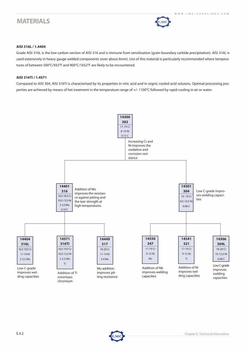
Low C-grade impro-ves welding capaci-ties
Mo additionimproves pit-ting resistance
Addition of Mo improves the resistan-ce against pitting andthe tear strength athigh temperatures
Increasing Cr andNi improves theoxidation andcorrosion resi-stance
Addition of Timinimizeschromium
Low C-gradeimprovesweldingcapacities
Addition of Nbimproves weldingcapacities
AISI 316L / 1.4404
Grade AISI 316L is the low-carbon version of AISI 316 and is immune from sensitisation (grain boundary carbide precipitation). AISI 316L is
used extensively in heavy gauge welded components (over about 6mm). Use of this material is particularly recommended where tempera-
tures of between 500°C/932°F and 900°C/1652°F are likely to be encountered.
AISI 316Ti / 1.4571
Compared to AISI 304, AISI 316Ti is characterised by its properties in niric acid and in orgnic cooled acid soluions. Optimal processing pro-
perties are achieved by means of het treatment in the temperature range of +/- 1100°C followed by rapid cooling in air or water.
e-technical information 5/22/08 11:12 AM Page 34

Chapter E: Technical information
MATERIALS
MATER
IALS
E.4.3
E.4.W W W . L M C - C O U P L I N G S . C O M
Germany USA SWEDEN FRANCE UK ITALY SPAIN JAPAN RUSSIA
W.-Nr. AISI UNS SS AFNOR BS UNI UNE JIS GOST
1.4301 304 S 30400 2332 Z 6 CN 18.09 304 S 15 X 5 CrNi 18.10 F.3504-X 5 CrNi 18.10 SUS 304 08Ch18N10
1.4305 303 S 30300 2346 Z 10 CNF 18.09 303 S 21 - - - -
1.4306 304L S 30403 2352 Z 2 CN 18.10 304 S 12 X 3 CrNi18.11 F.3503-X 2 CrNi 18.10 SUS 304L 03Ch18N11
1.4301 301 S 30100 - Z12Cn17-07 301 S 21 - - SUS 301 -
1.4401 316 S 31600 2347 Z 6 CND 17.11 316 S 16 X 5 CrNiMo 17.12 F,3534-X 5 CrNiMo 17.12.2 SUS 316 -
1.4404 316L S 31603 2348 Z 2 CND 17.12 316 S 14 X 2 CrNiMo 17.12 F.3533-X 2 CrNiMo 17.13.2 SUS 316L -
1.4541 321 S 32100 2337 Z 6 CNT 18.10 321 S 31 X 6 CrNiTi 18. 11 F.3523-X 6 CrNiTi 18.10 SUS 321 06Ch18N10T
1.4571 316Ti S 31635 2350 Z 6 CNDT 17.12 320 S 31 X 6 CrNiMoTi 17.12 F.3535-X 6 CrNiMoTi 17.12 .2 SUS 316Ti 10Ch17N13M2T
International material comparison - stainless steel
UNALLOYED STEEL
STEEL
The wide range of grades available allows steel to be used in a wide range of applications, including the automotive, construc-
tion and packaging industries. The excellent shape retention and strength characteristics of steel have made it one of the most
important products created by man. Steel has a huge range of properties, including:
1. Weldability
2. Fatigue resistance
3. Electrical conductivity / thermal conductivity
4. Corrosion resistance when galvanized
5. Mouldability
6. Reusability
7. Mechanical strenght
International material comparison - steel
GALVANIZED STEEL
For example, steel flange couplings are galvanized to improve their corrosion resistance. The galvanizing process involves the
adding of a zinc layer to the coupling surface. Zinc coatings prevent oxidation of the protected metal by forming a barrier and
acting as a sacrificial anode if this barrier becomes damaged. Galvanized steel can be welded, but this is not recommended.
Galvanized steel is suitable for high-temperature applications of up to 200°C / 392°F. Use at temperatures above this level will
result in the zinc layer peeling off at the intermetallic layer.
EN 10025-2 Material number EN 10025 (former) Germany France UKS235JR 1.0038 S235JR St 37-2 E 24-2 -S355J0 1.0553 S355J0 St 52-3 U E 36-3 50 CS355JR 1.0577 S355J2G3 St 52-3 N - 50 D
e-technical information 5/22/08 11:12 AM Page 35

Chapter E: Technical information
MATERIALS
E.4.4
W W W . L M C - C O U P L I N G S . C O M
NON FERROUS ALLOYS
BRASS
Brass is an alloy of copper and zinc, which becomes mutually soluble when melted and therefore lose their individual identities. On cool-
ing, the combination becomes brass. Small amounts of other elements can be added to brass to deliver specific effects and thereby add
useful properties and desirable characteristics to the parent alloy.
1) Tin
Additions of around 1% are usual, giving a small increase in tensile strength and improved corrosion resistance under marine conditions.
2) Lead
Virtually insoluble in brass, it can be introduced to form discrete particles finely distributed throughout the alloy. These particles act
as "chip breakers" in machining operations and enable higher-speed machining, finer swarf and reduced tool wear. The actual
amount of lead added depend on end-user requirements, but normally range from 1.5% to 4.5%.
3) Iron
The addition of small amounts of iron (around 0.5%) increases tensile strength, but higher amounts can result in excessive tool wear
and machining problems.
4) Aluminium
Use of this element increases hardness and tensile strength, but only at the expense of some reduction in ductility. 0.5% - 1.0% is
normal, but some brass alloys may contain as much as 6% aluminium. These alloys offer high corrosion resistance in marine applications.
5) Manganese
The addition of 0.5 - 2.5%, usually in association with iron, increases tensile strength and hardness with only a slight reduction in
ductility.
6) Nickel
Occasionally added in concentrations of 1 - 2%, nickel delivers some improvement in tensile strength with no
reduction in ductility.
7) Arsenic
Arsenic in concentrations of 0.03 - 0.25% delivers high resistance to 'dezincification', a specific form of corrosion.
International material comparison - Brass
EN US Germany France UK InternationalCuZN39Pb3 CW614N B455 C 38500 MS 58 CuZn40Pb3 CZ 121 CuZN39Pb3CuZn40Pb2 CW617N B455 C 38000 MS 58 CuZn39Pb2 CZ 122 CuZn40Pb2
e-technical information 5/22/08 11:12 AM Page 36

Chapter E: Technical information
MATERIALS
MATER
IALS
E.4.5
E.4.W W W . L M C - C O U P L I N G S . C O M
BRONZE
Bronze is a copper alloy made from natural ores alloyed with tin or other elements to create a metal which does not exist in
nature. When such ore is refined, the metal looks like copper, but is harder and more useful for making tools, weapons and
sculptures. Bronze is now widely used in tool and machinery manufacture, as well as in the minting of coins. The bronze soli-
dification process is quite unique. When molten bronze is poured into a mould, it expands as it cools and fills every detail of
the mould. As it cools further and solidifies, it shrinks slightly, so that the final result does not stick to the mould. Over time,
bronze takes on a range of colours caused by surface oxidation. This effect is referred to as patina.
Traditionally, bronze was defined as a copper alloy containing tin (not exceeding 10%). Tin increases hardness, making bronze
more wear-resistant than copper. Bronzes with a tin content of 10% or more are harder, stronger and more corrosion-resistant
than brass.
Today’s bronzes may vary quite significantly, and are typically copper alloys which may contain silicon (Si), manganese (Mn),
aluminium (Al), zinc (Zn), lead (Pb), iron (Fe) and other elements, either with or without tin (Sn). The variations in bronze (both
in proportion and elemental composition) can significantly affect its characteristics, whether by improving wear-resistance
and/or machine-ability, or reducing corrosion in water, etc.
ALUMINIUM
Aluminium is easily formed, machined and cast. Alloys containing small amounts of copper, magnesium, silicon, manganese,
and other elements have very useful properties. One of the key properties of aluminium is its low density, being only one-third
as heavy as steel. Aluminium and most of its alloys are highly resistant to most forms of corrosion. The metal's natural coating
of aluminium oxide provides a highly-effective barrier to the ravages of air, temperature, moisture and chemical attack.
Aluminium is also a very good conductor of electricity, which, in combination with its other intrinsic qualities, has ensured its
use as a replacement for copper in many applications. Aluminium is non-magnetic and non-combustible; properties invalu-
able in advanced industries like electronics and offshore engineering. Aluminium is non-toxic and impervious; qualities that
quickly established it as a preferred material in the food and packaging industries. Other valuable properties include high
reflectivity, heat barrier properties and heat conduction. The metal is malleable and easily worked using all the usual manufac-
turing and shaping processes.
EN US Germany France UK InternationalCuSn5Zn5Pb5-C CC491K C83600 G-CuSn5ZnPb CuSn5Pbn5Zn5LG2 CuPb5SnZn5
International material comparison - Bronze
International material comparison - Aluminium
Europe Germany USA FRANCE UK ITALY
EN W.-Nr. AISI AFNOR BS UNI
EN AW-6082 AlMg Si 1 6082 6082 6082 3571
EN AC-42100 G-AlSi 7CMG A375.0 A-S7G03 2L99 -
e-technical information 5/22/08 11:12 AM Page 37

Chapter E: Technical information
MATERIALS
E.4.6
W W W . L M C - C O U P L I N G S . C O M
THERMOPLASTICS
POLYPROPYLENE
Polypropylene is an economical material that offers a combination of outstanding physical, chemical, mechanical, thermal and electrical
properties not found in any other thermoplastic. Compared with low- and high-density polyethylene, it has lower impact strength, but
superior working temperature and tensile strength.
Polypropylene offers excellent resistance to organic solvents, degreasing agents and electrolytic attack. It is light in weight, stain-resistant
and has a low moisture absorption rate. Polypropylene is a tough, heat-resistant, semi-rigid material, ideal for the transfer of hot liquids or
gases. It is recommended for vacuum systems and wherever high temperatures and pressures are likely to be encountered. It offers excel-
lent resistance to acids and alkalies, but performs poorly with aromatic, aliphatic and chlorinated solvents.
HIGH DENSITY POLYETHYLENE (HDPE)
A linear polymer, High Density Polyethylene (HDPE) is prepared from ethylene by a catalytic process. The absence of branching results in a
more closely packed structure with a higher density and somewhat higher chemical resistance than LDPE. HDPE is also somewhat harder
and more opaque and it can withstand rather higher temperatures 120°C / 248°F for short periods and 110° C / 230°F continuously.
High density polyethylene lends itself particularly well to blow molding, e.g. for bottles, cutting boards, dipping baskets, dippers, trays and
containers. Dynalab Corp's plastic fabrication shop fabricates thousands of catalog and custom acrylic products.
HDPE is excellent resistance (no attack) to dilute and concentrated acids, alcohols and bases. It shows good resistance (minor attack) to
aldehydes, esters, aliphatic and aromatic hydrocarbons, ketones and mineral and vegetable oils.
NYLON (POLYAMIDE)
Nylon (Polyamide), is considered to be the first engineering thermoplastic. It is one of many heterochain thermoplastics which has atoms
other than C in the chain. Nylon is created when a condensation reaction occurs between amino acids, dibasic acids and diamines.
Commercially Nylon is commonly used in the production of tire cords, rope, belts, filter cloths, sports equipment and bristles. It is particu-
larly useful when machined into bearings, gears, rollers and thread guides.
Polyamide is excellent resistance (no attack) to oils and bases. It has a good resistance (no attack) to solvents, formaldehyde and alcohols.
It’s resistance is limited (moderate attack and suitable for short term use only) to dilute acids. Polyamide has poor resistance (not recom-
mended for use with) to phenols
e-technical information 5/22/08 11:12 AM Page 38
Chapter E: Technical information
MATERIALS
MATER
IALS
E.4.7
E.4.W W W . L M C - C O U P L I N G S . C O M
2. Surface treatments
Stainless steel surface cleanliness and smoothness
Microbiological cleanliness and particle control is of greatest importance and necessity in industrial applications like semi-
conductor manufacturing, pharmacy and biotechnology. The demand for process cleanliness in respect of analysis of pro-
cess gases, water, chemicals and products in the pharmacy and biotechnology industries also plays a major role.
Stainless steel is a common and obvious choice of material where sanitary and cleanliness is required. It looks clean and is
easily handled, welded, bent and formed. Under normal conditions it does not rust.
Stainless steel is available in cold-rolled or hot-rolled sheets, seamless tubes, welded tubes, bars and many other forms.
Surface roughness requirements have become increasingly common in the food and beverage industries in order to avoid
contamination, particle build-up or the growth of impurities in gases and liquids. There is also a need to avoid fouling and
surface contamination in pipelines and vessels.
These demanding and highly-specified requirements for stainless steel surfaces have resulted in the development of
electro-polishing, which is now accepted as a standard industrial method of meeting the highest demands of surface rough-
ness and surface cleanliness for stainless steel products and components.
Ra value
Stainless steel surfaces vary depending on the manufacturing method used (cold-rolled, hot-rolled, extruded, drawn or wel-
ded). Mechanical treatments like grinding will also affect the surface of stainless steel.
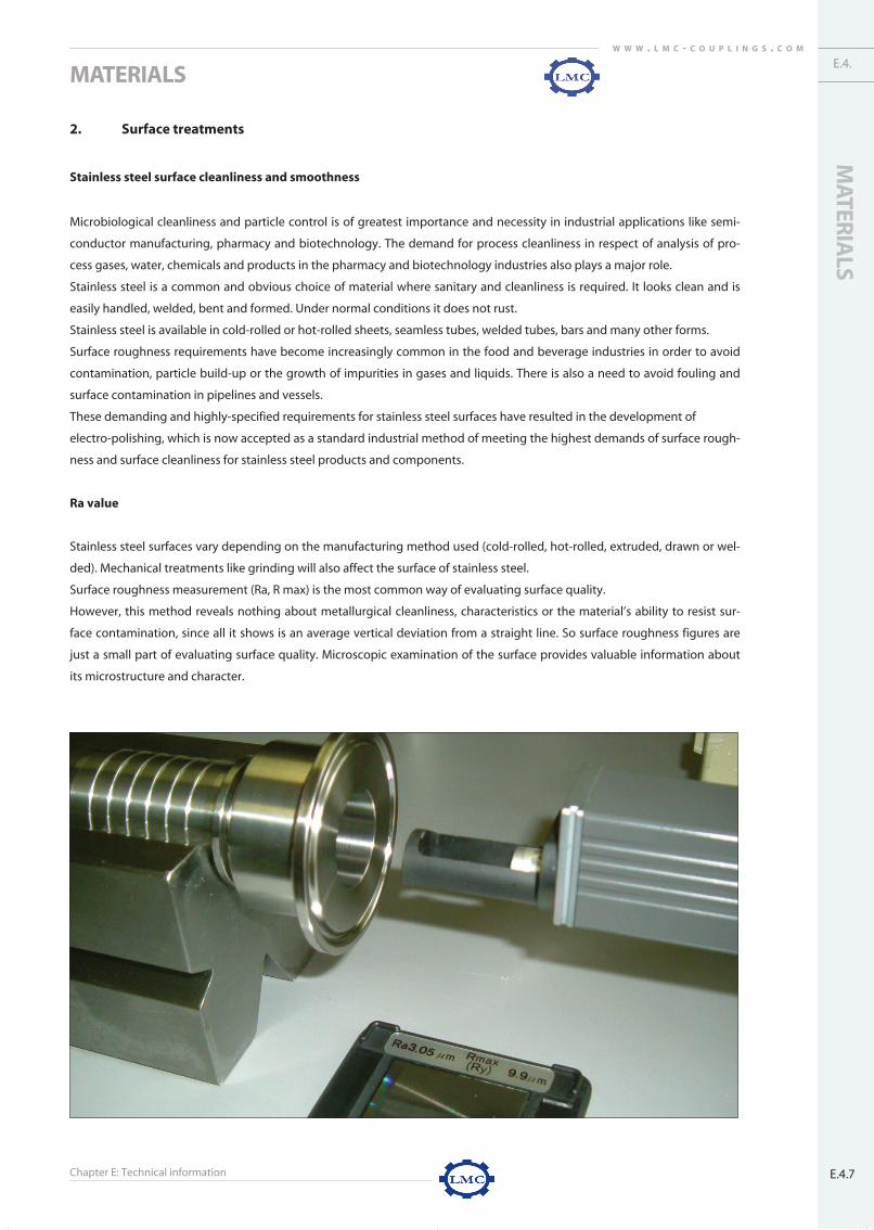
Surface roughness measurement (Ra, R max) is the most common way of evaluating surface quality.
However, this method reveals nothing about metallurgical cleanliness, characteristics or the material’s ability to resist sur-
face contamination, since all it shows is an average vertical deviation from a straight line. So surface roughness figures are
just a small part of evaluating surface quality. Microscopic examination of the surface provides valuable information about
its microstructure and character.
e-technical information 5/22/08 11:12 AM Page 39
Chapter E: Technical information
MATERIALS
E.4.8
W W W . L M C - C O U P L I N G S . C O M
The following methods are used in order to obtain surfaces with a fine and low Ra values:
1. Grinding/mechanical polishing
2. Blasting
3. Electro-polishing
1. Grinding/mechanical polishing is a very useful way of removing scratches or other mechanical defects.
The surface acquires a uniform appearance, and very low Ra values can be achieved by repeated polis-
hing. However, the outer surface layer and grain boundaries are contaminated with oxides, material from
the grinding belt and lubricants (where used). The austenitic structure is also damaged, and the surface
loses the properties of the underlying material. This defective surface layer is well-defined and is known
as the “Beilby” layer. Its negative effects are poor corrosion resistance and risk of contamination between
surface and medium.
2. Blasting has similar negative effects to grinding. Blasting should not be used as a preparation for electro-
polishing. Blasting gives an even appearance and is used primarily for surfaces not intended to come into
contact with media.
3. Electro-polishing is an electrochemical method which removes a surface layer approximately 20µm thick,
most of which comes from the peaks of the micro-profile. The austenitic structure appears very clean, the
surface has a bright, shiny appearance, and even the outer surface has the same properties as the under-
lying material. The technical advantages of electro-polishing are:
* Metallurgical cleanliness
* Reduced friction
* Improved corrosion resistance
* Reduced surface area
* Easy cleaning
The electro-polishing process may improve a surface finish by up to 50%, and removes material at the same time as redu-
cing surface roughness. Since material is removed, process runtimes are often limited to maintain dimensional tolerances,
thus delivering actual surface roughness improvements of between 10% and 35%. Electro-polishing improves surfaces at
the microscopic level, so if the material has a surface texture or scratching, electro-polishing will only produce a shiny textu-
re or shiny scratch. Mechanical polishing should be used to remove macroscopic texture or blemishes.
The life span of electro-polished surfaces
Electro-polishing is a surface treatment, not a surface coating, so polished surfaces can be physically damaged or degraded
in the same way as the underlying material. An electro-polished AISI 316 stainless steel surface has the same strength and
hardness as those published for AISI 316 material. It should however be noted that electro-polishing can produce such a
shiny finish that even the finest surface scratch may be visible. Electro-polished surfaces are more resistant to corrosion, and
are therefore more resilient in many corrosive environments.
The difference between electro-polishing and mechanical polishing
Electro-polishing is an electrochemical process, whereas mechanical polishing is a mechanical process. Electro-polishing is a
surface treatment that can improve surface finish, since it dissolves material from the surface. Mechanical polishing, like
machining, alters a surface by cutting material from it. Electro-polishing improves surface finish at the microscopic level,
whilst mechanical polishing improves it at the macroscopic level.
e-technical information 5/22/08 11:12 AM Page 40

Chapter E: Technical information
MATERIALS
MATER
IALS
E.4.9
E.4.W W W . L M C - C O U P L I N G S . C O M
Roughness certificate
When considering roughness measurements, measuring instru-
ments work within a specific spatial bandwidth, which means that
some features are too wide (or far apart) to be detected, whilst
some are too narrow (or close together). These limits are com-
monly expressed in terms of spatial frequency (i.e., the inverse of
maximum or minimum widths). The degree of roughness meas-
ured (RMS or Ra) does not include features outside this range.
For comparisons between measurements (or instruments) to be
valid, the spatial bandwidths must be identical. There are also
limits of operation for measuring the amplitude of surface features.
When expressing roughness, it is important to specify not only
bandwidth, but also to state the specific range of surface amplitu-
des covered by the instrument used.
LMC-Couplings triclamp couplings can be supplied with rough-
ness certificates on request. This certificate demonstrates that the
requested roughness average is achieved. The roughness certifi-
cate contains several reference measurements:
1. Ra
2. Ry
3. Rz
4. Rq
Ra – Arithmetical Roughness average
Ra is the arithmetic average of the absolute values of profile
height deviations from the mean line, recorded within the evalu-
ation length. Simply put, Ra is the average of a set of individual
measurements of the peaks and valleys of a surface within the
scanning path. Ra is the preferred method for evaluating gradual
surface changes. The calculation formula used means that the
numerical value measured for Ra is always smaller than that for Rz
for the same roughness profile.
L = evaluation length
Z(x) = the profile height function
The digital approximation is:
e-technical information 5/22/08 11:12 AM Page 41

Chapter E: Technical information
MATERIALS
E.4.10
W W W . L M C - C O U P L I N G S . C O M
Ry – Maximum height
A portion stretching over a reference length in the direction in which
the average line extends is cut out from the roughness curve. The gap
between the peak line and the trough line is measured in microns (µm)
in the direction of the magnitude axis.
Rz – Determined roughness
The determined roughness depth Rz is the mathematical average of the
largest individual roughness depths Zn from a number of individual
measurement paths l5 = c. Averaging the largest roughness depths of
measurement paths directly adjacent to each other reduces the influen-
ce exerted by individual peaks and ridges. The complete path L is the
sum of the individual measurement paths.
Rz = Z1 + Z2 + Z3 + Z4 + Z5
5
RMS (Rq) – Root mean square average
RMS is the root mean square average of the profile height deviations
from the mean line, recorded within the evaluation length.
L= evaluation length
Z(x) = the profile height function
The digital approximation is:
e-technical information 5/22/08 11:12 AM Page 42

Chapter E: Technical information
MATERIALS
MATER
IALS
E.4.11
E.4.W W W . L M C - C O U P L I N G S . C O M
Difference between Ra and RMS
Ra and RMS both represent surface roughness, but are calculated differently. Ra is the Roughness Average of the
measured microscopic peaks and valleys of a surface. RMS is the Root Mean Square of the measured microscopic
peaks and valleys of a surface. Each value uses the same individual height measurements of surface peaks and valleys,
but in different formula. The formulas are shown above. It can be seen that a single large peak or flaw within the
microscopic surface texture will affect (raise) the RMS value more than the Ra value.
Equivalent Ra values for surface finish grade numbers
Roughness values Ra Roughness values Ra Roughnessmicrometres micro inches Grade Numbers
50 2000 N1225 1000 N11
12.5 500 N108.3 250 N93.2 125 N81.6 63 N70.8 32 N60.4 16 N50.2 8 N40.1 4 N3
0.05 2 N20.025 1 N1
e-technical information 5/22/08 11:12 AM Page 43

Chapter E: Technical information
MATERIALS
E.4.12
W W W . L M C - C O U P L I N G S . C O M
1.4301 X 5 CrNi 18 10 304 Z6CN18.09 304S151.4305 X 10 CrNiS 18 9 303 Z10CNF18.09 303S211.4306 X 2 CrNi 19 11 304L Z2CN18.10 304S121.4401 X 5 CrNiMo 17 12 2 316 Z6CND17.11 316S161.4435 X 2 CrNiMo 18 14 3 316L Z2CND17.13 316S121.4541 X 6 CrNiTi 18 10 321 Z6CN18.10 321S121.4571 X 6 CrNiMoTi 17 12 2 316Ti Z6CNDT17.12 320S172,4602 - Hastelloy® C-22™ -2.4360 - Monel® Alloy 400™ -
1.0116 Fe 360 D 1 (St37-3) A573-81 65 E 24-U 4360 40 C1.0570 Fe 510 D 1 (St52-3) SAE 1518 E 36-3 4360 50 B1.0727 45S20 SAE 1151 45 MF 4 212 M 441.0737 9SMnPb36k 12L14 S300Pb -1.1181 Ck35 SAE 1035 XC38 080 A 321.1191 Ck45 SAE 1045 XC42 080 M 461,5217 20MnV6 - - -
3.0615 AlMgSiPb 6012 A SgPb -3.1645 AlCuMgPb 2007 A-U4PB -3.3215 AlMgSi 1 6082 A-SGM 0,7 H303.3206 AlMgSi 0,5 6060 A-GS H93.3503 AlMg 3 5754 A-G3M -
2.0401 CuZn 39 Pb3 (Ms58) ASTM 360 UZ39PB2 CZ121Pb32.0321 CuZn 37 (Ms63) ASTM 272 UZ36 CZ108
MATERIAL DESCRIPTION
W.-nr GERMANY - DIN USA - AISI/SAE FRANCE - AFNOR UK - BS
195 500~700 45 60 85 130~180195 500~700 35 60 - 130~180180 460~680 45 60 85 120~180205 510~710 40 60 85 130~180190 490~690 35 60 85 120~180200 500~730 40 50 85 130~190210 500~730 35 50 85 130~190372 786 62 - - -
276~690 552~758 30~60 - - 75~100
235 340~510 26 24 27 -355 490~680 22 - 23 -375 640~830 7 - - -390 490~740 8 - - -370 600~750 19 45 40 48~58430 650~800 16 40 30 55~62400 520~720 17 - - -
200 275 8 - - 80220~250 340~370 7 - - 90~100200~260 275~310 12~10 - - 80~95
160 215 12 - - 7080 180 14 - - 45
250 430 15 - - 125370 440~540 8 - - 135
120 270 12 - - 70
MECHANICAL PROPERTIESRP0.2 Rm A5 Z Av HRC
N/mm2 N/mm2 % %
Stainless steel
Steel
Aluminium
Brass
Bronze
1.43011.43051.43061.44011.44351.45411.45712,46022.4360
1.01161.05701.07271.07371.11811.11911,5217
3.06153.16453.32153.32063.3503
2.04012.0321
2.1090
0,070 1,000 2,000 0,045 0,030 17,000~19,000 - 8,500~10,500 -12,000 1,000 2,000 0,060 0,150~0,350 17,000~19,000 - 8,000~10,000 -0,030 1,000 2,000 0,045 0,030 18,000~20,000 - 10,000~12,500 -0,070 1,000 2,000 0,045 0,030 16,500~18,500 2,000~2,500 10,500~13,500 -0,030 1,000 2,000 0,045 0,025 17,000~18,500 2,500~3,000 12,500~15,000 -0,080 1,000 2,000 0,045 0,030 17,000~19,000 - 9,000~12,000 Ti ≥(5x%C)≤ 0,8000,080 1,000 2,000 0,045 0,030 16,500~18,500 2,000~2,500 10,500~13,500 Ti ≥(5x%C)≤ 0,8000,010 0,080 0,500 - - 22,000 13,000 55,560 Co2.5/W3/Fe3/V 0.35
0,500 2,000 - 0,024 - - 66,500 Fe 2.5 / Cu 31
0,170 - 1,400 0,045 0,045 - - - -0,200 0,550 1,600 0,045 0,045 - - - -
0,42~0,50 - 0,700~1,100 0,060 0,180~0,250 - - - -0,150 0,050 1,100~1,500 0,100 0,340~0,400 - - - Pb: 0,150~0,350
0,320~0,39 0,400 - 0,035 0,030 0,400 0,100 0,400 -- 0,400 0,500~0,800 0,035 0,030 0,400 0,100 0,400 -
0,220 0,500 1.200~1,700 0,040 0,040 - - - V: 0.15
0,60~1,40 0,50 0,10 0,40~1,00 0,60~1,20 0,30 0,30 0,20 -0,80 0,80 3,30~4,60 0,50~1,00 0,40~1,80 0,10 0,80 0,20 -
0,70~1,30 0,50 0,10 0,40~1,00 0,60~1,20 0,25 0,20 0,10 -0,30~0,60 0,10~0,30 0,10 0,10 0,35~0,60 0,05 0,15 0,10 -
0,40 0,40 0,10 0,50 2,60~3,60 0,30 0,20 0,15 -
57,0~59,0 2,5~3,5 35,5~38,5 0,10 0,50 0,50 0,30 0,40 -62,0~64,0 0,10 35,2~37,2 0,03 0,10 0,30 0,05 0,10 -
0,05 4,0~6,0 4,0~6,0 - 0,30 2,50 - 4,00~6,00 Cu 81~85 / Sb 0.3
CHEMICAL PROPERTIESW.-nr C Si Mn P S Cr Mo Ni Others
% % % % % % % % %
Stainless steel
Steel
Aluminium
Brass
Bronze
e-technical information 5/22/08 11:12 AM Page 44

Chapter E: Technical information E.4.13
MATERIALSW W W . L M C - C O U P L I N G S . C O M
TECHNICAL INFORMATION: PROPERTIES OF ELASTOMERS
AST
M 1
418
NR
SB
R
NB
R
EPD
M
IIRC
R
AU
C
SM
VM
Q
FVM
Q
FK
M
ISO
co
de
1629
NR
SBR
NB
REP
DM
IIRC
RA
UC
SMM
VQ
MFQ
FPM
Sho
ren
ess
(Sh
ore
A)
30-9
040
-90
40-9
540
-80
20-8
020
-90
50-9
040
-90
10-9
040
-80
60-9
0Pu
ll st
ren
gth
(p.s
.i.)
3000
3000
2500
2500
2000
3000
5000
2500
1400
900
2000
Tear
str
eng
ht
EV
GG
VV
EF
NN
GW
ear s
tren
gth
EE
GG
GG
VV
NN
G
Infla
mm
able
NN
NV
VF
NN
GV
F to
Eh
ydr.
liqu
ids
Lub
rica
nts
NN
GN
NF
VF
FE
EFu
el o
ilsN
NG
NN
FV
FR
EE
Hyd
rau
lic o
ilsN
NU
NN
GV
UG
EE
Veg
etab
le o
ilsN
FU
FU
GV
GG
EE
An
imal
fats
NF
UF
UG
VG
GE
E
Trad
e g
aso
line
NN
VN
NF
VF
FE
EG
aso
line
hig
h o
ctan
eN
NG
NN
NV
NN
EE
Ker
ose
ne
NN
VN
NF
VF
FE
E
Aro
mat
ic
NN
FN
NN
GR
NE
E
hyd
roca
rbo
ns
Alif
atic
NN
VN
NG
VG
FE
E
hyd
roca
rbo
ns
Wat
er (<
80°
C -
176°
F)G
VV
EE
FF
to N
EE
EE
Wat
er (>
80°
C -
176°
F)N
FF
EG
NN
EE
EG
Alc
oh
ols
GG
VE
EE
FV
EE
E
Ket
on
esN
NN
GV
NN
FG
NN
Co
nce
ntr
ated
NN
NF
FN
NV
FF
V
acid
s
Dilu
ted
aci
ds
FF
FG
EG
NE
GV
E
Alk
alis
?G
GF
VE
GN
EG
FG
Ch
lora
ted
NN
FN
NN
FN
NE
E
solv
ents
Ozo
ne
/ o
bse
len
ce li
gh
tF
FF
UU
EE
UU
UU
Max
. C°/
F°co
nti
nu
e70
°C/1
55°F
110°
C/23
0°F
120°
C/24
8°F
145°
C/29
3°F
120°
C/24
8°F
105°
C/22
0°F
70°C
/155
°F14
0°C/
284°
F23
0°C/
446°
F20
5°C/
400°
F20
0°C/
392°
F
Elec
tr. p
rop
erti
esU
EN
UU
EG
GU
UU
Flam
e ex
tin
gu
ish
ing
No
No
No
No
No
Yes
No
Yes
No
No
Yes
E= Excellent V= Very good G= Good F= Fair N= Not recomended
e-technical information 5/22/08 11:12 AM Page 45