Embed Size (px)
Citation preview
E-MU
R
Op
32-b
FX-32it Effects/Mixing System for the Emulator 4 UltraPN FI11460 Rev. C
eration Manual
RFX-32
Contents
RFX-32 32-bit Effects/Mixing System for the Emulator 4 Ultra
Operation Manual
©2000-2001, E-MU Systems, Inc. d.b.a. E-MU / ENSONIQ. All rights reserved.
FI11460 Rev. C
E-MU World Headquarters Europe, Africa, Middle EastE-MU / ENSONIQ E-MU / ENSONIQ1600 Green Hills Road Suite 6, Adam Ferguson House
Scotts Valley, CA USA Eskmills Industrial Park
95067-0015 Musselburgh, East Lothian
Telephone 831-438-1921 Scotland, EH21 7PQ
Fax 831-438-8612 Tel +44 (0) 131-653-6556
Internet www.emu.com Fax +44 (0) 131-665-0473
The following are registered worldwide trademarks owned and/or exclusively licensed by E-MU Systems, Inc. E-MU® and E-MU Systems®. All other trade-marks are the property of their respective holders.
This product is covered under one or more of the following U.S. patents 4,404,529; 4,506,579; 4,699,038; 4,987,600; 5,013,105; 5,072,645; 5,111,727; 5,144,676; 5,170,367; 5,248,845; 5,303,309; 5,317,104; 5,342,990; 5,430,244 and foreign patents and/or pending patents. All other trademarks belong to their respective companies. Specifications and features are subject to change without notice.
ii E-MU Systems
RFX-32
Contents
Table of Contents
RFX Software Install .........................................................1To Install EOS version 4.7: .......................................................................2
RFX-32 ...............................................................................3Overview ............................................................................................. 3Background: RFX Architecture.............................................................. 5
Getting a Signal into the RFX .................................................................... 5FX Send Programmed in the Voice ............................................................ 5FX Send Programmed by MIDI channel .................................................... 5FX Send Programmed by MIDI Mixer ........................................................ 6The RFX Setup .......................................................................................... 8
Housekeeping: Plug-ins, Effects & Setups ........................................... 10Plug-ins ................................................................................................10Effects ..................................................................................................10R Effect Diagram ...................................................................................10Setups ..................................................................................................11RFX Setup Diagram ..............................................................................11
Housekeeping 2: The Disk Browser .................................................... 12To Browse: ............................................................................................. 12
Putting it all together......................................................................... 14Step 1 - Create a new Effect: ................................................................... 14Step 2 - Build an Effect Setup: ................................................................. 15Step 3 - Program the Effect Sends by Voice: ........................................... 16Step 4 - Program the Effect Sends by MIDI Channel: .............................. 17Step 5 - Program the Effect Sends by MIDI Mixer: .................................. 17
Plug-in Manage ..............................................................18Plug-in Manage ................................................................................. 18
To Install new RFX Plug-ins: .................................................................... 18
Erase Plug-in ...................................................................................... 19To Erase an RFX Plug-in: ......................................................................... 19
Copy Plug-in...................................................................................... 19To Copy a Plug-in: .................................................................................. 20
Export Plug-in.................................................................................... 20To Export an RFX Plug-in: ....................................................................... 20
Get Info ............................................................................................. 21To Get Information about a Plug-in: ....................................................... 21
RFX-32 Operation Manual iii
RFX-32
Contents
RFX Effect Manage ......................................................... 22To Select and Edit RFX Effect presets: ......................................................22
Utilities .............................................................................................. 23Erase Effect ...........................................................................................23
To Erase an Effect ....................................................................................23
Name Effect....................................................................................... 23To Name an RFX Effects preset: ...............................................................23
New Effect......................................................................................... 24To Create a new RFX Effect: ....................................................................24
Copy Effect........................................................................................ 25To Copy an RFX Effect: ...........................................................................25
Export Effect ...................................................................................... 25To Export an RFX Effect: ..........................................................................25
Edit Effect .......................................................................................... 26To Edit an RFX Effect: ..............................................................................26
RFX Effects Setup ........................................................... 27RFX Effects Setup............................................................................... 27
To Select an RFX Effect Setup: .................................................................27
Utilities .............................................................................................. 28Erase Setup ..........................................................................................28
To Erase a Setup .....................................................................................28
Name Setup ...................................................................................... 28To Name an RFX Setup: ..........................................................................28
New Setup ........................................................................................ 29To Create a new RFX Setup: ....................................................................29
Copy Setup ....................................................................................... 30To Copy an RFX Setup: ...........................................................................30
Export Setup ..................................................................................... 31To Export an RFX Setup: .........................................................................31
RFX Block Diagram ............................................................................ 32Edit Setup.......................................................................................... 33
When the Cursor is on an RFX Bus Field: .................................................34When the Cursor is on an Effect Field: .....................................................34
MIDI Modulation of Effects ...................................................................35To Access the MIDI Modulation Patchbay: ..............................................35
Output Routing ....................................................................................36To Get to the RFX Setup menu: ..............................................................36To Edit the RFX Setup: ............................................................................37
Write FX ............................................................................................ 38To Write an Effect from the Setup menu: ................................................38
Name FX ........................................................................................... 38To Name an Effect from the Setup menu: ...............................................38
iv E-MU Systems
RFX-32
Contents
RFX Allocation.................................................................................... 39FX Legacy Mode ................................................................................ 40
Background ............................................................................................ 40
Selecting Effects Setups...................................................................... 41Three-way Effects Control .....................................................................411. Preset Selects the RFX Setup .............................................................42
To Program the RFX Setup as part of the Preset: ..................................... 422. Multisetup Selects RFX Setup ...........................................................43
To Link an RFX Setup to a Multisetup: .................................................... 433. MIDI Channel Determines the RFX Setup ..........................................44
To Select the RFX Setup by MIDI Channel: ............................................. 44Effects Bypass .......................................................................................45
To Bypass the Effects: ............................................................................. 45
Processing External Inputs .............................................46Processing External Inputs.................................................................. 46
To Bind an External Input onto a specific RFX Bus: .................................. 46To Connect External Inputs by MIDI Channel in Multimode: .................. 46
Live Samples ...................................................................................... 47To Program the External Inputs in a Voice: ............................................. 47
MIDI Triggers .................................................................48MIDI Triggers..................................................................................... 48
Input Levels ............................................................................................ 48To Set up the MIDI Triggers: .................................................................. 48
MIDI Trigger How-to’s, Tips & Tricks .....................................................49To Process Audio through the Z-Plane Filters & VCA: .............................. 49Drum Sound Replacement with MIDI Triggers: ....................................... 50
The Effects ......................................................................51General Effect Descriptions ................................................................ 51
Reverb ..................................................................................................51General Descriptions of Reverb ............................................................... 52
Chorus .................................................................................................52Doubling ..............................................................................................52Slapback ..............................................................................................52Stereo Flanger ......................................................................................52Delay ...................................................................................................53Stereo Delay .........................................................................................53Panning Delay ......................................................................................53Dual Tap ...............................................................................................54Vibrato .................................................................................................54Distortion .............................................................................................54
RFX-32 Operation Manual v
RFX
RFX Plug-ins ...................................................................................... 55FAT Effects ............................................................................................55Thin Effects ..........................................................................................55EOS Reverb Types .................................................................................55EOS Chorus Types ................................................................................55
RFX Hall............................................................................................. 56Simple Reverb ......................................................................................57
BPM Delay......................................................................................... 58Long Delay ........................................................................................ 59Rhythmic Delays................................................................................ 60Slap Delay ......................................................................................... 61Stereo Delay ...................................................................................... 62Stereo Slap ........................................................................................ 63Parametric/Shelf EQ........................................................................... 64
Param/Shelf EQ Parameters: ....................................................................65Dialing it in .............................................................................................65
10-band EQ....................................................................................... 654-band Split EQ ................................................................................. 66RFX Phaser......................................................................................... 67
RFX Phaser Block Diagram .......................................................................69RFX Phase Shifter Parameters: ..................................................................70
Ring Modulator ................................................................................. 72Ring Modulator Block Diagram ...............................................................73Ring Modulator Parameters: ....................................................................74
MuXster ............................................................................................ 76MuXster Block Diagram ........................................................................................76MuXster Parameters: ...............................................................................76
Quad MuXster................................................................................... 78Quad MuXster Block Diagram .................................................................78Quad MuXster Parameters: .....................................................................78A few possible routing configurations ......................................................80
Vocoder............................................................................................. 81Vocoder Block Diagram ...........................................................................81Vocoder Parameters: ...............................................................................82Filter Width .............................................................................................82Filter Width .............................................................................................82Formant Shift ..........................................................................................83Vocal/Synth Mix ......................................................................................85
Vocoder Tips & Tricks ...........................................................................85Patching into the Vocoder ....................................................................86
Create an RFX Vocoder Effect & Setup ....................................................86Create a Vocoder MultiSetup ..................................................................87Connecting External Inputs to the Vocoder .............................................87
vi E-MU Systems
RFX-32
Contents
Vocoding Emulator Presets with a Microphone ....................................... 88Connecting Internal Presets to the Vocoder by MIDI Channel ................. 89Connecting two Voices to the Vocoder ................................................... 91Other tips: .............................................................................................. 92
Advanced App. - Connecting Several Vocoders in Parallel ......................93To Connect 2 Vocoders in Parallel: ......................................................... 93Example Frequency Range Settings ......................................................... 95To Recall the Effect: ................................................................................ 96
More Ideas: ..........................................................................................96Troubleshooting Chart ..........................................................................96
Mixer Section .................................................................................... 97Mixer Section Block Diagram .................................................................. 97Mixer Section Parameters: ....................................................................... 98Modulation Parameters ........................................................................... 98
RFX Flanger ....................................................................................... 99RFX Flanger Block Diagram ..................................................................... 99RFX Flanger Parameters: ........................................................................ 100
Envelope Phaser............................................................................... 105Envelope Phaser Block Diagram ............................................................ 105Envelope Phaser Parameters: ................................................................. 106MIDI Modulation Parameters ................................................................ 108
RFX Chorus & RFX Ultra Chorus....................................................... 109Ultra Chorus Block Diagram .................................................................. 109RFX Chorus Parameters: ........................................................................ 112
Grungulator & StereoGrunglator ..................................................... 115Grungulator Block Diagram .................................................................. 115
Edit Channel Parameter (StereoGrunglator only) ...................................116Patch Parameter .................................................................................117Grungulator Modules ..........................................................................117
Filters .................................................................................................... 117Clipper .................................................................................................. 119Rectifier ................................................................................................. 120Bit Reducer ........................................................................................... 120Downsampler ....................................................................................... 121X-Over .................................................................................................. 122
MIDI Modulation Parameters (StereoGrunglator only) ...........................123
RFX Compressor .............................................................................. 124RFX Compressor Block Diagram ............................................................ 124Basic Parameters ................................................................................... 125Advanced Parameters ............................................................................ 128
Emulator IV Gain Structure............................................................... 137Using the RFX Compressor............................................................... 138
Basic Controls .....................................................................................138
Example Settings ............................................................................. 139Increase Drum Punch: .......................................................................... 139Smoothing out the Bass Guitar Level: ................................................... 139
RFX-32 Operation Manual vii
RFX-32
Contents
Peak Limiting: .......................................................................................140Vocal Compression/Spoken Word: ........................................................140Backwards Drums & Cymbals: ..............................................................140Creating a De-esser: ..............................................................................141Input Panning .......................................................................................1414-band Split EQ Settings .......................................................................141Compressor Settings .............................................................................141
Multimode Screen ........................................................ 142New Multimode Features ................................................................ 142
To access the Multimode screen: ..........................................................142To access the RFX Mixer screen: ............................................................142
Multisetups ................................................................... 144Multisetup Manage ......................................................................... 144
To Select & Edit a Multisetup: ...............................................................144
Utilities ............................................................................................ 145Erase Multisetup .................................................................................145
To Erase a Multisetup: ...........................................................................145Export Multisetup ...............................................................................145
To Export a Multisetup: ........................................................................145Get Info .............................................................................................146
To Get Information about a Multisetup: ................................................146
Name Multisetup............................................................................. 146To Name the Current Multisetup: .........................................................147
New Multisetup............................................................................... 147To Create a New Multisetup: ................................................................147
Copy Multisetup.............................................................................. 148To Copy the Current Multisetup: ..........................................................148
Multisetup Edit ................................................................................ 149Sequence Select .................................................................................149
To Select a Multisetup Sequence: ..........................................................149Sequence Tempo ................................................................................149
To Set the Multisetup Tempo: ...............................................................150RFX Setup Select ................................................................................150
To Set the Multisetup RFX Setup: ..........................................................150
Index ............................................................................. 151
viii E-MU Systems
RFX Software Install
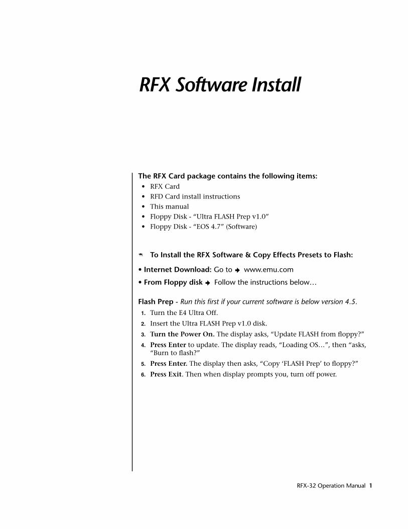
The RFX Card package contains the following items:• RFX Card
• RFD Card install instructions
• This manual
• Floppy Disk - “Ultra FLASH Prep v1.0”
• Floppy Disk - “EOS 4.7” (Software)
� To Install the RFX Software & Copy Effects Presets to Flash:
• Internet Download: Go to > www.emu.com
• From Floppy disk > Follow the instructions below…
Flash Prep - Run this first if your current software is below version 4.5.1. Turn the E4 Ultra Off.
2. Insert the Ultra FLASH Prep v1.0 disk.
3. Turn the Power On. The display asks, “Update FLASH from floppy?”
4. Press Enter to update. The display reads, “Loading OS…”, then “asks, “Burn to flash?”
5. Press Enter. The display then asks, “Copy ‘FLASH Prep’ to floppy?”
6. Press Exit. Then when display prompts you, turn off power.
RFX-32 Operation Manual 1
RFX-32
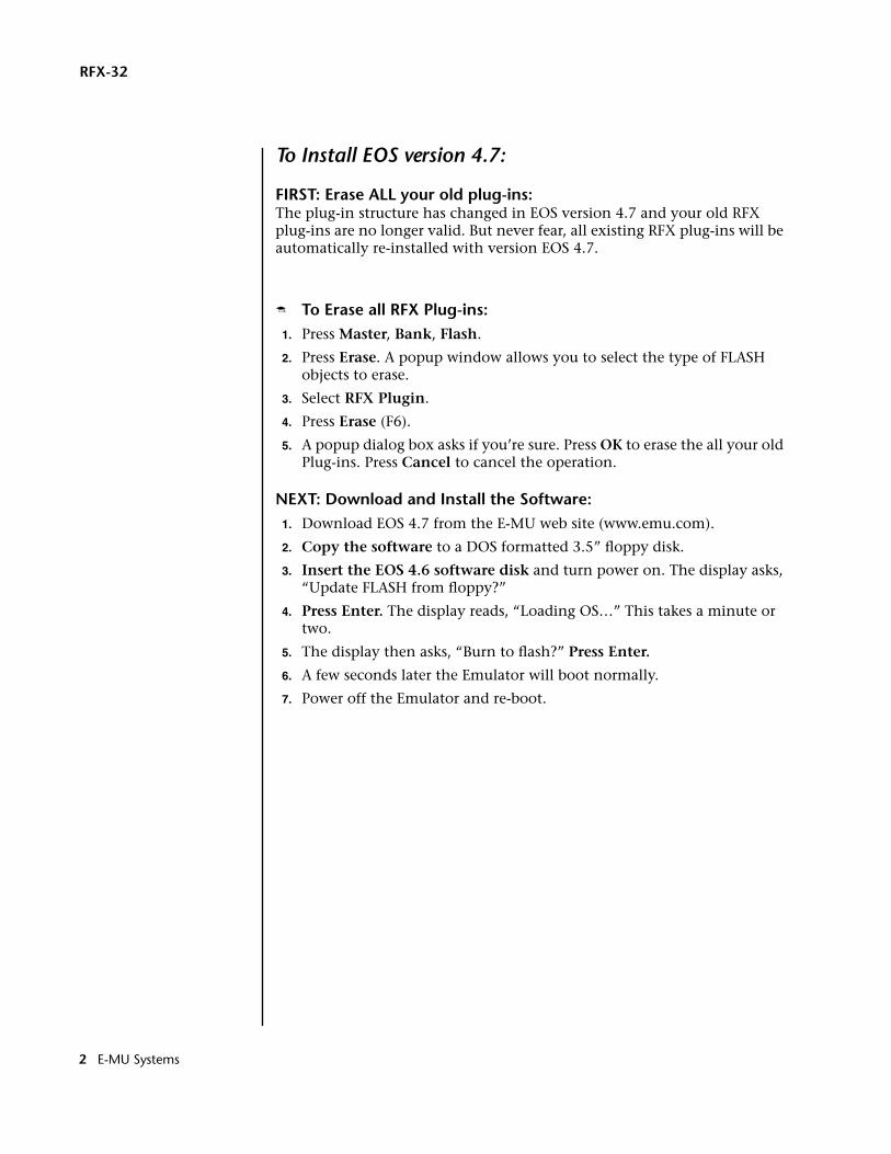
To Install EOS version 4.7:
FIRST: Erase ALL your old plug-ins:The plug-in structure has changed in EOS version 4.7 and your old RFX plug-ins are no longer valid. But never fear, all existing RFX plug-ins will be automatically re-installed with version EOS 4.7.
� To Erase all RFX Plug-ins: 1. Press Master, Bank, Flash.
2. Press Erase. A popup window allows you to select the type of FLASH objects to erase.
3. Select RFX Plugin.
4. Press Erase (F6).
5. A popup dialog box asks if you’re sure. Press OK to erase the all your old Plug-ins. Press Cancel to cancel the operation.
NEXT: Download and Install the Software:1. Download EOS 4.7 from the E-MU web site (www.emu.com).
2. Copy the software to a DOS formatted 3.5” floppy disk.
3. Insert the EOS 4.6 software disk and turn power on. The display asks, “Update FLASH from floppy?”
4. Press Enter. The display reads, “Loading OS…” This takes a minute or two.
5. The display then asks, “Burn to flash?” Press Enter.
6. A few seconds later the Emulator will boot normally.
7. Power off the Emulator and re-boot.
2 E-MU Systems
RFX-32
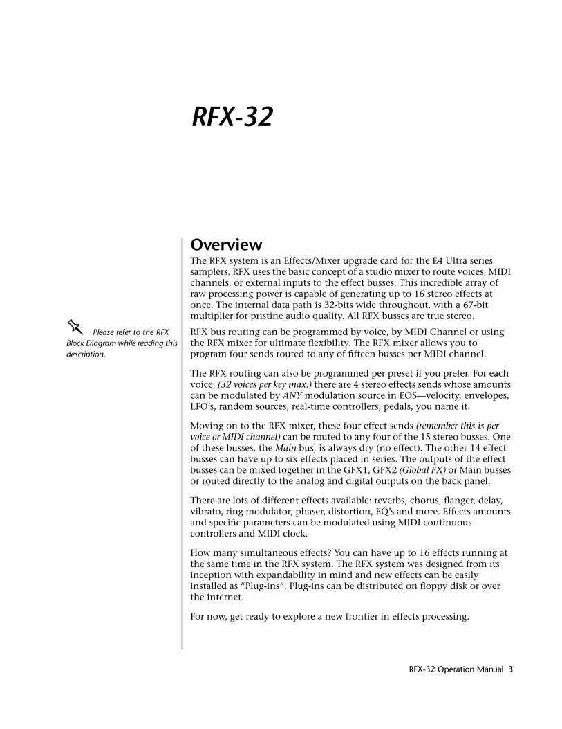
OverviewThe RFX system is an Effects/Mixer upgrade card for the E4 Ultra series samplers. RFX uses the basic concept of a studio mixer to route voices, MIDI channels, or external inputs to the effect busses. This incredible array of raw processing power is capable of generating up to 16 stereo effects at once. The internal data path is 32-bits wide throughout, with a 67-bit multiplier for pristine audio quality. All RFX busses are true stereo.
OOOO Please refer to the RFX Block Diagram while reading this description.
RFX bus routing can be programmed by voice, by MIDI Channel or using the RFX mixer for ultimate flexibility. The RFX mixer allows you to program four sends routed to any of fifteen busses per MIDI channel.
The RFX routing can also be programmed per preset if you prefer. For each voice, (32 voices per key max.) there are 4 stereo effects sends whose amounts can be modulated by ANY modulation source in EOS—velocity, envelopes, LFO’s, random sources, real-time controllers, pedals, you name it.
Moving on to the RFX mixer, these four effect sends (remember this is per voice or MIDI channel) can be routed to any four of the 15 stereo busses. One of these busses, the Main bus, is always dry (no effect). The other 14 effect busses can have up to six effects placed in series. The outputs of the effect busses can be mixed together in the GFX1, GFX2 (Global FX) or Main busses or routed directly to the analog and digital outputs on the back panel.
There are lots of different effects available: reverbs, chorus, flanger, delay, vibrato, ring modulator, phaser, distortion, EQ’s and more. Effects amounts and specific parameters can be modulated using MIDI continuous controllers and MIDI clock.
How many simultaneous effects? You can have up to 16 effects running at the same time in the RFX system. The RFX system was designed from its inception with expandability in mind and new effects can be easily installed as “Plug-ins”. Plug-ins can be distributed on floppy disk or over the internet.
For now, get ready to explore a new frontier in effects processing.
RFX-32 Operation Manual 3
RFX
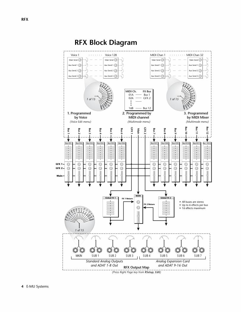
RFX Block Diagram
Aux Send 1
Main Send
Aux Send 2
Aux Send 3
Voice 128
Programmed byMIDI channel
Bus 1
Bus 2
Bus 3
Bus 4Bus 5
Bus 6Bus 7 Bu
s 8
Bus
9Bu
s 10
Bus 1
1Bu
s 12
GFX 1
GFX 2
Main
FX 1 Return
FX 2 Return
Aux Send 1
Main Send
Aux Send 2
Aux Send 3
Bus FX1 Bus FX2 Bus FX3 Bus FX4 Bus FX5 Bus FX6
MAIN
Main
GFX 2
GFX 1
Global FX 1
Bus FX7 Bus FX8 Bus FX9 Bus FX10 Bus FX11 Bus FX12
Voice 1
GFX
1
Bus 1
Bus 2
Bus 3
Bus 4
Bus 5
Bus 6
Bus 7
Bus 8
Bus 9
Bus 10
Bus 11
Bus 12
GFX
2
Main
MAIN SUB 1 SUB 2 SUB 3 SUB 4 SUB 5 SUB 6 SUB 7
Analog Expansion Cardand ADAT 9-16 Out
Standard Analog Outputsand ADAT 1-8 Out
1 of 15
(Press Right Page key from RSetup, Edit)
RFX Output Map
• All buses are stereo• Up to 6 effects per bus• 16 effects maximum
Programmedby Voice
MIDI Ch.01A02A
16B
FX BusBus 1GFX 2
Bus 12
(Multimode menu) (Multimode menu)
Programmedby MIDI Mixer
(Voice Edit menu)
Global FX 2
Bus
1Bu
s 2Bu
s 3
Bus 4
Bus 5
Bus 6
Bus 7Bus 8Bus 9Bus 10Bus 11Bus 12
GFX 1
GFX 2
Main
1 of 15
Aux Send 1
Main Send
Aux Send 2
Aux Send 3
Aux Send 1
Main Send
Aux Send 2
Aux Send 3
MIDI Chan 1 MIDI Chan 32
Bus
1Bu
s 2Bu
s 3
Bus 4
Bus 5
Bus 6
Bus 7Bus 8Bus 9Bus 10Bus 11Bus 12
GFX 1
GFX 2
Main
1 of 15
1. 2. 3.
4 E-MU Systems
RFX-32Background: RFX Architecture
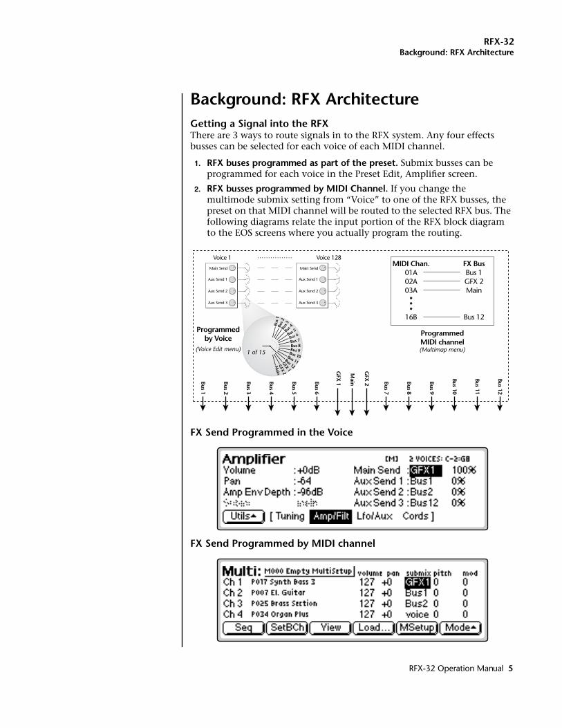
Background: RFX ArchitectureGetting a Signal into the RFXThere are 3 ways to route signals in to the RFX system. Any four effects busses can be selected for each voice of each MIDI channel.
1. RFX buses programmed as part of the preset. Submix busses can be programmed for each voice in the Preset Edit, Amplifier screen.
2. RFX busses programmed by MIDI Channel. If you change the multimode submix setting from “Voice” to one of the RFX busses, the preset on that MIDI channel will be routed to the selected RFX bus. The following diagrams relate the input portion of the RFX block diagram to the EOS screens where you actually program the routing.
FX Send Programmed in the Voice
FX Send Programmed by MIDI channel
Aux Send 1
Main Send
Aux Send 2
Aux Send 3
Aux Send 1
Main Send
Aux Send 2
Aux Send 3
Voice 1 Voice 128
GFX
1Bus 1
Bus 2
Bus 3
Bus 4
Bus 5
Bus 6
Bus 7
Bus 8
Bus 9
Bus 10
Bus 11
Bus 12
GFX
2
Main
1 of 15
Bus
1Bu
s 2Bu
s 3
Bus 4
Bus 5
Bus 6
Bus 7Bus 8Bus 9Bus 10Bus 11Bus 12
GFX 1
GFX 2
Main
Programmedby Voice
ProgrammedMIDI channel
MIDI Chan.01A02A03A
16B
FX BusBus 1GFX 2Main
Bus 12
(Multimap menu)(Voice Edit menu)
RFX-32 Operation Manual 5
RFX-32Background: RFX Architecture
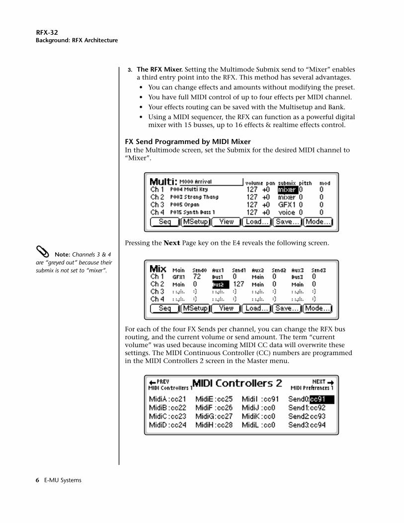
3. The RFX Mixer. Setting the Multimode Submix send to “Mixer” enables a third entry point into the RFX. This method has several advantages.
• You can change effects and amounts without modifying the preset.
• You have full MIDI control of up to four effects per MIDI channel.
• Your effects routing can be saved with the Multisetup and Bank.
• Using a MIDI sequencer, the RFX can function as a powerful digital mixer with 15 busses, up to 16 effects & realtime effects control.
FX Send Programmed by MIDI MixerIn the Multimode screen, set the Submix for the desired MIDI channel to “Mixer”.
Pressing the Next Page key on the E4 reveals the following screen.
Note: Channels 3 & 4 are “greyed out” because their submix is not set to “mixer”.
For each of the four FX Sends per channel, you can change the RFX bus routing, and the current volume or send amount. The term “current volume” was used because incoming MIDI CC data will overwrite these settings. The MIDI Continuous Controller (CC) numbers are programmed in the MIDI Controllers 2 screen in the Master menu.
6 E-MU Systems
RFX-32Background: RFX Architecture
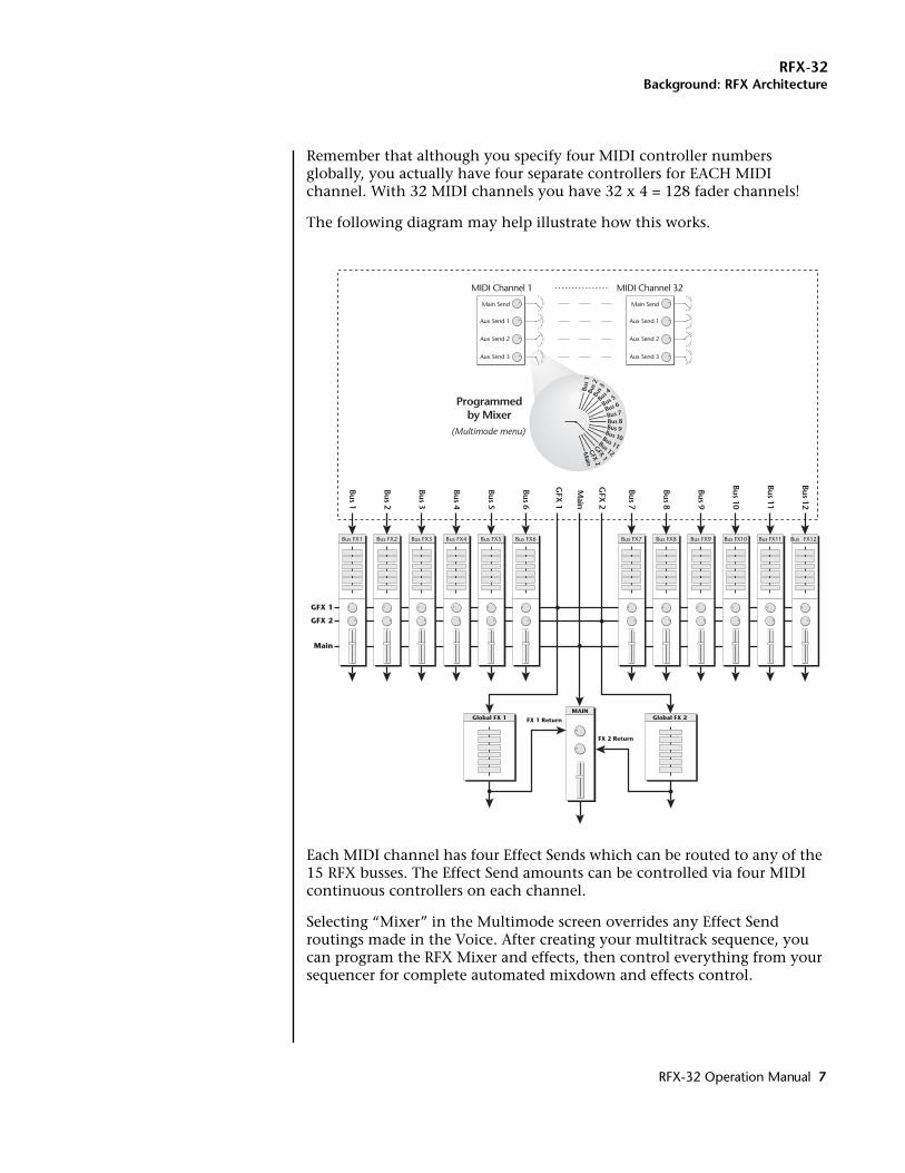
Remember that although you specify four MIDI controller numbers globally, you actually have four separate controllers for EACH MIDI channel. With 32 MIDI channels you have 32 x 4 = 128 fader channels!
The following diagram may help illustrate how this works.
Each MIDI channel has four Effect Sends which can be routed to any of the 15 RFX busses. The Effect Send amounts can be controlled via four MIDI continuous controllers on each channel.
Selecting “Mixer” in the Multimode screen overrides any Effect Send routings made in the Voice. After creating your multitrack sequence, you can program the RFX Mixer and effects, then control everything from your sequencer for complete automated mixdown and effects control.
FX 1 Return
FX 2 Return
Bus FX1 Bus FX2 Bus FX3 Bus FX4 Bus FX5 Bus FX6
MAIN
Main
GFX 2
GFX 1
Global FX 1
Bus FX7 Bus FX8 Bus FX9 Bus FX10 Bus FX11 Bus FX12
GFX
1
Bus 1
Bus 2
Bus 3
Bus 4
Bus 5
Bus 6
Bus 7
Bus 8
Bus 9
Bus 10
Bus 11
Bus 12
GFX
2
Main
Global FX 2
Aux Send 1
Main Send
Aux Send 2
Aux Send 3
Aux Send 1
Main Send
Aux Send 2
Aux Send 3
MIDI Channel 1 MIDI Channel 32
Programmedby Mixer
(Multimode menu)
Bus
1Bu
s 2Bu
s 3
Bus 4
Bus 5
Bus 6
Bus 7Bus 8Bus 9Bus 10Bus 11Bus 12
GFX 1
GFX 2
Main
RFX-32 Operation Manual 7
RFX-32Background: RFX Architecture
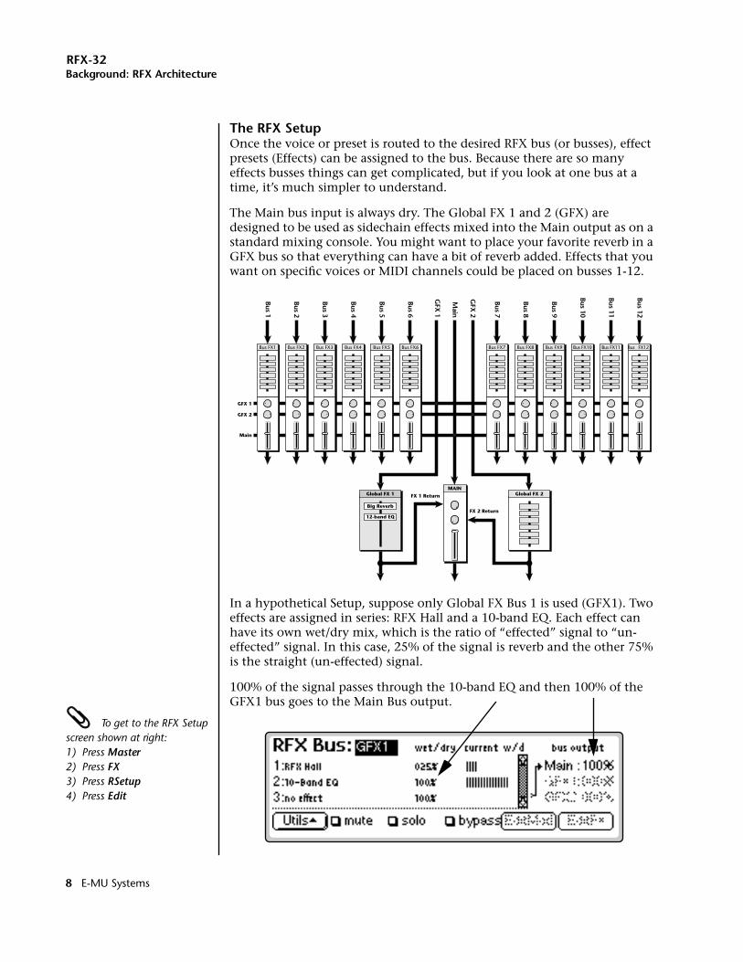
The RFX SetupOnce the voice or preset is routed to the desired RFX bus (or busses), effect presets (Effects) can be assigned to the bus. Because there are so many effects busses things can get complicated, but if you look at one bus at a time, it’s much simpler to understand.
The Main bus input is always dry. The Global FX 1 and 2 (GFX) are designed to be used as sidechain effects mixed into the Main output as on a standard mixing console. You might want to place your favorite reverb in a GFX bus so that everything can have a bit of reverb added. Effects that you want on specific voices or MIDI channels could be placed on busses 1-12.
In a hypothetical Setup, suppose only Global FX Bus 1 is used (GFX1). Two effects are assigned in series: RFX Hall and a 10-band EQ. Each effect can have its own wet/dry mix, which is the ratio of “effected” signal to “un-effected” signal. In this case, 25% of the signal is reverb and the other 75% is the straight (un-effected) signal.
100% of the signal passes through the 10-band EQ and then 100% of the GFX1 bus goes to the Main Bus output.
To get to the RFX Setup screen shown at right:1) Press Master2) Press FX3) Press RSetup4) Press Edit
FX 1 Return
FX 2 Return
Bus FX1 Bus FX2 Bus FX3 Bus FX4 Bus FX5 Bus FX6
MAIN
Main
GFX 2
GFX 1
Global FX 1
Bus FX7 Bus FX8 Bus FX9 Bus FX10 Bus FX11 Bus FX12
GFX
1
Bus 1
Bus 2
Bus 3
Bus 4
Bus 5
Bus 6
Bus 7
Bus 8
Bus 9
Bus 10
Bus 11
Bus 12
GFX
2
Main
Global FX 2
Big Reverb
12-band EQ
8 E-MU Systems
RFX-32Background: RFX Architecture
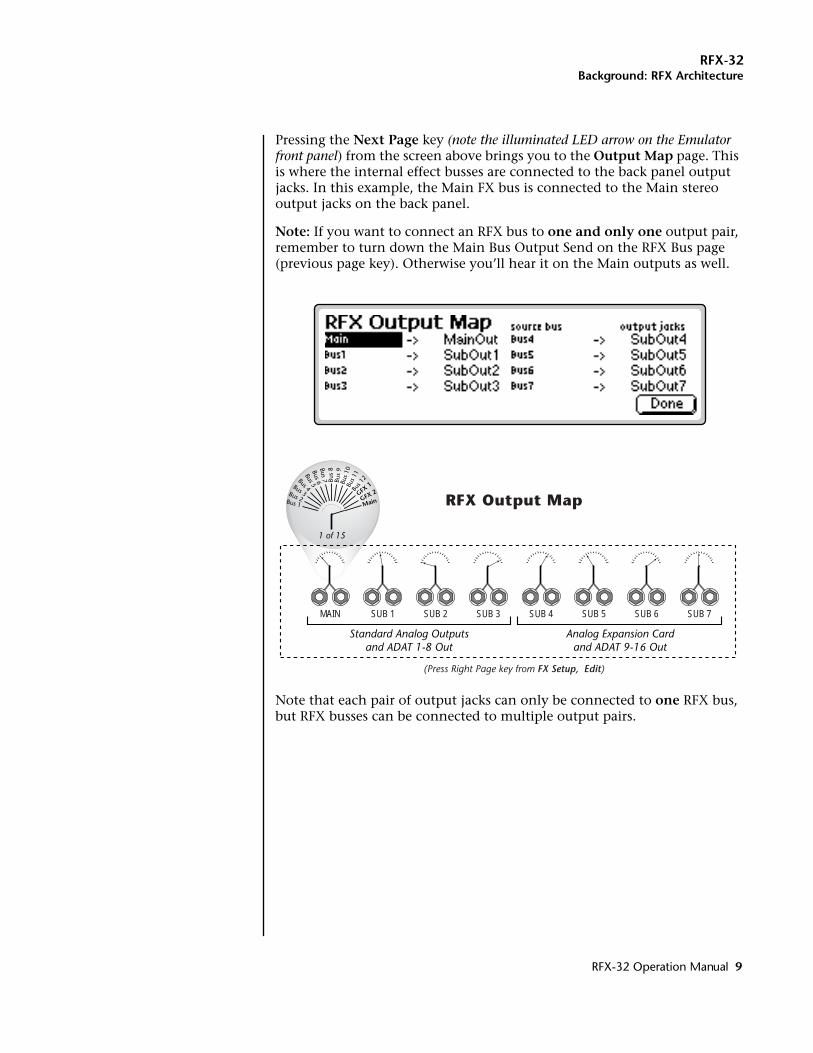
Pressing the Next Page key (note the illuminated LED arrow on the Emulator front panel) from the screen above brings you to the Output Map page. This is where the internal effect busses are connected to the back panel output jacks. In this example, the Main FX bus is connected to the Main stereo output jacks on the back panel.
Note: If you want to connect an RFX bus to one and only one output pair, remember to turn down the Main Bus Output Send on the RFX Bus page (previous page key). Otherwise you’ll hear it on the Main outputs as well.
Note that each pair of output jacks can only be connected to one RFX bus, but RFX busses can be connected to multiple output pairs.
Bus 1
Bus 2
Bus 3
Bus 4Bus 5
Bus 6Bus 7 Bu
s 8
Bus
9Bu
s 10
Bus 1
1Bu
s 12
GFX 1
GFX 2
Main
MAIN SUB 1 SUB 2 SUB 3 SUB 4 SUB 5 SUB 6 SUB 7
Analog Expansion Cardand ADAT 9-16 Out
Standard Analog Outputsand ADAT 1-8 Out
1 of 15
(Press Right Page key from FX Setup, Edit)
RFX Output Map
RFX-32 Operation Manual 9
RFX-32Housekeeping: Plug-ins, Effects & Setups
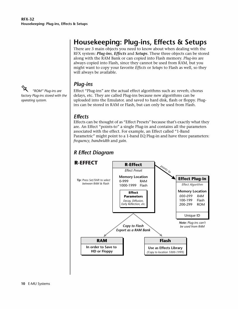
Housekeeping: Plug-ins, Effects & SetupsThere are 3 main objects you need to know about when dealing with the RFX system: Plug-ins, Effects and Setups. These three objects can be stored along with the RAM Bank or can copied into Flash memory. Plug-ins are always copied into Flash, since they cannot be used from RAM, but you might want to copy your favorite Effects or Setups to Flash as well, so they will always be available.
Plug-insOOOO “ROM” Plug-ins are factory Plug-ins stored with the operating system.
Effect “Plug-ins” are the actual effect algorithms such as: reverb, chorus delays, etc. They are called Plug-ins because new algorithms can be uploaded into the Emulator. and saved to hard disk, flash or floppy. Plug-ins can be stored in RAM or Flash, but can only be used from Flash.
EffectsEffects can be thought of as “Effect Presets” because that’s exactly what they are. An Effect “points-to” a single Plug-in and contains all the parameters associated with the effect. For example, an Effect called “1-Band Parametric” might point to a 1-band EQ Plug-in and have three parameters: frequency, bandwidth and gain.
R Effect Diagram
R-EffectEffect Preset
RAM Flash
Use as Effects Library
0-999 RAM1000-1999 Flash
Memory Location
EffectParameters
Decay, Diffusion,Early Reflection, etc.
Effect Plug-in
Memory Location
Effect Algorithm
000-099 RAM100-199 Flash200-299 ROM
Note: Plug-ins can'tbe used from RAMCopy to Flash
Export as a RAM Bank
Unique ID
(Copy to location 1000-1999)
Tip: Press Set/Shift to select between RAM & Flash
In order to Save to HD or Floppy
R-EFFECTpoints to
10 E-MU Systems
RFX-32Housekeeping: Plug-ins, Effects & Setups
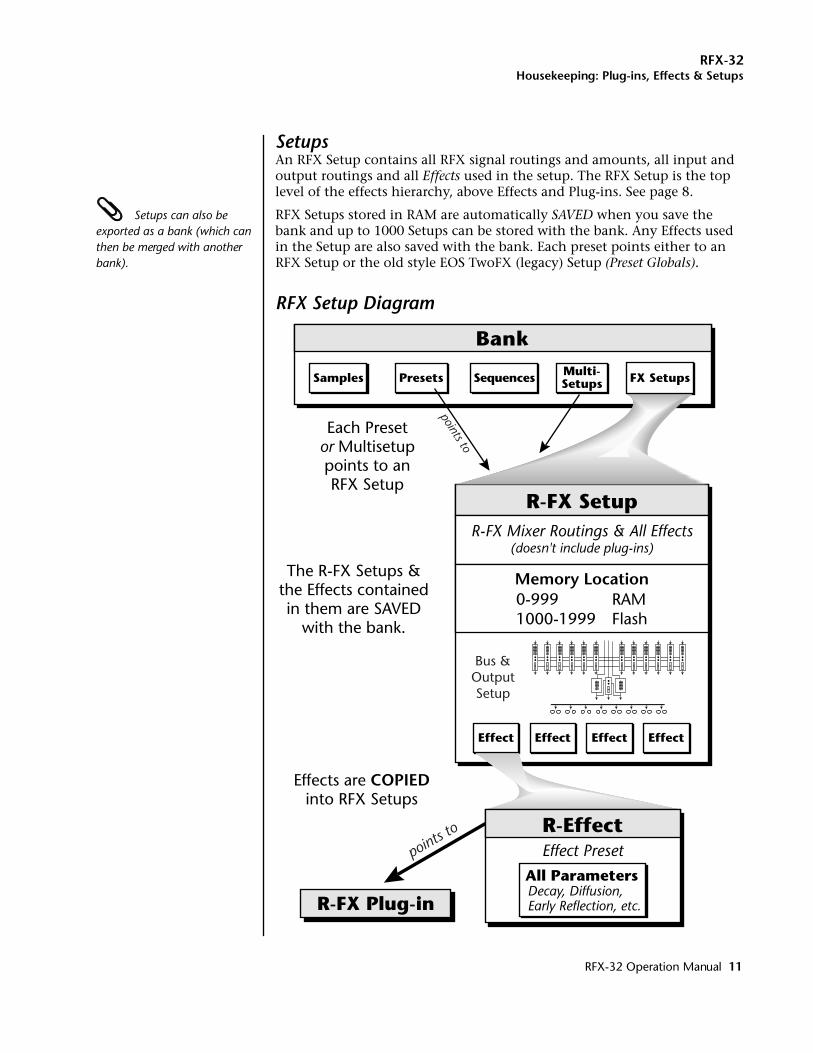
SetupsAn RFX Setup contains all RFX signal routings and amounts, all input and output routings and all Effects used in the setup. The RFX Setup is the top level of the effects hierarchy, above Effects and Plug-ins. See page 8.
Setups can also be exported as a bank (which can then be merged with another bank).
RFX Setups stored in RAM are automatically SAVED when you save the bank and up to 1000 Setups can be stored with the bank. Any Effects used in the Setup are also saved with the bank. Each preset points either to an RFX Setup or the old style EOS TwoFX (legacy) Setup (Preset Globals).
RFX Setup Diagram
R-FX Setup
Bank
R-FX Mixer Routings & All Effects(doesn't include plug-ins)
Effect Effect Effect
SequencesSamples Multi-SetupsPresets
The R-FX Setups &the Effects containedin them are SAVED
with the bank.
Each Presetor Multisetuppoints to anRFX Setup
0-999 RAM1000-1999 Flash
Memory Location
points to
Bus &OutputSetup
FX Setups
R-Effect
All ParametersDecay, Diffusion,Early Reflection, etc.R-FX Plug-in
points to
Effect
Effect Preset
Effects are COPIEDinto RFX Setups
RFX-32 Operation Manual 11
RFX-32Housekeeping 2: The Disk Browser
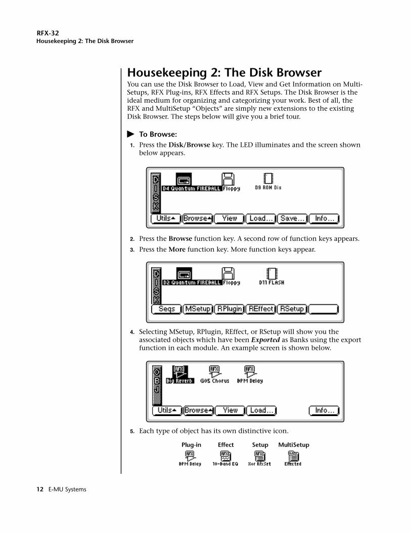
Housekeeping 2: The Disk BrowserYou can use the Disk Browser to Load, View and Get Information on Multi-Setups, RFX Plug-ins, RFX Effects and RFX Setups. The Disk Browser is the ideal medium for organizing and categorizing your work. Best of all, the RFX and MultiSetup “Objects” are simply new extensions to the existing Disk Browser. The steps below will give you a brief tour.
� To Browse:1. Press the Disk/Browse key. The LED illuminates and the screen shown
below appears.
2. Press the Browse function key. A second row of function keys appears.
3. Press the More function key. More function keys appear.
4. Selecting MSetup, RPlugin, REffect, or RSetup will show you the associated objects which have been Exported as Banks using the export function in each module. An example screen is shown below.
5. Each type of object has its own distinctive icon.
Plug-in Effect Setup MultiSetup
12 E-MU Systems
RFX-32Housekeeping 2: The Disk Browser
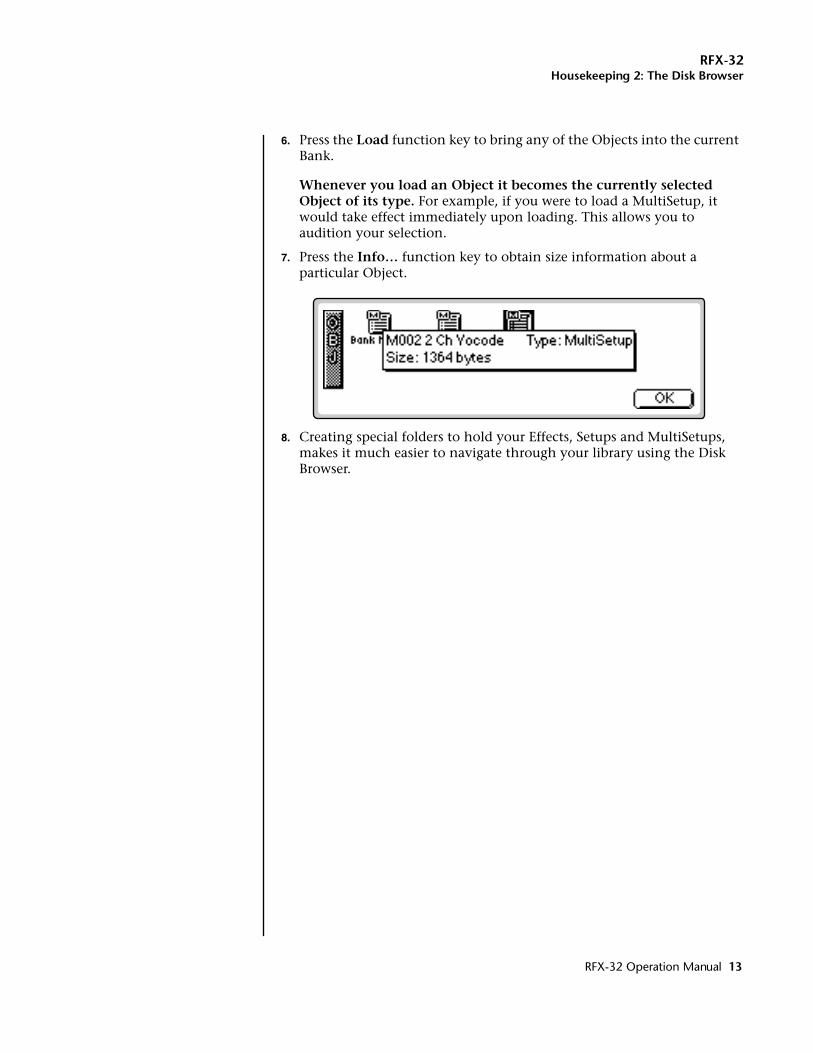
6. Press the Load function key to bring any of the Objects into the current Bank.
Whenever you load an Object it becomes the currently selected Object of its type. For example, if you were to load a MultiSetup, it would take effect immediately upon loading. This allows you to audition your selection.
7. Press the Info… function key to obtain size information about a particular Object.
8. Creating special folders to hold your Effects, Setups and MultiSetups, makes it much easier to navigate through your library using the Disk Browser.
RFX-32 Operation Manual 13
RFX-32Putting it all together
Putting it all togetherOK, enough theory. Now let's walk through the three main steps of putting together an RFX Setup.
� Step 1 - Create a new Effect:Before you can program an RFX Setup, you’ll need at least one effect preset. If you already have Effect presets in the bank, skip to step 2.
1. Press the Master button. The memory screen appears.
2. Press the FX function key. Another row of function keys appears.
3. Press the REffect function key. The RFX Effect Manage screen appears.
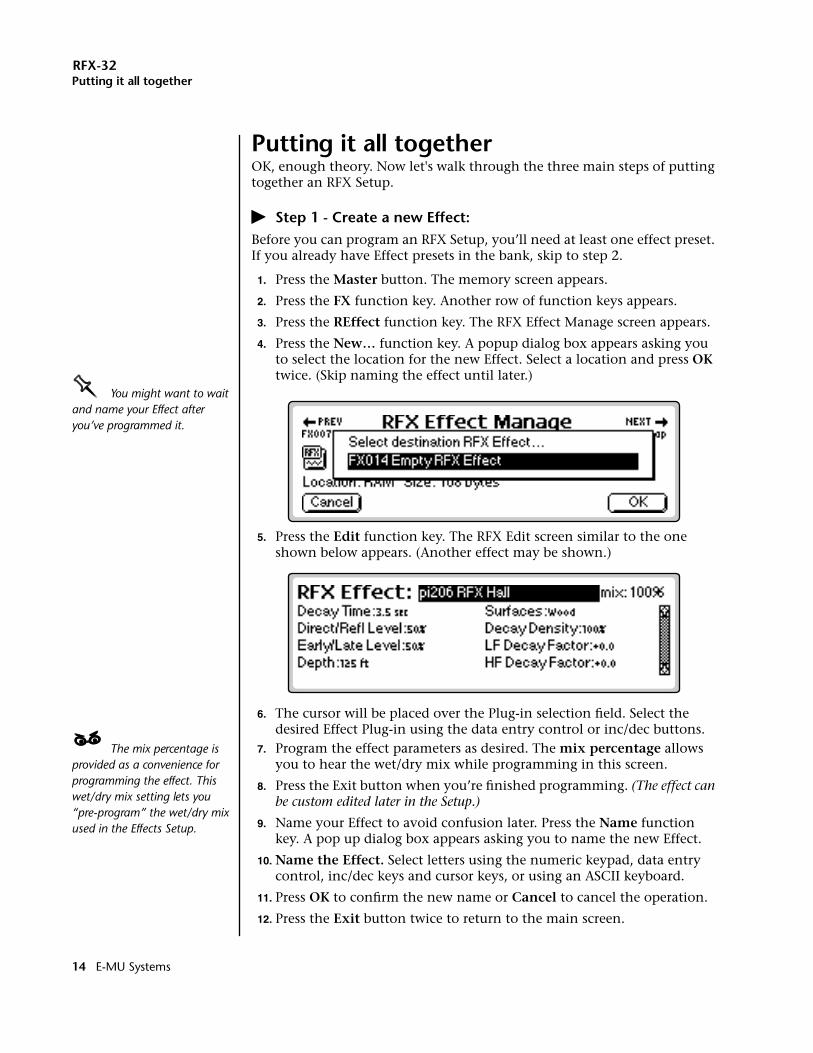
4. Press the New… function key. A popup dialog box appears asking you to select the location for the new Effect. Select a location and press OK twice. (Skip naming the effect until later.)
OOOO You might want to wait and name your Effect after you’ve programmed it.
5. Press the Edit function key. The RFX Edit screen similar to the one shown below appears. (Another effect may be shown.)
6. The cursor will be placed over the Plug-in selection field. Select the desired Effect Plug-in using the data entry control or inc/dec buttons.
____ The mix percentage is provided as a convenience for programming the effect. This wet/dry mix setting lets you “pre-program” the wet/dry mix used in the Effects Setup.
7. Program the effect parameters as desired. The mix percentage allows you to hear the wet/dry mix while programming in this screen.
8. Press the Exit button when you’re finished programming. (The effect can be custom edited later in the Setup.)
9. Name your Effect to avoid confusion later. Press the Name function key. A pop up dialog box appears asking you to name the new Effect.
10. Name the Effect. Select letters using the numeric keypad, data entry control, inc/dec keys and cursor keys, or using an ASCII keyboard.
11. Press OK to confirm the new name or Cancel to cancel the operation.
12. Press the Exit button twice to return to the main screen.
14 E-MU Systems
RFX-32Putting it all together
� Step 2 - Build an Effect Setup:Now that you have an Effect preset, you need to assign it to the RFX bus.
1. Press the Master button. The memory screen appears.
2. Press the FX function key. Another row of function keys appears.
3. Press the RSetup function key. The RFX Setup Manage screen appears.
4. Press the New… function key. A popup dialog box appears asking you to select the location for the new Setup. Select a location and press OK.
5. Name the Setup to avoid confusion later. Select letters using the numeric keypad, data entry control, inc/dec keys and cursor keys, or using an ASCII keyboard.
6. Press OK to confirm the new name or Cancel to cancel the operation.
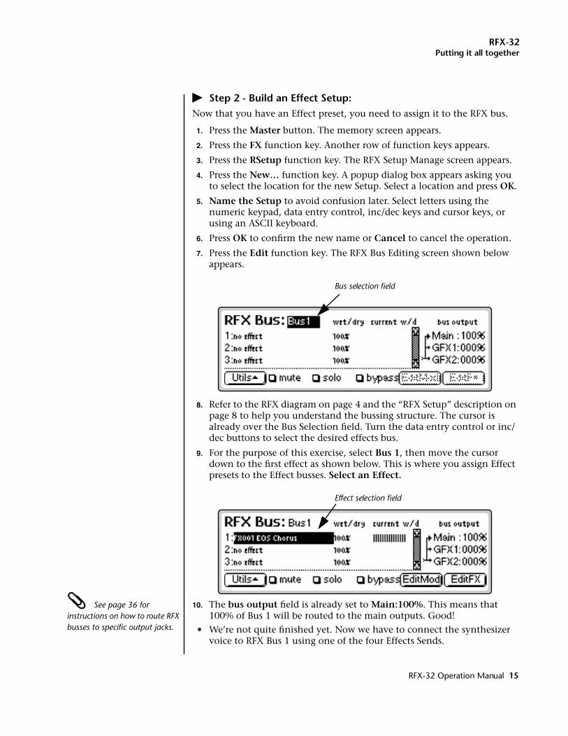
7. Press the Edit function key. The RFX Bus Editing screen shown below appears.
8. Refer to the RFX diagram on page 4 and the “RFX Setup” description on page 8 to help you understand the bussing structure. The cursor is already over the Bus Selection field. Turn the data entry control or inc/dec buttons to select the desired effects bus.
9. For the purpose of this exercise, select Bus 1, then move the cursor down to the first effect as shown below. This is where you assign Effect presets to the Effect busses. Select an Effect.
See page 36 for instructions on how to route RFX busses to specific output jacks.
10. The bus output field is already set to Main:100%. This means that 100% of Bus 1 will be routed to the main outputs. Good!
• We’re not quite finished yet. Now we have to connect the synthesizer voice to RFX Bus 1 using one of the four Effects Sends.
Bus selection field
Effect selection field
RFX-32 Operation Manual 15
RFX-32Putting it all together
� Step 3 - Program the Effect Sends by Voice:Effect Sends can be programmed by Voice or MIDI channel. We’ll start by programming by voice. Before you begin, set the E4 into Omni or Poly mode. (From the main screen press Mode, then Whole.)
1. Select a Preset of your choice.
2. Press the Preset Edit button. The Voices-Main screen appears.
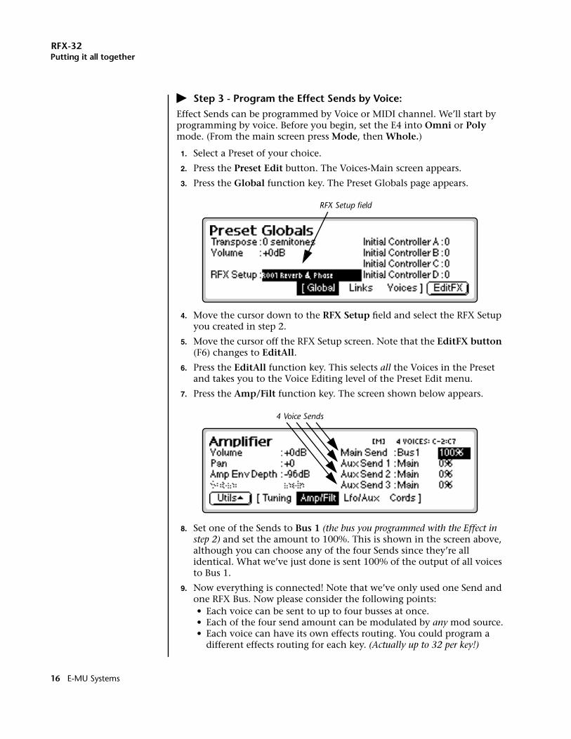
3. Press the Global function key. The Preset Globals page appears.
4. Move the cursor down to the RFX Setup field and select the RFX Setup you created in step 2.
5. Move the cursor off the RFX Setup screen. Note that the EditFX button (F6) changes to EditAll.
6. Press the EditAll function key. This selects all the Voices in the Preset and takes you to the Voice Editing level of the Preset Edit menu.
7. Press the Amp/Filt function key. The screen shown below appears.
8. Set one of the Sends to Bus 1 (the bus you programmed with the Effect in step 2) and set the amount to 100%. This is shown in the screen above, although you can choose any of the four Sends since they’re all identical. What we’ve just done is sent 100% of the output of all voices to Bus 1.
9. Now everything is connected! Note that we’ve only used one Send and one RFX Bus. Now please consider the following points:• Each voice can be sent to up to four busses at once.• Each of the four send amount can be modulated by any mod source.• Each voice can have its own effects routing. You could program a
different effects routing for each key. (Actually up to 32 per key!)
RFX Setup field
4 Voice Sends
16 E-MU Systems
RFX-32Putting it all together
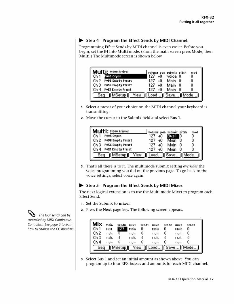
� Step 4 - Program the Effect Sends by MIDI Channel:Programming Effect Sends by MIDI channel is even easier. Before you begin, set the E4 into Multi mode. (From the main screen press Mode, then Multi.) The Multimode screen is shown below.
1. Select a preset of your choice on the MIDI channel your keyboard is transmitting.
2. Move the cursor to the Submix field and select Bus 1.
3. That’s all there is to it. The multimode submix setting overrides the voice programming you did on the previous page. To go back to the voice settings, select voice again.
� Step 5 - Program the Effect Sends by MIDI Mixer:The next logical extension is to use the Multi mode Mixer to program each Effect Send.
1. Set the Submix to mixer.
2. Press the Next page key. The following screen appears. The four sends can be controlled by MIDI Continuous Controllers. See page 6 to learn how to change the CC numbers.
3. Select Bus 1 and set an initial amount as shown above. You can program up to four RFX busses and amounts for each MIDI channel.
RFX-32 Operation Manual 17
RFX-32Plug-in Manage
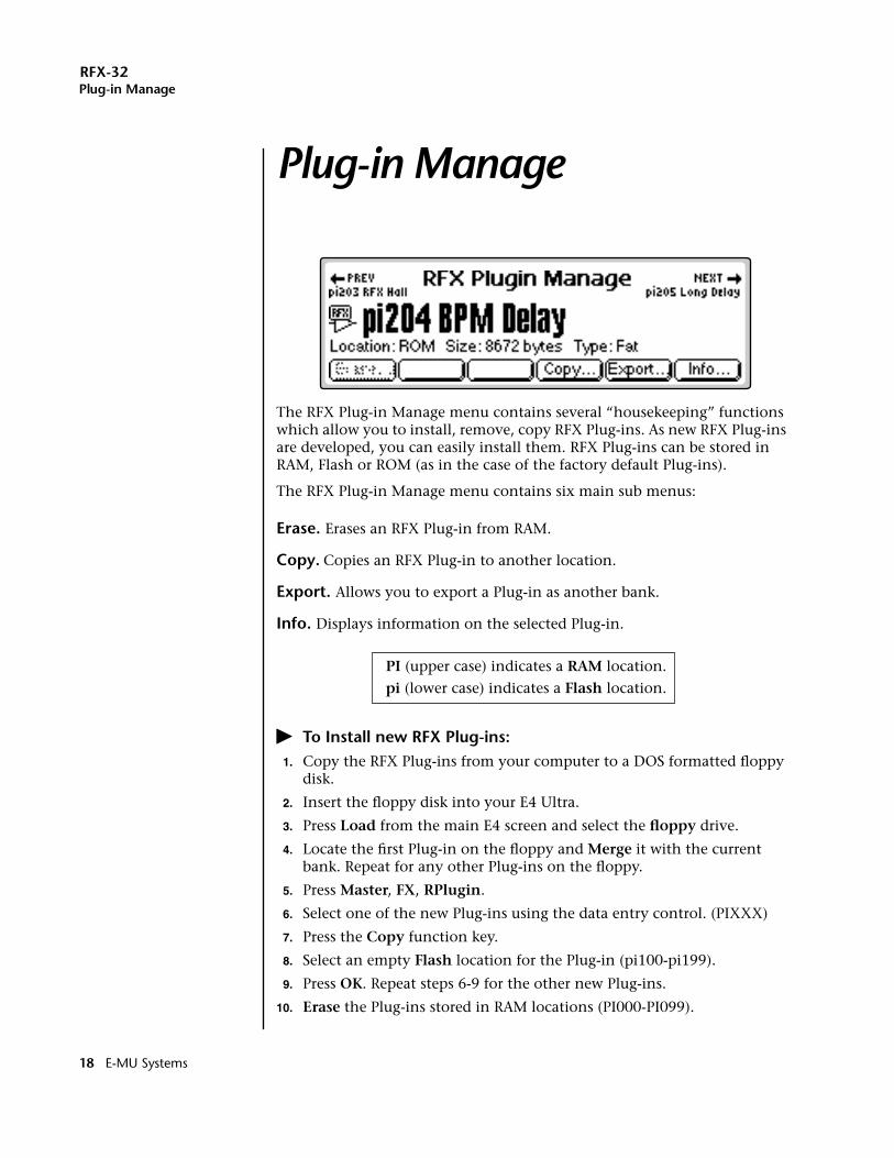
Plug-in ManagePlug-in Manage
The RFX Plug-in Manage menu contains several “housekeeping” functions which allow you to install, remove, copy RFX Plug-ins. As new RFX Plug-ins are developed, you can easily install them. RFX Plug-ins can be stored in RAM, Flash or ROM (as in the case of the factory default Plug-ins).
The RFX Plug-in Manage menu contains six main sub menus:
Erase. Erases an RFX Plug-in from RAM.
Copy. Copies an RFX Plug-in to another location.
Export. Allows you to export a Plug-in as another bank.
Info. Displays information on the selected Plug-in.
PI (upper case) indicates a RAM location.
pi (lower case) indicates a Flash location.
� To Install new RFX Plug-ins:1. Copy the RFX Plug-ins from your computer to a DOS formatted floppy
disk.
2. Insert the floppy disk into your E4 Ultra.
3. Press Load from the main E4 screen and select the floppy drive.
4. Locate the first Plug-in on the floppy and Merge it with the current bank. Repeat for any other Plug-ins on the floppy.
5. Press Master, FX, RPlugin.
6. Select one of the new Plug-ins using the data entry control. (PIXXX)
7. Press the Copy function key.
8. Select an empty Flash location for the Plug-in (pi100-pi199).
9. Press OK. Repeat steps 6-9 for the other new Plug-ins.
10. Erase the Plug-ins stored in RAM locations (PI000-PI099).
18 E-MU Systems
RFX-32Erase Plug-in
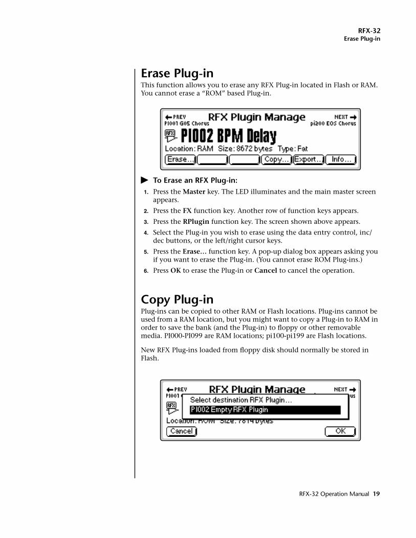
Erase Plug-inThis function allows you to erase any RFX Plug-in located in Flash or RAM. You cannot erase a “ROM” based Plug-in.
� To Erase an RFX Plug-in:1. Press the Master key. The LED illuminates and the main master screen
appears.
2. Press the FX function key. Another row of function keys appears.
3. Press the RPlugin function key. The screen shown above appears.
4. Select the Plug-in you wish to erase using the data entry control, inc/dec buttons, or the left/right cursor keys.
5. Press the Erase… function key. A pop-up dialog box appears asking you if you want to erase the Plug-in. (You cannot erase ROM Plug-ins.)
6. Press OK to erase the Plug-in or Cancel to cancel the operation.
Copy Plug-inPlug-ins can be copied to other RAM or Flash locations. Plug-ins cannot be used from a RAM location, but you might want to copy a Plug-in to RAM in order to save the bank (and the Plug-in) to floppy or other removable media. PI000-PI099 are RAM locations; pi100-pi199 are Flash locations.
New RFX Plug-ins loaded from floppy disk should normally be stored in Flash.
RFX-32 Operation Manual 19
RFX-32Export Plug-in
� To Copy a Plug-in:1. Press the Master key. The LED illuminates and the main master screen
appears.
2. Press the FX function key. Another row of function keys appears.
3. Press the RPlugin function key. The Plug-in Manage screen appears.
4. Select the Plug-in you wish to copy using the data entry control, inc/dec buttons, or the left/right cursor keys.
5. Press the Copy… function key. A pop-up dialog box appears asking you to select the destination for the Plug-in. (RAM: 000-099; Flash 100-199)
6. Select the destination using the data entry control or inc/dec buttons.
7. Press OK to copy the Plug-in or Cancel to cancel the operation.
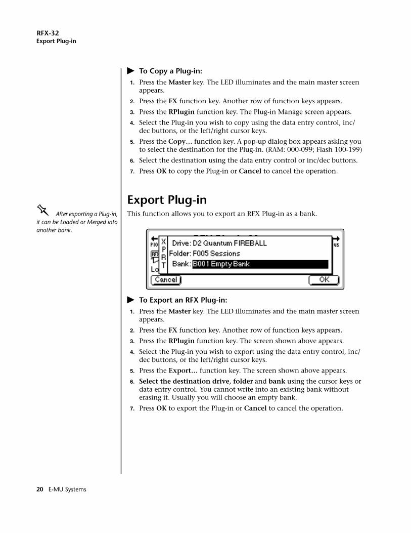
Export Plug-inOOOO After exporting a Plug-in, it can be Loaded or Merged into another bank.
This function allows you to export an RFX Plug-in as a bank.
� To Export an RFX Plug-in:1. Press the Master key. The LED illuminates and the main master screen
appears.
2. Press the FX function key. Another row of function keys appears.
3. Press the RPlugin function key. The screen shown above appears.
4. Select the Plug-in you wish to export using the data entry control, inc/dec buttons, or the left/right cursor keys.
5. Press the Export… function key. The screen shown above appears.
6. Select the destination drive, folder and bank using the cursor keys or data entry control. You cannot write into an existing bank without erasing it. Usually you will choose an empty bank.
7. Press OK to export the Plug-in or Cancel to cancel the operation.
20 E-MU Systems
RFX-32Get Info
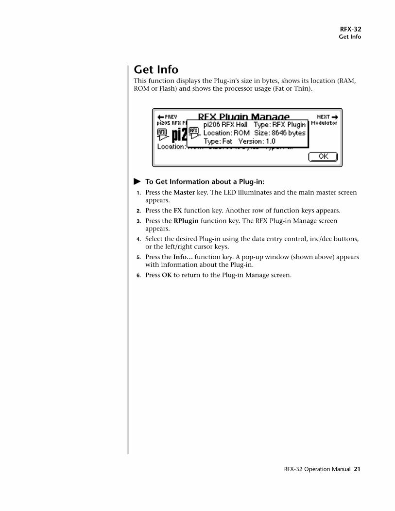
Get InfoThis function displays the Plug-in's size in bytes, shows its location (RAM, ROM or Flash) and shows the processor usage (Fat or Thin).
� To Get Information about a Plug-in:1. Press the Master key. The LED illuminates and the main master screen
appears.
2. Press the FX function key. Another row of function keys appears.
3. Press the RPlugin function key. The RFX Plug-in Manage screen appears.
4. Select the desired Plug-in using the data entry control, inc/dec buttons, or the left/right cursor keys.
5. Press the Info… function key. A pop-up window (shown above) appears with information about the Plug-in.
6. Press OK to return to the Plug-in Manage screen.
RFX-32 Operation Manual 21
RFX-32Get Info
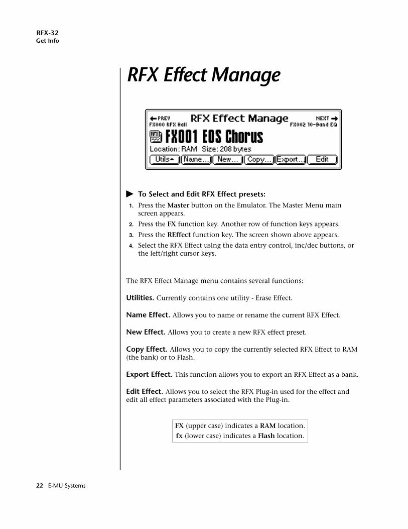
RFX Effect Manage
� To Select and Edit RFX Effect presets:1. Press the Master button on the Emulator. The Master Menu main
screen appears.
2. Press the FX function key. Another row of function keys appears.
3. Press the REffect function key. The screen shown above appears.
4. Select the RFX Effect using the data entry control, inc/dec buttons, or the left/right cursor keys.
The RFX Effect Manage menu contains several functions:
Utilities. Currently contains one utility - Erase Effect.
Name Effect. Allows you to name or rename the current RFX Effect.
New Effect. Allows you to create a new RFX effect preset.
Copy Effect. Allows you to copy the currently selected RFX Effect to RAM (the bank) or to Flash.
Export Effect. This function allows you to export an RFX Effect as a bank.
Edit Effect. Allows you to select the RFX Plug-in used for the effect and edit all effect parameters associated with the Plug-in.
FX (upper case) indicates a RAM location.
fx (lower case) indicates a Flash location.
22 E-MU Systems
RFX-32Utilities
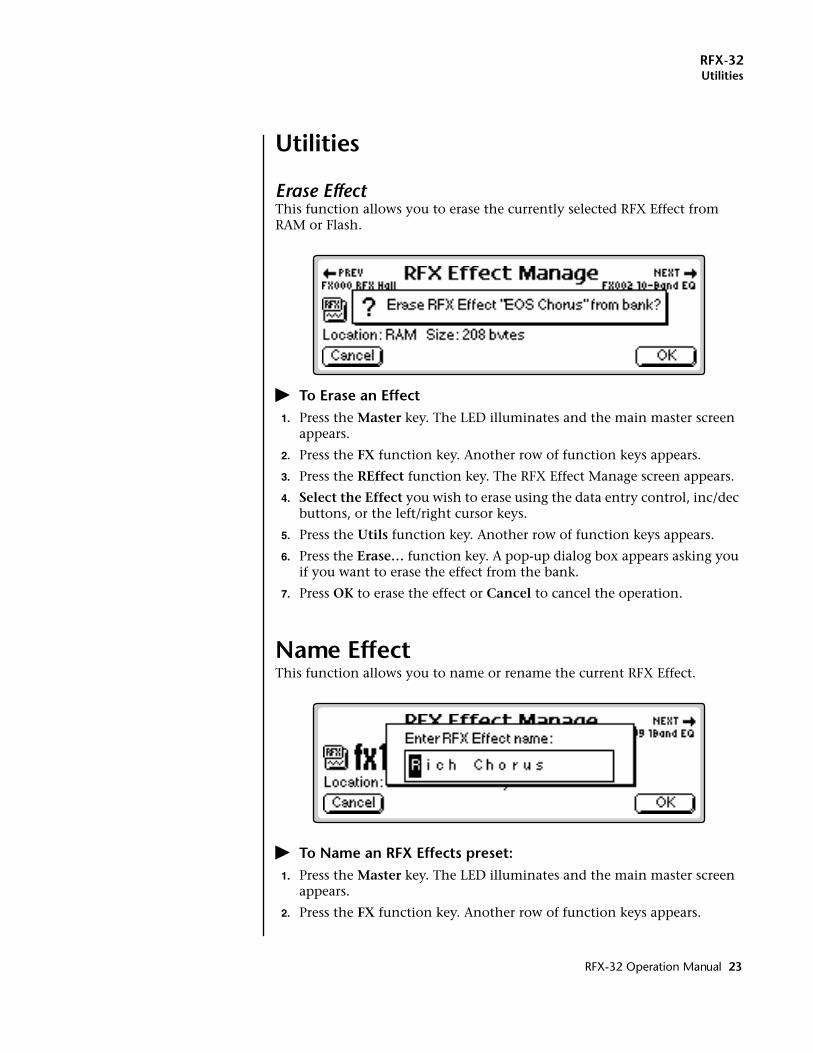
Utilities
Erase EffectThis function allows you to erase the currently selected RFX Effect from RAM or Flash.
� To Erase an Effect1. Press the Master key. The LED illuminates and the main master screen
appears.
2. Press the FX function key. Another row of function keys appears.
3. Press the REffect function key. The RFX Effect Manage screen appears.
4. Select the Effect you wish to erase using the data entry control, inc/dec buttons, or the left/right cursor keys.
5. Press the Utils function key. Another row of function keys appears.
6. Press the Erase… function key. A pop-up dialog box appears asking you if you want to erase the effect from the bank.
7. Press OK to erase the effect or Cancel to cancel the operation.
Name EffectThis function allows you to name or rename the current RFX Effect.
� To Name an RFX Effects preset:1. Press the Master key. The LED illuminates and the main master screen
appears.
2. Press the FX function key. Another row of function keys appears.
RFX-32 Operation Manual 23
RFX-32New Effect
3. Press the REffect function key. The RFX Effect Manage screen appears.
4. Select the Effect you wish to name using the data entry control, inc/dec buttons, or the left/right cursor keys.
5. Press the Name function key. A pop up dialog box appears asking you to enter the new RFX Effect name.
6. Name the Effect. Select letters using the numeric keypad, data entry control, inc/dec keys and cursor keys, or using an ASCII keyboard.
7. Press OK to confirm the new name or Cancel to cancel the operation.
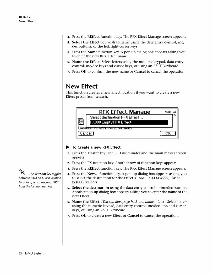
New EffectThis function creates a new Effect location if you want to create a new Effect preset from scratch.
� To Create a new RFX Effect:1. Press the Master key. The LED illuminates and the main master screen
appears.
2. Press the FX function key. Another row of function keys appears.
3. Press the REffect function key. The RFX Effect Manage screen appears.
OOOO The Set/Shift key toggles between RAM and Flash location by adding or subtracting 1000 from the location number.
4. Press the New… function key. A pop-up dialog box appears asking you to select the destination for the Effect. (RAM: FX000-FX999; Flash: fx1000-fx1999)
5. Select the destination using the data entry control or inc/dec buttons. Another pop-up dialog box appears asking you to enter the name of the new Effect.
6. Name the Effect. (You can always go back and name it later). Select letters using the numeric keypad, data entry control, inc/dec keys and cursor keys, or using an ASCII keyboard.
7. Press OK to create a new Effect or Cancel to cancel the operation.
24 E-MU Systems
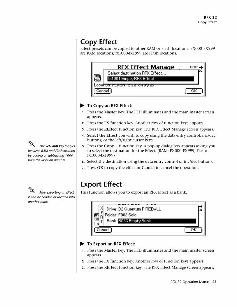
RFX-32Copy Effect
Copy EffectEffect presets can be copied to other RAM or Flash locations. FX000-FX999 are RAM locations; fx1000-fx1999 are Flash locations.
� To Copy an RFX Effect:1. Press the Master key. The LED illuminates and the main master screen
appears.
2. Press the FX function key. Another row of function keys appears.
3. Press the REffect function key. The RFX Effect Manage screen appears.
4. Select the Effect you wish to copy using the data entry control, inc/dec buttons, or the left/right cursor keys.
OOOO The Set/Shift key toggles between RAM and Flash location by adding or subtracting 1000 from the location number.
5. Press the Copy… function key. A pop-up dialog box appears asking you to select the destination for the Effect. (RAM: FX000-FX999; Flash: fx1000-fx1999)
6. Select the destination using the data entry control or inc/dec buttons.
7. Press OK to copy the effect or Cancel to cancel the operation.
Export EffectOOOO After exporting an Effect, it can be Loaded or Merged into another bank.
This function allows you to export an RFX Effect as a bank.
� To Export an RFX Effect:1. Press the Master key. The LED illuminates and the main master screen
appears.
2. Press the FX function key. Another row of function keys appears.
3. Press the REffect function key. The RFX Effect Manage screen appears.
RFX-32 Operation Manual 25
RFX-32Edit Effect
4. Select the Effect you wish to export using the data entry control, inc/dec buttons, or the left/right cursor keys.
5. Press the Export… function key. A pop-up dialog box appears asking you to select the destination for the Effect.
6. Select the destination drive, folder and bank using the cursor keys and data entry control. You cannot write into an existing bank without erasing it. Usually you will choose an empty bank.
7. Press OK to export the Effect or Cancel to cancel the operation.
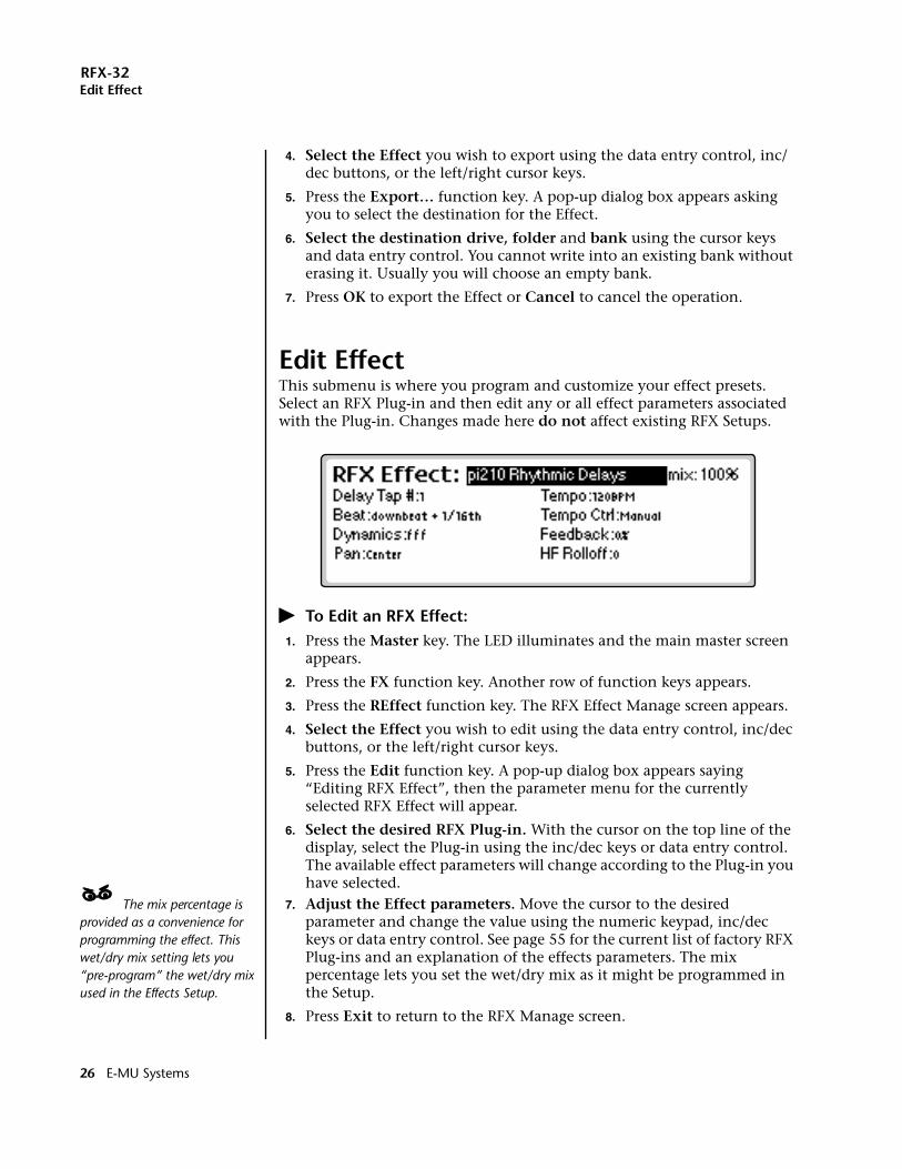
Edit EffectThis submenu is where you program and customize your effect presets. Select an RFX Plug-in and then edit any or all effect parameters associated with the Plug-in. Changes made here do not affect existing RFX Setups.
� To Edit an RFX Effect:1. Press the Master key. The LED illuminates and the main master screen
appears.
2. Press the FX function key. Another row of function keys appears.
3. Press the REffect function key. The RFX Effect Manage screen appears.
4. Select the Effect you wish to edit using the data entry control, inc/dec buttons, or the left/right cursor keys.
5. Press the Edit function key. A pop-up dialog box appears saying “Editing RFX Effect”, then the parameter menu for the currently selected RFX Effect will appear.
6. Select the desired RFX Plug-in. With the cursor on the top line of the display, select the Plug-in using the inc/dec keys or data entry control. The available effect parameters will change according to the Plug-in you have selected.
____ The mix percentage is provided as a convenience for programming the effect. This wet/dry mix setting lets you “pre-program” the wet/dry mix used in the Effects Setup.
7. Adjust the Effect parameters. Move the cursor to the desired parameter and change the value using the numeric keypad, inc/dec keys or data entry control. See page 55 for the current list of factory RFX Plug-ins and an explanation of the effects parameters. The mix percentage lets you set the wet/dry mix as it might be programmed in the Setup.
8. Press Exit to return to the RFX Manage screen.
26 E-MU Systems
RFX-32RFX Effects Setup
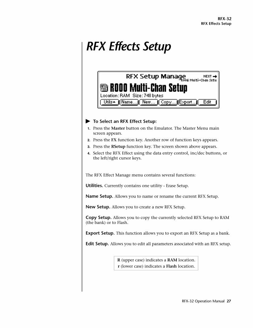
RFX Effects SetupRFX Effects Setup
� To Select an RFX Effect Setup:1. Press the Master button on the Emulator. The Master Menu main
screen appears.
2. Press the FX function key. Another row of function keys appears.
3. Press the RSetup function key. The screen shown above appears.
4. Select the RFX Effect using the data entry control, inc/dec buttons, or the left/right cursor keys.
The RFX Effect Manage menu contains several functions:
Utilities. Currently contains one utility - Erase Setup.
Name Setup. Allows you to name or rename the current RFX Setup.
New Setup. Allows you to create a new RFX Setup.
Copy Setup. Allows you to copy the currently selected RFX Setup to RAM (the bank) or to Flash.
Export Setup. This function allows you to export an RFX Setup as a bank.
Edit Setup. Allows you to edit all parameters associated with an RFX setup.
R (upper case) indicates a RAM location.
r (lower case) indicates a Flash location.
RFX-32 Operation Manual 27
RFX-32Utilities
Utilities
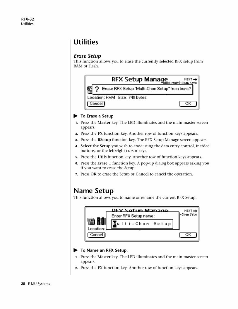
Erase SetupThis function allows you to erase the currently selected RFX setup from RAM or Flash.
� To Erase a Setup1. Press the Master key. The LED illuminates and the main master screen
appears.
2. Press the FX function key. Another row of function keys appears.
3. Press the RSetup function key. The RFX Setup Manage screen appears.
4. Select the Setup you wish to erase using the data entry control, inc/dec buttons, or the left/right cursor keys.
5. Press the Utils function key. Another row of function keys appears.
6. Press the Erase… function key. A pop-up dialog box appears asking you if you want to erase the Setup.
7. Press OK to erase the Setup or Cancel to cancel the operation.
Name SetupThis function allows you to name or rename the current RFX Setup.
� To Name an RFX Setup:1. Press the Master key. The LED illuminates and the main master screen
appears.
2. Press the FX function key. Another row of function keys appears.
28 E-MU Systems
RFX-32New Setup
3. Press the RSetup function key. The RFX Setup Manage screen appears.
4. Select the Setup you wish to name using the data entry control, inc/dec buttons, or the left/right cursor keys.
5. Press the Name function key. A pop up dialog box appears asking you to enter the new RFX Setup name.
6. Name the Setup. Select letters using the numeric keypad, data entry control, inc/dec keys and cursor keys, or using an ASCII keyboard.
7. Press OK to confirm the new name or Cancel to cancel the operation.
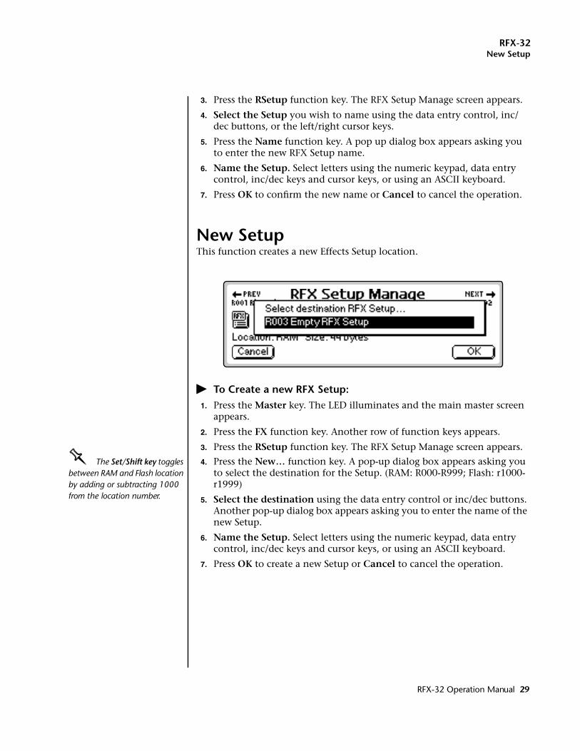
New SetupThis function creates a new Effects Setup location.
� To Create a new RFX Setup:1. Press the Master key. The LED illuminates and the main master screen
appears.
2. Press the FX function key. Another row of function keys appears.
3. Press the RSetup function key. The RFX Setup Manage screen appears.
OOOO The Set/Shift key toggles between RAM and Flash location by adding or subtracting 1000 from the location number.
4. Press the New… function key. A pop-up dialog box appears asking you to select the destination for the Setup. (RAM: R000-R999; Flash: r1000-r1999)
5. Select the destination using the data entry control or inc/dec buttons. Another pop-up dialog box appears asking you to enter the name of the new Setup.
6. Name the Setup. Select letters using the numeric keypad, data entry control, inc/dec keys and cursor keys, or using an ASCII keyboard.
7. Press OK to create a new Setup or Cancel to cancel the operation.
RFX-32 Operation Manual 29
RFX-32Copy Setup
Copy SetupRFX Setups can be copied to RAM or Flash locations. R000-R999 are RAM locations; r1000-r1999 are Flash locations.
� To Copy an RFX Setup:1. Press the Master key. The LED illuminates and the main master screen
appears.
2. Press the FX function key. Another row of function keys appears.
3. Press the RSetup function key. The RFX Setup Manage screen appears.
4. Select the Setup you wish to copy using the data entry control, inc/dec buttons, or the left/right cursor keys.
OOOO The Set/Shift key toggles between RAM and Flash location by adding or subtracting 1000 from the location number.
5. Press the Copy… function key. A pop-up dialog box appears asking you to select the destination for the Setup. (RAM: R000-R999; Flash: r1000-r1999)
6. Select the destination using the data entry control or inc/dec buttons.
7. Press OK to copy the Setup or Cancel to cancel the operation.
30 E-MU Systems
RFX-32Export Setup
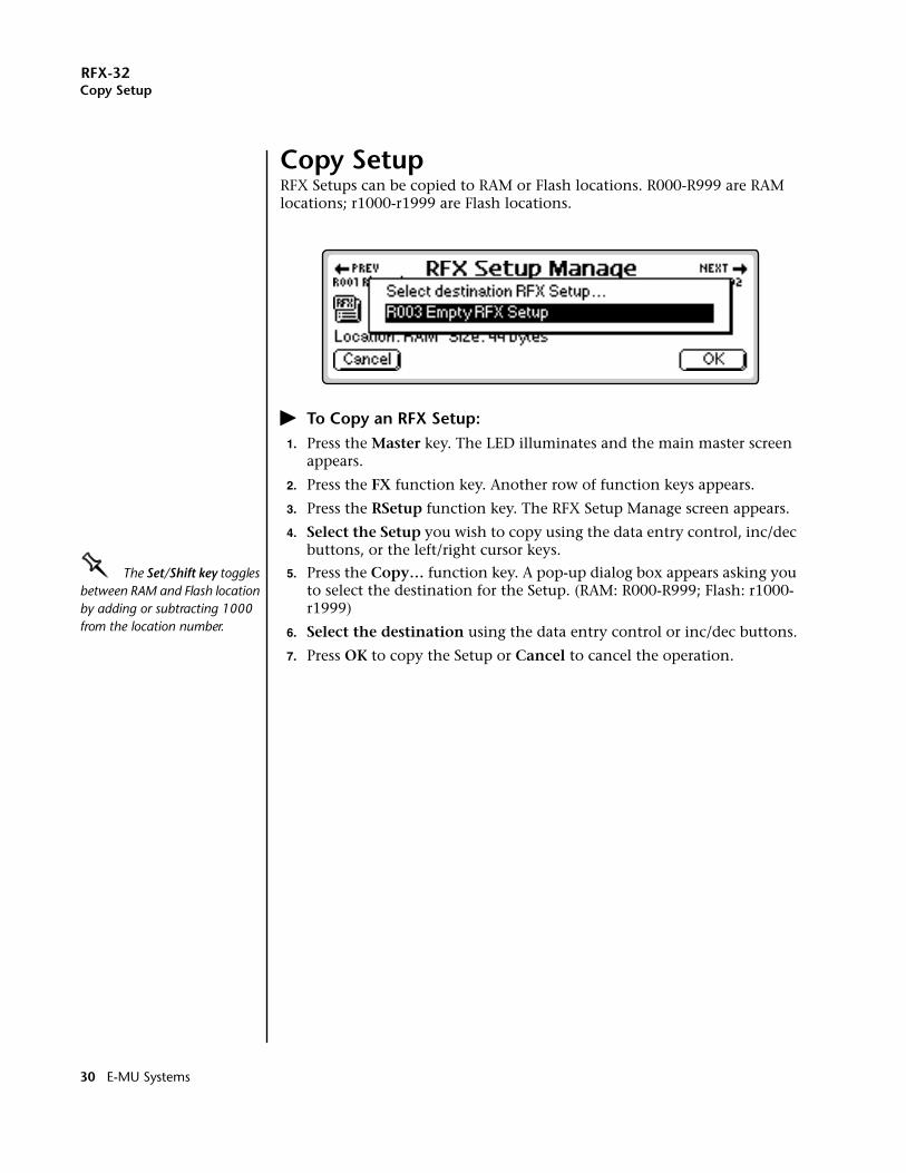
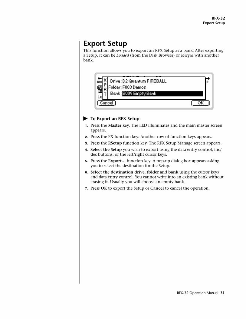
Export SetupThis function allows you to export an RFX Setup as a bank. After exporting a Setup, it can be Loaded (from the Disk Browser) or Merged with another bank.
� To Export an RFX Setup:1. Press the Master key. The LED illuminates and the main master screen
appears.
2. Press the FX function key. Another row of function keys appears.
3. Press the RSetup function key. The RFX Setup Manage screen appears.
4. Select the Setup you wish to export using the data entry control, inc/dec buttons, or the left/right cursor keys.
5. Press the Export… function key. A pop-up dialog box appears asking you to select the destination for the Setup.
6. Select the destination drive, folder and bank using the cursor keys and data entry control. You cannot write into an existing bank without erasing it. Usually you will choose an empty bank.
7. Press OK to export the Setup or Cancel to cancel the operation.
RFX-32 Operation Manual 31
RFX
RFX Block Diagram
Aux Send 1
Main Send
Aux Send 2
Aux Send 3
Voice 128
Programmed byMIDI channel
Bus 1
Bus 2
Bus 3
Bus 4Bus 5
Bus 6Bus 7 Bu
s 8
Bus
9Bu
s 10
Bus 1
1Bu
s 12
GFX 1
GFX 2
Main
FX 1 Return
FX 2 Return
Aux Send 1
Main Send
Aux Send 2
Aux Send 3
Bus FX1 Bus FX2 Bus FX3 Bus FX4 Bus FX5 Bus FX6
MAIN
Main
GFX 2
GFX 1
Global FX 1
Bus FX7 Bus FX8 Bus FX9 Bus FX10 Bus FX11 Bus FX12
Voice 1
GFX
1
Bus 1
Bus 2
Bus 3
Bus 4
Bus 5
Bus 6
Bus 7
Bus 8
Bus 9
Bus 10
Bus 11
Bus 12
GFX
2
Main
MAIN SUB 1 SUB 2 SUB 3 SUB 4 SUB 5 SUB 6 SUB 7
Analog Expansion Cardand ADAT 9-16 Out
Standard Analog Outputsand ADAT 1-8 Out
1 of 15
(Press Right Page key from RSetup, Edit)
RFX Output Map
• All buses are stereo• Up to 6 effects per bus• 16 effects maximum
Programmedby Voice
MIDI Ch.01A02A
16B
FX BusBus 1GFX 2
Bus 12
(Multimode menu) (Multimode menu)
Programmedby MIDI Mixer
(Voice Edit menu)
Global FX 2
Bus
1Bu
s 2Bu
s 3
Bus 4
Bus 5
Bus 6
Bus 7Bus 8Bus 9Bus 10Bus 11Bus 12
GFX 1
GFX 2
Main
1 of 15
Aux Send 1
Main Send
Aux Send 2
Aux Send 3
Aux Send 1
Main Send
Aux Send 2
Aux Send 3
MIDI Chan 1 MIDI Chan 32
Bus
1Bu
s 2Bu
s 3
Bus 4
Bus 5
Bus 6
Bus 7Bus 8Bus 9Bus 10Bus 11Bus 12
GFX 1
GFX 2
Main
1 of 15
1. 2. 3.
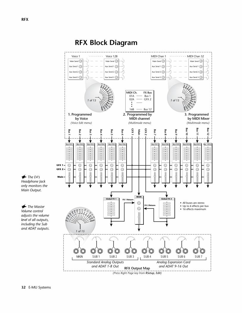
� The Master Volume control adjusts the volume level of all outputs, including the Sub and ADAT outputs.
� The E4’s Headphone Jack only monitors the Main Output.
32 E-MU Systems
RFX-32Edit Setup
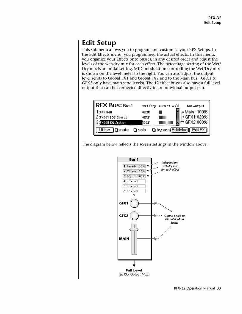
Edit SetupThis submenu allows you to program and customize your RFX Setups. In the Edit Effects menu, you programmed the actual effects. In this menu, you organize your Effects onto busses, in any desired order and adjust the levels of the wet/dry mix for each effect. The percentage setting of the Wet/Dry mix is an initial setting. MIDI modulation controlling the Wet/Dry mix is shown on the level meter to the right. You can also adjust the output level sends to Global FX1 and Global FX2 and to the Main bus. (GFX1 & GFX2 only have main send levels). The 12 effect busses also have a full level output that can be connected directly to an individual output pair.
The diagram below reflects the screen settings in the window above.
Bus 1
GFX1
GFX2
MAIN
1
2
3
4
5
6
55%
15%
Reverb
Chorus
no effect
no effect
no effect
EQ 100%
Independant wet/dry mix
for each effect
Output Levels toGlobal & Main
Busses
Full Level(to RFX Output Map)
RFX-32 Operation Manual 33
RFX-32Edit Setup
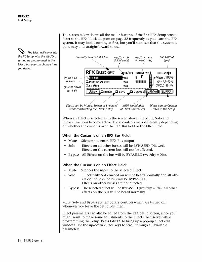
The screen below shows all the major features of the first RFX Setup screen. Refer to the RFX block diagram on page 32 frequently as you learn the RFX system. It may look daunting at first, but you’ll soon see that the system is quite easy and straightforward to use.
The Effect will come into the FX Setup with the Wet/Dry setting as programmed in the Effect, but you can change it as you desire.
When an Effect is selected as in the screen above, the Mute, Solo and Bypass functions become active. These controls work differently depending on whether the cursor is over the RFX Bus field or the Effect field.
When the Cursor is on an RFX Bus Field:• Mute Silences the entire RFX Bus output
• Solo Effects on all other busses will be BYPASSED (0% wet).Effects on the current bus will not be affected.
• Bypass All Effects on the bus will be BYPASSED (wet/dry = 0%).
When the Cursor is on an Effect Field:• Mute Silences the input to the selected Effect.
• Solo Effects with Solo turned on will be heard normally and all oth-ers on the selected bus will be BYPASSED.Effects on other busses are not affected.
• Bypass The selected effect will be BYPASSED (wet/dry = 0%). All other effects on the bus will be heard normally.
Mute, Solo and Bypass are temporary controls which are turned off whenever you leave the Setup Edit menu.
Effect parameters can also be edited from the RFX Setup screen, since you might want to make some adjustments to the Effects themselves while programming the Setup. Press EditFX to bring up a pop-up effect edit window. Use the up/down cursor keys to scroll through all available parameters.
Currently Selected RFX Bus Wet/Dry mix
Up to 6 FX in series
Bus OutputLevel
Effects can be CustomEdited in the Setup
(Cursor downfor 4-6)
MIDI Modulation of Effect parameterswhile constructing the Effects Setup
Effects can be Muted, Soloed or Bypassed
Wet/Dry meter(current state)(initial state)
34 E-MU Systems
RFX-32Edit Setup
OOOO Tip: Use the “WriteFX” feature to save edited Effects as independent RFX Effects. See page 38.
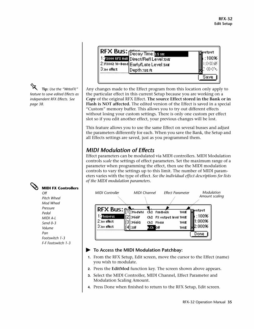
Any changes made to the Effect program from this location only apply to the particular effect in this current Setup because you are working on a Copy of the original RFX Effect. The source Effect stored in the Bank or in Flash is NOT affected. The edited version of the Effect is saved in a special “Custom” memory buffer. This allows you to try out different effects without losing your custom settings. There is only one custom per effect slot so if you edit another effect, your previous changes will be lost.
This feature allows you to use the same Effect on several busses and adjust the parameters differently for each. When you save the Bank, the Setup and all Effects settings are saved, just as you programmed them.
MIDI Modulation of EffectsEffect parameters can be modulated via MIDI controllers. MIDI Modulation controls scale the settings of effect parameters. Set the maximum range of a parameter when programming the effect, then use the MIDI modulation controls to vary the settings up to this limit. The number of MIDI param-eters varies with the type of effect. See the individual effect descriptions for lists of the MIDI modulation parameters.
MIDI FX ControllersOffPitch WheelMod WheelPressurePedalMIDI A-LSend 0-3VolumePanFootswitch 1-3F-F Footswitch 1-3
� To Access the MIDI Modulation Patchbay:1. From the RFX Setup, Edit screen, move the cursor to the Effect (name)
you wish to modulate.
2. Press the EditMod function key. The screen shown above appears.
3. Select the MIDI Controller, MIDI Channel, Effect Parameter and Modulation Scaling Amount.
4. Press Done when finished to return to the RFX Setup, Edit screen.
MIDI Controller MIDI Channel ModulationEffect ParameterAmount scaling
RFX-32 Operation Manual 35
RFX-32Edit Setup
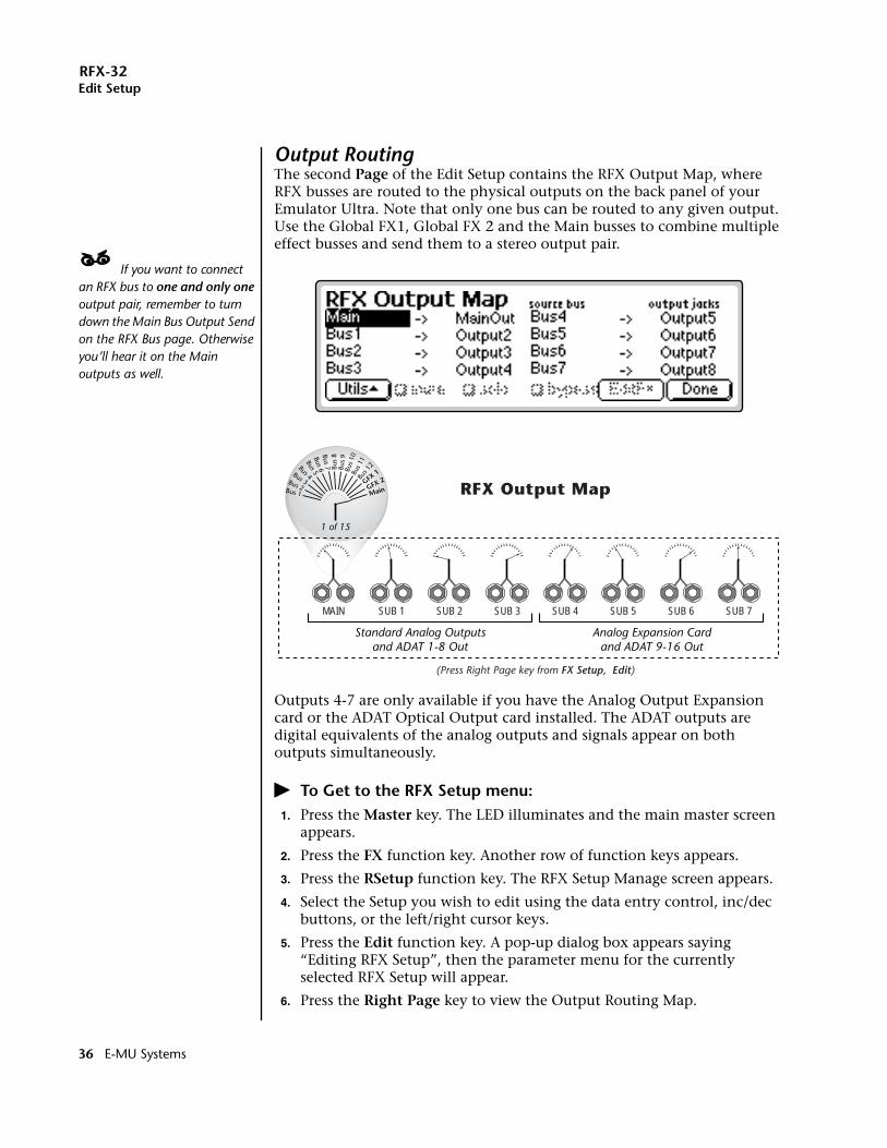
Output RoutingThe second Page of the Edit Setup contains the RFX Output Map, where RFX busses are routed to the physical outputs on the back panel of your Emulator Ultra. Note that only one bus can be routed to any given output. Use the Global FX1, Global FX 2 and the Main busses to combine multiple effect busses and send them to a stereo output pair.
____ If you want to connect an RFX bus to one and only one output pair, remember to turn down the Main Bus Output Send on the RFX Bus page. Otherwise you’ll hear it on the Main outputs as well.
Outputs 4-7 are only available if you have the Analog Output Expansion card or the ADAT Optical Output card installed. The ADAT outputs are digital equivalents of the analog outputs and signals appear on both outputs simultaneously.
� To Get to the RFX Setup menu:1. Press the Master key. The LED illuminates and the main master screen
appears.
2. Press the FX function key. Another row of function keys appears.
3. Press the RSetup function key. The RFX Setup Manage screen appears.
4. Select the Setup you wish to edit using the data entry control, inc/dec buttons, or the left/right cursor keys.
5. Press the Edit function key. A pop-up dialog box appears saying “Editing RFX Setup”, then the parameter menu for the currently selected RFX Setup will appear.
6. Press the Right Page key to view the Output Routing Map.
Bus 1
Bus 2
Bus 3
Bus 4Bus 5
Bus 6Bus 7 Bu
s 8
Bus
9Bu
s 10
Bus 1
1Bu
s 12
GFX 1
GFX 2
Main
MAIN SUB 1 SUB 2 SUB 3 SUB 4 SUB 5 SUB 6 SUB 7
Analog Expansion Cardand ADAT 9-16 Out
Standard Analog Outputsand ADAT 1-8 Out
1 of 15
(Press Right Page key from FX Setup, Edit)
RFX Output Map
36 E-MU Systems
RFX-32Edit Setup
� To Edit the RFX Setup:Please refer to the RFX block diagram while reading these instructions.
1. Select the desired RFX Bus. With the cursor on the top line of the display, select the RFX Bus using the inc/dec keys or data entry control.
Note that GFX1 and GFX2 (Global FX 1 & 2) are only routed to the Main bus while busses 1-12 can be routed through GFX 1 & 2 as well as to the Main bus.
2. Select the Effects for each bus you wish to use. Up to 6 effects can be placed in series for each bus. In each bus, signals are routed first through Effect 1, then Effect 2, and so on.
3. Move the cursor to the desired parameter and change the value using the numeric keypad, inc/dec keys or data entry control. See page 55 for the current list of factory RFX Plug-ins and an explanation of the effects parameters.
4. Press Exit to return to the RFX Manage screen.
RFX-32 Operation Manual 37
RFX-32Write FX
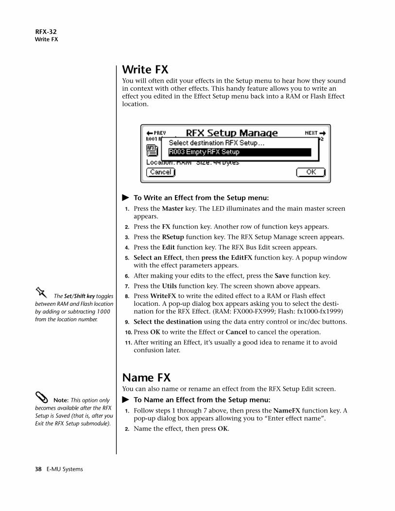
Write FXYou will often edit your effects in the Setup menu to hear how they sound in context with other effects. This handy feature allows you to write an effect you edited in the Effect Setup menu back into a RAM or Flash Effect location.
� To Write an Effect from the Setup menu:1. Press the Master key. The LED illuminates and the main master screen
appears.
2. Press the FX function key. Another row of function keys appears.
3. Press the RSetup function key. The RFX Setup Manage screen appears.
4. Press the Edit function key. The RFX Bus Edit screen appears.
5. Select an Effect, then press the EditFX function key. A popup window with the effect parameters appears.
6. After making your edits to the effect, press the Save function key.
7. Press the Utils function key. The screen shown above appears.
OOOO The Set/Shift key toggles between RAM and Flash location by adding or subtracting 1000 from the location number.
8. Press WriteFX to write the edited effect to a RAM or Flash effect location. A pop-up dialog box appears asking you to select the desti-nation for the RFX Effect. (RAM: FX000-FX999; Flash: fx1000-fx1999)
9. Select the destination using the data entry control or inc/dec buttons.
10. Press OK to write the Effect or Cancel to cancel the operation.
11. After writing an Effect, it’s usually a good idea to rename it to avoid confusion later.
Name FXYou can also name or rename an effect from the RFX Setup Edit screen.
Note: This option only becomes available after the RFX Setup is Saved (that is, after you Exit the RFX Setup submodule).
� To Name an Effect from the Setup menu:1. Follow steps 1 through 7 above, then press the NameFX function key. A
pop-up dialog box appears allowing you to “Enter effect name”.
2. Name the effect, then press OK.
38 E-MU Systems
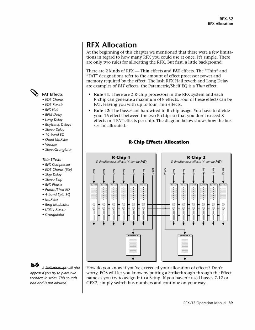
RFX-32RFX Allocation
RFX AllocationAt the beginning of this chapter we mentioned that there were a few limita-tions in regard to how many RFX you could use at once. It’s simple. There are only two rules for allocating the RFX. But first, a little background.
There are 2 kinds of RFX — Thin effects and FAT effects. The “Thin” and “FAT” designations refer to the amount of effect processor power and memory required by the effect. The lush RFX Hall reverb and Long Delay are examples of FAT effects; the Parametric/Shelf EQ is a Thin effect.
FAT Effects• EOS Chorus• EOS Reverb• RFX Hall• BPM Delay• Long Delay• Rhythmic Delays• Stereo Delay• 10-band EQ• Quad MuXster• Vocoder• StereoGrunglator
Thin Effects• RFX Compressor• EOS Chorus (lite)• Slap Delay• Stereo Slap• RFX Phaser• Param/Shelf EQ• 4-band Split EQ• MuXster• Ring Modulator• Utility Reverb• Grungulator
• Rule #1: There are 2 R-chip processors in the RFX system and eachR-chip can generate a maximum of 8 effects. Four of these effects can be FAT, leaving you with up to four Thin effects.
• Rule #2: The busses are hardwired to R-chip usage. You have to divide your 16 effects between the two R-chips so that you don’t exceed 8 effects or 4 FAT effects per chip. The diagram below shows how the bus-ses are allocated.
____ A Strikethrough will also appear if you try to place two vocoders in series. This sounds bad and is not allowed.
How do you know if you’ve exceeded your allocation of effects? Don’t worry, EOS will let you know by putting a Strikethrough through the Effect name as you try to assign it to a Setup. If you haven’t used busses 7-12 or GFX2, simply switch bus numbers and continue on your way.
Bus FX1 Bus FX2 Bus FX3 Bus FX4 Bus FX5 Bus FX6
Global FX 1
Bus FX7 Bus FX8 Bus FX9 Bus FX10 Bus FX11 Bus FX12
GFX
1
Bus 1
Bus 2
Bus 3
Bus 4
Bus 5
Bus 6
Bus 7
Bus 8
Bus 9
Bus 10
Bus 11
Bus 12
GFX
2
Global FX 2
R-Chip 18 simultaneous effects (4 can be FAT)
R-Chip 28 simultaneous effects (4 can be FAT)
R-Chip Effects Allocation
RFX-32 Operation Manual 39
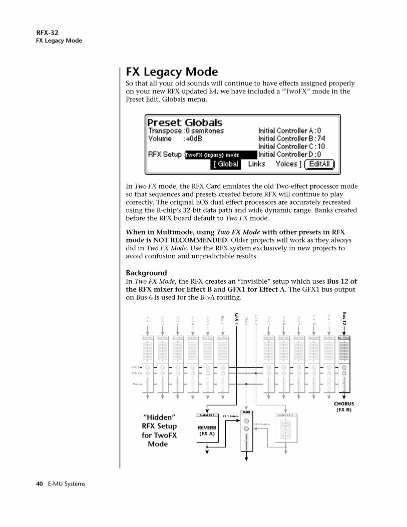
RFX-32FX Legacy Mode
FX Legacy ModeSo that all your old sounds will continue to have effects assigned properly on your new RFX updated E4, we have included a “TwoFX” mode in the Preset Edit, Globals menu.
In Two FX mode, the RFX Card emulates the old Two-effect processor mode so that sequences and presets created before RFX will continue to play correctly. The original EOS dual effect processors are accurately recreated using the R-chip’s 32-bit data path and wide dynamic range. Banks created before the RFX board default to Two FX mode.
When in Multimode, using Two FX Mode with other presets in RFX mode is NOT RECOMMENDED. Older projects will work as they always did in Two FX Mode. Use the RFX system exclusively in new projects to avoid confusion and unpredictable results.
BackgroundIn Two FX Mode, the RFX creates an “invisible” setup which uses Bus 12 of the RFX mixer for Effect B and GFX1 for Effect A. The GFX1 bus output on Bus 6 is used for the B->A routing.
FX 1 Return
FX 2 Return
Bus FX1 Bus FX2 Bus FX3 Bus FX4 Bus FX5 Bus FX6
MAIN
Main
GFX 2
GFX 1
Global FX 1
Bus FX7 Bus FX8 Bus FX9 Bus FX10 Bus FX11 Bus FX12
GFX
1
Bus 1
Bus 2
Bus 3
Bus 4
Bus 5
Bus 6
Bus 7
Bus 8
Bus 9
Bus 10
Bus 11
Bus 12
GFX
2
Main
Global FX 2
REVERB(FX A)
CHORUS(FX B)
“Hidden”RFX Setupfor TwoFX
Mode
40 E-MU Systems
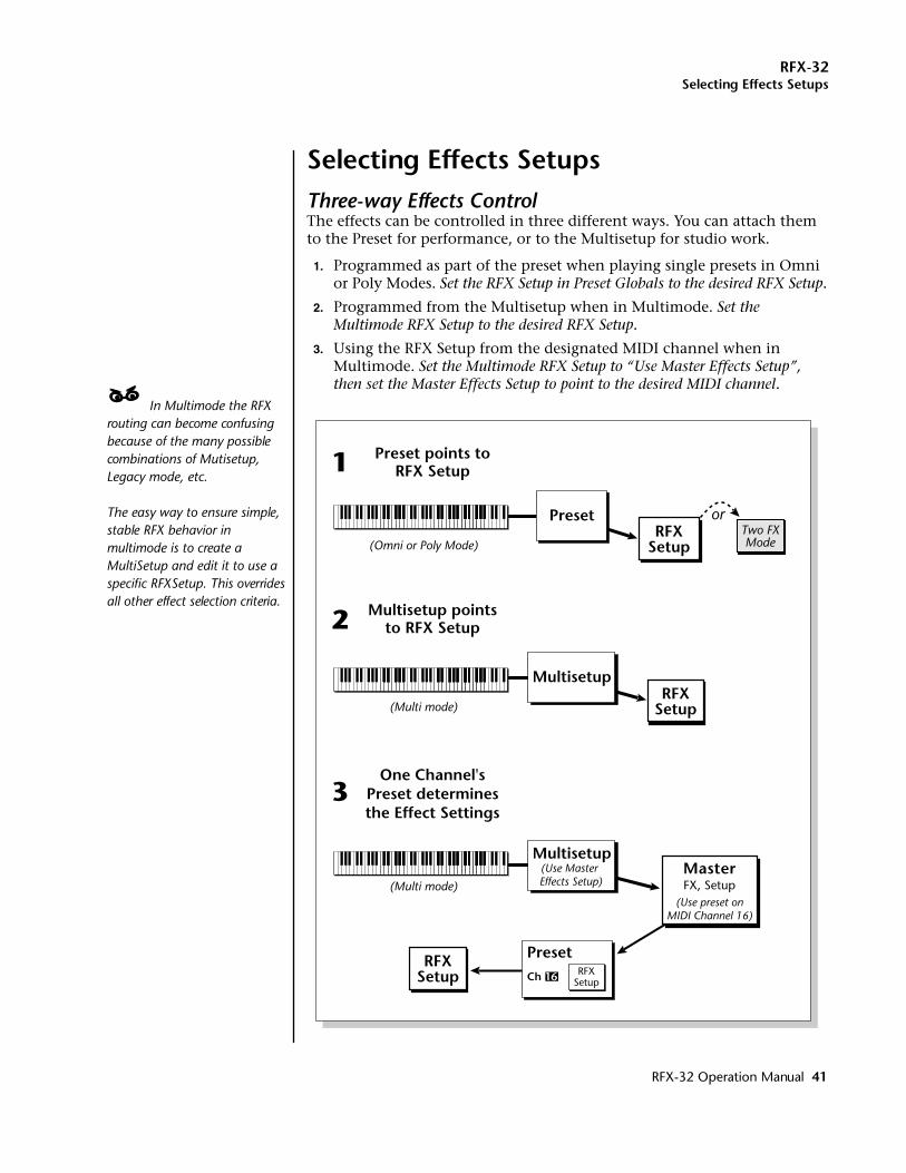
RFX-32Selecting Effects Setups
Selecting Effects SetupsThree-way Effects ControlThe effects can be controlled in three different ways. You can attach them to the Preset for performance, or to the Multisetup for studio work.
1. Programmed as part of the preset when playing single presets in Omni or Poly Modes. Set the RFX Setup in Preset Globals to the desired RFX Setup.
2. Programmed from the Multisetup when in Multimode. Set the Multimode RFX Setup to the desired RFX Setup.
3. Using the RFX Setup from the designated MIDI channel when in Multimode. Set the Multimode RFX Setup to “Use Master Effects Setup”, then set the Master Effects Setup to point to the desired MIDI channel.
____ In Multimode the RFX routing can become confusing because of the many possible combinations of Mutisetup, Legacy mode, etc. The easy way to ensure simple, stable RFX behavior in multimode is to create a MultiSetup and edit it to use a specific RFXSetup. This overrides all other effect selection criteria.
Preset
Preset points toRFX Setup
Multisetup pointsto RFX Setup
1
(Omni or Poly Mode)
2
(Multi mode)
Preset
One Channel'sPreset determinesthe Effect Settings
3
(Multi mode)
RFXSetup
RFXSetup
RFXSetup
MasterFX, Setup
Two FXMode
or
Multisetup
Multisetup(Use Master Effects Setup)
(Use preset onMIDI Channel 16)
RFXSetupCh 16
RFX-32 Operation Manual 41
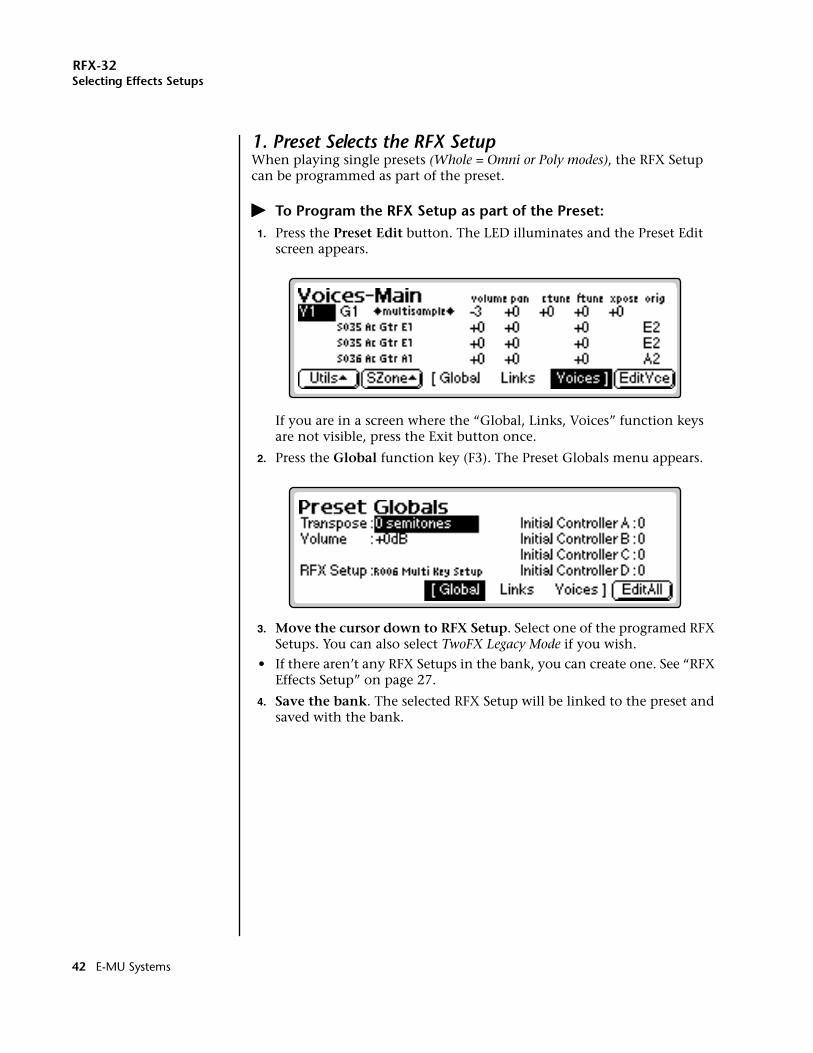
RFX-32Selecting Effects Setups
1. Preset Selects the RFX SetupWhen playing single presets (Whole = Omni or Poly modes), the RFX Setup can be programmed as part of the preset.
� To Program the RFX Setup as part of the Preset:1. Press the Preset Edit button. The LED illuminates and the Preset Edit
screen appears.
If you are in a screen where the “Global, Links, Voices” function keys are not visible, press the Exit button once.
2. Press the Global function key (F3). The Preset Globals menu appears.
3. Move the cursor down to RFX Setup. Select one of the programed RFX Setups. You can also select TwoFX Legacy Mode if you wish.
• If there aren’t any RFX Setups in the bank, you can create one. See “RFX Effects Setup” on page 27.
4. Save the bank. The selected RFX Setup will be linked to the preset and saved with the bank.
42 E-MU Systems
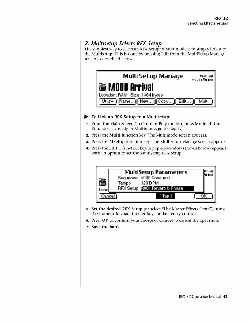
RFX-32Selecting Effects Setups
2. Multisetup Selects RFX SetupThe simplest way to select an RFX Setup in Multimode is to simply link it to the Multisetup. This is done by pressing Edit from the MultiSetup Manage screen as described below.
� To Link an RFX Setup to a Multisetup:1. From the Main Screen (in Omni or Poly modes), press Mode. (If the
Emulator is already in Multimode, go to step 3.)
2. Press the Multi function key. The Multimode screen appears.
3. Press the MSetup function key. The Multisetup Manage screen appears.
4. Press the Edit… function key. A pop-up window (shown below) appears with an option to set the Multisetup RFX Setup.
5. Set the desired RFX Setup (or select “Use Master Effects Setup”) using the numeric keypad, inc/dec keys or data entry control.
6. Press OK to confirm your choice or Cancel to cancel the operation.
7. Save the bank.
RFX-32 Operation Manual 43

RFX-32Selecting Effects Setups
3. MIDI Channel Determines the RFX SetupWhen sequencing in Multimode you might want to change the RFX Setup during the song. EOS provides a way to do this by allowing the preset on a particular MIDI channel to select the RFX Setup. See the diagram on page 41 for a graphic representation of the process.
� To Select the RFX Setup by MIDI Channel:1. From the Main Screen (in Omni or Poly modes), press Mode. (If the
Emulator is already in Multimode, go to step 3.)
2. Press the Multi function key. The Multimode screen appears.
3. Press the MSetup function key. The Multisetup Manage screen appears.
4. Press the FX… function key. A pop-up window appears with an option to set the Multisetup RFX Setup.
5. Select Use Master Effects Setup using the numeric keypad, inc/dec keys or data entry control.
6. Press the Master menu button. The Memory screen appears.
7. Press the FX menu button. Another row of function keys appears.
8. Press the Setup function key. The Effects Setup menu appears. A warning message appears if an effect routing other than “Master” is currently selected.
9. Move the cursor to the Multimode Effects Control field using the cursor buttons.
10. Set the Effect Control channel to: “Preset on MIDI channel XX” using the Data Entry Control or INC/DEC buttons.
11. Press the Exit button three times to save the settings and return to the main screen.
44 E-MU Systems
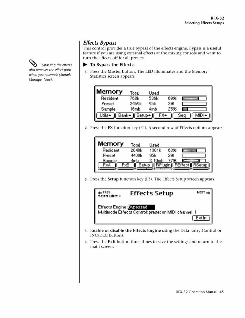
RFX-32Selecting Effects Setups
Effects BypassThis control provides a true bypass of the effects engine. Bypass is a useful feature if you are using external effects at the mixing console and want to turn the effects off for all presets.
Bypassing the effects also removes the effect path when you resample (Sample Manage, New).
� To Bypass the Effects:1. Press the Master button. The LED illuminates and the Memory
Statistics screen appears.
2. Press the FX function key (F4). A second row of Effects options appears.
3. Press the Setup function key (F3). The Effects Setup screen appears.
4. Enable or disable the Effects Engine using the Data Entry Control or INC/DEC buttons.
5. Press the Exit button three times to save the settings and return to the main screen.
RFX-32 Operation Manual 45
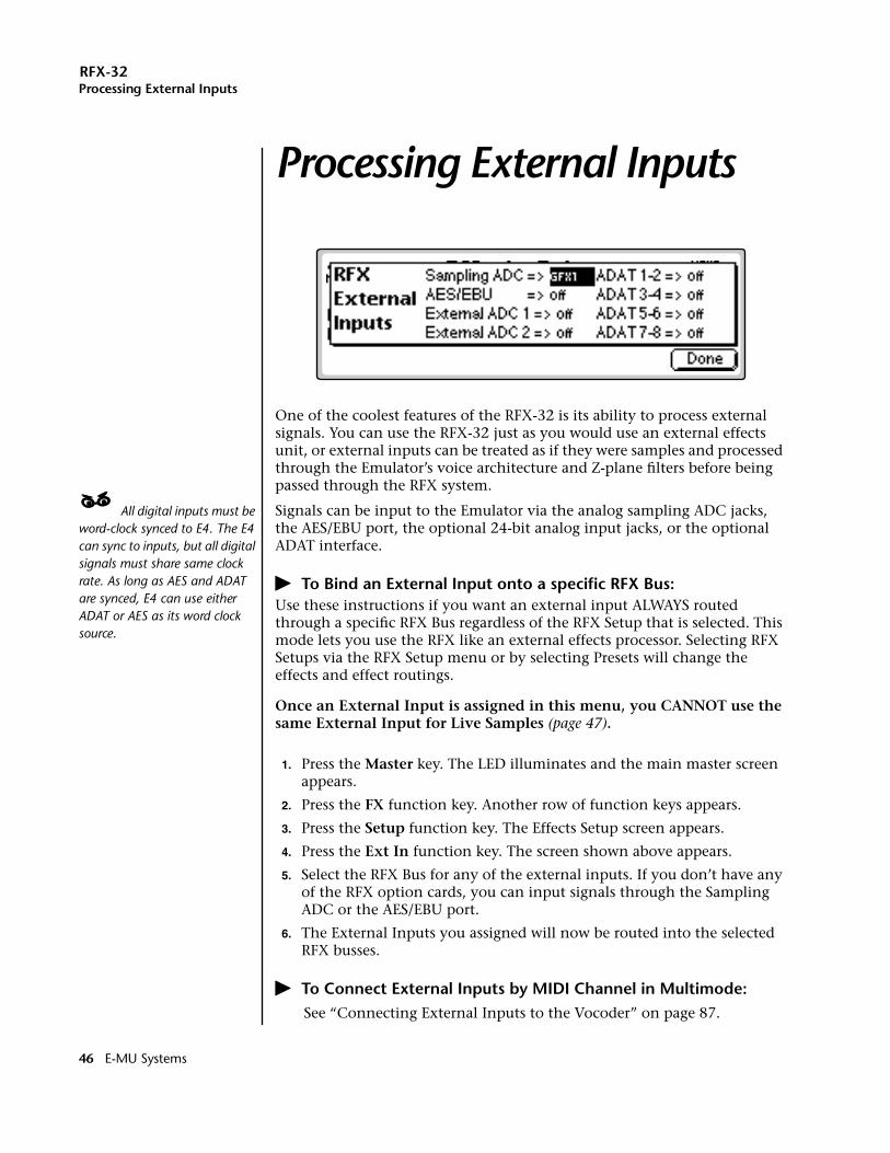
RFX-32Processing External Inputs
Processing External InputsProcessing External Inputs
One of the coolest features of the RFX-32 is its ability to process external signals. You can use the RFX-32 just as you would use an external effects unit, or external inputs can be treated as if they were samples and processed through the Emulator’s voice architecture and Z-plane filters before being passed through the RFX system.
____ All digital inputs must be word-clock synced to E4. The E4 can sync to inputs, but all digital signals must share same clock rate. As long as AES and ADAT are synced, E4 can use either ADAT or AES as its word clock source.
Signals can be input to the Emulator via the analog sampling ADC jacks, the AES/EBU port, the optional 24-bit analog input jacks, or the optional ADAT interface.
� To Bind an External Input onto a specific RFX Bus:Use these instructions if you want an external input ALWAYS routed through a specific RFX Bus regardless of the RFX Setup that is selected. This mode lets you use the RFX like an external effects processor. Selecting RFX Setups via the RFX Setup menu or by selecting Presets will change the effects and effect routings.
Once an External Input is assigned in this menu, you CANNOT use the same External Input for Live Samples (page 47).
1. Press the Master key. The LED illuminates and the main master screen appears.
2. Press the FX function key. Another row of function keys appears.
3. Press the Setup function key. The Effects Setup screen appears.
4. Press the Ext In function key. The screen shown above appears.
5. Select the RFX Bus for any of the external inputs. If you don’t have any of the RFX option cards, you can input signals through the Sampling ADC or the AES/EBU port.
6. The External Inputs you assigned will now be routed into the selected RFX busses.
� To Connect External Inputs by MIDI Channel in Multimode:See “Connecting External Inputs to the Vocoder” on page 87.
46 E-MU Systems
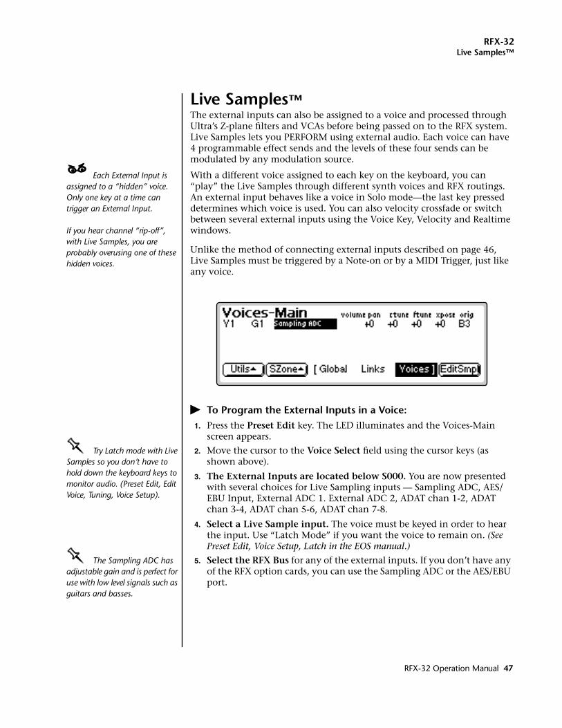
RFX-32Live Samples™
Live Samples™The external inputs can also be assigned to a voice and processed through Ultra’s Z-plane filters and VCAs before being passed on to the RFX system. Live Samples lets you PERFORM using external audio. Each voice can have 4 programmable effect sends and the levels of these four sends can be modulated by any modulation source.
____ Each External Input is assigned to a “hidden” voice. Only one key at a time can trigger an External Input.
If you hear channel “rip-off”, with Live Samples, you are probably overusing one of these hidden voices.
With a different voice assigned to each key on the keyboard, you can “play” the Live Samples through different synth voices and RFX routings. An external input behaves like a voice in Solo mode—the last key pressed determines which voice is used. You can also velocity crossfade or switch between several external inputs using the Voice Key, Velocity and Realtime windows.
Unlike the method of connecting external inputs described on page 46, Live Samples must be triggered by a Note-on or by a MIDI Trigger, just like any voice.
� To Program the External Inputs in a Voice:1. Press the Preset Edit key. The LED illuminates and the Voices-Main
screen appears.
OOOO Try Latch mode with Live Samples so you don’t have to hold down the keyboard keys to monitor audio. (Preset Edit, Edit Voice, Tuning, Voice Setup).
2. Move the cursor to the Voice Select field using the cursor keys (as shown above).
3. The External Inputs are located below S000. You are now presented with several choices for Live Sampling inputs — Sampling ADC, AES/EBU Input, External ADC 1. External ADC 2, ADAT chan 1-2, ADAT chan 3-4, ADAT chan 5-6, ADAT chan 7-8.
4. Select a Live Sample input. The voice must be keyed in order to hear the input. Use “Latch Mode” if you want the voice to remain on. (See Preset Edit, Voice Setup, Latch in the EOS manual.)
OOOO The Sampling ADC has adjustable gain and is perfect for use with low level signals such as guitars and basses.
5. Select the RFX Bus for any of the external inputs. If you don’t have any of the RFX option cards, you can use the Sampling ADC or the AES/EBU port.
RFX-32 Operation Manual 47
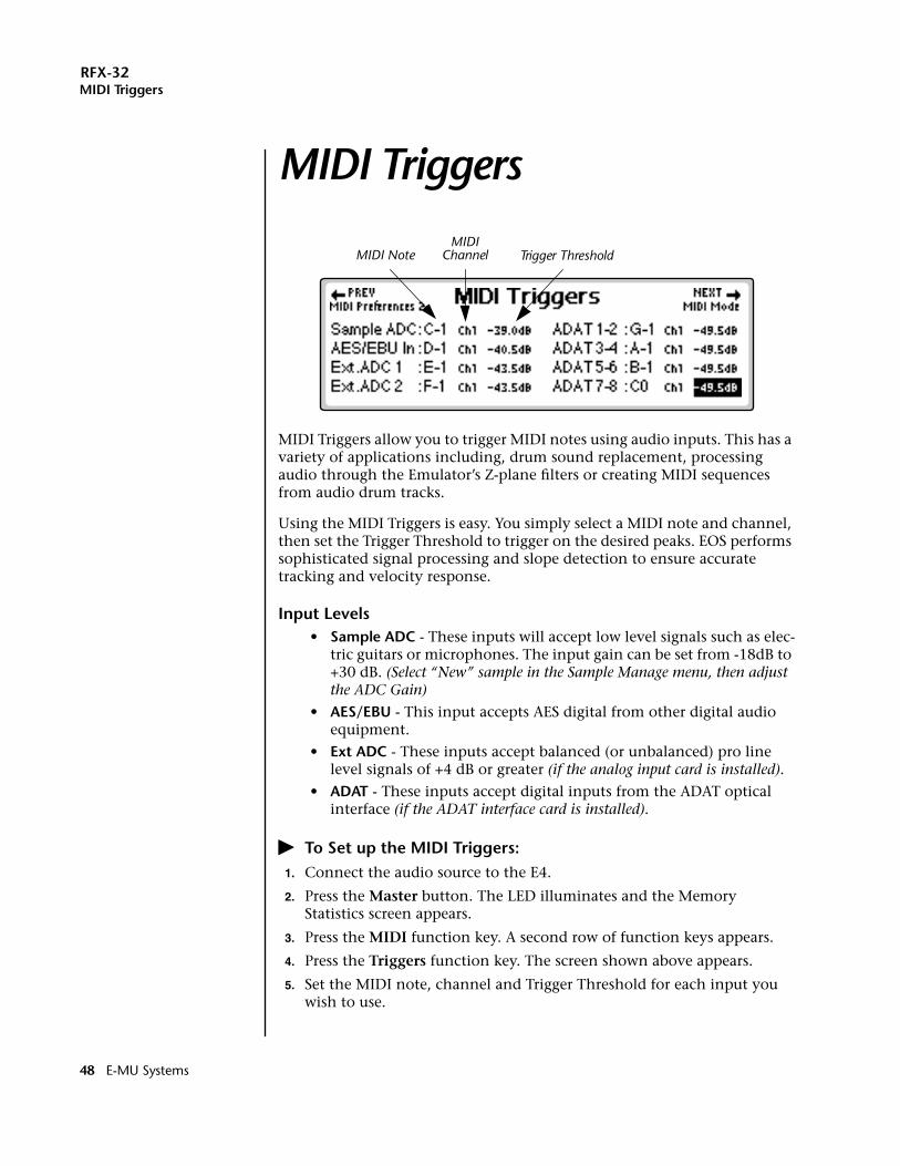
RFX-32MIDI Triggers
MIDI TriggersMIDI Triggers
MIDI Triggers allow you to trigger MIDI notes using audio inputs. This has a variety of applications including, drum sound replacement, processing audio through the Emulator’s Z-plane filters or creating MIDI sequences from audio drum tracks.
Using the MIDI Triggers is easy. You simply select a MIDI note and channel, then set the Trigger Threshold to trigger on the desired peaks. EOS performs sophisticated signal processing and slope detection to ensure accurate tracking and velocity response.
Input Levels• Sample ADC - These inputs will accept low level signals such as elec-
tric guitars or microphones. The input gain can be set from -18dB to +30 dB. (Select “New” sample in the Sample Manage menu, then adjust the ADC Gain)
• AES/EBU - This input accepts AES digital from other digital audio equipment.
• Ext ADC - These inputs accept balanced (or unbalanced) pro line level signals of +4 dB or greater (if the analog input card is installed).
• ADAT - These inputs accept digital inputs from the ADAT optical interface (if the ADAT interface card is installed).
� To Set up the MIDI Triggers:1. Connect the audio source to the E4.
2. Press the Master button. The LED illuminates and the Memory Statistics screen appears.
3. Press the MIDI function key. A second row of function keys appears.
4. Press the Triggers function key. The screen shown above appears.
5. Set the MIDI note, channel and Trigger Threshold for each input you wish to use.
MIDI NoteMIDI
Channel Trigger Threshold
48 E-MU Systems
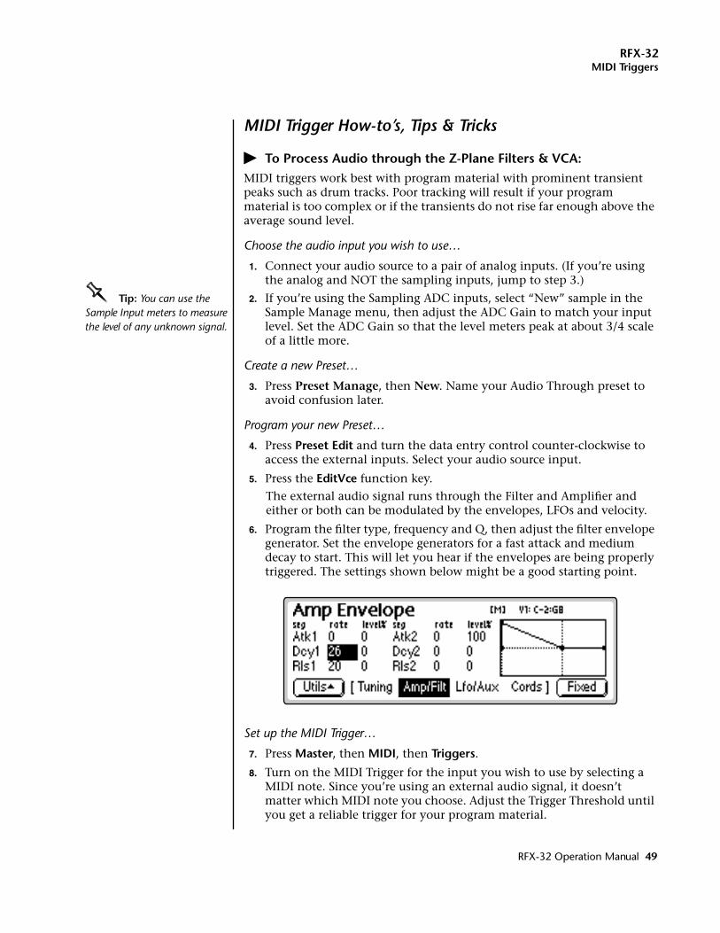
RFX-32MIDI Triggers
MIDI Trigger How-to’s, Tips & Tricks
� To Process Audio through the Z-Plane Filters & VCA:MIDI triggers work best with program material with prominent transient peaks such as drum tracks. Poor tracking will result if your program material is too complex or if the transients do not rise far enough above the average sound level.
Choose the audio input you wish to use…
1. Connect your audio source to a pair of analog inputs. (If you’re using the analog and NOT the sampling inputs, jump to step 3.)
OOOO Tip: You can use the Sample Input meters to measure the level of any unknown signal.
2. If you’re using the Sampling ADC inputs, select “New” sample in the Sample Manage menu, then adjust the ADC Gain to match your input level. Set the ADC Gain so that the level meters peak at about 3/4 scale of a little more.
Create a new Preset…
3. Press Preset Manage, then New. Name your Audio Through preset to avoid confusion later.
Program your new Preset…
4. Press Preset Edit and turn the data entry control counter-clockwise to access the external inputs. Select your audio source input.
5. Press the EditVce function key.
The external audio signal runs through the Filter and Amplifier and either or both can be modulated by the envelopes, LFOs and velocity.
6. Program the filter type, frequency and Q, then adjust the filter envelope generator. Set the envelope generators for a fast attack and medium decay to start. This will let you hear if the envelopes are being properly triggered. The settings shown below might be a good starting point.
Set up the MIDI Trigger…
7. Press Master, then MIDI, then Triggers.
8. Turn on the MIDI Trigger for the input you wish to use by selecting a MIDI note. Since you’re using an external audio signal, it doesn’t matter which MIDI note you choose. Adjust the Trigger Threshold until you get a reliable trigger for your program material.
RFX-32 Operation Manual 49
RFX-32MIDI Triggers
9. Continue to refine and adjust your Filter and Amplifier settings to your heart’s content. That’s it!
� Drum Sound Replacement with MIDI Triggers:Drum sound replacement is the process of replacing sounds on a recorded drum track with other sampled sounds. MIDI Triggers work best with a program material containing strong transient peaks such as a monophonic percussion track such as from a multitrack recorder. Multi-instrument signals with complex program material are usually not suitable for MIDI Triggering.
Once you have reliable triggering, ANY sound can replace the percussion track. Stereo samples can also replace mono tracks. Remember to patch in key velocity to volume to either preserve or modify the dynamics of the track.
1. Choose a Bank and Preset containing the chosen replacement sound.
2. Follow steps 1-2 in the Z-Plane Filter how-to, then…
Set up the MIDI Trigger…
3. Press Master, then MIDI, then Triggers.
4. Turn on the MIDI Trigger for the input you wish to use by selecting a MIDI note. Adjust the Trigger Threshold until you get a reliable trigger for your program material.
5. Re-record the new sound onto another track of your recorder.
6. Alternatively… you can record this as a MIDI sequence on the EOS sequencer. (Make sure the recorder and EOS are synchronized using MTC first.)
50 E-MU Systems
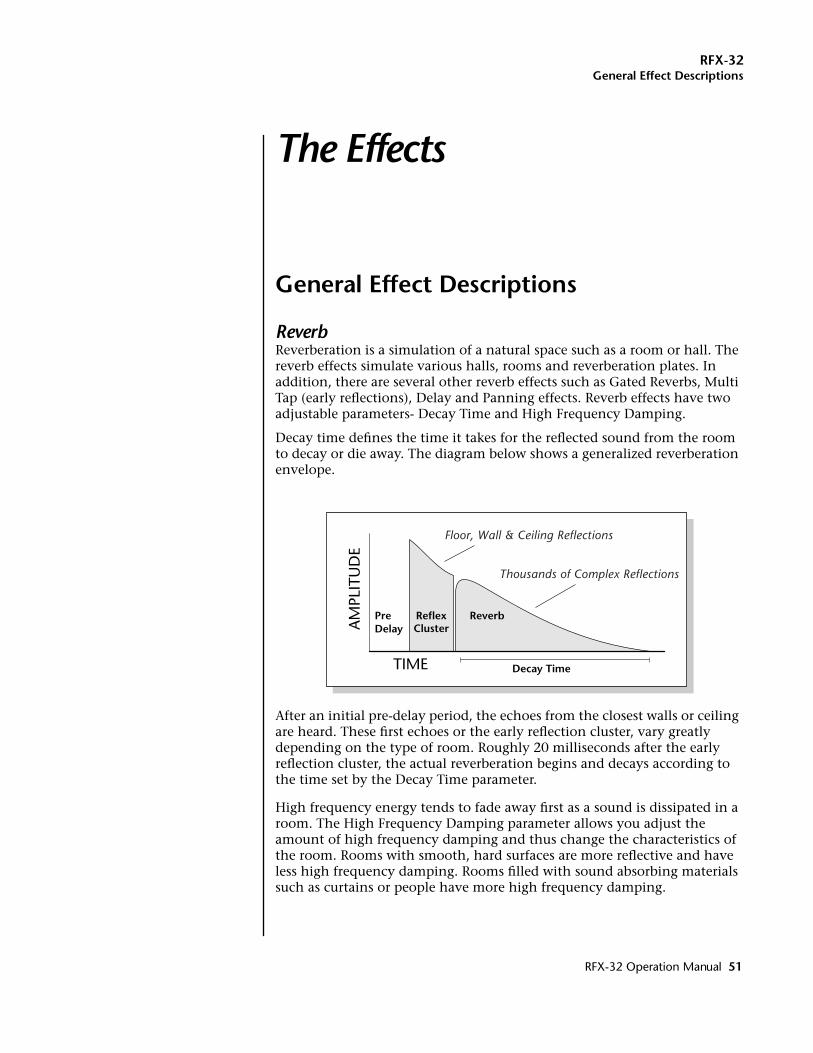
RFX-32General Effect Descriptions
The Effects
General Effect Descriptions
ReverbReverberation is a simulation of a natural space such as a room or hall. The reverb effects simulate various halls, rooms and reverberation plates. In addition, there are several other reverb effects such as Gated Reverbs, Multi Tap (early reflections), Delay and Panning effects. Reverb effects have two adjustable parameters- Decay Time and High Frequency Damping.
Decay time defines the time it takes for the reflected sound from the room to decay or die away. The diagram below shows a generalized reverberation envelope.
After an initial pre-delay period, the echoes from the closest walls or ceiling are heard. These first echoes or the early reflection cluster, vary greatly depending on the type of room. Roughly 20 milliseconds after the early reflection cluster, the actual reverberation begins and decays according to the time set by the Decay Time parameter.
High frequency energy tends to fade away first as a sound is dissipated in a room. The High Frequency Damping parameter allows you adjust the amount of high frequency damping and thus change the characteristics of the room. Rooms with smooth, hard surfaces are more reflective and have less high frequency damping. Rooms filled with sound absorbing materials such as curtains or people have more high frequency damping.
TIME
AM
PLIT
UD
E
PreDelay
ReverbReflexCluster
Decay Time
Floor, Wall & Ceiling Reflections
Thousands of Complex Reflections
RFX-32 Operation Manual 51
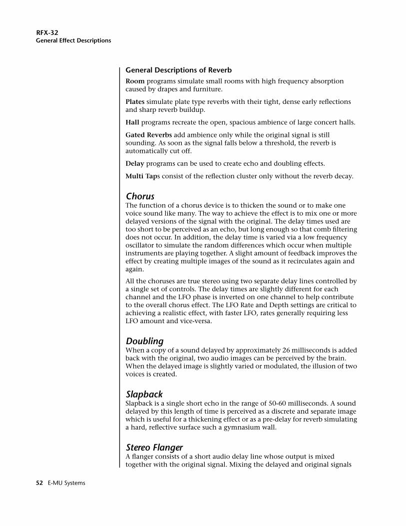
RFX-32General Effect Descriptions
General Descriptions of ReverbRoom programs simulate small rooms with high frequency absorption caused by drapes and furniture.
Plates simulate plate type reverbs with their tight, dense early reflections and sharp reverb buildup.
Hall programs recreate the open, spacious ambience of large concert halls.
Gated Reverbs add ambience only while the original signal is still sounding. As soon as the signal falls below a threshold, the reverb is automatically cut off.
Delay programs can be used to create echo and doubling effects.
Multi Taps consist of the reflection cluster only without the reverb decay.
ChorusThe function of a chorus device is to thicken the sound or to make one voice sound like many. The way to achieve the effect is to mix one or more delayed versions of the signal with the original. The delay times used are too short to be perceived as an echo, but long enough so that comb filtering does not occur. In addition, the delay time is varied via a low frequency oscillator to simulate the random differences which occur when multiple instruments are playing together. A slight amount of feedback improves the effect by creating multiple images of the sound as it recirculates again and again.
All the choruses are true stereo using two separate delay lines controlled by a single set of controls. The delay times are slightly different for each channel and the LFO phase is inverted on one channel to help contribute to the overall chorus effect. The LFO Rate and Depth settings are critical to achieving a realistic effect, with faster LFO, rates generally requiring less LFO amount and vice-versa.
DoublingWhen a copy of a sound delayed by approximately 26 milliseconds is added back with the original, two audio images can be perceived by the brain. When the delayed image is slightly varied or modulated, the illusion of two voices is created.
SlapbackSlapback is a single short echo in the range of 50-60 milliseconds. A sound delayed by this length of time is perceived as a discrete and separate image which is useful for a thickening effect or as a pre-delay for reverb simulating a hard, reflective surface such a gymnasium wall.
Stereo FlangerA flanger consists of a short audio delay line whose output is mixed together with the original signal. Mixing the delayed and original signals
52 E-MU Systems
RFX-32General Effect Descriptions
results in multiple frequency cancellations called a comb filter. Since the flanger is a type of filter, it works best with harmonically rich sounds.
Flanging was originally created using two tape recorders playing identical recordings. By exactly synchronizing the two decks and then slowing the speed of one by grasping the tape reel flanges, the flanging effect was born.
The flanger is a stereo device consisting of two separate delay lines controlled by a single set of controls. A Low Frequency Oscillator (LFO) varies this initial delay setting, changing the frequency of the notches and adding animation to the sound. LFO Rate controls the rate of change and LFO Depth controls how much the LFO changes the delay.
The Feedback control sends some of the delayed signal through the delay line again. When feedback is used the comb filter notches are deepened.
DelayDelay is an effect which can be used for doubling, reverb pre-delay, or echoes. Delay Time is variable from 0-635 mS and controls the time between echoes and Feedback and determines how long the echoes continue sounding. “Infinite” delay effects are also possible without the risk of runaway.
Stereo DelaySimilar to delay except that the delay line outputs a stereo signal from the mono input. The two output signals are a few milliseconds apart to create a stereo image. The delay times are variable from 0-635 mS.
Panning DelayA panning delay is similar to the normal delay lines except that the echoes bounce back and forth between the two stereo speakers.
FREQUENCY (log)A
MPL
ITU
DE
(dB)
Comb Filter
RFX-32 Operation Manual 53
RFX-32General Effect Descriptions
Dual TapThese are delay lines where the signal is “tapped off” at two unevenly spaced locations. When feedback is used, multiple complex echoes are produced. The fraction in the name (i.e. 1/3, 1/4) refers to the distance between the taps.
VibratoBasically, this a delay line modulated by an LFO, but with none of the original signal added in. The LFO modulation creates a Doppler shift and a resultant cyclical pitch shift. The vibrato created in this manner sounds very different than vibrato created by frequency modulating the sample.
DistortionDistortion uses a technique called “soft-clipping” to create additional harmonics in the signal. As the level increases, the top of the waveform becomes somewhat squared. As the level increases further, it transforms into a true square wave.
54 E-MU Systems
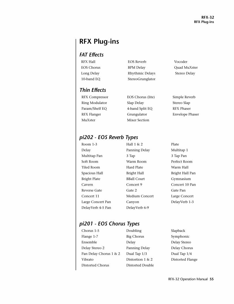
RFX-32RFX Plug-ins
RFX Plug-ins
FAT Effects
Thin Effects
pi202 - EOS Reverb Types
pi201 - EOS Chorus Types
RFX Hall EOS Reverb Vocoder
EOS Chorus BPM Delay Quad MuXster
Long Delay Rhythmic Delays Stereo Delay
10-band EQ StereoGrunglator
RFX Compressor EOS Chorus (lite) Simple Reverb
Ring Modulator Slap Delay Stereo Slap
Param/Shelf EQ 4-band Split EQ RFX Phaser
RFX Flanger Grungulator Envelope Phaser
MuXster Mixer Section
Room 1-3 Hall 1 & 2 Plate
Delay Panning Delay Multitap 1
Multitap Pan 3 Tap 3 Tap Pan
Soft Room Warm Room Perfect Room
Tiled Room Hard Plate Warm Hall
Spacious Hall Bright Hall Bright Hall Pan
Bright Plate BBall Court Gymnasium
Cavern Concert 9 Concert 10 Pan
Reverse Gate Gate 2 Gate Pan
Concert 11 Medium Concert Large Concert
Large Concert Pan Canyon DelayVerb 1-3
DelayVerb 4-5 Pan DelayVerb 6-9
Chorus 1-5 Doubling Slapback
Flange 1-7 Big Chorus Symphonic
Ensemble Delay Delay Stereo
Delay Stereo 2 Panning Delay Delay Chorus
Pan Delay Chorus 1 & 2 Dual Tap 1/3 Dual Tap 1/4
Vibrato Distortion 1 & 2 Distorted Flange
Distorted Chorus Distorted Double
RFX-32 Operation Manual 55
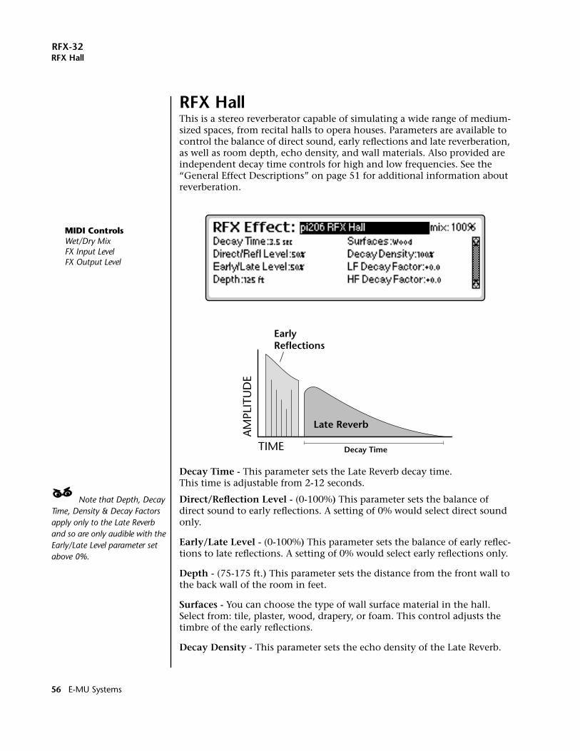
RFX-32RFX Hall
RFX HallThis is a stereo reverberator capable of simulating a wide range of medium-sized spaces, from recital halls to opera houses. Parameters are available to control the balance of direct sound, early reflections and late reverberation, as well as room depth, echo density, and wall materials. Also provided are independent decay time controls for high and low frequencies. See the “General Effect Descriptions” on page 51 for additional information about reverberation.
Decay Time - This parameter sets the Late Reverb decay time.This time is adjustable from 2-12 seconds.
____ Note that Depth, Decay Time, Density & Decay Factors apply only to the Late Reverb and so are only audible with the Early/Late Level parameter set above 0%.
Direct/Reflection Level - (0-100%) This parameter sets the balance of direct sound to early reflections. A setting of 0% would select direct sound only.
Early/Late Level - (0-100%) This parameter sets the balance of early reflec-tions to late reflections. A setting of 0% would select early reflections only.
Depth - (75-175 ft.) This parameter sets the distance from the front wall to the back wall of the room in feet.
Surfaces - You can choose the type of wall surface material in the hall. Select from: tile, plaster, wood, drapery, or foam. This control adjusts the timbre of the early reflections.
Decay Density - This parameter sets the echo density of the Late Reverb.
TIME
AM
PLIT
UD
E
Late Reverb
EarlyReflections
Decay Time
MIDI ControlsWet/Dry MixFX Input LevelFX Output Level
56 E-MU Systems
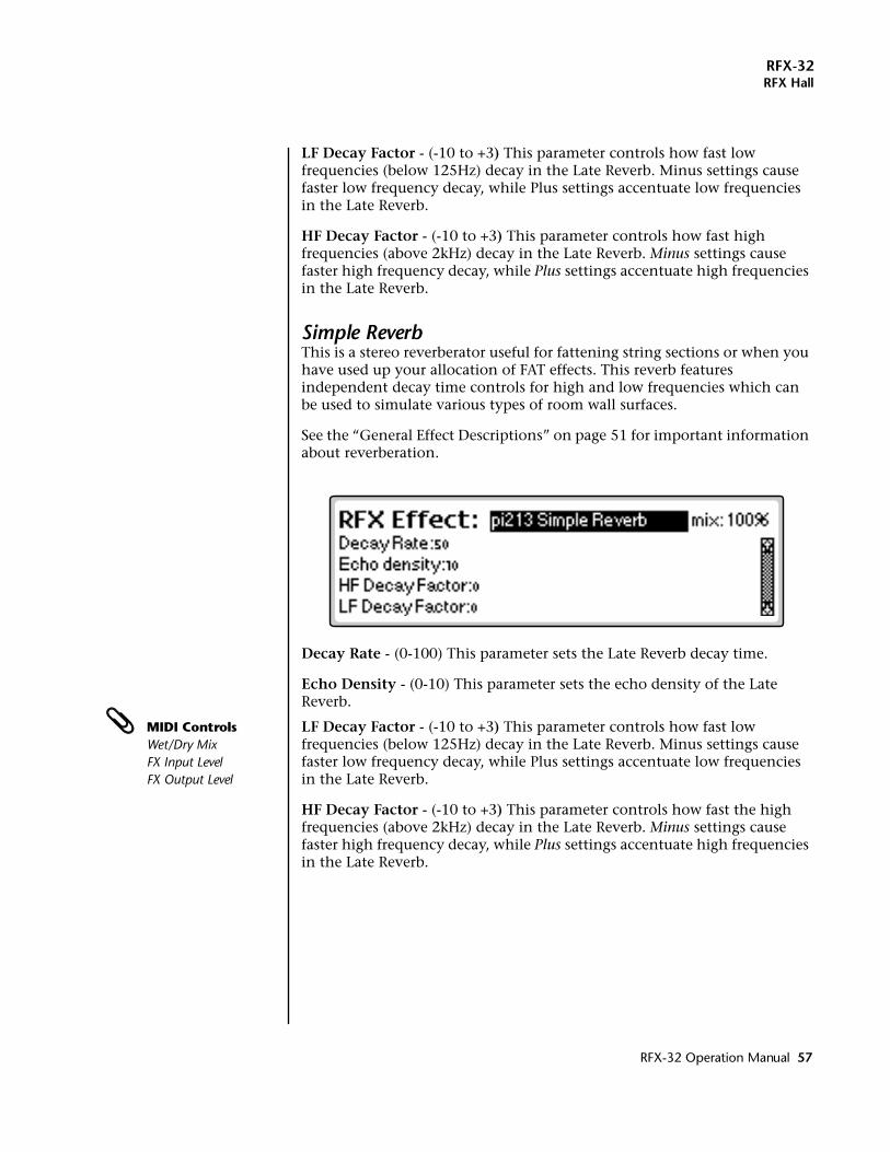
RFX-32RFX Hall
LF Decay Factor - (-10 to +3) This parameter controls how fast low frequencies (below 125Hz) decay in the Late Reverb. Minus settings cause faster low frequency decay, while Plus settings accentuate low frequencies in the Late Reverb.
HF Decay Factor - (-10 to +3) This parameter controls how fast high frequencies (above 2kHz) decay in the Late Reverb. Minus settings cause faster high frequency decay, while Plus settings accentuate high frequencies in the Late Reverb.
Simple ReverbThis is a stereo reverberator useful for fattening string sections or when you have used up your allocation of FAT effects. This reverb features independent decay time controls for high and low frequencies which can be used to simulate various types of room wall surfaces.
See the “General Effect Descriptions” on page 51 for important information about reverberation.
Decay Rate - (0-100) This parameter sets the Late Reverb decay time.
Echo Density - (0-10) This parameter sets the echo density of the Late Reverb.
MIDI ControlsWet/Dry MixFX Input LevelFX Output Level
LF Decay Factor - (-10 to +3) This parameter controls how fast low frequencies (below 125Hz) decay in the Late Reverb. Minus settings cause faster low frequency decay, while Plus settings accentuate low frequencies in the Late Reverb.
HF Decay Factor - (-10 to +3) This parameter controls how fast the high frequencies (above 2kHz) decay in the Late Reverb. Minus settings cause faster high frequency decay, while Plus settings accentuate high frequencies in the Late Reverb.
RFX-32 Operation Manual 57
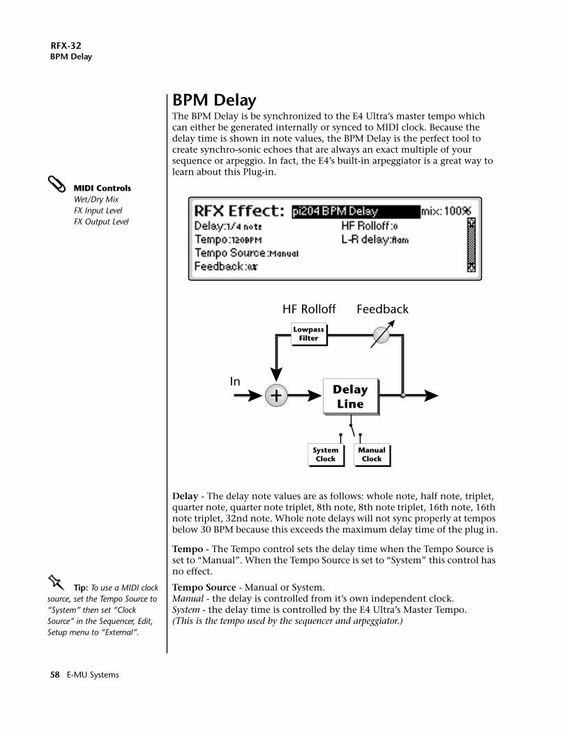
RFX-32BPM Delay
BPM DelayThe BPM Delay is be synchronized to the E4 Ultra’s master tempo which can either be generated internally or synced to MIDI clock. Because the delay time is shown in note values, the BPM Delay is the perfect tool to create synchro-sonic echoes that are always an exact multiple of your sequence or arpeggio. In fact, the E4’s built-in arpeggiator is a great way to learn about this Plug-in.
MIDI ControlsWet/Dry MixFX Input LevelFX Output Level
Delay - The delay note values are as follows: whole note, half note, triplet, quarter note, quarter note triplet, 8th note, 8th note triplet, 16th note, 16th note triplet, 32nd note. Whole note delays will not sync properly at tempos below 30 BPM because this exceeds the maximum delay time of the plug in.
Tempo - The Tempo control sets the delay time when the Tempo Source is set to “Manual”. When the Tempo Source is set to “System” this control has no effect.
OOOO Tip: To use a MIDI clock source, set the Tempo Source to “System” then set “Clock Source” in the Sequencer, Edit, Setup menu to “External”.
Tempo Source - Manual or System.Manual - the delay is controlled from it’s own independent clock.System - the delay time is controlled by the E4 Ultra’s Master Tempo. (This is the tempo used by the sequencer and arpeggiator.)
ManualClock
SystemClock
In
LowpassFilter
HF Rolloff Feedback
DelayLine
58 E-MU Systems
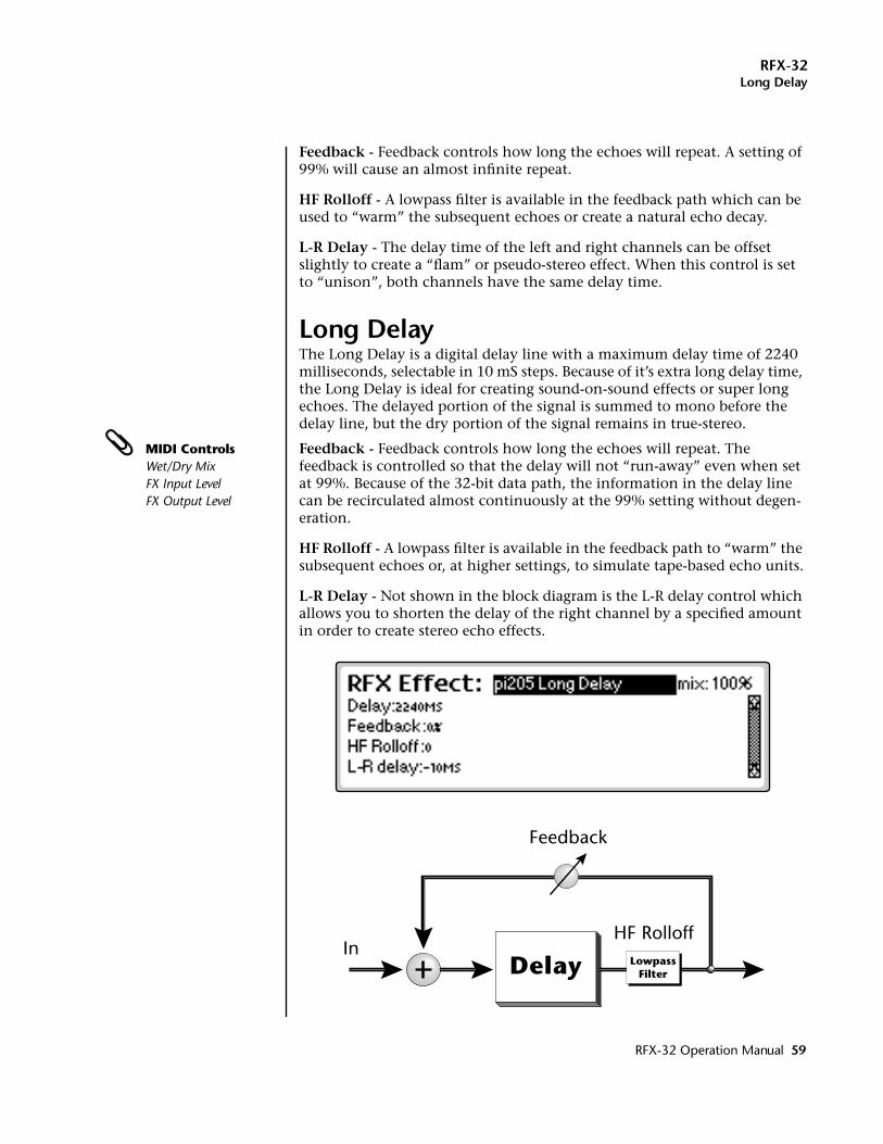
RFX-32Long Delay
Feedback - Feedback controls how long the echoes will repeat. A setting of 99% will cause an almost infinite repeat.
HF Rolloff - A lowpass filter is available in the feedback path which can be used to “warm” the subsequent echoes or create a natural echo decay.
L-R Delay - The delay time of the left and right channels can be offset slightly to create a “flam” or pseudo-stereo effect. When this control is set to “unison”, both channels have the same delay time.
Long DelayThe Long Delay is a digital delay line with a maximum delay time of 2240 milliseconds, selectable in 10 mS steps. Because of it’s extra long delay time, the Long Delay is ideal for creating sound-on-sound effects or super long echoes. The delayed portion of the signal is summed to mono before the delay line, but the dry portion of the signal remains in true-stereo.
MIDI ControlsWet/Dry MixFX Input LevelFX Output Level
Feedback - Feedback controls how long the echoes will repeat. The feedback is controlled so that the delay will not “run-away” even when set at 99%. Because of the 32-bit data path, the information in the delay line can be recirculated almost continuously at the 99% setting without degen-eration.
HF Rolloff - A lowpass filter is available in the feedback path to “warm” the subsequent echoes or, at higher settings, to simulate tape-based echo units.
L-R Delay - Not shown in the block diagram is the L-R delay control which allows you to shorten the delay of the right channel by a specified amount in order to create stereo echo effects.
Delay LowpassFilter
InHF Rolloff
Feedback
RFX-32 Operation Manual 59
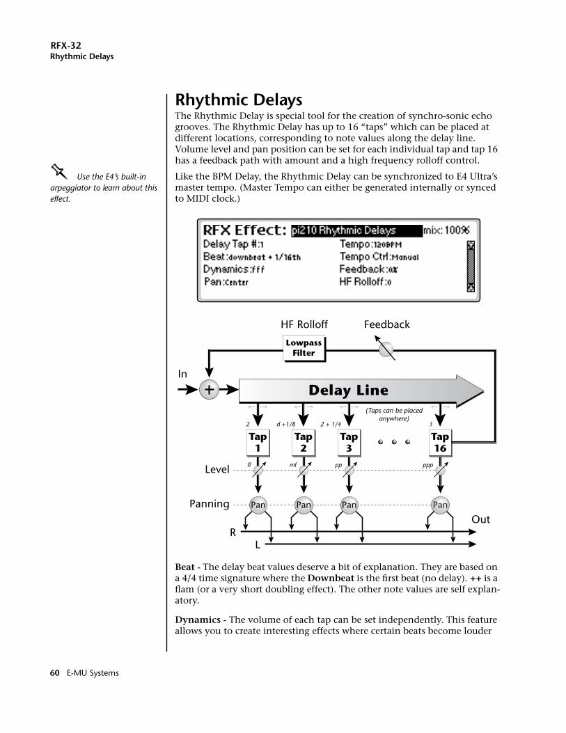
RFX-32Rhythmic Delays
Rhythmic DelaysThe Rhythmic Delay is special tool for the creation of synchro-sonic echo grooves. The Rhythmic Delay has up to 16 “taps” which can be placed at different locations, corresponding to note values along the delay line. Volume level and pan position can be set for each individual tap and tap 16 has a feedback path with amount and a high frequency rolloff control.
OOOO Use the E4’s built-in arpeggiator to learn about this effect.
Like the BPM Delay, the Rhythmic Delay can be synchronized to E4 Ultra’s master tempo. (Master Tempo can either be generated internally or synced to MIDI clock.)
Beat - The delay beat values deserve a bit of explanation. They are based on a 4/4 time signature where the Downbeat is the first beat (no delay). ++ is a flam (or a very short doubling effect). The other note values are self explan-atory.
Dynamics - The volume of each tap can be set independently. This feature allows you to create interesting effects where certain beats become louder
Tap1
LowpassFilter
Out
In
HF Rolloff Feedback
Panning
RL
Level
Tap2
Tap3
Tap16
Delay Line
2
ff mf pp ppp
d +1/8 2 + 1/4
(Taps can be placedanywhere)
3
Pan Pan Pan Pan
60 E-MU Systems
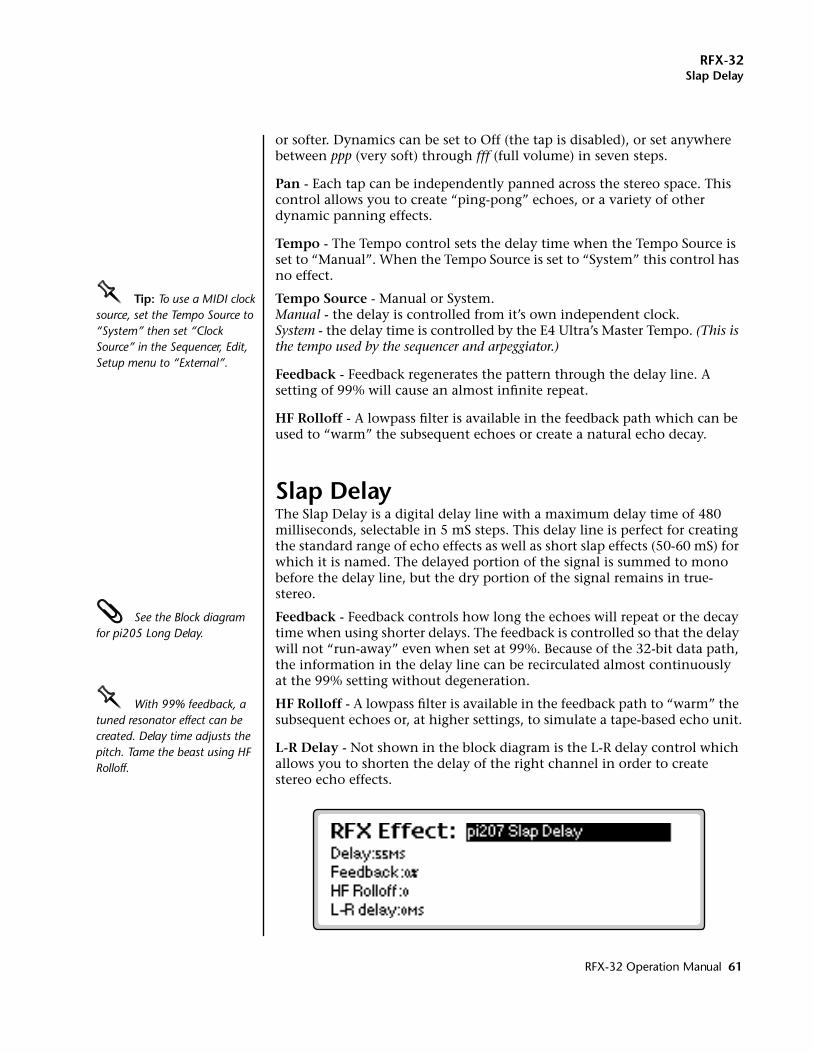
RFX-32Slap Delay
or softer. Dynamics can be set to Off (the tap is disabled), or set anywhere between ppp (very soft) through fff (full volume) in seven steps.
Pan - Each tap can be independently panned across the stereo space. This control allows you to create “ping-pong” echoes, or a variety of other dynamic panning effects.
Tempo - The Tempo control sets the delay time when the Tempo Source is set to “Manual”. When the Tempo Source is set to “System” this control has no effect.
OOOO Tip: To use a MIDI clock source, set the Tempo Source to “System” then set “Clock Source” in the Sequencer, Edit, Setup menu to “External”.
Tempo Source - Manual or System.Manual - the delay is controlled from it’s own independent clock.System - the delay time is controlled by the E4 Ultra’s Master Tempo. (This is the tempo used by the sequencer and arpeggiator.)
Feedback - Feedback regenerates the pattern through the delay line. A setting of 99% will cause an almost infinite repeat.
HF Rolloff - A lowpass filter is available in the feedback path which can be used to “warm” the subsequent echoes or create a natural echo decay.
Slap DelayThe Slap Delay is a digital delay line with a maximum delay time of 480 milliseconds, selectable in 5 mS steps. This delay line is perfect for creating the standard range of echo effects as well as short slap effects (50-60 mS) for which it is named. The delayed portion of the signal is summed to mono before the delay line, but the dry portion of the signal remains in true-stereo.
See the Block diagram for pi205 Long Delay.
Feedback - Feedback controls how long the echoes will repeat or the decay time when using shorter delays. The feedback is controlled so that the delay will not “run-away” even when set at 99%. Because of the 32-bit data path, the information in the delay line can be recirculated almost continuously at the 99% setting without degeneration.
OOOO With 99% feedback, a tuned resonator effect can be created. Delay time adjusts the pitch. Tame the beast using HF Rolloff.
HF Rolloff - A lowpass filter is available in the feedback path to “warm” the subsequent echoes or, at higher settings, to simulate a tape-based echo unit.
L-R Delay - Not shown in the block diagram is the L-R delay control which allows you to shorten the delay of the right channel in order to create stereo echo effects.
RFX-32 Operation Manual 61
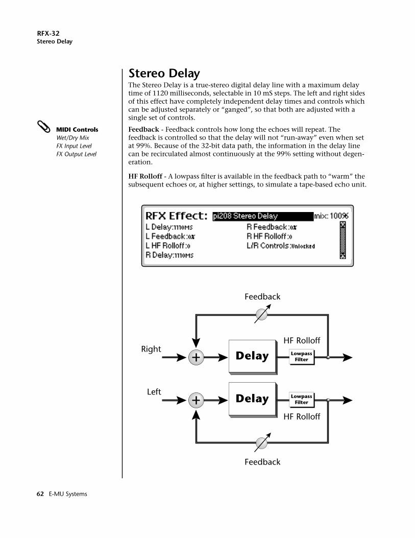
RFX-32Stereo Delay
Stereo DelayThe Stereo Delay is a true-stereo digital delay line with a maximum delay time of 1120 milliseconds, selectable in 10 mS steps. The left and right sides of this effect have completely independent delay times and controls which can be adjusted separately or “ganged”, so that both are adjusted with a single set of controls.
MIDI ControlsWet/Dry MixFX Input LevelFX Output Level
Feedback - Feedback controls how long the echoes will repeat. The feedback is controlled so that the delay will not “run-away” even when set at 99%. Because of the 32-bit data path, the information in the delay line can be recirculated almost continuously at the 99% setting without degen-eration.
HF Rolloff - A lowpass filter is available in the feedback path to “warm” the subsequent echoes or, at higher settings, to simulate a tape-based echo unit.
Delay LowpassFilter
RightHF Rolloff
Feedback
Delay LowpassFilter
Left
HF Rolloff
Feedback
62 E-MU Systems
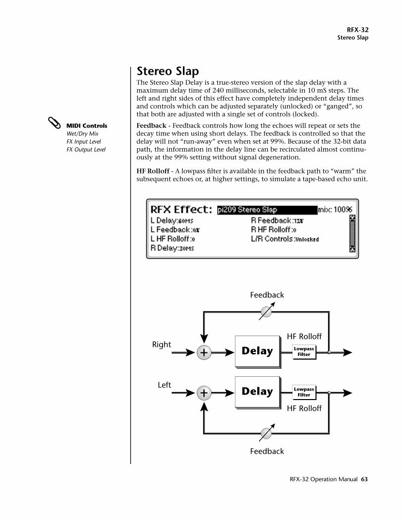
RFX-32Stereo Slap
Stereo SlapThe Stereo Slap Delay is a true-stereo version of the slap delay with a maximum delay time of 240 milliseconds, selectable in 10 mS steps. The left and right sides of this effect have completely independent delay times and controls which can be adjusted separately (unlocked) or “ganged”, so that both are adjusted with a single set of controls (locked).
MIDI ControlsWet/Dry MixFX Input LevelFX Output Level
Feedback - Feedback controls how long the echoes will repeat or sets the decay time when using short delays. The feedback is controlled so that the delay will not “run-away” even when set at 99%. Because of the 32-bit data path, the information in the delay line can be recirculated almost continu-ously at the 99% setting without signal degeneration.
HF Rolloff - A lowpass filter is available in the feedback path to “warm” the subsequent echoes or, at higher settings, to simulate a tape-based echo unit.
Delay LowpassFilter
RightHF Rolloff
Feedback
Delay LowpassFilter
Left
HF Rolloff
Feedback
RFX-32 Operation Manual 63
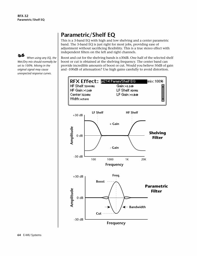
RFX-32Parametric/Shelf EQ
Parametric/Shelf EQThis is a 3-band EQ with high and low shelving and a center parametric band. The 3-band EQ is just right for most jobs, providing ease of adjustment without sacrificing flexibility. This is a true stereo effect with independent filters on the left and right channels.
____ When using any EQ, the Wet/Dry mix should normally be set to 100%. Mixing in the original signal may cause unexpected response curves.
Boost and cut for the shelving bands is ±30dB. One half of the selected shelf boost or cut is obtained at the shelving frequency. The center band can provide incredible amounts of boost or cut. Would you believe 50dB of gain and -100dB of attenuation? Use high gains carefully to avoid distortion.
+ Gain
- Gain
LF Shelf HF Shelf
0 dB
+30 dB
-30 dB100 1000 1K 20K
Frequency
Am
plit
ude
ShelvingFilter
Boost
Cut
Freq.
0 dB
+30 dB
-30 dB
Bandwidth
Frequency
Am
plit
ude
ParametricFilter
64 E-MU Systems
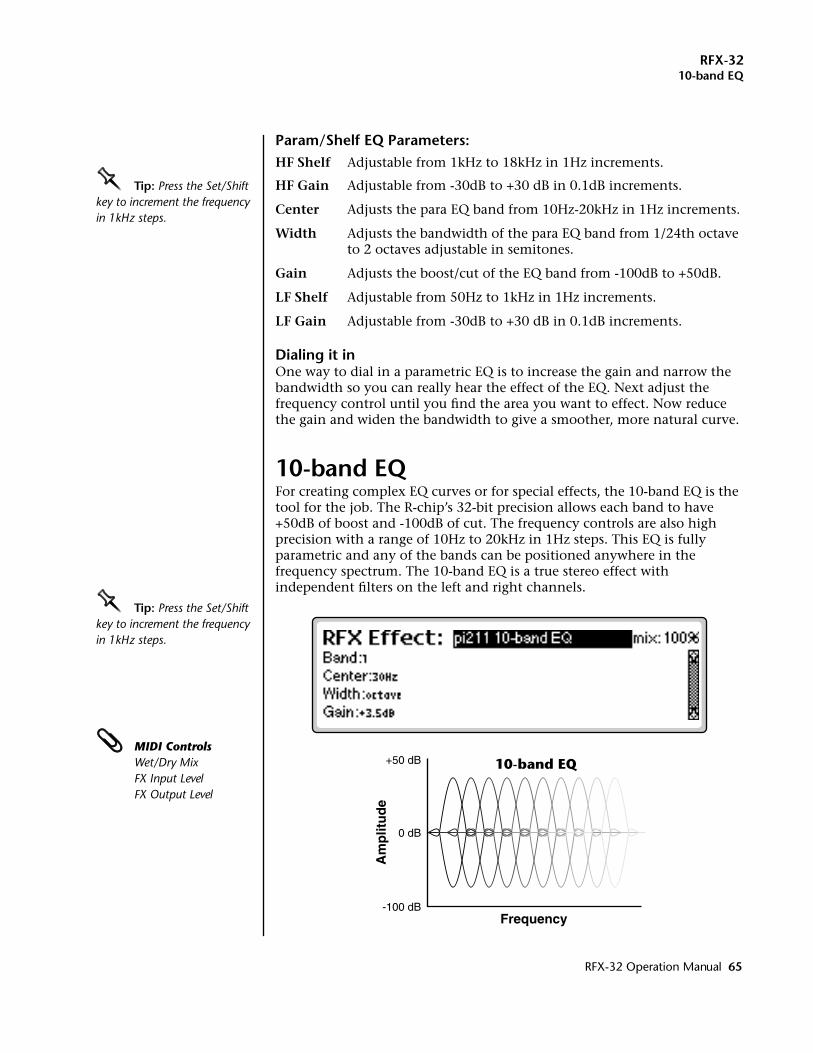
RFX-3210-band EQ
Param/Shelf EQ Parameters:HF Shelf Adjustable from 1kHz to 18kHz in 1Hz increments.
OOOO Tip: Press the Set/Shift key to increment the frequency in 1kHz steps.
HF Gain Adjustable from -30dB to +30 dB in 0.1dB increments.
Center Adjusts the para EQ band from 10Hz-20kHz in 1Hz increments.
Width Adjusts the bandwidth of the para EQ band from 1/24th octave to 2 octaves adjustable in semitones.
Gain Adjusts the boost/cut of the EQ band from -100dB to +50dB.
LF Shelf Adjustable from 50Hz to 1kHz in 1Hz increments.
LF Gain Adjustable from -30dB to +30 dB in 0.1dB increments.
Dialing it inOne way to dial in a parametric EQ is to increase the gain and narrow the bandwidth so you can really hear the effect of the EQ. Next adjust the frequency control until you find the area you want to effect. Now reduce the gain and widen the bandwidth to give a smoother, more natural curve.
10-band EQFor creating complex EQ curves or for special effects, the 10-band EQ is the tool for the job. The R-chip’s 32-bit precision allows each band to have +50dB of boost and -100dB of cut. The frequency controls are also high precision with a range of 10Hz to 20kHz in 1Hz steps. This EQ is fully parametric and any of the bands can be positioned anywhere in the frequency spectrum. The 10-band EQ is a true stereo effect with independent filters on the left and right channels.
OOOO Tip: Press the Set/Shift key to increment the frequency in 1kHz steps.
MIDI ControlsWet/Dry MixFX Input LevelFX Output Level
0 dB
+50 dB
-100 dBFrequency
Am
plit
ud
e
10-band EQ
RFX-32 Operation Manual 65
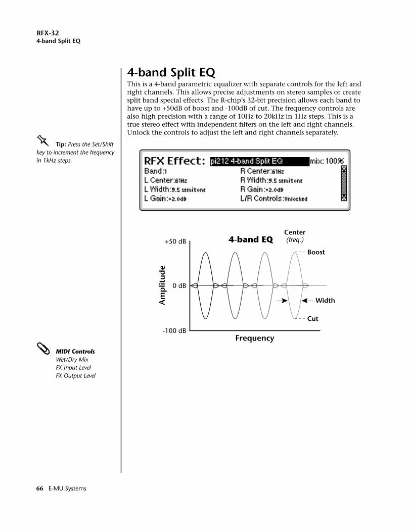
RFX-324-band Split EQ
4-band Split EQThis is a 4-band parametric equalizer with separate controls for the left and right channels. This allows precise adjustments on stereo samples or create split band special effects. The R-chip’s 32-bit precision allows each band to have up to +50dB of boost and -100dB of cut. The frequency controls are also high precision with a range of 10Hz to 20kHz in 1Hz steps. This is a true stereo effect with independent filters on the left and right channels. Unlock the controls to adjust the left and right channels separately.
OOOO Tip: Press the Set/Shift key to increment the frequency in 1kHz steps.
MIDI ControlsWet/Dry MixFX Input LevelFX Output Level
0 dB
+50 dB
-100 dBFrequency
Am
plit
ude
4-band EQCenter(freq.)
Width
Boost
Cut
66 E-MU Systems
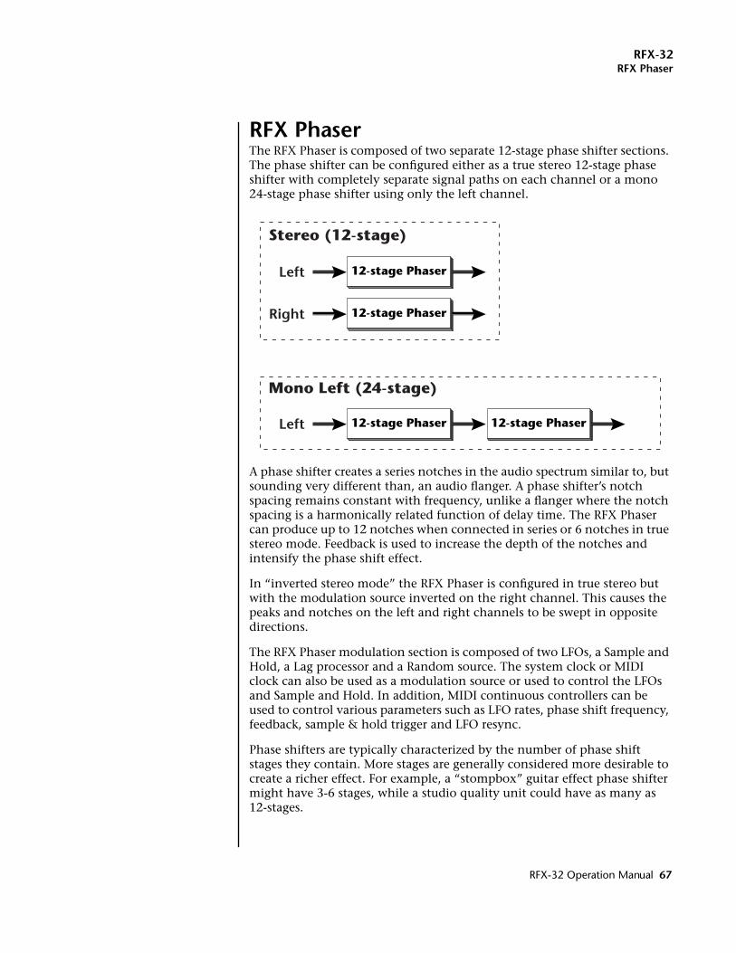
RFX-32RFX Phaser
RFX PhaserThe RFX Phaser is composed of two separate 12-stage phase shifter sections. The phase shifter can be configured either as a true stereo 12-stage phase shifter with completely separate signal paths on each channel or a mono 24-stage phase shifter using only the left channel.
A phase shifter creates a series notches in the audio spectrum similar to, but sounding very different than, an audio flanger. A phase shifter’s notch spacing remains constant with frequency, unlike a flanger where the notch spacing is a harmonically related function of delay time. The RFX Phaser can produce up to 12 notches when connected in series or 6 notches in true stereo mode. Feedback is used to increase the depth of the notches and intensify the phase shift effect.
In “inverted stereo mode” the RFX Phaser is configured in true stereo but with the modulation source inverted on the right channel. This causes the peaks and notches on the left and right channels to be swept in opposite directions.
The RFX Phaser modulation section is composed of two LFOs, a Sample and Hold, a Lag processor and a Random source. The system clock or MIDI clock can also be used as a modulation source or used to control the LFOs and Sample and Hold. In addition, MIDI continuous controllers can be used to control various parameters such as LFO rates, phase shift frequency, feedback, sample & hold trigger and LFO resync.
Phase shifters are typically characterized by the number of phase shift stages they contain. More stages are generally considered more desirable to create a richer effect. For example, a “stompbox” guitar effect phase shifter might have 3-6 stages, while a studio quality unit could have as many as 12-stages.
12-stage Phaser 12-stage PhaserLeft
12-stage PhaserLeft
12-stage PhaserRight
Mono Left (24-stage)
Stereo (12-stage)
RFX-32 Operation Manual 67
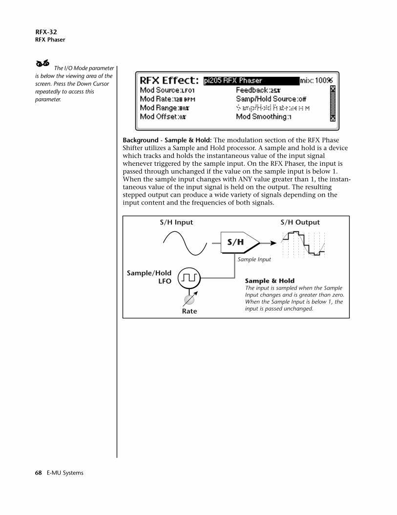
RFX-32RFX Phaser
____ The I/O Mode parameter is below the viewing area of the screen. Press the Down Cursor repeatedly to access this parameter.
Background - Sample & Hold: The modulation section of the RFX Phase Shifter utilizes a Sample and Hold processor. A sample and hold is a device which tracks and holds the instantaneous value of the input signal whenever triggered by the sample input. On the RFX Phaser, the input is passed through unchanged if the value on the sample input is below 1. When the sample input changes with ANY value greater than 1, the instan-taneous value of the input signal is held on the output. The resulting stepped output can produce a wide variety of signals depending on the input content and the frequencies of both signals.
S/H
Sample/HoldLFO
S/H Input S/H Output
Sample Input
Rate
Sample & HoldThe input is sampled when the Sample Input changes and is greater than zero.When the Sample Input is below 1, theinput is passed unchanged.
68 E-MU Systems
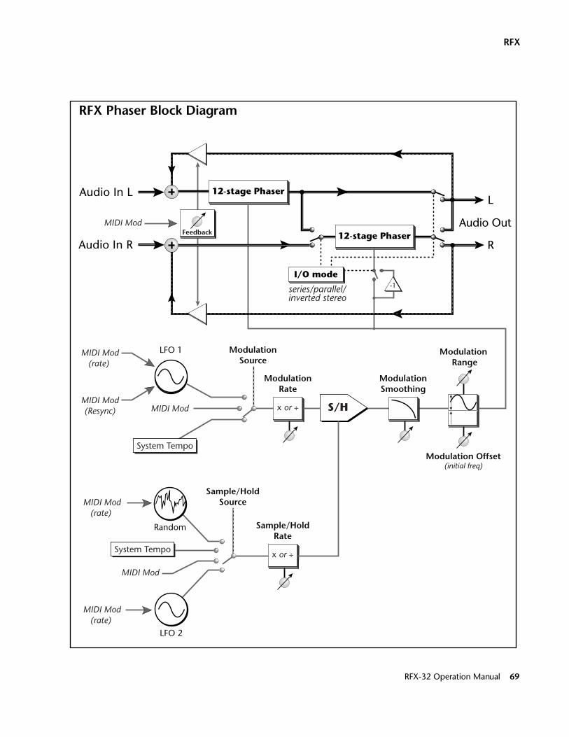
RFX
-1
L
Audio Out
R
Audio In L
Audio In R
Modulation Offset(initial freq)
Modulation Range
ModulationSmoothing
MIDI Mod
MIDI Mod
MIDI Mod
12-stage Phaser
12-stage Phaser
I/O mode
S/H
series/parallel/inverted stereo
ModulationRate
LFO 1
Sample/HoldSource
MIDI Mod(rate)
MIDI Mod(Resync)
MIDI Mod(rate)
MIDI Mod(rate)
Feedback
LFO 2
Random
System Tempo
System Tempo
x or ÷
Sample/HoldRate
x or ÷
ModulationSource
RFX Phaser Block Diagram
RFX-32 Operation Manual 69
RFX-32RFX Phaser
RFX Phase Shifter Parameters:Please refer to the Phase Shifter block diagram on the previous page to better understand the effect and modulation routings.
Resync - This MIDI control restarts LFO 1 whenever a positive controller value is sent. Resync can be used to restart a long slow sweep or to synchronize the LFO with the beat of the music.
Mod Source Selects the source of modulation• LFO 1 - sine wave oscillator• System Tempo - LFO 1 synced to Seq/Arp/MIDI clock• MIDI - MIDI CC value controls phase shift frequency
Mod Rate Sets the LFO 1 rate in bpm (.25-980 beats-per-minute) when selected as the Mod Source. When the Mod Source is set to System Tempo, the Mod Rate becomes a multiplier/divisor of the System Tempo (BPM/120 - BPM x 31).
Mod Range Adjusts the amount of modulation applied to the phase shifter from 1% to 100%.
____ The Modulation Offset value and the Modulation Range values interact. You may have to back off on the Modulation Range when increasing the Modulation Offset to prevent LFO 1 from clipping at the upper end of the range.
Mod Offset Adds an initial positive value or bias to the modulation source. This allows you to move the notch frequencies to an area of interest in the audio spectrum.
Feedback Feedback is used to increase the depth of the notches and intensify the phase shift effect. At high feedback values the phase shifter become highly resonant and will “ring” when excited by a signal with a sharp attack. Many interesting tonalities such as bell tones, log drums and resonant pipes can be produced using the phase shifter.
Samp/Hold Source A sample and hold can be inserted into the modulation path or turned off. This parameter selects the clock source for the sample and hold.
MIDI ControlsWet/Dry MixFX Input LevelFX Output LevelPhasePhase LFO1 RateS/H LFO2 RateS/H TriggerLFO ResyncFeedback
• Off - The modulation signal bypasses the Sample & Hold.
• LFO 2 - a clock oscillator with a range of .25 to 980 bpm.
• System Tempo - LFO 2 synced to Seq/Arp/MIDI clock
• MIDI - Any time the MIDI CC value (connected via “Edit Modulation” in the Setup Edit screen) changes and is a number greater than 0, the input to the S & H is sampled and held on its output. At values below 1, the input is passed unchanged.
• Random - the clock oscillator has a random rate. The sample & hold Rate value controls the general speed of the random clock, but the sample & hold will be triggered at random times.
Samp/Hold Rate Sets the LFO 2 rate in bpm (.25-980 beats-per-minute) when selected as the S/H Source. When the S/H Source is set to System Tempo, the S/H Rate becomes a multiplier/divisor of the System Tempo (BPM/120 - BPM x 31). When the S/H Source is set to Random, the S/H Rate sets the overall rate of LFO 2, although trigger pulses will occur randomly.
70 E-MU Systems
RFX-32RFX Phaser
OOOO Mod Smoothing is applied to the modulation signal even if the Sample & Hold is turned off.
Mod Smoothing can be used to change a random S/H signal into a smooth random control. This type of control signal can add realism to repeating drum samples as the timbre will be slightly different on each strike.
Mod Smoothing Controls the amount of smoothing from the lag processor following the sample & hold. No smoothing will be applied with a setting of 0 and the stepped output of the sample & hold will be passed unchanged. With the maximum lag setting of 10, rapid changes will be smoothed into a slowly changing control signal.
I/O Mode Changes the signal routing of the Phase Shifter to one of its three modes:
• Mono L (24-stage) - Both 12-stage sections are connected in series to form one 24-stage phase shifter. Only the Left input and output are used.
• Stereo (12-stage) - The left and right channels are routed through a separate 12-stage Phase Shifter.
• Inverted Stereo - Same as stereo (12-stage) mode except that the modulation source is inverted on the right channel. This causes the peaks and notches on the left and right channels to be swept in opposite directions.
RFX-32 Operation Manual 71
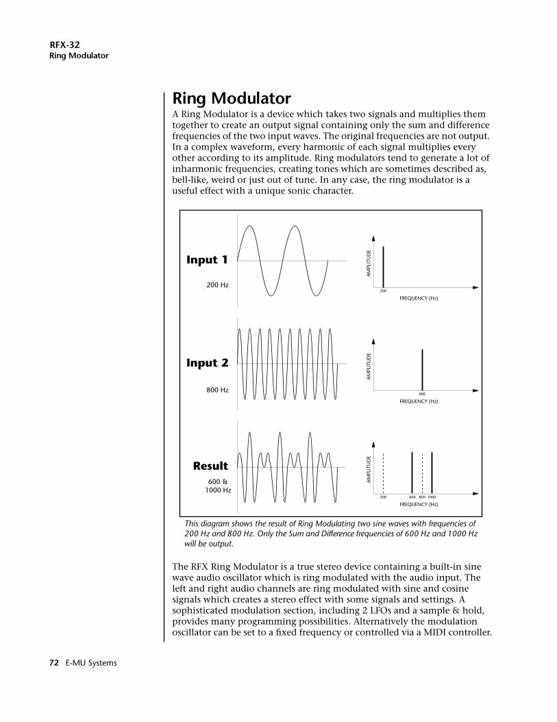
RFX-32Ring Modulator
Ring ModulatorA Ring Modulator is a device which takes two signals and multiplies them together to create an output signal containing only the sum and difference frequencies of the two input waves. The original frequencies are not output. In a complex waveform, every harmonic of each signal multiplies every other according to its amplitude. Ring modulators tend to generate a lot of inharmonic frequencies, creating tones which are sometimes described as, bell-like, weird or just out of tune. In any case, the ring modulator is a useful effect with a unique sonic character.
The RFX Ring Modulator is a true stereo device containing a built-in sine wave audio oscillator which is ring modulated with the audio input. The left and right audio channels are ring modulated with sine and cosine signals which creates a stereo effect with some signals and settings. A sophisticated modulation section, including 2 LFOs and a sample & hold, provides many programming possibilities. Alternatively the modulation oscillator can be set to a fixed frequency or controlled via a MIDI controller.
FREQUENCY (Hz)
AM
PLIT
UD
E
200
FREQUENCY (Hz)
AM
PLIT
UD
E
800
FREQUENCY (Hz)
AM
PLIT
UD
E
200 600 800 1000
Input 1
Input 2
Result
200 Hz
800 Hz
600 &1000 Hz
This diagram shows the result of Ring Modulating two sine waves with frequencies of 200 Hz and 800 Hz. Only the Sum and Difference frequencies of 600 Hz and 1000 Hz will be output.
72 E-MU Systems
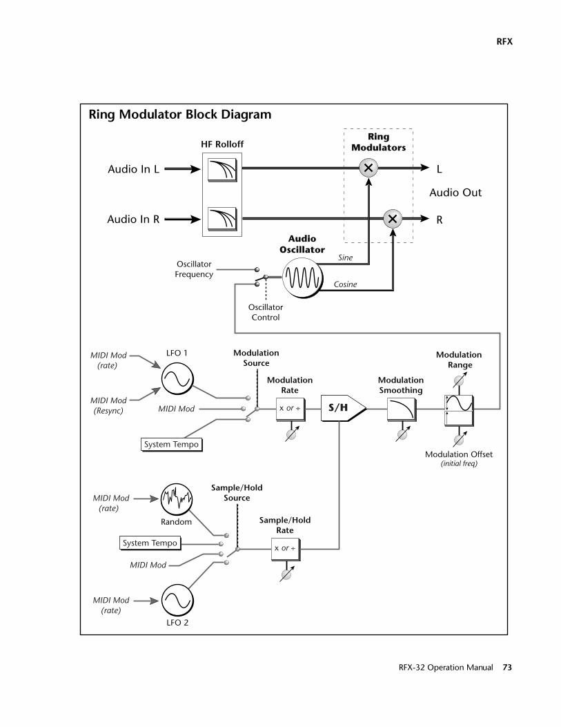
RFX
L
Audio Out
R
Audio In L
Audio In R
Modulation Offset(initial freq)
Modulation Range
ModulationSmoothing
MIDI Mod
MIDI Mod
S/H
ModulationRate
LFO 1
Sample/HoldSource
Cosine
Sine
MIDI Mod(rate)
MIDI Mod(rate)
LFO 2
Random
System Tempo
System Tempo
x or ÷
Sample/HoldRate
x or ÷
ModulationSource
OscillatorFrequency
OscillatorControl
HF Rolloff
AudioOscillator
RingModulators
MIDI Mod(rate)
MIDI Mod(Resync)
Ring Modulator Block Diagram
RFX-32 Operation Manual 73
RFX-32Ring Modulator
Ring Modulator Parameters:Please refer to the Ring Modulator block diagram on the previous page to better understand the effect and modulation routings.
Oscillator Control Selects between Manual control or Modulation.
When the Oscillator Control is set to Modulated, the Oscillator Frequency option is “greyed out”.
Oscillator Freq When the Oscillator Control is set to Manual, this control sets the frequency of the audio oscillator directly.
Mod Source Selects the source of modulation
• LFO 1 - sine wave oscillator• System Tempo - LFO 1 synced to Seq/Arp/MIDI clock• MIDI - MIDI CC value controls the audio oscillator
frequency. Resync - This MIDI control restarts LFO 1 whenever the controller value changes from zero to a positive number. Resync can be used to restart a long slow sweep or to synchronize the LFO with the beat of the music.
Mod Rate Sets the LFO 1 rate in bpm (.25-980 beats-per-minute) when selected as the Mod Source. When the Mod Source is set to System Tempo, the Mod Rate becomes a divisor/multiplier of the System Tempo (BPM/120 - BPM x 31).
Mod Range Adjusts the amount of modulation applied to the phase shifter from 1% to 100%.
Mod Offset Adds an initial positive value or bias to the modulation source. This allows you to move the sum and difference frequencies to an area of interest in the audio spectrum.
Samp/Hold Source A sample and hold can be inserted into the modulation path or turned off. This parameter selects the clock source for the sample and hold. See “Background: Sample & Hold” on page 68 for more information.
MIDI ControlsWet/Dry MixFX Input LevelFX Output LevelOscillator FrequencyMod LFO1 RateS/H LFO2 RateS/H TriggerLFO Resync
• Off - The modulation signal bypasses the Sample & Hold.
• LFO 2 - a clock oscillator with a range of .25 to 980 bpm.
• System Tempo - LFO 2 synced to Seq/Arp/MIDI clock
• MIDI - Any time the MIDI CC value (connected via “Edit Modulation” in the Setup Edit screen) changes and is a number greater than 0, the input to the S & H is sampled and held on its output. At values below 1, the input is passed unchanged.
• Random - the clock oscillator has a random rate. The sample & hold Rate value controls the general speed of the random clock, but the sample & hold will be triggered at random times.
Samp/Hold Rate Sets the LFO 2 rate in bpm (.25-980 beats-per-minute) when selected as the S/H Source. When the S/H Source is set to System Tempo, the S/H Rate becomes a divisor/multiplier of the System Tempo (BPM/120 - BPM x 31). When the S/H Source is set to Random, the S/H Rate sets the overall rate of LFO 2, although trigger pulses will occur randomly.
74 E-MU Systems
RFX-32Ring Modulator
OOOO Mod Smoothing is applied to the modulation signal even if the Sample & Hold is turned off.
Mod Smoothing Controls the amount of smoothing from the lag processor following the sample & hold. No smoothing will be applied with a setting of 0 and the stepped output of the sample & hold will be passed unchanged. With the maximum lag setting of 10, rapid changes will be smoothed into a slowly changing control signal.
HF Rolloff High Frequency Rolloff controls two lowpass filters inserted into the audio path before the ring modulators. Certain signals containing a lot of high frequency energy can produce a harsh, noiselike output. In these situations, smoother and more bell-like timbres can be achieved by filtering out the higher frequencies before ring modulation.
RFX-32 Operation Manual 75
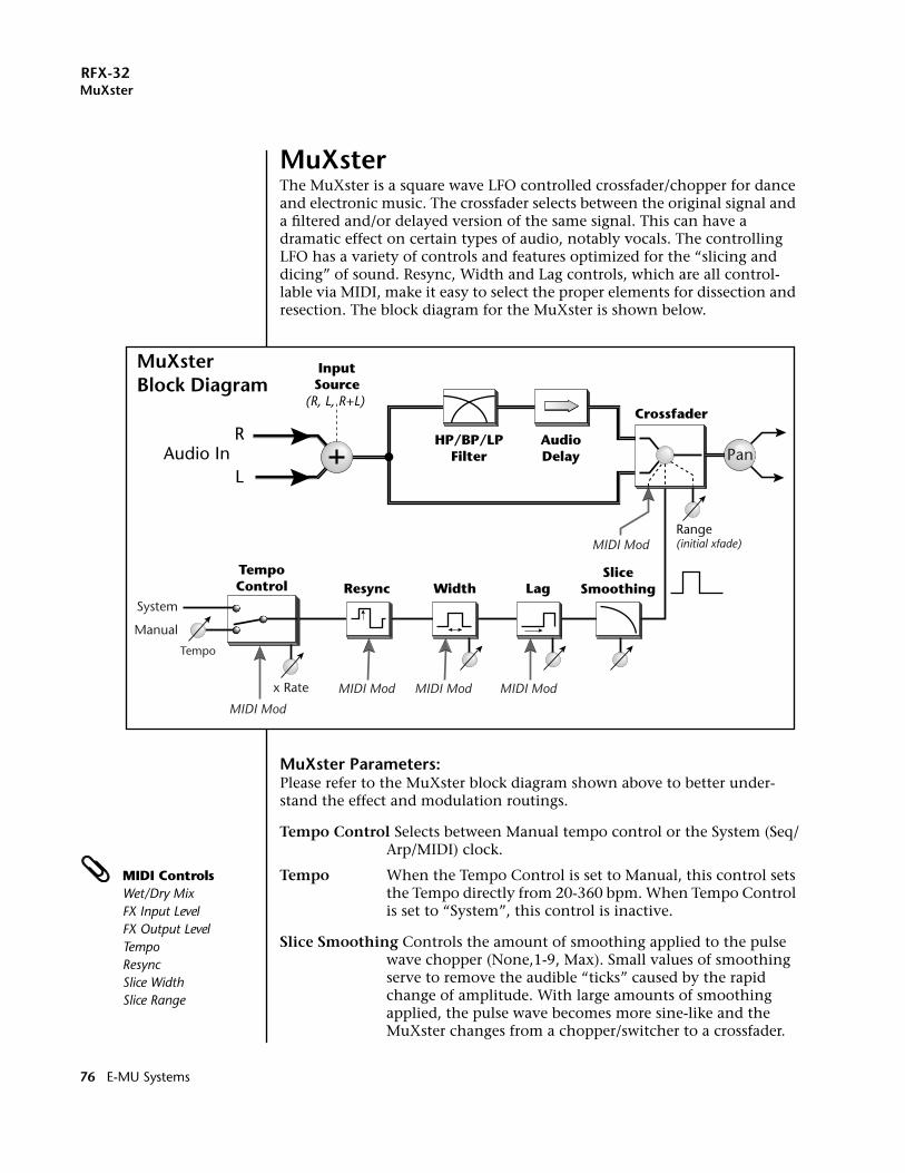
RFX-32MuXster
MuXsterThe MuXster is a square wave LFO controlled crossfader/chopper for dance and electronic music. The crossfader selects between the original signal and a filtered and/or delayed version of the same signal. This can have a dramatic effect on certain types of audio, notably vocals. The controlling LFO has a variety of controls and features optimized for the “slicing and dicing” of sound. Resync, Width and Lag controls, which are all control-lable via MIDI, make it easy to select the proper elements for dissection and resection. The block diagram for the MuXster is shown below.
MuXster Parameters:Please refer to the MuXster block diagram shown above to better under-stand the effect and modulation routings.
Tempo Control Selects between Manual tempo control or the System (Seq/Arp/MIDI) clock.
MIDI ControlsWet/Dry MixFX Input LevelFX Output LevelTempoResyncSlice WidthSlice Range
Tempo When the Tempo Control is set to Manual, this control sets the Tempo directly from 20-360 bpm. When Tempo Control is set to “System”, this control is inactive.
Slice Smoothing Controls the amount of smoothing applied to the pulse wave chopper (None,1-9, Max). Small values of smoothing serve to remove the audible “ticks” caused by the rapid change of amplitude. With large amounts of smoothing applied, the pulse wave becomes more sine-like and the MuXster changes from a chopper/switcher to a crossfader.
InputSource
(R, L, R+L)
RAudio In
L
HP/BP/LPFilter
AudioDelay
Crossfader
SliceSmoothingLagWidthResync
TempoControl
Pan
Range(initial xfade)MIDI Mod
MIDI Mod MIDI Mod MIDI Mod
MIDI Mod
Manual
System
x Rate
Tempo
MuXster Block Diagram
76 E-MU Systems
RFX-32MuXster
Resync - This MIDI control restarts the clock whenever the controller value changes from zero to a positive number. Resync is useful to synchronize the Muxing with the beat of the music.
Slice Rate Slice Rate is a divisor/multiplier of the Tempo (Tempo/8 - Tempo x 32). There is also a “freeze” setting which locks the MuXster in bypass mode.
Slice Width This control sets the pulse width of the slice or how much time the crossfader spends on each of the two inputs. The following widths are available: 1/32, 1/16, 1/8, 1/4, 1/2, 3/4, 31/32 slice.
Slice Lag Slice Lag delays the pulse by the following increments:None, 1/32, 1/16, 1/8, 1/4, 1/2, 3/4, 31/32 slice. This control is helpful with some types of audio signals to “zero-in” on the desired section to be sliced.
Slice Range This important control adjusts the relative mixture of the two inputs. With the Range set at 100%, only the processed input will be gated on and off. At a setting of 50%, the MuXster will switch (or fade) back and forth between the two inputs. At a setting of 0%, the output will be mostly unprocessed audio with slices of processed audio being heard at reduced volume.
OOOO Check out the Audio Delay parameter using spoken word as the input source.
Audio Delay This processor delays the signal input by a fixed amount before the crossfader. Serious audio scrambling is possible when the time shifted audio is switched (or faded) back and forth with the original signal. Audio Delay is adjustable in 1/128, 1/64, 1/32, 1/16, 1/8, 3/16, 1/4 note increments.
EQ Type This control selects which type of filter (or none) will be inserted into the processed channel: Lowpass, Bandpass, or Highpass. When using instrument sounds instead of spoken words, EQ is highly effective to differentiate the two signals.
EQ Frequency The frequency control sets the cutoff frequency of the highpass and lowpass filters or the center frequency of the bandpass filter. The frequency is adjustable from 50Hz to 12,800Hz in 25 increments.
Input Source Selects which channels will be used for the input to the MuXster. The choices are: Left, Right, or the sum of Left and Right channels.
Pan The monophonic output of the MuXster can be panned anywhere in the stereo field.
RFX-32 Operation Manual 77
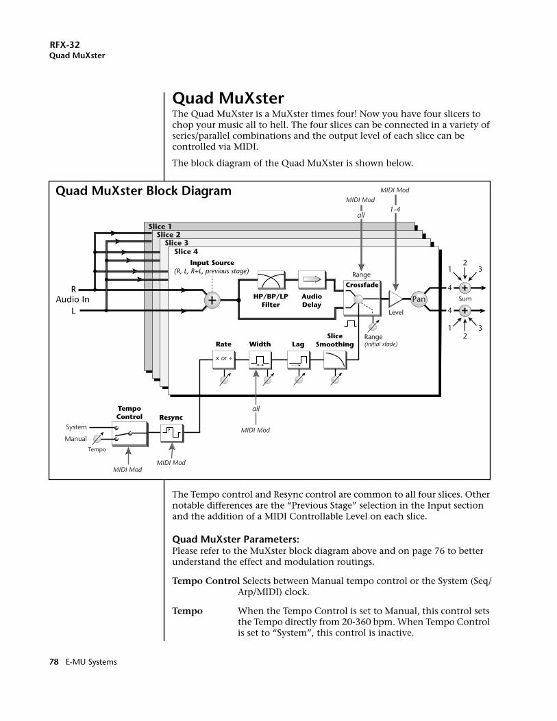
RFX-32Quad MuXster
Quad MuXsterThe Quad MuXster is a MuXster times four! Now you have four slicers to chop your music all to hell. The four slices can be connected in a variety of series/parallel combinations and the output level of each slice can be controlled via MIDI.
The block diagram of the Quad MuXster is shown below.
The Tempo control and Resync control are common to all four slices. Other notable differences are the “Previous Stage” selection in the Input section and the addition of a MIDI Controllable Level on each slice.
Quad MuXster Parameters:Please refer to the MuXster block diagram above and on page 76 to better understand the effect and modulation routings.
Tempo Control Selects between Manual tempo control or the System (Seq/Arp/MIDI) clock.
Tempo When the Tempo Control is set to Manual, this control sets the Tempo directly from 20-360 bpm. When Tempo Control is set to “System”, this control is inactive.
RAudio In
L
ResyncTempoControl
MIDI Mod MIDI Mod
Manual
System
Tempo
Rate Width
Input Source(R, L, R+L, previous stage)
HP/BP/LPFilter
AudioDelay
SliceSmoothingLag
Pan
Range(initial xfade)
Range
Level
Crossfade
x or ÷
Slice 4
Slice 1Slice 2
Slice 3
MIDI Mod MIDI Mod
all1-4
MIDI Mod
all
1 32
1 32
4
4Sum
Quad MuXster Block Diagram
78 E-MU Systems
RFX-32Quad MuXster
Resync - This MIDI control restarts the clock whenever the controller value changes from zero to a positive number. Resync is useful to synchronize the Muxing with the beat of the music.
Slice Smoothing Controls the amount of smoothing applied to the pulse wave chopper (None,1-9, Max). Small values of smoothing serve to remove the audible “ticks” caused by the rapid change of amplitude. With large amounts of smoothing applied, the pulse wave becomes more sine-like and the MuXster changes from a chopper/switcher to a crossfader.
Slice # Selects which slice you want to adjust.
Slice Rate Slice Rate is a divisor/multiplier of the Tempo (Tempo/8 - Tempo x 32). There is also a “freeze” setting which locks the MuXster in bypass mode.
MIDI ControlsWet/Dry MixFX Input LevelFX Output LevelTempoResyncSlice WidthSlice RangeSlice 1 LevelSlice 2 LevelSlice 3 LevelSlice 4 Level
Slice Width This control sets the pulse width of the slice or how much time the crossfader spends on each of the two inputs. The following widths are available: 1/32, 1/16, 1/8, 1/4, 1/2, 3/4, 31/32 slice.
Slice Lag Slice Lag delays the pulse by the following increments: None, 1/32, 1/16, 1/8, 1/4, 1/2, 3/4, 31/32 slice. This control is helpful with some types of audio signals to “zero-in” on the desired section to be sliced.
Slice Range This important control adjusts the relative mixture of the two inputs. With the Range set at 100%, only the processed input will be gated on and off. At a setting of 50%, the MuXster will switch (or fade) back and forth between the two inputs. At a setting of 0%, the output will be mostly unprocessed audio with slices of processed audio being heard at reduced volume.
OOOO Check out the Audio Delay parameter using spoken word as the input source.
Audio Delay This processor delays the signal input by a fixed amount before the crossfader. Serious audio scrambling is possible when the time shifted audio is switched (or faded) back and forth with the original signal. Audio Delay is adjustable in 1/128, 1/64, 1/32, 1/16, 1/8, 3/16, 1/4 note increments.
EQ Type This control selects which type of filter (or none) will be inserted into the processed channel: Lowpass, Bandpass, or Highpass. When using instrument sounds instead of spoken words, EQ is highly effective to differentiate the two signals.
EQ Frequency The frequency control sets the cutoff frequency of the highpass and lowpass filters or the center frequency of the bandpass filter. The frequency is adjustable from 50Hz to 12,800Hz in 25 increments.
Input Source Selects which channels will be used for the input to the MuXster. The choices are: Left, Right, the sum of Left and Right channels, or the Previous Slice.
Pan The monophonic output of the each MuXster Slice can be panned anywhere in the stereo field.
RFX-32 Operation Manual 79
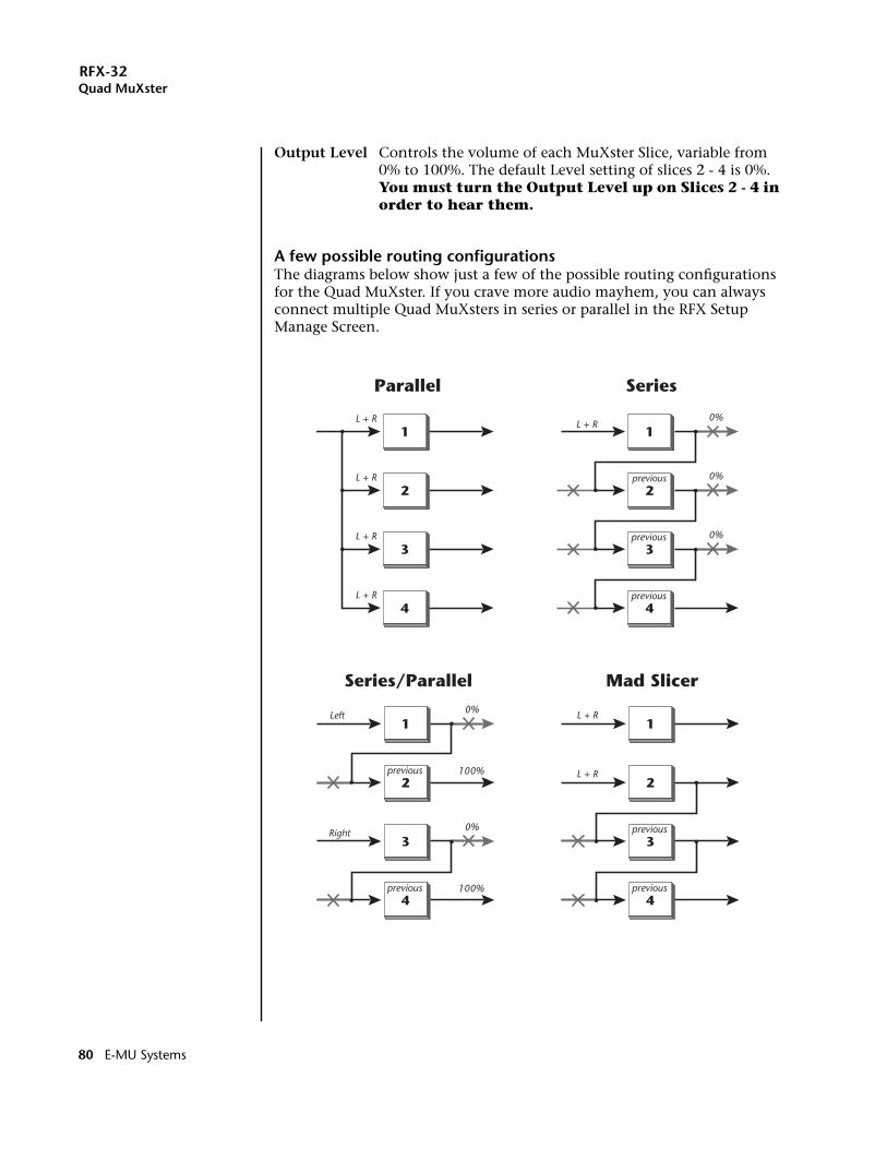
RFX-32Quad MuXster
Output Level Controls the volume of each MuXster Slice, variable from 0% to 100%. The default Level setting of slices 2 - 4 is 0%. You must turn the Output Level up on Slices 2 - 4 in order to hear them.
A few possible routing configurationsThe diagrams below show just a few of the possible routing configurations for the Quad MuXster. If you crave more audio mayhem, you can always connect multiple Quad MuXsters in series or parallel in the RFX Setup Manage Screen.
1
2
3
4
previous
L + R
previous
previous
1
2
3
4
0%
0%
0%
Parallel Series
L + R
L + R
L + R
L + R
1
2
3
4
previous
previous
1
2
3
4
previous
previous
Series/Parallel Mad Slicer
Left
Right
L + R
L + R0%
0%
100%
100%
80 E-MU Systems
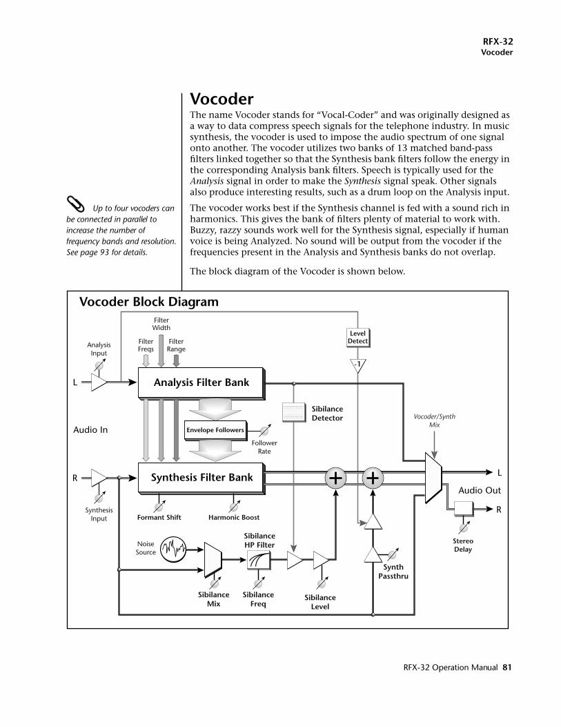
RFX-32Vocoder
VocoderThe name Vocoder stands for “Vocal-Coder” and was originally designed as a way to data compress speech signals for the telephone industry. In music synthesis, the vocoder is used to impose the audio spectrum of one signal onto another. The vocoder utilizes two banks of 13 matched band-pass filters linked together so that the Synthesis bank filters follow the energy in the corresponding Analysis bank filters. Speech is typically used for the Analysis signal in order to make the Synthesis signal speak. Other signals also produce interesting results, such as a drum loop on the Analysis input.
Up to four vocoders can be connected in parallel to increase the number of frequency bands and resolution. See page 93 for details.
The vocoder works best if the Synthesis channel is fed with a sound rich in harmonics. This gives the bank of filters plenty of material to work with. Buzzy, razzy sounds work well for the Synthesis signal, especially if human voice is being Analyzed. No sound will be output from the vocoder if the frequencies present in the Analysis and Synthesis banks do not overlap.
The block diagram of the Vocoder is shown below.
SibilanceHP Filter
Harmonic Boost
L
Audio Out
R
L
R
AnalysisInput
Vocoder/SynthMix
NoiseSource
SibilanceLevel
SynthPassthru
SibilanceDetector
LevelDetect
SibilanceMix
SibilanceFreq
Analysis Filter Bank
Synthesis Filter Bank
Envelope Followers
FilterFreqs
FilterWidth
FilterRange
SynthesisInput Formant Shift
FollowerRate
Audio In
-1
StereoDelay
Vocoder Block Diagram
RFX-32 Operation Manual 81
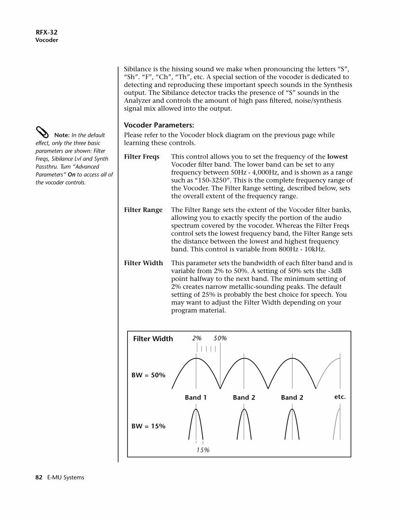
RFX-32Vocoder
Sibilance is the hissing sound we make when pronouncing the letters “S”, “Sh”. “F”, “Ch”, “Th”, etc. A special section of the vocoder is dedicated to detecting and reproducing these important speech sounds in the Synthesis output. The Sibilance detector tracks the presence of “S” sounds in the Analyzer and controls the amount of high pass filtered, noise/synthesis signal mix allowed into the output.
Vocoder Parameters: Note: In the default effect, only the three basic parameters are shown: Filter Freqs, Sibilance Lvl and Synth Passthru. Turn “Advanced Parameters” On to access all of the vocoder controls.
Please refer to the Vocoder block diagram on the previous page while learning these controls.
Filter Freqs This control allows you to set the frequency of the lowest Vocoder filter band. The lower band can be set to any frequency between 50Hz - 4,000Hz, and is shown as a range such as “150-3250”. This is the complete frequency range of the Vocoder. The Filter Range setting, described below, sets the overall extent of the frequency range.
Filter Range The Filter Range sets the extent of the Vocoder filter banks, allowing you to exactly specify the portion of the audio spectrum covered by the vocoder. Whereas the Filter Freqs control sets the lowest frequency band, the Filter Range sets the distance between the lowest and highest frequency band. This control is variable from 800Hz - 10kHz.
Filter Width This parameter sets the bandwidth of each filter band and is variable from 2% to 50%. A setting of 50% sets the -3dB point halfway to the next band. The minimum setting of 2% creates narrow metallic-sounding peaks. The default setting of 25% is probably the best choice for speech. You may want to adjust the Filter Width depending on your program material.
50%
BW = 50%
BW = 15%
2%
Band 1 Band 2 Band 2 etc.
15%
Filter Width
82 E-MU Systems
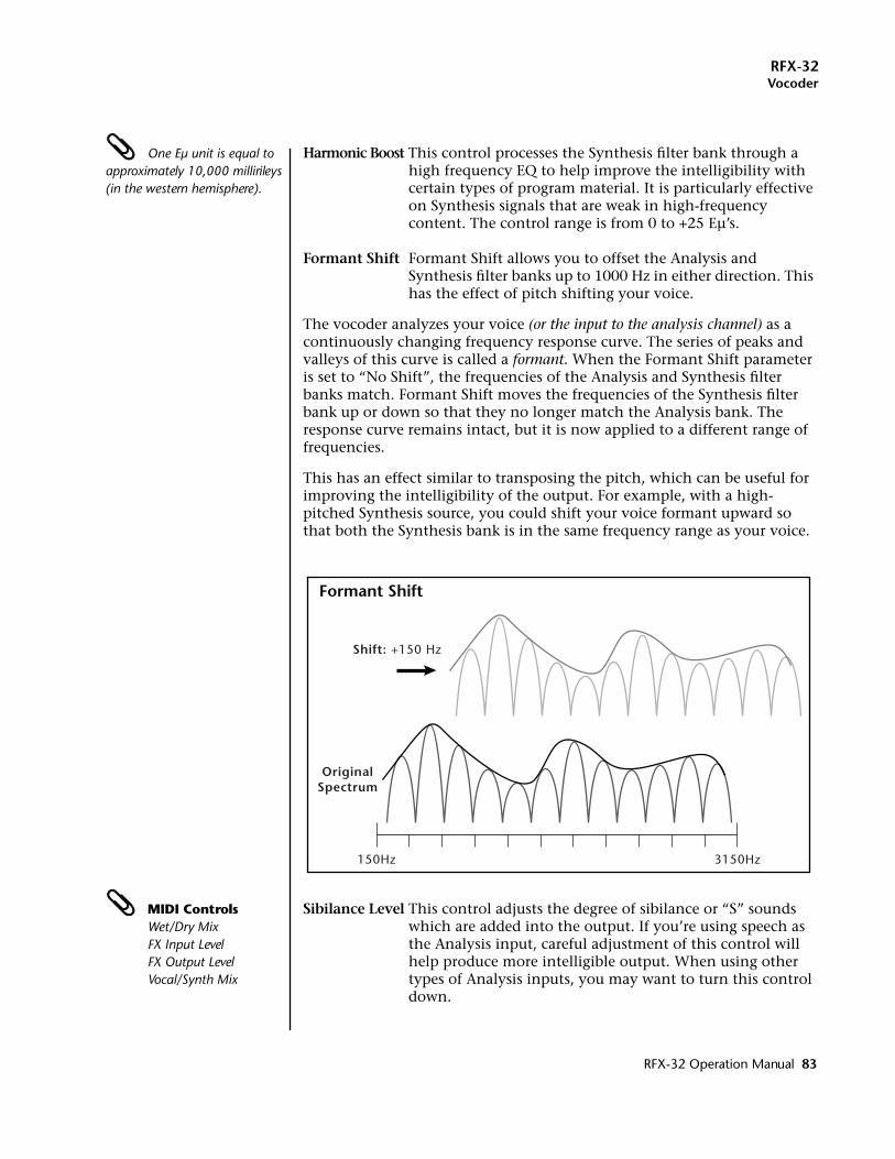
RFX-32Vocoder
One Eµ unit is equal to approximately 10,000 millirileys (in the western hemisphere).
Harmonic Boost This control processes the Synthesis filter bank through a high frequency EQ to help improve the intelligibility with certain types of program material. It is particularly effective on Synthesis signals that are weak in high-frequency content. The control range is from 0 to +25 Eµ’s.
Formant Shift Formant Shift allows you to offset the Analysis and Synthesis filter banks up to 1000 Hz in either direction. This has the effect of pitch shifting your voice.
The vocoder analyzes your voice (or the input to the analysis channel) as a continuously changing frequency response curve. The series of peaks and valleys of this curve is called a formant. When the Formant Shift parameter is set to “No Shift”, the frequencies of the Analysis and Synthesis filter banks match. Formant Shift moves the frequencies of the Synthesis filter bank up or down so that they no longer match the Analysis bank. The response curve remains intact, but it is now applied to a different range of frequencies.
This has an effect similar to transposing the pitch, which can be useful for improving the intelligibility of the output. For example, with a high-pitched Synthesis source, you could shift your voice formant upward so that both the Synthesis bank is in the same frequency range as your voice.
MIDI ControlsWet/Dry MixFX Input LevelFX Output LevelVocal/Synth Mix
Sibilance Level This control adjusts the degree of sibilance or “S” sounds which are added into the output. If you’re using speech as the Analysis input, careful adjustment of this control will help produce more intelligible output. When using other types of Analysis inputs, you may want to turn this control down.
150Hz 3150Hz
Shift: +150 Hz
OriginalSpectrum
Formant Shift
RFX-32 Operation Manual 83
RFX-32Vocoder
Sibilance Mix This control adjusts the balance between the Synthesis signal and the Noise Source which are input to the Sibilance Highpass Filter. This parameter, in combination with the Sibilance Frequency, can be adjusted to give a more natural sibilance sound or a highly unnatural sound.
Sibilance Freq This controls the cutoff frequency of the Sibilance Highpass Filter in the Analysis and Synthesis banks in sixteen steps from 5800Hz to 11800Hz. This parameter can be tuned to increase the accuracy of the Sibilance Detector in the Analysis bank.
Synth Passthru This parameter sets the level of Synthesis signal that is allowed to pass in the absence of a Analysis signal. With the control set to 0%, both Analysis and Synthesis channels must be active in order to hear any output.
When Synth Passthru is turned up, the raw Synthesis input will be bypassed around the Synthesis filter bank in the absence of an Analysis signal. When the Analysis is detected, the bypassed signal will be turned down (or ducked) so that the vocoded signal can be heard. Refer to the Vocoder block diagram for a graphic representation of this function.
Follower Rate This parameter controls the rate of a Lag processor on the output of the envelope signals from the Analysis filter bank. The Follower Rate control can produce spectral smearing at the slowest rate (1), or a sharp, mechanical sound at the fastest rate. Intermediate settings tend to produce the most natural speech.
Stereo Delay A delay from 1 to 50 ms can be applied to the right output of the Synthesis filter bank in order to create a simulated stereo signal. Since the vocoder does its processing in mono, this control can impart a pseudo stereo image to the signal.
Analysis Input This gain cell controls the Analysis input level and is variable from -20 dB to +25 dB.
The vocoder performs best with a strong signal level (but not clipping). A weak Analysis level will result in lack of definition and low output. A weak Synthesis signal will result in low output and more noise. The wide range of the Analysis and Synthesis Input controls makes it easy to get a proper level with almost any input.
Synthesis Input This gain cell controls the Synthesis input level and is variable from -20 dB to +25 dB.
84 E-MU Systems
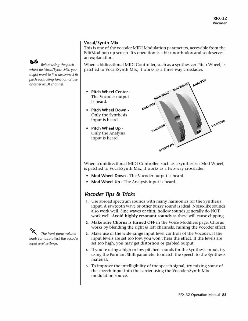
RFX-32Vocoder
Vocal/Synth MixThis is one of the vocoder MIDI Modulation parameters, accessible from the EditMod pop-up screen. It’s operation is a bit unorthodox and so deserves an explanation.
____ Before using the pitch wheel for Vocal/Synth Mix, you might want to first disconnect its pitch controlling function or use another MIDI channel.
When a bidirectional MIDI Controller, such as a synthesizer Pitch Wheel, is patched to Vocal/Synth Mix, it works as a three-way crossfader.
• Pitch Wheel Center - The Vocoder output is heard.
• Pitch Wheel Down - Only the Synthesis input is heard.
• Pitch Wheel Up -Only the Analysis input is heard.
When a unidirectional MIDI Controller, such as a synthesizer Mod Wheel, is patched to Vocal/Synth Mix, it works as a two-way crossfader.
• Mod Wheel Down - The Vocoder output is heard.
• Mod Wheel Up - The Analysis input is heard.
Vocoder Tips & Tricks1. Use abroad spectrum sounds with many harmonics for the Synthesis
input. A sawtooth wave or other buzzy sound is ideal. Noise-like sounds also work well. Sine waves or thin, hollow sounds generally do NOT work well. Avoid highly resonant sounds as these will cause clipping.
2. Make sure Chorus is turned OFF in the Voice Modifiers page. Chorus works by blending the right & left channels, ruining the vocoder effect.
OOOO The front panel volume knob can also affect the vocoder input level settings.
3. Make use of the wide-range input level controls of the Vocoder. If the input levels are set too low, you won't hear the effect. If the levels are set too high, you may get distortion or garbled output.
4. If you’re using a high or low pitched sounds for the Synthesis input, try using the Formant Shift parameter to match the speech to the Synthesis material.
5. To improve the intelligibility of the speech signal, try mixing some of the speech input into the carrier using the Vocoder/Synth Mix modulation source.
VOCODER VOCODER
ANALYSIS
ANALYSIS
Pitch Wheel
Mod Wheel
SYNTHESIS
RFX-32 Operation Manual 85
RFX-32Vocoder
Patching into the VocoderThe vocoder is a little different than any of the other effects because it uses the left and right channels as separate inputs. The Left channel goes to the Analysis input and the Right channel goes to the Synthesis input.
The next two sets of steps take you through the process of creating a Vocoder Effect, the Vocoder Setup and a Vocoder MultiSetup. Once these objects are created and saved, you can use them as building blocks for further experiments and Setups.
Create an RFX Vocoder Effect & Setup1. Press the Master key. The LED illuminates and the main master screen
appears.
2. Press the FX function key. Another row of function keys appears.
3. Press the REffect function key. The RFX Effect Manage screen appears.
4. Press the New function key. A pop-up dialog box asks you to select the location for the new Effect. An empty location will be selected by default. Press OK.
5. A pop-up dialog box asks you to name the new Effect. Name the Effect to avoid confusion later, then press OK.
6. Press the Edit function key. The RFX Effect edit screen appears.
7. Select the Vocoder Plug-in on the top line of the display.
8. Press the Exit button on the Emulator front panel. A pop-up dialog box will momentarily display, “Writing RFX Effect”.
9. Press the Exit button again, then press the RSetup function key. The RFX Setup Manage screen appears.
10. Press the New function key. A pop-up dialog box asks you to select the location for the new Setup. An empty location will be selected by default. Press OK.
11. A pop-up dialog box asks you to name the new Setup. Name the Setup to avoid confusion later, then press OK.
12. Press the Edit function key. The RFX bus setup screen appears. Bus 1 will be selected on the top line of the display. (If not, select Bus 1.)
13. Select the Vocoder Effect you created (in steps 4-7 above) in the Effect 1 slot. Set the Wet/Dry mix to 100%. The Main Bus output should also be set to 100%.
14. Press the Master button on the Emulator front panel. The LED will extinguish.
15. Save the Bank.
86 E-MU Systems
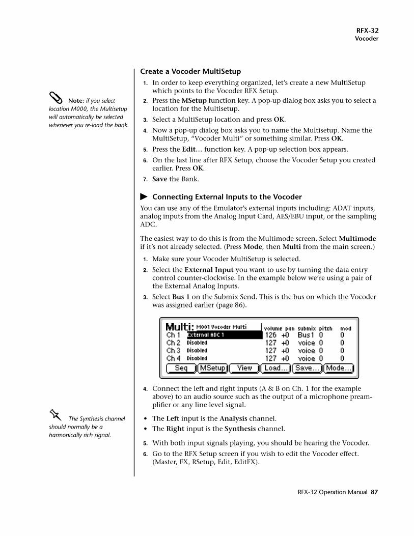
RFX-32Vocoder
Create a Vocoder MultiSetup1. In order to keep everything organized, let’s create a new MultiSetup
which points to the Vocoder RFX Setup. Note: if you select location M000, the Multisetup will automatically be selected whenever you re-load the bank.
2. Press the MSetup function key. A pop-up dialog box asks you to select a location for the Multisetup.
3. Select a MultiSetup location and press OK.
4. Now a pop-up dialog box asks you to name the Multisetup. Name the MultiSetup, “Vocoder Multi” or something similar. Press OK.
5. Press the Edit… function key. A pop-up selection box appears.
6. On the last line after RFX Setup, choose the Vocoder Setup you created earlier. Press OK.
7. Save the Bank.
� Connecting External Inputs to the VocoderYou can use any of the Emulator’s external inputs including: ADAT inputs, analog inputs from the Analog Input Card, AES/EBU input, or the sampling ADC.
The easiest way to do this is from the Multimode screen. Select Multimode if it’s not already selected. (Press Mode, then Multi from the main screen.)
1. Make sure your Vocoder MultiSetup is selected.
2. Select the External Input you want to use by turning the data entry control counter-clockwise. In the example below we’re using a pair of the External Analog Inputs.
3. Select Bus 1 on the Submix Send. This is the bus on which the Vocoder was assigned earlier (page 86).
4. Connect the left and right inputs (A & B on Ch. 1 for the example above) to an audio source such as the output of a microphone pream-plifier or any line level signal.
OOOO The Synthesis channel should normally be a harmonically rich signal.
• The Left input is the Analysis channel.
• The Right input is the Synthesis channel.
5. With both input signals playing, you should be hearing the Vocoder.
6. Go to the RFX Setup screen if you wish to edit the Vocoder effect. (Master, FX, RSetup, Edit, EditFX).
RFX-32 Operation Manual 87
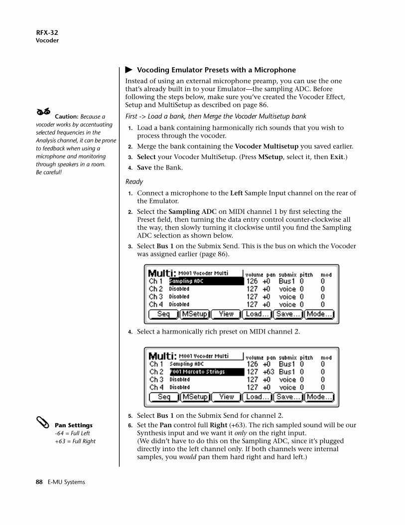
RFX-32Vocoder
� Vocoding Emulator Presets with a MicrophoneInstead of using an external microphone preamp, you can use the one that’s already built in to your Emulator—the sampling ADC. Before following the steps below, make sure you’ve created the Vocoder Effect, Setup and MultiSetup as described on page 86.
____ Caution: Because a vocoder works by accentuating selected frequencies in the Analysis channel, it can be prone to feedback when using a microphone and monitoring through speakers in a room. Be careful!
First -> Load a bank, then Merge the Vocoder Multisetup bank
1. Load a bank containing harmonically rich sounds that you wish to process through the vocoder.
2. Merge the bank containing the Vocoder Multisetup you saved earlier.
3. Select your Vocoder MultiSetup. (Press MSetup, select it, then Exit.)
4. Save the Bank.
Ready
1. Connect a microphone to the Left Sample Input channel on the rear of the Emulator.
2. Select the Sampling ADC on MIDI channel 1 by first selecting the Preset field, then turning the data entry control counter-clockwise all the way, then slowly turning it clockwise until you find the Sampling ADC selection as shown below.
3. Select Bus 1 on the Submix Send. This is the bus on which the Vocoder was assigned earlier (page 86).
4. Select a harmonically rich preset on MIDI channel 2.
5. Select Bus 1 on the Submix Send for channel 2. Pan Settings
-64 = Full Left+63 = Full Right
6. Set the Pan control full Right (+63). The rich sampled sound will be our Synthesis input and we want it only on the right input.(We didn’t have to do this on the Sampling ADC, since it’s plugged directly into the left channel only. If both channels were internal samples, you would pan them hard right and hard left.)
88 E-MU Systems
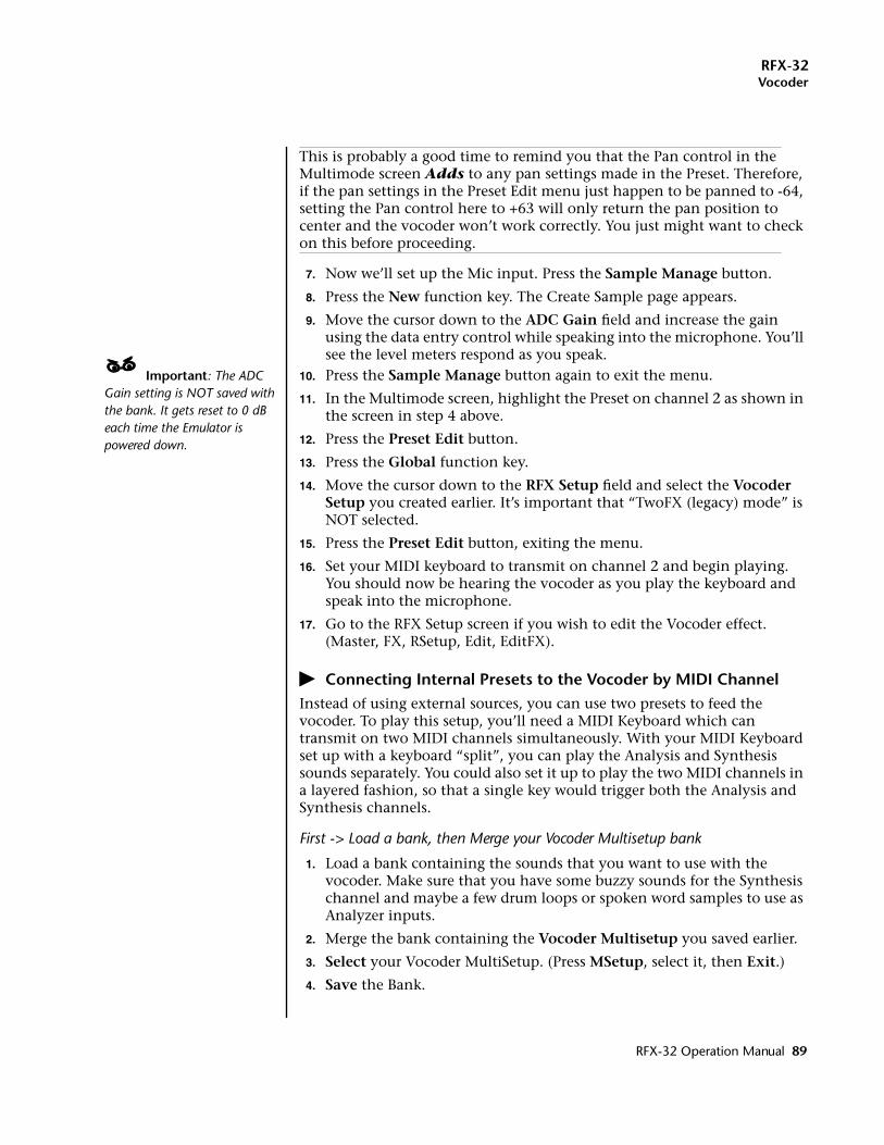
RFX-32Vocoder
This is probably a good time to remind you that the Pan control in the Multimode screen Adds to any pan settings made in the Preset. Therefore, if the pan settings in the Preset Edit menu just happen to be panned to -64, setting the Pan control here to +63 will only return the pan position to center and the vocoder won’t work correctly. You just might want to check on this before proceeding.
7. Now we’ll set up the Mic input. Press the Sample Manage button.
8. Press the New function key. The Create Sample page appears.
9. Move the cursor down to the ADC Gain field and increase the gain using the data entry control while speaking into the microphone. You’ll see the level meters respond as you speak.
____ Important: The ADC Gain setting is NOT saved with the bank. It gets reset to 0 dB each time the Emulator is powered down.
10. Press the Sample Manage button again to exit the menu.
11. In the Multimode screen, highlight the Preset on channel 2 as shown in the screen in step 4 above.
12. Press the Preset Edit button.
13. Press the Global function key.
14. Move the cursor down to the RFX Setup field and select the Vocoder Setup you created earlier. It’s important that “TwoFX (legacy) mode” is NOT selected.
15. Press the Preset Edit button, exiting the menu.
16. Set your MIDI keyboard to transmit on channel 2 and begin playing. You should now be hearing the vocoder as you play the keyboard and speak into the microphone.
17. Go to the RFX Setup screen if you wish to edit the Vocoder effect. (Master, FX, RSetup, Edit, EditFX).
� Connecting Internal Presets to the Vocoder by MIDI ChannelInstead of using external sources, you can use two presets to feed the vocoder. To play this setup, you’ll need a MIDI Keyboard which can transmit on two MIDI channels simultaneously. With your MIDI Keyboard set up with a keyboard “split”, you can play the Analysis and Synthesis sounds separately. You could also set it up to play the two MIDI channels in a layered fashion, so that a single key would trigger both the Analysis and Synthesis channels.
First -> Load a bank, then Merge your Vocoder Multisetup bank
1. Load a bank containing the sounds that you want to use with the vocoder. Make sure that you have some buzzy sounds for the Synthesis channel and maybe a few drum loops or spoken word samples to use as Analyzer inputs.
2. Merge the bank containing the Vocoder Multisetup you saved earlier.
3. Select your Vocoder MultiSetup. (Press MSetup, select it, then Exit.)
4. Save the Bank.
RFX-32 Operation Manual 89
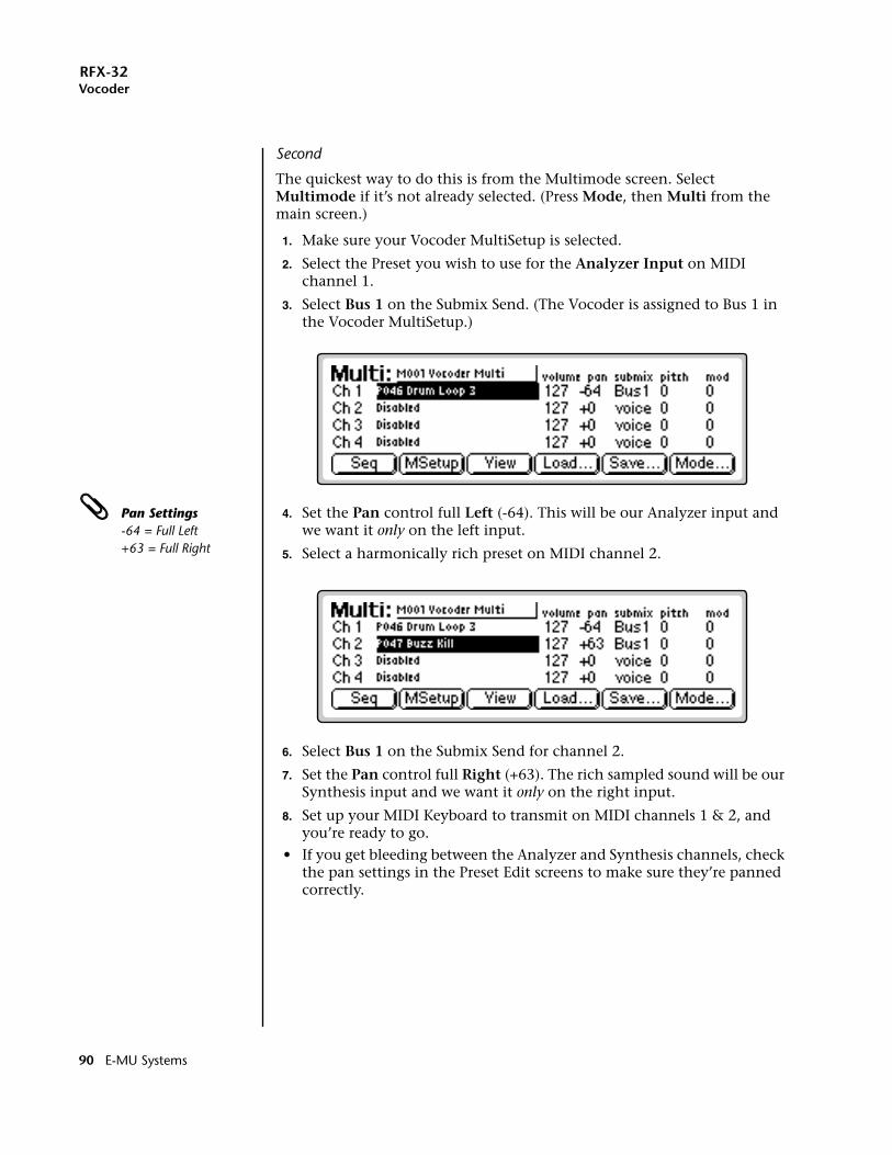
RFX-32Vocoder
Second
The quickest way to do this is from the Multimode screen. Select Multimode if it’s not already selected. (Press Mode, then Multi from the main screen.)
1. Make sure your Vocoder MultiSetup is selected.
2. Select the Preset you wish to use for the Analyzer Input on MIDI channel 1.
3. Select Bus 1 on the Submix Send. (The Vocoder is assigned to Bus 1 in the Vocoder MultiSetup.)
Pan Settings-64 = Full Left+63 = Full Right
4. Set the Pan control full Left (-64). This will be our Analyzer input and we want it only on the left input.
5. Select a harmonically rich preset on MIDI channel 2.
6. Select Bus 1 on the Submix Send for channel 2.
7. Set the Pan control full Right (+63). The rich sampled sound will be our Synthesis input and we want it only on the right input.
8. Set up your MIDI Keyboard to transmit on MIDI channels 1 & 2, and you’re ready to go.
• If you get bleeding between the Analyzer and Synthesis channels, check the pan settings in the Preset Edit screens to make sure they’re panned correctly.
90 E-MU Systems
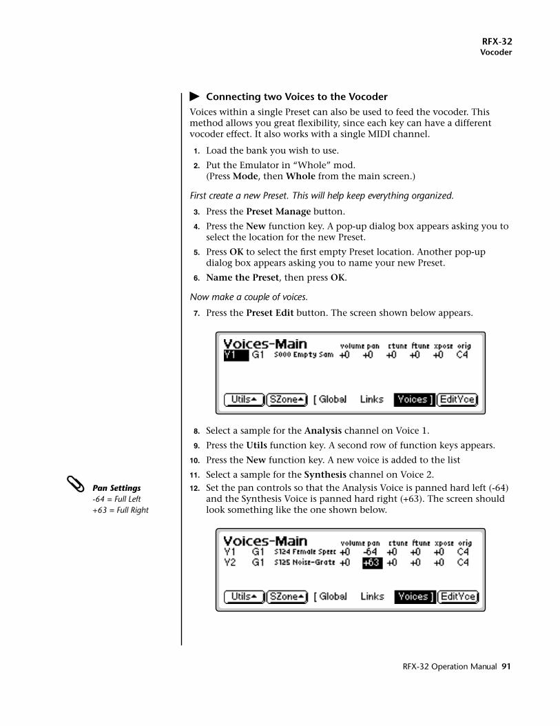
RFX-32Vocoder
� Connecting two Voices to the VocoderVoices within a single Preset can also be used to feed the vocoder. This method allows you great flexibility, since each key can have a different vocoder effect. It also works with a single MIDI channel.
1. Load the bank you wish to use.
2. Put the Emulator in “Whole” mod.(Press Mode, then Whole from the main screen.)
First create a new Preset. This will help keep everything organized.
3. Press the Preset Manage button.
4. Press the New function key. A pop-up dialog box appears asking you to select the location for the new Preset.
5. Press OK to select the first empty Preset location. Another pop-up dialog box appears asking you to name your new Preset.
6. Name the Preset, then press OK.
Now make a couple of voices.
7. Press the Preset Edit button. The screen shown below appears.
8. Select a sample for the Analysis channel on Voice 1.
9. Press the Utils function key. A second row of function keys appears.
10. Press the New function key. A new voice is added to the list
11. Select a sample for the Synthesis channel on Voice 2. Pan Settings
-64 = Full Left+63 = Full Right
12. Set the pan controls so that the Analysis Voice is panned hard left (-64) and the Synthesis Voice is panned hard right (+63). The screen should look something like the one shown below.
RFX-32 Operation Manual 91
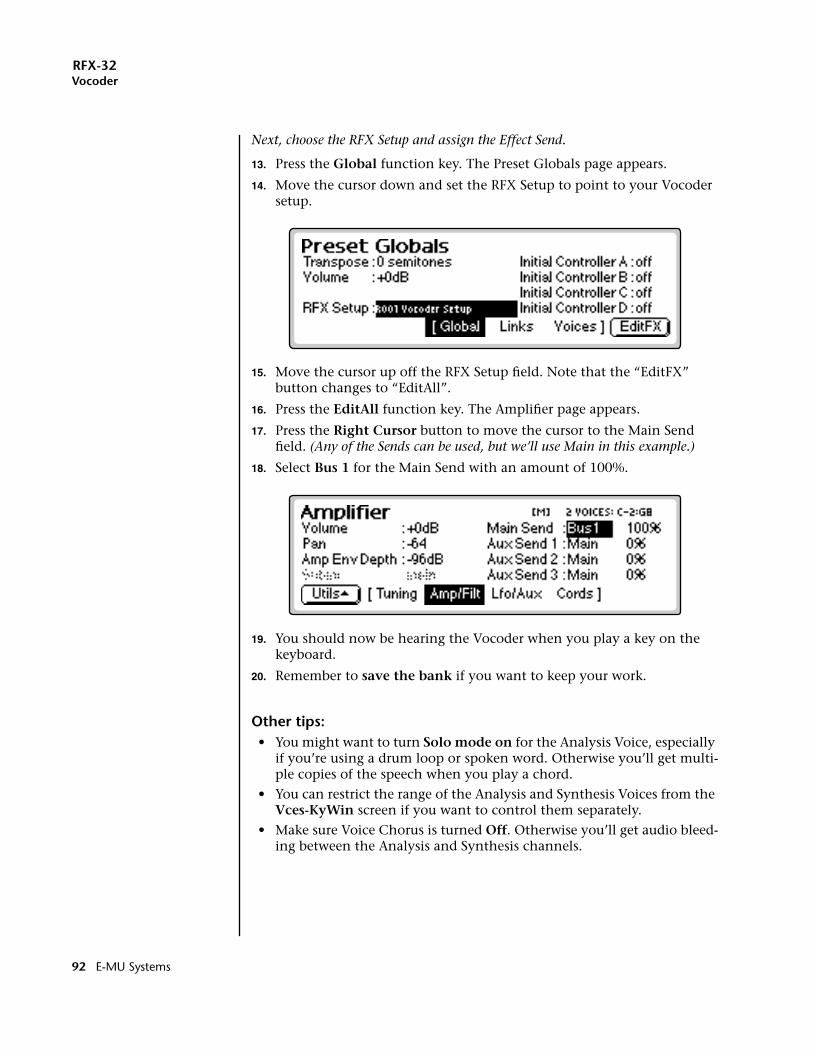
RFX-32Vocoder
Next, choose the RFX Setup and assign the Effect Send.
13. Press the Global function key. The Preset Globals page appears.
14. Move the cursor down and set the RFX Setup to point to your Vocoder setup.
15. Move the cursor up off the RFX Setup field. Note that the “EditFX” button changes to “EditAll”.
16. Press the EditAll function key. The Amplifier page appears.
17. Press the Right Cursor button to move the cursor to the Main Send field. (Any of the Sends can be used, but we’ll use Main in this example.)
18. Select Bus 1 for the Main Send with an amount of 100%.
19. You should now be hearing the Vocoder when you play a key on the keyboard.
20. Remember to save the bank if you want to keep your work.
Other tips:• You might want to turn Solo mode on for the Analysis Voice, especially
if you’re using a drum loop or spoken word. Otherwise you’ll get multi-ple copies of the speech when you play a chord.
• You can restrict the range of the Analysis and Synthesis Voices from the Vces-KyWin screen if you want to control them separately.
• Make sure Voice Chorus is turned Off. Otherwise you’ll get audio bleed-ing between the Analysis and Synthesis channels.
92 E-MU Systems
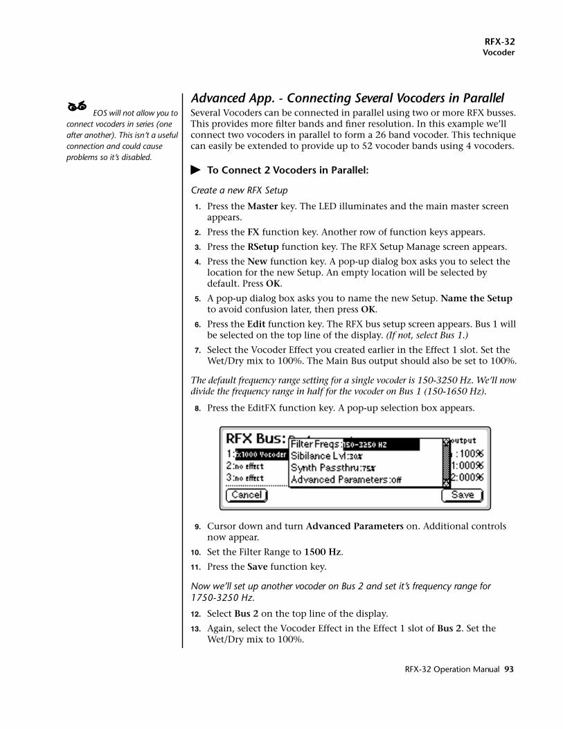
RFX-32Vocoder
Advanced App. - Connecting Several Vocoders in Parallel____ EOS will not allow you to connect vocoders in series (one after another). This isn’t a useful connection and could cause problems so it’s disabled.
Several Vocoders can be connected in parallel using two or more RFX busses. This provides more filter bands and finer resolution. In this example we’ll connect two vocoders in parallel to form a 26 band vocoder. This technique can easily be extended to provide up to 52 vocoder bands using 4 vocoders.
� To Connect 2 Vocoders in Parallel:
Create a new RFX Setup
1. Press the Master key. The LED illuminates and the main master screen appears.
2. Press the FX function key. Another row of function keys appears.
3. Press the RSetup function key. The RFX Setup Manage screen appears.
4. Press the New function key. A pop-up dialog box asks you to select the location for the new Setup. An empty location will be selected by default. Press OK.
5. A pop-up dialog box asks you to name the new Setup. Name the Setup to avoid confusion later, then press OK.
6. Press the Edit function key. The RFX bus setup screen appears. Bus 1 will be selected on the top line of the display. (If not, select Bus 1.)
7. Select the Vocoder Effect you created earlier in the Effect 1 slot. Set the Wet/Dry mix to 100%. The Main Bus output should also be set to 100%.
The default frequency range setting for a single vocoder is 150-3250 Hz. We’ll now divide the frequency range in half for the vocoder on Bus 1 (150-1650 Hz).
8. Press the EditFX function key. A pop-up selection box appears.
9. Cursor down and turn Advanced Parameters on. Additional controls now appear.
10. Set the Filter Range to 1500 Hz.
11. Press the Save function key.
Now we’ll set up another vocoder on Bus 2 and set it’s frequency range for 1750-3250 Hz.
12. Select Bus 2 on the top line of the display.
13. Again, select the Vocoder Effect in the Effect 1 slot of Bus 2. Set the Wet/Dry mix to 100%.
RFX-32 Operation Manual 93
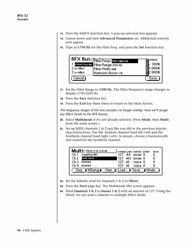
RFX-32Vocoder
14. Press the EditFX function key. A pop-up selection box appears.
15. Cursor down and turn Advanced Parameters on. Additional controls now appear.
16. Type in 1750 Hz for the Filter Freq. and press the Set function key.
17. Set the Filter Range to 1500 Hz. The Filter Frequency range changes to display 1750-3250 Hz.
18. Press the Save function key.
19. Press the Exit key three times to return to the Main Screen.
The frequency ranges of the two vocoders no longer overlap. Now we’ll assign our Effect Sends to the RFX busses.
20. Select Multimode if it’s not already selected. (Press Mode, then Multi from the main screen.)
21. Set up MIDI channels 1 & 2 just like you did in the previous step-by-step instructions. Pan the Analysis channel hard left (-64) and the Synthesis channel hard right (+63). As always, choose a harmonically rich sound for the Synthesis channel.
22. Set the Submix send for channels 1 & 2 to Mixer.
23. Press the Next page key. The Multimode Mix screen appears.
24. Send channels 1 & 2 to busses 1 & 2 with an amount of 127. Using the Mixer, we can send a channel to multiple Effect Sends.
94 E-MU Systems
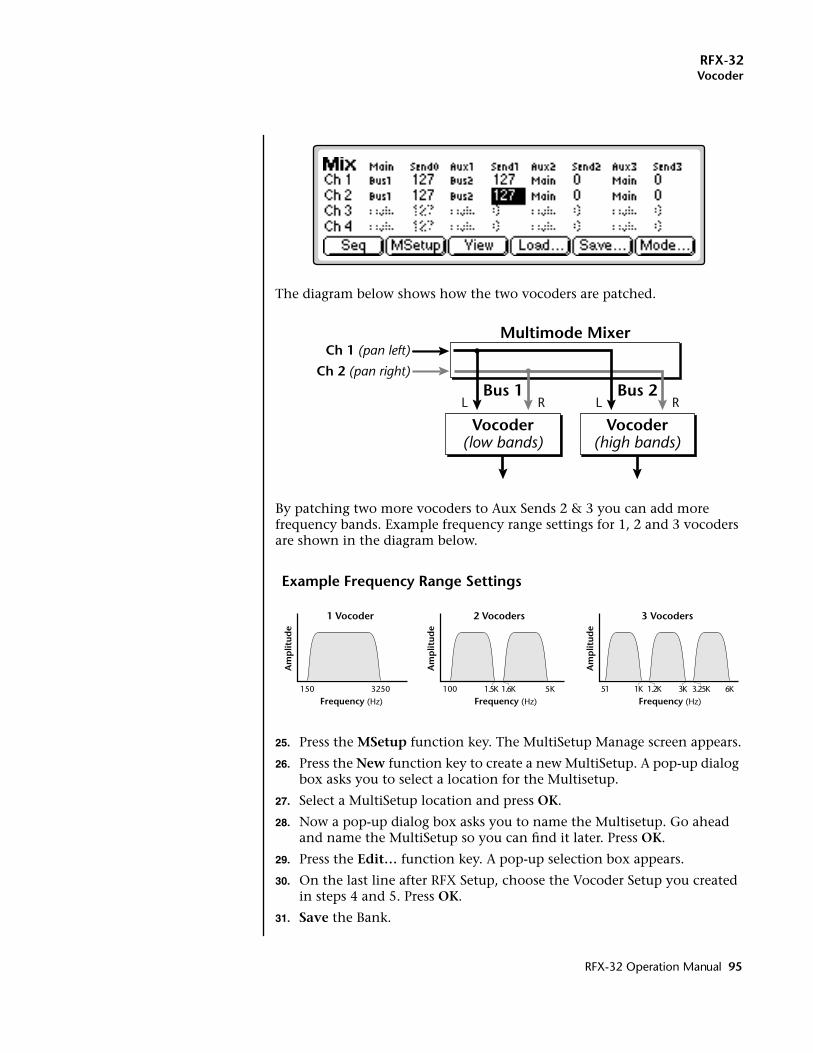
RFX-32Vocoder
The diagram below shows how the two vocoders are patched.
By patching two more vocoders to Aux Sends 2 & 3 you can add more frequency bands. Example frequency range settings for 1, 2 and 3 vocoders are shown in the diagram below.
25. Press the MSetup function key. The MultiSetup Manage screen appears.
26. Press the New function key to create a new MultiSetup. A pop-up dialog box asks you to select a location for the Multisetup.
27. Select a MultiSetup location and press OK.
28. Now a pop-up dialog box asks you to name the Multisetup. Go ahead and name the MultiSetup so you can find it later. Press OK.
29. Press the Edit… function key. A pop-up selection box appears.
30. On the last line after RFX Setup, choose the Vocoder Setup you created in steps 4 and 5. Press OK.
31. Save the Bank.
Vocoder(low bands)
Multimode Mixer
Vocoder(high bands)
Ch 1 (pan left)
Ch 2 (pan right)
L R L RBus 1 Bus 2
150 3250
Frequency (Hz)
Am
plit
ude
1 Vocoder 2 Vocoders
100 5K1.5K 1.6K
Am
plit
ude
Frequency (Hz)
51 6K3K 3.25K1K 1.2K
Am
plit
ude
Frequency (Hz)
3 Vocoders
Example Frequency Range Settings
RFX-32 Operation Manual 95
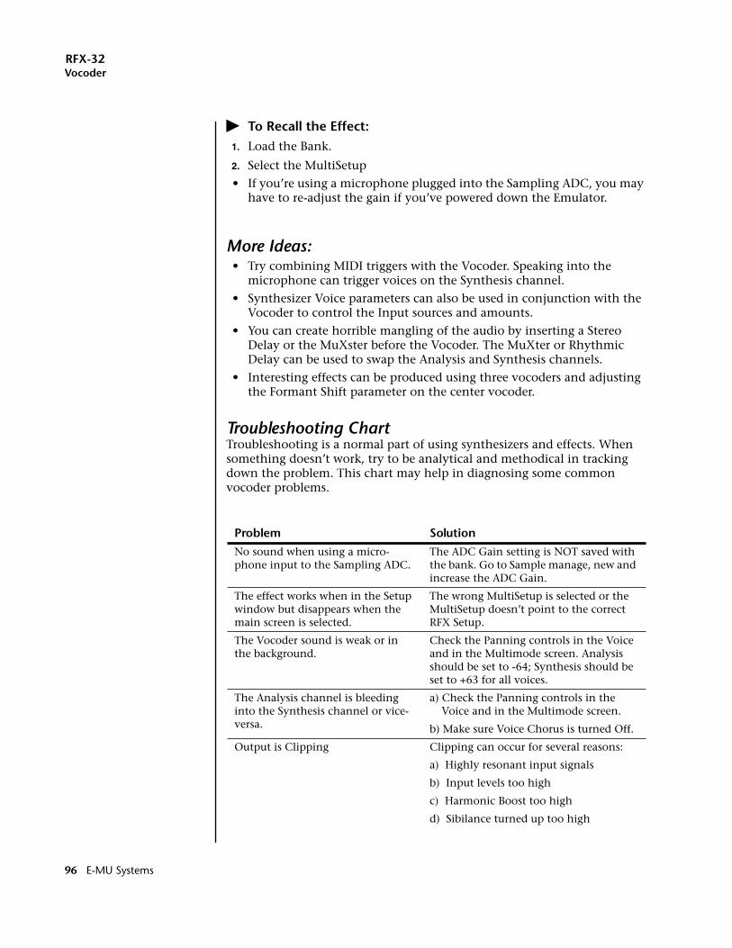
RFX-32Vocoder
� To Recall the Effect:1. Load the Bank.
2. Select the MultiSetup
• If you’re using a microphone plugged into the Sampling ADC, you may have to re-adjust the gain if you’ve powered down the Emulator.
More Ideas:• Try combining MIDI triggers with the Vocoder. Speaking into the
microphone can trigger voices on the Synthesis channel.
• Synthesizer Voice parameters can also be used in conjunction with the Vocoder to control the Input sources and amounts.
• You can create horrible mangling of the audio by inserting a Stereo Delay or the MuXster before the Vocoder. The MuXter or Rhythmic Delay can be used to swap the Analysis and Synthesis channels.
• Interesting effects can be produced using three vocoders and adjusting the Formant Shift parameter on the center vocoder.
Troubleshooting ChartTroubleshooting is a normal part of using synthesizers and effects. When something doesn’t work, try to be analytical and methodical in tracking down the problem. This chart may help in diagnosing some common vocoder problems.
Problem Solution
No sound when using a micro-phone input to the Sampling ADC.
The ADC Gain setting is NOT saved with the bank. Go to Sample manage, new and increase the ADC Gain.
The effect works when in the Setup window but disappears when the main screen is selected.
The wrong MultiSetup is selected or the MultiSetup doesn’t point to the correct RFX Setup.
The Vocoder sound is weak or in the background.
Check the Panning controls in the Voice and in the Multimode screen. Analysis should be set to -64; Synthesis should be set to +63 for all voices.
The Analysis channel is bleeding into the Synthesis channel or vice-versa.
a) Check the Panning controls in the Voice and in the Multimode screen.
b) Make sure Voice Chorus is turned Off.
Output is Clipping Clipping can occur for several reasons:
a) Highly resonant input signals
b) Input levels too high
c) Harmonic Boost too high
d) Sibilance turned up too high
96 E-MU Systems
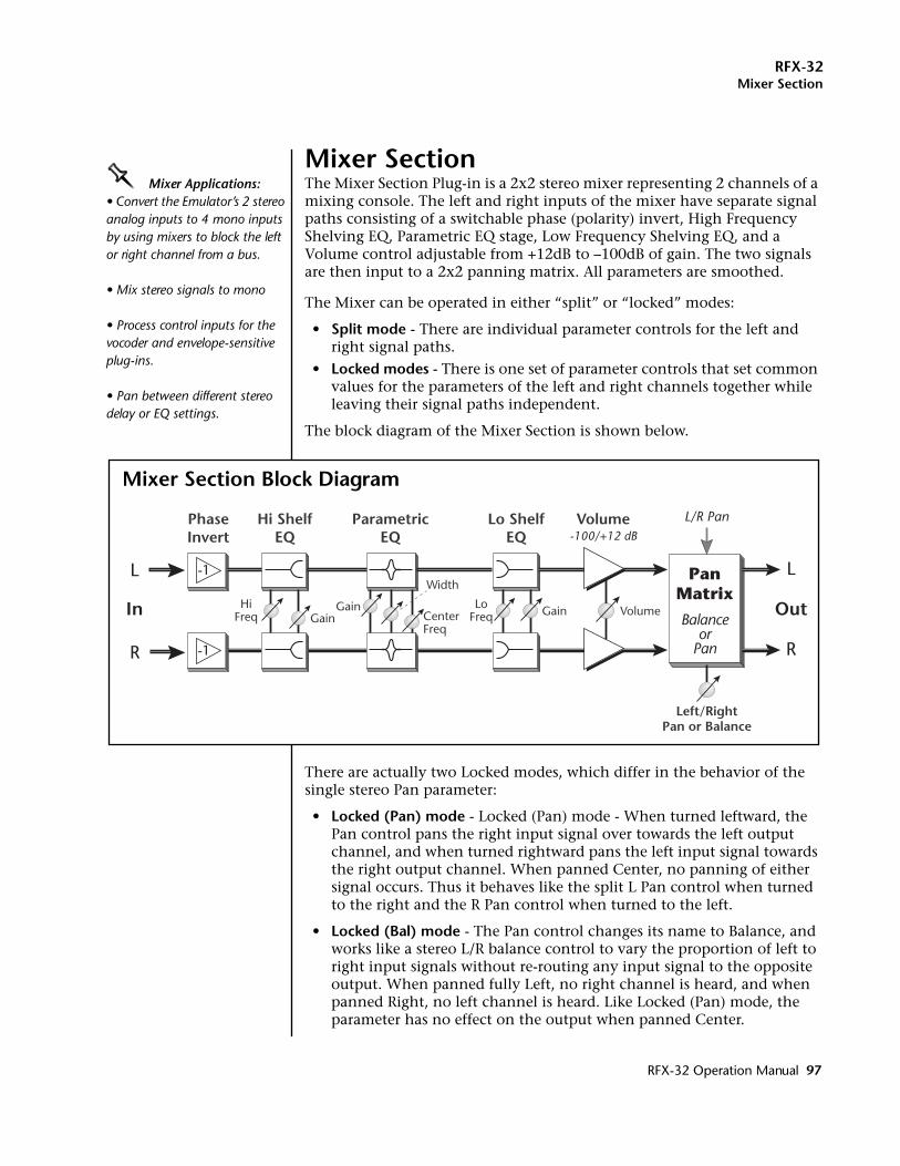
RFX-32Mixer Section
Mixer SectionOOOO Mixer Applications:• Convert the Emulator’s 2 stereo analog inputs to 4 mono inputs by using mixers to block the left or right channel from a bus.
• Mix stereo signals to mono
• Process control inputs for the vocoder and envelope-sensitive plug-ins.
• Pan between different stereo delay or EQ settings.
The Mixer Section Plug-in is a 2x2 stereo mixer representing 2 channels of a mixing console. The left and right inputs of the mixer have separate signal paths consisting of a switchable phase (polarity) invert, High Frequency Shelving EQ, Parametric EQ stage, Low Frequency Shelving EQ, and a Volume control adjustable from +12dB to –100dB of gain. The two signals are then input to a 2x2 panning matrix. All parameters are smoothed.
The Mixer can be operated in either “split” or “locked” modes:
• Split mode - There are individual parameter controls for the left and right signal paths.
• Locked modes - There is one set of parameter controls that set common values for the parameters of the left and right channels together while leaving their signal paths independent.
The block diagram of the Mixer Section is shown below.
There are actually two Locked modes, which differ in the behavior of the single stereo Pan parameter:
• Locked (Pan) mode - Locked (Pan) mode - When turned leftward, the Pan control pans the right input signal over towards the left output channel, and when turned rightward pans the left input signal towards the right output channel. When panned Center, no panning of either signal occurs. Thus it behaves like the split L Pan control when turned to the right and the R Pan control when turned to the left.
• Locked (Bal) mode - The Pan control changes its name to Balance, and works like a stereo L/R balance control to vary the proportion of left to right input signals without re-routing any input signal to the opposite output. When panned fully Left, no right channel is heard, and when panned Right, no left channel is heard. Like Locked (Pan) mode, the parameter has no effect on the output when panned Center.
L
Out
R
L
R
PhaseInvert
Hi ShelfEQ
ParametricEQ
Lo ShelfEQ
Volume
In
-1
-1
-100/+12 dB
PanMatrix
L/R Pan
HiFreq Gain
Gain
Width
CenterFreq
VolumeLoFreq Gain
Balanceor
Pan
Left/RightPan or Balance
Mixer Section Block Diagram
RFX-32 Operation Manual 97
RFX-32Mixer Section
Mixer Section Parameters:Please refer to the Mixer Section block diagram to better understand the effect and modulation routings.When in Split mode there are both “L” and “R” (left and right) versions of the following parameters; in Locked modes the “L” and “R” disappear, leaving parameters which work in common for both sides.
Volume Adjusts the gain of the channel from -100dB (off) to +12dB in .1 db steps. The lowest setting of the volume control is "MUTED" (-∞ dB.)
Pan In Split mode, this control pans the signal to the left or right output. In Locked (Pan) mode the control pans the right input signal over, routing it fully to the left output when turned Left, and pans the left input signal over to the right output when turned Right.
Balance This control only appears in Lock (Bal) mode. It works like a stereo L/R balance control to vary the proportion of left to right input signals without re-routing any input signal to the opposite output.
OOOO Tip: Press the Set/Shift key to increment the frequency in 1kHz steps.
HF Shelf Adjustable from 1kHz to 18kHz in 1Hz increments.
HF Gain Adjustable from -30dB to +30 dB in 0.1dB increments.
EQ Center Adjusts the para EQ band from 10Hz-20kHz in 1Hz steps.
EQ Width Adjusts the bandwidth of the para EQ band from 1/24th octave to 2 octaves adjustable in semitones.
Dialing in the Para EQ:An easy way to dial in a parametric EQ is to increase the gain and narrow the bandwidth so you can really hear the effect of the EQ. Next, adjust the Center frequency control until you find the area you want to affect. Now reduce the Gain and widen the Width to give a more natural curve.
EQ Gain Adjusts the boost/cut of the EQ band from -100dB to +50dB.
LF Shelf Adjustable from 50Hz to 1kHz in 1Hz increments.
LF Gain Adjustable from -30dB to +30 dB in 0.1dB increments.
Phase Invert Switches the polarity of the input signal. Normally this is used to correct cancellation problems caused by out of phase stereo signals. For certain effects, you may actually want to put a stereo signal out of phase in order to create cancellation effects using delay, phase shift or ring mod.
Modulation ParametersThere are two Modulation parameters, L Pan and R Pan, that duplicate the functions of the similarly named regular parameters. The regular and modulation parameters override each other, so the most recent update to each one “wins.” When in either Locked mode, the R Pan modulation parameter is ignored and L Pan works like either Pan or Balance.
Note: In order to modulate pan completely left or right, a bipolar controller (such as a pitch wheel) MUST be used. With a unipolar MIDI controller (such as a modulation wheel) you can only pan from center to the right side.
98 E-MU Systems
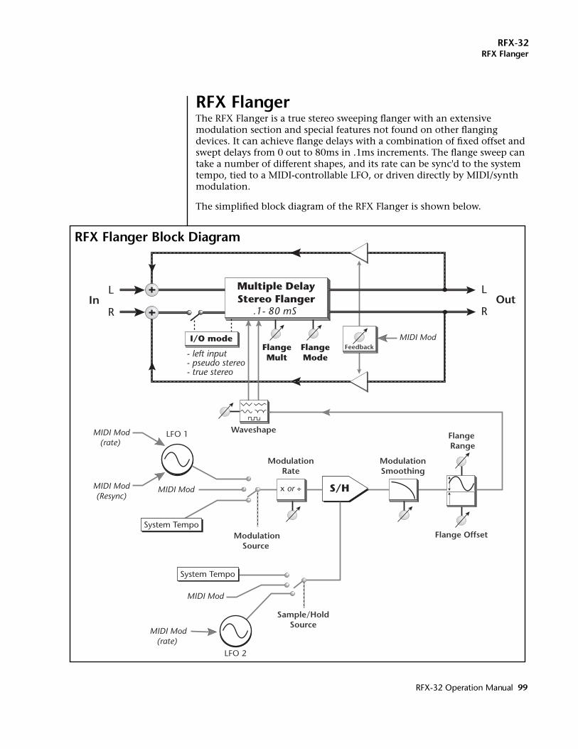
RFX-32RFX Flanger
RFX FlangerThe RFX Flanger is a true stereo sweeping flanger with an extensive modulation section and special features not found on other flanging devices. It can achieve flange delays with a combination of fixed offset and swept delays from 0 out to 80ms in .1ms increments. The flange sweep can take a number of different shapes, and its rate can be sync'd to the system tempo, tied to a MIDI-controllable LFO, or driven directly by MIDI/synth modulation.
The simplified block diagram of the RFX Flanger is shown below.
LOut
R
L
R
Flange Offset
Flange Range
ModulationSmoothing
MIDI Mod
MIDI Mod
MIDI Mod
Multiple DelayStereo Flanger
.1- 80 mS
S/H
ModulationRate
WaveshapeLFO 1
Sample/HoldSource
MIDI Mod(rate)
MIDI Mod(Resync)
MIDI Mod(rate)
Feedback
LFO 2
System Tempo
System Tempo
x or ÷
ModulationSource
In
I/O modeFlangeMult
FlangeMode- left input
- pseudo stereo- true stereo
RFX Flanger Block Diagram
RFX-32 Operation Manual 99
RFX-32RFX Flanger
Left and right channels can use dual inverted sweeps to generate spatial modulation and stereo flanging effects. Feedback amount can be set up to 100% without loss of stability and can also be controlled by external MIDI/synth modulation.
A flange multiplier factor can be used to tune the intensity of the effect independent of the feedback level, and a selection of flange cancellation modes are available that lend a variety of different sonic characteristics to the sound. A sample & hold is also included which can be modulated by tempo, LFO, or MIDI. The flanger can operate in mono (left input), pseudo-stereo and true stereo I/O modes.
This unique flanger is implemented using a number of internal delay lines – flanger “stages” – whose delay lengths are constantly changing in response to an oscillating modulation signal or MIDI controller. The flanging effect occurs when an undelayed signal is combined with these delayed signals, causing a cancellation that creates peaks and notches in the frequency spectrum which move with the sweeping control signal.
RFX Flanger Parameters:Please refer to the RFX Flanger block diagram on the previous page to better understand the effect and modulation routings.
Flange Offset This is the offset, or initial delay time, to which the modulated delay sweep is added. One way to view this is as the minimum sweep delay, an interpretation that is shown in the display of the Flange Range parameter: its delay range value is dynamically redisplayed as the Flange Offset changes. The Flange Offset can be adjusted from a minimum of 0 (actually 1 sample) to 40 milliseconds.
Flange Range This parameter scales the extent of the delay sweep. It is displayed as a pair of values beginning at the Flange Offset and extending to the Offset plus the Range to show the actual delay times over which the flanger will sweep. Classic flanger effects occur when the Offset is near zero and the Range is less than 10msec. Wider Ranges and larger Offsets are more useful for to achieve “doubling” or spatial effects, and long delays coupled with high Feedback can create highly resonant robot-like sounds on vocals.
Resync - This MIDI control restarts the Flanger’s LFOs whenever the controller value changes from zero to a positive number.
Sweep Source This parameter allows the flanger’s sweep to be driven by the internal LFO1 or directly by a MIDI controller. When this parameter is set to LFO1, the LFO frequency is set directly by the Sweep Rate parameter.
• LFO 1 - modulation oscillatorWhenever the Sweep Source is set to LFO1, the LFO1 Sweep Rate modulation parameter is also active. When a MIDI controller is patched to LFO1 Sweep Rate, the
100 E-MU Systems
RFX-32RFX Flanger
Sweep Rate parameter sets a maximum sweep rate that will be further modulated by the controller.
• System Tempo - LFO 1 synced to Seq/Arp/MIDI clockWhen set to System Tempo, the LFO frequency is controlled by the EOS system’s internal tempo, and runs at the tempo division indicated by the Sweep Rate parameter. In this mode, the LFO1 sweep oscillator will be restarted at the beginning of its sweep whenever the EOS arpeggiator or sequencer are resynchronized. In addition, any non-zero value applied to the LFO Resync modulation parameter will also restart the sweep when LFO or System Tempo are selected as sources.
• MIDI - MIDI CC value controls the flange delay.When the Sweep Source is set to MIDI, LFO sweeping and synchronization is disabled and the flange delay is controlled directly by the Flange Delay modulation parameter. The MIDI controller (contoured by the Sweep Shape parameter) will modulate the flanger between the minimum and maximum delay times set by the Flange Range parameter. This is the only time that the Flange Delay modulation parameter is active.
The Sweep Rate parameter is inactive when the Sweep Source is set to MIDI.
Sweep Rate This parameter is a rate multiplier or divisor for the flange sweep. When the Sweep Source is LFO1, this parameter manually sets the frequency of the internal sweep LFO1 to a tempo calibrated in beats per minute (BPM) from .25 to 1000. One complete cycle of the LFO will occur for each beat. When the Sweep Source is System Tempo, this parameter sets the multiple or submultiple of the system’s internal rate to which the sweep LFO is synchronized, from a submultiple of 1/120 (one cycle per minute at a tempo of 120BPM) to a multiple of 137 (275Hz at 120BPM).
Sweep Shape This parameter controls the shape of the modulation waveform that controls the flanger delay time. The possible sweep shapes are Triangle (linear sweep), Curved (a warped Triangle), Sine, Log (an approximately logarithmic shape which “flattens out” towards shorter delay times), or Square.
Each Sweep Shape also has a “Dual” selection. When Dual sweep shapes are selected, a 180 degree (inverted) copy of the normal LFO waveform is applied to alternate stages of the flanger. Thus in Mono/Stereo and Stereo I/O modes, the right output channel flanging is out of phase with respect to the left channel, which creates dramatic stereo spatial effects. In Mono I/O mode, this inverted LFO phase is only applied to
RFX-32 Operation Manual 101
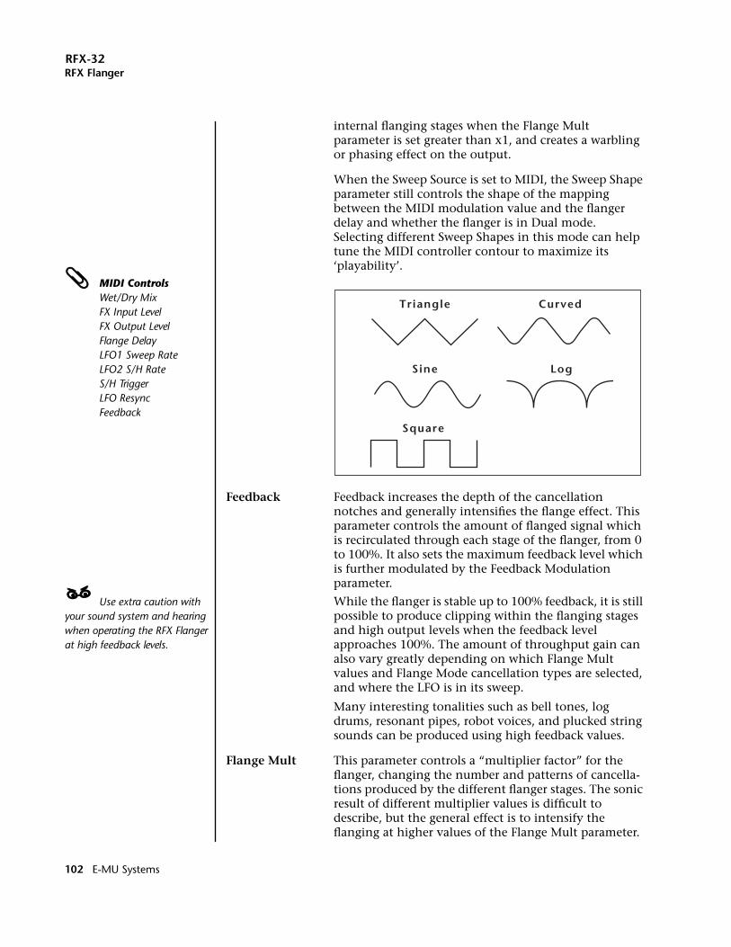
RFX-32RFX Flanger
internal flanging stages when the Flange Mult parameter is set greater than x1, and creates a warbling or phasing effect on the output.
When the Sweep Source is set to MIDI, the Sweep Shape parameter still controls the shape of the mapping between the MIDI modulation value and the flanger delay and whether the flanger is in Dual mode. Selecting different Sweep Shapes in this mode can help tune the MIDI controller contour to maximize its ‘playability’.
MIDI ControlsWet/Dry MixFX Input LevelFX Output LevelFlange DelayLFO1 Sweep RateLFO2 S/H RateS/H TriggerLFO ResyncFeedback
Feedback Feedback increases the depth of the cancellation notches and generally intensifies the flange effect. This parameter controls the amount of flanged signal which is recirculated through each stage of the flanger, from 0 to 100%. It also sets the maximum feedback level which is further modulated by the Feedback Modulation parameter.
____ Use extra caution with your sound system and hearing when operating the RFX Flanger at high feedback levels.
While the flanger is stable up to 100% feedback, it is still possible to produce clipping within the flanging stages and high output levels when the feedback level approaches 100%. The amount of throughput gain can also vary greatly depending on which Flange Mult values and Flange Mode cancellation types are selected, and where the LFO is in its sweep.
Many interesting tonalities such as bell tones, log drums, resonant pipes, robot voices, and plucked string sounds can be produced using high feedback values.
Flange Mult This parameter controls a “multiplier factor” for the flanger, changing the number and patterns of cancella-tions produced by the different flanger stages. The sonic result of different multiplier values is difficult to describe, but the general effect is to intensify the flanging at higher values of the Flange Mult parameter.
Triangle Curved
Square
Sine Log
102 E-MU Systems
RFX-32RFX Flanger
Note that the various “alternate” cancellation modes set by the Flange Mode parameter will generally not be perceptible until the Flange Mult parameter is greater than 1 and more flanging stages are employed. Varia-tions of the Flange Mult and Flange Mode parameters can create a wide variety of different flanging sounds. The exact effect of the Flange Mult parameter depends greatly on the I/O mode selected.
• In Mono I/O mode, the Flange Mult parameter controls the number of flange stages used in series between the input and output. To hear the effect of Dual sweep shapes, the Flange Mult value must be greater than 1 when in Mono mode.
• In Mono/Stereo & Stereo I/O modes, the Flange Mult parameter controls the number of stages as well as the notch patterns produced by the flanger. Again, higher multiplier values produce more “extreme” effects. Dual sweep shapes are always applied in these Stereo output modes, regardless of the Flange Mult value.
Flange Mode This parameter controls the type of cancellation produced at the various stages of the flanger. In conjunction with the Flange Mult parameter, it can produce widely varying flanging effects. When set to Positive, all flanging stages use positive cancellation, producing a “rounded” flanging sound; when set Negative, using all negative cancellation produces a more “hollow” effect.
When set to parameter values from “Alt 1” through “Alt 6”, various patterns of alternating polarities are applied to different stages of the flanger. Note that these different patterns may or may not be perceptible until higher values of the Flange Mult parameters are used and additional flanging stages are employed.
OOOO In “Delay Only” mode the Wet/Dry Mix control can be used to manually control the amount of flanging.
Flange cancellation is eliminated entirely when the Flange Mode is set to Delay Only. In this mode the input signals are processed straight through the flanger delay lines without encountering the spectral effects of cancellation with undelayed signals. (Note that the pitch shift produced by the sweeping delays and the shifting resonances produced by high feedback values will still be heard.) When used in Stereo output modes, this Flange Mode setting is useful for producing subtle spatial effects at low delay ranges and “double tracking” effects at higher delay ranges. Because the flange stages are connected in series, the effects of the Delay Only setting may be difficult to hear in Mono mode.
RFX-32 Operation Manual 103
RFX-32RFX Flanger
I/O Mode The three I/O modes control the input/outputconfiguration of the flanger:
• Mono - In this mode, only the left channel input signal is processed. All the flange stages are used in series to produce a single effect signal, which is fed equally to both left and right outputs.
• Mono/Stereo - In this mode, a pseudo-stereo output is produced by processing only the left input channel. Multiple flange stages with slightly different character-istics produce distinct left and right output signals which create a wide stereo panorama.
• Stereo - In this mode, the RFX Flanger operates as a true stereo flanger: left and right input channels are processed separately to produce distinct left and right outputs. The processing applied to each channel is the same until higher Flange Mult values and alternating cancellation Flange Modes are encountered, or until Dual sweeps are used to create inverted flange sweeps between outputs.
Sweep Smoothing This parameter applies varying amounts of smoothing to the sweep control signal after it has been shaped and before it is applied to control the delay lines.
OOOO Sweep Smoothing values greater than 0 may not be particularly useful until using the Log or Square sweep shapes, which have sharp transitions that can benefit from some smoothing.
The main utility of the Sweep Smoothing is for smoothing the transitions between flange offsets produced by the flanger’s internal Sample & Hold.
Sweep Smoothing is also applied to the flange offsets set directly by the Flange Delay modulation parameter. In this case it can be very useful for smoothing jittery input from MIDI controllers or limiting the amount of pitch-shift applied to the signal during radical modulation changes.
Samp/Hold Source A sample and hold can be inserted into the modulation path or turned off. This parameter selects the clock source for the sample and hold. See “Background: Sample & Hold” in the RFX operation manual for more information.
• Off - Modulation signal bypasses the Sample & Hold.• LFO 2 - an oscillator with a range of .25 to 980 bpm.• System Tempo - LFO 2 synced to Seq/Arp/MIDI clock• MIDI - Any time the MIDI CC value (connected via “Edit
Modulation” in the Setup Edit screen) changes and is a number greater than 0, the input to the S & H is sampled and held on its output. At values below 1, the input is passed unchanged.
104 E-MU Systems
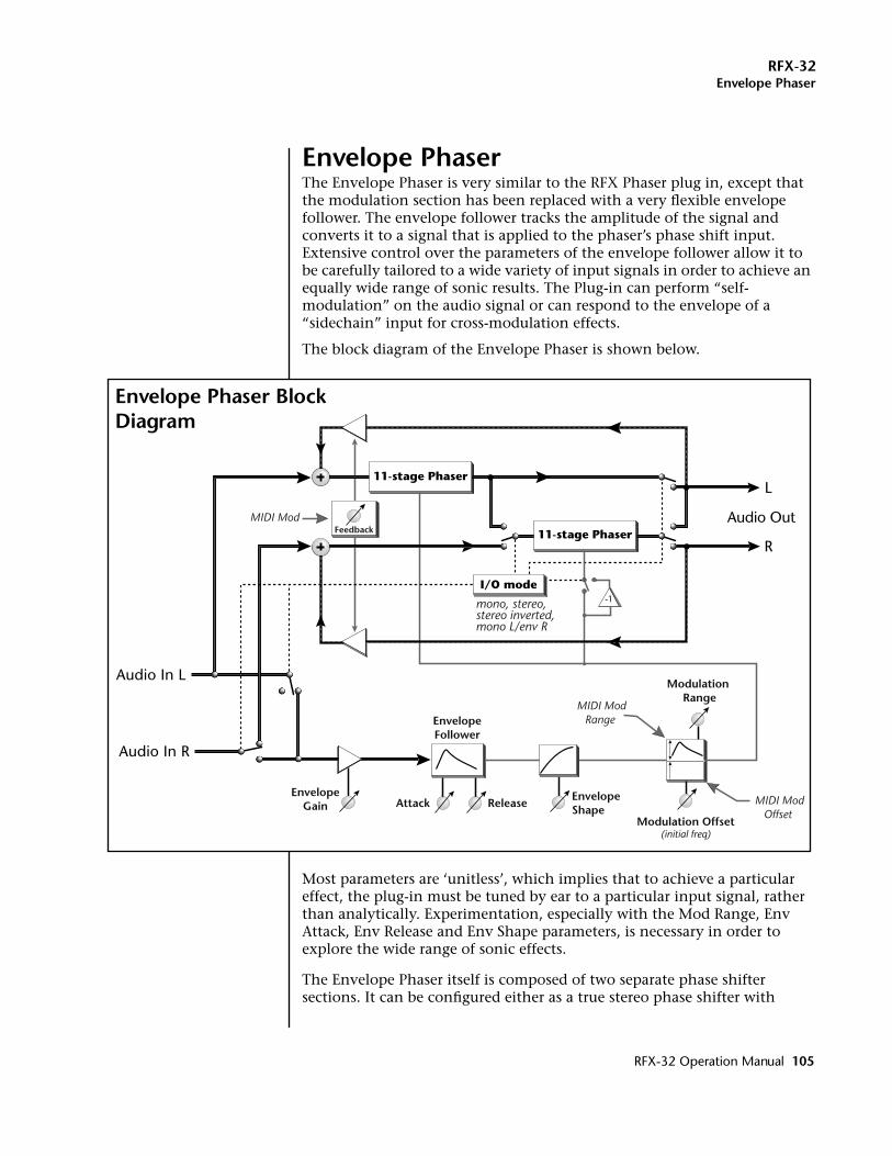
RFX-32Envelope Phaser
Envelope PhaserThe Envelope Phaser is very similar to the RFX Phaser plug in, except that the modulation section has been replaced with a very flexible envelope follower. The envelope follower tracks the amplitude of the signal and converts it to a signal that is applied to the phaser’s phase shift input. Extensive control over the parameters of the envelope follower allow it to be carefully tailored to a wide variety of input signals in order to achieve an equally wide range of sonic results. The Plug-in can perform “self-modulation” on the audio signal or can respond to the envelope of a “sidechain” input for cross-modulation effects.
The block diagram of the Envelope Phaser is shown below.
Most parameters are ‘unitless’, which implies that to achieve a particular effect, the plug-in must be tuned by ear to a particular input signal, rather than analytically. Experimentation, especially with the Mod Range, Env Attack, Env Release and Env Shape parameters, is necessary in order to explore the wide range of sonic effects.
The Envelope Phaser itself is composed of two separate phase shifter sections. It can be configured either as a true stereo phase shifter with
-1
L
Audio Out
R
Audio In L
Audio In R
Modulation Offset(initial freq)
Modulation Range
MIDI Mod
11-stage Phaser
11-stage Phaser
I/O mode
mono, stereo, stereo inverted, mono L/env R
AttackEnvelope
Gain ReleaseEnvelopeShape
MIDI ModOffset
MIDI ModRange
Feedback
EnvelopeFollower
Envelope Phaser Block Diagram
RFX-32 Operation Manual 105
RFX-32Envelope Phaser
completely separate signal paths on each channel or a mono phase shifter using only the left channel for its audio input.
A phase shifter creates a series notches in the audio spectrum similar to, but sounding very different than, an audio flanger. A phase shifter’s notch spacing remains constant with frequency, unlike a flanger where the notch spacing is a harmonically related function of delay time. Feedback is used to increase the depth of the notches and intensify the phase shift effect.
In “inverted stereo mode” the Envelope Phaser is configured in true stereo but with the envelope follower output inverted on the right channel. This causes the peaks and notches on the left and right channels to be swept in opposite directions.
MIDI continuous controllers can be used to control various parameters such as Modulation Offset, Modulation Range and Feedback.
Envelope Phaser Parameters:Please refer to the Envelope Phaser block diagram on the previous page to better understand the effect and modulation routings.
Mod Offset This parameter sets a fixed degree of phase shift that is added to the Range-scaled envelope before applying it to the phase shifter. The difference from the RFX Phaser is that this offset also sets a maximum offset amount which is further modulated by the Mod Offset MIDI modulation input.
Mod Range This is similar to the Mod Range control on the RFX Phaser, controlling the overall extent of phase shift that is affected by the signal envelope. The difference is that it now incorporates a negative range, varying from –100% to 100%. By using a large Mod Offset value and a negative Mod Range, the relationship between the signal envelope and the degree of phase is inverted. This parameter also sets the maximum amount to be modulated by the Mod Range MIDI modulation input.
Envelope Gain This is a gain control on the envelope input preceding the envelope follower itself. Use it to adjust the level of the input signal to achieve optimum excursion of the envelope follower across the full range of phase shifting (as scaled by Mod Range.)
Positive gain applied here can be used to compensate for low level signals, and can also be used to inten-tionally “peg” the envelope to the maximum phase shift except on the lowest possible input levels; clipping of the envelope signal does not affect the quality of the audio signal path. Negative gain can also be used to reduce the envelope follower response.
106 E-MU Systems
RFX-32Envelope Phaser
In current EOS releases (as of 4.61) the Emulator front panel master volume control is applied before the RFX board, and will affect how the envelope follower reacts to input signals. Env Gain can thus be used to make-up for less-than-full-scale settings of the master volume control.
Envelope Attack This unit-less parameter sets the attack rate of the envelope follower, controlling how quickly it responds to increasing signal levels. It can be varied from the slowest setting, which is nearly a signal “hold”, to the fastest setting of 30, which is essentially an instanta-neous response. Typically useful values are in the range of 15 to 30.
Envelope Release This parameter varies along the same values as the Env Attack, setting the rate that the envelope follower responds to decreasing signal levels. Typically useful values are in the range of 5 to 25.
Envelope Response This parameter varies along a continuum of 5 values, warping the “shape” of the envelope follower response from fully linear to fully logarithmic. This control is very useful, especially in conjunction with the Env Gain and Env Release parameters, for optimizing the way in which audio signals with different dynamic ranges and “crest factors” affect the degree of phase shift.
A logarithmic response can often be used to smooth out the envelope of signals with erratic amplitude response without slowing the attack time. Conversely, a linear shape makes the envelope follower more sensitive to small amplitude changes, and can be used to elicit more active phase shifter response from signals lacking in dynamic range.
MIDI ControlsWet/Dry MixFX Input LevelFX Output LevelModulation OffsetModulation RangeFeedback
Feedback This parameter controls the amount and polarity of the signal recirculated through the phase shift network, from -100% to 100%.
Negative feedback has a somewhat different sonic character from positive feedback, and when the Feedback parameter is set negative with any of the Inverted I/O modes, the left channel will use positive feedback and the right channel will use negative feedback.
.The feedback control is more dramatic when the phase shifter is in a monophonic input mode, since the left and right phase shift networks are then connected in series. At values of 100%, the phase shifter will remain stable, on the verge of self-oscillation.
RFX-32 Operation Manual 107
RFX-32Envelope Phaser
I/O Mode This parameter sets the input and output and modulation routing for the phase shifter.There are 5 different I/O modes:
• Mono L - In this mode, the right input channel of the Envelope Phaser is ignored. The left and right phase shift networks are connected in series for a total of 22 stages, and the left input channel supplies both the audio input and the envelope follower input. The output is mono-phonic.
• Stereo - In this mode, the Plug-in operates as a true stereo phase shifter, with separate signal paths for the left and right input channels. The envelope follower input is derived from the scaled sum of left and right inputs.
• StereoInverted - In this mode, the Plug-in operates in stereo, as for Ste-reo mode, but the envelope signals driving the phase shifters are inverted between the left and right sides. This produces a highly spatial phasing effect in which the “motion” in the left channel is always matched with an inverted motion in the right channel.
• Mono L/Env R - This mode is the same as Mono L, except that the envelope signal is derived solely from the right input channel (this is typically referred to as a “sidechain” input.) This allows right channel control signals that may be unrelated to the left channel audio input to drive the phase shifter, allowing cross-modulation between the enve-lope of one signal and the audio of another.
• Mono Inv L/Env R - This is similar to the Mono L/ Env R side-chain mode, except that the left input signal is applied to both left and right sides of the phase shifter. The phase shifter then operates in the same way as for Stereo Inverted mode, with the left and right output chan-nels showing inverted modulation.
MIDI Modulation ParametersThe modulation parameters are used to dynamically rescale several of the user-editable parameters. Those user parameters should be set to the maximum desired values; these maximum values are then modulated by the corresponding modulation parameters.
Mod Offset - This modulation input is used to dynamically rescale (from 0 to 100%) the offset specified by the user Mod Offset parameter. The resulting offset is the bias that is applied to the phase shifter before envelope modulation takes place. (This parameter was not present in the RFX Phaser Plug-in.)
Mod Range - This modulation input is used to dynamically rescale (from 0 to 100%) the phase shift range specified by the user Mod Range parameter. The resulting phase shift range is then further rescaled by the output of the envelope follower before being applied to the phase shifter.
Feedback - This modulation input is used to dynamically rescale (from 0 to 100%) the amount of feedback specified by the user feedback parameter.
108 E-MU Systems
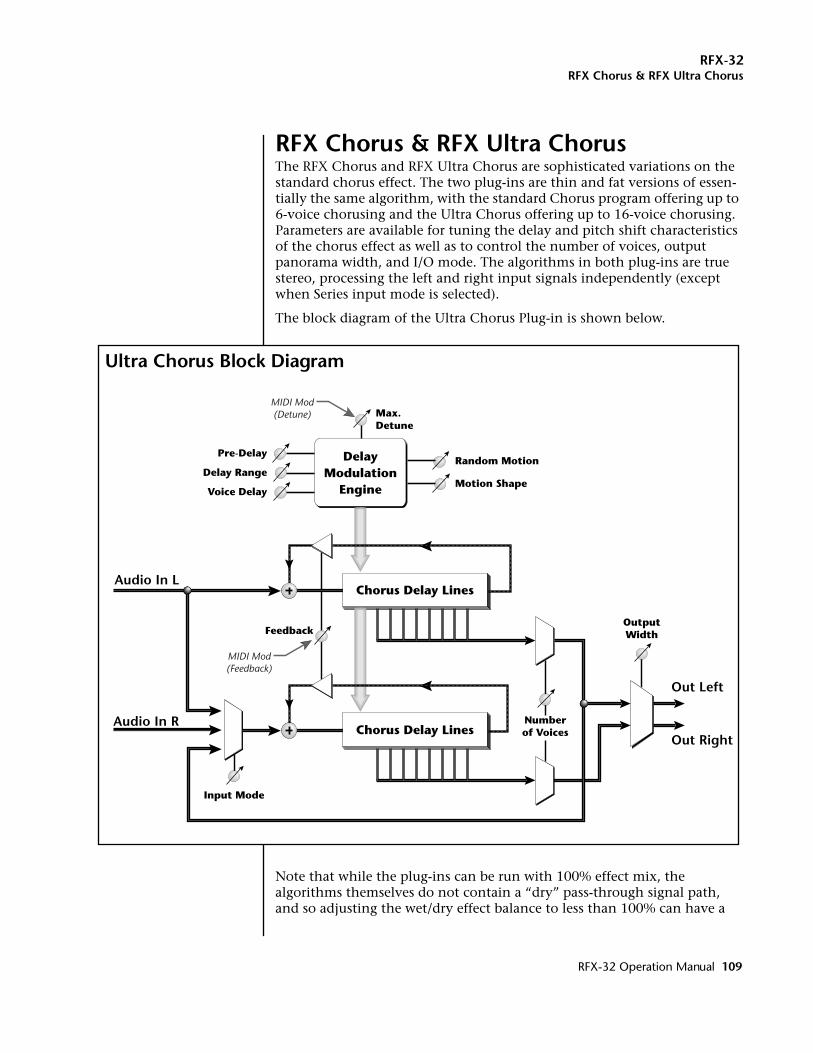
RFX-32RFX Chorus & RFX Ultra Chorus
RFX Chorus & RFX Ultra ChorusThe RFX Chorus and RFX Ultra Chorus are sophisticated variations on the standard chorus effect. The two plug-ins are thin and fat versions of essen-tially the same algorithm, with the standard Chorus program offering up to 6-voice chorusing and the Ultra Chorus offering up to 16-voice chorusing. Parameters are available for tuning the delay and pitch shift characteristics of the chorus effect as well as to control the number of voices, output panorama width, and I/O mode. The algorithms in both plug-ins are true stereo, processing the left and right input signals independently (except when Series input mode is selected).
The block diagram of the Ultra Chorus Plug-in is shown below.
Note that while the plug-ins can be run with 100% effect mix, the algorithms themselves do not contain a “dry” pass-through signal path, and so adjusting the wet/dry effect balance to less than 100% can have a
Chorus Delay LinesAudio In L
Audio In R
Out Left
Out Right
OutputWidthFeedback
Input Mode
MIDI Mod(Feedback)
MIDI Mod(Detune)
Numberof VoicesChorus Delay Lines
DelayModulation
EngineVoice Delay
Delay Range
Pre-Delay
Max.Detune
Random Motion
Motion Shape
Ultra Chorus Block Diagram
RFX-32 Operation Manual 109
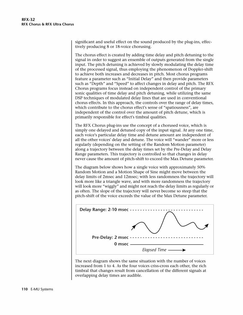
RFX-32RFX Chorus & RFX Ultra Chorus
significant and useful effect on the sound produced by the plug-ins, effec-tively producing 8 or 18-voice chorusing.
The chorus effect is created by adding time delay and pitch detuning to the signal in order to suggest an ensemble of outputs generated from the single input. The pitch detuning is achieved by slowly modulating the delay time of the processed signal, thus employing the phenomenon of Doppler-shift to achieve both increases and decreases in pitch. Most chorus programs feature a parameter such as “Initial Delay” and then provide parameters such as “Depth” and “Speed” to affect changes in delay and pitch. The RFX Chorus programs focus instead on independent control of the primary sonic qualities of time delay and pitch detuning, while utilizing the same DSP techniques of modulated delay lines that are used in conventional chorus effects. In this approach, the controls over the range of delay times, which contribute to the chorus effect's sense of “spatiousness”, are independent of the control over the amount of pitch detune, which is primarily responsible for effect's timbral qualities.
The RFX Chorus plug-ins use the concept of a chorused voice, which is simply one delayed and detuned copy of the input signal. At any one time, each voice's particular delay time and detune amount are independent of all the other voices' delay and detune. The voice will “wander” more or less regularly (depending on the setting of the Random Motion parameter) along a trajectory between the delay times set by the Pre-Delay and Delay Range parameters. This trajectory is controlled so that changes in delay never cause the amount of pitch-shift to exceed the Max Detune parameter.
The diagram below shows how a single voice with approximately 50% Random Motion and a Motion Shape of Sine might move between the delay limits of 2msec and 12msec; with less randomness the trajectory will look more like a triangle wave, and with more randomness the trajectory will look more “wiggly” and might not reach the delay limits as regularly or as often. The slope of the trajectory will never become so steep that the pitch-shift of the voice exceeds the value of the Max Detune parameter.
The next diagram shows the same situation with the number of voices increased from 1 to 4. As the four voices criss-cross each other, the rich timbral that changes result from cancellation of the different signals at overlapping delay times are audible.
Delay Range: 2-10 msec
Pre-Delay: 2 msec
Elapsed Time0 msec
110 E-MU Systems
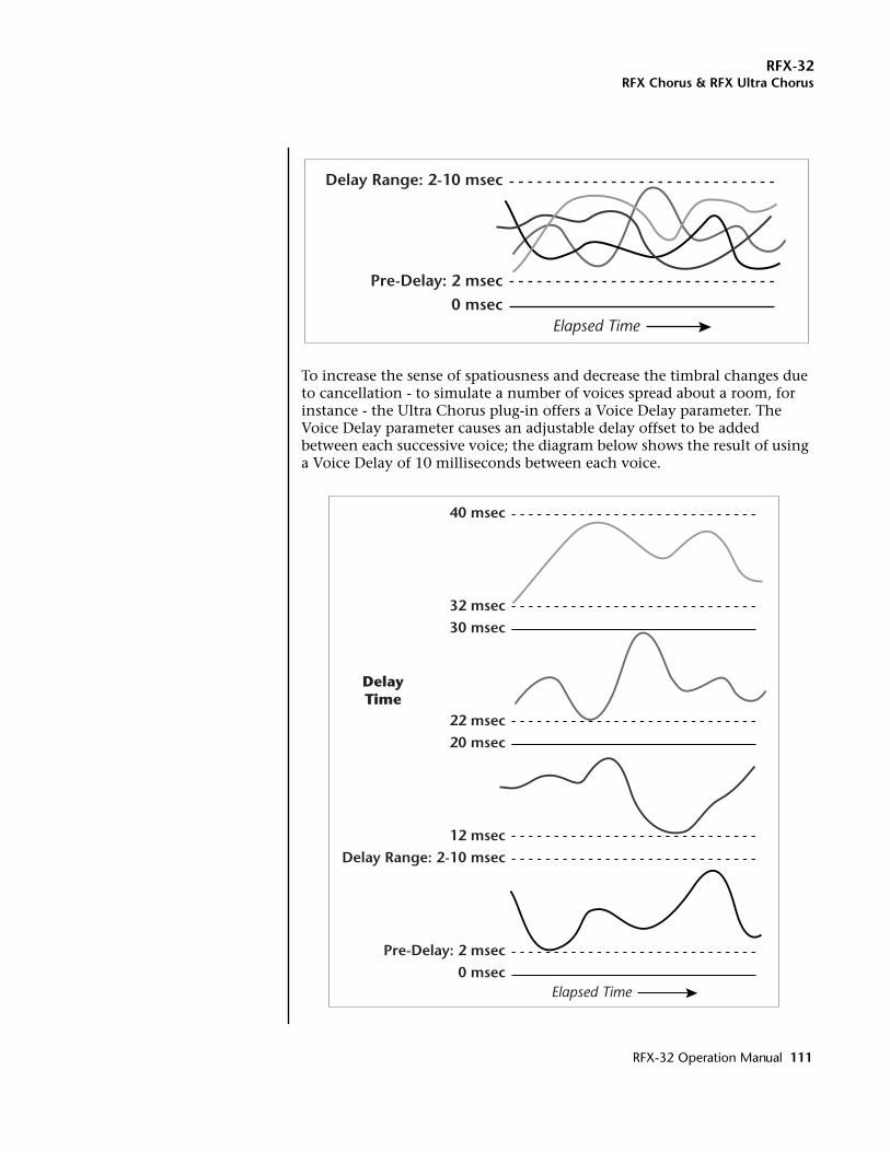
RFX-32RFX Chorus & RFX Ultra Chorus
To increase the sense of spatiousness and decrease the timbral changes due to cancellation - to simulate a number of voices spread about a room, for instance - the Ultra Chorus plug-in offers a Voice Delay parameter. The Voice Delay parameter causes an adjustable delay offset to be added between each successive voice; the diagram below shows the result of using a Voice Delay of 10 milliseconds between each voice.
Delay Range: 2-10 msec
Pre-Delay: 2 msec
Elapsed Time0 msec
Delay Range: 2-10 msec
Pre-Delay: 2 msec
Elapsed Time0 msec
20 msec
12 msec
30 msec
22 msec
40 msec
32 msec
DelayTime
RFX-32 Operation Manual 111
RFX-32RFX Chorus & RFX Ultra Chorus
Thus the Voice Delay parameter causes the voices to become spread out in time by the amount of the parameter, even as they stay within the now-relative delay times specified by the Delay Range parameter.
MIDI continuous controllers can be used to control various parameters such as Modulation Offset, Modulation Range and Feedback.
RFX Chorus Parameters:Please refer to the RFX Chorus block diagram on page 109 to better under-stand the effect and modulation routings.
Pre-Delay The Pre Delay parameter, ranging from 0 to 100msec, sets a lower limit to the delay applied to any chorused voice.
Delay Range The Delay Range parameter, from 0 to 100msec sets the range of delay times, above and beyond the Pre Delay parameter, over which the chorused voices will modulate. The display of Delay Range shows the actual delay range in milliseconds, tracking changes in both the Pre Delay and Delay Range value itself.
Voice Delay An additional delay, from 0 to 20msec in .5msec incre-ments, which is added between adjacent voices in order to spread them out in time. When used in conjunction with the Pre Delay and Delay Range parameters, the Voice Delay parameter can be used to control the amount of separation (when Voice Delay is greater than Delay Range) or overlap (when Voice Delay is less than Delay Range) in the delay ranges of adjacently numbered voices. Note that when Voice Delay is non-zero, the displayed Delay Range is strictly accurate only for the first pair of voices; subsequent pairs are additionally delayed by multiples of Voice Delay.
Max. Detune Sets the maximum amount of detuning, calibrated in cents and semitones, that any one voice will experience during the process of being modulated across its delay range. Note that when being modulated randomly, most voices will only occasionally reach this target maximum. With large Delay Ranges, the effect of changes to Max Detune may not be immediately apparent since, to avoid discontinuities, these changes are applied only at certain points in the delay modulation cycle.
The detune amount set by Max. Detune is a maximum that can be further scaled down using the MIDI Modulation Detune parameter.
(Ultra Chorus only)
112 E-MU Systems
RFX-32RFX Chorus & RFX Ultra Chorus
Random Motion The modulation used to generate each voice's delay is a variable mix of random-rate and constant-rate modulation, combined in the proportion shown by the Random Motion parameter. When the percentage is non-zero, the Motion Shape parameter becomes active to allow the selection of a particular shaping to the random modulation.
Motion Shape This parameter sets the shape of the random portion of the modulation signal. Linear motion causes pitch shifts which are constant until the modulator changes direction; the Curved shape allows some changes in pitch across the trajectory of the modulator; the Sine shape provides a sine-weighted warping of the modulation signal that produces a very “warbly” effect. This parameter is active only when the proportion of the Random Motion parameter is non-zero. without slowing the attack time. Conversely, a linear shape makes the envelope follower more sensitive to small amplitude changes, and can be used to elicit more active phase shifter response from signals lacking in dynamic range.
MIDI ControlsWet/Dry MixFX Input LevelFX Output LevelFeedbackDetune
Feedback This controls the amount of signal recirculated from selected delay taps back into the input of the choruser. At short delay ranges this produces a variable resonance which imparts a somewhat “liquid” character to the sound. At longer delay ranges the choruser acts like a multi-tap delay with feedback, producing a sense of ambience that at higher numbers of taps and longer delays approaches the effects of a reverberator.
The feedback amount set here can be further scaled down using the MIDI Modulation Feedback parameter.
Number of Voices This controls how many of the independent voices produced by the choruser are sent to the output. In the RFX Chorus plug-in this varies from 1 to 6 and in the Ultra Chorus plug-in varies from 2 to 16. Odd numbered voices are generated by the left chorus channel and even numbered voices by the right, so setting this parameter to odd values may result in some audible asymmetry in the stereo output panorama.
Output Width When scaled down from 100%, this parameter progres-sively “folds” the left and right choruser outputs together to produce a mono signal at both output channels. This can be useful for reducing the extremely wide stereo image produced by some settings of the choruser parameters or for reducing the asymmetry produced in the output by odd numbers of voices or the by the Series setting of the Input Mode parameter.
RFX-32 Operation Manual 113
RFX-32RFX Chorus & RFX Ultra Chorus
Input Mode This parameter has 3 possible values:
Stereo The left and right chorus elements are fed directly from the left and right inputsignals.
Mono(L) The left input signal is fed to both left and right chorus elements.
Series(L>R) The left input signal feeds the left chorus element which then feeds the right chorus element in series. The left output is fed the singly-processed result of the left chorus element, and the right output is fed the doubly-processed result of the series connection of the left and right chorus elements.
114 E-MU Systems
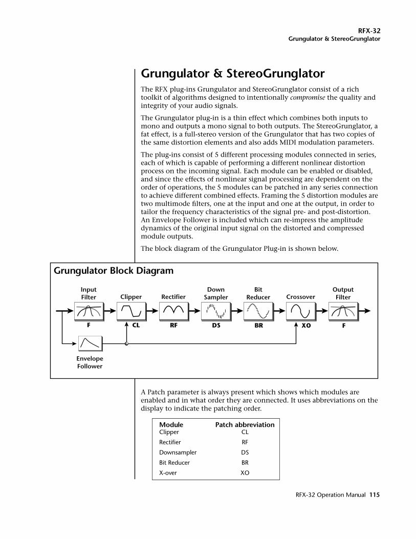
RFX-32Grungulator & StereoGrunglator
Grungulator & StereoGrunglatorThe RFX plug-ins Grungulator and StereoGrunglator consist of a rich toolkit of algorithms designed to intentionally compromise the quality and integrity of your audio signals.
The Grungulator plug-in is a thin effect which combines both inputs to mono and outputs a mono signal to both outputs. The StereoGrunglator, a fat effect, is a full-stereo version of the Grungulator that has two copies of the same distortion elements and also adds MIDI modulation parameters.
The plug-ins consist of 5 different processing modules connected in series, each of which is capable of performing a different nonlinear distortion process on the incoming signal. Each module can be enabled or disabled, and since the effects of nonlinear signal processing are dependent on the order of operations, the 5 modules can be patched in any series connection to achieve different combined effects. Framing the 5 distortion modules are two multimode filters, one at the input and one at the output, in order to tailor the frequency characteristics of the signal pre- and post-distortion. An Envelope Follower is included which can re-impress the amplitude dynamics of the original input signal on the distorted and compressed module outputs.
The block diagram of the Grungulator Plug-in is shown below.
A Patch parameter is always present which shows which modules are enabled and in what order they are connected. It uses abbreviations on the display to indicate the patching order.
Module Patch abbreviationClipper CL
Rectifier RF
Downsampler DS
Bit Reducer BR
X-over XO
EnvelopeFollower
InputFilter
F CL RF DS BR XO F
Clipper RectifierDown
SamplerBit
Reducer CrossoverOutputFilter
Grungulator Block Diagram
RFX-32 Operation Manual 115
RFX-32Grungulator & StereoGrunglator
In the StereoGrunglator the module ordering in the left and right channels is entirely independent. The Filter modules will also appear and disappear in the Patch display as they are enabled and disabled, but they are always the first and last modules in the patch, so their order in the display will not change.
Each module’s individual parameters appear on-screen one module at a time, selected by the Module parameter. Most modules are capable of parameter settings that make their effect nearly inaudible, and these are the default settings for all but the Clipping module. However, a better way to remove the effect of a module is to use each module’s Status parameter to disable it: when a module is disabled, it is taken entirely out of the signal path, and as it disappears from the Patch display its available parameters are also greyed-out to emphasize the fact that it is inactive. Those parameters do not change when the module is disabled, however, so enabling and disabling a module is a good way to compare the effects of that module on the overall patch.
Edit Channel Parameter (StereoGrunglator only)In the stereo version of the Grungulator, the entire distortion signal path is duplicated twice, once for the left and once for the right channel. The Channel parameter is used to select which channel's parameters are being edited. This allows the left and right halves of a stereo input signal to receive the same- or different- treatment from the filter and distortion modules.
By default, the StereoGrunglator uses identical parameters for its left and right channels, and by using the default Channel value of L+R, all new parameter edits are made in tandem to both channels. (Note that switching to L+R does not automatically copy all current parameter values from left to right- only newly edited values.)
In L+R mode, both the left and right channels' values are shown in the parameter display (except for the special case of the Patch parameter; only the left channel's patch is shown, even though the right channel may be patched differently.)
By setting the Channel parameter to L or R alone, separate edits can be made to each channel's individual filters and distortion elements. Setting the channel parameters differently can be useful for creating a pseudo-stereo signal from a mono input, or simply for making individual tweaks to each half of a stereo signal.
116 E-MU Systems
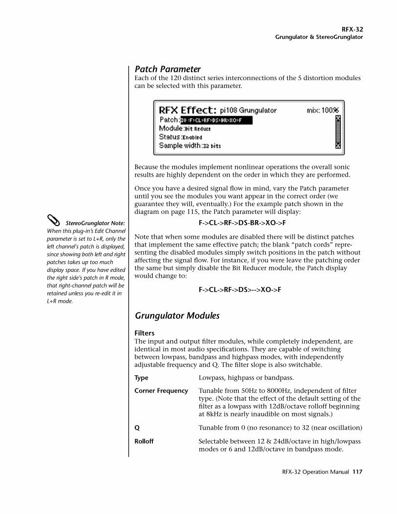
RFX-32Grungulator & StereoGrunglator
Patch ParameterEach of the 120 distinct series interconnections of the 5 distortion modules can be selected with this parameter.
Because the modules implement nonlinear operations the overall sonic results are highly dependent on the order in which they are performed.
Once you have a desired signal flow in mind, vary the Patch parameter until you see the modules you want appear in the correct order (we guarantee they will, eventually.) For the example patch shown in the diagram on page 115, the Patch parameter will display:
StereoGrunglator Note: When this plug-in’s Edit Channel parameter is set to L+R, only the left channel's patch is displayed, since showing both left and right patches takes up too much display space. If you have edited the right side's patch in R mode, that right-channel patch will be retained unless you re-edit it in L+R mode.
F->CL->RF->DS-BR->XO->F
Note that when some modules are disabled there will be distinct patches that implement the same effective patch; the blank “patch cords” repre-senting the disabled modules simply switch positions in the patch without affecting the signal flow. For instance, if you were leave the patching order the same but simply disable the Bit Reducer module, the Patch display would change to:
F->CL->RF->DS>-->XO->F
Grungulator Modules
FiltersThe input and output filter modules, while completely independent, are identical in most audio specifications. They are capable of switching between lowpass, bandpass and highpass modes, with independently adjustable frequency and Q. The filter slope is also switchable.
Type Lowpass, highpass or bandpass.
Corner Frequency Tunable from 50Hz to 8000Hz, independent of filter type. (Note that the effect of the default setting of the filter as a lowpass with 12dB/octave rolloff beginning at 8kHz is nearly inaudible on most signals.)
Q Tunable from 0 (no resonance) to 32 (near oscillation)
Rolloff Selectable between 12 & 24dB/octave in high/lowpass modes or 6 and 12dB/octave in bandpass mode.
RFX-32 Operation Manual 117
RFX-32Grungulator & StereoGrunglator
L/R Phase This allows the incoming right channel signal to be In-phase with the left channel, or Inverted. Setting the phase of opposing channels to be inverted can make a distinct difference in the sound of each output when asymmetrical distortion elements like the rectifier are anywhere in the signal path. Inverting one input is also a useful way to make interesting cancellation effects when the outputs are eventually combined to Mono using the Output Mode parameter.
Note: The L/R Phase parameter is always active, even when the Input Filter itself is bypassed, and since it is common to both channels it shows up in all the L, R and L+R edit modes.
Output Mode This sets the output mode of the effect, In Mono mode, the same grungulated signal appears on both left and right outputs. In Split modes, the grungulated wet signal appears on one of the outputs; the other output produces the clean dry signal present at the plug-in’s inputs. This is useful for patching ahead of plug-ins like envelope-controlled filters or vocoders, so that the original amplitude and spectral envelope of the signal is preserved for the sidechain input while the harmonically rich and dynamically compressed grunge signal can be fed into the normal signal input.
Output Width This an extension of the mono Grungulator's Output Mode parameter which allows the panorama of the left and right output signals to be widened to full stereo (100%), collapsed down to centered mono (0%) or split left and right like the mono Grungulator. Interesting cancellation effects can occur when differ-ently-distorted left and right signals are summed to mono. Note that in the split modes, the Dry output is the mono sum of the original left and right inputs, and the Wet output is the mono sum of both left and right distortion outputs.
Note: The Output Width parameter is always active, even when the Output Filter itself is bypassed, and since it is common to both channels it shows up in all the L, R and L+R edit modes.
(StereoGrunglator input filter only)
(Grungulator Output filter only)
118 E-MU Systems
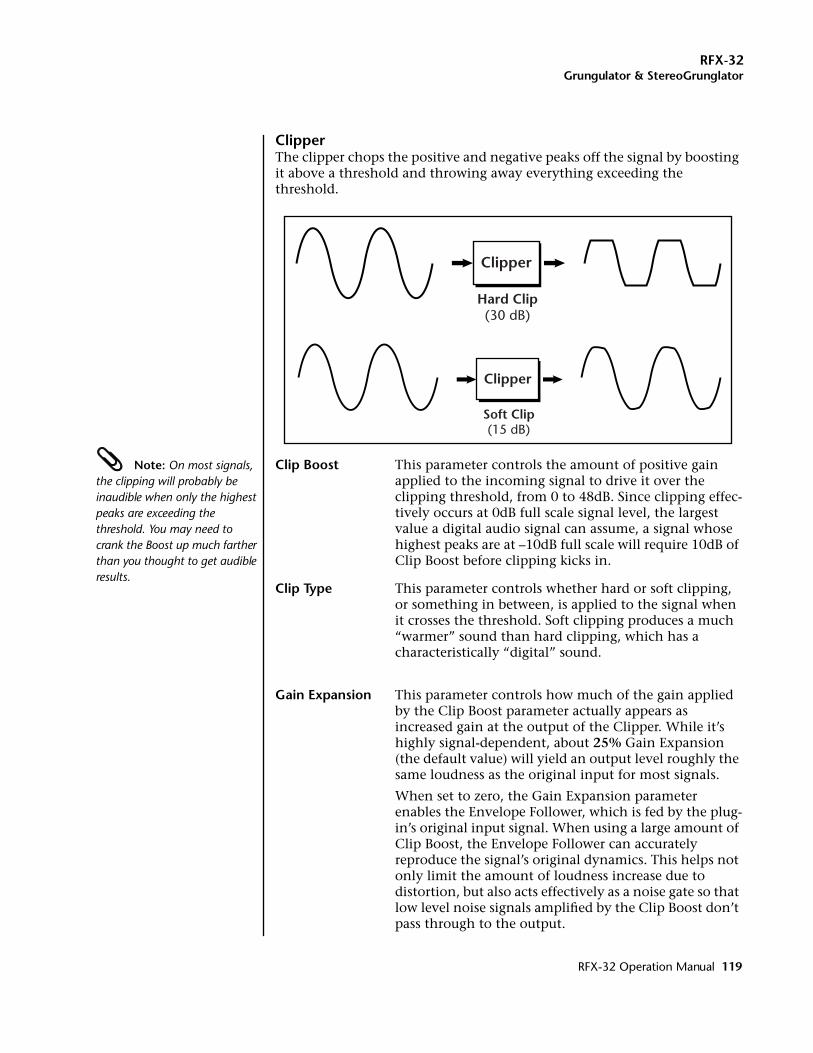
RFX-32Grungulator & StereoGrunglator
ClipperThe clipper chops the positive and negative peaks off the signal by boosting it above a threshold and throwing away everything exceeding the threshold.
Note: On most signals, the clipping will probably be inaudible when only the highest peaks are exceeding the threshold. You may need to crank the Boost up much farther than you thought to get audible results.
Clip Boost This parameter controls the amount of positive gain applied to the incoming signal to drive it over the clipping threshold, from 0 to 48dB. Since clipping effec-tively occurs at 0dB full scale signal level, the largest value a digital audio signal can assume, a signal whose highest peaks are at –10dB full scale will require 10dB of Clip Boost before clipping kicks in.
Clip Type This parameter controls whether hard or soft clipping, or something in between, is applied to the signal when it crosses the threshold. Soft clipping produces a much “warmer” sound than hard clipping, which has a characteristically “digital” sound.
Gain Expansion This parameter controls how much of the gain applied by the Clip Boost parameter actually appears as increased gain at the output of the Clipper. While it’s highly signal-dependent, about 25% Gain Expansion (the default value) will yield an output level roughly the same loudness as the original input for most signals.
When set to zero, the Gain Expansion parameter enables the Envelope Follower, which is fed by the plug-in’s original input signal. When using a large amount of Clip Boost, the Envelope Follower can accurately reproduce the signal’s original dynamics. This helps not only limit the amount of loudness increase due to distortion, but also acts effectively as a noise gate so that low level noise signals amplified by the Clip Boost don’t pass through to the output.
Clipper
Hard Clip(30 dB)
Clipper
Soft Clip(15 dB)
RFX-32 Operation Manual 119
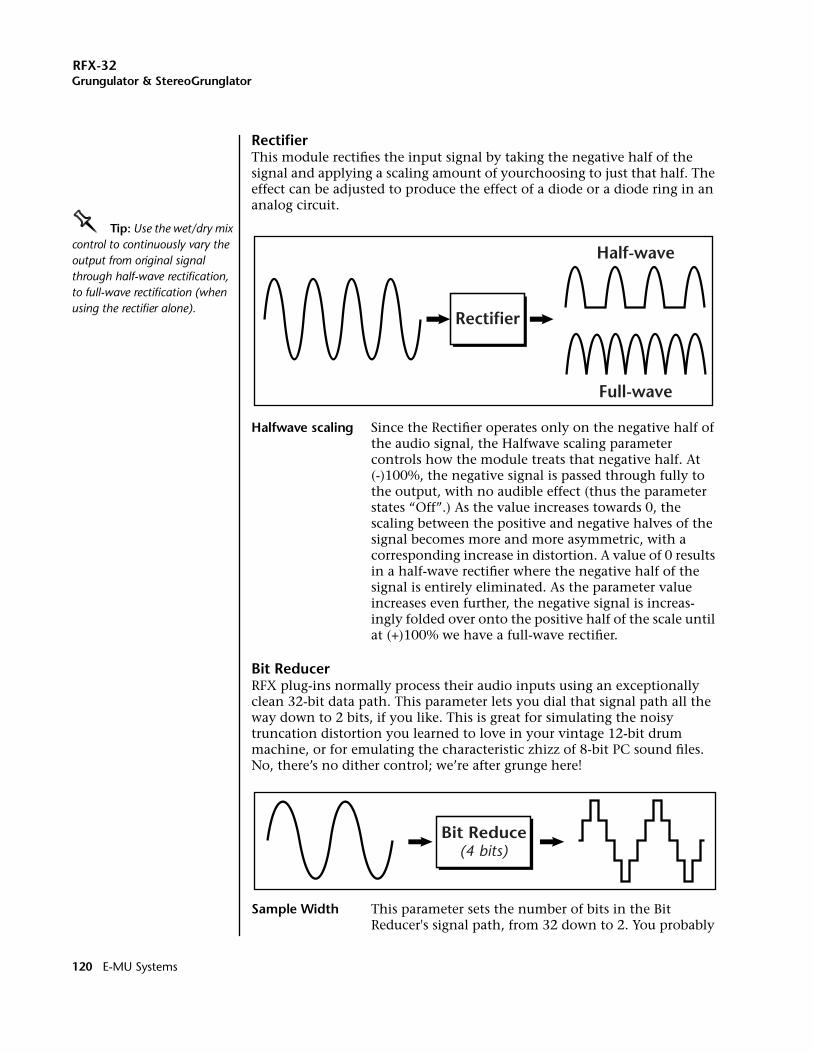
RFX-32Grungulator & StereoGrunglator
Rectifier This module rectifies the input signal by taking the negative half of the signal and applying a scaling amount of yourchoosing to just that half. The effect can be adjusted to produce the effect of a diode or a diode ring in an analog circuit.
OOOO Tip: Use the wet/dry mix control to continuously vary the output from original signal through half-wave rectification, to full-wave rectification (when using the rectifier alone).
Halfwave scaling Since the Rectifier operates only on the negative half of the audio signal, the Halfwave scaling parameter controls how the module treats that negative half. At (-)100%, the negative signal is passed through fully to the output, with no audible effect (thus the parameter states “Off”.) As the value increases towards 0, the scaling between the positive and negative halves of the signal becomes more and more asymmetric, with a corresponding increase in distortion. A value of 0 results in a half-wave rectifier where the negative half of the signal is entirely eliminated. As the parameter value increases even further, the negative signal is increas-ingly folded over onto the positive half of the scale until at (+)100% we have a full-wave rectifier.
Bit ReducerRFX plug-ins normally process their audio inputs using an exceptionally clean 32-bit data path. This parameter lets you dial that signal path all the way down to 2 bits, if you like. This is great for simulating the noisy truncation distortion you learned to love in your vintage 12-bit drum machine, or for emulating the characteristic zhizz of 8-bit PC sound files. No, there’s no dither control; we’re after grunge here!
Sample Width This parameter sets the number of bits in the Bit Reducer's signal path, from 32 down to 2. You probably
Rectifier
Half-wave
Full-wave
Bit Reduce(4 bits)
120 E-MU Systems
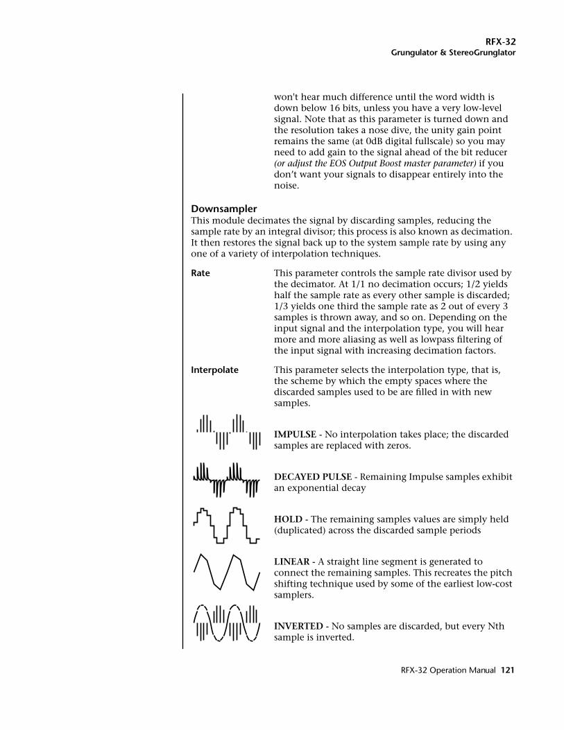
RFX-32Grungulator & StereoGrunglator
won't hear much difference until the word width is down below 16 bits, unless you have a very low-level signal. Note that as this parameter is turned down and the resolution takes a nose dive, the unity gain point remains the same (at 0dB digital fullscale) so you may need to add gain to the signal ahead of the bit reducer (or adjust the EOS Output Boost master parameter) if you don’t want your signals to disappear entirely into the noise.
DownsamplerThis module decimates the signal by discarding samples, reducing the sample rate by an integral divisor; this process is also known as decimation. It then restores the signal back up to the system sample rate by using any one of a variety of interpolation techniques.
Rate This parameter controls the sample rate divisor used by the decimator. At 1/1 no decimation occurs; 1/2 yields half the sample rate as every other sample is discarded; 1/3 yields one third the sample rate as 2 out of every 3 samples is thrown away, and so on. Depending on the input signal and the interpolation type, you will hear more and more aliasing as well as lowpass filtering of the input signal with increasing decimation factors.
Interpolate This parameter selects the interpolation type, that is, the scheme by which the empty spaces where the discarded samples used to be are filled in with new samples.
IMPULSE - No interpolation takes place; the discarded samples are replaced with zeros.
DECAYED PULSE - Remaining Impulse samples exhibit an exponential decay
HOLD - The remaining samples values are simply held (duplicated) across the discarded sample periods
LINEAR - A straight line segment is generated to connect the remaining samples. This recreates the pitch shifting technique used by some of the earliest low-cost samplers.
INVERTED - No samples are discarded, but every Nth sample is inverted.
RFX-32 Operation Manual 121
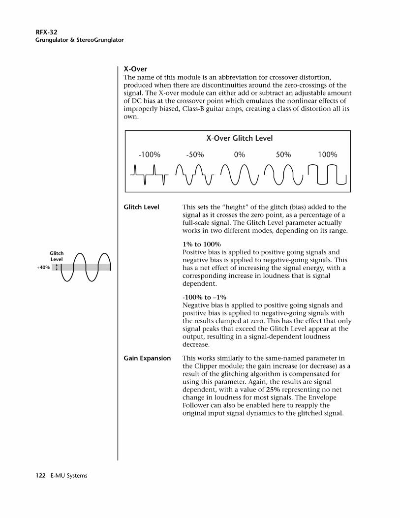
RFX-32Grungulator & StereoGrunglator
X-OverThe name of this module is an abbreviation for crossover distortion, produced when there are discontinuities around the zero-crossings of the signal. The X-over module can either add or subtract an adjustable amount of DC bias at the crossover point which emulates the nonlinear effects of improperly biased, Class-B guitar amps, creating a class of distortion all its own.
Glitch Level This sets the “height” of the glitch (bias) added to the signal as it crosses the zero point, as a percentage of a full-scale signal. The Glitch Level parameter actually works in two different modes, depending on its range.
1% to 100% Positive bias is applied to positive going signals and negative bias is applied to negative-going signals. This has a net effect of increasing the signal energy, with a corresponding increase in loudness that is signal dependent.
-100% to –1% Negative bias is applied to positive going signals and positive bias is applied to negative-going signals with the results clamped at zero. This has the effect that only signal peaks that exceed the Glitch Level appear at the output, resulting in a signal-dependent loudness decrease.
Gain Expansion This works similarly to the same-named parameter in the Clipper module; the gain increase (or decrease) as a result of the glitching algorithm is compensated for using this parameter. Again, the results are signal dependent, with a value of 25% representing no net change in loudness for most signals. The Envelope Follower can also be enabled here to reapply the original input signal dynamics to the glitched signal.
X-Over Glitch Level
0% 50% 100%-50%-100%
GlitchLevel
+40%
122 E-MU Systems
RFX-32Grungulator & StereoGrunglator
MIDI Modulation Parameters (StereoGrunglator only)Several MIDI Modulation parameters are available in the stereo version of the Grungulator. Like other RFX plug-ins, the MIDI control inputs are used to scale down the maximum values of the similarly-named edit parameters. Note that when the plug-in is in L+R edit mode, sending modulation values to the Left members of these modulation pairs will affect both the left and right channels - but will only affect them identically if both channels' edit parameters are already set identically.
L In FiltR In FiltL Out FiltR Out FiltThese parameters scale the maximum corner frequencies set by the left and right input and output filters, respectively. The filter frequency scaling occurs the same regardless of whether the filters are in lowpass, bandpass or highpass modes. Note that if any of the filters is set to be Bypassed, the filter modulation will produce no audible effect.
L RectifierR RectifierThese parameters scale the Halfwave scaling amount set by the plug-in’s edit parameters. Recall that the Halfwave Scaling parameter is bipolar, ranging from -100% to 100%, where Off is equivalent to -100%, Half-wave rectification is 0%, and Full-wave rectification is 100%. So as the MIDI controllers scale the value of this parameter towards 0%, they are progres-sively creating more distortion if Halfwave scaling was set at -100%, or shifting from fullwave to halfwave rectification if Halfwave scaling was set at 100%.
L DownsamplerR DownsamplerThese parameters scale the Downsample module's Rate factors from their edited value down to a ratio of 1/1. As this factor is progressively scaled, inharmonic overtones resulting from aliasing can be heard moving through the spectrum. The effect is reminiscent of the inharmonicity created by ring modulators.
RFX-32 Operation Manual 123
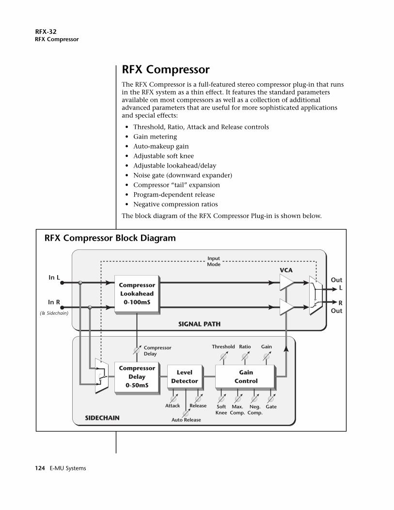
RFX-32RFX Compressor
RFX CompressorThe RFX Compressor is a full-featured stereo compressor plug-in that runs in the RFX system as a thin effect. It features the standard parameters available on most compressors as well as a collection of additional advanced parameters that are useful for more sophisticated applications and special effects:
• Threshold, Ratio, Attack and Release controls
• Gain metering
• Auto-makeup gain
• Adjustable soft knee
• Adjustable lookahead/delay
• Noise gate (downward expander)
• Compressor “tail” expansion
• Program-dependent release
• Negative compression ratios
The block diagram of the RFX Compressor Plug-in is shown below.
In L
In R
OutL
ROut
CompressorLookahead0-100mS
CompressorDelay
Attack
Auto Release
Release SoftKnee
Max.Comp.
Neg.Comp.
CompressorDelay
0-50mS
LevelDetector
GainControl
Threshold Ratio Gain
Gate
(& Sidechain)
InputMode
SIGNAL PATH
SIDECHAIN
VCA
RFX Compressor Block Diagram
124 E-MU Systems

RFX-32RFX Compressor
Note that the plug-in is split between a signal path and a sidechain path that contains the compressor's level detectors and gain computation. The signal path of the RFX Compressor is very close to a “straight wire”, with only a delay line and one gain control element inserted in it. The sidechain contains the bulk of the compressor algorithm and is responsible for computing the gain control signal. Signal multiplexers at the front of the signal path and sidechain allow linked stereo compression or split signal path/sidechain processing.
The RFX Compressor does not have the input gain control found on some compressors. These are typically used to align the input signal range to the compression threshold. Instead, we've allowed the RFX Compressor's Threshold parameter to operate over an exceptionally large range of 0-60dB so that it can be “steered” to the appropriate range of the input signal. The output Gain parameter also operates — either manually or automatically —over the unusually large range of -60dB to +60dB in order to renormalize the compressor's output for the next stage of the signal path.
The wide dynamic range of the RFX Compressor aside, it's generally a good idea to maintain the hottest signal levels possible without clipping at the input to any audio processor. In the RFX32, that means keeping signals peaks close to 0dBFS, the reference level corresponding to a full-scale sample value just below hard digital clipping. In the following parameter descriptions we'll simply use “0dB” as shorthand for 0dBFS, and reference all of the compressor's other signal levels in dB to this standard. See page 138 for important information about the Emulator gain structure.
Basic ParametersPlease refer to the RFX Compressor block diagram on page 124 to better understand the effect and modulation routings.
Threshold Threshold sets the input signal level above which dynamic range compression takes place. Everything above the threshold will be brought down in volume. The compression threshold ranges from -0 to -60dB, relative to full scale (0dBFS) input.
Setting the Threshold to 0dB disables normal compression, since no signal can exceed the maximum possible input level. A Threshold setting of 0dB is still useful, however, when using soft-knee compression or gating, since these actions occur below (and their thresholds are set relative to) the Threshold parameter.
Gain Meter When the Gain Meter parameter is set to Enabled, the Threshold value is followed on the same line by a real-time gain-reduction display. As input signals exceed the Threshold, the rightmost character in the bar graph is lit, and successive characters are lit for each approximately 3dB in gain reduction imposed by the compressor on the input signal. Because this is a compression meter and not a level
RFX-32 Operation Manual 125
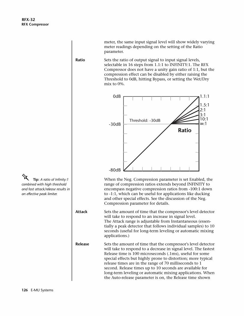
RFX-32RFX Compressor
meter, the same input signal level will show widely varying meter readings depending on the setting of the Ratio parameter.
Ratio Sets the ratio of output signal to input signal levels, selectable in 16 steps from 1.1:1 to INFINITY:1. The RFX Compressor does not have a unity gain ratio of 1:1, but the compression effect can be disabled by either raising the Threshold to 0dB, hitting Bypass, or setting the Wet/Dry mix to 0%.
OOOO Tip: A ratio of Infinity:1 combined with high threshold and fast attack/release results in an effective peak limiter.
When the Neg. Compression parameter is set Enabled, the range of compression ratios extends beyond INFINITY to encompass negative compression ratios from -100:1 down to -1:1, which can be useful for applications like ducking and other special effects. See the discussion of the Neg. Compression parameter for details.
Attack Sets the amount of time that the compressor's level detector will take to respond to an increase in signal level. The Attack range is adjustable from Instantaneous (essen-tially a peak detector that follows individual samples) to 10 seconds (useful for long-term leveling or automatic mixing applications.)
Release Sets the amount of time that the compressor's level detector will take to respond to a decrease in signal level. The fastest Release time is 100 microseconds (.1ms), useful for some special effects but highly prone to distortion; more typical release times are in the range of 70 milliseconds to 1 second. Release times up to 10 seconds are available for long-term leveling or automatic mixing applications. When the Auto-release parameter is on, the Release time shown
0dB 1.1:1
1.5:12:13:110:1 :1-30dB
-80dB
Threshold: -30dB 8
Ratio
126 E-MU Systems
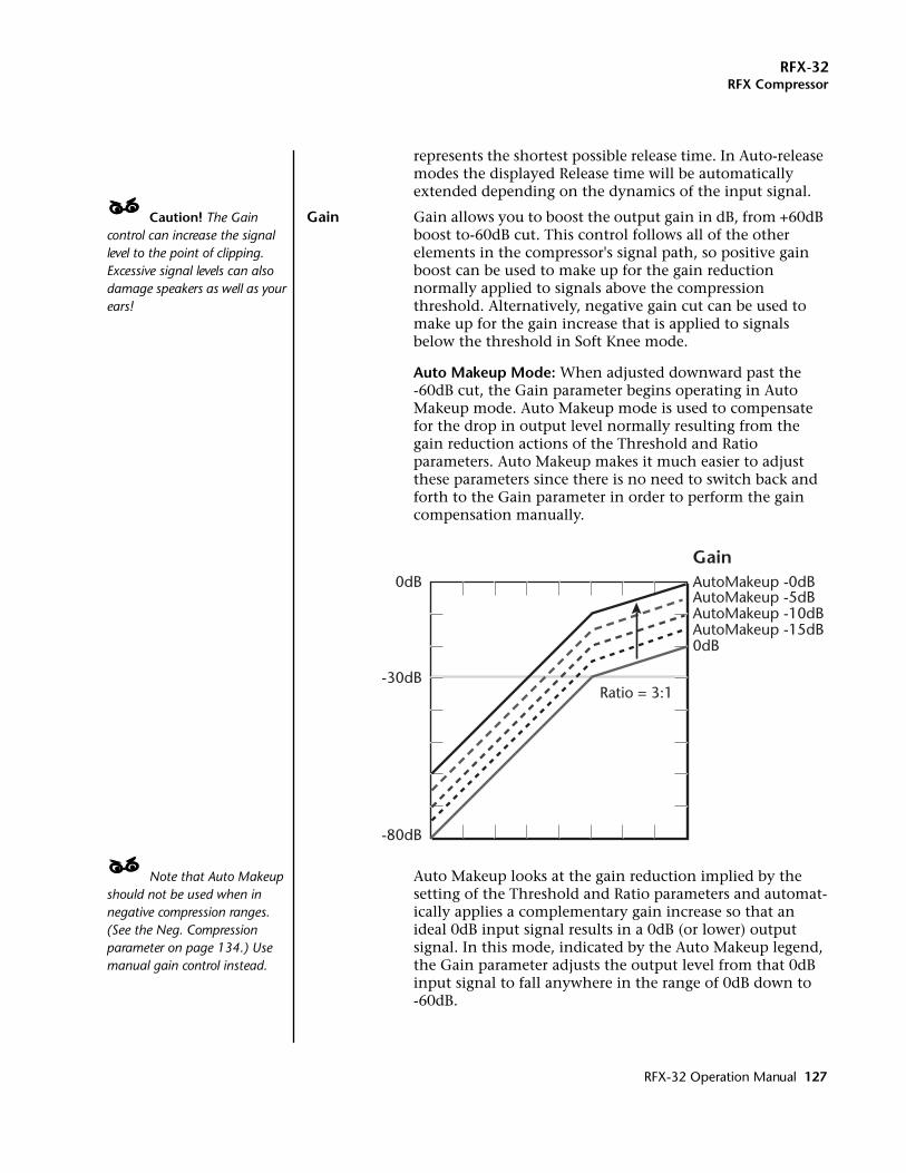
RFX-32RFX Compressor
represents the shortest possible release time. In Auto-release modes the displayed Release time will be automatically extended depending on the dynamics of the input signal.
____ Caution! The Gain control can increase the signal level to the point of clipping. Excessive signal levels can also damage speakers as well as your ears!
Gain Gain allows you to boost the output gain in dB, from +60dB boost to-60dB cut. This control follows all of the other elements in the compressor's signal path, so positive gain boost can be used to make up for the gain reduction normally applied to signals above the compression threshold. Alternatively, negative gain cut can be used to make up for the gain increase that is applied to signals below the threshold in Soft Knee mode.
Auto Makeup Mode: When adjusted downward past the -60dB cut, the Gain parameter begins operating in Auto Makeup mode. Auto Makeup mode is used to compensate for the drop in output level normally resulting from the gain reduction actions of the Threshold and Ratio parameters. Auto Makeup makes it much easier to adjust these parameters since there is no need to switch back and forth to the Gain parameter in order to perform the gain compensation manually.
____ Note that Auto Makeup should not be used when in negative compression ranges. (See the Neg. Compression parameter on page 134.) Use manual gain control instead.
Auto Makeup looks at the gain reduction implied by the setting of the Threshold and Ratio parameters and automat-ically applies a complementary gain increase so that an ideal 0dB input signal results in a 0dB (or lower) output signal. In this mode, indicated by the Auto Makeup legend, the Gain parameter adjusts the output level from that 0dB input signal to fall anywhere in the range of 0dB down to -60dB.
0dB AutoMakeup -0dBAutoMakeup -5dBAutoMakeup -10dBAutoMakeup -15dB0dB
-30dB
-80dB
Ratio = 3:1
Gain
RFX-32 Operation Manual 127
RFX-32RFX Compressor
Advanced Parameters
Adv. ParametersThis parameter controls whether the “Advanced Param-eters” listed in this section are hidden or exposed on the screen. For simple applications, quick edits or for novice users, these advanced parameters can be hidden to minimize screen clutter and preclude erroneous operation. For special and exotic applications and for experienced users, these parameters can be exposed to allow access to all the gory details of the compressor's operation.
Note that even when this parameter is set to “Off”, the settings of the advanced parameters are still active; the only effect of this parameter is to hide them from the screen.
Soft Knee This parameter sets the depth of the compression transition region, giving an adjustable hard or soft “knee” to the compressor's gain curve. Setting the depth of this region results in a knee shape that can be varied from a sharp transition to one that is imperceptibly gradual.
With the default value of Off, the Soft Knee parameter causes the gain curve to switch immediately at the Threshold point from no compression (1:1) to full compression (Ratio:1), representing the hard knee effect. By adjusting the parameter value, an additional knee threshold can be created 1dB to 60dB below the regular compression Threshold. Between these two thresholds the effective compression ratio increases smoothly along the curve of a circular arc, from 1:1 at the lower knee threshold to the full compression of Ratio:1 at the upper Threshold. Both the Soft Knee depth and the Ratio will affect the particular shape of the knee. Shallower depths and higher Ratios will create a sharper knee, while greater depths and lower ratios create a softer knee.
128 E-MU Systems
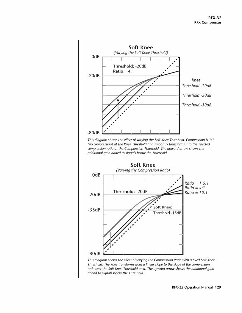
RFX-32RFX Compressor
0dB
Ratio = 1.5:1Ratio = 4:1Ratio = 10:1-20dB
-35dB
-80dB
Threshold: -20dB
Soft Knee(Varying the Compression Ratio)
Soft Knee:Threshold -15dB
This diagram shows the effect of varying the Soft Knee Threshold. Compression is 1:1 (no compression) at the Knee Threshold and smoothly transforms into the selected compression ratio at the Compression Threshold. The upward arrow shows the additional gain added to signals below the Threshold.
This diagram shows the effect of varying the Compression Ratio with a fixed Soft Knee Threshold. The knee transforms from a linear slope to the slope of the compression ratio over the Soft Knee Threshold area. The upward arrow shows the additional gain added to signals below the Threshold.
0dB
Threshold -10dB
Threshold -20dB
Threshold -30dB
Knee-20dB
-80dB
Threshold: -20dBRatio = 4:1
Soft Knee(Varying the Soft Knee Threshold)
RFX-32 Operation Manual 129
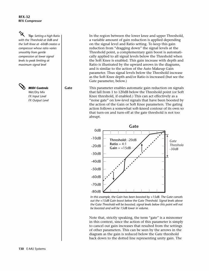
RFX-32RFX Compressor
OOOO Tip: Setting a high Ratio with the Threshold at 0dB and the Soft Knee at -60dB creates a compressor whose ratio varies smoothly from gentle compression at lower signal levels to peak limiting at maximum signal level
In the region between the lower knee and upper Threshold, a variable amount of gain reduction is applied depending on the signal level and Ratio setting. To keep this gain reduction from “dragging down” the signal levels at the Threshold point, a complementary gain boost is automati-cally applied to all signal levels below the Threshold when the Soft Knee is enabled. This gain increase with depth and Ratio is illustrated by the upward arrows in the diagrams, and is similar to the action of the Auto Makeup Gain parameter. Thus signal levels below the Threshold increase as the Soft Knee depth and/or Ratio is increased (but see the Gate parameter, below.)
MIDI ControlsWet/Dry MixFX Input LevelFX Output Level
Gate This parameter enables automatic gain reduction on signals that fall from 1 to 120dB below the Threshold point (or Soft Knee threshold, if enabled.) This can act effectively as a “noise gate” on low-level signals that have been boosted by the action of the Gain or Soft Knee parameters. The gating action follows a somewhat soft-kneed contour of its own so that turn-on and turn-off at the gate threshold is not too abrupt.
Note that, strictly speaking, the term “gate” is a misnomer in this context, since the action of this parameter is simply to cancel out gain increases that resulted from the settings of other parameters. This can be seen by the arrows in the diagram as the gain is reduced below the Gate threshold back down to the dotted line representing unity gain. The
0dB
-10dB
-20dB
-30dB
-40dB
-50dB
-60dB
-70dB
-80dB
Threshold: -20dBRatio = 4:1Gain = +15dB
Gate
GateThreshold-30dB
In this example, the Gain has been boosted by +15dB. The Gate cancels out the +15dB Gain boost below the Gate Threshold. Signal levels above the Gate Threshold will be boosted; signal levels below this point will not be boosted and will be 15dB lower in volume.
130 E-MU Systems
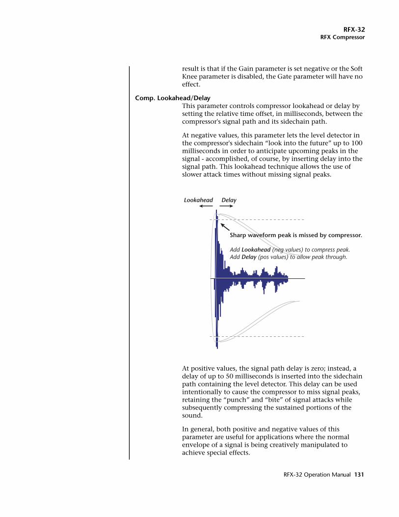
RFX-32RFX Compressor
result is that if the Gain parameter is set negative or the Soft Knee parameter is disabled, the Gate parameter will have no effect.
Comp. Lookahead/DelayThis parameter controls compressor lookahead or delay by setting the relative time offset, in milliseconds, between the compressor's signal path and its sidechain path.
At negative values, this parameter lets the level detector in the compressor's sidechain “look into the future” up to 100 milliseconds in order to anticipate upcoming peaks in the signal - accomplished, of course, by inserting delay into the signal path. This lookahead technique allows the use of slower attack times without missing signal peaks.
At positive values, the signal path delay is zero; instead, a delay of up to 50 milliseconds is inserted into the sidechain path containing the level detector. This delay can be used intentionally to cause the compressor to miss signal peaks, retaining the “punch” and “bite” of signal attacks while subsequently compressing the sustained portions of the sound.
In general, both positive and negative values of this parameter are useful for applications where the normal envelope of a signal is being creatively manipulated to achieve special effects.
Lookahead Delay
Sharp waveform peak is missed by compressor.
Add Lookahead (neg values) to compress peak.Add Delay (pos values) to allow peak through.
RFX-32 Operation Manual 131
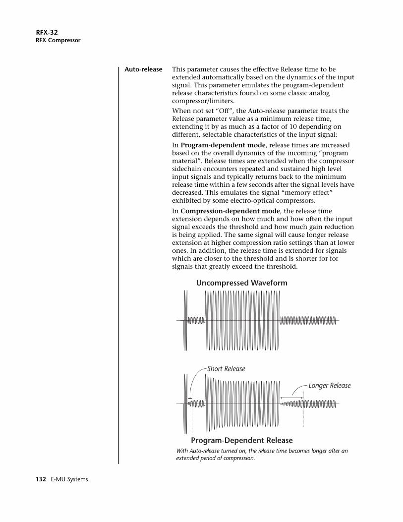
RFX-32RFX Compressor
Auto-release This parameter causes the effective Release time to be extended automatically based on the dynamics of the input signal. This parameter emulates the program-dependent release characteristics found on some classic analog compressor/limiters.
When not set “Off”, the Auto-release parameter treats the Release parameter value as a minimum release time, extending it by as much as a factor of 10 depending on different, selectable characteristics of the input signal:
In Program-dependent mode, release times are increased based on the overall dynamics of the incoming “program material”. Release times are extended when the compressor sidechain encounters repeated and sustained high level input signals and typically returns back to the minimum release time within a few seconds after the signal levels have decreased. This emulates the signal “memory effect” exhibited by some electro-optical compressors.
In Compression-dependent mode, the release time extension depends on how much and how often the input signal exceeds the threshold and how much gain reduction is being applied. The same signal will cause longer release extension at higher compression ratio settings than at lower ones. In addition, the release time is extended for signals which are closer to the threshold and is shorter for for signals that greatly exceed the threshold.
Uncompressed Waveform
Program-Dependent Release
Short Release
Longer Release
With Auto-release turned on, the release time becomes longer after an extended period of compression.
132 E-MU Systems
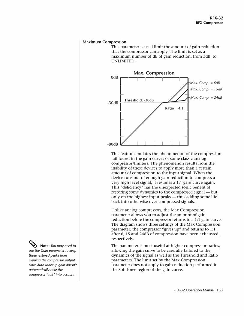
RFX-32RFX Compressor
Maximum CompressionThis parameter is used limit the amount of gain reduction that the compressor can apply. The limit is set as a maximum number of dB of gain reduction, from 3dB. to UNLIMITED.
This feature emulates the phenomenon of the compression tail found in the gain curves of some classic analog compressor/limiters. The phenomenon results from the inability of these devices to apply more than a certain amount of compression to the input signal. When the device runs out of enough gain reduction to compress a very high level signal, it resumes a 1:1 gain curve again. This “deficiency” has the unexpected sonic benefit of restoring some dynamics to the compressed signal — but only on the highest input peaks — thus adding some life back into otherwise over-compressed signals.
Unlike analog compressors, the Max Compression parameter allows you to adjust the amount of gain reduction before the compressor returns to a 1:1 gain curve. The diagram shows three settings of the Max Compression parameter; the compressor “gives up” and returns to 1:1 after 6, 15 and 24dB of compression have been exhausted, respectively.
Note: You may need to use the Gain parameter to keep these restored peaks from clipping the compressor output since Auto Makeup gain doesn't automatically take the compressor “tail” into account.
The parameter is most useful at higher compression ratios, allowing the gain curve to be carefully tailored to the dynamics of the signal as well as the Threshold and Ratio parameters. The limit set by the Max Compression parameter does not apply to gain reduction performed in the Soft Knee region of the gain curve.
0dB
-30dB
-80dB
Threshold: -30dB
Max. Compression
Max. Comp. = 6dB
Max. Comp. = 15dB
Max. Comp. = 24dB
Ratio = 4:1
RFX-32 Operation Manual 133
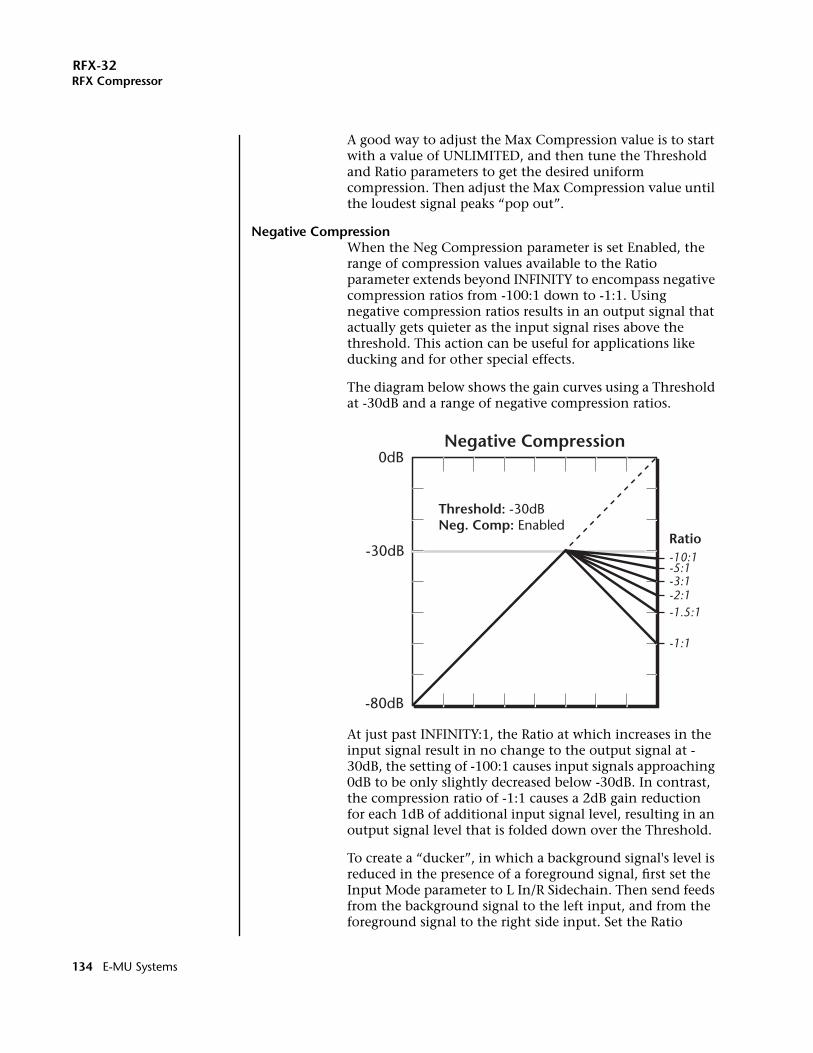
RFX-32RFX Compressor
A good way to adjust the Max Compression value is to start with a value of UNLIMITED, and then tune the Threshold and Ratio parameters to get the desired uniform compression. Then adjust the Max Compression value until the loudest signal peaks “pop out”.
Negative CompressionWhen the Neg Compression parameter is set Enabled, the range of compression values available to the Ratio parameter extends beyond INFINITY to encompass negative compression ratios from -100:1 down to -1:1. Using negative compression ratios results in an output signal that actually gets quieter as the input signal rises above the threshold. This action can be useful for applications like ducking and for other special effects.
The diagram below shows the gain curves using a Threshold at -30dB and a range of negative compression ratios.
At just past INFINITY:1, the Ratio at which increases in the input signal result in no change to the output signal at -30dB, the setting of -100:1 causes input signals approaching 0dB to be only slightly decreased below -30dB. In contrast, the compression ratio of -1:1 causes a 2dB gain reduction for each 1dB of additional input signal level, resulting in an output signal level that is folded down over the Threshold.
To create a “ducker”, in which a background signal's level is reduced in the presence of a foreground signal, first set the Input Mode parameter to L In/R Sidechain. Then send feeds from the background signal to the left input, and from the foreground signal to the right side input. Set the Ratio
0dB
-30dB
-80dB
Threshold: -30dBNeg. Comp: Enabled
Negative Compression
-10:1-5:1-3:1-2:1-1.5:1
-1:1
Ratio
134 E-MU Systems
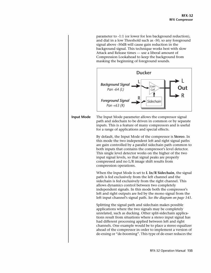
RFX-32RFX Compressor
parameter to -1:1 (or lower for less background reduction), and dial in a low Threshold such as -50, so any foreground signal above -50dB will cause gain reduction in the background signal. This technique works best with slow Attack and Release times — use a liberal amount of Compression Lookahead to keep the background from masking the beginning of foreground sounds.
Input Mode The Input Mode parameter allows the compressor signal path and sidechain to be driven in common or by separate inputs. This is a feature of many compressors and is useful for a range of applications and special effects.
By default, the Input Mode of the compressor is Stereo. In this mode the two independent left and right signal paths are gain controlled by a parallel sidechain path common to both inputs that contains the compressor's level detector. This single level detector works on the higher of the two input signal levels, so that signal peaks are properly compressed and no L/R image shift results from compression operations.
When the Input Mode is set to L In/R Sidechain, the signal path is fed exclusively from the left channel and the sidechain is fed exclusively from the right channel. This allows dynamics control between two completely independent signals. In this mode both the compressor's left and right outputs are fed by the mono signal from the left input channel's signal path. See the diagram on page 141.
Splitting the signal path and sidechain makes possible applications where the two signals may be completely unrelated, such as ducking. Other split-sidechain applica-tions result from situations where a stereo input signal has had different processing applied between left and right channels. One example would be to place a stereo equalizer ahead of the compressor in order to implement a version of de-essing or “de-booming”. This type of de-esser reduces the
LLOut
RR
Ducker
Sidechain
GainCell
Foreground Signal Pan +63 (R)
Background Signal Pan -64 (L)
RFX-32 Operation Manual 135
RFX-32RFX Compressor
gain of all frequencies in the signal during high levels of sibilance (“ssss”) in vocals.
Another example is placing a stereo delay line ahead of the compressor in order to extend the delay times available from the Compression Lookahead/Delay parameter.
Gain Meter This control enables or disables the Gain Reduction Meter. Because of the way that the gain reduction meter in the Threshold display has been implemented, keeping it updated in realtime requires a lot of the processor's time, and can slow down navigation and display of other param-eters in the plug-in. This parameter allows the meter display to be disabled in order to make editing and navigation of the other parameters more responsive.
136 E-MU Systems
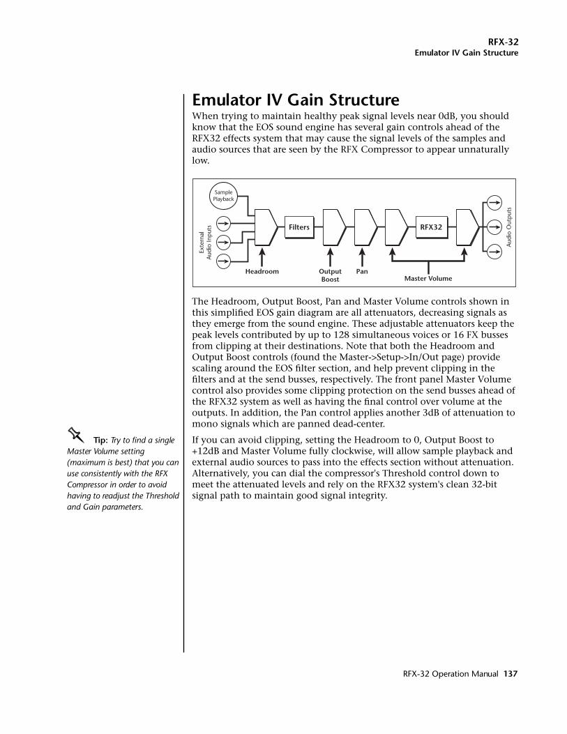
RFX-32Emulator IV Gain Structure
Emulator IV Gain StructureWhen trying to maintain healthy peak signal levels near 0dB, you should know that the EOS sound engine has several gain controls ahead of the RFX32 effects system that may cause the signal levels of the samples and audio sources that are seen by the RFX Compressor to appear unnaturally low.
The Headroom, Output Boost, Pan and Master Volume controls shown in this simplified EOS gain diagram are all attenuators, decreasing signals as they emerge from the sound engine. These adjustable attenuators keep the peak levels contributed by up to 128 simultaneous voices or 16 FX busses from clipping at their destinations. Note that both the Headroom and Output Boost controls (found the Master->Setup->In/Out page) provide scaling around the EOS filter section, and help prevent clipping in the filters and at the send busses, respectively. The front panel Master Volume control also provides some clipping protection on the send busses ahead of the RFX32 system as well as having the final control over volume at the outputs. In addition, the Pan control applies another 3dB of attenuation to mono signals which are panned dead-center.
OOOO Tip: Try to find a single Master Volume setting (maximum is best) that you can use consistently with the RFX Compressor in order to avoid having to readjust the Threshold and Gain parameters.
If you can avoid clipping, setting the Headroom to 0, Output Boost to +12dB and Master Volume fully clockwise, will allow sample playback and external audio sources to pass into the effects section without attenuation. Alternatively, you can dial the compressor's Threshold control down to meet the attenuated levels and rely on the RFX32 system's clean 32-bit signal path to maintain good signal integrity.
Filters RFX32
SamplePlayback
Exte
rnal
Aud
io In
put
s
Aud
io O
utp
uts
Headroom OutputBoost
PanMaster Volume
RFX-32 Operation Manual 137
RFX-32Using the RFX Compressor
Using the RFX CompressorA compressor is normally used as an “in-line” effect, which means you’ll be using a wet/dry mix of 100%. The RFX Compressor has a wide range of uses including, but not limited to:
• Drum compression on your own sampled drums (Commercial drumsamples are usually compressed already.)
• Prevent the bass from wandering in and out of the mix.
• Sampled vocal parts or live vocals using the external analog inputs.
• Final mastering when preparing radio or commercial spots.
• Improve the performance of the vocoder by inserting the compressor before the vocoder inputs.
Basic ControlsAlthough the RFX Compressor has many more features than a standard compressor, its basic controls remain the same. The three main controls are the Ratio control, the Threshold control and the Gain control.
If a signal falls below the threshold, no processing will take place. Signals exceeding the Threshold will have gain reduction applied as set by the ratio control. This important control allows you to dial in the range of amplitudes you want to tame. For example, if you’re tying to trim off just the loudest peaks, set the threshold so the gain reduction meter only shows compression during these peaks. One of the biggest mistakes in using a compressor is having the threshold set too low. This adds noise as the compressor will always be reducing the volume.
The Ratio control determines how strongly the compressor will affect the signal. The higher the ratio, the more reduction will be applied. If the ratio is high enough, (above 10:1) the signal will effectively be prevented from getting any louder. In this situation, the compressor will be acting as a Limiter, as it is placing an upper limit on the signal level. In general, ratios from 2:1 to 6:1 are considered compression and higher ratios above 10:1 are considered limiting.
Gain control amplifies the signal after it has been compressed to bring it back up in volume. If you don’t increase the gain, the compressed signal will be much lower in volume. The handy “AutoMakeup” feature automati-cally adjusts the gain depending on the threshold and ratio settings.
Two other important controls are Attack and Release. The Attack controls how quickly the gain is turned down after the signal exceeds the threshold. Release controls how fast the gain is returned to its normal setting after the signal has fallen below the threshold again. An attack setting of about10 milliseconds will delay the onset of compression long enough to preserve the attack transients in guitar, bass or drums while allowing the sustain portion of the sound to be compressed. Longer release times are generally used to reduce the so called “pumping” effect as the compressor turns on and off. Don’t make the release time too long, however, or the compressor
138 E-MU Systems
RFX-32Example Settings
won’t have time to recover for the next pluck or hit. In general, the attack and release controls are used to smooth out the action of the compressor, but they can also be used to create special effects.
Example SettingsHere we have provided a few examples to show the varied uses of this useful tool. Bear in mind that these examples are simply starting points and that you will undoubtedly need to fine tune the parameters to fit the program material and to suit your own taste.
� Increase Drum Punch:Adjust the Threshold control to control the amount of compression.
• Threshold: Adjust so that all hits are being compressed.• Ratio: 4:1• Attack: 8 msec (Increase the time to hear more “stick” sound.)• Release: 60 msec (Adjust according to the tempo of song.)• Gain: Adjust to make up for lost volume.• Soft Knee: Adjust as desired.• Comp. Lookahead: This can be used instead of the Attack control.• Max. Compression: Unlimited
� Smoothing out the Bass Guitar Level:This setup evens out the volume and prevents the bass guitar from wandering in and out of the mix.
• Threshold: -24dB (adjust according to the sound)• Ratio: 4:1• Attack: 8 msec• Release: 70 msec• Gain: +4dB (adjust according to the sound)• Soft Knee: Threshold -8dB• Gate: Off• Comp. Lookahead: 0 msec• Auto-release: Comp-dependent• Max. Compression: 18dB
RFX-32 Operation Manual 139
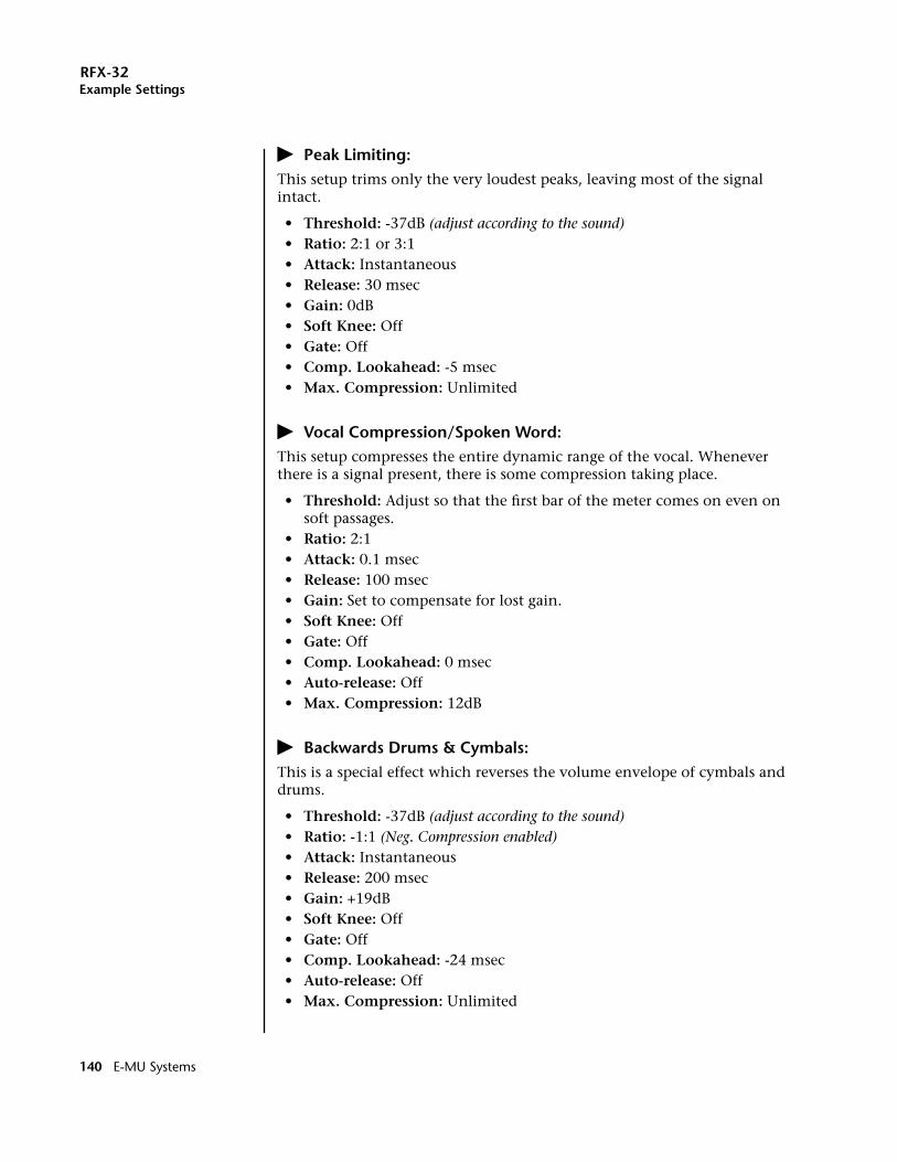
RFX-32Example Settings
� Peak Limiting:This setup trims only the very loudest peaks, leaving most of the signal intact.
• Threshold: -37dB (adjust according to the sound)• Ratio: 2:1 or 3:1• Attack: Instantaneous• Release: 30 msec• Gain: 0dB• Soft Knee: Off• Gate: Off• Comp. Lookahead: -5 msec• Max. Compression: Unlimited
� Vocal Compression/Spoken Word:This setup compresses the entire dynamic range of the vocal. Whenever there is a signal present, there is some compression taking place.
• Threshold: Adjust so that the first bar of the meter comes on even on soft passages.
• Ratio: 2:1• Attack: 0.1 msec• Release: 100 msec• Gain: Set to compensate for lost gain.• Soft Knee: Off• Gate: Off• Comp. Lookahead: 0 msec• Auto-release: Off• Max. Compression: 12dB
� Backwards Drums & Cymbals:This is a special effect which reverses the volume envelope of cymbals and drums.
• Threshold: -37dB (adjust according to the sound)• Ratio: -1:1 (Neg. Compression enabled)• Attack: Instantaneous• Release: 200 msec• Gain: +19dB• Soft Knee: Off• Gate: Off• Comp. Lookahead: -24 msec• Auto-release: Off• Max. Compression: Unlimited
140 E-MU Systems
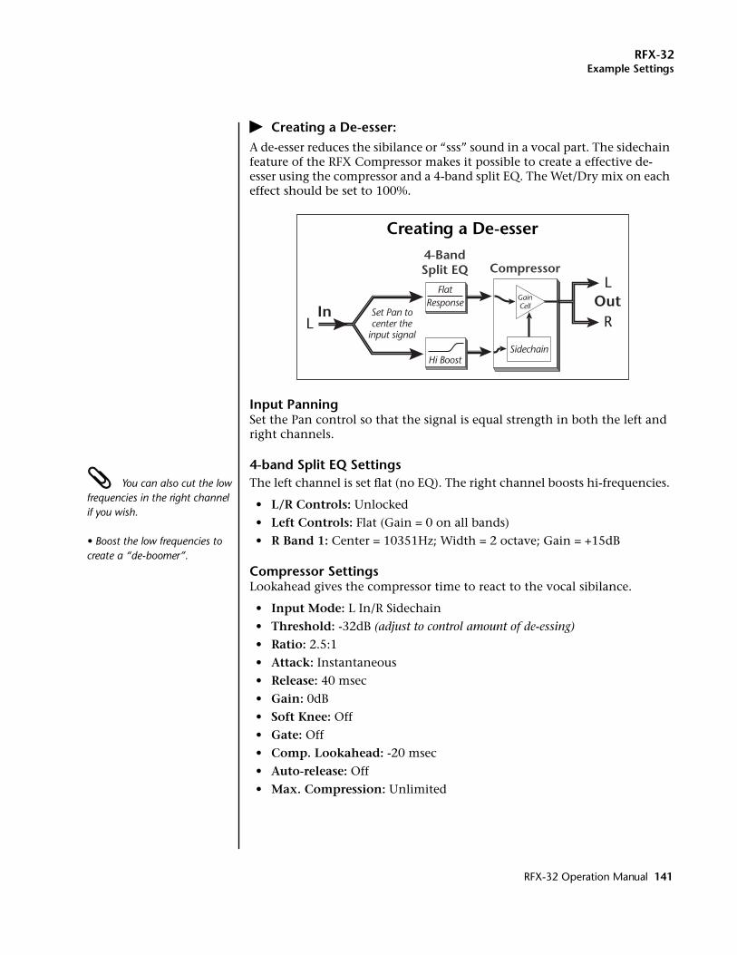
RFX-32Example Settings
� Creating a De-esser:A de-esser reduces the sibilance or “sss” sound in a vocal part. The sidechain feature of the RFX Compressor makes it possible to create a effective de-esser using the compressor and a 4-band split EQ. The Wet/Dry mix on each effect should be set to 100%.
Input PanningSet the Pan control so that the signal is equal strength in both the left and right channels.
4-band Split EQ Settings You can also cut the low frequencies in the right channel if you wish.
• Boost the low frequencies to create a “de-boomer”.
The left channel is set flat (no EQ). The right channel boosts hi-frequencies.
• L/R Controls: Unlocked
• Left Controls: Flat (Gain = 0 on all bands)
• R Band 1: Center = 10351Hz; Width = 2 octave; Gain = +15dB
Compressor SettingsLookahead gives the compressor time to react to the vocal sibilance.
• Input Mode: L In/R Sidechain
• Threshold: -32dB (adjust to control amount of de-essing)
• Ratio: 2.5:1
• Attack: Instantaneous
• Release: 40 msec
• Gain: 0dB
• Soft Knee: Off
• Gate: Off
• Comp. Lookahead: -20 msec
• Auto-release: Off
• Max. Compression: Unlimited
LIn
LOut
R
4-BandSplit EQ Compressor
FlatResponse
Hi Boost
Set Pan tocenter the
input signalSidechain
GainCell
Creating a De-esser
RFX-32 Operation Manual 141
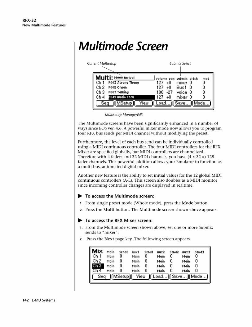
RFX-32New Multimode Features
Multimode ScreenNew Multimode Features
The Multimode screens have been significantly enhanced in a number of ways since EOS ver. 4.6. A powerful mixer mode now allows you to program four RFX bus sends per MIDI channel without modifying the preset.
Furthermore, the level of each bus send can be individually controlled using a MIDI continuous controller. The four MIDI controllers for the RFX Mixer are specified globally, but MIDI controllers are channelized. Therefore with 4 faders and 32 MIDI channels, you have (4 x 32 =) 128 fader channels. This powerful addition allows your Emulator to function as a multi-bus, automated digital mixer.
Another new feature is the ability to set initial values for the 12 global MIDI continuous controllers (A-L). This screen also doubles as a MIDI monitor since incoming controller changes are displayed in realtime.
� To access the Multimode screen:1. From single preset mode (Whole mode), press the Mode button.
2. Press the Multi button. The Multimode screen shown above appears.
� To access the RFX Mixer screen:1. From the Multimode screen shown above, set one or more Submix
sends to “mixer”.
2. Press the Next page key. The following screen appears.
Current Multisetup
Multisetup Manage/Edit
Submix Select
142 E-MU Systems
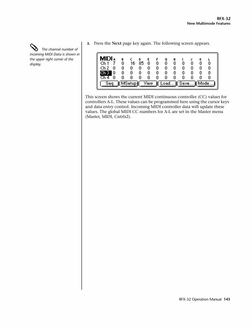
RFX-32New Multimode Features
3. Press the Next page key again. The following screen appears. The channel number of incoming MIDI Data is shown in the upper right corner of the display.
This screen shows the current MIDI continuous controller (CC) values for controllers A-L. These values can be programmed here using the cursor keys and data entry control. Incoming MIDI controller data will update these values. The global MIDI CC numbers for A-L are set in the Master menu (Master, MIDI, Cntrls2).
RFX-32 Operation Manual 143
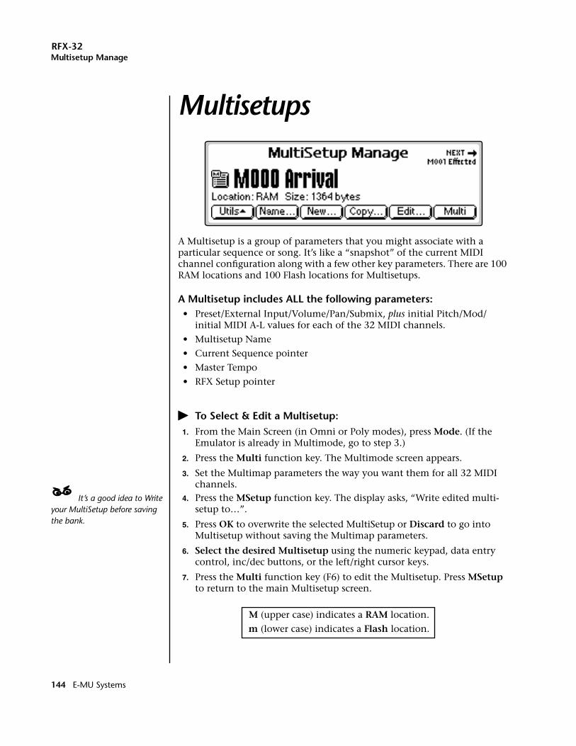
RFX-32Multisetup Manage
MultisetupsMultisetup Manage
A Multisetup is a group of parameters that you might associate with a particular sequence or song. It’s like a “snapshot” of the current MIDI channel configuration along with a few other key parameters. There are 100 RAM locations and 100 Flash locations for Multisetups.
A Multisetup includes ALL the following parameters:• Preset/External Input/Volume/Pan/Submix, plus initial Pitch/Mod/
initial MIDI A-L values for each of the 32 MIDI channels.
• Multisetup Name
• Current Sequence pointer
• Master Tempo
• RFX Setup pointer
� To Select & Edit a Multisetup:1. From the Main Screen (in Omni or Poly modes), press Mode. (If the
Emulator is already in Multimode, go to step 3.)
2. Press the Multi function key. The Multimode screen appears.
3. Set the Multimap parameters the way you want them for all 32 MIDI channels.
____ It’s a good idea to Write your MultiSetup before saving the bank.
4. Press the MSetup function key. The display asks, “Write edited multi-setup to…”.
5. Press OK to overwrite the selected MultiSetup or Discard to go into Multisetup without saving the Multimap parameters.
6. Select the desired Multisetup using the numeric keypad, data entry control, inc/dec buttons, or the left/right cursor keys.
7. Press the Multi function key (F6) to edit the Multisetup. Press MSetup to return to the main Multisetup screen.
M (upper case) indicates a RAM location.
m (lower case) indicates a Flash location.
144 E-MU Systems
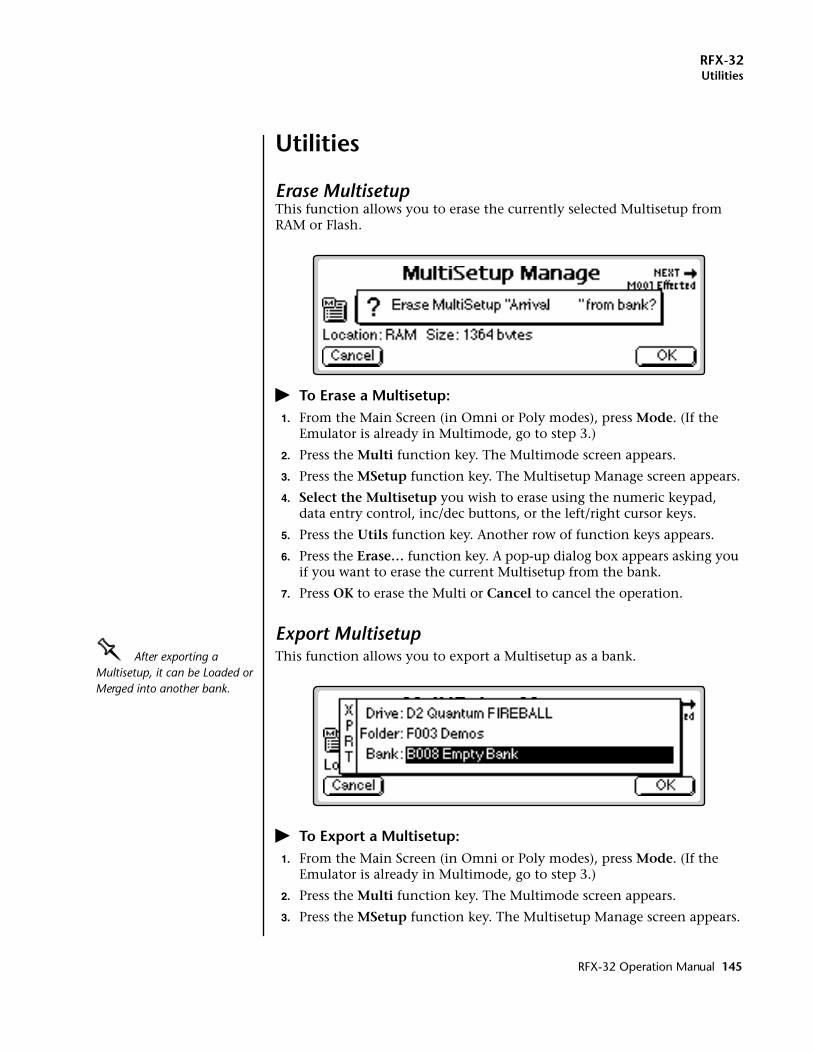
RFX-32Utilities
Utilities
Erase MultisetupThis function allows you to erase the currently selected Multisetup from RAM or Flash.
� To Erase a Multisetup:1. From the Main Screen (in Omni or Poly modes), press Mode. (If the
Emulator is already in Multimode, go to step 3.)
2. Press the Multi function key. The Multimode screen appears.
3. Press the MSetup function key. The Multisetup Manage screen appears.
4. Select the Multisetup you wish to erase using the numeric keypad, data entry control, inc/dec buttons, or the left/right cursor keys.
5. Press the Utils function key. Another row of function keys appears.
6. Press the Erase… function key. A pop-up dialog box appears asking you if you want to erase the current Multisetup from the bank.
7. Press OK to erase the Multi or Cancel to cancel the operation.
Export MultisetupOOOO After exporting a Multisetup, it can be Loaded or Merged into another bank.
This function allows you to export a Multisetup as a bank.
� To Export a Multisetup:1. From the Main Screen (in Omni or Poly modes), press Mode. (If the
Emulator is already in Multimode, go to step 3.)
2. Press the Multi function key. The Multimode screen appears.
3. Press the MSetup function key. The Multisetup Manage screen appears.
RFX-32 Operation Manual 145
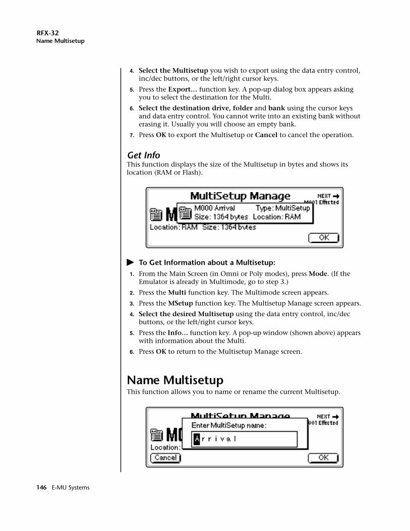
RFX-32Name Multisetup
4. Select the Multisetup you wish to export using the data entry control, inc/dec buttons, or the left/right cursor keys.
5. Press the Export… function key. A pop-up dialog box appears asking you to select the destination for the Multi.
6. Select the destination drive, folder and bank using the cursor keys and data entry control. You cannot write into an existing bank without erasing it. Usually you will choose an empty bank.
7. Press OK to export the Multisetup or Cancel to cancel the operation.
Get InfoThis function displays the size of the Multisetup in bytes and shows its location (RAM or Flash).
� To Get Information about a Multisetup:1. From the Main Screen (in Omni or Poly modes), press Mode. (If the
Emulator is already in Multimode, go to step 3.)
2. Press the Multi function key. The Multimode screen appears.
3. Press the MSetup function key. The Multisetup Manage screen appears.
4. Select the desired Multisetup using the data entry control, inc/dec buttons, or the left/right cursor keys.
5. Press the Info… function key. A pop-up window (shown above) appears with information about the Multi.
6. Press OK to return to the Multisetup Manage screen.
Name MultisetupThis function allows you to name or rename the current Multisetup.
146 E-MU Systems
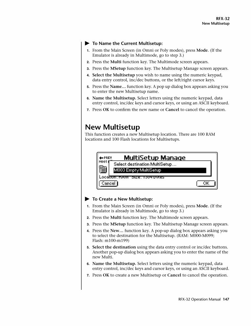
RFX-32New Multisetup
� To Name the Current Multisetup:1. From the Main Screen (in Omni or Poly modes), press Mode. (If the
Emulator is already in Multimode, go to step 3.)
2. Press the Multi function key. The Multimode screen appears.
3. Press the MSetup function key. The Multisetup Manage screen appears.
4. Select the Multisetup you wish to name using the numeric keypad, data entry control, inc/dec buttons, or the left/right cursor keys.
5. Press the Name… function key. A pop up dialog box appears asking you to enter the new Multisetup name.
6. Name the Multisetup. Select letters using the numeric keypad, data entry control, inc/dec keys and cursor keys, or using an ASCII keyboard.
7. Press OK to confirm the new name or Cancel to cancel the operation.
New MultisetupThis function creates a new Multisetup location. There are 100 RAM locations and 100 Flash locations for Multisetups.
� To Create a New Multisetup:1. From the Main Screen (in Omni or Poly modes), press Mode. (If the
Emulator is already in Multimode, go to step 3.)
2. Press the Multi function key. The Multimode screen appears.
3. Press the MSetup function key. The Multisetup Manage screen appears.
4. Press the New… function key. A pop-up dialog box appears asking you to select the destination for the Multisetup. (RAM: M000-M099;Flash: m100-m199)
5. Select the destination using the data entry control or inc/dec buttons. Another pop-up dialog box appears asking you to enter the name of the new Multi.
6. Name the Multisetup. Select letters using the numeric keypad, data entry control, inc/dec keys and cursor keys, or using an ASCII keyboard.
7. Press OK to create a new Multisetup or Cancel to cancel the operation.
RFX-32 Operation Manual 147
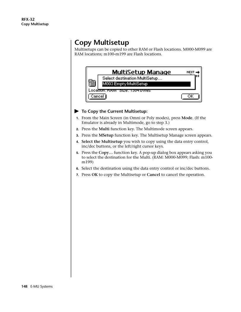
RFX-32Copy Multisetup
Copy MultisetupMultisetups can be copied to other RAM or Flash locations. M000-M099 are RAM locations; m100-m199 are Flash locations.
� To Copy the Current Multisetup:1. From the Main Screen (in Omni or Poly modes), press Mode. (If the
Emulator is already in Multimode, go to step 3.)
2. Press the Multi function key. The Multimode screen appears.
3. Press the MSetup function key. The Multisetup Manage screen appears.
4. Select the Multisetup you wish to copy using the data entry control, inc/dec buttons, or the left/right cursor keys.
5. Press the Copy… function key. A pop-up dialog box appears asking you to select the destination for the Multi. (RAM: M000-M099; Flash: m100-m199)
6. Select the destination using the data entry control or inc/dec buttons.
7. Press OK to copy the Multisetup or Cancel to cancel the operation.
148 E-MU Systems
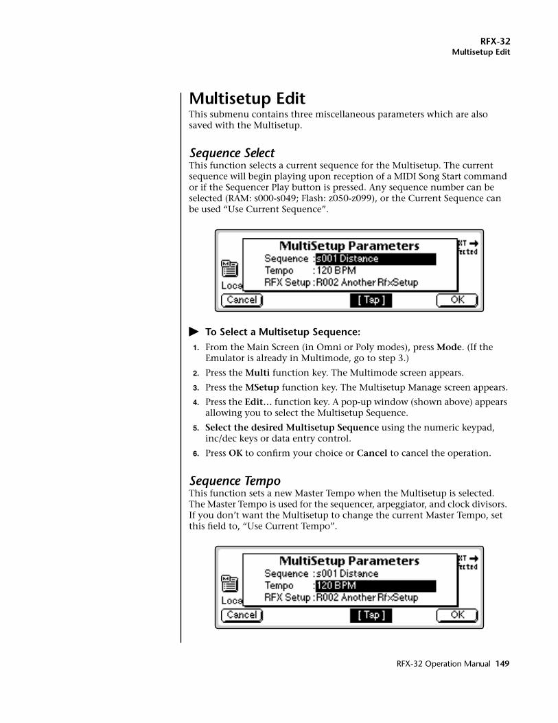
RFX-32Multisetup Edit
Multisetup EditThis submenu contains three miscellaneous parameters which are also saved with the Multisetup.
Sequence SelectThis function selects a current sequence for the Multisetup. The current sequence will begin playing upon reception of a MIDI Song Start command or if the Sequencer Play button is pressed. Any sequence number can be selected (RAM: s000-s049; Flash: z050-z099), or the Current Sequence can be used “Use Current Sequence”.
� To Select a Multisetup Sequence:1. From the Main Screen (in Omni or Poly modes), press Mode. (If the
Emulator is already in Multimode, go to step 3.)
2. Press the Multi function key. The Multimode screen appears.
3. Press the MSetup function key. The Multisetup Manage screen appears.
4. Press the Edit… function key. A pop-up window (shown above) appears allowing you to select the Multisetup Sequence.
5. Select the desired Multisetup Sequence using the numeric keypad, inc/dec keys or data entry control.
6. Press OK to confirm your choice or Cancel to cancel the operation.
Sequence TempoThis function sets a new Master Tempo when the Multisetup is selected. The Master Tempo is used for the sequencer, arpeggiator, and clock divisors. If you don’t want the Multisetup to change the current Master Tempo, set this field to, “Use Current Tempo”.
RFX-32 Operation Manual 149
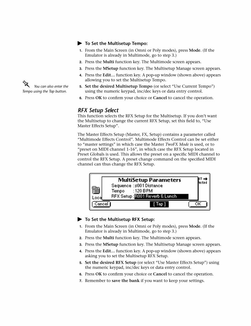
� To Set the Multisetup Tempo:1. From the Main Screen (in Omni or Poly modes), press Mode. (If the
Emulator is already in Multimode, go to step 3.)
2. Press the Multi function key. The Multimode screen appears.
3. Press the MSetup function key. The Multisetup Manage screen appears.
4. Press the Edit… function key. A pop-up window (shown above) appears allowing you to set the Multisetup Tempo.
OOOO You can also enter the Tempo using the Tap button.
5. Set the desired Multisetup Tempo (or select “Use Current Tempo”) using the numeric keypad, inc/dec keys or data entry control.
6. Press OK to confirm your choice or Cancel to cancel the operation.
RFX Setup SelectThis function selects the RFX Setup for the Multisetup. If you don’t want the Multisetup to change the current RFX Setup, set this field to, “Use Master Effects Setup”.
The Master Effects Setup (Master, FX, Setup) contains a parameter called “Multimode Effects Control”. Multimode Effects Control can be set either to “master settings” in which case the Master TwoFX Mode is used, or to “preset on MIDI channel 1-16”, in which case the RFX Setup located in Preset Globals is used. This allows the preset on a specific MIDI channel to control the RFX Setup. A preset change command on the specified MIDI channel can thus change the RFX Setup.
� To Set the Multisetup RFX Setup:1. From the Main Screen (in Omni or Poly modes), press Mode. (If the
Emulator is already in Multimode, go to step 3.)
2. Press the Multi function key. The Multimode screen appears.
3. Press the MSetup function key. The Multisetup Manage screen appears.
4. Press the Edit… function key. A pop-up window (shown above) appears asking you to set the Multisetup RFX Setup.
5. Set the desired RFX Setup (or select “Use Master Effects Setup”) using the numeric keypad, inc/dec keys or data entry control.
6. Press OK to confirm your choice or Cancel to cancel the operation.
7. Remember to save the bank if you want to keep your settings.
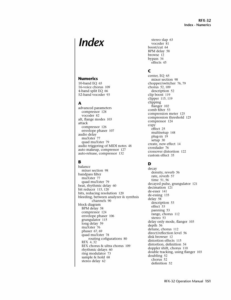
RFX-32Index - Numerics
Index
Numerics10-band EQ 6516-voice chorus 1094-band split EQ 6652-band vocoder 93
Aadvanced parameters
compressor 128vocoder 82
alt, flange modes 103attack
compressor 126envelope phaser 107
audio delaymuXster 77quad muXster 79
audio triggering of MIDI notes 48auto makeup, compressor 127auto-release, compressor 132
Bbalance
mixer section 98bandpass filter
muXster 77quad muXster 79
beat, rhythmic delay 60bit reducer 115, 120bits, reducing resolution 120bleeding, between analyzer & synthsis
channels 90block diagram
BPM delay 58compressor 124envelope phaser 106grungulator 115long delay 59muXster 76phaser 67, 69quad muXster 78
routing cofigurations 80RFX 4, 32RFX chorus & ultra chorus 109rhythmic delays 60ring modulator 73sample & hold 68stereo delay 62
stereo slap 63vocoder 81
boost/cut 64BPM delay 58browse 12bypass 34
effects 45
Ccenter, EQ 65
mixer section 98chopper/switcher 76, 79chorus 52, 109
description 52clip boost 119clipper 115, 119clipping
flanger 102comb filter 53compression meter 125compression threshold 125compressor 124copy
effect 25multisetup 148plug-in 19setup 30
create, new effect 14crossfader 76crossover distortion 122custom effect 35
Ddecay
density, reverb 56rate, reverb 57time 51, 56
decayed pulse, grungulator 121decimation 121de-esser 141de-essing 135delay 58
description 53effect 53panning 53range, chorus 112stereo 53
delay only mode, flanger 103depth 56detune, chorus 112direct/reflection level 56disk browser 12distortion effects 115distortion, definition 54doppler shift, chorus 110double tracking, using flanger 103doubling 52
chorus 52definition 52
RFX-32 Operation Manual 151
15
RFX-32Index - E
using flanger 103downsampler 115, 121drum sound replacement 50dual inverted sweep 100dual tap effect 54ducker 134dynamics, rhythmic delay 60
EE4 gain structure 137early/late level 56echo density 57edit
effect 22, 26setup 33, 37
EditFX button 34EditMod button 35effect descriptions 51effect manage 22effects 10, 53
browsing 12bypass 45chorus, about 52compressor 124control 41delay 53dual tap 54envelope phaser 105flanger 99grungulator 115mixer section 97muXster 76phase shifter 67preset 42quad muXster 78reverb, about 51ring modulator 72setup 27slapback 52stereo delay 53stereo flanger 52stereogrunglator 115using external 45vibrato 54vocoder 81
envelopecompressor attack & release 126follower, grungulator 115gain, envelope phaser 106phaser 105, 109response, envelope phaser 107shape, envelope phaser 107
EQ frequencymixer 98muXster 77quad muXster 79
EQ typemuXster 77quad muXster 79
eraseeffect 23multisetup 145plug-in 19setup 28
exporteffect 25multisetup 145plug-in 20setup 31
external inputs 46
FFAT effects 39, 55feedback 59, 61
envelope phaser 107flanger 102long delay 59phaser 70RFX chorus 113slap delay 61stereo delay 62stereo slap delay 63
filter10-band EQ 654-band split EQ 66bpm delay 59frequencies, vocoder 82grungulator 117long delay 59mixer section 97muxster 77parametric/shelf EQ 64quad muxter 79range, vocoder 82rhythmic delays 61ring modulator 75slap delay 61stereo delay 62stereo slap 63width, vocoder 82
flangemode 103multiplier 100, 102offset 100range 100
flangergeneral description 52stages, changing 103stereo 52
flasheffect 22multisetup 144plug-in 18, 19prep disk 1setup 27
follower rate, vocoder 84formant shift
diagram 83
2 E-MU Systems
RFX-32Index - G
vocoder 83freeze
muXster 77quad muXster 79
frequency, high 51full-wave rectifier 120FX 38
legacy mode 40
Ggain
compressor 127, 138EQ 65
mixer section 98expansion, grungulator 119, 122meter disable, compressor 136meter, compressor 125ratio 126structure, Emulator IV 137
gate, compressor 130get info
disk browser 13multisetup 146plug-in 21
glitch level, grungulator 122grungulator 115
Hhalf-wave rectifier 120halfwave scaling 120hall reverb 56harmonic boost, vocoder 83headphone jack 32HF decay factor 57HF gain 65HF rolloff 59, 61
long delay 59ring modulator 75slap delay 61stereo delay 62stereo slap delay 63
HF shelf 65, 98high frequency 51highpass filter
muxSter 77quad muXster 79
hold, grungulator downsampling 121how-to
build an RFX setup 15compress vocals 140connect external inputs to the
vocoder 87connect internal presets to the
vocoder by MIDI channel 89connect several vocoders in
parallel 93connect two voices to the vocoder 91create a backward cymbal effect 140create a de-esser 141
create a vocoder effect & setup 86create a vocoder multisetup 87create new effect 14increase drum punch 139limit peaks 140program FX sends by MIDI
channel 17program FX sends by MIDI mixer 17program FX sends by voice 16smooth bass guitar level 139use a ducker 134vocode emulator presets with a
microphone 88
II/O mode
envelope phaser 108flanger 104phaser 71
icon, effects & multisetup 12impulse mode, grungulator 121info, effects 13input mode
compressor 135RFX chorus 114
input sourcemuXster 77quad muXster 79
install software 1interpolation type, grungulator 121inverted downsampling,
grungulator 121inverted stereo mode
envelope phaser 106, 108phaser 67, 71
Llag processor
flanger 104phase shifter 71ring modulator 75vocoder 84
legacychorus types 55reverb types 55
LFdecay factor 57gain
mixer section 98parametric EQ 65
shelf 65, 70, 74mixer section 98
LFOphase shifter 70ring modulator 74
linear downsampling 121live samples 47load plug-in, effect, setup, msetup 12locked mode, mixer section 97
RFX-32 Operation Manual 153
RFX-32Index - M
logarithmic envelope shapeenvelope phaser 107
long delay 59lookahead, compressor 131lowpass filter
muXster 77quad muXster 79
L-R delay 59slap delay 61
Mmain bus 8master volume control, effect on enve-
lope phaser 107max. detune, chorus 112maximum compression 133MIDI
CC numbers for sends 0-3 6channel, program FX sends by 17clock 58effect controllers 35effect modulation 35global controllers A-L 143mixer, programming 17mod. parameters
10-band EQ 654-band split EQ 66bpm delay 58envelope phaser 107, 108long delay 59muxster 76phase shifter 70quad muxster 79RFX chorus 113RFX compressor 130RFX flanger 102rfx hall 56ring modulator 74simple reverb 57stereo slap 63stereogrunglator 123vocoder 83
triggers 48mix percentage, edit effect 26mixer
RFX 4, 6, 17section plug-in 97
mod offsetenvelope phaser 106phaser 70ring modulator 74
mod rangeenvelope phaser 106phaser 70ring modulator 74
mod ratephaser 70ring modulator 74
mod smoothingflanger 104ring modulator 75
mod sourcephaser 70ring modulator 74
mono inv L/env Renvelope phaser 108
mono L modeenvelope phaser 108phaser 71
mono L/env Renvelope phaser 108
mono modeenvelope phaser 108flanger 104
mono/stereo modeflanger 104
motion shape, chorus 113multi tap delay
effect 52rhythmic delay 60
multi-band vocoder, creating a 93multimode screen 142multisetup 144
edit menu 149icon 12
mute 34muXster 76
Nname
effect 23from setup edit 38
multisetup 146setup 28
negative compression 134negative feedback, envelope phaser 107negative gain, envelope phaser 106new
effect 24multisetup 147setup 29
noise gate, compressor 130notches
envelope phaser 106phase shifter 67, 106stereo flanger 52
Ooscillator
control, ring modulator 74output level, quad muXster 80output map 9, 36output mode, grungulator 118output width
chorus 113grungulator 118
overview 3
154 E-MU Systems
RFX-32Index - P
Ppan
grungulator 118mixer section 98muXster 77quad muXster 79rhythmic delay 61
panning delay 53description 53
patch parameter, grungulator 117peak limiter 126phase
flanger LFO 101invert
mixer section 98stereogrunglator 118
shifter effect 67phase shifter 67, 105phaser 67, 105plug-in 10
list 55location 21manage 18size 21
positive gainenvelope phaser 106
pre-delay, chorus 112preset, effects 42processing audio through the E4 49processing external inputs 46
QQ 65, 98, 117quad muXster 78
RRAM
effect 22multisetup 144plug-in 18, 19setup 27
random motion, chorus 113ratio, compressor 126, 138R-chip 39rectifier 115, 120release
compressor 126envelope phaser 107
resonator effectusing delay 61using flanger 102using phaser 70
response, envelope phaser 107resync
flanger 100muXster 77phaser 70quad muXster 79, 100ring modulator 74
reverb 51description 51RFX hall 56simple reverb 57
RFXallocation 39bus 34
programmed by MIDI channel 5programmed by MIDI mixer 6programmed by preset 5routing 33
chorus 109compressor 124effect icon 12flanger 99hall 56mixer 6
program effect sends using 17phaser 67plug-in icon 12setup 8, 11, 36
overview 8select, multisetup 150
setup icon 12ultra chorus 109
rhythmic delays 60ring modulator 72routing configurations
quad muXster 80
Ssample & hold
description 68rate
phaser 70ring modulator 74
sourceflanger 104phaser 70ring modulator 74
sample rate decimator 121samples, discarding 121sampling ADC 47select effect 22selecting effects setups 41send
programmed by MIDI channel 5programmed by MIDI mixer 6programmed by voice 5
sequenceusing multisetups in a 144
sequence select, multisetup 149sequence tempo 149set/shift key function 24setup diagram 11setups 11sibilance 82
freq 84level 83mix 84
RFX-32 Operation Manual 155
RFX-32Index - T
reducing 136sibilance, reducing 141sidechain modulation
compressor 134envelope phaser 105, 108
simple reverb 57slap delay 61slapback 52slice
1-4 level 79lag
muXster 77quad muXster 79
rangemuXster 77quad muXster 79
ratemuXster 77quad muXster 79
smoothingmuXster 76quad muXster 79
widthmuXster 77quad muXster 79
slice #, quad muXster 79smooth random control, of phaser 71soft clipping 54, 119soft knee 128software install 1solo 34solo mode, using with the vocoder 92split mode
mixer section 97step-by-step instructions for creating
effects & setups 14stereo (12-stage), phaser mode 71stereo delay 53, 62
vocoder 84stereo flanger 52stereo inverted mode
envelope phaser 108stereo mode
envelope phaser 108flanger 104
stereo slap delay 63stereogrunglator 115strikethrough 39surfaces, reflective rooms 56sweep
rate, flanger 101smoothing
flanger 104smoothing, flanger 104source, flanger 100
syncing delay 58synth passthru, vocoder 84
Ttap tempo button 150tap, dual delay 54tempo 58
muXster 76quad muXster 78rhythmic delay 61source 58, 61
tempo controlmuXster 76quad muXster 78
thickening the sound 52thin effects 39threshold, compressor 125, 138ticks, removing from muXster 79tips & tricks, vocoder 85, 96toggle RAM & flash 24trigger threshold, adjusting 49triggers, MIDI 48troubleshooting chart
vocoder 96two FX mode 11, 40
Uusing external effects 45utilities, multisetup 145
Vvibrato 54
description 54vocal/synth mix 85vocoder 81voice delay parameter, chorus 111, 112voice routing of inputs 47voice, routing of FX sends by 16voices
number of, chorus 113volume, mixer section 98
Wwaveform
flanger LFO 101wet/dry meter 34wet/dry mix 34width, EQ 65
mixer section 98
Xx-over, grungulator effect 115
156 E-MU Systems

Notes

E-MU / ENSONIQ U.S.A.1600 Green Hills Road
Scotts Valley, CA USA
95067-0015
Telephone 831-438-1921
FAX 831-438-8612
EUROPE, AFRICA, MIDDLE EASTE-MU / ENSONIQSuite 6, Adam Ferguson House
Eskmills Industrial park
Musselburgh, East Lothian
Scotland, EH21 7PQ
Telephone +44 (0) 131-653-6556