Embed Size (px)
Citation preview
Further author information: M. Cayrel: E-mail: [email protected], Telephone: +49 89 32006685
E-ELT Optomechanics: Overview
M. Cayrel
European Southern Observatory (ESO), Karl-Schwarzschild-Strasse. 2, Garching, Germany
ABSTRACT
The E-ELT is a project led by the European Southern Observatory (ESO) for a 40-m class optical, near- and mid-infrared, ground-based telescope. When it will enter into operation, the E-ELT will be the largest and most powerful optical telescope ever built. It will not only offer unrivalled light collecting power, but also exceedingly sharp images, thanks to its ability to compensate for the adverse effect of atmospheric turbulence on image sharpness.
The basic optical solution for the EELT is a folded three-mirror anastigmat, using a 39-m segmented primary mirror (M1), a 4-m convex secondary mirror (M2), and a 4-m concave tertiary mirror (M3), all active. Folding is provided by two additional flat mirrors sending the beams to either Nasmyth foci along the elevation axis of the telescope. The folding arrangement (flat M4 and M5 mirrors) is conceived to provide conveniently located flat surfaces for an adaptive shell (M4) and field stabilization (M5).
That paper provides an overview of the specifications, design, and expected performance of the E-ELT optical systems.
Keywords: E-ELT, ELT, active optics, adaptive optics, deformable mirror, segmented mirror, laser guide star
1. INTRODUCTION The E-ELT project originated in 2006 and followed extensive concept studies towards giant telescopes. The project Phase B, first for a 42-m and later for a 39-m telescope, was completed in 2011. The design, manufacturing, and test studies have been undertaken through tens of contracts with the industry. Each time it was deemed necessary, critical components and processes have been qualified using sub or full scale sub-system prototypes.
The results of these activities, detailed in the E-ELT Construction Proposal1, concluded in declaring the E-ELT ready for construction by end of 2011. That paper summarizes the outcomes of the E-ELT Phase B for the telescope optical systems. It presents the optical design, and its implementation at the level of all optomechanical units: the main mirrors M1 to M5, the prefocal stations, the laser guide star units. It focuses on the main design and performance characteristics of the units, not on manufacturing, testing, and control issues. Details about those can be found in references1 and many other publications.
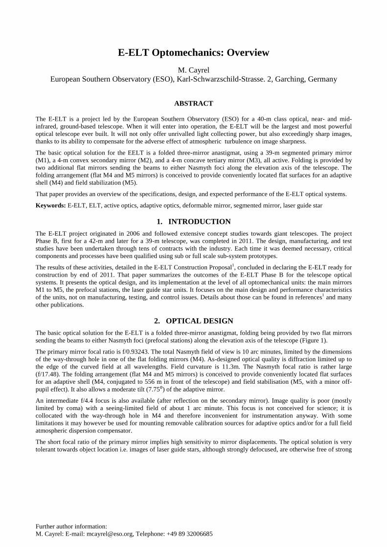
2. OPTICAL DESIGN The basic optical solution for the E-ELT is a folded three-mirror anastigmat, folding being provided by two flat mirrors sending the beams to either Nasmyth foci (prefocal stations) along the elevation axis of the telescope (Figure 1).
The primary mirror focal ratio is f/0.93243. The total Nasmyth field of view is 10 arc minutes, limited by the dimensions of the way-through hole in one of the flat folding mirrors (M4). As-designed optical quality is diffraction limited up to the edge of the curved field at all wavelengths. Field curvature is 11.3m. The Nasmyth focal ratio is rather large (f/17.48). The folding arrangement (flat M4 and M5 mirrors) is conceived to provide conveniently located flat surfaces for an adaptive shell (M4, conjugated to 556 m in front of the telescope) and field stabilisation (M5, with a minor off-pupil effect). It also allows a moderate tilt (7.75⁰) of the adaptive mirror.
An intermediate f/4.4 focus is also available (after reflection on the secondary mirror). Image quality is poor (mostly limited by coma) with a seeing-limited field of about 1 arc minute. This focus is not conceived for science; it is collocated with the way-through hole in M4 and therefore inconvenient for instrumentation anyway. With some limitations it may however be used for mounting removable calibration sources for adaptive optics and/or for a full field atmospheric dispersion compensator.
The short focal ratio of the primary mirror implies high sensitivity to mirror displacements. The optical solution is very tolerant towards object location i.e. images of laser guide stars, although strongly defocused, are otherwise free of strong
aberrations. The entrance pupil is collocated with the primary and the exit pupil is located 1945 mm after the quaternary mirror. Optical prescription can be adjusted to feed a Coudé focus.
Figure 1. Optical layout for the Nasmyth configuration of the E-ELT, optical prescription and optics dimensions
3. M1 UNIT 3.1 Concept
The E-ELT Primary Mirror (E-ELT M1 or M1) is a 39-m diameter elliptic concave mirror, with a 69-m radius of curvature. The M1 mirror is segmented, the segments are quasi-hexagonal, about 1.45 m in size (corner to corner) and 50 mm thick (thickness at centre). The gap between the segments is 4 mm.
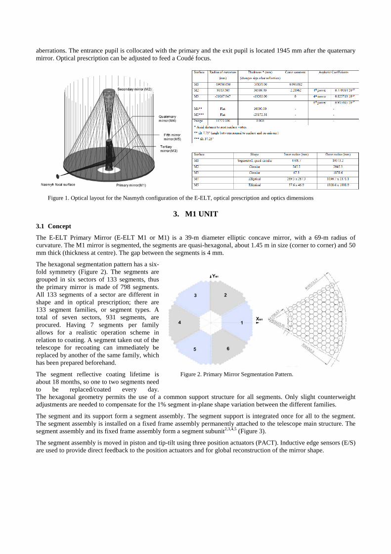
The hexagonal segmentation pattern has a six-fold symmetry (Figure 2). The segments are grouped in six sectors of 133 segments, thus the primary mirror is made of 798 segments. All 133 segments of a sector are different in shape and in optical prescription; there are 133 segment families, or segment types. A total of seven sectors, 931 segments, are procured. Having 7 segments per family allows for a realistic operation scheme in relation to coating. A segment taken out of the telescope for recoating can immediately be replaced by another of the same family, which has been prepared beforehand.
The segment reflective coating lifetime is about 18 months, so one to two segments need to be replaced/coated every day.
Figure 2. Primary Mirror Segmentation Pattern.
The hexagonal geometry permits the use of a common support structure for all segments. Only slight counterweight adjustments are needed to compensate for the 1% segment in-plane shape variation between the different families.
The segment and its support form a segment assembly. The segment support is integrated once for all to the segment. The segment assembly is installed on a fixed frame assembly permanently attached to the telescope main structure. The segment assembly and its fixed frame assembly form a segment subunit2,3,4,5 (Figure 3).
The segment assembly is moved in piston and tip-tilt using three position actuators (PACT). Inductive edge sensors (E/S) are used to provide direct feedback to the position actuators and for global reconstruction of the mirror shape.
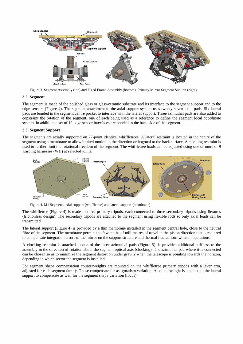
Figure 3. Segment Assembly (top) and Fixed Frame Assembly (bottom). Primary Mirror Segment Subunit (right).
3.2 Segment
The segment is made of the polished glass or glass-ceramic substrate and its interface to the segment support and to the edge sensors (Figure 4). The segment attachment to the axial support system uses twenty-seven axial pads. Six lateral pads are bonded in the segment centre pocket to interface with the lateral support. Three azimuthal pads are also added to constraint the rotation of the segment, one of each being used as a reference to define the segment local coordinate system. In addition, a set of 12 edge sensor interfaces are bonded to the back side of the segment.
3.3 Segment Support
The segments are axially supported on 27-point identical whiffletrees. A lateral restraint is located in the centre of the segment using a membrane to allow limited motion in the direction orthogonal to the back surface. A clocking restraint is used to further limit the rotational freedom of the segment. The whiffletree loads can be adjusted using one or more of 9 warping harnesses (WH) at selected joints.
Figure 4. M1 Segment, axial support (whiffletree) and lateral support (membrane)
The whiffletree (Figure 4) is made of three primary tripods, each connected to three secondary tripods using flexures (frictionless design). The secondary tripods are attached to the segment using flexible rods so only axial loads can be transmitted.
The lateral support (Figure 4) is provided by a thin membrane installed in the segment central hole, close to the neutral fibre of the segment. The membrane permits the few tenths of millimetres of travel in the piston direction that is required to compensate integration errors of the mirror on the support structure and thermal fluctuations when in operations.
A clocking restraint is attached to one of the three azimuthal pads (Figure 5). It provides additional stiffness to the assembly in the direction of rotation about the segment optical axis (clocking). The azimuthal pad where it is connected can be chosen so as to minimize the segment distortion under gravity when the telescope is pointing towards the horizon, depending in which sector the segment is installed.
For segment shape compensation counterweights are mounted on the whiffletree primary tripods with a lever arm, adjusted for each segment family. Those compensate for astigmatism variation. A counterweight is attached to the lateral support to compensate as well for the segment shape variation (focus).
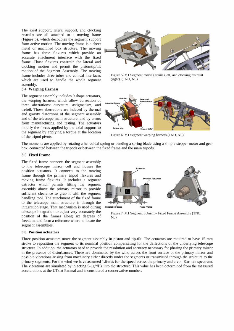
The axial support, lateral support, and clocking restraint are all attached to a moving frame (Figure 5), which decouples the segment support from active motion. The moving frame is a sheet metal or machined box structure. The moving frame has three flexures which provide an accurate attachment interface with the fixed frame. Those flexures constrain the lateral and clocking motion and permit the piston/tip/tilt motion of the Segment Assembly. The moving frame includes three tubes and conical interfaces which are used to handle the whole segment assembly.
Figure 5. M1 Segment moving frame (left) and clocking restraint (right). (TNO, NL)
3.4 Warping Harness
The segment assembly includes 9 shape actuators, the warping harness, which allow correction of three aberrations: curvature, astigmatism, and trefoil. Those aberrations are induced by thermal and gravity distortions of the segment assembly and of the telescope main structure, and by errors from manufacturing and testing. The actuators modify the forces applied by the axial support to the segment by applying a torque at the location of the tripod pivots.
Figure 6. M1 Segment warping harness (TNO, NL)
The moments are applied by rotating a helicoidal spring or bending a spring blade using a simple stepper motor and gear box, connected between the tripods or between the fixed frame and the main tripods.
3.5 Fixed Frame
The fixed frame connects the segment assembly to the telescope mirror cell and houses the position actuators. It connects to the moving frame through the primary tripod flexures and moving frame flexures. It includes a segment extractor which permits lifting the segment assembly above the primary mirror to provide sufficient clearance to grab it with the segment handling tool. The attachment of the fixed frame to the telescope main structure is through the integration stage. That mechanism is used during telescope integration to adjust very accurately the position of the frames along six degrees of freedom, and form a reference where to locate the segment assemblies.
Figure 7. M1 Segment Subunit – Fixed Frame Assembly (TNO, NL)
3.6 Position actuators
Three position actuators move the segment assembly in piston and tip-tilt. The actuators are required to have 15 mm stroke to reposition the segment to its nominal position compensating for the deflections of the underlying telescope structure. In addition, the actuators need to provide the resolution and accuracy necessary for phasing the primary mirror in the presence of disturbances. These are dominated by the wind across the front surface of the primary mirror and possible vibrations arising from machinery either directly under the segments or transmitted through the structure to the primary segments. For the wind we have assumed 1.6-m/s for the speed across the primary and a von Karman spectrum. The vibrations are simulated by injecting 5-μg/√Hz into the structure. This value has been determined from the measured accelerations at the UTs at Paranal and is considered a conservative number.
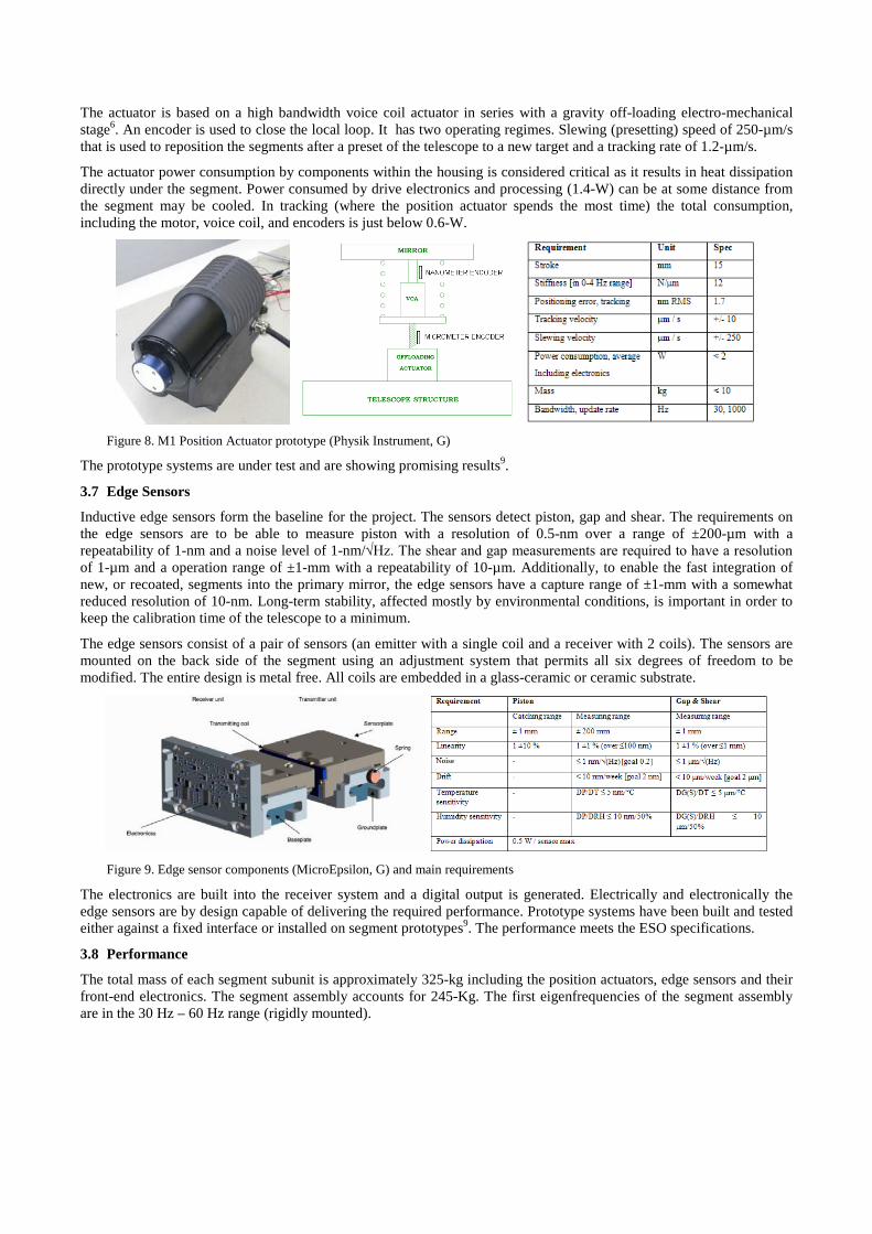
The actuator is based on a high bandwidth voice coil actuator in series with a gravity off-loading electro-mechanical stage6. An encoder is used to close the local loop. It has two operating regimes. Slewing (presetting) speed of 250-µm/s that is used to reposition the segments after a preset of the telescope to a new target and a tracking rate of 1.2-µm/s.
The actuator power consumption by components within the housing is considered critical as it results in heat dissipation directly under the segment. Power consumed by drive electronics and processing (1.4-W) can be at some distance from the segment may be cooled. In tracking (where the position actuator spends the most time) the total consumption, including the motor, voice coil, and encoders is just below 0.6-W.
Figure 8. M1 Position Actuator prototype (Physik Instrument, G)
The prototype systems are under test and are showing promising results9.
3.7 Edge Sensors
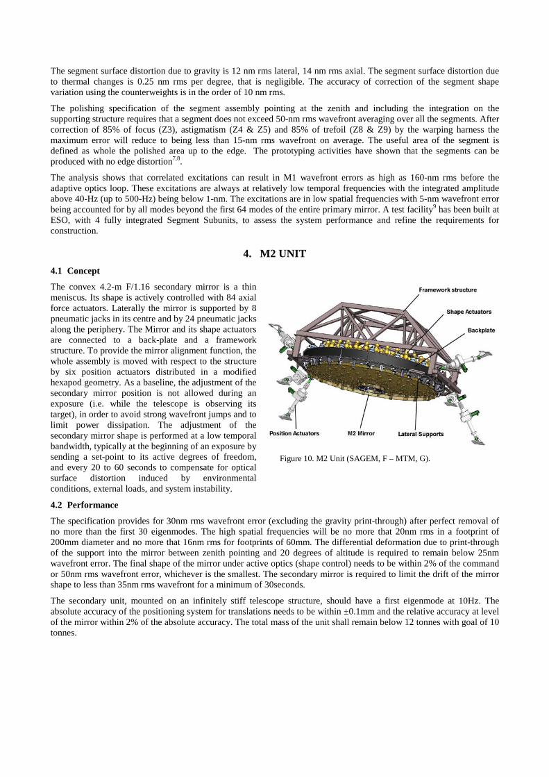
Inductive edge sensors form the baseline for the project. The sensors detect piston, gap and shear. The requirements on the edge sensors are to be able to measure piston with a resolution of 0.5-nm over a range of ±200-µm with a repeatability of 1-nm and a noise level of 1-nm/√Hz. The shear and gap measurements are required to have a resolution of 1-µm and a operation range of ±1-mm with a repeatability of 10-µm. Additionally, to enable the fast integration of new, or recoated, segments into the primary mirror, the edge sensors have a capture range of ±1-mm with a somewhat reduced resolution of 10-nm. Long-term stability, affected mostly by environmental conditions, is important in order to keep the calibration time of the telescope to a minimum.
The edge sensors consist of a pair of sensors (an emitter with a single coil and a receiver with 2 coils). The sensors are mounted on the back side of the segment using an adjustment system that permits all six degrees of freedom to be modified. The entire design is metal free. All coils are embedded in a glass-ceramic or ceramic substrate.
Figure 9. Edge sensor components (MicroEpsilon, G) and main requirements
The electronics are built into the receiver system and a digital output is generated. Electrically and electronically the edge sensors are by design capable of delivering the required performance. Prototype systems have been built and tested either against a fixed interface or installed on segment prototypes9. The performance meets the ESO specifications.
3.8 Performance
The total mass of each segment subunit is approximately 325-kg including the position actuators, edge sensors and their front-end electronics. The segment assembly accounts for 245-Kg. The first eigenfrequencies of the segment assembly are in the 30 Hz – 60 Hz range (rigidly mounted).
The segment surface distortion due to gravity is 12 nm rms lateral, 14 nm rms axial. The segment surface distortion due to thermal changes is 0.25 nm rms per degree, that is negligible. The accuracy of correction of the segment shape variation using the counterweights is in the order of 10 nm rms.
The polishing specification of the segment assembly pointing at the zenith and including the integration on the supporting structure requires that a segment does not exceed 50-nm rms wavefront averaging over all the segments. After correction of 85% of focus (Z3), astigmatism (Z4 & Z5) and 85% of trefoil (Z8 & Z9) by the warping harness the maximum error will reduce to being less than 15-nm rms wavefront on average. The useful area of the segment is defined as whole the polished area up to the edge. The prototyping activities have shown that the segments can be produced with no edge distortion7,8.
The analysis shows that correlated excitations can result in M1 wavefront errors as high as 160-nm rms before the adaptive optics loop. These excitations are always at relatively low temporal frequencies with the integrated amplitude above 40-Hz (up to 500-Hz) being below 1-nm. The excitations are in low spatial frequencies with 5-nm wavefront error being accounted for by all modes beyond the first 64 modes of the entire primary mirror. A test facility9 has been built at ESO, with 4 fully integrated Segment Subunits, to assess the system performance and refine the requirements for construction.
4. M2 UNIT 4.1 Concept
The convex 4.2-m F/1.16 secondary mirror is a thin meniscus. Its shape is actively controlled with 84 axial force actuators. Laterally the mirror is supported by 8 pneumatic jacks in its centre and by 24 pneumatic jacks along the periphery. The Mirror and its shape actuators are connected to a back-plate and a framework structure. To provide the mirror alignment function, the whole assembly is moved with respect to the structure by six position actuators distributed in a modified hexapod geometry. As a baseline, the adjustment of the secondary mirror position is not allowed during an exposure (i.e. while the telescope is observing its target), in order to avoid strong wavefront jumps and to limit power dissipation. The adjustment of the secondary mirror shape is performed at a low temporal bandwidth, typically at the beginning of an exposure by sending a set-point to its active degrees of freedom, and every 20 to 60 seconds to compensate for optical surface distortion induced by environmental conditions, external loads, and system instability.
Figure 10. M2 Unit (SAGEM, F – MTM, G).
4.2 Performance
The specification provides for 30nm rms wavefront error (excluding the gravity print-through) after perfect removal of no more than the first 30 eigenmodes. The high spatial frequencies will be no more that 20nm rms in a footprint of 200mm diameter and no more that 16nm rms for footprints of 60mm. The differential deformation due to print-through of the support into the mirror between zenith pointing and 20 degrees of altitude is required to remain below 25nm wavefront error. The final shape of the mirror under active optics (shape control) needs to be within 2% of the command or 50nm rms wavefront error, whichever is the smallest. The secondary mirror is required to limit the drift of the mirror shape to less than 35nm rms wavefront for a minimum of 30seconds.
The secondary unit, mounted on an infinitely stiff telescope structure, should have a first eigenmode at 10Hz. The absolute accuracy of the positioning system for translations needs to be within ±0.1mm and the relative accuracy at level of the mirror within 2% of the absolute accuracy. The total mass of the unit shall remain below 12 tonnes with goal of 10 tonnes.
4.3 M2 Cell
A first design of the M2 Unit has been developed by SAGEM and MT Mechatronics. The cell is made of a steel back structure supporting a carbon fibre sandwich plate against which the shape actuation takes place (Figure 10). A steel frame provides the interface for the position actuation of the entire cell.
Carbon fibre was selected for the sandwich structure as its thermal properties match the mirror material better thereby reducing the stroke of the shape actuators. The carbon fibre sandwich has upper and lower CFRP ‘deck’ layers and carbon foam material for the foam. Tube holes provide the interfaces to the actuators.
4.4 M2 Lateral Support
The 24 lateral supports are arranged to take the gravity loads and provide support in the y-direction. They are mechanical cantilever systems incorporating a double chamber pneumatic stage that works in push pull allowing the same actuator to be used on both the lower and upper side of the mirror (Figure 11).
Their support orientation is optimized to minimise the mirror deflection. The double chamber allows adjustment of the stiffness of the actuators. Eight additional central supports are installed to provide higher stiffness in the x direction, especially in case of wind and earthquake. The pneumatic control concept ensures that the reaction forces are equally distributed.
Figure 11. Lateral supports with force limiters, earthquake restrainers (SAGEM,F – MTM, G)
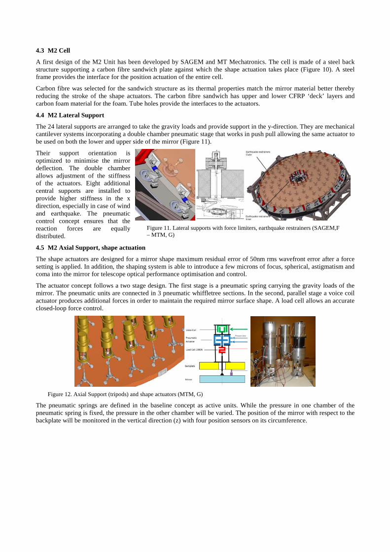
4.5 M2 Axial Support, shape actuation
The shape actuators are designed for a mirror shape maximum residual error of 50nm rms wavefront error after a force setting is applied. In addition, the shaping system is able to introduce a few microns of focus, spherical, astigmatism and coma into the mirror for telescope optical performance optimisation and control.
The actuator concept follows a two stage design. The first stage is a pneumatic spring carrying the gravity loads of the mirror. The pneumatic units are connected in 3 pneumatic whiffletree sections. In the second, parallel stage a voice coil actuator produces additional forces in order to maintain the required mirror surface shape. A load cell allows an accurate closed-loop force control.
Figure 12. Axial Support (tripods) and shape actuators (MTM, G)
The pneumatic springs are defined in the baseline concept as active units. While the pressure in one chamber of the pneumatic spring is fixed, the pressure in the other chamber will be varied. The position of the mirror with respect to the backplate will be monitored in the vertical direction (z) with four position sensors on its circumference.
4.6 M2 Position actuators
A worm gear system has been selected as baseline solution that meets the specification of ±30mm stroke, 100µm absolute positioning and 10µm resolution. The angular accuracy is ±7 arcseconds about the x and y axes with a goal of ±2 arcseconds.
Figure 13. Position actuator components and CAD view. (MTM, G)
4.7 M2 Earthquake protection
The secondary mirror unit is exposed to significant accelerations in the case of an earthquake. Assuming a non-isolated telescope mount, the peak accelerations at the location of the secondary are 1.7, 3.0 and 2.6g, in the local co-ordinates x, y and z. Force limiters connect the mirror and the axial and lateral supports. In case of an earthquake the mirror can then ‘float’ and the loads are carried by the earthquake restrainers (Figure 11), avoiding high stress at the support points. The force limiters also protect the mirror from high loads in case one pneumatic actuator fails (membrane rupture).
Earthquake restrainers are mounted at the periphery of the mirror and in the central hole. These are passive brackets with elastomeric pads limiting the maximum extent of travel for the mirror to 5.5mm, absorbing and damping the mirror displacement energy. Contact occurs at a mirror 1mm displacement.
5. M3 UNIT 5.1 Concept
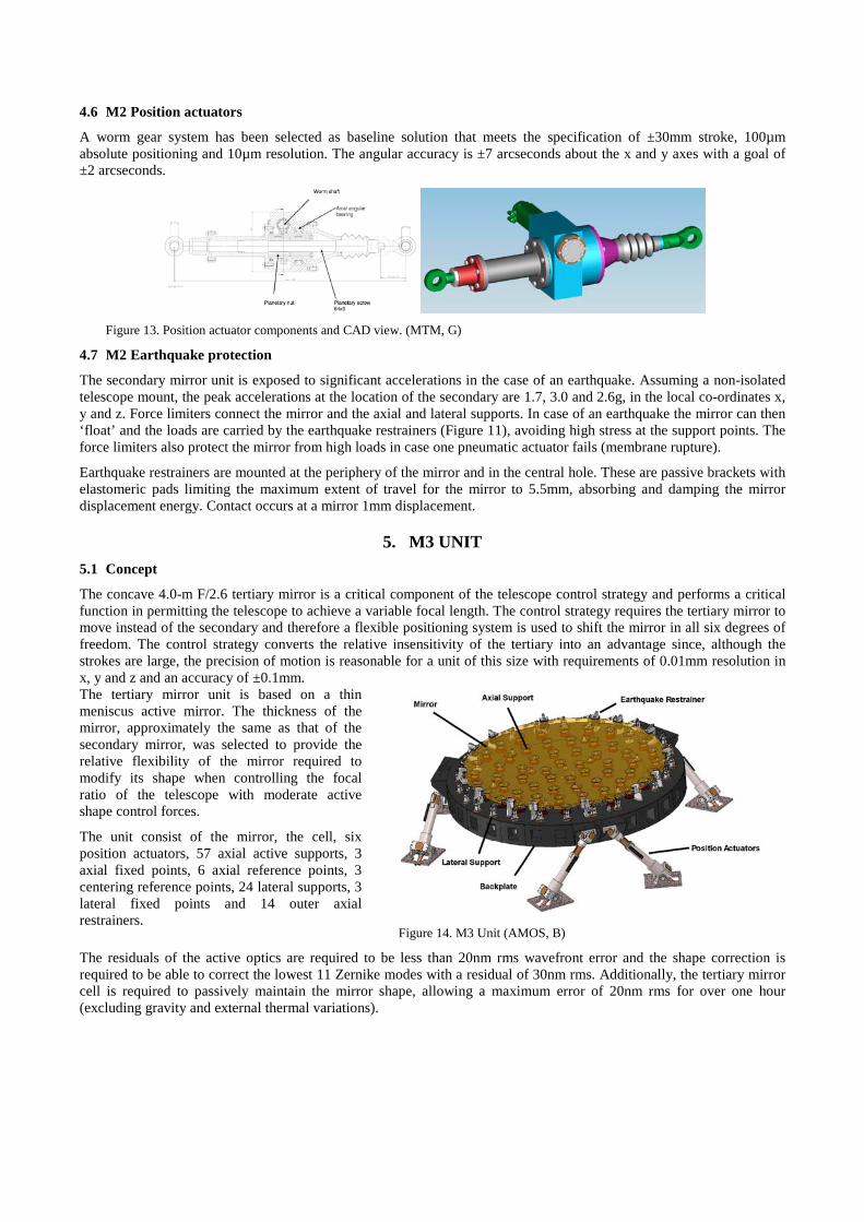
The concave 4.0-m F/2.6 tertiary mirror is a critical component of the telescope control strategy and performs a critical function in permitting the telescope to achieve a variable focal length. The control strategy requires the tertiary mirror to move instead of the secondary and therefore a flexible positioning system is used to shift the mirror in all six degrees of freedom. The control strategy converts the relative insensitivity of the tertiary into an advantage since, although the strokes are large, the precision of motion is reasonable for a unit of this size with requirements of 0.01mm resolution in x, y and z and an accuracy of ±0.1mm. The tertiary mirror unit is based on a thin meniscus active mirror. The thickness of the mirror, approximately the same as that of the secondary mirror, was selected to provide the relative flexibility of the mirror required to modify its shape when controlling the focal ratio of the telescope with moderate active shape control forces.
The unit consist of the mirror, the cell, six position actuators, 57 axial active supports, 3 axial fixed points, 6 axial reference points, 3 centering reference points, 24 lateral supports, 3 lateral fixed points and 14 outer axial restrainers.
Figure 14. M3 Unit (AMOS, B)
The residuals of the active optics are required to be less than 20nm rms wavefront error and the shape correction is required to be able to correct the lowest 11 Zernike modes with a residual of 30nm rms. Additionally, the tertiary mirror cell is required to passively maintain the mirror shape, allowing a maximum error of 20nm rms for over one hour (excluding gravity and external thermal variations).
5.2 Design overview
A first design of the M3 Unit has been developed by AMOS (Figure 14). The mirror cell is a stiff box-like steel structure with a steel plate supported on ribs providing the mounting location for the axial supports that follow the curvature of the back surface of the mirror.
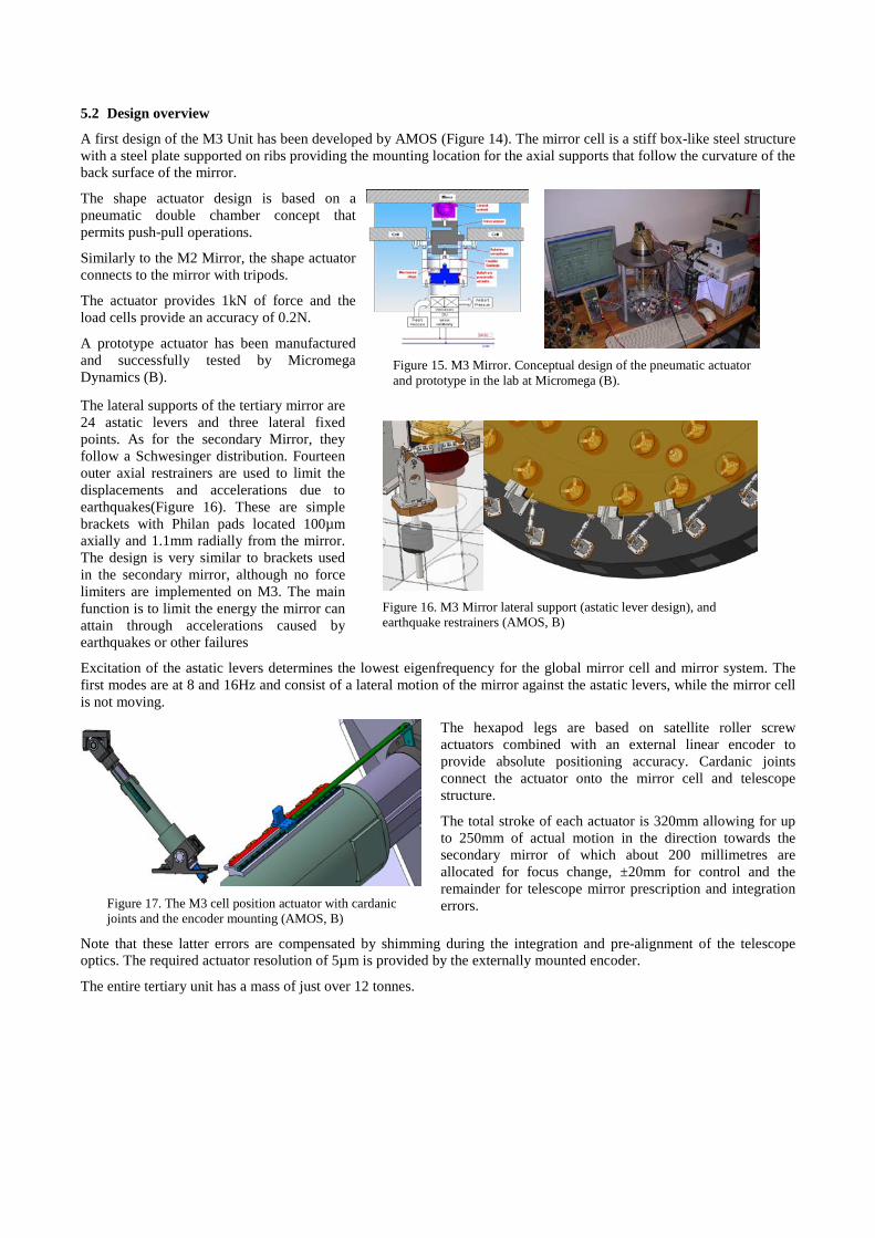
The shape actuator design is based on a pneumatic double chamber concept that permits push-pull operations.
Similarly to the M2 Mirror, the shape actuator connects to the mirror with tripods.
The actuator provides 1kN of force and the load cells provide an accuracy of 0.2N.
A prototype actuator has been manufactured and successfully tested by Micromega Dynamics (B).
Figure 15. M3 Mirror. Conceptual design of the pneumatic actuator and prototype in the lab at Micromega (B).
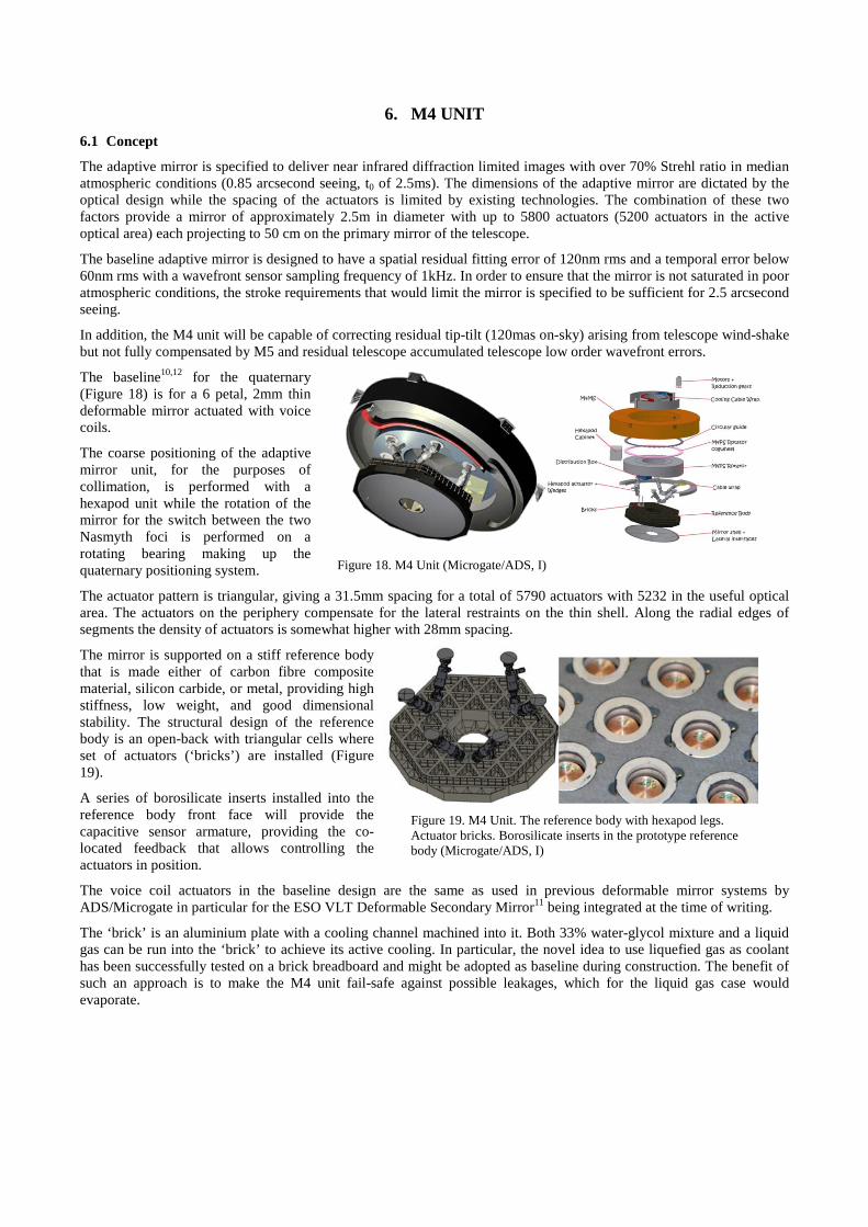
The lateral supports of the tertiary mirror are 24 astatic levers and three lateral fixed points. As for the secondary Mirror, they follow a Schwesinger distribution. Fourteen outer axial restrainers are used to limit the displacements and accelerations due to earthquakes(Figure 16). These are simple brackets with Philan pads located 100µm axially and 1.1mm radially from the mirror. The design is very similar to brackets used in the secondary mirror, although no force limiters are implemented on M3. The main function is to limit the energy the mirror can attain through accelerations caused by earthquakes or other failures
Figure 16. M3 Mirror lateral support (astatic lever design), and earthquake restrainers (AMOS, B)
Excitation of the astatic levers determines the lowest eigenfrequency for the global mirror cell and mirror system. The first modes are at 8 and 16Hz and consist of a lateral motion of the mirror against the astatic levers, while the mirror cell is not moving.
Figure 17. The M3 cell position actuator with cardanic joints and the encoder mounting (AMOS, B)
The hexapod legs are based on satellite roller screw actuators combined with an external linear encoder to provide absolute positioning accuracy. Cardanic joints connect the actuator onto the mirror cell and telescope structure.
The total stroke of each actuator is 320mm allowing for up to 250mm of actual motion in the direction towards the secondary mirror of which about 200 millimetres are allocated for focus change, ±20mm for control and the remainder for telescope mirror prescription and integration errors.
Note that these latter errors are compensated by shimming during the integration and pre-alignment of the telescope optics. The required actuator resolution of 5µm is provided by the externally mounted encoder.
The entire tertiary unit has a mass of just over 12 tonnes.
6. M4 UNIT 6.1 Concept
The adaptive mirror is specified to deliver near infrared diffraction limited images with over 70% Strehl ratio in median atmospheric conditions (0.85 arcsecond seeing, t0 of 2.5ms). The dimensions of the adaptive mirror are dictated by the optical design while the spacing of the actuators is limited by existing technologies. The combination of these two factors provide a mirror of approximately 2.5m in diameter with up to 5800 actuators (5200 actuators in the active optical area) each projecting to 50 cm on the primary mirror of the telescope.
The baseline adaptive mirror is designed to have a spatial residual fitting error of 120nm rms and a temporal error below 60nm rms with a wavefront sensor sampling frequency of 1kHz. In order to ensure that the mirror is not saturated in poor atmospheric conditions, the stroke requirements that would limit the mirror is specified to be sufficient for 2.5 arcsecond seeing.
In addition, the M4 unit will be capable of correcting residual tip-tilt (120mas on-sky) arising from telescope wind-shake but not fully compensated by M5 and residual telescope accumulated telescope low order wavefront errors.
The baseline10,12 for the quaternary (Figure 18) is for a 6 petal, 2mm thin deformable mirror actuated with voice coils.
The coarse positioning of the adaptive mirror unit, for the purposes of collimation, is performed with a hexapod unit while the rotation of the mirror for the switch between the two Nasmyth foci is performed on a rotating bearing making up the quaternary positioning system.
Figure 18. M4 Unit (Microgate/ADS, I)
The actuator pattern is triangular, giving a 31.5mm spacing for a total of 5790 actuators with 5232 in the useful optical area. The actuators on the periphery compensate for the lateral restraints on the thin shell. Along the radial edges of segments the density of actuators is somewhat higher with 28mm spacing.
The mirror is supported on a stiff reference body that is made either of carbon fibre composite material, silicon carbide, or metal, providing high stiffness, low weight, and good dimensional stability. The structural design of the reference body is an open-back with triangular cells where set of actuators (‘bricks’) are installed (Figure 19).
A series of borosilicate inserts installed into the reference body front face will provide the capacitive sensor armature, providing the co-located feedback that allows controlling the actuators in position.
Figure 19. M4 Unit. The reference body with hexapod legs. Actuator bricks. Borosilicate inserts in the prototype reference body (Microgate/ADS, I)
The voice coil actuators in the baseline design are the same as used in previous deformable mirror systems by ADS/Microgate in particular for the ESO VLT Deformable Secondary Mirror11 being integrated at the time of writing.
The ‘brick’ is an aluminium plate with a cooling channel machined into it. Both 33% water-glycol mixture and a liquid gas can be run into the ‘brick’ to achieve its active cooling. In particular, the novel idea to use liquefied gas as coolant has been successfully tested on a brick breadboard and might be adopted as baseline during construction. The benefit of such an approach is to make the M4 unit fail-safe against possible leakages, which for the liquid gas case would evaporate.
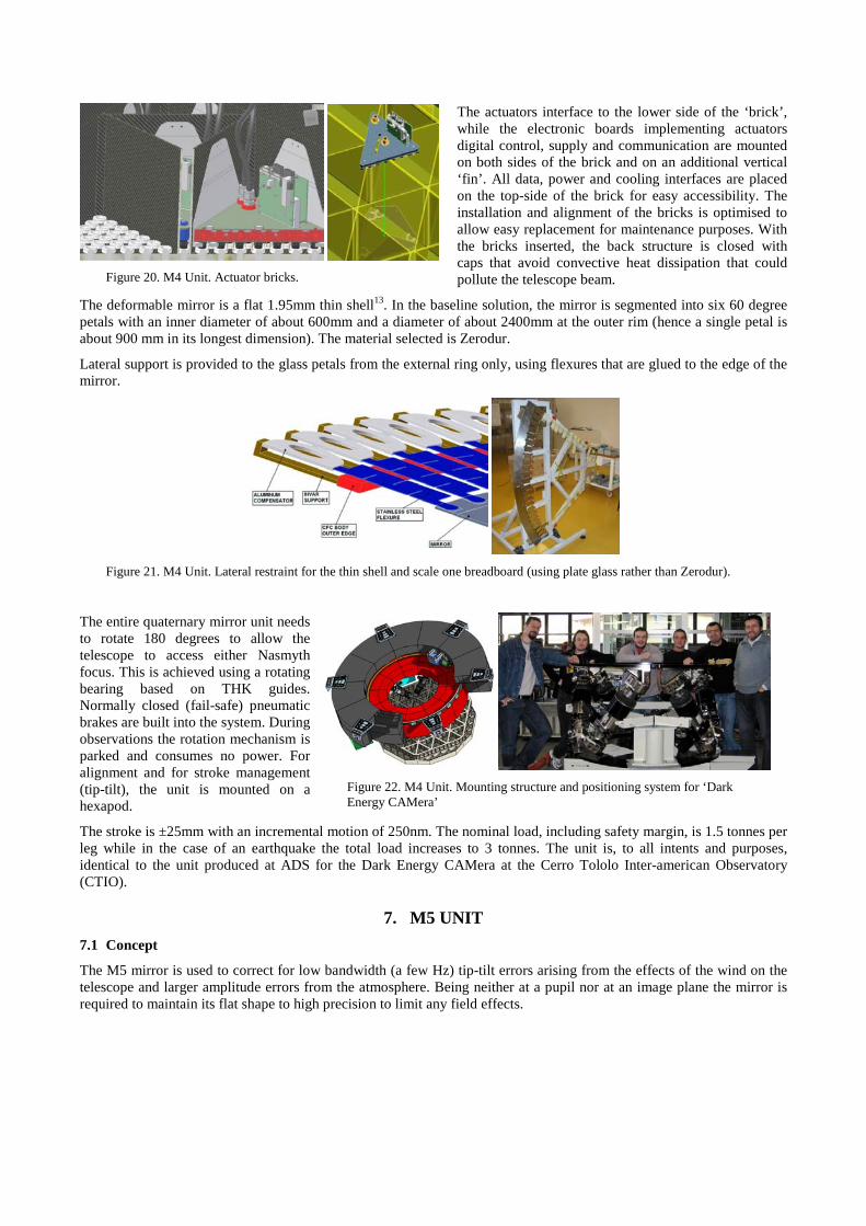
Figure 20. M4 Unit. Actuator bricks.
The actuators interface to the lower side of the ‘brick’, while the electronic boards implementing actuators digital control, supply and communication are mounted on both sides of the brick and on an additional vertical ‘fin’. All data, power and cooling interfaces are placed on the top-side of the brick for easy accessibility. The installation and alignment of the bricks is optimised to allow easy replacement for maintenance purposes. With the bricks inserted, the back structure is closed with caps that avoid convective heat dissipation that could pollute the telescope beam.
The deformable mirror is a flat 1.95mm thin shell13. In the baseline solution, the mirror is segmented into six 60 degree petals with an inner diameter of about 600mm and a diameter of about 2400mm at the outer rim (hence a single petal is about 900 mm in its longest dimension). The material selected is Zerodur.
Lateral support is provided to the glass petals from the external ring only, using flexures that are glued to the edge of the mirror.
Figure 21. M4 Unit. Lateral restraint for the thin shell and scale one breadboard (using plate glass rather than Zerodur).
The entire quaternary mirror unit needs to rotate 180 degrees to allow the telescope to access either Nasmyth focus. This is achieved using a rotating bearing based on THK guides. Normally closed (fail-safe) pneumatic brakes are built into the system. During observations the rotation mechanism is parked and consumes no power. For alignment and for stroke management (tip-tilt), the unit is mounted on a hexapod.
Figure 22. M4 Unit. Mounting structure and positioning system for ‘Dark Energy CAMera’
The stroke is ±25mm with an incremental motion of 250nm. The nominal load, including safety margin, is 1.5 tonnes per leg while in the case of an earthquake the total load increases to 3 tonnes. The unit is, to all intents and purposes, identical to the unit produced at ADS for the Dark Energy CAMera at the Cerro Tololo Inter-american Observatory (CTIO).
7. M5 UNIT 7.1 Concept
The M5 mirror is used to correct for low bandwidth (a few Hz) tip-tilt errors arising from the effects of the wind on the telescope and larger amplitude errors from the atmosphere. Being neither at a pupil nor at an image plane the mirror is required to maintain its flat shape to high precision to limit any field effects.
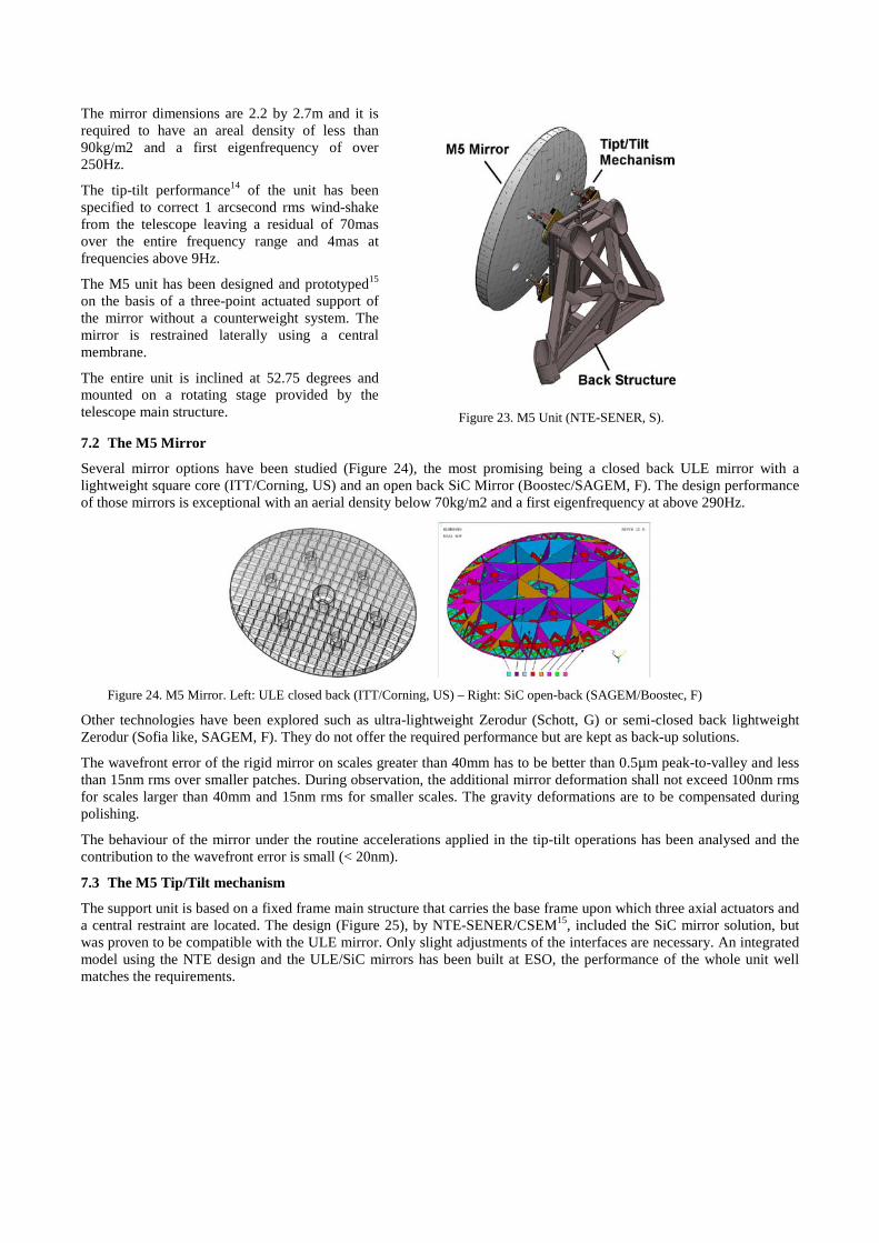
The mirror dimensions are 2.2 by 2.7m and it is required to have an areal density of less than 90kg/m2 and a first eigenfrequency of over 250Hz.
The tip-tilt performance14 of the unit has been specified to correct 1 arcsecond rms wind-shake from the telescope leaving a residual of 70mas over the entire frequency range and 4mas at frequencies above 9Hz.
The M5 unit has been designed and prototyped15 on the basis of a three-point actuated support of the mirror without a counterweight system. The mirror is restrained laterally using a central membrane.
The entire unit is inclined at 52.75 degrees and mounted on a rotating stage provided by the telescope main structure.
Figure 23. M5 Unit (NTE-SENER, S).
7.2 The M5 Mirror
Several mirror options have been studied (Figure 24), the most promising being a closed back ULE mirror with a lightweight square core (ITT/Corning, US) and an open back SiC Mirror (Boostec/SAGEM, F). The design performance of those mirrors is exceptional with an aerial density below 70kg/m2 and a first eigenfrequency at above 290Hz.
Figure 24. M5 Mirror. Left: ULE closed back (ITT/Corning, US) – Right: SiC open-back (SAGEM/Boostec, F)
Other technologies have been explored such as ultra-lightweight Zerodur (Schott, G) or semi-closed back lightweight Zerodur (Sofia like, SAGEM, F). They do not offer the required performance but are kept as back-up solutions.
The wavefront error of the rigid mirror on scales greater than 40mm has to be better than 0.5µm peak-to-valley and less than 15nm rms over smaller patches. During observation, the additional mirror deformation shall not exceed 100nm rms for scales larger than 40mm and 15nm rms for smaller scales. The gravity deformations are to be compensated during polishing.
The behaviour of the mirror under the routine accelerations applied in the tip-tilt operations has been analysed and the contribution to the wavefront error is small (< 20nm).
7.3 The M5 Tip/Tilt mechanism
The support unit is based on a fixed frame main structure that carries the base frame upon which three axial actuators and a central restraint are located. The design (Figure 25), by NTE-SENER/CSEM15, included the SiC mirror solution, but was proven to be compatible with the ULE mirror. Only slight adjustments of the interfaces are necessary. An integrated model using the NTE design and the ULE/SiC mirrors has been built at ESO, the performance of the whole unit well matches the requirements.
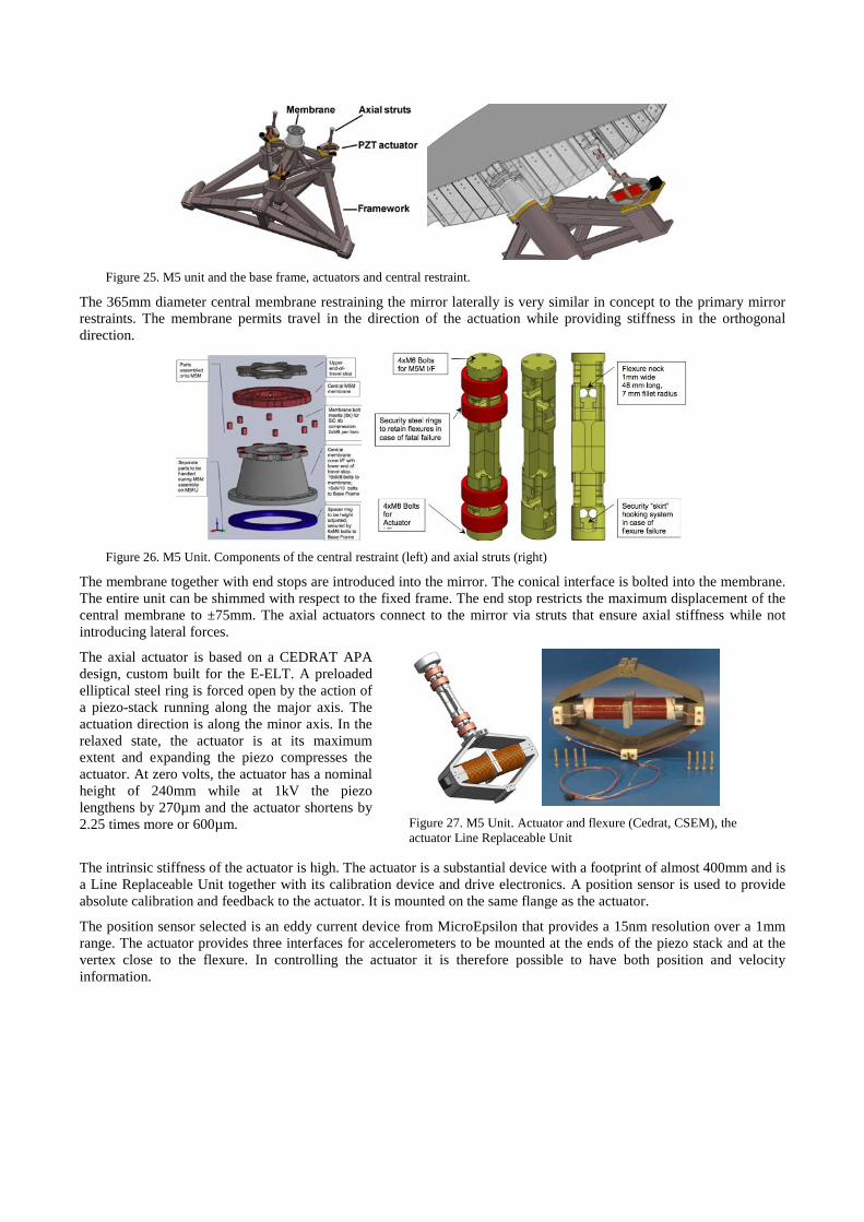
Figure 25. M5 unit and the base frame, actuators and central restraint.
The 365mm diameter central membrane restraining the mirror laterally is very similar in concept to the primary mirror restraints. The membrane permits travel in the direction of the actuation while providing stiffness in the orthogonal direction.
Figure 26. M5 Unit. Components of the central restraint (left) and axial struts (right)
The membrane together with end stops are introduced into the mirror. The conical interface is bolted into the membrane. The entire unit can be shimmed with respect to the fixed frame. The end stop restricts the maximum displacement of the central membrane to ±75mm. The axial actuators connect to the mirror via struts that ensure axial stiffness while not introducing lateral forces.
The axial actuator is based on a CEDRAT APA design, custom built for the E-ELT. A preloaded elliptical steel ring is forced open by the action of a piezo-stack running along the major axis. The actuation direction is along the minor axis. In the relaxed state, the actuator is at its maximum extent and expanding the piezo compresses the actuator. At zero volts, the actuator has a nominal height of 240mm while at 1kV the piezo lengthens by 270µm and the actuator shortens by 2.25 times more or 600µm.
Figure 27. M5 Unit. Actuator and flexure (Cedrat, CSEM), the actuator Line Replaceable Unit
The intrinsic stiffness of the actuator is high. The actuator is a substantial device with a footprint of almost 400mm and is a Line Replaceable Unit together with its calibration device and drive electronics. A position sensor is used to provide absolute calibration and feedback to the actuator. It is mounted on the same flange as the actuator.
The position sensor selected is an eddy current device from MicroEpsilon that provides a 15nm resolution over a 1mm range. The actuator provides three interfaces for accelerometers to be mounted at the ends of the piezo stack and at the vertex close to the flexure. In controlling the actuator it is therefore possible to have both position and velocity information.
The total stroke of each actuator is 0.75mm. The atmospheric contribution to the stroke is very small. The wind rejection dynamic stroke is a fourth of the total stroke. The remaining stroke is used for fine alignment and to compensate for gravity deformations.
8. PRE-FOCAL STATIONS 8.1 Concept
The design concept presented here, developed by AMOS (B), will significantly evolve during construction, as the requirements are being reviewed at the time of writing, following the change from a 42-m to a 39-m E-ELT. The functions are however unchanged so the 42-m is presented as background information.
In common with the VLT, NTT and other ESO telescopes, an adapter is envisaged to hold guide probes in fixed positions with respect to the telescope focal plane and the sky. For the E-ELT, two concentric adapters, one for lasers and one for natural guide stars, are located ahead of the natural focus of the telescope. This provides volume ahead of the focus to divert the full field of the telescope sideways to folded ports.
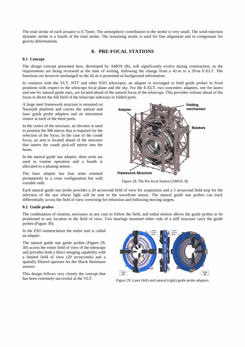
A large steel framework structure is mounted on Nasmyth platform and carries the natural and laser guide probe adapters and an instrument rotator at each of the three ports.
In the centre of the structure, an elevator is used to position the M6 mirror that is required for the selection of the focus. In the case of the coudé focus, an arm is located ahead of the structure that inserts the coudé pick-off mirror into the beam.
In the natural guide star adapter, three arms are used in routine operation and a fourth is allocated to a phasing sensor.
The laser adapter has four arms oriented permanently in a cross configuration but with variable radii.
Figure 28. The Pre-focal Station (AMOS, B)
Each natural guide star probe provides a 20 arcsecond field of view for acquisition and a 3 arcsecond field stop for the selection of the star whose light will be sent to the wavefront sensor. The natural guide star probes can track differentially across the field of view correcting for refraction and following moving targets.
8.2 Guide probes
The combination of rotation, necessary in any case to follow the field, and radial motion allows the guide probes to be positioned in any location in the field of view. Two bearings mounted either side of a stiff structure carry the guide probes (Figure 30).
In the ESO nomenclature the entire unit is called an adapter.
The natural guide star guide probes (Figure 29, 30) access the entire field of view of the telescope and provides both a direct imaging capability with a limited field of view (20 arcseconds) and a spatially filtered aperture for the Shack Hartmann sensors.
This design follows very closely the concept that has been extremely successful at the VLT.
Figure 29. Laser (left) and natural (right) guide probe adapters.
The guide probe is made of aluminium-beryllium alloy, again similar to the VLT, providing the same stiffness as steel at a quarter of the weight. The pick-off mirror is actuated with respect to its normal 45 degree inclination in order to follow the field curvature.
The mechanical dimensions of the probes are significant. The length is just under 1900mm and the pick-off mirror is 230mm in diameter. The mass of the probe is approximately 130kg. The probe is mounted on a stiff plate that is driven in and out of the field of view of the telescope using a translation stage based on a simple track and screw drive system with an accurate encoder.
Figure 30. Natural guide probe (left), laser guide probe (right).
Including the translation stage and electronics, the total mass of each natural guide star probe is approximately 540kg.
The laser guide probes (Figure 29, 30) are configured in a cross pattern without an option for differential rotational motions although they can move differentially in the transverse direction. Each laser guide probe is a substantial optical element, 2040mm long, hosting a 574mm diameter pick-off mirror.
Similarly to the natural guide star the pick-off mirror, tilt can be adjusted. Additionally, the optical train provides two folding mirrors that are located at a pupil and image plane to permit fine adjustments that ensure the residual differential motions of the laser beam relative to the telescope can be compensated (The bulk of the differential tip-tilt is handled by the laser launch system). Volume provision is made for the fast readout electronics of the wavefront sensors and any near-detector computations that may be necessary. The mass of each laser guide probe arm is 1000kg. In terms of mounting and driving, the solutions are almost identical for the laser guide probes as for the natural guide systems but with some simplifications due to the fixed geometry.
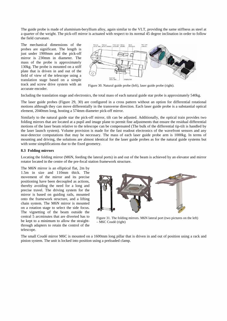
8.3 Folding mirrors
Locating the folding mirror (M6N, feeding the lateral ports) in and out of the beam is achieved by an elevator and mirror rotator located in the centre of the pre-focal station framework structure.
The M6N mirror is an elliptical flat, 2m by 1.5m in size and 110mm thick. The movement of the mirror and its precise positioning have been decoupled as actions, thereby avoiding the need for a long and precise travel. The driving system for the mirror is based on guiding rails, mounted onto the framework structure, and a lifting chain system. The M6N mirror is mounted on a rotation stage to select the side focus. The vignetting of the beam outside the central 5 arcminutes that are diverted has to be kept to a minimum to allow the straight-through adapters to retain the control of the telescope.
Figure 31. The folding mirrors. M6N lateral port (two pictures on the left) – M6C Coudé (right)
The small Coudé mirror M6C is mounted on a 1600mm long pillar that is driven in and out of position using a rack and pinion system. The unit is locked into position using a preloaded clamp.
9. LASER GUIDE STAR UNITS 9.1 Concept
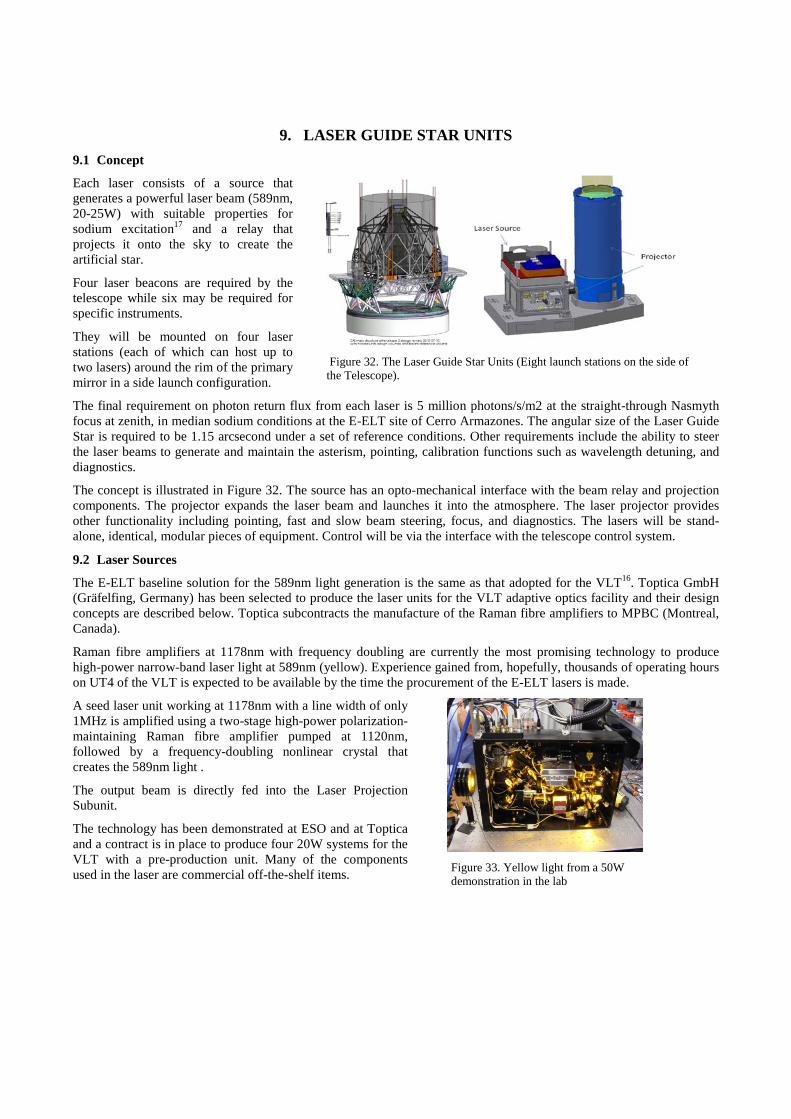
Each laser consists of a source that generates a powerful laser beam (589nm, 20-25W) with suitable properties for sodium excitation17 and a relay that projects it onto the sky to create the artificial star.
Four laser beacons are required by the telescope while six may be required for specific instruments.
They will be mounted on four laser stations (each of which can host up to two lasers) around the rim of the primary mirror in a side launch configuration.
Figure 32. The Laser Guide Star Units (Eight launch stations on the side of the Telescope).
The final requirement on photon return flux from each laser is 5 million photons/s/m2 at the straight-through Nasmyth focus at zenith, in median sodium conditions at the E-ELT site of Cerro Armazones. The angular size of the Laser Guide Star is required to be 1.15 arcsecond under a set of reference conditions. Other requirements include the ability to steer the laser beams to generate and maintain the asterism, pointing, calibration functions such as wavelength detuning, and diagnostics.
The concept is illustrated in Figure 32. The source has an opto-mechanical interface with the beam relay and projection components. The projector expands the laser beam and launches it into the atmosphere. The laser projector provides other functionality including pointing, fast and slow beam steering, focus, and diagnostics. The lasers will be stand-alone, identical, modular pieces of equipment. Control will be via the interface with the telescope control system.
9.2 Laser Sources
The E-ELT baseline solution for the 589nm light generation is the same as that adopted for the VLT16. Toptica GmbH (Gräfelfing, Germany) has been selected to produce the laser units for the VLT adaptive optics facility and their design concepts are described below. Toptica subcontracts the manufacture of the Raman fibre amplifiers to MPBC (Montreal, Canada).
Raman fibre amplifiers at 1178nm with frequency doubling are currently the most promising technology to produce high-power narrow-band laser light at 589nm (yellow). Experience gained from, hopefully, thousands of operating hours on UT4 of the VLT is expected to be available by the time the procurement of the E-ELT lasers is made.
A seed laser unit working at 1178nm with a line width of only 1MHz is amplified using a two-stage high-power polarization-maintaining Raman fibre amplifier pumped at 1120nm, followed by a frequency-doubling nonlinear crystal that creates the 589nm light .
The output beam is directly fed into the Laser Projection Subunit.
The technology has been demonstrated at ESO and at Toptica and a contract is in place to produce four 20W systems for the VLT with a pre-production unit. Many of the components used in the laser are commercial off-the-shelf items.
Figure 33. Yellow light from a 50W demonstration in the lab
The lasers require cooling with stable flow rate and temperature. Each of the lasers will be provided with a separate heat exchanger/cooling module located on the laser station to buffer against pressure and temperature variations of the telescope coolant.
9.3 Laser Launch Subunits
The main requirements are laser beam propagation, beam expansion to an output diameter of 22cm (30cm clear aperture), pointing, large-amplitude slow beam steering, small-amplitude fast beam steering (may be required for GLAO mode of telescope), variable focus control, diagnostics including laser power monitoring, mechanical and structural support, enclosure, stray light control and baffling. The opto-mechanical design is required to be essentially invariant under changing gravity, environmental conditions (particularly temperature and air pressure), and optical power density.
In the baseline design, the main parts are a mechanical structure and enclosure, beam relay and diagnostics, launch telescope, control electronics, and baffle towers.
A design study of the Laser Lunch Subunit was performed during the E-ELT phase B by the UK Astronomy Technology Centre. ESO is also procuring a launch telescope as part of the VLT adaptive optics facility18 currently being manufactured by TNO19 in the Netherlands.
The mechanical structure provides support for the opto-mechanics and a stiff interface for mounting all or part of the Laser Source Sub-Unit. The enclosure provides environmental protection and partially shields the opto-mechanics from external loads, e.g. wind. The enclosure also provides some thermal insulation to reduce heat dissipation in the dome.
The beam relay expands the laser beam diameter, provides variable focus, fast tip/tilt beam steering, and diagnostic functions including laser power.
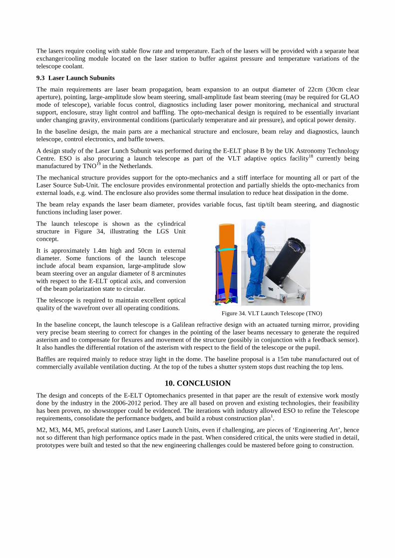
The launch telescope is shown as the cylindrical structure in Figure 34, illustrating the LGS Unit concept.
It is approximately 1.4m high and 50cm in external diameter. Some functions of the launch telescope include afocal beam expansion, large-amplitude slow beam steering over an angular diameter of 8 arcminutes with respect to the E-ELT optical axis, and conversion of the beam polarization state to circular.
The telescope is required to maintain excellent optical quality of the wavefront over all operating conditions.
Figure 34. VLT Launch Telescope (TNO)
In the baseline concept, the launch telescope is a Galilean refractive design with an actuated turning mirror, providing very precise beam steering to correct for changes in the pointing of the laser beams necessary to generate the required asterism and to compensate for flexures and movement of the structure (possibly in conjunction with a feedback sensor). It also handles the differential rotation of the asterism with respect to the field of the telescope or the pupil.
Baffles are required mainly to reduce stray light in the dome. The baseline proposal is a 15m tube manufactured out of commercially available ventilation ducting. At the top of the tubes a shutter system stops dust reaching the top lens.
10. CONCLUSION The design and concepts of the E-ELT Optomechanics presented in that paper are the result of extensive work mostly done by the industry in the 2006-2012 period. They are all based on proven and existing technologies, their feasibility has been proven, no showstopper could be evidenced. The iterations with industry allowed ESO to refine the Telescope requirements, consolidate the performance budgets, and build a robust construction plan1.
M2, M3, M4, M5, prefocal stations, and Laser Launch Units, even if challenging, are pieces of ‘Engineering Art’, hence not so different than high performance optics made in the past. When considered critical, the units were studied in detail, prototypes were built and tested so that the new engineering challenges could be mastered before going to construction.
The M1, with its hundreds of segments and mechanics, thousands of actuators and sensors, represents a new challenge, as the required pieces of ‘Engineering Art’ must be produced in mass. The challenge becomes an industrial one. In order to face it, all components of the M1 have been studied in detail, full scale and full performance prototypes have been built and tested, the manufacturing and assembly processes have been qualified as well, and each time possible by multiple contractors.
The volume of E-ELT high performance optomechanics to be produced is substantial, the challenge has been well prepared, and it is time for industry to take it over.
REFERENCES
[1] The E-ELT Construction Proposal. www.eso.org/public/products/books/e-elt_constrproposal/ [2] Nijenhuis, J. R., " The opto-mechanical performance prediction of thin mirror segments for E-ELT," Proc. SPIE
8450-09 (2012) [3] Cavaller, L., Marrero, J., Castro, J., " Design of the primary mirror segment support system for the E-ELT,"
Proc. SPIE 7012, 70121F (2008) [4] Nijenhuis, J., Hamelinck, R., Braam, B., " Meeting highest performance requirements for lowest price and mass
for the M1 segment support unit for E-ELT," Proc. SPIE 7733, 77332H (2010) [5] Nijenhuis, J., Hamelinck, R., " The optimization of the opto-mechanical performance of the mirror segments for
the E-ELT," Proc. SPIE 8336, 83360H (2011) [6] Jiménez, A., Morante, E., Viera, T., Núñez, M., " Design of a prototype position actuator for the primary mirror
segments of the European Extremely Large Telescope," Proc. SPIE 7733, 773354 (2010) [7] Rodolfo, J., " Prototypes segment polishing and testing for ELT M1," Proc. SPIE 8450-84 (2012) [8] Walker, D., " Edge-control and surface-smoothness in sub-aperture polishing of mirror segments," Proc. SPIE
8450-85 (2012) [9] Dimmler, M., " E-ELT M1 test facility," Proc. SPIE 8444-70 (2012) [10] Vernet, E., Hubin, N., Mueller, M., Biasi, R., Gallieni, D.," Specifications and design of the E-ELT M4
adaptive unit," Proc. SPIE 8447-226 (2012) [11] Biasi, R., " VLT deformable secondary mirror: integration and electromechanical tests results," Proc. SPIE
8447-88 (2012) [12] Spanò, P., Bianco, A., " Optical calibration and testing of the E-ELT M4 adaptive mirror," Proc. SPIE 8447-134
(2012) [13] Poutriquet, F., " Manufacturing of glassy thin shell for adaptive optics: results achieved," Proc. SPIE 8447-89
(2012) [14] Sedghi, B., " Active damping strategies for control of the E-ELT field stabilization mirror," Proc. SPIE 8444-71
(2012) [15] Casalta, J.M., Barriga, J., Ariño, J., Mercader, J., San Andrés, M., Serra, J., Kjelberg, I., " E-ELT M5 field
stabilisation unit scale 1 demonstrator design and performances evaluation," Proc. SPIE 7736, 77360M (2010) [16] Friedenauer, A., Ernstberger, B., Kaenders, W. G., " RFA-based 589-nm guide star lasers for ESO VLT: a
paradigm shift in performance, operational simplicity, reliability, and maintenance," Proc. SPIE 8447-15 (2012) [17] Holzlöhner, R., " Simulations of pulsed sodium laser guide stars: an overview," Proc. SPIE 8447-17 (2012) [18] Arsenault, R., " The ESO adaptive optics facility: integration completed and readiness for system tests," Proc.
SPIE 8447-19 (2012) [19] Henselmans, R., Nijkerk, D., Nijkerk, D., " Design, analysis, and testing of the optical tube assemblies for the
ESO VLT four laser guide star facility," Proc. SPIE 8447-172 (2012)