Embed Size (px)
Citation preview

Dynex Top Running Double Girder Hoist
Capacity Lift Trolley Gauge
Reeving Wire Rope Dia.
Hoist Speed Hoist Motor Trolley Speed Trolley Motor CMAA Service Class
3 Tons
32'-0" 48"
2 PD 10 mm 25 / 6 FPM 4.25 kW 80 / 20 FPM .44 kW D 51'-8" 60"
68'-10" 72"
86'-2" 84"
5 Tons
32'-0" 48"
2 PD 10 mm 25 / 6 FPM 7.8 kW 80 / 20 FPM .44 KW D 51'-8" 60"
68'-10" 72"
86'-2" 84"
7.5 Tons
32'-0" 48"
2 PD 10 mm 20 / 5 FPM 7.8 kW 80 / 20 FPM .44 KW D 51'-8" 60"
68'-10" 72"
86'-2" 84"
10 Tons
20'-0" 48"
3 PD 10 mm 16/ 4 FPM 21/5 FPM
7.8 kW 10.6 kW
80 / 20 FPM .44 KW D 31'-0" 60"
42'-6" 72"
54'-0" 84"
15 Tons 23'-4" 60"
4 PD 10 mm 15 / 4 FPM 15.5 kW 80 / 20 FPM .44 KW D 31'-11" 72"
40'-0" 84"

Specifications
Hoist Brake Motor Inverter duty, 4-pole, AC squirrel cage motor with DC rectified disc brake See motor data sheet (4.25 kW, 7.8 kW, 10.6 kW, 15.5 kW)
Hoist Gearbox
3-stage reduction, parallel helical gears supported on sealed ball bearings Gears and pinions forged from 4140 alloy bar , quenched and tempered Gears and pinions are hobbed, finish ground to AGMA 12 quality and ionitrided to 62+ HRC Output gear machined from a single forging and splined to drive the rope drum Gearcase is precision machined from A356-T6 heat treated aluminum alloy
Mechanical Gear Brake Low maintenance mechanical gear brake provides the primary means of braking
Reeving Double reeved, true vertical lift Wire Rope
Construction (2) 8 X 19S IWRC, COMPAC, 2160, RRL & LRL, galvanized w/button end
Rope Drum
C1026 Cold rolled carbon steel 9” pitch diameter, 24:1 Drum to rope ratio 42% groove depth, right and left hand groove Supported on sealed ball bearing
Trolley Brake Motor Inverter duty, 4-pole, AC squirrel cage motor with DC rectified disc brake See motor data sheet
Trolley gearbox Ground and polished worm gear, lubricated for life Single-piece cast iron housing Tapered roller input bearings
Trolley Dual motor, direct drive, rotating axle design Shock absorbing rubber bumpers and rail sweeps
Trolley Wheels
6 ½” diameter, 2 ½” tread width 100-70-03 graphite ductile, 360 BHN core hardness, ionitrided to 62+ HRC case 10,000 lbs. wheel load Tapered shaft connection
Load Block
Bolted ductile iron frame 100-70-03 graphite ductile iron sheaves, 360 BHN core hardness, ionitrided to 62+HRC case 21:1 sheave to rope ratio Sealed ball bearings Mechanically forged carbon/alloy steel hook mounted on sealed roller bearing for 360° rotation
Hoist VFD Controls
Hitachi WJ 200 variable frequency drive Continuous over weight protection with 2% accuracy 125% motor overload protection 2-step maintained or 2-step infinitely variable speed control
Trolley VFD Controls
Hitachi WJ 200 variable frequency drive 125% motor overload protection Full dynamic braking 2-step maintained or 2-step infinitely variable speed control
Control Panel
UL 508A listed enclosed industrial control panel in NEMA 4 enclosure 110 VAC control voltage (24 VDC optional) Branch circuit protection by UL489 circuit breakers Over-weight bypass switch for load testing 2-step maintained or 2-step infinitely variable selector switch
Limit Switches Adjustable upper and lower hook travel limit Block activated paddle emergency upper limit
Paint High gloss metal finishing enamel direct-to-metal coating Excellent chemical resistance including engine coolant, oil, diesel fuel and unleaded gasoline
MOTOR DATA SHEET Designazione motore /
Motor Designation
DATI TARGA / NAMEPLATE DATA
HBZ 100LB 4 230.460-60 B5 RC00003230
CARATTERISTICHE GENERALI / GENERAL CHARACTERISTICS
Grandezza / Frame size IEC72-1 100LB
Forma costruttiva / Type of construction IEC72-1 IM B5
Massa / Weigth [kg] 30
Momento inerzia / Moment of Inertia [10-4kgm2] J0 0,0072
Grado di protezione / Degree of protection IEC34-5 IP55
HBZ 100LB4 B5 30 F 2 30MIN
YY Y
55 40°C 411
rev.0 01/03/2011 pag.1/2
BZ 15 40 110÷480/50-60 0,26 RM2 103,L
COLLEGAMENTO MOTORE/ MOTOR CONNECTION
L1 L2 L3 L1 L2 L3
DATI ELETTRICI MOTORE / MOTOR ELECTRICAL DATA Report No.2843
Tensione nominale / Rated Voltage (Δ/Y) [V] Vn 230/460
Frequenza nominale / Rated Frequency [Hz] Fn 60
Corrente nominale / Rated Current (Δ/Y) [A] In 16 / 8
Potenza nominale / rated output power [kW]-[HP]
Fattore di servizio / Service Factor
Pn
SF
4,25- 5,7
1,0
Velocità nominale / rated speed [min-1] Nn 1700
Coppia nominale / Rated Torque [Nm] Mn 23,9
Senso di rotazione / direction of rotation Entrambi / Both
Metodo raffreddamento / method of cooling IEC34-7 IC411
Servizio / Duty IEC34-1 S2 30MIN
Classe Isolamento / Insulation class IEC34-1 F
Temperatura ambiente / ambient temperature -20 / +40°C
DIAGRAMMA COPPIA VELOCITA’ / TORQUE-SPEED DIAGRAM
DIMENSIONI GENERALI / GENERAL DIMENSIONS
AC Ø194 KK(1) 2x(M25+M16)
AD 151 R 106
L 465 V 82
LB 405 W 142
LC 533 W1 43
LD 136 Z 86
Z1 160
230 / 460 60 16 / 8 4,25 1700 0,80YY Y
NEMA MG1-12
NOM.EFF. 85,5% 5,7HP SF1,0 DES.C CODE G
•opzionale con esecuzione speciale ,L / optional with non-standard execution ,L
YY YT4 T5 T6 T4 T5 T6
T7 T8 T9 T7 T8 T9
T1 T2 T3 T1 T2 T3
Fattore di potenza nominale / Rated power factor [%] cosϕn 0,80
Rendimento nominale / Rated Effciency (2) [%] ηn85,5
Rapporto coppia di spunto / Starting torque ratio Ms/Mn 2,2
Rapporto coppia massima / Pull-out torque ratio Mmax/Mn 2,5
Rapporto corrente di spunto / Starting current ratio Is/In 5,0
NEMA Design - C
Locked Rotor Code Letter KVA - G
Resistenza statore a 25°C/Stator Resistance at 25°C [Ω] R1 1,6
Sovratemperatura avvolgimenti a 25°C /
Windings overtemperature at 25°C [°C]ΔT 66,1
Classe di efficienza / Efficiency Class
secondo/ according IEC EN60034-30, IEC EN60034-2-1- -
DIMENSIONI ESTREMITA’ ALBERO /
SHAFT END DIMENSIONS
D DA 28j6 M10
E EA 60
F FA 8
GA GC 31
DIMENSIONI FLANGIA /
FLANGE DIMENSIONS
M Ø215
N Ø180j6
P Ø250
LA 14
S 14
T 4
CUSCINETTI / BEARINGS
DE 6206 2Z
NDE 6206 2RS
1) Predisposizione per accesso cavi su entrambi i lati (due fratture
prestabilite per ogni lato) / Prearranged for cable entry knockout
openings on both sides (two openings on each side)
2) Calcolo efficienza per somma delle perdite, grado incertezza basso
secondo IEC/EN 60034-2-1/ Calculation of efficiency through summation
of losses, low uncertainty, according IEC/EN 60034-2-1
DATI FRENO / BRAKE DATA
Modello freno / Brake Model BZ 15
Momento frenante / Brake Moment [Nm] Mf 40
Tensione bobina freno c.c./
Brake d.c. coil voltage [V]Vcc 103
Corrente freno / brake current [A] Icc 0,26
Raddrizzatore / Bridge rectifier RM2Tensione in ingresso a.c. /
Designazione motore /
Motor DesignationMOTOR DATA SHEET
rev.0 01/03/2011 pag.2/2
ALTRE ESECUZIONI SPECIALI E ACCESSORI /
OTHER NON STANDARD DESIGN AND ACCESSORIES
Leva di sblocco manuale con ritorno automatico /
Lever for manual release with automatic return,L -
- - -
- - -
- - -
HBZ 100LB 4 230.460-60 B5 RC00003230
Tensione in ingresso a.c. /
Input a.c. voltage [V]Vac 110÷480
Ritardo di sblocco / Delay of release [ms] t1 63
Ritardo di frenatura / Delay of braking 5) [ms]t2
T2cc
220
15
Traferro/ Airgap [mm]Snom
Smax
0,30
0,45
Lavoro di attrito / Friction work 6) [MJ/mm] W1 160
Massimo consumo disco freno /
Maximum brake disc wear [mm]Cmax 5
Massimo lavoro di attrito per frenatura
(frenature/h) / Max. friction work for each
braking (brakings/h) [MJ/mm]
Wmax
10000 (10)
2500 (10²)
355 (10³)
- - -
- - -
- - -
* Il contattore di alimentazione freno deve lavorare in parallelo con il contattore di
alimentazione del motore; i contatti devono essere idonei all’apertura di carichi
fortemente induttivi / Brake supply contactor should work in parallel with motor
supply contactor; the contacts should be suitable to open very inductive loads.
1) Bobina freno, già collegata al raddrizzatore all’atto della fornitura / Brake coil supplied already connected to
rectifier.2) Linea separata / Separate supply.3) Morsettiera motore / Motor terminal block.4) Il collegamento motore diventa (U1)(U2) per tensione nominale alimentazione ≥500V / For nominal supply
voltage ≥500V the connected motor terminals become (U1)(U2).5) Ritardo di frenatura ottenuto con alimentazione separata freno e disinserzione dal lato c.a. del raddrizzatore (t2)
o dal lato c.a. e c.c. (t22). Con alimentazione diretta da morsettiera motore, i valori di t2 aumentano di circa 2,5
volte quelli di tabella. / Braking delay obtained by separate brake supply and coil disconnection on a.c. side of
rectifier (t2) or on a.c. and d.c. side (t22); with direct supply from motor terminal block, the values of t2 increase
approximately 2,5 times the ones of table.6) Lavoro di attrito per usura disco freno 1mm. (valore minimo per impegno gravoso, il valore reale è normalmente
superiore) / Friction work for brake disc wear 1mm. (minimum value for heavy duty, real value is usually greater
supply contactor; the contacts should be suitable to open very inductive loads.
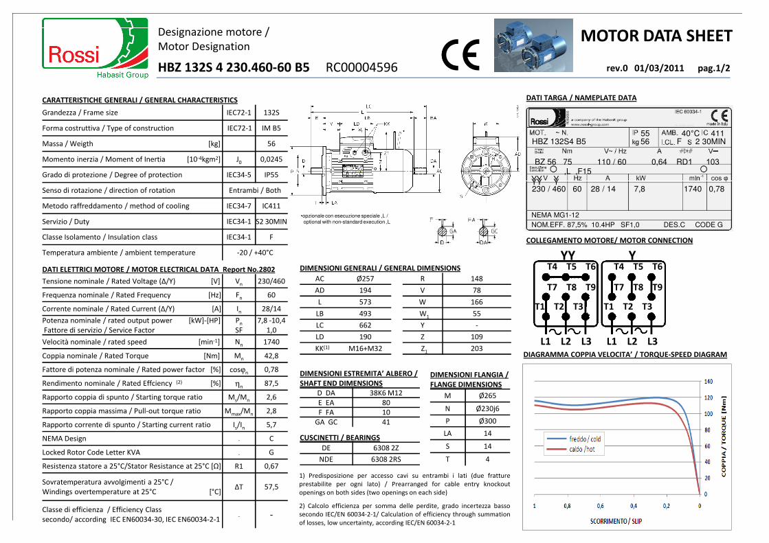
MOTOR DATA SHEET Designazione motore /
Motor Designation
DATI TARGA / NAMEPLATE DATA
HBZ 132S 4 230.460-60 B5 RC00004596
CARATTERISTICHE GENERALI / GENERAL CHARACTERISTICS
Grandezza / Frame size IEC72-1 132S
Forma costruttiva / Type of construction IEC72-1 IM B5
Massa / Weigth [kg] 56
Momento inerzia / Moment of Inertia [10-4kgm2] J0 0,0245
Grado di protezione / Degree of protection IEC34-5 IP55
HBZ 132S4 B5 56 F 2 30MIN
YY Y
55 40°C 411
rev.0 01/03/2011 pag.1/2
BZ 56 75 110 / 60 0,64 RD1 103,L ,F15
COLLEGAMENTO MOTORE/ MOTOR CONNECTION
L1 L2 L3 L1 L2 L3
Senso di rotazione / direction of rotation Entrambi / Both
Metodo raffreddamento / method of cooling IEC34-7 IC411
Servizio / Duty IEC34-1 S2 30MIN
Classe Isolamento / Insulation class IEC34-1 F
Temperatura ambiente / ambient temperature -20 / +40°C
DIAGRAMMA COPPIA VELOCITA’ / TORQUE-SPEED DIAGRAM
230 / 460 60 28 / 14 7,8 1740 0,78YY Y
NEMA MG1-12
NOM.EFF. 87,5% 10.4HP SF1,0 DES.C CODE G
•opzionale con esecuzione speciale ,L / optional with non-standard execution ,L
YY YT4 T5 T6 T4 T5 T6
T7 T8 T9 T7 T8 T9
T1 T2 T3 T1 T2 T3
DATI ELETTRICI MOTORE / MOTOR ELECTRICAL DATA Report No.2802
Tensione nominale / Rated Voltage (Δ/Y) [V] Vn 230/460
Frequenza nominale / Rated Frequency [Hz] Fn 60
Corrente nominale / Rated Current (Δ/Y) [A] In 28/14
Potenza nominale / rated output power [kW]-[HP]
Fattore di servizio / Service Factor
Pn
SF
7,8 -10,4
1,0
Velocità nominale / rated speed [min-1] Nn 1740
Coppia nominale / Rated Torque [Nm] Mn 42,8
DIMENSIONI GENERALI / GENERAL DIMENSIONS
AC Ø257 R 148
AD 194 V 78
L 573 W 166
LB 493 W1 55
LC 662 Y -
LD 190 Z 109
KK(1) M16+M32 Z1 203
1) Predisposizione per accesso cavi su entrambi i lati (due fratture
prestabilite per ogni lato) / Prearranged for cable entry knockout
openings on both sides (two openings on each side)
2) Calcolo efficienza per somma delle perdite, grado incertezza basso
secondo IEC/EN 60034-2-1/ Calculation of efficiency through summation
of losses, low uncertainty, according IEC/EN 60034-2-1
Fattore di potenza nominale / Rated power factor [%] cosϕn 0,78
Rendimento nominale / Rated Effciency (2) [%] ηn87,5
Rapporto coppia di spunto / Starting torque ratio Ms/Mn 2,6
Rapporto coppia massima / Pull-out torque ratio Mmax/Mn 2,8
Rapporto corrente di spunto / Starting current ratio Is/In 5,7
NEMA Design - C
Locked Rotor Code Letter KVA - G
Resistenza statore a 25°C/Stator Resistance at 25°C [Ω] R1 0,67
Sovratemperatura avvolgimenti a 25°C /
Windings overtemperature at 25°C [°C]ΔT 57,5
Classe di efficienza / Efficiency Class
secondo/ according IEC EN60034-30, IEC EN60034-2-1- -
DIMENSIONI ESTREMITA’ ALBERO /
SHAFT END DIMENSIONS
D DA 38K6 M12
E EA 80
F FA 10
GA GC 41
CUSCINETTI / BEARINGS
DE 6308 2Z
NDE 6308 2RS
DIMENSIONI FLANGIA /
FLANGE DIMENSIONS
M Ø265
N Ø230j6
P Ø300
LA 14
S 14
T 4

Designazione motore /
Motor DesignationMOTOR DATA SHEET
rev.0 01/03/2011 pag.2/2
ALTRE ESECUZIONI SPECIALI E ACCESSORI /
OTHER NON STANDARD DESIGN AND ACCESSORIES
Leva di sblocco manuale con ritorno automatico /
Lever for manual release with automatic return,L -
Tensione speciale alimentazione freno c.c. /
Non-Standard voltage d.c. brake supply,F15 110Vac
- - -
- - -
HBZ 132S 4 230.460-60 B5 RC00004596
DATI FRENO / BRAKE DATA
Modello freno / Brake Model BZ 56
Momento frenante / Brake Moment [Nm] Mf 75
Tensione bobina freno c.c./
Brake d.c. coil voltage [V]Vcc 103
Corrente freno / brake current [A] Icc 0,64
Raddrizzatore / Bridge rectifier RD1Tensione in ingresso a.c. / - - -
- - -
- - -
* Il contattore di alimentazione freno deve lavorare in parallelo con il contattore di
alimentazione del motore; i contatti devono essere idonei all’apertura di carichi
fortemente induttivi / Brake supply contactor should work in parallel with motor
supply contactor; the contacts should be suitable to open very inductive loads.
Tensione in ingresso a.c. /
Input a.c. voltage [V]Vac 110
Ritardo di sblocco / Delay of release [ms] t1 90
Ritardo di frenatura / Delay of braking 4) [ms]t2
T2cc
224
20
Traferro/ Airgap [mm]Snom
Smax
0,35
0,55
Lavoro di attrito / Friction work 5) [MJ/mm] W1 224
Massimo consumo disco freno /
Maximum brake disc wear [mm]Cmax 4,5
Massimo lavoro di attrito per frenatura
(frenature/h) / Max. friction work for each
braking (brakings/h) [MJ/mm]
Wmax
14000 (10)
3550 (10²)
500 (10³)
1) Bobina freno, già collegata al raddrizzatore all’atto della fornitura / Brake coil supplied already connected to
rectifier.2) Linea separata / Separate supply.3) Morsettiera motore / Motor terminal block.4) Ritardo di frenatura ottenuto con alimentazione separata freno e disinserzione dal lato c.a. del raddrizzatore (t2)
o dal lato c.a. e c.c. (t22). Con alimentazione diretta da morsettiera motore, i valori di t2 aumentano di circa 2,5
volte quelli di tabella. / Braking delay obtained by separate brake supply and coil disconnection on a.c. side of
rectifier (t2) or on a.c. and d.c. side (t22); with direct supply from motor terminal block, the values of t2 increase
approximately 2,5 times the ones of table.5) Lavoro di attrito per usura disco freno 1mm. (valore minimo per impegno gravoso, il valore reale è normalmente
superiore) / Friction work for brake disc wear 1mm. (minimum value for heavy duty, real value is usually greater
supply contactor; the contacts should be suitable to open very inductive loads.

MOTOR DATA SHEET Designazione motore /
Motor Designation
DATI TARGA / NAMEPLATE DATA
HBZ 132M 4 230.460-60 B5 RC00004595
CARATTERISTICHE GENERALI / GENERAL CHARACTERISTICS
Grandezza / Frame size IEC72-1 132M
Forma costruttiva / Type of construction IEC72-1 IM B5
Massa / Weigth [kg] 65
Momento inerzia / Moment of Inertia [10-4kgm2] J0 0,033
Grado di protezione / Degree of protection IEC34-5 IP55
HBZ 132M4 B5 65 F 2 30MIN
YY Y
55 40°C 411
rev.0 01/03/2011 pag.1/2
BZ 06 100 110 / 60 0,64 RD1 103,L
COLLEGAMENTO MOTORE/ MOTOR CONNECTION
L1 L2 L3 L1 L2 L3
Senso di rotazione / direction of rotation Entrambi / Both
Metodo raffreddamento / method of cooling IEC34-7 IC411
Servizio / Duty IEC34-1 S2 30MIN
Classe Isolamento / Insulation class IEC34-1 F
Temperatura ambiente / ambient temperature -20 / +40°C
DIAGRAMMA COPPIA VELOCITA’ / TORQUE-SPEED DIAGRAM
230 / 460 60 37,2/18,6 10,6 1730 0,84YY Y
NEMA MG1-12
NOM.EFF. 87,5% 14,2HP SF1,0 DES.C CODE H
•opzionale con esecuzione speciale ,L / optional with non-standard execution ,L
YY YT4 T5 T6 T4 T5 T6
T7 T8 T9 T7 T8 T9
T1 T2 T3 T1 T2 T3
DATI ELETTRICI MOTORE / MOTOR ELECTRICAL DATA Report No.2778
Tensione nominale / Rated Voltage (Δ/Y) [V] Vn 230/460
Frequenza nominale / Rated Frequency [Hz] Fn 60
Corrente nominale / Rated Current (Δ/Y) [A] In 37,2/18,6
Potenza nominale / rated output power [kW]-[HP]
Fattore di servizio / Service Factor
Pn
SF
10,6-14,2
1,0
Velocità nominale / rated speed [min-1] Nn 1730
Coppia nominale / Rated Torque [Nm] Mn 58,5
DIMENSIONI GENERALI / GENERAL DIMENSIONS
AC Ø257 R 148
AD 194 V 78
L 573 W 166
LB 493 W1 55
LC 662 Y -
LD 190 Z 109
KK(1) M16+M32 Z1 203
1) Predisposizione per accesso cavi su entrambi i lati (due fratture
prestabilite per ogni lato) / Prearranged for cable entry knockout
openings on both sides (two openings on each side)
2) Calcolo efficienza per somma delle perdite, grado incertezza basso
secondo IEC/EN 60034-2-1/ Calculation of efficiency through summation
of losses, low uncertainty, according IEC/EN 60034-2-1
Fattore di potenza nominale / Rated power factor [%] cosϕn 0,84
Rendimento nominale / Rated Effciency (2) [%] ηn87,5
Rapporto coppia di spunto / Starting torque ratio Ms/Mn 2,7
Rapporto coppia massima / Pull-out torque ratio Mmax/Mn 2,9
Rapporto corrente di spunto / Starting current ratio Is/In 5,8
NEMA Design - C
Locked Rotor Code Letter KVA - H
Resistenza statore a 25°C/Stator Resistance at 25°C [Ω] R1 0,46
Sovratemperatura avvolgimenti a 25°C /
Windings overtemperature at 25°C [°C]ΔT 65,6
Classe di efficienza / Efficiency Class
secondo/ according IEC EN60034-30, IEC EN60034-2-1- -
DIMENSIONI ESTREMITA’ ALBERO /
SHAFT END DIMENSIONS
D DA 38K6 M12
E EA 80
F FA 10
GA GC 41
CUSCINETTI / BEARINGS
DE 6308 2Z
NDE 6308 2RS
DIMENSIONI FLANGIA /
FLANGE DIMENSIONS
M Ø265
N Ø230j6
P Ø300
LA 14
S 14
T 4
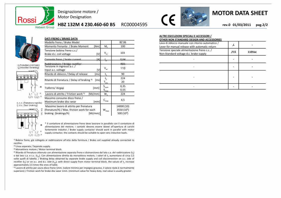
Designazione motore /
Motor DesignationMOTOR DATA SHEET
rev.0 01/03/2011 pag.2/2
ALTRE ESECUZIONI SPECIALI E ACCESSORI /
OTHER NON STANDARD DESIGN AND ACCESSORIES
Leva di sblocco manuale con ritorno automatico /
Lever for manual release with automatic return,L -
Tensione speciale alimentazione freno c.c. /
Non-Standard voltage d.c. brake supply,F15 110Vac
- - -
- - -
HBZ 132M 4 230.460-60 B5 RC00004595
DATI FRENO / BRAKE DATA
Modello freno / Brake Model BZ 06
Momento frenante / Brake Moment [Nm] Mf 100
Tensione bobina freno c.c./
Brake d.c. coil voltage [V] Vcc 103
Corrente freno / brake current [A] Icc 0,64
Raddrizzatore / Bridge rectifier RD1Tensione in ingresso a.c. / - - -
- - -
- - -
* Il contattore di alimentazione freno deve lavorare in parallelo con il contattore di
alimentazione del motore; i contatti devono essere idonei all’apertura di carichi
fortemente induttivi / Brake supply contactor should work in parallel with motor
supply contactor; the contacts should be suitable to open very inductive loads.
Tensione in ingresso a.c. /
Input a.c. voltage [V]Vac 110
Ritardo di sblocco / Delay of release [ms] t1 90
Ritardo di frenatura / Delay of braking 4) [ms]t2
T2cc
224
20
Traferro/ Airgap [mm]Snom
Smax
0,35
0,55
Lavoro di attrito / Friction work 5) [MJ/mm] W1 224
Massimo consumo disco freno /
Maximum brake disc wear [mm]Cmax 4,5
Massimo lavoro di attrito per frenatura
(frenature/h) / Max. friction work for each
braking (brakings/h) [MJ/mm]
Wmax
14000 (10)
3550 (10²)
500 (10³)
1) Bobina freno, già collegata al raddrizzatore all’atto della fornitura / Brake coil supplied already connected to
rectifier.2) Linea separata / Separate supply.3) Morsettiera motore / Motor terminal block.4) Ritardo di frenatura ottenuto con alimentazione separata freno e disinserzione dal lato c.a. del raddrizzatore (t2)
o dal lato c.a. e c.c. (t22). Con alimentazione diretta da morsettiera motore, i valori di t2 aumentano di circa 2,5
volte quelli di tabella. / Braking delay obtained by separate brake supply and coil disconnection on a.c. side of
rectifier (t2) or on a.c. and d.c. side (t22); with direct supply from motor terminal block, the values of t2 increase
approximately 2,5 times the ones of table.5) Lavoro di attrito per usura disco freno 1mm. (valore minimo per impegno gravoso, il valore reale è normalmente
superiore) / Friction work for brake disc wear 1mm. (minimum value for heavy duty, real value is usually greater
supply contactor; the contacts should be suitable to open very inductive loads.

MOTOR DATA SHEET Designazione motore /
Motor Designation
DATI TARGA / NAMEPLATE DATA
HBZ 132MC 4 230.460-60 B5 RC00004597
CARATTERISTICHE GENERALI / GENERAL CHARACTERISTICS
Grandezza / Frame size IEC72-1 132MC
Forma costruttiva / Type of construction IEC72-1 IM B5
Massa / Weigth [kg] 78
Momento inerzia / Moment of Inertia [10-4kgm2] J0 0,0455
Grado di protezione / Degree of protection IEC34-5 IP55
HBZ 132MC4 B5 78 F 2 30MIN
YY Y
55 40°C 411
rev.0 01/03/2011 pag.1/2
BZ 07 150 110 / 60 .64 RD1 103,L ,F15
COLLEGAMENTO MOTORE/ MOTOR CONNECTION
L1 L2 L3 L1 L2 L3
Senso di rotazione / direction of rotation Entrambi / Both
Metodo raffreddamento / method of cooling IEC34-7 IC411
Servizio / Duty IEC34-1 S2 30MIN
Classe Isolamento / Insulation class IEC34-1 F
Temperatura ambiente / ambient temperature -20 / +40°C
DIAGRAMMA COPPIA VELOCITA’ / TORQUE-SPEED DIAGRAM
230 / 460 60 58 / 29 15,6 1740 0,82YY Y
NEMA MG1-12
NOM.EFF. 89,5% 20,9HP SF1,0 DES.C CODE H
•opzionale con esecuzione speciale ,L / optional with non-standard execution ,L
YY YT4 T5 T6 T4 T5 T6
T7 T8 T9 T7 T8 T9
T1 T2 T3 T1 T2 T3
DATI ELETTRICI MOTORE / MOTOR ELECTRICAL DATA Report No.2806
Tensione nominale / Rated Voltage (Δ/Y) [V] Vn 230/460
Frequenza nominale / Rated Frequency [Hz] Fn 60
Corrente nominale / Rated Current (Δ/Y) [A] In 58/29
Potenza nominale / rated output power [kW]-[HP]
Fattore di servizio / Service Factor
Pn
SF
15,6-20,9
1,0
Velocità nominale / rated speed [min-1] Nn 1740
Coppia nominale / Rated Torque [Nm] Mn 85,6
DIMENSIONI GENERALI / GENERAL DIMENSIONS
AC Ø257 R 148
AD 194 V 138
L 633 W 226
LB 553 W1 55
LC 722 Y -
LD 190 Z 109
KK(1) M16+M32 Z1 226
1) Predisposizione per accesso cavi su entrambi i lati (due fratture
prestabilite per ogni lato) / Prearranged for cable entry knockout
openings on both sides (two openings on each side)
2) Calcolo efficienza per somma delle perdite, grado incertezza basso
secondo IEC/EN 60034-2-1/ Calculation of efficiency through summation
of losses, low uncertainty, according IEC/EN 60034-2-1
Fattore di potenza nominale / Rated power factor [%] cosϕn 0,82
Rendimento nominale / Rated Effciency (2) [%] ηn89,5
Rapporto coppia di spunto / Starting torque ratio Ms/Mn 2,7
Rapporto coppia massima / Pull-out torque ratio Mmax/Mn 2,9
Rapporto corrente di spunto / Starting current ratio Is/In 5,8
NEMA Design - C
Locked Rotor Code Letter KVA - H
Resistenza statore a 25°C/Stator Resistance at 25°C [Ω] R1 0,29
Sovratemperatura avvolgimenti a 25°C /
Windings overtemperature at 25°C [°C]ΔT 58,8
Classe di efficienza / Efficiency Class
secondo/ according IEC EN60034-30, IEC EN60034-2-1- -
DIMENSIONI ESTREMITA’ ALBERO /
SHAFT END DIMENSIONS
D DA 38K6 M12
E EA 80
F FA 10
GA GC 41
CUSCINETTI / BEARINGS
DE 6308 2Z
NDE 6308 2RS
DIMENSIONI FLANGIA /
FLANGE DIMENSIONS
M Ø265
N Ø230j6
P Ø300
LA 14
S 14
T 4

Designazione motore /
Motor DesignationMOTOR DATA SHEET
rev.0 01/03/2011 pag.2/2
ALTRE ESECUZIONI SPECIALI E ACCESSORI /
OTHER NON STANDARD DESIGN AND ACCESSORIES
Leva di sblocco manuale con ritorno automatico /
Lever for manual release with automatic return,L -
Tensione speciale alimentazione freno c.c. /
Non-Standard voltage d.c. brake supply,F15 110Vac
- - -
- - -
HBZ 132MC 4 230.460-60 B5 RC00004597
DATI FRENO / BRAKE DATA
Modello freno / Brake Model BZ 07
Momento frenante / Brake Moment [Nm] Mf 150
Tensione bobina freno c.c./
Brake d.c. coil voltage [V]Vcc 103
Corrente freno / brake current [A] Icc .64Raddrizzatore / Bridge rectifier RD1Tensione in ingresso a.c. / - - -
- - -
- - -
* Il contattore di alimentazione freno deve lavorare in parallelo con il contattore di
alimentazione del motore; i contatti devono essere idonei all’apertura di carichi
fortemente induttivi / Brake supply contactor should work in parallel with motor
supply contactor; the contacts should be suitable to open very inductive loads.
Tensione in ingresso a.c. /
Input a.c. voltage [V]Vac 110
Ritardo di sblocco / Delay of release [ms] t1 125
Ritardo di frenatura / Delay of braking 4) [ms]t2
T2cc
280
25
Traferro/ Airgap [mm]Snom
Smax
0,40
0,60
Lavoro di attrito / Friction work 5) [MJ/mm] W1 315
Massimo consumo disco freno /
Maximum brake disc wear [mm]Cmax 4,5
Massimo lavoro di attrito per frenatura
(frenature/h) / Max. friction work for each
braking (brakings/h) [MJ/mm]
Wmax
20000 (10)
5000 (10²)
710 (10³)
1) Bobina freno, già collegata al raddrizzatore all’atto della fornitura / Brake coil supplied already connected to
rectifier.2) Linea separata / Separate supply.3) Morsettiera motore / Motor terminal block.4) Ritardo di frenatura ottenuto con alimentazione separata freno e disinserzione dal lato c.a. del raddrizzatore (t2)
o dal lato c.a. e c.c. (t22). Con alimentazione diretta da morsettiera motore, i valori di t2 aumentano di circa 2,5
volte quelli di tabella. / Braking delay obtained by separate brake supply and coil disconnection on a.c. side of
rectifier (t2) or on a.c. and d.c. side (t22); with direct supply from motor terminal block, the values of t2 increase
approximately 2,5 times the ones of table.5) Lavoro di attrito per usura disco freno 1mm. (valore minimo per impegno gravoso, il valore reale è normalmente
superiore) / Friction work for brake disc wear 1mm. (minimum value for heavy duty, real value is usually greater
supply contactor; the contacts should be suitable to open very inductive loads.
Ionitriding®
Ionitriding® (Ion Nitriding or Plasma Nitriding) is a method of surface hardening producing nitrided cases, using the glow discharge technology to generate nitrogen ions to the surface of a metallic part for diffusion. This process is done in a vacuum vessel at low temperatures (750°-1040°F or 400°-560°C) and can be applied to any ferrous metal.
Increases surface hardness at values of 60-65 HRC and higher.•Improves resistance to wear, fatigue and corrosion.•Lowers coefficient of friction (typical 0.10 against steel)•Increases resistance against crack initiation, erosion and corrosion due to compressed stressesinduced by the Ionitriding process and compact formation of hard nitrided layers (case depths upto 0.025" or 0.6mm deep)
•
Advanced stress relieving in the same process.•Offers a final product ready for use with virtually no distortion, due to lower processingtemperatures and no required quenching.
•
Diffusion based, rather than a coating, the case will not chip or peel and has excellent anti scoringand antigalling properties.
•
Process is pollution free and environmentally safe.•10 Vessels, larget vessel capacity is up to 72" H x 108" W x 180" L (183cm x 274cm x 457cm)and 60,000 lbs./load.
•
- Prior to Ionitriding®, it is necessary to know if a coating is to be applied later. -
7/20/2011http://sunsteeltreating.com/ionitriding.html

Detroit Hoist Gear Brake
Features:
• Large diameter Kevlar composite friction surfaces with high coefficient of friction • Low maintenance and no adjustment required • Provides the primary means of braking leaving the motor brake to act solely as a holding brake • Operates on the oil shear principle virtually eliminating wear • High efficiency resulting in lower activation and release pressure • Fast acting to stop load within 1° of rotation • Designed to be used with VFD controls due to short engagement time and low release torque • Ionitrided components for maximum durability and low friction • Stresses are reduce to compression, as opposed to bending, resulting in a virtually failsafe design
Back Disc Brake Disc Holding Ring 1st Gear Cam
2nd Pinion Cam Steel Ball
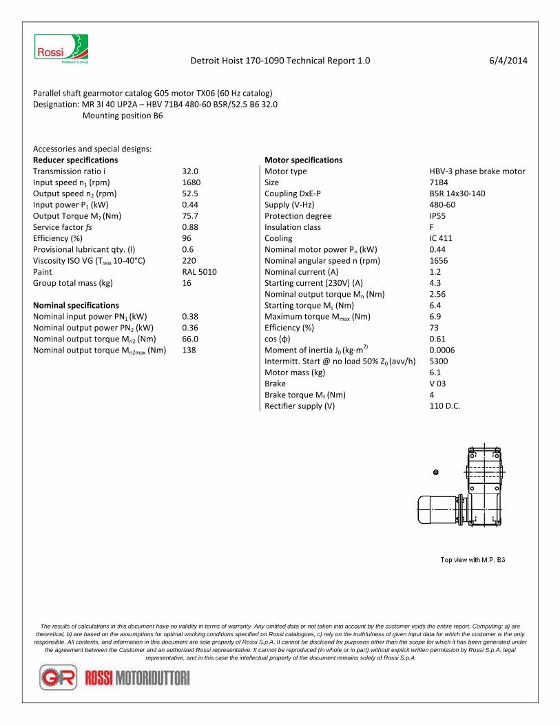
Detroit Hoist 170-1090 Technical Report 1.0 6/4/2014
Parallel shaft gearmotor catalog G05 motor TX06 (60 Hz catalog) Designation: MR 3I 40 UP2A – HBV 71B4 480-60 B5R/52.5 B6 32.0
Mounting position B6
Accessories and special designs: Reducer specifications Motor specifications Transmission ratio i 32.0 Motor type HBV-3 phase brake motor Input speed n1 (rpm) 1680 Size 71B4 Output speed n2 (rpm) 52.5 Coupling DxE-P B5R 14x30-140 Input power P1 (kW) 0.44 Supply (V-Hz) 480-60 Output Torque M2 (Nm) 75.7 Protection degree IP55 Service factor fs 0.88 Insulation class F Efficiency (%) 96 Cooling IC 411 Provisional lubricant qty. (l) 0.6 Nominal motor power Pn (kW) 0.44 Viscosity ISO VG (TAMB 10-40°C) 220 Nominal angular speed n (rpm) 1656 Paint RAL 5010 Nominal current (A) 1.2 Group total mass (kg) 16 Starting current [230V] (A) 4.3 Nominal output torque Mn (Nm) 2.56 Nominal specifications Starting torque Ms (Nm) 6.4 Nominal input power PN1 (kW) 0.38 Maximum torque Mmax (Nm) 6.9 Nominal output power PN2 (kW) 0.36 Efficiency (%) 73 Nominal output torque Mn2 (Nm) 66.0 cos (φ) 0.61 Nominal output torque Mn2max (Nm) 138 Moment of inertia J0 (kg·m2) 0.0006 Intermitt. Start @ no load 50% Z0 (avv/h) 5300 Motor mass (kg) 6.1 Brake V 03 Brake torque Mf (Nm) 4 Rectifier supply (V) 110 D.C.
The results of calculations in this document have no validity in terms of warranty. Any omitted data or not taken into account by the customer voids the entire report. Computing: a) are theoretical, b) are based on the assumptions for optimal working conditions specified on Rossi catalogues, c) rely on the truthfulness of given input data for which the customer is the only
responsible. All contents, and information in this document are sole property of Rossi S.p.A. It cannot be disclosed for purposes other than the scope for which it has been generated under the agreement between the Customer and an authorized Rossi representative. It cannot be reproduced (in whole or in part) without explicit written permission by Rossi S.p.A. legal
representative, and in this case the intellectual property of the document remains solely of Rossi S.p.A

Detroit Hoist 170-1090 Technical Report 1.0 6/4/2014
Parallel shaft gearmotor catalog G05 motor TX06 (60 Hz catalog) Designation: MR 3I 40 UP2A – HBV 71C4 480-60 B5R/52.5 B6 32.0
Mounting position B6
The results of calculations in this document have no validity in terms of warranty. Any omitted data or not taken into account by the customer voids the entire report. Computing: a) are theoretical, b) are based on the assumptions for optimal working conditions specified on Rossi catalogues, c) rely on the truthfulness of given input data for which the customer is the only
responsible. All contents, and information in this document are sole property of Rossi S.p.A. It cannot be disclosed for purposes other than the scope for which it has been generated under the agreement between the Customer and an authorized Rossi representative. It cannot be reproduced (in whole or in part) without explicit written permission by Rossi S.p.A. legal
representative, and in this case the intellectual property of the document remains solely of Rossi S.p.A

Detroit Hoist 170-1090 Technical Report 1.0 6/4/2014 Parallel shaft gearmotor catalog G05 motor TX06 (60 Hz catalog) Designation: MR 3I 40 UP2A – HBV 71C4 480-60 B5R/52.5 B6 32.0
Mounting position B6
The results of calculations in this document have no validity in terms of warranty. Any omitted data or not taken into account by the customer voids the entire report. Computing: a) are theoretical, b) are based on the assumptions for optimal working conditions specified on Rossi catalogues, c) rely on the truthfulness of given input data for which the customer is the only
responsible. All contents, and information in this document are sole property of Rossi S.p.A. It cannot be disclosed for purposes other than the scope for which it has been generated under the agreement between the Customer and an authorized Rossi representative. It cannot be reproduced (in whole or in part) without explicit written permission by Rossi S.p.A. legal
representative, and in this case the intellectual property of the document remains solely of Rossi S.p.A
Detroit Hoist 170-1090 Technical Report 1.0 6/4/2014
Parallel shaft gearmotor catalog G05 motor TX06 (60 Hz catalog) Designation: MR 3I 40 UP2A – HBV 71B4 230-60 B5R/52.5 B6 32.0
Mounting position B6
Accessories and special designs: Reducer specifications Motor specifications Transmission ratio i 32.0 Motor type HBV-3 phase brake motor Input speed n1 (rpm) 1680 Size 71B4 Output speed n2 (rpm) 52.5 Coupling DxE-P B5R 14x30-140 Input power P1 (kW) 0.37 Supply (V-Hz) 230-60 Output Torque M2 (Nm) 75.7 Protection degree IP55 Service factor fs 0.88 Insulation class F Efficiency (%) 96 Cooling IC 411 Provisional lubricant qty. (l) 0.6 Nominal motor power Pn (kW) 0.37 Viscosity ISO VG (TAMB 10-40°C) 220 Nominal angular speed n (rpm) 1715 Paint RAL 5010 Nominal current (A) 1.9 Group total mass (kg) 16 Starting current [230V] (A) 9.4 Nominal output torque Mn (Nm) 2.07 Nominal specifications Starting torque Ms (Nm) 6.4 Nominal input power PN1 (kW) 0.37 Maximum torque Mmax (Nm) 7.0 Nominal output power PN2 (kW) 0.37 Efficiency (%) 75.5 Output Torque Mn2 (Nm) 66.0 cos (φ) 0.68 Moment of inertia J0 (kg·m2) 0.0014 Intermitt. Start @ no load 50% Z0 (avv/h) 5300 Motor mass (kg) 7.9 Brake V 03 Brake torque Mf (Nm) 4 Rectifier supply (V) 110 D.C.
The results of calculations in this document have no validity in terms of warranty. Any omitted data or not taken into account by the customer voids the entire report. Computing: a) are theoretical, b) are based on the assumptions for optimal working conditions specified on Rossi catalogues, c) rely on the truthfulness of given input data for which the customer is the only
responsible. All contents, and information in this document are sole property of Rossi S.p.A. It cannot be disclosed for purposes other than the scope for which it has been generated under the agreement between the Customer and an authorized Rossi representative. It cannot be reproduced (in whole or in part) without explicit written permission by Rossi S.p.A. legal
representative, and in this case the intellectual property of the document remains solely of Rossi S.p.A
Detroit Hoist 170-1090 Technical Report 1.0 6/4/2014
Parallel shaft gearmotor catalog G05 motor TX06 (60 Hz catalog) Designation: MR 3I 40 UP2A – HBV 71C4 230-60 B5R/52.5 B6 32.0
Mounting position B6
The results of calculations in this document have no validity in terms of warranty. Any omitted data or not taken into account by the customer voids the entire report. Computing: a) are theoretical, b) are based on the assumptions for optimal working conditions specified on Rossi catalogues, c) rely on the truthfulness of given input data for which the customer is the only
responsible. All contents, and information in this document are sole property of Rossi S.p.A. It cannot be disclosed for purposes other than the scope for which it has been generated under the agreement between the Customer and an authorized Rossi representative. It cannot be reproduced (in whole or in part) without explicit written permission by Rossi S.p.A. legal
representative, and in this case the intellectual property of the document remains solely of Rossi S.p.A

SKF sensor bearing unitBMB-6204/048S2/UADD0A
2 © SKF 2010
ATTENTION
•Images not contractual
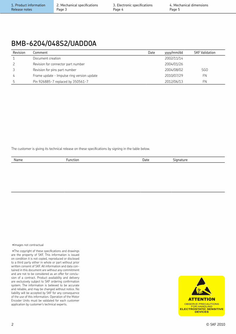
•The copyright of these specifications and drawings are the property of SKF. This information is issued on condition it is not copied, reproduced or disclosed to a third party either in whole or part without prior written consent of SKF. All information and data con-tained in this document are without any commitment and are not to be considered as an offer for conclu-sion of a contract. Product availability and delivery are exclusively subject to SKF ordering confirmation system. The information is believed to be accurate and reliable, and may be changed without notice. No liability will be accepted by SKF for any consequence of the use of this information. Operation of the Motor Encoder Units must be validated for each customer application by customer’s technical experts.
Revision Comment Date yyyy/mm/dd SKF Validation
1 Document creation 2002/11/14
2 Revision for connector part number 2004/01/26
3 Revision for pins part number 2004/08/02 SGO
4 Frame update - Impulse ring version update 2010/07/29 FN
5 Pin 926885-7 replaced by 350561-7 2012/06/13 FN
Name Function Date Signature
The customer is giving its technical release on these specifications by signing in the table below.
BMB-6204/048S2/UADD0A
1. Product informationRelease notes
2. Mechanical specificationsPage 3
4. Mechanical dimensionsPage 5
3. Electronic specificationsPage 4

BMB-6204/048S2/UADD0AMechanical specifications
© SKF 2010 3
1. Product informationRelease notes
2. Mechanical specifications Page 3
4. Mechanical dimensionsPage 5
3. Electronic specificationsPage 4
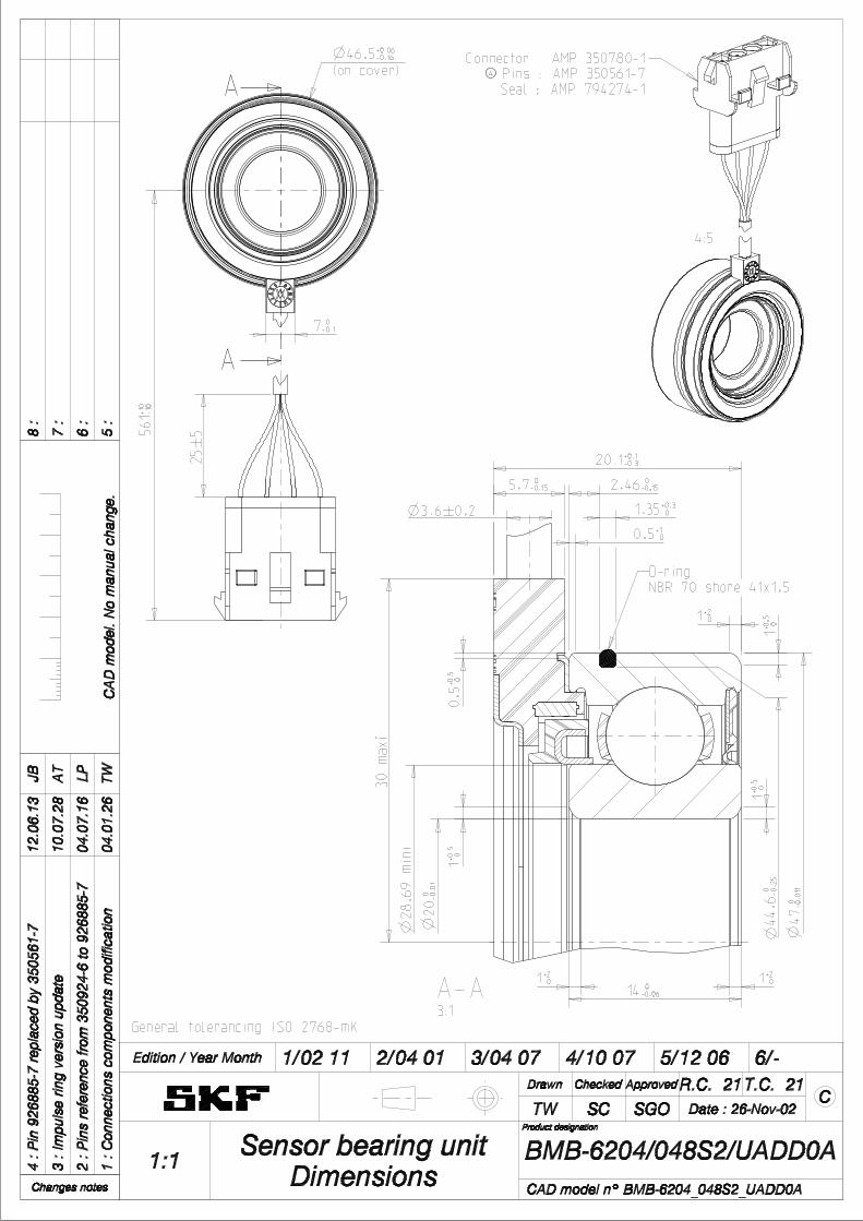
Table 1. Mechanical specifications
Parameter Value Unit
Unit weight approx. 0.146 kg
Bearing family 6204
Cage type Metallic
Seal type RS1
Grease type GWB
Radial clearance C3
Dynamic capacity 12700 N
Static capacity 6550 N
General dimensioning see drawing
The dimensions and tolerances of this product are given on the drawing on the last page of this document.
Mechanical specifications are given at 20°C (à table 1).
The SKF motor encoder units are Chromium VI and lead free.
Table 2. Cable specifications
Parameter Value
Conductor size AWG 24
Min. bending radius 12 mm
Designed for industrial environment ( for de-tailed specification, please contact SKF repre-sentative).
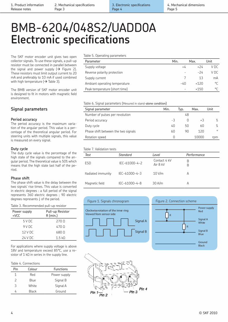
BMB-6204/048S2/UADD0AElectronic specifications
© SKF 20104
Table 5. Operating parameters
Parameter Min. Max. Unit
Supply voltage +4 +24 V DC
Reverse polarity protection - -24 V DC
Supply current 7 13 mA
Ambiant operating temperature -40 +120 °C
Peak temperature (short time) - +150 °C
Table 6. Signal parameters (Mesured in stand-alone condition)
Signal parameter Min. Typ. Max. Unit
Number of pulses per revolution 48
Period accuracy -3 0 +3 %
Duty cycle 40 50 60 %
Phase shift between the two signals 60 90 120 °
Rotation speed 0 10000 rpm
Figure 2. Connection scheme
R
R
Power supplyRed
Signal AWhite
Signal BBlue
GroundBlack
Figure 1. Signals chronogram
Signal A
Signal B
Clockwise rotation of the inner ringViewed from sensor side
1. Product informationRelease notes
2. Mechanical specificationsPage 3
4. Mechanical dimensionsPage 5
3. Electronic specifications Page 4
Signal parameters
Period accuracyThe period accuracy is the maximum varia-tion of the angular period. This value is a per-centage of the theoretical angular period. For steering units with multiple signals, this value is measured on every signal.
Duty cycleThe duty cycle value is the percentage of the high state of the signals compared to the an-gular period. The theoretical value is 50% which means that the high state last half of the pe-riod.
Phase shiftThe phase shift value is the delay between the two signals’ rise times. This value is converted in electric degrees : a full period of the signal represents 360 electric degrees ; 90 electric degrees represents ¼ of the period.
The SKF motor encoder unit gives two open collector signals. To use these signals, a pull-up resistor must be connected in parallel between the signal and power supply (à Figure 2). These resistors must limit output current to 20 mA and preferably to 10 mA if used combined with high temperature (à Table 3).
The BMB version of SKF motor encoder unit is designed to fit in motors with magnetic field environment.
Table 3. Recommended pull-up resistor
Power supply +VCC
Pull-up ResistorR (min.)
5 V DC 270 Ω
9 V DC 470 Ω
12 V DC 680 Ω
24 V DC 1.5 kΩ
For applications where supply voltage is above 18V and temperature exceed 85°C, use a re-sistor of 1 kΩ in series in the supply line.
Table 4. Connections
Pin Colour Functions
1 Red Power supply
2 Blue Signal B
3 White Signal A
4 Black Ground
Table 7. Validation tests
Test Standard Level Performance
ESD IEC-61000-4-2Contact 4 kVAir 8 kV
BB
Radiated immunity IEC-61000-4-3 10 V/m A
Magnetic field IEC-61000-4-8 30 A/m A
Product designation
A
A
14 0-0.06
1+0.5
0
1+2 0
1+0.5
0
1+2 0
0.5+1 0
0.5+0
.5 0
1+2 0
1+0.5
0
2.46 0-0.15
1.35+0.3 0
5.7 0-0.15
7 0-0.1
3.6#0.2
561+1
0-1
0
20.1+0.1-0.3
47
0 -0.0
11
20
0 -0.0
1
44.6 0 -0
.25
(on cover)46.5+0.06-0.16
30 maxi
28.69 mini
25#5
CAD model n° BMB-6204_048S2_UADD0A
Sensor bearing unitDimensions1:1 BMB-6204/048S2/UADD0A
CDate : 26-Nov-02SGOSCTW
T.C. 21R.C. 21ApprovedCheckedDrawn
6/- 5/12 06 4/10 07 3/04 07 2/04 01 1/02 11Edition / Year Month
1 : C
onne
ctio
ns c
ompo
nent
s m
odifi
catio
n04
.01.
26TW
CA
D m
odel
. No
man
ual c
hang
e.5
:
2 : P
ins
refe
renc
e fro
m 3
5092
4-6
to 9
2688
5-7
04.0
7.16
LP6
:
3 : I
mpu
lse
ring
vers
ion
upda
te10
.07.
28A
T7
:
4 : P
in 9
2688
5-7
repl
aced
by
3505
61-7
12.0
6.13
JB8
:
Changes notes
General tolerancing ISO 2768-mK
Connector : AMP 350780-1Pins : AMP 350561-7Seal : AMP 794274-1
A-A3:1
O-ringNBR 70 shore 41x1.5
4:5
Product Finishes
CHARACTERISTICS
Gloss: Semi-Gloss Black 45-55 units @ 60° Low Gloss Clear 15-20 units @ 60° All Others 90+ units at 60°
80+ units at 20° Volume Solids: 36-39 ± 2%
may vary by color Vi scosity: 20-60 seconds #5 Zahn Cup Recommended film thickness:
Mils Wet 3.0 - 4.0 Mils Dry 1.0 - 1.2
Spreading Rate (no application loss) 480-625 sq. ft./gal @ 1.0-1.2 mils dft Drying (1.0-1.2 mils dft, 77°F,50% RH):
To Touch: 20-40 minutes Tack Free: 2-3 hours To Handle 6-8 hours Through Dry Time 19-21 hours To Recoat apply second coat be-
fore 2 hours or after 21 hours
Force Dry: 20-30 minutes at 140-180°F
Critical recoat period may fluctuate de-pending on drying conditions and film thickness. Test a small area first. Catalyzed Product Dry Time:
To Touch 30-40 minutes Tack Free 2-4 hours To Handle 6-8 hours Through Dry Time 6-11 hours Potlife: 2 hours maximum at
room temperature Flash Point: 80°F, PMCC Package Life:
Enamel 12 months, unopened V66V1020 23 months, unopened Air Quality Data: • Photochemically reactive• Volatile Organic Compounds (VOC)
theoretical as packaged, maximum,less exempt solvents:4.20 lb/gal, 504 g/L
CC-B32 03/15 continued on back
SHER-KEM® High Gloss Metal Finishing Enamel
Detroit Hoist Silver...........F75WC7
Equipment Yellow .......... F75YC19
DESCRIPTION
SHER-KEM® High Gloss Metal Finishing Enamel is a direct-to-metal coating de-signed to give a factory applied finish and provide the brilliant color and per-formance required by the large agricul-tural and construction equipment and trailer manufacturers. It can also be used in the general metal finishing mar-ket when a premium, long lasting finish is needed.
Advantages:
• 8 Package colors provide quick hiding
and color clarity needed to achieve
OEM finishes
• Excellent, long lasting color and gloss
retention, adding value to the life of
finished products
• Superior distinctness of image reflecting
deep color clarity and mirror-like finish
• Full range of more than 60 pre-
formulated custom colors available for
fast in-store color matching
• One coat direct-to-metal protection
• Excellent chemical resistance includ-
ing engine coolant, oil, diesel fuel and
unleaded gasoline
• Easy to apply by simply reducing with
a variety of readily available industrial
solvents
• Ideal for coating large components
due to longer open time allowing for
rewetting
• For improved hardness, better over-
night hardness use V66V1020 Hard-
ener at an 8:1 ratio. Eliminates recoat
window
• Covers quickly due to increased vol-
ume solids
• Easy to apply with many types of
spray equipment
SPECIFICATIONS
General: Substrate should be free of grease, oil, dirt, fingerprints, drawing compounds, any contamination, and sur-face passivation treatments to ensure optimum adhesion and coating perform-ance properties. Consult Metal Prepara-tion Brochure CC-T1 for additional de-tails.
Aluminum: If untreated, prime with RoHS Compliant Wash Primer, P60G10 or Industrial Wash Primer, P60G2, or Kem Aqua® Wash Primer, E61G522. Over "pre-treated" aluminum, check ad-hesion before use as the proprietary pre-treatment may change from supplier to supplier which may have an effect on the final adhesion.
Steel or Iron: Remove rust, mill scale, and oxidation products. For best re-sults, treat the surface with a proprie-tary surface chemical treatment of zinc or iron phosphate to improve corrosion protection. Recommended for all direct to metal applications.
For improved corrosion protection, prim-ing is recommended. Prime with Kem®
400 Primer for best hold-out or Kem- Flash® Primers.
Testing: Due to the wide variety of sub-strates, surface preparation methods, and application methods and environ-ments, the customer should test the com-plete system for adhesion, compatibility and performance prior to full-scale appli-cation.
An Environmental Data Sheet is available from your local Sherwin-Williams facility or at www.paintdocs.com.
CC-B32
ADDITIONAL INFORMATION
• Apply at least 1.0 mils DFT on direct to
metal applications for good film integ-
rity and good corrosion resistance.
• For improved corrosion resistance and
to maintain high distinctness of image
use Kem® 400 Primer.
• For better corrosion resistance use
Kem-Flash® Prime. There will be a
loss of distinctness of image when
using Kem-Flash® Prime.
• Initial dry times are slightly slower
when BAC colorants are used. No loss
of dry time observed when 844 or
MaxiToner colorants are used.
• Blocking or sticking may occur when
flat surfaces are stacked before ade-
quate dry.
• Apply at temperatures above 60°F.
• Drying time is dependent on film
thickness and atmospheric conditions.
Heavier film thickness causes slow
drying.
• Not recommended for dip application.
• For increased chemical and abrasion
resistance, improved hardness and
better gloss and color retention SHER-
KEM High Gloss Metal Finishing
Enamel may be catalyzed at an 8 to 1
ratio with Hardener, V66V1020, prior
to reduction. Dry times are slightly
slower. Read label cautions before
use.
• Addition of Hardener, V66V1020,
eliminates the critical recoat window.
Hardener contains isocyanates.
• Working pot life of catalyzed product is 2
hours maximum at room temperature.
• Caution should be exercised when
recoating with products containing
aromatics, esters or ketone solvents
as they may result in lifting or dulling
of gloss.
• Maximum tint load is 8 ounces per
gallon except for the High Hide White,
which is 2 ounces per gallon.
• The Ultra Deep Base and Low Gloss
Clear must be tinted for use as a final
product. They are not designed for use
as clear coats.
• To quickly obtain a hard, mar-proof
finish, force dry 20 minutes at 140-
180°F.
• F75EC9 and F75RC7 contain organic
pigments and should not be force
dried above 160°F because they tend
to bronze above this temperature.
CAUTIONS
FOR INDUSTRIAL SHOP APPLICATION
Thoroughly review product label and Safety Data Sheet (SDS) for safety and cautions prior to using this product. A Safety Data Sheet is available from your local Sherwin-Williams facility or at www.paintdocs.com. Please direct any questions or com-ments to your local Sherwin-Williams facility.
APPLICATION Typical Setups
Reduction: Reduce with Xylene, R2K4, 10-20% by volume. For more flow and open time, use Aromatic Naphtha 100 Flash, R2K5. For faster dry time use Acetone, R6K9. Conventional Spray: Air Pressure ................................. 55 psi Reduction ................ 10-20% by volume Airless Spray: Fluid Pressure ............... 2100-2700 psi Tip ..................................................413" Reduction ................. 5-10% by Volume Air Assisted Airless: Air Pressure ............................... 15 psi Fluid Pressure ................ 1500-1800 psi Air Cap ......................................... AA-4 Fluid Tip ........................................ 1308 Reduction Rate .......... 5-10% by volume HVLP: Gun ................................. DeVilbiss EXL Pressure at the cap .......... 10 psi max. Fluid Pressure ....................... 10-25 psi Air Cap ......................................... 2000 Fluid Tip ..................................FF (.055) Reduction ............... 10-20% by volume Cleanup: Clean tools/equipment immediately after use with 100 Flash, R2K5, Xy-lene, R2K4, or Acetone, R6K9. Follow manufacturer's safety recom-mendations when using any solvent. Tintable with Following Systems: -BAC Colorants up to 8 ounces per gallon -844 Colorants up to 8 ounces per gallon -MaxiToner Colorants up to 8 ounces per gallon
*High Hide White base tint load is up to 2 oz per gallon.
Performance Test Results Product tested on Bonderite 1000 steel (iron phosphate) panels. Salt Spray Test - Corrosion ASTM B117 ..........................200-250 hours Humidity - Corrosion ASTM D2247, 100°F, 100% RH…...Pass200 hours Conical Mandrel - Flexibility ASTM D633 ................. passes 1/8" mandrel Impact Resistance - Direct ASTM D2794 ................................... 40 in lb Impact Resistance - Reverse ASTM D2794 ..................................... 4 in lb Pencil Hardness without Hardener ASTM D3363 ........................................... 2B Pencil Harness with Hardener ASTM D3363 .......................................... HB Chip Resistance ...................................... 5A 1 year 45°S Florida exposurePasses. No loss of gloss.
Note: Product Data Sheets are periodi-cally updated to reflect new information
relating to the product. It is important that the customer obtain the most recent Prod-uct Data Sheet for the product being used.
The information, rating, and opinions stated here pertain to the material cur-rently offered and represent the results of
tests believed to be reliable. However, due to variations in customer handling and methods of application which are not
known or under our control, The Sherwin-Williams Company cannot make any war-ranties as to the end result.
CC-B32 SHER-KEM® High Gloss Metal Finishing Enamel