Embed Size (px)
Citation preview
SECTION 16
DIFFERENTIAL
CONTENTS
16-1. GENERAL DESCRIPTION . . . . . . . . . . . . . . . . . . . . . . . . . . . . . . . 16-2
16.2. REMOVAL . . . . . . . . . . . . . . . . . . . . . . . . . . . . . . . . . . . . . . . . . . . 16-3
16-3. DISASSEMBLY . . . . . . . . . . . . . . . . . . . . . . . . . . . . . . . . . . . . . . . . 16-6
16-4. INSPECTION AND ADJUSTMENT OF COMPONENTS . . . . . . . . . 16-7
16.5. REASSEMBLY . . . . . . . . . . . . . . . . . . . . . . . . . . . . . . . . . . . . . . . 16-13
16-6. INSTALLATION . . . . . . . . . . . . . . . . . . . . . . . . . . . . . . . . . . . . . . 16-15
16-7. MAINTENANCE SERVICES. . . . . . . . . . . . . . . . . . . . . . . . . . . . . 16-16
16-8. RECOMMENDED TORQUE SPECIFICATIONS . . . . . . . . . . . . . . 16-16
16-1
16-1. GENERAL DESCRIPTION
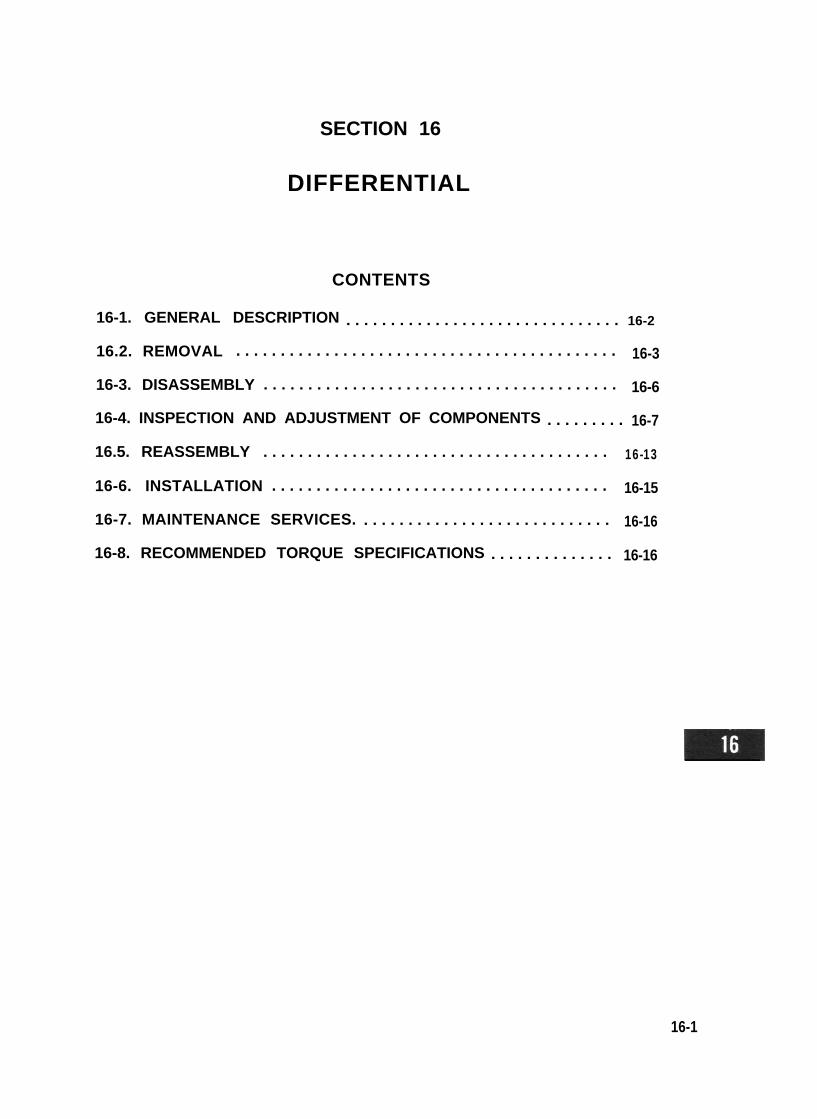
The two axles, front and rear, are identical as far as the designs of pinion-and-gear drive and differentialgearing are concerned. The major difference in this limited sense lies in the shape of the housing.Each axle may be regarded as consisting, speaking roughly, of supporting parts (axle sleeves, differentialhousing and carrier case) and drive transmitting parts (bevel pinion and gear, differential gearing andlive axle shafts). In the present section, only the bevel pinion and gear and differential gearing are takenup under the collective title of “differential.”The bevel gear drive is of hypoid design; pinion and gear have hypoid gear teeth. This means that thepinion is located slightly below the center of the bevel gear to permit the car body to be lowered in design,and that some wiping or sliding action occurs in tooth meshing between pinion and gear. Here lies thereason why use of hypoid gear oil is specified for the differential.Four differential pinions are used in the differential case to qualify this gearing for heavy-duty “differen-tial” drive. Thus, a total of 8 gears-a drive pinion, a crown gear, two side gears and four pinions-areinside the differential housing, all mounted on the differential carrier case bolted to the housing.This differential is so constructed that the bevel pinion bearing preload is adjusted by tightening the bevelpinion nut to compress the spacer.
1. Oil seal2. Bearing3. Carrier4. Joint flange5. Bearing preload
adjusting spacer6. Shim7. Bearing8. Bearing adjuster
9. Side bearing10. Adjuster lock plate11. Bevel gear pinion set12. Bolt13. Rear axle housing14. Front axle housing15. Bolt16. Oil level plug17. Gasket
18. Oil drain plug19. Right case20. Thrust washer21. Joint22. Thrust washer23. Pinion shaft No. 224. Pinion shaft No. 125. Side gear set26. Left case
16-2
Fig. 16-1
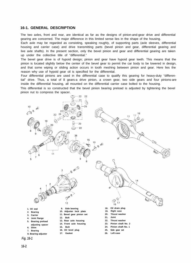
16-2. REMOVAL
1. Loosen, but do not remove, wheel nuts offront or rear wheels, and raise car off the
2.
3.
floor by jacking.Rest car steady on safety stands.Drain out oil in differential housing byloosening drain plug.Remove wheel nuts and take off wheels,front or rear. Each wheel has five wheel nuts.
For Front DifferentialAfter taking down front wheels, remove discbrake caliper with carrier.NOTE:Hang removed caliper with a wire hook or thelike so as to prevent brake hose from bendingand twisting excessively or being pulled.Don’t operate brake pedal with caliper removed.
Fig. 16-2
Fig. 16-3
At each tie rod end, remove nut and disconnectthe end from steering knuckle using special tool@
Fig. 16-4 @ Special tool (Tie rod end remover099 13-652 10)
Remove 8 oil seal cover securing bolts. Fromsteering knuckle, take off felt pad, oil seal andseal retainer.
Fig. 16-5
Remove top and bottom kingpins from knuckleby removing 4 bolts securing each pin.NOTE:The removed top and bottom kingpins must bekept separated so as to prevent an error whenputting them back in their place in reassembly.
16-3
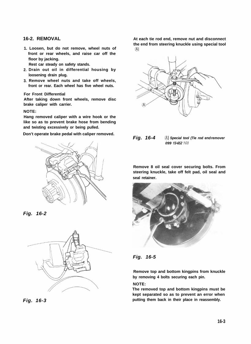
Fig. 16-6 Fig. 16-8
Draw out live axle shaft from axle housing.NOTE:At this time, lower kingpin bearing sometimesfalls off. So remove bearing while pulling offknuckle gradually.
Fig. 16-7
At differential housing, disconnect propellershaft by removing bolts securing flange yoke tocompanion flange. Remove 8 bolts holding fastdifferential carrier case to housing, and takedown carrier assembly.
For Rear DifferentialAfter taking down rear wheels, remove brakedrums by using special tools.
NOTE:Before removing brake drum, check to ensurethat parking brake lever is not pulled up.To increase clearance between brake shoe andbrake drum, remove parking brake shoe leverreturn spring @ and disconnect parking brakecable joint @ from parking brake shoe lever 0.Remove parking brake shoe lever stopper plate.
1. Parking brake shoe leverreturn spring
2. Parking brake shoe lever 3. Parking brake cable joint
4. Pin5. Clip6. Brake back plate
Fig. 16-9
16-4

Fig. 16-19-1 @ Special tool (Brake drum remover09943-355 7 1)
Fig. 16-10 @ Special tool (Rear axle remover09922-66010)
@ Special tool (Sliding hammer @ Special tool (Sliding hammer09942- 15510) 09942-15510)
Disconnect brake pipe from wheel cylinder.Have a small plug ready for use when disconnect-ing pipe. As pipe comes off the wheel cylinder,plug the pipe to prevent brake f lu id f romleaking out.And remove 4 brake backing plate securingbolts.
F i g . 1 6 - 9 - 2 @ Plug
Using special tools indicated below, draw outeach axle shaft with brake backing plate.
Disconnect propeller shaft as in the case of frontaxle, and detach and take down differentialcarrier case from housing by removing 8 bolts.
Fig. 16-11
16-5

16-3. DISASSEMBLY
Lock flange immovable by using special tool,and remove nut from the end of bevel pinionshank.
Fig. 16-12 @ Special tool (Rotor holder 09930-40 113)
Scribe marks on each cap bolted to the saddleportion of carrier case and holding down theside bearing. The marks are to identify caps.This means that there are right and left caps, soidentified and so handled at the time of reas-sembly.
Fig. 16-13 @ Scribed match marks
At each side, loosen bolts on bearing adjusterstopper, remove bearing cap securing bolts,and take off cap. Lift differential case assembly,complete with bevel gear, off the carrier.
Fig. 16-14
Remove 10 bolts securing bevel gear to diffe-rential case, and separate gear from case.
Fig. 16-15
There are 8 bolts fastening two differentialcase halves together. Remove these bolts tosever right-hand case half from left-hand one,and take off right-hand one.
Fig. 16-16 @ Special tool (Rotor holder09930-40 113)
16-6

Remove side gears, differential pinions andthrust washers.
Fig. 16-17Using special tools indicated below, extractside bearing from each differential case half.
Fig.16-18 @ Special tool (Bearing puller09913-60910)
@ SptCal tool (Side bearing removing jig099 13-85230)
Using puller and hydraulic press, remove innerrace of bevel pinion bearing.
16-4. INSPECTION AND ADJUSTMENTOF COMPONENTS
Side Gear Thrust PlayTo check thrust play, assemble differentialgearing and case, as shown in Fig. 16-19, fasten-ing together two case halves by tighteningsecuring bolts to prescribed torque. By compar-ing thrust play reading, taken as shown in Fig.16-19, against thrust play indicated below,increase or decrease total thickness of thrustwashers, which are located in two places, thatis, on the inner side of each case half.
Side gear thrust play 0 . 1 2 - 0 . 3 7 m mspecif icat ion ( 0 . 0 0 5 - 0 . 0 1 4 i n )
Avai lable thrust washersizes (thickness)
0.9, 1.O, 1.1 & 1.2 mm(0.035,0.039,0.043 &0.047 in)
Fig. 16-19
Fig. 16-18-1 0 Hydraulic press @ Puller
16-7
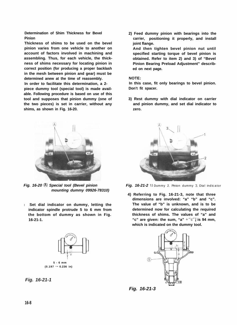
Determination of Shim Thickness for BevelPinionThickness of shims to be used on the bevelpinion varies from one vehicle to another onaccount of factors involved in machining andassembling. Thus, for each vehicle, the thick-ness of shims necessary for locating pinion incorrect position (for producing a proper backlashin the mesh between pinion and gear) must bedetermined anew at the time of reassembly.In order to facilitate this determination, a 2- piece dummy tool (special tool) is made avail-able. Following procedure is based on use of thistool and supposes that pinion dummy (one ofthe two pieces) is set in carrier, without anyshims, as shown in Fig. 16-20.
Fig. 16-20 @ Special tool (Bevel pinionmounting dummy 09926-78310)
l Set dial indicator on dummy, letting theindicator spindle protrude 5 to 6 mm fromthe bottom of dummy as shown in Fig.16-21-1.
5 - 6 mm(0.197 - 0.236 in)
16-8
2) Feed dummy pinion with bearings into thecarrier, positioning it properly, and installjoint flange.And then tighten bevel pinion nut untilspecified starting torque of bevel pinion isobtained. Refer to item 2) and 3) of “BevelPinion Bearing Preload Adjustment” describ-ed on next page.
NOTE:In this case, fit only bearings to bevel pinion.Don’t fit spacer.
3) Rest dummy with dial indicator on carrierand pinion dummy, and set dial indicator tozero.
Fig. 16-21-2 1. Dummy 2. Pinion dummy 3. Dial indicator
4) Referring to Fig. 16-21-3, note that threedimensions are involved: “a” “b” and “c”.The value of “b” is unknown, and is to bedetermined now for calculating the requiredthickness of shims. The values of “a” and“c” are given: the sum, “a” +“c”, is 94 mm,which is indicated on the dummy tool.
Fig. 16-21-3
Fig. 16-21-1
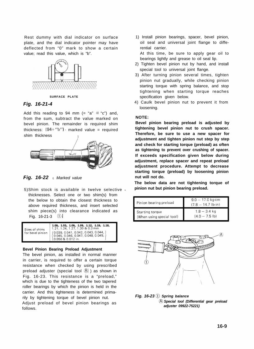
Rest dummy with dial indicator on surfaceplate, and the dial indicator pointer may havedeflected from “0” mark to show a certainvalue; read this value, which is “b”.
SURFACE PLATE
Fig. 16-21-4
Add this reading to 94 mm (= “a” + “c”) and,from the sum, subtract the value marked onbevel pinion. The remainder is required shimthickness: (94+“b”) - marked value = requiredshim thickness 1
Fig. 16-22 I. Marked value
5)Shim stock is available in twelve selective Lthicknesses. Select one or two shim(s) fromthe below to obtain the closest thickness toabove required thickness, and insert selectedshim piece(s) into clearance indicated asFig. 16-21-3 0.
1.00, 1.03, 1.06, 1.09, 1.12, 1.15, 1.18,
Bevel Pinion Bearing Preload AdjustmentThe bevel pinion, as installed in normal mannerin carrier, is required to offer a certain torqueresistance when checked by using prescribedpreload adjuster (special tool @ ) as shown inFig. 16-23. This resistance is a “preload,”which is due to the tighteness of the two taperedroller bearings by which the pinion is held in thecarrier. And this tighteness is determined prima-rily by tightening torque of bevel pinion nut.Adjust preload of bevel pinion bearings asfollows.
1) Install pinion bearings, spacer, bevel pinion,oil seal and universal joint flange to diffe-rential carrier.At this time, be sure to apply gear oil tobearings lightly and grease to oil seal lip.
2) Tighten bevel pinion nut by hand, and installspecial tool to universal joint flange.
3) After turning pinion several times, tightenpinion nut gradually, while checking pinionstarting torque with spring balance, and stoptightening when starting torque reachesspecification given below.
4) Caulk bevel pinion nut to prevent it fromloosening.
NOTE:Bevel pinion bearing preload is adjusted bytightening bevel pinion nut to crush spacer.Therefore, be sure to use a new spacer foradjustment and tighten pinion nut step by stepand check for starting torque (preload) as oftenas tightening to prevent over crushing of spacer.If exceeds specification given below duringadjustment, replace spacer and repeat preloadadjustment procedure. Attempt to decreasestarting torque (preload) by loosening pinionnut will not do.The below data are not tightening torque ofpinion nut but pinion bearing preload.
Fig. 16-23 @ Spring balance@ Special tool (Differential gear preload
adjuster 09922-75221)
16-9
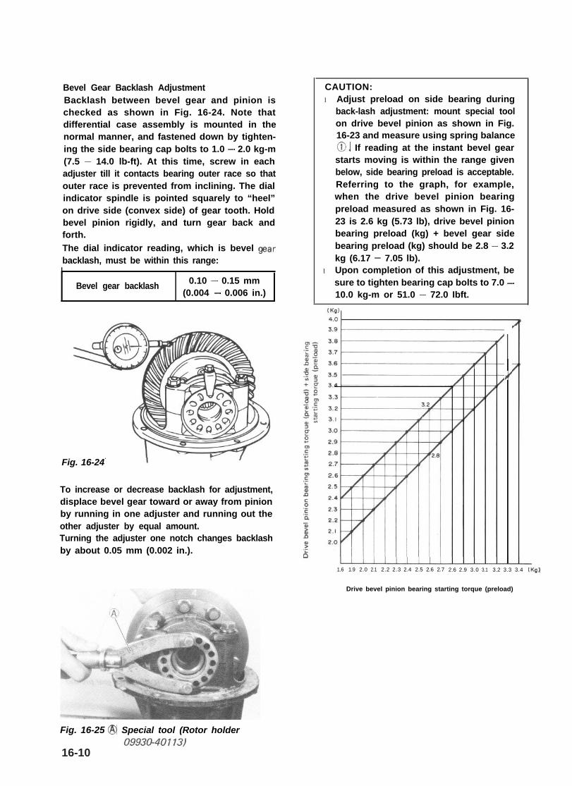
Bevel Gear Backlash AdjustmentBacklash between bevel gear and pinion ischecked as shown in Fig. 16-24. Note thatdifferential case assembly is mounted in thenormal manner, and fastened down by tighten-ing the side bearing cap bolts to 1.0 - 2.0 kg-m(7.5 - 14.0 lb-ft). At this time, screw in eachadjuster till it contacts bearing outer race so thatouter race is prevented from inclining. The dialindicator spindle is pointed squarely to “heel”on drive side (convex side) of gear tooth. Holdbevel pinion rigidly, and turn gear back andforth.The dial indicator reading, which is bevel Qearbacklash, must be within this range:I
Bevel gear backlash 0.10 - 0.15 mm(0.004 - 0.006 in.)
Fig. 16-24
To increase or decrease backlash for adjustment,displace bevel gear toward or away from pinionby running in one adjuster and running out theother adjuster by equal amount.Turning the adjuster one notch changes backlashby about 0.05 mm (0.002 in.).
CAUTION:l Adjust preload on side bearing during
back-lash adjustment: mount special toolon drive bevel pinion as shown in Fig.16-23 and measure using spring balance0. If reading at the instant bevel gearstarts moving is within the range givenbelow, side bearing preload is acceptable.Referring to the graph, for example,when the drive bevel pinion bearingpreload measured as shown in Fig. 16-23 is 2.6 kg (5.73 lb), drive bevel pinionbearing preload (kg) + bevel gear sidebearing preload (kg) should be 2.8 - 3.2kg (6.17 - 7.05 lb).
l Upon completion of this adjustment, besure to tighten bearing cap bolts to 7.0 -10.0 kg-m or 51.0 - 72.0 Ibft.
?’
1.6 1.9 2.0 2.1 2.2 2.3 2.4 2.5 2.6 2.7 2.6 2.9 3.0 3.1 3.2 3.3 3.4 (Kg)
Drive bevel pinion bearing starting torque (preload)
Fig. 16-25 @ Special tool (Rotor holder
16-10

Pinion-to-gear Tooth Contact Pattern Check and AdjustmentIn addition to proper backlash, proper tooth contact must be secured in the mesh of bevel pinion andgear, so that there will be no “gear noise” coming from the axle and that the hypoid teeth will not beoverstressed in transmitting drive.After the specified amount of backlash has been secured, check the pinion and gear for tooth contact by“rolling” contact patterns in a manner consistent with the standard shop practice: use a red lead paste topaint ten teeth, both drive side and coast side, of the gear, turn the gear back and forth by hand whileholding the pinion in a “braking” manner, and examine the contact patterns in reference to the followingchart:
c
Contact is roughly centered and somewhatmore displaced toward toe than toward heelon both drive side (concave) and coast
High contact: Contact is on heel (drive side)and on toe (coast side). This condition meansthat the pinion is too far back and must bebrought forward by increasing its shimthickness used in “mounting distance" adjust-
Low contact: Contact is on toe (drive side)and on heel (coast side). This conditionmeans that the pinion is too far out from thecarrier and must be backed away by decreas-ing its shim thickness.
These contact patterns indicate that the“offset” of differential carrier is too much ortoo little. The remedy is to replace thecarrier with a new one.
16-11
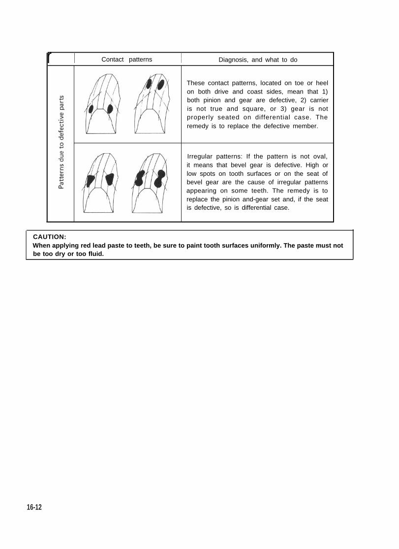
r I Contact patterns 1 Diagnosis, and what to do
These contact patterns, located on toe or heelon both drive and coast sides, mean that 1)both pinion and gear are defective, 2) carrieris not true and square, or 3) gear is notproperly seated on differential case. Theremedy is to replace the defective member.
Irregular patterns: If the pattern is not oval,it means that bevel gear is defective. High orlow spots on tooth surfaces or on the seat ofbevel gear are the cause of irregular patternsappearing on some teeth. The remedy is toreplace the pinion and-gear set and, if the seatis defective, so is differential case.
CAUTION:When applying red lead paste to teeth, be sure to paint tooth surfaces uniformly. The paste must notbe too dry or too fluid.
16-12

16-5. REASSEMBLY
Reverse disassembly procedure for reassembly,noting the following.
NOTE:Bevel pinion and bevel gear are supplied as aset. Even when only bevel pinion or bevel gearreplacement is necessary, be sure to replaceboth as a set.
Differential Pinion Shaft (Shorter)When installing shaft into differential case andpinion, insert its “A” side into pinion joint.
Fig. 16-26 @ Pinion jointA>B (“A” is longer than ‘/Br’.)
Drive Bevel Gear BoltsBolts securing bevel gear to differential case aresubject to shear stress since drive is transmittedby these bolts from gear to case. For this reason,they are special bolts made from chrome steeland must never be replaced by common bolts.When mounting gear onto case, be sure to applyTHREAD LOCK CEMENT SUPER 1333B(99000-32020) to these bolts before runningthem in.
Fig. 16-26-1
Differential Side BearingsPress-fit these bearings into differential case byusing special tool. Driving the bearing into caseis not permitted.
Fig. 16-27 @ Press@ Special tool (Bearing installer
09940-53111)
16-13
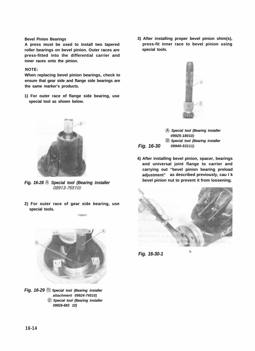
Bevel Pinion BearingsA press must be used to install two taperedroller bearings on bevel pinion. Outer races arepress-fitted into the differential carrier andinner races onto the pinion.
NOTE:When replacing bevel pinion bearings, check toensure that gear side and flange side bearings arethe same marker’s products.
1) For outer race of flange side bearing, usespecial tool as shown below.
Fig. 16-28 @ Special tool (Bearing installer09913-75510)
2) For outer race of gear side bearing, usespecial tools.
3) After installing proper bevel pinion shim(s),press-fit inner race to bevel pinion usingspecial tools.
@ Special tool (Bearing installer09925-18010)
Fig. 16-30@ Special tool (Bearing installer
09940-53111)
4) After installing bevel pinion, spacer, bearingsand universal joint flange to carrier andcarrying out “bevel pinion bearing preloadadjustment” as described previously, cau I kbevel pinion nut to prevent it from loosening.
Fig. 16-30-1
Fig. 16-29 @ Special tool (Bearing installerattachment 09924-74510)
@ Special tool (Bearing installer09926-683 10)
16-14

Side Bearings Caps When putting on side bearing caps, be sure todiscriminate the right-hand cap from the left-hand one by referring to match marks scribedat the time of disassembly.Then, after carrying out “Bevel gear backlashadjustment” as described on p. 16-10 torque capbolts to specification.
16-6. INSTALLATION
Reverse removal procedure for installation,noting the following.
Differential
Before installing differential ass’y to axle hous-ing, clean mating surfaces of differential carrierand housing and apply sealant to them.
Fig. 16-31 0 Scribed match marks
Fig. 16-32 @ Sealant (SUZUKI BOND NO.1215 99000-31110)
Front Axle Shaft and Steering KnuckleFor installation them, refer to “Front Suspen-sion Installation” in SECTION 17 of this manual.
Rear Brake DrumFor installation of rear brake drum, refer to“Rear Brake Installation” in SECTION 19 ofthis manual.
Differential Gear OilRefill differential housing with new specifiedoil. Refer to “MAINTENANCE SERVICE” inthis section for refill.
Brake Circuit Air PurgingIf brake pipe (right & left) was disconnectedfrom wheel cylinder as in Fig. 16-9-2, make sureto purge air out of brake circuit. Refer tosection 19. BRAKES for “air purging" operation. Then check to ensure that joint seam of pipe isfree from oil leak.
16-15
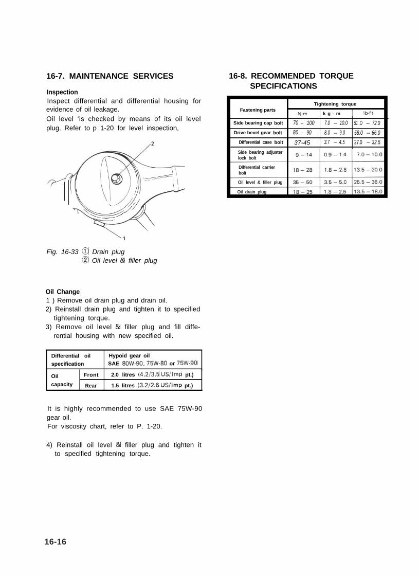
16-7. MAINTENANCE SERVICES
InspectionInspect differential and differential housing forevidence of oil leakage.Oil level ‘is checked by means of its oil levelplug. Refer to p 1-20 for level inspection,
Fig. 16-33 @ Drain plugCD Oil level & filler plug
Oil Change1 ) Remove oil drain plug and drain oil.2) Reinstall drain plug and tighten it to specified
tightening torque.3) Remove oil level & filler plug and fill diffe-
rential housing with new specified oil.
Differential oil Hypoid gear oilspecification SAE 8OW-90,75W-80 or 75W-90
Oil Front 2.0 litres (4.2/3.5 US/Imp pt.)
capacity Rear 1.5 litres (3.2/2.6 US/Imp pt.)
It is highly recommended to use SAE 75W-90 gear oil.For viscosity chart, refer to P. 1-20.
16-8. RECOMMENDED TORQUESPECIFICATIONS
I Tightening torque II Fastening partsN.m 1 k g - m 11
Side bearing cap bolt 70 - 100 7.0 - 10.0 51 .O - 72.0Drive bevel gear bolt 80 - 90 8.0 - 9.0 58.0 - 66.0
Differential case bolt 37-45 3.7 - 4.5 27.0 - 32.5I
4) Reinstall oil level & filler plug and tighten itto specified tightening torque.
16-16
Side bearing adjusterlock bolt
Differential carrierbolt
Oil level & filler plug
Oil drain plug