Embed Size (px)
Citation preview
*10
- A
I- IV
DYNELL Electronics CorporationMelvile, New York 11746
U - - - - - -I 1$ ~ I I.,I i

DISCLAIMER NOTICE
THilS DOCUMENT IS BESTQUALITY AVAILABLE. THE COPY
FURNISHED TO DTIC CONTAINED
A SIGNIFICANT NUMBER OFPAGES WHICH DO NOTREPRODUCE LEGIBLY.

TUt
IT
Trhe research documented in this Final Report wasmiponsored under Contract N00014-75-C-0633 by:
Office of Naval ResearchDepartment of the NavyWashington, D.C. ZZZ17
r' ~ Contract Authority NR 386-905/1-8-75 (220)
.eproduction in whole or in part it; permitted forany purpose of the United States Government.
~t ~[Prepared by: Dynell Electronics CorporationMelville, New York 11746
L 4iLE....DY-764R April 1977,.††††††††††

:I UNCLASSIFIEDi ~ ~Sec url.l; Clat.sfiet.,r in
DOCUMENT CONTROL DATA- R & D
O IIII IC I I I L ORI SICUiI3 CL.Asiri AIII N
Dynell Electronics Corporation J UNC LASSIFIEDF,75 Maxess Road 1b. C.NOoUPI Melville, New York Not Applicable
Wave Motion in a Thick-Walled Fluid-Filled I-oseoOsa A. ..deman
I _4 I' NS~ t~f NOtESypOea OA O FPAE f.N ~M
srni l eikt
l 7 nonerB 770.. ..l
ýO 11 2, p.N)''1l4-75--P'63
IIFC..! VA, O¶ tf o trP ON1' Haul~~ O~ (Any o~lier tttjibera thai mly 'be' 'aa|ill'e'd
* l Chl. rMput, )
"d. none1i0 •IltRllnUTION•mAT6MNT
S .. Distriuttion of this document is unlimited,
"J II SUPIPLM.SNNAMY NOTES 1l IPONIOPRING MILIIAtV ACIIVII,
Office of Naval ResearchDepartment of the Navy
_ _ ___Arlington, Virginia ZZ21713AgrtT AC, T
t.... 3 The subject of this report is the analytical solution for wave motions,in the fundamental mode, of an elastic tube filled with fluid when the wallthickness is not constrained to be small.
The results obtained show the existence of two waves which travel atdifferent speeds. Each of the two waves causes both loagitudinal and radialdisplacements of both the tube wall and the fluid, but in different proportions,
The slower wave, in the limiting case of the than-wailed tube, im identi-fled as the bulge wave. It is characterized by relatively large motions of the[ fluid, which contains moat of the kinetic energy. Thicker walls produce a higherbulge-wave speed, but the inclusion of longitudinal stiffening elements has verylittle effect.
The faster wave is what has been called the 'wall wave."' This Is mostlya longitudinal vibration of the home material, with a relatively small participation
by the fluid, and is greatly influenced by longitudinal reinforcement of the tubewall.
DD NOVsal14 73 UNCLASSIFIEDI i ,* 4e ..... le n {Lt rIv Cl i le•i i~llh,
hl i' ' I .... ... ... , :1 ... I- I~ .. . 'lI 1 I- I"° .,, I*.i ' -[ 1 ' T

WINK A LINK S L. INK C4
I Wave Motion In A Thick-Walled Fluid-Filled Hose
Acoustic Waves, Turbulent Boundary Layer,lii[ Mathematical Model, Bulge Wave, Wall Wave,
Longitudinal and Transverse Wave, HoseStiffening, Wave Speed
. . ti_
.... ......
., . ,..... ....
i • .. , --. 4"
~DW:
s iI1i
II
•eulv(l tia o
S. . .. : .. ... .... .. . . . . . . I I I I I I I I I I I

* WAVE MOTION IN A THICK-WALLED FLUID-FILLED HOSE
INTRODUCTION
¾ Random pressures on the outside surface of a fluid-filled hose,
originating from a turbulent boundary layer or other sources, excite waves which
p travel along the fluid-filled hose as in a wave guide. Consequently, inside the
hose there exist noise pressures which are correlated over large distances,
An important characteristic of this phenomenon Is the speed of such waves,
which is in general well below the acoustic rpeed because of the relatively soft
!, boundary which the hose presents to the inner column of fluid.
Previous mathematical models of such flexible hoses have reduced
them to membranes with circumferential stresses only. Longitudinal motions
and stresses in the wall were ignored. This model proved very adequate for
hoses with thin walls.
Recent interest in hoses of smaller size, where hose material occupies
a considerable part of the total cross section, requires that the analysis be
extended to include the wave motion in the wall as well as the fluid.
Thus the subject of this report is the analytical solution for wave
motions, in the fundamental mode, of an elastic tube filled with fluid when the
wall thickness is not constrained to be small (Fig. 1).
,I.
* FIG. 1 MODEL OF THICK-WALLED HOSE
A l•? " " ,l /• •• '#4• •, a ,' ...i••.•,. . .. .. " , _ . .; . •. , . . . . ... . .

The present model then includes as limiting cases the previous
thin-walled tube, where the ratio ai/a of the radii is almost one, and the solid
rod, where this ratio is zero. It also serves as a basis for studies of more
complicated models where the Inner fluid is replaced by a viscous or semisolid
material.
' In accordance with the results of previous investigations the outer
fluid, the ocean in which the tube is submerged, Is ignored, as wave propagation
iI in the hose Is not appreciably influenced by its presence.
The material of the tube is assumed to be homogeneous and isotropic
but in a subsequent modification longitudinal reinforcing elements of an arbi-
trary elastic modulus have been included. The compressibility of both the wall
material and the fluid is neglected only in the simplified final formulas which
are valid for waves of lengths much greater than the tube's transverse
dimensions; in these cases the effects of compressibility become negligible.
The outstanding result Is the existence of two waves which travel
at different speeds. Each of the two waves causes both longitudinal and radial
displacements of both the tube wall and the fluid, but in different proportions.
The slower wave, In the limiting case of the thin-walled tube, is
identified as the bulge wave. It im characterized by relatively large motions
of the fluid, which contains most of the kinetic energy. Thicker walls produce
a higher bulge-wave speed, but the inclusion of longitudinal stiffening elements
has very little effect.
The faster wave is what has been called the "wall wave." This Is
I mostly a longitudinal vibration of the hose material, with a relatively small
participation by the fluid, and is greatly influenced by longitudinal reinforcement
j of the tube wall.
The system functions as a wave-vector filter, that is, there is an
accei•tance function defined as the ratio of inner-fluid pressure to outer forcing
A"LauA1-6

pressure as a function of wave number, with frequency as a parameter. The
acceptance function will show two peaks, or windows, at the wave numbers
corresponding to the fast and slow waves. There is alioa zero in the acceptance
function, at the wave number corresponding to the speed of longitudinal plate
waves in the hose material, and independent of the ,vi.• thicknesea and the inner
fluid'sa density.
METHOD OF SOI.UTION
The very extended niathematical development of the problem will be
Included in this report. The method followed was completely orthodox.
The wave equation in the tube wall Is that corresponding to an
Isotropic elastic material. Both longitudinal and transverse components (having
respectively a svalar and a vector potential) are present, and each has two
terms described by modified Bessel functions. Thus four arbitrary constants
are necessary for the general solution. In the fluid there is only one component
and a fifth arbitrary constant must be introduced.
The determination of the five constants follows from the setting up
of five equations describing boundary conditions. These boundary conditions
are:o The radial displacements of the fluid and tube wall must
coincide at the interface.
o The tangential stress of the tube material must be zero at
the inner surface.
o The tangential stress must also be zero at the outer surface,
In the absence of reinforcing material: when there is reinforcing
material, this stress must be proportional to the longitudinal
strain.
o The normal (radial) stress in the tube material must balanceI the pressure of the Inner fluid at the interface.
.3-

I;
o Th e normal (radial) stress in the tube material must balance
the outer forcing pressure at the outer surface.
All these equations are transcendental because of the presence of
the Bessel functions. When, however, the assumnption is made that the wave-
lengths involved are long compared with the tube's outer radius, the arguments
of the Bessel functions become small, and they can be approximated by their
dominant terms. Thus the five constants became relatively simple functions
of wavenumber. When there is no forcing pressure, the system of equations
becomes homogeneous, and there can be solutions only for the values of wave
speed that negate the system determinant. This results In a second-degree
equation whose roots are the speeds of the slow and fast waves.
RESU LTS
In calculating and plotting the results, the wave speed is shown to
depend on the tube's wall thickness. In addition, and as parameters, first the
ratio of wall to fluid densities and then the influence of wall reinforcement are
considered.
In the fi rst case, when there is no wall reinforcerment but the ratio
of wall to fluid densities is allowed to vary, the wave speed for both waves is
given as the solution of the following quaadratic:
[3 + sY - - 1i) 0 4 th(e-
where the symbolb have the following meaning:
I j @ is aL nurnber proportional to thie square of the wave speed,
I t pcA/ji, where p is the density of the hose material, 4 its shear modulus
j and c tne save speed. The definition results in 17 being I for plane ,hear waves
in the niaterial of the hose when it has no bounds, 1 - 3 for longitudinal waves
in a free bar of the material, and V = 4 for those in a plate of the material.
-4-

~ the ratio of the densities of the hose material and thefluid.
D, the ratio of the inner to the outer radius of the hose.
A plot of il as a function of 0, with If an parameter, Is shown in
Fig. 2.
The curves where 1 t3 correspond to the slow wave. The slopes
of the curves at =0 give as the limiting speed for a thin-walled tube
C 4'3 .h1Za .. where h is wall thickne.s and a the outer radium. This
showm that, In the present came of incompressible material, the "circurn-
ferential modulus" E used previously in calculating the bulge-wave speed Lst l to be defined as the ordinary Young's mnodulus for a bar, E -"3ý for Incomnpres-
sible material.
The fast wave has 'i t 3, the lower value being that for a solid rod,
and the higher values showing the remarkable influence of the fluid fill. For a
thin-walled tube, n = 4, showing that the tube vibrates longitudinally over a fluid
column that acts as a stiff core.
The second case studied Is where there is an outer sheath of thin,
flexible but longitudinally stiff reinforcing material. The densities of the wall
and the fluid are supposed equal throughout. The wave speeds are now given by-
S[ "'i - t2(l + V) , + (2 V + 1) (1 - 02) - , (2)
Ii where,Mb a2
M is the longitudinal elastic modulus of the sheath, and 1) its thickness (or the
I equivalent thicknemm of the reinforcing fibers). Where there is no reinforcement,
i, ,i ii ,J~-5-

i 1l, which is the case previously studied, when ;he reinforcement becomes
infinitely stiff, V 00.
'• The stow wave Is very insensitive to the value of v., so there Is
only a small difference between the values of it when Yu I (as In Fig. 2) and
'If when V - 00; then 9 is given by
J IFor a thin-walled tube this gives
10# oa '..
i.e., the reinforcement tends to increase the wave speed to the value calculated
with E a 44., the plate modulus.
The fast wave is made faster by the reinforcement, the asymptotic
value of I/ as v--00 being ZV+ I + . This means that the shape of the curve
of 9 versus 0 hardly changes shape as v Increases. Fig. 3 shows the curves
for v = I and Y= 100.
TRANSFIEI FUNCTION
The free-going waves given by the values of 1 in figs. 2 and 3
correspond to the condition where there is pressure in the fluid with no outside
[ forcing pressure. They are the poles of the transfer function P/po defined as
the ratio of inside pressure over outside pressure,
There in also a zero in the transfer function, at the value of v
where an outside pressure produces no corresponding inner pressure. This
* value of n , called no. Is Independent of 0 and I , and is obtained in the
solution of the system of fivt- equatinns as
2(i +)

V.10 yagoo
:0
Sm yes
* :14
ya4
ioi
0100U ~NAO OP 14l
ye i
I"
'*1.~~~ ~-' I 0:-

C,,
v V a 10 ±/IU~ l I~ -
'Sol
FA 8AS WAVE
Vol
0 0.6 RATIO oF RADII I
'ED ASIFLEGEaIl /ýIfaRE E3 WAVE ~E)A N'AEGI WlNO(E~N
. . . . . . .. ..

iI.
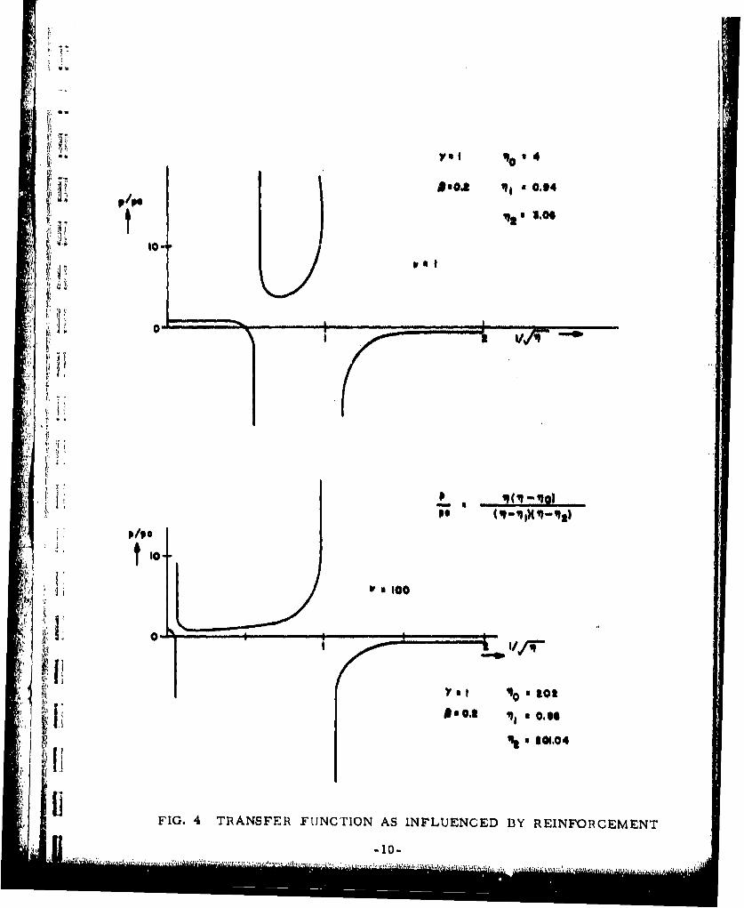
The transfer function is given in general by
iP
t where it and it are the values of it for slow and fast waves respectively.
Then for the first case studied, where Y 1 and Y is arbitrary,
we use Eq. (1) for the denominator and we have
In the second case studied, where V 1 and v is arbitrary, we use Eq. (2):
+ , 1('•+--- 1)ZZ 2
:1 •Fig. 4 graphs this last case for v = 1 (no reinforcement) and V = 100 (heavy
! 1 1,. •: reinforcement), akainst the nondimensional wavenumber I= (k 2 /] W17-.
The figure shows that overa region of wavenumbers at and below 1/-1
the inner pressure o is larger than the. outer pressure #. ; this is the
"window' of the systemr, the acceptance region of the wavenumber filter,
' ',where noise pickup is enhanced.
The equations in this report make it possible to locate and define
this "window" for a wide range of hose configuaations, and are expected to be
therefore useful In predicting noise levels.
C *iflagaflz'4'~ik.2w~1i~A~aLL .h&~4, fl~..±1~hma.h.3L~Ja~f4 &,; '
P/ O.oe W t , 0.94
ql 3.0 6to-
r ' pl'
0*0
tIto It
10-
V., 0130
Ii!FI.4TiNSE UCiO SIFUECD1YRENOCMN
S +0. . ',-',..t . . .... . .'-tA'..-~4 . ......+ I

A
CONCLUSIONS
This investigation has clarified completely the role the mechanical
properties of the wall play in the determination of wave speed@ in fluid-filled
hoses. Previous models merely defined the wall as an elastic boundary for
the fluid, and assigned to it suitable properties.
H The results for 'Y not equal to unity are of theoretical value only at A
it present, since the densities of the hose and the fluid are normally close to that
. of water for present materialso but aid in understanding wave progression in
the system,
The ability to predict wave motion in thick-walled tubes is the rnain
outcome of this study. It will serve as a sound basis for more elaborate models
which are now being studied (viscous fluid fill, solid fill, etc.). Finally, the
effect of restricting the longitudinal motions of the wall by stiffening member.,
necessary In any practical model, has been adequately taken care of and
assessed.
AI 1
1111
i el ...................................... •........ .