Embed Size (px)
Citation preview

Instructions for use
Title Dynamics of Tractor-implement Combinations on Slopes (Part Ⅰ) : State-of-the-art Review
Author(s) Yisa, Mohammed G.; TERAO, Hideo
Citation Journal of the Faculty of Agriculture, Hokkaido University = 北海道大學農學部紀要, 66(2): 240-262
Issue Date 1995-03
Doc URL http://hdl.handle.net/2115/13138
Type bulletin
File Information 66(2)_p240-262.pdf
Hokkaido University Collection of Scholarly and Academic Papers : HUSCAP
J. Fac. Agr. Hokkaido Univ., Vol. 66, Pt. 2 : 240-262 (1995)
Dynamics of Tractor-implement Combinations on Slopes (Part I)
-State-of-the-art Review-
Mohammed G. YISA and Hideo TERAO
Agricultural Vehicle System Engineering, Faculty of Agriculture,
Hokkaido University, 060 Sapporo, Japan.
(Received October 14, 1994)
Introduction
Tractor use in Nigeria (the first author's home country) is on the increase due to deliberate government policies to boost food production. Even though there exists the problem of fragmented land holdings, Nigerian farmers are now forming cooperatives, joining their lands and making mechanization feasible. Presently holdings of 100-10,000 ha are common. Although, Nigeria imported different types of tractors and trailers in the past, with the establishment of two tractor assembling plants in the country, the most common tractors are the products of these plants, that is, Fiat and Steyr models.
Tractor, the most common self-propelled machine in agriculture, roughterrain forklifts and all-terrain vehicles are increasingly used all over the world. Trailed machines such as manure-spreaders and slurry tankers are also common, and trailers are standard equipment. In forestry, most machines are selfpropelled, including skidders, forwarders, harvesters and processors. The tractor is used in combination with the trailer to convey farm workers to and from the farms, farm produce from the farm to local markets and to stores. The tractor and implement, both trailed and mounted also have to move from farm to farm in some cases on unpaved hilly roads because the individual farms are small and the farmers do not own tractors individually. Operation of tractorimplement combinations under these conditions can be likened to operation on a compound slope along different slope angles and different heading angles. The behavior of the system under such conditions and their behaviour on slopes poses an interesting off-road vehicle dynamics problem which requires better understanding.
Although a lot of resources have been expended in the last six decades on research into tractor stability and dynamics in different countries, tractor accidents are still many. Research must therefore continue, especially in the area of tractor-implement combinations, since this area has received little attention and the tractor alone is relatively stable. Earlier reviews of the subject was presented by MasayukPl, Grecenk0 2
) and Kim and Rehkugler3). Two major trends
Dynamics of Tractor-implement Combinations on Slopes (Part I) 241
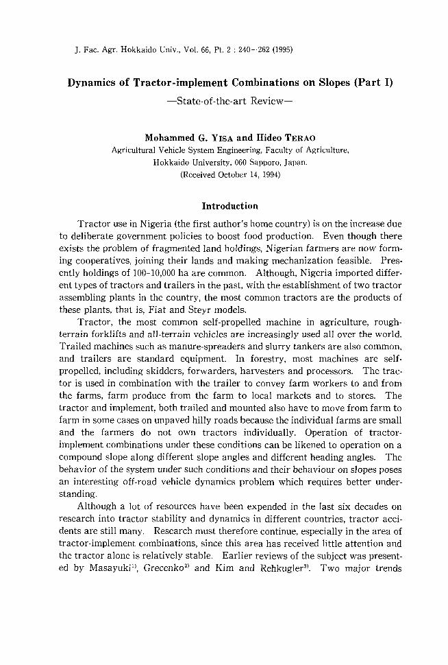
Fig.l Summary of the problem of tractordynamics and stability
(Figure 1) in the requirements of operators of tractors are dictating the directions of research and development. The first is the demand for higher levels of operator comfort and greater safety of operations. The second is the demand for better performance. This is not limited only to off-road operations but extends to travel on the road. This paper reviews the extent of research into tractor dynamics and tractor-implement combination dynamics combining the two trends. Emphasis will be laid on operation on slopes since critical situations are more likely to occur here.
Tyre forces playa central role in the behaviour of tractors, for this, they are discussed in the first part of this review. Other sections treat the problem of safety, performance respectively. Since the tractor is almost always operated in combination with implements, one section has been devoted to the discussion of research in to tractor-implement combinations.
Forces on Agricultural Tyres
Inasmuch as the performance of a tractor - the motions accomplished in accelerating, braking, cornering and ride is a response to forces imposed, much of the study of tractor dynamics must involve the study of how and why the forces are generated. The dominant forces acting on the tractor are produced from the ground. A knowledge of forces generated by agricultural tyres on hard and deformable surfaces is necessary in order to predict tractor handling and stability adequately. It is worth noting that the term "handling" is often used interchangeably with cornering, turning, or directional response, but there are nuances of difference between these terms. Cornering, turning, and directional response refer to objective properties of the vehicle when changing direction and sustaining lateral acceleration. On the other hand, handling adds to this the vehicle qualities that feed back to the driver affecting the ease of the driving task or affecting the drivers ability to maintain control.
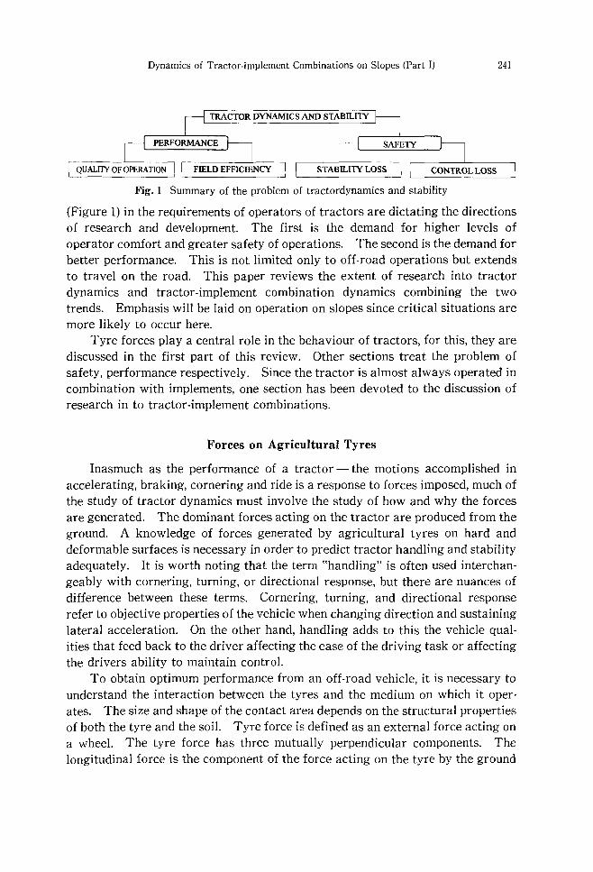
To obtain optimum performance from an off-road vehicle, it is necessary to understand the interaction between the tyres and the medium on which it operates. The size and shape of the contact area depends on the structural properties of both the tyre and the soil. Tyre force is defined as an external force acting on a wheel. The tyre force has three mutually perpendicular components. The longitudinal force is the component of the force acting on the tyre by the ground
242 M. G. YISA and H. TERAO
in the ground plane and parallel to the intersection of the wheel plane. Lateral force is the component of the force acting on the tyre by the ground in the ground plane and normal to the intersection of the wheel plane with the ground plane. The normal force (radial force) is the component of the force acting on the tyre by the ground which is normal to the plane of the ground. The normal force has a negative magnitude, it is equivalent to the negative of the vertical wheel load. The point of application of these tyre forces is the intersection of the wheel plane, the ground plane directly under the wheel center, and the plane passing through the wheel center, perpendicular to the ground and wheel planes (Fig. 2).
The tyre force normal to the ground is modeled by assuming the tyre could be represented by a spring plus a damper system, which has a point contact with the ground surface. The selection of a tyre model consisting of a spring plus damper with point contact with the ground surface necessitates that the surface specified be compatible with this model. In particular, the ability of the pneumatic tyre to envelope sharp obstacles must. be considered. Thompson4
) has shown that irregular surfaces that are traversed by a pneumatic tyre can be considered smooth when this tyre model is used. Matthews and Talamo5
) and Pershing and Y oerger6
) measured agricultural tyre vertical spring and damping rates and found that in general tyre's dynamic vertical spring rate was higher than the spring rate obtained from a linearisation of tyre's static load-deflection relation. Schuring and Belsdorf7l presented a review of the mathematical modeling of the tyre force in the vertical direction including the segmented wheel model of Lessemsl which divides the tyre into a number of pie-shaped segments with each segment having its own radial spring. Contributions in modeling the spring properties of agricultural tyres in the vertical direction have also been
Ground plane
Tyre plane
force
Fig.2 Tyre forces
/-----.."'-- Direction of wheel heading
Direction of travel
Tractive force
Slip Lateral angle(+)
force
Dynamics of Tractor-implement Combinations on Slopes (Part I) 243
presented by Thompson et aL 9), Shaw et aLlO), Davis ll
), Laib12) and Th_ Barrel
meyer et aU3).
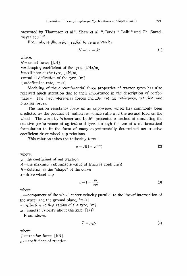
From above discussion, radial force is given by:
N=ci + kx
where, N=radial force, [kNJ c=damping coefficient of the tyre, [kNs/mJ k=stiffness of the tyre, [kN/mJ x=radial deflection of the tyre, [mJ i = deflection rate, [m/sJ
(1)
Modeling of the circumferential force properties of tractor tyres has also received much attention due to their importance in the description of performance. The circumferential forces include: rolling resistance, traction and braking forces.
The motion resistance force on an unpowered wheel has commonly been predicted by the product of motion resistance ratio and the normal load on the wheeL The work by Wismer and Luth14
) presented a method of simulating the tractive performance of agricultural tyres through the use of a mathematical formulation to fit the form of many experimentally determined net tractive coefficient-drive wheel slip relations.
This relation takes the following form;
where, f.L = the coefficient of net traction A=the maximum obtainable value of tractive coefficient B=determines the "shape" of the curve s=drive wheel slip
where,
s=l-..l'L no
(2)
(3)
Vf = component of the wheel center velocity parallel to the line-of intersection of the wheel and the ground plane, [m/sJ r=effective rolling radius of the tyre, [mJ w=angular velocity about the axle, [l/sJ
From above,
where, T = traction force, [kNJ f1.T = coefficient of traction
T=f1.TN (4)
244 M. G. YISA and H. TERAO
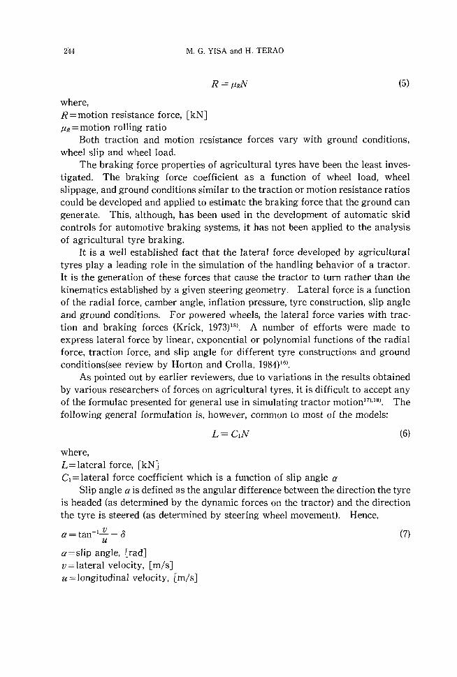
where, R=motion resistance force, [kN] f.1.R = motion rolling ratio
R=f.1.RN (5)
Both traction and motion resistance forces vary with ground conditions, wheel slip and wheel load.
The braking force properties of agricultural tyres have been the least investigated. The braking force coefficient as a function of wheel load, wheel slippage, and ground conditions similar to the traction or motion resistance ratios could be developed and applied to estimate the braking force that the ground can generate. This, although, has been used in the development of automatic skid controls for automotive braking systems, it has not been applied to the analysis of agricultural tyre braking.
It is a well established fact that the lateral force developed by agricultural tyres playa leading role in the simulation of the handling behavior of a tractor. It is the generation of these forces that cause the tractor to turn rather than the kinematics established by a given steering geometry. Lateral force is a function of the radial force, camber angle, inflation pressure, tyre construction, slip angle and ground conditions. For powered wheels, the lateral force varies with traction and braking forces (Krick, 1973)15). A number of efforts were made to express lateral force by linear, exponential or polynomial functions of the radial force, traction force, and slip angle for different tyre constructions and ground conditions(see review by Horton and Crolla, 1984)16).
As pointed out by earlier reviewers, due to variations in the results obtained by various researchers of forces on agricultural tyres, it is difficult to accept any of the formulae presented for general use in simulating tractor motion I7
),18). The following general formulation is, however, common to most of the models:
(6)
where, L=lateral force, [kN] C = lateral force coefficient which is a function of slip angle a
Slip angle a is defined as the angular difference between the direction the tyre is headed (as determined by the dynamic forces on the tractor) and the direction the tyre is steered (as determined by steering wheel movement). Hence,
a=tan- I...!!..- 0 (7) u
a=slip angle, [rad] v=lateral velocity, [m/s] u=longitudinal velocity, [m/s]
Dynamics of Tractor-implement Combinations on Slopes (Part I)
tan-l~ - 0 defines the direction of tyre heading u
o defines the direction in which the tyre is steered_
Safety
245
As the agricultural tractor originally evolved from its steam prototype, operating stability was largely taken for granted_ Tractors of that time were ponderous and their low drive wheel lugs afforded little penetration in to the soil, the resulting traction was poor, and the ratio of drawbar pull to total weight was low_ As long as field upsets were non-existent, stability characteristics posed no problems_ Tractor stability became a matter of concern ever since the development of the relatively light weight tractor from the massive steam engines of the past This concern is reflected as far as the 1920s with the now classic investigations of tractor static and dynamics by McKibbenI9).20).
Tractor overturning accidents on slopes, which always have serious consequences for the farmer, are of two categories_ These are stability loss which is when the tractor overturns directly, and control loss which is when the tractor slides bodily downhill before overturning. These accidents arise in a wide variety of circumstances: tractor alone, tractors with mounted and trailed equipment, on steep slopes and on gentle slopes.
Hazards on a slope are present when a tractor is traveling; downhill, changing direction, crossing the slope or climbing uphilL Sliding downhill will occur if the ground is too slippery for the tractor to remain under control; this is common on grass fields, and is also likely on loss surfaces_ Skidding or overturning on the other hand will occur when cornering at too high speed. Sideways overturning will occur on too steep slopes and on rough ground. Accelerating uphill will cause rearwards overturning or slipping, while with certain designs the machine will tip forwards when braking during a descent
The use of rollover protective structures ROPS will no doubt reduce the number of fatalities and injuries, but avoidance of the overturns altogether would be the optimum situation. If the tractor is never unstable, yet is still used at maximum output over the wide range of terrain, then the operator and the equipment manufacturer would have performed their jobs.
1. Research Methods The goal toward tractor safety will be achieved through the observation and
analysis of the tractor dynamics under numerous field operating conditions. Research into tractor stability and dynamics could be experimental, computer simulation or computer simulation and experimentation. The use of experimental methods only, to study tractor stability and dynamics is limited. The limitations arise because in the first place, such experiments would be slow and, very
246 M. G. VISA and H. TERAO
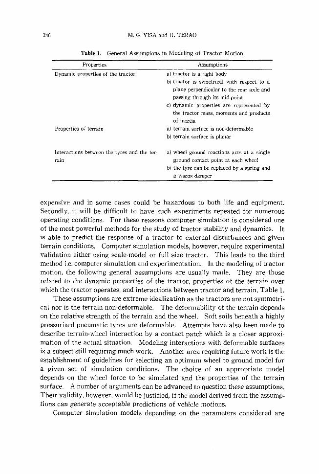
Table 1. General Assumpions in Modeling of Tractor Motion
Properties
Dynamic properties of the tractor
Properties of terrain
Assumptions
a) tractor is a right body
b) tractor is symetrical with respect to a
plane perpendicular to the rear axle and
passing through its mid-point
c) dynamic properties are represented by
the tractor mass, moments and products
of inertia
a) terrain surface is non-deformable
b) terrain surface is planar
Interactions between the tyres and the ter- a) wheel ground reactions acts at a single
rain ground contact point at each wheel
b) the tyre can be replaced by a spring and
a viscus damper
expensive and in some cases could be hazardous to both life and equipment_ Secondly, it will be difficult to have such experiments repeated for numerous operating conditions_ For these reasons computer simulation is considered one of the most powerful methods for the study of tractor stability and dynamics_ It is able to predict the response of a tractor to external disturbances and given terrain conditions. Computer simulation models, however, require experimental validation either using scale-model or full size tractor. This leads to the third method i.e. computer simulation and experimentation. In the modeling of tractor motion, the following general assumptions are usually made. They are those related to the dynamic properties of the tractor, properties of the terrain over which the tractor operates, and interactions between tractor and terrain, Table L
These assumptions are extreme idealization as the tractors are not symmetrical nor is the terrain non-deformable. The deformability of the terrain depends on the relative strength of the terrain and the wheel. Soft soils beneath a highly pressurized pneumatic tyres are deformable. Attempts have also been made to describe terrain-wheel interaction by a contact patch which is a closer approximation of the actual situation. Modeling interactions with deformable surfaces is a subject still requiring much work. Another area requiring future work is the establishment of guidelines for selecting an optimum wheel to ground model for a given set of simulation conditions. The choice of an appropriate model depends on the wheel force to be simulated and the properties of the terrain surface. A number of arguments can be advanced to question these assumptions_ Their validity, however, would be justified, if the model derived from the assumptions can generate acceptable predictions of vehicle motions.
Computer simulation models depending on the parameters considered are
Dynamics of Tractor-implement Combinations on Slopes (Part I) 247
either static, quasi-static or dynamic_ Under static conditions a tractor will loss stability and start to overturn when the normal to ground component of a wheel load becomes zero_ A modification of static models is the quasi-static models_ They take into account constant speed turning, and constant acceleration or deceleration_ Slope values at which zero wheel load is experienced is predicted just as in the case of static modeL
Dynamic models attempt to predict the conditions necessary for overturning_ This is considerably more complex than predicting zero wheel load because it is also necessary to predict the motion of the machine while it lifts off the ground and passes through the point of balance_ There are two main problems in obtaining a good dynamic modeL The first is simulating the interaction between the vehicle tyres and the ground, and the second is predicting the behaviour of the whole vehicle in response to random ground inputs_
2. Stability Measurement Schwanghare) estimates the following values of operating limits of different
machinery for different crops; sugar beet 7°, potatoes 11°, cereals 14°, forage IT, and grazing 24°_ These limits depend on the machinery used and relate only to traction limits for pulling harvesting equipment There is a wide variation between the stability limits of different types and designs of machine_ The two or four wheel drive tractor will tip at a side slope of 36° extending the track width by 210 mm can increase this value to 42°_ Trailed machinery are generally less stable than the tractor, with most stability values in the range 20° to 30°_
In Czechoslovakia, tractors working on slopes were to be marked with a label indicating the rated operating slope ROS which has been determined as 1/ 3 of the minimum static stability in degrees_ This resulted into problems because research results revealed that ROS is a function of velocity and should be determined by finding the smallest value of slope for a given speed by different criteria on condition that either the resistance to overturning or the resistance to sliding reach the defined limit22
)_
Static stability can be measured on a tilt table, yet so far as is known, this is not required under official procedures of any country except in N orway_ The new test of static stability which requires only portable weighpad equipment and an inclinometer is probably the easiest and least expensive method of assessing static stability_ It is based on measuring the weight transfer on a moderate slope and then predicting the slope angle where an uphill wheel will carry no 10ad23
)_
The dynamic effects of cornering, acceleration and deceleration can be calculated directly in terms of adjustments to the static stability limit, provided these effects remain constant
Testing a machine leads to the concept of determining an index of stability for the machine_ One proposal being made is that the index is a slope value, defined as the minimum slope on which a dynamic test causes the machine to tip
248 M. G. YISA and H. TERAO
halfway towards overturning. A machine with a high stability index will be more stable than a machine with a low stability index. Thus the index will be a valuable indicator of machines which are safer to use on slopes and it can be used to propose maximum operating slopes for individual machines. However, the index will not in itself define a safe slope because it will always be possible to cause an overturn, even on level ground, by violent manoeuvres and harsh driving. A stability index will provide a standard measure with which to compare the stability of different machines24l.
3. Types of Overturns Overturning accidents arise from reaching the limit of static stability, reach
ing stability limit under dynamic conditions, or sliding out of control. An agricultural tractor may overturn in any of the following three directions: rearwards, sideways or forwards. Of the three types of overturning situations, sideways overturning have been discovered to occur most often resulting in about 70 % of the total overturning accidents. It has also understandably received most attention in terms of research efforts. Forward overturning accidents are very rare and their study has received little attention. Although rearwards overturning covers just about 30 % of reported tractor overturning cases, they are more likely to result in fatalities than sideways overturning accidents25l. They have, therefore, received considerable attention. 3.1. Rearward overturning
Rearward stability has been a subject of considerable research since the development of the lightweight tractors from their massive steam tractor predecessors. Among the earlier works are those of Worthington26l, and Sack27l which treated the resulting differential equations of motion as algebraic equations since then methods of solving the often non-linear equations were either few or not in existence at all. The advent of digital and analog computers encouraged the development of more complex and accurate mathematical models such as those by Raney et aJ.28l, Goering and Buchele29l, Pershing and Yoerger30l, and Koch et al.31l. These works form the theoretical basis for the generally accepted principles of save tractor hitching which include, never to hitch a drawbar load at or above the rear axle and the stability of a tractor will be increased by lowering the hitch point and/or moving it to the rear.
Smith and Liljedahp2l developed a two part model to simulate rearward overturning of agricultural tractors. The first part considers the tractor as rotating about it's center of gravity when all wheels are in contact with the ground while the second part considers the tractor frame as rotating about the rear axle during the actual overturning. The parameters of the model were determined for a typical agricultural tractor. The tractor was instrumented to measure rear axle torque and angular acceleration. Additional instrumentation was also made to remotely engage the clutch and shut off the engine of the
Dynamics of Tractor·implement Combinations on Slopes (Part I) 249
tractoL The overturning situation studied was that of application of power to a tractor whose drive wheels were solidly lodged. A more recent work considering the influence of drawbar position on tractor rearward stability has been present· ed33
). The analytical procedure provides a means of evaluating the effect of drawbar position on tractor static rearward stability that considers the limiting effects of traction conditions and available axle load. Static stability is im· proved by moving the centre of gravity forward and lowering the angle of draft. 3.2. Sideways overturning
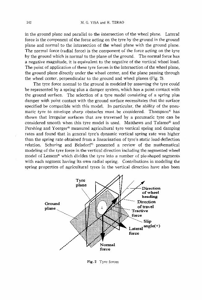
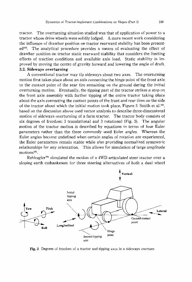
A conventional tractor may tip sideways about two axes. The overturning motion first takes place about an axis connecting the hinge point of the front axle to the contact point of the rear tire remaining on the ground during the initial overturning motion. Eventually, the tipping part of the tractor strikes a stop on the front axle assembly with further tipping of the entire tractor taking place about the axis connecting the contact points of the front and rear tires on the side of the tractor about which the initial motion took place, Figure 3. Smith et a1.34
),
based on the discussion above used vector analysis to describe three·dimensional motion of sideways overturning of a farm tractor. The tractor body consists of six degrees of freedom: 3 translational and 3 rotational (Fig. 3). The angular motion of the tractor motion is described by equations in terms of four Euler parameters rather than the three commonly used Euler angles. Whereas the Euler angles become undefined when certain angles of rotation are experienced, the Euler parameters remain stable while also providing normalized symmetric relationships for any orientation. This allows for simulation of large amplitude motions35
).
Rehkugler36) simulated the motion of a 4WD articulated steer tractor over a
sloping earth embankment for three steering alternatives of both a dual wheel
Yaw Pitch
Roll
Initial tipping aXIs
t Vertical
Lateral ~--~~~~+--+------~~~---~
Longitudinal
~ Second tipping point
axis
Fig.3 Degrees of freedom of a tractor and tipping axes in a sideways overturn
250 M. G. VISA and H. TERAO
and a single wheel tractor. Steering down the embankment was shown to be a possible maneuver to prevent an overturn. His simulation showed that steering straight ahead on a 50° slope soil embankment would likely result in a side overturn of both a dual and single wheeled articulated steer 4WD tractor.
Spencer and Gilfillan37) observe that field records obtained from a tractor
moving at constant speed suggest that measurements of energy input to ground irregularities causing roll or pitch of the machine represent a random stationary Gaussian process, for which a first passage time can be calculated. This procedure enables the length of time from the start of use of the tractor within which the first occasion of overturning may occur be considered along with the probability of stability being lost. It also offers a method for estimating the stability of a tractor on slopes having different ground surfaces by the use of data obtained in safety on level land.
Chisholm38) developed a mathematical model based on the force and displace
ment equations of equilibrium at each point where the tractor or cab makes contact with the ground during overturning. The model covers overturning phase, in addition to impact, by including tyre side forces relationships and damping terms. Survey results show that the two types of accidents likely to result in high energy being absorbed in a roll over protective structure RaPS are: a tractor falling over the edge of a bank 2 to 4 meters high, with a slope of 0 to 40 to the vertical and accidents involving multiple rolls.
A two-dimensional mathematical model was developed to describe the dynamic behaviour of a body in multiple point contact with the ground, where the flexibility of the body and ground can be represented by non-linear forces deformation characteristics. The transverse ground forces was assumed to bear a Coulomb-type relationship with the normal force, where the friction coefficient varied continuously according to sliding velocity and other variables. The model was validated by full-scale experiments in which a tractor with an instrumented experimental safety frame was overturned down a simulated bank about 2 m high39
). The model was also used to study the effect of parameters on energy absorbed in a RaPS during motion down a steep bank40
).
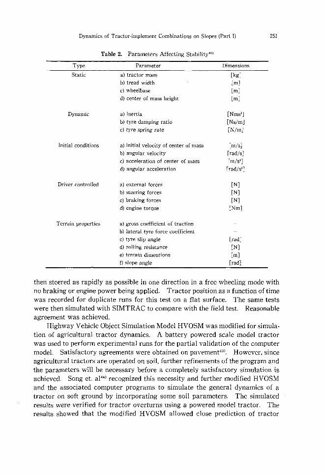
Kelly and Rehkugler41) showed in their research the velocity at which a
critically steered tractor will overturn on a given bank slope. The permissible bank slope would approach the static angle of tip, as the velocity approaches zero. On a flat terrain there will be a minimum velocity which will cause overturn. Twenty one variables identified to influence tractor overturn are presented in Table 2. Given a particular slope angle, the minimum velocity at which a tractor will overturn was determined.
Rehkugler (1982)42 conducted a full-scale verification study to establish the level boundaries of confidence one may expect in the use of SIMTRAC(a computer simulation program) during high speed turns on level terrain. A small utility tractor was accelerated to maximum travel speed in a straight line and
Dynamics of Tractor-implement Combinations on Slopes (Part I)
Table 2. Parameters Affecting Stability'O)
Type Parameter
Static a) tractor mass
b) tread width
c) wheelbase
d) center of mass height
Dynamic a) inertia
b) tyre damping ratio
c) tyre spring rate
Initial conditions a) initial velocity of center of mass
b) angular velocity
c) acceleration of center of mass
d) angular acceleration
Driver controlled a) external forces
b) steering forces
c) braking forces
d) engine torque
Terrain properties a) gross coefficient of traction
b) lateral tyre force coefficient
c) tyre slip angle
d) rolling resistance
e) terrain dimentions
f) slope angle
Dimensions
[kg]
[m]
[m]
[m]
[Nms']
[Ns/m]
[N/mJ
[m/sJ
[rad/sJ
[m/s']
[rad/s']
[N] [N] [N]
[Nm]
[rad]
[N]
Em] [rad]
251
then steered as rapidly as possible in one direction in a free wheeling mode with no braking or engine power being applied. Tractor position as a function of time was recorded for duplicate runs for this test on a flat surface. The same tests were then simulated with SIMTRAC to compare with the field test. Reasonable agreement was achieved.
Highway Vehicle Object Simulation Model HVOSM was modified for simulation of agricultural tractor dynamics. A battery powered scale model tractor was used to perform experimental runs for the partial validation of the computer model. Satisfactory agreements were obtained on pavement43
). However, since agricultural tractors are operated on soil, further refinements of the program and the parameters will be necessary before a completely satisfactory simulation is achieved. Song et. a1 44
) recognized this necessity and further modified HVOSM and the associated computer programs to simulate the general dynamics of a tractor on soft ground by incorporating some soil parameters. The simulated results were verified for tractor overturns using a powered model tractor. The results showed that the modified HVOSM allowed close prediction of tractor
252 M. G. VISA and H. TERAO
dynamics. A mathematical model combining the three major factors (sloping grounds,
bumps, and turns) responsible for tractor overturns was developed by Feng and Rehkugler45
). Two cases were considered, the situation where the tractor has three degrees of freedom with respect to the ground; two for translation and one for rotation (three or four wheels contact the ground) and a situation where the tractor has four degrees of freedom; two for translation and two for rotation (only two wheels keep contact with the soil). Newtonian Mechanics was used in the first case, while Lagrange equation was applied to the second case. Spencer and Crolla46
) presented a procedure for studying control of tractors on sloping ground. A remote controlled tractor was used to verify the developed model. To study sideslip phenomenon of agricultural tractors, Machida47
),48) used a single wheel sideslip analyzer and a model tyre on a plywood. Sideslip was found to be a function of slope angle and slip. Noh and Erbach49
) recently used the variational vector approach that uses relative generalized coordinates in Cartesian space to develop a semi-recurssive dynamic algorithm which was evaluated by modeling an agricultural tractor. Apart from this semi-recursive dynamic algorithm method, modeling of tractor dynamics has either been achieved through vectorial mechanics (Newtonian approach) or through variational approach to mechanics (Lagrangian dynamics).
Field Performance
The prediction of tractor-implement field performance has been attempted many times in the past. Simulation of tractors for predicting field performance using a graphical method was presented by Grecenk050
). The parameters plotted were wheel slip, implement draft, engine power, field speed, combination of tractive and transmission efficiency and fuel consumption. To determine the fuel consumption for steady-state operation, the graph was entered at the appropriate draft, engine power, wheel slip and transmission efficiency. Sclegel and Morling51
) developed a simple calculator for estimating the forward speed required to maximize tractor work rate when ploughing. The mathematical model used to produce the calculator was, however, a very simple one and did not include the effects of, for example, tyre size and type and condition of soil. 20Z52
)
developed a graphical solution technique for two-wheel drive tractor performance. Data needed were travel speed, axle load, engine power, type of hitch and soil condition. Using the graphical technique, the ratio of drawbar pull to rear axle load and tractive efficiency could be determined. This predictor was reported valid only for steady-state performance of 2WD tractors equipped with single wheel drive wheels.
Wismer and Luth53) produced a set of empirical equations which could be
used to predict the field performance of field vehicles. The equations utilize the
Dynamics of Tractor·implement Combinations on Slopes (Part I) 253
mobility number developed by Freitag54) and further extended by Turnage55). A transmission torque balance was used by Kolozsi and McCarthy56) in developing a computer simulation of tractor performance. The torque prediction equation relied upon measuring the independent variables in one gear prediction. Smith and Y oerger57) developed a mathematical model for predicting variations in the forward motion of farm tractors due to varying drawbar loading. They then used the model to study the translational frequency response characteristics of a tractor subjected to a periodic drawbar load. Seven degrees of freedom were considered in developing the mathematical modeL These were longitudinal and vertical translation of the tractor center of gravity, pitch of the tractor about its center of gravity, angular rotation of the inner and outer parts of the drive wheel, angular rotation of the engine, and angular motion of the engine governor flyweights. The equations of motion were developed using the principles of Lagrangian dynamics. The power train was assumed as storing potential energy due to torsional motion of the drive train. Drawbar pull was varied by a sinusoidal function.
The development of empirical equations for predicting the performance of a tractor·plough combination was presented by Gee-Clough et aL58). The empirical equations were considered accurate enough for the computational method presented to be used for a general parametric study of tractor-plough field performance. In another study, Yasuo et. a}59) developed climbing tractive performance charts. More recently, mathematical models describing the performance of 2WD and 4WD tractors were developed by Summers et aL60). The simulation model was validated by simulating the lugging ability of the Nebraska Tractor Tests. Reasonable agreements were obtained. A method to obtain theoretical traction characteristics for a tractor as a function of its engine performance, total transmission gear ratio, dimensional parameters, and drawbar performance on concrete for two gears was propose by Souza and Milanez61 ).
In order to improve the performance and stability of agricultural tractors on slope, a conventional tractor was modified and tested62).63).64). A major modification was made to the rear axle on which the centres of the drive wheels were at different heights.
Tractor-implement Combinations
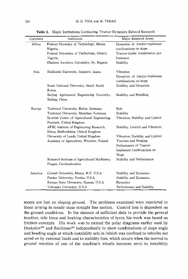
Although much research has been done on the dynamics and stability of an agricultural tractor alone in many countries (Table 3), the combination with a trailer or other implements has received less attention. Gilfilan65).66) reported work on the effect of slopes on the forces and moments acting on tractorimplement combinations operating uphill or downhill.
Spencer67) examined conditions under which the overturning stability and directional control of two-wheeled drive tractors with mounted or towed imple-
254 M. G. YISA and H. TERAO
Table 3. Major Institutions Conducting Tractor Dynamics Related Research
Continent Institution Major Research Areas
Africa Federal Unversity of Technology, Minna,
Nigeria.
Asia
Federal University of Technology, Owerri,
Nigeria.
Obafemi Awolowo University, Ife, Nigeria
Hokkaido University, Sapporo, Japan.
Dynamics of tractor· implement
combinations on slope
Tractor-trailer combination per·
formance
Stability
Vibration Dynamics of tractor·implement
combinations on slope
Seoul National University, Seoul, South Stability and Dynamics
Korea. Beijing Agricutural Engineering Unversity, Stability and Handling
Beijing, China.
Europe Technical University, Berlin, Germany. Ride
Technical University, Munchen, Germany. Stability
Scottish Centre of Agricultural Engineering, Vibration, Stability and Control
Penicuik, United Kingdom. AFRC Institute of Engineering Resaerch, Stability, Control and Vibration.
Silsoe, Bedfordshire, United Kingdom.
University of Leads, United Kingdom Academy of Agriculture, Wroclaw, Poland.
Research Institute of Agricultural Machinery,
Prague, Czechoslovakia
America Cornell University, Ithaca, N.Y, U.S.A
Purdue University, Purdue, U.S.A
Kansas State University, Kansas, U.S.A
Nebraska University, U.S.A
Vibration, Stability and Control
Traction and Braking
Performance of Tractor·
implement Combinations on
Slope
Stability and Performance
Stability and Dynamics
Stability and Dynamics
Dynamics
Performance and Stability
ments are lost on sloping ground. The problems examined were restricted to those arising in steady state straight line motion. Control loss is dependent on the ground conditions. In the absence of sufficient data to provide the general traction, side force and braking characteristics of tyres, his work was based on friction concepts. His work was to extend the polar diagrams earlier used by Daskalov68
) and Reichman69) independently to show combinations of slope angle and heading angle at which instability sets in (which was confined to vehicles not acted on by external loads and to stability loss, which occurs when the normal to ground reaction of one of the machine's wheels becomes zero) to instability
Dynamics of Tractor·implement Combinations on Slopes (Part I)
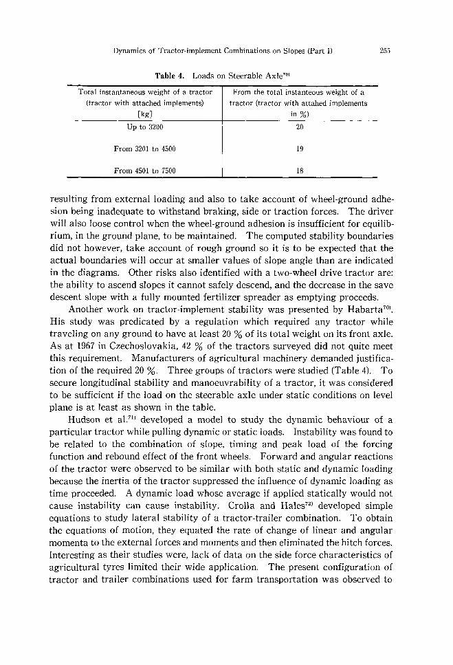
Table 4. Loads on Steerable AxleO)
Total instantaneous weight of a tractor
(tractor with attached implements) [kg]
Up to 3200
From 3201 to 4500
From 4501 to 7500
From the total instanteous weight of a tractor (tractor with attahed implements
in %)
20
19
18
255
resulting from external loading and also to take account of wheel·ground adhesion being inadequate to withstand braking, side or traction forces. The driver will also loose control when the wheel-ground adhesion is insufficient for equilibrium, in the ground plane, to be maintained. The computed stability boundaries did not however, take account of rough ground so it is to be expected that the actual boundaries will occur at smaller values of slope angle than are indicated in the diagrams. Other risks also identified with a two-wheel drive tractor are: the ability to ascend slopes it cannot safely descend, and the decrease in the save descent slope with a fully mounted fertilizer spreader as emptying proceeds.
Another work on tractor-implement stability was presented by Habarta70).
His study was predicated by a regulation which required any tractor while traveling on any ground to have at least 20 % of its total weight on its front axle. As at 1967 in Czechoslovakia, 42 % of the tractors surveyed did not quite meet this requirement. Manufacturers of agricultural machinery demanded justification of the required 20 %. Three groups of tractors were studied (Table 4). To secure longitudinal stability and manoeuvrability of a tractor, it was considered to be sufficient if the load on the steerable axle under static conditions on level plane is at least as shown in the table.
Hudson et aU!) developed a model to study the dynamic behaviour of a particular tractor while pulling dynamic or static loads. Instability was found to be related to the combination of slope, timing and peak load of the forcing function and rebound effect of the front wheels. Forward and angular reactions of the tractor were observed to be similar with both static and dynamic loading because the inertia of the tractor suppressed the influence of dynamic loading as time proceeded. A dynamic load whose average if applied statically would not cause instability can cause instability. Crolla and Hales72
) developed simple equations to study lateral stability of a tractor-trailer combination. To obtain the equations of motion, they equated the rate of change of linear and angular momenta to the external forces and moments and then eliminated the hitch forces. Interesting as their studies were, lack of data on the side force characteristics of agricultural tyres limited their wide application. The present configuration of tractor and trailer combinations used for farm transportation was observed to
256 M. G. VISA and H. TERAO
have severe stability problems at speeds higher than 9 m/s and also during breaking. Locking the tractor rear wheels results in a major instability known as jack-knifing. Locking the rear axle results in a less severer, but potentially dangerous instability situation known as tractor swing. Locking the front axle has a stabilizing effect on the combination.
Static loss of stability due to driving a tractor onto a smooth slope so steep that the tractor overturns is rare. This is because a tractor is reasonably stable. A typical two-wheel drive tractor must be driven onto a slope of 33° before it reaches its stability limit, which is much steeper than the slopes on which most accidents occur; the reason is that very few accidents are caused by simple static overturning. A tractor with a front loader being used to lift a heavy tree trunk overturned as it was turned downhill on a slope of 8° due to a shift in the overall centre of gravity. Ground roughness which may also be the cause of dynamic stability loss if a tractor is driven at high speed and the tractor wheels starts to bounce was found to be responsible for static stability loss as a result of the existence of a local steepness. Speed, acceleration and cornering are dynamic conditions which affect stability. Stability and control loss slopes are likely to coincide, not so much due to dynamic effects, but due to loads added to the tractor. For control loss calculations one parameter which is always difficult to assess is the braking force coefficient between the tyres and grass. The wide range of accident circumstances and the fluctuating grass grip are the two main reasons that it has been difficult to forestall accidents73).
Hunter and Owen74) reported on various types of accidents involving tractorimplement combinations on slopes. They described stability and control loss accidents to show the varied circumstances in which they occur and to demonstrate the wide range of equipment involved.
A stability-indicating system for use in minimizing the occurrence of frontend loader (FEL) roll over has been developed75). The following operator controlled factors contribute to the loss of stability of a FEL: weight of the load in the bucket, the bucket height, the yaw angle of articulation, its velocity, and the degree of breaking. It is observed that while any of these factors could be a principal contributor, it is usually a combination of these parameters that produces an accident.
Hunter76) analyzed the stability of trailed tankers on slopes. Due to movement of the center of gravity the tanker is less stable when partly full than when completely full, with the result that the tanker becomes progressively less stable as its contents are discharged during work. Sakai et al.77)·78) developed a mathematical model to study the dynamic behaviour of a tractor-vibrating subsoiler system. The validation of their model showed a considerable agreement with simulation data obtained. The virtual hitch point VHP was observed to have a considerable effect on the vertical acceleration under the drivers seat.
To study the steering and control characteristics of a vehicle, the design of
Dynamics of Tractor-implement Combinations on Slopes (Part I) 257
tractive system and the automatic guidance system, steering stability of a tractortrailer combination, evaluation of passing ability of a vehicle, the design of roads etc., the motion and the trajectories in the turning process are important. Zhenan79
) realized this importance and investigated the trajectories of wheels in a vehicle-trailer combination turning process. A study on the braking performance of tractor-trailer combination was done by Asoegwu80
). Tractors with balanced and unbalanced trailers were studied. The deceleration rate of a tractor-implement combination depends on, the type of trailer (balanced or unbalanced), whether the trailer is equipped with brakes or not, load carried by the trailer and the surface on which the combination travels. Five analytical mechanics methods to formulate dynamic equations for tractor-trailer system handling model were presented recently by Xie et al.8
1). General-purpose, large displacement computer simulation programs which utilize these methods have also been briefly discussed. Traction parameters of tractor-implement combinations on hills has been presented82
),83). Motion resistance, acceleration and traction forces on slopes of up to 16' were measured.
Another attempt at establishing the performance of tractor-implement combination was done by Zhang and Tera084
). They studied the performance of tractor-trailer combinations meant for farm use. Tractor-trailer performance was measured on both concrete and a harvested field. The necessity to equip trailers meant for farm transportation with brakes was stressed. They used optimal control theory to improve the performance of tractor-trailer combination.
Conclusions
Considerable research has been conducted on tractor overturning stability and dynamics on sloping ground, much of the work was connected to establishing safe operating slopes and the introduction of the roll over protective structures ROPS and their associated legislature. Many mathematical models for tractor dynamics and stability studies have been developed in the last 30 years. A lot of instrumentation has also been developed to validate most of the models either by using scale-models or full-size tractors85
-8
7). The static stability, which in itself has unexpected complexities depending on the design of the vehicle is, however, still better understood than the dynamic stability. In agriculture, over half the overturning accidents with machines are due to exceeding their slope capabilities, while only one quarter can be blamed on carelessness or misjudgment of the driver.
Computer models of tyres already exist, and they are standard elements in advanced commercial modeling packages such as, ADAMS, DAMS, DADS etc., but their use is still limited by the availability of field data for real tyres and real ground.
258 M. G. YISA and H. TERAO
Little work has been done on steering control and directional stability characteristics of tractor-implement combinations TICs or their handling performance on slopes generally. When agricultural wheeled tractors are operated across a slope, they tend to slide down as a result of the component of the gravitational force acting on the tractor and directed down the slopes which results in lateral load transfer LL T. LL T is the vertical load transfer from one of the front tyres (or rear tyres) to the other that is due to acceleration, rotational or inertial effects in the lateral direction. The consequence of this, is that maintaining a straight-line motion or motion along a desired path becomes difficult and constant directional correction is necessitated. Other shortcomings resulting from this, are, extra power requirement, increased fuel consumption, uneven motion of operating parts in attached implements, irregular seed distribution by planters, insufficient depth of tillage and poor conditions for plant growth (Amelchenco et al., 1978) as reported by Lyasko et al. SS
). Current research into tractor stability and dynamics should, therefore, be directed towards: 1) Harnessing already available models and research results for the optimization of the tractor configuration in particular and tractor-implement outfit in general. 2) Modeling the lateral dynamics of tractor-implement combinations on slope not only for stability analysis, but also for performance analysis. 3) Establishment of agricultural tractor tyre parameters pertinent to modeling its dynamic behaviour.
References
1) Masayuki K.: Research in to Tractor Stability Abroad. Journal of the Japanese Society of Agricultural Machinery, 37(4): 626-629, 1975 (In Japanese).
2) Grecenko A.: Operation on Steep Slopes. State-of-the-Art Report. Journal of Terramechanics 21(2): 181-194, 1984b.
3) Kim Uk K. and Rehkugler G. E.: A Review of Tractor Dynamics and Stability. Transactions of ASAE. 30(3): 615-623, 1987.
4) Thompson, L. ]., Liljedahl, ]. B., and Quinn, B. E.: Dynamic motion Response of Agricultural Tyres. ASAE Paper 70-148, 1970.
5) Matthews,]. and Talamo, ]. D. c.: Ride Comfort for Tractor Operators. III. Investi· gation of Tractor Dynamics by Analogue Computer. ]. of Agricultural Engineering Research 10(2): 93-108, 1965.
6) Pershing R. L. and Yoerger R. R.: Simulation of Tractors for Transient Response. Transactions of the ASAE. 12(5): 715-719, 1969.
7) Schuring, D. and Belsdorf, M. R.: Analysis and Simulation of Vehicle-terrain Interaction. Cornell Aeronautical Lab. Technical Memorandum No. VJ-2330-G-56, 206p, 1969.
8) Lessem, A. S.: Dynamics of Wheeled Vehicles. Report I: A Mathematical Model for the Traversal of Rigid Obstacles by Pneumatic Tyres. U. S. Army Engineer Waterways Experiment Station, Vicksburg, MS, 1968.
9) Thompson, L. ]., Liljedahl, ]. B., and Quinn, B. E.: Dynamic motion Response of
Dynamics of Tractor-implement Combinations on Slopes (Part I)
Agricultural Tyres_ Transactions of ASAE 15(2): 206-210, 1972. 10) Shaw, L N_, Johnson W_ H_ and Hamdy M_ Yo: Analysing Dynamic Response of a
Semi-mounted Implement Transactions of the ASAE 15(6): 1059-1063, 1972_ 11) Davis, D_ Co: A Radial Spring Terrain Enveloping Tyre ModeL Vehicle System
Dynamics 4(1): 55-69,1975_ 12) Laib, L On the Dynamic Behaviour of Agricultural Tyres_ Journal of Terrame
chanics 16(2): 77-85, 1979_ 13) Barrelmeyer, Th_, Armbruster, K , Langenbeck, B. and Kutzbach, H. D_: The Model
for Vertical, Longitudinal and Lateral Forces on Driven Angled Tractor Wheels_ Proceedings International Conference ISTVS, VoL II, 1993
14) Wismer, R D_ and Luth H. 1-: Off-Road Traction Prediction for Wheeled Vehicles_ Transactions of ASAE. 17(1): 8-10, 14, 1974_
15) Krick G_: Behaviour of Tyres Driven in Soft Ground with Side Slip_ 1- of Terramechanics_ 9(4): 9-30, 1973_
16) Horton, D_ H_ L and Crolla, D_ A_: The Handling Behaviour of Off-road Vehicles_ Int_ 1- of Vehicle Design 5(1/2): 197-218, 1984_
17) Crolla D_ A_ and Hales F_ D_: The Lateral Stability of Tractor and Trailer Combinations_ Journal of Terramechanics 16(1): 1-22, 1979_
18) Plackett Co W_: A Review of Force Prediction Methods for Off-Road Wheels, 1-agric_ Engng Res_ 31: 1-29, 1985_
19) Mckibben E. G_: The Kinematics and Dynamics of the Wheel Type Farm Tractor. Agricultural Engineering_ 8(1-7) Inclusive, 1927_
20) Mckibben E. G_: Effect of Pull Upon the Effective Weight on Front and Rear Wheels of Farm Tractors_ Agricultural Engineering 9(8), 243-245, 1928_
21) Schwanghart, H.: Tipping and Overturning Behaviour of Tractors_ Landtechnik 11: 488-492, 1978-
22) Grecenko A.: Study of the Motion of Agricultural Vehicles on Steep Grass-Covered Slopes_ Proceedings 8th International Conference ISTVS, 1984a_
23) Owen G_ M_, Hunter A. G_ M_ and Glasbey Co A_: Predicting Vehicle Stability Using Portable Measuring Equipment Proceedings 5th European Conference ISTVS VouI, 1991
24) Hunter A. G_ M_: A Review of Research into Machine Stability on Slopes_ Presented at AG ENG 92_ Agricultural International Conference_ Uppsala-Sweden, June 1-4, 1992_
25) National Safety Council, Accident Facts, Chicago, Ill, 1968_ 26) Worthington H. W_: Evaluation of Factors Affecting the Operating Stability of
Wheel Tractors_ Agricultural Engineering 30(3):179-182, 1949_ 27) Sack H. W_: Longitudinal Stability of Tractors_ Agricultural Engineering 37(5):328
-333, 1956_ 28) Raney 1- Po, Liljedahl 1- B. and Cone R: The Dynamic Behaviour of Farm Tractors_
Transactions of ASAE. 4(2):215-218, 221, 196L 29) Goering G_ E. and Buchele W_ F_: Computer Simulation of an Unsprung Vehicle Part
I _ and II. Transactions of ASAE 10(2): 272-280, 1967 30) Same as 5)_ 31) Koch, 1- A., Buchele, W_ F_ and Marley, S_ 1-: Verification of a Mathematical Model
to Predict tractor Tipping Behaviour_ Transactions of ASAE 13(1): 67-72, 76, 1970_
259
260 M. G. YISA and H. TERAO
32) Smith, D. W. and Liljedahl, J. B.: Simulation of Rearward Overturning of Farm Tractors. Transactions of the ASAE 15(5): 818-821, 1972.
33) Smith D. W.: The Influence of Drawbar Position on Tractor Rearward Stability. ASAE Paper No. 84-1560, 1984.
34) Smith, D. W., Perumral J. V. and Liljedal J. B.: The Kinematics of Tractor Sideways Overturning. Transactions of the ASAE 17(1): 1-3, 1974.
35) Davis D. C. and Rehkugler G. E.: Agricultural Wheel Tractor Overturns Part I; Mathematical Model. Transactions of ASAE 17 (3): 477-483, 1974a.
36) Rehkugler G. E.: Simulation of Articulated Steer Four-Wheel Drive Agricultural Tractor Motion and Overturns. Transactions of ASAE 23(1): 2-13, 1980.
37) Spencer H. B. and Gilffillan G.: An Approach to the Assessment of Tractor Stability on Rough Sloping Ground. J. agric. Engng Res. 24: 375-394, 1976.
38) Chisholm C. J.: A Mathematical Model of Tractor Overturning and Impact Behaviour. J. agric. Engng Res 24(4): 375-394, 1979a.
39) Chisholm C. J.: Experimental Validation of a Tractor Overturning Simulation. J. agric. Engng Res 24(4): 395-415, 1979b.
40) Chisholm C. J.: The Effect of Parameter Variation on Tractor Overturning and Impact Behaviour. J. agric. Engng Res 24(4): 417-440, 1979c.
41) Kelly J. E. and Rehkugler G. E.: Stability Criteria for Tractor Operation on Side Slopes. ASAE Special Publication, Engineering A Safer Food Machine. 145-157, 1980.
42) Rehkugler G. E.: Tractor Steering Dynamics-Simulated and Measured. Transactions of ASAE. 25(6): 1512-1515, 1982.
43) Henry Ying-Ren Chen: Dynamic Simulation of Wheel-tractor Using a Powered Scale Model. (Validation of Highway-Vehicle-Object Simulation Model Program for Tractor Dynamics). Ph.D. thesis, North Carolina State University at Raleigh, 1980.
44) Song A., Huang B. K., Bowen H. D.: Simulating a Powered Wheel-Tractor on Soft Ground. Transactions of the ASAE 32(1): 2-11, 1989.
45) Feng Y. and Rehkugler G. E.: A Mathematical Model For Simulation of Tractor Sideways Overturns on Slopes. ASAE Paper No. 86-1063, 1986.
46) Spencer H. B. and Crolla D. A.: Control of Tractors on Sloping Ground. Proceedings 8th International Conference ISTVS, 1984.
47) Machida T.: The Fundamental Study of Hillside Tractor (1). The effect of the warming-up process and the friction characteristic of the rubber tyre under the sloped condition, Journal of the Japanese Society of Agricultural Machinery, 47(3): 285-292, 1985 (In Japanese).
48) Machida T.: The Fundamental Study of Hillside Tractor (2). Studies on the lateral drift of rubber tyres, Journal of the Japanese Society of Agricultural Machinery, 49(4): 329-337, 1987 (In Japanese).
49) Noh K. M. and Erback D. c.: A Semi-Recurssive Dynamic Algorithm Using Variational Vector Approach. Transactions of ASAE. 34(4): 1566-1574, 1991.
50) Grecenko, A.: Predicting the Performance of Wheel Tractors in Combination with Implements. Journal of Agricultural Engineering Research 13(1): 49-63, 1968.
51) Schlegel J. E. and Morning R. W.: Optimum Travel Speed for Maximum Ploughing Acreage, Transactions of ASAE 12, 690, 1969.
52) 20z, F. M.: Predicting Tractor Field Performance, Transactions of ASAE 15(2): 249-255, 1974.
53) Same as 13)
Dynamics of Tractor-implement Combinations on Slopes (Part 1) 261
54) Freitag, D. R.: A Dimensional Analysis of the Performance of Pneumatic Tyres on Soft Soils. Technical Rept. 3-688. U. S. Army Engineer Waterways Experiment Station, 1965.
55) Turnage, G. W.: Tyre Selection and Performance Prediction for Off-road Wheeled Vehicle Operations. Proc. 4th Int. Conf. International Society for Terrain-Vehicle Systems, Stockholm, Sweden, 1972.
56) Kolozsi, Z. and MaCarthy, T. T.: The Prediction of Tractor Field Performance. Journal of Agricultural Engineering Research 19: 167-l72, 1974.
57) Smith D. W. and Yoerger R. R.: Variations in the Forward Motion of Farm Tractors. Transactions of ASAE. 18(3): 401-403 and 408, 1975.
58) Gee-Clough D., McAllister M., Pearson G. and Everden D.: The Empirical Prediction of Tractor-Implement Field Performance. Journal of Terramechanics 15 (2): 81-94, 1978.
59) Yasuo Yoshimura, Tokuro Abe, Kanji Otsuka: Method of Drawing Climbing Tractive Performance Chart of a Wheel Tractor Based on Ground-to Tyre Coefficients, Journal of the Japanese Society of Agricultural Machinery, 43(2): 165-172 (In Japanese).
60) Summers, J. D., Ekstron, R. E. and Von Bargen, K.: Development of a Tractor Performance Simulation Model. Transactions of ASAE 29(3): 661-666, 1986.
61) de Souza, E. G., Milanez, L. F.: Prediction of Tractor Performance on Concrete. Transactions of ASAE 34(3): 727-732, 1991.
62) Isao Tajiri, Kunio Sato, Osamu Kitani: Research on Attitude Control of Tractors for Sloping ground (Part 1). A Machine Manufactured for Trial and its Behavior, Journal of the Japanese Society of Agricultural Machinery, 50(6): 35-44, 1988 (In Japanese).
63) Isao Tajiri, Kunio Sato: Research on Attitude Control of Tractors for Sloping ground (Part 2). Characteristics of Parallel Links for Front Wheels and Ground Load, Journal of the Japanese Society of Agricultural Machinery, 51(2): 57-65, 1989 (In Japanese).
64) Isao Tajiri, Kunio Sato: Research on Attitude Control of Tractors for Sloping ground (Part 1). Response Characteristics of Servo Valve Sensor with Acceleration Input, Journal of the Japanese Society of Agricultural Machinery, 54(5): 9-17, 1992 (In Japanese)
65) Gilfillan G.: Tractor Behaviour during Motion Uphill, I. Factors Affecting Behaviour, Journal of Agricultural Engineering Research 15(3): 221-235, 1970.
66) Gilfillan G.: Tractor Behaviour during Motion Uphill, II. Comparisons of Behaviour, Journal of Agricultural Engineering Research 15(3): 236-243, 1970.
67) Spencer H. B.: Stability and Control of Two-wheel Drive Tractors and Machinery on Sloping Ground. ]. agric. Engng Res. (1978)23, 311-320.
68) Daskalov, A.: On the Dynamic Stability of Tractor Against Overturning. NIAE Translation No 330. National Institute of Agricultural Engineering. Silsoe, Bedfordshire, England, 1971.
69) Reichmann, E.: Hangstabilitat, landwirtschaftlicher Fahrzeuge, Forschungsberichte der Bundesversuchs und Prufungsanstalt fur landwirtschaftliche Maschinen und Gerate. Wieselburg, Austria, 1972.
70) Habarta F.: Determination in Relation to Safety of Operation of the Minimal Load on the Front Steering Axle of a Tractor with Implements Attached. ]. agric. Engng Res. 16(2): 126 -140,1971.
71) Hudson T. C., Diener R. G. and Dubbe E. C.: Development of Simplified Equations for Simulation of Tractor Response to Dynamic Trailing Loads. Transactions of ASAE. 16(5): 862-866, 1973.
72) Same as 1) 73) Hunter A. G. M.: Some Stability and Control Problems with Trailed Farm Tankers on
262 M. G. VISA and H. TERAO
Slopes. Proceedings International Conference ISTVS, 1984 74) Hunter A G. M. and Owen G. M.: Tractor Overturning Accidents on Slopes. Journal of
Occupational Accidents. Elsevier Science Publishers B. V., Amsterdam, 5: 195-210, 1985. 75) Wray G., Nazalewicz ]. and Kwitowski A ].: Stability Indicators for Front End Loaders.
Proceedings of the 8th International Conference, International Society for Terrain Vehicle Systems. Cambridge, UK, 1984.
76) Hunter A. G. M.: Stability Analysis of Trailed Tankers on Slopes. J. agric Engng Res. 32: 311-320, 1985.
77) Sakai k., Terao H. and Nambu S.: The Dynamic Behavior of a Tractor·Vibrating Subsoiler System and the Effect of Virtual Hitch Point. Proceedings ISTVS Vol. II., 1987.
78) Sakai K., Toyokawa Y., Nambu S., Mizushima S., Takai M. and Hata S.: Non-Linear Dynamics and Chaos in Agricultural Vehicle System. International Society for TerrainVehicle Systems. Proceedings of the 4th Regional North American Meeting Sacramento, CA, March 25-27, 1992.
79) Zhen-an L.: Investigations on the Trajectories of Wheels in a VehicleTrailer Combination in the Turning Process. Proceedings ISTVS. V oUI., 1987.
80) Asoegwu S. A: Braking Performance For Different Weight Ratios of Agricultural TractorTrailer Systems. Proceedings 10th International Conference of ISTVS, Kobe, Japan August 20-24, 1990.
81) Xie. L., Claar P. W. and Smith R. ].: Computer· Oriented Analytical Dynamics Methodol· ogies for Vehicle Simulation. Proceedings 10th International Conference of the ISTVS, Kobe, Japan, 1990.
82) Materek D. Wlodzimierz B. and Sadlo ].: Analiza Wlasciwosci Trakcyjnch Ciagnikow Eksploatowanych na Gorskich Uzytkach Zielonych. Zeszyty Naukowe Akademii Rolniczej we Wroclawiu. Mechanizacja Rolnicza I Nr 183, 1990.
83) Sadlo J., Bialczyk W. and Materek D.: Ocena Ukladow Hamulcowych Agregatow Przeznaczonych do Pracy w Warunkach Gorskich. Zeszyty N auk owe Akademii Rolniczej we Wroclawiu. Mechanizacja Rolnicza I Nr 183, 1990.
84) Zhang S. and Terao H.: Study of the Dynamic Performance of Tractor-Trailer Combinations for Farm Use. Memoirs of the Faculty of Agriculture, Hokkaido University 17(4), Sapporo, Japan, 1991.
85) Schwanghart H.: Tractor Overturning and Testing of Safety Devices Against Overturning. Landtechnik Forschung.19(1): 1-5, 1971.(Translated by E. Harris).
86) Davis D. C. and Rehkugler G. E.: Agricultural Wheel Tractor Overturns PartII; Mathemati· cal Model Verification by Scale-Model. Transactions of ASAE 17(3): 484-488 and 492,1974b
87) Chisholm C. ].: Research Note. Analysis of Rigid Body Motion From Cine Film Measure· ments. ]. agric. Engng Res 24(4): 441-446, 1979.
88) Lyasko M. I., Terzian V. A: Evaluation of the Compaction Effect and Directional Stability of a Wheeled Tractor Operating on Hillsides. Soil and Tillage Research 28(1): 37-49, 1993.