Embed Size (px)
Citation preview

Dynamics of flow pattern in baffled mixing vessel with axial impeller Proceedings of European Congress of Chemical Engineering (ECCE-6) Copenhagen, 16-20 September 2007
Dynamics of flow pattern in baffled mixing vessel with axial impeller
O. Brůha,a T. Brůha,b I. Fořt,c M. Jahodab
aDepartment of Physics, Faculty of Mechanical Engineering, Czech Technical University, Technická 4, CZ - 166 07 Praha 6, Czech Republic bDepartment of Chemical Engineering, Institute of Chemical Technology, Prague, Technická 5, CZ - 166 28 Praha 6, Czech Republic cDepartment of Process Engineering, Faculty of Mechanical Engineering Czech Technical University, Technická 4, CZ - 166 07 Praha 6, Czech Republic
Abstract
This paper deals with the primary circulation of an agitated liquid in a flat-bottomed cylindrical stirred tank. The study is based on experiments, and the results of the experiments are followed by a theoretical evaluation. The vessel was equipped with four radial baffles and stirred with a six pitched blade impeller pumping downwards. The experiments were concentrated on the lower part of the vessel, the origin of space pulsations of the primary loop, initiated by the pumping of the impeller action. This area is considered to be the birthplace of the flow macroinstabilities in the system - a phenomenon which has been studied and described by several authors. The flow was observed in a vertical plane passing through the vessel axis. The flow patterns of the agitated liquid were visualized by means of Al micro particles illuminated by a vertical light knife and scanned by a digital camera. The experimental conditions corresponded to the turbulent regime of agitated liquid flow. It was found that the primary circulation loop is elliptical in shape. The main diameter of the primary loop is not constant It increases in time and after reaching a certain value the loop disintegrates and collapses. This process is characterized by a certain periodicity and its period proved to be correlated to the occurrence of flow macroinstability. The instability of the loop can be explained by a dissipated energy balance. When the primary loop reaches the level of disintegration, the whole impeller power output is dissipated and under this condition any flow alteration requiring additional energy, even a very small vortex separation, causes the loop to collapse. Keywords: mixing, axial impeller, primary circulation loop, oscillation, macroinstability
O. Brůha et al.
1. Introduction
A mechanically agitated system under a turbulent regime of flow with or without internals (radial baffles, draft tubes, coils etc.) consists of a broad spectrum of eddies from the size of the main (primary) circulation loop (PCL) of the agitated batch down to the dissipative vortices corresponding to micro-scale eddies. This study deals with experimental and theoretical analysis of the behaviour of the flow pattern, and mainly the PCL in an agitated liquid in a system with an axial flow impeller and radial baffles. Some characteristics of the investigated behaviour are considered to be in correlation with the occurrence of flow macroinstabilities (FMIs), i.e. the flow macro-formation (vortex) appearing periodically in various parts of a stirred liquid. The flow macroinstabilities in a mechanically agitated system are large-scale variations of the mean flow which may affect the structural integrity of the vessel internals and can strongly affect both the mixing process and the measurement of turbulence in a stirred vessel. Their space and especially time scales considerably exceed those of the turbulent eddies, that are a well known feature of mixing systems. The FMIs occurs in a range from several up to tens of seconds in dependence on the scale of the agitated system. This low-frequency phenomenon is therefore quite different from the main frequency of an incompressible agitated liquid corresponding to the frequency of revolution of the impeller. Generally, experimental detection of FMIs is based on frequency analysis of the oscillating signal (velocity, pressure, force) in long time series and frequency spectra, or more sophisticated procedures (proper orthogonal decomposition of the oscillating signal, the Lomb period gram or the velocity decomposition technique) are used to determine the FMI frequencies. Theoretical finding of FMIs could contribute significantly to a deeper understanding of fluid flow behaviour in stirred vessels, e.g. a description of the circulation patterns of a agitated liquid, application of the theory of deterministic chaos, knowledge of turbulent coherent structures, etc. [1-10]. This study investigates oscillations of the primary circulation loop (the source of FMIs) in a cylindrical system with an axial flow impeller and radial baffles, aiming at a theoretical description of the hydrodynamical stability of the loop. However, no integrated theoretical study of the MI phenomenon has been presented up to now.
2. Experimental
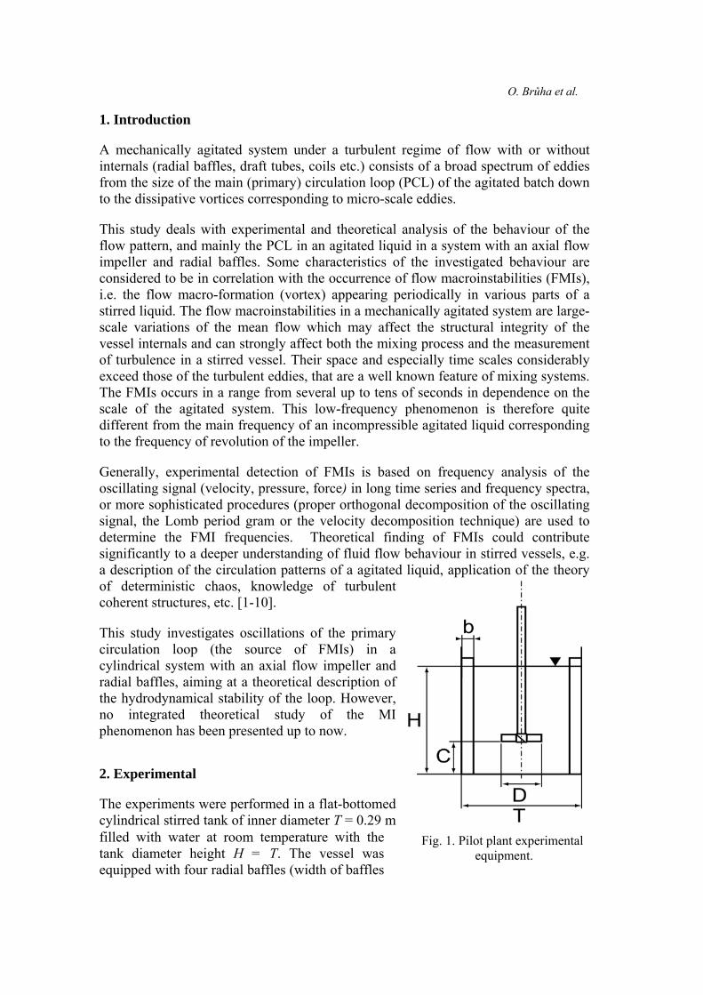
The experiments were performed in a flat-bottomed cylindrical stirred tank of inner diameter T = 0.29 m filled with water at room temperature with the tank diameter height H = T. The vessel was equipped with four radial baffles (width of baffles
Fig. 1. Pilot plant experimental equipment.

Dynamics of flow pattern in baffled mixing vessel with axial impeller 3
b = 0.1T) and stirred with six pitched blade impeller (pitch angle 45º, diameter D = T/3, width of blade W = D/5), pumping downwards. The impeller speed was adjusted n = 400 rpm = 6.67 s-1 and its off-bottom clearance C was T/3 (see Fig. 1). The flow under the parameters mentioned above was turbulent, with the impeller Reynolds number value ReM = 6.22·104. The flow was observed in a vertical plane passing through the vessel (vertical section of the vessel) in front of the adjacent baffles. The flow patterns of the agitated liquid were visualized by means of Al micro particles 0.05 mm in diameter spread in water and illuminated by a vertical light knife 5 mm in width, see Fig. 2.
Fig. 2. Experimental technique of flow visualization.
The visualized flow was scanned by a digital camera; series of shots were generated with a time step of 0.16 s and were analyzed by appropriate graphic software. The total length of the analyzed record was 30.24 s. The characteristics observed and analyzed were:

O. Brůha et al.
a) the shape and sizes of the PCL, b) the size of the PCL core, c) the positions of the top of the flow macro formation
and the corresponding functions were obtained: a) the height of the PCL hci= hci(t) ( see Fig. 3), b) the width of the PCL sci = sci(t) ( see Fig. 3), c) the equivalent mean diameter of the PCL core rc,av i = rc,av i(t) ( see Fig. 3), d) the height of the top of the flow macro formation hFMI,i= hFMI,i(t) (see Fig. 4).
Fig. 3. Visualization of the PCL.
Fig. 4. Visualization of flow macro formation.
3. Results of experiments
The analysis of the experiments provided the following findings: The PCL can be described as a closed stream tube with a vertical section elliptical in shape with a core. The flow in the elliptical annular area is intensive and streamlined, while the core is chaotic and has no apparent streamline characteristics. The flow in the remaining upper part is markedly steadier. This is in agreement with the earlier observations of some authors [6, 7]. The flow process is characterized by three stages. In the first stage, the PCL grows to a certain size (its shape can be approximated as elliptical). Then a quasi-steady stage follows, when the PCL remains at a constant size for a short time. In the next stage

Dynamics of flow pattern in baffled mixing vessel with axial impeller 5
the PCL collapses into very small flow formations (vortices) or disintegrates into chaotic flow, see Fig. 5a-c. Fig. 5. a) PCL growing b) PCL at maximum height c) PCL after its collapse. The process (oscillation of the PCL) is apparently characterized by a certain periodicity. The function of the incidence of the PCL in time is illustrated in Fig. 6, which shows that the PCL incidence ratio approaches 80% of the considered time.
0
20
40
60
80
100
120
0 5 10 15 20 25 30 35
t (s)
PCL
inci
denc
e (%
)
Fig. 6. Dependence of PCL incidence on time for the whole analyzed time.

O. Brůha et al.
The graph in Fig. 7 (vertical dimension of the PCL as a function of time) illustrates this process for the whole analysed time of 30.24 s.
0
0.05
0.1
0.15
0.2
0.25
0 5 10 15 20 25 30 35
t (s)
hci (
m)
Fig. 7. Dependence of the vertical dimension of PCL hci on time for the whole analyzed time. The calculated average time of one cycle (the time between the origin of the PCL and its collapse) is tc,av = 1.59 s. This means that the frequency of the PCL oscillations is fosc = 1/tc,av
= 0.63 Hz and dimensionless frequency Fosc = fosc/n = 0.094.
This dimensionless frequency is markedly higher than the value detected earlier in the interval 0.02-0.06 [8-10]. This corresponds to our finding that only some of the flow formations generated by one PCL cycle result in macro-flow formation causing a surface level eruption, detected as “macroinstability”.
Fig. 8. Time evolution of the height of the PCL (average cycle time tc,av = 1.59 s,
maximum height hc,max= 0.181 m, hc, max/H = 0.62) for one cycle of PCL oscillation.

Dynamics of flow pattern in baffled mixing vessel with axial impeller 7
The function hc = hc(t) for one cycle is shown in Fig. 8. This function was obtained by regression of the experimental data hci(t), where the individual cycle intervals were recalculated for an average time cycle tc,av = 1.59 s. Fig. 8 shows that the mean maximum height of the PCL hc,max reaches a value of 0.181 m, which is 62% of surface level height H. This agrees with earlier findings [11] that hc,max ≈ 2/3 H. The function hc = hc(t) was used for calculating the PCL rising velocity, see Fig. 9.
Fig. 9. Dependence of the mean rising velocity ur of the PCL on time ( ur = dh/dt = 0.042 m/s = const., t > 0.77 s).
Finally, the average rising time of flow macro formation generated by PCL was calculated from the time function hFMI = hFMI(t) (time between generating and disintegration), and the value obtained was tav, FMI = 1.0 s.
Fig. 10. Dependence of the height of the top of the flow macro formation hFMI,i
on the time for one cycle.

O. Brůha et al.
The regression curve hFMI,i = hFMI,i(t) corresponding to the experimental data for one cycle (development of one macro-formation, the time recalculated for average rising time tav,FMI) is illustrated in Fig. 10. To specify the PCL characteristics more deeply, the volume of the PCL (active volume of the primary circulation) was calculated. This was assumed as a toroidal volume around its elliptical projection in the r-z plane of the mixing vessel. The function of the ratio of the PCL volume to vessel volume Vc/V= (Vc/V) (t) for one cycle is illustrated in Fig. 11, where
⎟⎠⎞
⎜⎝⎛ )(
4)()(
2)( 2
c,avcc
c trT-tsthTπ=tV
2
(1)
is calculated from the corresponding regression curves hc = hc(t), sc = sc(t) and rc,av(t). Fig. 11 shows that the mean maximum ratio of the PCL volume to the vessel volume Vc,max/V reaches a value of 0.326.
Fig. 11. Dependence of the ratio of the PCL volume to the vessel volume Vc,max/V on time for one cycle of the PCL oscillation.
4. Theoretical calculation of energy balance
An energy balance for the PCL was carried out with a view to explaining the reasons for the flow field behaviour (predominantly PCL oscillations). As mentioned above, there are three different stages in the flow process. The energy balance was carried out for the quasi-steady stage under conditions when the PCL reaches its top position, i.e. hc = hc, max, see Fig. 12.

Dynamics of flow pattern in baffled mixing vessel with axial impeller 9
Fig. 12. Schematic view of the PCL under its top position (hc = hc, max).
This stage directly proceeds (precedes) the collapse and is assumed to have a critical influence on the flow disintegration. The impeller power input N is dissipated in the PCL by the following components: I) Mechanical energy losses:
1) Nturn - lower turn of the primary circulation loop about 180° from downwards to upwards.
2) Nwall - friction of the primary circulation loop along the vessel wall. II) Turbulence energy dissipation:
1) Ndisch - dissipation in the impeller discharge stream just below the impeller. 2) Nup - dissipation in the whole volume of the agitated liquid above the impeller
rotor region, i.e. in the space occupied by both the primary and secondary flow.
It is expected that under quasi-steady state conditions (just before the PCL collapses) these components are in balance with the impeller power output. This means that no spare power is available, and that no alternative steady state formation is possible. The individual power components and quantities can be calculated when the validity of the following simplifying assumption for the flow in the PCL is considered:
1) The system is axially symmetrical around the axis of symmetry of the vessel and impeller.
2) The primary circulation loop can be considered as a closed circuit. 3) The cross section of the primary circulation loop (stream tube) is constant. 4) The conditions in the primary circulation loop are isobaric.

O. Brůha et al.
5) The liquid flow regime in the whole agitated system is fully turbulent. 6) The character of the turbulence in the space above the impeller rotor region is
homogeneous and isotropic.
4.1. Calculation of basic quantities Impeller power input
(2) 53Dn ρ PoP =
where the impeller power number Po = 1.7 for ReM >104 [12], n = 6.67 s-1, D = 0.0967 m, ρ = 1000 kg/m3 . Then P = 4.25 W. The impeller power output can be calculated for known impeller hydraulic efficiency ηh (ηh = 0.48 for four 45°pitched blade impeller [14]).
N = ηh P = 2.04 W (3)
Impeller pumping capacity Qp can be calculated from the known flow rate number NQp (NQp= 0.94 for ReM >104 [13]).
(4) 1-1-33Qpp ls66.5sm1066.53 =⋅= −DnN=Q
The mass flow rate is
mp = Qp ρ = 5.66 kg s-1 (ρ = 1kg l-1) (5)
The axial impeller discharge velocity is equal to the average circulation velocity of the PCL (assuming a constant average circulation velocity in the loop):
2
pav c,
4
πD
Q=w = 0.77 ms-1 (6)
where πD2/4 is the cross sectional area of the impeller rotor region, i.e. the cylinder circumscribed by bottom and jacket by the rotary mixer. Then the primary circulation loop is a closed stream tube consisting of the set of stream lines passing through the impeller rotor region. 4.2. Calculation of turbulent dissipation below the impeller rotor region, Ndisch The energy dissipation rate per unit mass is [14]
L
qA´ε3/2
= (7)
where
(8) 3/2(2/3)=A´
and the integral length of turbulence [14] is

Dynamics of flow pattern in baffled mixing vessel with axial impeller 11
L=D/10 (9)
The kinetic energy of turbulence per unit of mass is
⎟⎠⎞
⎜⎝⎛ ++= 2
θ2
r2
z21 ´w´w´wq (10)
According to [14] the average value of q in impeller the discharge stream is q0 = 0.226 m2s-2 for the conditions described in [14]: a four pitched blade impeller with a pitch angle of 45°, D0 = 0.12 m, T0 = 0.24 m, n0 = 6.67s-1, Po0 = 1.4, ReM,0 = 44·104, P0 = 10.3 W, L0 = 0.012 m. We have from Eq. (7) ε0 =6.029 m2 s-3. The energy dissipation per unit mass ε related to the experimental system used in this study is
,/VP
P/Vε=/mP
P/mε=ε 00000
0 ( )0ρρ = (11)
and after substitution V = 0.0192 m3, P0 = 10.3 W, V0 = 0.0109 m3 we obtain ε = 1.384 m2 s-3. Using
Ndisch = ε ρVdisch (12)
where the dissipation volume below the impeller rotor region Vdisch = 0.000330 m3
(see Fig. 13). We obtain Ndisch = 0.46 W.
Fig. 13. Dissipation volume below the impeller rotor region Vdisc
before the first turn of the loop (D = T/3 = 0.0967 m, z = 0.045 m).

O. Brůha et al.
4.3. Calculation of dissipation in the whole volume above the impeller region, Nup According to [15]
Nup= ηup P = 0.60 W (13)
where the portion of the impeller power input dissipated above the impeller rotor region ηup = 0.14 for a six 45° pitched blade impeller (D/T = C/T =1/3, H = T ) and ReM > 104. When calculating the quantity Nup, the validity of introduced assumption No. 6 is considered. Moreover, because of the momentum transfer between the primary flow and the secondary flow out of the PCL the rate of energy dissipation above the impeller rotor region is related to the whole volume, consisting of both the primary and secondary flows. 4.4. Calculation of the dissipation in the lower turns of the PCL, Nturn According to [16]
p
2avc,
jjturn 2
mw
ξN ∑= (14)
Substituting the sum of loss coefficients = 0.50 for bend of turn of the PCL
β = 180° as well as the values of the average circulation velocity of the PCL w
∑j
jξ
c,av , and the mass flow rate mp, we obtain Nturn = 0.84 W. 4.5. Calculation of the dissipation by the wall friction along the PCL, Nwall Using the relation for mechanical energy loss due to the friction along the wall, from [17]
pwall 2
2avc, m
dw l
λNe
= (15)
where equivalent diameter is defined as
TD
πT
πD
OS
ed
2
24
44
=== (16)
and friction factor for a smooth wall
(17) -0.253164.0 Re=λ
where

Dynamics of flow pattern in baffled mixing vessel with axial impeller 13
η
ρDw=Re avc, (18)
Then we can calculate the rate of energy dissipation in the flow along the smooth vessel wall after substitution: η=1 mPas, length of the PCL along the wall
where hturnmaxc, hhl −= c,max= 0.181m, (see Fig. 8), hturn = 0.051 m, so l= 0.13 m, and values de = 0.032 m, Re = 7.45·104 and λ = 0.020 obtained from Eqs. (16)-(18) to Eq. (15), we get Nwall = 0.14 W. 4.6. Energy balance in the quasi-steady stage of the PCL The sum of all dissipated power components considered here is (19) updischwallturni NNNNN +++=∑ (19a) ∑ =+++= W04.260.046.014.084.0iN The value in Eq. (19a) is in good agreement with the impeller power output from Eq. (3), N = 2.04 W, though the data used for the calculations come from six independent literature sources. This result means that in the quasi-steady phase of the PCL oscillation cycle, all the impeller power output is consumed by dissipation. No power is available, either for increasing the PCL kinetic energy or for any changes in flow formation resulting in a higher energy level. On the other hand, it is well known that vortex disintegration in smaller formations or even a very small vortex separation from a primary flow is a process that consumes energy (according to the law of angular momentum conservation). The experiments proved that vortex separations (small and large) occur in all the stages, thus also in the quasi-steady stage. This seems to provide an explanation for the PCL collapse: in the quasi-steady stage, the energy necessary for vortex separation or for other changes in flow formation cannot be supplied by the impeller, but energy is exhausted from the ambient flow field. And then, even a very small energy deficit can result in a qualitative flow field change appearing as the PCL collapse. It should be noted that the PCL collapse can be followed by a noticeable rice of the surface level, classified as a macroinstability. But not each collapse reaches the level and is observed as a macroinstability. This corresponds to the disagreement between the PCL oscillation frequency determined experimentally in this study and the macroinstability frequency presented in other studies, as mentioned in section 3.
5. Conclusions
a) The average circulation velocity in the primary circulation loop is more than one order of magnitude higher than the rising velocity of the loop.
b) The frequency of the primary loop oscillations is about one order of magnitude lower than impeller frequency of revolution.

O. Brůha et al.
c) The top of the disintegration of the primary circulation loop is a birthplace of the flow macroinstabilities in the region of secondary flow.
d) The primary circulation loop collapses owing to disequilibrium between the impeller power output and the rate of dissipation of the mechanical energy in the loop. A small change (e.g. a small turbulent vortex or a small increase in the primary circulation loop) can have a great effect.
Acknowledgements
The authors of this paper are grateful for financial support from the following Czech Grants Agencies: 1. Czech Grant Agency Grant No. 104/05/2500. 2. Czech Ministry of Education Grant No. 1P05 LA 250. 3. Czech Ministry of Education Grant No. MSM6046137306.
List of symbols
b width of baffle, m C off-bottom clearance, m de equivalent diameter, m D impeller diameter, m fosc frequency of PCL oscillations, Hz Fosc dimensionless frequency of oscillations hc value of height of the PCL obtained by regression, m hci experimental value of height of the PCL, m hc, max maximal height of the PCL, m hc,min minimal height of the PCL, m hFMI value of height of top of flow macro formation obtained by regression, m hFMI,i experimental value of the height of the top of flow macro formation, m hturn height of turn of the PCL, m H height of water level, m l length of the PCL adjacent to wall, m L integral length scale of turbulence, m m mass of liquid in a stirred tank, kg mp mass flow rate, kg s-1
n impeller speed, s-1
N impeller power output, W Ndisch turbulent dissipation below the impeller rotor region, W NQp impeller pumping number Nturn dissipation in lower turns of the PCL, W Nup dissipation in the whole volume above the impeller rotor region, W Nwall dissipation by the wall friction of the PCL, W P impeller power input, W Po impeller power number q kinetic energy of turbulence per unit of mass, m2s-2

Dynamics of flow pattern in baffled mixing vessel with axial impeller 15
Qp impeller pumping capacity, m3 s-1
rc,av equivalent mean diameter value of the PCL core, obtained by regression, m rc,av i experimental value of equivalent mean diameter of the PCL core, m Re Reynolds number ReM impeller Reynolds number S cross section, m2
sc value of width of the PCL, obtained by regression, m sci experimental value of width of the PCL, m T diameter of stirred tank, m tc,av average time of the PCL cycle, s tav, FMI average rising time of flow macro formation, s ur rising velocity of the PCL, ms-1
ur,av mean rising velocity of the PCL, ms-1
V volume of stirred tank, m3 Vc calculated volume of the PCL, m3
Vc,max maximum value of calculated volume of the PCL, m3
Vdisch volume of dissipation below the impeller rotor region, m3
W width of blade, m wc,av axial impeller discharge velocity, ms-1
w΄z,w΄r, w΄θ turbulent velocity fluctuations in individual axis directions, ms-1
z height of cylindrical volume of dissipation below the impeller rotor region, m β bend of turn of the PCL, º ε energy dissipation rate per unit mass, m2s-3 η dynamic viscosity, Pa.s ηh impeller hydraulic efficiency ηup portion of the impeller power input dissipated above the impeller rotor region λ friction factor ρ density of liquid, kg m-3
ζ j loss coefficient
References
1. Roussinova, V.T., Kresta, S.M. and Weetman, R., (2003) Chemical Engineering Science 58, 2297-2311.
2. Roussinova, V.T., Kresta, S.M. and Weetman, R., (2004) AIChe Journal 50-12,
2986-3005. 3. Roussinova, V.T., Grcic, B. and Kresta, S.M., (2000) Trans I Chem E 78A, 1040-
1052.

O. Brůha et al.
4. Fan, J., Rao, Q., Wang, Y. and Fei, W., (2004) Chemical Engineering Science 59, 1863-1873.
5. Ducci, A., Yianneskis, M., (2007) AIChE Journal 53, 305-315. 6. Fořt, I., Gračková, Z. and Koza, V., (1972) Collection of Czechoslovak Chemical
Communications 37, 2371-2385. 7. Kresta, S.M., Wood, P.E., (1993) The Canadian Journal of Chemical Engineering
71, 52-42. 8. Brůha, O., Fořt, I. and Smolka, P., (1995) Collection of Czechoslovak Chemical
Communications 60,85-94. 9. Hasal, P., Montes, J-L., Boisson, H.C. and Fořt, I., (2000) Chemical Engineering
Science 55, 391-401. 10. Paglianti, A., Montante, G. and Magelli, F., (2006) AICHE Journal 52, 426-437. 11. Bittorf, K.V., Kresta, S.M., (2000) Chemical Engineering Science 55, 1325-1335. 12. Medek, J., (1985) International Chemical Engineering 20, 664-672. 13. Brůha, O., Fořt, I., Smolka, P. and Jahoda, M., (1996) Collection of Czechoslovak
Chemical Communications 61, 856-867. 14. Zhou, G., Kresta, S.M., (1996) Trans I Chem E 74 (Part A), 379-389. 15. Jaworski, Z., Fort, I., (1991) Collection of Czechoslovak Chemical
Communications 56, 1856-1867. 16. Perry, J.H., Chemical Engineer’s Handbook (Fourth Edition), McGraw–Hill
Book Comp., New York (1963). 17. Brodkey, R.S., The Phenomenon of Fluid Motions, Adison-Wesley Publishing
Comp., Reading (1967).