Embed Size (px)
Citation preview
Indian Journal of Engineering & Materials Science Vol. 8, October2001 , pp. 247-254
Dynamic studies of a typical payload fairing for different boat tail configurations
V Ramamurtia, S Rajarajanb & G Venkateswara Raoc
•oepartment of Applied Mechanics, Indian Institute of Technology, Madras 600 036, India bLaunch Vehicle Design Group, Vikram Sarabhai Space Centre, Trivandrum 695 022, India cStructural Engineering Group, Vikram Sarabhai Space Centre, Trivandrum 695 022, India
Received 21 February 2001; accepted 23 July 2001
Payload fairing structure of any launch vehicle protects the payload from the adverse aerodynamic environments besides providing the forward surface. This structure is separated from the core vehicle as soon as the purpose is served. The elastic response of this structure due to the separation force is very important to be considered along with rigid body movements. The boat tail structural element configuration is decided based on the dimensions of the core vehicle and the mi ssion requirements. The displacement response due to separation force of the payload fairing for different boat tail angles is an important input data required to finali se the boat tail angle and the payload fairing configuration in total. Finite element method is employed using three noded triangular plate and shell element and 30 beam element in conjunction with a mode superposition technique to carry out this study for a typical payload fairing. The contribution of the elastic response on the radial gap between the payload envelope and the separated fairing is also reported including a payload fairing configuration without boat tail structure.
The main structural purpose of payload fairing in any launch vehicle is to protect the payload from aerodynamic loading, heating, acoustic vibration and other environmental conditions during the ascent phase and to provide an aerodynamic forward surface. The payload fairing structure is jettisoned from the core vehicle as soon as the purpose is served. Generally the payload fairing structure is made in two halves as in Atlas 1, H If or in three sectors as in Titan 43
. Indian Polar Satellite Launch Vehicle uses a zip cord based mechanism to jettison the two halves of the payload fairing4
• When subjected to the separation forces, the fairing halves undergo rigid body as well as elastic movements that are very significant5
• Clean separation is required without the separated parts of the payload fairing coming in contact with the on going launch vehicle parts. The configuration of this structure is decided based on the satellite size, launch vehicle core diameter and the mission requirements. When the size of this structure is very large, the elastic displacement response play a greater importance in the separation event. The boat tail structural member provides an interface between the payload fairing and the launch vehicle. The vibration behaviour and the elastic displacement response at the time of separation for different boat tail configurations will be a very useful data bank in decision making and these details are presented in this work.
Payload Fairing Configuration Typical payload fairing configuration considered
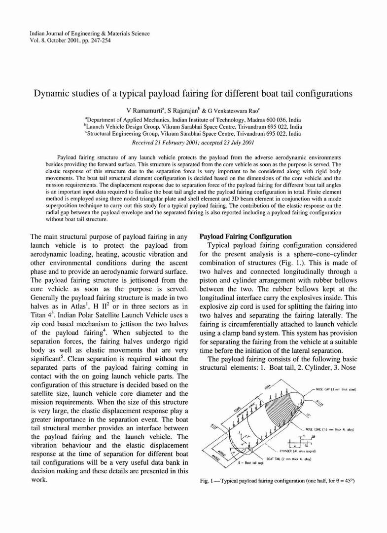
for the present analysis is a sphere-cone-cylinder combination of structures (Fig. 1.). This is made of two halves and connected longitudinally through a piston and cylinder arrangement with rubber bellows between the two. The rubber bellows kept at the longitudinal interface carry the explosives inside. This explosive zip cord is used for splitting the fairing into two halves and separating the fairing laterally. The fairing is circumferentially attached to launch vehicle using a clamp band system. This system has provision for separating the fairing from the vehicle at a suitable time before the initiation of the lateral separation.
The payload fairing consists of the following basic structural elements: 1. Boat tail, 2. Cylinder, 3. Nose
NOS( CAP (J n.rr. thick sled)
NOS£ CON£ (1.6 mm th ick AJ. alloy}
CvtiNOCR {AI. alloy isogrid)
BOAT TAl. (? mm thick AJ. olloy)
Fig. 1-Typical payload fairing configuration (one half, for 9 = 45°)
248 INDIAN J. ENG. MATER. SCI., OCTOBER 2001
cone, 4 . Nose cap. The boat tail is a truncated internal ly stiffened aluminium alloy conical shell with forward and aft end rings with interfacing provisions. The cy linder is an aluminium alloy isogrid structure with bulkhead in the middle and forward and aft end rings with necessary interfacing provisions. Nose cone is a truncated aluminium alloy cone with number of bu lkheads and end rings and is attached to the spherical steel nose cap with stiffeners in two perpendicular axes. One half of the fairing has edge beam and piston beam along part of the boat tail edge, entire length of cylinder edge and part of the nose cone edge where as the other half has cy linder beam instead of the piston beam. But for this difference, the two halves are dimensionally and structurally identical.
Boat tail angle (8) measurement convention used in this analysis is shown in Fig. I. For a fixed diameter of the payload fairing, increase/reduction in the boat tai l angle means reduction/increase in the boat tail height with corresponding increase/reduction in the cylinder. That is, the overall height of the payload fairing structure is kept constant for the entire study. The structural properties of the beam members of the fairing are given in Table 1.
Finite Element Formulation
Plate and shell element
Plate and shell . finite elements are used for modeling the shells. This is a three noded triangular element with six degrees of freedom per node, viz., three axial displacements u, v, w and three rotations 8., By, Bz. Typical finite element and the nodal degrees of freedom are shown in Fig. 2. The brief particulars of this element are given below. The details of the
formu lation are provided by Zienkiwicz6 and Ramamurti7
.
The in plane displacements are given by:
{8P}= [u , v1 u 2 v2 u3 vJ The bending di splacements are given by:
{8 J }= lw, e.<l eyl w2 ex2 ey2 w3 8,) e,J J
. . . (1)
.. . (2)
The in plane strain { Ep } and the bending strain { Er }
are given as:
IE x ) au 1 ax 1
{E J= E Y = av I ay ) y au av
xy -+-ay ax
... (3)
{EJ}=j=::;;:;: ) - 2a-w 1 axay
.. . (4)
Linear polynomials in the area coordinates L" L2,
L3 for in plane displacements u and v and cubic polynomials for bending displacements, w as presented by Zienkiwicz6 are used for the shape functions.
Vl 01
(i) In plane displacement (i i) Bending displacement
Fig. 2-Three noded plate and shell element
Table I -Sectional properties of beam members
Description Area (mm2) Moment of inertia (mm4
)
I .. f yy Ill
Nose cone forward end ring 402 61225 97380 3565 Nose cone bulk head 128 111 66 33333 119 Cy linder bulk head 757 238782 128553 10390 Boat tail forward end ring 1108 37 1131 272033 25065 Boat tail aft end ring 121 2 664364 160271 41483 Boat tail stiffeners 202 91467 30695 185 Nose cone aft end ring 895 293014 136454 12606 Nose cap ring + Nose cone forward end ring 71 8 201436 155217 5336 Piston beam 1362 279300 955800 6865 Nose cone edge beam 1289 469824 608174 3938 Boat tail edge beam 84 1 91841 374713 7959
RAMAMURTJ eta/. : PAYLOAD FAIRING FOR DIFFERENT BOAT TAIL CONFIGURATIONS 249
u = f3~~ + f32L2 + {33~ v= {34 L1 + {35L2 + /36~
w=a1 ~ +a2~ +a,~ +a{ ~2~ +~~L2~ J
+a5 (~ 2~ +~~~~)+a{ ~2~ +~~L/'l J
elements are transformed into global coordinate system and assembled to get global stiffness and mass matrices [K] and [M] , respectively.
The equation of motion of a free vibration problem is given by:
[M]{5}+[K]{8}=0 (7)
Assuming harmonic motion of displacement in the form 8 = 00 eiw\ Eq. (7) becomes:
{[K ]-w 2 [M ]}{80 }= 0 . · · (8)
+a{~ 2~ +~~~~ J+a{ ~2~ +~~~~ J
+a{ ~ 2~+~~l'2~ J
where a and f3 are constants .
··· (5) This forms a generalized eigenvalue problem given as:
30 beam element
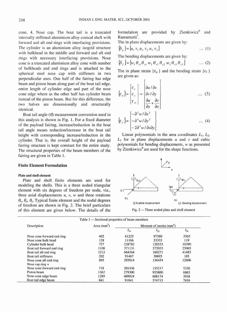
The beam element with two nodes per element, six deorees of freedom with the following displacement b
vector is used for modeling the stiffeners, end rings, edge beams, piston beams and bulkheads.
{8}= [ul VI WI (/JI (/JI ()I L/ 2 \1 2 11!2 (/J 2 (/) 2 eJr ··· (6)
where u is the axial displacement in x direction and v and w are lateral deflections due to bending in y and z directions as shown in Fig. 3.
Linear variation has been assumed for the axial displacement and cubic polynomials for the lateral
·7 displacements as presented by Ramamurt1 . Following the standard procedure the stiffness
matrix and mass matrix for plate and shell element and beam element are obtained .
Analysis
Eigenvalue problem
The element stiffness and mass matrices obtained in the local coordinate system for the shell and beam
y
lc: v,
Fig. 3 - Two noded 3D element
. . . (9)
where w is the natural frequency of the structure. Lanczos method is used to tridiagonalise the matrix
and inverse iteration method is used to solve for the lowest eigenvalues and corresponding eigenvectors satisfying:
[K ]{8}= w2 [M ]{8} ... (10) Free-Free vibration analysis is carried out for the
piston side of the payload fairing . Symmetry condition is made use of and half model of the piston side fairing is used for the analysis . Analysis is carried out for different boat tail angles from 10° to 80° varying in steps of 5°, apart from a configuration
without boat tail which in effect means 0° boat tail angle.
Response analysis
For a system with damping, the governing differential equation is given by:
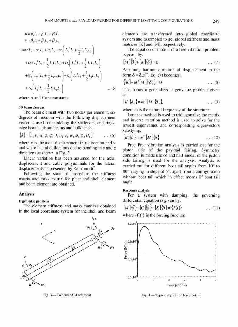
[M]{5}+[C]~}+[K]{8}={t(t)} ... (11) where { f(t)} is the forcing function.
Time (x 10'3 s)
Fig. 4-Typical separation force details
250 INDIAN J. ENG. MATER. SCI., OCTOBER 2001
In the absence of experimental values for damping, · a constant value of 1% damping is assumed for all the modes.
Mode superposition technique is used to decouple. the equations and solve for displacement response7
•
Separation force details, given in Fig. 4, is used to determine the displacement response in X (in the direction perpendicular to the direction of force
,.-.. N
;, >-.
15
g 10
VMode
~ L-----------~~=-~ .... II Mod
5
0 0 10 20 30 40 50 60
without Boat tail Boat Tail Angle (deg)
70
Fig. 5-Eigenvalues for different boat tail angles
Without boat tail Boat tail ang.
1000 1000
E' 500 5 ;: " 0 E g ~ -500 0
-1000 -1000
0 0. 1 0.2 0.3 0.4 0.5 0 0 .1 0 . ~ 0.3
Time (s) Time (s)
Boat tail ang. 25° Boat tail ang.
1000 1000
E 500 500 5 ;: 1! 0 0 ... g ~ -500 -500 0
-1000 -1000
0 0.1 0.2 0.3 0.4 o.s 0 0.1 0.2 0.3
Time (s) Time (s)
80
10°
0.4 o.s
application) and Z (along the direction of force application) directions (Fig. 1) for all the configurations.
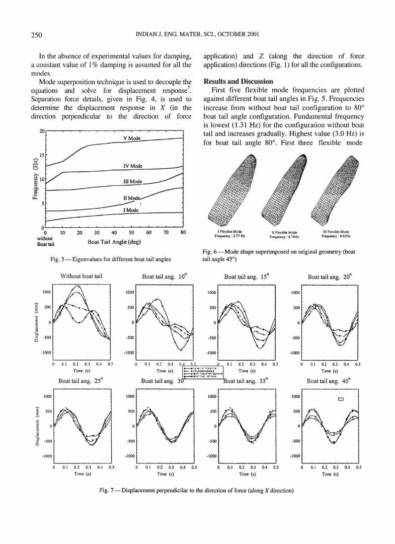
Results and Discussion First five flexible mode frequencies are plotted
against different boat tail angles in Fig. 5. Frequencies increase from without boat tail configuration to 80° boat tail angle configuration. Fundamental frequency is lowest ( 1.31 Hz) for the configuration without boat tail and increases gradually. Highest value (3.0 Hz) is for boat tail angle 80°. First three flexible mode
I Flexible Mcde 11 Flexible Mode Ill Flexible Mode Frequency : 2.77 Hz Frequency : 4 .74Hz Frequency : 8.62Hz
Fig. 6- Mode shape superimposed on original geometry (boat tail angle 45°)
Boat tail ang. 15° Boat tail ang. 20°
1000 1000
500
0
-500
-1000 -1000
0. 1 0.2 0.3 0.4 0.5 0 0. 1 0.2 0.3 0.4 0.5
Time (s) Time (s)
oat tail ang. 35° Boat tail an g. 40°
1000 1000 D
500 500
0 0
-500
-1000 -1000
0 0. 1 0.2 0.3 0.4 o.s 0 0.1 0.2 0.3 0.4 o.s Time (s) Time (s)
Fig. 7- Displacement perpendicilar to the direction of force (along X direction)

RAMAMURTI et al.: .PA YLOAD FAIRING FOR DIFFERENT BOAT TAIL CONFIGURATIONS 251
shapes for boat tail angle 45° configuration are given in Fig. 6.
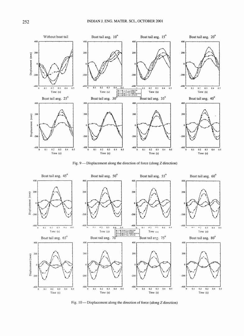
First 25 flexible modes are used for the response studies. The X direction displacement responses at four critical locations along the length of the force acting edge of the fairing namely boat tail aft end, boat tail forward end, cylinder middle and near cylinder top are given in Figs 7-8 and the Z direction displacement response in Figs 9-10.
Large displacements are observed in all the configurations in the direction perpendicular to the force (X direction). For the configuration without boat tail and for angles up to 25°, the maximum displacement is observed at the boat tail _aft/forward end. For boat tai l angle between 30° to 40°, the maximum displacement is at cylinder middle, where as for boat tail 45° to 80°, it is near the cylinder top. With the increase in the boat tail angle, the displacement reduces in the boat tail structural element indicating high local stiffness. The configuration without boat tail is displaying very large elastic displacements compared to the other configurations with boat tail.
The displacements along the direction of the forces (Z direction) are much lower compared to the
Boat tail ang. 45° Boat tail ang. 50°
1000 1000
e s " e ~ ~ i5
-1000 · 1000
a .1 0.1 0.] 0.4 0.5 0 .1 0.2 O.l 0 .4
Time (s) Time (s)
Boat tail ang. 65° Boat tail ang. 70
1000 1000
'E .§_ ;: " ~ ~ i5
-1000 -1000
0.1 0.2 0. ] 0.4 0.5 0 0. 1 0.2 0.] 0.4
Time (s) Ti me (s)
0.5
perpendicular direction. For the without boat tail configuration the maximum displacement is at the cylinder aft end. For boat tail angle from 10° to 25°, the maximum displacement is at the boat tail aft/forward end and for the rest of the cases it is near the cylinder top. All configurations other than without boat tail case have small initial movements in the direction opposite to the direction of the force at boat tail aft end. This tendency increases gradually from 10° boat tail angle to 65°, then onwards it gradually reduces. When the boat tail height becomes smaller corresponding to the increase in boat tail angle, the tendency covers more length of the boat tail structural element and for instance, at 80° angle, the entire boat tail starts their initial movements in the opposite direction to the force direction.
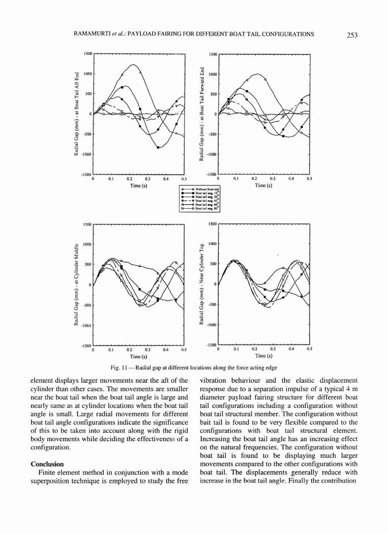
As the payload fairing separates, the important point of concern is how much the structure moves away radially . This determines whether there will be any interference with the vehicle and its attachments and whether the dynamic envelope of the payload is cleared all the time. The effect of the elastic displacements on the radial gap is given in Fig. 11 for different configurations and at different longitudinal locations. The configuration without boat tail structural
Boat tail ang. 55° Boat tail ang. 60°
1000 1000
- 1000 · 1000
11 . : 0.2 O.J 0 .4 0.5 0. 1 0.2 O.J 0.4 0.5
Time (s) Time ~.: .'
Boat tail ang. 80°
1000 1000
500
-1 000 -1000
0. 1 0.2 0.] 0.4 0.5 0.1 0.2 0.3 0.4 0.5
Time (s) Time (s)
Fig. 8 - Displacement perpendicular to the direction of force (along X direction)
252 INDIAN J. ENG. MATER. SCI. , OCTOBER 2001
Without boat tai l Boat tail ang. 10° Boat tail ang. 15° 400 400 400
e 200 200
.§. c e g ~ i:5 -200 -200
-400 0 01 0.1 0.3 OA 0. ~
-4000 0.1 0.2 0.3 OA 0.5 -400 .-, 0.1 0.2 0.3 0.4 0.5
Time (s) Time (s) •.-- ... : .~ ... -.:-..D<lfi)f'
Time (s) - 4' 0\.I,Ot l~IOOl~ _,.,.,:;, ... ,ot. ... ... iWt)>:) -- IIOHT\Il4rTE.'0
Boat tai l ang. 25° Boat tail ang. 30 Boat tail ang. 35° 400 400 400
E .§. c
i ]-
-400 -400 -400 0 0.1 0.2 0.3 0.4 0.5 0 0.1 0.2 0.3 OA 0.5 0 0.1 0.2 0.3 0.4 0.5
Time (s) Time (s) Time (s)
Fig. 9- Displacement along the direction of force (21 long Z direction)
Boat tail ang. 45° 400 .--~--------,
e 2oo .§.
-400
400
e 200
.§.
5 ~ ~ Q -200
-400
0
0
0.1 0~ c) OJ o< Time (s)
Boat tail ang. 65°
0. 1 0.2 0.3 0.4 0.5
Time (s)
Fig.
Boat tai l ang. 50° Boat tail ang. 55° 400 .---- --- ----, 400 r-- - - ------,
-400 -400 n " ' n~ I) _) 0.5 0 n 1 "' QJ (I ~
T1 m< (s) -- :!ooE.,lC"I1.1~0U.Tor Time ,sJ - 4' C'VU'Oll~·UliOU - IIO.Ul.o.ILfOII; .... \lDE'II --90.\TTA.Il Af1' E'0
Boat tail ang. 7 oat tail ang. 75° 400 400
, 00 200
-200
-400 -400 0 0.1 0.2 0.3 0.4 0.5 0 0.1 0.2 0.3 0.4 0.5
Time (s) Time (s)
I 0- Displacement along the direction of force (along Z direction)
Boat tai l ang. 20° 400
-400 0 0. 1 0.2 0.3 OA 0.5
Time (s)
Boat tai l ang. 40° 400
200
-200
-400 0 0.1 0.2 0.3 0.4 0.5
Time (s)
Boat tail ang. 60°
400 r----------,
-'00 " ,, ' 0! 0.4 0.5
Tim< (s)
Boat tail ang. 80° 400
200
-400 0 0.1 0.2 0.3 0.4 0.5
Time (s)
RAMAMURTI et at.: PAYLOAD FAIRING FOR DIFFERENT BOAT TAIL CONFIGURATIONS 253
1500 1500
"0 c:
"0 Lll c: "E Lll
.::; "' < ~ 0 ·;;; ""' f- ·;;;
:0 f-0
:0 Ol :0
0 Ol
E' :0
.§. E' 0. -500 .§. -500 "' 0 0.
"' ~ 0 "0 -;:; "' 0:: -1000 :0 · 1000
"' 0::
-1500 -1500 0 0.1 0.2 0.3 0.4 0.5 0 0.1 0.2 0.3 0.4 0.5
Time (s) 6----6. Witl~t Uoat toij
Time (s)
---- (lo;a( t.~ l ... , . 1.5 • ..._...... Bua1lro~l ang.lO• 9'- - • !Jo.lttl~lang. 450 >+--i< U.O..t La~l ana. 60., o------v Uuat to:nl ans . 80
1500 1500
" 1000 0. 1000 :;:; 0 "0 f-
~ ... u
"0 ... .:: " 500 500 "0 >. .:: u >. ... u "' " :0 z
0 0 ~ E' E .§. .§. 0. 0.
-500 "' -500 "' 0 0
] -;;; "0 :0 "' "' 0:: -1000
0:: ·1000
- 1500 · 1500 0 0.1 0.2 0.3 0.4 0.5 0 0. 1 0.2 0.3 0.4 0.5
Time (s} Time (s)
Fig. II- Radial gap at different locations along the force acting edge
element displays larger movements near the aft of the cylinder than other cases. The movements are smaller near the boat tail when the boat tail angle is large and nearly same as at cylinder locations when the boat tail angle is small. Large radial movements for different boat tail angle configurations indicate the significance of this to be taken into account along with the rigid body movements while deciding the effectivenes~; of a configuration.
Conclusion Finite element method in conjunction with a mode
superposition technique is employed to study the free
vibration behaviour and the elastic displacement response due to a separation impulse of a typical 4 m diameter payload fai ring structure for different boat tail configurations including a configuration without boat tai l structural member. The configuration without bait tail is found to be very flexib le compared to the configurations with boat tail structural element. Increasing the boat tail angle has an increasing effect on the natural frequencies. The configuration without boat tail is found to be displaying much larger movements compared to the other configurations with boat tail. The displacements generally reduce with increase in the boat tai l angle. Finally the contribution
254 INDIAN J. ENG. MATER. SCI., OCTOBER 2001
of the elastic response on the radial gap between the payload envelope and the separated fairing for various boat tail angles are studied. These studies provide very useful inputs for assessing the suitability of different boat tail configurations.
Acknowledgements Discussions with Mr A Prashanthan, Mr M
Sundaresan, Mr K Singa Rao and Mr E Janardhana of Launch Vehicle Design Group, Vikram Sarabhai Space Centre, Thiruvananthapuram, are thankfully acknow !edged.
References 1 Robbins Michael J, Ground test program for new Atlas payload
fairing in Research in structures, structural dynamics and materials (Long Beach, California) NASA CP 3064, 1990, pp. 194-205.
2 Yasunaga Y, Fukushima Y, Nakamura T & Fujita T, Separation jettison test of Japanese H-ll rocket satellite fairing in Proceedings of 28'11 aerospace sciences meeting (Reno, Nevada) AIAA 90-0720, 1990, pp. 1-8.
3 Kandebo Sta11ely W, Payload capacity of Titan 4 to expand with new fa iring, Aviation week & space technology, 1990, pp. 58-62.
4 Anjaneyalu M, Sudhakara Rao K & Srinivasan S, The Polar Satellite Launch Vehicle and mission for the Indian remote sensing spacecraft, Proceedings of 39'h congress of the international astronautical federation . Bangalore, India, pp. 1-8, 1988.
5 Elayuthu M N G & Abdul Salam E M, Elastic response of a launch vehicle payload fairing to separation shock, Proceedings of the international conference held at Indian Institute of Technology, Bombay, India, 1985, pp. 807-814.
6 Zienkiewicz 0 C, The finite element method in engineering sciences, second edition (McGraw-Hill Publications, London), 1971 .
7 Rarnamurti V, Computer aided mechanical design and analysis, 41
h edition, (Tata McGraw-Hill publishing company, New Delhi), 2000.


![7M BOAT DOLLY[THE ORIGINAL] BOAT DOLLIES](https://img.pdfslide.us/doc/110x75/620f62d952614c03d02120d1/7m-boat-dollythe-original-boat-dollies.jpg)