Embed Size (px)
Citation preview

ABSTRACT: In this paper a detailed FE model of a bolted steel beam-to-column end-plate connection developed in ABAQUS is presented. The model is capable of simulating the behaviour of partial-strength joints subjected to both monotonic and cyclicloading. The model is validated by comparing the numerical results with available experimental data and also with results derived with simpler 2D models. The modelling approach is then employed to undertake extensive non-linear time history analyses on a set of partial-strength joints using several earthquake records and considering increasing levels of ductility demand, for a range of connections capable of representing the behaviour of the three ductile failure modes defined in Eurocode3. Relationships between ductility and equivalent viscous damping are determined, which can be used in the application of the Direct Displacement-Based Design procedure to the seismic design of steel moment resisting framed structures with partial-strength connections.
KEY WORDS: Joints; Connections; Dynamic; Partial-Strength; Ductility; Equivalent Viscous Damping; Seismic.
1 INTRODUCTIONThe EN1998-1 [1] (EC8) paves the way to the use of advanced analyses, such as non-linear static (pushover) or non-linear time history (NLTH) analysis, in the design of ductile structures that are expected to behave in a non-linear way when subjected to severe actions such as earthquakes. These types of analyses allow for a more refined design and provide a more realistic prediction of structural response. Hence, they are seen as powerful tools to achieve more rational and economical structural solutions, such as steel moment-resisting frames with partial-strength joints, in which energy dissipation develops largely at the joint components. In spite of the number of advantages in adopting this structural solution, modern codes such as the EC8 do not fully address this typology and hence research still needs to be performed in this field.
In a pushover analysis the structure is subjected to a monotonically increasing pattern of lateral forces, which represent the inertia forces when the structure is subjected to an earthquake. The increasing loads originate the sequential yield of the structural elements and the consequent loss of stiffness, until the formation of a local and/or global failure mechanism. This type of analysis provides additional data on the strength and ductility of the structures that is inaccessible in conventional elastic analysis. However, for structures where the higher modes effects are significant, the results can be inaccurate [2]. The NLTH analysis is a more realistic approach, using a dynamic oriented solution, but also requires a higher level of expertise, particularly in terms of numerical modelling and data treatment. The time-dependent response of the structure may be obtained through direct numerical integration of its differential equations of motion, using acceleration time series that represent the expected ground motion [1]. Normally, a set of natural or artificial seismic records are adopted in order to get reliable estimates of the
structural response. In this approach, the nonlinear behaviour of the structural elements should account for the unloading-reloading cycles that realistically represent the energy dissipation during the seismic event.
In this work the two previously described analyses were used in the assessment of the behaviour of partial-strength bolted beam-to-column joint with extended end plate. The joint is representative of a typical joint in a moment resistant framed (MRF) structure, under static and dynamic conditions using a set of representative ground motion records. The objective is to find an equivalent elastic single degree of freedom (SDOF) system that possesses the same effective period of the inelastic system that achieves the same target displacement due to a modified equivalent viscous damping, assuring this way the same level of energy dissipation for both the original and the equivalent structure. So the key factor to be determined in this process is the equivalent viscous damping for several ductility demands. The use of the effective period allows the incorporation of the achieved relationships in direct displacement based design procedures (DDBD), like the one proposed by Priestley et al. [3] that uses the concept of an equivalent SDOF structure for the representation of the original multi-degree-of-freedom structure at peak displacement response, rather than by its initial elastic characteristics, and a level of equivalent viscous damping that represents the elastic damping, el and the energy absorbed (hysteretic damping hyst) during the inelastic response.
The displacement based design and assessment methodologies began to be widely employed in the beginning of the 1990’s, mainly in reinforced concrete, masonry and bridges structures [4][5] and have been recently applied to steel structures [3][6]. The driving motivations for that development were the inconsistencies identified in force-based methods, particularly in what regards to the control of
Dynamic simulation of beam-to-column partial-strength steel joints for the assessment of ductility-equivalent viscous damping relationships
Hugo Augusto1, José Miguel Castro2, Carlos Rebelo1, Luís Simões da Silva1
1Institute for Sustainability and Innovation in Structural Engineering (ISISE), Department of Civil Eng., Faculty of Sciences and Technology, University of Coimbra, Polo II, R. Luís Reis Santos, 3030-788 Coimbra, Portugal
2Department of Civil Eng., Faculty of Engineering, University of Porto, R. Dr. Roberto Frias, 4200-465 Porto, [email protected], [email protected], [email protected], [email protected]
Proceedings of the 9th International Conference on Structural Dynamics, EURODYN 2014Porto, Portugal, 30 June - 2 July 2014
A. Cunha, E. Caetano, P. Ribeiro, G. Müller (eds.)ISSN: 2311-9020; ISBN: 978-972-752-165-4
Proceedings of the 9th International Conference on Structural Dynamics, EURODYN 2014Porto, Portugal, 30 June - 2 July 2014
A. Cunha, E. Caetano, P. Ribeiro, G. Müller (eds.)ISSN: 2311-9020; ISBN: 978-972-752-165-4
395

inelastic structural demands. In fact, it is widely recognized that in ductile structures the focus should be essentially on deformation rather than on force control, since deformation is a more reliable measure of structural damage.
In this paper a detailed finite element (FE) model developed in ABAQUS [7] is described. The model of a beam-to-column end plate bolted connection was calibrated against experimental results, for the monotonically and cyclic loaded cases and for the dynamic analyses simpler 2D models were used to compare the results. The good agreement obtained in the comparisons allowed concluding that the model is able to represent the dissipative behaviour of the various connections components. After the calibration of the model, and for a series of joints representative of the various dissipative plastic mechanisms found in EN1993-1-8 [8] (EC3), successive NLTH analyses were performed using several records and target ductility levels in order to derive the ductility-equivalent viscous damping relationship, using a procedure described in detail in the subsequent parts of the paper.
2 FINITE ELEMENT MODEL DEVELOPMENT The preparation of the FE model followed the external joint
setup of the chosen experimental tests [9], namely the geometry, the boundary conditions and the loading protocol which consisted of a displacement control procedure. As shown in Error! Reference source not found., the model is obtained by the assembly of several parts: vertical column, horizontal beam, end plate welded to the beam (using a tie constraint) the bolts connecting the end plate to the column flange, using contact elements for the interaction.
Figure 1. Parts of the FE model: column, beam, end plate and bolts.
In general the standard volume elements of ABAQUS were used, designated by C3D8RH, mainly quadrilateral and hexahedra, which consist of an 8-node linear brick element, with a hybrid formulation, featuring constant pressure, reduced integration and hourglass control. The adoption of reduced integration elements, using a lower-order integration to form the element stiffness, is related to the large complex models and with the attempt of saving some computational time; and also to avoid the shear locking problem of the full-integration elements. Nevertheless, the hourglass can be a real problem for the linear reduced-integration elements with only one integration point in bending dominant problems, due to the severe reduction of the element stiffness. To avoid this problem, at least three layers were considered in the connections members’ thickness, and the hourglass control formulation was activated for the elements. Also, to save
some computational time in the vicinity of the connection, for the beam and the column, the beam element B31 was used, i.e., a three-dimensional first-order linear beam element with 2 nodes, based on the Timoshenko beam theory which allows for transverse shear strains, allowing also large strains and rotations due to its large strain formulation [7]. More information about the model is available in [10].
3 CALIBRATION OF THE NUMERICAL MODELS For the validation of the model two sets of experimental tests [9], the J1 and J3 sets, were chosen. In the first set, the main dissipative component is the column web panel in shear, and for the second one a more balanced energy dissipation capacity shared between the end-plate component in bending and the web column panel component in shear. The joints are very similar, differing only in the adopted column size. Whilst in the J1 set a HEA320 profile was used, in the J3 set a HEB320 profile was adopted. Following the test procedure, the bolts were preloaded with 20% of the ultimate bolt strength. The connections geometry is presented in Figure 2 and Figure 3.
Figure 2. Geometry for the J1 series (from [9])
The length of the column is equal to three meters and the beam is approximately 1.1 meter long. The upper and lower ends of the column were considered pinned. The lateral displacement normal to the beam-to-column plane was restrained at the beam end. The material properties used in the model were obtained from the material properties determined by the coupon test data.
Figure 3. Geometry for the J3 series (from [9])
The loading history for the cyclic analyses was the same adopted in the experimental tests. For the J1.3 a cyclic displacement was imposed at the tip of the beam, beginning with increasing amplitudes of single cycles of ( y 3)/4; (ii) 2( y 3)/4; (iii) 3( y 3)/4, where y denotes the yield rotation of the connection. This was followed by a
8 mm
HEA320
IPE360
tp=18mm
8 mm
310mm
360m
m
50mm40mm
60mm
240mm
60mm
40mm50mm
55m
m
55m
m
540mm
220mm
Ø26 mmM 24 10.9Steel S355
15 mm
15 mm
15mm
110m
m
8 mm
HEB320
IPE3608 mm
320mm
360m
m
Ø26 mmM 24 10.9Steel S355
tp=18mm
12 mm
12 mm
15mm
50mm40mm
60mm
240mm
60mm
40mm50mm
55m
m
55m
m
540mm
220mm
110m
m
Proceedings of the 9th International Conference on Structural Dynamics, EURODYN 2014
Proceedings of the 9th International Conference on Structural Dynamics, EURODYN 2014
396

constant cyclic displacement corresponding to y 3 until the connection reached the cycle corresponding to failure observed in the experimental test. In the case of the J3.2 the load strategy also began with single cycles applied according to ( y 3)/4; (ii) 2( y 3)/4; (iii) 3( y 3)/4, followed by 20 cycles at constant amplitude of y 3 and afterwards another 20 cycles with an increasing amplitude of an additional 2.5 mrad in each direction, successively, until the connection reached the cycle corresponding to failure observed in the experimental test.
Figure 4 shows the excellent agreement achieved between the monotonic results of the FE model and the experimental one for the J1 test series. A good agreement between the experimental results and the numerical simulation results was also achieved for the cyclic analyses (Figure 5). An excellent agreement between the numerical and experimental results can be seen for the J3 series, both for the monotonic (Figure 6) and cyclic loading (Figure 7) case.
Figure 4. Numerical and experimental results for the J1.1 connection under monotonic loading
Figure 5. Numerical and experimental results for the J1.3 connection under cyclic loading
Figure 6. Numerical and experimental results for the J3.1 connection under monotonic loading
Figure 7. Numerical and experimental results for the J3.2 connection under cyclic loading
For the validation of the NLTH analyses, the results of the ABAQUS model were compared with those obtained with a “simple” 2D model developed in SeismoStruct [11], using the previously calibrated parameters, of the modified Richard-Abbott model [12], for the J1.3 connection [13]. The sesimic record employed is depicted in Figure 8. A comparison of the results is shown in Figure 9, in which a good agreement can be observed.
Figure 8. Record used in the validation of the NLTH analyses
Figure 9. NLTHA comparison between the ABAQUS and the SeismoStruct results.
4 EQUIVALENT VISCOUS DAMPING
4.1 Procedure for the EVD assessment The linearization of the inelastic response of the partial-strength end plate connection is obtained by the procedure explained in detail hereafter. The sub-assemblages are subjected to seismic records with different levels of intensity, in order to achieve different levels of global ductility. Calibration is undertaken by identifying, for a given record, the level of damping that conducts to the same displacement demand on an elastic system with effective period Te to that obtained in the inelastic system, i.e., the partial-strength joint with nonlinear behaviour and with elastic viscous damping. The procedure can be summarized in the following steps:
0
100
200
300
400
500
0 10 20 30 40 50 60 70
Ben
ding
Mom
ent (
kNm
)
Rotation (mrad)
ExperimentalFE model
-600
-400
-200
0
200
400
600
-30 -20 -10 0 10 20 30
Ben
ding
Mom
ent (
kNm
)
Rotation (mrad)
Experimental FE model
0
100
200
300
400
500
0 10 20 30 40 50 60 70
Ben
ding
Mom
ent (
kNm
)
Rot.ation (mrad)
ExperimentalFE model
-600
-400
-200
0
200
400
600
-30 -20 -10 0 10 20 30
Ben
ding
Mom
ent (
kNm
)
Rotation (mrad)
Experimental FE model
0 5 10 15 20 25 30
-0.2
-0.1
0
0.1
0.2
-
-
Acc
eler
atio
n (g
)
Time (s)
-400
-200
0
200
400
-30 -10 10 30
Ben
ding
Mom
ent (
kNm
)
Rotation (mrad)
SeismoStructAbaqus
Proceedings of the 9th International Conference on Structural Dynamics, EURODYN 2014
Proceedings of the 9th International Conference on Structural Dynamics, EURODYN 2014
397

1 - The maximum response of the FE model sub-assemblage, calibrated in the previous sections, is determined from the NLTH analysis using a given record, for a given mass m, elastic period Tel and setting the level of elastic viscous damping el (see Figure 10).
Figure 10. NLTH analysis of the sub-assemblage
2 - The yield point ( y;M max) is determined by the linearization of the monotonic response curve (Figure 11).
Figure 11.Determination ductility and yield moment
3 - The achieved ductility is calculated by evaluating the ratio between the maximum displacement / rotation and the yield displacement / rotation, see equation (1).
ymax (1)
4 - Using the monotonic response curve (pushover) of the connection, the bending moment corresponding to the maximum rotation is obtained and the secant stiffness, ke, is determined, see equations (2) and (3).
max
maxM
ke (2)
mkT
ee
2 (3)
5 - The displacement spectra are determined for several values of viscous damping ( ) (Figure 12).
Figure 12.EVD assessment in the elastic displacement spectra
6 - With the effective period, Te, and the target displacement, d, (corresponding to the max rotation, max) the equivalent viscous damping, eq, is determined interpolating a more precise value in the displacement spectra.
Doing the previous procedure to a wide range of periods and a range of ductility demands it is possible to determine the ductility-EVD relationships need for the different joints behaviours found in practice.
4.2 Joints to be used in the EVD assessment Using the explained procedure applied to a series of joints capable of representing the different behaviours found in practice, namely the ones that lead to the several failure modes according to EC3 [8], the ductility-EVD relationships can be derived and implemented in a DDBD procedures for MRF structures with partial-strength joints, as schematically represented in Figure 13.
Figure 13.Example of -EVD relationship chart
Five joints were chosen that cover the different dissipative failure plastic mechanisms present in EC3, namely column panel zone yielding, yielding of the end plate in bending, plastic mechanism type one and type two. The joints were based on the J3.2 joint used in the validation of the models, changing some geometrical features and adding or removing stiffeners, to ensure the expected behaviour of the connections.
The geometrical properties of the joints are listed in Figure 14 and in Table 2, where tws denotes the thickness of the column web stiffener.
The steel grade considered in the behaviour assessment of the joints was S355. In the numerical models, the definition of the true-stress true-strain relationships was based on the
M max
y
My
Ben
ding
Mom
ent
Rotation
MonotonicKe
=3%
=6%
=12%=18%=30%
0
0.01
0.02
0.03
0.04
0.05
0.06
0 2 4 6
Sd (m
)
Te (sec)
Equivalent
Viscou
sDam
ping
eq(%
)
Ductility = d/ y
PARTIAL-STRENGTH JOINTS
M
max
ke
max
d
Te
eq
Proceedings of the 9th International Conference on Structural Dynamics, EURODYN 2014
Proceedings of the 9th International Conference on Structural Dynamics, EURODYN 2014
398

minimum values specified in Section 3 of EN1993-1-1 [8] (EC3-1-1) [14], namely the ratio between the ultimate and yielding strength 10.1yu ff ; the ratio between the ultimate and yield strains 15yu ; elongation at failure
15.0minr .
Table 1. Joints description
Connection % of Mb,Rd Description
C1 90% J3.2 [9]
C2 120% Modified to fulfil the EC3
requirements, strengthening the web and the end-plate
C3 75% Based on the C2, reduction of
the column strength (HEB320 to HEA320)
C4 75% Based on the C2, reduction of the end-plate, failure mode 1
according to the EC3
C5 75% Based on the C2, reduction of the end-plate, failure mode 2
according to the EC3
Table 2. Joints geometric properties (mm)
Con. C1 C2 C3 C4 C5 Col. HEB320 HEB320 HEA320 HEB320 HEB320
Beam IPE360 IPE360 IPE360 IPE360 IPE360
Bolts M24(10.9)
M30(10.9)
M30(10.9)
M30(10.9)
M24(8.8)
tP 18 60 60 18 27
e1 50 50 50 50 50 p1 100 190 190 190 190 p2 240 200 200 200 200 e2 55 50 50 50 50 ph 110 120 120 115 120
ts 15 15 - 15 15
tws - 12 - 12 12
Figure 14. Joints geometry
Table 3 summarizes the joints properties obtained with the analytical procedure prescribed in EC3.
Table 3. Properties of the joints according to EC3
C1 C2 C3 C4 C5 Mj,Rd 337.00 437.98 263.85 255.58 281.59 Sj,ini 74464 105733 55499 52525 71516
Stiff.class
Semi-rigid
(65.38%)
Semi-rigid(92.84%)
Semi-rigid(48.73%)
Semi-rigid(46.12%)
Semi-rigid(62.79%)
Stren.class
Partialstrength
(93.16%)
Fullstrength
(121.07%)
Partialstrength
(72.94%)
Partialstrength
(70.65%)
Partialstrength
(77.84%)
The joints were loaded monotonically and also cyclically, but for brevity only the monotonic results will be presented here. The moment-rotation relationship, measured at the end plate level, is presented in a combined chart in Figure 15.
Figure 15.Monotonic results
A close look at the results allows confirming that connection C1 exhibits a plastic mechanism similar to the failure mode of type 2, showing a plastic hinge line near the lower beam flange, and plastic hinges in the tensioned bolts that may lead to rupture. As expected, connection C2 responds in the elastic range with a plastic hinge forming in the beam. Connection C3 is clearly governed by the column web panel in shear. Connection C4 exhibits a plastic mechanism of type 1, with the formation of three plastic hinges in the end-plate before the bolts yield in tension. Connection C5 exhibits a plastic mechanism of type 2, similar to that developed in connection C1.
4.3 EVD assessment for the range of joints chosen The procedure described in Section 4.1 for the derivation of EVD has been applied to the joints. For each joint sub-assemblage the value of the additional mass in the beam was determined to achieve an elastic period, Tel, equal to 1.00s (mC1=637.500 t, mC2=837.500 t, mC3=634.375 t, mC4=545.313t, mC5=696.875 t). In the NLTH analyses a set of twenty records were used, for the soils type A LA1r to LA10r, and for soils type C LC1r to LC10r, although, because the work is still ongoing, only the LA1r to LA10r (Figure 16) and LC6r to LC9r (Figure 17) were used. eph1
epv1
ppv1
ppv2
ppv3
hp
eph2
ext
ext
ts
ts
ph tp
BEAM
CO
LUM
N
Web P
late0
200
400
600
0 20 40 60 80
Ben
ding
Mom
ent (
kNm
)
Rotation (mrad)
Joint Rot. - C1Joint Rot. - C2Joint Rot. - C3Joint Rot. - C4Joint Rot. - C5
Proceedings of the 9th International Conference on Structural Dynamics, EURODYN 2014
Proceedings of the 9th International Conference on Structural Dynamics, EURODYN 2014
399

Figure 16.Records for the soil type A
0 10 20 30 40 50 60
-0.6
-0.4
-0.2
0
0.2
0.4
0.6
-
-
-
Acc
eler
atio
n (g
)
Time (s)
LA1r
0 20 40 60 80
-0.4
-0.2
0
0.2
0.4
-
-Acc
eler
atio
n (g
)
Time (s)
LA2r
0 10 20 30 40 50 60
-0.2
-0.1
0
0.1
0.2
-
-Acc
eler
atio
n (g
)
Time (s)
LA3r
0 20 40 60 80 100 120
-0.2
-0.1
0
0.1
0.2
-
-Acc
eler
atio
n (g
)
Time (s)
LA4r
0 20 40 60 80
-0.8
-0.4
0
0.4
0.8
-
-Acc
eler
atio
n (g
)
Time (s)
LA5r
0 10 20 30 40 50
-0.6
-0.4
-0.2
0
0.2
0.4
0.6
-
-
-
Acc
eler
atio
n (g
)
Time (s)
LA6r
0 10 20 30 40 50
-0.8
-0.4
0
0.4
0.8
-
-Acc
eler
atio
n (g
)
Time (s)
LA7r
0 10 20 30 40
-0.8
-0.4
0
0.4
0.8
-
-Acc
eler
atio
n (g
)
Time (s)
LA8r
0 10 20 30 40
-0.8
-0.4
0
0.4
0.8
-
-Acc
eler
atio
n (g
)
Time (s)
LA9r
0 5 10 15 20 25 30
-0.8
-0.4
0
0.4
0.8
-
-Acc
eler
atio
n (g
)
Time (s)
LA10r
0 10 20 30 40 50
-0.6
-0.4
-0.2
0
0.2
0.4
0.6
-
-
-
Acc
eler
atio
n (g
)
Time (s)
LC6r
0 10 20 30 40 50
-0.4
-0.2
0
0.2
0.4
-
-Acc
eler
atio
n (g
)
Time (s)
LC7r
Proceedings of the 9th International Conference on Structural Dynamics, EURODYN 2014
Proceedings of the 9th International Conference on Structural Dynamics, EURODYN 2014
400
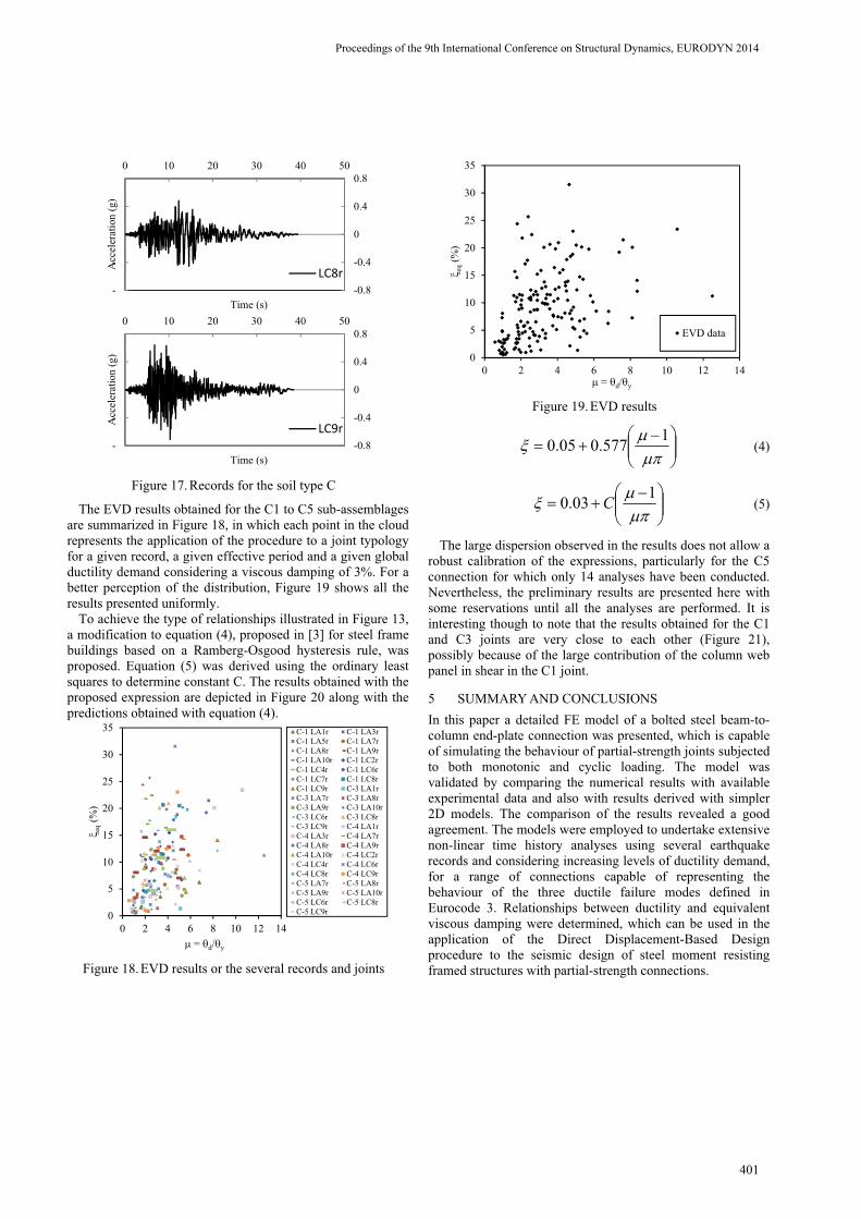
Figure 17.Records for the soil type C
The EVD results obtained for the C1 to C5 sub-assemblages are summarized in Figure 18, in which each point in the cloud represents the application of the procedure to a joint typology for a given record, a given effective period and a given global ductility demand considering a viscous damping of 3%. For a better perception of the distribution, Figure 19 shows all the results presented uniformly.
To achieve the type of relationships illustrated in Figure 13, a modification to equation (4), proposed in [3] for steel frame buildings based on a Ramberg-Osgood hysteresis rule, was proposed. Equation (5) was derived using the ordinary least squares to determine constant C. The results obtained with the proposed expression are depicted in Figure 20 along with the predictions obtained with equation (4).
Figure 18.EVD results or the several records and joints
Figure 19.EVD results
1577.005.0 (4)
103.0 C (5)
The large dispersion observed in the results does not allow a robust calibration of the expressions, particularly for the C5 connection for which only 14 analyses have been conducted. Nevertheless, the preliminary results are presented here with some reservations until all the analyses are performed. It is interesting though to note that the results obtained for the C1 and C3 joints are very close to each other (Figure 21), possibly because of the large contribution of the column web panel in shear in the C1 joint.
5 SUMMARY AND CONCLUSIONS In this paper a detailed FE model of a bolted steel beam-to-column end-plate connection was presented, which is capable of simulating the behaviour of partial-strength joints subjected to both monotonic and cyclic loading. The model was validated by comparing the numerical results with available experimental data and also with results derived with simpler 2D models. The comparison of the results revealed a good agreement. The models were employed to undertake extensive non-linear time history analyses using several earthquake records and considering increasing levels of ductility demand, for a range of connections capable of representing the behaviour of the three ductile failure modes defined in Eurocode 3. Relationships between ductility and equivalent viscous damping were determined, which can be used in the application of the Direct Displacement-Based Design procedure to the seismic design of steel moment resisting framed structures with partial-strength connections.
0 10 20 30 40 50
-0.8
-0.4
0
0.4
0.8
-
-Acc
eler
atio
n (g
)
Time (s)
LC8r
0 10 20 30 40 50
-0.8
-0.4
0
0.4
0.8
-
-Acc
eler
atio
n (g
)
Time (s)
LC9r
0
5
10
15
20
25
30
35
0 2 4 6 8 10 12 14
eq(%
)
= d/ y
C-1 LA1r C-1 LA3rC-1 LA5r C-1 LA7rC-1 LA8r C-1 LA9rC-1 LA10r C-1 LC2rC-1 LC4r C-1 LC6rC-1 LC7r C-1 LC8rC-1 LC9r C-3 LA1rC-3 LA7r C-3 LA8rC-3 LA9r C-3 LA10rC-3 LC6r C-3 LC8rC-3 LC9r C-4 LA1rC-4 LA3r C-4 LA7rC-4 LA8r C-4 LA9rC-4 LA10r C-4 LC2rC-4 LC4r C-4 LC6rC-4 LC8r C-4 LC9rC-5 LA7r C-5 LA8rC-5 LA9r C-5 LA10rC-5 LC6r C-5 LC8rC-5 LC9r
0
5
10
15
20
25
30
35
0 2 4 6 8 10 12 14
eq(%
)
= d/ y
EVD data
Proceedings of the 9th International Conference on Structural Dynamics, EURODYN 2014
Proceedings of the 9th International Conference on Structural Dynamics, EURODYN 2014
401

Figure 20.Adjustment of the analytical expressions to the EVD data obtained
Figure 21.Preliminary results for - EVD
From the results obtained it is possible to conclude that the majority of the values found for the EVD are below the values obtained with the expression proposed by Priestley et al. [3], indicating therefore that the expression should be improved in order to be applicable to steel moment frames with partial-strength beam-to-column joints.
Despite the considerable amount of results presented, research is still on-going and it is expected that definitive results will be obtained in the course of this work.
ACKNOWLEDGMENTSThe research leading to these results has received funding from the European Union's Research Fund for Coal and Steel (RFCS) research programme under grant agreement no. [RFSR-CT-2010-00029]. Also the financial support from the Portuguese Ministry of Science, Technology and Higher Education (Ministério da Ciência, Tecnologia e Ensino Superior) under contract grants SFRH / BD / 91167 / 2012, provided to Hugo Augusto, is gratefully acknowledged..
REFERENCES[1] CEN, EN 1998-1: Eurocode 8: Design of earthquake resistance of
structures – part 1-1: General rules – Seismic Actions and General Requirements for Structures, December, European Committee for Standardization, Brussels, 2004
[2] Fajfar,P. A nonlinear analysis method for performance based seismic design, Earthquake Spectra, Vol. 16(3), pp. 573-592, 2000.
[3] Priestley, M.J.N., Calvi, G.M. and Kowalsky, M.J. Displacement-Based Seismic Design of Structures, IUSS Press, Pavia, Italy, 2007
[4] Paulay, T. and Priestley, M.J.N. Seismic Design of Reinforced Concrete and Masonry Buildings. Wiley, New York, 1992.
[5] Priestley, M.J.N., Seible, F. and Calvi, G.M. Seismic Design and Retrofit of Bridges. Wiley, New York, 1996.
[6] Sullivan T.J, Priestley, M.J.N and Calvi G.M.,. Eds., A Model Code for the Displacement-Based Seismic Design of Structures, DBD12, IUSS press, Pavia, Italy, 2012.
[7] ABAQUS User’s Manual, Version 6.12, ABAQUS, Inc., DassaultSystèmes Simulia Corp., Providence, USA, 2012
[8] CEN, EN 1993-1-8. Eurocode 3: Design of steel structures – part 1-8: Design of joints, May, European Committee for Standardization,Brussels, 2005
[9] Nogueiro, P., Simões da Silva, L. and Bento, R. Numerical implementation and calibration of a hysteretic model for cyclic response of end-plate beam-to-column steel joints under arbitrary cyclic loading. Z. H. Yao and M. W. Yuan (eds.). Computational Methods in Engineering & Science, Sanya, China, 2006
[10] Augusto, H., Castro, J.M., Rebelo, C., Simões da Silva, L. Numerical Simulation of Partial-Strength Steel Beam-to-Column Connections under Monotonic and Cyclic Loading, Proccedings of Congress on Numerical Methods in Engineering, CMN 2013, Bilbao, Spain, pp.121-140, 2013
[11] SeismoSoft. SeismoStruct Version 5.2.2. SeismoSoft Ltd., Inc., Earthquake Engineering Software Solutions, Pavia, Italy, 2011, [online] Available from URL: http://www.seismosoft.com
[12] Della Corte, G., De Matteis, G. and Landolfo, R. Influence of Connection Modelling on Seismic Response of Moment Resisting Steel Frames, Mazzolani, F. M. (eds.), Moment Resistant Connections of Steel Buildings Frames in Seismic Areas, E. & F.N. Spon, London, UK, 2000
[13] Nogueiro, P.,Simões da Silva, L., Bento, R. and Simões, R., Numerical implementation and calibration of a hysteretic model with pinching for the cyclic response of steel and composite joints, Shen, Z. Y., Li, G. Q. and Chan, S. L. (eds.). Fourth International Conference on Advances in Steel Structures, Vol. I, pp. 767-774, 2005
[14] CEN, EN 1993-1-1. Eurocode 3: Design of steel structures – part 1-1: General rules and rules for buildings,.May, European Committee for Standardization, Brussels, 2005.
0
5
10
15
20
25
30
35
0 2 4 6 8 10 12 14
eq(%
)
= d/ y
EVD [3]
EVD data
EVD for All C= 0.341
EVD for C1 C= 0.333
EVD for C3 C= 0.323
EVD for C4 C= 0.383
EVD for C5 C= 0.180
0
2
4
6
8
10
12
14
16
0 2 4 6 8 10 12 14
eq(%
)
= d/ y
C1 C3C4 C5
Proceedings of the 9th International Conference on Structural Dynamics, EURODYN 2014
Proceedings of the 9th International Conference on Structural Dynamics, EURODYN 2014
402