Embed Size (px)
Citation preview
Coupled underground blast simulation using a 2D axisymmetric LagrangianFinite Difference Time Domain solver with a Perfectly Matched Layer
Bram Desmet1,2, Stijn Francois2, John Vantomme1, Geert Degrande21 Royal Military Academy, Civil and Materials Engineering Department, Renaissancelaan 30, BE-1000 Brussel, Belgium
2 KU Leuven, Department of Civil Engineering, Kasteelpark Arenberg 40, BE-3001 Leuven, Belgiumemail:bram.desmet, [email protected],stijn.francois, [email protected]
ABSTRACT: Blast induced soil vibrations can cause structural damage even at large distances from the source, causing the needfor accurate prediction methods. The occurrence of shock waves and the high strain rates and deformations call for the use ofhydrocodes in the proximity of an explosion. At larger distance, the use of a more cost effective linear elastic calculation tool ispreferred. A coupled numerical model is proposed, which combines a 2D axisymmetric Finite Difference Time Domain modelinAutodyn with a frequency domain linear elastic method. The Autodyn model uses a coupled Eulerian-ALE-Lagrangian solver and istruncated in the linear elastic hydrocode domain. Spuriousreflections are avoided by adding an unsplit field Perfectly Matched Layerto the truncated hydrocode domain. The results at an interface in the linear elastic hydrocode domain are used to computeresults inthe far field, based on the dynamic reciprocity theorem and the Green’s functions of a layered elastic halfspace. The methodologyis validated against a linear elastic reference solution and applied to a small subsurface explosion in a non elastic soil. The blastinduced vibrations are determined at distances up to 200 m from the source and are compared to empirical reference results.
KEY WORDS: Soil wave propagation; underground blast; FDTD hydrocode; Perfectly Matched Layer; Dynamic reciprocity.
1 INTRODUCTION
Subsurface explosions cause vibrations that can have detrimen-tal effects on structures, even at large distances. Accurateprediction of the soil vibrations is needed to control theseeffects.
Empirical models [1, 2] are frequently used for this purpose,but only give rough approximations based on a limited numberof input parameters. Their accuracy depends on the statisticalanalysis of large experimental data sets.
Analytical models deliver closed form solutions to the dif-ferential equations of wave propagation, applying considerablesimplifications to the geometry of the problem, the materialmodel and the blast loading [3].
In view of these limitations, numerical modeling can provideresults with more detail for realistic configurations. Ahydrocode enables the simulation of highly non-linear eventsin the immediate surroundings of an explosion. Hydrocodeswere originally developed for fluid dynamics applications,but have since been adapted to handle material strengthand solid material models, enabling elasto-plastic and linearanalysis. Adapted computational methodologies, combiningdifferent solver types, are used to calculate the shock wavepropagation and extremely high material deformations [4].These methods are computationally expensive and materialmodels that cover the entire deformation range - from linearelastic to hydrodynamic - can be very complicated.
Hydrocodes have been used extensively for determining nearfield effects of soil blast loading. Fiserova [5] determinesthe effects of buried mines on protective plating with EulerianAutodyn models, using a compaction model. Luccioni et al. [6]use a similar approach to investigate cratering by buried charges.Gu et al. [7] investigate crater formation in a layered soil usingan elasto-plastic soil model in a coupled Eulerian-AleatoryLagrangian Eulerian (ALE) setup. These models avoid the
shortcomings of the hydrocode, by limiting the extent of themodeled domain. Spurious reflections caused by this truncationdo not affect the solution, since only short term and short rangeeffects are investigated.
Hydrocode modeling of far field effects of undergroundblast mainly focuses on rocks, in the context of mining orunderground ammunition storage. Oversized models withviscous absorbing boundary conditions (ABC) are used toreduce the effects of spurious reflections. Wu and Hao [8]study the ground motion characteristics due to a large rockchamber blast and the effects on surface structures with 2Dand 3D coupled Eulerian-Lagrangian models in Autodyn. Thehydrocode models extend to over 100 m from the source.
Coupled methodologies are usually limited to an Eulerian-Lagrangian coupling, where the explosive source is Eulerianand the soil is Lagrangian. Large deformations near the blastsource lead to heavily distorted meshes and early termination ofcomputations. Lu et al. [9] use a three-phase soil model [10]to determine blast induced far field effects on buried structures,using a coupled Eulerian-Smoothed Particle Hydrodynamic-Lagrangian model. The Smoothed Particle Hydrodynamics partaccounts for the largest deformations surrounding the Eulerianblast source, ensuring the continued integrity of the Lagrangianpart. Similarly, Jayasinghe et al. [11] use a coupled Euler-ALEmodel to determine the response of a foundation pile to blastinduced vibration. The ALE remapping compensates for thelarge mesh deformations.
In this paper, a coupled numerical methodology is proposedto obtain a prediction of far field blast induced vibrations ina halfspace. Results in a bounded subdomain, surroundingthe explosive source, are obtained with the Autodyn 2Daxisymmetric hydrocode, using a coupled Eulerian-ALE-Lagrangian model. This subdomain is obtained by truncatingthe halfspace at sufficient distance from the blast source, where
Proceedings of the 9th International Conference on Structural Dynamics, EURODYN 2014Porto, Portugal, 30 June - 2 July 2014
A. Cunha, E. Caetano, P. Ribeiro, G. Müller (eds.)ISSN: 2311-9020; ISBN: 978-972-752-165-4
3511
the response is linear elastic. To avoid truncation errors,an 2Daxisymmetric unsplit field PML for elastic media, as proposedby Kucukcoban and Kallivokas [12], is integrated in Autodyn’sLagrangian FDTD code. The tractions and displacements on aninterface near the truncated edge are used to compute the elasticfar field response based on the dynamic reciprocity theorem andthe Green’s functions of an elastic halfspace [13]. The coupledmethodology is validated considering the case of a surface loadon a linear elastic halfspace in section 5 and is applied on anunderground explosion in a homogeneous non-linear soil. Usingthis methodology, blast induced vibrations in the far field canbe calculated in a cost efficient manner, taking into accountthenon-linear behavior of the soil near the explosive source.
2 COUPLED METHODOLOGY
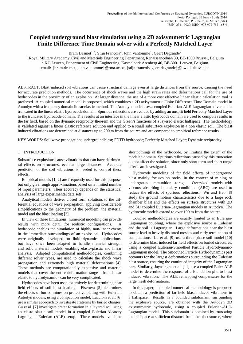
In the surroundings of an underground explosion, the behaviorof the soil changes with growing distance from the explosivesource. The 3D semi-infinite problem domainΩ is boundedby a free surfaceΓt and is divided into three subdomainsΩ1, Ω2 and Ω3 (figure 1). In the hydrodynamic subdomainΩ1, immediately surrounding the explosive source S, extremesoil deformations occur at high speeds and the soil strengthis exceeded: the soil behaves hydrodynamically. At a largerdistance from the source, pressure waves are attenuated, butare still in the non-linear range: in the subdomainΩ2 thesoil behavior is elasto-plastic. With further attenuationofthe pressure waves, the elastic limit of the soil is no longerexceeded: in the semi-infinite subdomainΩ3, the soil has alinear elastic behavior. SubdomainsΩ1 andΩ2 are separatedby the interfaceΣ12, while interfaceΣ23 separates subdomainsΩ2 andΩ3.
The size and shape of subdomainsΩ1 and Ω2 depends onthe soil properties and the amplitude and depth of the blastsource. For an underground explosion, the released energy isgenerally high enough to cause elasto-plastic soil deformationsin the vicinity of the source. The stress levels are not necessarilyhigh enough to cause hydrodynamic soil behavior. If the ratio ofthe depth to the amplitude of the source is sufficiently small,the subdomain interfacesΣ12 and Σ23 can intersect the freesurfaceΓt. The soil at the free surface is significantly deformed,resulting in visible surface effects such as dome formation, soilejection or cratering.
The high deformations and strain rates of the soil in thehydrodynamic domainΩ1 require the use of computationalmethods and material models that can handle this non-linearbehavior. The wave propagation in domainΩ2 can be studiedusing non-linear, elasto-plastic methods, while inΩ3, a linearelastic solver is used.
The complex constitutive behavior inΩ requires a computa-tionally expensive hydrocode, applied to a bounded subdomainΩ. To avoid spurious reflections, an ABC is applied toΩin the linear elastic domainΩ3. Ω is then bounded by the
truncated free surfaceΓt and equalsΩ1 ∪Ω2 ∪Ω3, whereΩ3
is the truncated part ofΩ3. In this work, a PML is used:ΩPML
is coupled toΩ at the interfaceΣPML and is bounded by the freesurfaceΓPML
t and the fixed boundaryΓPMLu (figure 2).
Results in the far field, for which a hydrocode computationis not possible or cost-efficient, are obtained using a linearelastic method. The halfspaceΩe is a linear elastic copy of
r
z
SΩ1
Ω2
Ω3
Ω
Γt
Σ12
Σ23
Figure 1. The problem domainΩ = Ω1 ∪Ω2∪Ω3, boundedby the free surfaceΓt, containing the source S and theinterfacesΣ12 andΣ23.
r
z
ΣPML
ΩPML
Γt ΓPMLt
ΓPMLu
Σie
S
Ω1
Ω2
Ω3
Ω
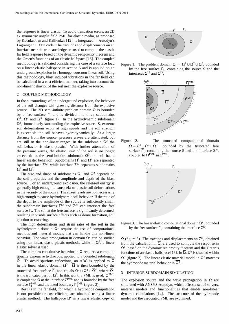
Figure 2. The truncated computational domain
Ω = Ω1∪Ω2∪Ω3, bounded by the truncated free
surfaceΓt, containing the source S and the interfaceΣie,coupled toΩPML in ΣPML.
r
z
Ωe
Γt
Σie
Figure 3. The linear elastic computational domainΩe, boundedby the free surfaceΓt, containing the interfaceΣie.
Ω (figure 3). The tractions and displacements onΣie, obtainedfrom the calculation inΩ, are used to compute the response inΩe, based on the dynamic reciprocity theorem and the Green’sfunctions of an elastic halfspace [13]. InΩ, Σie is situated within
Ω3(figure 2). The linear elastic material model inΩe matches
the hydrocode material behavior inΩ3.
3 INTERIOR SUBDOMAIN SIMULATION
The explosion source and the wave propagation inΩ aresimulated with ANSYS Autodyn, which offers a set of solvers,material models and functionalities that enable non-lineardynamic calculations [14]. The structure of the hydrocodemodel and the associated PML are explained.
Proceedings of the 9th International Conference on Structural Dynamics, EURODYN 2014
3512
3.1 The hydrocode model
Ω is modeled in Autodyn, using a 2D axisymmetric Eulerian-ALE-Lagrangian multi-solver model in the time domain. Thismodel is subdivided in coupled subgrids, each using one of thesesolvers. Autodyn only uses quadrilateral meshing, imposingimportant restrictions on the geometry and the coupling strategyof the subgrids.
The explosive source S and its gaseous explosion productsare modeled using a multi-material first order Eulerian FiniteVolume solver. In this part, a fine mesh is needed to obtaincorrect generation of the detonation wave. For small charges,this has a big impact on the time step used in the entiremodel. While the shape of the Euler part normally matches theexplosive’s shape, a spherical approximation can be adopted forcompactly shaped charges. This enables a simplification of thestructure of the model and has little effect on the far field results.
Ω is modeled using a combination of Finite Difference TimeDomain (FDTD) solvers: the soil near the explosive is modeledusing an ALE FDTD solver. The applied motion constraintsdepend on the shape of the charge and the post-blast explosioncavity. The ALE part should be as small as possible, to limitthe computational cost. Other ALE subgrids can be includedwherever large deformations are expected. The remainingvolume of the model is calculated with a Lagrangian FDTDmodel.
The hydrocode methodology is illustrated in detail using theapplication in section 6.
3.2 The Perfectly Matched Layer
Autodyn uses a 1D viscous ABC, which is supposed to absorblinear elastic waves propagating perpendicularly towardstheboundary. Due to a bug in the software, only positive pressuresare absorbed. To meet the truncation requirements expressed insection 2, the unsplit field 2D axisymmetric PML methodologydeveloped by Kucukcoban and Kallivokas [12] is integratedin the Lagrangian computational cycle of Autodyn, usingcustomizable user-subroutines.
ΩPML
Ω
ΣPML ΓPMLu
LPMLs so st
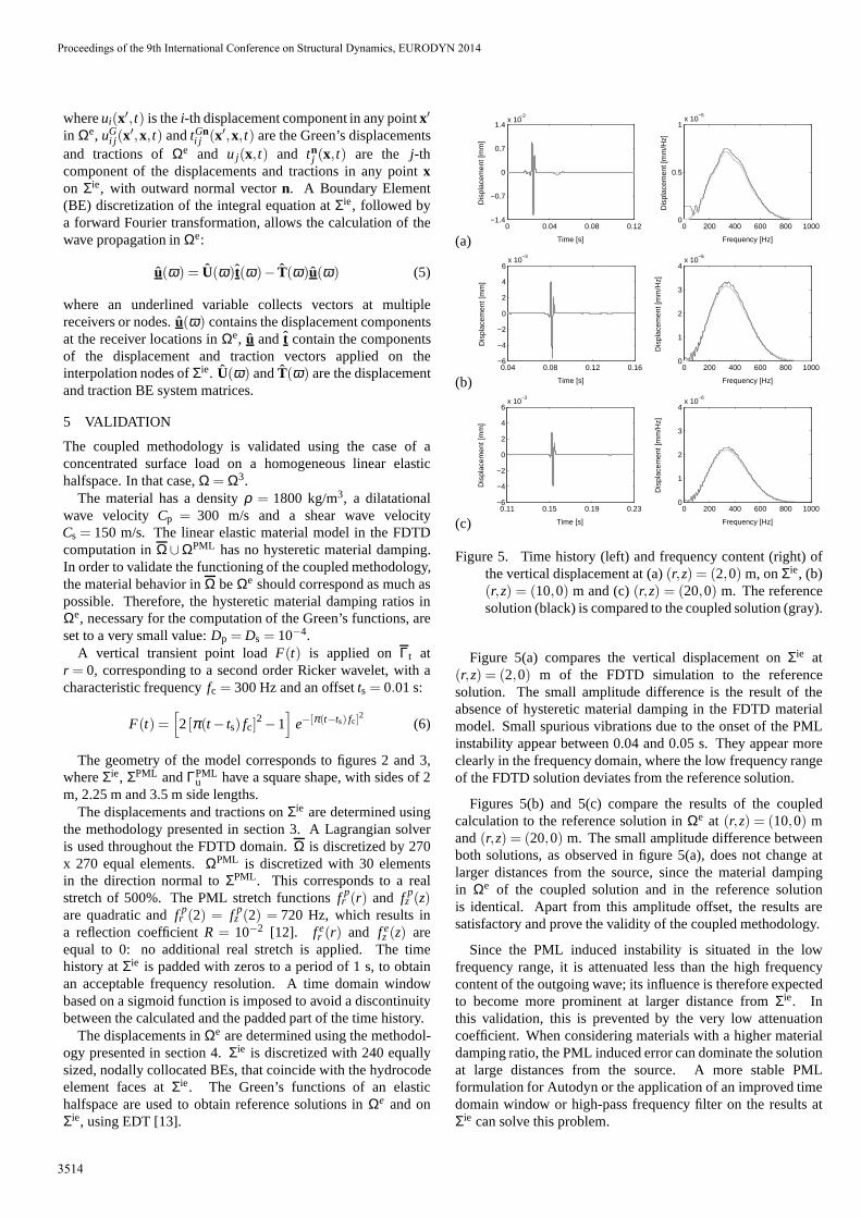
Figure 4. ΩPML, coupled toΩ in ΣPML. A wave passes throughΣPML, decays with distance and reflects onΓPML
u .
Consider the PML domainΩPML, coupled toΩ at ΣPML,as shown in figure 2. Ifs is the coordinate in the directionnormal toΣPML, ΩPML extends froms= so to s= st (figure 4).An outgoing wave passes throughΣPML without reflections anddecays with distance withinΩPML. The coordinates is replaced
by a stretched coordinate ˜s, defined as [15]:
s=∫ s
0λs(s)ds= so+
∫ st
so
λs(s)ds (1)
where λs(s) is a frequency dependent, continuous, non-zerocomplex valued stretching function [15, 16]:
λs(s) = 1+ f es (s)− i
f ps (s)ω
, (2)
whereω is the circular frequency, and the functionsf es (s) and
f ps (s) cause attenuation of evanescent and propagating waves.
Within Ω and onΣPML, the attenuation functions are zero. Thisguarantees the continuity of the stretch functions across theinterface and the perfectly matching properties of the PML.To obtain sufficient yet gradual attenuation within the PML,aquadratic formulation is used forf p
s (s) [12]:
f ps (s) =
3Cp
2LPML log
[
1R
][
(s− s0)
LPML
]2
if s0 ≤ s< st
0 if 0 ≤ s< s0
(3)
whereCp is the dilatational wave propagation velocity andR is areflection coefficient, indicating the needed attenuation at ΓPML
u .A similar formulation is used forf e
s (s), whereCp is replaced bya characteristic lengthb of the domainΩPML (e.g. the cell sizeor LPML).
In the 2D axisymmetric geometry proposed in section 3.1,the stretch is applied to ther and z coordinate. The stretchfunctions are introduced in the governing wave equations inthefrequency domain of an axisymmetric linear elastic medium,asshown in [12]. The constitutive equation of the linear elasticmedium is unaffected by the coordinate stretch. The stretchedwave equations are then transformed to the time domain by aninverse Fourier transform and solved using a Lagrangian FDTDscheme, based on the Autodyn code.
A known instability issue with this type of PML is expectedto cause some spurious reflections [17]. This instability canbe delayed by applying a gradual, real stretch toΩPML inthe direction of the stretched coordinates, without additionalcomputational cost and with equally perfectly matchingbehavior of the PML. It can also be reduced by loweringthe reflection coefficientR. To compensate for the reducedattenuation,ΓPML
u can be replaced by a viscous ABC [18], whichabsorbs a large part of the remaining outgoing waves.
4 EXTERIOR SUBDOMAIN SIMULATION
The tractionstn and displacementsu at Σie that result from thecalculation inΩ are imposed onΩe. The displacements inΩe
can then be related to the imposed tractions and displacementsby applying the dynamic reciprocity theorem [19, 20]. If bodyforces are neglected andΩe is initially at rest, the introduction ofthe Green’s functions of an elastic halfspace [13] in the dynamicreciprocity equation yields the following integral representation:
ui(x′, t) =∫
Σie
[
uGi j (x
′,x, t)tnj (x, t)− tGn
i j (x′,x, t)u j(x, t)]
dS (4)
Proceedings of the 9th International Conference on Structural Dynamics, EURODYN 2014
3513
whereui(x′, t) is thei-th displacement component in any pointx′
in Ωe, uGi j (x
′,x, t) andtGni j (x′,x, t) are the Green’s displacements
and tractions ofΩe and u j(x, t) and tnj (x, t) are the j-th
component of the displacements and tractions in any pointxon Σie, with outward normal vectorn. A Boundary Element(BE) discretization of the integral equation atΣie, followed bya forward Fourier transformation, allows the calculation of thewave propagation inΩe:
u(ω) = U(ω)t(ω)− T(ω)u(ω) (5)
where an underlined variable collects vectors at multiplereceivers or nodes.u(ω) contains the displacement componentsat the receiver locations inΩe, u and t contain the componentsof the displacement and traction vectors applied on theinterpolation nodes ofΣie. U(ω) andT(ω) are the displacementand traction BE system matrices.
5 VALIDATION
The coupled methodology is validated using the case of aconcentrated surface load on a homogeneous linear elastichalfspace. In that case,Ω = Ω3.
The material has a densityρ = 1800 kg/m3, a dilatationalwave velocity Cp = 300 m/s and a shear wave velocityCs = 150 m/s. The linear elastic material model in the FDTDcomputation inΩ∪ΩPML has no hysteretic material damping.In order to validate the functioning of the coupled methodology,the material behavior inΩ beΩe should correspond as much aspossible. Therefore, the hysteretic material damping ratios inΩe, necessary for the computation of the Green’s functions, areset to a very small value:Dp = Ds = 10−4.
A vertical transient point loadF(t) is applied onΓt atr = 0, corresponding to a second order Ricker wavelet, with acharacteristic frequencyfc = 300 Hz and an offsetts = 0.01 s:
F(t) =[
2[π(t − ts) fc]2−1
]
e−[π(t−ts) fc]2
(6)
The geometry of the model corresponds to figures 2 and 3,whereΣie, ΣPML andΓPML
u have a square shape, with sides of 2m, 2.25 m and 3.5 m side lengths.
The displacements and tractions onΣie are determined usingthe methodology presented in section 3. A Lagrangian solveris used throughout the FDTD domain.Ω is discretized by 270x 270 equal elements.ΩPML is discretized with 30 elementsin the direction normal toΣPML. This corresponds to a realstretch of 500%. The PML stretch functionsf p
r (r) and f pz (z)
are quadratic andf pr (2) = f p
z (2) = 720 Hz, which results ina reflection coefficientR = 10−2 [12]. f e
r (r) and f ez (z) are
equal to 0: no additional real stretch is applied. The timehistory atΣie is padded with zeros to a period of 1 s, to obtainan acceptable frequency resolution. A time domain windowbased on a sigmoid function is imposed to avoid a discontinuitybetween the calculated and the padded part of the time history.
The displacements inΩe are determined using the methodol-ogy presented in section 4.Σie is discretized with 240 equallysized, nodally collocated BEs, that coincide with the hydrocodeelement faces atΣie. The Green’s functions of an elastichalfspace are used to obtain reference solutions inΩe and onΣie, using EDT [13].
(a)0 0.04 0.08 0.12
−1.4
−0.7
0
0.7
1.4x 10
−2
Dis
plac
emen
t [m
m]
Time [s]
0 200 400 600 800 10000
0.5
1x 10
−5
Dis
plac
emen
t [m
m/H
z]
Frequency [Hz]
(b)0.04 0.08 0.12 0.16
−6
−4
−2
0
2
4
6x 10
−3
Time [s]
Dis
plac
emen
t [m
m]
0 200 400 600 800 10000
1
2
3
4x 10
−6
Dis
plac
emen
t [m
m/H
z]
Frequency [Hz]
(c)0.11 0.15 0.19 0.23
−6
−4
−2
0
2
4
6x 10
−3
Time [s]
Dis
plac
emen
t [m
m]
0 200 400 600 800 10000
1
2
3
4x 10
−6
Dis
plac
emen
t [m
m/H
z]
Frequency [Hz]
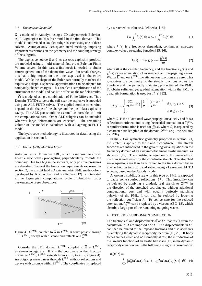
Figure 5. Time history (left) and frequency content (right)ofthe vertical displacement at (a)(r,z) = (2,0) m, onΣie, (b)(r,z) = (10,0) m and (c)(r,z) = (20,0) m. The referencesolution (black) is compared to the coupled solution (gray).
Figure 5(a) compares the vertical displacement onΣie at(r,z) = (2,0) m of the FDTD simulation to the referencesolution. The small amplitude difference is the result of theabsence of hysteretic material damping in the FDTD materialmodel. Small spurious vibrations due to the onset of the PMLinstability appear between 0.04 and 0.05 s. They appear moreclearly in the frequency domain, where the low frequency rangeof the FDTD solution deviates from the reference solution.
Figures 5(b) and 5(c) compare the results of the coupledcalculation to the reference solution inΩe at (r,z) = (10,0) mand(r,z) = (20,0) m. The small amplitude difference betweenboth solutions, as observed in figure 5(a), does not change atlarger distances from the source, since the material dampingin Ωe of the coupled solution and in the reference solutionis identical. Apart from this amplitude offset, the resultsaresatisfactory and prove the validity of the coupled methodology.
Since the PML induced instability is situated in the lowfrequency range, it is attenuated less than the high frequencycontent of the outgoing wave; its influence is therefore expectedto become more prominent at larger distance fromΣie. Inthis validation, this is prevented by the very low attenuationcoefficient. When considering materials with a higher materialdamping ratio, the PML induced error can dominate the solutionat large distances from the source. A more stable PMLformulation for Autodyn or the application of an improved timedomain window or high-pass frequency filter on the results atΣie can solve this problem.
Proceedings of the 9th International Conference on Structural Dynamics, EURODYN 2014
3514
6 APPLICATION
The coupled methodology is applied to the undergroundexplosion of a 1 kg sphere of C4 explosive at a depth of 2 min a homogeneous halfspace.
A single soil model is used throughoutΩ, based on the modelof Luccioni et al. [6]. The bulk compressibility of the soilis modeled using a Mie-Gruneisen equation of state, based onthe shock Hugoniot of the material [14]. The hydrodynamicpressurep(t) equals
p(t) = pH(t)+ γρ0
[
e(t)− pH(t)µ(t)2ρ0(1+ µ(t))
]
(7)
where the Hugoniot pressurepH(t) is
pH(t) =ρ0 µ(t)(1+ µ(t))
√
Cp2− 4
3Cs2
[1− (sH−1)µ(t)]2(8)
with γ = 0.11 the Gruneisen coefficient,sH = 1.5 thelinear shock Hugoniot slope coefficient,ρ0 = 1920 kg/m3
the soil density,Cp = 600 m/s the dilatational wave velocity,Cs = 300 m/s the shear wave velocity,ρ(t) the density,e(t)the specific internal energy andµ(t) = [ρ(t)/ρ0] − 1 thecompression rate.ρ0, Cp andCs are considered atp = 0. Ahydrodynamic bulk failure limit pressurepmin is set at -1 MPa.In terms of Von Mises stress, the yield strengthσy is determinedby a piecewise linear Drucker-Prager criterion:
σy =
α p+β [MPa] if pmin ≤ p ≤ 6.88 MPa
6.2 MPa if p > 6.88 MPa(9)
whereα = 0.74 andβ =1.11 MPa depend on the soil’s cohesionand internal friction angle. At low pressures, this materialmodel approaches a linear elastic model, with wave velocitiesCp andCs and densityρ0. This model is used inΩPML. InΩe, this material is used in combination with hysteretic materialdamping ratiosDp = Ds = 0.02. The explosive material modelis the Jones-Wilkins-Lee equation of state for C4, as used inAutodyn [6, 14].
In this case, it is possible to perform the hydrocode simulationin two steps. The first 2.55 milliseconds after the detonation aremodeled with an Eulerian 1D spherical symmetric starter model.It has a length of 2 m from the center of the explosive to the freesurface and is discretized by 2000 equally sized elements. Theexplosive, which has a radius of 0.055 m, is situated at the centerof this model and is surrounded by soil. The wave propagationis modeled from the detonation up to the moment the shockwave reaches the free surface. The 1D results are subsequentlyremapped onto the full model, which has been dimensioned tocorrespond to the deformed state at the end of the 1D simulation.The radius of the explosive productsR1 at t = 2.55 ms equals0.268 m.
The starter model contains explosive and soil material in asingle multi-material Eulerian mesh. The interface between bothmaterials risks blurring due to diffusion [21]. If soil material isremapped into the Euler part of the full model, this leads to localerrors in the Eulerian part and in the fluid-structure interface andcan stop or delay the computation.
The use of a two step hydrocode methodology has severaladvantages. Autodyn uses explicit time integration with a
r
z
Σie
ΩPML
ΣPML
Z2
LP
ML
R2 LPML
R1
R3
R4
Z4
Ω
D
D
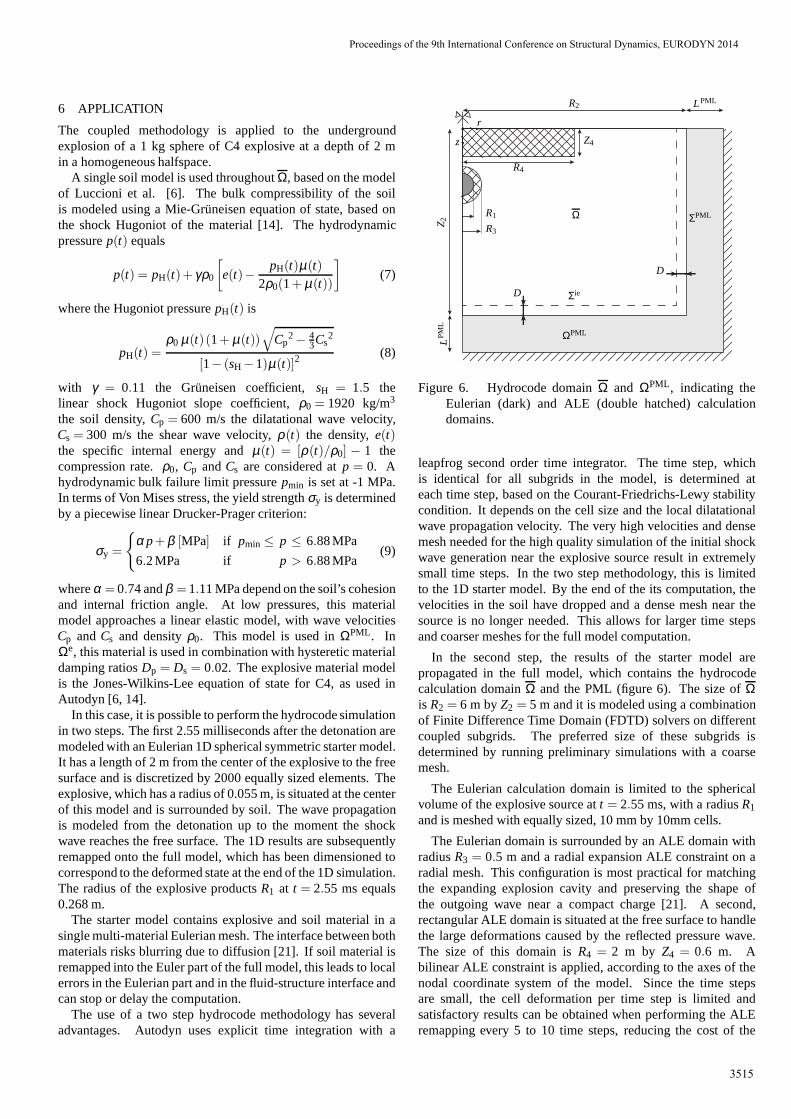
Figure 6. Hydrocode domainΩ and ΩPML, indicating theEulerian (dark) and ALE (double hatched) calculationdomains.
leapfrog second order time integrator. The time step, whichis identical for all subgrids in the model, is determined ateach time step, based on the Courant-Friedrichs-Lewy stabilitycondition. It depends on the cell size and the local dilatationalwave propagation velocity. The very high velocities and densemesh needed for the high quality simulation of the initial shockwave generation near the explosive source result in extremelysmall time steps. In the two step methodology, this is limitedto the 1D starter model. By the end of the its computation, thevelocities in the soil have dropped and a dense mesh near thesource is no longer needed. This allows for larger time stepsand coarser meshes for the full model computation.
In the second step, the results of the starter model arepropagated in the full model, which contains the hydrocodecalculation domainΩ and the PML (figure 6). The size ofΩis R2 = 6 m byZ2 = 5 m and it is modeled using a combinationof Finite Difference Time Domain (FDTD) solvers on differentcoupled subgrids. The preferred size of these subgrids isdetermined by running preliminary simulations with a coarsemesh.
The Eulerian calculation domain is limited to the sphericalvolume of the explosive source att = 2.55 ms, with a radiusR1
and is meshed with equally sized, 10 mm by 10mm cells.
The Eulerian domain is surrounded by an ALE domain withradiusR3 = 0.5 m and a radial expansion ALE constraint on aradial mesh. This configuration is most practical for matchingthe expanding explosion cavity and preserving the shape ofthe outgoing wave near a compact charge [21]. A second,rectangular ALE domain is situated at the free surface to handlethe large deformations caused by the reflected pressure wave.The size of this domain isR4 = 2 m by Z4 = 0.6 m. Abilinear ALE constraint is applied, according to the axes ofthenodal coordinate system of the model. Since the time stepsare small, the cell deformation per time step is limited andsatisfactory results can be obtained when performing the ALEremapping every 5 to 10 time steps, reducing the cost of the
Proceedings of the 9th International Conference on Structural Dynamics, EURODYN 2014
3515
ALE remapping. Nodes at subgrid interfaces are not subjectedto the ALE motion constraints, to ensure correct coupling.
The remaining parts ofΩ use the Lagrangian FDTD solverand are meshed with equally sized, 10 mm by 10 mm cells.At large distances from the blast source, spherical meshingneeds to be avoided, since acceptable cell size ratios can onlybe obtained by introducing multiple transition parts, whichneedlessly complicate the structure of the model. In thisconfiguration, only one transitional discretization subgrid isneeded to couple the rectangular Lagrangian subgrid to theradial ALE subgrid.
ΩPML uses the adapted Lagrangian FDTD solver discussedin section 3.2. The domain has a widthLPML = 1 m andis discretized with 50 rectangular elements in the directionnormal to ΣPML, with a linearly increasing real stretch.The PML stretch functionsf p
r (r) and f pz (z) are quadratic
and f pr (7) = f p
z (6) = 1800 Hz, which results in a reflectioncoefficientR= 10−2 in accordance with the stretch formulationsin [12]. f e
r (r) and f ez (z) are constant and equal to 1: no
additional real stretch is applied.Σie is parallel to theΣPML interface, at a distance of
D = 0.15 m. This interface is discretized with 1070 equallysized and nodally collocated BEs that coincide with thehydrocode element faces atΣie.
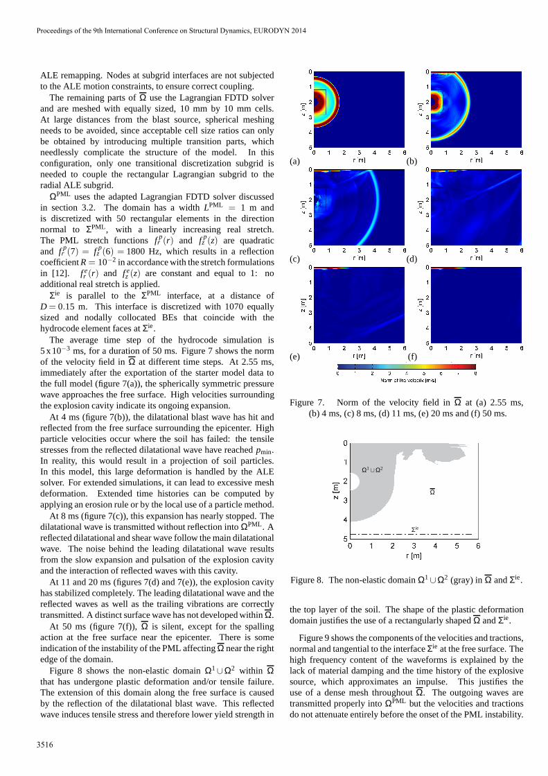
The average time step of the hydrocode simulation is5 x10−3 ms, for a duration of 50 ms. Figure 7 shows the normof the velocity field inΩ at different time steps. At 2.55 ms,immediately after the exportation of the starter model datatothe full model (figure 7(a)), the spherically symmetric pressurewave approaches the free surface. High velocities surroundingthe explosion cavity indicate its ongoing expansion.
At 4 ms (figure 7(b)), the dilatational blast wave has hit andreflected from the free surface surrounding the epicenter. Highparticle velocities occur where the soil has failed: the tensilestresses from the reflected dilatational wave have reachedpmin.In reality, this would result in a projection of soil particles.In this model, this large deformation is handled by the ALEsolver. For extended simulations, it can lead to excessive meshdeformation. Extended time histories can be computed byapplying an erosion rule or by the local use of a particle method.
At 8 ms (figure 7(c)), this expansion has nearly stopped. Thedilatational wave is transmitted without reflection intoΩPML. Areflected dilatational and shear wave follow the main dilatationalwave. The noise behind the leading dilatational wave resultsfrom the slow expansion and pulsation of the explosion cavityand the interaction of reflected waves with this cavity.
At 11 and 20 ms (figures 7(d) and 7(e)), the explosion cavityhas stabilized completely. The leading dilatational wave and thereflected waves as well as the trailing vibrations are correctlytransmitted. A distinct surface wave has not developed within Ω.
At 50 ms (figure 7(f)),Ω is silent, except for the spallingaction at the free surface near the epicenter. There is someindication of the instability of the PML affectingΩ near the rightedge of the domain.
Figure 8 shows the non-elastic domainΩ1∪Ω2 within Ωthat has undergone plastic deformation and/or tensile failure.The extension of this domain along the free surface is causedby the reflection of the dilatational blast wave. This reflectedwave induces tensile stress and therefore lower yield strength in
(a) (b)
(c) (d)
(e) (f)
Figure 7. Norm of the velocity field inΩ at (a) 2.55 ms,(b) 4 ms, (c) 8 ms, (d) 11 ms, (e) 20 ms and (f) 50 ms.
Ω1∪Ω2
Σie
Ω
Figure 8. The non-elastic domainΩ1∪Ω2 (gray) inΩ andΣie.
the top layer of the soil. The shape of the plastic deformationdomain justifies the use of a rectangularly shapedΩ andΣie.
Figure 9 shows the components of the velocities and tractions,normal and tangential to the interfaceΣie at the free surface. Thehigh frequency content of the waveforms is explained by thelack of material damping and the time history of the explosivesource, which approximates an impulse. This justifies theuse of a dense mesh throughoutΩ. The outgoing waves aretransmitted properly intoΩPML but the velocities and tractionsdo not attenuate entirely before the onset of the PML instability.
Proceedings of the 9th International Conference on Structural Dynamics, EURODYN 2014
3516
(a)0 0.01 0.02 0.03 0.04 0.05
−2
−1
0
1
2
Time [s]
Vel
ocity
[m/s
]
10−1
100
101
102
103
104
0
1
2x 10
−3
Frequency [Hz]
Ve
loci
ty [
m/s
/Hz]
(b)0 0.01 0.02 0.03 0.04 0.05
−2
−1
0
1
2
Time [s]
Vel
ocity
[m/s
]
10−1
100
101
102
103
104
0
1
2x 10
−3
Frequency [Hz]
Ve
loci
ty [
m/s
/Hz]
(c)0 0.01 0.02 0.03 0.04 0.05
−2
−1
0
1
2
Time [s]
Tra
ctio
n [M
Pa]
10−1
100
101
102
103
104
0
0.2
0.4
0.6
0.8
1x 10
−3
Frequency [Hz]
Tra
ctio
n [M
Pa/
Hz]
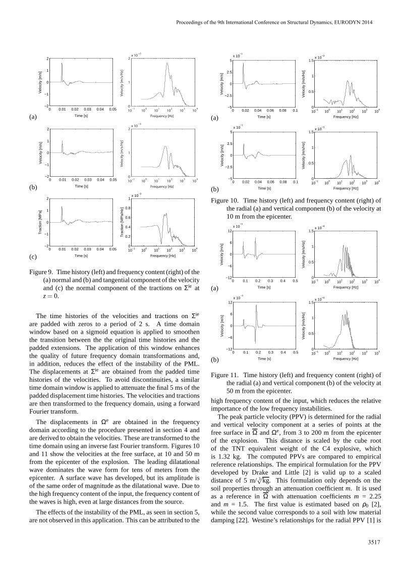
Figure 9. Time history (left) and frequency content (right)of the(a) normal and (b) and tangential component of the velocityand (c) the normal component of the tractions onΣie atz= 0.
The time histories of the velocities and tractions onΣie
are padded with zeros to a period of 2 s. A time domainwindow based on a sigmoid equation is applied to smoothenthe transition between the the original time histories and thepadded extensions. The application of this window enhancesthe quality of future frequency domain transformations and,in addition, reduces the effect of the instability of the PML.The displacements atΣie are obtained from the padded timehistories of the velocities. To avoid discontinuities, a similartime domain window is applied to attenuate the final 5 ms of thepadded displacement time histories. The velocities and tractionsare then transformed to the frequency domain, using a forwardFourier transform.
The displacements inΩe are obtained in the frequencydomain according to the procedure presented in section 4 andare derived to obtain the velocities. These are transformedto thetime domain using an inverse fast Fourier transform. Figures 10and 11 show the velocities at the free surface, at 10 and 50 mfrom the epicenter of the explosion. The leading dilatationalwave dominates the wave form for tens of meters from theepicenter. A surface wave has developed, but its amplitude isof the same order of magnitude as the dilatational wave. Due tothe high frequency content of the input, the frequency content ofthe waves is high, even at large distances from the source.
The effects of the instability of the PML, as seen in section 5,are not observed in this application. This can be attributedto the
(a)0 0.02 0.04 0.06 0.08 0.1
−5
−2.5
0
2.5
5
Time [s]
Vel
ocity
[m/s
]
x 10−1
10−1
100
101
102
103
104
0
0.5
1
1.5x 10
−3
Frequency [Hz]
Vel
ocity
[m/s
/Hz]
(b)0 0.02 0.04 0.06 0.08 0.1
−5
−2.5
0
2.5
5
Time [s]
Vel
ocity
[m/s
]
x 10−1
10−1
100
101
102
103
104
0
0.5
1
1.5x 10
−3
Frequency [Hz]
Vel
ocity
[m/s
/Hz]
Figure 10. Time history (left) and frequency content (right) ofthe radial (a) and vertical component (b) of the velocity at10 m from the epicenter.
(a)0 0.1 0.2 0.3 0.4 0.5
−12
−6
0
6
12
Time [s]
Vel
ocity
[m/s
]x 10
−3
10−1
100
101
102
103
104
0
0.5
1
1.5x 10
−4
Frequency [Hz]
Vel
ocity
[m/s
/Hz]
(b)0 0.1 0.2 0.3 0.4 0.5
−12
−6
0
6
12
Time [s]
Vel
ocity
[m/s
]
x 10−3
10−1
100
101
102
103
104
0
0.5
1
1.5x 10
−4
Frequency [Hz]
Vel
ocity
[m/s
/Hz]
Figure 11. Time history (left) and frequency content (right) ofthe radial (a) and vertical component (b) of the velocity at50 m from the epicenter.
high frequency content of the input, which reduces the relativeimportance of the low frequency instabilities.
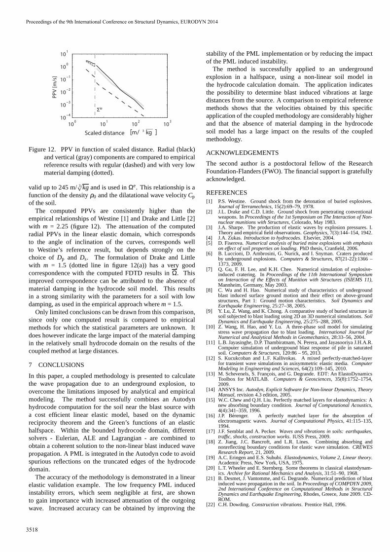
The peak particle velocity (PPV) is determined for the radialand vertical velocity component at a series of points at thefree surface inΩ andΩe, from 3 to 200 m from the epicenterof the explosion. This distance is scaled by the cube rootof the TNT equivalent weight of the C4 explosive, whichis 1.32 kg. The computed PPVs are compared to empiricalreference relationships. The empirical formulation for the PPVdeveloped by Drake and Little [2] is valid up to a scaleddistance of 5 m/3
√kg. This formulation only depends on the
soil properties through an attenuation coefficientm. It is usedas a reference inΩ with attenuation coefficientsm = 2.25and m = 1.5. The first value is estimated based onρ0 [2],while the second value corresponds to a soil with low materialdamping [22]. Westine’s relationships for the radial PPV [1] is
Proceedings of the 9th International Conference on Structural Dynamics, EURODYN 2014
3517
100
101
102
103
10−4
10−3
10−2
10−1
100
101
[m/ 3 kg ]Scaled distance
PPV [m/s]
Σie
Figure 12. PPV in function of scaled distance. Radial (black)and vertical (gray) components are compared to empiricalreference results with regular (dashed) and with very lowmaterial damping (dotted).
valid up to 245 m/3√
kg and is used inΩe. This relationship is afunction of the densityρ0 and the dilatational wave velocityCp
of the soil.The computed PPVs are consistently higher than the
empirical relationships of Westine [1] and Drake and Little[2]with m = 2.25 (figure 12). The attenuation of the computedradial PPVs in the linear elastic domain, which correspondsto the angle of inclination of the curves, corresponds wellto Westine’s reference result, but depends strongly on thechoice of Dp and Ds. The formulation of Drake and Littlewith m = 1.5 (dotted line in figure 12(a)) has a very goodcorrespondence with the computed FDTD results inΩ. Thisimproved correspondence can be attributed to the absence ofmaterial damping in the hydrocode soil model. This resultsin a strong similarity with the parameters for a soil with lowdamping, as used in the empirical approach wherem = 1.5.
Only limited conclusions can be drawn from this comparison,since only one computed result is compared to empiricalmethods for which the statistical parameters are unknown. Itdoes however indicate the large impact of the material dampingin the relatively small hydrocode domain on the results of thecoupled method at large distances.
7 CONCLUSIONS
In this paper, a coupled methodology is presented to calculatethe wave propagation due to an underground explosion, toovercome the limitations imposed by analytical and empiricalmodeling. The method successfully combines an Autodynhydrocode computation for the soil near the blast source witha cost efficient linear elastic model, based on the dynamicreciprocity theorem and the Green’s functions of an elastichalfspace. Within the bounded hydrocode domain, differentsolvers - Eulerian, ALE and Lagrangian - are combined toobtain a coherent solution to the non-linear blast induced wavepropagation. A PML is integrated in the Autodyn code to avoidspurious reflections on the truncated edges of the hydrocodedomain.
The accuracy of the methodology is demonstrated in a linearelastic validation example. The low frequency PML inducedinstability errors, which seem negligible at first, are shownto gain importance with increased attenuation of the outgoingwave. Increased accuracy can be obtained by improving the
stability of the PML implementation or by reducing the impactof the PML induced instability.
The method is successfully applied to an undergroundexplosion in a halfspace, using a non-linear soil model inthe hydrocode calculation domain. The application indicatesthe possibility to determine blast induced vibrations at largedistances from the source. A comparison to empirical referencemethods shows that the velocities obtained by this specificapplication of the coupled methodology are considerably higherand that the absence of material damping in the hydrocodesoil model has a large impact on the results of the coupledmethodology.
ACKNOWLEDGEMENTS
The second author is a postdoctoral fellow of the ResearchFoundation-Flanders (FWO). The financial support is gratefullyacknowledged.
REFERENCES[1] P.S. Westine. Ground shock from the detonation of buriedexplosives.
Journal of Terramechnics, 15(2):69–79, 1978.[2] J.L. Drake and C.D. Little. Ground shock from penetrating conventional
weapons. InProceedings of the 1st Symposium on The Interaction of Non-nuclear munitions with Structures, Colorado, May 1983.
[3] J.A. Sharpe. The production of elastic waves by explosion pressures. I.Theory and empirical field observations.Geophysics, 7(3):144–154, 1942.
[4] J.A. Zukas.Introduction to hydrocodes. Elsevier, 2004.[5] D. Fiserova.Numerical analysis of buried mine explosions with emphasis
on effect of soil properties on loading. PhD thesis, Cranfield, 2006.[6] B. Luccioni, D. Ambrosini, G. Nurick, and I. Snyman. Craters produced
by underground explosions.Computers & Structures, 87(21-22):1366 –1373, 2009.
[7] Q. Gu, F. H. Lee, and K.H. Chee. Numerical simulation of explosive-induced cratering. InProceedings of the 11th International Symposiumon Interaction of the Effects of Munition with Structures (ISIEMS 11),Mannheim, Germany, May 2003.
[8] C. Wu and H. Hao. Numerical study of characteristics of undergroundblast induced surface ground motion and their effect on above-groundstructures, Part 1: Ground motion characteristics.Soil Dynamics andEarthquake Engineering, 25:27–38, 2005.
[9] Y. Lu, Z. Wang, and K. Chong. A comparative study of buriedstructure insoil subjected to blast loading using 2D an 3D numerical simulations.SoilDynamics and Earthquake Engineering, 25:275–288, 2005.
[10] Z. Wang, H. Hao, and Y. Lu. A three-phase soil model for simulatingstress wave propagation due to blast loading.International Journal forNumerical and Analytical Methods in Geomechanics, 28:33–56, 2004.
[11] L.B. Jayasinghe, D.P. Thambiratnam, N. Perera, and Jayasooriya J.H.A.R.Computer simulation of underground blast response of pile in saturatedsoil. Computers & Structures, 120:86 – 95, 2013.
[12] S. Kucukcoban and L.F. Kallivokas. A mixed perfectly-matched-layerfor transient wave simulations in axisymmetric elastic media. ComputerModeling in Engineering and Sciences, 64(2):109–145, 2010.
[13] M. Schevenels, S. Francois, and G. Degrande. EDT: An ElastoDynamicsToolbox for MATLAB. Computers & Geosciences, 35(8):1752–1754,2009.
[14] ANSYS Inc.Autodyn, Explicit Software for Non-linear Dynamics, TheoryManual, revision 4.3 edition, 2005.
[15] W.C. Chew and Q.H. Liu. Perfectly matched layers for elastodynamics: Anew absorbing boundary condition.Journal of Computational Acoustics,4(4):341–359, 1996.
[16] J.P. Berenger. A perfectly matched layer for the absorption ofelectromagnetic waves.Journal of Computational Physics, 41:115–135,1994.
[17] J.F. Semblat and A. Pecker.Waves and vibrations in soils: earthquakes,traffic, shocks, construction works. IUSS Press, 2009.
[18] Z. Jiang, J.C. Bancroft, and L.R. Lines. Combining absorbing andnonreflecting boundary conditions for elastic wave simulation. CREWESResearch Report, 21, 2009.
[19] A.C. Eringen and E.S. Suhubi.Elastodynamics, Volume 2, Linear theory.Academic Press, New York, USA, 1975.
[20] L.T. Wheeler and E. Sternberg. Some theorems in classical elastodynam-ics. Archive for Rational Mechanics and Analysis, 31:51–90, 1968.
[21] B. Desmet, J. Vantomme, and G. Degrande. Numerical prediction of blastinduced wave propagation in the soil. InProceedings of COMPDYN 2009,2nd International Conference on Computational Methods in StructuralDynamics and Earthquake Engineering, Rhodes, Greece, June 2009. CD-ROM.
[22] C.H. Dowding.Construction vibrations. Prentice Hall, 1996.
Proceedings of the 9th International Conference on Structural Dynamics, EURODYN 2014
3518