Embed Size (px)
Citation preview

Dynamic Response of Distributed Generators in a Hybrid Microgrid
Dr. Manjula Dewadasa
Prof. Arindam Ghosh
Prof. Gerard Ledwich
What is a microgrid?
Small scale generation units connected to a grid is called distributed generators (DGs)
A microgrid can be considered as an entirely DG based grid that contains both generators and loads
A microgrid can operate in either grid connected mode or islanded mode
In an islanded mode, the DGs connected to the microgrid supply its loads
2
What are the Operational Challenges in a Microgrid?
3
Different types of sources: dispatchable or non-
dispatchable, inertial or non-inertial
Different dynamic response of sources Inertial sources – slower response
Non-inertial sources – fast response
Grid-connected and islanded operation Frequency and voltage control, power sharing
Desired Control Strategies for a Microgrid
4
Incorporate both inertial and non-inertial sources
allow grid-connected and islanded operation
enable load power sharing amongst different sources
damp out transient power oscillations
5
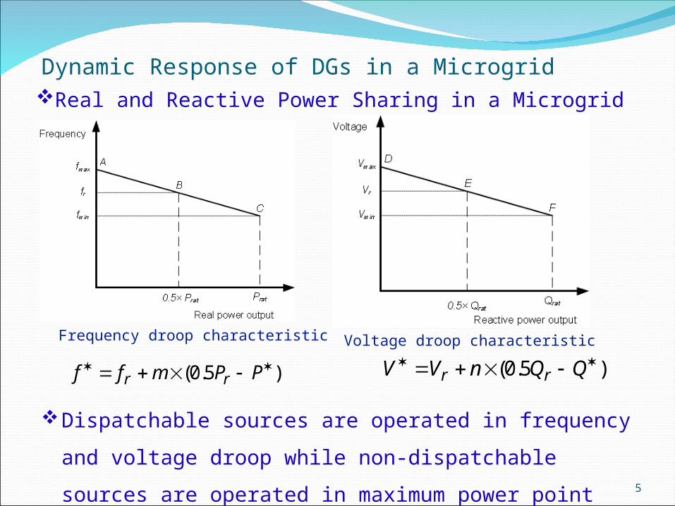
Dynamic Response of DGs in a MicrogridReal and Reactive Power Sharing in a Microgrid
Frequency droop characteristic Voltage droop characteristic
)5.0( PPmff rr)5.0( QQnVV rr
Dispatchable sources are operated in frequency and
voltage droop while non-dispatchable sources are
operated in maximum power point tracking (MPPT)

6
Dynamic Response of DGs in a Microgrid Contd.
Microgrid Simulation Studies
System data Value
System frequency 50 Hz
System voltage 0.415 kV rms (L-L)
DG1 power rating (12 + j 8) kVA
DG2 power rating (15 + j 10) kVA
Feeder impedance (Z12=Z23)
(0.025+ j 1.2566) Ω
load1 impedance (15+ j 11.781) Ω
load2 impedance (20+ j 15.708) Ω
Frequency droop coefficient (Hz/kW)
m1=33.33, m2= 41.67
Voltage droop coefficient (V/kVAR)
n1=1.2, n2=1.5
Schematic diagram of two DGs sharing loads
7
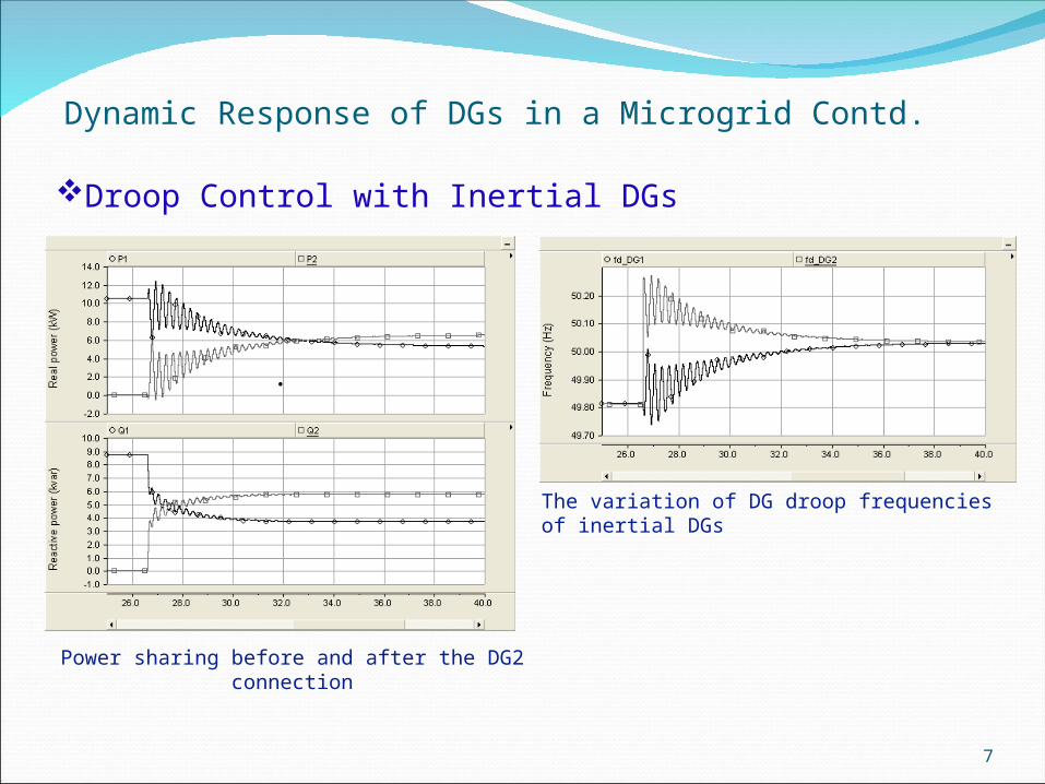
Dynamic Response of DGs in a Microgrid Contd.
Droop Control with Inertial DGs
Power sharing before and after the DG2 connection
.
The variation of DG droop frequencies of inertial DGs
8
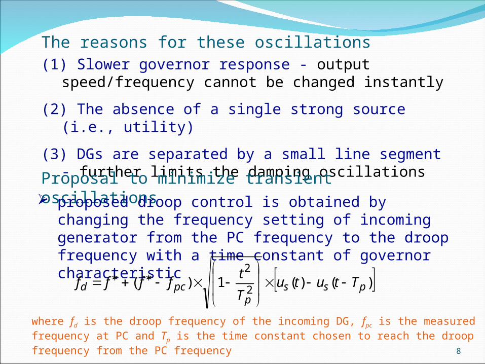
The reasons for these oscillations(1) Slower governor response - output
speed/frequency cannot be changed instantly
(2) The absence of a single strong source (i.e., utility)
(3) DGs are separated by a small line segment - further limits the damping oscillations
Proposal to minimize transient oscillations proposed droop control is obtained by changing the
frequency setting of incoming generator from the PC frequency to the droop frequency with a time constant of governor characteristic
)()(1)(2
2
pssp
pcd TtutuT
tffff
where fd is the droop frequency of the incoming DG, fpc is the measured frequency at PC and Tp is the time constant chosen to reach the droop frequency from the PC frequency

9
Proposed Droop Control with Inertial DGs
.
Power sharing before and after the DG2 connection
The variation of DG droop frequencies of inertial DGs
The proposed droop helps incoming diesel generator to connect smoothly, thus minimizing frequency and power fluctuations in an autonomous microgrid

10
Dynamic Response of DGs in a Microgrid Contd.
Droop Control with Non-inertial DGs
.
Power sharing with non-inertial DGs
The variation of DG droop frequencies
The interaction during synchronization and load change is smooth since converters can respond quickly
They have the ability to reach the steady state rapidly.
11
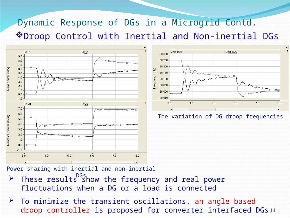
Dynamic Response of DGs in a Microgrid Contd.Droop Control with Inertial and Non-inertial DGs
.
These results show the frequency and real power fluctuations when a DG or a load is connected
To minimize the transient oscillations, an angle based droop controller is proposed for converter interfaced DGs.
Power sharing with inertial and non-inertial DGs
The variation of DG droop frequencies

12
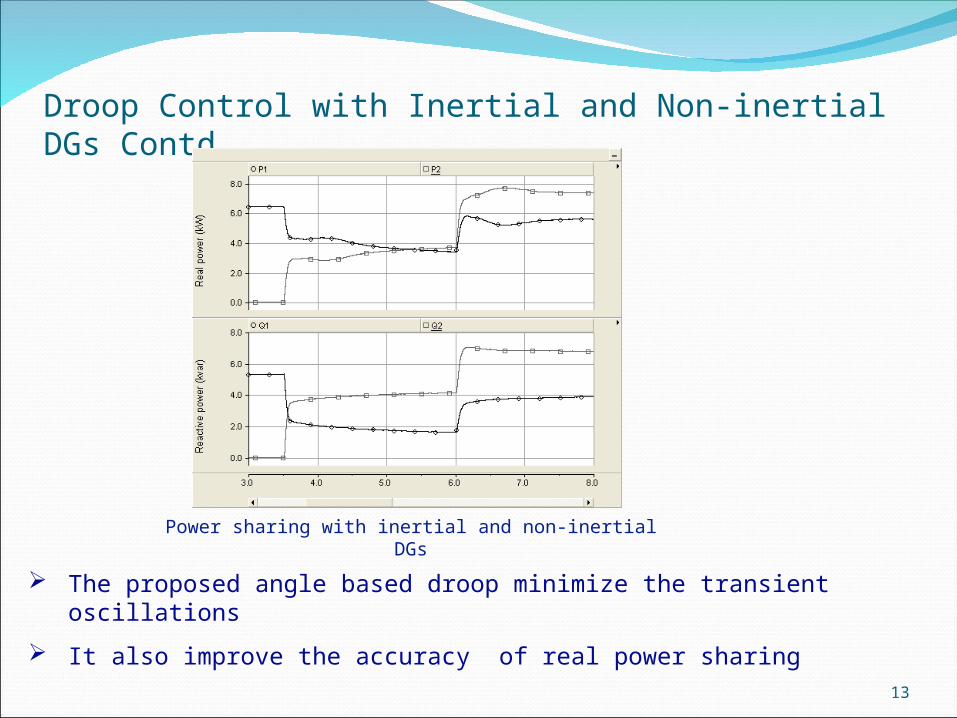
Droop Control with Inertial and Non-inertial DGs Contd.
.
The converters can change its output voltage angle instantaneously
Instead of droop frequency, a corresponding angle is set for the converter output voltage
The proposed droop control is given below
dtffff pcd )(
fd - modified droop frequencyf* - conventional droop frequency fpc - frequency at point of connection (PC)
The time constant of the integrator is selected according to the inertial DG dynamics (i.e., time constant of governor) to ensure a similar response from the non-inertial DGs in the system
*
*2
f
ff r
Converterangle
13
.
The proposed angle based droop minimize the transient oscillations
It also improve the accuracy of real power sharing
Power sharing with inertial and non-inertial DGs
Droop Control with Inertial and Non-inertial DGs Contd.