Embed Size (px)
Citation preview

Dynamic Power Management Strategies
W ith in th e IE E E 8 0 2 .1 1 Standard �
Andrea Acquaviva, Edoardo Bonta, Em anuele L attanz i
Universita d i Urb ino “ C a rlo B o ”Istitu to d i S c ienze e T ecno lo g ie d ell’Info rm a z io neP ia z z a d ella R ep u b b lic a 1 3 , 6 1 0 2 9 Urb ino , Ita ly{acquaviva,bonta,lattanzi}@sti.uniurb.it
Abstract. M o b ile term ina ls su ch a s cellu la r p h o nes, sm a rt p h o nes a ndP D A s req u ire w ireless c o nnectio n to ex ch a ng e info rm a tio n w ith th e ex -terna l w o rld . In th is tu to ria l w e fo c u s o n w ireless p a ck et netw o rk s b a sedo n th e IE E E 8 0 2 .1 1 b p ro to c o l, c o m m o nly u sed to b u ild lo c a l a rea net-w o rk s o f p a lm to p a nd no teb o o k c o m p u ters. D u e to lim ited b a ttery life-tim e o f m o b ile term ina ls, energ y c o nsu m p tio n o f w ireless interfa ces b e-c o m es a critic a l d esig n co nstra int. W ith in th e IE E E 8 0 2 .1 1 sta nd a rd ,p o w er c o nserva tio n p ro to c o ls h a ve b een im p lem ented th a t tra d e p o w erfo r p erfo rm a nce. In th is tu to ria l, w e p resent a p o w er-a c c u ra te m o d elo f w ireless netw o rk interfa ce c a rd th a t a llo w s th e p o w er/ p erfo rm a ncetra d e-o ff to b e stu d ied a s a fu nctio n o f tra ffi c p a tterns im p o sed b y th ea p p lic a tio ns. T h e m o d el h a s b een va lid a ted a g a inst m ea su rem ents o nrea l h a rd w a re d evices.
1 Introduction
W ireless netw orks are a key enabling technolog y for the developm ent of m obileand ubiquitous com puting . H ow ever, several challeng es characterize the desig nand im plem entation of an effi cient w ireless link, rang ing from channel unreli-ability to lim ited bandw idth (w .r.t. w ired netw orks), and pow er consum ption.R ecently , the latter has g ained a prim ary role because of the lim ited batteryautonom y of m obile term inals. In fact, a considerable am ount of pow er is spentin a portable sy stem in the radio frequency (R F) section. T his is especially truefor palm top com puters and personal dig ital assistants (P D A), w here there areno pow er-hung ry m echanical com ponents (such as hard disks).
T he institute of electrical and electronic eng eneers (IEEE) has standardizeda class of M edium Access C ontrol (M AC ) protocols that coordinate the accessof m obile term inals to the radio channel and allow w ireless local area netw orks(W L AN s) to be built. D isting uishing features of protocols in this class are carrierfrequency and bandw idth.
C urrently , the m ost w idespread protocol is IEEE 8 0 2 .1 1 b[1 ], m ainly becauseit m atches bandw idth requirem ents of m ost popular netw ork services w ith lim -ited cost of hardw are interfaces. It supports also a pow er conservation strateg y
� C o -fi na nced b y R eg io ne M a rch e w ith in th e C IP E 3 6 / 2 0 0 2 fra m ew o rk .

called Power Save Protocol (PSP) that allows stations to sleep when they arenot transmitting or receiving data. This allows ower spent by network interfacesto sense the medium during idle periods to be saved. Since ex iting from sleepstate imposes a non-negligible delay, packets sent to a station are buff ered bythe transmitter while the receiver station is sleeping. Sleeping stations (STAs)wake-up at synchronized time instants to retrieve backlogged traffic. Sleepingintervals have a programmable duration (sleep time) that for commercial wire-less interfaces are on the order of hundreds of milliseconds. During sleep periods,the card cannot receive packets, but it can wake-up to transmit. Clearly, thisstrategy aff ects system responsiveness. As a consequence, there could be a con-sistent impact on the quality of delay-sensitive real-time applications such hasvideo streaming and video conferencing tools.
It is clear from the previous discussion that it is of critical importance thestudy of the efficiency of 802.11b power conservation strategy and the assess-ment of its impact on Q uality of Service (Q oS). In this tutorial, we describe aperformance/ power model of wireless network interface cards that we ex ploit tocharacterize PSP efficiency. We report also results of the validation of this modelagainst measurements on real hardware devices. We used a client-server appli-cation as case study, where the wireless network interface on the client receivesdata from an application server.
All commercial wireless cards implement PSP protocol. However, only a lim-ited sleep time duration can be set, depending on the particular implementationand fi rmware version. The model we describe in this paper overcomes this limi-tation allowing to tune sleeping period on all possible values. V alidation of themodel against real hardware has been made on those confi guration points thatmatch parameter values available on hardware devices. To stress the validationprocess, we also compare simulated and real measurements by varying the serverdata rate.
The rest of the paper is organized as follows. In Section 2 we give a detailedoverview of IEEE 802.11b standard with particular emphasis on the power con-servation protocol. In Section ?? we describe the model of a IEEE 802.11b com-pliant wireless network interface. In Section ?? we report the results of analisysand simulations on the model as well as the validation against real hardwaremeasurements.
2 IEEE 802.11
In this Section we give a detailed overview of IEEE 802.11b protocol. We fi rst de-scribe its general specifi cations, than we go in to details describing the power con-servation strategy. Finally, we resume some of the most important non-standardsolutions proposed to save power in IEEE 802.11b wireless networks.

2.1 WLAN Architecture
Wireless networks based on IEEE 802.11b protocol can be infrastructured orad-hoc. In the first case, there is a central coordination and synchronizationelement called access point (AP) which routes all the packets transmitted bymobile stations in its coverage area and provide bridging functionalities to wirednetworks. In the second case, stations directly communicate with each other.The first type of organization is suitable for buildings and urban areas whereAPs can be connected to wired backbones. O n the contrary, ad-hoc networks aresuitable for less accessible environments and may be used for environment mon-itoring and battlefields. IEEE 802.11b networks consist of four major physicalcomponents [9 ]:
– D istrib ution sy stem . When several access points are connected to forma large coverage area, they must communicate with each other to followthe movements of mobile stations. The distribution system is the logicalcomponent that forwards frames to destination. 802.11 does not specify anyparticular technology for the distribution system. In most commercial prod-ucts, the distribution system is implemented as a combination of a bridgingelements and a distribution system medium, which in almost all practicalcases is the Ethernet.
– Access p oin ts. Frames on an 802.11 network must be converted to anothertype of frame for delivery to the rest of the world. Devices called accesspoints perform the wireless-to-wired bridging function.
– Wireless m ed ium . The medium carries frames from station to station.Physical layer defines the transmission technology on the medium. Severaldifferent physical layers are defined. Initially, two radio frequency (RF) phys-ical layers and one infrared physical layer were standardized, though the RFlayers have proven far more popular.
– S ta tion s. Networks are built to transfer data between stations. Stations arecomputing devices with wireless network interfaces. Typically, stations arebattery-operated laptop or handheld computers.
2.2 T y p es of Netw ork s
The basic building block of an 802.11 network is the basic service set (BSS),which is simply a group of stations that communicate with each other. Com-munications take place within a somewhat fuzzy area, called the basic servicearea, defined by the propagation characteristics of the wireless medium [9 ]. Whena station is in the basic service area, it can communicate with the other mem-bers of the BSS. BSSs come in two fl avors, both of which are illustrated in Fig. 1.
In d ep en d en t n etw ork s. O n the left is an independent BSS (IBSS). Sta-tions in an IBSS communicate directly with each other and thus must be within

Fig. 1. Independent and infrastructure BSSs
direct communication range. The smallest possible 802.11 network is an IBSSwith two stations. Typically, IBSSs are composed of a small number of stationsset up for a specific purpose and for a short period of time. One common use is tocreate a short-lived network to support a single meeting in a conference room.As the meeting begins, the participants create an IBSS to share data. Whenthe meeting ends, the IBSS is dissolved. Due to their short duration, small size,and focused purpose, IBSSs are sometimes referred to as ad hoc BSSs or ad hocnetworks.
Infrastructure networks. On the right side of Fig. 1 is an infrastructureBSS (never called an IBSS). Infrastructure networks are distinguished by theuse of an access point. Access points are used for all communications in infras-tructure networks, including communication between mobile nodes in the sameservice area. If one mobile station in an infrastructure BSS needs to communi-cate with a second mobile station, the communication must take two hops. First,the originating mobile station transfers the frame to the access point. Second,the access point transfers the frame to the destination station. With all commu-nications relayed through an access point, the basic service area correspondingto an infrastructure BSS is defined by the points in which transmissions fromthe access point can be received. Although the multihop transmission takes moretransmission capacity than a directed frame from the sender to the receiver, ithas two major advantages:
– An infrastructure BSS is defined by the distance from the access point. Allmobile stations are required to be within reach of the access point, but norestriction is placed on the distance between mobile stations themselves. Al-lowing direct communication between mobile stations would save transmis-sion capacity but at the cost of increased physical layer complexity becausemobile stations would need to maintain neighbor relationships with all othermobile stations within the service area.

– Access points in infrastructure networks are in a position to assist with sta-tions attempting to save power. Access points can note when a station entersa powersaving mode and buffer frames for it. Battery-operated stations canturn the wireless transceiver off and power it up only to transmit and retrievebuffered frames from the access point.
In an infrastructure network, stations must associate with an access pointto obtain network services. Association is the process by which a mobile stationjoins an 802.11 network. Mobile stations always initiate the association process,and access points may choose to grant or deny access based on the contents ofan association request. Associations are also exclusive on the part of the mobilestation: a mobile station can be associated with only one access point. The 802.11standard places no limit on the number of mobile stations that an access pointmay serve. Implementation considerations may, of course, limit the number ofmobile stations an access point may serve. In practice, however, the relativelylow throughput of wireless networks is far more likely to limit the number ofstations placed on a wireless network.
E x tended serv ice areas. BSSs can create coverage in small offices andhomes, but they cannot provide network coverage to larger areas. 802.11 allowswireless networks of arbitrarily large size to be created by linking BSSs into anextended service set (ESS). An ESS is created by chaining BSSs together witha backbone network. 802.11 does not specify a particular backbone technology;it requires only that the backbone provide a specified set of services. In Fig. 2,the ESS is the union of the four BSSs (provided that all the access points areconfigured to be part of the same ESS). In real-world deployments, the degreeof overlap between the BSSs would probably be much greater than the overlapin Fig. 2.
Stations within the same ESS may communicate with each other, even thoughthese stations may be in different basic service areas and may even be movingbetween basic service areas. For stations in an ESS to communicate with eachother, the wireless medium must act like a single MAC-level connection. Accesspoints act as bridges, so direct communication between stations in an ESS re-quires that the backbone network also be a MAC-level connection. Any link-layerconnection will suffice. Several access points in a single area may be connected toa single hub or switch, or they can use virtual LANs if the link-layer connectionmust span a large area. 802.11 supplies link-layer mobility within an ESS butonly if the backbone network is a single link-layer domain, such as a shared Eth-ernet or a VLAN. This important constraint on mobility is often a major factorin 802.11 network design. Extended service areas are the highest-level abstrac-tion supported by 802.11 networks. Access points in an ESS operate in concertto allow the outside world to use a single MAC address to talk to a station some-where within the ESS. In Fig. 2, the router uses a single MAC address to deliverframes to a mobile station; the access point with which that mobile station isassociated delivers the frame. The router remains ignorant of the location of themobile station and relies on the access points to deliver the frame.

Fig. 2. Extended service set.
2.3 802.11 MAC Layer
The key to the 802.11 specification is the MAC. It rides on every physical layerand controls the transmission of user data into the air. It provides the coreframing operations and the interaction with a wired network backbone. Differ-ent physical layers may provide different transmission speeds, all of which aresupposed to interoperate. 802.11 does not depart from the previous IEEE 802standards in any radical way. The standard successfully adapts Ethernet-stylenetworking to radio links. Like Ethernet, 802.11 uses a carrier sense multipleaccess (CSMA) scheme to control access to the transmission medium. How-ever, collisions waste valuable transmission capacity, so rather than the collisiondetection (CSMA/CD) employed by Ethernet, 802.11 uses collision avoidance(CSMA/CA). Also like Ethernet, 802.11 uses a distributed access scheme withno centralized controller. Each 802.11 station uses the same method to gain ac-cess to the medium. The major differences between 802.11 and Ethernet stemfrom the differences in the underlying medium.
On a wired Ethernet, it is reasonable to transmit a frame and assume thatthe destination receives it correctly. Radio links are different, especially when thefrequencies used are unlicensed ISM (Industrial, Science and Medicine) bands.Even narrowband transmissions are subject to noise and interference, but un-licensed devices must assume that interference will exist and work around it.The designers of 802.11 considered ways to work around the radiation from mi-crowave ovens and other RF sources. In addition to the noise, multipath fadingmay also lead to situations in which frames cannot be transmitted because a nodemoves into a dead spot. U nlike many other link layer protocols, 802.11 incorpo-

Fig. 3. Positive acknowledgment of data transmissions.
rates positive acknowledgments. All transmitted frames must be acknowledged,as shown in Fig. 3 . If any part of the transfer fails, the frame is considered lost.
Wireless networks boundaries are represented by the point where each nodemay not be able to communicate with every other node in the wireless network,as in Fig. 4 .
Fig. 4 . N odes 1 and 3 are hidden
In the figure, node 2 can communicate with both nodes 1 and 3 , but some-thing prevents nodes 1 and 3 from communicating directly. From the perspectiveof node 1, node 3 is a “ hidden“ node. If a simple transmission protocol were used,it could happen that node 1 and node 3 transmit simultaneously, thus causingnode 2 unable to receive a correct information. Furthermore, nodes 1 and 3 wouldnot have any indication of the error because the collision was local to node 2.
Collisions resulting from hidden nodes may be hard to detect in wireless net-works because wireless transceivers are generally half-duplex; they don’t transmitand receive at the same time. To prevent collisions, 802.11 allows stations to use

Request to Send (RTS) and Clear to Send (CTS) signals to clear out an area.Fig. 5 illustrates the procedure.
Fig. 5. RTS/CTS clearing
In Fig. 5 , node 1 has a frame to send; it initiates the process by sending anRTS frame. The RTS frame serves several purposes: in addition to reserving theradio link for transmission, it silences any stations that hear it. If the targetstation receives an RTS, it responds with a CTS. Like the RTS frame, the CTSframe silences stations in the immediate vicinity. Once the RTS/CTS exchangeis complete, node 1 can transmit its frames without worry of interference fromany hidden nodes. Hidden nodes beyond the range of the sending station aresilenced by the CTS from the receiver. When the RTS/CTS clearing procedureis used, any frames must be positively acknowledged. The multiframe RTS/CTStransmission procedure consumes a fair amount of capacity, especially because ofthe additional latency incurred before transmission can commence. As a result,it is used only in high-capacity environments and environments with significantcontention on transmission. For lower-capacity environments, it is not necessary.User can set a RTS threshold if the device driver in most commercial cards. TheRTS/CTS exchange is performed for those frames whose size is larger than thethreshold.
2.4 Power Conservation Strategy
The major advantage of wireless networks is that network access does not requirenodes to be in any particular location. To take full advantage of mobility, nothingcan constrain the location of a node, including the availability of electrical power.

Mobility therefore implies that most mobile devices can run on batteries. Butbattery power is a scarce resource; batteries can run only so long before theyneed to be recharged. Requiring mobile users to return frequently to commercialpower is inconvenient, to say the least. Many wireless applications require longbattery life without sacrificing network connectivity. As with any other networkinterface, powering down the transceiver can lead to great power savings inwireless networks. When the transceiver is off, it is said to be sleeping, dozing,or in power-saving mode (PS). When the transceiver is on, it is said to be awake,active, or simply on. Power conservation in 802.11 is achieved by minimizing thetime spent in the latter stage and maximizing the time in the former. However,802.11 accomplishes this without sacrificing connectivity.
Power Conservation in Infrastructure Networks
Power management can achieve the greatest savings in infrastructure networks.All traffic for mobile stations must go through access points, so they are an ideallocation to buffer traffic. There is no need to work on a distributed buffer systemthat must be implemented on every station; the bulk of the work is left to theaccess point. By definition, access points are aware of the location of mobilestations, and a mobile station can communicate its power management state toits access point. Furthermore, access points must remain active at all times; it isassumed that they have access to continuous power. Combining these two factsallows access points to play a key role in power management on infrastructurenetworks. Access points have two power management-related tasks. First, be-cause an access point knows the power management state of every station thathas associated with it, it can determine whether a frame should be delivered tothe wireless network because the station is active or buffered because the stationis asleep. But buffering frames alone does not enable mobile stations to pick upthe data waiting for them. An access point’s second task is to announce period-ically which stations have frames waiting for them. The periodic announcementof buffer status also helps to contribute to the power savings in infrastructurenetworks. Powering up a receiver to listen to the buffer status requires far lesspower than periodically transmitting polling frames. Stations only need to powerup the transmitter to transmit polling frames after being informed that there isa reason to expend the energy. Power management is designed around the needsof the battery-powered mobile stations. Mobile stations can sleep for extendedperiods to avoid using the wireless network interface. Part of the associationrequest is the listen interval parameter, which is the number of beacon periodsfor which the mobile station may choose to sleep. Longer listen intervals requiremore buffer space on the access point; therefore, the listen lnterval is one of thekey parameters used in estimating the resources required to support an asso-ciation. The listen interval is a contract with the access point. In agreeing tobuffer any frames while the mobile station is sleeping, the access point agrees towait for at least the listen interval before discarding frames. If a mobile stationfails to check for waiting frames after each listen interval, such frames may bediscarded without notification.

TIM - Traffic Indication Message. When frames are buffered, a desti-nation node’s AID (association ID) provides the logical link between the frameand its destination. The AID indicated to which BSS a node belongs to, and isassigned by the base station. Each AID is logically connected to frames bufferedfor the mobile station that is assigned that AID. Multicast and broadcast framesare buffered and linked to an AID of zero. To inform stations that frames arebuffered, access points periodically assemble a traffic indication map (TIM) andtransmit it in beacon frames. The TIM is a virtual bitmap composed of 2,008bits; offsets are used so that the access point needs to transmit only a smallportion of the virtual bitmap. This conserves network capacity when only a fewstations have buffered data. Each bit in the TIM corresponds to a particularAID; setting the bit indicates that the access point has buffered unicast framesfor the station with the AID corresponding to the bit position. Mobile stationsmust wake up and enter the active mode to listen for Beacon frames to receivethe TIM. By examining the TIM, a station can determine if the access point hasbuffered traffic on its behalf. To retrieve buffered frames, mobile stations use PS-Poll (Power Save Poll) Control frames. Each PS-Poll frame is used to retrieveone buffered frame. That frame must be positively acknowledged before it isremoved from the buffer. Positive acknowledgment is required to keep a second,retried PS-Poll from acting as an implicit acknowledgment. Fig. 6 illustrates theprocess.
Fig. 6. PS-Poll frame retrieval
If multiple frames are buffered for a mobile station, then the More Data bitin the Frame Control field is set to 1. Mobile stations can then issue additional

PS-Poll requests to the access point until the More Data bit is set to 0, thoughno time constraint is imposed by the standard. After transmitting the PS-Poll,a mobile station must remain awake until either the polling transaction hasconcluded or the bit corresponding to its AID is no longer set in the TIM. Thereason for the first case is obvious: the mobile station has successfully polled theaccess point; part of that transaction was a notification that the mobile stationwill be returning to a sleeping mode. The second case allows the mobile stationto return to a power conservation mode if the access point discards the bufferedframe. Once all the traffic buffered for a station is delivered or discarded, thestation can resume sleeping.
Stations may switch from a power conservation mode to active mode atany time. It is common for laptop computers to operate with full power to allperipherals when connected to AC power and conserve power only when usingthe battery. If a mobile station switches to the active mode from a sleepingmode, frames can be transmitted without waiting for a PS-Poll. PS-Poll framesindicate that a power-saving mobile station has temporarily switched to an activemode and is ready to receive a buffered frame. By definition, active stations havetransceivers operating continuously. After a switch to active mode, the accesspoint can assume that the receiver is operational, even without receiving explicitnotification to that effect.
Access points must retain frames long enough for mobile stations to pickthem up, but buffer memory is a finite resource. 802.11 mandates that accesspoints use an aging function to determine when buffered frames are old enough tobe discarded. The standard leaves a great deal to the discretion of the developerbecause it specifies only one constraint. Mobile stations depend on access pointsto buffer traffic for at least the listen interval specified with the association, andthe standard forbids the aging function from discarding frames before the listeninterval has elapsed. Beyond that, however, there is a great deal of latitude forvendors to develop different buffer management routines.
DTIM - Deliverying TIM. Frames with a group address cannot be de-livered using a polling algorithm because they are, by definition, addressed to agroup. Therefore, 802.11 incorporates a mechanism for buffering and deliveringbroadcast and multicast frames. Buffering is identical to the unicast case, exceptthat frames are buffered whenever any station associated with the access pointis sleeping. Buffered broadcast and multicast frames are saved using AID 0. Ac-cess points indicate whether any broadcast or multicast frames are buffered bysetting the first bit in the TIM to 0; this bit corresponds to AID 0. Each BSS hasa parameter called the DTIM Period. TIMs are transmitted with every Beacon.At a fixed number of Beacon intervals, a special type of TIM, a Delivery TrafficIndication Map (DTIM), is sent. The TIM element in Beacon frames containsa counter that counts down to the next DTIM; this counter is zero in a DTIMframe. Buffered broadcast and multicast traffic is transmitted after a DTIMBeacon. Multiple buffered frames are transmitted in sequence; the More Databit in the Frame Control field indicates that more frames must be transmitted.Normal channel acquisition rules apply to the transmission of buffered frames.

The access point may choose to defer the processing of incoming PS-Poll framesuntil the frames in the broadcast and multicast transmission buffers have beentransmitted.
To receive broadcast and multicast frames, a mobile station must be awakefor DTIM transmissions. Nothing in the specification, however, keeps power-saving stations in infrastructure networks from waking up to listen to DTIMframes. Some products that implement power-saving modes will attempt to aligntheir awakenings with DTIM transmissions. If the system administrator deter-mines that battery life is more important than receiving broadcast and multicastframes, a station can be configured to sleep for its listen period without regardto DTIM transmissions. Some documentation may refer to this as extremely lowpower, ultra power-saving mode, deep sleep, or something similar. Several prod-ucts allow configuration of the DTIM interval. Lengthening the DTIM intervalallows mobile stations to sleep for longer periods and maximizes battery life atthe expense of timely delivery. Shorter DTIM intervals emphasize quick deliv-ery at the expense of more frequent power-up and power-down cycles. A longerDTIM can be used when battery life is critical.
Power Conservation in Ad-Hoc Networks
Power management in an IBSS is not as efficient as power management in an in-frastructure network. In an IBSS, far more of the burden is placed on the senderto ensure that the receiver is active. Receivers must also be more available andcannot sleep for the same lengths of time as in infrastructure networks. As ininfrastructure networks, power management in independent networks is basedon traffic indication messages. Independent networks must use a distributed sys-tem because there is no logical central coordinator. Stations in an independentnetwork use announcement traffic indication messages (ATIMs), which are some-times called ad hoc traffic indication messages, to preempt other stations fromsleeping. All stations in an IBSS listen to ATIM frames during specified periodsafter Beacon transmissions. If a station has buffered data for another station, itcan send an ATIM frame as notification. In effect, the ATIM frame is a messageto keep the transceiver on because there are pending data. Stations that do notreceive ATIM frames are free to conserve power. In Fig. 7 on the left, station Ahas buffered a frame for station C, so it sends a unicast ATIM frame to station Cduring the ATIM transmission window, which has the effect of notifying stationC that it should not enter power-saving mode. Station B, however, is free topower down its wireless interface. Fig. 7 on the right shows a multicast ATIMframe in use. This frame can be used to notify an entire group of stations toavoid entering low-power modes.
A time window called the ATIM window follows the Beacon transmission.This window is the period during which nodes must remain active. No stationsare permitted to power down their wireless interfaces during the ATIM window.It starts at the time when the beacon is expected and ends after a period specifiedwhen the IBSS is created. If the beacon is delayed due to a traffic overrun, theusable portion of the ATIM window shrinks by the same amount. The ATIM

Fig. 7. ATIM usage
window is the only IBSS-specific parameter required to create an IBSS. Setting itto 0 avoids using any power management. Fig. 8 illustrates the ATIM window andits relation to the beacon interval. In the figure, the fourth beacon is delayed dueto a busy medium. The ATIM window remains constant, starting at the targetbeacon interval and extending the length of the ATIM window. Of course, theusable period of the ATIM window shrinks by the length of the delay in beacontransmission.
Fig. 8 . ATIM window
To monitor the entire ATIM window, stations must wake up before the targetbeacon transmission. Four situations are possible: the station has transmitted anATIM, received an ATIM, neither transmitted nor received, or both transmittedand received. Stations that transmit ATIM frames must not sleep. Transmittingan ATIM indicates an intent to transmit buffered traffic and thus an intentto stay active. Stations to which ATIM frames are addressed must also avoidsleeping so they can receive any frames transmitted by the ATIM’s sender. Ifa station both transmits and receives ATIM frames, it stays up. A station ispermitted to sleep only if it neither transmits nor receives an ATIM. When a

station stays up due to ATIM traffic, it remains active until the conclusion ofthe next ATIM window.
Only certain control and management frames can be transmitted during theATIM window: Beacons, RTS, CTS, ACK , and, of course, ATIM frames. ATIMframes may be transmitted only during the ATIM window because stations maybe sleeping outside the ATIM window. Sending an ATIM frame is useless if otherstations in the IBSS are sleeping. In the same vein, acknowledgments are requiredfor unicast ATIM frames because that is the only guarantee that the ATIMwas received and that the frame destination will be active for the remainderof the beacon interval. Acknowledgments are not required for multicast ATIMframes because multicast frames cannot be efficiently acknowledged by a largegroup of stations. If all potential recipients of an ATIM frame were required toacknowledge it, the mass of acknowledgments could potentially interrupt networkservice.
Buffered broadcast and multicast frames are transmitted after the conclusionof the ATIM window, subject to DCF constraints. Following the transmissionof broadcast and multicast frames, a station may attempt to transmit unicastframes that were announced with an ATIM and for which an acknowledgmentwas received. Following all transmissions announced with an ATIM, stationsmay transmit unbuffered frames to other stations that are known to be active.Stations are active if they have transmitted the Beacon, an ATIM, or are notcapable of sleeping. If contention is severe enough to prevent a station from send-ing the buffered frame it announced with an ATIM, the station must reannouncethe transmission with an ATIM at the start of the next ATIM window.
Stations are responsible for maintaining sufficient memory to buffer frames,but the buffer size must be traded off against the use of that memory for otherpurposes. The standard allows a station in an independent network to discardframes that have been buffered for an“excessive“ amount of time, but the algo-rithm used to make that determination is beyond the scope of the standard. Theonly requirement placed on any buffer management function is that it retainsframes for at least one beacon period.
Alternative Approaches to Power Conservation
Different techniques have been proposed to reduce wireless network card (WNIC)power consumption, including transmission power control [16] and MAC-levelpower management (PM) [13, 18], that can be activated by the card driver whenpower is critical.
It has been shown [7] that an effective way to further reduce energy consump-tion is to create opportunities for card shutdown by network traffic reshaping ata higher level than MAC. The basic rationale of this approach is to create longidle periods for the NIC, so that the high shut-down transition cost (in terms oflatency and energy) can be fully amortized and power can be saved during longshut-down times.
In many WLANs, such as home networks, a few servers connect multipleWLAN clients to a wired network via access points (APs). In a multiclient

environment, traffic reshaping becomes a scheduling problem. While clients runon power constrained devices, servers are typically not as power constrained.In addition, servers can have access to the information about both wired andwireless network conditions. For these reasons, servers are the best candidatesfor efficiently scheduling data transmission to clients.
Traditionally, scheduling for multimedia traffic has been studied from twomain perspectives. In the context of multimedia data delivery across large net-work topologies, several QoS sensitive schemes have been proposed. These schemesare designed to work in network elements (switches and routers) responsible toallocate a share of the link bandwidth to multimedia streams. They are basi-cally aimed at overcoming limitations of fair queuing schemes such as WeightedFair Queuing (WFQ) and Virtual Clock (VC) in providing QoS guarantees tosoft real-time applications. In this context, the Dual Queue discipline has beenproposed that tries to maximize the number of customers receiving a good ser-vice in case of congestion [10]. Real-time traffic scheduling schemes suitable tobe used in QoS oriented network architectures, such as IntServ, have been alsoproposed [17].
When multimedia data must be delivered across a local area network, schedul-ing strategies can be implemented at the traffic source level. Several schemeshave been proposed in this context, mostly for video-on-demand (VOD) sys-tems. These schedulers have been traditionally targeted to minimize waiting timeof clients. To ensure service robustness with respect to packet delivery latencyvariations and time-varying re-transmission rates, the streaming video clientsand the server decouple frame transmission and playback through client framebuffers, which are controlled by the server via packet transmission scheduling.A traditional scheduling policy is join-the-shortest-queue (JSQ) (i.e., earliest-deadline first), which guarantees optimal results in terms of buffer emptinessavoidance [14].
More recent work in this area leads to the development of schedulers aimedat matching real-time constraints for scalable VOD systems [22] and QoS re-quirements for simultaneous video transmission [21].
Recently, the problem of traffic scheduling for multimedia applications hasbeen addressed using the client-side communication energy as objective functionfor optimization under real-time constraints [3]. Authors propose energy-awarescheduling and buffer management policies exploiting the WNIC radio-off stateto aggressively reduce power. Two strategies have been presented: open-loop andc losed -loop . The open-loop strategy is completely controlled by the server thatexploits the knowledge of the consumption rate of all clients in order to providebursts of new frames followed by timed shut-down command that turns off theWNIC of the client for a given amount of time. The closed-loop strategy is basedon a low-water-mark notification sent by each client to the server whenever thenumber of packets in the local application buffer falls below a given threshold.In both cases, the best energy efficiency is provided by a join-the-longest-queue
(JLQ) scheduling policy, since it maximizes the burstiness of the traffic directedto each client.

Another alternative strategy to perform power control in wireless networkcomes from the observation that PSP is not effective in some traffic conditions.First, the energy efficiency of the 802.11b PM decreases and receiver wait timesincrease with more mobile hosts, since multiple concurrent attempts at synchro-nization with the beacon cause media access contention. Second, the responsetime of the wireless link with 802.11b PM grows because of the delay imposedby sleep periods [20]. These two issues can be resolved by careful scheduling ofcommunication between the server and the client WLAN. Lastly, in a typicalwireless network, broadcast traffic can significantly reduce the chances to en-ter the doze mode. Fig. 9 shows the power consumption of a WLAN card with802.11b PM enabled under light and heavy network broadcast traffic conditions.Clearly, as the amount of broadcast traffic increases, the WLAN spends a largeamount of energy listening to it, even if no other application is running on thedevice. As a result, very little or no energy savings are obtained. One way tosolve this problem is to turn off the card. It is important to schedule data trans-mission carefully, since the overhead of waking up the WLAN from the off stateis large.
a) Light traffic b) H eavy traffic
Fig. 9. 802.11 PM under different broadcast traffic conditions
Many current WLANs are organized in a client-server fashion. MultipleWLAN clients connect to wired servers via APs. Servers are great candidatesfor efficient scheduling of data transmission to clients as they are not powerconstrained, and know both wired and wireless network conditions.
To overcome these limitations, a server-controlled power management strat-egy has been presented [5]. Authors propose a technique that exploits serverknowledge of the workload, traffic conditions and feedback information from theclient in order to minimize WLAN power consumption. The methodology canbe employed for a wide variety of applications, ranging from video and audiostreaming, to web browsing and e-mail. Two new entities are defined: a serverpower manager (server PM) and a client power manager (client PM). Server PMuses the information obtained from the client and the network to control the
parameters of 802.11b PM and to perform energy efficient traffic reshaping sothat WLAN can be turned off. Client PM communicates through a dedicatedlow-bandwidth link with the server PM and implements power controls by in-terfacing with device drivers. It also provides a set of APIs that client programscan use to provide extra information to the server.
In order to illustrate the effectiveness of the proposed approach, authors useda streaming video application as a testbed. In this case study, server knowledgeof stream characteristics is exploited. Power savings obtained are of around 67%with respect to leaving the card always on, and of around 50% relative to usingPSP.
3 Modeling the WN IC
In this section we describe a model that will be used to study the energy/QoStrade-off of a WNIC. We employed separate state diagrams for the operatingmodes of a WNIC implementing the IEEE 802.11b protocol. The state diagramsare based both on the protocol specification and on the observation of experimen-tal current profiles. Focusing only on the reception of UDP traffic, we describetwo main operating modes: always on (ON) and power-save protocol (PSP). Thetwo operating modes can be viewed as macro-states of a top-level state diagramwhere state transitions are triggered by user commands.
We used this model within an functional verification and performance evalua-tion tool [7], that allows to study energy/QoS trade-off of the WNIC. Exploitingthe capabilities of such a tool we can also study the properties of the wirelesscard that cannot be studied using real hardware and common simulation en-vironments, such as the well known Network Simulator (NS) [15], that do notprovide a detailed model of the wireless interface. Compared to NS, our mod-eling and simulation environment has a completely different target. First, wemodel in details power consumption of the WNIC, while NS has much moreapprossimate power models. Second, we are not targeting a network simulation.In fact, our model does not implement collision management algorithms nor apropagation model. However, the latter can be easily added without changingthe model structure.
3.1 ON Mode
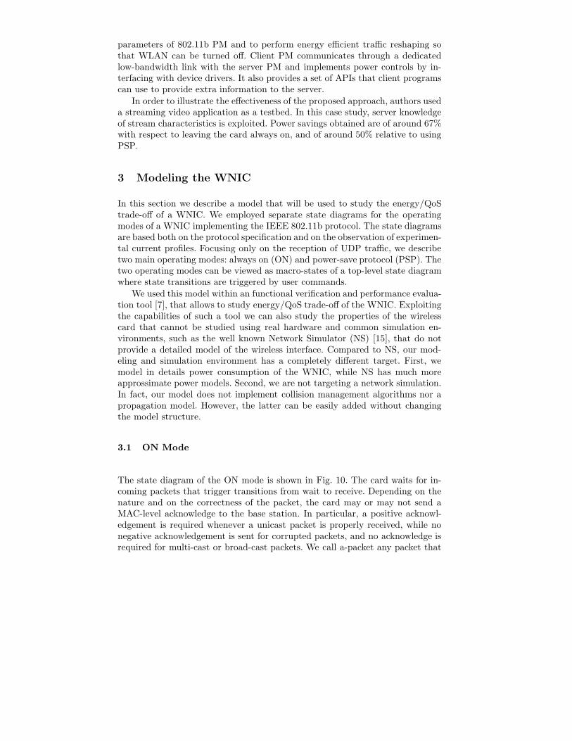
The state diagram of the ON mode is shown in Fig. 10. The card waits for in-coming packets that trigger transitions from wait to receive. Depending on thenature and on the correctness of the packet, the card may or may not send aMAC-level acknowledge to the base station. In particular, a positive acknowl-edgement is required whenever a unicast packet is properly received, while nonegative acknowledgement is sent for corrupted packets, and no acknowledge isrequired for multi-cast or broad-cast packets. We call a-packet any packet that

Ackeor
eot
eor
Wait
Receive
Receive
a−packet
n−a−packet w/o−ack
w−ack
Wakeup beaconWait
Poll
eow beacon1
Sleep
eot
timer
beaconReceive
eorbeacon0
eor
Receive
eotReceiveeor
eorpacketlast
Ackeot eop
Process
eorn−a−packet
Idle
Bus
y Waitw−ack
w/o−ack
a) ON mode b) OFF mode
Fig. 10. State diagram of the WNIC working either in ON mode (left) or in PSP mode(right).
requires a positive acknowledge, n-a-packet any packet that will not be acknowl-edged.
Although the power state of the card during reception is independent of thenature of the received packet, in our state diagram we use two different receivestates: receive w ack, that leads to the Ack state, and receive w/o ack, thatleads back to the Wait state. State duplication is used only to represent thedependence of the acknowledge on the nature of the received packet.
3.2 PSP Mode
According to the 802.11b MAC-level protocol, the AP can perform traffic reshap-ing by buffering incoming packets to allow the WNIC to enter a low-power state.If the MAC-level power management is enabled, the WNIC goes to sleep for afixed period of time as soon as no traffic is detected. While the NIC is sleeping,incoming packets are buffered by the AP. After expiration of the sleeping period,the card wakes up and listens to the beacons periodically sent by the AP. Bea-cons contain a TIM that provides information about buffered packets, and areused to re-synchronize the WNIC to the AP. If there are buffered packets to bereceived by the client, the WNIC replies to the beacon by sending polling framesto get the back-log from the AP packet by packet. A positive acknowledgementis sent for each properly received uni-cast packet.
The state diagram that represents the behavior described above is shownin Fig. 10. For readability, states are clustered into two subsets labeled Idleand Busy. The Idle part of the graph describes the behavior of the card whenno traffic is received. The card stays in a low-power sleep state until a giventimeout expires. Then it wakes up and waits for the beacon. We call beacon1(beacon0) a beacon if its TIM indicates that there is (there is no) buffered trafficfor the card. If a beacon0 is received, the card goes back to sleep as soon as the

beacon has been completely received, otherwise it stays awake and enters theBusy sub-graph to get the buffered backlog from the base station.
To get the buffered packets the card enters a 5-state loop that entails: sendinga polling frame (Poll), waiting for a packet (Wait), receiving a packet (Receivew ack), sending a positive acknowledgement (Ack) and preparing a new pollingframe (Process). Each packet contains a more bit telling the card whether thereare additional buffered frames (more= 1) or not (more= 0). The card exits theloop as soon as the last packet (i.e., a packet with more= 0) is received. Noticethat, when in the wait state, the card is also sensitive to broad-cast and multi-castpackets that do not require any acknowledgement. We use the same modelingstrategy employed for the ON-mode to model the reaction of the card to packetsthat do not require a positive acknowledgement.
0 500 1000Time [ms]
0
0.05
0.1
Cur
rent
[A]
Busy
BeaconIdle
515 520 525Time [ms]
0.05
0.06
0.07
0.08
0.09
Cur
rent
[A]
Poll
Wait
Receive
Ack
Process
Multi-cast packet
a) Current in PSP Mode b) Current details
Fig. 11. Current waveforms of a Compaq WNIC receiving UDP traffic in PSP mode.
3.3 Æmilia and TwoTowers
The previous model has been described using Æmilia, an architectural descrip-tion language. Æmilia is the input language of TwoTowers [6], a software toolfor the functional verification, security analysis, and performance evaluation ofcomputer, communication and software systems. The reason for resorting to theÆmilia/TwoTowers technology is that we wish to apply the methodology of [2],which is based on such technology, to study the energy/QoS trade-off of theWNIC. The Æmilia models can be found at http : //w w w .s ti.u n iu r b .it/be r n a r d o /tw o to w e r s /.
4 Results
In this section we report results obtained by analyzing and simulating the WNICmodel presented in the previous section. In order to assess performance and

energy efficiency of a wireless link through our model, we inserted the modelin a larger system model where an application server sends UDP packets to awireless client. The server is connected through a wired link to an access pointto which the card is associated. In our assessment, we tune service time (i.e.time interval among packets sent to the client) and card sleeping period (i.e.time interval among card wake-up events). To simulate channel unreliability, weconsidered also a probability of receiving corrupted packets at the client of 0.2%.It must be recalled that, referring to 802.11 standard, when a corrupted packetis received by the client, a retransmission is performed by the server after atimeout set to 10ms.
The modelling and simulation methodology follows the same approach ex-plained in [2]. We obtained three classes of results, one by means of Markoviananalysis and the others through simulations.
Results are organized in four parts: i) Markovian analysis, ii) simulation withexponential rates; iii) simulation with deterministic rates; iv) model validation.For each of the first three parts, we show two kinds of results: a) a Pareto curverepresenting optimal reliability/energy trade-off (where reliability is intended aspacket loss probability); b) a packet loss probability as a function of card sleeptime (i.e. aggressiveness of power management policy). Packets are lost at theaccess point buffer.
In the last part we show results obtained by comparing deterministic simu-lation energy consumption with measures obtained on the real hardware.
4.1 Markovian Model
In Fig. 12 we show Pareto optimal configurations. For a given packet loss proba-bility, the curve allows to find card sleep times that provide minimum energy perpacket. We reported results for different server service times. It can be observedthat, for a given packet loss probability, energy per packet is lower if servicetime is lower. This can be explained because the additional power cost spentby the card in waiting state when the server service time is large. It can bealso observed that this cost is higher when the card sleep time increases. Thisresult is a consequence of the power spent by the card while in sleep state, whichis not negligible and whose per-packet contribution on the energy consumptionincreases as sleeping time increases.
In Fig. 13 we reported the packet loss probability as a function of card sleeptime. It can be observed that, as expected, for a given server service time, packetloss probability increases as a function of sleep time because of the AP buffersaturation. Clearly, the AP buffer saturates earlier for lower server service times(higher server rate). This explains the relative positions of the three curves shownin the figure. In our case study AP buffer was set to 10 packets.

0 0.1 0.2 0.3 0.4 0.5 0.6 0.7 0.8 0.9 1packet loss probability
0.2
0.3
0.4
0.5
0.6
0.7
0.8
ener
gy/p
acke
t
server service time 15msserver service time 30msserver service time 60ms
Fig. 12. Pareto curve for the Markovian model
0 100 200 300 400 500 600 700 800 900 1000card sleep time
0
0.2
0.4
0.6
0.8
1
pack
et lo
ss p
roba
bilit
y
server service time 15msserver service time 30msserver service time 60ms
Fig. 13. Packet loss for the Markovian model

4.2 Exponential and Deterministic Models
In Figure 14 results of the same experiment described in previous part are re-ported. However, in this case we simulated our system using first exponentialrates (exponential model) and then deterministic rates (deterministic model).The model shows the same behavior as the markovian analysis. In fact, in canbe observed that both pareto and packet loss probability curves (Fig. 12 and 13,respectively) show the same shape of corresponding Markovian curves, the onlydifference being an offset in absolute values. Results are averaged on 30 runs.Variances as vertical lines across simulated points.
0 0.2 0.4 0.6 0.8 1packet loss probability
0
0.2
0.4
0.6
0.8
1
1.2
ener
gy/p
acke
t
server service time 60msserver service time 30msserver service time 15ms
Fig. 14. Pareto curve for the exponential model
The third part of results regards simulations with deterministic rates. Theonly event which is not deterministic in this simulation is the probability ofpacket corruption at the client.
In Fig. 16 and 17 Pareto and packet loss curves are reported. As for theprevious case, the model behaviour reflects the Markovian case.
4.3 Model V alidation
In this last part, we show the results of experiments carried out to validate ourmodel. To perform our experiments we used a Athlon 4 Mobile 1.2 G Hz notebookrunning Linux kernel 2.4.21. The WNIC installed on the laptop was a COMPAQWL110 [11], while the access point was a CISCO 350 Series base station [8]. The

0 100 200 300 400 500 600 700 800 900 1000card sleep time
0
0.2
0.4
0.6
0.8
1
pack
et lo
ss p
roba
bilit
y
server service time 15msserver service time 30msserver service time 60ms
Fig. 15. Packet loss for the exponential model
0 0.2 0.4 0.6 0.8 1packet loss probability
0.2
0.3
0.4
0.5
0.6
0.7
0.8
0.9
1
ener
gy/p
acke
t
server service time 60msserver service time 30msserver service time 15ms
Fig. 16. Pareto curve for the deterministic model

0 100 200 300 400 500 600 700 800 900 1000card sleep time
0
0.1
0.2
0.3
0.4
0.5
0.6
0.7
0.8
0.9
1
pack
et lo
ss p
roba
bilit
y
server service time 15msserver service time 30msserver service time 60ms
Fig. 17. Packet loss for the deterministic model
power consumption of the WNIC was measured using a Sycard CardBus Ex-tender [19] that allowed us to monitor the time behavior of the supply currentdrawn by the card. The current waveforms were then digitized using a NationalInstruments DAQ Board PCI 6024E connected to a PC running Labview 6.1.
We compared simulation results with measurements performed on the realhardware. In our experiments, we fixed card sleep time to 100ms (Fig. 18) and200ms (Fig. 19) because they are card sleep time intervals allowed by commercialcards we used. The duration of the experiments is 10 seconds. In both cases, weperformed measurements and simulations by computing energy consumption asa function of server service time. The overall behaviour shows that total energyconsumption decreases when service time increases, because the card receivesless packets (the service rate decreases and the total duration of the benchmarkis constant).
The more important result evidenced by these plots is that there is a negligi-ble difference between simulation and real measurements, stating the accuracyof the card model.
5 Conclusion
In this paper we presented a tutorial on standard power management in wirelessIEEE 802.11b networks. We described in details the power save protocol (PSP)standard implemented by all commercial cards. We summarized also alternativeapproaches to power management proposed in the literature. Then we introduceda power-accurate model of a wireless network card targeted to the analitycalstudy and simulations of power/performance trade-off in a wireless link. We

sleep 100ms
0
100
200
300
400
500
600
700
800
0 20 40 60 80 100
server service time
tota
l e
ne
rgy
(m
J)
Real
Simulated
Fig. 18. Comparison among simulations and hardware measurements: sleep time100ms.
sleep 200ms
0
100
200
300
400
500
600
700
0 20 40 60 80 100
server service time
tota
l e
ne
rgy
(m
J) Real
Simulated
Fig. 19. Comparison among simulations and hardware measurements: sleep time200ms.

validated our model against power measurements carried out on real hardwarecommercial devices.
References
1. LAN/MAN Standards Committee of the IEEE Computer Society: Part 11: Wire-less LAN MAC and PHY Specifications: Higher-Speed Physical Layer Extensionin the 2.4 G Hz Band. IEEE, 1999.
2. A. Acquaviva, A. Aldini, M. Bernardo, A. Bogliolo, E. Bonta, E. Lattanzi, “AMethodology Based on Formal Methods for Predicting the Impact of DynamicPower Management”, In Formal Methods for Mobile Computing, LNCS 34 65 ,2005 .
3. A. Acquaviva, E. Lattanzi, A. Bogliolo, Designa and Simulation of Power-AwareScheduling Strategies of Streaming Data in Wireless LANs, In P roc. of A CM
MS W IM, October 2004 .4 . A. Acquaviva, E. Lattanzi, A. Bogliolo, L. Benini, A Simulation Model for
Streaming Applications over a Power-Manageable Wireless Link, In P roc. of
E uropean S imulation and Modeling Conference, October 2003.5 . A. Acquaviva, T. Simunic, V . Deolalikar, and S. Roy. Remote power control of
wireless network interfaces. In P roc. of P ow er and T iming Modeling, O ptimiza-
tion and S imulation, September 2003.6. M. Bernardo, TwoTowers 5 .0 User Manual,
http://www.sti.uniurb.it/bernardo/twotowers/, 2004 .7 . D. Bertozzi, A. Raghunathan, L. Benini, and S. Ravi. Transport protocol op-
timization for energy efficient wireless embedded systems. In P roc. of D esign,
A utomation and T est Conference, March 2003.8. Cisco Systems, Cisco Aironet 35 0 Series Access Points, http :
/ / w w w .c is c o .c o m / u n iv e r c d / c c / td / d o c / pr o d u c t/ w ir e le s s / a ir o 3 5 0/ a c c s s pts /in d e x .htm ,2003.
9. M. S. G ast, ”‘802.11 Wireless Networks, The Definitive G uide.”’, OReally.10. D. Hayes, M. Rumsewicz, and L. Andrew. Q uality of service driven packet
scheduling disciplines for real-time applications: Looking beyond fairness. InP roc. of A nnual J oint Conference of the IE E E Computer and Communications
S ocieties, March 1999.11. Hewlett Packard, WL110 Client Card Manual, http :
/ / h20015 .w w w 2.hp.c o m / c o n te n t/ c o m m o n / m a n u a ls / bpe60027 / bpe60027 .pdf , 2004 .12. C. J ones, K . Sivalingam, P. Agrawal, J . Chen, “A Survey of Energy Efficient
Network Protocols for Wireless Networks”, P roc. of D A T E , March 1999.13. R. K rashinsky, H. Balakrishnan, “Minimizing Energy for Wireless Web Access
with Bounded Slowdown”, P roc. of MO B ICO M, October 2002.14 . X . Liu, Y . X iang, and T. J . Li. Counter based routing policies. In P roc. of High
P erformance Computing Conference, pages 389– 393, December 1999.15 . Network Simulator, http : / / w w w .is i.e d u / n s n a m / n s /16. V . Raghunathan, S. G aneriwal, C. Schurgers, M. Srivastava, “E2W F Q : An En-
ergy Efficient Fair Scheduling Policy for Wireless Systems”, P roc. of IS L P E D ,August 2002.
17 . H. Shi and H. Sethu. Scheduling real-time traffic under controlled load servicein an integrated service internet. In P roc. of W orkshop on High P erformance
S w itching and R outing, May 2001.

18. K. Sivalingam, J. Chen, P. Agrawal, M. Srivastava, “Design and Analysis oflow-power access protocols for wireless and mobile ATM networks”, Wireless
N etworks, no.6, 2000.19. Sycard Technology, PCCextend 140 CardBus Extender User’s Manual, http :
//www.sy card.com/docs/cextman.pdf, 1996.20. E. Takahashi, “Application Aware Scheduling for Power Management on IEEE
802.11” Proc. of Intl. Performance, Computers, and Communications Conf.,February 2000.
21. H. Wan and X. Lin. Multiple priorities qos scheduling for simultaneous videostransmissions. In Proc. of International Symposium on Multimedia Software
Engineering, December 2000.22. M. Y. Wu, S. Ma, and W. Shu. Scheduled video delivery for scalable on-demand
service. In in Proc. of the 1 2 th international workshop on N etwork and operating
sy stems support for digital audio and video, May 2002.