Embed Size (px)
Citation preview

HAL Id: hal-02423322https://hal.archives-ouvertes.fr/hal-02423322
Submitted on 23 Dec 2019
HAL is a multi-disciplinary open accessarchive for the deposit and dissemination of sci-entific research documents, whether they are pub-lished or not. The documents may come fromteaching and research institutions in France orabroad, or from public or private research centers.
L’archive ouverte pluridisciplinaire HAL, estdestinée au dépôt et à la diffusion de documentsscientifiques de niveau recherche, publiés ou non,émanant des établissements d’enseignement et derecherche français ou étrangers, des laboratoirespublics ou privés.
Dynamic optimization of methanol synthesis section inthe dual type configuration to increase methanol
productionSamane Masoudi, Mohammad Farsi, Mohammad Reza Rahimpour
To cite this version:Samane Masoudi, Mohammad Farsi, Mohammad Reza Rahimpour. Dynamic optimization ofmethanol synthesis section in the dual type configuration to increase methanol production. Oil &Gas Science and Technology - Revue d’IFP Energies nouvelles, Institut Français du Pétrole, 2019, 74,pp.90. �10.2516/ogst/2019062�. �hal-02423322�
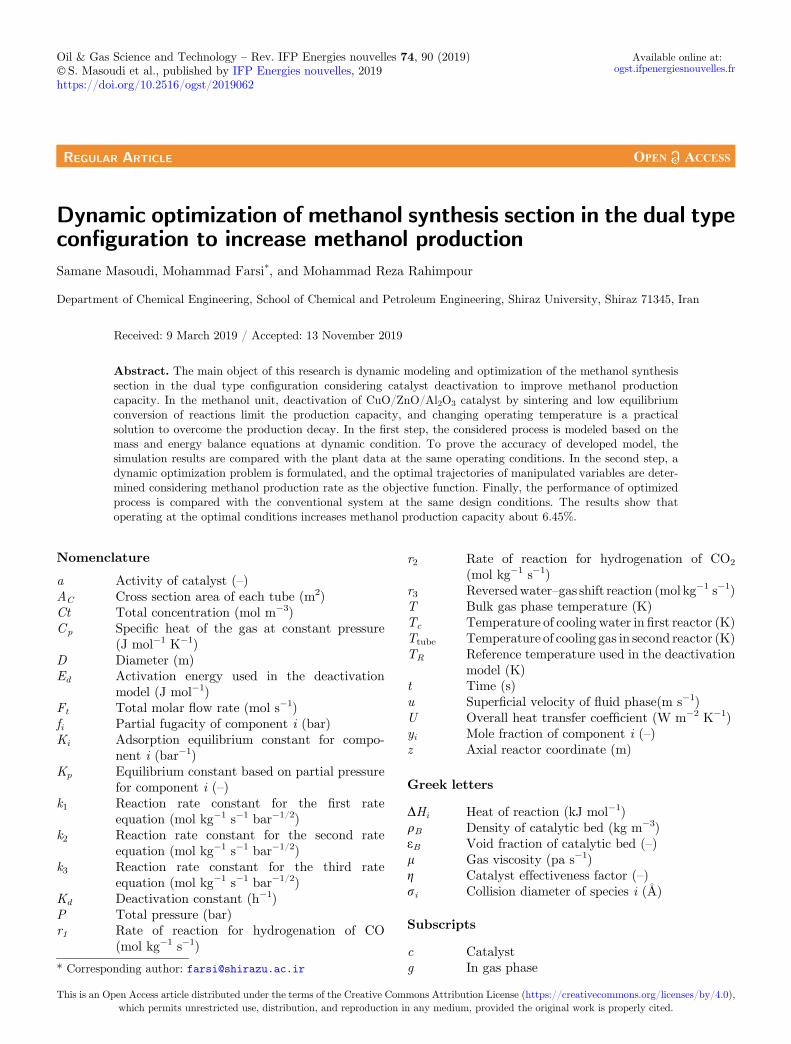
Dynamic optimization of methanol synthesis section in the dual typeconfiguration to increase methanol productionSamane Masoudi, Mohammad Farsi*, and Mohammad Reza Rahimpour
Department of Chemical Engineering, School of Chemical and Petroleum Engineering, Shiraz University, Shiraz 71345, Iran
Received: 9 March 2019 / Accepted: 13 November 2019
Abstract. The main object of this research is dynamic modeling and optimization of the methanol synthesissection in the dual type configuration considering catalyst deactivation to improve methanol productioncapacity. In the methanol unit, deactivation of CuO/ZnO/Al2O3 catalyst by sintering and low equilibriumconversion of reactions limit the production capacity, and changing operating temperature is a practicalsolution to overcome the production decay. In the first step, the considered process is modeled based on themass and energy balance equations at dynamic condition. To prove the accuracy of developed model, thesimulation results are compared with the plant data at the same operating conditions. In the second step, adynamic optimization problem is formulated, and the optimal trajectories of manipulated variables are deter-mined considering methanol production rate as the objective function. Finally, the performance of optimizedprocess is compared with the conventional system at the same design conditions. The results show thatoperating at the optimal conditions increases methanol production capacity about 6.45%.
Nomenclature
a Activity of catalyst (–)AC Cross section area of each tube (m2)Ct Total concentration (mol m�3)Cp Specific heat of the gas at constant pressure
(J mol�1 K�1)D Diameter (m)Ed Activation energy used in the deactivation
model (J mol�1)Ft Total molar flow rate (mol s�1)fi Partial fugacity of component i (bar)Ki Adsorption equilibrium constant for compo-
nent i (bar�1)Kp Equilibrium constant based on partial pressure
for component i (–)k1 Reaction rate constant for the first rate
equation (mol kg�1 s�1 bar�1/2)k2 Reaction rate constant for the second rate
equation (mol kg�1 s�1 bar�1/2)k3 Reaction rate constant for the third rate
equation (mol kg�1 s�1 bar�1/2)Kd Deactivation constant (h�1)P Total pressure (bar)r1 Rate of reaction for hydrogenation of CO
(mol kg�1 s�1)
r2 Rate of reaction for hydrogenation of CO2
(mol kg�1 s�1)r3 Reversedwater–gas shift reaction (mol kg�1 s�1)T Bulk gas phase temperature (K)Tc Temperature of cooling water in first reactor (K)Ttube Temperature of cooling gas in second reactor (K)TR Reference temperature used in the deactivation
model (K)t Time (s)u Superficial velocity of fluid phase(m s�1)U Overall heat transfer coefficient (W m�2 K�1)yi Mole fraction of component i (–)z Axial reactor coordinate (m)
Greek letters
DHi Heat of reaction (kJ mol�1)qB Density of catalytic bed (kg m�3)eB Void fraction of catalytic bed (–)l Gas viscosity (pa s�1)g Catalyst effectiveness factor (–)ri Collision diameter of species i (Å)
Subscripts
c Catalystg In gas phase* Corresponding author: [email protected]
This is an Open Access article distributed under the terms of the Creative Commons Attribution License (https://creativecommons.org/licenses/by/4.0),which permits unrestricted use, distribution, and reproduction in any medium, provided the original work is properly cited.
Oil & Gas Science and Technology – Rev. IFP Energies nouvelles 74, 90 (2019) Available online at:� S. Masoudi et al., published by IFP Energies nouvelles, 2019 ogst.ifpenergiesnouvelles.fr
https://doi.org/10.2516/ogst/2019062
REGULAR ARTICLEREGULAR ARTICLE

i Chemical speciesp Tube sides Shell side
Abbreviations
DC Dual ConfigurationODC Optimized Dual ConfigurationOMDC Optimized Modified Dual Configuration
1 Introduction
Nowadays methanol as a building block to produce chemi-cals, solvents and fuels plays an important role in the petro-chemical and chemical industries [1, 2]. It is the mainfeedstock to produce acetic acid, formaldehyde, dimethylether, melamine resin, ethylene and propylene. Currently,methanol has been proposed as a clean alternative greenenergy source that could be used in the internal combustionand other engines [3]. Although wood distillation is the old-est route to produce methanol, the catalytic syngas conver-sion is the main commercial technology that carried out inthe presence of CuO/ZnO/Al2O3 catalyst [4]. The ICI,Lurgi, Mitsubishi, Haldor Topsoe, Linde and Casale compa-nies are common licensors that developed different tech-nologies to convert syngas to methanol [5]. MitsubishiCompany used the conventional adiabatic reactors in themethanol plants. In the ICI process, the methanol is synthe-sized in the adiabatic reactors supported by quench pointsto inject a part of feed stream to the reactor for direct cool-ing. Since the methanol synthesis reactions are exothermicand reversible, decreasing reaction temperature by quenchstream shifts reactions toward the methanol synthesis side.Lurgi and Linde utilized the isothermal reactor for metha-nol synthesis. The isothermal reactor is a shell and tubeexchanger that the tube side is packed by catalyst andthe heat of reaction is removed from reaction zone by circu-lating boiling water in the shell. The proposed plate isother-mal reactor by Casale is a radial flow plate heat exchangerthat the cooling medium flows in the plates and feed streamflows in the radial direction [6–8]. Generally, fixed andfluidized bed isothermal reactors are more attractive com-pared to other types at the same catalyst loading due tofavorable temperature profile along the reactor.
Low equilibrium conversion of syngas to methanol anddeactivation of the catalyst by thermal and chemical sinter-ing and sulfur poisoning are the main challenges in themethanol plant, which limit production capacity. In thisregard, many researches have focused on the kinetic model-ing, process optimization and modification to improve pro-duction rate in the industrial methanol plants. Setinc andLevec presented a kinetic model to describe the rate ofmethanol synthesis over CuO/ZnO/Al2O3 catalyst basedon the Langmuir-Hinshelwood model. The results showedthat the Langmuir-Hinshelwood kinetic model is a suitabletool to describe rate of reactions [9]. Although the CuO/ZnO/Al2O3 presents a rather long lifetime and activity
compared to other catalysts, it is very sensitive to sulfurpoisoning, and the sulfur content in the feed stream needsto be reduced to less than 0.5 ppm [10]. In addition, itcan be deactivated thermally, especially at above 300 �Cbecause of the growth of the Cu crystallites and the result-ing loss of catalytically active area. Liu et al. presented agood review on developed catalysts for methanol synthesisvia hydrogenation of CO and CO2 [11]. Rezaie et al.compared the precision of heterogeneous and homogeneousmodels to predict performance of a single-stage methanolsynthesis reactor [12]. In the heterogeneous modeling, themass and energy transfer resistances in the CuO/ZnO/Al2O3 catalyst and gas phase were considered in the model.The simulation results showed that both homogeneous andheterogeneous models present a similar accuracy to predictreactor performance. Jahanmiri and Eslamloueyan modeleda single-stage methanol reactor and calculated the optimaltemperature profile along the reactor at steady state condi-tion. The results showed that applying the optimal temper-ature on the reactor could increase methanol production[13]. Kordabadi and Jahanmiri modified the methanolsynthesis reactor to enhance the equilibrium conversion.They supported a single-stage reactor by two series coolingshells and calculated the optimum temperature of each shellto achieve maximum methanol production. The simulationresults showed that the modification of conventional reactorbased on the proposed idea increased methanol productionrate over CuO/ZnO/Al2O3 catalyst about 2.9% [14]. Fuadet al. modeled a single-stage methanol synthesis reactorconsidering catalyst deactivation and formulated a real-time optimization strategy to improve process performance.The results showed that changing coolant temperature is apractical solution to overcome the catalyst decay and pre-vent the decline in methanol production [15]. Rahimpourproposed the dual bed concept based on the CuO/ZnO/Al2O3 catalyst as a suitable configuration to overcomethermodynamic limitations in the methanol plants. In theproposed configuration the first reactor was cooled by cool-ing water, while the second one was cooled by the feedstream. The proposed configuration was heterogeneouslymodeled at dynamic condition. The results showed thatapplying dual bed configuration in the methanol plantincreased catalyst lifetime and resulted in the higher syngasconversion [16]. Askari et al. calculated the optimal operat-ing conditions of the dual-bed configuration consideringcooling temperature in the water cooled reactor and feedtemperature as the decision variables. The results showedthat applying the optimal condition on the systemimproved the production capacity about 5.8% [17].
Since the methanol synthesis reactions are exothermicand reversible, integration of reaction and separation is aneffective method to improve methanol production. Farsiand Jahanmiri investigated the dynamic operability of dualmembrane reactor considering deactivation of CuO/ZnO/Al2O3 catalyst to produce methanol [18]. In this configura-tion, a conventional reactor has been supported by a Pd/Agmembrane tube for hydrogen permeation and alumina-silicacomposite membrane tube to remove water vapor from thereaction zone. The results showed that main advantages ofthe dual-membrane reactor were higher catalyst activity
S. Masoudi et al.: Oil & Gas Science and Technology – Rev. IFP Energies nouvelles 74, 90 (2019)2
and lifetime, higher CO2 conversion and methanol produc-tion. Rahimpour and Elekaei modeled a bubbling fluidized-bed membrane dual-type methanol reactor consideringlong-term deactivation of CuO/ZnO/Al2O3 catalyst. Inthe proposed process, the feed stream is preheated in thetubes of the gas cooled reactor and hydrogen is penetratedfrom feed into the reaction side through the membrane [19].The outlet feed from gas cooled reactor is fed to tubes of thewater cooled reactor. The outlet product from water cooledreactor is fed into the shell side of gas cooled reactor and thereactions are completed in the fluidized-bed side. This con-figuration solves some observed drawbacks of conventionaldual-type reactor such as pressure drop, internal masstransfer limitations, radial gradient of concentration andtemperature in gas cooled reactor. Rahimpour et al. pro-posed a cascade fluidized-bed hydrogen permselective mem-brane reactor to overcome thermodynamic limitations inmethanol synthesis process [8]. In the fluidized-bed watercooled reactor, the synthesis gas is partly converted tomethanol over the CuO/ZnO/Al2O3 catalyst. In the secondbed which is a membrane assisted fluidized-bed reactor, thereaction heat is used to preheat the feed stream in the firstbed. The two-phase theory in bubbling regime was used tomodel and simulate the proposed reactors. The resultsshowed that fluidizing catalyst bed in the water cooled reac-tor caused a favorable temperature profile in the reactorand represented 3.94% and 9.53% enhancement in themethanol yield compared to fluidized-bed membrane dual-type and industrial dual-type reactors. The dynamic simu-lation of cascade fluidized-bed hydrogen permselectivemembrane reactor shows that favorable temperature profilein the reactors could decrease catalyst decay [20]. Dehghaniet al. proposed a sorption-enhanced configuration within situ water adsorption for methanol synthesis to decreasesintering of CuO/ZnO/Al2O3 catalyst by steam andimproving methanol production [21]. In the proposed con-figuration, the zeolite 4A flows in the methanol synthe-sis reactor and produced steam is selectively absorbed bysolid particles. A theoretical investigation was per-formed to evaluate the optimal operating condition andmaximize the methanol production in the proposedconfiguration.
Typically, increasing production capacity and decreas-ing direct and indirect CO2 emissions are attractive chal-lenges in the chemical plants. In this regard, the mainobject of this research is dynamic optimization of thedual-type methanol synthesis loop in the presence of cata-lyst deactivation to improve production capacity and CO2conversion. In the first step, the considered process ismodeled based on the mass and energy balance equationsat dynamic condition. In the second step, a dynamic opti-mization problem is formulated and the optimal trajectoriesof the feed temperature and cooling temperature are deter-mined. In the third step, the process is supported by twoheat exchangers and the optimal trajectories of the avail-able inputs are determined during the process run time.Generally, supporting the dual type configuration by twoheat exchangers increases the number of manipulatedvariables and results in the suitable heat management inthe system.
2 Methods
The main object of this research is dynamic optimization ofsyngas conversion section in the methanol plant to increasemethanol production and CO2 conversion. In this part, theprocess description, considered kinetic and process models,formulated optimization algorithm and considered methodto solve the optimization problem and obtained equationsare presented.
2.1 Process description
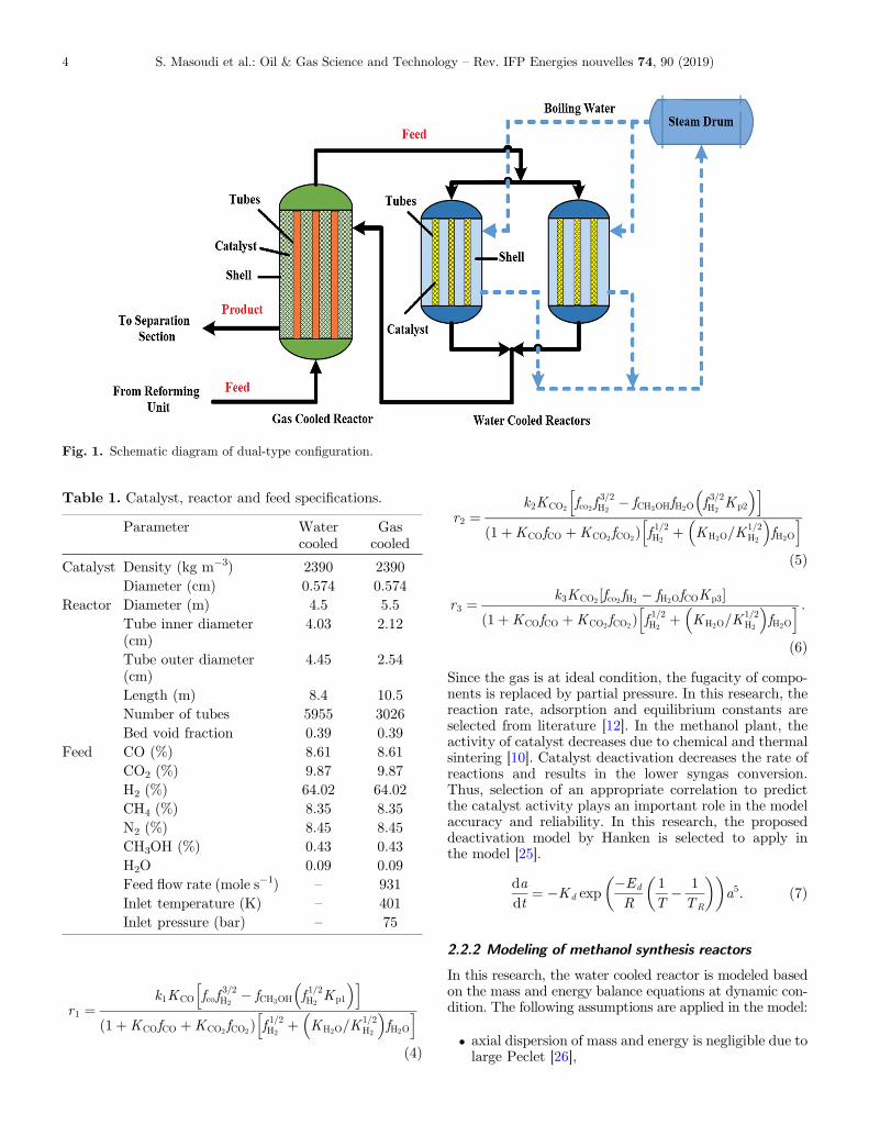
Figure 1 shows the process flow diagram of syngas conver-sion section in the considered methanol unit [22]. Themethanol unit consists of three main steps including syngasproduction from natural gas, methanol synthesis fromsyngas and downstream purification sections. The methanolsynthesis section consists of two water cooled reactorsaligned in parallel, and gas cooled reactor in series withwater cooled reactors. The CuO/ZnO/Al2O3 catalyst ispacked in the shell side of gas cooled, and in the tubes ofwater cooled reactors. Typically, the produced syngas inthe steam methane reforming unit feeds to the tube sideof gas cooled reactor. The outlet preheated stream fromtubes of gas cooled reactor directly feeds to the tube sideof water cooled reactor and syngas is partially convertedto methanol. The heat produced in the tubes is transferredto saturated water in the shell side. The outlet stream fromshell side of water cooled reactor feeds to the shell side of thegas cooled reactor. Since the shell side of gas cooled reactoris packed by CuO/ZnO/Al2O3 catalyst, the reactions occuron the catalyst surface and the generated heat is transferredto the syngas in the tube side. The outlet product from gascooled reactor enters to the separation section to producepure methanol. Table 1 shows the reactor design data,catalyst characteristics and feed specifications of the dualtype configuration [22].
2.2 Process modeling
2.2.1 Reaction kinetics
Typically, the CO and CO2 hydrogenation and the water–gas shift reactions occur on the surface of CuO/ZnO/Al2O3catalyst. The kinetics of reactions are as [23]:
CO þ 2H2 $ CH3OH �H 298 ¼ �90:5 ðkJmol�1Þð1Þ
CO2 þ 3H2 $ CH3OHþH2O �H 298 ¼ �49:43 kJmol�1� �ð2Þ
CO2 þ H2 $ COþ H2O �H 298 ¼ þ41:12 ðkJmol�1Þ :ð3Þ
Based on the presented data in the literature, the rate ofCO and CO2 hydrogenation and the water–gas shift reac-tions are as follows [24]:
S. Masoudi et al.: Oil & Gas Science and Technology – Rev. IFP Energies nouvelles 74, 90 (2019) 3
r1 ¼k1KCO fcof
3=2H2
� fCH3OH f 1=2H2Kp1
� �h i1þKCOfCO þKCO2 fCO2ð Þ f 1=2H2
þ KH2O=K1=2H2
� �fH2O
h ið4Þ
r2 ¼k2KCO2 fco2 f
3=2H2
� fCH3OHfH2O f 3=2H2Kp2
� �h i1þKCOfCO þKCO2 fCO2ð Þ f 1=2H2
þ KH2O=K1=2H2
� �fH2O
h ið5Þ
r3 ¼ k3KCO2 fco2 fH2 � fH2OfCOKp3½ �1þKCOfCO þKCO2 fCO2ð Þ f 1=2H2
þ KH2O=K1=2H2
� �fH2O
h i :ð6Þ
Since the gas is at ideal condition, the fugacity of compo-nents is replaced by partial pressure. In this research, thereaction rate, adsorption and equilibrium constants areselected from literature [12]. In the methanol plant, theactivity of catalyst decreases due to chemical and thermalsintering [10]. Catalyst deactivation decreases the rate ofreactions and results in the lower syngas conversion.Thus, selection of an appropriate correlation to predictthe catalyst activity plays an important role in the modelaccuracy and reliability. In this research, the proposeddeactivation model by Hanken is selected to apply inthe model [25].
dadt
¼ �Kd exp�Ed
R1T
� 1TR
� �� �a5: ð7Þ
2.2.2 Modeling of methanol synthesis reactors
In this research, the water cooled reactor is modeled basedon the mass and energy balance equations at dynamic con-dition. The following assumptions are applied in the model:
� axial dispersion of mass and energy is negligible due tolarge Peclet [26],
Fig. 1. Schematic diagram of dual-type configuration.
Table 1. Catalyst, reactor and feed specifications.
Parameter Watercooled
Gascooled
Catalyst Density (kg m�3) 2390 2390Diameter (cm) 0.574 0.574
Reactor Diameter (m) 4.5 5.5Tube inner diameter(cm)
4.03 2.12
Tube outer diameter(cm)
4.45 2.54
Length (m) 8.4 10.5Number of tubes 5955 3026Bed void fraction 0.39 0.39
Feed CO (%) 8.61 8.61CO2 (%) 9.87 9.87H2 (%) 64.02 64.02CH4 (%) 8.35 8.35N2 (%) 8.45 8.45CH3OH (%) 0.43 0.43H2O 0.09 0.09Feed flow rate (mole s�1) – 931Inlet temperature (K) – 401Inlet pressure (bar) – 75
S. Masoudi et al.: Oil & Gas Science and Technology – Rev. IFP Energies nouvelles 74, 90 (2019)4
� the mass and heat transfer resistances in the gas phaseare negligible [12],
� flow regime in the tube side is Plug due to largeReynolds Number,
� the temperature gradient in the catalyst is negligibledue to small Biot [27].
The mass and energy balance equations on the watercooled reactor are as follows:
eBCt@yi@t
¼ � Ft
Ac
@yi@z
þX3j¼1
gjri;jqBa ð8Þ
eBCtCp@T@t
¼ � Ft
ACCp
@T@z
þ qBaX3j¼1
gjrj ��Hj
� �
þ pDi
ACU Tc � Tð Þ: ð9Þ
The pressure drop along the bed is calculated by Tallmadgeequation [28]:
�Pl
¼ 150Re
ð1� eÞ2e3
þ 4:2
Re1=6ð1� eÞ1:166
e3
!u2qD
: ð10Þ
In the gas cooled reactor feed stream flows in the tube side,while the shell side is packed with the catalyst particles.The produced heat in the shell side is transferred to the tubeside and temperature of fresh feed increases gradually. Themass and energy balance equations for the shell side of gascooled reactor are as follows:
eBCt@yi@t
¼ � Ft
Ac
@yi@z
þX3j¼1
gjri;jqBa ð11Þ
eBCtCp@Ts
@t¼ �Fs
AsCp
@Ts
@zþ qBa
X3j¼1
gj rj ��Hj
� �
þ pDp
AsU Tp � Tsð Þ: ð12Þ
The pressure drop along the shell side of gas cooled reac-tor is calculated by Tallmadge equation. In addition, theenergy balance equation for the cooling gas in tube sideis as follows:
CtCp@Tp
@t¼ �Fp
AtCp
@Tp
@zþ pDp
AtU Ts � Tpð Þ: ð13Þ
The catalyst effectiveness factor, gj, is calculated based onthe dusty gas model [29]. It is defined as the ratio of theactual reaction rate in the catalyst to the calculated ratewhen the concentration and temperature gradients arenegligible in the catalyst. The effectiveness factor couldbe explained as:
g ¼ DeACdCidr jr¼R
ri 16 pd
3p
� � : ð14Þ
In this research, the effectiveness factor is calculated basedon the Thiele modulus method. In this regard, the intrinsicrate of each reaction is explained by a first-order power lawmodel in each element of reactor and the concentrationdistribution in the catalyst is obtained analytically.Equation (15) illustrates the analytical expression of effec-tiveness factor:
g ¼ 1u2
u coth 3uð Þ � 13
� �: ð15Þ
2.2.3 Supplementary equations
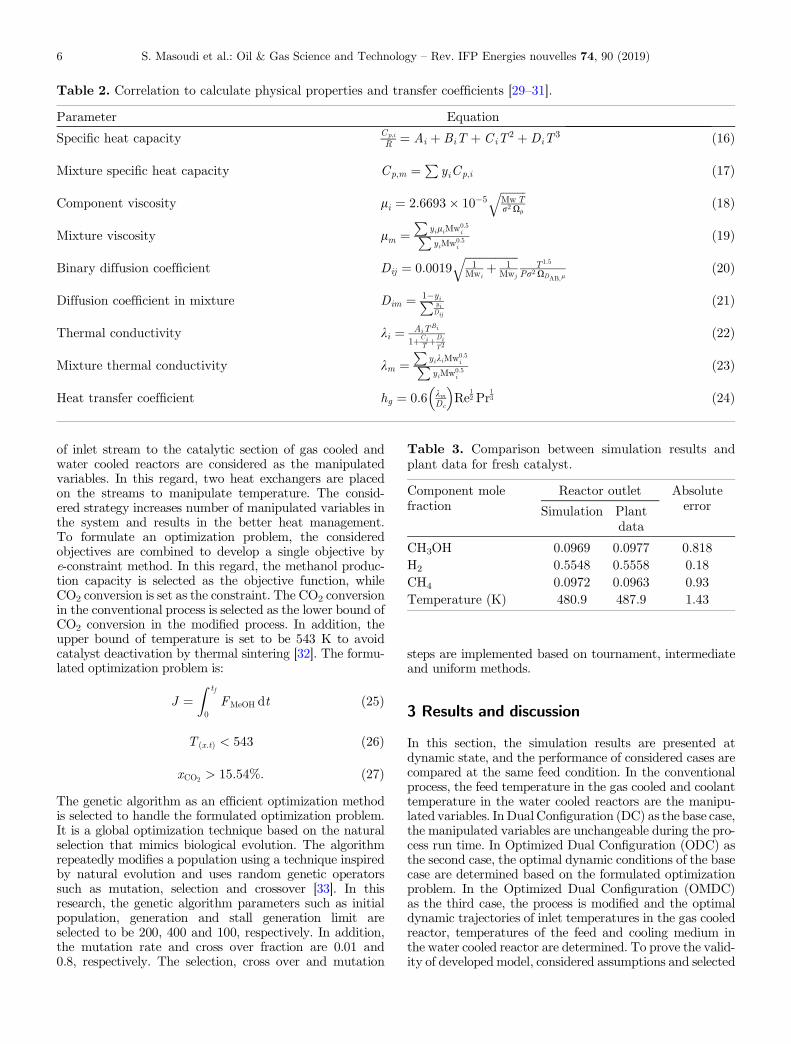
In this section, the considered equations to calculate thephysical, and thermal properties and transfer coefficientsare presented. Table 2 shows the used correlation to calcu-late physical properties and transfer coefficients.
2.3 Numerical solution
The developed equations in the modeling subsection aresolved numerically based on a two steps solution. In the firststep, the equations are solved by Euler method at steadystate condition and the obtained solution is considered asthe initial condition of dynamic model. In the second stage,the dynamic model is reduced to a set of ordinary differen-tial equations by the method of line and the obtained ODEset is solved numerically. The considered procedure to solveobtained set of equations is as:
� guess a temperature for inlet stream to the watercooled reactor,
� solve the water cooled model and calculate the outletcomposition and temperature,
� solve the gas cooled model and calculate feed temper-ature based on the outlet product from water cooledreactor and guessed temperature,
� if the absolute difference between calculated feedtemperature and plant data is negligible go to the nexttime step,
� if the absolute difference is considerable, correct theguessed temperature.
2.4 Process optimization
The main object of this research is dynamic optimization ofthe syngas conversion section in the methanol plant toincrease methanol production and CO2 conversion. Thus,the considered objective functions are higher methanolproduction and carbon dioxide conversion. Typically, thereare two manipulated variables in the methanol synthesissection including feed temperature in the gas cooled andcooling temperature in the water cooled reactors to controlthe process performance at the desired conditions. Since COand CO2 hydrogenation reactions are exothermic and rever-sible, heat management is a practical solution to overcomethe equilibrium limitations and decreasing the effects ofcatalyst deactivation on the methanol production. Thus,as well as feed temperature in the gas cooled and coolingtemperature in the water cooled reactors, the temperature
S. Masoudi et al.: Oil & Gas Science and Technology – Rev. IFP Energies nouvelles 74, 90 (2019) 5
of inlet stream to the catalytic section of gas cooled andwater cooled reactors are considered as the manipulatedvariables. In this regard, two heat exchangers are placedon the streams to manipulate temperature. The consid-ered strategy increases number of manipulated variables inthe system and results in the better heat management.To formulate an optimization problem, the consideredobjectives are combined to develop a single objective bye-constraint method. In this regard, the methanol produc-tion capacity is selected as the objective function, whileCO2 conversion is set as the constraint. The CO2 conversionin the conventional process is selected as the lower bound ofCO2 conversion in the modified process. In addition, theupper bound of temperature is set to be 543 K to avoidcatalyst deactivation by thermal sintering [32]. The formu-lated optimization problem is:
J ¼Z tf
0FMeOH dt ð25Þ
T x:tð Þ < 543 ð26Þ
xCO2 > 15:54%: ð27ÞThe genetic algorithm as an efficient optimization methodis selected to handle the formulated optimization problem.It is a global optimization technique based on the naturalselection that mimics biological evolution. The algorithmrepeatedly modifies a population using a technique inspiredby natural evolution and uses random genetic operatorssuch as mutation, selection and crossover [33]. In thisresearch, the genetic algorithm parameters such as initialpopulation, generation and stall generation limit areselected to be 200, 400 and 100, respectively. In addition,the mutation rate and cross over fraction are 0.01 and0.8, respectively. The selection, cross over and mutation
steps are implemented based on tournament, intermediateand uniform methods.
3 Results and discussion
In this section, the simulation results are presented atdynamic state, and the performance of considered cases arecompared at the same feed condition. In the conventionalprocess, the feed temperature in the gas cooled and coolanttemperature in the water cooled reactors are the manipu-lated variables. In Dual Configuration (DC) as the base case,the manipulated variables are unchangeable during the pro-cess run time. In Optimized Dual Configuration (ODC) asthe second case, the optimal dynamic conditions of the basecase are determined based on the formulated optimizationproblem. In the Optimized Dual Configuration (OMDC)as the third case, the process is modified and the optimaldynamic trajectories of inlet temperatures in the gas cooledreactor, temperatures of the feed and cooling medium inthe water cooled reactor are determined. To prove the valid-ity of developed model, considered assumptions and selected
Table 2. Correlation to calculate physical properties and transfer coefficients [29–31].
Parameter Equation
Specific heat capacity Cp;i
R ¼ Ai þ BiT þ CiT 2 þDiT 3 (16)
Mixture specific heat capacity Cp;m ¼P yiCp;i (17)
Component viscosity li ¼ 2:6693� 10�5ffiffiffiffiffiffiffiffiffiMwTr2 Xl
q(18)
Mixture viscosity lm ¼P
yiliMw0:5iP
yiMw0:5i
(19)
Binary diffusion coefficient Dij ¼ 0:0019ffiffiffiffiffiffiffiffiffiffiffiffiffiffiffiffiffiffiffi1
Mwiþ 1
Mwj
qT1:5
Pr2 XDAB;l(20)
Diffusion coefficient in mixture Dim ¼ 1�yiP yiDij
(21)
Thermal conductivity ki ¼ AiTBi
1þCiT þDi
T2
(22)
Mixture thermal conductivity km ¼P
yikiMw0:5iP
yiMw0:5i
(23)
Heat transfer coefficient hg ¼ 0:6 kmDc
� �Re
12 Pr
13 (24)
Table 3. Comparison between simulation results andplant data for fresh catalyst.
Component molefraction
Reactor outlet AbsoluteerrorSimulation Plant
data
CH3OH 0.0969 0.0977 0.818H2 0.5548 0.5558 0.18CH4 0.0972 0.0963 0.93Temperature (K) 480.9 487.9 1.43
S. Masoudi et al.: Oil & Gas Science and Technology – Rev. IFP Energies nouvelles 74, 90 (2019)6

kinetic equations and correlations, the results of simulationare compared with the available plant data in Table 3 [22].It appears that there is a good agreement between plant dataand simulation results at the same process condition. Thus,the developed model could be used in the optimizationsection to calculate the optimal conditions of process.
Figures 2a and 2b show the methanol mole fraction inthe outlet stream from gas cooled reactor during the processrun time and methanol concentration in the third case.It appears that catalyst deactivation decreases productioncapacity in the methanol plant, and changing operatingtemperature is a practical solution to overcome theappeared decay. Based on the simulation results, the meanproduction capacity in DC, ODC and OMDC are 4564.48,4693.92 and 4859.13 ton day�1, respectively. Althoughapplying the optimal trajectories on the base case increasesmethanol production by 2.83%, supporting the process bytwo heat exchangers and applying the optimal trajectorieson the system improves methanol production about6.45%. It appears that the methanol production rate inthe base case decreases from 4853 to 4393 ton day�1 duringthe process run time. The production decay in DC, ODCand OMDC are about 460, 369 and 359 ton day�1, respec-tively. It concludes that the main benefits of optimizedprocess are the higher production capacity and lowerproduction decay during the process run time.
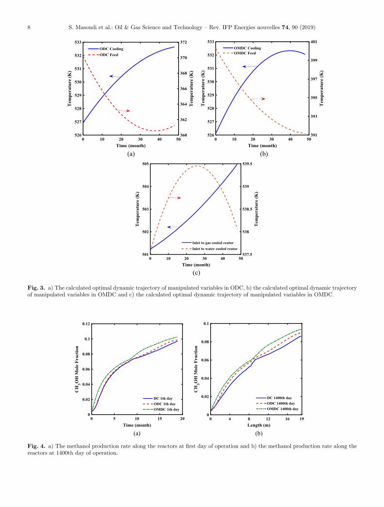
Figures 3a–3c show the optimal trajectories of manipu-lated variables based on the formulated optimizationproblem in the second and third cases, respectively. Basedon the simulation results, increasing temperature of coolingmedium in the water cooled reactor and decreasing feedtemperature in the gas cooled reactor could improveproduction capacity in the second case. Typically, catalystdeactivation reduces the rate of syngas conversion andresults in the higher deviation from thermodynamic equilib-rium. Increasing coolant temperature in the water cooledreactor promotes the rate of syngas conversion. On theother hand, applying the lower feed temperature in the
gas cooled reactor shifts thermodynamic limitations andresults in the higher equilibrium conversion. In the thirdcase, increasing coolant temperature in the water cooledreactor increases the rate of hydrogenation reactions andcould decrease the effect of catalyst deactivation on therate. Since the gas cooled reactor is a counter-current heatexchanger, increasing temperature of inlet stream to theshell side increases operating temperature in the first halfof reactor while decreasing temperature of inlet stream tothe tube side reduces temperature in the second.
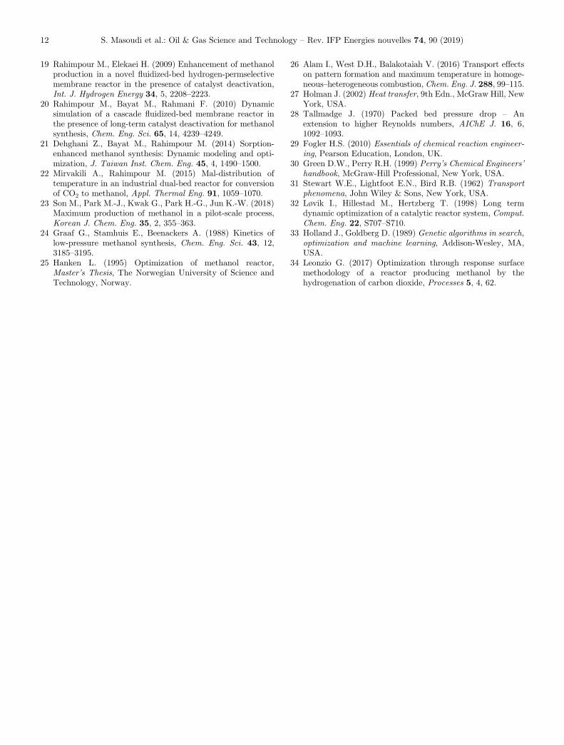
According to kinetic theory and Le Chatelier’s principle,applying the high temperature in the first half of gas cooledreactor increases the rate of reactions, while low tempera-ture in the second half shifts the thermodynamic equilib-rium. It concludes that the developed temperature profilesalong the gas and water cooled reactors in the third caseresult in the higher syngas conversion. It is confirmed thatthe calculated temperature trajectories are feasible andcould be applied on the system by conventional heatexchangers. Figures 4a and 4b show the methanol molefraction along the gas and water cooled reactors at startof run and end of run conditions, respectively. Based onthe kinetic model, CO and CO2 hydrogenation reactionscompete to produce methanol. It appears that the methanolmole fraction increases along the gas and water cooled reac-tors and approaches to the equilibrium condition in allcases. Although the performance of first and second casesis similar when the catalyst is fresh, the second case presentsthe superior performance compared to the base when thecatalyst presents lower activity.
The results show that the OMDC presents a superiorperformance over the DC and ODC due to better heatmanagement in the system. Figures 5a–5c present thetemperature profile along the water cooled and gas cooledreactors at different run times. Although increasing temper-ature enhances the rate in exothermic reversible reactions,it decreases equilibrium conversion in the system. In thedual type configuration, the feed stream is preheated in
(a) (b)
Fig. 2. a) Methanol mole fraction during process run time in DC, ODC and OMDC, and b) methanol mole fraction along the OMDCduring the process run time.
S. Masoudi et al.: Oil & Gas Science and Technology – Rev. IFP Energies nouvelles 74, 90 (2019) 7
(a) (b)
(c)
Fig. 3. a) The calculated optimal dynamic trajectory of manipulated variables in ODC, b) the calculated optimal dynamic trajectoryof manipulated variables in OMDC and c) the calculated optimal dynamic trajectory of manipulated variables in OMDC.
(a) (b)
Fig. 4. a) The methanol production rate along the reactors at first day of operation and b) the methanol production rate along thereactors at 1400th day of operation.
S. Masoudi et al.: Oil & Gas Science and Technology – Rev. IFP Energies nouvelles 74, 90 (2019)8

(a) (b)
(c)
Fig. 5. a) The temperature profile along the reactors at first day of operation and b) the temperature profile along the reactors at1400th day of operation, c) temperature profile along the OMDC during the process run time.
(a) (b)
Fig. 6. a) CO2 concentration profile along the reactors at first day of operation and b) CO2 concentration profile along the reactors at1400th day of operation.
S. Masoudi et al.: Oil & Gas Science and Technology – Rev. IFP Energies nouvelles 74, 90 (2019) 9

the gas cooled reactor and feeds to the tube side of watercooled reactor. Indeed, the water cooled reactor acts asthe first catalytic section. Then, the outlet stream fromwater cooled feeds to the shell side of gas cooled reactorand syngas is converted to methanol over the catalystsurface. Thus, applying the high temperature on the watercooled reactor as the first catalytic part increases rate ofreactions and system approaches to the equilibrium condi-tion, while applying low temperature on the gas cooledreactor shifts the methanol synthesis reactions toward theright side and results in the higher methanol production.It concludes that the suitable heat management is the mainadvantage of OMDC over DC and ODC cases that resultsin the higher methanol production. Thus, supporting thebase case by heat exchangers and applying the optimaltrajectories on the system shifts the process toward theideal condition and results in the higher methanol produc-tion. Since CO2 has a significant effect on the climate
change and world warming, and it provides an availableand inexpensive source to produce fuels and chemicals,CO2 conversion and recycling has received a significantattention in the world [34]. In this regard, improving metha-nol unit to increase rate of CO2 conversion is attractive.
Figures 6a and 6b show the carbon dioxide concentra-tion along the gas cooled and water cooled reactors inDC, ODC and OMDC at different run times. Based onthe reaction network, CO2 hydrogenation and water gasshift reactions influence the CO2 concentration in the reac-tor. Although CO2 concentration decreases at the initialpart of water cooled and the last part of gas cooled reactors,it increases along the other parts.
The lower carbon dioxide concentration in the outletstream from gas cooled reactor in ODC and OMDC com-pared to the base case proves the higher CO2 conversion.Based on the simulation results, the mean CO2 conversionin the DC, ODC and OMDC is 15.54%, 16.74% and
(a) (b)
Fig. 7. a) CO concentration profile along the reactors at first day of operation and b) CO concentration profile along the reactors at1400th day of operation.
(a) (b)
Fig. 8. a) Mean bed activity in the water cooled reactor and b) mean bed activity in the gas cooled reactor.
S. Masoudi et al.: Oil & Gas Science and Technology – Rev. IFP Energies nouvelles 74, 90 (2019)10

17.04% at the same feed condition, respectively. Figures 7aand 7b show the carbon monoxide concentration along thegas cooled and water cooled reactors in DC, ODC andOMDC at different run times. It appears that COmole frac-tion decreases along the reactors gradually, and CO conver-sion tomethanol inDC andODC is similarwhen the catalystis active. Based on the simulation results, decreasing catalystactivity reduces the rate of CO hydrogenation to methanoland applying the optimal conditions on the system couldimprove equilibrium conversion and rate of reactions.
It appears that third case presents a superior perfor-mance over the first and second cases to convert CO tomethanol during the process run time. Based on the simu-lation results, the mean CO conversion in the first, secondand third cases are 64.40%, 65.59% and 68.53% at the samefeed conditions, respectively. Figures 8a and 8b show themean catalyst activity in the water cooled and gas cooledreactors, respectively. It appears that catalyst activitydecreases during the process run time. Although the appliedcatalyst in water cooled reactor in OMDC presents loweractivity because of higher operating temperature, the cata-lyst with more activity is appeared in the gas cooled reactordue to lower operating temperature. On the other word, theeffect of low catalyst activity in the water cooled reactor onthe methanol production rate is overcome by applying thehigh feed temperature, and the equilibrium conversion inthe gas cooled reactor is improved by applying low feedtemperature in the OMDC. In addition, the applied cata-lyst in gas cooled reactor in OMDC presents the higheractivity compared to dual and optimized DCs.
4 Conclusion
In this research, the methanol synthesis section in the dualtype configuration was modeled and optimized in the pres-ence of catalyst deactivation. Based on the simulationresults, deactivation of CuO/ZnO/Al2O3 catalyst by sinter-ing and low equilibrium conversion of hydrogenation reac-tions limited the production capacity in the methanolplant. In this regard, the reactors were modeled based onthe mass and energy balance equations at dynamic condi-tion. Then, a dynamic optimization problem was formu-lated to calculate the optimal trajectories of manipulatedvariables in the base case. Although the feed temperaturein the gas cooled and coolant temperature in the watercooled reactors were manipulated variables in the base case,applying two exchangers on the system increased thenumber of manipulated variables in the system. Based onthe simulation results, the mean production capacity inthe base case, ODC and OMDC was 4564.48, 4693.92and 4859.13 ton day�1, respectively. Although, applyingthe optimal operating condition on the conventional processincreased methanol production by 2.83%, modification ofthe base case by heat exchangers and applying the optimalcondition on the system improved methanol productionabout 6.45%. In addition, the mean carbon dioxide conver-sion in the DC, ODC and OMDC configurations was15.54%, 16.74% and 17.04% at the same feed condition,respectively.
References
1 Mäyrä O., Leiviskä K. (2018) Modeling in methanol synthe-sis, Methanol, Elsevier, pp. 475–492.
2 Dalena F., Senatore A., Marino A., Gordano A., Basile M.,Basile A. (2018) Methanol production and applications: Anoverview, Methanol, Elsevier, pp. 3–28.
3 Alarifi A., Alsobhi S., Elkamel A., Croiset E. (2015)Multiobjective optimization of methanol synthesis loop fromsynthesis gas via a multibed adiabatic reactor with addi-tional interstage CO2 quenching, Energy Fuels 29, 2, 530–537.
4 Tursunov O., Kustov L., Kustov A. (2017) A brief review ofcarbon dioxide hydrogenation to methanol over copper andiron based catalysts, Oil Gas Sci. Technol. - Rev. IFPEnergies nouvelles 72, 5, 30.
5 Farsi M., Jahanmiri A. (2011) Methanol production in anoptimized dual-membrane fixed-bed reactor, Chem. Eng.Process.: Process Intensification 50, 11–12, 1177–1185.
6 Wagialla K., Elnashaie S. (1991) Fluidized-bed reactor formethanol synthesis. A theoretical investigation, Ind. Eng.Chem. Res. 30, 10, 2298–2308.
7 Struis R.P.W.J., Stucki S., Wiedorn M. (1996) A membranereactor for methanol synthesis, J. Membr. Sci. 113, 1, 93–100.
8 Rahimpour M., Bayat M., Rahmani F. (2010) Enhancementof methanol production in a novel cascading fluidized-bedhydrogen permselective membrane methanol reactor, Chem.Eng. J. 157, 2–3, 520–529.
9 Šetinc M., Levec J. (2001) Dynamics of a mixed slurryreactor for the three-phase methanol synthesis, Chem. Eng.Sci. 56, 21–22, 6081–6087.
10 Kung H.H. (1992) Deactivation of methanol synthesiscatalysts – A review, Catal. Today 11, 4, 443–453.
11 Liu X.-M., Lu G., Yan Z.-F., Beltramini J. (2003) Recentadvances in catalysts for methanol synthesis via hydrogena-tion of CO and CO2, Ind. Eng. Chem. Res. 42, 25, 6518–6530.
12 Rezaie N., Jahanmiri A., Moghtaderi B., Rahimpour M.(2005) A comparison of homogeneous and heterogeneousdynamic models for industrial methanol reactors in thepresence of catalyst deactivation, Chem. Eng. Process:Process Intensification 44, 8, 911–921.
13 Jahanmiri A., Eslamloueyan R. (2002) Optimal temperatureprofile in methanol synthesis reactor, Chem. Eng. Commun.189, 6, 713–741.
14 Kordabadi H., Jahanmiri A. (2005) Optimization of metha-nol synthesis reactor using genetic algorithms, Chem. Eng. J.108, 3, 249–255.
15 Fuad M.N.M., Hussain M.A., Zakaria A. (2012) Optimiza-tion strategy for long-term catalyst deactivation in a fixed-bed reactor for methanol synthesis process, Comput. Chem.Eng. 44, 104–126.
16 Rahimpour M. (2007) A dual-catalyst bed concept forindustrial methanol synthesis, Chem. Eng. Commun. 194,12, 1638–1653.
17 Askari F., Rahimpour M.R., Jahanmiri A., KhosravanipourMostafazadeh A. (2008) Dynamic simulation and optimiza-tion of a dual-type methanol reactor using genetic algo-rithms, Chem. Eng. Technol.: Ind. Chem. Plant Equip.Process Eng. Biotechnol. 31, 4, 513–524.
18 Farsi M., Jahanmiri A. (2014) Dynamic modeling andoperability analysis of a dual-membrane fixed bed reactor toproduce methanol considering catalyst deactivation, J. Ind.Eng. Chem. 20, 5, 2927–2933.
S. Masoudi et al.: Oil & Gas Science and Technology – Rev. IFP Energies nouvelles 74, 90 (2019) 11
19 Rahimpour M., Elekaei H. (2009) Enhancement of methanolproduction in a novel fluidized-bed hydrogen-permselectivemembrane reactor in the presence of catalyst deactivation,Int. J. Hydrogen Energy 34, 5, 2208–2223.
20 Rahimpour M., Bayat M., Rahmani F. (2010) Dynamicsimulation of a cascade fluidized-bed membrane reactor inthe presence of long-term catalyst deactivation for methanolsynthesis, Chem. Eng. Sci. 65, 14, 4239–4249.
21 Dehghani Z., Bayat M., Rahimpour M. (2014) Sorption-enhanced methanol synthesis: Dynamic modeling and opti-mization, J. Taiwan Inst. Chem. Eng. 45, 4, 1490–1500.
22 Mirvakili A., Rahimpour M. (2015) Mal-distribution oftemperature in an industrial dual-bed reactor for conversionof CO2 to methanol, Appl. Thermal Eng. 91, 1059–1070.
23 Son M., Park M.-J., Kwak G., Park H.-G., Jun K.-W. (2018)Maximum production of methanol in a pilot-scale process,Korean J. Chem. Eng. 35, 2, 355–363.
24 Graaf G., Stamhuis E., Beenackers A. (1988) Kinetics oflow-pressure methanol synthesis, Chem. Eng. Sci. 43, 12,3185–3195.
25 Hanken L. (1995) Optimization of methanol reactor,Master’s Thesis, The Norwegian University of Science andTechnology, Norway.
26 Alam I., West D.H., Balakotaiah V. (2016) Transport effectson pattern formation and maximum temperature in homoge-neous–heterogeneous combustion, Chem. Eng. J. 288, 99–115.
27 Holman J. (2002) Heat transfer, 9th Edn., McGraw Hill, NewYork, USA.
28 Tallmadge J. (1970) Packed bed pressure drop – Anextension to higher Reynolds numbers, AIChE J. 16, 6,1092–1093.
29 Fogler H.S. (2010) Essentials of chemical reaction engineer-ing, Pearson Education, London, UK.
30 Green D.W., Perry R.H. (1999) Perry’s Chemical Engineers’handbook, McGraw-Hill Professional, New York, USA.
31 Stewart W.E., Lightfoot E.N., Bird R.B. (1962) Transportphenomena, John Wiley & Sons, New York, USA.
32 Løvik I., Hillestad M., Hertzberg T. (1998) Long termdynamic optimization of a catalytic reactor system, Comput.Chem. Eng. 22, S707–S710.
33 Holland J., Goldberg D. (1989) Genetic algorithms in search,optimization and machine learning, Addison-Wesley, MA,USA.
34 Leonzio G. (2017) Optimization through response surfacemethodology of a reactor producing methanol by thehydrogenation of carbon dioxide, Processes 5, 4, 62.
S. Masoudi et al.: Oil & Gas Science and Technology – Rev. IFP Energies nouvelles 74, 90 (2019)12