Embed Size (px)
Citation preview
883 IEPC-93-095
DYNAMIC CHARACTERISTICS OF CLOSED DRIFT THRUSTERS
V.Zhurin*, J.Kahn*, H.Kaufman*, K.Kozubsky**, M.Day**** - Front Range Research, Fort Collins, Colorado** - Fakel Enterprise, Kaliningrad on Baltic Sea; Russia*** - Space Systems Loral, Palo Alto, California
thrusters are called thrusters with closed electron drift.Abstract During operation, electrons migrate to the anode due
to collisions with atoms of the propellant, ions, walls,Studies have been made using a variety of closed- and also due to oscillations. Ions, since they are
drift thrusters, including both thrusters with anode practically unaffected by the magnetic field, move inlayer, or TAL, and thrusters with extended acceleration the direction of the electric field and are accelerated byzone, or SPT. It was found out that oscillations existed this field. The accelerated ion flow from the thrusterin practically every regime of operation, with the collects the necessary number of electrons to neutralizecharacter of the oscillation depending on the operating it and develops the thrust.parameters. Although the efficiency of a plasma The electrons, drifting in the azimuthal direction,thruster generally decreased with increasing oscillation neutralize the ion space charge within the dischargeamplitude, operation with an amplitude not exceeding channel. This is the reason why, there is no apparenta certain value also permitted operation in regimes in limit on the flow due to space charge in this type ofwhich operation cannot otherwise be realized, thruster, and a significantly higher thrust density can be
obtained than in electrostatic thrusters.Introduction Thrusters with closed electron drift (TCED) operate
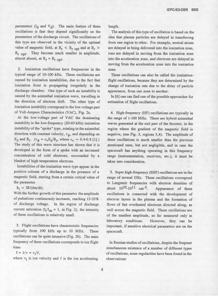
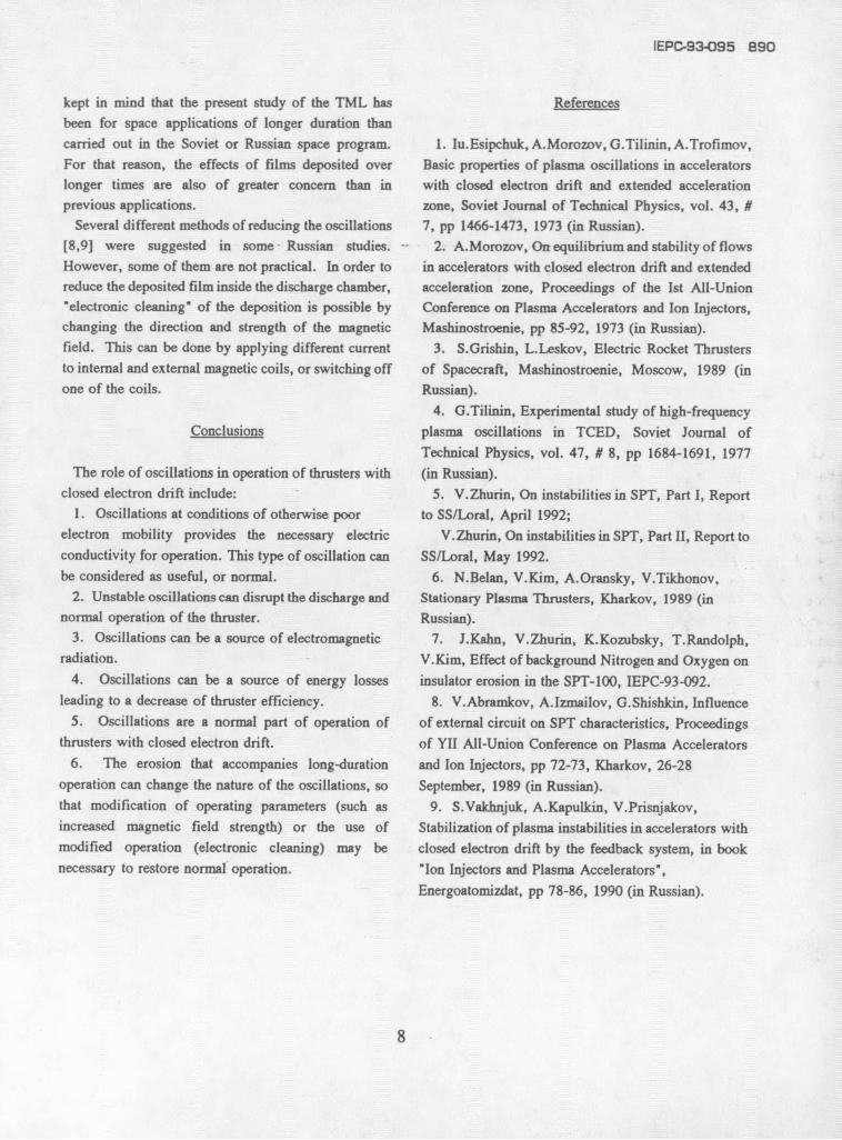
at low pressure in the sense that the mean free path ofThrusters with closed electron drift (Fig. 1), also particles in absence of the magnetic field is much
called Hall current thrusters, operate as follows, larger than the size of the discharge chamber. So, inPropellant (or working material) coming from the the absence of the magnetic field, the flow of ionizedanode is ionized by electrons moving under the and neutral particles would approximate free molecularinfluence of electric and magnetic fields. The electric flow, passing through the discharge region with fewfield is established by the anode and cathode and is in collisions. With the absence of any collectivethe axial direction. fluctuations, this flow could be likened to the laminar
The magnetic field is in the radial direction and has regime of conventional fluid flow.a value such that the Larmour radii of electrons, rLe, However, the appearance of a magnetic field changesand ions, rLi, satisfy to the condition: the picture significantly, depending, of course, on the
rLe < < << rLi , magnetic field value. With the application ofwhere I is the characteristic size of the acceleration sufficiently high magnetic field, the flow loses itsregion. laminar character and becomes a turbulent.
At such conditions, the general motion of the There are two well known types of thrusters withelectrons is in the azimuthal direction. Since the closed electron drift. The first is the thruster withazimuthal velocity of electrons is considerably larger closed electron drift and extended acceleration zonethan their longitudinal velocity, the electron trajectories (TCEDEAZ). This thruster is sometimes called thefollow almost closed paths. That is why these thruster with a magnetic layer (TML), and is more
1
IEPC-93-095 884
often called the stationary plasma thruster (SPT). of anomalous increase of electron transfer coefficientsAnother type of thruster is the thruster with anode across the magnetic field in the near-anode zone, whichlayer (TAL), which can also be called an SPT, because are often responsible for providing the bulk of theit also operates at constant voltage and current. We electron current to the anode.will use here TML and TAL, and sometimes SPT as The near-anode zone is the region in the acceleratingthe names for these thrusters. channel where the longitudinal component of the
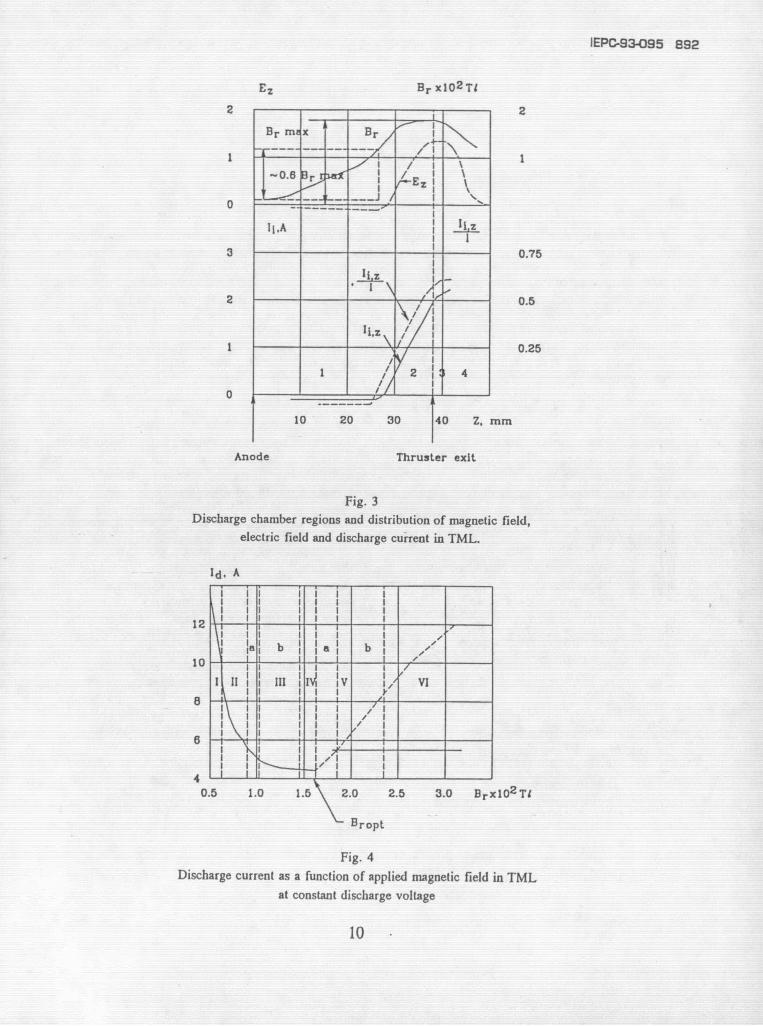
The TML has dielectric discharge chamber walls. In electric field, Ez , is approximately of the 0. In modernpractice, the walls from the anode to thruster exit have - SPTs of the TML type at optimal regimes, this regiona length from 30 to 50 mm. The TAL has a metal begins at the anode surface and reaches the boundarydischarge chamber with a length from approximately 0 of the LIA (layer of ionization and acceleration), where(in the case of an anode extended outside of the the value of the radial magnetic field is (0.5-discharge chamber) to 20 mm. 0.7 )Br,max, with Br,max the maximum value of the
The SPT has been flown in space tens of times, with radial magnetic field (see Fig. 3). In a considerablemore than one hundred thrusters of the SPT-50, the part of this zone the Br values are large, and the EzSPT-60 and the SPT-70 type operated for a total of values are small. The values of the electron pressureseveral thousands of hours. Eight SPT-100 have been gradient are also not sufficient to provide the observedprepared for flight on Russian geostationary satellite electron transfer by classical mechanisms. The most"GALS". probable reason for the increase of the transfer
As the propellant, moder TMLs and TALs all use coefficients is the oscillations.xenon. In the optimal regimes the LIA is separated from the
The physical phenomena which occur in both anode, and the Ez values in the near-anode zone arethrusters are very similar, but each one has its own small. This also means that the ionization and motionsdistinctive features, which will be discussed in this of ions and electrons to the anode are provided by thepaper. energy carried by electrons from the LIA. From the
In the TML and TAL the most important processes anode side of the LIA, the values of the electronin the discharge are near the anode, near the cathode temperature gradient are close to zero, i.e. the energyand processes at the discharge chamber walls. We will transfer from the LIA into the near-anode zone due tonot discuss in detail the near-cathode processes thermoconductivity is negligible. The main source isinasmuch as their characteristics are well known and therefore convective energy transfer.not limited to closed drift thrusters. In an SPT of the TML type due to the LIA
Let us consider first the near-anode processes in separation from anode the requirements on accuracy ofmore detail. Most important for the TML and TAL in anode placement are not severe in comparison with thethe near-anode region are the processes responsible for TAL, where the discharge region can be practicallythe delivery of the necessary number of electrons to the outside of the discharge chamber, and the LIA could beanode. It is possible to observe operating regimes, adjacent to anode.where the electron concentration and energy in thenearby plasma are sufficient for providing the discharge Oscillationscurrent with thermal motion of electrons. There arealso regimes possible, where this condition is not During the operation of thrusters with closed electronfulfilled. In the first case the near-anode potential drift it was found that the discharge experiencesjump is AUa < 0, while in the second case it is different types of oscillations and instabilities which canAUa > 0. The conditions, where one or the other decrease the efficiency of plasma acceleration.regime is realized have not been sufficiently studied. However, the appearance in the plasma of oscillationsIn particular, very little is known about the mechanisms with an intensity not exceeding a certain critical value,
2
885 IEPC-93-095
though it can lead to a partial decrease of efficiency, minimum.can also, in principle, provide stable operation of Also, it is necessary to note that, generally speaking,thrusters in regimes which can't otherwise be realized, thruster efficiency depends not only on the magnetic
From studies of the TML and TAL, the following field value, which is, in principle, is changeable, butobservations were made: also on the shape of magnetic field, which is hard to
1. A large variety of oscillations exist in practically change in an operating thruster. This comment isall regimes of operation; important for the TMLs, which have been qualified for
2. The character of the oscillations is different for space flight in the Russian space program. The presentlow (1-1.5 kW) and high (5-30 kW) power thrusters. configuration uses the discharge current to provide
3. Oscillations depend on the operating parameters: current through magnetic coils. In other words, thea. Discharge voltage, Vd; same power supply is used for the anode current andb. Discharge current, Id; for the magnetic coils. This is done, of course, toc. Neutralizer current, Ic; simplify the circuitry. However, for the TAL thed. Magnetic field strength and configuration power supply for the magnetic coils is separate, andof magnetic system; external and internal coils even have their own powere. Discharge chamber configuration; supplies (A similar circuitry was also used on earlyf. Number of cathode-neutralizers; TMLs, even some that were used in space).g. Location of cathode-neutralizers; In the discharge chamber, electron transfer across theh. Mass flow, and the ratio of mass flow between magnetic field can be realized by typical mechanisms,the anode and cathode; including collisions of electrons in the azimuthalj. Power supply circuit characteristics, direction with ions, atoms, channel walls and potential
variations due to oscillations. With an increase ofIn addition to the above observations, an increase of magnetic field, oscillations start to play a more
propellant mass flow and an increase of back flow (a important role than collisions.larger background pressure) leads to an increase of Since they began work with TML and TAL thrusters,oscillation amplitude. There is a minimum critical Russian scientists encountered many problems withdynamic pressure with an operating thruster of about oscillations which accompanied the operation of such2x10-4 torr (uncorrected reading for ion gauge thrusters. Many types of oscillations were studied incalibrated for air). At larger pressures, oscillations publications devoted to operation of thrusters withmake thruster operation very unstable, which can lead closed electron drift [1-6]. Also, it was found that theto the disruption of the discharge. These have been power-supply/thruster-discharge is a dynamic circuit,general observations of oscillations in the TML and the and the supply and thruster interact in a very complexTAL. manner.
The regulation of TML and TAL parameters is In general, the most important oscillations that existpossible through three means: discharge voltage, Vd; during the thruster operation are:mass flow, dm/dt; and applied magnetic field, Br. Thestudy of TML and TAL characteristics shows that, in 1. Contour oscillations are longitudinal oscillationsorder to obtain high thruster efficiency, it is impossible with typical frequencies of 1-20 kHz. The mechanismto change independently all three mentioned values, of development of such oscillations is connected withFor a fixed Vd and dm/dt there is an optimal value for the instability of location of the ionization zone.magnetic field, Br,opt, at which maximum efficiency These oscillations are the most intensive inis reached. At this optimum, the discharge current comparison with other types of oscillations. In thevalue, Id, reaches a minimum. At this field strength, regimes of operation with developed oscillations of thisBr,opt , the amplitude of observed oscillations is also a type, there is almost 100% modulation of the discharge
3
IEPC-93-095 886
parameters (Id and Vd). The main feature of these length.oscillations is that they depend significantly on the The analysis of this type of oscillation is based on theparameters of the discharge circuit. The oscillations of idea that plasma particles are delayed in transferringthis type are observed in the vicinity of the optimal from one region to other. For example, neutral atomsvalue of magnetic field, at Br < Br opt and at Br > are delayed in being delivered into the ionization zone,Br opt. They become much smaller in amplitude, ions are delayed in moving from the ionization zonealmost absent, at Br = Br opt- into the acceleration zone, and electrons are delayed in
moving from the acceleration zone into the ionization2. Ionization oscillations have frequencies in the zone.
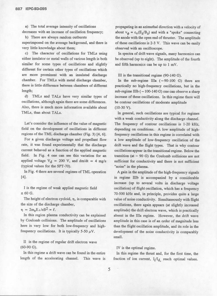
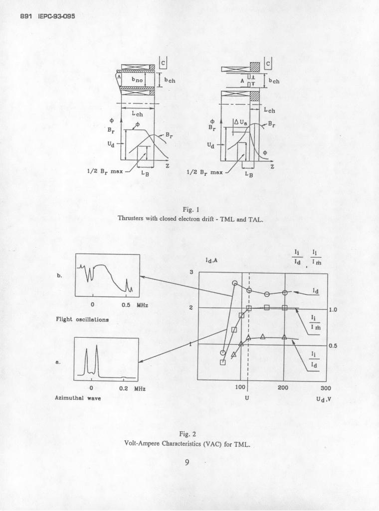
typical range of 10-100 kHz. These oscillations are These oscillations can also be called the ionization-caused by ionization instabilities, due to the fact that flight oscillations, because they are determined by theionization front is propagating irregularly in the change of ionization rate due to the delay of particledischarge chamber. One type of such an instability is appearance, from one zone to another.caused by the azimuthal ionization wave, travelling in In [6] one can find one of the possible approaches forthe direction of electron drift. The other type of estimation of flight oscillations.ionization instability correspond to the low-voltage partof Volt-Ampere Characteristics (VAC), Fig. 2a. 4. High-frequency (HF) oscillations are typically in
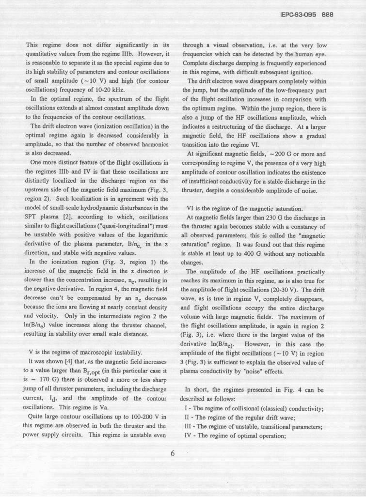
At the low-voltage part of VAC the dominating the range of 1-100 MHz. These are hybrid azimuthalinstability is the low-frequency (20-60 kHz) ionization waves generated at the exit part of the thruster, in theinstability of the "spoke" type, rotating in the azimuthal region where the gradient of the magnetic field isdirection with constant velocity, vo, and depending on negative, (see Fig. 3, regions 3,4). The amplitude ofEz and Br. (v = cvEz/Br, where cv = 0.4-0.8 [1].) these oscillations is much smaller than the previousThe study of this wave structure has shown that it is mentioned ones, but not negligible, and in case thedeveloped in the form of a spoke with an increased spacecraft has anything operating in this frequencyconcentration of cold electrons, surrounded by a range (instrumentation, receivers, etc.), it must beblanket of high-temperature electrons, taken into consideration.
Instabilities of the ionization wave type appear in thepositive column of a discharge in the presence of a 5. Super high-frequency (SHF) oscillations are in themagnetic field, starting from a certain critical value of range of several GHz. These oscillations correspondthe parameter to Langmuir frequencies with electron densities of
ki = IB/(dm/dt). about 1010-1011 cm- 3 . Appearance of theseWith the further growth of this parameter the amplitude oscillations is connected with the development ofof pulsations continuously increases, reaching 15-20% electron layers in the plasma and the formation ofof discharge voltage. In the region of discharge flows of fast overheated electrons directed along, ascurrent saturation (Ii/Im = 1, in Fig. 2), the intensity well across the magnetic field. These oscillations areof these oscillations is relatively small. of the smallest amplitude, so far measured only in
laboratory conditions. However, they can be3. Flight oscillations have characteristic frequencies important, if sensitive electrical parameters are on the
typically from 100 kHz up to 10 MHz. These spacecraft.oscillations can be quite intensive (Fig. 2b). The mainfrequency of these oscillations corresponds to ion flight In Russian studies of oscillations, despite the frequenttime: simultaneous existence of a number of different types
f = 1/T = vil/, of oscillations, some regularities have been found in thewhere vi is ion velocity and I is the ion accelerating observations:
4
887 IEPC-93-095
a) The total average intensity of oscillations propagating in an azimuthal direction with a velocity ofdecreases with an increase of oscillation frequency; about v - cv(Ez/Bz) and with a "spoke" connecting
b) There are always random outbursts the anode with the open end of thruster. The amplitudesuperimposed on the average background, and there is of these oscillations is 2-3 V. This wave can be easilyvery little knowledge about them; observed with an oscilloscope.
c) The character of oscillations for TMLs using In spectra of drift wave signals, many harmonics caneither insulator or metal walls of various length is both be observed (up to eight). The amplitude of the fourthsimilar for some types of oscillations and slightly and fifth harmonics can be up to 1 mV.different for certain other types of oscillations whichare more prominent with an insulated discharge III is the transitional regime (90-140 G).chamber. For TMLs with metal discharge chamber, In the sub-regime IIIa (-90-100 G) there arethere is little difference between chambers of different practically no high-frequency oscillations, but in thelength; sub-regime IIIb (~ 100-140 G) one can observe a sharp
d) TMLs and TALs have very similar types of increase of these oscillations. In this regime there willoscillations, although again there are some differences, be contour oscillations of moderate amplitudeAlso, there is much more information available about (10-30 V).TMLs, than about TALs. In general, such oscillations are typical for regimes
with a weak conductivity along the discharge channel.Let's consider the influence of the value of magnetic The frequency of contour oscillations is 1-20 kHz,
field on the development of oscillations in different depending on conditions. A low amplitude of high-regions of the TML discharge chamber (Fig. 3) [4, 6]. frequency oscillations in this regime is correlated with
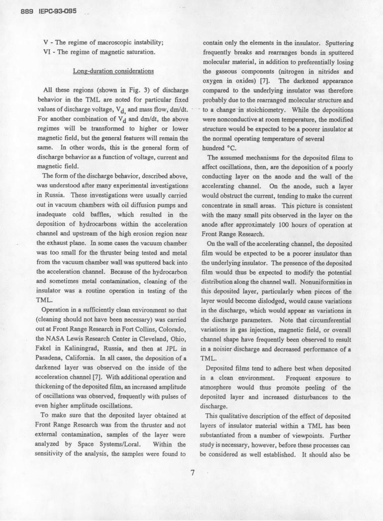
For a given discharge voltage and propellant flow a low amplitude of low-frequency oscillation of therate, it was found experimentally that the discharge drift wave and the flight types. That is why contourcurrent behaved as a function of the applied magnetic oscillations appear in the transitional regime. Below thefield. In Fig. 4 one can see this variation for an transition (at - 90 G) the Coulomb collisions are notapplied voltage Vd = 200 V, and dm/dt = 4 mg/s sufficient for conductivity and there is not sufficient(typical values for the SPT-70). "noise" in the plasma.
In Fig. 4 there are several regimes of TML operation A gain in the amplitude of the high-frequency signals[4]. in regime IIIb is accompanied by a considerable
increase (up to several volts in discharge voltageI is the regime of weak applied magnetic field oscillation) of flight oscillation, which has a frequency
5 60 G. 70-500 kHz and, in principle, provides quite a largeThe height of electron cycloid, ii, is comparable with value of noise conductivity. Simultaneously with flight
the size of the discharge chamber, oscillations, there again appears (at slightly increasedi = 2meE±/eB2 = i. amplitude) the drift electron wave, which is practicallyIn this region plasma conductivity can be explained absent in the hIa regime. However, the drift wave
by Coulomb collisions. The amplitude of oscillations amplitude in this case is of an order of magnitude lesshere is very low for both low-frequency and high- than the flight oscillation amplitude, and its role in thefrequency oscillations. It is typically 5-50 pV. development of the noise conductivity is comparably
small.II is the regime of regular drift electron wave
(60-90 G). IV is the optimal regime.In this regime a drift wave can be found in the entire In this regime the thrust and, for the first time, the
length of the accelerating channel. This wave is fraction of ion current, Ii/Id, reach optimal values.
5
IEPC-934-95 888
This regime does not differ significantly in its through a visual observation, i.e. at the very lowquantitative values from the regime IIIb. However, it frequencies which can be detected by the human eye.is reasonable to separate it as the special regime due to Complete discharge damping is frequently experiencedits high stability of parameters and contour oscillations in this regime, with difficult subsequent ignition.of small amplitude (- 10 V) and high (for contour The drift electron wave disappears completely withinoscillations) frequency of 10-20 kHz. the jump, but the amplitude of the low-frequency part
In the optimal regime, the spectrum of the flight of the flight oscillation increases in comparison withoscillations extends at almost constant amplitude down the optimum regime. Within the jump region, there isto the frequencies of the contour oscillations, also a jump of the HF oscillations amplitude, which
The drift electron wave (ionization oscillation) in the indicates a restructuring of the discharge. At a largeroptimal regime again is decreased considerably in magnetic field, the HF oscillations show a gradualamplitude, so that the number of observed harmonics transition into the regime VI.is also decreased. At significant magnetic fields, -200 G or more and
One more distinct feature of the flight oscillations in corresponding to regime V, the presence of a very highthe regimes IIIb and IV is that these oscillations are amplitude of contour oscillation indicates the existencedistinctly localized in the discharge region on the of insufficient conductivity for a stable discharge in theupstream side of the magnetic field maximum (Fig. 3, thruster, despite a considerable amplitude of noise.region 2). Such localization is in agreement with themodel of small-scale hydrodynamic disturbances in the VI is the regime of the magnetic saturation.SPT plasma [2], according to which, oscillations At magnetic fields larger than 230 G the discharge insimilar to flight oscillations ("quasi-longitudinal") must the thruster again becomes stable with a constancy ofbe unstable with positive values of the logarithmic all observed parameters; this is called the "magneticderivative of the plasma parameter, B/ne, in the z saturation" regime. It was found out that this regimedirection, and stable with negative values, is stable at least up to 400 G without any noticeable
In the ionization region (Fig. 3, region 1) the changes.increase of the magnetic field in the z direction is The amplitude of the HF oscillations practicallyslower than the concentration increase, ne, resulting in reaches its maximum in this regime, as is also true forthe negative derivative. In region 4, the magnetic field the amplitude of flight oscillations (20-30 V). The driftdecrease can't be compensated by an ne decrease wave, as is true in regime V, completely disappears,because the ions are flowing at nearly constant density and flight oscillations occupy the entire dischargeand velocity. Only in the intermediate region 2 the volume with large magnetic fields. The maximum ofIn(B/ne) value increases along the thruster channel, the flight oscillations amplitude, is again in region 2resulting in stability over small scale distances. (Fig. 3), i.e. where there is the largest value of the
derivative In(B/ne). However, in this case theV is the regime of macroscopic instability, amplitude of the flight oscillations (- 10 V) in regionIt was shown [4] that, as the magnetic field increases 3 (Fig. 3) is sufficient to explain the observed value of
to a value larger than Br,opt (in this particular case it plasma conductivity by "noise" effects.is - 170 G) there is observed a more or less sharpjump of all thruster parameters, including the discharge In short, the regimes presented in Fig. 4 can becurrent, Id, and the amplitude of the contour described as follows:oscillations. This regime is Va. I - The regime of collisional (classical) conductivity;
Quite large contour oscillations up to 100-200 V in II - The regime of the regular drift wave;this regime are observed in both the thruster and the III - The regime of unstable, transitional parameters;power supply circuits. This regime is unstable even IV - The regime of optimal operation;
6
889 IEPC-93-095
V - The regime of macroscopic instability; contain only the elements in the insulator. SputteringVI - The regime of magnetic saturation, frequently breaks and rearranges bonds in sputtered
molecular material, in addition to preferentially losingLong-duration considerations the gaseous components (nitrogen in nitrides and
oxygen in oxides) [7]. The darkened appearanceAll these regions (shown in Fig. 3) of discharge compared to the underlying insulator was therefore
behavior in the TML are noted for particular fixed probably due to the rearranged molecular structure andvalues of discharge voltage, Vd, and mass flow, dm/dt. to a change in stoichiometry. While the depositionsFor another combination of Vd and dm/dt, the above were nonconductive at room temperature, the modifiedregimes will be transformed to higher or lower structure would be expected to be a poorer insulator atmagnetic field, but the general features will remain the the normal operating temperature of severalsame. In other words, this is the general form of hundred °C.discharge behavior as a function of voltage, current and The assumed mechanisms for the deposited films tomagnetic field. affect oscillations, then, are the deposition of a poorly
The form of the discharge behavior, described above, conducting layer on the anode and the wall of thewas understood after many experimental investigations accelerating channel. On the anode, such a layerin Russia. These investigations were usually carried would obstruct the current, tending to make the currentout in vacuum chambers with oil diffusion pumps and concentrate in small areas. This picture is consistentinadequate cold baffles, which resulted in the with the many small pits observed in the layer on thedeposition of hydrocarbons within the acceleration anode after approximately 100 hours of operation atchannel and upstream of the high erosion region near Front Range Research.the exhaust plane. In some cases the vacuum chamber On the wall of the accelerating channel, the depositedwas too small for the thruster being tested and metal film would be expected to be a poorer insulator thanfrom the vacuum chamber wall was sputtered back into the underlying insulator. The presence of the depositedthe acceleration channel. Because of the hydrocarbon film would thus be expected to modify the potentialand sometimes metal contamination, cleaning of the distribution along the channel wall. Nonuniformities ininsulator was a routine operation in testing of the this deposited layer, particularly when pieces of theTML. layer would become dislodged, would cause variations
Operation in a sufficiently clean environment so that in the discharge, which would appear as variations in(cleaning should not have been necessary) was carried the discharge parameters. Note that circumferentialout at Front Range Research in Fort Collins, Colorado, variations in gas injection, magnetic field, or overallthe NASA Lewis Research Center in Cleveland, Ohio, channel shape have frequently been observed to resultFakel in Kaliningrad, Russia, and then at JPL in in a noisier discharge and decreased performance of aPasadena, California. In all cases, the deposition of a TML.darkened layer was observed on the inside of the Deposited films tend to adhere best when depositedacceleration channel [7]. With additional operation and in a clean environment. Frequent exposure tothickening of the deposited film, an increased amplitude atmosphere would thus promote peeling of theof oscillations was observed, frequently with pulses of deposited layer and increased disturbances to theeven higher amplitude oscillations, discharge.
To make sure that the deposited layer obtained at This qualitative description of the effect of depositedFront Range Research was from the thruster and not layers of insulator material within a TML has beenexternal contamination, samples of the layer were substantiated from a number of viewpoints. Furtheranalyzed by Space Systems/Loral. Within the study is necessary, however, before these processes cansensitivity of the analysis, the samples were found to be considered as well established. It should also be
7
IEPC-93-095 890
kept in mind that the present study of the TML has Referencesbeen for space applications of longer duration thancarried out in the Soviet or Russian space program. 1. Iu.Esipchuk, A.Morozov, G.Tilinin, A.Trofimov,For that reason, the effects of films deposited over Basic properties of plasma oscillations in acceleratorslonger times are also of greater concern than in with closed electron drift and extended accelerationprevious applications, zone, Soviet Journal of Technical Physics, vol. 43, #
Several different methods of reducing the oscillations 7, pp 1466-1473, 1973 (in Russian).
[8,9] were suggested in some-Russian studies.- 2. A.Morozov, On equilibrium and stability of flowsHowever, some of them are not practical. In order to in accelerators with closed electron drift and extendedreduce the deposited film inside the discharge chamber, acceleration zone, Proceedings of the Ist All-Union"electronic cleaning" of the deposition is possible by Conference on Plasma Accelerators and Ion Injectors,changing the direction and strength of the magnetic Mashinostroenie, pp 85-92, 1973 (in Russian).field. This can be done by applying different current 3. S.Grishin, L.Leskov, Electric Rocket Thrustersto internal and external magnetic coils, or switching off of Spacecraft, Mashinostroenie, Moscow, 1989 (inone of the coils. Russian).
4. G.Tilinin, Experimental study of high-frequencyConclusions plasma oscillations in TCED, Soviet Journal of
Technical Physics, vol. 47, # 8, pp 1684-1691, 1977The role of oscillations in operation of thrusters with (in Russian).
closed electron drift include: 5. V.Zhurin, On instabilities in SPT, Part I, Report1. Oscillations at conditions of otherwise poor to SS/Loral, April 1992;
electron mobility provides the necessary electric V.Zhurin, On instabilities in SPT, Part II, Report toconductivity for operation. This type of oscillation can SS/Loral, May 1992.be considered as useful, or normal. 6. N.Belan, V.Kim, A.Oransky, V.Tikhonov,
2. Unstable oscillations can disrupt the discharge and Stationary Plasma Thrusters, Kharkov, 1989 (innormal operation of the thruster. Russian).
3. Oscillations can be a source of electromagnetic 7. J.Kahn, V.Zhurin, K.Kozubsky, T.Randolph,radiation. V.Kim, Effect of background Nitrogen and Oxygen on
4. Oscillations can be a source of energy losses insulator erosion in the SPT-100, IEPC-93-092.leading to a decrease of thruster efficiency. 8. V.Abramkov, A.Izmailov, G.Shishkin, Influence
5. Oscillations are a normal part of operation of of external circuit on SPT characteristics, Proceedingsthrusters with closed electron drift, of YII All-Union Conference on Plasma Accelerators
6. The erosion that accompanies long-duration and Ion Injectors, pp 72-73, Kharkov, 26-28operation can change the nature of the oscillations, so September, 1989 (in Russian).that modification of operating parameters (such as 9. S.Vakhnjuk, A.Kapulkin, V.Prisnjakov,increased magnetic field strength) or the use of Stabilization of plasma instabilities in accelerators withmodified operation (electronic cleaning) may be closed electron drift by the feedback system, in booknecessary to restore normal operation. "Ion Injectors and Plasma Accelerators",
Energoatomizdat, pp 78-86, 1990 (in Russian).
8
891 IEPC-93-095
bn o bch A bch
Lch ' Lch
BrBB
Ud- Ud"
z z1/2 Br max LB 1/2 Br max LB
Fig. 1Thrusters with closed electron drifl - TML and TAL.
I II
IdA Id Ih
b.
0 0 .5 MHz 2 r 1.0
Flight oscillations
a. d
Ir
I I
i -- 0.5
0 0.2 MHz 100 200 300
Azimuthal wave U Ud ,V
Fig. 2
Volt-Ampere Characteristics (VAC) for TML.
9
IEPC-93-095 892
Ez Br x102 TI
2 2
Br me x Br
1 1
/z ~ \1
I IA
3 0.75II
2 /____ 0.5
1 - 0.25S/ //
0
10 20 30 40 Z, mm
Anode Thruster exit
Fig. 3Discharge chamber regions and distribution of magnetic field,
electric field and discharge current in TML.
Id. A
I II II I II I I I II I I I I
12 I II II I II IS a b ia b / /
10 - I I __ _I . I -L I -/II III , /
I II III I IV I, VII I I I , I
8 ----
I I I
4 /I I I I/ I
0.5 1.0 1.5 2.0 2.5 3.0 Brx0l2 Tl
Bropt
Fig. 4
Discharge current as a function of applied magnetic field in TML
at constant discharge voltage
10