Embed Size (px)
Citation preview
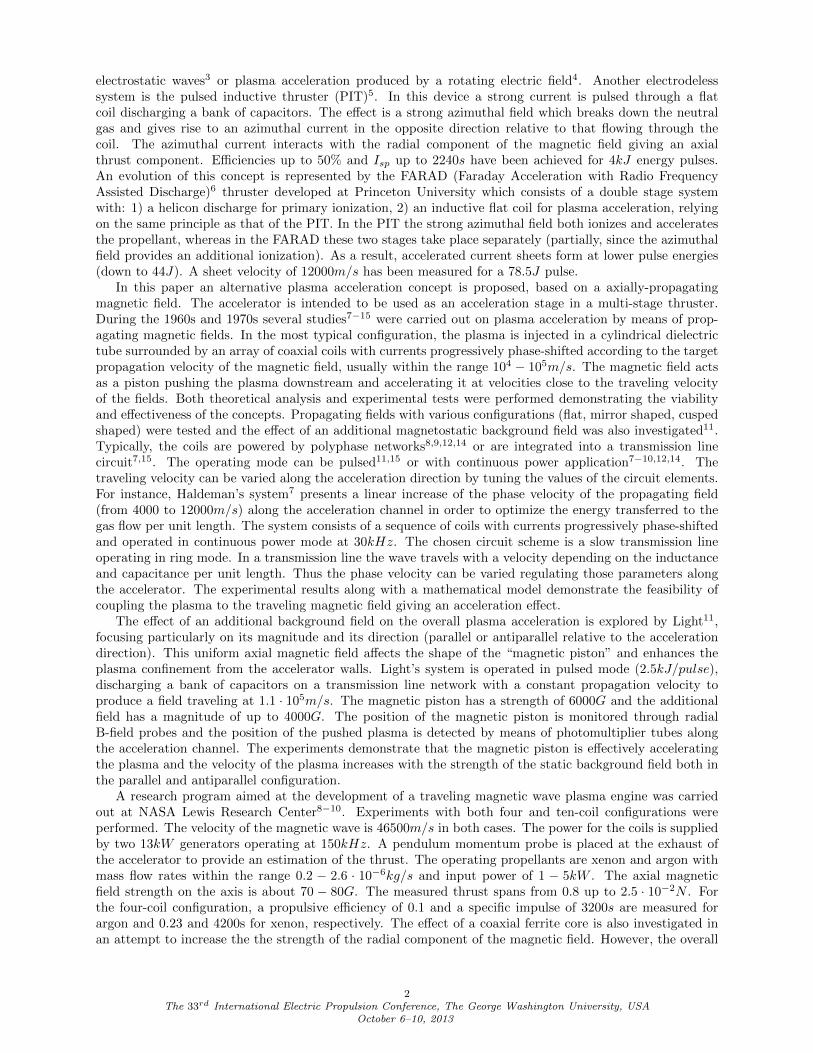
Traveling Magnetic Field Plasma Accelerator
IEPC-2013-86
Presented at the 33rd International Electric Propulsion Conference,The George Washington University, Washington, D.C., USA
October 6–10, 2013
Andrea Lucca Fabris∗
University of Padova, Padova, 35131, Italy
Mark A. Cappelli†
Stanford University, Stanford, CA 94305, USA
This paper describes a new dual-stage propulsion system based on a traveling magneticfield accelerator. The plasma produced in a primary ionization source is injected into thesecond stage where it is accelerated by means of a traveling magnetic field. An analysisthrough a particle-in-cell model highlights the role of electrons as carriers of the accelera-tion: the magnetic field directly acts on electrons creating a space charge at the magneticfront, where the resulting electric field also accelerates the ions.A prototype of the system has been built using a transmission line configuration for apreliminary experimental investigation. A microwave source is used as the primary ion-ization stage. The experimental setup includes current probes, magnetic field probes andtime-of-flight probes.
Nomenclature
Isp = specific impulse
PIT = Pulsed Inductive Thruster
FARAD = Faraday Acceleration with Radio Frequency Assisted Discharge
ECR = electrons cyclotron resonance
PIC = particle-in-cell
vt = propagation velocity of the traveling magnetic field
w = magnetic pulse width
τci = ion cyclotron period
τce = electron cyclotron period
I. Introduction
Electrodeless propulsion can be considered to be the next step in the technological evolution of spacepropulsion, since it is able to overcome some critical issues of consolidated propulsion systems, particularlythe erosion of electrodes and of the plasma channel wall. Acceleration grid erosion is a lifetime-limitingprocess in ion thrusters as is wall and cathode erosion in Hall thrusters1. The absence of the externalneutralizer is an attractive advantage that is offered by electrodeless propulsion systems. In the last decadesseveral research efforts have been dedicated to the development of new electrodeless propulsion concepts.Helicon thrusters2 are a promising technology, and research on helicon double-layer thrusters, exploringdifferent working regimes and performance, is ongoing in Australia, USA, Europe and Japan. Other moreunconventional solutions have been proposed in the last few years, such as ion acceleration with beating
∗PhD Candidate, Center of Studies and Activities for Space, [email protected].†Professor, Mechanical Engineering Department, Thermosciences group, [email protected].
1The 33rd International Electric Propulsion Conference, The George Washington University, USA
October 6–10, 2013Copyright c©2013 by Stanford University and University of Padova. Published by the Electric Rocket
Propulsion Society with permission.
electrostatic waves3 or plasma acceleration produced by a rotating electric field4. Another electrodelesssystem is the pulsed inductive thruster (PIT)5. In this device a strong current is pulsed through a flatcoil discharging a bank of capacitors. The effect is a strong azimuthal field which breaks down the neutralgas and gives rise to an azimuthal current in the opposite direction relative to that flowing through thecoil. The azimuthal current interacts with the radial component of the magnetic field giving an axialthrust component. Efficiencies up to 50% and Isp up to 2240s have been achieved for 4kJ energy pulses.An evolution of this concept is represented by the FARAD (Faraday Acceleration with Radio FrequencyAssisted Discharge)6 thruster developed at Princeton University which consists of a double stage systemwith: 1) a helicon discharge for primary ionization, 2) an inductive flat coil for plasma acceleration, relyingon the same principle as that of the PIT. In the PIT the strong azimuthal field both ionizes and acceleratesthe propellant, whereas in the FARAD these two stages take place separately (partially, since the azimuthalfield provides an additional ionization). As a result, accelerated current sheets form at lower pulse energies(down to 44J). A sheet velocity of 12000m/s has been measured for a 78.5J pulse.
In this paper an alternative plasma acceleration concept is proposed, based on a axially-propagatingmagnetic field. The accelerator is intended to be used as an acceleration stage in a multi-stage thruster.During the 1960s and 1970s several studies7−15 were carried out on plasma acceleration by means of prop-agating magnetic fields. In the most typical configuration, the plasma is injected in a cylindrical dielectrictube surrounded by an array of coaxial coils with currents progressively phase-shifted according to the targetpropagation velocity of the magnetic field, usually within the range 104 − 105m/s. The magnetic field actsas a piston pushing the plasma downstream and accelerating it at velocities close to the traveling velocityof the fields. Both theoretical analysis and experimental tests were performed demonstrating the viabilityand effectiveness of the concepts. Propagating fields with various configurations (flat, mirror shaped, cuspedshaped) were tested and the effect of an additional magnetostatic background field was also investigated11.Typically, the coils are powered by polyphase networks8,9,12,14 or are integrated into a transmission linecircuit7,15. The operating mode can be pulsed11,15 or with continuous power application7−10,12,14. Thetraveling velocity can be varied along the acceleration direction by tuning the values of the circuit elements.For instance, Haldeman’s system7 presents a linear increase of the phase velocity of the propagating field(from 4000 to 12000m/s) along the acceleration channel in order to optimize the energy transferred to thegas flow per unit length. The system consists of a sequence of coils with currents progressively phase-shiftedand operated in continuous power mode at 30kHz. The chosen circuit scheme is a slow transmission lineoperating in ring mode. In a transmission line the wave travels with a velocity depending on the inductanceand capacitance per unit length. Thus the phase velocity can be varied regulating those parameters alongthe accelerator. The experimental results along with a mathematical model demonstrate the feasibility ofcoupling the plasma to the traveling magnetic field giving an acceleration effect.
The effect of an additional background field on the overall plasma acceleration is explored by Light11,focusing particularly on its magnitude and its direction (parallel or antiparallel relative to the accelerationdirection). This uniform axial magnetic field affects the shape of the “magnetic piston” and enhances theplasma confinement from the accelerator walls. Light’s system is operated in pulsed mode (2.5kJ/pulse),discharging a bank of capacitors on a transmission line network with a constant propagation velocity toproduce a field traveling at 1.1 · 105m/s. The magnetic piston has a strength of 6000G and the additionalfield has a magnitude of up to 4000G. The position of the magnetic piston is monitored through radialB-field probes and the position of the pushed plasma is detected by means of photomultiplier tubes alongthe acceleration channel. The experiments demonstrate that the magnetic piston is effectively acceleratingthe plasma and the velocity of the plasma increases with the strength of the static background field both inthe parallel and antiparallel configuration.
A research program aimed at the development of a traveling magnetic wave plasma engine was carriedout at NASA Lewis Research Center8−10. Experiments with both four and ten-coil configurations wereperformed. The velocity of the magnetic wave is 46500m/s in both cases. The power for the coils is suppliedby two 13kW generators operating at 150kHz. A pendulum momentum probe is placed at the exhaust ofthe accelerator to provide an estimation of the thrust. The operating propellants are xenon and argon withmass flow rates within the range 0.2 − 2.6 · 10−6kg/s and input power of 1 − 5kW . The axial magneticfield strength on the axis is about 70 − 80G. The measured thrust spans from 0.8 up to 2.5 · 10−2N . Forthe four-coil configuration, a propulsive efficiency of 0.1 and a specific impulse of 3200s are measured forargon and 0.23 and 4200s for xenon, respectively. The effect of a coaxial ferrite core is also investigated inan attempt to increase the the strength of the radial component of the magnetic field. However, the overall
2The 33rd International Electric Propulsion Conference, The George Washington University, USA
October 6–10, 2013
effect is negative because of the drag and heat losses due to the core.An alternative configuration is proposed by Heflinger14, characterized by a rectangular duct with a
transverse geometry of the magnetic field which is perpendicular to the traveling direction. The magnetic fieldhas an intensity of about 500G, travels with a velocity of 54000m/s, and is generated by four coils poweredat 480kHz. The neutral gas is ionized by the electric field associated with the propagating magnetic field.Several propellants are tested. The best performance is obtained with helium, showing a specific impulse upto 6000s and an efficiency of about 0.5 for a power of 160kW and a mass flow of 5 · 10−5kg/s.
Despite the significant prior history and promising results of these traveling wave concepts, the systemdescribed here is still in a proof-of-concept phase. Particularly, its application to space propulsion in thelow power range (< 250W ) has never been explored. In this paper we present the results of our preliminarystudies on this traveling magnetic field plasma accelerator, focusing on the understanding of the basic physicsof the device through both analytical and numerical simulations of the plasma acceleration process. Alongwith the simulations, we have designed a system of coils able to produce a magnetic field traveling with avelocity of about 20000m/s. The system is based on a transmission line scheme operating either in continuouspower mode, employing a 300W − 280kHz generator, or in pulsed mode in the range 0.7 − 5J/pulse. Themass flow rate range we intend to explore is 1− 5 · 10−7kg/s. Preliminary operation of this design includes aneon plasma source driven by an Evanson microwave cavity16 operating at 2.45GHz as primary ionizationstage.
The paper is structured as follow: a basic description of a propulsion system based on a travelingmagnetic field accelerator is provided in section II; 1-D particle-in-cell code simulations aimed to providephysical insight of the acceleration mechanism are described in section III ; the preliminary experiment setup to characterize the accelerator’s operation is illustrated in section IV.
II. Thruster concept
The thruster consists of two-stages:
• a plasma source stage to ionize the neutral propellant flow;
• a plasma accelerator which exploits a traveling magnetic field to accelerate and eject the plasma,generating thrust.
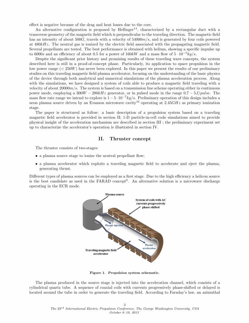
Different types of plasma sources can be employed as a first stage. Due to the high efficiency a helicon sourceis the best candidate as used in the FARAD concept6. An alternative solution is a microwave dischargeoperating in the ECR mode.
Figure 1. Propulsion system schematic.
The plasma produced in the source stage is injected into the acceleration channel, which consists of acylindrical quartz tube. A sequence of coaxial coils with currents progressively phase-shifted or delayed islocated around the tube in order to generate the traveling field. According to Faraday’s law, an azimuthal
3The 33rd International Electric Propulsion Conference, The George Washington University, USA
October 6–10, 2013
electric field is associated to the time-varying magnetic field, generating an azimuthal current in the plasma(Ohm’s law)13.
∇×E = −∂B
∂t(1)
J = σE (2)
This azimuthal current interacts with the radial component of the magnetic field giving a force term in theaxial direction.
f = J×B (3)
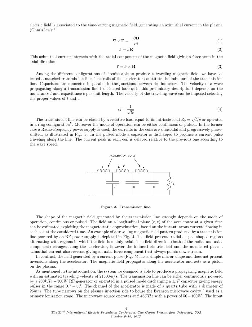
Among the different configurations of circuits able to produce a traveling magnetic field, we have se-lected a matched transmission line. The coils of the accelerator constitute the inductors of the transmissionline. Capacitors are connected in parallel in the junctions between the inductors. The velocity of a wavepropagating along a transmission line (considered lossless in this preliminary description) depends on theinductance l and capacitance c per unit length. The velocity of the traveling wave can be imposed selectingthe proper values of l and c.
vt =1√lc
(4)
The transmission line can be closed by a resistive load equal to its intrinsic load Z0 =√l/c or operated
in a ring configuration7. Moreover the mode of operation can be either continuous or pulsed. In the formercase a Radio-Frequency power supply is used, the currents in the coils are sinusoidal and progressively phase-shifted, as illustrated in Fig. 3. In the pulsed mode a capacitor is discharged to produce a current pulsetraveling along the line. The current peak in each coil is delayed relative to the previous one according tothe wave speed.
Figure 2. Transmission line.
The shape of the magnetic field generated by the transmission line strongly depends on the mode ofoperation, continuous or pulsed. The field on a longitudinal plane (r, z) of the accelerator at a given timecan be estimated exploiting the magnetostatic approximation, based on the instantaneous currents flowing ineach coil at the considered time. An example of a traveling magnetic field pattern produced by a transmissionline powered by an RF power supply is depicted in Fig. 4. The field presents radial cusped-shaped regionsalternating with regions in which the field is mainly axial. The field direction (both of the radial and axialcomponent) changes along the accelerator, however the induced electric field and the associated plasmaazimuthal current also reverse, giving an axial force component that always points downstream.
In contrast, the field generated by a current pulse (Fig. 5) has a simple mirror shape and does not presentinversions along the accelerator. The magnetic field propagates along the accelerator and acts as a pistonon the plasma.
As mentioned in the introduction, the system we designed is able to produce a propagating magnetic fieldwith an estimated traveling velocity of 21500m/s. The transmission line can be either continuously poweredby a 280kHz− 300W RF generator or operated in a pulsed mode discharging a 1µF capacitor giving energypulses in the range 0.7 − 5J . The channel of the accelerator is made of a quartz tube with a diameter of25mm. The tube narrows on the plasma injection side to house the Evanson microwave cavity16 used as aprimary ionization stage. The microwave source operates at 2.45GHz with a power of 50−100W . The input
4The 33rd International Electric Propulsion Conference, The George Washington University, USA
October 6–10, 2013
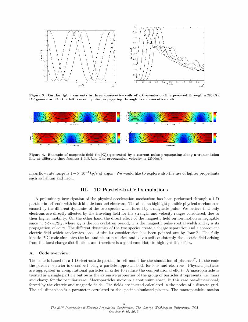
Figure 3. On the right: currents in three consecutive coils of a transmission line powered through a 280kHzRF generator. On the left: current pulse propagating through five consecutive coils.
Figure 4. Example of magnetic field (in [G]) generated by a current pulse propagating along a transmissionline at different time frames: 1, 3, 5, 7µs. The propagation velocity is 22500m/s.
mass flow rate range is 1− 5 · 10−7kg/s of argon. We would like to explore also the use of lighter propellantssuch as helium and neon.
III. 1D Particle-In-Cell simulations
A preliminary investigation of the physical acceleration mechanism has been performed through a 1-Dparticle-in-cell code with both kinetic ions and electrons. The aim is to highlight possible physical mechanismscaused by the different dynamics of the two species when forced by a magnetic pulse. We believe that onlyelectrons are directly affected by the traveling field for the strength and velocity ranges considered, due totheir higher mobility. On the other hand the direct effect of the magnetic field on ion motion is negligiblesince τci >> w/2vt, where τci is the ion cyclotron period, w is the magnetic pulse spatial width and vt is itspropagation velocity. The different dynamics of the two species create a charge separation and a consequentelectric field which accelerates ions. A similar consideration has been pointed out by Jones9. The fullykinetic PIC code simulates the ion and electron motion and solves self-consistently the electric field arisingfrom the local charge distribution, and therefore is a good candidate to highlight this effect.
A. Code overview.
The code is based on a 1-D electrostatic particle-in-cell model for the simulation of plasmas17. In the codethe plasma behavior is described using a particle approach both for ions and electrons. Physical particlesare aggregated in computational particles in order to reduce the computational effort. A macroparticle istreated as a single particle but owns the extensive properties of the group of particles it represents, i.e. massand charge for the peculiar case. Macroparticles move in a continuum space, in this case one-dimensional,forced by the electric and magnetic fields. The fields are instead calculated in the nodes of a discrete grid.The cell dimension is a parameter correlated to the specific simulated plasma. The macroparticles motion
5The 33rd International Electric Propulsion Conference, The George Washington University, USA
October 6–10, 2013
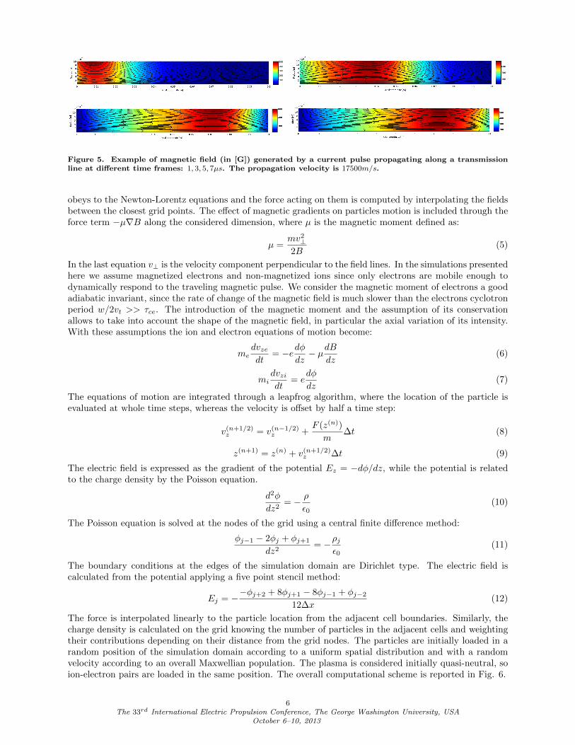
Figure 5. Example of magnetic field (in [G]) generated by a current pulse propagating along a transmissionline at different time frames: 1, 3, 5, 7µs. The propagation velocity is 17500m/s.
obeys to the Newton-Lorentz equations and the force acting on them is computed by interpolating the fieldsbetween the closest grid points. The effect of magnetic gradients on particles motion is included through theforce term −µ∇B along the considered dimension, where µ is the magnetic moment defined as:
µ =mv2⊥2B
(5)
In the last equation v⊥ is the velocity component perpendicular to the field lines. In the simulations presentedhere we assume magnetized electrons and non-magnetized ions since only electrons are mobile enough todynamically respond to the traveling magnetic pulse. We consider the magnetic moment of electrons a goodadiabatic invariant, since the rate of change of the magnetic field is much slower than the electrons cyclotronperiod w/2vt >> τce. The introduction of the magnetic moment and the assumption of its conservationallows to take into account the shape of the magnetic field, in particular the axial variation of its intensity.With these assumptions the ion and electron equations of motion become:
medvzedt
= −edφdz− µdB
dz(6)
midvzidt
= edφ
dz(7)
The equations of motion are integrated through a leapfrog algorithm, where the location of the particle isevaluated at whole time steps, whereas the velocity is offset by half a time step:
v(n+1/2)z = v(n−1/2)z +
F (z(n))
m∆t (8)
z(n+1) = z(n) + v(n+1/2)z ∆t (9)
The electric field is expressed as the gradient of the potential Ez = −dφ/dz, while the potential is relatedto the charge density by the Poisson equation.
d2φ
dz2= − ρ
ε0(10)
The Poisson equation is solved at the nodes of the grid using a central finite difference method:
φj−1 − 2φj + φj+1
dz2= −ρj
ε0(11)
The boundary conditions at the edges of the simulation domain are Dirichlet type. The electric field iscalculated from the potential applying a five point stencil method:
Ej = −−φj+2 + 8φj+1 − 8φj−1 + φj−212∆x
(12)
The force is interpolated linearly to the particle location from the adjacent cell boundaries. Similarly, thecharge density is calculated on the grid knowing the number of particles in the adjacent cells and weightingtheir contributions depending on their distance from the grid nodes. The particles are initially loaded in arandom position of the simulation domain according to a uniform spatial distribution and with a randomvelocity according to an overall Maxwellian population. The plasma is considered initially quasi-neutral, soion-electron pairs are loaded in the same position. The overall computational scheme is reported in Fig. 6.
6The 33rd International Electric Propulsion Conference, The George Washington University, USA
October 6–10, 2013
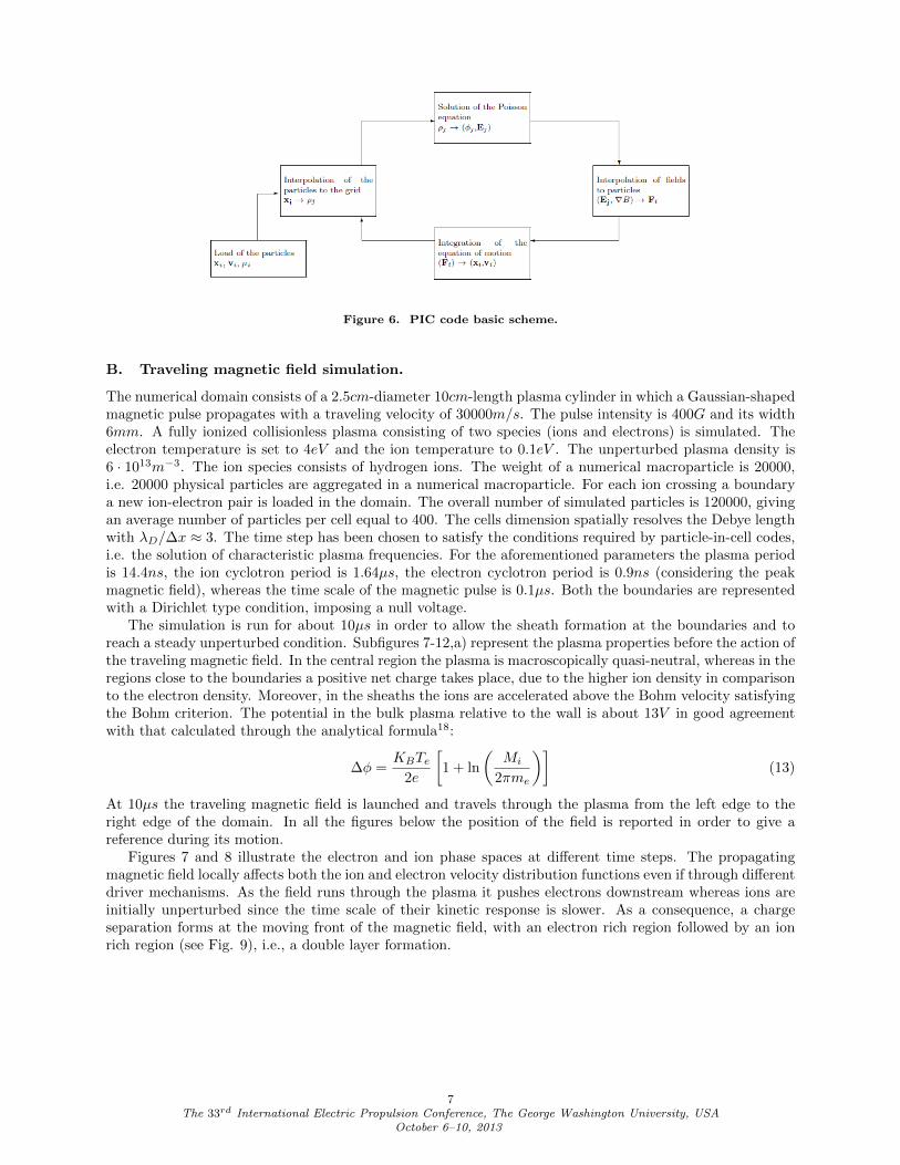
Figure 6. PIC code basic scheme.
B. Traveling magnetic field simulation.
The numerical domain consists of a 2.5cm-diameter 10cm-length plasma cylinder in which a Gaussian-shapedmagnetic pulse propagates with a traveling velocity of 30000m/s. The pulse intensity is 400G and its width6mm. A fully ionized collisionless plasma consisting of two species (ions and electrons) is simulated. Theelectron temperature is set to 4eV and the ion temperature to 0.1eV . The unperturbed plasma density is6 · 1013m−3. The ion species consists of hydrogen ions. The weight of a numerical macroparticle is 20000,i.e. 20000 physical particles are aggregated in a numerical macroparticle. For each ion crossing a boundarya new ion-electron pair is loaded in the domain. The overall number of simulated particles is 120000, givingan average number of particles per cell equal to 400. The cells dimension spatially resolves the Debye lengthwith λD/∆x ≈ 3. The time step has been chosen to satisfy the conditions required by particle-in-cell codes,i.e. the solution of characteristic plasma frequencies. For the aforementioned parameters the plasma periodis 14.4ns, the ion cyclotron period is 1.64µs, the electron cyclotron period is 0.9ns (considering the peakmagnetic field), whereas the time scale of the magnetic pulse is 0.1µs. Both the boundaries are representedwith a Dirichlet type condition, imposing a null voltage.
The simulation is run for about 10µs in order to allow the sheath formation at the boundaries and toreach a steady unperturbed condition. Subfigures 7-12,a) represent the plasma properties before the action ofthe traveling magnetic field. In the central region the plasma is macroscopically quasi-neutral, whereas in theregions close to the boundaries a positive net charge takes place, due to the higher ion density in comparisonto the electron density. Moreover, in the sheaths the ions are accelerated above the Bohm velocity satisfyingthe Bohm criterion. The potential in the bulk plasma relative to the wall is about 13V in good agreementwith that calculated through the analytical formula18:
∆φ =KBTe
2e
[1 + ln
(Mi
2πme
)](13)
At 10µs the traveling magnetic field is launched and travels through the plasma from the left edge to theright edge of the domain. In all the figures below the position of the field is reported in order to give areference during its motion.
Figures 7 and 8 illustrate the electron and ion phase spaces at different time steps. The propagatingmagnetic field locally affects both the ion and electron velocity distribution functions even if through differentdriver mechanisms. As the field runs through the plasma it pushes electrons downstream whereas ions areinitially unperturbed since the time scale of their kinetic response is slower. As a consequence, a chargeseparation forms at the moving front of the magnetic field, with an electron rich region followed by an ionrich region (see Fig. 9), i.e., a double layer formation.
7The 33rd International Electric Propulsion Conference, The George Washington University, USA
October 6–10, 2013
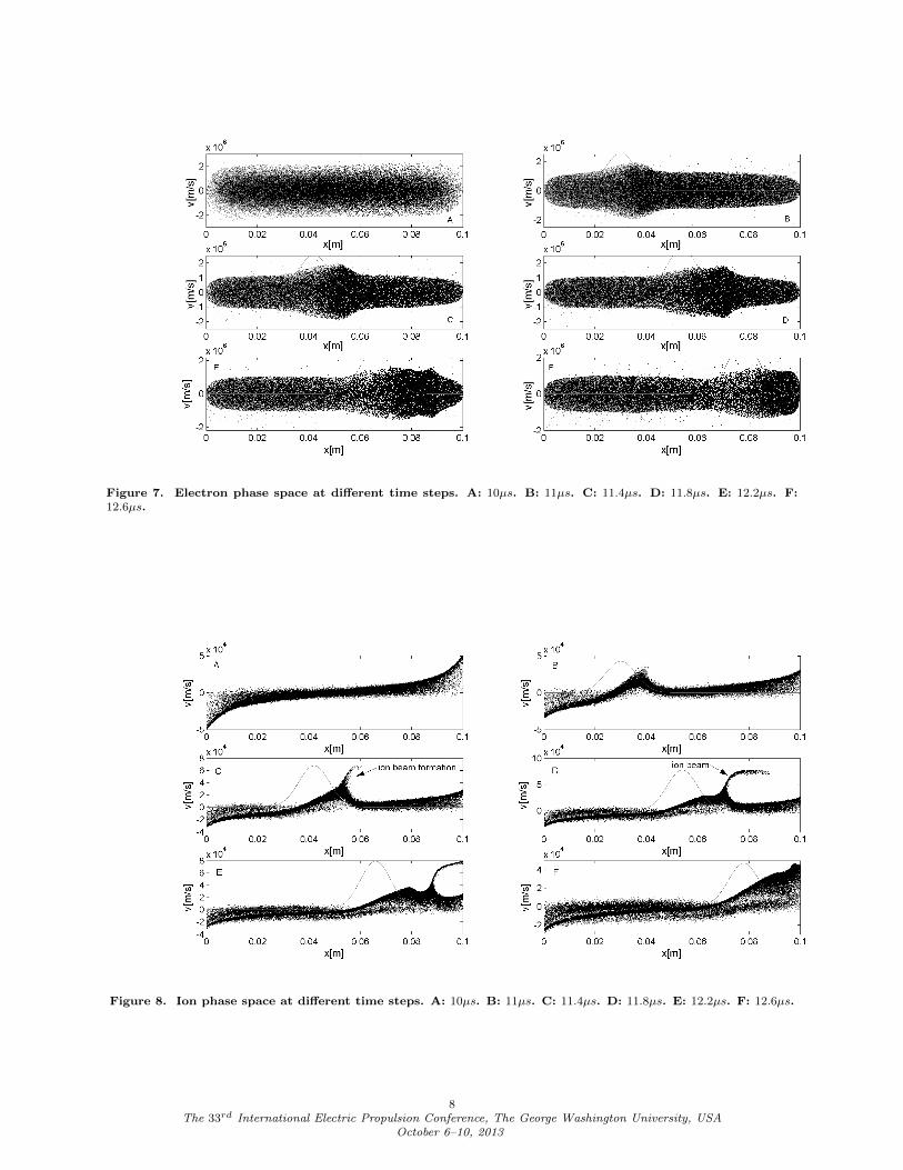
Figure 7. Electron phase space at different time steps. A: 10µs. B: 11µs. C: 11.4µs. D: 11.8µs. E: 12.2µs. F:12.6µs.
Figure 8. Ion phase space at different time steps. A: 10µs. B: 11µs. C: 11.4µs. D: 11.8µs. E: 12.2µs. F: 12.6µs.
8The 33rd International Electric Propulsion Conference, The George Washington University, USA
October 6–10, 2013
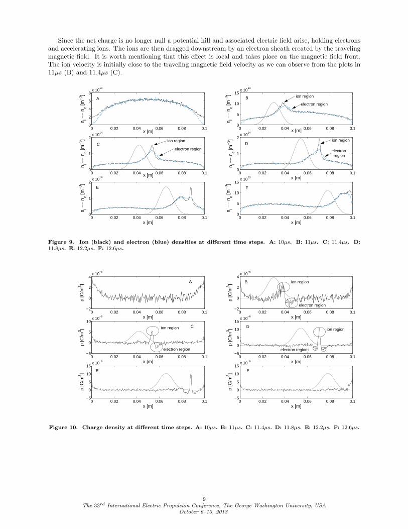
Since the net charge is no longer null a potential hill and associated electric field arise, holding electronsand accelerating ions. The ions are then dragged downstream by an electron sheath created by the travelingmagnetic field. It is worth mentioning that this effect is local and takes place on the magnetic field front.The ion velocity is initially close to the traveling magnetic field velocity as we can observe from the plots in11µs (B) and 11.4µs (C).
0 0.02 0.04 0.06 0.08 0.10
2
4
6
8x 10
13
x [m]
n i −−
ne [m
−3 ]
0 0.02 0.04 0.06 0.08 0.10
5
10
15x 10
13
x [m]
n i −−
ne [m
−3 ]
0 0.02 0.04 0.06 0.08 0.10
1
2x 10
14
x [m]
n i −−
ne [m
−3 ]
0 0.02 0.04 0.06 0.08 0.10
1
2x 10
14
x [m]
n i −−
ne [m
−3 ]
0 0.02 0.04 0.06 0.08 0.10
1
2x 10
14
x [m]
n i −−
ne [m
−3 ]
0 0.02 0.04 0.06 0.08 0.10
5
10
15x 10
13
x [m]n i −
− n
e [m−
3 ]
A B
C D
E F
ion region
electron region
ion region
electron region
ion region
electron region
Figure 9. Ion (black) and electron (blue) densities at different time steps. A: 10µs. B: 11µs. C: 11.4µs. D:11.8µs. E: 12.2µs. F: 12.6µs.
0 0.02 0.04 0.06 0.08 0.1−5
0
5
10x 10
−6
x [m]
ρ [C
/m3 ]
0 0.02 0.04 0.06 0.08 0.1−5
0
5
10
15x 10
−6
x [m]
ρ [C
/m3 ]
0 0.02 0.04 0.06 0.08 0.1−5
0
5
10
15x 10
−6
x [m]
ρ [C
/m3 ]
0 0.02 0.04 0.06 0.08 0.1−5
0
5
10
15x 10
−6
x [m]
ρ [C
/m3 ]
0 0.02 0.04 0.06 0.08 0.1−2
0
2
4x 10
−6
x [m]
ρ [C
/m3 ]
0 0.02 0.04 0.06 0.08 0.1−2
0
2
4x 10
−6
x [m]
ρ [C
/m3 ]
D
B
E F
A
C
ion region
electron region
electron region
ion region
electron regions
ion region
Figure 10. Charge density at different time steps. A: 10µs. B: 11µs. C: 11.4µs. D: 11.8µs. E: 12.2µs. F: 12.6µs.
9The 33rd International Electric Propulsion Conference, The George Washington University, USA
October 6–10, 2013
0 0.02 0.04 0.06 0.08 0.1
−2000
0
2000
x [m]
E [V
/m]
0 0.02 0.04 0.06 0.08 0.1
−1000
0
1000
x [m]
E [V
/m]
0 0.02 0.04 0.06 0.08 0.1−1000
0
1000
x [m]
E [V
/m]
0 0.02 0.04 0.06 0.08 0.1−1000
0
1000
x [m]
E [V
/m]
0 0.02 0.04 0.06 0.08 0.1−1000
0
1000
x [m]
E [V
/m]
0 0.02 0.04 0.06 0.08 0.1−1000
0
1000
2000
3000
x [m]
E [V
/m]
A B
C D
E F
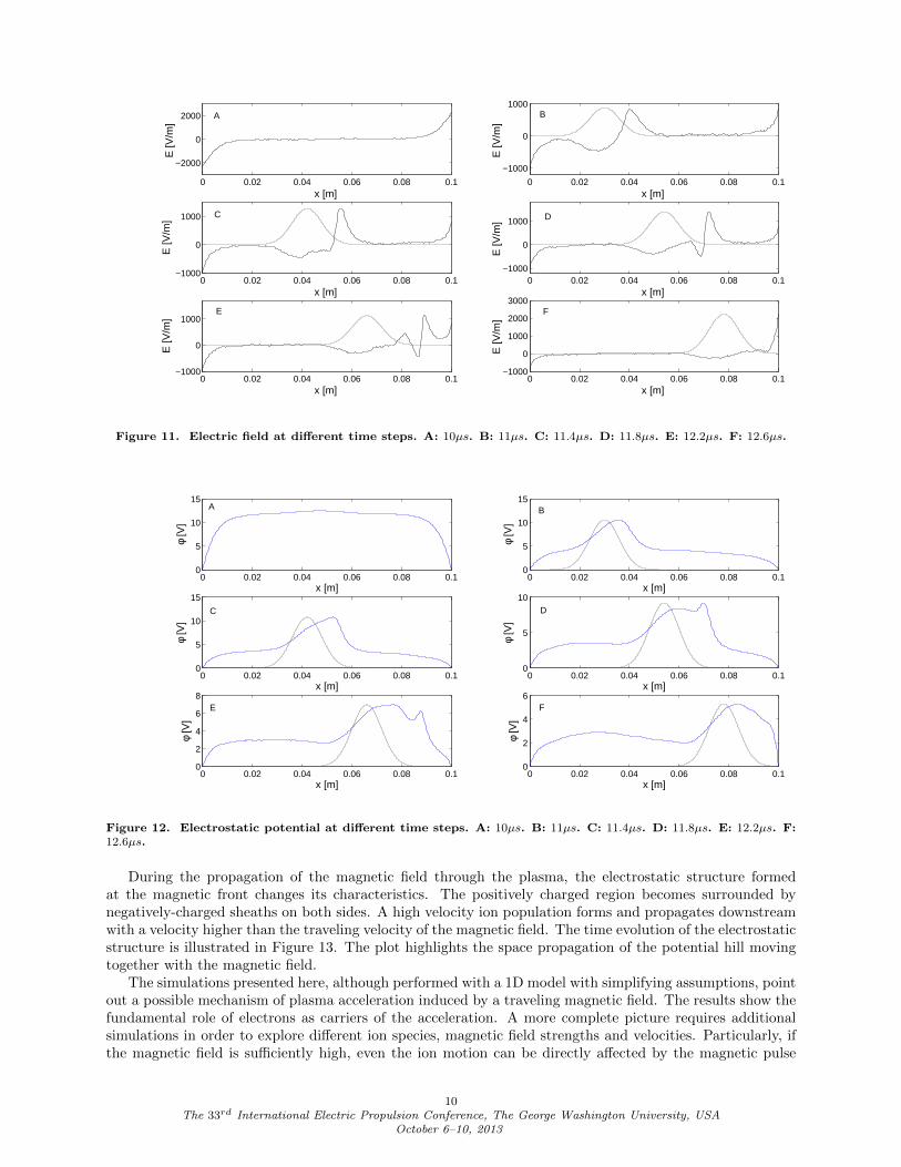
Figure 11. Electric field at different time steps. A: 10µs. B: 11µs. C: 11.4µs. D: 11.8µs. E: 12.2µs. F: 12.6µs.
0 0.02 0.04 0.06 0.08 0.10
5
10
15
x [m]
φ [V
]
0 0.02 0.04 0.06 0.08 0.10
5
10
15
x [m]
φ [V
]
0 0.02 0.04 0.06 0.08 0.10
5
10
15
x [m]
φ [V
]
0 0.02 0.04 0.06 0.08 0.10
5
10
x [m]
φ [V
]
0 0.02 0.04 0.06 0.08 0.10
2
4
6
8
x [m]
φ [V
]
0 0.02 0.04 0.06 0.08 0.10
2
4
6
x [m]
φ [V
]A B
C D
FE
Figure 12. Electrostatic potential at different time steps. A: 10µs. B: 11µs. C: 11.4µs. D: 11.8µs. E: 12.2µs. F:12.6µs.
During the propagation of the magnetic field through the plasma, the electrostatic structure formedat the magnetic front changes its characteristics. The positively charged region becomes surrounded bynegatively-charged sheaths on both sides. A high velocity ion population forms and propagates downstreamwith a velocity higher than the traveling velocity of the magnetic field. The time evolution of the electrostaticstructure is illustrated in Figure 13. The plot highlights the space propagation of the potential hill movingtogether with the magnetic field.
The simulations presented here, although performed with a 1D model with simplifying assumptions, pointout a possible mechanism of plasma acceleration induced by a traveling magnetic field. The results show thefundamental role of electrons as carriers of the acceleration. A more complete picture requires additionalsimulations in order to explore different ion species, magnetic field strengths and velocities. Particularly, ifthe magnetic field is sufficiently high, even the ion motion can be directly affected by the magnetic pulse
10The 33rd International Electric Propulsion Conference, The George Washington University, USA
October 6–10, 2013
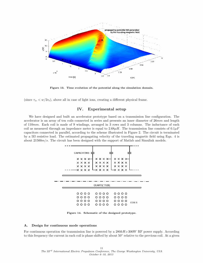
Figure 13. Time evolution of the potential along the simulation domain.
(since τic < w/2vt), above all in case of light ions, creating a different physical frame.
IV. Experimental setup
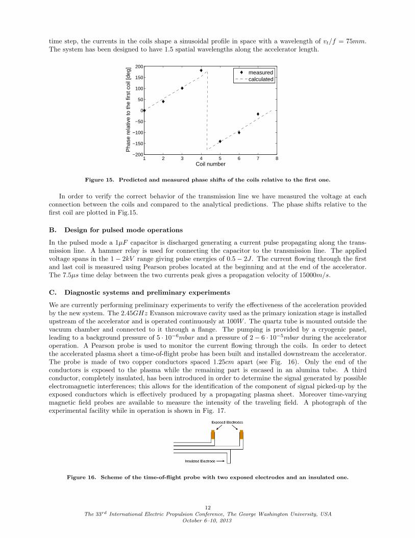
We have designed and built an accelerator prototype based on a transmission line configuration. Theaccelerator is an array of ten coils connected in series and presents an inner diameter of 26mm and lengthof 110mm. Each coil is made of 9 windings, arranged in 3 rows and 3 columns. The inductance of eachcoil as measured through an impedance meter is equal to 2.68µH. The transmission line consists of 0.1µFcapacitors connected in parallel, according to the scheme illustrated in Figure 2. The circuit is terminatedby a 5Ω resistive load. The estimated propagating velocity of the traveling magnetic field using Eqn. 4 isabout 21500m/s. The circuit has been designed with the support of Matlab and Simulink models.
Figure 14. Schematic of the designed prototype.
A. Design for continuous mode operations
For continuous operation the transmission line is powered by a 280kHz-300W RF power supply. Accordingto this frequency the current in each coil is phase shifted by about 50 relative to the previous coil. At a given
11The 33rd International Electric Propulsion Conference, The George Washington University, USA
October 6–10, 2013
time step, the currents in the coils shape a sinusoidal profile in space with a wavelength of vt/f = 75mm.The system has been designed to have 1.5 spatial wavelengths along the accelerator length.
1 2 3 4 5 6 7 8−200
−150
−100
−50
0
50
100
150
200
Coil number
Pha
se r
elat
ive
to th
e fir
st c
oil [
deg]
measuredcalculated
Figure 15. Predicted and measured phase shifts of the coils relative to the first one.
In order to verify the correct behavior of the transmission line we have measured the voltage at eachconnection between the coils and compared to the analytical predictions. The phase shifts relative to thefirst coil are plotted in Fig.15.
B. Design for pulsed mode operations
In the pulsed mode a 1µF capacitor is discharged generating a current pulse propagating along the trans-mission line. A hammer relay is used for connecting the capacitor to the transmission line. The appliedvoltage spans in the 1− 2kV range giving pulse energies of 0.5− 2J . The current flowing through the firstand last coil is measured using Pearson probes located at the beginning and at the end of the accelerator.The 7.5µs time delay between the two currents peak gives a propagation velocity of 15000m/s.
C. Diagnostic systems and preliminary experiments
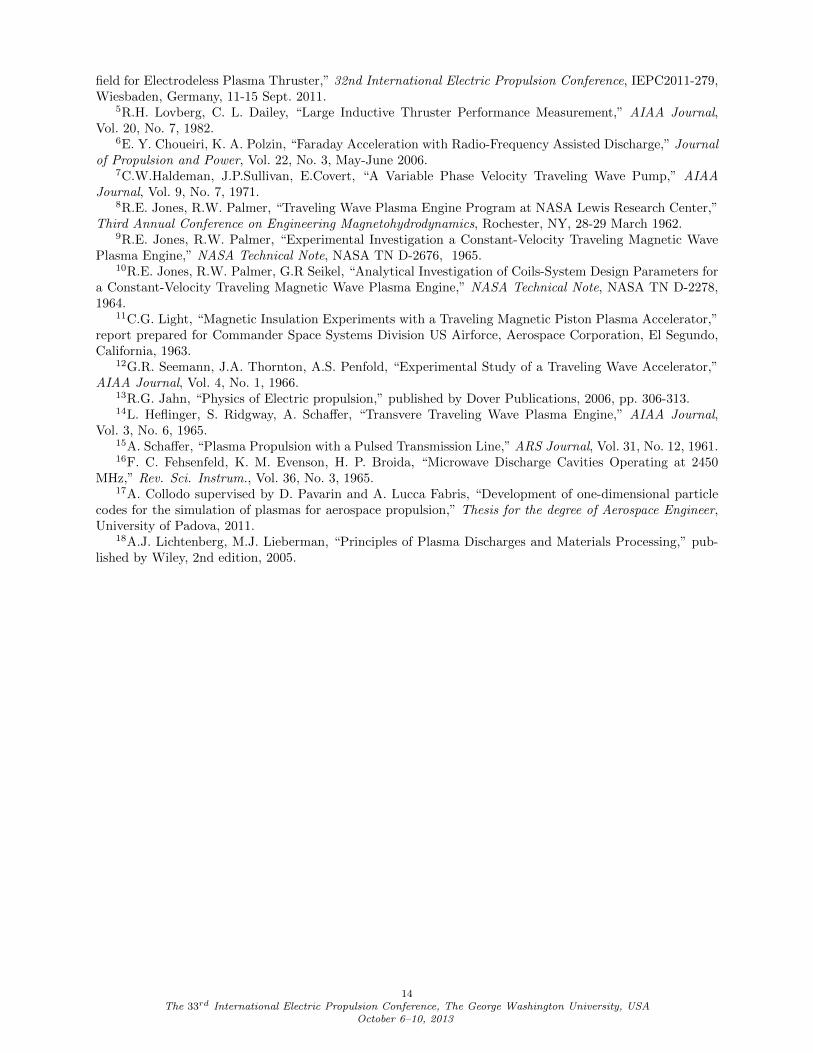
We are currently performing preliminary experiments to verify the effectiveness of the acceleration providedby the new system. The 2.45GHz Evanson microwave cavity used as the primary ionization stage is installedupstream of the accelerator and is operated continuously at 100W . The quartz tube is mounted outside thevacuum chamber and connected to it through a flange. The pumping is provided by a cryogenic panel,leading to a background pressure of 5 · 10−6mbar and a pressure of 2− 6 · 10−5mbar during the acceleratoroperation. A Pearson probe is used to monitor the current flowing through the coils. In order to detectthe accelerated plasma sheet a time-of-flight probe has been built and installed downstream the accelerator.The probe is made of two copper conductors spaced 1.25cm apart (see Fig. 16). Only the end of theconductors is exposed to the plasma while the remaining part is encased in an alumina tube. A thirdconductor, completely insulated, has been introduced in order to determine the signal generated by possibleelectromagnetic interferences; this allows for the identification of the component of signal picked-up by theexposed conductors which is effectively produced by a propagating plasma sheet. Moreover time-varyingmagnetic field probes are available to measure the intensity of the traveling field. A photograph of theexperimental facility while in operation is shown in Fig. 17.
Figure 16. Scheme of the time-of-flight probe with two exposed electrodes and an insulated one.
12The 33rd International Electric Propulsion Conference, The George Washington University, USA
October 6–10, 2013
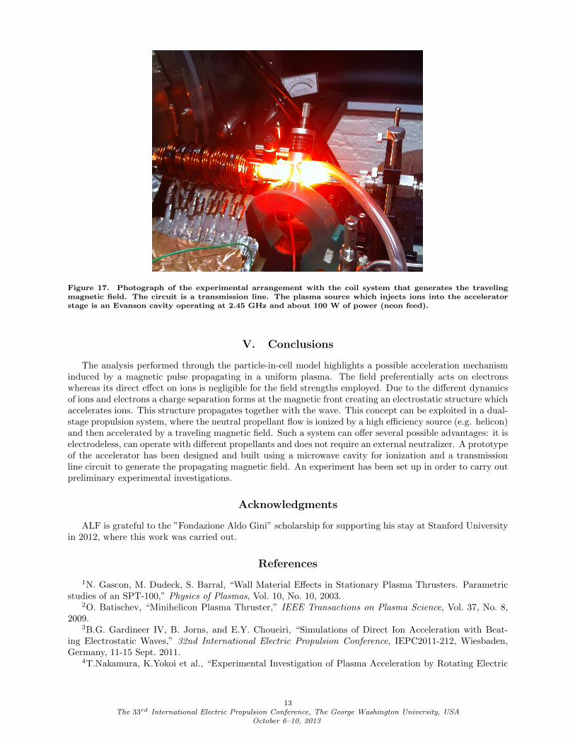
Figure 17. Photograph of the experimental arrangement with the coil system that generates the travelingmagnetic field. The circuit is a transmission line. The plasma source which injects ions into the acceleratorstage is an Evanson cavity operating at 2.45 GHz and about 100 W of power (neon feed).
V. Conclusions
The analysis performed through the particle-in-cell model highlights a possible acceleration mechanisminduced by a magnetic pulse propagating in a uniform plasma. The field preferentially acts on electronswhereas its direct effect on ions is negligible for the field strengths employed. Due to the different dynamicsof ions and electrons a charge separation forms at the magnetic front creating an electrostatic structure whichaccelerates ions. This structure propagates together with the wave. This concept can be exploited in a dual-stage propulsion system, where the neutral propellant flow is ionized by a high efficiency source (e.g. helicon)and then accelerated by a traveling magnetic field. Such a system can offer several possible advantages: it iselectrodeless, can operate with different propellants and does not require an external neutralizer. A prototypeof the accelerator has been designed and built using a microwave cavity for ionization and a transmissionline circuit to generate the propagating magnetic field. An experiment has been set up in order to carry outpreliminary experimental investigations.
Acknowledgments
ALF is grateful to the ”Fondazione Aldo Gini” scholarship for supporting his stay at Stanford Universityin 2012, where this work was carried out.
References
1N. Gascon, M. Dudeck, S. Barral, “Wall Material Effects in Stationary Plasma Thrusters. Parametricstudies of an SPT-100,” Physics of Plasmas, Vol. 10, No. 10, 2003.
2O. Batischev, “Minihelicon Plasma Thruster,” IEEE Transactions on Plasma Science, Vol. 37, No. 8,2009.
3B.G. Gardineer IV, B. Jorns, and E.Y. Choueiri, “Simulations of Direct Ion Acceleration with Beat-ing Electrostatic Waves,” 32nd International Electric Propulsion Conference, IEPC2011-212, Wiesbaden,Germany, 11-15 Sept. 2011.
4T.Nakamura, K.Yokoi et al., “Experimental Investigation of Plasma Acceleration by Rotating Electric
13The 33rd International Electric Propulsion Conference, The George Washington University, USA
October 6–10, 2013
field for Electrodeless Plasma Thruster,” 32nd International Electric Propulsion Conference, IEPC2011-279,Wiesbaden, Germany, 11-15 Sept. 2011.
5R.H. Lovberg, C. L. Dailey, “Large Inductive Thruster Performance Measurement,” AIAA Journal,Vol. 20, No. 7, 1982.
6E. Y. Choueiri, K. A. Polzin, “Faraday Acceleration with Radio-Frequency Assisted Discharge,” Journalof Propulsion and Power, Vol. 22, No. 3, May-June 2006.
7C.W.Haldeman, J.P.Sullivan, E.Covert, “A Variable Phase Velocity Traveling Wave Pump,” AIAAJournal, Vol. 9, No. 7, 1971.
8R.E. Jones, R.W. Palmer, “Traveling Wave Plasma Engine Program at NASA Lewis Research Center,”Third Annual Conference on Engineering Magnetohydrodynamics, Rochester, NY, 28-29 March 1962.
9R.E. Jones, R.W. Palmer, “Experimental Investigation a Constant-Velocity Traveling Magnetic WavePlasma Engine,” NASA Technical Note, NASA TN D-2676, 1965.
10R.E. Jones, R.W. Palmer, G.R Seikel, “Analytical Investigation of Coils-System Design Parameters fora Constant-Velocity Traveling Magnetic Wave Plasma Engine,” NASA Technical Note, NASA TN D-2278,1964.
11C.G. Light, “Magnetic Insulation Experiments with a Traveling Magnetic Piston Plasma Accelerator,”report prepared for Commander Space Systems Division US Airforce, Aerospace Corporation, El Segundo,California, 1963.
12G.R. Seemann, J.A. Thornton, A.S. Penfold, “Experimental Study of a Traveling Wave Accelerator,”AIAA Journal, Vol. 4, No. 1, 1966.
13R.G. Jahn, “Physics of Electric propulsion,” published by Dover Publications, 2006, pp. 306-313.14L. Heflinger, S. Ridgway, A. Schaffer, “Transvere Traveling Wave Plasma Engine,” AIAA Journal,
Vol. 3, No. 6, 1965.15A. Schaffer, “Plasma Propulsion with a Pulsed Transmission Line,” ARS Journal, Vol. 31, No. 12, 1961.16F. C. Fehsenfeld, K. M. Evenson, H. P. Broida, “Microwave Discharge Cavities Operating at 2450
MHz,” Rev. Sci. Instrum., Vol. 36, No. 3, 1965.17A. Collodo supervised by D. Pavarin and A. Lucca Fabris, “Development of one-dimensional particle
codes for the simulation of plasmas for aerospace propulsion,” Thesis for the degree of Aerospace Engineer,University of Padova, 2011.
18A.J. Lichtenberg, M.J. Lieberman, “Principles of Plasma Discharges and Materials Processing,” pub-lished by Wiley, 2nd edition, 2005.
14The 33rd International Electric Propulsion Conference, The George Washington University, USA
October 6–10, 2013