Embed Size (px)
Citation preview
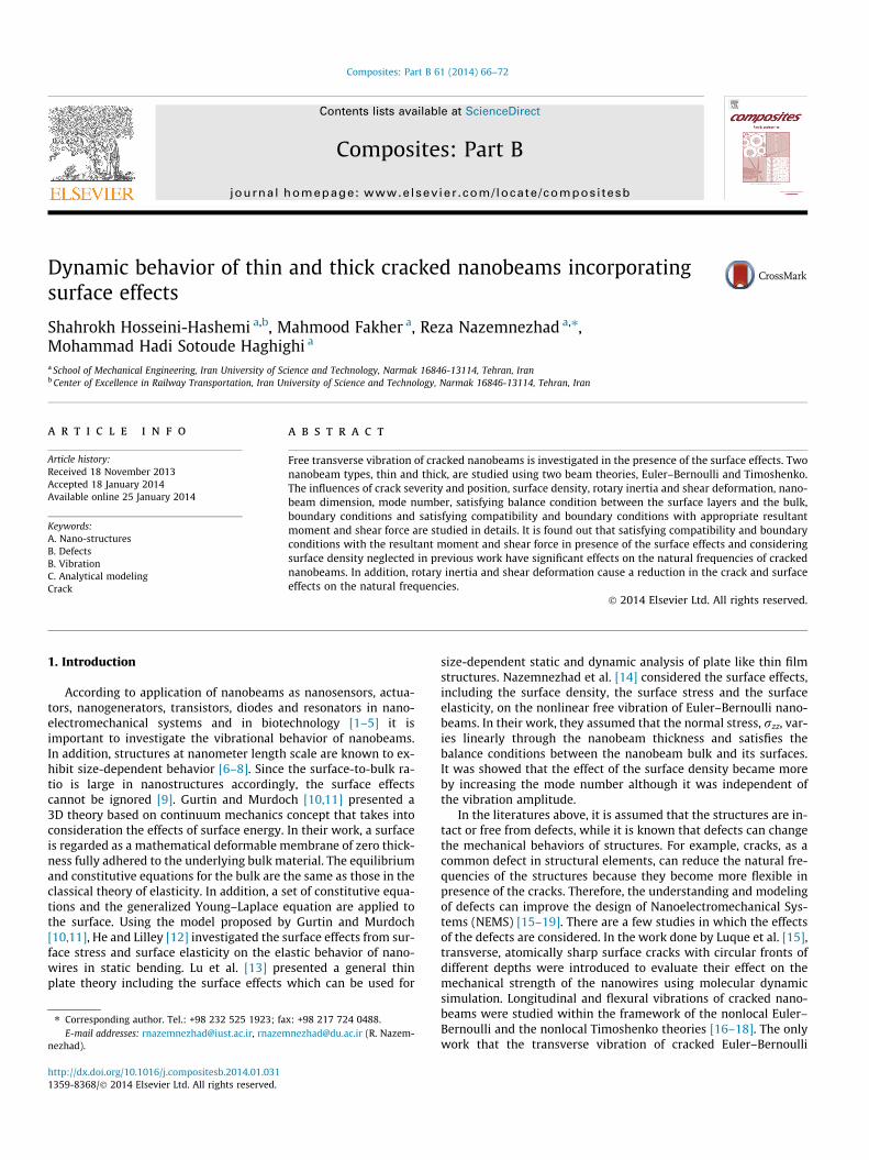
Composites: Part B 61 (2014) 66–72
Contents lists available at ScienceDirect
Composites: Part B
journal homepage: www.elsevier .com/locate /composi tesb
Dynamic behavior of thin and thick cracked nanobeams incorporatingsurface effects
http://dx.doi.org/10.1016/j.compositesb.2014.01.0311359-8368/� 2014 Elsevier Ltd. All rights reserved.
⇑ Corresponding author. Tel.: +98 232 525 1923; fax: +98 217 724 0488.E-mail addresses: [email protected], [email protected] (R. Nazem-
nezhad).
Shahrokh Hosseini-Hashemi a,b, Mahmood Fakher a, Reza Nazemnezhad a,⇑,Mohammad Hadi Sotoude Haghighi a
a School of Mechanical Engineering, Iran University of Science and Technology, Narmak 16846-13114, Tehran, Iranb Center of Excellence in Railway Transportation, Iran University of Science and Technology, Narmak 16846-13114, Tehran, Iran
a r t i c l e i n f o
Article history:Received 18 November 2013Accepted 18 January 2014Available online 25 January 2014
Keywords:A. Nano-structuresB. DefectsB. VibrationC. Analytical modelingCrack
a b s t r a c t
Free transverse vibration of cracked nanobeams is investigated in the presence of the surface effects. Twonanobeam types, thin and thick, are studied using two beam theories, Euler–Bernoulli and Timoshenko.The influences of crack severity and position, surface density, rotary inertia and shear deformation, nano-beam dimension, mode number, satisfying balance condition between the surface layers and the bulk,boundary conditions and satisfying compatibility and boundary conditions with appropriate resultantmoment and shear force are studied in details. It is found out that satisfying compatibility and boundaryconditions with the resultant moment and shear force in presence of the surface effects and consideringsurface density neglected in previous work have significant effects on the natural frequencies of crackednanobeams. In addition, rotary inertia and shear deformation cause a reduction in the crack and surfaceeffects on the natural frequencies.
� 2014 Elsevier Ltd. All rights reserved.
1. Introduction size-dependent static and dynamic analysis of plate like thin film
According to application of nanobeams as nanosensors, actua-tors, nanogenerators, transistors, diodes and resonators in nano-electromechanical systems and in biotechnology [1–5] it isimportant to investigate the vibrational behavior of nanobeams.In addition, structures at nanometer length scale are known to ex-hibit size-dependent behavior [6–8]. Since the surface-to-bulk ra-tio is large in nanostructures accordingly, the surface effectscannot be ignored [9]. Gurtin and Murdoch [10,11] presented a3D theory based on continuum mechanics concept that takes intoconsideration the effects of surface energy. In their work, a surfaceis regarded as a mathematical deformable membrane of zero thick-ness fully adhered to the underlying bulk material. The equilibriumand constitutive equations for the bulk are the same as those in theclassical theory of elasticity. In addition, a set of constitutive equa-tions and the generalized Young–Laplace equation are applied tothe surface. Using the model proposed by Gurtin and Murdoch[10,11], He and Lilley [12] investigated the surface effects from sur-face stress and surface elasticity on the elastic behavior of nano-wires in static bending. Lu et al. [13] presented a general thinplate theory including the surface effects which can be used for
structures. Nazemnezhad et al. [14] considered the surface effects,including the surface density, the surface stress and the surfaceelasticity, on the nonlinear free vibration of Euler–Bernoulli nano-beams. In their work, they assumed that the normal stress, rzz, var-ies linearly through the nanobeam thickness and satisfies thebalance conditions between the nanobeam bulk and its surfaces.It was showed that the effect of the surface density became moreby increasing the mode number although it was independent ofthe vibration amplitude.
In the literatures above, it is assumed that the structures are in-tact or free from defects, while it is known that defects can changethe mechanical behaviors of structures. For example, cracks, as acommon defect in structural elements, can reduce the natural fre-quencies of the structures because they become more flexible inpresence of the cracks. Therefore, the understanding and modelingof defects can improve the design of Nanoelectromechanical Sys-tems (NEMS) [15–19]. There are a few studies in which the effectsof the defects are considered. In the work done by Luque et al. [15],transverse, atomically sharp surface cracks with circular fronts ofdifferent depths were introduced to evaluate their effect on themechanical strength of the nanowires using molecular dynamicsimulation. Longitudinal and flexural vibrations of cracked nano-beams were studied within the framework of the nonlocal Euler–Bernoulli and the nonlocal Timoshenko theories [16–18]. The onlywork that the transverse vibration of cracked Euler–Bernoulli
S. Hosseini-Hashemi et al. / Composites: Part B 61 (2014) 66–72 67
nanobeams was studied in presence of the surface effects was theone done by Hasheminejad et al. [19]. They considered the influ-ences of the surface elasticity and surface tension. Moreover, thebalance condition between the surface layers and the nanobeambulk was not satisfied and the surface density was neglected.
From literature, it is understood that the effects of the rotaryinertia and the shear deformation on the free vibrations of crackednanobeams are not examined when the surface effects are in-cluded. Also, the influences of satisfying the balance conditionand the surface density effect are not reported. Therefore, in thisarticle, the influences of three parameters, including the rotaryinertia and shear deformation, the surface density and satisfyingthe balance condition, on the free transverse vibration of crackednanobeams are investigated. To this end, governing equations ofthe cracked nanobeams incorporating the surface effects areobtained based on the Timoshenko and Euler–Bernoulli theories.A linear variation for the normal stress, rzz, is assumed in orderto satisfy the balance condition. The influences of crack position,crack depth, mode number and dimension of the nanobeam onthe natural frequencies of the simply-simply and clamp–clampnanobeams are examined.
2. Problem formulation
In this section, the governing equations of a nanobeam in pres-ence of the surface effects are derived. To this end, we consider ananobeam with rectangular cross section with length L (0 6 x 6 L),width b (�0.5b 6 y 6 0.5b) and thickness, H = 2h (�h 6 z 6 +h).
2.1. Surface effects
At the micro/nanoscale, the fraction of energy stored in the sur-faces becomes comparable with that in the bulk, because of the rela-tively high ratio of surface area to volume of nanoscale structures;therefore the surface and the induced surface forces cannot beignored. The constitutive relations of the surface layers, S+ (upper sur-face) and S� (Lower surface), given by Gurtin and Murdoch [10,11] as
s�ab ¼ s�0 dab þ ðl�0 � s�0 Þðu�a;b þ u�b;aÞ þ ðk�0 þ s�0 Þu�c;cdab
þ s�0 u�a;b; s�a3
¼ s�0 u�3;a ð1Þ
where s�0 are residual surface tensions under unconstrained condi-tions, k�0 and l�0 are the surface Lame constants on the surfaces S+
and S� which can be determined from atomistic calculations [20],dab is the Kronecker delta and u�a are the displacement componentsof the surfaces S+ and S�. If the top and bottom layers have the samematerial properties, the stress–strain relations of the surface layers,i.e. Eq. (1), can be reduced to the following relation for nanobeams
sxx ¼ s0 þ Esux;x; Es ¼ 2l0 þ k0; snx ¼ s0un;x ð2Þ
where n denotes the outward unit normal. The equilibrium rela-tions for the surface layers can be expressed in terms of the surfaceand bulk stress components as
sia;a � Ti ¼ q0€usi ð3Þ
where i = x, n, t; a = x, t; q0 denotes surface density; T is the contacttractions on the contact surface between the bulk material and thesurface layer; t is the tangent unit vector; and €us
i denotes the accel-eration of surface layers in the i-direction.
In the classical beam theory, the stress component, rzz, is ne-glected. However, rzz must be considered to satisfy the surfaceequilibrium equations of the Gurtin–Murdoch model. It is assumedthat bulk stress, rzz, varies linearly through the nanobeam thick-ness as follow
rzz ¼12ðrþzz þ r�zzÞ þ
zHðrþzz � r�zzÞ ð4Þ
By considering Eq. (2) and satisfying Eq. (3) both of rþzz and r�zz
are obtained. Therefore, Eq. (4) can be rewritten as
rzz ¼12ðs0uþz;xx � s0u�z;xx � q0€uþz þ q0€u�z Þ
þ zHðs0uþz;xx þ s0u�z;xx � q0€uþz � q0€u�z Þ ð5Þ
2.2. Governing equations of nanobeams
2.2.1. Timoshenko beam theoryThe bending moment and vertical force equilibrium equations
including rotary inertia, shear deformation and surface effectscan be expressed as follow [21]
dMdxþZ
ssxx;xzds� Q ¼
ZAq€uxzdAþ
Zsq0€us
xzds ð6Þ
dQdxþZ
ssnx;xnzds ¼
ZAq€uzdAþ
Zsq0€us
nnzds ð7Þ
where sxx and snx are nonzero membrane stresses due to surface en-ergy; q is the bulk density. Q and M are the stress resultants definedas
Q ¼Z
ArxzdA; M ¼
ZArxxzdA ð8Þ
Bulk stress–strain relations of the nanobeam can be expressedasrxx ¼ Eexx þ mrzz; rxz ¼ 2Gexz ð9Þ
where E is the elastic modulus, m is the Poisson’s ratio and G is theshear modulus. Defining the displacement fields as Timoshenkobeam theoryux ¼ z/ðx; tÞ; uz ¼ wðx; tÞ ð10Þ
where /(x, t) and w (x, t) denote the rotation of cross section andvertical displacement of mid-plane at time t, respectively. So, thenonzero strains are given by
exx ¼@ux
@x¼ z
@/ðx; tÞ@x
; exz ¼12
@ux
@zþ @uz
@x
� �
¼ 12
/ðx; tÞ þ @wðx; tÞ@x
� �ð11Þ
Substituting Eq. (10) into Eq. (2) we have
sxx ¼ s0 þ zEs @/@x
; snx ¼ s0@w@x
nz; s�nx ¼ �s0@w@x
ð12Þ
The relative bulk stresses can be presented by substituting Eq.(12) into Eq. (5) and then into Eq. (9)
rzz ¼2zH
s0@2w@x2 � q0 €w
!; rxx
¼ E z@/@x
� �þ 2tz
Hs0@2w@x2 � q0 €w
!; rxz ¼ Gk
@w@xþ /
� �ð13Þ
where k denotes shear correction coefficient. By substituting Eq.(13) into Eq. (8) and considering Eq. (12), Eqs. (6) and (7) can berewritten as follow
ðqAþ 2bq0Þ@2w@t2 ¼ kGA
@/@xþ @
2w@x2
!þ 2bs0
@2w@x2 ð14Þ
ðqI þ q0I�Þ @2/
@t2 þ kGA /þ @w@x
� �
¼ ðEI þ EsI�Þ @2/@x2 þ
2ms0IH
@3w@x3 �
2mq0IH
@3w@x@t2 ð15Þ
68 S. Hosseini-Hashemi et al. / Composites: Part B 61 (2014) 66–72
where I⁄ = 2bh2 + 4h3/3 for the rectangular cross section. Also, theresultant moment and shear force of a nanobeam cross section,including surface layers contributions, are given by
MT ¼ ðEI þ EsI�Þ @/@xþ 2ts0I
H@2w@x2 �
2tq0IH
@2w@t2 ð16Þ
Q T ¼ kGA /þ @w@x
� �þ 2bs0
@w@x
ð17Þ
It is seen from Eqs. (16) and (17) that the resultant moment andshear force of a nanobeam in presence of the surface effects are dif-ferent from the classical ones.
2.2.2. Euler–Bernoulli beam theoryIn the case of Euler–Bernoulli beam theory, the rotational dis-
placement of the cross section is related to the slope of the verticaldeflection and the shear deformation effect is ignored, i.e. / = �ow/ox [22,23]. In addition, the rotational inertia effect is neglected. So,the governing equation of Euler–Bernoulli nanobeam in presenceof the surface effects can be obtained from Eqs. (14) and (15) as
EI þ EsI� � 2ts0IH
� �@4w@x4 � 2bs0
@2w@x2 þ
2tq0IH
@4w@x2@t2
¼ �ðqAþ 2bq0Þ@2w@t2 ð18Þ
Moreover, the relative resultant moment and shear force of theEuler–Bernoulli nanobeam cross section are presented as follow
ME ¼ � EI þ EsI� � 2ms0IH
� �@2w@x2 �
2mq0IH
@2w@t2 ð19Þ
Q E ¼ � EI þ EsI� � 2ms0IH
� �@3w@x3 �
2mq0IH
@3w@x@t2 þ 2bs0
@w@x
ð20Þ
It is re-confirmed here that the resultant moment and shearforce of the nanobeam in presence of the surface effects are differ-ent from the classical ones.
3. Free vibration of cracked nanobeams
In this section, we consider that a crack is located at distance L*
from the left end of the nanobeam. Let lc = L*/L. Moreover, by con-sidering Dh and Du as the rotated angle by the rotational spring(see Fig. 1) and the relative horizontal displacement at x = L*, thefollowing relations can be defined [16]
Dh ¼ kMM@/@x þ kMN
@ux@x
Du ¼ kNN@ux@x þ kNM
@/@x
ð21Þ
where KMM, KNN, KMN and KNM are the flexibility constants. Since inthis work the transverse free vibration is investigated, and hence nolongitudinal displacement is considered, and the crossover
Fig. 1. Schematic of the problem.
flexibility constants (KMN and KNM) are assumed to be small enough[16], accordingly only the flexibility constant related to the bendingmoment (KMM) should be considered, so
Dh ¼ kMM@/@x
����x¼L�¼ KL
@/@x
����x¼L�
; K ¼ kMM
Lð22Þ
where K is the crack severity. In the case of classical cracked beams,the additional strain energy due to the crack can be calculated fromthe fracture mechanics theory. In the case of nanobeams; it must beobtained from either ab initio studies or molecular dynamicscalculations.
3.1. Timoshenko cracked nanobeam
To solve the governing equations of a Timoshenko crackednanobeam in presence of the surface effects, we consider / (x, t)and w (x, t) as follow
wðx; tÞ ¼WðxÞeikt
/ðx; tÞ ¼ UðxÞeikt
�ð23Þ
where k denotes the vibration frequency. By considering Eq. (23),the solution of Eqs. (14) and (15) can be expressed as
WjðxÞ ¼ c1j sin n1xþ c2j cos n1xþ c3j sinh n2xþc4j cosh n2x; j ¼ 1;2
UjðxÞ ¼ kac2j sin n1x� kac1j cos n1xþ kbc4j sinh n2xþkbc3j cosh n2x; j ¼ 1;2
ð24Þ
Eq. (24) with j equals 1 and 2 is the free vibration solution of thesegment one and two, respectively. Also,
n1 ¼g1þ
ffiffiffiffiffiffiffiffiffiffiffiffig2
1�4g2
p2
� �12
; n2 ¼�g1þ
ffiffiffiffiffiffiffiffiffiffiffiffig2
1�4g2
p2
� �12
g1 ¼ K1=K2;g2 ¼ K3=K2
ð25Þ
where
K1¼ k4k5þk2k6�k1k7�k25; K2¼ k3k5�k2k7; K3¼ k1k6
k1¼�ðqIþq0I�Þk2þkGA; k2¼�ðEIþEsI�Þ; k3¼2ms0I=Hk4¼2tq0Ik2=H; k5¼ kGA; k6¼ðqAþ2bq0Þk
2; k7¼�kGA�2bs0
ð26Þ
and
ka ¼ðk5 � k4Þn1 þ k3n
31
k1 � k2n21
; kb ¼k3n
32 � ðk5 � k4Þn2
k1 þ k2n22
ð27Þ
To obtain the natural frequencies of the cracked Timoshenkonanobeams, it is essential to satisfy following boundary conditions
W1ð0Þ ¼ MT1ð0Þ ¼ 0; W2ðLÞ ¼ MT
2ðLÞ ¼ 0; Simply—SimplyW1ð0Þ ¼ U1ð0Þ ¼ 0; W2ðLÞ ¼ U2ðLÞ ¼ 0; Clamped—Clamped
ð28Þ
Also, following compatibility conditions should be consideredin the crack position
MT1ðL
�Þ ¼ MT2ðL
�Þ; Q T1ðL
�Þ ¼ Q T2ðL
�ÞW1ðL�Þ ¼W2ðL�Þ; U2ðL�Þ �U1ðL�Þ ¼ KL @U1
@x jx¼L�ð29Þ
It can be seen that there are eight equations and eight unknowncoefficients. Accordingly, for the nontrivial solution, the determi-nant of the coefficients matrix must be zero.
3.2. Euler–Bernoulli cracked nanobeam
In this section we let the following relation to solve governingequation of the Euler–Bernoulli cracked nanobeam
wðx; tÞ ¼WðxÞeikt ð30Þ
S. Hosseini-Hashemi et al. / Composites: Part B 61 (2014) 66–72 69
By considering Eq. (30), the solution of Eq. (18) can be expressedas
WjðxÞ ¼ c1j sin n1xþ c2j cos n1xþ c3j sinh n2xþ c4j cosh n2x;
j ¼ 1;2 ð31Þ
where W(x) = W1(x) for 0 6 x 6 L⁄ and W(x) = W2 (x) for L⁄ 6 x6 L and
n1 ¼�g1þ
ffiffiffiffiffiffiffiffiffiffiffiffig2
1þ4g2
p2
� �12
; n2 ¼g1þ
ffiffiffiffiffiffiffiffiffiffiffiffig2
1þ4g2
p2
� �12
g1 ¼ K1=K2; g2 ¼ K3=K2
K1 ¼ 2tq0 IH k2 þ 2bs0; K2 ¼ ðEI þ EsI�Þ � 2ms0 I
H ; K3 ¼ k2ðqAþ 2bq0Þð32Þ
The following boundary conditions should be regarded to ob-tain natural frequencies of the cracked Euler–Bernoulli nanobeam
W1ð0Þ ¼ ME1ð0Þ ¼ 0; W2ðLÞ ¼ ME
2ðLÞ ¼ 0; Simply—SimplyW1ð0Þ ¼ @W1ð0Þ
@x ¼ 0; W2ðLÞ ¼ @W2ðLÞ@x ¼ 0; Clamped—Clamped
ð33Þ
In addition, following compatibility conditions should be con-sidered in the crack position
ME1ðL
�Þ ¼ ME2ðL�Þ; Q E
1ðL�Þ ¼ Q E
2ðL�Þ
W1ðL�Þ ¼W2ðL�Þ; @W2ðL�Þ@x � @W1ðL�Þ
@x ¼ KL @2W1ðL�Þ@x2
ð34Þ
Similar to the Timoshenko cracked nanobeam, we have eightequations and eight unknown coefficients, and for the nontrivialsolution, the determinant of the coefficients matrix must be zero.
4. Numerical results and discussion
4.1. Comparison study
To confirm the reliability of the present formulation and results,two comparison studies are conducted for the natural frequenciesof a simply supported cracked Euler–Bernoulli nanobeam [16] andSS and CC Euler–Bernoulli and Timoshenko nanobeams in presenceof the surface effects [21].
In Table 1, fundamental dimensionless natural frequencies,X4
1 ¼ ðqAL4=EIÞk2
1, of a SS Euler–Bernoulli cracked nanobeam with-out considering the surface effects are listed. The results given byLoya et al. [16] are also provided for direct comparison. It is ob-served that the present results agree very well with those givenby Loya et al. [16].
Table 1Values of the first order dimensionless natural frequency of simply–simply Euler–Bernoulli cracked nanobeam, lc = 0.5 and Es = ss = q0 = 0.
X1 K = 0 K = 0.065 K = 0.35 K = 2
Present 3.14159 3.04691 2.74957 2.09598Ref. [16] 3.1416 3.0469 2.7496 2.0960
Table 2Comparison of the first four natural frequencies of the SS and CC Euler–Bernoulli (thin) andL = 50 and 120 nm for thick and thin nanobeams, respectively.
Beam type 1st (GHz) 2nd (GHz)
Present Ref. [21] Present Re
SS Thin 1.6616 1.66 5.1872 5Thick 7.0809 7.08 25.0636 25
CC Thin 2.9283 2.94 7.6366 7Thick 14.1948 14.20 35.3994 35
A comparative study for evaluation of the first four natural fre-quencies between the present solution, without considering crack(K = 0), and the results given by Liu and Rajapakse [21] is carriedout in Table 2 for Euler–Bernoulli (thin) and Timoshenko (thick)nanobeams made of silicon with SS and CC boundary conditions.The results given in Table 2 are obtained in presence of the surfaceeffects. Table 2 confirms the reliability of the present formulationand results.
4.2. Benchmark results
To demonstrate the influences of the rotary inertia and sheardeformation, satisfying the balance condition, and the surface ef-fects on the free vibration of cracked nanobeams, variations ofthe frequency ratio, Eq. (35), versus the length of nanobeam, modenumber, crack severity and position are illustrated in this section.A nanobeam with rectangular cross section and two differentboundary conditions, i.e. simply–simply (SS) and clamped–clamped (CC), is considered. The nanobeam made of aluminumwith crystallographic direction of [111] and following bulk andsurface properties is also considered as illustrative examples:
� E ¼ 70 GPa; m ¼ 0:3; q ¼ 2700 kg=m3; Es ¼ 5:1882 N=m; ss ¼0:9108 N=m; q0 ¼ 5:46� 10�7 kg=m
Frequency ratio
¼Natural frequency of cracked nanobeam with surface effectsNatural frequency of nanobeam
ð35Þ
In the following discussion and for the brevity, CrF, CrSuF andClF stand for the natural frequency with only the crack effects,the natural frequency in presence of the both crack and surfaceeffects, and the classical natural frequency, respectively.
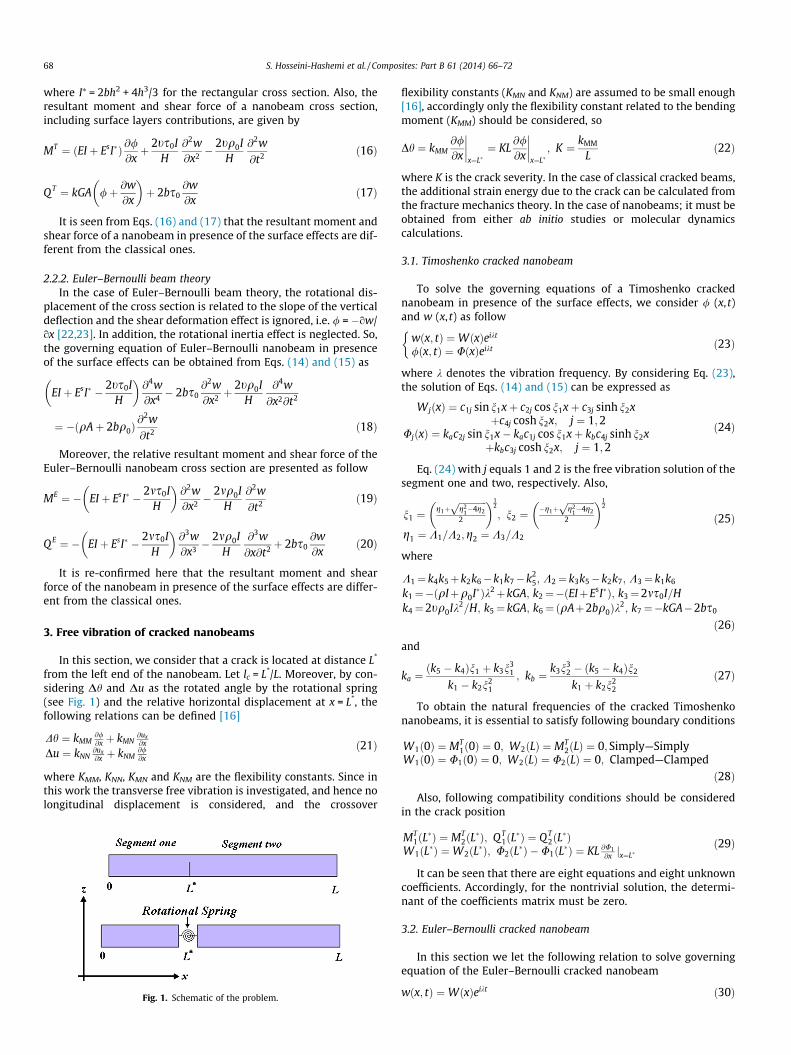
Firstly, the influences of satisfying the balance condition andconsidering the surface density in addition to the surface stressand elasticity on the frequency ratios are investigated. To thisend, variations of the frequency ratio of the SS Euler–Bernoullinanobeam versus the length are plotted in Fig. 2. For the sake ofcomparison, the frequency ratio curves of the SS Euler–Bernoullinanobeam given by Hasheminejad et al. [19] is also presented inFig. 2. It should be noted here that the frequency ratios given byRef. [19] were obtained without satisfying the balance conditionand without considering the surface density effect. Moreover, theyused the classical resultant moment and shear force to satisfy theboundary and compatibility conditions. While, it is clear fromEqs. (19) and (20) that the resultant moment and shear force inpresence of the surface effects differ from the classical ones. InFig. 2, three cases are also defined. In Case-1, frequency ratios areobtained by using the resultant moment and shear force in pres-ence of the surface effects (without surface density) for satisfyingthe boundary and compatibility conditions. In Case-2, satisfyingthe balance condition and the surface density effects are consid-ered while the classical resultant moment and shear force are used
Timoshenko (thick) nanobeams incorporating surface effects when K = 0, b = h = 3 nm,
3rd (GHz) 4th (GHz)
f. [21] Present Ref. [21] Present Ref. [21]
.19 10.9565 10.96 19.0148 19.02
.07 51.3283 51.33 82.9234 82.92
.64 14.5885 14.59 23.8182 23.83
.41 62.7245 62.74 93.84 93.86
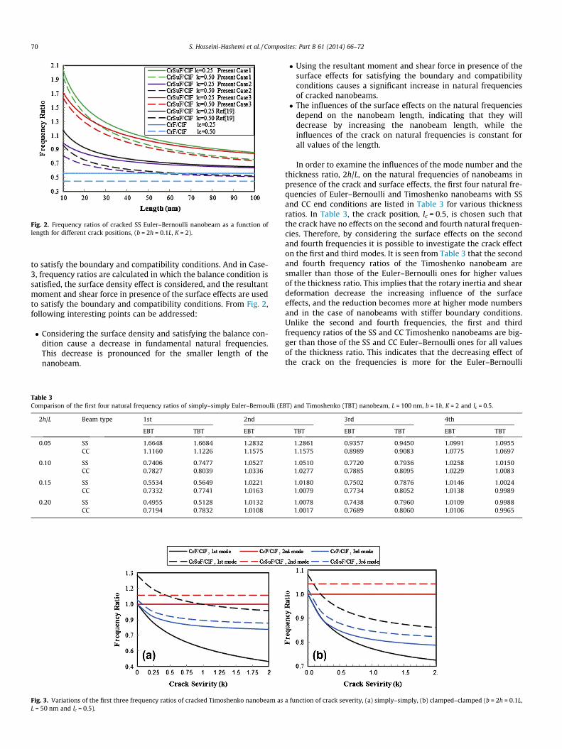
Fig. 2. Frequency ratios of cracked SS Euler–Bernoulli nanobeam as a function oflength for different crack positions, (b = 2h = 0.1L, K = 2).
70 S. Hosseini-Hashemi et al. / Composites: Part B 61 (2014) 66–72
to satisfy the boundary and compatibility conditions. And in Case-3, frequency ratios are calculated in which the balance condition issatisfied, the surface density effect is considered, and the resultantmoment and shear force in presence of the surface effects are usedto satisfy the boundary and compatibility conditions. From Fig. 2,following interesting points can be addressed:
� Considering the surface density and satisfying the balance con-dition cause a decrease in fundamental natural frequencies.This decrease is pronounced for the smaller length of thenanobeam.
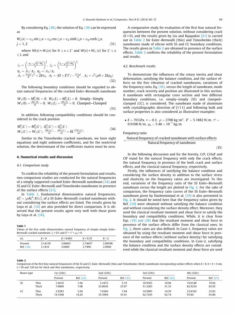
Fig. 3. Variations of the first three frequency ratios of cracked Timoshenko nanobeam asL = 50 nm and lc = 0.5).
Table 3Comparison of the first four natural frequency ratios of simply–simply Euler–Bernoulli (E
2h/L Beam type 1st 2nd
EBT TBT EBT
0.05 SS 1.6648 1.6684 1.2832CC 1.1160 1.1226 1.1575
0.10 SS 0.7406 0.7477 1.0527CC 0.7827 0.8039 1.0336
0.15 SS 0.5534 0.5649 1.0221CC 0.7332 0.7741 1.0163
0.20 SS 0.4955 0.5128 1.0132CC 0.7194 0.7832 1.0108
� Using the resultant moment and shear force in presence of thesurface effects for satisfying the boundary and compatibilityconditions causes a significant increase in natural frequenciesof cracked nanobeams.� The influences of the surface effects on the natural frequencies
depend on the nanobeam length, indicating that they willdecrease by increasing the nanobeam length, while theinfluences of the crack on natural frequencies is constant forall values of the length.
In order to examine the influences of the mode number and thethickness ratio, 2h/L, on the natural frequencies of nanobeams inpresence of the crack and surface effects, the first four natural fre-quencies of Euler–Bernoulli and Timoshenko nanobeams with SSand CC end conditions are listed in Table 3 for various thicknessratios. In Table 3, the crack position, lc = 0.5, is chosen such thatthe crack have no effects on the second and fourth natural frequen-cies. Therefore, by considering the surface effects on the secondand fourth frequencies it is possible to investigate the crack effecton the first and third modes. It is seen from Table 3 that the secondand fourth frequency ratios of the Timoshenko nanobeam aresmaller than those of the Euler–Bernoulli ones for higher valuesof the thickness ratio. This implies that the rotary inertia and sheardeformation decrease the increasing influence of the surfaceeffects, and the reduction becomes more at higher mode numbersand in the case of nanobeams with stiffer boundary conditions.Unlike the second and fourth frequencies, the first and thirdfrequency ratios of the SS and CC Timoshenko nanobeams are big-ger than those of the SS and CC Euler–Bernoulli ones for all valuesof the thickness ratio. This indicates that the decreasing effect ofthe crack on the frequencies is more for the Euler–Bernoulli
a function of crack severity, (a) simply–simply, (b) clamped–clamped (b = 2h = 0.1L,
BT) and Timoshenko (TBT) nanobeam, L = 100 nm, b = 1h, K = 2 and lc = 0.5.
3rd 4th
TBT EBT TBT EBT TBT
1.2861 0.9357 0.9450 1.0991 1.09551.1575 0.8989 0.9083 1.0775 1.0697
1.0510 0.7720 0.7936 1.0258 1.01501.0277 0.7885 0.8095 1.0229 1.0083
1.0180 0.7502 0.7876 1.0146 1.00241.0079 0.7734 0.8052 1.0138 0.9989
1.0078 0.7438 0.7960 1.0109 0.99881.0017 0.7689 0.8060 1.0106 0.9965
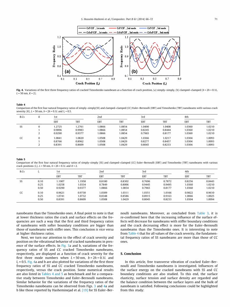
Fig. 4. Variations of the first three frequency ratios of cracked Timoshenko nanobeam as a function of crack position, (a) simply–simply, (b) clamped–clamped (b = 2h = 0.1L,L = 50 nm, K = 2).
Table 4Comparison of the first four natural frequency ratios of simply–simply(SS) and clamped–clamped (CC) Euler–Bernoulli (EBT) and Timoshenko (TBT) nanobeams with various crackseverity (K), L = 50 nm, b = 2h = 0.1L and lc = 0.5.
B.Cs K 1st 2nd 3rd 4th
EBT TBT EBT TBT EBT TBT EBT TBT
SS 0 1.2725 1.2761 1.0866 1.0854 1.0490 1.0408 1.0360 1.02101 0.9896 0.9983 1.0866 1.0854 0.8245 0.8444 1.0360 1.02102 0.9290 0.9377 1.0866 1.0854 0.7965 0.8177 1.0360 1.0210
CC 0 1.0841 1.0820 1.0508 1.0429 1.0366 1.0217 1.0304 1.00931 0.8766 0.8962 1.0508 1.0429 0.8277 0.8457 1.0304 1.00932 0.8391 0.8609 1.0508 1.0429 0.8045 0.8233 1.0304 1.0093
Table 5Comparison of the first four natural frequency ratios of simply–simply (SS) and clamped–clamped (CC) Euler–Bernoulli (EBT) and Timoshenko (TBT) nanobeams with variouscrack positions (lc), L = 50 nm, b = 2h = 0.1L and K = 2.
B.Cs lc 1st 2nd 3rd 4th
EBT TBT EBT TBT EBT TBT EBT TBT
SS 0.10 1.1907 1.1958 0.8180 0.8302 0.7696 0.7872 0.8256 0.84430.25 1.0258 1.0334 0.7849 0.8006 0.9445 0.9495 1.0360 1.02100.50 0.9290 0.9377 1.0866 1.0854 0.7965 0.8177 1.0360 1.0210
CC 0.10 0.9621 0.9730 1.0309 1.0311 1.0351 1.0166 0.9822 0.96100.25 1.0741 1.0732 0.8348 0.8586 0.8915 0.9163 1.0066 1.00250.50 0.8391 0.8609 1.0508 1.0429 0.8045 0.8233 1.0304 1.0094
S. Hosseini-Hashemi et al. / Composites: Part B 61 (2014) 66–72 71
nanobeams than the Timoshenko ones. A final point to note is thatat lower thickness ratios the crack and surface effects on the fre-quencies are such a way that the first and third frequency ratiosof nanobeams with softer boundary conditions are bigger thanthose of nanobeams with stiffer ones. This conclusion is vice versaat higher thickness ratios.
Next, we turn our attention to the effect of crack severity andposition on the vibrational behavior of cracked nanobeams in pres-ence of the surface effects. In Fig. 3a and b, variations of the fre-quency ratios of SS and CC cracked Timoshenko nanobeams,respectively, are displayed as a function of crack severity for thefirst three mode numbers when L = 50 nm, b = 2h = 0.1L andlc = 0.5. Fig. 4a and b are also plotted for variations of the first threefrequency ratios of SS and CC cracked Timoshenko nanobeams,respectively, versus the crack position. Some numerical resultsare also listed in Tables 4 and 5 as benchmark and for a compara-tive study between Timoshenko and Euler–Bernoulli nanobeams.Similar behavior for the variations of the frequency ratios of theTimoshenko nanobeams can be observed from Figs. 3 and 4a andb like those reported by Hasheminejad et al. [19] for SS Euler–Ber-
noulli nanobeams. Moreover, as concluded from Table 3, it isre-confirmed here that the increasing influence of the surface ef-fects will decrease for nanobeams with stiffer boundary conditionsand the crack decreasing effect is more for the Euler–Bernoullinanobeams than the Timoshenko ones. It is interesting to notefrom Table 4 that for all values of the crack severity, the fundamen-tal frequency ratios of SS nanobeams are more than those of CCones.
5. Conclusion
In this article, free transverse vibration of cracked Euler–Ber-noulli and Timoshenko nanobeams is investigated. Influences ofthe surface energy on the cracked nanobeams with SS and CCboundary conditions are also studied. To this end, the surfaceelasticity, surface tension and surface density are regarded andthe balance condition between the surface layers and the bulk ofnanobeam is satisfied. Following conclusions could be highlightedfrom this study:
72 S. Hosseini-Hashemi et al. / Composites: Part B 61 (2014) 66–72
� Considering the surface density and satisfying the balance con-dition cause a decrease in fundamental natural frequencies. Thisdecrease is pronounced for the smaller length of the nanobeam.� Using the resultant moment and shear force in presence of the
surface effects for satisfying the boundary and compatibilityconditions causes a significant increase in natural frequenciesof the cracked nanobeam.� The influences of the surface effects on the natural frequencies
depend on the nanobeam length, while the influences of thecrack on natural frequencies is constant for all values of thenanobeam length.� The rotary inertia and shear deformation decrease the increas-
ing influence of the surface effects, and the reduction becomesmore at higher mode numbers and in the case of nanobeamswith stiffer boundary conditions.� The decreasing effect of the crack on the frequencies is more for
the Euler–Bernoulli nanobeams than the Timoshenko ones.
References
[1] Bai X, Gao P, Wang ZL, Wang E. Dual-mode mechanical resonance of individualZnO nanobelts. Appl Phys Lett 2003;82(26):4806–8.
[2] Fei P, Yeh P-H, Zhou J, Xu S, Gao Y, Song J, et al. Piezoelectric potential gatedfield-effect transistor based on a free-standing ZnO wire. Nano Lett2009;9(10):3435–9.
[3] He JH, Hsin CL, Liu J, Chen LJ, Wang ZL. Piezoelectric gated diode of a single ZnOnanowire. Adv Mater 2007;19(6):781–4.
[4] Wang ZL, Song J. Piezoelectric nanogenerators based on zinc oxide nanowirearrays. Science 2006;312(5771):242–6.
[5] Zhong Z, Wang D, Cui Y, Bockrath MW, Lieber CM. Nanowire crossbar arrays asaddress decoders for integrated nanosystems. Science2003;302(5649):1377–9.
[6] Wong EW, Sheehan PE, Lieber CM. Nanobeam mechanics: elasticity, strength,and toughness of nanorods and nanotubes. Science 1997;277(5334):1971–5.
[7] Chen C, Shi Y, Zhang Y, Zhu J, Yan Y. Size dependence of Young’s modulus inZnO nanowires. Phys Rev Lett 2006;96(7):075505.
[8] Chang T, Gao H. Size-dependent elastic properties of a single-walled carbonnanotube via a molecular mechanics model. J Mech Phys Solids2003;51(6):1059–74.
[9] He L, Lim C, Wu B. A continuum model for size-dependent deformation ofelastic films of nano-scale thickness. Int J Solids Struct 2004;41(3):847–57.
[10] Gurtin ME, Murdoch AI. A continuum theory of elastic material surfaces. ArchRation Mech Anal 1975;57(4):291–323.
[11] Gurtin ME, Ian Murdoch A. Surface stress in solids. Int J Solids Struct1978;14(6):431–40.
[12] He J, Lilley CM. Surface effect on the elastic behavior of static bendingnanowires. Nano Lett 2008;8(7):1798–802.
[13] Lu P, He L, Lee H, Lu C. Thin plate theory including surface effects. Int J SolidsStruct 2006;43(16):4631–47.
[14] Nazemnezhad R, Salimi M, Hosseini-Hashemi Sh, Sharabiani PA. An analyticalstudy on the nonlinear free vibration of nanoscale beams incorporating surfacedensity effects. Compos Part B: Eng 2012;43:2893–7.
[15] Luque A, Aldazabal J, Martínez-Esnaola J, Sevillano J. Atomistic simulation oftensile strength and toughness of cracked Cu nanowires. Fatigue Eng Mater2006;29(8):615–22.
[16] Loya J, López-Puente J, Zaera R, Fernández-Sáez J. Free transverse vibrations ofcracked nanobeams using a nonlocal elasticity model. J Appl Phys2009;105(4). 044309-9.
[17] Torabi K, Dastgerdi JN. An analytical method for free vibration analysis ofTimoshenko beam theory applied to cracked nanobeams using a nonlocalelasticity model. Thin Solid Films 2012;520:6595–602.
[18] Hsu J-C, Lee H-L, Chang W-J. Longitudinal vibration of cracked nanobeamsusing nonlocal elasticity theory. Curr Appl Phys 2011;11(6):1384–8.
[19] Hasheminejad SM, Gheshlaghi B, Mirzaei Y, Abbasion S. Free transversevibrations of cracked nanobeams with surface effects. Thin Solid Films2011;519(8):2477–82.
[20] Shenoy VB. Atomistic calculations of elastic properties of metallic fcc crystalsurfaces. Phys Rev B 2005;71(9):094104.
[21] Liu C, Rajapakse R. Continuum models incorporating surface energy for staticand dynamic response of nanoscale beams. IEEE Trans Nanotechnol2010;9(4):422–31.
[22] Timoshenko S, Goodier J. Theory of elasticity. New York: McGraw-Hill; 1970.[23] Rao SS. Vibration of continuous systems. John Wiley & Sons; 2007.