Embed Size (px)
Citation preview
Type series booklet8511.1/6--10 DYNACTAIR 1.5 to 800
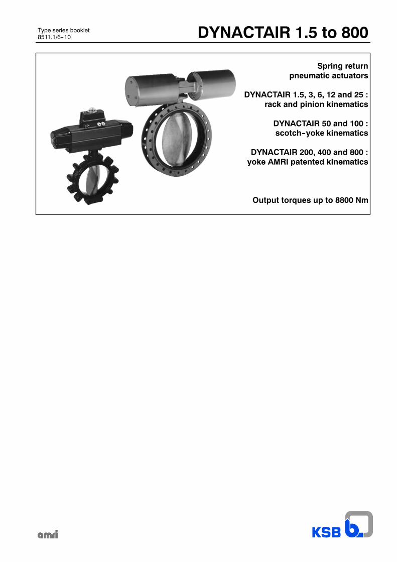
Spring returnpneumatic actuators
DYNACTAIR 1.5, 3, 6, 12 and 25 :rack and pinion kinematics
DYNACTAIR 50 and 100 :scotch--yoke kinematics
DYNACTAIR 200, 400 and 800 :yoke AMRI patented kinematics
Output torques up to 8800 Nm
DYNACTAIR 1.5 to 800
2
General features
Designed for the automation of ¼ turn valves (butterfly valves, ball valves), the DYNACTAIR series of spring return pneumaticactuators and their AMTROBOX/AMTRONIC/SMARTRONIC box are involved in all the functions of control and supervisionencountered in all modern processes, and more particularly in communication by fieldbus.
3 kinematics are used for the actuators operation:-- rack and pinion kinematics for DYNACTAIR 1.5, DYNACTAIR 3, DYNACTAIR 6, DYNACTAIR 12 and DYNACTAIR 25,-- scotch--yoke kinematics for DYNACTAIR 50 and DYNACTAIR 100,-- yoke AMRI patented kinematics for DYNACTAIR 200, DYNACTAIR 400 and DYNACTAIR 800.The mounting interface is in accordance with ISO 5211 standard.Equipped with an interchangeable insert, they can be easily fitted on different valve shaft (square end, flat end, key).In standard version, the DYNACTAIR actuators are equipped with a visual pointer and adjustable mechanical travel stops:-- on closed or on open position for DYNACTAIR 1.5 to 100 (see pages 6 and 7),-- on closed and on open position for DYNACTAIR 200 to 800.The actuator is mounted directly or by means of an adaptator on ¼ turn valve plate.
Protection:
They are hose and fine dust proof (protection degree equivalent to IP 65).
External coating:
DYNACTAIR 1.5 to 100: housing with 50 µm thickness hard anodization and cylinder head with black cataphoresis coating 30 µm.DYNACTAIR 200 to 800: polyurethane paint, thickness 80 µm, colour dark grey RAL 7016.
Working temperature :
From –20°C up to +80°C: standard version,
Alternative construction for DYNACTAIR 1.5 to 100:–40° to +80°C: dynamic O--rings in special Nitrile,–20° to +120°C: dynamic O--rings in Viton (available with corrosive motive medium).
Other working temperature range for DYNACTAIR 200 to 800: Please consult us.
Standard variant:
ATEX version in accordance with 94/9/EC directive.
This spring return actuator range is completed by the ACTAIR series of double acting pneumatic actuators. Please consult typeseries booklet ACTAIR 1.5 to 1600 pneumatic actuators, ref. 8515.1.
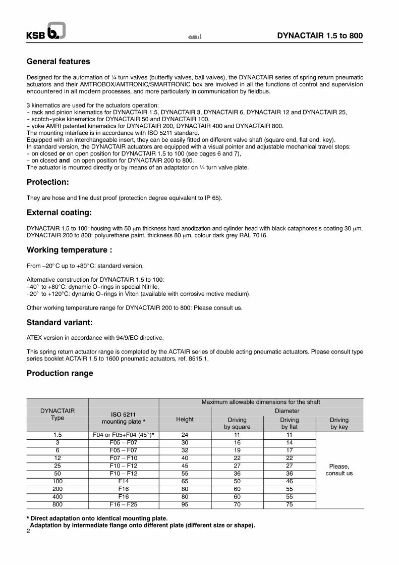
Production range
Maximum allowable dimensions for the shaft
DYNACTAIRT ISO 5211
DiameterType ISO 5211
mounting plate * Height Driving Driving Drivingmounting plate g Drivingby square
Drivingby flat
Drivingby key
1.5 F04 or F05+F04 (45° )* 24 11 113 F05 – F07 30 16 146 F05 – F07 32 19 1712 F07 – F10 40 22 2225 F10 – F12 45 27 27 Please,50 F10 – F12 55 36 36
Please,consult us
100 F14 65 50 46200 F16 80 60 55400 F16 80 60 55800 F16 – F25 95 70 75
* Direct adaptation onto identical mounting plate.Adaptation by intermediate flange onto different plate (different size or shape).
DYNACTAIR 1.5 to 800
3
Control fluid supplyAir or any neutral gas,filtered, dry or lubricated:-- filtration: 50 µm,-- drying: dew point at max. working pressure ≤ 4°C and min. temperature --5°CIf a lubrification is required -- the lubrification increases the actuator life -- the useof a nondetergent oil without aggressive additive isrecommended:-- viscosity 2 to 3° ENGLER at 50°C-- anhiline point 90°C to 105°C-- flow 1 to 3 drop for 500 NL/mn.
Operating timesThe table below defines the minimum operating times under 5 bar control air pressure and the operation rates per minute forDYNACTAIR actuators on/off function.
Minimum operating time
On/off functionOperation rates
DYNACTAIRtype DYNACTAIR DYNACTAIR with distibutor
ISO--1 or NAMURDYNACTAIR
Operation ratesper minute
type DYNACTAIR+ AMTRONIC ISO--1 or NAMUR
fitted onto the housing
DYNACTAIRdirect connection
pe e
1.5 2 seconds 2 seconds 30 maxi3 2 seconds 2 seconds 30 maxi6 2 seconds 2 seconds 30 maxi12 4 seconds 2 seconds 15 maxi25 6 seconds 3,5 seconds 10 maxi50 10 seconds 5 seconds 6 maxi100 15 seconds 8 seconds 4 maxi200 45 seconds 30 seconds 15 seconds 2 maxi400 90 seconds 45 seconds 30 seconds 1 maxi800 180 seconds 90 seconds 40 seconds 0,5 maxi
On request, adjust construction for :-- other operation times,-- hight operation rates.Please consult us.
Capacity
DYNACTAIR Capacity in cm3
type1.5 2403 5706 118012 240025 470050 5280100 9800200 25000400 50000800 92000
Safety functionIn standard version, the DYNACTAIR actuators are designed to ensure valve closure in case of lack of control fluidpressure.On request, valve opening by lack of control fluid is available.The opening function by lack of control fluid differentiates itself from the closing function by a different mounting of thekinematics (refer to pages 6 to 9) and by amore or less powerful construction of the energy accumulator (refer to pages 4and 5).Due to these differences of construction, the use of a closing function actuator instead of an opening function actuator(and vice versa) can cause some hazards during operation such as the impossibility to operate the valve or operation inthe wrong direction. For these reasons, it is strongly inadvisable to try to change from one type of actuator to the other.
DYNACTAIR 1.5 to 800
4
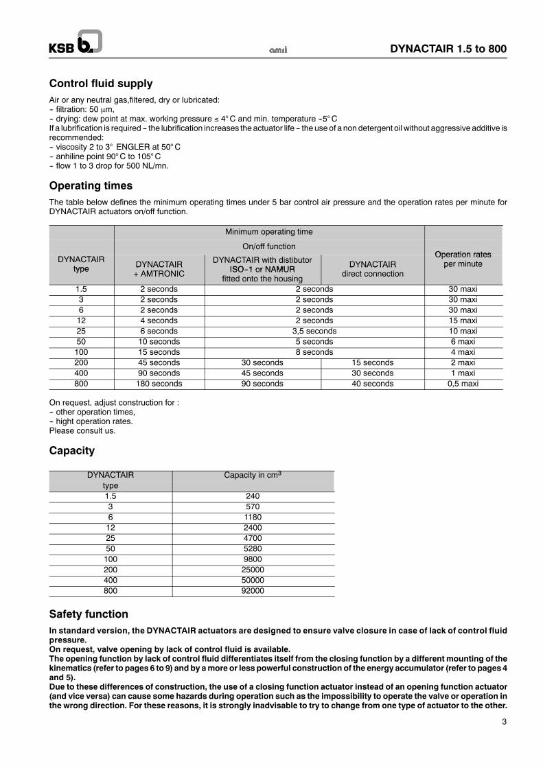
Output torque (Nm) relating to the control fluid pressure and the safety functionToensure the safety function (closing or opening) in case of lack of control fluid, theDYNACTAIR spring return pneumatic actuatorsare equipped with an energy accumulator.This energy accumulator consists in:-- for DYNACTAIR 1.5 to 25 actuators: 2, 3 or 4 precompressed spring cartridges fitted between the pistons, each cartridge includingfour helicoidal springs,
-- for DYNACTAIR 50 to 800 actuators: a precompressed spring cartrige fitted at each housing end, ech cartrige including one, twoor three helicoidal springs depending on the requested output torque.
The table below shows the different output torques relating to the control fluid pressure and the quantity of spring cartriges (case ofDYNACTAIR 1.5 to 25) or of the quantity of springs and their position (case of DYNACTAIR 50 to 800).
Output torque restored by Output torque during the setting of the energy accumulatorEnergy
Output torque restored by Output torque during the setting of the energy accumulatorrelating to the control fluid pressureEnergy
p q ythe energy accumulator relating to the control fluid pressure
DYNACTAIR
gyaccumulatorconfiguration
the energy accumulator(cartridge/spring 3 bar 4 bar 5 bar 6 bar 7 bar 8 bar
configuration(cartridge/spring) Springs Springs Air Air Air Air Air Air(cartridge/spring)
start end start end start end start end start end start end start end
Rack and pinion kinematics (refer to page 6 for curves and operation)
1 53 (2 cart./ 2 springs) 16 9 16 5 24 13 32 20
1.5 4 (2 cart./ 4 spring) 30 15 25 5 32 132 (2 cartridges) 28 16 27 14 41 28 55 43
3 3 (3 cartridges) 42 24 33 14 47 29 61 4334 (4 cartridges) 57 32 39 14 53 29 68 43 82 572 (2 cartridges) 51 32 55 28 82 55 108 81
6 3 (3 cartridges) 77 48 58 29 85 56 111 8264 (4 cartridges) 103 64 69 30 96 57 122 83 148 1092 (2 cartridges 108 64 94 50 147 103 200 156
12 3 (3 cartridges) 161 96 115 50 168 103 220 155124 (4 cartridges) 215 128 136 48 188 101 241 154 294 2072 (2 cartridges) 220 131 186 97 292 203 398 308
25 3 (3 cartridges) 330 196 226 94 332 199 437 305254 (4 cartridges) 440 262 267 89 372 194 478 299 583 405
Scotch- yoke kinematics (refer to page 7 for curves and operation)1 (1 spring A ) 360 229 401 270 611 481
502 (2 springs A C) 550 336 295 81 505 291 716 502
50 3 (2 springs A B ) 622 404 437 218 647 429 857 6394 (3 springs A B C) 810 520 317 60 528 278 738 488 949 698 1116 9091 (1 spring A ) 728 447 789 508 1202 921
1002 (2 ressorts A C) 970 585 652 267 1065 680 1478 1093
100 3 (2 ressorts A B ) 1350 800 843 293 1256 706 1669 11194 (3 ressorts A B C) 1600 1010 657 120 1070 533 1482 946 1895 1358 2300 1771
Yoke AMRI patented kinematics (refer to pages 8 and 8 for curves and operation)2 (1 spring A ) 800 1000 1880 700
200 3 (2 springs A B ) 1000 1700 2100 6002004 (3 springs A B C) 1000 2150 1700 300 2600 1000 2600 1000
Closing by 2 (1 spring A ) 1000 2000 3700 1000Closing bylack of 400 3 (2 springs A B ) 1000 3400 4200 1000lack of
control fluid400
4 (3 springs A B C) 1000 4300 3400 600 4400 1000 4400 10002 (1 spring A ) 2000 3000 7000 2000
800 3 (2 springs A B ) 2000 5400 4400 700 7800 20008004 (3 springs A B C) 2000 8000 8800 2000 8800 2000
2002 (1 spring A ) 1500 500 1000 1300 1000 2100
Opening by
200 3 (2 springs A B ) 2500 1000 1000 1050 1000 2000 1000 2900Opening bylack of 400
2 (1 spring A ) 3000 1000 1000 2600 1000 4200lack of
control flui400 3 (2 springs A B ) 4400 1000 1000 2100 1000 4000 1000 4400control flui
8002 (1 spring A ) 4600 1800 2000 5420 2000 8800
800 3 (2 springs A B ) 8800 2000 2000 1200 2000 4500 2000 7900 2000 8800
DYNACTAIR 1.5 to 800
5
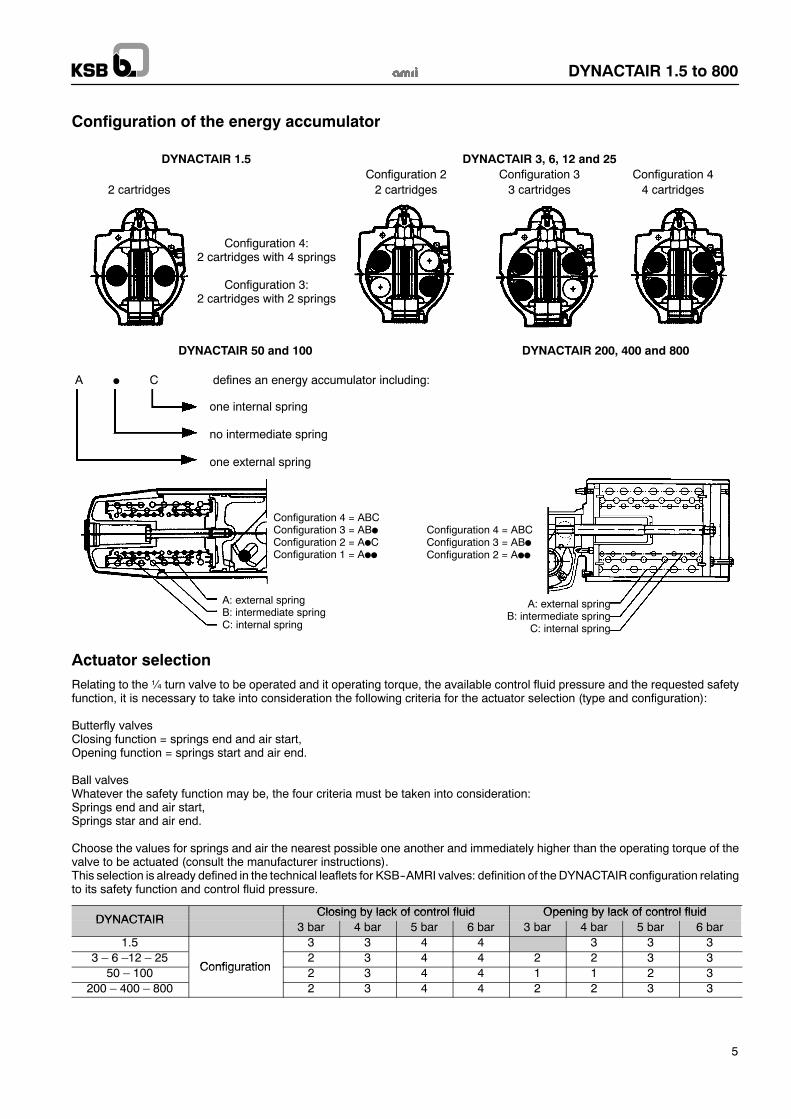
Configuration of the energy accumulator
DYNACTAIR 1.5 DYNACTAIR 3, 6, 12 and 25Configuration 2 Configuration 3 Configuration 4
2 cartridges 2 cartridges 3 cartridges 4 cartridges
Configuration 4:2 cartridges with 4 springs
Configuration 3:2 cartridges with 2 springs
DYNACTAIR 50 and 100 DYNACTAIR 200, 400 and 800
A C defines an energy accumulator including:
one internal spring
no intermediate spring
one external spring
Configuration 4 = ABCConfiguration 3 = ABConfiguration 2 = A CConfiguration 1 = A
Configuration 4 = ABCConfiguration 3 = ABConfiguration 2 = A
A: external springB: intermediate springC: internal spring
A: external springB: intermediate spring
C: internal spring
Actuator selectionRelating to the¼ turn valve to be operated and it operating torque, the available control fluid pressure and the requested safetyfunction, it is necessary to take into consideration the following criteria for the actuator selection (type and configuration):
Butterfly valvesClosing function = springs end and air start,Opening function = springs start and air end.
Ball valvesWhatever the safety function may be, the four criteria must be taken into consideration:Springs end and air start,Springs star and air end.
Choose the values for springs and air the nearest possible one another and immediately higher than the operating torque of thevalve to be actuated (consult the manufacturer instructions).This selection is already defined in the technical leaflets for KSB--AMRI valves: definition of the DYNACTAIR configuration relatingto its safety function and control fluid pressure.
Closing by lack of control fluid Opening by lack of control fluidDYNACTAIR
Closing by lack of control fluid Opening by lack of control fluidDYNACTAIR
3 bar 4 bar 5 bar 6 bar 3 bar 4 bar 5 bar 6 bar1.5 3 3 4 4 3 3 3
3 – 6 –12 – 25Configuration
2 3 4 4 2 2 3 350 – 100 Configuration 2 3 4 4 1 1 2 3
200 – 400 – 800 2 3 4 4 2 2 3 3
DYNACTAIR 1.5 to 800
6
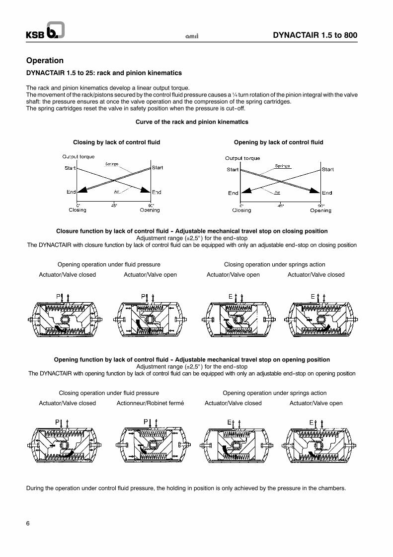
Operation
DYNACTAIR 1.5 to 25: rack and pinion kinematics
The rack and pinion kinematics develop a linear output torque.Themovement of the rack/pistons secured by the control fluid pressure causes a¼ turn rotation of the pinion integral with the valveshaft: the pressure ensures at once the valve operation and the compression of the spring cartridges.The spring cartridges reset the valve in safety position when the pressure is cut--off.
Curve of the rack and pinion kinematIcs
Closing by lack of control fluid Opening by lack of control fluid
Closure function by lack of control fluid -- Adjustable mechanical travel stop on closing positionAdjustment range (±2,5° ) for the end--stop
The DYNACTAIR with closure function by lack of control fluid can be equipped with only an adjustable end--stop on closing position
Opening operation under fluid pressure Closing operation under springs action
Actuator/Valve closed Actuator/Valve open Actuator/Valve open Actuator/Valve closed
Opening function by lack of control fluid -- Adjustable mechanical travel stop on opening positionAdjustment range (±2,5° ) for the end--stop
The DYNACTAIR with opening function by lack of control fluid can be equipped with only an adjustable end--stop on opening position
Closing operation under fluid pressure Opening operation under springs action
Actuator/Valve closed Actionneur/Robinet fermé Actuator/Valve closed Actuator/Valve open
During the operation under control fluid pressure, the holding in position is only achieved by the pressure in the chambers.
DYNACTAIR 1.5 to 800
7
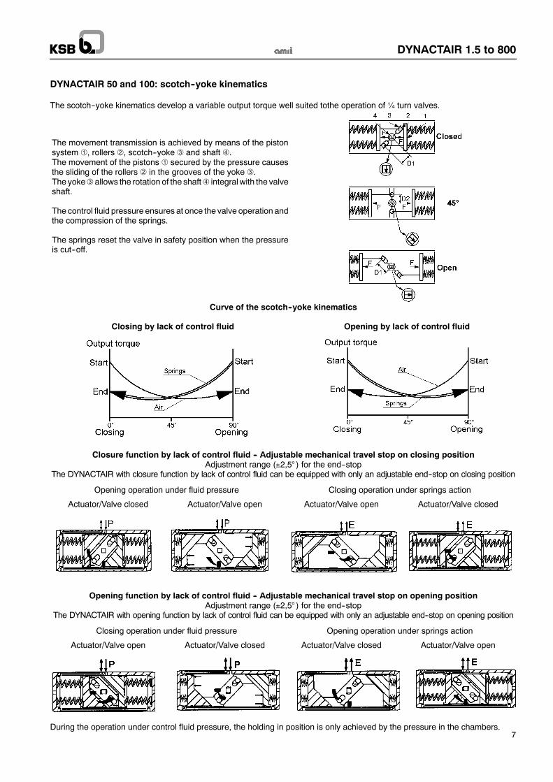
DYNACTAIR 50 and 100: scotch--yoke kinematics
The scotch--yoke kinematics develop a variable output torque well suited tothe operation of ¼ turn valves.
The movement transmission is achieved by means of the pistonsystem , rollers , scotch--yoke and shaft .The movement of the pistons secured by the pressure causesthe sliding of the rollers in the grooves of the yoke .The yoke allows the rotation of the shaft integral with the valveshaft.
The control fluid pressure ensures at once the valve operation andthe compression of the springs.
The springs reset the valve in safety position when the pressureis cut--off.
Curve of the scotch--yoke kinematics
Closing by lack of control fluid Opening by lack of control fluid
Closure function by lack of control fluid -- Adjustable mechanical travel stop on closing positionAdjustment range (±2,5° ) for the end--stop
The DYNACTAIR with closure function by lack of control fluid can be equipped with only an adjustable end--stop on closing position
Opening operation under fluid pressure Closing operation under springs action
Actuator/Valve closed Actuator/Valve open Actuator/Valve open Actuator/Valve closed
Opening function by lack of control fluid -- Adjustable mechanical travel stop on opening positionAdjustment range (±2,5° ) for the end--stop
The DYNACTAIR with opening function by lack of control fluid can be equipped with only an adjustable end--stop on opening position
Closing operation under fluid pressure Opening operation under springs action
Actuator/Valve open Actuator/Valve closed Actuator/Valve closed Actuator/Valve open
During the operation under control fluid pressure, the holding in position is only achieved by the pressure in the chambers.
DYNACTAIR 1.5 to 800
8
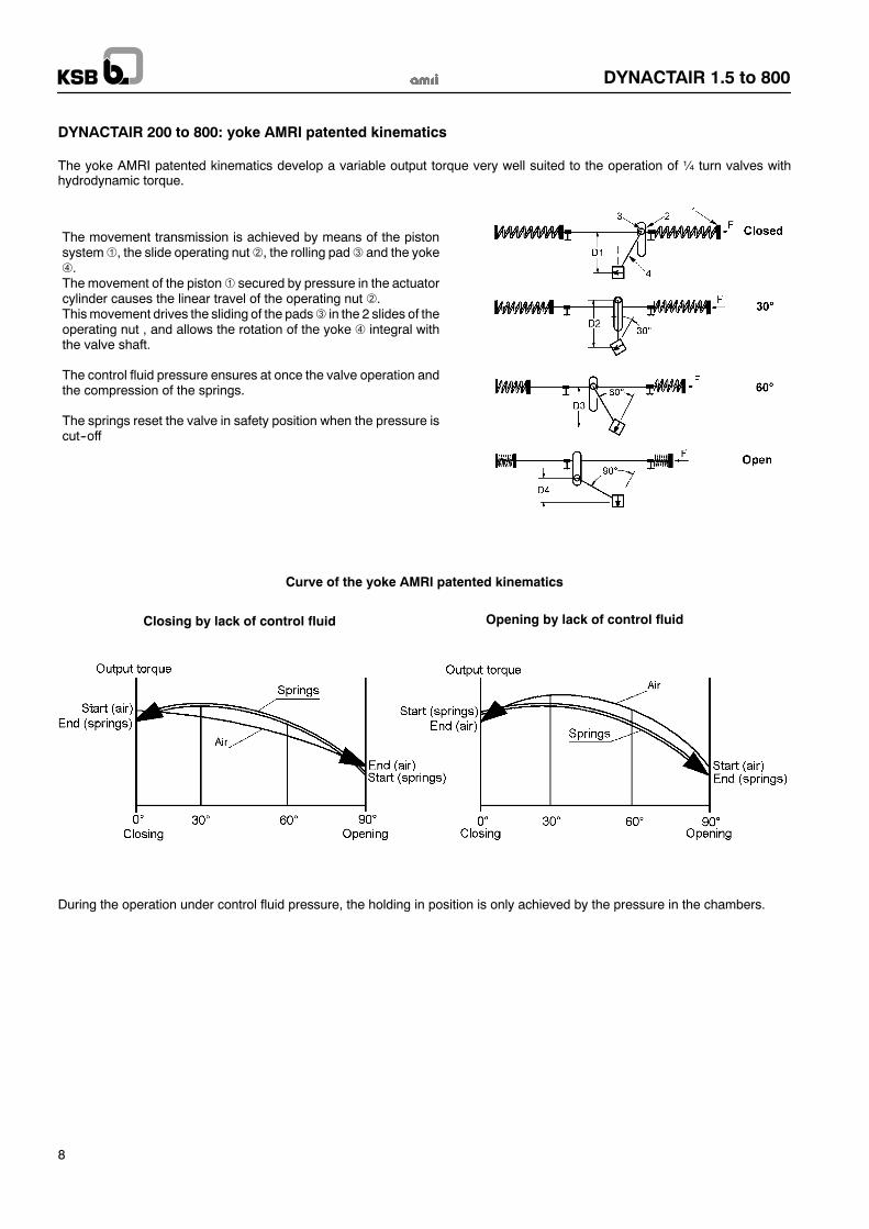
DYNACTAIR 200 to 800: yoke AMRI patented kinematics
The yoke AMRI patented kinematics develop a variable output torque very well suited to the operation of ¼ turn valves withhydrodynamic torque.
The movement transmission is achieved by means of the pistonsystem , the slide operating nut , the rolling pad and the yoke.
The movement of the piston secured by pressure in the actuatorcylinder causes the linear travel of the operating nut .Thismovement drives the sliding of the pads in the 2 slides of theoperating nut , and allows the rotation of the yoke integral withthe valve shaft.
The control fluid pressure ensures at once the valve operation andthe compression of the springs.
The springs reset the valve in safety position when the pressure iscut--off
Curve of the yoke AMRI patented kinematics
Closing by lack of control fluid Opening by lack of control fluid
During the operation under control fluid pressure, the holding in position is only achieved by the pressure in the chambers.
DYNACTAIR 1.5 to 800
9
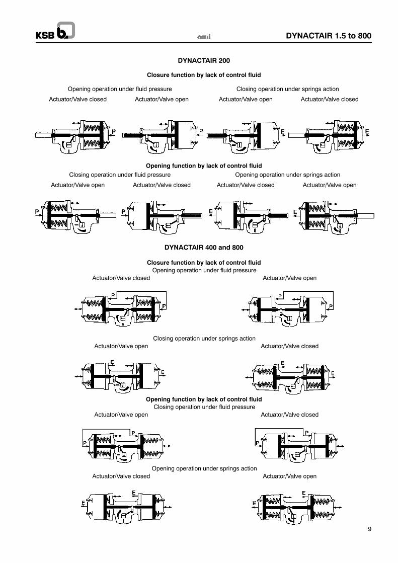
DYNACTAIR 200
Closure function by lack of control fluid
Opening operation under fluid pressure Closing operation under springs action
Actuator/Valve closed Actuator/Valve open Actuator/Valve open Actuator/Valve closed
Opening function by lack of control fluidClosing operation under fluid pressure Opening operation under springs action
Actuator/Valve open Actuator/Valve closed Actuator/Valve closed Actuator/Valve open
DYNACTAIR 400 and 800
Closure function by lack of control fluidOpening operation under fluid pressure
Actuator/Valve closed Actuator/Valve open
Closing operation under springs actionActuator/Valve open Actuator/Valve closed
Opening function by lack of control fluidClosing operation under fluid pressure
Actuator/Valve open Actuator/Valve closed
Opening operation under springs actionActuator/Valve closed Actuator/Valve open
DYNACTAIR 1.5 to 800
10
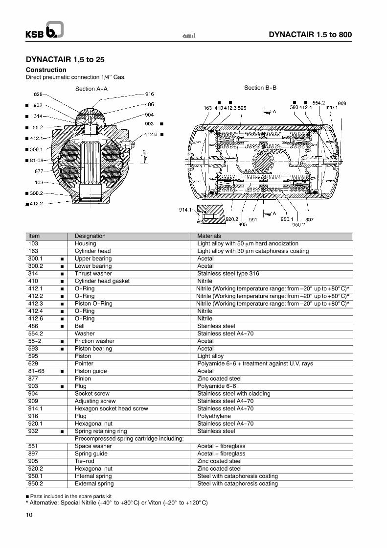
DYNACTAIR 1,5 to 25ConstructionDirect pneumatic connection 1/4’’ Gas.
Section A--A Section B--B
Item Designation Materials103 Housing Light alloy with 50 µm hard anodization163 Cylinder head Light alloy with 30 µm cataphoresis coating300.1 Upper bearing Acetal300.2 Lower bearing Acetal314 Thrust washer Stainless steel type 316410 Cylinder head gasket Nitrile412.1 O--Ring Nitrile (Working temperature range: from –20° up to +80°C)*412.2 O--Ring Nitrile (Working temperature range: from –20° up to +80°C)*412.3 Piston O--Ring Nitrile (Working temperature range: from –20° up to +80°C)*412.4 O--Ring Nitrile412.6 O--Ring Nitrile486 Ball Stainless steel554.2 Washer Stainless steel A4--7055--2 Friction washer Acetal593 Piston bearing Acetal595 Piston Light alloy629 Pointer Polyamide 6--6 + treatment against U.V. rays81--68 Piston guide Acetal877 Pinion Zinc coated steel903 Plug Polyamide 6--6904 Socket screw Stainless steel with cladding909 Adjusting screw Stainless steel A4--70914.1 Hexagon socket head screw Stainless steel A4--70916 Plug Polyethylene920.1 Hexagonal nut Stainless steel A4--70932 Spring retaining ring Stainless steel
Precompressed spring cartridge including:551 Space washer Acetal + fibreglass897 Spring guide Acetal + fibreglass905 Tie--rod Zinc coated steel920.2 Hexagonal nut Zinc coated steel950.1 Internal spring Steel with cataphoresis coating950.2 External spring Steel with cataphoresis coating
Parts included in the spare parts kit* Alternative: Special Nitrile (–40° to +80°C) or Viton (–20° to +120°C)
DYNACTAIR 1.5 to 800
11
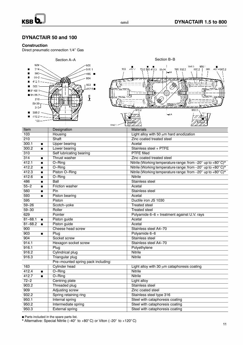
DYNACTAIR 50 and 100
ConstructionDirect pneumatic connection 1/4’’ Gas
Section A--A Section B--B
Item Designation Materials103 Housing Light alloy with 50 µm hard anodization210 Shaft Zinc coated treated steel300.1 Upper bearing Acetal300.2 Lower bearing Stainless steel + PTFE310 Self lubricating bearing PTFE filled314 Thrust washer Zinc coated treated steel412.1 O--Ring Nitrile (Working temperature range: from –20° up to +80°C)*412.2 O--Ring Nitrile (Working temperature range: from –20° up to +80°C)*412.3 Piston O--Ring Nitrile (Working temperature range: from –20° up to +80°C)*412.6 O--Ring Nitrile486 Ball Stainless steel55--2 Friction washer Acetal560 Pin Stainless steel593 Piston bearing Acetal595 Piston Ductile iron JS 103059--26 Scotch--yoke Treated steel59--30 Roller Treated steel629 Pointer Polyamide 6--6 + treatment against U.V. rays81--68.1 Piston guide Acetal81--68.2 Piston guide Acetal900 Cheese head screw Stainless steel A4--70903 Plug Polyamide 6--6904 Socket screw Stainless steel914.1 Hexagon socket screw Stainless steel A4--70916.1 Plug Polyethylene916.2 Cylindrical plug Nitrile916.3 Triangular plug Nitrile
Pre--mounted spring pack including:163 Cylinder head Light alloy with 30 µm cataphoresis coating412.4 O--Ring Nitrile412.7 O--Ring Nitrile72--2 Centring plate Light alloy903.2 Threaded plug Stainless steel909 Adjusting screw Zinc coated steel932.2 Spring retaining ring Stainless steel type 316950.1 Internal spring Steel with cataphoresis coating950.2 Intermediate spring Steel with cataphoresis coating950.3 External spring Steel with cataphoresis coating
Parts included in the spare parts list.* Alternative: Special Nitrile (–40° to +80°C) or Viton (–20° to +120°C)
DYNACTAIR 1.5 to 800
12
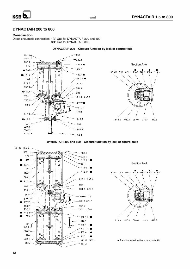
DYNACTAIR 200 to 800
ConstructionDirect pneumatic connection: 1/2” Gas for DYNACTAIR 200 and 400
3/4” Gas for DYNACTAIR 800
Section A--A
DYNACTAIR 200 -- Closure function by lack of control fluid
Section A--A
Parts included in the spare parts kit
DYNACTAIR 400 and 800 – Closure function by lack of control fluid
DYNACTAIR 1.5 to 800
13
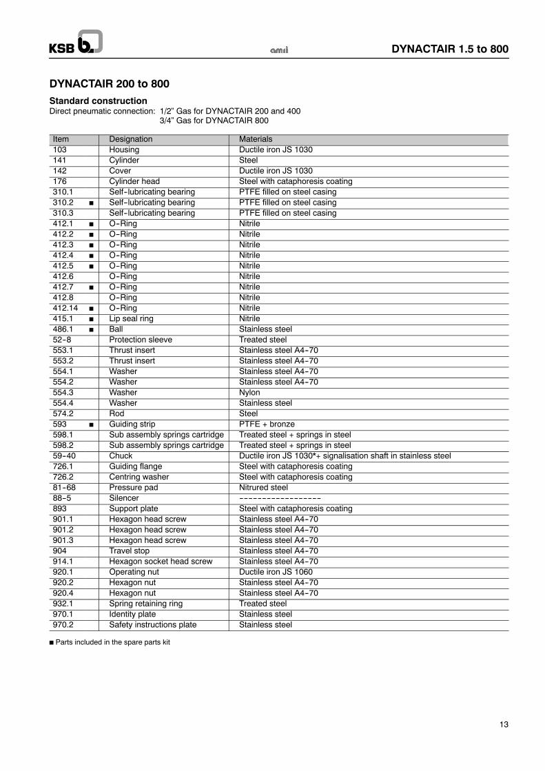
DYNACTAIR 200 to 800
Standard constructionDirect pneumatic connection: 1/2” Gas for DYNACTAIR 200 and 400
3/4” Gas for DYNACTAIR 800
Item Designation Materials103 Housing Ductile iron JS 1030141 Cylinder Steel142 Cover Ductile iron JS 1030176 Cylinder head Steel with cataphoresis coating310.1 Self--lubricating bearing PTFE filled on steel casing310.2 Self--lubricating bearing PTFE filled on steel casing310.3 Self--lubricating bearing PTFE filled on steel casing412.1 O--Ring Nitrile412.2 O--Ring Nitrile412.3 O--Ring Nitrile412.4 O--Ring Nitrile412.5 O--Ring Nitrile412.6 O--Ring Nitrile412.7 O--Ring Nitrile412.8 O--Ring Nitrile412.14 O--Ring Nitrile415.1 Lip seal ring Nitrile486.1 Ball Stainless steel52--8 Protection sleeve Treated steel553.1 Thrust insert Stainless steel A4--70553.2 Thrust insert Stainless steel A4--70554.1 Washer Stainless steel A4--70554.2 Washer Stainless steel A4--70554.3 Washer Nylon554.4 Washer Stainless steel574.2 Rod Steel593 Guiding strip PTFE + bronze598.1 Sub assembly springs cartridge Treated steel + springs in steel598.2 Sub assembly springs cartridge Treated steel + springs in steel59--40 Chuck Ductile iron JS 1030*+ signalisation shaft in stainless steel726.1 Guiding flange Steel with cataphoresis coating726.2 Centring washer Steel with cataphoresis coating81--68 Pressure pad Nitrured steel88--5 Silencer ------------------------------------893 Support plate Steel with cataphoresis coating901.1 Hexagon head screw Stainless steel A4--70901.2 Hexagon head screw Stainless steel A4--70901.3 Hexagon head screw Stainless steel A4--70904 Travel stop Stainless steel A4--70914.1 Hexagon socket head screw Stainless steel A4--70920.1 Operating nut Ductile iron JS 1060920.2 Hexagon nut Stainless steel A4--70920.4 Hexagon nut Stainless steel A4--70932.1 Spring retaining ring Treated steel970.1 Identity plate Stainless steel970.2 Safety instructions plate Stainless steel
Parts included in the spare parts kit
DYNACTAIR 1.5 to 800
14
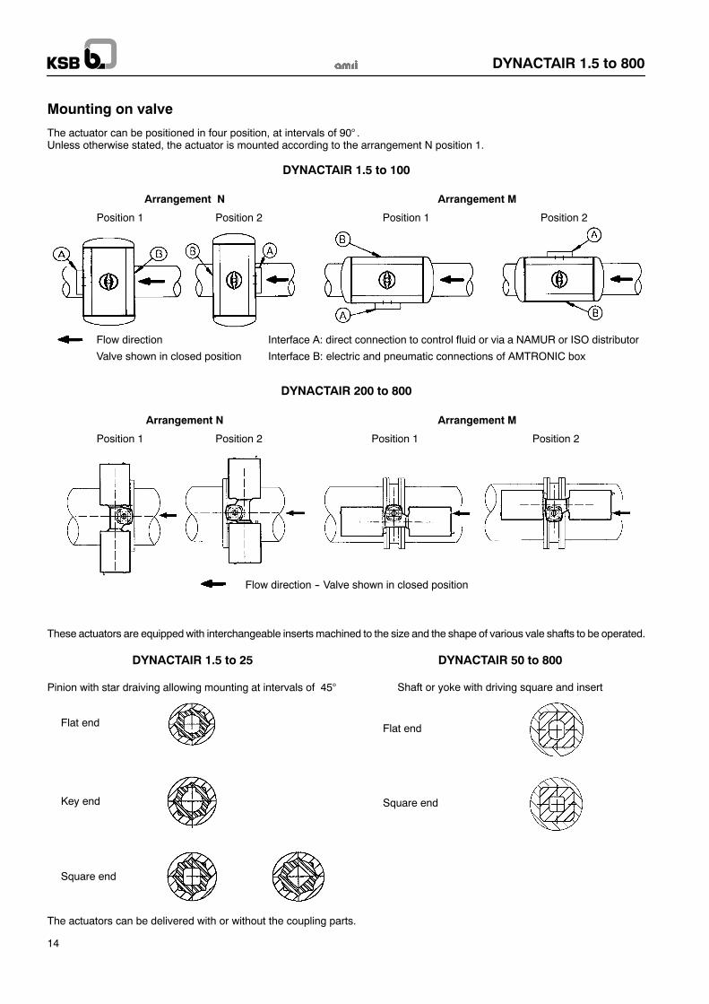
Mounting on valve
The actuator can be positioned in four position, at intervals of 90° .Unless otherwise stated, the actuator is mounted according to the arrangement N position 1.
DYNACTAIR 1.5 to 100
Arrangement N Arrangement M
Position 1 Position 2 Position 1 Position 2
Flow direction Interface A: direct connection to control fluid or via a NAMUR or ISO distributor
Valve shown in closed position Interface B: electric and pneumatic connections of AMTRONIC box
DYNACTAIR 200 to 800
Arrangement N Arrangement M
Position 1 Position 2 Position 1 Position 2
Flow direction -- Valve shown in closed position
These actuators are equipped with interchangeable inserts machined to the size and the shape of various vale shafts to be operated.
DYNACTAIR 1.5 to 25
Pinion with star draiving allowing mounting at intervals of 45°
Flat end
Key end
Square end
DYNACTAIR 50 to 800
Shaft or yoke with driving square and insert
Flat end
Square end
The actuators can be delivered with or without the coupling parts.
DYNACTAIR 1.5 to 800
15
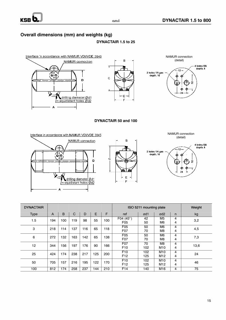
Overall dimensions (mm) and weights (kg)
DYNACTAIR 1.5 to 25
NAMUR connection(detail)
DYNACTAIR 50 and 100
NAMUR connection(detail)
DYNACTAIR ISO 5211 mounting plate WeightDYNACTAIR ISO 5211 mounting plate Weight
Type A B C D E F ref ød1 ød2 n kg
1.5 194 100 119 98 55 100 F04 (45° )F05
4250
M5M6
44 3,2
3 218 114 137 116 65 118F05F07
5070
M6M8
44 4,5
6 272 132 163 142 65 138F05F07
5070
M6M8
44 7,3
12 344 156 197 176 90 166F07F10
70102
M8M10
44 13,6
25 424 174 238 217 125 200F10F12
102125
M10M12
44 24
50 705 157 216 195 122 170F10F12
102125
M10M12
44 46
100 812 174 258 237 144 210 F14 140 M16 4 75
DYNACTAIR 1.5 to 800
16
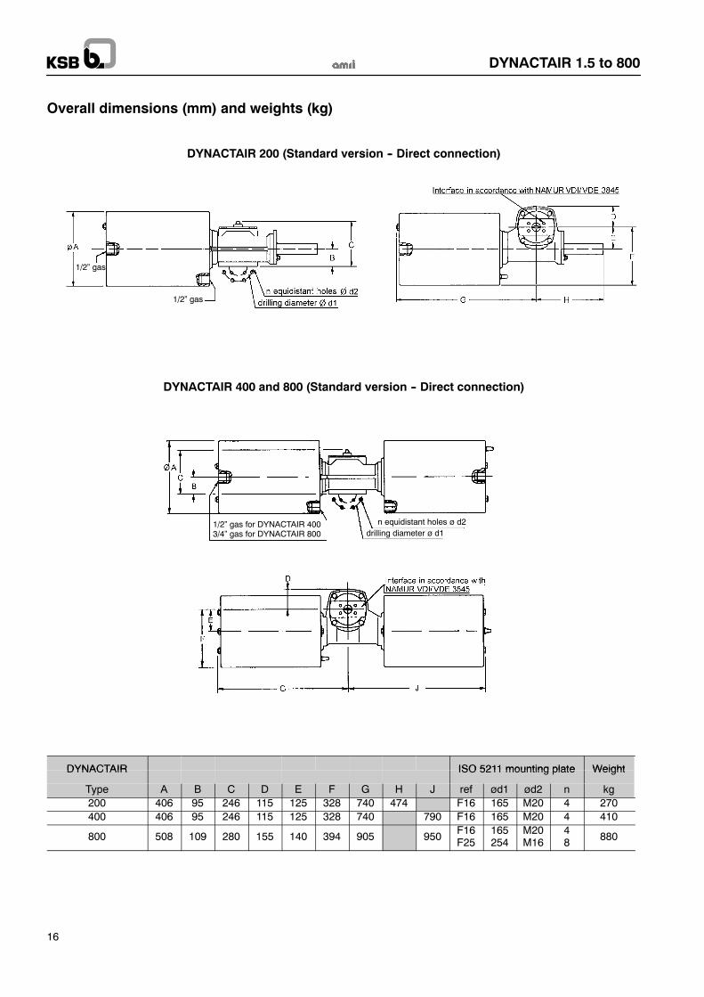
Overall dimensions (mm) and weights (kg)
DYNACTAIR 200 (Standard version -- Direct connection)
1/2” gas
1/2” gas
DYNACTAIR 400 and 800 (Standard version -- Direct connection)
1/2” gas for DYNACTAIR 4003/4” gas for DYNACTAIR 800
n equidistant holes ø d2drilling diameter ø d1
DYNACTAIR ISO 5211 mounting plate WeightDYNACTAIR ISO 5211 mounting plate Weight
Type A B C D E F G H J ref ød1 ød2 n kg200 406 95 246 115 125 328 740 474 F16 165 M20 4 270400 406 95 246 115 125 328 740 790 F16 165 M20 4 410
800 508 109 280 155 140 394 905 950F16F25
165254
M20M16
48 880
DYNACTAIR 1.5 to 800
17
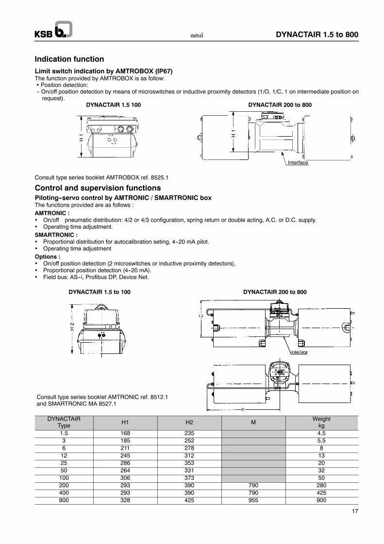
Indication function
Limit switch indication by AMTROBOX (IP67)The function provided by AMTROBOX is as follow:• Position detection:-- On/off position detection by means of microswitches or inductive proximity detectors (1/O, 1/C, 1 on intermediate position onrequest).
DYNACTAIR 1.5 100 DYNACTAIR 200 to 800
H1
Interface
H1
Consult type series booklet AMTROBOX ref. 8525.1
Control and supervision functionsPiloting--servo control by AMTRONIC / SMARTRONIC boxThe functions provided are as follows :AMTRONIC :• On/off pneumatic distribution: 4/2 or 4/3 configuration, spring return or double acting, A.C. or D.C. supply.• Operating time adjustment.SMARTRONIC :• Proportional distribution for autocalibration seting, 4--20 mA pilot.• Operating time adjustmentOptions :• On/off position detection (2 microswitches or inductive proximity detectors),• Proportional position detection (4--20 mA).• Field bus: AS--i, Profibus DP, Device Net.
DYNACTAIR 200 to 800DYNACTAIR 1.5 to 100
Consult type series booklet AMTRONIC ref. 8512.1and SMARTRONIC MA 8527.1
H2
DYNACTAIRType H1 H2 M
Weightkg
1.5 168 235 4,53 185 252 5,56 211 278 812 245 312 1325 286 353 2050 264 331 32100 306 373 50200 293 390 790 280400 293 390 790 425800 328 425 955 900
DYNACTAIR 1.5 to 800
18
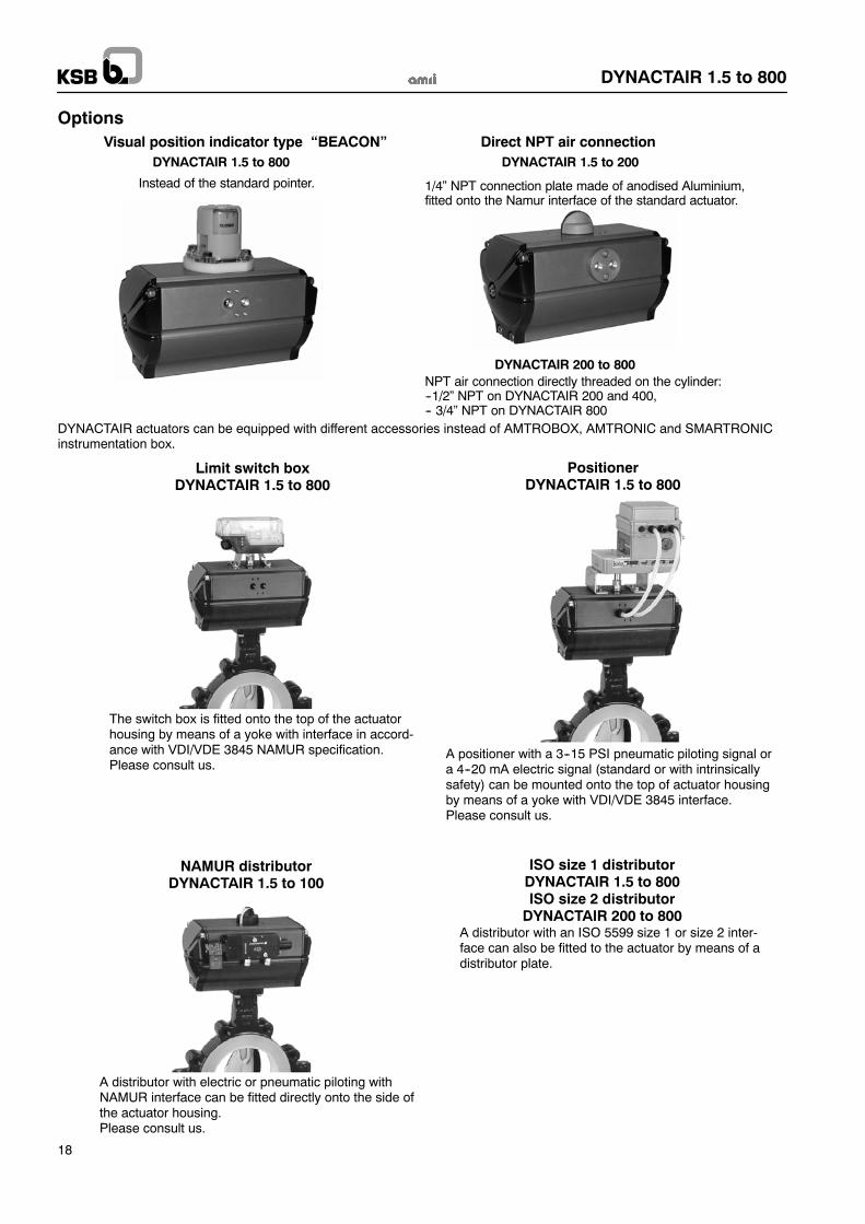
OptionsVisual position indicator type “BEACON”
Instead of the standard pointer.
DYNACTAIR 1.5 to 800
Direct NPT air connectionDYNACTAIR 1.5 to 200
DYNACTAIR 200 to 800NPT air connection directly threaded on the cylinder:--1/2” NPT on DYNACTAIR 200 and 400,-- 3/4” NPT on DYNACTAIR 800
1/4” NPT connection plate made of anodised Aluminium,fitted onto the Namur interface of the standard actuator.
DYNACTAIR actuators can be equipped with different accessories instead of AMTROBOX, AMTRONIC and SMARTRONICinstrumentation box.
A distributor with electric or pneumatic piloting withNAMUR interface can be fitted directly onto the side ofthe actuator housing.Please consult us.
NAMUR distributorDYNACTAIR 1.5 to 100
Limit switch boxDYNACTAIR 1.5 to 800
The switch box is fitted onto the top of the actuatorhousing by means of a yoke with interface in accord-ance with VDI/VDE 3845 NAMUR specification.Please consult us.
PositionerDYNACTAIR 1.5 to 800
A positioner with a 3--15 PSI pneumatic piloting signal ora 4--20 mA electric signal (standard or with intrinsicallysafety) can be mounted onto the top of actuator housingby means of a yoke with VDI/VDE 3845 interface.Please consult us.
ISO size 1 distributorDYNACTAIR 1.5 to 800ISO size 2 distributorDYNACTAIR 200 to 800
A distributor with an ISO 5599 size 1 or size 2 inter-face can also be fitted to the actuator by means of adistributor plate.
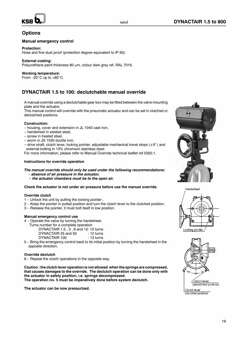
Amanual override using a declutchable gear boxmay be fitted between the valvemountingplate and the actuator.This manual control will override with the pneumatic actuator and can be set in clutched ordeclutched positions.
Construction:-- housing, cover and extension in JL 1040 cast iron,-- handwheel in welded steel,-- screw in treated steel,-- worm in JS 1030 ductile iron,-- drive shaft, clutch lever, locking pointer, adjustable mechanical travel stops (±5° ) andexternal bolting in 13% chromium stainless steel.For more information, please refer to Manual Override technical leaflet ref 5350.1.
Instructions for override operation
The manual override should only be used under the following recommendations:- absence of air pressure in the actuator,- the actuator chambers must be to the open air.
Check the actuator is not under air pressure before use the manual override.
Override clutch1 – Unlock the unit by pulling the locking pointer ,2 – Keep the pointer in pulled position and turn the clutch lever to the clutched position,3 – Release the pointer, it must bolt itself in low position.
Manual emergency control use4 – Operate the valve by turning the handwheel.
Turns number for a complete operationDYNACTAIR 1.5 , 3 , 6 and 12: 10 turnsDYNACTAIR 25 and 50 : 12 turnsDYNACTAIR 100 : 13 turns
5 – Bring the emergency control back to its initial position by turning the handwheel in theopposite direction.
Override declutch6 – Repeat the clutch operations in the opposite way.
Caution : the clutch lever operation is not allowed when thesprings are compressed,that causes damages to the override. The declutch operation can be done only withthe actuator in safety position, i.e. springs decompressed.The operation no. 5 must be imperatively done before system declutch.
The actuator can be now pressurized.
DYNACTAIR 1.5 to 800
19
Options
Manual emergency control
Protection:Hose and fine dust proof (protection degree equivalent to IP 65).
External coating:Polyurethane paint thickness 80 µm, colour dark grey ref. RAL 7016.
Working temperature:From –20°C up to +80°C.
DYNACTAIR 1.5 to 100: declutchable manual override
KSB S.A.S.4, allée des Barbanniers • 92635 Gennevilliers Cedex (France)Tel.: +33 1 41 47 75 00 • Fax: +33 1 41 47 75 10 • www.ksb.com
DYNACTAIR 1.5 to 800
Options
Manual emergency control
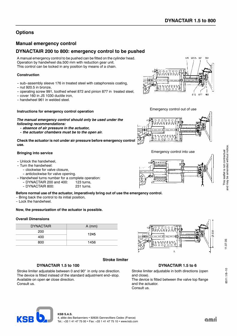
DYNACTAIR 200 to 800: emergency control to be pushedAmanual emergency control to be pushed can be fitted on the cylinder head.Operation by handwheel dia.500 mm with reduction gear unit.This control can be locked in any position by means of a chain.
Construction
-- sub--assembly sleeve 176 in treated steel with cataphoresis coating,-- nut 920.5 in bronze,-- operating screw 991, toothed wheel 872 and pinion 877 in treated steel,-- cover 160 in JS 1030 ductile iron,-- handwheel 961 in welded steel.
Instructions for emergency control operation
The manual emergency control should only be used under thefollowing recommendations:- absence of air pressure in the actuator,- the actuator chambers must be to the open air.
Check the actuator is not under air pressure before emergency controluse.
Bringing into service
-- Unlock the handwheel,-- Turn the handwheel:
-- clockwise for valve closure,-- anticlockwise for valve opening.
-- Handwheel turns number for a complete operation:-- DYNACTAIR 200 and 400: 123 turns,-- DYNACTAIR 800: 231 turns.
Emergency control out of use
Emergency control into use
Before normal use of the actuator, imperatively bring out of use the emergency control.-- Bring back the control to its initial position,-- Lock the handwheel.
Now, the pressurization of the actuator is possible.
Overall Dimensions
DYNACTAIR A (mm)
2001245
4001245
800 1456
Stroke limiterDYNACTAIR 1.5 to 100
Stroke limiter adjustable between 0 and 90° in only one direction.The device is fitted instead of the standard adjustment end--stop.Available on open or close direction.Consult us.
DYNACTAIR 1.5 to 6Stroke limiter adjustable in both directions (openand close).The device is fitted between the valve top flangeand the actuator.Consult us.
11.07.05
Thisleafletisnotcontractual
andmay
beam
endedwithoutnotice.
8511.1/6--10


![DTU...0 100 200 300 400 500 600 700 800 0.5 1 1.5 2 2.5] 0 100 200 300 400 500 600 700 800 49.9 49.95 50 50.05 50.1 50.15] 0 100 200 300 400 500 600 700 800 15 …](https://img.pdfslide.us/doc/110x75/60a27572ca4d7f2ddb428ae4/dtu-0-100-200-300-400-500-600-700-800-05-1-15-2-25-0-100-200-300-400-500.jpg)


![[XLS]sdmylife.comsdmylife.com/files/Master_Course_List_08.27.14.xlsx · Web view3. 3. 1. 1.5. 3. 3. 1.5. 1.5. 1.5. 1.5. 1.5. 1.5. 1.5. 3. 1.5. 3. 3. 3. 1.5. 1.5. 2. 3. 3. 1.5. 1.5](https://img.pdfslide.us/doc/110x75/5ac153d87f8b9a213f8cf61b/xls-view3-3-1-15-3-3-15-15-15-15-15-15-15-3-15-3-3-3.jpg)