Embed Size (px)
Citation preview
IMU-P
DatasheetRev.2.4
InertialLabsAddress:39959CatoctinRidgeStreet,PaeonianSprings,VA20129U.S.A.
Tel:+1(703)880-4222,Fax:+1(703)935-8377Website:www.inertiallabs.com
1
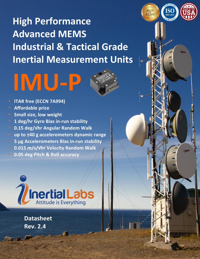
HighPerformanceAdvancedMEMSIndustrial&TacticalGradeInertialMeasurementUnits
IMU-P
DatasheetRev.2.4
• ITARfree(ECCN7A994)• Affordableprice• Smallsize,lowweight• 1deg/hrGyroBiasin-runstability• 0.15deg/√hrAngularRandomWalk• upto±40gaccelerometersdynamicrange• 5μgAccelerometersBiasin-runstability• 0.015m/s/√hrVelocityRandomWalk• 0.05degPitch&Rollaccuracy

IMU-P
DatasheetRev.2.4
InertialLabsAddress:39959CatoctinRidgeStreet,PaeonianSprings,VA20129U.S.A.
Tel:+1(703)880-4222,Fax:+1(703)935-8377Website:www.inertiallabs.com
2
The Inertial Labs Inertial Measurement Unit (IMU-P) is an Advanced MEMS sensors based, compact, self-contained strapdown, industrial and tactical grade Inertial Measurement Systems and Digital Tilt Sensor, that measures linear accelerations, angular rates, Pitch & Roll with three-axis high-grade MEMS accelerometers and three-axis tactical grade MEMS gyroscopes. Angular rates and accelerations are determined with high accuracy for both motionless and dynamic applications.
The Inertial Labs IMU-P is breakthrough, fully integrated inertial solutions that combine the latest MEMS sensors technology. Fully calibrated, temperature compensated, mathematically aligned to an orthogonal coordinate system, IMU demonstrate less than 1 deg/hr gyroscopes and 0.005 mg accelerometers bias in-run stability with very low noise and high reliability.
Continuous Built-in Test (BIT), configurable communications protocols, electromagnetic interference (EMI) protection, and flexible input power requirements make the Inertial Labs IMU-P easy to use in a wide range of higher order integrated system applications.
The Inertial Labs IMU-P was designed for applications, like: v Antenna and Line of Sight Stabilization Systems v Passengers trains acceleration / deceleration and jerking systems v Motion Reference Units (MRU) v Motion Control Sensors (MCS) v Gimbals, EOC/IR, platforms orientation and stabilization v GPS-Aided Inertial Navigation Systems (INS) v Attitude and Heading Reference Systems (AHRS) v Land vehicles navigation and motion analysis v Buoy or Racing Boat Motion Monitoring v UAV & AUV/ROV navigation and control
Parameter IMU-P “Industrial”
IMU-P “Tactical”
GYROSCOPES (±450 deg/sec range) Gyroscopes Bias in-run stability, RMS 3 deg/hr 1 deg/hr
Gyroscopes error over temperature, RMS 50 deg/hr 25 deg/hr Gyroscopes Angular Random Walk, RMS 0.3 deg/√hr 0.15 deg/√hr
ACCELEROMETERS (±8 g range) Accelerometers Bias in-run stability, RMS 0.01 mg 0.005 mg
Accelerometers error over temperature, RMS 0.7 mg 0.5 mg Accelerometers Velocity Random Walk 0.018 m/sec/√hr 0.015 m/sec/√hr
PITCH & ROLL Pitch & Roll static accuracy, RMS 0.05 deg 0.05 deg
Pitch & Roll dynamic accuracy, RMS 0.08 deg 0.08 deg
IMU-P
DatasheetRev.2.4
InertialLabsAddress:39959CatoctinRidgeStreet,PaeonianSprings,VA20129U.S.A.
Tel:+1(703)880-4222,Fax:+1(703)935-8377Website:www.inertiallabs.com
3
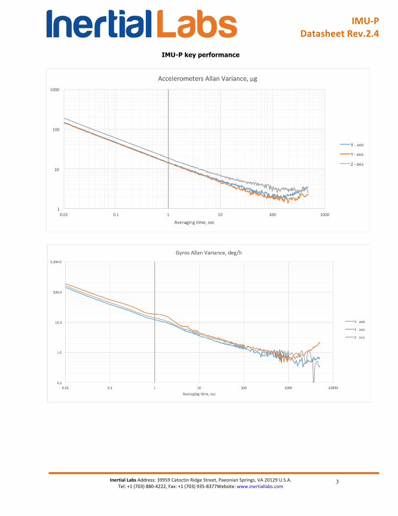
IMU-P key performance
IMU-P
DatasheetRev.2.4
InertialLabsAddress:39959CatoctinRidgeStreet,PaeonianSprings,VA20129U.S.A.
Tel:+1(703)880-4222,Fax:+1(703)935-8377Website:www.inertiallabs.com
4
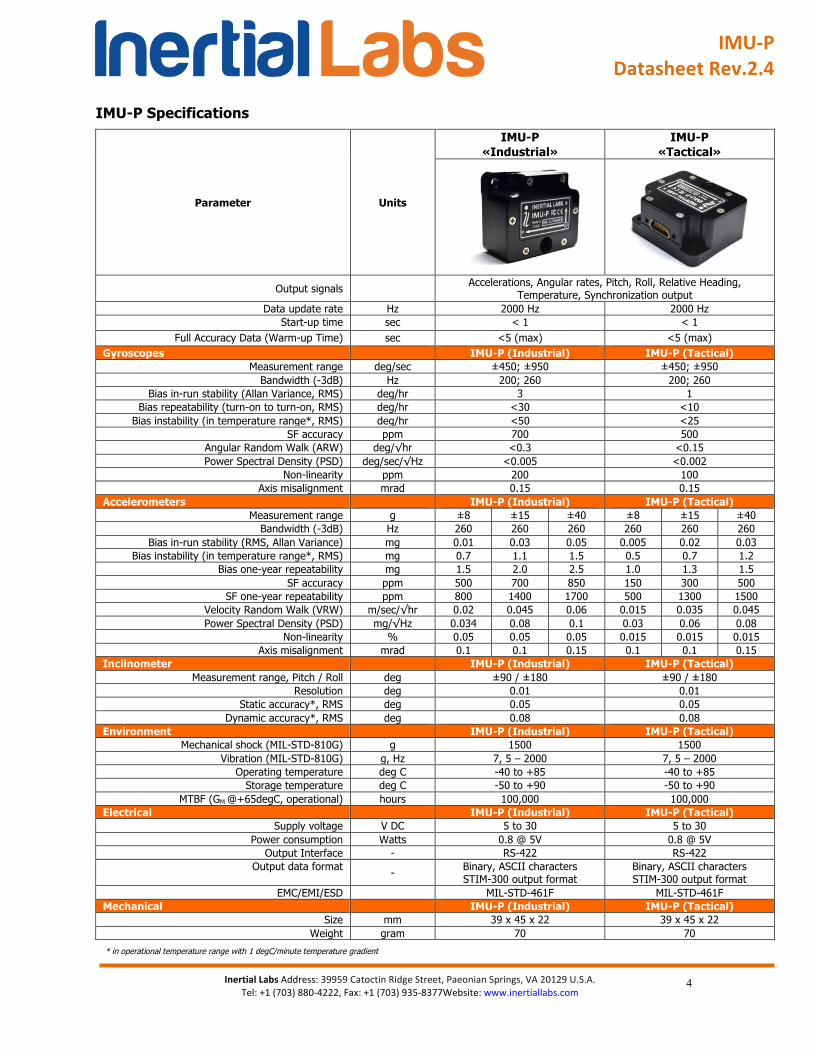
IMU-P Specifications
Parameter Units
IMU-P «Industrial»
IMU-P «Tactical»
Output signals Accelerations, Angular rates, Pitch, Roll, Relative Heading, Temperature, Synchronization output
Data update rate Hz 2000 Hz 2000 Hz Start-up time sec < 1 < 1
Full Accuracy Data (Warm-up Time) sec <5 (max) <5 (max) Gyroscopes IMU-P (Industrial) IMU-P (Tactical)
Measurement range deg/sec ±450; ±950 ±450; ±950 Bandwidth (-3dB) Hz 200; 260 200; 260
Bias in-run stability (Allan Variance, RMS) deg/hr 3 1 Bias repeatability (turn-on to turn-on, RMS) deg/hr <30 <10
Bias instability (in temperature range*, RMS) deg/hr <50 <25 SF accuracy ppm 700 500
Angular Random Walk (ARW) deg/√hr <0.3 <0.15 Power Spectral Density (PSD) deg/sec/√Hz <0.005 <0.002
Non-linearity ppm 200 100 Axis misalignment mrad 0.15 0.15
Accelerometers IMU-P (Industrial) IMU-P (Tactical) Measurement range g ±8 ±15 ±40 ±8 ±15 ±40
Bandwidth (-3dB) Hz 260 260 260 260 260 260 Bias in-run stability (RMS, Allan Variance) mg 0.01 0.03 0.05 0.005 0.02 0.03
Bias instability (in temperature range*, RMS) mg 0.7 1.1 1.5 0.5 0.7 1.2 Bias one-year repeatability mg 1.5 2.0 2.5 1.0 1.3 1.5
SF accuracy ppm 500 700 850 150 300 500 SF one-year repeatability ppm 800 1400 1700 500 1300 1500
Velocity Random Walk (VRW) m/sec/√hr 0.02 0.045 0.06 0.015 0.035 0.045 Power Spectral Density (PSD) mg/√Hz 0.034 0.08 0.1 0.03 0.06 0.08
Non-linearity % 0.05 0.05 0.05 0.015 0.015 0.015 Axis misalignment mrad 0.1 0.1 0.15 0.1 0.1 0.15
Inclinometer IMU-P (Industrial) IMU-P (Tactical) Measurement range, Pitch / Roll deg ±90 / ±180 ±90 / ±180
Resolution deg 0.01 0.01 Static accuracy*, RMS deg 0.05 0.05
Dynamic accuracy*, RMS deg 0.08 0.08 Environment IMU-P (Industrial) IMU-P (Tactical)
Mechanical shock (MIL-STD-810G) g 1500 1500 Vibration (MIL-STD-810G) g, Hz 7, 5 – 2000 7, 5 – 2000
Operating temperature deg C -40 to +85 -40 to +85 Storage temperature deg C -50 to +90 -50 to +90
MTBF (GM @+65degC, operational) hours 100,000 100,000 Electrical IMU-P (Industrial) IMU-P (Tactical)
Supply voltage V DC 5 to 30 5 to 30 Power consumption Watts 0.8 @ 5V 0.8 @ 5V
Output Interface - RS-422 RS-422
Output data format - Binary, ASCII characters STIM-300 output format
Binary, ASCII characters STIM-300 output format
EMC/EMI/ESD MIL-STD-461F MIL-STD-461F Mechanical IMU-P (Industrial) IMU-P (Tactical)
Size mm 39 x 45 x 22 39 x 45 x 22 Weight gram 70 70
* in operational temperature range with 1 degC/minute temperature gradient
IMU-P
DatasheetRev.2.4
InertialLabsAddress:39959CatoctinRidgeStreet,PaeonianSprings,VA20129U.S.A.
Tel:+1(703)880-4222,Fax:+1(703)935-8377Website:www.inertiallabs.com
5
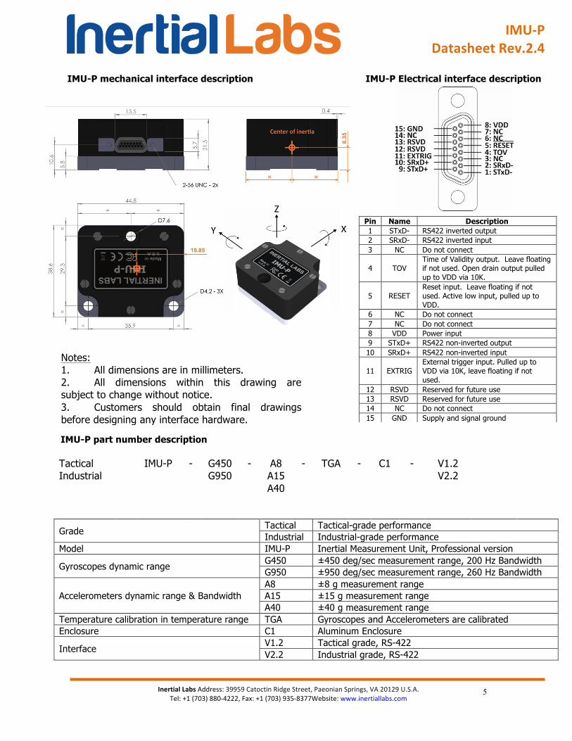
IMU-P mechanical interface description IMU-P Electrical interface description
IMU-P part number description
Tactical IMU-P - G450 - A8 - TGA - C1 - V1.2 Industrial G950 A15 V2.2
A40
Grade Tactical Tactical-grade performance Industrial Industrial-grade performance
Model IMU-P Inertial Measurement Unit, Professional version
Gyroscopes dynamic range G450 ±450 deg/sec measurement range, 200 Hz Bandwidth G950 ±950 deg/sec measurement range, 260 Hz Bandwidth
Accelerometers dynamic range & Bandwidth A8 ±8 g measurement range A15 ±15 g measurement range A40 ±40 g measurement range
Temperature calibration in temperature range TGA Gyroscopes and Accelerometers are calibrated Enclosure C1 Aluminum Enclosure
Interface V1.2 Tactical grade, RS-422 V2.2 Industrial grade, RS-422
Pin Name Description 1 STxD- RS422 inverted output 2 SRxD- RS422 inverted input 3 NC Do not connect
4 TOV Time of Validity output. Leave floating if not used. Open drain output pulled up to VDD via 10K.
5 RESET Reset input. Leave floating if not used. Active low input, pulled up to VDD.
6 NC Do not connect 7 NC Do not connect 8 VDD Power input 9 STxD+ RS422 non-inverted output 10 SRxD+ RS422 non-inverted input
11 EXTRIG External trigger input. Pulled up to VDD via 10K, leave floating if not used.
12 RSVD Reserved for future use 13 RSVD Reserved for future use 14 NC Do not connect 15 GND Supply and signal ground
Notes: 1. All dimensions are in millimeters. 2. All dimensions within this drawing are subject to change without notice. 3. Customers should obtain final drawings before designing any interface hardware.