Embed Size (px)
Citation preview

Project Number: Tracking Code: TC0612--0977
Requested by: Gary Lewis Date: 3/24/2006 Product Rev: N/A
Part #: N-EQRF-020-06.0-T-L-SMA-J-1 Lot #: N/A Tech: Troy Cook/Tony Wagoner
Eng: Dave Scopelliti
Part description: EQRF Qty to test: 40
Test Start: 05/12/2006 Test Completed: 8/1/2006
Page 1 of 19
DVT REPORT
for EQRF-020-06.0-T-L-SMA-J-1
Mated with SMA-J-P-H-ST-TH1

Tracking Code: TC0612--0977 Part #: N-EQRF-020-06.0-T-L-SMA-J-1 Part description: EQRF
Page 2 of 19
CERTIFICATION
All instruments and measuring equipment were calibrated to National Institute for Standards and Technology (NIST) traceable standards according to IS0 10012-l and ANSI/NCSL 2540-1, as applicable. All contents contained herein are the property of Samtec. No portion of this report, in part or in full shall be reproduced without prior written approval of Samtec. SCOPE To perform the following tests: TESTPLAN ALLREADY SETUP….IR/DWV, CCC, PULL, FLEX APPLICABLE DOCUMENTS Standards: EIA Publication 364 TEST SAMPLES AND PREPARATION
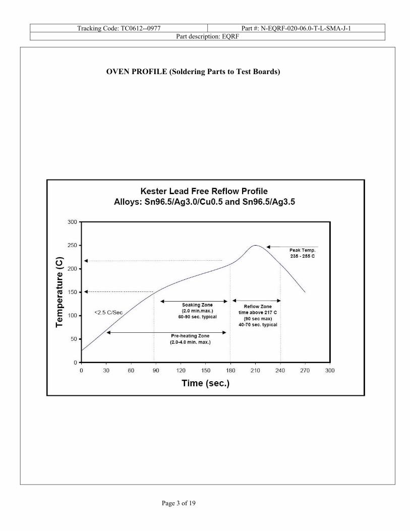
1) All materials were manufactured in accordance with the applicable product specification. 2) All test samples were identified and encoded to maintain traceability throughout the test sequences. 3) After soldering, the parts to be used for LLCR and DWV/IR testing were cleaned according to TLWI-0001. 4) Either an automated cleaning procedure or an ultrasonic cleaning procedure may be used. 5) The automated procedure is used with aqueous compatible soldering materials. 6) Parts not intended for testing LLCR and DWV/IR are visually inspected and cleaned if necessary. 7) Any additional preparation will be noted in the individual test sequences. 8) Solder Information: Lead Free 9) Re-Flow Time/Temp: See accompanying profile. 10) Internal Test PCBs used: PCB-100492-TST-XX
Tracking Code: TC0612--0977 Part #: N-EQRF-020-06.0-T-L-SMA-J-1 Part description: EQRF
Page 3 of 19
OVEN PROFILE (Soldering Parts to Test Boards)

Tracking Code: TC0612--0977 Part #: N-EQRF-020-06.0-T-L-SMA-J-1 Part description: EQRF
Page 4 of 19
FLOWCHARTS
Current Carrying Capacity
TEST GROUP 1
STEP Cable Center
6 Adjacent Signal Lines01 CCC
Tabulate calculated current at RT, 55° C, 65° C and 70° Cafter derating 20% and based on 80° C
CCC, Temp rise = EIA-364-70
IR
TEST GROUP 1A GROUP 1A
STEP DV DVPin-Pin Row-Row
01 IR IR
02 Data Review Data Review
03 Thermal Aging Thermal Aging
04 IR IR
05 Data Review Data Review
06 Humidity Humidity07 IR IR
Thermal Aging = EIA-364-17, Test Condition 4, 105 deg C;Time Condition 'B' (250 hours)
Humidity =EIA-364-31, Test Condition B (240 Hours) and Method III (+25 ° C to +65 ° C @ 90%RH to 98% RH)delete steps 7a and 7b
DWV
TEST GROUP 1a GROUP 2a GROUP 1b GROUP 2b GROUP 1c GROUP 2c
STEP Pin-Pin Row-Row Pin-Pin Row-Row Pin-Pin Row-RowAmbient Ambient Thermals Thermals Humidity Humidity
01DWV/Working
VoltageDWV/Working
Voltage Thermal Aging Thermal Aging Humidity Humidity
02DWV/Working
VoltageDWV/Working
VoltageDWV/Working
VoltageDWV/Working
Voltage
Thermal Aging = EIA-364-17, Test Condition 4, 105 deg C;Time Condition 'B' (250 hours)
Humidity =EIA-364-31, Test Condition B (240 Hours) and Method III (+25 ° C to +65 ° C @ 90%RH to 98% RH)delete steps 7a and 7b

Tracking Code: TC0612--0977 Part #: N-EQRF-020-06.0-T-L-SMA-J-1 Part description: EQRF
Page 5 of 19
FLOWCHARTS Continued
Connector Pull
TEST GROUP 1A GROUP 1B
STEP DV DV
SIG 0° SIG 90°
01 Pull test, Continuity Pull test, Continuity
Secure both cables in the centerMonitor continuity and pullrecord forces when continuity fails. Resistance, Snaked for 2-Wire Resistance
Flex Mode Pendulum ModeTEST GROUP 1 GROUP 2
STEP DV DVSIG, ±90° Bend Shroud SIG, ±35° Bend Shroud
01 Resistance Resistance
02 5000 Cycles 5000 Cycles
03 Data Review Data Review
04 Resistance Resistance
05 10000 Cycles 10000 Cycles06 Data Review Data Review
07 Resistance Resistance
08 15000 Cycles 15000 Cycles
09 Data Review Data Review
10 Resistance Resistance
11 20000 Cycles 20000 Cycles
12 Data Review Data Review
13 Resistance Resistance14 25000 Cycles 25000 Cycles15 Resistance Resistance
Cycling with No Load on cable loading at 1500 to 3000 /Hour25 to 50 per minute

Tracking Code: TC0612--0977 Part #: N-EQRF-020-06.0-T-L-SMA-J-1 Part description: EQRF
Page 6 of 19
ATTRIBUTE DEFINITIONS
The following is a brief, simplified description of attributes. THERMAL:
1) EIA-364-17, Temperature Life with or without Electrical Load Test Procedure for Electrical Connectors. 2) Test Condition 4 at 105° C. 3) Test Time Condition B for 250 hours. 4) Connectors are sometimes mated and all samples are pre-conditioned at ambient.
HUMIDITY:
1) Reference document: EIA-364-31, Humidity Test Procedure for Electrical Connectors. 2) Test Condition B, 240 Hours. 3) Method III, +25° C to + 65° C, 90% to 98% Relative Humidity excluding sub-cycles 7a and 7b. 4) Connectors are sometimes mated and all samples are pre-conditioned at ambient.
TEMPERATURE RISE (Current Carrying Capacity, CCC):
1) EIA-364-70, Temperature Rise versus Current Test Procedure for Electrical Connectors and Sockets. 2) When current passes through a contact, the temperature of the contact increases as a result of I2R (resistive)
heating. 3) The number of contacts being investigated plays a significant part in power dissipation and therefore
temperature rise. 4) The size of the temperature probe can affect the measured temperature. 5) Copper traces on PC boards will contribute to temperature rise:
a. Self heating (resistive) b. Reduction in heat sink capacity affecting the heated contacts
6) A de-rating curve, usually 20%, is calculated. 7) Calculated de-rated currents at three temperature points are reported:
a. Ambient b. 55о C c. 65о C d. 70о C
8) Typically, neighboring contacts (in close proximity to maximize heat build up) are energized. 9) The thermocouple (or temperature measuring probe) will be positioned at a location to sense the maximum
temperature in the vicinity of the heat generation area. 10) A computer program, TR 803.exe, ensures accurate stability for data acquisition. 11) Hook-up wire cross section is larger than the cross section of any connector leads/PC board traces, jumpers,
etc. 12) Hook-up wire length is longer than the minimum specified in the referencing standard.

Tracking Code: TC0612--0977 Part #: N-EQRF-020-06.0-T-L-SMA-J-1 Part description: EQRF
Page 7 of 19
INSULATION RESISTANCE (IR):
To determine the resistance of insulation materials to leakage of current through or on the surface of these materials when a DC potential is applied.
1) PROCEDURE: a. Reference document: EIA-364-21, Insulation Resistance Test Procedure for Electrical Connectors. b. Test Conditions:
i. Between Adjacent Contacts ii. Electrification Time 2.0 minutes iii. Test Voltage (500 VDC) corresponds to calibration settings for measuring resistances.
2) MEASUREMENTS: 3) When the specified test voltage is applied (VDC), the insulation resistance shall not be less than 5000
megohms. DIELECTRIC WITHSTANDING VOLTAGE (DWV):
To determine if the sockets can operate at its rated voltage and withstand momentary over potentials due to switching, surges, and other similar phenomenon. Separate samples are used to evaluate the effect of environmental stresses so not to influence the readings from arcing that occurs during the measurement process.
1) PROCEDURE: a. Reference document: EIA-364-20, Withstanding Voltage Test Procedure for Electrical Connectors. b. Test Conditions:
i. Between Adjacent Contacts ii. Rate of Application 500 V/Sec
iii. Test Voltage (VAC) until breakdown occurs 2) MEASUREMENTS/CALCULATIONS
a. The breakdown voltage shall be measured and recorded. b. The dielectric withstanding voltage shall be recorded as 75% of the minimum breakdown voltage. c. The working voltage shall be recorded as one-third (1/3) of the dielectric withstanding voltage (one-
fourth of the breakdown voltage).

Tracking Code: TC0612--0977 Part #: N-EQRF-020-06.0-T-L-SMA-J-1 Part description: EQRF
Page 8 of 19
SUPPLEMENTAL TESTS
CONNECTOR PULL:
1) Secure cable near center and pull on connector a. At 90°, right angle to cable b. At 0°, in-line with cable
Fig. 1 (Typical set-up.)
0° Connector pull, notice the electrical continuity hook-up wires.

Tracking Code: TC0612--0977 Part #: N-EQRF-020-06.0-T-L-SMA-J-1 Part description: EQRF
Page 9 of 19
CABLE DURABILITY:
1) Oscillate and monitor electrical continuity for open circuit indication.
a. ± 35° Pendulum Mode, bend up to 15,000 cycles with no weight or load on the cable end.
Fig. 2 (Typical set-up, actual part depicted.)

Tracking Code: TC0612--0977 Part #: N-EQRF-020-06.0-T-L-SMA-J-1 Part description: EQRF
Page 10 of 19
b. ± 90° Flex Mode, bend up to 5,000 cycles with no weight or load on cable end.
Fig. 3 (Typical set-up, actual part depicted.)

Tracking Code: TC0612--0977 Part #: N-EQRF-020-06.0-T-L-SMA-J-1 Part description: EQRF
Page 11 of 19
RESULTS
Temperature Rise, CCC at a 20% de-rating
• CCC for a 30°C Temperature Rise (Cable Center) ---1.3 A per contact with 6 adjacent contacts powered Insulation Resistance minimums, IR
• Initial o Row to Row---------------------------------------- 10,000 Meg Ω ------------------------ Pass o Pin to Pin------------------------------------------100,000 Meg Ω
• Thermal o Row to Row---------------------------------------100,000 Meg Ω o Pin to Pin------------------------------------------- 50,000 Meg Ω
• Humidity o Row to Row---------------------------------------100,000 Meg Ω o Pin to Pin------------------------------------------- 50,000 Meg Ω
Dielectric Withstanding Voltage minimums, DWV
• Initial o Breakdown
Row to Row-------------------------------1,800 VAC Pin to Pin------------------------------------740 VAC
o DWV Row to Row-------------------------------1,350 VAC Pin to Pin------------------------------------555 VAC
o Working voltage Row to Row---------------------------------450 VAC Pin to Pin------------------------------------185 VAC
• Thermal o Breakdown
Row to Row-------------------------------1,000 VAC Pin to Pin----------------------------------1,100 VAC
o DWV Row to Row---------------------------------750 VAC Pin to Pin------------------------------------825 VAC
o Working voltage Row to Row---------------------------------250 VAC Pin to Pin------------------------------------275 VAC
• Humidity o Breakdown
Row to Row-------------------------------1,400 VAC Pin to Pin----------------------------------1,000 VAC
o DWV Row to Row-------------------------------1,050 VAC Pin to Pin------------------------------------750 VAC
o Working voltage Row to Row---------------------------------350 VAC Pin to Pin------------------------------------250 VAC

Tracking Code: TC0612--0977 Part #: N-EQRF-020-06.0-T-L-SMA-J-1 Part description: EQRF
Page 12 of 19
SUPPLEMENTAL TESTING
Supplemental – Connector/Cable Pull
• 0°----------------------------------------------------------------------- 138.06 lbs min • 90° --------------------------------------------------------------------- 79.72 lbs min
Supplemental – Cable Bend 25,000 Cycles
• ±35° Pendulum Mode --------------------------------------------- Earliest failure at 24,317 Cycles • ±90°Flex Mode------------------------------------------------------ Earliest failure at 459 Cycles

Tracking Code: TC0612--0977 Part #: N-EQRF-020-06.0-T-L-SMA-J-1 Part description: EQRF
Page 13 of 19
DATA SUMMARIES
TEMPERATURE RISE (Current Carrying Capacity, CCC):
1) High quality thermocouples whose temperature slopes track one another were used for temperature monitoring.
2) The thermocouples were placed at a location to sense the maximum temperature generated during testing. 3) Temperature readings recorded are those for which three successive readings, 15 minutes apart, differ less
than 1° C (computer controlled data acquisition). 4) Adjacent contacts were powered:
a. Linear configuration with SIX adjacent conductors/contacts powered 5) CCC was tested with the thermocouples in the following locations:
a. Bundled in the cable, 6 adjacent lines powered
TC0612--09776 Contacts powered
Themocouple in Cable
2.22.2
1.81.8
1.41.4
1.21.2 1.11.1
0.90.9 0.90.9
0.70.7
0.0
0.5
1.0
1.5
2.0
2.5
3.0
18 28 38 48 58 68 78 88
Ambient Temperature, ° C
Max
imum
Cur
rent
, Am
p pe
r Con
tact
Base CurveDerated 20 %RT Peak AmpRT Derated AmpMeasured Current55 ° C55 ° C Peak Amp55 ° C Derated Amp65 ° C65 ° C Peak Amp65 ° C Derated AmpLimit70 ° C Peak Amp70 ° C Derated Amp70 ° CRoom Temp
80° CLimit
Useful Range
Room Temp= 21.4 C Typical LLCR (Ohms)= 1.81

Tracking Code: TC0612--0977 Part #: N-EQRF-020-06.0-T-L-SMA-J-1 Part description: EQRF
Page 14 of 19
DATA SUMMARIES Continued
INSULATION RESISTANCE (IR): Initial, Meg Ohms Thermal, Meg Ohms Humidity, Meg Ohms
P-P R-R P-P R-R P-P R-R
Insulation Resistance
Insulation Resistance
Insulation Resistance
Insulation Resistance
Insulation Resistance
Insulation Resistance
Average 100000 55000 75000 100000 75000 100000 Min 100000 10000 50000 100000 50000 100000 Max 100000 100000 100000 100000 100000 100000
DIELECTRIC WITHSTANDING VOLTAGE (DWV):
Initial, VAC P-P Initial, VAC R-R
Breakdown
Voltage DWV Working Voltage
Breakdown Voltage DWV
Working Voltage
Average 1030 773 258 1517 1138 379 Min 740 555 185 1000 750 250 Max 1200 900 300 1900 1425 475
Thermal, VAC P-P Thermal, VAC R-R
Breakdown
Voltage DWV Working Voltage
Breakdown Voltage DWV
Working Voltage
Average 1120 840 280 1150 863 288 Min 1100 825 275 1000 750 250 Max 1140 855 285 1300 975 325
Humidity, VAC P-P Humidity, VAC R-R
Breakdown
Voltage DWV Working Voltage
Breakdown Voltage DWV
Working Voltage
Average 1000 750 250 1550 1163 388 Min 1000 750 250 1400 1050 350 Max 1000 750 250 1700 1275 425

Tracking Code: TC0612--0977 Part #: N-EQRF-020-06.0-T-L-SMA-J-1 Part description: EQRF
Page 15 of 19
DATA SUMMARIES Continued
SUPPLEMENTAL – CONNECTOR/CABLE PULL 0 Deg. Pull 90 Deg. Pull
Force (Lbs) Force (Lbs) Minimum 138.06 79.72 Maximum 155.00 93.71 Average 144.3 86.3
SUPPLEMENTAL – CABLE BEND 15,000 CYCLES
a. 35 Deg. Pendulum Resistance, Ohms Initial 5000 10000 15000 20000 25000
Avg 11.4250 11.3400 11.3150 11.3550 11.3450 11.3600 Min 11.3700 11.3200 11.3000 11.3500 11.3400 11.3600 Max 11.4800 11.3600 11.3300 11.3600 11.3500 11.3600
St. Dev. 0.0778 0.0283 0.0212 0.0071 0.0071 N/A Count 2 2 2 2 2 1
b. 90 Deg. Flex
Resistance, Ohms Initial 5000 10000 15000 20000 25000
Avg 11.3950 #DIV/0! #DIV/0! #DIV/0! #DIV/0! #DIV/0! Min 11.3800 0.0000 0.0000 0.0000 0.0000 0.0000 Max 11.4100 0.0000 0.0000 0.0000 0.0000 0.0000
St. Dev. 0.0212 #DIV/0! #DIV/0! #DIV/0! #DIV/0! #DIV/0! Count 2 0 0 0 0 0

Tracking Code: TC0612--0977 Part #: N-EQRF-020-06.0-T-L-SMA-J-1 Part description: EQRF
Page 16 of 19
DATA
INSULATION RESISTANCE (IR): Initial, Meg Ohms Thermal, Meg Ohms Humidity, Meg Ohms
P-P R-R P-P R-R P-P R-R
Sample # Insulation Resistance
Insulation Resistance
Insulation Resistance
Insulation Resistance
Insulation Resistance
Insulation Resistance
1 100000 10000 50000 100000 50000 100000 2 100000 100000 100000 100000 100000 100000
DIELECTRIC WITHSTANDING VOLTAGE (DWV): Initial, VAC P-P Initial, VAC R-R Sample
# Breakdown
Voltage DWV Working Voltage
Breakdown Voltage DWV
Working Voltage
1 740 555 185 1800 1350 450 2 1200 900 300 1900 1425 475
Thermal, VAC P-P Thermal, VAC R-R Sample
# Breakdown
Voltage DWV Working Voltage
Breakdown Voltage DWV
Working Voltage
1 1140 855 285 1300 975 325 2 1100 825 275 1000 750 250
Humidity, VAC P-P Humidity, VAC R-R Sample
# Breakdown
Voltage DWV Working Voltage
Breakdown Voltage DWV
Working Voltage
1 1000 750 250 1400 1050 350 2 1000 750 250 1700 1275 425

Tracking Code: TC0612--0977 Part #: N-EQRF-020-06.0-T-L-SMA-J-1 Part description: EQRF
Page 17 of 19
DATA (continued)
SUPPLEMENTAL – CONNECTOR/CABLE PULL
0 Deg. Pull 90 Deg. Pull Sample# Maximum Force (Lbs) Maximum Force (Lbs)
1 138.06 93.71 2 139.90 85.42 3 155.00 79.72
NOTE: Tested 6 wires bundled together for pull testing.
SUPPLEMENTAL – CABLE BEND 15,000 CYCLES
a. 35 Deg. Pendulum
No Load Used Cable Resistance, Ohms
Initial 5000 10000 15000 20000 25000 1 11.48 11.32 11.30 11.36 11.34 Failed at 24317 Cycles 2 11.37 11.36 11.33 11.35 11.35 11.3600
b. 90 Deg. Flex
No Load Used Cable Resistance, Ohms
Initial 5000 10000 15000 20000 25000 1 11.3800 Failed at 459 cycles N/A N/A N/A N/A 2 11.4100 Failed at 813 cycles N/A N/A N/A N/A

Tracking Code: TC0612--0977 Part #: N-EQRF-020-06.0-T-L-SMA-J-1 Part description: EQRF
Page 18 of 19
EQUIPMENT AND CALIBRATION SCHEDULES
Equipment #: MO-02 Description: Multimeter /Data Acquisition System Manufacturer: Keithley Model: 2700 Serial #: 0780546 Accuracy: See Manual … Last Cal: 05/12/06, Next Cal: 05/12/07 Equipment #: MO-04 Description: Multimeter /Data Acquisition System Manufacturer: Keithley Model: 2700 Serial #: 0798688 Accuracy: See Manual … Last Cal: 01/31/06, Next Cal: 01/31/07 Equipment #: PS-01 Description: System Power Supply Manufacturer: Hewlett Packard Model: HP 6033A Serial #: (HP) 3329A-07330 Accuracy: See Manual … Last Cal: 05/12/06, Next Cal: 05/12/07 Equipment #: TC090601-103/105 Description: IC Thermocouple-103/105 Manufacturer: Samtec Model: Serial #: TC090601-103/105 Accuracy: +/- 1 degree C … Last Cal: , Next Cal: Equipment #: HPM-01 Description: Hipot Megommeter Manufacturer: Hipotronics Model: H306B-A Serial #: M9905004 Accuracy: 2 % Full Scale Accuracy … Last Cal: 5/12/06, Next Cal: 05/12/07

Tracking Code: TC0612--0977 Part #: N-EQRF-020-06.0-T-L-SMA-J-1 Part description: EQRF
Page 19 of 19
Equipment #: OV-03 Description: Cascade Tek Forced Air Oven Manufacturer: Cascade Tek Model: TFO-5 Serial #: 0500100 Accuracy: Temp. Stability: +/-.1C/C change in ambient … Last Cal: 05/12/06, Next Cal: 05/12/07 Equipment #: THC-01 Description: Temperature/Humidity Chamber Manufacturer: Thermotron Model: SM-8-7800 Serial #: 30676 Accuracy: See Manual See Manual … Last Cal: 8/18/2006, Next Cal: 8/18/2007 Equipment #: TCT-03 Description: Dillon Quantrol TC2 Test Stand Manufacturer: Dillon Quantrol Model: TC2 Serial #: 02-1033-03 Accuracy: Speed Accuracy: +/- 5% of indicated speed; Displacement: +/- 5 micrometers. … Last Cal: 5/12/06, Next Cal: 5/12/07 Equipment #: LC-2500N(icell) Description: 2500 N Load Cell for Dillon Quantrol Manufacturer: Dillon Quantrol Model: icell Serial #: 01-0132-01 Accuracy: .10% of capacity … Last Cal: 6/13/06, Next Cal: 6/13/07 Equipment #: MO-01 Description: Micro-Ohmeter Manufacturer: Keithley Model: 580 Serial #: 0772740 Accuracy: See Manual … Last Cal: 05/12/06, Next Cal: 05/12/07 Equipment #: HDR - 01 Description: HDR Flex Tester Manufacturer: Samtec Inc. Model: AT-1440-000 Serial #: 0780546 Accuracy: N/A … Last Cal: No Calibration Required…