Embed Size (px)
Citation preview
Digital Video Recorder User Manual
i
DVR User Manual
For H.264-4-channe/ 8-channel/16-channel Digital Video Recorder All rights reserved

Digital Video Recorder User Manual
ii
CAUTION Please read this user manual carefully to ensure that you can use the device correctly and safely This manual is suitable for 4-channel, 8-channel and 16-channel series DVR. In this book, we take 200FPS
8-channel DVR as a sample. All examples and pictures used are conforming to it. As product update, the contents of this manual are subject to change without notice. This device should operate only from the type of power source indicated on the marking label. The voltage
of the power must verify before using. If not in use for a long time, pull out the plug from the socket Do not install this device near any heat sources such as radiators, heat registers, stoves or other device that
produce heat Do not install this device near water. Clean only with a dry cloth Do not block any ventilation openings. And ensure well ventilation around the machine Do not power off the DVR at normal recording condition! The correct operation to shut off DVR is to stop
recording firstly, and then select “shut-down” button at the right of the menu bar to exit, and finally to cut off the power.
This machine is indoor using equipment. Do not expose the machine in rain or moist environment. In case any solid or liquid get into the machine’s case, please cut off the power supply immediately, and ask for qualified technicians to check the machine before restart
Refer all servicing to qualified service personnel. No any parts repaired by yourself without technical aid or approval.
Digital Video Recorder User Manual
iii
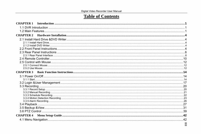
Table of Contents CHAPTER 1 Introduction ......................................................................................................................................................... 1
1.1 DVR Introduction ................................................................................................................................................................ 1 1.2 Main Features ..................................................................................................................................................................... 1
CHAPTER 2 Hardware Installation ........................................................................................................................................... 4 2.1 Install Hard Drive &DVD Writer ........................................................................................................................................... 4
2.1.1 Install Hard Drive ................................................................................................................................................................................................4 2.1.2 Install DVD Writer ...............................................................................................................................................................................................4
2.2 Front Panel Instructions ...................................................................................................................................................... 4 2.3 Rear Panel Instructions ...................................................................................................................................................... 6
2.3.1 Rear Panel Interface ..........................................................................................................................................................................................6 2.4 Remote Controller ............................................................................................................................................................. 10 2.5 Control with Mouse ........................................................................................................................................................... 12
2.5.1 Connect Mouse ................................................................................................................................................................................................ 12 2.5.2 Use Mouse ....................................................................................................................................................................................................... 12
CHAPTER 3 Basic Function Instructions ................................................................................................................................. 14 3.1 Power On/Off .................................................................................................................................................................... 14
3.1.1 Start .................................................................................................................................................................................................................. 14 3.2 Login &User Management ................................................................................................................................................ 17 3.3 Recording ......................................................................................................................................................................... 20
3.3.1 Record Setup ................................................................................................................................................................................................... 20 3.3.2 Manual Recording ............................................................................................................................................................................................ 21 3.3.3 Schedule Recording ......................................................................................................................................................................................... 22 3.3.4 Motion Detection Recording ............................................................................................................................................................................. 23 3.3.5 Alarm Recording ............................................................................................................................................................................................... 26
3.4 Playback ........................................................................................................................................................................... 27 3.5 Backup &View ................................................................................................................................................................... 31 3.6 PTZ Control ...................................................................................................................................................................... 39
CHAPTER 4 Menu Setup Guide .............................................................................................................................................. 42 4.1 Menu Navigation ............................................................................................................................................................... 42

Digital Video Recorder User Manual
iv
4.2 Main Menu Setup.............................................................................................................................................................. 43 4.2.1 Basic Configuration .......................................................................................................................................................................................... 45 4.2.2 Live Configuration ............................................................................................................................................................................................ 46 4.2.3 Record Configuration ....................................................................................................................................................................................... 47 4.2.4 Schedule Configuration .................................................................................................................................................................................... 49 4.2.5 Alarm Configuration .......................................................................................................................................................................................... 49 4.2.6 Motion Configuration ........................................................................................................................................................................................ 51 4.2.7 Network Configuration ...................................................................................................................................................................................... 53 4.2.8 P.T.Z Configuration ........................................................................................................................................................................................... 56 4.2.9 User Configuration ........................................................................................................................................................................................... 58 4.2.10 Tools Configuration ........................................................................................................................................................................................ 59
CHAPTER 5 Manage DVR ...................................................................................................................................................... 60 5.1 Format Hard Disk.............................................................................................................................................................. 60 5.2 Update Firmware .............................................................................................................................................................. 61 5.3 Load Default Setup ........................................................................................................................................................... 61 5.4 Check System Information ................................................................................................................................................ 62 5.5 Check System Log ............................................................................................................................................................ 64 5.6 Check On-line Network Users .......................................................................................................................................... 66 5.7 Lock &Delete Files ............................................................................................................................................................ 66
CHAPTER 6 Remote Surveillance ........................................................................................................................................... 68 6.1 Accessing DVR ................................................................................................................................................................. 68
6.1.1 On LAN ............................................................................................................................................................................................................ 68 6.1.2 On WAN ........................................................................................................................................................................................................... 70
6.2 Remote Preview ............................................................................................................................................................... 70 6.3 Remote Playback &Backup .............................................................................................................................................. 76
6.3.1 Remote Playback ............................................................................................................................................................................................. 76 6.3.2 Remote Backup ............................................................................................................................................................................................... 80
6.4 Remote Menu Configuration ............................................................................................................................................. 81 6.5 Remote DVR Management ............................................................................................................................................... 83
6.5.1 Check System Log Remotely ........................................................................................................................................................................... 83 6.5.2 Lock &Delete Files Remotely ........................................................................................................................................................................... 85
CHAPTER 7 Mobile Surveillance ......................................................................................................................................... 87
Digital Video Recorder User Manual
v
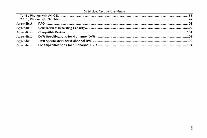
7.1 By Phones with WinCE ..................................................................................................................................................... 88 7.2 By Phones with Symbian .................................................................................................................................................. 92
Appendix A FAQ ................................................................................................................................................................... 96 Appendix B Calculation of Recording Capacity .................................................................................................................... 100 Appendix C Compatible Devices .......................................................................................................................................... 101 Appendix D DVR Specifications for 4-channel DVR ........................................................................................................ 102 Appendix E DVR Specifications for 8-channel DVR ........................................................................................................... 103 Appendix F DVR Specifications for 16-channel DVR ...................................................................................................... 104

Digital Video Recorder User Manual
1
CHAPTER 1 Introduction
1.1 DVR Introduction This model DVR (Digital Video Recorder) is designed specially for CCTV system. It adopts high performance video processing chips and embedded Linux system. Meanwhile, it utilizes many most advanced technologies, such as standard H.264 with low bit rate, Dual stream, SATA interface, VGA output mouse supported, IE browser supported with full remote control, mobile view(by phones), etc., which ensure its powerful functions and high stability. Due to these distinctive characteristics, it is widely used in banks, telecommunication, transportation, factories, warehouse, and irrigation and so on.
1.2 Main Features COMPRESSION FORMAT
• Standard H.264 compression with low bit rate and better image quality
LIVE SURVEILLANCE • Support VGA output • Support channel security by hiding live display • Display the local record state and basic information • Support USB or PS/2 mouse to make full control
RECORD MEDIA • Support several SATA HDD to record for a longer time without any limitation
Digital Video Recorder User Manual
2
BACKUP • Support USB 2.0 devices to backup • Support built-in SATA DVD writer to backup • Support saving recorded files with AVI standard format to a remote computer through internet
RECORD & PLAYBACK • Record modes: Manual, Schedule, Motion detection and Sensor alarm recording • Support recycle after HDD full • Resolution, frame rate and picture quality are adjustable • 64MB for every video file packaging • 4/8/16 audio channels available • Two record search mode: time search and event search • Support single and 4 screen playback • Support deleting and locking the recorded files one by one • Support remote playback in Network Client through LAN or internet
ALARM • 4 channel alarm output and 16 channel alarm input available • Support schedule for motion detection and sensor alarm • Support pre-recording and post recording • Support linked channels recording once motion or alarm triggered on certain channel • Support linked PTZ preset and auto cruise of the corresponding channel
PTZ CONTROL • Support various PTZ protocols • Support 128 PTZ presets and 32 auto cruise tracks • Support remote PTZ control through internet
Digital Video Recorder User Manual
3
SECURITY • Two level user group management: advance and normal, rights authorized by administrator • Support 1 administrator and 15 users. • Support event log recording and checking, events unlimited
NETWORK • Support TCP/IP, DHCP, PPPoE, DDNS protocol • Support IE browser to do remote view • Support max 5 connection simultaneously • Support dual stream. Network stream is adjustable independently to fit the network bandwidth and environment. • Support picture snap and color adjustment in remote live • Support remote time and event search, and channel playback with picture snap • Support remote PTZ control with preset and auto cruise • Support remote full menu setup, changing all the DVR parameters remotely • Support mobile surveillance by smart phones or PDA with WinCE OS, 3G network available • Support CMS to manage multi devices on internet

Digital Video Recorder User Manual
4
CHAPTER 2 Hardware Installation
Notice: Check the unit and the accessories after getting the DVR. Please disconnect the power before connected to other devices. Do not hot plug in/out
2.1 Install Hard Drive &DVD Writer 2.1.1 Install Hard Drive
Notice: 1. Support eight SATA hard-disk drives. Please use the hard-disk drive the manufacturers recommend specially for security and safe field. 2. Please calculate HDD capacity according to the recording setting. For the details, please refer to “Appendix-2 Calculation of Recording Capacity”.
2.1.2 Install DVD Writer Notice: 1. The writers must be the compatible devices we recommend. Please refer to “Appendix -3 Compatible Devices”
2. This device is only for backup
2.2 Front Panel Instructions Notice: The pictures are only for reference; please make the object as the standard.
The Front Panel interface is shown as Fig 2.1:

Digital Video Recorder User Manual
5
Fig 2.1 Front Panel
Item Name Function 1 Multi-screen button Change screen display like single, 4, 8 ,and 16 screens 2 10+ Input number 10 and the above number together with other digital keys. 3 MENU Enter menu in live 4 BACKUP Enter backup mode in live 5 P.T.Z Enter PTZ mode in live 6 AUDIO Control voice 7 Enter button To confirm the choice or setup 8 INFO Check recording data 9 Direction Direction buttons. Move cursor in setup or pan/title PTZ
10 REW Rewind 11 PLAY Enter play interface 12 Shuttle Control the speed of playback 13 STOP Quit playback mode
Digital Video Recorder User Manual
6
14 FF Fast forward 15 IR receiver For remote controller 16 SEARCH Enter search mode 17 REC Record manually 18 Power Power on/off
19 USB port To connect external USB devices for backup or update firmware(Can not connect to mouse)
20 Digital keys Input digital number or select the number of camera 21 Indicators Working indicators of power and network, etc.
Tab 2.1 Definition of Front Panel Buttons
2.3 Rear Panel Instructions 2.3.1 Rear Panel Interface
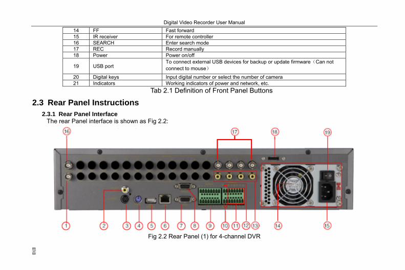
The rear Panel interface is shown as Fig 2.2:
Fig 2.2 Rear Panel (1) for 4-channel DVR

Digital Video Recorder User Manual
7
Item Name Description
1 SPOT OUT Connect to monitor as an AUX output channel by channel. Only video display, no menu show
2 AUDIO OUT Audio output, connect to the sound box 3 S-VIDEO S-Video output, connect to monitor 4 PS/2 port Connect to PS/2 mouse 5 USB MOUSE Only for USB mouse 6 RJ45 port Connected to internet 7 VGA port VGA output, connect to monitor 8 RS232 For debug 9 ALARM IN Connect to external sensor1-4, 5-16 reserved 10 RS485 Connect to speed dome 11 ALARM OUT Relay output1-4. Connect to external alarm. 12 +5V and GND +5 V and Grounding 13 AUDIO IN 4CH AUDIO input 14 FAN For cooling the device 15 POWER INPUT AC 110Vor 110V 16 VIDEO OUT Connect to monitor 17 VIDEO INPUT 4CH VIDEO input 18 E-SATA Connect to HDD for backup 19 POWER SWITCH Switch on/off
Tab 2.2 Definition of Rear Interface
Digital Video Recorder User Manual
8
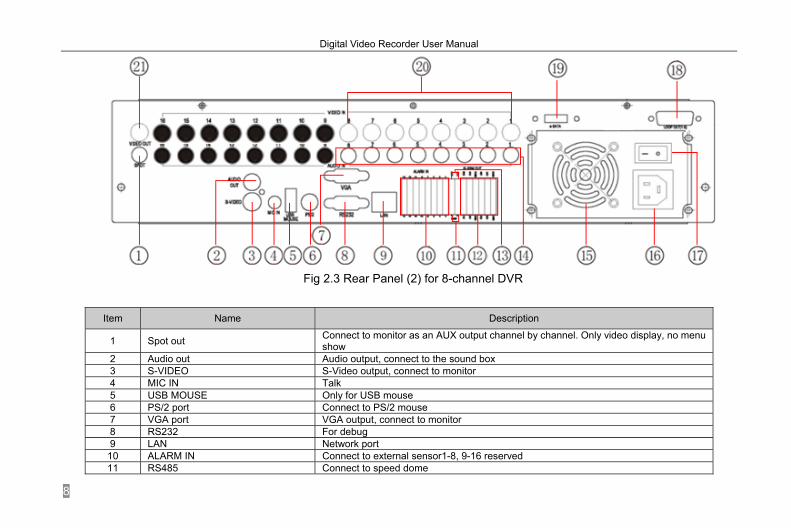
Fig 2.3 Rear Panel (2) for 8-channel DVR
Item Name Description
1 Spot out Connect to monitor as an AUX output channel by channel. Only video display, no menu show
2 Audio out Audio output, connect to the sound box 3 S-VIDEO S-Video output, connect to monitor 4 MIC IN Talk 5 USB MOUSE Only for USB mouse 6 PS/2 port Connect to PS/2 mouse 7 VGA port VGA output, connect to monitor 8 RS232 For debug 9 LAN Network port 10 ALARM IN Connect to external sensor1-8, 9-16 reserved 11 RS485 Connect to speed dome

Digital Video Recorder User Manual
9
Item Name Description
12 ALARM OUT Relay output1-4. Connect to external alarm. 13 +5V and GND +5 V and Grounding 14 AUDIO IN Audio input form 1-8 channels 15 FAN For cooling the device 16 POWER INPUT AC 110Vor 110V 17 POWER SWITCH Switch on/off 18 LOOP OUT For outputting each channel’s image independently 19 e-SATA Connect to HDD for backup 20 Video in Video input channels from 1-8 21 Video out Connect to monitor
Tab 2.3 Definition of Rear Interface
Fig 2.4 Rear Panel (3) for 16-channel DVR

Digital Video Recorder User Manual
10
Item Name Description
1 Spot out Connect to monitor as an AUX output channel by channel. Only video display, no menu show
2 Audio in 16 CH Audio input 3 Audio out Audio output, connect to the sound box 4 S-video S-Video output, connect to monitor 5 MIC IN Talk 6 USB MOUSE Only for USB mouse 7 PS/2 port Connect to PS/2 mouse 8 VGA port VGA output, connect to monitor 9 RS232 For debug 10 LAN Network port 11 ALARM IN Connect to external sensor1-16 12 RS485 Connect to speed dome 13 ALARM OUT Relay output1-4. Connect to external alarm. 14 + 5V and GND +5 V and Grounding 15 FAN For cooling the device 16 POWER INPUT AC 110Vor 110V 17 POWER SWITCH Power on/off 18 Loop out For outputting each channel’s image independently 19 e-SATA Connect to HDD for backup 20 Video in Video input channels from 1-16 21 Video out Connect to monitor
Tab 2.4 Definition of Rear Interface
2.4 Remote Controller It uses two AAA size batteries and works after loading batteries as following:
STEP1 Open the battery cover of the Remote Controller STEP2 Place batteries. Please take care the poles (+ and -) STEP3 Replace the battery cover

Digital Video Recorder User Manual
11
Notice: Frequently defect checking as following 1. Check batteries poles 2. Check the remaining charge in the batteries 3. Check IR controller sensor is mask If it doesn't still work, Please change a new remote controller to try, or contact your dealers
The interface of remote controller is shown in Fig 2.5 Remote Controller.
Fig 2.5 Remote Controller
Digital Video Recorder User Manual
12
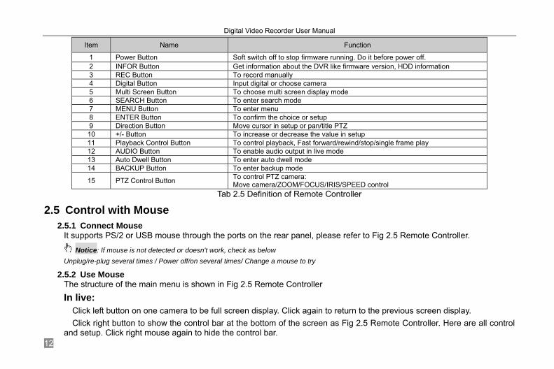
Item Name Function
1 Power Button Soft switch off to stop firmware running. Do it before power off. 2 INFOR Button Get information about the DVR like firmware version, HDD information 3 REC Button To record manually 4 Digital Button Input digital or choose camera 5 Multi Screen Button To choose multi screen display mode 6 SEARCH Button To enter search mode 7 MENU Button To enter menu 8 ENTER Button To confirm the choice or setup 9 Direction Button Move cursor in setup or pan/title PTZ 10 +/- Button To increase or decrease the value in setup 11 Playback Control Button To control playback, Fast forward/rewind/stop/single frame play 12 AUDIO Button To enable audio output in live mode 13 Auto Dwell Button To enter auto dwell mode 14 BACKUP Button To enter backup mode
15 PTZ Control Button To control PTZ camera: Move camera/ZOOM/FOCUS/IRIS/SPEED control
Tab 2.5 Definition of Remote Controller
2.5 Control with Mouse 2.5.1 Connect Mouse
It supports PS/2 or USB mouse through the ports on the rear panel, please refer to Fig 2.5 Remote Controller.
Notice: If mouse is not detected or doesn't work, check as below Unplug/re-plug several times / Power off/on several times/ Change a mouse to try
2.5.2 Use Mouse The structure of the main menu is shown in Fig 2.5 Remote Controller In live:
Click left button on one camera to be full screen display. Click again to return to the previous screen display. Click right button to show the control bar at the bottom of the screen as Fig 2.5 Remote Controller. Here are all control
and setup. Click right mouse again to hide the control bar.
Digital Video Recorder User Manual
13
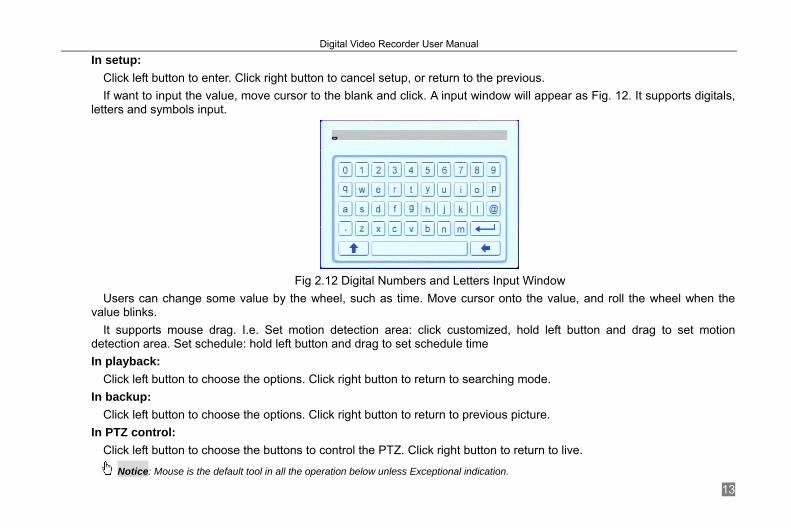
In setup: Click left button to enter. Click right button to cancel setup, or return to the previous. If want to input the value, move cursor to the blank and click. A input window will appear as Fig. 12. It supports digitals,
letters and symbols input.
Fig 2.12 Digital Numbers and Letters Input Window
Users can change some value by the wheel, such as time. Move cursor onto the value, and roll the wheel when the value blinks.
It supports mouse drag. I.e. Set motion detection area: click customized, hold left button and drag to set motion detection area. Set schedule: hold left button and drag to set schedule time In playback:
Click left button to choose the options. Click right button to return to searching mode. In backup:
Click left button to choose the options. Click right button to return to previous picture. In PTZ control:
Click left button to choose the buttons to control the PTZ. Click right button to return to live.
Notice: Mouse is the default tool in all the operation below unless Exceptional indication.

Digital Video Recorder User Manual
14
CHAPTER 3 Basic Function Instructions
3.1 Power On/Off Notice: Before you power on the unit, please make sure all the connection is good.
3.1.1 Start There are two ways to start this DVR. One way is to Connect with the source power, switch on the power button near the
power port in the rear panel, and the system will be loaded. The other is to start by the Power button on the front panel, ( this method will be used only if the system is shot shut-down), please press Power button 3~5 seconds, the system will start normally, and the screen will display as Fig 3.1 System Loading.
Fig 3.1 System Loading
Following that, it will enter in live with eight screens shown below:

Digital Video Recorder User Manual
15
Fig 3.2 Preview

Digital Video Recorder User Manual
16
Symbol Meaning Symbol Meaning
Enable audio in live Disable audio in live
(green) Manual record (blue) Timer record (yellow) Motion detection record (red) Alarm record HDD Current working HDD Space Size of current HDD Free Free space of current USB devices connected
HDD full 3.1.2 Close
When you close the system, please strictly obey normal close operation. Users can close the unit by remote controller, front panel, and mouse.
By remote controller: STEP1 Press POWER button, the screen below will appear.
Fig 3.3 Shut down

Digital Video Recorder User Manual
17
STEP2 Choose OK to enter. The unit will power off automatically after a while STEP3 Disconnect the power
By front panel or mouse:
STEP1 Press ENTER button or click right mouse to show menu bar, referring to Fig 4.1 Control Bar. STEP2 Click Shut down button, referring to Fig 3.3 Shut down STEP3 Click OK to enter on the pop-up window. The unit will power off automatically after a while STEP4 Disconnect the power
3.2 Login &User Management Users can logout and login the DVR system. Users cannot do any other operations except changing the multi-screen
display once logout. It is in logout once it starts or restarts. Login:
If it is in logout, please press right mouse to show the control bar. Press Login, Search, or System etc. A login window will appear, asking for ID and password as Fig 3.4 Login.
Fig 3.4 Login
Digital Video Recorder User Manual
18
Notice: The default is admin and 123456.
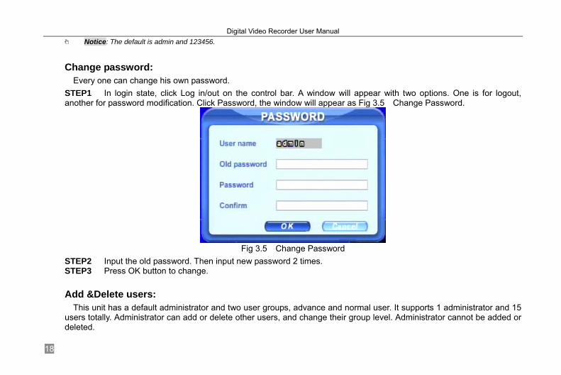
Change password:
Every one can change his own password. STEP1 In login state, click Log in/out on the control bar. A window will appear with two options. One is for logout, another for password modification. Click Password, the window will appear as Fig 3.5 Change Password.
Fig 3.5 Change Password
STEP2 Input the old password. Then input new password 2 times. STEP3 Press OK button to change.
Add &Delete users:
This unit has a default administrator and two user groups, advance and normal user. It supports 1 administrator and 15 users totally. Administrator can add or delete other users, and change their group level. Administrator cannot be added or deleted.

Digital Video Recorder User Manual
19
Press right mouse to show the control bar. Enter Menu---->System. STEP1 Enter USER configuration. Click Add button, please see Fig 3.6 Add User.
Fig 3.6 Add User
STEP2 Input user name and password. Choose the user group. STEP3 Click OK button to add a new user STEP4 Choose a user, a symbol will display at the end of the user information. Click Authority button to change the group level. STEP5 Press Delete button to delete the user. A security window will appear as below.
Digital Video Recorder User Manual
20
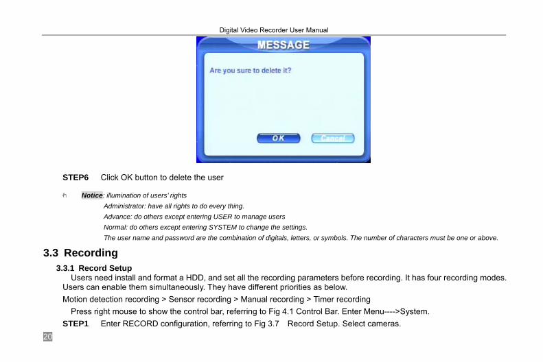
STEP6 Click OK button to delete the user
Notice: illumination of users’ rights Administrator: have all rights to do every thing. Advance: do others except entering USER to manage users Normal: do others except entering SYSTEM to change the settings. The user name and password are the combination of digitals, letters, or symbols. The number of characters must be one or above.
3.3 Recording 3.3.1 Record Setup
Users need install and format a HDD, and set all the recording parameters before recording. It has four recording modes. Users can enable them simultaneously. They have different priorities as below. Motion detection recording > Sensor recording > Manual recording > Timer recording
Press right mouse to show the control bar, referring to Fig 4.1 Control Bar. Enter Menu---->System. STEP1 Enter RECORD configuration, referring to Fig 3.7 Record Setup. Select cameras.

Digital Video Recorder User Manual
21
Fig 3.7 Record Setup
STEP2 Set Video quality, Frame rate, and Resolution. STEP3 Have Audio checked if you input audio and want to record. Check Time stamp to record. STEP4 Enable recording function for cameras in Record option.
Notice: If having camera unchecked here, it will not record in any recording mode.
STEP5 Set Alarm record hold time. It is for post alarm recording. STEP6 Enable Recycle. It covers old video once HDD full. If you have it unchecked, it will stop recording auto once HDD full. STEP7 Click OK to finish.
Notice: The more space is used per hour, the higher the value of Video quality, Frame rate, and Resolution. This Unit supports pre-alarm recording. However, no option to set the pre-alarm recording time, the default is 10 seconds
3.3.2 Manual Recording Just press REC button on the front panel after quitting system setup. Press Stop button to stop recording. Alternatively, press REC button on remote controller, click again to stop. Or click REC button on the control bar with mouse, click again to stop.
Digital Video Recorder User Manual
22
3.3.3 Schedule Recording Users can set different schedule time for every day in one week. If you want a special schedule for one day, you can use
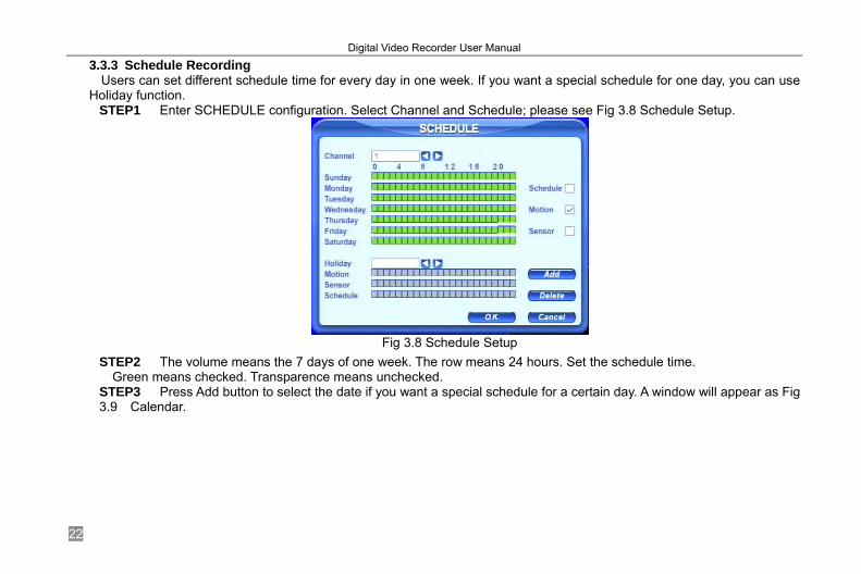
Holiday function. STEP1 Enter SCHEDULE configuration. Select Channel and Schedule; please see Fig 3.8 Schedule Setup.
Fig 3.8 Schedule Setup
STEP2 The volume means the 7 days of one week. The row means 24 hours. Set the schedule time. Green means checked. Transparence means unchecked.
STEP3 Press Add button to select the date if you want a special schedule for a certain day. A window will appear as Fig 3.9 Calendar.

Digital Video Recorder User Manual
23
Fig 3.9 Calendar
STEP4 Select the date and set the schedule time. If want to delete this special schedule, click Delete button STEP5 Click OK button to finish Then the DVR will auto record once it goes to the time you set.
3.3.4 Motion Detection Recording This unit supports recording channels and PTZ linking. This means it will record any cameras, or trigger any speed
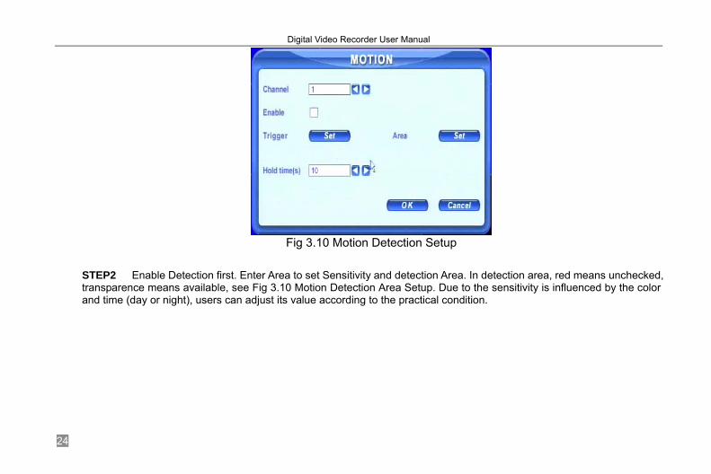
dome to preset or do auto cruise once motion detected. STEP1 Enter MOTION configuration, please see Select cameras
Digital Video Recorder User Manual
24
Fig 3.10 Motion Detection Setup
STEP2 Enable Detection first. Enter Area to set Sensitivity and detection Area. In detection area, red means unchecked, transparence means available, see Fig 3.10 Motion Detection Area Setup. Due to the sensitivity is influenced by the color and time (day or night), users can adjust its value according to the practical condition.

Digital Video Recorder User Manual
25
Fig 3.10 Motion Detection Area Setup
STEP3 Enter Trigger configuration, see Fig 3.11 Alarm Out Setup
Fig 3.11 Alarm Out Setup
Digital Video Recorder User Manual
26
STEP4 Select alarm out and recording channels. It can trigger any alarm out and cameras to record once motion detected. STEP5 Enable or disable Buzzer on board. Select speed dome and enable preset or auto cruise. Press OK to save STEP6 Set Hold time. It is the interval time between the two adjacent efficient motions. If a second motion were detects in Hold time again, it recognized as a continuous motion. If a second motion were detects after hold time, this motion and the previous are recognized as two different motion events. STEP7 Click OK to save settings STEP8 Enter SCHEDULE configuration. Select Motion and relative cameras to set, referring to 3.3.3 Schedule Recording.
Notice: About preset and auto cruise, users can only select one at same time. The actual post- alarm record time equals Hold time in RECORD and Hold time in MOTION
3.3.5 Alarm Recording This unit supports recording channels and PTZ linking after alarm.
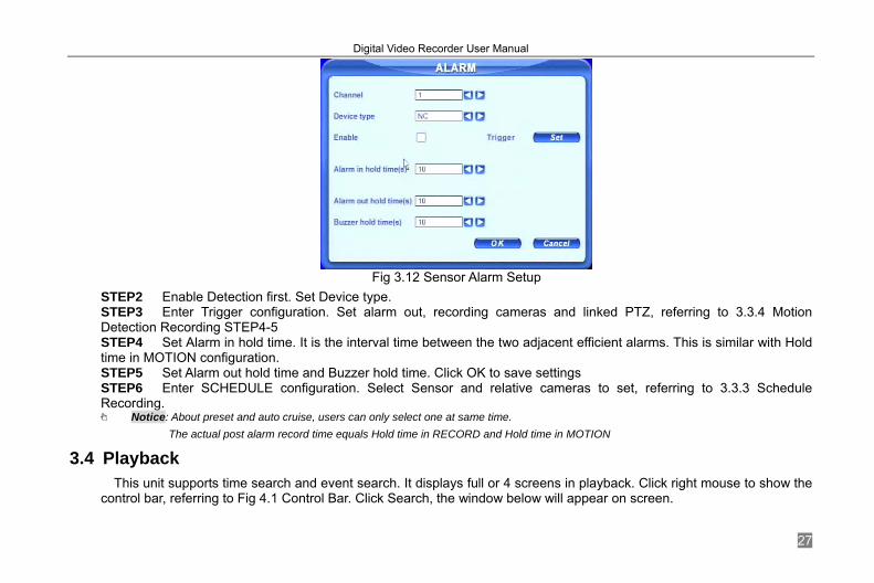
STEP1 Enter ALARM configuration, see Fig 3.12 Sensor Alarm Setup. Select cameras
Digital Video Recorder User Manual
27
Fig 3.12 Sensor Alarm Setup
STEP2 Enable Detection first. Set Device type. STEP3 Enter Trigger configuration. Set alarm out, recording cameras and linked PTZ, referring to 3.3.4 Motion Detection Recording STEP4-5 STEP4 Set Alarm in hold time. It is the interval time between the two adjacent efficient alarms. This is similar with Hold time in MOTION configuration. STEP5 Set Alarm out hold time and Buzzer hold time. Click OK to save settings STEP6 Enter SCHEDULE configuration. Select Sensor and relative cameras to set, referring to 3.3.3 Schedule Recording.
Notice: About preset and auto cruise, users can only select one at same time. The actual post alarm record time equals Hold time in RECORD and Hold time in MOTION
3.4 Playback This unit supports time search and event search. It displays full or 4 screens in playback. Click right mouse to show the
control bar, referring to Fig 4.1 Control Bar. Click Search, the window below will appear on screen.
Digital Video Recorder User Manual
28
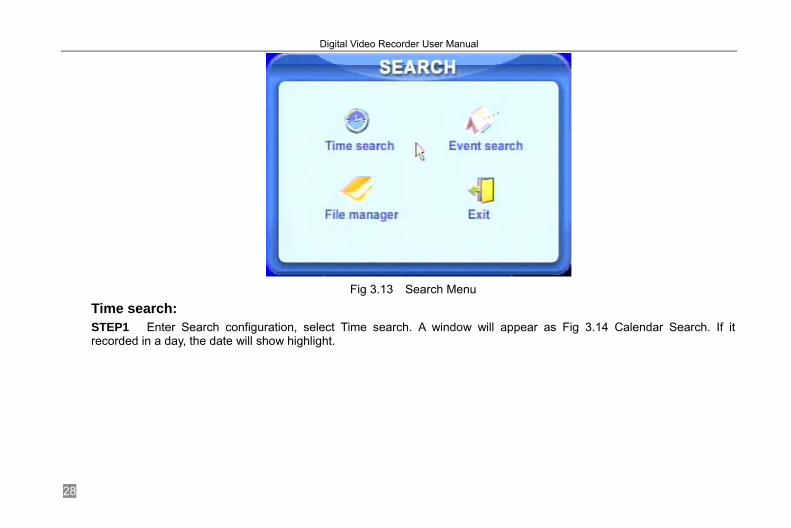
Fig 3.13 Search Menu
Time search: STEP1 Enter Search configuration, select Time search. A window will appear as Fig 3.14 Calendar Search. If it recorded in a day, the date will show highlight.
Digital Video Recorder User Manual
29
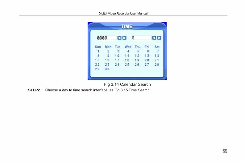
Fig 3.14 Calendar Search
STEP2 Choose a day to time search interface, as Fig 3.15 Time Search.
Digital Video Recorder User Manual
30
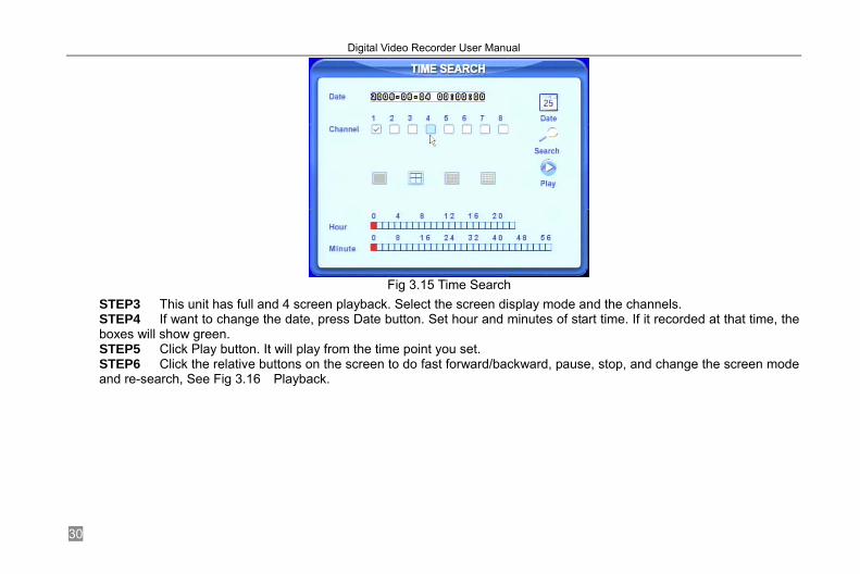
Fig 3.15 Time Search
STEP3 This unit has full and 4 screen playback. Select the screen display mode and the channels. STEP4 If want to change the date, press Date button. Set hour and minutes of start time. If it recorded at that time, the boxes will show green. STEP5 Click Play button. It will play from the time point you set. STEP6 Click the relative buttons on the screen to do fast forward/backward, pause, stop, and change the screen mode and re-search, See Fig 3.16 Playback.

Digital Video Recorder User Manual
31
Fig 3.16 Playback
Event search: STEP1 Enter Search---->Event search. The calendar window will appear as that of time search

Digital Video Recorder User Manual
32
STEP2 Choose a day in event search interface, as Fig 3.17 Event Search
Fig 3.17 Event Search
STEP3 Choose camera and event type, motion or sensor. STEP4 Double click one video file to play.
3.5 Backup &View This unit supports backup by built-in SATA DVD Writer with USB Flash, through the USB port on the front panel. Users
can also make backup by IE browser via internet, referring to 6.3.2 Remote Backup. Take USB flash backup as an example. Press right mouse to show the control bar, referring to Fig 4.1 Control Bar.
At DVR location: STEP1 Enter Backup interface, see Fig 3.18 Backup Setup
Digital Video Recorder User Manual
33
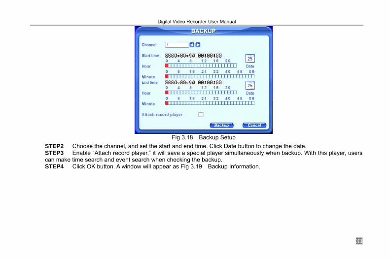
Fig 3.18 Backup Setup
STEP2 Choose the channel, and set the start and end time. Click Date button to change the date. STEP3 Enable “Attach record player,” it will save a special player simultaneously when backup. With this player, users can make time search and event search when checking the backup. STEP4 Click OK button. A window will appear as Fig 3.19 Backup Information.

Digital Video Recorder User Manual
34
Fig 3.19 Backup Information
Notice: If users install built-in DVD writer and USB device, it will show USB device in previous. It will show CD-ROM even though users install DVD writer
STEP5 Press OK button. It will begin to write video from HDD inside DVR to backup device, and show the process as below.
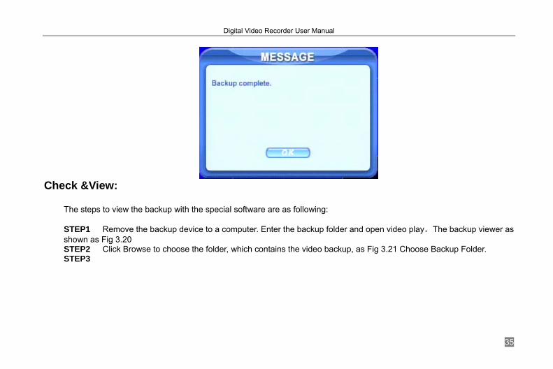
STEP6 It will show “Backup complete” after finished, as below.
Digital Video Recorder User Manual
35
Check &View:
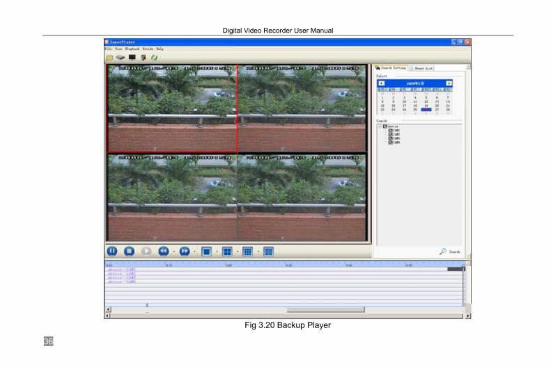
The steps to view the backup with the special software are as following: STEP1 Remove the backup device to a computer. Enter the backup folder and open video play。The backup viewer as shown as Fig 3.20 STEP2 Click Browse to choose the folder, which contains the video backup, as Fig 3.21 Choose Backup Folder. STEP3
Digital Video Recorder User Manual
36
Fig 3.20 Backup Player
Digital Video Recorder User Manual
37
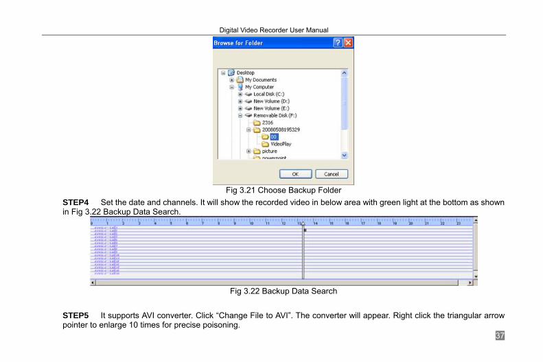
Fig 3.21 Choose Backup Folder
STEP4 Set the date and channels. It will show the recorded video in below area with green light at the bottom as shown in Fig 3.22 Backup Data Search.
Fig 3.22 Backup Data Search
STEP5 It supports AVI converter. Click “Change File to AVI”. The converter will appear. Right click the triangular arrow pointer to enlarge 10 times for precise poisoning.

Digital Video Recorder User Manual
38
STEP6 Drag the slide bar to the start time point, click play button to view.
STEP7 Click icon a conversion AVI window will appear as shown as Fig 3.23. Click Conversion button, it will Start converting the files and the process will show at the bottom.
Fig 3.23 Conversion AVI
STEP8 Select the files. Click Change button, it will start converting the files and show the process at the bottom. STEP9 It is finished when the process show 100%. Users can play the AVI files with the third player directly.
Notice: About network backup, please refer to 6.3.2 Remote Backup.
Digital Video Recorder User Manual
39
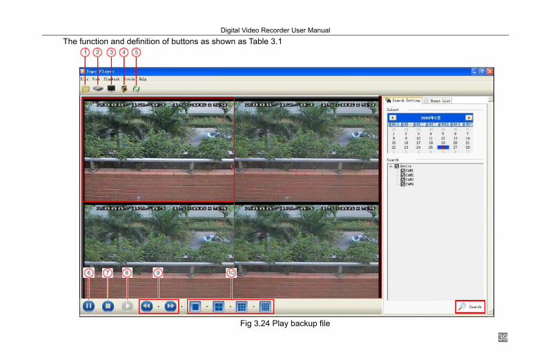
The function and definition of buttons as shown as Table 3.1
Fig 3.24 Play backup file
Digital Video Recorder User Manual
40
Index Definition Index Definition Index Definition Index Definition Index Definition ① Open file ② Open disk ③ Full
screen ④ Snap picture ⑤ Convert video
file into AVI ⑥ Pause ⑦ Stop ⑧ Play ⑨ Forward/Rewind ⑩ Screen mode
Tab 3.1 Definition of buttons
Notice: ①Search CD-ROM or DVR backup file; ②Search DVR hardware recording data
3.6 PTZ Control Please connect speed domes to the DVR via RS485 first, referring to 2.3.1 Rear Panel Interface. In addition, make sure
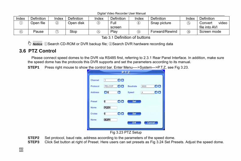
the speed dome has the protocols this DVR supports and set the parameters according to its manual. STEP1 Press right mouse to show the control bar. Enter Menu---->System--->P.T.Z, see Fig 3.23.
Fig 3.23 PTZ Setup
STEP2 Set protocol, baud rate, address according to the parameters of the speed dome. STEP3 Click Set button at right of Preset. Here users can set presets as Fig 3.24 Set Presets. Adjust the speed dome.
Digital Video Recorder User Manual
41
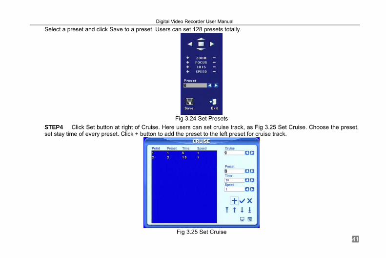
Select a preset and click Save to a preset. Users can set 128 presets totally.
Fig 3.24 Set Presets
STEP4 Click Set button at right of Cruise. Here users can set cruise track, as Fig 3.25 Set Cruise. Choose the preset, set stay time of every preset. Click + button to add the preset to the left preset for cruise track.
Fig 3.25 Set Cruise
Digital Video Recorder User Manual
42
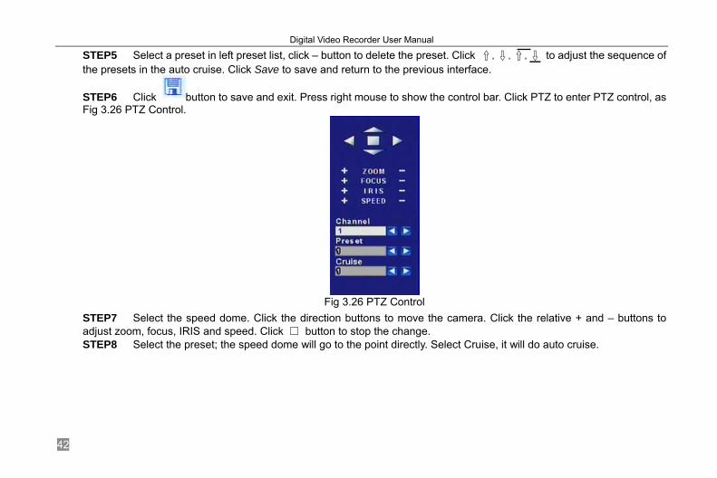
STEP5 Select a preset in left preset list, click – button to delete the preset. Click ↑,↓,↑,↓ to adjust the sequence of the presets in the auto cruise. Click Save to save and return to the previous interface.
STEP6 Click button to save and exit. Press right mouse to show the control bar. Click PTZ to enter PTZ control, as Fig 3.26 PTZ Control.
Fig 3.26 PTZ Control
STEP7 Select the speed dome. Click the direction buttons to move the camera. Click the relative + and – buttons to adjust zoom, focus, IRIS and speed. Click button to stop the change. STEP8 Select the preset; the speed dome will go to the point directly. Select Cruise, it will do auto cruise.
Digital Video Recorder User Manual
43
CHAPTER 4 Menu Setup Guide
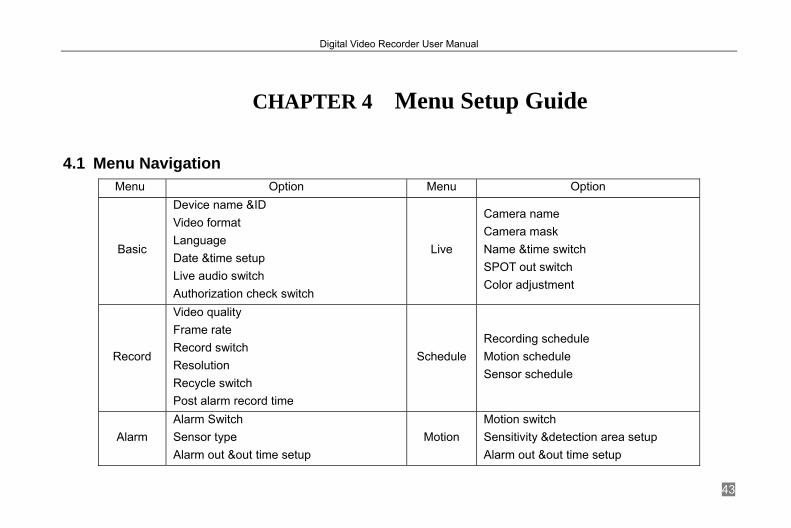
4.1 Menu Navigation Menu Option Menu Option
Basic
Device name &ID Video format Language Date &time setup Live audio switch Authorization check switch
Live
Camera name Camera mask Name &time switch SPOT out switch Color adjustment
Record
Video quality Frame rate Record switch Resolution Recycle switch Post alarm record time
ScheduleRecording schedule Motion schedule Sensor schedule
Alarm Alarm Switch Sensor type Alarm out &out time setup
Motion Motion switch Sensitivity &detection area setup Alarm out &out time setup

Digital Video Recorder User Manual
44
Recorded cameras and PTZ linking Recorded cameras and PTZ linking
Network
HTTP &server ports IP address setup PPPoE Network video setup DDNS
PTZ
Protocol, baud rate and address Speed setup Presets setup Cruise setup
User Add users Delete users Change authorization
Tools Disk manager Update Load default
Tab 4.1 Menu Navigation
4.2 Main Menu Setup Click right mouse, or press ENTER button on the front panel, the control bar will show on the bottom of the screen as Fig 4.1 Control Bar.
Fig 4.1 Control Bar Move the cursor to Menu and click, the up list menu will show as Fig 4.2 Up-listed Menu
Digital Video Recorder User Manual
45
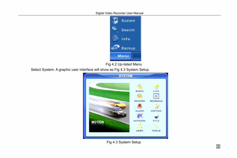
Fig 4.2 Up-listed Menu
Select System. A graphic user interface will show as Fig 4.3 System Setup.
Fig 4.3 System Setup

Digital Video Recorder User Manual
46
Press MENU button on the front panel or remote controller. The interface above will also appear.
Notice: Only administrator and advance user can enter system setup and do setup. It need reboot after some parameters changed, like video format.
4.2.1 Basic Configuration Click BASIC to enter basic configuration as Fig. 4.4.
Fig 4.4 Basic Configuration
Here users can set video system, menu language, audio, time and authorization check. The following are the definitions of every option. Device name: The name of the unit. It may display on the client end or CMS, which help users to recognize the unit remotely. Device ID: It is used to multi devices at the same place. Users can manage them by remote controller. Video format: It has PAL and NTSC. Users make the choice according to that of that of cameras. Language: set the menu language. But customer terminal can not change it. Authorization check: It needs user name and password when user want system setup, playback, backup etc, if enable

Digital Video Recorder User Manual
47
this. Audio: enable audio in live. Users can choose a random channel. Date format: three formats, YY-MM-DD, DD-MM-YY, MM-DD-YY. System time: set the time. If the unit is recording, users cannot change the time. When recording, click Adjust button, a security window will appear.
4.2.2 Live Configuration Click LIVE to enter live configuration as Fig 4.5 Live Configuration
Fig 4.5 Live Configuration
Here users can set name/time display, picture color and hide cameras. The following are the definitions of every option. Camera name: set camera name. it is the combination of digitals, letters and symbols. Show name: display camera name in live. Show time: display time in live. Dwell time: it is available for both Sequence and SPOT simultaneously. This unit has 2-channel video output, referring to 2.3.1 Rear Panel Interface. One is main output, and the other is spot output. Users can set the display time of cameras in

Digital Video Recorder User Manual
48
auto dwell and spot out. SPOT enable: enable spot output. Color: Click Set button, a window will appear as Fig 4.6 Color Adjustment.
Fig 4.6 Color Adjustment
Adjust Brightness, Hue, Saturation, and Contrast in live here. Default: set the color to the default value.
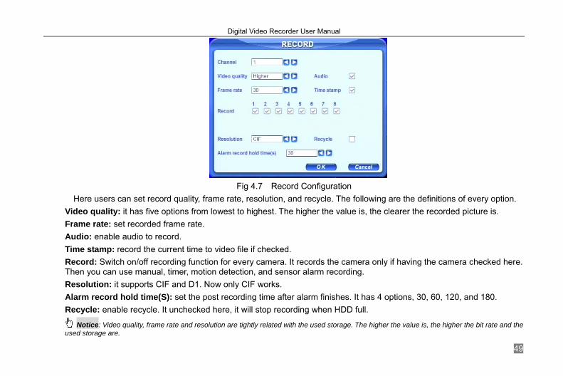
4.2.3 Record Configuration Click RECORD to enter record configuration as Fig 4.7 Record Configuration.
Digital Video Recorder User Manual
49
Fig 4.7 Record Configuration
Here users can set record quality, frame rate, resolution, and recycle. The following are the definitions of every option. Video quality: it has five options from lowest to highest. The higher the value is, the clearer the recorded picture is. Frame rate: set recorded frame rate. Audio: enable audio to record. Time stamp: record the current time to video file if checked. Record: Switch on/off recording function for every camera. It records the camera only if having the camera checked here. Then you can use manual, timer, motion detection, and sensor alarm recording. Resolution: it supports CIF and D1. Now only CIF works. Alarm record hold time(S): set the post recording time after alarm finishes. It has 4 options, 30, 60, 120, and 180. Recycle: enable recycle. It unchecked here, it will stop recording when HDD full.
Notice: Video quality, frame rate and resolution are tightly related with the used storage. The higher the value is, the higher the bit rate and the used storage are.

Digital Video Recorder User Manual
50
4.2.4 Schedule Configuration Click SCHEDULE to enter schedule configuration as Fig 4.8 Schedule Configuration.
Fig 4.8 Schedule Configuration
Here users can set schedule for timer, motion detection, and sensor alarm respectively. The following are the definitions of every option Always, Motion and Sensor: refer to record schedule, motion schedule and alarm schedule respectively.
The volume means the 7 days of one week from Monday to Sunday. The row refers to 24 hours. Click the boxes or hold mouse to drag to set the schedule time. Green means checked. Transparence means unchecked. Add: users can set schedule for a certain day by date. Click Add to add date as Fig 3.9 Calendar. Delete: delete holiday schedule.
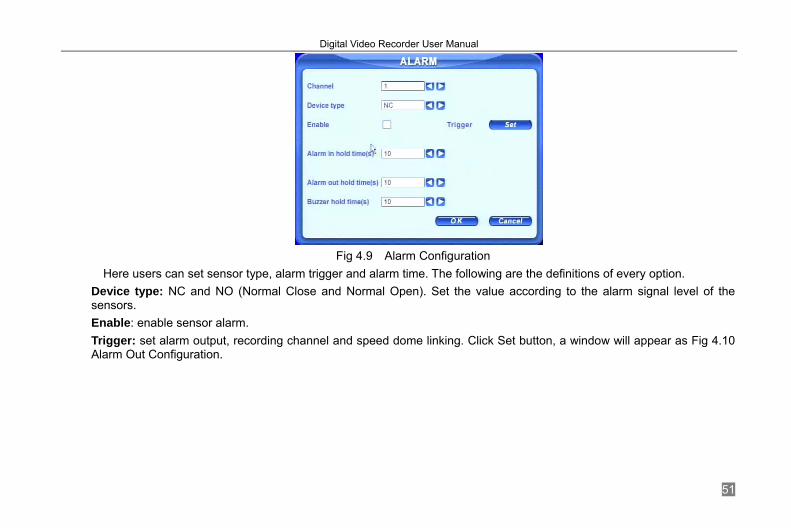
4.2.5 Alarm Configuration Click ALARM to enter alarm configuration as Fig 4.9 Alarm Configuration.
Digital Video Recorder User Manual
51
Fig 4.9 Alarm Configuration
Here users can set sensor type, alarm trigger and alarm time. The following are the definitions of every option. Device type: NC and NO (Normal Close and Normal Open). Set the value according to the alarm signal level of the sensors. Enable: enable sensor alarm. Trigger: set alarm output, recording channel and speed dome linking. Click Set button, a window will appear as Fig 4.10 Alarm Out Configuration.

Digital Video Recorder User Manual
52
Fig 4.10 Alarm Out Configuration
Alarm out: set relay alarm out channel. You can select any alarm channels. To record: set recording channels. You can select any record channels. It will record the cameras you choose here when alarm triggered. Buzzer: enable buzzer on board for alarm. To P.T.Z CH: set linked preset and cruise for alarm. You can select any channel and multi channels as linked channels. Alarm in holding time(S): the interval time between the two adjacent efficient sensor alarms. If a second alarm were detects in Hold time again, it is recognized as a continuous alarm. If a second alarm were detects after hold time, this alarm and the previous are recognized as two different alarm events. Alarm out holding time(S): set relay alarm out time after alarm triggered. Buzzer holding time(S): set on board buzzer time after alarm triggered.
4.2.6 Motion Configuration Click MOTION to enter motion configuration as Fig 4.11 Motion Configuration.
Digital Video Recorder User Manual
53
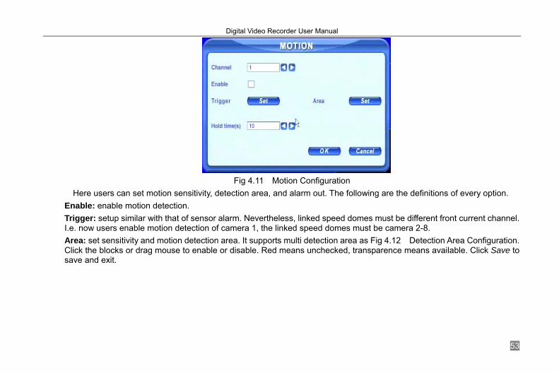
Fig 4.11 Motion Configuration
Here users can set motion sensitivity, detection area, and alarm out. The following are the definitions of every option. Enable: enable motion detection. Trigger: setup similar with that of sensor alarm. Nevertheless, linked speed domes must be different front current channel. I.e. now users enable motion detection of camera 1, the linked speed domes must be camera 2-8. Area: set sensitivity and motion detection area. It supports multi detection area as Fig 4.12 Detection Area Configuration. Click the blocks or drag mouse to enable or disable. Red means unchecked, transparence means available. Click Save to save and exit.

Digital Video Recorder User Manual
54
Fig 4.12 Detection Area Configuration
Sensitivity: set detection sensitivity from 1-8. The default is 4. Exit: quit without saving
Holding time(S): the interval time between the two adjacent efficient motions, similar with that of sensor alarm.
4.2.7 Network Configuration Click NETWORK to enter network configuration as Fig 4.13 Network Configuration.

Digital Video Recorder User Manual
55
Fig 4.13 Network Configuration
This unit supports DHCP, PPPoE, and DDNS. Users enable network function, and configure IP address, DDNS, transmission video parameters here. The following are the definitions of every option. HTTP port: the default is 80. If users change the value, they need add the port number when typing IP address in IE address blank. I.e. set HTTP port to 82, IP address to 192.168.0.25. Users need input http://192.168.0.25:82 in IE browser. Server port: communication port DHCP: enable DHCP. It wants this feature work, need enable DHCP in the router or virtual server. The unit will get IP address automatically, not input IP, Subnet, and Gateway manually. IP, Subnet, Gateway, DNS1 and 2: IP address information. If users do not enable DHCP, it is necessary to input the value manually here. PPPoE: enable PPPoE. If users connect the DVR to internet directly by ADSL, not through a router or a virtual server, please enable it.
Digital Video Recorder User Manual
56
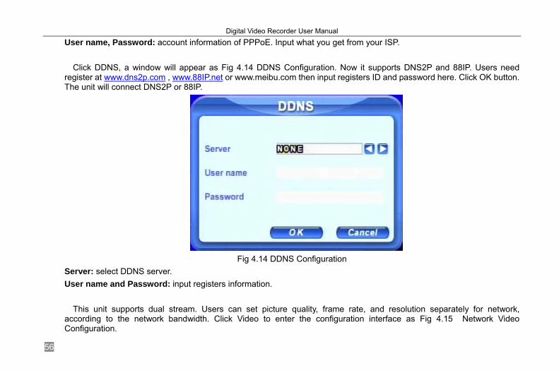
User name, Password: account information of PPPoE. Input what you get from your ISP. Click DDNS, a window will appear as Fig 4.14 DDNS Configuration. Now it supports DNS2P and 88IP. Users need
register at www.dns2p.com , www.88IP.net or www.meibu.com then input registers ID and password here. Click OK button. The unit will connect DNS2P or 88IP.
Fig 4.14 DDNS Configuration
Server: select DDNS server. User name and Password: input registers information.
This unit supports dual stream. Users can set picture quality, frame rate, and resolution separately for network,
according to the network bandwidth. Click Video to enter the configuration interface as Fig 4.15 Network Video Configuration.

Digital Video Recorder User Manual
57
Fig 4.15 Network Video Configuration
Video quality: network picture quality. Frame rate: it has 3 options, 1, 2 and 3 fps. Resolution: now it only has CIF. Time stamp: Time displayed in the image.
4.2.8 P.T.Z Configuration Click P.T.Z to enter PTZ configuration as Fig 4.16 PTZ Configuration.
Digital Video Recorder User Manual
58
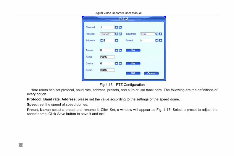
Fig 4.16 PTZ Configuration
Here users can set protocol, baud rate, address, presets, and auto cruise track here. The following are the definitions of every option. Protocol, Baud rate, Address: please set the value according to the settings of the speed dome. Speed: set the speed of speed domes. Preset, Name: select a preset and rename it. Click Set, a window will appear as Fig. 4.17. Select a preset to adjust the speed dome. Click Save button to save it and exit.
Digital Video Recorder User Manual
59
Fig 4.17 Set Presets
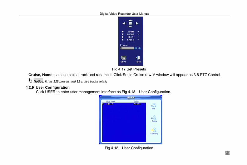
Cruise, Name: select a cruise track and rename it. Click Set in Cruise row. A window will appear as 3.6 PTZ Control.
Notice: It has 128 presets and 32 cruise tracks totally
4.2.9 User Configuration Click USER to enter user management interface as Fig 4.18 User Configuration.
Fig 4.18 User Configuration

Digital Video Recorder User Manual
60
Administrator can add, delete users, and change their authorization. Please refer to 3.2 Login &User Management.
Notice: It supports one administrator and max 15 users.
4.2.10 Tools Configuration Click TOOLS to enter tools configuration as Fig 4.19 Tools Manager.
Fig 4.19 Tools Manager
Disk manager: please refer to 5.1 Format Hard Disk. Update: please refer to 5.2 Update Firmware. Load default: please refer to 5.3 Load Default Setup.
Digital Video Recorder User Manual
61
CHAPTER 5 Manage DVR
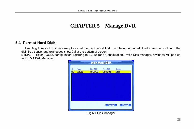
5.1 Format Hard Disk If wanting to record, it is necessary to format the hard disk at first. If not being formatted, it will show the position of the
disk, free space, and total space show 0M at the bottom of screen. STEP1 Enter TOOLS configuration, referring to 4.2.10 Tools Configuration. Press Disk manager, a window will pop up as Fig 5.1 Disk Manager.
Fig 5.1 Disk Manager

Digital Video Recorder User Manual
62
STEP2 If a disk has never been formatted, Status will show “new”. Select hard disks, press Format button to begin. STEP3 A security window will remind user that this will delete all data on HDD. Press OK to continue. A process will display on the screen as below.
STEP4 It will return to the previous automatically after finished. In addition, status will show “normal” after formatted.
Notice: All recorded files will be lost after formatted.
5.2 Update Firmware Now it only supports USB update. Get the firmware from your dealer, and Make sure the firmware is corresponding with
the DVR. Users can check USB information in disk manager, please refer to Fig 5.1 Disk Manager. STEP1 Plug an USB flash to the computer. Copy the firmware to the flash. The extension of firmware is tar. STEP2 Remove the USB flash to the DVR. Enter TOOLS configuration, referring to 4.2.10 Tools Configuration. STEP3 Click Update. A window will appear, which reminds users that it will automatically load default settings after update. STEP4 Press OK to begin. The process bar will display on the screen during update.
STEP5 After finished, the unit needs restart.
Notice: If a “no device or no file” error appears, it is possible that the USB device is incompatible. Please change an USB flash. Please be patient to wait. It will take 2-3 minutes to update. Moreover,, the updating file should be only one at one time.
5.3 Load Default Setup The DVR has different setup blocks, like Basic, Record, Schedule, Motion etc. Users can choose any block to do default,
as Fig 5.2 Reset Blocks.

Digital Video Recorder User Manual
63
Fig 5.2 Reset Blocks
STEP1 Enter TOOLS configuration, referring to 4.2.10 Tools Configuration. STEP2 Click Load default. Select setup blocks; please refer to Fig 5.2 Reset Blocks. STEP3 Press OK to do default. It will return to TOOLS interface after finished.
5.4 Check System Information Users can check system information like firmware version, IP address, etc.
STEP1 Press right mouse to show the control bar. Click Menu, referring to Fig 4.2 Up-listed Menu. STEP2 Click Info, the window below will appear.

Digital Video Recorder User Manual
64
Fig 5.3 Status Interface
STEP3 Click System, the window below will display. Check firmware version, recording parameters here.
Fig 5.4 System Information.
Digital Video Recorder User Manual
65
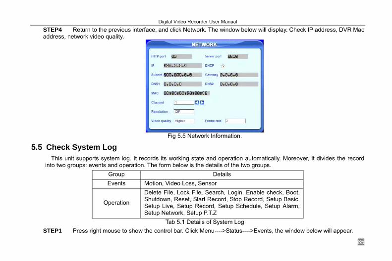
STEP4 Return to the previous interface, and click Network. The window below will display. Check IP address, DVR Mac address, network video quality.
Fig 5.5 Network Information.
5.5 Check System Log This unit supports system log. It records its working state and operation automatically. Moreover, it divides the record
into two groups: events and operation. The form below is the details of the two groups. Group Details Events Motion, Video Loss, Sensor
Operation
Delete File, Lock File, Search, Login, Enable check, Boot, Shutdown, Reset, Start Record, Stop Record, Setup Basic, Setup Live, Setup Record, Setup Schedule, Setup Alarm, Setup Network, Setup P.T.Z
Tab 5.1 Details of System Log STEP1 Press right mouse to show the control bar. Click Menu---->Status---->Events, the window below will appear.

Digital Video Recorder User Manual
66
Fig 5.6 Events LOG
STEP2 Click Date to change date by a calendar. Click Type to select the event type. Then click Search button. It will refresh the event list. STEP3 Click ←, ←, →, → to do pgdn or pgup STEP4 Click right mouse to return to the previous interface. Click Operation to search operation Log
Fig 5.7 Operation Log

Digital Video Recorder User Manual
67
STEP5 The operating is similar with searching events log. Notice: The log files saved to the HDD inside. If HDD not installed, it will not record any thing.
The number of log files is unlimited.
5.6 Check On-line Network Users Press right mouse to show the control bar. Click Menu---->Online users. It will show the details of the current connections as below.
Fig 5.8 Details of Current Network Connections
5.7 Lock &Delete Files Users can control every video file, locking and deleting them. Once users lock an important file, it cannot be covered or
deleted. However, the locked files can clear by formatting. STEP1 Press right mouse to show the control bar. Click Menu, referring to Fig 4.2 Up-listed Menu. STEP2 Click Search----->File manager, the window below will appear.

Digital Video Recorder User Manual
68
Fig 5.9 File Manager
STEP3 Click Date to change date by a calendar, click Search to refresh the list. The files found will be listed in the file area of file manager at bottom. It shows the details of every file, like start/end time, lock state. STEP4 Select the files and click Lock, it will lock the selected files. At this time, a letter “L” display at the end of the file rows as Fig 5.9 File Manager. STEP5 Select the files that are unlocked, click Delete. A window display and remind users. Click Ok to delete them.
Digital Video Recorder User Manual
69
CHAPTER 6 Remote Surveillance
6.1 Accessing DVR If making remote view, the DVR must connect with LAN or internet. Then enable network server in the unit. Please refer
to 4.2.7 Network Configuration. This unit supports IE browser, not any client software installed. In addition, it supports XP and Vista.
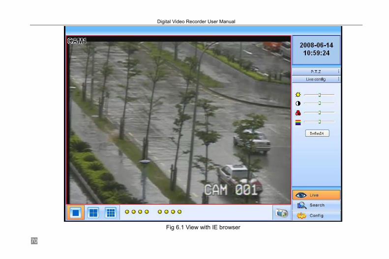
6.1.1 On LAN STEP1 Input IP address, Subnet, Gateway. If using DHCP, please enable DHCP in both the DVR and router. Enter Menu—Information—Network, and user can check the network configuration of DVR. STEP2 Enter Video to set network video parameters like resolution, frame rate etc. STEP3 Open IE browser on a computer on the same LAN. Input the IP address of the DVR in IE address blank and enter. STEP4 IE will download activeX automatically. Then a window pops up and asks for user name and password. STEP5 Input name and password correctly, and enter. It will show the picture as below.
Digital Video Recorder User Manual
70
Fig 6.1 View with IE browser
Digital Video Recorder User Manual
71
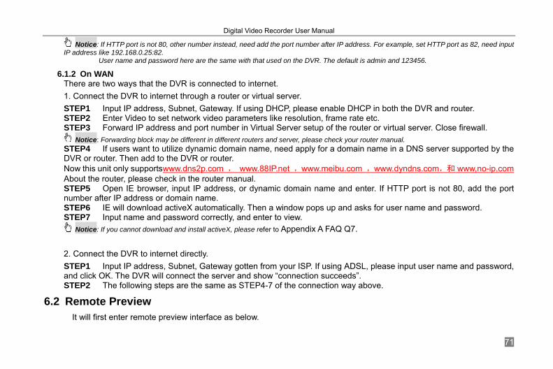
Notice: If HTTP port is not 80, other number instead, need add the port number after IP address. For example, set HTTP port as 82, need input IP address like 192.168.0.25:82.
User name and password here are the same with that used on the DVR. The default is admin and 123456. 6.1.2 On WAN
There are two ways that the DVR is connected to internet. 1. Connect the DVR to internet through a router or virtual server. STEP1 Input IP address, Subnet, Gateway. If using DHCP, please enable DHCP in both the DVR and router. STEP2 Enter Video to set network video parameters like resolution, frame rate etc. STEP3 Forward IP address and port number in Virtual Server setup of the router or virtual server. Close firewall.
Notice: Forwarding block may be different in different routers and server, please check your router manual. STEP4 If users want to utilize dynamic domain name, need apply for a domain name in a DNS server supported by the DVR or router. Then add to the DVR or router. Now this unit only supportswww.dns2p.com , www.88IP.net ,www.meibu.com ,www.dyndns.com,和 www,no-ip.com About the router, please check in the router manual. STEP5 Open IE browser, input IP address, or dynamic domain name and enter. If HTTP port is not 80, add the port number after IP address or domain name. STEP6 IE will download activeX automatically. Then a window pops up and asks for user name and password. STEP7 Input name and password correctly, and enter to view.
Notice: If you cannot download and install activeX, please refer to Appendix A FAQ Q7. 2. Connect the DVR to internet directly. STEP1 Input IP address, Subnet, Gateway gotten from your ISP. If using ADSL, please input user name and password, and click OK. The DVR will connect the server and show “connection succeeds”. STEP2 The following steps are the same as STEP4-7 of the connection way above.
6.2 Remote Preview It will first enter remote preview interface as below.

Digital Video Recorder User Manual
72
Fig 6.2 Remote Preview Interface

Digital Video Recorder User Manual
73
① Full screen, 1/4/8 screens display mode. ② Camera indicators: ③ Picture snapshot ④ Remote preview: adjust the color of cameras and control PTZ. ⑤ Remote playback and backup: make remote playback and backup, check system log and journal. Please refer to 6.3 Remote Playback &Backup. ⑥ Remote menu setup: set the parameters remotely. Please refer to 6.4 Remote Menu Configuration. ④, ⑤, and ⑥ are the function blocks. When one is active, the button will show orange.
Snap pictures: STEP1 Click on a channel to choose. Click the button, a window will appear as Fig 6.3 Preview Snap.
Digital Video Recorder User Manual
74
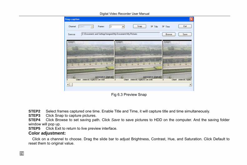
Fig 6.3 Preview Snap
STEP2 Select frames captured one time. Enable Title and Time, it will capture title and time simultaneously. STEP3 Click Snap to capture pictures. STEP4 Click Browse to set saving path. Click Save to save pictures to HDD on the computer. And the saving folder window will pop up. STEP5 Click Exit to return to live preview interface. Color adjustment:
Click on a channel to choose. Drag the slide bar to adjust Brightness, Contrast, Hue, and Saturation. Click Default to reset them to original value.
Digital Video Recorder User Manual
75
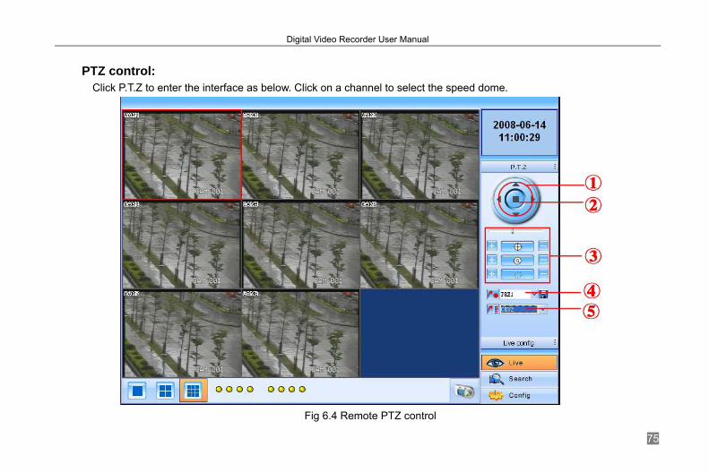
PTZ control:
Click P.T.Z to enter the interface as below. Click on a channel to select the speed dome.
Fig 6.4 Remote PTZ control

Digital Video Recorder User Manual
76
① Move the speed dome. ② Stop adjustment. ③ Adjust zoom, focus, Iris, Speed.
④ Go to the preset. Click to rename the preset. ⑤ Select and do auto cruise. Click right mouse, a pull-down menu will appear as below.
Fig 6.5 Preview Control Menu
Full screen: the picture will fill the screen, without tools bar display. Double click or click right mouse to return to the previous interface. Set cruise: select this function to set, the window below will appear.

Digital Video Recorder User Manual
77
Fig 6.6 Set Cruise
Click Add to add presets for the selected cruise. Click the preset, a down list menu will pop up. Users can select presets to add. Double click Time to set display time in auto cruise. Click Delete or Clear all to delete the presets. Click OK to save and exit. Fast stream: enable the master stream. This DVR supports dual stream, sub stream and master stream. Sub stream has low frame rate, max 4fps for every channel, referring to 4.2.7 Network Configuration. It requires low network bandwidth.
Master stream has higher frame rate, max 30fps for every channel. It also needs higher network bandwidth simultaneously. Therefore, users can select the stream according to their bandwidth. Refresh: update the picture on the channel. Sometimes the picture on one channel will freeze due to network block. At this time, users can refresh the pictures.
6.3 Remote Playback &Backup 6.3.1 Remote Playback
Click Search to enter the playback and backup block as below, where users can make remote playback, remote backup and remote video file management.
Digital Video Recorder User Manual
78
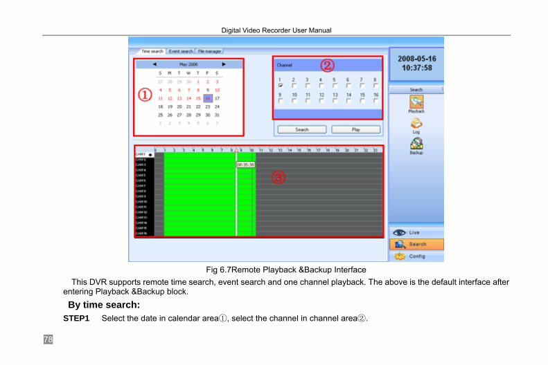
Fig 6.7Remote Playback &Backup Interface
This DVR supports remote time search, event search and one channel playback. The above is the default interface after entering Playback &Backup block. By time search:
STEP1 Select the date in calendar area①, select the channel in channel area②.
Digital Video Recorder User Manual
79
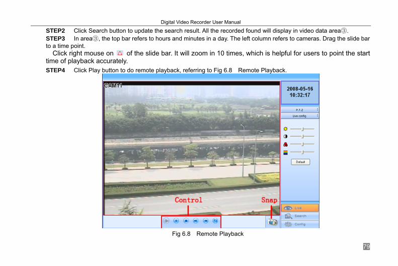
STEP2 Click Search button to update the search result. All the recorded found will display in video data area③. STEP3 In area③, the top bar refers to hours and minutes in a day. The left column refers to cameras. Drag the slide bar to a time point.
Click right mouse on of the slide bar. It will zoom in 10 times, which is helpful for users to point the start time of playback accurately. STEP4 Click Play button to do remote playback, referring to Fig 6.8 Remote Playback.
Fig 6.8 Remote Playback
Digital Video Recorder User Manual
80
STEP5 Users can make fast forward/backward, pause, stop playback and snap pictures. About snap feature, it is the same as that in remote preview, referring to Fig 6.3 Preview Snap.
STEP6 Click to return to search interface. By event search:
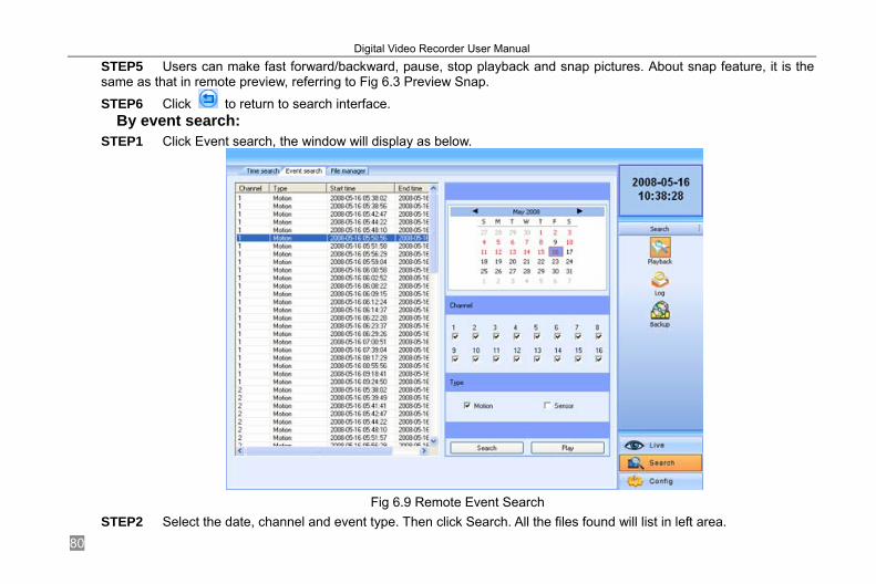
STEP1 Click Event search, the window will display as below.
Fig 6.9 Remote Event Search
STEP2 Select the date, channel and event type. Then click Search. All the files found will list in left area.
Digital Video Recorder User Manual
81
STEP3 Select a event, and click Play button to do remote playback. The following steps are the same as SETP5-6 of time search above.
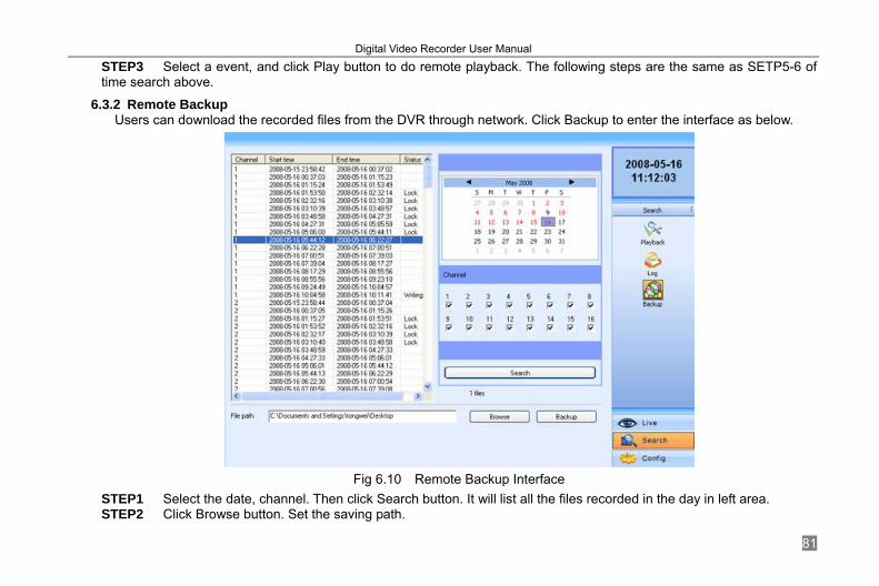
6.3.2 Remote Backup Users can download the recorded files from the DVR through network. Click Backup to enter the interface as below.
Fig 6.10 Remote Backup Interface
STEP1 Select the date, channel. Then click Search button. It will list all the files recorded in the day in left area. STEP2 Click Browse button. Set the saving path.
Digital Video Recorder User Manual
82
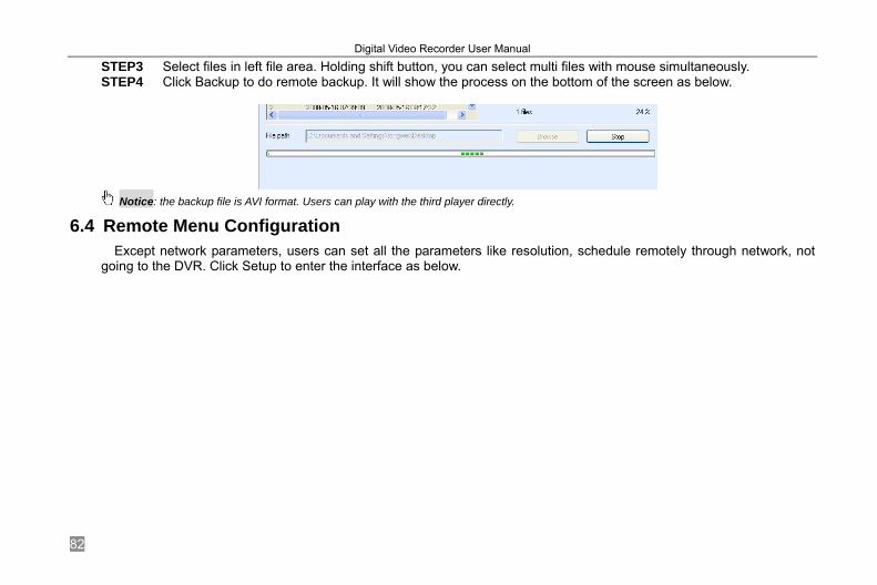
STEP3 Select files in left file area. Holding shift button, you can select multi files with mouse simultaneously. STEP4 Click Backup to do remote backup. It will show the process on the bottom of the screen as below.
Notice: the backup file is AVI format. Users can play with the third player directly.
6.4 Remote Menu Configuration Except network parameters, users can set all the parameters like resolution, schedule remotely through network, not
going to the DVR. Click Setup to enter the interface as below.

Digital Video Recorder User Manual
83
Fig 6.11 Remote Menu Setup
The sub menu lists and the options in every sub menu are similar with those on the DVR. Please refer to 4.2 Main Menu Setup to do setup.
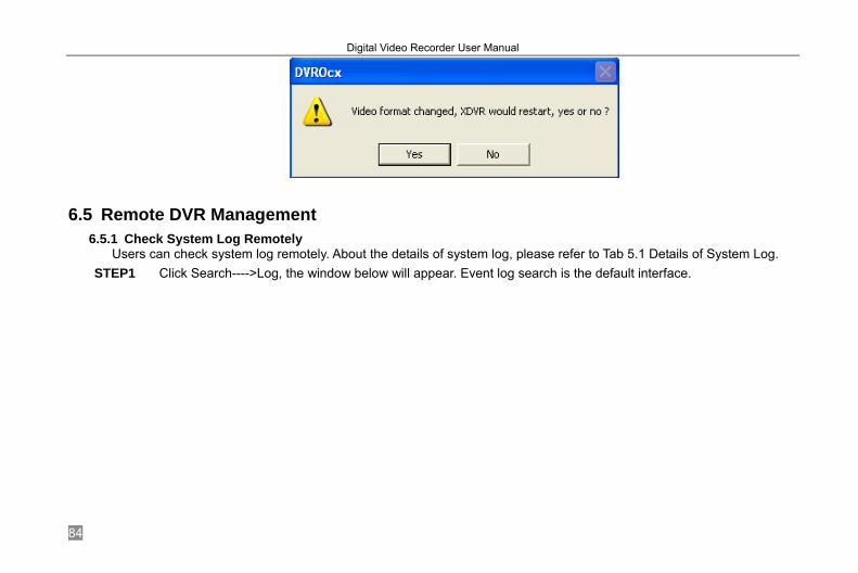
Click Save to save the change. Some changes may pop up a dialog box as below and need restart.
Digital Video Recorder User Manual
84
6.5 Remote DVR Management 6.5.1 Check System Log Remotely
Users can check system log remotely. About the details of system log, please refer to Tab 5.1 Details of System Log. STEP1 Click Search---->Log, the window below will appear. Event log search is the default interface.

Digital Video Recorder User Manual
85
Fig 6.12 Remote System LOG Search
STEP2 Select the date, channel and event type. Then click Search. STEP3 The entire log found will list in left area. STEP4 Click Operation to enter operation Log search interface

Digital Video Recorder User Manual
86
Fig 6.13 Remote Operation Log Search
STEP5 Select the date and click Search. It will list all the log files in the day in left area.
6.5.2 Lock &Delete Files Remotely Users can lock and delete video files through network. About the details of this feature please refer to 5.7 Lock &Delete
Files. STEP1 Click Search---->Playback---->File manager, the window below will appear.
Digital Video Recorder User Manual
87
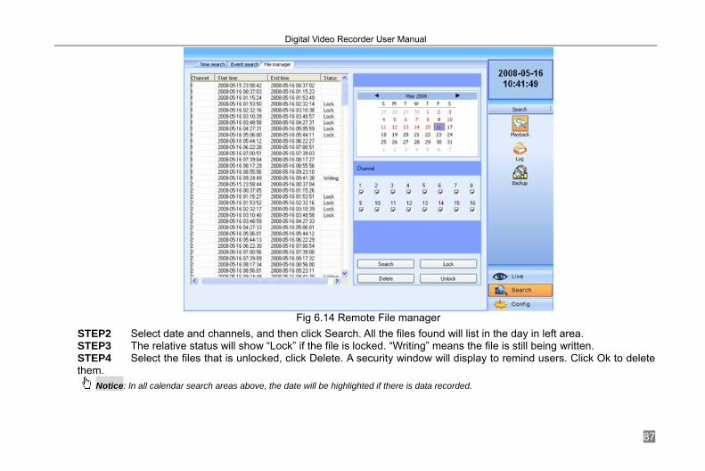
Fig 6.14 Remote File manager
STEP2 Select date and channels, and then click Search. All the files found will list in the day in left area. STEP3 The relative status will show “Lock” if the file is locked. “Writing” means the file is still being written. STEP4 Select the files that is unlocked, click Delete. A security window will display to remind users. Click Ok to delete them.
Notice: In all calendar search areas above, the date will be highlighted if there is data recorded.
Digital Video Recorder User Manual
88
CHAPTER 7 Mobile Surveillance
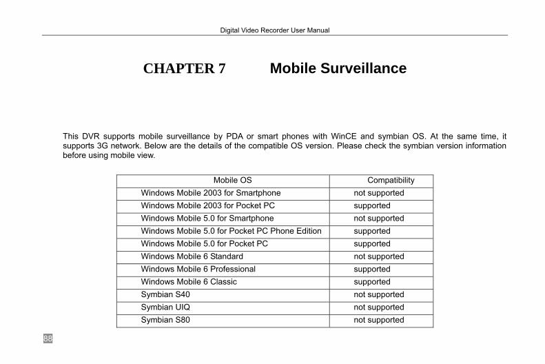
This DVR supports mobile surveillance by PDA or smart phones with WinCE and symbian OS. At the same time, it supports 3G network. Below are the details of the compatible OS version. Please check the symbian version information before using mobile view.
Mobile OS Compatibility Windows Mobile 2003 for Smartphone not supported Windows Mobile 2003 for Pocket PC supported Windows Mobile 5.0 for Smartphone not supported Windows Mobile 5.0 for Pocket PC Phone Edition supported Windows Mobile 5.0 for Pocket PC supported Windows Mobile 6 Standard not supported Windows Mobile 6 Professional supported Windows Mobile 6 Classic supported Symbian S40 not supported Symbian UIQ not supported Symbian S80 not supported

Digital Video Recorder User Manual
89
Symbian S60 1st Edition-Symbian OS v6.1 supported Symbian S60 2nd Edition-Symbian OS v7.0s supported Symbian S60 2nd Edition with FP1-Symbian OS v7.0s enhanced
supported
Symbian S60 2nd Edition with FP2-Symbian OS v8.0a
supported
Symbian S60 2nd Edition with FP3-Symbian OS v8.1
supported
Symbian S60 3rd Edition-Symbian OS v9.1 supported Symbian S60 3rd Edition with FP1-Symbian OS v9.2
supported
Symbian S60 3rd Edition with FP2-Symbian OS v9.3
supported
Symbian S60 5th Edition-Symbian OS v9.4 supported Symbian S60 5.1 Edition-Symbian OS v9.5 supported
It wants to make mobile surveillance, need first enable network service on the DVR, referring to 4.2.7 Network Configuration. The below is the use instructions on mobile client end for two OS.
Notice: It supports only live view by mobile devices and on channel at a time.
7.1 By Phones with WinCE Please use the PDA or smart phones with WinCE version supported by this unit.
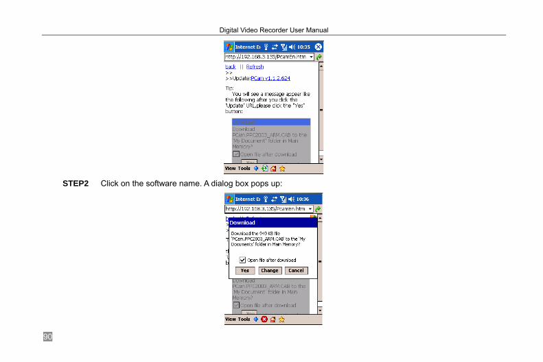
STEP1 Firstly activate the network access on mobile phone and then run “Internet Explorer”. Input the server’s address and the connection is built up shown as below:
Digital Video Recorder User Manual
90
STEP2 Click on the software name. A dialog box pops up:

Digital Video Recorder User Manual
91
STEP3 Click “Yes” to start downloading and installing: STEP4 PCam will be opened automatically after installed
STEP5 Input the server’s address, ID and password respectively in the columns of “Server”, “User” and “Password”, and click “Go” to log on the server. It will show the picture if access successfully.

Digital Video Recorder User Manual
92
STEP6 Camera one is the default channel after login. Change the channel in rolling-down menu of “Channel”:

Digital Video Recorder User Manual
93
Notice: User name and password here are the same with that used on the DVR. The default is admin and 123456.
7.2 By Phones with Symbian Please use the smart phones with symbian version supported by this unit. STEP1 Firstly enable the network access on mobile phone. And then run Web browser. STEP2 Input the DVR server’s IP address in a new-built bookmark. Click this bookmark to connect to the DVR.
STEP3 A welcome window will pop up and requires a package. Click the software name to download

Digital Video Recorder User Manual
94
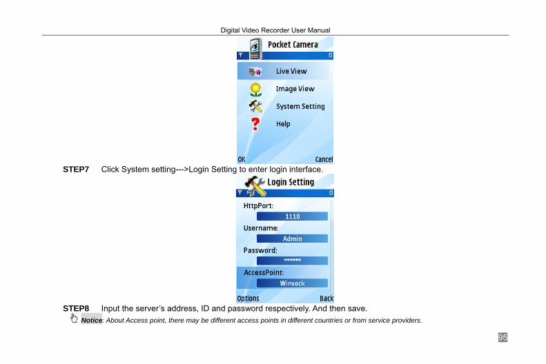
STEP4 A security windows will pop up after downloading and ask if install the package. Click YES to install. STEP5 A Scam shortcut icon appears on the system menu after finished. STEP6 Run Scam program. It will enter a function interface. Live view: to do mobile live view Image view: to check the pictures snapped in live view System setting: Login setting and Alarm setting. Help: function indication and help
Digital Video Recorder User Manual
95
STEP7 Click System setting--->Login Setting to enter login interface.
STEP8 Input the server’s address, ID and password respectively. And then save.
Notice: About Access point, there may be different access points in different countries or from service providers.
Digital Video Recorder User Manual
96
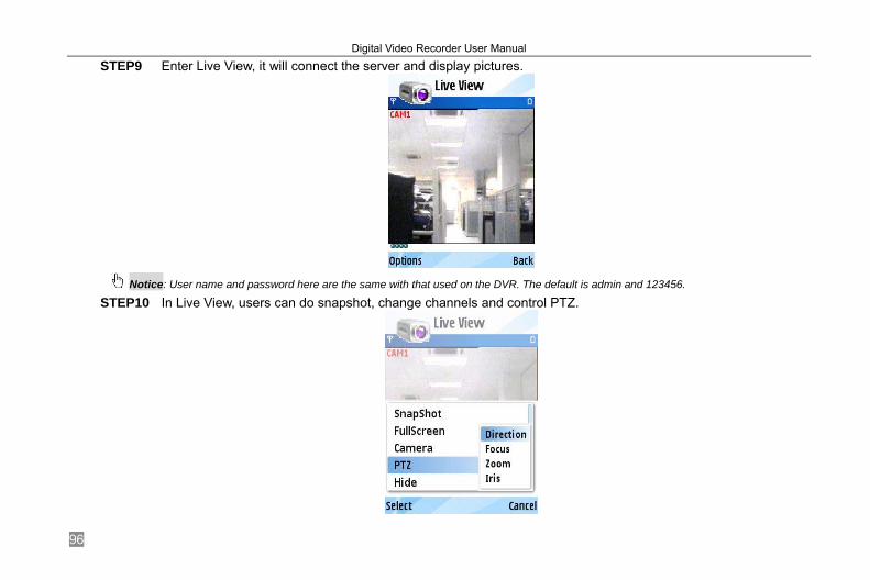
STEP9 Enter Live View, it will connect the server and display pictures.
Notice: User name and password here are the same with that used on the DVR. The default is admin and 123456.
STEP10 In Live View, users can do snapshot, change channels and control PTZ.
Digital Video Recorder User Manual
97
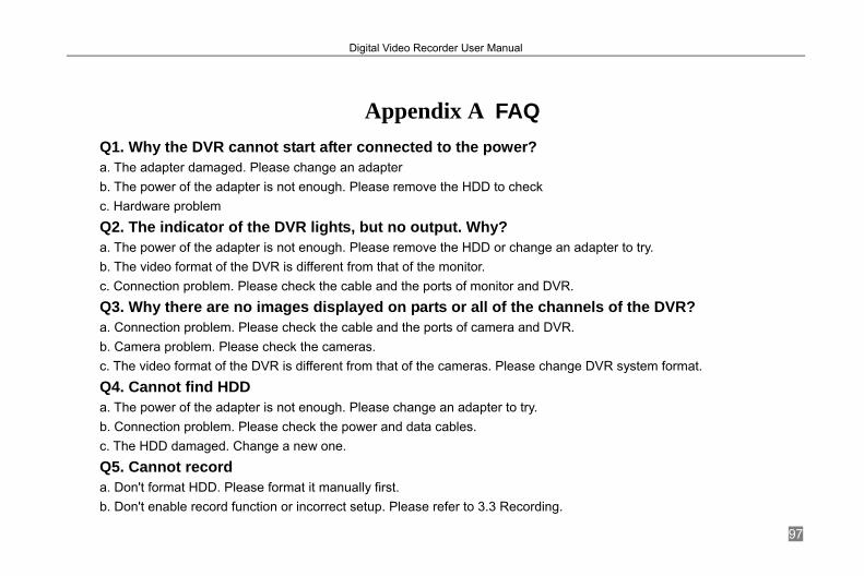
Appendix A FAQ Q1. Why the DVR cannot start after connected to the power? a. The adapter damaged. Please change an adapter b. The power of the adapter is not enough. Please remove the HDD to check c. Hardware problem Q2. The indicator of the DVR lights, but no output. Why? a. The power of the adapter is not enough. Please remove the HDD or change an adapter to try. b. The video format of the DVR is different from that of the monitor. c. Connection problem. Please check the cable and the ports of monitor and DVR. Q3. Why there are no images displayed on parts or all of the channels of the DVR? a. Connection problem. Please check the cable and the ports of camera and DVR. b. Camera problem. Please check the cameras. c. The video format of the DVR is different from that of the cameras. Please change DVR system format. Q4. Cannot find HDD a. The power of the adapter is not enough. Please change an adapter to try. b. Connection problem. Please check the power and data cables. c. The HDD damaged. Change a new one. Q5. Cannot record a. Don't format HDD. Please format it manually first. b. Don't enable record function or incorrect setup. Please refer to 3.3 Recording.

Digital Video Recorder User Manual
98
c. HDD is full and not enables recycle function. Please refer to 4.2.3 Record Configuration. Chang a new HDD or enable recycle. d. The HDD damaged. Change a new one. Q6. Cannot use mouse. a. wait 5 minutes after mouse connected. b. No detected. Plug/unplug several times. c. The mouse is incompatible. Please change a mouse. Q7. Cannot download ActiveX control. a. IE browser blocks activeX. Please do setup following below. ① Open IE browser. Click Tools-----Internet Options….
Fig 7-1
② select Security------Custom Level….As shown as Fig 7-2 ③ Enable all the sub options under “ActiveX controls and plug-ins”. Shown as Fig 7-3

Digital Video Recorder User Manual
99
Fig 7-2 Fig 7-3
④ Then click ok to finish setup. b. Other plug-ins or anti-virus block activeX. Please uninstall or close them.
Q8: How to deal with when DVR starts, it displays “please wait…”all the time First possible reason: hard-disk cable and data cable are not well connected. Solution: Please check the connection of hard-disk cable and data cable and make sure they are well connected; If still not

Digital Video Recorder User Manual
100
working, please unplug them and then try re-plugging again; Second possible reason: It is forced to stop because hard disk has disabled track which causes the system checking hard disk cannot skip Solution: Change another new hard disk or reformat the broken one
Q9: The mouse inserting into the front USB jack does not work Hereby the front USB jack is only for backup of U disk, USB DVD writer etc., and not support USB mouse. Please use the USB jack in the rear panel if using mouse to operate.
Q10: How to input password and digital numbers The method to input password and digital numbers is to click the box behind password or items needing to input by numbers, and then the small keyboard will appear. Please select number or letter to input (the initial password is 123456), or you can use the digital keys in the front panel, or the digital keys on the remote controller.
Q11: How to upgrade when added new functions or revised software After getting the upgraded software from manufacturer, please copy it into U disk, and then select “upgrade” in the menu. If upgrading the kernel procedure, please refer to the following method: firstly insert U disk into DVR, and then input “adwsws” in the password of system login and the system will upgrade kernel procedure automatically. After finished, please restart DVR to achieve. Notice: Do not power off in the system upgrading process! Otherwise, it may cause that DVR cannot start.
Q12: Why is the hard disk used in a DVR identified a new hard disk if directly used to another same type DVR? And
why must we format it again? When DVR only uses one hard disk, the hard disk removed from one to another same type DVR can work normally without format. When a DVR adds to a new hard disk, it will identify the hard disk as a new one and inquire whether to format no matter whether this hard disk used or not in another same type DVR before. In this condition, it can be used normally after formatted according to the guide; if two or more hard disks used in different DVRs, when used in another one DVR with the same type, they will be identified to be two or more new hard disks, and all of them need to format. In general, please do not try using more disks removed from different DVRs into another one DVR in case the data lose.

Digital Video Recorder User Manual
101
Appendix B Calculation of Recording Capacity Users can calculate the size of hard disk according to the saving time and DVR recording settings. The DVR uses fixed
video bit rate. The below are the details at different settings DVR.
Video Format Resolution
Farm Rate Totally(FPS)
Video Quality Bit Rate (kbps)
Used Space (MB/h)
PAL D1 25
Highest 2M 915 Higher 1.5M 700 Medium 1M 465 Lower 768K 297 Lowest 512K 241
NTSC D1 30
Highest 2M 910 Higher 1.5M 712 Medium 1M 468 Lower 768K 297 Lowest 512K 240
The calculation format is: Total Recording capacity =Used space per hour (MB/h) (coverage rate of hard disk)
× Recording time (hour) ×channel numbers Take 4-channel DVR for example:
Total Recoding capacity =700(mb/h) X 24(hours) X30(days) X4(channels) = 2016000(MB) = 2016(GB)
If users install one2016GB SATA HDD, it can almost record one month.

Digital Video Recorder User Manual
102
Appendix C Compatible Devices
1. Compatible USB drive after test
Brand Capacity Netac 4GB Kingston 2GB Aigo 2GB Smatter vider 1GB Scandisk 4GB SSK 512MB, 1G, 2GB
Tab C.1 Compatible USB drive
2. Compatible SATA CD/DVD writers after test
Brand Model SAMSUNG TS-H653B LITEN-ON DH-20A6S01C
Tab C.2 Compatible CD/DVD writers
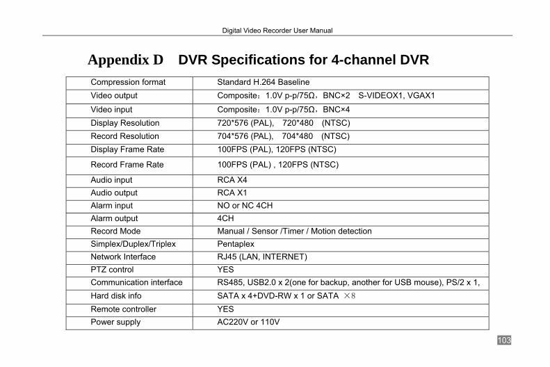
Digital Video Recorder User Manual
103
Appendix D DVR Specifications for 4-channel DVR Compression format Standard H.264 Baseline Video output Composite:1.0V p-p/75Ω,BNC×2 S-VIDEOX1, VGAX1
Video input Composite:1.0V p-p/75Ω,BNC×4 Display Resolution 720*576 (PAL), 720*480 (NTSC) Record Resolution 704*576 (PAL), 704*480 (NTSC) Display Frame Rate 100FPS (PAL), 120FPS (NTSC)
Record Frame Rate 100FPS (PAL) , 120FPS (NTSC)
Audio input RCA X4 Audio output RCA X1 Alarm input NO or NC 4CH Alarm output 4CH Record Mode Manual / Sensor /Timer / Motion detection Simplex/Duplex/Triplex Pentaplex Network Interface RJ45 (LAN, INTERNET) PTZ control YES Communication interface RS485, USB2.0 x 2(one for backup, another for USB mouse), PS/2 x 1, Hard disk info SATA x 4+DVD-RW x 1 or SATA ×8 Remote controller YES Power supply AC220V or 110V
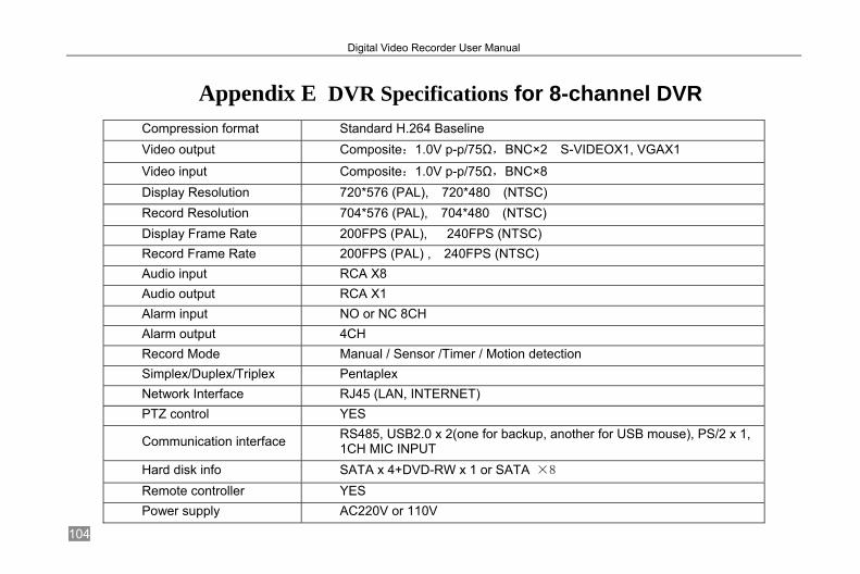
Digital Video Recorder User Manual
104
Appendix E DVR Specifications for 8-channel DVR Compression format Standard H.264 Baseline Video output Composite:1.0V p-p/75Ω,BNC×2 S-VIDEOX1, VGAX1
Video input Composite:1.0V p-p/75Ω,BNC×8 Display Resolution 720*576 (PAL), 720*480 (NTSC) Record Resolution 704*576 (PAL), 704*480 (NTSC) Display Frame Rate 200FPS (PAL), 240FPS (NTSC) Record Frame Rate 200FPS (PAL) , 240FPS (NTSC) Audio input RCA X8 Audio output RCA X1 Alarm input NO or NC 8CH Alarm output 4CH Record Mode Manual / Sensor /Timer / Motion detection Simplex/Duplex/Triplex Pentaplex Network Interface RJ45 (LAN, INTERNET) PTZ control YES
Communication interface RS485, USB2.0 x 2(one for backup, another for USB mouse), PS/2 x 1, 1CH MIC INPUT
Hard disk info SATA x 4+DVD-RW x 1 or SATA ×8 Remote controller YES Power supply AC220V or 110V

Digital Video Recorder User Manual
105
Appendix F DVR Specifications for 16-channel DVR Compression format Standard H.264 Baseline Video output Composite:1.0V p-p/75Ω,BNC×2 S-VIDEOX1, VGAX1
Video input Composite:1.0V p-p/75Ω,BNC×16 Display Resolution 720*576 (PAL), 720*480 (NTSC) Record Resolution 704*576 (PAL), 704*480 (NTSC) Display Frame Rate 400FPS (PAL), 480FPS (NTSC)
Record Frame Rate 400FPS (PAL) , 480FPS (NTSC)
Audio input RCA X16 Audio output RCA X1 Alarm input NO or NC 16CH Alarm output 4CH Record Mode Manual / Sensor /Timer / Motion detection Simplex/Duplex/Triplex Pentaplex Network Interface RJ45 (LAN, INTERNET) PTZ control YES
Communication interface RS485, USB2.0 x 2(one for backup, another for USB mouse), PS/2 x 1, 1CH MIC INPUT
Hard disk info SATA x 3+DVD-RW x 1 or SATA ×8 Remote controller YES Power supply AC 220V or 110V