Embed Size (px)
Citation preview
AMC2 DCUAAPC-AMC2-DCUA
en Installation manual

AMC2 DCUA Table of Contents | en 3
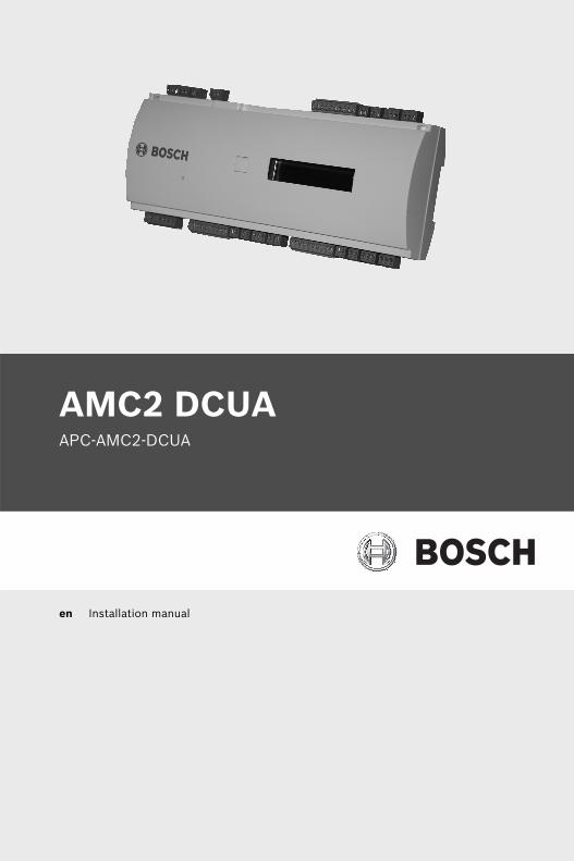
Table of Contents
1 Important Information 51.1 Explanation of symbols in this document 51.2 Internet 6
2 Safety Instructions 72.1 Important Safety Notes 72.2 Safety Precautions 92.3 Unpacking 10
3 Introduction 113.1 Description of the AMC2 DCUA 113.2 Equipment Configuration 133.3 Performance Characteristics 153.4 System Overview 16
4 Technical Data 19
5 Installing 225.1 Mounting 225.2 Unmounting 235.3 Opening the Case 245.4 Closing the Case 255.5 Cabling 265.5.1 Conductor data 265.6 Grounding and Shielding 285.6.1 Host Interface and Extension Interface 285.6.2 Bus Interfaces 295.7 Connecting Power Supply 305.8 Ethernet Interface 315.9 RS-485 Host Interface 325.9.1 RS-485 Two Wire Connection 345.10 DIL switch selector 365.11 RS-485 for extension modules 38
Bosch Sicherheitssysteme GmbH Installation manual V 1.4 | 2010.01

4 en | Table of Contents AMC2 DCUA
5.12 Wiegand/Omron Interface for Card Readers 405.12.1 Connecting different reader types 415.13 RS-485 Interface for Card Readers 455.14 RS-232 Interface for Readers 465.15 Connecting Relay Outputs 475.16 Connecting Analog Input Devices 505.17 Tamper Protection 53
6 Operating 546.1 Status Display of the AMC2 DCUA 546.2 Configuring the Ethernet Interface 566.3 Resetting the AMC2 DCUA 576.3.1 Resetting the Software 576.3.2 Resetting the Network Configuration 58
7 Appendix 597.1 AMC2 Devices and their Documents 597.2 Connecting Diagrams 60
Index 66
V 1.4 | 2010.01 Installation manual Bosch Sicherheitssysteme GmbH
AMC2 DCUA Important Information | en 5
1 Important InformationRemarksThis hardware is part of a security system. Access should be limited to authorized persons only.Some states do not allow the exclusion or limitation of implied warranties, or limitation of liability for incidental or consequential damages, hence the above limitation or exclusion might not apply to you.Bosch Security Systems retains all rights not expressly granted. Nothing in this license constitutes a waiver of Bosch’s rights under the U.S. Copyright laws or any other federal or state law.If you have any questions concerning this license, please, write to:
Bosch Access Systems GmbH Charlottenburger Allee 50D-52068 AachenGermany
1.1 Explanation of symbols in this documentThroughout this document, helpful tips, important notes, cautions and warnings are presented for the reader. These appear as follows:
!WARNING! These warn the operator of potential damage to the program or equipment.
iNOTICE! Important Notes – must be followed to ensure successful operation and programming. Tips and shortcuts may also be included in such notes.
Bosch Sicherheitssysteme GmbH Installation manual | V 1.4 | 2010.01
6 en | Important Information AMC2 DCUA
1.2 InternetIf you are interested in further information on this product or information on other products, please consult our website at http://www.boschsecuritysystems.com.
| V 1.4 | 2010.01 Installation manual Bosch Sicherheitssysteme GmbH
AMC2 DCUA Safety Instructions | en 7
2 Safety Instructions
2.1 Important Safety Notes1. Read, follow, and retain instructions - All safety and
operating instructions must be read and followed properly before putting the unit into operation. Retain instructions for future reference.
2. Do not ignore warnings - Adhere to all warnings on the unit and in the operating instructions.
3. Accessories - Use only accessories recommended by the manufacturer or those sold with the product. Accessories not recommended by the manufacturer must not be used, as they may cause hazards.
4. Installation precautions - Do not place this unit on an unstable stand, tripod, bracket, or mount. The unit may fall, causing serious injury to persons and damage to the unit. Mount the unit according to the manufacturer’s instructions.
5. Service - Do not attempt to service this unit by yourself. Opening or removing covers may expose you to dangerous voltages or other hazards. Refer all servicing to qualified service personnel.
6. Damage which requires service - Disconnect the unit from the main AC or DC power source and refer servicing to qualified service personnel under the following conditions:– If the power supply cord or plug is damaged.– If liquid has been spilled or an object has fallen into
the unit.– If the unit has been exposed to water and/or
inclement weather (rain, snow, etc.).– If the unit does not operate normally when following
the operating instructions. Adjust only those controls specified in the operating instructions. Improper adjustment of other controls may result in damage, and require extensive work by a qualified technician
Bosch Sicherheitssysteme GmbH Installation manual | V 1.4 | 2010.01
8 en | Safety Instructions AMC2 DCUA
to restore the unit to normal operation.– If the unit has been dropped or the cabinet damaged.– If the unit exhibits a distinct change in performance
7. Replacement parts - If replacement parts are required, the service technician must use only replacement parts that are specified by the manufacturer. Unauthorized replacements may result in fire, electrical shock or other hazards.
8. Safety check - Upon completion of service or repair work on the unit, ask the service technician to perform safety checks to ensure that the unit operates properly
9. Power sources - Operate the unit only from the type of power source indicated on the label. If unsure of the type of power supply to use, contact your dealer – For units intended to operate on battery power, refer
to the operating instructions.– For units intended to operate with external power
supplies, use only the recommended approved power supplies corresponding to norm EN/UL 60950.
– For units intended to operate with a limited power source, this power source must comply with EN/UL 60950. Unsuitable replacements may damage the unit or cause fire or shock.
– For units intended to operate at 12V DC normal input voltage is 12V DC. Voltage input must never exceed 15V DC.
10. Lightning - For added protection during electrical storms external lightning conductors can be installed. This prevents power surges from damaging the unit.
11. The units should be installed in locations with restricted access.
| V 1.4 | 2010.01 Installation manual Bosch Sicherheitssysteme GmbH
AMC2 DCUA Safety Instructions | en 9
2.2 Safety Precautions
!WARNING! Read instructions!Before working with the AMC2 device, read these instructions carefully. Make sure you have understood all information described in this document.
!WARNING! Risk of electric shock!External power supplies must be installed and put into service by qualified personnel. Compliance with the relevant regulations must be ensured.
!
WARNING! Risk of damage to equipment!– Always switch off power of the AMC2 device before
modifying the installation. – Do not connect or disconnect plug connectors, data cables
or screw connectors while power is on!
!
WARNING! Health and Safety!Installation of the AMC2 device must comply with any local fire, health and safety regulations. A secured door that may be part of an escape route from an area must be installed with:– A fail-safe lock (A). So that the door will be released if
power fails. Ideally, a magnetic lock should be used.– A normally-closed break-glass or manual pull (B) in the lock
supply wiring, so that in an emergency the fail-safe lock can be immediately powered down.
!WARNING! You must ground the controller. Disconnect both AC and battery power supply before working on the controller.
Bosch Sicherheitssysteme GmbH Installation manual | V 1.4 | 2010.01
10 en | Safety Instructions AMC2 DCUA
2.3 UnpackingCheck the packaging for visible damage. If anything has been damaged during transport, please inform the transport agency.Unpack the unit carefully. This is an electronic device that must be handled with care to avoid damage. Do not attempt to put the unit into operation if components are damaged.If any parts are missing, inform your customer service representative or a Bosch Security Systems salesperson. The shipping carton is the safest transport container for the unit. Store it and the other packaging material for future use. If the unit has to be sent back, use the original packaging.
!WARNING! Risk of damage!Protect the hardware from electrostatic discharge by observing ESD instructions before unpacking or touching connectors or electronics.
!
WARNING! Lithium BatteryDanger of explosion if battery is replaced incorrectly. Replace only with the same type as recommended by the manufacturer. Dispose used batteries according to the battery manufacturer’s instructions.
| V 1.4 | 2010.01 Installation manual Bosch Sicherheitssysteme GmbH
AMC2 DCUA Introduction | en 11
3 Introduction
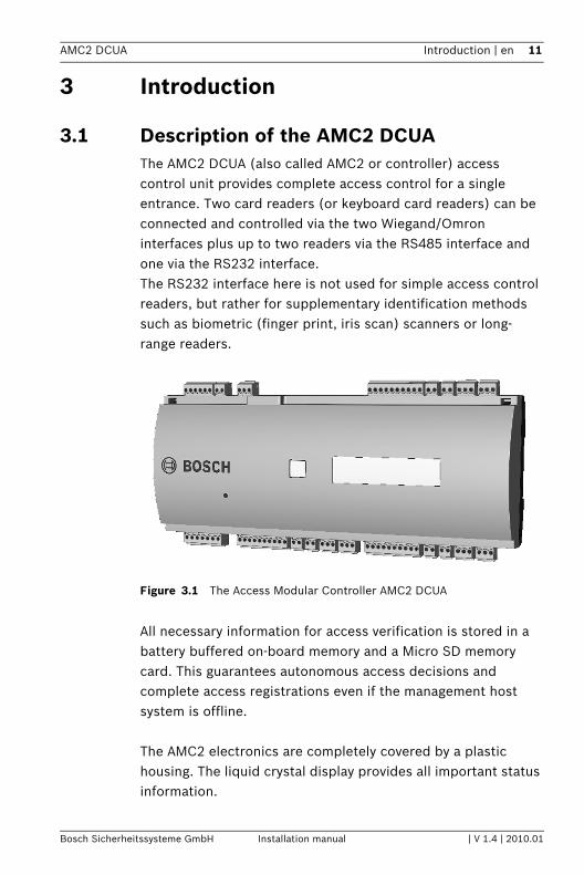
3.1 Description of the AMC2 DCUA The AMC2 DCUA (also called AMC2 or controller) access control unit provides complete access control for a single entrance. Two card readers (or keyboard card readers) can be connected and controlled via the two Wiegand/Omron interfaces plus up to two readers via the RS485 interface and one via the RS232 interface.The RS232 interface here is not used for simple access control readers, but rather for supplementary identification methods such as biometric (finger print, iris scan) scanners or long-range readers.
Figure 3.1 The Access Modular Controller AMC2 DCUA
All necessary information for access verification is stored in a battery buffered on-board memory and a Micro SD memory card. This guarantees autonomous access decisions and complete access registrations even if the management host system is offline.
The AMC2 electronics are completely covered by a plastic housing. The liquid crystal display provides all important status information.
Bosch Sicherheitssysteme GmbH Installation manual | V 1.4 | 2010.01
12 en | Introduction AMC2 DCUA
The AMC2 DCUA can be extended by a maximum of one AMC2 4W-EXT plus a maximum of three I/O extension modules. The I/O extension modules AMC2 8I-8O-EXT, AMC2 16I-16O-EXT, or AMC2 16I-EXT (in any combination) are, like the AMC2 4W-EXT, connected via the AMC2 DCUA’s extension interface. As the extension modules contain neither memory nor display they are controlled and monitored entirely by the AMC2 DCUA.The signal settings and parametrization of the readers connected to the extension module, are carried out by the AMC2 DCUA to which it belongs.The AMC2 DCUA communicates with the host system primarily by ethernet. In special configurations the RS485 interface can also be used for the host connection.
The AMC2 DCUA possesses six analog inputs and six relay outputs. It receives state information about the entrance via the inputs and transmits door control signals and/or notifications to external monitoring systems via the outputs. If the six inputs and six outputs of the AMC2 DCUA are not sufficient then up to 3 extensions (AMC2 8I-8O-EXT, AMC2 16I-16O-EXT or AMC2 16I-EXT) with 8 or 16 inputs and outputs respectively can be connected.
The allocation of the signals is determined by "door models" which, when selected, reserve the necessary reader connections and contacts for their usage. This default allocation can be overriden and adapted to circumstances using the parameterization tools in the access control system, where
iNOTICE! The RS485 interface can be used either for the host connection or to connect extension boards. If extension boards are used then the host connection must be by ethernet.
iNOTICE! This controller is currently a project version. In future product software up to three extensions will be connectable in Access Engine, and one in Access PE.
| V 1.4 | 2010.01 Installation manual Bosch Sicherheitssysteme GmbH
AMC2 DCUA Introduction | en 13
any free contact can have a signal allocated.
3.2 Equipment Configuration
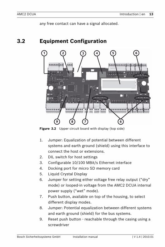
Figure 3.2 Upper circuit board with display (top side)
1. Jumper: Equalization of potential between different systems and earth ground (shield) using this interface to connect the host or extensions.
2. DIL switch for host settings3. Configurable 10/100 MBit/s Ethernet interface4. Docking port for micro SD memory card5. Liquid Crystal Display6. Jumper for setting either voltage free relay output (“dry”
mode) or looped-in voltage from the AMC2 DCUA internal power supply (“wet” mode).
7. Push button, available on top of the housing, to select different display modes.
8. Jumper: Potential equalization between different systems and earth ground (shield) for the bus systems.
9. Reset push button - reachable through the casing using a screwdriver
Bosch Sicherheitssysteme GmbH Installation manual | V 1.4 | 2010.01
14 en | Introduction AMC2 DCUA
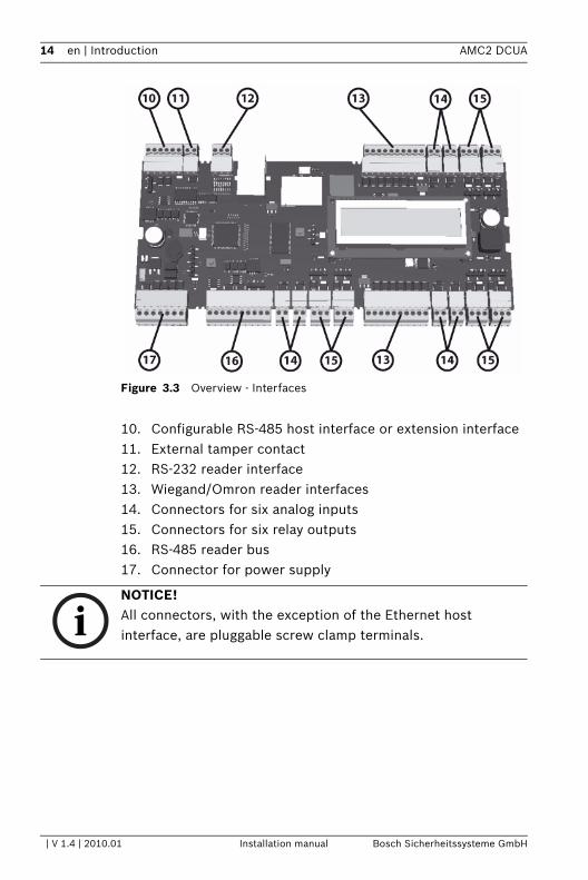
Figure 3.3 Overview - Interfaces
10. Configurable RS-485 host interface or extension interface11. External tamper contact 12. RS-232 reader interface13. Wiegand/Omron reader interfaces14. Connectors for six analog inputs 15. Connectors for six relay outputs 16. RS-485 reader bus 17. Connector for power supply
iNOTICE! All connectors, with the exception of the Ethernet host interface, are pluggable screw clamp terminals.
| V 1.4 | 2010.01 Installation manual Bosch Sicherheitssysteme GmbH
AMC2 DCUA Introduction | en 15
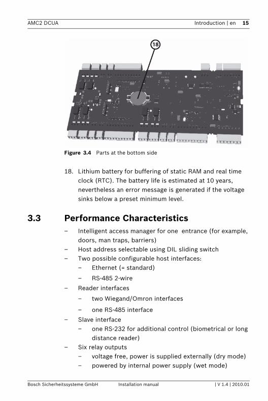
Figure 3.4 Parts at the bottom side
18. Lithium battery for buffering of static RAM and real time clock (RTC). The battery life is estimated at 10 years, nevertheless an error message is generated if the voltage sinks below a preset minimum level.
3.3 Performance Characteristics– Intelligent access manager for one entrance (for example,
doors, man traps, barriers)– Host address selectable using DIL sliding switch– Two possible configurable host interfaces:
– Ethernet (= standard)
– RS-485 2-wire
– Reader interfaces
– two Wiegand/Omron interfaces
– one RS-485 interface
– Slave interface– one RS-232 for additional control (biometrical or long
distance reader)– Six relay outputs
– voltage free, power is supplied externally (dry mode)– powered by internal power supply (wet mode)
Bosch Sicherheitssysteme GmbH Installation manual | V 1.4 | 2010.01
16 en | Introduction AMC2 DCUA
– Six analog inputs with internal power supply– Battery buffered SRAM and real time clock (RTC)– Pluggable Micro SD memory card (1024 MB)– Liquid Crystal Display– Transfer rate host interface RS-485: 38,4 kBit/s– Transfer rate host interface Ethernet: 10/100 MBit/s– Transfer rate to the extension interface: 9,6 kBit/s– Transfer rate reader interface RS-485: 9,6 kBit/s or
19,2 kBit/s– Transfer rate reader interface RS-232: 9,6 kBit/s depends
on the connected device– Self regulating transmit/receive switching– Power supply: 10 to 30 Vdc, max. 5 A– Tamper contact for external covers– If an external power supply is used then this should be an
PBC-60 (F.01U.026.573) with integrated uninterruptable power supply (UPS).
3.4 System OverviewThe Access Controller AMC2 DCUA is connected between the management host system and different peripheral devices. By default, a management host system is connected using Ethernet. A management host connection using RS-485 is also possible.
| V 1.4 | 2010.01 Installation manual Bosch Sicherheitssysteme GmbH
AMC2 DCUA Introduction | en 17
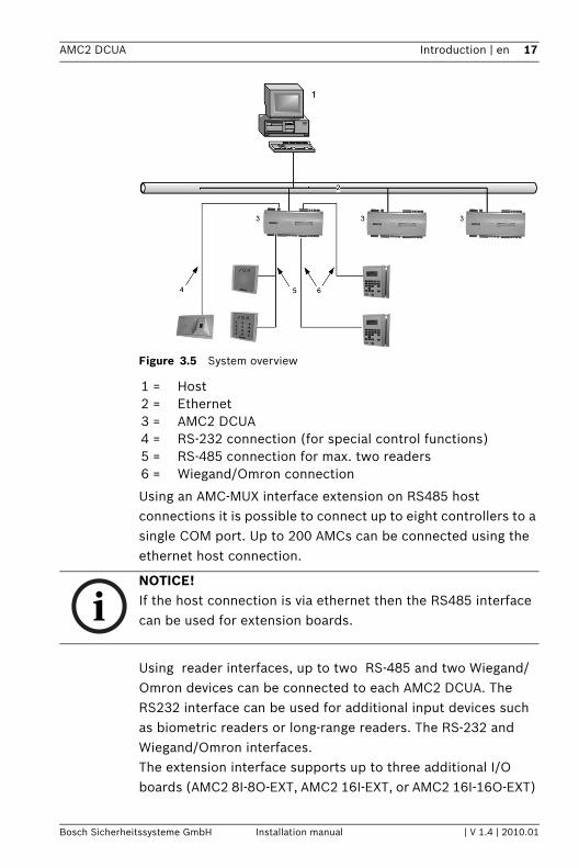
Figure 3.5 System overview
Using an AMC-MUX interface extension on RS485 host connections it is possible to connect up to eight controllers to a single COM port. Up to 200 AMCs can be connected using the ethernet host connection.
Using reader interfaces, up to two RS-485 and two Wiegand/Omron devices can be connected to each AMC2 DCUA. The RS232 interface can be used for additional input devices such as biometric readers or long-range readers. The RS-232 and Wiegand/Omron interfaces. The extension interface supports up to three additional I/O boards (AMC2 8I-8O-EXT, AMC2 16I-EXT, or AMC2 16I-16O-EXT)
1 = Host2 = Ethernet3 = AMC2 DCUA4 = RS-232 connection (for special control functions)5 = RS-485 connection for max. two readers6 = Wiegand/Omron connection
iNOTICE! If the host connection is via ethernet then the RS485 interface can be used for extension boards.
Bosch Sicherheitssysteme GmbH Installation manual | V 1.4 | 2010.01
18 en | Introduction AMC2 DCUA
if ethernet is used for the host connection. All extension boards are controlled by the AMC2 and are freely combinable.
iNOTICE! This controller is currently a project version. In future product software up to three extensions will be connectable in Access Engine, and one in Access PE.
| V 1.4 | 2010.01 Installation manual Bosch Sicherheitssysteme GmbH
AMC2 DCUA Technical Data | en 19
4 Technical DataHardware– Integrated Microcontroller (32 Bit, 30 MHz)– SRAM (256 kB)– Serial EEPROM– RTC (real time clock)– Pluggable 1 GB Micro SD memory card– Battery for SRAM and RTC– DIL switch for host settings (address and protocol mode)– Host interfaces
– Ethernet 10/100 MBit/s
– RS-485 2-wire
Transfer rate: 38,4 kBit/s (even parity, 7 bit, 1 stop bit)
– Reader interfaces:– one RS-485 interface for max. two readers
Transfer rate: 9,6 kBit/s(no parity, 8 bit, 2 stop bit)
or
Transfer rate: 19,2 kBit/s(no parity, 8 bit, 1 stop bit)
– two Wiegand/Omron interfaces - each for one reader– Slave interface (RS-232) to connect additional control
units - the transfer rate depends on the connected device– Six relay outputs
– maximum ratings (wet and dry):switching voltage: 30 Vdc
switching current: 1,25 A
– operating ratings (wet and dry):1,25 A @ 30 Vdc
2 A @ 12 Vdc
1,5 A @ 24 Vdc
– Six analog inputs with sabotage monitoring; only connect dry contacts
Bosch Sicherheitssysteme GmbH Installation manual | V 1.4 | 2010.01
20 en | Technical Data AMC2 DCUA
– RS-485 extension interface:Transfer rate: 9,6 kBit/s(no parity, 8 bit, 2 stop bit)
– Tamper contact for enclosures
Power supply10 to 30 Vdc
Display64,8 mm x 13,9 mm (2.551 x 0.547 in.)1 line, 16 characters
Power consumptionAMC: 5 VA Peripheral devices: using the PBC-60
– up to 55 VA– constant load: 25 VA
ConnectorsPluggable screw connectors
Protection class
IP30
Environment temperature0 °C to 45 °C (32 °F to 113 °F)
HumidityUp to 95%, without condensation
Housing materialABS with OC (UL 94 V-0)
Dimensions(W/H/D)in.) 287 x 50 x 142 mm (11.3 x 1.96 x 5.59 in.)
Weight
| V 1.4 | 2010.01 Installation manual Bosch Sicherheitssysteme GmbH
AMC2 DCUA Technical Data | en 21
app. 0,53 kg (0.9 pounds)
!WARNING! The voltage drop from the power supply to the AMC has effect on the AMC interfaces. Their sum must be less than 2 V!
iNOTICE! Using several devices in an installation system take care about the greatest minimum and the lowest maximum value for the environment. Take these for the system limits.
Bosch Sicherheitssysteme GmbH Installation manual | V 1.4 | 2010.01
22 en | Installing AMC2 DCUA
5 Installing
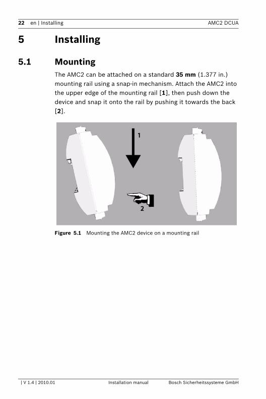
5.1 MountingThe AMC2 can be attached on a standard 35 mm (1.377 in.) mounting rail using a snap-in mechanism. Attach the AMC2 into the upper edge of the mounting rail [1], then push down the device and snap it onto the rail by pushing it towards the back [2].
Figure 5.1 Mounting the AMC2 device on a mounting rail
| V 1.4 | 2010.01 Installation manual Bosch Sicherheitssysteme GmbH
AMC2 DCUA Installing | en 23
5.2 Unmounting
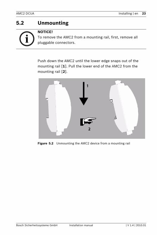
Push down the AMC2 until the lower edge snaps out of the mounting rail [1]. Pull the lower end of the AMC2 from the mounting rail [2].
Figure 5.2 Unmounting the AMC2 device from a mounting rail
iNOTICE! To remove the AMC2 from a mounting rail, first, remove all pluggable connectors.
Bosch Sicherheitssysteme GmbH Installation manual | V 1.4 | 2010.01
24 en | Installing AMC2 DCUA
5.3 Opening the Case
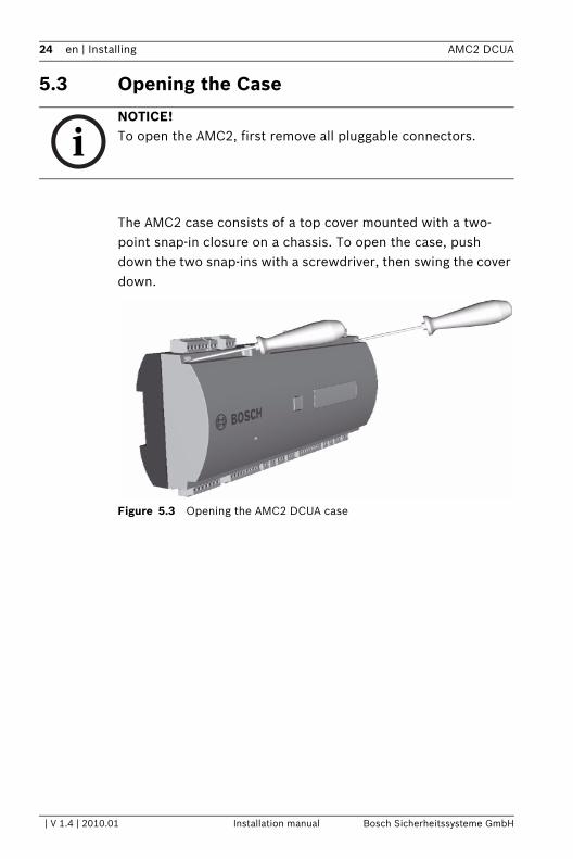
The AMC2 case consists of a top cover mounted with a two-point snap-in closure on a chassis. To open the case, push down the two snap-ins with a screwdriver, then swing the cover down.
Figure 5.3 Opening the AMC2 DCUA case
iNOTICE! To open the AMC2, first remove all pluggable connectors.
| V 1.4 | 2010.01 Installation manual Bosch Sicherheitssysteme GmbH
AMC2 DCUA Installing | en 25
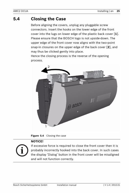
5.4 Closing the CaseBefore aligning the covers, unplug any pluggable screw connectors. Insert the hooks on the lower edge of the front cover into the lugs on lower edge of the plastic back cover [1]. Please ensure that the BOSCH logo is not upside-down. The upper edge of the front cover now aligns with the two-point snap-in closures on the upper edge of the back cover [2], and may thus be clicked gently into place. Hence the closing process is the reverse of the opening process.
Figure 5.4 Closing the case
iNOTICE! If excessive force is required to close the front cover then it is probably incorrectly hooked into the back cover. In such cases the display ’Dialog’ button in the front cover will be misaligned and will not function correctly.
Bosch Sicherheitssysteme GmbH Installation manual | V 1.4 | 2010.01
26 en | Installing AMC2 DCUA
5.5 Cabling
5.5.1 Conductor dataWith the calculation below you can find out which cable type must be used. If you connect the power supply and the AMC-device with the delivered cable set from the enclosure the calculation is not necessary. For distances below 25 m (75 ft) use AWG18 conductors (1 mm²). For longer distances, install an additional power supply close to the AMC2 controller.Please, calculate the voltage drop by checking the conductor specifications for characteristic resistance values. The voltage drop shall not exceed 2 V.Example:Length = 100 m/328 ftU = 12 V, I = 1 A, maximum UDrop = 2 V
i.e. RAWG18 (acc. specs) = 6.385 or 20,948
UDrop = 20,948 x 0.1 km x 1 A = 2.1 V
UDrop = 6.385 x 328 ft x 1 A = 2.1 V
Critical condition! Install the power supply closer to the controller.
!
WARNING! The cables used in the AMC2 access control system are not prone to electrical interference. However, you should avoid routing cables close to heavy load switching cables and equipment. If this is unavoidable, cross the cable at right angles every 1 to 2 m (3 to 6 ft) to reduce interference.
| V 1.4 | 2010.01 Installation manual Bosch Sicherheitssysteme GmbH

AMC2 DCUA Installing | en 27
iNOTICE! These specifications apply to power supply, readers, relay outputs, and extension interface.Regarding inputs, specific voltage-drop values need to be taken into account. Refer to Table 5.3
Bosch Sicherheitssysteme GmbH Installation manual | V 1.4 | 2010.01
28 en | Installing AMC2 DCUA
5.6 Grounding and ShieldingThe main grounding point at the AMC2 is connected to pin 2 of the power supply connector - see Table 7.3.It is good practice to shield all wires carrying low level signals.
The AMC2 allows you to create a central ground or shielding point, simply by setting certain jumpers. Set these jumpers only if grounding or shielding is not achieved by other means.
5.6.1 Host Interface and Extension Interface
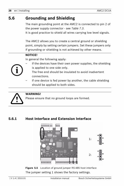
Figure 5.5 Location of ground jumper RS-485 host interface
The jumper setting 1 shows the factory settings.
i
NOTICE! In general the following apply:– If the devices have their own power supplies, the shielding
is applied to one side only.The free end should be insulated to avoid inadvertent connections.
– If one device is fed power by another, the cable shielding should be applied to both sides.
!WARNING! Please ensure that no ground loops are formed.
| V 1.4 | 2010.01 Installation manual Bosch Sicherheitssysteme GmbH
AMC2 DCUA Installing | en 29
Jumper setting 2 manages the signal ground.
Settings for jumper 2:If the ground conductor and the shield on the host are not connected and ...– no party line exists, the jumper 2 is set– a party line exists and signal ground is connected, the
jumper 2 is set at the first device, only – a party line exists and signal ground is not connected, the
jumper 2 is set at all devices
5.6.2 Bus Interfaces
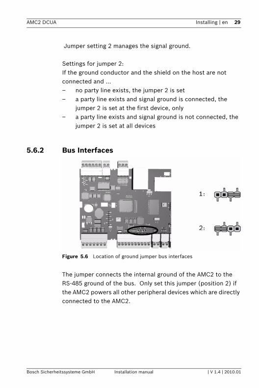
Figure 5.6 Location of ground jumper bus interfaces
The jumper connects the internal ground of the AMC2 to the RS-485 ground of the bus. Only set this jumper (position 2) if the AMC2 powers all other peripheral devices which are directly connected to the AMC2.
Bosch Sicherheitssysteme GmbH Installation manual | V 1.4 | 2010.01
30 en | Installing AMC2 DCUA
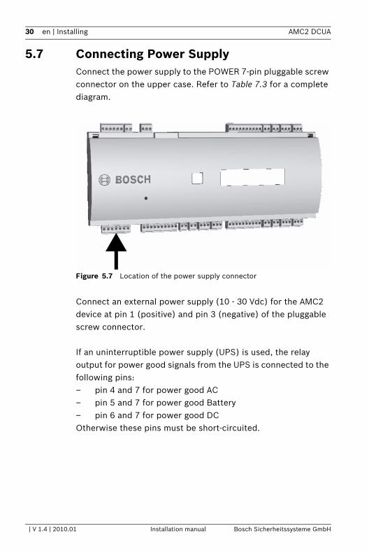
5.7 Connecting Power SupplyConnect the power supply to the POWER 7-pin pluggable screw connector on the upper case. Refer to Table 7.3 for a complete diagram.
Figure 5.7 Location of the power supply connector
Connect an external power supply (10 - 30 Vdc) for the AMC2 device at pin 1 (positive) and pin 3 (negative) of the pluggable screw connector.
If an uninterruptible power supply (UPS) is used, the relay output for power good signals from the UPS is connected to the following pins:– pin 4 and 7 for power good AC – pin 5 and 7 for power good Battery – pin 6 and 7 for power good DC Otherwise these pins must be short-circuited.
| V 1.4 | 2010.01 Installation manual Bosch Sicherheitssysteme GmbH
AMC2 DCUA Installing | en 31
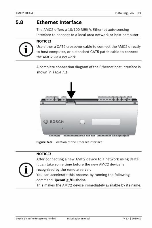
5.8 Ethernet InterfaceThe AMC2 offers a 10/100 MBit/s Ethernet auto-sensing interface to connect to a local area network or host computer.
A complete connection diagram of the Ethernet host interface is shown in Table 7.1.
Figure 5.8 Location of the Ethernet interface
iNOTICE! Use either a CAT5 crossover cable to connect the AMC2 directly to host computer, or a standard CAT5 patch cable to connect the AMC2 via a network.
i
NOTICE! After connecting a new AMC2 device to a network using DHCP, it can take some time before the new AMC2 device is recognized by the remote server.You can accelerate this process by running the following command: ipconfig /flushdnsThis makes the AMC2 device immediately available by its name.
Bosch Sicherheitssysteme GmbH Installation manual | V 1.4 | 2010.01
32 en | Installing AMC2 DCUA
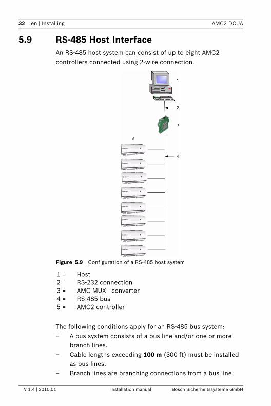
5.9 RS-485 Host InterfaceAn RS-485 host system can consist of up to eight AMC2 controllers connected using 2-wire connection.
Figure 5.9 Configuration of a RS-485 host system
The following conditions apply for an RS-485 bus system:– A bus system consists of a bus line and/or one or more
branch lines.– Cable lengths exceeding 100 m (300 ft) must be installed
as bus lines.– Branch lines are branching connections from a bus line.
1 = Host2 = RS-232 connection3 = AMC-MUX - converter4 = RS-485 bus5 = AMC2 controller
| V 1.4 | 2010.01 Installation manual Bosch Sicherheitssysteme GmbH
AMC2 DCUA Installing | en 33
– Peripheral devices are AMC2 which are connected to the host computer.
– Maximum cable length of a bus line must not exceed 1200 m (4000 ft).
– The cable length of branch lines must not exceed 100 m (330 ft).
– Any bus line conductor connects up to eight AMC2. Do not exceed the maximum number of devices.
– For longer bus lines connect the AMC2 to multiple AMC-MUX (-EXT) with the host.
To use RS-485 mode at the AMC2, connect the data cables to the pluggable screw connector of the RS-485 host interface. Set the connection mode of the RS-485 (two-wire) using the DIL switch of the AMC-MUX. Then set the RS-485 address using DIL switch on the AMC. For connection diagrams and settings refer to Figure 5.13 andTable 5.1.
i
NOTICE! Up to seven AMC-MUX-EXT can be connected to an AMC-MUX. Every module is subject to the conditions above. Even when using extension modules the maximum number of AMC2’s which can be connected is eight.For more information about the AMC-MUX and AMC-MUX-EXT please consult their respective installation guides.
Bosch Sicherheitssysteme GmbH Installation manual | V 1.4 | 2010.01
34 en | Installing AMC2 DCUA
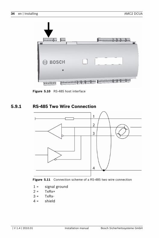
Figure 5.10 RS-485 host interface
5.9.1 RS-485 Two Wire Connection
Figure 5.11 Connection scheme of a RS-485 two wire connection
1 = signal ground2 = TxRx+3 = TxRx-4 = shield
| V 1.4 | 2010.01 Installation manual Bosch Sicherheitssysteme GmbH
AMC2 DCUA Installing | en 35
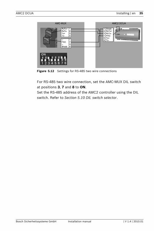
Figure 5.12 Settings for RS-485 two wire connections
For RS-485 two wire connection, set the AMC-MUX DIL switch at positions 3, 7 and 8 to ON. Set the RS-485 address of the AMC2 controller using the DIL switch. Refer to Section 5.10 DIL switch selector.
Bosch Sicherheitssysteme GmbH Installation manual | V 1.4 | 2010.01
36 en | Installing AMC2 DCUA
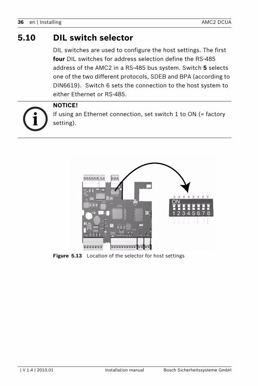
5.10 DIL switch selectorDIL switches are used to configure the host settings. The first four DIL switches for address selection define the RS-485 address of the AMC2 in a RS-485 bus system. Switch 5 selects one of the two different protocols, SDEB and BPA (according to DIN6619). Switch 6 sets the connection to the host system to either Ethernet or RS-485.
Figure 5.13 Location of the selector for host settings
iNOTICE! If using an Ethernet connection, set switch 1 to ON (= factory setting).
| V 1.4 | 2010.01 Installation manual Bosch Sicherheitssysteme GmbH
AMC2 DCUA Installing | en 37
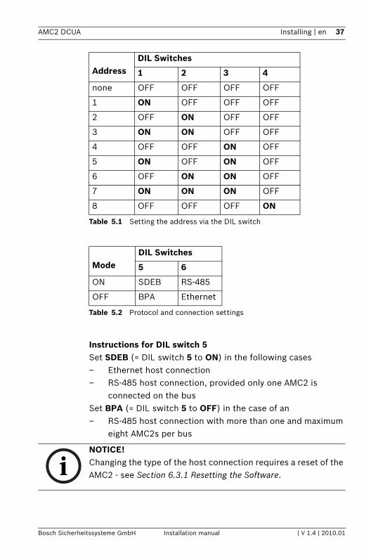
Table 5.1 Setting the address via the DIL switch
Table 5.2 Protocol and connection settings
Instructions for DIL switch 5Set SDEB (= DIL switch 5 to ON) in the following cases– Ethernet host connection– RS-485 host connection, provided only one AMC2 is
connected on the busSet BPA (= DIL switch 5 to OFF) in the case of an– RS-485 host connection with more than one and maximum
eight AMC2s per bus
AddressDIL Switches
1 2 3 4
none OFF OFF OFF OFF
1 ON OFF OFF OFF
2 OFF ON OFF OFF
3 ON ON OFF OFF
4 OFF OFF ON OFF
5 ON OFF ON OFF
6 OFF ON ON OFF
7 ON ON ON OFF
8 OFF OFF OFF ON
ModeDIL Switches
5 6
ON SDEB RS-485
OFF BPA Ethernet
iNOTICE! Changing the type of the host connection requires a reset of the AMC2 - see Section 6.3.1 Resetting the Software.
Bosch Sicherheitssysteme GmbH Installation manual | V 1.4 | 2010.01
38 en | Installing AMC2 DCUA
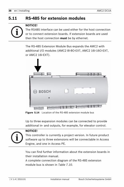
5.11 RS-485 for extension modules
The RS-485 Extension Module Bus expands the AMC2 with additional I/O modules (AMC2 8I-8O-EXT, AMC2 16I-16O-EXT, or AMC2 16I-EXT).
Figure 5.14 Location of the RS-485 extension module bus
Up to three expansion modules can be connected to provide additional in- and outputs, for example, for elevator control.
You can find further information about the extension boards in their installation manual.A complete connection diagram of the RS-485 extension module bus is shown in Table 7.10.
iNOTICE! The RS485 interface can be used either for the host connection or to connect extension boards. If extension boards are used then the host connection must be by ethernet.
iNOTICE! This controller is currently a project version. In future product software up to three extensions will be connectable in Access Engine, and one in Access PE.
| V 1.4 | 2010.01 Installation manual Bosch Sicherheitssysteme GmbH
AMC2 DCUA Installing | en 39
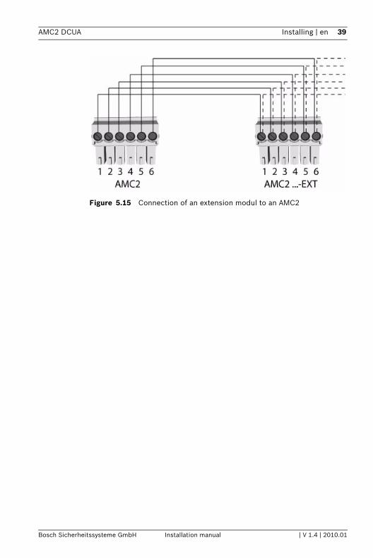
Figure 5.15 Connection of an extension modul to an AMC2
Bosch Sicherheitssysteme GmbH Installation manual | V 1.4 | 2010.01
40 en | Installing AMC2 DCUA
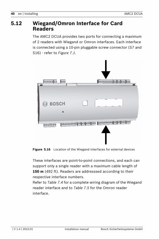
5.12 Wiegand/Omron Interface for Card ReadersThe AMC2 DCUA provides two ports for connecting a maximum of 2 readers with Wiegand or Omron interfaces. Each interface is connected using a 10-pin pluggable screw connector (S7 and S16) - refer to Figure 7.1.
Figure 5.16 Location of the Wiegand interfaces for external devices
These interfaces are point-to-point connections, and each can support only a single reader with a maximum cable length of 150 m (492 ft). Readers are addresssed according to their respective interface numbers.Refer to Table 7.4 for a complete wiring diagram of the Wiegand reader interface and to Table 7.5 for the Omron reader interface.
| V 1.4 | 2010.01 Installation manual Bosch Sicherheitssysteme GmbH
AMC2 DCUA Installing | en 41
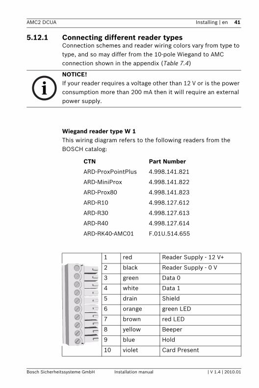
5.12.1 Connecting different reader typesConnection schemes and reader wiring colors vary from type to type, and so may differ from the 10-pole Wiegand to AMC connection shown in the appendix (Table 7.4)
Wiegand reader type W 1This wiring diagram refers to the following readers from the BOSCH catalog:
iNOTICE! If your reader requires a voltage other than 12 V or is the power consumption more than 200 mA then it will require an external power supply.
CTN Part Number
ARD-ProxPointPlus 4.998.141.821
ARD-MiniProx 4.998.141.822
ARD-Prox80 4.998.141.823
ARD-R10 4.998.127.612
ARD-R30 4.998.127.613
ARD-R40 4.998.127.614
ARD-RK40-AMC01 F.01U.514.655
1 red Reader Supply - 12 V+
2 black Reader Supply - 0 V
3 green Data 0
4 white Data 1
5 drain Shield
6 orange green LED
7 brown red LED
8 yellow Beeper
9 blue Hold
10 violet Card Present
Bosch Sicherheitssysteme GmbH Installation manual | V 1.4 | 2010.01
42 en | Installing AMC2 DCUA
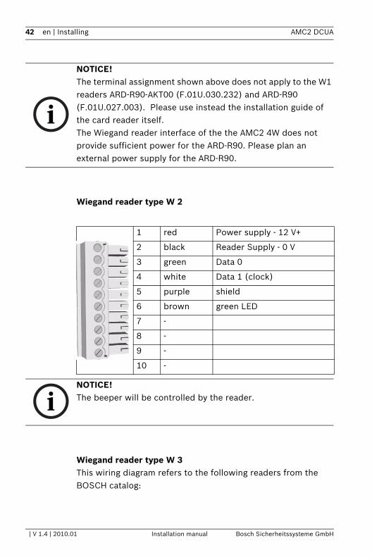
Wiegand reader type W 2
Wiegand reader type W 3This wiring diagram refers to the following readers from the BOSCH catalog:
i
NOTICE! The terminal assignment shown above does not apply to the W1 readers ARD-R90-AKT00 (F.01U.030.232) and ARD-R90 (F.01U.027.003). Please use instead the installation guide of the card reader itself.The Wiegand reader interface of the the AMC2 4W does not provide sufficient power for the ARD-R90. Please plan an external power supply for the ARD-R90.
1 red Power supply - 12 V+
2 black Reader Supply - 0 V
3 green Data 0
4 white Data 1 (clock)
5 purple shield
6 brown green LED
7 -
8 -
9 -
10 -
iNOTICE! The beeper will be controlled by the reader.
| V 1.4 | 2010.01 Installation manual Bosch Sicherheitssysteme GmbH
AMC2 DCUA Installing | en 43
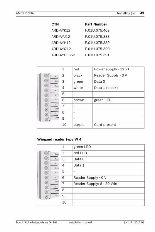
Wiegand reader type W 4
CTN Part Number
ARD-AYK12 F.01U.075.408
ARD-AYJ12 F.01U.075.388
ARD-AYH12 F.01U.075.389
ARD-AYQ12 F.01U.075.390
ARD-AYCE65B F.01U.075.391
1 red Power supply - 12 V+
2 black Reader Supply - 0 V
3 green Data 0
4 white Data 1 (clock)
5 -
6 brown green LED
7 -
8 -
9 -
10 purple Card present
1 green LED
2 red LED
3 Data 0
4 Data 1
5 -
6 Reader Supply - 0 V
7 Reader Supply: 8 - 30 Vdc
8 -
9 -
10 -
Bosch Sicherheitssysteme GmbH Installation manual | V 1.4 | 2010.01
44 en | Installing AMC2 DCUA
The reader has an additional DIL switch to choose the following parameter settings.
S1 = on The beeper is controlled by input 1.
S2 = on The beeper will allways be set after card reading.
S3 = on The LED displays will be controlled by the reader.
S4 = off
S5 = on The beeper is controlled by input 2.
iNOTICE! In the default delivery status pin 2 is set to ON.
| V 1.4 | 2010.01 Installation manual Bosch Sicherheitssysteme GmbH
AMC2 DCUA Installing | en 45
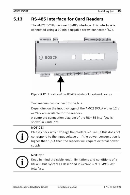
5.13 RS-485 Interface for Card ReadersThe AMC2 DCUA has one RS-485 interface. This interface is connected using a 10-pin pluggable screw connector (S2).
Figure 5.17 Location of the RS-485 interface for external devices
Two readers can connect to the bus.
Depending on the input voltage of the AMC2 DCUA either 12 V
or 24 V are available for the readers. A complete connection diagram of the RS-485 interface is shown in Table 7.6.
iNOTICE! Please check which voltage the readers require. If this does not correspond to the input voltage or if the power consumption is higher than 1,5 A then the readers will require external power supply.
iNOTICE! Keep in mind the cable length limitations and conditions of a RS-485 bus system as described in Section 5.9 RS-485 Host Interface.
Bosch Sicherheitssysteme GmbH Installation manual | V 1.4 | 2010.01
46 en | Installing AMC2 DCUA
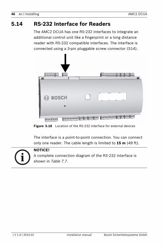
5.14 RS-232 Interface for ReadersThe AMC2 DCUA has one RS-232 interfaces to integrate an additional control unit like a fingerprint or a long distance reader with RS-232 compatible interfaces. The interface is connected using a 3-pin pluggable screw connector (S14).
Figure 5.18 Location of the RS-232 interface for external devices
The interface is a point-to-point connection. You can connect only one reader. The cable length is limited to 15 m (49 ft).
iNOTICE! A complete connection diagram of the RS-232 interface is shown in Table 7.7.
| V 1.4 | 2010.01 Installation manual Bosch Sicherheitssysteme GmbH
AMC2 DCUA Installing | en 47
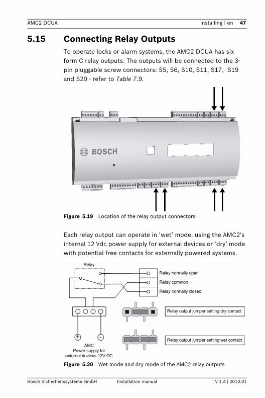
5.15 Connecting Relay OutputsTo operate locks or alarm systems, the AMC2 DCUA has six form C relay outputs. The outputs will be connected to the 3-pin pluggable screw connectors: S5, S6, S10, S11, S17, S19 and S20 - refer to Table 7.9.
Figure 5.19 Location of the relay output connectors
Each relay output can operate in ‘wet’ mode, using the AMC2's internal 12 Vdc power supply for external devices or ‘dry’ mode with potential free contacts for externally powered systems.
Figure 5.20 Wet mode and dry mode of the AMC2 relay outputs
Bosch Sicherheitssysteme GmbH Installation manual | V 1.4 | 2010.01
48 en | Installing AMC2 DCUA
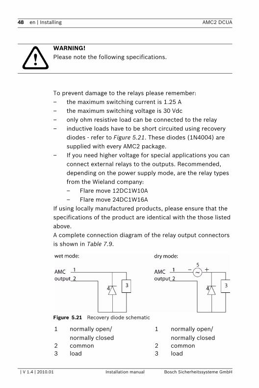
To prevent damage to the relays please remember:– the maximum switching current is 1.25 A – the maximum switching voltage is 30 Vdc– only ohm resistive load can be connected to the relay– inductive loads have to be short circuited using recovery
diodes - refer to Figure 5.21. These diodes (1N4004) are supplied with every AMC2 package.
– If you need higher voltage for special applications you can connect external relays to the outputs. Recommended, depending on the power supply mode, are the relay types from the Wieland company:– Flare move 12DC1W10A– Flare move 24DC1W16A
If using locally manufactured products, please ensure that the specifications of the product are identical with the those listed above.A complete connection diagram of the relay output connectors is shown in Table 7.9.
Figure 5.21 Recovery diode schematic
!WARNING! Please note the following specifications.
1 normally open/normally closed
1 normally open/normally closed
2 common 2 common3 load 3 load
| V 1.4 | 2010.01 Installation manual Bosch Sicherheitssysteme GmbH
AMC2 DCUA Installing | en 49
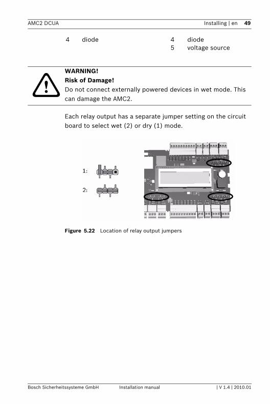
Each relay output has a separate jumper setting on the circuit board to select wet (2) or dry (1) mode.
Figure 5.22 Location of relay output jumpers
4 diode 4 diode5 voltage source
!WARNING! Risk of Damage!Do not connect externally powered devices in wet mode. This can damage the AMC2.
Bosch Sicherheitssysteme GmbH Installation manual | V 1.4 | 2010.01
50 en | Installing AMC2 DCUA
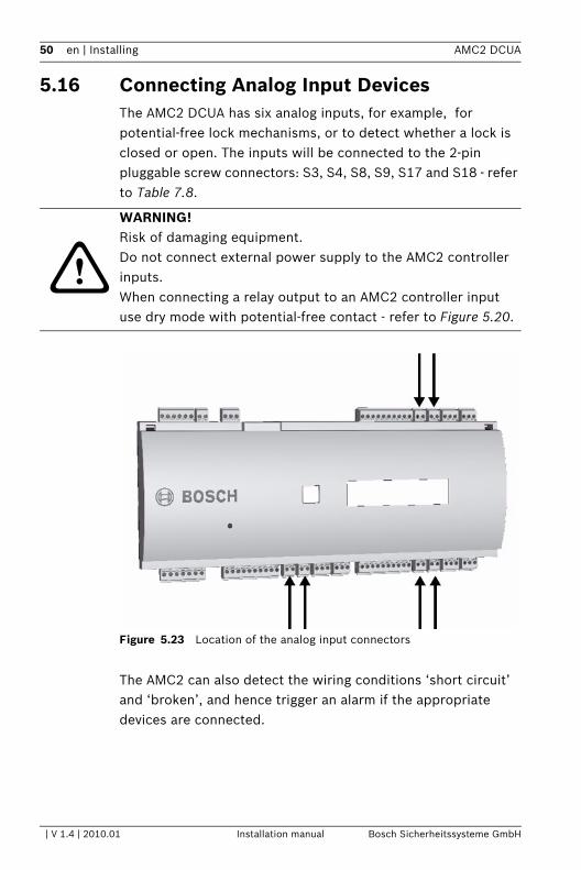
5.16 Connecting Analog Input DevicesThe AMC2 DCUA has six analog inputs, for example, for potential-free lock mechanisms, or to detect whether a lock is closed or open. The inputs will be connected to the 2-pin pluggable screw connectors: S3, S4, S8, S9, S17 and S18 - refer to Table 7.8.
Figure 5.23 Location of the analog input connectors
The AMC2 can also detect the wiring conditions ‘short circuit’ and ‘broken’, and hence trigger an alarm if the appropriate devices are connected.
!
WARNING! Risk of damaging equipment.Do not connect external power supply to the AMC2 controller inputs.When connecting a relay output to an AMC2 controller input use dry mode with potential-free contact - refer to Figure 5.20.
| V 1.4 | 2010.01 Installation manual Bosch Sicherheitssysteme GmbH
AMC2 DCUA Installing | en 51
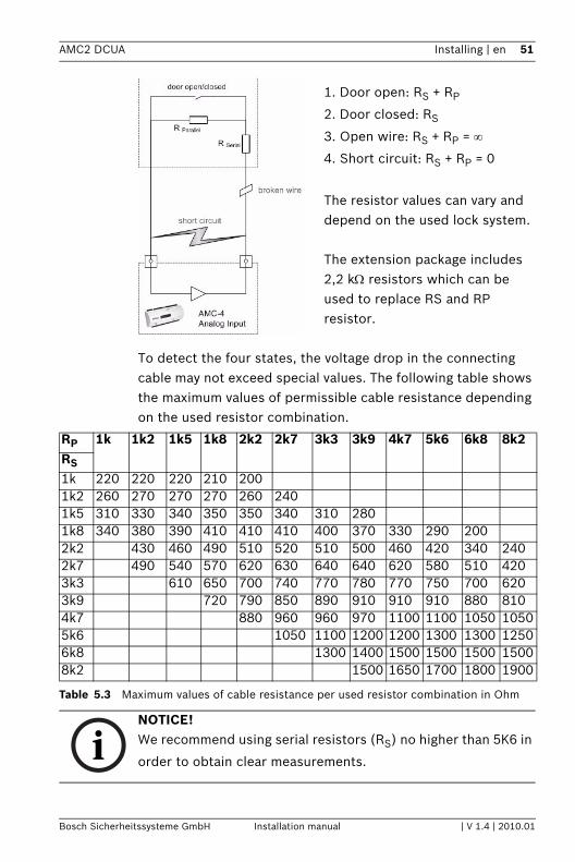
1. Door open: RS + RP
2. Door closed: RS
3. Open wire: RS + RP = ∞
4. Short circuit: RS + RP = 0
The resistor values can vary and depend on the used lock system.
The extension package includes 2,2 kΩ resistors which can be used to replace RS and RP resistor.
To detect the four states, the voltage drop in the connecting cable may not exceed special values. The following table shows the maximum values of permissible cable resistance depending on the used resistor combination.
Table 5.3 Maximum values of cable resistance per used resistor combination in Ohm
RP 1k 1k2 1k5 1k8 2k2 2k7 3k3 3k9 4k7 5k6 6k8 8k2RS
1k 220 220 220 210 2001k2 260 270 270 270 260 2401k5 310 330 340 350 350 340 310 2801k8 340 380 390 410 410 410 400 370 330 290 2002k2 430 460 490 510 520 510 500 460 420 340 2402k7 490 540 570 620 630 640 640 620 580 510 4203k3 610 650 700 740 770 780 770 750 700 6203k9 720 790 850 890 910 910 910 880 8104k7 880 960 960 970 1100 1100 1050 10505k6 1050 1100 1200 1200 1300 1300 12506k8 1300 1400 1500 1500 1500 15008k2 1500 1650 1700 1800 1900
iNOTICE! We recommend using serial resistors (RS) no higher than 5K6 in
order to obtain clear measurements.
Bosch Sicherheitssysteme GmbH Installation manual | V 1.4 | 2010.01

52 en | Installing AMC2 DCUA
| V 1.4 | 2010.01 Installation manual Bosch Sicherheitssysteme GmbH
AMC2 DCUA Installing | en 53
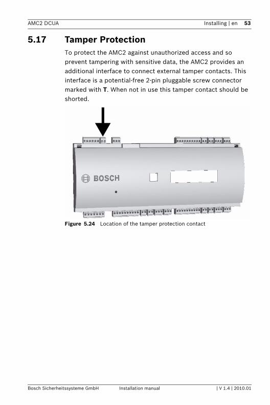
5.17 Tamper ProtectionTo protect the AMC2 against unauthorized access and so prevent tampering with sensitive data, the AMC2 provides an additional interface to connect external tamper contacts. This interface is a potential-free 2-pin pluggable screw connector marked with T. When not in use this tamper contact should be shorted.
Figure 5.24 Location of the tamper protection contact
Bosch Sicherheitssysteme GmbH Installation manual | V 1.4 | 2010.01
54 en | Operating AMC2 DCUA
6 Operating
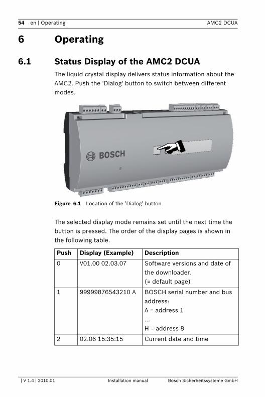
6.1 Status Display of the AMC2 DCUA The liquid crystal display delivers status information about the AMC2. Push the 'Dialog' button to switch between different modes.
Figure 6.1 Location of the ’Dialog’ button
The selected display mode remains set until the next time the button is pressed. The order of the display pages is shown in the following table.
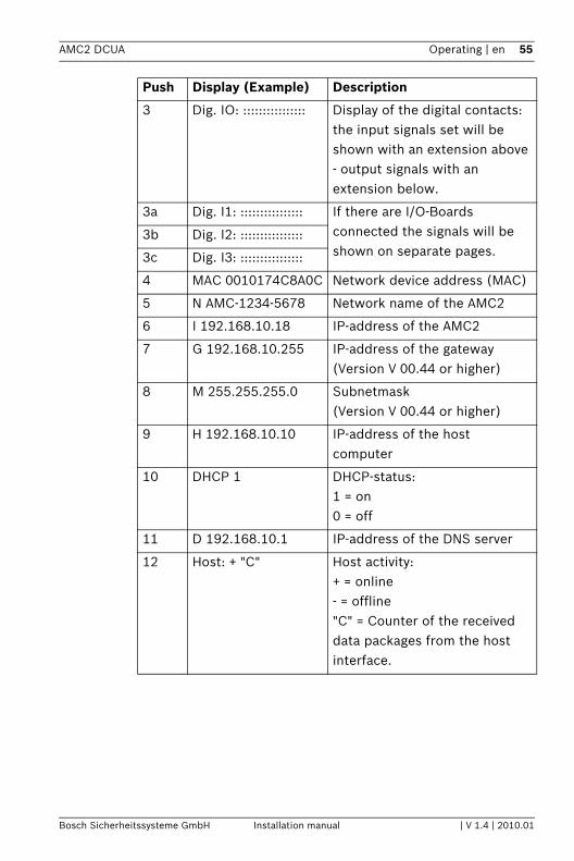
Push Display (Example) Description
0 V01.00 02.03.07 Software versions and date of the downloader.(= default page)
1 99999876543210 A BOSCH serial number and bus address:A = address 1...H = address 8
2 02.06 15:35:15 Current date and time
| V 1.4 | 2010.01 Installation manual Bosch Sicherheitssysteme GmbH
AMC2 DCUA Operating | en 55
3 Dig. IO: :::::::::::::::: Display of the digital contacts: the input signals set will be shown with an extension above - output signals with an extension below.
3a Dig. I1: :::::::::::::::: If there are I/O-Boards connected the signals will be shown on separate pages.
3b Dig. I2: ::::::::::::::::
3c Dig. I3: ::::::::::::::::
4 MAC 0010174C8A0C Network device address (MAC)
5 N AMC-1234-5678 Network name of the AMC2
6 I 192.168.10.18 IP-address of the AMC2
7 G 192.168.10.255 IP-address of the gateway(Version V 00.44 or higher)
8 M 255.255.255.0 Subnetmask(Version V 00.44 or higher)
9 H 192.168.10.10 IP-address of the host computer
10 DHCP 1 DHCP-status:1 = on0 = off
11 D 192.168.10.1 IP-address of the DNS server
12 Host: + "C" Host activity:+ = online- = offline"C" = Counter of the received data packages from the host interface.
Push Display (Example) Description
Bosch Sicherheitssysteme GmbH Installation manual | V 1.4 | 2010.01
56 en | Operating AMC2 DCUA
6.2 Configuring the Ethernet InterfaceTo configure the AMC2 in a TCP/IP network environment, use the AmcIpConfig tool provided in the following directory on the standalone or the remote server of the Building Integration System:\\Runtime-drive:\MgtS\AccessEngine\AC\bin
The access control system Access Personal Edition has an entry of this tool in its program folder:Start > Programs > Access Personal Edition > AmcIpConfigThis tool can be copied and used on every computer on the network.
!
CAUTION! Use only alphanumeric characters plus the seperator "-" (minus/dash).The network name has to start with a letter. Do not use special characters or spaces.The names are not case sensitive.
iNOTICE! Please consult the AmcIpConfig tool’s own online help for details on configuring the AMC2.
| V 1.4 | 2010.01 Installation manual Bosch Sicherheitssysteme GmbH
AMC2 DCUA Operating | en 57
6.3 Resetting the AMC2 DCUA If problems occur, they should first be tackled directly - for example check the Network connection, IP-address and DIL switch settings. Nevertheless it is sometimes an indirect help to reset the AMC2 unit to its factory defaults.
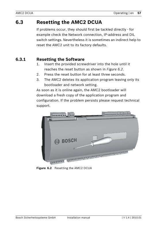
6.3.1 Resetting the Software1. Insert the provided screwdriver into the hole until it
reaches the reset button as shown in Figure 6.2.2. Press the reset button for at least three seconds.3. The AMC2 deletes its application program leaving only its
bootloader and network setting.As soon as it is online again, the AMC2 bootloader will download a fresh copy of the application program and configuration. If the problem persists please request technical support.
Figure 6.2 Resetting the AMC2 DCUA
Bosch Sicherheitssysteme GmbH Installation manual | V 1.4 | 2010.01
58 en | Operating AMC2 DCUA
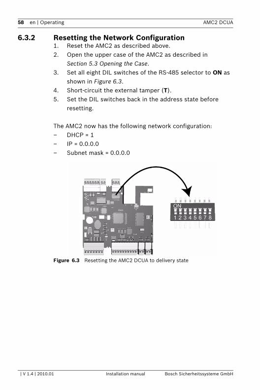
6.3.2 Resetting the Network Configuration1. Reset the AMC2 as described above.2. Open the upper case of the AMC2 as described in
Section 5.3 Opening the Case.3. Set all eight DIL switches of the RS-485 selector to ON as
shown in Figure 6.3.4. Short-circuit the external tamper (T).5. Set the DIL switches back in the address state before
resetting.
The AMC2 now has the following network configuration:– DHCP = 1– IP = 0.0.0.0– Subnet mask = 0.0.0.0
Figure 6.3 Resetting the AMC2 DCUA to delivery state
| V 1.4 | 2010.01 Installation manual Bosch Sicherheitssysteme GmbH
AMC2 DCUA Appendix | en 59
7 Appendix
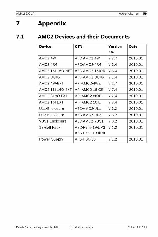
7.1 AMC2 Devices and their Documents
Device CTN Version no.
Date
AMC2 4W APC-AMC2-4W V 7.7 2010.01
AMC2 4R4 APC-AMC2-4R4 V 3.4 2010.01
AMC2 16I-16O-NET APC-AMC2-16ION V 3.3 2010.01
AMC2 DCUA APC-AMC2-DCUA V 1.4 2010.01
AMC2 4W-EXT API-AMC2-4WE V 2.7 2010.01
AMC2 16I-16O-EXT API-AMC2-16IOE V 7.4 2010.01
AMC2 8I-8O-EXT API-AMC2-8IOE V 7.4 2010.01
AMC2 16I-EXT API-AMC2-16IE V 7.4 2010.01
UL1-Enclosure AEC-AMC2-UL1 V 3.2 2010.01
UL2-Enclosure AEC-AMC2-UL2 V 3.2 2010.01
VDS1-Enclosure AEC-AMC2-VDS1 V 3.2 2010.01
19-Zoll Rack AEC-Panel19-UPSAEC-Panel19-4DR
V 1.2 2010.01
Power Supply APS-PBC-60 V 1.2 2010.01
Bosch Sicherheitssysteme GmbH Installation manual | V 1.4 | 2010.01
60 en | Appendix AMC2 DCUA
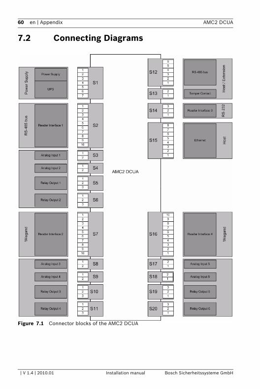
7.2 Connecting Diagrams
Figure 7.1 Connector blocks of the AMC2 DCUA
| V 1.4 | 2010.01 Installation manual Bosch Sicherheitssysteme GmbH
AMC2 DCUA Appendix | en 61
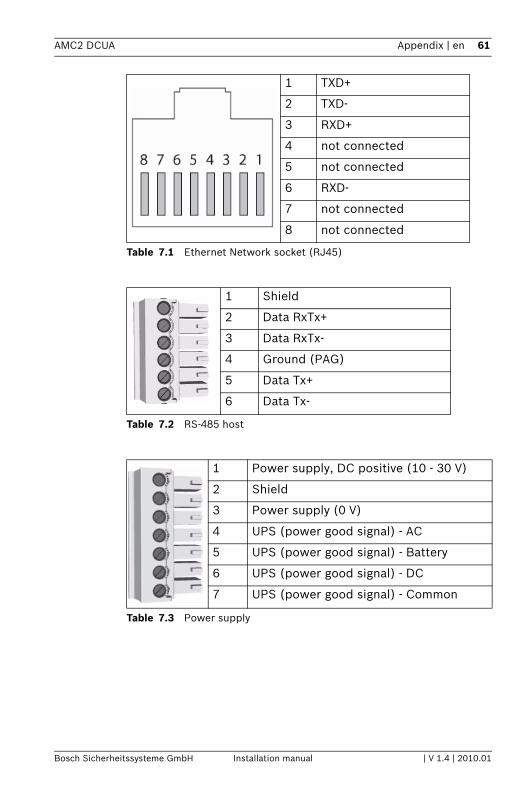
Table 7.1 Ethernet Network socket (RJ45)
Table 7.2 RS-485 host
Table 7.3 Power supply
1 TXD+
2 TXD-
3 RXD+
4 not connected
5 not connected
6 RXD-
7 not connected
8 not connected
1 Shield
2 Data RxTx+
3 Data RxTx-
4 Ground (PAG)
5 Data Tx+
6 Data Tx-
1 Power supply, DC positive (10 - 30 V)
2 Shield
3 Power supply (0 V)
4 UPS (power good signal) - AC
5 UPS (power good signal) - Battery
6 UPS (power good signal) - DC
7 UPS (power good signal) - Common
Bosch Sicherheitssysteme GmbH Installation manual | V 1.4 | 2010.01
62 en | Appendix AMC2 DCUA
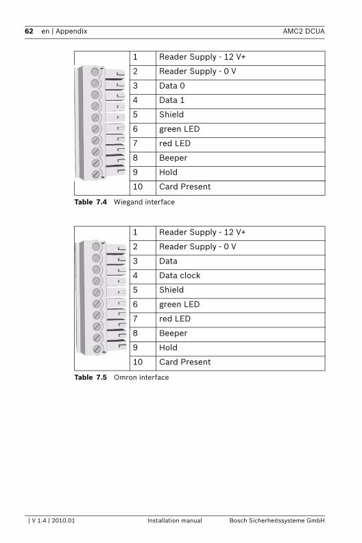
Table 7.4 Wiegand interface
Table 7.5 Omron interface
1 Reader Supply - 12 V+
2 Reader Supply - 0 V
3 Data 0
4 Data 1
5 Shield
6 green LED
7 red LED
8 Beeper
9 Hold
10 Card Present
1 Reader Supply - 12 V+
2 Reader Supply - 0 V
3 Data
4 Data clock
5 Shield
6 green LED
7 red LED
8 Beeper
9 Hold
10 Card Present
| V 1.4 | 2010.01 Installation manual Bosch Sicherheitssysteme GmbH
AMC2 DCUA Appendix | en 63
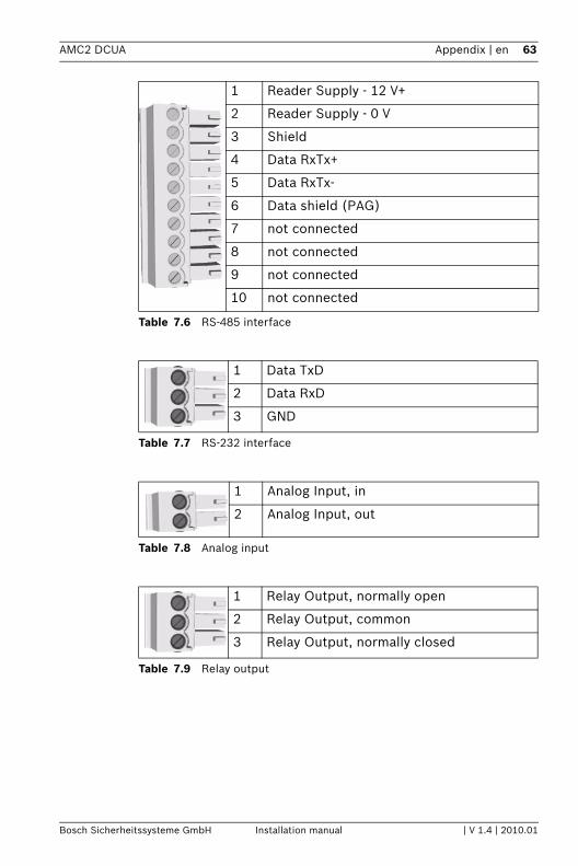
Table 7.6 RS-485 interface
Table 7.7 RS-232 interface
Table 7.8 Analog input
Table 7.9 Relay output
1 Reader Supply - 12 V+
2 Reader Supply - 0 V
3 Shield
4 Data RxTx+
5 Data RxTx-
6 Data shield (PAG)
7 not connected
8 not connected
9 not connected
10 not connected
1 Data TxD
2 Data RxD
3 GND
1 Analog Input, in
2 Analog Input, out
1 Relay Output, normally open
2 Relay Output, common
3 Relay Output, normally closed
Bosch Sicherheitssysteme GmbH Installation manual | V 1.4 | 2010.01
64 en | Appendix AMC2 DCUA
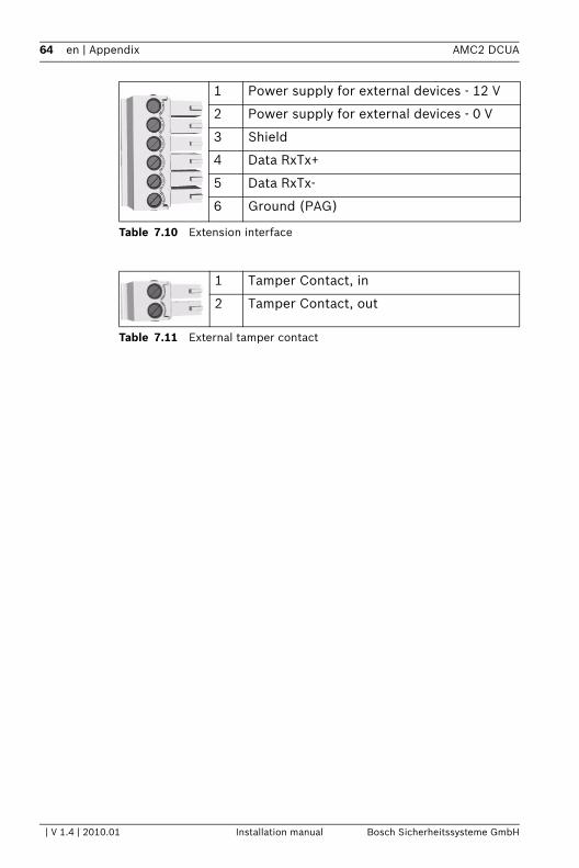
Table 7.10 Extension interface
Table 7.11 External tamper contact
1 Power supply for external devices - 12 V
2 Power supply for external devices - 0 V
3 Shield
4 Data RxTx+
5 Data RxTx-
6 Ground (PAG)
1 Tamper Contact, in
2 Tamper Contact, out
| V 1.4 | 2010.01 Installation manual Bosch Sicherheitssysteme GmbH
AMC2 DCUA Appendix | en 65
Bosch Sicherheitssysteme GmbH Installation manual | V 1.4 | 2010.01
66 en | Index AMC2 DCUA
V 1.4 | 2010.01 Installation manual Bosch Sicherheitssysteme GmbH
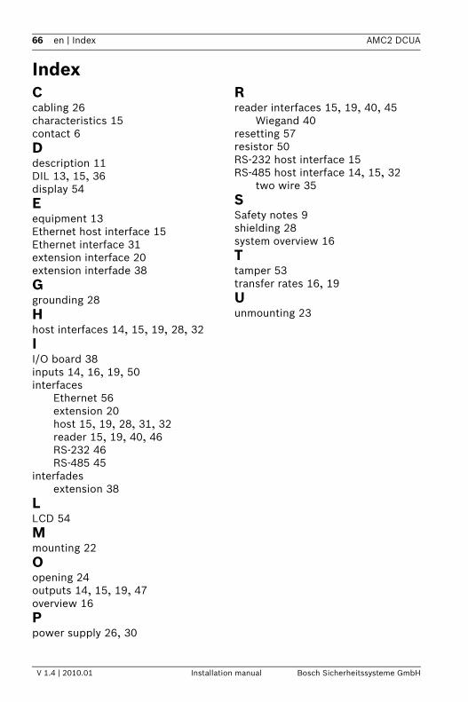
IndexCcabling 26characteristics 15contact 6Ddescription 11DIL 13, 15, 36display 54Eequipment 13Ethernet host interface 15Ethernet interface 31extension interface 20extension interfade 38Ggrounding 28Hhost interfaces 14, 15, 19, 28, 32II/O board 38inputs 14, 16, 19, 50interfaces
Ethernet 56extension 20host 15, 19, 28, 31, 32reader 15, 19, 40, 46RS-232 46RS-485 45
interfadesextension 38
LLCD 54Mmounting 22Oopening 24outputs 14, 15, 19, 47overview 16Ppower supply 26, 30
Rreader interfaces 15, 19, 40, 45
Wiegand 40resetting 57resistor 50RS-232 host interface 15RS-485 host interface 14, 15, 32
two wire 35SSafety notes 9shielding 28system overview 16Ttamper 53transfer rates 16, 19Uunmounting 23

Bosch Sicherheitssysteme GmbH Robert-Koch-Straße 100D-85521 OttobrunnGermanyTelefon +49 89 6290-0Fax +49 89 6290-1020www.bosch-securitysystems.com © Bosch Sicherheitssysteme GmbH, 2010