Embed Size (px)
Citation preview

MMMIMMMOPERATING INSTRUCTIONSO P E R A T I N G I N S T R U C T I O N S
DUSTHUNTER SBDust Concentration Monitor
Installation, Operation, Maintenance
Title Page

2 8012422/YWL2/3-0/2016-08 | SICKO P E R A T I N G I N S T R U C T I O N S | DUSTHUNTER SBSubject to change without notice
Described ProductProduct name: DUSTHUNTER SBVariants: DUSTHUNTER SB50
DUSTHUNTER SB100
ManufacturerSICK Engineering GmbHBergener Ring 27 · D-01458 Ottendorf-Okrilla · GermanyPhone: +49 7641 469-0E-Mail: [email protected]
TrademarksWindows is a Microsoft Corporation trademark. Other product names used in this document may also be trademarks and are only used for identification purposes.
Legal InformationThis document is protected by copyright. Any rights derived from the copyright shall be reserved for SICK AG. Reproduction of this document or parts of this document is only permissible within the limits of the legal determination of Copyright Law.Any modification, shortening or translation of this document is prohibited without the express written permission of SICK AG.The trademarks stated in this document are the property of their respective owner.
© SICK AG. All rights reserved.
Original documentThis document is an original document of SICK AG.

CONTENTS
Contents
1 Important Information .............................................................................. 71.1 Main hazards...................................................................................................7
1.1.1 Hazard through hot and/or aggressive gases and high pressure 7
1.1.2 Hazards through electrical equipment ..........................................7
1.1.3 Hazards through laser beam..........................................................7
1.2 Symbols and document conventions .............................................................8
1.2.1 Warning Symbols ...........................................................................8
1.2.2 Warning levels and signal words....................................................8
1.2.3 Information symbols .......................................................................8
1.3 Intended use ...................................................................................................8
1.4 Responsibility of user......................................................................................9
1.4.1 General information........................................................................9
1.4.2 Safety information and protective measures ................................9
2 Product Description.................................................................................112.1 Measuring principle, measured variables....................................................11
2.1.1 Functional principle ......................................................................11
2.1.2 Response time ..............................................................................13
2.1.3 Function check..............................................................................14
2.2 Device components ......................................................................................16
2.2.1 Sender/receiver unit ....................................................................17
2.2.2 Flange with tube ...........................................................................19
2.2.3 MCU control unit ...........................................................................20
2.2.3.1 Standard interfaces ..................................................20
2.2.3.2 Versions .....................................................................21
2.2.3.3 Type code ..................................................................23
2.2.3.4 Options ......................................................................24
2.2.3.5 Modules .....................................................................24
2.2.4 Optional external purge air unit ...................................................26
2.2.5 Installation accessories................................................................26
2.2.6 Test equipment for linearity test ..................................................27
2.3 Device configuration .....................................................................................28
2.4 SOPAS ET (PC program) ................................................................................29
3 Assembly and Installation ......................................................................303.1 Project planning ............................................................................................30
3.2 Assembly .......................................................................................................32
3.2.1 Fitting the flange with tube ..........................................................32
3.2.2 Work to be performed...................................................................33
3.2.3 Fitting the MCU control unit .........................................................34
3.2.4 Fitting the optional external purge air unit ..................................36
3.2.5 Assembly work ..............................................................................37
3.2.6 Fitting the weatherproof cover .....................................................38
Contents
38012422/YWL2/3-0/2016-08 | SICK O P E R A T I N G I N S T R U C T I O N S | DUSTHUNTER SBSubject to change without notice

CONTENTS
3.3 Electrical installation .................................................................................... 39
3.3.1 Electrical safety ............................................................................ 39
3.3.1.1 Properly installed power isolating switches............. 39
3.3.1.2 Lines with correct rating........................................... 39
3.3.1.3 Grounding the devices.............................................. 39
3.3.1.4 Responsibility for system safety .............................. 39
3.3.2 General information, prerequisites ............................................. 40
3.3.3 Installing the purge air supply ..................................................... 40
3.3.3.1 Control unit with integrated purge air supply (MCU-P) ..................................................................... 40
3.3.3.2 Optional external purge air unit ............................... 41
3.3.3.3 Installing the non-return valve option...................... 42
3.3.4 Connecting the MCU control unit................................................. 43
3.3.4.1 Work to be done ....................................................... 43
3.3.4.2 MCU processor board connections.......................... 44
3.3.4.3 Connection of connection line to MCU .................... 45
3.3.4.4 Standard connection ................................................ 46
3.3.5 Connecting the MCU remote control unit .................................... 47
3.3.5.1 Connection to the MCU control unit......................... 47
3.3.5.2 Connection to the MCU remote control unit ............ 47
3.3.6 Fitting the interface and I/O module (option) ............................. 49
4 Start-up and Parameter Settings ..........................................................504.1 Basics............................................................................................................ 50
4.1.1 General information ..................................................................... 50
4.1.2 Installing SOPAS ET ...................................................................... 51
4.1.2.1 Password for SOPAS ET menus................................ 51
4.1.3 Connection to the device via USB line ........................................ 51
4.1.3.1 Finding the DUSTHUNTER COM port........................ 51
4.1.4 Connection to the device via Ethernet (option) .......................... 52
4.2 Fitting the sender/receiver unit ................................................................... 54
4.2.1 Connecting the sender/receiver unit to the purge air supply .... 54
4.2.2 Fitting and connecting the sender/receiver unit on the duct .... 54
4.2.3 Aligning the laser control ............................................................. 55
4.2.4 Assigning the sender/receiver unit to the measuring location (in SOPAS ET)............................................................................... 57
4 8012422/YWL2/3-0/2016-08 | SICKO P E R A T I N G I N S T R U C T I O N S | DUSTHUNTER SBSubject to change without notice

CONTENTS
4.3 Setting standard parameters .......................................................................58
4.3.1 Assigning the MCU to the sender/receiver unit ..........................58
4.3.2 Factory settings.............................................................................59
4.3.3 Determining the function check...................................................60
4.3.4 Setting the analog outputs parameters.......................................61
4.3.5 Setting the analog inputs parameters .........................................63
4.3.6 Setting the response time ............................................................64
4.3.7 Calibration for dust concentration measurement .......................65
4.3.8 Data backup in SOPAS ET ............................................................67
4.3.9 Starting measurement mode .......................................................68
4.4 Setting the Interface module parameters....................................................69
4.4.1 General information......................................................................69
4.4.2 Setting the Ethernet module parameters .................................70
4.5 Operating/setting parameters via the optional LC-Display .........................71
4.5.1 General information on use .........................................................71
4.5.2 Password and operating levels ....................................................71
4.5.3 Menu structure .............................................................................72
4.5.4 Configuration ................................................................................72
4.5.4.1 MCU ...........................................................................72
4.5.4.2 Sender/receiver unit .................................................75
4.5.5 Using SOPAS ET to modify display settings .................................76
5 Maintenance.............................................................................................785.1 General ..........................................................................................................78
5.2 Maintenance on the sender/receiver unit ..................................................80
5.3 Maintenance on the purge air supply ..........................................................83
5.3.1 Control unit MCU with integrated purge air supply .....................84
5.3.2 Optional external purge air unit ...................................................85
5.4 Shutdown.......................................................................................................86
6 Troubleshooting .......................................................................................876.1 General ..........................................................................................................87
6.2 Sender/receiver unit .....................................................................................88
6.3 MCU control unit ...........................................................................................89
6.3.1 Malfunctions .................................................................................89
6.3.2 Warning and error messages in the SOPAS ET program ............89
6.3.3 Replacing the fuse ........................................................................91
7 Specifications...........................................................................................927.1 Compliances..................................................................................................92
7.2 Technical Data ..............................................................................................93
7.3 Dimensions, part Nos. ..................................................................................95
7.3.1 Flange with tube ...........................................................................96
7.3.2 MCU control unit ...........................................................................97
7.3.3 Optional external purge air unit ...................................................99
7.3.4 Weatherproof covers ................................................................. 100
58012422/YWL2/3-0/2016-08 | SICK O P E R A T I N G I N S T R U C T I O N S | DUSTHUNTER SBSubject to change without notice

CONTENTS
7.4 Accessories .................................................................................................101
7.4.1 Line sender/receiver unit - MCU................................................101
7.4.2 Purge air supply..........................................................................101
7.4.3 Assembly parts ...........................................................................101
7.4.4 Device check accessories ..........................................................101
7.4.5 Options for MCU control unit .....................................................102
7.4.6 Miscellaneous ............................................................................102
7.5 Consumable parts for 2-years operation ...................................................102
7.5.1 MCU with integrated purge air supply .......................................102
7.5.2 Optional external purge air unit .................................................102
6 8012422/YWL2/3-0/2016-08 | SICKO P E R A T I N G I N S T R U C T I O N S | DUSTHUNTER SBSubject to change without notice
IMPORTANT INFORMATION 1
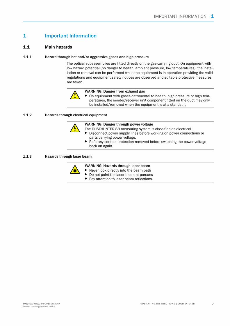
1 Important Information
1.1 Main hazards
1.1.1 Hazard through hot and/or aggressive gases and high pressure
The optical subassemblies are fitted directly on the gas-carrying duct. On equipment with low hazard potential (no danger to health, ambient pressure, low temperatures), the instal-lation or removal can be performed while the equipment is in operation providing the valid regulations and equipment safety notices are observed and suitable protective measures are taken.
1.1.2 Hazards through electrical equipment
1.1.3 Hazards through laser beam
WARNING: Danger from exhaust gas On equipment with gases detrimental to health, high pressure or high tem-
peratures, the sender/receiver unit component fitted on the duct may only be installed/removed when the equipment is at a standstill.
WARNING: Danger through power voltageThe DUSTHUNTER SB measuring system is classified as electrical. Disconnect power supply lines before working on power connections or
parts carrying power voltage. Refit any contact protection removed before switching the power voltage
back on again.
WARNING: Hazards through laser beam Never look directly into the beam path Do not point the laser beam at persons Pay attention to laser beam reflections.
78012422/YWL2/3-0/2016-08| SICK O P E R A T I N G I N S T R U C T I O N S | DUSTHUNTER SBSubject to change without notice
1 IMPORTANT INFORMATION
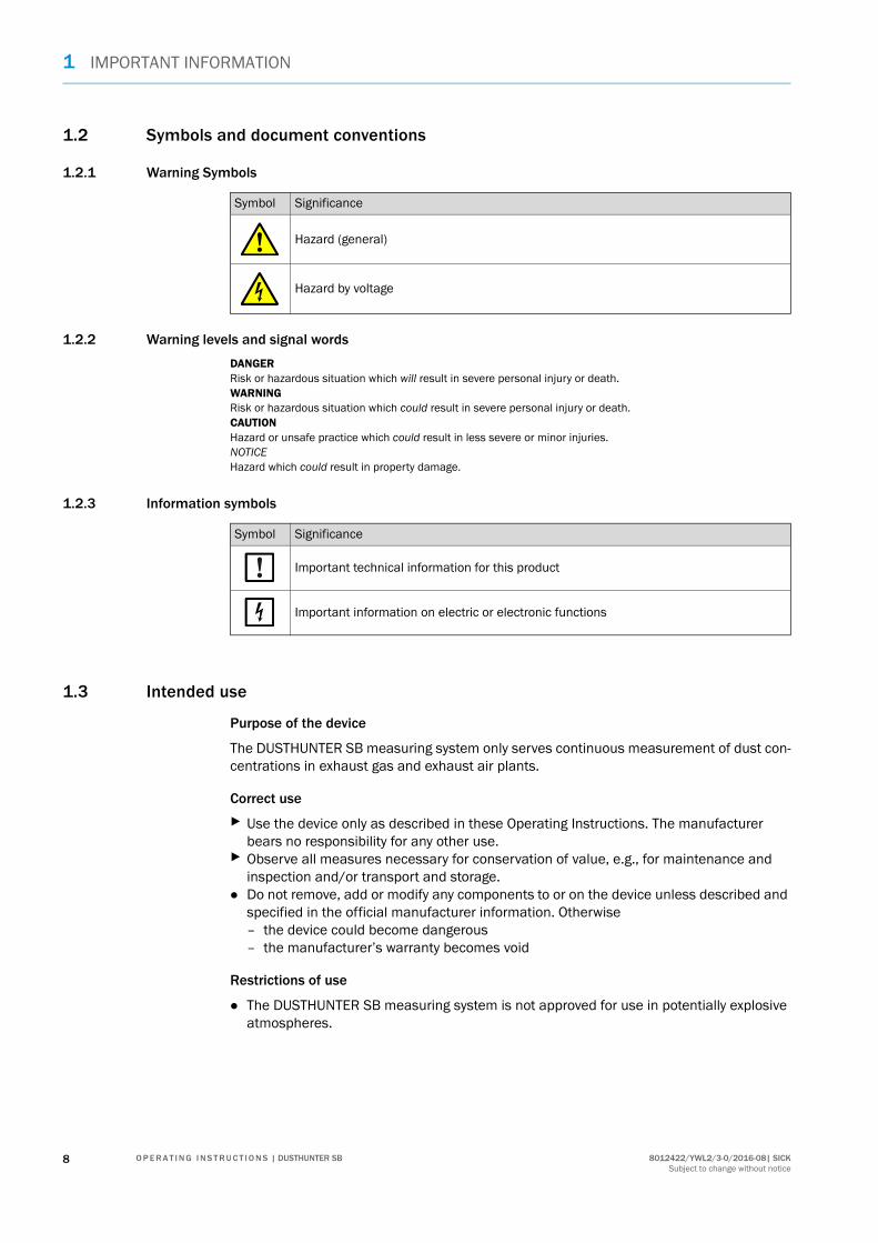
1.2 Symbols and document conventions
1.2.1 Warning Symbols
1.2.2 Warning levels and signal words
DANGERRisk or hazardous situation which will result in severe personal injury or death.WARNINGRisk or hazardous situation which could result in severe personal injury or death.CAUTIONHazard or unsafe practice which could result in less severe or minor injuries.NOTICEHazard which could result in property damage.
1.2.3 Information symbols
1.3 Intended use
Purpose of the device
The DUSTHUNTER SB measuring system only serves continuous measurement of dust con-centrations in exhaust gas and exhaust air plants.
Correct use
Use the device only as described in these Operating Instructions. The manufacturer bears no responsibility for any other use.
Observe all measures necessary for conservation of value, e.g., for maintenance and inspection and/or transport and storage.
Do not remove, add or modify any components to or on the device unless described and specified in the official manufacturer information. Otherwise – the device could become dangerous– the manufacturer’s warranty becomes void
Restrictions of use
The DUSTHUNTER SB measuring system is not approved for use in potentially explosive atmospheres.
Symbol Significance
Hazard (general)
Hazard by voltage
Symbol Significance
Important technical information for this product
Important information on electric or electronic functions
8 8012422/YWL2/3-0/2016-08| SICKO P E R A T I N G I N S T R U C T I O N S | DUSTHUNTER SBSubject to change without notice

IMPORTANT INFORMATION 1
1.4 Responsibility of user
1.4.1 General information
Designated users
The measuring system DUSTHUNTER SB may only be installed and operated by skilled technicians who, based on their technical training and knowledge as well as knowledge of the relevant regulations, can assess the tasks given and recognize the hazards involved.
Special local conditions
Observe the valid legal regulations as well as the technical rules deriving from imple-mentation of these regulations applicable for the respective equipment during work preparation and performance.
Carry out work according to the local conditions specific for the equipment as well as operational hazards and regulations.
Retention of documents
Keep the Operating Instructions belonging to the measuring system as well as equipment documentation onsite for reference at all times. Pass the respective documentation on to any new owner of the measuring system.
1.4.2 Safety information and protective measures
Protection devices
Behavior during purge air failure
The purge air supply serves to protect optical subassemblies fitted on the duct against hot or aggressive gases. Leave the supply switched on when the equipment is at a standstill. Optical subassemblies can be severely damaged in a short time if the purge air supply fails.
Preventive measures for operating safety
NOTE:Depending on the particular hazard potential, an adequate number of suitable protection devices and personal safety equipment must be available and used by the personnel.
NOTE:When no fail-safe shutters are fitted:The user must ensure that: The purge air supply runs reliably and continuously Failure of the purge air supply is immediately detected (e.g., by using pres-
sure monitors) Optical subassemblies are removed from the duct if the purge air supply
fails and the duct opening is closed off (e.g. with a flange cover).
NOTE:The user must ensure that: Neither failures nor erroneous measurements can lead to operational states
that can cause damage or become dangerous The specified maintenance and inspection tasks are carried out regularly by
qualified, experienced personnel.
98012422/YWL2/3-0/2016-08| SICK O P E R A T I N G I N S T R U C T I O N S | DUSTHUNTER SBSubject to change without notice
1 IMPORTANT INFORMATION
Recognizing malfunctions
Every deviation from normal operation is to be regarded as a serious indication of a func-tional impairment. These are, amongst others:
Warning displays Significant drifts in measured results Increased power consumption Higher temperatures of system components Monitoring devices triggering Smells or smoke emission Heavy contamination.
Avoiding damage
Electrical connection
Ensure the device can be switched off with a power isolating switch/circuit breaker in accordance with EN 61010-1.
NOTE:In order to avoid malfunctions that can cause direct or indirect personal injury or property damage, the operator must ensure: The responsible maintenance personnel are present at any time and as fast
as possible The maintenance personnel are adequately qualified to react correctly to
malfunctions of the measuring system and any resulting operational inter-ruptions (e.g., when used for measurement and control purposes)
The malfunctioning equipment is switched off immediately in case of doubt and that switching off does not cause collateral malfunctions.
10 8012422/YWL2/3-0/2016-08| SICKO P E R A T I N G I N S T R U C T I O N S | DUSTHUNTER SBSubject to change without notice

PRODUCT DESCRIPTION 2
2 Product Description
2.1 Measuring principle, measured variables
2.1.1 Functional principle
The measuring system works according to the scattered light measurement principle (backward dispersion). A laser diode beams the dust particles in the gas flow with modulated light in the visual range (wavelength approx. 650 nm). A highly sensitive detector registers the light scattered by the particles, amplifies the light electrically and feeds it to the measuring channel of a microprocessor as central part of the measuring, control and evaluation electronics. The measuring volume in the gas duct is defined through the intersection of the sender beam sent and the receive aperture.
Continuous monitoring of the sender output registers the smallest changes in brightness of the light beam sent which then serves to determine the measurement signal.
Fig. 1: Measuring principle
An additional control receiver prevents background light and ambient light influencing the measured value. This is adjusted so that the projection surfaces of the measurement receiver and control receiver on the opposite duct wall are over each other (see “Compen-sating background lighting and ambient light”, page 12). The signal measured by the control receiver (resulting from background light and ambient light) is deducted from the signal measured by the measurement receiver.
Approx. 15°
Sender/receiver unit Receiver Gas duct Sender Measuring volume
118012422/YWL2/3-0/2016-08| SICK O P E R A T I N G I N S T R U C T I O N S | DUSTHUNTER SBSubject to change without notice

2 PRODUCT DESCRIPTION
The incline of the control receiver can be modified for differing internal duct diameters. A small light trap may be required in certain cases for very narrow internal duct diameters (most unfavorable conditions for background light).
Fig. 2: Compensating background lighting and ambient light
Determining the dust concentration
Measured scattered light intensity (SI) is proportional to dust concentration (c). Scattered light intensity not only depends on the number and size of particles but also on the optical characteristics of the particles and therefore the measuring system must be calibrated using a gravimetric comparison measurement for exact dust concentration measurement. The calibration coefficients determined can be entered directly in the measuring system as
c = cc2 · SI² + cc1 · SI + cc0
(Entry see “Calibration for dust concentration measurement”, page 65; standard factory setting: cc2 = 0, cc1 = 1, cc0 = 0).
Measuring volume
Projection surface control receiver Auxiliary laserInternal duct wall Control receiverProjection surface measurement receiver Sender Sender beam Measurement receiver
12 8012422/YWL2/3-0/2016-08| SICKO P E R A T I N G I N S T R U C T I O N S | DUSTHUNTER SBSubject to change without notice

PRODUCT DESCRIPTION 2
2.1.2 Response time
The response time is the time required to attain 90% of the signal peak after a sudden change in the measurement signal. It can be set anywhere between 1 and 600 s. As the response time increases, transient measured value fluctuations and interruptions are damped stronger and stronger which “smoothes out” the output signal.
Fig. 3: Response time
100
98
96
94
92
90
88
86
84
Response time
t in s
Measured value with response time
90% of the signal peak
Process change
0 10 20 30 40 50 60 70 80 90
Measured valuein %
138012422/YWL2/3-0/2016-08| SICK O P E R A T I N G I N S T R U C T I O N S | DUSTHUNTER SBSubject to change without notice
2 PRODUCT DESCRIPTION
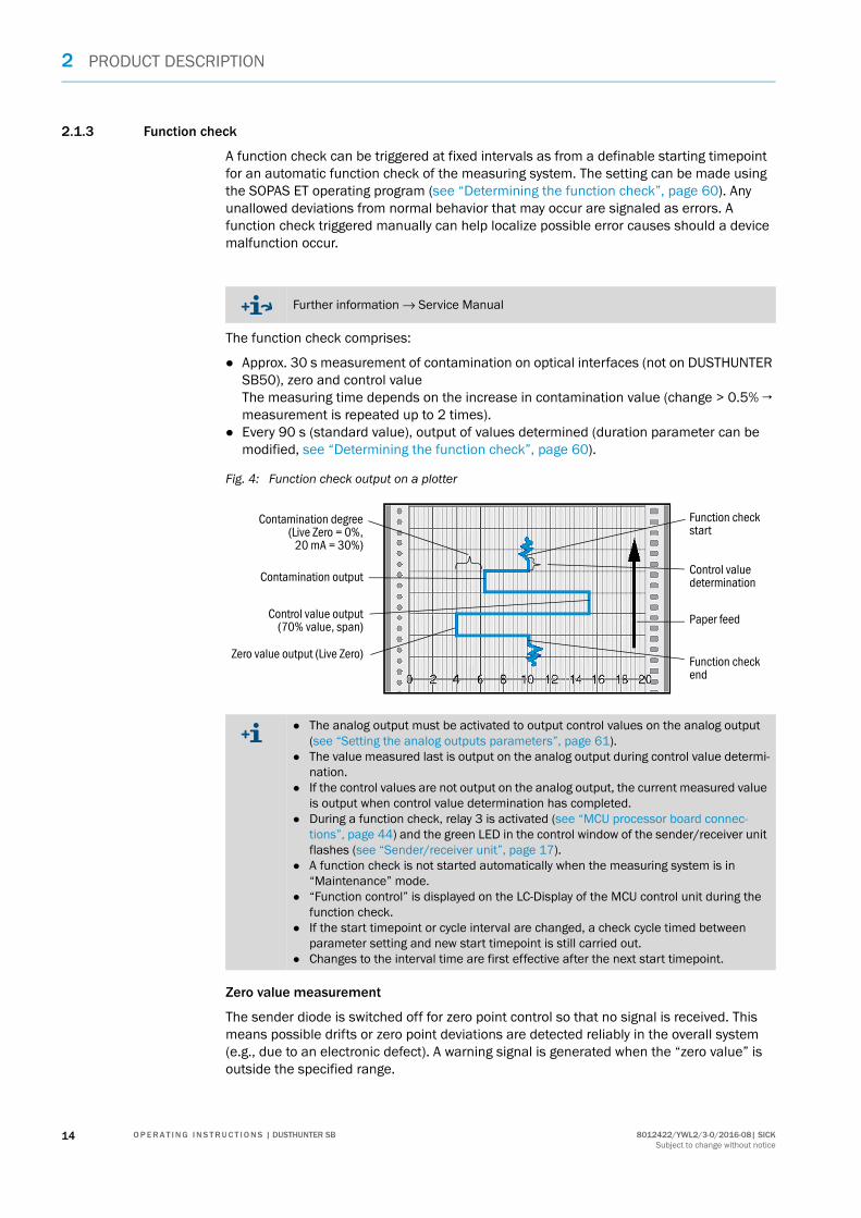
2.1.3 Function check
A function check can be triggered at fixed intervals as from a definable starting timepoint for an automatic function check of the measuring system. The setting can be made using the SOPAS ET operating program (see “Determining the function check”, page 60). Any unallowed deviations from normal behavior that may occur are signaled as errors. A function check triggered manually can help localize possible error causes should a device malfunction occur.
The function check comprises:
Approx. 30 s measurement of contamination on optical interfaces (not on DUSTHUNTER SB50), zero and control valueThe measuring time depends on the increase in contamination value (change > 0.5% → measurement is repeated up to 2 times).
Every 90 s (standard value), output of values determined (duration parameter can be modified, see “Determining the function check”, page 60).
Fig. 4: Function check output on a plotter
Zero value measurement
The sender diode is switched off for zero point control so that no signal is received. This means possible drifts or zero point deviations are detected reliably in the overall system (e.g., due to an electronic defect). A warning signal is generated when the “zero value” is outside the specified range.
Further information → Service Manual
Contamination degree(Live Zero = 0%,
20 mA = 30%)
Function check start
Zero value output (Live Zero)
Control value output(70% value, span)
Contamination outputControl value determination
Paper feed
Function check end
The analog output must be activated to output control values on the analog output (see “Setting the analog outputs parameters”, page 61).
The value measured last is output on the analog output during control value determi-nation.
If the control values are not output on the analog output, the current measured value is output when control value determination has completed.
During a function check, relay 3 is activated (see “MCU processor board connec-tions”, page 44) and the green LED in the control window of the sender/receiver unit flashes (see “Sender/receiver unit”, page 17).
A function check is not started automatically when the measuring system is in “Maintenance” mode.
“Function control” is displayed on the LC-Display of the MCU control unit during the function check.
If the start timepoint or cycle interval are changed, a check cycle timed between parameter setting and new start timepoint is still carried out.
Changes to the interval time are first effective after the next start timepoint.
14 8012422/YWL2/3-0/2016-08| SICKO P E R A T I N G I N S T R U C T I O N S | DUSTHUNTER SBSubject to change without notice

PRODUCT DESCRIPTION 2
Control value measurement (Span test)
Sender beam intensity changes between 70 and 100% during control value determination. The light intensity received is compared against the standard value (70%). The measuring system generates an error signal for deviations greater than ±2%. The error message is cleared again when the next function check runs successfully. The control value is deter-mined with high precision through statistical evaluation of a high number of intensity changes.
For DUSTHUNTER SB100, the control value is determined when the optical subassembly is in reference position (see “Contamination measurement”, page 15).
For DUSTHUNTER SB50, the value calculated theoretically (70%) is output for very low dust concentrations (< approx. 1 mg/m³).
Contamination measurement (only for DUSTHUNTER SB100)
The sender beam is diverted by sliding in an optical component and sent directly to the receiver. An integrated damping filter reduces the light intensity to a normal level to prevent overmodulation of the receiver. The measured value determined and the value defined as factory setting are used to calculate a correction factor. This serves to completely com-pensate any contamination that occurs.
A value between live zero and 20 mA is output on the analog output for contamination values < 30% ; when this value is exceeded, the “Failure” status is output (on the analog output the set error current; see “Factory settings”, page 59, see “Setting the analog outputs parameters”, page 61).
Fig. 5: Contamination measurement
Optics in measuring position
Optics in reference position
158012422/YWL2/3-0/2016-08| SICK O P E R A T I N G I N S T R U C T I O N S | DUSTHUNTER SBSubject to change without notice

2 PRODUCT DESCRIPTION
2.2 Device components
Measuring system DUSTHUNTER SB comprises the components:
Sender/receiver unit DHSB-T Connection line to connect the sender/receiver unit to the MCU control unit (lengths
5 m, 10 m) Flange with tube MCU control unit
to control, evaluate and output the data of the sender/receiver unit(s) connected via the RS485 interface– With integrated purge air supply, for internal duct pressure -50 ... +2 hPa– Without purge air supply, therefore additionally required:
Optional external purge air unit, for internal duct pressure -50 ... +30 hPa
Fig. 6: DUSTHUNTER SB device components
Communication between sender/receiver unit and MCU
As standard, each sender/receiver unit is connected to an MCU control unit via the con-nection line.
Power
Meas
Power
Meas
USB 1.1
(RS 232)
Duct Connection cable MCU-P (with purge air supply) MCU-N (without purge air supply) (option) Purge air hose DN40 Sender/receiver unit External purge air supply unit (option) Operating and parameter program
SOPAS ET Flange with tube Power supply
16 8012422/YWL2/3-0/2016-08| SICKO P E R A T I N G I N S T R U C T I O N S | DUSTHUNTER SBSubject to change without notice
PRODUCT DESCRIPTION 2
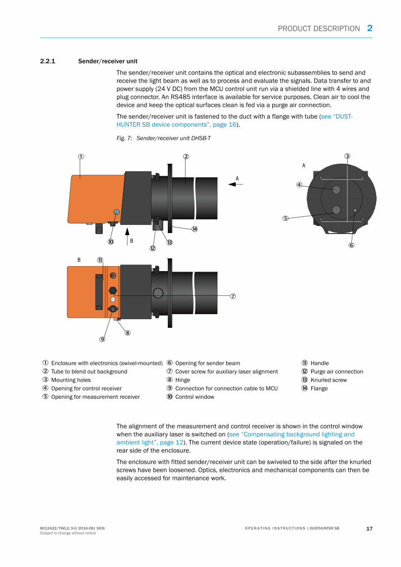
2.2.1 Sender/receiver unit
The sender/receiver unit contains the optical and electronic subassemblies to send and receive the light beam as well as to process and evaluate the signals. Data transfer to and power supply (24 V DC) from the MCU control unit run via a shielded line with 4 wires and plug connector. An RS485 interface is available for service purposes. Clean air to cool the device and keep the optical surfaces clean is fed via a purge air connection.
The sender/receiver unit is fastened to the duct with a flange with tube (see “DUST-HUNTER SB device components”, page 16).
Fig. 7: Sender/receiver unit DHSB-T
The alignment of the measurement and control receiver is shown in the control window when the auxiliary laser is switched on (see “Compensating background lighting and ambient light”, page 12). The current device state (operation/failure) is signaled on the rear side of the enclosure.
The enclosure with fitted sender/receiver unit can be swiveled to the side after the knurled screws have been loosened. Optics, electronics and mechanical components can then be easily accessed for maintenance work.
A
A
B
B â
á
à
ã
Enclosure with electronics (swivel-mounted) Opening for sender beam à Handle Tube to blend out background Cover screw for auxiliary laser alignment á Purge air connection Mounting holes Hinge â Knurled screw Opening for control receiver Connection for connection cable to MCU ã Flange Opening for measurement receiver Control window
178012422/YWL2/3-0/2016-08| SICK O P E R A T I N G I N S T R U C T I O N S | DUSTHUNTER SBSubject to change without notice

2 PRODUCT DESCRIPTION
Versions
The sender/receiver unit is available without (DUSTHUNTER SB50) and with contamination measurement (DUSTHUNTER SB100) and with different angles between the sender beam and receive aperture (see “Relations between scattering angle, immersion depth and mea-suring volume length”, page 18). The resulting different immersion depths (distance flange — measuring volume) and lengths of the measuring volume enable easy adaptation to different wall thicknesses and duct diameters.
Fig. 8: Relations between scattering angle, immersion depth and measuring volume length
Type code
A type code identifies the special version:
Short immersion depth0 400 650
Long immersion depth
0 800 1800
250
1000
Sender/receiver unit: DHSB-TXX
Contamination measurement:- 0: Without- 1: With
Immersion depth - 0: Short- 1: Long
18 8012422/YWL2/3-0/2016-08| SICKO P E R A T I N G I N S T R U C T I O N S | DUSTHUNTER SBSubject to change without notice

PRODUCT DESCRIPTION 2
2.2.2 Flange with tube
The flange with tube is available in different steel grades and dimensions (see “Flange with tube”, page 96). Selection depends on the wall and isolation thickness of the duct wall (→ nominal length) and the duct material.
Fig. 9: Flange with tube
TOP
NL
Marking for assembly position Securing bolt Material St 37 or 1.4571
198012422/YWL2/3-0/2016-08| SICK O P E R A T I N G I N S T R U C T I O N S | DUSTHUNTER SBSubject to change without notice

2 PRODUCT DESCRIPTION
2.2.3 MCU control unit
Control unit MCU has the following functions:
Control of the data traffic and processing of the sender/receiver unit data connected via the RS485 interface
Signal output via analog output (measured value) and relay outputs (device status) Signal input via analog and digital inputs Power supply for the connected measuring unit via 24 V switch-mode power supply with
wide range input Communication with higher level control systems via optional modules
Equipment and device parameters can be set easily and conveniently via a USB interface using a PC and a user-friendly operating program. The parameters are stored reliably even in the case of a power failure.
Control unit MCU has a sheet steel enclosure as standard.
2.2.3.1 Standard interfacesAnalog output Analog inputs Relay outputs Digital inputs Communication
0/2/4...22 mA (electrically isolated, active); resolution 10 bits 1x on DUSTHUNTER
SB50 to output the dust concentration
3x on DUSTHUNTER SB100 to output the scattered light concentra-tion (corresponds to the uncalibrated dust con-centration), calibrated dust concentration, scaled dust concentra-tion.
2 inputs 0 ... 20 mA (standard, without electrical isolation); Resolution 10 bits
5 changeover contacts (48 V, 1 A) to output status signals: Operation/failure Maintenance Function check Maintenance
request Limit value
4 inputs to connect potential-free contacts (e.g. to connect a maintenance switch, trigger a function check or more error messages)
USB 1.1 and RS232 (on terminals) for measured value inquiries, setting parameters and soft-ware updates.
RS485 for sensor con-nection
20 8012422/YWL2/3-0/2016-08| SICKO P E R A T I N G I N S T R U C T I O N S | DUSTHUNTER SBSubject to change without notice

PRODUCT DESCRIPTION 2
2.2.3.2 Versions
Control unit MCU-N without purge air supply
Fig. 10: Control unit MCU-N with options
DISPLAYMODUL
relay 3 relay 4 relay 5BUSTerm
Term
relay 1 relay 2com nc. no. com nc. no. com nc. no. com nc. no. com nc. no.
Res
et
Display module (option) I/O module (option) Processor board Display module (option) Interface module (option)
218012422/YWL2/3-0/2016-08| SICK O P E R A T I N G I N S T R U C T I O N S | DUSTHUNTER SBSubject to change without notice

2 PRODUCT DESCRIPTION
MCU-P control unit with integrated purge air supply This version is also fitted with a purge air blower, air filter and purge air connection to connect the purge air hose to the sender/receiver unit.
Fig. 11: Control unit MCU-P with integrated purge air supply
The purge air hose (standard lengths 5 and 10 m (see “Purge air supply”, page 101)) is a separate part of the measuring system and must be ordered separately.
Purge air blower Installation plate Air filter Power supply unit (on back of installation plate) Optional Display module Purge air connection Processor board Purge air inlet
22 8012422/YWL2/3-0/2016-08| SICKO P E R A T I N G I N S T R U C T I O N S | DUSTHUNTER SBSubject to change without notice

PRODUCT DESCRIPTION 2
2.2.3.3 Type code
The following type code defines the various configuration options in the same manner as for the sender/receiver unit:
Type code MCU control unit: MCU-X X O D N X 1 0 0 0 N N N E
Integrated purge air supply - N: Without (no)- P: With (purged)
Voltage supply- W: 90 ... 250 V AC - 2: Optional 24 V DC
Enclosure variants- O: Wall enclosure, SICK, orange
Display module- D: With
Other options- N: Without
Analog input option (plug-in module; 0/4...20 mA; 2 inputs per module)- 0: Without- n: With, n = 1
Analog output option (plug-in module; 0/4...20 mA; 2 outputs per module)- 0: Without- n: With, n = 1 (standard for DUSTHUNTER SB100)
Digital input option (plug-in module; 4 inputs per module)- 0: Without
Digital output power option (plug-in module; 48 V DC, 5 A; 2 changeovers per module)- 0: Without
Digital output low power option (plug-in module; 48 V DC, 0.5 A; 4 make contact elements per module)- 0: Without
Optional Interface module- N: Without- E: Ethernet type 1, COLA-B- P: Profibus
- E: Ethernet type 2, COLA-B
Special versions- N: No special featuresEX certification- N: Without EX certificationSoftware- E: Emission measurement
238012422/YWL2/3-0/2016-08| SICK O P E R A T I N G I N S T R U C T I O N S | DUSTHUNTER SBSubject to change without notice

2 PRODUCT DESCRIPTION
2.2.3.4 Options
The options described in the following can considerably expand the functionality of the MCU:
2.2.3.5 Modules
1 Display moduleModule to display measured values and status information and for configuration during start-up, selection via operating buttons.
a) Displays
The graphic display shows two main measured values of a connected sender/receiver unit selected at the factory or calculated values from the MCU (e.g., scaled dust concentration) as bar charts. Alternatively, up to 8 single measured values of a sender/receiver unit can be displayed (toggle with “Meas” button).
Fig. 12: LC-LC-Display with graphic (left) and text (right) display)
b) Control buttons
Type Display
LED
Power (green) Voltage supply OK
Failure (red) Function fault
Maintenance request (yellow)
Maintenance request
LC-Display Graphic display (main screen)
– Dust concentration– Scattered light
Text display Six possible measured values (see graphic display)
Button Function
Meas Toggle between text and graphic display Display the contrast setting (after 2.5 s)
Arrows Select next/previous measured value page
Diag Display alarm or fault message
Menu Display of main menu and selection of submenus
24 8012422/YWL2/3-0/2016-08| SICKO P E R A T I N G I N S T R U C T I O N S | DUSTHUNTER SBSubject to change without notice

PRODUCT DESCRIPTION 2
2 I/O moduleTo be fitted on the module carrier (see “Options for MCU control unit”, page 102), optional as:– 2x analog output 0/4 ... 22 mA to output further measured variables (max. load
500 Ω)– 2x analog input 0/4 ... 22 mA to read-in values from external sensors (gas temper-
ature, internal duct pressure, moisture, O2) to calculate the dust concentration in standard state.
3 Interface modulesModule to pass on measured values, system status and service information to higher level control systems, optionally for Profibus DP V0 or Ethernet, to plug onto hat rails. A corresponding line serves to connect the module to the connection board.
4 MCU remote control unitThe MCU remote control unit has identical functions to the MCU display near the device, however, it can be installed further away.– Operating function the same as the MCU display– Distance to the device:
- MCU remote control unit without separate power supply unit: Max. 100 m- MCU remote control unit with own power supply unit: Max. 1000 m
– The MCU and the MCU remote control unit are interlocked (it is not possible to oper-ate both MCUs at the same time).
One module carrier is required per module (to plug in on the hat rail). One mod-ule carrier is connected to the processor board using a special line and another one is docked.
On the DUSTHUNTER SB50 version, a maximum of 1 Analog Input and 1 Analog Output module can be plugged on.
On the DUSTHUNTER SB100 version, a maximum of 1 Analog Input module can be plugged on.
Profibus DP-V0 for transfer via RS485 according to DIN 19245 Part 3 as well as IEC 61158.
258012422/YWL2/3-0/2016-08| SICK O P E R A T I N G I N S T R U C T I O N S | DUSTHUNTER SBSubject to change without notice

2 PRODUCT DESCRIPTION
2.2.4 Optional external purge air unit
The MCU control unit with integrated purge air supply cannot be used when the internal duct pressure is greater than +2 hPa. Use the optional external purge air unit in this case. It has a powerful blower and can be used for excess pressure in the duct up to 30 hPa. The scope of delivery includes a purge air hose with 40 mm nominal diameter (length 5 m or 10 m).
Fig. 13: Optional external purge air unit
A weatherproof cover is available for use outdoors (see “Weatherproof covers”, page 100).
2.2.5 Installation accessories
Separate parts of the measuring system (order separately) are:
Purge air hose with 40 mm nominal diameter for purge air supply to the sender/receiver unit from the MCU-P control unit,
Connection line from the MCU to the sender/receiver unit.
Weatherproof cover
A weatherproof cover is available when using the sender/receiver unit outdoors (see “Weatherproof covers”, page 100).
Purge air heater
It is recommended to use an optional purge air heater available for delivery (see “Purge air supply”, page 101) to prevent condensation in the device or flange tube when the mea-suring system is operated at gas temperatures close to the dew point or very low ambient temperatures
Air filter Cover cap with opening (part of the purge air reduction)
Blower (standard type 2BH13) Purge air hose Base plate To purge air connection of sender/receiver unit
The purge air heater can only be used for purge air supply with an external purge air unit.
26 8012422/YWL2/3-0/2016-08| SICKO P E R A T I N G I N S T R U C T I O N S | DUSTHUNTER SBSubject to change without notice

PRODUCT DESCRIPTION 2
Optional non-return valve
When the measuring system is used in applications with overpressure in the duct, it is pos-sible to protect the sender/receiver unit, external purge air unit and the environment against the consequences of purge air supply failure by installing a non-return valve on the purge air connection of the sender/receiver unit (see “Installation of non-return valve”, page 42).
2.2.6 Test equipment for linearity test
A linearity test can serve to check the correct measurement function (see Service Manual). In this case, filter glasses with defined transmission values are positioned in the beam path and the values compared against those measured by the measuring system. Com-pliance within the allowed tolerance means the measuring system is working correctly. The filter glasses with holder required for the check are deliverable including a carrying case.
278012422/YWL2/3-0/2016-08| SICK O P E R A T I N G I N S T R U C T I O N S | DUSTHUNTER SBSubject to change without notice

2 PRODUCT DESCRIPTION
2.3 Device configuration
Two versions of the DUSTHUNTER SB measuring system are available with the following features (standard components):
Variants
Voltage and purge air supply
Device version
DUSTHUNTER SB50 DUSTHUNTER SB100
Smallest range: 0 ... 20 mg/m³ Smallest range: 0 ... 10 mg/m³
Sender/receiver unit DHSB-T T0xwithout contamination measurement
Sender/receiver unit DHSB-T T1xwith contamination measurement
Control unit MCU-xxOx000000NNNE with 1 analog output, LC-Display as option
Control unit MCU-xxOD010000NNNEwith 3 analog outputs (2x with module), with LC-Display
Internal duct pressure [hPa ]
Connection and supply components
Purge air Voltage
-50 ... +2 MCU-P + purge air hose DN40
-50... +30 Optional external purge air unit MCU-N
We recommend using the optional external purge air unit when the sender/receiver unit is more than 10 m away from the MCU control unit.
28 8012422/YWL2/3-0/2016-08| SICKO P E R A T I N G I N S T R U C T I O N S | DUSTHUNTER SBSubject to change without notice

PRODUCT DESCRIPTION 2
2.4 SOPAS ET (PC program)
SOPAS ET is a SICK Software for easy operation and configuration of the DUSTHUNTER.
SOPAS ET runs on a laptop/PC connected to the DUSTHUNTER via a USB line or Ethernet interface (option).
The menu structure simplifies changing settings. Further functions are also available (e.g., data storage, graphic displays).
SOPAS ET is delivered on the product CD. Alternatively, you can download SOPAS ET free of charge from the SICK homepage (“Downloads”).
298012422/YWL2/3-0/2016-08| SICK O P E R A T I N G I N S T R U C T I O N S | DUSTHUNTER SBSubject to change without notice

3 ASSEMBLY AND INSTALLATION
3 Assembly and Installation
3.1 Project planning
The following Table provides an overview of the project planning work necessary as prerequisite for trouble-free assembly and subsequent device functionality. You can use this Table as a Checklist and check off the completed steps.
Task Requirements Work step
Determine measuring location and fitting loca-tions for the device compo-nents
Inlet and outlet paths according to DIN EN 13284-1 (inlet at least 5x hydraulic diameter dh, outlet at least 3x dh; distance to stack opening at least 5x dh)
For round and square ducts: dh = duct diameter
Follow specifications for new equip-ment
Select best possible location for exist-ing equipment;
For too short inlet/outlet paths: Inlet path > outlet path
For rectangular ducts:dh = 4x cross-section divided by cir-cumference
Homogeneous flow distribu-tionRepresentative dust distri-bution
Whenever possible, no deflections, cross-section variations, feed and drain lines, flaps or fittings in the area of the inlet and outlet paths
If conditions cannot be ensured, define flow profile according to DIN EN 13284-1 and select best possible location
Fitting position for the sender/receiver unit
Select best possible location
Accessibility, accident prevention
The device components must be eas-ily and safely accessible
Provide platforms or pedestals as required
Installation free of vibra-tions
Acceleration < 1 gEliminate/reduce vibrations throughsuitable measures
Ambient conditionsLimit values according to Technical Data
If necessary: Provide weatherproof covers/sun
protection Enclose or lag device components
Select the purge air sup-ply
Sufficient primary purge air pressure depending on internal duct pressure
Up to +2 hPa, MCU control unit with integrated purge air supplyAbove +2 hPa to +30 hPa, optional external purge air unitPlan a purge air heater for gas tem-peratures close to the dew point or very low ambient temperatures
Select supply type
Clean intake airWhenever possible, low amount of dust, no oil, moisture or corrosive gases
Select best possible location for air intake
Determine required purge air hose length
Select device components
Duct wall thickness with isolation
Flange with tube Select components according to Configu-ration Table (see “Device configuration”, page 28); If necessary, plan additional measures to fit the flange with tube (see “Fitting the flange with tube”, page 32)
Internal duct pressure Type of purge air supply
Fitting locations Line and purge air hose lengths
45°
30 8012422/YWL2/3-0/2016-08| SICKO P E R A T I N G I N S T R U C T I O N S | DUSTHUNTER SBSubject to change without notice

ASSEMBLY AND INSTALLATION 3
Plan calibra-tion openings
Access Easy and safeProvide platforms or pedestals as required
Distances to measuring level
No mutual interference between calibration probe and measuring system
Plan sufficient distance between measuring and calibration level (approx. 500 mm)
Plan the volt-age supply
Operating voltage, power requirements
According to Technical Data (see “Technical Data”, page 93)
Plan adequate line cross-sections and fuses
Task Requirements Work step
318012422/YWL2/3-0/2016-08| SICK O P E R A T I N G I N S T R U C T I O N S | DUSTHUNTER SBSubject to change without notice

3 ASSEMBLY AND INSTALLATION
3.2 Assembly
Carry out all assembly work onsite. This includes:
Fitting the flange with tube Fitting the MCU control unit, Fitting the optional external purge air unit.
3.2.1 Fitting the flange with tube
Fig. 14: Fitting the flange with tube
WARNING: Observe the relevant safety regulations as well as the safety notices during
all work: see “Important Information”, page 7 Consider the equipment weight specifications when planning the mounting
brackets. Only carry out assembly work on equipment with hazard potential (hot or
aggressive gases, higher internal duct pressure) when the equipment is at a standstill.
Take suitable protection measures against possible local hazards or haz-ards arising from the equipment.
All dimensions specified in this Section are shown in mm.
TOPA AAA
> 30
Approx. 1°
Ø 1
95
Assembly on steel duct Marking for assembly position Assembly on brick stack Assembly on thin-walled duct
Junction plate Duct wall Anchor plate Flange with tube
NOTE:Maximum wall and isolation thickness are derived from the flange tube length (350 mm or 700 mm) less the distance between flange and stack outer wall, and stack immersion depth (> 30 mm).
32 8012422/YWL2/3-0/2016-08| SICKO P E R A T I N G I N S T R U C T I O N S | DUSTHUNTER SBSubject to change without notice

ASSEMBLY AND INSTALLATION 3
3.2.2 Work to be performed
Measure the fitting location and mark the assembly location.Leave enough clearance around the flange with tube to fit the sender/receiver unit.
Fig. 15: Clearance for sender/receiver unit (dimensions in mm)
Remove insulation (when fitted) Cut suitable openings in the duct wall; bore large enough holes in brick or concrete
stacks (flange tube diameter (see “Flange with tube”, page 96))
Insert the flange with tube in the opening slanting slightly downwards (1 to 3°, see “Fitting the flange with tube”, page 32) so that the “Top” marking points upwards and any condensate that may collect in the duct can drain off.
Weld the flange with tube on using an anchor plate for brick or concrete stacks, insert junction plates for thin-walled ducts (see “Fitting the flange with tube”, page 32).
Close off the flange opening after fitting to prevent gas escaping.
TOP
400 400
200
Clearance
600
300
Flange with tube Duct wall
NOTE: Do not let separated pieces fall into the duct.
338012422/YWL2/3-0/2016-08| SICK O P E R A T I N G I N S T R U C T I O N S | DUSTHUNTER SBSubject to change without notice

3 ASSEMBLY AND INSTALLATION
3.2.3 Fitting the MCU control unit
Fit the MCU control unit in a protected location that is easily accessible (see “MCU assembly dimensions”, page 34). Observe the following points during fitting:
Maintain the ambient temperature according to the Technical Data; take possible radiant heat into consideration (shield when necessary).
Protect against direct sunlight. Whenever possible, choose an assembly location with minimum vibrations; dampen any
vibrations when necessary. Provide sufficient clearance for lines and opening the door.
Assembly dimensions
Fig. 16: MCU assembly dimensions
c
f
e
> 25
0
db
M8
Clearance to open door
Clearance for cables
a
Dimen-sion
Control unit type
MCU-N MCU-P
a 160 260
b 320 420
c 210 300
d 340 440
e 125 220
f > 350 > 540
MCU-N:Control unit without purge air supplyMCU-P:Control unit with purge air supply(see “MCU control unit”, page 20)
34 8012422/YWL2/3-0/2016-08| SICKO P E R A T I N G I N S T R U C T I O N S | DUSTHUNTER SBSubject to change without notice

ASSEMBLY AND INSTALLATION 3
Using a suitable line (see “General information, prerequisites”, page 40), the MCU-N control unit (without integrated purge air supply) can be located up to 1000 m away from the sender/receiver unit.
We therefore recommend fitting the MCU in a control room (measuring station or similar) to ensure free access to the MCU. This considerably simplifies communication with the mea-suring system in order to set parameters or to locate malfunction or error causes.
It is advantageous to provide weather protection (tin roof or similar), to be made onsite, for use outdoors.
Requirements when using the MCU-P control unit
The following is applicable in addition to the general specifications:
Install the MCU-P control unit at a location with clean air whenever possible. The air intake temperature must correspond to specifications in the Technical data (see “Tech-nical Data”, page 93). In unfavorable conditions, lay an air intake hose to a location with better conditions.
The purge air hose to the sender/receiver unit should be as short as possible. When possible. lay the purge air hose so that no water can collect. We recommend using the optional external purge air unit when the sender/receiver unit
is more than 10 m away from the MCU control unit.
358012422/YWL2/3-0/2016-08| SICK O P E R A T I N G I N S T R U C T I O N S | DUSTHUNTER SBSubject to change without notice

3 ASSEMBLY AND INSTALLATION
3.2.4 Fitting the optional external purge air unit
Consider the following points when selecting the assembly location:
Install the purge air unit at a location with clean air whenever possible. The air intake temperature must correspond to specifications in the Technical data (see “Technical Data”, page 93). In unfavorable conditions, lay an air intake hose or pipe to a location with better conditions.
The fitting location must be easily accessible and meet all safety regulations. Install the purge air unit only as far as necessary below the flange with tube for the
sender/receiver unit so that the purge air hoses can be laid downwards (avoids water collecting).
Provide sufficient clearance to exchange the filter element. Provide sufficient space to attach and remove the weatherproof cover when installing
the purge air unit outdoors see “Purge air unit layout and assembly dimensions (dimen-sions in mm)”, page 37).
36 8012422/YWL2/3-0/2016-08| SICKO P E R A T I N G I N S T R U C T I O N S | DUSTHUNTER SBSubject to change without notice

ASSEMBLY AND INSTALLATION 3
3.2.5 Assembly work
Prepare holder (see “Purge air unit layout and assembly dimensions (dimensions in mm)”, page 37).
Fasten purge air unit with 4 M8 screws. Check whether the filter element is fitted in the filter housing otherwise fit when
necessary.
Fig. 17: Purge air unit layout and assembly dimensions (dimensions in mm)
> 14
0
Clearance to fit weatherproof cover
Flange with tube Clearance to exchange filter ele-
ment Alternative: Mounting bracket Steel pipe 50 x 5 DIN 2391 Duct
(550
)
470
50M 8
> 160 (550)
470
378012422/YWL2/3-0/2016-08| SICK O P E R A T I N G I N S T R U C T I O N S | DUSTHUNTER SBSubject to change without notice

3 ASSEMBLY AND INSTALLATION
3.2.6 Fitting the weatherproof cover
Weatherproof cover for external purge air unit
The weatherproof cover (see “Weatherproof covers”, page 100) comprises a cover and locking set.
Assembly:
Mount the locking pins from the locking set on the base plate. Put the weatherproof cover on from above. Insert the holding catches into the counterpieces from the side, twist and lock in.
38 8012422/YWL2/3-0/2016-08| SICKO P E R A T I N G I N S T R U C T I O N S | DUSTHUNTER SBSubject to change without notice

ASSEMBLY AND INSTALLATION 3
3.3 Electrical installation
3.3.1 Electrical safety
3.3.1.1 Properly installed power isolating switches
3.3.1.2 Lines with correct rating
3.3.1.3 Grounding the devices
3.3.1.4 Responsibility for system safety
WARNING: Observe the relevant safety regulations as well as the safety notices in see
“Important Information”, page 7 during all installation work. Take suitable protection measures against possible local hazards or
hazards arising from the equipment.
WARNING:Endangerment of electrical safety during installation and maintenance work when the power supply is not switched off.An electrical accident can occur during installation and maintenance work when the power supply to the device or lines is not switched off using a power isolating switch/circuit breaker. Before starting work on the device, ensure the power supply can be
switched off using a power isolating switch/circuit breaker in accordance with DIN EN 61010.
Make sure the power isolating switch is easily accessible. An additional disconnecting device is mandatory when the power isolating
switch cannot be accessed or only with difficulty after installation. The power supply may only be activated again after the work or for test
purposes by personnel carrying out the work under consideration of valid safety regulations.
WARNING:Endangerment of electrical safety through power line with incorrect rating.Electrical accidents can occur when the specifications for replacement of a removable power line have not been adequately observed. Always observe the exact specifications in the Operating Instructions
(Technical Data Section) when replacing a removable power line.
CAUTION:Device damage through incorrect or missing grounding. During installation and maintenance work, it must be ensured that the
protective grounding to the devices and/or lines involved is effective in accordance with EN 61010-1.
WARNING:Responsibility for the safety of a system. The person setting the system up is responsible for the safety of the system
in which the device is integrated.
398012422/YWL2/3-0/2016-08| SICK O P E R A T I N G I N S T R U C T I O N S | DUSTHUNTER SBSubject to change without notice

3 ASSEMBLY AND INSTALLATION
3.3.2 General information, prerequisites
All assembly work previously described must be completed (as far as applicable) before starting installation work.
Carry out all installation work onsite unless otherwise explicitly agreed with SICK or autho-rized representatives. This includes laying and connecting the power supply and signal lines, installing switches and power fuses and connecting the purge air supply.
3.3.3 Installing the purge air supply
Lay the purge air hoses with shortest paths and free of bends, shorten as required. Maintain sufficient distance from hot duct walls.
3.3.3.1 Control unit with integrated purge air supply (MCU-P)
Connect the purge air hose DN40 to the purge air outlet DN40 (1) on the underside of the MCU-P and secure with a strap retainer. Set the purge air outlet as shown (correct when necessary). Close the second purge air outlet (2) with a cap (3) (scope of supply).
Fig. 18: Underside of MCU-P
Plan adequate line cross-sections (see “Technical Data”, page 93). Line ends with plugs to connect the sender/receiver unit must have sufficient free
length.
Purge air inlet
40 8012422/YWL2/3-0/2016-08| SICKO P E R A T I N G I N S T R U C T I O N S | DUSTHUNTER SBSubject to change without notice

ASSEMBLY AND INSTALLATION 3
3.3.3.2 Optional external purge air unit
1 Connect the purge air hose Connect the DN 40 purge air hose to the Y-distributor of the purge air unit and secure
with a D32-52 hose clamp. Close off the second outlet opening on the Y-distributor with the cover cap.
Fig. 19: Optional external purge air unit connection
2 Electrical connection Compare power voltage and frequency with the specifications on the type plate on the
purge air motor.
Connect the power supply line to the purge air motor terminals (refer to the supple-mentary sheet on the purge air motor and lid of the motor terminal box for terminal allo-cation).
Fig. 20: Electrical connection of the external purge air unit
Connect protective conductor to terminal.
Optional external purge air unit
Cover cap with opening (part of the purge air reduction) To the purge air connections of the sender/receiver unit
CAUTION: Only connect when these match!
L1 L1
U1 U1
U1
U1
V1 V1
V1
V1
W1 W1
W1
W1
PE PE
W2 W2
W2
W2
V2 V2
V2V2
U2 U2
U2
U2
L2 L2 + 24 VL3 L3 _PE PE
Low-pressure monitor Energy supply
4 x 1.5 mm²
418012422/YWL2/3-0/2016-08| SICK O P E R A T I N G I N S T R U C T I O N S | DUSTHUNTER SBSubject to change without notice

3 ASSEMBLY AND INSTALLATION
Set motor circuit breakers according to the blower connection data (see Technical Data for purge air unit) to a value 10% above the rated current.
Check the function and running direction of the blower (purge air flow direction must match the arrows on the inlet and outlet openings on the blower). For wrong direction on 3-phase motors: Swap power connections L1 and L2.
Connect the pressure controller (option) to monitor purge air feed.
3.3.3.3 Installing the non-return valve option
Fig. 21: Installation of non-return valve
NOTE:In case of doubt or when using a special motor version, the operating instructions supplied with the motor have priority over any other informa-tion.
NOTE: Use a fail-safe power supply (standby unit, rails with redundant supply) Fuse the purge air unit separate from the other system components. The
fuse type must match the rated current (see technical details of purge air unit). Fuse each phase separately. Use circuit breakers to prevent phase failures on one side.
Sender/receiver unit Non-return valve Purge air hose External purge air unit
42 8012422/YWL2/3-0/2016-08| SICKO P E R A T I N G I N S T R U C T I O N S | DUSTHUNTER SBSubject to change without notice

ASSEMBLY AND INSTALLATION 3
3.3.4 Connecting the MCU control unit
Fig. 22: Component layout in the MCU (without purge air supply, with options)
3.3.4.1 Work to be done
Connect the connection line: see “Standard connection”, page 46.
Connect lines for status signals (operation/failure, maintenance, function check, main-tenance request, limit value), analog output, analog and digital inputs according to requirements (see “Standard connection”, page 46, p. 49, Fig. 27 and Fig. “Terminal assignment of analog input module”; only use shielded lines with twisted pairs).
Connect power line to terminals L1, N, PE of the MCU (see “Component layout in the MCU (without purge air supply, with options)”, page 43).
DISPLAYMODUL
relay 3 relay 4 relay 5BUSTerm
Term
relay 1 relay 2com nc. no. com nc. no. com nc. no. com nc. no. com nc. no.
Rese
t
Optional Interface module Processor board Optional Display module Optional I/O modules Terminals for power connection
If an onsite line is to be used, it must be connected to a suitable 7-pole socket (see “Plug connector connection to onsite line”, page 45; SICK Part No.: 7045569).
NOTICE: Only use shielded lines with twisted pairs (e.g., UNITRONIC LiYCY (TP) 2 x
2 x 0.5 mm² from LAPPKabel; 1 pair of wires for RS 485, 1 pair of wires for power supply; not suitable for underground laying).
438012422/YWL2/3-0/2016-08| SICK O P E R A T I N G I N S T R U C T I O N S | DUSTHUNTER SBSubject to change without notice

3 ASSEMBLY AND INSTALLATION
Close off unused line openings with dummy plugs.
3.3.4.2 MCU processor board connections
Fig. 23: MCU processor board connections
WARNING: Be sure to check the wiring before switching the supply voltage on. Only modify wiring when disconnected from the power supply and potential-
free.
á
à
ß
Supply voltage 24 V DC RS232 Connection for optional I/O
module Connection for Display module Connection for LEDs Connection for optional Inter-
face module USB plug connector Connections for sender/
receiver units Connections for relays 1 to 5 Connections for digital inputs 1
to 4à Connection for analog outputá Connections for analog inputs
1 and 2
44 8012422/YWL2/3-0/2016-08| SICKO P E R A T I N G I N S T R U C T I O N S | DUSTHUNTER SBSubject to change without notice

ASSEMBLY AND INSTALLATION 3
3.3.4.3 Connection of connection line to MCU
Fig. 24: Plug connector connection to onsite line
Cable provided by customer according to page 40, §3.3.2
ClosedClosed
OpenOpen A
A
A -A
+24 V
NoteTo open, connect the plug connector to the plug on the sender/receiver unit.
RS485 B
RS485 A
gnd
Shield
458012422/YWL2/3-0/2016-08| SICK O P E R A T I N G I N S T R U C T I O N S | DUSTHUNTER SBSubject to change without notice

3 ASSEMBLY AND INSTALLATION
3.3.4.4 Standard connection
Fig. 25: Standard connection
MCU processor board
Sender/receiver unit
Plug
Connection line (SICK line or onsite line according to see “General information, prerequisites”, page 40)
Socket
Whi
teBr
own
Gre
enYe
llow
Whi
te
Yello
wG
reen
Brow
n
Plug assignment (View on pin side)
RS485 B 3
RS485 A4
5
6-24 V
2
7
1+24 V
Switching position of the relay contacts in currentless condition
Ope
ratio
n/fa
ilure
Mai
nten
ance
Func
tion
chec
k
Mai
nten
ance
requ
est
Lim
it va
lue
MaintenanceFunction check
Relay Terminal
1 1, 2, 3
2 4, 5,6
3 7, 8, 9
4 10, 11, 12
5 13, 14, 15
46 8012422/YWL2/3-0/2016-08| SICKO P E R A T I N G I N S T R U C T I O N S | DUSTHUNTER SBSubject to change without notice

ASSEMBLY AND INSTALLATION 3
3.3.5 Connecting the MCU remote control unit
3.3.5.1 Connection to the MCU control unit
Electrical connection see “Standard connection”, page 46
Electrical connection of the MCU remote control unit without an own power supply unit:– 24V supply: Terminals 36 and 37 (or equivalent) – Signals: Terminals 38 and 39 (or equivalent)
Electrical connection of the MCU remote control unit with an own power supply unit:– Signals: Terminals 38 and 39 (or equivalent)
3.3.5.2 Connection to the MCU remote control unit
Version without power supply unit
Connect the connection cable to the measuring and control unit (4-wire, twisted pair, with shield) to the connections in the control unit and the module of the remote unit.
Fig. 26: Connections in the remote control unit (version with integrated wide-range power pack)
Version with integrated wide-range power pack:
Connect the 2-wire cable (twisted pair, with shield) to the connections for RS485 A/B and shield in the control and remote control unit.
Connect the 3-wire power cable with sufficient cross-section to the onsite power supply and the corresponding terminals in the remote unit.
+24 V
-24 V
Shield RS485 A
RS485B
Connection cable to the MCU measuring and control unit
Power cable
478012422/YWL2/3-0/2016-08| SICK O P E R A T I N G I N S T R U C T I O N S | DUSTHUNTER SBSubject to change without notice

3 ASSEMBLY AND INSTALLATION
NOTICE: During installation, it must be possible to switch the power supply off
using a power isolating switch/circuit breaker in accordance with EN 61010-1.
After completion of the work or for test purposes, the power supply may only be activated again by the personnel who carried out the work and complying with the valid safety regulations.
48 8012422/YWL2/3-0/2016-08| SICKO P E R A T I N G I N S T R U C T I O N S | DUSTHUNTER SBSubject to change without notice

ASSEMBLY AND INSTALLATION 3
3.3.6 Fitting the interface and I/O module (option)
Plug Interface modules and module carriers for I/O modules onto the hat rail in the MCU (see “Component layout in the MCU (without purge air supply, with options)”, page 43) and connect to the associated connection on the processor board with the line with plug con-nector (see “MCU processor board connections”, page 44). Then plug the I/O modules on the module carriers.
Connect the Interface modules using the customer provided network line to the local network. Use the terminals on the module carrier to connect I/O modules.
Terminal assignment of AO module
Fig. 27: Terminal assignment of analog output module
Terminal assignment of AI module
Fig. 28: Terminal assignment of analog input module
+
1 AO1
+ 2
AO2
Shi
eld
11 12 13 14
21 22 23 24
AO 1+ -
AO 2+ -
Module carrier
+ -
+
1 AI1
11 12 13 14
21 22 23 24
+ 2
AI2
Shi
eld
AI 1
AI 2+ -
Module carrier
498012422/YWL2/3-0/2016-08| SICK O P E R A T I N G I N S T R U C T I O N S | DUSTHUNTER SBSubject to change without notice
4 START-UP AND PARAMETER SETTINGS
4 Start-up and Parameter Settings
4.1 Basics
4.1.1 General information
Assembly and installation must have been completed according to Section 3 before starting the work described in the following.
Start-up and parameter setting comprise:
Setting the measuring system to the duct dimensions Fitting and connecting the sender/receiver unit, Customizing parameter settings according to the respective requirements.
To achieve exact measurement, the measuring system must first be calibrated using a gravimetric comparison measurement (see “Calibration for dust concentration mea-surement”, page 65) before being used for continuous measurement of dust content.
50 8012422/YWL2/3-0/2016-08| SICKO P E R A T I N G I N S T R U C T I O N S | DUSTHUNTER SBSubject to change without notice

START-UP AND PARAMETER SETTINGS 4
4.1.2 Installing SOPAS ET
Install SOPAS ET on a laptop/PC. Start SOPAS ET. Following the installation instructions of SOPAS ET.
4.1.2.1 Password for SOPAS ET menus
Certain device functions are first accessible after a password has been entered.
4.1.3 Connection to the device via USB line
Recommended procedure:
1 Connect the USB line to the MCU control unit (see “MCU processor board connections”, page 44) and the laptop/PC.
2 Switch the device on.3 Start SOPAS ET.4 “Search settings”5 “Device family oriented search”6 Click the desired MCU.7 Make the settings:
– Ethernet communication (always clicked)– USB communication (always clicked)– Serial communication: Click
8 Do not specify IP addresses.9 A list of COM ports is shown.
Specify the COM port of the DUSTHUNTER.If you do not know the COM port: see “Finding the DUSTHUNTER COM port”, page 51
10 Assign a name for this search.11 “Finish”
4.1.3.1 Finding the DUSTHUNTER COM port
If you do not know your COM port: You can find the COM port with the Windows Device Manager (Administrator rights are not required).
1 Disconnect the DUSTHUNTER from your laptop/PC.2 Input: devmgmt.msc
User level Access to
0 OperatorDisplays measured values and system statesNo password required
1 Authorized operatorDisplays, inquiries as well as start-up or adjustment to customer-spe-cific demands and diagnosis of necessary parameters.Preset password: sickoptic
518012422/YWL2/3-0/2016-08| SICK O P E R A T I N G I N S T R U C T I O N S | DUSTHUNTER SBSubject to change without notice

4 START-UP AND PARAMETER SETTINGS
3 this message is shown:
4 “OK”5 The Device Manager opens.
See: “Ports (COM & LPT)”
6 Now connect the MCU with the laptop/PC.A new COM port is shown.
Use this COM port for communication.
4.1.4 Connection to the device via Ethernet (option)
Recommended procedure:
1 The MCU must be switched off.2 Connect the MCU with the network.
The Ethernet interface module (see “Options for MCU control unit”, page 102) must be installed in the MCU (see “Fitting the interface and I/O module (option)”, page 49) and configured (see “Setting the Ethernet module parameters”, page 70) to connect to the measuring system via Ethernet.
52 8012422/YWL2/3-0/2016-08| SICKO P E R A T I N G I N S T R U C T I O N S | DUSTHUNTER SBSubject to change without notice

START-UP AND PARAMETER SETTINGS 4
3 Connect the PC to the same network.4 Switch the MCU on.5 Start SOPAS ET.6 “Search settings”7 “Device family oriented search”8 Click the desired MCU9 Make the settings:
– Ethernet communication (always clicked)– USB communication (always clicked)– Serial communication: Do not click
10 Specify the IP addressesIP address: see “Setting the Ethernet module parameters”, page 70
11 Do not click a COM port12 Assign a name for this search13 “Finish”
538012422/YWL2/3-0/2016-08| SICK O P E R A T I N G I N S T R U C T I O N S | DUSTHUNTER SBSubject to change without notice

4 START-UP AND PARAMETER SETTINGS
4.2 Fitting the sender/receiver unit
4.2.1 Connecting the sender/receiver unit to the purge air supply
Check whether the purge air supply is available (the flow direction must be correct and the purge air hose fits tight on the connection).
With purge air supply from the MCU-P control unit or an optional external purge air unit, push the DN 40 purge air hose onto the sender/receiver unit connection and secure with a strap retainer.
4.2.2 Fitting and connecting the sender/receiver unit on the duct
Assembly without weatherproof cover
Lay the seal on the flange with tube, position the sender/receiver unit in the flange with tube and fasten with the assembly kit.
Connect the connection line to the MCU on the plug connector and screw tight.
Assembly with weatherproof cover
Lay seal (1) on flange with tube (2), position sender/receiver unit (8) in the flange with tube and fasten on the bottom bolts (6).
Place base plate (3) on flange with tube (2) and fasten on the top bolts (4).
Fig. 29: Installation of base plate for weatherproof cover
Connections for connection lines and purge air hose must always be at the bottom (see “DUSTHUNTER SB device components”, page 16).
Seal Flange with tube Base plate Top bolts Flange with tube Bottom bolts Duct Sender/receiver unit
54 8012422/YWL2/3-0/2016-08| SICKO P E R A T I N G I N S T R U C T I O N S | DUSTHUNTER SBSubject to change without notice

START-UP AND PARAMETER SETTINGS 4
Place cover (3) from above on base plate (1). Insert the side holding catches (2) into the counterpieces, twist and lock in.
Fig. 30: Installation of weatherproof cover (dimensions in mm)
4.2.3 Aligning the laser control
Start the SOPAS ET program and connect to the measuring system (see “Connection to the device via USB line”, page 51).
Select device file “DH SB50” or “DH SB100” and move it to the “Project Tree” window.
Enter password level 1. Set the sender/receiver unit to “Maintenance”: Click “Maintenance sensor”.
Fig. 31: Set “Maintenance” mode
Select the “Adjustment / Manual Adjustment / Laser control” directory and switch the auxiliary laser by clicking “Laser scattered light” and “Laser background light” in the “Laser control” group.
Clearance to lift off cover
(492)(365)
(239) > 25
0
(360
)
Duct
Base plate Side holding catches Cover
The respective device type connected is displayed automatically
558012422/YWL2/3-0/2016-08| SICK O P E R A T I N G I N S T R U C T I O N S | DUSTHUNTER SBSubject to change without notice

4 START-UP AND PARAMETER SETTINGS
Fig. 32: SOPAS ET menu: SBxx/Adjustment/Manual Adjustment/Laser control
Unscrew the cover screw for auxiliary laser alignment on the underside of the sender/receiver unit to align the laser (see “Sender/receiver unit DHSB-T”, page 17).
Push the SW 8 socket wrench into the opening and onto the adjustment screw. Align the laser control so that the light spot of the auxiliary laser for the laser control
(“Laser background light”) is as near as possible to the light spot of the auxiliary laser for the receiver (“Laser scattered light”).
Fig. 33: Aligning the laser control
Direction of rotation 1 Light spot sender light beam Direction of rotation 2 Light spot “laser scattered light” Light spot, “laser background light” Control window
56 8012422/YWL2/3-0/2016-08| SICKO P E R A T I N G I N S T R U C T I O N S | DUSTHUNTER SBSubject to change without notice

START-UP AND PARAMETER SETTINGS 4
Screw the cover screw back in. Deactivate the auxiliary lasers again (see “SOPAS ET menu: SBxx/Adjustment/Manual
Adjustment/Laser control”, page 56).
4.2.4 Assigning the sender/receiver unit to the measuring location (in SOPAS ET)
The sender/receiver unit can be assigned explicitly to the respective measuring location. For assignment select the “Configuration / Application parameter” directory and enter the desired data in the “Mounting location” entry field in group “Device identification”.
Fig. 34: “Configuration / Application parameter” directory
The entry fields “LED scattered light” and “LED background light” in the “Adjustment / Manual Adjustment / Laser control” directory in the “Laser control” group are only needed for service tasks (see Service Manual).
578012422/YWL2/3-0/2016-08| SICK O P E R A T I N G I N S T R U C T I O N S | DUSTHUNTER SBSubject to change without notice

4 START-UP AND PARAMETER SETTINGS
4.3 Setting standard parameters
4.3.1 Assigning the MCU to the sender/receiver unit
The MCU must be set to the sender/receiver unit to be connected. A malfunction is reported in case of a mismatch. Assignment must be made after installation when the setting is not possible at the factory (e.g., when several devices are delivered at the same time or when the MCU is swapped later). The following steps are then necessary:
Connect the measuring system to the SOPAS ET program. Enter the Level 1 password (see “Password and operating levels”, page 71). Set the sender/receiver unit to “Maintenance”: Click “Maintenance sensor”.
Fig. 35: SOPAS ET menu: MCU/Maintenance/Maintenance
Change to the “Configuration / Application selection” directory (see “SOPAS ET menu: MCU/Configuration/Application selection”, page 58).
The basic type of the sender/receiver unit connected is displayed in the “Connected variant” window (field “Application selection”). Click “Save selection” to assign to the MCU.
Fig. 36: SOPAS ET menu: MCU/Configuration/Application selection
The sender/receiver unit must be connected to the MCU.
58 8012422/YWL2/3-0/2016-08| SICKO P E R A T I N G I N S T R U C T I O N S | DUSTHUNTER SBSubject to change without notice

START-UP AND PARAMETER SETTINGS 4
4.3.2 Factory settings
*: Only when an optional analog module is present (standard on DUSTHUNTER SB100)
The steps required to modify these settings are described in the following Sections. For this purpose, the devices must be connected in SOPAS ET (see “Connection to the device via USB line”, page 51), the Level 1 password set and the “Maintenance” mode set.
Parameter Value
Function check Every 8 h; output of control values (every 90 s) on standard analog output
Analog output (AO) [mA]
Live zero (LZ) 4
Upper measuring range value (MBE)
20
Current during maintenance 0.5
Current by malfunction 21 (optional 1)
Response time 60 s for all measured variables
Measured variable Output on AO Value at LZ Value at MBE
Dust concentration [mg/m³] 1 0 200
Scattered light intensity 2 *
Coefficients set (only for dust concentration) 0.00 / 1.00 / 0.00
598012422/YWL2/3-0/2016-08| SICK O P E R A T I N G I N S T R U C T I O N S | DUSTHUNTER SBSubject to change without notice

4 START-UP AND PARAMETER SETTINGS
4.3.3 Determining the function check
Interval time, control value output on the analog output and the starting timepoint for auto-matic function check can be modified in the “Adjustment / Function Check - Automatic” directory.
Fig. 37: SOPAS ET menu: MCU/Adjustment/Function Check - Automatic (example)
Default values see “Factory settings”, page 59
Entry field Parameter Remark
Output duration of function control value
Value in seconds Output duration of control values.
Function check interval
Time between two check cycles
see “Function check”, page 14
Function Check Start Time
Hour Defining a start timepoint in hours and minutes.
Minute
The value measured last is output during control value determination (see “Function check output on a plotter”, page 14).
60 8012422/YWL2/3-0/2016-08| SICKO P E R A T I N G I N S T R U C T I O N S | DUSTHUNTER SBSubject to change without notice

START-UP AND PARAMETER SETTINGS 4
4.3.4 Setting the analog outputs parameters
Select the “Configuration / IO Configuration / Output Parameters” directory to set the analog outputs.
Fig. 38: SOPAS ET menu: MCU/Configuration/IO configuration/Output Parameters
Default values see “Factory settings”, page 59 In order to output the dust concentration under standard conditions (“Conc. s.c.”
(Ext)), set the parameters for the analog outputs according to see “Setting the ana-log inputs parameters”, page 63.
The “Analog Output 2(3) Parameter” and “Analog Output 2(3) Scaling” fields only appear after activation of the “Use first analog output module” checkbox and when an AO module is plugged in (standard on DUSTHUNTER SB100).
618012422/YWL2/3-0/2016-08| SICK O P E R A T I N G I N S T R U C T I O N S | DUSTHUNTER SBSubject to change without notice

4 START-UP AND PARAMETER SETTINGS
Field Parameter Remark
Analog Out-puts- General Con-figuration
Output Error current
Yes Error current is output.
No Error current is not output.
Error Current Value < Live Zero (LZ) or > 20 mA
mA value to be output in “Malfunction” state (error case) (size depends on connected evaluation system).
Current in maintenance
User defined value A value to be defined is output during “Maintenance”
Value measured last The value measured last is output during “Maintenance”
Measured value output
The current measured value is output during “Maintenance”.
Maintenance current
Whenever possible, value ≠ LZ
mA value to be output in “Maintenance” state
Optional Ana-log Output Modules
Use first analog output module
Inactive Not permitted for DUSTHUNTER SB100 (results in error, because AO 2 and AO 3 are available by default).
Active Opens the fields see “Function check”, page 14 to set parameters for AO 2 and AO 3 (standard for DUSTHUNTER SB100)
Analog Out-put 1 Parameter
Value on analogoutput 1
Conc. a.c. (SI) Dust concentration under operating (actual) conditions (based on scattered light intensity)
The selected measured variables are output on the analog output.
Conc.s.c.dry O2 corr. (SI)
Dust concentration under standard conditions (based on scattered light intensity)
SI Scattered light intensity
Live zero Zero point (0, 2 or 4 mA)
Select 2 or 4 mA to ensure being able to differentiate between measured value and switched off device or interrupted current loop.
Output checkcycle results on the AO
Inactive Control values (see “Function check”, page 14) are not output on the analog output.
Active Control values are output on the analog output .
Write absolute value
Inactive Positive and negative measured values are differentiated.
Active The amount of the measured value is output.
Analog Out-put 1 Scaling
Range low Lower measuring range limit
Physical value at live zero
Range high Upper measuring range limit
Physical value at 20 mA
Limiting Value Limit value Conc. a.c. (SI) Dust concentration under operating (actual) conditions (based on scattered light intensity)
Select the measured variable for which a limit value is to be monitored.
Conc.s.c.dry O2 corr. (SI)
Dust concentration under standard conditions (based on scattered light intensity)
SI Scattered light intensity
Hysteresis type Percent Assignment of the value entered in the “Hysteresis value” field as relative or absolute value of defined limit valueAbsolute
Switch at Value exceeded Define the switching direction
Underflow
Limit Switch Parameters
Limit value Value The limit value relay switches when the entered value is overflown or underflown.
Hysteresis Value Define a tolerance for resetting the limit value relay
Set the parameters for “Analog Output 2(3) Parameter” and “Analog Output 2(3) Scaling” in the same manner as for “Analog Output 1 Parameter” and “Analog Output 1 Scaling”.
62 8012422/YWL2/3-0/2016-08| SICKO P E R A T I N G I N S T R U C T I O N S | DUSTHUNTER SBSubject to change without notice

START-UP AND PARAMETER SETTINGS 4
4.3.5 Setting the analog inputs parameters
Select the “Configuration / I/O Configuration / Input Parameters DUSTHUNTER” directory to set the analog inputs.
Fig. 39: SOPAS ET menu: MCU/Configuration/IO configuration/Input Parameters
Field Parameter Remark
Temperature Source
Constant Value A fixed value is used to calculate the scaled value.This parameter opens the “Temperature Constant” field to enter the scaling value in °C (° F for imperial units) or K.
Analog Input 1 The value from an external sensor connected to analog input 1 (standard scope of delivery) is used to calculate the scaled value. This parameter opens the “Analog input 1 - Temperature” field to set the lower and upper range limit values and the Live Zero value.
Pressure Source
Constant Value A fixed value is used to calculate the scaled value.This parameter opens the “Constant Pressure” field to enter the scaling value in mbar (= hPa).
Analog Input 2 The value from an external sensor connected to analog input 2 (standard scope of delivery) is used to calculate the scaled value. This parameter opens the “Analog input 2 - Pressure” field to set the lower and upper range limit values and the Live Zero value.
Moisture Source
Constant Value A fixed value is used to calculate the scaled value.This parameter opens the “Constant Moisture” field to enter the scaling value in %.
Analog Input 3 The value from an external sensor connected to analog input 3 (optional module required) is used to calculate the scaled value. This parameter opens the “Analog input 3 - Moisture” field to set the lower and upper range limit values and the Live Zero value.
Oxygen Source
Constant Value A fixed value is used to calculate the scaled value.This parameter opens the “Constant Oxygen” field to enter the scaling value in %.
Analog Input 4 The value from an external sensor connected to analog input 4 (optional module required) is used to calculate the scaled value. This parameter opens the “Analog input 4 - Oxygen” field to set the lower and upper range limit values and the Live Zero value.
638012422/YWL2/3-0/2016-08| SICK O P E R A T I N G I N S T R U C T I O N S | DUSTHUNTER SBSubject to change without notice

4 START-UP AND PARAMETER SETTINGS
4.3.6 Setting the response time
Select the “Configuration / Value Damping” directory to set the damping time.
Fig. 40: SOPAS ET menu: MCU/Configuration/Value Damping
Field Parameter Remark
Damping time for Sensor 1
Value in s Response time for the selected measured variable (see “Response time”, page 13)Setting range 1 ... 600 s
64 8012422/YWL2/3-0/2016-08| SICKO P E R A T I N G I N S T R U C T I O N S | DUSTHUNTER SBSubject to change without notice

START-UP AND PARAMETER SETTINGS 4
4.3.7 Calibration for dust concentration measurement
For exact dust concentration measurement, the relation between the primary measured variable scattered light intensity and the actual dust concentration in the duct must be established. To do this, the dust concentration must be determined based through a gravi-metric comparison measurement according to DIN EN 13284-1 and set in relation to the values measured at the same time by the measuring system.
Steps to be carried out
Select device file “MCU”, set the measuring system to “Maintenance” mode Enter the Level 1 password (see “Password and operating levels”, page 71). Select the “Configuration / IO Configuration / Output Parameters” directory (see “SOPAS
ET menu: MCU/Configuration/IO configuration/Output Parameters”, page 61) and assign the “Scattered light intensity” measured variable to an analog output.
Estimate the measuring range required for the dust concentration in operational state and enter this in the “Analog Output 1 (2/3) Scaling” field assigned to the selected analog output assigned to the scattered light intensity.
Deactivate “Maintenance” mode. Carry out the gravimetric comparison measurement according to DIN EN 13284-1. Determine regression coefficients from the mA values of the analog output for “Scat-
tered light intensity” and the actual dust concentrations measured gravimetrically.
c: Dust concentration in mg/m³
K2, K1, K0: Regression coefficients of the function c = f (Iout )Iout: Current output value in mA
SI: Measured scattered light intensityLZ: Live ZeroMBE: Defined upper range limit value
(value entered for 20 mA;normally 2.5 x fixed limit value)
NOTE:Carrying out a gravimetric comparison measurement demands special knowledge that cannot be described in detail here.
c K2 Iout2⋅ K1 Iout⋅ K0+ += (1)
Iout LZ SL 20mA LZ–MBE
-----------------------------⋅+= (2)
658012422/YWL2/3-0/2016-08| SICK O P E R A T I N G I N S T R U C T I O N S | DUSTHUNTER SBSubject to change without notice

4 START-UP AND PARAMETER SETTINGS
Enter the regression coefficients
There are two options:– Direct input of K2, K1, K0 in a measured value computer.
– Use the regression function of the measuring system (use without measured value computer).In this case, the correlation to the scattered light intensity has to be determined. To do this, calculate the regression coefficients cc2, cc1, cc0 to be entered in the mea-suring system from K2, K1, K0.
Using (2) in (1), the result is as follows:
Using (3), the result is as follows:
Now enter the regression coefficients cc2, cc1 and cc0 determined in directory “Configuration/Application parameters” (see “Assigning the sender/receiver unit to the measuring location (in SOPAS ET)”, page 57) (set sender/receiver unit to “Maintenance” state and enter the Level 1 password.
Reset the sender/receiver unit back to “Measurement” state afterwards).
NOTE:In this case, the regression coefficients set in the sender/receiver unit and the measuring range set in the MCU may not be changed anymore. On the optional LC Display (when used), the dust concentration is displayed as uncalibrated value in mg/m³.
c cc2 SL2⋅ cc1 SL⋅ cc0+ += (3)
c K2 LZ SL 20mA LZ–MBE
-----------------------------⋅+ 2
K1 LZ SL 20mA LZ–MBE
-----------------------------⋅+ K0+⋅+⋅=
cc1 2 K2 LZ K1+⋅ ⋅( ) 20mA LZ–MBE
----------------------------- ⋅=
cc0 K2 LZ2⋅ K1 LZ⋅ K0+ +=
cc2 K2 20mA LZ–MBE
----------------------------- ⋅
2=
This method allows changing the parameters for the selected measuring range as desired.
66 8012422/YWL2/3-0/2016-08| SICKO P E R A T I N G I N S T R U C T I O N S | DUSTHUNTER SBSubject to change without notice

START-UP AND PARAMETER SETTINGS 4
4.3.8 Data backup in SOPAS ET
All parameters relevant for recording, processing and input/output of measured values as well as current measured values can be saved in SOPAS ET and printed. This allows easy reentering of set device parameters as needed or registering device data and states for diagnostic purposes.
The following options are available:
Saving as a project Not only device parameters but also data logs can be saved.
Saving as a device fileSaved parameters can be processed without a device connected and transferred to the device again later.
Saving as a protocolDevice data and parameters are registered in the Parameter protocol.A Diagnosis protocol can be created for analysis of the device function and recognition of possible malfunctions.
Parameter protocol example
Fig. 41: DUSTHUNTER SB100 Parameter protocol (example)
Description, see SOPAS ET Help menu and DUSTHUNTER Service Manual.
678012422/YWL2/3-0/2016-08| SICK O P E R A T I N G I N S T R U C T I O N S | DUSTHUNTER SBSubject to change without notice

4 START-UP AND PARAMETER SETTINGS
4.3.9 Starting measurement mode
Set the measuring system to “Measurement” mode after entering/modifying parameters.
To do so, cancel “Maintenance”: Deselect “Maintenance sensor”.
Fig. 42: SOPAS ET menu: MCU/Maintenance/Maintenance
Standard start-up is now completed.
68 8012422/YWL2/3-0/2016-08| SICKO P E R A T I N G I N S T R U C T I O N S | DUSTHUNTER SBSubject to change without notice

START-UP AND PARAMETER SETTINGS 4
4.4 Setting the Interface module parameters
4.4.1 General information
The following steps are necessary to select and set the optionally available Interface modules Profibus DP, Modbus TCP and Ethernet type 1:1
Select device file “MCU”, set the measuring system to “Maintenance” mode Enter the Level 1 password (see “Password and operating levels”, page 71). Switch to the “Configuration / System Configuration” directory.
The installed interface module is displayed in the field “Interface Module”. Configure the Interface module according to requirements.
Fig. 43: SOPAS ET menu: MCU/Configuration/System Configuration
GSD file and measured value assignment are available for the Profibus DP module on request.
698012422/YWL2/3-0/2016-08| SICK O P E R A T I N G I N S T R U C T I O N S | DUSTHUNTER SBSubject to change without notice

4 START-UP AND PARAMETER SETTINGS
4.4.2 Setting the Ethernet module parameters
Standard setting: 192.168.0.10
A predefined IP address is set on request.
To change the settings:
Select directory “Configuration / I/O Configuration / Interface Module”. Set the desired network configuration in the “Expansion module information” field and
click “Reset module”.
Fig. 44: SOPAS ET menu: MCU/Configuration/IO configuration/Interface Module
NOTICE:The risk of undesired access to the measuring system is inherent when communicating via Ethernet. Operate the measuring system only behind suitable protection (e.g., Firewall).
The configuration of interface module Ethernet type 2 (see “Options for MCU control unit”, page 102) is not possible with program SOPAS ET. A special software with description is supplied with the program.
70 8012422/YWL2/3-0/2016-08| SICKO P E R A T I N G I N S T R U C T I O N S | DUSTHUNTER SBSubject to change without notice

START-UP AND PARAMETER SETTINGS 4
4.5 Operating/setting parameters via the optional LC-Display
4.5.1 General information on use
The display and operating interface of the LC-Display contains the functional elements shown in Fig. “LC-Display functional elements”.
Fig. 45: LC-Display functional elements
Button functions
The function shown depends on the Menu currently selected. Only the function shown in the button is available.
4.5.2 Password and operating levels
Certain device functions are first accessible after a password has been entered.
Status LED Display field Control buttons Status bar Current button function
Button Function
Diag Display diagnostic information (warnings and errors during a start using the Main menu, sensor information during a start using the Diagnostics menu)
Back Switch to higher level menu
Arrow ↑ Scroll up
Arrow ↓ Scroll down
Enter Execution of the action selected with an arrow button (switch to a submenu, confirm parameter selected during parameter setting)
Start Start an action
Save Store a changed parameter
Meas Switch from main measured values to measured sensor valuesDisplay the contrast setting (after 2.5 s)
User level Access to
0 Operator Displays measured values and system statesNo password required
1 Authorized operator Displays, inquiries as well as start-up or adjustment to customer-specific demands and diagnosis of necessary parametersPreset password: 1234
718012422/YWL2/3-0/2016-08| SICK O P E R A T I N G I N S T R U C T I O N S | DUSTHUNTER SBSubject to change without notice

72
4 START-UP AND PARAMETER SETTINGS
4.5.3 Menu structure
Fig. 46: LC-Display menu structure
4.5.4 Configuration
4.5.4.1 MCU
Analog outputs / inputs
Set the MCU to “Maintenance” mode and select the “I/O Parameter” submenu. Select the desired parameter and enter the default password “1234” using the “^”
(scrolls from 0 to 9) and/or “→” (moves the cursor to the right) buttons. Select the desired value using the “^” and/or “→” buttons and write it to the device with
“Save” (confirm 2x).
1): as in the operating state2): see “MCU”, page 723): see “Sender/receiver unit”, page 75
1)
2)
1)
3)
8012422/YWL2/3-0/2016-08| SICKO P E R A T I N G I N S T R U C T I O N S | DUSTHUNTER SBSubject to change without notice

START-UP AND PARAMETER SETTINGS 4
Fig. 47: Menu structure for configuring analog outputs/inputs and setting the MCU variant
738012422/YWL2/3-0/2016-08| SICK O P E R A T I N G I N S T R U C T I O N S | DUSTHUNTER SBSubject to change without notice

4 START-UP AND PARAMETER SETTINGS
Setting the MCU variant
The following steps are required to set the MCU for the DUSTHUNTER SB50 or SB100 sender/receiver unit to be connected (see “Assigning the MCU to the sender/receiver unit”, page 58):
Set the MCU to “Maintenance” mode, select the “MCU Variant” submenu and select the type “DUSTHUNTER S”.
Enter the default password and store the type with “Save” (confirm twice).
The other selection options have no significance here.
74 8012422/YWL2/3-0/2016-08| SICKO P E R A T I N G I N S T R U C T I O N S | DUSTHUNTER SBSubject to change without notice

START-UP AND PARAMETER SETTINGS 4
4.5.4.2 Sender/receiver unit
The following steps are required to enter the regression coefficients:
Set the sender/receiver unit to “Maintenance” and select the “Parameter” submenu. Select the desired parameter and enter the password (see “Password and operating
levels”, page 71). Set the calculated coefficients (see “Calibration for dust concentration measurement”,
page 65) using the “^” and/or “→” buttons and write to the device with “Save” (confirm twice).
Fig. 48: Entering the regression coefficients
Back Enter
1 cc22 cc13 cc0
Parameter
/ /paramsensor/1
Back Save
Back Save
Back Save
Back Save
000.000
000.000
-01.130.
-06.780
Parameter
Parameter
Parameter
Parameter
Back Save
Back Save
Password XXXX
Password XXXX
Parameter
Parameter
Back Save Back Save
001.000 000.560.
Parameter Parameter
Back Save
Password XXXX
Parameter1 2 3
758012422/YWL2/3-0/2016-08| SICK O P E R A T I N G I N S T R U C T I O N S | DUSTHUNTER SBSubject to change without notice

4 START-UP AND PARAMETER SETTINGS
4.5.5 Using SOPAS ET to modify display settings
To modify the factory settings, connect SOPAS ET with the “MCU” (see “Connection to the device via USB line”, page 51), enter the Level 1 password and select the “Configuration /Display Settings” directory.
Fig. 49: SOPAS ET menu: MCU/Configuration/Display Settings
76 8012422/YWL2/3-0/2016-08| SICKO P E R A T I N G I N S T R U C T I O N S | DUSTHUNTER SBSubject to change without notice

START-UP AND PARAMETER SETTINGS 4
Measured value assignment
Window Entry field Significance
Common Display Settings
Display language Language version shown on the LC-Display
Display Unit System Unit of measurement system used in displays
Overview Screen Settings
Bars 1 to 8 Number of measured value for the first measured value bar in the graphic display
Value Measured value index for the respective measured value bar
Use AO scaling When activated, the measured value bar is scaled to the associated analog output. If not activated, define the limit values separately
Range low Values for separate scaling of the measured value bar independent of the analog output Range high
Security settings Authorized operator Password input for the Display menu operating level “Authorized Operator”Default: 1234
Idle time Time until user level “Authorized Operator” is automat-ically switched off again.
MCU measured value Sender/receiver unit measured value
Value 1 Not used
Value 2 Concentration (SL)
Value 3 Not used
Value 4 Not used
Value 5 Not used
Value 6 Not used
Value 7 Scattered light
Value 8 Not used
MCU Value 1 Concentration s.c.
778012422/YWL2/3-0/2016-08| SICK O P E R A T I N G I N S T R U C T I O N S | DUSTHUNTER SBSubject to change without notice

5 MAINTENANCE
5 Maintenance
5.1 General
The maintenance work to be carried out is limited to cleaning work and securing the purge air supply function.
Take the following steps to set the measuring system to “Maintenance” mode before starting maintenance work.
Connect the MCU to the laptop/PC using the USB line and start program SOPAS ET. Connect with the MCU (see “Connection to the device via USB line”, page 51). Enter the Level 1 password (see “Password and operating levels”, page 71). Set the sender/receiver unit to “Maintenance”: Click “Maintenance sensor”)
Fig. 50: SOPAS ET menu: MCU/Maintenance/Maintenance
Resuming measuring operation
Resume measuring operation after completing the work (deactivate the “Maintenance on/off” checkbox in the “Maintenance / Operation” window and click “Set State”).
Maintenance intervals
The equipment operator must specify the maintenance intervals. The period depends on existing operating parameters such as dust content and state, gas temperature, how the equipment is run and ambient conditions. Therefore only general recommendations can be made here. Normally, the maintenance intervals are about 4 weeks during the initial period and can be steadily incremented to up to a year depending on the respective conditions.
WARNING:Observe the relevant safety regulations as well as the safety notices (see “Responsibil-ity of user”, page 9) during all work.
“Maintenance” mode can also be set using the buttons on the display on the MCU (see “Menu structure”, page 72) when the LC-Display option is present or by con-necting an external maintenance switch to the terminals for Dig In2 (17, 18) in the MCU (see “Connecting the MCU control unit”, page 43).
An automatic function check is not carried out during “Maintenance”. The value set for “Maintenance” is output on the analog output (see “Setting the
analog outputs parameters”, page 61). This is also applicable when a malfunction is present (signaled on relay output).
The “Maintenance” mode is reset when there is a voltage failure. In this case, the measuring system switches automatically to “Measurement” after the operating volt-age is switched on again.
78 8012422/YWL2/3-0/2016-08| SICKO P E R A T I N G I N S T R U C T I O N S | DUSTHUNTER SBSubject to change without notice

MAINTENANCE 5
The equipment operator must specify the specific work to be carried out and its perfor-mance in a Maintenance Manual.
Maintenance contract
Scheduled maintenance work can be carried out by the equipment operator. Only qualified personnel according to Section 1 should be allowed to do the work. If requested, all main-tenance activities can also be performed by SICK Service or an authorized Service partner. Any repairs will be made by specialists onsite whenever possible.
Auxiliary means required
Brush, cleaning cloth, cotton swabs Water Replacement air filter, preliminary filter (for suction)
798012422/YWL2/3-0/2016-08| SICK O P E R A T I N G I N S T R U C T I O N S | DUSTHUNTER SBSubject to change without notice

5 MAINTENANCE
5.2 Maintenance on the sender/receiver unit
Clean the outside of the sender/receiver unit in regular intervals. Remove deposits with water or mechanically using suitable auxiliary means.
Clean the optical interfaces when deposits can be seen or, on DUSTHUNTER SB100, when the contamination limit values are reached (20% for warning, 30% for failure).
In addition to cleaning, check that the control receiver is still aligned correctly (see “Aligning the laser control”, page 55) (if necessary, correct alignment).
DUSTHUNTER SB50
Set the measuring system to “Maintenance” mode (see “General”, page 78). Loosen the knurled screws and swivel electronic unit (1) to the side (see “Cleaning
optical interfaces (Optic carrier (2) only for DUSTHUNTERS SB100)”, page 81). Close the mounting flange with cover (see “Miscellaneous”, page 102). Carefully clean sender optics (3), receiver optics (4) and optics for control receiver (5)
with an optics cloth/cotton swabs (see “Cleaning optical interfaces (Optic carrier (2) only for DUSTHUNTERS SB100)”, page 81).
Swivel the electronic unit back again and lock with the knurled screws. Resume Measuring mode.
DUSTHUNTER SB100
Set the measuring system to “Maintenance” mode. Loosen the knurled screws and swivel the electronics unit to the side. Close the mounting flange with cover (see “Miscellaneous”, page 102). Select the “Adjustment / Manual Adjustment / Motor control“ subdirectory and click
“Move to control position”. Optic carrier (2) is then moved to the reference position so that all the optical surfaces are accessible.
Fig. 51: SOPAS ET menu: DH SBxx/Adjustment/Manual Adjustment/Motor control
Carefully clean sender optics (3), receiver optics (4) and optics for control receiver and damping filter (6) with an optics cloth/cotton swabs.
Click “Move to measuring position” to move optic carrier (2) back to the measuring position.
Remove the cover from the mounting flange, swivel the electronics unit back and lock with the knurled screws.
NOTE: Do not damage any device parts during maintenance work. Do not interrupt the purge air supply.
80 8012422/YWL2/3-0/2016-08| SICKO P E R A T I N G I N S T R U C T I O N S | DUSTHUNTER SBSubject to change without notice

MAINTENANCE 5
Fig. 52: Cleaning optical interfaces (Optic carrier (2) only for DUSTHUNTERS SB100)
Start the function check by selecting device file “MCU” under tab “Network Scan Assistant / Detected devices”, moving it into the “Project tree” window, changing to the “Adjustment / Function Check Manual” directory and clicking the “Start Manual Function Check” button.
A
View A
B
View B
Control receiver Electronics unit Damping filter Sender optics Optic carrier Receiver optics
818012422/YWL2/3-0/2016-08| SICK O P E R A T I N G I N S T R U C T I O N S | DUSTHUNTER SBSubject to change without notice

5 MAINTENANCE
Fig. 53: SOPAS ET menu: MCU/Adjustment/Function Check - Manual
Select the “DH SB100” device file in the “Project Tree” window, select the “Diagnosis / Check values” directory and check the contamination value.
Fig. 54: SOPAS ET menu: DH SBxx/Diagnosis/Check values
If the measured values for contamination, zero point and span are within the allowed ranges, save them to the device by clicking the “Refresh” button (“Check values” field); if not, repeat cleaning and check the contamination value again by triggering a renewed function check.
Remove the cover from the mounting flange, swivel the electronics unit back, lock with the knurled screws and resume Measuring mode (see “Resuming measuring operation”, page 78).
The function check can also be started via the LC-Display buttons on the MCU (see “Menu structure”, page 72).
The contamination value can also be displayed on the LC display of the MCU (initiate a function check and select the “SB100/Diagnosis” menu, see “Menu structure”, page 72).
If the contamination value does not sink below the value for warning (20%) in spite of several cleaning processes, the device is probably defective → contact SICK Ser-vice.
82 8012422/YWL2/3-0/2016-08| SICKO P E R A T I N G I N S T R U C T I O N S | DUSTHUNTER SBSubject to change without notice

MAINTENANCE 5
5.3 Maintenance on the purge air supply
Maintenance work to be carried out:
Inspecting the entire purge air supply Cleaning the filter housing Replacing the filter element, if necessary.
The dust load and wear on the filter element depend on the degree of contamination of the intake ambient air. It is therefore not possible to specify precise time intervals for these tasks. We recommend inspecting the purge air supply at short intervals (approx. 2 weeks) and then optimizing maintenance intervals over a longer period of operation.
Inspection
Check the running noise of the blower at regular intervals; increases in the noise level can indicate a blower failure.
Check that all hoses are secure and free of damage. Check the filter element for contamination. Exchange the filter element when:
– Severe contamination (deposits on the filter surface) is visible – The purge air volume is reduced considerably as compared to operation with a new
filter.
NOTE:Irregular or insufficient maintenance of the purge air supply can cause it to fail and thus cause severe damage to the sender/receiver unit. Always ensure the purge air supply when the optical component sender/receiver unit
is fitted on the duct. Disassemble the connected components before exchanging damaged purge air
hoses (see “Shutdown”, page 86).
The purge air supply does not have to be switched off to clean the filter housing or to replace the filter element, i.e. the components can remain on the duct.
838012422/YWL2/3-0/2016-08| SICK O P E R A T I N G I N S T R U C T I O N S | DUSTHUNTER SBSubject to change without notice

5 MAINTENANCE
5.3.1 Control unit MCU with integrated purge air supply
Cleaning or replacing the filter element
Open the door of the MCU with the appropriate key. Loosen strap retainer (1) on the filter outlet and pull filter housing (2) off the connection
piece. Remove the filter housing. Rotate filter housing cover (3) in the “OPEN” arrow direction and remove the cover. Take out the filter element and replace with a new element. Clean the inside of the filter housing and the filter housing cover with a cloth and brush.
Insert new filter element.Spare part: Filter element C1140, Part No. 7047560
Mount the cover on the filter housing cover and rotate opposite to the direction of the arrow until it clicks into place.
Reinstall the filter housing in the control unit.
Fig. 55: Exchanging the filter element for the control unit with purge air supply
NOTICE: For wet cleaning, use only a water-soaked cloth and then dry the parts well.
Strap retainer Filter housing Filter housing cover
84 8012422/YWL2/3-0/2016-08| SICKO P E R A T I N G I N S T R U C T I O N S | DUSTHUNTER SBSubject to change without notice

MAINTENANCE 5
5.3.2 Optional external purge air unit
Replacing the filter element
Fig. 56: Replacing the filter element
Switch the fan off for a short time. Clean outside of filter housing (2). Loosen strap retainer (7) and clamp purge air hose (6) to a clean location.
Press snap locks (5) together and take off filter housing cover (4). Remove filter element (3) with twisting-pulling movements. Clean the inside of the filter housing and the filter housing cover with a cloth and brush.
Insert the new filter element with twisting-pressing movements.Spare part: Filter element Micro-Top element C11 100, Part No. 5306091
Mount the filter housing cover, ensuring that it is aligned correctly with the housing, and snap the snap locks into place.
Reconnect the purge air hose to the filter outlet using the hose clamp. Switch the fan on again.
NOTICE:The purge air unit must be serviced at the latest when the low-pressure monitor (7) at the filter outlet triggers (see “Replacing the filter element”, page 85).
Low-pressure monitor Snap lock Filter housing Purge air hose Filter element Strap retainer Filter housing cover
NOTICE: Place the end of the hose in a safe place so that foreign objects cannot be
sucked in (this will cause irreparable damage to the blower), but do not close the end of the hose! During this time, the purge air entering the purge air connection pieces is unfiltered.
NOTICE: For wet cleaning, use only a water-soaked cloth and then dry the parts well.
858012422/YWL2/3-0/2016-08| SICK O P E R A T I N G I N S T R U C T I O N S | DUSTHUNTER SBSubject to change without notice

5 MAINTENANCE
5.4 Shutdown
The measuring system must be shut down:
Immediately when the purge air supply fails If the equipment is to be put out of operation for a longer period of time (as from approx.
1 week)
Work to be performed
Loosen the connection line to the MCU. Dismantle the sender/receiver unit from the duct.
Close off the flange with tube with a blind plug. Switch off the purge air supply Loosen the hose clamps and pull the purge air hose off the connections and secure the
hose ends against dirt and moisture Disconnect the MCU control unit from the supply voltage.
Storage
Store dismantled device parts in a clean, dry location. Use suitable auxiliary means to protect the connection line plug connectors against dirt
and moisture. Secure purge air hoses against penetration by dirt and moisture.
NOTE:Never switch off or interrupt the purge air supply when the sender/receiver unit is fitted on the duct.
WARNING: Hazard through gas and hot parts Observe the relevant safety regulations as well as the safety notices in Section 1
during all disassembly work. Only remove the sender/receiver unit on equipment with hazard potential (higher
internal duct pressure, hot or aggressive gases) when the equipment is at a standstill.
Take suitable protection measures against possible local hazards or hazards aris-ing from the equipment.
Secure switches that should not be switched on again for safety reasons with signs and safeguards to prevent unintentional switching.
86 8012422/YWL2/3-0/2016-08| SICKO P E R A T I N G I N S T R U C T I O N S | DUSTHUNTER SBSubject to change without notice

TROUBLESHOOTING 6
6 Troubleshooting
6.1 General
Warning or error messages are output as follows:
On the MCU, the respective relay is switched on (see “Standard connection”, page 46). Maintenance requ.” or “Failure” is displayed in the status bar of the LC-Display. In
addition, the respective LED goes on (“MAINTENANCE REQUEST” for warnings, “FAILURE” for errors). After pressing the button “Diag”, possible causes are shown as short information in the menu “Diagnosis” after selecting the device (“MCU” or “DH SB50/DH SB100”).
Figure 57 Display on the LC-Display
“Diagnosis / Error messages/warnings” provides detailed information on the current device state. To display, connect the measuring system to SOPAS ET and start the device file “DH SB50”, “DH SB100” or “MCU”.
Move the mouse to the respective message to display more details on the significance of individual messages in a separate window. Clicking on the display shows a short description of possible causes and corrections under “Help” (see “Warning and error mes-sages in SOPAS ET”, page 88, ).
Warning messages are output when internal limits for individual device functions/compo-nents are reached or exceeded which can then lead to erroneous measured values or an imminent failure of the measuring system.
Menu Diag
ConcSL 8.6 0.0 mg/m³ 200.0
0.0 200.0
SL 8.6
Diagnosis I/O Diagnosis
Diagnosis
/diag /i/o/status
/sensor/status
Back Enter Back Enter
Back Enter
Display of current warning or failure
Warning messages do not imply a malfunction of the measuring system. The current measured value continues to be output on the analog output.
See the Service Manual for a detailed description of messages and options for clear-ance.
878012422/YWL2/3-0/2016-08| SICK O P E R A T I N G I N S T R U C T I O N S | DUSTHUNTER SBSubject to change without notice

6 TROUBLESHOOTING
6.2 Sender/receiver unit
Malfunctions
Warning and error messages in SOPAS ET
Fig. 58: SOPAS ET menu: DH SB100/Diagnosis/Error messages/Warnings
Current warning or error messages, or earlier messages stored in the error memory, can be shown by selecting “actual” or “memory” in the “Error selection” or “Warnings selection” window.
Display of error or warning: With LED symbol Description of error or warning: In the description field of SOPAS ET
Malfunctions listed below can probably be cleared onsite.
Symptom Possible cause Action
LEDs of the sender/receiver are not on
No supply voltage Connection line not connected correctly
or defective Defective plug connector
Check plug connectors and lines. Contact SICK Customer Service.
Message Significance Possible cause Action
Contamination (only for DUST-HUNTER SB100)
Current reception intensity is lower than the allowable limit value (see “Technical Data”, page 93)
Deposits on the optical interfaces
Unclean purge air
Clean the optical surfaces (see “Main-tenance on the sender/receiver unit”, page 80).
Check purge air filter (see “Mainte-nance on the purge air supply”, page 83)
Contact SICK Customer Service.
Span test Deviation from nominal value above ±2%
Sudden changes in measur-ing conditions during determi-nation of control values
Repeat the function check. Contact SICK Customer Service.
Overflow con-stant light
Constant light signal > 3.5 V; measured values invalid
Extraneous light share too high
Reduce incidence of extraneous light (select different fitting location, sun protection, ...).
88 8012422/YWL2/3-0/2016-08| SICKO P E R A T I N G I N S T R U C T I O N S | DUSTHUNTER SBSubject to change without notice

TROUBLESHOOTING 6
6.3 MCU control unit
6.3.1 Malfunctions
6.3.2 Warning and error messages in the SOPAS ET program
Fig. 59: SOPAS ET menu: MCU/Diagnosis/Error messages/Warnings
Display of error or warning: With LED symbol Description of error or warning: In the description field of SOPAS ET
Symptom Possible cause Action
No display on the LCD No supply voltage Connection line to LC-Display not
connected or damaged Defective fuse
Check voltage supply. Check the connection line Exchange fuse. Contact SICK Customer Service.
898012422/YWL2/3-0/2016-08| SICK O P E R A T I N G I N S T R U C T I O N S | DUSTHUNTER SBSubject to change without notice

6 TROUBLESHOOTING
Malfunctions listed below can probably be cleared onsite.
Message Significance Possible cause Action
AO configuration the number of available and configured analog outputs is not identical.
No parameters set for AO
Connection error Module failure
Check configuration (see “Set-ting the analog outputs param-eters”, page 61).
Contact SICK Customer Ser-vice.
AI configuration Number of available and configured analog inputs not identical.
No parameters set for AI Connection error Module failure
Check configuration (see “Set-ting the analog inputs parame-ters”, page 63).
Contact SICK Customer Ser-vice.
Interface Module No communication via Interface module
No parameters set for module
Connection error Module failure
Check configuration (see “Set-ting the Ethernet module parameters”, page 70).
Contact SICK Customer Ser-vice.
No sensor found Sender/receiver unit was not recognized
Communication prob-lems on RS485 line
Supply voltage problems
Check system settings. Check the connection line Check voltage supply. Contact SICK Customer Ser-
vice.
Variant configuration error
MCU setting does not match the connected sensor
Sensor type has been changed
Correct application settings (see “Assigning the MCU to the sender/receiver unit”, page 58).
Testmode enabled MCU in “Test” mode. Deactivate “System Test” mode (“Maintenance” directory)
90 8012422/YWL2/3-0/2016-08| SICKO P E R A T I N G I N S T R U C T I O N S | DUSTHUNTER SBSubject to change without notice

TROUBLESHOOTING 6
6.3.3 Replacing the fuse
Control unit MCU must be disconnected from the power supply and potential-free. Open the door of the MCU, remove and open fuse holder (1). Replace the defective fuse (2) (see “Miscellaneous”, page 102). Close and attach the fuse holder. Close the door and connect power voltage.
Fig. 60: Replacing the fuse
Fuse holder Fuse
918012422/YWL2/3-0/2016-08| SICK O P E R A T I N G I N S T R U C T I O N S | DUSTHUNTER SBSubject to change without notice
7 SPECIFICATIONS
7 Specifications
7.1 Compliances
The technical design of this device complies with the following EU directives and EN standards:
EU Directive: LVD (Low Voltage Directive) EU Directive: EMC (Electromagnetic Compatibility)
Applied EN standards:
EN 61010-1, Safety requirements for electrical equipment for measurement, control and laboratory use
EN 61326, Electrical equipment for measurement technology, control technology and laboratory use - EMC requirements
EN 14181, Stationary source emissions - Quality assurance of automated measuring systems
Electrical protection
Insulation: Protection class 1 according to EN 61010-1. Insulation coordination: Measuring category II according to EN 61010-1. Contamination: The device operates safely in an environment up to degree of contami-
nation 2 according to EN 61010-1 (usual, not conductive contamination and temporary conductivity by occasional moisture condensation).
Electrical energy: The wiring system to the power supply voltage of the system must be installed and fused according to the relevant regulations.
Approvals
DUSTHUNTER SB is performance-tested according to EN 15267 and may be used for continuous emission monitoring in plants requiring approval and plants according to EU Directives.
92 8012422/YWL2/3-0/2016-08| SICKO P E R A T I N G I N S T R U C T I O N S | DUSTHUNTER SBSubject to change without notice
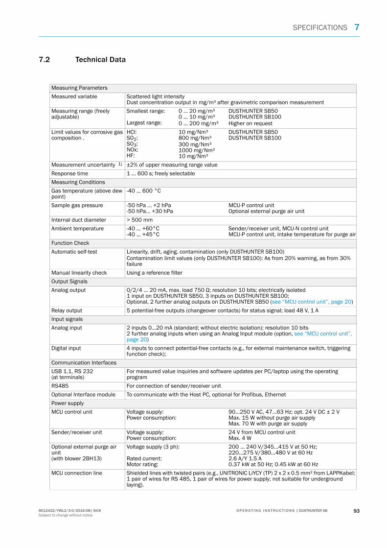
SPECIFICATIONS 7
7.2 Technical Data
Measuring Parameters
Measured variable Scattered light intensity Dust concentration output in mg/m³ after gravimetric comparison measurement
Measuring range (freely adjustable)
Smallest range: Largest range:
0 ... 20 mg/m³0 ... 10 mg/m³0 ... 200 mg/m³
DUSTHUNTER SB50DUSTHUNTER SB100Higher on request
Limit values for corrosive gas composition .
HCl:SO2:SO3:NOx:HF:
10 mg/Nm³800 mg/Nm³300 mg/Nm³1000 mg/Nm³10 mg/Nm³
DUSTHUNTER SB50DUSTHUNTER SB100
Measurement uncertainty 1) ±2% of upper measuring range value
Response time 1 ... 600 s; freely selectable
Measuring Conditions
Gas temperature (above dew point)
-40 ... 600 °C
Sample gas pressure -50 hPa ... +2 hPa-50 hPa... +30 hPa
MCU-P control unitOptional external purge air unit
Internal duct diameter > 500 mm
Ambient temperature -40 ... +60°C-40 ... +45°C
Sender/receiver unit, MCU-N control unitMCU-P control unit, intake temperature for purge air
Function Check
Automatic self-test Linearity, drift, aging. contamination (only DUSTHUNTER SB100)Contamination limit values (only DUSTHUNTER SB100): As from 20% warning, as from 30% failure
Manual linearity check Using a reference filter
Output Signals
Analog output 0/2/4 ... 20 mA, max. load 750 Ω; resolution 10 bits; electrically isolated 1 input on DUSTHUNTER SB50, 3 inputs on DUSTHUNTER SB100; Optional, 2 further analog outputs on DUSTHUNTER SB50 (see “MCU control unit”, page 20)
Relay output 5 potential-free outputs (changeover contacts) for status signal; load 48 V, 1 A
Input signals
Analog input 2 inputs 0...20 mA (standard; without electric isolation); resolution 10 bits 2 further analog inputs when using an Analog Input module (option, see “MCU control unit”, page 20)
Digital input 4 inputs to connect potential-free contacts (e.g., for external maintenance switch, triggering function check);
Communication Interfaces
USB 1.1, RS 232 (at terminals)
For measured value inquiries and software updates per PC/laptop using the operating program
RS485 For connection of sender/receiver unit
Optional Interface module To communicate with the Host PC, optional for Profibus, Ethernet
Power supply
MCU control unit Voltage supply:Power consumption:
90...250 V AC, 47...63 Hz; opt. 24 V DC ± 2 V Max. 15 W without purge air supplyMax. 70 W with purge air supply
Sender/receiver unit Voltage supply:Power consumption:
24 V from MCU control unitMax. 4 W
Optional external purge air unit(with blower 2BH13)
Voltage supply (3 ph):
Rated current:Motor rating:
200 ... 240 V/345...415 V at 50 Hz;220...275 V/380...480 V at 60 Hz2.6 A/Y 1.5 A0.37 kW at 50 Hz; 0.45 kW at 60 Hz
MCU connection line Shielded lines with twisted pairs (e.g., UNITRONIC LiYCY (TP) 2 x 2 x 0.5 mm² from LAPPKabel; 1 pair of wires for RS 485, 1 pair of wires for power supply; not suitable for underground laying).
938012422/YWL2/3-0/2016-08| SICK O P E R A T I N G I N S T R U C T I O N S | DUSTHUNTER SBSubject to change without notice

7 SPECIFICATIONS
1): In temperature range - 20 °C ... +50 °C
Weight
Sender/receiver unit 9 kg10 kg
DHSB-T0DHSB-T1
MCU control unit 13.5 kg 3.7 kg
MCU-PMCU-N
Optional external purge air unit
14 kg
Miscellaneous
Protection class IP 66 IP 54
Sender/receiver unit, MCU control unitOptional external purge air unit
Connection line length 5 m, 10 m Other lengths on request
Purge air hose length 5 m, 10 m Other lengths on request
Laser Degree of protection 2; capacity < 1 mW; wavelength between 640 nm and 660 nm
Purge air feed volume Max. 20 m³/hMax. 63 m³/h
MCU-P control unitOptional external purge air unit
94 8012422/YWL2/3-0/2016-08| SICKO P E R A T I N G I N S T R U C T I O N S | DUSTHUNTER SBSubject to change without notice

SPECIFICATIONS 7
7.3 Dimensions, part Nos.
All measures are specified in mm.
Fig. 61: Sender/receiver unit
388
≥ 30
0∅
159
∅ 26
5
r = 280200
110
208
10026
8
205
Clearance to open the enclosure
302
A A
∅ 40
Designation Part No.
Sender/receiver unit DHSB-T00without contamination measurement, immersion depth 400 mm
1043909
Sender/receiver unit DHSB-T01without contamination measurement, immersion depth 800 mm
1046851
Sender/receiver unit DHSB-T10with contamination measurement, immersion depth 400 mm
1043910
Sender/receiver unit DHSB-T11with contamination measurement, immersion depth 800 mm
1046850
958012422/YWL2/3-0/2016-08| SICK O P E R A T I N G I N S T R U C T I O N S | DUSTHUNTER SBSubject to change without notice

7 SPECIFICATIONS
7.3.1 Flange with tube
Fig. 62: Flange with tube
TOP
Ø 1
95
Ø 225
Ø 265
45° 45°
M12
L L = 350, 700
Designation Part No.
Flange with tube, DN195, length 350 mm, St37 2046526
Flange with tube, DN195, length 700 mm, St37 2046492
Flange with tube, DN195, length 350 mm, 1.4571 2047288
Flange with tube, DN195, length 700 mm, 1.4571 2047287
96 8012422/YWL2/3-0/2016-08| SICKO P E R A T I N G I N S T R U C T I O N S | DUSTHUNTER SBSubject to change without notice

SPECIFICATIONS 7
7.3.2 MCU control unit
MCU-N control unit and MCU remote control unit without integrated purge air supply
Fig. 63: MCU-N control unit
Meas
300
210
160
320
340
120
Designation Part No.Control unit MCU-NWONN00000NNNE in wall-mounted enclosure (orange), Supply voltage 90 ... 250 V AC, without purge air unit, without display [1]
1040667
Control unit MCU-NWODN00000NNNE in wall-mounted enclosure (orange), Supply voltage 90 ... 250 V AC, without purge air unit, with display 1)
1040675
Control unit MCU-N2ONN00000NNNE in wall-mounted enclosure (orange), Supply voltage 24 V DC, without purge air unit, without display 1)
1040669
Control unit MCU-N2ODN00000NNNE in wall-mounted enclosure (orange), Supply voltage 24 V DC, without purge air unit, with display 1)
1040677
Control unit MCU-NWONN01000NNNE in wall-mounted enclosure (orange), Supply voltage 90 ... 250 V AC, without purge air unit, without display 1)
1044496
Control unit MCU-NWODN01000NNNE in wall-mounted enclosure (orange), Supply voltage 90 ... 250 V AC, without purge air unit, with display [2]
1045001
Control unit MCU-N2ONN01000NNNE in wall-mounted enclosure (orange), Supply voltage 24 V DC, without purge air unit, without display 1)
1044999
Control unit MCU-N2ODN01000NNNE in wall-mounted enclosure (orange), Supply voltage 24 V DC, without purge air unit, with display 2)
1045003
MCU remote control unit without power supply unit 2075567MCU remote control unit with power supply unit 2075568
[1]Only for DUSTHUNTER SB50[2]For DUSTHUNTER SB50 and SB100
978012422/YWL2/3-0/2016-08| SICK O P E R A T I N G I N S T R U C T I O N S | DUSTHUNTER SBSubject to change without notice

7 SPECIFICATIONS
MCU-P control unit with integrated purge air supply
Fig. 64: MCU-P control unit
300 220
455
420
400
260 Ø 8
Designation Part No.Control unit MCU-PWONN00000NNNE in wall-mounted enclosure (orange), Supply voltage 90 ... 250 V AC, with purge air unit, without display [1]
1040668
Control unit MCU-PWODN00000NNNE in wall-mounted enclosure (orange), Supply voltage 90 ... 250 V AC, with purge air unit, with display 1)
1040676
Control unit MCU-P2ONN00000NNNE in wall-mounted enclosure (orange), Supply voltage 24 V DC, with purge air unit, without display 1)
1040670
Control unit MCU-P2ODN00000NNNE in wall-mounted enclosure (orange), Supply voltage 24 V DC, with purge air unit, with display 1)
1040678
Control unit MCU-PWONN01000NNNE in wall-mounted enclosure (orange), Supply voltage 90 ... 250 V AC, with purge air unit, without display1)
1044497
Control unit MCU-PWODN01000NNNE in wall-mounted enclosure (orange), Supply voltage 90 ... 250 V AC, with purge air unit, with display [2]
1045002
Control unit MCU-P2ONN01000NNNE in wall-mounted enclosure (orange), Supply voltage 24 V DC, with purge air unit, without display 1)
1045000
Control unit MCU-P2ODN01000NNNE in wall-mounted enclosure (orange), Supply voltage 24 V DC, with purge air unit, with display 2)
1045004
[1]Only for DUSTHUNTER SB50[2]For DUSTHUNTER SB50 and SB100
98 8012422/YWL2/3-0/2016-08| SICKO P E R A T I N G I N S T R U C T I O N S | DUSTHUNTER SBSubject to change without notice

SPECIFICATIONS 7
7.3.3 Optional external purge air unit
Fig. 65: Optional external purge air unit
550
258
ø 14
470
550
40
40 470
128
40
Designation Part No.
Purge air unit with blower 2BH13 and purge air hose, length 5 m 1012424
Purge air unit with blower 2BH13 and purge air hose, length 10 m 1012409
998012422/YWL2/3-0/2016-08| SICK O P E R A T I N G I N S T R U C T I O N S | DUSTHUNTER SBSubject to change without notice

7 SPECIFICATIONS
7.3.4 Weatherproof covers
Weatherproof cover for external purge air unit
Fig. 66: Weatherproof cover for external purge air unit
Weatherproof cover for sender/receiver unit
Fig. 67: Weatherproof cover for sender/receiver unit
550
605
350
245
550
Designation Part No.
Weatherproof cover for purge air unit 5306108
492365
239
360
Designation Part No.
Weatherproof cover flange k225 2048657
100 8012422/YWL2/3-0/2016-08| SICKO P E R A T I N G I N S T R U C T I O N S | DUSTHUNTER SBSubject to change without notice

SPECIFICATIONS 7
7.4 Accessories
7.4.1 Line sender/receiver unit - MCU
7.4.2 Purge air supply
7.4.3 Assembly parts
7.4.4 Device check accessories
Designation Part No.
Connection line, length 5 m 7042017
Connection line, length 10 m 7042018
Designation Part No.
Non-return valve DN40 2035098
Hose clamp D32-52 5300809
Purge air heater with enclosure for fitting outdoors230 V AC, 50/60 Hz, 3000 W, 1 ph
2021514
Purge air heater with enclosure for fitting outdoors120 V AC, 50/60 Hz, 2200 W, 1 ph
2021513
Designation Part No.
Assembly kit 2048677
Designation Part No.
Check filter set 2042339
Optic carrier for linearity test DUSTHUNTER SB50 2048281
1018012422/YWL2/3-0/2016-08| SICK O P E R A T I N G I N S T R U C T I O N S | DUSTHUNTER SBSubject to change without notice

7 SPECIFICATIONS
7.4.5 Options for MCU control unit
7.4.6 Miscellaneous
7.5 Consumable parts for 2-years operation
7.5.1 MCU with integrated purge air supply
7.5.2 Optional external purge air unit
Designation Part No.
Analog input module, 2 channels, 100 W, 0/4...22 mA, electrically isolated
2034656
Analog output module, 2 channels, 500 W 0/4 ... 22 mA, Electrically isolated per module, resolution 12 bit
2034657
Module carrier (for one each AI or AO module) 6028668
Connection line for optional I/O modules 2040977
Interface, Profibus module DP V0 2048920
Interface module Ethernet type 1 2055719
Designation Part No.
Cover 2052377
Seal 4055065
Fuse set T 2 A (for MCU with power voltage supply) 2054541
Fuse set T 4 A (for MCU with 24 V supply) 2056334
Designation Number Part No.
Filter element C1140 4 7047560
Optics cloth 4 4003353
Designation Number Part No.
Filter element Micro-Topelement C11 100 4 5306091
Optics cloth 4 4003353
102 8012422/YWL2/3-0/2016-08| SICKO P E R A T I N G I N S T R U C T I O N S | DUSTHUNTER SBSubject to change without notice

INDEX 8
1038012422/YWL2/3-0/2016-08 | SICK O P E R A T I N G I N S T R U C T I O N S | DUSTHUNTER SBSubject to change without notice
8 IndexA
Additional documentation (information) ............................................ 9
C
Calibration .......................................................................................... 65Check cycle ......................................................................................... 14Circuit board connections .................................................................44COM port ............................................................................................. 51Connect with SOPAS ET .....................................................................51Connecting Ethernet .......................................................................... 52Control unit ......................................................................................... 16Creating a USB connection ............................................................... 51
D
Data backup .......................................................................................67Determining the function check ....................................................... 60Display ................................................................................................ 24Display settings .................................................................................. 76
E
Error clearance ................................................................................... 88
F
Fitting the I/O module ....................................................................... 49Fitting the interface modules ............................................................ 49Flange with tube ................................................................................ 19Function check ................................................................................... 14Functional principle ...........................................................................11
I
I/O module ......................................................................................... 25Important Information ......................................................................... 7Installation site ..................................................................................... 8Intended use ........................................................................................ 8Interface module ................................................................................ 25Interfaces ...........................................................................................20
M
Malfunctions ...................................................................................... 88MCU ............................................................................................16, 20MCU remote control unit ................................................................... 25Measured values ................................................................................. 8Measuring function (general) .............................................................. 8Menu structure .................................................................................. 72
P
Parameter protocol ............................................................................ 67Parameter setting ......................................................................50, 58Password For LC-Display ................................................................... 71Password for SOPAS ET .....................................................................51Potentially explosive atmospheres ..................................................... 8Processor board .................................................................................44Product description ............................................................................ 11Purge air unit ...................................................................................... 26
R
Remote control unit ...........................................................................47Reset maintenance ...........................................................................78Response time ................................................................................... 13Responsibility of user .......................................................................... 9Restrictions of use ............................................................................... 8Resuming measuring operation ........................................................78
S
Setting the analog inputs parameters ............................................. 63Setting the analog outputs parameters ........................................... 61Setting the Ethernet module parameters ........................................ 70Setting the Interface module parameters ....................................... 69SOPAS ET ........................................................................................... 29SOPAS ET data backup ..................................................................... 67
T
Troubleshooting ................................................................................. 88Type code ................................................................................... 18, 23
U
User- Responsibility of user .......................................................................9
W
Warning messages ............................................................................ 88
Index

www.sick.com
Australia
E-Mail [email protected]
Austria
Belgium/Luxembourg
Brazil
Canada
Czech Republic
E-Mail [email protected]
Chile
China
Denmark
E-Mail [email protected]
Finland
France
Gemany
Great Britain
Hong Kong
Hungary
India
Israel
Italy
Japan
Malaysia
E-Mail [email protected]
Netherlands
New Zealand
E-Mail [email protected]
Norway
E-Mail [email protected]
Poland
Romania
Russia
Singapore
Slovakia
E-Mail [email protected]
Slovenia
South Africa
South Korea
Spain
Sweden
Switzerland
Taiwan
Thailand
Turkey
United Arab Emirates
USA/Mexico
Vietnam
8012
422/
YWL2
/201
6-08
SICK AG | Waldkirch | Germany | www.sick.com