Embed Size (px)
Citation preview
COURSE Testing techniques for structures inspection 29th and 30th May 2012
Investing in our common future
METALLOGRAPHY AND FRACTOGRAPHY OF IRON AND STEEL
M. J. Correia
LNEC, Laboratório Nacional de Engenharia Civil, DM, Av. do Brasil, 101, 1700‐066 Lisboa, Portugal
COURSE Testing techniques for structures inspection 29th and 30th May 2012
Investing in our common future
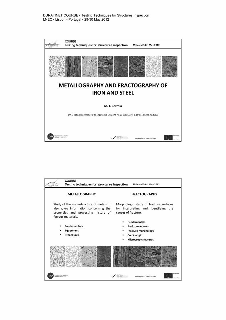
METALLOGRAPHY
Study of the microstructure of metals. Italso gives information concerning theproperties and processing history offerrous materials.
Fundamentals
Equipment
Procedures
FRACTOGRAPHY
Morphologic study of fracture surfacesfor interpreting and identifying thecauses of fracture.
Fundamentals
Basic procedures
Fracture morphology
Crack origin
Microscopic features
DURATINET COURSE - Testing Techniques for Structures Inspection LNEC • Lisbon • Portugal • 29-30 May 2012
Durati
Net
6/8/2012
COURSE Testing techniques for structures inspection 29th and 30th May 2012
Investing in our common future
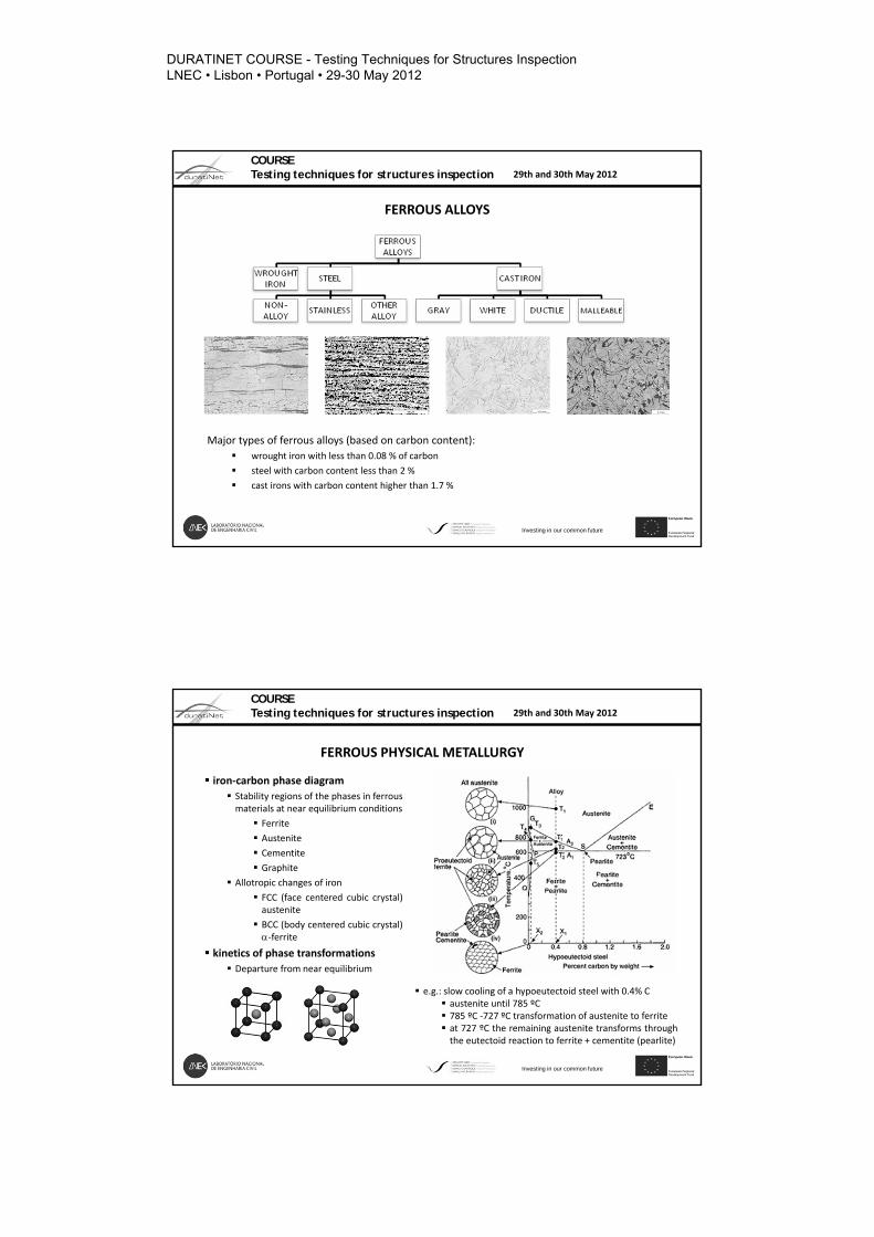
FERROUS ALLOYS
Major types of ferrous alloys (based on carbon content):
wrought iron with less than 0.08 % of carbon
steel with carbon content less than 2 %
cast irons with carbon content higher than 1.7 %
COURSE Testing techniques for structures inspection 29th and 30th May 2012
Investing in our common future
FERROUS PHYSICAL METALLURGY
iron‐carbon phase diagram
Stability regions of the phases in ferrousmaterials at near equilibrium conditions
Ferrite
Austenite
Cementite
Graphite
Allotropic changes of iron
FCC (face centered cubic crystal)austenite
BCC (body centered cubic crystal)‐ferrite
kinetics of phase transformations
Departure from near equilibrium
e.g.: slow cooling of a hypoeutectoid steel with 0.4% C austenite until 785 ºC 785 ºC ‐727 ºC transformation of austenite to ferrite at 727 ºC the remaining austenite transforms throughthe eutectoid reaction to ferrite + cementite (pearlite)
DURATINET COURSE - Testing Techniques for Structures Inspection LNEC • Lisbon • Portugal • 29-30 May 2012
Durati
Net

COURSE Testing techniques for structures inspection 29th and 30th May 2012
Investing in our common future
MAJOR CONSTITUENTS OF FERROUS ALLOYS
COURSE Testing techniques for structures inspection 29th and 30th May 2012
Investing in our common future
MICROSTRUCTURE – MATERIAL PROPERTIES
Cementite (hard; brittle) ‐ wear resistance
Pearlite ‐ strength and hardness (but degradetoughness and formability)
Martensite ‐ strength (partially lost during temperingto restore ductility)
Bainite – strength and toughness
Austenite ‐ ductility
CHEMICAL COMPOSITION
PROCESSING
MICROSTRUCTURE
MATERIALPROPERTIES
DURATINET COURSE - Testing Techniques for Structures Inspection LNEC • Lisbon • Portugal • 29-30 May 2012
Durati
Net
COURSE Testing techniques for structures inspection 29th and 30th May 2012
Investing in our common future
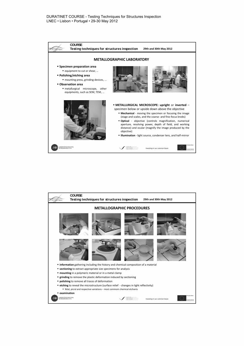
METALLOGRAPHIC LABORATORY
Specimen preparation area
equipment to cut or shear, …
Polishing/etching area mounting press, grinding devices, ...
Observation area
metallurgical microscope, otherequipments, such as SEM, TEM, …
METALLURGICAL MICROSCOPE: upright or inverted –specimen below or upside down above the objective
Mechanical ‐ moving the specimen or focusing the image(stage and scales, and the coarse‐ and fine‐focus knobs)
Optical ‐ objective (controls magnification, numericalaperture, resolving power, depth of field, and workingdistance) and ocular (magnify the image produced by theobjective)
Illumination ‐ light source, condenser lens, and half‐mirror
6/8/2012
COURSE Testing techniques for structures inspection 29th and 30th May 2012
Investing in our common future
METALLOGRAPHIC PROCEDURES
information gathering including the history and chemical composition of a material
sectioning to extract appropriate size specimens for analysis
mounting in a polymeric material or in a metal clamp
grinding to remove the plastic deformation induced by sectioning
polishing to remove all traces of deformation
etching to reveal the microstructure (surface relief ‐ changes in light reflectivity)
Nital, picral and respective variations – most commom chemical etchants
examination
DURATINET COURSE - Testing Techniques for Structures Inspection LNEC • Lisbon • Portugal • 29-30 May 2012
Durati
Net
6/8/2012
COURSE Testing techniques for structures inspection 29th and 30th May 2012
Investing in our common future
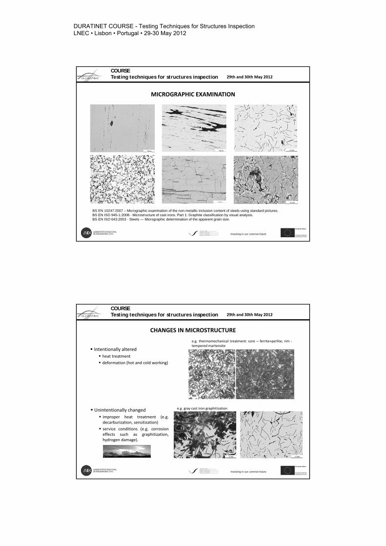
MICROGRAPHIC EXAMINATION
BS EN 10247:2007 – Micrographic examination of the non-metallic inclusion content of steels using standard pictures.BS EN ISO 945-1:2008 - Microstructure of cast irons. Part 1: Graphite classification by visual analysis.BS EN ISO 643:2003 - Steels — Micrographic determination of the apparent grain size.
10
COURSE Testing techniques for structures inspection 29th and 30th May 2012
Investing in our common future
CHANGES IN MICROSTRUCTURE
Intentionally altered heat treatment
deformation (hot and cold working)
Unintentionally changed improper heat treatment (e.g.decarburization, sensitization)
service conditions (e.g. corrosioneffects such as graphitization,hydrogen damage).
e.g. thermomechanical treatment: core – ferrite+perlite; rim ‐tempered martensite
e.g. gray cast iron graphitization
DURATINET COURSE - Testing Techniques for Structures Inspection LNEC • Lisbon • Portugal • 29-30 May 2012
Durati
Net
11
COURSE Testing techniques for structures inspection 29th and 30th May 2012
Investing in our common future
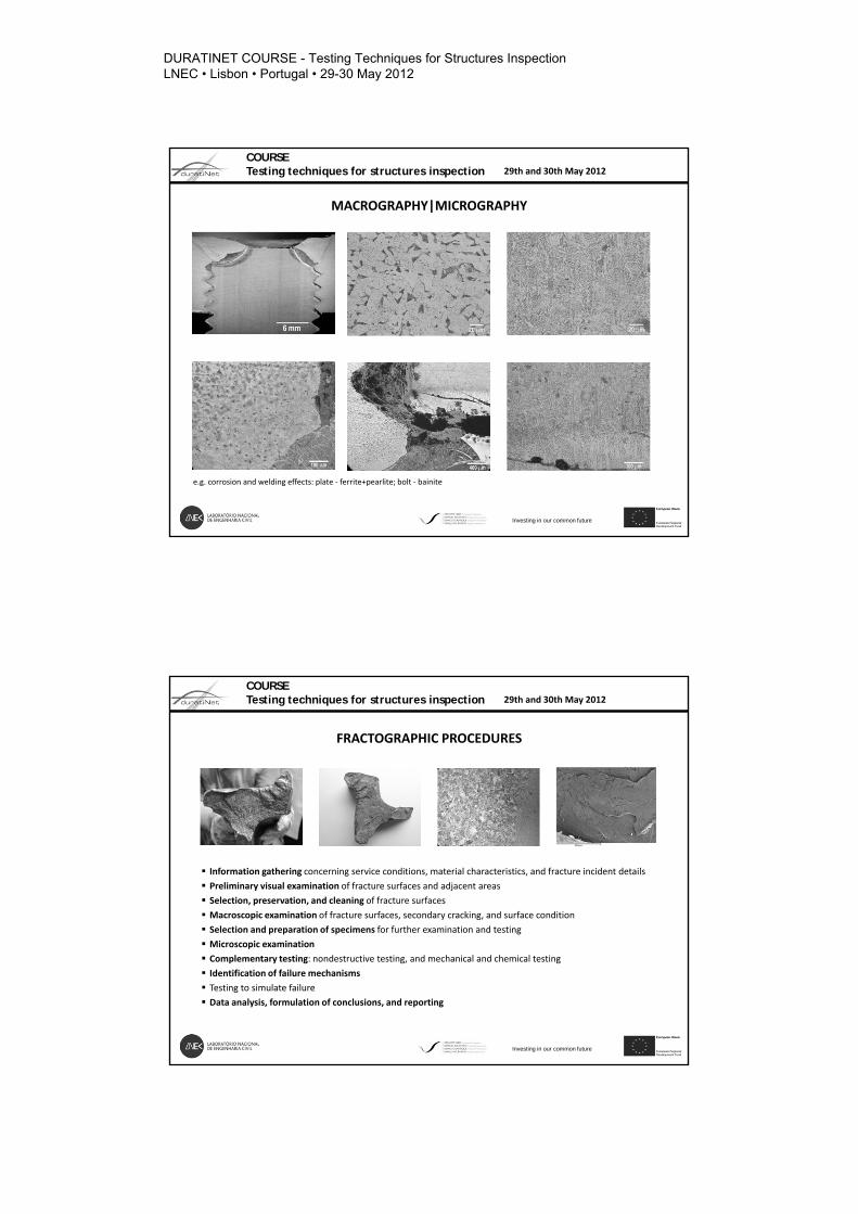
MACROGRAPHY|MICROGRAPHY
e.g. corrosion and welding effects: plate ‐ ferrite+pearlite; bolt ‐ bainite
6/8/2012
COURSE Testing techniques for structures inspection 29th and 30th May 2012
Investing in our common future
FRACTOGRAPHIC PROCEDURES
Information gathering concerning service conditions, material characteristics, and fracture incident details
Preliminary visual examination of fracture surfaces and adjacent areas
Selection, preservation, and cleaning of fracture surfaces
Macroscopic examination of fracture surfaces, secondary cracking, and surface condition
Selection and preparation of specimens for further examination and testing
Microscopic examination
Complementary testing: nondestructive testing, and mechanical and chemical testing
Identification of failure mechanisms
Testing to simulate failure
Data analysis, formulation of conclusions, and reporting
DURATINET COURSE - Testing Techniques for Structures Inspection LNEC • Lisbon • Portugal • 29-30 May 2012
Durati
Net
13
COURSE Testing techniques for structures inspection 29th and 30th May 2012
Investing in our common future
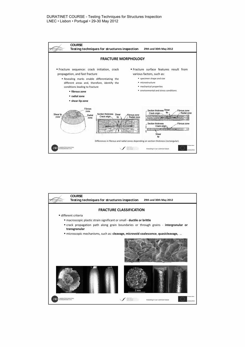
FRACTURE MORPHOLOGY
Fracture sequence: crack initiation, crack
propagation, and fast fracture
Revealing marks enable differentiating the
different areas and, therefore, identify the
conditions leading to fracture
fibrous zone
radial zone
shear‐lip zone
Fracture surface features result from
various factors, such as:
specimen shape and size
microstructure
mechanical properties
environmental and stress conditions
Differences in fibrous and radial zones depending on section thickness (rectangular).
14
COURSE Testing techniques for structures inspection 29th and 30th May 2012
Investing in our common future
FRACTURE CLASSIFICATION
different criteria
macroscopic plastic strain significant or small ‐ ductile or brittle
crack propagation path along grain boundaries or through grains ‐ intergranular ortransgranular
microscopic mechanisms, such as: cleavage, microvoid coalescence, quasicleavage, …
DURATINET COURSE - Testing Techniques for Structures Inspection LNEC • Lisbon • Portugal • 29-30 May 2012
Durati
Net

15
COURSE Testing techniques for structures inspection 29th and 30th May 2012
Investing in our common future
CHARACTERISTIC DUCTILE AND BRITTLE FRACTURES
In a ductile material, cracking in tension originates near the center of the specimen and propagates towardthe surface, the shear stress causing considerable deformation prior to fracture.
In a brittle material, a single overloaded fracture shows little permanent deformation and is roughlyperpendicular to the tensile stress direction. In absence of a stress concentration, the stress distribution isuniform across the section and, thus, fracture can originate at any location.
16
COURSE Testing techniques for structures inspection 29th and 30th May 2012
Investing in our common future
CRACK ORIGIN
Features that point to the crack origin
radial marks lie perpendicular to the crack front
and thus radiate and point to the origin
apexes of the V‐shape chevron patterns point
to the fracture origin
origin on concave side of fibrous or beach
marks
typical features related with crack propagation
Reassembling the fragments ‐ fracture
sequencing (strain mismatch)
Examination of the external surface for
secondary cracks
Surface notches ‐ alter the position of the
crack origin, the direction of crack growth, and
the sequence of fracture‐zone features
DURATINET COURSE - Testing Techniques for Structures Inspection LNEC • Lisbon • Portugal • 29-30 May 2012
Durati
Net

17
COURSE Testing techniques for structures inspection 29th and 30th May 2012
Investing in our common future
MICROSCOPIC FEATURES
The most common categories of microscopic fracture features include:
cleavage (tongues, microtwins, and crack origins) – transgranular path crystallographic well defined
quasicleavage (cleavage facets not clearly identified as crystallographic planes)
dimples from microvoid coalescence ‐ microvoids initiated at interfaces between the matrix and
particles or discontinuities expand and coalesce to form the dimples
fatigue striations
separated grain facets
mixed fracture features
18
COURSE Testing techniques for structures inspection 29th and 30th May 2012
Investing in our common future
PRACTICE
DURATINET COURSE - Testing Techniques for Structures Inspection LNEC • Lisbon • Portugal • 29-30 May 2012
Durati
Net