Embed Size (px)
Citation preview

Design for Durability of Concrete Structures
DURABLE STRUCTURESLNEC ���� Lisbon ���� 31 May - 1June 2012
31 May 2012
Júlio Appleton
Full Professor
Instituto Superior Técnico
a2p Consult, Lda

Design for Durability of Concrete Structures
DURABLE STRUCTURESLNEC ���� Lisbon ���� 31 May - 1June 2012
BASIC CONCEPTS
DESIGN MODELS
STRATEGIES FOR DURABILITYSTRATEGIES FOR DURABILITY
DURABILITY DESIGNS OF NEW STRUCTURES
EXPERIENCE FROM MAJOR REPAIRING WORKS

DURABILITY
Durability of a structure is its capacity to meet the requirements of serviceability, strength
and stability throughout its design working life, without loss of utility or excessive
unforeseen maintenance
DURABILITY – BASIC CONCEPTS
Júlio Appleton 3

PARTICIPANTS AND RESPONSABILITIES
Owner Designer Contractor Supervisor
Specify the servicelife period, the use, the design basisand performance criteria
Identification of exposureconditions
Conceptual design anddesign basis
Choose materials and theirspecification
Concrete mix, executionand curing
Control of minimumcover
Quality of execution
Quality control ofexecution
DURABILITY – BASIC CONCEPTS
Júlio Appleton
specification
Cover
Detailing
Durability design
Acess for inspection
Inspection and maintenancemanual
Quality of execution
User
Proper use of constructionImplement maintenanceprocedures (andinspection)
Update information
4

BIRTH CERTIFICATION
(fib proposal)
Selected engineering information related to maintenance and durability, continuously updated including the
evaluation of the remaining service life
DURABILITY – BASIC CONCEPTS
− General Information
Júlio Appleton 5
Description of the construction, location, environment conditions. Identification of all participants, main dates, …
− Design Information
Design basis and drawings
− Construction
Materials used and suppliers, dates, …
Concrete mixes and its use in the structure
Events, nonconformities, …
− Inspection Plan and Maintenance
− Durability Assessment
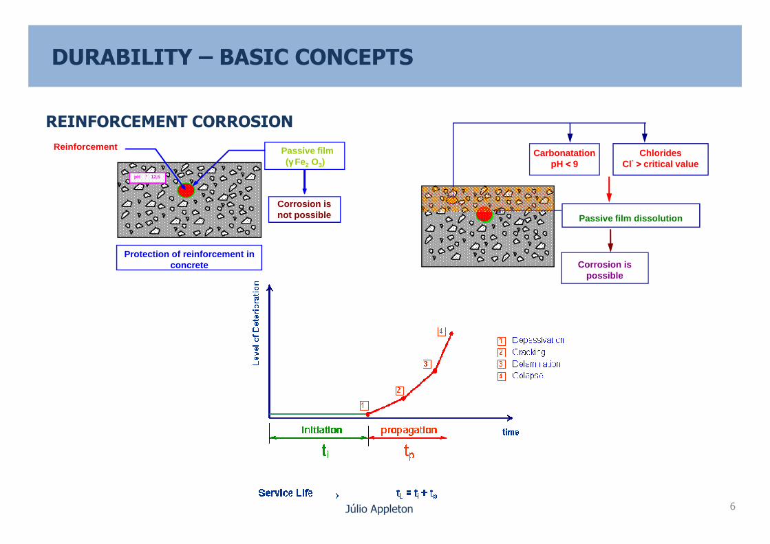
REINFORCEMENT CORROSION
pH ³ 12,5
Passive filmReinforcement
Corrosion is not possible
Protection of reinforcement in concrete
DURABILITY – BASIC CONCEPTS
Passive film dissolution
CarbonatationpH <<<< 9
ChloridesCl- >>>> critical value
Corrosion is possible
(γγγγ Fe2 O3)
Júlio Appleton 6
possible
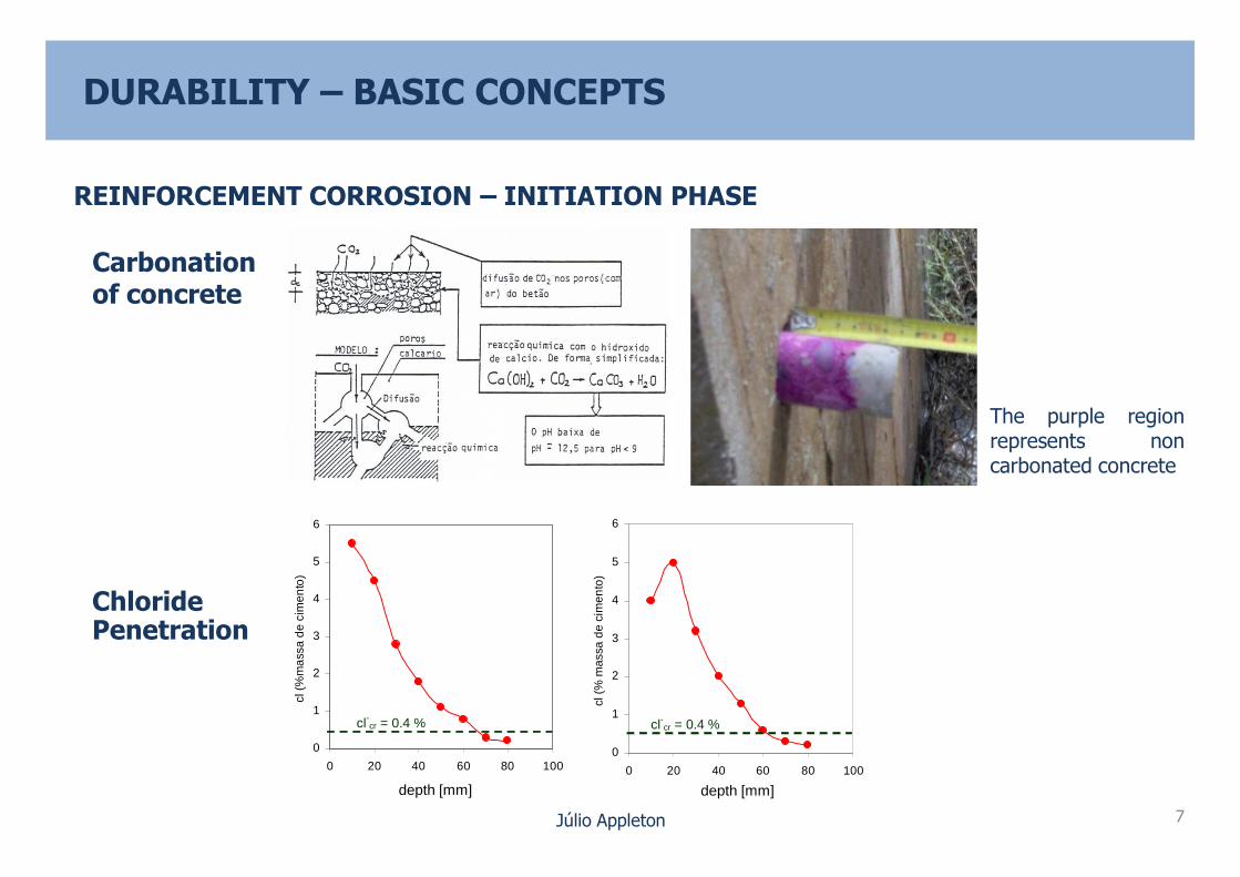
Carbonationof concrete
The purple regionrepresents non
DURABILITY – BASIC CONCEPTS
REINFORCEMENT CORROSION – INITIATION PHASE
Júlio Appleton
ChloridePenetration
represents noncarbonated concrete
0
1
2
3
4
5
6
0 20 40 60 80 100
cl (
%m
ass
a d
e c
imen
to)
cl-cr = 0.4 %
0
1
2
3
4
5
6
0 20 40 60 80 100
cl (
% m
assa
de
cim
ento
)
cl-cr = 0.4 %
7
depth [mm] depth [mm]

REINFORCEMENT CORROSION – INITIATION PHASE
Exposure ConditionsResistance to penetrationof CO2 and Cl-
Concrete Quality Type of cementaditions
Concrete mix
Compaction
DURABILITY – BASIC CONCEPTS
W/C
Júlio Appleton
Compaction
curing
ReinforcementCover
8

05
1015
20
25
30
354045
50
0 20 40 60 80 100 120 140
TEMPO [anos]
PR
OF
UN
DID
AD
E [m
m]
DURABILITY – BASIC CONCEPTS
REINFORCEMENT CORROSION – INITIATION PHASE
m/s
)
Júlio Appleton
C
ti t0
X cl-cr
= K 0tt −
X cl-
cr
t 9
Cover = Cnon
ti = 25 years
1
2Cover = Cnon
ti = 100 years
Perm
eabili
ty (
10
-14
m/s
)
W/C

DURABILITY – BASIC CONCEPTS
REINFORCEMENT CORROSION – INITIATION PHASE
Júlio Appleton 10
Cmin [mm]
t i(y
ears
)

DURABILITY – BASIC CONCEPTS
REINFORCEMENT CORROSION – PROPAGATION PHASE
H2O O2
CÁTODO ÂNODO
Cl- CO2 H2O O2
2 e-
OH-
Fe++
Anode Cathode
Júlio Appleton
Exposure of bar in a beam angledue to corrosion
Corrosion process
Anode - Region of bar depassivation
Cathod - Region of bar with oxigen acess O2
Electric condutor - Bar
Electrolyte - Concrete
At the anodes irons oxides and hidroxides are developed.
11
Steel Dissolution
Fe ���� Fe++ + 2e-
Oxygen Reduction
½ O2 ���� 2OH-
Corrosion Products
Fe++ + 2OH- ���� Fe (OH)2

DURABILITY – BASIC CONCEPTS
REINFORCEMENT CORROSION – PROPAGATION PHASE
Júlio Appleton
φ = φ0 – 0,023 Icorr . t (µm/year)
Cracking ⇔ loss of 15 to 40 µm
12
DURABILITY – BASIC CONCEPTS
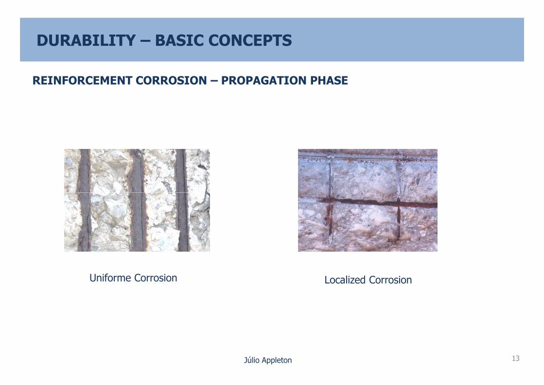
REINFORCEMENT CORROSION – PROPAGATION PHASE
Júlio Appleton
Uniforme Corrosion Localized Corrosion
13

DURABILITY – BASIC CONCEPTS
REINFORCEMENT CORROSION – PROPAGATION PHASE
Júlio Appleton
Cracking parallel to bars Delamination
Icorr = 100 µm/year , Tp = 10 years ⇒ ∆r = 1 mm
∆ Aφ10 = 0,36 Aφ10
∆ Aφ20 = 0,19 Aφ20
14
(Marine exposure)
+ Loss of bond + Delamination
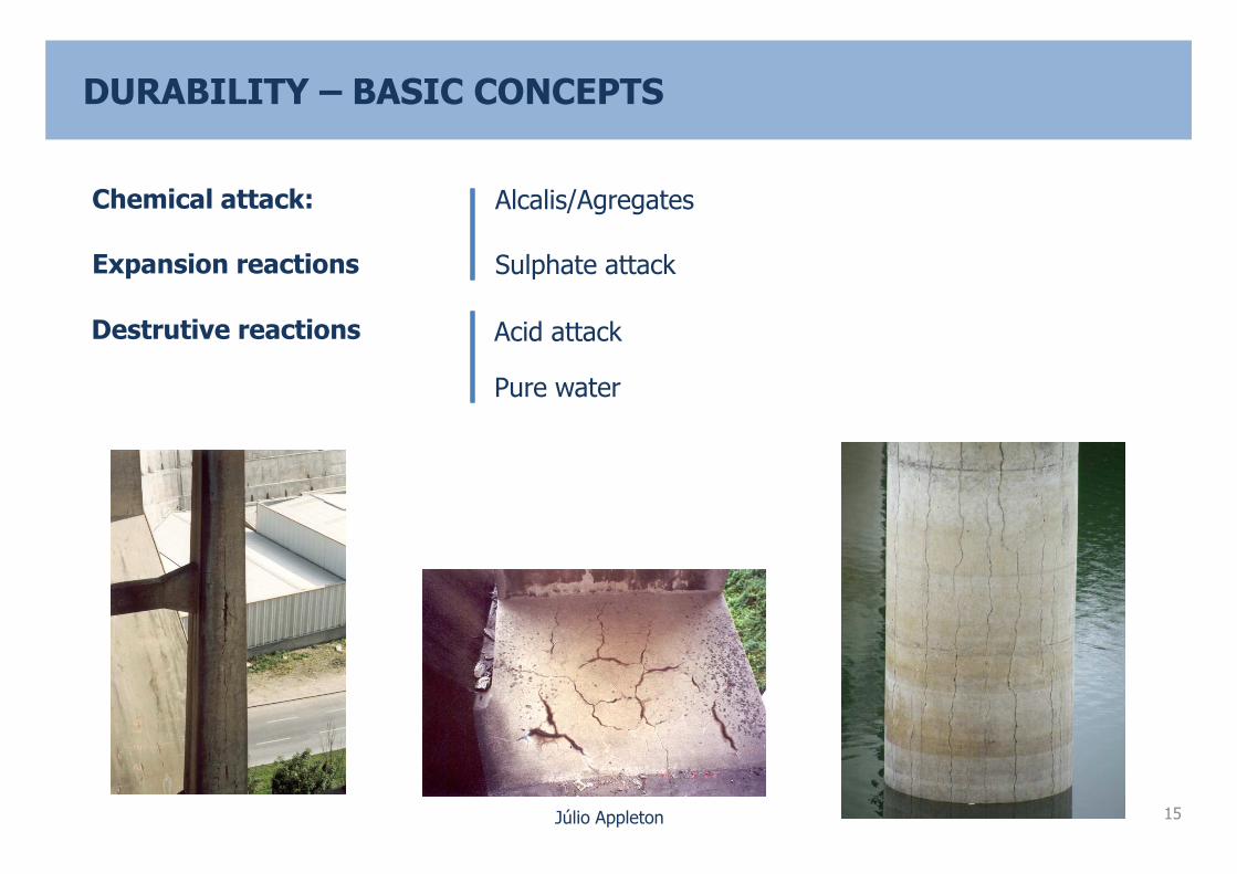
Chemical attack:
Destrutive reactions
Expansion reactions
Alcalis/Agregates
Acid attack
Pure water
Sulphate attack
DURABILITY – BASIC CONCEPTS
Júlio Appleton 15

CHEMICAL ATTACK – ALCALIS/AGREGATES REACTIONS
LNEC – E461 – Potential reactive aggregates and prevention of expansive reactions
Reactions Alcalinity in concrete pores
Critical amount of reactive silica
DURABILITY – BASIC CONCEPTS
Júlio Appleton
Water
Relevantcontrolparameters
Percentage of reactive aggregates
Control of humidity at concrete pores
Concrete porosity
16

Reactions Presence of aluminates
Presence of sulphates (from inside or outside concrete)
DURABILITY – BASIC CONCEPTS
CHEMICAL ATTACK – SULPHATE REACTIONS
Júlio Appleton
InternalsulphateReaction
Large concrete masses
Very rapid hardening with high concretetemperature
17
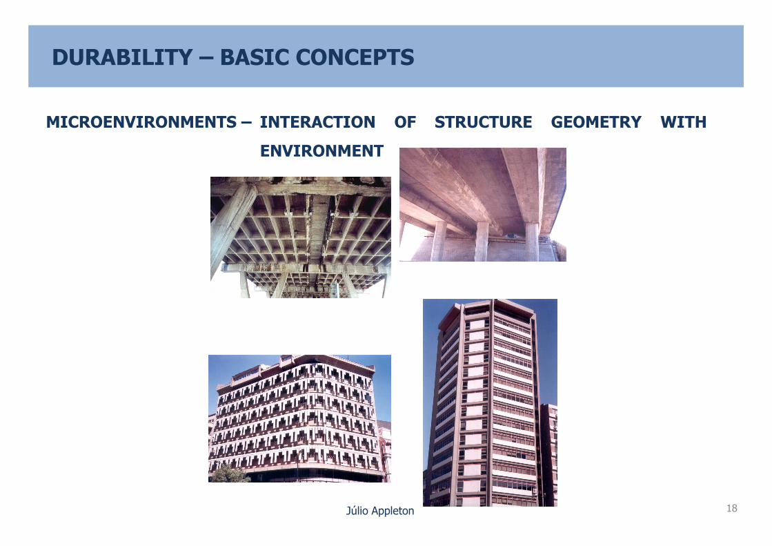
MICROENVIRONMENTS – INTERACTION OF STRUCTURE GEOMETRY WITH
ENVIRONMENT
DURABILITY – BASIC CONCEPTS
Júlio Appleton 18

DURABILITY – BASIC CONCEPTS
MICROENVIRONMENTS – INTERACTION OF STRUCTURE GEOMETRY WITH
ENVIRONMENT
Júlio Appleton 19
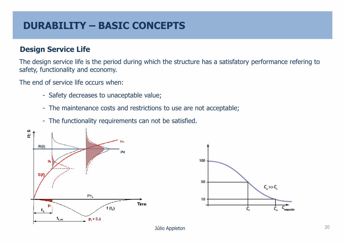
Design Service Life
The design service life is the period during which the structure has a satisfatory performance refering to safety, functionality and economy.
The end of service life occurs when:
- Safety decreases to unaceptable value;
- The maintenance costs and restrictions to use are not acceptable;
- The functionality requirements can not be satisfied.
DURABILITY – BASIC CONCEPTS
Júlio Appleton
- The functionality requirements can not be satisfied.
20

LIMIT STATES
Service – (β = 1,5 ; P = 10-1) - Depassivation
- Cracking due to corrosion
DURABILITY – BASIC CONCEPTS
Cl- CO2 H2O O2
Júlio Appleton
Ultimate – (β = 3,8 ; P = 10-4) - Rupture
21
H2O O2
CÁTODO ÂNODO
2 e-
OH-
Fe++
Steel Dissolution
Fe ���� Fe++ + 2e-
Oxygen Reduction
½ O2 ���� 2OH-
Corrosion Products
Fe++ + 2OH- ���� Fe (OH)2
Anode Cathode

STRATEGIES FOR DURABILITY DESIGN
Eliminate the deterioration risk
– Surface protection (changes exposure conditions)
– Use of non reactive materials (inox steel, non reactive aggregates)
DURABILITY – BASIC CONCEPTS
Júlio Appleton
Surface encapsulation with glass fiber (APE)
Surface protection
22

Selected materials and conceive the structures to resist deterioration duringservice life
– Adopt the adequate cover
– Adopt the proper concrete mix
– Adopt the proper structure conceptual design
DURABILITY – BASIC CONCEPTS
STRATEGIES FOR DURABILITY DESIGN
Júlio Appleton
Control the risk of corrosion
– Cathodic prevention
For very aggressive environments adopt a multipleprotection strategy.
Access the global construction cost during its servicelife (initial cost + maintenance)
23
Cathodic prevention

SERVICE LIFE ASSESSMENT MODELS
Macro level – Semiempirical rules, related to environmentalaggressivity and deterioration mechanisms
EN1992-1-1; LNEC E464
Conceptual design (+ drainage)
DURABILITY – DESIGN MODELS – MACRO LEVEL
Júlio Appleton
Crack control
Concrete mix requirements
Minimum cover requirements
Additional protections
24

DURABILITY – DESIGN MODELS – MACRO LEVEL
X0 – No risk of corrosion or attack
XC – Corrosion induced by carbonation
XD – Corrosion induced by chloride
XS – Corrosion induced by chloride from sea water
EXPOSURE CLASSES
Júlio Appleton
XF – Freeze/thaw attack
XA – Chemical attack
(Sea water – XA1 ou XA2)
25

XC Corrosion induced by carbonation
Class Description of the
environment
Informative examples where exposure classes may
occur
XC1 Dry or permanently wet Concrete inside buildings with low air humidity
Concrete permanently submerged in water
DURABILITY – DESIGN MODELS – MACRO LEVEL
EXPOSURE CLASSES
Júlio Appleton
Concrete permanently submerged in water
XC2 Wet, rarely dry Concrete surfaces subject to long-term water contact
Many foundations
XC3 Moderate humidity Concrete inside buildings with moderate or high air humidity
External concrete sheltered from rain
XC4 Cyclic wet and dry Concrete surfaces subject to water contact, not within
exposure class XC2
26
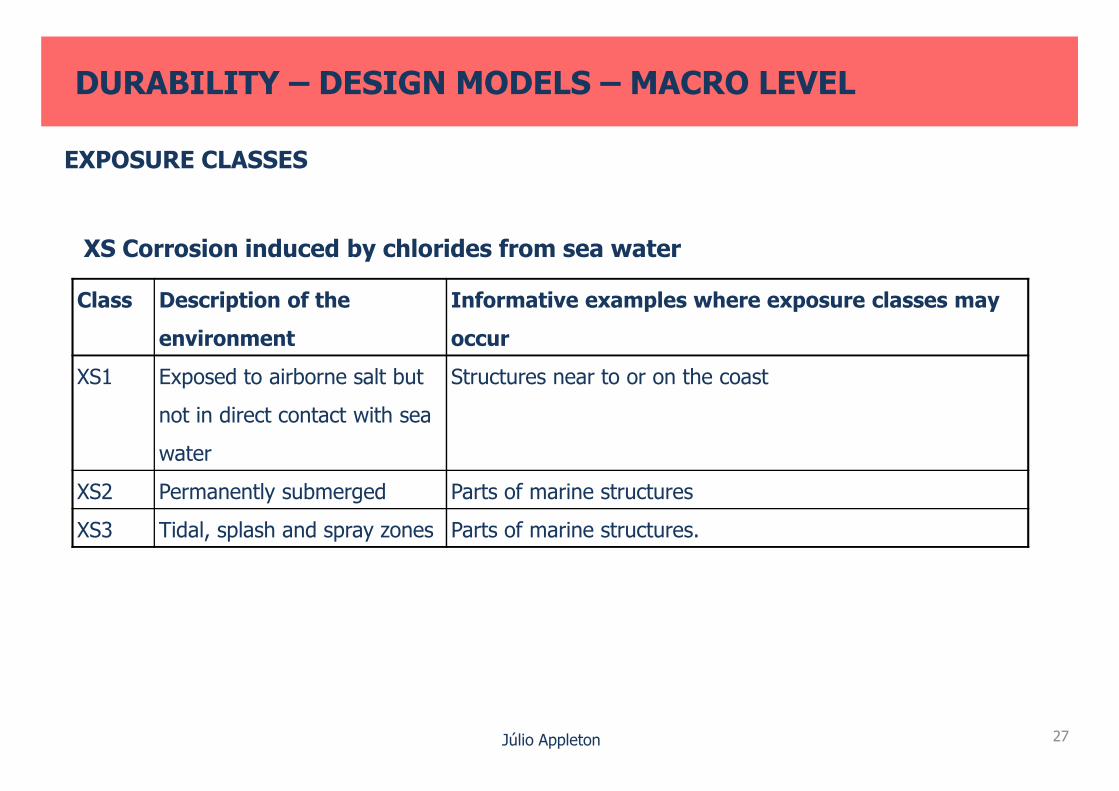
XS Corrosion induced by chlorides from sea water
Class Description of the
environment
Informative examples where exposure classes may
occur
XS1 Exposed to airborne salt but Structures near to or on the coast
DURABILITY – DESIGN MODELS – MACRO LEVEL
EXPOSURE CLASSES
Júlio Appleton
not in direct contact with sea
water
XS2 Permanently submerged Parts of marine structures
XS3 Tidal, splash and spray zones Parts of marine structures.
27

MINIMUM REQUIREMENTS AND NOMINAL COVER
Environmental Requirement for Cmin,dur (mm)
Structural
Class
Exposure Class
X0 XC1 XC2/XC3 XC4 XD1/XS1 XD2/XS2 XD3/XS3
S1 10 15 20 25 30 35 40
S2 10 15 25 30 35 40 45
DURABILITY – DESIGN MODELS – MACRO LEVEL
Júlio Appleton
S2 10 15 25 30 35 40 45
S3 10 20 30 35 40 45 50
S4 10 25 35 40 45 50 55
S5 15 30 40 45 50 55 60
S6 20 35 45 50 55 60 65
28
tg = 50 years →→→→ S4
tg = 100 years →→→→ S6

Minimum Cover for tg = 50 years (class S4)
Areinf steel Prest. Steel
X0 10 10
XC1 15 25
XC2, XC3 25 35
DURABILITY – DESIGN MODELS – MACRO LEVEL
REQUIREMENTS
Júlio Appleton
XC2, XC3 25 35
XC4 30 40
XS1 35 45
XS2 40 50
XS3 45 55
+ Concrete mix requirements
29
cnom = cmin + ∆∆∆∆ctol

Concrete Quality
Type of cement CEM I (Reference); CEM II/A (1)CEM II/B(1); CEM III/A(2); CEM
IV(2); CEM V/A(2)
Exposure class XC1/XC2 XC3/XC4 XC1/XC2 XC3/XC4
Maximum water/cement 0,65 0,60 0,65 0,55
Minimum cement content, C (kg/m3) 240 280 260 300
Minimum strength class C25/30 C30/37 C25/30 C30/37
DURABILITY – DESIGN MODELS – MACRO LEVEL
REQUIREMENTS
Júlio Appleton
Minimum strength class C25/30
LC25/28
C30/37
LC30/33
C25/30
LC25/28
C30/37
LC30/33
Type of cementCEM IV/A (Reference); CEM IV/B; CEM III/A;
CEM III/B; CEM V; CEM II/B (3); CEM II/A-DCEM I; CEM II/A (3)
Exposure class XS1/XD1 XS2/XD2 XS3/XD3 XS1/XD1
XS2/XD2
XS3/XD3
Maximum water/cement 0,55 0,45 0,45 0,40
Minimum cement content, C (kg/m3) 320 340 360 380
Minimum strength class C30/37 LC30/33 C35/45 LC35/38 C40/50
LC40/44
C50/60
LC50/5530

Type of cementCEM IV/A (Referência); CEM IV/B; CEM III/A;
CEM III/B; CEM V; CEM II/B (3); CEM II/A-DCEM I; CEM II/A (3)
Exposure class XA1 XA2 (4) XA3 (4) XA1 XA2 (4) XA3 (4)
Maximum0,55 0,50 0,45 0,50 0,45 0,45
Concrete Quality
DURABILITY – DESIGN MODELS – MACRO LEVEL
REQUIREMENTS
Júlio Appleton 31
Maximum
water/cement0,55 0,50 0,45 0,50 0,45 0,45
Minimum cement
content, C (kg/m3)
320 340 360 340 360 380
Minimum strength
class
C30/37
LC30/33
C35/45
LC35/38
C35/45
LC35/38
C35/45
LC35/38
C40/50
LC40/44
C40/50
LC40/44
Water/cement – water/binder
Binder = cement + addition

Possible modifications of durability requirements
For 100 years design service life
− For the actions of CO2 and Cl-
DURABILITY – DESIGN MODELS – MACRO LEVEL
Minimum Cover and Concrete Quality
REQUIREMENTS
Júlio Appleton
� Change covers increasing the structure classe for S6
− For chemical attack:
increase cement content by 20 kg/m3
increase 2 classes the minimum concrete strength class
reduce w/c by 0,05
In special situations Cmin may be reduced
32

COBERTURA
PISO 3
PISO 2
PISO 1
DURABILITY – DESIGN MODELS – MACRO LEVEL
Example – Building designed for 50 years service life
EXPOSURE AND REQUIREMENTS CLASSES
XC3
XC4
XC1
Júlio Appleton
R/CHÃO
Description ClassificationPreventive measure
Cnom (a/c)max Cmin fck
Interior XC1 25 0.65 240 30
Exposed surface XC4 40 0.60 280 37
Protected surfaces XC3 35 0.60 280 37
Underground XC2 35(5) 0.65 240 30
cub
33
XC2
XC4

DURABILITY – DESIGN MODELS – MACRO LEVEL
Example – Bridge designed for 100 years service life
EXPOSURE AND REQUIREMENTS CLASSES
CORTE TIPO
XS1
Júlio Appleton 34
XS3XA1
XS2XA1
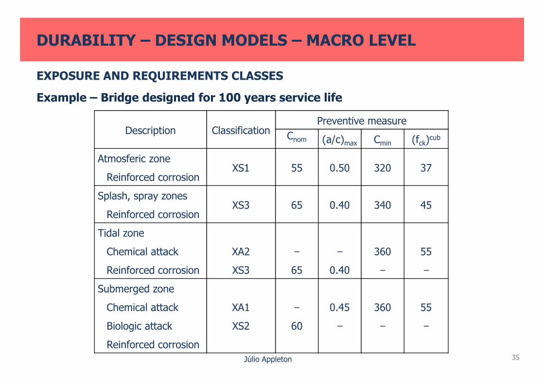
Description ClassificationPreventive measure
Cnom (a/c)max Cmin (fck)cub
Atmosferic zone
Reinforced corrosionXS1 55 0.50 320 37
Splash, spray zones
DURABILITY – DESIGN MODELS – MACRO LEVEL
Example – Bridge designed for 100 years service life
EXPOSURE AND REQUIREMENTS CLASSES
Júlio Appleton
Splash, spray zones
Reinforced corrosionXS3 65 0.40 340 45
Tidal zone
Chemical attack
Reinforced corrosion
XA2
XS3
−
65
−
0.40
360
−
55
−
Submerged zone
Chemical attack
Biologic attack
Reinforced corrosion
XA1
XS2
−
60
0.45
−
360
−
55
−
35
DURABILITY – DESIGN MODELS – MACRO LEVEL
Example – Dockyard designed for 50 years service life
EXPOSURE AND REQUIREMENTS CLASSES
XS1XS3
Júlio Appleton 36
XS2XA1
XA1
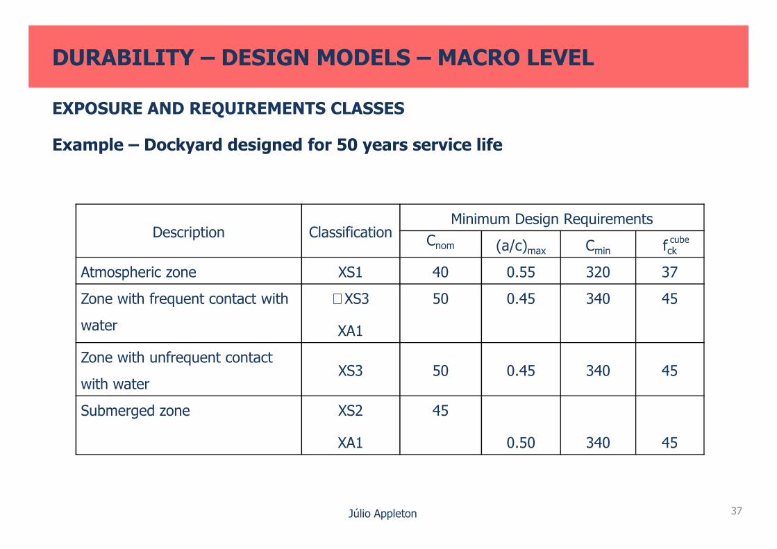
Description ClassificationMinimum Design Requirements
Cnom (a/c)max Cmin fck
Atmospheric zone XS1 40 0.55 320 37
DURABILITY – DESIGN MODELS – MACRO LEVEL
Example – Dockyard designed for 50 years service life
EXPOSURE AND REQUIREMENTS CLASSES
cube
Júlio Appleton
Atmospheric zone XS1 40 0.55 320 37
Zone with frequent contact with
water
≅ XS3
XA1
50 0.45 340 45
Zone with unfrequent contact
with waterXS3 50 0.45 340 45
Submerged zone XS2
XA1
45
0.50 340 45
37

Meso level – Metodology based in physical models
Semiprobabilistic method
ad = amin + ∆a ≥ xc,d (t) = xc,k (t) . γf
DURABILITY – DESIGN MODELS – MESO LEVEL
SERVICE LIFE ASSESSMENT MODELS
Júlio Appleton
amin – minimum cover
∆a – tolerance
xc,d (t) – design carbonation depth or for tservice life (+ propagation period)
xc,k (t) – Characteristic value
γf – Partial safety coefficient
critCl�
38

LNEC E465
tservice life = ti + tp >td = γ tg
Service life estimated with Design service life
Safety coefficient
DURABILITY – DESIGN MODELS – MESO LEVEL
SERVICE LIFE ASSESSMENT MODELS
Júlio Appleton
Service life estimated withperformance models(initiation and propagation)
ti and tp represents the initiation and propagation periods
Design service life
39

Corrosion associated with depassivation by carbonation
ti – as a function of environment exposure, …
Cacel = 90 × 103 Kg/m3 CO2
(E391)
X – Carbonation depth after t
DURABILITY – DESIGN MODELS – MESO LEVEL
SERVICE LIFE ASSESSMENT MODELS
Rc65 = 2 Cacel . t1
x21
Júlio Appleton 40
X1 – Carbonation depth after t1
Corrosion associated with depassivation by chloride penetration ti as a
function of environment exposure, and material resistance
D0 (m2/s) – E463 (Rapid chloride method NT Build 492)
tp = K φ0/(1,15 α Icorr)
Da = k .
t0
t
n
. D0

E465 Tables for D0 required for:
− various environmental classes XS1, XS2, XS3
− tg target service life
− Type of cement, concrete mix
DURABILITY – DESIGN MODELS – MESO LEVEL
SERVICE LIFE ASSESSMENT MODELS
Júlio Appleton 41
− Type of cement, concrete mix
− reliability classes

Probabilistic method
pdesp = p {a – xc (t) < 0} < p0 ≈ 10-1 (β = 1.3)
Ultimate Limit States
a – coverxc (t) – carbonation depth
DURABILITY – DESIGN MODELS – MESO LEVEL
SERVICE LIFE ASSESSMENT MODELS
Júlio Appleton
pcorrosion = p {∆rR - ∆rs (t) < 0} < p0 ≈ 10-4 a 10-6
(β = 3.7 a 4.4)
loss of bar radiusassociated with rupture
42
loss of bar radiusdue to corrosion

Exemple
DURABILITY – DESIGN MODELS – MESO LEVEL
SERVICE LIFE ASSESSMENT MODELS – MESO LEVELS
Júlio Appleton
Model for Chloride penetration, as in E 465
Monte Carlo method for the probabilistic analysis
Z(t) = R(t) - S(t)
S(t) = X(t) = 2erf -1
43
Cs - Ccr
Cs D (t) t

Probabilistic Method
DURABILITY – DESIGN MODELS – MESO LEVEL
SERVICE LIFE ASSESSMENT MODELS – MESO LEVEL
Cover [mm]R
elat
ive
freq
uenc
e (%
)
Júlio Appleton
- D (t) from D0 = 5,39 × 10⁻¹² m2/s (obtained during the execution)med
44
Cover [mm]
Time (years)
Rel
iabi
lity
inde
x β
Pro
babi
lity
S >
R (
%)

Micro level – Probabilistic method based in materials science
DURABILITY – DESIGN MODELS – MICRO LEVEL
SERVICE LIFE ASSESSMENT MODELS
Júlio Appleton 45
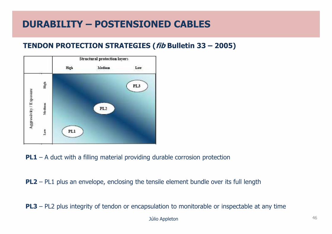
DURABILITY – POSTENSIONED CABLES
TENDON PROTECTION STRATEGIES (fib Bulletin 33 – 2005)
Júlio Appleton 46
PL1 – A duct with a filling material providing durable corrosion protection
PL2 – PL1 plus an envelope, enclosing the tensile element bundle over its full length
PL3 – PL2 plus integrity of tendon or encapsulation to monitorable or inspectable at any time
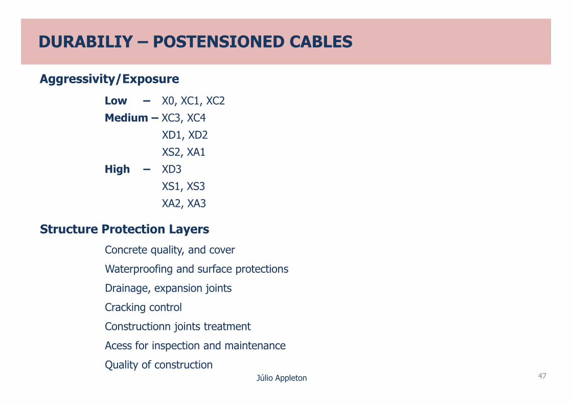
Aggressivity/Exposure
Low – X0, XC1, XC2
Medium – XC3, XC4
XD1, XD2
XS2, XA1
High – XD3
XS1, XS3
XA2, XA3
DURABILIY – POSTENSIONED CABLES
Júlio Appleton 47
XA2, XA3
Structure Protection Layers
Concrete quality, and cover
Waterproofing and surface protections
Drainage, expansion joints
Cracking control
Constructionn joints treatment
Acess for inspection and maintenance
Quality of construction

DURABILIY – PREVENTION OF EXPANSIVE CONCRETE REACTIONS
LNEC E 461RAS – Aggregate Classification
Non reactive (class I) Reactive (classes II and III)
Environment exposure
Risk cathegory
A1 A2 A3
Risk class associated
R1, R2 , R3
Júlio Appleton 48
Exposure conditions
A1, A2 , A3
Level of prevention
P1 – No measures required
P2 – One measure required
P3 – Two measures required
Preventive Measure
• Avoid critical values of reactive silica
• Control alcalinity of concrete pores
R1 P1 P1 P1
R2 P1 P2 P2
R3 P2 * P3 P3
* For large masses of concreting level P3 is to be considered

RSI – SIMILAR METHODOLOGY
Preventive Measures
• Avoid high concrete temperatures during hydration
(T < 65°C)
DURABILIY – PREVENTION OF EXPANSIVE CONCRETE REACTIONS
Júlio Appleton 49
(T < 65°C)
• Control alcalis, sulphats and aluminates of the cement

DURABILITY – REDUCE EXECUTION DEFFECTS
• Cover control of execution
• Adequate spacers (E 469)
• concrete mix, good compaction and curing
• Treating concreting joints
Júlio Appleton 50

DURABILITY DESIGN OF NEW STRUCTURE IN AGGRESSIVE ENVIRONMENT
EXAMPLE 1
Maritime Traffic Control Buildings – Build in the year 2000
Offshore 9 storey building constructed in an artificial jetty, 100m from the coast in Lisbon
Júlio Appleton 51

DURABILITY DESIGN OF NEW STRUCTURE IN AGGRESSIVE ENVIRONMENT
EXAMPLE 1
Maritime Traffic Control Buildings
Durability specifications (1998 – ENV 206/E374)
Concrete mix specifications
HP Concrete C > 35/45
w/c ≤ 0,40
Microsilica ≥ 15 Kg/m3
Júlio Appleton 52
C ≤ 400 Kg/m3
Concrete performance
Water penetration < 20 mm (ISO 7031)
k < 1 × 10-12 m/s
Capilarity absortion
a < 0,1 mm/min0,5
Porosity P < 14% (RILEM1980 – COM25 PEM)
Chloride penetration I < 1000 Coulombs (ASTM C1202 – 94)
D < 1 × 10-12 m2/s
i a t�

DURABILITY DESIGN OF NEW STRUCTURE IN AGGRESSIVE ENVIRONMENT
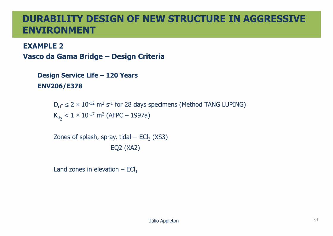
EXAMPLE 2
Vasco da Gama Bridge – Built 1998
12.3 Km in Tejo Estuary
South Viaduct
Central Viaduct
Main Bridge
Expo Viaducts
In the estuary
Júlio Appleton 53
Expo Viaducts
North Viaducts
DURABILITY DESIGN OF NEW STRUCTURE IN AGGRESSIVE ENVIRONMENT
EXAMPLE 2
Vasco da Gama Bridge – Design Criteria
Design Service Life – 120 Years
ENV206/E378
Dcl- ≤ 2 × 10-12 m2 s-1 for 28 days specimens (Method TANG LUPING)
K02< 1 × 10-17 m2 (AFPC – 1997a)
Júlio Appleton 54
K02< 1 × 10 m (AFPC – 1997a)
Zones of splash, spray, tidal – ECl3 (XS3)
EQ2 (XA2)
Land zones in elevation – ECl1

DURABILITY DESIGN OF NEW STRUCTURE IN AGGRESSIVE ENVIRONMENT
EXAMPLE 2
Vasco da Gama Bridge – Design Criteria
Concrete fck ≥ 45 MPa (in general)
CEM I – Land zones
CEM IV – Estuary zones
No reactive aggregates
w/c = 0,33 - 0,35
cubes
Júlio Appleton 55
w/c = 0,33 - 0,35
Concrete cover 70 mm – in contact with water
50 mm – pier
40 mm – deck
Detailed inspection and maintenance plan
Preventive measures were introduced when execution deffects were identified
Surface protection
APE protection
Pilot cathodic prevention project

DURABILITY DESIGN OF NEW STRUCTURE WITH LARGE CONCRETE MASS
EXAMPLE 3
Ponte Ocreza – In Construction - 2012
XC
Concreting Large Masses – RSI Prevention
Júlio Appleton 56

OCREZA BRIDGE – DESIGN DURABILITY SPECIFICATIONS
Design Service Life – 100 Years
Corrosion Prevention
XC4 Cover 50 mm
Concrete – C35/45 – Foundations
DURABILITY DESIGN OF NEW STRUCTURE WITH LARGE CONCRETE MASS
Júlio Appleton 57
Concrete – C35/45 – Foundations
C40/50 – Piers
C50/60 – Deck
Prevention of Internal Chemical Expansive Reactions (E461)
In general – Level P2
Foundations and top pier slabs – Level P3
OCREZA BRIDGE – DESIGN DURABILITY SPECIFICATIONS
Design Service Life – 100 Years
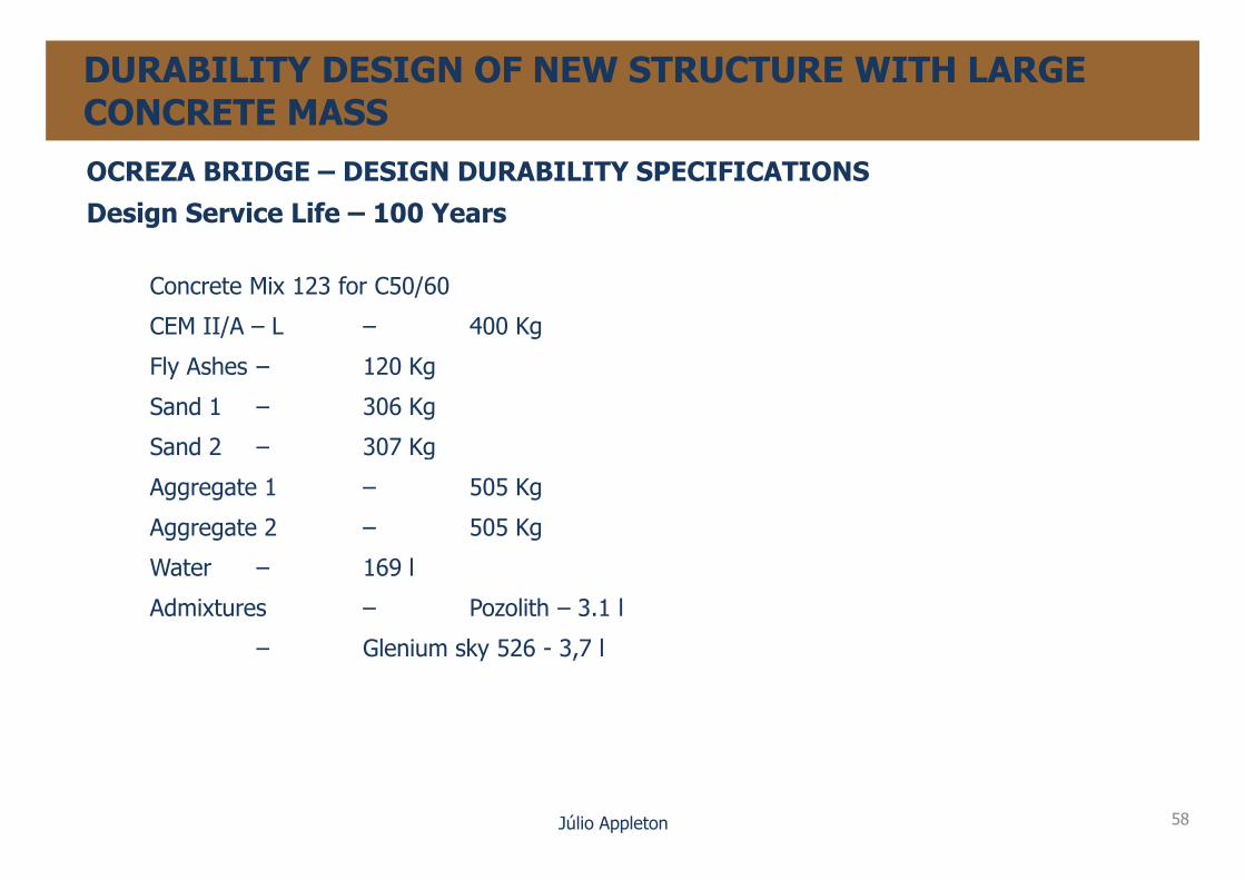
Concrete Mix 123 for C50/60
CEM II/A – L – 400 Kg
Fly Ashes – 120 Kg
Sand 1 – 306 Kg
Sand 2 – 307 Kg
DURABILITY DESIGN OF NEW STRUCTURE WITH LARGE CONCRETE MASS
Júlio Appleton 58
Sand 2 – 307 Kg
Aggregate 1 – 505 Kg
Aggregate 2 – 505 Kg
Water – 169 l
Admixtures – Pozolith – 3.1 l
– Glenium sky 526 - 3,7 l

DURABILITY – EXPERIENCE FROM MAJOR REPAIRING WORKS
Name Type Dimension Type ofExposure
Date ofConstruction
Date ofRepairing
Age of repair Main Cause ofDeterioration
P. ChaminéR. Mora
Reinforced Concrete -3 Arches
L = 81,6 m
l = 27,2 mXC 1934 1994 60
Coverconcretedeffects
P. ArcosR. Sado
Reinforced Concrete –Bowstring
L = 68 m
l = 31,5 mXC 1944 2008 64
Cover
V. DuartePacheco
Reinforced ConcreteArches and Viaducts
L = 355,1 mXC
(ASR)1944 2001 57
CoverASR
Júlio Appleton 59
Pachecol = 90 m (ASR)
1944 2001 57 ASR
P. SousaR. Sousa
L = 153 m
l = 115 mXC 1952 2009 57
Cover
P. CávadoCaniçadaReservoir
Reinforced ConcreteContinuous Girder
L = 176 m
l = 23 mXC
(Albufeira)1954 2008 54
CoverSt cracking
V. Alhandra Prestressed Concreteprecast girder deck
L = 276 m
l = 115 mXC 1961 2003 42
CoverDrainage

Name Type Dimension Type ofExposure
Date ofConstruction
Date ofRepairing
Age of repair Main Cause ofDeterioration
P. VarelaAveiro
L = 308 m
l = 30,8 mXS 1964 2008 44
Cover
P. ArrábidaR. Douro
Reinforced Concrete Arches
L = 493 m
l = 270 mXS 1965 2002 37
CoverConcretedeffects
P. S.JoãoAreias
L = 260 mXC
ASR
DURABILITY – EXPERIENCE FROM MAJOR REPAIRING WORKS
Júlio Appleton 60
AreiasR.Mondego
Aguieira Reservoir
l = 40 mXC
Albufeira (ASR)
1975 2012 37
SiloporJetty
L = 254 m
XS 1975 2005 30
Cover
LisnaveDocks
L = 1000 m
XS 1975 2000 25
Conc. qualitycracks
BuildingfacadeLisbon
10 Storeys
XC 1976 2006 30
Cover
Name Type Dimension Type ofExposure
Date ofConstruction
Date ofRepairing
Age of repair Main Cause ofDeterioration
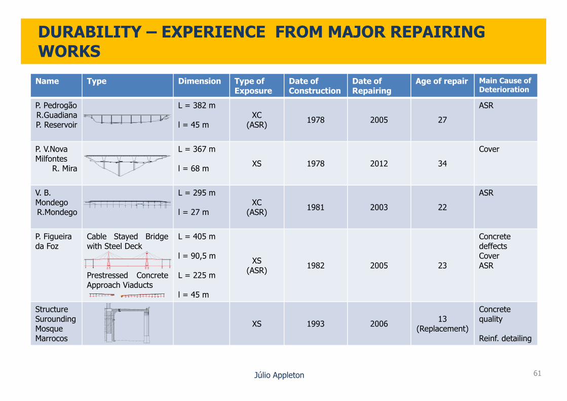
P. PedrogãoR.GuadianaP. Reservoir
L = 382 m
l = 45 mXC
(ASR)1978 2005 27
ASR
P. V.NovaMilfontes
R. Mira
L = 367 m
l = 68 mXS 1978 2012 34
Cover
V. B. Mondego
L = 295 mXC
ASR
DURABILITY – EXPERIENCE FROM MAJOR REPAIRING WORKS
Júlio Appleton 61
MondegoR.Mondego l = 27 m
XC(ASR)
1981 2003 22
P. Figueira da Foz
Cable Stayed Bridgewith Steel Deck
Prestressed ConcreteApproach Viaducts
L = 405 m
l = 90,5 m
L = 225 m
l = 45 m
XS(ASR)
1982 2005 23
ConcretedeffectsCoverASR
StructureSuroundingMosqueMarrocos
XS 1993 200613
(Replacement)
Concretequality
Reinf. detailing

4
5
6
7
Nu
mb
er
of
stru
ctu
res
DURABILITY – EXPERIENCE FROM MAJOR REPAIRING WORKS
Júlio Appleton 62
0
1
2
3
1930/1940 1940/1950 1950/1960 1960/1970 1970/1980 1980/1990 1990/2000
Nu
mb
er
of
stru
ctu
res
Date of Construction

6
8
10
12
14
Nu
mb
er
of
cau
ses
6
8
10
12
Nu
mb
er
of
cau
ses
DURABILITY – EXPERIENCE FROM MAJOR REPAIRING WORKS
Júlio Appleton 63
0
2
4
6
Cover + C. quality Conc. defect and
quality
Cracks and
structure defect
ASR
Nu
mb
er
of
cau
ses
Main Causes of Deterioration
0
2
4
XC XS ASR
Nu
mb
er
of
cau
ses
Main Causes of Deterioration

50
60
70
80
90
Ag
e o
f re
pa
ir
DURABILITY – EXPERIENCE FROM MAJOR REPAIRING WORKS
Júlio Appleton 64
0
10
20
30
40
1930 1940 1950 1960 1970 1980 1990 2000
Ag
e o
f re
pa
ir
Date of construction
DURABILITY – FINAL CONSIDERATIONS
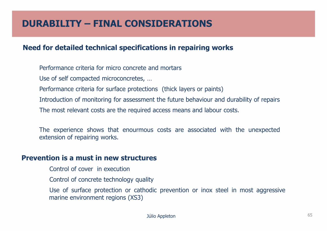
Need for detailed technical specifications in repairing works
Performance criteria for micro concrete and mortars
Use of self compacted microconcretes, …
Performance criteria for surface protections (thick layers or paints)
Introduction of monitoring for assessment the future behaviour and durability of repairs
The most relevant costs are the required access means and labour costs.
Júlio Appleton 65
The experience shows that enourmous costs are associated with the unexpectedextension of repairing works.
Prevention is a must in new structures
Control of cover in execution
Control of concrete technology quality
Use of surface protection or cathodic prevention or inox steel in most aggressivemarine environment regions (XS3)


![2 André Rosa Durable Structures LNEC [Modo de Compatibilidade]durati.lnec.pt/pdf/ICDS12_Presentations/TDS_2_ARosa.pdf · DURABLE STRUCTURES LNEC Lisbon 31 May - 1June 2012 Before](https://img.pdfslide.us/doc/110x75/5c296a1109d3f2476c8cec3a/2-andre-rosa-durable-structures-lnec-modo-de-compatibilidade-durable-structures.jpg)