Embed Size (px)
Citation preview
Running beyond the bio-inspired regime
Duncan W. Haldane, and Ronald S. Fearing
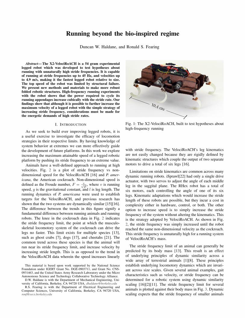
Abstract— The X2-VelociRoACH is a 54 gram experimentallegged robot which was developed to test hypotheses aboutrunning with unnaturally high stride frequencies. It is capableof running at stride frequencies up to 45 Hz, and velocities upto 4.9 m/s, making it the fastest legged robot relative to size.The top speed of the robot was limited by structural failure.We present new methods and materials to make more robustfolded robotic structures. High-frequency running experimentswith the robot shows that the power required to cycle itsrunning appendages increase cubically with the stride rate. Ourfindings show that although it is possible to further increase themaximum velocity of a legged robot with the simple strategy ofincreasing stride frequency, considerations must be made forthe energetic demands of high stride rates.
I. INTRODUCTION
As we seek to build ever improving legged robots, it isa useful exercise to investigate the efficacy of locomotionstrategies in their respective limits. By having knowledge ofsystem behavior at extremes we can more effectively guidethe development of future platforms. In this work we exploreincreasing the maximum attainable speed of a legged roboticplatform by pushing its stride frequency to an extreme value.
Animals have a well-defined approach to running at highvelocities. Fig. 2 is a plot of stride frequency vs non-dimensional speed for the VelociRoACH [16] and P. amer-icana, the American cockroach. Non-dimensional speed isdefined as the Froude number, F = v√
gl, where v is running
speed, g is the gravitational constant, and l is leg length. Therunning dynamics of P. americana were used to establishtargets for the VelociRoACH, and previous research hasshown that the two systems are dynamically similar [15][16].The difference between the trends in this figure signify afundamental difference between running animals and runningrobots. The knee in the cockroach data in Fig. 2 indicatesthe stride frequency limit, the point at which the musculo-skeletal locomotory system of the cockroach can drive thelegs no faster. This limit exists for multiple species [13],such as ghost crabs [7], dogs [17], and cheetahs [21]. Thecommon trend across these species is that the animal willrun near its stride frequency limit, and increase velocity byincreasing stride length. This is as opposed to the trend inthe VelociRoACH data wherein the speed increases linearly
This material is based upon work supported by the National ScienceFoundation under IGERT Grant No. DGE-0903711, and Grant No. CNS-0931463, and the United States Army Research Laboratory under the MicroAutonomous Science and Technology Collaborative Technology Alliance.
D.W. Haldane is with the Department of Mechanical Engineering, Uni-versity of California, Berkeley, CA 94720 USA, [email protected]
R.S. Fearing is with the Department of Electrical Engineering andComputer Sciences, University of California, Berkeley, CA 94720 USA,[email protected]
Fig. 1: The X2-VelociRoACH, built to test hypotheses abouthigh-frequency running
with stride frequency. The VelociRoACH’s leg kinematicsare not easily changed because they are rigidly defined bykinematic structures which couple the output of two separatemotors to drive a total of six legs [16].
Limitations on stride kinematics are common across manydynamic running robots. iSprawl[22] had only a single driveactuator, with two servos to adjust the angle of each middleleg in the saggital plane. The RHex robot has a total ofsix motors, each controlling the angle of one of its sixlegs. Kinematic adaptations which would increase the stridelength of these robots are possible, but they incur a cost incomplexity either in hardware, control, or both. The otheroption to increase speed is to simply increase the stridefrequency of the system without altering the kinematics. Thisis the strategy adopted by VelociRoACH. As shown in Fig.2, the stride frequency was simply increased until the robotreached the same non-dimensional velocity as the cockroach.This stride frequency is unnaturally high for a running systemof VelociRoACH’s mass.
The stride frequency limit of an animal can generally bepredicted by its body mass [13]. This result is an effectof underlying principles of dynamic similarity across awide array of terrestrial animals [1][8]. These principlesestablish underlying locomotory dynamics which are invari-ant across size scales. Given several animal examples, gaitcharacteristics such as velocity, or stride frequency can bedetermined for a robotic system using dynamic similarityscaling [16][2][11]. The stride frequency limit for severalanimals is plotted against their body mass in Fig. 3. Dynamicscaling expects that the stride frequency of smaller animals

0 1 2 3 4 5 60
5
10
15
20
25
30
Non-dimensional Speed
StrideFrequen
cy(H
z)
VelociRoACH
P. americana
Fig. 2: Stride frequency vs non-dimensional speed for theAmerican cockroach (trend-line extracted from Full & Tu[14]) and VelociRoACH [16]. The non-dimensional speed isequivalent to the Froude number (defined in text). The dottedline indicates walking behaviors, the solid line indicatesrunning. The VelociRoACH has a running gait (defined bythe presence of an aerial phase) above 8 Hz.
will be higher than that of larger animals1. Also shown inFig. 3 are the masses and stride frequency limits of severalrunning robotic platforms. All of these platforms are capableof a higher stride frequency than an animal of the samemass would be expected to use. Engineered systems such asthese legged robots are not subject to the same physiologicalconstraints as their animal counterparts, so it is reasonablethat these robots have used an increased stride frequency toincrease the span of velocities that they are able to achieve.An area that has not been fully explored is what happenswhen the stride frequency of a robot is pushed even higher.The trade-offs that occur in this operating regime have notbeen assessed. Addressing these questions will inform thedesign of future running robots.
In this work we present the design of the experimentalrobotic platform, X2-VelociRoACH, which has been createdto test what happens to legged locomotion in the frequencylimit. The design and fabrication of the platform is shown inSection II. Results from high-frequency running experimentsare given in Section III. The principles of locomotion withunnaturally-high stride frequencies are given in Section IV.
II. METHODS
A. Design and Construction of the X2-VelociRoACH
The X2-VelociRoACH was built to test hypotheses aboutthe characteristics of running at unnaturally high stride
1The stride frequency scales with ∼ α−0.17M where αM is the ratio of
masses of the two systems being compared.
1 g 10 g 100 g 1 kg 10 kg 1000 kg1
2
5
10
20
3550
Body mass
Strid
eFr
eque
ncy
(Hz) iSprawl
Horse
Dog
Rat
CrabMouse
CockroachDASH
VelociRoACH
X2-VelociRoACH
RHex
Fig. 3: Stride frequency vs body mass for a range of runninganimals and robots. Animal data from Full [13]. The X2-VelociRoACH presented in this work has the highest stridefrequency of any extant running robot.
frequencies. We based the design on the extant running robot,VelociRoACH. VelociRoACH was made using the SmartComposite Microstructures (SCM) process which createslinkages by combining rigid and flexible materials usingplanar processes [20]. It has been used to create severalmilliscale [6][26][19][16] and microscale [5][18] leggedrobots. Linkages made with SCM have been used reducethe requisite number of actuators for legged robots whichallows for the use of larger, more power dense actuators. Thegeometric parameters of the SCM kinematic linkages whichcouple motor rotation to leg motion were maintained betweenVelociRoACH and the X2-VelociRoACH, so both robotshave the same stride kinematics. This allows for a pointof direct comparison the prior art. A number of challengeshad to be overcome to make the X2-VelociRoACH a reality.Firstly, the power density of the platform had to increaseto make more power available for cycling the legs morequickly. Secondly, the coupling between the motor and theSCM linkages had to be rigidified. The robustness of theSCM components had to be increased to cope with the loadsexerted on the robot by the legs.
1) Power transmission: The original VelociRoACH usedtwo coreless brushed DC motors to drive its legs, one foreither side of the robot [16]. To increase the power density ofthe new platform we replaced these motors with a single out-runner brushless motor the Air King AX-1306. This motor hasa listed voltage constant of Kv = 2200 rpm
V , phase windingresistance of 0.88Ω, and current limit of 6A. We staticallymeasured the torque constant to be 5.5 mNm
A , which indicatesa somewhat lower Kv of 1720 rpm
V . The estimated maximumrotational frequency (for a 7.4V battery, after gearing) isthen 85 Hz; the maximum torque produced would be 81mNm. This motor weighs nine grams and has a peak output

power of 6.5 W after gearing. X2-VelociRoACH thereforehas significantly more power than VelociRoACH, whose twomotors have a combined peak power output of 1.3 W.
The hobby-grade motor used in the X2-VelociRoACH isfar less expensive than high-quality brushless motors like theFaulhaber 06022 and is more power-dense (but less efficient).The out-runner form factor of the motor allows for a largegap radius, reducing the requisite gear ratio. In conjunctionwith the smart composite microstructures process, the lowcost allows us to stay within the paradigm of ultra-low costmicrorobots, to which VelociRoACH belongs. For all theiradvantages hobby-grade motors of this type have a majordownside for the purposes of legged robotics: they have noHall effect sensors to specify commutation of the motor.Lacking a specialized micro-scale brushless motor controller,we have employed a hobby-grade sensorless electronic speedcontroller (ESC) (Hobbyking 6A ESC). Controllers of thistype measure the back-EMF generated by the spinning motorto control commutation which has several implications: theyhave a high minimum speed, and they do not cope well withvarying loads. This second point is critical, the inability thesecontrollers to cope with the slightly varying loads from aflapping mechanism in a MAV [25] caused complications;the impact loads generated by legged locomotion causegreater ones (see Section III).
The X2-VelociRoACH’s transmission is shown in Fig 4.The brushless motor drives two cranks through a single2.48:1 reduction, which puts the maximum power pointof the motor at a stride frequency of 50 Hz. This dualdrive constrains the drive layer of the robot to be parallel,replacing the parallel four-bar mechanism that served thesame function in VelociRoACH [16]. Previous SCM robots[16][19][26] used a simple pin-bushing connection to couplecrank rotation to the SCM layer. This strategy did notproperly constrain the drive plate at high velocities so weemployed bearings mounted in 3D printed plastic, whichwere connected to the crank with a shoulder bolt (as canbe seen in Fig. 1). We sought to enable the rapid fabricationof this robot, thus the majority of the transmission was 3Dprinted, including the gears. The 3D printed plastic materialwas not strong enough to use as a drive shaft so hollowshafts were printed, which were internally reinforced withcarbon-fiber tubing.
This transmission physically constrains the gait of theX2-VelociRoACH to alternating tripod, as shown in Fig.4B, meaning it cannot use differential steering like previ-ous robots [16][26]. However we have shown that simpledifferential steering is not desirable for repeatable dynamicrunning [10], and steering can be more readily accomplishedusing a multi-functional inertial [24], or aerodynamic [23]appendage. Steering is unnecessary for the experimentalgoals for the X2-VelociRoACH; it can be added later toenable field operation.
2) Damage mitigation: It has been proposed that animalsrunning at high stride frequencies incur higher peak forces
2Which has been used in other small scale robots, e.g. [9]
(A)
(B)
M
α
Fig. 4: A conceptual kinematic drawing of the X2-VelociRoACH’s drive mechanism. (A) A side view of themechanism. The motor (shown in green) drives two parallelcrankshafts through two gears (shown in gray). (B) A frontview of the mechanism showing how the driven cranks areoffset by 180, thereby constraining the gait to alternatingtripod. The crank angle α is also shown on the figure.
[21]. This is certainly the case with the X2-VelociRoACH.Materials which have been previously used to create SCMmillirobots are unable to withstand the high loads that occurin high frequency running. We observed that these loads areproportional to the inertia of the running appendages, sofiberglass legs were used. These legs were made with sixlayers of alternating ±45 and 0/90 S grade fiberglass ina wet-layup epoxy process. The fiberglass legs had 30% lessinertia than the rubber legs used by VelociRoACH [16].
In the past, 25 µm polyethylene terephthalate (PET)film has been used for the flexure layer of several robots[16][19][26]. A X2-VelociRoACH made with PET was testedto destruction to determine the achievable stride frequencylimit. While running in air, the inertial forces from therecirculating limbs were enough to destroy the flexuresbefore the stride frequency reached 45 Hz. On the ground,one three second run at 32 Hz was enough to tear flexures.Tendons made of Kevlar filament placed across flexureswere able to extend the running life by a small amount,but these failed eventually as well. We experimented with acomposite of tough Spectra fibers sandwiched between twosheets of polyester film (Cuben Fabric) as a flexure layer.This material is similar in dimension and bonding chemistryto the PET film, and greatly extended the running life of therobot. However, flexures made with this material still failedafter a few trials of high frequency running, as shown inFig. 5a. We therefore decided to use rip-stop nylon (1.9 ozUncoated rip-stop nylon. From ripstopbytheroll.com) as ourflexure layer3. Flexures made with rip-stop nylon did not failin any of our experiments. Instead, the rigid component of
3 This material is now used in the flexure layer of the commercializedversion of the DASH robot

(a) A failed Cuben fabric flexure.Failure of this material was typifiedby fiber pullout.
(b) The rigid material failing bypeeling at a hip flexure.
Fig. 5: Failure modes of SCM mechanisms after high fre-quency running
the SCM composite began to fail at the highest achievablestride frequencies, as shown in Fig. 5b. This material failureis the limit for the top speed of the robot.
Despite these material limits, the X2-VelociRoACH wasable to run on the ground at stride frequencies up to 45Hz without incurring significant damage. More dynamicperformance from this robot is achievable if new materialsand processes that further increase the durability of SCMrobots are developed.
B. Control electronics
The X2-VelociRoACH is driven by the imageProc 2.54
[3] robot control board. Motor current measurements are un-available from the sensorless speed controller, so a low-sideshunt resistor was used to measure current consumption forthe entire robot. We estimated the motor power by offsettingthe total power consumption by the levels recorded whilethe motor is powered down. A Hall-effect based encoderwas placed on the brushless motor output to determine theposition of the legs. The imageProc collects telemetry dataincluding current measurements, battery voltage level, 6-axisinertial measurements, and motor position at 1000 Hz. Theintegrated 802.15.4 radio interface was used for communica-tion and external control5. A 7.4V, 180mAh battery poweredthe robot, lasting for approximately twenty minutes beforeneeding recharging.
C. Experiments
A number of experiments were conducted to determinethe characteristics of high-frequency running. The X2-VelociRoACH was run without the legs touching the groundto establish the cost of recirculating the legs in the absence ofany interaction with the ground. During these experiments,the robot was held firmly by hand. Another set of off-the-ground experiments were run with the robot’s legs removedto determine the contribution of appendage inertia to theoverall cost. Running experiments across a wide range ofspeeds were conducted on level closed-pile carpet. Motiondata was collected from the robot by recording high-speed
4Embedded board: https://github.com/biomimetics/imageproc pcb5Embedded code: https://github.com/dhaldane/roach
Fig. 6: Stills from a high-speed video (583 fps) of the X2-VelociRoACH running at 45 Hz.
video at 600 frames per second, and digitizing visual markerswith Pro-Analyst motion analysis software.
To facilitate data collection, all experiments were run withthe same aerodynamic stabilizer developed for VelociRoACH[16]. All experiments were run on the same robot, withon-ground running first, appendages in the air second, andwithout appendages in the air last. For each experiment,a range of open-loop throttle commands was sent to thesensorless speed controller to explore the span of achievableperformance.
III. RESULTS
Fig. 6 shows several stills from a high-speed video of therobot running with a stride frequency of 45 Hz. These stillsdemonstrate behaviors typical to high frequency running.Fig. 6A shows hyper-extension of the flexible ‘C’ legs.High inertial forces occuring during high frequency runningtend to stretch out the robot’s appendages. There is also asignificant increase in the robot’s range of leg angles; inertialforces acting on the semi-compliant SCM mechanisms causeincreases in both abduction and adduction angle. At highvelocities the touchdown angle of the leg approaches thevertical, as shown in Fig. 6B. It should be noted that thebattery of the X2-VelociRoACH is mounted on the bottomof the platform. It is very close to the ground, but never madecontact in any of the experiments.
Fig. 7 shows the fore-aft acceleration of the X2-VelociRoACH over approximately 70 strides during steadystate running at 45 Hz. This figure demonstrates the strongperiodicity of high-frequency running gaits. Well definedregions of positive and negative acceleration (as have beenwell documented in low-frequency running) can also be seen.
Fig. 8a shows the speed of the X2-VelociRoACH as afunction of stride frequency. The robot was unable to run atstride frequencies below 35 Hz due high impact loads inter-fering with the brushless ESC. Gaits in this lower frequency

0 π/2 π 3π/2 2π
-40
-20
0
20
40
Crank angle (rad)
Fore-AftAcceleration(ms−
2 )
Fig. 7: Fore-aft accelerations of the X2-VelociRoACH run-ning at 45 Hz as a function of the crank angle. Approximately70 strides were averaged, the shaded region is one standarddeviation.
region were typified by repeated motor stalls followed by∼ 500 ms of rapid leg motion as the ESC attempted togenerate a measurable back-EMF (electro-motive force) fromthe motor. This phenomena caused large perturbations inheight and pitch angle as the robot attempted to proceedforward.
Above 35 Hz, in the regime of stable running, the forwardvelocity increased linearly with stride frequency to a maxi-mum of 4.9 m/s, without significant changes in slope. Alsoshown on the graph is a kinematic limit on the velocity ofthe robot. The peak leg tip velocity occurs at mid-stance (asdescribed in previous works [10]). If the robot were on theboundary of the kinematic limit, it would be moving at thistop speed over the entire stride. Fig. 8b shows the averagestride length of the robot as a function of stride frequency.The increasing trend in this graph shows that the robot travelsa greater distance per stride at higher frequencies. This maybe caused by an increase in the effective leg length causedby the previously discussed inertial forces. Alternatively, therobot could be generating impulses when the legs collidewith the ground at high speeds. Because the leg touchesdown near the vertical these impulses would be propulsive,allowing the robot to generate additional thrust.
To estimate the effects of inertial loads during high-frequency locomotion we created a full simulation of the X2-VelociRoACH kinematic mechanism in Solidworks. Shownin Fig. 9a, this model has one degree of freedom and predictsthe motor loading caused by inertial effects of the mechanismand appendages. The simulated motor drove the mechanismat a constant stride frequency, and Solidworks Motion wasused to calculate the power required to produce the motion.Data from three of these simulations are presented in Fig.9b. The peak power required increases cubically with thestride frequency, as would be expected for an inertial loadforced to track a sinusoidal position input. To validate theSolidworks simulation, data from the robot running in air at40 Hz are presented in Fig. 9c. This plot shows the crankangle with the cyclic trend removed, as a function of time,over one stride period. The sensorless speed controller drivesthe motor with an open-loop duty cycle, so we would expect
0 10 20 30 40 500
1
2
3
4
5
6
Stride Frequency (Hz)
Spee
d(m
/s)
VelociRoACHX2−VelociRoACHKinematic limit
(a) Speed as a function of stride frequency for the X2-VelociRoACH, andVelociRoACH [16]. Also shown is a kinematic upper bound on the stridefrequency.
20 25 30 35 40 45 500.06
0.08
0.1
0.12
StrideLen
gth
(m)
Stride Frequency (Hz)
(b) Distance traveled over a single stride (one full crank rotation), as afunction of stride frequency. The red line is the distance a robot with wheelsof the same radius as the nominal leg length would travel.
Fig. 8: Trends in velocity and stride length for the X2-VelociRoACH.
the crank angle to lag in regions of the cycle which requirepositive torque input. Conversely, the crank angle is expectedto lead in regions which require negative torque input. Fig.9c confirms these expectations, indicating that the simulationis at least somewhat valid.
Fig. 10 shows the mechanical power the X2-VelociRoACHuses as a function of stride frequency for three differentrunning scenarios: running on the ground, running in theair, and running in the air without legs. The mechanicalpower was calculated by recording electrical motor powermeasurements, and combining them with a model of thetransmission efficiency:
Electric power ∼ Mechanical powerη
≤ avg
(|τ ||θ|η
)(1)
where η is the efficiency, τ is the motor torque, and θ isthe motor velocity.
The efficiency of a DC brushless motor is a direct functionof its speed so we fit an efficiency model to the transmission

(a) A rendering of a Solidworks model of X2-VelociRoACH. The legmechanisms have one degree of freedom, and are driven by a single virtualmotor.
0 π/2 π 3π/2 2π-3
-2
-1
0
1
2
3
Crank angle (rad)
Mec
hani
cal P
ower
(W)
20 Hz30 Hz40 Hz
(b) Power requirements for driving the motor at constant rates, as a functionof crank angle (see Fig. 4). The peak amplitude increases cubically withstride frequency.
0 5 10 15 20 25−0.1
−0.05
0
0.05
0.1
Time (ms)
Angle
Variation(rad)
(c) Variation of crank angle over a full rotation for one in-air stride at 40Hz, as measured by the Hall-encoder on the motor.
Fig. 9: Solidworks model of X2-VelociRoACH, used topredict power required for appendage recirculation.
by measuring the power input to the system for a rangeof known output loads and speeds. The efficiency of thecombined brushless ESC/motor/transmission system peakedat 36%. The low-cost nature of the hobby components andthe non-ideal properties of 3D printed gears make this lowefficiency understandable.
Data collected from VelociRoACH [16] are shown asa point of comparison. Also shown on the graph is thepredicted inertial power cost, which was calculated usingthe Solidworks model shown in Fig. 9a. This estimate iscalculated by integrating the positive power requirementsfrom the Solidworks model over a stride, and multiplying bythe stride rate. This assumes that the sensorless ESC doesno work to brake the motor, which is a safe assumptionconsidering it lacks the transistors that would allow it to doso. This consideration is shown in the inequality in Eq. 1.
An upper bound for frictional dissipation is also shown.
0 20 40 60 80
1
2
3
4
5
6
Stride Frequency (Hz)
Mec
hanicalPower
(W)
GroundAirAir No LegsVelociRoACHInertial CostFriction Bound
Fig. 10: Power as a function of stride frequency for the X2-VelociRoACH for running in air, with and without legs, andrunning on the ground. The data are segmented by individualstride; the middle line is the average, the shaded region isone standard deviation.
This upper bound is given by P = µmgvbnd, where µ is thefrictional coefficient (0.55), g is the gravitational constant,and vbnd is the kinematic speed limit for a given frequency(from Fig. 8a). This bound corresponds to the robot beingdragged along the ground at its maximum attainable speed.This is maximum amount of energy that could be dissipatedby the legs using friction. When it is exceeded, we can besure that power is being consumed by another source.
For the experimental data, the least power was consumedby the robot running in the air without its legs attached. Thelinear increase in this graph shows the power cost in runningfrom only the transmission and kinematic mechanism. Whenthe legs are added to the robot, the mechanical powerrequirement greatly increases. The power cost incurred byrunning on the ground is not greater than the power requiredto move the legs. There may be an issue with this data inthat the order in which the trials were run may affect thetrends. The robot was run in the air after it was run on theground, so the accumulated damage may have caused thepower draw in the air to be higher. In any case, the effectof running in the air vs on the ground at high frequencies isless than the effect of damage that the robot accrues duringhigh-frequency running.
Fig. 11 shows the specific resistance of X2-VelociRoACHas a function of stride frequency. Data from VelociRoACHare provided as a reference. To allow a more direct compar-ison between the two platforms, the specific resistance wascalculated as S = Pm
mgv where Pm is the total mechanicalpower6, g is the gravitational constant and v is the forward
6As opposed to electrical power, which is sometimes used instead

10 20 30 40 501
1.5
2
2.5
Stride Frequency (Hz)
SpecificResistance
VelociRoACH−X2
VelociRoACH
Fig. 11: Specific resistance as a function of stride frequencyfor the X2-VelociRoACH, and VelociRoACH [16].
velocity. The specific resistance of the X2-VelociRoACHincreases at its highest speeds due to the high rates of powerconsumption associated with high-frequency running.
IV. DISCUSSION
With the X2-VelociRoACH we have yet to find a fun-damental speed limit for legged locomotion. The velocityincreased with increased stride rate without the trend be-coming sub-linear (Fig. 8a), showing that further gains invelocity can be achieved if the stride frequency can befurther increased. The X2-VelociRoACH had an observedtop speed of 4.9 m/s while running at 45 Hz, making itfaster than the vast majority of untethered running robots interms of absolute speed, and faster than all extant runningrobots in terms of relative speed (shown in Table I). Onelimit that was encountered was one of material strength.The loads experienced by the flexures increase with thesquare of the stride frequency (as predicted from SolidworksMotion simulations), so accumulated damage is especiallyproblematic for high-frequency running. Because the gainin velocity is linear, further gains in speed (which wouldbe accomplished by increasing stride frequency) will havediminishing returns in terms of platform survivability.
During high-frequency locomotion, the power draw ofthe X2-VelociRoACH is dominated by the inertial cost ofrecirculating the running appendages. When running above20 Hz, the robot draws more power than the legs would beable to dissipate by any frictional interaction. We can see thisinertial cost in the sharp increase in the power required forlocomotion at high-speeds. When the robot is run in the airwith its legs attached, it has a similar power draw to the robotrunning on the ground. More data collected in a properlyrandomized experimental trial would further elucidate thesetrends. The real power required to drive the legs at a constantspeed (in the absence of friction) is zero, as shown by Fig.
9b. The X2-VelociRoACH has no means of storing andreturning the energy fluctuations from inertial effects butif greater efficiency was desired, a flywheel or spring [4]could be added to the robot to reduce the robot’s powerconsumption at high stride rates. This design adjustmentwould not mitigate the high loads applied to the flexures soa further increase in maximum speed is not expected, giventhe strength limits of current materials.
The large increase in power cost at high stride frequenciesled to an interesting trend in the overall specific resistanceof the robot. The specific resistance7 of legged invertebratelocomotion is monotonically decreasing [12] with stride fre-quency. This trend is also shown in the VelociRoACH data.The fact that the specific resistance of the X2-VelociRoACHincreases at its highest attainable (and furthest removed fromthe bio-inspired regime) stride frequencies is an importantpoint. Locomotion at these unnaturally high frequencies isless efficient than an intermediate speed. Increasing thevelocity with higher stride rates is possible, but it comeswith a considerable cost in power and efficiency.
V. CONCLUSION
An interesting question for legged robotics is where thelimits to maximal speed running come from. Most runninganimals prefer to run near their maximum stride frequencyand increase their velocity by increasing their stride length.In this work we have shown an alternative strategy ofsimply increasing the stride frequency to increase velocity.This simple strategy can be readily used by biomimeticmillirobots, whereas increasing stride length would requirea higher degree of articulation than is available on theseunderactuated platforms. An alternative to a higher degreeof articulation are passively extensible legs which couldexaggerate the trend seen in Fig. 8b.
With the X2-VelociRoACH we have increased the stridefrequency of a legged robotic platform far beyond what ananimal of equivalent size would use. This platform runs at ahigher stride frequency than any other extant legged robot.The top speed of 4.9 m/s was observed at 45 Hz, the highestfrequency the robot could use without losing appendages.The current limitation on the maximum speed of the X2-VelociRoACH is therefore one of material strength. Due tothe choice of actuation scheme the minimum speed for stablerunning was 2.75 m/s, which makes the X2-VelociRoACHa highly specialized runner. Position based control of thebrushless motor would improve the performance of this robotat low speeds.
We investigated the energetic costs associated with high-frequency running. The power demand increases greatlyat high stride frequencies due to the rapidly cycling therunning appendages. This causes the specific resistance ofthe platform to increase at its highest attainable speeds. Thistrend is uncommon to animal locomotion, because animalsincrease stride length instead of stride frequency [13].
7Cost of Transport is reported in [12]. Specific resistance is cost oftransport normalized by the gravitational constant.
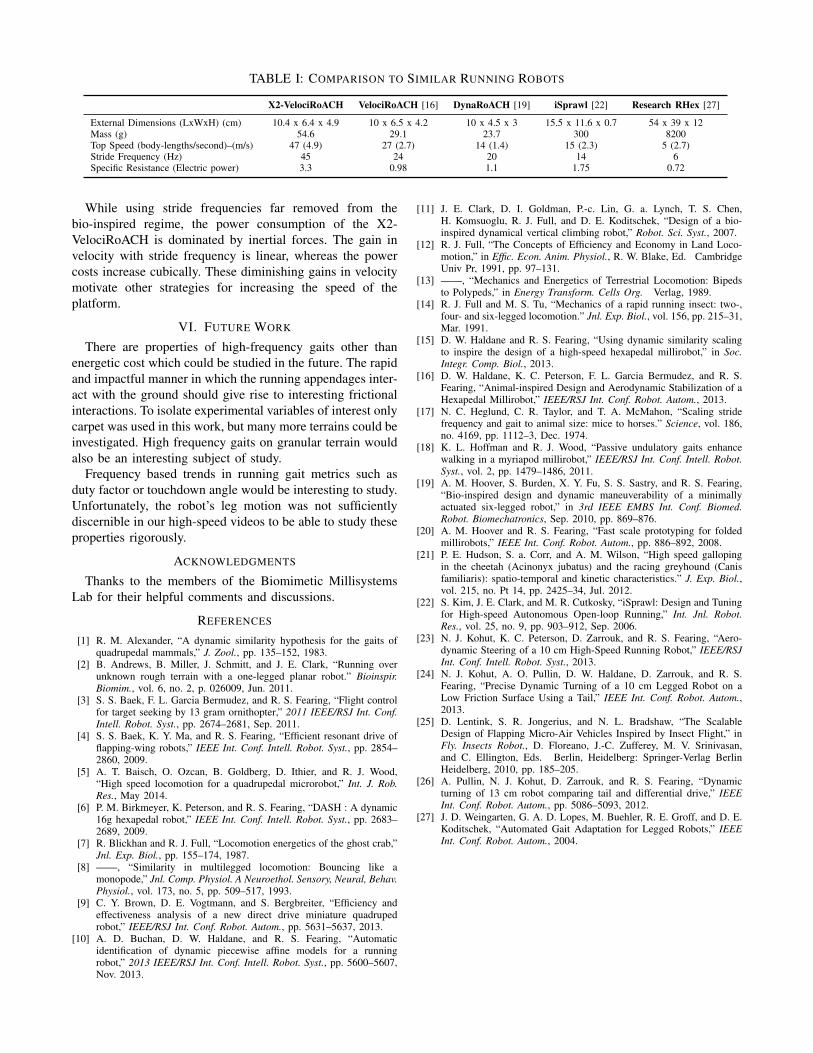
TABLE I: COMPARISON TO SIMILAR RUNNING ROBOTS
X2-VelociRoACH VelociRoACH [16] DynaRoACH [19] iSprawl [22] Research RHex [27]
External Dimensions (LxWxH) (cm) 10.4 x 6.4 x 4.9 10 x 6.5 x 4.2 10 x 4.5 x 3 15.5 x 11.6 x 0.7 54 x 39 x 12Mass (g) 54.6 29.1 23.7 300 8200Top Speed (body-lengths/second)–(m/s) 47 (4.9) 27 (2.7) 14 (1.4) 15 (2.3) 5 (2.7)Stride Frequency (Hz) 45 24 20 14 6Specific Resistance (Electric power) 3.3 0.98 1.1 1.75 0.72
While using stride frequencies far removed from thebio-inspired regime, the power consumption of the X2-VelociRoACH is dominated by inertial forces. The gain invelocity with stride frequency is linear, whereas the powercosts increase cubically. These diminishing gains in velocitymotivate other strategies for increasing the speed of theplatform.
VI. FUTURE WORK
There are properties of high-frequency gaits other thanenergetic cost which could be studied in the future. The rapidand impactful manner in which the running appendages inter-act with the ground should give rise to interesting frictionalinteractions. To isolate experimental variables of interest onlycarpet was used in this work, but many more terrains could beinvestigated. High frequency gaits on granular terrain wouldalso be an interesting subject of study.
Frequency based trends in running gait metrics such asduty factor or touchdown angle would be interesting to study.Unfortunately, the robot’s leg motion was not sufficientlydiscernible in our high-speed videos to be able to study theseproperties rigorously.
ACKNOWLEDGMENTS
Thanks to the members of the Biomimetic MillisystemsLab for their helpful comments and discussions.
REFERENCES
[1] R. M. Alexander, “A dynamic similarity hypothesis for the gaits ofquadrupedal mammals,” J. Zool., pp. 135–152, 1983.
[2] B. Andrews, B. Miller, J. Schmitt, and J. E. Clark, “Running overunknown rough terrain with a one-legged planar robot.” Bioinspir.Biomim., vol. 6, no. 2, p. 026009, Jun. 2011.
[3] S. S. Baek, F. L. Garcia Bermudez, and R. S. Fearing, “Flight controlfor target seeking by 13 gram ornithopter,” 2011 IEEE/RSJ Int. Conf.Intell. Robot. Syst., pp. 2674–2681, Sep. 2011.
[4] S. S. Baek, K. Y. Ma, and R. S. Fearing, “Efficient resonant drive offlapping-wing robots,” IEEE Int. Conf. Intell. Robot. Syst., pp. 2854–2860, 2009.
[5] A. T. Baisch, O. Ozcan, B. Goldberg, D. Ithier, and R. J. Wood,“High speed locomotion for a quadrupedal microrobot,” Int. J. Rob.Res., May 2014.
[6] P. M. Birkmeyer, K. Peterson, and R. S. Fearing, “DASH : A dynamic16g hexapedal robot,” IEEE Int. Conf. Intell. Robot. Syst., pp. 2683–2689, 2009.
[7] R. Blickhan and R. J. Full, “Locomotion energetics of the ghost crab,”Jnl. Exp. Biol., pp. 155–174, 1987.
[8] ——, “Similarity in multilegged locomotion: Bouncing like amonopode,” Jnl. Comp. Physiol. A Neuroethol. Sensory, Neural, Behav.Physiol., vol. 173, no. 5, pp. 509–517, 1993.
[9] C. Y. Brown, D. E. Vogtmann, and S. Bergbreiter, “Efficiency andeffectiveness analysis of a new direct drive miniature quadrupedrobot,” IEEE/RSJ Int. Conf. Robot. Autom., pp. 5631–5637, 2013.
[10] A. D. Buchan, D. W. Haldane, and R. S. Fearing, “Automaticidentification of dynamic piecewise affine models for a runningrobot,” 2013 IEEE/RSJ Int. Conf. Intell. Robot. Syst., pp. 5600–5607,Nov. 2013.
[11] J. E. Clark, D. I. Goldman, P.-c. Lin, G. a. Lynch, T. S. Chen,H. Komsuoglu, R. J. Full, and D. E. Koditschek, “Design of a bio-inspired dynamical vertical climbing robot,” Robot. Sci. Syst., 2007.
[12] R. J. Full, “The Concepts of Efficiency and Economy in Land Loco-motion,” in Effic. Econ. Anim. Physiol., R. W. Blake, Ed. CambridgeUniv Pr, 1991, pp. 97–131.
[13] ——, “Mechanics and Energetics of Terrestrial Locomotion: Bipedsto Polypeds,” in Energy Transform. Cells Org. Verlag, 1989.
[14] R. J. Full and M. S. Tu, “Mechanics of a rapid running insect: two-,four- and six-legged locomotion.” Jnl. Exp. Biol., vol. 156, pp. 215–31,Mar. 1991.
[15] D. W. Haldane and R. S. Fearing, “Using dynamic similarity scalingto inspire the design of a high-speed hexapedal millirobot,” in Soc.Integr. Comp. Biol., 2013.
[16] D. W. Haldane, K. C. Peterson, F. L. Garcia Bermudez, and R. S.Fearing, “Animal-inspired Design and Aerodynamic Stabilization of aHexapedal Millirobot,” IEEE/RSJ Int. Conf. Robot. Autom., 2013.
[17] N. C. Heglund, C. R. Taylor, and T. A. McMahon, “Scaling stridefrequency and gait to animal size: mice to horses.” Science, vol. 186,no. 4169, pp. 1112–3, Dec. 1974.
[18] K. L. Hoffman and R. J. Wood, “Passive undulatory gaits enhancewalking in a myriapod millirobot,” IEEE/RSJ Int. Conf. Intell. Robot.Syst., vol. 2, pp. 1479–1486, 2011.
[19] A. M. Hoover, S. Burden, X. Y. Fu, S. S. Sastry, and R. S. Fearing,“Bio-inspired design and dynamic maneuverability of a minimallyactuated six-legged robot,” in 3rd IEEE EMBS Int. Conf. Biomed.Robot. Biomechatronics, Sep. 2010, pp. 869–876.
[20] A. M. Hoover and R. S. Fearing, “Fast scale prototyping for foldedmillirobots,” IEEE Int. Conf. Robot. Autom., pp. 886–892, 2008.
[21] P. E. Hudson, S. a. Corr, and A. M. Wilson, “High speed gallopingin the cheetah (Acinonyx jubatus) and the racing greyhound (Canisfamiliaris): spatio-temporal and kinetic characteristics.” J. Exp. Biol.,vol. 215, no. Pt 14, pp. 2425–34, Jul. 2012.
[22] S. Kim, J. E. Clark, and M. R. Cutkosky, “iSprawl: Design and Tuningfor High-speed Autonomous Open-loop Running,” Int. Jnl. Robot.Res., vol. 25, no. 9, pp. 903–912, Sep. 2006.
[23] N. J. Kohut, K. C. Peterson, D. Zarrouk, and R. S. Fearing, “Aero-dynamic Steering of a 10 cm High-Speed Running Robot,” IEEE/RSJInt. Conf. Intell. Robot. Syst., 2013.
[24] N. J. Kohut, A. O. Pullin, D. W. Haldane, D. Zarrouk, and R. S.Fearing, “Precise Dynamic Turning of a 10 cm Legged Robot on aLow Friction Surface Using a Tail,” IEEE Int. Conf. Robot. Autom.,2013.
[25] D. Lentink, S. R. Jongerius, and N. L. Bradshaw, “The ScalableDesign of Flapping Micro-Air Vehicles Inspired by Insect Flight,” inFly. Insects Robot., D. Floreano, J.-C. Zufferey, M. V. Srinivasan,and C. Ellington, Eds. Berlin, Heidelberg: Springer-Verlag BerlinHeidelberg, 2010, pp. 185–205.
[26] A. Pullin, N. J. Kohut, D. Zarrouk, and R. S. Fearing, “Dynamicturning of 13 cm robot comparing tail and differential drive,” IEEEInt. Conf. Robot. Autom., pp. 5086–5093, 2012.
[27] J. D. Weingarten, G. A. D. Lopes, M. Buehler, R. E. Groff, and D. E.Koditschek, “Automated Gait Adaptation for Legged Robots,” IEEEInt. Conf. Robot. Autom., 2004.