Embed Size (px)
Citation preview

1
DUCATI748RS
Manuale d'officinaWorkshop manualModel Year 2000

2
Premessa• Gli interventi descritti nel presente
manuale, richiedono esperienza ecompetenza da parte dei tecnicipreposti, che sono invitati al pienorispetto delle caratteristichetecniche originali, riportate dalCostruttore.
• Alcune informazioni sono stateappositamente omesse, poichè, anostro avviso, facenti partedell'indispensabile cultura tecnicadi base che un tecnicospecializzato deve possedere.
• Altre eventuali informazionipossono essere dedotte dalcatalogo ricambi.
• Tutto il materiale da utilizzaredovrà essere ordinato alla DucatiCorse S.r.l.
• La Ducati Corse S.r.l. declina ogniresponsabilità per errori edomissioni di carattere tecnico,prodotti nella redazione delpresente manuale e si riserva ildiritto di apportare qualsiasimodifica richiesta dall'evoluzionetecnologica dei suoi motocicli,senza l'obbligo di divulgazionetempestiva.
• Tutte le informazioni riportate,sono aggiornate alla data distampa.
• Riproduzioni o divulgazioni ancheparziali degli argomenti trattatinella presente pubblicazione, sonoassolutamente vietate. Ogni dirittoè riservato alla Ducati Corse S.r.l.,alla quale si dovrà richiedereautorizzazione (scritta)specificandone la motivazione.
Ducati Corse S.r.l.
Foreword• All operations described in this
manual must be carried out bysenior skilled technicians, who arerequested to strictly follow theManufacturer’s instructions.
• Some information has beenintentionally omitted, as, at ouradvice, a specialized technicianmust have this technicalbackground.
• Other information can be takenfrom the spare parts catalogue.
• The orders for all the parts to beused shall be placed at DucatiCorse S.r.l.
• Ducati Corse S.r.l. declines allresponsibility for any technicalerrors or omissions in this manualand reserves the right to makechanges without prior notice.
• The information given in thismanual was correct at the time ofgoing to print.
• Reproduction and disclosure,even partially, of the contents ofthis manual are strictly forbiddenwithout prior written authorizationof Ducati Corse S.r.l., which hasexclusive right on this manual.Applications for authorizationmust specify the reasons forreproduction or disclosure.
Ducati Corse S.r.l.

3
SommarioContents

4
Indicazioni generali 7Simbologia di redazione 8Consigli utili 9Norme generali sugli interventiriparativi 10
Generalità 11Motore 12Distribuzione 12Alimentazione 13Accensione 13Candele 13Lubrificazione 13Raffreddamento 13Trasmissione 14Freni 14Telaio 15Sospensioni 15Ruote 15Pneumatici 16Impianto elettrico 16Pesi 16Ingombri 16Capacità 16
Interventi raccomandati 17Operazioni per lamanutenzione del motore 18Simboli identificazioneoperazione 18Tabella manutenzione motore 19
Scomposizione motore 21Attrezzi speciali 23Caratteristiche prodotti 25Scarico olio 27Scarico liquido di raffreddamento 27Candele, cinghie e tenditori mobili 28Testa 28Cilindro e pistone 29Coperchio alternatore 30Alternatore e volano 32Ingranaggi comandodistribuzione 33Leveraggio selezione marce 34Asta comando frizione 34Frizione 35Coperchio frizione 37Ingranaggio frizione dellatrasmissione primaria 38Pompa olio 38Ingranaggio albero motore dellatrasmissione primaria 39Pulegge rinvio distribuzione 40Accessori basamento 41Prigionieri, boccole e grani dicentraggio 42Apertura carter 43Elementi interni semicarter 45Teste 47
Revisione motore 51Pulizia dei particolari 52Accoppiamenti 52Sostituzione anelli di tenuta olio(paraoli) 53Anelli di arresto (seeger) 53Cuscinetti 54Cilindro 54Pistone 55Spinotto 55Segmenti 56
Description 7Graphic symbols 8A word of advice 9General advice on repair work 10
Description 11Engine 12Timing system 12Fuel system 13Ignition 13Spark plugs 13Lubrication 13Cooling system 13Transmission 14Brakes 14Frame 15Suspension 15Wheels 15Tyres 16Electrical system 16Weights 16Overall dimensions 16Capacity 16
Maintenance schedule 17Engine maintenance 18Operation symbols 18Engine service table 20
Engine disassembly 21Special service tools for engine 24Product specifications 26Draining the oil 27Draining the coolant 27Spark plugs, timing beltsand mobile tensioners 28Cylinder head 28Cylinders and pistons 29Generator cover 30Generator and flywheel 32Timing gears 33Gear selector lever 34Clutch push rod 34Clutch 35Clutch casing 37Clutch primary drive gear 38Oil pump 38Crankshaft primary drive gear 39Timing system rollers 40Crankcase fittings 41Stud bolts, centring bushes andlocators 42Opening the crankcase 43Parts inside the crankcase halves 45Cylinder heads 47
Engine overhaul 51Cleaning parts 52Clearances and fits 52Changing oil seals 53Circlips 53Bearings 54Cylinders 54Pistons 55Gudgeon pins 55Piston rings 56Piston ring-ring groove gap 56Piston ring end gap 57Connecting rods 57Data record sheet 59Big-end bearing - Crankpinclearance 63
5
Accoppiamento segmento-cavasul pistone 56Accoppiamento segmenti-cilindro 57Imbiellaggio 57Scheda rilevamento dati 58Accoppiamento semicuscinetti-pernobiella 63Ricomposizione dell’imbiellaggio 64Sede valvola 66Guidavalvola 67Valvola 68Controllo tenuta valvole 69Controllo profondità sacchevalvole 69Bilancieri 70Registri di apertura e chiusura -molle 70Albero a camme 71Supporti albero a camme 71Pulegge-Cinghie-Tenditori 72Semicarter motore 72Cuscinetti di banco 73Circuito di lubrificazione 74Schema di lubrificazione 75Revisione componenti frizione 78Gruppo di rinvio frizione 82Gruppo cambio 83Tamburo comando forcelle 84Forcelle selezione marce 84Spessorazione alberi cambio etamburo comando forcelle 85
Ricomposizione motore 87Norme generali 88Ricomposizione organidella testa 89Registrazione dei giochi 90Registri di chiusura 91Registri di apertura 92Montaggio coperchietti laterali 92Montaggio supporto tenditori 94Montaggio raccordo uscita acqua 95Coperchio aspirazione 95Collettore di aspirazione 95Chiusura semicarter 96Rimontaggio leveraggio selezionemarce 100Rimontaggio pulegge rinviodistribuzione 102Rimontaggio ingranaggidistribuzione 103Rimontaggio ingranaggiotrasmissione primaria 103Rimontaggio volano e rotorealternatore 104Rimontaggio pompa acqua sulcoperchio alternatore 106Rimontaggio coperchioalternatore 108Rimontaggio pompa olio 109Rimontaggio coperchio frizione 109Ricomposizione frizione 111Controllo traferro sensori di fase enumero di giri motore 113Ricomposizione gruppi termici 114Controllo altezza di “squish” 114Verifica fasatura motore 115Rimontaggio definitivogruppi termici 120Coppie di serraggio motore 122
Reassembling the connectingrods 64Valve seats 66Valve guides 67Valves 68Checking the valve seal 69Checking the valve pocket depth 69Rocker arms 70Opening and closing adjusters -Springs 70Camshaft 71Camshaft supports 71Rollers - Belts - Tensioners 72Crankcase halves 72Main bearings 73Lubrication circuit 74Lubrication circuit diagram 75Clutch overhaul 78Clutch transmission unit 82Gearbox 83Selector drum 84Gear selector forks 84Shimming the gearbox shafts andthe selector drum 85
Engine reassembly 87General instructions 88Reassembling cylinder head parts 89Adjusting clearance 90Closing shims 91Opening shims 91Assembling side covers 92Assembling tensioner support 94Assembling water outletconnector 95Intake cover 95Intake manifold 95Closing the crankcase halves 96Refitting the gear selector lever 100Reassembly of the timing rollers 102Refitting the timing gears 103Reassembling the primary drivegear 103Reassembling the flywheel and thegenerator rotor 104Refitting the water pump to thegenerator cover 106Refitting the generator cover 108Refitting the oil pump 109Refitting the clutch casing 109Clutch reassembly 111Checking the air gap of the timingand RPM sensors 113Refitting the cylinders 114Checking the “squish” height 114Checking engine timing 115Final reassembly of the cylinders 120Torque settings, engine 124

6
Mototelaio 127Trasmissione secondaria 128Messa a punto telaio 128Messa a punto standard 129Tabella taratura 135Individuazione guasti 136Coppie di serraggio mototelaio 140Individuazione guasti impiantoelettrico 146Schema impianto elettricoprincipale 147
Frame 127Final drive 128Frame and suspension setup 128Standard set-up 129Set-up tables 135Troubleshooting 136Torque settings, frame 143Troubleshooting of electricsystem 146Main wiring diagram 147

7
Indicazioni generaliDescription
8
SIMBOLOGIA DI REDAZIONE
• Per una lettura rapida e razionalesono stati impiegati simboli cheevidenziano situazioni di massimaattenzione, consigli pratici osemplici informazioni.
NotaPrestare attenzione al
significato dei simboli, in quanto laloro funzione è quella di non dovereripetere concetti tecnici o avvertenzedi sicurezza. Sono da considerare,quindi, dei veri e propri"promemoria". Consultare questapagina ogni volta che sorgerannodubbi sul loro significato.
❍ Questo simbolo, posto all’iniziodel testo, identifica una operazione oun intervento che costituisce parteintegrante di una procedura dismontaggio.
● Questo simbolo, posto all’iniziodel testo, identifica un dato o unriferimento particolarmenteimportante per l'operazione incorso.
▲ Questo simbolo, posto all’iniziodel testo, identifica una operazione dirimontaggio.
Tutte le indicazioni destroo sinistro si riferisconoal senso di marcia delmotociclo.
AttenzioneLa non osservanza delle
istruzioni riportate può creare unasituazione di pericolo e causare gravilesioni personali e anche la morte.
ImportanteIndica la possibilità di
arrecare danno al veicolo e/oai suoi componenti se leistruzioni riportate non vengonoeseguite.
NoteFornisce utili
informazioni sull'operazione incorso.
GRAPHIC SYMBOLS
• For easy and rational reading, thismanual uses graphic symbols forhighlighting situations in whichmaximum care is required,practical advice or simpleinformation.
NotePlease pay maximum attention
to these symbols as they are meantfor not repeating technical conceptsor safety rules. They must beconsidered real “notes”. Read thispage in case of doubts on theirmeaning.
❍ This symbol at the start of an itemof text indicates an operation whichis part of a disassembly procedure.
● This symbol at the start of an itemof text indicates a piece ofinformation or a reference itemwhich is particularly important for thecurrent operation.
▲ This symbol at the start of an itemof text indicates a reassemblyoperation.
Left-hand and right-hand in thedescriptions of the motorcycle andcomponents refer to the left andright of the machine as seen in thedirection of travel.
WarningFailure to follow the
instructions given in text markedwith this symbol can lead to seriouspersonal injury or death.
CautionFailure to follow the
instructions in text marked with thissymbol can lead to serious damageto the motorcycle and/or itscomponents.
NoteThis symbol indicates
additional useful information for thecurrent operation.

9
A WORD OF ADVICE
• Ducati would like to offer a wordor two of advice on how to bestensure an efficient, fault-freecustomer service.
• When diagnosing breakdowns,primary consideration shouldalways be given to what thecustomer reports. Your questionsto the customer should aim toclarify the problem a step at atime and lead to an accuratediagnosis of the source of thetrouble.
• Diagnose the problemsystematically and accuratelybefore proceeding further. Thismanual provides the theoreticalbackground for troubleshooting tobe integrated with your ownpersonal experience.
• Repair work should be plannedcarefully in advance to preventany unnecessary down-time, forexample picking-up of requiredspare parts or arrangement ofrequired tools, etc.
• Limit the number of operationsneeded to reach the part to berepaired to the minimum.
• The disassembly procedures inthis manual describe the mostefficient way to reach a part to berepaired.
CONSIGLI UTILI
• La Ducati consiglia, ondeprevenire inconvenienti e per ilraggiungimento di un ottimorisultato finale, di attenersigenericamente alle seguentinorme:
• in caso di una probabileriparazione valutare le impressionidel Cliente, evidenziantianomalie di funzionamento delmotociclo, e formulare leopportunedomande di chiarimentosui sintomi dell’inconveniente;
• diagnosticare in modo chiaro lecause dell’anomalia. Dal presentemanuale si potranno assimilare lebasi teoriche fondamentali, cheperaltro dovranno essereintegrate dall’esperienzapersonale
• pianificare razionalmente lariparazione onde evitare tempimorti come ad esempio il prelievodi parti di ricambio, lapreparazione degli attrezzi, ecc.;
• raggiungere il particolareda riparare limitandosialle operazioniessenziali.
• A tale proposito sarà di validoaiuto la consultazione dellasequenza di smontaggio espostanel presente manuale.
10
GENERAL ADVICE ON REPAIRWORK
• Always use top quality tools.• Lift the motorcycle only with
devices in full compliance withrelevant European directives.
• During repair work always keepthe tools within reach, possibly inthe right order. Never put themon the vehicle or in hardlyreachable places or somehowhidden.
• Work place must be neat andclean.
• During repair work alwayschange gaskets, seals and splitpins.
• When loosening or tighteningnuts and bolts, always start withthe largest and always start fromthe center. Tighten nuts and boltsworking crossways; tighten to thespecified torque wrench settings.
• At disassembly, mark any partsand positions which might easilybe confused at reassembly.
• Use Ducati original spare partsonly. Use the recommendedlubricants only.
• Use special service tools wherespecified.
• Ducati Technical Bulletins oftencontain up-dated versions of theservice procedures described inthis manual. Check the latestBulletins for details.
NORME GENERALI SUGLIINTERVENTI RIPARATIVI
• Utilizzare sempre attrezzature diottima qualità.
• Utilizzare, per il sollevamento delmotoveicolo, attrezzaturaespressamente realizzata econforme alle direttive Europee.
• Mantenere, durante le operazioni,gli attrezzi a portata di mano,possibilmente secondo unasequenza predeterminata ecomunque mai sul veicolo o inposizioni nascoste o pocoaccessibili.
• Mantenere ordinata e pulita lapostazione di lavoro.
• Sostituire sempre le guarnizioni,gli anelli di tenuta e le copiglie conparticolari nuovi.
• Allentando o serrando dadi o viti,iniziare sempre da quelle condimensioni maggiori oppure dalcentro; bloccare alla coppia diserraggio prescritta seguendo unpercorso incrociato.
• Contrassegnare sempre particolario posizioni che potrebbero esserescambiati fra di loro all’atto delrimontaggio.
• Usare parti di ricambio originaliDucati ed i lubrificanti dellemarche raccomandate.
• Usare attrezzi speciali dovespecificato.
• Consultare le Circolari Tecniche inquanto potrebbero riportare dati diregolazione e metodologie diintervento maggiormenteaggiornate rispetto al presentemanuale.

Generalità / Description 11
GeneralitàDescription
12 Generalità / Description
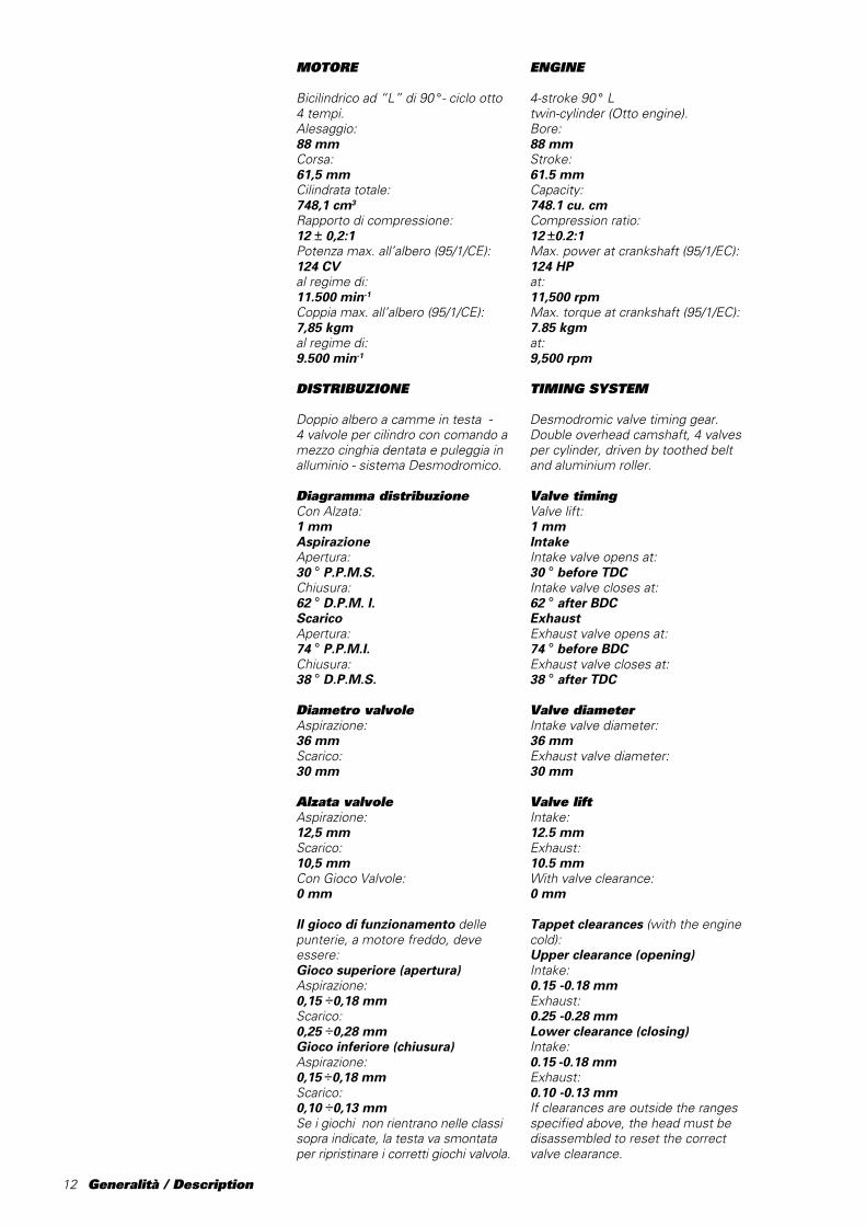
MOTORE
Bicilindrico ad “L” di 90 °- ciclo otto4 tempi.Alesaggio:88 mmCorsa:61,5 mmCilindrata totale:748,1 cm3
Rapporto di compressione:12 ± 0,2:1Potenza max. all’albero (95/1/CE):124 CVal regime di:11.500 min-1
Coppia max. all’albero (95/1/CE):7,85 kgmal regime di:9.500 min-1
DISTRIBUZIONE
Doppio albero a camme in testa -4␣ valvole per cilindro con comando amezzo cinghia dentata e puleggia inalluminio - sistema Desmodromico.
Diagramma distribuzioneCon Alzata:1 mmAspirazioneApertura:30 ° P.P.M.S.Chiusura:62 ° D.P.M. I.ScaricoApertura:74 ° P.P.M.I.Chiusura:38 ° D.P.M.S.
Diametro valvoleAspirazione:36 mmScarico:30 mm
Alzata valvoleAspirazione:12,5 mmScarico:10,5 mmCon Gioco Valvole:0 mm
Il gioco di funzionamento dellepunterie, a motore freddo, deveessere:Gioco superiore (apertura)Aspirazione:0,15 ÷0,18 mmScarico:0,25 ÷0,28 mmGioco inferiore (chiusura)Aspirazione:0,15 ÷0,18 mmScarico:0,10 ÷0,13 mmSe i giochi non rientrano nelle classisopra indicate, la testa va smontataper ripristinare i corretti giochi valvola.
ENGINE
4-stroke 90 ° Ltwin-cylinder (Otto engine).Bore:88 mmStroke:61.5 mmCapacity:748.1 cu. cmCompression ratio:12 ±0.2:1Max. power at crankshaft (95/1/EC):124 HPat:11,500 rpmMax. torque at crankshaft (95/1/EC):7.85 kgmat:9,500 rpm
TIMING SYSTEM
Desmodromic valve timing gear.Double overhead camshaft, 4 valvesper cylinder, driven by toothed beltand aluminium roller.
Valve timingValve lift:1 mmIntakeIntake valve opens at:30 ° before TDCIntake valve closes at:62 ° after BDCExhaustExhaust valve opens at:74 ° before BDCExhaust valve closes at:38 ° after TDC
Valve diameterIntake valve diameter:36 mmExhaust valve diameter:30 mm
Valve liftIntake:12.5 mmExhaust:10.5 mmWith valve clearance:0 mm
Tappet clearances (with the enginecold):Upper clearance (opening)Intake:0.15 -0.18 mmExhaust:0.25 -0.28 mmLower clearance (closing)Intake:0.15 -0.18 mmExhaust:0.10 -0.13 mmIf clearances are outside the rangesspecified above, the head must bedisassembled to reset the correctvalve clearance.
Generalità / Description 13
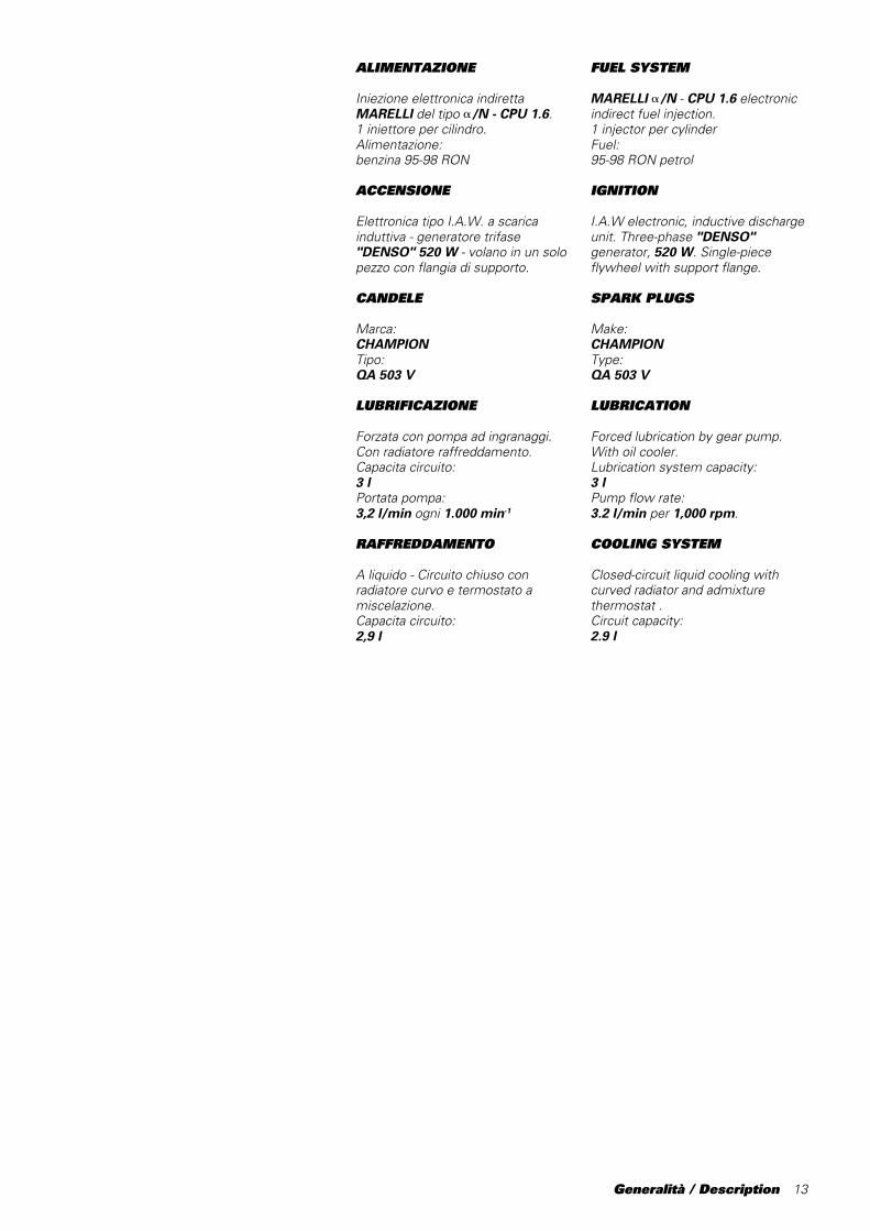
ALIMENTAZIONE
Iniezione elettronica indirettaMARELLI del tipo /N - CPU 1.6.1 iniettore per cilindro.Alimentazione:benzina 95-98 RON
ACCENSIONE
Elettronica tipo I.A.W. a scaricainduttiva - generatore trifase"DENSO" 520 W - volano in un solopezzo con flangia di supporto.
CANDELE
Marca:CHAMPIONTipo:QA 503 V
LUBRIFICAZIONE
Forzata con pompa ad ingranaggi.Con radiatore raffreddamento.Capacita circuito:3 lPortata pompa:3,2 l/min ogni 1.000 min-1
RAFFREDDAMENTO
A liquido - Circuito chiuso conradiatore curvo e termostato amiscelazione.Capacita circuito:2,9 l
FUEL SYSTEM
MARELLI /N - CPU 1.6 electronicindirect fuel injection.1 injector per cylinderFuel:95-98 RON petrol
IGNITION
I.A.W electronic, inductive dischargeunit. Three-phase "DENSO"generator, 520 W. Single-pieceflywheel with support flange.
SPARK PLUGS
Make:CHAMPIONType:QA 503 V
LUBRICATION
Forced lubrication by gear pump.With oil cooler.Lubrication system capacity:3 lPump flow rate:3.2 l/min per 1,000 rpm.
COOLING SYSTEM
Closed-circuit liquid cooling withcurved radiator and admixturethermostat .Circuit capacity:2.9 l

14 Generalità / Description
TRASMISSIONE
Trasmissione primariaAd ingranaggi a denti diritti.Pignone motore:Z31Corona frizione:Z62Rapporto di trasmissione:2÷1
Cambio velocitàCon ingranaggi a denti diritti semprein presa, comando a pedale sul latosinistro del veicolo.
Rapporti di trasmissione(Norme Cuna)
Marcia inserita
1a 32/16
2a 29/18
3a 27/20
4a 25/21
5a 24/22
6a 23/23
Trasmissione secondariaPignone uscita cambio:Z15Corona posteriore:Z38Marca e tipo catena:Regina 135ORNV4W
FRENI
AnterioreA doppio disco diametro 320 mmflottante con comando idraulico.Diametro cilindro pompa (PSC 16):16 mmDiametro cilindro pinza (p4.30-34):30-34 mm
PosterioreA disco diametro 220 mm concomando idraulico.Diametro cilindro pompa (PS 11):11 mmDiametro cilindro pinza (P 32F):32 mm
TRANSMISSION
Primary transmissionStraight-tooth gearsCrankshaft sprocket:31 teethClutch crown wheel:62 teethPrimary reduction ratio:2-1
GearboxConstant-mesh spur gears, directdrive. Gear change pedal on LH sideof motorcycle.
Gearbox ratios(Cuna Standard)
Gear engaged
1st 32/16
2nd 29/18
3rd 27/20
4th 25/21
5th 24/22
6th 23/23
Final driveFinal drive sprocket:15 teethRear wheel sprocket:38 teethChain make and type:Regina 135ORNV4W
BRAKES
Front brakeTwin 320 mm diam. floating discs,hydraulically operated.Master cylinder (PSC 16) diameter:16 mmCaliper slave cylinder (p 4-30-34)diameter:30-34 mm
Rear brake220 mm diam. disc, hydraulicallyoperated.Master cylinder (PS 11) diam.:11 mmCaliper slave cylinder (P 32F) diam.:32 mm

Generalità / Description 15
TELAIO
Traliccio aperto con il motoreelemento stressato della struttura -tubi tondi in acciaio, la carenatura, iparafanghi, il cupolino e la sella sonorealizzati in fibra composita carbonioe kevlar.Interasse:1410 mmAvancorsa regolabile:91,1÷97,1 mmInclinazione cannotto, angoloregolabile:23 ° 30' - 24 °30'Ammortizzatore di sterzo ÖHLINS.
SOSPENSIONI
AnterioreForcella SHOWA a canne rovesciate- freno idraulico in estensione,compressione, precarico mollaregolabili.Diametro steli:43 mmCorsa sull’asse gambe:127 mm
PosterioreProgressiva conmonoammortizzatore ÖHLINS concorpo in alluminio - regolabile inestensione, compressione eprecarico molla.Corsa ammortizzatore:74 mm (54 mm fino a tampone)Escursione ruota:130 mm
RUOTE
AnterioreCerchio anteriore in lega di alluminioa 5 razze.Dimensioni:MT 3,50 x 17"
PosterioreCerchio posteriore in lega dialluminio a 5 razze.Dimensioni :MT 5,50 x 17"
FRAME
Trellis space frame with engine asload bearing component. Steel roundtubes. Fairing, mudguards, frontfairing and seat in carbon fibre andKevlar.Wheelbase:1410 mmTrail:91.1 to 97.1 mm adjustableHeadstock rake:23 ° 30’ to 24° 30’ adjustableÖHLINS steering damper.
SUSPENSION
Front suspensionSHOWA inverted hydraulic fork; withadjustable spring rebound,compression and preload.Leg diameter:43 mmStanchion travel on slider:127 mm
Rear suspensionProgressive linkage with ÖHLINSaluminium-body monoshock.Adjustable spring rebound,compression and preload.Shock travel:74 mm (54 mm to buffer)Rear wheel travel:130 mm
WHEELS
Front wheelFive-spoke aluminium alloy wheel.Front rim size:MT 3.50 x 17”
Rear wheelFive-spoke aluminium alloy wheel.Rear rim size:MT 5.50 x 17”

16 Generalità / Description
PNEUMATICI
AnterioreMarca e tipo:MICHELINDimensione:120/70 ZR 17 TL
PosterioreMarca e tipo:MICHELINDimensione:180/55 ZR 17 TL
IMPIANTO ELETTRICO
Tensione impianto:12 VAlternatore:12 V - 520 WBatteria:12 V - 4 Ah
PESI
Totale (con olio e acqua):174 Kg
INGOMBRI
Lunghezza totale:2045 mmLarghezza max.:680 mmAltezza max.:1100 mmAltezza sella:800 mmAltezza min. da terra:130 mmAltezza manubrio:830 mmAltezza pedane:410 mm
CAPACITÀ
Serbatoio carburante:17 l.
TYRES
Front tyreMake and type:MICHELINSize:120/70 ZR 17 TL
Rear tyreMake and type:MICHELINSize:180/55 ZR 17 TL
ELECTRICAL SYSTEM
Voltage:12VGenerator:12 V - 520 WBattery:12 V - 4 Ah
WEIGHTS
Total weight (including oil and water):174 Kg
OVERALL DIMENSIONS
Overall length:2045 mmOverall width:680 mmOverall height:1100 mmSeat height:800 mmMin. ground clearance:130 mmHandlebar height:830 mmFront footpeg height:410 mm
CAPACITY
Fuel tank capacity:17 l.

Generalità / Description 17
Interventi raccomandatiMaintenance schedule
Interventi raccomandati / Maintenance schedule
18 Generalità / Description
Utilizzate solo ed esclusivamenteparti di ricambio originali Ducati eprodotti per il serraggio, la tenuta e lalubrificazione, consigliati e riportatinella tabella: "Caratteristicheprodotti".
OPERAZIONI PER LAMANUTENZIONE DEL MOTORE
- Nella pagina che segue è riportatala tabella di manutenzione motore,nella quale sono elencati i piùimportanti interventi e la relativaperiodicità.- È della massima importanzaattenersi a tale programmazione, perla manutenzione del motore.
SIMBOLI IDENTIFICAZIONEOPERAZIONE
C = Controllo e regolazioneP = PuliziaS = Sostituzione* = Solo in sala prova# = Sostituire ogni tre serraggi(considerando il serraggio iniziale delfornitore).
ImportanteAd ogni revisione, smontare
completamente il motore e sostituiretutte le parti anche soltantoapparentemente danneggiate, oltreche attenersi alla tabella dimanutenzione. Dopo la revisione:1000 km, il motore non è piùutilizzabile in gara.
Use Ducati original spare parts only.Use only the recommended thread-lockers, sealants and lubricantsspecified in table "Productspecifications".
ENGINE MAINTENANCE
- The next page provides an engineservice table listing the mostimportant maintenance operationsand recommended intervals.- It is very important that you strictlyfollow the recommendedmaintenance schedule.
OPERATION SYMBOLS
C = Check and adjustP = CleanS = Change* = do this in a test room# = Replace every three tightenings(including the original manufacturertightening).
CautionUpon each overhaul, strip the
engine completely and change allparts that appear to be even slightlydamaged. Follow the service table.After overhaul: 1,000 km, the enginecan no longer be used for racing.
Interventi raccomandati / Maintenance schedule

Generalità / Description 19
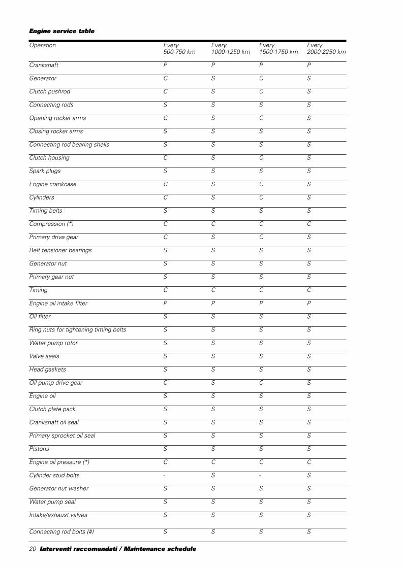
Tabella manutenzione motore
Operazioni Ogni Ogni Ogni Ogni500-750 km 1000 -1250km 1500-1750 km 2000-2250 km
Albero motore P P P P
Alternatore C S C S
Asta comando frizione C S C S
Bielle S S S S
Bilancieri di apertura C S C S
Bilancieri di chiusura S S S S
Bronzine bielle S S S S
Campana frizione C S C S
Candele S S S S
Carter motore C S C S
Cilindri C S C S
Cinghie distribuzione S S S S
Compressione (*) C C C C
Coppia primaria C S C S
Cuscinetti tendicinghia S S S S
Dado alternatore S S S S
Dado pignone primaria S S S S
Fasatura distribuzione C C C C
Filtro aspirazione olio motore P P P P
Filtro olio S S S S
Ghiere serraggio pulegge distribuzione S S S S
Girante pompa H2O S S S S
Gommini valvola S S S S
Guarnizioni teste S S S S
Ingranaggio di comando pompa olio C S C S
Olio motore S S S S
Pacco dischi frizione S S S S
Paraolio albero motore S S S S
Paraolio corona primaria S S S S
Pistoni completi S S S S
Pressione olio motore (*) C C C C
Prigionieri cilindri - S - S
Rosetta dado alternatore S S S S
Tenuta pompa acqua S S S S
Valvole aspirazione/scarico S S S S
Viti biella (#) S S S S
Interventi raccomandati / Maintenance schedule
20 Generalità / Description
Engine service table
Operation Every Every Every Every500-750 km 1000-1250 km 1500-1750 km 2000-2250 km
Crankshaft P P P P
Generator C S C S
Clutch pushrod C S C S
Connecting rods S S S S
Opening rocker arms C S C S
Closing rocker arms S S S S
Connecting rod bearing shells S S S S
Clutch housing C S C S
Spark plugs S S S S
Engine crankcase C S C S
Cylinders C S C S
Timing belts S S S S
Compression (*) C C C C
Primary drive gear C S C S
Belt tensioner bearings S S S S
Generator nut S S S S
Primary gear nut S S S S
Timing C C C C
Engine oil intake filter P P P P
Oil filter S S S S
Ring nuts for tightening timing belts S S S S
Water pump rotor S S S S
Valve seals S S S S
Head gaskets S S S S
Oil pump drive gear C S C S
Engine oil S S S S
Clutch plate pack S S S S
Crankshaft oil seal S S S S
Primary sprocket oil seal S S S S
Pistons S S S S
Engine oil pressure (*) C C C C
Cylinder stud bolts - S - S
Generator nut washer S S S S
Water pump seal S S S S
Intake/exhaust valves S S S S
Connecting rod bolts (#) S S S S
Interventi raccomandati / Maintenance schedule

Scomposizione motore / Engine disassembly 21
Scomposizione motoreEngine disassembly

22 Scomposizione motore / Engine disassembly
Scomposizione motore / Engine disassembly 23
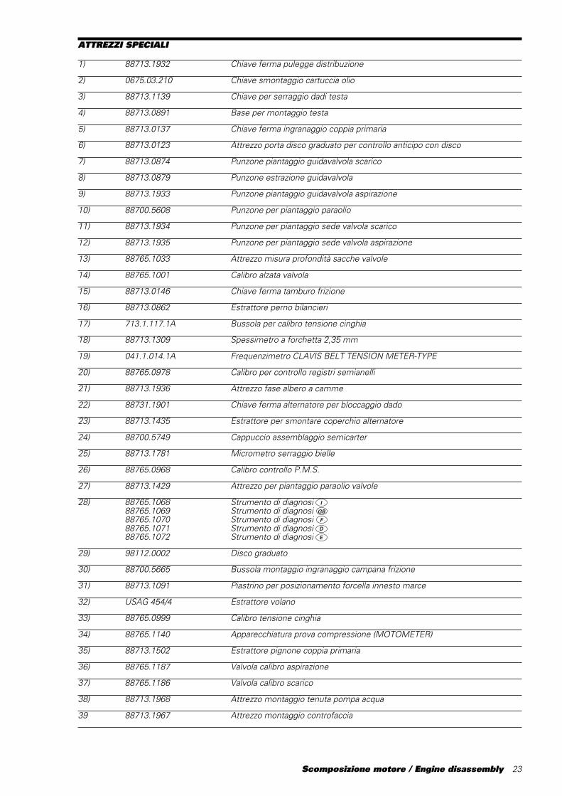
ATTREZZI SPECIALI
1) 88713.1932 Chiave ferma pulegge distribuzione
2) 0675.03.210 Chiave smontaggio cartuccia olio
3) 88713.1139 Chiave per serraggio dadi testa
4) 88713.0891 Base per montaggio testa
5) 88713.0137 Chiave ferma ingranaggio coppia primaria
6) 88713.0123 Attrezzo porta disco graduato per controllo anticipo con disco
7) 88713.0874 Punzone piantaggio guidavalvola scarico
8) 88713.0879 Punzone estrazione guidavalvola
9) 88713.1933 Punzone piantaggio guidavalvola aspirazione
10) 88700.5608 Punzone per piantaggio paraolio
11) 88713.1934 Punzone per piantaggio sede valvola scarico
12) 88713.1935 Punzone per piantaggio sede valvola aspirazione
13) 88765.1033 Attrezzo misura profondità sacche valvole
14) 88765.1001 Calibro alzata valvola
15) 88713.0146 Chiave ferma tamburo frizione
16) 88713.0862 Estrattore perno bilancieri
17) 713.1.117.1A Bussola per calibro tensione cinghia
18) 88713.1309 Spessimetro a forchetta 2,35 mm
19) 041.1.014.1A Frequenzimetro CLAVIS BELT TENSION METER-TYPE
20) 88765.0978 Calibro per controllo registri semianelli
21) 88713.1936 Attrezzo fase albero a camme
22) 88731.1901 Chiave ferma alternatore per bloccaggio dado
23) 88713.1435 Estrattore per smontare coperchio alternatore
24) 88700.5749 Cappuccio assemblaggio semicarter
25) 88713.1781 Micrometro serraggio bielle
26) 88765.0968 Calibro controllo P.M.S.
27) 88713.1429 Attrezzo per piantaggio paraolio valvole
28) 88765.1068 Strumento di diagnosi I
88765.1069 Strumento di diagnosi GB
88765.1070 Strumento di diagnosi F
88765.1071 Strumento di diagnosi D
88765.1072 Strumento di diagnosi E
29) 98112.0002 Disco graduato
30) 88700.5665 Bussola montaggio ingranaggio campana frizione
31) 88713.1091 Piastrino per posizionamento forcella innesto marce
32) USAG 454/4 Estrattore volano
33) 88765.0999 Calibro tensione cinghia
34) 88765.1140 Apparecchiatura prova compressione (MOTOMETER)
35) 88713.1502 Estrattore pignone coppia primaria
36) 88765.1187 Valvola calibro aspirazione
37) 88765.1186 Valvola calibro scarico
38) 88713.1968 Attrezzo montaggio tenuta pompa acqua
39 88713.1967 Attrezzo montaggio controfaccia

24 Scomposizione motore / Engine disassembly
SPECIAL SERVICE TOOLS FOR ENGINE
1) 88713.1932 Timing belt rollers wrench
2) 0675.03.210 Wrench for removing oil filter cartridge
3) 88713.1139 Wrench for tightening head nuts
4) 88713.0891 Base for head assemby
5) 88713.0137 Primary drive gear lock wrench
6) 88713.0123 Degree wheel holder tool for ignition advance check
7) 88713.0874 Exhaust valve guide drift
8) 88713.0879 Valve guide pulling drift
9) 88713.1933 Intake valve guide drift
10) 88700.5608 Oil seal drift
11) 88713.1934 Exhaust valve seat drift
12) 88713.1935 Intake valve seat drift
13) 88765.1033 Valve pocket depth gauge
14) 88765.1001 Valve lift gauge
15) 88713.0146 Clutch drum lock wrench
16) 88713.0862 Rocker shaft puller
17) 713.1.117.1A Bushing for belt tension gauge
18) 88713.1309 Fork feeler gauge - 2.35 mm
19) 041.1.014.1A Frequency meter CLAVIS BELT TENSION METER-TYPE
20) 88765.0978 Split ring shim gauge
21) 88713.1936 Camshaft timing tool
22) 88713.1901 Generator clamp wrench for nut locking
23) 88713.1435 Puller for removal of generator cover
24) 88700.5749 Casing assembly cap
25) 88713.1781 Micrometer for tightening con-rods
26) 88765.0968 TDC check gauge
27) 88713.1429 Valve seal drift
28) 88765.1068 Tester I
88765.1069 Tester E
88765.1070 Tester F
88765.1071 Tester D88765.1072 Tester E
29) 98112.0002 Degree wheel
30) 88700.5665 Bushing for mounting clutch housing gear
31) 88713.1091 Plate for positioning gear engagement fork
32) USAG 454/4 Flywheel puller
33) 88765.0999 Belt tension gauge
34) 88765.1140 Compression tester (MOTOMETER)
35) 88713.1502 Primary drive sprocket puller
36) 88765.1187 Master intake valve
37) 88765.1186 Master exhaust valve
38) 88713.1968 Water pump seal assembly tool
39) 88713.1967 Counter face assembly tool

Scomposizione motore / Engine disassembly 25
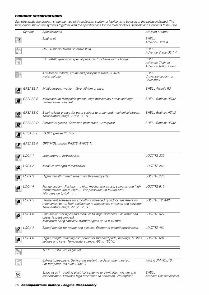
CARATTERISTICHE PRODOTTI
I prodotti usati per il serraggio, la sigillatura e la lubrificazione degli elementi verranno rappresentati all'interno dellafigura con un simbolo. La tabella riporta i simboli utilizzati e le caratteristiche relative ai vari prodotti.
Simbolo Caratteristiche Prodotto consigliato
Olio motore SHELLAdvance Ultra 4
Liquido speciale per sistemi idraulici DOT 4. SHELLAdvance Brake DOT 4
Olio per ingranaggi SAE 80-90 o prodotti specifici per catene SHELLcon anelli OR. Advance Chain o
Advance Teflon Chain
Liquido antigelo (totalmente assente da nitriti, ammine e fosfati) SHELL35÷40% + acqua. Advance coolant o
Glycoshell
GREASE A Grasso a base di litio, a fibra media, di tipo "multipurpose". SHELL Alvania R3
GREASE B Grasso al bisolfuro di molibdeno resistente ad estreme sollecitazioni SHELL meccaniche e termiche. Retinax HDX2
GREASE C Grasso per cuscinetti e articolazioni sottoposti a prolungate sollecitazioni SHELLmeccaniche. Temperatura di utilizzo da –10 a 110 °C. Retinax LX2
GREASE D Grasso con proprietà protettive, anticorrosive e di idrorepellenza. SHELLRetinax HD2
GREASE E Grasso PANKL - PLB 05.
GREASE F Grasso OPTIMOL - PASTE WHITE T.
LOCK 1 Frenafiletti a debole resistenza meccanica. LOCTITE 222
LOCK 2 Frenafiletti a media resistenza meccanica. LOCTITE 243
LOCK 3 Frenafiletti ad alta resistenza meccanica per sigillatura di parti filettate. LOCTITE 270
LOCK 4 Sigillante per piani ad alta resistenza meccanica e ai solventi. Resiste ad LOCTITE 510alte temperature (fino a 200 °C), sigilla pressioni fino a 350 Atm ecolma giochi fino a 0,4 mm.
LOCK 5 Adesivo strutturale permanente per accoppiamenti cilindri a LOCTITE 128443scorrimento libero o filettati su parti meccaniche. Alta resistenzameccanica ed ai solventi. Temperatura di utilizzo da –55 a 175 °C.
LOCK 6 Sigillante di tubazioni e raccorderie medio-grandi, per acqua e ogni tipo LOCTITE 577di gas (ad eccezione dell'ossigeno). Massima capacità di riempimento:0,40 mm (gioco diametrale).
LOCK 7 Adesivo istantaneo gomma - plastica, con base etilica caricato LOCTITE 480ad elastomeri.
LOCK 8 Bloccante permanente di parti filettate, cuscinetti, bussole, scanalati LOCTITE 601e chiavette. Temperatura di esercizio da –55 a 150 °C.
Guarnizione liquida THREE BOND.
Pasta sigillante per tubi di scarico. Autosigillante si indurisce al calore FIRE GUM HOLTSe resiste a temperature superiori a 1000 °C.
Spray impiegato nel trattamento degli impianti elettrici. Rimuove umidità SHELLe condensa e offre alta resistenza alla corrosione. Idrorepellente. Advance Contact Cleaner
1LOCK
2LOCK
3LOCK
4LOCK
5LOCK
6LOCK
7LOCK
8LOCK
A
B
C
E
F
D
26 Scomposizione motore / Engine disassembly
PRODUCT SPECIFICATIONS
Symbols inside the diagram show the type of threadlocker, sealant or lubricants to be used at the points indicated. Thetable below shows the symbols together with the specifications for the threadlockers, sealants and lubricants to be used.
Symbol Specifications Advised product
Engine oil SHELLAdvance Ultra 4
DOT 4 special hydraulic brake fluid. SHELLAdvance Brake DOT 4
SAE 80-90 gear oil or special products for chains with O-rings. SHELLAdvance Chain orAdvance Teflon Chain
Anti-freeze (nitride, amine and phosphate free) 35 -40% SHELLwater solution. Advance coolant or
Glycoshell
GREASE A Multipurpose, medium fibre, lithium grease. SHELL Alvania R3
GREASE B Molybdenum disulphide grease, high mechanical stress and high SHELL Retinax HDX2temperature resistant.
GREASE C Bearing/joint grease for parts subject to prolonged mechanical stress. SHELL Retinax HDX2Temperature range: -10 to 110 °C.
GREASE D Protective grease. Corrosion protectant, waterproof. SHELL Retinax HDX2
GREASE E PANKL grease PLB 05.
GREASE F OPTIMOL grease PASTE WHITE T.
LOCK 1 Low-strength threadlocker. LOCTITE 222
LOCK 2 Medium-strength threadlocker. LOCTITE 243
LOCK 3 High-strength thread sealant for threaded parts. LOCTITE 270
LOCK 4 Flange sealant. Resistant to high mechanical stress, solvents and high LOCTITE 510temperatures (up to 200 °C). For pressures up to 350 Atm.Fills gaps up to 0.4 mm.
LOCK 5 Permanent adhesive for smooth or threaded cylindrical fasteners on LOCTITE 128443mechanical parts. High resistance to mechanical stresses and solvents.Temperature range: -55 to 175 °C.
LOCK 6 Pipe sealant for pipes and medium to large fasteners. For water and LOCTITE 577gases (except oxygen).Maximum filling capacity: diameter gaps up to 0.40 mm.
LOCK 7 Speed bonder for rubber and plastics. Elastomer loaded ethylic base. LOCTITE 480
LOCK 8 High-strength retaining compound for threaded parts, bearings, bushes, LOCTITE 601splines and keys. Temperature range: -55 to 150 °C.
THREE BOND liquid gasket.
Exhaust pipe paste. Self-curing sealant, hardens when heated. FIRE GUM HOLTSFor temperatures over 1000 °C.
Spray used in treating electrical systems to eliminate moisture and SHELLcondensation. Provides high resistance to corrosion. Waterproof. Advance Contact cleaner.
1LOCK
2LOCK
3LOCK
4LOCK
5LOCK
6LOCK
7LOCK
8LOCK
A
B
C
E
D
F
Scomposizione motore / Engine disassembly 27
SCARICO OLIO
❍ Svitare e rimuovere il tappo discarico (1) con relativa guarnizione.❍ Svitare e rimuovere il filtro olio (2)utilizzando l’apposito attrezzocod.␣ 0675.03.210.
AttenzioneNon disperdere l’olio esausto
nell’ambiente
SCARICO LIQUIDO DIRAFFREDDAMENTO
❍ Svitare la vite (1) dal raccordo dimandata acqua dalla pompa alcilindro orizzontale e lasciare drenareil liquido contenuto nel motore.❍ Rimuovere i manicotti dicollegamento pompa-cilindri.
1
2
1
DRAINING THE OIL
❍ Unscrew and remove the drainplug (1) complete with its seal.❍ Unscrew and remove the oil filter(2) using the service tool partno.␣ 0675.03.210.
WarningDispose of oil in compliance
with environmental protectionregulations.
DRAINING THE COOLANT
❍ Unscrew the screw (1) of thecoolant delivery hose between thepump and the horizontal cylinder andallow the engine coolant to drain off.❍ Remove the hoses between thepump and the cylinders.
28 Scomposizione motore / Engine disassembly
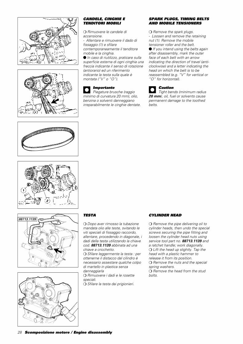
CANDELE, CINGHIE ETENDITORI MOBILI
❍ Rimuovere le candele diaccensione.- Allentare e rimuovere il dado difissaggio (1) e sfilarecontemporaneamente il tenditoremobile e la cinghia.● In caso di riutilizzo, praticare sullasuperficie esterna di ogni cinghia unafreccia indicante il senso di rotazione(antiorario) ed un riferimentoindicante la testa sulla quale èmontata (“V” o “O”).
ImportantePiegature brusche (raggio
minimo di curvatura 20 mm), olio,benzina o solventi danneggianoirreparabilmente le cinghie dentate.
TESTA
❍ Dopo aver rimosso la tubazionemandata olio alle teste, svitando leviti speciali di fissaggio raccordo,allentare, procedendo in diagonale, idadi della testa utilizzando la chiavecod. 88713.1139 abbinata ad unachiave a cricchetto.❍ Sfilare leggermente la testa : perottenerne il distacco dal cilindro ènecessario assestare qualche colpodi martello in plastica senzadanneggiarla❍ Rimuovere i dadi e le rosettespeciali.❍ Sfilare la testa dai prigionieri.
88713.1139
SPARK PLUGS, TIMING BELTSAND MOBILE TENSIONERS
❍ Remove the spark plugs.- Loosen and remove the retainingnut (1). Remove the mobiletensioner roller and the belt.● If you intend using the belts againafter disassembly, mark the outerface of each belt with an arrowindicating the direction of travel (anti-clockwise) and a letter indicating thehead on which the belt is to bereassembled (e.g. “V” for vertical or“O” for horizontal).
CautionTight bends (minimum radius
20 mm), oil, fuel or solvents causepermanent damage to the toothedbelts.
CYLINDER HEAD
❍ Remove the pipe delivering oil tocylinder heads, then undo the specialscrews securing the pipe fitting andloosen the cylinder head nuts usingservice tool part no.␣ 88713.1139 anda ratchet handle; work diagonally.❍ Lift the head up slightly. Tap thehead with a plastic hammer torelease it from its position.❍ Remove the nuts and the specialspring washers.❍ Remove the head from the studbolts.
Scomposizione motore / Engine disassembly 29
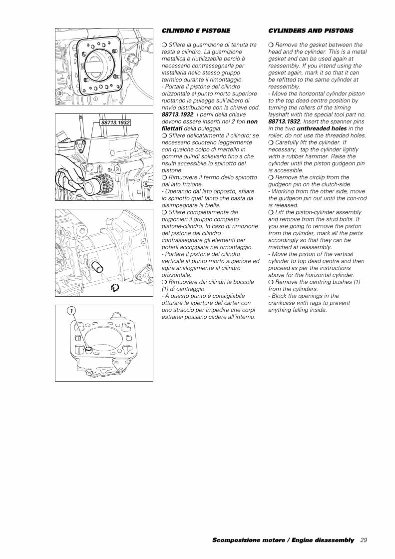
CILINDRO E PISTONE
❍ Sfilare la guarnizione di tenuta tratesta e cilindro. La guarnizionemetallica è riutilizzabile perciò ènecessario contrassegnarla perinstallarla nello stesso gruppotermico durante il rimontaggio.- Portare il pistone del cilindroorizzontale al punto morto superioreruotando le pulegge sull’albero dirinvio distribuzione con la chiave cod.88713.1932. I perni della chiavedevono essere inseriti nei 2 fori nonfilettati della puleggia.❍ Sfilare delicatamente il cilindro; senecessario scuoterlo leggermentecon qualche colpo di martello ingomma quindi sollevarlo fino a cherisulti accessibile lo spinotto delpistone.❍ Rimuovere il fermo dello spinottodal lato frizione.- Operando dal lato opposto, sfilarelo spinotto quel tanto che basta dadisimpegnare la biella.❍ Sfilare completamente daiprigionieri il gruppo completopistone-cilindro. In caso di rimozionedel pistone dal cilindrocontrassegnare gli elementi perpoterli accoppiare nel rimontaggio.- Portare il pistone del cilindroverticale al punto morto superiore edagire analogamente al cilindroorizzontale.❍ Rimuovere dai cilindri le boccole(1) di centraggio.- A questo punto è consigliabileotturare le aperture del carter conuno straccio per impedire che corpiestranei possano cadere all’interno.
88713.1932
1
CYLINDERS AND PISTONS
❍ Remove the gasket between thehead and the cylinder. This is a metalgasket and can be used again atreassembly. If you intend using thegasket again, mark it so that it canbe refitted to the same cylinder atreassembly.- Move the horizontal cylinder pistonto the top dead centre position byturning the rollers of the timinglayshaft with the special tool part no.88713.1932. Insert the spanner pinsin the two unthreaded holes in theroller; do not use the threaded holes.❍ Carefully lift the cylinder. Ifnecessary, tap the cylinder lightlywith a rubber hammer. Raise thecylinder until the piston gudgeon pinis accessible.❍ Remove the circlip from thegudgeon pin on the clutch-side.- Working from the other side, movethe gudgeon pin out until the con-rodis released.❍ Lift the piston-cylinder assemblyand remove from the stud bolts. Ifyou are going to remove the pistonfrom the cylinder, mark all the partsaccordingly so that they can bematched at reassembly.- Move the piston of the verticalcylinder to top dead centre and thenproceed as per the instructionsabove for the horizontal cylinder.❍ Remove the centring bushes (1)from the cylinders.- Block the openings in thecrankcase with rags to preventanything falling inside.
30 Scomposizione motore / Engine disassembly
COPERCHIO ALTERNATORE
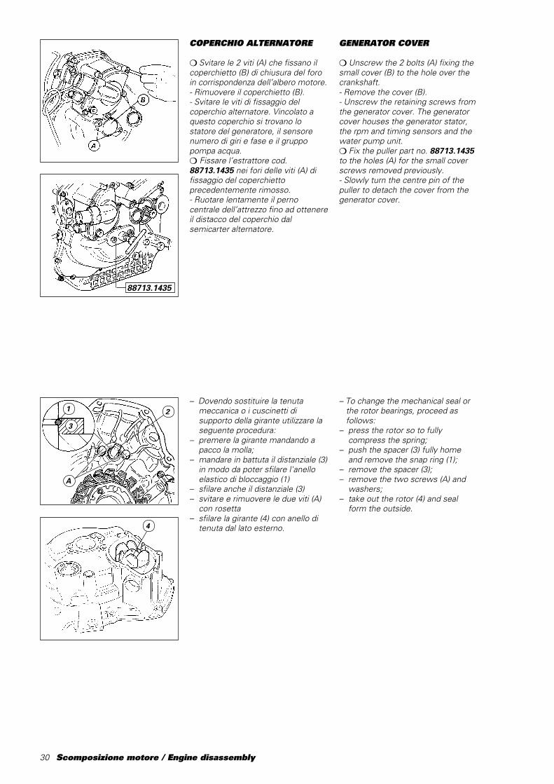
❍ Svitare le 2 viti (A) che fissano ilcoperchietto (B) di chiusura del foroin corrispondenza dell’albero motore.- Rimuovere il coperchietto (B).- Svitare le viti di fissaggio delcoperchio alternatore. Vincolato aquesto coperchio si trovano lostatore del generatore, il sensorenumero di giri e fase e il gruppopompa acqua.❍ Fissare l’estrattore cod.88713.1435 nei fori delle viti (A) difissaggio del coperchiettoprecedentemente rimosso.- Ruotare lentamente il pernocentrale dell’attrezzo fino ad ottenereil distacco del coperchio dalsemicarter alternatore.
– Dovendo sostituire la tenuta meccanica o i cuscinetti di supporto della girante utilizzare la seguente procedura:– premere la girante mandando a
pacco la molla;– mandare in battuta il distanziale (3)
in modo da poter sfilare l'anelloelastico di bloccaggio (1)
– sfilare anche il distanziale (3)– svitare e rimuovere le due viti (A)
con rosetta– sfilare la girante (4) con anello di
tenuta dal lato esterno.4
GENERATOR COVER
❍ Unscrew the 2 bolts (A) fixing thesmall cover (B) to the hole over thecrankshaft.- Remove the cover (B).- Unscrew the retaining screws fromthe generator cover. The generatorcover houses the generator stator,the rpm and timing sensors and thewater pump unit.❍ Fix the puller part no. 88713.1435to the holes (A) for the small coverscrews removed previously.- Slowly turn the centre pin of thepuller to detach the cover from thegenerator cover.
– To change the mechanical seal or the rotor bearings, proceed as follows:– press the rotor so to fully
compress the spring;– push the spacer (3) fully home
and remove the snap ring (1);– remove the spacer (3);– remove the two screws (A) and
washers;– take out the rotor (4) and seal
form the outside.
88713.1435
3
1 2
A
Scomposizione motore / Engine disassembly 31
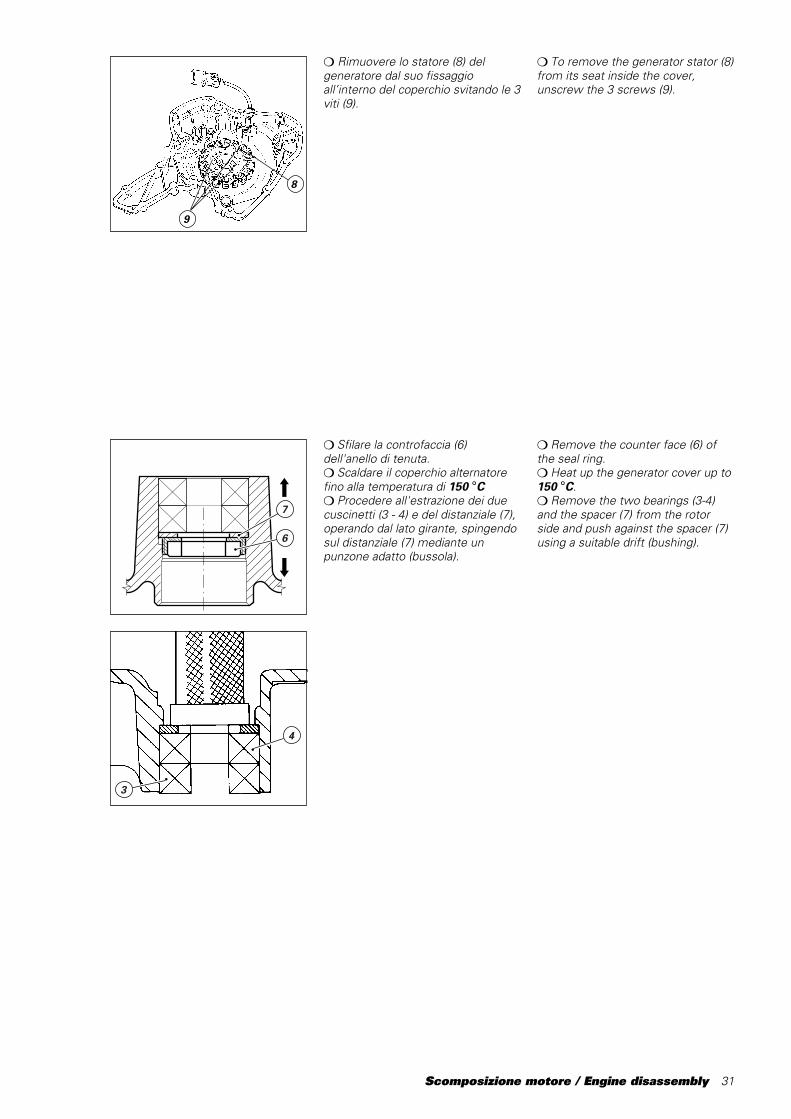
❍ Sfilare la controfaccia (6)dell'anello di tenuta.❍ Scaldare il coperchio alternatorefino alla temperatura di 150 °C❍ Procedere all'estrazione dei duecuscinetti (3 - 4) e del distanziale (7),operando dal lato girante, spingendosul distanziale (7) mediante unpunzone adatto (bussola).
3
4
7
6
9
8
❍ To remove the generator stator (8)from its seat inside the cover,unscrew the 3 screws (9).
❍ Remove the counter face (6) ofthe seal ring.❍ Heat up the generator cover up to150 °C.❍ Remove the two bearings (3-4)and the spacer (7) from the rotorside and push against the spacer (7)using a suitable drift (bushing).
❍ Rimuovere lo statore (8) delgeneratore dal suo fissaggioall’interno del coperchio svitando le 3viti (9).
32 Scomposizione motore / Engine disassembly
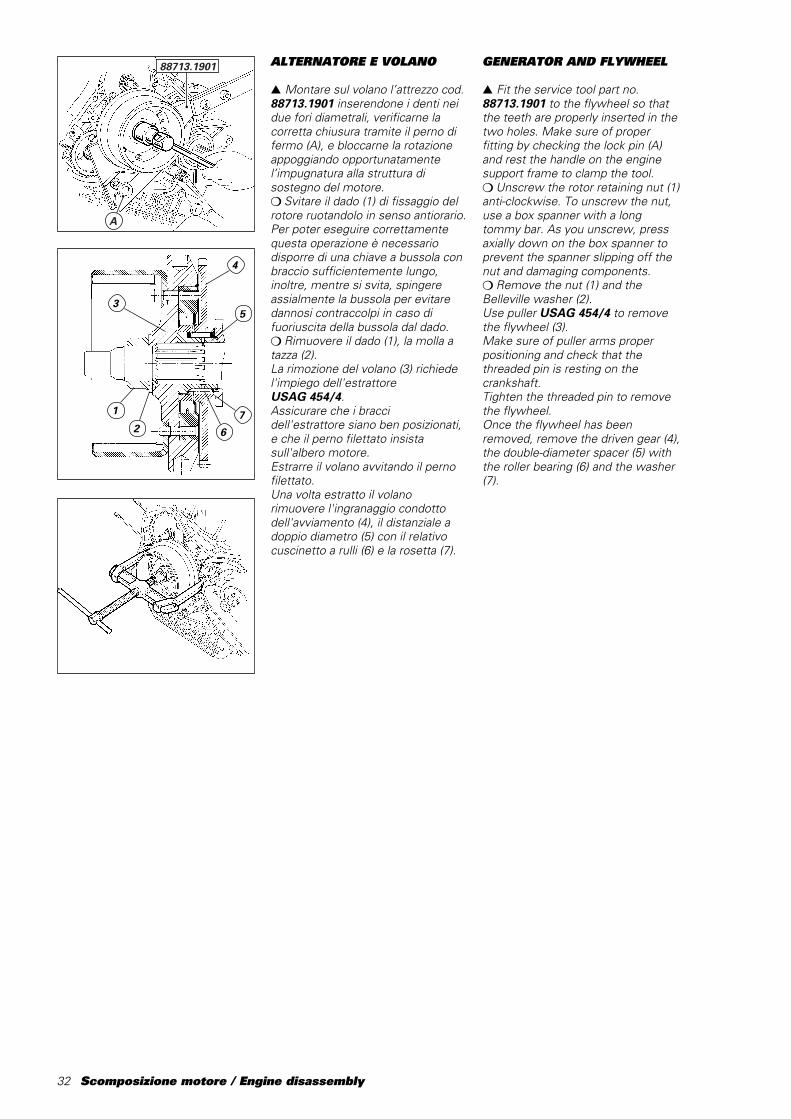
ALTERNATORE E VOLANO
▲ Montare sul volano l’attrezzo cod.88713.1901 inserendone i denti neidue fori diametrali, verificarne lacorretta chiusura tramite il perno difermo (A), e bloccarne la rotazioneappoggiando opportunatamentel’impugnatura alla struttura disostegno del motore.❍ Svitare il dado (1) di fissaggio delrotore ruotandolo in senso antiorario.Per poter eseguire correttamentequesta operazione è necessariodisporre di una chiave a bussola conbraccio sufficientemente lungo,inoltre, mentre si svita, spingereassialmente la bussola per evitaredannosi contraccolpi in caso difuoriuscita della bussola dal dado.❍ Rimuovere il dado (1), la molla atazza (2).La rimozione del volano (3) richiedel'impiego dell'estrattoreUSAG 454/4.Assicurare che i braccidell'estrattore siano ben posizionati,e che il perno filettato insistasull'albero motore.Estrarre il volano avvitando il pernofilettato.Una volta estratto il volanorimuovere l'ingranaggio condottodell'avviamento (4), il distanziale adoppio diametro (5) con il relativocuscinetto a rulli (6) e la rosetta (7).
A
88713.1901
2
1
53
GENERATOR AND FLYWHEEL
▲ Fit the service tool part no.88713.1901 to the flywheel so thatthe teeth are properly inserted in thetwo holes. Make sure of properfitting by checking the lock pin (A)and rest the handle on the enginesupport frame to clamp the tool.❍ Unscrew the rotor retaining nut (1)anti-clockwise. To unscrew the nut,use a box spanner with a longtommy bar. As you unscrew, pressaxially down on the box spanner toprevent the spanner slipping off thenut and damaging components.❍ Remove the nut (1) and theBelleville washer (2).Use puller USAG 454/4 to removethe flywheel (3).Make sure of puller arms properpositioning and check that thethreaded pin is resting on thecrankshaft.Tighten the threaded pin to removethe flywheel.Once the flywheel has beenremoved, remove the driven gear (4),the double-diameter spacer (5) withthe roller bearing (6) and the washer(7).
7
6
4
Scomposizione motore / Engine disassembly 33
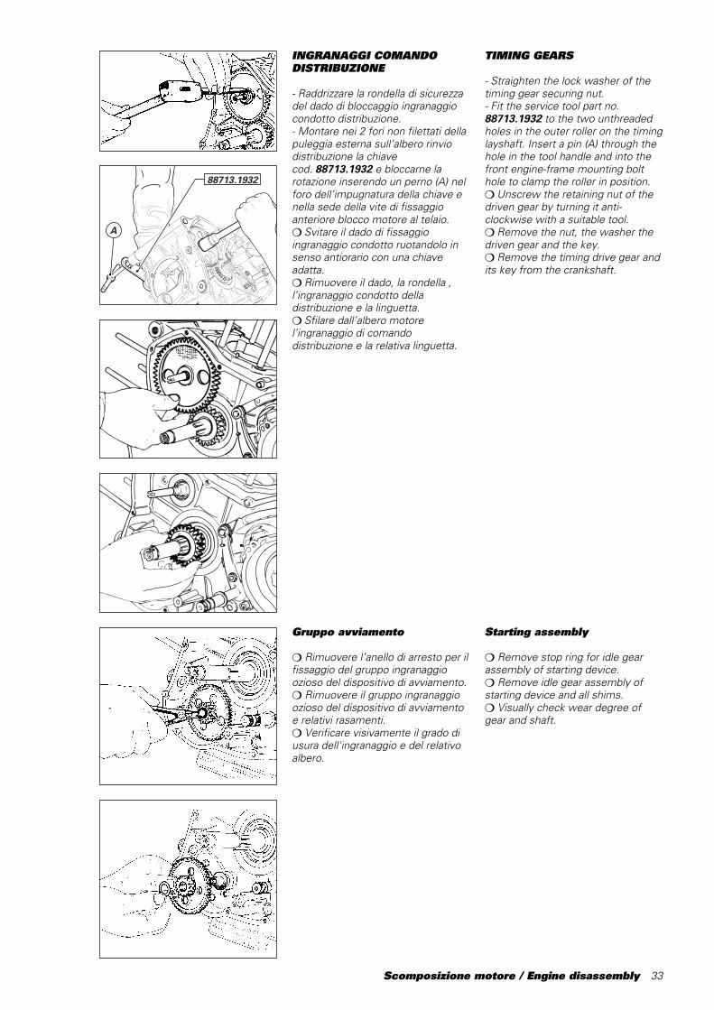
INGRANAGGI COMANDODISTRIBUZIONE
- Raddrizzare la rondella di sicurezzadel dado di bloccaggio ingranaggiocondotto distribuzione.- Montare nei 2 fori non filettati dellapuleggia esterna sull’albero rinviodistribuzione la chiavecod.␣ 88713.1932 e bloccarne larotazione inserendo un perno (A) nelforo dell’impugnatura della chiave enella sede della vite di fissaggioanteriore blocco motore al telaio.❍ Svitare il dado di fissaggioingranaggio condotto ruotandolo insenso antiorario con una chiaveadatta.❍ Rimuovere il dado, la rondella ,l’ingranaggio condotto delladistribuzione e la linguetta.❍ Sfilare dall’albero motorel’ingranaggio di comandodistribuzione e la relativa linguetta.
A
88713.1932
TIMING GEARS
- Straighten the lock washer of thetiming gear securing nut.- Fit the service tool part no.88713.1932 to the two unthreadedholes in the outer roller on the timinglayshaft. Insert a pin (A) through thehole in the tool handle and into thefront engine-frame mounting bolthole to clamp the roller in position.❍ Unscrew the retaining nut of thedriven gear by turning it anti-clockwise with a suitable tool.❍ Remove the nut, the washer thedriven gear and the key.❍ Remove the timing drive gear andits key from the crankshaft.
Gruppo avviamento
❍ Rimuovere l’anello di arresto per ilfissaggio del gruppo ingranaggioozioso del dispositivo di avviamento.❍ Rimuovere il gruppo ingranaggioozioso del dispositivo di avviamentoe relativi rasamenti.❍ Verificare visivamente il grado diusura dell'ingranaggio e del relativoalbero.
Starting assembly
❍ Remove stop ring for idle gearassembly of starting device.❍ Remove idle gear assembly ofstarting device and all shims.❍ Visually check wear degree ofgear and shaft.

34 Scomposizione motore / Engine disassembly
1
ASTA COMANDO FRIZIONE
❍ Sfilare l’asta (1) comando frizionecompleta di anelli OR.
GEAR SELECTOR LEVER
❍ Unscrew the 2 retaining boltsfrom the gear selector lever.❍ Remove the complete leverassembly from the casing.
CLUTCH PUSHROD
❍ Slide out the clutch pushrod (1)complete with O-rings.
LEVERAGGIO SELEZIONEMARCE
❍ Svitare le 2 viti di fissaggio delleveraggio di selezione del cambio.❍ Rimuovere il leveraggio completodal carter.
Scomposizione motore / Engine disassembly 35
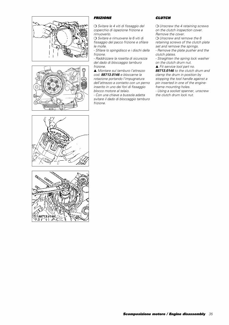
FRIZIONE
❍ Svitare le 4 viti di fissaggio delcoperchio di ispezione frizione erimuoverlo.❍ Svitare e rimuovere le 6 viti difissaggio del pacco frizione e sfilarele molle.- Sfilare lo spingidisco e i dischi dellafrizione.- Raddrizzare la rosetta di sicurezzadel dado di bloccaggio tamburofrizione.▲ Montare sul tamburo l’attrezzocod. 88713.0146 e bloccarne larotazione portando l’impugnaturadell’attrezzo a contatto con un pernoinserito in uno dei fori di fissaggioblocco motore al telaio.- Con una chiave a bussola adattasvitare il dado di bloccaggio tamburofrizione.
CLUTCH
❍ Unscrew the 4 retaining screwson the clutch inspection cover.Remove the cover.❍ Unscrew and remove the 6retaining screws of the clutch plateset and remove the springs.- Remove the plate pusher and theclutch plates.- Straighten the spring lock washeron the clutch drum nut.▲ Fit service tool part no.88713.0146 to the clutch drum andclamp the drum in position bystopping the tool handle against apin inserted in one of the engine-frame mounting holes.- Using a socket spanner, unscrewthe clutch drum lock nut.
36 Scomposizione motore / Engine disassembly
31 2 4
5 6
987
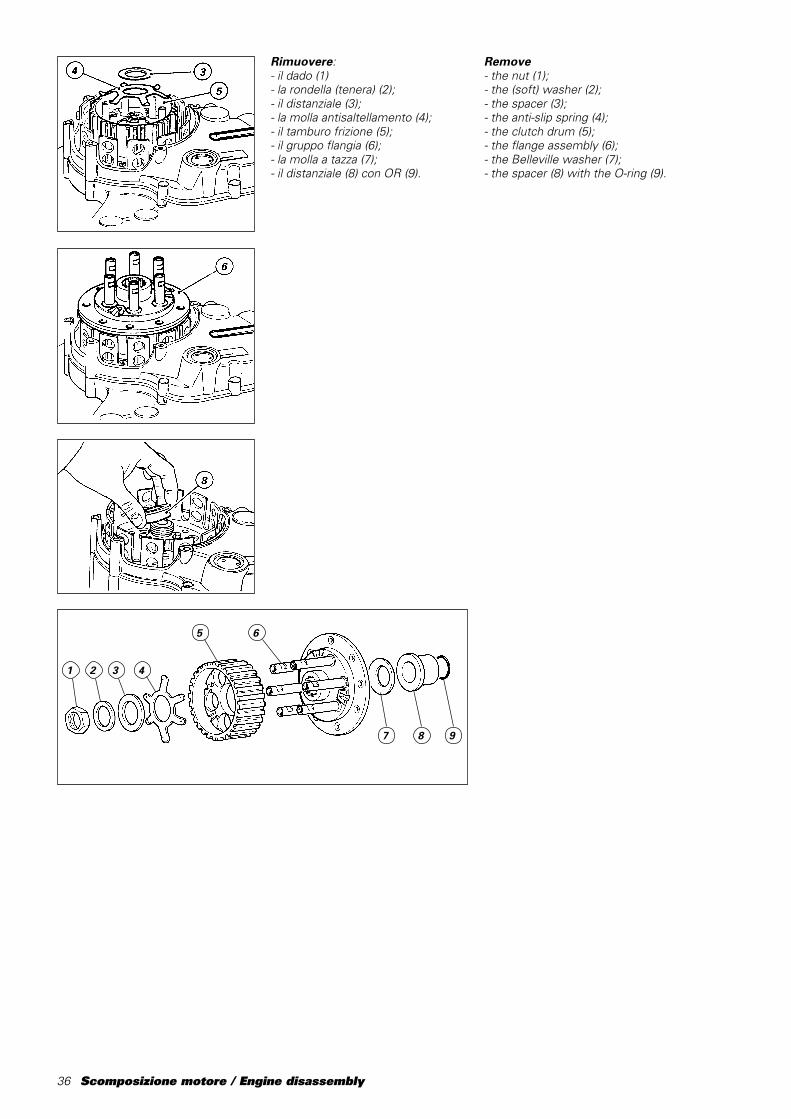
Remove- the nut (1);- the (soft) washer (2);- the spacer (3);- the anti-slip spring (4);- the clutch drum (5);- the flange assembly (6);- the Belleville washer (7);- the spacer (8) with the O-ring (9).
Rimuovere:- il dado (1)- la rondella (tenera) (2);- il distanziale (3);- la molla antisaltellamento (4);- il tamburo frizione (5);- il gruppo flangia (6);- la molla a tazza (7);- il distanziale (8) con OR (9).

Scomposizione motore / Engine disassembly 37
1
CLUTCH CASING
- Fit the service tool part no.88713.1932, as shown to preventthe drum unit from rotating while thescrews are being loosened.- Remove the clutch housing fromthe primary drive gear.
NoteIf you do not intend to work on
any of the clutch casingcomponents, you may skip theprevious operation and leave thehousing and the primary drive gearmounted on the clutch casing.
- Unscrew and remove the 8retaining bolts on the clutch casing.Tap around the outside of the casingwith a plastic hammer so that clutchcasing detaches from the crankcasehalf.- Remove the 0-ring (1) from the oilway between the clutch casing andthe crankcase half.
COPERCHIO FRIZIONE
- Posizionare l'attrezzocod.␣ 88713.1932, come in figura, perimpedire la rotazione della campanadurante l'allentamento delle viti.- Rimuovere la campana frizionedall’ingranaggio della primaria.
NoteSe non deve essere eseguito
nessun intervento sugli elementi checompongono il coperchio, questaoperazione può essere evitatalasciando il gruppo campana eingranaggio della primaria montatosul coperchio frizione.
- Svitare e rimuovere le 8 viti difissaggio del coperchio frizione e,aiutandosi con un martello diplastica, battere in vari punti sulcontorno del coperchio per favorire ildistacco dello stesso dal semicarter.- Rimuovere l’anello OR (1) incorrispondenza del passaggio olio tracoperchio frizione e semicarter.
38 Scomposizione motore / Engine disassembly
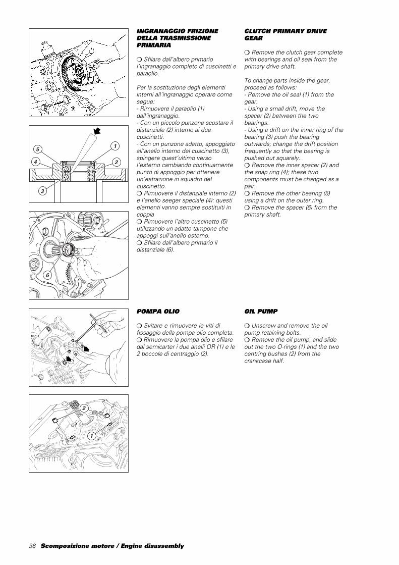
POMPA OLIO
❍ Svitare e rimuovere le viti difissaggio della pompa olio completa.❍ Rimuovere la pompa olio e sfilaredal semicarter i due anelli OR (1) e le2 boccole di centraggio (2).
2
1
INGRANAGGIO FRIZIONEDELLA TRASMISSIONEPRIMARIA
❍ Sfilare dall’albero primariol’ingranaggio completo di cuscinetti eparaolio.
Per la sostituzione degli elementiinterni all’ingranaggio operare comesegue:- Rimuovere il paraolio (1)dall’ingranaggio.- Con un piccolo punzone scostare ildistanziale (2) interno ai duecuscinetti.- Con un punzone adatto, appoggiatoall’anello interno del cuscinetto (3),spingere quest’ultimo versol’esterno cambiando continuamentepunto di appoggio per ottenereun’estrazione in squadro delcuscinetto.❍ Rimuovere il distanziale interno (2)e l’anello seeger speciale (4): questielementi vanno sempre sostituiti incoppia❍ Rimuovere l’altro cuscinetto (5)utilizzando un adatto tampone cheappoggi sull’anello esterno.❍ Sfilare dall’albero primario ildistanziale (6).
6
��@@��ÀÀ��@@��ÀÀ��yy��@@��ÀÀ��@@��ÀÀ��yy
1
24
5
3
CLUTCH PRIMARY DRIVEGEAR
❍ Remove the clutch gear completewith bearings and oil seal from theprimary drive shaft.
To change parts inside the gear,proceed as follows:- Remove the oil seal (1) from thegear.- Using a small drift, move thespacer (2) between the twobearings.- Using a drift on the inner ring of thebearing (3) push the bearingoutwards; change the drift positionfrequently so that the bearing ispushed out squarely.❍ Remove the inner spacer (2) andthe snap ring (4); these twocomponents must be changed as apair.❍ Remove the other bearing (5)using a drift on the outer ring.❍ Remove the spacer (6) from theprimary shaft.
OIL PUMP
❍ Unscrew and remove the oilpump retaining bolts.❍ Remove the oil pump, and slideout the two O-rings (1) and the twocentring bushes (2) from thecrankcase half.
Scomposizione motore / Engine disassembly 39
INGRANAGGIO ALBEROMOTORE DELLATRASMISSIONE PRIMARIA
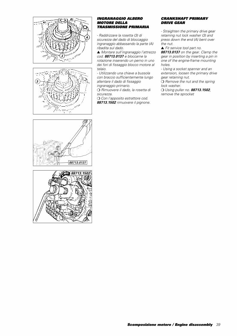
- Raddrizzare la rosetta (3) disicurezza del dado di bloccaggioingranaggio abbassando la parte (A)ribadita sul dado.▲ Montare sull’ingranaggio l’attrezzocod. 88713.0137 e bloccarne larotazione inserendo un perno in unodei fori di fissaggio blocco motore altelaio.- Utilizzando una chiave a bussolacon braccio sufficientemente lungoallentare il dado di fissaggioingranaggio primario.❍ Rimuovere il dado, la rosetta disicurezza.❍ Con l'apposito estrattore cod.88713.1502 rimuovere il pignone.
88713.0137
3
CRANKSHAFT PRIMARYDRIVE GEAR
- Straighten the primary drive gearretaining nut lock washer (3) andpress down the end (A) bent overthe nut.▲ Fit service tool part no.88713.0137 on the gear. Clamp thegear in position by inserting a pin inone of the engine-frame mountingholes.- Using a socket spanner and anextension, loosen the primary drivegear retaining nut.❍ Remove the nut and the springlock washer.❍ Using puller no. 88713.1502,remove the sprocket
88713.1502

40 Scomposizione motore / Engine disassembly
PULEGGE RINVIODISTRIBUZIONE
- Montare nei due fori non filettatidella puleggia esterna la chiave cod.88713.1932 e bloccarne la rotazioneinserendo un perno (A) nel forodell’impugnatura dell’attrezzo e nellasede della vite di fissaggio anterioreblocco motore al telaio.- Utilizzando la bussola dell’attrezzoinserita in una chiave a cricchettoallentare la ghiera di fissaggiopulegge distribuzione.❍ Sfilare la ghiera (1), la rosetta (2), lapuleggia esterna (3), la prima linguetta(4), la rondella di guida (5), la puleggiainterna (3), la seconda linguetta (4) e ildistanziale interno (6).
ImportanteIn fase di rimontaggio,
utilizzare una ghiera (1) e una rosetta(2) nuove.
Se l’operazione di rimozione dellepulegge risulta difficoltosa, utilizzarel’estrattore cod. 88713.1435,precedentemente utilizzato per larimozione del coperchio alternatore,applicato nei due fori filettati dellapuleggia da rimuovere.
A88713.1932
43
5
43
6
2
1
TIMING SYSTEM ROLLERS
- Fit service tool part no. 88713.1932to the two unthreaded holes in theouter roller. Clamp the roller inposition by inserting a pin (A)through the hole in the tool handleand into the front engine-framemounting hole.- Fit a ratchet handle to the servicetool socket and loosen the timingroller ring nut.❍ Remove the ring nut (1), thewasher (2), the outer roller (3), thefirst key (4), the guide washer (5),the inner roller (3), the second key(4) and the inner spacer (6).
CautionWhen reassembling, fit a new
ring nut (1) and a new washer (2).
If it becomes difficult to remove therollers, use the puller partno.␣ 88713.1435 previously used toremove the generator cover; insertthe roller into the two threaded holeson the roller to be removed.

Scomposizione motore / Engine disassembly 41
ACCESSORI BASAMENTO
NoteLa rimozione degli elementi di
seguito illustrata è finalizzata allasostituzione e/o alla completa puliziadei semicarter. In caso di riutilizzodei semicarter la loro rimozione nonè indispensabile.
❍ Svitare e rimuovere il tappo (1) dichiusura sede predisposizione spiafolle.❍ Svitare e rimuovere il tappo (2),con relativa guarnizione, di chiusurasede puntalino scatto marce.- Rimuovere il raccordo (3) di sfiatovapori olio dal basamento. Pereseguire questa operazione ènecessario munirsi di una chiave asettore con dentino cilindrico (tipoUSAG 282/45-50).❍ Svitare e rimuovere i 2 nippli (4) dientrata e di uscita olio dal semicarterfrizione.❍ Svitare e rimuovere il nipplo (5) disupporto filtro olio.❍ Svitare e rimuovere il tappo (6),con relativa guarnizione, per controllotraferro sensore di fase motore.❍ Rimuovere il motorinod'avviamento (7) svitando le 3 viti difissaggio.❍ Rimuovere le guarnizioni carter-cilindro. In caso di riutilizzo,contrassegnare le guarnizioni perpoterle rimontare nello stessoalloggiamento.
2
1
3
CRANKCASE FITTINGS
NoteThe parts described in this
section only require removal if theyare to be changed and/or if thecrankcase halves are to be fullycleaned. If the crankcase halves areto be used again they need not beremoved.
❍ Unscrew and remove the blankingplug (1) from the neutral light hole.❍ Unscrew and remove the blankingplug (2) and washer from the gearstopper.- Remove the oil breatherconnector␣ (3) from the crankcase. Toremove this part use a C-spannerwith round pins (e.g. USAG 282/45-50).❍ Unscrew and remove the 2nipples␣ (4) for oil infeed and outfeedfrom the clutch half-casing.❍ Unscrew and remove the oil filternipple (5).❍ Unscrew and remove the plug (6)and washer to check the timingsensor air gap .❍ Undo the 3 retaining screws andremove the starter motor (7).❍ Remove the crankcase-cylindergaskets. If you intend re-using thegaskets, mark them so that they canbe refitted in the same position.
42 Scomposizione motore / Engine disassembly
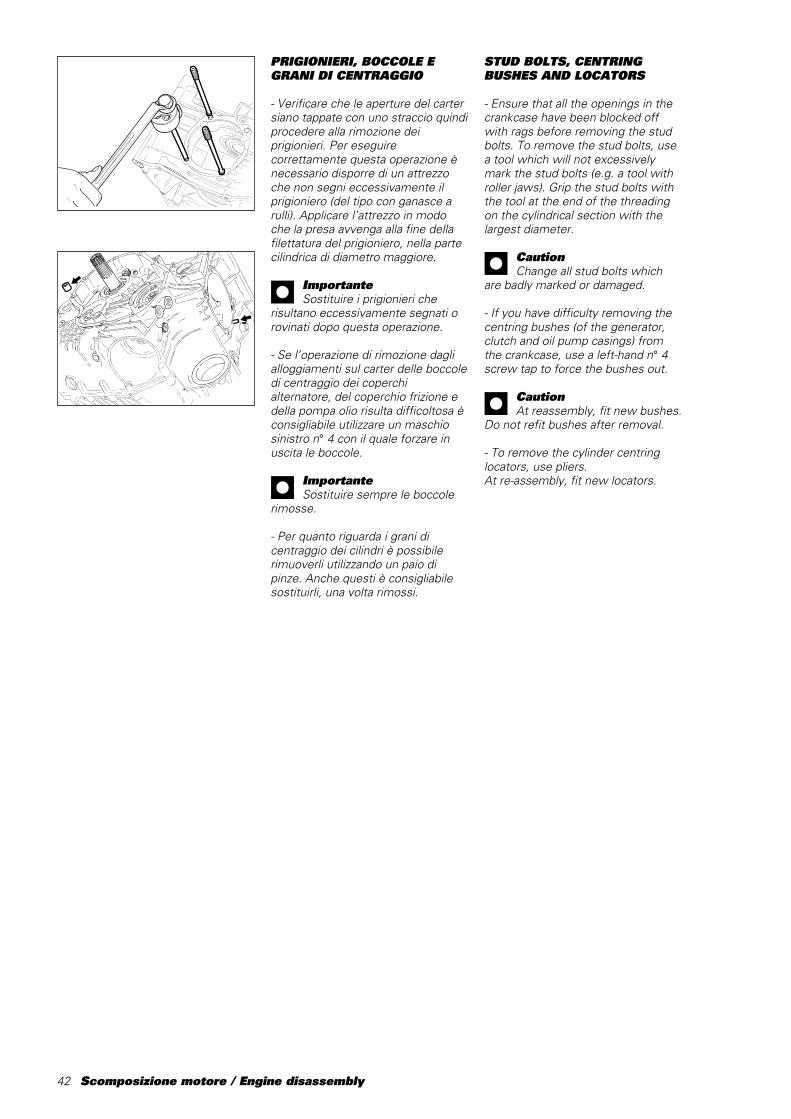
STUD BOLTS, CENTRINGBUSHES AND LOCATORS
- Ensure that all the openings in thecrankcase have been blocked offwith rags before removing the studbolts. To remove the stud bolts, usea tool which will not excessivelymark the stud bolts (e.g. a tool withroller jaws). Grip the stud bolts withthe tool at the end of the threadingon the cylindrical section with thelargest diameter.
CautionChange all stud bolts which
are badly marked or damaged.
- If you have difficulty removing thecentring bushes (of the generator,clutch and oil pump casings) fromthe crankcase, use a left-hand n° 4screw tap to force the bushes out.
CautionAt reassembly, fit new bushes.
Do not refit bushes after removal.
- To remove the cylinder centringlocators, use pliers.At re-assembly, fit new locators.
PRIGIONIERI, BOCCOLE EGRANI DI CENTRAGGIO
- Verificare che le aperture del cartersiano tappate con uno straccio quindiprocedere alla rimozione deiprigionieri. Per eseguirecorrettamente questa operazione ènecessario disporre di un attrezzoche non segni eccessivamente ilprigioniero (del tipo con ganasce arulli). Applicare l’attrezzo in modoche la presa avvenga alla fine dellafilettatura del prigioniero, nella partecilindrica di diametro maggiore.
ImportanteSostituire i prigionieri che
risultano eccessivamente segnati orovinati dopo questa operazione.
- Se l’operazione di rimozione daglialloggiamenti sul carter delle boccoledi centraggio dei coperchialternatore, del coperchio frizione edella pompa olio risulta difficoltosa èconsigliabile utilizzare un maschiosinistro n° 4 con il quale forzare inuscita le boccole.
ImportanteSostituire sempre le boccole
rimosse.
- Per quanto riguarda i grani dicentraggio dei cilindri è possibilerimuoverli utilizzando un paio dipinze. Anche questi è consigliabilesostituirli, una volta rimossi.

Scomposizione motore / Engine disassembly 43
APERTURA CARTER
❍ Svitare e rimuovere dal semicarterlato frizione il filtro a rete (A) conrelativa guarnizione.- Svitare per prime le due viti (1),M6x80, poste sul semicarter frizione,in corrispondenza della sede delcilindro verticale.- Capovolgere il carter e svitare lerimanenti viti di fissaggio dei duesemicarter.- Riutilizzare il coperchio alternatore(o un coperchio di servizio comeraffigurato) con l’estrattorecod.␣ 88713.1435 montato; fissarlo alsemicarter con tre viti originalidiametralmente opposte.- Azionare il perno centraledell’attrezzo e contemporaneamentebattere con un martello in plasticasull’albero secondario del cambiofino ad ottenere la separazione deisemicarter.❍ Rimuovere il semicarteralternatore prestando attenzione airasamenti installati in corrispondenzadegli alberi cambio, motore etamburo selettore.
1
OPENING THE CRANKCASE
❍ Unscrew and remove the meshfilter (A) and washer from the clutch-side case-half.- Unscrew the first two M6x80screws (1) on the clutch-side case-half close to the vertical cylinder.- Overturn the case and unscrew theother two screws on the casehalves.- For the next operation use thegenerator cover (or a service coveras shown) fitted with the puller partno.␣ 88713.1435. Fix this assembly tothe case half with the original threescrews fitted opposite each other.- Turn the puller centre pin and at thesame time tap the gearboxsecondary shaft with a plastichammer until the two crankcasehalves separate.❍ Remove the generator-side casehalf. Take care not to lose the shimson the gearbox shaft, the crankshaftand the selector drum shaft.
88713.1435
44 Scomposizione motore / Engine disassembly
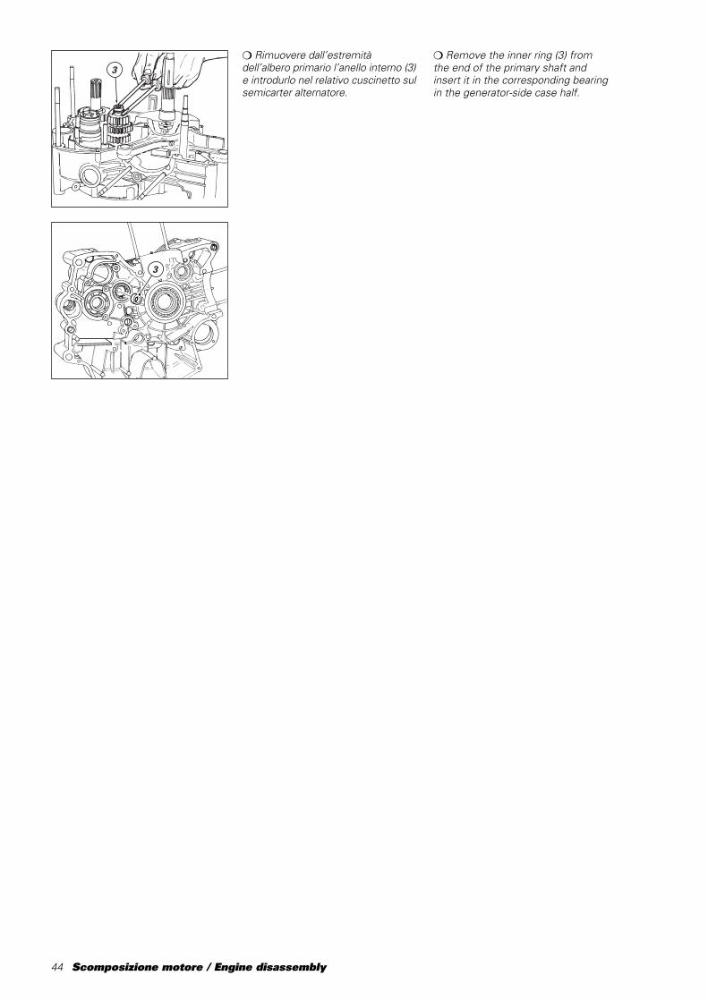
❍ Rimuovere dall’estremitàdell’albero primario l’anello interno␣ (3)e introdurlo nel relativo cuscinetto sulsemicarter alternatore.
3
3
❍ Remove the inner ring (3) fromthe end of the primary shaft andinsert it in the corresponding bearingin the generator-side case half.
Scomposizione motore / Engine disassembly 45
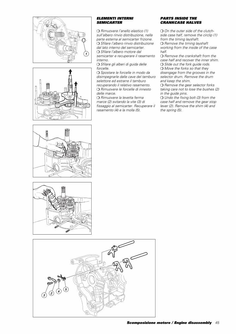
ELEMENTI INTERNISEMICARTER
❍ Rimuovere l’anello elastico (1)sull’albero rinvio distribuzione, nellaparte esterna al semicarter frizione.❍ Sfilare l’albero rinvio distribuzionedal lato interno del semicarter.❍ Sfilare l’albero motore dalsemicarter e recuperare il rasamentointerno.❍ Sfilare gli alberi di guida delleforcelle.❍ Spostare le forcelle in modo dadisimpegnarle dalle cave del tamburoselettore ed estrarre il tamburorecuperando il relativo rasamento.❍ Rimuovere le forcelle di innestodelle marce.❍ Rimuovere la levetta fermamarce␣ (2) svitando la vite (3) difissaggio al semicarter. Recuperare ilrasamento (4) e la molla (5).
3 2 4 5
1
PARTS INSIDE THECRANKCASE HALVES
❍ On the outer side of the clutch-side case half, remove the circlip (1)from the timing layshaft.❍ Remove the timing layshaftworking from the inside of the casehalf.❍ Remove the crankshaft from thecase half and recover the inner shim.❍ Slide out the fork guide rods.❍ Move the forks so that theydisengage from the grooves in theselector drum. Remove the drumand keep the shim.❍ Remove the gear selector forkstaking care not to lose the bushes (2)in the guide pins.❍ Undo the fixing bolt (3) from thecase half and remove the gear stoplever (2). Remove the shim (4) andthe spring (5).

46 Scomposizione motore / Engine disassembly
❍ Rimuovere gli alberi primario esecondario del cambio completi diingranaggi e recuperare i relativirasamenti.
NotePer comodità di rimontaggio si
consiglia di lasciare l’anello internodel cuscinetto di estremitàsull’albero secondario montato suquest’ultimo.
❍ Remove the primary shaft andtransmission shaft complete withtheir gears and keep the shims.
NoteTo facilitate re-assembly, leave
the inner ring of the bearing on theend of the transmission shaft.
Scomposizione motore / Engine disassembly 47
TESTE
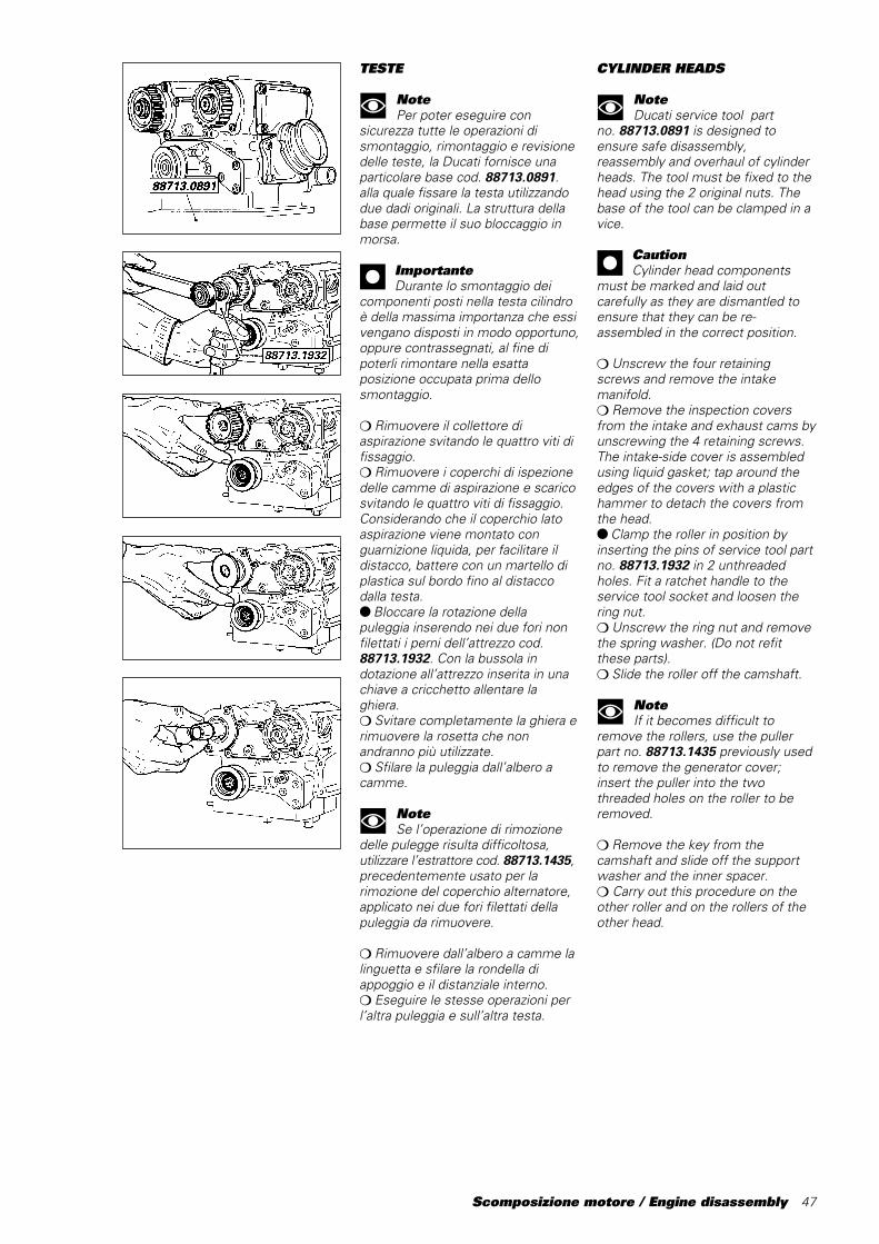
NotePer poter eseguire con
sicurezza tutte le operazioni dismontaggio, rimontaggio e revisionedelle teste, la Ducati fornisce unaparticolare base cod. 88713.0891.alla quale fissare la testa utilizzandodue dadi originali. La struttura dellabase permette il suo bloccaggio inmorsa.
ImportanteDurante lo smontaggio dei
componenti posti nella testa cilindroè della massima importanza che essivengano disposti in modo opportuno,oppure contrassegnati, al fine dipoterli rimontare nella esattaposizione occupata prima dellosmontaggio.
❍ Rimuovere il collettore diaspirazione svitando le quattro viti difissaggio.❍ Rimuovere i coperchi di ispezionedelle camme di aspirazione e scaricosvitando le quattro viti di fissaggio.Considerando che il coperchio latoaspirazione viene montato conguarnizione liquida, per facilitare ildistacco, battere con un martello diplastica sul bordo fino al distaccodalla testa.● Bloccare la rotazione dellapuleggia inserendo nei due fori nonfilettati i perni dell’attrezzo cod.88713.1932. Con la bussola indotazione all’attrezzo inserita in unachiave a cricchetto allentare laghiera.❍ Svitare completamente la ghiera erimuovere la rosetta che nonandranno più utilizzate.❍ Sfilare la puleggia dall’albero acamme.
NoteSe l’operazione di rimozione
delle pulegge risulta difficoltosa,utilizzare l’estrattore cod. 88713.1435,precedentemente usato per larimozione del coperchio alternatore,applicato nei due fori filettati dellapuleggia da rimuovere.
❍ Rimuovere dall’albero a camme lalinguetta e sfilare la rondella diappoggio e il distanziale interno.❍ Eseguire le stesse operazioni perl’altra puleggia e sull’altra testa.
CYLINDER HEADS
NoteDucati service tool part
no.␣ 88713.0891 is designed toensure safe disassembly,reassembly and overhaul of cylinderheads. The tool must be fixed to thehead using the 2 original nuts. Thebase of the tool can be clamped in avice.
CautionCylinder head components
must be marked and laid outcarefully as they are dismantled toensure that they can be re-assembled in the correct position.
❍ Unscrew the four retainingscrews and remove the intakemanifold.❍ Remove the inspection coversfrom the intake and exhaust cams byunscrewing the 4 retaining screws.The intake-side cover is assembledusing liquid gasket; tap around theedges of the covers with a plastichammer to detach the covers fromthe head.● Clamp the roller in position byinserting the pins of service tool partno.␣ 88713.1932 in 2 unthreadedholes. Fit a ratchet handle to theservice tool socket and loosen thering nut.❍ Unscrew the ring nut and removethe spring washer. (Do not refitthese parts).❍ Slide the roller off the camshaft.
NoteIf it becomes difficult to
remove the rollers, use the pullerpart no. 88713.1435 previously usedto remove the generator cover;insert the puller into the twothreaded holes on the roller to beremoved.
❍ Remove the key from thecamshaft and slide off the supportwasher and the inner spacer.❍ Carry out this procedure on theother roller and on the rollers of theother head.

48 Scomposizione motore / Engine disassembly
❍ Svitare le due viti di fissaggio delsupporto albero a camme, latopulegge distribuzione.❍ Sfilare il supporto con albero acamme e recuperare la guarnizioneOR. Eseguire le stesse operazioniper l’altro supporto e sull’altra testa.- Operando sul lato opposto dellatesta, svitare le due viti di fissaggiodel supporto chiuso dell’albero acamme.❍ Sfilare il supporto e recuperare laguarnizione OR.❍ Eseguire le stesse operazioni perl’altro supporto e sull’altra testa.
NotePer lo smontaggio dei
componenti interni ai supporti alberoa camme vedi capitolo “Revisionemotore”.
❍ Rimuovere i coperchi di chiusuradelle sedi dei perni bilancieri suentrambi i lati della testa. Recuperarele guarnizioni.
❍ Undo the 2 retaining screws ofthe camshaft support, on the timingroller side.❍ Remove the support withcamshaft and keep the OR. Repeatthe above procedure for the othersupport and head.- Position on the other side of thehead and undo the 2 retainingscrews of the closed support of thecamshaft.❍ Remove the support and keep theOR.❍ Repeat the above procedure forthe other support and head.
NoteRefer to “Engine overhaul” for
removing the components inside thecamshaft supports.
❍ Remove the covers closing therocker arm shaft seats on both headsides. Keep the seals.
Scomposizione motore / Engine disassembly 49
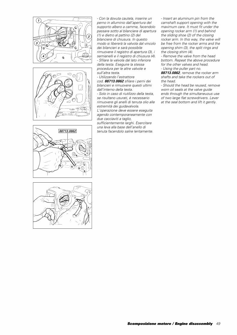
- Con la dovuta cautela, inserire unperno in alluminio dall’apertura delsupporto albero a camme, facendolopassare sotto al bilanciere di apertura(1) e dietro al pattino (2) delbilanciere di chiusura. In questomodo si libererà la valvola dal vincolodei bilancieri e sarà possibilerimuovere il registro di apertura (3), isemianelli e il registro di chiusura (4).- Sfilare la valvola dal lato inferioredella testa. Eseguire la stessaprocedura per le altre valvole esull’altra testa.- Utilizzando l’estrattorecod.␣ 88713.0862 sfilare i perni deibilancieri e rimuovere questi ultimidall’interno della testa.- Solo in caso di riutilizzo della testa,se risultano usurati, è necessariorimuovere gli anelli di tenuta olio alleestremità dei guidavalvola.L’operazione deve essere eseguitaagendo contemporaneamente condue cacciaviti a taglio,sufficientemente larghi. Esercitareuna leva alla base dell’anello ditenuta facendolo salire lentamente.88713.0862
1
3
4
2
- Insert an aluminum pin from thecamshaft support opening with themaximum care. It must fit under theopening rocker arm (1) and behindthe sliding shoe (2) of the closingrocker arm. In this way, the valve willbe free from the rocker arms and theopening shim (3), the split rings andthe closing shim (4).- Remove the valve from the headbottom. Repeat the above procedurefor the other valves and head.- Using the puller part no.88713.0862, remove the rocker armshafts and take the rockers out ofthe head.- Should the head be reused, removeworn oil seals at the valve guideends through the simultaneuous useof two large flat screwdrivers. Leverat the seal bottom and lift it gently.

50 Scomposizione motore / Engine disassembly
Testa verticale❍ Rimuovere la bussola (1) tenditorefisso dalla testa.❍ Svitare completamente le viti (2) erimuovere il supporto tenditori (3)dalla testa facendo attenzione arecuperare la guarnizione OR del foroacqua.❍ Agendo sul lato opposto,rimuovere il raccordo (4) di uscitaacqua dalla testa svitando le 3 viti difissaggio e recuperando laguarnizione OR.
Testa orizzontale❍ Rimuovere la bussola (5) tenditorefisso dalla testa allentando prima ilgrano del relativo perno.❍ Svitare completamente le viti (6), ilperno tenditore mobile (7) erimuovere il supporto dalla testa.❍ Agendo sul lato opposto,rimuovere il raccordo (8) di uscitaacqua dalla testa svitando le 3 viti difissaggio e recuperando laguarnizione OR.
8
Vertical head❍ Remove the fixed tensioner bush(1) from the head.❍ Undo the screws (2) and removethe belt tensioner support (3) fromthe head. Remove the water hole O-ring.❍ Move round to the opposite sideof the head and remove the wateroutlet connector (4) by unscrewingthe 3 retaining screws. Remove theO-ring.
Horizontal head❍ Loosen the dowel of the mobiletensioner shaft and remove thecorresponding bush (5).❍ Undo the screws (6), the mobiletensioner pin (7) and remove thesupport from the head.❍ Move round to the opposite sideof the head and remove the wateroutlet connector (8) by unscrewingthe 3 retaining screws. Remove theO-ring.

Revisione motore / Engine overhaul 51
Revisione motoreEngine overhaul
52 Revisione motore / Engine overhaul
PULIZIA DEI PARTICOLARI
Tutti i particolari metallici devonoessere puliti e lavati con solventespecifico, possibilmentebiodegradabile, ed asciugati con ariacompressa.
AttenzioneDurante questa operazione si
sviluppano vapori infiammabili eparticelle di metallo possono essereespulse ad alta velocità. Siraccomanda di operare in unambiente privo di fiamme libere oscintille e di indossare occhialiprotettivi.
Soffiare con aria compressa dentro aicondotti di passaggio olio deisemicarter e delle teste. Togliereaccuratamente dalle superfici diaccoppiamento eventuali tracce disigillante, con estrema cautela, pernon danneggiarle: utilizzare a tal fineraschietto e diluente specifico. Primadel rimontaggio, ripassare lefilettature di alloggiamento deiprigionieri nei semicarter e delle viti,per eliminare i residui di Loctite osigillante.
ACCOPPIAMENTI
Per consentire al motore difunzionare nelle migliori condizioni,fornendo quindi il massimorendimento, è indispensabile chetutti gli accoppiamenti rientrino nelletolleranze prescritte dalla casacostruttrice.
CLEANING PARTS
All metal components must becleaned and washed using suitablebiodegradable solvents and thendried with compressed air.
WarningCleaning solvents give off
inflammable fumes. Metal particlesmay be projected at high speed fromengines during cleaning. Cleaningwith solvent must take place inpremises where there are no nakedflames or sparks. Always wear eyeprotection during cleaningoperations.
Blow through the oilways in thecrankcase halves and the cylinderheads with compressed air. Removeresidues of liquid gasket and sealantfrom all contact and fasteningsurfaces. Do not damage thesesurfaces. Use a suitable scraper andsolvent. Before reassembling theengine, clean all traces of Loctite andsealant from the threads of the studbolt holes in the crankcase halvesand screws.
CLEARANCES AND FITS
To ensure top engine performance,all the clearances and fits must bewithin the tolerances specified bythe manufacturer.

Revisione motore / Engine overhaul 53
SOSTITUZIONE ANELLI DITENUTA OLIO (PARAOLI)
ImportanteSostituire sempre i paraolio ad
ogni revisione del motore. Installare iparaolio nuovi, inserendoli in quadronei loro alloggiamenti, utilizzandotamponi adatti.Montare sempre il paraolio con il latoprovvisto di molla, rivolto verso ladirezione di uscita dell’olio (vedifigura).Dopo il montaggio, lubrificare conolio motore i labbri di tenuta delparaolio.
ANELLI DI ARRESTO (SEEGER)
ImportanteSostituire sempre gli anelli di
arresto che risultano deformati o chehanno perduto l’elasticità originale.Tutti gli anelli di arresto presentanoun lato (1) completamente piano conspigolo vivo e un lato (2) a spigololeggermente arrotondato. Quando simontano nelle gole degli alberi onelle sedi dei coperchi, il lato aspigolo vivo (1) deve sempre essereopposto alla direzione della forza (F)esercitata dall’elemento da fermare.
Labbro primarioMain lip
Labbro secondarioSecondary lip
MollaSpring
SupportoSupport
OlioOil
����������������
@@@@@@@@@@@@@@@@
����������������
ÀÀÀÀÀÀÀÀÀÀÀÀÀÀÀÀ
����������������
@@@@@@@@@@@@@@@@
����������������
ÀÀÀÀÀÀÀÀÀÀÀÀÀÀÀÀ
����������������
yyyyyyyyyyyyyyyy
2
1
1
F
2
CIRCLIPS
CautionChange all circlips which are
deformed or which have lost theiroriginal spring.Circlips have a flat side (1) with asharp edge and a side (2) with aslightly rounded edge. Circlips mustbe fitted to grooves in shafts andcovers with the sharp-edged side (1)always facing the force␣ (F) appliedby the part being held in position.
CHANGING OIL SEALS
CautionChange oil seals at each
engine overhaul. Fit new oil sealsusing suitable drifts. Ensure that theseals fit squarely in their seats.Always fit oil seals with the springside facing the oil outfeed direction(see drawing).After fitting a new oil seal, lubricatethe seal lip with a small amount ofengine oil.

54 Revisione motore / Engine overhaul
CUSCINETTI
ImportanteLavarli accuratamente con
benzina ed asciugarli con ariacompressa, senza farli ruotare.Lubrificare leggermente e ruotarelentamente a mano l’anello interno:non si devono riscontrare irregolaritàdi rotazione, attriti anomali o giochieccessivi. È buona normasostituire i cuscinetti ad ognirevisione del motore.
������@@@@@@������ÀÀÀÀÀÀ������@@@@@@������ÀÀÀÀÀÀ������yyyyyy
��� @@@ ��� ÀÀÀ ��� @@@ ��� ÀÀÀ ��� yyy��@@��ÀÀ��@@��ÀÀ��yy
��@@��ÀÀ��@@��ÀÀ��yy
���@@@���ÀÀÀ���@@@���ÀÀÀ���yyy��@@��ÀÀ��@@��ÀÀ��yy
����
@@@@
����
ÀÀÀÀ
����
@@@@
����
ÀÀÀÀ
����
yyyy
������
@@@@@@
������
ÀÀÀÀÀÀ
������
@@@@@@
������
ÀÀÀÀÀÀ
������
yyyyyy
����
@@@@
����
ÀÀÀÀ
����
@@@@
����
ÀÀÀÀ
����
yyyy
����
@@@@
����
ÀÀÀÀ
����
@@@@
����
ÀÀÀÀ
����
yyyy
����
@@@@
����
ÀÀÀÀ
����
@@@@
����
ÀÀÀÀ
����
yyyy
��@@��ÀÀ��@@��ÀÀ��yy
���@@@���ÀÀÀ���@@@���ÀÀÀ���yyy
������
@@@@@@
������
ÀÀÀÀÀÀ
������
@@@@@@
������
ÀÀÀÀÀÀ
������
yyyyyy
������
@@@@@@
������
ÀÀÀÀÀÀ
������
@@@@@@
������
ÀÀÀÀÀÀ
������
yyyyyy
����
@@@@
����
ÀÀÀÀ
����
@@@@
����
ÀÀÀÀ
����
yyyy
����
@@@@
����
ÀÀÀÀ
����
@@@@
����
ÀÀÀÀ
����
yyyy
������@@@@@@������ÀÀÀÀÀÀ������@@@@@@������ÀÀÀÀÀÀ������yyyyyy
��� @@@ ��� ÀÀÀ ��� @@@ ��� ÀÀÀ ��� yyy
Gioco assialeAxial play
Gioco radialeRadial play
CILINDRO
Controllare che la superficie discorrimento del pistone siaperfettamente liscia. Controllare ivalori dell’accoppiamento con ilpistone, di conicità e di ovalizzazioneeffettuando la misurazione deldiametro del cilindro, a tre altezzediverse ed in due direzioni a 90° tradi loro:- Gioco di accoppiamento con ilpistone:0,06÷0,08 mm.- Conicità max. (limite di usura):0,02 mm.- Ovalizzazione max. (limite di usura):0,02 mm.In caso di danni o di usura eccessiva,il cilindro deve essere sostituito inquanto non può essere rettificato.I cilindri sono contrassegnati da unalettera A, B, o C (stampigliatanell’apposita superficie sul fianco)indicante la classe di appartenenza.
PunzonaturaMark
BEARINGS
CautionWash bearings thoroughly with
fuel. Do not rotate bearings duringwashing. Dry with compressed air.Lightly oil the bearings. Slowly rotatethe inner ring by hand and check forirregular rotation, jamming andexcessive play. As a general rule itis a good idea to change bearingsat each engine overhaul.
CYLINDERS
Check that the cylinder liners areperfectly smooth. Measure thecylinder diameter at three differentheights and in two positions at 90 °to each other. Use thesemeasurements to check pistonclearance in bore, taper and oval.- Piston clearance in bore:0.06-0.08 mm.- Max. taper (wear limit):0.02 mm.- Max. oval (wear limit):0.02 mm.Damaged or worn cylinders cannotbe rebored and must be changed.Cylinders are punched (in a locationon the sides) with the letter A, B, orC to indicate their class.
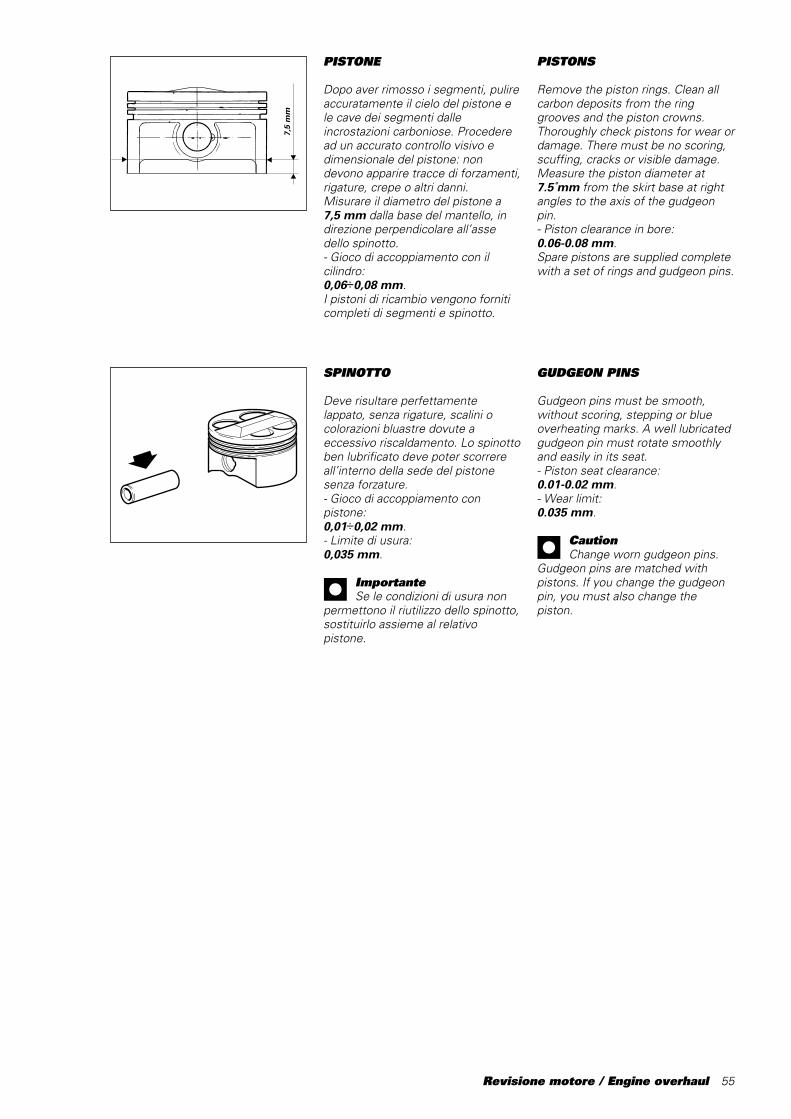
Revisione motore / Engine overhaul 55
PISTONE
Dopo aver rimosso i segmenti, pulireaccuratamente il cielo del pistone ele cave dei segmenti dalleincrostazioni carboniose. Procederead un accurato controllo visivo edimensionale del pistone: nondevono apparire tracce di forzamenti,rigature, crepe o altri danni.Misurare il diametro del pistone a7,5 mm dalla base del mantello, indirezione perpendicolare all’assedello spinotto.- Gioco di accoppiamento con ilcilindro:0,06÷0,08 mm.I pistoni di ricambio vengono forniticompleti di segmenti e spinotto.
7,5
mm
SPINOTTO
Deve risultare perfettamentelappato, senza rigature, scalini ocolorazioni bluastre dovute aeccessivo riscaldamento. Lo spinottoben lubrificato deve poter scorrereall’interno della sede del pistonesenza forzature.- Gioco di accoppiamento conpistone:0,01÷0,02 mm.- Limite di usura:0,035 mm.
ImportanteSe le condizioni di usura non
permettono il riutilizzo dello spinotto,sostituirlo assieme al relativopistone.
GUDGEON PINS
Gudgeon pins must be smooth,without scoring, stepping or blueoverheating marks. A well lubricatedgudgeon pin must rotate smoothlyand easily in its seat.- Piston seat clearance:0.01-0.02 mm.- Wear limit:0.035 mm.
CautionChange worn gudgeon pins.
Gudgeon pins are matched withpistons. If you change the gudgeonpin, you must also change thepiston.
PISTONS
Remove the piston rings. Clean allcarbon deposits from the ringgrooves and the piston crowns.Thoroughly check pistons for wear ordamage. There must be no scoring,scuffing, cracks or visible damage.Measure the piston diameter at7.5␣ mm from the skirt base at rightangles to the axis of the gudgeonpin.- Piston clearance in bore:0.06-0.08 mm.Spare pistons are supplied completewith a set of rings and gudgeon pins.
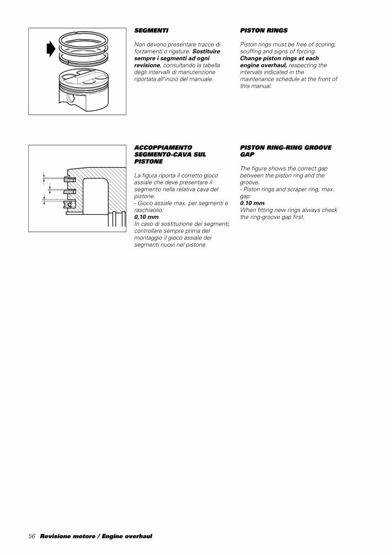
56 Revisione motore / Engine overhaul
SEGMENTI
Non devono presentare tracce diforzamenti o rigature. Sostituiresempre i segmenti ad ognirevisione, consultando la tabelladegli intervalli di manutenzioneriportata all’inizio del manuale.
ACCOPPIAMENTOSEGMENTO-CAVA SULPISTONE
La figura riporta il corretto giocoassiale che deve presentare ilsegmento nella relativa cava delpistone.- Gioco assiale max. per segmenti eraschiaolio:0,10 mm.In caso di sostituzione dei segmenti,controllare sempre prima delmontaggio il gioco assiale deisegmenti nuovi nel pistone.
PISTON RINGS
Piston rings must be free of scoring,scuffing and signs of forcing.Change piston rings at eachengine overhaul, respecting theintervals indicated in themaintenance schedule at the front ofthis manual.
PISTON RING-RING GROOVEGAP
The figure shows the correct gapbetween the piston ring and thegroove.- Piston rings and scraper ring, max.gap:0.10 mm.When fitting new rings always checkthe ring-groove gap first.

Revisione motore / Engine overhaul 57
IMBIELLAGGIO
Scomporre l’imbiellaggio separandole bielle dall’albero motore.
ImportanteFare attenzione a non
scambiare le bielle tra loro e amantenere l’orientamento originale,con la scritta “PANKL” rivolta versol’esterno (estremità albero motore,cioé visibile ad imbiellaggio chiusocon bielle affiancate).
Per agevolare i tecnici addetti allarevisione dei componentil’imbiellaggio riportiamo un fac-similedi “Scheda rilevamento dati”, dautilizzare come documento per latrascrizione e per l’archivio dei datirilevati sul motore.
ACCOPPIAMENTO SEGMENTI-CILINDRO
È importante che il rilevamentovenga fatto con segmento (1)posizionato perfettamenteperpendicolare all’asse del cilindro. Atal proposito inserire nel cilindro ilpistone nudo in posizione rovesciatasu cui appoggiare il segmento dacontrollare (vedi figura).Misurare la distanza tra le estremitàdel segmento.Visto la presenza di tre selezioni (A,B, C) del gruppo cilindro/pistoneseguono i seguenti giochi:
Selezione - A– Segmento superiore (nominale):0,25÷0,53 mm.– Segmento intermedio (nominale):0,3÷0,53 mm.– Segmento raschiaolio (nominale):0,25÷0,53 mm.
Selezione - B– Segmento superiore (nominale):0,28÷0,56 mm.– Segmento intermedio (nominale):0,33÷0,56 mm.– Segmento raschiaolio (nominale):0,28÷0,56 mm.
Selezione - C– Segmento superiore (nominale):0,31÷0,59 mm.– Segmento intermedio (nominale):0,36÷0,59 mm.– Segmento raschiaolio (nominale):0,31÷0,59 mm.
1
CONNECTING RODS
Remove the connecting rods fromthe crankshaft.
CautionDo not mix up the connecting
rods and reassemble them in theiroriginal positions. Be sure the“PANKL” wording is facingoutwards (crankshaft end - thismeans it should be visible with theconnecting rods reassembled andlined up side by side).
To facilitate the work of themechanic overhauling the con-rodswe have provided the following copyof a “Data record sheet”. Use thissheet to record and file engine datameasured during work.
PISTON RING END GAP
Measurements must be taken withthe ring (1) sitting squarely in thebore. As an aid, insert a pistonwithout rings into the bore under thering as a support duringmeasurements (see drawing).Measure the piston ring end gap.Refer to the following valuesaccording to the different type (A, B,C):
Type- A- Upper ring end gap (nominal):0.25-0.53 mm- Middle ring end gap (nominal):0.3-0.53 mm- Scraper ring end gap (nominal):0.25-0.53 mm
Type- B- Upper ring end gap (nominal):0.28-0.56 mm- Middle ring end gap (nominal):0.33-0.56 mm- Scraper ring end gap (nominal):0.28-0.56 mm
Type- C- Upper ring end gap (nominal):0.31-0.59 mm- Middle ring end gap (nominal):0.36-0.59 mm- Scraper ring end gap (nominal):0.31-0.59 mm
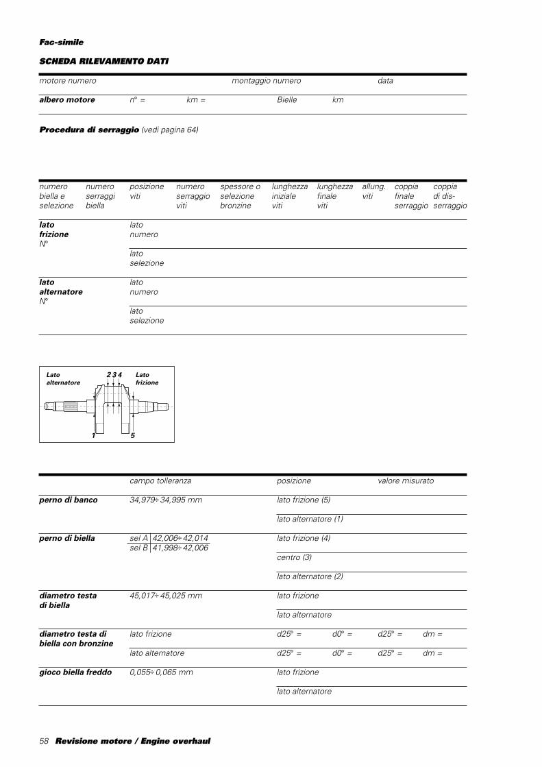
58 Revisione motore / Engine overhaul
Fac-simile
SCHEDA RILEVAMENTO DATI
motore numero montaggio numero data
albero motore n° = km = Bielle km
campo tolleranza posizione valore misurato
perno di banco 34,979÷34,995 mm lato frizione (5)
lato alternatore (1)
perno di biella sel A 42,006÷42,014 lato frizione (4)sel B 41,998÷42,006
centro (3)
lato alternatore (2)
diametro testa 45,017÷45,025 mm lato frizionedi biella
lato alternatore
diametro testa di lato frizione d25° = d0° = d25° = dm =biella con bronzine
lato alternatore d25° = d0° = d25° = dm =
gioco biella freddo 0,055÷0,065 mm lato frizione
lato alternatore
Procedura di serraggio (vedi pagina 64)
numero numero posizione numero spessore o lunghezza lunghezza allung. coppia coppiabiella e serraggi viti serraggio selezione iniziale finale viti finale di dis-selezione biella viti bronzine viti viti serraggio serraggio
lato latofrizione numeroN°
latoselezione
lato latoalternatore numeroN°
latoselezione
2
1 5
3 4 Lato frizione
Latoalternatore
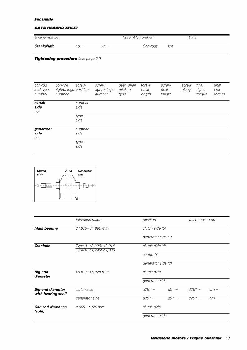
Revisione motore / Engine overhaul 59
Facsimile
DATA RECORD SHEET
Engine number Assembly number Date
Crankshaft no. = km = Con-rods km
Tightening procedure (see page 64)
con-rod con-rod screw screw bear. shell screw screw screw final finaland type tightenings position tightenings thick. or initial final elong. tight. loos.number number number type length length torque torque
clutch numberside sideno.
typeside
generator numberside sideno.
typeside
tolerance range position value measured
Main bearing 34.979÷34.995 mm clutch side (5)
generator side (1)
Crankpin Type A 42,006÷42,014 clutch side (4)Type B 41,998÷42,006
centre (3)
generator side (2)
Big-end 45,017÷45,025 mm clutch sidediameter
generator side
Big-end diameter clutch side d25 ° = d0 ° = d25 ° = dm =with bearing shell
generator side d25 ° = d0 ° = d25 ° = dm =
Con-rod clearance 0.055 - 0.075 mm clutch side(cold)
generator side
2
1 5
3 4 Generatorside
Clutchside
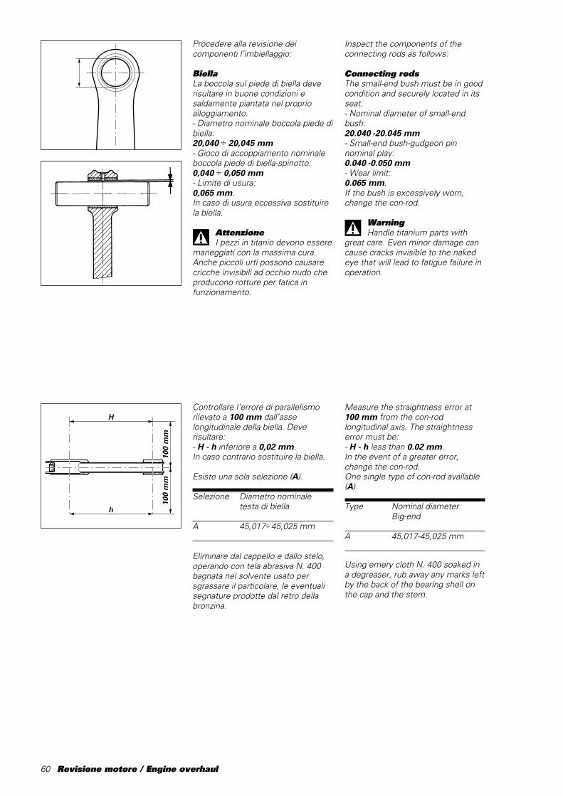
60 Revisione motore / Engine overhaul
Measure the straightness error at100 mm from the con-rodlongitudinal axis. The straightnesserror must be:- H - h less than 0.02 mm.In the event of a greater error,change the con-rod.One single type of con-rod available(A)
Type Nominal diameterBig-end
A 45,017-45,025 mm
Using emery cloth N. 400 soaked ina degreaser, rub away any marks leftby the back of the bearing shell onthe cap and the stem.
Procedere alla revisione deicomponenti l’imbiellaggio:
BiellaLa boccola sul piede di biella deverisultare in buone condizioni esaldamente piantata nel proprioalloggiamento.- Diametro nominale boccola piede dibiella:20,040 ÷ 20,045 mm- Gioco di accoppiamento nominaleboccola piede di biella-spinotto:0,040 ÷ 0,050 mm- Limite di usura:0,065 mm.In caso di usura eccessiva sostituirela biella.
AttenzioneI pezzi in titanio devono essere
maneggiati con la massima cura.Anche piccoli urti possono causarecricche invisibili ad occhio nudo cheproducono rotture per fatica infunzionamento.
H
h
100
mm
100
mm
Controllare l’errore di parallelismorilevato a 100 mm dall’asselongitudinale della biella. Deverisultare:- H - h inferiore a 0,02 mm.In caso contrario sostituire la biella.
Esiste una sola selezione (A).
Selezione Diametro nominaletesta di biella
A 45,017÷45,025 mm
Eliminare dal cappello e dallo stelo,operando con tela abrasiva N. 400bagnata nel solvente usato persgrassare il particolare, le eventualisegnature prodotte dal retro dellabronzina.
Inspect the components of theconnecting rods as follows:
Connecting rodsThe small-end bush must be in goodcondition and securely located in itsseat.- Nominal diameter of small-endbush:20.040 -20.045 mm- Small-end bush-gudgeon pinnominal play:0.040 -0.050 mm- Wear limit:0.065 mm.If the bush is excessively worn,change the con-rod.
WarningHandle titanium parts with
great care. Even minor damage cancause cracks invisible to the nakedeye that will lead to fatigue failure inoperation.
Revisione motore / Engine overhaul 61
Colore/ Codice/ Dimensione nominale/colors code nominal dimension
ROSSO/ 112.1.012.1AA 1,478 mmREDBLU/ 112.1.012.1AB 1,482 mmBLUE
ROSSO e BLURED and BLUE
Installazione cuscinetti- Appoggiare il semicuscinetto sullatesta o sul cappello di biella in modoche la sporgenza delle estremitàrispetto alla superficie di unionerisulti equidistante.- Verificare anche che risulti centratoassialmente nella testa o nel cappellodi biella.- Con le dita spingere ilsemicuscinetto in sede facendopressione (F) sulla mezzeria delcuscinetto facendo attenzione che ildentino corrisponda al vano ricavatonella biella.- Rovesciare la testa o il cappello dibiella e ripetere le stesse operazioni.- Verificare che il semicuscinettorisulti centrato assialmente rispettoalla testa o al cappello di biella edeliminare eventuali bavature chepossono formarsi nello sfregamentodell’estremità del cuscinetto con lospigolo della sede sulla biella.
SemicuscinettiÈ buona norma sostituire isemicuscinetti ad ogni revisione ocomunque secondo gli intervalliprescritti nella tabelle dellemanutenzioni periodiche riportataall’inizio del manuale.I semicuscinetti nuovi vengonoforniti già pronti per il montaggio enon devono essere ritoccati conraschietti o tela smeriglio.Appartengono a classi dimensionaliidentificabile ciascuna da un colore(ROSSO, BLU).
Assembling the bearings- Put the bearing onto the connectingrod big end or cap so that an equalportion of bearing protrudes over thebig end on either end.- Make sure it is properly centeredwith the big end or cap axis.- Press onto the bearing axis (F) withyour fingers and make sure the toothis properly positioned in its seat onthe connecting rod.- Lay the connecting rod big end orcap on the tool and center it withrespect to the bearing surfaceprojection.- Turn the connecting rod big end orcap until it stops against the toolretainer.- Turn the connecting rod big end orcap over and repeat the aboveprocedure.- Make sure the bearing is centeredwith the connecting rod big end orcap axis. Remove possible fins,which may be caused by rubbing thebearing against its seat in theconnecting rod.
Connecting rod bearingsChange the bearings every time theengine is overhauled or at regularintervals as specified in themaintenance schedule table at thebeginning of this manual.Spare bearings are supplied ready forfitting. They must not be reworkedwith scrapers or emery cloth.These bearings can belong todifferent classes identified bydifferent colors (RED, BLUE).
+ 0,005 0
62 Revisione motore / Engine overhaul
Rilevare con comparatorel’allineamento dei perni di banco,posizionando l’albero motore tra duecontropunte:- Errore di concentricità nominale:0,01 mm
Verificare ed eventualmenteripassare la filettatura della sede deltappo (C); in questo caso ènecessario lavare l’albero motore.Rimontare i tappi utilizzando THREEBOND.Serrare i tre grani filettati alla coppiaprescritta.Avvitare il tappo in alluminio (C) finoad avere la massima sporgenza deltappo dal piano mannaia, senzatoccare il rasamento (tra mannaia ecuscinetto di banco) posto nella suaposizione di funzionamento (maxsporgenza ~ 0,2 ÷ 0,3 mm).
Ogni albero motore è classificato dadue selezioni A e B, punzonate sulfianco mannaia, lato pignone, riferiteal perno di biella.
Selezione Diametro nominale
A 42,006 ÷42,014 mm
B 41,998 ÷42,006 mm
Albero motore❍ Rimuovere tutti i tappi dall’alberomotore. Passare con lo scovolinotutti canali e lavare con sgrassante.Ripassare lo scovolino pulito, lavarenuovamente e soffiare con ariacompressa.Procedere al controllo visivodell’albero motore: i perni di banco edi biella non devono presentaresolchi o rigature. Eventualmentelevigare la superficie con telafinissima e olio. Verificare che nellazona di raccordo tra perno espallamento non vi siano segni dilavoro o bave.- Raggio di raccordo:2 mm.
Le filettature, le sedi delle linguette ele scanalature devono essere inbuone condizioni.Rilevare con l’ausilio di unmicrometro, l’ovalizzazione del pernodi biella ed il parallellismo dell’assedello stesso; eseguendo i rilevamentiin diverse direzioni:- Parallellismo asse perno di biellarispetto AB:
// Ø 0,01/100 AB
- Cilindricità nominale:0,005 mm.
2 mm
A B
SelezioneType
CianfrinareCaulk C
C
Crankshaft❍ Remove all the plugs from thecrankshaft. Clean out the oilwayswith a spiral brush and wash withdegreaser. Clean out the oilwayswith a clean brush and wash withdegreaser for a second time. Blowout with compressed air.Visually check the crankshaft. Themain bearings and the crankpinsmust not be scored or grooved. Ifnecessary, polish the surface withfine emery cloth soaked in oil. Checkthat there is no excessive wear orburrs in the area between thebearing and the shoulder.- Radius:2 mm.
Check that the threads, keyways andsplines are in good condition.Use a micrometer to measure theoval of the crankpin and parallelismof its axis in several directions:- Crankpin axis parallelism comparedto AB:
// Ø 0,01/100 AB
- Nominal out-of-round:0.005 mm.
Fix the crankshaft between twocentres and then use a dial gauge tocheck the alignment of the mainbearings.- Nominal out-of-round error:0.01 mm
Check and if necessary re-tap thethreads of the plug hole (C). If youre-tap the thread, you must wash thecrankshaft again.Refit the plugs using THREE BONDand tighten the three threadeddowels to the specified torque.Tighten the aluminium plug (C) so thata max. portion of plug protrudes overthe blade. Do not remove the shimplaced between blade and mainbearing - max. value 0.2 - 0.3 mmapprox.
Crankshafts are classified into twotypes: A and B. The type is punchedon the side of the blade on thesprocket side near to the mainbearing.
Type Nominal diameter
A 42.006 - 42.014 mm
B 41.998 - 42.006 mm
Revisione motore / Engine overhaul 63
ACCOPPIAMENTOSEMICUSCINETTI-PERNOBIELLA
Per verificare il gioco diaccoppiamento tra semicuscinetti ealbero motore procedere comesegue:- Rilevare il diametro del perno dibiella nelle posizioni indicate (a - c).In riferimento agli assi ortogonali (1 -2), determinare il valore medio.- Serrare le viti della biella, alla coppiaprescritta, con i cuscinetti.- Rilevare il diametro interno inriferimento agli assi (d - e - f) edeterminare il valore medio.- Applicare la formula:
Gioco di accoppiamento = Diametrobiella (con cuscinetti) - Diametroperno.
Gioco di accoppiamento nominale:0,055 ÷0,065 mm
Scegliere lo spessore deisemicuscinetti nella classe diappartenenza, che permetta lamigliore centratura.
ImportanteEvitare di utilizzare imbiellaggi
che presentano un gioco inferiore a0,055 mm.
AttenzioneI pezzi in titanio devono essere
maneggiati con la massima cura.Anche piccoli urti possono causarecricche invisibili ad occhio nudo cheproducono rotture per fatica infunzionamento.
1
2
a c
BIG-END BEARING -CRANKPIN CLEARANCE
To check the clearance between thebig-end bearings and the crankpinproceed as follows:- measure the crankpin diameter inthe specified positions (a - c).Calculate the average value at rightangles (1 - 2).- Tighten the con-rod bolts to thespecified torque (with bearings).- Measure the internal diameter ofthe con-rod with reference to (d - e -f) axes. Calculate the average value.Use the formula:
Clearance = Con-rod diameter (withbearings) - Crankpin diameter
Nominal clearance:0.055-0.065 mm
Select a bearing for proper centering(refer to bearing classes).
CautionDo not use bearings with
clearances of less than 0.055 mm.
WarningHandle the titanium parts with
great care. Even minor damage cancause cracks invisible to the nakedeye that will lead to fatigue failure inoperation.

64 Revisione motore / Engine overhaul
PANKL PLB 05E
RICOMPOSIZIONEDELL’IMBIELLAGGIO
Lubrificare abbondantemente conolio motore e disporre sull’alberomotore le bielle e relativi cappelli,mantenendo, in caso di riutilizzo deicomponenti originali, la posizione el’orientamento che avevano primadello smontaggio.Interporre tra le bielle lo spessimetroa forchetta cod.88713.1309 dispessore 2,35 mm per anullare ilgioco assiale bielle-perno.Lubrificare filetto e sottotesta delleviti di fissaggio con grasso PANKL.
Procedura di serraggio viti:1) effettuare l’avvicinamentomanuale.2) preserrare le viti, controllando unallungamento di 0,05 ± 0,005 mm,tramite l’attrezzo cod. 88713.1781(micrometro).3) effettuare il serraggio finale,controllando allungamento (0,155 ±0,005 mm).
ImportanteLe viti di biella possono essere
utilizzate solo per tre serraggi(compreso il serraggio iniziale delfornitore).Si consiglia di utilizzare viti di servizioper effettuare le misure delle bielle.
88713.1781
REASSEMBLING THECONNECTING RODS
Oil the con-rods and caps withgenerous amounts of engine oil andthen fit them to the crankshaft. Ifyou are using parts dismantledpreviously, make sure that you fitthese parts back into their originalpositions and facing in the originaldirection.Insert the fork feeler gauge part no.88713.1309, thickness 2.35 mmbetween the con-rods to eliminatethe connecting rods - crankpins axialplay.Grease threads and underside of thebolt heads with PANKL grease.
Tightening procedure:1) Snug bolts manually.2) Preliminary tightening: use toolno. 88713.1781 (micrometer), andcheck bolt stretch, it should be 0.05±0.005 mm.3) Final tightening. Check stretch(0.160 ±0.005 mm).
CautionThe con-rod bolts may be used
for a total of 3 tightenings only(including the supplier’s originaltightening).Use service bolts to carry out con-rod measurements.
88713.1309
Revisione motore / Engine overhaul 65
TestaRimuovere i depositi carboniosi dallacamera di combustione e dai relativicondotti. Pulire da eventualiincrostazioni le canalizzazioni delliquido di raffreddamento. Controllareche non vi siano crepe e che lesuperfici di tenuta risultino prive disolchi, scalini o altri danni.La planarità della superficie diaccoppiamento con il cilindro deveessere perfetta. In caso contrario,applicare su di un piano di riscontrosospensione diamantata (spessore6 ÷12 micron) e ripassare lasuperficie muovendo la testa comeevidenziato in figura, fino ad ottenereun piano uniforme.
In caso di consistenti spianature delpiano testa è necessario ripristinarela superficie di “squish” per evitareche il cielo del pistone al PMS possaoriginare impatti. Attenersi alle quotedi figura per ripristinare la superficiedi “squish”.
ø 87,8 ÷ 88 mm 28˚
Cylinder headsRemove carbon deposits from thecombustion chamber, ports andducts. Clean off scaling and depositsfrom coolant ducts. Check the headfor cracks. Check that the contactsurfaces are smooth and without anyscoring, steps or damage.The contact surfaces with thecylinder must be perfectly flat. If thisis not the case, apply a grindingsolution (6-12 micron thickness) to areference surface and grind thesurfaces by passing the head acrossthe table as shown in the drawing.Continue until you obtain a perfectlyflat surface.
If the head surfaces have beenconsiderably flattened, it will benecessary to rework the squishsurfaces to prevent collisions withthe piston crown at TDC. Use themeasurement given in the drawingfor the squish surfaces.
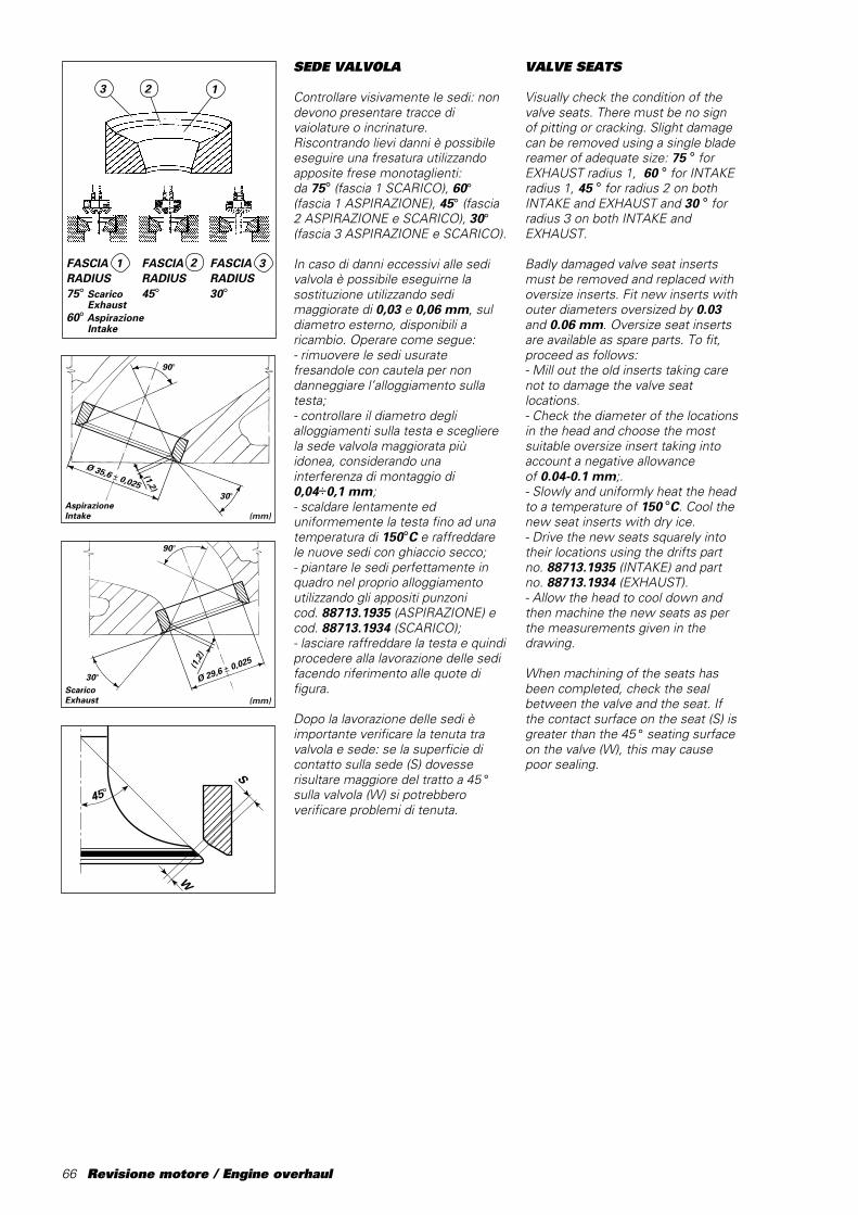
66 Revisione motore / Engine overhaul
SEDE VALVOLA
Controllare visivamente le sedi: nondevono presentare tracce divaiolature o incrinature.Riscontrando lievi danni è possibileeseguire una fresatura utilizzandoapposite frese monotaglienti:da 75° (fascia 1 SCARICO), 60°(fascia 1 ASPIRAZIONE), 45° (fascia2 ASPIRAZIONE e SCARICO), 30°(fascia 3 ASPIRAZIONE e SCARICO).
In caso di danni eccessivi alle sedivalvola è possibile eseguirne lasostituzione utilizzando sedimaggiorate di 0,03 e 0,06 mm, suldiametro esterno, disponibili aricambio. Operare come segue:- rimuovere le sedi usuratefresandole con cautela per nondanneggiare l’alloggiamento sullatesta;- controllare il diametro deglialloggiamenti sulla testa e sceglierela sede valvola maggiorata piùidonea, considerando unainterferenza di montaggio di0,04÷0,1 mm;- scaldare lentamente eduniformemente la testa fino ad unatemperatura di 150°C e raffreddarele nuove sedi con ghiaccio secco;- piantare le sedi perfettamente inquadro nel proprio alloggiamentoutilizzando gli appositi punzonicod.␣ 88713.1935 (ASPIRAZIONE) ecod. 88713.1934 (SCARICO);- lasciare raffreddare la testa e quindiprocedere alla lavorazione delle sedifacendo riferimento alle quote difigura.
Dopo la lavorazione delle sedi èimportante verificare la tenuta travalvola e sede: se la superficie dicontatto sulla sede (S) dovesserisultare maggiore del tratto a 45 °sulla valvola (W) si potrebberoverificare problemi di tenuta.
90°
30°
(1,2)
Ø 35,6 ± 0,025
AspirazioneIntake (mm)
90°
30°
(1,2
)
Ø 29,6 ± 0,025
ScaricoExhaust (mm)
����
����
@@@@
@@@@
����
����
ÀÀÀÀ
ÀÀÀÀ
����
����
@@@@
@@@@
����
����
ÀÀÀÀ
ÀÀÀÀ
����
����
yyyy
yyyy
W
S
45°
VALVE SEATS
Visually check the condition of thevalve seats. There must be no signof pitting or cracking. Slight damagecan be removed using a single bladereamer of adequate size: 75 ° forEXHAUST radius 1, 60 ° for INTAKEradius 1, 45 ° for radius 2 on bothINTAKE and EXHAUST and 30 ° forradius 3 on both INTAKE andEXHAUST.
Badly damaged valve seat insertsmust be removed and replaced withoversize inserts. Fit new inserts withouter diameters oversized by 0.03and 0.06 mm. Oversize seat insertsare available as spare parts. To fit,proceed as follows:- Mill out the old inserts taking carenot to damage the valve seatlocations.- Check the diameter of the locationsin the head and choose the mostsuitable oversize insert taking intoaccount a negative allowanceof 0.04-0.1 mm;.- Slowly and uniformly heat the headto a temperature of 150 °C. Cool thenew seat inserts with dry ice.- Drive the new seats squarely intotheir locations using the drifts partno. 88713.1935 (INTAKE) and partno. 88713.1934 (EXHAUST).- Allow the head to cool down andthen machine the new seats as perthe measurements given in thedrawing.
When machining of the seats hasbeen completed, check the sealbetween the valve and the seat. Ifthe contact surface on the seat (S) isgreater than the 45 ° seating surfaceon the valve (W), this may causepoor sealing.
123
1 2FASCIARADIUS75° Scarico
Exhaust60° Aspirazione
Intake
FASCIARADIUS30°
FASCIARADIUS45°
3
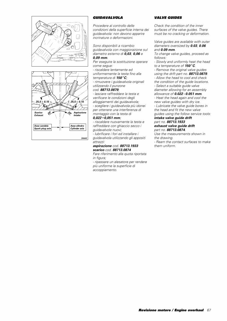
Revisione motore / Engine overhaul 67
GUIDAVALVOLA
Procedere al controllo dellecondizioni della superficie interna deiguidavalvola: non devono apparireincrinature o deformazioni.
Sono disponibili a ricambioguidavalvola con maggiorazione suldiametro esterno di 0,03, 0,06 e0,09 mm.Per eseguire la sostituzione operarecome segue:- riscaldare lentamente eduniformemente la testa fino allatemperatura di 150 °C;- rimuovere i guidavalvola originaliutilizzando il punzonecod.␣ 88713.0879;- lasciare raffreddare la testa everificare le condizioni deglialloggiamenti dei guidavalvola;- scegliere i guidavalvola più idoneiper ottenere una interferenza dimontaggio con la testa di0,022 ÷0,051 mm;- riscaldare nuovamente la testa eraffreddare con ghiaccio secco iguidavalvole nuovi;- lubrificare i fori ed installare iguidavalvola utilizzando gli appositiattrezzi:aspirazione cod. 88713.1933scarico cod. 88713.0874Fare riferimento alla quota riportatain figura;- ripassare un alesatore per renderepiù uniforme la superficie diaccoppiamento.
VALVE GUIDES
Check the condition of the innersurfaces of the valve guides. Theremust be no cracking or deformation.
Valve guides are available with outerdiameters oversized by 0.03, 0.06and 0.09 mm.To change valve guides, proceed asfollows:- Slowly and uniformly heat the headto a temperature of 150 °C.- Remove the original valve guidesusing the drift part no. 88713.0879.- Allow the head to cool and checkthe condition of the guide locations.- Select a suitable guide valvediameter allowing for an assemblyallowance of 0.022 - 0.051 mm.- Heat the head again and cool thenew valve guides with dry ice.- Lubricate the valve guide bores inthe head and fit the new valveguides using the follow service tools:intake valve guide driftpart␣ no.␣ 88713.1933exhaust valve guide driftpart␣ no.␣ 88713.0874.Use the measurements shown inthe drawing.- Ream the contact surfaces to makethem uniform.
20°20°
25,5 ± 0,15
ScaricoExhaust
AspirazioneIntake
(mm)
25,5 ± 0,15
Asse cilindroCylinder axis
Asse candelaSpark plug axis
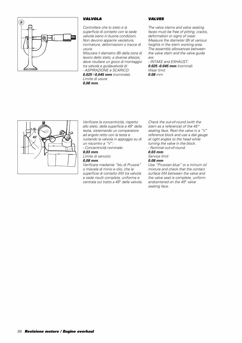
68 Revisione motore / Engine overhaul
VALVOLA
Controllare che lo stelo e lasuperficie di contatto con la sedevalvola siano in buone condizioni.Non devono apparire vaiolature,incrinature, deformazioni o tracce diusura.Misurare il diametro (B) della zona dilavoro dello stelo, a diverse altezze;deve risultare un gioco di montaggiotra valvola e guidavalvola di:- ASPIRAZIONE e SCARICO:0,025 ÷0,045 mm (nominale).Limite di usura:0,08 mm.
Verificare la concentricità, rispettoallo stelo, della superficie a 45° dellatesta, sistemando un comparatoread angolo retto con la testa eruotando la valvola in appoggio su diun riscontro a “V”:- Concentricità nominale:0,03 mm.Limite di servizio:0,08 mm.Verificare mediante “blu di Prussia”o miscela di minio e olio, che lasuperficie di contatto (W) tra valvolae sede risulti completa, uniforme ecentrata sul tratto a 45° della valvola.
B
45°
W
VALVES
The valve stems and valve seatingfaces must be free of pitting, cracks,deformation or signs of wear.Measure the diameter (B) at variousheights in the stem working area.The assembly allowances betweenthe valve stem and the valve guideare:- INTAKE and EXHAUST:0.025 -0.045 mm (nominal).Wear limit:0.08 mm
Check the out-of-round (with thestem as a reference) of the 45 °seating face. Rest the valve in a “V”reference block and use a dial gaugeat right angles to the head whileturning the valve in the block.- Nominal out-of-round:0.03 mmService limit:0.08 mmUse “Prussian blue” or a minium oilmixture and check that the contactsurface (W) between the valve andthe valve seat is complete, uniformandcentered on the 45° valveseating face.

Revisione motore / Engine overhaul 69
CONTROLLO TENUTAVALVOLE
La seguente procedura può avveniresia in sala prova che a motoremontato sul veicolo.– Portare a regime termico il motore(olio ed acqua a 80° circa), quindispegnerlo.– Partire con il controllo del cilindroorizzontale.– Togliere la candela.– Inserire connettore MOTOMETERnel filetto candela (cod. 88765.1140).– Aprire le farfalle al 100%.– Trascinare il motore a 1500 min-1
(nel caso di procedura sul veicolo,utilizzare avviatore ruota posteriore).– Leggere sullo strumento il valore dicompressione: se inferiore a 12,5ripristinare la tenuta valvole.– Ripetere la procedura sul cilindroverticale.
CONTROLLO PROFONDITÀSACCHE VALVOLE
Per evitare il contatto tra valvola epistone è necessario verificare laprofondità delle valvole sulla testa edelle sacche valvola sul pistoneutilizzando l’apposito attrezzo cod.88765.1033.Introdurre le valvole calibro,aspirazione cod. 88765.1187 escarico cod. 88765.1186 nellerispettive sedi e fissare l’attrezzosulla testa, utilizzando le 2 boccole dicentraggio. Con un calibro diprofondità, in appoggio sullasuperficie esterna ed inserito nelleapposite asole dell’attrezzo,contattare la valvola e verificarne laprofondità (P):- Valore nominale (PA):52,24±0,025 mm.- Valore nominale (PS):52,24±0,025 mm.
S A
PS
PA
88765.1033
Piano testaHead surface
VALVE LEAK TEST
This test can be done either in a testroom or with the engine in theframe.- Let the engine warm up tooperating temperature (oil and waterat 80° approximately), then stop it.- Check the horizontal cylinder first.- Remove the spark plug.- Screw the MOTOMETERconnector into the spark plug thread(part no. 88765.1140).- Open the throttles fully.- Crank the engine to 1,500 rpm (ifyou are doing the test with theengine in the frame, use the rearwheel starter).- Check the compression reading onthe meter. If it is less than 12.5, youwill need to overhaul the concernedarea to ensure proper sealing.- Repeat the procedure with thevertical cylinder.
CHECKING THE VALVEPOCKET DEPTH
In order to prevent any contactbetween the valves and the pistonsit will be necessary to check thedepth of valves on the heads and thepiston pockets. Use the service toolpart no. 88765.1033.Insert the master valves, i.e. masterintake valve part no. 88765.1187 andexhaust master valve part no.88765.1186 in the seats. Fit theservice tool to the head using the 2stud bolt holes. Rest a depth gaugeon the outer surface and insert itthrough the slots in the service tooluntil it touches the valve. Measurethe depth (P):- Nominal value (PA):52.24±0.025 mm.- Nominal value (PS):52.24±0.025 mm.
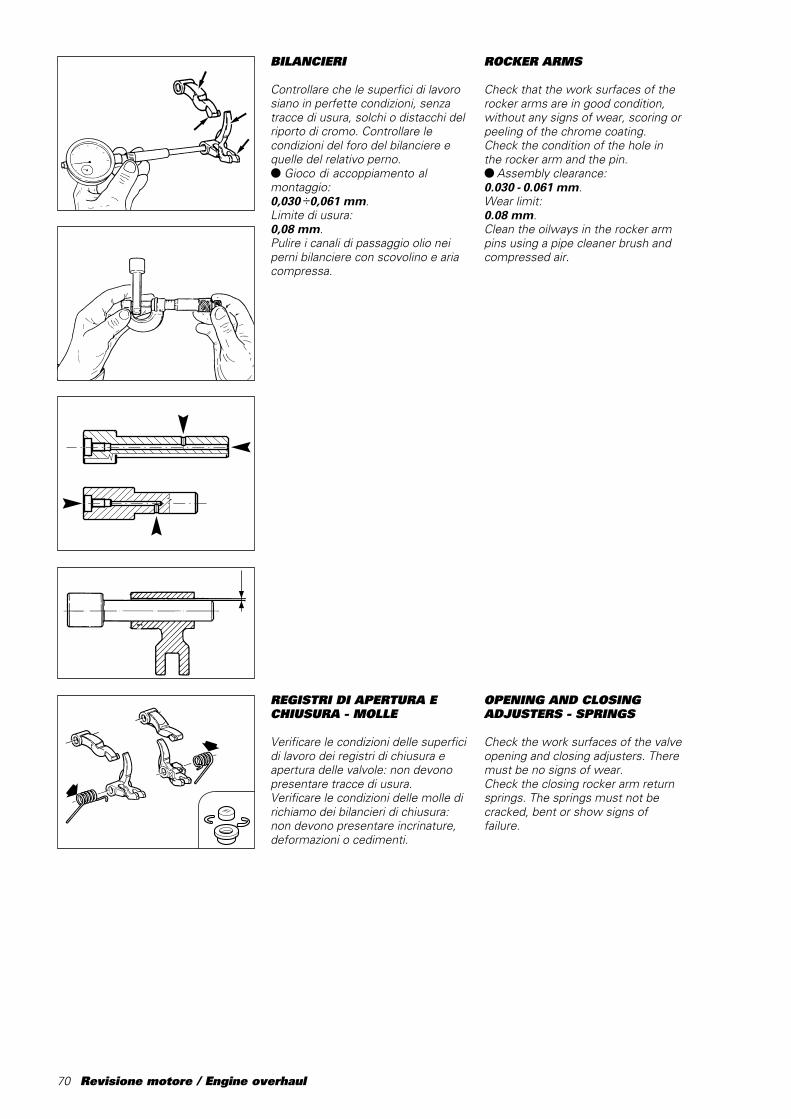
70 Revisione motore / Engine overhaul
REGISTRI DI APERTURA ECHIUSURA - MOLLE
Verificare le condizioni delle superficidi lavoro dei registri di chiusura eapertura delle valvole: non devonopresentare tracce di usura.Verificare le condizioni delle molle dirichiamo dei bilancieri di chiusura:non devono presentare incrinature,deformazioni o cedimenti.
BILANCIERI
Controllare che le superfici di lavorosiano in perfette condizioni, senzatracce di usura, solchi o distacchi delriporto di cromo. Controllare lecondizioni del foro del bilanciere equelle del relativo perno.● Gioco di accoppiamento almontaggio:0,030 ÷0,061 mm.Limite di usura:0,08 mm.Pulire i canali di passaggio olio neiperni bilanciere con scovolino e ariacompressa.
ROCKER ARMS
Check that the work surfaces of therocker arms are in good condition,without any signs of wear, scoring orpeeling of the chrome coating.Check the condition of the hole inthe rocker arm and the pin.● Assembly clearance:0.030 - 0.061 mm.Wear limit:0.08 mm.Clean the oilways in the rocker armpins using a pipe cleaner brush andcompressed air.
OPENING AND CLOSINGADJUSTERS - SPRINGS
Check the work surfaces of the valveopening and closing adjusters. Theremust be no signs of wear.Check the closing rocker arm returnsprings. The springs must not becracked, bent or show signs offailure.

Revisione motore / Engine overhaul 71
ALBERO A CAMME
Controllare che le superfici di lavorodelle camme siano prive di striature,solchi, scalini o ondulazioni. Lecamme troppo usurate sono spessocausa di una irregolare fasatura cheriduce la potenza del motore.Inserire l’albero a camme tra duecontropunte e con comparatoreverificare la deviazione:- Limite di usura:0,05 mm.
AttenzioneManipolare con estrema cura,
l’albero a cammes. Eventuali graffi oanche impalpabili ammaccaturedovute ad urti, cadute dal banco,ecc... possono infatti, pregiudicare ilrendimento del motore.
SUPPORTI ALBERO A CAMME
I supporti sono costituiti da unafusione in lega leggera con all’internoun anello seeger, un cuscinetto e unparaolio. Verificare lo stato di usuradel cuscinetto e del paraolio (vediparagrafo “Sostituzione paraoli” e“Cuscinetti” di questo capitolo).Fare attenzione al posizionamento eal verso di montaggio del paraolioall’interno del supporto (vedi figura).Lubrificare tutti i componenti primadel rimontaggio.
2 mm
CAMSHAFT
Check that the work surfaces of thecams are free of scratches, grooves,steps and waving. Worn cams areoften the cause of irregular timingand cause power losses.Mount the cam shaft between twocentres and check the deviationusing two dial gauges:- Wear limit:0.05 mm.
WarningHandle the camshafts with
great care. Possible dents,scratching caused by shocks, fallsfrom the bench and so on may affectoperation and lead to severe enginedamage.
CAMSHAFT SUPPORTS
The camshaft supports consist of alight-alloy casting housing a circlip, abearing and an oil seal. Checkbearing and oil seal for wear (see“Changing oil seals” and “Bearings”in this section).When fitting the oil seal, ensure thatit is positioned correctly and facingthe correct way (as shown in thedrawing).Lubricate all parts before refitting.

72 Revisione motore / Engine overhaul
PULEGGE - CINGHIE -TENDITORI
Le pulegge della distribuzione nondevono presentare tracce di usura oaltri danni.Verificare la sede della linguetta: nondeve risultare rovinata o impostatadal contatto con la linguetta stessa.Ad ogni rimontaggio sostituiresempre la ghiera esterna e la rosettadi bloccaggio puleggia.
Le cinghie devono essere in perfettecondizioni, senza screpolature, tagli odeformazioni. È buona normasostituire le cinghie ad ognirevisione del motore.
Ruotando la bussola esterna deitenditori, verificare lo stato di usuradel cuscinetto interno. Sostituire iltenditore che presenti difficoltà dirotazione o gioco eccessivo.
SEMICARTER MOTORE
Eliminare ogni traccia di sigillante.Lavare accuratamente tutte lecanalizzazioni interne, eliminandoeventuali strozzature od ostruzioni;asciugare con aria compressa quindiprocedere ad un accurato controllovisivo dei semicarter.Controllare, su di un piano diriscontro, che le superfici diaccoppiamento siano perfettamentepiane. In caso contrario, applicaresospensione diamantata (spessore6 ÷12 micron) e ripassare lasuperficie nel modo descritto laparagrafo “Testa”.Controllare che i cuscinetti siano inottimo stato. In caso di sostituzione,seguire la procedura descritta alparagrafo “Cuscinetti di banco”.
MobileMobile
FissoFixed
ROLLERS - BELTS -TENSIONERS
The timing rollers must not showany signs of wear or damage of anykind.Check the keyway. It must not bedamaged or worn by contact withthe key.At reassembly, change the outerlocking ring nut and washer on theroller.
Belts must be in perfect conditionwithout cracks, cuts or kinks.It is good working practice tochange the belts at each engineoverhaul.
Turn the outer bush of thetensioners and check the wear ofthe inner bearing. If the bearingrotates with difficulty or showsexcessive play, change thetensioner.
CRANKCASE HALVES
Clean off all signs of sealant.Thoroughly flush out and clean theoil ways removing any blockages orobstructions and then dry withcompressed air.Visually check the crankcase half.Place the crankcase half on areference table and check that thefastening surfaces are perfectly flat.If the surfaces are uneven, grindthem with a grinding solution (6 - 12micron) as described in the “CylinderHead” section.Check that the bearings are in goodcondition. To change the bearings,follow the instructions given in thesection “Main bearings”.
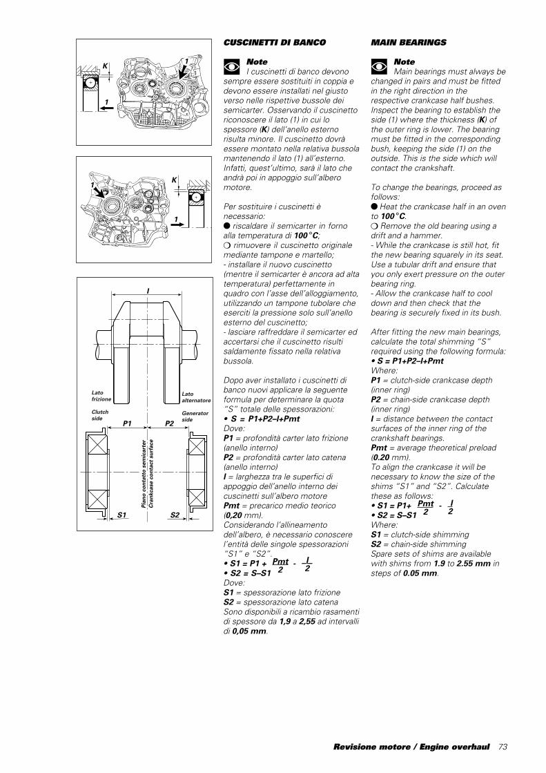
Revisione motore / Engine overhaul 73
CUSCINETTI DI BANCO
NoteI cuscinetti di banco devono
sempre essere sostituiti in coppia edevono essere installati nel giustoverso nelle rispettive bussole deisemicarter. Osservando il cuscinettoriconoscere il lato (1) in cui lospessore (K) dell’anello esternorisulta minore. Il cuscinetto dovràessere montato nella relativa bussolamantenendo il lato (1) all’esterno.Infatti, quest’ultimo, sarà il lato cheandrà poi in appoggio sull’alberomotore.
Per sostituire i cuscinetti ènecessario:● riscaldare il semicarter in fornoalla temperatura di 100 °C;❍ rimuovere il cuscinetto originalemediante tampone e martello;- installare il nuovo cuscinetto(mentre il semicarter è ancora ad altatemperatura) perfettamente inquadro con l’asse dell’alloggiamento,utilizzando un tampone tubolare cheeserciti la pressione solo sull’anelloesterno del cuscinetto;- lasciare raffreddare il semicarter edaccertarsi che il cuscinetto risultisaldamente fissato nella relativabussola.
Dopo aver installato i cuscinetti dibanco nuovi applicare la seguenteformula per determinare la quota“S” totale delle spessorazioni:• S = P1+P2–l+PmtDove:P1 = profondità carter lato frizione(anello interno)P2 = profondità carter lato catena(anello interno)l = larghezza tra le superfici diappoggio dell’anello interno deicuscinetti sull’albero motorePmt = precarico medio teorico(0,20 ␣ mm).Considerando l’allineamentodell’albero, è necessario conoscerel’entità delle singole spessorazioni“S1” e “S2”.• S1 = P1 + - Pmt/2• S2 = S–S1Dove:S1 = spessorazione lato frizioneS2 = spessorazione lato catenaSono disponibili a ricambio rasamentidi spessore da 1,9 a 2,55 ad intervallidi 0,05 mm.
1
1K
1
1K
Pmt2
_I_2
MAIN BEARINGS
NoteMain bearings must always be
changed in pairs and must be fittedin the right direction in therespective crankcase half bushes.Inspect the bearing to establish theside (1) where the thickness (K) ofthe outer ring is lower. The bearingmust be fitted in the correspondingbush, keeping the side (1) on theoutside. This is the side which willcontact the crankshaft.
To change the bearings, proceed asfollows:● Heat the crankcase half in an ovento 100 °C.❍ Remove the old bearing using adrift and a hammer.- While the crankcase is still hot, fitthe new bearing squarely in its seat.Use a tubular drift and ensure thatyou only exert pressure on the outerbearing ring.- Allow the crankcase half to cooldown and then check that thebearing is securely fixed in its bush.
After fitting the new main bearings,calculate the total shimming “S”required using the following formula:• S = P1+P2–l+PmtWhere:P1 = clutch-side crankcase depth(inner ring)P2 = chain-side crankcase depth(inner ring)l = distance between the contactsurfaces of the inner ring of thecrankshaft bearings.Pmt = average theoretical preload(0.20 mm).To align the crankcase it will benecessary to know the size of theshims “S1” and “S2”. Calculatethese as follows:• S1 = P1+ -• S2 = S–S1Where:S1 = clutch-side shimmingS2 = chain-side shimmingSpare sets of shims are availablewith shims from 1.9 to 2.55 mm insteps of 0.05 mm.
������
@@@@@@
������
ÀÀÀÀÀÀ
������
@@@@@@
������
ÀÀÀÀÀÀ
������
yyyyyy
������
@@@@@@
������
ÀÀÀÀÀÀ
������
@@@@@@
������
ÀÀÀÀÀÀ
������
yyyyyy
��@@��ÀÀ��@@��ÀÀ��yy
��@@��ÀÀ��@@��ÀÀ��yy
I
P1
S1
P2
S2
Pian
o co
ntat
to s
emic
arte
rC
rank
case
con
tact
sur
face
Lato frizione
Clutchside
Lato alternatore
Generatorside
I2
Pmt2
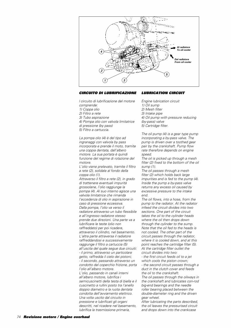
74 Revisione motore / Engine overhaul
CIRCUITO DI LUBRIFICAZIONE
l circuito di lubrificazione del motorecomprende:1) Coppa olio2) Filtro a rete3) Tubo aspirazione4) Pompa olio con valvola limitatricedi pressione (by pass)5) Filtro a cartuccia.
La pompa olio (4) è del tipo adingranaggi con valvola by passincorporata e prende il moto, tramiteuna coppia dentata, dall’alberomotore. La sua portata è quindifunzione del regime di rotazione delmotore.L’olio viene prelevato, tramite il filtroa rete (2), solidale al fondo dellacoppa olio (1).Attraverso il filtro a rete (2), in gradodi trattenere eventuali impuritàgrossolane, l’olio raggiunge lapompa␣ (4). Al suo interno agisce unavalvola limitatrice che rimandal’eccedenza di olio in aspirazione incaso di pressione eccessiva.Dalla pompa, l’olio va verso ilradiatore attraverso un tubo flessibilee all’ingresso radiatore stessoprende due direzioni. Una parte va alubrificare le teste (olio nonraffreddato) per poi ricadere,attraverso il cilindro, nel basamento.L’altra parte attraversa il radiatoreraffreddandosi e successivamenteraggiunge il filtro a cartuccia␣ (5)all’uscita del quale segue due circuiti:- il primo, attraverso un particolaregetto, raffredda il cielo dei pistoni;- il secondo, passando attraverso uncondotto del coperchio frizione, portal’olio all’albero motore.L’olio, passando in canali interniall’albero motore, lubrifica isemicuscinetti della testa di biella e ilcuscinetto a rullini posto tra l’anellodoppio diametro e la ruota dentatacondotta dell’avviamento elettrico.Una volta uscito dal circuito inpressione e lubrificati gli organidescritti, nel ricadere nel basamento,lubrifica la trasmissione primaria,
LUBRICATION CIRCUIT
Engine lubrication circuit1) Oil sump2) Mesh filter3) Intake pipe4) Oil pump with pressure reducing(by-pass) valve5) Cartridge filter.
The oil pump (4) is a gear type pumpincorporating a by-pass valve. Thepump is driven over a toothed gearpair by the crankshaft. Pump flowrate therefore depends on enginespeed.The oil is picked up through a meshfilter␣ (2) fixed to the bottom of the oilsump (1).The oil passes through a meshfilter␣ (2) which holds back largeimpurities and is fed to the pump (4).Inside the pump a by-pass valvereturns any excess oil caused byexcessive pressure to the intakeend.The oil flows, into a hose, from thepump to the radiator. At the radiatorinfeed the circuit divides into twosections. One part of the circuittakes the oil to the cylinder headswhere the oil then drops downthrough the cylinder to the sump.Note that the oil fed to the heads isnot cooled. The other part of thecircuit passes through the radiator,where it is cooled down, and at thispoint reaches the cartridge filter (5).At the cartridge filter outlet thecircuit divides into two:- the first circuit feeds oil to a jetwhich cools the piston crown;- the second circuit passes through aduct in the clutch cover and feedsthe oil to the crankshaft.The oil passes through the oilways inthe crankshaft and lubricates con-rodbig-end bearings and the needleroller bearing placed between thedouble-diameter ring and the drivengear wheel.After lubricating the parts described,the oil leaves the pressurised circuitand drops down into the crankcase
4
2
1
5
3
Al radiatoreTo oil cooler
Dal radiatoreFrom oil cooler
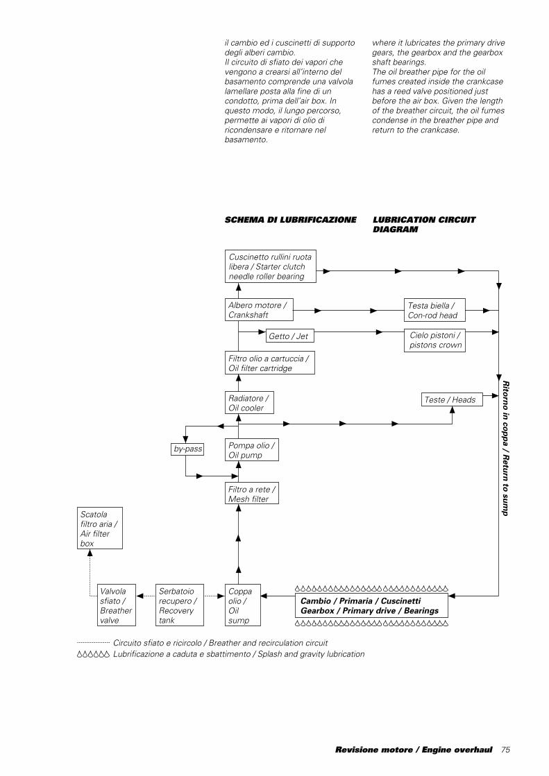
Revisione motore / Engine overhaul 75
SCHEMA DI LUBRIFICAZIONE
by-pass
Scatola filtro aria /Air filter box
Circuito sfiato e ricircolo / Breather and recirculation circuitLubrificazione a caduta e sbattimento / Splash and gravity lubrication
Coppa olio /Oil sump
Valvola sfiato /Breather valve
Serbatoiorecupero /Recovery tank
Filtro olio a cartuccia / Oil filter cartridge
Cuscinetto rullini ruota libera / Starter clutch needle roller bearing
Teste / Heads
Cielo pistoni /pistons crown
Getto / Jet
Pompa olio /Oil pump
Radiatore /Oil cooler
Filtro a rete / Mesh filter
Ritorno in coppa / R
eturn to sump
Cambio / Primaria / Cuscinetti Gearbox / Primary drive / Bearings
Albero motore /Crankshaft
Testa biella /Con-rod head
il cambio ed i cuscinetti di supportodegli alberi cambio.Il circuito di sfiato dei vapori chevengono a crearsi all’interno delbasamento comprende una valvolalamellare posta alla fine di uncondotto, prima dell’air box. Inquesto modo, il lungo percorso,permette ai vapori di olio diricondensare e ritornare nelbasamento.
LUBRICATION CIRCUITDIAGRAM
where it lubricates the primary drivegears, the gearbox and the gearboxshaft bearings.The oil breather pipe for the oilfumes created inside the crankcasehas a reed valve positioned justbefore the air box. Given the lengthof the breather circuit, the oil fumescondense in the breather pipe andreturn to the crankcase.
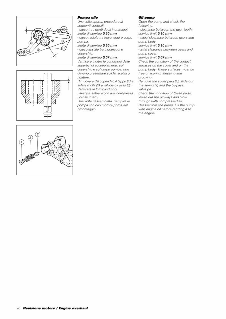
76 Revisione motore / Engine overhaul
Pompa olioUna volta aperta, procedere aiseguenti controlli:- gioco tra i denti degli ingranaggi:limite di servizio 0,10 mm- gioco radiale tra ingranaggi e corpopompa:limite di servizio 0,10 mm- gioco assiale tra ingranaggi ecoperchio:limite di servizio 0,07 mm.Verificare inoltre le condizioni dellesuperfici di accoppiamento sulcoperchio e sul corpo pompa: nondevono presentare solchi, scalini origature.Rimuovere dal coperchio il tappo (1) esfilare molla (2) e valvola by␣ pass␣ (3).Verificare le loro condizioni.Lavare e soffiare con aria compressai canali interni.Una volta riassemblata, riempire lapompa con olio motore prima delrimontaggio.
���������������������������������������������
@@@@@@@@@@@@@@@@@@@@@@@@@@@@@@@@@@@@@@@@@@@@@
���������������������������������������������
ÀÀÀÀÀÀÀÀÀÀÀÀÀÀÀÀÀÀÀÀÀÀÀÀÀÀÀÀÀÀÀÀÀÀÀÀÀÀÀÀÀÀÀÀÀ
���������������������������������������������
@@@@@@@@@@@@@@@@@@@@@@@@@@@@@@@@@@@@@@@@@@@@@
���������������������������������������������
ÀÀÀÀÀÀÀÀÀÀÀÀÀÀÀÀÀÀÀÀÀÀÀÀÀÀÀÀÀÀÀÀÀÀÀÀÀÀÀÀÀÀÀÀÀ
���������������������������������������������
yyyyyyyyyyyyyyyyyyyyyyyyyyyyyyyyyyyyyyyyyyyyy
12
3
Oil pumpOpen the pump and check thefollowing:- clearance between the gear teeth:service limit 0.10 mm- radial clearance between gears andpump body:service limit 0.10 mm- axial clearance between gears andpump cover:service limit 0.07 mm.Check the condition of the contactsurfaces on the cover and on thepump body. These surfaces must befree of scoring, stepping andgrooving.Remove the cover plug (1), slide outthe spring (2) and the by-passvalve␣ (3).Check the condition of these parts.Wash out the oil ways and blowthrough with compressed air.Reassemble the pump. Fill the pumpwith engine oil before refitting it tothe engine.
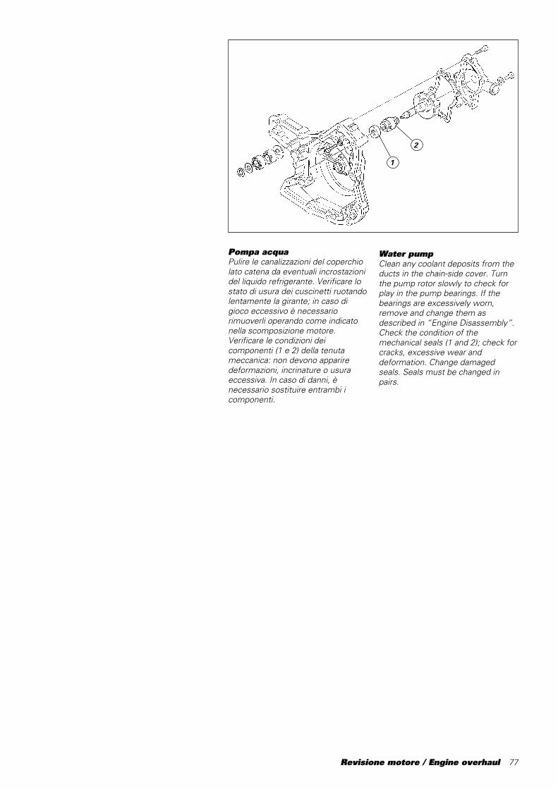
Revisione motore / Engine overhaul 77
Pompa acquaPulire le canalizzazioni del coperchiolato catena da eventuali incrostazionidel liquido refrigerante. Verificare lostato di usura dei cuscinetti ruotandolentamente la girante; in caso digioco eccessivo è necessariorimuoverli operando come indicatonella scomposizione motore.Verificare le condizioni deicomponenti (1 e 2) della tenutameccanica: non devono appariredeformazioni, incrinature o usuraeccessiva. In caso di danni, ènecessario sostituire entrambi icomponenti.
1
2
Water pumpClean any coolant deposits from theducts in the chain-side cover. Turnthe pump rotor slowly to check forplay in the pump bearings. If thebearings are excessively worn,remove and change them asdescribed in “Engine Disassembly”.Check the condition of themechanical seals (1 and 2); check forcracks, excessive wear anddeformation. Change damagedseals. Seals must be changed inpairs.
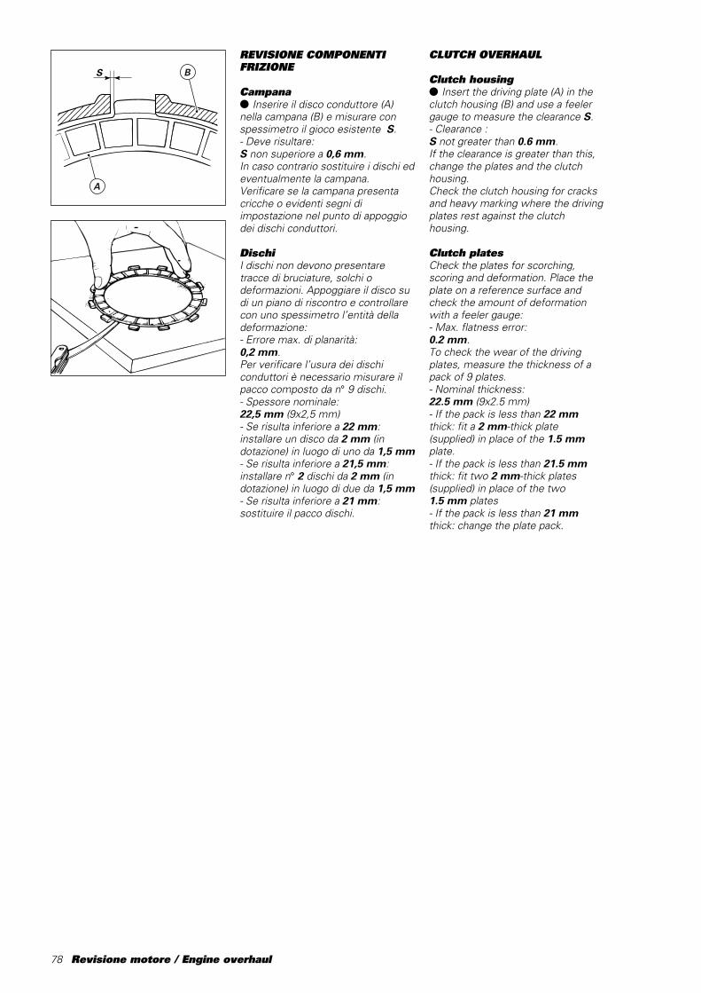
78 Revisione motore / Engine overhaul
������������
@@@@@@@@@@@@
������������
ÀÀÀÀÀÀÀÀÀÀÀÀ
������������
@@@@@@@@@@@@
������������
ÀÀÀÀÀÀÀÀÀÀÀÀ
������������
yyyyyyyyyyyy
������������
@@@@@@@@@@@@
������������
ÀÀÀÀÀÀÀÀÀÀÀÀ
������������
@@@@@@@@@@@@
������������
ÀÀÀÀÀÀÀÀÀÀÀÀ
������������
yyyyyyyyyyyy
S B
A
REVISIONE COMPONENTIFRIZIONE
Campana● Inserire il disco conduttore (A)nella campana (B) e misurare conspessimetro il gioco esistente S.- Deve risultare:S non superiore a 0,6 mm.In caso contrario sostituire i dischi edeventualmente la campana.Verificare se la campana presentacricche o evidenti segni diimpostazione nel punto di appoggiodei dischi conduttori.
DischiI dischi non devono presentaretracce di bruciature, solchi odeformazioni. Appoggiare il disco sudi un piano di riscontro e controllarecon uno spessimetro l’entità delladeformazione:- Errore max. di planarità:0,2 mm.Per verificare l’usura dei dischiconduttori è necessario misurare ilpacco composto da n° 9 dischi.- Spessore nominale:22,5 mm (9x2,5 mm)- Se risulta inferiore a 22 mm:installare un disco da 2 mm (indotazione) in luogo di uno da 1,5 mm- Se risulta inferiore a 21,5 mm:installare n° 2 dischi da 2 mm (indotazione) in luogo di due da 1,5 mm- Se risulta inferiore a 21 mm:sostituire il pacco dischi.
CLUTCH OVERHAUL
Clutch housing● Insert the driving plate (A) in theclutch housing (B) and use a feelergauge to measure the clearance S.- Clearance :S not greater than 0.6 mm.If the clearance is greater than this,change the plates and the clutchhousing.Check the clutch housing for cracksand heavy marking where the drivingplates rest against the clutchhousing.
Clutch platesCheck the plates for scorching,scoring and deformation. Place theplate on a reference surface andcheck the amount of deformationwith a feeler gauge:- Max. flatness error:0.2 mm.To check the wear of the drivingplates, measure the thickness of apack of 9 plates.- Nominal thickness:22.5 mm (9x2.5 mm)- If the pack is less than 22 mmthick: fit a 2 mm-thick plate(supplied) in place of the 1.5 mmplate.- If the pack is less than 21.5 mmthick: fit two 2 mm-thick plates(supplied) in place of the two1.5 mm plates- If the pack is less than 21 mmthick: change the plate pack.
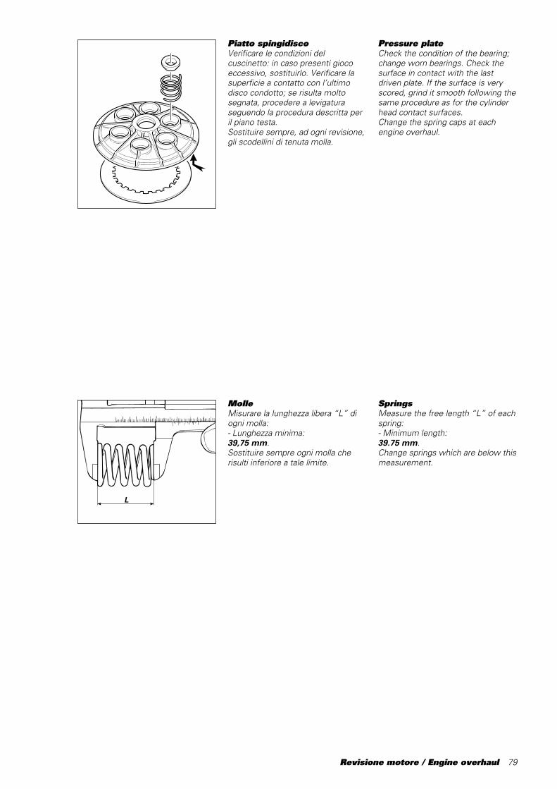
Revisione motore / Engine overhaul 79
MolleMisurare la lunghezza libera “L” diogni molla:- Lunghezza minima:39,75 mm.Sostituire sempre ogni molla cherisulti inferiore a tale limite.
L
Piatto spingidiscoVerificare le condizioni delcuscinetto: in caso presenti giocoeccessivo, sostituirlo. Verificare lasuperficie a contatto con l’ultimodisco condotto; se risulta moltosegnata, procedere a levigaturaseguendo la procedura descritta peril piano testa.Sostituire sempre, ad ogni revisione,gli scodellini di tenuta molla.
Pressure plateCheck the condition of the bearing;change worn bearings. Check thesurface in contact with the lastdriven plate. If the surface is veryscored, grind it smooth following thesame procedure as for the cylinderhead contact surfaces.Change the spring caps at eachengine overhaul.
SpringsMeasure the free length “L” of eachspring:- Minimum length:39.75 mm.Change springs which are below thismeasurement.
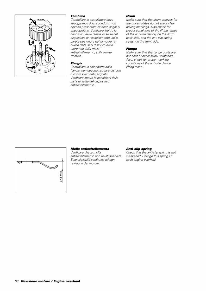
80 Revisione motore / Engine overhaul
Molla antisaltellamentoVerificare che la mollaantisaltellamento non risulti snervata.È consigliabile sostituirla ad ognirevisione del motore.
TamburoControllare le scanalature doveappoggiano i dischi condotti: nondevono presentare evidenti segni diimpostazione. Verificare inoltre lecondizioni delle rampe di salita deldispositivo antisaltellamento, sullaparete posteriore del tamburo, equelle delle sedi di lavoro delleestremità della mollaantisaltellamento, sulla paretefrontale.
FlangiaControllare le colonnette dellaflangia: non devono risultare distorteo eccessivamente segnate.Verificare inoltre le condizioni dellepiste di salita del dispositivoantisaltellamento.
��������������������������������������������������������������������������������������������������������������������������������������������
@@@@@@@@@@@@@@@@@@@@@@@@@@@@@@@@@@@@@@@@@@@@@@@@@@@@@@@@@@@@@@@@@@@@@@@@@@@@@@@@@@@@@@@@@@@@@@@@@@@@@@@@@@@@@@@@@@@@@@@@@@@@@@@@@@@@@@@@@@@@
��������������������������������������������������������������������������������������������������������������������������������������������
ÀÀÀÀÀÀÀÀÀÀÀÀÀÀÀÀÀÀÀÀÀÀÀÀÀÀÀÀÀÀÀÀÀÀÀÀÀÀÀÀÀÀÀÀÀÀÀÀÀÀÀÀÀÀÀÀÀÀÀÀÀÀÀÀÀÀÀÀÀÀÀÀÀÀÀÀÀÀÀÀÀÀÀÀÀÀÀÀÀÀÀÀÀÀÀÀÀÀÀÀÀÀÀÀÀÀÀÀÀÀÀÀÀÀÀÀÀÀÀÀÀÀÀÀÀÀÀÀÀÀÀÀÀÀÀÀÀÀÀÀ
��������������������������������������������������������������������������������������������������������������������������������������������
yyyyyyyyyyyyyyyyyyyyyyyyyyyyyyyyyyyyyyyyyyyyyyyyyyyyyyyyyyyyyyyyyyyyyyyyyyyyyyyyyyyyyyyyyyyyyyyyyyyyyyyyyyyyyyyyyyyyyyyyyyyyyyyyyyyyyyyyyyyy
���������������
@@@@@@@@@@@@@@@
���������������
ÀÀÀÀÀÀÀÀÀÀÀÀÀÀÀ
���������������
@@@@@@@@@@@@@@@
���������������
ÀÀÀÀÀÀÀÀÀÀÀÀÀÀÀ
���������������
yyyyyyyyyyyyyyy
≥7,5
mm
.
DrumMake sure that the drum grooves forthe driven plates do not show cleardriving markings. Also check forproper conditions of the lifting rampsof the anti-slip device, on the drumback side, and the anti-slip springseats, on the front side.
FlangeMake sure that the flange posts arenot bent or excessively scratched.Also, check for proper workingconditions of the anti-slip devicelifting races.
Anti-slip springCheck that the anti-slip spring is notweakened. Change this spring ateach engine overhaul.
Revisione motore / Engine overhaul 81
AnomalieRiportiamo di seguito un elenco dicause che possono determinare unmalfunzionamento della frizione o deldispositivo di disinnesto.Una frizione che non stacca puòdipendere da:- eccessivo gioco della leva di comando;- dischi frizione distorti;- irregolare carico delle molle;- difetto nel dispositivo di disinnesto;- eccessiva usura del mozzo o della campana.Una frizione che slitta può dipendereda:- mancanza di gioco sulla leva di comando;- dischi frizione usurati;- molle snervate;- difetto nel dispositivo di disinnesto;- eccessiva usura del mozzo o della campana.Una frizione rumorosa puòdipendere da:- eccessivo gioco tra gli ingranaggi della trasmissione primaria;- denti degli ingranaggi della trasmissione primaria danneggiati;- eccessivo gioco tra estremità dischi conduttori e campana frizione;- cuscinetti di supporto ingranaggio/ campana frizione usurati;- presenza di particelle metalliche (limatura) sui denti degli ingranaggi.
Clutch troubleshootingThis section describes clutch anddisengagement mechanismmalfunctions and some of theirpossible causes.The clutch will not disengage.Causes:- excessive play of the clutch lever;- distorted clutch plates;- uneven spring loading;- faulty disengagement mechanism;- excessive wear of the drum or clutch housing.The clutch slips. Causes:- insufficient play of the clutch lever;- worn clutch plates;- weakened springs;- faulty disengagement mechanism;- excessive wear of the drum or clutch housing.The clutch is noisy. Causes:- excessive play between the primary drive gears;- damaged primary drive gear teeth;- excessive clearance betweendriving plate tangs and clutchhousing slots;- worn clutch cover/gear bearing;- filings and metal particles on gearteeth.
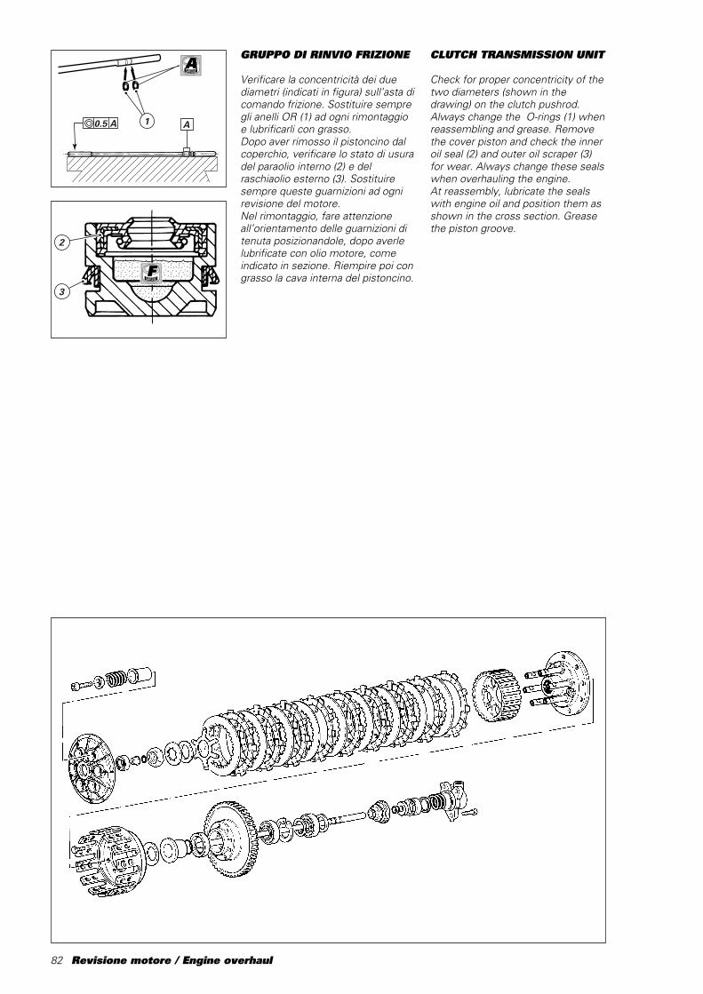
82 Revisione motore / Engine overhaul
GRUPPO DI RINVIO FRIZIONE
Verificare la concentricità dei duediametri (indicati in figura) sull’asta dicomando frizione. Sostituire sempregli anelli OR (1) ad ogni rimontaggioe lubrificarli con grasso.Dopo aver rimosso il pistoncino dalcoperchio, verificare lo stato di usuradel paraolio interno (2) e delraschiaolio esterno (3). Sostituiresempre queste guarnizioni ad ognirevisione del motore.Nel rimontaggio, fare attenzioneall’orientamento delle guarnizioni ditenuta posizionandole, dopo averlelubrificate con olio motore, comeindicato in sezione. Riempire poi congrasso la cava interna del pistoncino.
A10.5 A
�����������
2
3
F
ACLUTCH TRANSMISSION UNIT
Check for proper concentricity of thetwo diameters (shown in thedrawing) on the clutch pushrod.Always change the O-rings (1) whenreassembling and grease. Removethe cover piston and check the inneroil seal (2) and outer oil scraper (3)for wear. Always change these sealswhen overhauling the engine.At reassembly, lubricate the sealswith engine oil and position them asshown in the cross section. Greasethe piston groove.
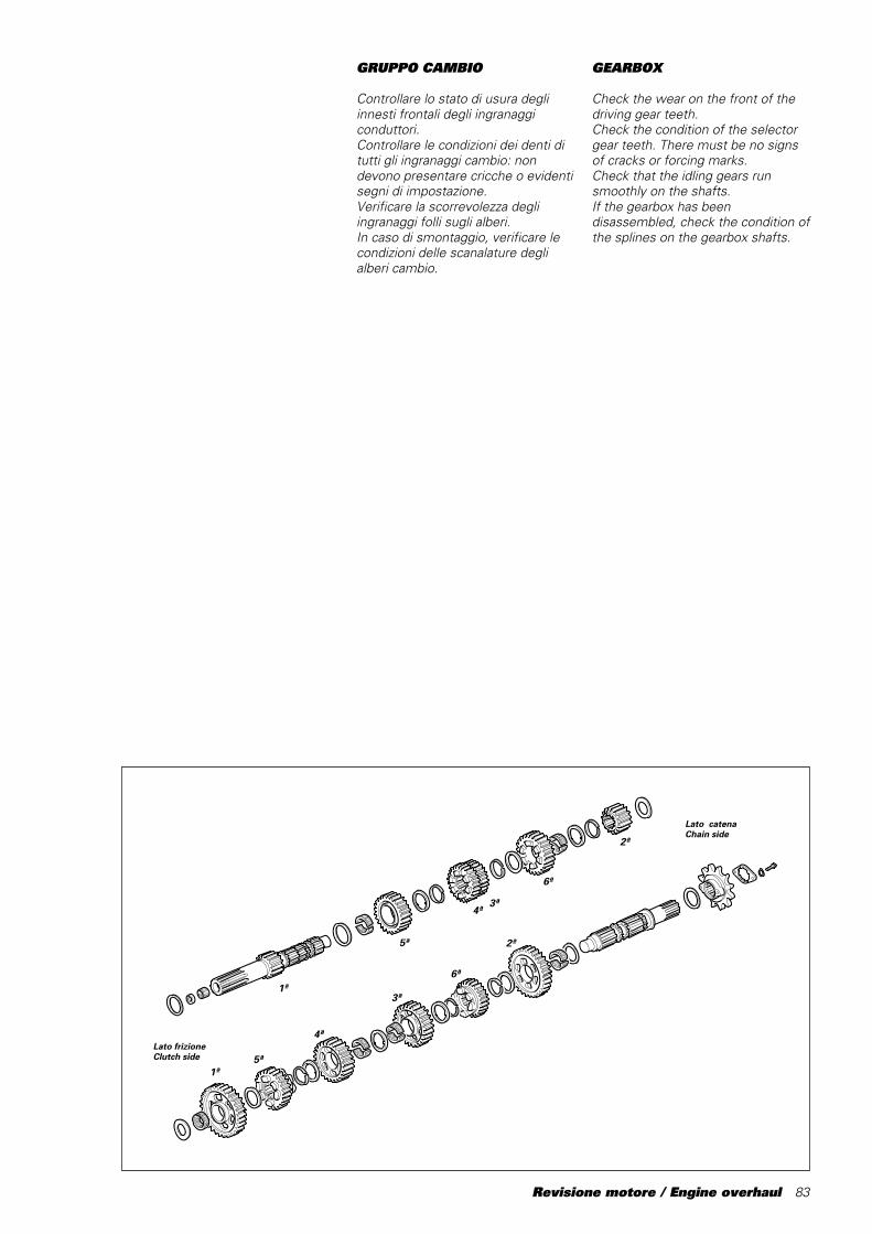
Revisione motore / Engine overhaul 83
GRUPPO CAMBIO
Controllare lo stato di usura degliinnesti frontali degli ingranaggiconduttori.Controllare le condizioni dei denti ditutti gli ingranaggi cambio: nondevono presentare cricche o evidentisegni di impostazione.Verificare la scorrevolezza degliingranaggi folli sugli alberi.In caso di smontaggio, verificare lecondizioni delle scanalature deglialberi cambio.
Lato frizioneClutch side
Lato catenaChain side
1ª
5ª
4ª3ª
6ª
2ª
1ª5ª
4ª
3ª
6ª
2ª
GEARBOX
Check the wear on the front of thedriving gear teeth.Check the condition of the selectorgear teeth. There must be no signsof cracks or forcing marks.Check that the idling gears runsmoothly on the shafts.If the gearbox has beendisassembled, check the condition ofthe splines on the gearbox shafts.
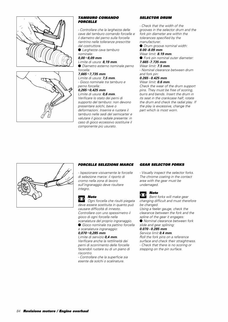
84 Revisione motore / Engine overhaul
TAMBURO COMANDOFORCELLE
- Controllare che la larghezza dellecave del tamburo comando forcelle eil diametro del perno sulla forcellarientrino nelle tolleranze prescrittedal costruttore.● Larghezza cava tamburonominale:8,00 ÷8,09 mmLimite di usura: 8,19 mm.● Diametro esterno nominale pernoforcella:7,665 ÷7,735 mmLimite di usura: 7,5 mm.- Gioco nominale tra tamburo eperno forcella:0,265 ÷0,425 mmLimite di usura: 0,6 mm.Verificare lo stato dei perni disupporto del tamburo: non devonopresentare solchi, bave odeformazioni. Inserire e ruotare iltamburo nelle sedi del semicarter evalutare il gioco radiale presente: incaso di gioco eccessivo sostituire ilcomponente più usurato.
FORCELLE SELEZIONE MARCE
- Ispezionare visivamente le forcelledi selezione marce: il riporto dicromo nella zona di lavorosull’ingranaggio deve risultareintegro.
NoteOgni forcella che risulti piegata
deve essere sostituita in quanto puòcausare difficoltà di innesto.Controllare con uno spessimetro ilgioco di ogni forcella nellascanalatura del proprio ingranaggio.● Gioco nominale tra pattino forcellae scanalatura ingranaggio:0,070 ÷0,285 mmLimite di servizio 0,4 mm.Verificare anche la rettilineità deiperni di scorrimento delle forcellefacendoli ruotare su di un piano diriscontro.- Controllare che la superficie siaesente da solchi o scalinature.
SELECTOR DRUM
- Check that the width of thegrooves in the selector drum and thefork pin diameter are within thetolerances specified by themanufacturer.● Drum groove nominal width:8.00 -8.09 mmWear limit: 8.19 mm.● Fork pin nominal outer diameter:7.665 -7.735 mmWear limit: 7.5 mm.- Nominal clearance between drumand fork pin:0.265 - 0.425 mmWear limit: 0.6 mm.Check the wear of the drum supportpins. They must be free of scoring,burrs and bends. Insert the drum inits seat in the crankcase half; rotatethe drum and check the radial play. Ifthe play is excessive, change thepart which is most worn.
GEAR SELECTOR FORKS
- Visually inspect the selector forks.The chrome coating in the contactarea with the gear must beundamaged.
NoteBent forks will make gear
changing difficult and must thereforebe changed.Using a feeler gauge, check theclearance between the fork and thespline of the gear it engages:● Nominal clearance between forkslide and gear splining:0.070 - 0.285 mmService limit 0.4 mm.Roll the fork pins on a referencesurface and check their straightness.- Check that there is no scoring orstepping on the pin surface.
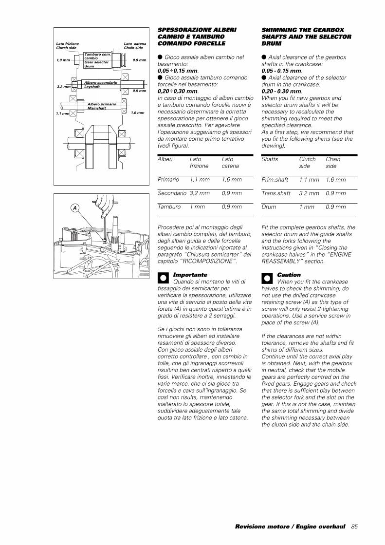
Revisione motore / Engine overhaul 85
SPESSORAZIONE ALBERICAMBIO E TAMBUROCOMANDO FORCELLE
● Gioco assiale alberi cambio nelbasamento:0,05 ÷0,15 mm.● Gioco assiale tamburo comandoforcelle nel basamento:0,20 ÷0,30 mm.In caso di montaggio di alberi cambioe tamburo comando forcelle nuovi ènecessario determinare la correttaspessorazione per ottenere il giocoassiale prescritto. Per agevolarel’operazione suggeriamo gli spessorida montare come primo tentativo(vedi figura).
Alberi Lato Latofrizione catena
Primario 1,1 mm 1,6 mm
Secondario 3,2 mm 0,9 mm
Tamburo 1 mm 0,9 mm
Procedere poi al montaggio deglialberi cambio completi, del tamburo,degli alberi guida e delle forcelleseguendo le indicazioni riportate alparagrafo “Chiusura semicarter” delcapitolo “RICOMPOSIZIONE”.
ImportanteQuando si montano le viti di
fissaggio dei semicarter perverificare la spessorazione, utilizzareuna vite di servizio al posto della viteforata (A) in quanto quest’ultima è ingrado di resistere a 2 serraggi.
Se i giochi non sono in tolleranzarimuovere gli alberi ed installarerasamenti di spessore diverso.Con gioco assiale degli albericorretto controllare , con cambio infolle, che gli ingranaggi scorrevolirisultino ben centrati rispetto a quellifissi. Verificare inoltre, innestando levarie marce, che ci sia gioco traforcella e cava sull’ingranaggio. Secosì non risulta, mantenendoinalterato lo spessore totale,suddividere adeguatamente talequota tra lato frizione e lato catena.
A
Lato frizioneClutch side
Lato catenaChain side
Tamburo com. cambioGear selector drum
Albero secondarioLayshaft
Albero primarioMainshaft
1,1 mm
3,2 mm
1,0 mm 0,9 mm
0,9 mm
1,6 mm
SHIMMING THE GEARBOXSHAFTS AND THE SELECTORDRUM
● Axial clearance of the gearboxshafts in the crankcase:0.05 - 0.15 mm.● Axial clearance of the selectordrum in the crankcase:0.20 - 0.30 mm.When you fit new gearbox andselector drum shafts it will benecessary to recalculate theshimming required to meet thespecified clearance.As a first step, we recommend thatyou fit the following shims (see thedrawing):
Shafts Clutch Chainside side
Prim.shaft 1.1 mm 1.6 mm
Trans.shaft 3.2 mm 0.9 mm
Drum 1 mm 0.9 mm
Fit the complete gearbox shafts, theselector drum and the guide shaftsand the forks following theinstructions given in “Closing thecrankcase halves” in the “ENGINEREASSEMBLY” section.
CautionWhen you fit the crankcase
halves to check the shimming, donot use the drilled crankcaseretaining screw (A) as this type ofscrew will only resist 2 tighteningoperations. Use a service screw inplace of the screw␣ (A).
If the clearances are not withintolerance, remove the shafts and fitshims of different sizes.Continue until the correct axial playis obtained. Next, with the gearboxin neutral, check that the mobilegears are perfectly centred on thefixed gears. Engage gears and checkthat there is sufficient play betweenthe selector fork and the slot on thegear. If this is not the case, maintainthe same total shimming and dividethe shimming necessary betweenthe clutch side and the chain side.

86 Revisione motore / Engine overhaul

Ricomposizione motore / Engine reassembly 87
Ricomposizione motoreEngine reassembly
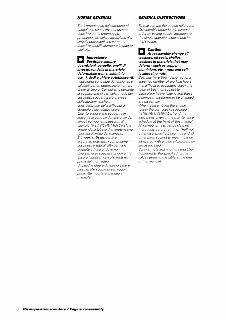
88 Ricomposizione motore / Engine reassembly
NORME GENERALI
Per il rimontaggio dei componentieseguire in senso inverso quantodescritto per lo smontaggio,prestando particolare attenzione allesingole operazioni che verrannodescritte specificatamente in questocapitolo.
ImportanteSostituire sempre
guarnizioni, paraolio, anelli diarresto, rondelle in materialedeformabile (rame, alluminio,ecc...), dadi e ghiere autobloccanti.I cuscinetti sono stati dimensionati ecalcolati per un determinato numerodi ore di lavoro. Consigliamo pertantola sostituzione in particolar modo deicuscinetti soggetti a più gravosesollecitazioni, anche inconsiderazione della difficoltà dicontrollo della relativa usura.Quanto sopra viene suggerito inaggiunta ai controlli dimensionali deisingoli componenti, descritti alcapitolo “REVISIONE MOTORE”, eseguendo la tabella di manutenzioneriportata all’inizio del manuale.È importantissimo pulireaccuratamente tutti i componenti; icuscinetti e tutti gli altri particolarisoggetti ad usura, dove nondiversamente specificato, dovrannoessere lubrificati con olio motore,prima del montaggio.Viti, dadi e ghiere dovranno esserebloccati alle coppie di serraggioprescritte, riportate in fondo almanuale.
GENERAL INSTRUCTIONS
To reassemble the engine follow thedisassembly procedure in reverseorder by paying special attention tothe single operations described inthis section.
CautionAt reassembly change all
washers, oil seals, circlips,washers in materials that maydeform - such as copper,aluminium, etc. - nuts and self-locking ring nuts.Bearings have been designed for aspecified number of working hours.It is difficult to accurately check thewear of bearings subject toparticularly heavy loading and thesebearings must therefore be changedat reassembly.When reassembling the engine,follow the part checks specified in“ENGINE OVERHAUL” and theindications given in the maintenanceschedule at the front of this manual.All components must be cleanedthoroughly before refitting. TheIf nototherwise specified, bearings and allother parts subject to wear must belubricated with engine oil before theyare assembled.Screws, nuts and ring nuts must betightened to the specified torquevalues (refer to the table at the endof this manual).
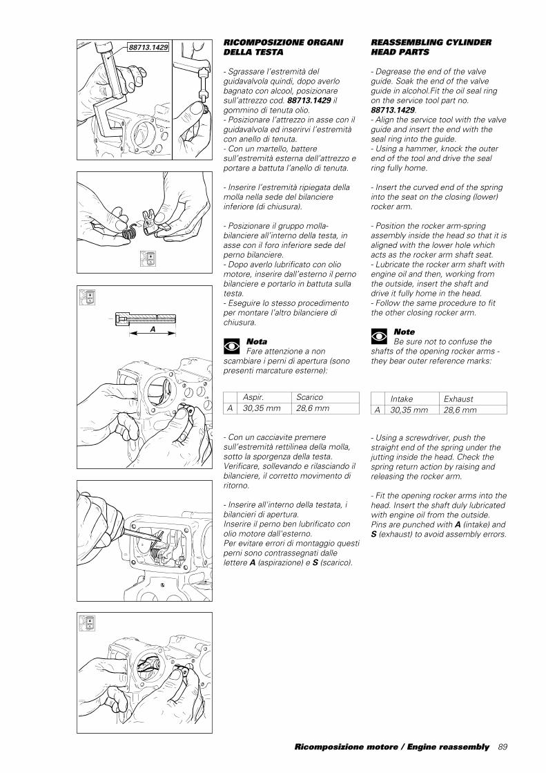
Ricomposizione motore / Engine reassembly 89
Aspir. ScaricoA 30,35 mm 28,6 mm
RICOMPOSIZIONE ORGANIDELLA TESTA
- Sgrassare l’estremità delguidavalvola quindi, dopo averlobagnato con alcool, posizionaresull’attrezzo cod. 88713.1429 ilgommino di tenuta olio.- Posizionare l’attrezzo in asse con ilguidavalvola ed inserirvi l’estremitàcon anello di tenuta.- Con un martello, batteresull’estremità esterna dell’attrezzo eportare a battuta l’anello di tenuta.
- Inserire l’estremità ripiegata dellamolla nella sede del bilanciereinferiore (di chiusura).
- Posizionare il gruppo molla-bilanciere all’interno della testa, inasse con il foro inferiore sede delperno bilanciere.- Dopo averlo lubrificato con oliomotore, inserire dall’esterno il pernobilanciere e portarlo in battuta sullatesta.- Eseguire lo stesso procedimentoper montare l’altro bilanciere dichiusura.
NotaFare attenzione a non
scambiare i perni di apertura (sonopresenti marcature esterne):
- Con un cacciavite premeresull’estremità rettilinea della molla,sotto la sporgenza della testa.Verificare, sollevando e rilasciando ilbilanciere, il corretto movimento diritorno.
- Inserire all'interno della testata, ibilancieri di apertura.Inserire il perno ben lubrificato conolio motore dall'esterno.Per evitare errori di montaggio questiperni sono contrassegnati dallelettere A (aspirazione) e S (scarico).
REASSEMBLING CYLINDERHEAD PARTS
- Degrease the end of the valveguide. Soak the end of the valveguide in alcohol.Fit the oil seal ringon the service tool part no.88713.1429.- Align the service tool with the valveguide and insert the end with theseal ring into the guide.- Using a hammer, knock the outerend of the tool and drive the sealring fully home.
- Insert the curved end of the springinto the seat on the closing (lower)rocker arm.
- Position the rocker arm-springassembly inside the head so that it isaligned with the lower hole whichacts as the rocker arm shaft seat.- Lubricate the rocker arm shaft withengine oil and then, working fromthe outside, insert the shaft anddrive it fully home in the head.- Follow the same procedure to fitthe other closing rocker arm.
NoteBe sure not to confuse the
shafts of the opening rocker arms -they bear outer reference marks:
- Using a screwdriver, push thestraight end of the spring under thejutting inside the head. Check thespring return action by raising andreleasing the rocker arm.
- Fit the opening rocker arms into thehead. Insert the shaft duly lubricatedwith engine oil from the outside.Pins are punched with A (intake) andS (exhaust) to avoid assembly errors.
88713.1429
A
Intake ExhaustA 30,35 mm 28,6 mm

90 Ricomposizione motore / Engine reassembly
ADJUSTING CLEARANCE
● Fit head side covers and pulleysonto camshafts before shimming foroptimal results.● Comply with instructions on page92 “Assembling side covers” andpage 93.
- Verificare che all’interno delcappellotto chiuso siano installatil’anello di tenuta, il cuscinetto el’anello di arresto (vedi al paragrafo“Supporti albero a camme” delcapitolo “Revisione motore”).Lubrificare con olio motore icomponenti interni e con grasso lasede della guarnizione OR.▲ Montare la guarnizione ORdisponendola perfettamente nellarelativa sede quindi installare ilcappellotto sulla superficie dellatesta, opposta al lato cinghie.- Orientare il cappellotto disponendoil foro di passaggio olio (A) rivoltoverso l’interno.- Fissarlo alla testa con n° 2 vitibloccate alla coppia prescritta.▲ Montare allo stesso modo l’altrocappellotto.
A
A
- Check that the seal ring, thebearing and the stop ring are fitted tothe camshaft closed support (see“Camshaft supports” in “EngineOverhaul”).Lubricate the components inside thesupport with engine oil and greasethe O-ring groove.▲ Fit the O-ring squarely in itsgroove. Fit the closed support to thecylinder head side opposite the beltside.- Fit the closed support so that theoilway (A) is facing inwards.- Fix the closed support to the headwith the 2 screws and tighten to thespecified torque.▲ Fit the other closed support in thesame way.
Capovolgere la testa ed inserire levalvole nei relativi guidavalvolelubrificando abbondantemente conolio motore l'accoppiamento.Verificare il centraggio dello stelovalvola rispetto alla forchetta delbilanciere di chiusura, ed in caso didecentraggio, usare, se possibile,degli spessori, o provvedere allasostituzione del bilanciere.
Turn the head over and fit the valvesinto their valve guides. Lubricatewith abundant engine oil.Check valve stem centering withrespect to closing rocker arm fork. Incase of wrong centering, fit shims ifpossible otherwise replace therocker arm.
REGISTRAZIONE DEI GIOCHI
● Prima della spessorazione èopportuno montare i coperchiettilaterali della testa, e le pulegge suglialberi a camme, al fine di noncompromettere i risultati.● Per questo motivo si consiglia diseguire le istruzioni descritte a pag.92 “Montaggio coperchietti laterali“e 93.

Ricomposizione motore / Engine reassembly 91
2
1
3
CLOSING SHIMS
- Lift the opening rocker arms andlower the closing rocker arms. Inserta screwdriver into the camshaftsupport hole, behind the slidingshoes (1) with the maximum care.- Clean the closing shims (2) and thesplit rings (3).Insert the closing shims (2) and thesplit rings (3) on the valve stem.Apply a thin layer of grease to keepthe split rings in position on thevalve, if necessary.- Remove the screwdriver and checkfor proper installation of the shimand split rings. Use an aluminiumtool to slightly beat the closingsliding shoe.
CautionAlways use new split rings.
REGISTRI DI CHIUSURA
- Alzare i bilancieri di apertura edabbassare quelli di chiusurainserendo, con la dovuta cautela, ungiravite dall'apertura del supportoalbero a camme e facendolo passaredietro ai pattini (1).- Pulire accuratamente i registri dichiusura (2), i semianelli (3).Inserire gli scodellini di chiusura (2) ei semianelli (3) sullo stelo dellevalvole. Eventualmente utilizzare unleggero strato di grasso permantenere in posizione i semianellisulla valvola.- Estrarre il giravite ed assicurarsi lacorretta posizione del registro e deisemianelli, dopo aver battuto con unleggero colpo sul pattino di chiusura,con un battente in alluminio.
ImportanteUsare sempre semianelli
nuovi.
1
1
▲ Installare l'albero a cammeoriginale serrando il relativosupporto.Per facilitare la rotazione dell’alberodistribuzione è utile, durante laprocedura di spessorazione valvole,installare con linguetta la puleggiadentata, come già anticipatoprecedentemente.Con valvola in posizione di riposoverificare con spessimetro, inseritotra pattino bilanciere di chiusura ecamma, che il gioco di chiusurarisulti quello prescritto.Se così non risulta, misurarecomunque il gioco presente. Ciòconsentirà di determinare ladifferenza di spessore che sarànecessario considerare per sostituirelo scodellino di chiusura.- Rimuovere il registro di chiusura econtrollarne lo spessore conl’apposito calibro cod. 88765.0978 eun comparatore inserito su di unsupporto a colonna.- Azzerare il comparatore utilizzandoil blocchetto in dotazione all’attrezzo.- Inserire il registro di chiusura (1)sulla sommità del calibro (vedifigura).Misurare l’altezza della spalla delregistro di chiusura e scegliere quelloappropriato in base al valore rilevatoper ottenere il gioco prescritto.▲ Rimontarlo comeprecedentemente descritto everificare nuovamente il gioco dichiusura tra camma e pattinobilanciere.
▲ Fit the original camshaft andtighten its support.For a smoother camshaft rotation,install the toothed roller with the keyduring valve shimming - as we toldbefore.With the valve in its rest position,make sure that the closing clearanceis as specified by inserting a feelergauge between closing rocker armsliding shoe and cam.If the clearance is not as specified,measure it for determining the shimdifference required when changingthe closing shim.- Remove the closing shim andmeasure it with gauge part no.88765.0978; also fit a dial gaugeonto a stand support.- Reset the dial gauge with thesupplied block.Fit the closing shim (1) onto thegauge top (see drawing).Measure the height starting from theshim shoulder and select therequired shim according to themeasured value.▲ Fit the shim as previouslydescribed and check for properclosing clearance between cam androcker arm sliding shoe.
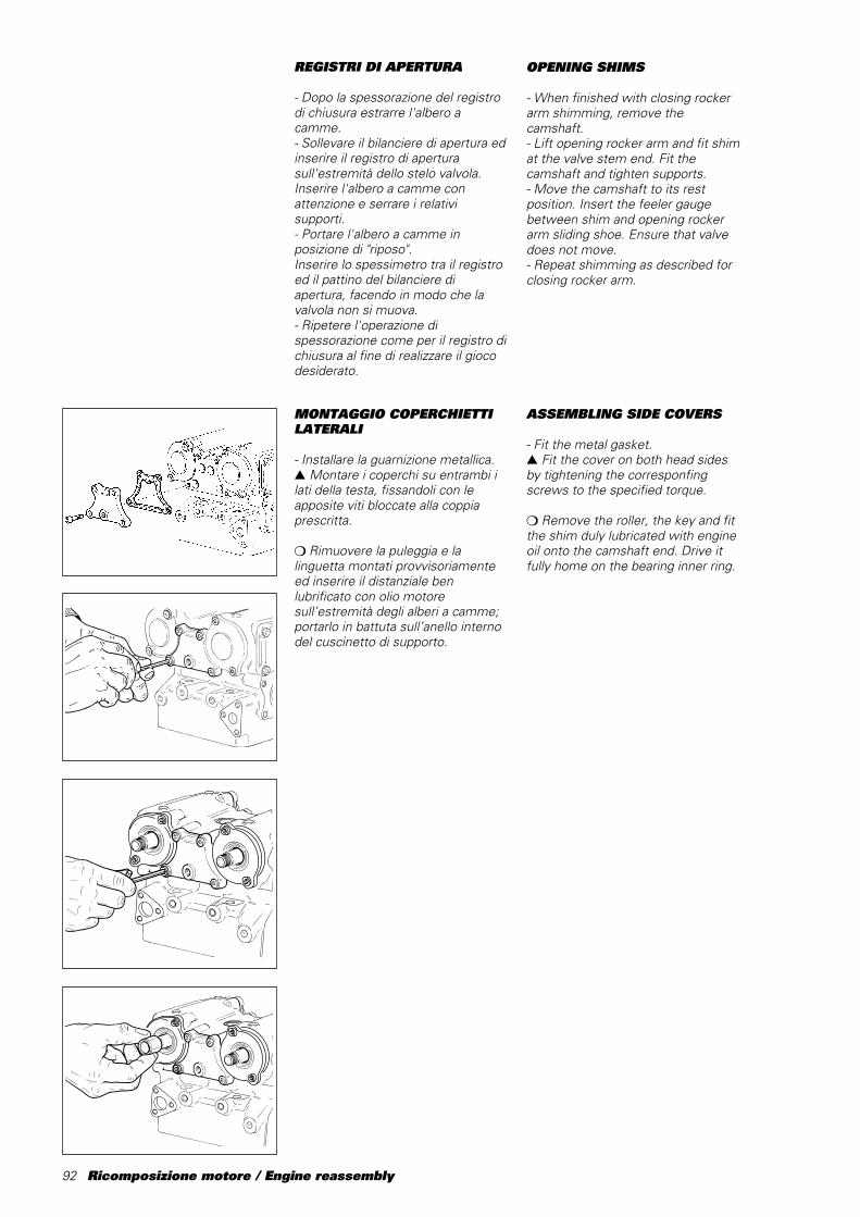
92 Ricomposizione motore / Engine reassembly
REGISTRI DI APERTURA
- Dopo la spessorazione del registrodi chiusura estrarre l'albero acamme.- Sollevare il bilanciere di apertura edinserire il registro di aperturasull'estremità dello stelo valvola.Inserire l'albero a camme conattenzione e serrare i relativisupporti.- Portare l'albero a camme inposizione di "riposo".Inserire lo spessimetro tra il registroed il pattino del bilanciere diapertura, facendo in modo che lavalvola non si muova.- Ripetere l'operazione dispessorazione come per il registro dichiusura al fine di realizzare il giocodesiderato.
OPENING SHIMS
- When finished with closing rockerarm shimming, remove thecamshaft.- Lift opening rocker arm and fit shimat the valve stem end. Fit thecamshaft and tighten supports.- Move the camshaft to its restposition. Insert the feeler gaugebetween shim and opening rockerarm sliding shoe. Ensure that valvedoes not move.- Repeat shimming as described forclosing rocker arm.
MONTAGGIO COPERCHIETTILATERALI
- Installare la guarnizione metallica.▲ Montare i coperchi su entrambi ilati della testa, fissandoli con leapposite viti bloccate alla coppiaprescritta.
❍ Rimuovere la puleggia e lalinguetta montati provvisoriamenteed inserire il distanziale benlubrificato con olio motoresull’estremità degli alberi a camme;portarlo in battuta sull’anello internodel cuscinetto di supporto.
ASSEMBLING SIDE COVERS
- Fit the metal gasket.▲ Fit the cover on both head sidesby tightening the corresponfingscrews to the specified torque.
❍ Remove the roller, the key and fitthe shim duly lubricated with engineoil onto the camshaft end. Drive itfully home on the bearing inner ring.
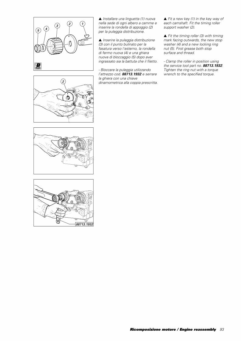
Ricomposizione motore / Engine reassembly 93
▲ Installare una linguetta (1) nuovanella sede di ogni albero a camme einserire la rondella di appoggio (2)per la puleggia distribuzione.
▲ Inserire la puleggia distribuzione(3) con il punto bulinato per lafasatura verso l'esterno, la rondelladi fermo nuova (4) e una ghieranuova di bloccaggio (5) dopo averingrassato sia la battuta che il filetto.
- Bloccare la puleggia utilizzandol’attrezzo cod. 88713.1932 e serrarela ghiera con una chiavedinamometrica alla coppia prescritta.
5 43 2 1
2
88713.1932
▲ Fit a new key (1) in the key way ofeach camshaft. Fit the timing rollersupport washer (2).
▲ Fit the timing roller (3) with timingmark facing outwards, the new stopwasher (4) and a new locking ringnut␣ (5). First grease both stopsurface and thread.
- Clamp the roller in position usingthe service tool part no. 88713.1932.Tighten the ring nut with a torquewrench to the specified torque.
B
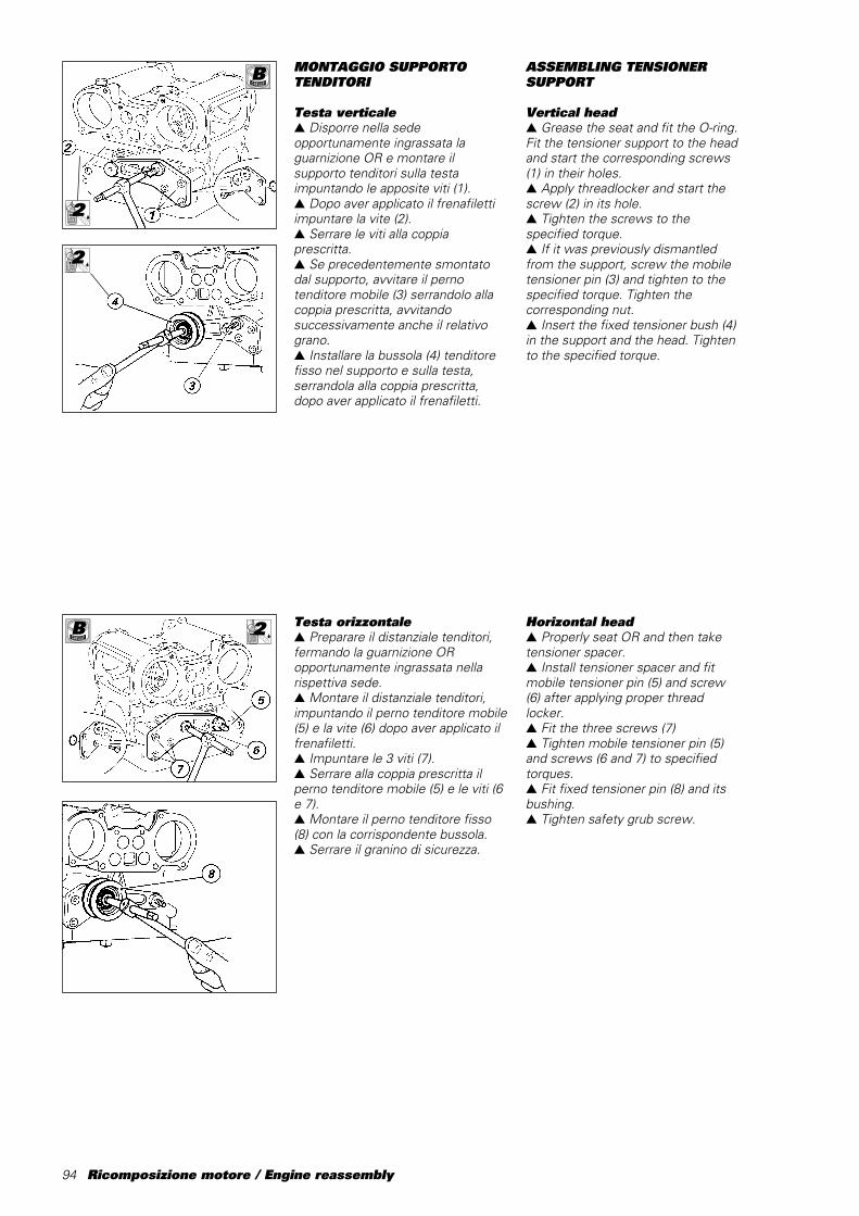
94 Ricomposizione motore / Engine reassembly
MONTAGGIO SUPPORTOTENDITORI
Testa verticale▲ Disporre nella sedeopportunamente ingrassata laguarnizione OR e montare ilsupporto tenditori sulla testaimpuntando le apposite viti (1).▲ Dopo aver applicato il frenafilettiimpuntare la vite (2).▲ Serrare le viti alla coppiaprescritta.▲ Se precedentemente smontatodal supporto, avvitare il pernotenditore mobile (3) serrandolo allacoppia prescritta, avvitandosuccessivamente anche il relativograno.▲ Installare la bussola (4) tenditorefisso nel supporto e sulla testa,serrandola alla coppia prescritta,dopo aver applicato il frenafiletti.
ASSEMBLING TENSIONERSUPPORT
Vertical head▲ Grease the seat and fit the O-ring.Fit the tensioner support to the headand start the corresponding screws(1) in their holes.▲ Apply threadlocker and start thescrew (2) in its hole.▲ Tighten the screws to thespecified torque.▲ If it was previously dismantledfrom the support, screw the mobiletensioner pin (3) and tighten to thespecified torque. Tighten thecorresponding nut.▲ Insert the fixed tensioner bush (4)in the support and the head. Tightento the specified torque.
Testa orizzontale▲ Preparare il distanziale tenditori,fermando la guarnizione ORopportunamente ingrassata nellarispettiva sede.▲ Montare il distanziale tenditori,impuntando il perno tenditore mobile(5) e la vite (6) dopo aver applicato ilfrenafiletti.▲ Impuntare le 3 viti (7).▲ Serrare alla coppia prescritta ilperno tenditore mobile (5) e le viti (6e 7).▲ Montare il perno tenditore fisso(8) con la corrispondente bussola.▲ Serrare il granino di sicurezza.
2LOCK
2LOCK
B
B 2LOCK
Horizontal head▲ Properly seat OR and then taketensioner spacer.▲ Install tensioner spacer and fitmobile tensioner pin (5) and screw(6) after applying proper threadlocker.▲ Fit the three screws (7)▲ Tighten mobile tensioner pin (5)and screws (6 and 7) to specifiedtorques.▲ Fit fixed tensioner pin (8) and itsbushing.▲ Tighten safety grub screw.
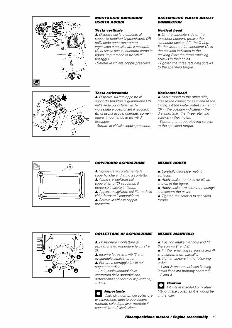
Ricomposizione motore / Engine reassembly 95
COLLETTORE DI ASPIRAZIONE
▲ Posizionare il collettore diaspirazione ed impuntare le viti (1 e2).▲ Inserire le restanti viti (3 e 4)avvitandole parzialmente.▲ Portare a serraggio le viti nelseguente ordine:– 1 e 2, assicurandosi dellacentratura delle superfici chedefiniscono i condotti di aspirazione;– 3 e 4.
ImportanteVisto gli ingombri del collettore
di aspirazione, questo può esseremontato solo dopo aver montato ilcoperchietto di aspirazione.
Testa orrizzontale▲ Disporre sul lato opposto alsupporto tenditori la guarnizione ORnella sede opportunamenteingrassata e posizionare il raccordo(B) di uscita acqua, orientato come infigura, impuntando le tre viti difissaggio.- Serrare le viti alla coppia prescritta.
MONTAGGIO RACCORDOUSCITA ACQUA
Testa verticale▲ Disporre sul lato opposto alsupporto tenditori la guarnizione ORnella sede opportunamenteingrassata e posizionare il raccordo(A) di uscita acqua, orientato come infigura, impuntando le tre viti difissaggio.- Serrare le viti alla coppia prescritta.
ASSEMBLING WATER OUTLETCONNECTOR
Vertical head▲ On the opposite side of thetensioner support, grease theconnector seat and fit the O-ring.Fit the water outlet connector (A) inthe position indicated in thedrawing.Start the three retainingscrews in their holes.- Tighten the three retaining screwsto the specified torque.
Horizontal head▲ Move round to the other side,grease the connector seat and fit theO-ring. Fit the water outlet connector(B) in the position indicated in thedrawing. Start the three retainingscrews in their holes.- Tighten the three retaining screwsto the specified torque.
C
B
COPERCHIO ASPIRAZIONE
▲ Sgrassare accuratamente lesuperfici che andranno a contatto.▲ Applicare sigillante sulcoperchietto (C) seguendo ilpercorso indicato in figura.▲ Applicare sigillante sul filetto delleviti e fermare il coperchietto.▲ Serrare le viti alla coppiaprescritta.
INTAKE COVER
▲ Carefully degrease matingsurfaces.▲ Apply sealant onto cover (C) asshown in the figure.▲ Apply sealant to screw threadingsand secure the cover.▲ Tighten the screws to specifiedtorque.
INTAKE MANIFOLD
▲ Position intake manifold and fitthe screws (1 and 2).▲ Fit the remaining screws (3 and 4)and tighten them partially.▲ Tighten screws in the followingorder:– 1 and 2: ensure surfaces limitingintake lines are properly centered;– 3 and 4
CautionFit intake manifold only after
fitting intake cover, as it is would bein the way.
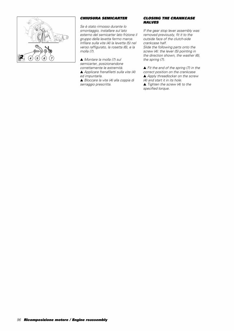
96 Ricomposizione motore / Engine reassembly
CHIUSURA SEMICARTER
Se è stato rimosso durante losmontaggio, installare sul latoesterno del semicarter lato frizione ilgruppo della levetta fermo marce.Infilare sulla vite (4) la levetta (5) nelverso raffigurato, la rosetta (6), e lamolla (7).
▲ Montare la molla (7) sulsemicarter, posizionandonecorrettamente le estremità.▲ Applicare frenafiletti sulla vite (4)ed impuntarla.▲ Bloccare la vite (4) alla coppia diserraggio prescritta.
4 5 6 7
CLOSING THE CRANKCASEHALVES
If the gear stop lever assembly wasremoved previously, fit it to theoutside face of the clutch-sidecrankcase half.Slide the following parts onto thescrew (4): the lever (5) pointing inthe direction shown, the washer (6),the spring (7).
▲ Fit the end of the spring (7) in thecorrect position on the crankcase▲ Apply threadlocker on the screw(4) and start it in its hole.▲ Tighten the screw (4) to thespecified torque.
2LOCK

Ricomposizione motore / Engine reassembly 97
▲ Installare sull’albero motore, suglialberi cambio e sul tamburo selettorei rasamenti stabiliti con la proceduradi spessorazione descritta al capitolo“REVISIONE MOTORE” quindiprocedere al montaggio sulsemicarter lato frizione.
NoteQuando si inserisce l’albero
motore nel semicarter accertarsi chele bielle siano correttamenteposizionate nelle rispettive sedi deicilindri.Installare l’albero rinvio distribuzione,ben lubrificato, nel cuscinetto disupporto del semicarter.- Prima di inserire il gruppo cambionel semicarter, assicurarsi che lapista interna (B) del cuscinetto alberoprimario sia installata nel cuscinettoe non sia rimasta montataall’estremità dell’albero stesso.- Analogamente anche per la pistainterna del cuscinetto alberosecondario sul semicarter latofrizione.▲ Installare i perni di guida e leforcelle rifacendo invertite leoperazioni descritte nellosmontaggio.
- Pulire e sgrassare le superfici diaccoppiamento dei semicarter quindiapplicare una guarnizione liquida sulsemicarter lato frizione, contornandotutti i fori delle viti e delle boccole,senza lasciare tratti scoperti chepotrebbero provocare perdite di olio.
B
▲ Fit the shims calculated during theshimming procedure described in“ENGINE OVERHAUL” to thecrankshaft, the gearbox shafts andthe gear selector drum. Fit theseparts to the clutch-side crankcasehalf.
NoteWhen you insert the
crankshaft in the crankcase, ensurethat the con-rods are positioned inthe correct cylinder seats.
Lubricate and insert the timinglayshaft in the corresponding supportbearing in the crankcase half.- Before you fit the gearboxassembly to the crankcase half,check that the internal race (B) of theprimary shaft bearing is attached tothe bearing and has not been left onthe end of the shaft.- Make the same check on theinternal race of the ltransmissionshaft bearing in the clutch-side casehalf.▲ Fit the guide rods and selectorforks following the disassemblyprocedure in reverse order.
- Clean and degrease the crankcasehalf contact surfaces. Apply liquidgasket on the clutch-side half. Applythe sealant around the bolt holes andbush seats. Do not leave any sectionof the contact surface uncovered asthis will cause leaks later.
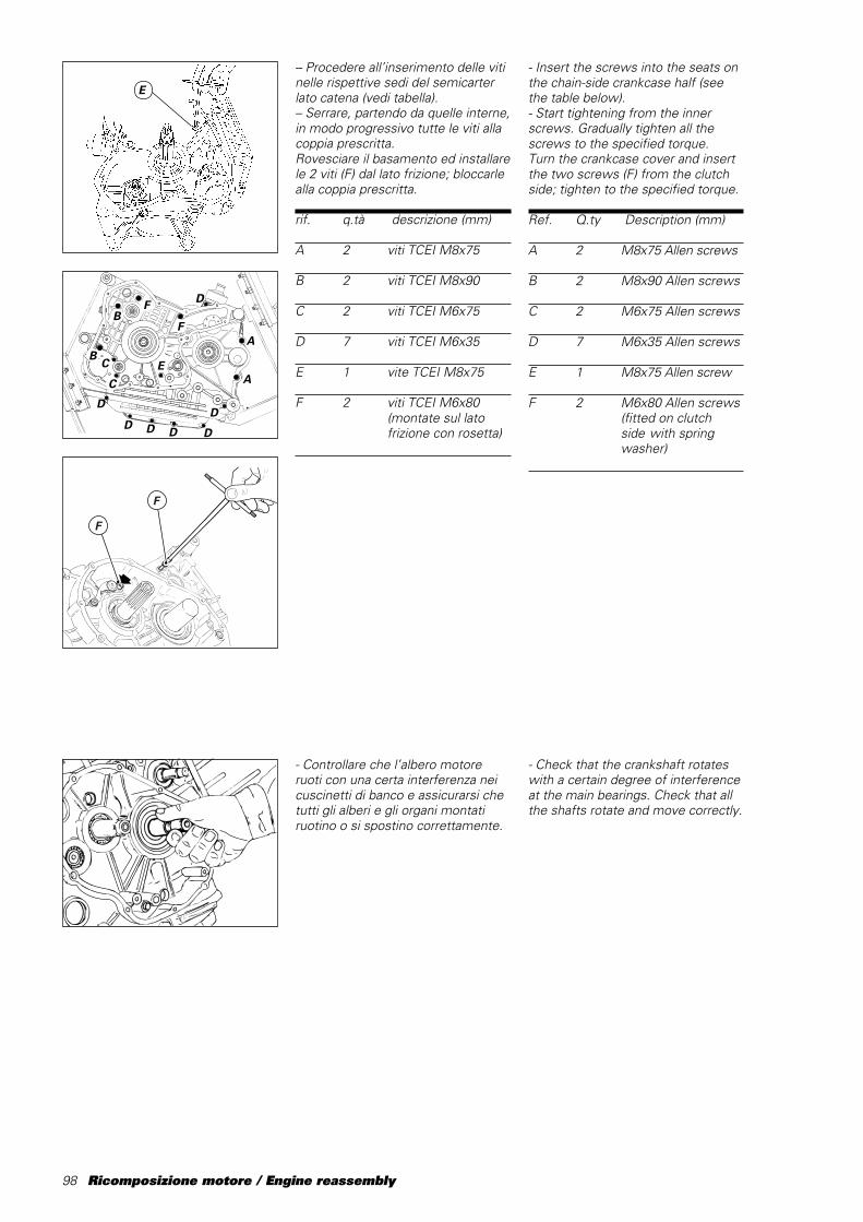
98 Ricomposizione motore / Engine reassembly
- Insert the screws into the seats onthe chain-side crankcase half (seethe table below).- Start tightening from the innerscrews. Gradually tighten all thescrews to the specified torque.Turn the crankcase cover and insertthe two screws (F) from the clutchside; tighten to the specified torque.
Ref. Q.ty Description (mm)
A 2 M8x75 Allen screws
B 2 M8x90 Allen screws
C 2 M6x75 Allen screws
D 7 M6x35 Allen screws
E 1 M8x75 Allen screw
F 2 M6x80 Allen screws(fitted on clutchside with springwasher)
– Procedere all’inserimento delle vitinelle rispettive sedi del semicarterlato catena (vedi tabella).– Serrare, partendo da quelle interne,in modo progressivo tutte le viti allacoppia prescritta.Rovesciare il basamento ed installarele 2 viti (F) dal lato frizione; bloccarlealla coppia prescritta.
rif. q.tà descrizione (mm)
A 2 viti TCEI M8x75
B 2 viti TCEI M8x90
C 2 viti TCEI M6x75
D 7 viti TCEI M6x35
E 1 vite TCEI M8x75
F 2 viti TCEI M6x80(montate sul latofrizione con rosetta)
F
F
- Controllare che l’albero motoreruoti con una certa interferenza neicuscinetti di banco e assicurarsi chetutti gli alberi e gli organi montatiruotino o si spostino correttamente.
D
D D D D
D
D
F
FB
BC
C
EA
A
- Check that the crankshaft rotateswith a certain degree of interferenceat the main bearings. Check that allthe shafts rotate and move correctly.
E
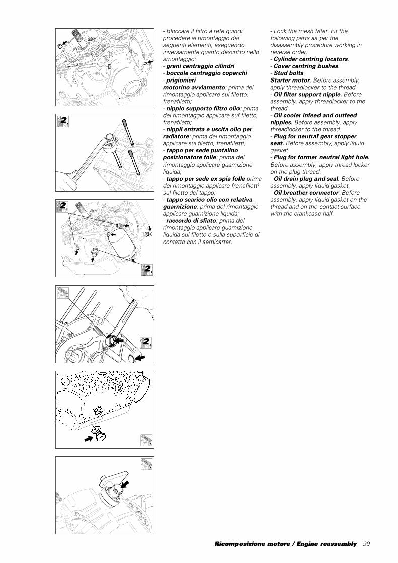
Ricomposizione motore / Engine reassembly 99
- Bloccare il filtro a rete quindiprocedere al rimontaggio deiseguenti elementi, eseguendoinversamente quanto descritto nellosmontaggio:- grani centraggio cilindri- boccole centraggio coperchi- prigionierimotorino avviamento: prima delrimontaggio applicare sul filetto,frenafiletti;- nipplo supporto filtro olio: primadel rimontaggio applicare sul filetto,frenafiletti;- nippli entrata e uscita olio perradiatore: prima del rimontaggioapplicare sul filetto, frenafiletti;- tappo per sede puntalinoposizionatore folle: prima delrimontaggio applicare guarnizioneliquida;- tappo per sede ex spia folle primadel rimontaggio applicare frenafilettisul filetto del tappo;- tappo scarico olio con relativaguarnizione: prima del rimontaggioapplicare guarnizione liquida;- raccordo di sfiato: prima delrimontaggio applicare guarnizioneliquida sul filetto e sulla superficie dicontatto con il semicarter.
- Lock the mesh filter. Fit thefollowing parts as per thedisassembly procedure working inreverse order.- Cylinder centring locators.- Cover centring bushes.- Stud bolts.Starter motor. Before assembly,apply threadlocker to the thread.- Oil filter support nipple. Beforeassembly, apply threadlocker to thethread.- Oil cooler infeed and outfeednipples. Before assembly, applythreadlocker to the thread.- Plug for neutral gear stopperseat. Before assembly, apply liquidgasket.- Plug for former neutral light hole.Before assembly, apply thread lockeron the plug thread.- Oil drain plug and seal. Beforeassembly, apply liquid gasket.- Oil breather connector: Beforeassembly, apply liquid gasket on thethread and on the contact surfacewith the crankcase half.
2LOCK
2LOCK
2LOCK
2LOCK

100 Ricomposizione motore / Engine reassembly
- Posizionare l’arpione che sposta iltamburo comando forcelle, centratorispetto ai rullini del tamburo.▲ Montare provvisoriamente la levadel cambio (o una leva di servizio) e ilpignone motore e mettere il cambioin terza marcia.
RIMONTAGGIO LEVERAGGIOSELEZIONE MARCE
NoteSe durante lo smontaggio si è
proceduto alla separazione deicomponenti del leveraggio diselezione è necessario posizionarecorrettamente la leva (1) rispetto allapiastrina (2) di fine corsa.Il perno della leva deve risultareequidistante rispetto ai bordi dellapiastrina; per modificare dettaposizione, agire sull’apposito pernoeccentrico (3) dopo aver allentato ilcontrodado (4).▲ Serrare il controdado e montare illeveraggio completo sul semicartercon le apposite viti di fissaggio,senza bloccarle.
������������������������������������
@@@@@@@@@@@@@@@@@@@@@@@@@@@@@@@@@@@@
������������������������������������
ÀÀÀÀÀÀÀÀÀÀÀÀÀÀÀÀÀÀÀÀÀÀÀÀÀÀÀÀÀÀÀÀÀÀÀÀ
������������������������������������
@@@@@@@@@@@@@@@@@@@@@@@@@@@@@@@@@@@@
������������������������������������
ÀÀÀÀÀÀÀÀÀÀÀÀÀÀÀÀÀÀÀÀÀÀÀÀÀÀÀÀÀÀÀÀÀÀÀÀ
������������������������������������
yyyyyyyyyyyyyyyyyyyyyyyyyyyyyyyyyyyy
������������������������
@@@@@@@@@@@@@@@@@@@@@@@@
������������������������
ÀÀÀÀÀÀÀÀÀÀÀÀÀÀÀÀÀÀÀÀÀÀÀÀ
������������������������
@@@@@@@@@@@@@@@@@@@@@@@@
������������������������
ÀÀÀÀÀÀÀÀÀÀÀÀÀÀÀÀÀÀÀÀÀÀÀÀ
������������������������
yyyyyyyyyyyyyyyyyyyyyyyy
==
2
1
4
3
REFITTING THE GEARSELECTOR LEVER
NoteIf the gear selector
components were dismantled atengine disassembly it will now benecessary to correctly position thelever (1) in relation to the stop plate(2).The lever pin must be in the centrebetween the edges of the plate. Toadjust the pin position, loosen thelock nut (4) and turn the camadjuster (3).▲ Tighten the lock nut and then fitthe complete lever assembly to thecrankcase half. Do not tighten.
- Position the selector drum controlpawl so that it is centred on thedrum rollers.▲ Temporarily fit the gear selectorlever (or a service lever) and thecrankshaft sprocket. Select the thirdspeed.

Ricomposizione motore / Engine reassembly 101
- Installare il piastrino cod.88713.1091 nei perni del tamburocomando forcelle.- Allineare la tacca corrispondentealla mezzeria dell’arpione dispostamento tamburo comandoforcelle con l’estremità del piastrino;su questa posizione bloccare le viti difissaggio del leveraggio alla coppiaprescritta.- Con cambio in posizione di folle,verificare che la corsa della leva infase di innesto e in scalata risultiuguale. Analoga situazione deveverificarsi anche con marcia inserita.- Ruotare il pignone motore econtemporaneamente agire sullaleva comando cambio per provarel’inserimento di tutte le marce infase di innesto e in scalata.Rimuovere leva e pignone.
88713.1091
- Fit the plate part no 88713.1091 onthe pins of the selector drum.- Align the centre line of the selectordrum pawl with the edge of theplate. With the assembly in thisposition, tighten the lever retainingscrews to the specified torque.- Select neutral. Check that the levertravel is the same duringengagement and when changing up.Lever travel must also be the samewhen a gear speed is engaged.- Rotate the crankshaft sprocket andat the same time move the gearselector lever and check that gearscorrectly engage when selected andwhen changing up.Remove the lever and the sprocket.
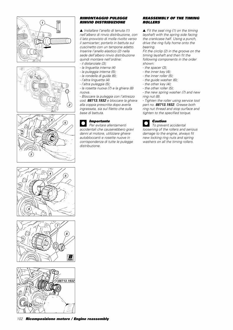
102 Ricomposizione motore / Engine reassembly
RIMONTAGGIO PULEGGERINVIO DISTRIBUZIONE
▲ Installare l’anello di tenuta (1)nell’albero di rinvio distribuzione, conil lato provvisto di molla rivolto versoil semicarter; portarlo in battuta sulcuscinetto con un tampone adatto.Inserire l’anello elastico (2) nellasede dell’albero rinvio distribuzionequindi montare nell’ordine:- il distanziale (3);- la linguetta interna (4)- la puleggia interna (5);- la rondella di guida (6);- l’altra linguetta (4)- l’altra puleggia (5);- la rosetta nuova (7) e la ghiera (8)nuova.- Bloccare la puleggia con l’attrezzocod. 88713.1932 e bloccare la ghieraalla coppia prescritta dopo averlaingrassata, sia sul filetto che sullabase di battuta.
ImportantePer evitare allentamenti
accidentali che causerebbero gravidanni al motore, utilizzare ghiereautobloccanti e rosette nuove incorrispondenza di tutte le puleggedistribuzione.
1
2
88713.1932
REASSEMBLY OF THE TIMINGROLLERS
▲ Fit the seal ring (1) on the timinglayshaft with the spring side facingthe crankcase half. Using a punch,drive the ring fully home onto thebearing.Fit the circlip (2) in the groove on thetiming layshaft and then fit thefollowing components in the ordershown:- the spacer (3);- the inner key (4);- the inner roller (5);- the guide washer (6);- the other key (4);- the other roller (5);- the new spring washer (7) and newring nut (8).- Tighten the roller using service toolpart no. 88713.1932. Grease bothring nut thread and stop surface andtighten to the specified torque.
CautionTo prevent accidental
loosening of the rollers and seriousdamage to the engine, always fitnew locking ring nuts and springwashers on all the timing rollers.
7
8
45
6
45
3
B
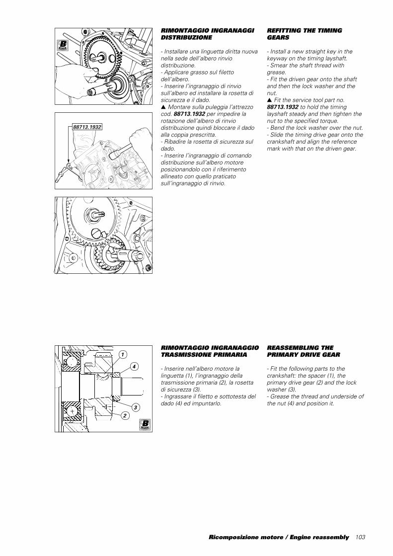
Ricomposizione motore / Engine reassembly 103
RIMONTAGGIO INGRANAGGIDISTRIBUZIONE
- Installare una linguetta diritta nuovanella sede dell’albero rinviodistribuzione.- Applicare grasso sul filettodell'albero.- Inserire l’ingranaggio di rinviosull’albero ed installare la rosetta disicurezza e il dado.▲ Montare sulla puleggia l’attrezzocod.␣ 88713.1932 per impedire larotazione dell’albero di rinviodistribuzione quindi bloccare il dadoalla coppia prescritta.- Ribadire la rosetta di sicurezza suldado.- Inserire l’ingranaggio di comandodistribuzione sull’albero motoreposizionandolo con il riferimentoallineato con quello praticatosull’ingranaggio di rinvio.
RIMONTAGGIO INGRANAGGIOTRASMISSIONE PRIMARIA
- Inserire nell’albero motore lalinguetta (1), l’ingranaggio dellatrasmissione primaria (2), la rosettadi sicurezza (3).- Ingrassare il filetto e sottotesta deldado (4) ed impuntarlo.
88713.1932
REFITTING THE TIMINGGEARS
- Install a new straight key in thekeyway on the timing layshaft.- Smear the shaft thread withgrease.- Fit the driven gear onto the shaftand then the lock washer and thenut.▲ Fit the service tool part no.88713.1932 to hold the timinglayshaft steady and then tighten thenut to the specified torque.- Bend the lock washer over the nut.- Slide the timing drive gear onto thecrankshaft and align the referencemark with that on the driven gear.
REASSEMBLING THEPRIMARY DRIVE GEAR
- Fit the following parts to thecrankshaft: the spacer (1), theprimary drive gear (2) and the lockwasher (3).- Grease the thread and underside ofthe nut (4) and position it.
B
B
1
23
4
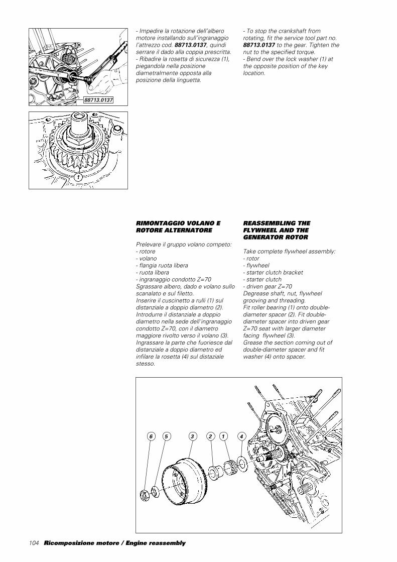
104 Ricomposizione motore / Engine reassembly
RIMONTAGGIO VOLANO EROTORE ALTERNATORE
Prelevare il gruppo volano competo:- rotore- volano- flangia ruota libera- ruota libera- ingranaggio condotto Z=70Sgrassare albero, dado e volano sulloscanalato e sul filetto.Inserire il cuscinetto a rulli (1) suldistanziale a doppio diametro (2).Introdurre il distanziale a doppiodiametro nella sede dell'ingranaggiocondotto Z=70, con il diametromaggiore rivolto verso il volano (3).Ingrassare la parte che fuoriesce daldistanziale a doppio diametro edinfilare la rosetta (4) sul distazialestesso.
- Impedire la rotazione dell’alberomotore installando sull’ingranaggiol’attrezzo cod. 88713.0137, quindiserrare il dado alla coppia prescritta.- Ribadire la rosetta di sicurezza (1),piegandola nella posizionediametralmente opposta allaposizione della linguetta.
- To stop the crankshaft fromrotating, fit the service tool part no.88713.0137 to the gear. Tighten thenut to the specified torque.- Bend over the lock washer (1) atthe opposite position of the keylocation.
REASSEMBLING THEFLYWHEEL AND THEGENERATOR ROTOR
Take complete flywheel assembly:- rotor- flywheel- starter clutch bracket- starter clutch- driven gear Z=70Degrease shaft, nut, flywheelgrooving and threading.Fit roller bearing (1) onto double-diameter spacer (2). Fit double-diameter spacer into driven gearZ=70 seat with larger diameterfacing flywheel (3).Grease the section coming out ofdouble-diameter spacer and fitwasher (4) onto spacer.
12356 4
88713.0137
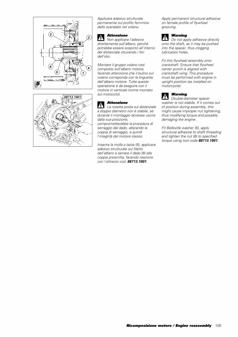
Ricomposizione motore / Engine reassembly 105
Apply permanent structural adhesiveon female profile of flywheelgrooving.
WarningDo not apply adhesive directly
onto the shaft, as it may be pushedinto the spacer, thus clogginglubrication holes.
Fit this flywheel assembly ontocrankshaft. Ensure that flywheelcenter punch is aligned withcrankshaft wing. This proceduremust be performed with engine inupright position (as installed onmotorcycle).
WarningDouble-diameter spacer
washer is not stabile. If it comes outof position during assembly, thismight cause improper nut tightening,thus modifying torque and possiblydamaging the engine .
Fit Belleville washer (5), applystructural adhesive to shaft threadingand tighten the nut (6) to specifiedtorque using tool code 88713.1901.
Applicare adesivo strutturalepermanente sul profilo femminadello scanalato nel volano.
AttenzioneNon applicare l'adesivo
direttamente sull'albero, perchépotrebbe essere sospinto all'internodel distanziale otturando i foridell'olio.
Montare il gruppo volano cosìcomposto sull'albero motore,facendo attenzione che il bulino sulvolano corrisponda con la linguettadell'albero motore. Tutta questaoperazione è da eseguire con ilmotore in verticale (come montatosul motociclo).
AttenzioneLa rosetta posta sul distanziale
a doppio diametro non è stabile, sedurante il montaggio dovesse usciredalla sua posizione,comprometterebbe la procedura diserraggio del dado, alterando lacoppia di serraggio, e quindil'integrità del motore stesso.
Inserire la molla a tazza (5), applicareadesivo strutturale sul filettodell'albero e serrare il dado (6) allacoppia prescritta, facendo reazionecon l'attrezzo cod. 88713.1901.
5
6
23
4
1
88713.1901
5LOCK
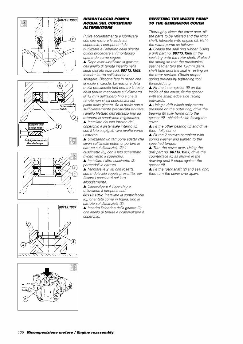
106 Ricomposizione motore / Engine reassembly
RIMONTAGGIO POMPAACQUA SUL COPERCHIOALTERNATORE
Pulire accuratamente e lubrificarecon olio motore la sede sulcoperchio, i componenti dariutilizzare e l'alberino della girantequindi procedere al rimontaggiooperando come segue:▲ Dopo aver lubrificato la gommadell'anello di tenuta inserilo nellasede dell'attrezzo cod. 88713.1968.Inserire iltutto sull'alberino espingere. Bisogna fare in modo chela molla si carichi. La reazione dellamolla precaricata farà entrare la testadella tenuta meccanica sul diametroØ 12 mm dell'albero fino a che latenuta non si sia posizionata sulpiano della girante. Se la molla non èsufficientemente precaricata avvitarel'anello filettato dell'attrezzo fino adottenere la condizione migliorativa.▲ Installare dal lato interno delcoperchio il distanziale interno (8)con il lato a spigolo vivo rivolto versol'esterno.▲ Utilizzando un tampone adatto chelavori sull'anello esterno, portare inbattuta sul distanziale (8) ilcuscinetto (5), con il lato schermatorivolto verso il coperchio.▲ Installare l'altro cuscinetto (3)portandoli in battuta.▲ Montare le 2 viti con rosetta,serrandole alla coppia prescritta, perfissare i cuscinetti nel loroalloggiamente.▲ Capovolgere il coperchio e,utilizzando il tampone cod.88713.1967, installare la controfaccia(6), orientata come in figura, fino inbattuta sul distanziale (8).▲ Inserire l'alberino della girante (2)con anello di tenuta e ricapovolgere ilcoperchio.
2
3
5
SchermaturaShield
Spigolo vivoSharp edge
Spigolo smussatoBeveled edge
5
REFITTING THE WATER PUMPTO THE GENERATOR COVER
Thoroughly clean the cover seat, allthe parts to be refitted and the rotorshaft; lubricate with engine oil. Refitthe water pump as follows:▲ Grease the seal ring rubber. Usinga drift part no. 88713.1968 fit theseal ring onto the rotor shaft. Preloadthe spring so that the mechanicalseal head enters the 12-mm diam.shaft hole until the seal is resting onthe rotor surface. Obtain properspring preload by tightening toolthreaded ring.▲ Fit the inner spacer (8) on theinside of the cover; fit the spacerwith the sharp edge side facingoutwards.▲ Using a drift which only exertspressure on the outer ring, drive thebearing (5) fully home onto thespacer (8) - shielded side facing thecover.▲ Fit the other bearing (3) and drivethem fully home.▲ Fit the 2 screws complete withspring washer and tighten to thespecified torque.▲ Turn the cover over. Using thedrift␣ part no. 88713.1967, drive thecounterface (6) as shown in thedrawing until it stops against thespacer (8).▲ Fit the rotor shaft (2) and seal ring,then turn the cover over again.
7
88713.1968
88713.1967
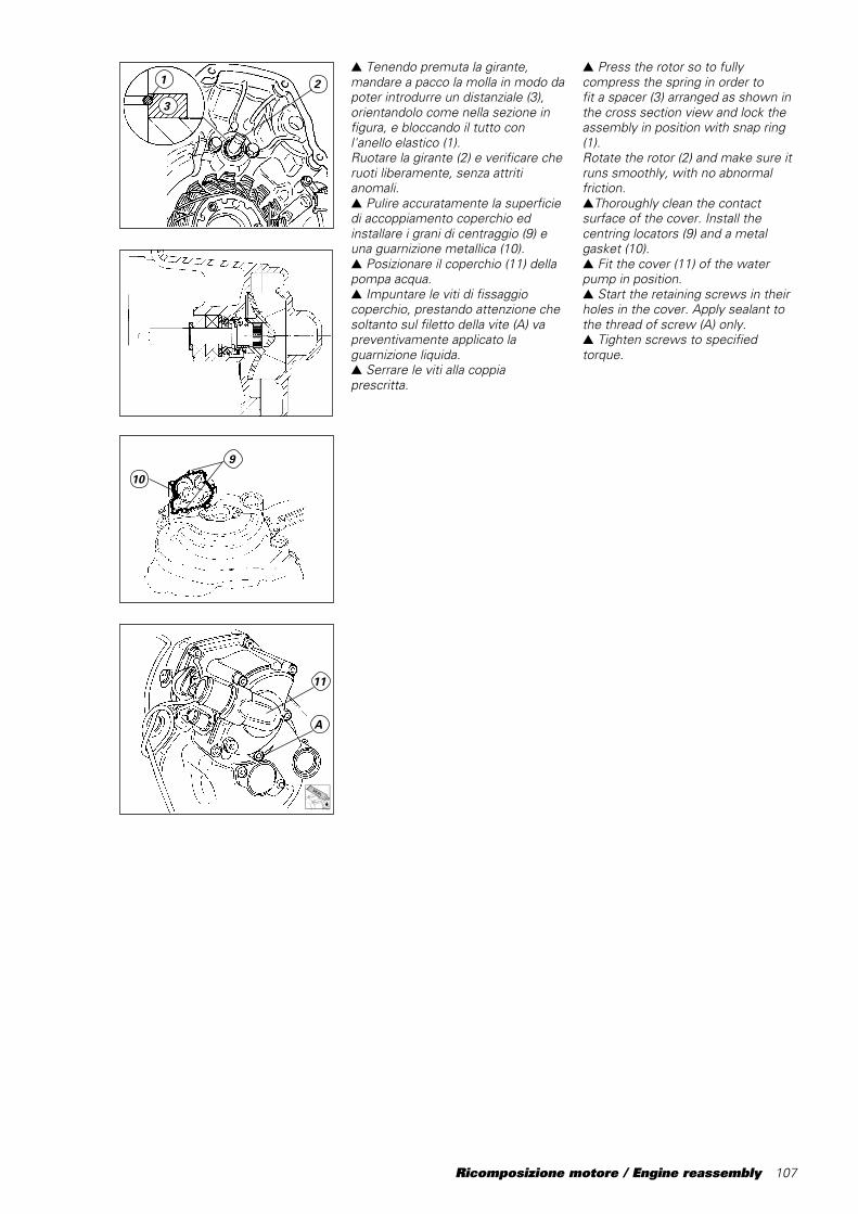
Ricomposizione motore / Engine reassembly 107
▲ Tenendo premuta la girante,mandare a pacco la molla in modo dapoter introdurre un distanziale (3),orientandolo come nella sezione infigura, e bloccando il tutto conl'anello elastico (1).Ruotare la girante (2) e verificare cheruoti liberamente, senza attritianomali.▲ Pulire accuratamente la superficiedi accoppiamento coperchio edinstallare i grani di centraggio (9) euna guarnizione metallica (10).▲ Posizionare il coperchio (11) dellapompa acqua.▲ Impuntare le viti di fissaggiocoperchio, prestando attenzione chesoltanto sul filetto della vite (A) vapreventivamente applicato laguarnizione liquida.▲ Serrare le viti alla coppiaprescritta.
9
10
11
A
3
1 2▲ Press the rotor so to fullycompress the spring in order tofit a spacer (3) arranged as shown inthe cross section view and lock theassembly in position with snap ring(1).Rotate the rotor (2) and make sure itruns smoothly, with no abnormalfriction.▲Thoroughly clean the contactsurface of the cover. Install thecentring locators (9) and a metalgasket (10).▲ Fit the cover (11) of the waterpump in position.▲ Start the retaining screws in theirholes in the cover. Apply sealant tothe thread of screw (A) only.▲ Tighten screws to specifiedtorque.
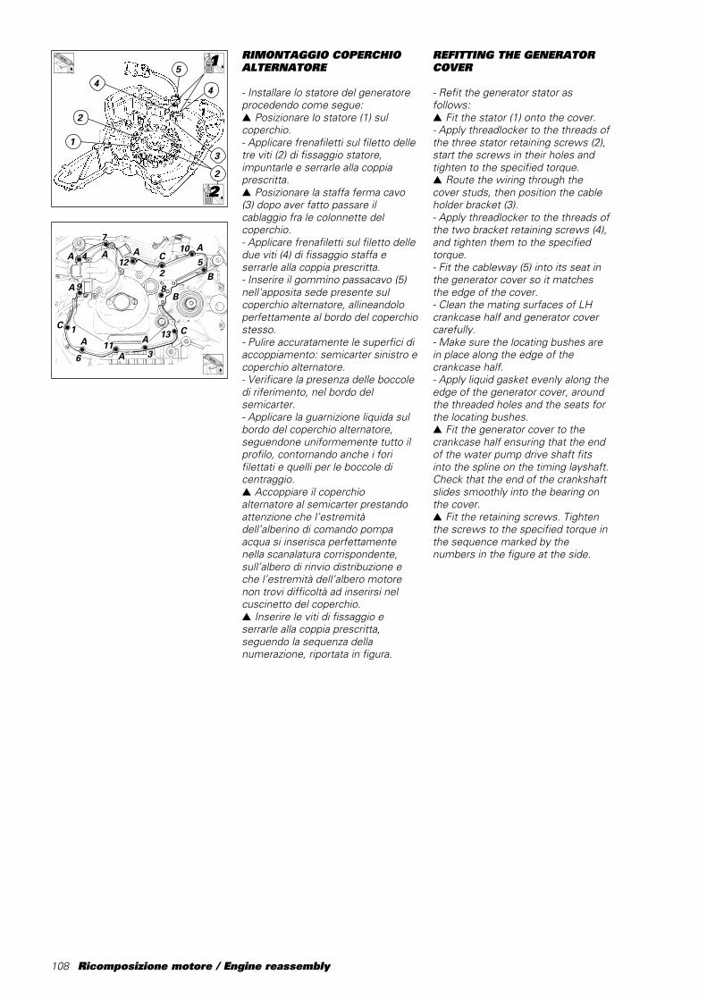
108 Ricomposizione motore / Engine reassembly
RIMONTAGGIO COPERCHIOALTERNATORE
- Installare lo statore del generatoreprocedendo come segue:▲ Posizionare lo statore (1) sulcoperchio.- Applicare frenafiletti sul filetto delletre viti (2) di fissaggio statore,impuntarle e serrarle alla coppiaprescritta.▲ Posizionare la staffa ferma cavo(3) dopo aver fatto passare ilcablaggio fra le colonnette delcoperchio.- Applicare frenafiletti sul filetto delledue viti (4) di fissaggio staffa eserrarle alla coppia prescritta.- Inserire il gommino passacavo (5)nell'apposita sede presente sulcoperchio alternatore, allineandoloperfettamente al bordo del coperchiostesso.- Pulire accuratamente le superfici diaccoppiamento: semicarter sinistro ecoperchio alternatore.- Verificare la presenza delle boccoledi riferimento, nel bordo delsemicarter.- Applicare la guarnizione liquida sulbordo del coperchio alternatore,seguendone uniformemente tutto ilprofilo, contornando anche i forifilettati e quelli per le boccole dicentraggio.▲ Accoppiare il coperchioalternatore al semicarter prestandoattenzione che l’estremitàdell’alberino di comando pompaacqua si inserisca perfettamentenella scanalatura corrispondente,sull’albero di rinvio distribuzione eche l’estremità dell’albero motorenon trovi difficoltà ad inserirsi nelcuscinetto del coperchio.▲ Inserire le viti di fissaggio eserrarle alla coppia prescritta,seguendo la sequenza dellanumerazione, riportata in figura.
1LOCK
2LOCK
A
A
AC
B
B
CAA
A
C
9
1
611
3
13
8
510
AA
212
4
7
2
44
3
5
2
1
REFITTING THE GENERATORCOVER
- Refit the generator stator asfollows:▲ Fit the stator (1) onto the cover.- Apply threadlocker to the threads ofthe three stator retaining screws (2),start the screws in their holes andtighten to the specified torque.▲ Route the wiring through thecover studs, then position the cableholder bracket (3).- Apply threadlocker to the threads ofthe two bracket retaining screws (4),and tighten them to the specifiedtorque.- Fit the cableway (5) into its seat inthe generator cover so it matchesthe edge of the cover.- Clean the mating surfaces of LHcrankcase half and generator covercarefully.- Make sure the locating bushes arein place along the edge of thecrankcase half.- Apply liquid gasket evenly along theedge of the generator cover, aroundthe threaded holes and the seats forthe locating bushes.▲ Fit the generator cover to thecrankcase half ensuring that the endof the water pump drive shaft fitsinto the spline on the timing layshaft.Check that the end of the crankshaftslides smoothly into the bearing onthe cover.▲ Fit the retaining screws. Tightenthe screws to the specified torque inthe sequence marked by thenumbers in the figure at the side.

Ricomposizione motore / Engine reassembly 109
rif. q.tà descrizione (mm)
A 9 viti TCEI M6x25
B 2 viti TCEI M6x20
C 2 viti TCEI M6x30
▲ Installare sul coperchioalternatore, in corrispondenza delperno comando cambio, il paraolio(7) con il lato provvisto di mollarivolto verso il coperchio.▲ Installare nel semicarter latocatena sull’albero secondariocambio, il paraolio (8), allo stessoverso di montaggio del precedente.- Portare in battuta entrambi i paraoliutilizzando tamponi adatti.
RIMONTAGGIO POMPA OLIO
- Posizionare le boccole diriferimento (1) e le guarnizioni OR (2)di tenuta olio nelle relative sedi delsemicarter.- Riempire completamente la pompacon olio motore e lubrificarel’ingranaggio esterno quindiposizionarla sul semicarter.▲ Inserire le viti di fissaggio ebloccarle alla coppia di serraggioprescritta.- Verificare dopo il serraggio delle vitiche tra i denti degli ingranaggi non visia interferenza.
RIMONTAGGIO COPERCHIOFRIZIONE
▲ Installare sull’albero primario delcambio il distanziale (3) el’ingranaggio di trasmissione primaria(4), completo di cuscinetti e paraoliointerno nuovo.1
2
3
4
Ref. Q.ty Description (mm)
A 9 M6x25 Allen screws
B 2 M6x20 Allen screws
C 2 M6x30 Allen screws
▲ Fit the oil seal (7) to the generatorcover close to the gear control shaft;fit the seal with the spring sidefacing the cover.▲ Fit the oil seal (8) on the gearboxlayshaft in the chain-side crankcasehalf. Fit the seal with the spring sidefacing the cover.- Drive the two seals fully homeusing a suitable drift.
REFITTING THE OIL PUMP
- Insert the locating bushes (1) andthe O-rings (2) in their seats in thecrankcase half.- Completely fill the pump withengine oil. Lubricate the outer gear.Position the pump on the crankcasehalf.▲ Fit the retaining screws andtighten to the specified torque.- Once the screws have beentightened, check that there is nointerference between the pumpgear teeth.
REFITTING THE CLUTCHCASING
▲ Fit the spacer (3) and the primarydrive gear (4) complete with bearingsand a new inner oil seal on thegearbox primary shaft.
8
7
4
3
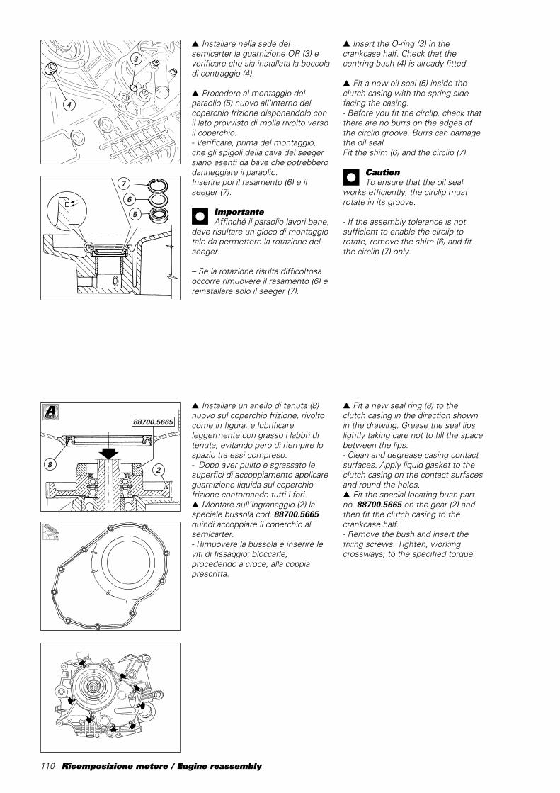
110 Ricomposizione motore / Engine reassembly
28
88700.5665
▲ Installare un anello di tenuta (8)nuovo sul coperchio frizione, rivoltocome in figura, e lubrificareleggermente con grasso i labbri ditenuta, evitando però di riempire lospazio tra essi compreso.- Dopo aver pulito e sgrassato lesuperfici di accoppiamento applicareguarnizione liquida sul coperchiofrizione contornando tutti i fori.▲ Montare sull’ingranaggio (2) laspeciale bussola cod. 88700.5665quindi accoppiare il coperchio alsemicarter.- Rimuovere la bussola e inserire leviti di fissaggio; bloccarle,procedendo a croce, alla coppiaprescritta.
▲ Installare nella sede delsemicarter la guarnizione OR (3) everificare che sia installata la boccoladi centraggio␣ (4).
▲ Procedere al montaggio delparaolio (5) nuovo all’interno delcoperchio frizione disponendolo conil lato provvisto di molla rivolto versoil coperchio.- Verificare, prima del montaggio,che gli spigoli della cava del seegersiano esenti da bave che potrebberodanneggiare il paraolio.Inserire poi il rasamento (6) e ilseeger (7).
ImportanteAffinché il paraolio lavori bene,
deve risultare un gioco di montaggiotale da permettere la rotazione delseeger.
– Se la rotazione risulta difficoltosaoccorre rimuovere il rasamento (6) ereinstallare solo il seeger (7).
7
6
5
3
4
A
▲ Insert the O-ring (3) in thecrankcase half. Check that thecentring bush (4) is already fitted.
▲ Fit a new oil seal (5) inside theclutch casing with the spring sidefacing the casing.- Before you fit the circlip, check thatthere are no burrs on the edges ofthe circlip groove. Burrs can damagethe oil seal.Fit the shim (6) and the circlip (7).
CautionTo ensure that the oil seal
works efficiently, the circlip mustrotate in its groove.
- If the assembly tolerance is notsufficient to enable the circlip torotate, remove the shim (6) and fitthe circlip (7) only.
▲ Fit a new seal ring (8) to theclutch casing in the direction shownin the drawing. Grease the seal lipslightly taking care not to fill the spacebetween the lips.- Clean and degrease casing contactsurfaces. Apply liquid gasket to theclutch casing on the contact surfacesand round the holes.▲ Fit the special locating bush partno.␣ 88700.5665 on the gear (2) andthen fit the clutch casing to thecrankcase half.- Remove the bush and insert thefixing screws. Tighten, workingcrossways, to the specified torque.
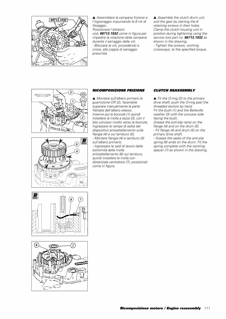
Ricomposizione motore / Engine reassembly 111
RICOMPOSIZIONE FRIZIONE
▲ Montare sull’albero primario laguarnizione OR (2), facendolesuperare manualmente la partefilettata dell’albero stesso.Inserire poi la boccola (1) quindiinstallare la molla a tazza (3), con illato concavo rivolto verso la boccola.Ingrassare le rampe di salita deldispositivo antisaltellamento sullaflangia (4) e sul tamburo (5).- Montare flangia (4) e tamburo (5)sull'albero primario.- Ingrassare le sedi di lavoro delleestremità della mollaantisaltellamento (6) sul tamburo,quindi installare la molla condistanziale centratore (7), posizionaticome in figura.
5
4
2
3
1
▲ Assemblare la campana frizione el’ingranaggio impuntando le 8 viti difissaggio.Posizionare l'attrezzocod.␣ 88713.1932 come in figura perimpedire la rotazione della campanadurante il serraggio delle viti.- Bloccare le viti, procedendo acroce, alla coppia di serraggioprescritta.
6 7
B
B
▲ Assemble the clutch drum unitand the gear by starting the 8retaining screws in their holes.Clamp the clutch housing unit inposition during tightening using theservice tool part no. 88713.1932 asshown in the drawing.- Tighten the screws, workingcrossways, to the specified torque.
CLUTCH REASSEMBLY
▲ Fit the O-ring (2) to the primarydrive shaft; push the O-ring past thethreaded section by hand.Fit the bush (1) and the Bellevillewasher (3) with the concave sidefacing the bush.Grease the anti-slip ramp on theflange (4) and on the drum (5).- Fit flange (4) and drum (5) on theprimary drive shaft.- Grease the seats of the anti-slipspring (6) ends on the drum. Fit thespring complete with the centringspacer (7) as shown in the drawing.

112 Ricomposizione motore / Engine reassembly
- Inserire la rosetta di sicurezza eimpuntare a mano il dado.- Applicare l’attrezzocod. 88713.0146 sul tamburo ebloccare il dado alla coppia prescrittadopo averlo ingrassato sia sul filettoche sulla faccia di battuta.Ribadire la rosetta di sicurezza suldado.
- Inserire nella campana, osservandola sequenza rappresentata in figura,la serie dei dischi frizione compostoda:A) n°9 dischi sinterizzatiB) n° 4 dischi di acciaio spessore1,5 mmC) n° 4 dischi bombati.Per la revisione dei componentifrizione si veda procedura a pagina78.D) n° 1 disco di acciaio spessore2 mm
- Operando sul lato opposto, inserirel’asta comando frizione, conguarnizioni OR nuove eopportunamente ingrassate.
- Verificare che sul piatto spingidiscosia montato il perno di comando conguarnizione OR quindi installare sullospingidisco le molle, gli scodelliniguidamolla nuovi e le viti.▲ Montare il piatto spingidisco sullaflangia impuntando le 6 viti a mano.Bloccare le viti, procedendo a croce,alla coppia di serraggio prescritta.
- Installare il coperchio di ispezionefissandolo con le apposite viti.
88713.0146
A
- Fit the lock washer and start thenut in its thread by hand.- Grease nut thread and stop surface.Fit service tool part no. 88713.0146on the drum and then tighten the nutto the specified torque.Bend the lock washer over the nut.
- Insert the plate pack in the clutchhousing. Insert the plates in theorder shown in the drawing. Theplate pack consists of:A) 9 sintered platesB) 4 steel plates, 1.5 mm thickC) 4 dished plates.See page 78 for clutch overhaulprocedure.D) 1 steel plate, 2 mm thick
- Working on the other side of thehousing, insert the clutch pushrodwith a new, greased O-ring.
- Check that the control pin withO-ring is mounted on the flatpressure plate. Fit the springs, thenew spring guide caps and thescrews to the flat pressure plate.▲ Fit the flat pressure plate to theflange and tighten the 6 screws byhand.Tighten the screws, workingcrossways, to the specified torque.
- Fit the clutch inspection cover.Attach and tighten the coverretaining screws.
A
C
B
C
D

Ricomposizione motore / Engine reassembly 113
CONTROLLO TRAFERROSENSORI DI FASE E NUMERODI GIRI MOTORE
Considerando l’esigenza di doverruotare l’albero motore per tutte leoperazioni di fasatura è consigliabileinstallare sul coperchio alternatore esull’albero motore l’attrezzocod.␣ 88713.0123, completo di discocod.␣ 98112.0002.● Ruotando l’impugnaturadell’attrezzo, portare il pistone delcilindro orizzontale al punto mortosuperiore corrispondenteall’allineamento del riferimento sullapuleggia esterna dell’albero rinviodistribuzione con quello sulcoperchio frizione.Ruotare il goniometro facendocorrispondere la scritta “PMS” conl’indice fisso dell’attrezzo.
● Dopo aver rimosso il tappo (1) conguarnizione (2) dal foro ricavato sullaparete frontale del semicarter latocatena, inserire la lama di unospessimetro tra sensore di fase eriscontro sull’ingranaggio rinviodistribuzione: deve risultare0,6 ÷0,8␣ mm.Se così non risulta rimuovere ilsensore e modificare lo spessoredelle guarnizioni (A) poste trasupporto e sensore per ottenere ilvalore prescritto.Rimontare tappo (1) e guarnizione (2)per chiudere il foro sul semicarter.
CHECKING THE AIR GAP OFTHE TIMING AND RPMSENSORS
It will be necessary to rotate thecrankshaft throughout timingoperations. For this purpose, fitservice tool part no. 88713.0123,complete with the timing disc partno.␣ 98112.0002 to the generatorcover and crankshaft.● Turn the handle of the service toolto move the horizontal piston toTDC; in this position the referenceon the timing layshaft outer pulleymust be aligned with the referencemark on the clutch casing.Rotate the degree wheel so that thelegend “PMS-TDC” is at the fixedindicator on the tool.
● Remove the plug (1) and seal (2)from the hole in the front wall of thechain-side crankcase half. Insert afeeler gauge between the timingsensor and the reference on thetiming driven gear. The gap must be0.6 - 0.8 mm.If the gap is not as specified, removethe sensor and change the thicknessof the seals (A) between the supportand the sensor to obtain the gaprequired.Refit the plug (1) and the seal (2) toclose the hole in the crankcase.
A
1
2
Spigolo vivoSharp edge
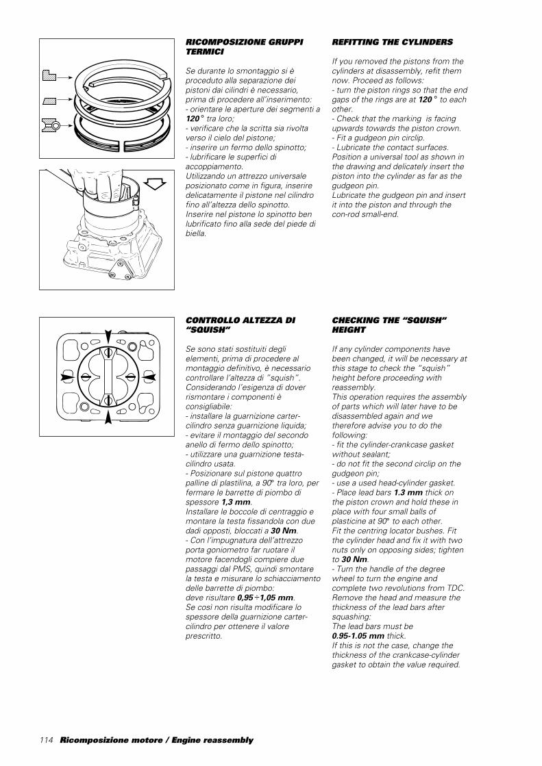
114 Ricomposizione motore / Engine reassembly
���������
@@@@@@@@@
���������
ÀÀÀÀÀÀÀÀÀ
���������
@@@@@@@@@
���������
ÀÀÀÀÀÀÀÀÀ
���������
yyyyyyyyy
������@@@@@@������ÀÀÀÀÀÀ������@@@@@@������ÀÀÀÀÀÀ������yyyyyy
������������
@@@@@@@@@@@@
������������
ÀÀÀÀÀÀÀÀÀÀÀÀ
������������
@@@@@@@@@@@@
������������
ÀÀÀÀÀÀÀÀÀÀÀÀ
������������
yyyyyyyyyyyy
RICOMPOSIZIONE GRUPPITERMICI
Se durante lo smontaggio si èproceduto alla separazione deipistoni dai cilindri è necessario,prima di procedere all’inserimento:- orientare le aperture dei segmenti a120 ° tra loro;- verificare che la scritta sia rivoltaverso il cielo del pistone;- inserire un fermo dello spinotto;- lubrificare le superfici diaccoppiamento.Utilizzando un attrezzo universaleposizionato come in figura, inseriredelicatamente il pistone nel cilindrofino all’altezza dello spinotto.Inserire nel pistone lo spinotto benlubrificato fino alla sede del piede dibiella.
CONTROLLO ALTEZZA DI“SQUISH”
Se sono stati sostituiti deglielementi, prima di procedere almontaggio definitivo, è necessariocontrollare l’altezza di ”squish”.Considerando l’esigenza di doverrismontare i componenti èconsigliabile:- installare la guarnizione carter-cilindro senza guarnizione liquida;- evitare il montaggio del secondoanello di fermo dello spinotto;- utilizzare una guarnizione testa-cilindro usata.- Posizionare sul pistone quattropalline di plastilina, a 90° tra loro, perfermare le barrette di piombo dispessore 1,3 mm.Installare le boccole di centraggio emontare la testa fissandola con duedadi opposti, bloccati a 30 Nm.- Con l’impugnatura dell’attrezzoporta goniometro far ruotare ilmotore facendogli compiere duepassaggi dal PMS, quindi smontarela testa e misurare lo schiacciamentodelle barrette di piombo:deve risultare 0,95 ÷1,05 mm.Se così non risulta modificare lospessore della guarnizione carter-cilindro per ottenere il valoreprescritto.
REFITTING THE CYLINDERS
If you removed the pistons from thecylinders at disassembly, refit themnow. Proceed as follows:- turn the piston rings so that the endgaps of the rings are at 120 ° to eachother.- Check that the marking is facingupwards towards the piston crown.- Fit a gudgeon pin circlip.- Lubricate the contact surfaces.Position a universal tool as shown inthe drawing and delicately insert thepiston into the cylinder as far as thegudgeon pin.Lubricate the gudgeon pin and insertit into the piston and through thecon-rod small-end.
CHECKING THE “SQUISH”HEIGHT
If any cylinder components havebeen changed, it will be necessary atthis stage to check the “squish”height before proceeding withreassembly.This operation requires the assemblyof parts which will later have to bedisassembled again and wetherefore advise you to do thefollowing:- fit the cylinder-crankcase gasketwithout sealant;- do not fit the second circlip on thegudgeon pin;- use a used head-cylinder gasket.- Place lead bars 1.3 mm thick onthe piston crown and hold these inplace with four small balls ofplasticine at 90° to each other.Fit the centring locator bushes. Fitthe cylinder head and fix it with twonuts only on opposing sides; tightento 30 Nm.- Turn the handle of the degreewheel to turn the engine andcomplete two revolutions from TDC.Remove the head and measure thethickness of the lead bars aftersquashing:The lead bars must be0.95-1.05 mm thick.If this is not the case, change thethickness of the crankcase-cylindergasket to obtain the value required.
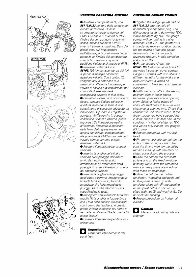
Ricomposizione motore / Engine reassembly 115
VERIFICA FASATURA MOTORE
● Avvitare il comparatore (A) cod.88713.0123 nel foro della candela delcilindro orizzontale. Questostrumento serve per la ricerca delPMS: Quando ci si avvicina al PMS,l’indice del comparatore ruota in unsenso, appena superato il PMS,inverte il senso di rotazione. Dare deipiccoli colpi sull’impugnaturadell’attrezzo porta goniometro fino alpunto in cui l’indice del comparatoreinverte la rotazione: in questaposizione il pistone si troverà al PMS.● Installare i calibri (C) cod.88765.1001 in corrispondenza dei forisuperiori di fissagio coperchioispezione valvole. Con il calibro (C)vengono dati in dotazione duetastatori di differente lunghezza pervalvole di scarico e di aspirazione; percomodità di esecuzione èconsigliabile disporre di due calibri.● Con alberi a camme in posizione diriposo, azzerare il gioco valvola inapertura inserendo la lama di unospessimetro di spessore adeguato trail bilanciere superiore e il registro diapertura. Verificare che in questacondizione l’albero a camme possamuoversi. Se l’operazione risultadifficoltosa, diminuire lo spessoredella lama dello spessimetro. Inquesta condizione, corrispondentealla posizione di PMS orizzontale convalvole completamente chiuse,azzerare i calibri (C).● Ripetere l’operazione per la testaverticale● Inserire la cinghia del cilindroverticale sulla puleggia dell’alberorinvio distribuzione facendoattenzione che il riferimento dellapuleggia rimanga allineato con quellodel coperchio frizione● Inserire la cinghia sulle puleggedegli alberi a camme, impegnando labussola tenditore fisso, facendoattenzione che i riferimenti dellepulegge siano allineati con quelli suicappellotti della testa.● Impegnare con la bussola tenditoremobile (1) la cinghia, e forzare fino ache il foro della bussola sia coassialecon il perno del tenditore. A questopunto, infilare la bussola nel perno efermarla con il dado (2) e la rosetta (3)senza fissarla.● Ripetere l’operazione per il cilindroorizzontale.
ImportanteRispettare l’allineamento dei
punti fase.
CHECKING ENGINE TIMING
● Tighten the dial gauge (A) part no.88713.0123 into the hole ofhorizontal cylinder spark plug. Thedial gauge is used to determine TDC.While approaching TDC, dial gaugepointer will be turning in a givendirection. Past TDC, the pointer willimmediately reverse rotation. Lightlytap the handle of the dial gaugefixture until the pointer startsreversing rotation. In this condition,piston is at TDC.● Fit the gauges (C) part no.88765.1001 into the upper holes forthe valve inspection cover screws.Gauge (C) comes with two stylus indifferent lengths for the intake andexhaust valves. It would beconvenient to have two such gaugesavailable.● With the camshafts in the restingposition, slide a feeler gaugebetween upper rocker and openingshim. Select a feeler gauge ofadequate thickness to take up valveclearance at opening end. Check thatcamshaft is still free to move. If thefeeler gauge you have selected fitsin hard, choose a smaller one. In thiscondition - horizontal piston at TDCand valves fully closed - set gauges(C) to zero.● Repeat procedure with verticalhead.● Fit the vertical cylinder belt on thepulley of the timing lay shaft. Besure the timing mark on the pulleyremains lined up with the mark onclutch cover during the process.● Slide the belt on the camshaftpulleys and on the fixed tensionerbushing. Make sure the referencemarks on the pulleys are lined upwith those on head caps.● Slide the belt on the mobiletensioner (1) bushing and push untilbushing hole is lined up withtensioner pivot bolt. Fit the bushingon the pivot bolt and secure it inplace with nut (2) and washer (3). Donot lock the bushing.● Repeat procedure on horizontalcylinder
CautionMake sure all timing dots are
lined up.
C B
C
A
88713.0123
C
88765.1001
3
1
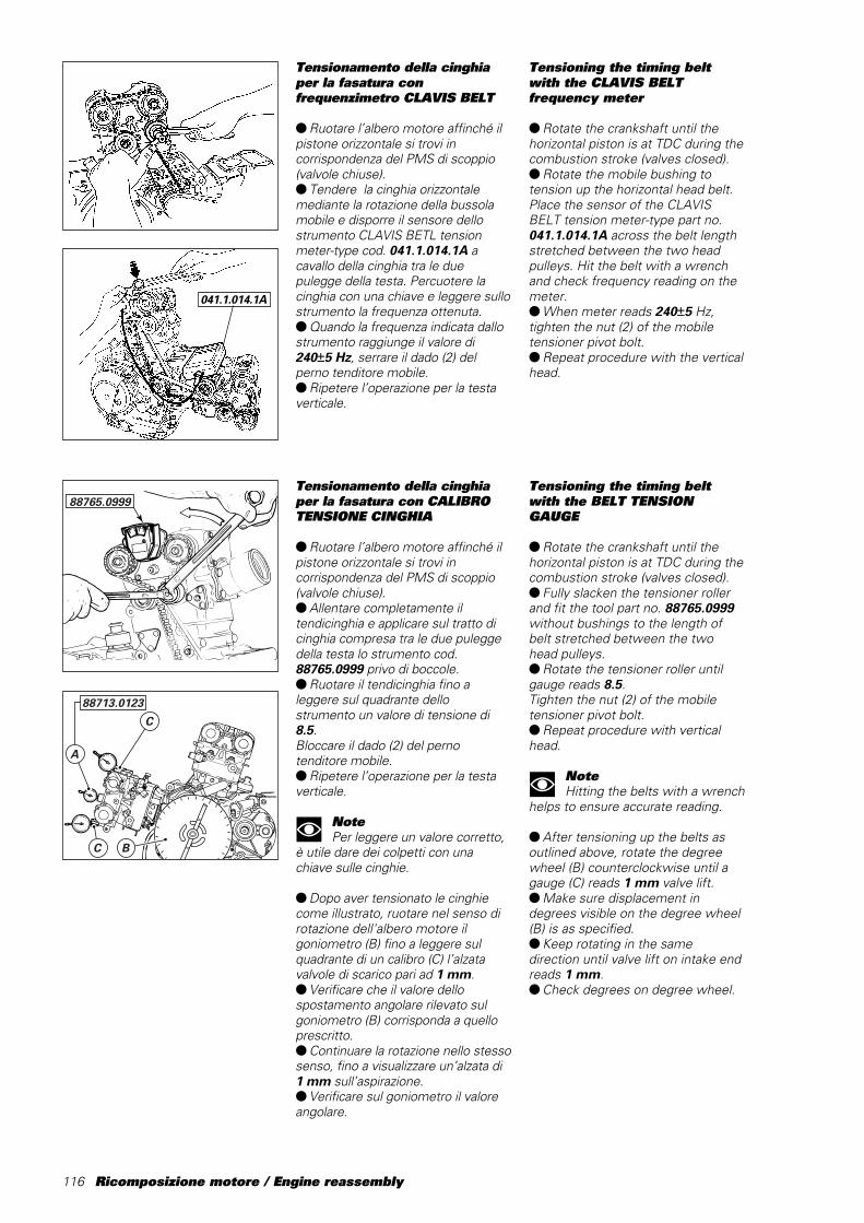
116 Ricomposizione motore / Engine reassembly
88765.0999
C B
C
A
88713.0123
Tensioning the timing beltwith the CLAVIS BELTfrequency meter
● Rotate the crankshaft until thehorizontal piston is at TDC during thecombustion stroke (valves closed).● Rotate the mobile bushing totension up the horizontal head belt.Place the sensor of the CLAVISBELT tension meter-type part no.041.1.014.1A across the belt lengthstretched between the two headpulleys. Hit the belt with a wrenchand check frequency reading on themeter.● When meter reads 240±5 Hz,tighten the nut (2) of the mobiletensioner pivot bolt.● Repeat procedure with the verticalhead.
Tensioning the timing beltwith the BELT TENSIONGAUGE
● Rotate the crankshaft until thehorizontal piston is at TDC during thecombustion stroke (valves closed).● Fully slacken the tensioner rollerand fit the tool part no. 88765.0999without bushings to the length ofbelt stretched between the twohead pulleys.● Rotate the tensioner roller untilgauge reads 8.5.Tighten the nut (2) of the mobiletensioner pivot bolt.● Repeat procedure with verticalhead.
NoteHitting the belts with a wrench
helps to ensure accurate reading.
● After tensioning up the belts asoutlined above, rotate the degreewheel (B) counterclockwise until agauge (C) reads 1 mm valve lift.● Make sure displacement indegrees visible on the degree wheel(B) is as specified.● Keep rotating in the samedirection until valve lift on intake endreads 1 mm.● Check degrees on degree wheel.
041.1.014.1A
Tensionamento della cinghiaper la fasatura confrequenzimetro CLAVIS BELT
● Ruotare l’albero motore affinché ilpistone orizzontale si trovi incorrispondenza del PMS di scoppio(valvole chiuse).● Tendere la cinghia orizzontalemediante la rotazione della bussolamobile e disporre il sensore dellostrumento CLAVIS BETL tensionmeter-type cod. 041.1.014.1A acavallo della cinghia tra le duepulegge della testa. Percuotere lacinghia con una chiave e leggere sullostrumento la frequenza ottenuta.● Quando la frequenza indicata dallostrumento raggiunge il valore di240±5 Hz, serrare il dado (2) delperno tenditore mobile.● Ripetere l’operazione per la testaverticale.
Tensionamento della cinghiaper la fasatura con CALIBROTENSIONE CINGHIA
● Ruotare l’albero motore affinché ilpistone orizzontale si trovi incorrispondenza del PMS di scoppio(valvole chiuse).● Allentare completamente iltendicinghia e applicare sul tratto dicinghia compresa tra le due puleggedella testa lo strumento cod.88765.0999 privo di boccole.● Ruotare il tendicinghia fino aleggere sul quadrante dellostrumento un valore di tensione di8.5.Bloccare il dado (2) del pernotenditore mobile.● Ripetere l’operazione per la testaverticale.
NotePer leggere un valore corretto,
è utile dare dei colpetti con unachiave sulle cinghie.
● Dopo aver tensionato le cinghiecome illustrato, ruotare nel senso dirotazione dell'albero motore ilgoniometro (B) fino a leggere sulquadrante di un calibro (C) l’alzatavalvole di scarico pari ad 1 mm.● Verificare che il valore dellospostamento angolare rilevato sulgoniometro (B) corrisponda a quelloprescritto.● Continuare la rotazione nello stessosenso, fino a visualizzare un’alzata di1 mm sull’aspirazione.● Verificare sul goniometro il valoreangolare.
Ricomposizione motore / Engine reassembly 117
● Eseguire poi, il controllo del valoreper le chiusure: scarico edaspirazione, con l’avvertenza (se siinverte il senso di rotazione delgoniometro) di approssimarsi all’alzatavalvola di 1 mm, sempre nel senso dirotazione dell'albero motore, per laripresa dei giochi.● Eseguire le stesse operazioni per ilcilindro rimanente.● È consentita una tolleranza di ± 1 °dei valori riscontrati con la proceduradescritta rispetto a quelli prescritti.
ImportanteFinita l’operazione di controllo
fasatura, è sempre necessarioriportare la tensione delle cinghie alvalore prescritto:- 150 ± 5 Hz con frequenzimetroClavis- 8 con calibro tensione cinghia conuna boccola
Controllo distanza minimavalvole-pistone (“passaggiovalvole”)
● Portare la tensione delle cinghie alvalore in frequenza pari a 240 ± 5 Hz(misurato con CLAVIS BELT tensionmeter-type cod. 041.1.014.1A)oppure al valore 8,5 (misurato concalibro tensione cinghia cod.88765.0999 privo di boccole).● Montare il comparatore percontrollo posizione pistoneavvitandolo sul foro candela● Posizionare il pistone orizzontale incorrispondenza del PMS d'incrocio.● Azzerare il comparatore percontrollo posizione pistone● Ruotare l’albero motore nel sensodi rotazione dell'albero motorerealizzando lo spostamento delpistone prescritto nella sotto riportatatabella di scarico (prima del PMS)● Annotare il valore dell’alzata valvoladi scarico in corrispondenza dellaposizione pistone sopra descritta● Ruotare l’albero motore nel sensodi rotazione dell'albero motorerealizzando lo spostamento delpistone prescritto nella sotto riportatatabella di aspirazione (dopo PMS)● Annotare il valore dell’alzata valvolaaspirazione in corrispondenza dellaposizione pistone sopra descritta● Smontare le cinghie● Posizionare il pistone come nellasotto riportata tabella di aspirazione● Ruotare manualmente l’albero acamme di aspirazione fino a che levalvole non toccano il pistone eleggere il valore indicato dalcomparatore aspirazione: la differenzatra quest’ultimo valore e quelloprecedentemente annotatorappresenta l’effettivo passaggiovalvole e non deve essere inferiore a2.2 [mm]
● Check value at closing end onintake and exhaust. Be sure toapproach 1 mm valve lift - in thecrankshaft direction of rotation -when turning counterclockwise (ifyou reverse degree wheel rotation),so to take up play.● Repeat procedure with the othercylinder.● Allowed tolerance on specifiedvalues is ±1 °.
CautionWhen you have checked
timing, do not forget to set belts tospecified tension:- 150 ± 5 Hz if you are using theClavis frequency meter- 8 if you are using the belt tensiongauge with one bushing.
Checking minimum valve-piston distance
● Set belt tension to 240 ± 5 Hz(measured with CLAVIS BELTtension meter-type part no.041.1.014.1A) or to 8.5 (measuredwith belt tension gauge part no.88765.0999 without bushings).● Screw the dial gauge to checkpiston height into spark plug hole.● Bring horizontal piston at TDC atvalve overlap.● Set the dial gauge to check pistonheight to zero.● Rotate crankshaft forward so tomove piston as indicated in theexhaust table below (before TDC).● Note exhaust valve lift with thepiston in this position.● Rotate crankshaft forward untilmoving piston as indicated in theintake table below (after TDC).● Note intake valve lift with thepiston in this position.● Remove the belts.● Move the piston back to theposition indicated in the intake tablebelow.● Rotate the intake valve shaftmanually until the valves touch thepiston and look at the reading of thedial gauge on intake end.The difference between this valueand that noted before gives actualvalve-to-piston distance and shouldnot be lower than 2.2 [mm].
118 Ricomposizione motore / Engine reassembly
● Riposizionare il pistone come nellasotto riportata tabella di scarico● Ruotare manualmente l’albero acamme di scarico fino a che le valvolenon toccano il pistone e leggere ilvalore indicato dal comparatorecamma scarico: la differenza traquest’ultimo valore e quelloprecedentemente annotatorappresenta l’effettivo passaggiovalvole e non deve essere inferiore a2.2 [mm]
Tabella per albero a camme CA506
ASPIRAZIONE CON FASE AP.30 °/CH.62 °
SPOSTAMENTO PISTONE DOPOP.M.S. D’INCROCIO ,INCORRISPONDENZA DEL QUALE VAEFFETTUATA LA MISURA DELPASSAGGIO MINIMO
0,84 [mm]
Tabella per albero a camme CS455
SCARICO CON FASE AP.74°/CH.38°
SPOSTAMENTO PISTONE PRIMAP.M.S. D’INCROCIO, INCORRISPONDENZA DEL QUALE VAEFFETTUATA LA MISURA DELPASSAGGIO MINIMO
0,58 [mm]
● Move the piston back to theposition indicated in the exhausttable below.● Manually rotate the exhaustcamshaft until the valves touch thepiston and look at the reading on thedial gauge on exhaust cam.This value less that noted previouslygives actual valve-to-piston distanceand should not be lower than 2.2[mm].
Table for camshaft CA506
INTAKE: OPENING 30 ° / CLOSING62 °
PISTON MOVEMENT AFTER TDCAT VALVE OVERLAP. MEASUREMINIMUM VALVE-TO-PISTONDISTANCE IN THIS CONDITION.
0.84 [mm]
Table for camshaft CS455
EXHAUST: OPENING 74 ° /CLOSING 38 °
PISTON MOVEMENT BEFORE TDCAT VALVE OVERLAP. MEASUREMINIMUM VALVE-TO-PISTONDISTANCE IN THIS CONDITION.
0.58 [mm]
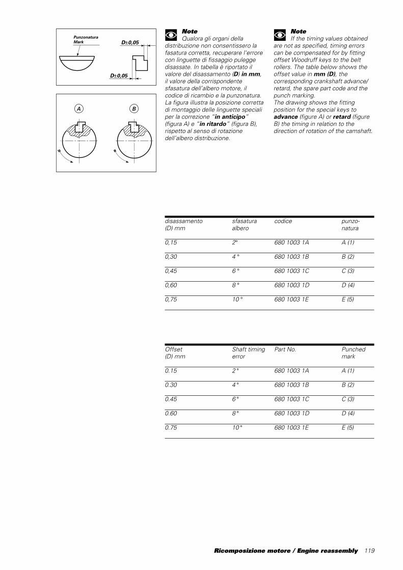
Ricomposizione motore / Engine reassembly 119
����������@@@@@@@@@@����������ÀÀÀÀÀÀÀÀÀÀ����������@@@@@@@@@@����������ÀÀÀÀÀÀÀÀÀÀ����������
����������@@@@@@@@@@����������ÀÀÀÀÀÀÀÀÀÀ����������@@@@@@@@@@����������ÀÀÀÀÀÀÀÀÀÀ����������
A B
NoteQualora gli organi della
distribuzione non consentissero lafasatura corretta, recuperare l'errorecon linguette di fissaggio puleggedisassate. In tabella è riportato ilvalore del disassamento (D) in mm,il valore della corrispondentesfasatura dell’albero motore, ilcodice di ricambio e la punzonatura.La figura illustra la posizione correttadi montaggio delle linguette specialiper la correzione “in anticipo”(figura A) e “in ritardo” (figura B),rispetto al senso di rotazionedell’albero distribuzione.
disassamento sfasatura codice punzo-(D) mm albero natura
0,15 2° 680 1003 1A A (1)
0,30 4 ° 680 1003 1B B (2)
0,45 6 ° 680 1003 1C C (3)
0,60 8 ° 680 1003 1D D (4)
0,75 10 ° 680 1003 1E E (5)
PunzonaturaMark
D±0,05
D±0,05
NoteIf the timing values obtained
are not as specified, timing errorscan be compensated for by fittingoffset Woodruff keys to the beltrollers. The table below shows theoffset value in mm (D), thecorresponding crankshaft advance/retard, the spare part code and thepunch marking.The drawing shows the fittingposition for the special keys toadvance (figure A) or retard (figureB) the timing in relation to thedirection of rotation of the camshaft.
Offset Shaft timing Part No. Punched(D) mm error mark
0.15 2 ° 680 1003 1A A (1)
0.30 4 ° 680 1003 1B B (2)
0.45 6 ° 680 1003 1C C (3)
0.60 8 ° 680 1003 1D D (4)
0.75 10 ° 680 1003 1E E (5)
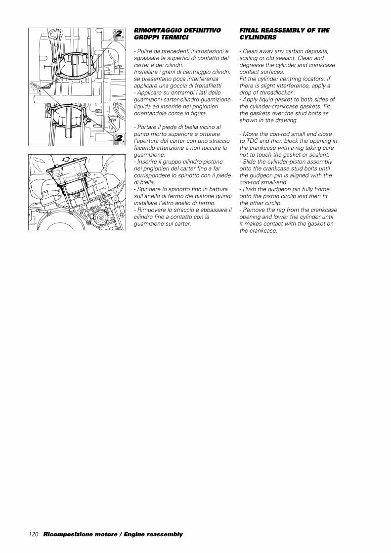
120 Ricomposizione motore / Engine reassembly
RIMONTAGGIO DEFINITIVOGRUPPI TERMICI
- Pulire da precedenti incrostazioni esgrassare le superfici di contatto delcarter e dei cilindri.Installare i grani di centraggio cilindri,se presentano poca interferenzaapplicare una goccia di frenafiletti- Applicare su entrambi i lati delleguarnizioni carter-cilindro guarnizioneliquida ed inserirle nei prigionieriorientandole come in figura.
- Portare il piede di biella vicino alpunto morto superiore e otturarel’apertura del carter con uno stracciofacendo attenzione a non toccare laguarnizione.- Inserire il gruppo cilindro-pistonenei prigionieri del carter fino a farcorrispondere lo spinotto con il piededi biella.- Spingere lo spinotto fino in battutasull’anello di fermo del pistone quindiinstallare l’altro anello di fermo.- Rimuovere lo straccio e abbassare ilcilindro fino a contatto con laguarnizione sul carter.
2LOCK
2LOCK
FINAL REASSEMBLY OF THECYLINDERS
- Clean away any carbon deposits,scaling or old sealant. Clean anddegrease the cylinder and crankcasecontact surfaces.Fit the cylinder centring locators; ifthere is slight interference, apply adrop of threadlocker .- Apply liquid gasket to both sides ofthe cylinder-crankcase gaskets. Fitthe gaskets over the stud bolts asshown in the drawing.
- Move the con-rod small end closeto TDC and then block the opening inthe crankcase with a rag taking carenot to touch the gasket or sealant.- Slide the cylinder-piston assemblyonto the crankcase stud bolts untilthe gudgeon pin is aligned with thecon-rod small-end.- Push the gudgeon pin fully homeonto the piston circlip and then fitthe other circlip.- Remove the rag from the crankcaseopening and lower the cylinder untilit makes contact with the gasket onthe crankcase.
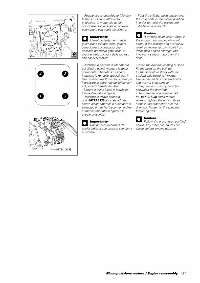
Ricomposizione motore / Engine reassembly 121
– Posizionare la guarnizione (cilindro/testa) sul cilindro, attraverso iprigionieri, in modo tale da farcoincidere i fori di scarico olio dellaguarnizione con quelli del cilindro.
ImportanteL'errato orientamento della
guarnizione cilindro-testa, generapericolosissimi grippaggi chepossono procurare gravi danni alpilota e, nella migliore delle ipotesi,seri danni al motore.
- Installare le boccole di riferimentosul cilindro quindi montare la testaportandola in battuta sul cilindro.Installare le rondelle speciali, con illato rettilineo rivolto verso l’interno, eingrassare le estremità dei prigionierie il piano di battuta dei dadi.- Serrare a mano i dadi di serraggio(come illustrato in figura).- Utilizzare la chiave specialecod.␣ 88713.1139 abbinata ad unachiave dinamometrica e procedere alserraggio (in tre fasi secondo l'ordinenumerico riportato in figura) allecoppie prescritte.
ImportanteUna procedura diversa da
quella indicata può causare seri dannial motore.
88713.1139
C
4 2
1 3
- Refit the cylinder-head gasket overthe stud bolts in the proper position,in order to make the gasket andcylinder always match.
CautionA cylinder-head gasket fitted in
the wrong mounting position willobstruct the oilways and eventuallyresult in engine seizure. Apart fromirreparable engine damage, thisinvolves a serious hazard for therider.
- Insert the cylinder locating bushes.Fit the head on the cylinder.Fit the special washers with thestraight side pointing inwards.Grease the ends of the stud boltsand the nut stop surface.- Snug the lock nuts by hand (asshownion the drawing).- Using the service wrench partno.␣ 88713.1139 and a torquewrench, tighten the nuts in threesteps in the order shown in thedrawing. Tighten to the specifiedtorque figures.
CautionFollow the procedure specified
above. Any other procedures cancause serious engine damage.
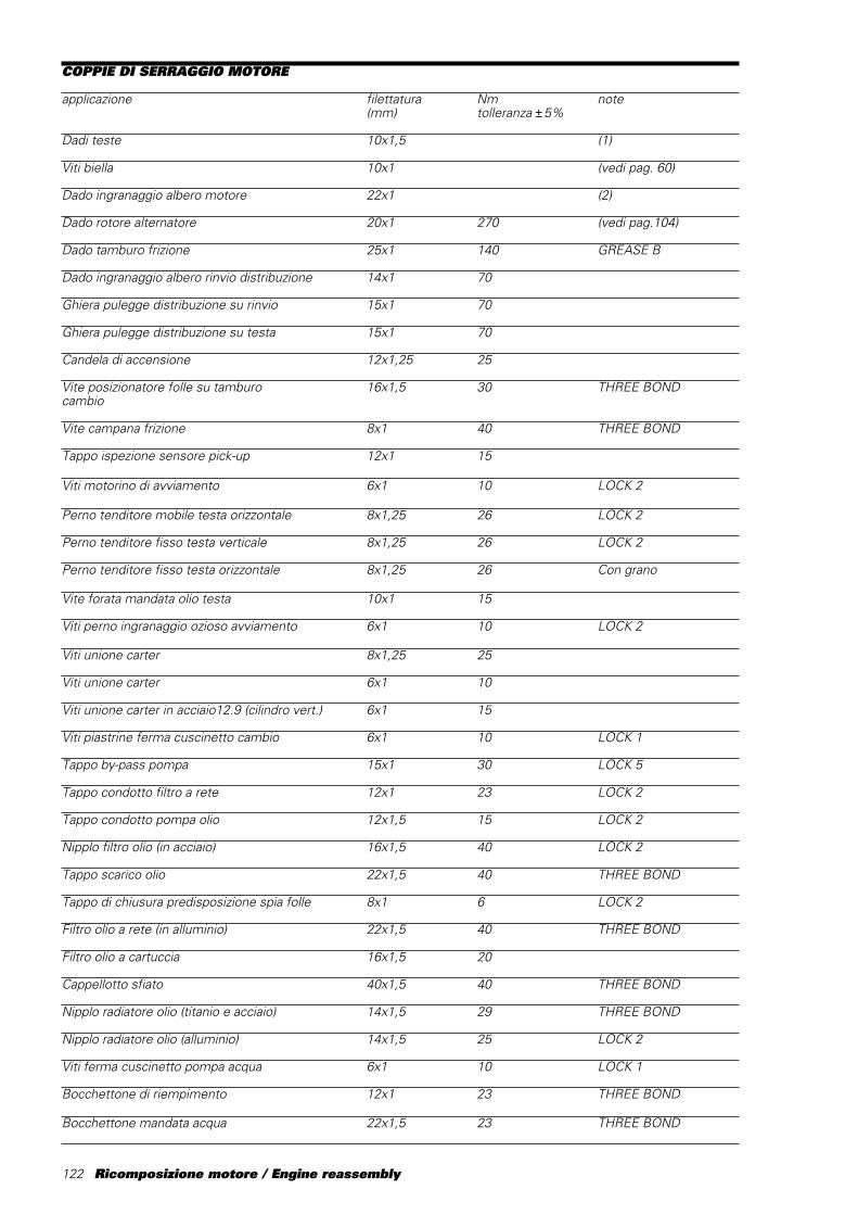
122 Ricomposizione motore / Engine reassembly
COPPIE DI SERRAGGIO MOTORE
applicazione filettatura Nm note(mm) tolleranza ±5%
Dadi teste 10x1,5 (1)
Viti biella 10x1 (vedi pag. 60)
Dado ingranaggio albero motore 22x1 (2)
Dado rotore alternatore 20x1 270 (vedi pag.104)
Dado tamburo frizione 25x1 140 GREASE B
Dado ingranaggio albero rinvio distribuzione 14x1 70
Ghiera pulegge distribuzione su rinvio 15x1 70
Ghiera pulegge distribuzione su testa 15x1 70
Candela di accensione 12x1,25 25
Vite posizionatore folle su tamburo 16x1,5 30 THREE BONDcambio
Vite campana frizione 8x1 40 THREE BOND
Tappo ispezione sensore pick-up 12x1 15
Viti motorino di avviamento 6x1 10 LOCK 2
Perno tenditore mobile testa orizzontale 8x1,25 26 LOCK 2
Perno tenditore fisso testa verticale 8x1,25 26 LOCK 2
Perno tenditore fisso testa orizzontale 8x1,25 26 Con grano
Vite forata mandata olio testa 10x1 15
Viti perno ingranaggio ozioso avviamento 6x1 10 LOCK 2
Viti unione carter 8x1,25 25
Viti unione carter 6x1 10
Viti unione carter in acciaio12.9 (cilindro vert.) 6x1 15
Viti piastrine ferma cuscinetto cambio 6x1 10 LOCK 1
Tappo by-pass pompa 15x1 30 LOCK 5
Tappo condotto filtro a rete 12x1 23 LOCK 2
Tappo condotto pompa olio 12x1,5 15 LOCK 2
Nipplo filtro olio (in acciaio) 16x1,5 40 LOCK 2
Tappo scarico olio 22x1,5 40 THREE BOND
Tappo di chiusura predisposizione spia folle 8x1 6 LOCK 2
Filtro olio a rete (in alluminio) 22x1,5 40 THREE BOND
Filtro olio a cartuccia 16x1,5 20
Cappellotto sfiato 40x1,5 40 THREE BOND
Nipplo radiatore olio (titanio e acciaio) 14x1,5 29 THREE BOND
Nipplo radiatore olio (alluminio) 14x1,5 25 LOCK 2
Viti ferma cuscinetto pompa acqua 6x1 10 LOCK 1
Bocchettone di riempimento 12x1 23 THREE BOND
Bocchettone mandata acqua 22x1,5 23 THREE BOND

Ricomposizione motore / Engine reassembly 123
applicazione filettatura Nm note(mm) tolleranza ±5%
Sensore temperatura acqua (Weber) 12x1,5 20
Bocchettone aspirazione acqua 30x1,5 23 THREE BOND
Viti raccordi entrata acqua nel cilindro 6x1 10
Viti coperchio alternatore 6x1 10
Vite fissaggio levetta fermamarce 8x1,25 22 LOCK 2
Viti coperchio frizione 6x1 10
Viti corpo pompa olio 8x1,25 25
Viti corpo pompa olio 6x1 10
Viti coperchio pompa olio 6x1 10
Viti coperchio valvole 6x1 10
Viti cappellotti porta camme 6x1 10
Viti raccordo uscita acqua testa 6x1 10
Viti collettore aspirazione 6x1 10
Dadi flangia di scarico 6x1 10
Interuttore spia temperatura acqua 10x1 20
Tappo chiusura (pressostato) 10x1 23
Prigionieri testa 10x1,5 30 LOCK 2
Prigionieri scarico 6x1 5 LOCK 2
Viti e dadi in generale 5x0,8 5
Viti e dadi in generale 6x1 10
Viti e dadi in generale 8x1,25 25
Viti e dadi in generale 10x1,5 35
Viti e dadi in generale 12x1,75 55
Vite fissaggio volano-rotore DENSO 6x1 20 LOCK 2
Vite fissaggio statore DENSO 6x1 10 LOCK 2
Vite TCEIR M8x20 supporto tenditore 8x1,25 30 LOCK 2
Perno tenditore mobile testa verticale 8x1,25 26 Con grano
(1) Ingrassare sottodado, filetto e rosetta con grasso GREASE C:- 1a fase 15 Nm;- 2a fase 25 Nm;- 3a fase 40 Nm.(2) Ingrassare sottotesta dado con GREASE B.Serrare a 200 Nm

124 Ricomposizione motore / Engine reassembly
TORQUE SETTINGS, ENGINE
Part Thread Nm Notes(mm) ±5% tolerance
Head nuts 10x1,5 (1)
Con-rod bolts 10x1 (see page 60)
Crankshaft gear nut 22x1 (2)
Generator rotor nut 20x1 270 (see page 104)
Clutch drum nut 25x1 140 GREASE B
Timing lay shaft gear nut 14x1 70
Ring nut of timing rollers on lay shaft 15x1 70
Ring nut of timing rollers on head 15x1 70
Spark plug 12x1,25 25
Gearbox positioner drum screw 16x1,5 30 THREE BOND
Clutch housing screw 8x1 40 THREE BOND
Pick-up sensor inspection plug 12x1 15
Starter motor screw 6x1 10 LOCK 2
Horizontal head mobile tensioner pin 8x1,25 26 LOCK 2
Vertical head fixed tensioner pin 8x1,25 26 LOCK 2
Horizontal head fixed tensioner pin 8x1,25 26 with grub screw
Head oil delivery drilled screw 10x1 15
Starter idle gear pin screw 6x1 10 LOCK 2
Crankcase fixing screws 8x1,25 25
Crankcase fixing screws 6x1 10
Crankcase fixing screws in 12.9 steel (vert. cyl.) 6x1 15
Bolts for gearbox bearing holder plates 6x1 10 LOCK 1
Pump by-pass plug 15x1 30 LOCK 5
Mesh filter duct plug 12x1 23 LOCK 2
Oil pump duct plug 12x1,5 15 LOCK 2
Oil filter nipple (steel) 16x1,5 40 LOCK 2
Oil drain plug 22x1,5 40 THREE BOND
Blanking plug for neutral light hole 8x1 6 LOCK 2
Mesh oil filter (aluminium) 22x1,5 40 THREE BOND
Oil filter cartridge 16x1,5 20
Breather cap 40x1,5 40 THREE BOND
Oil cooler nipple (titanium and steel) 14x1,5 29 THREE BOND
Oil cooler nipple (aluminium) 14x1,5 25 LOCK 2
Water pump bearing lock screws 6x1 10 LOCK 1
Filler plug 12x1 23 THREE BOND
Water delivery connector 22x1,5 23 THREE BOND
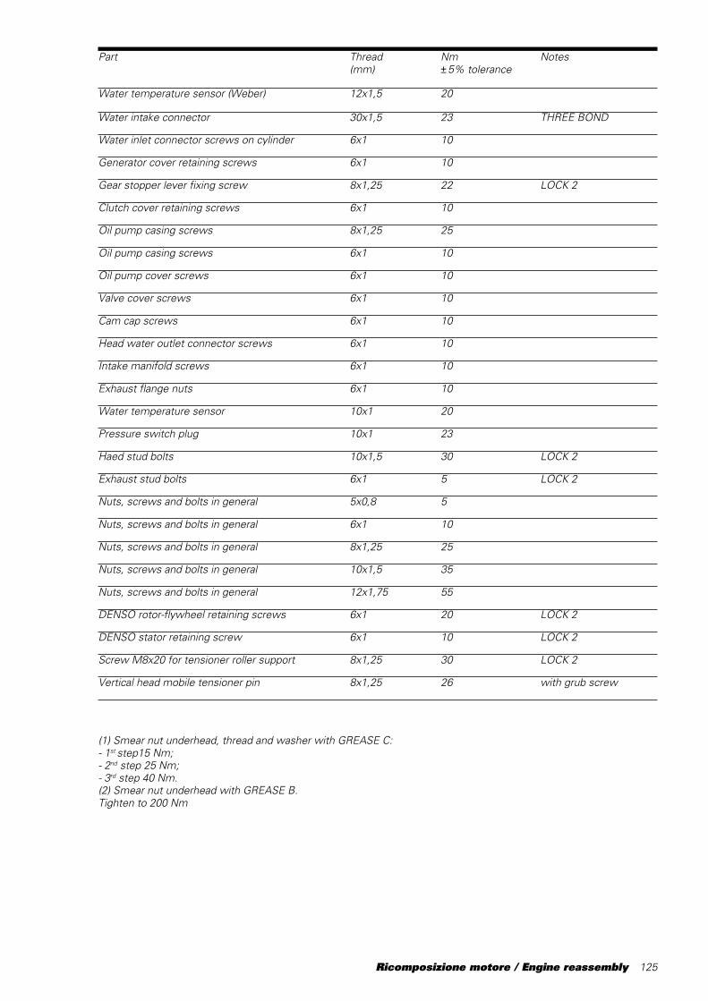
Ricomposizione motore / Engine reassembly 125
Part Thread Nm Notes(mm) ±5% tolerance
Water temperature sensor (Weber) 12x1,5 20
Water intake connector 30x1,5 23 THREE BOND
Water inlet connector screws on cylinder 6x1 10
Generator cover retaining screws 6x1 10
Gear stopper lever fixing screw 8x1,25 22 LOCK 2
Clutch cover retaining screws 6x1 10
Oil pump casing screws 8x1,25 25
Oil pump casing screws 6x1 10
Oil pump cover screws 6x1 10
Valve cover screws 6x1 10
Cam cap screws 6x1 10
Head water outlet connector screws 6x1 10
Intake manifold screws 6x1 10
Exhaust flange nuts 6x1 10
Water temperature sensor 10x1 20
Pressure switch plug 10x1 23
Haed stud bolts 10x1,5 30 LOCK 2
Exhaust stud bolts 6x1 5 LOCK 2
Nuts, screws and bolts in general 5x0,8 5
Nuts, screws and bolts in general 6x1 10
Nuts, screws and bolts in general 8x1,25 25
Nuts, screws and bolts in general 10x1,5 35
Nuts, screws and bolts in general 12x1,75 55
DENSO rotor-flywheel retaining screws 6x1 20 LOCK 2
DENSO stator retaining screw 6x1 10 LOCK 2
Screw M8x20 for tensioner roller support 8x1,25 30 LOCK 2
Vertical head mobile tensioner pin 8x1,25 26 with grub screw
(1) Smear nut underhead, thread and washer with GREASE C:- 1st step15 Nm;- 2nd step 25 Nm;- 3rd step 40 Nm.(2) Smear nut underhead with GREASE B.Tighten to 200 Nm

126 Ricomposizione motore / Engine reassembly

Mototelaio / Frame 127
MototelaioFrame
128 Mototelaio / Frame
TRASMISSIONE SECONDARIA
- L’impiego di catene DID, prevedel’abbinamento con pignoni e coroneAFAM, marcati Z**D (es. Z38D).- L’impiego di catene REGINA,prevede l’abbinamento con pignoni ecorone AFAM, marcati Z**R (es.Z38R).- L’impiego di catene diverse,prevede l’abbinamento con pignoni ecorone AFAM, marcati:• D per profili tipo ASA I• R per profili tipo ISO R 606,
ANSI B29-1 e DIN 8196
MESSA A PUNTO TELAIO
- Questa sezione del manualecontiene le principali informazionitecniche per la messa a punto deltelaio e delle sospensioni.Gli argomenti trattati riportanoconcetti generalizzati, in quantosarebbe praticamente impossibiledettagliare interventi dipersonalizzazione individuale, poichéogni pilota ha esigenze, preferenze,abitudini e stile di guida diversi.- Le moto da competizione esigonouna attenta e scrupolosamanutenzione in ogni componentemeccanico, elettrico, elettronico.- La manutenzione del telaio è quindialtrettanto importante dellamanutenzione del motore.- Alcuni consigli essenziali:
- non utilizzare solventi“aggressivi”, come il solvente perfreni e benzina, sulle sospensioniper non danneggiare le guarnizioni.- Far controllare periodicamente lesospensioni dall’assistenzaautorizzata.
FINAL DRIVE
- DID chains are used in combinationwith AFAM rear and front sprocketsmarked Z**D (ex. Z38D).- REGINA chains are used incombination with AFAM rear andfront sprockets marked Z**R (ex.Z38R).- Other types of chains are used incombination with AFAM rear andfront sprockets marked as follows:• a D identified ASA I profiles• an R identifies ISO R 606,
ANSI B29-1 and DIN 8196 profiles.
FRAME AND SUSPENSIONSETUP
- This section provides instructionson how to set up the frame andsuspension.The ideal race bike set-up dependson a variety of factors: rider style andpreferences; track surface andconditions; tyre type and wear. Thismanual is therefore intended as aguide only and as a starting point forsetting up your bike.- Racing bikes require that each andevery mechanical, electric andelctronic component be carefullyinspected and maintained.- This means frame maintenance isjust as essential as enginemaintenance.- A few important hints:- Do not use strong solvents suchas brake cleaner or petrol onsuspension parts thus avoidingdamaging gaskets.- Have your suspension componentsregularly serviced by the authorisedservice.
Mototelaio / Frame 129
MESSA A PUNTO STANDARD
La taratura base delle sospensioni sibasa sull’esperienza dei piloti ufficialimaturata durante le gare dicampionato mondiale Supersport, esull’esperienza di Ducati Corse.Le seguenti indicazioni vanno tenutecome riferimento nel corso dellamessa a punto della ciclistica.
Forcella anterioreLa forcella anteriore SHOWA utilizzaun sistema per la parte idraulica. Inquesto modo si ottiene una forzaviscosa che dipende solo dallavelocità del pistone.- La molla e il livello olio permettonodi regolare la forza dello stelo e lecaratteristiche della forcella in mododa adattarsi ai diversi percorsi e aidiversi piloti. Grazie alla regolazioneesterna dell’oleodinamica, con laregolazione dell’estensione sullatesta e della compressione sul fondodella forcella si ha un’ampiapossibilità di regolazione dellafrenatura idraulica, che dipendesoltanto dalla velocità di movimentoe non dalla posizione.- Per impostare il regolatore diammortizzazione a scatto, ruotate ilregolatore con una chiavettaesagonale in senso orario e giratedalla posizione chiusa per il numerodi scatti raccomandati. Non sforzatemai la coppia della vite di regolazionenella posizione chiusa.- La regolazione è del tipo a valvolaconica, quindi le differenze tra gliscatti aumentano man mano chediminuisce il numero di scatti cheusate.
ImportanteNon usate il regolatore su un
numero di scatti inferiore a3 - 4.
STANDARD SET-UP
The set-up of the bike is based onthe experience of the Ducati worksteam and riders during the WorldSupersport season and on theexperience of the Ducati Corse.The information detailed below is foryour reference and provides a usefulguide when setting up your bike.
Front forkThe SHOWA front fork uses acartridge system for hydraulicdamping. The damping force thusdepends directly on the speed of thepiston in the cartridge system.- The fork spring and oil level can beadjusted to vary stanchion force andfork operation to match trackconditions and rider preferences.The fork has two external hydraulicadjusters: a rebound adjuster at thetop and a compression adjuster onthe bottom of the fork. This allowsfor a wide range of dampingsettings. Note that setting isdetermined by speed rather thanposition.- To set the damping click adjuster,turn the adjuster clockwise with ahex key starting from the closedposition. Turn by the recommendednumber of clicks. Do not overtorquethe adjuster in the closed position.- Recommended position forrebound: 7 to 11 clicks- Adjustment is of the tapered valvebleed type. This means that thedifference between one click andanother increases as the number ofclicks gets smaller.
CautionDo not use settings below 3
to 4 clicks.
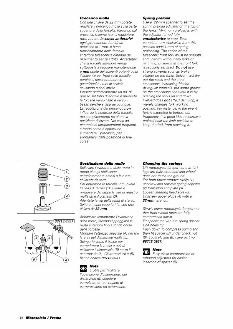
130 Mototelaio / Frame
Sostituzione delle molleSollevare l’avantreno della moto inmodo che gli steli sianocompletamente estesi e la ruotasollevata da terra.Per entrambe le forcelle: rimuoverel’anello di fermo (1); svitare erimuovere dal tappo la vite di registromolla (2) e il piattello (3).Allentate le viti della testa di sterzo.Svitate i tappi superiori (4) con unachiave da 32 mm.
Abbassate lentamente l’avantrenodella moto, facendo appoggiare laruota anteriore fino a fondo corsadelle forcelle.Montare l’attrezzo speciale (A) nei forilaterali del distanziale molla (5).Spingerlo verso il basso percomprimere la molla e quindicollocare il distanziale (B) sotto ilcontrodado (6). Gli attrezzi (A) e (B)hanno codice 88713.0957.
NotaÈ utile per facilitare
l’operazione d’inserimento deldistanziale (B) chiuderecompletamente i registri dicompressione ed estensione.
Precarico mollaCon una chiave da 22 mm poteteregolare il precarico molla sulla partesuperiore della forcella. Partendo dalprecarico minimo (con il regolatoretutto ruotato in senso antiorario)ogni giro ulteriore fornirà unprecarico di 1 mm. Il buonfunzionamento della forcellaanteriore telescopica dipende dalmovimento senza attrito. Accertateviche la forcella anteriore vengasottoposta a regolare manutenzionee non usate dei solventi potenti qualiil solvente per freni sulle forcelleperchè si seccherebbero leguarnizioni e i tubi di acciaiocausando quindi attrito.Versate periodicamente un po’ digrasso sul tubo di acciaio e muovetele forcelle verso l’alto e verso ilbasso perchè si sparga ovunque.La regolazione del precarico noninfluenza la rigidezza della forcella,ma semplicemente ne altera laposizione di lavoro. Nel caso adesempio di tamponamenti frequenti,a fondo corse è opportunoaumentare il precarico, perallontanarsi dalla posizione di finecorse.
Spring preloadUse a 22-mm spanner to set thespring preload adjuster on the top ofthe forks. Minimum preload is withthe adjuster turned fullyanticlockwise to stop. Eachcomplete turn clockwise from thisposition adds 1 mm of springpreloading. The action of thetelescopic front fork must be smoothand uniform without any jerks orjamming. Ensure that the front forkis regularly serviced. Do not usestrong solvents such as brakecleaner on the forks. Solvent will dryout the seals and the steelstanchions, increasing friction.At regular intervals, put some greaseon the stanchions and work it in bypushing the forks up and down.Preload does not affect damping, itmerely changes fork workingposition. For instance, in the eventfork is expected to bottom outfrequently, it is good idea to increasepreload near the limit position tokeep the fork from reaching it.
Changing the springsLift motorcycle forepart so that forklegs are fully extended and wheeldoes not touch the ground.For both forks: remove circlip (1),unscrew and remove spring adjuster(2) from plug and plate (3).Loosen steering head screws.Unscrew upper plugs (4) with a32-mm wrench.
Slowly lower motorcycle forepart sothat front wheel forks are fullycompressed down.Fit special tool (A) into spring spacerside holes (5).Push down to compress spring andthen fit spacer (B) under check nut(6). Tools (A) and (B) have part no.88713.0957.
NoteFully close compression or
rebound adjusters for easierinsertion of spacer (B).
3
2
1
4
A5
B 6
88713.0957
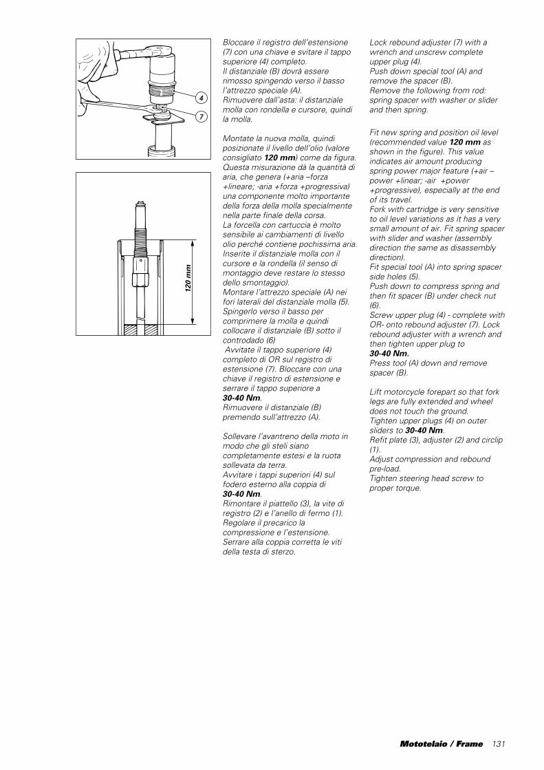
Mototelaio / Frame 131
Lock rebound adjuster (7) with awrench and unscrew completeupper plug (4).Push down special tool (A) andremove the spacer (B).Remove the following from rod:spring spacer with washer or sliderand then spring.
Fit new spring and position oil level(recommended value 120 mm asshown in the figure). This valueindicates air amount producingspring power major feature (+air –power +linear; -air +power+progressive), especially at the endof its travel.Fork with cartridge is very sensitiveto oil level variations as it has a verysmall amount of air. Fit spring spacerwith slider and washer (assemblydirection the same as disassemblydirection).Fit special tool (A) into spring spacerside holes (5).Push down to compress spring andthen fit spacer (B) under check nut(6).Screw upper plug (4) - complete withOR- onto rebound adjuster (7). Lockrebound adjuster with a wrench andthen tighten upper plug to30-40 Nm.Press tool (A) down and removespacer (B).
Lift motorcycle forepart so that forklegs are fully extended and wheeldoes not touch the ground.Tighten upper plugs (4) on outersliders to 30-40 Nm.Refit plate (3), adjuster (2) and circlip(1).Adjust compression and reboundpre-load.Tighten steering head screw toproper torque.
Bloccare il registro dell’estensione(7) con una chiave e svitare il tapposuperiore (4) completo.Il distanziale (B) dovrà essererimosso spingendo verso il bassol’attrezzo speciale (A).Rimuovere dall’asta: il distanzialemolla con rondella e cursore, quindila molla.
Montate la nuova molla, quindiposizionate il livello dell’olio (valoreconsigliato 120 mm) come da figura.Questa misurazione dà la quantità diaria, che genera (+aria –forza+lineare; -aria +forza +progressiva)una componente molto importantedella forza della molla specialmentenella parte finale della corsa.La forcella con cartuccia è moltosensibile ai cambiamenti di livelloolio perché contiene pochissima aria.Inserite il distanziale molla con ilcursore e la rondella (il senso dimontaggio deve restare lo stessodello smontaggio).Montare l’attrezzo speciale (A) neifori laterali del distanziale molla (5).Spingerlo verso il basso percomprimere la molla e quindicollocare il distanziale (B) sotto ilcontrodado (6) Avvitate il tappo superiore (4)completo di OR sul registro diestensione (7). Bloccare con unachiave il registro di estensione eserrare il tappo superiore a30-40 Nm.Rimuovere il distanziale (B)premendo sull’attrezzo (A).
Sollevare l’avantreno della moto inmodo che gli steli sianocompletamente estesi e la ruotasollevata da terra.Avvitare i tappi superiori (4) sulfodero esterno alla coppia di30-40 Nm.Rimontare il piattello (3), la vite diregistro (2) e l’anello di fermo (1).Regolare il precarico lacompressione e l’estensione.Serrare alla coppia corretta le vitidella testa di sterzo.
120
mm
4
7
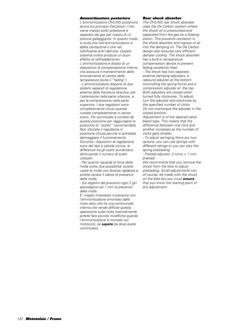
132 Mototelaio / Frame
Ammortizzatore posterioreL’ammortizzatore ÖHLINS posteriorelavora sul principio DeCarbon: l’olioviene messo sotto pressione eseparato dal gas per mezzo di unpistone galleggiante. In questo modosi evita che nell’ammortizzatore siabbia cavitazione o che nellubrificante entri dell’aria. Questosistema inoltre produce un buoneffetto di raffreddamento.L’ammortizzatore è dotato di undispositivo di compensazione internoche assicura il mantenimento dellosmorzamento al variare dellatemperatura (evita il “fading”).- L’ammortizzatore dispone di duesistemi separati di regolazioneesterna della frenatura idraulica, perl’estensione nella parte inferiore, eper la compressione nella partesuperiore. I due regolatori sonocompletamente chiusi quandoruotate completamente in sensoorario. Poi cominciate a contare daquesta posizione per raggiungere laposizione di “scatto” raccomandata.Non sforzate il regolatore inposizione chiusa perchè si potrebbedanneggiare il funzionamento.Siccome i dispositivi di regolazionesono del tipo a valvola conica, ledifferenze tra gli scatti aumentanodiminuendo il numero di scattiutilizzati.- Per quanto riguarda la forza dellamolla avete due possibilità: poteteusare le molle con diversa rigidezza epotete variare il valore di precaricodella molla.- Sul registro del precarico ogni 2 giriequivalgono ad 1 mm di precaricodella molla.E’ meglio impostare il precarico conl’ammortizzatore smontato dallamoto dato che ha una contromollainterna che rende difficile questaoperazione sulla moto (naturalmentepotete fare piccole modifiche quandol’ammortizzatore è montato sulmotociclo, se sapete da dove avetecominciato).
Rear shock absorberThe ÖHLINS rear shock absorberuses the De Carbon system wherethe shock oil is pressurised andseparated from the gas by a floatingpiston. This prevents cavitation inthe shock absorber and ingress of airinto the damping oil. The De Carbondesign also ensures very efficientdamper cooling. The shock absorberhas a built-in temperaturecompensation device to preventfading caused by heat.- The shock has two separateexternal damping adjusters, arebound adjuster at the bottom(controlling the spring force) and acompression adjuster at the top.Both adjusters are closed whenturned fully clockwise. To adjust,turn the adjuster anti-clockwise bythe specified number of clicks.Do not overtorque the adjuster in theclosed position.Adjustment is of the tapered valvebleed type. This means that thedifference between one click andanother increases as the number ofclicks gets smaller.- To adjust springing there are twooptions: you can use springs withdifferent ratings or you can vary thespring preloading.- Preload adjuster: 2 turns = 1 mmpreload.We recommend that you remove theshock from the bike to adjustpreloading. Small adjustments can,of course, be made with the shockon the bike but you must ensurethat you know the starting point ofany adjustment.

Mototelaio / Frame 133
Ammortizzazione di sterzoL’ammortizzatore di sterzo è statoprogettato per aumentare la stabilitàdella moto. La posizione degli scattiè variabile per ogni pilota ma laposizione standard è 6-12 scatti dallaposizione chiusa (senso orario).- Per determinare la messa a puntoideale e personalizzata, ridurrelentamente il numero di scatti,aumentando l’effetto ammortizzante.
Altezza di guidaMettere il motociclo sul cavalletto inmodo che entrambe le ruote sianosollevate da terra. Misurate ladistanza tra il tubo esterno el’estremità della forcella anteriore(altezza anteriore, vedi figura).Usare l’attrezzo del kit(cod.␣ 6992.063.1A) per misurare laparte posteriore completamenteestesa (altezza posteriore). Prenderenota!Rimettere il motociclo sulle ruote.Rilevare nuovamente le misure eprendere nota.Detrarre la prima misura dallaseconda e si avrà il cedimentostatico. E’ importante che ilmotociclo sia sempre nelle stessecondizioni (carburante, acqua, ecc.),per poter ottenere delle registrazionicorrette.Rilevare la misura ancora una voltacon il pilota in posizione di guida sulmotociclo e detrarre questa misuradalla prima per ottenere la cosiddettaposizione “1G”.Conservando le tre misurazioni,registrare ed annotare la corsarimanente della forcella anteriore edell’ammortizzatore posteriore (èpossibile versare un po’ di grassosullo stelo o mettere una fascetta),dopo ogni utilizzo della moto, saràmolto utile per avere una buonamessa a punto per ogni gara.
Steering damperThe steering damper increases bikestability. The damper has a clickadjuster which is closed whenturned fully clockwise. Dampersettings are a matter of riderpreference. The standard setting isbetween 6 and 12 clicks from thefully closed position.- Start with a soft set-up andgradually reduce the number ofclicks (to increase the dampingeffect) until you find the dampersetting which suits you best.
Ride heightRaise the bike on a stand so thatboth wheels are off the ground.Measure the distance from the outertube and the end of the front fork(front height, see drawing).Use the service tool(part␣ no.␣ 6992.063.1A) to measurethe fully extended rear height. Makenote of these measurements.Drop the bike down on its wheels,measure and note the distancesagain.The second measure less the firstgives static yield.The first and second measurementsmust be taken under the sameconditions, i.e. with the bike loadedwith the same amount of fuel andwater.Do one more measurement with therider in the riding position on the bikeand deduct this value from the firstmeasurement to obtain the “1G”position.Keep a record of these threemeasurements and note theremaining travel of the front fork andrear shock absorber (put a smallamount of grease or a tie around theshock rod). Record all settings anduse these as a set-up aid beforeeach race.
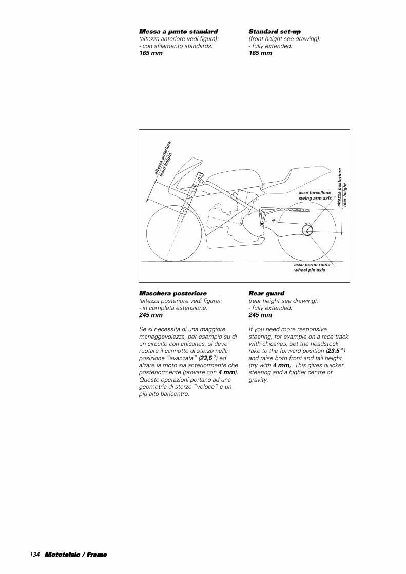
134 Mototelaio / Frame
asse forcelloneswing arm axis
asse perno ruotawheel pin axis
alte
zza
post
erio
rere
ar h
eigh
t
alte
zza
ante
riore
fron
t hei
ght
Messa a punto standard(altezza anteriore vedi figura):- con sfilamento standards:165 mm
Maschera posteriore(altezza posteriore vedi figura):- in completa estensione:245 mm
Se si necessita di una maggioremaneggevolezza, per esempio su diun circuito con chicanes, si deveruotare il cannotto di sterzo nellaposizione “avanzata” (23,5 °) edalzare la moto sia anteriormente cheposteriormente (provare con 4 mm).Queste operazioni portano ad unageometria di sterzo “veloce” e unpiù alto baricentro.
Standard set-up(front height see drawing):- fully extended:165 mm
Rear guard(rear height see drawing):- fully extended:245 mm
If you need more responsivesteering, for example on a race trackwith chicanes, set the headstockrake to the forward position (23.5 °)and raise both front and tail height(try with 4 mm). This gives quickersteering and a higher centre ofgravity.
134 Mototelaio / Frame
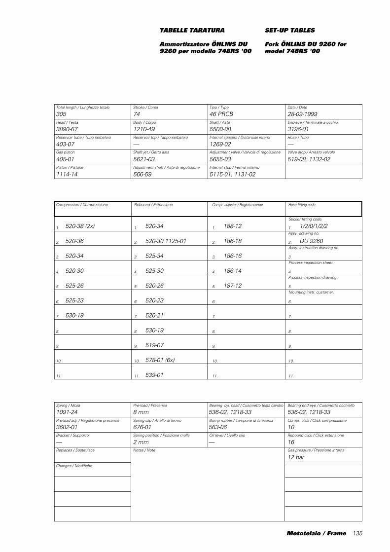
Mototelaio / Frame 135
Piston / Pistone Adjustment shaft / Asta di regolazione Internal stop / Fermo interno
Spring / Molla Pre-load / Precarico Bearing cyl. head / Cuscinetto testa cilindro Bearing end eye / Cuscinetto occhiello
Pre-load adj. / Regolazione precarico Spring clip / Anello di fermo Bump rubber / Tampone di finecorsa Compr. click / Click compressione
Bracket / Supporto Spring position / Posizione molla Oil level / Livello olio Rebound click / Click estensione
Replaces / Sostituisce Notas / Note Gas pressure / Pressione interna
Total length / Lunghezza totale Stroke / Corsa Tipo / Type Data / Date
Head / Testa Body / Corpo Shaft / Asta End-eye / Terminale a occhio
Reservoir tube / Tubo serbatoio Reservoir top / Tappo serbatoio Internal spacers / Distanziali interni Hose / Tubo
Gas piston Shaft jet / Getto asta Adjustment valve / Valvola di regolazione Valve stop / Arresto valvola
1. 1. 1. 1.
2. 2. 2. 2.
3. 3. 3. 3.
4. 4. 4. 4.
5. 5. 5. 5.
6. 6. 6. 6.
7. 7. 7. 7.
8. 8. 8. 8.
9. 9. 9. 9.
10. 10. 10. 10.
11. 11. 11. 11.
Changes / Modifiche
Compression / Compressione Rebound / Estensione Compr. adjuster / Registro compr. Hose fitting code.
TABELLE TARATURA
Ammortizzatore ÖHLINS DU9260 per modello 748RS '00
305 74 46 PRCB 28-09-1999
3890-67 1210-49 5500-08 3196-01
403-07 — 1269-02 —
405-01 5621-03 5655-03 519-08, 1132-02
1114-14 566-59 5115-01, 1131-02
520-38 (2x) 520-34 188-12 1/2/0/1/2/2
520-36 520-30 1125-01 186-18 DU 9260
520-34 525-34 186-16
520-30 525-30 186-14
525-26 520-26 187-12
525-23 520-23
530-19 520-21
530-19
519-07
578-01 (6x)
539-01
1091-24 8 mm 536-02, 1218-33 536-02, 1218-33
3682-01 676-01 563-06 10
— 2 mm — 16
12 bar
SET-UP TABLES
Fork ÖHLINS DU 9260 formodel 748RS '00
Sticker fitting code.
Assy. drawing no.
Assy. instruction drawing no.
Process inspection sheet.
Process inspection drawing.
Mounting instr. customer.

136 Mototelaio / Frame
INDIVIDUAZIONE GUASTI
Riportiamo alcuni esempi di problemicomunemente riscontrabili e di comerisolverli.
1) La ruota anteriore “vibra”entrando in curva, il problemasi risolve appena rilasciate ifreni o quando cominciate adaprire il gas.Nella maggior parte dei casi questo èdovuto a un sovraccarico delpneumatico anteriore poichè laforcella anteriore è troppo bassadurante il percorso e raggiunge laparte più rigida vicino al fine corsa.Risposte:a) Inserire un precarico maggiore perlavorare in una parte più alta e piùmorbida della corsa.Se è necessario mettere unprecarico molto più alto.– Abbassare la parte anteriore dellamoto per riportare in assetto ilmanubrio ed equilibrio della moto.b) Se rimane una eccessiva corsanon utilizzata (10 mm), abbassare illivello dell’olio.c) Accertarsi che la forcella anteriorenon abbia attrito.d) L’altezza della parte posteriore ètroppo elevata o il precarico dellamolla posteriore è eccessivo:abbassare la parte posteriore otogliere un po’ di precarico.e) Eventualmente controllare lo statodei dischi, pinze e pastiglie e lecoppie di serraggio delle relative vitidi fissaggio.
2) La ruota anteriore “salta”durante l’ultima parte dellafrenata.Risposte:a) Se resta un’eccessiva corsa nonutilizzata (10 mm), il livello dell’olio ètroppo elevato. Abbassatelo.b) Se la forcella è in basso ma va benenelle curve, alzate il livello dell’olio.Se inoltre genera una sensazione“vaga” o di leggerezza nelle curve,cambiate con una molla anteriore piùdura e mantenete il livello.
3) La ruota anteriore perdeaderenza uscendo dalla curva.Risposte:a) Scarso freno in estensione:aumentatelo.b) Eccessivo precarico forcella:diminuitelo.c) La moto è troppo alta davanti.Abbassatela sfilando le forcelle nellepiastre (fate attenzione al gioco tra laruota anteriore e il motore e traparafango e cupolino).d) Sospensione anteriore tropporigida, se possibile utilizzare almenouna molla più cedevole.
TROUBLESHOOTING
This section details some of theproblems encountered in road racingand how to solve them.
1. Front wheel chatterentering a corner; chatterstops when the brakes arereleased and the throttle isopened.In most cases this is caused byoverloading of the front tyre becausethe front fork travel is set too lowand reaches the progressive, hardpart at the end of the stroke.Solutions:a) Increase the preload setting sothat the fork works in the higher,softer part of the stroke.If you need to put on a lot of preloadmaybe you have to lower the frontend of the bike to get the handlebarsand balance of the bike back tonormal.b) If a lot of stroke remains (10 mm),lower the oil level.c) Ensure that the front fork isoperating smoothly.d) Rear ride height is too high or rearspring preload is too high. Lower therear end or decrease the preload.e) It might be a good idea to checkthe condition of brake disks, calipersand pads, as well the tighteningtorque of corresponding retainingscrews.
2) The front wheel jumps atthe end of braking.Solutions:a) If a lot of stroke remains (10 mm),the oil level is too high. Lower thelevel.b) If the fork is bottoming, butcorners OK, raise the oil level.If the front end feels low orunresponsive during cornering, fit aharder front spring with the same oillevel.
3) The front tyre looses grip,coming out of the corner.Solutions:a) Not enough rebound damping.Increase the rebound damping.b) Too much preload. Reduce thepreload.c) Front end is too high. Lower thefront end by pulling the forks throughthe yokes. Check the clearancebetween the front wheel and theengine, the mudguard and the frontfairing.d) Front suspension is too stiff, use asofter spring if possible.
Mototelaio / Frame 137
4) Scarsa aderenza nelpneumatico posteriore.Risposte:a) Posteriore troppo alto,specialmente se si trova nella fase diapertura iniziale del gas.b) Eccessivo precarico mollaammortizzatore: riducetelo.c) Eccessivo freno ammortizzatore incompressione: riducetelo.d) Se sentite che risulta anche duranei sobbalzi, c’è un’eccessivo frenoin’estensione: riducetelo.e) Sospensione posteriore tropporigida, se possibile utilizzare mollapiù cedevole.
5) La moto ha poca stabilitàsul rettilineo.Risposta:a) Controllate che non vi siano difettisulla moto, cuscinetti testa di sterzolenti o consumati, ammortizzazionesullo sterzo difettosa, attrito nelcuscinetto braccio girevole, ecc.b) Controllate il serraggio del pernoforcellone.c) Aumentare la frenatura idraulicadell’ammortizzatore di sterzo.d) Adottare un rapporto finale checonsenta di allungare il forcellone dialmeno alcuni mm.
NoteIl nostro consiglio è di
cambiare solo una cosa alla volta e difare tutto gradualmente per poteravere una migliore comprensione.
4) Poor rear tyre grip.Solutions:a) Rear ride height is too high,especially if grip is poor whenthrottle is opened.b) Too much spring preload. Reducethe preload.c) Too much compression damping.Reduce the compression damping.d) If damping feels harsh overbumps this indicates too muchrebound damping. Reduce therebound damping.e) Rear suspension is too stiff, use asofter spring if possible.
5) The bike is unstable on thestraight.Solutions:a) Check for faults on the bike, e.g.loose or worn headstock bearings,faulty steering damper, jamming inthe swinging arm bearing, etc.b) Check the tightness of the swingarm pivot pin.c) Increase damping on the steeringdamper.d) Use a final drive ratio that willaccommodate a swingarm at leastseveral mm longer.
NoteTo ensure that you diagnose
the real cause of a problem, werecommend that you make changesone at a time and adopt a step-by-step approach to troubleshooting.
138 Mototelaio / Frame
DISTRIBUTORI ESCLUSIVIÖHLINS
ARGENTINAGregorio Racing Team S.R.L.Armada Argentina 4915 - Cno a AGracia km10Tel. +54 51 945579Fax. +54 51 930844E-mail:[email protected]
AUSTRALIA*Steve Cramer Products39, Industrial Drive - BRAESIDE,Victoria 3195Tel. +61 3-9587 1466Fax. +61 3-9587 2018E-mail: [email protected]
AUSTRIA*Motopart Handelsges. m.b.H.Triester Str. 201 - A-1232 WIENTel. +43 1 667 6628Fax. +43 1 667 0696
BELGIUM*Wim Kroon Import V.O.F.Meulenveldt 6 - NL-5451 HV MILLThe NetherlandsTel. +31 485 453 911Fax. +31 485 454 848E-Mail:[email protected]
BRASILSpeed PartsAv. Contorno, 72 41CEP 30,110-060Belo Horizonte MGTel. +955 31 297 0953Fax. +955 31 297 0032
CANADAS. Hansen Racing Products6710-76 AvenueEDMONTON, Alberta T6B 0A8Tel. +1 780 466 8653Fax. +1 780 465-9483E-mail: [email protected]
CROATIAMoto ZIP trgovina d.o.oSuceva 27 - SLO-64000 KRANJTel: +386 64 268 515Fax: +386 64 268 514
DENMARK*F.I. Motorcykler ApSPedersborg Torv 13 - DK-4180 SORÖTel. +45 57 833 348Fax. +45 57 834 855
DUBAI (U.A.E.)Motorcycle CityP.O. Box 53 963 - DUBAI (U.A.E.)Tel. +971 43 38336Fax. +971 43 38337
ÖHLINS EXCLUSIVEDISTRIBUTORS
ESTONIARamo Ltd.Räpina mnt 22 - EE 2710 VÖRUTel. +372 78 21959Fax. +372 78 21959
FINLAND*Mauri Penttilä RacingSahanmäenkatu 30SF-05800 HYVINKÄÄTel. +358 19 437 100Fax. +358 19 489 872E-mail: [email protected]
FRANCE*P.F.P - Öhlins FranceB.P. 59 - F-151 30 Arpajon-Sur-CereTel. +33 471 481 534Fax. +33 471 642 593E-mail: [email protected]
GERMANY*Zupin Moto-Sport GmbHTrostbergerstrasse 26D-83301 TRAUNREUTTel. +49 8669 8480Fax. +49 8669 848590E-mail: [email protected]
GREECE*Vassilis Dulaveris16, Kallirois StreetGR-117 43 ATHENSTel. +30 1-923 6051Fax. +30 1-924 9957
HONG KONG*Power Motorcycle Specialist19 Tai Kok Tsui Road, G/FKOWLOONTel. +852 3903 949Fax. +852 3919 434
ICELANDBaldurssons TradingP.O.Box 235 - IS-602 AKUREYRITel: +354 8545 3136Fax: +354 462 2777
IRELANDPro-Link Racing ServicesMain Street - NewblissCounty MonaghanTel. +353 47 54 010Fax. +44 1247788841
ISRAELArnav Energy LtdPark 2000 - P.O.B. 2383KEFAR-SAVA 44425Tel. +972 9 766 4858Fax. +972 9 766 4815
ITALYMotorquality S.p.A.Via Venezia 2I-20099 SESTO S GIOVANNI (MI)Tel. +39 02 249 511Fax. +39 02 2495 1232E-mail: [email protected]
JAPAN*Carrozzeria Japan Co., Ltd.8-23-13 Tsuji, UrawaSAITAMA-PREF; 336Tel. +81 48 863 1801Fax. +81 48 863 1802E-mail: [email protected]
LATVIAH33 LtdKarla Ulmana gatve 100LV-1046 RIGATel. +371Fax.+ 371 93 55021
LUXEMBURG*Wim Kroon Import V.O.F.Meulenveldt 6NL-5451 HV MILLThe NetherlandsTel. +31 485-453 911Fax. +31 485 454 848E-mail:[email protected]
THE NETHERLANDS*Wim Kroon Import V.O.F.Meulenveldt 6NL-5451 HV MILLTel. +31 485 453 911Fax. +31 485 454 848E-mail:[email protected]
NORWAY*MC-SpesialistenSolheimsveien 62N-1473 SKÅRERTel. +47 67 920 380Fax. +47 67 972 855E-mail: [email protected]
NEW ZEALANDHawera Motorcycles LMVD5-7 Glover RoadHAWERA TARNAKITel.+64 627 84160Fax. +64 627 86552
PHILIPPINESAccess Plus579 EDSA Cor.P.TuazonCuba Quenzon CityMETRO MANILATel. +63 2 7250 897Fax. +63 2 7247 871
Mototelaio / Frame 139
DISTRIBUTORI ESCLUSIVIÖHLINS
POLANDP.T.M. SP. zo.o.A1 Sienkiewicza 1805-126 NIEPORETTel. +48 22 774 8978Fax. +48 22 774 8978
PORTUGAL*MotoniQuinta Grande, Celula C, Lote 57A,AlfragideP-2700 AMADORATel. +351 21 472 8160Fax. +351 21 471 4809
RUSSIAAlpine LtdKrylatskaya st. 8MOSCOW 121 552Tel. +7 95 149 5069Fax. +7 95 141 2310
SINGAPORESporting MotorcyclesB1-23 Ruby Pl, 205 Balestier RdSINGAPORE 1232Tel. +65 250 5508Fax. +65 253 6312E-mail: [email protected]
SLOVENIA*Moto ZIP trgovina d.o.oSuceva 27SLO-64000 KRANJTel: +386 64 26 85 15Fax: +386 64 26 85 14
SOUTH AFRICATechnical Motor ProductsP.O.B. 4810Halfway House 1685MIDRANDTel. +27 11 805 2471Fax. +27 11 315 0472E-mail: [email protected]
SPAIN*Zacatin S.A.c/. Alcoron, 19E-28850 TORREJON DE ARDOZTel. +34 91 677 7897Fax. +34 91 677 6123E-mail: [email protected]
SWEDEN*Öhlins Racing ABBox 722Instrumentvägen 8-10S-194 27 Upplands VäsbyTel. +46 8 5900 2500Fax. +46 8 5900 2580E-mail: [email protected]
ÖHLINS EXCLUSIVEDISTRIBUTORS
SWITZERLAND*3W MotorsportPostfach 274CH-8408 WINTERTHURTel. +41 52 315 3188Fax. +41 52 315 3754E-mail: [email protected]
TAIWAN*Henly Company LtdP.O Box 3188TAIPEI 10422Tel. +886 2 5375 600Fax. +886 2 5631 357
TURKEYDemaks Motor-ServisHizmetleri A.S.Bagdat Cad, No 12/4Adatepe, MaltepeISTANBULTel. +90 216 442 1580Fax. +90 216 442 2380
U.K.*Harris Performance Prod. Ltd.6, Marshgate Industrial EstateHERTFORD, Herts. SG13 7AQTel. +44 1992 551 026Fax. +44 1992 587 052E-mail:[email protected]
USA* AND CANADAParts Unlimited3501, Kennedy Rd, Box 5222JANESVILLE, WI 53547Tel. +1 608 758 1111Fax. +1 608 758 1144
ServicePettersson Pro Suspension4065E, La Palma AvenueANAHEIM, CA 92807Tel. +1 714 630 4777Fax. +1 714 630 4788
serviceTUF Racing Products2727 Sycamore RdDEKALB, IL 60115Tel. +1 815 756 3588Fax. +1 815 756 3528
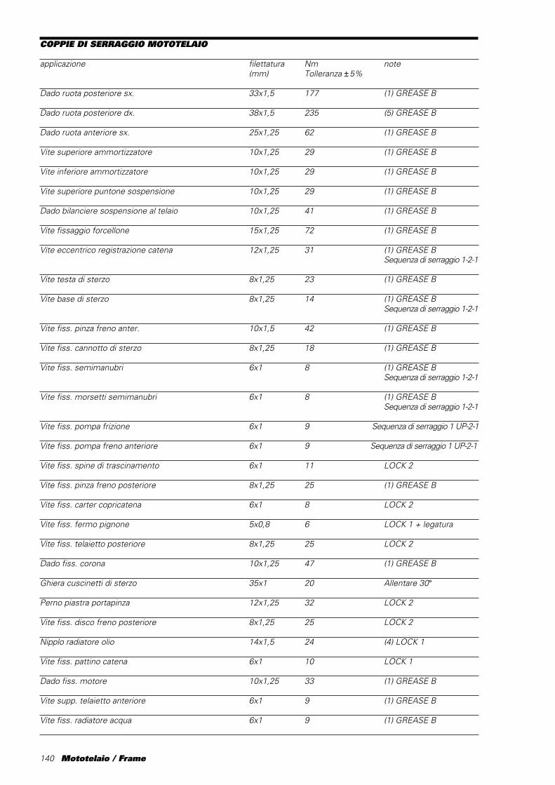
140 Mototelaio / Frame
COPPIE DI SERRAGGIO MOTOTELAIO
applicazione filettatura Nm note(mm) Tolleranza ±5%
Dado ruota posteriore sx. 33x1,5 177 (1) GREASE B
Dado ruota posteriore dx. 38x1,5 235 (5) GREASE B
Dado ruota anteriore sx. 25x1,25 62 (1) GREASE B
Vite superiore ammortizzatore 10x1,25 29 (1) GREASE B
Vite inferiore ammortizzatore 10x1,25 29 (1) GREASE B
Vite superiore puntone sospensione 10x1,25 29 (1) GREASE B
Dado bilanciere sospensione al telaio 10x1,25 41 (1) GREASE B
Vite fissaggio forcellone 15x1,25 72 (1) GREASE B
Vite eccentrico registrazione catena 12x1,25 31 (1) GREASE BSequenza di serraggio 1-2-1
Vite testa di sterzo 8x1,25 23 (1) GREASE B
Vite base di sterzo 8x1,25 14 (1) GREASE BSequenza di serraggio 1-2-1
Vite fiss. pinza freno anter. 10x1,5 42 (1) GREASE B
Vite fiss. cannotto di sterzo 8x1,25 18 (1) GREASE B
Vite fiss. semimanubri 6x1 8 (1) GREASE BSequenza di serraggio 1-2-1
Vite fiss. morsetti semimanubri 6x1 8 (1) GREASE BSequenza di serraggio 1-2-1
Vite fiss. pompa frizione 6x1 9 Sequenza di serraggio 1 UP-2-1
Vite fiss. pompa freno anteriore 6x1 9 Sequenza di serraggio 1 UP-2-1
Vite fiss. spine di trascinamento 6x1 11 LOCK 2
Vite fiss. pinza freno posteriore 8x1,25 25 (1) GREASE B
Vite fiss. carter copricatena 6x1 8 LOCK 2
Vite fiss. fermo pignone 5x0,8 6 LOCK 1 + legatura
Vite fiss. telaietto posteriore 8x1,25 25 LOCK 2
Dado fiss. corona 10x1,25 47 (1) GREASE B
Ghiera cuscinetti di sterzo 35x1 20 Allentare 30°
Perno piastra portapinza 12x1,25 32 LOCK 2
Vite fiss. disco freno posteriore 8x1,25 25 LOCK 2
Nipplo radiatore olio 14x1,5 24 (4) LOCK 1
Vite fiss. pattino catena 6x1 10 LOCK 1
Dado fiss. motore 10x1,25 33 (1) GREASE B
Vite supp. telaietto anteriore 6x1 9 (1) GREASE B
Vite fiss. radiatore acqua 6x1 9 (1) GREASE B
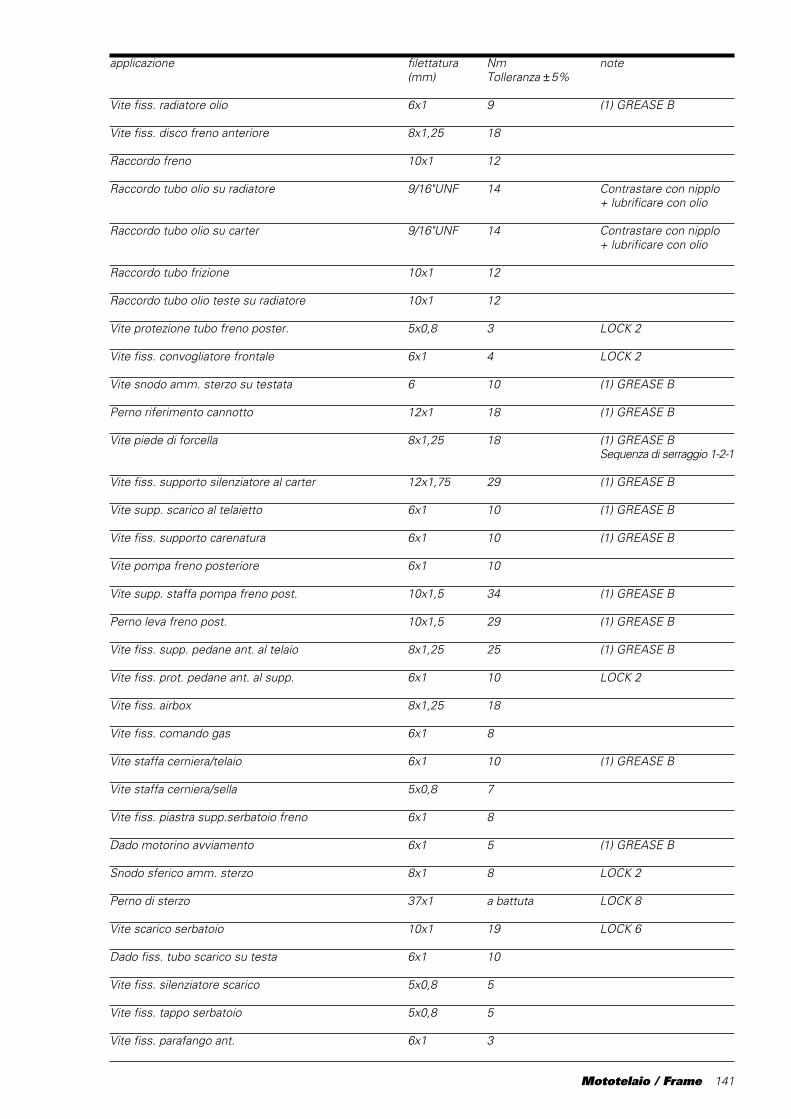
Mototelaio / Frame 141
applicazione filettatura Nm note(mm) Tolleranza ±5%
Vite fiss. radiatore olio 6x1 9 (1) GREASE B
Vite fiss. disco freno anteriore 8x1,25 18
Raccordo freno 10x1 12
Raccordo tubo olio su radiatore 9/16"UNF 14 Contrastare con nipplo+ lubrificare con olio
Raccordo tubo olio su carter 9/16"UNF 14 Contrastare con nipplo+ lubrificare con olio
Raccordo tubo frizione 10x1 12
Raccordo tubo olio teste su radiatore 10x1 12
Vite protezione tubo freno poster. 5x0,8 3 LOCK 2
Vite fiss. convogliatore frontale 6x1 4 LOCK 2
Vite snodo amm. sterzo su testata 6 10 (1) GREASE B
Perno riferimento cannotto 12x1 18 (1) GREASE B
Vite piede di forcella 8x1,25 18 (1) GREASE BSequenza di serraggio 1-2-1
Vite fiss. supporto silenziatore al carter 12x1,75 29 (1) GREASE B
Vite supp. scarico al telaietto 6x1 10 (1) GREASE B
Vite fiss. supporto carenatura 6x1 10 (1) GREASE B
Vite pompa freno posteriore 6x1 10
Vite supp. staffa pompa freno post. 10x1,5 34 (1) GREASE B
Perno leva freno post. 10x1,5 29 (1) GREASE B
Vite fiss. supp. pedane ant. al telaio 8x1,25 25 (1) GREASE B
Vite fiss. prot. pedane ant. al supp. 6x1 10 LOCK 2
Vite fiss. airbox 8x1,25 18
Vite fiss. comando gas 6x1 8
Vite staffa cerniera/telaio 6x1 10 (1) GREASE B
Vite staffa cerniera/sella 5x0,8 7
Vite fiss. piastra supp.serbatoio freno 6x1 8
Dado motorino avviamento 6x1 5 (1) GREASE B
Snodo sferico amm. sterzo 8x1 8 LOCK 2
Perno di sterzo 37x1 a battuta LOCK 8
Vite scarico serbatoio 10x1 19 LOCK 6
Dado fiss. tubo scarico su testa 6x1 10
Vite fiss. silenziatore scarico 5x0,8 5
Vite fiss. tappo serbatoio 5x0,8 5
Vite fiss. parafango ant. 6x1 3
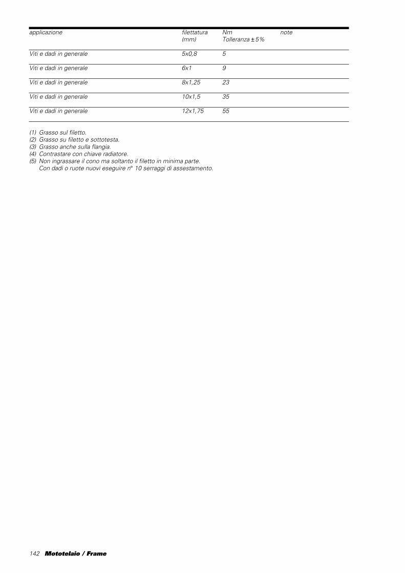
142 Mototelaio / Frame
applicazione filettatura Nm note(mm) Tolleranza ±5%
Viti e dadi in generale 5x0,8 5
Viti e dadi in generale 6x1 9
Viti e dadi in generale 8x1,25 23
Viti e dadi in generale 10x1,5 35
Viti e dadi in generale 12x1,75 55
(1) Grasso sul filetto.(2) Grasso su filetto e sottotesta.(3) Grasso anche sulla flangia.(4) Contrastare con chiave radiatore.(5) Non ingrassare il cono ma soltanto il filetto in minima parte.
Con dadi o ruote nuovi eseguire n° 10 serraggi di assestamento.

Mototelaio / Frame 143
TORQUE SETTINGS, FRAME
Part Thread Nm Notes(mm) ±5% Tolerance
LH rear wheel nut 33x1.5 177 (1) GREASE B
RH rear wheel nut 38x1.5 235 (5) GREASE B
LH front wheel nut 25x1.25 62 (1) GREASE B
Shock absorber top screw 10x1.25 29 (1) GREASE B
Shock absorber bottom screw 10x1.25 29 (1) GREASE B
Suspension top fixing screw 10x1.25 29 (1) GREASE B
Suspension linkage rocker screw to frame 10x1.25 41 (1) GREASE B
Swingarm screw 15x1.25 72 (1) GREASE B
Chain cam adjuster screw 12x1.25 31 (1) GREASE B Tightening sequence 1-2-1
Top yoke bolt 8x1.25 23 (1) GREASE B
Bottom yoke bolt 8x1.25 14 (1) GREASE B Tightening sequence 1-2-1
Front brake caliper screw 10x1.5 42 (1) GREASE B
Headstock fixing bolts 8x1.25 18 (1) GREASE B
Handlebar screw 6x1 8 (1) GREASE B Tightening sequence 1-2-1
Handlebar clamp screw 6x1 8 (1) GREASE B Tightening sequence 1-2-1
Clutch master cylinder screw 6x1 9 Tightening sequence 1UP-2-1
Front brake master cylinder screw 6x1 9 Tightening sequence 1UP-2-1
Driving pin screw 6x1 11 LOCK 2
Rear brake caliper screw 8x1,25 25 (1) GREASE B
Chain guard retaining screw 6x1 8 LOCK 2
Sprocket lock screw 5x0,8 6 LOCK 1
Rear subframe nut 8x1,25 25 LOCK 2
Sprocket retaining nut 10x1,25 47 (1) GREASE B
Headstock bearing ring nut 35x1 20 Loosen by 30°
Caliper holder plate pin 12x1.25 32 LOCK 2
Rear brake disc bolt 8x1.25 25 LOCK 2
Oil cooler nipple 14x1.5 24 (4) LOCK 1
Chain shoe screw 6x1 10 LOCK 1
Engine mounting bolt 10x1.25 33 (1) GREASE B
Front subframe screw 6x1 9 (1) GREASE B
Water radiator screw 6x1 9 (1) GREASE B
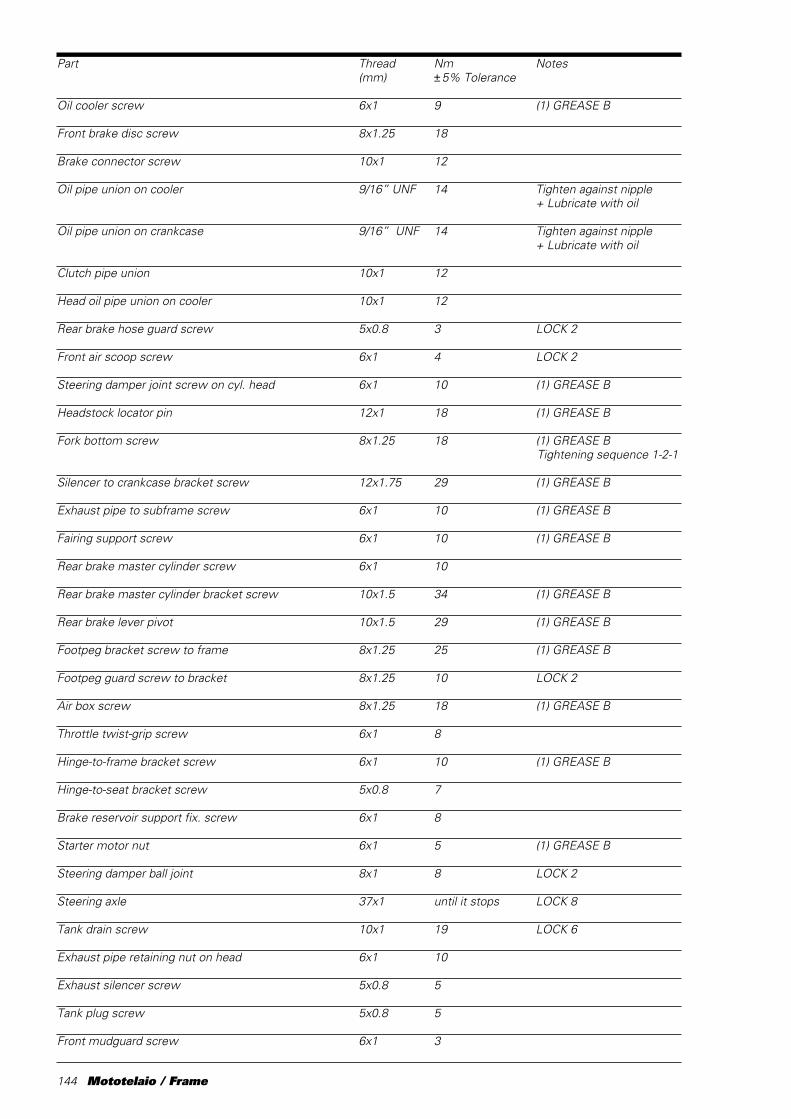
144 Mototelaio / Frame
Part Thread Nm Notes(mm) ±5% Tolerance
Oil cooler screw 6x1 9 (1) GREASE B
Front brake disc screw 8x1.25 18
Brake connector screw 10x1 12
Oil pipe union on cooler 9/16” UNF 14 Tighten against nipple+ Lubricate with oil
Oil pipe union on crankcase 9/16” UNF 14 Tighten against nipple+ Lubricate with oil
Clutch pipe union 10x1 12
Head oil pipe union on cooler 10x1 12
Rear brake hose guard screw 5x0.8 3 LOCK 2
Front air scoop screw 6x1 4 LOCK 2
Steering damper joint screw on cyl. head 6x1 10 (1) GREASE B
Headstock locator pin 12x1 18 (1) GREASE B
Fork bottom screw 8x1.25 18 (1) GREASE B Tightening sequence 1-2-1
Silencer to crankcase bracket screw 12x1.75 29 (1) GREASE B
Exhaust pipe to subframe screw 6x1 10 (1) GREASE B
Fairing support screw 6x1 10 (1) GREASE B
Rear brake master cylinder screw 6x1 10
Rear brake master cylinder bracket screw 10x1.5 34 (1) GREASE B
Rear brake lever pivot 10x1.5 29 (1) GREASE B
Footpeg bracket screw to frame 8x1.25 25 (1) GREASE B
Footpeg guard screw to bracket 8x1.25 10 LOCK 2
Air box screw 8x1.25 18 (1) GREASE B
Throttle twist-grip screw 6x1 8
Hinge-to-frame bracket screw 6x1 10 (1) GREASE B
Hinge-to-seat bracket screw 5x0.8 7
Brake reservoir support fix. screw 6x1 8
Starter motor nut 6x1 5 (1) GREASE B
Steering damper ball joint 8x1 8 LOCK 2
Steering axle 37x1 until it stops LOCK 8
Tank drain screw 10x1 19 LOCK 6
Exhaust pipe retaining nut on head 6x1 10
Exhaust silencer screw 5x0.8 5
Tank plug screw 5x0.8 5
Front mudguard screw 6x1 3

Mototelaio / Frame 145
Part Thread Nm Notes(mm) ±5% Tolerance
Nuts, bolts and screws in general 5x0.8 5
Nuts, bolts and screws in general 6x1 9
Nuts, bolts and screws in general 8x1.25 23
Nuts, bolts and screws in general 10x1.5 35
Nuts, bolts and screws in general 12x1.75 55
(1) Grease thread(2) Grease thread and head underside(3) Grease flange also(4) Tighten with spanner against cooler(5) Do not grease cone, but thread only.
With new nut or wheel, bed in with 10 tightenings
146 Mototelaio / Frame
INDIVIDUAZIONE GUASTIIMPIANTO ELETTRICO
1) La moto non parteRisposte:a) Controllare che la tensione batteriasia di almeno 12V.b) Avvicinando l’orecchio al serbatoiobenzina, controllare che, appenaportato l’interruttore generale sullaposizione ON, la pompa benzinafunzioni per qualche secondo.c) Controllare il livello benzina nelserbatoio.d) Controllare lo stato delle candeleed assicurarsi che sianoesclusivamente del modelloChampion QA55V (codice Ducati670.4.009.2A), in caso di dubbiosostituirle.e) Controllare la connessione delcablaggio corpo farfallato al cablaggioprincipale.f) Controllare tramite tester che sial’interuttore a mercurio chel’interuttore a manubrio sianonormalmente chiusi.g) Controllare che l’EPROM siainserita correttamente.
2) La moto “perde colpi”Risposte:a) Controllare lo stato delle candeleed assicurarsi che sianoesclusivamente del modello.Champion QA55V (codice Ducati670.4.009.2A), in caso di dubbiosostituirle.b) Controllare il livello benzina nelserbatoio.c) Controllare tutti gli organi delcircuito di alimentazione benzina.d) Verificare i contatti di massa delcablaggio.
TROUBLESHOOTING OFELECTRIC SYSTEM
1) The engine will not startSolutions:a) Check that battery voltage is atleast 12V.b) Place your ear near the fuel tankand listen for the fuel pump. As soonas the main switch is flipped ON,you should hear the fuel pumprunning for several seconds.c) Check fuel level in the tank.d) Inspect the spark plugs. Makesure they are Champion QA55V(Ducati part no. 670.4.009.2A). If indoubt, change the spark plugs.e) Check connection of throttlebody wiring to main wiring harness.f) Use the tester to check that themercury switch is normally closedand the kill switch on the handlebaris normally open.g) Check that EPROM is properlypositioned.
2) Engine “misfires”Solutions:a) Inspect the spark plugs. Be surethey are Champion QA55V (Ducatipart no. 670.4.009.2A). If in doubt,change the spark plugs.b) Check fuel level in the tank.c) Check all components of the fuelsystem.d) Check wiring earth connection.
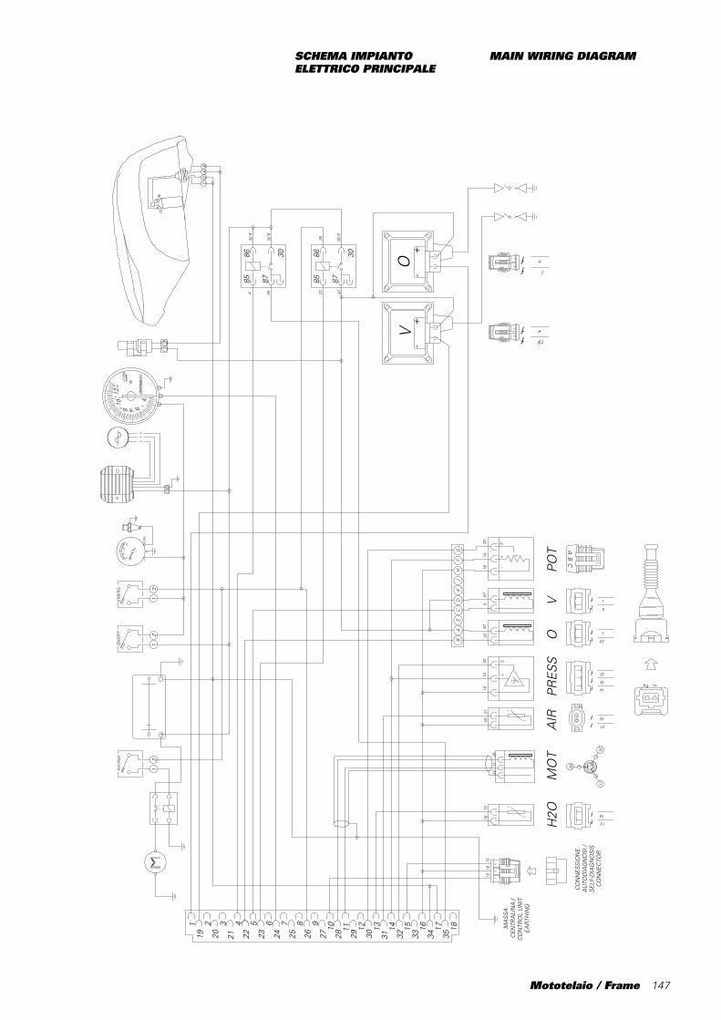
Mototelaio / Frame 147
SCHEMA IMPIANTOELETTRICO PRINCIPALE
MAIN WIRING DIAGRAM
119
220
321
422
523
624
725
826
927
1028
11 12 13 14
29 30 31 3215 16 17
33 34 3518
f
f
f
+-
fff
ff
ff
ff
+-
21O
N/O
FF
21EM
ER
G.
ff
12AMP
21A
VV
IAM
.
ff
12AMP
-S
12
AMP
3
13
16
14
16
32
22
+
5
+
OV
PO
TH
2OP
RE
SS
+
f
f
ff
16
31
1
+
19
+
S3014
1687
587
2232
1416
3116
2811
SC
1316
1516
10
872326
4 35
30 R
30 R
30 R
11
28
SC
YY
Y
+-
+-
f
f
f
f
f
f
5080
100
150
C
DA
VO
+-
CO
M
CB
468
1012
5
7
9
1113
x100
0E
LEC
TRO
NIC
AB
C
DE
CA
FJ
KH
GB
12
8586
87
30
8586
87
30
21
AB
MA
SS
AC
EN
TRA
LIN
A /
CO
NTR
OL
UN
IT
EA
RTH
ING
CO
NN
ES
SIO
NE
AU
TOD
IAG
NO
SI /
SE
LF-D
IAG
NO
SIS
CO
NN
EC
TOR
AB
C
A
BC
+-
AIR
1
MO
T

148 Mototelaio / Frame
DUCATICORSE srlVia A. Cavalieri Ducati, 340132 Bologna, ItalyTel. 39.051.6413111Fax 39.051.6413183Internet: www.ducati.com
914.7.027.1AStampato 05/2000