Embed Size (px)
Citation preview

Marmeladekessel - Bedienungsanleitung
mit Ölbefüllung, Gasbrenner und Rührarm
Pentolone ad olio - istruzioni d‘uso per marmellata con fornello a gas e agitatore
Jam cooking pot - instruction manual with charged, gas burner and electric mixer
Art. 26065, 26066, 14028, 30194,
26067, 26068, 26069

Diese Bedienungsanleitung ist ein wichtiger Bestandteil des Produkts und muss dem Benutzer/Betreiber zusammen mit dem Gerät ausgehändigt werden. Lesen Sie bitte die in diesem Handbuch enthaltenen Hinweise sorgfältig durch, da sich diese vor allem auf die Betriebssicherheit und die Durchführung wichtiger Wartungsarbeiten beziehen. Bewahren Sie bitte dieses Handbuch unbedingt für die gesamte Lebensdauer des Gerätes sorgfältig auf. Die Installation des Gerätes darf ausschließlich unter Beachtung der aktuell geltenden bzw. länderspezifischen Sicherheitsvorschriften, nach den Herstellervorgaben und nur von Fachpersonal vorgenommen werden. Vergewissern Sie sich bitte vor dem Anschließen des Gerätes, dass die örtlichen Anschlussmöglichkeiten einen sachgemäßen und sicheren Betrieb innerhalb der zulässigen Leistungswerte des Gerätes gewährleisten können. Dieses Gerät darf ausschließlich für den bestimmungsgemäßen Gebrauch eingesetzt werden. Jegliche Zweckentfremdung des Gerätes birgt akute Gefahren in sich und ist strengstens untersagt. Der Hersteller übernimmt keinerlei vertragsbezogene, sowie außervertragliche Haftung für Schäden, die durch unsachgemäße Installation, Handhabung oder Nichtbeachtung der hiesigen Sicherheitshinweise hervorgerufen werden. Diese Kochkessel sind ausschließlich zum (Ein)Kochen von Lebensmitteln bestimmt.
TECHNISCHE DATEN
Beschreibung Modell oder Art.-Nr. des Ofens
Zündsicherung und Pilotflamme FGC70040 FGC70060
Kochkessel mit Ölbefüllung – mit Gasbrenner
Typ FGC...
Nennleistung (in KW) 8,00 11,00
Verbrauch G30 kg/Std 0,582 0,800
Düse G30 28-30 m/bar 1,45 1,65
Verbrauch G31 kg/Std 0,572 0,786
Düse G31 37 m/bar 1,45 1,65
Verbrauch G20 mc/Std 0,762 1,048
Düse G20 20m/bar 2,40 2,70
Verbrauch G25 mc/Std 0,886 1,219
Düse G25 25 m/bar 2,40 2,70
Gasventil B3 1 1
HAUTABMESSUNGEN DES GASBRENNERS
Breite (in cm) 40 50
Tiefe (in cm) 40 50
Höhe (in cm) 90 90

Bei den Kochtöpfen der Baureihe CATERING handelt es sich um Geräte, die für den Betrieb mit der Gaskategorie II2H3+ vorgesehen sind. Diese müssen nach folgenden Normen installiert werden: UNI-CIG 7129/2001 Planung, Installation und Wartung von Gasanlagen für den Hausgebrauch – Gasanschluss über Erdgasversorgungsnetz (METHAN) UNI-CIG 7131/72 Planung, Installation und Wartung von Flüssiggasanlagen (LPG) für den Hausgebrauch, mit unabhängiger Versorgung (z.B. Gasflasche etc.) D.P.R. n°412 vom 26.08.1993. Planung, Installation, Betrieb und Wartung von thermischen Anlagen zur Energieeinsparung. Sicherheitsbestimmung 46 vom 05.03.1990: Normen für die Sicherheit von Gasanlagen. Sicherheitsbestimmung 186 vom 01.03.1968 Installationsnorm CEI 64-8/II und elektrische Stromkreise mit einer Nennspannung unter 1000V Wechselspannung bzw. 1500 Gleichspannung. Installationsnorm CEI64-8/I und elektrische Stromkreise in Wohngebäuden etc. INSTALLATION Alle Bestandteile der Verpackung dürfen nicht in die Hände von Kindern gelangen, da diese Bauteile eine potentielle Gefahr darstellen. Der Hersteller übernimmt keine Haftung für Personen-Tier oder Sachschäden, die auf die Nichtbeachtung der o. g. Hinweise zurückzuführen sind. BELÜFTUNG DER BETRIEBSRÄUME Der Kochkessel darf nur in einen für dessen Betrieb geeignetem Raum gemäß den geltenden Sicherheitsvorschriften installiert und benutzt werden. Die Anlage hat eine offene Brennkammer und muss an einem Abzugsschacht angeschlossen werden. Die Luft für die Verbrennung wird direkt der Umgebungsluft entzogen! Die Räumlichkeiten dürfen sowohl über eine direkte (d.h. mit Lüftungsgittern in den Raumwänden) als auch über indirekte Belüftung (d. h. die Lüftungsgitter befinden sind in den umliegenden Räumen) verfügen. Dabei müssen unbedingt sämtliche folgend aufgeführten Sicherheitshinweise beachtet werden: DIREKTE BELÜFTUNG Der Raum muss eine Belüftungsfläche von mind. 6 m² aufweisen. Die Belüftungsöffnung muss sich in der Außenwand und möglichst nah am Boden befinden. Die Öffnung darf nicht zugestellt/verstopft werden, sondern vielmehr mit ein Schutzgitter versehen sein, das den Luftdurchlass nicht beeinträchtigt. Eine angemessene Belüftung kann selbstverständlich auch gewährleistet werden, wenn die Gesamtfläche der einzelnen Belüftungsöffnungen der o.g. Gesamtfläche entspricht. Falls die Belüftungsöffnung nicht in Bodennähe ausgeführt werden kann, sollte die Fläche der Öffnung um mind. 50% erhöht werden. Falls im Betriebsraum keine Belüftungsöffnung bewerkstelligt werden kann, kann man auf eine indirekte Belüftung zurückgreifen, d.h. es muss z. B. im unteren Bereich der Verbindungstür zu einem benachbarten Raum eine entsprechende Öffnung ausgeführt werden. Allerdings muss der benachbarte Raum selbst über eine entsprechende Belüftungsöffnung verfügen. Dieser Raum darf keinesfalls als Schlafraum genutzt werden und darf kein Raum sein, in dem potentielle Brandgefahr besteht. (z.B. ein Treibstofflager, eine Garage etc.).

AUFSTELLUNG DES KOCHKESSELS Der mit Gas beheizte Kochkessel darf nur unter Einhaltung der geltenden Sicherheitsvorschriften installiert werden. Der Betriebsraum muss ausreichend belüftet sein. Bei der Installation des Kochkessels sollten folgende Regeln beachtet werden: Installationshinweise im Kapitel „ Rauchabzug“ berücksichtigen. Es muss ein Mindestabstand von 600mm um den Kochkessel herum freigelassen werden, um anfallende Wartungsarbeiten am Gerät zu ermöglichen. Der Kochkessel sollte nicht in staubigen und korrosionsempfindlichen Räumen aufgestellt werden. Der mit Gas beheizte Kochkessel muss direkt aus dem Boden (KEIN HOLZBODEN!) aufgestellt werden, da dieser eigene Aufstellfüße aufweist. Falls der Fußboden besonders feucht ist, sollte ein Betonsockel eingerichtet werden. GASANSCHLUSS Die Gas-Versorgungsleitung muss eine ausreichende Querschnittsfläche haben, um den Gasdurchsatz zu gewährleisten und darf niemals kleiner als die Querschnittsfläche des Geräteanschlusses sein. Hierbei sollte man die in den Richtlinien UNI-CIG 7129-7131 allgemeinen Installationsnormen“ beachtet werden. Vor der Inbetriebnahme des Gerätes bzw. bevor das Gerät an den Gaszähler angeschlossen wird, muss zwingend eine Dichtigkeitsprüfung durchgeführt werden! Abgedeckte/geschützte Leitungsabschnitte müssen VOR der Anbringung der Schutz/Verkleidungsbleche erfolgen! Vor dem Anschluss des Gerätes, muss die gesamte Anlage mit Luft bzw. mit einem reaktionsträgen Gas mit einem Druck von 100 mbar geprüft werden. Die Inbetriebnahme der Anlage beinhaltet folgende Schritte und Prüfungen: - Öffnen des Gashahns am Gaszähler und Entlüftung der Gasleitungen. - Kontrolle der angeschlossen Geräte auf Dichtigkeit. Nach einem 15-minutigen -Betrieb darf der Manometer keinen Druckabfall anzeigen. Eventuell festgestellte Leckstellen müssen UMGEHEND mit entsprechenden Hilfsmitteln ausfindig gemacht und abgedichtet werden. RAUCHABZUG/ABZUGSROHR Anschluss am Abzugsschacht/Abzugsrohr. Der Abzugsschacht/Schornstein hat eine grundlegende Bedeutung für eine korrekte und sichere Funktion des Kochkessels. Das Abzugsrohr muss aus rauchfestem und gasdichtem Material bestehen. Dieser muss außerdem eine möglichst geringe Wärmeleitfähigkeit und eine hohe mechanische Festigkeit haben. Das Rohr muss 100% gasdicht sein um einer unerwünschten Abkühlung entgegenzuwirken. Das Abzugsrohr muss einen möglichst vertikalen Verlauf aufweisen, wobei das Endstück über eine statische Absaugvorrichtung verfügen sollte, damit die Verbrennungsrückstände permanent und restlos ausgestoßen werden können. Um zu vermeiden, dass der Wind den austretenden Rauch in das Abzugrohr zurückdrücken könnte, muss das offene Ende des Rohres mind. 0,4 Meter über der Wand/dem Dach aus dem der Schornstein befestigt ist hinausragen. Eventuell angrenzende Bauten müssen mind. 8 Meter vom Schornstein entfernt liegen. Das Abzugsrohr muss einen Durchmesser aufweisen, der mindestens so gross ist, wie der Durchmesser der Windhaube. Falls es sich um ein Abzugsrohr mit eckigem Querschnitt handelt, muss die Querschnittsfläche um mind. 10% in Verhältnis zum Anschluss-Querschnitt der Windhaube. Ab der Windschutzhaube, muss der Anschlussstutzen einen geraden vertikalen Abschnitt aufweisen, der eine Mindestlänge vom 2-fachen Durchmesser hat.
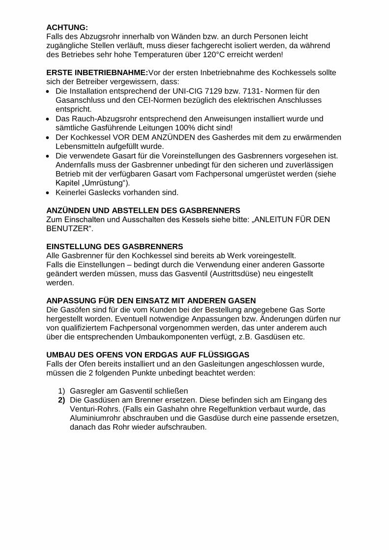
ACHTUNG: Falls des Abzugsrohr innerhalb von Wänden bzw. an durch Personen leicht zugängliche Stellen verläuft, muss dieser fachgerecht isoliert werden, da während des Betriebes sehr hohe Temperaturen über 120°C erreicht werden! ERSTE INBETRIEBNAHME:Vor der ersten Inbetriebnahme des Kochkessels sollte sich der Betreiber vergewissern, dass:
• Die Installation entsprechend der UNI-CIG 7129 bzw. 7131- Normen für den Gasanschluss und den CEI-Normen bezüglich des elektrischen Anschlusses entspricht.
• Das Rauch-Abzugsrohr entsprechend den Anweisungen installiert wurde und sämtliche Gasführende Leitungen 100% dicht sind!
• Der Kochkessel VOR DEM ANZÜNDEN des Gasherdes mit dem zu erwärmenden Lebensmitteln aufgefüllt wurde.
• Die verwendete Gasart für die Voreinstellungen des Gasbrenners vorgesehen ist. Andernfalls muss der Gasbrenner unbedingt für den sicheren und zuverlässigen Betrieb mit der verfügbaren Gasart vom Fachpersonal umgerüstet werden (siehe Kapitel „Umrüstung“).
• Keinerlei Gaslecks vorhanden sind. ANZÜNDEN UND ABSTELLEN DES GASBRENNERS Zum Einschalten und Ausschalten des Kessels siehe bitte: „ANLEITUN FÜR DEN BENUTZER“. EINSTELLUNG DES GASBRENNERS Alle Gasbrenner für den Kochkessel sind bereits ab Werk voreingestellt. Falls die Einstellungen – bedingt durch die Verwendung einer anderen Gassorte geändert werden müssen, muss das Gasventil (Austrittsdüse) neu eingestellt werden. ANPASSUNG FÜR DEN EINSATZ MIT ANDEREN GASEN Die Gasöfen sind für die vom Kunden bei der Bestellung angegebene Gas Sorte hergestellt worden. Eventuell notwendige Anpassungen bzw. Änderungen dürfen nur von qualifiziertem Fachpersonal vorgenommen werden, das unter anderem auch über die entsprechenden Umbaukomponenten verfügt, z.B. Gasdüsen etc. UMBAU DES OFENS VON ERDGAS AUF FLÜSSIGGAS Falls der Ofen bereits installiert und an den Gasleitungen angeschlossen wurde, müssen die 2 folgenden Punkte unbedingt beachtet werden:
1) Gasregler am Gasventil schließen 2) Die Gasdüsen am Brenner ersetzen. Diese befinden sich am Eingang des
Venturi-Rohrs. (Falls ein Gashahn ohre Regelfunktion verbaut wurde, das Aluminiumrohr abschrauben und die Gasdüse durch eine passende ersetzen, danach das Rohr wieder aufschrauben.

VOREINSTELLUNGEN UND EINSTELLUNGEN
Alle notwendigen Einstellungen müssen entsprechend dem Gerätetyp erfolgen.
ANZÜNDEN DER PILOTFLAMME Den Druckknopf (Nr. 1) drücken und gleichzeitig den Piezoknopf (Nr. 2) betätigen und einige Sekunden lang gedrückt halten (siehe Bild 1). Den Knopf wieder loslassen und sicherstellen, dass die Pilotflamme an bleibt. Falls diese erloschen sollte, den Vorgang wiederholen. ANZÜNDEN DES HAUPTBRENNERS Den gelben Gashebel (Bild 2) betätigen und diese entsprechend der gewünschten Flammenstärke einstellen. STANDBY EINSTELLUNG Damit der Brenner ausgeschaltet bleibt und nur die Pilotflamme brennt, den gelben Gashebel in Position „zu“ bringen. ABSTELLEN DES BRENNERS Zum endgültigen Abstellen des Brenners den Haupthahn ganz zudrehen. KOCHKESSEL MIT DIATHERMISCHEM ÖL: Diese Kochkessel bestehen aus Edelstahl und sind doppelwandig ausgeführt. Der Zwischenraum ist mit diathermischem Öl VOM Typ Mobilterm 605 befüllt. Diese konstruktive Maßnahme ermöglicht ein Kochen/Garen von Lebensmitteln jeder Art, vom Fleisch über Konserven, Marmelade, Käse etc. Das diathermische Öl, welches ab Werk vom Hersteller selbst aufgefüllt wurde, könnte – während der Standzeit - Feuchtigkeit aufgenommen haben, die während des Betriebes lästige Geräusche im Kessel selbst verursachen könnte.
Bild 5
Daher ist es von bedeutender Wichtigkeit, nach der ersten Inbetriebnahme, den Entlüftungsstopfen A (Bild 5) zu entfernen, während der Brenner eingeschaltet wird und die Lebensmittel, die aufgekocht werden sollen zum Kochen gebracht werden.
A
Druckknopf n°1
Piezoknopf n°2

Falls während des Vorganges Öl aus dem Einfüll /Entlüftungsöffnung austreten sollte, wurde vom Hersteller zuviel Öl eingefüllt. Das übersüssige Öl tritt dann beim Kochen aus der Einfüllöffnung wieder aus. Den Stopfen bei noch heissem Kessel dann wieder aufschrauben. Somit kann der Kessel jahrelang ohne Nachfüllen von Öl betrieben werden. Im Ausnahmefall eines Öllecks darf der Hohlraum nur mit Öl der Sorte Mobiltherm 605 befüllt werden, wobei der Hohlraum nicht bis zur Oberkannte aufgefüllt erden muss, sondern bis etwa 25-30 cm unterhalb der Oberkante. WARTUNG: Einmal jährlich müssen folgende Überprüfungen durchgeführt werden:
- Kontrolle und Reinigung des Hauptbrenners - Kontrolle des Gasventils - Kontrolle des Thermostats - Kontrolle des Sicherheitsventils - Bei auftretenden Funktionsstörungen, Manipulationen etc. sofort einen
qualifizierten Servicemitarbeiter verständigen.
RÜHRARM: Dieser sorgt dafür, dass während des Kochvorgangs der Inhalt des Kessels gut durchmischt wird und fördert eine bessere Verdampfung. Ein-Phasen Elektromotor: 0,180 Kw Betriebsspannung: 230 Volt Getriebeuntersetzung: 14 Der Elektromotor muss unbedingt mit einem Erdanschluss verkabelt werden und mit einem NOT-AUS-Schalter nachgerüstet werden.

IMPORTANTE Libretto d’istruzioni costituisce parte integrale ed essenziale del prodotto e dovrà essere consegnato all’utilizzatore. Leggere attentamente le avvertenze contenute nel libretto in quanto forniscono importanti indicazioni riguardanti la sicurezza d’uso e manutenzione. Conservare il libretto per ogni ulteriore consultazione. L’installazione deve essere effettuata in ottemperanza alle norme vigenti, secondo le istruzioni del costruttore e da personale professionalmente qualificato. Per personale professionale qualificato si intende quello avente competenza tecnica nella installazione di impianti termici e sanitari. Prima di collegare l’apparecchio accertarsi che i dati forniti dal costruttore consentano un corretto impiego dello stesso entro i limiti di minimo e massimo di potenza consentito. Questo apparecchio dovrà essere destinato all’uso per il quale è stato espressamente previsto. Ogni altro uso è da considerarsi improprio e quindi pericoloso. E’ esclusa qualsiasi responsabilità contrattuale ed extracontrattuale del Costruttore per i danni causati da errori di installazione e nell’uso e comunque da inosservanza c delle istruzioni date. Questi paioli sono destinati alla cottura di prodotti . DATI TECNICI
Descrizione MODELLO O CODICE BRUCIATORE
Sicurezza e Pilota
FGC70040
FGC70060
Paiolo ad olio con bruciatore a gas FGC…
Portata nominale Kw 8,00 11,00
Consumo G30 kg/h 0,582 0,800
Ugello G30 28-30 m/bar
1,45 1,65
Consumo G31 kg/h 0,572 0,786
Ugello G31 37 m/bar 1,45 1,65
Ugello G31 50 m/bar 1,25 1,35
Consumo G20 mc/h 0,762 1,048
Ugello G20 20 m/bar 2,40 2,70
Consumo G25 mc/h 0,886 1,219
Ugello G25 25 m/bar 2,40 2,70
Valvola gas B3 1 1
DIMENSIONI BRUCIATORE A GAS
Larghezza cm. 400 500
Profondità cm. 400 500
Altezza cm. 90 90

ISTRUZIONI PER L’INSTALLATORE (apparecchi previsti per il mercato Italiano) I paiolo serie CATERING sono apparecchi previsti per la categoria gas II2H3+ e debbono essere installati secondo quanto indicato dalle norme di seguito riportate. Norma UNI-CIG 7129/2001 Progettazione ,installazione e manutenzione di impianti a gas per uso domestico alimentati da rete di distribuzione (METANO) Norma UNI-CIG 7131/72 Progettazione, installazione e manutenzione di impianti a gas di petrolio liquefatto(GPL) per uso domestico non alimentati da rete di distribuzione. D.P.R.n°412 del 26.08.1993 Progettazione installazione, esercizio e manutenzione degli impianti termici al fine del contenimento dei consumi di energia. Legge 46 del 05.03.1990 Norme per la sicurezza degli impianti. Legge 186 del 01.03.1968 Norma di installazione CEI 64-8/II ed impianti elettrici utilizzatori a tensione nominale non superiore a 1000V in corrente alternata e a 1500V in correte continua. Norma di installazione CEI64-8/I ed. impianti elettrici utilizzatori negli edifici a destinazione residenziale e similari.
INSTALLAZIONE
Tutte le parti componenti l’imballo non debbono essere lasciati alla portata dei bambini in quanto potenziali fonti di pericolo. Il Costruttore declina ogni responsabilità procurati a persone animali o cose derivante dalla inosservanza di quanto sopra esposto
VENTILAZIONE DEI LOCALI
Il paiolo a gas deve essere installato in locale adeguato conformemente alle norme in vigore. Essa è a camera di combustione aperta e prevista per essere allacciato alla canna fumaria; l’aria comburente è prelevata direttamente dall’ambiente nel quale il paiolo a gas è installato . I Locali potranno usufruire sia di una ventilazione di tipo diretto (cioè con prese d’aria direttamente sull’esterno) sia di ventilazione indiretta(cioè con prese d’aria sui locali attigui) purché vengano rispettate tutte le condizioni di seguito indicate: AERAZIONE DIRETTA Il locale deve avere un’apertura di aerazione pari a 6 cmq. Per ogni KW installato e comunque mai inferiore a 100 cmq,praticamente sul muro verso l’esterno. L’apertura deve essere più vicina al pavimento. Non deve essere ostruita, ma protetta da una griglia che non ne ostruisca il passaggio dell’aria. Una aerazione corretta può essere ottenuta anche attraverso anche attraverso la somma delle varie sezioni corrisponda a quella necessaria Nel caso non sia possibile praticare l’apertura vicino al pavimento,è necessario aumentare la sezione della stessa almeno del 50%. Nel caso non sia possibile effettuare l’aerazione direttamente nel locale, si può ricorrere alla ventilazione indiretta,prelevando l’aria di un locale attiguo attraverso una adeguata apertura praticata nella parte bassa della porta, Tale soluzione è però possibile solo se: Il locale attiguo è dotato di ventilazione diretta adeguata (vedi sezione”Aerazione diretta”) Il locale attiguo non è adibito a camera da letto. Il locale attiguo non è una parte comune dell’immobile e non è un ambiente con pericolo d’incendio(ad esempio un deposito di combustibile,un garage,ecc.)

POSIZIONAMENTO DEL PAIOLO Il paiolo a gas deve essere installatori nel rispetto delle norme e delle prescrizioni vigenti. Il locale dovrà risultare ben aerato. Nel determinare la posizione del paiolo a gas ricordarsi di: Tenere conto delle indicazioni contenute nel paragrafo “Sistema scarico fumi”. Lasciare una distanza di 600mm su ciascun lato dell’apparecchio per facilitare eventuali operazioni di manutenzione. Evitare altresì l’installazione in locali con atmosfera corrosiva e molto polverosa . Il paiolo a gas deve essere appoggiato direttamente sul pavimento (non in legno) perché dotato dei propri piedi. E’ consigliabile uno zoccolo in cemento in quei casi di pavimenti molto umidi. ALLACCIAMENTO GAS La tubazione di alimentazione deve avere una sezione idonea a garantire la portata sufficiente di gas e mai inferiore alla sezione dell’utilizzatore. E’comunque opportuno attenersi alle “Norme generali di installazione esposte nella normativa UNI-CIG 7129-7131. Prima di mettere in servizio un impianto di distribuzione interna di gas e quindi prima di allacciamento al contattore ,si deve verificare accuratamente la tenuta . Se qualche parte dell’allacciamento non è in vista ,la prova di tenuta deve precedere la copertura della tubazione. Prima di allacciare le apparecchiature,l’impianto deve essere provato con aria o gas inerte ad una pressione di 100mbar. La messa in servizio dell’impianto comprende le seguenti operazioni e controlli. Apertura del rubinetto del contattore e spurgo dell’aria contenuta nelle tubazioni. Controllo, con gli apparecchi in chiusura che non vi siano fughe di gas. Durante il 2° quarto d’ora dall’inizio della prova il manometro non dovrà accusare nessuna caduta di pressione. Eventuali fughe devono essere ricercate con soluzioni saponosa o prodotto equivalente ed eliminate. SISTEMA DI SCARICO DEI FUMI Allacciamento alla canna fumaria. La canna fumaria ha una importanza fondamentale per il buon funzionamento dell’installazione del paiolo a gas. E quindi deve rispondere ai seguenti requisiti. Deve essere di materiale impermeabile e resistente alla temperatura dei fumi e relative condensazioni. Deve essere di sufficiente resistenza meccanica e di debole conduttività termica. Deve essere a perfettamente a tenuta per evitare raffreddamento della canna fumaria stessa. Deve avere un andamento il più possibile verticale mentre la parte terminale deve avere un aspiratore statico che assicuri costantemente la evacuazione dei prodotti della combustione. Allo scopo di evitare che il vento possa creare intorno al comignolo delle zone di pressione tali da prevalere sulla forza ascensionali dei gas combusti è necessario che l’orifizio di scarico sovrasti di almeno 0,40 m. Qualsiasi struttura adiacente al camino stesso (compreso il colmo del tetto dell’edificio) distante almeno 8 m. La canna fumaria deve avere un diametro mai inferiore a quello della cappa antivento; per canne fumarie con sezione quadrata o rettangolare la sezione interna deve essere maggiorata del 10% rispetto a quella di attacco della cappa antivento. A partire dalla cappa antivento , il raccordo deve avere un tratto verticale di lunghezza non inferiore a 2 volte il diametro, prima di imboccarsi nella canna fumaria.
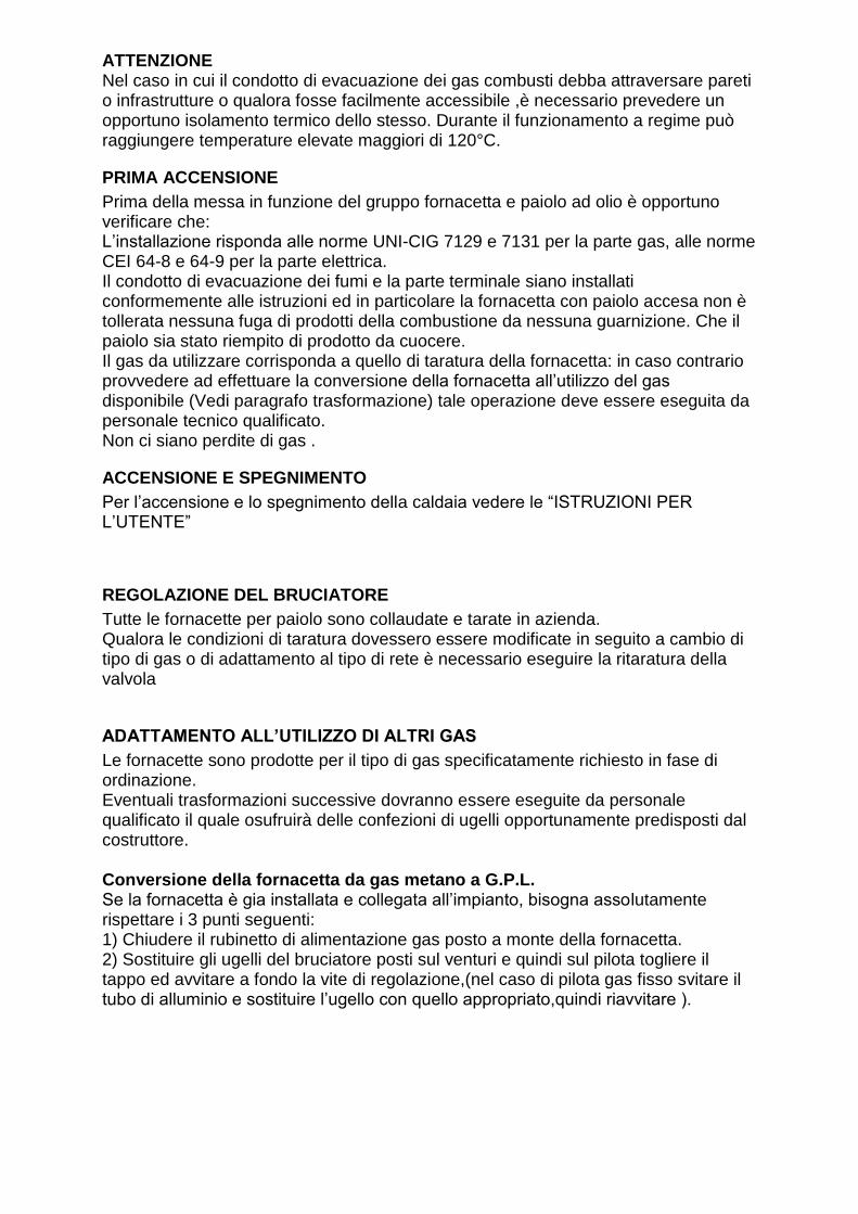
ATTENZIONE Nel caso in cui il condotto di evacuazione dei gas combusti debba attraversare pareti o infrastrutture o qualora fosse facilmente accessibile ,è necessario prevedere un opportuno isolamento termico dello stesso. Durante il funzionamento a regime può raggiungere temperature elevate maggiori di 120°C.
PRIMA ACCENSIONE
Prima della messa in funzione del gruppo fornacetta e paiolo ad olio è opportuno verificare che: L’installazione risponda alle norme UNI-CIG 7129 e 7131 per la parte gas, alle norme CEI 64-8 e 64-9 per la parte elettrica. Il condotto di evacuazione dei fumi e la parte terminale siano installati conformemente alle istruzioni ed in particolare la fornacetta con paiolo accesa non è tollerata nessuna fuga di prodotti della combustione da nessuna guarnizione. Che il paiolo sia stato riempito di prodotto da cuocere. Il gas da utilizzare corrisponda a quello di taratura della fornacetta: in caso contrario provvedere ad effettuare la conversione della fornacetta all’utilizzo del gas disponibile (Vedi paragrafo trasformazione) tale operazione deve essere eseguita da personale tecnico qualificato. Non ci siano perdite di gas .
ACCENSIONE E SPEGNIMENTO
Per l’accensione e lo spegnimento della caldaia vedere le “ISTRUZIONI PER L’UTENTE”
REGOLAZIONE DEL BRUCIATORE
Tutte le fornacette per paiolo sono collaudate e tarate in azienda. Qualora le condizioni di taratura dovessero essere modificate in seguito a cambio di tipo di gas o di adattamento al tipo di rete è necessario eseguire la ritaratura della valvola
ADATTAMENTO ALL’UTILIZZO DI ALTRI GAS
Le fornacette sono prodotte per il tipo di gas specificatamente richiesto in fase di ordinazione. Eventuali trasformazioni successive dovranno essere eseguite da personale qualificato il quale osufruirà delle confezioni di ugelli opportunamente predisposti dal costruttore. Conversione della fornacetta da gas metano a G.P.L. Se la fornacetta è gia installata e collegata all’impianto, bisogna assolutamente rispettare i 3 punti seguenti: 1) Chiudere il rubinetto di alimentazione gas posto a monte della fornacetta. 2) Sostituire gli ugelli del bruciatore posti sul venturi e quindi sul pilota togliere il tappo ed avvitare a fondo la vite di regolazione,(nel caso di pilota gas fisso svitare il tubo di alluminio e sostituire l’ugello con quello appropriato,quindi riavvitare ).

TARATURE E REGOLAZIONI Tutte le regolazioni vanno fatte in base alle specifiche caratteristiche dell’apparecchio di utilizzazione.
FIG. 2
FUNZIONAMENTO Accensione della fiamma pilota Premere il pulsante n°1 e contemporaneamente il piezoelettrico n°2 mantenendo il pulsante premuto a fondo per alcuni secondi (fig. 1).Rilasciare il pulsante e verificare che la fiamma pilota rimanga accesa (Fig. 2). In caso di spegnimento, ripetere le operazioni di accensione. Accensione del bruciatore principale Aprire la leva giallo Fig. 2 e regolarla nella posizione desiderata di fiamma. Posizione di Stand by Per mantenere spento il bruciatore principale e la fiamma pilota accesa, ruotare la leva gialla di comando in posizione Chiusa Spegnimento Per lo spegnimento totale del bruciatore chiudere completamente il rubinetto generale.
Pulsante n°1
Pulsante piezzo n°2

PAIOLO AD OLIO DIETERMICO Costruiti in acciaio a doppia intercapedine contengono olio diatermico Mobilterm 605 il quale permette una cottura senza strinatura di prodotti alimentari di qualsiasi tipo, dalla carne, alle conserve, alle marmellate, ai formaggi ecc. L’olio diatermico durante il riempimento da parte del costruttore potrebbe avere assorbito umidità, la quale durante il funzionamento potrebbe causare fastidiose rumorosità nel paiolo.
fig .5
Quindi durante la prima accensione e importante togliere il tappo di sfiato A Fig. 5 e accendere il bruciatore in modo portare ad ebollizione il prodotto da cuocere,(se durante la prima accensione a tappo aperto, si verificasse una fuori uscita di olio diatermico durante il funzionamento questo è dovuto ad una carica eccessiva di olio da parte del costruttore) quindi rimettere il tappo di sfiato con olio del paiolo ancora bollente. A questo punto il paiolo ad olio può funzionare per anni senza effettuare nessun rabbocco o sostituzione dell’olio. Nel caso eccezionale di una perdita d’olio è indispensabile rabboccare con olio Mobilterm 605 tenendo presente Di non riempire completamente il serbatoio ma di lasciare uno spazio di 25-30 cm per le dilatazioni dell’olio. MANUTENZIONE: Una volta all’anno effettuare le seguenti verifiche: - Controllo e pulizia del bruciatore principale - Controllo della valvola gas - Controllo funzionamento termostato - Controllo della valvola di sicurezza - In caso di guasto o cattivo funzionamento dell’apparecchio astenersi da qualsiasi tentativo di riparazione,manomissione o intervento diretto; rivolgersi a personale professionalmente qualificato. AGITATORE: Ha la funzione di mantenere il prodotto movimentato per una migliore cottura ed evaporazione . Motore monofase kw. 0,180 Tensione volt. 230 Riduttore giri/min n° 14 E’ indispensabile collegare il motore ad una presa di terra,e munirlo di un interruttore rapido di emergenza
A

IMPORTANT: These operating instructions are an important component of the product and must be handed over, together with the device, to the user/operator Please read carefully through the advices because they refer to the operational safety and the execution of important maintenance work. Please keep this manual carefully for the complete life time of the device. The installation of the device may be carried out exclusively considering the currently prevailing or country-specific safety regulations, following the manufacturer information and only of specialist staff. Before attaching the device, please make sure that the local connectivities can ensure a proper and safe business within the permitted performance values of the device. This device may be used exclusively for the intended use. Any misuse of the device entails a risk and it’s strictly forbidden. The manufacturer assumes no contract related and no contractual liability for damage caused by improper installation, handling or noncompliance of the local safety instructions. These pots are only for cooking of food.
TECHNICAL FEATURES
description Model or Art.Nr. of the oven
Igniter and pilot light FGC70040 FGC70060
Pot with oil charge – with gas burner
Model FGC...
Rated power (in KW) 8,00 11,00
Consumption G30 kg/h 0,582 0,800
nozzle G30 28-30 m/bar 1,45 1,65
Consumption G31 kg/h 0,572 0,786
nozzle G31 37 m/bar 1,45 1,65
Consumption G20 mc/h 0,762 1,048
nozzle G20 20m/bar 2,40 2,70
Consumption G25 mc/h 0,886 1,219
nozzle G25 25 m/bar 2,40 2,70
gas valve B3 1 1
MEASUREMENTS OF THE GAS BURNER
width (in cm) 400 500
depth (in cm) 400 500
height (in cm) 90 90

The pots of the series CATERING are intended for the use with the gas category II2H3 +. These must be installed according to the following standards: UNI-CIG 7129 \/ 2001. Planning, installation and maintenance of gas equipment for domestic use – gas connection over natural gas supply network (methane), UNI-CIG 7131 \/ 72 planning, installation and maintenance of liquefied petroleum gas systems (LPG) for domestic use, with independent power supply (E. g. gas cylinder, etc. ) D. P. R n ° 412 of the 26.08.1993. Planning, installation, operation and maintenance of thermal energy conservation. Safety regulation 46 of the 05.03. 1990: Standards for the safety of gas Installation. Safety regulation 186 of the 01.03. 1968 installation standard CEI 64-8\/II and electric circuits with a nominal voltage below 1000V AC or 1500 DC Installation norm CEI64-8\/I and electric circuits in residential buildings etc. INSTALLATION All the packaging components must not get into the hands of children, because these components represent a potential danger. The manufacturer accepts no liability for damage to people, animal or property, caused by non-observance of the mentioned rules. VENTILATION OF THE ROOMS The pot must be installed and used only in a suitable room. The system has an open combustion chamber and must be connected to a flue. The air for combustion is directly extracted from the ambient air! The premises should have a direct ventilation (it means the ventilation grilles are in the interior walls) or an indirect ventilation (it means ventilation grilles are located in the surrounding rooms). All following safety instructions must be observed: DIRECT VENTILATION The room must have a ventilation area of at least 6 m². The ventilation opening must be located in the outer wall and as close as possible to the ground. The opening must not be closed/blocked, but it must be fitted with a mesh which do not interfere the air flow. Proper ventilation can also be ensured if the total of the individual vents is equivalent to the total above. If the ventilation opening cannot be performed at ground level, the surface of the opening should increase to at least 50% . If no ventilation opening can be done in the room, you can fall back on an indirect ventilation, this means it must run an appropriate opening for example at the bottom of the connecting door to an adjoining room. However, the adjacent room must have a ventilation hole. This room should never be used as a bedroom and must be no room with fire risk (E. g. a fuel storage, garage etc. ). ERECTION OF THE POT The pot heated with gas may be installed only in compliance with the current safety regulations. The room must be ventilated sufficiently. During the installation of the pot following rules should be observed: Take into account the installation instructions in the chapter "Flue". The pot must be placed directly off the ground (no wooden flooring!), because it has its own feet. If the floor is very damp, a concrete plinth should be set up.

GAS CONNECTION The gas supply line must have a sufficient cross sectional area to ensure the gas delivery and cannot be never smaller than the cross sectional area of the device connection. Here you have to obtain the regulations UNI-CIG 7129-7131. Beforehand the using of the product or before the appliance to the gas meter, a leak test must be carried! Covered\/protected pipe sections must be made BEFORE of installing the protection\/panels! Before connecting the device, the entire system must be checked with air or an inert gas at a pressure of 100 mbar! The operation includes following steps and tests: - Open the gas tap on the gas meter and venting the gas pipe. - Control the connected devices for tightness. After a 15-minute running the manometer should not indicate pressure drop. Any detected leaks must be located and sealed IMMEDIATELY with appropriate tools. FLUE Connecting to the flue. The flue/chimney has a fundamental importance for a correct and safe function of the pot.. The flue pipe must be made of smoke and gastight material. It must also have a low caloric conductivity and a high mechanical strength. The pipe must be 100% gastight to prevent an unwanted cooling. The flue pipe must show a vertical gradient, where the heel should have a static suction, so that the combustion residues can turn out permanently and completely. To avoid that the wind could push back the escaping smoke in the flue, the open end of the pipe at least must extend 0. 4 meters above the wall/roof where the chimney is attached. Any adjacent buildings have to be away at least 8 meters from the chimney. The flue pipe must have a diameter that is at least as large as the diameter of the covering. If there is an exhaust duct with a rectangular cross-section, the cross-section area must stay at least 10% in relation to the connection section of the covering. From the windscreen, the connector must have a straight vertical section, which has a minimum length of twice its diameter. ATTENTION: If the flue pipe runs within walls or in places easily accessible by persons, it must be insulated expertly, because during the operation it reach very high temperatures over 120°C! FIRST OPENING: Before the first use of the pot the operator should ensure that:
• The installation according to the standards for the gas connection and the CEI-standards, relating to the connection UNI-CIG 7129 or. 7131.
• That all the pipes with contains gas are tight.
• The pot was fill up with food, before the light up of the gas cooker..
• The used type of gas is envisaged for the gas burner. Otherwise the gas burner must necessarily be converted for safe and reliable operation with the available type of gas by skilled personnel (See chapter “Conversion”)
• Any gas leak is available.

LIGHTING UP AND SWITCH OFF THE GAS BURNER For the switch on and the switch off see: “INSTRUCTIONS FOR THE USER“. SETTING OF THE GAS BURNER All gas burners are defaulted ex works. If the settings - due must be modified through the use of a different type of gas, the gas valve (nozzle) must be adjust. ADAPTION FOR USE WITH OTHER GASES The gas ovens have been made for a specified gas type which the customers give up at the order. Any necessary adjustments or changes may be carried out only by qualified personnel, which has the components, for example gas nozzles etc. CONVERSION OF THE OVEN FROM NATURAL GAS TO LIQUID GAS If the oven is already installed and connected with the gas pipe, following 2 points must really be observed. 3) Connect the gas controller at the cylinder valve 4) Substitute the gas jet at the burner. They are located at the entrance of the
venture-tube. (If a gas tap without regulated function was built in, unscrew the aluminum tube and reimburse the gas jet through a matching, after unscrew the tube.)
PRESETTINGS AND SETTINGS
All necessary settings must be made according to the type of device.
LIGHTING THE PILOT FLAME Pushing the press stud (Nr. 1) and the piezo button (Nr.2) simultaneous and pushing them a few seconds. Letting the button off and making sure that the pilot flame remains. If the flame is on expiry, repeat the process. LIGHTING THE MAIN BURNER Pressing the yellow accelerator (pic. 2) and adjusting this according to the desired flame strength. POSITION “STANDBY” Just so the burner remains off and only the pilot flame burns, bring the yellow accelerator in the position „to“. TURNING OFF THE BURNER For turning off the burner completely, cut out the main cock.
Press stud n°1
Piezo button n°2

POT WITH DIATHERMIC OIL: The pot is made of stainless steel and is double walled executed. The gap is filled with diathermic oil of the type Mobilterm 605. This constructive measure makes possible a cooking/simmering of every manner of food, from meat to preserved foods, jam, cheese etc. The diathermic oil (filled out ex works by the manufacturer) could have taken dampness, which could cause annoying noises.
Picture 5
After the first use it is important to remove the ventilation stoppers A (pic. 5) during the burner is working and the food is cooking. If during the process, oil comes out of the ventilation opening, the manufacturer has filled in too much oil. Then unscrewing the stopper at a still hot pot. The pot can be used for years without the refilling of oil. If a oil leak arise, the cavity should only be filled with oil of the sort Mobiltherm 605. The cavity should not fill in till the top edge, but only till 25-30cm below the top edge. SERVICE: Yearly you have to carry out following inspections:
- Control and cleaning of the burner - Control the gas valves - Control the thermostat - Control the safety valve - If dysfunction arises, inform immediately a qualified service person.
ELECTRIC MIXER: The electric mixer cause that the contents of the pot is mixed well and achieve the vaporization. Single-phased electric motor: 0,180 Kw Circuit voltage: 230 Volt Transmission: 14 The electromotor must be connected with an earth connection and be retrofitted with a NEED-OUT button.
A