Embed Size (px)
Citation preview

Dual-reflector system with a spherical main reflector and shaped subreflector for compact range
D.-C.Chang C.-C. Ya n g S .-Y. Ya n g
Abstract: For many years, the compact range has successfully been used to evaluate antenna electromagnetic radiation and target scattering. Single offset paraboloidal reflectors, dual parabolic --cylindrical reflectors, and dual shaped reflectors exist for the compact-range reflector systcms. A dual-reflector compact-range system with a spherical main reflector and a shaped subreflector is described with this this design, an arbitrary position of the feed is permissible for the anechoic-chamber size and existing chamber- fitting considerations. A spherical surface is adopted to reduce manufacturing cost. A Gregorian-type dual-reflector system with a 1.83m-diameter truncated spherical main reflector has been evaluated and manufactured. The test results, for frequencies from 8 to 39.5GHz, showed that the performance of quiet zone is within +0.4dB amplitude ripple and 25” phase ripple over a 70‘31 area of the main reflector projected in the quiet-zone direction.
1 Introduction
Compact range-measurement technology using differ- ent approaches has been growing rapidly over the last decade. Basically, there are three commercial compact- range configurations; single offset paraboloidal reflec- tor [ l ] , dual parabolic-cylindrical reflectors [2, 31, and dual shaped reflectors [4, 51. From the mechanical point of view, a large apex-fed reflector or a large shaped main reflector is not easy to fabricate. Owing to the existence of a symmetrical axis and equal radius of curvature, the adoption of a spherical surface will reduce the cost and increase the surface accuracy dur- ing manufacturing. According to the theory of spheri- cal-reflector antennas in [6], the sphcrical reflector will cause obvious phasc error but this aberration can be corrected by using an additional shaped surface. Although this shaped subreflector has a nonclassical
0 IEE. 1997 IEE Procc~c~lings online no. 19970832 Paper first received 6111 November 1995 and in revised fonn 21st August I996 Thc authors are with the Antcnna Section, Elcctronics System Division, Chung Shan Institute of Science and Tcchnology, PO Box 900008-16-24, Lung-Tan, Taiwan, Republic of China
shape, its relatively small size considerably reduces the mechanical difficulties compared with a large reflector.
In this paper, a dual-reflector compact-range system employing an axially-symmetric main reflector illumi- nated by a shaped subreflector in a Gregorian configu- ration is presented. This compact-range design determines the subreflector-surface shape which will transform the feed spherical wave into the particular wavefront that will be reflected by the spherical main reflector as a plane wave. Since there is no other con- straint on feed position, the arbitrariness of feed loca- tion becomes one of the design characteristics in this work. The freedom of feed position will affect the space requirement of the anechoic chamber and the spillover effect from the feed to the quiet zone.
2 reflector
Compact-range design with a spherical main
2.1 Determination of subreflector shape The subreflector shape for a dual-reflector compact- range system with a spherical main reflector can be obtained by noting that the path length of any ray travelling from system phase centre to the subreflector reflection point, spherical-main-reflector reflection point, and aperture-plane intersection point must be equal to the principal ray-path length. The source phase centre 0, is located at (0,-N,-F) in the global xyz co-ordinate system. 2a is the subtended angle from the centre to the rims of the spherical main reflector as shown in Fig. 1. Since the main reflector is part of a sphere with radius U centred at the origin in the x’y’z’ co-ordinate system, the spherical-main-reflector surface can be expressed a5
ZI = Ja2 - ( J l ) 2 - (y’)Z (1)
97

and a = d / ( 2 sin a) ( 2 )
where d is the aperture diameter of the main reflector. Thus the spherical surface can be rewritten in the xyz co-ordinate system as
2 = 5' ( 3 )
y = y'cosp - z'sinp (4)
z = y ' s i n p + z ' c o s p (3 where @ is the angle between the z and z' axes.
Let viz be the unit vector of a ray from point B on main reflector to point A on subreflector; then 62 can be obtained by using Snell's law:
f i E 8% - a(.? . f i ~ ) f ? " l g mz? + my$ + mZ2 (6) in which fig is the unit normal vector at point B on the main reflector, and
Let (7) 8% 1 -2
O,B = Z M = z? + (p + H ) $ + ( Z + F ) 2 (8) and
m= Rs = zs.?+(ys+H)$+(zs+F)2 = B.l,f+c(z; g)i%
(9) where c(x, y ) is the distance from point B to point A. Substituting eqn. 8 into eqn. 9,
5s = x + c(5, y)m,
Ys = !/ + 4 2 , !/)m,,
zs = z + c ( 2 , y)m,
(10)
(11)
(12) To determine c(x, y ) , the equal-path-length condition in the z = 0 plane is used, i.e.
where 1 is the principal ray-path length that a ray trav- els from focus point 0, through the given subreflector point P(P,, PJ>, P,), main reflector point T and ends up at the point R in the z = 0 plane. Choose an arbitrary point D in the z = 0 plane; then a ray called BD parallel to the z - direction and intersecting the spheri- cal surface at point B, can be found and the relative point A on the subreflector is determined.
The parameters O,, P, a and f i are generally deter- mined by the specifications of a particular application. From eqns. 3-12, one has [7]
1 (!+ Z ) Z - z2 ~ (y + H ) 2 ~ ( z + F ) 2 2 m , z + m , ( y + H ) + m , ( z + F ) + e + z
c (2 ,y ) = -
(14) and the unit position vector from the feed to the subre- flector is given by
then the unit surface normal vector of subreflector can be expressed using eqns. 6 and 15 as
Finally, the shape of the subreflector can be completely described by eqns. 10-12 and 16 with c(x, y ) in eqn. 14.
98
2.2 Design parameters The critical design parameters used to determine the geometry of a dual-reflector compact-range system with a spherical main reflector are: CI spherical main reflector radius a, and origin with a and /3; b the initial rim position of subreflector P(P,, P,, P,); c Feed position (0, -H, - f ) .
d The illuminated-field taper on the rim of the subre- flector radiated from the feed. First, given the radius a of the spherical main reflector and the angle /3 between the z and z' axes, the projected aperture of spherical main reflector in the z = 0 plane can be determined. A proper choice of p will make the subreflector curvature small enough to do the mechani- cal work. The initial point P(P,, P,, P,) on the subre- flector is chosen to determine the type of reflector system (Gregorian or Cassegrain). For a Cassegrain system, point P must be located between the main reflector and its caustic region. For a Gregorian sys- tem, the main-reflector caustic region should be between the spherical surface and point P (see Fig. 1).
For the feed location, an arbitrary position is permis- sible either to fit an existing anechoic chamber or to reduce the chamber size for compact-range reflector- system use and the direct spilled field from the feed to the quiet zone can be reduced by adjusting the feed position without any blockage or impact on chamber size.
3 Gregorian-type dual-reflector system
An example of a Gregorian-type dual reflector is pre- sented. The design parameters, a trade-off study of the feed position and spillover, are discussed and the per- formance of this dual-reflector system is analysed. This Gregorian-type dual-reflector compact-range system with serrated edges has been manufactured and system- test results are discussed in this Section.
3. I Design parameters Parameters for a Gregorian-type compact-range design are given as: (i) spherical surface radius a = 442.08cm, a = 12.21", = 15,89"; (ii) the initial rim position of subreflector P(P,, Py, P,) = P(0, -12.34cm, -125.85) (iii) feed location (0, -H, -q = (0, 346.5cm, -173.25 cm); and (iv) the illuminated field taper from feed to the subre- flector is -1 SdB. Once the spherical surface radius U, subtended by an angle a, and tilt angle @ are determined, the projected elliptical aperture in the z = 0 plane can be obtained from eqns, 1-5, and the lengths on the major and minor axes are 186.99cm (= 2asin a) and 179.85cm (= d cos p), respectively. In this work, the real projected aperture is chosen to be a rectangular one with 151.15cm height and 179.85cm width instead of the elliptical aperture mentioned above in order to reduce the size of the spherical main reflector. To determine the initial point P of the subreflector, the caustic region for reference must be found and the initial point P is located along the reflected direction TP for the Grego-
IEE Proc.-Micuovi Antenna Propug., Vol. 144, No. 2, April 1997

rian case. Then the subreflector shape can be obtained through eqns. 10-12 and 16 with c(x, y ) in eqn. 14 as described above.
3.2 Trade-off study of feed position and pattern The condition are chosen of a given spherical radius a, subtended angle a, tilt angle and subreflector initial point P. The position of the feed phase centre is chosen based on the required chamber size and feed-spillover reduction.
Once the system geometry has been determined, the feed-radiation pattern used to generate the plane wave in the quiet zone through this dual-reflector compact- range system has to be decided. To do that, the excita- tion source illuminating the subreflector is assumed to be a point source radiating a spherical wavefront with a raised-cosine amplitude profile. The geometrical optics (GO) is used to find out the optimum feed-radi- ation pattern from both the feed taper and feed-direct spillover to the quiet zone.
-90 -60 -30 0 30 60 90 x direction,cm
Fig. 2 are used
GO field in the x direction when dgerent primary source patterns
16 78 110 112 206 y direction,cm
Fig. 3 are used
GO field in the y direction when dgjrent primary source patterns
Figs. 2 and 3 show the GO fields in the quiet zone for subreflector tapers of 0, 0.5, 1.5 and 2.5dB for a Gregorian system. In the x direction, the field varia- tions are within 0.5dB for the 0, 0.5 and 1.5dB illumi- nated-taper examples, and 1dB for the 2.5 illuminated- taper example. In the asymmetrical plane, the field variations shown in Fig. 3 are about 1.7dB for the 0, 0.5 and 2.5dB illuminated-taper examples, but 0.4dB for the 1.5 illuminated-taper example. From these, it is found that a 1.5dB illumination taper is the optimum choice to obtain the flattest amplitude response from this Gregorian-type dual-reflector compact-range system.
IEE Pro< -MI(IOM. Antennur Propag , Vol 144, No 2, April 1997
3.3 Simulation of Gregorian-type dual- reflector s ystern The geometry and feed pattern for the Gregorian dual- reflector system with spherical main reflector and shaped subreflector have been determined. A corru- gated horn is adopted as the primary source for the Gregorian-type dual-reflector system to approximate the 1.5dB illuminated-taper requirement within r7,33" (which is the subtended angle from the feed to the rim of the subreflector). The measured patterns of the cor- rugated horn are shown in Figs. 4 and 5. Comparing the E- and H-plane radiation patterns from Figs. 4 and 5) an axially symmetric pattern and a higher-taper pat- tern, can be seen which reduce wide-angle-field effects, such as spillover and multipath reflection. These test results from the corrugated horn are used for system- performance evaluation in the following.
-120 -90 -60 -30 0 30 60 90 120
angle, 0 deg.
Fig. 4 Measured radiation patterns in the H-plane o j u cormgated horn
ang(e, 0 deg Fig. 5 Measured radiation patterns in the H-plane o j a corruguted horn
The field intensity in the quiet zone is usually com- posed of a GO field reflected from the main reflector, an edge-diffraction field from the rim of the reflectors, and the direct fleld due to feed spillover. Thus, the field at D in the quiet zone can be expressed as
H ( D ) = H;,(B) exp(-jklzl) + m
-t $ ( D ) + H S ~ ( D )
n=l
(17) In eqn. 17, the term Hd0 (B)exp(-jklzl) is the GO com- ponent of the scattered magnetic field obtained from point B on the main reflector; the term E:,"=1 Rt(D) is the total diffraction magnetic field due to the m edge- diffraction points of the reflectors. H,,(D) is the field due to the feed spillover and is a function of the feed pattern and the distance between D and the feed phase centre O,\.
99
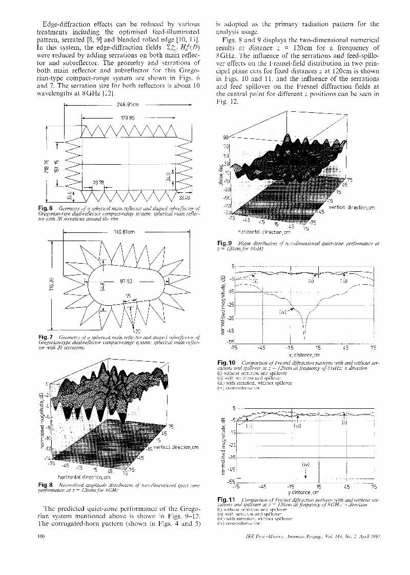
Edge-diffraction effects can be reduced by various treatments including the optimised feed-illuminated pattern, serrated [8, 91 and blended rolled edge [lo, 111. In this system, the edge-diffraction fields Z7;:, Gt(D) were reduced by adding serrations on both main reflec- tor and subreflector. The geometry and serrations of both main reflector and subreflector for this Grego- rian-type compact-range system are shown in Figs. 6 and 7. The serration size for both reflectors is about 10 wavelengths at 8 GHz [ 121.
Fig. 6 Geometry OJ a spherical muin rejectos unit s l i y d .suhiejlec.tor of Gregorian-type dual-rejlector compuct-sunge systen?: sp ieimil i m i n reflec- tor with 28 serrations around the sim
Fig. 7 Geometry of ci sphericul muin reflector. cmd shn led subrejlectos of Gregorian-type dual-rejector compact-range system: splesiciil nwin r e ~ w tor with 20 serrations
.
'5
dirc !ction.cm
- I 3 horizontal direction,cm Nornzulised aniplitude distribution of tivo-diniensioncii quiet-sone Fig. 8
performance at z = 120cnzjhv 8GHz
The predicted quiet-zone performance of the Grego- rian system mentioned above is shown in Figs. 9-12. The corrugated-horn pattern (shown in Figs. 4 and 5 )
100
is adopted as the primary radiation pattern for the analysis usage.
Figs. 8 and 9 displays the two-dimensional numerical results at distance z = 120cm for a freequency of 8GHz. The influence of the serrations and feed-spillo- ver effects on the Fresnel-field distribution in two prin- cipal plane cuts for fixed distances z at 120cm is shown in Figs. 10 and 11, and the influence of the serrations and feed spillover on the Fresnel diffraction fields at the central point for different z positions can be seen in Fig. 12.
75
verttca. dtrect'on,cm
'd 45 75 horizontal direction,cm
Plicise distribution qf :I !~.~-diniensionul quiet-zone performance ut Fig. 9 2 = 120cn1 for 8GHz
5 , I I I I 1
-7 5 -15 -1 5 15 15 7 5 x, distance,cm
Fig. 10 l ~ ~ t i o n . ~ undspiIkoi,er at z = 120cni at frequency of KGHz: x direction (i) without serration and spillovei- (ii) with serration and spillover (iii) with serration. without spillover (ib j crosspolarisation
Con?parison of Fresnel diflkaction palterns with and without ser-
- - -75 4 5 -I 5
y distance,cm Fig. 11 rations and s p i l L L a t z f 120cm ut jrequency oj 8GHz: y disection (i) without serration and spillover
Coni arimn o Fresnel dijfiytion patterns with and without ser-
(i i j with serration and spillover (iii) with serration, without spillover (iv) crosspolarisation
IEE Proc.-iMicrow. Antennus Propug.. Vol. 144, No. 2, April 1997

I I , l l -70 -1- - -60 -30 0 30 6 0 9 b l;O 150 l/O 210 210
z distance,cm Fig. 12 Conzparison of fiesnel diffiaction patterns ivitlz a id without ,ser- rations and ,spillow wkcn observing Lit the centre of the main rf.f2tctor .for dgferent distanca z at jrqnency qJ8GHz (i) without serration and spillover (ii) with scrralion and spillover (iii) with serration, without spillovcr
Fig. 13 Gregoriun-type dual-reflector compact-range .systenz with a s hericul main reflector and shaped sulireflcctor set up in uu anechoic cham- L r
3.4 Hardware implementation and test results The Gregorian-type dual-reflector compact-range sys- tem with serrated edges, which was designed in Section 3.3, has been manufactured and tested. The spherical main reflector, as shown in Fig. 6 is composed of a reflected area with four pieces of panel and 28 pieces of serration. The subreflector shown in Fig. 7 was divided into a central part and 20 serrations. One of these Gre- gorian dual-reflector compact-range systems is shown in an anechoic chamber in Fig. 13.
The practical results in the quiet zone of this com- pact-range system were obtained by measuring the quiet-zone characteristics using a low-gain horn antenna mounted on a planar Scanner to probe the field at z = 120cm. The scan area of the planar is 152cm by 152cm.
A normalised planar probing field at 8GHz is shown in Figs. 14 and 15, from which it can be been that most of the ripple variations are within 1dB except those close to the edge of the planar area and phase slant due to the misalignment between the planar and the colli- mated rays reflected from the main reflector to the quiet zone.
The test results along the horizontal and vertical cuts through the centre of the quiet zone for frequencies 8. 24.5 and 39.5GHz are shown in Figs. 16-19, in which thc amplitude has been normalised and the phase-slant error has been corrected.
IEE Ptoc - M i o o \ v AntennuJ Piopug Vol 144 No 2 Api11 1997
.cm
horizontal direction,cm
Fig. 14 Measured rcsults f tn,o-din?en.sionul piet-zone perfornrunce ut z = 120cnr for 8GHz: norma ired cinzplitude distributiou
1L direction,cm
CO' 2 0. h ,o' h;
horizontal direction,cm
Fig. 15 z = 120cnz for 8GHz: phase distrihution
Measured r-esu1t.s of t~vo-riinzmsional quiet-zone perforzance at
I I I I I 15
-551 -1 5 - L5 -1 5 15 45
horizontal cut,cm Fig. 16 plane cut qf Gregorim-type dual-reflector compact-range system
Variation in ntagnitudc of probing ,field in horizontal principal

Fig. 16 shows the amplitude variation of the probing field in the horizontal direction. The usable test area for probing fields with 1dB amplitude taper is about 131cm at 8GHz, 125cm at 24.5GHz and 129cm at 39.5GHz, the peak-to-peak ripple is about r0.4dB at 8GHz, k0.25dB at 24.5GHz and k0.4dB at 39.5GHz; the quadratic phase errors shown in Fig. 17 were caused by the twist of the planar scanner frame. Fig. 18 showed the probing field in the vertical direction, for 1dB amplitude taper is about 105cm at 8GHz, 108cm at 24.5GHz and 128cm at 39.5GHz, the peak-to-peak ripple is about 50.4dB at 8GHz, r0.25dB at 24.5GHz and r0.2dB at 39.5GHz. The phase variations of the probing field in the vertical direction are shown in Fig. 19. As a result that the effective ratio, defined as the ratio of the usable area with 1dB amplitude taper and f 0.5dB, r 5 ’ peak-to-peak amplitude and phase ripple in the quiet-zone area to the projected area of the main reflector in the xy plane (which is 179.85cm in the horizontal plane and 151.15cm in the vertical
150 120
-7 5 -1 5 -1 5 15 L 5 15 vertical cut, cm
Fig. 18 plane cui o j Gregorian-type dual-reflector compact-range system
Variation in magnitude of probing Jield in vertical principal
I
I - I
-9 0 -120 -150 -1 80
frequency 2L 5GHz 60 2 30
2 -30 :- 0
a -60
I
plane, respectively), of this Gregorian dual-reflector compact-range system is about 0.7.
4 Conclusions
A dual-reflector compact-range system with a spherical main reflector and shaped subreflector has been designed and manufactured at the antenna section in CSIST. The probing data illustrated the good quiet- zone-field quality achieved by such a range. In cross- range quiet-zone usage, this Gregorian dual-reflector compact-range system can provide as large a 70% area as the given spherical-main-reflector projected size. For special applications, both amplitude and phase ripples can be reduced, to improve the performance of the quiet-zone area, by reducing the mechanical surface tolerance and increasing the size of serrations on both reflectors. Meanwhile, the characteristic of arbitrary feed position provides more freedom for the anechoic- chamber size and existing chamber-fitting considera- tions.
5
1
2
3
4
5
6
7
8
9
References
JOHNSON, R.C., ECKER, H.A., and MOORE, R.A.: ‘Compact range techniques and measurements’, IEEE Trans., 1969, AP-17, ( 5 ) , pp. 568-576 VOKURKA, V.J.: ‘New compact range with cylindrical reflectors and high efficiency factor’. Proceedings of Electronic 76 Confer- ence, Munchen, Germany, 1976 SANAD. M.S.A.. and SHAFAI. L.: ‘Dual oarabolic cvlindrical reflectors employed as a compact range’, ZEiE Trans., 1590, AP- 38, (6), pp. 814822 HARRISON, T.: ‘A new approach to radar cross-section com- pact range’, Microw. J., 1986, 29, (6), pp. 137-145
W.A., and MITTRA, R.: ‘Offset dual-shaped reflectors for dual chamber compact ranges’, ZEEE Trans., 1991, AP-39, (7), pp. 1007-1013 KELLEHER, K.S., and HYDE, G.: ‘Reflector antennas’ in JOHNSON, R.C., and JASIK, H. (Eds.): ‘Antenna engineering handbook’ (McGraw-Hill, New York, 1984), 2nd edn., section 17.1 CHANG, D.C., and RUSCH, W.V.T.: ‘An offset-fed reflector antenna with an axially symmetric main reflector’, IEEE Trans.,
JOHNSON, R.C., and HESS, D.W.: ‘Performance of a compact antenna range’. Proceedings of IEEE Trans., Antennas & Propa- gation Society International Symposium, 1975 JOY, E.B., and WILSON, R.E.: ‘Shaped edge serrations for improved compact range performance’. Proceedings of Antenna Measurement Technical Association. Seattle. USA. 1987
GALINDO-ISRAEL, V., RENGARAJAN, R., IMBRIALE,
1984, AP-32, ( I I ) , pp. 1230-1236
10 BURNSIDE. W.D.. GILBEATH.’M.C.. ’ KENT. B.M.. and CLERICI, G.L.: ‘Curved edge modification of compact range reflector’, IEEE Trans., 1987, AP-35, (2), pp. 176-182
11 GUPTA, I.J., ERICKSEN, K.P., and BURNSIDE, W.D.: ‘A method to design blended rolled edges for compact range reflec- tors’, IEEE Trans., 1990, AP-38, (6), pp. 853-861
12 BEECKMAN, P.A.: ‘Prediction of the Fresnel region field of a compact antenna test range with serrated edges’, ZEE Proc. H, 1986, 133, (2)
102 IEE Pvoc -Microw Antennas Pvopag., Vol. 144, No. 2, April 1997