Embed Size (px)
Citation preview
A// Building Infrastructure Guideline v.5
Copy
right
du
Is
sue
Dec
embe
r 20
13
Building Infrastructure Guideline v.5
Telecom infrastructure standards for buildings
1B // Building Infrastructure Guideline v.5// Building Infrastructure Guideline v.5
ContentIntroduction 02
Telecommunication spaces 0٦
General specifications 08
Safety and other considerations 09
Temperature and humidity 09
Main telecom room 09
Clustered buildings 10
Mobile Service Room 10
Floor telecom closets 11
Rooftop mobile service room 11
Home consolidation cabinets 11
Office consolidation cabinets 12
Electro-mechanical 12
Mobile service room and rooftop 13
Pathway 14
General specifications 16
Vertical containment 16
Horizontal containment 17
Cables 18
General specifications 19
Fibre optic cables 19
CAT 6 copper cables 20
Administration and Labelling scheme 21
Bulk service application 22
Other special requirements 24
Entry ducts 24
Appendices 26
Layout & labellings 28
Tables 69
Location Map 75
32 // Building Infrastructure Guideline v.5// Building Infrastructure Guideline v.5
IntroductionWe are pleased to issue the updated Telecommunications Infrastructure Standards for Buildings v.5.
The new design guidelines in this document are based on our prior experience of offering quality telecommunications services to our consumer and enterprise customers across UAE.
The purpose of this document is to:
• Introduce the new design guidelines for fibre infrastructure to enable property developers, consultants, and contractor to deliver high-quality, future-proof telecommunications and multimedia services to their tenants.
• Provide a guide for consultants, contractors, and engineers related to the ‘No Objection Certificate’ (Building NOC) process that includes design and construction drawing review and Structure Cabling Material data sheets review, with samples checking and site inspections required during implementation.
• Meet the growing demand for improved communications at work, at home, in business, and in public services.
We advise our clients to use qualified and certified professionals in all aspects of the application and implementation of these design guidelines during building construction stages.
Developers are encouraged to engage with us in the early stages so that any process and/or design issues may be resolved. If property developers or tenants have special requirements that may not be covered by these guidelines, it’s necessary to involve our design teams at an early stage of development planning, to enable seamless delivery of premium telecommunications services at launch.
We look forward to feedback from developers as it helps us understand your issues and incorporate valid suggestions in future designs.
For more information on obtaining building NOCs or any design-related queries, please contact us at any of the below channels:
• Dubai and Northern Emirates NOC help desk: +971 4 391 5018
• Abu Dhabi, Al Ain and Western regions NOC help desk: +971 2 234 4401
• General inquiries and technical support: 800-dunoc
• Email: [email protected]
• Website: www.du.ae
Thank you,du
54 // Building Infrastructure Guideline v.5// Building Infrastructure Guideline v.5
This document covers the following properties types:
• Single villa and villa complexes• Residential towers and groups
of residential towers• Commercial towers and groups
of commercial towers• Government buildings• Mosque• Shopping malls• Groups of shops and retail outlets• Hospitals, hotels, schools, universities
and other bulk service applications• Warehouses, sheds, etc.
The document is structured to coverall aspects of infrastructure for:
• Telecommunication spaces• Electro-mechanical• Pathways• Cables and its related accessories• Bulk services• Duct entry• Labelling scheme
All telecom spaces, pathways, ducts and cabling system specified in this document are designed to meet the requirements of du to provide high-quality, future-proof services to the Customers and should be used for telecommunication services.
The contents of this document are the minimum requirements of du for the new buildings and subject to revision without notice due to continued progress in methodology, design and manufacturing and for the purpose of regulatory compliance.
76 // Building Infrastructure Guideline v.5// Building Infrastructure Guideline v.5
Telecommunication spaces
98 // Building Infrastructure Guideline v.5// Building Infrastructure Guideline v.5
Safety and other considerationsAll telecom rooms must comply with municipality and national authority standards and regulations, such as those issued by civil defence and utility companies. Notwithstanding this, it is expected that the following will be provided:
• All telecom spaces should be fitted with smoke detectors connected to the building management system.
• All telecom spaces should be fitted with emergency lighting.
• All containment openings to telecom spaces must be sealed with a regulation fire retardant material.
• All doors to telecom rooms must be of solid wood core or steel construction, fire retardant with a minimum rating of 2 hours.
• All doors to telecom rooms must be outward opening with an automatic door closer system fitted on the hinged edge.
• All doors to telecom rooms must be labelled.
• The room must be free from contaminants and pollutants.
• All telecom rooms should have basic firefighting provision of handheld CO2 cylinder type extinguishers.
• If the building developer has any concerns over safety, especially fire protection and suppression systems, this should be raised with du at the NOC stage.
Temperature and humidityAll telecom rooms must be maintained at 20°C ± 3°C and the relative humidity at 50% ± 10%. However, floor telecom closets can be maintained within 20°C to 30°C temperature range.
The Main Telecom Room (MTR)A main telecom room must be provided on the ground floor for all multi-storey buildings. This room will be used for the termination of telecom fibre optic cables and to house telecom equipment, if needed, now or in the future.
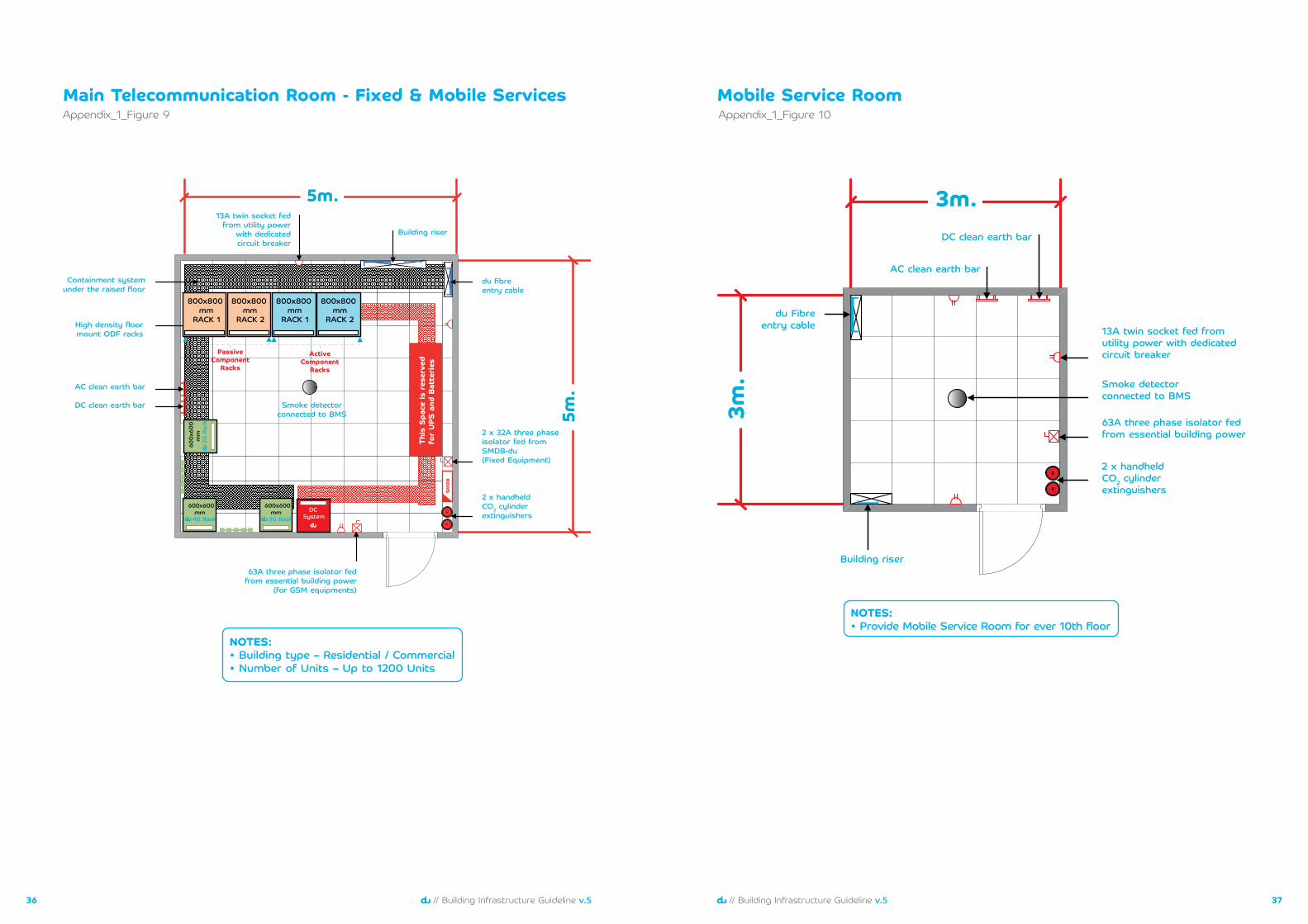
Generally, the MTR can be shared by both du Fixed and Mobile services. If a mobile service room is required in the building (more than G+10) the first mobile service landing room can be shared with the MTR. The minimum combined room dimension should be 4m x 4m x 3m (WxDxH) and maybe increased depending on the functions and features of the building.
The room specifications are detailed in Appendix_1_Figure 5 to 9. If the architectural design limits the room sharing, then two dedicated rooms with minimum sizes of 3m x 3m x 3m (WXDXH) each must be provided.
The room specifications are detailed in Table-1, Table-2, and Appendix_1_Figure-1 to 3 and 18.
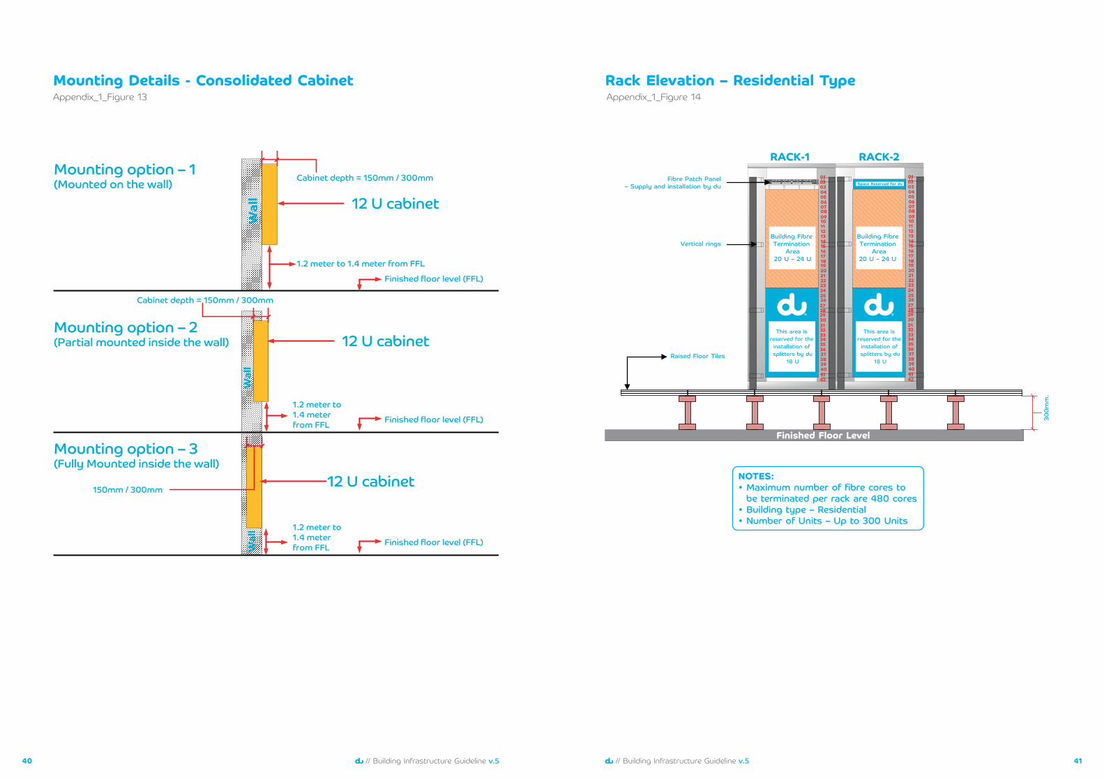
Refer to Appendix_1_Figure-14 to 16 for Rack elevation layouts details.
General specificationsA number of telecom rooms will be required in a building depending on its characteristics. The following room types are required and the details of these rooms shown below:
• Main telecom room
• Mobile service room
• Rooftop mobile service room
• Floor telecom closet
In multi-storey buildings the telecom rooms should be vertically aligned and linked by a shared containment system. This containment system must not reduce the minimum requested space. All telecom rooms must be dedicated for the use of du. The rooms must be easily accessible to du personnel 24 hours a day and secured from unauthorised entry.
Telecom rooms must not be in close proximity to any sources of the following:
• Heat
• Moisture
• Corrosive atmospheric or environmental conditions
• High voltages
• Radio frequency interference (RFI)
• Electro-magnetic interference (EMI)
The rooms must not be directly beneath or next to wet areas such as:
• Showers
• Washrooms
• Swimming pools
• Garbage area
The rooms should be clean and free from any items not directly related to the specifications in this document such as:
• Non-du equipment
• Utility pipes
• Sprinkler systems
• Windows
All telecom spaces and pathways must be pest controlled using best available practices. It should be noted that rodents often gnaw cables resulting in damage and the potential for service disruption. Hence, special attention should be given to preventing rodents from entering telecom spaces and pathways. This could involve the installation of covers to cable trays; if this is the case these covers must be removable to allow for the installation of additional cables.
The walls, floor and ceiling should be painted and treated with anti-dust and anti-static coating to minimise dust and static electricity. Walls and ceilings shall receive primer and finish coat of light colour paint.
In order to move equipment into and out of telecom rooms, all entrances must not be smaller than 900mm x 2100mm (WxH).
1110 // Building Infrastructure Guideline v.5// Building Infrastructure Guideline v.5
Floor Telecom Closet (FTC)A floor telecom closet must be provided on each floor of all multi-storey buildings. The floor telecom closet is required to provide a flexible point for the installation, pulling and maintenance of telecom cables. FTC must have a minimum dimension of 2m x 1m x 3m (WXDXH).
The floor telecom closet should be provided with two outward opening doors with a minimum total opening of 1500mm x 2100mm (WxH). The door should be labelled (Floor Telecom Closet خدماتحجرة ( االتصاالتالطابقية
In the case of a multi-storey villas, townhouses, G+1 warehouses or small retail shops, floor distribution boxes will be required with a minimum size of 300mm x 300mm x 150 mm (WxHxD), as an alternative to replace FTC.
In high rise buildings which usually exceed 30 floors, proper planning and consideration must be given to the FTC space and dimension, which might be increased. It is highly advisable to seek du advice and pay close attention during NOC stage to understand the concept of high rise building infrastructure design. Refer to Table 3 and 4 and Appendix_1_Figure-4 for the complete detailed layouts of FTC.
Rooftop mobile service room (up to G+10)
Rooftop mobile service rooms must be provided on the roof of all multi-tenant buildings up to G+10 and access must be provided to the building riser system.
The door dimension must be 900mm x 2100mm (WxH) and opening outwards and should be labelled ‘Roof Telecom Room’ .غرفةخدماتالهاتفالمتحركعلىالسطح
The rooftop mobile room must have a minimum distributed floor load rating of 10 kN/m2.
An opening must be provided with a dimension of 600mm x 400mm (WxH), 500mm below the room ceiling in walls facing the building’s rooftop area.
Space must be reserved on the rooftop of the building for the installation of mobile service antennas. This will vary from building to building, but will typically be at the corners of the building or on any raised structure on the rooftop. The exact details will be defined during the NOC stage. Refer to Appendix _1_Figure-10 for the complete detailed room layouts for mobile service rooms.
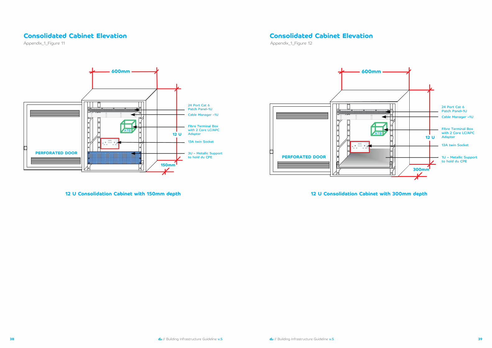
Home consolidation cabinetsThe home consolidation cabinet is a space to house du’s network termination equipment. It also serves as the distribution point for all local wiring. A consolidation cabinet should be provided in each home. This should be a telecom cabinet with the following specifications:
• Minimum internal dimensions 600mm x 600mm x 15٠mm (HxWxD) for 24 or less CAT6 cables termination per unit
• Minimum internal dimensions 600mm x 600mm x 300mm (HxWxD) for more than 24 CAT6 cables termination per unit
• Wall mount or flushed mount installation at 1.2m high measured from the finished floor level up to the edge of the cabinet.
• Fitted with RJ45 UTP patch panel and cable management.
• Fitted with 2-core fibre terminal box.
• 2 nos. 13A twin sockets fed from the essential power supply with dedicated 20A circuit breaker.
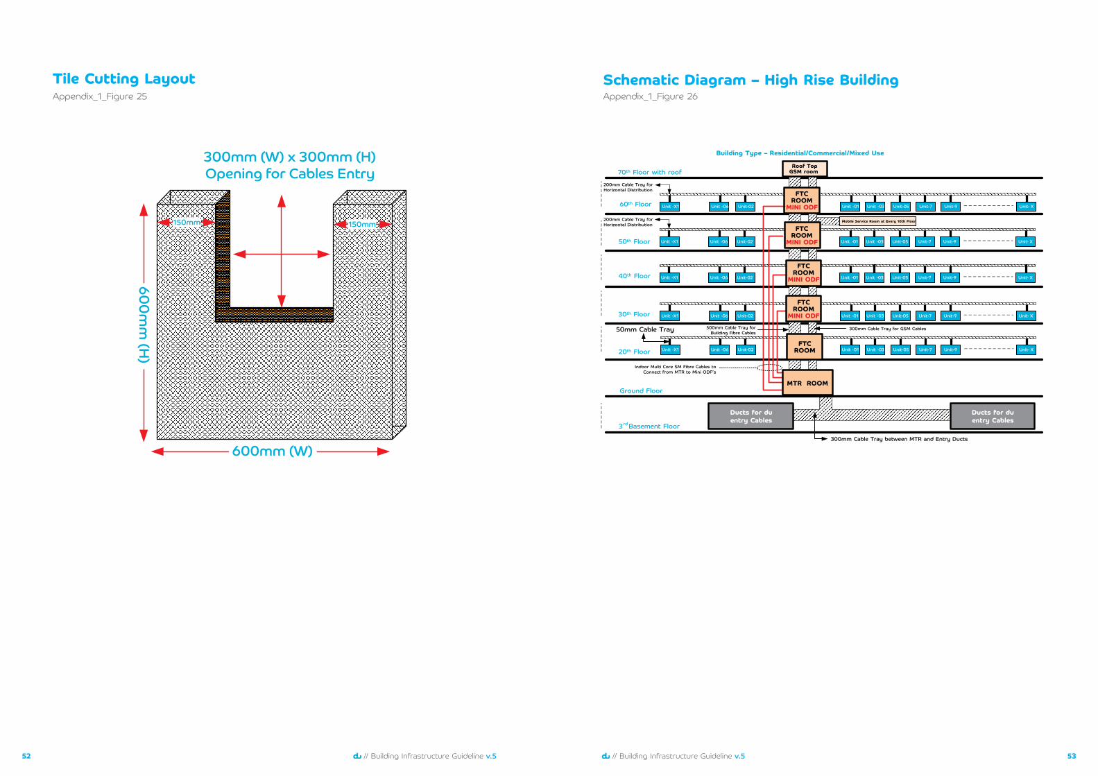
The 3m clearance height specified is the minimum finished clearance after taking into account allowances for raised floors (if used), overhead cable trays and any other obstructions such as lighting fixtures and beams. In areas where overhead trays are used, a minimum headroom access of 300mm is required above the tray. Depending on the telecom room usage, a ‘raised floor’ might be required inside the MTR having active equipment, particularly commercial or mixed use buildings. A minimum of 300mm height above the base floor of the room should be provided. Tile cutting details are specified in Appendix_1_Figure-25. In other cases involving residential buildings, raised floor is not mandatory, and will be further advised during the NOC stage.
The floor level of the room must be constructed at the same level as the outside access or corridor. If this cannot be met, then a suitable ramped entry with an anti-slip surface must be provided. A threshold step of 100mm must also be provided inside the room under the raised floor to prevent any ingress of water from outside the room.
The door of the main telecom room must have outward opening with size not smaller than 900mm x 2100mm (WxH). The door should be labelled ‘Main Telecom Room’ “لالتصاالتالرئيسيةالغرفة
All cables in the main telecom room must be properly routed to the desired destinations. For this purpose, an adequately sized cable tray system must be installed to maintain the connectivity as described in Appendix_1_Figure-20 to 21.
Clustered buildingsGroup of towers
If a project consists of a cluster of multi-tenant buildings, then all the requirements of a single tower still applies. One of the buildings will be selected as the location for the main telecom room, which usually stands in the centre of the cluster or often times closest to the main telecom duct entry points. This would require the cluster of buildings to be linked to the designated main telecom room via multicore single mode fibre cables. The details of this arrangement should be discussed with du during the NOC stage. Cabling concept is described in the clustered building schematic diagram in Appendix_1_Figure-22.
The Mobile Service Room (more than G+10)
As mentioned in the MTR section, du Fixed and Mobile Services can be combined in one room. The first mobile service room can be shared with the MTR to serve the first 10 floors of the building. If sharing is not feasible, a dedicated 3m x3m x 3m (WXDXH) mobile service room can also be provided. Accordingly, the mobile service rooms must be provided for every 10 floors thereafter. The locations of the mobile service rooms must be close to the floor telecom closet (FTC).
The mobile service rooms must have a minimum distributed floor load rating of 10 kN/m2. The door dimension must be 900mm x 2100mm (WxH) and opening outwards.
The doors should be labelled ‘Mobile Service Room’ المتحركالهاتفخدماتغرفة.
Refer to the Table-2 and Appendix_1_Figure-10.
1312 // Building Infrastructure Guideline v.5// Building Infrastructure Guideline v.5
• Adequate ventilation with ambient temperature maintained at 20°C – 30°C.
• Adequate safe working space around the location with ambient lighting.
• Not close to sources of water or heat and any electrical distribution or bus bars.
• Labelled with villa or flat number.
A layout of a typical home consolidation cabinet is provided in Appendix_1_Figure-11 to 13
Office consolidation cabinets Commercial predefined offices, warehouses, sheds, shops.
The office consolidation cabinet is a space to house du’s network termination equipment. It also serves as the distribution point for all the local wiring. A consolidation cabinet must be provided in each business area. This should be a telecom cabinet with the following minimum specifications:
• Minimum internal dimensions 600mm x 600mm x 300mm (HxWxD)
• Wall mount or flushed mount installation at 1.2m high measured from the finished floor level up to the bottom edge of the cabinet.
• Fitted with RJ45 UTP patch panel and cable management.
• Fitted with 2-core fibre terminal box.
• Fitted with dual 13A switched socket power outlet fed from a dedicated circuit breaker on the domestic supply.
• Sufficient cable entries to accommodate the incoming fibre optic and UTP cables.
• Located in an accessible area close to the entrance; avoiding areas such as kitchen, laundry room or bedroom.
• Adequate ventilation with ambient temperature maintained at 20°C – 30°C.
• Adequate safe working space around the location with ambient lighting.
• Notclosetosourcesofwaterorheatandanyelectricaldistributionorbusbars.
• Labelled with office/retail/building unit number.
A layout of a typical office consolidation cabinet is provided in Appendix_1_Figure-12 to 13
Commercial shell and core
In case of shell and core development (open space office floor with no pre-defined offices), the building’s contractor should install one indoor wall mount mini ODF inside the FTC. The size of the mini ODF will depend on the number of fibre cores required based on the floor area served. In addition, free wall space inside the floor telecom closet must be reserved for future offices terminations. Refer to the FTC layout as shown in Appendix_1_Figure-4
Mini ODF specifications are as follows:
• Lockable side panels.
• Lockable front door.
• Sufficient cable entries to accommodate the incoming fibre optic cables.
• Labelled with floor number.
• Labelled ports.
Electro-MechanicalMain Telecom Room (MTR)
For commercial and mixed used buildings, the following requirements need to be provided:
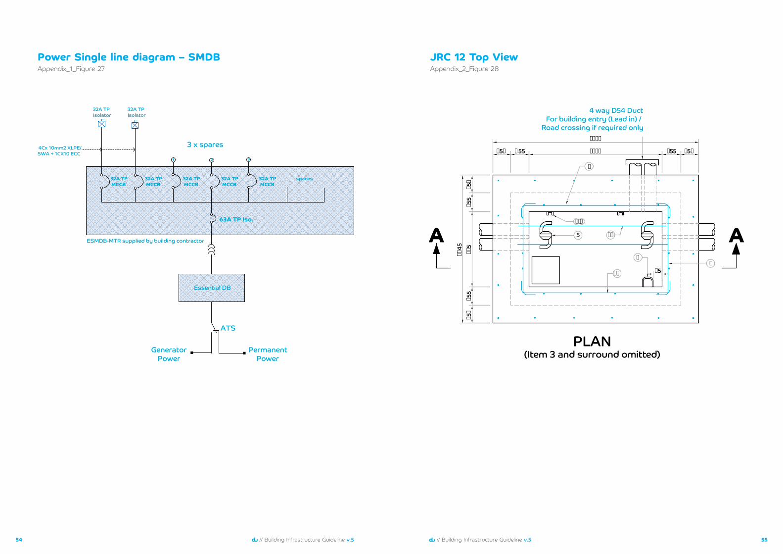
• SMDB inside the room fed from power supply (with generator backup) for fixed equipment. Refer to the single line diagram in Appendix_1_Figure_27
• 2x32A TP isolators to be provided in the Main Telecom Room - Refer to the SLD in Appendix_1_Figure_27
• 2 nos. 13A twin sockets fed from the essential power supply with dedicated 20A circuit breaker.
• AC and DC earth bars connected to the dedicated earth pits with resistance less than 1ohm.
• Dedicated A/C system (ducted split FCU) with duty and standby units with proper interlocking, to maintain the room temp. at 20+/-3°C.
• Heat dissipation can be considered at 300 Watts/sq.mtr.+3kW per rack.
• Room should be provided with adequate lighting and comply with the fire and safety requirements like smoke detector, fire alarm, emergency light etc. as per local authority standards. Any water sprinklers to be avoided.
• 2 nos. handheld CO2 cylinder extinguishers to be provided inside the room.
• Add 1x63A TP isolator fed with dedicated feeder from essential power supply (with generator backup) for GSM equipment – if MTR is shared between du Fixed and Mobile services.
• Heat dissipation to be Increased by 8kW for GSM equipment- if MTR is shared between du Fixed and Mobile services.
For residential buildings, the following requirements need to be provided:
• 2 nos. 13A twin sockets fed from the essential power supply with dedicated 20A circuit breaker.
• One earth bar connected to the telecom earth pit with resistance less than 1ohm.
• Room must be provided with adequate lighting.
• Room should be provided with air conditioning system to maintain the room temp. at 20+/-3٠C
• Room should comply with the fire and safety requirements like smoke
detector, fire alarm, emergency light etc. as per local authority standards. Any water sprinklers to be avoided.
• 2 nos. handheld CO2 cylinder extinguishers to be provided inside the room.
• Add 1x63A TP isolator fed with dedicated feeder from essential power supply (with generator back up) for GSM equipment – if MTR is shared between du fixed and Mobile services.
• Heat dissipation of 8kW for GSM equipment- if MTR is shared between du Fixed and mobile services.
Mobile Service Room and RooftopMobile Service Rooms
For all mobile service rooms and rooftop mobile service room, all requirements mentioned in Passive MTR must be followed including the 1x63A TP isolator and the heat dissipation requirement. Further advice will be given during the NOC stage for the rooftop mobile service room design.
Floor Telecom Closet (FTC)
• Adequate lighting and 1x13A twin socket fed from the normal building supply with dedicated 20A circuit breaker.
• Room should comply with the fire and safety requirements like smoke detector, fire alarm, emergency light etc. as per local authority standards. Any water sprinklers to be avoided.
• 1x handheld CO2 cylinder extinguisher.
Refer to Appendix_1_Figure-10 for the complete detailed room layouts.
1514 // Building Infrastructure Guideline v.5// Building Infrastructure Guideline v.5
Pathways
1716 // Building Infrastructure Guideline v.5// Building Infrastructure Guideline v.5
General specificationsThe following requirements must be applied to all containment systems:
• The containment system must be designed so that installed cables do not exceed the minimum specified bend radius.
• All metal containment parts must be free from sharp edges and earth bonded.
• Telecom riser openings must be sealed with a suitable fire retardant material.
• Cable trays must be easily accessible in common areas to facilitate any future provision of additional cables.
• Any cable trays that are in areas accessible to the public and less than 4.8m above the floor must be covered.
• Containment systems must not run through areas exposed to excessive heat, moisture, corrosive atmospheric or environmental conditions, high voltages, radio frequency interference (RFI) or electro-magnetic interference (EMI).
• For all containment systems a minimum separation must be maintained from sources of electromagnetic interference.
• The building developer may want to consider redundant containment systems, particularly in commercial or prestigious developments. du must be contacted at the design stage to discuss any such requirements.
Vertical Containment
Multi-storey/multi-tenant buildings
Risers must be provided in multi-storey/multi-tenant buildings to allow the installation of telecom cables from the main telecom room to the floor telecom closets, mobile service rooms and rooftop mobile service rooms. Hot-Dip Galvanized (HDG) slotted steel cable trays must be provided in the risers to carry the telecom cables between all the telecom rooms. It is recommended that the main telecom room and floor telecom closets should be designed so that they are vertically aligned within the building.
Two cable trays, with the following minimum dimensions are recommended:
• One of 500mm x 100mm (WxH) with Heavy Duty Return Flange (HDRF) for fibre optic cables.
• One of 300mm x 50mm (WxH) with Heavy Duty Return Flange (HDRF) for GSM cables (covering all floors from last basement till roof).
If it is not possible to provide all of the cable trays running vertically then horizontal trays of the same size should be provided.
Note: above cable trays requirements to be finalised during NOC stage.
Within homes
In case of multi-floor apartments/villas, the UTP cables between the floors must run through 50mm diameter PVC conduits via junction/pull boxes located on each floor. The junction/pull boxes must have a minimum dimension of 300mm x 300mm x 150mm (WxHxD). The slab opening for these conduits must be in a suitable and accessible location in every floor. It is recommended that all vertical conduit runs be aligned to ease the installation of cables.
Horizontal Containment Multi-storey/multi-tenant buildings
The horizontal containment for routing cables from the floor telecom closets to consolidation points on the served floor can use a number of systems (cable trays, conduits, etc.). The solution will depend on the characteristics of the building. Conduits must only be used when the consolidation point locations are permanent, the cable density is low and the flexibility to modify the routing is not required. Specification for the size of this containment is given in Appendix_1_Figure-20 to 21
Note: Intermediate PVC junction/pull boxes with minimum size of 300mm x 300mm x 150mm (HxWxD) must be provided on individual runs that exceed 30m. PVC junction/pull boxes must also be provided where an individual conduit run has a sharp change in direction.
The cable tray minimum dimensions are described below:
• One 200mm x 50mm (WxH) cable tray with Heavy Duty Return Flange (HDRF) as a main route from floor telecom closet to main corridors and then branches to each consolidation cabinet through cable trays of 50mm x 50mm (WxH).
Mobile service antennas
Cable trays must be provided to route mobile service antenna cables from the floor telecom closets to all common corridors including all lift lobbies in all floors including podium and basement.
One cable tray following minimum dimensions must be provided:
• 150mm x 50mm (WxH) with Heavy Duty Return Flange (HDRF)
For office/commercial buildings, the horizontal containments should be extended till inside the entrance of each office units.
Within homes
All UTP cables inside the home must run through PVC conduit with a minimum 25mm diameter from the home consolidation point to each dual outlet. If more than one dual outlet is fed by a conduit then the size and quantity of the conduit may need to be increased. Intermediate PVC junction/pull boxes must be provided on individual runs that exceed 30m. PVC junction /pull boxes must also be provided where an individual conduit run has a sharp change in direction.
Cluster of buildings – groups of towers
Where a building consists of a group of towers (on a common shared podium) all of the requirements of a single tower still apply. In addition, cable trays must be provided linking the main telecom rooms of all towers, exact requirement to be finalised during NOC stage.
One cable tray with the following dimension must be provided:
• 300 x 100 (WxH) with Heavy Duty Return Flanged (HDRF)
These trays should be readily accessible in common areas to facilitate any future provision of additional cables. However, if these trays are in an area accessible to the public and are less than 4.8m above the floor then the trays should be covered. For more details, refer to Appendix_1_Figure-22
1918 // Building Infrastructure Guideline v.5// Building Infrastructure Guideline v.5
General specificationsSpecifications of all the cables to be used must be submitted to du for approval during the NOC stage. This must also include test reports showing that the performance of the cabling system meets defined requirements. Cable test must be performed using power metre and OTDR tests, whichever is applicable. Details for cable labelling are included in Appendix_2
Fibre Optic CablesThe quantity of fibre optic cables that must be provided and installed from the main telecom room to the consolidation points or FTC depends on the characteristics of the building.
Drop Fibre Cable
• Indoor rated drop fibre• Individual pairs (2-core)• Single mode• Suitable for LC/APC connectors • Bend insensitive, ITU-T, G.657A1,
and compliant with G.652D• Jacket made from halogen free and flame retardant material• Low Smoke Zero Halogen (LSZH) or Flame Retardant Polythene Sheath (FRP)
Multicore Fibre Cable
• Indoor rated• Single mode• Compliant with ITU-T, G.657A1
and G.652D• Jacket made from halogen free
and flame retardant material• Low Smoke Zero Halogen (LSZH)
or Flame Retardant Polythene Sheath (FRP)
• Fibre optic colouring code shall be in accordance to EIA/TIA-598
For fibre cables that need to be installed or routed outside the building to serve guard houses or security rooms, or any other similar facilities, outdoor rated fibre cables must be used, with the specifications as mentioned below:
OSP Fibre Cable
• Outdoor rated• Single mode• Compliant with ITU-T G.652D• Loose tube inner construction or Ribbon type for high density cables• Fibre optic colouring code shall be in accordance to EIA/TIA-598
Fibre optic cable requirements – from main telecom room to consolidation points (direct fibre)
2 core (individual pair) fibre optic cables will be required from MTR up to each apartment, retail shop, and pre-defined office. It is recommended to apply direct fibre installation up to G+30 only to maintain cable management inside the FTC and MTR.
The fibre cables must be provided from the main telecom room to each consolidation point and should be of continuous lengths free from joints, branches or patching. By default, all the fibre cables should pass through the FTC.
The fibre cables should be labelled at both ends with a unique reference for the consolidation point served and the room or area of origin. Labelling details are included in Appendix_2
All fibre optic cables should be terminated inside the MTR and inside the unit CP cabinet. Refer to Appendix_1_figure-19
Cables
2120 // Building Infrastructure Guideline v.5// Building Infrastructure Guideline v.5
Fibre optic cable requirements – from MTR to FTC (multicore fibre)
For high rise buildings exceeding G+30, a FTC must be selected for every 10 floors. Multicore fibre cable must be installed in a mini ODF inside the FTC, where the number of fibre core will depend on the number of units in each served floor. 2 fibre cores per unit should be considered as the basic foundation of multicore fibre calculation.
If there are unused fibre cores, these must be left un-terminated and coiled properly inside the mini ODF and the MTR ODF. Refer to Appendix_1_figure-26
Fibre optic cable requirements – from MTR to FTC (shell and core)
For shell and core office development, one pair of fibre optic cable per 200sq m of leasable commercial area should be provided up to FTC of the same floor. Depending on the building design and built up area, multicore fibre cables from 12 cores up to 288 cores may be required to be installed between the MTR and FTC to meet the cable quantity requirement.
The fibre cables should be labelled at both ends with a unique reference for the floor served and the MTR. Labelling details are included in Appendix_2
All fibre optic cables should be terminated inside the MTR and in the FTC mini ODF cabinet. Refer to the FTC layout as shown in Appendix_1_Figure-4
Fibre optic cables – from MTR to all mobile service rooms
12 single mode fibre pair cables must be provided from the main telecom room cascaded to all mobile service rooms ending at the last mobile service room. 10m of spare fibre must be left neatly coiled.
Fibre optic cables – from MTR to rooftop mobile service room
12 single mode fibre pair cables must be provided from the main telecom room to the rooftop mobile service rooms. 10m of spare fibre must be left neatly coiled.
CAT6 Copper CablesCAT 6 Copper cables – from consolidation points to tenant outlets
To deliver services from the consolidation points to the building outlets, unshielded twisted pair (UTP) copper cables must be provided. The complete design of this service is the responsibility of the building developer. However, the following minimum requirements must be followed for the efficient and effective provision of services:
• The cables must conform to a minimum of CAT 6 specification (Category 6, 100 Ohm, 4 pair 23 AWG as specified in ANSI/TIA/EIA 568-B.2 Addendum 1).
• The wiring must be in a‘star’topology fanning out from the consolidation point.
• Dual RJ45 outlets with spring load sliding shutters must be provided wherever service is required (all outlets should comply with the performance specifications as detailed in ANSI/TIA EIA 568-B.2 Addendum 6).
• Each socket in the dual RJ45 outlet must be wired back to the consolidation point.
• Outlets must not be cascaded or looped & there must be no splitting of cable pairs.
• The maximum cable length from consolidation point to outlet must not exceed 90m.
• At the consolidation point the cables should be terminated on an RJ45 patch panel and labelled with the socket and outlet served.
• In each outlet the cable must beterminated to maintain the twists in each pair up to within 5mm of the termination.
• Proper strain relief should be provided at the terminated ends of the cable.
• The components of the CAT 6 system must be from the same supplier or at least compatible to insure maximum performance.
• Design should incorporate built-in flexibility to meet the growing needs of the occupants.
• The CAT 6 cabling system must be tested using an appropriate field test instrument for compliance with ANSI TIA/EIA 568-B.2 Category 6 (or equivalent if a higher specification has been used)
• Numbering and colouring of the pairs should be as defined in EIA/TIA 568B, SO 11801/EN50173 using the T568B option.
Administration and labelling schemeAll the infrastructure components described in this document must be clearly and uniquely labelled. The label information must correspond with the description on the as-built drawings.
The type of label must be suitable for the object being labelled and its environment. This is particularly important for cables and consolidation cabinets where a high quality printed self-laminating type must be used. For detail of the Labelling scheme refer to the Appendix_2
2322 // Building Infrastructure Guideline v.5// Building Infrastructure Guideline v.5
Bulk serviceapplication
Bulk service requirementsThis kind of service solution usually applies to buildings that are having their own IT network and system operator, such as hotels, hospitals, schools, universities, banks, airports, warehouses, workshops and other similar establishments. Sharing the client server or IT room with du can be one solution to deliver the services simply and quickly which is convenient for both du and the client. In such cases of room sharing, free space inside the client room needs to be provided and reserved for du usage. Free space could be either rack unit space in an existing client rack or a floor space inside the room to accommodate a floor mounted rack dedicated for du.
A letter from the client should be submitted during the building NOC stage confirming the bulk service request with detailed information on the required telecom services.
The consultant is advised to approach du prior to the Building NOC submission to be able to assess and decide if sharing the space with the client is the best approach or a dedicated du room is technically recommended for some reason or another.
If a dedicated room is required by du, the room specifications as mentioned in the telecom spaces section must be followed. The final du requirements including space, containment, cabling and power will be finalised during the NOC stage.
Cable connectivity between du and the client rack or room must conform to the cabling standard of du, as discussed in the cable section of this document. Single mode fibre, UTP CAT6 and multi pair CAT3 copper cables are generally required, to be supplied, terminated and tested. Final cabling connectivity design including cable type and quantity will be advised during the NOC stage. Refer to the Appendix_1_Figure-17
2524 // Building Infrastructure Guideline v.5// Building Infrastructure Guideline v.5
Other special requirementsPublic phones, ATM machines and retail kiosks
Provision needs to be made for the connection of public phones, ATM machines and retail kiosks. This must use the same design as that prescribed for commercial buildings; 2-core single mode fibre (individual pair) from the main telecom room to a business consolidation cabinet must be installed. The final requirement will be finalised during the NOC stage. The business consolidation cabinet must be in a secured location. It is the responsibility of the building developer/consultant to coordinate with du at the NOC stage for any special or non-standard requirement.
Entry ductsThe building developer must provide lead-in ducts from the main telecom room to the plot boundary. The exact connection points at the plot boundary will depend on whether the du network already reaches the plot.
Option 1 – du duct network already exists
• The building developer will be responsible to connect to the du ducting system.
• The operator will identify the location and quantity of their lead-in ducts.
Option 2 – du duct network is still to be built
• The building developer will be responsible to extend the lead-in duct to 1m outside the plot boundary.
• The building developer is responsible for locating and clearly identifying lead in ducts.
In both cases the building developer will be responsible for the maintenance and repair of lead-in ducts. The lead-in ducts systems in this document are designed to meet du requirements to serve the development, building or property and must be used for telecommunication purposes. The quantity and size of these ducts for different kind of developments is detailed in Table-6. Refer to the Appendix_1_Figure-23 to 24
The lead-in duct specifications are as follows:
• Made from black uPVC.
• Upmost part of ducts must be buried to a depth of 600mm below finished ground level.
• Clearly marked above ground level for easy location.
• Sloping away from the building.
• Protected by concrete when running under permanent paved surfaces.
• Sealed at each end to prevent the ingress of any materials such as water, sub-soil, gas, and pests.
• An entry/pull box must be installed for any right-angled or sharp bends in the lead-in duct route.
• If required at the entry to the main telecom room, a wide-angle long radius bend (factory made) may be provided; alternatively an entry box may also be provided.
• All ducts must include a draw rope made of twisted mildew and rot resistant polypropylene; minimum outside diameter of 6mm; minimum tensile strength of 2400lbs/1000kg/
In case of combined plots, two entry locations are still required for primary and secondary network connections; this will be advised by du at the design stage.
Lead-In ducts – villa complex
In the case of a villa complex, the building developer must connect the lead-in ducts to each villa in the complex. The lead-in duct size must not be reduced until the branching point for an individual villa.
Lead-In ducts – group of buildings
In cases where the building developer wishes to share lead-in ducts between a group of buildings (not on a common shared podium), then the design needs must be discussed with du at the design stage.
Lead-In ducts - building entry
Where lead-in ducts cannot be routed directly into the main telecom room, Hot-Dip Galvanized (HDG) slotted steel cable trays must be provided as an alternative. These trays must be easily accessible in common areas to facilitate any future provision of additional cables. However, if these trays are in an area accessible to the public and are less that 4.8m above the floor then the trays must be covered.
A cable tray of minimum dimensions 300mm x 100mm (WxH) with Heavy Duty Return Flange (HDRF) will be required for each plot entry point.
Lead-In ducts – entry box
Entry boxes are required to install telecom cables through the lead-in duct. The type and size of entry/pull boxes will depend on the characteristics of the building development. The details for entry boxes are included in the text below and summarised in Table-6. The quantity and location of the entry boxes will depend on the route from the main telecom room to the network.
Entry boxes must be included wherever the duct system has right-angles or sharp bends or other factors to facilitate cable pulling.
The following specifications must be followed:
• Constructed with reinforced concrete.
• Fitted with a ductile iron frame and cover.
• Minimum load rating 400kN.
• Cover to be marked ‘du – Telecom’.
• An earth rod must be provided with a resistance of less than 5 ohms.
Note: A more detailed set of entry box specifications and drawings are included in Table-6
Please contact [email protected] any OSP design queries.

2726 // Building Infrastructure Guideline v.5// Building Infrastructure Guideline v.5
Appendices
2928 // Building Infrastructure Guideline v.5// Building Infrastructure Guideline v.5
٣m.
٣m.
٢ x handheldCO٢ cylinderextinguishers
Smoke detectorconnected to BMS
du fibreentry cable
٨٠٠x
٨٠٠
mm
RACK
٢
٨٠٠x
٨٠٠
mm
RACK
١
١٣A twin socket fedfrom utility powerwith dedicatedcircuit breaker
Containment system under the raised floor
AC clean earth bar
Building riser
Raised floor
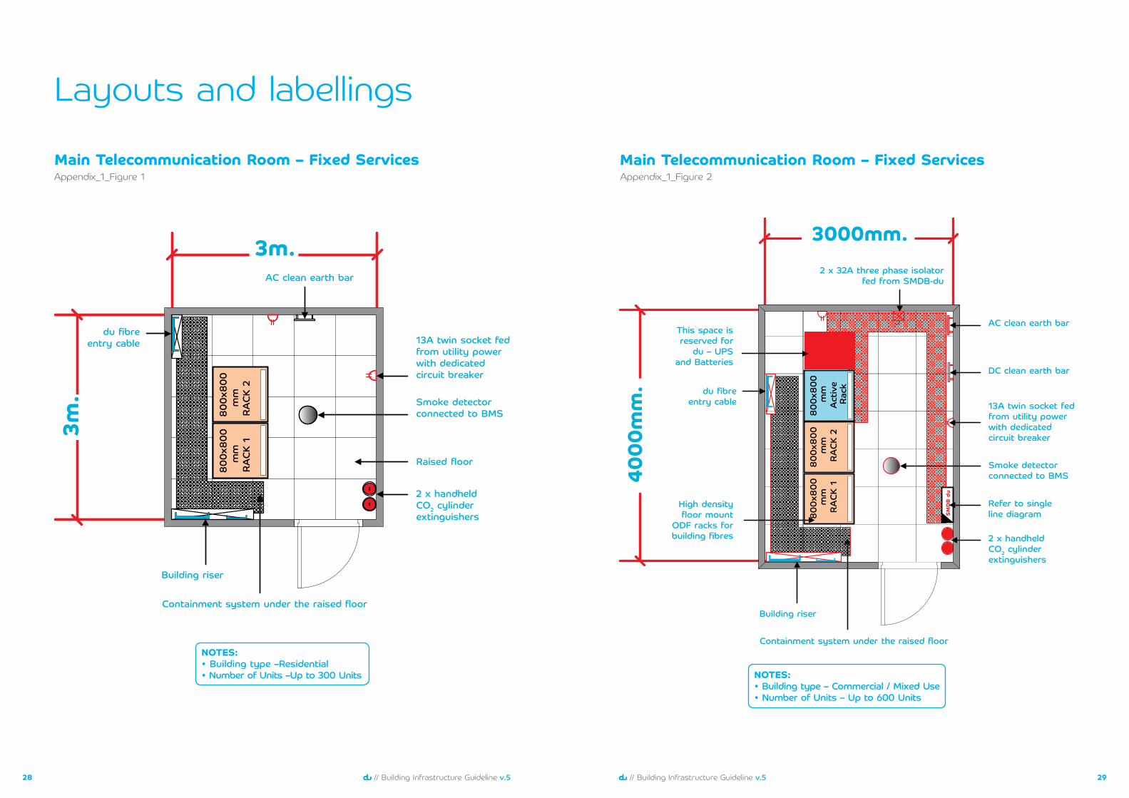
Main Telecommunication Room – Fixed Services
NOTES:• Building type –Residential• Number of Units –Up to 300 Units
Appendix_1_Figure 1
NOTES:• Building type – Commercial / Mixed Use• Number of Units – Up to 600 Units
٣٠٠٠mm.
٤٠٠٠
mm
. du fibreentry cable
٨٠٠x
٨٠٠
mm
RACK
٢
٨٠٠x
٨٠٠
mm
RACK
١
Containment system under the raised floor
AC clean earth bar
DC clean earth bar
Building riser
٨٠٠x
٨٠٠
mm
Act
ive
Rack
High densityfloor mount
ODF racks forbuilding fibres
SMD
B du
٢ x ٣٢A three phase isolatorfed from SMDB-du
This space isreserved for
du – UPSand Batteries
Refer to singleline diagram
٢ x handheldCO٢ cylinderextinguishers
Smoke detectorconnected to BMS
١٣A twin socket fedfrom utility powerwith dedicatedcircuit breaker
Main Telecommunication Room – Fixed ServicesAppendix_1_Figure 2
Layouts and labellings
3130 // Building Infrastructure Guideline v.5// Building Infrastructure Guideline v.5
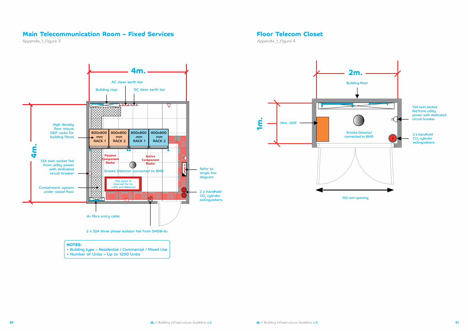
NOTES:• Building type – Residential / Commercial / Mixed Use• Number of Units – Up to 1200 Units
٤m.
٤m.
AC clean earth bar
DC clean earth bar
Smoke Detector connected to BMS
Building riser
du fibre entry cable
Containment systemunder raised floor
٨٠٠x٨٠٠ mm
RACK ٢
٨٠٠x٨٠٠ mm
RACK ١
٨٠٠x٨٠٠ mm
RACK ٢
٨٠٠x٨٠٠ mm
RACK ١
SMD
B du
ActiveComponent
Racks
PassiveComponent
Racks
This space isreserved for du
– UPS and Batteries
٢ x ٣٢A three phase isolator fed from SMDB-du
٢ x handheld CO٢ cylinderextinguishers
Refer tosingle linediagram
High densityfloor mount
ODF racks forbuilding fibres
١٣A twin socket fedfrom utility power
with dedicatedcircuit breaker
Main Telecommunication Room – Fixed ServicesAppendix_1_Figure 3
٢m.
١m.
Building Riser
Smoke Detectorconnected to BMS ٢ x handheld
CO٢ cylinderextinguishers
١٥٠ mm opening
١٣A twin socketfed from utilitypower with dedicatedcircuit breaker
Mini - ODF
Floor Telecom ClosetAppendix_1_Figure 4
3332 // Building Infrastructure Guideline v.5// Building Infrastructure Guideline v.5
٤m.
٤m.
٦٠٠x٦٠٠ m
m٢G
RackDC
System
٦٠٠x٦٠٠ mm٣G Rack
٦٠٠x٦٠٠ mm٤G Rack
٨٠٠x
٨٠٠
mm
RACK
٢
٨٠٠x
٨٠٠
mm
RACK
١
AC clean earth bar
DC clean earth bar
٢ x handheld CO٢ cylinder extinguishers
٦٣A three phaseisolator fedfrom essentialbuilding power(for GSM equipments)
١٣A twin socketfed from utility
power withdedicated
circuit breaker
١٣A twin socketfed from utilitypower withdedicatedcircuit breaker
١٣A twin socket fed from utility powerwith dedicated circuit breaker
Smoke detectorconnected to BMS
Building riser
du fibre entry cable
Containment systemat high level
High density floormount ODF racks
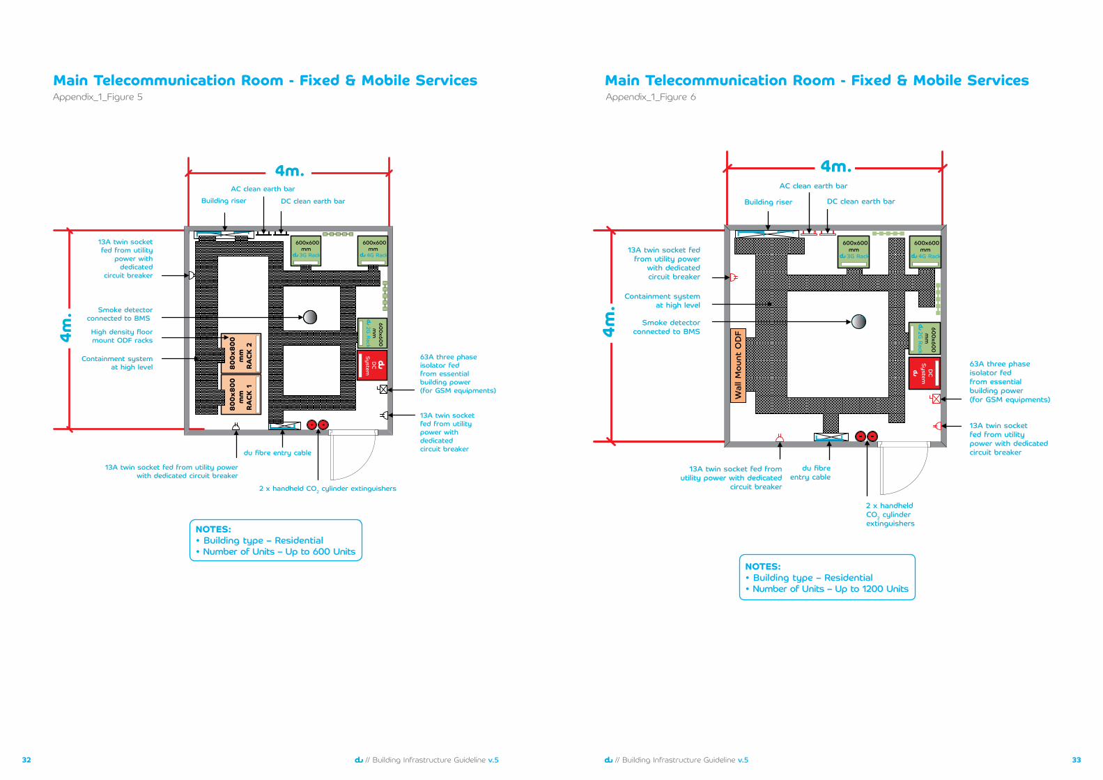
Main Telecommunication Room - Fixed & Mobile Services
NOTES:• Building type – Residential• Number of Units – Up to 600 Units
Appendix_1_Figure 5Main Telecommunication Room - Fixed & Mobile Services
NOTES:• Building type – Residential• Number of Units – Up to 1200 Units
٤m.
٤m.
Smoke detectorconnected to BMS
Building riser
Containment systemat high level
Wal
l Mou
nt O
DF
١٣A twin socket fedfrom utility power
with dedicatedcircuit breaker
AC clean earth bar
du fibreentry cable
DC clean earth bar
١٣A twin socket fed fromutility power with dedicated
circuit breaker
١٣A twin socketfed from utilitypower with dedicatedcircuit breaker
٢ x handheldCO٢ cylinderextinguishers
٦٣A three phaseisolator fedfrom essentialbuilding power(for GSM equipments)
٦٠٠x٦٠٠ mm٤G Rack
٦٠٠x٦٠٠ m
m٢G
Rack
٦٠٠x٦٠٠ mm٣G Rack
DC
System
Appendix_1_Figure 6
3534 // Building Infrastructure Guideline v.5// Building Infrastructure Guideline v.5
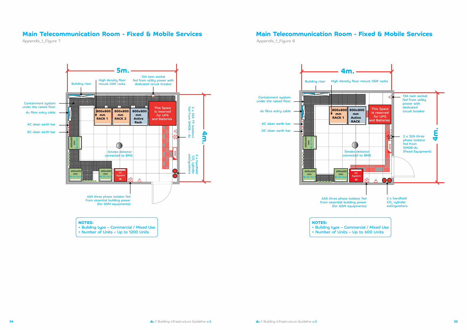
Main Telecommunication Room - Fixed & Mobile Services
NOTES:• Building type – Commercial / Mixed Use• Number of Units – Up to 600 Units
٤m.
AC clean earth bar
Building riser
du fibre entry cable
Containment systemunder the raised floor
DC clean earth bar
SMDB
٥m.
٦٣A three phase isolator fedfrom essential building power
(for GSM equipments)
Smoke detectorconnected to BMS
٨٠٠x٨٠٠ mm
RACK ٢
٨٠٠x٨٠٠ mm
RACK ١
٨٠٠x٨٠٠ mm
Active Rack
This Spaceis reservedfor UPS
and Batteries
High density floormount ODF racks
١٣A twin socketfed from utility power withdedicated circuit breaker
٢ x handheldCO
٢ cylinderextinguishers
٢ x ٣٢A TP isolators
fed from S
MDB – du
٦٠٠x٦٠٠ mm٣G Rack
DC System
٦٠٠x
٦٠٠
mm
٢G R
ack
٦٠٠x٦٠٠ mm٤G Rack
Appendix_1_Figure 7Main Telecommunication Room - Fixed & Mobile Services
NOTES:• Building type – Commercial / Mixed Use• Number of Units – Up to 1200 Units
٤m.
SMDB
٤m.
٨٠٠x٨٠٠ mm
ActiveRACK
٢ x ٣٢A threephase isolatorfed fromSMDB-du (Fixed Equipment)
High density floor mount ODF racks
٨٠٠x٨٠٠ mm
RACK ١
This Spaceis reservedfor UPS
and Batteries
Building riser
AC clean earth bar
DC clean earth bar
du fibre entry cable
Containment systemunder the raised floor
١٣A twin socketfed from utilitypower withdedicatedcircuit breaker
٢ x handheldCO٢ cylinderextinguishers
٦٣A three phase isolator fedfrom essential building power
(for GSM equipments)
٦٠٠x٦٠٠ mm٣G Rack
٦٠٠x٦٠٠ mm٤G Rack
٦٠٠x
٦٠٠
mm
٢G R
ack
Smoke detectorconnected to BMS
DC System
Appendix_1_Figure 8
3736 // Building Infrastructure Guideline v.5// Building Infrastructure Guideline v.5
Main Telecommunication Room - Fixed & Mobile Services
NOTES:• Building type – Residential / Commercial• Number of Units – Up to 1200 Units
٥m.
٥m.
SMDB
This
Spa
ce is
res
erve
dfo
r U
PS a
nd B
atte
ries
Smoke detectorconnected to BMS
AC clean earth bar
DC clean earth bar
du fibreentry cable
Containment systemunder the raised floor
High density floormount ODF racks
٢ x ٣٢A three phaseisolator fed fromSMDB-du (Fixed Equipment)
١٣A twin socket fedfrom utility power
with dedicatedcircuit breaker
٢ x handheldCO٢ cylinderextinguishers
٦٣A three phase isolator fedfrom essential building power
(for GSM equipments)
Building riser
٦٠٠x٦٠٠ mm٣G Rack
٦٠٠x٦٠٠ mm٤G Rack
٦٠٠x
٦٠٠
mm
٢G R
ack
DC System
ActiveComponent
Racks
٨٠٠x٨٠٠ mm
RACK ٢
٨٠٠x٨٠٠ mm
RACK ١
PassiveComponent
Racks
٨٠٠x٨٠٠ mm
RACK ٢
٨٠٠x٨٠٠ mm
RACK ١
Appendix_1_Figure 9Mobile Service Room
٣m.
٣m.
du Fibreentry cable
Smoke detectorconnected to BMS
AC clean earth bar
DC clean earth bar
١٣A twin socket fed fromutility power with dedicatedcircuit breaker
٢ x handheldCO٢ cylinderextinguishers
٦٣A three phase isolator fedfrom essential building power
Building riser
NOTES:• Provide Mobile Service Room for ever 10th floor
Appendix_1_Figure 10
3938 // Building Infrastructure Guideline v.5// Building Infrastructure Guideline v.5
Consolidated Cabinet Elevation
١٥٠mm
١٢ U
Cable Manager –١U
٢٤ Port Cat ٦Patch Panel–١U
PERFORATED DOOR
٦٠٠mm
۱ ۲ ۳ ٤ ٥ ٦ ۷ ۸ ۹ ۱۰ ۱۱ ۱۲ ۱۳ ۱٤ ۱٥ ۱٦ ۱۷ ۱۸ ۱۹ ۲۰ ۲۱ ۲۲ ۲۳ ۲٤
ATBFibre Terminal Boxwith ٢ Core LC/APC Adapter
٣U – Metallic Supportto hold du CPE
١٢ U consolidation cabinet with ١٥٠ mm depth
١٣A twin Socket
Appendix_1_Figure 11Consolidated Cabinet Elevation
12 U Consolidation Cabinet with 300mm depth12 U Consolidation Cabinet with 150mm depth
٣٠٠mm
١٢ U
PERFORATED DOOR
٦٠٠mm
۱ ۲ ۳ ٤ ٥ ٦ ۷ ۸ ۹ ۱۰ ۱۱ ۱۲ ۱۳ ۱٤ ۱٥ ۱٦ ۱۷ ۱۸ ۱۹ ۲۰ ۲۱ ۲۲ ۲۳ ۲٤
ATB
١٢ U consolidation cabinet with ٣٠٠ mm depth
Cable Manager –١U
٢٤ Port Cat ٦Patch Panel–١U
Fibre Terminal Boxwith ٢ Core LC/APC Adapter
١U – Metallic Supportto hold du CPE
١٣A twin Socket
Appendix_1_Figure 12
4140 // Building Infrastructure Guideline v.5// Building Infrastructure Guideline v.5
Mounting Details - Consolidated Cabinet
١٢ U cabinet
Wal
lW
all
Wal
l
١٢ U cabinet
Mounting option – ١(Mounted on the wall)
Mounting option – ٢(Partial mounted inside the wall)
Mounting option – ٣(Fully Mounted inside the wall)
١٢ U cabinet
Cabinet depth = ١٥٠mm / ٣٠٠mm
1.2 meter to 1.4 meter from FFL
1.2 meter to 1.4 meter from FFL
Finished floor level (FFL)
Finished floor level (FFL)
1.2 meter to 1.4 meter from FFL Finished floor level (FFL)
Cabinet depth = ١٥٠mm / ٣٠٠mm
١٥٠mm / ٣٠٠mm
Appendix_1_Figure 13Rack Elevation – Residential Type
٣٠٠m
m.
٤٢
٤٠٣٩٣٨
٣٤٣٥٣٦٣٧
٣٣
٠٢٠٣٠٤٠٥٠٦٠٧٠٨٠٩١٠
١٣١٤
١٦١٧١٨١٩٢٠٢١٢٢٢٣٢٤٢٥٢٦٢٧
٢٩٣٠٣١٣٢
١١١٢
٢٨
١٥
٤١
٠١iPatchFiber
۱۰
B A
۱۱
B A
۱۲
B A
۷
B A
۸
B A
۹
B A
٤
B A
٥
B A
٦
B A
۱
B A
۲
B A
۳
B A
Fibre Patch Panel– Supply and installation by du
Building Fibre Termination
Area٢٠ U – ٢٤ U
Vertical rings
Finished Floor Level
Raised Floor Tiles
٤٢
٤٠٣٩٣٨
٣٤٣٥٣٦٣٧
٣٣
٠٢٠٣٠٤٠٥٠٦٠٧٠٨٠٩١٠
١٣١٤
١٦١٧١٨١٩٢٠٢١٢٢٢٣٢٤٢٥٢٦٢٧
٢٩٣٠٣١٣٢
١١١٢
٢٨
١٥
٤١
٠١
Building Fibre Termination
Area٢٠ U – ٢٤ U
This area is reserved for the installation of splitters by du
١٨ U
This area is reserved for the installation of splitters by du
١٨ U
RACK-2
Space Reserved for du
RACK-1
NOTES:• Maximum number of fibre cores to
be terminated per rack are 480 cores• Building type – Residential• Number of Units – Up to 300 Units
Appendix_1_Figure 14
4342 // Building Infrastructure Guideline v.5// Building Infrastructure Guideline v.5
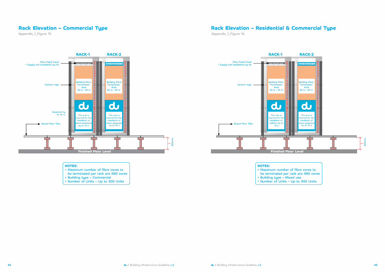
Rack Elevation – Commercial Type
٣٠٠m
m.
٤٢
٤٠٣٩٣٨
٣٤٣٥٣٦٣٧
٣٣
٠٢٠٣٠٤٠٥٠٦٠٧٠٨٠٩١٠
١٣١٤
١٦١٧١٨١٩٢٠٢١٢٢٢٣٢٤٢٥٢٦٢٧
٢٩٣٠٣١٣٢
١١١٢
٢٨
١٥
٤١
٠١iPatchFiber
۱۰
B A
۱۱
B A
۱۲
B A
۷
B A
۸
B A
۹
B A
٤
B A
٥
B A
٦
B A
۱
B A
۲
B A
۳
B A
Fibre Patch Panel– Supply and installation by du
Building Fibre Termination
Area٢٠ U – ٢٤ U
Vertical rings
Finished Floor Level
Raised Floor Tiles
٤٢
٤٠٣٩٣٨
٣٤٣٥٣٦٣٧
٣٣
٠٢٠٣٠٤٠٥٠٦٠٧٠٨٠٩١٠
١٣١٤
١٦١٧١٨١٩٢٠٢١٢٢٢٣٢٤٢٥٢٦٢٧
٢٩٣٠٣١٣٢
١١١٢
٢٨
١٥
٤١
٠١
Building Fibre Termination
Area٢٠ U – ٢٤ U
This area is reserved for the installation of
active equipmentby du ١٨ U
This area is reserved for the installation of
active equipmentby du ١٨ U
RACK-2
Space Reserved for du
RACK-1
Equipment bydu ١٨- U
NOTES:• Maximum number of fibre cores to
be terminated per rack are 480 cores• Building type – Commercial• Number of Units – Up to 300 Units
Appendix_1_Figure 15Rack Elevation – Residential & Commercial Type
NOTES:• Maximum number of fibre cores to
be terminated per rack are 480 cores• Building type – Mixed use• Number of Units – Up to 300 Units
٣٠٠m
m.
٤٢
٤٠٣٩٣٨
٣٤٣٥٣٦٣٧
٣٣
٠٢٠٣٠٤٠٥٠٦٠٧٠٨٠٩١٠
١٣١٤
١٦١٧١٨١٩٢٠٢١٢٢٢٣٢٤٢٥٢٦٢٧
٢٩٣٠٣١٣٢
١١١٢
٢٨
١٥
٤١
٠١iPatchFiber
10
B A
11
B A
12
B A
7
B A
8
B A
9
B A
4
B A
5
B A
6
B A
1
B A
2
B A
3
B A
Fibre Patch Panel– Supply and installation by du
Building Fibre Termination
Area٢٠ U – ٢٤ U
Vertical rings
Finished Floor Level
Raised Floor Tiles
٤٢
٤٠٣٩٣٨
٣٤٣٥٣٦٣٧
٣٣
٠٢٠٣٠٤٠٥٠٦٠٧٠٨٠٩١٠
١٣١٤
١٦١٧١٨١٩٢٠٢١٢٢٢٣٢٤٢٥٢٦٢٧
٢٩٣٠٣١٣٢
١١١٢
٢٨
١٥
٤١
٠١
Building Fibre Termination
Area٢٠ U – ٢٤ U
This area is reserved for the installation of
active equipmentby du ١٨ U
This area is reserved for the installation of splitters by du
١٨ U
RACK-2
Space Reserved for du
RACK-1
Appendix_1_Figure 16
4544 // Building Infrastructure Guideline v.5// Building Infrastructure Guideline v.5
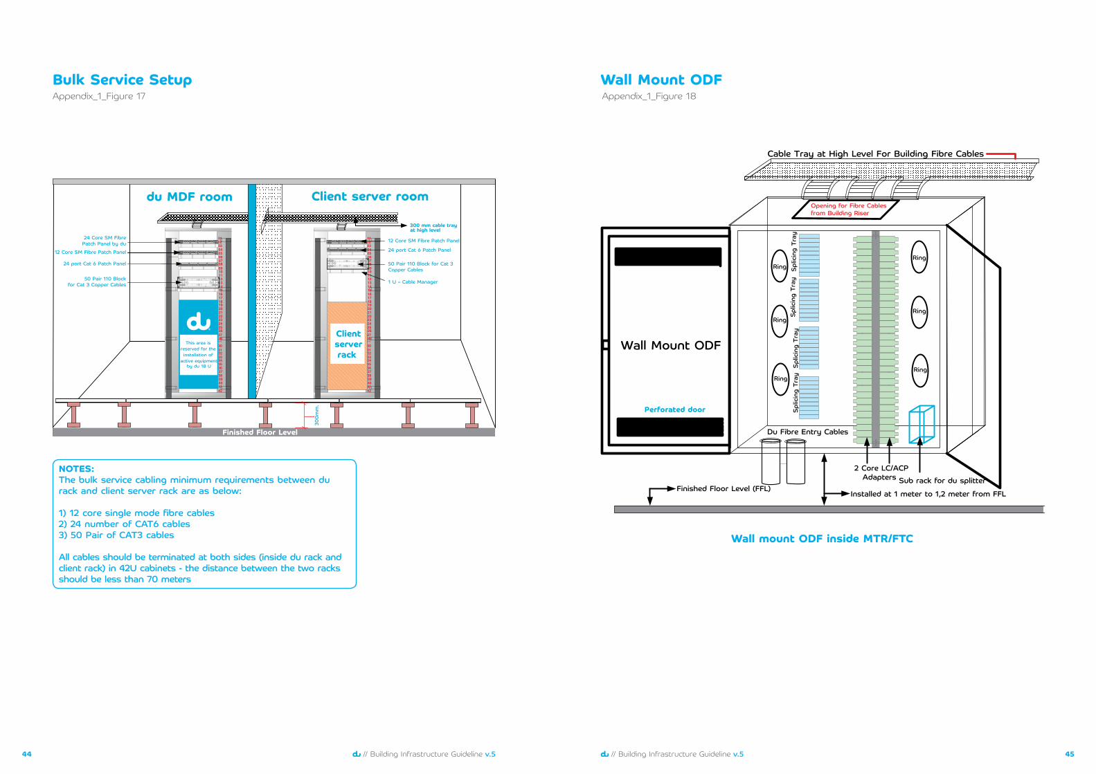
Bulk Service Setup
٣٠٠ mm cable trayat high level
42
403938
34353637
33
020304050607080910
1314
161718192021222324252627
۲۹303132
1112
28
15
41
01
iPatchFiber
۱۰
B A
۱۱
B A
۱۲
B A
۷
B A
۸
B A
۹
B A
٤
B A
٥
B A
٦
B A
۱
B A
۲
B A
۳
B A
42
403938
34353637
33
020304050607080910
1314
161718192021222324252627
۲۹303132
1112
28
15
41
01
Clientserverrack
۱ ۲ ۳ ٤ ٥ ٦ ۷ ۸ ۹ ۱۰ ۱۱ ۱۲ ۱۳ ۱٤ ۱٥ ۱٦ ۱۷ ۱۸ ۱۹ ۲۰ ۲۱ ۲۲ ۲۳ ۲٤
iPatchFiber
۱۰
B A
۱۱
B A
۱۲
B A
۷
B A
۸
B A
۹
B A
٤
B A
٥
B A
٦
B A
۱
B A
۲
B A
۳
B A
iPatchFiber
10
B A
11
B A
12
B A
7
B A
8
B A
9
B A
4
B A
5
B A
6
B A
1
B A
2
B A
3
B A
۱ ۲ ۳ ٤ ٥ ٦ ۷ ۸ ۹ ۱۰ ۱۱ ۱۲ ۱۳ ۱٤ ۱٥ ۱٦ ۱۷ ۱۸ ۱۹ ۲۰ ۲۱ ۲۲ ۲۳ ۲٤ ٢٤ port Cat ٦ Patch Panel
١٢ Core SM Fibre Patch Panel
٥٠ Pair ١١٠ Block for Cat ٣Copper Cables
١ U – Cable Manager
١٢ Core SM Fibre Patch Panel
٢٤ port Cat ٦ Patch Panel
٥٠ Pair ١١٠ Blockfor Cat ٣ Copper Cables
٢٤ Core SM FibrePatch Panel by du
du MDF room Client server room
٣٠٠m
m.
Finished Floor Level
This area is reserved for the installation of
active equipmentby du ١٨ U
NOTES:The bulk service cabling minimum requirements between du rack and client server rack are as below:
1) 12 core single mode fibre cables2) 24 number of CAT6 cables3) 50 Pair of CAT3 cables
All cables should be terminated at both sides (inside du rack and client rack) in 42U cabinets - the distance between the two racks should be less than 70 meters
Appendix_1_Figure 17
Wall mount ODF inside MTR/FTC
Wall Mount ODF
Sub rack for du splitter٢ Core LC/ACP
Adapters
Ring
Ring
Ring
Opening for Fibre Cablesfrom Building Riser
Du Fibre Entry Cables
Spl
icin
g Tr
aySpl
icin
g Tr
aySpl
icin
g Tr
aySpl
icin
g Tr
ay
Ring
Ring
Ring
Wall Mount ODF
Perforated door
Finished Floor Level (FFL)Installed at ١ meter to ١٫٢ meter from FFL
Cable Tray at High Level For Building Fibre Cables
Appendix_1_Figure 18
4746 // Building Infrastructure Guideline v.5// Building Infrastructure Guideline v.5
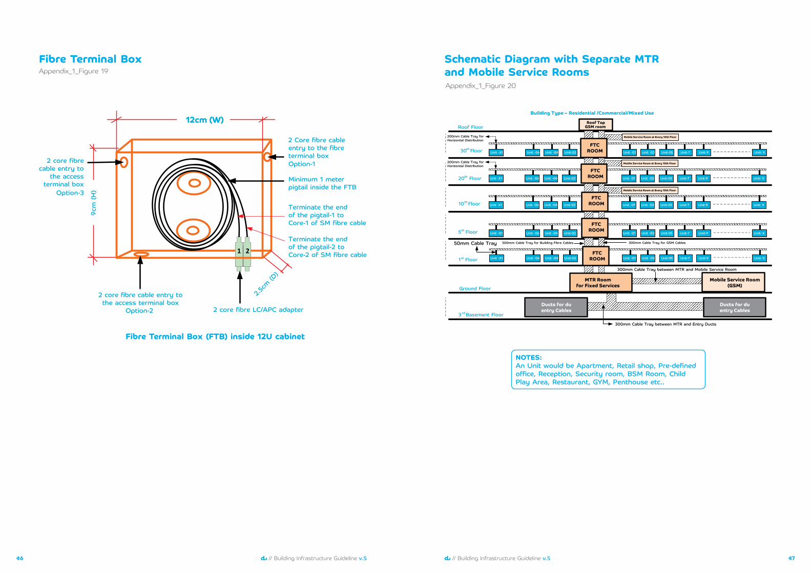
Fibre Terminal Box
Fibre Terminal Box (FTB) inside 12U cabinet
12cm (W)
9cm
(H)
2.5cm
(D)
2 Core fibre cableentry to the fibreterminal boxOption-12 core fibre
cable entry tothe access
terminal boxOption-3
2 core fibre cable entry tothe access terminal box
Option-2 2 core fibre LC/APC adapter
Minimum 1 meterpigtail inside the FTB
Terminate the endof the pigtail-1 toCore-1 of SM fibre cable
Terminate the endof the pigtail-2 toCore-2 of SM fibre cable1 2
Appendix_1_Figure 19Schematic Diagram with Separate MTR and Mobile Service Rooms
Unit -01 Unit -03 Unit-05 Unit-7 Unit-9 Unit- XUnit -06 Unit -04 Unit-02Unit -X1
Unit -01 Unit -03 Unit-05 Unit-7 Unit-9 Unit- XUnit -06 Unit -04 Unit-02Unit -X1
Unit -01 Unit -03 Unit-05 Unit-7 Unit-9 Unit- XUnit -06 Unit -04 Unit-02Unit -X1
Unit -01 Unit -03 Unit-05 Unit-7 Unit-9 Unit- XUnit -06 Unit -04 Unit-02Unit -X1
Ground Floor
١st Floor
٥th Floor
١٠thFloor
٢٠th Floor
٣٠thFloor
Roof Floor
٣rdBasement Floor
Mobile Service Room(GSM)
٣٠٠mm Cable Tray between MTR and Mobile Service Room
Ducts for duentry Cables
Ducts for duentry Cables
٣٠٠mm Cable Tray between MTR and Entry Ducts
MTR Roomfor Fixed Services
FTCROOM
٣٠٠mm Cable Tray for GSM Cables٥٠٠mm Cable Tray for Building Fibre Cables
Unit -01 Unit -03 Unit-05 Unit-7 Unit-9 Unit- XUnit -06 Unit -04 Unit-02Unit -X1
٥٠mm Cable Tray
Building Type – Residential /Commercial/Mixed Use
Roof TopGSM room
٢٠٠mm Cable Tray forHorizontal Distribution
٢٠٠mm Cable Tray forHorizontal Distribution
FTCROOM
FTCROOM
FTCROOM
FTCROOM
Mobile Service Room at Every ١٠th Floor
Mobile Service Room at Every ١٠th Floor
Mobile Service Room at Every ١٠th Floor
Appendix_1_Figure 20
NOTES:An Unit would be Apartment, Retail shop, Pre-defined office, Reception, Security room, BSM Room, Child Play Area, Restaurant, GYM, Penthouse etc..
4948 // Building Infrastructure Guideline v.5// Building Infrastructure Guideline v.5
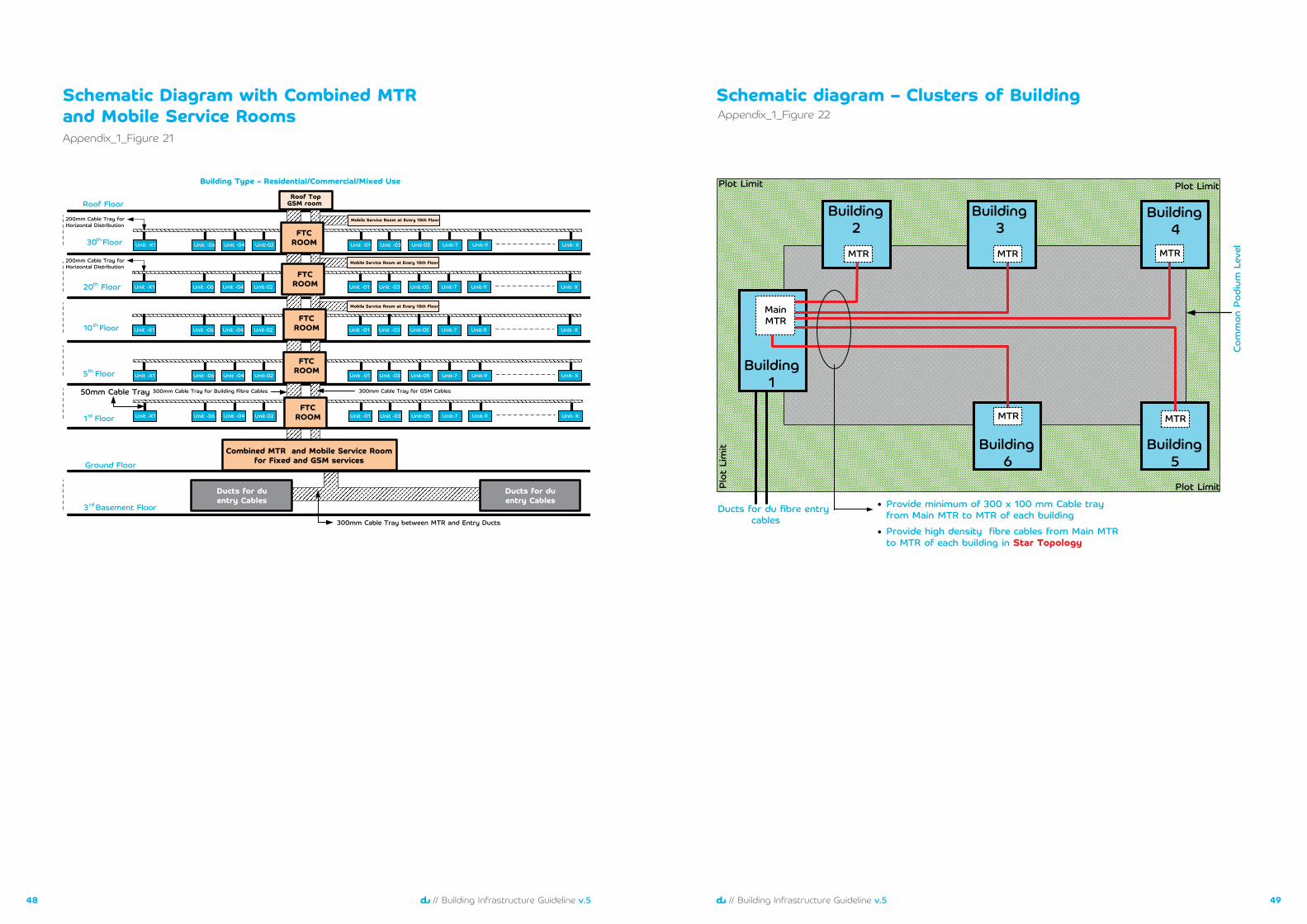
Schematic Diagram with Combined MTR and Mobile Service Rooms
Unit -01 Unit -03 Unit-05 Unit-7 Unit-9 Unit- XUnit -06 Unit -04 Unit-02Unit -X1
Unit -01 Unit -03 Unit-05 Unit-7 Unit-9 Unit- XUnit -06 Unit -04 Unit-02Unit -X1
Unit -01 Unit -03 Unit-05 Unit-7 Unit-9 Unit- XUnit -06 Unit -04 Unit-02Unit -X1
Unit -01 Unit -03 Unit-05 Unit-7 Unit-9 Unit- XUnit -06 Unit -04 Unit-02Unit -X1
Ground Floor
١st Floor
٥th Floor
١٠thFloor
٢٠th Floor
٣٠thFloor
Roof Floor
٣rdBasement Floor
Ducts for duentry Cables
Ducts for duentry Cables
٣٠٠mm Cable Tray between MTR and Entry Ducts
Combined MTR and Mobile Service Roomfor Fixed and GSM services
FTCROOM
٣٠٠mm Cable Tray for GSM Cables٥٠٠mm Cable Tray for Building Fibre Cables
Unit -01 Unit -03 Unit-05 Unit-7 Unit-9 Unit- XUnit -06 Unit -04 Unit-02Unit -X1
٥٠mm Cable Tray
Building Type – Residential/Commercial/Mixed Use
Roof TopGSM room
٢٠٠mm Cable Tray forHorizontal Distribution
٢٠٠mm Cable Tray forHorizontal Distribution
FTCROOM
FTCROOM
FTCROOM
FTCROOM
Mobile Service Room at Every ١٠th Floor
Mobile Service Room at Every ١٠th Floor
Mobile Service Room at Every ١٠th Floor
Appendix_1_Figure 21
Schematic diagram – Clusters of Building
Building١
Building٦
Building٥
Building٤
Building٣
Building٢
MainMTR
MTR MTR
MTR
MTR
MTR
Provide minimum of ٣٠٠ x ١٠٠ mm Cable trayfrom Main MTR to MTR of each building Ducts for du fibre entry
cables
Com
mon
Pod
ium
Lev
el
Plot Limit
Plot LimitPlot Limit
Plot
Lim
it
Provide high density fibre cables from Main MTRto MTR of each building in Star Topology
Appendix_1_Figure 22
5150 // Building Infrastructure Guideline v.5// Building Infrastructure Guideline v.5
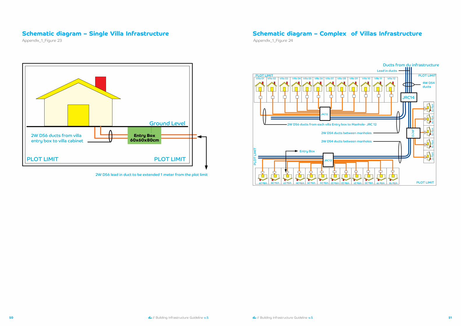
Schematic diagram – Single Villa Infrastructure
Entry Box٦٠x٦٠x٨٠cm
Ground Level
PLOT LIMITPLOT LIMIT
٢W D٥٦ lead in duct to be extended ١ meter from the plot limit
٢W D٥٦ ducts from villa entry box to villa cabinet
Appendix_1_Figure 23Schematic diagram – Complex of Villas Infrastructure
Villa 01
Villa 18
Villa 02
JRC12
JRC١٢
JRC١٢
JRC١٤
Ducts from du infrastructure
Villa 03 Villa 04 Villa 05 Villa 06 Villa 07 Villa 08 Villa 09 Villa 10 Villa 11 Villa 12
Villa 13Villa 14
Villa 15Villa 16
Villa 17
Villa 19Villa 20Villa 21 Villa 22Villa 23Villa 24 Villa 25Villa 26Villa 27 Villa 28Villa 29
٢W D٥٦ ducts from each villa Entry box to Manhole- JRC ١٢
٢W D٥٤ ducts between manholes
٢W D٥٤ ducts between manholes
٤W D٥٤ ducts
PLOT LIMIT
PLOT LIMIT
PLOT LIMIT
PLO
T LI
MIT Entry Box
Lead in ducts
Appendix_1_Figure 24
5352 // Building Infrastructure Guideline v.5// Building Infrastructure Guideline v.5
Tile Cutting Layout
٣٠٠mm (W) x ٣٠٠mm (H) Opening for Cables Entry
٦٠٠mm (W)
٦٠٠mm
(H)
١٥٠mm ١٥٠mm
Appendix_1_Figure 25Schematic Diagram – High Rise Building
Unit -01 Unit -03 Unit-05 Unit-7 Unit-9 Unit- XUnit -06 Unit-02Unit -X1
Unit -01 Unit -03 Unit-05 Unit-7 Unit-9 Unit- XUnit -06 Unit-02Unit -X1
Unit -01 Unit -03 Unit-05 Unit-7 Unit-9 Unit- XUnit -06 Unit-02Unit -X1
Unit -01 Unit -03 Unit-05 Unit-7 Unit-9 Unit- XUnit -06 Unit-02Unit -X1
Ground Floor
٢٠th Floor
٣٠th Floor
٤٠th Floor
٥٠th Floor
٦٠th Floor
٧٠th Floor with roof
٣rdBasement Floor
Ducts for duentry Cables
Ducts for duentry Cables
٣٠٠mm Cable Tray between MTR and Entry Ducts
FTCROOM
MINI ODF
FTCROOM
MINI ODF
FTCROOM
MINI ODF
FTCROOM
٣٠٠mm Cable Tray for GSM Cables٥٠٠mm Cable Tray forBuilding Fibre Cables
Unit -01 Unit -03 Unit-05 Unit-7 Unit-9 Unit- XUnit -06 Unit-02Unit -X1
٥٠mm Cable Tray
Building Type – Residential/Commercial/Mixed Use
Roof TopGSM room
٢٠٠mm Cable Tray forHorizontal Distribution
٢٠٠mm Cable Tray forHorizontal Distribution
Mobile Service Room at Every ١٠th Floor
Indoor Multi Core SM Fibre Cables toConnect from MTR to Mini ODF’s
FTCROOM
MINI ODF
MTR ROOM
Appendix_1_Figure 26
5554 // Building Infrastructure Guideline v.5// Building Infrastructure Guideline v.5
Power Single line diagram – SMDB
٣٢A TPMCCB
٣٢A TPMCCB
٣٢A TPMCCB
٣٢A TPMCCB
spaces٣٢A TPMCCB
٦٣A TP Iso.
ESMDB-MTR supplied by building contractor
Essential DB
PermanentPower
GeneratorPower
ATS
١ ٢ ٣
٣ x spares
٣٢A TP Isolator
٣٢A TP Isolator
٤Cx ١٠mm٢ XLPE/SWA + ١CX١٠ ECC
Appendix_1_Figure 27JRC 12 Top View
4 way D54 DuctFor building entry (Lead in) /
Road crossing if required only
�
���
5 ��
�
�5�
��
����
�����5� � 55 �55 �5�
�55
�55
��5
��4
5
�5�
�5�
AA
PLAN(Item 3 and surround omitted)
Appendix_2_Figure 28
5756 // Building Infrastructure Guideline v.5// Building Infrastructure Guideline v.5
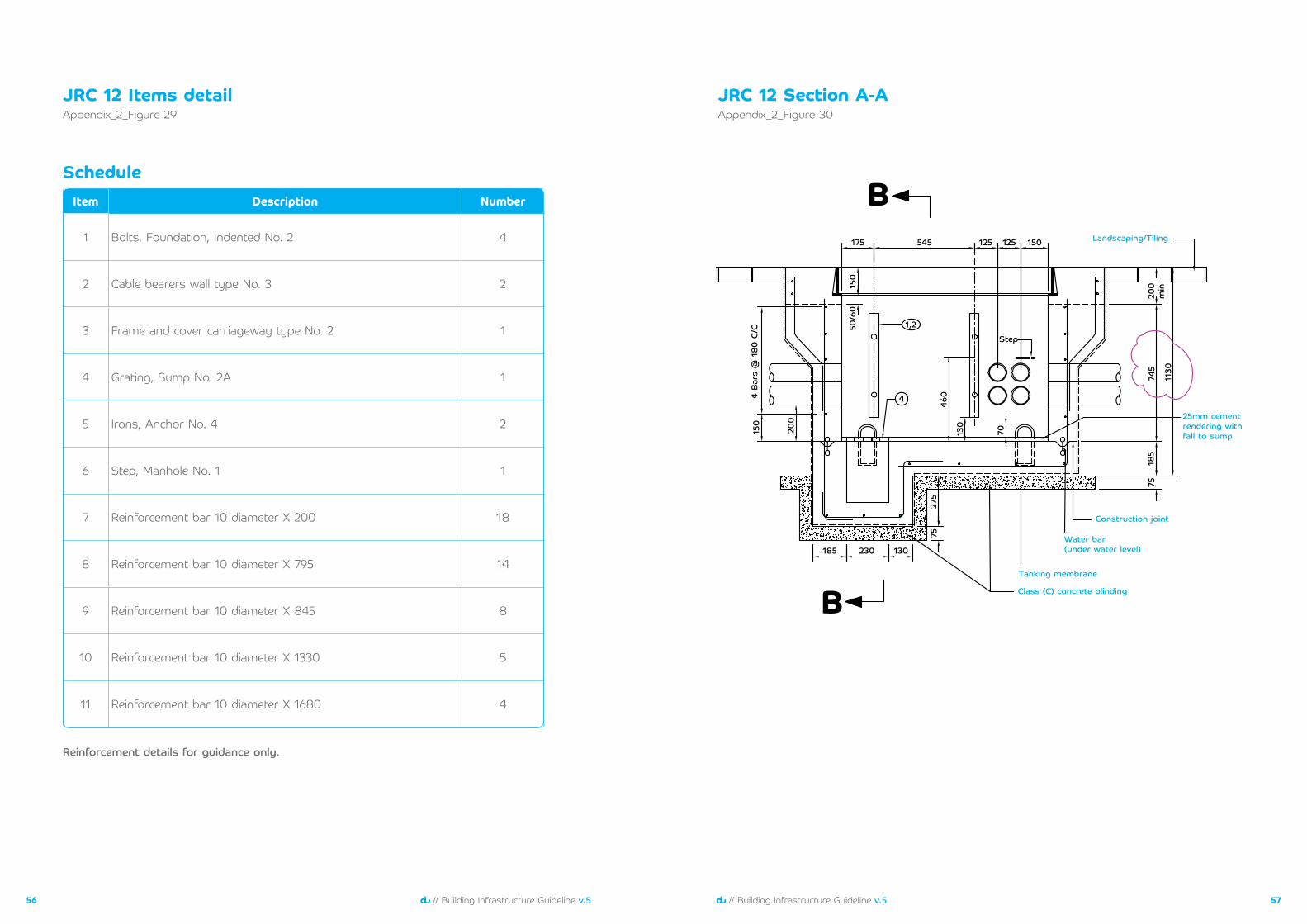
JRC 12 Items detailAppendix_2_Figure 29
Reinforcement details for guidance only.
Schedule
JRC 12 Section A-A
١٧٥
١٥٠
50/6
0
460
745
200
min
185
75
1130
٢٠٠
١٥٠
4 Ba
rs @
180
C/C
١٣٠
70
٢٧٥
١٨٥ ٢٣٠ ١٣٠
٧٥
٥٤٥
١,٢Step
٤
١٢٥ ١٢٥ ١٥٠
٢٥mm cementrendering withfall to sump
Construction joint
Landscaping/Tiling
Water bar(under water level)
Tanking membrane
Class (C) concrete blindingB
B
Appendix_2_Figure 30
Item Description Number
1 Bolts, Foundation, Indented No. 2 4
2 Cable bearers wall type No. 3 2
3 Frame and cover carriageway type No. 2 1
4 Grating, Sump No. 2A 1
5 Irons, Anchor No. 4 2
6 Step, Manhole No. 1 1
7 Reinforcement bar 10 diameter X 200 18
8 Reinforcement bar 10 diameter X 795 14
9 Reinforcement bar 10 diameter X 845 8
10 Reinforcement bar 10 diameter X 1330 5
11 Reinforcement bar 10 diameter X 1680 4
5958 // Building Infrastructure Guideline v.5// Building Infrastructure Guideline v.5
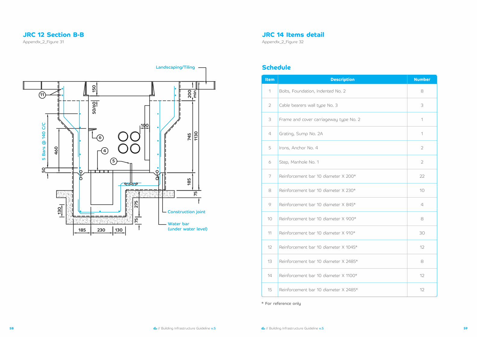
JRC 12 Section B-B
Landscaping/Tiling
Construction joint
Water bar(under water level)
5 Bar
s @
140
C/C
١٨٥ ٢٣٠ ١٣٠
٢٧٥
٧٥
١3٠
50
185
7574
5
100
1130
200
min١٥
٠50
/60
٦
١١
٤
٥
460
Appendix_2_Figure 31JRC 14 Items detailAppendix_2_Figure 32
Item Description Number
1 Bolts, Foundation, Indented No. 2 8
2 Cable bearers wall type No. 3 3
3 Frame and cover carriageway type No. 2 1
4 Grating, Sump No. 2A 1
5 Irons, Anchor No. 4 2
6 Step, Manhole No. 1 2
7 Reinforcement bar 10 diameter X 200* 22
8 Reinforcement bar 10 diameter X 230* 1٠
9 Reinforcement bar 10 diameter X 845* 4
10 Reinforcement bar 10 diameter X 900* 8
11 Reinforcement bar 10 diameter X 910* 3٠
12 Reinforcement bar 10 diameter X 1045* 12
13 Reinforcement bar 10 diameter X 2485* 8
14 Reinforcement bar 10 diameter X 1100* 12
15 Reinforcement bar 10 diameter X 2485* 12
Schedule
* For reference only
6160 // Building Infrastructure Guideline v.5// Building Infrastructure Guideline v.5
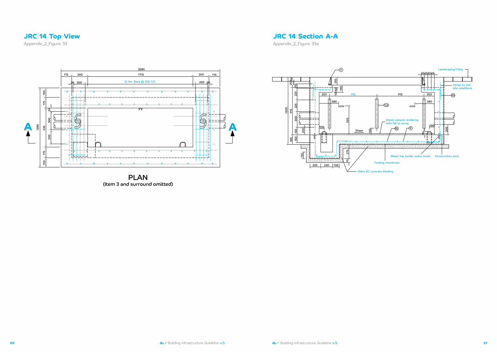
JRC 14 Top View
12 No. Bars @ 220 C/C
1285
150
175
635
300
230
55
175
175 260 1715 260 175
200 20
2585
20020
150
AA
PLAN(Item 3 and surround omitted)
Appendix_2_Figure 33JRC 14 Section A-AAppendix_2_Figure 33a
Construction jointWater bar (under water level)
Tanking membrane
Class (C) concrete blinding
Landscaping/Tiling
Varies to suitsite conditions
٢٥mm cement renderingwith fall to sump
١٣٠٠
١٨٥
٩١٥
9022
5
140
225
200
300
560
130 200
70
130
130
100 100
203 203915
Slope
915
1,2
15 9
3
10
65656565
380 380
230205
50/6
0
150
150
150
275
75
٢٠٠
min
.
6362 // Building Infrastructure Guideline v.5// Building Infrastructure Guideline v.5
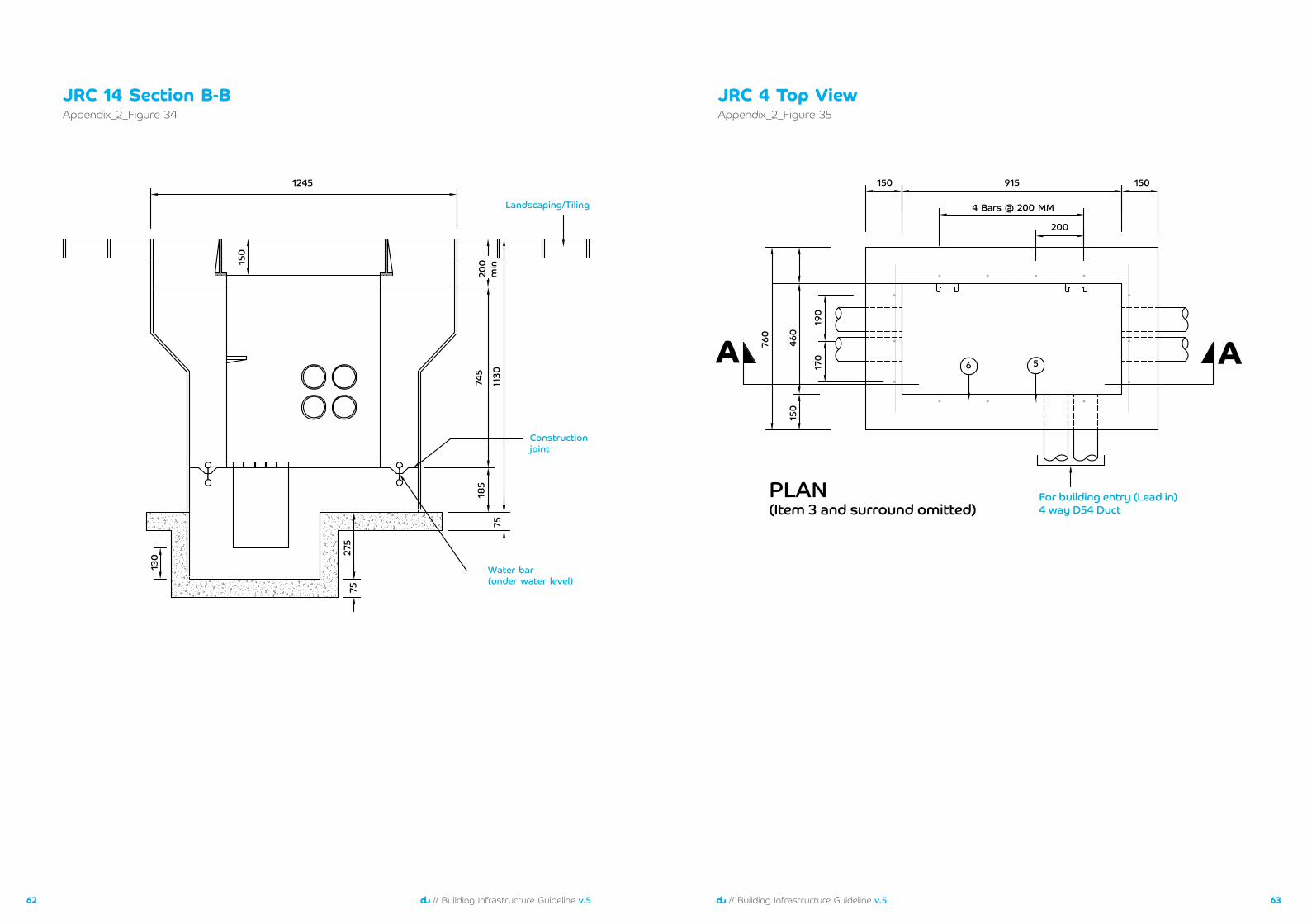
Appendix_2_Figure 34JRC 14 Section B-B
Constructionjoint
Landscaping/Tiling
Water bar(under water level)
١٣٠ 27
575
75
185
745
150
1245
1130
200
min
JRC 4 Top ViewAppendix_2_Figure 35
AA
PLAN(Item 3 and surround omitted)
١٥٠
460
150
170
190
760
١٥٠
200
915
6 5
4 Bars @ 200 MM
For building entry (Lead in)4 way D54 Duct
6564 // Building Infrastructure Guideline v.5// Building Infrastructure Guideline v.5
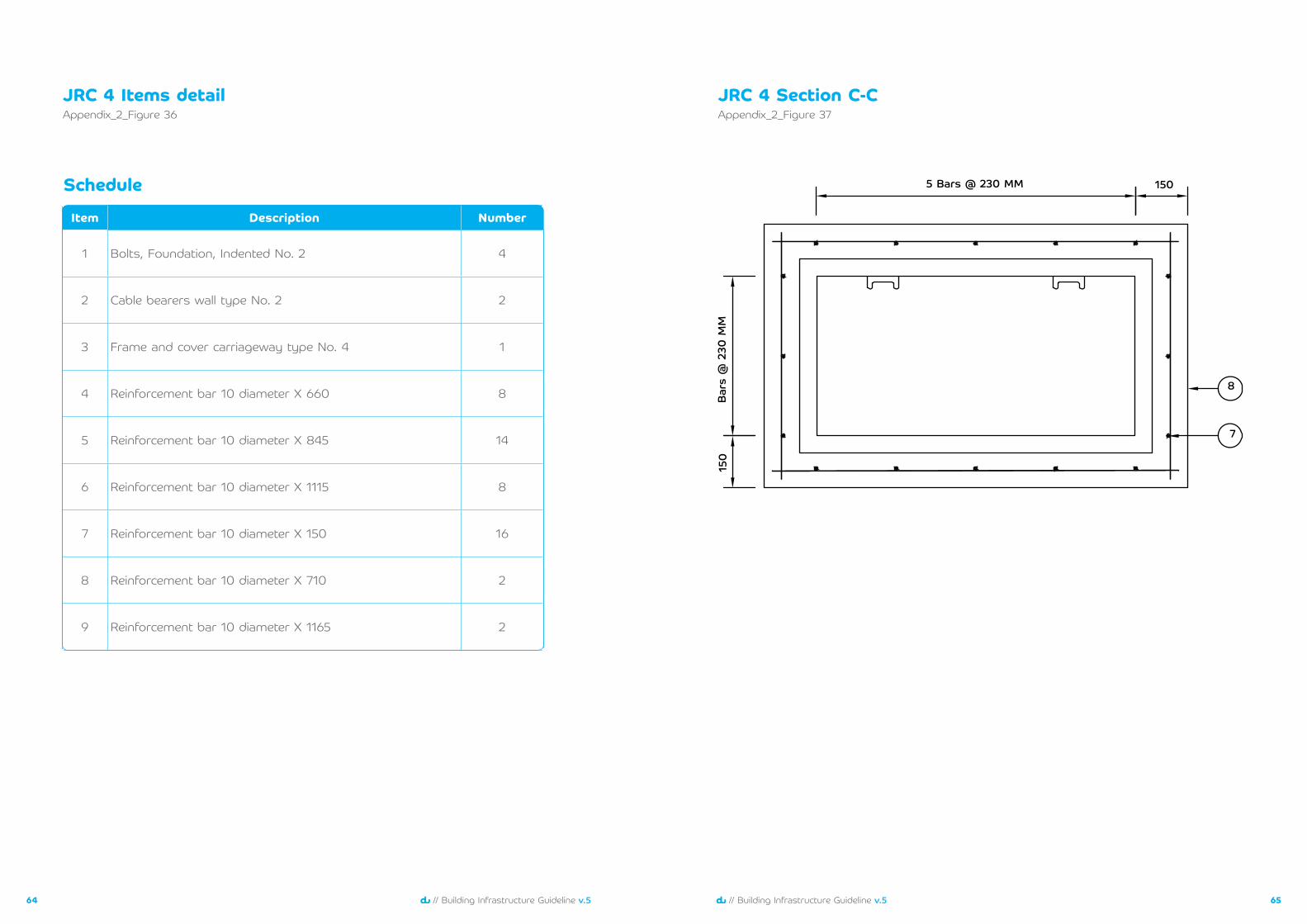
Appendix_2_Figure 36JRC 4 Items detail JRC 4 Section C-C
Appendix_2_Figure 37
5 Bars @ 230 MM
Bar
s @
230
MM
150
150
8
7
Item Description Number
1 Bolts, Foundation, Indented No. 2 4
2 Cable bearers wall type No. 2 2
3 Frame and cover carriageway type No. 4 1
4 Reinforcement bar 10 diameter X 660 8
5 Reinforcement bar 10 diameter X 845 14
6 Reinforcement bar 10 diameter X 1115 8
7 Reinforcement bar 10 diameter X 150 16
8 Reinforcement bar 10 diameter X 710 2
9 Reinforcement bar 10 diameter X 1165 2
Schedule
6766 // Building Infrastructure Guideline v.5// Building Infrastructure Guideline v.5
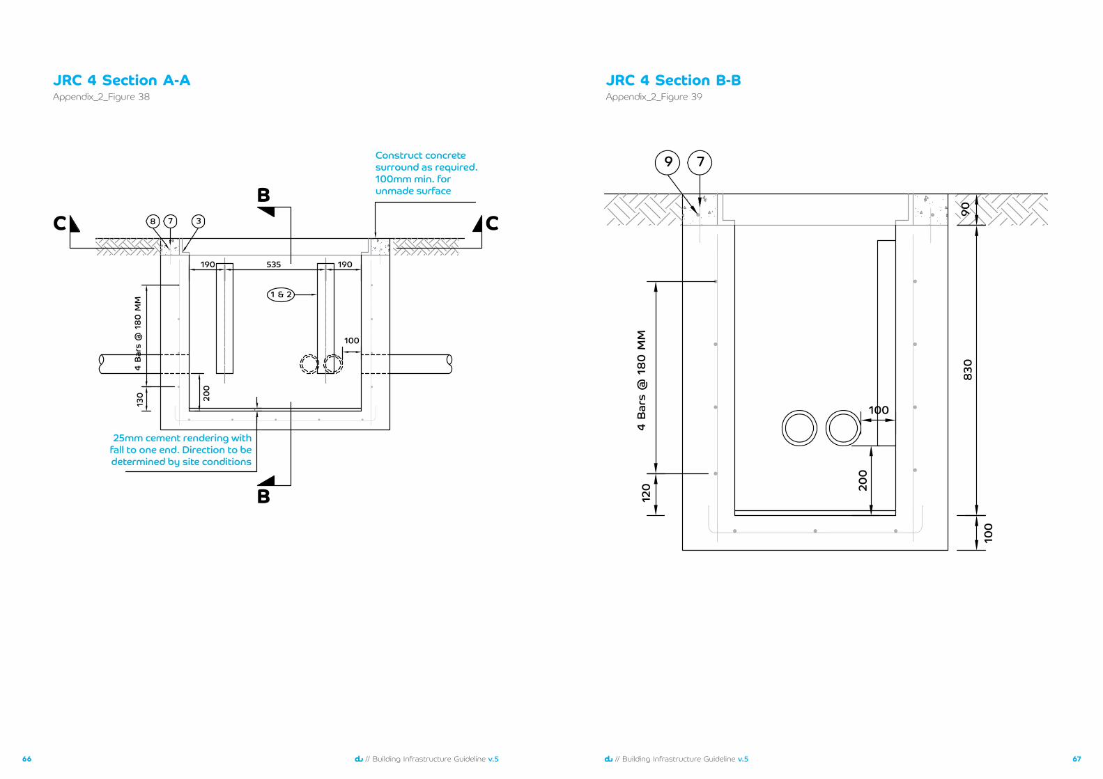
Appendix_2_Figure 38JRC 4 Section A-A
B
BCC
4 Bar
s @
180
MM
130 20
0
190 535 190
1 & 2
8 7 3
100
25mm cement rendering withfall to one end. Direction to bedetermined by site conditions
Construct concretesurround as required. 100mm min. forunmade surface
JRC 4 Section B-BAppendix_2_Figure 39
4 Bar
s @
180
MM
120 20
0
830
100
100
90
9 7
6968 // Building Infrastructure Guideline v.5// Building Infrastructure Guideline v.5
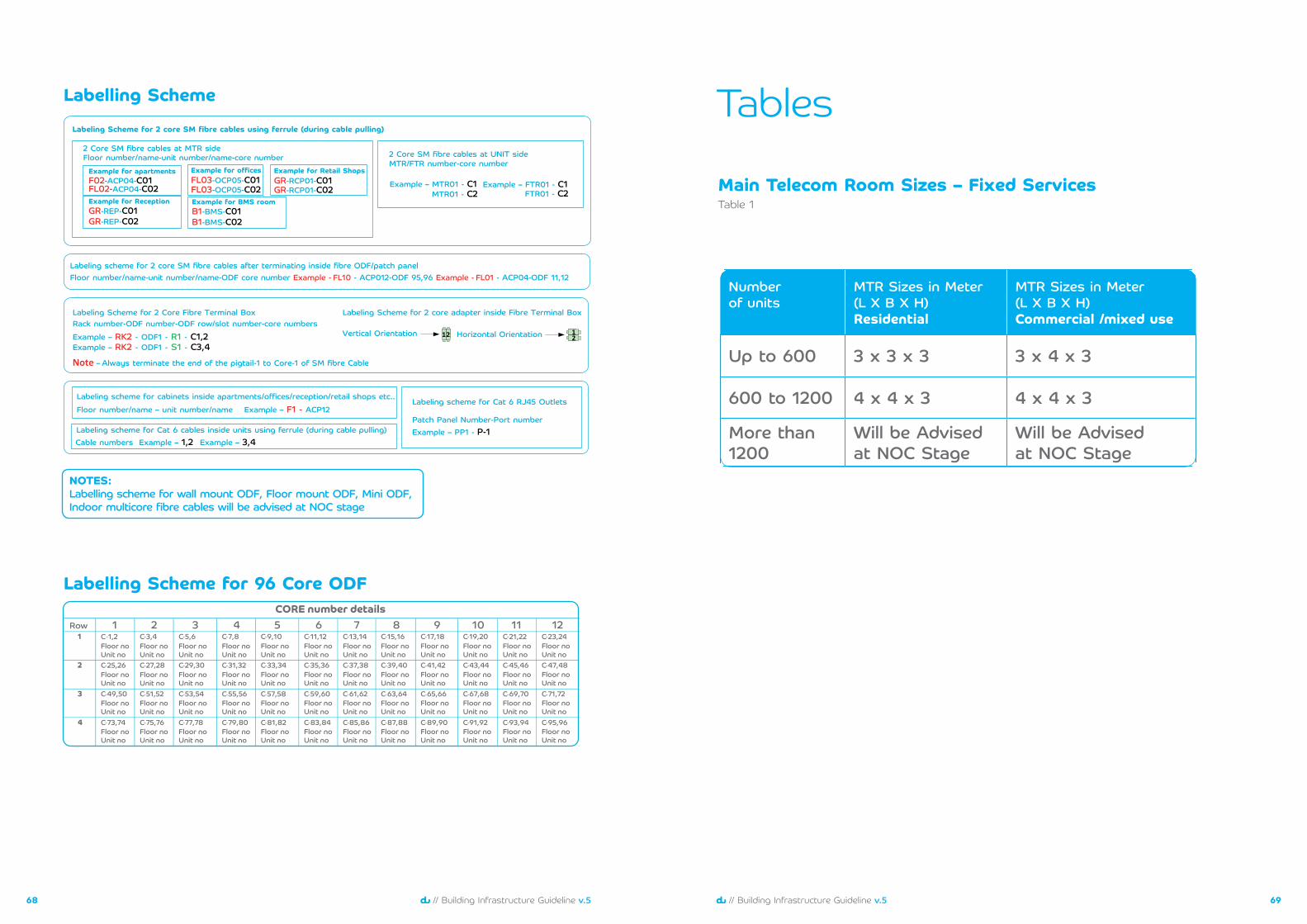
Number of units
MTR Sizes in Meter(L X B X H) Residential
MTR Sizes in Meter(L X B X H) Commercial /mixed use
Up to 600 3 x 3 x 3 3 x 4 x 3
600 to 1200 4 x 4 x 3 4 x 4 x 3
More than 1200
Will be Advised at NOC Stage
Will be Advised at NOC Stage
Main Telecom Room Sizes – Fixed ServicesTable 1
Tables
NOTES:Labelling scheme for wall mount ODF, Floor mount ODF, Mini ODF, Indoor multicore fibre cables will be advised at NOC stage
Labelling Scheme
Labelling Scheme for 96 Core ODF
Labeling Scheme for 2 core SM fibre cables using ferrule (during cable pulling)
2 Core SM fibre cables at MTR side2 Core SM fibre cables at UNIT sideMTR/FTR number-core number
F02-ACP04-C01
GR-REP-C01GR-REP-C02
Example for apartments Example for offices Example for Retail ShopsFL03-OCP05-C01
FL02-ACP04-C02 FL03-OCP05-C02GR-RCP01-C01GR-RCP01-C02
Example for Reception Example for BMS roomB1-BMS-C01B1-BMS-C02
MTR01 - C2 FTR01 - C2Example – MTR01 - C1 Example – FTR01 - C1
Floor number/name-unit number/name-core number
Labeling scheme for 2 core SM fibre cables after terminating inside fibre ODF/patch panelFloor number/name-unit number/name-ODF core number Example - FL10 - ACP012-ODF 95,96 Example - FL01 - ACP04-ODF 11,12
Labeling Scheme for 2 Core Fibre Terminal Box Rack number-ODF number-ODF row/slot number-core numbersExample – RK2 - ODF1 - R1 - C1,2Example – RK2 - ODF1 - S1 - C3,4
Note – Always terminate the end of the pigtail-1 to Core-1 of SM fibre Cable
Labeling Scheme for 2 core adapter inside Fibre Terminal Box
Vertical Orientation 12 Horizontal Orientation 12
Labeling scheme for cabinets inside apartments/offices/reception/retail shops etc..Floor number/name – unit number/name Example – F1 - ACP12
Labeling scheme for Cat 6 cables inside units using ferrule (during cable pulling) Cable numbers Example – 1,2 Example – 3,4
Labeling scheme for Cat 6 RJ45 Outlets
Patch Panel Number-Port numberExample – PP1 - P-1
CORE number detailsRow 1 2 3 4 5 6 7 8 9 10 11 12
1 C-1,2Floor noUnit no
Floor noUnit no
Floor noUnit no
Floor noUnit no
Floor noUnit no
Floor noUnit no
Floor noUnit no
Floor noUnit no
Floor noUnit no
Floor noUnit no
Floor noUnit no
Floor noUnit no
Floor noUnit no
Floor noUnit no
Floor noUnit no
Floor noUnit no
Floor noUnit no
Floor noUnit no
Floor noUnit no
Floor noUnit no
Floor noUnit no
Floor noUnit no
Floor noUnit no
Floor noUnit no
Floor noUnit no
Floor noUnit no
Floor noUnit no
Floor noUnit no
Floor noUnit no
Floor noUnit no
Floor noUnit no
Floor noUnit no
Floor noUnit no
Floor noUnit no
Floor noUnit no
Floor noUnit no
Floor noUnit no
Floor noUnit no
Floor noUnit no
Floor noUnit no
Floor noUnit no
Floor noUnit no
Floor noUnit no
Floor noUnit no
Floor noUnit no
Floor noUnit no
Floor noUnit no
Floor noUnit no
C-3,4 C-5,6 C-7,8 C-9,10 C-11,12 C-13,14 C-15,16 C-17,18 C-19,20 C-21,22 C-23,24
2 C-25,26 C-27,28 C-29,30 C-31,32 C-33,34 C-35,36 C-37,38 C-39,40 C-41,42 C-43,44 C-45,46 C-47,48
3 C-49,50 C-51,52 C-53,54 C-55,56 C-57,58 C-59,60 C-61,62 C-63,64 C-65,66 C-67,68 C-69,70 C-71,72
4 C-73,74 C-75,76 C-77,78 C-79,80 C-81,82 C-83,84 C-85,86 C-87,88 C-89,90 C-91,92 C-93,94 C-95,96
7170 // Building Infrastructure Guideline v.5// Building Infrastructure Guideline v.5
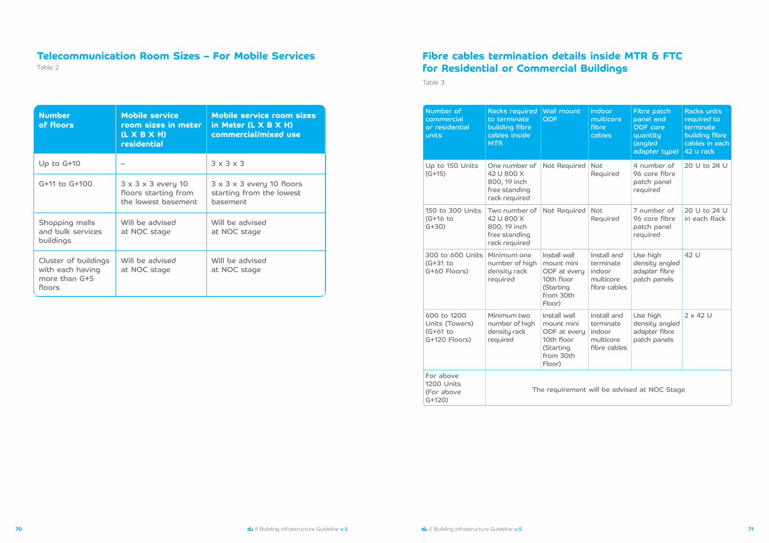
Table 2Telecommunication Room Sizes – For Mobile Services
Number of floors
Mobile service room sizes in meter(L X B X H)residential
Mobile service room sizes in Meter (L X B X H)commercial/mixed use
Up to G+10 – 3 x 3 x 3
G+11 to G+100 3 x 3 x 3 every 10 floors starting from the lowest basement
3 x 3 x 3 every 10 floors starting from the lowest basement
Shopping malls and bulk services buildings
Will be advised at NOC stage
Will be advised at NOC stage
Cluster of buildings with each having more than G+5 floors
Will be advised at NOC stage
Will be advised at NOC stage
Number of commercialor residential units
Racks required to terminate building fibre cables inside MTR
Wall mount ODF
Indoor multicore fibre cables
Fibre patch panel and ODF core quantity (angled adapter type)
Racks units required to terminate building fibre cables in each 42 u rack
Up to 150 Units(G+15)
One number of 42 U 800 X 800, 19 inch free standing rack required
Not Required NotRequired
4 number of 96 core fibre patch panel required
20 U to 24 U
150 to 300 Units(G+16 toG+30)
Two number of 42 U 800 X 800, 19 inch free standing rack required
Not Required Not Required
7 number of 96 core fibre patch panel required
20 U to 24 U in each Rack
300 to 600 Units(G+31 to G+60 Floors)
Minimum one number of high density rack required
Install wall mount mini ODF at every 10th floor(Starting from 30th Floor)
Install and terminateindoor multicore fibre cables
Use high density angled adapter fibre patch panels
42 U
600 to 1200 Units (Towers)(G+61 to G+120 Floors)
Minimum two number of high density rack required
Install wall mount mini ODF at every 10th floor(Starting from 30th Floor)
Install and terminateindoor multicore fibre cables
Use high density angled adapter fibre patch panels
2 x 42 U
For above1200 Units (For above G+120)
The requirement will be advised at NOC Stage
Fibre cables termination details inside MTR & FTC for Residential or Commercial BuildingsTable 3
7372 // Building Infrastructure Guideline v.5// Building Infrastructure Guideline v.5
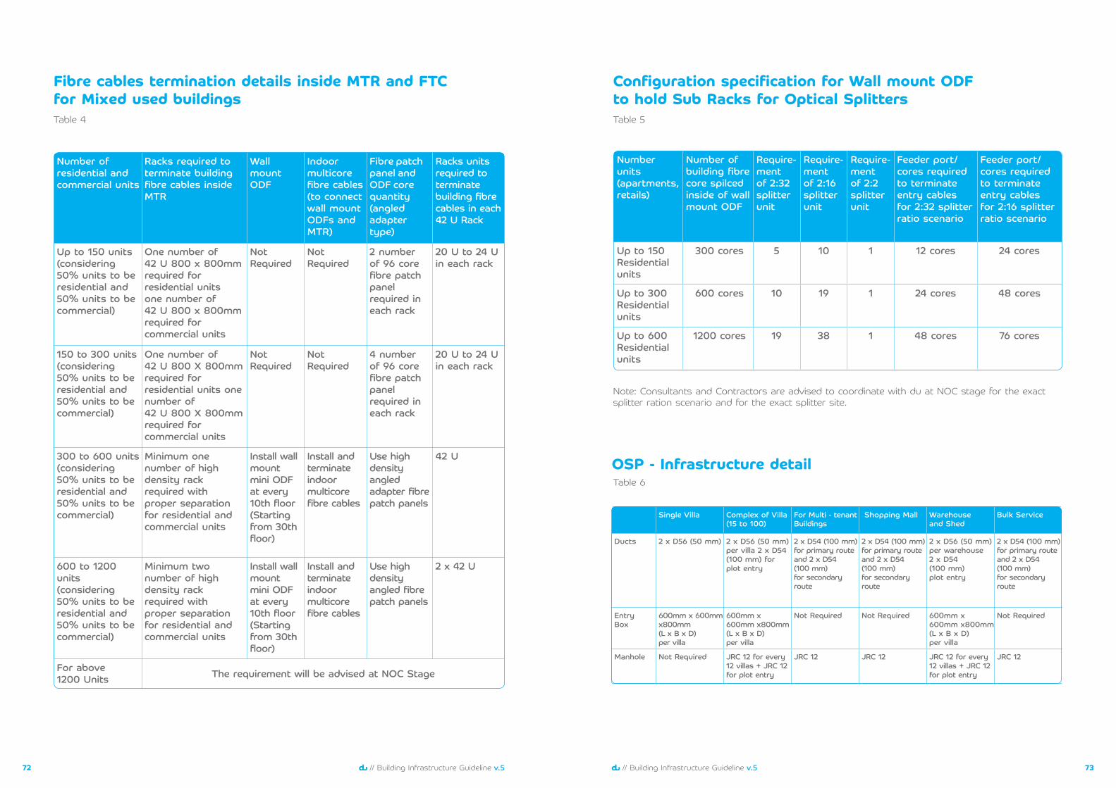
Table 4
Number of residential and commercial units
Racks required to terminate building fibre cables inside MTR
Wall mount ODF
Indoor multicore fibre cables(to connect wall mount ODFs and MTR)
Fibre patch panel and ODF core quantity(angled adaptertype)
Racks units required to terminate building fibre cables in each 42 U Rack
Up to 150 units(considering 50% units to be residential and 50% units to be commercial)
One number of42 U 800 x 800mm required for residential units one number of42 U 800 x 800mm required for commercial units
NotRequired
NotRequired
2 number of 96 core fibre patch panel required in each rack
20 U to 24 Uin each rack
150 to 300 units(considering 50% units to be residential and 50% units to be commercial)
One number of42 U 800 X 800mm required for residential units one number of42 U 800 X 800mm required for commercial units
NotRequired
NotRequired
4 number of 96 core fibre patch panel required in each rack
20 U to 24 U in each rack
300 to 600 units(considering 50% units to be residential and 50% units to be commercial)
Minimum one number of high density rack required with proper separation for residential and commercial units
Install wall mount mini ODF at every 10th floor (Starting from 30th floor)
Install and terminateindoor multicore fibre cables
Use high density angled adapter fibre patch panels
42 U
600 to 1200 units(considering 50% units to be residential and 50% units to be commercial)
Minimum two number of high density rack required with proper separation for residential and commercial units
Install wall mount mini ODF at every 10th floor (Starting from 30th floor)
Install and terminateindoor multicore fibre cables
Use high density angled fibre patch panels
2 x 42 U
For above 1200 Units The requirement will be advised at NOC Stage
Fibre cables termination details inside MTR and FTC for Mixed used buildings
Configuration specification for Wall mount ODFto hold Sub Racks for Optical SplittersTable 5
Note: Consultants and Contractors are advised to coordinate with du at NOC stage for the exact splitter ration scenario and for the exact splitter site.
Number units(apartments, retails)
Number of building fibre core spilced inside of wall mount ODF
Require-ment of 2:32 splitter unit
Require-ment of 2:16 splitter unit
Require-ment of 2:2 splitter unit
Feeder port/cores required to terminate entry cables for 2:32 splitter ratio scenario
Feeder port/cores required to terminate entry cables for 2:16 splitter ratio scenario
Up to 150 Residential units
300 cores 5 10 1 12 cores 24 cores
Up to 300 Residential units
600 cores 10 19 1 24 cores 48 cores
Up to 600 Residential units
1200 cores 19 38 1 48 cores 76 cores
OSP - Infrastructure detail
Single Villa Complex of Villa(15 to 100)
For Multi - tenant Buildings
Shopping Mall Warehouse and Shed
Bulk Service
Ducts 2 x D56 (50 mm) 2 x D56 (50 mm)per villa 2 x D54 (100 mm) for plot entry
2 x D54 (100 mm) for primary route and 2 x D54 (100 mm) for secondary route
2 x D54 (100 mm) for primary route and 2 x D54 (100 mm) for secondary route
2 x D56 (50 mm) per warehouse2 x D54(100 mm) plot entry
2 x D54 (100 mm) for primary route and 2 x D54 (100 mm) for secondary route
Entry Box
600mm x 600mmx800mm(L x B x D) per villa
600mm x 600mm x800mm(L x B x D) per villa
Not Required Not Required 600mm x 600mm x800mm(L x B x D) per villa
Not Required
Manhole Not Required JRC 12 for every 12 villas + JRC 12 for plot entry
JRC 12 JRC 12 JRC 12 for every 12 villas + JRC 12 for plot entry
JRC 12
Table 6
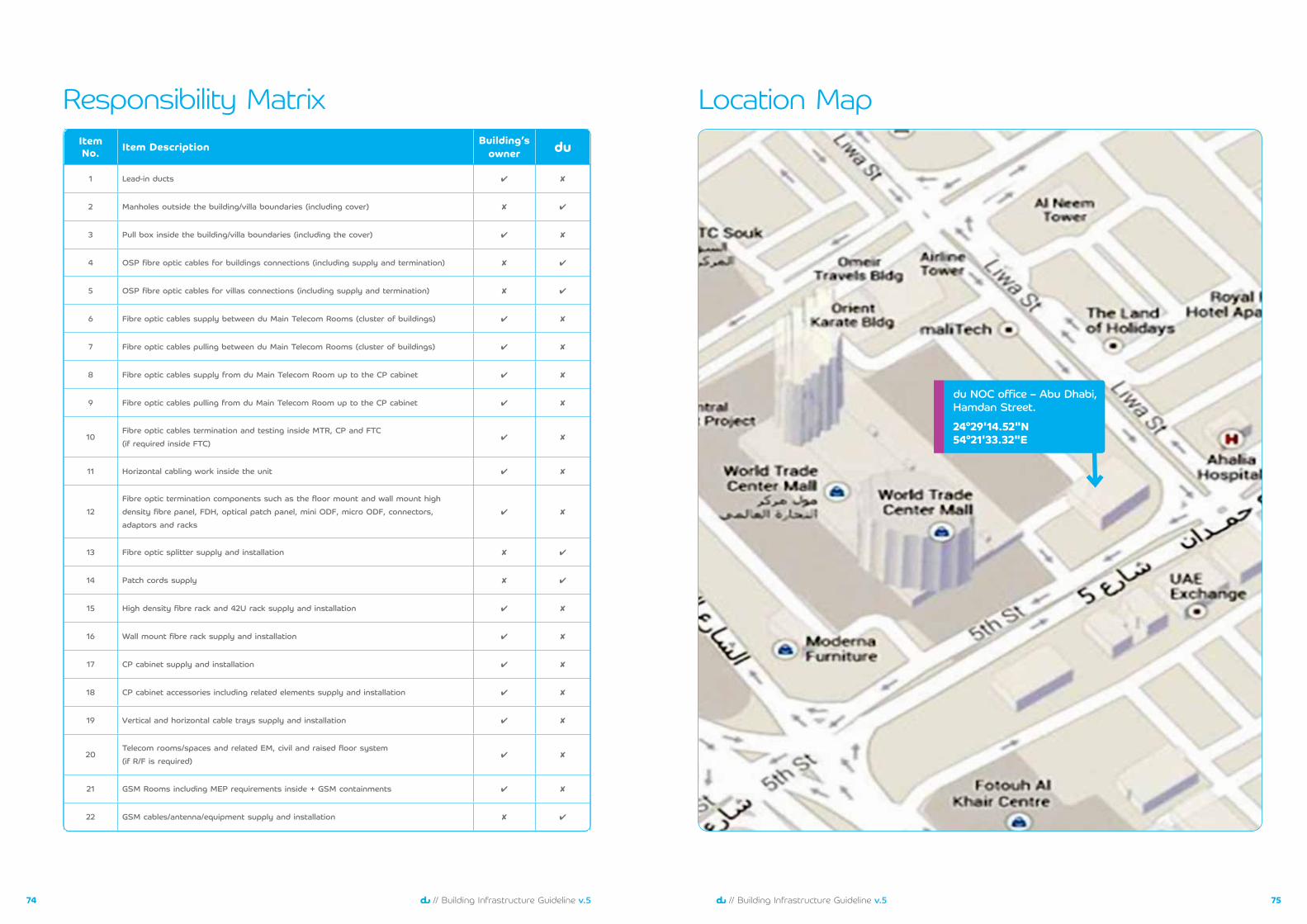
7574 // Building Infrastructure Guideline v.5// Building Infrastructure Guideline v.5
Item No. Item Description Building’s
owner du
1 Lead-in ducts ✔ ✘
2 Manholes outside the building/villa boundaries(including cover) ✘ ✔
3 Pull box inside the building/villa boundaries(including the cover) ✔ ✘
4 OSP fibre optic cables for buildings connections(including supply and termination) ✘ ✔
5 OSP fibre optic cables for villas connections(including supply and termination) ✘ ✔
٦ Fibre optic cables supply between du Main Telecom Rooms(cluster of buildings) ✔ ✘
7 Fibre optic cables pulling between du Main Telecom Rooms(cluster of buildings) ✔ ✘
8 Fibre optic cables supply from du Main Telecom Room up to the CP cabinet ✔ ✘
9 Fibre optic cables pulling from du Main Telecom Room up to the CP cabinet ✔ ✘
10Fibre optic cables termination and testing inside MTR,CP and FTC(if required inside FTC)
✔ ✘
11 Horizontal cabling work inside the unit ✔ ✘
12Fibre optic termination components such as the floor mount and wall mount highdensity fibre panel,FDH,optical patch panel,mini ODF,micro ODF,connectors,adaptors and racks
✔ ✘
13 Fibre optic splitter supply and installation ✘ ✔
14 Patch cords supply ✘ ✔
15 High density fibre rack and42U rack supply and installation ✔ ✘
1٦ Wall mount fibre rack supply and installation ✔ ✘
17 CP cabinet supply and installation ✔ ✘
18 CP cabinet accessories including related elements supply and installation ✔ ✘
19 Vertical and horizontal cable trays supply and installation ✔ ✘
20Telecom rooms/spaces and related EM,civil and raised floor system (if R/F is required)
✔ ✘
21 GSM Rooms including MEP requirements inside+GSM containments ✔ ✘
22 GSM cables/antenna/equipment supply and installation ✘ ✔
Responsibility Matrix Location Map
du NOC office – Abu Dhabi, Hamdan Street.
24°29'14.52"N 54°21'33.32"E
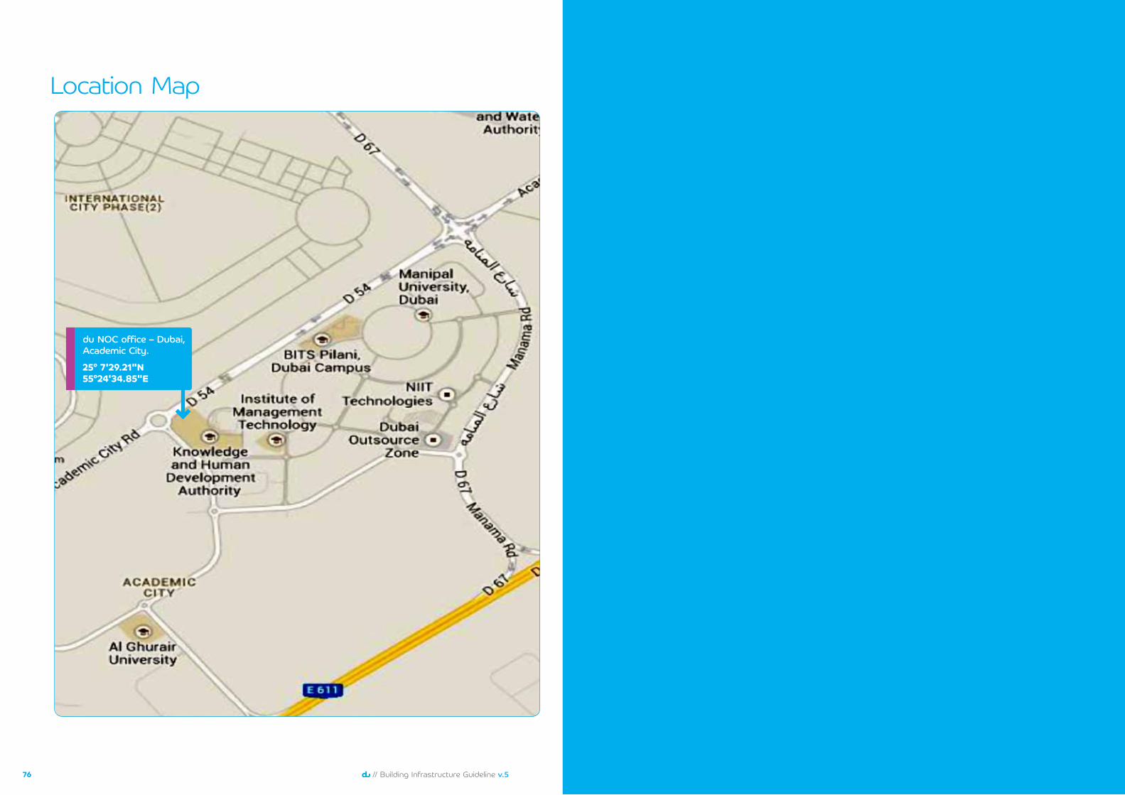
7776 // Building Infrastructure Guideline v.5// Building Infrastructure Guideline v.5
Location Map
du NOC office – Dubai, Academic City.
25° 7'29.21"N 55°24'34.85"E

©R
eser
ved
du-E
ITC.
Thi
s do
cum
ent
is n
ot f
or r
esal
e.P
rinte
d in
Uni
ted
Ara
b Em
irate
s.