Embed Size (px)
Citation preview
Safety Handbook

2 1 SAC 103 201 H 0201
1 SAC 103 201 H 0201 3
Safety handbookContents
Product overview 4
Regulations and Standards
General information 8Machine safety 10Process industry 21Furnaces 26
Push buttons
EMERGENCY OFF control devices 28Signal towers and Signal beacons 30Position switch LS-Series 31
Advant Controller 31-S
Safe intelligence 34System data 35Safety-related input/output modules 36
Safety control devices
Rules for application 38EMERGENCY OFF control gear and safety door watchdog 41Two-hand control, Dribbling inspection and test equipment 45Extension device, Monitoring relay 46Technical data /Certifi cations C 57x 47Selection tables/Accessories C 57x 48Dimension drawings (C 57x, C 580) 49Electronic safety relay C 67xx 51Selection table C 67xx 52Terminology 53
Circuit examples
Switch safely 58Safety contactor combinations C 57x 61Relay safety combinations C 57x 62EMERGENCY OFF (EMERGENCY STOP) circuit 63Protective door monitoring 67Press control devices 72Monitoring underspeed 76Electronic safety relay 77
Appendix
Certifi cates 80
4 1 SAC 103 201 H 0201
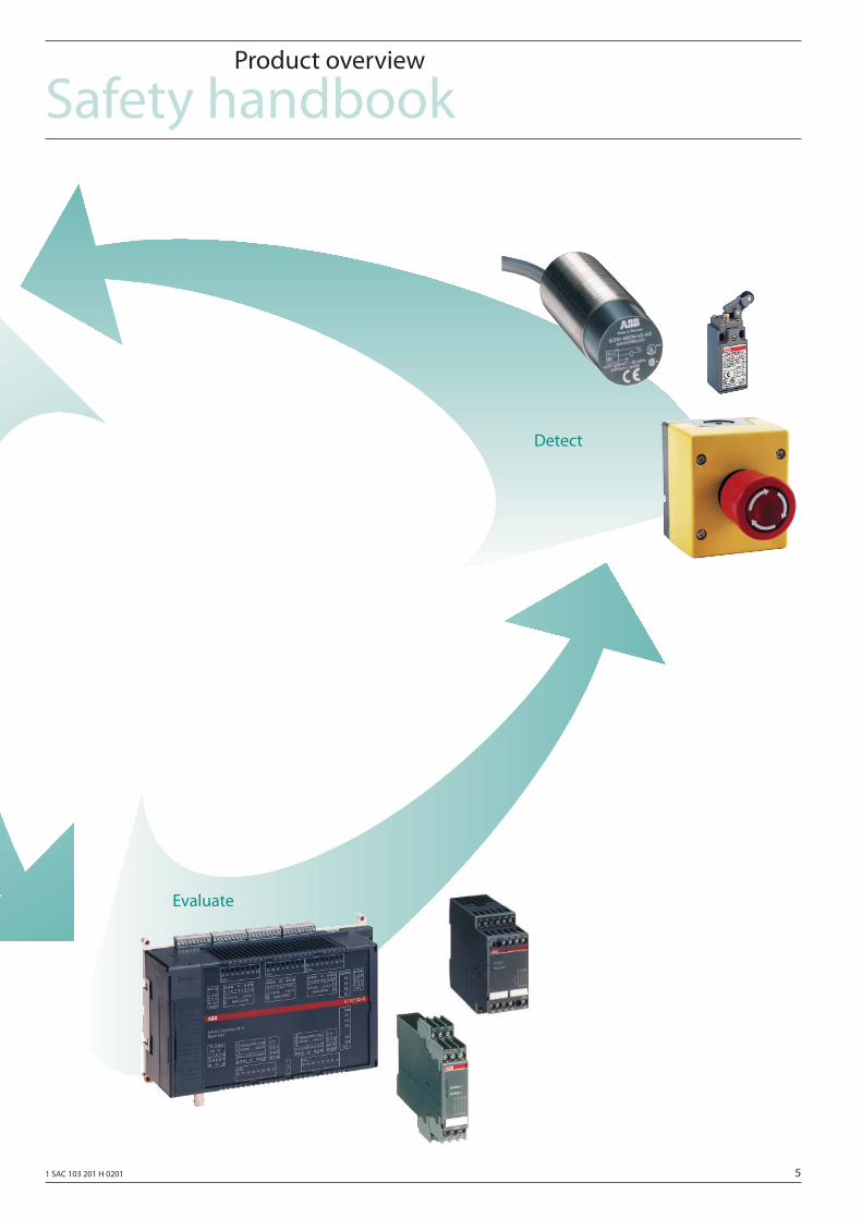
Safety handbookProduct overview
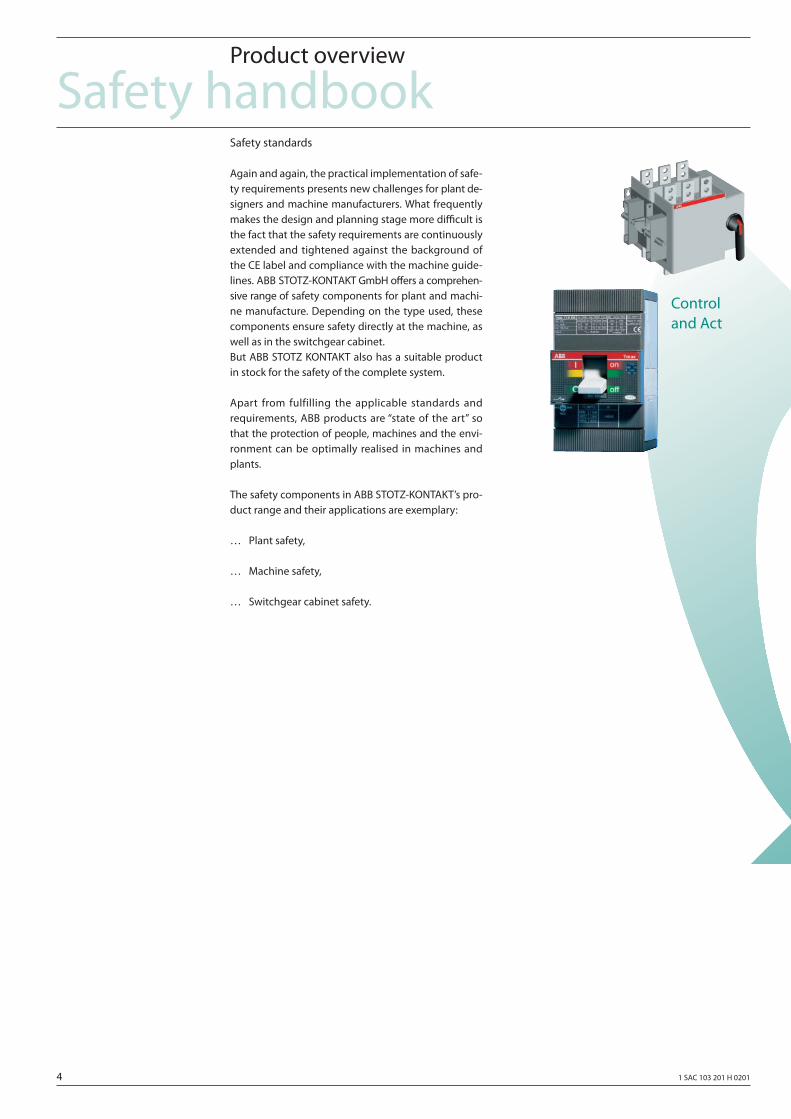
Safety standards
Again and again, the practical implementation of safe-ty requirements presents new challenges for plant de-signers and machine manufacturers. What frequently makes the design and planning stage more diffi cult is the fact that the safety requirements are continuously extended and tightened against the background of the CE label and compliance with the machine guide-lines. ABB STOTZ-KONTAKT GmbH off ers a comprehen-sive range of safety components for plant and machi-ne manufacture. Depending on the type used, these components ensure safety directly at the machine, as well as in the switchgear cabinet. But ABB STOTZ KONTAKT also has a suitable product in stock for the safety of the complete system.
Apart from fulfilling the applicable standards and requirements, ABB products are “state of the art” so that the protection of people, machines and the envi-ronment can be optimally realised in machines and plants.
The safety components in ABB STOTZ-KONTAKT’s pro-duct range and their applications are exemplary:
… Plant safety,
… Machine safety,
… Switchgear cabinet safety.
Controland Act
1 SAC 103 201 H 0201 5
Safety handbookProduct overview
Evaluate
Detect

6 1 SAC 103 201 H 0201
1 SAC 103 201 H 0201 7
Regulations and Standards
8 1 SAC 103 201 H 0201
Regulations and StandardsGeneral information
Goal
The goal of safety technology is to keep the potential hazards for man and the environment as low as possible by applying and utilizing technology. However, this should be achieved without imposing unnecessary re-strictions on industrial production, the use of machines and the production of chemical products. By applying internationally harmonized regulations, man and the environment should be uniformly protected to the same degree in all countries. At the same time, diff e-rences in competitive environments, due to diff erent safety requirements, should be eliminated.
Basic principles of European legislation
Legislation states that we must focus our eff orts “… at preserving and protecting the quality of the environ-ment, and protecting human health through preventive actions” (Council Directive 96/82/EC on the control of major-accident hazards involving dangerous sub-stances). It also demands “Health and safety at the workplace” (Workplace, health and safety legislation, …). Legislation demands that this and similar goals are achieved for various areas (“Areas which are legis-lated”) in the EC Directives. In order to achieve these goals, legislation places demands on the operators and users of plants, and the manufacturers of equip-ment and machines. It also assigns the responsibility for possible injury.
The EC Directives
… Specify demands placed on plants and systems and their operators/users to protect the health and safety of personnel and the quality of the environment
… Defi ne product features and characteristics to protect the health and safety of users
… Contain regulations about health and safety at the workplace (minimum requirements).
A new, global concept forms the (“new approach”, “global approach”) basis for the EC Directives:
… EC Directives only contain generally valid safety goals, and defi ne fundamental safety require- ments
… Legislation no longer specifi es that specifi c stan- dards have to be met
… Standards Committees, which have received the appropriate mandate from the EC Commission, can defi ne technical details in the Standards. These Standards are harmonized under a specifi c Directive and are listed in the Offi cial Journal of the EC. When the harmonized standards are ful- fi lled, then it is assumed that the associated safe- ty requirements of the Directive are fulfi lled. EC Directives specify that Member States recogni- ze each other’s national regulations and laws.
The EC Directives have the same degree of impor-tance, i.e. if several Directives apply for a specifi c piece of equipment, then the requirements of all of the rele-vant Directives have to be met (e.g. for a machine with electrical equipment, the Machinery Directive, Low-Voltage Directive and EMC Directive apply).
Other regulations apply to equipment where the EC Directives are not applicable. They include regulations and criteria for voluntary tests and certifi cation.
Workplace health and safety legislation
Health and safety at the workplace is subject to natio-nal legislation, i.e. the national requirements must be observed, as other safety requirements can be derived from these.
Note: The Directives and laws, mentioned in this Ma-nual, represent a selection in order to provide infor-mation about the essential goals and principles. This does not claim to be complete.
1 SAC 103 201 H 0201 9
Regulations and StandardsGeneral information
Standardization goals
The demand to make plants, machines and other equipment as safe as possible, in-line with state-of-the-art technology, comes from the responsibility of the manufacturers and users of equipment and products for their safety. State-of-the-art technolo-gy regarding all aspects which are of signifi cance for safety, is described in the Standards. State-of-the-art technology is ensured by fulfi lling the various relevant standards. This also ensures that the erector of a plant or system, or manufacturer of a machine or a piece of equipment, has fulfi lled his responsibility for ensuring safety.
Functional safety
From the perspective of the object to be protected, safety can not be segregated. As the causes of hazards and the technical measures applied to avoid them can diff er widely, a diff erentiation is now made between various types of safety, e.g. by specifying the cause of the potential hazard. For instance, “electrical safety” is used if protection has to be provided against hazards due to electricity, or “functional safety”, if the safety is dependent on the correct function.
This diff erentiation is now refl ected in the new stan-dardization in so much that there are special stan-dards which are involved with functional safety. The area of safety of machinery, EN 954 (or ISO 13489) deals especially with safety-relevant parts of controls and therefore concentrates on the functional safety. IEC handles, in the pilot standard IEC 61508, the functio-nal safety of electrical, electronic and programmable electronic systems, independent of any special appli-cation area.
In IEC 61508, functional safety is defi ned as “part of the overall safety relating to the EUC* and the EUC control system which depends on the correct functioning of the E/E/PE** safety-related systems, other safety-related systems and external risk reduction facilities”.
In order to achieve functional safety of a machine or a plant, the safety-relevant parts of the pro-tective- and control devices must function correctly and, when a fault or failure occurs, the plant or system must remain in a safe condition or be brought into a safe state. To realize this, specifi c qualifi ed technology is required, which fulfi lls the requirements specifi ed in the rele-vant standards.
The requirements to achieve functional safety are based on the basic goals:
… avoid systematic faults
… control systematic faults
… control random faults or failures.
The measure for the achieved functional safety is the probability of dangerous failures, the fault tole-rance and the quality which should be guaranteed by avoiding systematic faults. In the Standards, this is expressed using various terms. In IEC 61508: “Safety Integrity Level (SIL), in EN 954 (ISO 13489): Categories” and in DIN V 19250 and DIN V VDE 0801: “Requirement class” (AK).
* EUC: Equipment under control
** E/E/PE: Electrical, electronical, programmable electronical
10 1 SAC 103 201 H 0201
Machinery Directive (98/37/EC)*
With the introduction of a common European market, eff ective 01.01.1993, a decision was made to harmoni-ze the national standards and regulations of all of the EC Member States. This meant that Machinery Direc-tive, as an internal Directive, had to be implemented in the domestic legislation of the individual Member States. (For instance, in Germany, the contents of the Machinery Directive were implemented as the 9th Decree of the Equipment Safety Law.) For the Machi-nery Directive, this was realized with the goal to have unifi ed protective goals and to reduce trading barriers. The application area of the Machinery Directive corre-sponds to its defi nition.
“Machinery also means an assembly of machines which, in order to achieve the same end, are arranged and controlled so that they function as an integral whole”.
The application area of the Machinery Directive thus ranges from a basic machine up to a complete plant. The Machinery Directive has 14 Articles and 7 An-nexes. The basic health and safety requirements in Annex I of the Directive are mandatory for the safety
of the machine. The protective goals must be imple-mented in a responsible fashion in order to fulfi ll the requirements for conformance with the Directive. The manufacturer of a machine must prove that the basic requirements are fulfi lled. This proof is made easier by applying harmonized standards.
A certifi cation technique is required for machines li-sted in Annex IV of the Machinery Directive, which repre-sent a greater hazard potential.
Regulations and StandardsMachine safety
* substitute 89/392/EC, 91/368/EC, 93/68/EC
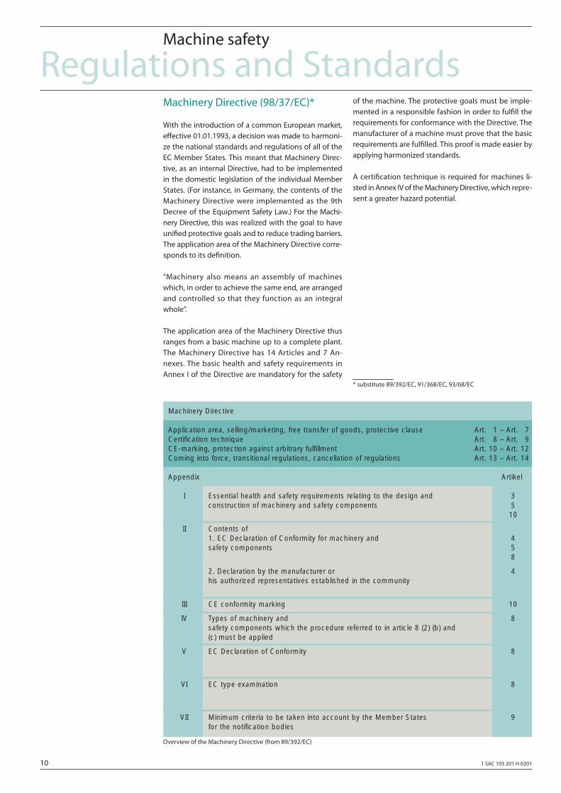
Overview of the Machinery Directive (from 89/392/EC)
Application area, selling/marketing, free transfer of goods, protective clause Art. 1 – Art. 7Certification technique Art. 8 – Art. 9CE-marking, protection against arbitrary fulfillment Art. 10 – Art. 12Coming into force, transitional regulations, cancellation of regulations Art. 13 – Art. 14
Essential health and safety requirements relating to the design and construction of machinery and safety components
Contents of1. EC Declaration of Conformity for machinery and safety components
2. Declaration by the manufacturer or his authorized representatives established in the community
CE conformity marking
Types of machinery and safety components which the procedure referred to in article 8 (2) (b) and (c) must be applied
EC Declaration of Conformity
EC type examination
Minimum criteria to be taken into account by the Member States for the notification bodies
I
II
III
IV
V
VI
VII
35
10
458
4
10
8
8
8
9
Machinery Directive
Appendix Artikel
1 SAC 103 201 H 0201 11
Regulations and StandardsMachine safety
Annex IV of the Machinery Directive
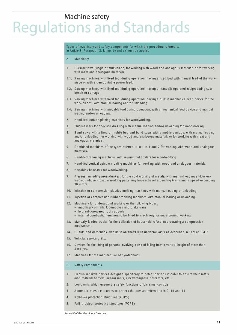
1. Electro-sensitive devices designed specifically to detect persons in order to ensure their safety (non-material barriers, sensor mats, electromagnetic detectors, etc.)
2. Logic units which ensure the safety functions of bimanual controls.
3. Automatic movable screens to protect the presses referred to in 9, 10 and 11
4. Roll-over protection structures (ROPS)
5. Falling-object protective structures (FOPS)
B. Safety components
1. Circular saws (single or multi-blade) for working with wood and analogous materials or for workingwith meat and analogous materials.
1.1. Sawing machines with fixed tool during operation, having a fixed bed with manual feed of the work-piece or with a demountable power feed.
1.2. Sawing machines with fixed tool during operation, having a manually operated reciprocating saw-bench or carriage.
1.3. Sawing machines with fixed tool during operation, having a built-in mechanical feed device for thework-pieces, with manual loading and/or unloading.
1.4. Sawing machines with movable tool during operation, with a mechanical feed device and manualloading and/or unloading.
2. Hand-fed surface planing machines for woodworking.
3. Thicknessers for one-side dressing with manual loading and/or unloading for woodworking.
4. Band-saws with a fixed or mobile bed and band-saws with a mobile carriage, with manual loadingand/or unloading, for working with wood and analogous materials or for working with meat and analogous materials.
5. Combined machines of the types referred to in 1 to 4 and 7 for working with wood and analogousmaterials.
6. Hand-fed tenoning machines with several tool holders for woodworking.
7. Hand-fed vertical spindle molding machines for working with wood and analogous materials.
8. Portable chainsaws for woodworking.
9. Presses, including press-brakes, for the cold working of metals, with manual loading and/or un-loading, whose movable working parts may have a travel exceeding 6 mm and a speed exceeding30 mm/s.
10. Injection or compression plastics-molding machines with manual loading or unloading.
11. Injection or compression rubber-molding machines with manual loading or unloading.
12. Machinery for underground working or the following types:– machinery on rails: locomotives and brake-vans– hydraulic-powered roof supports– internal combustion engines to be fitted to machinery for underground working.
13. Manually-loaded trucks for the collection of household refuse incorporating a compression mechanism.
14. Guards and detachable transmission shafts with universal joints as described in Section 3.4.7.
15. Vehicles servicing lifts.
16. Devices for the lifting of persons involving a risk of falling from a vertical height of more than 3 meters.
17. Machines for the manufacture of pyrotechnics.
A. Machinery
Types of machinery and safety components for which the procedure referred to in Article 8, Paragraph 2, letters b) and c) must be applied
12 1 SAC 103 201 H 0201
Standards
To sell, market or operate/use products, these pro-ducts must fulfi ll the basic safety requirements of the EC Directives. Standards can be extremely helpful when it involves fulfi lling these safety requirements. In this case, a diff erentiation must be made between harmonized European standards and other technical rules and regulations which are known in the Directives as “National Standards”.
Generally, all European Standards must be included, unchanged in the national standards of the Member States, independent of whether they are hamroni-zed under the Machinery Directive or not. National standards handling the same subject must then be withdrawn.
Thus, within a period of time in Europe, a unifi ed set of regulations will be created.
Harmonized European Standards
These are drawn-up by the two standards organiza-tions CEN (Comité Européen de Normalisation) and CENELEC (Comité Européen de Normalisation Électro-technique) as mandate from the EC Commission in or-der to fulfi ll the requirements of the EU Directives for a specifi c product. And they must be published in the offi cial documentation of the European Communities. These Standards (EN Standards) are then transferred into the national standards unchanged. They are used to fulfi ll the basic health- and safety requirements and the protective goals specifi ed in the Annex I of the Ma-chinery Directive.
When using such standards, there is an “automatic presumption of conformity”; i.e. the manufacturer can be trusted to have fulfi lled all of the safety aspects of the Directive as long as they are handled in the particular Standard.
However, not every European Standard is harmoni-zed in this sense. The listing in the European docu-mentation is decisive. The up-to-date version of these lists can always be called-up in the Internet (Address: http://www2.echo.lu/nasd/index.html).
The European Standards of CEN for the safety of ma-chines are hierarchically structured as follows
… A Standards; also known as Basic Standards.
… B Standards; also known as Group Standards.
… C Standards; also known as Product Standards.
The diagram above shows the structure.
Type A Standards/Basic Standards
As Standards contain basic terminology and defi ni-tions for all machines. This includes EN 292 “Safety of machinery – Basic concepts, general principles for design”.
A Standards primarily address the party setting B- and C Standards. The techniques for minimizing risks, spe-cifi ed there, can however, also be helpful for manufac-turers, if there are no relevant C Standards.
Type B Standards/Group Standards
These include all Standards with safety-related state-ments, which can involve several types of machines.
The B Standards also primarily address the party set-ting C Standards. However, they can also be helpful for manufacturers when designing and building machine if there are no relevant C Standards.
For B Standards, an additional subdivision was made, and more precisely in:
… Type B1 Standards for higher-level safety aspects, e.g. ergonomic design principles, safety distances from potential sources of danger, minimum clearances to prevent crushing of body parts.
… Type B2 Standards for safety equipment are specifi ed for various machine types, e.g. EMERGENCY STOP equipment, two-hand con- trols,
interlocking/latching, contactless protective devices, safety-related parts of controls.
Regulations and StandardsMachine safety
1 SAC 103 201 H 0201 13
Type C Standards/Product Standards
These involve the Machine-Specific Standards, e.g. for machine tools, woodworking machines, elevators, packaging machines, printing machines etc.
The European Standards are conceived, in order to avoid repeating general statements, which are alrea-dy included in type A, or type B standards; as far as possible, reference to these are made in type C Stan-dards.
In addition to machine-related requirements, Pro-duct Standards can also include requirements which, under certain circumstances, deviate from the Basic- and Group Standards. For the machine OEM, type C Standard/Product standards have the highest priority. It can be assumed that it therefore contains the basic requirements of Annex I of the Machinery Directive (automatic presumption of conformity).
If there is no Product Standard for a particular machi-ne, then type B Standards can be applied as support when building a machine.
National Standards
If harmonized European Standards are not available, or they cannot be applied for certain reasons, then the manufacturer can utilize the “National Standards”. All of the other technical rules and regulations and European Standards, not listed in the European official docu-mentation (non-harmonized), fall under this term of the Machinery Directive. Those not listed in official documentation can include, for example, still valid DIN Standards and VDE Regulations and are declared, also from the German government as “helpful to fulfi ll the Machinery Directive”.
However, when such standards are applied, the above mentioned “automatic presumption of conformity” does not apply. This means, that a risk analysis must be carried-out and proven and if necessary, risk re-duction measures applied which makes the whole procedure more costly. These national standards are for example, used by notifi ed bodies in order to iden-tify whether a specifi c product fulfi lls the goals of the Machinery Directive.
Regulations and StandardsMachine safety
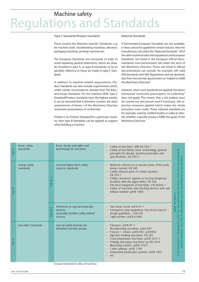
European Standards for safety of machinery
Basic safety standards
Basic design principles and terminology for machines
Group safety standards
General higher-level safety aspects standards
Reference to special protective devicesGenerally handled safety-relateddevices
Specialist Standards Special safety features for individual machine groups
Typ
B
Typ
B-1
Typ
B-2
Typ
ATy
p C
– Elevators: prEN 81-1– Woodworking machines: prEN 691– Presses + shears: prEN 692, prEN963– Injection molding machines: EN 201– Food preparation machines: prEN 1672-1– Printing and paper machines: pr EN 1010– Machining centers: prEN 12417– Cable railways: prEN 1709– Automated production systems: prEN 1921– etc.
– Two-hand circuit: prEN 81-1– Emergency stop equipment, functional aspects –
design guidelines – EN 418– Light barriers: prEN 61496
– Minimum clearances to prevent parts of the bodybeing crushed: EN 349
– Safety-relevant parts of control systems: EN 954-1
– Safety clearances against accessing dangerouslocations with the upper limbs: EN 294
– Electrical equipment of machines: EN 60204-1– Safety of machines inter-latching devices with and
without tumbler: prEN 1088
– Safety of machines: DIN EN 292-1– Safety of machinery; basic terminology, general
principles for design; technical principles and specifications: EN 292-2
No
te f
or
use
rs:
If h
arm
on
ized
C S
tan
dar
ds
exis
t fo
r th
e p
arti
cula
r p
rod
uct
, th
en t
he
asso
ciat
ed B
- an
d i
f re
leva
nt,
als
o t
he
A S
tan
dar
ds
can
be
con
sid
ered
as
seco
nd
ary
14 1 SAC 103 201 H 0201
Risk analysis/evaluation
As a result of their general design and functionality, ma-chines and plants represent potential risks. Thus, the Machinery Directive requires a risk assessment for every machine and, if relevant, risk reduction, so that the remaining risk is less than the tolerable risk. The following Standards should be applied for the techni-que to assess these risks:
… EN 292 “Safety of machinery – Basic concepts, general principles for design”
… EN 1050 “Safety of machinery – Principles for risk assessment”
EN 292 mainly handles the risks to be evaluated and design principles to reduce risks. EN 1050 basically handles the iterative process with risk assessment and risk reduction to achieve safety.
Risk assessment
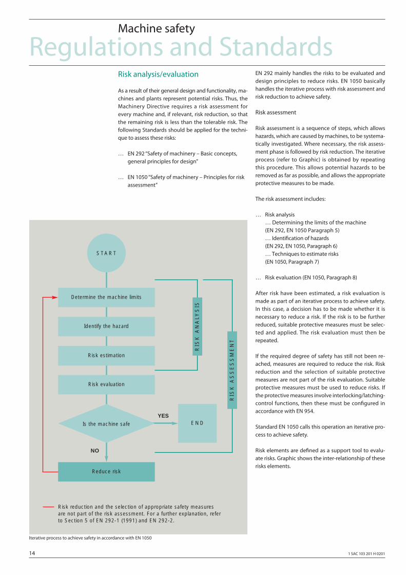
Risk assessment is a sequence of steps, which allows hazards, which are caused by machines, to be systema-tically investigated. Where necessary, the risk assess-ment phase is followed by risk reduction. The iterative process (refer to Graphic) is obtained by repeating this procedure. This allows potential hazards to be removed as far as possible, and allows the appropriate protective measures to be made.
The risk assessment includes:
… Risk analysis … Determining the limits of the machine (EN 292, EN 1050 Paragraph 5) … Identifi cation of hazards (EN 292, EN 1050, Paragraph 6) … Techniques to estimate risks (EN 1050, Paragraph 7)
… Risk evaluation (EN 1050, Paragraph 8)
After risk have been estimated, a risk evaluation is made as part of an iterative process to achieve safety. In this case, a decision has to be made whether it is necessary to reduce a risk. If the risk is to be further reduced, suitable protective measures must be selec-ted and applied. The risk evaluation must then be repeated.
If the required degree of safety has still not been re-ached, measures are required to reduce the risk. Risk reduction and the selection of suitable protective measures are not part of the risk evaluation. Suitable protective measures must be used to reduce risks. If the protective measures involve interlocking/latching-control functions, then these must be confi gured in accordance with EN 954.
Standard EN 1050 calls this operation an iterative pro-cess to achieve safety.
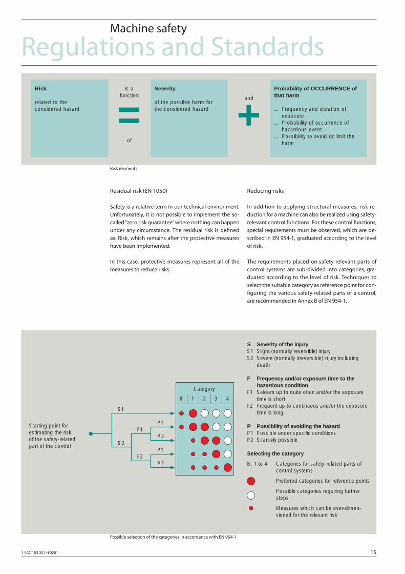
Risk elements are defi ned as a support tool to evalu-ate risks. Graphic shows the inter-relationship of these risks elements.
Regulations and StandardsMachine safety
Iterative process to achieve safety in accordance with EN 1050
NO
YESE N D
Risk reduction and the selection of appropriate safety measures are not part of the risk assessment. For a further explanation, referto Section 5 of EN 292-1 (1991) and EN 292-2.
S TA R T
Determine the machine limits
Identify the hazard
Risk estimation
Risk evaluation
Reduce risk
Is the machine safe
RIS
K A
NA
LY
SIS
RIS
K A
SS
ES
SM
EN
T
1 SAC 103 201 H 0201 15
Residual risk (EN 1050)
Safety is a relative term in our technical environment. Unfortunately, it is not possible to implement the so-called “zero risk guarantee” where nothing can happen under any circumstance. The residual risk is defi ned as: Risk, which remains after the protective measures have been implemented.
In this case, protective measures represent all of the measures to reduce risks.
Reducing risks
In addition to applying structural measures, risk re-duction for a machine can also be realized using safety-relevant control functions. For these control functions, special requirements must be observed, which are de-scribed in EN 954-1, graduated according to the level of risk.
The requirements placed on safety-relevant parts of control systems are sub-divided into categories, gra-duated according to the level of risk. Techniques to select the suitable category as reference point for con-fi guring the various safety-related parts of a control, are recommended in Annex B of EN 954-1.
Regulations and StandardsMachine safety
Risk elements
Possible selection of the categories in accordance with EN 954-1
Risk
related to the considered hazard
Severity
of the possible harm for the considered hazard= +
is a function
of
and
Probability of OCCURRENCE ofthat harm
… Frequency and duration of exposure
… Probability of occurrence ofhazardous event
… Possibility to avoid or limit theharm
S Severity of the injuryS1 Slight (normally reversible) injuryS2 Severe (normally irreversible) injury including
death
F Frequency and/or exposure time to thehazardous condition
F1 Seldom up to quite often and/or the exposuretime is short
F2 Frequent up to continuous and/or the exposuretime is long
P Possibility of avoiding the hazardP1 Possible under specific conditionsP2 Scarcely possible
Selecting the category
B, 1 to 4 Categories for safety-related parts ofcontrol systems
Preferred categories for reference points
Possible categories requiring furthersteps
Measures which can be over-dimen-sioned for the relevant risk
Starting point forestimating the riskof the safety-relatedpart of the control
Category
B 1 2 3 4
S1
S2
F1
F2
P1
P2
P1
P2
16 1 SAC 103 201 H 0201
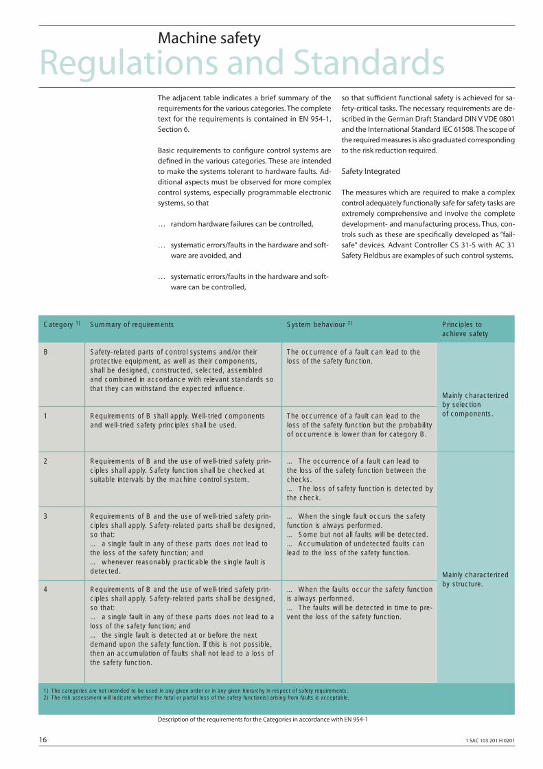
The adjacent table indicates a brief summary of the requirements for the various categories. The complete text for the requirements is contained in EN 954-1, Section 6.
Basic requirements to confi gure control systems are defi ned in the various categories. These are intended to make the systems tolerant to hardware faults. Ad-ditional aspects must be observed for more complex control systems, especially programmable electronic systems, so that
… random hardware failures can be controlled,
… systematic errors/faults in the hardware and soft- ware are avoided, and
… systematic errors/faults in the hardware and soft- ware can be controlled,
so that suffi cient functional safety is achieved for sa-fety-critical tasks. The necessary requirements are de-scribed in the German Draft Standard DIN V VDE 0801 and the International Standard IEC 61508. The scope of the required measures is also graduated corresponding to the risk reduction required.
Safety Integrated
The measures which are required to make a complex control adequately functionally safe for safety tasks are extremely comprehensive and involve the complete development- and manufacturing process. Thus, con-trols such as these are specifi cally developed as “fail-safe” devices. Advant Controller CS 31-S with AC 31 Safety Fieldbus are examples of such control systems.
Regulations and StandardsMachine safety
Description of the requirements for the Categories in accordance with EN 954-1
Principles to achieve safety
System behaviour 2)Summary of requirementsCategory 1)
B Safety-related parts of control systems and/or their protective equipment, as well as their components, shall be designed, constructed, selected, assembledand combined in accordance with relevant standards sothat they can withstand the expected influence.
The occurrence of a fault can lead to theloss of the safety function.
Mainly characterizedby selection of components.
Mainly characterizedby structure.
1 Requirements of B shall apply. Well-tried componentsand well-tried safety principles shall be used.
The occurrence of a fault can lead to theloss of the safety function but the probabilityof occurrence is lower than for category B.
2 Requirements of B and the use of well-tried safety prin-ciples shall apply. Safety function shall be checked at suitable intervals by the machine control system.
… The occurrence of a fault can lead to the loss of the safety function between thechecks.… The loss of safety function is detected bythe check.
3 Requirements of B and the use of well-tried safety prin-ciples shall apply. Safety-related parts shall be designed,so that:… a single fault in any of these parts does not lead to the loss of the safety function; and … whenever reasonably practicable the single fault isdetected.
… When the single fault occurs the safetyfunction is always performed.… Some but not all faults will be detected.… Accumulation of undetected faults canlead to the loss of the safety function.
4
1) The categories are not intended to be used in any given order or in any given hierarchy in respect of safety requirements. 2) The risk assessment will indicate whether the total or partial loss of the safety function(s) arising from faults is acceptable.
Requirements of B and the use of well-tried safety prin-ciples shall apply. Safety-related parts shall be designed,so that:… a single fault in any of these parts does not lead to aloss of the safety function; and… the single fault is detected at or before the nextdemand upon the safety function. If this is not possible,then an accumulation of faults shall not lead to a loss ofthe safety function.
… When the faults occur the safety functionis always performed.… The faults will be detected in time to pre-vent the loss of the safety function.
1 SAC 103 201 H 0201 17
Safety-related functions
The safety-related functions include, in addition to the classic functions
… stop… actions in an emergency situation
in the meantime, also more complex functions such as
… speed limiting… position limiting… speed deviation etc.
The classic functions are defi ned in EN 60204-1 and are generally implemented using basic electromecha-nical components. Electronic programmable systems can also be used to implement more complex func-tions, if they fulfi ll the relevant standards (IEC 61508, EN 954 or DIN V VDE 0801).
Stop
Stop categories according to EN 60204-1There are three stop categories, which are defi ned in EN 60204-1, independent of an emergency situation:
Stop Category 0Uncontrolled stop; stopping by immediate removal of power to the machine actuators (e.g. motor).
Stop Category 1Controlled stop; the power is only removed when the machine has come to a standstill.
Stop Category 2Controlled stop, where power is still fed to the ma-chine when it is at a standstill.
Emergency operationsThe new EN 60204-1/11.98 (IEC 60204-1), harmonized with HD 384 (IEC 60364), has defi ned the following pos-sible actions for emergency situations (EN 60204-1 Annex D):
Action in an emergency situation includes individu-ally, or a combination of:
… EMERGENCY STOP… EMERGENCY START… EMERGENCY OFF… EMERGENCY SWITCHING ON.
According to EN 60204-1 and EN 418, these functions are exclusively initiated by a conscious manual inter-vention. In the following text, only EMERGENCY OFF and EMERGENCY STOP will be discussed.
The latter fully corresponds to the same terminology in the EC Machinery Directive.
EMERGENCY OFFThis is an intervention (action) in an emergency situa-tion, which disconnects the electrical power to a com-plete system or installation or part of it if there is a risk of electric shock or another risk caused by electricity (from EN 60204-1 Annex D).
Further, the following is defined in 9.2.5.4.3 of EN 60204-1:
Functional aspects to disconnect the power in an emergency situation are defined in IEC 60364-4-46 (identical to HD 384-4-46).
Power must be disconnected in an emergency situa-tion, where
… protection against direct contact (e.g. with con- tact cables, slip ring assemblies, switch-gear in electrical rooms) is only achieved by maintaining a clearance or barriers;
… other hazard or damage could occur as a result of electric power.
In an emergency situation, the power supply is dis-connected from the machine which results in a Cate-gory 0 Stop.
If a Category 0 Stop is not permissible for a machine, then it may be necessary to provide other protection, e.g. against direct contact, so that power does not have to be disconnected in an emergency situation.
This means, that EMERGENCY OFF should be used where the risk analysis indicates a hazard due to elec-tric voltage/power and therefore requires that the electric voltage is immediately disconnected from the complete machine.
Regulations and StandardsMachine safety
18 1 SAC 103 201 H 0201
In the application area of the EC, EMERGENCY OFF de-vices fall under the Low-voltage Directive 73/23/EEC, if they are not used in conjunction with machines. If they are used in conjunction with machines, then they come under the Machinery Directive 98/37/EC, as is true for all of the other electrical equipment.
EMERGENCY STOPThis is an action, in an emergency situation, which is defi ned to stop a process or movement which has become hazardous (from EN 60204-1 Annex D).
Further, in 9.2.5.4.2 of EN 60204-1 the following is de-fi ned:
StopIn addition to the requirements for stop (refer to 9.2.5.3), the following requirements apply for an emer-gency stop:
… It must have priority over all other functions and actions in all operating modes;
… The power to the machine actuators, which could cause hazardous conditions, must be disconnec- ted as quickly as possible without creating other hazards (e.g. using mechanical stopping/ braking devices, which do not require an external supply by using counter-current braking) for Stop Cate- gory 1;
… Resetting may not initiate a restart.
Stopping in an emergency situation must either be eff ective as a Stop, Category 0 or Category 1 (refer to 9.2.2). The Stop Category in an emergency situation must be defi ned as a result of the risk evaluation for the machine.
To technically implement the EMERGENCY STOP, cor-responding to the application recommendation in the foreword of EN 60204-1, the requirements of either EN 60204-1 or EN 954 and IEC 61508 can be applied. EN 60204-1 primarily requires that this is implemented using electromechanical components, as “basic” (pro-grammable) electronic systems are not safe enough. By correctly applying EN 954 and, if required, IEC 61508, electronic- and programmable electronic com-ponents become functionally safe enough, that they can also be used to implement EMERGENCY STOP for all Categories.
Devices for EMERGENCY OFF and EMERGENCY STOP
In order to fulfill the protective goals, both of EN 60204-1 as well as EN 418, the following require-ments are valid for both functions (also refer to 10.7 in EN 60204-1):
… When contacts switch, even with just a brief ac- tuation, the control device must positively latch.
… It is not permissible that the machine can be re- started from a remote main operator control sta- tion without the hazard or danger fi rst having been removed. The emergency stop device must be consciously released again locally.
Other safety-related functions
For all other safety-related functions, EN 60204-1 re-commends that electromechanical components are used. With the argument that it is “presently diffi cult” to be able to secure the reliability of fault-free opera-tion of a single-channel programmable electronic unit with suffi cient confi dence. This expressly refers to the time at which the associated text of the standard was drawn-up.
The application recommendation in the foreword of the new EN 60204-1 for this Chapter takes into ac-count the progress which has been made in develo-ping safety-relevant technology. It recommends that the “different” requirements of other relevant stan-dards, e.g. IEC 61508, should be taken into conside-ration. When taking into account the requirements of these standards, it is possible to use electronic and programmable electronics, for example, a fail-safe Ad-vant Controller 31-S in a safety-related fashion, even for complex functions.
Regulations and StandardsMachine safety
1 SAC 103 201 H 0201 19
Man – Machine
In order to simplify the interaction between man and machines, reference is made to Standards EN 60073 an DIN EN 60204.
Switches, pushbuttons and signaling lamps are, in the fi rst instance, the machine components which are used as the interface between man and machine. These operator control elements are clearly and uniformly identifi ed using color coding which has a very spe-cifi c signifi cance. This guarantees that the safety of operating personnel is increased and it is easier to handle and maintain the operating resources/plants and systems.
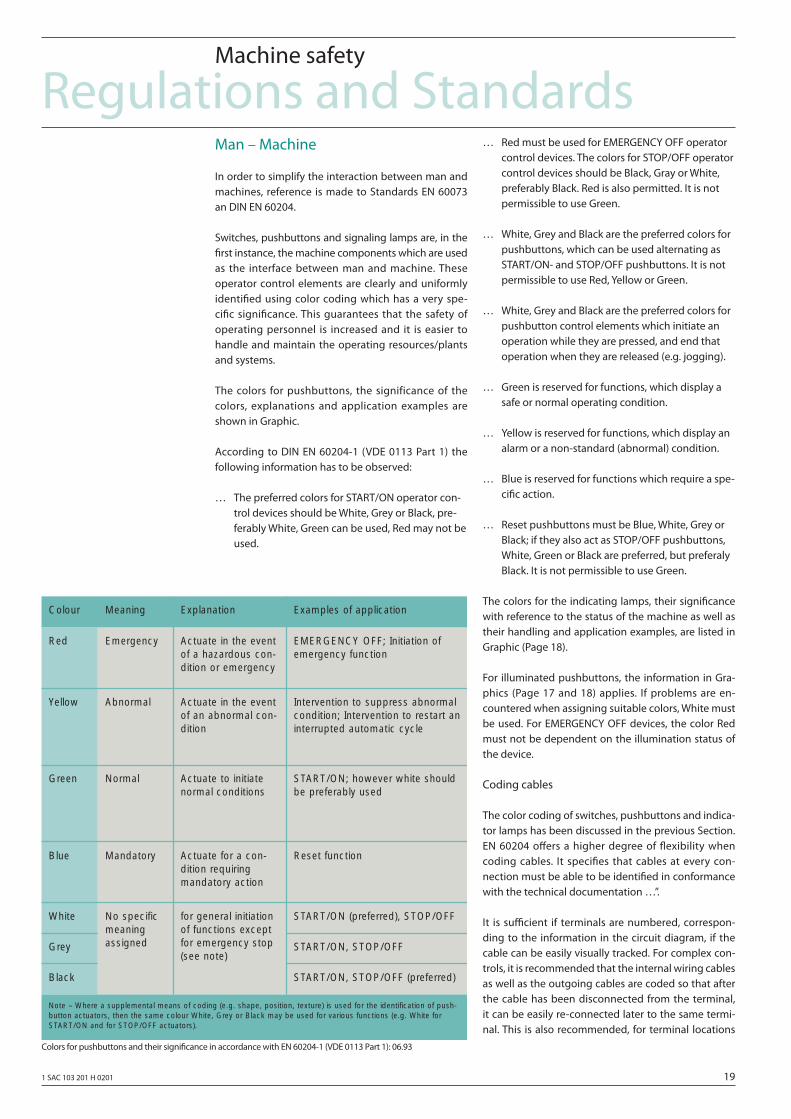
The colors for pushbuttons, the significance of the colors, explanations and application examples are shown in Graphic.
According to DIN EN 60204-1 (VDE 0113 Part 1) the following information has to be observed:
… The preferred colors for START/ON operator con- trol devices should be White, Grey or Black, pre- ferably White, Green can be used, Red may not be used.
… Red must be used for EMERGENCY OFF operator control devices. The colors for STOP/OFF operator control devices should be Black, Gray or White, preferably Black. Red is also permitted. It is not permissible to use Green.
… White, Grey and Black are the preferred colors for pushbuttons, which can be used alternating as START/ON- and STOP/OFF pushbuttons. It is not permissible to use Red, Yellow or Green.
… White, Grey and Black are the preferred colors for pushbutton control elements which initiate an operation while they are pressed, and end that operation when they are released (e.g. jogging).
… Green is reserved for functions, which display a safe or normal operating condition.
… Yellow is reserved for functions, which display an alarm or a non-standard (abnormal) condition.
… Blue is reserved for functions which require a spe- cifi c action.
… Reset pushbuttons must be Blue, White, Grey or Black; if they also act as STOP/OFF pushbuttons, White, Green or Black are preferred, but preferaly Black. It is not permissible to use Green.
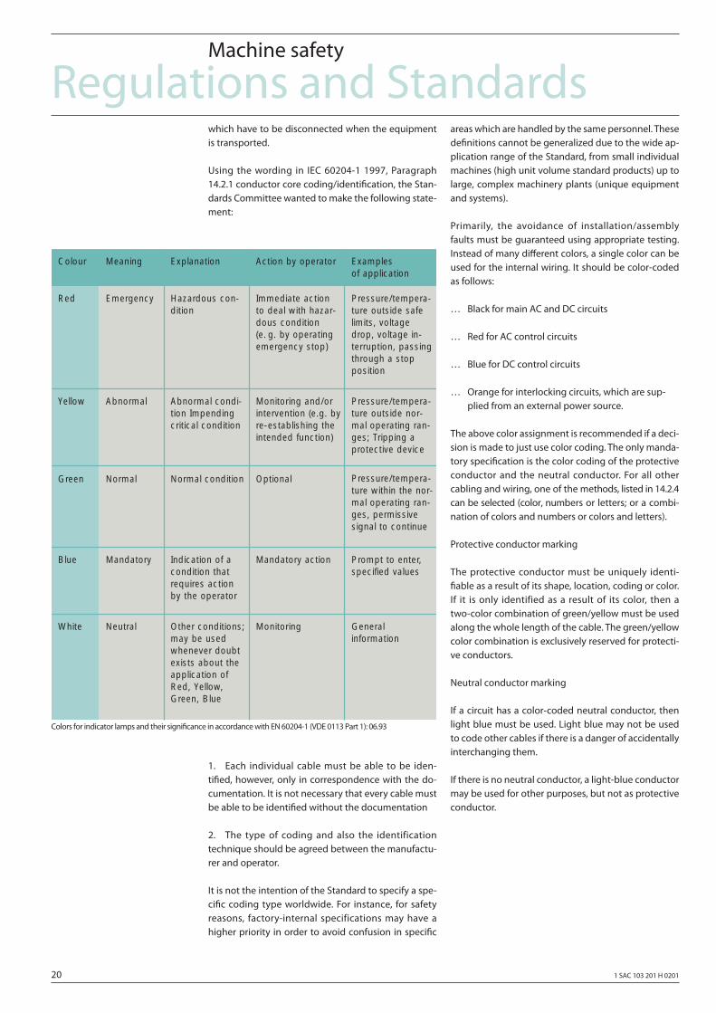
The colors for the indicating lamps, their signifi cance with reference to the status of the machine as well as their handling and application examples, are listed in Graphic (Page 18).
For illuminated pushbuttons, the information in Gra-phics (Page 17 and 18) applies. If problems are en-countered when assigning suitable colors, White must be used. For EMERGENCY OFF devices, the color Red must not be dependent on the illumination status of the device.
Coding cables
The color coding of switches, pushbuttons and indica-tor lamps has been discussed in the previous Section. EN 60204 off ers a higher degree of fl exibility when coding cables. It specifi es that cables at every con-nection must be able to be identifi ed in conformance with the technical documentation …”.
It is suffi cient if terminals are numbered, correspon-ding to the information in the circuit diagram, if the cable can be easily visually tracked. For complex con-trols, it is recommended that the internal wiring cables as well as the outgoing cables are coded so that after the cable has been disconnected from the terminal, it can be easily re-connected later to the same termi-nal. This is also recommended, for terminal locations
Regulations and StandardsMachine safety
Colors for pushbuttons and their signifi cance in accordance with EN 60204-1 (VDE 0113 Part 1): 06.93
Explanation Meaning Colour
Red Emergency Actuate in the eventof a hazardous con-dition or emergency
Yellow Abnormal Actuate in the eventof an abnormal con-dition
Green Normal Actuate to initiatenormal conditions
Blue Mandatory Actuate for a con-dition requiring mandatory action
Black
Grey
White
Note – Where a supplemental means of coding (e.g. shape, position, texture) is used for the identification of push-button actuators, then the same colour White, Grey or Black may be used for various functions (e.g. White forSTART/ON and for STOP/OFF actuators).
No specificmeaningassigned
for general initiationof functions exceptfor emergency stop(see note)
Examples of application
EMERGENCY OFF; Initiation ofemergency function
Intervention to suppress abnormalcondition; Intervention to restart aninterrupted automatic cycle
START/ON; however white shouldbe preferably used
Reset function
START/ON, STOP/OFF (preferred)
START/ON, STOP/OFF
START/ON (preferred), STOP/OFF
20 1 SAC 103 201 H 0201
which have to be disconnected when the equipment is transported.
Using the wording in IEC 60204-1 1997, Paragraph 14.2.1 conductor core coding/identifi cation, the Stan-dards Committee wanted to make the following state-ment:
1. Each individual cable must be able to be iden-tifi ed, however, only in correspondence with the do-cumentation. It is not necessary that every cable must be able to be identifi ed without the documentation
2. The type of coding and also the identification technique should be agreed between the manufactu-rer and operator.
It is not the intention of the Standard to specify a spe-cifi c coding type worldwide. For instance, for safety reasons, factory-internal specifications may have a higher priority in order to avoid confusion in specifi c
areas which are handled by the same personnel. These defi nitions cannot be generalized due to the wide ap-plication range of the Standard, from small individual machines (high unit volume standard products) up to large, complex machinery plants (unique equipment and systems).
Primarily, the avoidance of installation/assembly faults must be guaranteed using appropriate testing. Instead of many diff erent colors, a single color can be used for the internal wiring. It should be color-coded as follows:
… Black for main AC and DC circuits
… Red for AC control circuits
… Blue for DC control circuits
… Orange for interlocking circuits, which are sup- plied from an external power source.
The above color assignment is recommended if a deci-sion is made to just use color coding. The only manda-tory specifi cation is the color coding of the protective conductor and the neutral conductor. For all other cabling and wiring, one of the methods, listed in 14.2.4 can be selected (color, numbers or letters; or a combi-nation of colors and numbers or colors and letters).
Protective conductor marking
The protective conductor must be uniquely identi-fi able as a result of its shape, location, coding or color. If it is only identified as a result of its color, then a two-color combination of green/yellow must be used along the whole length of the cable. The green/yellow color combination is exclusively reserved for protecti-ve conductors.
Neutral conductor marking
If a circuit has a color-coded neutral conductor, then light blue must be used. Light blue may not be used to code other cables if there is a danger of accidentally interchanging them.
If there is no neutral conductor, a light-blue conductor may be used for other purposes, but not as protective conductor.
Regulations and StandardsMachine safety
Colors for indicator lamps and their signifi cance in accordance with EN 60204-1 (VDE 0113 Part 1): 06.93
Explanation Meaning Colour
Red Emergency Hazardous con-dition
Yellow Abnormal Abnormal condi-tion Impendingcritical condition
Green Normal Normal condition
Blue Mandatory Indication of acondition thatrequires actionby the operator
White Neutral Other conditions;may be usedwhenever doubtexists about theapplication ofRed, Yellow,Green, Blue
Action by operator
Immediate actionto deal with hazar-dous condition(e. g. by operatingemergency stop)
Monitoring and/orintervention (e.g. byre-establishing theintended function)
Optional
Mandatory action
Monitoring
Examples of application
Pressure/tempera-ture outside safelimits, voltagedrop, voltage in-terruption, passingthrough a stopposition
Pressure/tempera-ture outside nor-mal operating ran-ges; Tripping aprotective device
Pressure/tempera-ture within the nor-mal operating ran-ges, permissivesignal to continue
Prompt to enter,specified values
General information
1 SAC 103 201 H 0201 21
Regulations and StandardsProcess industry
Legislation Requirements in Europe
For the process industry, essentially the following EC Directives must be applied:
… Council Directive 96/82/EC of 9th of Dec. 1996 on the control major-accident hazards involving dan- gerous substances (“Seveso Directive” II).
… Low-Voltage Directive
… Machinery Directive (98/37/EC)
… Pressure Equipment Directive (97/23/EC).
The latter is only relevant in so much that the devi-ces used must fulfi ll this Directive. “The Directive on the other hand is not valid for assembling pressured devices at the user’s plant, for example, in industrial system under his responsibility.”
At the same time, the health and safety at work laws (Refer to Page 1/2, “Workplace Health and Safety Le-gislation”) and accident prevention regulations must always be observed.
“Seveso Directive”
This EC Directive specifi es, corresponding to the prin-ciples explained in the introduction, the safety goal.
“… preserving and protecting the quality of the en- vironment, and protecting human health through preventive action;”
In order to achieve this goal, the following basic re-quirements have been drawn-up, which the Member States must ensure are fulfi lled.
Concept to prevent severe accidentsThe owner/operating company is responsible in dra-wing up a document setting out his major-accident prevention policy and to ensure that it is properly implemented. The major-accident prevention policy established by the owner/operating company shall be designed to guarantee a high level of protection for man and the environment by appropriate means, structures and management systems (Article 7 Para-graph 1).
The document must take into account the following basic principles.
… The concept to prevent severe accidents must be in written form.
… A safety management system, in which, among others, the following issues are regulated:
… Determining and evaluating the risks – defi ning and applying techniques to systematically deter- mine hazards… Operation monitoring – defi ning and applying techniques for safe operation, including the maintenance and service of the plants and systems.… Quality assurance – defi ning and applying techni- ques to continuously ensure that the goals are achieved.
Safety report
The owner/operating company is responsible in ge-nerating a safety report, in which the following is de-fi ned,
… that the concept to prevent severe accidents has been implemented,
… that the hazards have been identifi ed and all of the required measures to prevent these types of accidents and limiting the results for man and the environment, have been put in place, and
… the implementation, erection and installation and operation of all plants and systems is adequately safe and reliable.
Inspection
The regulatory bodies must set-up a system of inspec-tions to systematically check the operational-, orga-nizational and management-specifi c systems of the operation which will allow these regulatory bodies to confi rm that the user can prove,
… that he has undertaken measures to prevent se- vere accidents, and
… he has provided adequate measures to limit the results of any accident
This EC Directive must be implemented on a national basis.
22 1 SAC 103 201 H 0201
Regulations and StandardsProcess industry
Technical measures to fulfi ll the legislative goals
The fi rst priority is to design the process so that it is intrinsically safe. Where this is not possible, then ad-ditional measures are required in order to reduce the remaining risk, as a result of the process, to a tolerable level. This can be realized using electronic controllers if these are suitable for the particular task. Electronic controllers are then suitable for securing the safety of the plant, if they have been especially designed for this purpose. The requirements are described in Standards.
Relevant standards for safety measures using process control technology
For safety measures using process control technology, e.g. in Germany, presently the following national stan-dards must be applied:
… DIN V 19250 “Basic safety issues for control and instrumentation protective devices”
… DIN V 19251 “Instrumentation and control protec- tive devices – requirements and measures for sa- fety-related functioning”
… DIN V VDE 0801 “Basic rules for computers in sys- tems with safety-related tasks.” The standards are also recognized in other European countries and appropriately applied, but however, this must be clarifi ed on a case-for-case basis. The in- ternational standards for this application area are:
… IEC 61508 “Functional safety of electrical/electro- nic/programmable electronic safety-related sys- tems”
… Draft IEC 61511 “Functional safety: safety instru- mented systems for the process industry sector”.
IEC 61508 is a basic standard, primarily for developing sector-specifi c standards. It can be directly applied, if there is no specifi c standard for the associated appli-cation area.
Presently, in Germany, the above specifi ed national standards are still valid. Today, instead of DIN V VDE 0801, IEC 61508 can be used. DIN V 19250 and 19251 are scheduled to be replaced by IEC 61511.
The national standard in the US is
… ISA S 84 “Application of Safety Instrumented Sys- tems for the Process Industries” with Technical Report TR 84.
The process industry in the US and Canada is not inten-ding to replace ISA S 84 by IEC 61508, but only with IEC 61511 (the principles of ISA S 84 correspond to those of IEC 61508).
Further, for the equipment and deviced used, there are additional standards which apply which are invol-ved with specifi c safety requirements. Also refer to the Section on Machine Safety.
1 SAC 103 201 H 0201 23
Regulations and StandardsProcess industry
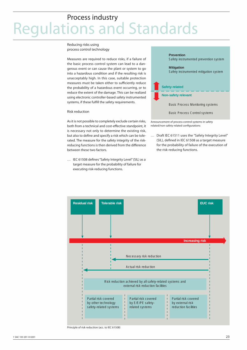
Announcement of process control systems in safety related/non-safety related confi gurations
Principle of risk reduction (acc. to IEC 61508)
Reducing risks using process control technology
Measures are required to reduce risks, if a failure of the basic process control system can lead to a dan-gerous event or can cause the plant or system to go into a hazardous condition and if the resulting risk is unacceptably high. In this case, suitable protection measures must be taken either to suffi ciently reduce the probability of a hazardous event occurring, or to reduce the extent of the damage. This can be realized using electronic controller-based safety instrumented systems, if these fulfi ll the safety requirements.
Risk reduction
As it is not possible to completely exclude certain risks, both from a technical and cost-eff ective standpoint, it is necessary not only to determine the existing risk, but also to defi ne and specify a risk which can be tole-rated. The measure for the safety integrity of the risk-reducing functions is then derived from the diff erence between these two factors.
… IEC 61508 defi nes “Safety Integrity Level” (SIL) as a target measure for the probability of failure for executing risk-reducing functions.
… Draft IEC 61511 uses the “Safety Integrity Level” (SIL), defi ned in IEC 61508 as a target measure for the probability of failure of the execution of the risk-reducing functions.
Actual risk reduction
Partial risk coveredby other technologysafety-related systems
Partial risk coveredby E/E/PE safety-related systems
Risk reduction achieved by all safety-related systems andexternal risk reduction facilities
Partial risk coveredby external riskreduction facilities
Necessary risk reduction
Increasing risk
EUC riskResidual risk Tolerable risk
PreventionSafety instrumented prevention system
MitigationSafety instrumented mitigation system
Basic Process Monitoring systems
Basic Process Control systems
Safety-related
Non-safety relevant
24 1 SAC 103 201 H 0201
Regulations and StandardsProcess industry
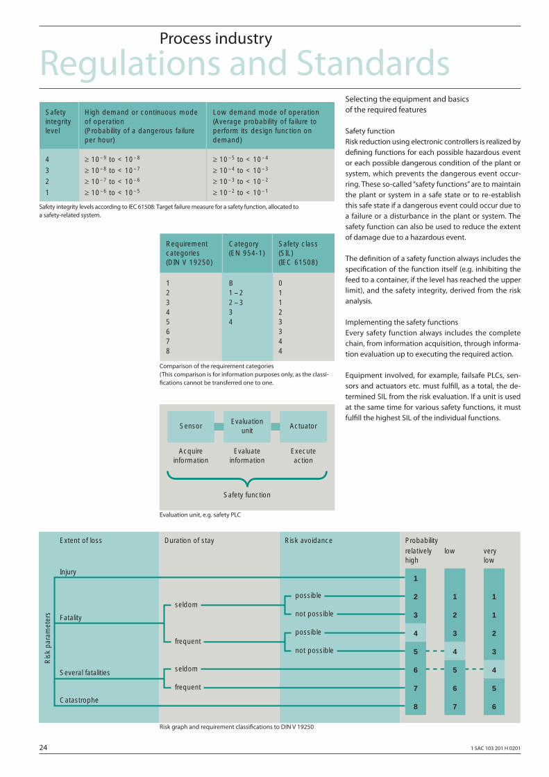
Safety integrity levels according to IEC 61508: Target failure measure for a safety function, allocated to a safety-related system.
Comparison of the requirement categories (This comparison is for information purposes only, as the classi-fi cations cannot be transferred one to one.
Evaluation unit, e.g. safety PLC
Risk graph and requirement classifi cations to DIN V 19250
Selecting the equipment and basics of the required features
Safety functionRisk reduction using electronic controllers is realized by defi ning functions for each possible hazardous event or each possible dangerous condition of the plant or system, which prevents the dangerous event occur-ring. These so-called “safety functions” are to maintain the plant or system in a safe state or to re-establish this safe state if a dangerous event could occur due to a failure or a disturbance in the plant or system. The safety function can also be used to reduce the extent of damage due to a hazardous event.
The defi nition of a safety function always includes the specifi cation of the function itself (e.g. inhibiting the feed to a container, if the level has reached the upper limit), and the safety integrity, derived from the risk analysis.
Implementing the safety functionsEvery safety function always includes the complete chain, from information acquisition, through informa-tion evaluation up to executing the required action.
Equipment involved, for example, failsafe PLCs, sen-sors and actuators etc. must fulfi ll, as a total, the de-termined SIL from the risk evaluation. If a unit is used at the same time for various safety functions, it must fulfi ll the highest SIL of the individual functions.
Safety integrity level
High demand or continuous modeof operation (Probability of a dangerous failureper hour)
Low demand mode of operation(Average probability of failure toperform its design function ondemand)
4
3
2
1
≥ 10– 9 to < 10– 8
≥ 10– 8 to < 10– 7
≥ 10– 7 to < 10– 6
≥ 10– 6 to < 10– 5
≥ 10– 5 to < 10– 4
≥ 10– 4 to < 10– 3
≥ 10– 3 to < 10– 2
≥ 10– 2 to < 10– 1
Category(EN 954-1)
Safety class(SIL)(IEC 61508)
B1 – 22 – 334
01123344
Requirementcategories (DIN V 19250)
12345678
Acquireinformation
Evaluateinformation
Executeaction
Safety function
SensorEvaluation
unitActuator
Extent of loss
Injury1
Duration of stay Risk avoidance Probabilityrelativelyhigh
low verylow
2
3
4
5
6
7
8
1
2
3
4
5
6
7
1
1
2
3
4
5
6
Several fatalities
Fatality
Catastrophe
Ris
k pa
ram
eter
s
possible
not possible
possible
not possible
seldom
frequent
seldom
frequent
1 SAC 103 201 H 0201 25
Regulations and StandardsProcess industry
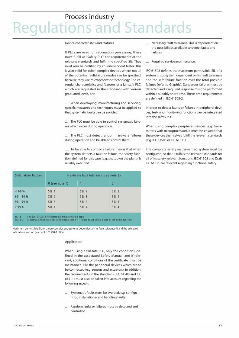
Maximum permissible SIL for a non-complex sub-systems dependent on its fault tolerance N and the achieved safe failure fraction (acc. to IEC 61508-2 FDIS)
Device characteristics and features
If PLCs are used for information processing, these must fulfill as “Safety-PLC” the requirements of the relevant standards and fulfi ll the specifi ed SIL. They must also be certifi ed by an independent tester. This is also valid for other complex devices where not all of the potential fault/failure modes can be specifi ed, because they use microprocessor technology. The es-sential characteristics and features of a fail-safe PLC, which are requested in the standards with various graduated levels, are:
… When developing, manufacturing and servicing, specifi c measures and techniques must be applied so that systematic faults can be avoided.
… The PLC must be able to control systematic failu-res which occur during operation.
… The PLC must detect random hardware failures during operation and be able to control them.
… To be able to control a failure means that when the system detects a fault or failure, the safety func-tion, defi ned for this case (e.g. shutdown the plant), is reliably executed.
Application
When using a fail-safe PLC, only the conditions, de-fined in the associated Safety Manual, and if rele-vant, additional conditions of the certifi cate, must be maintained. For the peripheral devices which are to be connected (e.g. sensors and actuators), in addition, the requirements in the standards (IEC 61508 and IEC 61511) must also be taken into account regarding the following aspects:
… Systematic faults must be avoided, e.g. confi gu- ring-, installations- and handling faults
… Random faults or failures must be detected and controlled.
… Necessary fault tolerance. This is dependent on the possibilities available to detect faults and failures.
… Required service/maintenance.
IEC 61508 defi nes the maximum permissible SIL of a system or subsystem dependent on its fault tolerance and the safe failure fraction over the total possible failures (refer to Graphic). Dangerous failures must be detected and a required response must be performed within a suitably short time. These time requirements are defi ned in IEC 61508-2.
In order to detect faults or failures in peripheral devi-ces, test- and monitoring functions can be integrated into the safety PLC.
When using complex peripheral devices (e.g. trans-mitters with microprocessor), it must be ensured that these devices themselves fulfi ll the relevant standards (e.g. IEC 61508 or IEC 61511).
The complete safety instrumented system must be confi gured, so that it fulfi lls the relevant standards for all of its safety-relevant functions. IEC 61508 and Draft IEC 61511 are relevant regarding functional safety.
Safe failure fraction
< 60 %
60 – 90 %
90 – 99 %
≥ 99 %
SIL 1
SIL 2
SIL 3
SIL 4
SIL 2
SIL 3
SIL 4
SIL 4
SIL 3
SIL 4
SIL 4
SIL 4
Hardware fault tolerance (see note 2)
0 (see note 1) 1 2
NOTE 1: See IEC 61508-2 for details on interpreting this tableNOTE 2: A hardware fault tolerance of N means that N + 1 faults could cause a loss of the safety function.
26 1 SAC 103 201 H 0201
Regulations and StandardsFurnaces
EC Directives
Furnaces and burners are subject to the relevant direc-tives due to their application and the devices which are used. There are no specifi c EC Directives for furnaces. Furnaces are subject, where relevant, to applicati-on-specifi c directives. Industrial thermo-processing equipment are, for example, classified as machines under the Machinery Directive.
Standards
Industrial thermo-processing equipmentThere is a European draft standard for these systems, which was drawn-up under a mandate of the Machin-ery Directive, and more precisely, prEN 746 “Industrial thermo-processing equipment” with
Part 1: General safety requirements of industrial thermo-processing equipment
Part 2: Safety requirements for combustion and fuel handling systems.
prEN 746 can be applied to industrial thermo-proces-sing equipment, for example
… Metal producing and processing
… Glassworks,
… Ceramic plants,
… Cement-, lime-, and gypsum plants,
… Chemical plants,
… Incinerators etc.
This refers to EN 60204-1 and EN 654-1 as well as, for safety-relevant electronic systems, also to IEC 61508.
FurnacesFor furnaces, which do not belong to industrial ther-mo-processing equipment, and are not used to heat process liquids and gases in the chemical industry, there are the following general standards for electrical equipment – the European Draft Standard
… prEN 50156 “Electrical equipment for furnaces Part 1: Requirements for application design and installation”
and the German Standard
… DIN VDE 0116
The following Standards are available for burners:
… prEN 676 gas burners;
… EN 230 oil-vapor burner in a mono-block design;
… EN 267 oil burners;
… EN 298 automation equipment for furnaces for gas burners and gas units with and without blower.
EMERGENCY OFF for furnaces
For equipping furnaces with devices to switch-off in an emergency situation, prEN 50156 specifi es that EN 60204-1 and EN 954-1 must be observed so that the appropriate EC Directives are fulfi lled.
The regulations are also involved with the associated equipment for storage, preparation and pumping fuels.
1 SAC 103 201 H 0201 27
Push buttons
28 1 SAC 103 201 H 0201
Push buttonsEMERGENCY OFF control devices
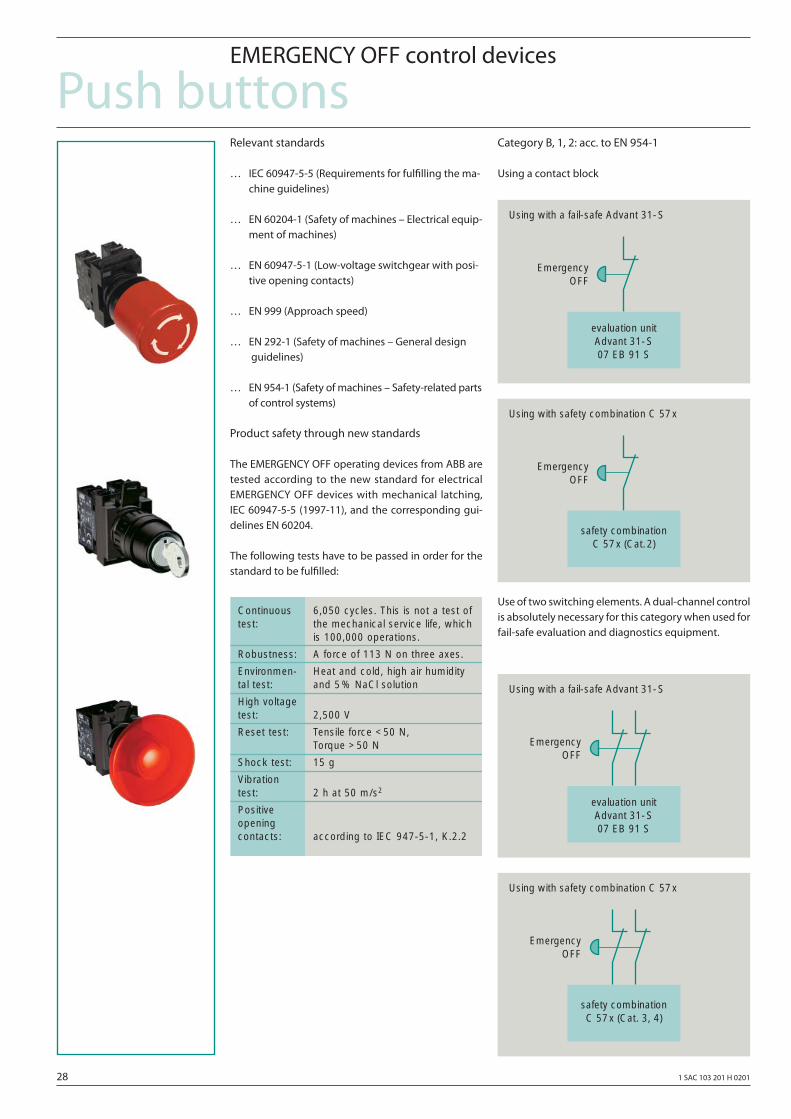
Relevant standards
… IEC 60947-5-5 (Requirements for fulfi lling the ma- chine guidelines)
… EN 60204-1 (Safety of machines – Electrical equip- ment of machines)
… EN 60947-5-1 (Low-voltage switchgear with posi- tive opening contacts)
… EN 999 (Approach speed)
… EN 292-1 (Safety of machines – General design guidelines)
… EN 954-1 (Safety of machines – Safety-related parts of control systems)
Product safety through new standards
The EMERGENCY OFF operating devices from ABB are tested according to the new standard for electrical EMERGENCY OFF devices with mechanical latching, IEC 60947-5-5 (1997-11), and the corresponding gui-delines EN 60204.
The following tests have to be passed in order for the standard to be fulfi lled:
Category B, 1, 2: acc. to EN 954-1
Using a contact block
Use of two switching elements. A dual-channel control is absolutely necessary for this category when used for fail-safe evaluation and diagnostics equipment.
Continuous 6,050 cycles. This is not a test of test: the mechanical service life, which
is 100,000 operations.
Robustness: A force of 113 N on three axes.
Environmen- Heat and cold, high air humiditytal test: and 5% NaCl solution
High voltage test: 2,500 V
Reset test: Tensile force <50 N, Torque >50 N
Shock test: 15 g
Vibration test: 2 h at 50 m/s2
Positive opening contacts: according to IEC 947-5-1, K.2.2
Using with a fail-safe Advant 31-S
evaluation unitAdvant 31-S07 EB 91 S
EmergencyOFF
Using with safety combination C 57x
safety combinationC 57x (Cat.2)
EmergencyOFF
Using with a fail-safe Advant 31-S
evaluation unitAdvant 31-S07 EB 91 S
EmergencyOFF
Using with safety combination C 57x
safety combinationC 57x (Cat. 3, 4)
EmergencyOFF
1 SAC 103 201 H 0201 29
Push buttonsEMERGENCY OFF control devices
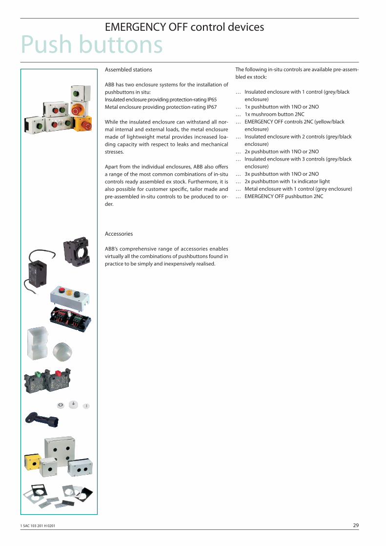
Assembled stations
ABB has two enclosure systems for the installation of pushbuttons in situ:Insulated enclosure providing protection-rating IP65Metal enclosure providing protection-rating IP67
While the insulated enclosure can withstand all nor-mal internal and external loads, the metal enclosure made of lightweight metal provides increased loa-ding capacity with respect to leaks and mechanical stresses.
Apart from the individual enclosures, ABB also off ers a range of the most common combinations of in-situ controls ready assembled ex stock. Furthermore, it is also possible for customer specifi c, tailor made and pre-assembled in-situ controls to be produced to or-der.
Accessories
ABB’s comprehensive range of accessories enables virtually all the combinations of pushbuttons found in practice to be simply and inexpensively realised.
The following in-situ controls are available pre-assem-bled ex stock:
… Insulated enclosure with 1 control (grey/black enclosure)… 1x pushbutton with 1NO or 2NO… 1x mushroom button 2NC… EMERGENCY OFF controls 2NC (yellow/black enclosure)… Insulated enclosure with 2 controls (grey/black enclosure)… 2x pushbutton with 1NO or 2NO… Insulated enclosure with 3 controls (grey/black enclosure)… 3x pushbutton with 1NO or 2NO… 2x pushbutton with 1x indicator light… Metal enclosure with 1 control (grey enclosure)… EMERGENCY OFF pushbutton 2NC
30 1 SAC 103 201 H 0201
Push buttonsSignal towers and signal beacons
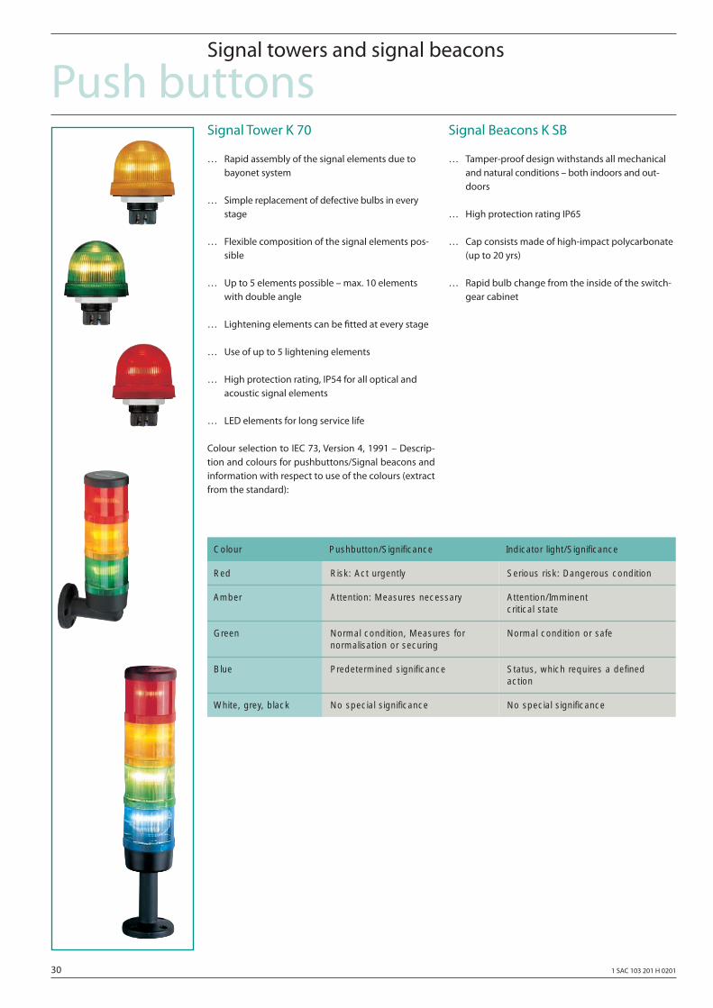
Signal Tower K 70
… Rapid assembly of the signal elements due to bayonet system
… Simple replacement of defective bulbs in every stage
… Flexible composition of the signal elements pos- sible
… Up to 5 elements possible – max. 10 elements with double angle
… Lightening elements can be fi tted at every stage
… Use of up to 5 lightening elements
… High protection rating, IP54 for all optical and acoustic signal elements
… LED elements for long service life
Colour selection to IEC 73, Version 4, 1991 – Descrip-tion and colours for pushbuttons/Signal beacons and information with respect to use of the colours (extract from the standard):
Signal Beacons K SB
… Tamper-proof design withstands all mechanical and natural conditions – both indoors and out- doors
… High protection rating IP65
… Cap consists made of high-impact polycarbonate (up to 20 yrs)
… Rapid bulb change from the inside of the switch- gear cabinet
Colour Pushbutton/Significance Indicator light/Significance
Serious risk: Dangerous condition
Attention/Imminent critical state
Normal condition or safe
Status, which requires a definedaction
No special significance
Risk: Act urgently
Attention: Measures necessary
Normal condition, Measures for normalisation or securing
Predetermined significance
No special significance
Red
Amber
Green
Blue
White, grey, black
1 SAC 103 201 H 0201 31
Push buttonsPosition switches LS-Serie
Relevant standards
… EN 1088 (Latching devices in conjunction with isolating protective devices)
… EN 60947-5-1 (Low-voltage switchgear with posi- tive opening contacts)
… prEN 999 (Approach speed)
… EN 292-1 (Safety of machines – General design guidelines)
… EN 954-1 (Safety of machines – Safety-related parts of control systems)
… EN 60204-1 (Safety of machines – Electrical equip- ment of machines)
Product spectrum
Position switches LS-Series can be used for:
… Monitoring protective equipment with hinges, such as hinged doors, fl aps, covers etc.
… Monitoring protective equipment which can be moved sideways, for example, sliding doors, pro- tective screens etc.
… Detecting hazardous movements of machine parts.
Every category can be achieved by using
ABB position switches LS-Series are optimally harmo-nized with the requirements for the highest degree of safety and off er the following advantages:
… Positive opening of the NC contacts
… Version with/without separate actuator
… Increased safety using additional latching (tumbler mechanism)
… High degree of protection IP 65/67
… Standard enclosure, also in accordance with DIN EN 50047 and 50041
… Diff erent actuators
… Electrically insulated contacts with moving doub-le contacts.
Position switches LS-Series are supplied with separate actuators or without actuator. The actuator elements are shown for the particular switch types.
Positive opening operation of the contacts (EN 60947-5-1)
Positive opening operation is specifi ed in accordance with DIN VDE 0660 Part 200 and is the same as IEC 947-5-1-3 and EN 60947-5-1.For the electrical equipment of machines, the positive opening of NC contacts is expressively specified in all safety circuits. It is designated according to IEC 947-5-1-3 by the following character → (personnel protective funktion).
32 1 SAC 103 201 H 0201
Push buttonsPosition switches
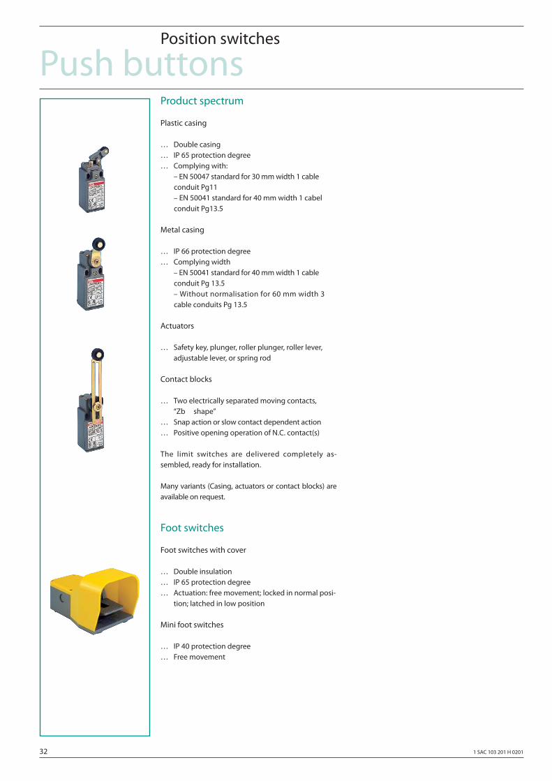
Product spectrum
Plastic casing
… Double casing… IP 65 protection degree… Complying with: – EN 50047 standard for 30 mm width 1 cable conduit Pg11 – EN 50041 standard for 40 mm width 1 cabel conduit Pg13.5
Metal casing
… IP 66 protection degree… Complying width – EN 50041 standard for 40 mm width 1 cable conduit Pg 13.5 – Without normalisation for 60 mm width 3 cable conduits Pg 13.5
Actuators
… Safety key, plunger, roller plunger, roller lever, adjustable lever, or spring rod
Contact blocks
… Two electrically separated moving contacts, “Zb shape”… Snap action or slow contact dependent action… Positive opening operation of N.C. contact(s)
The limit switches are delivered completely as-sembled, ready for installation.
Many variants (Casing, actuators or contact blocks) are available on request.
Foot switches
Foot switches with cover
… Double insulation… IP 65 protection degree… Actuation: free movement; locked in normal posi- tion; latched in low position
Mini foot switches
… IP 40 protection degree… Free movement
1 SAC 103 201 H 0201 33
Advant Controller 31-S
34 1 SAC 103 201 H 0201
Advant Controller 31-SSave intelligence
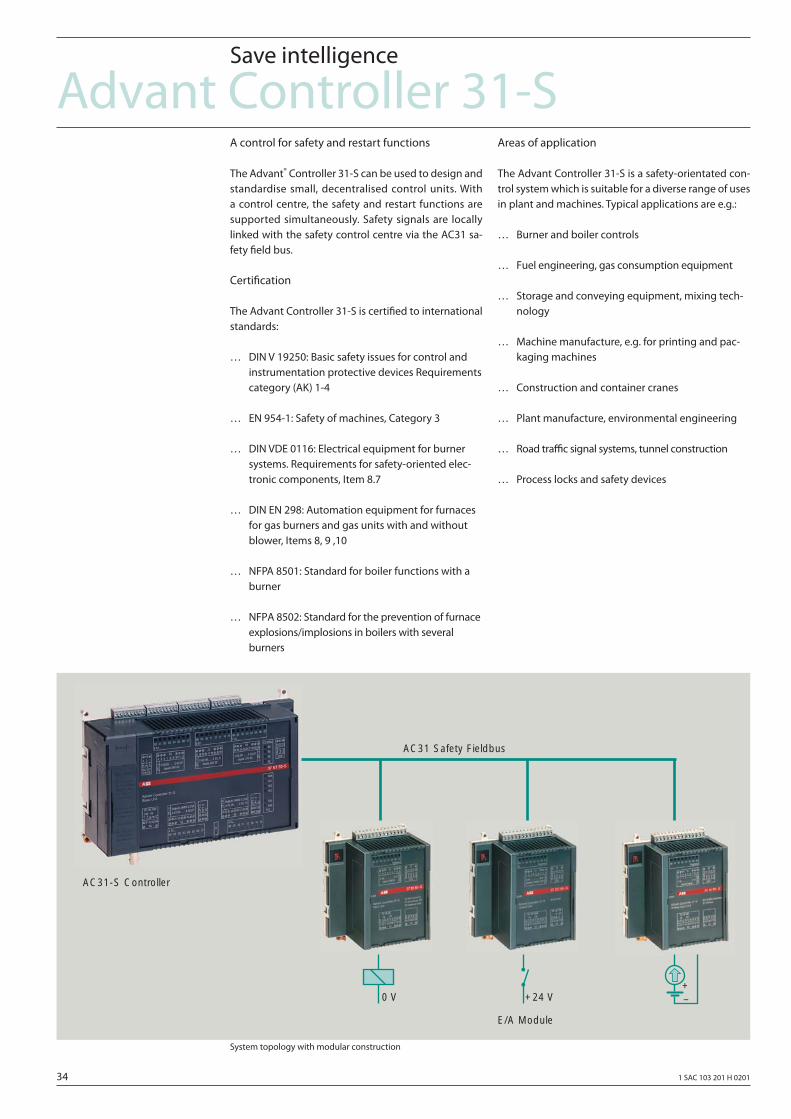
A control for safety and restart functions
The Advant® Controller 31-S can be used to design and standardise small, decentralised control units. With a control centre, the safety and restart functions are supported simultaneously. Safety signals are locally linked with the safety control centre via the AC31 sa-fety fi eld bus.
Certifi cation
The Advant Controller 31-S is certifi ed to international standards:
… DIN V 19250: Basic safety issues for control and instrumentation protective devices Requirements category (AK) 1-4
… EN 954-1: Safety of machines, Category 3
… DIN VDE 0116: Electrical equipment for burner systems. Requirements for safety-oriented elec- tronic components, Item 8.7
… DIN EN 298: Automation equipment for furnaces for gas burners and gas units with and without blower, Items 8, 9 ,10
… NFPA 8501: Standard for boiler functions with a burner
… NFPA 8502: Standard for the prevention of furnace explosions/implosions in boilers with several burners
Areas of application
The Advant Controller 31-S is a safety-orientated con-trol system which is suitable for a diverse range of uses in plant and machines. Typical applications are e.g.:
… Burner and boiler controls
… Fuel engineering, gas consumption equipment
… Storage and conveying equipment, mixing tech- nology
… Machine manufacture, e.g. for printing and pac- kaging machines
… Construction and container cranes
… Plant manufacture, environmental engineering
… Road traffi c signal systems, tunnel construction
… Process locks and safety devices
System topology with modular construction
AC31 Safety Fieldbus
AC31-S Controller
E/A Module
0 V +24 V+–
1 SAC 103 201 H 0201 35
Advant Controller 31-SSystem data
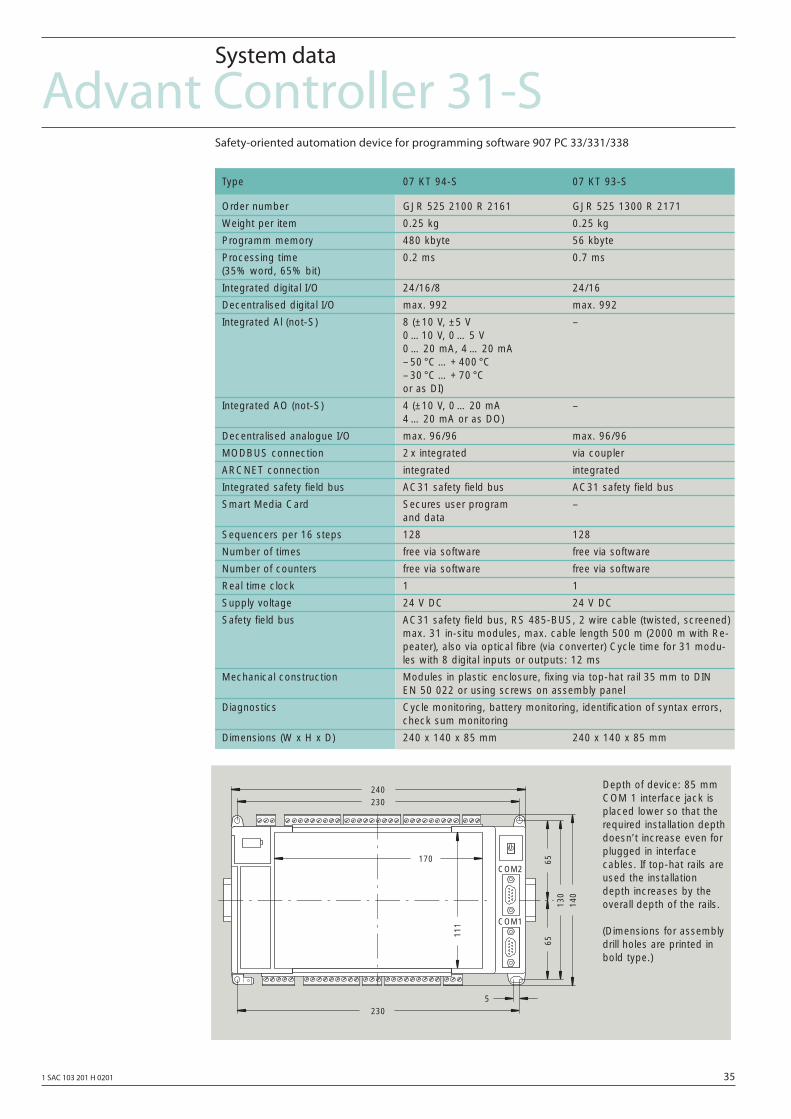
Safety-oriented automation device for programming software 907 PC 33/331/338
Type 07 KT 94-S 07 KT 93-S
Order number GJR 525 2100 R 2161 GJR 525 1300 R 2171
Weight per item 0.25 kg 0.25 kg
Programm memory 480 kbyte 56 kbyte
Processing time 0.2 ms 0.7 ms(35% word, 65% bit)
Integrated digital I/O 24/16/8 24/16
Decentralised digital I/O max. 992 max. 992
Integrated Al (not-S) 8 (±10 V, ±5 V –0 …10 V, 0 … 5 V0 … 20 mA, 4 … 20 mA– 50 °C … + 400 °C– 30 °C … + 70 °Cor as DI)
Integrated AO (not-S) 4 (±10 V, 0 … 20 mA –4 … 20 mA or as DO)
Decentralised analogue I/O max. 96/96 max. 96/96
MODBUS connection 2 x integrated via coupler
ARCNET connection integrated integrated
Integrated safety field bus AC31 safety field bus AC31 safety field bus
Smart Media Card Secures user program –and data
Sequencers per 16 steps 128 128
Number of times free via software free via software
Number of counters free via software free via software
Real time clock 1 1
Supply voltage 24 V DC 24 V DC
Safety field bus AC31 safety field bus, RS 485-BUS, 2 wire cable (twisted, screened)max. 31 in-situ modules, max. cable length 500 m (2000 m with Re-peater), also via optical fibre (via converter) Cycle time for 31 modu-les with 8 digital inputs or outputs: 12 ms
Mechanical construction Modules in plastic enclosure, fixing via top-hat rail 35 mm to DIN EN 50 022 or using screws on assembly panel
Diagnostics Cycle monitoring, battery monitoring, identification of syntax errors,check sum monitoring
Dimensions (W x H x D) 240 x 140 x 85 mm 240 x 140 x 85 mm
COM1
COM2
5230
230240
6513
014
0
65
170
111
Depth of device: 85 mmCOM 1 interface jack isplaced lower so that therequired installation depthdoesn’t increase even forplugged in interfacecables. If top-hat rails areused the installationdepth increases by theoverall depth of the rails.
(Dimensions for assemblydrill holes are printed inbold type.)
36 1 SAC 103 201 H 0201
Advant Controller 31-SSafety-related input/output modules
Programming and test software, additional package
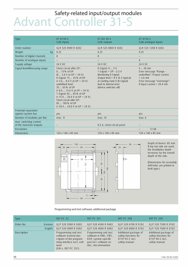
Type 07 DI 90-S 07 DO 90-S 07 Al 90-SSafe inputs Safe outputs Safe analogue inputs
Order number GJR 525 0900 R 0202 GJR 525 0800 R 0202 GJR 525 1200 R 0202
Weight kg 0.25 0.25 0.25
Number of digital channels 8 8 –
Number of analogue inputs – – 4
Supply voltage 24 V DC 24 V DC 24 V DC
Signal level/Measuring range Short circuit after ZP: 0-Signal: 0 … 3 V 4 … 20 mA0 … 15 % of UP 1-Signal: > UP – 2.5 V Error message “Range -(0 … 3.6 V at UP = 24 V) Monitoring 0-Signal: underflow”: if input current0-Signal: 15 … 35 % of UP Output level > 8 V (5 V typical) < 3.6 mA(+ 3.6 … 8.4 V at UP = 24 V) at starting state 0 (0-Signal) Error message “overrange”:undefined level: lead to internal error if input current > 20.4 mA35 … 65 % of UP (device switches off)(+ 8.4 … 15.6 V at UP = 24 V)1-Signal: 65 … 85 % of UP (+ 15.6 … 20.4 V at UP = 24 V)Short circuit after UP: 85 … 100 % of UP (+ 20.4 … 24,0 V at UP = 24 V)
Potential separation against system bus yes yes yes
Number of modules per line max. 8 max. 16 max. 6
max. switching current of the transistor outputs – 0.5 A, short-circuit proof –
Resolution – – 12 bit
Dimensions 120 x 140 x 85 mm 120 x 140 x 85 mm 120 x 140 x 85 mm
6513
065
140
94120
2085
25
111
75
594
Depth of device: 85 mmIf top hat rails are used,the installation depthincreases by the overalldepth of the rails.
(Dimensions for assemblydrill holes are printed inbold type.)
Type 907 PC 33 907 PC 331 907 PC 338 907 PC 339
Order No. German GJP 520 3900 R 0302 GJP 520 4500 R 0402 GJP 520 6700 R 0102 GJP 520 7500 R 0102
English GJP 520 4000 R 0302 GJP 520 4600 R 0402 GJP 520 6800 R 0102 GJP 520 7600 R 0102
Description Programming and test Programming and test Additional package of Additional package ofsoftware General des- software in AWL, FBS, safety functions for safety functions for cription of the program- KOP, system-specific 07 KT 93-S incl. 07 KT 94-S incl. ming interface excl. soft- part incl. software on safety manual safety manualware disc, documentation(SW s. 907 PC 331)
1 SAC 103 201 H 0201 37
Safety control devices
38 1 SAC 103 201 H 0201
Safety control devicesRules for application
Safety Combinations types C 57x und C 581
The complete program of safety combinations has been especially designed for the requirements of state-of-the as safety technology. Safety combinations can be simply used to confi gure safety circuits, as the devices fulfi ll EN 60204-1 (VDE 0113 Part 1) and are certifi ed by the German Trade Association (BG), German Sta-tutory Industrial Accident Insurance Association (BIA) and the Swiss Accident Insurance Institution (SUVA).
Applications
Safety combinations cover wide range of possible applications. These include monitoring EMERGENCY-STOP and protective door devices. It is also possible to monitor press control systems.
Safety Combinations tend to be used for some-what less complex safety circuits as conventional switching technology used with electromechanical contacts. Sa-fety circuits using PLC technology (Advant Controller 31-S) can be used for more complex plants and sy-stems with a high functional scope (e.g. with a diagno-stics function when an EMERGENCY OFF is initiated). A fail-safe Advant Controller 31-S is frequently used if a Advant Controller is used for the non-safety-relevant control of the plant or system.
Positively-driven contacts, a plus for safety
Relays are often used for safety circuits. The special feature of ABB safety combinations is the fact that con-tactors or safety relays use positively driven contacts. In this case, ABB off er two Versions of safety combinati-ons, and more specifi cally, using contactors (CC 570) or relays (C 571…C 581).
Contactor-type safety combinations (C 570)
Contactors have a high switching capacity. For sa-fety combinations, rated operating currents of 6 A are possible for AC-1, and for DC-13, up to 6 A, and a thermal continuous current up to 10 A. This is also valid up to 55°C when mounted in a ca-binet without having to derate the devices. With this performance data, you can optimally confi gure every safety circuit, and it is even possible to switch smaller drives directly using a safety combination. With a safety combination, additional main contactors are not required to switch higher ratings. That naturally saves costs.
Furthermore, high switching currents also mean more safety and safety combinations use auxiliary contactors with an extremely high contact reliability. Statistically, only 1 contact fault occurs every 100 million switching operations. These low fault statistics signifi cantly in-crease the plant availability.
Relay-type safety combinations (C 571…C 581)
In recent years, the trend in low-voltage technology has been towards miniaturization of the switching de-vices. With newly-developed, smaller devices, it was possible to increasingly accommodate more func-tionality in a cabinet. It was therefore a logical step that when it came to safety technology, that there would also be demand for smaller, more compact sa-fety combinations. ABB fulfi lled this enhanced safety demand by using space-saving safety relays with po-sitively-driven contacts. These safety relays switch so that they are intrinsically fail-safe. In this case, 2 con-tacts, which are independent of one another, have to be switched in series; normally so-called NO contacts of monostable relays are used. If a contact was to weld, then the 2nd contact, connected in series, is used to disconnect the circuit. A positively-driven NC contact is used to signal the fault, in this case the welded NO contact. This NC contact is actuated in synchronism with the NO contact. For example, if the NO contact is closed, then the NC contact, which is provided for monitoring, must be open and vice versa. Using these paired, positively-driven contacts, it is ensured that the safety relay also drops-out, if all of the contacts of the circuit to be protected are welded.
With this new-type of contact arrangement, the safety relay has positively-driven contacts, which are tested and recognized by SUVA and which fully conform to Standard ZH1/457.
The relay safety combinations C57x and 581 can be used in ambient temperatures of up to 60°C, up to 70°C with some restrictions when mounted in-line.
Many switching functions can be implemented using the series of C 57x and 581 safety combination. The following program overview shows the spectrum of devices available:
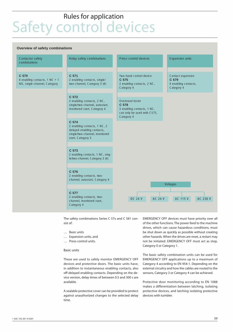
1 SAC 103 201 H 0201 39
Safety control devicesRules for application
The safety combinations Series C 57x and C 581 con-sist of:
… Basic units… Expansion units, and… Press-control units.
Basic units
These are used to safely monitor EMERGENCY OFF devices and protective doors. The basic units have, in addition to instantaneous enabling contacts, also off -delayed enabling contacts. Depending on the de-vice version, delay times of between 0.5 and 300 s are available.
A sealable protective cover can be provided to protect against unauthorized changes to the selected delay time.
EMERGENCY OFF devices must have priority over all of the other functions. The power feed to the machine drives, which can cause hazardous conditions, must be shut down as quickly as possible without creating other hazards. When the drives are reset, a restart may not be initiated. EMERGENCY OFF must act as stop, Category 0 or Category 1.
The basic safety combination units can be used for EMERGENCY OFF applications up to a maximum of Category 4 according to EN 954-1. Depending on the external circuitry and how the cables are routed to the sensors, Category 3 or Category 4 can be achieved.
Protective door monitoring according to EN 1088 makes a differentiation between latching, isolating protective devices, and latching isolating protective devices with tumbler.
Relay safety combinations
Overview of safety combinations
DC 24 V AC 24 V AC 115 V AC 230 V
Contactor safety combinations
C 570 4 enabling contacts, 1 NC + 1NO, single-channel, Category
Two-hand control device C 575 2 enabling contacts, 2 NC,Category 4
Contact expension C 579 4 enabling contacts, Category 4
Overtravel tester C 578 3 enabling contacts, 1 NC, can only be used with C575,Category 4
C 574 2 enabling contacts, 1 NC, 2delayed enabling contacts,single/two-channel, monitoredstart, Category 3
Press-control devices Expansion units
C 571 2 enabling contacts, single/two-channel, Category 3 (4)
C 573 2 enabling contacts, 1 NC, sing-le/two-channel, Category 3 (4)
C 576 2 enabling contacts, two-channel, autostart, Category 4
C 577 2 enabling contacts, two-channel, monitored start,Category 4
C 572 3 enabling contacts, 2 NC,single/two-channel, autostart,monitored start, Category 4
Voltages
40 1 SAC 103 201 H 0201
Safety control devicesSafety combinations series are also used here. Control systems up to Category 4 according to EN 954-1 can be confi gured.
Expansion units
Expansion units may not be used separately in safety circuits, and they must be combined with a basic C 57x and 581 safety combination unit. An enabling contact of the basic unit is required to connect an expansion unit. The category of a control system with expansion unit corresponds to the category of the basic unit.
Presses and punches
The two-hand control device is a device where both hands of the operator must be simultaneously used. This protects the operator from hazards.
The overtravel tester is used for linear-driven presses and punches in accordance with VBG 7n5.2. It only checks once at the test stroke
… that the operator control elements have been correctly connected
… for external cable interruptions and breaks
… if the components which are cyclically monitored, have failed.
The overtravel tester can only be used in conjunction with a two-hand control device.
The press control devices and overtravel testers are suitable for installation in control system for eccentric, hydraulic and spindle presses. They can be used up to Category 4 in accordance with EN 954-1. Type III C ac-cording EN 574 can be especially used for presses.
Rules for application
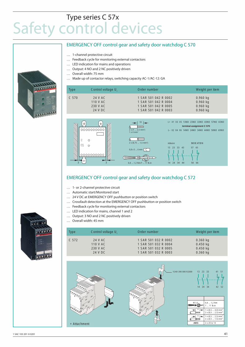
1 SAC 103 201 H 0201 41
Safety control devicesType series C 57x
EMERGENCY OFF control gear and safety door watchdog C 570
… 1-channel protective circuit… Feedback cycle for monitoring external contactors… LED indication for mains and operations… Output: 4 NO and 2 NC positively driven… Overall width: 75 mm… Made up of contactor relays, switching capacity AC-1/AC-12: GA
EMERGENCY OFF control gear and safety door watchdog C 572
… 1- or 2-channel protective circuit… Automatic start/Monitored start… 24 V DC at EMERGENCY OFF pushbutton or position switch… Crossfault detection at the EMERGENCY OFF pushbutton or position switch… Feedback cycle for monitoring external contactors… LED indication for mains, channel 1 and 2… Output: 3 NO and 2 NC positively driven… Overall width: 45 mm
Type Control voltage Uc Order number Weight per item
C 570 24 V AC 1 SAR 501 042 R 0002 0.960 kg110 V AC 1 SAR 501 042 R 0004 0.960 kg230 V AC 1 SAR 501 042 R 0005 0.960 kg24 V DC 1 SAR 501 042 R 0003 0.960 kg
Type Control voltage Uc Order number Weight per item
C 572 24 V AC 1 SAR 501 032 R 0002 0.360 kg110 V AC 1 SAR 501 032 R 0004 0.450 kg230 V AC 1 SAR 501 032 R 0005 0.450 kg24 V DC 1 SAR 501 032 R 0003 0.360 kg
3 3
EinOn
BereitReady
2 x (1 ... 2,5 mm2)1 x 4 mm2
2 x (0,75 ... 1,5 mm2)
0,8 x 5 ... 6 mm
0,8 ... 1,2 Nm/7 ... 11 lb.in
L+ X1 X3 X5 13NO 23NO 33NO 43NO 57NO 65NO
terminal assignment C 570
L– X2 X4 X6 14NO 24NO 34NO 44NO 58NO 69NO
release INDICATION
14
13
24
23
34
33
44
43
58
57
66
65
10
1SAR 390 000 R2000
14
13
24
23
34
33
42
41
52
51
+ Attachment
M 3,57 ... 11 lb.in
1 x (0,5 ... 4,0) mm2
2 x (0,5 ... 2,5) mm2
1 x (0,5 ... 2,5) mm2
2 x (0,5 ... 1,5) mm2
0,8 ... 1,2 Nm
2 x 20 to 14AWG
10
10
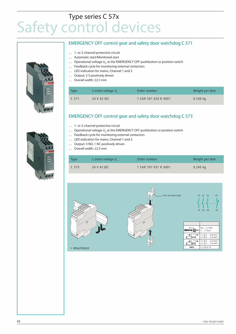
42 1 SAC 103 201 H 0201
Safety control devicesType series C 57x
EMERGENCY OFF control gear and safety door watchdog C 571
… 1- or 2-channel protective circuit… Automatic start/Monitored start… Operational voltage UC at the EMERGENCY OFF pushbutton or position switch… Feedback cycle for monitoring external contactors… LED indication for mains, Channel 1 and 2… Output: 2 S positively driven… Overall width: 22.5 mm
EMERGENCY OFF control gear and safety door watchdog C 573
… 1- or 2-channel protective circuit… Operational voltage Ue at the EMERGENCY OFF pushbutton or position switch… Feedback cycle for monitoring external contactors… LED indication for mains, Channel 1 and 2… Output: 3 NO, 1 NC positively driven… Overall width: 22.5 mm
Type Control voltage Uc Order number Weight per item
C 571 24 V AC/DC 1 SAR 501 020 R 0001 0.240 kg
Type Control voltage Uc Order number Weight per item
C 573 24 V AC(DC 1 SAR 501 031 R 0001 0,240 kg
14
13
24
23
34
33
42
411SAR 390 000 R2000
+ Attachment
M 3,57 ... 11 lb.in
1 x (0,5 ... 4,0) mm2
2 x (0,5 ... 2,5) mm2
1 x (0,5 ... 2,5) mm2
2 x (0,5 ... 1,5) mm2
0,8 ... 1,2 Nm
2 x 20 to 14AWG
10
10
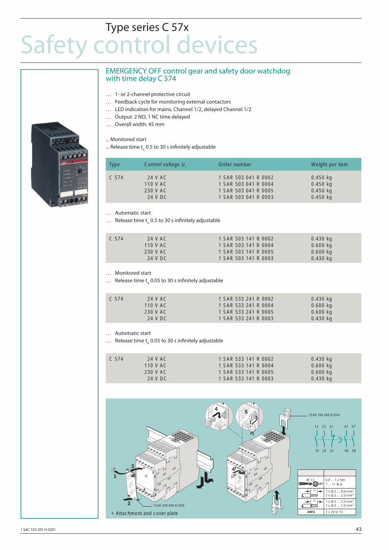
1 SAC 103 201 H 0201 43
Safety control devicesType series C 57x
EMERGENCY OFF control gear and safety door watchdog with time delay C 574
… 1- or 2-channel protective circuit… Feedback cycle for monitoring external contactors… LED indication for mains, Channel 1/2, delayed Channel 1/2… Output: 2 NO, 1 NC time delayed… Overall width: 45 mm
... Monitored start
... Release time tv 0.5 to 30 s infi nitely adjustable
… Automatic start… Release time tv 0.5 to 30 s infi nitely adjustable
… Monitored start… Release time tv 0.05 to 30 s infi nitely adjustable
… Automatic start… Release time tv 0.05 to 30 s infi nitely adjustable
Type Control voltage Uc Order number Weight per item
C 574 124 V AC 1 SAR 503 041 R 0002 0.450 kg110 V AC 1 SAR 503 041 R 0004 0.450 kg230 V AC 1 SAR 503 041 R 0005 0.450 kg124 V DC 1 SAR 503 041 R 0003 0.450 kg
C 574 124 V AC 1 SAR 503 141 R 0002 0.430 kg110 V AC 1 SAR 503 141 R 0004 0.600 kg230 V AC 1 SAR 503 141 R 0005 0.600 kg124 V DC 1 SAR 503 141 R 0003 0.430 kg
C 574 124 V AC 1 SAR 533 241 R 0002 0.430 kg110 V AC 1 SAR 533 241 R 0004 0.600 kg230 V AC 1 SAR 533 241 R 0005 0.600 kg124 V DC 1 SAR 533 241 R 0003 0.430 kg
C 574 124 V AC 1 SAR 533 141 R 0002 0.430 kg110 V AC 1 SAR 533 141 R 0004 0.600 kg230 V AC 1 SAR 533 141 R 0005 0.600 kg124 V DC 1 SAR 533 141 R 0003 0.430 kg
+ Attachment and cover plate
4
2
54
1
3
1SAR 390 000 R2000
1SAR 390 000 R1000
14
13
24
23
32
31
48
47
58
57
M 3,57 ... 11 lb.in
1 x (0,5 ... 4,0) mm2
2 x (0,5 ... 2,5) mm2
1 x (0,5 ... 2,5) mm2
2 x (0,5 ... 1,5) mm2
0,8 ... 1,2 Nm
2 x 20 to 14AWG
10
10
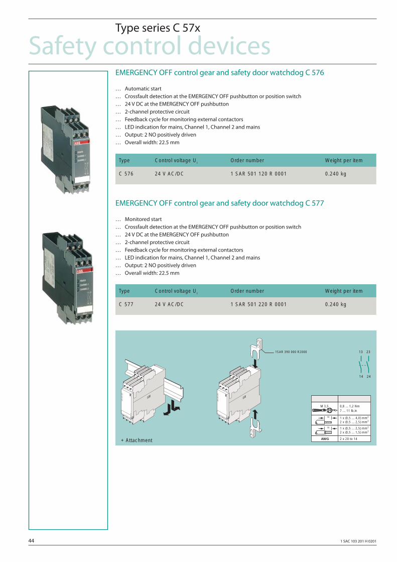
44 1 SAC 103 201 H 0201
Safety control devicesType series C 57x
EMERGENCY OFF control gear and safety door watchdog C 576
… Automatic start… Crossfault detection at the EMERGENCY OFF pushbutton or position switch… 24 V DC at the EMERGENCY OFF pushbutton… 2-channel protective circuit… Feedback cycle for monitoring external contactors… LED indication for mains, Channel 1, Channel 2 and mains… Output: 2 NO positively driven… Overall width: 22.5 mm
EMERGENCY OFF control gear and safety door watchdog C 577
… Monitored start… Crossfault detection at the EMERGENCY OFF pushbutton or position switch… 24 V DC at the EMERGENCY OFF pushbutton… 2-channel protective circuit… Feedback cycle for monitoring external contactors… LED indication for mains, Channel 1, Channel 2 and mains… Output: 2 NO positively driven… Overall width: 22.5 mm
Type Control voltage Uc Order number Weight per item
C 576 24 V AC/DC 1 SAR 501 120 R 0001 0.240 kg
Type Control voltage Uc Order number Weight per item
C 577 24 V AC/DC 1 SAR 501 220 R 0001 0.240 kg
14
13
24
231SAR 390 000 R2000
+ Attachment
M 3,57 ... 11 lb.in
1 x (0,5 ... 4,0) mm2
2 x (0,5 ... 2,5) mm2
1 x (0,5 ... 2,5) mm2
2 x (0,5 ... 1,5) mm2
0,8 ... 1,2 Nm
2 x 20 to 14AWG
10
10
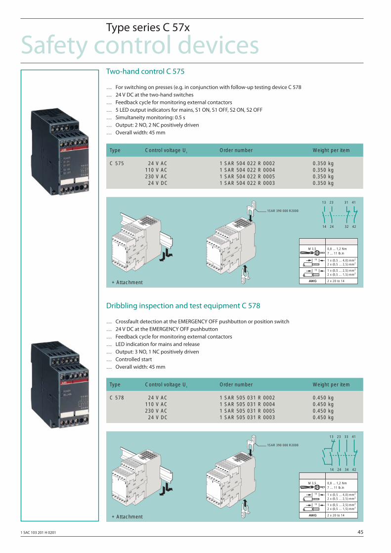
1 SAC 103 201 H 0201 45
Safety control devicesType series C 57x
Two-hand control C 575
… For switching on presses (e.g. in conjunction with follow-up testing device C 578… 24 V DC at the two-hand switches… Feedback cycle for monitoring external contactors… 5 LED output indicators for mains, S1 ON, S1 OFF, S2 ON, S2 OFF… Simultaneity monitoring: 0.5 s… Output: 2 NO, 2 NC positively driven… Overall width: 45 mm
Dribbling inspection and test equipment C 578
… Crossfault detection at the EMERGENCY OFF pushbutton or position switch… 24 V DC at the EMERGENCY OFF pushbutton… Feedback cycle for monitoring external contactors… LED indication for mains and release… Output: 3 NO, 1 NC positively driven… Controlled start… Overall width: 45 mm
Type Control voltage Uc Order number Weight per item
C 575 124 V AC 1 SAR 504 022 R 0002 0.350 kg110 V AC 1 SAR 504 022 R 0004 0.350 kg230 V AC 1 SAR 504 022 R 0005 0.350 kg124 V DC 1 SAR 504 022 R 0003 0.350 kg
Type Control voltage Uc Order number Weight per item
C 578 124 V AC 1 SAR 505 031 R 0002 0.450 kg110 V AC 1 SAR 505 031 R 0004 0.450 kg230 V AC 1 SAR 505 031 R 0005 0.450 kg124 V DC 1 SAR 505 031 R 0003 0.450 kg
+ Attachment
14
13
24
23
32
31
42
41
1SAR 390 000 R2000
M 3,57 ... 11 lb.in
1 x (0,5 ... 4,0) mm2
2 x (0,5 ... 2,5) mm2
1 x (0,5 ... 2,5) mm2
2 x (0,5 ... 1,5) mm2
0,8 ... 1,2 Nm
2 x 20 to 14AWG
10
10
+ Attachment
1SAR 390 000 R2000
14
13
24
23
34
33
42
41
M 3,57 ... 11 lb.in
1 x (0,5 ... 4,0) mm2
2 x (0,5 ... 2,5) mm2
1 x (0,5 ... 2,5) mm2
2 x (0,5 ... 1,5) mm2
0,8 ... 1,2 Nm
2 x 20 to 14AWG
10
10
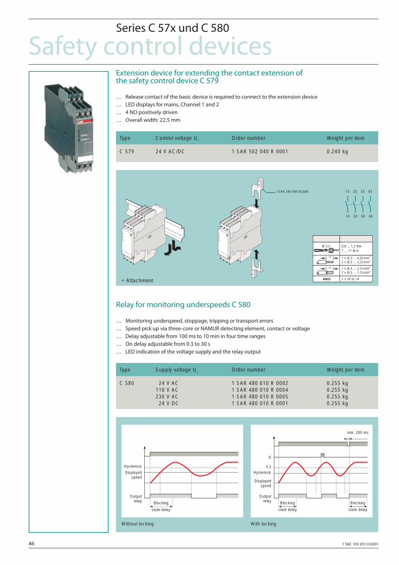
46 1 SAC 103 201 H 0201
Safety control devicesSeries C 57x und C 580
Extension device for extending the contact extension of the safety control device C 579
… Release contact of the basic device is required to connect to the extension device… LED displays for mains, Channel 1 and 2… 4 NO positively driven… Overall width: 22.5 mm
Relay for monitoring underspeeds C 580
… Monitoring underspeed, stoppage, tripping or transport errors… Speed pick up via three-core or NAMUR detecting element, contact or voltage… Delay adjustable from 100 ms to 10 min in four time ranges… On delay adjustable from 0.3 to 30 s… LED indication of the voltage supply and the relay output
Type Control voltage Uc Order number Weight per item
C 579 24 V AC/DC 1 SAR 502 040 R 0001 0.240 kg
Type Supply voltage Uc Order number Weight per item
C 580 124 V AC 1 SAR 480 010 R 0002 0.255 kg110 V AC 1 SAR 480 010 R 0004 0.255 kg230 V AC 1 SAR 480 010 R 0005 0.255 kg124 V DC 1 SAR 480 010 R 0001 0.255 kg
Displayedspeed
Blocking
state delay
Outputrelay
Hysteresis
Displayedspeed
Blocking
state delay
Outputrelay Blocking
state delay
min. 200 ms
HysteresisS2
U
Without locking With locking
1SAR 390 000 R2000
+ Attachment
M 3,57 ... 11 lb.in
1 x (0,5 ... 4,0) mm2
2 x (0,5 ... 2,5) mm2
1 x (0,5 ... 2,5) mm2
2 x (0,5 ... 1,5) mm2
0,8 ... 1,2 Nm
2 x 20 to 14AWG
10
10
14
13
24
23
34
33
44
43
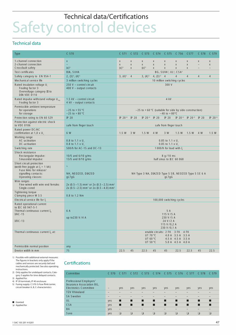
1 SAC 103 201 H 0201 47
Safety control devicesTechnical data/Certifi cations
Technical data
Certifi cations1) Possible with additional external measures. The fi gures in brackets only apply if the cables and sensors are securely laid and mechanically protected. See also operating instructions.2) Only applies for undelayed contacts, Cate- gory 3 applies for time delayed contacts.3) Applied for.4) IP 20 terminals, IP 40 enclosure5) Fusing supply: C 570: G-fuse fl ink/carrier, circuit breaker A, B, C-characteristics
■ Granted ❏ Applied for
C 570 C 571 C 572 C 573 C 574 C 575 C 756 C577 C 578 C 579Type
1-channel connection x x x x x x x x x x2-channel connection – x x x x x x x – xCrossfault safety (x)1) (x)1) x (x)1) x x x x – –
Test certificates BIA, SUVA BG, SUVA3, UL3, CSA3
Safety category to EN 954-1 2, (3)1), (4)1) 3, (4)1) 4 3, (4)1) 4, (3) 2) 4 4 4 4 4
Mechanical service life 3 million switching cycles 10 million switching cycles
Rated insulation voltage Ui 250 V – control circuit 300 VFouling factor 3 400 V – output contactsOvervoltage category III to DIN VDE 0110
Rated impulse withstand voltage Uimp 1.5 kV – control circuit 4 kVFouling factor 3 4 kV – output contacts
Permissible ambient temperaturefor operations – 25 to + 55 °C – 25 to + 60 °C (suitable for side by side construction)for storage – 25 to + 80 °C – 40 to + 80°C
Protection rating to EN 60 529 IP 20 IP 20 4) IP 20 IP 20 4) IP 20 IP 20 IP 20 4) IP 20 4) IP 20 IP 20 4)
Protection against electric shock to VDE 0106 safe from finger touch safe from finger touch
Rated power DC/AC confirmation at 1,0 x Us 6 W 1.5 W 3 W 1.5 W 4 W 3 W 1.5 W 1.5 W 4 W 1.5 W
Working rangeAC-activation 0.8 to 1.1 x Us 0.85 to 1.1 x Us
DC-activation 0.8 to 1.1 x Us 0.85 to 1.1 x Us
Switching rate 500/h for AC-15 and DC-13 1 000/h for load with IeShock resistance
Rectangular impulse: 10/5 and 6/10 g/ms 8 g / 10 msSinusoidal impulse: 13/5 and 8/10 g/ms half sinus to IEC 60 068
Short circuit protection (weld-free joggle at Ik = 1 kA) 5)
Fuse links for release/signalling contacts: NH, NEOZED, DIAZED NH Type 3 NA, DIAZED Type 5 SB, NEOZED Type 5 SE 6 AOperating classes: gL7gG gL7gG
Wire rangesFine-wired with wire end ferrules 2x (0.5 – 1.5) mm2 or 2x (0.5 – 2.5) mm2
Single-cored 2x (0.5 – 2.5) mm2 or 2x (0.5 – 4.0) mm2
Tightening torqueClamping piece M 3.5 0.8 to 1.2 Nm
Electrical service life for Ie 100,000 switching cycles
Rated operational current to IEC 60 947-5-1Thermal continuous current Ith 6 A 5 AI/AC-15 115 V / 5 A
up to230 V / 4 A 230 V / 5 AI/DC-13 24 V / 2 A
115 V / 0,2 A230 V / 0,1 A
Thermal continuous current Ith at: enable circuits: 2 FK 3 FK 4 FKUT 70 °C 4.0 A 3.5 A 3.5 AUT 60 °C 4.5 A 4.5 A 3.5 AUT 50 °C 5.0 A 4.5 A 4.0 A
Permissible normal position any
Device width in mm 75 22.5 45 22.5 45 45 22.5 22.5 45 22.5
Committee C 570 C 571 C 572 C 573 C 574 C 575 C 576 C 577 C 578 C 579
Professional Employers’ Insurance Association BG, Electronics Committee – yes yes yes yes yes yes yes yes yes
TÜV Rhineland – – – – – – – – – –
SA Sweden – – – – – – – – – –
UL yes ■ ■ ■ ■ ■ ■ ■ ■ ■
CSA yes ■ ■ ■ ■ ■ ■ ■ ■ ■
BA yes – – – – – – – – –
Suva yes ❏ ❏ ❏ ❏ ❏ ❏ ❏ ❏ ❏
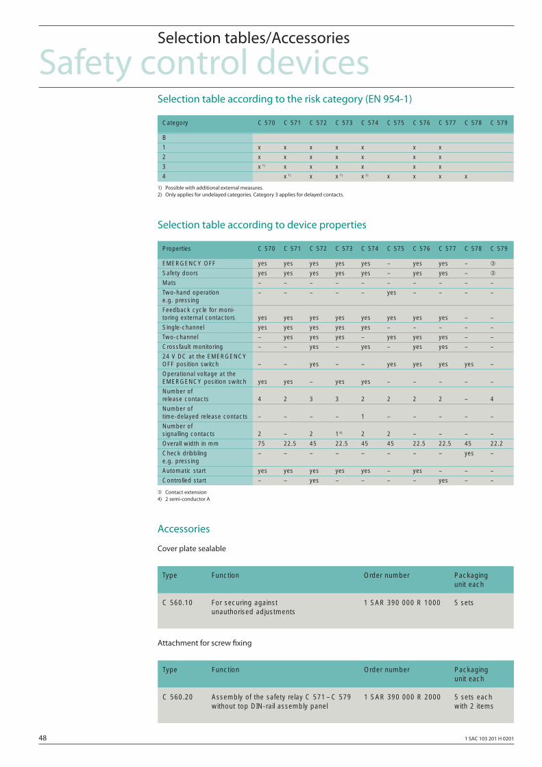
48 1 SAC 103 201 H 0201
Safety control devicesSelection tables/Accessories
Selection table according to the risk category (EN 954-1)
1) Possible with additional external measures.2) Only applies for undelayed categories. Category 3 applies for delayed contacts.
Selection table according to device properties
➂ Contact extension4) 2 semi-conductor A
Accessories
Cover plate sealable
Attachment for screw fi xing
Category C 570 C 571 C 572 C 573 C 574 C 575 C 576 C 577 C 578 C 579
B
1 x x x x x x x
2 x x x x x x x
3 x 1) x x x x x x
4 x 1) x x 1) x 2) x x x x
Properties C 570 C 571 C 572 C 573 C 574 C 575 C 576 C 577 C 578 C 579
EMERGENCY OFF yes yes yes yes yes – yes yes – ➂
Safety doors yes yes yes yes yes – yes yes – ➂
Mats – – – – – – – – – –
Two-hand operation – – – – – yes – – – –e.g. pressing
Feedback cycle for moni-toring external contactors yes yes yes yes yes yes yes yes – –
Single-channel yes yes yes yes yes – – – – –
Two-channel – yes yes yes – yes yes yes – –
Crossfault monitoring – – yes – yes – yes yes – –
24 V DC at the EMERGENCYOFF position switch – – yes – – yes yes yes yes –
Operational voltage at theEMERGENCY position switch yes yes – yes yes – – – – –
Number of release contacts 4 2 3 3 2 2 2 2 – 4
Number of time-delayed release contacts – – – – 1 – – – – –
Number of signalling contacts 2 – 2 14) 2 2 – – – –
Overall width in mm 75 22.5 45 22.5 45 45 22.5 22.5 45 22.2
Check dribbling – – – – – – – – yes –e.g. pressing
Automatic start yes yes yes yes yes – yes – – –
Controlled start – – yes – – – – yes – –
Type Function Order number Packaging unit each
C 560.10 For securing against 1 SAR 390 000 R 1000 5 setsunauthorised adjustments
Type Function Order number Packaging unit each
C 560.20 Assembly of the safety relay C 571– C 579 1 SAR 390 000 R 2000 5 sets eachwithout top DIN-rail assembly panel with 2 items
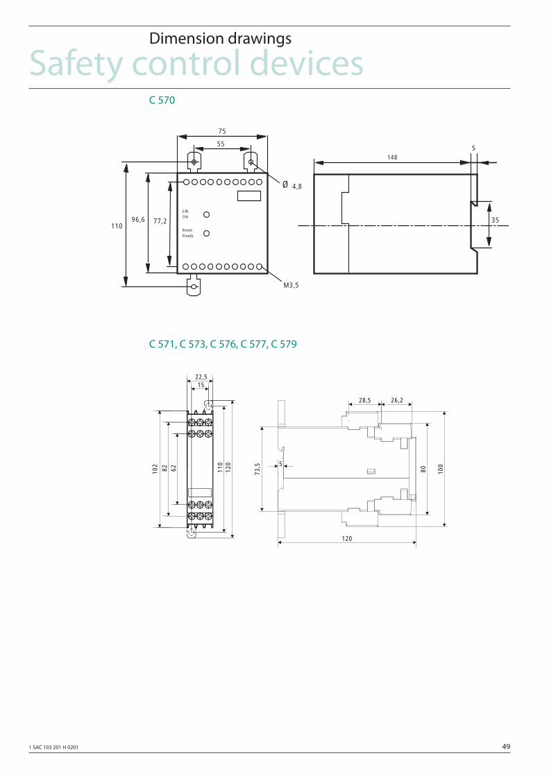
1 SAC 103 201 H 0201 49
Safety control devicesDimension drawings
C 570
C 571, C 573, C 576, C 577, C 579
3577,2
55
75
96,6110
M3,5
Ø 4,8
EINON
5148
ReadyBereit
22,515
82 62 110
120
102
120
80
5
73,5
28,5
100
26,2
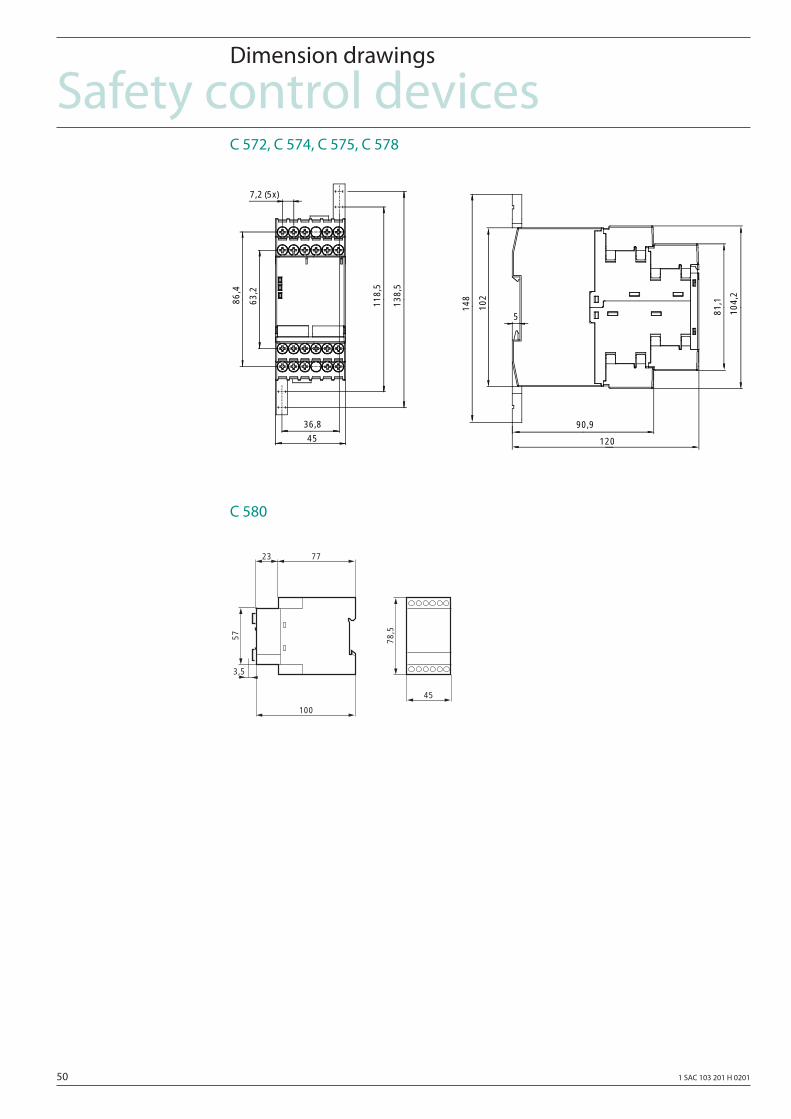
50 1 SAC 103 201 H 0201
Safety control devicesDimension drawings
C 572, C 574, C 575, C 578
C 580
102
90,9
81,1
104,
2
148
36,8
118,
5
138,
5
5
120
63,2
86,4
7,2 (5x)
45
57
7723
100
78,5
45
3,5
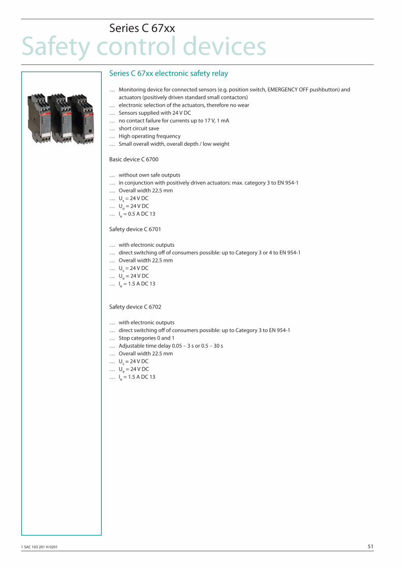
1 SAC 103 201 H 0201 51
Safety control devicesSeries C 67xx
Series C 67xx electronic safety relay
… Monitoring device for connected sensors (e.g. position switch, EMERGENCY OFF pushbutton) and actuators (positively driven standard small contactors)… electronic selection of the actuators, therefore no wear… Sensors supplied with 24 V DC… no contact failure for currents up to 17 V, 1 mA… short circuit save… High operating frequency… Small overall width, overall depth / low weight
Basic device C 6700
… without own safe outputs… in conjunction with positively driven actuators: max. category 3 to EN 954-1… Overall width 22.5 mm… Us = 24 V DC… Ue = 24 V DC… Ie = 0.5 A DC 13
Safety device C 6701
… with electronic outputs… direct switching off of consumers possible: up to Category 3 or 4 to EN 954-1… Overall width 22.5 mm… Us = 24 V DC… Ue = 24 V DC… Ie = 1.5 A DC 13
Safety device C 6702
… with electronic outputs… direct switching off of consumers possible: up to Category 3 to EN 954-1… Stop categories 0 and 1… Adjustable time delay 0.05 – 3 s or 0.5 – 30 s… Overall width 22.5 mm… Us = 24 V DC… Ue = 24 V DC… Ie = 1.5 A DC 13
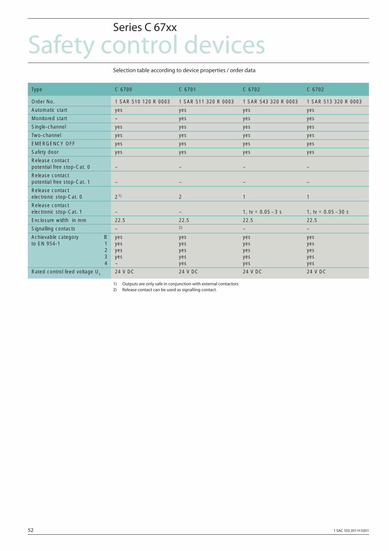
52 1 SAC 103 201 H 0201
Safety control devicesSeries C 67xx
Selection table according to device properties / order data
1) Outputs are only safe in conjunction with external contactors2) Release contact can be used as signalling contact.
Type C 6700 C 6701 C 6702 C 6702
Order No. 1 SAR 510 120 R 0003 1 SAR 511 320 R 0003 1 SAR 543 320 R 0003 1 SAR 513 320 R 0003
Automatic start yes yes yes yes
Monitored start – yes yes yes
Single-channel yes yes yes yes
Two-channel yes yes yes yes
EMERGENCY OFF yes yes yes yes
Safety door yes yes yes yes
Release contact potential free stop-Cat. 0 – – – –
Release contact potential free stop-Cat. 1 – – – –
Release contact electronic stop-Cat. 0 21) 2 1 1
Release contact electronic stop-Cat. 1 – – 1, tv = 0.05 – 3 s 1, tv = 0.05 – 30 s
Enclosure width in mm 22.5 22.5 22.5 22.5
Signalling contacts – 2) – –
Achievable category B yes yes yes yesto EN 954-1 1 yes yes yes yes
2 yes yes yes yes3 yes yes yes yes4 – yes yes yes
Rated control feed voltage Us 24 V DC 24 V DC 24 V DC 24 V DC
1 SAC 103 201 H 0201 53
Safety control devicesTerminology
EMERGENCY OFF device
EN 60204 Part 1 specifi es that when a hazardous situa-tion occurs, a machine must be stopped as quickly as possible using EMERGENCY OFF.
According to EN 60204-1, stop Categories 0 and 1 are permitted.
There are 2 ways to fulfi ll these requirements:
… Directly using an EMERGENCY OFF switch
… Using a arrangement of control circuits which allows all of the appropriate main circuits to be reliably and safely disconnected with one single command.
Protective door monitoring
Protective equipment is used to ensure the safety of operating personnel. If protective equipment is re-moved or opened, then all movements which cause these hazards must be permanently and eff ectively stopped. The machine can only be entered after it has come to a complete fi nal stop.
Redundancy
Redundancy is present if there are more control- or drive lines than actually required to fulfi ll a specifi c function. Using redundancy, it is possible to reduce the probability that a single fault in an electrical circuit will result in a hazardous condition. For safety-related circuits, for reasons of redundancy, at least 2 switching devices than are required (input circuit/sensor control and load circuit/actuators).
Two-channel confi guration
EN 60204 does not expressly specify two-channel con-figurations. The Standard states that the Category, according to EN 954-1, must be defi ned using a risk analysis. A two-channel EMERGENCY OFF circuit is used in environments with a high degree of dirt ac-cumulation.
Cross-circuit safety/cross-circuit identifi cation
With a two-channel control confi guration, a device can identify a cross-circuit or a connection between the two externally operated control elements (e.g. EMERGENCY OFF or limit switch). If a cross-circuit oc-curs due to a damaged connecting cable, then the device goes into the safe initial condition.
The cross-circuit identifi cation is realized using diff e-rent potentials in the momentary-contact circuit.
Positively-driven contacts
Contacts are positively-driven, if all of the contacts of a switchgear device are connected with one another, so that the NC contact and NO contact cannot close simultaneously. Further, it must also be guaranteed, that over the complete lifetime of the switching de-vice, that there is a least 0.5 mm contact clearance even when the device is in the faulted condition.
Ground-fault detection
The device identifi es a connection between the sen-sor cable and ground potential and it goes into a safe condition. The device becomes operational again af-ter the fault has been removed.
Diversity
In order to minimize the probability that faults and failures can result in hazardous conditions, diversi-ty is required. This is either achieved using diff erent functional principles or by using diff erent devices. In safety circuits, this is achieved by combining NC and NO contacts.
Enabling contacts
Enabling contacts are safety contacts, which are al-ways realized as NO contacts. This means that if the sa-fety combination is in the ON condition, the enabling contacts must be closed. Enabling contacts may also be used for signaling.
Signaling contacts
Signaling contacts can either be realized as NC con-tact or as NO contact. However, it is not permissible that they are used for enabling circuits.
“Ready ON”
ON button “Ready ON” are used to enable safety com-binations.
After the main switch (circuit-breaker) of the machine has been closed or the safety combination has been initiated, the ON button “Ready ON” must be actuated, so that the safety combination is enabled.
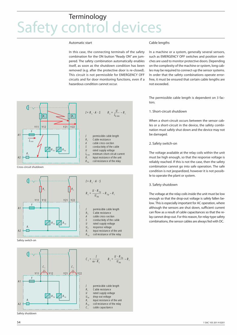
54 1 SAC 103 201 H 0201
Safety control devicesAutomatic start
In this case, the connecting terminals of the safety combination for the ON button “Ready ON” are jum-pered. The safety combination automatically enables itself, as soon as the shutdown condition has been removed (e.g. after the protective door is re-closed). This circuit is not permissible for EMERGENCY OFF circuits and for door monitoring functions, even if a hazardous condition cannot occur.
Terminology
Cable lengths
In a machine or a system, generally several sensors, such as EMERGENCY OFF switches and position swit-ches are used to monitor protective doors. Depending on the complexity of the machine or system, long cab-les may be required to connect-up the sensor systems. In order that the safety combinations operate error-free, it must be ensured that certain cable lengths are not exceeded.
The permissible cable length is dependent on 3 fac-tors.
1. Short-circuit shutdown
When a short-circuit occurs between the sensor cab-les or a short-circuit in the device, the safety combi-nation must safely shut down and the device may not be damaged.
2. Safety switch-on
The voltage available at the relay coils within the unit must be high enough, so that the response voltage is reliably reached. If this is not the case, then the safety combination cannot go into safe operation. The safe condition is not jeopardized, however it is not possib-le to operate the plant or system.
3. Safety shutdown
The voltage at the relay coils inside the unit must be low enough so that the drop-out voltage is safely fallen be-low. This is especially important for AC operation, where although the sensors are shut down, suffi cient current can fl ow as a result of cable capacitances so that the re-lay cannot drop-out. For this reason, for relay-type safety combinations, the sensor cables are always fed with DC.
Cross-circuit shutdown
Safety switch-on
Safety shutdown
I permissible cable lengthRL Cable resistanceA cable cross-sectionS conductivity of the cableU rated supply voltageIK min minimum short-circuit currentR i input resistance of the unitRSp coil resistance of the relay
A1
A2
Y11 Y12 Y21 Y22
R i
RSp RSp
IK min
RL RL
F
I = RL · A · S RL = – R iU
IK min
I permissible cable lengthRL Cable resistanceA cable cross-sectionS conductivity of the cableU rated supply voltageUA response voltageR i input resistance of the unitRSp coil resistance of the relay
A1
A2
Y11 Y12 Y21 Y22
R i
RSp RSp
RL RL
F
I = RL · A · S
RL = – RSp – R i
U · RSp
UAb
I permissible cable lengthRL Cable resistanceU rated supply voltageUAb drop-out voltageR i input resistance of the unitRSp coil resistance of the relayCL cable capacitance
A1
A2
Y11 Y12 Y21 Y22
R i
RSp RSp
CL CL
F
RL = – R i
U · RSp
UAb
CL =I
ω · RL
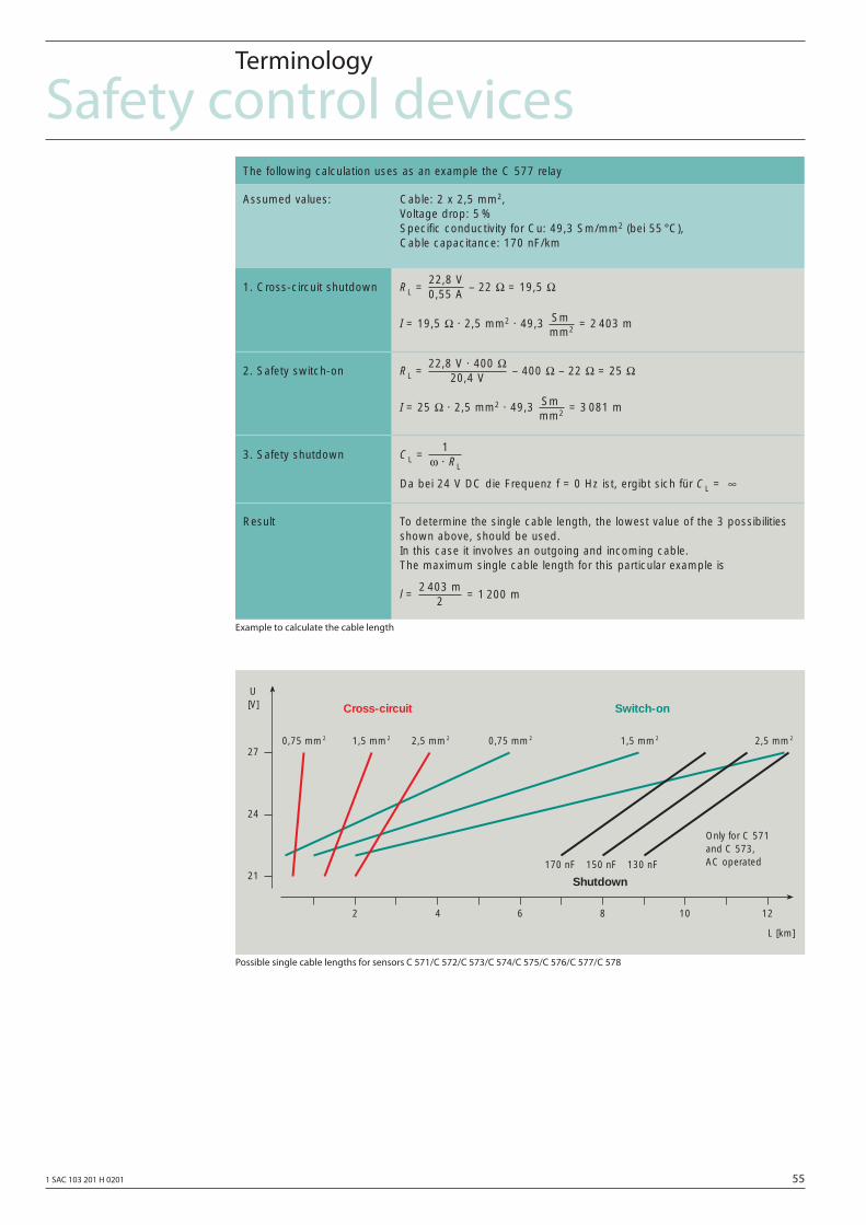
1 SAC 103 201 H 0201 55
Safety control devicesTerminology
Example to calculate the cable length
Possible single cable lengths for sensors C 571/C 572/C 573/C 574/C 575/C 576/C 577/C 578
The following calculation uses as an example the C 577 relay
Assumed values: Cable: 2 x 2,5 mm2,Voltage drop: 5 %Specific conductivity for Cu: 49,3 Sm/mm2 (bei 55 °C),Cable capacitance: 170 nF/km
1. Cross-circuit shutdown
2. Safety switch-on
3. Safety shutdown
Result
RL = – 22 Ω = 19,5 Ω
I = 19,5 Ω · 2,5 mm2 · 49,3 = 2 403 mSmmm2
22,8 V0,55 A
RL = – 400 Ω – 22 Ω = 25 Ω
I = 25 Ω · 2,5 mm2 · 49,3 = 3 081 mSmmm2
22,8 V · 400 Ω20,4 V
CL =
Da bei 24 V DC die Frequenz f = 0 Hz ist, ergibt sich für CL = ∞
1ω · RL
To determine the single cable length, the lowest value of the 3 possibilitiesshown above, should be used.In this case it involves an outgoing and incoming cable.The maximum single cable length for this particular example is
l = = 1 200 m2 403 m
2
2 4 6 8 10 12
27
24
21
0,75 mm2 1,5 mm2 2,5 mm2 0,75 mm2 1,5 mm2 2,5 mm2
170 nF 150 nF 130 nF
U[V]
L [km]
Cross-circuit Switch-on
Shutdown
Only for C 571and C 573,AC operated
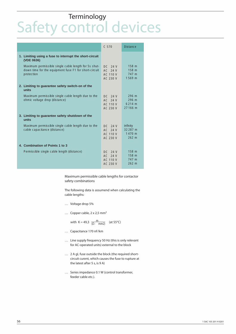
56 1 SAC 103 201 H 0201
Safety control devices
Maximum permissible cable lengths for contactor safety combinations
The following data is assumend when calculating the cable lengths:
… Voltage drop 5%
… Copper cable, 2 x 2,5 mm2
with K = 49,3 (Ω ·
mmm2) (at 55°C)
… Capacitance 170 nF/km
… Line supply frequency 50 Hz (this is only relevant for AC-operated units) external to the block
… 2 A gL fuse outside the block (the required short- circuit curent, which causes the fuse to rupture at the latest after 5 s, is 9 A)
… Series impedance 0.1 W (control transformer, feeder cable etc.).
Terminology
1. Limiting using a fuse to interrupt the short-circuit(VDE 0636)
Maximum permissible single cable length for 5s shut-down time for the equipment fuse F1 for short-circuitprotection
2. Limiting to guarantee safety switch-on of theunits
Maximum permissible single cable length due to theohmic voltage drop (distance)
3. Limiting to guarantee safety shutdown of theunits
Maximum permissible single cable length due to thecable capacitance (distance)
4. Combination of Points 1 to 3
Permissible single cable length (distance)
158 m158 m747 m
1 569 m
296 m296 m
6 214 m27 166 m
infinity 32 287 m1 470 m
262 m
158 m158 m747 m262 m
Distance C 570
DC 224 VAC 224 VAC 110 VAC 230 V
DC 224 VAC 224 VAC 110 VAC 230 V
DC 224 VAC 224 VAC 110 VAC 230 V
DC 224 VAC 224 VAC 110 VAC 230 V
1 SAC 103 201 H 0201 57
Circuit examples
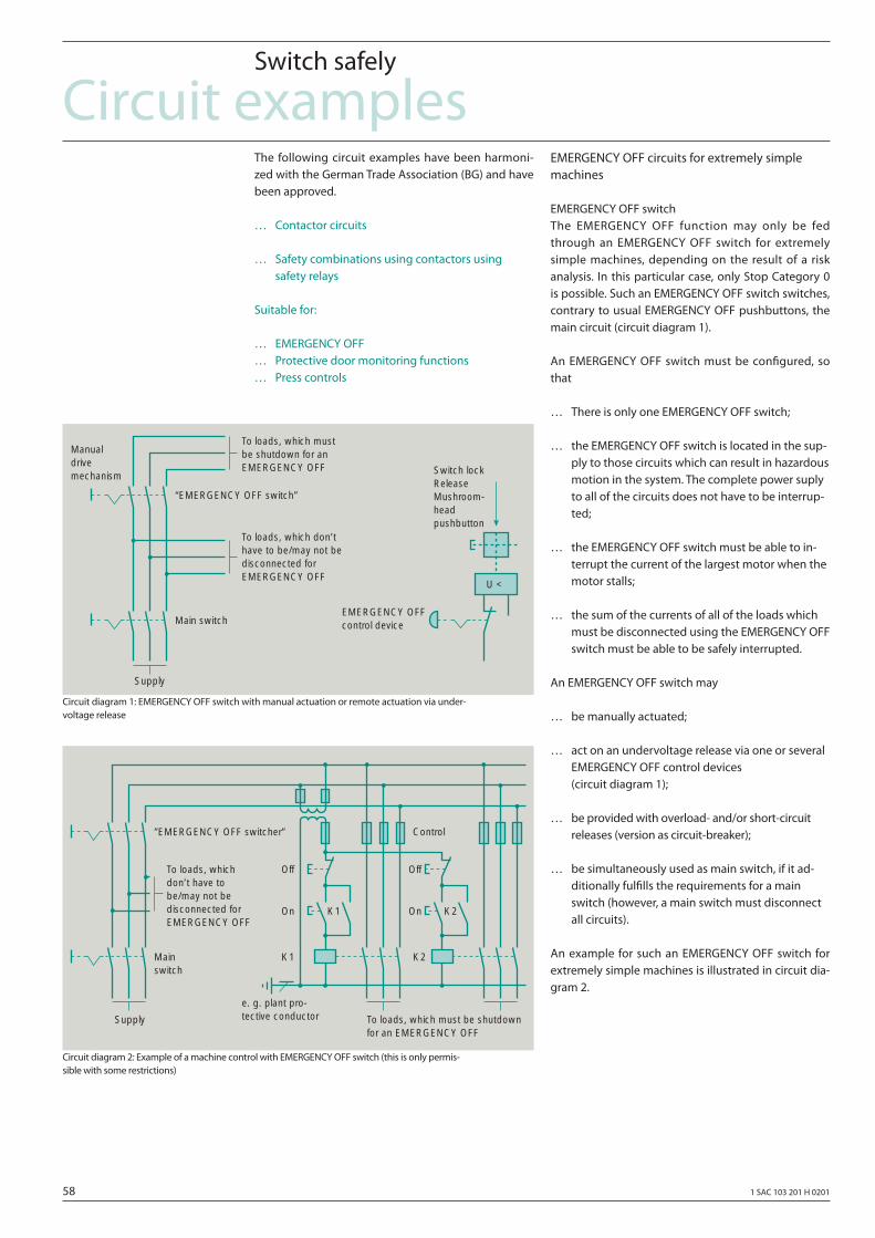
58 1 SAC 103 201 H 0201
Circuit examplesSwitch safely
The following circuit examples have been harmoni-zed with the German Trade Association (BG) and have been approved.
… Contactor circuits
… Safety combinations using contactors using safety relays
Suitable for:
… EMERGENCY OFF… Protective door monitoring functions… Press controls
EMERGENCY OFF circuits for extremely simple machines
EMERGENCY OFF switchThe EMERGENCY OFF function may only be fed through an EMERGENCY OFF switch for extremely simple machines, depending on the result of a risk analysis. In this particular case, only Stop Category 0 is possible. Such an EMERGENCY OFF switch switches, contrary to usual EMERGENCY OFF pushbuttons, the main circuit (circuit diagram 1).
An EMERGENCY OFF switch must be confi gured, so that
… There is only one EMERGENCY OFF switch;
… the EMERGENCY OFF switch is located in the sup- ply to those circuits which can result in hazardous motion in the system. The complete power suply to all of the circuits does not have to be interrup- ted;
… the EMERGENCY OFF switch must be able to in- terrupt the current of the largest motor when the motor stalls;
… the sum of the currents of all of the loads which must be disconnected using the EMERGENCY OFF switch must be able to be safely interrupted.
An EMERGENCY OFF switch may
… be manually actuated;
… act on an undervoltage release via one or several EMERGENCY OFF control devices (circuit diagram 1);
… be provided with overload- and/or short-circuit releases (version as circuit-breaker);
… be simultaneously used as main switch, if it ad- ditionally fulfi lls the requirements for a main switch (however, a main switch must disconnect all circuits).
An example for such an EMERGENCY OFF switch for extremely simple machines is illustrated in circuit dia-gram 2.
Circuit diagram 1: EMERGENCY OFF switch with manual actuation or remote actuation via under-voltage release
Circuit diagram 2: Example of a machine control with EMERGENCY OFF switch (this is only permis-sible with some restrictions)
To loads, which mustbe shutdown for anEMERGENCY OFF
To loads, which don’thave to be/may not bedisconnected forEMERGENCY OFF
“EMERGENCY OFF switch”
Main switch
Supply
Switch lockReleaseMushroom-headpushbutton
EMERGENCY OFFcontrol device
Manualdrivemechanism
U <
To loads, whichdon’t have tobe/may not bedisconnected forEMERGENCY OFF
”EMERGENCY OFF switcher”
Mainswitch
Supply To loads, which must be shutdownfor an EMERGENCY OFF
Off
On K2K1
K2K1
Off
On
Control
e. g. plant pro-tective conductor
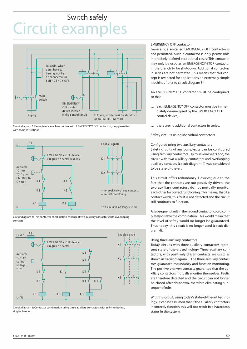
1 SAC 103 201 H 0201 59
Circuit examplesSwitch safely
EMERGENCY OFF contactorGenerally, a so-called EMERGENCY OFF contactor is not permitted. Such a contactor is only permissible in precisely defi ned exceptional cases: This contactor may only be used as an EMERGENCY-STOP contactor in the branch to be shutdown. Additional contactors in series are not permitted. This means that this con-cept is restricted for applications on extremely simple machines (refer to circuit diagram 3).
An EMERGENCY OFF contactor must be confi gured, so that
… each EMERGENCY OFF contactor must be imme- diately de-energized by the EMERGENCY OFF control device;
… there are no additional contactors in series.
Safety circuits using individual contactors
Confi gured using two auxiliary contactorsSafety circuits of any complexity can be confi gured using auxiliary contactors. Up to several years ago, the circuit with two auxiliary contactors and overlapping auxiliary contacts (circuit diagram 4) was considered to be state-of-the-art.
This circuit off ers redundancy. However, due to the fact that the contacts are not positively driven, the two auxiliary contactors do not mutually monitor each other for correct functioning. This means, that if a contact welds, this fault is not detected and the circuit still continues to function.
A subsequent fault in the second contactor could com-pletely disable the combination. This would mean that the level of safety would no longer be guaranteed. Thus, today, this circuit is no longer used (circuit dia-gram 4).
Using three auxiliary contactorsToday, circuits with three auxiliary contactors repre-sent state-of-the-art technology. Three auxiliary con-tactors, with positively-driven contacts are used, as shown in circuit diagram 5. The three auxiliary contac-tors guarantee redundancy and function monitoring. The positively-driven contacts guarantee that the au-xiliary contactors mutually monitor themselves. Faults are therefore detected and the circuit can not longer be closed after shutdown, therefore eliminating sub-sequent faults.
With this circuit, using today’s state-of-the-art techno-logy, it can be assumed that if the auxiliary contactors incorrectly function this will not result in a hazardous status in the system.
Circuit diagram 3: Example of a machine control with 2 EMERGENCY OFF contactors, only permitted with some restrictions
Circuit diagram 4: This contactor combination consists of two auxiliary contactors with overlapping contacts
Circuit diagram 5: Contactor combination using three auxiliary contactors with self-monitoring, single-channel
To loads, whichdon’t have tobe/may not bedisconnected forEMERGENCY OFF
Mainswitch
Supply To loads, which must be shutdownfor an EMERGENCY OFF
EMERGENCYOFF controldevice locatedin the control circuit
EMERGENCY OFF device,if required several in series
F1
Actuator“On”or“On” afterEMERGEN-CY OFF
Enable signalsL1
N
K1
K2
K1
K2
K1 K2
K1
K2
– no positively-drives contacts– no self-monitoring
This circuit is no longer used.
EMERGENCY OFF device,if required several
F1
Actuator“On” orcontrolvoltage“On”
Enable signalsL+/L1
L–/N
K2
K3
K1 K2
K1 K2
K1
K2
K3
K3
K1 K3
K3
K1
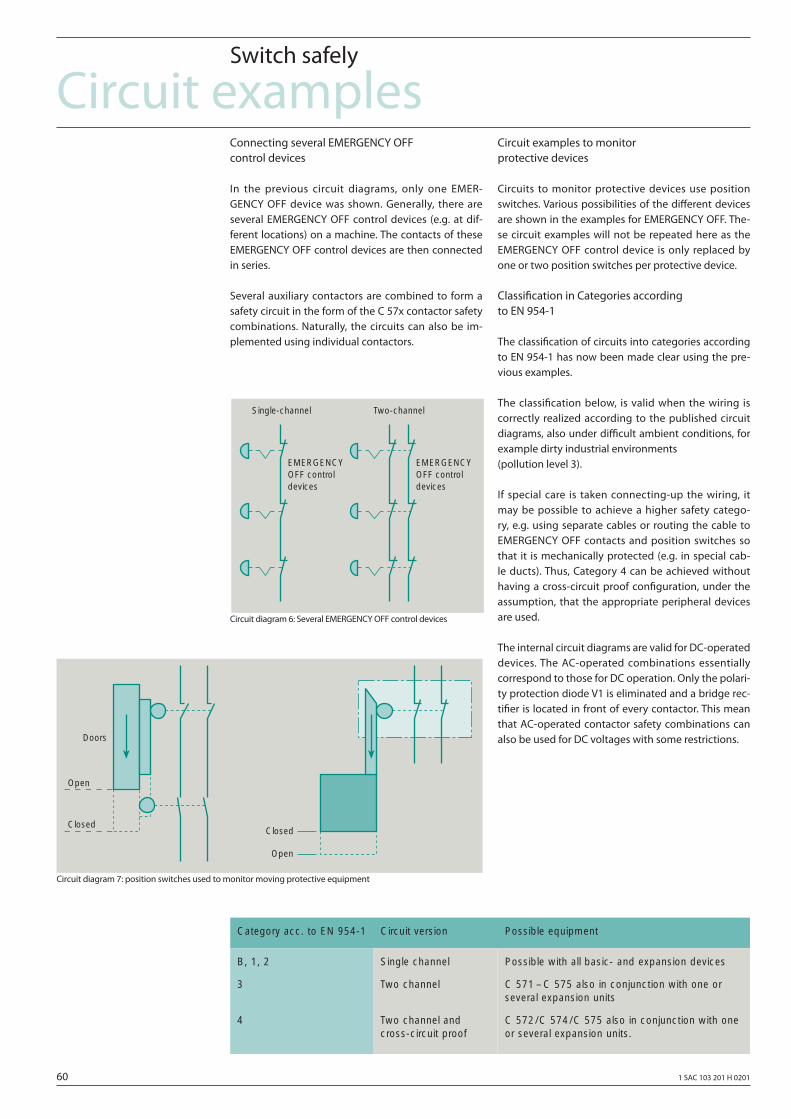
60 1 SAC 103 201 H 0201
Circuit examplesSwitch safely
Connecting several EMERGENCY OFF control devices
In the previous circuit diagrams, only one EMER-GENCY OFF device was shown. Generally, there are several EMERGENCY OFF control devices (e.g. at dif-ferent locations) on a machine. The contacts of these EMERGENCY OFF control devices are then connected in series.
Several auxiliary contactors are combined to form a safety circuit in the form of the C 57x contactor safety combinations. Naturally, the circuits can also be im-plemented using individual contactors.
Circuit examples to monitor protective devices
Circuits to monitor protective devices use position switches. Various possibilities of the diff erent devices are shown in the examples for EMERGENCY OFF. The-se circuit examples will not be repeated here as the EMERGENCY OFF control device is only replaced by one or two position switches per protective device.
Classifi cation in Categories according to EN 954-1
The classifi cation of circuits into categories according to EN 954-1 has now been made clear using the pre-vious examples.
The classifi cation below, is valid when the wiring is correctly realized according to the published circuit diagrams, also under diffi cult ambient conditions, for example dirty industrial environments (pollution level 3).
If special care is taken connecting-up the wiring, it may be possible to achieve a higher safety catego-ry, e.g. using separate cables or routing the cable to EMERGENCY OFF contacts and position switches so that it is mechanically protected (e.g. in special cab-le ducts). Thus, Category 4 can be achieved without having a cross-circuit proof confi guration, under the assumption, that the appropriate peripheral devices are used.
The internal circuit diagrams are valid for DC-operated devices. The AC-operated combinations essentially correspond to those for DC operation. Only the polari-ty protection diode V1 is eliminated and a bridge rec-tifi er is located in front of every contactor. This mean that AC-operated contactor safety combinations can also be used for DC voltages with some restrictions.
Circuit diagram 6: Several EMERGENCY OFF control devices
Circuit diagram 7: position switches used to monitor moving protective equipment
Single-channel
EMERGENCYOFF controldevices
Two-channel
EMERGENCYOFF controldevices
Doors
Open
ClosedClosed
Open
Category acc. to EN 954-1 Circuit version Possible equipment
B, 1, 2
3
4
Single channel
Two channel
Two channel and cross-circuit proof
Possible with all basic- and expansion devices
C 571 – C 575 also in conjunction with one orseveral expansion units
C 572/C 574/C 575 also in conjunction with oneor several expansion units.
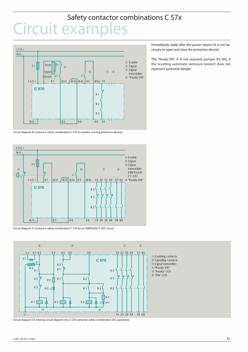
1 SAC 103 201 H 0201 61
Circuit examplesSafety contactor combinations C 57x
Circuit diagram 8: Contactor safety combination C 570 to monitor moving protective devices.
Immediately ready after the power returns (it is not ne-cessary to open and close the protective device):
The “Ready ON” ➃ is not required (jumper X5–X6), if the resulting automatic reclosure (restart) does not represent potential danger.
Circuit diagram 9: Contactor safety combination C 570 for an EMERGENCY OFF circuit.
Circuit diagram 10: Internal circuit diagram of a C 570 contactor safety combination (DC operation)
F1➀ Enable➁ Signal➂ Signal
transmitter➃ “Ready ON”
L1/L+
N/L–
K2
K3
K1
N/L–
Door
Open
Closed
X1L1/L+ (X2) (X3) (X4) X5 (X6) 13
X2 X4 X6 14
➀ ➁➃
➂
C 570
F1
➀ Enable➁ Signal➂ Signal
transmitterEMERGEN-CY OFF
➃ “Ready ON”
L1/L+
N/L–
K2
K3
K1
N/L–
X1L1/L+ (X2) (X3) (X4) X5 (X6) 13
X2 X4 X6
➀ ➁➃➂
23 33 43 6557
14 24 34 44 6658
C 570
U
➀ Enabling contacts➁ Signaling contacts➂ Signal transmitter➃ “Ready ON”➄ “Ready” LED➅ “ON” LED
L–
K2
K3
K1
X1L+ X2 X3 X4 X5 X6 13
➀ ➁➃➂
23 33 43 6557
14 24 34 44 6658
V1
R3K1
K2
K3
K1
➄
K2 K3
R2
H2
R1
H1
K3K1
K2K1
K1
K3
➅
C 570
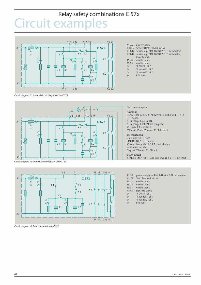
62 1 SAC 103 201 H 0201
Circuit examplesRelay safety combinations C 57x
Circuit diagram 11: Internal circuit diagram of the C 573
Circuit diagram 12: Internal circuit diagram of the C 577
Circuit diagram 13: Function description C 577
K2
K1
ϑ
➀➁
➃
➂
13 23
V1
C1
K2
A1
A2
K1
K1 K1
K1
K2 K2
K2
Y33 Y34 Y22 Y21
C 577
Function description
Power-onConnect the power, the “Power” LED is lit, EMERGENCYOFF closed,C1 is charged, press ON,C1 is charged, K1, V1 are energized,K2 starts, K1 + K2 latch,“Channel 1” and “Channel 2” LEDs are lit.
ON monitoringON is pressed → fault!EMERGENCY OFF closed,V1 immediately start K2, C1 is not charged→ K1 does not start.Only the “Channel 2” LED is lit
Cross-circuitIf EMERGENCY OFF 1 and EMERGENCY OFF 2 are short-circuited, a short-circuit current flows through the PTC fuse.
A1/A2 power supply via EMERGENCY OFF pushbuttonY1/Y2 “ON” feedback circuit13/14 enable circuit23/24 enable circuit33/34 enable circuit41/42 signaling circuit➀ “POWER” LED➁ “Channel 1” LED➂ “Channel 2” LED➃ PTC fuse
K1
ϑ ➀
➁
➃
➂
13 23
14 24
K2
A1
A2
K1 K1
K1 K2
Y2 Y1 (33) (41)
(34) (42)
K2
K2
C 573
A1/A2 power supplyY33/34 “ready ON” Feedback circuitY11/12 sensor (e.g. EMERGENCY OFF pushbutton)Y21/12 sensor (e.g. EMERGENCY OFF pushbutton,
tow-channel)13/14 enable circuit23/24 enable circuit➀ “POWER” LED➁ “Channel 1” LED➂ “Channel 2” LED➃ PTC fuse
K2
K1
ϑ
➀➁
➃
➂
13 23
14 24
V1
C1
K2
Y11
A1
A2
K1
Y12
K1 K1
K1
K2 K2
K2
Y33 Y34 Y22 Y21
C 577
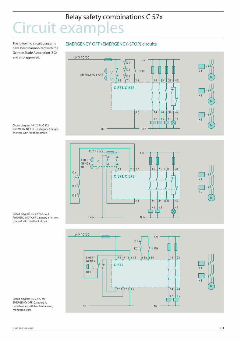
1 SAC 103 201 H 0201 63
Circuit examplesRelay safety combinations C 57x
Circuit diagram 14: C 571/C 573 for EMERGENCY OFF, Category 2, single-channel, with feedback circuit
The following circuit diagrams have been harmonized with the German Trade Association (BG) and also approved.
Circuit diagram 15: C 571/C 573 for EMERGENCY OFF, Category 3 (4), two-channel, with feedback circuit
Circuit diagram 16: C 577 for EMERGENCY OFF, Category 4, two-channel, with feedback circuit, monitored start
EMERGENCY OFF (EMERGENCY-STOP) circuits
K1
13 23
14 24
K2
A2
A1
24 V AC/DC
K3
Y1 (33) (41)
(34) (42)
EMERGENCY OFFEIN
Y2
K1
K2
K3
H1
L/+
N/– N/–
M
K1
M
K2
M
K3
C 571/C 573
K1
13 23
14 24
K2
A2
A1
24 V AC/DC
Y1 (33) (41)
(34) (42)
EMER-GENCYOFF
Y2
H1
L/+
N/– N/–
K1
K2
ON
K1
M
K2
C 571/C 573
K1
13 23
14 24
K2
A2
A1
24 V AC/DC
Y11EMER-GENCY
OFF
ON
Y33
K1
K2
L/+
N/– N/–
K1
M
K2
Y34Y12
Y11 Y12
C 577
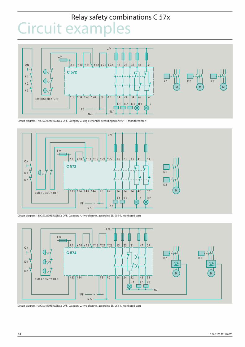
64 1 SAC 103 201 H 0201
Circuit examplesRelay safety combinations C 57x
Circuit diagram 17: C 572 EMERGENCY OFF, Category 2, single-channel, according to EN 954-1, monitored start
Circuit diagram 18: C 572 EMERGENCY OFF, Category 4, two-channel, according EN 954-1, monitored start
Circuit diagram 19: C 574 EMERGENCY OFF, Category 2, two-channel, according EN 954-1, monitored start
H1
41 51
42 52
H2
A1 Y10
EMERGENCY OFF
K1
K2
L/+
N/–N/–
Y11
Y33
M
K1
M
K2
M
K3
Y34 Y43 Y44 PE A2
K2
23 33
24 34
K3K1
13
14
PE
L/+
Y12 Y21 Y22ON
K3
C 572
H1
41 51
42 52
H2
A1 Y10
K1
K2
L/+
N/–N/–
Y11
Y33 Y34 Y43 Y44 PE A2
K2
23 33
24 34
K1
13
14
PE
L/+
Y12 Y21 Y22ON
K1
M
K2
C 572
EMERGENCY OFF
K1
47 57
48 58
K2
A1 Y10
K1
K2
L/+
N/–
N/–
Y11
Y33 Y34 PE A2
23 31
24 32
H1
13
14
PE
L/+
Y12 Y21 Y22ON
M
K2
M
K1
C 574
EMERGENCY OFF
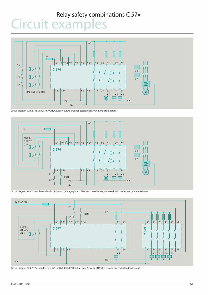
1 SAC 103 201 H 0201 65
Circuit examplesRelay safety combinations C 57x
Circuit diagram 20: C 574 EMERGENCY OFF, Category 3, two-channel, according EN 954-1, monitored start
Circuit diagram 21: C 574 with switch off in Stop-cat. 1, Category 3 acc. EN 954-1, two-channel, with feedback control loop, monitored start
Circuit diagram 22: C 577 expanded by C 579 for EMERGENCY OFF, Category 4. acc. to EN 954-1, two-channel, with feedback circuit
K1
47 57
48 58
K2
A1 Y10
K1
K2
L/+
N/–
N/–
Y11
Y33 Y34 PE A2
23 31
24 32
H1
13
14
PE
L/+
Y12 Y21 Y22ON
M
K2
K1C 574
EMERGENCY OFF
K1
47 57
48 58
K2
A1 Y10
K1
K2
L/+
N/–
N/–
Y11
Y33 Y34 PE A2
23 31
24 32
H1
13
14
PE
L/+
Y12 Y21 Y22
ON
M
K2
K1C 574
EMER-GENCYOFF
K1
13 23
14 24
A1 Y11
L/+
N/–N/–
Y12
Y21 Y22
Y33 Y34
K2
13 23
14 24
K3 K4
33 43
34 44
K5
A2
A1 51
52A2
K1
K5ON
24 V AC/DC
C 577
C 5
79
EMER-GENCYOFF
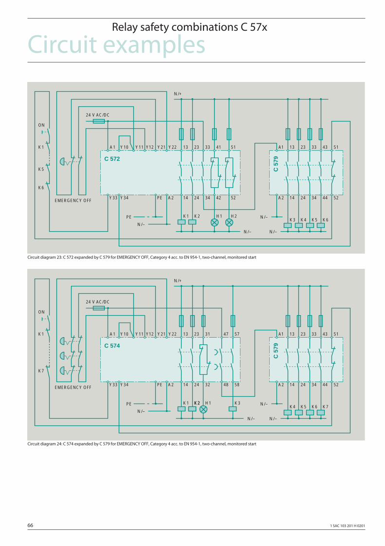
66 1 SAC 103 201 H 0201
Circuit examplesRelay safety combinations C 57x
Circuit diagram 23: C 572 expanded by C 579 for EMERGENCY OFF, Category 4 acc. to EN 954-1, two-channel, monitored start
Circuit diagram 24: C 574 expanded by C 579 for EMERGENCY OFF, Category 4 acc. to EN 954-1, two-channel, monitored start
A1 Y10
N/–
Y11
Y33 Y34
Y12 Y21
K3
13 23
14 24
K4 K5
33 43
34 44
K6
A2
A1 51
52
24 V AC/DC
H1
41 51
42 52
H2K2
23 33
24 34
K1
13
14PE A2
K1
K5
ON
K6
Y22
N/–
PE
N/–
N/–
N/+
C 572
C 5
79
EMERGENCY OFF
A1 Y10
N/–
Y11
Y33 Y34
Y12 Y21
K4
13 23
14 24
K5 K6
33 43
34 44
K7
A2
A1 51
52
24 V AC/DC
H1
47 57
48 58
K2
23 31
24 32
K1
13
14PE A2
K1
ON
K7
Y22
N/–
PE
N/–
N/–
N/+
K2 K3
C 574
C 5
79
EMERGENCY OFF
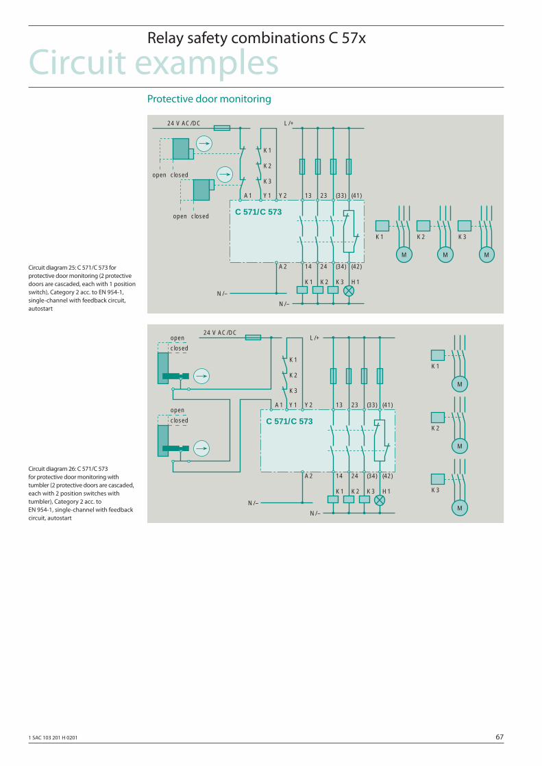
1 SAC 103 201 H 0201 67
Circuit examplesRelay safety combinations C 57x
Circuit diagram 25: C 571/C 573 for protective door monitoring (2 protective doors are cascaded, each with 1 position switch), Category 2 acc. to EN 954-1, single-channel with feedback circuit, autostart
Protective door monitoring
Circuit diagram 26: C 571/C 573 for protective door monitoring with tumbler (2 protective doors are cascaded, each with 2 position switches with tumbler), Category 2 acc. to EN 954-1, single-channel with feedback circuit, autostart
K1
13 23
14 24
K2
A2
A1
24 V AC/DC
K3
Y1 (33) (41)
(34) (42)
Y2
K1
K2
K3
H1
L/+
N/–
N/–
M
K1
M
K2
M
K3
open closed
open closed C 571/C 573
K1
13 23
14 24
K2
A2
A1
24 V AC/DC
K3
Y1 (33) (41)
(34) (42)
Y2
K1
K2
K3
H1
L/+
N/–
N/–
open
closed
open
closed
M
K1
M
K2
M
K3
C 571/C 573
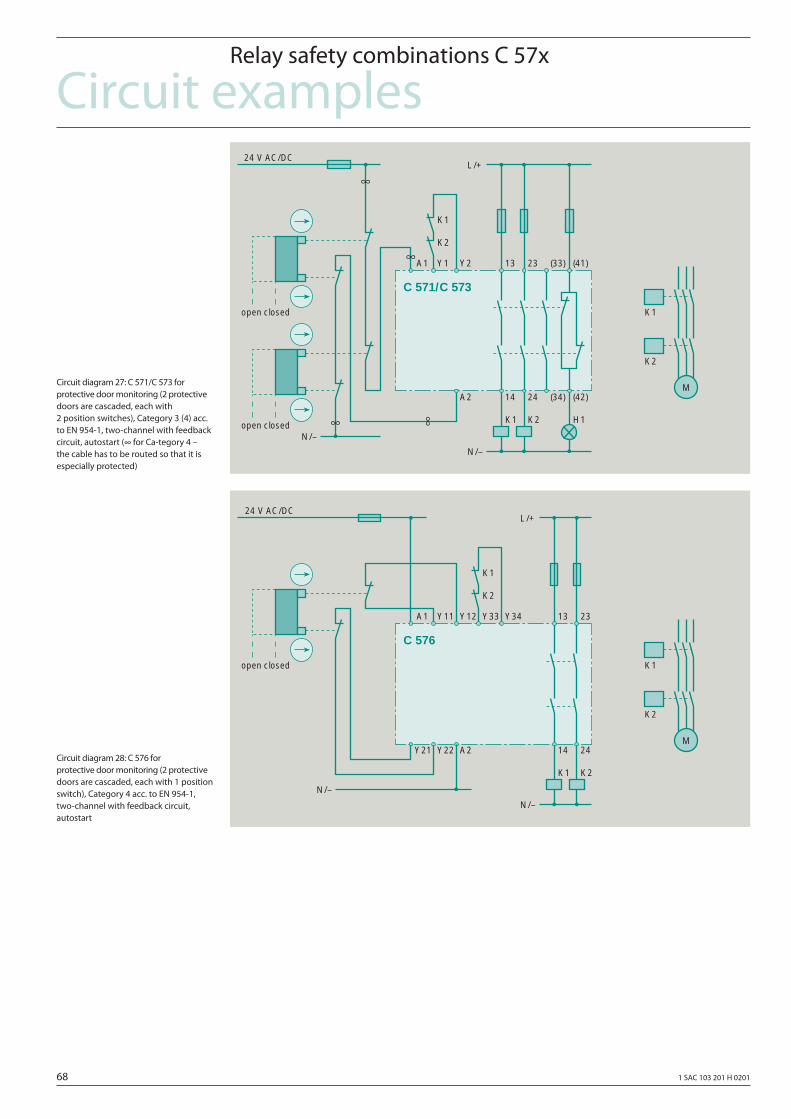
68 1 SAC 103 201 H 0201
Circuit examplesRelay safety combinations C 57x
Circuit diagram 27: C 571/C 573 for protective door monitoring (2 protective doors are cascaded, each with 2 position switches), Category 3 (4) acc. to EN 954-1, two-channel with feedback circuit, autostart (∞ for Ca-tegory 4 – the cable has to be routed so that it is especially protected)
Circuit diagram 28: C 576 for protective door monitoring (2 protective doors are cascaded, each with 1 position switch), Category 4 acc. to EN 954-1, two-channel with feedback circuit, autostart
K1
13 23
14 24
K2
A2
A1
24 V AC/DC
Y1 (33) (41)
(34) (42)
Y2
K1
K2
H1
L/+
N/–
N/–
K1
M
K2
open closed
open closed
C 571/C 573
K1
13 23
14 24
K2
A2
A1
24 V AC/DC
Y11 Y12
K1
K2
L/+
N/–
N/–
K1
M
K2
open closed
Y33 Y34
Y22Y21
C 576
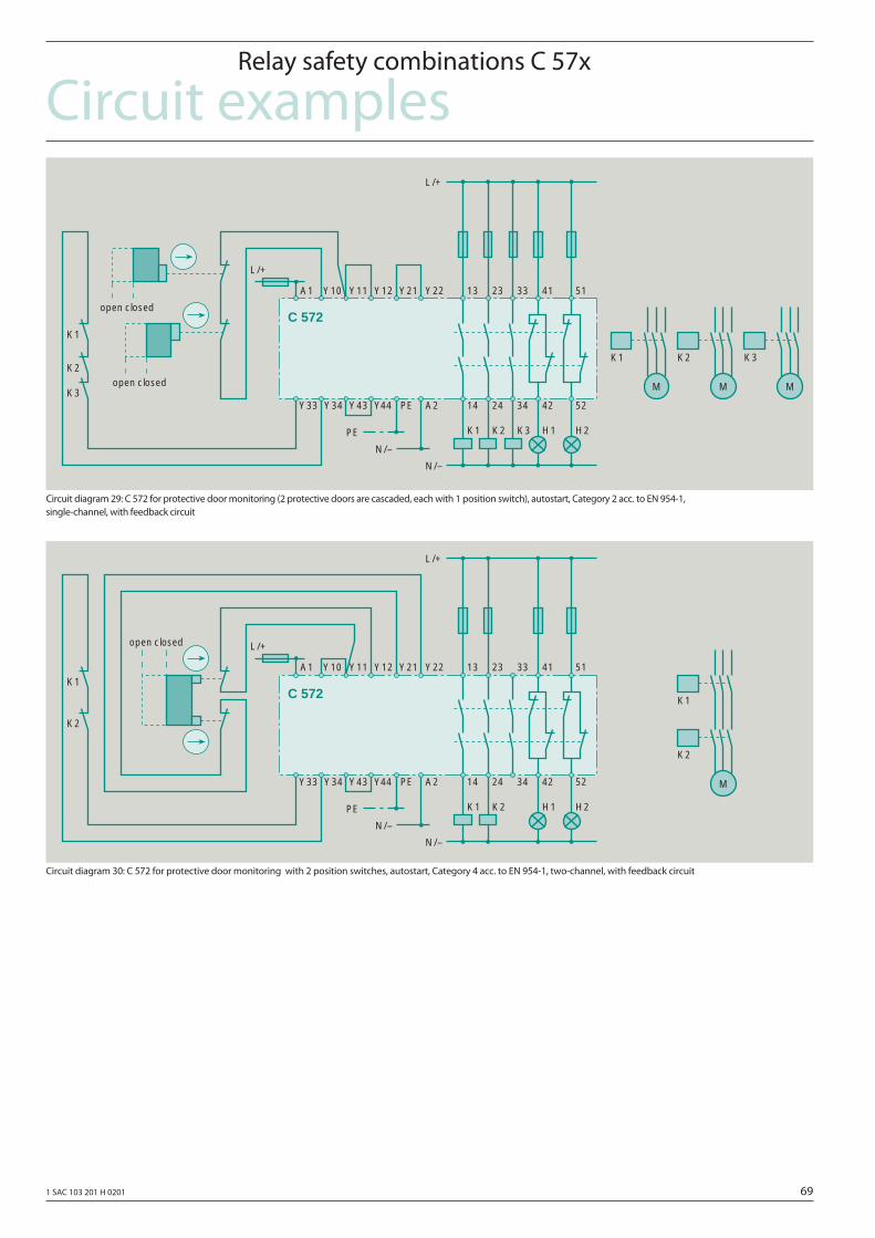
1 SAC 103 201 H 0201 69
Circuit examplesRelay safety combinations C 57x
Circuit diagram 29: C 572 for protective door monitoring (2 protective doors are cascaded, each with 1 position switch), autostart, Category 2 acc. to EN 954-1, single-channel, with feedback circuit
Circuit diagram 30: C 572 for protective door monitoring with 2 position switches, autostart, Category 4 acc. to EN 954-1, two-channel, with feedback circuit
K1
13 23
14 24
K2
A2
A1
K3
Y10 33 41
34 42
Y11
K1
K2
K3
H1
L/+
N/–
N/–
open closed
M
K1
M
K2
M
K3
open closed
51
52
H2
L/+
Y12 Y21 Y22
PE
PE
Y43Y34Y33 Y44
C 572
K1
13 23
14 24
K2
A2
A1 Y10 33 41
34 42
Y11K1
K2
H1
L/+
N/–
N/–
51
52
H2
L/+
Y12 Y21 Y22
PE
PE
Y43Y34Y33 Y44
K1
M
K2
open closed
C 572
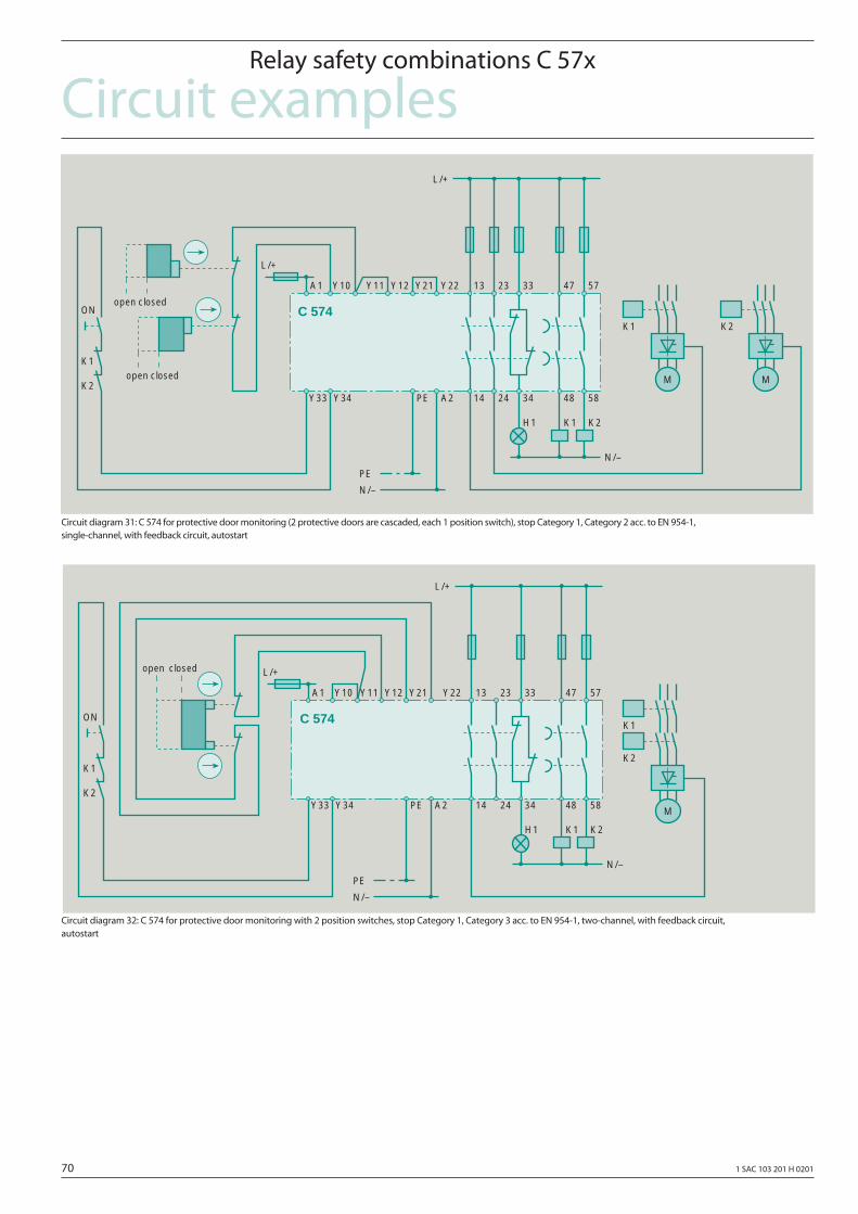
70 1 SAC 103 201 H 0201
Circuit examplesRelay safety combinations C 57x
Circuit diagram 31: C 574 for protective door monitoring (2 protective doors are cascaded, each 1 position switch), stop Category 1, Category 2 acc. to EN 954-1, single-channel, with feedback circuit, autostart
Circuit diagram 32: C 574 for protective door monitoring with 2 position switches, stop Category 1, Category 3 acc. to EN 954-1, two-channel, with feedback circuit, autostart
K1
13 23
14 24
K2
A2
A1 Y10 33 47
34 48
Y11
ON
K1
K2
H1
L/+
N/–
N/–
open closed
open closed
57
58
L/+
Y12 Y21 Y22
PE
PE
Y34Y33
M
K1
M
K2C 574
K1
13 23
14 24
K2
A2
A1 Y10 33 47
34 48
Y11
ON
K1
K2
H1
L/+
N/–
N/–
57
58
L/+
Y12 Y21 Y22
PE
PE
Y34Y33
open closed
M
K2
K1C 574
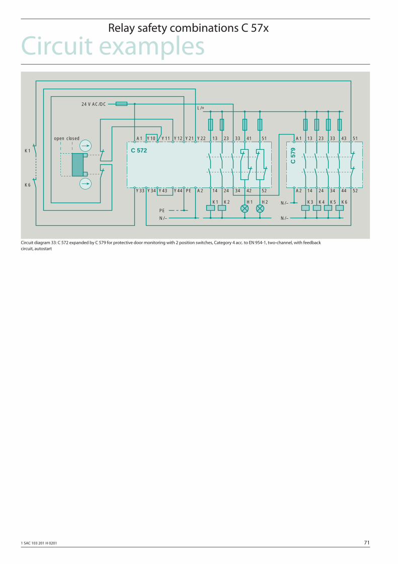
1 SAC 103 201 H 0201 71
Circuit examplesRelay safety combinations C 57x
Circuit diagram 33: C 572 expanded by C 579 for protective door monitoring with 2 position switches, Category 4 acc. to EN 954-1, two-channel, with feedback circuit, autostart
K1
13 23
14 24
K2
A2
A1 Y10 33 41
34 42
Y11
H1
L/+
N/–
N/–
51
52
24 V AC/DC
Y12 Y21 Y22
PE
PE
Y34Y33
open closed
K1
K6
H2 K3
13 23
14 24
K4 K5
33 43
34 44
K6
A2
N/–
A1 51
52Y44Y43
C 572
C 5
79
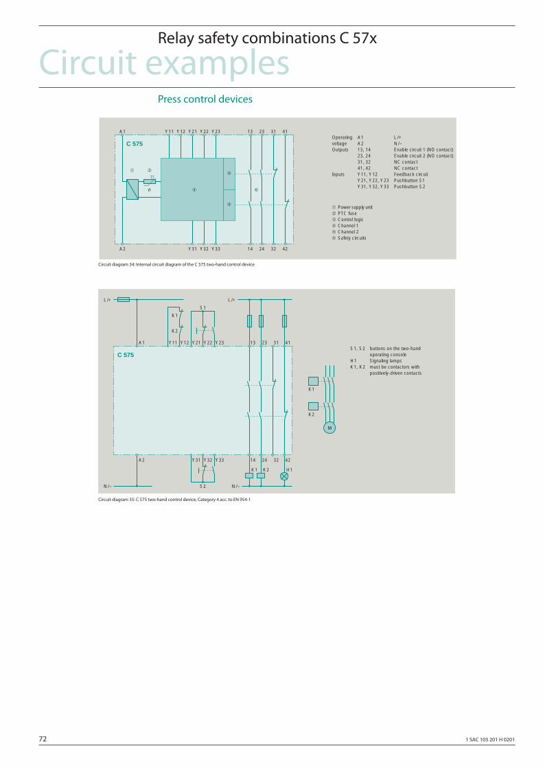
72 1 SAC 103 201 H 0201
Circuit examplesRelay safety combinations C 57x
Press control devices
Circuit diagram 34: Internal circuit diagram of the C 575 two-hand control device
Circuit diagram 35: C 575 two-hand control device, Category 4 acc. to EN 954-1
Operating A1 L/+voltage A2 N/–Outputs 13, 14 Enable circuit 1 (NO contact)
23, 24 Enable circuit 2 (NO contact)31, 32 NC contact41, 42 NC contact
Inputs Y11, Y12 Feedback circuitY21, Y22, Y23 Pushbutton S1Y31, Y32, Y33 Pushbutton S2ϑ
➀
14
Y11A1
A2
Y12 Y23 13Y22Y21
➀ Power supply unit➁ PTC fuse➂ Control logic➃ Channel 1➄ Channel 2➅ Safety circuits
23 31 41
24 32 42Y33Y32Y31
➁➃
➄
➂ ➅
C 575
S1, S2 buttons on the two-handoperating console
H1 Signaling lampsK1, K2 must be contactors with
positively-driven contacts
14
Y11A1
A2
Y12 Y23 13Y22Y21 23 31 41
24 32 42Y33Y32Y31
K1
M
K2
K1 K2 H1
N/–S2
K1
K2
S1
L/+L/+
N/–
C 575
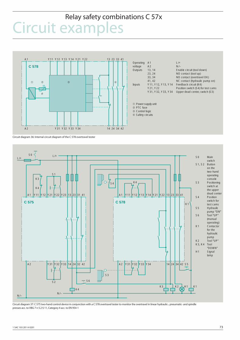
1 SAC 103 201 H 0201 73
Circuit examplesRelay safety combinations C 57x
Circuit diagram 36: Internal circuit diagram of the C 578 overtravel tester
Circuit diagram 37: C 575 two-hand control device in conjunction with a C 578 overtravel tester to monitor the overtravel in linear hydraulic-, pneumatic- and spindle presses acc. to VBG 7 n 5.2 § 11, Category 4 acc. to EN 954-1
Operating A1 L/+voltage A2 N/–Outputs 13, 14 Enable circuit (tool down)
23, 24 NO contact (tool up)33, 34 NO contact (overtravel OK)41, 42 NC contact (hydraulic pump on)
Inputs Y11, Y12, Y13, Y14 Feedback circuit (K4)Y21, Y22 Position switch (S4) for test camsY31, Y32, Y33, Y34 Upper dead center, switch (S3)ϑ
➀
14
Y11A1
A2
Y12 Y21 13Y14Y13
➀ Power supply unit➁ PTC fuse➂ Control logic➃ Safety circuits
23 33 41
24 34 42Y33Y32Y31
➁ ➃➂
Y22
Y34
C 578
S0 Mainswitch
S1, S2 Buttonon thetwo-handoperatingconsole
S3 Positioningswitch atthe upperdead center
S4 Positionswitch fortest cams
S5 Hydraulicpump “ON”
S6 Tool “UP”(manualoperating)
K1 Contactorfor thehydraulicpump
K2 Tool “UP”K3, K4 Tool
“DOWN”H1 Signal
lamp
14
Y11A1
A2
Y12 Y23 13Y22Y21 23 31 41
24 32 42Y33Y32Y31
K4N/–
S2
K3
K4
S1
L/+L/+
N/–
S0
S6
14
Y11A1
A2
Y12 Y21 13Y14Y13 23 33 41
24 34 42Y33Y32Y31
K2
K4
S5
Y22
Y34
K3 H1 K1
K1
S4
S3
C 575 C 578
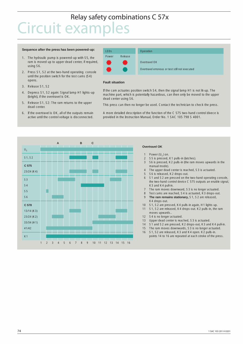
74 1 SAC 103 201 H 0201
Circuit examplesRelay safety combinations C 57x
Sequence after the press has been powered-up:
1. The hydraulic pump is powered-up with S5, theram is moved up to upper dead center, if required,using S6.
2. Press S1, S2 at the two-hand operating consoleuntil the position switch for the test cams (S4)opens.
3. Release S1, S2
4. Depress S1, S2 again: Signal lamp H1 lights-up(bright), if the overtravel is OK.
5. Release S1, S2: The ram returns to the upperdead center.
6. If the overtravel is OK, all of the outputs remainactive until the control voltage is disconnected.
Fault situation
If the cam actuates position switch S4, then the signal lamp H1 is not lit-up. Themachine part, which is potentially hazardous, can then only be moved to the upperdead center using S6.
This press can then no longer be used. Contact the technician to check the press.
A more detailed description of the function of the C 575 two-hand control divece isprovided in the Instruction Manual, Order No. 1 SAC 105 798 S 4001.
Overtravel erronous or test still not executed
Overtravel OK
Power Release
LEDs Operation
Overtravel OK
1 Power (US) on.2 S5 is pressed, K1 pulls-in (latches).3 S6 is pressed, K2 pulls-in (the ram moves upwards in the
manual mode).4 The upper dead center is reached, S3 is actuated.5 S6 is released, K2 drops-out.6 S1 and S2 are pressed on the two-hand operating console,
the two-hand control device C 575 outputs an enable signal,K3 and K4 pull-in.
7 The ram moves downward, S3 is no longer actuated.8 Test cams are reached, S4 is actuated, K3 drops-out.9 The ram remains stationary, S1, S2 are released,
K4 drops-out.10 S1, S2 are pressed, K4 pulls-in again, H1 lights up.11 S1, S2 are released, K4 drops-out. K2 pulls-in, the ram
moves upwards..12 S4 is no longer actuated.13 Upper dead center is reached, S3 is actuated.14 S1 and S2 are pressed, K2 drops-out, K3 and K4 pull-in.15 The ram moves downwards, S3 is no longer actuated.16 S1, S2 are released, K3 and K4 open. K2 pulls-in.
points 14 to 16 are repeated at each stroke of the press.
S1, S2
S6
US
K1
S4
S3
41/42
33/34 (H1)
23/24 (K2)
13/14 (K3)
S5
C 578
23/24 (K4)
C 575
1 2 3 4 5 6 7 8 9 10 11 12 13 14 15 16
A B C
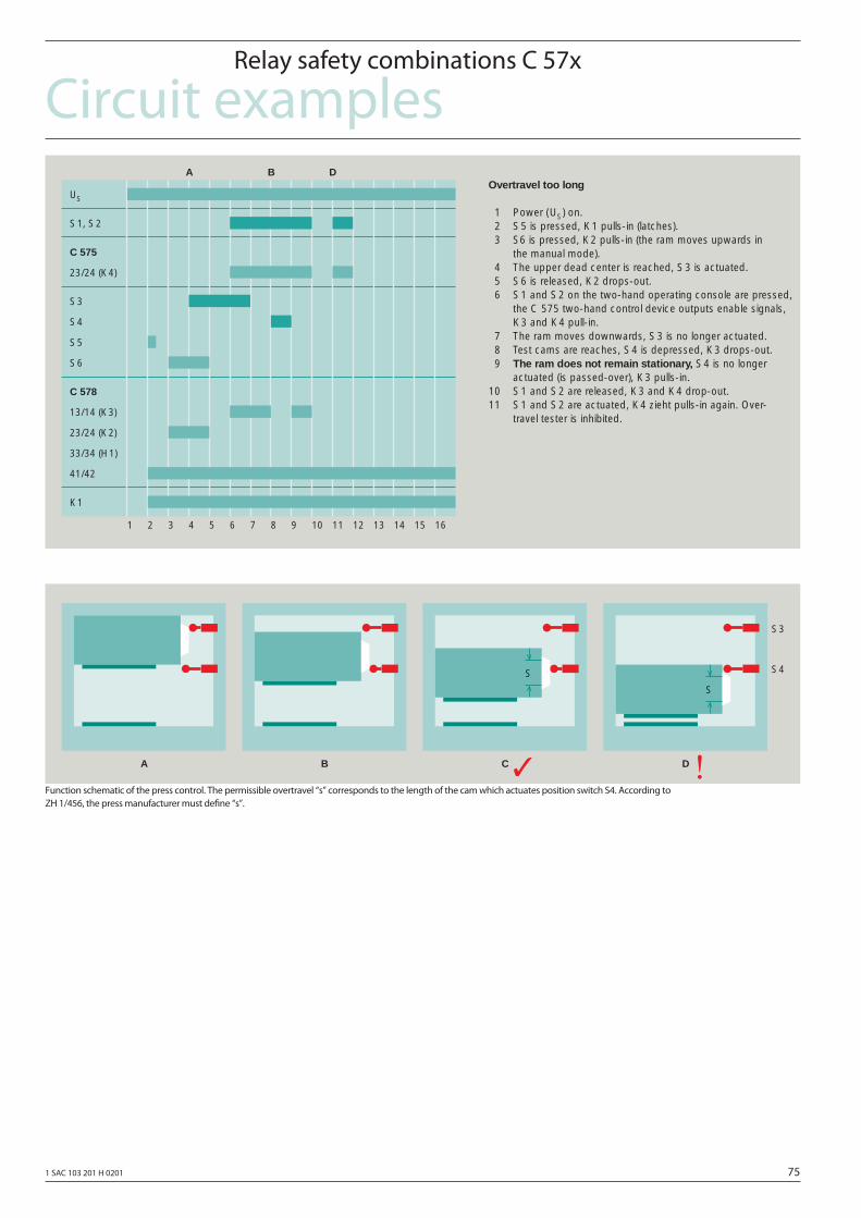
1 SAC 103 201 H 0201 75
Circuit examplesRelay safety combinations C 57x
Function schematic of the press control. The permissible overtravel “s” corresponds to the length of the cam which actuates position switch S4. According to ZH 1/456, the press manufacturer must defi ne “s”.
Overtravel too long
1 Power (US) on.2 S5 is pressed, K1 pulls-in (latches).3 S6 is pressed, K2 pulls-in (the ram moves upwards in
the manual mode).4 The upper dead center is reached, S3 is actuated.5 S6 is released, K2 drops-out.6 S1 and S2 on the two-hand operating console are pressed,
the C 575 two-hand control device outputs enable signals,K3 and K4 pull-in.
7 The ram moves downwards, S3 is no longer actuated.8 Test cams are reaches, S4 is depressed, K3 drops-out.9 The ram does not remain stationary, S4 is no longer
actuated (is passed-over), K3 pulls-in.10 S1 and S2 are released, K3 and K4 drop-out.11 S1 and S2 are actuated, K4 zieht pulls-in again. Over-
travel tester is inhibited.
S1, S2
S6
US
K1
S4
S3
41/42
33/34 (H1)
23/24 (K2)
13/14 (K3)
S5
C 578
23/24 (K4)
C 575
1 2 3 4 5 6 7 8 9 10 11 12 13 14 15 16
A B D
S3
S4
A B C D
S
S
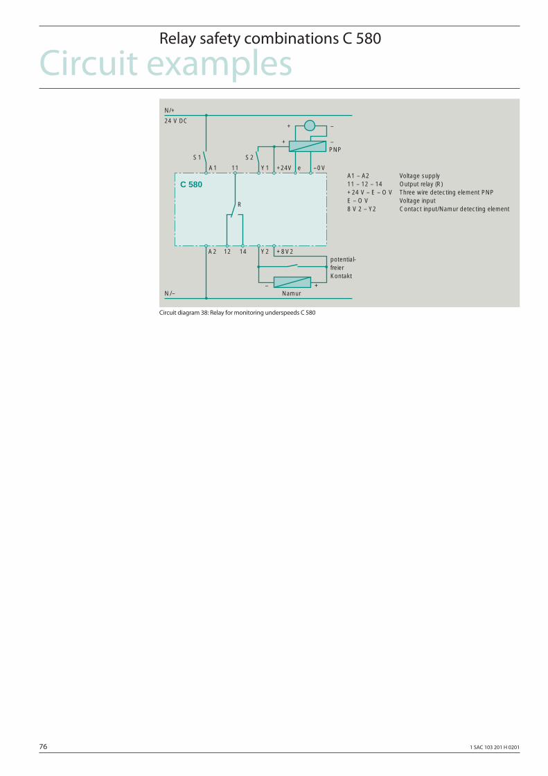
76 1 SAC 103 201 H 0201
Circuit examplesRelay safety combinations C 580
Circuit diagram 38: Relay for monitoring underspeeds C 580
A1 – A2 Voltage supply11 – 12 – 14 Output relay (R)+24 V – E – O V Three wire detecting element PNPE – O V Voltage input8 V 2 – Y2 Contact input/Namur detecting element
N/+
N/–
A1
Y2
C 580
24 V DC
A2 12 14
S1 S2
+8V2
Y1 +24V e –0V11
+
+ –
–
– +
R
PNP
Namur
potential-freierKontakt
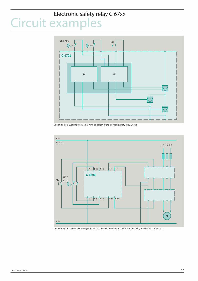
1 SAC 103 201 H 0201 77
Circuit examplesElectronic safety relay C 67xx
Circuit diagram 39: Principle internal wiring diagram of the electronic safety relay C 6701
Circuit diagram 40: Principle wiring diagram of a safe load feeder with C 6700 and positively driven small contactors.
A1 Y22 Y11
EIN
N/–
N/+
24 V DC
12 11
Y34Y21Y12A2 Y33
C 6700NOTAUS
M
L1 L2 L3
C 6701
μCμC
EinNOT-AUS

78 1 SAC 103 201 H 0201
1 SAC 103 201 H 0201 79
Appendix
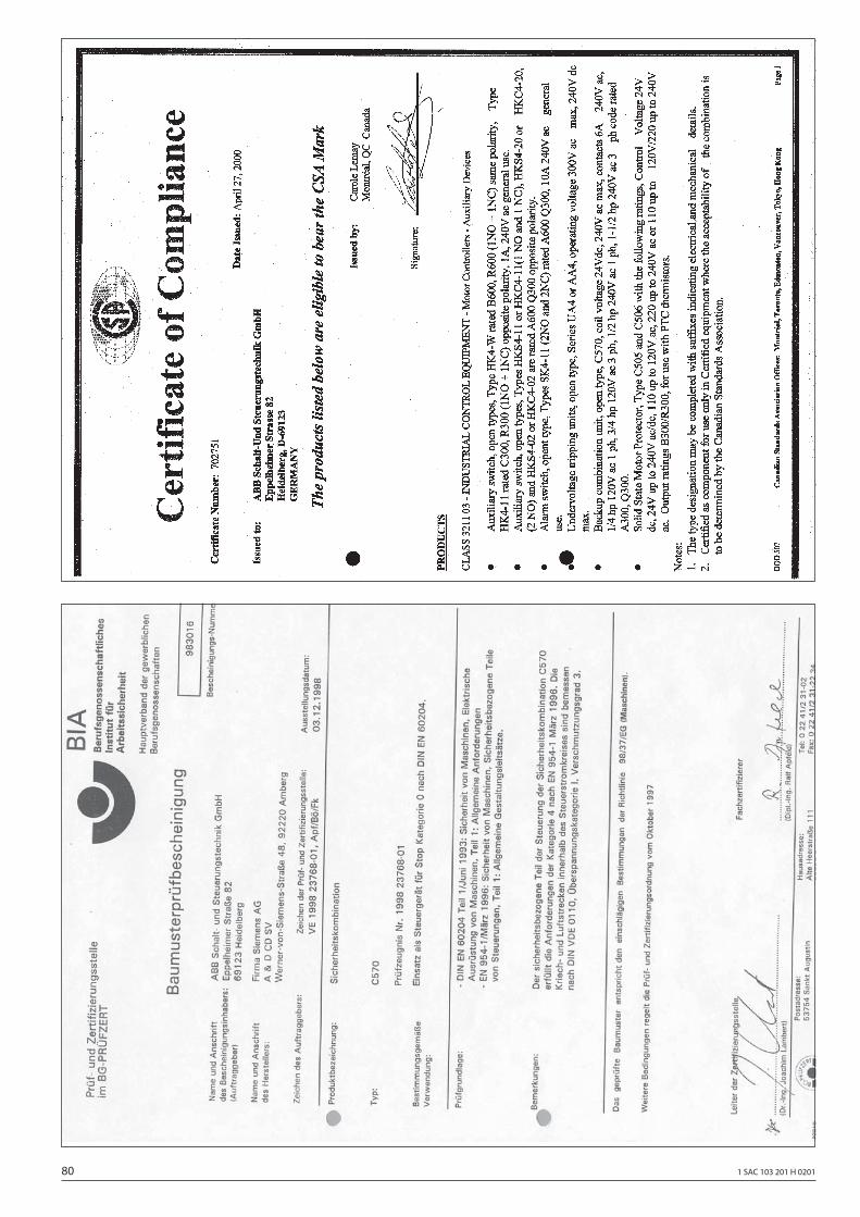
80 1 SAC 103 201 H 0201
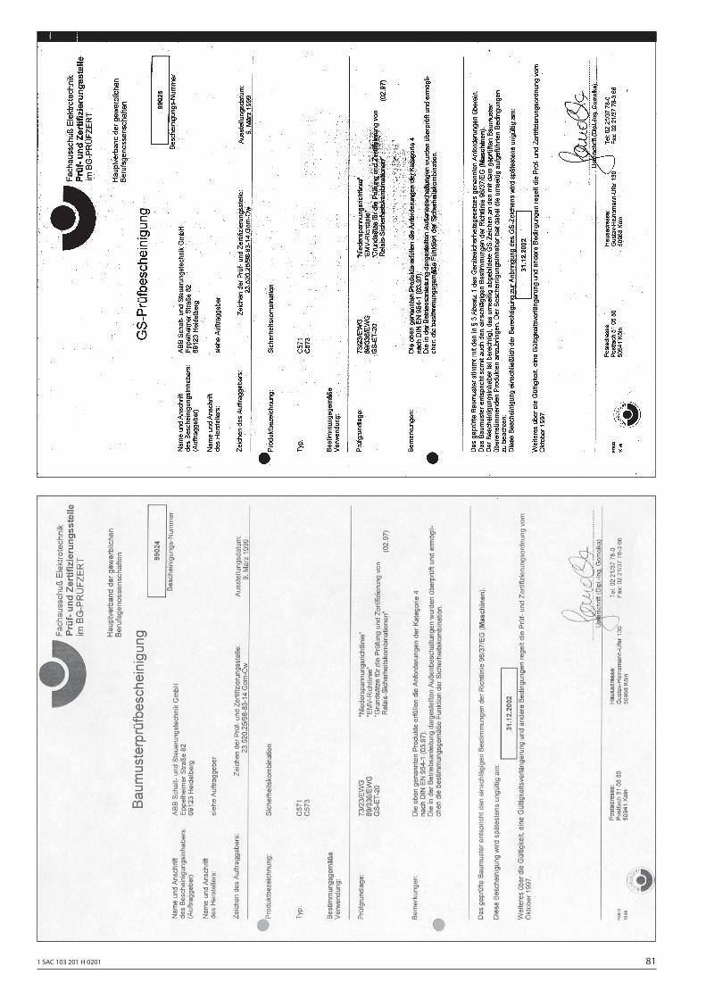
1 SAC 103 201 H 0201 81
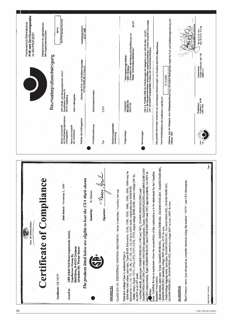
82 1 SAC 103 201 H 0201
1 SAC 103 201 H 0201 83
84 1 SAC 103 201 H 0201
1 SAC 103 201 H 0201 85
86 1 SAC 103 201 H 0201

1 SAC 103 201 H 0201 87
Doc
umen
t No.
1 S
AC 1
03 2
01 H
020
1 Pr
inte
d in
the
Fede
ral R
epub
lic o
f Ger
man
y (0
8/01
• 5
• GKD
) V
ERM
EER
Kom
mun
ikat
ions
Des
ign,
Ber
lin, G
esta
ltung
A. P
äch
ABB STOTZ-KONTAKT GmbH
Vertriebsbüros:
Lessingstraße 79D-13158 BerlinTelefon (030) 9177-2148Telefax (030) 9177-2101
Hildesheimer Str. 25D-30169 HannoverTelefon (0511) 6782-240Telefax (0511) 6782-320
ABB STOTZ-KONTAKT GmbHEppelheimer Straße 82D-69123 HeidelbergTelefon (06221) 701-0Telefax (06221) [email protected]
http://www.abb.de/totzkontakt
Eppelheimer Straße 82D-69123 HeidelbergTelefon (06221) 701-1368Telefax (06221) 701-1377
Lina-Ammon-Straße 22D-90471 NürnbergTelefon (0911) 8124-0Telefax (0911) 8124-286
Oberhausener Straße 33D-40472 RatingenTelefon (02102) 12-1144Telefax (02102) 12-1725