Embed Size (px)
Citation preview

distribution
R
PD70/10070 cm, 110 cm, 150 cm, 200 cm, 250 cm, 300 cm
ASSEMBLY AND USE MANUAL OF PD 70/100
FRAME SCAFFOLDING

Assembly and use manual of PD 70/100
frame scaffolding
plettac Sp. z o.o. Koúciuszki 31 PL 63-500 Ostrzeszów
Distribution
Ostrzeszów, July 2013
ASSEMBLY AND USE MANUAL OF PD 70/100 FRAME SCAFFOLDING
Table of Contents
Chapter I. Application range of PD 70/100 system scaffoldings 3
Application range of “PD 70/100” system scaffoldings. 3
Chapter II. Component specification of PD 70/100 system scaffoldings 4
Basic equipment 4
Communication route 6
Scaffolding extension 8
Safety scaffoldings 8
Passageways, Underpasses 9
Rolling scaffoldings 9
Anchoring elements 10
Bad weather protection 10
Couplings
Storage and transport
11
11
Chapter III. Assembly and disassembly rules of PD 70/100 system scaffoldings
Assembly and disassembly rules of PD 70/100 system scaffoldings
13
13
General remarks 13
Specific requirements arising from the provisions of PN standards and applicable laws in Poland 13
Bearing capacity of the ground3.1.2.1 13
Scaffolding placement3.1.2.2 13
3.1.2.3 Location of scaffoldings in the vicinity of overhead electricity lines 13
3.1.2.4 Electrical equipment (electrical cables) 13
3.1.2.5 Lightning protection equipment 13
3.1.2.6 Protective roofs 13
3.1.2.7 Fencing, bumping posts, signs, warning lights 13
3.1.2.8 Transport equipment 13
3.1.2.9 Scaffoldings with canvas covers and safety nets 13
3.1.2.10 Examination of the assembled scaffolding structures 14
3.1.2.11 Technical acceptance of the assembled scaffolding 14
3.1.2.12 Scaffolding periodic inspection 14
3.1.2.13 Packing, storage and transport of scaffolding components 14
Manual issued for:
Company name and address
Company NIP (TIN)
Acronym in Plettac Distribution Sp. z o.o.
Stamp and signature of the issuing person
Manual no.
Purchase document
2.1.
1.1.
2.2.
2.3.
2.4.
2.5.
2.6.
2.7.
2.8.
2.9.
2.10.
3.1
3.1.1
3.1.2
plettac Sp. z o.o. Koúciuszki 31 PL 63-500 Ostrzeszów
Distribution
Assembly instructions 14
General remarks 14
Pod³o¿e 15
Assembly of the first scaffolding field and further levels 15
Anchor types 18
Anchoring layout
Anchoring execution rules
19
19
Anchoring forces 18
Inspection of anchoring under load
Scaffolding disassembly
19
19
Chapter IV. PD 70/100 scaffolding assembly diagrams 20
Chapter V. Protocol forms 32
Technical acceptance protocol of a scaffolding intended for use 32
Anchoring force inspection protocol 33
The scaffolding components have been designated by the following inscription:
PD/XX
where XX - mean the last digits of manufacturing year.
NOTEThis manual is intended for designers, assembly personnel and „PD 70/100” scaffolding users. The company performing the assembly, disassembly, and using the „PD 70/100” system scaffolding must ensure the availability of this manual at a location in which the scaffoldings are assembled, disassembled and used.
COMPONENT DESIGNATION
PD70 scaffolding designation
Scaffolding EN 12810-4N-SW06/300-H1-A-LSScaffolding EN 12810-4N-SW06/300-H1-B-LS
Pd100 scaffolding designation
Scaffolding EN 12810-4N-SW09/300-H1-A-LSScaffolding EN 12810-4N-SW09/300-H1-B-LS
3.1.3.
3.1.3.1.
3.1.3.2.
3.1.3.3.
3.1.3.4.
3.1.3.5.
3.1.3.6.
3.1.3.7.
3.1.3.8.
3.1.3.9.
5.1.
5.2.
Assembly and use manual of PD 70/100
frame scaffolding
plettac Sp. z o.o. Koúciuszki 31 PL 63-500 Ostrzeszów
Distribution
distribution
R
3
CHAPTER I.Application range of PD 70/100
system scaffoldings
1.1 Application range of PD 70/100 system scaffoldings has been distinguished based on:
1. Working load of typical scaffoldings:
- PD 70 spacing 3,0 m = 2,0 kN/m2- PD 70 spacing 2,5 m = 3,0 kN/m2- PD 100 spacing 2,5 m = 3,0 kN/m2- PD 100 spacing 3,0 m = 2,0 kN/m2
2. Allowable working load of decks - provided on the list of PD 70/100 system scaffolding components p. 7-14.
3. Allowable height of typical PD70/100 scaffoldings:
- PD 70 – 24 m, fields of max length 2,5 m,- PD 70 – 24 m, fields of max length 3,0 m,- PD 100 – 24 m, fields of max length 3,0 m.
4. Allowable wind load at which the use of scaffoldings is possible without special designs:
- only within the 1st area of wind loads as per PN-77/B-02011.
5. Hoist installation - the scaffolding cannot be exposed to installation of construction hoists or lifting equipment of lifting capacity above 150 kg.
6. Scaffolding works - Allowable only on one level of each scaffolding vertical section.
7. The use of scaffoldings apart from the mentioned in pts. 1-6 application range, requires performing static calculations and the execution of technical construction design.
8. Static calculations are also required by scaffolding structures in which the following are assumed to be used:- compensation frames, - walk-through frames,- girders for suspension over gates,- canvas covers and protective nets, - wide triple-deck extension brackets, - different than specified in this manual bracing or anchoring layout.
PD 70/100 scaffolding structure calculations should be performed in accordance with the applicable standards and regulations based on an agreement with Sp. z o.o. company representatives.plettac Distribution
Assembly and use manual of PD 70/100
frame scaffolding
4
plettac Sp. z o.o. Koúciuszki 31 PL 63-500 Ostrzeszów
Distribution
CHAPTER II.Component specification of PD 70/100
system scaffoldings
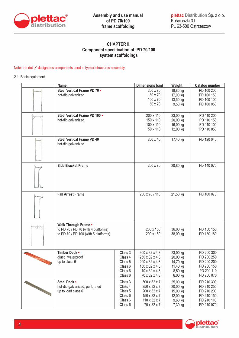
Note: the dot „•” designates components used in typical structures assembly.
2.1. Basic equipment.
Steel Vertical Frame PD 70 hot-dip galvanized
• 200 x 70150 x 70100 x 7050 x 70
18,85 kg17,00 kg13,50 kg9,50 kg
PD 100 200PD 100 150PD 100 100PD 100 050
Name Dimensions (cm) Weight Catalog number
Steel Vertical Frame PD 100 •hot-dip galvanized
200 x 110150 x 110100 x 11050 x 110
23,00 kg20,00 kg16,00 kg12,00 kg
PD 110 200PD 110 150PD 110 100PD 110 050
Steel Vertical Frame PDhot-dip galvanized
40 200 x 40 17,40 kg PD 120 040
Side Bracket Frame 200 x 70 20,80 kg PD 140 070
Fall Arrest Frame 200 x 70 / 110 21,50 kg PD 160 070
Walk Through Frame to PD 70 / PD 70 (with 4 platforms)to PD 70 / PD 100 (with 5 platforms)
•200 x 150200 x 180
36,00 kg38,00 kg
PD 150 150PD 150 180
Timber Deck glued, waterproofup to class 6
• 300 x 32 x 4,8250 x 32 x 4,8200 x 32 x 4,8150 x 32 x 4,8110 x 32 x 4,870 x 32 x 4,8
23,00 kg20,00 kg14,70 kg11,40 kg8,50 kg6,00 kg
PD 200 300PD 200 250PD 200 200PD 200 150PD 200 110PD 200 070
Steel Deck hot-dip galvanized, perforatedup to load class 6
• 300 x 32 x 7250 x 32 x 7200 x 32 x 7150 x 32 x 7110 x 32 x 770 x 32 x 7
25,00 kg20,00 kg15,00 kg12,00 kg9,60 kg7,30 kg
PD 210 300PD 210 250PD 210 200PD 210 150PD 210 110PD 210 070
Class 3 4 5 6 6 6
ClassClassClassClassClass
Class 3ClassClassClassClassClass
4 5 6 6 6
Assembly and use manual of PD 70/100
frame scaffolding
distribution
R
5
Name Dimensions (cm) Weight Catalog number
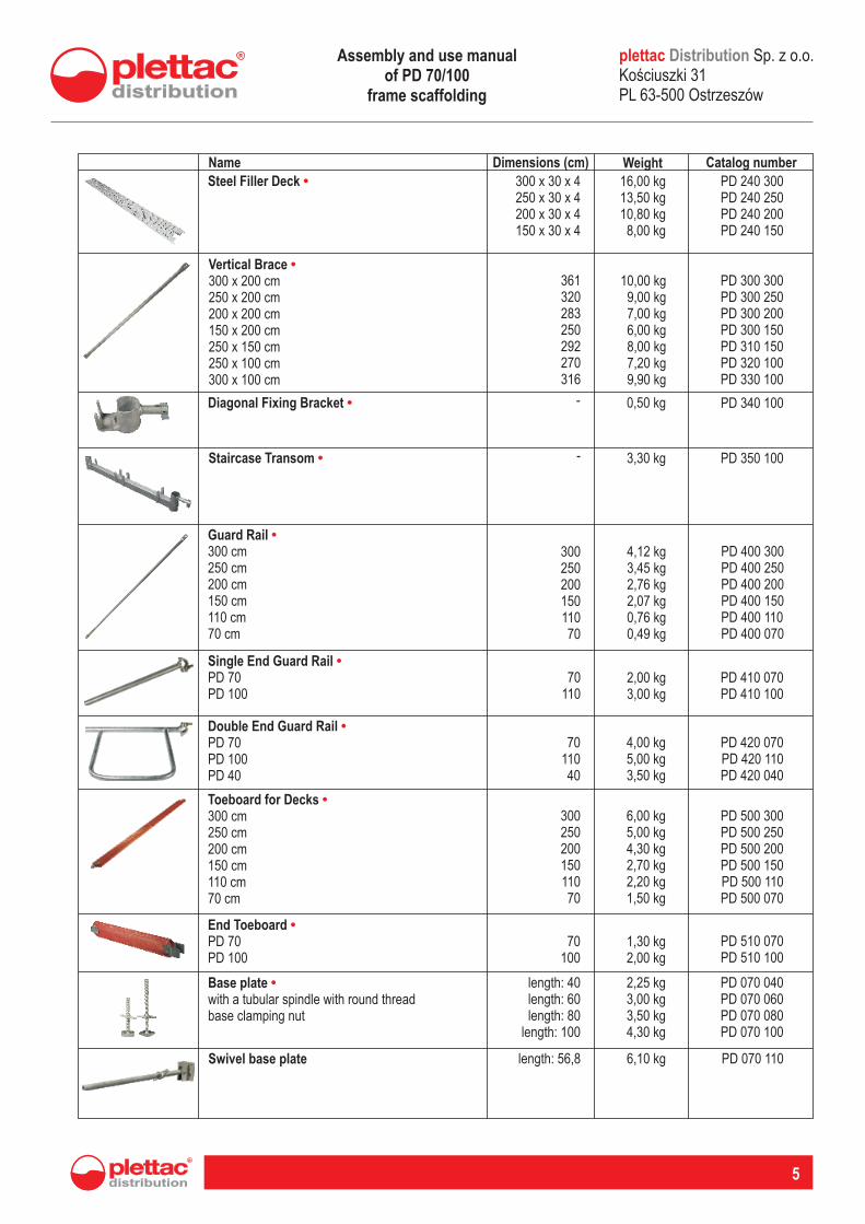
Steel Filler Deck • 300 x 30 x 4250 x 30 x 4200 x 30 x 4150 x 30 x 4
16,00 kg13,50 kg10,80 kg8,00 kg
PD 240 300PD 240 250PD 240 200PD 240 150
Vertical Brace 300 x 200 cm250 x 200 cm200 x 200 cm150 x 200 cm250 x 150 cm250 x 100 cm300 x 100 cm
•361320283250292270316
10,00 kg9,00 kg7,00 kg6,00 kg8,00 kg7,20 kg9,90 kg
PD 300 300PD 300 250PD 300 200PD 300 150PD 310 150PD 320 100PD 330 100
Diagonal Fixing Bracket • 0,50 kg PD 340 100-
Staircase Transom • - 3,30 kg PD 350 100
Guard Rail 300 cm250 cm200 cm150 cm110 cm70 cm
•30025020015011070
4,12 kg3,45 kg2,76 kg2,07 kg0,76 kg0,49 kg
PD 400 300PD 400 250PD 400 200PD 400 150PD 400 110PD 400 070
Single End Guard Rail PD 70PD 100
•70
1102,00 kg3,00 kg
PD 410 070PD 410 100
Double End Guard Rail PD 70PD 100PD 40
•70
11040
4,00 kg5,00 kg3,50 kg
PD 420 070PD 420 110PD 420 040
Toeboard for Decks 300 cm250 cm200 cm150 cm110 cm70 cm
•30025020015011070
6,00 kg5,00 kg4,30 kg2,70 kg2,20 kg1,50 kg
PD 500 300PD 500 250PD 500 200PD 500 150PD 500 110PD 500 070
End Toeboard PD 70PD 100
•70
1001,30 kg2,00 kg
PD 510 070PD 510 100
Base plate with a tubular spindle with round threadbase clamping nut
• length: 40: 60: 80
: 100
lengthlength
length
2,25 kg3,00 kg3,50 kg4,30 kg
PD 070 040PD 070 060PD 070 080PD 070 100
Swivel base plate length: 56,8 6,10 kg PD 070 110
plettac Sp. z o.o. Koúciuszki 31 PL 63-500 Ostrzeszów
DistributionAssembly and use manual of PD 70/100
frame scaffolding
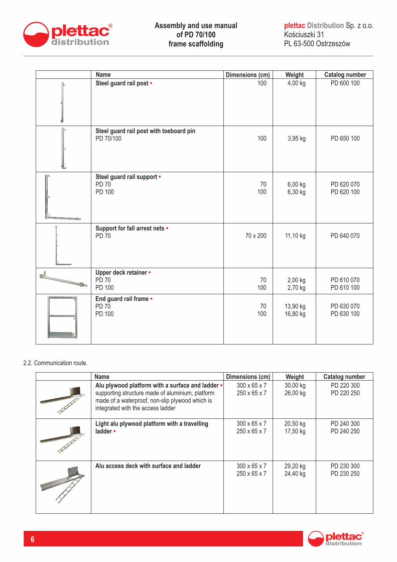
2.2. Communication route.
6
Name Dimensions (cm) Weight Catalog number
Steel guard rail post • 100 4,00 kg PD 600 100
Steel guard rail post with toeboard pinPD 70/100 100 3,95 kg PD 650 100
Steel guard rail support PD 70PD 100
•70
1006,00 kg6,30 kg
PD 620 070PD 620 100
Support for fall arrest nets PD 70
•70 x 200 11,10 kg PD 640 070
Upper deck retainer PD 70PD 100
•70
1002,00 kg2,70 kg
PD 610 070PD 610 100
End guard rail frame PD 70PD 100
•70
10013,90 kg16,80 kg
PD 630 070PD 630 100
Name Dimensions (cm) Weight Catalog number
Alu plywood platform with a surface and ladder supporting structure made of aluminium, platformmade of a waterproof, non-slip plywood which is integrated with the access ladder
• 300 x 65 x 7250 x 65 x 7
30,00 kg26,00 kg
PD 220 300PD 220 250
Light alu plywood platform with a travelling ladder •
300 x 65 x 7250 x 65 x 7
20,50 kg17,50 kg
PD 240 300PD 240 250
Alu access deck with surface and ladder 300 x 65 x 7250 x 65 x 7
29,20 kg24,40 kg
PD 230 300PD 230 250
plettac Sp. z o.o. Koúciuszki 31 PL 63-500 Ostrzeszów
DistributionAssembly and use manual of PD 70/100
frame scaffolding
distribution
R
7
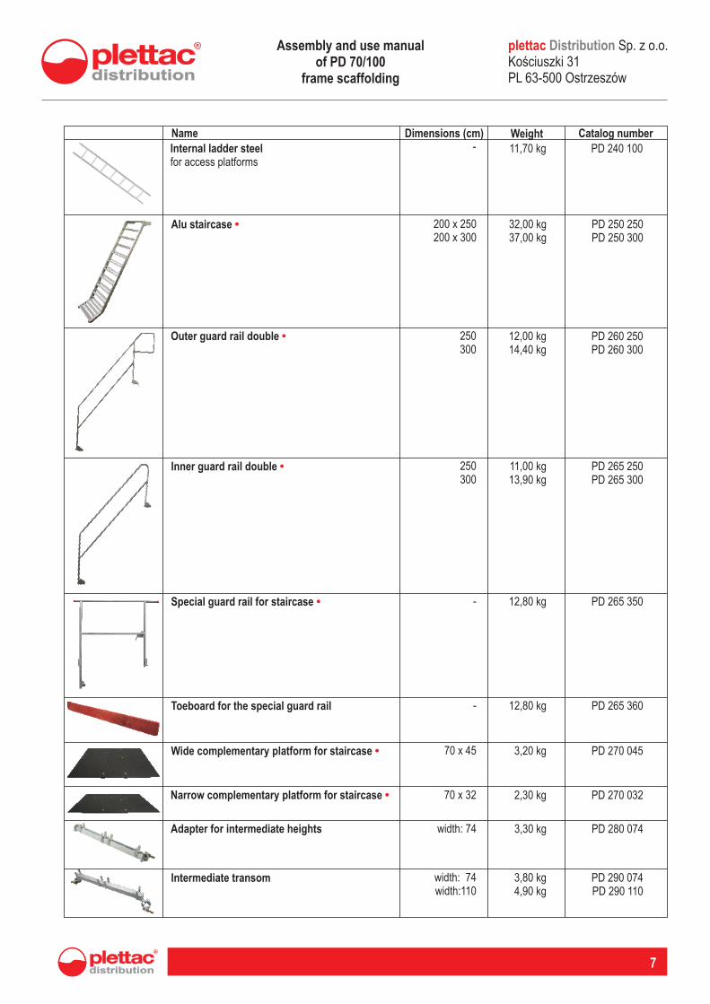
Name Dimensions (cm) Weight Catalog number
Alu staircase • 200 x 250200 x 300
32,00 kg37,00 kg
PD 250 250PD 250 300
Outer guard rail double • 250300
12,00 kg14,40 kg
PD 260 250PD 260 300
Inner guard rail double • 250300
11,00 kg13,90 kg
PD 265 250PD 265 300
Special guard rail for staircase • - 12,80 kg PD 265 350
Toeboard for the special guard rail - 12,80 kg PD 265 360
Wide complementary platform for staircase • 70 x 45 3,20 kg PD 270 045
Narrow complementary platform for staircase • 70 x 32 2,30 kg PD 270 032
Adapter for intermediate heights width: 74 3,30 kg PD 280 074
Intermediate transom width: 74 width:110
3,80 kg4,90 kg
PD 290 074PD 290 110
Internal ladder steelfor access platforms
- 11,70 kg PD 240 100
plettac Sp. z o.o. Koúciuszki 31 PL 63-500 Ostrzeszów
DistributionAssembly and use manual of PD 70/100
frame scaffolding
8
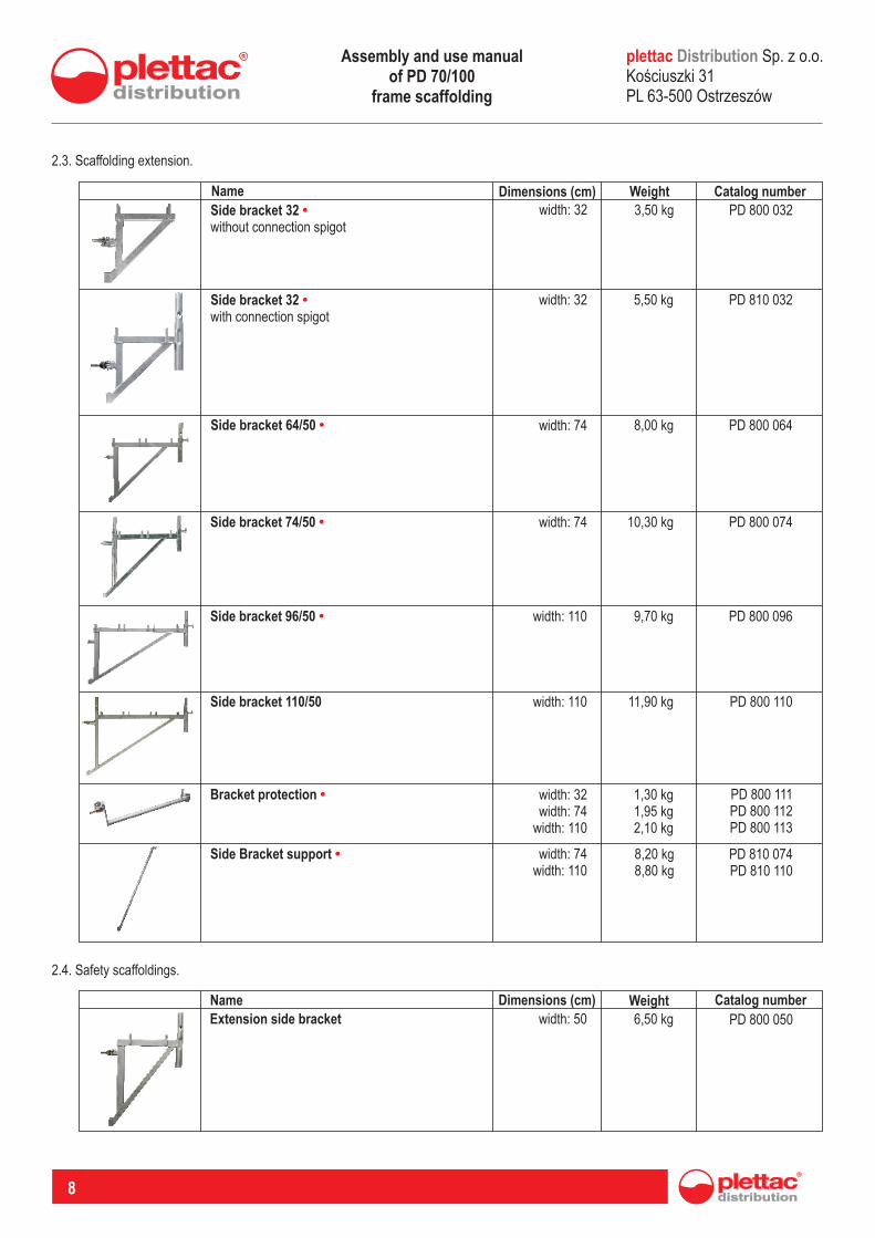
Name Dimensions (cm) Weight Catalog number
Side bracket 32 without connection spigot
• width: 32 3,50 kg PD 800 032
2.3. Scaffolding extension.
Side bracket 32 with connection spigot
• width: 32 5,50 kg PD 810 032
Side bracket 64/50 • width: 74 8,00 kg PD 800 064
Side bracket 74/50 • width: 74 10,30 kg PD 800 074
Side bracket 96/50 • width: 110 9,70 kg PD 800 096
Side bracket 110/50 width: 110 11,90 kg PD 800 110
Bracket protection • width:width:
width:
32 74110
1,30 kg1,95 kg2,10 kg
PD 800 111PD 800 112PD 800 113
Side Bracket support • width:width:
74 110
8,20 kg8,80 kg
PD 810 074PD 810 110
2.4. Safety scaffoldings.
Name Dimensions (cm) Weight Catalog number
Extension side bracket width: 50 6,50 kg PD 800 050
plettac Sp. z o.o. Koúciuszki 31 PL 63-500 Ostrzeszów
DistributionAssembly and use manual of PD 70/100
frame scaffolding
distribution
R
9
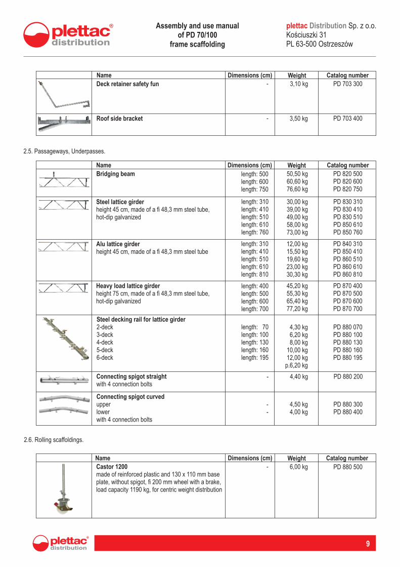
Name Dimensions (cm) Weight Catalog number
Deck retainer safety fun - 3,10 kg PD 703 300
Roof side bracket - 3,50 kg PD 703 400
2.5. Passageways, Underpasses.
Name Dimensions (cm) Weight Catalog number
Bridging beam length: 500: 600: 750
lengthlength
50,50 kg60,60 kg76,60 kg
PD 820 500 PD 820 600PD 820 750
Steel lattice girderheight 45 cm, made of a fi 48,3 mm steel tube,hot-dip galvanized
PD 830 310 PD 830 410PD 830 510PD 850 610PD 850 760
lengthlengthlengthlengthlength
: 310: 410: 510: 610: 760
30,00 kg39,00 kg49,00 kg58,00 kg73,00 kg
Alu lattice girderheight 45 cm, made of a fi 48,3 mm steel tube
PD 840 310 PD 850 410PD 860 510PD 860 610PD 860 810
lengthlengthlengthlengthlength
: 310: 410: 510: 610: 810
12,00 kg15,50 kg19,60 kg23,00 kg30,30 kg
Heavy load lattice girderheight 75 cm, made of a fi 48,3 mm steel tube, hot-dip galvanized
PD 870 400 PD 870 500PD 870 600PD 870 700
lengthlengthlengthlength
: 400: 500: 600: 700
45,20 kg55,30 kg65,40 kg77,20 kg
Steel decking rail for lattice girder2-deck3-4-5-6-
deckdeckdeckdeck
PD 880 070PD 880 100PD 880 130PD 880 160PD 880 195
lengthlengthlengthlengthlength
: 70: 100: 130: 160: 195
4,30 kg6,20 kg8,00 kg
10,00 kg12,00 kgp.6,20 kg
Connecting spigot straightwith 4 connection bolts
PD 880 200- 4,40 kg
Connecting spigot curvedupperlowerwith 4 connection bolts
PD 880 300PD 880 400
--
4,50 kg4,00 kg
2.6. Rolling scaffoldings.
Name Dimensions (cm) Weight Catalog number
Castor 1200made of reinforced plastic and 130 x 110 mm baseplate, without spigot, fi 200 mm wheel with a brake, load capacity 1190 kg, for centric weight distribution
- 6,00 kg PD 880 500
plettac Sp. z o.o. Koúciuszki 31 PL 63-500 Ostrzeszów
DistributionAssembly and use manual of PD 70/100
frame scaffolding
10
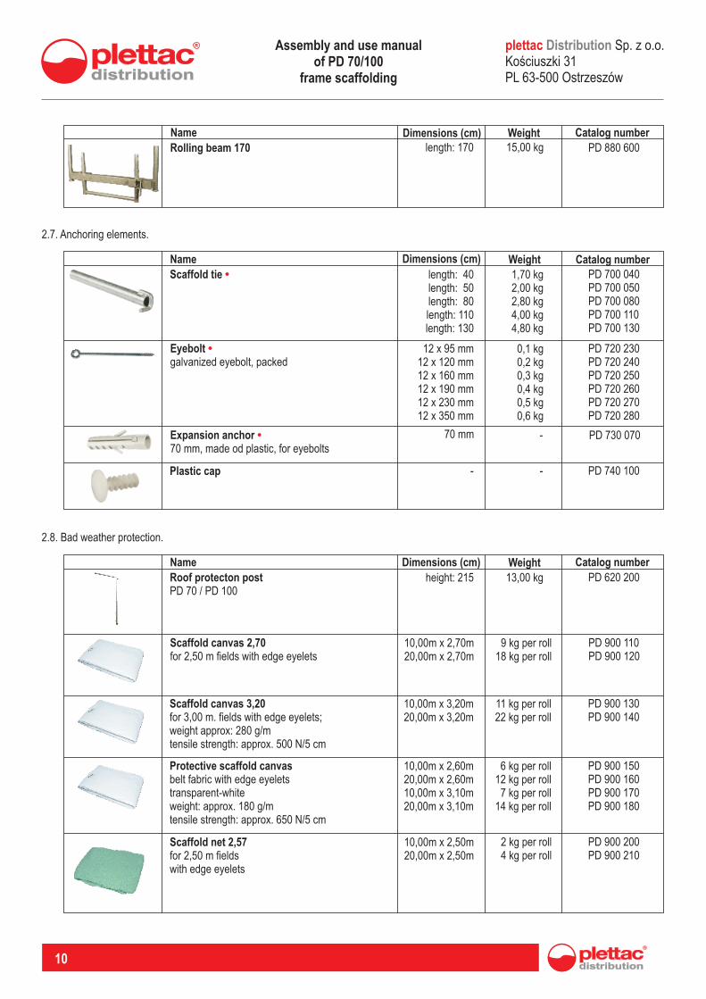
Name Dimensions (cm) Weight Catalog number
Rolling beam 170 length: 170 15,00 kg PD 880 600
Name Dimensions (cm) Weight Catalog numberScaffold tie • length: 40
: 50: 80 : 110: 130
lengthlengthlengthlength
1,70 kg2,00 kg2,80 kg4,00 kg4,80 kg
PD 700 040PD 700 050PD 700 080PD 700 110PD 700 130
2.7. Anchoring elements.
Eyebolt galvanized eyebolt, packed
• PD 720 230PD 720 240PD 720 250PD 720 260PD 720 270PD 720 280
12 x 95 mm12 x 120 mm12 x 160 mm12 x 190 mm12 x 230 mm12 x 350 mm
0,1 kg0,2 kg0,3 kg0,4 kg0,5 kg0,6 kg
Expansion anchor 70 mm, made od plastic, for eyebolts
• 70 mm - PD 730 070
Plastic cap - - PD 740 100
Name Dimensions (cm) Weight Catalog number
Roof protecton postPD 70 / PD 100
height: 215 13,00 kg PD 620 200
2.8. Bad weather protection.
Scaffold canvas 2,70for 2,50 m fields with edge eyelets
10,00m x 2,70m 20,00m x 2,70m
9 kg per roll18 kg per roll
PD 900 110 PD 900 120
Scaffold canvas 3,20fields for 3,00 m. with edge eyelets;
weight approx: 280 g/mtensile strength: approx. 500 N/5 cm
10,00m x 3,20m20,00m x 3,20m
11 kg 22 kg
per rollper roll
PD 900 130 PD 900 140
Protective scaffold canvasbelt fabric with edge eyeletstransparent-whiteweight: approx. 180 g/mtensile strength: approx. 650 N/5 cm
10,00m x 2,60m20,00m x 2,60m10,00m x 3,10m20,00m x 3,10m
6 kg 12 kg 7 kg
14 kg
per rollper rollper rollper roll
PD 900 150PD 900 160 PD 900 170 PD 900 180
Scaffold net 2,57for 2,50 m fieldswith edge eyelets
10,00m x 2,50m20,00m x 2,50m
2 kg 4 kg
per rollper roll
PD 900 200 PD 900 210
plettac Sp. z o.o. Koúciuszki 31 PL 63-500 Ostrzeszów
DistributionAssembly and use manual of PD 70/100
frame scaffolding
distribution
R
11
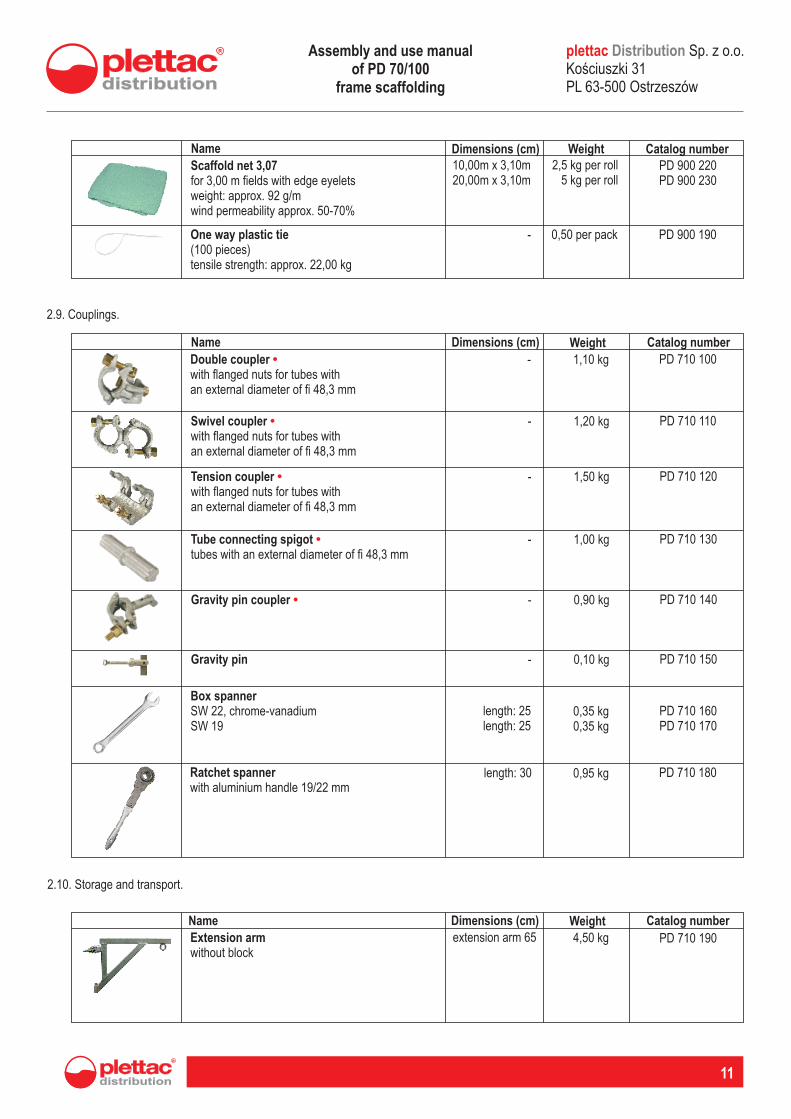
Name Dimensions (cm) Weight Catalog numberScaffold net 3,07for 3,00 m fields with edge eyeletsweight: approx. 92 g/mwind permeability approx. 50-70%
10,00m x 3,10m20,00m x 3,10m
2,5 kg per roll5 kg per roll
PD 900 220 PD 900 230
One way plastic tie(100 pieces)tensile strength: approx. 22,00 kg
- 0,50 per pack PD 900 190
Name Dimensions (cm) Weight Catalog number
Double coupler with flanged nuts for tubes withan external diameter of fi 48,3 mm
• - 1,10 kg PD 710 100
2.9. Couplings.
Swivel coupler with flanged nuts for tubes withan external diameter of fi 48,3 mm
• - 1,20 kg PD 710 110
Tension coupler with flanged nuts for tubes withan external diameter of fi 48,3 mm
• - 1,50 kg PD 710 120
Tube connecting spigot tubes with an external diameter of fi 48,3 mm
• - 1,00 kg PD 710 130
Gravity pin coupler • - 0,90 kg PD 710 140
Gravity pin - 0,10 kg PD 710 150
Box spannerSW 22, chrome-vanadiumSW 19 length: 25
length: 25 0,35 kg0,35 kg
PD 710 160 PD 710 170
Ratchet spannerwith aluminium handle 19/22 mm
length: 30 0,95 kg PD 710 180
2.10. Storage and transport.
Name Dimensions (cm) Weight Catalog number
Extension armwithout block
extension arm 65 4,50 kg PD 710 190
plettac Sp. z o.o. Koúciuszki 31 PL 63-500 Ostrzeszów
DistributionAssembly and use manual of PD 70/100
frame scaffolding
12
Name Dimensions (cm) Weight Catalog number
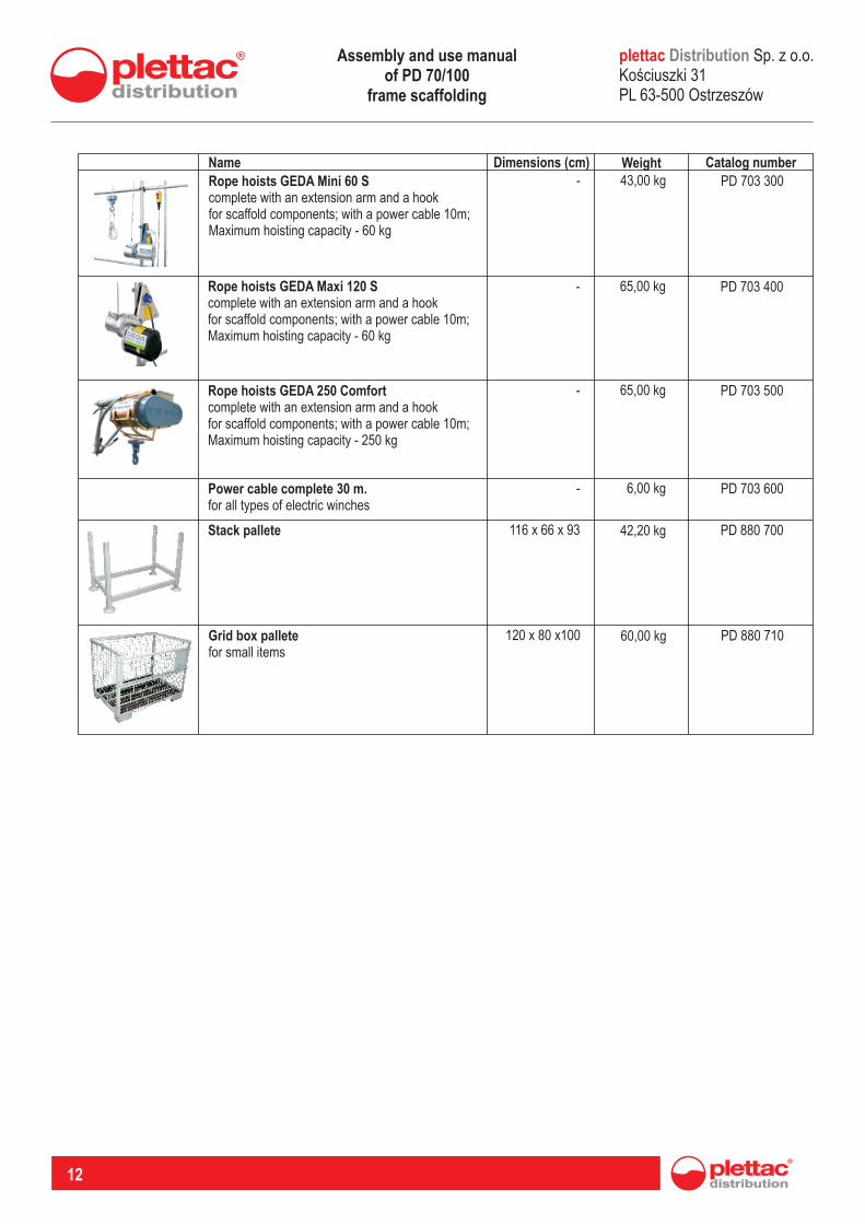
Rope hoists GEDA Mini 60 Scomplete with an extension arm and a hookfor scaffold components; with a power cable 10m;Maximum hoisting capacity - 60 kg
- 43,00 kg PD 703 300
Rope hoists GEDA Maxi 120 Scomplete with an extension arm and a hookfor scaffold components; with a power cable 10m;Maximum hoisting capacity - 60 kg
- 65,00 kg PD 703 400
Rope hoists GEDA 250 Comfortcomplete with an extension arm and a hookfor scaffold components; with a power cable 10m;Maximum hoisting capacity - 250 kg
- 65,00 kg PD 703 500
Power cable complete 30 m.for all types of electric winches
- 6,00 kg PD 703 600
Stack pallete 116 x 66 x 93 42,20 kg PD 880 700
Grid box palletefor small items
120 x 80 x100 60,00 kg PD 880 710
plettac Sp. z o.o. Koúciuszki 31 PL 63-500 Ostrzeszów
DistributionAssembly and use manual of PD 70/100
frame scaffolding
distribution
R
13
CHAPTER III.Assembly and disassembly rules of PD 70/100 system scaffoldings
3.1. Assembly and disassembly rules of PD 70/100 system scaffoldings.
3.1.1
The scaffolding user is strictly obliged to follow the use and assembly rules provided: - in this manual,- in standards PN-M-47900:1996, PN-EN 12811; PN-EN 12810- in the Ordinance of Minister of Infrastructure dated 6th February 2003 on health and safety during the execution of construction works (Journal of Laws No. 47 dated 2003, item 401),- in the Ordinance of the Minister of Labor and Social Policy dated 26th September 1997 on general health and safety provisions (Journal of Laws No. 129 item 844 as amended),- in the Ordinance of the Minister of Economy, the Minister of Labor and Social Policy date 30th September 2003 amending the ordinance on minimum requirements of health and safety within the use of work equipment by workers at work (Journal of Laws No. 178, item 1745)
Specific requirements arising from the provisions of PN standards and applicable laws in Poland.
General remarks.
1.)
The abovementioned regulations are intended for assembly supervisors and scaffolding technical acceptance staff.
The assembly and disassembly of PD 70/100l scaffoldings may be performed under the supervision of a competent person with appropriate certificates and familiarized with this manual.
2.)
3.1.2
Bearing capacity of the ground 3.1.2.1
Provisions of the PN-M-47900-2:1996 pt. 4.3 standard are applicable.
Scaffolding placement. 3.1.2.2
Provisions of the PN-M-47900-2:1996 pt. 4.4 standard are applicable.
Location of scaffoldings in the vicinity of overhead electricity lines. 3.1.2.3
Provisions of the PN-M-47900-2:1996 pt. 4.9.1 standard are applicable.
Electrical equipment (electrical cables).3.1.2.4
Provisions of the PN-M-47900-2:1996 pts. 4.9.2; 4.9.3. standards are applicable.
Lightning protection equipment.3.1.2.5
Provisions of the PN-M-47900-2:1996 pt. 4.8 standard are applicable.
Protective roofs.3.1.2.6
Protective roofs should be installed in accordance with the provisions of the PN-M-47900-2:1996 pt. 4.10.3.
Fencing, bumping posts, signs and warning lights.3.1.2.7
The installation of the abovementioned protective measure should be executed in accordance with the provisions of the PN-M-47900-2:1996 pts. 4.10.4; 4.10.5; 4.10.6; 4.10.7.
Transport equipment.3.1.2.8
During the use and installation of transport equipment, the provisions of PN-M-47900-2:1996 pts. 4.7.2; 4.7.3 are applicable.
Scaffoldings with canvas covers and safety nets.3.1.2.9
The method of securing scaffoldings with canvas covers and protective nets is regulated by the provisions of PN standards, therefore the use of this type of protective measures should be agreed with the manufacturer's representatives and confirmed by static calculations.
plettac Sp. z o.o. Koúciuszki 31 PL 63-500 Ostrzeszów
DistributionAssembly and use manual of PD 70/100
frame scaffolding
14
Examination of the assembled scaffolding structures.3.1.2.10
The examination of the assembled scaffolding structure should be conducted in accordance with the procedure described in PN-M-47900-2:1996 pt. 7.3
Technical acceptance of the assembled scaffolding.3.1.2.11
Scaffolding use is possible after a technical acceptance. The acceptance should be conducted by a person who is competent in accor-dance with the applicable regulations. The acceptance conditions have been defined in the Ordinance of Minister of Infrastructure (Jo-urnal of Laws No. 47 dated 2003, item 401).
Scaffolding periodic inspection.3.1.2.12
PD70/100 scaffoldings under operation are subjected to the following inspections:
Daily inspections:1.)
Daily inspections should be conducted by users of the scaffolding i.e. employees working on the scaffolding. Daily inspection consists in checking whether:the scaffolding has not been damaged or deformed, the scaffolding has been properly anchored, the electrical cables have been properly insulated and are not in contact with the scaffolding structure,the condition of working and communication decks is appropriate (cleanliness of deck, during winter time - the anti-slip deck protection), phenomenons influencing the scaffolding safety have occurred.
a)b)c)d)
e)
Decade inspections:2.)Decade inspections should be conducted every 10 days. The inspection should be performed by the scaffolding maintenance employ-ee or an engineering and technical worker, e.g. foreman or the site manager. The aim of the decade inspection is to check whether the entire scaffolding construction has not been changed in a way that could result in a construction disaster or cause a dangerous scaffol-ding use environment.
Immediate inspections:3.)Immediate inspections should be carried out after a downtime of more than 2 weeks and after every storm of wind force above 6 points on the Beaufort scale (i.e. 12 m/s). Immediate inspection should be carried out by a commission consisting of the foreman, master wo-rkman and the Construction Supervision Inspector. It may be ordered at any time by a construction supervision inspection body. The spotted defects should be removed after each inspection before attempting work. The inspection responsibility lays on the site ma-nager or the indicated by him authorized person. The results of decade and immediate inspections should be entered into the construc-tion log book by the staff performing the inspection.
Packing, storage and transport of scaffolding components.3.1.2.12
This field is governed by the requirements of PN-M-47900-2:1996 pt. 6.
Assembly and disassembly instructions.3.1.3
General remarks.3.1.3.1
The assembly and disassembly of PD 70/100 scaffoldings may be performed by staff with proper qualifications and under the supervi-sion of a competent person.
This manual provides general scaffolding assembly and disassembly instructions
All scaffolding components should be visually checked before the assembly. Damaged components as well as non-system components must not be installed within the scaffolding.
The scaffolding assembly is performed in stages, one following another.
A dangerous zone should be determined and marked properly during the assembly, reconstruction or disassembly of the scaffolding. Only the scaffolding assembly, reconstruction or disassembly staff should be present within the borders of the dangerous zone. A scaf-folding technical acceptance should be held after works completion in accordance with pt. 3.1.2.11 and the protocol should be placed in a visible place, next to the communication paths. The use of a scaffolding without a valid protocol is FORBIDDEN.
1.)
2.)
3.)
4.)
5.)
plettac Sp. z o.o. Koúciuszki 31 PL 63-500 Ostrzeszów
DistributionAssembly and use manual of PD 70/100
frame scaffolding
distribution
R
15
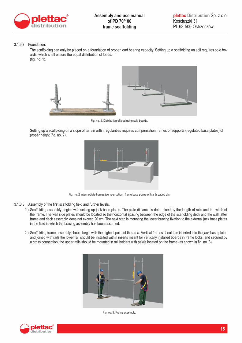
Foundation.3.1.3.2
The scaffolding can only be placed on a foundation of proper load bearing capacity. Setting up a scaffolding on soil requires sole bo-ards, which shall ensure the equal distribution of loads. (fig. no. 1).
Fig. no. 1. Distribution of load using sole boards.
Setting up a scaffolding on a slope of terrain with irregularities requires compensation frames or supports (regulated base plates) of proper height (fig. no. 2).
Fig. no. 2 Intermediate frames (compensation), frame base plates with a threaded pin.
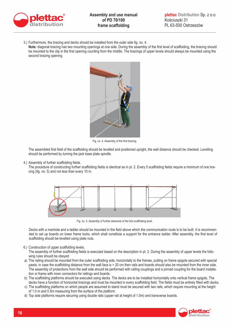
Assembly of the first scaffolding field and further levels.3.1.3.3
Scaffolding assembly begins with setting up jack base plates. The plate distance is determined by the length of rails and the width of the frame. The wall side plates should be located so the horizontal spacing between the edge of the scaffolding deck and the wall, after frame and deck assembly, does not exceed 20 cm. The next step is mounting the lower bracing fixation to the external jack base plates in the field in which the bracing assembly has been assumed.
1.)
Scaffolding frame assembly should begin with the highest point of the area. Vertical frames should be inserted into the jack base plates and joined with rails the lower rail should be installed within inserts meant for vertically installed boards in frame locks, and secured by a cross connection, the upper rails should be mounted in rail holders with pawls located on the frame (as shown in fig. no. 3).
2.)
Fig. no. 3. Frame assembly.
plettac Sp. z o.o. Koúciuszki 31 PL 63-500 Ostrzeszów
DistributionAssembly and use manual of PD 70/100
frame scaffolding
16
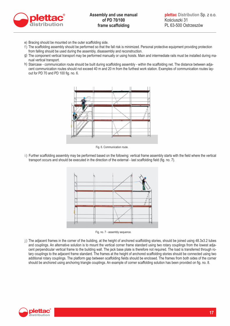
Furthermore, the bracing and decks should be installed from the outer side fig. no. 4.Note: diagonal bracing has two mounting openings at one side. During the assembly of the first level of scaffolding, the bracing should be mounted to the clip in the first opening counting from the middle. The bracings of upper levels should always be mounted using the second bracing opening.
3.)
Fig. no. 4. Assembly of the first bracing.
The assembled first field of the scaffolding should be levelled and positioned upright, the wall distance should be checked. Levelling should be performed by turning the jack base plate spindle.
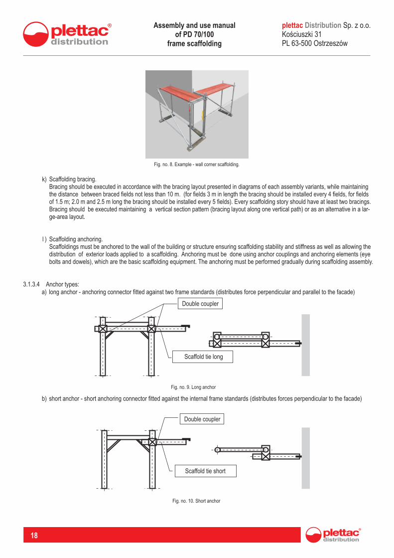
Assembly of further scaffolding fields.The procedure of constructing further scaffolding fields is identical as in pt. 2. Every 5 scaffolding fields require a minimum of one bra-cing (fig. no. 5) and not less than every 10 m.
4.)
Fig. no. 5. Assembly of further elements of the first scaffolding level.
Decks with a manhole and a ladder should be mounted in the field above which the communication route is to be built. It is recommen-ded to set up boards on lower frame locks, which shall constitute a support for the entrance ladder. After assembly, the first level of scaffolding should be levelled using plate nuts.
Construction of upper scaffolding levels.The assembly of further scaffolding fields is executed based on the description in pt. 2. During the assembly of upper levels the follo-wing rules should be obeyed: The railing should be mounted from the outer scaffolding side, horizontally to the frames, putting on frame spigots secured with special pawls; in case the scaffolding distance from the wall face is > 20 cm then rails and boards should also be mounted from the inner side. The assembly of protections from the wall side should be performed with railing couplings and a pinned coupling for the board installa-tion or frame with inner connectors for railings and boards.The scaffolding platforms should be executed using decks. The decks are to be installed horizontally onto vertical frame spigots. The decks have a function of horizontal bracings and must be mounted in every scaffolding field. The fields must be entirely filled with decks.The scaffolding platforms on which people are assumed to stand must be secured with two rails, which require mounting at the height of 1.0 m and 0.5m measuring from the surface of the platform.Top side platforms require securing using double rails (upper rail at height of 1.0m) and transverse boards.
6.)
a)
b)
c)
d)
plettac Sp. z o.o. Koúciuszki 31 PL 63-500 Ostrzeszów
DistributionAssembly and use manual of PD 70/100
frame scaffolding
distribution
R
17
Bracing should be mounted on the outer scaffolding side.The scaffolding assembly should be performed so that the fall risk is minimized. Personal protective equipment providing protection from falling should be used during the assembly, disassembly and reconstruction.The component vertical transport may be performed manually or using hoists. Main and intermediate rails must be installed during ma-nual vertical transport.Staircase - communication route should be built during scaffolding assembly - within the scaffolding net. The distance between adja-cent communication routes should not exceed 40 m and 20 m from the furthest work station. Examples of communication routes lay-out for PD 70 and PD 100 fig. no. 6.
e) f )
g)
h)
Fig. 6. Communication route.
Further scaffolding assembly may be performed based on the following: vertical frame assembly starts with the field where the vertical transport occurs and should be executed in the direction of the external - last scaffolding field (fig. no. 7).
i )
Fig. no. 7 - assembly sequence.
The adjacent frames in the corner of the building, at the height of anchored scaffolding stories, should be joined using 48.3x3.2 tubes and couplings. An alternative solution is to mount the vertical corner frame standard using two rotary couplings from the lowest adja-cent perpendicular vertical frame to the building wall. The jack base plate is therefore not required. The load is transferred through ro-tary couplings to the adjacent frame standard. The frames at the height of anchored scaffolding stories should be connected using two additional rotary couplings. The platform gap between scaffolding fields should be enclosed. The frames from both sides of the corner should be anchored using anchoring triangle couplings. An example of corner scaffolding solution has been provided on fig. no. 8.
j )
plettac Sp. z o.o. Koúciuszki 31 PL 63-500 Ostrzeszów
DistributionAssembly and use manual of PD 70/100
frame scaffolding
18
Fig. no. 8. Example - wall corner scaffolding.
Scaffolding bracing.Bracing should be executed in accordance with the bracing layout presented in diagrams of each assembly variants, while maintaining the distance between braced fields not less than 10 m. (for fields 3 m in length the bracing should be installed every 4 fields, for fields of 1.5 m; 2.0 m and 2.5 m long the bracing should be installed every 5 fields). Every scaffolding story should have at least two bracings. Bracing should be executed maintaining a vertical section pattern (bracing layout along one vertical path) or as an alternative in a lar-ge-area layout.
k)
Scaffolding anchoring.Scaffoldings must be anchored to the wall of the building or structure ensuring scaffolding stability and stiffness as well as allowing the distribution of exterior loads applied to a scaffolding. Anchoring must be done using anchor couplings and anchoring elements (eye bolts and dowels), which are the basic scaffolding equipment. The anchoring must be performed gradually during scaffolding assembly.
l )
Anchor types:3.1.3.4long anchor - anchoring connector fitted against two frame standards (distributes force perpendicular and parallel to the facade)a)
short anchor - short anchoring connector fitted against the internal frame standards (distributes forces perpendicular to the facade) b)
Fig. no. 9. Long anchor
Fig. no. 10. Short anchor
Double coupler
Scaffold tie long
Double coupler
Scaffold tie short
plettac Sp. z o.o. Koúciuszki 31 PL 63-500 Ostrzeszów
DistributionAssembly and use manual of PD 70/100
frame scaffolding
Double coupler
2 x Scaffold tie short
distribution
R
19
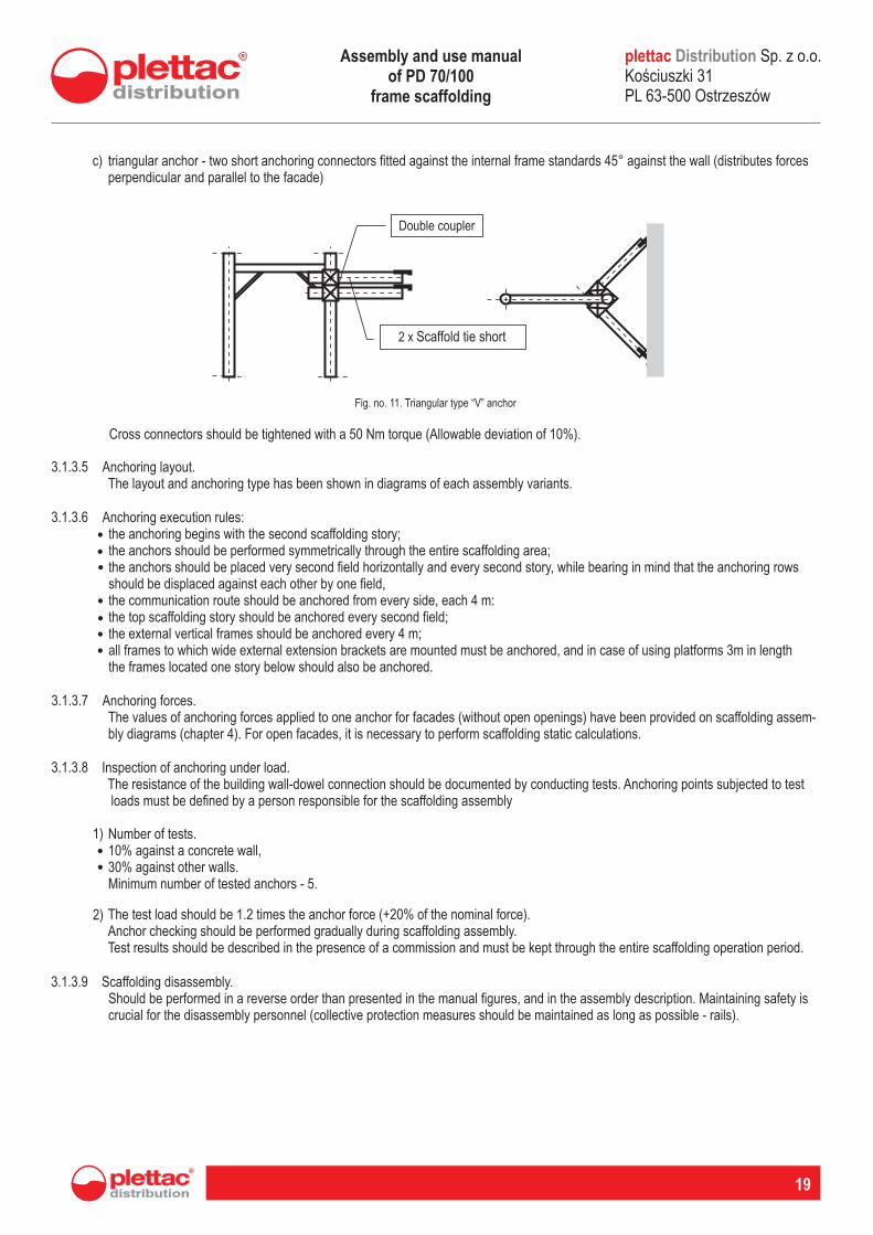
triangular anchor - two short anchoring connectors fitted against the internal frame standards 45° against the wall (distributes forces perpendicular and parallel to the facade)
c)
Fig. no. 11. Triangular type “V” anchor
Cross connectors should be tightened with a 50 Nm torque (Allowable deviation of 10%).
3.1.3.5 Anchoring layout. The layout and anchoring type has been shown in diagrams of each assembly variants.
3.1.3.6 Anchoring execution rules:the anchoring begins with the second scaffolding story;the anchors should be performed symmetrically through the entire scaffolding area;the anchors should be placed very second field horizontally and every second story, while bearing in mind that the anchoring rows should be displaced against each other by one field, the communication route should be anchored from every side, each 4 m:the top scaffolding story should be anchored every second field;the external vertical frames should be anchored every 4 m;all frames to which wide external extension brackets are mounted must be anchored, and in case of using platforms 3m in length the frames located one story below should also be anchored.
•••
••••
3.1.3.7 Anchoring forces. The values of anchoring forces applied to one anchor for facades (without open openings) have been provided on scaffolding assem-bly diagrams (chapter 4). For open facades, it is necessary to perform scaffolding static calculations.
3.1.3.8 Inspection of anchoring under load. The resistance of the building wall-dowel connection should be documented by conducting tests. Anchoring points subjected to test loads must be defined by a person responsible for the scaffolding assembly
Number of tests.10% against a concrete wall,30% against other walls.Minimum number of tested anchors - 5.
1)
••
The test load should be 1.2 times the anchor force (+20% of the nominal force).Anchor checking should be performed gradually during scaffolding assembly.Test results should be described in the presence of a commission and must be kept through the entire scaffolding operation period.
2)
3.1.3.9 Scaffolding disassembly. Should be performed in a reverse order than presented in the manual figures, and in the assembly description. Maintaining safety is crucial for the disassembly personnel (collective protection measures should be maintained as long as possible - rails).
plettac Sp. z o.o. Koúciuszki 31 PL 63-500 Ostrzeszów
DistributionAssembly and use manual of PD 70/100
frame scaffolding
20
CHAPTER IV.PD 70/100 scaffolding assembly diagrams
GENERAL REMARKS4.1Typical structures described in this manual may be used provided that the below mentioned rules are followed: Only one platform in each scaffolding vertical section may be subjected to operation and full load. Other scaffolding load states require confirmation through scaffolding structure static calculations, Scaffoldings may only be used in the 1st and 2nd wind load area as per PN-77/B-02011. Scaffoldings under operation in the 3rd wind load category should be subjected to additional static calculations, which consider higher wind load in the area. Impermissible is overloading the scaffolding platforms above the assumed scaffolding load capacity. Typical scaffolding variants have been verified using the static method as per PN-EN 12811-1; i PN-EN 12811-2 standards, while assuming a load factor of gf = 1,5.
•
•
•
DECKS4.2Typical scaffolding platforms may be assembled with system decks adapted for mounting on horizontal crossbars with self-lock hooks.Scaffolding decks have also the function of horizontal braces in the scaffolding field plane, therefore must be necessarily mounted in each scaffolding field.
The following can be used for the assembly of platforms in PD 70 scaffoldings: 2 decks 0.32m wide (wooden or steel)- 1 deck 0.64 wide (as a communication platform) with sheathing of plywood, equipped in a “floating” fastening ladder.
The following can be used for the assembly of platforms in PD 100 scaffoldings: 3 decks 0.32m wide (wooden or steel)1 deck 0.64 wide (as a communication platform) with sheathing of plywood, equipped in a “floating” fastening ladder, and 1 deck 0.32m wide (wooden or steel)In PD70/100 scaffoldings with working platform extensions all gaps between decks, greater than 8cm, require compensation using steel decks.
•
••
•
ANCHORING4.3Basic anchoring layout. The scaffolding should be anchored beginning with the second story, every second field vertically, and every second field horizontally, while the adjacent anchoring rows should be displaced against each other by one field.Additional anchoring - anchored should be the external frames at the edge of the scaffolding in each horizontal anchor row, - the communication route fields should also be anchored at both sides of each anchoring row,- additional anchors should be executed in accordance with specific variant diagrams. The anchoring elements should be fixed with frame standards using cross connections. Cross connection nuts should be tightened with a 50 Nm torque. Anchoring should not distribute vertical forces. Anchor couplings should be fixed with two standards directly under horizontal crossbars planes (platform planes) in accordance with the anchoring layout presented in the figures. Allowable deviation from theoretical anchoring points along standards is equal to: 40cm for 24m high scaffoldings.
ANCHOR STRESS (ANCHORING FORCES)4.4
Scaffolding covers/maximum
platform lengths
No covers/3.0m
Net cover/3.0m
Canvas cover/3.0m
Partially open wall Enclosed wall
Anchor stress [kN]
4,5
5,2
6,6
1,7
1,9
2,1
2,5
4,2
6,6
1,7
1,9
2,1
F F^ = F^ F =
plettac Sp. z o.o. Koúciuszki 31 PL 63-500 Ostrzeszów
DistributionAssembly and use manual of PD 70/100
frame scaffolding
distribution
R
21
The required anchoring forces values provided on drawings have been defined for scaffoldings located by:- partially open walls, meaning those, which have evenly spread opening surfaces not exceeding 60% of the entire wall surface,- enclosed walls, meaning those, which have evenly spread opening surfaces not exceeding 20% of the entire wall surface.In case of wall “permeability” of 20% to 60% the linear interpolation of anchoring forces is not allowable.
GENERAL REMARKS4.5It should be adopted that for typical scaffoldings not exceeding 24m of height the nominal (characteristic) load of one standard is equal to:- for PD70 scaffoldings (w/wo brackets) - 20kN - for PD100 scaffoldings (w/wo brackets) - 25kN
BRACING4.6The bracing should be fixed every 5th field maintaining a vertical section or a large-size pattern, while the bracing number should not be less than two on each scaffolding story. Additional bracing in accordance with the layout have been presented in diagrams of speci-fic variants.
SCAFFOLDING WORKING LOADS (NOMINAL VALUE) 4.7Typical PD70 variants are scaffoldings of 2kN/m2 of working load. Nominal value 3 as per PN-M-47900:1996. Typical PD100 variants are scaffoldings of 3kN/m2 of working load. Nominal value 4 as per PN-M-47900:1996.
COMMUNICATION ROUTES4.8Communication route platforms should be mounted in each scaffolding vertical section so that the manholes are placed on both sides of the field. Frame standards adjacent to the communication route must be anchored with a distance not exceeding 4m.
SAFETY RAILING AND TOE-BOARDS4.9All platforms should be secured in accordance with pt. 3.1.3.In case of setting up the scaffolding more than 20cm from the wall, the safety railing and toe-boards must also be assembled from the wall side.
NARROW EXTENSION PLATFORM (BRACKET)4.10Narrow extension platforms (one-deck) can be assembled only at the inner scaffolding side, and only at the main platform level.
WIDEEXTENSION PLATFORM (BRACKET)4.10Wide extension platforms (two-deck) can be assembled only at the outer scaffolding side, and only at the top main platform level.
plettac Sp. z o.o. Koúciuszki 31 PL 63-500 Ostrzeszów
DistributionAssembly and use manual of PD 70/100
frame scaffolding
22
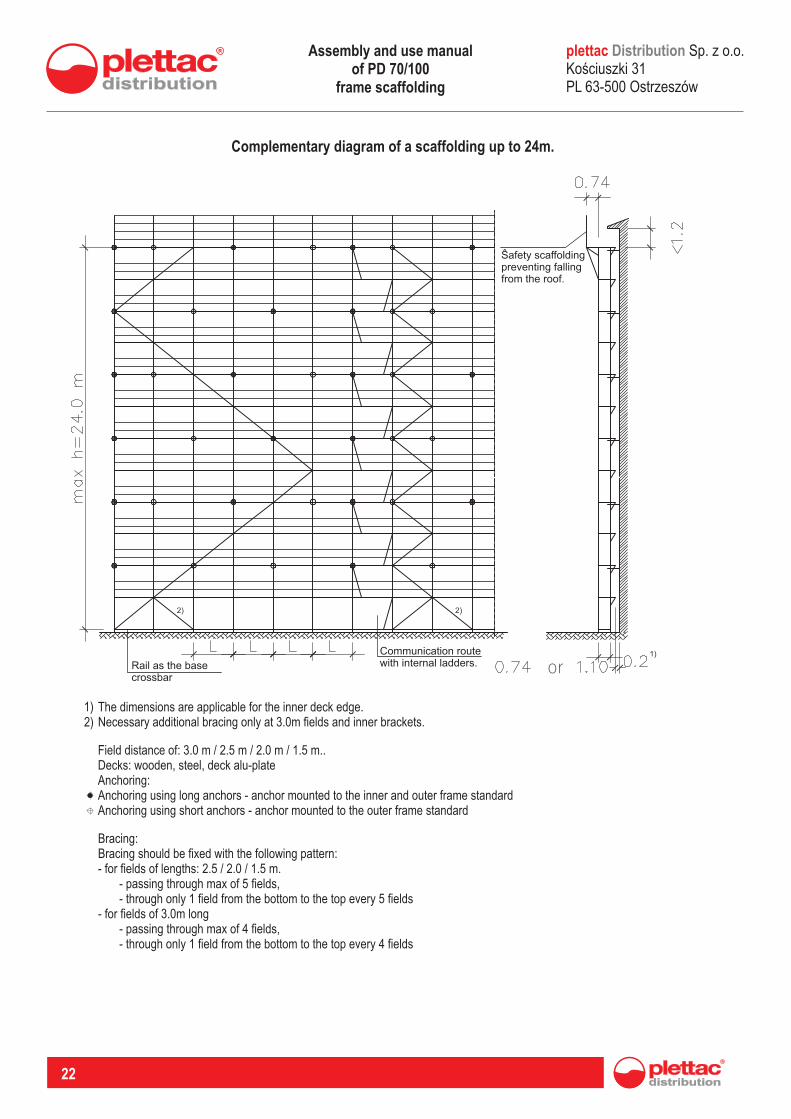
Complementary diagram of a scaffolding up to 24m.
The dimensions are applicable for the inner deck edge.Necessary additional bracing only at 3.0m fields and inner brackets.
1)2)
Field distance of: 3.0 m / 2.5 m / 2.0 m / 1.5 m..Decks: wooden, steel, deck alu-plateAnchoring:Anchoring using long anchors - anchor mounted to the inner and outer frame standardAnchoring using short anchors - anchor mounted to the outer frame standard
Bracing:Bracing should be fixed with the following pattern:- for fields of lengths: 2.5 / 2.0 / 1.5 m. - passing through max of 5 fields, - through only 1 field from the bottom to the top every 5 fields- for fields of 3.0m long - passing through max of 4 fields, - through only 1 field from the bottom to the top every 4 fields
plettac Sp. z o.o. Koúciuszki 31 PL 63-500 Ostrzeszów
Distribution
Rail as the base crossbar
Communication route with internal ladders. or
Safety scaffolding preventing falling from the roof.
Assembly and use manual of PD 70/100
frame scaffolding
distribution
R
23
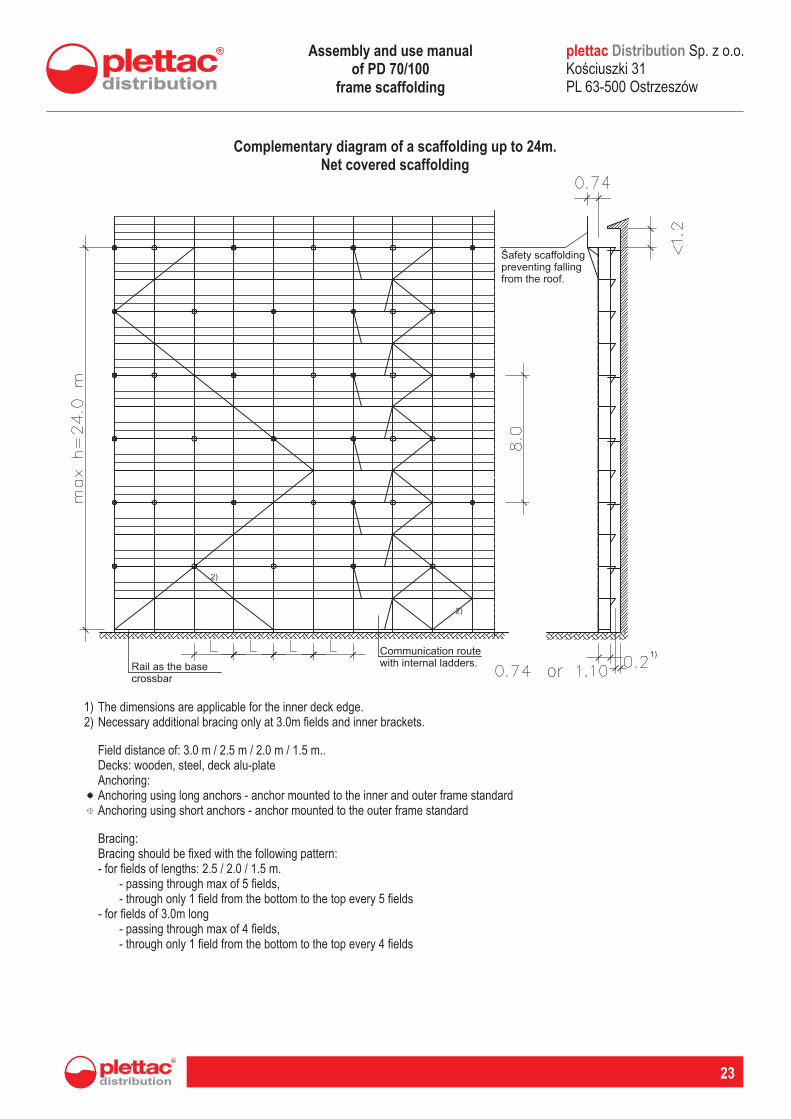
Complementary diagram of a scaffolding up to 24m.Net covered scaffolding
plettac Sp. z o.o. Koúciuszki 31 PL 63-500 Ostrzeszów
Distribution
The dimensions are applicable for the inner deck edge.Necessary additional bracing only at 3.0m fields and inner brackets.
1)2)
Field distance of: 3.0 m / 2.5 m / 2.0 m / 1.5 m..Decks: wooden, steel, deck alu-plateAnchoring:Anchoring using long anchors - anchor mounted to the inner and outer frame standardAnchoring using short anchors - anchor mounted to the outer frame standard
Bracing:Bracing should be fixed with the following pattern:- for fields of lengths: 2.5 / 2.0 / 1.5 m. - passing through max of 5 fields, - through only 1 field from the bottom to the top every 5 fields- for fields of 3.0m long - passing through max of 4 fields, - through only 1 field from the bottom to the top every 4 fields
Safety scaffolding preventing falling from the roof.
Rail as the base crossbar
Communication route with internal ladders.
or
Assembly and use manual of PD 70/100
frame scaffolding
24
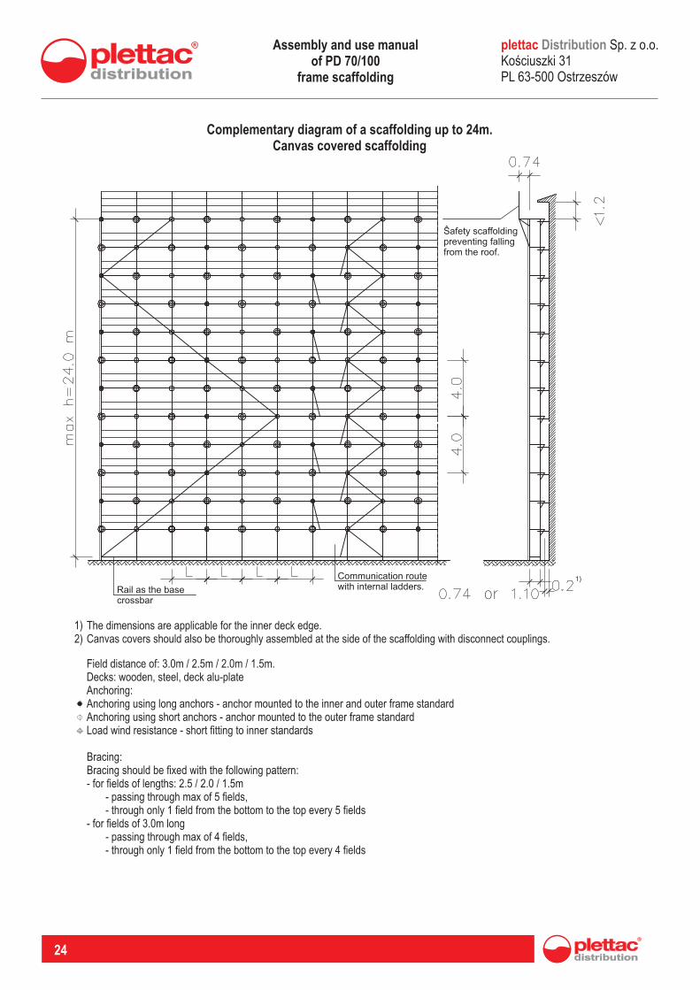
Complementary diagram of a scaffolding up to 24m.Canvas covered scaffolding
The dimensions are applicable for the inner deck edge.Canvas covers should also be thoroughly assembled at the side of the scaffolding with disconnect couplings.
1)2)
Field distance of: 3.0m / 2.5m / 2.0m / 1.5m.Decks: wooden, steel, deck alu-plateAnchoring:Anchoring using long anchors - anchor mounted to the inner and outer frame standardAnchoring using short anchors - anchor mounted to the outer frame standardLoad wind resistance - short fitting to inner standards
Bracing:Bracing should be fixed with the following pattern:- for fields of lengths: 2.5 / 2.0 / 1.5m - passing through max of 5 fields, - through only 1 field from the bottom to the top every 5 fields- for fields of 3.0m long - passing through max of 4 fields, - through only 1 field from the bottom to the top every 4 fields
plettac Sp. z o.o. Koúciuszki 31 PL 63-500 Ostrzeszów
Distribution
Safety scaffolding preventing falling from the roof.
Rail as the base crossbar
Communication route with internal ladders.
or
Assembly and use manual of PD 70/100
frame scaffolding
distribution
R
25
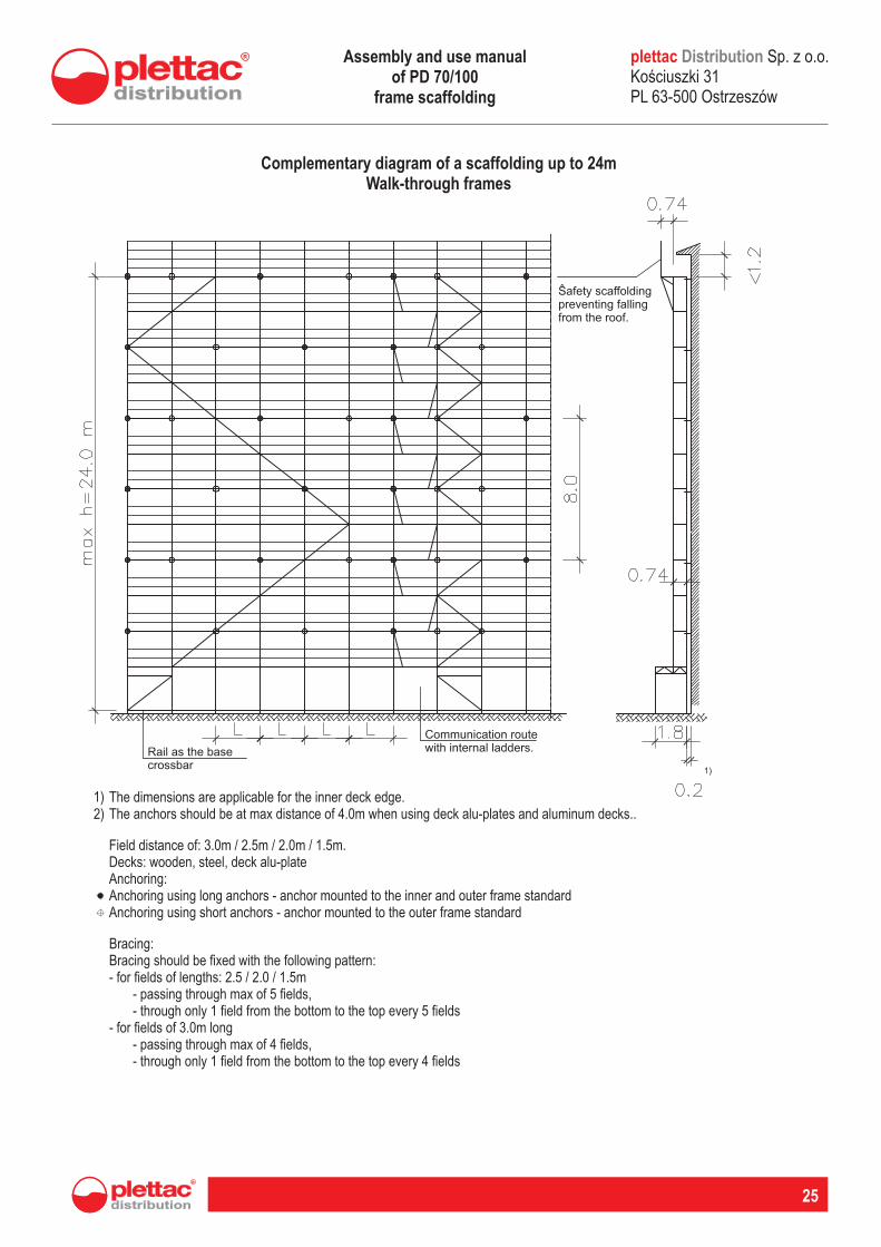
Complementary diagram of a scaffolding up to 24mWalk-through frames
The dimensions are applicable for the inner deck edge.The anchors should be at max distance of 4.0m when using deck alu-plates and aluminum decks..
1)2)
Field distance of: 3.0m / 2.5m / 2.0m / 1.5m.Decks: wooden, steel, deck alu-plateAnchoring:Anchoring using long anchors - anchor mounted to the inner and outer frame standardAnchoring using short anchors - anchor mounted to the outer frame standard
Bracing:Bracing should be fixed with the following pattern:- for fields of lengths: 2.5 / 2.0 / 1.5m - passing through max of 5 fields, - through only 1 field from the bottom to the top every 5 fields- for fields of 3.0m long - passing through max of 4 fields, - through only 1 field from the bottom to the top every 4 fields
plettac Sp. z o.o. Koúciuszki 31 PL 63-500 Ostrzeszów
Distribution
Safety scaffolding preventing falling from the roof.
Rail as the base crossbar
Communication route with internal ladders.
Assembly and use manual of PD 70/100
frame scaffolding
26
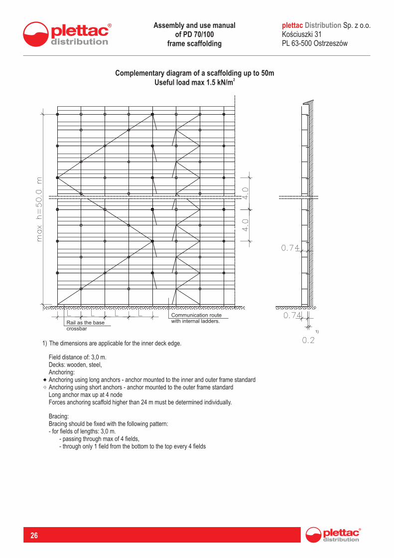
The dimensions are applicable for the inner deck edge.1)
Complementary diagram of a scaffolding up to 50m2Useful load max 1.5 kN/m
Field distance ofDecks: wooden, steel,AnchoringAnchoring using long anchors - anchor mounted to the inner and outer frame standardAnchoring using short anchors - anchor mounted to the outer frame standard
: 3,0 m.
:
Long anchor max up at 4 nodeForces anchoring scaffold higher than 24 m must be determined individually.
Bracing:Bracing should be fixed with the following pattern:
for fields of lengths:passing through max of 4 fieldsthrough only 1 field from the bottom to the top every 4 fields
- 3,0 m. - , -
plettac Sp. z o.o. Koúciuszki 31 PL 63-500 Ostrzeszów
Distribution
Rail as the base crossbar
Communication route with internal ladders.
Assembly and use manual of PD 70/100
frame scaffolding
distribution
R
27
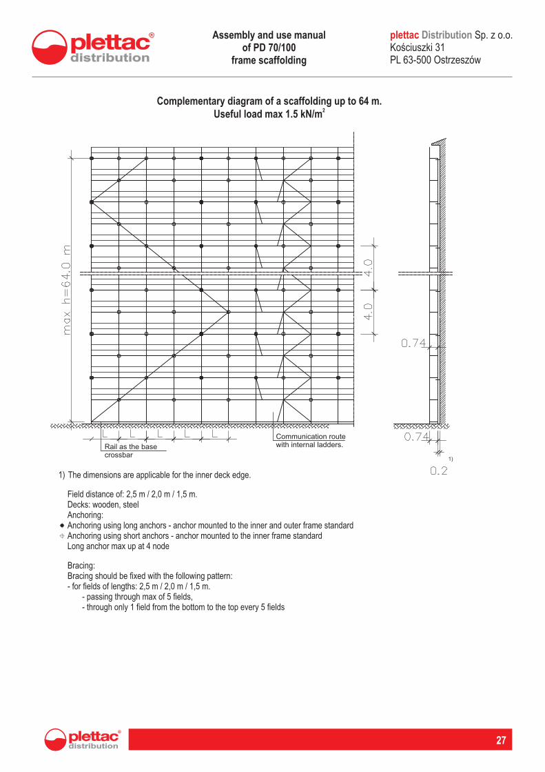
Complementary diagram of a scaffolding up toUseful load max
64 m.2 1.5 kN/m
The dimensions are applicable for the inner deck edge.1)
Field distance ofDecks: wooden, steelAnchoring:Anchoring using long anchors - anchor mounted to the inner and outer frame standardAnchoring using short anchors - anchor mounted to the inner frame standard Long anchor max up at 4 node
: 2,5 m / 2,0 m / 1,5 m.
Bracing:Bracing should be fixed with the following pattern:
for fields of lengths:passing through max of 5 fieldsthrough only 1 field from the bottom to the top every 5 fields
- 2,5 m / 2,0 m / 1,5 m. - , -
plettac Sp. z o.o. Koúciuszki 31 PL 63-500 Ostrzeszów
Distribution
Rail as the base crossbar
Communication route with internal ladders.
Assembly and use manual of PD 70/100
frame scaffolding
28
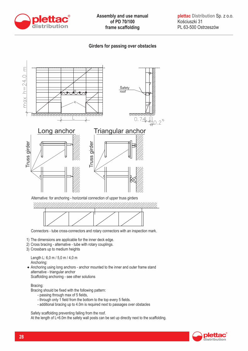
Girders for passing over obstacles
Alternative: for anchoring - horizontal connection of upper truss girders
Connectors - tube cross-connectors and rotary connectors with an inspection mark.
The dimensions are applicable for the inner deck edge.Cross bracing - alternative - tube with rotary couplings.Crossbars up to medium heights
1)2)3)
Length L: 6,0 m / 5,0 m / 4,0 mAnchoring:Anchoring using long anchors - anchor mounted to the inner and outer frame standalternative - triangular anchorScaffolding anchoring - see other solutions
Bracing:Bracing should be fixed with the following pattern: - passing through max of 5 fields, - through only 1 field from the bottom to the top every 5 fields. - additional bracing up to 4.0m is required next to passages over obstacles
Safety scaffolding preventing falling from the roof.At the length of L=6.0m the safety wall posts can be set up directly next to the scaffolding.
plettac Sp. z o.o. Koúciuszki 31 PL 63-500 Ostrzeszów
Distribution
Safety roof
Long anchor Triangular anchor
Tru
ss g
irder
Tru
ss g
irder
Assembly and use manual of PD 70/100
frame scaffolding
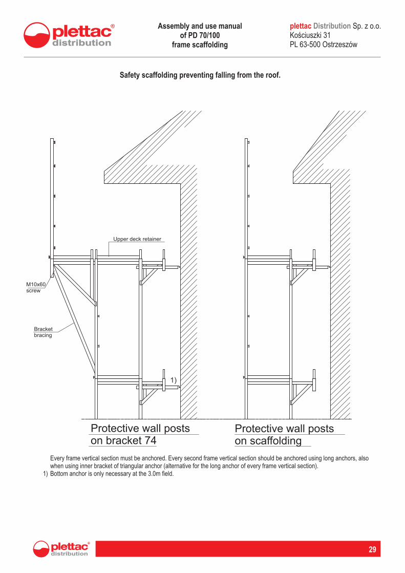
Safety scaffolding preventing falling from the roof.
Every frame vertical section must be anchored. Every second frame vertical section should be anchored using long anchors, also when using inner bracket of triangular anchor (alternative for the long anchor of every frame vertical section).Bottom anchor is only necessary at the 3.0m field.1)
distribution
R
29
plettac Sp. z o.o. Koúciuszki 31 PL 63-500 Ostrzeszów
Distribution
Upper deck retainer
M10x60screw
Bracket bracing
Protective wall posts on bracket 74
Protective wall posts on scaffolding
Assembly and use manual of PD 70/100
frame scaffolding
30
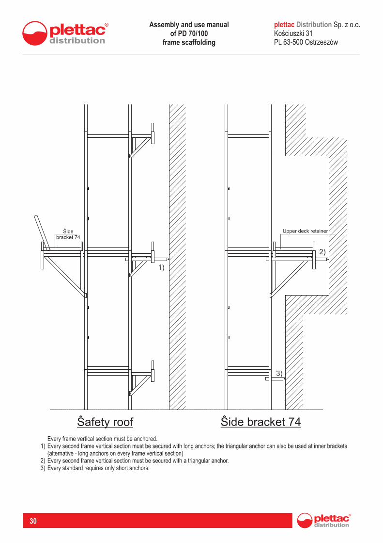
Every frame vertical section must be anchored.Every second frame vertical section must be secured with long anchors; the triangular anchor can also be used at inner brackets (alternative - long anchors on every frame vertical section)Every second frame vertical section must be secured with a triangular anchor.Every standard requires only short anchors.
1)
2)3)
plettac Sp. z o.o. Koúciuszki 31 PL 63-500 Ostrzeszów
Distribution
Upper deck retainerSidebracket 74
Safety roof Side bracket 74
Assembly and use manual of PD 70/100
frame scaffolding
distribution
R
31
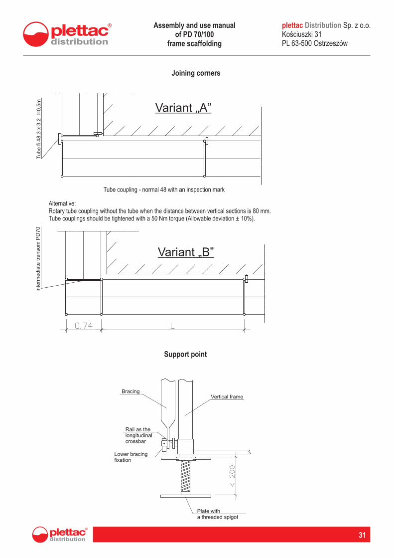
Joining corners
Tube coupling - normal 48 with an inspection mark
Alternative:Rotary tube coupling without the tube when the distance between vertical sections is 80 mm.Tube couplings should be tightened with a 50 Nm torque (Allowable deviation ± 10%).
Support point
plettac Sp. z o.o. Koúciuszki 31 PL 63-500 Ostrzeszów
Distribution
Variant „A”
Variant „B”
Tube fi 4
8,3
x 3
,2 l=
0,5
mIn
term
edia
te tra
nso
m P
D70
Plate with a threaded spigot
Bracing
Rail as the longitudinal crossbar
Vertical frame
Lower bracing fixation
Assembly and use manual of PD 70/100
frame scaffolding

32
PROTOKÓ£ ODBIORU TECHNICZNEGO R
Logo firmy montaSowej
odbioru technicznego rusztowania Protokó
1. Numer rejestracyjny u:......................................... protoko .......................................
2. Data odbioru rusztowania:.......................................................................................
3. Wykonawca montaSu rusztowania:.........................................................................
4. USytkownik rusztowania (zleceniodawca monta…………………………………………………………………………………..................
5. Miejsce montaSu rusztowania i jego powierzchnia (obj……………………………………………………………………..........
6. Typ rusztowania:......................................................................................................
7. Dopuszczalna noœnoœæ podestów roboczych:
8. u Wykonawca przekaza Sytkownikowi nast
a) dokumentacjê techniczn¹ (statyk
b) instrukcêj eksploatacji rusztowania, ................................................................
c) y………………………………………………………………………………………………… inne protoko .
d) ...........................................................................
……………………………………………………………………………………………………………………..
9. Oœwiadczenie: wykonawca stwierdza, o zmontowane zosta zgodnie ze sztuka budowlan
DTR) i instrukc¹j montaSu wydanhigieny pracy. MontaS wykonali uprawnieni montanadaje siê do eksploatacji bez uwag.
ad komisji odbiorowej: 10. Sk
......................................................
......................................................
.....................................................
(imiona i nazwiska)
11. oszenia rusztowania do demonta Data zg
UWAGI: 1. Zmiany w konstrukcji rusztowania mog¹2. Opornoœæ uziomu podano w „Protokole pomiaru oporno3. Terminy kolejnych przegl¹dów rusztowania okre
PROTOKÓ£ ODBIORU TECHNICZNEGO R USZTOWANIA DO
EKSPLOATACJI
odbioru technicznego rusztowania Protokó do eksploatacji
u:......................................... protoko .......................................
Data odbioru rusztowania:.......................................................................................
u rusztowania:.........................................................................
ytkownik rusztowania (zleceniodawca montaSu):…………………………............…………………………………………………………………………………..................
u rusztowania i jego powierzchnia (objêtoœæ):.................................……………………………………………………………………...................................
Typ rusztowania:......................................................................................................
podestów roboczych: 1,5 kN/m2; 2 kN/m2; 3,0 kN/m2; ……
ytkownikowi nastêpuj¹ce dokumenty odbiorowe:
(statykê) rusztowania,.............................................
eksploatacji rusztowania, ................................................................
y………………………………………………………………………………………………… inne protoko .
..............................................................................................................................................................
……………………………………………………………………………………………………………………..
em jest k wiadczenie: wykonawca stwierdza, Se rusztowanie opisane niniejszym protoko ompletne, zgodnie ze sztuka budowlan¹, dokumentacj¹ techniczno
u wydan¹ przez producenta oraz zgodnie z wymogami bezpiecze wykonali uprawnieni montaSyœci. Komisja odbiorowa
do eksploatacji bez uwag.
................................................................. – USytkownik.....................................................
......................................... – USytkownik.....................................................
................................................................ – Wykonawca..............................................
(imiona i nazwiska) (podpisy)
oszenia rusztowania do demonta Data zg Su:..........................................................
1. Zmiany w konstrukcji rusztowania mog¹ byæ dokonywane wy¹cznie przez Wykonawcê monta uziomu podano w „Protokole pomiaru opornoœci uziemienia”
dów rusztowania okreœlono w Instrukcji eksploatacji rusztowania
WWW.PIGR.PL INFORMACJE TECHNICZNE
DATA 01-10-2010
do eksploatacji
u:......................................... protoko ....................................... ....................................
Data odbioru rusztowania:...........................................................................................................................
u rusztowania:.............................................................................................................
u):………………………….............................................. …………………………………………………………………………………....................................................
):.................................................................... .............................................................
Typ rusztowania:.........................................................................................................................................
……………………………
) rusztowania,..................................................................................
eksploatacji rusztowania, .....................................................................................................
y………………………………………………………………………………………………… inne protoko .
.............................................
……………………………………………………………………………………………………………………..
em jest k e rusztowanie opisane niniejszym protoko ompletne, techniczno-eksploatacyjn¹ (dawniej
przez producenta oraz zgodnie z wymogami bezpieñcsztewa i stwierdza, Se rusztowanie
ytkownik..............................................................................
ytkownik..............................................................................
Wykonawca............................................................................
(podpisy)
....................
cznie przez Wykonawcê montaSu rusztowania!
Instrukcji eksploatacji rusztowania
TECHNICAL ACCEPTANCE PROTOCOL OF A SCAFFOLDING INTENDED FOR USE
plettac Sp. z o.o. Koúciuszki 31 PL 63-500 Ostrzeszów
Distribution
Logo of the assembly company
Technical acceptance protocol of the scaffolding intended for use
Protocol registry number
Scaffolding acceptance date
Scaffolding assembly contractor
1.
2.
3.
4.
5.
6.
7.
8.
Scaffolding user (assembly ordering party)
Place of scaffolding assembly and its area (volume)
Scaffolding type:
Allowable working deck load capacity: 1,5 kN/m2; 2 kN/m2; 3 kN/m2;
The contractor has handed over to the user the following acceptance documents:
scaffolding technical documentations (statistics)a)
scaffolding operation manualb)
other protocolsc)
Statement: the contractor ascertains that the scaffolding described herein is complete, has been as-sembled in accordance with the sound engineering practice, the operation and maintenance manual (former DTR), and the user manual issued by the manufacturer in accordance with the health and s¹-fety requirements. The assembly has been executed by a certified staff. The acceptance commission ascertains with no remarks that the scaffolding is ready for use.
9.
Acceptance commission members:10.
User
User
User
(Names and surnames) (Signatures)
Date of notifying the scaffolding for deassembly11.
Remarks1. Changes in the scaffolding structure may only be performed by the scaffolding assembly Contractor!2. The grounding electrode resistance has been provided in the “Grounding measurement protocol”.3. Dates of further scaffolding inspections have been provided in the Scaffolding operation manual.
Assembly and use manual of PD 70/100
frame scaffolding
distribution
R
33
plettac Sp. z o.o. Koúciuszki 31 PL 63-500 Ostrzeszów
Distribution
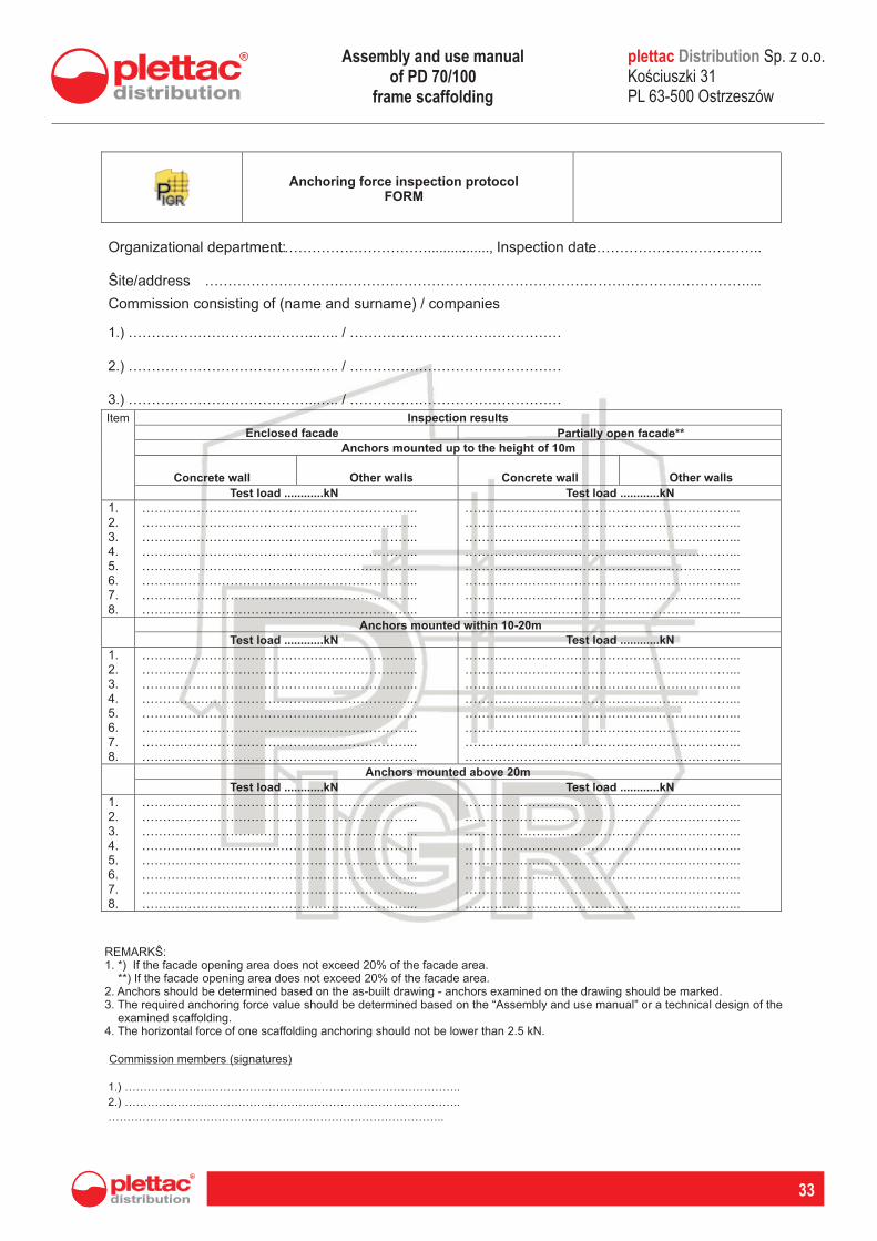
Anchoring force inspection protocol FORM
Organizational department: Inspection date
Site/address
Commission consisting of (name and surname) / companies
Item Inspection results
Enclosed facade Partially open facade**
Anchors mounted up to the height of 10m
Concrete wall Other walls Concrete wall Other walls
Test load ............kN Test load ............kN
Anchors mounted within 10-20m
Test load ............kN Test load ............kN
Anchors mounted above 20m
Test load ............kN Test load ............kN
REMARKS:1. *) If the facade opening area does not exceed 20% of the facade area. **) If the facade opening area does not exceed 20% of the facade area.2. Anchors should be determined based on the as-built drawing - anchors examined on the drawing should be marked.3. The required anchoring force value should be determined based on the “Assembly and use manual” or a technical design of the examined scaffolding.4. The horizontal force of one scaffolding anchoring should not be lower than 2.5 kN.
Commission members (signatures)
Assembly and use manual of PD 70/100
frame scaffolding

34
plettac Sp. z o.o. Koúciuszki 31 PL 63-500 Ostrzeszów
DistributionAssembly and use manual of PD 70/100
frame scaffolding

plettac Sp. z o.o. Koúciuszki 31 PL 63-500 Ostrzeszów
Distribution
distribution
R
35
Assembly and use manual of PD 70/100
frame scaffolding

36
plettac Sp. z o.o. Koúciuszki 31 PL 63-500 Ostrzeszów
DistributionAssembly and use manual of PD 70/100
frame scaffolding

www.rusztowanie.com
distribution
R
Plettac Distribution Sp. z o.o.ul. Koœciuszki 31, 63-500 Ostrzeszów
Tel. +48 62 586 06 40, fax +48 62 586 06 50E-mail: [email protected]
www.plettac.com.pl, www.rusztowanie.com
ul. Mszczonowska 30, 05-090 JankiTel. +48 22 487 97 57
E-mail: [email protected]
THE COMPANY’S SEAT
WARSAW BRANCH
Your Partner