Embed Size (px)
Citation preview
8132019 DTR 650 User Manual
httpslidepdfcomreaderfulldtr-650-user-manual 170
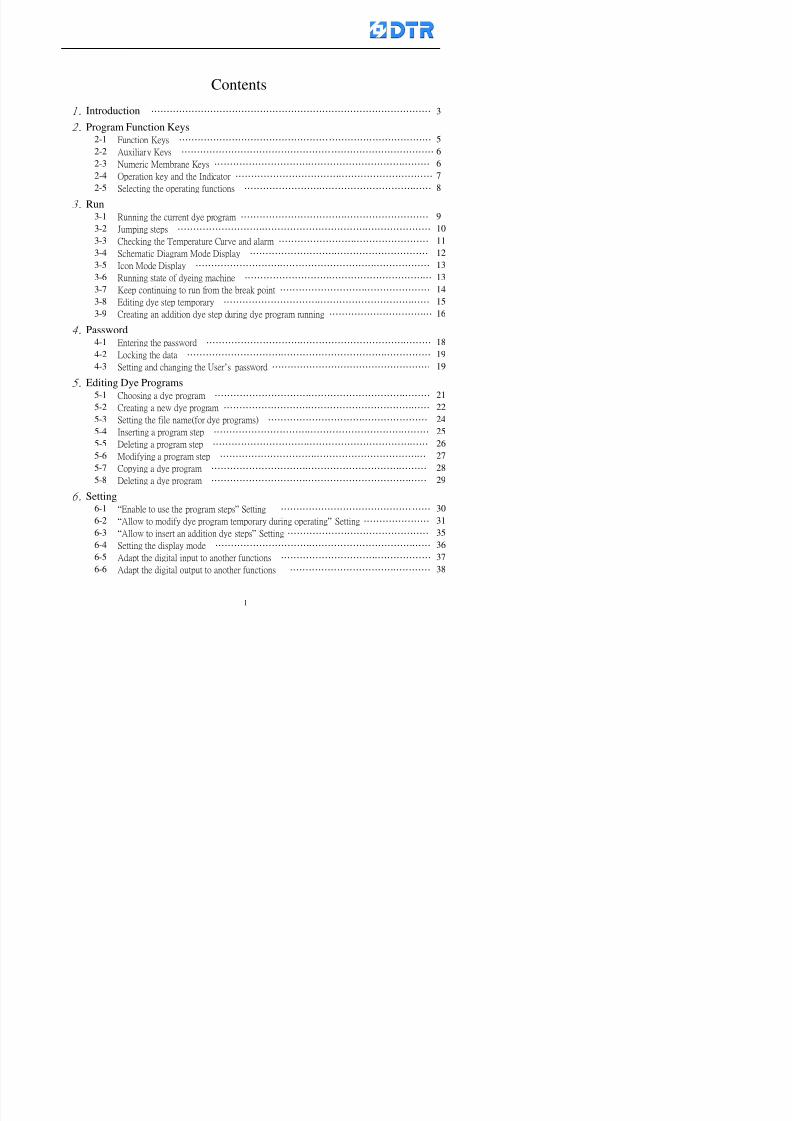
Contents
1 Introduction helliphelliphelliphelliphelliphelliphelliphelliphelliphelliphelliphelliphelliphelliphelliphelliphelliphelliphelliphelliphelliphelliphelliphelliphelliphelliphelliphelliphelliphellip 3
2 Program Function Keys2-1 Function Keys helliphelliphelliphelliphelliphelliphelliphelliphelliphelliphelliphelliphelliphelliphelliphelliphelliphelliphelliphelliphelliphelliphelliphelliphelliphelliphellip 5
2-2 Auxiliary Keys helliphelliphelliphelliphelliphelliphelliphelliphelliphelliphelliphelliphelliphelliphelliphelliphelliphelliphelliphelliphelliphelliphelliphelliphelliphelliphellip 6
2-3 Numeric Membrane Keys helliphelliphelliphelliphelliphelliphelliphelliphelliphelliphelliphelliphelliphelliphelliphelliphelliphelliphelliphelliphelliphelliphellip 62-4 Operation key and the Indicator helliphelliphelliphelliphelliphelliphelliphelliphelliphelliphelliphelliphelliphelliphelliphelliphelliphelliphelliphelliphellip 7
2-5 Selecting the operating functions helliphelliphelliphelliphelliphelliphelliphelliphelliphelliphelliphelliphelliphelliphelliphelliphelliphelliphelliphellip 8
3 Run3-1 Running the current dye program helliphelliphelliphelliphelliphelliphelliphelliphelliphelliphelliphelliphelliphelliphelliphelliphelliphelliphelliphellip 9
3-2 Jumping steps helliphelliphelliphelliphelliphelliphelliphelliphelliphelliphelliphelliphelliphelliphelliphelliphelliphelliphelliphelliphelliphelliphelliphelliphelliphelliphellip 10
3-3 Checking the Temperature Curve and alarm helliphelliphelliphelliphelliphelliphelliphelliphelliphelliphelliphelliphelliphelliphelliphellip 11
3-4 Schematic Diagram Mode Display helliphelliphelliphelliphelliphelliphelliphelliphelliphelliphelliphelliphelliphelliphelliphelliphelliphelliphellip 123-5 Icon Mode Display helliphelliphelliphelliphelliphelliphelliphelliphelliphelliphelliphelliphelliphelliphelliphelliphelliphelliphelliphelliphelliphelliphelliphelliphellip 13
3-6 Running state of dyeing machine helliphelliphelliphelliphelliphelliphelliphelliphelliphelliphelliphelliphelliphelliphelliphelliphelliphelliphelliphellip 13
3-7 Keep continuing to run from the break point helliphelliphelliphelliphelliphelliphelliphelliphelliphelliphelliphelliphelliphelliphelliphellip 14
3-8 Editing dye step temporary helliphelliphelliphelliphelliphelliphelliphelliphelliphelliphelliphelliphelliphelliphelliphelliphelliphelliphelliphelliphelliphellip 15
3-9 Creating an addition dye step during dye program running helliphelliphelliphelliphelliphelliphelliphelliphelliphelliphellip 16
4Password 4-1 Entering the password helliphelliphelliphelliphelliphelliphelliphelliphelliphelliphelliphelliphelliphelliphelliphelliphelliphelliphelliphelliphelliphelliphelliphellip 18
4-2 Locking the data helliphelliphelliphelliphelliphelliphelliphelliphelliphelliphelliphelliphelliphelliphelliphelliphelliphelliphelliphelliphelliphelliphelliphelliphelliphellip 19
4-3 Setting and changing the Userrsquos password helliphelliphelliphelliphelliphelliphelliphelliphelliphelliphelliphelliphelliphelliphelliphelliphellip 19
5 Editing Dye Programs 5-1 Choosing a dye program helliphelliphelliphelliphelliphelliphelliphelliphelliphelliphelliphelliphelliphelliphelliphelliphelliphelliphelliphelliphelliphelliphellip 21
5-2 Creating a new dye program helliphelliphelliphelliphelliphelliphelliphelliphelliphelliphelliphelliphelliphelliphelliphelliphelliphelliphelliphelliphelliphellip 22
5-3 Setting the file name(for dye programs) helliphelliphelliphelliphelliphelliphelliphelliphelliphelliphelliphelliphelliphelliphelliphelliphellip 245-4 Inserting a program step helliphelliphelliphelliphelliphelliphelliphelliphelliphelliphelliphelliphelliphelliphelliphelliphelliphelliphelliphelliphelliphelliphellip 25
5-5 Deleting a program step helliphelliphelliphelliphelliphelliphelliphelliphelliphelliphelliphelliphelliphelliphelliphelliphelliphelliphelliphelliphelliphelliphellip 26
5-6 Modifying a program step helliphelliphelliphelliphelliphelliphelliphelliphelliphelliphelliphelliphelliphelliphelliphelliphelliphelliphelliphelliphelliphellip 27
5-7 Copying a dye program helliphelliphelliphelliphelliphelliphelliphelliphelliphelliphelliphelliphelliphelliphelliphelliphelliphelliphelliphelliphelliphelliphellip 28
5 8 D l i d 29
8132019 DTR 650 User Manual
httpslidepdfcomreaderfulldtr-650-user-manual 270
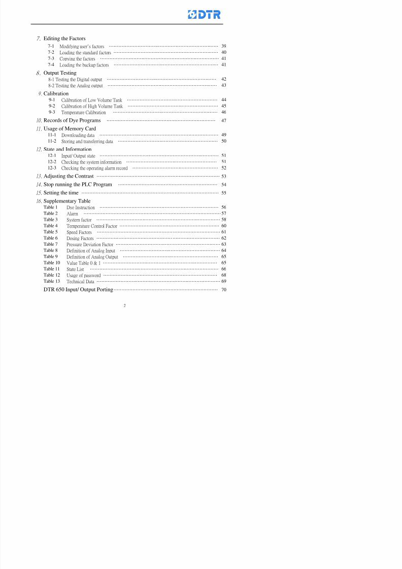
7 Editing the Factors
7-1 Modifying userrsquos factors helliphelliphelliphelliphelliphelliphelliphelliphelliphelliphelliphelliphelliphelliphelliphelliphelliphelliphelliphelliphelliphelliphellip 39
7-2 Loading the standard factors helliphelliphelliphelliphelliphelliphelliphelliphelliphelliphelliphelliphelliphelliphelliphelliphelliphelliphelliphelliphelliphellip 40
7-3 Copying the factors helliphelliphelliphelliphelliphelliphelliphelliphelliphelliphelliphelliphelliphelliphelliphelliphelliphelliphelliphelliphelliphelliphelliphelliphellip 41
7-4 Loading the backup factors helliphelliphelliphelliphelliphelliphelliphelliphelliphelliphelliphelliphelliphelliphelliphelliphelliphelliphelliphelliphelliphellip 41
8 Output Testing 8-1 Testing the Digital output helliphelliphelliphelliphelliphelliphelliphelliphelliphelliphelliphelliphelliphelliphelliphelliphelliphelliphelliphelliphelliphelliphellip 42
8-2 Testing the Analog output helliphelliphelliphelliphelliphelliphelliphelliphelliphelliphelliphelliphelliphelliphelliphelliphelliphelliphelliphelliphelliphelliphellip 43
9 Calibration 9-1 Calibration of Low Volume Tank helliphelliphelliphelliphelliphelliphelliphelliphelliphelliphelliphelliphelliphelliphelliphelliphelliphelliphellip 44
9-2 Calibration of High Volume Tank helliphelliphelliphelliphelliphelliphelliphelliphelliphelliphelliphelliphelliphelliphelliphelliphelliphelliphellip 45
9-3 Temperature Calibration helliphelliphelliphelliphelliphelliphelliphelliphelliphelliphelliphelliphelliphelliphelliphelliphelliphelliphelliphelliphelliphellip 46
10 Records of Dye Programs helliphelliphelliphelliphelliphelliphelliphelliphelliphelliphelliphelliphelliphelliphelliphelliphelliphelliphelliphelliphelliphelliphellip 47
11 Usage of Memory Card 11-1 Downloading data helliphelliphelliphelliphelliphelliphelliphelliphelliphelliphelliphelliphelliphelliphelliphelliphelliphelliphelliphelliphelliphelliphelliphelliphellip 49
11-2 Storing and transferring data helliphelliphelliphelliphelliphelliphelliphelliphelliphelliphelliphelliphelliphelliphelliphelliphelliphelliphelliphelliphellip 50
12 State and Information 12-1 Input Output state helliphelliphelliphelliphelliphelliphelliphelliphelliphelliphelliphelliphelliphelliphelliphelliphelliphelliphelliphelliphelliphelliphelliphelliphellip 51
12-2 Checking the system information helliphelliphelliphelliphelliphelliphelliphelliphelliphelliphelliphelliphelliphelliphelliphelliphelliphelliphellip 51
12-3 Checking the operating alarm record helliphelliphelliphelliphelliphelliphelliphelliphelliphelliphelliphelliphelliphelliphelliphelliphelliphellip 5213 Adjusting the Contrast helliphelliphelliphelliphelliphelliphelliphelliphelliphelliphelliphelliphelliphelliphelliphelliphelliphelliphelliphelliphelliphelliphelliphelliphelliphellip 53
14 Stop running the PLC Program helliphelliphelliphelliphelliphelliphelliphelliphelliphelliphelliphelliphelliphelliphelliphelliphelliphelliphelliphelliphellip 54
15 Setting the time helliphelliphelliphelliphelliphelliphelliphelliphelliphelliphelliphelliphelliphelliphelliphelliphelliphelliphelliphelliphelliphelliphelliphelliphelliphelliphelliphelliphellip 55
16 Supplementary Table Table 1 Dye Instruction helliphelliphelliphelliphelliphelliphelliphelliphelliphelliphelliphelliphelliphelliphelliphelliphelliphelliphelliphelliphelliphelliphelliphelliphellip 56
Table 2 Alarm helliphelliphelliphelliphelliphelliphelliphelliphelliphelliphelliphelliphelliphelliphelliphelliphelliphelliphelliphelliphelliphelliphelliphelliphelliphelliphelliphelliphellip 57Table 3 System factor helliphelliphelliphelliphelliphelliphelliphelliphelliphelliphelliphelliphelliphelliphelliphelliphelliphelliphelliphelliphelliphelliphelliphelliphelliphellip 58
Table 4 Temperature Control Factor helliphelliphelliphelliphelliphelliphelliphelliphelliphelliphelliphelliphelliphelliphelliphelliphelliphelliphelliphelliphellip 60
Table 5 Speed Factors helliphelliphelliphelliphelliphelliphelliphelliphelliphelliphelliphelliphelliphelliphelliphelliphelliphelliphelliphelliphelliphelliphelliphelliphelliphellip 61
Table 6 Dosing Factors helliphelliphelliphelliphelliphelliphelliphelliphelliphelliphelliphelliphelliphelliphelliphelliphelliphelliphelliphelliphelliphelliphelliphelliphelliphellip 62
8132019 DTR 650 User Manual
httpslidepdfcomreaderfulldtr-650-user-manual 370
1 983113983150983156983154983151983140983157983139983156983145983151983150
DTR 650 Dyeing Machine Controller is a device that suitable for any kinds of high
or low temperaturersquos dyeing machines
57 inches TFT 256K Color Display with Chinese English and more language 8 individual PID control loops 3 loops for temperature control 2 loops for dosing
2 loops for pressure control and 1 loop speed control can operate indenpently atthe same time
Expandable InOutputrsquos up to 96 digital outputs and 72 digital inputs 6 setsPT100 temperature sensors 12 analog inputs and 12 analog outputs
Dye program and dye step can be edit before running an additional dye programand step can also run during dye program in operating or in a stop state
Each of the digital input and output channel can be adapted to another functions
directly from controllers Each main function can be operating with 4 parallel functions at the same time Three types of display mode during operating Schematic Diagram mode for
monitoring the whole dyeing process water level and the valve state Icon modefor viewing the main and parallel functions at the same time Program List modefor viewing the main function and all parallel functions at the same time User canchange the mode at anytime
Memorize for the past 15 days of running programs and temperature curves for
checking if necessary Provide memory storage function for storing dye programs and operation data
downloading and swapping PLC programs dye programs factors library files andconfiguration files through an compact flash memory card (optional)
Built-in testing self-checking temperauture and calibration for quick and easychecking
Provide a dosing and temperature control functions by manual operating Built-in PLC no need to connect an external PLC device
Connecting to external DTRPLC device for In Output remote control Multi rank passwords for security purpose Connect to the DTR Central Control and Management System for controlling the
dyeing machines at the Control Room directly
8132019 DTR 650 User Manual
httpslidepdfcomreaderfulldtr-650-user-manual 470
2 983120983154983151983143983154983137983149 983110983157983150983139983156983145983151983150 983115983141983161983155
The DTR-650 standard logo appears when the controller is power on It enters to the
window of 「Run」in few seconds Ready to start running and operating immediately or
press key「F1」(Exit)to go to the Main Menu Press()()to choose the operating
functions
State of dye
programs
Temperature of
the major
sensor Program Step
number
Main Menu
Sub-function
Menu
State Bar
8132019 DTR 650 User Manual
httpslidepdfcomreaderfulldtr-650-user-manual 570
2-1 Function Keys
There are five function keys「F1」~「F5」corresponding to 5 function items of the
main window press the function key corresponding to the item will get access to its
operation For example of the running page
F1 F2 F3 F4 F5
8132019 DTR 650 User Manual
httpslidepdfcomreaderfulldtr-650-user-manual 670
2-2 Auxiliary Keys
Auxiliary Keys「3」「4」「5」「6」 have handy function for moving different directions
or pages
Key「OK」to confirm before make changes
Key「Esc」quit or return the previous changes
5555 33 44
6666 Esc OK
2-3 Numeric Membrane Keys
7 8 9
4 5 6
1 2 3 0
a Setting factors
b Password input
c Program selecting
d Program name
Program List mode Displays
Enter the window of addition program steps when
the program is runningAssist to check
the alarm info
8132019 DTR 650 User Manual
httpslidepdfcomreaderfulldtr-650-user-manual 770
2-4 Operation key and the Indicator
Operation key lsquoStartrsquo (Green button) to run and lsquoStoprsquo ( Red button ) to stop
dye programs
Indicator Run It turns On when the dye program running turns off when program
stops
Indicator Alarm It turns on when alarm is occurred
Indicator Operator It turns on when requesting an operator during program running
Run Alarm Operator
8132019 DTR 650 User Manual
httpslidepdfcomreaderfulldtr-650-user-manual 870
2-5 Selecting the operating functions
When the power on「Run」window appears can start running directly
To choose other function items press「F1」(Exit) to get access to the Main Meun Cursor
stays at the main function field now Choose operating function to move the cursor
accordingly
Steps(a) Press「F2」()「F3」() to move the cursor to the selected functions Press
「F5」(OK)
(b) Now the cursor is at the sub-function field Press「F2」()「F3」()to choose
the functions Press「F5」(ok )to enter the relating window
(c) Press「F1」(Exit)to exit
a)a)a)a)
b)
8132019 DTR 650 User Manual
httpslidepdfcomreaderfulldtr-650-user-manual 970
3 983122983157983150
3-1 Running the current dye program
To enter to the Run window directly when the power on or press「F1」
(Run) to enter the Run window at main menu The ldquostatus barrdquo shows
the current dye programrsquos number and steprsquos number
Check the dye program number and step on the ldquoProgram Status Listrdquo
Press「」「」or「6」「5」to move the cursor to select the program step
to start with When select a step press「start」 to start running
program Now the indicator light「Run」turns on
One main function can be operating with 1 to 4 parallel functions at the same time
The five function keys on function row corresponding to its operating items of
that window press that relating key「F1」~「F5」will get access to its operation
T f th di l d k 「F4 i k 「3 t th S h ti
Parallel functions
Main function in ruuning
8132019 DTR 650 User Manual
httpslidepdfcomreaderfulldtr-650-user-manual 1070
3-2 Jumping steps
During the program operating press「F2」(Jump)to jump to another steps to keep on
running Window appears
「Jump Prev」return to the step in front of the current step
「Jump Next」go to the next step from the current step
Press「」「」to move cursor then press「F5」(OK)to start running the target
dye step
Can use the numeric keys「Jump to XXX」to input the target dye steps directly
Press「F1」(Exit)to quit Keep operating the current program steps
8132019 DTR 650 User Manual
httpslidepdfcomreaderfulldtr-650-user-manual 1170
8132019 DTR 650 User Manual
httpslidepdfcomreaderfulldtr-650-user-manual 1270
3-4 Schematic Diagram Mode Display
Schematic diagram mode displays the dye program operating the water level and
valve status and etc
During the dye program operating press membrance key「F4」to change the
display mode
When program stops it displays to Program list mode automatically from
Schematic diagram display mode Press membrance key「3」to view the
Schematic diagram mode again But if there is an alram occurred it stays at the
Program List mode Please release the alarm first
Press numeric key「9」(Exit)to return to the Program list mode
By setting factor can view the Schematic diagram mode displays directly during
operating (refer to the《6-4》「Display mode setting」for details)
8132019 DTR 650 User Manual
httpslidepdfcomreaderfulldtr-650-user-manual 1370
3-5 Icon Mode Display
During the dye program operating press membrance key「F4」to change to the
display mode
When program stops it displays to Program list mode automatically from Icon
Mode Display Press numeric key「6」to view the Icon mode again But if there is
an alram occurred it stays at the Program list mode Please release the alarm first
Press numeric key「9」(Exit)to return to the Program list display
By setting factor can view the Icon mode displays directly during operating (refer
to the《6-4》Display mode setting for details)
3-6 Running state of dyeing machine
There is totally 2 pages of the Running status information
To check the running status when the program is in operating press「F5」(State)「Inputoutput State」appears pess key「F5」 「Running Information」appears
8132019 DTR 650 User Manual
httpslidepdfcomreaderfulldtr-650-user-manual 1470
3-7 Keep continuing to run from the break point
Due to power sudden off or stop running the dye program it can keep continuing to
run from the break point when the power is retore Users can set the ldquoControl factorrdquo
which dye instruction allows (or prohitbit) to keep continuing to run from the breakpoint (refer to the charpter 6 for Setting)
When the power is restore the cursor stays at the step which stops suddenlybefore starting from the break point to press 「Run」 Window appears
Press「F4」(Yes)to keep going run from the break point
Press「F2」(No)to re-start that dye instruction
Press「F1 (Exit) to return
8132019 DTR 650 User Manual
httpslidepdfcomreaderfulldtr-650-user-manual 1570
3-8 Editing dye step temporary
Before dye program operating the ready-to-run dye step could be edit That edit will
not saved to the file and will not disappear by causing a sudden power inruption or
stop operating until a new dye program is selecting
Step
A Set the system factor as「22」first to allow editing the dye programs temporary
B Set the system factor as「23」 to allow the existing program can temporay
editing its range of step
C Item「19」of the system factor set the dye steps which allows or prohibits to edit
temporary (Refer to the Charpter 6 for details of 「Setting」the A-C )
D Press「F2」()「F3」()or「5」「6」at the Run window To move cursor
to the dye step intend to edit Press membrance key「2」「Edit instrunction
value」appears
E Press「F5」(Edit) then press()()or「5」「6」Programs names is listing
at the cursor or key in a value by the numeric keys Select and press「F5」(ok) to
confirm
F Press「F4」(Save)to confirm and go back to the Run window
G 〔Before pressing「F4」(Save)〕Press「F1」(Exit)to quit
8132019 DTR 650 User Manual
httpslidepdfcomreaderfulldtr-650-user-manual 1670
3-9 Creating an additon dye step during dye program running
Before and during the dye program running the users can creat an addition dye step in
the existing dye programs
3-9-1 Creating an addition dye step
To creat one addition dye step before running or during running step as follows
A Set the System Factor as「34」to allow to creat an addition step (Refer to the
Chartper 6 for details)
B In window「Run dye program」 press numeric key「8」to enter window of 「Edit
addition instruction」 to edit the single dye step first
C Press「」「」「5」
「6」to choose dye
steps press「F5」(OK)
D Press「F5」to edit the
content of dye step
E After complete editing the single dye
step Press「F4」(Run) to start running the
addition step
8132019 DTR 650 User Manual
httpslidepdfcomreaderfulldtr-650-user-manual 1770
3-9-2 Creating an addition treatment to a saved dye program
During and before the dye program running can creat an addition treatment to a
saved dye program or a dye step in a saved dye program
(1) Set the System factor as「34」to allow creating an addition step (Refer to the
Chartper 6 for details)
(2) In window「Run dye program」 press numeric key「8」to enter window of「Edit
single step」
(3) Press「」「」to choose「Sub Prog」 press「4」to move cursor and set itrsquos
dye program number and the step number by numeric keys Or stay at the
「Prog」and press「F3」(File) window appears
(4) Press「」「」to choose an addition dye program then press「F5」(OK)
(5) Press「F4」(Run)to run the addition dye program(sub-dye program)
(6) Finish to run the sub-dye program and return to the main dye program
8132019 DTR 650 User Manual
httpslidepdfcomreaderfulldtr-650-user-manual 1870
4 983120983137983155983155983155983159983151983154983140 DTR-650 provides four ranks of password for sercurity protection
(Refer to the ltTable 10gt Supplementary Table of the Password Usage for details)
First rank (User1 password) Edit delete dye programs control factors in output
testing etchellipall operating fuctions
Second rank (User2 password) Edit in output connecting table operating factors
Third rank (User3 password) Edit copy delete dye programs factors PLC run stop
Fourth rank (User4 password) Edit and modify dye programs
4-1 Entering the password
When the window of 「password」appears enter 6-digits number password by using
the numeric membrane keys then press「F5」(OK) If key-in an incorrect password
press「F3」(Del)and enter again
If the password is correct「」appears it allows to enter the relating operation
8132019 DTR 650 User Manual
httpslidepdfcomreaderfulldtr-650-user-manual 1970
4-2 Locking the data
After editing the programs and factors ensure to disable the password to protect all
programs and data of DTR-650 The way and step as follows
(1) Choose「8Others」at the main meun
(2) Choose「02Data Locking」at the sub-function field
(3) Press「F5」(OK)to confirm
(4) Return to the main menu「」disppears on the status bar that means the data
has been locking already
4-3 Setting and changing the Userrsquos password
There are four userrsquos password for setting and edit by the users themselves
User1 password Access to all operation setting
User2 password For edit in output connection table operating factors
User3 password Only for copy and delete dye programs factors PLC run stop
User4 password Only for edit and modify dye programs
Method of setting edit
(1) Choose「8Others」at main menu press「F5」(OK)
(2) Choose「7 Set Password 2」at the sub-function field press「F5」(OK)
(3) The cursor shows the default password now press「F3」(Clr)to delete Key in
a new password with 6-digit
(4) Press「F5」(OK)to complete the setting of User2 password Go back to the main
menu
8132019 DTR 650 User Manual
httpslidepdfcomreaderfulldtr-650-user-manual 2070
The four userrsquos password has to made from different group numbers Using
same password will affect the operating Please pay attention when update the
password
8132019 DTR 650 User Manual
httpslidepdfcomreaderfulldtr-650-user-manual 2170
5555 983109983140983145983156983145983150983143 983108983161983141 983120983154983151983143983154983137983149983155
5-1 Choosing a dye program
Press function key「F4」(Edit)or choose「1Dye Program」at the main menu press
「F5」(OK)
Choose「1Edit Dye prog」at the sub-function field press「F5」(OK)to enter to the
window「Sel dye program」During the dye program running it is allowed to edit asaved program or a new dye program or the current dye program in running
Method Press「」「」and「5」「6」「3」「4」to move cursor to choose
a dye program number Press「F5」(OK)to enter that dye program Press
「F1(Exit)to quit and return
Method
Directly key in the number selection box
appears at the right corner of the window
Select a program number and press「F5」
(OK) fi
8132019 DTR 650 User Manual
httpslidepdfcomreaderfulldtr-650-user-manual 2270
5-2 Creating a new dye program
Step
A Choose「1Dye Program」Press「F5」(OK)
B Choose「1Edit Dye prog」at the sub-function menu press「F5」(OK)to enter
to window「Sel dye program」
C At the window「Sel dye program」 choose an empty dye number (eg「002」)
press「F5」(OK)window《Fig 5-2-1》appears
《Fig 5-2-1》
D Press「F2」(Add) table of 「Edit dye instruction」《Fig 5-2-2》appears
E Press「F5」(Edit) the dye instruction appears at the cursor locates press「」「」
」and「5」「6」「3」「4」to move cursor to edit the instruction and its
factors
F All inserted new dye instructions would be listed in front of 「Program End」
8132019 DTR 650 User Manual
httpslidepdfcomreaderfulldtr-650-user-manual 2370
【Eg】Edit「CycRinse」
A Edit the main function step first Press「F2」
()「F3」()to move the cursor The dye
step is listing by orders Choose「CycRinse」
and press「」 there is a cursor at itrsquos value
B Move cursor to setting value「Cold」andchoose「Mix」by pressing()() Then
press「」to move cursor to「Time」and enter
itrsquos setting value as「2」Press「F5」(OK) to
complete the main function setting
C To move cursor to the parallel functionsetting field Press()()to choose the
dye step Press「」to confirm and move
cursor to choose itrsquos setting facor
D Press「F5」(OK)to move cursor to the next
parallel function
E Repeat above steps C-D until all parallel
functions setting are completed Each main
function can be operating with the
maximum 4 parallel functions
F Press「F4」(Save)to confirm and return to
the「Edit dye program」window
G Repeat the above step A E to keep on
8132019 DTR 650 User Manual
httpslidepdfcomreaderfulldtr-650-user-manual 2470
5-3 Setting the file name (for dye programs)
When a dye program is setting up it is saved by numbers automatically Optionally users
can save it by another names
Step
(1) Create a new dye program first (the Name is not available for empty dye
programs)
(2) At the window「Sel dye program」 press「F4」(File) Window《Fig5-3》appears
《Fig5-3》
(3) Use numeric 0~9「+」「-」「_」blank alphabet A~Z and symbols [ ] etchellip to
create a file name Each file name can type-in the max 8 unit Press 「3」「4」
「5」「6」to move the cursor to choose the unit It also can use the membrane
numbric key to type in The selected unit is showed in front of the cursor at the
「File」Press「OK」to confirm
(4) Quit to input to press「F3」(Clr)
(5) After complete the set up press「F5」(OK)to confirm and go back to the window
「Sel dye program」 Now the name behind the dye program number is created
8132019 DTR 650 User Manual
httpslidepdfcomreaderfulldtr-650-user-manual 2570
5-4 Inserting a program step
Insert the program step means to insert a step in the existing program step where youwant to insert a step All following steps are moved one step ahead The total number of
steps will be increased by itself Able to insert more than one step continusely at the
same time
【Example】《Fig5-4》 To insert a step「call」before「002 Rinse」
《Fig 5-4》
Step
A Enter to the dye program「002」at the window of 「Sel dye program」
(Example)
B Press「6」to move cursor to「002 Rinse」 then press「F2」(add)
C Press「F5」(Edit) then press「」「」or「5」「6」to choose program
step to modify Choose「call」and press「」to move cursor to modify itrsquos
value
8132019 DTR 650 User Manual
httpslidepdfcomreaderfulldtr-650-user-manual 2670
D Press「」「」 value of 「call」is listing at the table Choose「pH Check 」Press「F5」(OK)
E Press「F4」(Save)and press「F1」(Undo)to return to previous window Complete
to insert the「02 Call」The previous「02 Rinse」update to「03」 All following
steps are moved one step ahead Total number of steps will be increased ldquo1rdquo by
itself
Repeat the steps B-E can non-stop to insert more than one step
Quit the insert and modify ( before pressing「F4」) press「F1」(Undo) to exit
The original dye steps will be unchanged
To delete an inserted dye steps press key「F3」(Del) The step deletes
immediately
5-5 Deleting a program step
Delete the program step means to delete step which the cursor locates When that step is
deleted the step number will be updated automatically All following steps are moved up
one step It is allowed to delete more than one steps continuously at the same time
Step
A Enter to the「Edit dye program」《Fig5-5》at the window「Select dye program」
B Press「6」「5」move cursor to the want to delete
C Confirm and press「F3」(Del) Window「Confirm delete」appears Press
「F4」(Yes)
8132019 DTR 650 User Manual
httpslidepdfcomreaderfulldtr-650-user-manual 2770
D That step is deleted immediately and all following steps move up one step
Repeat the steps above can non-stop to delete more than one step
Press「F2」(No)to cancel the deletion
Press「F1」(Exit)to end
5-6 Modifying a program step
To modify the saved name and the setting value of the dyeing steps
Step
1 Choose a dye program which need to modify at the「Sel dye program」 press「F5」
(OK)
2 Press「6」「5」to move cursor to a step which need to modify Select and press
「F5」(Edit) Window of 「Edit dye instruction」appears
3 Press「F2」()「F3」()to choose the step list select it and press「」to move
the cursor to itrsquos value setting
4 Press numeric key to input the value or press「6」「5」to choose the item Press
「F5」(OK)when complete Cursor move to the next value (if need to set more
than one item)
5 Press「F4」(Save)when all setting is complete Return to「Edit dye program」
Method of parallel functionrsquos modification is same as above
Before pressing the key「「「「Save」」」」 press「F1」(Undo)to quit all modify Return
to the window of Edit dye program
All edit and modify functions mentioned of this charper are only available
for the dyeing files which already saved in the file and not being running It
8132019 DTR 650 User Manual
httpslidepdfcomreaderfulldtr-650-user-manual 2870
5-7 Copying a dye program
Copying a dye programs mean to make a copy of an dye programs to a blank dyeprogram This function is for creating new dye program rapidly
Choose「1Dye Program」at the main menu Press「F5」(OK)then press「F2」()to choose「2Copy dye prog」 Press「F5」(OK) 《Fig5-7-1》appears
《Fig 5-7-1》
《Fig 5-7-2》
【【【【Eg】】】】
Copy program 003 to program 012
Press「」「」to move cursor to theprogram「003」 press「F4」(Copy)
Program「003」shows at the top right side of
the bar
Press「」「」to move cursor to program「012」 Then press「F5」(Paste)「」appears behind the「012」That means it issuccessfully copying the program
If the target program is occupied
confirmation window「Overwrite」
When choose an program or a targetprogram can select them by using the
8132019 DTR 650 User Manual
httpslidepdfcomreaderfulldtr-650-user-manual 2970
5-8 Deleting a dye program
Choose「1Dye program」at the main menu Press「F5」(OK)then press「F2」()to choose「3Delete dye prog」 Press「F5」(OK) 《Fig5-8-1》appears
《Fig5-8-1》
《Fig5-8-2》
Press「」「」to move cursor to
choose program need to delete Eg
delete program「012」 press「F5」(Del) Confirmation window
「Confirm delete」appears
Press「F4」(Yes) to confirm delete
Repeat the above step can delete more
than one program at the same time
Press「F2」(No) to return to window
《Fig5-8-1》and not delete that program
Exit to press「F1」(Exit)and return to the
main menu
8132019 DTR 650 User Manual
httpslidepdfcomreaderfulldtr-650-user-manual 3070
6 983123983141983156983156983145983150983143DTR-650 has a built-in standard factor that can fulfill all different types of dyeing
machinesrsquos basic demand Users can also modify the factors base on their request to
fulfill their special control demand Before modify please refer to the table of each
range of Setting Factors (see the Supplementary Table)
6-1 ldquoEnable to use the program stepsrdquo setting
There are totally 64 program steps Parts of them are usually applying to the programs
In order to make more efficiently of editing programs it can「Disable」the other part
of program steps which are not usually applying or not applicable to the programs
For example dye machine with one tank it is only using step Tank B In this case itcan firstly「Disable」the program steps of Tank C When edit the program the
「Disable」rsquos steps will not appear at the cursor for choosing But this will not effect
and change the saved files The saved files can be kept as before
Step
(1) Choose「2 Factors」at the main menu Press「F5」(OK)(2) Choose「18 Dye Instruction」at the sub-function menu Then presss「F5」(OK)
Window「Edit dye ins」appears
「Enable」instruction can available to
use「Disable」instruction is temporarystop to use
Press「F2」()「F3」()to move
8132019 DTR 650 User Manual
httpslidepdfcomreaderfulldtr-650-user-manual 3170
6-2 ldquoAllow to modify dye program temporary during operatingrdquo Setting
During dye program running it can modify dye program temporary Thesemodification will not disappear by causing a sudden power interruption or power off
until select another new dye program to run
Please note that it is only for modifying the dye program temporary That program
file would not saved due to the modification If need to modify the program file and
save choose the function of Edit Dye Program to edit (Refer to the Charper 5 for the【Edit Dye Prograrm】)
6-2-1 ldquoAllow to modify all dye programsrdquo Setting
Step
(1) Choose「2 Factors」at the main menu Press「F5」(OK)
(2) Choose「02 System Factor」at the sub-function menu Then presss「F5」(OK)
Window「Edit System Factor」appears
Set to stop using temporary the「07
Rinse」press「F4」(Sel)to set it as Disable
Repeat above steps to complete all setting
Press 「F1」(Exit)to return to main menu
8132019 DTR 650 User Manual
httpslidepdfcomreaderfulldtr-650-user-manual 3270
6-2-2 ldquoAllow to modify part of dye programsrdquo Setting
【Eg】Set the number 08 or above (including number 08) is allowing to modify dye
programs during operating
Step
A Refer to【6-2-1】setting the factor as「22」to allow editing dye program
temporary during operating
(4) Press「3」「4」to edit the setting
as「Enable」 and press「F5」(OK)
Restore the standard factor by
pressing「F3」(Clr)
(5) Exit to press「F1」(Exit)and
return to window of 「Main Menu」
8132019 DTR 650 User Manual
httpslidepdfcomreaderfulldtr-650-user-manual 3370
6-2-3 ldquoAllow to modify dye steps temporaryrdquo Setting
After setting the dye programs are allowed to edit it also can set which dye steps are
allowed to edit temporary during operating
Step
(1) Choose「2 Factors」at the main menu Press「F5」(OK)
(2) Choose「19 Dye Ins control」at the sub-function menu Then presss「F5」
(OK) Window「Edit ins mode」appears
「Enable」 Allow to edit that dye step before
operating
「Disable」 Not allow to edit dye step before
operating
(3) Press「」「」to move cursor
to choose dye step Press「F4」
To enter to the「Edit dye program」from the
function menu there is a「」in front of the
file name「0-7」 means that program is not
allowing to edit during operating
8132019 DTR 650 User Manual
httpslidepdfcomreaderfulldtr-650-user-manual 3470
6-2-4 ldquoSet the dye step to keep running from the interrupt pointrdquo setting
When the dye program is operating it will disappear by causing power
interruption or sudden power off When start running again part of dye steps can
run again from the interrupt point part of them cannot
How to set
(1) Choose「2Factors」in the main menu and press「F5」(OK)
(2) Choose「20Continue mode」in the sub-function menu Press「F5」(OK) to
enter window of 「Continue Setting」
(3) Press「」「」to move cursor to choose dye steps Press「F4」(Sel)it
shows「Disable」or「Enable」for choosing Press「F5」(OK)to move cursorto the next setting
(4) Repeat above method until all setting is complete press「F1」(Exit)and
return to the main menu
8132019 DTR 650 User Manual
httpslidepdfcomreaderfulldtr-650-user-manual 3570
6-3 ldquoAllow to insert an addition dye stepsrdquo setting
During the program is running can temporary insert an addition dye step or a dye
program according to the operating actual situation Through this setting can set which
dye steps can apply or not to the program in operating
During to insert an addition step if sudden interruption or power off occurred it returns
to the main dye program automatically Before starting again should decide seriously
and set it again by actual needed
Step
(1) Choose「2Factors」at the main menu and press「F5」(OK)
(2) Choose「02System factor」and press「F5」(OK)
(3) Press「」「」to move cursor to the factor「34」and press「3」「4」to set
it as「Enable」 Press「F5」(OK)
(4) Press「F1」(Exit)to return to main menu Choose「21Addition Ins」at the
sub-function menu Press「F5」(OK)to enter the window「Addition Instruction」
(5) Press「」「」to move cursor to choose dye steps and press「F4」(Sel) Cursors
locates shows「Eable」or「Disable」 Press「F5」(OK)to move cursor to the
next dye step
(6) Repeat above method until to complete all setting press「F1」(Exit)and return
to the main menu
8132019 DTR 650 User Manual
httpslidepdfcomreaderfulldtr-650-user-manual 3670
6-4 Setting the display mode
DTR650 has three types of display mode during operating Program List mode
Schematic Diagram mode and Icon mode Users can set the display mode during
operating by factor setting
It goes back to a Program List mode when dye program ended
Step
(1) Choose「2Factors」at the main menu and press「F5」(OK)
(2) Choose「02System factor」and press「F5」(OK)
(3) Press「F2」()「F3」()to move cursor to choose「32Display mode」Press
「3」「4」 it shows「Online picture」「Instruction」「Big Icon」 choose
「Online picture」(eg) and press「F5」to confirm
8132019 DTR 650 User Manual
httpslidepdfcomreaderfulldtr-650-user-manual 3770
(4) Press「F1」(Exit)to return to the main menu
(5) The Schematic Diagram displays when the program is running (it stays at theProgram List mode when there is an alarm occurred)
Press「F4」to transfer to another display mode
It goes back to a Program List mode from Schematic Diagram Mode when dye
program ended Press numeric key「3」to view Schematic Diagram Mode again
Quit to press「F5」(Exit)
6-5 Adapt the digital input to another functions
DTR-650 has 32(0~31)input terminal it owns an standard setting when the
controller is initial According to the userrsquos demand they can change the DTR-650rsquos
anther functions of Input Terminal and PLC Input channel
The PLC Intputrsquos name can also define by the users (use IBM computer to edit and
download)
How to set
(1) Choose「2 Factor」at the main menu Press「F5」(OK)
(2) Choose「22 Input table」at the sub-function menu and press「F5」(OK)to enter
「Edit input table」
The actual input
terminal of theIBM computer
PLCrsquos input channel
8132019 DTR 650 User Manual
httpslidepdfcomreaderfulldtr-650-user-manual 3870
6-6 Adapt the digital output to another functions
DTR-650 has 32(0~31)output terminals it owns an standard setting when thecontroller is initial According to the userrsquos demand they can adapte the digital output
and the PLC outputrsquos channel to another functions The PLC Output channelrsquos name
can also define by users (use IBM computer to edit and download)
Step
(1) Choose「2 Factor」at the main menu Press「F5」(OK)
(2) Choose「23 Output table」at the main menu and press「F5」(OK)
(3) Press「F2」()「F3」()to move cursor to choose the output terminal atthe left side of the window Press「F5」(Add) the PLCrsquos output channelrsquos
name is listing at the right side of the window
(4) Press「F2」()「F3」()to move cursor to choose the PLC outputrsquos channel
If cursor moves to the PLC output channel which already linking「Add」is
not for choosing that means that output channel is already occupied
(5) Confirm the connection to press「F5」(Add) Quit to press「F4」(Del)Press「F1」(Exit)when complete all setting and return to main menu
The actual output
terminal of the
IBM computer
PLCrsquos output channel
8132019 DTR 650 User Manual
httpslidepdfcomreaderfulldtr-650-user-manual 3970
983095 983109983140983145983156983145983150983143 983156983144983141 983110983137983139983156983151983154983155DTR-650 has several kinds of control factors
Userrsquos factors System factors Temperature Control factors Speed factors Dosing
factors PID factors Analog Input Output factors standard factors etchellipPlease refer
to the supplementary table for the setting range and standard of the factors
DTR-650 has a built-in standard factor Users can edit by themselves if necessary
7-1 Modifying userrsquos factors
Userrsquos factors is setting with the Dyeing machinesrsquos PLC Programrsquos factor it is define by
the PLC Programmer
Step to edit
(1) Choose「2Factors」at main menu Press「F5」(OK)
(2) Choose「01User Factor」Press「F5」(OK)
(3) Press「F2」()「F3」()「6」「5」to move cursor up down and by page
Choose a factor need to edit then press「3」「4」to set itrsquos value Press「F5」(OK) Cursor moves to the next factor
(4) Some of factors can input numbers by the numeric membrance keys to edit If
the input is incorrect it turns to red and means the edit is not available
8132019 DTR 650 User Manual
httpslidepdfcomreaderfulldtr-650-user-manual 4070
Modifyrsquos method of the system factors temperature factors speed factors dosingfactors PID factors analog Input output factors standard factors etchellipare same asabove
If apply the library of DTR500 and DTR600 into the DTR650 the key「3」「4」may not valid to use Please use the numeric keys instead of it to key in factors itmay not effect the normal operation
Please pay a serious attention and read carefully at the factorrsquos table before modify the factors An incorrect value may effect the DTR-650 Dyeing
Machine Controllerrsquos operating After modifying factors must cancel the
password and secure data
7-2 Loading the standard factors
After modifying factors if need to restore a manufacturerrsquos standard factors of
DTR-650 The method as follows
1 Choose「2Factors」at main menu Press「F5」(OK)
「 「 ( ) 「
8132019 DTR 650 User Manual
httpslidepdfcomreaderfulldtr-650-user-manual 4170
7-3 Copying the factor
Users can build up a set of factor by themselves and make a copy and save
Step
1 Choose「2Factors」at main menu Press「F5」(OK)
2 Choose「13Restore Factor」 press「F5」(OK) window「factor will be
overwrite 」
3 Press「F4」(Yes)copy finished and saved Return to the main menu
4 Press「F2」(No)to not copy the factor and the existing factor is not change Return
to the main menu
7-4 Loading the backup factors
Users can build up a set of factor and backup files to load to DTR-650
Step1 Choose「14Backup factor」at the sub-function menu Press「F5」(OK)and
window「Factror will be overwrite」appears
2 Press「F3」(OK)to load the the backup factor them return to main menu
Press「F2」(No)to not copy the factor and the existing factor is not change
Return to the main menu
8132019 DTR 650 User Manual
httpslidepdfcomreaderfulldtr-650-user-manual 4270
983096 983119983157983156983152983157983156 983124983141983155983156983145983150983143
Before the output testing must be complete the steps as follows
A Cut off all connecting line of output terminal of DTR-650
B Stop running the PLC
C Check up the connections of all output channels to avoid damages from
incorrect connections
D Check up state of dyeing machines include the temperature pressure valves
onoff and pumpshellipetc ensure the safety for priority
8-1 Testing the Digital output
Step
1 Choose「3Output Testing」at the main menu Press「F5」(OK) 2 Choose「1Digital」at the sub function menu Press「F5」(OK) window「Digital
output testing」appears
3 Press「」「」「」to move cursor to each output channels Press「F5」(OK)
Output Name
8132019 DTR 650 User Manual
httpslidepdfcomreaderfulldtr-650-user-manual 4370
8-2 Testing the Analog output
(1) Choose「3Output Testing」at the main menu Press「F5」(OK)
(2) Choose「2Analog」at the sub function menu Press「F5」(OK) window「Analog output testing」appears
(3) Press「」「」「」to move cursor to each channels Then key in number by
the numeric membrance keys (range0~200= 0~20mA) Press「F5」(OK) there
is a output current relating to the output channel
(4) Press「F5」(OK) There is an output when the output channel with red light No
output without light onl(5) When complete the testing press「F1」(OK)to return to the main menu
8132019 DTR 650 User Manual
httpslidepdfcomreaderfulldtr-650-user-manual 4470
983097 983107983137983148983145983138983154983137983156983145983151983150
DTR-650 has Dosing and Temperature calibration
When enter to Dosing calibration must be set the Low Volume calibration first and
then High Volume calibration When enter to Temperature calibration must be set the
Low Temperature calibration first and then High Temperature calibration Must be
hightly follow this orders seriously
9-1 Calibration of Low Volume Tank
Step
A Choose「4Calibration」at the main menu Press「F5」(OK)
B Choose「Dosing 0 low vol」at the sub function menu Press「F5」(OK) window
appears
C Fill the Dosing Tank to a half level input value shows how much the water level
If it stays ldquo0rdquo check the connection and the factor setting is correct or not
And connect the pressure sensorrsquos output channel to the Current Meter to ensure
that sensor works or not
8132019 DTR 650 User Manual
httpslidepdfcomreaderfulldtr-650-user-manual 4570
D Fill the Dosing Tank to 50ml (Calcalate from the bottom side of the pressure
sensor steel tube) input value should show 4~6 (input value must between
0~10) Then enter the water volume The setting volume is relating the water
levelrsquos water value (litre as unit) input range 0~80 Set as「 「「 「0000 0000 0000 0000」」」」is strongly is strongly is strongly is strongly
receommend receommend receommend receommend Press「F5」(OK)to complete [Calibration of Low Volume Tank 1
is same as above method]
9-2 Calibration of High Volume Tank
Step
A Choose「4Calibration」at the main menu Press「F5」(OK)
B Choose「Dos 0 high vol」at the sub function menu Press「F5」(OK) window of
「Calibrate high 」appears
C Fill the Dosing Tank to a full level input value should be larger than 30 enter
the current water level which relates to the water volume Enter the range within
100~2500 Then press「F5」(OK) to complete the calibrate the high volume tank
8132019 DTR 650 User Manual
httpslidepdfcomreaderfulldtr-650-user-manual 4670
9-3 Temperature Calibration
Step
A This function is for adjusting the DTR650rsquos accuracy of Temperature Control It
must be using with the special terminal which is only for DTR650
B Choose「4Calibration」at the main function menu and press「F5」(OK)
C Choose「3Low Temp」at the sub-function menu Press「F5」(OK)and《Fig9-3》
appears insert the DTR650rsquos low temperature calibration terminal to the temperature
input terminal wait for the jumping value to stable down then press「F5」(OK) then
to adjust the high temperature calibration
D Adjusting the High Temperature Calibrationrsquos method is same as above But usersusersusersusers
must be using the High Temperature Terminalmust be using the High Temperature Terminalmust be using the High Temperature Terminalmust be using the High Temperature Terminal whichwhichwhichwhich is specially for DTR650 onlyis specially for DTR650 onlyis specially for DTR650 onlyis specially for DTR650 only
《Fig 9-3》
8132019 DTR 650 User Manual
httpslidepdfcomreaderfulldtr-650-user-manual 4770
10 983122983141983139983151983154983140983155 983151983142 983108983161983141 983120983154983151983143983154983137983149983155
It contains the past 15 days of temperature curves of running history
Checking method
(1) Choose「5Dye Record」at main menu press「F5」(OK)
(2) Sub-function menu shows the set up date of the past 15 days dye programs
Listing by the lastest set up date
(3) Choose a program date and press「F5」(OK) it appears window「Temp
record」
(4) Press「」「」to move the white line in the box one minute by moving once
(5) Press「3」「4」to move the line to check the time period 2 hours by moving once
The yellow selecting line of the「24 hours operating state」is repectively moving
The curve info is show in the curve box Left side of the widnow appears the
relating running info the time is the time value of the line locates at
(6) Check more details of the temperature info to press numeric key「middot」 a bright red line
appears in the selecting box this line is to check the starting point of the
temperature inforsquos time period Then press「」to move the white line to the end
point of the time period The temperature info between the starting point and end
point are appears at the right side of the window Press「middot」to return to the preious
curve page
(7) Check more details of the alarm infor To perss numeric key「7」「9」 the alarmrsquos
details is listing by orders
(8) Press「F1」(exit) to return
8132019 DTR 650 User Manual
httpslidepdfcomreaderfulldtr-650-user-manual 4870
11 983125983155983137983143983141 983151983142 983117983141983149983151983154983161 983107983137983154983140
DTR-650 supports 32MB or above Compact Flash Card which can transfer and save all
information for 4 sets of DTR-650 Including library files schematic diagram icon
image PLC program dye program factor and confiruration files etchellip Use the CF Card
to up download and swap the information of DTR-650 promptly install the relating
device and program updates
DTR-650 CF Card with bank 1 to bank 4 can save 4 sets information of Dyeing
Machines When download or save files should choose the BANK first
《Fig11-1》
8132019 DTR 650 User Manual
httpslidepdfcomreaderfulldtr-650-user-manual 4970
11-1 Downloading data
1 Firmly insert the CF card into the DTR-650rsquos PCMCIA connector Ensure it is
wholely and firmly inserted if the card is not totally inserted or the card do not
touch in all to the connector there will be an error occurred and cannot
updownload or interrupted during operation
2 Choose「6Memory Card」at the main menu and press「F5」(OK) 《Fig11-1》
appears Information of Bank「1」shows at the left hand side of the window press
number 1-4 by using numeric keys to choose the BANK Check the
information in the Bank seriously which is exactly need to download to the
DTR650
3 Press()()「6」「5」to move cursor to the sub-function menu to choose
the downloading items Press「F5」(OK) window appears「Stop PLC run before
access memory card Stop the PLC run」 Press「F5」(YES) to stop PLC
running
4 Press「F5」(OK) window appears Confirm to update or not the DTR-650rsquos
information As that downloading will be replace the DTR-650rsquos information
(that means the existing information of the DTR-650 will be removed and
replaced)
5 Press「F4」(YES)to download the information from the DTR-650 to the CF
Card Return to the main menu when finish
8132019 DTR 650 User Manual
httpslidepdfcomreaderfulldtr-650-user-manual 5070
Ensure inserting firmly the CF card into the DTR-650 unless it will cause
error or cannot Updownload data
Never remove CF card during transferring or updownloading data Until it
is all completed
DTR-650rsquos dyeing program is not compatible with DTR-500 and
DTR-600 Never use CF card to transfer data among them
11-2 Storing and transfering data
1 Insert the CF Card to the DTR-650
2 Choose「6Memory Card」at the main menu and press「F5」(OK) 《Fig11-1》
appears Left hand side of the window shows the data of BANK 1 press numeric
keys 1-4 to select the BANK To confirm the put the data in the DTR-650 to the CF
Card The existing data of that bank will be replaced and covered by the new data (if
that bank is already occuplied)
3 Choose「23Save Dye prog」(Example)at the sub-funciton menu press「F5」(OK)to confirm Window「Update memory card data」appears
4 Press「F5」(OK)to transfer the data to the CF card Return to the main menu
5 Put the CF card into another DTR-650 and follow the operating method of 「11-1
Downloading data」」」」can transfer and swap data with more than one set of
DTR-650
8132019 DTR 650 User Manual
httpslidepdfcomreaderfulldtr-650-user-manual 5170
12 983123983156983137983156983141 983137983150983140 983113983150983142983151983154983149983137983156983145983151983150
The state and information is including the Dyeing Machinersquos state of Digit Input output
Analog Input output Temperature control PID Dosing PID Pressure different PID
software system information and alarm record This information is for checking at any
time
12-1 Input Output state
Step
1 Choose「7Info and state」at main menu and press「F5」(OK)
2 Choose「01Digital IO put」at the sub-function menu then press「F5」(OK)
「Digital In Out State」0=None 1=Input
3 Press「F1」(Exit)to return to main menu
Same method for checking the temperature control analog dosing pressure
different etchellip
12-2 Checking the system information
Step
1 Choose「7Info and state」at main menu and press「F5」(OK)
2 Choose「11 System info」at sub-function field press「F5」(OK)Window
「System Information」appear
System information is including System info(software version) Library doc
Icon files Schematic file Definition file hardare state Config File Commandinstruction icon PLC file etc
8132019 DTR 650 User Manual
httpslidepdfcomreaderfulldtr-650-user-manual 5270
12-3 Checking the operating alarm record
Operating record shows the latest 40 operating items and alarm records including
the time and content of the alarm
A) Choose「7 Info and state」
and press「F5」(OK)
B) Choose「12Alarm logs」at
the sub-funciton menu then
press「F5」(OK)
8132019 DTR 650 User Manual
httpslidepdfcomreaderfulldtr-650-user-manual 5370
13 983105983140983146983157983155983156983145983150983143 983156983144983141 983107983151983150983156983154983137983155983156
The displaysrsquos brightness can be adjusted if necessary
Step
1 Choose「8Others」at main menu press「F5」(OK)
2 Choose「01Contrast」at sub-function menu press「F5」(OK) window「Set
Contrast」appears
3 Press「」「」to move the bar to set the brightness then press「F5」(OK)Window appears「Please reboot the system」
4 Press「F5」(OK)to return to main menu and re-boot the DTR-650 to complete
adjusting the brightness
8132019 DTR 650 User Manual
httpslidepdfcomreaderfulldtr-650-user-manual 5470
14 983123983156983151983152 983154983157983150983150983145983150983143 983156983144983141 983120983116983107 983120983154983151983143983154983137983149
Before testing the Input output testing transfer of the PLC program must stop the PLC
running
Step
1 Choose「8Others」at the main menu Press「F5」(OK)
2 Choose「04 PLC Stop」at sub-function menu Press「F5」(OK) window
「Password」appears
3 Enter password and press「F5」(OK) Window「Stop the PLC run」appears
4 Press「F4」(Yes)and window「PLC Stop」appear Press「F5」(OK) Now
the PLC is stop running and return to the main menu
All testing cannot operate when the PLC is running
Editing dye program and the relating operation can
perform with the PLC running together
8132019 DTR 650 User Manual
httpslidepdfcomreaderfulldtr-650-user-manual 5570
15 983123983141983156983156983145983150983143 983156983144983141 983156983145983149983141
Step
1 Press「8Others」at the main menu Press「F5」(OK)
2 Choose「10Set date time」at the sub-function menu Press「F5」(OK) window
「Set date time」appears
3 Press「F5」(Edit) to move cursor by 「3」「4」 enter the time value at the
cursor locates
4 Press「F5」(OK)to complete the modify Press「F1」(Exit)to return to main
menu
5 Press「F1」(Exit)if not modify and return to main menu
8132019 DTR 650 User Manual
httpslidepdfcomreaderfulldtr-650-user-manual 5670
1166 983123983123983157983157 983152 983152 983152 983152983148983148983141983141983149983149983141983141983150983150983156 983156 983137983137983154 983154 983161983161 983124 983124 983137983137983138983138983148983148983141983141
TTTTTTTTaaaaaaaabbbbbbbblllllllleeeeeeee 11111111 【Dye Instruction】
Code Icon Instruction Code Icon Instruction
000 End 016 Inject C
001 Start 017 Dosing BV
002 Heat 018 PH
003 Cool 019 Addsalt B
004 Flow Fill 020 Addsalt C
005 Level Fill 021 Ana Fill
006 Drian 022 Lock Fill007 Rinse 023 Lock Level
008 Run 024 Low Rinse
009 Call 025 Cyc Rinse
010 Prep B 026 Rinse B
011 Addsalt B 027 Rinse C
012 Dosing B 028 Temp
013 Inject B 029 Nozzle Pressure
014 Prep C 030 Main Pump
015 Dosing C 031 Pump Speed
8132019 DTR 650 User Manual
httpslidepdfcomreaderfulldtr-650-user-manual 5770
Table 2 【【【【Alarm】】】】
System Alarm Must stop operating and check up to solve problems before restarting
the machine
Running Alarm It is a reminder Not effect the operating of DTR-650
Userrsquos Alarm Total of 32 Users can define themselves and use it when edit the PLC
Program (do not listing below)
No System Alarm No Running Alarm
1 PLC program not running 16 Temp ctrl 0 Grad too slow
2 Main temp sensor error 17 Temp ctrl 0 Grad too fast
3 Not at Run window 18 Temp ctrl 0 Hold temp too low
4 Exceeding max temp 19 Temp ctrl 0 Hold temp too high
5 - 20 Temp ctrl 1 Grad too slow6 - 21 Temp ctrl 1 Grad too fast
7 - 22 Temp ctrl 1 Hold temp too low
8 Communication error 23 Temp ctrl 1 Hold temp too high
9 Slave not answer 24 Temp ctrl 2 Grad too slow
10 PLC 0 not answer 25 Temp ctrl 2 Grad too fast
11 PLC 1 not answer 26 Temp 2 Hold temp too low12 Display not answer 27 Temp 2 Hold temp too high
13 Lower power voltage 28 Temp ctrl 3 Grad too slow
14 - 29 Temp ctrl 3 Grad too fast
15 - 30 Temp3 Hold temp too low
31 Temp3 Hold temp too high
32 Dosing 0 injection too slow
33 Dosing 0 injection too fast
34 Dosing 1 injection too slow
35 Dosing 1 injection too fast
8132019 DTR 650 User Manual
httpslidepdfcomreaderfulldtr-650-user-manual 5870
TTTTTTTTaaaaaaaabbbbbbbblllllllleeeeeeee 33333333 【【【【System factor】】】】
No Description Std Range amp Definition
1 ID No 000 000- 100 Controller no
2 Communication Rate 4800Bps 2400 4800 9600 19200 38400
3 Display language Chinese English Chinese
4 Temp display mode and
5 Maxmium temperature 145 025 ~ 145 6 Type of external PLC Default PLC32DPLC32PLC16Default
7 Number of external PLC NANA 1 unit connect
2 unit connect
8Communication Rate of
PLC9600Bps 2400 4800 9600 19200
9 Set point 1 085 000 ~ 145
If signal source is temperaturethe setting value is thetemperature value If the signal
source is Analog Input 6~17 then
setting value for Analog input is 0 ndash
100 and relates Analog
Input14~020mA
10 Source 1 Sensor0Sensor 0 ~5
Analog input 0 ~1111 Set point 2 092 Same as 09
12 Source 2 PT100 1 Same as 10
13 Set point 3 085 Same as 09
14 Source 3 PT100 2 Same as 10
15 Set point 4 092 Same as 09
16 Source 4 PT100 3 Same as 1017 Set point 5 085 Same as 09
18 Source 5 PT100 4 Same as 10
19 Set point 6 092 Same as 09
8132019 DTR 650 User Manual
httpslidepdfcomreaderfulldtr-650-user-manual 5970
29 Min cyclic time of cloth 100sec 0 ~ 255 sec
30 Max cyclic time of cloth 240sec 0 ~255 sec
31Standard cyclic time of
cloth
180 000 ~ 255 sec
32 Display ModeProgram
List
Program list Schematic Diagram
Icon mode
33 CF card format Standard of
DTR CF
Card
Standard of DTR CF Card V20
Standard CF Card
34 Addition step Disable Disable Enable35 Mode Com 3
CouplingEsure Com 3 is the communication
port of the Central or Coupling
36Com 3 Communication
rate9600 Central communication speed
8132019 DTR 650 User Manual
httpslidepdfcomreaderfulldtr-650-user-manual 6070
TTTTTTTTaaaaaaaabbbbbbbblllllllleeeeeeee 44444444 【【【【Temperature Cotnrol Factor】】】】
No Factor Definition Standard Range and Definition
01 PT No PT-0 PT 0~5 PT-100 Input number
02 Max working temp 140 000~140
03 Output mode 0 0~2
04 Alarm time of gardient 240sec 000~255 sec
05 Alarm mode of gradient Always AlwaysOnceNone
06 Control mode of gradient Heating orCooling
interlocked
Heating and Cooling interlocked
No limitation
07 Alarm range of HoldTemp 03 01~20
08 Alarm time for HoldTemp 240sec 000~255sec
09 Alarm mode of HoldTemp Always AlwaysOnceNone
10 Control mode ofHoldTemp
Heating only Only heating and cooling Cooling whenalarm occurred Only heating andcooling No limitation when alarmHeating only
11 Porportional Band 100 000~250
12 Integral band 128 sec 000~255 sec
13 Differential time 04 sec 00~20 sec
14 Min transit gradient 02 00~50
15 Transit rate 20 times 00~50 times (020= 2 times)
16 PID initial output value 010 000~100
17 ONOFF cycle time 10 sec 05~25 sec
Onoff valve set as 010 sec
Proportional valve set as 020 sec
18 Time down count mode Mode 0 0~10 = The time down count range from「Factor 20 + target temp」to「Target
8132019 DTR 650 User Manual
httpslidepdfcomreaderfulldtr-650-user-manual 6170
TTTTTTTTaaaaaaaabbbbbbbblllllllleeeeeeee 55555555 【【【【Speed Factor】】】】
No Factor Definition Standard Range amp Definition
01 Input Number Speed input 0 Speed input 0~11
02 Average times 05 times 01~10
03 Sensor Number 008pcs 001~255
04 Roller Dimension 250mm 050~500
05 Max cloth speed 200mmin 001~25506 Min cloth speed 020mmin 001~255
07 Alarm delay time 240sec 001~255
08 Alarm mode Every oncenoneevery
09 Alarm range () 020 001~255
10 Proportional band 100 001~255
11 Integer band 128 001~25512 Differential time 000 001~200
13 Initial speed () 020 001~255
14 Control cycle ti(01sec) 05 01~30
15 First cycle time(01sec) 10 01~30
16 Speed increase limit () 010 001~100
17 Speed decrease limit () 010 001~100
18 Min speed() 005 001~100
19 Manual speed adjust () 005 001~100
20 Manual initial speed() 020 001~100
21 Stopping speed() 010 001~100
22 Switch speed() 020 001~100
23 Not used
24 Speed decrease turns 03turns 01~50
8132019 DTR 650 User Manual
httpslidepdfcomreaderfulldtr-650-user-manual 6270
Table 6 【【【【Dosing Factors】】】】
No Description Range Range and Explanation
1 Analog input no Analog input 0 Analog input no 0 ~11
2Alarm delay time for
dosing240 sec 000 ~255 sec
3 Alarm time for dosing Every Every Once None
4 Proportional band 100 000 ~255 sec Factor P
5 Integer band 128 000 ~255 sec Factor I6 Differential time 04 00 ~20 Factor D
7 Max adjust rate 150 50~ 255
8 Initial factor for dosing 10 000 ~100
9 User curve section 0 10 Gradient of sect1 for dosing curve9
10 User curve section 1 10 Gradient of sect2 for dosing curve9
11 User curve section 2 10 Gradient of sect3 for dosing curve9
12 User curve section 3 10 Gradient of sect4 for dosing curve9
13 User curve section 4 10 Gradient of sect5 for dosing curve9
14 User curve section 5 10 Gradient of sect6 for dosing curve9
15 User curve section 6 10 Gradient of sect7 for dosing curve9
16 User curve section 7 10 Gradient of sect8 for dosing curve9
17 User curve section 8 10 Gradient of sect9 for dosing curve9
18 User curve section 9 10 Gradient of sect10 for dosing curve9
19 Min water level 05 00~ 10 04~20mA percentagechange to the userrsquos factor setting
20 Output value for Tank
clean
100 000~ 100
Injected percentage of dosing valve
in dosing End period
This factor will be invalided if usingONOFF dosing valve
21 Full range 100 001~255 Self-adjustment cannotchange
22 Range ratio 001001~255 Self-adjustment cannot
change
8132019 DTR 650 User Manual
httpslidepdfcomreaderfulldtr-650-user-manual 6370
【【【【TTaabbllee 77 】】】】Pressure Deviation Factors
No Description Std Range amp Definition
1 Analog input number + Analog in 0 Analog in 0~11
2 Analog input number - Analog in 1 Analog in 0~11
3 Input mode Pressure Pressure Pressure deviation
4 Full range 050x01Kgcm
001~255
5 Range ratio 001 001~255
6 Alarm delay time 100sec 001~255
7 Alarm mode Every oncenone
8 Alarm range 010 001~255
9 Proportional band 100 001~255
10 Integer band 128 001~255
11 Differential time 00 00~20
12 PID Init output value 010 001~255
13 Cycle time 10 03~30
14 First cycle time 030 003~100
15 Max adjust rate 010 001~100
8132019 DTR 650 User Manual
httpslidepdfcomreaderfulldtr-650-user-manual 6470
【【【【TTaabbllee 88 】】】】Definition of Analog Input
No Description Standard Range and Explanation
01 PT 0 correction standard DIN std DIN std JIS std
02 PT 0 correction +0 +- 9
03 PT 1 correction standard DIN std DIN std JIS std
04 PT 1 correction +0 +- 9
05 PT 2 correction standard DIN std DIN std JIS std
06 PT 2 correction +0 +- 9
07 PT 3 correction standard DIN std DIN std JIS std
08 PT 3 correction +0 +- 9
09 PT 4 correction standard DIN std DIN std JIS std
10 PT 4 correction +0 +- 9
11 PT 5 correction standard DIN std DIN std JIS std
12 PT 5 correction +0 +- 9
13 Analog input 0 define 4 ~ 20mA 0 ndash 20mA 4 ndash 20mA
14 Analog input 0 average times 10 times 01- 20 times
15 Analog input 0 min value 0000 0000 - 1000
16 Analog input 0 max value 100 0001 - 9999
17-60 Analog input 1~11 Same as Analog input 0
【【【【 】】】】 fi i i f A O
8132019 DTR 650 User Manual
httpslidepdfcomreaderfulldtr-650-user-manual 6570
【【【【TTaabbllee 99 】】】】Definition of Analog Output
No Description Standard Range and explanation
61 Analog output 0 define Control byPLC
Control by PLC
Temperature control PID0 output
Temperature control PID1 output
Temperature control PID2 output
Speed PID3 output
Dosing PID0 output Dosing PID1output
Pressure different PID0 outputPressure different PID1 output
Main temperature output
62 Mode of Analog ouptput0 4 ~20mA 0 ndash20mA 4 ndash 20mA
63-84 Analog output 1~11 Same as Analog output 0
【【【【TTaabbllee 1100】】】】Value Table 0 amp 1
No Description Range Std Range and explanation
1 Analog input no 000~011 000 Analog input no
2 Data ratio 001~255 100 Multiple by factors
3~53 0~98 000~255 000-100 Analog input 0~98 data
【【【【 】】】】St t Li t
8132019 DTR 650 User Manual
httpslidepdfcomreaderfulldtr-650-user-manual 6670
【【【【TTaabbllee 1111】】】】State List
No Description Range Standard Range and explanation
1 Display setting 1 0~255 205 See remarks at next page
2 Display setting 2 0~255 208
3 Display setting 3 0~255 209
4 Display setting 4 0~255 017
5 Display setting 5 0~255 0186 Display setting 6 0~255 019
7 Display setting 7 0~255 020
8 Display setting 8 0~255 021
9 Display setting 9 0~255 000
10 Display setting 1 0~255 000
11 Display setting 2 0~255 000
12 Display setting 3 0~255 000
13 Display setting 4 0~255 000
14 Display setting 5 0~255 000
15 Display setting 6 0~255 000
16 Display setting 7 0~255 000
Remarks
8132019 DTR 650 User Manual
httpslidepdfcomreaderfulldtr-650-user-manual 6770
0 = No display 1~255 = Display type of number
1~16 Content of PLC VB0~15
No 1 corresponding to VB0
No 16 corresponding to VB15
17~32 Content of PLC DB0~15
No 17 corresponding to DB0
No 32 corresponding to DB15
33~46 Content of PLC CNT0~29
No 33 corresponding to CNT0
No 46 corresponding to CNT29 47~78 Content of dyeing instruction 0~31 CNT0
No 47 corresponding to system instruction to No 0 of CNT0
No 78 corresponding to system instruction to No 31 of CNT0rsquos content
79~110 Dyeing instruction 0~31 of CNT0rsquos setting
111~142 Content of Dyeing instruction 0~31 CNT1No 111 corresponding to dyeing instruction No 0 of CNT1
No 142 corresponding to dyeing instruction No 31 of CNT1rsquos content
143~174 Dyeing instruction 0~31 of CNT1rsquos setting
175~204 Content of PLC HTIM0~29
No 175 corresponding to HTIM0
No 204 corresponding to HTIM29
205 Loading
206 Ratio 1
207 Ratio 2208 Ratio 1 x Loading
209 Ratio 2 x Loading
210 Fix value
211 Value Table 1 matching result
212 Value Table 2 matching result
213 Value Table 1 setting214 Value Table 2 setting
215 Pressure control PID0 different pressure value
216 Pressure control PID1 different pressure value
TTTTTTTTaaaaaaaabbbbbbbblllllllleeeeeeee 1122 【【【【Usage of password】】】】
8132019 DTR 650 User Manual
httpslidepdfcomreaderfulldtr-650-user-manual 6870
No Main FunctionFactor Sub Function Factor Password Rank
1 Run None
2 Dye program User3 or above
3 Control factor
- User factor User 1
- System factor User 1
- Temp PID 0
- Temp PID 1 User 1- Speed PID 0 User 1
- Dosing PID 0 User 1
- Dosing PID 1 User 1
- Pressure PID 0 User 1
- Pressure PID 1 User 1
- Analog IO User 1
- Load standard factor User 2 or above- Load a copied factor User 2 or above
- Copy factor User 2 or above
- Value table 0 User 1
- Value table 1 User 1
- Information and state User 1
- Dye instruction User 1
- Edit dye instruction setting User 14 Output testing User 2 or above
5 Calibration User 2 or above
6 Dye record None
7 CF card User 1
8 Info and state None
9 Others
- Contrast User3 or above
- Data Locking None
- PLC Run User 1
- PLC Stop User 1
- Password setting User 1
TTTTTTTTaaaaaaaabbbbbbbblllllllleeeeeeee 1133 【【【【Technical Data】】】】
8132019 DTR 650 User Manual
httpslidepdfcomreaderfulldtr-650-user-manual 6970
TTTTTTTTaaaaaaaabbbbbbbblllllllleeeeeeee 1133 【【【【Technical Data】】】】
1 Temperature Control
- Range 10~145(plusmn1)
- Mode Proportional or PWM
- Sensor PT100 (JIS or DIN standard)
2 Input and output channel
- Digital Input 32 DC24V PNP- Digital Output 32 DC24V 054A Relay connect point
- Analog Input 4 04~20 mA
- Analog Output 4 0~20mA 或 4~20 mA
3 Communication port 3 RS-232 amp 0~20 mAx1 RS485x 2
4 Dye program
- Number 15000 Steps
- Standard step 61Heating Cooling Fill Drain RinseDosingetc
5LCD module and Display
langage
Chinese
English
320 x 240 TFT color display with
more language
6 CF card connector 1 PCMCIA standard
7 Membrane Keyboard- Number Key 10 [0]~[9] Input factors
- Function Key 5 [F1]~[F5] function selecting
- Operation Key 2 [Start] [Stop]
- Auxiliary Key 7 [][][][][Esc] [larr][OK] [bull]
8 Operating Condition
- Temperature 5~45
- Humidity ≦85 (25)
9 Power supply
V l DC 24V
8132019 DTR 650 User Manual
httpslidepdfcomreaderfulldtr-650-user-manual 7070
70
983108983124983122983085650 983113983150983152983157983156 983119983157983156983152983157983156 983120983151983154983156983145983150983143 (983138983137983139983147983155983145983140983141 983158983145983141983159)
8132019 DTR 650 User Manual
httpslidepdfcomreaderfulldtr-650-user-manual 270
7 Editing the Factors
7-1 Modifying userrsquos factors helliphelliphelliphelliphelliphelliphelliphelliphelliphelliphelliphelliphelliphelliphelliphelliphelliphelliphelliphelliphelliphelliphellip 39
7-2 Loading the standard factors helliphelliphelliphelliphelliphelliphelliphelliphelliphelliphelliphelliphelliphelliphelliphelliphelliphelliphelliphelliphelliphellip 40
7-3 Copying the factors helliphelliphelliphelliphelliphelliphelliphelliphelliphelliphelliphelliphelliphelliphelliphelliphelliphelliphelliphelliphelliphelliphelliphelliphellip 41
7-4 Loading the backup factors helliphelliphelliphelliphelliphelliphelliphelliphelliphelliphelliphelliphelliphelliphelliphelliphelliphelliphelliphelliphelliphellip 41
8 Output Testing 8-1 Testing the Digital output helliphelliphelliphelliphelliphelliphelliphelliphelliphelliphelliphelliphelliphelliphelliphelliphelliphelliphelliphelliphelliphelliphellip 42
8-2 Testing the Analog output helliphelliphelliphelliphelliphelliphelliphelliphelliphelliphelliphelliphelliphelliphelliphelliphelliphelliphelliphelliphelliphelliphellip 43
9 Calibration 9-1 Calibration of Low Volume Tank helliphelliphelliphelliphelliphelliphelliphelliphelliphelliphelliphelliphelliphelliphelliphelliphelliphelliphellip 44
9-2 Calibration of High Volume Tank helliphelliphelliphelliphelliphelliphelliphelliphelliphelliphelliphelliphelliphelliphelliphelliphelliphelliphellip 45
9-3 Temperature Calibration helliphelliphelliphelliphelliphelliphelliphelliphelliphelliphelliphelliphelliphelliphelliphelliphelliphelliphelliphelliphelliphellip 46
10 Records of Dye Programs helliphelliphelliphelliphelliphelliphelliphelliphelliphelliphelliphelliphelliphelliphelliphelliphelliphelliphelliphelliphelliphelliphellip 47
11 Usage of Memory Card 11-1 Downloading data helliphelliphelliphelliphelliphelliphelliphelliphelliphelliphelliphelliphelliphelliphelliphelliphelliphelliphelliphelliphelliphelliphelliphelliphellip 49
11-2 Storing and transferring data helliphelliphelliphelliphelliphelliphelliphelliphelliphelliphelliphelliphelliphelliphelliphelliphelliphelliphelliphelliphellip 50
12 State and Information 12-1 Input Output state helliphelliphelliphelliphelliphelliphelliphelliphelliphelliphelliphelliphelliphelliphelliphelliphelliphelliphelliphelliphelliphelliphelliphelliphellip 51
12-2 Checking the system information helliphelliphelliphelliphelliphelliphelliphelliphelliphelliphelliphelliphelliphelliphelliphelliphelliphelliphellip 51
12-3 Checking the operating alarm record helliphelliphelliphelliphelliphelliphelliphelliphelliphelliphelliphelliphelliphelliphelliphelliphelliphellip 5213 Adjusting the Contrast helliphelliphelliphelliphelliphelliphelliphelliphelliphelliphelliphelliphelliphelliphelliphelliphelliphelliphelliphelliphelliphelliphelliphelliphelliphellip 53
14 Stop running the PLC Program helliphelliphelliphelliphelliphelliphelliphelliphelliphelliphelliphelliphelliphelliphelliphelliphelliphelliphelliphelliphellip 54
15 Setting the time helliphelliphelliphelliphelliphelliphelliphelliphelliphelliphelliphelliphelliphelliphelliphelliphelliphelliphelliphelliphelliphelliphelliphelliphelliphelliphelliphelliphellip 55
16 Supplementary Table Table 1 Dye Instruction helliphelliphelliphelliphelliphelliphelliphelliphelliphelliphelliphelliphelliphelliphelliphelliphelliphelliphelliphelliphelliphelliphelliphelliphellip 56
Table 2 Alarm helliphelliphelliphelliphelliphelliphelliphelliphelliphelliphelliphelliphelliphelliphelliphelliphelliphelliphelliphelliphelliphelliphelliphelliphelliphelliphelliphelliphellip 57Table 3 System factor helliphelliphelliphelliphelliphelliphelliphelliphelliphelliphelliphelliphelliphelliphelliphelliphelliphelliphelliphelliphelliphelliphelliphelliphelliphellip 58
Table 4 Temperature Control Factor helliphelliphelliphelliphelliphelliphelliphelliphelliphelliphelliphelliphelliphelliphelliphelliphelliphelliphelliphelliphellip 60
Table 5 Speed Factors helliphelliphelliphelliphelliphelliphelliphelliphelliphelliphelliphelliphelliphelliphelliphelliphelliphelliphelliphelliphelliphelliphelliphelliphelliphellip 61
Table 6 Dosing Factors helliphelliphelliphelliphelliphelliphelliphelliphelliphelliphelliphelliphelliphelliphelliphelliphelliphelliphelliphelliphelliphelliphelliphelliphelliphellip 62
8132019 DTR 650 User Manual
httpslidepdfcomreaderfulldtr-650-user-manual 370
1 983113983150983156983154983151983140983157983139983156983145983151983150
DTR 650 Dyeing Machine Controller is a device that suitable for any kinds of high
or low temperaturersquos dyeing machines
57 inches TFT 256K Color Display with Chinese English and more language 8 individual PID control loops 3 loops for temperature control 2 loops for dosing
2 loops for pressure control and 1 loop speed control can operate indenpently atthe same time
Expandable InOutputrsquos up to 96 digital outputs and 72 digital inputs 6 setsPT100 temperature sensors 12 analog inputs and 12 analog outputs
Dye program and dye step can be edit before running an additional dye programand step can also run during dye program in operating or in a stop state
Each of the digital input and output channel can be adapted to another functions
directly from controllers Each main function can be operating with 4 parallel functions at the same time Three types of display mode during operating Schematic Diagram mode for
monitoring the whole dyeing process water level and the valve state Icon modefor viewing the main and parallel functions at the same time Program List modefor viewing the main function and all parallel functions at the same time User canchange the mode at anytime
Memorize for the past 15 days of running programs and temperature curves for
checking if necessary Provide memory storage function for storing dye programs and operation data
downloading and swapping PLC programs dye programs factors library files andconfiguration files through an compact flash memory card (optional)
Built-in testing self-checking temperauture and calibration for quick and easychecking
Provide a dosing and temperature control functions by manual operating Built-in PLC no need to connect an external PLC device
Connecting to external DTRPLC device for In Output remote control Multi rank passwords for security purpose Connect to the DTR Central Control and Management System for controlling the
dyeing machines at the Control Room directly
8132019 DTR 650 User Manual
httpslidepdfcomreaderfulldtr-650-user-manual 470
2 983120983154983151983143983154983137983149 983110983157983150983139983156983145983151983150 983115983141983161983155
The DTR-650 standard logo appears when the controller is power on It enters to the
window of 「Run」in few seconds Ready to start running and operating immediately or
press key「F1」(Exit)to go to the Main Menu Press()()to choose the operating
functions
State of dye
programs
Temperature of
the major
sensor Program Step
number
Main Menu
Sub-function
Menu
State Bar
8132019 DTR 650 User Manual
httpslidepdfcomreaderfulldtr-650-user-manual 570
2-1 Function Keys
There are five function keys「F1」~「F5」corresponding to 5 function items of the
main window press the function key corresponding to the item will get access to its
operation For example of the running page
F1 F2 F3 F4 F5
8132019 DTR 650 User Manual
httpslidepdfcomreaderfulldtr-650-user-manual 670
2-2 Auxiliary Keys
Auxiliary Keys「3」「4」「5」「6」 have handy function for moving different directions
or pages
Key「OK」to confirm before make changes
Key「Esc」quit or return the previous changes
5555 33 44
6666 Esc OK
2-3 Numeric Membrane Keys
7 8 9
4 5 6
1 2 3 0
a Setting factors
b Password input
c Program selecting
d Program name
Program List mode Displays
Enter the window of addition program steps when
the program is runningAssist to check
the alarm info
8132019 DTR 650 User Manual
httpslidepdfcomreaderfulldtr-650-user-manual 770
2-4 Operation key and the Indicator
Operation key lsquoStartrsquo (Green button) to run and lsquoStoprsquo ( Red button ) to stop
dye programs
Indicator Run It turns On when the dye program running turns off when program
stops
Indicator Alarm It turns on when alarm is occurred
Indicator Operator It turns on when requesting an operator during program running
Run Alarm Operator
8132019 DTR 650 User Manual
httpslidepdfcomreaderfulldtr-650-user-manual 870
2-5 Selecting the operating functions
When the power on「Run」window appears can start running directly
To choose other function items press「F1」(Exit) to get access to the Main Meun Cursor
stays at the main function field now Choose operating function to move the cursor
accordingly
Steps(a) Press「F2」()「F3」() to move the cursor to the selected functions Press
「F5」(OK)
(b) Now the cursor is at the sub-function field Press「F2」()「F3」()to choose
the functions Press「F5」(ok )to enter the relating window
(c) Press「F1」(Exit)to exit
a)a)a)a)
b)
8132019 DTR 650 User Manual
httpslidepdfcomreaderfulldtr-650-user-manual 970
3 983122983157983150
3-1 Running the current dye program
To enter to the Run window directly when the power on or press「F1」
(Run) to enter the Run window at main menu The ldquostatus barrdquo shows
the current dye programrsquos number and steprsquos number
Check the dye program number and step on the ldquoProgram Status Listrdquo
Press「」「」or「6」「5」to move the cursor to select the program step
to start with When select a step press「start」 to start running
program Now the indicator light「Run」turns on
One main function can be operating with 1 to 4 parallel functions at the same time
The five function keys on function row corresponding to its operating items of
that window press that relating key「F1」~「F5」will get access to its operation
T f th di l d k 「F4 i k 「3 t th S h ti
Parallel functions
Main function in ruuning
8132019 DTR 650 User Manual
httpslidepdfcomreaderfulldtr-650-user-manual 1070
3-2 Jumping steps
During the program operating press「F2」(Jump)to jump to another steps to keep on
running Window appears
「Jump Prev」return to the step in front of the current step
「Jump Next」go to the next step from the current step
Press「」「」to move cursor then press「F5」(OK)to start running the target
dye step
Can use the numeric keys「Jump to XXX」to input the target dye steps directly
Press「F1」(Exit)to quit Keep operating the current program steps
8132019 DTR 650 User Manual
httpslidepdfcomreaderfulldtr-650-user-manual 1170
8132019 DTR 650 User Manual
httpslidepdfcomreaderfulldtr-650-user-manual 1270
3-4 Schematic Diagram Mode Display
Schematic diagram mode displays the dye program operating the water level and
valve status and etc
During the dye program operating press membrance key「F4」to change the
display mode
When program stops it displays to Program list mode automatically from
Schematic diagram display mode Press membrance key「3」to view the
Schematic diagram mode again But if there is an alram occurred it stays at the
Program List mode Please release the alarm first
Press numeric key「9」(Exit)to return to the Program list mode
By setting factor can view the Schematic diagram mode displays directly during
operating (refer to the《6-4》「Display mode setting」for details)
8132019 DTR 650 User Manual
httpslidepdfcomreaderfulldtr-650-user-manual 1370
3-5 Icon Mode Display
During the dye program operating press membrance key「F4」to change to the
display mode
When program stops it displays to Program list mode automatically from Icon
Mode Display Press numeric key「6」to view the Icon mode again But if there is
an alram occurred it stays at the Program list mode Please release the alarm first
Press numeric key「9」(Exit)to return to the Program list display
By setting factor can view the Icon mode displays directly during operating (refer
to the《6-4》Display mode setting for details)
3-6 Running state of dyeing machine
There is totally 2 pages of the Running status information
To check the running status when the program is in operating press「F5」(State)「Inputoutput State」appears pess key「F5」 「Running Information」appears
8132019 DTR 650 User Manual
httpslidepdfcomreaderfulldtr-650-user-manual 1470
3-7 Keep continuing to run from the break point
Due to power sudden off or stop running the dye program it can keep continuing to
run from the break point when the power is retore Users can set the ldquoControl factorrdquo
which dye instruction allows (or prohitbit) to keep continuing to run from the breakpoint (refer to the charpter 6 for Setting)
When the power is restore the cursor stays at the step which stops suddenlybefore starting from the break point to press 「Run」 Window appears
Press「F4」(Yes)to keep going run from the break point
Press「F2」(No)to re-start that dye instruction
Press「F1 (Exit) to return
8132019 DTR 650 User Manual
httpslidepdfcomreaderfulldtr-650-user-manual 1570
3-8 Editing dye step temporary
Before dye program operating the ready-to-run dye step could be edit That edit will
not saved to the file and will not disappear by causing a sudden power inruption or
stop operating until a new dye program is selecting
Step
A Set the system factor as「22」first to allow editing the dye programs temporary
B Set the system factor as「23」 to allow the existing program can temporay
editing its range of step
C Item「19」of the system factor set the dye steps which allows or prohibits to edit
temporary (Refer to the Charpter 6 for details of 「Setting」the A-C )
D Press「F2」()「F3」()or「5」「6」at the Run window To move cursor
to the dye step intend to edit Press membrance key「2」「Edit instrunction
value」appears
E Press「F5」(Edit) then press()()or「5」「6」Programs names is listing
at the cursor or key in a value by the numeric keys Select and press「F5」(ok) to
confirm
F Press「F4」(Save)to confirm and go back to the Run window
G 〔Before pressing「F4」(Save)〕Press「F1」(Exit)to quit
8132019 DTR 650 User Manual
httpslidepdfcomreaderfulldtr-650-user-manual 1670
3-9 Creating an additon dye step during dye program running
Before and during the dye program running the users can creat an addition dye step in
the existing dye programs
3-9-1 Creating an addition dye step
To creat one addition dye step before running or during running step as follows
A Set the System Factor as「34」to allow to creat an addition step (Refer to the
Chartper 6 for details)
B In window「Run dye program」 press numeric key「8」to enter window of 「Edit
addition instruction」 to edit the single dye step first
C Press「」「」「5」
「6」to choose dye
steps press「F5」(OK)
D Press「F5」to edit the
content of dye step
E After complete editing the single dye
step Press「F4」(Run) to start running the
addition step
8132019 DTR 650 User Manual
httpslidepdfcomreaderfulldtr-650-user-manual 1770
3-9-2 Creating an addition treatment to a saved dye program
During and before the dye program running can creat an addition treatment to a
saved dye program or a dye step in a saved dye program
(1) Set the System factor as「34」to allow creating an addition step (Refer to the
Chartper 6 for details)
(2) In window「Run dye program」 press numeric key「8」to enter window of「Edit
single step」
(3) Press「」「」to choose「Sub Prog」 press「4」to move cursor and set itrsquos
dye program number and the step number by numeric keys Or stay at the
「Prog」and press「F3」(File) window appears
(4) Press「」「」to choose an addition dye program then press「F5」(OK)
(5) Press「F4」(Run)to run the addition dye program(sub-dye program)
(6) Finish to run the sub-dye program and return to the main dye program
8132019 DTR 650 User Manual
httpslidepdfcomreaderfulldtr-650-user-manual 1870
4 983120983137983155983155983155983159983151983154983140 DTR-650 provides four ranks of password for sercurity protection
(Refer to the ltTable 10gt Supplementary Table of the Password Usage for details)
First rank (User1 password) Edit delete dye programs control factors in output
testing etchellipall operating fuctions
Second rank (User2 password) Edit in output connecting table operating factors
Third rank (User3 password) Edit copy delete dye programs factors PLC run stop
Fourth rank (User4 password) Edit and modify dye programs
4-1 Entering the password
When the window of 「password」appears enter 6-digits number password by using
the numeric membrane keys then press「F5」(OK) If key-in an incorrect password
press「F3」(Del)and enter again
If the password is correct「」appears it allows to enter the relating operation
8132019 DTR 650 User Manual
httpslidepdfcomreaderfulldtr-650-user-manual 1970
4-2 Locking the data
After editing the programs and factors ensure to disable the password to protect all
programs and data of DTR-650 The way and step as follows
(1) Choose「8Others」at the main meun
(2) Choose「02Data Locking」at the sub-function field
(3) Press「F5」(OK)to confirm
(4) Return to the main menu「」disppears on the status bar that means the data
has been locking already
4-3 Setting and changing the Userrsquos password
There are four userrsquos password for setting and edit by the users themselves
User1 password Access to all operation setting
User2 password For edit in output connection table operating factors
User3 password Only for copy and delete dye programs factors PLC run stop
User4 password Only for edit and modify dye programs
Method of setting edit
(1) Choose「8Others」at main menu press「F5」(OK)
(2) Choose「7 Set Password 2」at the sub-function field press「F5」(OK)
(3) The cursor shows the default password now press「F3」(Clr)to delete Key in
a new password with 6-digit
(4) Press「F5」(OK)to complete the setting of User2 password Go back to the main
menu
8132019 DTR 650 User Manual
httpslidepdfcomreaderfulldtr-650-user-manual 2070
The four userrsquos password has to made from different group numbers Using
same password will affect the operating Please pay attention when update the
password
8132019 DTR 650 User Manual
httpslidepdfcomreaderfulldtr-650-user-manual 2170
5555 983109983140983145983156983145983150983143 983108983161983141 983120983154983151983143983154983137983149983155
5-1 Choosing a dye program
Press function key「F4」(Edit)or choose「1Dye Program」at the main menu press
「F5」(OK)
Choose「1Edit Dye prog」at the sub-function field press「F5」(OK)to enter to the
window「Sel dye program」During the dye program running it is allowed to edit asaved program or a new dye program or the current dye program in running
Method Press「」「」and「5」「6」「3」「4」to move cursor to choose
a dye program number Press「F5」(OK)to enter that dye program Press
「F1(Exit)to quit and return
Method
Directly key in the number selection box
appears at the right corner of the window
Select a program number and press「F5」
(OK) fi
8132019 DTR 650 User Manual
httpslidepdfcomreaderfulldtr-650-user-manual 2270
5-2 Creating a new dye program
Step
A Choose「1Dye Program」Press「F5」(OK)
B Choose「1Edit Dye prog」at the sub-function menu press「F5」(OK)to enter
to window「Sel dye program」
C At the window「Sel dye program」 choose an empty dye number (eg「002」)
press「F5」(OK)window《Fig 5-2-1》appears
《Fig 5-2-1》
D Press「F2」(Add) table of 「Edit dye instruction」《Fig 5-2-2》appears
E Press「F5」(Edit) the dye instruction appears at the cursor locates press「」「」
」and「5」「6」「3」「4」to move cursor to edit the instruction and its
factors
F All inserted new dye instructions would be listed in front of 「Program End」
8132019 DTR 650 User Manual
httpslidepdfcomreaderfulldtr-650-user-manual 2370
【Eg】Edit「CycRinse」
A Edit the main function step first Press「F2」
()「F3」()to move the cursor The dye
step is listing by orders Choose「CycRinse」
and press「」 there is a cursor at itrsquos value
B Move cursor to setting value「Cold」andchoose「Mix」by pressing()() Then
press「」to move cursor to「Time」and enter
itrsquos setting value as「2」Press「F5」(OK) to
complete the main function setting
C To move cursor to the parallel functionsetting field Press()()to choose the
dye step Press「」to confirm and move
cursor to choose itrsquos setting facor
D Press「F5」(OK)to move cursor to the next
parallel function
E Repeat above steps C-D until all parallel
functions setting are completed Each main
function can be operating with the
maximum 4 parallel functions
F Press「F4」(Save)to confirm and return to
the「Edit dye program」window
G Repeat the above step A E to keep on
8132019 DTR 650 User Manual
httpslidepdfcomreaderfulldtr-650-user-manual 2470
5-3 Setting the file name (for dye programs)
When a dye program is setting up it is saved by numbers automatically Optionally users
can save it by another names
Step
(1) Create a new dye program first (the Name is not available for empty dye
programs)
(2) At the window「Sel dye program」 press「F4」(File) Window《Fig5-3》appears
《Fig5-3》
(3) Use numeric 0~9「+」「-」「_」blank alphabet A~Z and symbols [ ] etchellip to
create a file name Each file name can type-in the max 8 unit Press 「3」「4」
「5」「6」to move the cursor to choose the unit It also can use the membrane
numbric key to type in The selected unit is showed in front of the cursor at the
「File」Press「OK」to confirm
(4) Quit to input to press「F3」(Clr)
(5) After complete the set up press「F5」(OK)to confirm and go back to the window
「Sel dye program」 Now the name behind the dye program number is created
8132019 DTR 650 User Manual
httpslidepdfcomreaderfulldtr-650-user-manual 2570
5-4 Inserting a program step
Insert the program step means to insert a step in the existing program step where youwant to insert a step All following steps are moved one step ahead The total number of
steps will be increased by itself Able to insert more than one step continusely at the
same time
【Example】《Fig5-4》 To insert a step「call」before「002 Rinse」
《Fig 5-4》
Step
A Enter to the dye program「002」at the window of 「Sel dye program」
(Example)
B Press「6」to move cursor to「002 Rinse」 then press「F2」(add)
C Press「F5」(Edit) then press「」「」or「5」「6」to choose program
step to modify Choose「call」and press「」to move cursor to modify itrsquos
value
8132019 DTR 650 User Manual
httpslidepdfcomreaderfulldtr-650-user-manual 2670
D Press「」「」 value of 「call」is listing at the table Choose「pH Check 」Press「F5」(OK)
E Press「F4」(Save)and press「F1」(Undo)to return to previous window Complete
to insert the「02 Call」The previous「02 Rinse」update to「03」 All following
steps are moved one step ahead Total number of steps will be increased ldquo1rdquo by
itself
Repeat the steps B-E can non-stop to insert more than one step
Quit the insert and modify ( before pressing「F4」) press「F1」(Undo) to exit
The original dye steps will be unchanged
To delete an inserted dye steps press key「F3」(Del) The step deletes
immediately
5-5 Deleting a program step
Delete the program step means to delete step which the cursor locates When that step is
deleted the step number will be updated automatically All following steps are moved up
one step It is allowed to delete more than one steps continuously at the same time
Step
A Enter to the「Edit dye program」《Fig5-5》at the window「Select dye program」
B Press「6」「5」move cursor to the want to delete
C Confirm and press「F3」(Del) Window「Confirm delete」appears Press
「F4」(Yes)
8132019 DTR 650 User Manual
httpslidepdfcomreaderfulldtr-650-user-manual 2770
D That step is deleted immediately and all following steps move up one step
Repeat the steps above can non-stop to delete more than one step
Press「F2」(No)to cancel the deletion
Press「F1」(Exit)to end
5-6 Modifying a program step
To modify the saved name and the setting value of the dyeing steps
Step
1 Choose a dye program which need to modify at the「Sel dye program」 press「F5」
(OK)
2 Press「6」「5」to move cursor to a step which need to modify Select and press
「F5」(Edit) Window of 「Edit dye instruction」appears
3 Press「F2」()「F3」()to choose the step list select it and press「」to move
the cursor to itrsquos value setting
4 Press numeric key to input the value or press「6」「5」to choose the item Press
「F5」(OK)when complete Cursor move to the next value (if need to set more
than one item)
5 Press「F4」(Save)when all setting is complete Return to「Edit dye program」
Method of parallel functionrsquos modification is same as above
Before pressing the key「「「「Save」」」」 press「F1」(Undo)to quit all modify Return
to the window of Edit dye program
All edit and modify functions mentioned of this charper are only available
for the dyeing files which already saved in the file and not being running It
8132019 DTR 650 User Manual
httpslidepdfcomreaderfulldtr-650-user-manual 2870
5-7 Copying a dye program
Copying a dye programs mean to make a copy of an dye programs to a blank dyeprogram This function is for creating new dye program rapidly
Choose「1Dye Program」at the main menu Press「F5」(OK)then press「F2」()to choose「2Copy dye prog」 Press「F5」(OK) 《Fig5-7-1》appears
《Fig 5-7-1》
《Fig 5-7-2》
【【【【Eg】】】】
Copy program 003 to program 012
Press「」「」to move cursor to theprogram「003」 press「F4」(Copy)
Program「003」shows at the top right side of
the bar
Press「」「」to move cursor to program「012」 Then press「F5」(Paste)「」appears behind the「012」That means it issuccessfully copying the program
If the target program is occupied
confirmation window「Overwrite」
When choose an program or a targetprogram can select them by using the
8132019 DTR 650 User Manual
httpslidepdfcomreaderfulldtr-650-user-manual 2970
5-8 Deleting a dye program
Choose「1Dye program」at the main menu Press「F5」(OK)then press「F2」()to choose「3Delete dye prog」 Press「F5」(OK) 《Fig5-8-1》appears
《Fig5-8-1》
《Fig5-8-2》
Press「」「」to move cursor to
choose program need to delete Eg
delete program「012」 press「F5」(Del) Confirmation window
「Confirm delete」appears
Press「F4」(Yes) to confirm delete
Repeat the above step can delete more
than one program at the same time
Press「F2」(No) to return to window
《Fig5-8-1》and not delete that program
Exit to press「F1」(Exit)and return to the
main menu
8132019 DTR 650 User Manual
httpslidepdfcomreaderfulldtr-650-user-manual 3070
6 983123983141983156983156983145983150983143DTR-650 has a built-in standard factor that can fulfill all different types of dyeing
machinesrsquos basic demand Users can also modify the factors base on their request to
fulfill their special control demand Before modify please refer to the table of each
range of Setting Factors (see the Supplementary Table)
6-1 ldquoEnable to use the program stepsrdquo setting
There are totally 64 program steps Parts of them are usually applying to the programs
In order to make more efficiently of editing programs it can「Disable」the other part
of program steps which are not usually applying or not applicable to the programs
For example dye machine with one tank it is only using step Tank B In this case itcan firstly「Disable」the program steps of Tank C When edit the program the
「Disable」rsquos steps will not appear at the cursor for choosing But this will not effect
and change the saved files The saved files can be kept as before
Step
(1) Choose「2 Factors」at the main menu Press「F5」(OK)(2) Choose「18 Dye Instruction」at the sub-function menu Then presss「F5」(OK)
Window「Edit dye ins」appears
「Enable」instruction can available to
use「Disable」instruction is temporarystop to use
Press「F2」()「F3」()to move
8132019 DTR 650 User Manual
httpslidepdfcomreaderfulldtr-650-user-manual 3170
6-2 ldquoAllow to modify dye program temporary during operatingrdquo Setting
During dye program running it can modify dye program temporary Thesemodification will not disappear by causing a sudden power interruption or power off
until select another new dye program to run
Please note that it is only for modifying the dye program temporary That program
file would not saved due to the modification If need to modify the program file and
save choose the function of Edit Dye Program to edit (Refer to the Charper 5 for the【Edit Dye Prograrm】)
6-2-1 ldquoAllow to modify all dye programsrdquo Setting
Step
(1) Choose「2 Factors」at the main menu Press「F5」(OK)
(2) Choose「02 System Factor」at the sub-function menu Then presss「F5」(OK)
Window「Edit System Factor」appears
Set to stop using temporary the「07
Rinse」press「F4」(Sel)to set it as Disable
Repeat above steps to complete all setting
Press 「F1」(Exit)to return to main menu
8132019 DTR 650 User Manual
httpslidepdfcomreaderfulldtr-650-user-manual 3270
6-2-2 ldquoAllow to modify part of dye programsrdquo Setting
【Eg】Set the number 08 or above (including number 08) is allowing to modify dye
programs during operating
Step
A Refer to【6-2-1】setting the factor as「22」to allow editing dye program
temporary during operating
(4) Press「3」「4」to edit the setting
as「Enable」 and press「F5」(OK)
Restore the standard factor by
pressing「F3」(Clr)
(5) Exit to press「F1」(Exit)and
return to window of 「Main Menu」
8132019 DTR 650 User Manual
httpslidepdfcomreaderfulldtr-650-user-manual 3370
6-2-3 ldquoAllow to modify dye steps temporaryrdquo Setting
After setting the dye programs are allowed to edit it also can set which dye steps are
allowed to edit temporary during operating
Step
(1) Choose「2 Factors」at the main menu Press「F5」(OK)
(2) Choose「19 Dye Ins control」at the sub-function menu Then presss「F5」
(OK) Window「Edit ins mode」appears
「Enable」 Allow to edit that dye step before
operating
「Disable」 Not allow to edit dye step before
operating
(3) Press「」「」to move cursor
to choose dye step Press「F4」
To enter to the「Edit dye program」from the
function menu there is a「」in front of the
file name「0-7」 means that program is not
allowing to edit during operating
8132019 DTR 650 User Manual
httpslidepdfcomreaderfulldtr-650-user-manual 3470
6-2-4 ldquoSet the dye step to keep running from the interrupt pointrdquo setting
When the dye program is operating it will disappear by causing power
interruption or sudden power off When start running again part of dye steps can
run again from the interrupt point part of them cannot
How to set
(1) Choose「2Factors」in the main menu and press「F5」(OK)
(2) Choose「20Continue mode」in the sub-function menu Press「F5」(OK) to
enter window of 「Continue Setting」
(3) Press「」「」to move cursor to choose dye steps Press「F4」(Sel)it
shows「Disable」or「Enable」for choosing Press「F5」(OK)to move cursorto the next setting
(4) Repeat above method until all setting is complete press「F1」(Exit)and
return to the main menu
8132019 DTR 650 User Manual
httpslidepdfcomreaderfulldtr-650-user-manual 3570
6-3 ldquoAllow to insert an addition dye stepsrdquo setting
During the program is running can temporary insert an addition dye step or a dye
program according to the operating actual situation Through this setting can set which
dye steps can apply or not to the program in operating
During to insert an addition step if sudden interruption or power off occurred it returns
to the main dye program automatically Before starting again should decide seriously
and set it again by actual needed
Step
(1) Choose「2Factors」at the main menu and press「F5」(OK)
(2) Choose「02System factor」and press「F5」(OK)
(3) Press「」「」to move cursor to the factor「34」and press「3」「4」to set
it as「Enable」 Press「F5」(OK)
(4) Press「F1」(Exit)to return to main menu Choose「21Addition Ins」at the
sub-function menu Press「F5」(OK)to enter the window「Addition Instruction」
(5) Press「」「」to move cursor to choose dye steps and press「F4」(Sel) Cursors
locates shows「Eable」or「Disable」 Press「F5」(OK)to move cursor to the
next dye step
(6) Repeat above method until to complete all setting press「F1」(Exit)and return
to the main menu
8132019 DTR 650 User Manual
httpslidepdfcomreaderfulldtr-650-user-manual 3670
6-4 Setting the display mode
DTR650 has three types of display mode during operating Program List mode
Schematic Diagram mode and Icon mode Users can set the display mode during
operating by factor setting
It goes back to a Program List mode when dye program ended
Step
(1) Choose「2Factors」at the main menu and press「F5」(OK)
(2) Choose「02System factor」and press「F5」(OK)
(3) Press「F2」()「F3」()to move cursor to choose「32Display mode」Press
「3」「4」 it shows「Online picture」「Instruction」「Big Icon」 choose
「Online picture」(eg) and press「F5」to confirm
8132019 DTR 650 User Manual
httpslidepdfcomreaderfulldtr-650-user-manual 3770
(4) Press「F1」(Exit)to return to the main menu
(5) The Schematic Diagram displays when the program is running (it stays at theProgram List mode when there is an alarm occurred)
Press「F4」to transfer to another display mode
It goes back to a Program List mode from Schematic Diagram Mode when dye
program ended Press numeric key「3」to view Schematic Diagram Mode again
Quit to press「F5」(Exit)
6-5 Adapt the digital input to another functions
DTR-650 has 32(0~31)input terminal it owns an standard setting when the
controller is initial According to the userrsquos demand they can change the DTR-650rsquos
anther functions of Input Terminal and PLC Input channel
The PLC Intputrsquos name can also define by the users (use IBM computer to edit and
download)
How to set
(1) Choose「2 Factor」at the main menu Press「F5」(OK)
(2) Choose「22 Input table」at the sub-function menu and press「F5」(OK)to enter
「Edit input table」
The actual input
terminal of theIBM computer
PLCrsquos input channel
8132019 DTR 650 User Manual
httpslidepdfcomreaderfulldtr-650-user-manual 3870
6-6 Adapt the digital output to another functions
DTR-650 has 32(0~31)output terminals it owns an standard setting when thecontroller is initial According to the userrsquos demand they can adapte the digital output
and the PLC outputrsquos channel to another functions The PLC Output channelrsquos name
can also define by users (use IBM computer to edit and download)
Step
(1) Choose「2 Factor」at the main menu Press「F5」(OK)
(2) Choose「23 Output table」at the main menu and press「F5」(OK)
(3) Press「F2」()「F3」()to move cursor to choose the output terminal atthe left side of the window Press「F5」(Add) the PLCrsquos output channelrsquos
name is listing at the right side of the window
(4) Press「F2」()「F3」()to move cursor to choose the PLC outputrsquos channel
If cursor moves to the PLC output channel which already linking「Add」is
not for choosing that means that output channel is already occupied
(5) Confirm the connection to press「F5」(Add) Quit to press「F4」(Del)Press「F1」(Exit)when complete all setting and return to main menu
The actual output
terminal of the
IBM computer
PLCrsquos output channel
8132019 DTR 650 User Manual
httpslidepdfcomreaderfulldtr-650-user-manual 3970
983095 983109983140983145983156983145983150983143 983156983144983141 983110983137983139983156983151983154983155DTR-650 has several kinds of control factors
Userrsquos factors System factors Temperature Control factors Speed factors Dosing
factors PID factors Analog Input Output factors standard factors etchellipPlease refer
to the supplementary table for the setting range and standard of the factors
DTR-650 has a built-in standard factor Users can edit by themselves if necessary
7-1 Modifying userrsquos factors
Userrsquos factors is setting with the Dyeing machinesrsquos PLC Programrsquos factor it is define by
the PLC Programmer
Step to edit
(1) Choose「2Factors」at main menu Press「F5」(OK)
(2) Choose「01User Factor」Press「F5」(OK)
(3) Press「F2」()「F3」()「6」「5」to move cursor up down and by page
Choose a factor need to edit then press「3」「4」to set itrsquos value Press「F5」(OK) Cursor moves to the next factor
(4) Some of factors can input numbers by the numeric membrance keys to edit If
the input is incorrect it turns to red and means the edit is not available
8132019 DTR 650 User Manual
httpslidepdfcomreaderfulldtr-650-user-manual 4070
Modifyrsquos method of the system factors temperature factors speed factors dosingfactors PID factors analog Input output factors standard factors etchellipare same asabove
If apply the library of DTR500 and DTR600 into the DTR650 the key「3」「4」may not valid to use Please use the numeric keys instead of it to key in factors itmay not effect the normal operation
Please pay a serious attention and read carefully at the factorrsquos table before modify the factors An incorrect value may effect the DTR-650 Dyeing
Machine Controllerrsquos operating After modifying factors must cancel the
password and secure data
7-2 Loading the standard factors
After modifying factors if need to restore a manufacturerrsquos standard factors of
DTR-650 The method as follows
1 Choose「2Factors」at main menu Press「F5」(OK)
「 「 ( ) 「
8132019 DTR 650 User Manual
httpslidepdfcomreaderfulldtr-650-user-manual 4170
7-3 Copying the factor
Users can build up a set of factor by themselves and make a copy and save
Step
1 Choose「2Factors」at main menu Press「F5」(OK)
2 Choose「13Restore Factor」 press「F5」(OK) window「factor will be
overwrite 」
3 Press「F4」(Yes)copy finished and saved Return to the main menu
4 Press「F2」(No)to not copy the factor and the existing factor is not change Return
to the main menu
7-4 Loading the backup factors
Users can build up a set of factor and backup files to load to DTR-650
Step1 Choose「14Backup factor」at the sub-function menu Press「F5」(OK)and
window「Factror will be overwrite」appears
2 Press「F3」(OK)to load the the backup factor them return to main menu
Press「F2」(No)to not copy the factor and the existing factor is not change
Return to the main menu
8132019 DTR 650 User Manual
httpslidepdfcomreaderfulldtr-650-user-manual 4270
983096 983119983157983156983152983157983156 983124983141983155983156983145983150983143
Before the output testing must be complete the steps as follows
A Cut off all connecting line of output terminal of DTR-650
B Stop running the PLC
C Check up the connections of all output channels to avoid damages from
incorrect connections
D Check up state of dyeing machines include the temperature pressure valves
onoff and pumpshellipetc ensure the safety for priority
8-1 Testing the Digital output
Step
1 Choose「3Output Testing」at the main menu Press「F5」(OK) 2 Choose「1Digital」at the sub function menu Press「F5」(OK) window「Digital
output testing」appears
3 Press「」「」「」to move cursor to each output channels Press「F5」(OK)
Output Name
8132019 DTR 650 User Manual
httpslidepdfcomreaderfulldtr-650-user-manual 4370
8-2 Testing the Analog output
(1) Choose「3Output Testing」at the main menu Press「F5」(OK)
(2) Choose「2Analog」at the sub function menu Press「F5」(OK) window「Analog output testing」appears
(3) Press「」「」「」to move cursor to each channels Then key in number by
the numeric membrance keys (range0~200= 0~20mA) Press「F5」(OK) there
is a output current relating to the output channel
(4) Press「F5」(OK) There is an output when the output channel with red light No
output without light onl(5) When complete the testing press「F1」(OK)to return to the main menu
8132019 DTR 650 User Manual
httpslidepdfcomreaderfulldtr-650-user-manual 4470
983097 983107983137983148983145983138983154983137983156983145983151983150
DTR-650 has Dosing and Temperature calibration
When enter to Dosing calibration must be set the Low Volume calibration first and
then High Volume calibration When enter to Temperature calibration must be set the
Low Temperature calibration first and then High Temperature calibration Must be
hightly follow this orders seriously
9-1 Calibration of Low Volume Tank
Step
A Choose「4Calibration」at the main menu Press「F5」(OK)
B Choose「Dosing 0 low vol」at the sub function menu Press「F5」(OK) window
appears
C Fill the Dosing Tank to a half level input value shows how much the water level
If it stays ldquo0rdquo check the connection and the factor setting is correct or not
And connect the pressure sensorrsquos output channel to the Current Meter to ensure
that sensor works or not
8132019 DTR 650 User Manual
httpslidepdfcomreaderfulldtr-650-user-manual 4570
D Fill the Dosing Tank to 50ml (Calcalate from the bottom side of the pressure
sensor steel tube) input value should show 4~6 (input value must between
0~10) Then enter the water volume The setting volume is relating the water
levelrsquos water value (litre as unit) input range 0~80 Set as「 「「 「0000 0000 0000 0000」」」」is strongly is strongly is strongly is strongly
receommend receommend receommend receommend Press「F5」(OK)to complete [Calibration of Low Volume Tank 1
is same as above method]
9-2 Calibration of High Volume Tank
Step
A Choose「4Calibration」at the main menu Press「F5」(OK)
B Choose「Dos 0 high vol」at the sub function menu Press「F5」(OK) window of
「Calibrate high 」appears
C Fill the Dosing Tank to a full level input value should be larger than 30 enter
the current water level which relates to the water volume Enter the range within
100~2500 Then press「F5」(OK) to complete the calibrate the high volume tank
8132019 DTR 650 User Manual
httpslidepdfcomreaderfulldtr-650-user-manual 4670
9-3 Temperature Calibration
Step
A This function is for adjusting the DTR650rsquos accuracy of Temperature Control It
must be using with the special terminal which is only for DTR650
B Choose「4Calibration」at the main function menu and press「F5」(OK)
C Choose「3Low Temp」at the sub-function menu Press「F5」(OK)and《Fig9-3》
appears insert the DTR650rsquos low temperature calibration terminal to the temperature
input terminal wait for the jumping value to stable down then press「F5」(OK) then
to adjust the high temperature calibration
D Adjusting the High Temperature Calibrationrsquos method is same as above But usersusersusersusers
must be using the High Temperature Terminalmust be using the High Temperature Terminalmust be using the High Temperature Terminalmust be using the High Temperature Terminal whichwhichwhichwhich is specially for DTR650 onlyis specially for DTR650 onlyis specially for DTR650 onlyis specially for DTR650 only
《Fig 9-3》
8132019 DTR 650 User Manual
httpslidepdfcomreaderfulldtr-650-user-manual 4770
10 983122983141983139983151983154983140983155 983151983142 983108983161983141 983120983154983151983143983154983137983149983155
It contains the past 15 days of temperature curves of running history
Checking method
(1) Choose「5Dye Record」at main menu press「F5」(OK)
(2) Sub-function menu shows the set up date of the past 15 days dye programs
Listing by the lastest set up date
(3) Choose a program date and press「F5」(OK) it appears window「Temp
record」
(4) Press「」「」to move the white line in the box one minute by moving once
(5) Press「3」「4」to move the line to check the time period 2 hours by moving once
The yellow selecting line of the「24 hours operating state」is repectively moving
The curve info is show in the curve box Left side of the widnow appears the
relating running info the time is the time value of the line locates at
(6) Check more details of the temperature info to press numeric key「middot」 a bright red line
appears in the selecting box this line is to check the starting point of the
temperature inforsquos time period Then press「」to move the white line to the end
point of the time period The temperature info between the starting point and end
point are appears at the right side of the window Press「middot」to return to the preious
curve page
(7) Check more details of the alarm infor To perss numeric key「7」「9」 the alarmrsquos
details is listing by orders
(8) Press「F1」(exit) to return
8132019 DTR 650 User Manual
httpslidepdfcomreaderfulldtr-650-user-manual 4870
11 983125983155983137983143983141 983151983142 983117983141983149983151983154983161 983107983137983154983140
DTR-650 supports 32MB or above Compact Flash Card which can transfer and save all
information for 4 sets of DTR-650 Including library files schematic diagram icon
image PLC program dye program factor and confiruration files etchellip Use the CF Card
to up download and swap the information of DTR-650 promptly install the relating
device and program updates
DTR-650 CF Card with bank 1 to bank 4 can save 4 sets information of Dyeing
Machines When download or save files should choose the BANK first
《Fig11-1》
8132019 DTR 650 User Manual
httpslidepdfcomreaderfulldtr-650-user-manual 4970
11-1 Downloading data
1 Firmly insert the CF card into the DTR-650rsquos PCMCIA connector Ensure it is
wholely and firmly inserted if the card is not totally inserted or the card do not
touch in all to the connector there will be an error occurred and cannot
updownload or interrupted during operation
2 Choose「6Memory Card」at the main menu and press「F5」(OK) 《Fig11-1》
appears Information of Bank「1」shows at the left hand side of the window press
number 1-4 by using numeric keys to choose the BANK Check the
information in the Bank seriously which is exactly need to download to the
DTR650
3 Press()()「6」「5」to move cursor to the sub-function menu to choose
the downloading items Press「F5」(OK) window appears「Stop PLC run before
access memory card Stop the PLC run」 Press「F5」(YES) to stop PLC
running
4 Press「F5」(OK) window appears Confirm to update or not the DTR-650rsquos
information As that downloading will be replace the DTR-650rsquos information
(that means the existing information of the DTR-650 will be removed and
replaced)
5 Press「F4」(YES)to download the information from the DTR-650 to the CF
Card Return to the main menu when finish
8132019 DTR 650 User Manual
httpslidepdfcomreaderfulldtr-650-user-manual 5070
Ensure inserting firmly the CF card into the DTR-650 unless it will cause
error or cannot Updownload data
Never remove CF card during transferring or updownloading data Until it
is all completed
DTR-650rsquos dyeing program is not compatible with DTR-500 and
DTR-600 Never use CF card to transfer data among them
11-2 Storing and transfering data
1 Insert the CF Card to the DTR-650
2 Choose「6Memory Card」at the main menu and press「F5」(OK) 《Fig11-1》
appears Left hand side of the window shows the data of BANK 1 press numeric
keys 1-4 to select the BANK To confirm the put the data in the DTR-650 to the CF
Card The existing data of that bank will be replaced and covered by the new data (if
that bank is already occuplied)
3 Choose「23Save Dye prog」(Example)at the sub-funciton menu press「F5」(OK)to confirm Window「Update memory card data」appears
4 Press「F5」(OK)to transfer the data to the CF card Return to the main menu
5 Put the CF card into another DTR-650 and follow the operating method of 「11-1
Downloading data」」」」can transfer and swap data with more than one set of
DTR-650
8132019 DTR 650 User Manual
httpslidepdfcomreaderfulldtr-650-user-manual 5170
12 983123983156983137983156983141 983137983150983140 983113983150983142983151983154983149983137983156983145983151983150
The state and information is including the Dyeing Machinersquos state of Digit Input output
Analog Input output Temperature control PID Dosing PID Pressure different PID
software system information and alarm record This information is for checking at any
time
12-1 Input Output state
Step
1 Choose「7Info and state」at main menu and press「F5」(OK)
2 Choose「01Digital IO put」at the sub-function menu then press「F5」(OK)
「Digital In Out State」0=None 1=Input
3 Press「F1」(Exit)to return to main menu
Same method for checking the temperature control analog dosing pressure
different etchellip
12-2 Checking the system information
Step
1 Choose「7Info and state」at main menu and press「F5」(OK)
2 Choose「11 System info」at sub-function field press「F5」(OK)Window
「System Information」appear
System information is including System info(software version) Library doc
Icon files Schematic file Definition file hardare state Config File Commandinstruction icon PLC file etc
8132019 DTR 650 User Manual
httpslidepdfcomreaderfulldtr-650-user-manual 5270
12-3 Checking the operating alarm record
Operating record shows the latest 40 operating items and alarm records including
the time and content of the alarm
A) Choose「7 Info and state」
and press「F5」(OK)
B) Choose「12Alarm logs」at
the sub-funciton menu then
press「F5」(OK)
8132019 DTR 650 User Manual
httpslidepdfcomreaderfulldtr-650-user-manual 5370
13 983105983140983146983157983155983156983145983150983143 983156983144983141 983107983151983150983156983154983137983155983156
The displaysrsquos brightness can be adjusted if necessary
Step
1 Choose「8Others」at main menu press「F5」(OK)
2 Choose「01Contrast」at sub-function menu press「F5」(OK) window「Set
Contrast」appears
3 Press「」「」to move the bar to set the brightness then press「F5」(OK)Window appears「Please reboot the system」
4 Press「F5」(OK)to return to main menu and re-boot the DTR-650 to complete
adjusting the brightness
8132019 DTR 650 User Manual
httpslidepdfcomreaderfulldtr-650-user-manual 5470
14 983123983156983151983152 983154983157983150983150983145983150983143 983156983144983141 983120983116983107 983120983154983151983143983154983137983149
Before testing the Input output testing transfer of the PLC program must stop the PLC
running
Step
1 Choose「8Others」at the main menu Press「F5」(OK)
2 Choose「04 PLC Stop」at sub-function menu Press「F5」(OK) window
「Password」appears
3 Enter password and press「F5」(OK) Window「Stop the PLC run」appears
4 Press「F4」(Yes)and window「PLC Stop」appear Press「F5」(OK) Now
the PLC is stop running and return to the main menu
All testing cannot operate when the PLC is running
Editing dye program and the relating operation can
perform with the PLC running together
8132019 DTR 650 User Manual
httpslidepdfcomreaderfulldtr-650-user-manual 5570
15 983123983141983156983156983145983150983143 983156983144983141 983156983145983149983141
Step
1 Press「8Others」at the main menu Press「F5」(OK)
2 Choose「10Set date time」at the sub-function menu Press「F5」(OK) window
「Set date time」appears
3 Press「F5」(Edit) to move cursor by 「3」「4」 enter the time value at the
cursor locates
4 Press「F5」(OK)to complete the modify Press「F1」(Exit)to return to main
menu
5 Press「F1」(Exit)if not modify and return to main menu
8132019 DTR 650 User Manual
httpslidepdfcomreaderfulldtr-650-user-manual 5670
1166 983123983123983157983157 983152 983152 983152 983152983148983148983141983141983149983149983141983141983150983150983156 983156 983137983137983154 983154 983161983161 983124 983124 983137983137983138983138983148983148983141983141
TTTTTTTTaaaaaaaabbbbbbbblllllllleeeeeeee 11111111 【Dye Instruction】
Code Icon Instruction Code Icon Instruction
000 End 016 Inject C
001 Start 017 Dosing BV
002 Heat 018 PH
003 Cool 019 Addsalt B
004 Flow Fill 020 Addsalt C
005 Level Fill 021 Ana Fill
006 Drian 022 Lock Fill007 Rinse 023 Lock Level
008 Run 024 Low Rinse
009 Call 025 Cyc Rinse
010 Prep B 026 Rinse B
011 Addsalt B 027 Rinse C
012 Dosing B 028 Temp
013 Inject B 029 Nozzle Pressure
014 Prep C 030 Main Pump
015 Dosing C 031 Pump Speed
8132019 DTR 650 User Manual
httpslidepdfcomreaderfulldtr-650-user-manual 5770
Table 2 【【【【Alarm】】】】
System Alarm Must stop operating and check up to solve problems before restarting
the machine
Running Alarm It is a reminder Not effect the operating of DTR-650
Userrsquos Alarm Total of 32 Users can define themselves and use it when edit the PLC
Program (do not listing below)
No System Alarm No Running Alarm
1 PLC program not running 16 Temp ctrl 0 Grad too slow
2 Main temp sensor error 17 Temp ctrl 0 Grad too fast
3 Not at Run window 18 Temp ctrl 0 Hold temp too low
4 Exceeding max temp 19 Temp ctrl 0 Hold temp too high
5 - 20 Temp ctrl 1 Grad too slow6 - 21 Temp ctrl 1 Grad too fast
7 - 22 Temp ctrl 1 Hold temp too low
8 Communication error 23 Temp ctrl 1 Hold temp too high
9 Slave not answer 24 Temp ctrl 2 Grad too slow
10 PLC 0 not answer 25 Temp ctrl 2 Grad too fast
11 PLC 1 not answer 26 Temp 2 Hold temp too low12 Display not answer 27 Temp 2 Hold temp too high
13 Lower power voltage 28 Temp ctrl 3 Grad too slow
14 - 29 Temp ctrl 3 Grad too fast
15 - 30 Temp3 Hold temp too low
31 Temp3 Hold temp too high
32 Dosing 0 injection too slow
33 Dosing 0 injection too fast
34 Dosing 1 injection too slow
35 Dosing 1 injection too fast
8132019 DTR 650 User Manual
httpslidepdfcomreaderfulldtr-650-user-manual 5870
TTTTTTTTaaaaaaaabbbbbbbblllllllleeeeeeee 33333333 【【【【System factor】】】】
No Description Std Range amp Definition
1 ID No 000 000- 100 Controller no
2 Communication Rate 4800Bps 2400 4800 9600 19200 38400
3 Display language Chinese English Chinese
4 Temp display mode and
5 Maxmium temperature 145 025 ~ 145 6 Type of external PLC Default PLC32DPLC32PLC16Default
7 Number of external PLC NANA 1 unit connect
2 unit connect
8Communication Rate of
PLC9600Bps 2400 4800 9600 19200
9 Set point 1 085 000 ~ 145
If signal source is temperaturethe setting value is thetemperature value If the signal
source is Analog Input 6~17 then
setting value for Analog input is 0 ndash
100 and relates Analog
Input14~020mA
10 Source 1 Sensor0Sensor 0 ~5
Analog input 0 ~1111 Set point 2 092 Same as 09
12 Source 2 PT100 1 Same as 10
13 Set point 3 085 Same as 09
14 Source 3 PT100 2 Same as 10
15 Set point 4 092 Same as 09
16 Source 4 PT100 3 Same as 1017 Set point 5 085 Same as 09
18 Source 5 PT100 4 Same as 10
19 Set point 6 092 Same as 09
8132019 DTR 650 User Manual
httpslidepdfcomreaderfulldtr-650-user-manual 5970
29 Min cyclic time of cloth 100sec 0 ~ 255 sec
30 Max cyclic time of cloth 240sec 0 ~255 sec
31Standard cyclic time of
cloth
180 000 ~ 255 sec
32 Display ModeProgram
List
Program list Schematic Diagram
Icon mode
33 CF card format Standard of
DTR CF
Card
Standard of DTR CF Card V20
Standard CF Card
34 Addition step Disable Disable Enable35 Mode Com 3
CouplingEsure Com 3 is the communication
port of the Central or Coupling
36Com 3 Communication
rate9600 Central communication speed
8132019 DTR 650 User Manual
httpslidepdfcomreaderfulldtr-650-user-manual 6070
TTTTTTTTaaaaaaaabbbbbbbblllllllleeeeeeee 44444444 【【【【Temperature Cotnrol Factor】】】】
No Factor Definition Standard Range and Definition
01 PT No PT-0 PT 0~5 PT-100 Input number
02 Max working temp 140 000~140
03 Output mode 0 0~2
04 Alarm time of gardient 240sec 000~255 sec
05 Alarm mode of gradient Always AlwaysOnceNone
06 Control mode of gradient Heating orCooling
interlocked
Heating and Cooling interlocked
No limitation
07 Alarm range of HoldTemp 03 01~20
08 Alarm time for HoldTemp 240sec 000~255sec
09 Alarm mode of HoldTemp Always AlwaysOnceNone
10 Control mode ofHoldTemp
Heating only Only heating and cooling Cooling whenalarm occurred Only heating andcooling No limitation when alarmHeating only
11 Porportional Band 100 000~250
12 Integral band 128 sec 000~255 sec
13 Differential time 04 sec 00~20 sec
14 Min transit gradient 02 00~50
15 Transit rate 20 times 00~50 times (020= 2 times)
16 PID initial output value 010 000~100
17 ONOFF cycle time 10 sec 05~25 sec
Onoff valve set as 010 sec
Proportional valve set as 020 sec
18 Time down count mode Mode 0 0~10 = The time down count range from「Factor 20 + target temp」to「Target
8132019 DTR 650 User Manual
httpslidepdfcomreaderfulldtr-650-user-manual 6170
TTTTTTTTaaaaaaaabbbbbbbblllllllleeeeeeee 55555555 【【【【Speed Factor】】】】
No Factor Definition Standard Range amp Definition
01 Input Number Speed input 0 Speed input 0~11
02 Average times 05 times 01~10
03 Sensor Number 008pcs 001~255
04 Roller Dimension 250mm 050~500
05 Max cloth speed 200mmin 001~25506 Min cloth speed 020mmin 001~255
07 Alarm delay time 240sec 001~255
08 Alarm mode Every oncenoneevery
09 Alarm range () 020 001~255
10 Proportional band 100 001~255
11 Integer band 128 001~25512 Differential time 000 001~200
13 Initial speed () 020 001~255
14 Control cycle ti(01sec) 05 01~30
15 First cycle time(01sec) 10 01~30
16 Speed increase limit () 010 001~100
17 Speed decrease limit () 010 001~100
18 Min speed() 005 001~100
19 Manual speed adjust () 005 001~100
20 Manual initial speed() 020 001~100
21 Stopping speed() 010 001~100
22 Switch speed() 020 001~100
23 Not used
24 Speed decrease turns 03turns 01~50
8132019 DTR 650 User Manual
httpslidepdfcomreaderfulldtr-650-user-manual 6270
Table 6 【【【【Dosing Factors】】】】
No Description Range Range and Explanation
1 Analog input no Analog input 0 Analog input no 0 ~11
2Alarm delay time for
dosing240 sec 000 ~255 sec
3 Alarm time for dosing Every Every Once None
4 Proportional band 100 000 ~255 sec Factor P
5 Integer band 128 000 ~255 sec Factor I6 Differential time 04 00 ~20 Factor D
7 Max adjust rate 150 50~ 255
8 Initial factor for dosing 10 000 ~100
9 User curve section 0 10 Gradient of sect1 for dosing curve9
10 User curve section 1 10 Gradient of sect2 for dosing curve9
11 User curve section 2 10 Gradient of sect3 for dosing curve9
12 User curve section 3 10 Gradient of sect4 for dosing curve9
13 User curve section 4 10 Gradient of sect5 for dosing curve9
14 User curve section 5 10 Gradient of sect6 for dosing curve9
15 User curve section 6 10 Gradient of sect7 for dosing curve9
16 User curve section 7 10 Gradient of sect8 for dosing curve9
17 User curve section 8 10 Gradient of sect9 for dosing curve9
18 User curve section 9 10 Gradient of sect10 for dosing curve9
19 Min water level 05 00~ 10 04~20mA percentagechange to the userrsquos factor setting
20 Output value for Tank
clean
100 000~ 100
Injected percentage of dosing valve
in dosing End period
This factor will be invalided if usingONOFF dosing valve
21 Full range 100 001~255 Self-adjustment cannotchange
22 Range ratio 001001~255 Self-adjustment cannot
change
8132019 DTR 650 User Manual
httpslidepdfcomreaderfulldtr-650-user-manual 6370
【【【【TTaabbllee 77 】】】】Pressure Deviation Factors
No Description Std Range amp Definition
1 Analog input number + Analog in 0 Analog in 0~11
2 Analog input number - Analog in 1 Analog in 0~11
3 Input mode Pressure Pressure Pressure deviation
4 Full range 050x01Kgcm
001~255
5 Range ratio 001 001~255
6 Alarm delay time 100sec 001~255
7 Alarm mode Every oncenone
8 Alarm range 010 001~255
9 Proportional band 100 001~255
10 Integer band 128 001~255
11 Differential time 00 00~20
12 PID Init output value 010 001~255
13 Cycle time 10 03~30
14 First cycle time 030 003~100
15 Max adjust rate 010 001~100
8132019 DTR 650 User Manual
httpslidepdfcomreaderfulldtr-650-user-manual 6470
【【【【TTaabbllee 88 】】】】Definition of Analog Input
No Description Standard Range and Explanation
01 PT 0 correction standard DIN std DIN std JIS std
02 PT 0 correction +0 +- 9
03 PT 1 correction standard DIN std DIN std JIS std
04 PT 1 correction +0 +- 9
05 PT 2 correction standard DIN std DIN std JIS std
06 PT 2 correction +0 +- 9
07 PT 3 correction standard DIN std DIN std JIS std
08 PT 3 correction +0 +- 9
09 PT 4 correction standard DIN std DIN std JIS std
10 PT 4 correction +0 +- 9
11 PT 5 correction standard DIN std DIN std JIS std
12 PT 5 correction +0 +- 9
13 Analog input 0 define 4 ~ 20mA 0 ndash 20mA 4 ndash 20mA
14 Analog input 0 average times 10 times 01- 20 times
15 Analog input 0 min value 0000 0000 - 1000
16 Analog input 0 max value 100 0001 - 9999
17-60 Analog input 1~11 Same as Analog input 0
【【【【 】】】】 fi i i f A O
8132019 DTR 650 User Manual
httpslidepdfcomreaderfulldtr-650-user-manual 6570
【【【【TTaabbllee 99 】】】】Definition of Analog Output
No Description Standard Range and explanation
61 Analog output 0 define Control byPLC
Control by PLC
Temperature control PID0 output
Temperature control PID1 output
Temperature control PID2 output
Speed PID3 output
Dosing PID0 output Dosing PID1output
Pressure different PID0 outputPressure different PID1 output
Main temperature output
62 Mode of Analog ouptput0 4 ~20mA 0 ndash20mA 4 ndash 20mA
63-84 Analog output 1~11 Same as Analog output 0
【【【【TTaabbllee 1100】】】】Value Table 0 amp 1
No Description Range Std Range and explanation
1 Analog input no 000~011 000 Analog input no
2 Data ratio 001~255 100 Multiple by factors
3~53 0~98 000~255 000-100 Analog input 0~98 data
【【【【 】】】】St t Li t
8132019 DTR 650 User Manual
httpslidepdfcomreaderfulldtr-650-user-manual 6670
【【【【TTaabbllee 1111】】】】State List
No Description Range Standard Range and explanation
1 Display setting 1 0~255 205 See remarks at next page
2 Display setting 2 0~255 208
3 Display setting 3 0~255 209
4 Display setting 4 0~255 017
5 Display setting 5 0~255 0186 Display setting 6 0~255 019
7 Display setting 7 0~255 020
8 Display setting 8 0~255 021
9 Display setting 9 0~255 000
10 Display setting 1 0~255 000
11 Display setting 2 0~255 000
12 Display setting 3 0~255 000
13 Display setting 4 0~255 000
14 Display setting 5 0~255 000
15 Display setting 6 0~255 000
16 Display setting 7 0~255 000
Remarks
8132019 DTR 650 User Manual
httpslidepdfcomreaderfulldtr-650-user-manual 6770
0 = No display 1~255 = Display type of number
1~16 Content of PLC VB0~15
No 1 corresponding to VB0
No 16 corresponding to VB15
17~32 Content of PLC DB0~15
No 17 corresponding to DB0
No 32 corresponding to DB15
33~46 Content of PLC CNT0~29
No 33 corresponding to CNT0
No 46 corresponding to CNT29 47~78 Content of dyeing instruction 0~31 CNT0
No 47 corresponding to system instruction to No 0 of CNT0
No 78 corresponding to system instruction to No 31 of CNT0rsquos content
79~110 Dyeing instruction 0~31 of CNT0rsquos setting
111~142 Content of Dyeing instruction 0~31 CNT1No 111 corresponding to dyeing instruction No 0 of CNT1
No 142 corresponding to dyeing instruction No 31 of CNT1rsquos content
143~174 Dyeing instruction 0~31 of CNT1rsquos setting
175~204 Content of PLC HTIM0~29
No 175 corresponding to HTIM0
No 204 corresponding to HTIM29
205 Loading
206 Ratio 1
207 Ratio 2208 Ratio 1 x Loading
209 Ratio 2 x Loading
210 Fix value
211 Value Table 1 matching result
212 Value Table 2 matching result
213 Value Table 1 setting214 Value Table 2 setting
215 Pressure control PID0 different pressure value
216 Pressure control PID1 different pressure value
TTTTTTTTaaaaaaaabbbbbbbblllllllleeeeeeee 1122 【【【【Usage of password】】】】
8132019 DTR 650 User Manual
httpslidepdfcomreaderfulldtr-650-user-manual 6870
No Main FunctionFactor Sub Function Factor Password Rank
1 Run None
2 Dye program User3 or above
3 Control factor
- User factor User 1
- System factor User 1
- Temp PID 0
- Temp PID 1 User 1- Speed PID 0 User 1
- Dosing PID 0 User 1
- Dosing PID 1 User 1
- Pressure PID 0 User 1
- Pressure PID 1 User 1
- Analog IO User 1
- Load standard factor User 2 or above- Load a copied factor User 2 or above
- Copy factor User 2 or above
- Value table 0 User 1
- Value table 1 User 1
- Information and state User 1
- Dye instruction User 1
- Edit dye instruction setting User 14 Output testing User 2 or above
5 Calibration User 2 or above
6 Dye record None
7 CF card User 1
8 Info and state None
9 Others
- Contrast User3 or above
- Data Locking None
- PLC Run User 1
- PLC Stop User 1
- Password setting User 1
TTTTTTTTaaaaaaaabbbbbbbblllllllleeeeeeee 1133 【【【【Technical Data】】】】
8132019 DTR 650 User Manual
httpslidepdfcomreaderfulldtr-650-user-manual 6970
TTTTTTTTaaaaaaaabbbbbbbblllllllleeeeeeee 1133 【【【【Technical Data】】】】
1 Temperature Control
- Range 10~145(plusmn1)
- Mode Proportional or PWM
- Sensor PT100 (JIS or DIN standard)
2 Input and output channel
- Digital Input 32 DC24V PNP- Digital Output 32 DC24V 054A Relay connect point
- Analog Input 4 04~20 mA
- Analog Output 4 0~20mA 或 4~20 mA
3 Communication port 3 RS-232 amp 0~20 mAx1 RS485x 2
4 Dye program
- Number 15000 Steps
- Standard step 61Heating Cooling Fill Drain RinseDosingetc
5LCD module and Display
langage
Chinese
English
320 x 240 TFT color display with
more language
6 CF card connector 1 PCMCIA standard
7 Membrane Keyboard- Number Key 10 [0]~[9] Input factors
- Function Key 5 [F1]~[F5] function selecting
- Operation Key 2 [Start] [Stop]
- Auxiliary Key 7 [][][][][Esc] [larr][OK] [bull]
8 Operating Condition
- Temperature 5~45
- Humidity ≦85 (25)
9 Power supply
V l DC 24V
8132019 DTR 650 User Manual
httpslidepdfcomreaderfulldtr-650-user-manual 7070
70
983108983124983122983085650 983113983150983152983157983156 983119983157983156983152983157983156 983120983151983154983156983145983150983143 (983138983137983139983147983155983145983140983141 983158983145983141983159)
8132019 DTR 650 User Manual
httpslidepdfcomreaderfulldtr-650-user-manual 370
1 983113983150983156983154983151983140983157983139983156983145983151983150
DTR 650 Dyeing Machine Controller is a device that suitable for any kinds of high
or low temperaturersquos dyeing machines
57 inches TFT 256K Color Display with Chinese English and more language 8 individual PID control loops 3 loops for temperature control 2 loops for dosing
2 loops for pressure control and 1 loop speed control can operate indenpently atthe same time
Expandable InOutputrsquos up to 96 digital outputs and 72 digital inputs 6 setsPT100 temperature sensors 12 analog inputs and 12 analog outputs
Dye program and dye step can be edit before running an additional dye programand step can also run during dye program in operating or in a stop state
Each of the digital input and output channel can be adapted to another functions
directly from controllers Each main function can be operating with 4 parallel functions at the same time Three types of display mode during operating Schematic Diagram mode for
monitoring the whole dyeing process water level and the valve state Icon modefor viewing the main and parallel functions at the same time Program List modefor viewing the main function and all parallel functions at the same time User canchange the mode at anytime
Memorize for the past 15 days of running programs and temperature curves for
checking if necessary Provide memory storage function for storing dye programs and operation data
downloading and swapping PLC programs dye programs factors library files andconfiguration files through an compact flash memory card (optional)
Built-in testing self-checking temperauture and calibration for quick and easychecking
Provide a dosing and temperature control functions by manual operating Built-in PLC no need to connect an external PLC device
Connecting to external DTRPLC device for In Output remote control Multi rank passwords for security purpose Connect to the DTR Central Control and Management System for controlling the
dyeing machines at the Control Room directly
8132019 DTR 650 User Manual
httpslidepdfcomreaderfulldtr-650-user-manual 470
2 983120983154983151983143983154983137983149 983110983157983150983139983156983145983151983150 983115983141983161983155
The DTR-650 standard logo appears when the controller is power on It enters to the
window of 「Run」in few seconds Ready to start running and operating immediately or
press key「F1」(Exit)to go to the Main Menu Press()()to choose the operating
functions
State of dye
programs
Temperature of
the major
sensor Program Step
number
Main Menu
Sub-function
Menu
State Bar
8132019 DTR 650 User Manual
httpslidepdfcomreaderfulldtr-650-user-manual 570
2-1 Function Keys
There are five function keys「F1」~「F5」corresponding to 5 function items of the
main window press the function key corresponding to the item will get access to its
operation For example of the running page
F1 F2 F3 F4 F5
8132019 DTR 650 User Manual
httpslidepdfcomreaderfulldtr-650-user-manual 670
2-2 Auxiliary Keys
Auxiliary Keys「3」「4」「5」「6」 have handy function for moving different directions
or pages
Key「OK」to confirm before make changes
Key「Esc」quit or return the previous changes
5555 33 44
6666 Esc OK
2-3 Numeric Membrane Keys
7 8 9
4 5 6
1 2 3 0
a Setting factors
b Password input
c Program selecting
d Program name
Program List mode Displays
Enter the window of addition program steps when
the program is runningAssist to check
the alarm info
8132019 DTR 650 User Manual
httpslidepdfcomreaderfulldtr-650-user-manual 770
2-4 Operation key and the Indicator
Operation key lsquoStartrsquo (Green button) to run and lsquoStoprsquo ( Red button ) to stop
dye programs
Indicator Run It turns On when the dye program running turns off when program
stops
Indicator Alarm It turns on when alarm is occurred
Indicator Operator It turns on when requesting an operator during program running
Run Alarm Operator
8132019 DTR 650 User Manual
httpslidepdfcomreaderfulldtr-650-user-manual 870
2-5 Selecting the operating functions
When the power on「Run」window appears can start running directly
To choose other function items press「F1」(Exit) to get access to the Main Meun Cursor
stays at the main function field now Choose operating function to move the cursor
accordingly
Steps(a) Press「F2」()「F3」() to move the cursor to the selected functions Press
「F5」(OK)
(b) Now the cursor is at the sub-function field Press「F2」()「F3」()to choose
the functions Press「F5」(ok )to enter the relating window
(c) Press「F1」(Exit)to exit
a)a)a)a)
b)
8132019 DTR 650 User Manual
httpslidepdfcomreaderfulldtr-650-user-manual 970
3 983122983157983150
3-1 Running the current dye program
To enter to the Run window directly when the power on or press「F1」
(Run) to enter the Run window at main menu The ldquostatus barrdquo shows
the current dye programrsquos number and steprsquos number
Check the dye program number and step on the ldquoProgram Status Listrdquo
Press「」「」or「6」「5」to move the cursor to select the program step
to start with When select a step press「start」 to start running
program Now the indicator light「Run」turns on
One main function can be operating with 1 to 4 parallel functions at the same time
The five function keys on function row corresponding to its operating items of
that window press that relating key「F1」~「F5」will get access to its operation
T f th di l d k 「F4 i k 「3 t th S h ti
Parallel functions
Main function in ruuning
8132019 DTR 650 User Manual
httpslidepdfcomreaderfulldtr-650-user-manual 1070
3-2 Jumping steps
During the program operating press「F2」(Jump)to jump to another steps to keep on
running Window appears
「Jump Prev」return to the step in front of the current step
「Jump Next」go to the next step from the current step
Press「」「」to move cursor then press「F5」(OK)to start running the target
dye step
Can use the numeric keys「Jump to XXX」to input the target dye steps directly
Press「F1」(Exit)to quit Keep operating the current program steps
8132019 DTR 650 User Manual
httpslidepdfcomreaderfulldtr-650-user-manual 1170
8132019 DTR 650 User Manual
httpslidepdfcomreaderfulldtr-650-user-manual 1270
3-4 Schematic Diagram Mode Display
Schematic diagram mode displays the dye program operating the water level and
valve status and etc
During the dye program operating press membrance key「F4」to change the
display mode
When program stops it displays to Program list mode automatically from
Schematic diagram display mode Press membrance key「3」to view the
Schematic diagram mode again But if there is an alram occurred it stays at the
Program List mode Please release the alarm first
Press numeric key「9」(Exit)to return to the Program list mode
By setting factor can view the Schematic diagram mode displays directly during
operating (refer to the《6-4》「Display mode setting」for details)
8132019 DTR 650 User Manual
httpslidepdfcomreaderfulldtr-650-user-manual 1370
3-5 Icon Mode Display
During the dye program operating press membrance key「F4」to change to the
display mode
When program stops it displays to Program list mode automatically from Icon
Mode Display Press numeric key「6」to view the Icon mode again But if there is
an alram occurred it stays at the Program list mode Please release the alarm first
Press numeric key「9」(Exit)to return to the Program list display
By setting factor can view the Icon mode displays directly during operating (refer
to the《6-4》Display mode setting for details)
3-6 Running state of dyeing machine
There is totally 2 pages of the Running status information
To check the running status when the program is in operating press「F5」(State)「Inputoutput State」appears pess key「F5」 「Running Information」appears
8132019 DTR 650 User Manual
httpslidepdfcomreaderfulldtr-650-user-manual 1470
3-7 Keep continuing to run from the break point
Due to power sudden off or stop running the dye program it can keep continuing to
run from the break point when the power is retore Users can set the ldquoControl factorrdquo
which dye instruction allows (or prohitbit) to keep continuing to run from the breakpoint (refer to the charpter 6 for Setting)
When the power is restore the cursor stays at the step which stops suddenlybefore starting from the break point to press 「Run」 Window appears
Press「F4」(Yes)to keep going run from the break point
Press「F2」(No)to re-start that dye instruction
Press「F1 (Exit) to return
8132019 DTR 650 User Manual
httpslidepdfcomreaderfulldtr-650-user-manual 1570
3-8 Editing dye step temporary
Before dye program operating the ready-to-run dye step could be edit That edit will
not saved to the file and will not disappear by causing a sudden power inruption or
stop operating until a new dye program is selecting
Step
A Set the system factor as「22」first to allow editing the dye programs temporary
B Set the system factor as「23」 to allow the existing program can temporay
editing its range of step
C Item「19」of the system factor set the dye steps which allows or prohibits to edit
temporary (Refer to the Charpter 6 for details of 「Setting」the A-C )
D Press「F2」()「F3」()or「5」「6」at the Run window To move cursor
to the dye step intend to edit Press membrance key「2」「Edit instrunction
value」appears
E Press「F5」(Edit) then press()()or「5」「6」Programs names is listing
at the cursor or key in a value by the numeric keys Select and press「F5」(ok) to
confirm
F Press「F4」(Save)to confirm and go back to the Run window
G 〔Before pressing「F4」(Save)〕Press「F1」(Exit)to quit
8132019 DTR 650 User Manual
httpslidepdfcomreaderfulldtr-650-user-manual 1670
3-9 Creating an additon dye step during dye program running
Before and during the dye program running the users can creat an addition dye step in
the existing dye programs
3-9-1 Creating an addition dye step
To creat one addition dye step before running or during running step as follows
A Set the System Factor as「34」to allow to creat an addition step (Refer to the
Chartper 6 for details)
B In window「Run dye program」 press numeric key「8」to enter window of 「Edit
addition instruction」 to edit the single dye step first
C Press「」「」「5」
「6」to choose dye
steps press「F5」(OK)
D Press「F5」to edit the
content of dye step
E After complete editing the single dye
step Press「F4」(Run) to start running the
addition step
8132019 DTR 650 User Manual
httpslidepdfcomreaderfulldtr-650-user-manual 1770
3-9-2 Creating an addition treatment to a saved dye program
During and before the dye program running can creat an addition treatment to a
saved dye program or a dye step in a saved dye program
(1) Set the System factor as「34」to allow creating an addition step (Refer to the
Chartper 6 for details)
(2) In window「Run dye program」 press numeric key「8」to enter window of「Edit
single step」
(3) Press「」「」to choose「Sub Prog」 press「4」to move cursor and set itrsquos
dye program number and the step number by numeric keys Or stay at the
「Prog」and press「F3」(File) window appears
(4) Press「」「」to choose an addition dye program then press「F5」(OK)
(5) Press「F4」(Run)to run the addition dye program(sub-dye program)
(6) Finish to run the sub-dye program and return to the main dye program
8132019 DTR 650 User Manual
httpslidepdfcomreaderfulldtr-650-user-manual 1870
4 983120983137983155983155983155983159983151983154983140 DTR-650 provides four ranks of password for sercurity protection
(Refer to the ltTable 10gt Supplementary Table of the Password Usage for details)
First rank (User1 password) Edit delete dye programs control factors in output
testing etchellipall operating fuctions
Second rank (User2 password) Edit in output connecting table operating factors
Third rank (User3 password) Edit copy delete dye programs factors PLC run stop
Fourth rank (User4 password) Edit and modify dye programs
4-1 Entering the password
When the window of 「password」appears enter 6-digits number password by using
the numeric membrane keys then press「F5」(OK) If key-in an incorrect password
press「F3」(Del)and enter again
If the password is correct「」appears it allows to enter the relating operation
8132019 DTR 650 User Manual
httpslidepdfcomreaderfulldtr-650-user-manual 1970
4-2 Locking the data
After editing the programs and factors ensure to disable the password to protect all
programs and data of DTR-650 The way and step as follows
(1) Choose「8Others」at the main meun
(2) Choose「02Data Locking」at the sub-function field
(3) Press「F5」(OK)to confirm
(4) Return to the main menu「」disppears on the status bar that means the data
has been locking already
4-3 Setting and changing the Userrsquos password
There are four userrsquos password for setting and edit by the users themselves
User1 password Access to all operation setting
User2 password For edit in output connection table operating factors
User3 password Only for copy and delete dye programs factors PLC run stop
User4 password Only for edit and modify dye programs
Method of setting edit
(1) Choose「8Others」at main menu press「F5」(OK)
(2) Choose「7 Set Password 2」at the sub-function field press「F5」(OK)
(3) The cursor shows the default password now press「F3」(Clr)to delete Key in
a new password with 6-digit
(4) Press「F5」(OK)to complete the setting of User2 password Go back to the main
menu
8132019 DTR 650 User Manual
httpslidepdfcomreaderfulldtr-650-user-manual 2070
The four userrsquos password has to made from different group numbers Using
same password will affect the operating Please pay attention when update the
password
8132019 DTR 650 User Manual
httpslidepdfcomreaderfulldtr-650-user-manual 2170
5555 983109983140983145983156983145983150983143 983108983161983141 983120983154983151983143983154983137983149983155
5-1 Choosing a dye program
Press function key「F4」(Edit)or choose「1Dye Program」at the main menu press
「F5」(OK)
Choose「1Edit Dye prog」at the sub-function field press「F5」(OK)to enter to the
window「Sel dye program」During the dye program running it is allowed to edit asaved program or a new dye program or the current dye program in running
Method Press「」「」and「5」「6」「3」「4」to move cursor to choose
a dye program number Press「F5」(OK)to enter that dye program Press
「F1(Exit)to quit and return
Method
Directly key in the number selection box
appears at the right corner of the window
Select a program number and press「F5」
(OK) fi
8132019 DTR 650 User Manual
httpslidepdfcomreaderfulldtr-650-user-manual 2270
5-2 Creating a new dye program
Step
A Choose「1Dye Program」Press「F5」(OK)
B Choose「1Edit Dye prog」at the sub-function menu press「F5」(OK)to enter
to window「Sel dye program」
C At the window「Sel dye program」 choose an empty dye number (eg「002」)
press「F5」(OK)window《Fig 5-2-1》appears
《Fig 5-2-1》
D Press「F2」(Add) table of 「Edit dye instruction」《Fig 5-2-2》appears
E Press「F5」(Edit) the dye instruction appears at the cursor locates press「」「」
」and「5」「6」「3」「4」to move cursor to edit the instruction and its
factors
F All inserted new dye instructions would be listed in front of 「Program End」
8132019 DTR 650 User Manual
httpslidepdfcomreaderfulldtr-650-user-manual 2370
【Eg】Edit「CycRinse」
A Edit the main function step first Press「F2」
()「F3」()to move the cursor The dye
step is listing by orders Choose「CycRinse」
and press「」 there is a cursor at itrsquos value
B Move cursor to setting value「Cold」andchoose「Mix」by pressing()() Then
press「」to move cursor to「Time」and enter
itrsquos setting value as「2」Press「F5」(OK) to
complete the main function setting
C To move cursor to the parallel functionsetting field Press()()to choose the
dye step Press「」to confirm and move
cursor to choose itrsquos setting facor
D Press「F5」(OK)to move cursor to the next
parallel function
E Repeat above steps C-D until all parallel
functions setting are completed Each main
function can be operating with the
maximum 4 parallel functions
F Press「F4」(Save)to confirm and return to
the「Edit dye program」window
G Repeat the above step A E to keep on
8132019 DTR 650 User Manual
httpslidepdfcomreaderfulldtr-650-user-manual 2470
5-3 Setting the file name (for dye programs)
When a dye program is setting up it is saved by numbers automatically Optionally users
can save it by another names
Step
(1) Create a new dye program first (the Name is not available for empty dye
programs)
(2) At the window「Sel dye program」 press「F4」(File) Window《Fig5-3》appears
《Fig5-3》
(3) Use numeric 0~9「+」「-」「_」blank alphabet A~Z and symbols [ ] etchellip to
create a file name Each file name can type-in the max 8 unit Press 「3」「4」
「5」「6」to move the cursor to choose the unit It also can use the membrane
numbric key to type in The selected unit is showed in front of the cursor at the
「File」Press「OK」to confirm
(4) Quit to input to press「F3」(Clr)
(5) After complete the set up press「F5」(OK)to confirm and go back to the window
「Sel dye program」 Now the name behind the dye program number is created
8132019 DTR 650 User Manual
httpslidepdfcomreaderfulldtr-650-user-manual 2570
5-4 Inserting a program step
Insert the program step means to insert a step in the existing program step where youwant to insert a step All following steps are moved one step ahead The total number of
steps will be increased by itself Able to insert more than one step continusely at the
same time
【Example】《Fig5-4》 To insert a step「call」before「002 Rinse」
《Fig 5-4》
Step
A Enter to the dye program「002」at the window of 「Sel dye program」
(Example)
B Press「6」to move cursor to「002 Rinse」 then press「F2」(add)
C Press「F5」(Edit) then press「」「」or「5」「6」to choose program
step to modify Choose「call」and press「」to move cursor to modify itrsquos
value
8132019 DTR 650 User Manual
httpslidepdfcomreaderfulldtr-650-user-manual 2670
D Press「」「」 value of 「call」is listing at the table Choose「pH Check 」Press「F5」(OK)
E Press「F4」(Save)and press「F1」(Undo)to return to previous window Complete
to insert the「02 Call」The previous「02 Rinse」update to「03」 All following
steps are moved one step ahead Total number of steps will be increased ldquo1rdquo by
itself
Repeat the steps B-E can non-stop to insert more than one step
Quit the insert and modify ( before pressing「F4」) press「F1」(Undo) to exit
The original dye steps will be unchanged
To delete an inserted dye steps press key「F3」(Del) The step deletes
immediately
5-5 Deleting a program step
Delete the program step means to delete step which the cursor locates When that step is
deleted the step number will be updated automatically All following steps are moved up
one step It is allowed to delete more than one steps continuously at the same time
Step
A Enter to the「Edit dye program」《Fig5-5》at the window「Select dye program」
B Press「6」「5」move cursor to the want to delete
C Confirm and press「F3」(Del) Window「Confirm delete」appears Press
「F4」(Yes)
8132019 DTR 650 User Manual
httpslidepdfcomreaderfulldtr-650-user-manual 2770
D That step is deleted immediately and all following steps move up one step
Repeat the steps above can non-stop to delete more than one step
Press「F2」(No)to cancel the deletion
Press「F1」(Exit)to end
5-6 Modifying a program step
To modify the saved name and the setting value of the dyeing steps
Step
1 Choose a dye program which need to modify at the「Sel dye program」 press「F5」
(OK)
2 Press「6」「5」to move cursor to a step which need to modify Select and press
「F5」(Edit) Window of 「Edit dye instruction」appears
3 Press「F2」()「F3」()to choose the step list select it and press「」to move
the cursor to itrsquos value setting
4 Press numeric key to input the value or press「6」「5」to choose the item Press
「F5」(OK)when complete Cursor move to the next value (if need to set more
than one item)
5 Press「F4」(Save)when all setting is complete Return to「Edit dye program」
Method of parallel functionrsquos modification is same as above
Before pressing the key「「「「Save」」」」 press「F1」(Undo)to quit all modify Return
to the window of Edit dye program
All edit and modify functions mentioned of this charper are only available
for the dyeing files which already saved in the file and not being running It
8132019 DTR 650 User Manual
httpslidepdfcomreaderfulldtr-650-user-manual 2870
5-7 Copying a dye program
Copying a dye programs mean to make a copy of an dye programs to a blank dyeprogram This function is for creating new dye program rapidly
Choose「1Dye Program」at the main menu Press「F5」(OK)then press「F2」()to choose「2Copy dye prog」 Press「F5」(OK) 《Fig5-7-1》appears
《Fig 5-7-1》
《Fig 5-7-2》
【【【【Eg】】】】
Copy program 003 to program 012
Press「」「」to move cursor to theprogram「003」 press「F4」(Copy)
Program「003」shows at the top right side of
the bar
Press「」「」to move cursor to program「012」 Then press「F5」(Paste)「」appears behind the「012」That means it issuccessfully copying the program
If the target program is occupied
confirmation window「Overwrite」
When choose an program or a targetprogram can select them by using the
8132019 DTR 650 User Manual
httpslidepdfcomreaderfulldtr-650-user-manual 2970
5-8 Deleting a dye program
Choose「1Dye program」at the main menu Press「F5」(OK)then press「F2」()to choose「3Delete dye prog」 Press「F5」(OK) 《Fig5-8-1》appears
《Fig5-8-1》
《Fig5-8-2》
Press「」「」to move cursor to
choose program need to delete Eg
delete program「012」 press「F5」(Del) Confirmation window
「Confirm delete」appears
Press「F4」(Yes) to confirm delete
Repeat the above step can delete more
than one program at the same time
Press「F2」(No) to return to window
《Fig5-8-1》and not delete that program
Exit to press「F1」(Exit)and return to the
main menu
8132019 DTR 650 User Manual
httpslidepdfcomreaderfulldtr-650-user-manual 3070
6 983123983141983156983156983145983150983143DTR-650 has a built-in standard factor that can fulfill all different types of dyeing
machinesrsquos basic demand Users can also modify the factors base on their request to
fulfill their special control demand Before modify please refer to the table of each
range of Setting Factors (see the Supplementary Table)
6-1 ldquoEnable to use the program stepsrdquo setting
There are totally 64 program steps Parts of them are usually applying to the programs
In order to make more efficiently of editing programs it can「Disable」the other part
of program steps which are not usually applying or not applicable to the programs
For example dye machine with one tank it is only using step Tank B In this case itcan firstly「Disable」the program steps of Tank C When edit the program the
「Disable」rsquos steps will not appear at the cursor for choosing But this will not effect
and change the saved files The saved files can be kept as before
Step
(1) Choose「2 Factors」at the main menu Press「F5」(OK)(2) Choose「18 Dye Instruction」at the sub-function menu Then presss「F5」(OK)
Window「Edit dye ins」appears
「Enable」instruction can available to
use「Disable」instruction is temporarystop to use
Press「F2」()「F3」()to move
8132019 DTR 650 User Manual
httpslidepdfcomreaderfulldtr-650-user-manual 3170
6-2 ldquoAllow to modify dye program temporary during operatingrdquo Setting
During dye program running it can modify dye program temporary Thesemodification will not disappear by causing a sudden power interruption or power off
until select another new dye program to run
Please note that it is only for modifying the dye program temporary That program
file would not saved due to the modification If need to modify the program file and
save choose the function of Edit Dye Program to edit (Refer to the Charper 5 for the【Edit Dye Prograrm】)
6-2-1 ldquoAllow to modify all dye programsrdquo Setting
Step
(1) Choose「2 Factors」at the main menu Press「F5」(OK)
(2) Choose「02 System Factor」at the sub-function menu Then presss「F5」(OK)
Window「Edit System Factor」appears
Set to stop using temporary the「07
Rinse」press「F4」(Sel)to set it as Disable
Repeat above steps to complete all setting
Press 「F1」(Exit)to return to main menu
8132019 DTR 650 User Manual
httpslidepdfcomreaderfulldtr-650-user-manual 3270
6-2-2 ldquoAllow to modify part of dye programsrdquo Setting
【Eg】Set the number 08 or above (including number 08) is allowing to modify dye
programs during operating
Step
A Refer to【6-2-1】setting the factor as「22」to allow editing dye program
temporary during operating
(4) Press「3」「4」to edit the setting
as「Enable」 and press「F5」(OK)
Restore the standard factor by
pressing「F3」(Clr)
(5) Exit to press「F1」(Exit)and
return to window of 「Main Menu」
8132019 DTR 650 User Manual
httpslidepdfcomreaderfulldtr-650-user-manual 3370
6-2-3 ldquoAllow to modify dye steps temporaryrdquo Setting
After setting the dye programs are allowed to edit it also can set which dye steps are
allowed to edit temporary during operating
Step
(1) Choose「2 Factors」at the main menu Press「F5」(OK)
(2) Choose「19 Dye Ins control」at the sub-function menu Then presss「F5」
(OK) Window「Edit ins mode」appears
「Enable」 Allow to edit that dye step before
operating
「Disable」 Not allow to edit dye step before
operating
(3) Press「」「」to move cursor
to choose dye step Press「F4」
To enter to the「Edit dye program」from the
function menu there is a「」in front of the
file name「0-7」 means that program is not
allowing to edit during operating
8132019 DTR 650 User Manual
httpslidepdfcomreaderfulldtr-650-user-manual 3470
6-2-4 ldquoSet the dye step to keep running from the interrupt pointrdquo setting
When the dye program is operating it will disappear by causing power
interruption or sudden power off When start running again part of dye steps can
run again from the interrupt point part of them cannot
How to set
(1) Choose「2Factors」in the main menu and press「F5」(OK)
(2) Choose「20Continue mode」in the sub-function menu Press「F5」(OK) to
enter window of 「Continue Setting」
(3) Press「」「」to move cursor to choose dye steps Press「F4」(Sel)it
shows「Disable」or「Enable」for choosing Press「F5」(OK)to move cursorto the next setting
(4) Repeat above method until all setting is complete press「F1」(Exit)and
return to the main menu
8132019 DTR 650 User Manual
httpslidepdfcomreaderfulldtr-650-user-manual 3570
6-3 ldquoAllow to insert an addition dye stepsrdquo setting
During the program is running can temporary insert an addition dye step or a dye
program according to the operating actual situation Through this setting can set which
dye steps can apply or not to the program in operating
During to insert an addition step if sudden interruption or power off occurred it returns
to the main dye program automatically Before starting again should decide seriously
and set it again by actual needed
Step
(1) Choose「2Factors」at the main menu and press「F5」(OK)
(2) Choose「02System factor」and press「F5」(OK)
(3) Press「」「」to move cursor to the factor「34」and press「3」「4」to set
it as「Enable」 Press「F5」(OK)
(4) Press「F1」(Exit)to return to main menu Choose「21Addition Ins」at the
sub-function menu Press「F5」(OK)to enter the window「Addition Instruction」
(5) Press「」「」to move cursor to choose dye steps and press「F4」(Sel) Cursors
locates shows「Eable」or「Disable」 Press「F5」(OK)to move cursor to the
next dye step
(6) Repeat above method until to complete all setting press「F1」(Exit)and return
to the main menu
8132019 DTR 650 User Manual
httpslidepdfcomreaderfulldtr-650-user-manual 3670
6-4 Setting the display mode
DTR650 has three types of display mode during operating Program List mode
Schematic Diagram mode and Icon mode Users can set the display mode during
operating by factor setting
It goes back to a Program List mode when dye program ended
Step
(1) Choose「2Factors」at the main menu and press「F5」(OK)
(2) Choose「02System factor」and press「F5」(OK)
(3) Press「F2」()「F3」()to move cursor to choose「32Display mode」Press
「3」「4」 it shows「Online picture」「Instruction」「Big Icon」 choose
「Online picture」(eg) and press「F5」to confirm
8132019 DTR 650 User Manual
httpslidepdfcomreaderfulldtr-650-user-manual 3770
(4) Press「F1」(Exit)to return to the main menu
(5) The Schematic Diagram displays when the program is running (it stays at theProgram List mode when there is an alarm occurred)
Press「F4」to transfer to another display mode
It goes back to a Program List mode from Schematic Diagram Mode when dye
program ended Press numeric key「3」to view Schematic Diagram Mode again
Quit to press「F5」(Exit)
6-5 Adapt the digital input to another functions
DTR-650 has 32(0~31)input terminal it owns an standard setting when the
controller is initial According to the userrsquos demand they can change the DTR-650rsquos
anther functions of Input Terminal and PLC Input channel
The PLC Intputrsquos name can also define by the users (use IBM computer to edit and
download)
How to set
(1) Choose「2 Factor」at the main menu Press「F5」(OK)
(2) Choose「22 Input table」at the sub-function menu and press「F5」(OK)to enter
「Edit input table」
The actual input
terminal of theIBM computer
PLCrsquos input channel
8132019 DTR 650 User Manual
httpslidepdfcomreaderfulldtr-650-user-manual 3870
6-6 Adapt the digital output to another functions
DTR-650 has 32(0~31)output terminals it owns an standard setting when thecontroller is initial According to the userrsquos demand they can adapte the digital output
and the PLC outputrsquos channel to another functions The PLC Output channelrsquos name
can also define by users (use IBM computer to edit and download)
Step
(1) Choose「2 Factor」at the main menu Press「F5」(OK)
(2) Choose「23 Output table」at the main menu and press「F5」(OK)
(3) Press「F2」()「F3」()to move cursor to choose the output terminal atthe left side of the window Press「F5」(Add) the PLCrsquos output channelrsquos
name is listing at the right side of the window
(4) Press「F2」()「F3」()to move cursor to choose the PLC outputrsquos channel
If cursor moves to the PLC output channel which already linking「Add」is
not for choosing that means that output channel is already occupied
(5) Confirm the connection to press「F5」(Add) Quit to press「F4」(Del)Press「F1」(Exit)when complete all setting and return to main menu
The actual output
terminal of the
IBM computer
PLCrsquos output channel
8132019 DTR 650 User Manual
httpslidepdfcomreaderfulldtr-650-user-manual 3970
983095 983109983140983145983156983145983150983143 983156983144983141 983110983137983139983156983151983154983155DTR-650 has several kinds of control factors
Userrsquos factors System factors Temperature Control factors Speed factors Dosing
factors PID factors Analog Input Output factors standard factors etchellipPlease refer
to the supplementary table for the setting range and standard of the factors
DTR-650 has a built-in standard factor Users can edit by themselves if necessary
7-1 Modifying userrsquos factors
Userrsquos factors is setting with the Dyeing machinesrsquos PLC Programrsquos factor it is define by
the PLC Programmer
Step to edit
(1) Choose「2Factors」at main menu Press「F5」(OK)
(2) Choose「01User Factor」Press「F5」(OK)
(3) Press「F2」()「F3」()「6」「5」to move cursor up down and by page
Choose a factor need to edit then press「3」「4」to set itrsquos value Press「F5」(OK) Cursor moves to the next factor
(4) Some of factors can input numbers by the numeric membrance keys to edit If
the input is incorrect it turns to red and means the edit is not available
8132019 DTR 650 User Manual
httpslidepdfcomreaderfulldtr-650-user-manual 4070
Modifyrsquos method of the system factors temperature factors speed factors dosingfactors PID factors analog Input output factors standard factors etchellipare same asabove
If apply the library of DTR500 and DTR600 into the DTR650 the key「3」「4」may not valid to use Please use the numeric keys instead of it to key in factors itmay not effect the normal operation
Please pay a serious attention and read carefully at the factorrsquos table before modify the factors An incorrect value may effect the DTR-650 Dyeing
Machine Controllerrsquos operating After modifying factors must cancel the
password and secure data
7-2 Loading the standard factors
After modifying factors if need to restore a manufacturerrsquos standard factors of
DTR-650 The method as follows
1 Choose「2Factors」at main menu Press「F5」(OK)
「 「 ( ) 「
8132019 DTR 650 User Manual
httpslidepdfcomreaderfulldtr-650-user-manual 4170
7-3 Copying the factor
Users can build up a set of factor by themselves and make a copy and save
Step
1 Choose「2Factors」at main menu Press「F5」(OK)
2 Choose「13Restore Factor」 press「F5」(OK) window「factor will be
overwrite 」
3 Press「F4」(Yes)copy finished and saved Return to the main menu
4 Press「F2」(No)to not copy the factor and the existing factor is not change Return
to the main menu
7-4 Loading the backup factors
Users can build up a set of factor and backup files to load to DTR-650
Step1 Choose「14Backup factor」at the sub-function menu Press「F5」(OK)and
window「Factror will be overwrite」appears
2 Press「F3」(OK)to load the the backup factor them return to main menu
Press「F2」(No)to not copy the factor and the existing factor is not change
Return to the main menu
8132019 DTR 650 User Manual
httpslidepdfcomreaderfulldtr-650-user-manual 4270
983096 983119983157983156983152983157983156 983124983141983155983156983145983150983143
Before the output testing must be complete the steps as follows
A Cut off all connecting line of output terminal of DTR-650
B Stop running the PLC
C Check up the connections of all output channels to avoid damages from
incorrect connections
D Check up state of dyeing machines include the temperature pressure valves
onoff and pumpshellipetc ensure the safety for priority
8-1 Testing the Digital output
Step
1 Choose「3Output Testing」at the main menu Press「F5」(OK) 2 Choose「1Digital」at the sub function menu Press「F5」(OK) window「Digital
output testing」appears
3 Press「」「」「」to move cursor to each output channels Press「F5」(OK)
Output Name
8132019 DTR 650 User Manual
httpslidepdfcomreaderfulldtr-650-user-manual 4370
8-2 Testing the Analog output
(1) Choose「3Output Testing」at the main menu Press「F5」(OK)
(2) Choose「2Analog」at the sub function menu Press「F5」(OK) window「Analog output testing」appears
(3) Press「」「」「」to move cursor to each channels Then key in number by
the numeric membrance keys (range0~200= 0~20mA) Press「F5」(OK) there
is a output current relating to the output channel
(4) Press「F5」(OK) There is an output when the output channel with red light No
output without light onl(5) When complete the testing press「F1」(OK)to return to the main menu
8132019 DTR 650 User Manual
httpslidepdfcomreaderfulldtr-650-user-manual 4470
983097 983107983137983148983145983138983154983137983156983145983151983150
DTR-650 has Dosing and Temperature calibration
When enter to Dosing calibration must be set the Low Volume calibration first and
then High Volume calibration When enter to Temperature calibration must be set the
Low Temperature calibration first and then High Temperature calibration Must be
hightly follow this orders seriously
9-1 Calibration of Low Volume Tank
Step
A Choose「4Calibration」at the main menu Press「F5」(OK)
B Choose「Dosing 0 low vol」at the sub function menu Press「F5」(OK) window
appears
C Fill the Dosing Tank to a half level input value shows how much the water level
If it stays ldquo0rdquo check the connection and the factor setting is correct or not
And connect the pressure sensorrsquos output channel to the Current Meter to ensure
that sensor works or not
8132019 DTR 650 User Manual
httpslidepdfcomreaderfulldtr-650-user-manual 4570
D Fill the Dosing Tank to 50ml (Calcalate from the bottom side of the pressure
sensor steel tube) input value should show 4~6 (input value must between
0~10) Then enter the water volume The setting volume is relating the water
levelrsquos water value (litre as unit) input range 0~80 Set as「 「「 「0000 0000 0000 0000」」」」is strongly is strongly is strongly is strongly
receommend receommend receommend receommend Press「F5」(OK)to complete [Calibration of Low Volume Tank 1
is same as above method]
9-2 Calibration of High Volume Tank
Step
A Choose「4Calibration」at the main menu Press「F5」(OK)
B Choose「Dos 0 high vol」at the sub function menu Press「F5」(OK) window of
「Calibrate high 」appears
C Fill the Dosing Tank to a full level input value should be larger than 30 enter
the current water level which relates to the water volume Enter the range within
100~2500 Then press「F5」(OK) to complete the calibrate the high volume tank
8132019 DTR 650 User Manual
httpslidepdfcomreaderfulldtr-650-user-manual 4670
9-3 Temperature Calibration
Step
A This function is for adjusting the DTR650rsquos accuracy of Temperature Control It
must be using with the special terminal which is only for DTR650
B Choose「4Calibration」at the main function menu and press「F5」(OK)
C Choose「3Low Temp」at the sub-function menu Press「F5」(OK)and《Fig9-3》
appears insert the DTR650rsquos low temperature calibration terminal to the temperature
input terminal wait for the jumping value to stable down then press「F5」(OK) then
to adjust the high temperature calibration
D Adjusting the High Temperature Calibrationrsquos method is same as above But usersusersusersusers
must be using the High Temperature Terminalmust be using the High Temperature Terminalmust be using the High Temperature Terminalmust be using the High Temperature Terminal whichwhichwhichwhich is specially for DTR650 onlyis specially for DTR650 onlyis specially for DTR650 onlyis specially for DTR650 only
《Fig 9-3》
8132019 DTR 650 User Manual
httpslidepdfcomreaderfulldtr-650-user-manual 4770
10 983122983141983139983151983154983140983155 983151983142 983108983161983141 983120983154983151983143983154983137983149983155
It contains the past 15 days of temperature curves of running history
Checking method
(1) Choose「5Dye Record」at main menu press「F5」(OK)
(2) Sub-function menu shows the set up date of the past 15 days dye programs
Listing by the lastest set up date
(3) Choose a program date and press「F5」(OK) it appears window「Temp
record」
(4) Press「」「」to move the white line in the box one minute by moving once
(5) Press「3」「4」to move the line to check the time period 2 hours by moving once
The yellow selecting line of the「24 hours operating state」is repectively moving
The curve info is show in the curve box Left side of the widnow appears the
relating running info the time is the time value of the line locates at
(6) Check more details of the temperature info to press numeric key「middot」 a bright red line
appears in the selecting box this line is to check the starting point of the
temperature inforsquos time period Then press「」to move the white line to the end
point of the time period The temperature info between the starting point and end
point are appears at the right side of the window Press「middot」to return to the preious
curve page
(7) Check more details of the alarm infor To perss numeric key「7」「9」 the alarmrsquos
details is listing by orders
(8) Press「F1」(exit) to return
8132019 DTR 650 User Manual
httpslidepdfcomreaderfulldtr-650-user-manual 4870
11 983125983155983137983143983141 983151983142 983117983141983149983151983154983161 983107983137983154983140
DTR-650 supports 32MB or above Compact Flash Card which can transfer and save all
information for 4 sets of DTR-650 Including library files schematic diagram icon
image PLC program dye program factor and confiruration files etchellip Use the CF Card
to up download and swap the information of DTR-650 promptly install the relating
device and program updates
DTR-650 CF Card with bank 1 to bank 4 can save 4 sets information of Dyeing
Machines When download or save files should choose the BANK first
《Fig11-1》
8132019 DTR 650 User Manual
httpslidepdfcomreaderfulldtr-650-user-manual 4970
11-1 Downloading data
1 Firmly insert the CF card into the DTR-650rsquos PCMCIA connector Ensure it is
wholely and firmly inserted if the card is not totally inserted or the card do not
touch in all to the connector there will be an error occurred and cannot
updownload or interrupted during operation
2 Choose「6Memory Card」at the main menu and press「F5」(OK) 《Fig11-1》
appears Information of Bank「1」shows at the left hand side of the window press
number 1-4 by using numeric keys to choose the BANK Check the
information in the Bank seriously which is exactly need to download to the
DTR650
3 Press()()「6」「5」to move cursor to the sub-function menu to choose
the downloading items Press「F5」(OK) window appears「Stop PLC run before
access memory card Stop the PLC run」 Press「F5」(YES) to stop PLC
running
4 Press「F5」(OK) window appears Confirm to update or not the DTR-650rsquos
information As that downloading will be replace the DTR-650rsquos information
(that means the existing information of the DTR-650 will be removed and
replaced)
5 Press「F4」(YES)to download the information from the DTR-650 to the CF
Card Return to the main menu when finish
8132019 DTR 650 User Manual
httpslidepdfcomreaderfulldtr-650-user-manual 5070
Ensure inserting firmly the CF card into the DTR-650 unless it will cause
error or cannot Updownload data
Never remove CF card during transferring or updownloading data Until it
is all completed
DTR-650rsquos dyeing program is not compatible with DTR-500 and
DTR-600 Never use CF card to transfer data among them
11-2 Storing and transfering data
1 Insert the CF Card to the DTR-650
2 Choose「6Memory Card」at the main menu and press「F5」(OK) 《Fig11-1》
appears Left hand side of the window shows the data of BANK 1 press numeric
keys 1-4 to select the BANK To confirm the put the data in the DTR-650 to the CF
Card The existing data of that bank will be replaced and covered by the new data (if
that bank is already occuplied)
3 Choose「23Save Dye prog」(Example)at the sub-funciton menu press「F5」(OK)to confirm Window「Update memory card data」appears
4 Press「F5」(OK)to transfer the data to the CF card Return to the main menu
5 Put the CF card into another DTR-650 and follow the operating method of 「11-1
Downloading data」」」」can transfer and swap data with more than one set of
DTR-650
8132019 DTR 650 User Manual
httpslidepdfcomreaderfulldtr-650-user-manual 5170
12 983123983156983137983156983141 983137983150983140 983113983150983142983151983154983149983137983156983145983151983150
The state and information is including the Dyeing Machinersquos state of Digit Input output
Analog Input output Temperature control PID Dosing PID Pressure different PID
software system information and alarm record This information is for checking at any
time
12-1 Input Output state
Step
1 Choose「7Info and state」at main menu and press「F5」(OK)
2 Choose「01Digital IO put」at the sub-function menu then press「F5」(OK)
「Digital In Out State」0=None 1=Input
3 Press「F1」(Exit)to return to main menu
Same method for checking the temperature control analog dosing pressure
different etchellip
12-2 Checking the system information
Step
1 Choose「7Info and state」at main menu and press「F5」(OK)
2 Choose「11 System info」at sub-function field press「F5」(OK)Window
「System Information」appear
System information is including System info(software version) Library doc
Icon files Schematic file Definition file hardare state Config File Commandinstruction icon PLC file etc
8132019 DTR 650 User Manual
httpslidepdfcomreaderfulldtr-650-user-manual 5270
12-3 Checking the operating alarm record
Operating record shows the latest 40 operating items and alarm records including
the time and content of the alarm
A) Choose「7 Info and state」
and press「F5」(OK)
B) Choose「12Alarm logs」at
the sub-funciton menu then
press「F5」(OK)
8132019 DTR 650 User Manual
httpslidepdfcomreaderfulldtr-650-user-manual 5370
13 983105983140983146983157983155983156983145983150983143 983156983144983141 983107983151983150983156983154983137983155983156
The displaysrsquos brightness can be adjusted if necessary
Step
1 Choose「8Others」at main menu press「F5」(OK)
2 Choose「01Contrast」at sub-function menu press「F5」(OK) window「Set
Contrast」appears
3 Press「」「」to move the bar to set the brightness then press「F5」(OK)Window appears「Please reboot the system」
4 Press「F5」(OK)to return to main menu and re-boot the DTR-650 to complete
adjusting the brightness
8132019 DTR 650 User Manual
httpslidepdfcomreaderfulldtr-650-user-manual 5470
14 983123983156983151983152 983154983157983150983150983145983150983143 983156983144983141 983120983116983107 983120983154983151983143983154983137983149
Before testing the Input output testing transfer of the PLC program must stop the PLC
running
Step
1 Choose「8Others」at the main menu Press「F5」(OK)
2 Choose「04 PLC Stop」at sub-function menu Press「F5」(OK) window
「Password」appears
3 Enter password and press「F5」(OK) Window「Stop the PLC run」appears
4 Press「F4」(Yes)and window「PLC Stop」appear Press「F5」(OK) Now
the PLC is stop running and return to the main menu
All testing cannot operate when the PLC is running
Editing dye program and the relating operation can
perform with the PLC running together
8132019 DTR 650 User Manual
httpslidepdfcomreaderfulldtr-650-user-manual 5570
15 983123983141983156983156983145983150983143 983156983144983141 983156983145983149983141
Step
1 Press「8Others」at the main menu Press「F5」(OK)
2 Choose「10Set date time」at the sub-function menu Press「F5」(OK) window
「Set date time」appears
3 Press「F5」(Edit) to move cursor by 「3」「4」 enter the time value at the
cursor locates
4 Press「F5」(OK)to complete the modify Press「F1」(Exit)to return to main
menu
5 Press「F1」(Exit)if not modify and return to main menu
8132019 DTR 650 User Manual
httpslidepdfcomreaderfulldtr-650-user-manual 5670
1166 983123983123983157983157 983152 983152 983152 983152983148983148983141983141983149983149983141983141983150983150983156 983156 983137983137983154 983154 983161983161 983124 983124 983137983137983138983138983148983148983141983141
TTTTTTTTaaaaaaaabbbbbbbblllllllleeeeeeee 11111111 【Dye Instruction】
Code Icon Instruction Code Icon Instruction
000 End 016 Inject C
001 Start 017 Dosing BV
002 Heat 018 PH
003 Cool 019 Addsalt B
004 Flow Fill 020 Addsalt C
005 Level Fill 021 Ana Fill
006 Drian 022 Lock Fill007 Rinse 023 Lock Level
008 Run 024 Low Rinse
009 Call 025 Cyc Rinse
010 Prep B 026 Rinse B
011 Addsalt B 027 Rinse C
012 Dosing B 028 Temp
013 Inject B 029 Nozzle Pressure
014 Prep C 030 Main Pump
015 Dosing C 031 Pump Speed
8132019 DTR 650 User Manual
httpslidepdfcomreaderfulldtr-650-user-manual 5770
Table 2 【【【【Alarm】】】】
System Alarm Must stop operating and check up to solve problems before restarting
the machine
Running Alarm It is a reminder Not effect the operating of DTR-650
Userrsquos Alarm Total of 32 Users can define themselves and use it when edit the PLC
Program (do not listing below)
No System Alarm No Running Alarm
1 PLC program not running 16 Temp ctrl 0 Grad too slow
2 Main temp sensor error 17 Temp ctrl 0 Grad too fast
3 Not at Run window 18 Temp ctrl 0 Hold temp too low
4 Exceeding max temp 19 Temp ctrl 0 Hold temp too high
5 - 20 Temp ctrl 1 Grad too slow6 - 21 Temp ctrl 1 Grad too fast
7 - 22 Temp ctrl 1 Hold temp too low
8 Communication error 23 Temp ctrl 1 Hold temp too high
9 Slave not answer 24 Temp ctrl 2 Grad too slow
10 PLC 0 not answer 25 Temp ctrl 2 Grad too fast
11 PLC 1 not answer 26 Temp 2 Hold temp too low12 Display not answer 27 Temp 2 Hold temp too high
13 Lower power voltage 28 Temp ctrl 3 Grad too slow
14 - 29 Temp ctrl 3 Grad too fast
15 - 30 Temp3 Hold temp too low
31 Temp3 Hold temp too high
32 Dosing 0 injection too slow
33 Dosing 0 injection too fast
34 Dosing 1 injection too slow
35 Dosing 1 injection too fast
8132019 DTR 650 User Manual
httpslidepdfcomreaderfulldtr-650-user-manual 5870
TTTTTTTTaaaaaaaabbbbbbbblllllllleeeeeeee 33333333 【【【【System factor】】】】
No Description Std Range amp Definition
1 ID No 000 000- 100 Controller no
2 Communication Rate 4800Bps 2400 4800 9600 19200 38400
3 Display language Chinese English Chinese
4 Temp display mode and
5 Maxmium temperature 145 025 ~ 145 6 Type of external PLC Default PLC32DPLC32PLC16Default
7 Number of external PLC NANA 1 unit connect
2 unit connect
8Communication Rate of
PLC9600Bps 2400 4800 9600 19200
9 Set point 1 085 000 ~ 145
If signal source is temperaturethe setting value is thetemperature value If the signal
source is Analog Input 6~17 then
setting value for Analog input is 0 ndash
100 and relates Analog
Input14~020mA
10 Source 1 Sensor0Sensor 0 ~5
Analog input 0 ~1111 Set point 2 092 Same as 09
12 Source 2 PT100 1 Same as 10
13 Set point 3 085 Same as 09
14 Source 3 PT100 2 Same as 10
15 Set point 4 092 Same as 09
16 Source 4 PT100 3 Same as 1017 Set point 5 085 Same as 09
18 Source 5 PT100 4 Same as 10
19 Set point 6 092 Same as 09
8132019 DTR 650 User Manual
httpslidepdfcomreaderfulldtr-650-user-manual 5970
29 Min cyclic time of cloth 100sec 0 ~ 255 sec
30 Max cyclic time of cloth 240sec 0 ~255 sec
31Standard cyclic time of
cloth
180 000 ~ 255 sec
32 Display ModeProgram
List
Program list Schematic Diagram
Icon mode
33 CF card format Standard of
DTR CF
Card
Standard of DTR CF Card V20
Standard CF Card
34 Addition step Disable Disable Enable35 Mode Com 3
CouplingEsure Com 3 is the communication
port of the Central or Coupling
36Com 3 Communication
rate9600 Central communication speed
8132019 DTR 650 User Manual
httpslidepdfcomreaderfulldtr-650-user-manual 6070
TTTTTTTTaaaaaaaabbbbbbbblllllllleeeeeeee 44444444 【【【【Temperature Cotnrol Factor】】】】
No Factor Definition Standard Range and Definition
01 PT No PT-0 PT 0~5 PT-100 Input number
02 Max working temp 140 000~140
03 Output mode 0 0~2
04 Alarm time of gardient 240sec 000~255 sec
05 Alarm mode of gradient Always AlwaysOnceNone
06 Control mode of gradient Heating orCooling
interlocked
Heating and Cooling interlocked
No limitation
07 Alarm range of HoldTemp 03 01~20
08 Alarm time for HoldTemp 240sec 000~255sec
09 Alarm mode of HoldTemp Always AlwaysOnceNone
10 Control mode ofHoldTemp
Heating only Only heating and cooling Cooling whenalarm occurred Only heating andcooling No limitation when alarmHeating only
11 Porportional Band 100 000~250
12 Integral band 128 sec 000~255 sec
13 Differential time 04 sec 00~20 sec
14 Min transit gradient 02 00~50
15 Transit rate 20 times 00~50 times (020= 2 times)
16 PID initial output value 010 000~100
17 ONOFF cycle time 10 sec 05~25 sec
Onoff valve set as 010 sec
Proportional valve set as 020 sec
18 Time down count mode Mode 0 0~10 = The time down count range from「Factor 20 + target temp」to「Target
8132019 DTR 650 User Manual
httpslidepdfcomreaderfulldtr-650-user-manual 6170
TTTTTTTTaaaaaaaabbbbbbbblllllllleeeeeeee 55555555 【【【【Speed Factor】】】】
No Factor Definition Standard Range amp Definition
01 Input Number Speed input 0 Speed input 0~11
02 Average times 05 times 01~10
03 Sensor Number 008pcs 001~255
04 Roller Dimension 250mm 050~500
05 Max cloth speed 200mmin 001~25506 Min cloth speed 020mmin 001~255
07 Alarm delay time 240sec 001~255
08 Alarm mode Every oncenoneevery
09 Alarm range () 020 001~255
10 Proportional band 100 001~255
11 Integer band 128 001~25512 Differential time 000 001~200
13 Initial speed () 020 001~255
14 Control cycle ti(01sec) 05 01~30
15 First cycle time(01sec) 10 01~30
16 Speed increase limit () 010 001~100
17 Speed decrease limit () 010 001~100
18 Min speed() 005 001~100
19 Manual speed adjust () 005 001~100
20 Manual initial speed() 020 001~100
21 Stopping speed() 010 001~100
22 Switch speed() 020 001~100
23 Not used
24 Speed decrease turns 03turns 01~50
8132019 DTR 650 User Manual
httpslidepdfcomreaderfulldtr-650-user-manual 6270
Table 6 【【【【Dosing Factors】】】】
No Description Range Range and Explanation
1 Analog input no Analog input 0 Analog input no 0 ~11
2Alarm delay time for
dosing240 sec 000 ~255 sec
3 Alarm time for dosing Every Every Once None
4 Proportional band 100 000 ~255 sec Factor P
5 Integer band 128 000 ~255 sec Factor I6 Differential time 04 00 ~20 Factor D
7 Max adjust rate 150 50~ 255
8 Initial factor for dosing 10 000 ~100
9 User curve section 0 10 Gradient of sect1 for dosing curve9
10 User curve section 1 10 Gradient of sect2 for dosing curve9
11 User curve section 2 10 Gradient of sect3 for dosing curve9
12 User curve section 3 10 Gradient of sect4 for dosing curve9
13 User curve section 4 10 Gradient of sect5 for dosing curve9
14 User curve section 5 10 Gradient of sect6 for dosing curve9
15 User curve section 6 10 Gradient of sect7 for dosing curve9
16 User curve section 7 10 Gradient of sect8 for dosing curve9
17 User curve section 8 10 Gradient of sect9 for dosing curve9
18 User curve section 9 10 Gradient of sect10 for dosing curve9
19 Min water level 05 00~ 10 04~20mA percentagechange to the userrsquos factor setting
20 Output value for Tank
clean
100 000~ 100
Injected percentage of dosing valve
in dosing End period
This factor will be invalided if usingONOFF dosing valve
21 Full range 100 001~255 Self-adjustment cannotchange
22 Range ratio 001001~255 Self-adjustment cannot
change
8132019 DTR 650 User Manual
httpslidepdfcomreaderfulldtr-650-user-manual 6370
【【【【TTaabbllee 77 】】】】Pressure Deviation Factors
No Description Std Range amp Definition
1 Analog input number + Analog in 0 Analog in 0~11
2 Analog input number - Analog in 1 Analog in 0~11
3 Input mode Pressure Pressure Pressure deviation
4 Full range 050x01Kgcm
001~255
5 Range ratio 001 001~255
6 Alarm delay time 100sec 001~255
7 Alarm mode Every oncenone
8 Alarm range 010 001~255
9 Proportional band 100 001~255
10 Integer band 128 001~255
11 Differential time 00 00~20
12 PID Init output value 010 001~255
13 Cycle time 10 03~30
14 First cycle time 030 003~100
15 Max adjust rate 010 001~100
8132019 DTR 650 User Manual
httpslidepdfcomreaderfulldtr-650-user-manual 6470
【【【【TTaabbllee 88 】】】】Definition of Analog Input
No Description Standard Range and Explanation
01 PT 0 correction standard DIN std DIN std JIS std
02 PT 0 correction +0 +- 9
03 PT 1 correction standard DIN std DIN std JIS std
04 PT 1 correction +0 +- 9
05 PT 2 correction standard DIN std DIN std JIS std
06 PT 2 correction +0 +- 9
07 PT 3 correction standard DIN std DIN std JIS std
08 PT 3 correction +0 +- 9
09 PT 4 correction standard DIN std DIN std JIS std
10 PT 4 correction +0 +- 9
11 PT 5 correction standard DIN std DIN std JIS std
12 PT 5 correction +0 +- 9
13 Analog input 0 define 4 ~ 20mA 0 ndash 20mA 4 ndash 20mA
14 Analog input 0 average times 10 times 01- 20 times
15 Analog input 0 min value 0000 0000 - 1000
16 Analog input 0 max value 100 0001 - 9999
17-60 Analog input 1~11 Same as Analog input 0
【【【【 】】】】 fi i i f A O
8132019 DTR 650 User Manual
httpslidepdfcomreaderfulldtr-650-user-manual 6570
【【【【TTaabbllee 99 】】】】Definition of Analog Output
No Description Standard Range and explanation
61 Analog output 0 define Control byPLC
Control by PLC
Temperature control PID0 output
Temperature control PID1 output
Temperature control PID2 output
Speed PID3 output
Dosing PID0 output Dosing PID1output
Pressure different PID0 outputPressure different PID1 output
Main temperature output
62 Mode of Analog ouptput0 4 ~20mA 0 ndash20mA 4 ndash 20mA
63-84 Analog output 1~11 Same as Analog output 0
【【【【TTaabbllee 1100】】】】Value Table 0 amp 1
No Description Range Std Range and explanation
1 Analog input no 000~011 000 Analog input no
2 Data ratio 001~255 100 Multiple by factors
3~53 0~98 000~255 000-100 Analog input 0~98 data
【【【【 】】】】St t Li t
8132019 DTR 650 User Manual
httpslidepdfcomreaderfulldtr-650-user-manual 6670
【【【【TTaabbllee 1111】】】】State List
No Description Range Standard Range and explanation
1 Display setting 1 0~255 205 See remarks at next page
2 Display setting 2 0~255 208
3 Display setting 3 0~255 209
4 Display setting 4 0~255 017
5 Display setting 5 0~255 0186 Display setting 6 0~255 019
7 Display setting 7 0~255 020
8 Display setting 8 0~255 021
9 Display setting 9 0~255 000
10 Display setting 1 0~255 000
11 Display setting 2 0~255 000
12 Display setting 3 0~255 000
13 Display setting 4 0~255 000
14 Display setting 5 0~255 000
15 Display setting 6 0~255 000
16 Display setting 7 0~255 000
Remarks
8132019 DTR 650 User Manual
httpslidepdfcomreaderfulldtr-650-user-manual 6770
0 = No display 1~255 = Display type of number
1~16 Content of PLC VB0~15
No 1 corresponding to VB0
No 16 corresponding to VB15
17~32 Content of PLC DB0~15
No 17 corresponding to DB0
No 32 corresponding to DB15
33~46 Content of PLC CNT0~29
No 33 corresponding to CNT0
No 46 corresponding to CNT29 47~78 Content of dyeing instruction 0~31 CNT0
No 47 corresponding to system instruction to No 0 of CNT0
No 78 corresponding to system instruction to No 31 of CNT0rsquos content
79~110 Dyeing instruction 0~31 of CNT0rsquos setting
111~142 Content of Dyeing instruction 0~31 CNT1No 111 corresponding to dyeing instruction No 0 of CNT1
No 142 corresponding to dyeing instruction No 31 of CNT1rsquos content
143~174 Dyeing instruction 0~31 of CNT1rsquos setting
175~204 Content of PLC HTIM0~29
No 175 corresponding to HTIM0
No 204 corresponding to HTIM29
205 Loading
206 Ratio 1
207 Ratio 2208 Ratio 1 x Loading
209 Ratio 2 x Loading
210 Fix value
211 Value Table 1 matching result
212 Value Table 2 matching result
213 Value Table 1 setting214 Value Table 2 setting
215 Pressure control PID0 different pressure value
216 Pressure control PID1 different pressure value
TTTTTTTTaaaaaaaabbbbbbbblllllllleeeeeeee 1122 【【【【Usage of password】】】】
8132019 DTR 650 User Manual
httpslidepdfcomreaderfulldtr-650-user-manual 6870
No Main FunctionFactor Sub Function Factor Password Rank
1 Run None
2 Dye program User3 or above
3 Control factor
- User factor User 1
- System factor User 1
- Temp PID 0
- Temp PID 1 User 1- Speed PID 0 User 1
- Dosing PID 0 User 1
- Dosing PID 1 User 1
- Pressure PID 0 User 1
- Pressure PID 1 User 1
- Analog IO User 1
- Load standard factor User 2 or above- Load a copied factor User 2 or above
- Copy factor User 2 or above
- Value table 0 User 1
- Value table 1 User 1
- Information and state User 1
- Dye instruction User 1
- Edit dye instruction setting User 14 Output testing User 2 or above
5 Calibration User 2 or above
6 Dye record None
7 CF card User 1
8 Info and state None
9 Others
- Contrast User3 or above
- Data Locking None
- PLC Run User 1
- PLC Stop User 1
- Password setting User 1
TTTTTTTTaaaaaaaabbbbbbbblllllllleeeeeeee 1133 【【【【Technical Data】】】】
8132019 DTR 650 User Manual
httpslidepdfcomreaderfulldtr-650-user-manual 6970
TTTTTTTTaaaaaaaabbbbbbbblllllllleeeeeeee 1133 【【【【Technical Data】】】】
1 Temperature Control
- Range 10~145(plusmn1)
- Mode Proportional or PWM
- Sensor PT100 (JIS or DIN standard)
2 Input and output channel
- Digital Input 32 DC24V PNP- Digital Output 32 DC24V 054A Relay connect point
- Analog Input 4 04~20 mA
- Analog Output 4 0~20mA 或 4~20 mA
3 Communication port 3 RS-232 amp 0~20 mAx1 RS485x 2
4 Dye program
- Number 15000 Steps
- Standard step 61Heating Cooling Fill Drain RinseDosingetc
5LCD module and Display
langage
Chinese
English
320 x 240 TFT color display with
more language
6 CF card connector 1 PCMCIA standard
7 Membrane Keyboard- Number Key 10 [0]~[9] Input factors
- Function Key 5 [F1]~[F5] function selecting
- Operation Key 2 [Start] [Stop]
- Auxiliary Key 7 [][][][][Esc] [larr][OK] [bull]
8 Operating Condition
- Temperature 5~45
- Humidity ≦85 (25)
9 Power supply
V l DC 24V
8132019 DTR 650 User Manual
httpslidepdfcomreaderfulldtr-650-user-manual 7070
70
983108983124983122983085650 983113983150983152983157983156 983119983157983156983152983157983156 983120983151983154983156983145983150983143 (983138983137983139983147983155983145983140983141 983158983145983141983159)
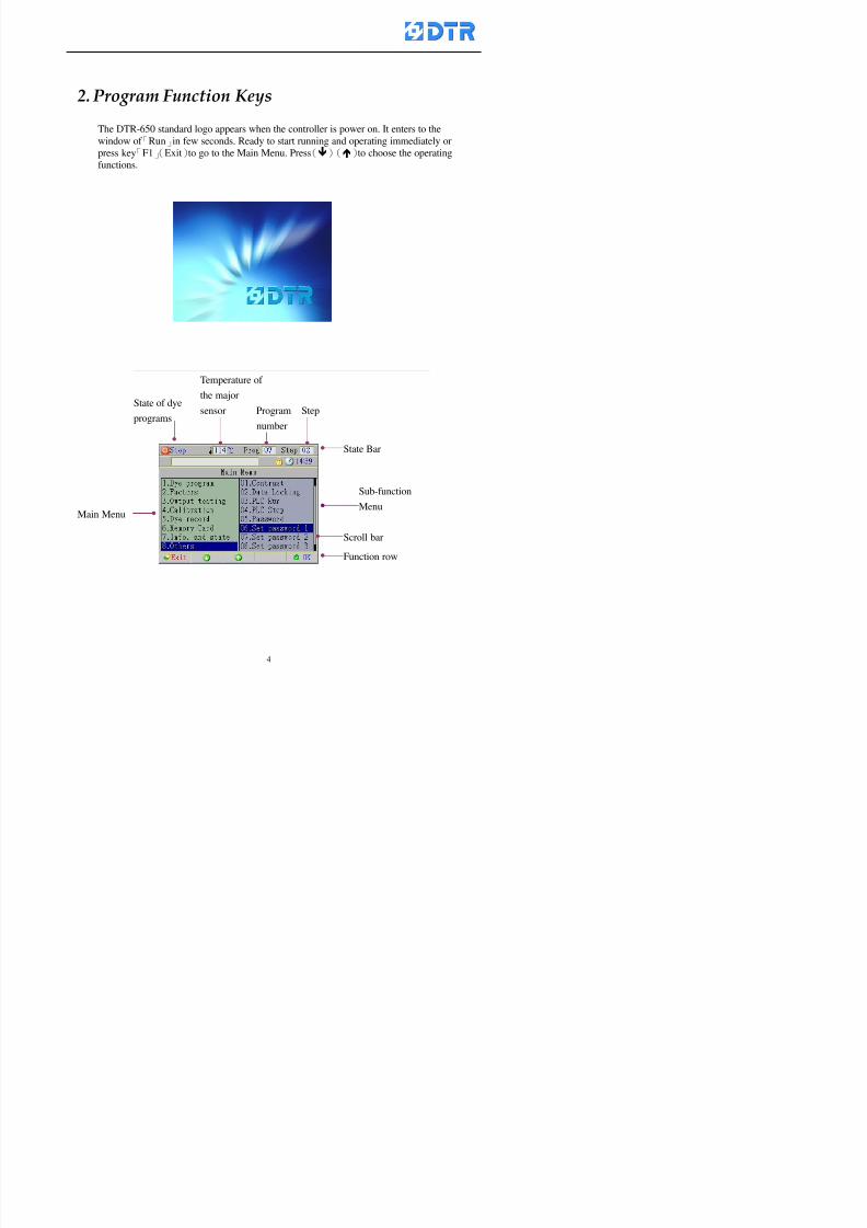
8132019 DTR 650 User Manual
httpslidepdfcomreaderfulldtr-650-user-manual 570
2-1 Function Keys
There are five function keys「F1」~「F5」corresponding to 5 function items of the
main window press the function key corresponding to the item will get access to its
operation For example of the running page
F1 F2 F3 F4 F5
8132019 DTR 650 User Manual
httpslidepdfcomreaderfulldtr-650-user-manual 670
2-2 Auxiliary Keys
Auxiliary Keys「3」「4」「5」「6」 have handy function for moving different directions
or pages
Key「OK」to confirm before make changes
Key「Esc」quit or return the previous changes
5555 33 44
6666 Esc OK
2-3 Numeric Membrane Keys
7 8 9
4 5 6
1 2 3 0
a Setting factors
b Password input
c Program selecting
d Program name
Program List mode Displays
Enter the window of addition program steps when
the program is runningAssist to check
the alarm info
8132019 DTR 650 User Manual
httpslidepdfcomreaderfulldtr-650-user-manual 770
2-4 Operation key and the Indicator
Operation key lsquoStartrsquo (Green button) to run and lsquoStoprsquo ( Red button ) to stop
dye programs
Indicator Run It turns On when the dye program running turns off when program
stops
Indicator Alarm It turns on when alarm is occurred
Indicator Operator It turns on when requesting an operator during program running
Run Alarm Operator
8132019 DTR 650 User Manual
httpslidepdfcomreaderfulldtr-650-user-manual 870
2-5 Selecting the operating functions
When the power on「Run」window appears can start running directly
To choose other function items press「F1」(Exit) to get access to the Main Meun Cursor
stays at the main function field now Choose operating function to move the cursor
accordingly
Steps(a) Press「F2」()「F3」() to move the cursor to the selected functions Press
「F5」(OK)
(b) Now the cursor is at the sub-function field Press「F2」()「F3」()to choose
the functions Press「F5」(ok )to enter the relating window
(c) Press「F1」(Exit)to exit
a)a)a)a)
b)
8132019 DTR 650 User Manual
httpslidepdfcomreaderfulldtr-650-user-manual 970
3 983122983157983150
3-1 Running the current dye program
To enter to the Run window directly when the power on or press「F1」
(Run) to enter the Run window at main menu The ldquostatus barrdquo shows
the current dye programrsquos number and steprsquos number
Check the dye program number and step on the ldquoProgram Status Listrdquo
Press「」「」or「6」「5」to move the cursor to select the program step
to start with When select a step press「start」 to start running
program Now the indicator light「Run」turns on
One main function can be operating with 1 to 4 parallel functions at the same time
The five function keys on function row corresponding to its operating items of
that window press that relating key「F1」~「F5」will get access to its operation
T f th di l d k 「F4 i k 「3 t th S h ti
Parallel functions
Main function in ruuning
8132019 DTR 650 User Manual
httpslidepdfcomreaderfulldtr-650-user-manual 1070
3-2 Jumping steps
During the program operating press「F2」(Jump)to jump to another steps to keep on
running Window appears
「Jump Prev」return to the step in front of the current step
「Jump Next」go to the next step from the current step
Press「」「」to move cursor then press「F5」(OK)to start running the target
dye step
Can use the numeric keys「Jump to XXX」to input the target dye steps directly
Press「F1」(Exit)to quit Keep operating the current program steps
8132019 DTR 650 User Manual
httpslidepdfcomreaderfulldtr-650-user-manual 1170
8132019 DTR 650 User Manual
httpslidepdfcomreaderfulldtr-650-user-manual 1270
3-4 Schematic Diagram Mode Display
Schematic diagram mode displays the dye program operating the water level and
valve status and etc
During the dye program operating press membrance key「F4」to change the
display mode
When program stops it displays to Program list mode automatically from
Schematic diagram display mode Press membrance key「3」to view the
Schematic diagram mode again But if there is an alram occurred it stays at the
Program List mode Please release the alarm first
Press numeric key「9」(Exit)to return to the Program list mode
By setting factor can view the Schematic diagram mode displays directly during
operating (refer to the《6-4》「Display mode setting」for details)
8132019 DTR 650 User Manual
httpslidepdfcomreaderfulldtr-650-user-manual 1370
3-5 Icon Mode Display
During the dye program operating press membrance key「F4」to change to the
display mode
When program stops it displays to Program list mode automatically from Icon
Mode Display Press numeric key「6」to view the Icon mode again But if there is
an alram occurred it stays at the Program list mode Please release the alarm first
Press numeric key「9」(Exit)to return to the Program list display
By setting factor can view the Icon mode displays directly during operating (refer
to the《6-4》Display mode setting for details)
3-6 Running state of dyeing machine
There is totally 2 pages of the Running status information
To check the running status when the program is in operating press「F5」(State)「Inputoutput State」appears pess key「F5」 「Running Information」appears
8132019 DTR 650 User Manual
httpslidepdfcomreaderfulldtr-650-user-manual 1470
3-7 Keep continuing to run from the break point
Due to power sudden off or stop running the dye program it can keep continuing to
run from the break point when the power is retore Users can set the ldquoControl factorrdquo
which dye instruction allows (or prohitbit) to keep continuing to run from the breakpoint (refer to the charpter 6 for Setting)
When the power is restore the cursor stays at the step which stops suddenlybefore starting from the break point to press 「Run」 Window appears
Press「F4」(Yes)to keep going run from the break point
Press「F2」(No)to re-start that dye instruction
Press「F1 (Exit) to return
8132019 DTR 650 User Manual
httpslidepdfcomreaderfulldtr-650-user-manual 1570
3-8 Editing dye step temporary
Before dye program operating the ready-to-run dye step could be edit That edit will
not saved to the file and will not disappear by causing a sudden power inruption or
stop operating until a new dye program is selecting
Step
A Set the system factor as「22」first to allow editing the dye programs temporary
B Set the system factor as「23」 to allow the existing program can temporay
editing its range of step
C Item「19」of the system factor set the dye steps which allows or prohibits to edit
temporary (Refer to the Charpter 6 for details of 「Setting」the A-C )
D Press「F2」()「F3」()or「5」「6」at the Run window To move cursor
to the dye step intend to edit Press membrance key「2」「Edit instrunction
value」appears
E Press「F5」(Edit) then press()()or「5」「6」Programs names is listing
at the cursor or key in a value by the numeric keys Select and press「F5」(ok) to
confirm
F Press「F4」(Save)to confirm and go back to the Run window
G 〔Before pressing「F4」(Save)〕Press「F1」(Exit)to quit
8132019 DTR 650 User Manual
httpslidepdfcomreaderfulldtr-650-user-manual 1670
3-9 Creating an additon dye step during dye program running
Before and during the dye program running the users can creat an addition dye step in
the existing dye programs
3-9-1 Creating an addition dye step
To creat one addition dye step before running or during running step as follows
A Set the System Factor as「34」to allow to creat an addition step (Refer to the
Chartper 6 for details)
B In window「Run dye program」 press numeric key「8」to enter window of 「Edit
addition instruction」 to edit the single dye step first
C Press「」「」「5」
「6」to choose dye
steps press「F5」(OK)
D Press「F5」to edit the
content of dye step
E After complete editing the single dye
step Press「F4」(Run) to start running the
addition step
8132019 DTR 650 User Manual
httpslidepdfcomreaderfulldtr-650-user-manual 1770
3-9-2 Creating an addition treatment to a saved dye program
During and before the dye program running can creat an addition treatment to a
saved dye program or a dye step in a saved dye program
(1) Set the System factor as「34」to allow creating an addition step (Refer to the
Chartper 6 for details)
(2) In window「Run dye program」 press numeric key「8」to enter window of「Edit
single step」
(3) Press「」「」to choose「Sub Prog」 press「4」to move cursor and set itrsquos
dye program number and the step number by numeric keys Or stay at the
「Prog」and press「F3」(File) window appears
(4) Press「」「」to choose an addition dye program then press「F5」(OK)
(5) Press「F4」(Run)to run the addition dye program(sub-dye program)
(6) Finish to run the sub-dye program and return to the main dye program
8132019 DTR 650 User Manual
httpslidepdfcomreaderfulldtr-650-user-manual 1870
4 983120983137983155983155983155983159983151983154983140 DTR-650 provides four ranks of password for sercurity protection
(Refer to the ltTable 10gt Supplementary Table of the Password Usage for details)
First rank (User1 password) Edit delete dye programs control factors in output
testing etchellipall operating fuctions
Second rank (User2 password) Edit in output connecting table operating factors
Third rank (User3 password) Edit copy delete dye programs factors PLC run stop
Fourth rank (User4 password) Edit and modify dye programs
4-1 Entering the password
When the window of 「password」appears enter 6-digits number password by using
the numeric membrane keys then press「F5」(OK) If key-in an incorrect password
press「F3」(Del)and enter again
If the password is correct「」appears it allows to enter the relating operation
8132019 DTR 650 User Manual
httpslidepdfcomreaderfulldtr-650-user-manual 1970
4-2 Locking the data
After editing the programs and factors ensure to disable the password to protect all
programs and data of DTR-650 The way and step as follows
(1) Choose「8Others」at the main meun
(2) Choose「02Data Locking」at the sub-function field
(3) Press「F5」(OK)to confirm
(4) Return to the main menu「」disppears on the status bar that means the data
has been locking already
4-3 Setting and changing the Userrsquos password
There are four userrsquos password for setting and edit by the users themselves
User1 password Access to all operation setting
User2 password For edit in output connection table operating factors
User3 password Only for copy and delete dye programs factors PLC run stop
User4 password Only for edit and modify dye programs
Method of setting edit
(1) Choose「8Others」at main menu press「F5」(OK)
(2) Choose「7 Set Password 2」at the sub-function field press「F5」(OK)
(3) The cursor shows the default password now press「F3」(Clr)to delete Key in
a new password with 6-digit
(4) Press「F5」(OK)to complete the setting of User2 password Go back to the main
menu
8132019 DTR 650 User Manual
httpslidepdfcomreaderfulldtr-650-user-manual 2070
The four userrsquos password has to made from different group numbers Using
same password will affect the operating Please pay attention when update the
password
8132019 DTR 650 User Manual
httpslidepdfcomreaderfulldtr-650-user-manual 2170
5555 983109983140983145983156983145983150983143 983108983161983141 983120983154983151983143983154983137983149983155
5-1 Choosing a dye program
Press function key「F4」(Edit)or choose「1Dye Program」at the main menu press
「F5」(OK)
Choose「1Edit Dye prog」at the sub-function field press「F5」(OK)to enter to the
window「Sel dye program」During the dye program running it is allowed to edit asaved program or a new dye program or the current dye program in running
Method Press「」「」and「5」「6」「3」「4」to move cursor to choose
a dye program number Press「F5」(OK)to enter that dye program Press
「F1(Exit)to quit and return
Method
Directly key in the number selection box
appears at the right corner of the window
Select a program number and press「F5」
(OK) fi
8132019 DTR 650 User Manual
httpslidepdfcomreaderfulldtr-650-user-manual 2270
5-2 Creating a new dye program
Step
A Choose「1Dye Program」Press「F5」(OK)
B Choose「1Edit Dye prog」at the sub-function menu press「F5」(OK)to enter
to window「Sel dye program」
C At the window「Sel dye program」 choose an empty dye number (eg「002」)
press「F5」(OK)window《Fig 5-2-1》appears
《Fig 5-2-1》
D Press「F2」(Add) table of 「Edit dye instruction」《Fig 5-2-2》appears
E Press「F5」(Edit) the dye instruction appears at the cursor locates press「」「」
」and「5」「6」「3」「4」to move cursor to edit the instruction and its
factors
F All inserted new dye instructions would be listed in front of 「Program End」
8132019 DTR 650 User Manual
httpslidepdfcomreaderfulldtr-650-user-manual 2370
【Eg】Edit「CycRinse」
A Edit the main function step first Press「F2」
()「F3」()to move the cursor The dye
step is listing by orders Choose「CycRinse」
and press「」 there is a cursor at itrsquos value
B Move cursor to setting value「Cold」andchoose「Mix」by pressing()() Then
press「」to move cursor to「Time」and enter
itrsquos setting value as「2」Press「F5」(OK) to
complete the main function setting
C To move cursor to the parallel functionsetting field Press()()to choose the
dye step Press「」to confirm and move
cursor to choose itrsquos setting facor
D Press「F5」(OK)to move cursor to the next
parallel function
E Repeat above steps C-D until all parallel
functions setting are completed Each main
function can be operating with the
maximum 4 parallel functions
F Press「F4」(Save)to confirm and return to
the「Edit dye program」window
G Repeat the above step A E to keep on
8132019 DTR 650 User Manual
httpslidepdfcomreaderfulldtr-650-user-manual 2470
5-3 Setting the file name (for dye programs)
When a dye program is setting up it is saved by numbers automatically Optionally users
can save it by another names
Step
(1) Create a new dye program first (the Name is not available for empty dye
programs)
(2) At the window「Sel dye program」 press「F4」(File) Window《Fig5-3》appears
《Fig5-3》
(3) Use numeric 0~9「+」「-」「_」blank alphabet A~Z and symbols [ ] etchellip to
create a file name Each file name can type-in the max 8 unit Press 「3」「4」
「5」「6」to move the cursor to choose the unit It also can use the membrane
numbric key to type in The selected unit is showed in front of the cursor at the
「File」Press「OK」to confirm
(4) Quit to input to press「F3」(Clr)
(5) After complete the set up press「F5」(OK)to confirm and go back to the window
「Sel dye program」 Now the name behind the dye program number is created
8132019 DTR 650 User Manual
httpslidepdfcomreaderfulldtr-650-user-manual 2570
5-4 Inserting a program step
Insert the program step means to insert a step in the existing program step where youwant to insert a step All following steps are moved one step ahead The total number of
steps will be increased by itself Able to insert more than one step continusely at the
same time
【Example】《Fig5-4》 To insert a step「call」before「002 Rinse」
《Fig 5-4》
Step
A Enter to the dye program「002」at the window of 「Sel dye program」
(Example)
B Press「6」to move cursor to「002 Rinse」 then press「F2」(add)
C Press「F5」(Edit) then press「」「」or「5」「6」to choose program
step to modify Choose「call」and press「」to move cursor to modify itrsquos
value
8132019 DTR 650 User Manual
httpslidepdfcomreaderfulldtr-650-user-manual 2670
D Press「」「」 value of 「call」is listing at the table Choose「pH Check 」Press「F5」(OK)
E Press「F4」(Save)and press「F1」(Undo)to return to previous window Complete
to insert the「02 Call」The previous「02 Rinse」update to「03」 All following
steps are moved one step ahead Total number of steps will be increased ldquo1rdquo by
itself
Repeat the steps B-E can non-stop to insert more than one step
Quit the insert and modify ( before pressing「F4」) press「F1」(Undo) to exit
The original dye steps will be unchanged
To delete an inserted dye steps press key「F3」(Del) The step deletes
immediately
5-5 Deleting a program step
Delete the program step means to delete step which the cursor locates When that step is
deleted the step number will be updated automatically All following steps are moved up
one step It is allowed to delete more than one steps continuously at the same time
Step
A Enter to the「Edit dye program」《Fig5-5》at the window「Select dye program」
B Press「6」「5」move cursor to the want to delete
C Confirm and press「F3」(Del) Window「Confirm delete」appears Press
「F4」(Yes)
8132019 DTR 650 User Manual
httpslidepdfcomreaderfulldtr-650-user-manual 2770
D That step is deleted immediately and all following steps move up one step
Repeat the steps above can non-stop to delete more than one step
Press「F2」(No)to cancel the deletion
Press「F1」(Exit)to end
5-6 Modifying a program step
To modify the saved name and the setting value of the dyeing steps
Step
1 Choose a dye program which need to modify at the「Sel dye program」 press「F5」
(OK)
2 Press「6」「5」to move cursor to a step which need to modify Select and press
「F5」(Edit) Window of 「Edit dye instruction」appears
3 Press「F2」()「F3」()to choose the step list select it and press「」to move
the cursor to itrsquos value setting
4 Press numeric key to input the value or press「6」「5」to choose the item Press
「F5」(OK)when complete Cursor move to the next value (if need to set more
than one item)
5 Press「F4」(Save)when all setting is complete Return to「Edit dye program」
Method of parallel functionrsquos modification is same as above
Before pressing the key「「「「Save」」」」 press「F1」(Undo)to quit all modify Return
to the window of Edit dye program
All edit and modify functions mentioned of this charper are only available
for the dyeing files which already saved in the file and not being running It
8132019 DTR 650 User Manual
httpslidepdfcomreaderfulldtr-650-user-manual 2870
5-7 Copying a dye program
Copying a dye programs mean to make a copy of an dye programs to a blank dyeprogram This function is for creating new dye program rapidly
Choose「1Dye Program」at the main menu Press「F5」(OK)then press「F2」()to choose「2Copy dye prog」 Press「F5」(OK) 《Fig5-7-1》appears
《Fig 5-7-1》
《Fig 5-7-2》
【【【【Eg】】】】
Copy program 003 to program 012
Press「」「」to move cursor to theprogram「003」 press「F4」(Copy)
Program「003」shows at the top right side of
the bar
Press「」「」to move cursor to program「012」 Then press「F5」(Paste)「」appears behind the「012」That means it issuccessfully copying the program
If the target program is occupied
confirmation window「Overwrite」
When choose an program or a targetprogram can select them by using the
8132019 DTR 650 User Manual
httpslidepdfcomreaderfulldtr-650-user-manual 2970
5-8 Deleting a dye program
Choose「1Dye program」at the main menu Press「F5」(OK)then press「F2」()to choose「3Delete dye prog」 Press「F5」(OK) 《Fig5-8-1》appears
《Fig5-8-1》
《Fig5-8-2》
Press「」「」to move cursor to
choose program need to delete Eg
delete program「012」 press「F5」(Del) Confirmation window
「Confirm delete」appears
Press「F4」(Yes) to confirm delete
Repeat the above step can delete more
than one program at the same time
Press「F2」(No) to return to window
《Fig5-8-1》and not delete that program
Exit to press「F1」(Exit)and return to the
main menu
8132019 DTR 650 User Manual
httpslidepdfcomreaderfulldtr-650-user-manual 3070
6 983123983141983156983156983145983150983143DTR-650 has a built-in standard factor that can fulfill all different types of dyeing
machinesrsquos basic demand Users can also modify the factors base on their request to
fulfill their special control demand Before modify please refer to the table of each
range of Setting Factors (see the Supplementary Table)
6-1 ldquoEnable to use the program stepsrdquo setting
There are totally 64 program steps Parts of them are usually applying to the programs
In order to make more efficiently of editing programs it can「Disable」the other part
of program steps which are not usually applying or not applicable to the programs
For example dye machine with one tank it is only using step Tank B In this case itcan firstly「Disable」the program steps of Tank C When edit the program the
「Disable」rsquos steps will not appear at the cursor for choosing But this will not effect
and change the saved files The saved files can be kept as before
Step
(1) Choose「2 Factors」at the main menu Press「F5」(OK)(2) Choose「18 Dye Instruction」at the sub-function menu Then presss「F5」(OK)
Window「Edit dye ins」appears
「Enable」instruction can available to
use「Disable」instruction is temporarystop to use
Press「F2」()「F3」()to move
8132019 DTR 650 User Manual
httpslidepdfcomreaderfulldtr-650-user-manual 3170
6-2 ldquoAllow to modify dye program temporary during operatingrdquo Setting
During dye program running it can modify dye program temporary Thesemodification will not disappear by causing a sudden power interruption or power off
until select another new dye program to run
Please note that it is only for modifying the dye program temporary That program
file would not saved due to the modification If need to modify the program file and
save choose the function of Edit Dye Program to edit (Refer to the Charper 5 for the【Edit Dye Prograrm】)
6-2-1 ldquoAllow to modify all dye programsrdquo Setting
Step
(1) Choose「2 Factors」at the main menu Press「F5」(OK)
(2) Choose「02 System Factor」at the sub-function menu Then presss「F5」(OK)
Window「Edit System Factor」appears
Set to stop using temporary the「07
Rinse」press「F4」(Sel)to set it as Disable
Repeat above steps to complete all setting
Press 「F1」(Exit)to return to main menu
8132019 DTR 650 User Manual
httpslidepdfcomreaderfulldtr-650-user-manual 3270
6-2-2 ldquoAllow to modify part of dye programsrdquo Setting
【Eg】Set the number 08 or above (including number 08) is allowing to modify dye
programs during operating
Step
A Refer to【6-2-1】setting the factor as「22」to allow editing dye program
temporary during operating
(4) Press「3」「4」to edit the setting
as「Enable」 and press「F5」(OK)
Restore the standard factor by
pressing「F3」(Clr)
(5) Exit to press「F1」(Exit)and
return to window of 「Main Menu」
8132019 DTR 650 User Manual
httpslidepdfcomreaderfulldtr-650-user-manual 3370
6-2-3 ldquoAllow to modify dye steps temporaryrdquo Setting
After setting the dye programs are allowed to edit it also can set which dye steps are
allowed to edit temporary during operating
Step
(1) Choose「2 Factors」at the main menu Press「F5」(OK)
(2) Choose「19 Dye Ins control」at the sub-function menu Then presss「F5」
(OK) Window「Edit ins mode」appears
「Enable」 Allow to edit that dye step before
operating
「Disable」 Not allow to edit dye step before
operating
(3) Press「」「」to move cursor
to choose dye step Press「F4」
To enter to the「Edit dye program」from the
function menu there is a「」in front of the
file name「0-7」 means that program is not
allowing to edit during operating
8132019 DTR 650 User Manual
httpslidepdfcomreaderfulldtr-650-user-manual 3470
6-2-4 ldquoSet the dye step to keep running from the interrupt pointrdquo setting
When the dye program is operating it will disappear by causing power
interruption or sudden power off When start running again part of dye steps can
run again from the interrupt point part of them cannot
How to set
(1) Choose「2Factors」in the main menu and press「F5」(OK)
(2) Choose「20Continue mode」in the sub-function menu Press「F5」(OK) to
enter window of 「Continue Setting」
(3) Press「」「」to move cursor to choose dye steps Press「F4」(Sel)it
shows「Disable」or「Enable」for choosing Press「F5」(OK)to move cursorto the next setting
(4) Repeat above method until all setting is complete press「F1」(Exit)and
return to the main menu
8132019 DTR 650 User Manual
httpslidepdfcomreaderfulldtr-650-user-manual 3570
6-3 ldquoAllow to insert an addition dye stepsrdquo setting
During the program is running can temporary insert an addition dye step or a dye
program according to the operating actual situation Through this setting can set which
dye steps can apply or not to the program in operating
During to insert an addition step if sudden interruption or power off occurred it returns
to the main dye program automatically Before starting again should decide seriously
and set it again by actual needed
Step
(1) Choose「2Factors」at the main menu and press「F5」(OK)
(2) Choose「02System factor」and press「F5」(OK)
(3) Press「」「」to move cursor to the factor「34」and press「3」「4」to set
it as「Enable」 Press「F5」(OK)
(4) Press「F1」(Exit)to return to main menu Choose「21Addition Ins」at the
sub-function menu Press「F5」(OK)to enter the window「Addition Instruction」
(5) Press「」「」to move cursor to choose dye steps and press「F4」(Sel) Cursors
locates shows「Eable」or「Disable」 Press「F5」(OK)to move cursor to the
next dye step
(6) Repeat above method until to complete all setting press「F1」(Exit)and return
to the main menu
8132019 DTR 650 User Manual
httpslidepdfcomreaderfulldtr-650-user-manual 3670
6-4 Setting the display mode
DTR650 has three types of display mode during operating Program List mode
Schematic Diagram mode and Icon mode Users can set the display mode during
operating by factor setting
It goes back to a Program List mode when dye program ended
Step
(1) Choose「2Factors」at the main menu and press「F5」(OK)
(2) Choose「02System factor」and press「F5」(OK)
(3) Press「F2」()「F3」()to move cursor to choose「32Display mode」Press
「3」「4」 it shows「Online picture」「Instruction」「Big Icon」 choose
「Online picture」(eg) and press「F5」to confirm
8132019 DTR 650 User Manual
httpslidepdfcomreaderfulldtr-650-user-manual 3770
(4) Press「F1」(Exit)to return to the main menu
(5) The Schematic Diagram displays when the program is running (it stays at theProgram List mode when there is an alarm occurred)
Press「F4」to transfer to another display mode
It goes back to a Program List mode from Schematic Diagram Mode when dye
program ended Press numeric key「3」to view Schematic Diagram Mode again
Quit to press「F5」(Exit)
6-5 Adapt the digital input to another functions
DTR-650 has 32(0~31)input terminal it owns an standard setting when the
controller is initial According to the userrsquos demand they can change the DTR-650rsquos
anther functions of Input Terminal and PLC Input channel
The PLC Intputrsquos name can also define by the users (use IBM computer to edit and
download)
How to set
(1) Choose「2 Factor」at the main menu Press「F5」(OK)
(2) Choose「22 Input table」at the sub-function menu and press「F5」(OK)to enter
「Edit input table」
The actual input
terminal of theIBM computer
PLCrsquos input channel
8132019 DTR 650 User Manual
httpslidepdfcomreaderfulldtr-650-user-manual 3870
6-6 Adapt the digital output to another functions
DTR-650 has 32(0~31)output terminals it owns an standard setting when thecontroller is initial According to the userrsquos demand they can adapte the digital output
and the PLC outputrsquos channel to another functions The PLC Output channelrsquos name
can also define by users (use IBM computer to edit and download)
Step
(1) Choose「2 Factor」at the main menu Press「F5」(OK)
(2) Choose「23 Output table」at the main menu and press「F5」(OK)
(3) Press「F2」()「F3」()to move cursor to choose the output terminal atthe left side of the window Press「F5」(Add) the PLCrsquos output channelrsquos
name is listing at the right side of the window
(4) Press「F2」()「F3」()to move cursor to choose the PLC outputrsquos channel
If cursor moves to the PLC output channel which already linking「Add」is
not for choosing that means that output channel is already occupied
(5) Confirm the connection to press「F5」(Add) Quit to press「F4」(Del)Press「F1」(Exit)when complete all setting and return to main menu
The actual output
terminal of the
IBM computer
PLCrsquos output channel
8132019 DTR 650 User Manual
httpslidepdfcomreaderfulldtr-650-user-manual 3970
983095 983109983140983145983156983145983150983143 983156983144983141 983110983137983139983156983151983154983155DTR-650 has several kinds of control factors
Userrsquos factors System factors Temperature Control factors Speed factors Dosing
factors PID factors Analog Input Output factors standard factors etchellipPlease refer
to the supplementary table for the setting range and standard of the factors
DTR-650 has a built-in standard factor Users can edit by themselves if necessary
7-1 Modifying userrsquos factors
Userrsquos factors is setting with the Dyeing machinesrsquos PLC Programrsquos factor it is define by
the PLC Programmer
Step to edit
(1) Choose「2Factors」at main menu Press「F5」(OK)
(2) Choose「01User Factor」Press「F5」(OK)
(3) Press「F2」()「F3」()「6」「5」to move cursor up down and by page
Choose a factor need to edit then press「3」「4」to set itrsquos value Press「F5」(OK) Cursor moves to the next factor
(4) Some of factors can input numbers by the numeric membrance keys to edit If
the input is incorrect it turns to red and means the edit is not available
8132019 DTR 650 User Manual
httpslidepdfcomreaderfulldtr-650-user-manual 4070
Modifyrsquos method of the system factors temperature factors speed factors dosingfactors PID factors analog Input output factors standard factors etchellipare same asabove
If apply the library of DTR500 and DTR600 into the DTR650 the key「3」「4」may not valid to use Please use the numeric keys instead of it to key in factors itmay not effect the normal operation
Please pay a serious attention and read carefully at the factorrsquos table before modify the factors An incorrect value may effect the DTR-650 Dyeing
Machine Controllerrsquos operating After modifying factors must cancel the
password and secure data
7-2 Loading the standard factors
After modifying factors if need to restore a manufacturerrsquos standard factors of
DTR-650 The method as follows
1 Choose「2Factors」at main menu Press「F5」(OK)
「 「 ( ) 「
8132019 DTR 650 User Manual
httpslidepdfcomreaderfulldtr-650-user-manual 4170
7-3 Copying the factor
Users can build up a set of factor by themselves and make a copy and save
Step
1 Choose「2Factors」at main menu Press「F5」(OK)
2 Choose「13Restore Factor」 press「F5」(OK) window「factor will be
overwrite 」
3 Press「F4」(Yes)copy finished and saved Return to the main menu
4 Press「F2」(No)to not copy the factor and the existing factor is not change Return
to the main menu
7-4 Loading the backup factors
Users can build up a set of factor and backup files to load to DTR-650
Step1 Choose「14Backup factor」at the sub-function menu Press「F5」(OK)and
window「Factror will be overwrite」appears
2 Press「F3」(OK)to load the the backup factor them return to main menu
Press「F2」(No)to not copy the factor and the existing factor is not change
Return to the main menu
8132019 DTR 650 User Manual
httpslidepdfcomreaderfulldtr-650-user-manual 4270
983096 983119983157983156983152983157983156 983124983141983155983156983145983150983143
Before the output testing must be complete the steps as follows
A Cut off all connecting line of output terminal of DTR-650
B Stop running the PLC
C Check up the connections of all output channels to avoid damages from
incorrect connections
D Check up state of dyeing machines include the temperature pressure valves
onoff and pumpshellipetc ensure the safety for priority
8-1 Testing the Digital output
Step
1 Choose「3Output Testing」at the main menu Press「F5」(OK) 2 Choose「1Digital」at the sub function menu Press「F5」(OK) window「Digital
output testing」appears
3 Press「」「」「」to move cursor to each output channels Press「F5」(OK)
Output Name
8132019 DTR 650 User Manual
httpslidepdfcomreaderfulldtr-650-user-manual 4370
8-2 Testing the Analog output
(1) Choose「3Output Testing」at the main menu Press「F5」(OK)
(2) Choose「2Analog」at the sub function menu Press「F5」(OK) window「Analog output testing」appears
(3) Press「」「」「」to move cursor to each channels Then key in number by
the numeric membrance keys (range0~200= 0~20mA) Press「F5」(OK) there
is a output current relating to the output channel
(4) Press「F5」(OK) There is an output when the output channel with red light No
output without light onl(5) When complete the testing press「F1」(OK)to return to the main menu
8132019 DTR 650 User Manual
httpslidepdfcomreaderfulldtr-650-user-manual 4470
983097 983107983137983148983145983138983154983137983156983145983151983150
DTR-650 has Dosing and Temperature calibration
When enter to Dosing calibration must be set the Low Volume calibration first and
then High Volume calibration When enter to Temperature calibration must be set the
Low Temperature calibration first and then High Temperature calibration Must be
hightly follow this orders seriously
9-1 Calibration of Low Volume Tank
Step
A Choose「4Calibration」at the main menu Press「F5」(OK)
B Choose「Dosing 0 low vol」at the sub function menu Press「F5」(OK) window
appears
C Fill the Dosing Tank to a half level input value shows how much the water level
If it stays ldquo0rdquo check the connection and the factor setting is correct or not
And connect the pressure sensorrsquos output channel to the Current Meter to ensure
that sensor works or not
8132019 DTR 650 User Manual
httpslidepdfcomreaderfulldtr-650-user-manual 4570
D Fill the Dosing Tank to 50ml (Calcalate from the bottom side of the pressure
sensor steel tube) input value should show 4~6 (input value must between
0~10) Then enter the water volume The setting volume is relating the water
levelrsquos water value (litre as unit) input range 0~80 Set as「 「「 「0000 0000 0000 0000」」」」is strongly is strongly is strongly is strongly
receommend receommend receommend receommend Press「F5」(OK)to complete [Calibration of Low Volume Tank 1
is same as above method]
9-2 Calibration of High Volume Tank
Step
A Choose「4Calibration」at the main menu Press「F5」(OK)
B Choose「Dos 0 high vol」at the sub function menu Press「F5」(OK) window of
「Calibrate high 」appears
C Fill the Dosing Tank to a full level input value should be larger than 30 enter
the current water level which relates to the water volume Enter the range within
100~2500 Then press「F5」(OK) to complete the calibrate the high volume tank
8132019 DTR 650 User Manual
httpslidepdfcomreaderfulldtr-650-user-manual 4670
9-3 Temperature Calibration
Step
A This function is for adjusting the DTR650rsquos accuracy of Temperature Control It
must be using with the special terminal which is only for DTR650
B Choose「4Calibration」at the main function menu and press「F5」(OK)
C Choose「3Low Temp」at the sub-function menu Press「F5」(OK)and《Fig9-3》
appears insert the DTR650rsquos low temperature calibration terminal to the temperature
input terminal wait for the jumping value to stable down then press「F5」(OK) then
to adjust the high temperature calibration
D Adjusting the High Temperature Calibrationrsquos method is same as above But usersusersusersusers
must be using the High Temperature Terminalmust be using the High Temperature Terminalmust be using the High Temperature Terminalmust be using the High Temperature Terminal whichwhichwhichwhich is specially for DTR650 onlyis specially for DTR650 onlyis specially for DTR650 onlyis specially for DTR650 only
《Fig 9-3》
8132019 DTR 650 User Manual
httpslidepdfcomreaderfulldtr-650-user-manual 4770
10 983122983141983139983151983154983140983155 983151983142 983108983161983141 983120983154983151983143983154983137983149983155
It contains the past 15 days of temperature curves of running history
Checking method
(1) Choose「5Dye Record」at main menu press「F5」(OK)
(2) Sub-function menu shows the set up date of the past 15 days dye programs
Listing by the lastest set up date
(3) Choose a program date and press「F5」(OK) it appears window「Temp
record」
(4) Press「」「」to move the white line in the box one minute by moving once
(5) Press「3」「4」to move the line to check the time period 2 hours by moving once
The yellow selecting line of the「24 hours operating state」is repectively moving
The curve info is show in the curve box Left side of the widnow appears the
relating running info the time is the time value of the line locates at
(6) Check more details of the temperature info to press numeric key「middot」 a bright red line
appears in the selecting box this line is to check the starting point of the
temperature inforsquos time period Then press「」to move the white line to the end
point of the time period The temperature info between the starting point and end
point are appears at the right side of the window Press「middot」to return to the preious
curve page
(7) Check more details of the alarm infor To perss numeric key「7」「9」 the alarmrsquos
details is listing by orders
(8) Press「F1」(exit) to return
8132019 DTR 650 User Manual
httpslidepdfcomreaderfulldtr-650-user-manual 4870
11 983125983155983137983143983141 983151983142 983117983141983149983151983154983161 983107983137983154983140
DTR-650 supports 32MB or above Compact Flash Card which can transfer and save all
information for 4 sets of DTR-650 Including library files schematic diagram icon
image PLC program dye program factor and confiruration files etchellip Use the CF Card
to up download and swap the information of DTR-650 promptly install the relating
device and program updates
DTR-650 CF Card with bank 1 to bank 4 can save 4 sets information of Dyeing
Machines When download or save files should choose the BANK first
《Fig11-1》
8132019 DTR 650 User Manual
httpslidepdfcomreaderfulldtr-650-user-manual 4970
11-1 Downloading data
1 Firmly insert the CF card into the DTR-650rsquos PCMCIA connector Ensure it is
wholely and firmly inserted if the card is not totally inserted or the card do not
touch in all to the connector there will be an error occurred and cannot
updownload or interrupted during operation
2 Choose「6Memory Card」at the main menu and press「F5」(OK) 《Fig11-1》
appears Information of Bank「1」shows at the left hand side of the window press
number 1-4 by using numeric keys to choose the BANK Check the
information in the Bank seriously which is exactly need to download to the
DTR650
3 Press()()「6」「5」to move cursor to the sub-function menu to choose
the downloading items Press「F5」(OK) window appears「Stop PLC run before
access memory card Stop the PLC run」 Press「F5」(YES) to stop PLC
running
4 Press「F5」(OK) window appears Confirm to update or not the DTR-650rsquos
information As that downloading will be replace the DTR-650rsquos information
(that means the existing information of the DTR-650 will be removed and
replaced)
5 Press「F4」(YES)to download the information from the DTR-650 to the CF
Card Return to the main menu when finish
8132019 DTR 650 User Manual
httpslidepdfcomreaderfulldtr-650-user-manual 5070
Ensure inserting firmly the CF card into the DTR-650 unless it will cause
error or cannot Updownload data
Never remove CF card during transferring or updownloading data Until it
is all completed
DTR-650rsquos dyeing program is not compatible with DTR-500 and
DTR-600 Never use CF card to transfer data among them
11-2 Storing and transfering data
1 Insert the CF Card to the DTR-650
2 Choose「6Memory Card」at the main menu and press「F5」(OK) 《Fig11-1》
appears Left hand side of the window shows the data of BANK 1 press numeric
keys 1-4 to select the BANK To confirm the put the data in the DTR-650 to the CF
Card The existing data of that bank will be replaced and covered by the new data (if
that bank is already occuplied)
3 Choose「23Save Dye prog」(Example)at the sub-funciton menu press「F5」(OK)to confirm Window「Update memory card data」appears
4 Press「F5」(OK)to transfer the data to the CF card Return to the main menu
5 Put the CF card into another DTR-650 and follow the operating method of 「11-1
Downloading data」」」」can transfer and swap data with more than one set of
DTR-650
8132019 DTR 650 User Manual
httpslidepdfcomreaderfulldtr-650-user-manual 5170
12 983123983156983137983156983141 983137983150983140 983113983150983142983151983154983149983137983156983145983151983150
The state and information is including the Dyeing Machinersquos state of Digit Input output
Analog Input output Temperature control PID Dosing PID Pressure different PID
software system information and alarm record This information is for checking at any
time
12-1 Input Output state
Step
1 Choose「7Info and state」at main menu and press「F5」(OK)
2 Choose「01Digital IO put」at the sub-function menu then press「F5」(OK)
「Digital In Out State」0=None 1=Input
3 Press「F1」(Exit)to return to main menu
Same method for checking the temperature control analog dosing pressure
different etchellip
12-2 Checking the system information
Step
1 Choose「7Info and state」at main menu and press「F5」(OK)
2 Choose「11 System info」at sub-function field press「F5」(OK)Window
「System Information」appear
System information is including System info(software version) Library doc
Icon files Schematic file Definition file hardare state Config File Commandinstruction icon PLC file etc
8132019 DTR 650 User Manual
httpslidepdfcomreaderfulldtr-650-user-manual 5270
12-3 Checking the operating alarm record
Operating record shows the latest 40 operating items and alarm records including
the time and content of the alarm
A) Choose「7 Info and state」
and press「F5」(OK)
B) Choose「12Alarm logs」at
the sub-funciton menu then
press「F5」(OK)
8132019 DTR 650 User Manual
httpslidepdfcomreaderfulldtr-650-user-manual 5370
13 983105983140983146983157983155983156983145983150983143 983156983144983141 983107983151983150983156983154983137983155983156
The displaysrsquos brightness can be adjusted if necessary
Step
1 Choose「8Others」at main menu press「F5」(OK)
2 Choose「01Contrast」at sub-function menu press「F5」(OK) window「Set
Contrast」appears
3 Press「」「」to move the bar to set the brightness then press「F5」(OK)Window appears「Please reboot the system」
4 Press「F5」(OK)to return to main menu and re-boot the DTR-650 to complete
adjusting the brightness
8132019 DTR 650 User Manual
httpslidepdfcomreaderfulldtr-650-user-manual 5470
14 983123983156983151983152 983154983157983150983150983145983150983143 983156983144983141 983120983116983107 983120983154983151983143983154983137983149
Before testing the Input output testing transfer of the PLC program must stop the PLC
running
Step
1 Choose「8Others」at the main menu Press「F5」(OK)
2 Choose「04 PLC Stop」at sub-function menu Press「F5」(OK) window
「Password」appears
3 Enter password and press「F5」(OK) Window「Stop the PLC run」appears
4 Press「F4」(Yes)and window「PLC Stop」appear Press「F5」(OK) Now
the PLC is stop running and return to the main menu
All testing cannot operate when the PLC is running
Editing dye program and the relating operation can
perform with the PLC running together
8132019 DTR 650 User Manual
httpslidepdfcomreaderfulldtr-650-user-manual 5570
15 983123983141983156983156983145983150983143 983156983144983141 983156983145983149983141
Step
1 Press「8Others」at the main menu Press「F5」(OK)
2 Choose「10Set date time」at the sub-function menu Press「F5」(OK) window
「Set date time」appears
3 Press「F5」(Edit) to move cursor by 「3」「4」 enter the time value at the
cursor locates
4 Press「F5」(OK)to complete the modify Press「F1」(Exit)to return to main
menu
5 Press「F1」(Exit)if not modify and return to main menu
8132019 DTR 650 User Manual
httpslidepdfcomreaderfulldtr-650-user-manual 5670
1166 983123983123983157983157 983152 983152 983152 983152983148983148983141983141983149983149983141983141983150983150983156 983156 983137983137983154 983154 983161983161 983124 983124 983137983137983138983138983148983148983141983141
TTTTTTTTaaaaaaaabbbbbbbblllllllleeeeeeee 11111111 【Dye Instruction】
Code Icon Instruction Code Icon Instruction
000 End 016 Inject C
001 Start 017 Dosing BV
002 Heat 018 PH
003 Cool 019 Addsalt B
004 Flow Fill 020 Addsalt C
005 Level Fill 021 Ana Fill
006 Drian 022 Lock Fill007 Rinse 023 Lock Level
008 Run 024 Low Rinse
009 Call 025 Cyc Rinse
010 Prep B 026 Rinse B
011 Addsalt B 027 Rinse C
012 Dosing B 028 Temp
013 Inject B 029 Nozzle Pressure
014 Prep C 030 Main Pump
015 Dosing C 031 Pump Speed
8132019 DTR 650 User Manual
httpslidepdfcomreaderfulldtr-650-user-manual 5770
Table 2 【【【【Alarm】】】】
System Alarm Must stop operating and check up to solve problems before restarting
the machine
Running Alarm It is a reminder Not effect the operating of DTR-650
Userrsquos Alarm Total of 32 Users can define themselves and use it when edit the PLC
Program (do not listing below)
No System Alarm No Running Alarm
1 PLC program not running 16 Temp ctrl 0 Grad too slow
2 Main temp sensor error 17 Temp ctrl 0 Grad too fast
3 Not at Run window 18 Temp ctrl 0 Hold temp too low
4 Exceeding max temp 19 Temp ctrl 0 Hold temp too high
5 - 20 Temp ctrl 1 Grad too slow6 - 21 Temp ctrl 1 Grad too fast
7 - 22 Temp ctrl 1 Hold temp too low
8 Communication error 23 Temp ctrl 1 Hold temp too high
9 Slave not answer 24 Temp ctrl 2 Grad too slow
10 PLC 0 not answer 25 Temp ctrl 2 Grad too fast
11 PLC 1 not answer 26 Temp 2 Hold temp too low12 Display not answer 27 Temp 2 Hold temp too high
13 Lower power voltage 28 Temp ctrl 3 Grad too slow
14 - 29 Temp ctrl 3 Grad too fast
15 - 30 Temp3 Hold temp too low
31 Temp3 Hold temp too high
32 Dosing 0 injection too slow
33 Dosing 0 injection too fast
34 Dosing 1 injection too slow
35 Dosing 1 injection too fast
8132019 DTR 650 User Manual
httpslidepdfcomreaderfulldtr-650-user-manual 5870
TTTTTTTTaaaaaaaabbbbbbbblllllllleeeeeeee 33333333 【【【【System factor】】】】
No Description Std Range amp Definition
1 ID No 000 000- 100 Controller no
2 Communication Rate 4800Bps 2400 4800 9600 19200 38400
3 Display language Chinese English Chinese
4 Temp display mode and
5 Maxmium temperature 145 025 ~ 145 6 Type of external PLC Default PLC32DPLC32PLC16Default
7 Number of external PLC NANA 1 unit connect
2 unit connect
8Communication Rate of
PLC9600Bps 2400 4800 9600 19200
9 Set point 1 085 000 ~ 145
If signal source is temperaturethe setting value is thetemperature value If the signal
source is Analog Input 6~17 then
setting value for Analog input is 0 ndash
100 and relates Analog
Input14~020mA
10 Source 1 Sensor0Sensor 0 ~5
Analog input 0 ~1111 Set point 2 092 Same as 09
12 Source 2 PT100 1 Same as 10
13 Set point 3 085 Same as 09
14 Source 3 PT100 2 Same as 10
15 Set point 4 092 Same as 09
16 Source 4 PT100 3 Same as 1017 Set point 5 085 Same as 09
18 Source 5 PT100 4 Same as 10
19 Set point 6 092 Same as 09
8132019 DTR 650 User Manual
httpslidepdfcomreaderfulldtr-650-user-manual 5970
29 Min cyclic time of cloth 100sec 0 ~ 255 sec
30 Max cyclic time of cloth 240sec 0 ~255 sec
31Standard cyclic time of
cloth
180 000 ~ 255 sec
32 Display ModeProgram
List
Program list Schematic Diagram
Icon mode
33 CF card format Standard of
DTR CF
Card
Standard of DTR CF Card V20
Standard CF Card
34 Addition step Disable Disable Enable35 Mode Com 3
CouplingEsure Com 3 is the communication
port of the Central or Coupling
36Com 3 Communication
rate9600 Central communication speed
8132019 DTR 650 User Manual
httpslidepdfcomreaderfulldtr-650-user-manual 6070
TTTTTTTTaaaaaaaabbbbbbbblllllllleeeeeeee 44444444 【【【【Temperature Cotnrol Factor】】】】
No Factor Definition Standard Range and Definition
01 PT No PT-0 PT 0~5 PT-100 Input number
02 Max working temp 140 000~140
03 Output mode 0 0~2
04 Alarm time of gardient 240sec 000~255 sec
05 Alarm mode of gradient Always AlwaysOnceNone
06 Control mode of gradient Heating orCooling
interlocked
Heating and Cooling interlocked
No limitation
07 Alarm range of HoldTemp 03 01~20
08 Alarm time for HoldTemp 240sec 000~255sec
09 Alarm mode of HoldTemp Always AlwaysOnceNone
10 Control mode ofHoldTemp
Heating only Only heating and cooling Cooling whenalarm occurred Only heating andcooling No limitation when alarmHeating only
11 Porportional Band 100 000~250
12 Integral band 128 sec 000~255 sec
13 Differential time 04 sec 00~20 sec
14 Min transit gradient 02 00~50
15 Transit rate 20 times 00~50 times (020= 2 times)
16 PID initial output value 010 000~100
17 ONOFF cycle time 10 sec 05~25 sec
Onoff valve set as 010 sec
Proportional valve set as 020 sec
18 Time down count mode Mode 0 0~10 = The time down count range from「Factor 20 + target temp」to「Target
8132019 DTR 650 User Manual
httpslidepdfcomreaderfulldtr-650-user-manual 6170
TTTTTTTTaaaaaaaabbbbbbbblllllllleeeeeeee 55555555 【【【【Speed Factor】】】】
No Factor Definition Standard Range amp Definition
01 Input Number Speed input 0 Speed input 0~11
02 Average times 05 times 01~10
03 Sensor Number 008pcs 001~255
04 Roller Dimension 250mm 050~500
05 Max cloth speed 200mmin 001~25506 Min cloth speed 020mmin 001~255
07 Alarm delay time 240sec 001~255
08 Alarm mode Every oncenoneevery
09 Alarm range () 020 001~255
10 Proportional band 100 001~255
11 Integer band 128 001~25512 Differential time 000 001~200
13 Initial speed () 020 001~255
14 Control cycle ti(01sec) 05 01~30
15 First cycle time(01sec) 10 01~30
16 Speed increase limit () 010 001~100
17 Speed decrease limit () 010 001~100
18 Min speed() 005 001~100
19 Manual speed adjust () 005 001~100
20 Manual initial speed() 020 001~100
21 Stopping speed() 010 001~100
22 Switch speed() 020 001~100
23 Not used
24 Speed decrease turns 03turns 01~50
8132019 DTR 650 User Manual
httpslidepdfcomreaderfulldtr-650-user-manual 6270
Table 6 【【【【Dosing Factors】】】】
No Description Range Range and Explanation
1 Analog input no Analog input 0 Analog input no 0 ~11
2Alarm delay time for
dosing240 sec 000 ~255 sec
3 Alarm time for dosing Every Every Once None
4 Proportional band 100 000 ~255 sec Factor P
5 Integer band 128 000 ~255 sec Factor I6 Differential time 04 00 ~20 Factor D
7 Max adjust rate 150 50~ 255
8 Initial factor for dosing 10 000 ~100
9 User curve section 0 10 Gradient of sect1 for dosing curve9
10 User curve section 1 10 Gradient of sect2 for dosing curve9
11 User curve section 2 10 Gradient of sect3 for dosing curve9
12 User curve section 3 10 Gradient of sect4 for dosing curve9
13 User curve section 4 10 Gradient of sect5 for dosing curve9
14 User curve section 5 10 Gradient of sect6 for dosing curve9
15 User curve section 6 10 Gradient of sect7 for dosing curve9
16 User curve section 7 10 Gradient of sect8 for dosing curve9
17 User curve section 8 10 Gradient of sect9 for dosing curve9
18 User curve section 9 10 Gradient of sect10 for dosing curve9
19 Min water level 05 00~ 10 04~20mA percentagechange to the userrsquos factor setting
20 Output value for Tank
clean
100 000~ 100
Injected percentage of dosing valve
in dosing End period
This factor will be invalided if usingONOFF dosing valve
21 Full range 100 001~255 Self-adjustment cannotchange
22 Range ratio 001001~255 Self-adjustment cannot
change
8132019 DTR 650 User Manual
httpslidepdfcomreaderfulldtr-650-user-manual 6370
【【【【TTaabbllee 77 】】】】Pressure Deviation Factors
No Description Std Range amp Definition
1 Analog input number + Analog in 0 Analog in 0~11
2 Analog input number - Analog in 1 Analog in 0~11
3 Input mode Pressure Pressure Pressure deviation
4 Full range 050x01Kgcm
001~255
5 Range ratio 001 001~255
6 Alarm delay time 100sec 001~255
7 Alarm mode Every oncenone
8 Alarm range 010 001~255
9 Proportional band 100 001~255
10 Integer band 128 001~255
11 Differential time 00 00~20
12 PID Init output value 010 001~255
13 Cycle time 10 03~30
14 First cycle time 030 003~100
15 Max adjust rate 010 001~100
8132019 DTR 650 User Manual
httpslidepdfcomreaderfulldtr-650-user-manual 6470
【【【【TTaabbllee 88 】】】】Definition of Analog Input
No Description Standard Range and Explanation
01 PT 0 correction standard DIN std DIN std JIS std
02 PT 0 correction +0 +- 9
03 PT 1 correction standard DIN std DIN std JIS std
04 PT 1 correction +0 +- 9
05 PT 2 correction standard DIN std DIN std JIS std
06 PT 2 correction +0 +- 9
07 PT 3 correction standard DIN std DIN std JIS std
08 PT 3 correction +0 +- 9
09 PT 4 correction standard DIN std DIN std JIS std
10 PT 4 correction +0 +- 9
11 PT 5 correction standard DIN std DIN std JIS std
12 PT 5 correction +0 +- 9
13 Analog input 0 define 4 ~ 20mA 0 ndash 20mA 4 ndash 20mA
14 Analog input 0 average times 10 times 01- 20 times
15 Analog input 0 min value 0000 0000 - 1000
16 Analog input 0 max value 100 0001 - 9999
17-60 Analog input 1~11 Same as Analog input 0
【【【【 】】】】 fi i i f A O
8132019 DTR 650 User Manual
httpslidepdfcomreaderfulldtr-650-user-manual 6570
【【【【TTaabbllee 99 】】】】Definition of Analog Output
No Description Standard Range and explanation
61 Analog output 0 define Control byPLC
Control by PLC
Temperature control PID0 output
Temperature control PID1 output
Temperature control PID2 output
Speed PID3 output
Dosing PID0 output Dosing PID1output
Pressure different PID0 outputPressure different PID1 output
Main temperature output
62 Mode of Analog ouptput0 4 ~20mA 0 ndash20mA 4 ndash 20mA
63-84 Analog output 1~11 Same as Analog output 0
【【【【TTaabbllee 1100】】】】Value Table 0 amp 1
No Description Range Std Range and explanation
1 Analog input no 000~011 000 Analog input no
2 Data ratio 001~255 100 Multiple by factors
3~53 0~98 000~255 000-100 Analog input 0~98 data
【【【【 】】】】St t Li t
8132019 DTR 650 User Manual
httpslidepdfcomreaderfulldtr-650-user-manual 6670
【【【【TTaabbllee 1111】】】】State List
No Description Range Standard Range and explanation
1 Display setting 1 0~255 205 See remarks at next page
2 Display setting 2 0~255 208
3 Display setting 3 0~255 209
4 Display setting 4 0~255 017
5 Display setting 5 0~255 0186 Display setting 6 0~255 019
7 Display setting 7 0~255 020
8 Display setting 8 0~255 021
9 Display setting 9 0~255 000
10 Display setting 1 0~255 000
11 Display setting 2 0~255 000
12 Display setting 3 0~255 000
13 Display setting 4 0~255 000
14 Display setting 5 0~255 000
15 Display setting 6 0~255 000
16 Display setting 7 0~255 000
Remarks
8132019 DTR 650 User Manual
httpslidepdfcomreaderfulldtr-650-user-manual 6770
0 = No display 1~255 = Display type of number
1~16 Content of PLC VB0~15
No 1 corresponding to VB0
No 16 corresponding to VB15
17~32 Content of PLC DB0~15
No 17 corresponding to DB0
No 32 corresponding to DB15
33~46 Content of PLC CNT0~29
No 33 corresponding to CNT0
No 46 corresponding to CNT29 47~78 Content of dyeing instruction 0~31 CNT0
No 47 corresponding to system instruction to No 0 of CNT0
No 78 corresponding to system instruction to No 31 of CNT0rsquos content
79~110 Dyeing instruction 0~31 of CNT0rsquos setting
111~142 Content of Dyeing instruction 0~31 CNT1No 111 corresponding to dyeing instruction No 0 of CNT1
No 142 corresponding to dyeing instruction No 31 of CNT1rsquos content
143~174 Dyeing instruction 0~31 of CNT1rsquos setting
175~204 Content of PLC HTIM0~29
No 175 corresponding to HTIM0
No 204 corresponding to HTIM29
205 Loading
206 Ratio 1
207 Ratio 2208 Ratio 1 x Loading
209 Ratio 2 x Loading
210 Fix value
211 Value Table 1 matching result
212 Value Table 2 matching result
213 Value Table 1 setting214 Value Table 2 setting
215 Pressure control PID0 different pressure value
216 Pressure control PID1 different pressure value
TTTTTTTTaaaaaaaabbbbbbbblllllllleeeeeeee 1122 【【【【Usage of password】】】】
8132019 DTR 650 User Manual
httpslidepdfcomreaderfulldtr-650-user-manual 6870
No Main FunctionFactor Sub Function Factor Password Rank
1 Run None
2 Dye program User3 or above
3 Control factor
- User factor User 1
- System factor User 1
- Temp PID 0
- Temp PID 1 User 1- Speed PID 0 User 1
- Dosing PID 0 User 1
- Dosing PID 1 User 1
- Pressure PID 0 User 1
- Pressure PID 1 User 1
- Analog IO User 1
- Load standard factor User 2 or above- Load a copied factor User 2 or above
- Copy factor User 2 or above
- Value table 0 User 1
- Value table 1 User 1
- Information and state User 1
- Dye instruction User 1
- Edit dye instruction setting User 14 Output testing User 2 or above
5 Calibration User 2 or above
6 Dye record None
7 CF card User 1
8 Info and state None
9 Others
- Contrast User3 or above
- Data Locking None
- PLC Run User 1
- PLC Stop User 1
- Password setting User 1
TTTTTTTTaaaaaaaabbbbbbbblllllllleeeeeeee 1133 【【【【Technical Data】】】】
8132019 DTR 650 User Manual
httpslidepdfcomreaderfulldtr-650-user-manual 6970
TTTTTTTTaaaaaaaabbbbbbbblllllllleeeeeeee 1133 【【【【Technical Data】】】】
1 Temperature Control
- Range 10~145(plusmn1)
- Mode Proportional or PWM
- Sensor PT100 (JIS or DIN standard)
2 Input and output channel
- Digital Input 32 DC24V PNP- Digital Output 32 DC24V 054A Relay connect point
- Analog Input 4 04~20 mA
- Analog Output 4 0~20mA 或 4~20 mA
3 Communication port 3 RS-232 amp 0~20 mAx1 RS485x 2
4 Dye program
- Number 15000 Steps
- Standard step 61Heating Cooling Fill Drain RinseDosingetc
5LCD module and Display
langage
Chinese
English
320 x 240 TFT color display with
more language
6 CF card connector 1 PCMCIA standard
7 Membrane Keyboard- Number Key 10 [0]~[9] Input factors
- Function Key 5 [F1]~[F5] function selecting
- Operation Key 2 [Start] [Stop]
- Auxiliary Key 7 [][][][][Esc] [larr][OK] [bull]
8 Operating Condition
- Temperature 5~45
- Humidity ≦85 (25)
9 Power supply
V l DC 24V
8132019 DTR 650 User Manual
httpslidepdfcomreaderfulldtr-650-user-manual 7070
70
983108983124983122983085650 983113983150983152983157983156 983119983157983156983152983157983156 983120983151983154983156983145983150983143 (983138983137983139983147983155983145983140983141 983158983145983141983159)
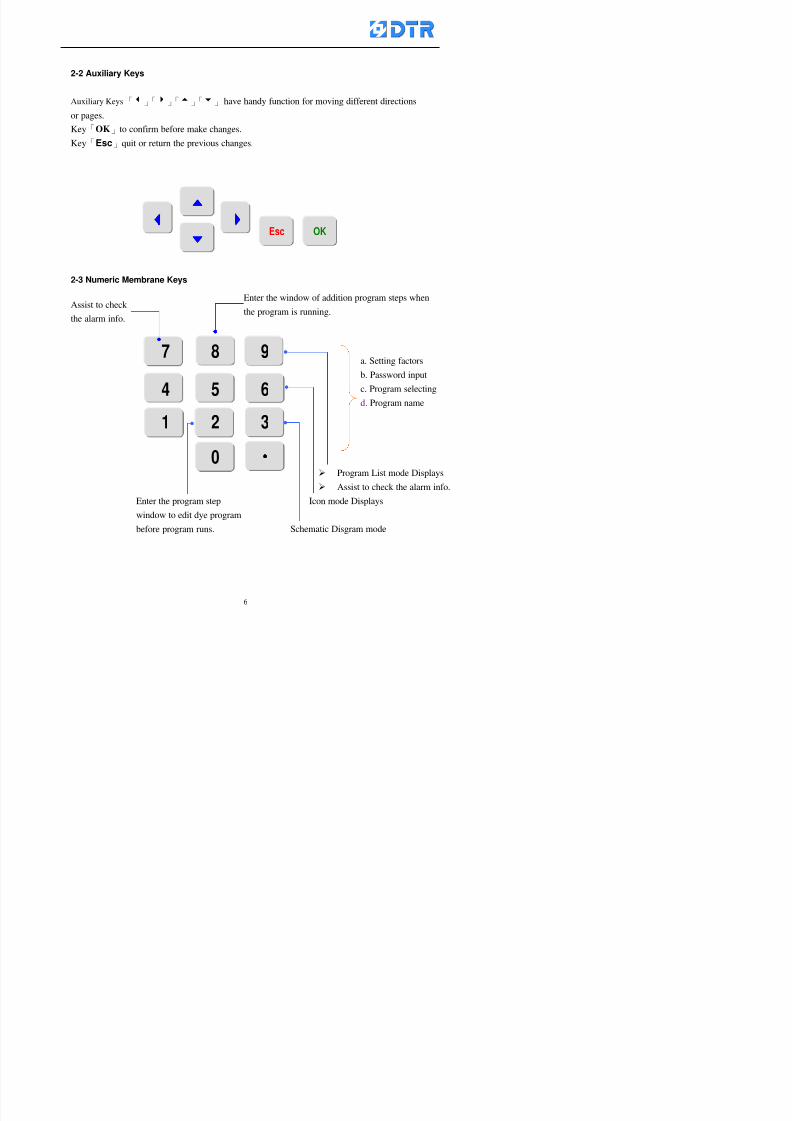
8132019 DTR 650 User Manual
httpslidepdfcomreaderfulldtr-650-user-manual 670
2-2 Auxiliary Keys
Auxiliary Keys「3」「4」「5」「6」 have handy function for moving different directions
or pages
Key「OK」to confirm before make changes
Key「Esc」quit or return the previous changes
5555 33 44
6666 Esc OK
2-3 Numeric Membrane Keys
7 8 9
4 5 6
1 2 3 0
a Setting factors
b Password input
c Program selecting
d Program name
Program List mode Displays
Enter the window of addition program steps when
the program is runningAssist to check
the alarm info
8132019 DTR 650 User Manual
httpslidepdfcomreaderfulldtr-650-user-manual 770
2-4 Operation key and the Indicator
Operation key lsquoStartrsquo (Green button) to run and lsquoStoprsquo ( Red button ) to stop
dye programs
Indicator Run It turns On when the dye program running turns off when program
stops
Indicator Alarm It turns on when alarm is occurred
Indicator Operator It turns on when requesting an operator during program running
Run Alarm Operator
8132019 DTR 650 User Manual
httpslidepdfcomreaderfulldtr-650-user-manual 870
2-5 Selecting the operating functions
When the power on「Run」window appears can start running directly
To choose other function items press「F1」(Exit) to get access to the Main Meun Cursor
stays at the main function field now Choose operating function to move the cursor
accordingly
Steps(a) Press「F2」()「F3」() to move the cursor to the selected functions Press
「F5」(OK)
(b) Now the cursor is at the sub-function field Press「F2」()「F3」()to choose
the functions Press「F5」(ok )to enter the relating window
(c) Press「F1」(Exit)to exit
a)a)a)a)
b)
8132019 DTR 650 User Manual
httpslidepdfcomreaderfulldtr-650-user-manual 970
3 983122983157983150
3-1 Running the current dye program
To enter to the Run window directly when the power on or press「F1」
(Run) to enter the Run window at main menu The ldquostatus barrdquo shows
the current dye programrsquos number and steprsquos number
Check the dye program number and step on the ldquoProgram Status Listrdquo
Press「」「」or「6」「5」to move the cursor to select the program step
to start with When select a step press「start」 to start running
program Now the indicator light「Run」turns on
One main function can be operating with 1 to 4 parallel functions at the same time
The five function keys on function row corresponding to its operating items of
that window press that relating key「F1」~「F5」will get access to its operation
T f th di l d k 「F4 i k 「3 t th S h ti
Parallel functions
Main function in ruuning
8132019 DTR 650 User Manual
httpslidepdfcomreaderfulldtr-650-user-manual 1070
3-2 Jumping steps
During the program operating press「F2」(Jump)to jump to another steps to keep on
running Window appears
「Jump Prev」return to the step in front of the current step
「Jump Next」go to the next step from the current step
Press「」「」to move cursor then press「F5」(OK)to start running the target
dye step
Can use the numeric keys「Jump to XXX」to input the target dye steps directly
Press「F1」(Exit)to quit Keep operating the current program steps
8132019 DTR 650 User Manual
httpslidepdfcomreaderfulldtr-650-user-manual 1170
8132019 DTR 650 User Manual
httpslidepdfcomreaderfulldtr-650-user-manual 1270
3-4 Schematic Diagram Mode Display
Schematic diagram mode displays the dye program operating the water level and
valve status and etc
During the dye program operating press membrance key「F4」to change the
display mode
When program stops it displays to Program list mode automatically from
Schematic diagram display mode Press membrance key「3」to view the
Schematic diagram mode again But if there is an alram occurred it stays at the
Program List mode Please release the alarm first
Press numeric key「9」(Exit)to return to the Program list mode
By setting factor can view the Schematic diagram mode displays directly during
operating (refer to the《6-4》「Display mode setting」for details)
8132019 DTR 650 User Manual
httpslidepdfcomreaderfulldtr-650-user-manual 1370
3-5 Icon Mode Display
During the dye program operating press membrance key「F4」to change to the
display mode
When program stops it displays to Program list mode automatically from Icon
Mode Display Press numeric key「6」to view the Icon mode again But if there is
an alram occurred it stays at the Program list mode Please release the alarm first
Press numeric key「9」(Exit)to return to the Program list display
By setting factor can view the Icon mode displays directly during operating (refer
to the《6-4》Display mode setting for details)
3-6 Running state of dyeing machine
There is totally 2 pages of the Running status information
To check the running status when the program is in operating press「F5」(State)「Inputoutput State」appears pess key「F5」 「Running Information」appears
8132019 DTR 650 User Manual
httpslidepdfcomreaderfulldtr-650-user-manual 1470
3-7 Keep continuing to run from the break point
Due to power sudden off or stop running the dye program it can keep continuing to
run from the break point when the power is retore Users can set the ldquoControl factorrdquo
which dye instruction allows (or prohitbit) to keep continuing to run from the breakpoint (refer to the charpter 6 for Setting)
When the power is restore the cursor stays at the step which stops suddenlybefore starting from the break point to press 「Run」 Window appears
Press「F4」(Yes)to keep going run from the break point
Press「F2」(No)to re-start that dye instruction
Press「F1 (Exit) to return
8132019 DTR 650 User Manual
httpslidepdfcomreaderfulldtr-650-user-manual 1570
3-8 Editing dye step temporary
Before dye program operating the ready-to-run dye step could be edit That edit will
not saved to the file and will not disappear by causing a sudden power inruption or
stop operating until a new dye program is selecting
Step
A Set the system factor as「22」first to allow editing the dye programs temporary
B Set the system factor as「23」 to allow the existing program can temporay
editing its range of step
C Item「19」of the system factor set the dye steps which allows or prohibits to edit
temporary (Refer to the Charpter 6 for details of 「Setting」the A-C )
D Press「F2」()「F3」()or「5」「6」at the Run window To move cursor
to the dye step intend to edit Press membrance key「2」「Edit instrunction
value」appears
E Press「F5」(Edit) then press()()or「5」「6」Programs names is listing
at the cursor or key in a value by the numeric keys Select and press「F5」(ok) to
confirm
F Press「F4」(Save)to confirm and go back to the Run window
G 〔Before pressing「F4」(Save)〕Press「F1」(Exit)to quit
8132019 DTR 650 User Manual
httpslidepdfcomreaderfulldtr-650-user-manual 1670
3-9 Creating an additon dye step during dye program running
Before and during the dye program running the users can creat an addition dye step in
the existing dye programs
3-9-1 Creating an addition dye step
To creat one addition dye step before running or during running step as follows
A Set the System Factor as「34」to allow to creat an addition step (Refer to the
Chartper 6 for details)
B In window「Run dye program」 press numeric key「8」to enter window of 「Edit
addition instruction」 to edit the single dye step first
C Press「」「」「5」
「6」to choose dye
steps press「F5」(OK)
D Press「F5」to edit the
content of dye step
E After complete editing the single dye
step Press「F4」(Run) to start running the
addition step
8132019 DTR 650 User Manual
httpslidepdfcomreaderfulldtr-650-user-manual 1770
3-9-2 Creating an addition treatment to a saved dye program
During and before the dye program running can creat an addition treatment to a
saved dye program or a dye step in a saved dye program
(1) Set the System factor as「34」to allow creating an addition step (Refer to the
Chartper 6 for details)
(2) In window「Run dye program」 press numeric key「8」to enter window of「Edit
single step」
(3) Press「」「」to choose「Sub Prog」 press「4」to move cursor and set itrsquos
dye program number and the step number by numeric keys Or stay at the
「Prog」and press「F3」(File) window appears
(4) Press「」「」to choose an addition dye program then press「F5」(OK)
(5) Press「F4」(Run)to run the addition dye program(sub-dye program)
(6) Finish to run the sub-dye program and return to the main dye program
8132019 DTR 650 User Manual
httpslidepdfcomreaderfulldtr-650-user-manual 1870
4 983120983137983155983155983155983159983151983154983140 DTR-650 provides four ranks of password for sercurity protection
(Refer to the ltTable 10gt Supplementary Table of the Password Usage for details)
First rank (User1 password) Edit delete dye programs control factors in output
testing etchellipall operating fuctions
Second rank (User2 password) Edit in output connecting table operating factors
Third rank (User3 password) Edit copy delete dye programs factors PLC run stop
Fourth rank (User4 password) Edit and modify dye programs
4-1 Entering the password
When the window of 「password」appears enter 6-digits number password by using
the numeric membrane keys then press「F5」(OK) If key-in an incorrect password
press「F3」(Del)and enter again
If the password is correct「」appears it allows to enter the relating operation
8132019 DTR 650 User Manual
httpslidepdfcomreaderfulldtr-650-user-manual 1970
4-2 Locking the data
After editing the programs and factors ensure to disable the password to protect all
programs and data of DTR-650 The way and step as follows
(1) Choose「8Others」at the main meun
(2) Choose「02Data Locking」at the sub-function field
(3) Press「F5」(OK)to confirm
(4) Return to the main menu「」disppears on the status bar that means the data
has been locking already
4-3 Setting and changing the Userrsquos password
There are four userrsquos password for setting and edit by the users themselves
User1 password Access to all operation setting
User2 password For edit in output connection table operating factors
User3 password Only for copy and delete dye programs factors PLC run stop
User4 password Only for edit and modify dye programs
Method of setting edit
(1) Choose「8Others」at main menu press「F5」(OK)
(2) Choose「7 Set Password 2」at the sub-function field press「F5」(OK)
(3) The cursor shows the default password now press「F3」(Clr)to delete Key in
a new password with 6-digit
(4) Press「F5」(OK)to complete the setting of User2 password Go back to the main
menu
8132019 DTR 650 User Manual
httpslidepdfcomreaderfulldtr-650-user-manual 2070
The four userrsquos password has to made from different group numbers Using
same password will affect the operating Please pay attention when update the
password
8132019 DTR 650 User Manual
httpslidepdfcomreaderfulldtr-650-user-manual 2170
5555 983109983140983145983156983145983150983143 983108983161983141 983120983154983151983143983154983137983149983155
5-1 Choosing a dye program
Press function key「F4」(Edit)or choose「1Dye Program」at the main menu press
「F5」(OK)
Choose「1Edit Dye prog」at the sub-function field press「F5」(OK)to enter to the
window「Sel dye program」During the dye program running it is allowed to edit asaved program or a new dye program or the current dye program in running
Method Press「」「」and「5」「6」「3」「4」to move cursor to choose
a dye program number Press「F5」(OK)to enter that dye program Press
「F1(Exit)to quit and return
Method
Directly key in the number selection box
appears at the right corner of the window
Select a program number and press「F5」
(OK) fi
8132019 DTR 650 User Manual
httpslidepdfcomreaderfulldtr-650-user-manual 2270
5-2 Creating a new dye program
Step
A Choose「1Dye Program」Press「F5」(OK)
B Choose「1Edit Dye prog」at the sub-function menu press「F5」(OK)to enter
to window「Sel dye program」
C At the window「Sel dye program」 choose an empty dye number (eg「002」)
press「F5」(OK)window《Fig 5-2-1》appears
《Fig 5-2-1》
D Press「F2」(Add) table of 「Edit dye instruction」《Fig 5-2-2》appears
E Press「F5」(Edit) the dye instruction appears at the cursor locates press「」「」
」and「5」「6」「3」「4」to move cursor to edit the instruction and its
factors
F All inserted new dye instructions would be listed in front of 「Program End」
8132019 DTR 650 User Manual
httpslidepdfcomreaderfulldtr-650-user-manual 2370
【Eg】Edit「CycRinse」
A Edit the main function step first Press「F2」
()「F3」()to move the cursor The dye
step is listing by orders Choose「CycRinse」
and press「」 there is a cursor at itrsquos value
B Move cursor to setting value「Cold」andchoose「Mix」by pressing()() Then
press「」to move cursor to「Time」and enter
itrsquos setting value as「2」Press「F5」(OK) to
complete the main function setting
C To move cursor to the parallel functionsetting field Press()()to choose the
dye step Press「」to confirm and move
cursor to choose itrsquos setting facor
D Press「F5」(OK)to move cursor to the next
parallel function
E Repeat above steps C-D until all parallel
functions setting are completed Each main
function can be operating with the
maximum 4 parallel functions
F Press「F4」(Save)to confirm and return to
the「Edit dye program」window
G Repeat the above step A E to keep on
8132019 DTR 650 User Manual
httpslidepdfcomreaderfulldtr-650-user-manual 2470
5-3 Setting the file name (for dye programs)
When a dye program is setting up it is saved by numbers automatically Optionally users
can save it by another names
Step
(1) Create a new dye program first (the Name is not available for empty dye
programs)
(2) At the window「Sel dye program」 press「F4」(File) Window《Fig5-3》appears
《Fig5-3》
(3) Use numeric 0~9「+」「-」「_」blank alphabet A~Z and symbols [ ] etchellip to
create a file name Each file name can type-in the max 8 unit Press 「3」「4」
「5」「6」to move the cursor to choose the unit It also can use the membrane
numbric key to type in The selected unit is showed in front of the cursor at the
「File」Press「OK」to confirm
(4) Quit to input to press「F3」(Clr)
(5) After complete the set up press「F5」(OK)to confirm and go back to the window
「Sel dye program」 Now the name behind the dye program number is created
8132019 DTR 650 User Manual
httpslidepdfcomreaderfulldtr-650-user-manual 2570
5-4 Inserting a program step
Insert the program step means to insert a step in the existing program step where youwant to insert a step All following steps are moved one step ahead The total number of
steps will be increased by itself Able to insert more than one step continusely at the
same time
【Example】《Fig5-4》 To insert a step「call」before「002 Rinse」
《Fig 5-4》
Step
A Enter to the dye program「002」at the window of 「Sel dye program」
(Example)
B Press「6」to move cursor to「002 Rinse」 then press「F2」(add)
C Press「F5」(Edit) then press「」「」or「5」「6」to choose program
step to modify Choose「call」and press「」to move cursor to modify itrsquos
value
8132019 DTR 650 User Manual
httpslidepdfcomreaderfulldtr-650-user-manual 2670
D Press「」「」 value of 「call」is listing at the table Choose「pH Check 」Press「F5」(OK)
E Press「F4」(Save)and press「F1」(Undo)to return to previous window Complete
to insert the「02 Call」The previous「02 Rinse」update to「03」 All following
steps are moved one step ahead Total number of steps will be increased ldquo1rdquo by
itself
Repeat the steps B-E can non-stop to insert more than one step
Quit the insert and modify ( before pressing「F4」) press「F1」(Undo) to exit
The original dye steps will be unchanged
To delete an inserted dye steps press key「F3」(Del) The step deletes
immediately
5-5 Deleting a program step
Delete the program step means to delete step which the cursor locates When that step is
deleted the step number will be updated automatically All following steps are moved up
one step It is allowed to delete more than one steps continuously at the same time
Step
A Enter to the「Edit dye program」《Fig5-5》at the window「Select dye program」
B Press「6」「5」move cursor to the want to delete
C Confirm and press「F3」(Del) Window「Confirm delete」appears Press
「F4」(Yes)
8132019 DTR 650 User Manual
httpslidepdfcomreaderfulldtr-650-user-manual 2770
D That step is deleted immediately and all following steps move up one step
Repeat the steps above can non-stop to delete more than one step
Press「F2」(No)to cancel the deletion
Press「F1」(Exit)to end
5-6 Modifying a program step
To modify the saved name and the setting value of the dyeing steps
Step
1 Choose a dye program which need to modify at the「Sel dye program」 press「F5」
(OK)
2 Press「6」「5」to move cursor to a step which need to modify Select and press
「F5」(Edit) Window of 「Edit dye instruction」appears
3 Press「F2」()「F3」()to choose the step list select it and press「」to move
the cursor to itrsquos value setting
4 Press numeric key to input the value or press「6」「5」to choose the item Press
「F5」(OK)when complete Cursor move to the next value (if need to set more
than one item)
5 Press「F4」(Save)when all setting is complete Return to「Edit dye program」
Method of parallel functionrsquos modification is same as above
Before pressing the key「「「「Save」」」」 press「F1」(Undo)to quit all modify Return
to the window of Edit dye program
All edit and modify functions mentioned of this charper are only available
for the dyeing files which already saved in the file and not being running It
8132019 DTR 650 User Manual
httpslidepdfcomreaderfulldtr-650-user-manual 2870
5-7 Copying a dye program
Copying a dye programs mean to make a copy of an dye programs to a blank dyeprogram This function is for creating new dye program rapidly
Choose「1Dye Program」at the main menu Press「F5」(OK)then press「F2」()to choose「2Copy dye prog」 Press「F5」(OK) 《Fig5-7-1》appears
《Fig 5-7-1》
《Fig 5-7-2》
【【【【Eg】】】】
Copy program 003 to program 012
Press「」「」to move cursor to theprogram「003」 press「F4」(Copy)
Program「003」shows at the top right side of
the bar
Press「」「」to move cursor to program「012」 Then press「F5」(Paste)「」appears behind the「012」That means it issuccessfully copying the program
If the target program is occupied
confirmation window「Overwrite」
When choose an program or a targetprogram can select them by using the
8132019 DTR 650 User Manual
httpslidepdfcomreaderfulldtr-650-user-manual 2970
5-8 Deleting a dye program
Choose「1Dye program」at the main menu Press「F5」(OK)then press「F2」()to choose「3Delete dye prog」 Press「F5」(OK) 《Fig5-8-1》appears
《Fig5-8-1》
《Fig5-8-2》
Press「」「」to move cursor to
choose program need to delete Eg
delete program「012」 press「F5」(Del) Confirmation window
「Confirm delete」appears
Press「F4」(Yes) to confirm delete
Repeat the above step can delete more
than one program at the same time
Press「F2」(No) to return to window
《Fig5-8-1》and not delete that program
Exit to press「F1」(Exit)and return to the
main menu
8132019 DTR 650 User Manual
httpslidepdfcomreaderfulldtr-650-user-manual 3070
6 983123983141983156983156983145983150983143DTR-650 has a built-in standard factor that can fulfill all different types of dyeing
machinesrsquos basic demand Users can also modify the factors base on their request to
fulfill their special control demand Before modify please refer to the table of each
range of Setting Factors (see the Supplementary Table)
6-1 ldquoEnable to use the program stepsrdquo setting
There are totally 64 program steps Parts of them are usually applying to the programs
In order to make more efficiently of editing programs it can「Disable」the other part
of program steps which are not usually applying or not applicable to the programs
For example dye machine with one tank it is only using step Tank B In this case itcan firstly「Disable」the program steps of Tank C When edit the program the
「Disable」rsquos steps will not appear at the cursor for choosing But this will not effect
and change the saved files The saved files can be kept as before
Step
(1) Choose「2 Factors」at the main menu Press「F5」(OK)(2) Choose「18 Dye Instruction」at the sub-function menu Then presss「F5」(OK)
Window「Edit dye ins」appears
「Enable」instruction can available to
use「Disable」instruction is temporarystop to use
Press「F2」()「F3」()to move
8132019 DTR 650 User Manual
httpslidepdfcomreaderfulldtr-650-user-manual 3170
6-2 ldquoAllow to modify dye program temporary during operatingrdquo Setting
During dye program running it can modify dye program temporary Thesemodification will not disappear by causing a sudden power interruption or power off
until select another new dye program to run
Please note that it is only for modifying the dye program temporary That program
file would not saved due to the modification If need to modify the program file and
save choose the function of Edit Dye Program to edit (Refer to the Charper 5 for the【Edit Dye Prograrm】)
6-2-1 ldquoAllow to modify all dye programsrdquo Setting
Step
(1) Choose「2 Factors」at the main menu Press「F5」(OK)
(2) Choose「02 System Factor」at the sub-function menu Then presss「F5」(OK)
Window「Edit System Factor」appears
Set to stop using temporary the「07
Rinse」press「F4」(Sel)to set it as Disable
Repeat above steps to complete all setting
Press 「F1」(Exit)to return to main menu
8132019 DTR 650 User Manual
httpslidepdfcomreaderfulldtr-650-user-manual 3270
6-2-2 ldquoAllow to modify part of dye programsrdquo Setting
【Eg】Set the number 08 or above (including number 08) is allowing to modify dye
programs during operating
Step
A Refer to【6-2-1】setting the factor as「22」to allow editing dye program
temporary during operating
(4) Press「3」「4」to edit the setting
as「Enable」 and press「F5」(OK)
Restore the standard factor by
pressing「F3」(Clr)
(5) Exit to press「F1」(Exit)and
return to window of 「Main Menu」
8132019 DTR 650 User Manual
httpslidepdfcomreaderfulldtr-650-user-manual 3370
6-2-3 ldquoAllow to modify dye steps temporaryrdquo Setting
After setting the dye programs are allowed to edit it also can set which dye steps are
allowed to edit temporary during operating
Step
(1) Choose「2 Factors」at the main menu Press「F5」(OK)
(2) Choose「19 Dye Ins control」at the sub-function menu Then presss「F5」
(OK) Window「Edit ins mode」appears
「Enable」 Allow to edit that dye step before
operating
「Disable」 Not allow to edit dye step before
operating
(3) Press「」「」to move cursor
to choose dye step Press「F4」
To enter to the「Edit dye program」from the
function menu there is a「」in front of the
file name「0-7」 means that program is not
allowing to edit during operating
8132019 DTR 650 User Manual
httpslidepdfcomreaderfulldtr-650-user-manual 3470
6-2-4 ldquoSet the dye step to keep running from the interrupt pointrdquo setting
When the dye program is operating it will disappear by causing power
interruption or sudden power off When start running again part of dye steps can
run again from the interrupt point part of them cannot
How to set
(1) Choose「2Factors」in the main menu and press「F5」(OK)
(2) Choose「20Continue mode」in the sub-function menu Press「F5」(OK) to
enter window of 「Continue Setting」
(3) Press「」「」to move cursor to choose dye steps Press「F4」(Sel)it
shows「Disable」or「Enable」for choosing Press「F5」(OK)to move cursorto the next setting
(4) Repeat above method until all setting is complete press「F1」(Exit)and
return to the main menu
8132019 DTR 650 User Manual
httpslidepdfcomreaderfulldtr-650-user-manual 3570
6-3 ldquoAllow to insert an addition dye stepsrdquo setting
During the program is running can temporary insert an addition dye step or a dye
program according to the operating actual situation Through this setting can set which
dye steps can apply or not to the program in operating
During to insert an addition step if sudden interruption or power off occurred it returns
to the main dye program automatically Before starting again should decide seriously
and set it again by actual needed
Step
(1) Choose「2Factors」at the main menu and press「F5」(OK)
(2) Choose「02System factor」and press「F5」(OK)
(3) Press「」「」to move cursor to the factor「34」and press「3」「4」to set
it as「Enable」 Press「F5」(OK)
(4) Press「F1」(Exit)to return to main menu Choose「21Addition Ins」at the
sub-function menu Press「F5」(OK)to enter the window「Addition Instruction」
(5) Press「」「」to move cursor to choose dye steps and press「F4」(Sel) Cursors
locates shows「Eable」or「Disable」 Press「F5」(OK)to move cursor to the
next dye step
(6) Repeat above method until to complete all setting press「F1」(Exit)and return
to the main menu
8132019 DTR 650 User Manual
httpslidepdfcomreaderfulldtr-650-user-manual 3670
6-4 Setting the display mode
DTR650 has three types of display mode during operating Program List mode
Schematic Diagram mode and Icon mode Users can set the display mode during
operating by factor setting
It goes back to a Program List mode when dye program ended
Step
(1) Choose「2Factors」at the main menu and press「F5」(OK)
(2) Choose「02System factor」and press「F5」(OK)
(3) Press「F2」()「F3」()to move cursor to choose「32Display mode」Press
「3」「4」 it shows「Online picture」「Instruction」「Big Icon」 choose
「Online picture」(eg) and press「F5」to confirm
8132019 DTR 650 User Manual
httpslidepdfcomreaderfulldtr-650-user-manual 3770
(4) Press「F1」(Exit)to return to the main menu
(5) The Schematic Diagram displays when the program is running (it stays at theProgram List mode when there is an alarm occurred)
Press「F4」to transfer to another display mode
It goes back to a Program List mode from Schematic Diagram Mode when dye
program ended Press numeric key「3」to view Schematic Diagram Mode again
Quit to press「F5」(Exit)
6-5 Adapt the digital input to another functions
DTR-650 has 32(0~31)input terminal it owns an standard setting when the
controller is initial According to the userrsquos demand they can change the DTR-650rsquos
anther functions of Input Terminal and PLC Input channel
The PLC Intputrsquos name can also define by the users (use IBM computer to edit and
download)
How to set
(1) Choose「2 Factor」at the main menu Press「F5」(OK)
(2) Choose「22 Input table」at the sub-function menu and press「F5」(OK)to enter
「Edit input table」
The actual input
terminal of theIBM computer
PLCrsquos input channel
8132019 DTR 650 User Manual
httpslidepdfcomreaderfulldtr-650-user-manual 3870
6-6 Adapt the digital output to another functions
DTR-650 has 32(0~31)output terminals it owns an standard setting when thecontroller is initial According to the userrsquos demand they can adapte the digital output
and the PLC outputrsquos channel to another functions The PLC Output channelrsquos name
can also define by users (use IBM computer to edit and download)
Step
(1) Choose「2 Factor」at the main menu Press「F5」(OK)
(2) Choose「23 Output table」at the main menu and press「F5」(OK)
(3) Press「F2」()「F3」()to move cursor to choose the output terminal atthe left side of the window Press「F5」(Add) the PLCrsquos output channelrsquos
name is listing at the right side of the window
(4) Press「F2」()「F3」()to move cursor to choose the PLC outputrsquos channel
If cursor moves to the PLC output channel which already linking「Add」is
not for choosing that means that output channel is already occupied
(5) Confirm the connection to press「F5」(Add) Quit to press「F4」(Del)Press「F1」(Exit)when complete all setting and return to main menu
The actual output
terminal of the
IBM computer
PLCrsquos output channel
8132019 DTR 650 User Manual
httpslidepdfcomreaderfulldtr-650-user-manual 3970
983095 983109983140983145983156983145983150983143 983156983144983141 983110983137983139983156983151983154983155DTR-650 has several kinds of control factors
Userrsquos factors System factors Temperature Control factors Speed factors Dosing
factors PID factors Analog Input Output factors standard factors etchellipPlease refer
to the supplementary table for the setting range and standard of the factors
DTR-650 has a built-in standard factor Users can edit by themselves if necessary
7-1 Modifying userrsquos factors
Userrsquos factors is setting with the Dyeing machinesrsquos PLC Programrsquos factor it is define by
the PLC Programmer
Step to edit
(1) Choose「2Factors」at main menu Press「F5」(OK)
(2) Choose「01User Factor」Press「F5」(OK)
(3) Press「F2」()「F3」()「6」「5」to move cursor up down and by page
Choose a factor need to edit then press「3」「4」to set itrsquos value Press「F5」(OK) Cursor moves to the next factor
(4) Some of factors can input numbers by the numeric membrance keys to edit If
the input is incorrect it turns to red and means the edit is not available
8132019 DTR 650 User Manual
httpslidepdfcomreaderfulldtr-650-user-manual 4070
Modifyrsquos method of the system factors temperature factors speed factors dosingfactors PID factors analog Input output factors standard factors etchellipare same asabove
If apply the library of DTR500 and DTR600 into the DTR650 the key「3」「4」may not valid to use Please use the numeric keys instead of it to key in factors itmay not effect the normal operation
Please pay a serious attention and read carefully at the factorrsquos table before modify the factors An incorrect value may effect the DTR-650 Dyeing
Machine Controllerrsquos operating After modifying factors must cancel the
password and secure data
7-2 Loading the standard factors
After modifying factors if need to restore a manufacturerrsquos standard factors of
DTR-650 The method as follows
1 Choose「2Factors」at main menu Press「F5」(OK)
「 「 ( ) 「
8132019 DTR 650 User Manual
httpslidepdfcomreaderfulldtr-650-user-manual 4170
7-3 Copying the factor
Users can build up a set of factor by themselves and make a copy and save
Step
1 Choose「2Factors」at main menu Press「F5」(OK)
2 Choose「13Restore Factor」 press「F5」(OK) window「factor will be
overwrite 」
3 Press「F4」(Yes)copy finished and saved Return to the main menu
4 Press「F2」(No)to not copy the factor and the existing factor is not change Return
to the main menu
7-4 Loading the backup factors
Users can build up a set of factor and backup files to load to DTR-650
Step1 Choose「14Backup factor」at the sub-function menu Press「F5」(OK)and
window「Factror will be overwrite」appears
2 Press「F3」(OK)to load the the backup factor them return to main menu
Press「F2」(No)to not copy the factor and the existing factor is not change
Return to the main menu
8132019 DTR 650 User Manual
httpslidepdfcomreaderfulldtr-650-user-manual 4270
983096 983119983157983156983152983157983156 983124983141983155983156983145983150983143
Before the output testing must be complete the steps as follows
A Cut off all connecting line of output terminal of DTR-650
B Stop running the PLC
C Check up the connections of all output channels to avoid damages from
incorrect connections
D Check up state of dyeing machines include the temperature pressure valves
onoff and pumpshellipetc ensure the safety for priority
8-1 Testing the Digital output
Step
1 Choose「3Output Testing」at the main menu Press「F5」(OK) 2 Choose「1Digital」at the sub function menu Press「F5」(OK) window「Digital
output testing」appears
3 Press「」「」「」to move cursor to each output channels Press「F5」(OK)
Output Name
8132019 DTR 650 User Manual
httpslidepdfcomreaderfulldtr-650-user-manual 4370
8-2 Testing the Analog output
(1) Choose「3Output Testing」at the main menu Press「F5」(OK)
(2) Choose「2Analog」at the sub function menu Press「F5」(OK) window「Analog output testing」appears
(3) Press「」「」「」to move cursor to each channels Then key in number by
the numeric membrance keys (range0~200= 0~20mA) Press「F5」(OK) there
is a output current relating to the output channel
(4) Press「F5」(OK) There is an output when the output channel with red light No
output without light onl(5) When complete the testing press「F1」(OK)to return to the main menu
8132019 DTR 650 User Manual
httpslidepdfcomreaderfulldtr-650-user-manual 4470
983097 983107983137983148983145983138983154983137983156983145983151983150
DTR-650 has Dosing and Temperature calibration
When enter to Dosing calibration must be set the Low Volume calibration first and
then High Volume calibration When enter to Temperature calibration must be set the
Low Temperature calibration first and then High Temperature calibration Must be
hightly follow this orders seriously
9-1 Calibration of Low Volume Tank
Step
A Choose「4Calibration」at the main menu Press「F5」(OK)
B Choose「Dosing 0 low vol」at the sub function menu Press「F5」(OK) window
appears
C Fill the Dosing Tank to a half level input value shows how much the water level
If it stays ldquo0rdquo check the connection and the factor setting is correct or not
And connect the pressure sensorrsquos output channel to the Current Meter to ensure
that sensor works or not
8132019 DTR 650 User Manual
httpslidepdfcomreaderfulldtr-650-user-manual 4570
D Fill the Dosing Tank to 50ml (Calcalate from the bottom side of the pressure
sensor steel tube) input value should show 4~6 (input value must between
0~10) Then enter the water volume The setting volume is relating the water
levelrsquos water value (litre as unit) input range 0~80 Set as「 「「 「0000 0000 0000 0000」」」」is strongly is strongly is strongly is strongly
receommend receommend receommend receommend Press「F5」(OK)to complete [Calibration of Low Volume Tank 1
is same as above method]
9-2 Calibration of High Volume Tank
Step
A Choose「4Calibration」at the main menu Press「F5」(OK)
B Choose「Dos 0 high vol」at the sub function menu Press「F5」(OK) window of
「Calibrate high 」appears
C Fill the Dosing Tank to a full level input value should be larger than 30 enter
the current water level which relates to the water volume Enter the range within
100~2500 Then press「F5」(OK) to complete the calibrate the high volume tank
8132019 DTR 650 User Manual
httpslidepdfcomreaderfulldtr-650-user-manual 4670
9-3 Temperature Calibration
Step
A This function is for adjusting the DTR650rsquos accuracy of Temperature Control It
must be using with the special terminal which is only for DTR650
B Choose「4Calibration」at the main function menu and press「F5」(OK)
C Choose「3Low Temp」at the sub-function menu Press「F5」(OK)and《Fig9-3》
appears insert the DTR650rsquos low temperature calibration terminal to the temperature
input terminal wait for the jumping value to stable down then press「F5」(OK) then
to adjust the high temperature calibration
D Adjusting the High Temperature Calibrationrsquos method is same as above But usersusersusersusers
must be using the High Temperature Terminalmust be using the High Temperature Terminalmust be using the High Temperature Terminalmust be using the High Temperature Terminal whichwhichwhichwhich is specially for DTR650 onlyis specially for DTR650 onlyis specially for DTR650 onlyis specially for DTR650 only
《Fig 9-3》
8132019 DTR 650 User Manual
httpslidepdfcomreaderfulldtr-650-user-manual 4770
10 983122983141983139983151983154983140983155 983151983142 983108983161983141 983120983154983151983143983154983137983149983155
It contains the past 15 days of temperature curves of running history
Checking method
(1) Choose「5Dye Record」at main menu press「F5」(OK)
(2) Sub-function menu shows the set up date of the past 15 days dye programs
Listing by the lastest set up date
(3) Choose a program date and press「F5」(OK) it appears window「Temp
record」
(4) Press「」「」to move the white line in the box one minute by moving once
(5) Press「3」「4」to move the line to check the time period 2 hours by moving once
The yellow selecting line of the「24 hours operating state」is repectively moving
The curve info is show in the curve box Left side of the widnow appears the
relating running info the time is the time value of the line locates at
(6) Check more details of the temperature info to press numeric key「middot」 a bright red line
appears in the selecting box this line is to check the starting point of the
temperature inforsquos time period Then press「」to move the white line to the end
point of the time period The temperature info between the starting point and end
point are appears at the right side of the window Press「middot」to return to the preious
curve page
(7) Check more details of the alarm infor To perss numeric key「7」「9」 the alarmrsquos
details is listing by orders
(8) Press「F1」(exit) to return
8132019 DTR 650 User Manual
httpslidepdfcomreaderfulldtr-650-user-manual 4870
11 983125983155983137983143983141 983151983142 983117983141983149983151983154983161 983107983137983154983140
DTR-650 supports 32MB or above Compact Flash Card which can transfer and save all
information for 4 sets of DTR-650 Including library files schematic diagram icon
image PLC program dye program factor and confiruration files etchellip Use the CF Card
to up download and swap the information of DTR-650 promptly install the relating
device and program updates
DTR-650 CF Card with bank 1 to bank 4 can save 4 sets information of Dyeing
Machines When download or save files should choose the BANK first
《Fig11-1》
8132019 DTR 650 User Manual
httpslidepdfcomreaderfulldtr-650-user-manual 4970
11-1 Downloading data
1 Firmly insert the CF card into the DTR-650rsquos PCMCIA connector Ensure it is
wholely and firmly inserted if the card is not totally inserted or the card do not
touch in all to the connector there will be an error occurred and cannot
updownload or interrupted during operation
2 Choose「6Memory Card」at the main menu and press「F5」(OK) 《Fig11-1》
appears Information of Bank「1」shows at the left hand side of the window press
number 1-4 by using numeric keys to choose the BANK Check the
information in the Bank seriously which is exactly need to download to the
DTR650
3 Press()()「6」「5」to move cursor to the sub-function menu to choose
the downloading items Press「F5」(OK) window appears「Stop PLC run before
access memory card Stop the PLC run」 Press「F5」(YES) to stop PLC
running
4 Press「F5」(OK) window appears Confirm to update or not the DTR-650rsquos
information As that downloading will be replace the DTR-650rsquos information
(that means the existing information of the DTR-650 will be removed and
replaced)
5 Press「F4」(YES)to download the information from the DTR-650 to the CF
Card Return to the main menu when finish
8132019 DTR 650 User Manual
httpslidepdfcomreaderfulldtr-650-user-manual 5070
Ensure inserting firmly the CF card into the DTR-650 unless it will cause
error or cannot Updownload data
Never remove CF card during transferring or updownloading data Until it
is all completed
DTR-650rsquos dyeing program is not compatible with DTR-500 and
DTR-600 Never use CF card to transfer data among them
11-2 Storing and transfering data
1 Insert the CF Card to the DTR-650
2 Choose「6Memory Card」at the main menu and press「F5」(OK) 《Fig11-1》
appears Left hand side of the window shows the data of BANK 1 press numeric
keys 1-4 to select the BANK To confirm the put the data in the DTR-650 to the CF
Card The existing data of that bank will be replaced and covered by the new data (if
that bank is already occuplied)
3 Choose「23Save Dye prog」(Example)at the sub-funciton menu press「F5」(OK)to confirm Window「Update memory card data」appears
4 Press「F5」(OK)to transfer the data to the CF card Return to the main menu
5 Put the CF card into another DTR-650 and follow the operating method of 「11-1
Downloading data」」」」can transfer and swap data with more than one set of
DTR-650
8132019 DTR 650 User Manual
httpslidepdfcomreaderfulldtr-650-user-manual 5170
12 983123983156983137983156983141 983137983150983140 983113983150983142983151983154983149983137983156983145983151983150
The state and information is including the Dyeing Machinersquos state of Digit Input output
Analog Input output Temperature control PID Dosing PID Pressure different PID
software system information and alarm record This information is for checking at any
time
12-1 Input Output state
Step
1 Choose「7Info and state」at main menu and press「F5」(OK)
2 Choose「01Digital IO put」at the sub-function menu then press「F5」(OK)
「Digital In Out State」0=None 1=Input
3 Press「F1」(Exit)to return to main menu
Same method for checking the temperature control analog dosing pressure
different etchellip
12-2 Checking the system information
Step
1 Choose「7Info and state」at main menu and press「F5」(OK)
2 Choose「11 System info」at sub-function field press「F5」(OK)Window
「System Information」appear
System information is including System info(software version) Library doc
Icon files Schematic file Definition file hardare state Config File Commandinstruction icon PLC file etc
8132019 DTR 650 User Manual
httpslidepdfcomreaderfulldtr-650-user-manual 5270
12-3 Checking the operating alarm record
Operating record shows the latest 40 operating items and alarm records including
the time and content of the alarm
A) Choose「7 Info and state」
and press「F5」(OK)
B) Choose「12Alarm logs」at
the sub-funciton menu then
press「F5」(OK)
8132019 DTR 650 User Manual
httpslidepdfcomreaderfulldtr-650-user-manual 5370
13 983105983140983146983157983155983156983145983150983143 983156983144983141 983107983151983150983156983154983137983155983156
The displaysrsquos brightness can be adjusted if necessary
Step
1 Choose「8Others」at main menu press「F5」(OK)
2 Choose「01Contrast」at sub-function menu press「F5」(OK) window「Set
Contrast」appears
3 Press「」「」to move the bar to set the brightness then press「F5」(OK)Window appears「Please reboot the system」
4 Press「F5」(OK)to return to main menu and re-boot the DTR-650 to complete
adjusting the brightness
8132019 DTR 650 User Manual
httpslidepdfcomreaderfulldtr-650-user-manual 5470
14 983123983156983151983152 983154983157983150983150983145983150983143 983156983144983141 983120983116983107 983120983154983151983143983154983137983149
Before testing the Input output testing transfer of the PLC program must stop the PLC
running
Step
1 Choose「8Others」at the main menu Press「F5」(OK)
2 Choose「04 PLC Stop」at sub-function menu Press「F5」(OK) window
「Password」appears
3 Enter password and press「F5」(OK) Window「Stop the PLC run」appears
4 Press「F4」(Yes)and window「PLC Stop」appear Press「F5」(OK) Now
the PLC is stop running and return to the main menu
All testing cannot operate when the PLC is running
Editing dye program and the relating operation can
perform with the PLC running together
8132019 DTR 650 User Manual
httpslidepdfcomreaderfulldtr-650-user-manual 5570
15 983123983141983156983156983145983150983143 983156983144983141 983156983145983149983141
Step
1 Press「8Others」at the main menu Press「F5」(OK)
2 Choose「10Set date time」at the sub-function menu Press「F5」(OK) window
「Set date time」appears
3 Press「F5」(Edit) to move cursor by 「3」「4」 enter the time value at the
cursor locates
4 Press「F5」(OK)to complete the modify Press「F1」(Exit)to return to main
menu
5 Press「F1」(Exit)if not modify and return to main menu
8132019 DTR 650 User Manual
httpslidepdfcomreaderfulldtr-650-user-manual 5670
1166 983123983123983157983157 983152 983152 983152 983152983148983148983141983141983149983149983141983141983150983150983156 983156 983137983137983154 983154 983161983161 983124 983124 983137983137983138983138983148983148983141983141
TTTTTTTTaaaaaaaabbbbbbbblllllllleeeeeeee 11111111 【Dye Instruction】
Code Icon Instruction Code Icon Instruction
000 End 016 Inject C
001 Start 017 Dosing BV
002 Heat 018 PH
003 Cool 019 Addsalt B
004 Flow Fill 020 Addsalt C
005 Level Fill 021 Ana Fill
006 Drian 022 Lock Fill007 Rinse 023 Lock Level
008 Run 024 Low Rinse
009 Call 025 Cyc Rinse
010 Prep B 026 Rinse B
011 Addsalt B 027 Rinse C
012 Dosing B 028 Temp
013 Inject B 029 Nozzle Pressure
014 Prep C 030 Main Pump
015 Dosing C 031 Pump Speed
8132019 DTR 650 User Manual
httpslidepdfcomreaderfulldtr-650-user-manual 5770
Table 2 【【【【Alarm】】】】
System Alarm Must stop operating and check up to solve problems before restarting
the machine
Running Alarm It is a reminder Not effect the operating of DTR-650
Userrsquos Alarm Total of 32 Users can define themselves and use it when edit the PLC
Program (do not listing below)
No System Alarm No Running Alarm
1 PLC program not running 16 Temp ctrl 0 Grad too slow
2 Main temp sensor error 17 Temp ctrl 0 Grad too fast
3 Not at Run window 18 Temp ctrl 0 Hold temp too low
4 Exceeding max temp 19 Temp ctrl 0 Hold temp too high
5 - 20 Temp ctrl 1 Grad too slow6 - 21 Temp ctrl 1 Grad too fast
7 - 22 Temp ctrl 1 Hold temp too low
8 Communication error 23 Temp ctrl 1 Hold temp too high
9 Slave not answer 24 Temp ctrl 2 Grad too slow
10 PLC 0 not answer 25 Temp ctrl 2 Grad too fast
11 PLC 1 not answer 26 Temp 2 Hold temp too low12 Display not answer 27 Temp 2 Hold temp too high
13 Lower power voltage 28 Temp ctrl 3 Grad too slow
14 - 29 Temp ctrl 3 Grad too fast
15 - 30 Temp3 Hold temp too low
31 Temp3 Hold temp too high
32 Dosing 0 injection too slow
33 Dosing 0 injection too fast
34 Dosing 1 injection too slow
35 Dosing 1 injection too fast
8132019 DTR 650 User Manual
httpslidepdfcomreaderfulldtr-650-user-manual 5870
TTTTTTTTaaaaaaaabbbbbbbblllllllleeeeeeee 33333333 【【【【System factor】】】】
No Description Std Range amp Definition
1 ID No 000 000- 100 Controller no
2 Communication Rate 4800Bps 2400 4800 9600 19200 38400
3 Display language Chinese English Chinese
4 Temp display mode and
5 Maxmium temperature 145 025 ~ 145 6 Type of external PLC Default PLC32DPLC32PLC16Default
7 Number of external PLC NANA 1 unit connect
2 unit connect
8Communication Rate of
PLC9600Bps 2400 4800 9600 19200
9 Set point 1 085 000 ~ 145
If signal source is temperaturethe setting value is thetemperature value If the signal
source is Analog Input 6~17 then
setting value for Analog input is 0 ndash
100 and relates Analog
Input14~020mA
10 Source 1 Sensor0Sensor 0 ~5
Analog input 0 ~1111 Set point 2 092 Same as 09
12 Source 2 PT100 1 Same as 10
13 Set point 3 085 Same as 09
14 Source 3 PT100 2 Same as 10
15 Set point 4 092 Same as 09
16 Source 4 PT100 3 Same as 1017 Set point 5 085 Same as 09
18 Source 5 PT100 4 Same as 10
19 Set point 6 092 Same as 09
8132019 DTR 650 User Manual
httpslidepdfcomreaderfulldtr-650-user-manual 5970
29 Min cyclic time of cloth 100sec 0 ~ 255 sec
30 Max cyclic time of cloth 240sec 0 ~255 sec
31Standard cyclic time of
cloth
180 000 ~ 255 sec
32 Display ModeProgram
List
Program list Schematic Diagram
Icon mode
33 CF card format Standard of
DTR CF
Card
Standard of DTR CF Card V20
Standard CF Card
34 Addition step Disable Disable Enable35 Mode Com 3
CouplingEsure Com 3 is the communication
port of the Central or Coupling
36Com 3 Communication
rate9600 Central communication speed
8132019 DTR 650 User Manual
httpslidepdfcomreaderfulldtr-650-user-manual 6070
TTTTTTTTaaaaaaaabbbbbbbblllllllleeeeeeee 44444444 【【【【Temperature Cotnrol Factor】】】】
No Factor Definition Standard Range and Definition
01 PT No PT-0 PT 0~5 PT-100 Input number
02 Max working temp 140 000~140
03 Output mode 0 0~2
04 Alarm time of gardient 240sec 000~255 sec
05 Alarm mode of gradient Always AlwaysOnceNone
06 Control mode of gradient Heating orCooling
interlocked
Heating and Cooling interlocked
No limitation
07 Alarm range of HoldTemp 03 01~20
08 Alarm time for HoldTemp 240sec 000~255sec
09 Alarm mode of HoldTemp Always AlwaysOnceNone
10 Control mode ofHoldTemp
Heating only Only heating and cooling Cooling whenalarm occurred Only heating andcooling No limitation when alarmHeating only
11 Porportional Band 100 000~250
12 Integral band 128 sec 000~255 sec
13 Differential time 04 sec 00~20 sec
14 Min transit gradient 02 00~50
15 Transit rate 20 times 00~50 times (020= 2 times)
16 PID initial output value 010 000~100
17 ONOFF cycle time 10 sec 05~25 sec
Onoff valve set as 010 sec
Proportional valve set as 020 sec
18 Time down count mode Mode 0 0~10 = The time down count range from「Factor 20 + target temp」to「Target
8132019 DTR 650 User Manual
httpslidepdfcomreaderfulldtr-650-user-manual 6170
TTTTTTTTaaaaaaaabbbbbbbblllllllleeeeeeee 55555555 【【【【Speed Factor】】】】
No Factor Definition Standard Range amp Definition
01 Input Number Speed input 0 Speed input 0~11
02 Average times 05 times 01~10
03 Sensor Number 008pcs 001~255
04 Roller Dimension 250mm 050~500
05 Max cloth speed 200mmin 001~25506 Min cloth speed 020mmin 001~255
07 Alarm delay time 240sec 001~255
08 Alarm mode Every oncenoneevery
09 Alarm range () 020 001~255
10 Proportional band 100 001~255
11 Integer band 128 001~25512 Differential time 000 001~200
13 Initial speed () 020 001~255
14 Control cycle ti(01sec) 05 01~30
15 First cycle time(01sec) 10 01~30
16 Speed increase limit () 010 001~100
17 Speed decrease limit () 010 001~100
18 Min speed() 005 001~100
19 Manual speed adjust () 005 001~100
20 Manual initial speed() 020 001~100
21 Stopping speed() 010 001~100
22 Switch speed() 020 001~100
23 Not used
24 Speed decrease turns 03turns 01~50
8132019 DTR 650 User Manual
httpslidepdfcomreaderfulldtr-650-user-manual 6270
Table 6 【【【【Dosing Factors】】】】
No Description Range Range and Explanation
1 Analog input no Analog input 0 Analog input no 0 ~11
2Alarm delay time for
dosing240 sec 000 ~255 sec
3 Alarm time for dosing Every Every Once None
4 Proportional band 100 000 ~255 sec Factor P
5 Integer band 128 000 ~255 sec Factor I6 Differential time 04 00 ~20 Factor D
7 Max adjust rate 150 50~ 255
8 Initial factor for dosing 10 000 ~100
9 User curve section 0 10 Gradient of sect1 for dosing curve9
10 User curve section 1 10 Gradient of sect2 for dosing curve9
11 User curve section 2 10 Gradient of sect3 for dosing curve9
12 User curve section 3 10 Gradient of sect4 for dosing curve9
13 User curve section 4 10 Gradient of sect5 for dosing curve9
14 User curve section 5 10 Gradient of sect6 for dosing curve9
15 User curve section 6 10 Gradient of sect7 for dosing curve9
16 User curve section 7 10 Gradient of sect8 for dosing curve9
17 User curve section 8 10 Gradient of sect9 for dosing curve9
18 User curve section 9 10 Gradient of sect10 for dosing curve9
19 Min water level 05 00~ 10 04~20mA percentagechange to the userrsquos factor setting
20 Output value for Tank
clean
100 000~ 100
Injected percentage of dosing valve
in dosing End period
This factor will be invalided if usingONOFF dosing valve
21 Full range 100 001~255 Self-adjustment cannotchange
22 Range ratio 001001~255 Self-adjustment cannot
change
8132019 DTR 650 User Manual
httpslidepdfcomreaderfulldtr-650-user-manual 6370
【【【【TTaabbllee 77 】】】】Pressure Deviation Factors
No Description Std Range amp Definition
1 Analog input number + Analog in 0 Analog in 0~11
2 Analog input number - Analog in 1 Analog in 0~11
3 Input mode Pressure Pressure Pressure deviation
4 Full range 050x01Kgcm
001~255
5 Range ratio 001 001~255
6 Alarm delay time 100sec 001~255
7 Alarm mode Every oncenone
8 Alarm range 010 001~255
9 Proportional band 100 001~255
10 Integer band 128 001~255
11 Differential time 00 00~20
12 PID Init output value 010 001~255
13 Cycle time 10 03~30
14 First cycle time 030 003~100
15 Max adjust rate 010 001~100
8132019 DTR 650 User Manual
httpslidepdfcomreaderfulldtr-650-user-manual 6470
【【【【TTaabbllee 88 】】】】Definition of Analog Input
No Description Standard Range and Explanation
01 PT 0 correction standard DIN std DIN std JIS std
02 PT 0 correction +0 +- 9
03 PT 1 correction standard DIN std DIN std JIS std
04 PT 1 correction +0 +- 9
05 PT 2 correction standard DIN std DIN std JIS std
06 PT 2 correction +0 +- 9
07 PT 3 correction standard DIN std DIN std JIS std
08 PT 3 correction +0 +- 9
09 PT 4 correction standard DIN std DIN std JIS std
10 PT 4 correction +0 +- 9
11 PT 5 correction standard DIN std DIN std JIS std
12 PT 5 correction +0 +- 9
13 Analog input 0 define 4 ~ 20mA 0 ndash 20mA 4 ndash 20mA
14 Analog input 0 average times 10 times 01- 20 times
15 Analog input 0 min value 0000 0000 - 1000
16 Analog input 0 max value 100 0001 - 9999
17-60 Analog input 1~11 Same as Analog input 0
【【【【 】】】】 fi i i f A O
8132019 DTR 650 User Manual
httpslidepdfcomreaderfulldtr-650-user-manual 6570
【【【【TTaabbllee 99 】】】】Definition of Analog Output
No Description Standard Range and explanation
61 Analog output 0 define Control byPLC
Control by PLC
Temperature control PID0 output
Temperature control PID1 output
Temperature control PID2 output
Speed PID3 output
Dosing PID0 output Dosing PID1output
Pressure different PID0 outputPressure different PID1 output
Main temperature output
62 Mode of Analog ouptput0 4 ~20mA 0 ndash20mA 4 ndash 20mA
63-84 Analog output 1~11 Same as Analog output 0
【【【【TTaabbllee 1100】】】】Value Table 0 amp 1
No Description Range Std Range and explanation
1 Analog input no 000~011 000 Analog input no
2 Data ratio 001~255 100 Multiple by factors
3~53 0~98 000~255 000-100 Analog input 0~98 data
【【【【 】】】】St t Li t
8132019 DTR 650 User Manual
httpslidepdfcomreaderfulldtr-650-user-manual 6670
【【【【TTaabbllee 1111】】】】State List
No Description Range Standard Range and explanation
1 Display setting 1 0~255 205 See remarks at next page
2 Display setting 2 0~255 208
3 Display setting 3 0~255 209
4 Display setting 4 0~255 017
5 Display setting 5 0~255 0186 Display setting 6 0~255 019
7 Display setting 7 0~255 020
8 Display setting 8 0~255 021
9 Display setting 9 0~255 000
10 Display setting 1 0~255 000
11 Display setting 2 0~255 000
12 Display setting 3 0~255 000
13 Display setting 4 0~255 000
14 Display setting 5 0~255 000
15 Display setting 6 0~255 000
16 Display setting 7 0~255 000
Remarks
8132019 DTR 650 User Manual
httpslidepdfcomreaderfulldtr-650-user-manual 6770
0 = No display 1~255 = Display type of number
1~16 Content of PLC VB0~15
No 1 corresponding to VB0
No 16 corresponding to VB15
17~32 Content of PLC DB0~15
No 17 corresponding to DB0
No 32 corresponding to DB15
33~46 Content of PLC CNT0~29
No 33 corresponding to CNT0
No 46 corresponding to CNT29 47~78 Content of dyeing instruction 0~31 CNT0
No 47 corresponding to system instruction to No 0 of CNT0
No 78 corresponding to system instruction to No 31 of CNT0rsquos content
79~110 Dyeing instruction 0~31 of CNT0rsquos setting
111~142 Content of Dyeing instruction 0~31 CNT1No 111 corresponding to dyeing instruction No 0 of CNT1
No 142 corresponding to dyeing instruction No 31 of CNT1rsquos content
143~174 Dyeing instruction 0~31 of CNT1rsquos setting
175~204 Content of PLC HTIM0~29
No 175 corresponding to HTIM0
No 204 corresponding to HTIM29
205 Loading
206 Ratio 1
207 Ratio 2208 Ratio 1 x Loading
209 Ratio 2 x Loading
210 Fix value
211 Value Table 1 matching result
212 Value Table 2 matching result
213 Value Table 1 setting214 Value Table 2 setting
215 Pressure control PID0 different pressure value
216 Pressure control PID1 different pressure value
TTTTTTTTaaaaaaaabbbbbbbblllllllleeeeeeee 1122 【【【【Usage of password】】】】
8132019 DTR 650 User Manual
httpslidepdfcomreaderfulldtr-650-user-manual 6870
No Main FunctionFactor Sub Function Factor Password Rank
1 Run None
2 Dye program User3 or above
3 Control factor
- User factor User 1
- System factor User 1
- Temp PID 0
- Temp PID 1 User 1- Speed PID 0 User 1
- Dosing PID 0 User 1
- Dosing PID 1 User 1
- Pressure PID 0 User 1
- Pressure PID 1 User 1
- Analog IO User 1
- Load standard factor User 2 or above- Load a copied factor User 2 or above
- Copy factor User 2 or above
- Value table 0 User 1
- Value table 1 User 1
- Information and state User 1
- Dye instruction User 1
- Edit dye instruction setting User 14 Output testing User 2 or above
5 Calibration User 2 or above
6 Dye record None
7 CF card User 1
8 Info and state None
9 Others
- Contrast User3 or above
- Data Locking None
- PLC Run User 1
- PLC Stop User 1
- Password setting User 1
TTTTTTTTaaaaaaaabbbbbbbblllllllleeeeeeee 1133 【【【【Technical Data】】】】
8132019 DTR 650 User Manual
httpslidepdfcomreaderfulldtr-650-user-manual 6970
TTTTTTTTaaaaaaaabbbbbbbblllllllleeeeeeee 1133 【【【【Technical Data】】】】
1 Temperature Control
- Range 10~145(plusmn1)
- Mode Proportional or PWM
- Sensor PT100 (JIS or DIN standard)
2 Input and output channel
- Digital Input 32 DC24V PNP- Digital Output 32 DC24V 054A Relay connect point
- Analog Input 4 04~20 mA
- Analog Output 4 0~20mA 或 4~20 mA
3 Communication port 3 RS-232 amp 0~20 mAx1 RS485x 2
4 Dye program
- Number 15000 Steps
- Standard step 61Heating Cooling Fill Drain RinseDosingetc
5LCD module and Display
langage
Chinese
English
320 x 240 TFT color display with
more language
6 CF card connector 1 PCMCIA standard
7 Membrane Keyboard- Number Key 10 [0]~[9] Input factors
- Function Key 5 [F1]~[F5] function selecting
- Operation Key 2 [Start] [Stop]
- Auxiliary Key 7 [][][][][Esc] [larr][OK] [bull]
8 Operating Condition
- Temperature 5~45
- Humidity ≦85 (25)
9 Power supply
V l DC 24V
8132019 DTR 650 User Manual
httpslidepdfcomreaderfulldtr-650-user-manual 7070
70
983108983124983122983085650 983113983150983152983157983156 983119983157983156983152983157983156 983120983151983154983156983145983150983143 (983138983137983139983147983155983145983140983141 983158983145983141983159)
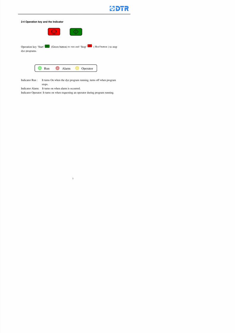
8132019 DTR 650 User Manual
httpslidepdfcomreaderfulldtr-650-user-manual 770
2-4 Operation key and the Indicator
Operation key lsquoStartrsquo (Green button) to run and lsquoStoprsquo ( Red button ) to stop
dye programs
Indicator Run It turns On when the dye program running turns off when program
stops
Indicator Alarm It turns on when alarm is occurred
Indicator Operator It turns on when requesting an operator during program running
Run Alarm Operator
8132019 DTR 650 User Manual
httpslidepdfcomreaderfulldtr-650-user-manual 870
2-5 Selecting the operating functions
When the power on「Run」window appears can start running directly
To choose other function items press「F1」(Exit) to get access to the Main Meun Cursor
stays at the main function field now Choose operating function to move the cursor
accordingly
Steps(a) Press「F2」()「F3」() to move the cursor to the selected functions Press
「F5」(OK)
(b) Now the cursor is at the sub-function field Press「F2」()「F3」()to choose
the functions Press「F5」(ok )to enter the relating window
(c) Press「F1」(Exit)to exit
a)a)a)a)
b)
8132019 DTR 650 User Manual
httpslidepdfcomreaderfulldtr-650-user-manual 970
3 983122983157983150
3-1 Running the current dye program
To enter to the Run window directly when the power on or press「F1」
(Run) to enter the Run window at main menu The ldquostatus barrdquo shows
the current dye programrsquos number and steprsquos number
Check the dye program number and step on the ldquoProgram Status Listrdquo
Press「」「」or「6」「5」to move the cursor to select the program step
to start with When select a step press「start」 to start running
program Now the indicator light「Run」turns on
One main function can be operating with 1 to 4 parallel functions at the same time
The five function keys on function row corresponding to its operating items of
that window press that relating key「F1」~「F5」will get access to its operation
T f th di l d k 「F4 i k 「3 t th S h ti
Parallel functions
Main function in ruuning
8132019 DTR 650 User Manual
httpslidepdfcomreaderfulldtr-650-user-manual 1070
3-2 Jumping steps
During the program operating press「F2」(Jump)to jump to another steps to keep on
running Window appears
「Jump Prev」return to the step in front of the current step
「Jump Next」go to the next step from the current step
Press「」「」to move cursor then press「F5」(OK)to start running the target
dye step
Can use the numeric keys「Jump to XXX」to input the target dye steps directly
Press「F1」(Exit)to quit Keep operating the current program steps
8132019 DTR 650 User Manual
httpslidepdfcomreaderfulldtr-650-user-manual 1170
8132019 DTR 650 User Manual
httpslidepdfcomreaderfulldtr-650-user-manual 1270
3-4 Schematic Diagram Mode Display
Schematic diagram mode displays the dye program operating the water level and
valve status and etc
During the dye program operating press membrance key「F4」to change the
display mode
When program stops it displays to Program list mode automatically from
Schematic diagram display mode Press membrance key「3」to view the
Schematic diagram mode again But if there is an alram occurred it stays at the
Program List mode Please release the alarm first
Press numeric key「9」(Exit)to return to the Program list mode
By setting factor can view the Schematic diagram mode displays directly during
operating (refer to the《6-4》「Display mode setting」for details)
8132019 DTR 650 User Manual
httpslidepdfcomreaderfulldtr-650-user-manual 1370
3-5 Icon Mode Display
During the dye program operating press membrance key「F4」to change to the
display mode
When program stops it displays to Program list mode automatically from Icon
Mode Display Press numeric key「6」to view the Icon mode again But if there is
an alram occurred it stays at the Program list mode Please release the alarm first
Press numeric key「9」(Exit)to return to the Program list display
By setting factor can view the Icon mode displays directly during operating (refer
to the《6-4》Display mode setting for details)
3-6 Running state of dyeing machine
There is totally 2 pages of the Running status information
To check the running status when the program is in operating press「F5」(State)「Inputoutput State」appears pess key「F5」 「Running Information」appears
8132019 DTR 650 User Manual
httpslidepdfcomreaderfulldtr-650-user-manual 1470
3-7 Keep continuing to run from the break point
Due to power sudden off or stop running the dye program it can keep continuing to
run from the break point when the power is retore Users can set the ldquoControl factorrdquo
which dye instruction allows (or prohitbit) to keep continuing to run from the breakpoint (refer to the charpter 6 for Setting)
When the power is restore the cursor stays at the step which stops suddenlybefore starting from the break point to press 「Run」 Window appears
Press「F4」(Yes)to keep going run from the break point
Press「F2」(No)to re-start that dye instruction
Press「F1 (Exit) to return
8132019 DTR 650 User Manual
httpslidepdfcomreaderfulldtr-650-user-manual 1570
3-8 Editing dye step temporary
Before dye program operating the ready-to-run dye step could be edit That edit will
not saved to the file and will not disappear by causing a sudden power inruption or
stop operating until a new dye program is selecting
Step
A Set the system factor as「22」first to allow editing the dye programs temporary
B Set the system factor as「23」 to allow the existing program can temporay
editing its range of step
C Item「19」of the system factor set the dye steps which allows or prohibits to edit
temporary (Refer to the Charpter 6 for details of 「Setting」the A-C )
D Press「F2」()「F3」()or「5」「6」at the Run window To move cursor
to the dye step intend to edit Press membrance key「2」「Edit instrunction
value」appears
E Press「F5」(Edit) then press()()or「5」「6」Programs names is listing
at the cursor or key in a value by the numeric keys Select and press「F5」(ok) to
confirm
F Press「F4」(Save)to confirm and go back to the Run window
G 〔Before pressing「F4」(Save)〕Press「F1」(Exit)to quit
8132019 DTR 650 User Manual
httpslidepdfcomreaderfulldtr-650-user-manual 1670
3-9 Creating an additon dye step during dye program running
Before and during the dye program running the users can creat an addition dye step in
the existing dye programs
3-9-1 Creating an addition dye step
To creat one addition dye step before running or during running step as follows
A Set the System Factor as「34」to allow to creat an addition step (Refer to the
Chartper 6 for details)
B In window「Run dye program」 press numeric key「8」to enter window of 「Edit
addition instruction」 to edit the single dye step first
C Press「」「」「5」
「6」to choose dye
steps press「F5」(OK)
D Press「F5」to edit the
content of dye step
E After complete editing the single dye
step Press「F4」(Run) to start running the
addition step
8132019 DTR 650 User Manual
httpslidepdfcomreaderfulldtr-650-user-manual 1770
3-9-2 Creating an addition treatment to a saved dye program
During and before the dye program running can creat an addition treatment to a
saved dye program or a dye step in a saved dye program
(1) Set the System factor as「34」to allow creating an addition step (Refer to the
Chartper 6 for details)
(2) In window「Run dye program」 press numeric key「8」to enter window of「Edit
single step」
(3) Press「」「」to choose「Sub Prog」 press「4」to move cursor and set itrsquos
dye program number and the step number by numeric keys Or stay at the
「Prog」and press「F3」(File) window appears
(4) Press「」「」to choose an addition dye program then press「F5」(OK)
(5) Press「F4」(Run)to run the addition dye program(sub-dye program)
(6) Finish to run the sub-dye program and return to the main dye program
8132019 DTR 650 User Manual
httpslidepdfcomreaderfulldtr-650-user-manual 1870
4 983120983137983155983155983155983159983151983154983140 DTR-650 provides four ranks of password for sercurity protection
(Refer to the ltTable 10gt Supplementary Table of the Password Usage for details)
First rank (User1 password) Edit delete dye programs control factors in output
testing etchellipall operating fuctions
Second rank (User2 password) Edit in output connecting table operating factors
Third rank (User3 password) Edit copy delete dye programs factors PLC run stop
Fourth rank (User4 password) Edit and modify dye programs
4-1 Entering the password
When the window of 「password」appears enter 6-digits number password by using
the numeric membrane keys then press「F5」(OK) If key-in an incorrect password
press「F3」(Del)and enter again
If the password is correct「」appears it allows to enter the relating operation
8132019 DTR 650 User Manual
httpslidepdfcomreaderfulldtr-650-user-manual 1970
4-2 Locking the data
After editing the programs and factors ensure to disable the password to protect all
programs and data of DTR-650 The way and step as follows
(1) Choose「8Others」at the main meun
(2) Choose「02Data Locking」at the sub-function field
(3) Press「F5」(OK)to confirm
(4) Return to the main menu「」disppears on the status bar that means the data
has been locking already
4-3 Setting and changing the Userrsquos password
There are four userrsquos password for setting and edit by the users themselves
User1 password Access to all operation setting
User2 password For edit in output connection table operating factors
User3 password Only for copy and delete dye programs factors PLC run stop
User4 password Only for edit and modify dye programs
Method of setting edit
(1) Choose「8Others」at main menu press「F5」(OK)
(2) Choose「7 Set Password 2」at the sub-function field press「F5」(OK)
(3) The cursor shows the default password now press「F3」(Clr)to delete Key in
a new password with 6-digit
(4) Press「F5」(OK)to complete the setting of User2 password Go back to the main
menu
8132019 DTR 650 User Manual
httpslidepdfcomreaderfulldtr-650-user-manual 2070
The four userrsquos password has to made from different group numbers Using
same password will affect the operating Please pay attention when update the
password
8132019 DTR 650 User Manual
httpslidepdfcomreaderfulldtr-650-user-manual 2170
5555 983109983140983145983156983145983150983143 983108983161983141 983120983154983151983143983154983137983149983155
5-1 Choosing a dye program
Press function key「F4」(Edit)or choose「1Dye Program」at the main menu press
「F5」(OK)
Choose「1Edit Dye prog」at the sub-function field press「F5」(OK)to enter to the
window「Sel dye program」During the dye program running it is allowed to edit asaved program or a new dye program or the current dye program in running
Method Press「」「」and「5」「6」「3」「4」to move cursor to choose
a dye program number Press「F5」(OK)to enter that dye program Press
「F1(Exit)to quit and return
Method
Directly key in the number selection box
appears at the right corner of the window
Select a program number and press「F5」
(OK) fi
8132019 DTR 650 User Manual
httpslidepdfcomreaderfulldtr-650-user-manual 2270
5-2 Creating a new dye program
Step
A Choose「1Dye Program」Press「F5」(OK)
B Choose「1Edit Dye prog」at the sub-function menu press「F5」(OK)to enter
to window「Sel dye program」
C At the window「Sel dye program」 choose an empty dye number (eg「002」)
press「F5」(OK)window《Fig 5-2-1》appears
《Fig 5-2-1》
D Press「F2」(Add) table of 「Edit dye instruction」《Fig 5-2-2》appears
E Press「F5」(Edit) the dye instruction appears at the cursor locates press「」「」
」and「5」「6」「3」「4」to move cursor to edit the instruction and its
factors
F All inserted new dye instructions would be listed in front of 「Program End」
8132019 DTR 650 User Manual
httpslidepdfcomreaderfulldtr-650-user-manual 2370
【Eg】Edit「CycRinse」
A Edit the main function step first Press「F2」
()「F3」()to move the cursor The dye
step is listing by orders Choose「CycRinse」
and press「」 there is a cursor at itrsquos value
B Move cursor to setting value「Cold」andchoose「Mix」by pressing()() Then
press「」to move cursor to「Time」and enter
itrsquos setting value as「2」Press「F5」(OK) to
complete the main function setting
C To move cursor to the parallel functionsetting field Press()()to choose the
dye step Press「」to confirm and move
cursor to choose itrsquos setting facor
D Press「F5」(OK)to move cursor to the next
parallel function
E Repeat above steps C-D until all parallel
functions setting are completed Each main
function can be operating with the
maximum 4 parallel functions
F Press「F4」(Save)to confirm and return to
the「Edit dye program」window
G Repeat the above step A E to keep on
8132019 DTR 650 User Manual
httpslidepdfcomreaderfulldtr-650-user-manual 2470
5-3 Setting the file name (for dye programs)
When a dye program is setting up it is saved by numbers automatically Optionally users
can save it by another names
Step
(1) Create a new dye program first (the Name is not available for empty dye
programs)
(2) At the window「Sel dye program」 press「F4」(File) Window《Fig5-3》appears
《Fig5-3》
(3) Use numeric 0~9「+」「-」「_」blank alphabet A~Z and symbols [ ] etchellip to
create a file name Each file name can type-in the max 8 unit Press 「3」「4」
「5」「6」to move the cursor to choose the unit It also can use the membrane
numbric key to type in The selected unit is showed in front of the cursor at the
「File」Press「OK」to confirm
(4) Quit to input to press「F3」(Clr)
(5) After complete the set up press「F5」(OK)to confirm and go back to the window
「Sel dye program」 Now the name behind the dye program number is created
8132019 DTR 650 User Manual
httpslidepdfcomreaderfulldtr-650-user-manual 2570
5-4 Inserting a program step
Insert the program step means to insert a step in the existing program step where youwant to insert a step All following steps are moved one step ahead The total number of
steps will be increased by itself Able to insert more than one step continusely at the
same time
【Example】《Fig5-4》 To insert a step「call」before「002 Rinse」
《Fig 5-4》
Step
A Enter to the dye program「002」at the window of 「Sel dye program」
(Example)
B Press「6」to move cursor to「002 Rinse」 then press「F2」(add)
C Press「F5」(Edit) then press「」「」or「5」「6」to choose program
step to modify Choose「call」and press「」to move cursor to modify itrsquos
value
8132019 DTR 650 User Manual
httpslidepdfcomreaderfulldtr-650-user-manual 2670
D Press「」「」 value of 「call」is listing at the table Choose「pH Check 」Press「F5」(OK)
E Press「F4」(Save)and press「F1」(Undo)to return to previous window Complete
to insert the「02 Call」The previous「02 Rinse」update to「03」 All following
steps are moved one step ahead Total number of steps will be increased ldquo1rdquo by
itself
Repeat the steps B-E can non-stop to insert more than one step
Quit the insert and modify ( before pressing「F4」) press「F1」(Undo) to exit
The original dye steps will be unchanged
To delete an inserted dye steps press key「F3」(Del) The step deletes
immediately
5-5 Deleting a program step
Delete the program step means to delete step which the cursor locates When that step is
deleted the step number will be updated automatically All following steps are moved up
one step It is allowed to delete more than one steps continuously at the same time
Step
A Enter to the「Edit dye program」《Fig5-5》at the window「Select dye program」
B Press「6」「5」move cursor to the want to delete
C Confirm and press「F3」(Del) Window「Confirm delete」appears Press
「F4」(Yes)
8132019 DTR 650 User Manual
httpslidepdfcomreaderfulldtr-650-user-manual 2770
D That step is deleted immediately and all following steps move up one step
Repeat the steps above can non-stop to delete more than one step
Press「F2」(No)to cancel the deletion
Press「F1」(Exit)to end
5-6 Modifying a program step
To modify the saved name and the setting value of the dyeing steps
Step
1 Choose a dye program which need to modify at the「Sel dye program」 press「F5」
(OK)
2 Press「6」「5」to move cursor to a step which need to modify Select and press
「F5」(Edit) Window of 「Edit dye instruction」appears
3 Press「F2」()「F3」()to choose the step list select it and press「」to move
the cursor to itrsquos value setting
4 Press numeric key to input the value or press「6」「5」to choose the item Press
「F5」(OK)when complete Cursor move to the next value (if need to set more
than one item)
5 Press「F4」(Save)when all setting is complete Return to「Edit dye program」
Method of parallel functionrsquos modification is same as above
Before pressing the key「「「「Save」」」」 press「F1」(Undo)to quit all modify Return
to the window of Edit dye program
All edit and modify functions mentioned of this charper are only available
for the dyeing files which already saved in the file and not being running It
8132019 DTR 650 User Manual
httpslidepdfcomreaderfulldtr-650-user-manual 2870
5-7 Copying a dye program
Copying a dye programs mean to make a copy of an dye programs to a blank dyeprogram This function is for creating new dye program rapidly
Choose「1Dye Program」at the main menu Press「F5」(OK)then press「F2」()to choose「2Copy dye prog」 Press「F5」(OK) 《Fig5-7-1》appears
《Fig 5-7-1》
《Fig 5-7-2》
【【【【Eg】】】】
Copy program 003 to program 012
Press「」「」to move cursor to theprogram「003」 press「F4」(Copy)
Program「003」shows at the top right side of
the bar
Press「」「」to move cursor to program「012」 Then press「F5」(Paste)「」appears behind the「012」That means it issuccessfully copying the program
If the target program is occupied
confirmation window「Overwrite」
When choose an program or a targetprogram can select them by using the
8132019 DTR 650 User Manual
httpslidepdfcomreaderfulldtr-650-user-manual 2970
5-8 Deleting a dye program
Choose「1Dye program」at the main menu Press「F5」(OK)then press「F2」()to choose「3Delete dye prog」 Press「F5」(OK) 《Fig5-8-1》appears
《Fig5-8-1》
《Fig5-8-2》
Press「」「」to move cursor to
choose program need to delete Eg
delete program「012」 press「F5」(Del) Confirmation window
「Confirm delete」appears
Press「F4」(Yes) to confirm delete
Repeat the above step can delete more
than one program at the same time
Press「F2」(No) to return to window
《Fig5-8-1》and not delete that program
Exit to press「F1」(Exit)and return to the
main menu
8132019 DTR 650 User Manual
httpslidepdfcomreaderfulldtr-650-user-manual 3070
6 983123983141983156983156983145983150983143DTR-650 has a built-in standard factor that can fulfill all different types of dyeing
machinesrsquos basic demand Users can also modify the factors base on their request to
fulfill their special control demand Before modify please refer to the table of each
range of Setting Factors (see the Supplementary Table)
6-1 ldquoEnable to use the program stepsrdquo setting
There are totally 64 program steps Parts of them are usually applying to the programs
In order to make more efficiently of editing programs it can「Disable」the other part
of program steps which are not usually applying or not applicable to the programs
For example dye machine with one tank it is only using step Tank B In this case itcan firstly「Disable」the program steps of Tank C When edit the program the
「Disable」rsquos steps will not appear at the cursor for choosing But this will not effect
and change the saved files The saved files can be kept as before
Step
(1) Choose「2 Factors」at the main menu Press「F5」(OK)(2) Choose「18 Dye Instruction」at the sub-function menu Then presss「F5」(OK)
Window「Edit dye ins」appears
「Enable」instruction can available to
use「Disable」instruction is temporarystop to use
Press「F2」()「F3」()to move
8132019 DTR 650 User Manual
httpslidepdfcomreaderfulldtr-650-user-manual 3170
6-2 ldquoAllow to modify dye program temporary during operatingrdquo Setting
During dye program running it can modify dye program temporary Thesemodification will not disappear by causing a sudden power interruption or power off
until select another new dye program to run
Please note that it is only for modifying the dye program temporary That program
file would not saved due to the modification If need to modify the program file and
save choose the function of Edit Dye Program to edit (Refer to the Charper 5 for the【Edit Dye Prograrm】)
6-2-1 ldquoAllow to modify all dye programsrdquo Setting
Step
(1) Choose「2 Factors」at the main menu Press「F5」(OK)
(2) Choose「02 System Factor」at the sub-function menu Then presss「F5」(OK)
Window「Edit System Factor」appears
Set to stop using temporary the「07
Rinse」press「F4」(Sel)to set it as Disable
Repeat above steps to complete all setting
Press 「F1」(Exit)to return to main menu
8132019 DTR 650 User Manual
httpslidepdfcomreaderfulldtr-650-user-manual 3270
6-2-2 ldquoAllow to modify part of dye programsrdquo Setting
【Eg】Set the number 08 or above (including number 08) is allowing to modify dye
programs during operating
Step
A Refer to【6-2-1】setting the factor as「22」to allow editing dye program
temporary during operating
(4) Press「3」「4」to edit the setting
as「Enable」 and press「F5」(OK)
Restore the standard factor by
pressing「F3」(Clr)
(5) Exit to press「F1」(Exit)and
return to window of 「Main Menu」
8132019 DTR 650 User Manual
httpslidepdfcomreaderfulldtr-650-user-manual 3370
6-2-3 ldquoAllow to modify dye steps temporaryrdquo Setting
After setting the dye programs are allowed to edit it also can set which dye steps are
allowed to edit temporary during operating
Step
(1) Choose「2 Factors」at the main menu Press「F5」(OK)
(2) Choose「19 Dye Ins control」at the sub-function menu Then presss「F5」
(OK) Window「Edit ins mode」appears
「Enable」 Allow to edit that dye step before
operating
「Disable」 Not allow to edit dye step before
operating
(3) Press「」「」to move cursor
to choose dye step Press「F4」
To enter to the「Edit dye program」from the
function menu there is a「」in front of the
file name「0-7」 means that program is not
allowing to edit during operating
8132019 DTR 650 User Manual
httpslidepdfcomreaderfulldtr-650-user-manual 3470
6-2-4 ldquoSet the dye step to keep running from the interrupt pointrdquo setting
When the dye program is operating it will disappear by causing power
interruption or sudden power off When start running again part of dye steps can
run again from the interrupt point part of them cannot
How to set
(1) Choose「2Factors」in the main menu and press「F5」(OK)
(2) Choose「20Continue mode」in the sub-function menu Press「F5」(OK) to
enter window of 「Continue Setting」
(3) Press「」「」to move cursor to choose dye steps Press「F4」(Sel)it
shows「Disable」or「Enable」for choosing Press「F5」(OK)to move cursorto the next setting
(4) Repeat above method until all setting is complete press「F1」(Exit)and
return to the main menu
8132019 DTR 650 User Manual
httpslidepdfcomreaderfulldtr-650-user-manual 3570
6-3 ldquoAllow to insert an addition dye stepsrdquo setting
During the program is running can temporary insert an addition dye step or a dye
program according to the operating actual situation Through this setting can set which
dye steps can apply or not to the program in operating
During to insert an addition step if sudden interruption or power off occurred it returns
to the main dye program automatically Before starting again should decide seriously
and set it again by actual needed
Step
(1) Choose「2Factors」at the main menu and press「F5」(OK)
(2) Choose「02System factor」and press「F5」(OK)
(3) Press「」「」to move cursor to the factor「34」and press「3」「4」to set
it as「Enable」 Press「F5」(OK)
(4) Press「F1」(Exit)to return to main menu Choose「21Addition Ins」at the
sub-function menu Press「F5」(OK)to enter the window「Addition Instruction」
(5) Press「」「」to move cursor to choose dye steps and press「F4」(Sel) Cursors
locates shows「Eable」or「Disable」 Press「F5」(OK)to move cursor to the
next dye step
(6) Repeat above method until to complete all setting press「F1」(Exit)and return
to the main menu
8132019 DTR 650 User Manual
httpslidepdfcomreaderfulldtr-650-user-manual 3670
6-4 Setting the display mode
DTR650 has three types of display mode during operating Program List mode
Schematic Diagram mode and Icon mode Users can set the display mode during
operating by factor setting
It goes back to a Program List mode when dye program ended
Step
(1) Choose「2Factors」at the main menu and press「F5」(OK)
(2) Choose「02System factor」and press「F5」(OK)
(3) Press「F2」()「F3」()to move cursor to choose「32Display mode」Press
「3」「4」 it shows「Online picture」「Instruction」「Big Icon」 choose
「Online picture」(eg) and press「F5」to confirm
8132019 DTR 650 User Manual
httpslidepdfcomreaderfulldtr-650-user-manual 3770
(4) Press「F1」(Exit)to return to the main menu
(5) The Schematic Diagram displays when the program is running (it stays at theProgram List mode when there is an alarm occurred)
Press「F4」to transfer to another display mode
It goes back to a Program List mode from Schematic Diagram Mode when dye
program ended Press numeric key「3」to view Schematic Diagram Mode again
Quit to press「F5」(Exit)
6-5 Adapt the digital input to another functions
DTR-650 has 32(0~31)input terminal it owns an standard setting when the
controller is initial According to the userrsquos demand they can change the DTR-650rsquos
anther functions of Input Terminal and PLC Input channel
The PLC Intputrsquos name can also define by the users (use IBM computer to edit and
download)
How to set
(1) Choose「2 Factor」at the main menu Press「F5」(OK)
(2) Choose「22 Input table」at the sub-function menu and press「F5」(OK)to enter
「Edit input table」
The actual input
terminal of theIBM computer
PLCrsquos input channel
8132019 DTR 650 User Manual
httpslidepdfcomreaderfulldtr-650-user-manual 3870
6-6 Adapt the digital output to another functions
DTR-650 has 32(0~31)output terminals it owns an standard setting when thecontroller is initial According to the userrsquos demand they can adapte the digital output
and the PLC outputrsquos channel to another functions The PLC Output channelrsquos name
can also define by users (use IBM computer to edit and download)
Step
(1) Choose「2 Factor」at the main menu Press「F5」(OK)
(2) Choose「23 Output table」at the main menu and press「F5」(OK)
(3) Press「F2」()「F3」()to move cursor to choose the output terminal atthe left side of the window Press「F5」(Add) the PLCrsquos output channelrsquos
name is listing at the right side of the window
(4) Press「F2」()「F3」()to move cursor to choose the PLC outputrsquos channel
If cursor moves to the PLC output channel which already linking「Add」is
not for choosing that means that output channel is already occupied
(5) Confirm the connection to press「F5」(Add) Quit to press「F4」(Del)Press「F1」(Exit)when complete all setting and return to main menu
The actual output
terminal of the
IBM computer
PLCrsquos output channel
8132019 DTR 650 User Manual
httpslidepdfcomreaderfulldtr-650-user-manual 3970
983095 983109983140983145983156983145983150983143 983156983144983141 983110983137983139983156983151983154983155DTR-650 has several kinds of control factors
Userrsquos factors System factors Temperature Control factors Speed factors Dosing
factors PID factors Analog Input Output factors standard factors etchellipPlease refer
to the supplementary table for the setting range and standard of the factors
DTR-650 has a built-in standard factor Users can edit by themselves if necessary
7-1 Modifying userrsquos factors
Userrsquos factors is setting with the Dyeing machinesrsquos PLC Programrsquos factor it is define by
the PLC Programmer
Step to edit
(1) Choose「2Factors」at main menu Press「F5」(OK)
(2) Choose「01User Factor」Press「F5」(OK)
(3) Press「F2」()「F3」()「6」「5」to move cursor up down and by page
Choose a factor need to edit then press「3」「4」to set itrsquos value Press「F5」(OK) Cursor moves to the next factor
(4) Some of factors can input numbers by the numeric membrance keys to edit If
the input is incorrect it turns to red and means the edit is not available
8132019 DTR 650 User Manual
httpslidepdfcomreaderfulldtr-650-user-manual 4070
Modifyrsquos method of the system factors temperature factors speed factors dosingfactors PID factors analog Input output factors standard factors etchellipare same asabove
If apply the library of DTR500 and DTR600 into the DTR650 the key「3」「4」may not valid to use Please use the numeric keys instead of it to key in factors itmay not effect the normal operation
Please pay a serious attention and read carefully at the factorrsquos table before modify the factors An incorrect value may effect the DTR-650 Dyeing
Machine Controllerrsquos operating After modifying factors must cancel the
password and secure data
7-2 Loading the standard factors
After modifying factors if need to restore a manufacturerrsquos standard factors of
DTR-650 The method as follows
1 Choose「2Factors」at main menu Press「F5」(OK)
「 「 ( ) 「
8132019 DTR 650 User Manual
httpslidepdfcomreaderfulldtr-650-user-manual 4170
7-3 Copying the factor
Users can build up a set of factor by themselves and make a copy and save
Step
1 Choose「2Factors」at main menu Press「F5」(OK)
2 Choose「13Restore Factor」 press「F5」(OK) window「factor will be
overwrite 」
3 Press「F4」(Yes)copy finished and saved Return to the main menu
4 Press「F2」(No)to not copy the factor and the existing factor is not change Return
to the main menu
7-4 Loading the backup factors
Users can build up a set of factor and backup files to load to DTR-650
Step1 Choose「14Backup factor」at the sub-function menu Press「F5」(OK)and
window「Factror will be overwrite」appears
2 Press「F3」(OK)to load the the backup factor them return to main menu
Press「F2」(No)to not copy the factor and the existing factor is not change
Return to the main menu
8132019 DTR 650 User Manual
httpslidepdfcomreaderfulldtr-650-user-manual 4270
983096 983119983157983156983152983157983156 983124983141983155983156983145983150983143
Before the output testing must be complete the steps as follows
A Cut off all connecting line of output terminal of DTR-650
B Stop running the PLC
C Check up the connections of all output channels to avoid damages from
incorrect connections
D Check up state of dyeing machines include the temperature pressure valves
onoff and pumpshellipetc ensure the safety for priority
8-1 Testing the Digital output
Step
1 Choose「3Output Testing」at the main menu Press「F5」(OK) 2 Choose「1Digital」at the sub function menu Press「F5」(OK) window「Digital
output testing」appears
3 Press「」「」「」to move cursor to each output channels Press「F5」(OK)
Output Name
8132019 DTR 650 User Manual
httpslidepdfcomreaderfulldtr-650-user-manual 4370
8-2 Testing the Analog output
(1) Choose「3Output Testing」at the main menu Press「F5」(OK)
(2) Choose「2Analog」at the sub function menu Press「F5」(OK) window「Analog output testing」appears
(3) Press「」「」「」to move cursor to each channels Then key in number by
the numeric membrance keys (range0~200= 0~20mA) Press「F5」(OK) there
is a output current relating to the output channel
(4) Press「F5」(OK) There is an output when the output channel with red light No
output without light onl(5) When complete the testing press「F1」(OK)to return to the main menu
8132019 DTR 650 User Manual
httpslidepdfcomreaderfulldtr-650-user-manual 4470
983097 983107983137983148983145983138983154983137983156983145983151983150
DTR-650 has Dosing and Temperature calibration
When enter to Dosing calibration must be set the Low Volume calibration first and
then High Volume calibration When enter to Temperature calibration must be set the
Low Temperature calibration first and then High Temperature calibration Must be
hightly follow this orders seriously
9-1 Calibration of Low Volume Tank
Step
A Choose「4Calibration」at the main menu Press「F5」(OK)
B Choose「Dosing 0 low vol」at the sub function menu Press「F5」(OK) window
appears
C Fill the Dosing Tank to a half level input value shows how much the water level
If it stays ldquo0rdquo check the connection and the factor setting is correct or not
And connect the pressure sensorrsquos output channel to the Current Meter to ensure
that sensor works or not
8132019 DTR 650 User Manual
httpslidepdfcomreaderfulldtr-650-user-manual 4570
D Fill the Dosing Tank to 50ml (Calcalate from the bottom side of the pressure
sensor steel tube) input value should show 4~6 (input value must between
0~10) Then enter the water volume The setting volume is relating the water
levelrsquos water value (litre as unit) input range 0~80 Set as「 「「 「0000 0000 0000 0000」」」」is strongly is strongly is strongly is strongly
receommend receommend receommend receommend Press「F5」(OK)to complete [Calibration of Low Volume Tank 1
is same as above method]
9-2 Calibration of High Volume Tank
Step
A Choose「4Calibration」at the main menu Press「F5」(OK)
B Choose「Dos 0 high vol」at the sub function menu Press「F5」(OK) window of
「Calibrate high 」appears
C Fill the Dosing Tank to a full level input value should be larger than 30 enter
the current water level which relates to the water volume Enter the range within
100~2500 Then press「F5」(OK) to complete the calibrate the high volume tank
8132019 DTR 650 User Manual
httpslidepdfcomreaderfulldtr-650-user-manual 4670
9-3 Temperature Calibration
Step
A This function is for adjusting the DTR650rsquos accuracy of Temperature Control It
must be using with the special terminal which is only for DTR650
B Choose「4Calibration」at the main function menu and press「F5」(OK)
C Choose「3Low Temp」at the sub-function menu Press「F5」(OK)and《Fig9-3》
appears insert the DTR650rsquos low temperature calibration terminal to the temperature
input terminal wait for the jumping value to stable down then press「F5」(OK) then
to adjust the high temperature calibration
D Adjusting the High Temperature Calibrationrsquos method is same as above But usersusersusersusers
must be using the High Temperature Terminalmust be using the High Temperature Terminalmust be using the High Temperature Terminalmust be using the High Temperature Terminal whichwhichwhichwhich is specially for DTR650 onlyis specially for DTR650 onlyis specially for DTR650 onlyis specially for DTR650 only
《Fig 9-3》
8132019 DTR 650 User Manual
httpslidepdfcomreaderfulldtr-650-user-manual 4770
10 983122983141983139983151983154983140983155 983151983142 983108983161983141 983120983154983151983143983154983137983149983155
It contains the past 15 days of temperature curves of running history
Checking method
(1) Choose「5Dye Record」at main menu press「F5」(OK)
(2) Sub-function menu shows the set up date of the past 15 days dye programs
Listing by the lastest set up date
(3) Choose a program date and press「F5」(OK) it appears window「Temp
record」
(4) Press「」「」to move the white line in the box one minute by moving once
(5) Press「3」「4」to move the line to check the time period 2 hours by moving once
The yellow selecting line of the「24 hours operating state」is repectively moving
The curve info is show in the curve box Left side of the widnow appears the
relating running info the time is the time value of the line locates at
(6) Check more details of the temperature info to press numeric key「middot」 a bright red line
appears in the selecting box this line is to check the starting point of the
temperature inforsquos time period Then press「」to move the white line to the end
point of the time period The temperature info between the starting point and end
point are appears at the right side of the window Press「middot」to return to the preious
curve page
(7) Check more details of the alarm infor To perss numeric key「7」「9」 the alarmrsquos
details is listing by orders
(8) Press「F1」(exit) to return
8132019 DTR 650 User Manual
httpslidepdfcomreaderfulldtr-650-user-manual 4870
11 983125983155983137983143983141 983151983142 983117983141983149983151983154983161 983107983137983154983140
DTR-650 supports 32MB or above Compact Flash Card which can transfer and save all
information for 4 sets of DTR-650 Including library files schematic diagram icon
image PLC program dye program factor and confiruration files etchellip Use the CF Card
to up download and swap the information of DTR-650 promptly install the relating
device and program updates
DTR-650 CF Card with bank 1 to bank 4 can save 4 sets information of Dyeing
Machines When download or save files should choose the BANK first
《Fig11-1》
8132019 DTR 650 User Manual
httpslidepdfcomreaderfulldtr-650-user-manual 4970
11-1 Downloading data
1 Firmly insert the CF card into the DTR-650rsquos PCMCIA connector Ensure it is
wholely and firmly inserted if the card is not totally inserted or the card do not
touch in all to the connector there will be an error occurred and cannot
updownload or interrupted during operation
2 Choose「6Memory Card」at the main menu and press「F5」(OK) 《Fig11-1》
appears Information of Bank「1」shows at the left hand side of the window press
number 1-4 by using numeric keys to choose the BANK Check the
information in the Bank seriously which is exactly need to download to the
DTR650
3 Press()()「6」「5」to move cursor to the sub-function menu to choose
the downloading items Press「F5」(OK) window appears「Stop PLC run before
access memory card Stop the PLC run」 Press「F5」(YES) to stop PLC
running
4 Press「F5」(OK) window appears Confirm to update or not the DTR-650rsquos
information As that downloading will be replace the DTR-650rsquos information
(that means the existing information of the DTR-650 will be removed and
replaced)
5 Press「F4」(YES)to download the information from the DTR-650 to the CF
Card Return to the main menu when finish
8132019 DTR 650 User Manual
httpslidepdfcomreaderfulldtr-650-user-manual 5070
Ensure inserting firmly the CF card into the DTR-650 unless it will cause
error or cannot Updownload data
Never remove CF card during transferring or updownloading data Until it
is all completed
DTR-650rsquos dyeing program is not compatible with DTR-500 and
DTR-600 Never use CF card to transfer data among them
11-2 Storing and transfering data
1 Insert the CF Card to the DTR-650
2 Choose「6Memory Card」at the main menu and press「F5」(OK) 《Fig11-1》
appears Left hand side of the window shows the data of BANK 1 press numeric
keys 1-4 to select the BANK To confirm the put the data in the DTR-650 to the CF
Card The existing data of that bank will be replaced and covered by the new data (if
that bank is already occuplied)
3 Choose「23Save Dye prog」(Example)at the sub-funciton menu press「F5」(OK)to confirm Window「Update memory card data」appears
4 Press「F5」(OK)to transfer the data to the CF card Return to the main menu
5 Put the CF card into another DTR-650 and follow the operating method of 「11-1
Downloading data」」」」can transfer and swap data with more than one set of
DTR-650
8132019 DTR 650 User Manual
httpslidepdfcomreaderfulldtr-650-user-manual 5170
12 983123983156983137983156983141 983137983150983140 983113983150983142983151983154983149983137983156983145983151983150
The state and information is including the Dyeing Machinersquos state of Digit Input output
Analog Input output Temperature control PID Dosing PID Pressure different PID
software system information and alarm record This information is for checking at any
time
12-1 Input Output state
Step
1 Choose「7Info and state」at main menu and press「F5」(OK)
2 Choose「01Digital IO put」at the sub-function menu then press「F5」(OK)
「Digital In Out State」0=None 1=Input
3 Press「F1」(Exit)to return to main menu
Same method for checking the temperature control analog dosing pressure
different etchellip
12-2 Checking the system information
Step
1 Choose「7Info and state」at main menu and press「F5」(OK)
2 Choose「11 System info」at sub-function field press「F5」(OK)Window
「System Information」appear
System information is including System info(software version) Library doc
Icon files Schematic file Definition file hardare state Config File Commandinstruction icon PLC file etc
8132019 DTR 650 User Manual
httpslidepdfcomreaderfulldtr-650-user-manual 5270
12-3 Checking the operating alarm record
Operating record shows the latest 40 operating items and alarm records including
the time and content of the alarm
A) Choose「7 Info and state」
and press「F5」(OK)
B) Choose「12Alarm logs」at
the sub-funciton menu then
press「F5」(OK)
8132019 DTR 650 User Manual
httpslidepdfcomreaderfulldtr-650-user-manual 5370
13 983105983140983146983157983155983156983145983150983143 983156983144983141 983107983151983150983156983154983137983155983156
The displaysrsquos brightness can be adjusted if necessary
Step
1 Choose「8Others」at main menu press「F5」(OK)
2 Choose「01Contrast」at sub-function menu press「F5」(OK) window「Set
Contrast」appears
3 Press「」「」to move the bar to set the brightness then press「F5」(OK)Window appears「Please reboot the system」
4 Press「F5」(OK)to return to main menu and re-boot the DTR-650 to complete
adjusting the brightness
8132019 DTR 650 User Manual
httpslidepdfcomreaderfulldtr-650-user-manual 5470
14 983123983156983151983152 983154983157983150983150983145983150983143 983156983144983141 983120983116983107 983120983154983151983143983154983137983149
Before testing the Input output testing transfer of the PLC program must stop the PLC
running
Step
1 Choose「8Others」at the main menu Press「F5」(OK)
2 Choose「04 PLC Stop」at sub-function menu Press「F5」(OK) window
「Password」appears
3 Enter password and press「F5」(OK) Window「Stop the PLC run」appears
4 Press「F4」(Yes)and window「PLC Stop」appear Press「F5」(OK) Now
the PLC is stop running and return to the main menu
All testing cannot operate when the PLC is running
Editing dye program and the relating operation can
perform with the PLC running together
8132019 DTR 650 User Manual
httpslidepdfcomreaderfulldtr-650-user-manual 5570
15 983123983141983156983156983145983150983143 983156983144983141 983156983145983149983141
Step
1 Press「8Others」at the main menu Press「F5」(OK)
2 Choose「10Set date time」at the sub-function menu Press「F5」(OK) window
「Set date time」appears
3 Press「F5」(Edit) to move cursor by 「3」「4」 enter the time value at the
cursor locates
4 Press「F5」(OK)to complete the modify Press「F1」(Exit)to return to main
menu
5 Press「F1」(Exit)if not modify and return to main menu
8132019 DTR 650 User Manual
httpslidepdfcomreaderfulldtr-650-user-manual 5670
1166 983123983123983157983157 983152 983152 983152 983152983148983148983141983141983149983149983141983141983150983150983156 983156 983137983137983154 983154 983161983161 983124 983124 983137983137983138983138983148983148983141983141
TTTTTTTTaaaaaaaabbbbbbbblllllllleeeeeeee 11111111 【Dye Instruction】
Code Icon Instruction Code Icon Instruction
000 End 016 Inject C
001 Start 017 Dosing BV
002 Heat 018 PH
003 Cool 019 Addsalt B
004 Flow Fill 020 Addsalt C
005 Level Fill 021 Ana Fill
006 Drian 022 Lock Fill007 Rinse 023 Lock Level
008 Run 024 Low Rinse
009 Call 025 Cyc Rinse
010 Prep B 026 Rinse B
011 Addsalt B 027 Rinse C
012 Dosing B 028 Temp
013 Inject B 029 Nozzle Pressure
014 Prep C 030 Main Pump
015 Dosing C 031 Pump Speed
8132019 DTR 650 User Manual
httpslidepdfcomreaderfulldtr-650-user-manual 5770
Table 2 【【【【Alarm】】】】
System Alarm Must stop operating and check up to solve problems before restarting
the machine
Running Alarm It is a reminder Not effect the operating of DTR-650
Userrsquos Alarm Total of 32 Users can define themselves and use it when edit the PLC
Program (do not listing below)
No System Alarm No Running Alarm
1 PLC program not running 16 Temp ctrl 0 Grad too slow
2 Main temp sensor error 17 Temp ctrl 0 Grad too fast
3 Not at Run window 18 Temp ctrl 0 Hold temp too low
4 Exceeding max temp 19 Temp ctrl 0 Hold temp too high
5 - 20 Temp ctrl 1 Grad too slow6 - 21 Temp ctrl 1 Grad too fast
7 - 22 Temp ctrl 1 Hold temp too low
8 Communication error 23 Temp ctrl 1 Hold temp too high
9 Slave not answer 24 Temp ctrl 2 Grad too slow
10 PLC 0 not answer 25 Temp ctrl 2 Grad too fast
11 PLC 1 not answer 26 Temp 2 Hold temp too low12 Display not answer 27 Temp 2 Hold temp too high
13 Lower power voltage 28 Temp ctrl 3 Grad too slow
14 - 29 Temp ctrl 3 Grad too fast
15 - 30 Temp3 Hold temp too low
31 Temp3 Hold temp too high
32 Dosing 0 injection too slow
33 Dosing 0 injection too fast
34 Dosing 1 injection too slow
35 Dosing 1 injection too fast
8132019 DTR 650 User Manual
httpslidepdfcomreaderfulldtr-650-user-manual 5870
TTTTTTTTaaaaaaaabbbbbbbblllllllleeeeeeee 33333333 【【【【System factor】】】】
No Description Std Range amp Definition
1 ID No 000 000- 100 Controller no
2 Communication Rate 4800Bps 2400 4800 9600 19200 38400
3 Display language Chinese English Chinese
4 Temp display mode and
5 Maxmium temperature 145 025 ~ 145 6 Type of external PLC Default PLC32DPLC32PLC16Default
7 Number of external PLC NANA 1 unit connect
2 unit connect
8Communication Rate of
PLC9600Bps 2400 4800 9600 19200
9 Set point 1 085 000 ~ 145
If signal source is temperaturethe setting value is thetemperature value If the signal
source is Analog Input 6~17 then
setting value for Analog input is 0 ndash
100 and relates Analog
Input14~020mA
10 Source 1 Sensor0Sensor 0 ~5
Analog input 0 ~1111 Set point 2 092 Same as 09
12 Source 2 PT100 1 Same as 10
13 Set point 3 085 Same as 09
14 Source 3 PT100 2 Same as 10
15 Set point 4 092 Same as 09
16 Source 4 PT100 3 Same as 1017 Set point 5 085 Same as 09
18 Source 5 PT100 4 Same as 10
19 Set point 6 092 Same as 09
8132019 DTR 650 User Manual
httpslidepdfcomreaderfulldtr-650-user-manual 5970
29 Min cyclic time of cloth 100sec 0 ~ 255 sec
30 Max cyclic time of cloth 240sec 0 ~255 sec
31Standard cyclic time of
cloth
180 000 ~ 255 sec
32 Display ModeProgram
List
Program list Schematic Diagram
Icon mode
33 CF card format Standard of
DTR CF
Card
Standard of DTR CF Card V20
Standard CF Card
34 Addition step Disable Disable Enable35 Mode Com 3
CouplingEsure Com 3 is the communication
port of the Central or Coupling
36Com 3 Communication
rate9600 Central communication speed
8132019 DTR 650 User Manual
httpslidepdfcomreaderfulldtr-650-user-manual 6070
TTTTTTTTaaaaaaaabbbbbbbblllllllleeeeeeee 44444444 【【【【Temperature Cotnrol Factor】】】】
No Factor Definition Standard Range and Definition
01 PT No PT-0 PT 0~5 PT-100 Input number
02 Max working temp 140 000~140
03 Output mode 0 0~2
04 Alarm time of gardient 240sec 000~255 sec
05 Alarm mode of gradient Always AlwaysOnceNone
06 Control mode of gradient Heating orCooling
interlocked
Heating and Cooling interlocked
No limitation
07 Alarm range of HoldTemp 03 01~20
08 Alarm time for HoldTemp 240sec 000~255sec
09 Alarm mode of HoldTemp Always AlwaysOnceNone
10 Control mode ofHoldTemp
Heating only Only heating and cooling Cooling whenalarm occurred Only heating andcooling No limitation when alarmHeating only
11 Porportional Band 100 000~250
12 Integral band 128 sec 000~255 sec
13 Differential time 04 sec 00~20 sec
14 Min transit gradient 02 00~50
15 Transit rate 20 times 00~50 times (020= 2 times)
16 PID initial output value 010 000~100
17 ONOFF cycle time 10 sec 05~25 sec
Onoff valve set as 010 sec
Proportional valve set as 020 sec
18 Time down count mode Mode 0 0~10 = The time down count range from「Factor 20 + target temp」to「Target
8132019 DTR 650 User Manual
httpslidepdfcomreaderfulldtr-650-user-manual 6170
TTTTTTTTaaaaaaaabbbbbbbblllllllleeeeeeee 55555555 【【【【Speed Factor】】】】
No Factor Definition Standard Range amp Definition
01 Input Number Speed input 0 Speed input 0~11
02 Average times 05 times 01~10
03 Sensor Number 008pcs 001~255
04 Roller Dimension 250mm 050~500
05 Max cloth speed 200mmin 001~25506 Min cloth speed 020mmin 001~255
07 Alarm delay time 240sec 001~255
08 Alarm mode Every oncenoneevery
09 Alarm range () 020 001~255
10 Proportional band 100 001~255
11 Integer band 128 001~25512 Differential time 000 001~200
13 Initial speed () 020 001~255
14 Control cycle ti(01sec) 05 01~30
15 First cycle time(01sec) 10 01~30
16 Speed increase limit () 010 001~100
17 Speed decrease limit () 010 001~100
18 Min speed() 005 001~100
19 Manual speed adjust () 005 001~100
20 Manual initial speed() 020 001~100
21 Stopping speed() 010 001~100
22 Switch speed() 020 001~100
23 Not used
24 Speed decrease turns 03turns 01~50
8132019 DTR 650 User Manual
httpslidepdfcomreaderfulldtr-650-user-manual 6270
Table 6 【【【【Dosing Factors】】】】
No Description Range Range and Explanation
1 Analog input no Analog input 0 Analog input no 0 ~11
2Alarm delay time for
dosing240 sec 000 ~255 sec
3 Alarm time for dosing Every Every Once None
4 Proportional band 100 000 ~255 sec Factor P
5 Integer band 128 000 ~255 sec Factor I6 Differential time 04 00 ~20 Factor D
7 Max adjust rate 150 50~ 255
8 Initial factor for dosing 10 000 ~100
9 User curve section 0 10 Gradient of sect1 for dosing curve9
10 User curve section 1 10 Gradient of sect2 for dosing curve9
11 User curve section 2 10 Gradient of sect3 for dosing curve9
12 User curve section 3 10 Gradient of sect4 for dosing curve9
13 User curve section 4 10 Gradient of sect5 for dosing curve9
14 User curve section 5 10 Gradient of sect6 for dosing curve9
15 User curve section 6 10 Gradient of sect7 for dosing curve9
16 User curve section 7 10 Gradient of sect8 for dosing curve9
17 User curve section 8 10 Gradient of sect9 for dosing curve9
18 User curve section 9 10 Gradient of sect10 for dosing curve9
19 Min water level 05 00~ 10 04~20mA percentagechange to the userrsquos factor setting
20 Output value for Tank
clean
100 000~ 100
Injected percentage of dosing valve
in dosing End period
This factor will be invalided if usingONOFF dosing valve
21 Full range 100 001~255 Self-adjustment cannotchange
22 Range ratio 001001~255 Self-adjustment cannot
change
8132019 DTR 650 User Manual
httpslidepdfcomreaderfulldtr-650-user-manual 6370
【【【【TTaabbllee 77 】】】】Pressure Deviation Factors
No Description Std Range amp Definition
1 Analog input number + Analog in 0 Analog in 0~11
2 Analog input number - Analog in 1 Analog in 0~11
3 Input mode Pressure Pressure Pressure deviation
4 Full range 050x01Kgcm
001~255
5 Range ratio 001 001~255
6 Alarm delay time 100sec 001~255
7 Alarm mode Every oncenone
8 Alarm range 010 001~255
9 Proportional band 100 001~255
10 Integer band 128 001~255
11 Differential time 00 00~20
12 PID Init output value 010 001~255
13 Cycle time 10 03~30
14 First cycle time 030 003~100
15 Max adjust rate 010 001~100
8132019 DTR 650 User Manual
httpslidepdfcomreaderfulldtr-650-user-manual 6470
【【【【TTaabbllee 88 】】】】Definition of Analog Input
No Description Standard Range and Explanation
01 PT 0 correction standard DIN std DIN std JIS std
02 PT 0 correction +0 +- 9
03 PT 1 correction standard DIN std DIN std JIS std
04 PT 1 correction +0 +- 9
05 PT 2 correction standard DIN std DIN std JIS std
06 PT 2 correction +0 +- 9
07 PT 3 correction standard DIN std DIN std JIS std
08 PT 3 correction +0 +- 9
09 PT 4 correction standard DIN std DIN std JIS std
10 PT 4 correction +0 +- 9
11 PT 5 correction standard DIN std DIN std JIS std
12 PT 5 correction +0 +- 9
13 Analog input 0 define 4 ~ 20mA 0 ndash 20mA 4 ndash 20mA
14 Analog input 0 average times 10 times 01- 20 times
15 Analog input 0 min value 0000 0000 - 1000
16 Analog input 0 max value 100 0001 - 9999
17-60 Analog input 1~11 Same as Analog input 0
【【【【 】】】】 fi i i f A O
8132019 DTR 650 User Manual
httpslidepdfcomreaderfulldtr-650-user-manual 6570
【【【【TTaabbllee 99 】】】】Definition of Analog Output
No Description Standard Range and explanation
61 Analog output 0 define Control byPLC
Control by PLC
Temperature control PID0 output
Temperature control PID1 output
Temperature control PID2 output
Speed PID3 output
Dosing PID0 output Dosing PID1output
Pressure different PID0 outputPressure different PID1 output
Main temperature output
62 Mode of Analog ouptput0 4 ~20mA 0 ndash20mA 4 ndash 20mA
63-84 Analog output 1~11 Same as Analog output 0
【【【【TTaabbllee 1100】】】】Value Table 0 amp 1
No Description Range Std Range and explanation
1 Analog input no 000~011 000 Analog input no
2 Data ratio 001~255 100 Multiple by factors
3~53 0~98 000~255 000-100 Analog input 0~98 data
【【【【 】】】】St t Li t
8132019 DTR 650 User Manual
httpslidepdfcomreaderfulldtr-650-user-manual 6670
【【【【TTaabbllee 1111】】】】State List
No Description Range Standard Range and explanation
1 Display setting 1 0~255 205 See remarks at next page
2 Display setting 2 0~255 208
3 Display setting 3 0~255 209
4 Display setting 4 0~255 017
5 Display setting 5 0~255 0186 Display setting 6 0~255 019
7 Display setting 7 0~255 020
8 Display setting 8 0~255 021
9 Display setting 9 0~255 000
10 Display setting 1 0~255 000
11 Display setting 2 0~255 000
12 Display setting 3 0~255 000
13 Display setting 4 0~255 000
14 Display setting 5 0~255 000
15 Display setting 6 0~255 000
16 Display setting 7 0~255 000
Remarks
8132019 DTR 650 User Manual
httpslidepdfcomreaderfulldtr-650-user-manual 6770
0 = No display 1~255 = Display type of number
1~16 Content of PLC VB0~15
No 1 corresponding to VB0
No 16 corresponding to VB15
17~32 Content of PLC DB0~15
No 17 corresponding to DB0
No 32 corresponding to DB15
33~46 Content of PLC CNT0~29
No 33 corresponding to CNT0
No 46 corresponding to CNT29 47~78 Content of dyeing instruction 0~31 CNT0
No 47 corresponding to system instruction to No 0 of CNT0
No 78 corresponding to system instruction to No 31 of CNT0rsquos content
79~110 Dyeing instruction 0~31 of CNT0rsquos setting
111~142 Content of Dyeing instruction 0~31 CNT1No 111 corresponding to dyeing instruction No 0 of CNT1
No 142 corresponding to dyeing instruction No 31 of CNT1rsquos content
143~174 Dyeing instruction 0~31 of CNT1rsquos setting
175~204 Content of PLC HTIM0~29
No 175 corresponding to HTIM0
No 204 corresponding to HTIM29
205 Loading
206 Ratio 1
207 Ratio 2208 Ratio 1 x Loading
209 Ratio 2 x Loading
210 Fix value
211 Value Table 1 matching result
212 Value Table 2 matching result
213 Value Table 1 setting214 Value Table 2 setting
215 Pressure control PID0 different pressure value
216 Pressure control PID1 different pressure value
TTTTTTTTaaaaaaaabbbbbbbblllllllleeeeeeee 1122 【【【【Usage of password】】】】
8132019 DTR 650 User Manual
httpslidepdfcomreaderfulldtr-650-user-manual 6870
No Main FunctionFactor Sub Function Factor Password Rank
1 Run None
2 Dye program User3 or above
3 Control factor
- User factor User 1
- System factor User 1
- Temp PID 0
- Temp PID 1 User 1- Speed PID 0 User 1
- Dosing PID 0 User 1
- Dosing PID 1 User 1
- Pressure PID 0 User 1
- Pressure PID 1 User 1
- Analog IO User 1
- Load standard factor User 2 or above- Load a copied factor User 2 or above
- Copy factor User 2 or above
- Value table 0 User 1
- Value table 1 User 1
- Information and state User 1
- Dye instruction User 1
- Edit dye instruction setting User 14 Output testing User 2 or above
5 Calibration User 2 or above
6 Dye record None
7 CF card User 1
8 Info and state None
9 Others
- Contrast User3 or above
- Data Locking None
- PLC Run User 1
- PLC Stop User 1
- Password setting User 1
TTTTTTTTaaaaaaaabbbbbbbblllllllleeeeeeee 1133 【【【【Technical Data】】】】
8132019 DTR 650 User Manual
httpslidepdfcomreaderfulldtr-650-user-manual 6970
TTTTTTTTaaaaaaaabbbbbbbblllllllleeeeeeee 1133 【【【【Technical Data】】】】
1 Temperature Control
- Range 10~145(plusmn1)
- Mode Proportional or PWM
- Sensor PT100 (JIS or DIN standard)
2 Input and output channel
- Digital Input 32 DC24V PNP- Digital Output 32 DC24V 054A Relay connect point
- Analog Input 4 04~20 mA
- Analog Output 4 0~20mA 或 4~20 mA
3 Communication port 3 RS-232 amp 0~20 mAx1 RS485x 2
4 Dye program
- Number 15000 Steps
- Standard step 61Heating Cooling Fill Drain RinseDosingetc
5LCD module and Display
langage
Chinese
English
320 x 240 TFT color display with
more language
6 CF card connector 1 PCMCIA standard
7 Membrane Keyboard- Number Key 10 [0]~[9] Input factors
- Function Key 5 [F1]~[F5] function selecting
- Operation Key 2 [Start] [Stop]
- Auxiliary Key 7 [][][][][Esc] [larr][OK] [bull]
8 Operating Condition
- Temperature 5~45
- Humidity ≦85 (25)
9 Power supply
V l DC 24V
8132019 DTR 650 User Manual
httpslidepdfcomreaderfulldtr-650-user-manual 7070
70
983108983124983122983085650 983113983150983152983157983156 983119983157983156983152983157983156 983120983151983154983156983145983150983143 (983138983137983139983147983155983145983140983141 983158983145983141983159)
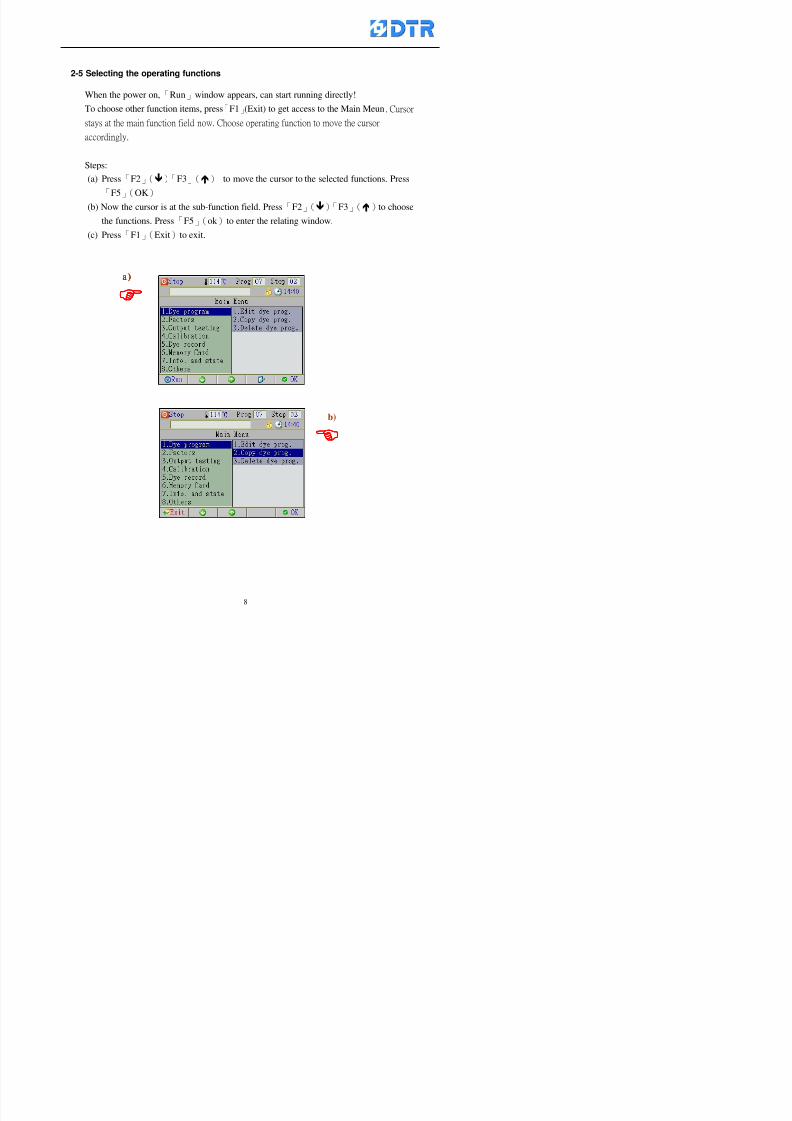
8132019 DTR 650 User Manual
httpslidepdfcomreaderfulldtr-650-user-manual 870
2-5 Selecting the operating functions
When the power on「Run」window appears can start running directly
To choose other function items press「F1」(Exit) to get access to the Main Meun Cursor
stays at the main function field now Choose operating function to move the cursor
accordingly
Steps(a) Press「F2」()「F3」() to move the cursor to the selected functions Press
「F5」(OK)
(b) Now the cursor is at the sub-function field Press「F2」()「F3」()to choose
the functions Press「F5」(ok )to enter the relating window
(c) Press「F1」(Exit)to exit
a)a)a)a)
b)
8132019 DTR 650 User Manual
httpslidepdfcomreaderfulldtr-650-user-manual 970
3 983122983157983150
3-1 Running the current dye program
To enter to the Run window directly when the power on or press「F1」
(Run) to enter the Run window at main menu The ldquostatus barrdquo shows
the current dye programrsquos number and steprsquos number
Check the dye program number and step on the ldquoProgram Status Listrdquo
Press「」「」or「6」「5」to move the cursor to select the program step
to start with When select a step press「start」 to start running
program Now the indicator light「Run」turns on
One main function can be operating with 1 to 4 parallel functions at the same time
The five function keys on function row corresponding to its operating items of
that window press that relating key「F1」~「F5」will get access to its operation
T f th di l d k 「F4 i k 「3 t th S h ti
Parallel functions
Main function in ruuning
8132019 DTR 650 User Manual
httpslidepdfcomreaderfulldtr-650-user-manual 1070
3-2 Jumping steps
During the program operating press「F2」(Jump)to jump to another steps to keep on
running Window appears
「Jump Prev」return to the step in front of the current step
「Jump Next」go to the next step from the current step
Press「」「」to move cursor then press「F5」(OK)to start running the target
dye step
Can use the numeric keys「Jump to XXX」to input the target dye steps directly
Press「F1」(Exit)to quit Keep operating the current program steps
8132019 DTR 650 User Manual
httpslidepdfcomreaderfulldtr-650-user-manual 1170
8132019 DTR 650 User Manual
httpslidepdfcomreaderfulldtr-650-user-manual 1270
3-4 Schematic Diagram Mode Display
Schematic diagram mode displays the dye program operating the water level and
valve status and etc
During the dye program operating press membrance key「F4」to change the
display mode
When program stops it displays to Program list mode automatically from
Schematic diagram display mode Press membrance key「3」to view the
Schematic diagram mode again But if there is an alram occurred it stays at the
Program List mode Please release the alarm first
Press numeric key「9」(Exit)to return to the Program list mode
By setting factor can view the Schematic diagram mode displays directly during
operating (refer to the《6-4》「Display mode setting」for details)
8132019 DTR 650 User Manual
httpslidepdfcomreaderfulldtr-650-user-manual 1370
3-5 Icon Mode Display
During the dye program operating press membrance key「F4」to change to the
display mode
When program stops it displays to Program list mode automatically from Icon
Mode Display Press numeric key「6」to view the Icon mode again But if there is
an alram occurred it stays at the Program list mode Please release the alarm first
Press numeric key「9」(Exit)to return to the Program list display
By setting factor can view the Icon mode displays directly during operating (refer
to the《6-4》Display mode setting for details)
3-6 Running state of dyeing machine
There is totally 2 pages of the Running status information
To check the running status when the program is in operating press「F5」(State)「Inputoutput State」appears pess key「F5」 「Running Information」appears
8132019 DTR 650 User Manual
httpslidepdfcomreaderfulldtr-650-user-manual 1470
3-7 Keep continuing to run from the break point
Due to power sudden off or stop running the dye program it can keep continuing to
run from the break point when the power is retore Users can set the ldquoControl factorrdquo
which dye instruction allows (or prohitbit) to keep continuing to run from the breakpoint (refer to the charpter 6 for Setting)
When the power is restore the cursor stays at the step which stops suddenlybefore starting from the break point to press 「Run」 Window appears
Press「F4」(Yes)to keep going run from the break point
Press「F2」(No)to re-start that dye instruction
Press「F1 (Exit) to return
8132019 DTR 650 User Manual
httpslidepdfcomreaderfulldtr-650-user-manual 1570
3-8 Editing dye step temporary
Before dye program operating the ready-to-run dye step could be edit That edit will
not saved to the file and will not disappear by causing a sudden power inruption or
stop operating until a new dye program is selecting
Step
A Set the system factor as「22」first to allow editing the dye programs temporary
B Set the system factor as「23」 to allow the existing program can temporay
editing its range of step
C Item「19」of the system factor set the dye steps which allows or prohibits to edit
temporary (Refer to the Charpter 6 for details of 「Setting」the A-C )
D Press「F2」()「F3」()or「5」「6」at the Run window To move cursor
to the dye step intend to edit Press membrance key「2」「Edit instrunction
value」appears
E Press「F5」(Edit) then press()()or「5」「6」Programs names is listing
at the cursor or key in a value by the numeric keys Select and press「F5」(ok) to
confirm
F Press「F4」(Save)to confirm and go back to the Run window
G 〔Before pressing「F4」(Save)〕Press「F1」(Exit)to quit
8132019 DTR 650 User Manual
httpslidepdfcomreaderfulldtr-650-user-manual 1670
3-9 Creating an additon dye step during dye program running
Before and during the dye program running the users can creat an addition dye step in
the existing dye programs
3-9-1 Creating an addition dye step
To creat one addition dye step before running or during running step as follows
A Set the System Factor as「34」to allow to creat an addition step (Refer to the
Chartper 6 for details)
B In window「Run dye program」 press numeric key「8」to enter window of 「Edit
addition instruction」 to edit the single dye step first
C Press「」「」「5」
「6」to choose dye
steps press「F5」(OK)
D Press「F5」to edit the
content of dye step
E After complete editing the single dye
step Press「F4」(Run) to start running the
addition step
8132019 DTR 650 User Manual
httpslidepdfcomreaderfulldtr-650-user-manual 1770
3-9-2 Creating an addition treatment to a saved dye program
During and before the dye program running can creat an addition treatment to a
saved dye program or a dye step in a saved dye program
(1) Set the System factor as「34」to allow creating an addition step (Refer to the
Chartper 6 for details)
(2) In window「Run dye program」 press numeric key「8」to enter window of「Edit
single step」
(3) Press「」「」to choose「Sub Prog」 press「4」to move cursor and set itrsquos
dye program number and the step number by numeric keys Or stay at the
「Prog」and press「F3」(File) window appears
(4) Press「」「」to choose an addition dye program then press「F5」(OK)
(5) Press「F4」(Run)to run the addition dye program(sub-dye program)
(6) Finish to run the sub-dye program and return to the main dye program
8132019 DTR 650 User Manual
httpslidepdfcomreaderfulldtr-650-user-manual 1870
4 983120983137983155983155983155983159983151983154983140 DTR-650 provides four ranks of password for sercurity protection
(Refer to the ltTable 10gt Supplementary Table of the Password Usage for details)
First rank (User1 password) Edit delete dye programs control factors in output
testing etchellipall operating fuctions
Second rank (User2 password) Edit in output connecting table operating factors
Third rank (User3 password) Edit copy delete dye programs factors PLC run stop
Fourth rank (User4 password) Edit and modify dye programs
4-1 Entering the password
When the window of 「password」appears enter 6-digits number password by using
the numeric membrane keys then press「F5」(OK) If key-in an incorrect password
press「F3」(Del)and enter again
If the password is correct「」appears it allows to enter the relating operation
8132019 DTR 650 User Manual
httpslidepdfcomreaderfulldtr-650-user-manual 1970
4-2 Locking the data
After editing the programs and factors ensure to disable the password to protect all
programs and data of DTR-650 The way and step as follows
(1) Choose「8Others」at the main meun
(2) Choose「02Data Locking」at the sub-function field
(3) Press「F5」(OK)to confirm
(4) Return to the main menu「」disppears on the status bar that means the data
has been locking already
4-3 Setting and changing the Userrsquos password
There are four userrsquos password for setting and edit by the users themselves
User1 password Access to all operation setting
User2 password For edit in output connection table operating factors
User3 password Only for copy and delete dye programs factors PLC run stop
User4 password Only for edit and modify dye programs
Method of setting edit
(1) Choose「8Others」at main menu press「F5」(OK)
(2) Choose「7 Set Password 2」at the sub-function field press「F5」(OK)
(3) The cursor shows the default password now press「F3」(Clr)to delete Key in
a new password with 6-digit
(4) Press「F5」(OK)to complete the setting of User2 password Go back to the main
menu
8132019 DTR 650 User Manual
httpslidepdfcomreaderfulldtr-650-user-manual 2070
The four userrsquos password has to made from different group numbers Using
same password will affect the operating Please pay attention when update the
password
8132019 DTR 650 User Manual
httpslidepdfcomreaderfulldtr-650-user-manual 2170
5555 983109983140983145983156983145983150983143 983108983161983141 983120983154983151983143983154983137983149983155
5-1 Choosing a dye program
Press function key「F4」(Edit)or choose「1Dye Program」at the main menu press
「F5」(OK)
Choose「1Edit Dye prog」at the sub-function field press「F5」(OK)to enter to the
window「Sel dye program」During the dye program running it is allowed to edit asaved program or a new dye program or the current dye program in running
Method Press「」「」and「5」「6」「3」「4」to move cursor to choose
a dye program number Press「F5」(OK)to enter that dye program Press
「F1(Exit)to quit and return
Method
Directly key in the number selection box
appears at the right corner of the window
Select a program number and press「F5」
(OK) fi
8132019 DTR 650 User Manual
httpslidepdfcomreaderfulldtr-650-user-manual 2270
5-2 Creating a new dye program
Step
A Choose「1Dye Program」Press「F5」(OK)
B Choose「1Edit Dye prog」at the sub-function menu press「F5」(OK)to enter
to window「Sel dye program」
C At the window「Sel dye program」 choose an empty dye number (eg「002」)
press「F5」(OK)window《Fig 5-2-1》appears
《Fig 5-2-1》
D Press「F2」(Add) table of 「Edit dye instruction」《Fig 5-2-2》appears
E Press「F5」(Edit) the dye instruction appears at the cursor locates press「」「」
」and「5」「6」「3」「4」to move cursor to edit the instruction and its
factors
F All inserted new dye instructions would be listed in front of 「Program End」
8132019 DTR 650 User Manual
httpslidepdfcomreaderfulldtr-650-user-manual 2370
【Eg】Edit「CycRinse」
A Edit the main function step first Press「F2」
()「F3」()to move the cursor The dye
step is listing by orders Choose「CycRinse」
and press「」 there is a cursor at itrsquos value
B Move cursor to setting value「Cold」andchoose「Mix」by pressing()() Then
press「」to move cursor to「Time」and enter
itrsquos setting value as「2」Press「F5」(OK) to
complete the main function setting
C To move cursor to the parallel functionsetting field Press()()to choose the
dye step Press「」to confirm and move
cursor to choose itrsquos setting facor
D Press「F5」(OK)to move cursor to the next
parallel function
E Repeat above steps C-D until all parallel
functions setting are completed Each main
function can be operating with the
maximum 4 parallel functions
F Press「F4」(Save)to confirm and return to
the「Edit dye program」window
G Repeat the above step A E to keep on
8132019 DTR 650 User Manual
httpslidepdfcomreaderfulldtr-650-user-manual 2470
5-3 Setting the file name (for dye programs)
When a dye program is setting up it is saved by numbers automatically Optionally users
can save it by another names
Step
(1) Create a new dye program first (the Name is not available for empty dye
programs)
(2) At the window「Sel dye program」 press「F4」(File) Window《Fig5-3》appears
《Fig5-3》
(3) Use numeric 0~9「+」「-」「_」blank alphabet A~Z and symbols [ ] etchellip to
create a file name Each file name can type-in the max 8 unit Press 「3」「4」
「5」「6」to move the cursor to choose the unit It also can use the membrane
numbric key to type in The selected unit is showed in front of the cursor at the
「File」Press「OK」to confirm
(4) Quit to input to press「F3」(Clr)
(5) After complete the set up press「F5」(OK)to confirm and go back to the window
「Sel dye program」 Now the name behind the dye program number is created
8132019 DTR 650 User Manual
httpslidepdfcomreaderfulldtr-650-user-manual 2570
5-4 Inserting a program step
Insert the program step means to insert a step in the existing program step where youwant to insert a step All following steps are moved one step ahead The total number of
steps will be increased by itself Able to insert more than one step continusely at the
same time
【Example】《Fig5-4》 To insert a step「call」before「002 Rinse」
《Fig 5-4》
Step
A Enter to the dye program「002」at the window of 「Sel dye program」
(Example)
B Press「6」to move cursor to「002 Rinse」 then press「F2」(add)
C Press「F5」(Edit) then press「」「」or「5」「6」to choose program
step to modify Choose「call」and press「」to move cursor to modify itrsquos
value
8132019 DTR 650 User Manual
httpslidepdfcomreaderfulldtr-650-user-manual 2670
D Press「」「」 value of 「call」is listing at the table Choose「pH Check 」Press「F5」(OK)
E Press「F4」(Save)and press「F1」(Undo)to return to previous window Complete
to insert the「02 Call」The previous「02 Rinse」update to「03」 All following
steps are moved one step ahead Total number of steps will be increased ldquo1rdquo by
itself
Repeat the steps B-E can non-stop to insert more than one step
Quit the insert and modify ( before pressing「F4」) press「F1」(Undo) to exit
The original dye steps will be unchanged
To delete an inserted dye steps press key「F3」(Del) The step deletes
immediately
5-5 Deleting a program step
Delete the program step means to delete step which the cursor locates When that step is
deleted the step number will be updated automatically All following steps are moved up
one step It is allowed to delete more than one steps continuously at the same time
Step
A Enter to the「Edit dye program」《Fig5-5》at the window「Select dye program」
B Press「6」「5」move cursor to the want to delete
C Confirm and press「F3」(Del) Window「Confirm delete」appears Press
「F4」(Yes)
8132019 DTR 650 User Manual
httpslidepdfcomreaderfulldtr-650-user-manual 2770
D That step is deleted immediately and all following steps move up one step
Repeat the steps above can non-stop to delete more than one step
Press「F2」(No)to cancel the deletion
Press「F1」(Exit)to end
5-6 Modifying a program step
To modify the saved name and the setting value of the dyeing steps
Step
1 Choose a dye program which need to modify at the「Sel dye program」 press「F5」
(OK)
2 Press「6」「5」to move cursor to a step which need to modify Select and press
「F5」(Edit) Window of 「Edit dye instruction」appears
3 Press「F2」()「F3」()to choose the step list select it and press「」to move
the cursor to itrsquos value setting
4 Press numeric key to input the value or press「6」「5」to choose the item Press
「F5」(OK)when complete Cursor move to the next value (if need to set more
than one item)
5 Press「F4」(Save)when all setting is complete Return to「Edit dye program」
Method of parallel functionrsquos modification is same as above
Before pressing the key「「「「Save」」」」 press「F1」(Undo)to quit all modify Return
to the window of Edit dye program
All edit and modify functions mentioned of this charper are only available
for the dyeing files which already saved in the file and not being running It
8132019 DTR 650 User Manual
httpslidepdfcomreaderfulldtr-650-user-manual 2870
5-7 Copying a dye program
Copying a dye programs mean to make a copy of an dye programs to a blank dyeprogram This function is for creating new dye program rapidly
Choose「1Dye Program」at the main menu Press「F5」(OK)then press「F2」()to choose「2Copy dye prog」 Press「F5」(OK) 《Fig5-7-1》appears
《Fig 5-7-1》
《Fig 5-7-2》
【【【【Eg】】】】
Copy program 003 to program 012
Press「」「」to move cursor to theprogram「003」 press「F4」(Copy)
Program「003」shows at the top right side of
the bar
Press「」「」to move cursor to program「012」 Then press「F5」(Paste)「」appears behind the「012」That means it issuccessfully copying the program
If the target program is occupied
confirmation window「Overwrite」
When choose an program or a targetprogram can select them by using the
8132019 DTR 650 User Manual
httpslidepdfcomreaderfulldtr-650-user-manual 2970
5-8 Deleting a dye program
Choose「1Dye program」at the main menu Press「F5」(OK)then press「F2」()to choose「3Delete dye prog」 Press「F5」(OK) 《Fig5-8-1》appears
《Fig5-8-1》
《Fig5-8-2》
Press「」「」to move cursor to
choose program need to delete Eg
delete program「012」 press「F5」(Del) Confirmation window
「Confirm delete」appears
Press「F4」(Yes) to confirm delete
Repeat the above step can delete more
than one program at the same time
Press「F2」(No) to return to window
《Fig5-8-1》and not delete that program
Exit to press「F1」(Exit)and return to the
main menu
8132019 DTR 650 User Manual
httpslidepdfcomreaderfulldtr-650-user-manual 3070
6 983123983141983156983156983145983150983143DTR-650 has a built-in standard factor that can fulfill all different types of dyeing
machinesrsquos basic demand Users can also modify the factors base on their request to
fulfill their special control demand Before modify please refer to the table of each
range of Setting Factors (see the Supplementary Table)
6-1 ldquoEnable to use the program stepsrdquo setting
There are totally 64 program steps Parts of them are usually applying to the programs
In order to make more efficiently of editing programs it can「Disable」the other part
of program steps which are not usually applying or not applicable to the programs
For example dye machine with one tank it is only using step Tank B In this case itcan firstly「Disable」the program steps of Tank C When edit the program the
「Disable」rsquos steps will not appear at the cursor for choosing But this will not effect
and change the saved files The saved files can be kept as before
Step
(1) Choose「2 Factors」at the main menu Press「F5」(OK)(2) Choose「18 Dye Instruction」at the sub-function menu Then presss「F5」(OK)
Window「Edit dye ins」appears
「Enable」instruction can available to
use「Disable」instruction is temporarystop to use
Press「F2」()「F3」()to move
8132019 DTR 650 User Manual
httpslidepdfcomreaderfulldtr-650-user-manual 3170
6-2 ldquoAllow to modify dye program temporary during operatingrdquo Setting
During dye program running it can modify dye program temporary Thesemodification will not disappear by causing a sudden power interruption or power off
until select another new dye program to run
Please note that it is only for modifying the dye program temporary That program
file would not saved due to the modification If need to modify the program file and
save choose the function of Edit Dye Program to edit (Refer to the Charper 5 for the【Edit Dye Prograrm】)
6-2-1 ldquoAllow to modify all dye programsrdquo Setting
Step
(1) Choose「2 Factors」at the main menu Press「F5」(OK)
(2) Choose「02 System Factor」at the sub-function menu Then presss「F5」(OK)
Window「Edit System Factor」appears
Set to stop using temporary the「07
Rinse」press「F4」(Sel)to set it as Disable
Repeat above steps to complete all setting
Press 「F1」(Exit)to return to main menu
8132019 DTR 650 User Manual
httpslidepdfcomreaderfulldtr-650-user-manual 3270
6-2-2 ldquoAllow to modify part of dye programsrdquo Setting
【Eg】Set the number 08 or above (including number 08) is allowing to modify dye
programs during operating
Step
A Refer to【6-2-1】setting the factor as「22」to allow editing dye program
temporary during operating
(4) Press「3」「4」to edit the setting
as「Enable」 and press「F5」(OK)
Restore the standard factor by
pressing「F3」(Clr)
(5) Exit to press「F1」(Exit)and
return to window of 「Main Menu」
8132019 DTR 650 User Manual
httpslidepdfcomreaderfulldtr-650-user-manual 3370
6-2-3 ldquoAllow to modify dye steps temporaryrdquo Setting
After setting the dye programs are allowed to edit it also can set which dye steps are
allowed to edit temporary during operating
Step
(1) Choose「2 Factors」at the main menu Press「F5」(OK)
(2) Choose「19 Dye Ins control」at the sub-function menu Then presss「F5」
(OK) Window「Edit ins mode」appears
「Enable」 Allow to edit that dye step before
operating
「Disable」 Not allow to edit dye step before
operating
(3) Press「」「」to move cursor
to choose dye step Press「F4」
To enter to the「Edit dye program」from the
function menu there is a「」in front of the
file name「0-7」 means that program is not
allowing to edit during operating
8132019 DTR 650 User Manual
httpslidepdfcomreaderfulldtr-650-user-manual 3470
6-2-4 ldquoSet the dye step to keep running from the interrupt pointrdquo setting
When the dye program is operating it will disappear by causing power
interruption or sudden power off When start running again part of dye steps can
run again from the interrupt point part of them cannot
How to set
(1) Choose「2Factors」in the main menu and press「F5」(OK)
(2) Choose「20Continue mode」in the sub-function menu Press「F5」(OK) to
enter window of 「Continue Setting」
(3) Press「」「」to move cursor to choose dye steps Press「F4」(Sel)it
shows「Disable」or「Enable」for choosing Press「F5」(OK)to move cursorto the next setting
(4) Repeat above method until all setting is complete press「F1」(Exit)and
return to the main menu
8132019 DTR 650 User Manual
httpslidepdfcomreaderfulldtr-650-user-manual 3570
6-3 ldquoAllow to insert an addition dye stepsrdquo setting
During the program is running can temporary insert an addition dye step or a dye
program according to the operating actual situation Through this setting can set which
dye steps can apply or not to the program in operating
During to insert an addition step if sudden interruption or power off occurred it returns
to the main dye program automatically Before starting again should decide seriously
and set it again by actual needed
Step
(1) Choose「2Factors」at the main menu and press「F5」(OK)
(2) Choose「02System factor」and press「F5」(OK)
(3) Press「」「」to move cursor to the factor「34」and press「3」「4」to set
it as「Enable」 Press「F5」(OK)
(4) Press「F1」(Exit)to return to main menu Choose「21Addition Ins」at the
sub-function menu Press「F5」(OK)to enter the window「Addition Instruction」
(5) Press「」「」to move cursor to choose dye steps and press「F4」(Sel) Cursors
locates shows「Eable」or「Disable」 Press「F5」(OK)to move cursor to the
next dye step
(6) Repeat above method until to complete all setting press「F1」(Exit)and return
to the main menu
8132019 DTR 650 User Manual
httpslidepdfcomreaderfulldtr-650-user-manual 3670
6-4 Setting the display mode
DTR650 has three types of display mode during operating Program List mode
Schematic Diagram mode and Icon mode Users can set the display mode during
operating by factor setting
It goes back to a Program List mode when dye program ended
Step
(1) Choose「2Factors」at the main menu and press「F5」(OK)
(2) Choose「02System factor」and press「F5」(OK)
(3) Press「F2」()「F3」()to move cursor to choose「32Display mode」Press
「3」「4」 it shows「Online picture」「Instruction」「Big Icon」 choose
「Online picture」(eg) and press「F5」to confirm
8132019 DTR 650 User Manual
httpslidepdfcomreaderfulldtr-650-user-manual 3770
(4) Press「F1」(Exit)to return to the main menu
(5) The Schematic Diagram displays when the program is running (it stays at theProgram List mode when there is an alarm occurred)
Press「F4」to transfer to another display mode
It goes back to a Program List mode from Schematic Diagram Mode when dye
program ended Press numeric key「3」to view Schematic Diagram Mode again
Quit to press「F5」(Exit)
6-5 Adapt the digital input to another functions
DTR-650 has 32(0~31)input terminal it owns an standard setting when the
controller is initial According to the userrsquos demand they can change the DTR-650rsquos
anther functions of Input Terminal and PLC Input channel
The PLC Intputrsquos name can also define by the users (use IBM computer to edit and
download)
How to set
(1) Choose「2 Factor」at the main menu Press「F5」(OK)
(2) Choose「22 Input table」at the sub-function menu and press「F5」(OK)to enter
「Edit input table」
The actual input
terminal of theIBM computer
PLCrsquos input channel
8132019 DTR 650 User Manual
httpslidepdfcomreaderfulldtr-650-user-manual 3870
6-6 Adapt the digital output to another functions
DTR-650 has 32(0~31)output terminals it owns an standard setting when thecontroller is initial According to the userrsquos demand they can adapte the digital output
and the PLC outputrsquos channel to another functions The PLC Output channelrsquos name
can also define by users (use IBM computer to edit and download)
Step
(1) Choose「2 Factor」at the main menu Press「F5」(OK)
(2) Choose「23 Output table」at the main menu and press「F5」(OK)
(3) Press「F2」()「F3」()to move cursor to choose the output terminal atthe left side of the window Press「F5」(Add) the PLCrsquos output channelrsquos
name is listing at the right side of the window
(4) Press「F2」()「F3」()to move cursor to choose the PLC outputrsquos channel
If cursor moves to the PLC output channel which already linking「Add」is
not for choosing that means that output channel is already occupied
(5) Confirm the connection to press「F5」(Add) Quit to press「F4」(Del)Press「F1」(Exit)when complete all setting and return to main menu
The actual output
terminal of the
IBM computer
PLCrsquos output channel
8132019 DTR 650 User Manual
httpslidepdfcomreaderfulldtr-650-user-manual 3970
983095 983109983140983145983156983145983150983143 983156983144983141 983110983137983139983156983151983154983155DTR-650 has several kinds of control factors
Userrsquos factors System factors Temperature Control factors Speed factors Dosing
factors PID factors Analog Input Output factors standard factors etchellipPlease refer
to the supplementary table for the setting range and standard of the factors
DTR-650 has a built-in standard factor Users can edit by themselves if necessary
7-1 Modifying userrsquos factors
Userrsquos factors is setting with the Dyeing machinesrsquos PLC Programrsquos factor it is define by
the PLC Programmer
Step to edit
(1) Choose「2Factors」at main menu Press「F5」(OK)
(2) Choose「01User Factor」Press「F5」(OK)
(3) Press「F2」()「F3」()「6」「5」to move cursor up down and by page
Choose a factor need to edit then press「3」「4」to set itrsquos value Press「F5」(OK) Cursor moves to the next factor
(4) Some of factors can input numbers by the numeric membrance keys to edit If
the input is incorrect it turns to red and means the edit is not available
8132019 DTR 650 User Manual
httpslidepdfcomreaderfulldtr-650-user-manual 4070
Modifyrsquos method of the system factors temperature factors speed factors dosingfactors PID factors analog Input output factors standard factors etchellipare same asabove
If apply the library of DTR500 and DTR600 into the DTR650 the key「3」「4」may not valid to use Please use the numeric keys instead of it to key in factors itmay not effect the normal operation
Please pay a serious attention and read carefully at the factorrsquos table before modify the factors An incorrect value may effect the DTR-650 Dyeing
Machine Controllerrsquos operating After modifying factors must cancel the
password and secure data
7-2 Loading the standard factors
After modifying factors if need to restore a manufacturerrsquos standard factors of
DTR-650 The method as follows
1 Choose「2Factors」at main menu Press「F5」(OK)
「 「 ( ) 「
8132019 DTR 650 User Manual
httpslidepdfcomreaderfulldtr-650-user-manual 4170
7-3 Copying the factor
Users can build up a set of factor by themselves and make a copy and save
Step
1 Choose「2Factors」at main menu Press「F5」(OK)
2 Choose「13Restore Factor」 press「F5」(OK) window「factor will be
overwrite 」
3 Press「F4」(Yes)copy finished and saved Return to the main menu
4 Press「F2」(No)to not copy the factor and the existing factor is not change Return
to the main menu
7-4 Loading the backup factors
Users can build up a set of factor and backup files to load to DTR-650
Step1 Choose「14Backup factor」at the sub-function menu Press「F5」(OK)and
window「Factror will be overwrite」appears
2 Press「F3」(OK)to load the the backup factor them return to main menu
Press「F2」(No)to not copy the factor and the existing factor is not change
Return to the main menu
8132019 DTR 650 User Manual
httpslidepdfcomreaderfulldtr-650-user-manual 4270
983096 983119983157983156983152983157983156 983124983141983155983156983145983150983143
Before the output testing must be complete the steps as follows
A Cut off all connecting line of output terminal of DTR-650
B Stop running the PLC
C Check up the connections of all output channels to avoid damages from
incorrect connections
D Check up state of dyeing machines include the temperature pressure valves
onoff and pumpshellipetc ensure the safety for priority
8-1 Testing the Digital output
Step
1 Choose「3Output Testing」at the main menu Press「F5」(OK) 2 Choose「1Digital」at the sub function menu Press「F5」(OK) window「Digital
output testing」appears
3 Press「」「」「」to move cursor to each output channels Press「F5」(OK)
Output Name
8132019 DTR 650 User Manual
httpslidepdfcomreaderfulldtr-650-user-manual 4370
8-2 Testing the Analog output
(1) Choose「3Output Testing」at the main menu Press「F5」(OK)
(2) Choose「2Analog」at the sub function menu Press「F5」(OK) window「Analog output testing」appears
(3) Press「」「」「」to move cursor to each channels Then key in number by
the numeric membrance keys (range0~200= 0~20mA) Press「F5」(OK) there
is a output current relating to the output channel
(4) Press「F5」(OK) There is an output when the output channel with red light No
output without light onl(5) When complete the testing press「F1」(OK)to return to the main menu
8132019 DTR 650 User Manual
httpslidepdfcomreaderfulldtr-650-user-manual 4470
983097 983107983137983148983145983138983154983137983156983145983151983150
DTR-650 has Dosing and Temperature calibration
When enter to Dosing calibration must be set the Low Volume calibration first and
then High Volume calibration When enter to Temperature calibration must be set the
Low Temperature calibration first and then High Temperature calibration Must be
hightly follow this orders seriously
9-1 Calibration of Low Volume Tank
Step
A Choose「4Calibration」at the main menu Press「F5」(OK)
B Choose「Dosing 0 low vol」at the sub function menu Press「F5」(OK) window
appears
C Fill the Dosing Tank to a half level input value shows how much the water level
If it stays ldquo0rdquo check the connection and the factor setting is correct or not
And connect the pressure sensorrsquos output channel to the Current Meter to ensure
that sensor works or not
8132019 DTR 650 User Manual
httpslidepdfcomreaderfulldtr-650-user-manual 4570
D Fill the Dosing Tank to 50ml (Calcalate from the bottom side of the pressure
sensor steel tube) input value should show 4~6 (input value must between
0~10) Then enter the water volume The setting volume is relating the water
levelrsquos water value (litre as unit) input range 0~80 Set as「 「「 「0000 0000 0000 0000」」」」is strongly is strongly is strongly is strongly
receommend receommend receommend receommend Press「F5」(OK)to complete [Calibration of Low Volume Tank 1
is same as above method]
9-2 Calibration of High Volume Tank
Step
A Choose「4Calibration」at the main menu Press「F5」(OK)
B Choose「Dos 0 high vol」at the sub function menu Press「F5」(OK) window of
「Calibrate high 」appears
C Fill the Dosing Tank to a full level input value should be larger than 30 enter
the current water level which relates to the water volume Enter the range within
100~2500 Then press「F5」(OK) to complete the calibrate the high volume tank
8132019 DTR 650 User Manual
httpslidepdfcomreaderfulldtr-650-user-manual 4670
9-3 Temperature Calibration
Step
A This function is for adjusting the DTR650rsquos accuracy of Temperature Control It
must be using with the special terminal which is only for DTR650
B Choose「4Calibration」at the main function menu and press「F5」(OK)
C Choose「3Low Temp」at the sub-function menu Press「F5」(OK)and《Fig9-3》
appears insert the DTR650rsquos low temperature calibration terminal to the temperature
input terminal wait for the jumping value to stable down then press「F5」(OK) then
to adjust the high temperature calibration
D Adjusting the High Temperature Calibrationrsquos method is same as above But usersusersusersusers
must be using the High Temperature Terminalmust be using the High Temperature Terminalmust be using the High Temperature Terminalmust be using the High Temperature Terminal whichwhichwhichwhich is specially for DTR650 onlyis specially for DTR650 onlyis specially for DTR650 onlyis specially for DTR650 only
《Fig 9-3》
8132019 DTR 650 User Manual
httpslidepdfcomreaderfulldtr-650-user-manual 4770
10 983122983141983139983151983154983140983155 983151983142 983108983161983141 983120983154983151983143983154983137983149983155
It contains the past 15 days of temperature curves of running history
Checking method
(1) Choose「5Dye Record」at main menu press「F5」(OK)
(2) Sub-function menu shows the set up date of the past 15 days dye programs
Listing by the lastest set up date
(3) Choose a program date and press「F5」(OK) it appears window「Temp
record」
(4) Press「」「」to move the white line in the box one minute by moving once
(5) Press「3」「4」to move the line to check the time period 2 hours by moving once
The yellow selecting line of the「24 hours operating state」is repectively moving
The curve info is show in the curve box Left side of the widnow appears the
relating running info the time is the time value of the line locates at
(6) Check more details of the temperature info to press numeric key「middot」 a bright red line
appears in the selecting box this line is to check the starting point of the
temperature inforsquos time period Then press「」to move the white line to the end
point of the time period The temperature info between the starting point and end
point are appears at the right side of the window Press「middot」to return to the preious
curve page
(7) Check more details of the alarm infor To perss numeric key「7」「9」 the alarmrsquos
details is listing by orders
(8) Press「F1」(exit) to return
8132019 DTR 650 User Manual
httpslidepdfcomreaderfulldtr-650-user-manual 4870
11 983125983155983137983143983141 983151983142 983117983141983149983151983154983161 983107983137983154983140
DTR-650 supports 32MB or above Compact Flash Card which can transfer and save all
information for 4 sets of DTR-650 Including library files schematic diagram icon
image PLC program dye program factor and confiruration files etchellip Use the CF Card
to up download and swap the information of DTR-650 promptly install the relating
device and program updates
DTR-650 CF Card with bank 1 to bank 4 can save 4 sets information of Dyeing
Machines When download or save files should choose the BANK first
《Fig11-1》
8132019 DTR 650 User Manual
httpslidepdfcomreaderfulldtr-650-user-manual 4970
11-1 Downloading data
1 Firmly insert the CF card into the DTR-650rsquos PCMCIA connector Ensure it is
wholely and firmly inserted if the card is not totally inserted or the card do not
touch in all to the connector there will be an error occurred and cannot
updownload or interrupted during operation
2 Choose「6Memory Card」at the main menu and press「F5」(OK) 《Fig11-1》
appears Information of Bank「1」shows at the left hand side of the window press
number 1-4 by using numeric keys to choose the BANK Check the
information in the Bank seriously which is exactly need to download to the
DTR650
3 Press()()「6」「5」to move cursor to the sub-function menu to choose
the downloading items Press「F5」(OK) window appears「Stop PLC run before
access memory card Stop the PLC run」 Press「F5」(YES) to stop PLC
running
4 Press「F5」(OK) window appears Confirm to update or not the DTR-650rsquos
information As that downloading will be replace the DTR-650rsquos information
(that means the existing information of the DTR-650 will be removed and
replaced)
5 Press「F4」(YES)to download the information from the DTR-650 to the CF
Card Return to the main menu when finish
8132019 DTR 650 User Manual
httpslidepdfcomreaderfulldtr-650-user-manual 5070
Ensure inserting firmly the CF card into the DTR-650 unless it will cause
error or cannot Updownload data
Never remove CF card during transferring or updownloading data Until it
is all completed
DTR-650rsquos dyeing program is not compatible with DTR-500 and
DTR-600 Never use CF card to transfer data among them
11-2 Storing and transfering data
1 Insert the CF Card to the DTR-650
2 Choose「6Memory Card」at the main menu and press「F5」(OK) 《Fig11-1》
appears Left hand side of the window shows the data of BANK 1 press numeric
keys 1-4 to select the BANK To confirm the put the data in the DTR-650 to the CF
Card The existing data of that bank will be replaced and covered by the new data (if
that bank is already occuplied)
3 Choose「23Save Dye prog」(Example)at the sub-funciton menu press「F5」(OK)to confirm Window「Update memory card data」appears
4 Press「F5」(OK)to transfer the data to the CF card Return to the main menu
5 Put the CF card into another DTR-650 and follow the operating method of 「11-1
Downloading data」」」」can transfer and swap data with more than one set of
DTR-650
8132019 DTR 650 User Manual
httpslidepdfcomreaderfulldtr-650-user-manual 5170
12 983123983156983137983156983141 983137983150983140 983113983150983142983151983154983149983137983156983145983151983150
The state and information is including the Dyeing Machinersquos state of Digit Input output
Analog Input output Temperature control PID Dosing PID Pressure different PID
software system information and alarm record This information is for checking at any
time
12-1 Input Output state
Step
1 Choose「7Info and state」at main menu and press「F5」(OK)
2 Choose「01Digital IO put」at the sub-function menu then press「F5」(OK)
「Digital In Out State」0=None 1=Input
3 Press「F1」(Exit)to return to main menu
Same method for checking the temperature control analog dosing pressure
different etchellip
12-2 Checking the system information
Step
1 Choose「7Info and state」at main menu and press「F5」(OK)
2 Choose「11 System info」at sub-function field press「F5」(OK)Window
「System Information」appear
System information is including System info(software version) Library doc
Icon files Schematic file Definition file hardare state Config File Commandinstruction icon PLC file etc
8132019 DTR 650 User Manual
httpslidepdfcomreaderfulldtr-650-user-manual 5270
12-3 Checking the operating alarm record
Operating record shows the latest 40 operating items and alarm records including
the time and content of the alarm
A) Choose「7 Info and state」
and press「F5」(OK)
B) Choose「12Alarm logs」at
the sub-funciton menu then
press「F5」(OK)
8132019 DTR 650 User Manual
httpslidepdfcomreaderfulldtr-650-user-manual 5370
13 983105983140983146983157983155983156983145983150983143 983156983144983141 983107983151983150983156983154983137983155983156
The displaysrsquos brightness can be adjusted if necessary
Step
1 Choose「8Others」at main menu press「F5」(OK)
2 Choose「01Contrast」at sub-function menu press「F5」(OK) window「Set
Contrast」appears
3 Press「」「」to move the bar to set the brightness then press「F5」(OK)Window appears「Please reboot the system」
4 Press「F5」(OK)to return to main menu and re-boot the DTR-650 to complete
adjusting the brightness
8132019 DTR 650 User Manual
httpslidepdfcomreaderfulldtr-650-user-manual 5470
14 983123983156983151983152 983154983157983150983150983145983150983143 983156983144983141 983120983116983107 983120983154983151983143983154983137983149
Before testing the Input output testing transfer of the PLC program must stop the PLC
running
Step
1 Choose「8Others」at the main menu Press「F5」(OK)
2 Choose「04 PLC Stop」at sub-function menu Press「F5」(OK) window
「Password」appears
3 Enter password and press「F5」(OK) Window「Stop the PLC run」appears
4 Press「F4」(Yes)and window「PLC Stop」appear Press「F5」(OK) Now
the PLC is stop running and return to the main menu
All testing cannot operate when the PLC is running
Editing dye program and the relating operation can
perform with the PLC running together
8132019 DTR 650 User Manual
httpslidepdfcomreaderfulldtr-650-user-manual 5570
15 983123983141983156983156983145983150983143 983156983144983141 983156983145983149983141
Step
1 Press「8Others」at the main menu Press「F5」(OK)
2 Choose「10Set date time」at the sub-function menu Press「F5」(OK) window
「Set date time」appears
3 Press「F5」(Edit) to move cursor by 「3」「4」 enter the time value at the
cursor locates
4 Press「F5」(OK)to complete the modify Press「F1」(Exit)to return to main
menu
5 Press「F1」(Exit)if not modify and return to main menu
8132019 DTR 650 User Manual
httpslidepdfcomreaderfulldtr-650-user-manual 5670
1166 983123983123983157983157 983152 983152 983152 983152983148983148983141983141983149983149983141983141983150983150983156 983156 983137983137983154 983154 983161983161 983124 983124 983137983137983138983138983148983148983141983141
TTTTTTTTaaaaaaaabbbbbbbblllllllleeeeeeee 11111111 【Dye Instruction】
Code Icon Instruction Code Icon Instruction
000 End 016 Inject C
001 Start 017 Dosing BV
002 Heat 018 PH
003 Cool 019 Addsalt B
004 Flow Fill 020 Addsalt C
005 Level Fill 021 Ana Fill
006 Drian 022 Lock Fill007 Rinse 023 Lock Level
008 Run 024 Low Rinse
009 Call 025 Cyc Rinse
010 Prep B 026 Rinse B
011 Addsalt B 027 Rinse C
012 Dosing B 028 Temp
013 Inject B 029 Nozzle Pressure
014 Prep C 030 Main Pump
015 Dosing C 031 Pump Speed
8132019 DTR 650 User Manual
httpslidepdfcomreaderfulldtr-650-user-manual 5770
Table 2 【【【【Alarm】】】】
System Alarm Must stop operating and check up to solve problems before restarting
the machine
Running Alarm It is a reminder Not effect the operating of DTR-650
Userrsquos Alarm Total of 32 Users can define themselves and use it when edit the PLC
Program (do not listing below)
No System Alarm No Running Alarm
1 PLC program not running 16 Temp ctrl 0 Grad too slow
2 Main temp sensor error 17 Temp ctrl 0 Grad too fast
3 Not at Run window 18 Temp ctrl 0 Hold temp too low
4 Exceeding max temp 19 Temp ctrl 0 Hold temp too high
5 - 20 Temp ctrl 1 Grad too slow6 - 21 Temp ctrl 1 Grad too fast
7 - 22 Temp ctrl 1 Hold temp too low
8 Communication error 23 Temp ctrl 1 Hold temp too high
9 Slave not answer 24 Temp ctrl 2 Grad too slow
10 PLC 0 not answer 25 Temp ctrl 2 Grad too fast
11 PLC 1 not answer 26 Temp 2 Hold temp too low12 Display not answer 27 Temp 2 Hold temp too high
13 Lower power voltage 28 Temp ctrl 3 Grad too slow
14 - 29 Temp ctrl 3 Grad too fast
15 - 30 Temp3 Hold temp too low
31 Temp3 Hold temp too high
32 Dosing 0 injection too slow
33 Dosing 0 injection too fast
34 Dosing 1 injection too slow
35 Dosing 1 injection too fast
8132019 DTR 650 User Manual
httpslidepdfcomreaderfulldtr-650-user-manual 5870
TTTTTTTTaaaaaaaabbbbbbbblllllllleeeeeeee 33333333 【【【【System factor】】】】
No Description Std Range amp Definition
1 ID No 000 000- 100 Controller no
2 Communication Rate 4800Bps 2400 4800 9600 19200 38400
3 Display language Chinese English Chinese
4 Temp display mode and
5 Maxmium temperature 145 025 ~ 145 6 Type of external PLC Default PLC32DPLC32PLC16Default
7 Number of external PLC NANA 1 unit connect
2 unit connect
8Communication Rate of
PLC9600Bps 2400 4800 9600 19200
9 Set point 1 085 000 ~ 145
If signal source is temperaturethe setting value is thetemperature value If the signal
source is Analog Input 6~17 then
setting value for Analog input is 0 ndash
100 and relates Analog
Input14~020mA
10 Source 1 Sensor0Sensor 0 ~5
Analog input 0 ~1111 Set point 2 092 Same as 09
12 Source 2 PT100 1 Same as 10
13 Set point 3 085 Same as 09
14 Source 3 PT100 2 Same as 10
15 Set point 4 092 Same as 09
16 Source 4 PT100 3 Same as 1017 Set point 5 085 Same as 09
18 Source 5 PT100 4 Same as 10
19 Set point 6 092 Same as 09
8132019 DTR 650 User Manual
httpslidepdfcomreaderfulldtr-650-user-manual 5970
29 Min cyclic time of cloth 100sec 0 ~ 255 sec
30 Max cyclic time of cloth 240sec 0 ~255 sec
31Standard cyclic time of
cloth
180 000 ~ 255 sec
32 Display ModeProgram
List
Program list Schematic Diagram
Icon mode
33 CF card format Standard of
DTR CF
Card
Standard of DTR CF Card V20
Standard CF Card
34 Addition step Disable Disable Enable35 Mode Com 3
CouplingEsure Com 3 is the communication
port of the Central or Coupling
36Com 3 Communication
rate9600 Central communication speed
8132019 DTR 650 User Manual
httpslidepdfcomreaderfulldtr-650-user-manual 6070
TTTTTTTTaaaaaaaabbbbbbbblllllllleeeeeeee 44444444 【【【【Temperature Cotnrol Factor】】】】
No Factor Definition Standard Range and Definition
01 PT No PT-0 PT 0~5 PT-100 Input number
02 Max working temp 140 000~140
03 Output mode 0 0~2
04 Alarm time of gardient 240sec 000~255 sec
05 Alarm mode of gradient Always AlwaysOnceNone
06 Control mode of gradient Heating orCooling
interlocked
Heating and Cooling interlocked
No limitation
07 Alarm range of HoldTemp 03 01~20
08 Alarm time for HoldTemp 240sec 000~255sec
09 Alarm mode of HoldTemp Always AlwaysOnceNone
10 Control mode ofHoldTemp
Heating only Only heating and cooling Cooling whenalarm occurred Only heating andcooling No limitation when alarmHeating only
11 Porportional Band 100 000~250
12 Integral band 128 sec 000~255 sec
13 Differential time 04 sec 00~20 sec
14 Min transit gradient 02 00~50
15 Transit rate 20 times 00~50 times (020= 2 times)
16 PID initial output value 010 000~100
17 ONOFF cycle time 10 sec 05~25 sec
Onoff valve set as 010 sec
Proportional valve set as 020 sec
18 Time down count mode Mode 0 0~10 = The time down count range from「Factor 20 + target temp」to「Target
8132019 DTR 650 User Manual
httpslidepdfcomreaderfulldtr-650-user-manual 6170
TTTTTTTTaaaaaaaabbbbbbbblllllllleeeeeeee 55555555 【【【【Speed Factor】】】】
No Factor Definition Standard Range amp Definition
01 Input Number Speed input 0 Speed input 0~11
02 Average times 05 times 01~10
03 Sensor Number 008pcs 001~255
04 Roller Dimension 250mm 050~500
05 Max cloth speed 200mmin 001~25506 Min cloth speed 020mmin 001~255
07 Alarm delay time 240sec 001~255
08 Alarm mode Every oncenoneevery
09 Alarm range () 020 001~255
10 Proportional band 100 001~255
11 Integer band 128 001~25512 Differential time 000 001~200
13 Initial speed () 020 001~255
14 Control cycle ti(01sec) 05 01~30
15 First cycle time(01sec) 10 01~30
16 Speed increase limit () 010 001~100
17 Speed decrease limit () 010 001~100
18 Min speed() 005 001~100
19 Manual speed adjust () 005 001~100
20 Manual initial speed() 020 001~100
21 Stopping speed() 010 001~100
22 Switch speed() 020 001~100
23 Not used
24 Speed decrease turns 03turns 01~50
8132019 DTR 650 User Manual
httpslidepdfcomreaderfulldtr-650-user-manual 6270
Table 6 【【【【Dosing Factors】】】】
No Description Range Range and Explanation
1 Analog input no Analog input 0 Analog input no 0 ~11
2Alarm delay time for
dosing240 sec 000 ~255 sec
3 Alarm time for dosing Every Every Once None
4 Proportional band 100 000 ~255 sec Factor P
5 Integer band 128 000 ~255 sec Factor I6 Differential time 04 00 ~20 Factor D
7 Max adjust rate 150 50~ 255
8 Initial factor for dosing 10 000 ~100
9 User curve section 0 10 Gradient of sect1 for dosing curve9
10 User curve section 1 10 Gradient of sect2 for dosing curve9
11 User curve section 2 10 Gradient of sect3 for dosing curve9
12 User curve section 3 10 Gradient of sect4 for dosing curve9
13 User curve section 4 10 Gradient of sect5 for dosing curve9
14 User curve section 5 10 Gradient of sect6 for dosing curve9
15 User curve section 6 10 Gradient of sect7 for dosing curve9
16 User curve section 7 10 Gradient of sect8 for dosing curve9
17 User curve section 8 10 Gradient of sect9 for dosing curve9
18 User curve section 9 10 Gradient of sect10 for dosing curve9
19 Min water level 05 00~ 10 04~20mA percentagechange to the userrsquos factor setting
20 Output value for Tank
clean
100 000~ 100
Injected percentage of dosing valve
in dosing End period
This factor will be invalided if usingONOFF dosing valve
21 Full range 100 001~255 Self-adjustment cannotchange
22 Range ratio 001001~255 Self-adjustment cannot
change
8132019 DTR 650 User Manual
httpslidepdfcomreaderfulldtr-650-user-manual 6370
【【【【TTaabbllee 77 】】】】Pressure Deviation Factors
No Description Std Range amp Definition
1 Analog input number + Analog in 0 Analog in 0~11
2 Analog input number - Analog in 1 Analog in 0~11
3 Input mode Pressure Pressure Pressure deviation
4 Full range 050x01Kgcm
001~255
5 Range ratio 001 001~255
6 Alarm delay time 100sec 001~255
7 Alarm mode Every oncenone
8 Alarm range 010 001~255
9 Proportional band 100 001~255
10 Integer band 128 001~255
11 Differential time 00 00~20
12 PID Init output value 010 001~255
13 Cycle time 10 03~30
14 First cycle time 030 003~100
15 Max adjust rate 010 001~100
8132019 DTR 650 User Manual
httpslidepdfcomreaderfulldtr-650-user-manual 6470
【【【【TTaabbllee 88 】】】】Definition of Analog Input
No Description Standard Range and Explanation
01 PT 0 correction standard DIN std DIN std JIS std
02 PT 0 correction +0 +- 9
03 PT 1 correction standard DIN std DIN std JIS std
04 PT 1 correction +0 +- 9
05 PT 2 correction standard DIN std DIN std JIS std
06 PT 2 correction +0 +- 9
07 PT 3 correction standard DIN std DIN std JIS std
08 PT 3 correction +0 +- 9
09 PT 4 correction standard DIN std DIN std JIS std
10 PT 4 correction +0 +- 9
11 PT 5 correction standard DIN std DIN std JIS std
12 PT 5 correction +0 +- 9
13 Analog input 0 define 4 ~ 20mA 0 ndash 20mA 4 ndash 20mA
14 Analog input 0 average times 10 times 01- 20 times
15 Analog input 0 min value 0000 0000 - 1000
16 Analog input 0 max value 100 0001 - 9999
17-60 Analog input 1~11 Same as Analog input 0
【【【【 】】】】 fi i i f A O
8132019 DTR 650 User Manual
httpslidepdfcomreaderfulldtr-650-user-manual 6570
【【【【TTaabbllee 99 】】】】Definition of Analog Output
No Description Standard Range and explanation
61 Analog output 0 define Control byPLC
Control by PLC
Temperature control PID0 output
Temperature control PID1 output
Temperature control PID2 output
Speed PID3 output
Dosing PID0 output Dosing PID1output
Pressure different PID0 outputPressure different PID1 output
Main temperature output
62 Mode of Analog ouptput0 4 ~20mA 0 ndash20mA 4 ndash 20mA
63-84 Analog output 1~11 Same as Analog output 0
【【【【TTaabbllee 1100】】】】Value Table 0 amp 1
No Description Range Std Range and explanation
1 Analog input no 000~011 000 Analog input no
2 Data ratio 001~255 100 Multiple by factors
3~53 0~98 000~255 000-100 Analog input 0~98 data
【【【【 】】】】St t Li t
8132019 DTR 650 User Manual
httpslidepdfcomreaderfulldtr-650-user-manual 6670
【【【【TTaabbllee 1111】】】】State List
No Description Range Standard Range and explanation
1 Display setting 1 0~255 205 See remarks at next page
2 Display setting 2 0~255 208
3 Display setting 3 0~255 209
4 Display setting 4 0~255 017
5 Display setting 5 0~255 0186 Display setting 6 0~255 019
7 Display setting 7 0~255 020
8 Display setting 8 0~255 021
9 Display setting 9 0~255 000
10 Display setting 1 0~255 000
11 Display setting 2 0~255 000
12 Display setting 3 0~255 000
13 Display setting 4 0~255 000
14 Display setting 5 0~255 000
15 Display setting 6 0~255 000
16 Display setting 7 0~255 000
Remarks
8132019 DTR 650 User Manual
httpslidepdfcomreaderfulldtr-650-user-manual 6770
0 = No display 1~255 = Display type of number
1~16 Content of PLC VB0~15
No 1 corresponding to VB0
No 16 corresponding to VB15
17~32 Content of PLC DB0~15
No 17 corresponding to DB0
No 32 corresponding to DB15
33~46 Content of PLC CNT0~29
No 33 corresponding to CNT0
No 46 corresponding to CNT29 47~78 Content of dyeing instruction 0~31 CNT0
No 47 corresponding to system instruction to No 0 of CNT0
No 78 corresponding to system instruction to No 31 of CNT0rsquos content
79~110 Dyeing instruction 0~31 of CNT0rsquos setting
111~142 Content of Dyeing instruction 0~31 CNT1No 111 corresponding to dyeing instruction No 0 of CNT1
No 142 corresponding to dyeing instruction No 31 of CNT1rsquos content
143~174 Dyeing instruction 0~31 of CNT1rsquos setting
175~204 Content of PLC HTIM0~29
No 175 corresponding to HTIM0
No 204 corresponding to HTIM29
205 Loading
206 Ratio 1
207 Ratio 2208 Ratio 1 x Loading
209 Ratio 2 x Loading
210 Fix value
211 Value Table 1 matching result
212 Value Table 2 matching result
213 Value Table 1 setting214 Value Table 2 setting
215 Pressure control PID0 different pressure value
216 Pressure control PID1 different pressure value
TTTTTTTTaaaaaaaabbbbbbbblllllllleeeeeeee 1122 【【【【Usage of password】】】】
8132019 DTR 650 User Manual
httpslidepdfcomreaderfulldtr-650-user-manual 6870
No Main FunctionFactor Sub Function Factor Password Rank
1 Run None
2 Dye program User3 or above
3 Control factor
- User factor User 1
- System factor User 1
- Temp PID 0
- Temp PID 1 User 1- Speed PID 0 User 1
- Dosing PID 0 User 1
- Dosing PID 1 User 1
- Pressure PID 0 User 1
- Pressure PID 1 User 1
- Analog IO User 1
- Load standard factor User 2 or above- Load a copied factor User 2 or above
- Copy factor User 2 or above
- Value table 0 User 1
- Value table 1 User 1
- Information and state User 1
- Dye instruction User 1
- Edit dye instruction setting User 14 Output testing User 2 or above
5 Calibration User 2 or above
6 Dye record None
7 CF card User 1
8 Info and state None
9 Others
- Contrast User3 or above
- Data Locking None
- PLC Run User 1
- PLC Stop User 1
- Password setting User 1
TTTTTTTTaaaaaaaabbbbbbbblllllllleeeeeeee 1133 【【【【Technical Data】】】】
8132019 DTR 650 User Manual
httpslidepdfcomreaderfulldtr-650-user-manual 6970
TTTTTTTTaaaaaaaabbbbbbbblllllllleeeeeeee 1133 【【【【Technical Data】】】】
1 Temperature Control
- Range 10~145(plusmn1)
- Mode Proportional or PWM
- Sensor PT100 (JIS or DIN standard)
2 Input and output channel
- Digital Input 32 DC24V PNP- Digital Output 32 DC24V 054A Relay connect point
- Analog Input 4 04~20 mA
- Analog Output 4 0~20mA 或 4~20 mA
3 Communication port 3 RS-232 amp 0~20 mAx1 RS485x 2
4 Dye program
- Number 15000 Steps
- Standard step 61Heating Cooling Fill Drain RinseDosingetc
5LCD module and Display
langage
Chinese
English
320 x 240 TFT color display with
more language
6 CF card connector 1 PCMCIA standard
7 Membrane Keyboard- Number Key 10 [0]~[9] Input factors
- Function Key 5 [F1]~[F5] function selecting
- Operation Key 2 [Start] [Stop]
- Auxiliary Key 7 [][][][][Esc] [larr][OK] [bull]
8 Operating Condition
- Temperature 5~45
- Humidity ≦85 (25)
9 Power supply
V l DC 24V
8132019 DTR 650 User Manual
httpslidepdfcomreaderfulldtr-650-user-manual 7070
70
983108983124983122983085650 983113983150983152983157983156 983119983157983156983152983157983156 983120983151983154983156983145983150983143 (983138983137983139983147983155983145983140983141 983158983145983141983159)
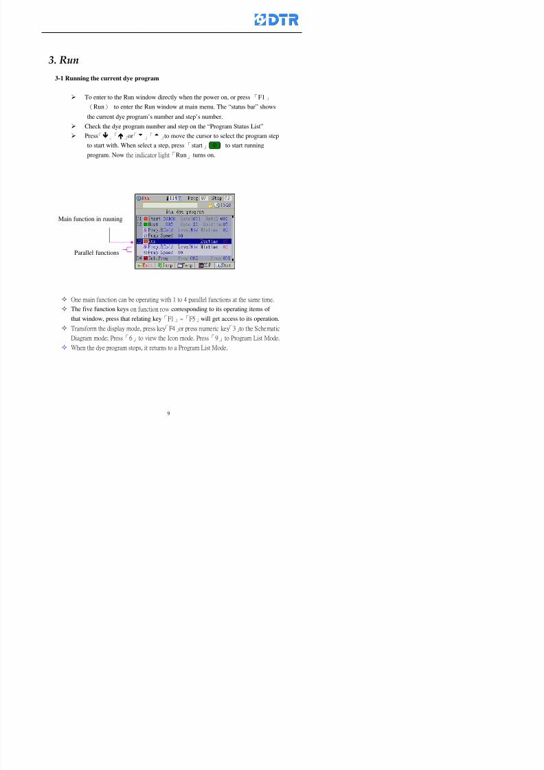
8132019 DTR 650 User Manual
httpslidepdfcomreaderfulldtr-650-user-manual 970
3 983122983157983150
3-1 Running the current dye program
To enter to the Run window directly when the power on or press「F1」
(Run) to enter the Run window at main menu The ldquostatus barrdquo shows
the current dye programrsquos number and steprsquos number
Check the dye program number and step on the ldquoProgram Status Listrdquo
Press「」「」or「6」「5」to move the cursor to select the program step
to start with When select a step press「start」 to start running
program Now the indicator light「Run」turns on
One main function can be operating with 1 to 4 parallel functions at the same time
The five function keys on function row corresponding to its operating items of
that window press that relating key「F1」~「F5」will get access to its operation
T f th di l d k 「F4 i k 「3 t th S h ti
Parallel functions
Main function in ruuning
8132019 DTR 650 User Manual
httpslidepdfcomreaderfulldtr-650-user-manual 1070
3-2 Jumping steps
During the program operating press「F2」(Jump)to jump to another steps to keep on
running Window appears
「Jump Prev」return to the step in front of the current step
「Jump Next」go to the next step from the current step
Press「」「」to move cursor then press「F5」(OK)to start running the target
dye step
Can use the numeric keys「Jump to XXX」to input the target dye steps directly
Press「F1」(Exit)to quit Keep operating the current program steps
8132019 DTR 650 User Manual
httpslidepdfcomreaderfulldtr-650-user-manual 1170
8132019 DTR 650 User Manual
httpslidepdfcomreaderfulldtr-650-user-manual 1270
3-4 Schematic Diagram Mode Display
Schematic diagram mode displays the dye program operating the water level and
valve status and etc
During the dye program operating press membrance key「F4」to change the
display mode
When program stops it displays to Program list mode automatically from
Schematic diagram display mode Press membrance key「3」to view the
Schematic diagram mode again But if there is an alram occurred it stays at the
Program List mode Please release the alarm first
Press numeric key「9」(Exit)to return to the Program list mode
By setting factor can view the Schematic diagram mode displays directly during
operating (refer to the《6-4》「Display mode setting」for details)
8132019 DTR 650 User Manual
httpslidepdfcomreaderfulldtr-650-user-manual 1370
3-5 Icon Mode Display
During the dye program operating press membrance key「F4」to change to the
display mode
When program stops it displays to Program list mode automatically from Icon
Mode Display Press numeric key「6」to view the Icon mode again But if there is
an alram occurred it stays at the Program list mode Please release the alarm first
Press numeric key「9」(Exit)to return to the Program list display
By setting factor can view the Icon mode displays directly during operating (refer
to the《6-4》Display mode setting for details)
3-6 Running state of dyeing machine
There is totally 2 pages of the Running status information
To check the running status when the program is in operating press「F5」(State)「Inputoutput State」appears pess key「F5」 「Running Information」appears
8132019 DTR 650 User Manual
httpslidepdfcomreaderfulldtr-650-user-manual 1470
3-7 Keep continuing to run from the break point
Due to power sudden off or stop running the dye program it can keep continuing to
run from the break point when the power is retore Users can set the ldquoControl factorrdquo
which dye instruction allows (or prohitbit) to keep continuing to run from the breakpoint (refer to the charpter 6 for Setting)
When the power is restore the cursor stays at the step which stops suddenlybefore starting from the break point to press 「Run」 Window appears
Press「F4」(Yes)to keep going run from the break point
Press「F2」(No)to re-start that dye instruction
Press「F1 (Exit) to return
8132019 DTR 650 User Manual
httpslidepdfcomreaderfulldtr-650-user-manual 1570
3-8 Editing dye step temporary
Before dye program operating the ready-to-run dye step could be edit That edit will
not saved to the file and will not disappear by causing a sudden power inruption or
stop operating until a new dye program is selecting
Step
A Set the system factor as「22」first to allow editing the dye programs temporary
B Set the system factor as「23」 to allow the existing program can temporay
editing its range of step
C Item「19」of the system factor set the dye steps which allows or prohibits to edit
temporary (Refer to the Charpter 6 for details of 「Setting」the A-C )
D Press「F2」()「F3」()or「5」「6」at the Run window To move cursor
to the dye step intend to edit Press membrance key「2」「Edit instrunction
value」appears
E Press「F5」(Edit) then press()()or「5」「6」Programs names is listing
at the cursor or key in a value by the numeric keys Select and press「F5」(ok) to
confirm
F Press「F4」(Save)to confirm and go back to the Run window
G 〔Before pressing「F4」(Save)〕Press「F1」(Exit)to quit
8132019 DTR 650 User Manual
httpslidepdfcomreaderfulldtr-650-user-manual 1670
3-9 Creating an additon dye step during dye program running
Before and during the dye program running the users can creat an addition dye step in
the existing dye programs
3-9-1 Creating an addition dye step
To creat one addition dye step before running or during running step as follows
A Set the System Factor as「34」to allow to creat an addition step (Refer to the
Chartper 6 for details)
B In window「Run dye program」 press numeric key「8」to enter window of 「Edit
addition instruction」 to edit the single dye step first
C Press「」「」「5」
「6」to choose dye
steps press「F5」(OK)
D Press「F5」to edit the
content of dye step
E After complete editing the single dye
step Press「F4」(Run) to start running the
addition step
8132019 DTR 650 User Manual
httpslidepdfcomreaderfulldtr-650-user-manual 1770
3-9-2 Creating an addition treatment to a saved dye program
During and before the dye program running can creat an addition treatment to a
saved dye program or a dye step in a saved dye program
(1) Set the System factor as「34」to allow creating an addition step (Refer to the
Chartper 6 for details)
(2) In window「Run dye program」 press numeric key「8」to enter window of「Edit
single step」
(3) Press「」「」to choose「Sub Prog」 press「4」to move cursor and set itrsquos
dye program number and the step number by numeric keys Or stay at the
「Prog」and press「F3」(File) window appears
(4) Press「」「」to choose an addition dye program then press「F5」(OK)
(5) Press「F4」(Run)to run the addition dye program(sub-dye program)
(6) Finish to run the sub-dye program and return to the main dye program
8132019 DTR 650 User Manual
httpslidepdfcomreaderfulldtr-650-user-manual 1870
4 983120983137983155983155983155983159983151983154983140 DTR-650 provides four ranks of password for sercurity protection
(Refer to the ltTable 10gt Supplementary Table of the Password Usage for details)
First rank (User1 password) Edit delete dye programs control factors in output
testing etchellipall operating fuctions
Second rank (User2 password) Edit in output connecting table operating factors
Third rank (User3 password) Edit copy delete dye programs factors PLC run stop
Fourth rank (User4 password) Edit and modify dye programs
4-1 Entering the password
When the window of 「password」appears enter 6-digits number password by using
the numeric membrane keys then press「F5」(OK) If key-in an incorrect password
press「F3」(Del)and enter again
If the password is correct「」appears it allows to enter the relating operation
8132019 DTR 650 User Manual
httpslidepdfcomreaderfulldtr-650-user-manual 1970
4-2 Locking the data
After editing the programs and factors ensure to disable the password to protect all
programs and data of DTR-650 The way and step as follows
(1) Choose「8Others」at the main meun
(2) Choose「02Data Locking」at the sub-function field
(3) Press「F5」(OK)to confirm
(4) Return to the main menu「」disppears on the status bar that means the data
has been locking already
4-3 Setting and changing the Userrsquos password
There are four userrsquos password for setting and edit by the users themselves
User1 password Access to all operation setting
User2 password For edit in output connection table operating factors
User3 password Only for copy and delete dye programs factors PLC run stop
User4 password Only for edit and modify dye programs
Method of setting edit
(1) Choose「8Others」at main menu press「F5」(OK)
(2) Choose「7 Set Password 2」at the sub-function field press「F5」(OK)
(3) The cursor shows the default password now press「F3」(Clr)to delete Key in
a new password with 6-digit
(4) Press「F5」(OK)to complete the setting of User2 password Go back to the main
menu
8132019 DTR 650 User Manual
httpslidepdfcomreaderfulldtr-650-user-manual 2070
The four userrsquos password has to made from different group numbers Using
same password will affect the operating Please pay attention when update the
password
8132019 DTR 650 User Manual
httpslidepdfcomreaderfulldtr-650-user-manual 2170
5555 983109983140983145983156983145983150983143 983108983161983141 983120983154983151983143983154983137983149983155
5-1 Choosing a dye program
Press function key「F4」(Edit)or choose「1Dye Program」at the main menu press
「F5」(OK)
Choose「1Edit Dye prog」at the sub-function field press「F5」(OK)to enter to the
window「Sel dye program」During the dye program running it is allowed to edit asaved program or a new dye program or the current dye program in running
Method Press「」「」and「5」「6」「3」「4」to move cursor to choose
a dye program number Press「F5」(OK)to enter that dye program Press
「F1(Exit)to quit and return
Method
Directly key in the number selection box
appears at the right corner of the window
Select a program number and press「F5」
(OK) fi
8132019 DTR 650 User Manual
httpslidepdfcomreaderfulldtr-650-user-manual 2270
5-2 Creating a new dye program
Step
A Choose「1Dye Program」Press「F5」(OK)
B Choose「1Edit Dye prog」at the sub-function menu press「F5」(OK)to enter
to window「Sel dye program」
C At the window「Sel dye program」 choose an empty dye number (eg「002」)
press「F5」(OK)window《Fig 5-2-1》appears
《Fig 5-2-1》
D Press「F2」(Add) table of 「Edit dye instruction」《Fig 5-2-2》appears
E Press「F5」(Edit) the dye instruction appears at the cursor locates press「」「」
」and「5」「6」「3」「4」to move cursor to edit the instruction and its
factors
F All inserted new dye instructions would be listed in front of 「Program End」
8132019 DTR 650 User Manual
httpslidepdfcomreaderfulldtr-650-user-manual 2370
【Eg】Edit「CycRinse」
A Edit the main function step first Press「F2」
()「F3」()to move the cursor The dye
step is listing by orders Choose「CycRinse」
and press「」 there is a cursor at itrsquos value
B Move cursor to setting value「Cold」andchoose「Mix」by pressing()() Then
press「」to move cursor to「Time」and enter
itrsquos setting value as「2」Press「F5」(OK) to
complete the main function setting
C To move cursor to the parallel functionsetting field Press()()to choose the
dye step Press「」to confirm and move
cursor to choose itrsquos setting facor
D Press「F5」(OK)to move cursor to the next
parallel function
E Repeat above steps C-D until all parallel
functions setting are completed Each main
function can be operating with the
maximum 4 parallel functions
F Press「F4」(Save)to confirm and return to
the「Edit dye program」window
G Repeat the above step A E to keep on
8132019 DTR 650 User Manual
httpslidepdfcomreaderfulldtr-650-user-manual 2470
5-3 Setting the file name (for dye programs)
When a dye program is setting up it is saved by numbers automatically Optionally users
can save it by another names
Step
(1) Create a new dye program first (the Name is not available for empty dye
programs)
(2) At the window「Sel dye program」 press「F4」(File) Window《Fig5-3》appears
《Fig5-3》
(3) Use numeric 0~9「+」「-」「_」blank alphabet A~Z and symbols [ ] etchellip to
create a file name Each file name can type-in the max 8 unit Press 「3」「4」
「5」「6」to move the cursor to choose the unit It also can use the membrane
numbric key to type in The selected unit is showed in front of the cursor at the
「File」Press「OK」to confirm
(4) Quit to input to press「F3」(Clr)
(5) After complete the set up press「F5」(OK)to confirm and go back to the window
「Sel dye program」 Now the name behind the dye program number is created
8132019 DTR 650 User Manual
httpslidepdfcomreaderfulldtr-650-user-manual 2570
5-4 Inserting a program step
Insert the program step means to insert a step in the existing program step where youwant to insert a step All following steps are moved one step ahead The total number of
steps will be increased by itself Able to insert more than one step continusely at the
same time
【Example】《Fig5-4》 To insert a step「call」before「002 Rinse」
《Fig 5-4》
Step
A Enter to the dye program「002」at the window of 「Sel dye program」
(Example)
B Press「6」to move cursor to「002 Rinse」 then press「F2」(add)
C Press「F5」(Edit) then press「」「」or「5」「6」to choose program
step to modify Choose「call」and press「」to move cursor to modify itrsquos
value
8132019 DTR 650 User Manual
httpslidepdfcomreaderfulldtr-650-user-manual 2670
D Press「」「」 value of 「call」is listing at the table Choose「pH Check 」Press「F5」(OK)
E Press「F4」(Save)and press「F1」(Undo)to return to previous window Complete
to insert the「02 Call」The previous「02 Rinse」update to「03」 All following
steps are moved one step ahead Total number of steps will be increased ldquo1rdquo by
itself
Repeat the steps B-E can non-stop to insert more than one step
Quit the insert and modify ( before pressing「F4」) press「F1」(Undo) to exit
The original dye steps will be unchanged
To delete an inserted dye steps press key「F3」(Del) The step deletes
immediately
5-5 Deleting a program step
Delete the program step means to delete step which the cursor locates When that step is
deleted the step number will be updated automatically All following steps are moved up
one step It is allowed to delete more than one steps continuously at the same time
Step
A Enter to the「Edit dye program」《Fig5-5》at the window「Select dye program」
B Press「6」「5」move cursor to the want to delete
C Confirm and press「F3」(Del) Window「Confirm delete」appears Press
「F4」(Yes)
8132019 DTR 650 User Manual
httpslidepdfcomreaderfulldtr-650-user-manual 2770
D That step is deleted immediately and all following steps move up one step
Repeat the steps above can non-stop to delete more than one step
Press「F2」(No)to cancel the deletion
Press「F1」(Exit)to end
5-6 Modifying a program step
To modify the saved name and the setting value of the dyeing steps
Step
1 Choose a dye program which need to modify at the「Sel dye program」 press「F5」
(OK)
2 Press「6」「5」to move cursor to a step which need to modify Select and press
「F5」(Edit) Window of 「Edit dye instruction」appears
3 Press「F2」()「F3」()to choose the step list select it and press「」to move
the cursor to itrsquos value setting
4 Press numeric key to input the value or press「6」「5」to choose the item Press
「F5」(OK)when complete Cursor move to the next value (if need to set more
than one item)
5 Press「F4」(Save)when all setting is complete Return to「Edit dye program」
Method of parallel functionrsquos modification is same as above
Before pressing the key「「「「Save」」」」 press「F1」(Undo)to quit all modify Return
to the window of Edit dye program
All edit and modify functions mentioned of this charper are only available
for the dyeing files which already saved in the file and not being running It
8132019 DTR 650 User Manual
httpslidepdfcomreaderfulldtr-650-user-manual 2870
5-7 Copying a dye program
Copying a dye programs mean to make a copy of an dye programs to a blank dyeprogram This function is for creating new dye program rapidly
Choose「1Dye Program」at the main menu Press「F5」(OK)then press「F2」()to choose「2Copy dye prog」 Press「F5」(OK) 《Fig5-7-1》appears
《Fig 5-7-1》
《Fig 5-7-2》
【【【【Eg】】】】
Copy program 003 to program 012
Press「」「」to move cursor to theprogram「003」 press「F4」(Copy)
Program「003」shows at the top right side of
the bar
Press「」「」to move cursor to program「012」 Then press「F5」(Paste)「」appears behind the「012」That means it issuccessfully copying the program
If the target program is occupied
confirmation window「Overwrite」
When choose an program or a targetprogram can select them by using the
8132019 DTR 650 User Manual
httpslidepdfcomreaderfulldtr-650-user-manual 2970
5-8 Deleting a dye program
Choose「1Dye program」at the main menu Press「F5」(OK)then press「F2」()to choose「3Delete dye prog」 Press「F5」(OK) 《Fig5-8-1》appears
《Fig5-8-1》
《Fig5-8-2》
Press「」「」to move cursor to
choose program need to delete Eg
delete program「012」 press「F5」(Del) Confirmation window
「Confirm delete」appears
Press「F4」(Yes) to confirm delete
Repeat the above step can delete more
than one program at the same time
Press「F2」(No) to return to window
《Fig5-8-1》and not delete that program
Exit to press「F1」(Exit)and return to the
main menu
8132019 DTR 650 User Manual
httpslidepdfcomreaderfulldtr-650-user-manual 3070
6 983123983141983156983156983145983150983143DTR-650 has a built-in standard factor that can fulfill all different types of dyeing
machinesrsquos basic demand Users can also modify the factors base on their request to
fulfill their special control demand Before modify please refer to the table of each
range of Setting Factors (see the Supplementary Table)
6-1 ldquoEnable to use the program stepsrdquo setting
There are totally 64 program steps Parts of them are usually applying to the programs
In order to make more efficiently of editing programs it can「Disable」the other part
of program steps which are not usually applying or not applicable to the programs
For example dye machine with one tank it is only using step Tank B In this case itcan firstly「Disable」the program steps of Tank C When edit the program the
「Disable」rsquos steps will not appear at the cursor for choosing But this will not effect
and change the saved files The saved files can be kept as before
Step
(1) Choose「2 Factors」at the main menu Press「F5」(OK)(2) Choose「18 Dye Instruction」at the sub-function menu Then presss「F5」(OK)
Window「Edit dye ins」appears
「Enable」instruction can available to
use「Disable」instruction is temporarystop to use
Press「F2」()「F3」()to move
8132019 DTR 650 User Manual
httpslidepdfcomreaderfulldtr-650-user-manual 3170
6-2 ldquoAllow to modify dye program temporary during operatingrdquo Setting
During dye program running it can modify dye program temporary Thesemodification will not disappear by causing a sudden power interruption or power off
until select another new dye program to run
Please note that it is only for modifying the dye program temporary That program
file would not saved due to the modification If need to modify the program file and
save choose the function of Edit Dye Program to edit (Refer to the Charper 5 for the【Edit Dye Prograrm】)
6-2-1 ldquoAllow to modify all dye programsrdquo Setting
Step
(1) Choose「2 Factors」at the main menu Press「F5」(OK)
(2) Choose「02 System Factor」at the sub-function menu Then presss「F5」(OK)
Window「Edit System Factor」appears
Set to stop using temporary the「07
Rinse」press「F4」(Sel)to set it as Disable
Repeat above steps to complete all setting
Press 「F1」(Exit)to return to main menu
8132019 DTR 650 User Manual
httpslidepdfcomreaderfulldtr-650-user-manual 3270
6-2-2 ldquoAllow to modify part of dye programsrdquo Setting
【Eg】Set the number 08 or above (including number 08) is allowing to modify dye
programs during operating
Step
A Refer to【6-2-1】setting the factor as「22」to allow editing dye program
temporary during operating
(4) Press「3」「4」to edit the setting
as「Enable」 and press「F5」(OK)
Restore the standard factor by
pressing「F3」(Clr)
(5) Exit to press「F1」(Exit)and
return to window of 「Main Menu」
8132019 DTR 650 User Manual
httpslidepdfcomreaderfulldtr-650-user-manual 3370
6-2-3 ldquoAllow to modify dye steps temporaryrdquo Setting
After setting the dye programs are allowed to edit it also can set which dye steps are
allowed to edit temporary during operating
Step
(1) Choose「2 Factors」at the main menu Press「F5」(OK)
(2) Choose「19 Dye Ins control」at the sub-function menu Then presss「F5」
(OK) Window「Edit ins mode」appears
「Enable」 Allow to edit that dye step before
operating
「Disable」 Not allow to edit dye step before
operating
(3) Press「」「」to move cursor
to choose dye step Press「F4」
To enter to the「Edit dye program」from the
function menu there is a「」in front of the
file name「0-7」 means that program is not
allowing to edit during operating
8132019 DTR 650 User Manual
httpslidepdfcomreaderfulldtr-650-user-manual 3470
6-2-4 ldquoSet the dye step to keep running from the interrupt pointrdquo setting
When the dye program is operating it will disappear by causing power
interruption or sudden power off When start running again part of dye steps can
run again from the interrupt point part of them cannot
How to set
(1) Choose「2Factors」in the main menu and press「F5」(OK)
(2) Choose「20Continue mode」in the sub-function menu Press「F5」(OK) to
enter window of 「Continue Setting」
(3) Press「」「」to move cursor to choose dye steps Press「F4」(Sel)it
shows「Disable」or「Enable」for choosing Press「F5」(OK)to move cursorto the next setting
(4) Repeat above method until all setting is complete press「F1」(Exit)and
return to the main menu
8132019 DTR 650 User Manual
httpslidepdfcomreaderfulldtr-650-user-manual 3570
6-3 ldquoAllow to insert an addition dye stepsrdquo setting
During the program is running can temporary insert an addition dye step or a dye
program according to the operating actual situation Through this setting can set which
dye steps can apply or not to the program in operating
During to insert an addition step if sudden interruption or power off occurred it returns
to the main dye program automatically Before starting again should decide seriously
and set it again by actual needed
Step
(1) Choose「2Factors」at the main menu and press「F5」(OK)
(2) Choose「02System factor」and press「F5」(OK)
(3) Press「」「」to move cursor to the factor「34」and press「3」「4」to set
it as「Enable」 Press「F5」(OK)
(4) Press「F1」(Exit)to return to main menu Choose「21Addition Ins」at the
sub-function menu Press「F5」(OK)to enter the window「Addition Instruction」
(5) Press「」「」to move cursor to choose dye steps and press「F4」(Sel) Cursors
locates shows「Eable」or「Disable」 Press「F5」(OK)to move cursor to the
next dye step
(6) Repeat above method until to complete all setting press「F1」(Exit)and return
to the main menu
8132019 DTR 650 User Manual
httpslidepdfcomreaderfulldtr-650-user-manual 3670
6-4 Setting the display mode
DTR650 has three types of display mode during operating Program List mode
Schematic Diagram mode and Icon mode Users can set the display mode during
operating by factor setting
It goes back to a Program List mode when dye program ended
Step
(1) Choose「2Factors」at the main menu and press「F5」(OK)
(2) Choose「02System factor」and press「F5」(OK)
(3) Press「F2」()「F3」()to move cursor to choose「32Display mode」Press
「3」「4」 it shows「Online picture」「Instruction」「Big Icon」 choose
「Online picture」(eg) and press「F5」to confirm
8132019 DTR 650 User Manual
httpslidepdfcomreaderfulldtr-650-user-manual 3770
(4) Press「F1」(Exit)to return to the main menu
(5) The Schematic Diagram displays when the program is running (it stays at theProgram List mode when there is an alarm occurred)
Press「F4」to transfer to another display mode
It goes back to a Program List mode from Schematic Diagram Mode when dye
program ended Press numeric key「3」to view Schematic Diagram Mode again
Quit to press「F5」(Exit)
6-5 Adapt the digital input to another functions
DTR-650 has 32(0~31)input terminal it owns an standard setting when the
controller is initial According to the userrsquos demand they can change the DTR-650rsquos
anther functions of Input Terminal and PLC Input channel
The PLC Intputrsquos name can also define by the users (use IBM computer to edit and
download)
How to set
(1) Choose「2 Factor」at the main menu Press「F5」(OK)
(2) Choose「22 Input table」at the sub-function menu and press「F5」(OK)to enter
「Edit input table」
The actual input
terminal of theIBM computer
PLCrsquos input channel
8132019 DTR 650 User Manual
httpslidepdfcomreaderfulldtr-650-user-manual 3870
6-6 Adapt the digital output to another functions
DTR-650 has 32(0~31)output terminals it owns an standard setting when thecontroller is initial According to the userrsquos demand they can adapte the digital output
and the PLC outputrsquos channel to another functions The PLC Output channelrsquos name
can also define by users (use IBM computer to edit and download)
Step
(1) Choose「2 Factor」at the main menu Press「F5」(OK)
(2) Choose「23 Output table」at the main menu and press「F5」(OK)
(3) Press「F2」()「F3」()to move cursor to choose the output terminal atthe left side of the window Press「F5」(Add) the PLCrsquos output channelrsquos
name is listing at the right side of the window
(4) Press「F2」()「F3」()to move cursor to choose the PLC outputrsquos channel
If cursor moves to the PLC output channel which already linking「Add」is
not for choosing that means that output channel is already occupied
(5) Confirm the connection to press「F5」(Add) Quit to press「F4」(Del)Press「F1」(Exit)when complete all setting and return to main menu
The actual output
terminal of the
IBM computer
PLCrsquos output channel
8132019 DTR 650 User Manual
httpslidepdfcomreaderfulldtr-650-user-manual 3970
983095 983109983140983145983156983145983150983143 983156983144983141 983110983137983139983156983151983154983155DTR-650 has several kinds of control factors
Userrsquos factors System factors Temperature Control factors Speed factors Dosing
factors PID factors Analog Input Output factors standard factors etchellipPlease refer
to the supplementary table for the setting range and standard of the factors
DTR-650 has a built-in standard factor Users can edit by themselves if necessary
7-1 Modifying userrsquos factors
Userrsquos factors is setting with the Dyeing machinesrsquos PLC Programrsquos factor it is define by
the PLC Programmer
Step to edit
(1) Choose「2Factors」at main menu Press「F5」(OK)
(2) Choose「01User Factor」Press「F5」(OK)
(3) Press「F2」()「F3」()「6」「5」to move cursor up down and by page
Choose a factor need to edit then press「3」「4」to set itrsquos value Press「F5」(OK) Cursor moves to the next factor
(4) Some of factors can input numbers by the numeric membrance keys to edit If
the input is incorrect it turns to red and means the edit is not available
8132019 DTR 650 User Manual
httpslidepdfcomreaderfulldtr-650-user-manual 4070
Modifyrsquos method of the system factors temperature factors speed factors dosingfactors PID factors analog Input output factors standard factors etchellipare same asabove
If apply the library of DTR500 and DTR600 into the DTR650 the key「3」「4」may not valid to use Please use the numeric keys instead of it to key in factors itmay not effect the normal operation
Please pay a serious attention and read carefully at the factorrsquos table before modify the factors An incorrect value may effect the DTR-650 Dyeing
Machine Controllerrsquos operating After modifying factors must cancel the
password and secure data
7-2 Loading the standard factors
After modifying factors if need to restore a manufacturerrsquos standard factors of
DTR-650 The method as follows
1 Choose「2Factors」at main menu Press「F5」(OK)
「 「 ( ) 「
8132019 DTR 650 User Manual
httpslidepdfcomreaderfulldtr-650-user-manual 4170
7-3 Copying the factor
Users can build up a set of factor by themselves and make a copy and save
Step
1 Choose「2Factors」at main menu Press「F5」(OK)
2 Choose「13Restore Factor」 press「F5」(OK) window「factor will be
overwrite 」
3 Press「F4」(Yes)copy finished and saved Return to the main menu
4 Press「F2」(No)to not copy the factor and the existing factor is not change Return
to the main menu
7-4 Loading the backup factors
Users can build up a set of factor and backup files to load to DTR-650
Step1 Choose「14Backup factor」at the sub-function menu Press「F5」(OK)and
window「Factror will be overwrite」appears
2 Press「F3」(OK)to load the the backup factor them return to main menu
Press「F2」(No)to not copy the factor and the existing factor is not change
Return to the main menu
8132019 DTR 650 User Manual
httpslidepdfcomreaderfulldtr-650-user-manual 4270
983096 983119983157983156983152983157983156 983124983141983155983156983145983150983143
Before the output testing must be complete the steps as follows
A Cut off all connecting line of output terminal of DTR-650
B Stop running the PLC
C Check up the connections of all output channels to avoid damages from
incorrect connections
D Check up state of dyeing machines include the temperature pressure valves
onoff and pumpshellipetc ensure the safety for priority
8-1 Testing the Digital output
Step
1 Choose「3Output Testing」at the main menu Press「F5」(OK) 2 Choose「1Digital」at the sub function menu Press「F5」(OK) window「Digital
output testing」appears
3 Press「」「」「」to move cursor to each output channels Press「F5」(OK)
Output Name
8132019 DTR 650 User Manual
httpslidepdfcomreaderfulldtr-650-user-manual 4370
8-2 Testing the Analog output
(1) Choose「3Output Testing」at the main menu Press「F5」(OK)
(2) Choose「2Analog」at the sub function menu Press「F5」(OK) window「Analog output testing」appears
(3) Press「」「」「」to move cursor to each channels Then key in number by
the numeric membrance keys (range0~200= 0~20mA) Press「F5」(OK) there
is a output current relating to the output channel
(4) Press「F5」(OK) There is an output when the output channel with red light No
output without light onl(5) When complete the testing press「F1」(OK)to return to the main menu
8132019 DTR 650 User Manual
httpslidepdfcomreaderfulldtr-650-user-manual 4470
983097 983107983137983148983145983138983154983137983156983145983151983150
DTR-650 has Dosing and Temperature calibration
When enter to Dosing calibration must be set the Low Volume calibration first and
then High Volume calibration When enter to Temperature calibration must be set the
Low Temperature calibration first and then High Temperature calibration Must be
hightly follow this orders seriously
9-1 Calibration of Low Volume Tank
Step
A Choose「4Calibration」at the main menu Press「F5」(OK)
B Choose「Dosing 0 low vol」at the sub function menu Press「F5」(OK) window
appears
C Fill the Dosing Tank to a half level input value shows how much the water level
If it stays ldquo0rdquo check the connection and the factor setting is correct or not
And connect the pressure sensorrsquos output channel to the Current Meter to ensure
that sensor works or not
8132019 DTR 650 User Manual
httpslidepdfcomreaderfulldtr-650-user-manual 4570
D Fill the Dosing Tank to 50ml (Calcalate from the bottom side of the pressure
sensor steel tube) input value should show 4~6 (input value must between
0~10) Then enter the water volume The setting volume is relating the water
levelrsquos water value (litre as unit) input range 0~80 Set as「 「「 「0000 0000 0000 0000」」」」is strongly is strongly is strongly is strongly
receommend receommend receommend receommend Press「F5」(OK)to complete [Calibration of Low Volume Tank 1
is same as above method]
9-2 Calibration of High Volume Tank
Step
A Choose「4Calibration」at the main menu Press「F5」(OK)
B Choose「Dos 0 high vol」at the sub function menu Press「F5」(OK) window of
「Calibrate high 」appears
C Fill the Dosing Tank to a full level input value should be larger than 30 enter
the current water level which relates to the water volume Enter the range within
100~2500 Then press「F5」(OK) to complete the calibrate the high volume tank
8132019 DTR 650 User Manual
httpslidepdfcomreaderfulldtr-650-user-manual 4670
9-3 Temperature Calibration
Step
A This function is for adjusting the DTR650rsquos accuracy of Temperature Control It
must be using with the special terminal which is only for DTR650
B Choose「4Calibration」at the main function menu and press「F5」(OK)
C Choose「3Low Temp」at the sub-function menu Press「F5」(OK)and《Fig9-3》
appears insert the DTR650rsquos low temperature calibration terminal to the temperature
input terminal wait for the jumping value to stable down then press「F5」(OK) then
to adjust the high temperature calibration
D Adjusting the High Temperature Calibrationrsquos method is same as above But usersusersusersusers
must be using the High Temperature Terminalmust be using the High Temperature Terminalmust be using the High Temperature Terminalmust be using the High Temperature Terminal whichwhichwhichwhich is specially for DTR650 onlyis specially for DTR650 onlyis specially for DTR650 onlyis specially for DTR650 only
《Fig 9-3》
8132019 DTR 650 User Manual
httpslidepdfcomreaderfulldtr-650-user-manual 4770
10 983122983141983139983151983154983140983155 983151983142 983108983161983141 983120983154983151983143983154983137983149983155
It contains the past 15 days of temperature curves of running history
Checking method
(1) Choose「5Dye Record」at main menu press「F5」(OK)
(2) Sub-function menu shows the set up date of the past 15 days dye programs
Listing by the lastest set up date
(3) Choose a program date and press「F5」(OK) it appears window「Temp
record」
(4) Press「」「」to move the white line in the box one minute by moving once
(5) Press「3」「4」to move the line to check the time period 2 hours by moving once
The yellow selecting line of the「24 hours operating state」is repectively moving
The curve info is show in the curve box Left side of the widnow appears the
relating running info the time is the time value of the line locates at
(6) Check more details of the temperature info to press numeric key「middot」 a bright red line
appears in the selecting box this line is to check the starting point of the
temperature inforsquos time period Then press「」to move the white line to the end
point of the time period The temperature info between the starting point and end
point are appears at the right side of the window Press「middot」to return to the preious
curve page
(7) Check more details of the alarm infor To perss numeric key「7」「9」 the alarmrsquos
details is listing by orders
(8) Press「F1」(exit) to return
8132019 DTR 650 User Manual
httpslidepdfcomreaderfulldtr-650-user-manual 4870
11 983125983155983137983143983141 983151983142 983117983141983149983151983154983161 983107983137983154983140
DTR-650 supports 32MB or above Compact Flash Card which can transfer and save all
information for 4 sets of DTR-650 Including library files schematic diagram icon
image PLC program dye program factor and confiruration files etchellip Use the CF Card
to up download and swap the information of DTR-650 promptly install the relating
device and program updates
DTR-650 CF Card with bank 1 to bank 4 can save 4 sets information of Dyeing
Machines When download or save files should choose the BANK first
《Fig11-1》
8132019 DTR 650 User Manual
httpslidepdfcomreaderfulldtr-650-user-manual 4970
11-1 Downloading data
1 Firmly insert the CF card into the DTR-650rsquos PCMCIA connector Ensure it is
wholely and firmly inserted if the card is not totally inserted or the card do not
touch in all to the connector there will be an error occurred and cannot
updownload or interrupted during operation
2 Choose「6Memory Card」at the main menu and press「F5」(OK) 《Fig11-1》
appears Information of Bank「1」shows at the left hand side of the window press
number 1-4 by using numeric keys to choose the BANK Check the
information in the Bank seriously which is exactly need to download to the
DTR650
3 Press()()「6」「5」to move cursor to the sub-function menu to choose
the downloading items Press「F5」(OK) window appears「Stop PLC run before
access memory card Stop the PLC run」 Press「F5」(YES) to stop PLC
running
4 Press「F5」(OK) window appears Confirm to update or not the DTR-650rsquos
information As that downloading will be replace the DTR-650rsquos information
(that means the existing information of the DTR-650 will be removed and
replaced)
5 Press「F4」(YES)to download the information from the DTR-650 to the CF
Card Return to the main menu when finish
8132019 DTR 650 User Manual
httpslidepdfcomreaderfulldtr-650-user-manual 5070
Ensure inserting firmly the CF card into the DTR-650 unless it will cause
error or cannot Updownload data
Never remove CF card during transferring or updownloading data Until it
is all completed
DTR-650rsquos dyeing program is not compatible with DTR-500 and
DTR-600 Never use CF card to transfer data among them
11-2 Storing and transfering data
1 Insert the CF Card to the DTR-650
2 Choose「6Memory Card」at the main menu and press「F5」(OK) 《Fig11-1》
appears Left hand side of the window shows the data of BANK 1 press numeric
keys 1-4 to select the BANK To confirm the put the data in the DTR-650 to the CF
Card The existing data of that bank will be replaced and covered by the new data (if
that bank is already occuplied)
3 Choose「23Save Dye prog」(Example)at the sub-funciton menu press「F5」(OK)to confirm Window「Update memory card data」appears
4 Press「F5」(OK)to transfer the data to the CF card Return to the main menu
5 Put the CF card into another DTR-650 and follow the operating method of 「11-1
Downloading data」」」」can transfer and swap data with more than one set of
DTR-650
8132019 DTR 650 User Manual
httpslidepdfcomreaderfulldtr-650-user-manual 5170
12 983123983156983137983156983141 983137983150983140 983113983150983142983151983154983149983137983156983145983151983150
The state and information is including the Dyeing Machinersquos state of Digit Input output
Analog Input output Temperature control PID Dosing PID Pressure different PID
software system information and alarm record This information is for checking at any
time
12-1 Input Output state
Step
1 Choose「7Info and state」at main menu and press「F5」(OK)
2 Choose「01Digital IO put」at the sub-function menu then press「F5」(OK)
「Digital In Out State」0=None 1=Input
3 Press「F1」(Exit)to return to main menu
Same method for checking the temperature control analog dosing pressure
different etchellip
12-2 Checking the system information
Step
1 Choose「7Info and state」at main menu and press「F5」(OK)
2 Choose「11 System info」at sub-function field press「F5」(OK)Window
「System Information」appear
System information is including System info(software version) Library doc
Icon files Schematic file Definition file hardare state Config File Commandinstruction icon PLC file etc
8132019 DTR 650 User Manual
httpslidepdfcomreaderfulldtr-650-user-manual 5270
12-3 Checking the operating alarm record
Operating record shows the latest 40 operating items and alarm records including
the time and content of the alarm
A) Choose「7 Info and state」
and press「F5」(OK)
B) Choose「12Alarm logs」at
the sub-funciton menu then
press「F5」(OK)
8132019 DTR 650 User Manual
httpslidepdfcomreaderfulldtr-650-user-manual 5370
13 983105983140983146983157983155983156983145983150983143 983156983144983141 983107983151983150983156983154983137983155983156
The displaysrsquos brightness can be adjusted if necessary
Step
1 Choose「8Others」at main menu press「F5」(OK)
2 Choose「01Contrast」at sub-function menu press「F5」(OK) window「Set
Contrast」appears
3 Press「」「」to move the bar to set the brightness then press「F5」(OK)Window appears「Please reboot the system」
4 Press「F5」(OK)to return to main menu and re-boot the DTR-650 to complete
adjusting the brightness
8132019 DTR 650 User Manual
httpslidepdfcomreaderfulldtr-650-user-manual 5470
14 983123983156983151983152 983154983157983150983150983145983150983143 983156983144983141 983120983116983107 983120983154983151983143983154983137983149
Before testing the Input output testing transfer of the PLC program must stop the PLC
running
Step
1 Choose「8Others」at the main menu Press「F5」(OK)
2 Choose「04 PLC Stop」at sub-function menu Press「F5」(OK) window
「Password」appears
3 Enter password and press「F5」(OK) Window「Stop the PLC run」appears
4 Press「F4」(Yes)and window「PLC Stop」appear Press「F5」(OK) Now
the PLC is stop running and return to the main menu
All testing cannot operate when the PLC is running
Editing dye program and the relating operation can
perform with the PLC running together
8132019 DTR 650 User Manual
httpslidepdfcomreaderfulldtr-650-user-manual 5570
15 983123983141983156983156983145983150983143 983156983144983141 983156983145983149983141
Step
1 Press「8Others」at the main menu Press「F5」(OK)
2 Choose「10Set date time」at the sub-function menu Press「F5」(OK) window
「Set date time」appears
3 Press「F5」(Edit) to move cursor by 「3」「4」 enter the time value at the
cursor locates
4 Press「F5」(OK)to complete the modify Press「F1」(Exit)to return to main
menu
5 Press「F1」(Exit)if not modify and return to main menu
8132019 DTR 650 User Manual
httpslidepdfcomreaderfulldtr-650-user-manual 5670
1166 983123983123983157983157 983152 983152 983152 983152983148983148983141983141983149983149983141983141983150983150983156 983156 983137983137983154 983154 983161983161 983124 983124 983137983137983138983138983148983148983141983141
TTTTTTTTaaaaaaaabbbbbbbblllllllleeeeeeee 11111111 【Dye Instruction】
Code Icon Instruction Code Icon Instruction
000 End 016 Inject C
001 Start 017 Dosing BV
002 Heat 018 PH
003 Cool 019 Addsalt B
004 Flow Fill 020 Addsalt C
005 Level Fill 021 Ana Fill
006 Drian 022 Lock Fill007 Rinse 023 Lock Level
008 Run 024 Low Rinse
009 Call 025 Cyc Rinse
010 Prep B 026 Rinse B
011 Addsalt B 027 Rinse C
012 Dosing B 028 Temp
013 Inject B 029 Nozzle Pressure
014 Prep C 030 Main Pump
015 Dosing C 031 Pump Speed
8132019 DTR 650 User Manual
httpslidepdfcomreaderfulldtr-650-user-manual 5770
Table 2 【【【【Alarm】】】】
System Alarm Must stop operating and check up to solve problems before restarting
the machine
Running Alarm It is a reminder Not effect the operating of DTR-650
Userrsquos Alarm Total of 32 Users can define themselves and use it when edit the PLC
Program (do not listing below)
No System Alarm No Running Alarm
1 PLC program not running 16 Temp ctrl 0 Grad too slow
2 Main temp sensor error 17 Temp ctrl 0 Grad too fast
3 Not at Run window 18 Temp ctrl 0 Hold temp too low
4 Exceeding max temp 19 Temp ctrl 0 Hold temp too high
5 - 20 Temp ctrl 1 Grad too slow6 - 21 Temp ctrl 1 Grad too fast
7 - 22 Temp ctrl 1 Hold temp too low
8 Communication error 23 Temp ctrl 1 Hold temp too high
9 Slave not answer 24 Temp ctrl 2 Grad too slow
10 PLC 0 not answer 25 Temp ctrl 2 Grad too fast
11 PLC 1 not answer 26 Temp 2 Hold temp too low12 Display not answer 27 Temp 2 Hold temp too high
13 Lower power voltage 28 Temp ctrl 3 Grad too slow
14 - 29 Temp ctrl 3 Grad too fast
15 - 30 Temp3 Hold temp too low
31 Temp3 Hold temp too high
32 Dosing 0 injection too slow
33 Dosing 0 injection too fast
34 Dosing 1 injection too slow
35 Dosing 1 injection too fast
8132019 DTR 650 User Manual
httpslidepdfcomreaderfulldtr-650-user-manual 5870
TTTTTTTTaaaaaaaabbbbbbbblllllllleeeeeeee 33333333 【【【【System factor】】】】
No Description Std Range amp Definition
1 ID No 000 000- 100 Controller no
2 Communication Rate 4800Bps 2400 4800 9600 19200 38400
3 Display language Chinese English Chinese
4 Temp display mode and
5 Maxmium temperature 145 025 ~ 145 6 Type of external PLC Default PLC32DPLC32PLC16Default
7 Number of external PLC NANA 1 unit connect
2 unit connect
8Communication Rate of
PLC9600Bps 2400 4800 9600 19200
9 Set point 1 085 000 ~ 145
If signal source is temperaturethe setting value is thetemperature value If the signal
source is Analog Input 6~17 then
setting value for Analog input is 0 ndash
100 and relates Analog
Input14~020mA
10 Source 1 Sensor0Sensor 0 ~5
Analog input 0 ~1111 Set point 2 092 Same as 09
12 Source 2 PT100 1 Same as 10
13 Set point 3 085 Same as 09
14 Source 3 PT100 2 Same as 10
15 Set point 4 092 Same as 09
16 Source 4 PT100 3 Same as 1017 Set point 5 085 Same as 09
18 Source 5 PT100 4 Same as 10
19 Set point 6 092 Same as 09
8132019 DTR 650 User Manual
httpslidepdfcomreaderfulldtr-650-user-manual 5970
29 Min cyclic time of cloth 100sec 0 ~ 255 sec
30 Max cyclic time of cloth 240sec 0 ~255 sec
31Standard cyclic time of
cloth
180 000 ~ 255 sec
32 Display ModeProgram
List
Program list Schematic Diagram
Icon mode
33 CF card format Standard of
DTR CF
Card
Standard of DTR CF Card V20
Standard CF Card
34 Addition step Disable Disable Enable35 Mode Com 3
CouplingEsure Com 3 is the communication
port of the Central or Coupling
36Com 3 Communication
rate9600 Central communication speed
8132019 DTR 650 User Manual
httpslidepdfcomreaderfulldtr-650-user-manual 6070
TTTTTTTTaaaaaaaabbbbbbbblllllllleeeeeeee 44444444 【【【【Temperature Cotnrol Factor】】】】
No Factor Definition Standard Range and Definition
01 PT No PT-0 PT 0~5 PT-100 Input number
02 Max working temp 140 000~140
03 Output mode 0 0~2
04 Alarm time of gardient 240sec 000~255 sec
05 Alarm mode of gradient Always AlwaysOnceNone
06 Control mode of gradient Heating orCooling
interlocked
Heating and Cooling interlocked
No limitation
07 Alarm range of HoldTemp 03 01~20
08 Alarm time for HoldTemp 240sec 000~255sec
09 Alarm mode of HoldTemp Always AlwaysOnceNone
10 Control mode ofHoldTemp
Heating only Only heating and cooling Cooling whenalarm occurred Only heating andcooling No limitation when alarmHeating only
11 Porportional Band 100 000~250
12 Integral band 128 sec 000~255 sec
13 Differential time 04 sec 00~20 sec
14 Min transit gradient 02 00~50
15 Transit rate 20 times 00~50 times (020= 2 times)
16 PID initial output value 010 000~100
17 ONOFF cycle time 10 sec 05~25 sec
Onoff valve set as 010 sec
Proportional valve set as 020 sec
18 Time down count mode Mode 0 0~10 = The time down count range from「Factor 20 + target temp」to「Target
8132019 DTR 650 User Manual
httpslidepdfcomreaderfulldtr-650-user-manual 6170
TTTTTTTTaaaaaaaabbbbbbbblllllllleeeeeeee 55555555 【【【【Speed Factor】】】】
No Factor Definition Standard Range amp Definition
01 Input Number Speed input 0 Speed input 0~11
02 Average times 05 times 01~10
03 Sensor Number 008pcs 001~255
04 Roller Dimension 250mm 050~500
05 Max cloth speed 200mmin 001~25506 Min cloth speed 020mmin 001~255
07 Alarm delay time 240sec 001~255
08 Alarm mode Every oncenoneevery
09 Alarm range () 020 001~255
10 Proportional band 100 001~255
11 Integer band 128 001~25512 Differential time 000 001~200
13 Initial speed () 020 001~255
14 Control cycle ti(01sec) 05 01~30
15 First cycle time(01sec) 10 01~30
16 Speed increase limit () 010 001~100
17 Speed decrease limit () 010 001~100
18 Min speed() 005 001~100
19 Manual speed adjust () 005 001~100
20 Manual initial speed() 020 001~100
21 Stopping speed() 010 001~100
22 Switch speed() 020 001~100
23 Not used
24 Speed decrease turns 03turns 01~50
8132019 DTR 650 User Manual
httpslidepdfcomreaderfulldtr-650-user-manual 6270
Table 6 【【【【Dosing Factors】】】】
No Description Range Range and Explanation
1 Analog input no Analog input 0 Analog input no 0 ~11
2Alarm delay time for
dosing240 sec 000 ~255 sec
3 Alarm time for dosing Every Every Once None
4 Proportional band 100 000 ~255 sec Factor P
5 Integer band 128 000 ~255 sec Factor I6 Differential time 04 00 ~20 Factor D
7 Max adjust rate 150 50~ 255
8 Initial factor for dosing 10 000 ~100
9 User curve section 0 10 Gradient of sect1 for dosing curve9
10 User curve section 1 10 Gradient of sect2 for dosing curve9
11 User curve section 2 10 Gradient of sect3 for dosing curve9
12 User curve section 3 10 Gradient of sect4 for dosing curve9
13 User curve section 4 10 Gradient of sect5 for dosing curve9
14 User curve section 5 10 Gradient of sect6 for dosing curve9
15 User curve section 6 10 Gradient of sect7 for dosing curve9
16 User curve section 7 10 Gradient of sect8 for dosing curve9
17 User curve section 8 10 Gradient of sect9 for dosing curve9
18 User curve section 9 10 Gradient of sect10 for dosing curve9
19 Min water level 05 00~ 10 04~20mA percentagechange to the userrsquos factor setting
20 Output value for Tank
clean
100 000~ 100
Injected percentage of dosing valve
in dosing End period
This factor will be invalided if usingONOFF dosing valve
21 Full range 100 001~255 Self-adjustment cannotchange
22 Range ratio 001001~255 Self-adjustment cannot
change
8132019 DTR 650 User Manual
httpslidepdfcomreaderfulldtr-650-user-manual 6370
【【【【TTaabbllee 77 】】】】Pressure Deviation Factors
No Description Std Range amp Definition
1 Analog input number + Analog in 0 Analog in 0~11
2 Analog input number - Analog in 1 Analog in 0~11
3 Input mode Pressure Pressure Pressure deviation
4 Full range 050x01Kgcm
001~255
5 Range ratio 001 001~255
6 Alarm delay time 100sec 001~255
7 Alarm mode Every oncenone
8 Alarm range 010 001~255
9 Proportional band 100 001~255
10 Integer band 128 001~255
11 Differential time 00 00~20
12 PID Init output value 010 001~255
13 Cycle time 10 03~30
14 First cycle time 030 003~100
15 Max adjust rate 010 001~100
8132019 DTR 650 User Manual
httpslidepdfcomreaderfulldtr-650-user-manual 6470
【【【【TTaabbllee 88 】】】】Definition of Analog Input
No Description Standard Range and Explanation
01 PT 0 correction standard DIN std DIN std JIS std
02 PT 0 correction +0 +- 9
03 PT 1 correction standard DIN std DIN std JIS std
04 PT 1 correction +0 +- 9
05 PT 2 correction standard DIN std DIN std JIS std
06 PT 2 correction +0 +- 9
07 PT 3 correction standard DIN std DIN std JIS std
08 PT 3 correction +0 +- 9
09 PT 4 correction standard DIN std DIN std JIS std
10 PT 4 correction +0 +- 9
11 PT 5 correction standard DIN std DIN std JIS std
12 PT 5 correction +0 +- 9
13 Analog input 0 define 4 ~ 20mA 0 ndash 20mA 4 ndash 20mA
14 Analog input 0 average times 10 times 01- 20 times
15 Analog input 0 min value 0000 0000 - 1000
16 Analog input 0 max value 100 0001 - 9999
17-60 Analog input 1~11 Same as Analog input 0
【【【【 】】】】 fi i i f A O
8132019 DTR 650 User Manual
httpslidepdfcomreaderfulldtr-650-user-manual 6570
【【【【TTaabbllee 99 】】】】Definition of Analog Output
No Description Standard Range and explanation
61 Analog output 0 define Control byPLC
Control by PLC
Temperature control PID0 output
Temperature control PID1 output
Temperature control PID2 output
Speed PID3 output
Dosing PID0 output Dosing PID1output
Pressure different PID0 outputPressure different PID1 output
Main temperature output
62 Mode of Analog ouptput0 4 ~20mA 0 ndash20mA 4 ndash 20mA
63-84 Analog output 1~11 Same as Analog output 0
【【【【TTaabbllee 1100】】】】Value Table 0 amp 1
No Description Range Std Range and explanation
1 Analog input no 000~011 000 Analog input no
2 Data ratio 001~255 100 Multiple by factors
3~53 0~98 000~255 000-100 Analog input 0~98 data
【【【【 】】】】St t Li t
8132019 DTR 650 User Manual
httpslidepdfcomreaderfulldtr-650-user-manual 6670
【【【【TTaabbllee 1111】】】】State List
No Description Range Standard Range and explanation
1 Display setting 1 0~255 205 See remarks at next page
2 Display setting 2 0~255 208
3 Display setting 3 0~255 209
4 Display setting 4 0~255 017
5 Display setting 5 0~255 0186 Display setting 6 0~255 019
7 Display setting 7 0~255 020
8 Display setting 8 0~255 021
9 Display setting 9 0~255 000
10 Display setting 1 0~255 000
11 Display setting 2 0~255 000
12 Display setting 3 0~255 000
13 Display setting 4 0~255 000
14 Display setting 5 0~255 000
15 Display setting 6 0~255 000
16 Display setting 7 0~255 000
Remarks
8132019 DTR 650 User Manual
httpslidepdfcomreaderfulldtr-650-user-manual 6770
0 = No display 1~255 = Display type of number
1~16 Content of PLC VB0~15
No 1 corresponding to VB0
No 16 corresponding to VB15
17~32 Content of PLC DB0~15
No 17 corresponding to DB0
No 32 corresponding to DB15
33~46 Content of PLC CNT0~29
No 33 corresponding to CNT0
No 46 corresponding to CNT29 47~78 Content of dyeing instruction 0~31 CNT0
No 47 corresponding to system instruction to No 0 of CNT0
No 78 corresponding to system instruction to No 31 of CNT0rsquos content
79~110 Dyeing instruction 0~31 of CNT0rsquos setting
111~142 Content of Dyeing instruction 0~31 CNT1No 111 corresponding to dyeing instruction No 0 of CNT1
No 142 corresponding to dyeing instruction No 31 of CNT1rsquos content
143~174 Dyeing instruction 0~31 of CNT1rsquos setting
175~204 Content of PLC HTIM0~29
No 175 corresponding to HTIM0
No 204 corresponding to HTIM29
205 Loading
206 Ratio 1
207 Ratio 2208 Ratio 1 x Loading
209 Ratio 2 x Loading
210 Fix value
211 Value Table 1 matching result
212 Value Table 2 matching result
213 Value Table 1 setting214 Value Table 2 setting
215 Pressure control PID0 different pressure value
216 Pressure control PID1 different pressure value
TTTTTTTTaaaaaaaabbbbbbbblllllllleeeeeeee 1122 【【【【Usage of password】】】】
8132019 DTR 650 User Manual
httpslidepdfcomreaderfulldtr-650-user-manual 6870
No Main FunctionFactor Sub Function Factor Password Rank
1 Run None
2 Dye program User3 or above
3 Control factor
- User factor User 1
- System factor User 1
- Temp PID 0
- Temp PID 1 User 1- Speed PID 0 User 1
- Dosing PID 0 User 1
- Dosing PID 1 User 1
- Pressure PID 0 User 1
- Pressure PID 1 User 1
- Analog IO User 1
- Load standard factor User 2 or above- Load a copied factor User 2 or above
- Copy factor User 2 or above
- Value table 0 User 1
- Value table 1 User 1
- Information and state User 1
- Dye instruction User 1
- Edit dye instruction setting User 14 Output testing User 2 or above
5 Calibration User 2 or above
6 Dye record None
7 CF card User 1
8 Info and state None
9 Others
- Contrast User3 or above
- Data Locking None
- PLC Run User 1
- PLC Stop User 1
- Password setting User 1
TTTTTTTTaaaaaaaabbbbbbbblllllllleeeeeeee 1133 【【【【Technical Data】】】】
8132019 DTR 650 User Manual
httpslidepdfcomreaderfulldtr-650-user-manual 6970
TTTTTTTTaaaaaaaabbbbbbbblllllllleeeeeeee 1133 【【【【Technical Data】】】】
1 Temperature Control
- Range 10~145(plusmn1)
- Mode Proportional or PWM
- Sensor PT100 (JIS or DIN standard)
2 Input and output channel
- Digital Input 32 DC24V PNP- Digital Output 32 DC24V 054A Relay connect point
- Analog Input 4 04~20 mA
- Analog Output 4 0~20mA 或 4~20 mA
3 Communication port 3 RS-232 amp 0~20 mAx1 RS485x 2
4 Dye program
- Number 15000 Steps
- Standard step 61Heating Cooling Fill Drain RinseDosingetc
5LCD module and Display
langage
Chinese
English
320 x 240 TFT color display with
more language
6 CF card connector 1 PCMCIA standard
7 Membrane Keyboard- Number Key 10 [0]~[9] Input factors
- Function Key 5 [F1]~[F5] function selecting
- Operation Key 2 [Start] [Stop]
- Auxiliary Key 7 [][][][][Esc] [larr][OK] [bull]
8 Operating Condition
- Temperature 5~45
- Humidity ≦85 (25)
9 Power supply
V l DC 24V
8132019 DTR 650 User Manual
httpslidepdfcomreaderfulldtr-650-user-manual 7070
70
983108983124983122983085650 983113983150983152983157983156 983119983157983156983152983157983156 983120983151983154983156983145983150983143 (983138983137983139983147983155983145983140983141 983158983145983141983159)
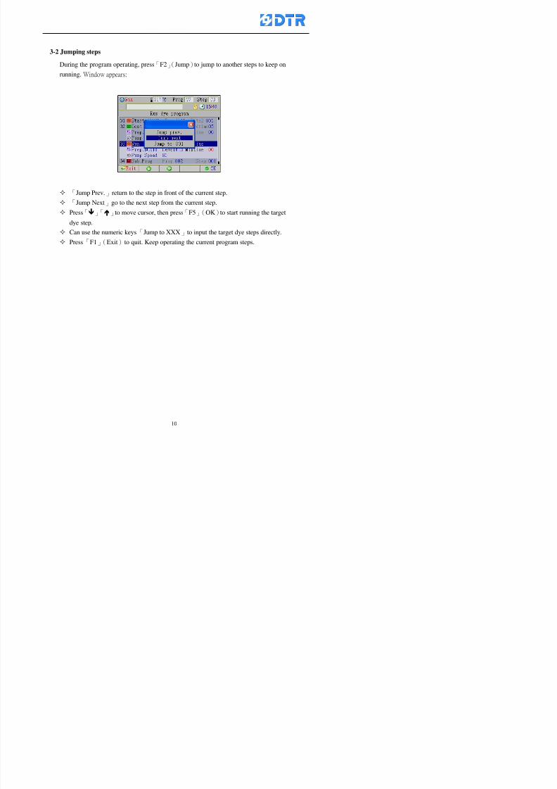
8132019 DTR 650 User Manual
httpslidepdfcomreaderfulldtr-650-user-manual 1070
3-2 Jumping steps
During the program operating press「F2」(Jump)to jump to another steps to keep on
running Window appears
「Jump Prev」return to the step in front of the current step
「Jump Next」go to the next step from the current step
Press「」「」to move cursor then press「F5」(OK)to start running the target
dye step
Can use the numeric keys「Jump to XXX」to input the target dye steps directly
Press「F1」(Exit)to quit Keep operating the current program steps
8132019 DTR 650 User Manual
httpslidepdfcomreaderfulldtr-650-user-manual 1170
8132019 DTR 650 User Manual
httpslidepdfcomreaderfulldtr-650-user-manual 1270
3-4 Schematic Diagram Mode Display
Schematic diagram mode displays the dye program operating the water level and
valve status and etc
During the dye program operating press membrance key「F4」to change the
display mode
When program stops it displays to Program list mode automatically from
Schematic diagram display mode Press membrance key「3」to view the
Schematic diagram mode again But if there is an alram occurred it stays at the
Program List mode Please release the alarm first
Press numeric key「9」(Exit)to return to the Program list mode
By setting factor can view the Schematic diagram mode displays directly during
operating (refer to the《6-4》「Display mode setting」for details)
8132019 DTR 650 User Manual
httpslidepdfcomreaderfulldtr-650-user-manual 1370
3-5 Icon Mode Display
During the dye program operating press membrance key「F4」to change to the
display mode
When program stops it displays to Program list mode automatically from Icon
Mode Display Press numeric key「6」to view the Icon mode again But if there is
an alram occurred it stays at the Program list mode Please release the alarm first
Press numeric key「9」(Exit)to return to the Program list display
By setting factor can view the Icon mode displays directly during operating (refer
to the《6-4》Display mode setting for details)
3-6 Running state of dyeing machine
There is totally 2 pages of the Running status information
To check the running status when the program is in operating press「F5」(State)「Inputoutput State」appears pess key「F5」 「Running Information」appears
8132019 DTR 650 User Manual
httpslidepdfcomreaderfulldtr-650-user-manual 1470
3-7 Keep continuing to run from the break point
Due to power sudden off or stop running the dye program it can keep continuing to
run from the break point when the power is retore Users can set the ldquoControl factorrdquo
which dye instruction allows (or prohitbit) to keep continuing to run from the breakpoint (refer to the charpter 6 for Setting)
When the power is restore the cursor stays at the step which stops suddenlybefore starting from the break point to press 「Run」 Window appears
Press「F4」(Yes)to keep going run from the break point
Press「F2」(No)to re-start that dye instruction
Press「F1 (Exit) to return
8132019 DTR 650 User Manual
httpslidepdfcomreaderfulldtr-650-user-manual 1570
3-8 Editing dye step temporary
Before dye program operating the ready-to-run dye step could be edit That edit will
not saved to the file and will not disappear by causing a sudden power inruption or
stop operating until a new dye program is selecting
Step
A Set the system factor as「22」first to allow editing the dye programs temporary
B Set the system factor as「23」 to allow the existing program can temporay
editing its range of step
C Item「19」of the system factor set the dye steps which allows or prohibits to edit
temporary (Refer to the Charpter 6 for details of 「Setting」the A-C )
D Press「F2」()「F3」()or「5」「6」at the Run window To move cursor
to the dye step intend to edit Press membrance key「2」「Edit instrunction
value」appears
E Press「F5」(Edit) then press()()or「5」「6」Programs names is listing
at the cursor or key in a value by the numeric keys Select and press「F5」(ok) to
confirm
F Press「F4」(Save)to confirm and go back to the Run window
G 〔Before pressing「F4」(Save)〕Press「F1」(Exit)to quit
8132019 DTR 650 User Manual
httpslidepdfcomreaderfulldtr-650-user-manual 1670
3-9 Creating an additon dye step during dye program running
Before and during the dye program running the users can creat an addition dye step in
the existing dye programs
3-9-1 Creating an addition dye step
To creat one addition dye step before running or during running step as follows
A Set the System Factor as「34」to allow to creat an addition step (Refer to the
Chartper 6 for details)
B In window「Run dye program」 press numeric key「8」to enter window of 「Edit
addition instruction」 to edit the single dye step first
C Press「」「」「5」
「6」to choose dye
steps press「F5」(OK)
D Press「F5」to edit the
content of dye step
E After complete editing the single dye
step Press「F4」(Run) to start running the
addition step
8132019 DTR 650 User Manual
httpslidepdfcomreaderfulldtr-650-user-manual 1770
3-9-2 Creating an addition treatment to a saved dye program
During and before the dye program running can creat an addition treatment to a
saved dye program or a dye step in a saved dye program
(1) Set the System factor as「34」to allow creating an addition step (Refer to the
Chartper 6 for details)
(2) In window「Run dye program」 press numeric key「8」to enter window of「Edit
single step」
(3) Press「」「」to choose「Sub Prog」 press「4」to move cursor and set itrsquos
dye program number and the step number by numeric keys Or stay at the
「Prog」and press「F3」(File) window appears
(4) Press「」「」to choose an addition dye program then press「F5」(OK)
(5) Press「F4」(Run)to run the addition dye program(sub-dye program)
(6) Finish to run the sub-dye program and return to the main dye program
8132019 DTR 650 User Manual
httpslidepdfcomreaderfulldtr-650-user-manual 1870
4 983120983137983155983155983155983159983151983154983140 DTR-650 provides four ranks of password for sercurity protection
(Refer to the ltTable 10gt Supplementary Table of the Password Usage for details)
First rank (User1 password) Edit delete dye programs control factors in output
testing etchellipall operating fuctions
Second rank (User2 password) Edit in output connecting table operating factors
Third rank (User3 password) Edit copy delete dye programs factors PLC run stop
Fourth rank (User4 password) Edit and modify dye programs
4-1 Entering the password
When the window of 「password」appears enter 6-digits number password by using
the numeric membrane keys then press「F5」(OK) If key-in an incorrect password
press「F3」(Del)and enter again
If the password is correct「」appears it allows to enter the relating operation
8132019 DTR 650 User Manual
httpslidepdfcomreaderfulldtr-650-user-manual 1970
4-2 Locking the data
After editing the programs and factors ensure to disable the password to protect all
programs and data of DTR-650 The way and step as follows
(1) Choose「8Others」at the main meun
(2) Choose「02Data Locking」at the sub-function field
(3) Press「F5」(OK)to confirm
(4) Return to the main menu「」disppears on the status bar that means the data
has been locking already
4-3 Setting and changing the Userrsquos password
There are four userrsquos password for setting and edit by the users themselves
User1 password Access to all operation setting
User2 password For edit in output connection table operating factors
User3 password Only for copy and delete dye programs factors PLC run stop
User4 password Only for edit and modify dye programs
Method of setting edit
(1) Choose「8Others」at main menu press「F5」(OK)
(2) Choose「7 Set Password 2」at the sub-function field press「F5」(OK)
(3) The cursor shows the default password now press「F3」(Clr)to delete Key in
a new password with 6-digit
(4) Press「F5」(OK)to complete the setting of User2 password Go back to the main
menu
8132019 DTR 650 User Manual
httpslidepdfcomreaderfulldtr-650-user-manual 2070
The four userrsquos password has to made from different group numbers Using
same password will affect the operating Please pay attention when update the
password
8132019 DTR 650 User Manual
httpslidepdfcomreaderfulldtr-650-user-manual 2170
5555 983109983140983145983156983145983150983143 983108983161983141 983120983154983151983143983154983137983149983155
5-1 Choosing a dye program
Press function key「F4」(Edit)or choose「1Dye Program」at the main menu press
「F5」(OK)
Choose「1Edit Dye prog」at the sub-function field press「F5」(OK)to enter to the
window「Sel dye program」During the dye program running it is allowed to edit asaved program or a new dye program or the current dye program in running
Method Press「」「」and「5」「6」「3」「4」to move cursor to choose
a dye program number Press「F5」(OK)to enter that dye program Press
「F1(Exit)to quit and return
Method
Directly key in the number selection box
appears at the right corner of the window
Select a program number and press「F5」
(OK) fi
8132019 DTR 650 User Manual
httpslidepdfcomreaderfulldtr-650-user-manual 2270
5-2 Creating a new dye program
Step
A Choose「1Dye Program」Press「F5」(OK)
B Choose「1Edit Dye prog」at the sub-function menu press「F5」(OK)to enter
to window「Sel dye program」
C At the window「Sel dye program」 choose an empty dye number (eg「002」)
press「F5」(OK)window《Fig 5-2-1》appears
《Fig 5-2-1》
D Press「F2」(Add) table of 「Edit dye instruction」《Fig 5-2-2》appears
E Press「F5」(Edit) the dye instruction appears at the cursor locates press「」「」
」and「5」「6」「3」「4」to move cursor to edit the instruction and its
factors
F All inserted new dye instructions would be listed in front of 「Program End」
8132019 DTR 650 User Manual
httpslidepdfcomreaderfulldtr-650-user-manual 2370
【Eg】Edit「CycRinse」
A Edit the main function step first Press「F2」
()「F3」()to move the cursor The dye
step is listing by orders Choose「CycRinse」
and press「」 there is a cursor at itrsquos value
B Move cursor to setting value「Cold」andchoose「Mix」by pressing()() Then
press「」to move cursor to「Time」and enter
itrsquos setting value as「2」Press「F5」(OK) to
complete the main function setting
C To move cursor to the parallel functionsetting field Press()()to choose the
dye step Press「」to confirm and move
cursor to choose itrsquos setting facor
D Press「F5」(OK)to move cursor to the next
parallel function
E Repeat above steps C-D until all parallel
functions setting are completed Each main
function can be operating with the
maximum 4 parallel functions
F Press「F4」(Save)to confirm and return to
the「Edit dye program」window
G Repeat the above step A E to keep on
8132019 DTR 650 User Manual
httpslidepdfcomreaderfulldtr-650-user-manual 2470
5-3 Setting the file name (for dye programs)
When a dye program is setting up it is saved by numbers automatically Optionally users
can save it by another names
Step
(1) Create a new dye program first (the Name is not available for empty dye
programs)
(2) At the window「Sel dye program」 press「F4」(File) Window《Fig5-3》appears
《Fig5-3》
(3) Use numeric 0~9「+」「-」「_」blank alphabet A~Z and symbols [ ] etchellip to
create a file name Each file name can type-in the max 8 unit Press 「3」「4」
「5」「6」to move the cursor to choose the unit It also can use the membrane
numbric key to type in The selected unit is showed in front of the cursor at the
「File」Press「OK」to confirm
(4) Quit to input to press「F3」(Clr)
(5) After complete the set up press「F5」(OK)to confirm and go back to the window
「Sel dye program」 Now the name behind the dye program number is created
8132019 DTR 650 User Manual
httpslidepdfcomreaderfulldtr-650-user-manual 2570
5-4 Inserting a program step
Insert the program step means to insert a step in the existing program step where youwant to insert a step All following steps are moved one step ahead The total number of
steps will be increased by itself Able to insert more than one step continusely at the
same time
【Example】《Fig5-4》 To insert a step「call」before「002 Rinse」
《Fig 5-4》
Step
A Enter to the dye program「002」at the window of 「Sel dye program」
(Example)
B Press「6」to move cursor to「002 Rinse」 then press「F2」(add)
C Press「F5」(Edit) then press「」「」or「5」「6」to choose program
step to modify Choose「call」and press「」to move cursor to modify itrsquos
value
8132019 DTR 650 User Manual
httpslidepdfcomreaderfulldtr-650-user-manual 2670
D Press「」「」 value of 「call」is listing at the table Choose「pH Check 」Press「F5」(OK)
E Press「F4」(Save)and press「F1」(Undo)to return to previous window Complete
to insert the「02 Call」The previous「02 Rinse」update to「03」 All following
steps are moved one step ahead Total number of steps will be increased ldquo1rdquo by
itself
Repeat the steps B-E can non-stop to insert more than one step
Quit the insert and modify ( before pressing「F4」) press「F1」(Undo) to exit
The original dye steps will be unchanged
To delete an inserted dye steps press key「F3」(Del) The step deletes
immediately
5-5 Deleting a program step
Delete the program step means to delete step which the cursor locates When that step is
deleted the step number will be updated automatically All following steps are moved up
one step It is allowed to delete more than one steps continuously at the same time
Step
A Enter to the「Edit dye program」《Fig5-5》at the window「Select dye program」
B Press「6」「5」move cursor to the want to delete
C Confirm and press「F3」(Del) Window「Confirm delete」appears Press
「F4」(Yes)
8132019 DTR 650 User Manual
httpslidepdfcomreaderfulldtr-650-user-manual 2770
D That step is deleted immediately and all following steps move up one step
Repeat the steps above can non-stop to delete more than one step
Press「F2」(No)to cancel the deletion
Press「F1」(Exit)to end
5-6 Modifying a program step
To modify the saved name and the setting value of the dyeing steps
Step
1 Choose a dye program which need to modify at the「Sel dye program」 press「F5」
(OK)
2 Press「6」「5」to move cursor to a step which need to modify Select and press
「F5」(Edit) Window of 「Edit dye instruction」appears
3 Press「F2」()「F3」()to choose the step list select it and press「」to move
the cursor to itrsquos value setting
4 Press numeric key to input the value or press「6」「5」to choose the item Press
「F5」(OK)when complete Cursor move to the next value (if need to set more
than one item)
5 Press「F4」(Save)when all setting is complete Return to「Edit dye program」
Method of parallel functionrsquos modification is same as above
Before pressing the key「「「「Save」」」」 press「F1」(Undo)to quit all modify Return
to the window of Edit dye program
All edit and modify functions mentioned of this charper are only available
for the dyeing files which already saved in the file and not being running It
8132019 DTR 650 User Manual
httpslidepdfcomreaderfulldtr-650-user-manual 2870
5-7 Copying a dye program
Copying a dye programs mean to make a copy of an dye programs to a blank dyeprogram This function is for creating new dye program rapidly
Choose「1Dye Program」at the main menu Press「F5」(OK)then press「F2」()to choose「2Copy dye prog」 Press「F5」(OK) 《Fig5-7-1》appears
《Fig 5-7-1》
《Fig 5-7-2》
【【【【Eg】】】】
Copy program 003 to program 012
Press「」「」to move cursor to theprogram「003」 press「F4」(Copy)
Program「003」shows at the top right side of
the bar
Press「」「」to move cursor to program「012」 Then press「F5」(Paste)「」appears behind the「012」That means it issuccessfully copying the program
If the target program is occupied
confirmation window「Overwrite」
When choose an program or a targetprogram can select them by using the
8132019 DTR 650 User Manual
httpslidepdfcomreaderfulldtr-650-user-manual 2970
5-8 Deleting a dye program
Choose「1Dye program」at the main menu Press「F5」(OK)then press「F2」()to choose「3Delete dye prog」 Press「F5」(OK) 《Fig5-8-1》appears
《Fig5-8-1》
《Fig5-8-2》
Press「」「」to move cursor to
choose program need to delete Eg
delete program「012」 press「F5」(Del) Confirmation window
「Confirm delete」appears
Press「F4」(Yes) to confirm delete
Repeat the above step can delete more
than one program at the same time
Press「F2」(No) to return to window
《Fig5-8-1》and not delete that program
Exit to press「F1」(Exit)and return to the
main menu
8132019 DTR 650 User Manual
httpslidepdfcomreaderfulldtr-650-user-manual 3070
6 983123983141983156983156983145983150983143DTR-650 has a built-in standard factor that can fulfill all different types of dyeing
machinesrsquos basic demand Users can also modify the factors base on their request to
fulfill their special control demand Before modify please refer to the table of each
range of Setting Factors (see the Supplementary Table)
6-1 ldquoEnable to use the program stepsrdquo setting
There are totally 64 program steps Parts of them are usually applying to the programs
In order to make more efficiently of editing programs it can「Disable」the other part
of program steps which are not usually applying or not applicable to the programs
For example dye machine with one tank it is only using step Tank B In this case itcan firstly「Disable」the program steps of Tank C When edit the program the
「Disable」rsquos steps will not appear at the cursor for choosing But this will not effect
and change the saved files The saved files can be kept as before
Step
(1) Choose「2 Factors」at the main menu Press「F5」(OK)(2) Choose「18 Dye Instruction」at the sub-function menu Then presss「F5」(OK)
Window「Edit dye ins」appears
「Enable」instruction can available to
use「Disable」instruction is temporarystop to use
Press「F2」()「F3」()to move
8132019 DTR 650 User Manual
httpslidepdfcomreaderfulldtr-650-user-manual 3170
6-2 ldquoAllow to modify dye program temporary during operatingrdquo Setting
During dye program running it can modify dye program temporary Thesemodification will not disappear by causing a sudden power interruption or power off
until select another new dye program to run
Please note that it is only for modifying the dye program temporary That program
file would not saved due to the modification If need to modify the program file and
save choose the function of Edit Dye Program to edit (Refer to the Charper 5 for the【Edit Dye Prograrm】)
6-2-1 ldquoAllow to modify all dye programsrdquo Setting
Step
(1) Choose「2 Factors」at the main menu Press「F5」(OK)
(2) Choose「02 System Factor」at the sub-function menu Then presss「F5」(OK)
Window「Edit System Factor」appears
Set to stop using temporary the「07
Rinse」press「F4」(Sel)to set it as Disable
Repeat above steps to complete all setting
Press 「F1」(Exit)to return to main menu
8132019 DTR 650 User Manual
httpslidepdfcomreaderfulldtr-650-user-manual 3270
6-2-2 ldquoAllow to modify part of dye programsrdquo Setting
【Eg】Set the number 08 or above (including number 08) is allowing to modify dye
programs during operating
Step
A Refer to【6-2-1】setting the factor as「22」to allow editing dye program
temporary during operating
(4) Press「3」「4」to edit the setting
as「Enable」 and press「F5」(OK)
Restore the standard factor by
pressing「F3」(Clr)
(5) Exit to press「F1」(Exit)and
return to window of 「Main Menu」
8132019 DTR 650 User Manual
httpslidepdfcomreaderfulldtr-650-user-manual 3370
6-2-3 ldquoAllow to modify dye steps temporaryrdquo Setting
After setting the dye programs are allowed to edit it also can set which dye steps are
allowed to edit temporary during operating
Step
(1) Choose「2 Factors」at the main menu Press「F5」(OK)
(2) Choose「19 Dye Ins control」at the sub-function menu Then presss「F5」
(OK) Window「Edit ins mode」appears
「Enable」 Allow to edit that dye step before
operating
「Disable」 Not allow to edit dye step before
operating
(3) Press「」「」to move cursor
to choose dye step Press「F4」
To enter to the「Edit dye program」from the
function menu there is a「」in front of the
file name「0-7」 means that program is not
allowing to edit during operating
8132019 DTR 650 User Manual
httpslidepdfcomreaderfulldtr-650-user-manual 3470
6-2-4 ldquoSet the dye step to keep running from the interrupt pointrdquo setting
When the dye program is operating it will disappear by causing power
interruption or sudden power off When start running again part of dye steps can
run again from the interrupt point part of them cannot
How to set
(1) Choose「2Factors」in the main menu and press「F5」(OK)
(2) Choose「20Continue mode」in the sub-function menu Press「F5」(OK) to
enter window of 「Continue Setting」
(3) Press「」「」to move cursor to choose dye steps Press「F4」(Sel)it
shows「Disable」or「Enable」for choosing Press「F5」(OK)to move cursorto the next setting
(4) Repeat above method until all setting is complete press「F1」(Exit)and
return to the main menu
8132019 DTR 650 User Manual
httpslidepdfcomreaderfulldtr-650-user-manual 3570
6-3 ldquoAllow to insert an addition dye stepsrdquo setting
During the program is running can temporary insert an addition dye step or a dye
program according to the operating actual situation Through this setting can set which
dye steps can apply or not to the program in operating
During to insert an addition step if sudden interruption or power off occurred it returns
to the main dye program automatically Before starting again should decide seriously
and set it again by actual needed
Step
(1) Choose「2Factors」at the main menu and press「F5」(OK)
(2) Choose「02System factor」and press「F5」(OK)
(3) Press「」「」to move cursor to the factor「34」and press「3」「4」to set
it as「Enable」 Press「F5」(OK)
(4) Press「F1」(Exit)to return to main menu Choose「21Addition Ins」at the
sub-function menu Press「F5」(OK)to enter the window「Addition Instruction」
(5) Press「」「」to move cursor to choose dye steps and press「F4」(Sel) Cursors
locates shows「Eable」or「Disable」 Press「F5」(OK)to move cursor to the
next dye step
(6) Repeat above method until to complete all setting press「F1」(Exit)and return
to the main menu
8132019 DTR 650 User Manual
httpslidepdfcomreaderfulldtr-650-user-manual 3670
6-4 Setting the display mode
DTR650 has three types of display mode during operating Program List mode
Schematic Diagram mode and Icon mode Users can set the display mode during
operating by factor setting
It goes back to a Program List mode when dye program ended
Step
(1) Choose「2Factors」at the main menu and press「F5」(OK)
(2) Choose「02System factor」and press「F5」(OK)
(3) Press「F2」()「F3」()to move cursor to choose「32Display mode」Press
「3」「4」 it shows「Online picture」「Instruction」「Big Icon」 choose
「Online picture」(eg) and press「F5」to confirm
8132019 DTR 650 User Manual
httpslidepdfcomreaderfulldtr-650-user-manual 3770
(4) Press「F1」(Exit)to return to the main menu
(5) The Schematic Diagram displays when the program is running (it stays at theProgram List mode when there is an alarm occurred)
Press「F4」to transfer to another display mode
It goes back to a Program List mode from Schematic Diagram Mode when dye
program ended Press numeric key「3」to view Schematic Diagram Mode again
Quit to press「F5」(Exit)
6-5 Adapt the digital input to another functions
DTR-650 has 32(0~31)input terminal it owns an standard setting when the
controller is initial According to the userrsquos demand they can change the DTR-650rsquos
anther functions of Input Terminal and PLC Input channel
The PLC Intputrsquos name can also define by the users (use IBM computer to edit and
download)
How to set
(1) Choose「2 Factor」at the main menu Press「F5」(OK)
(2) Choose「22 Input table」at the sub-function menu and press「F5」(OK)to enter
「Edit input table」
The actual input
terminal of theIBM computer
PLCrsquos input channel
8132019 DTR 650 User Manual
httpslidepdfcomreaderfulldtr-650-user-manual 3870
6-6 Adapt the digital output to another functions
DTR-650 has 32(0~31)output terminals it owns an standard setting when thecontroller is initial According to the userrsquos demand they can adapte the digital output
and the PLC outputrsquos channel to another functions The PLC Output channelrsquos name
can also define by users (use IBM computer to edit and download)
Step
(1) Choose「2 Factor」at the main menu Press「F5」(OK)
(2) Choose「23 Output table」at the main menu and press「F5」(OK)
(3) Press「F2」()「F3」()to move cursor to choose the output terminal atthe left side of the window Press「F5」(Add) the PLCrsquos output channelrsquos
name is listing at the right side of the window
(4) Press「F2」()「F3」()to move cursor to choose the PLC outputrsquos channel
If cursor moves to the PLC output channel which already linking「Add」is
not for choosing that means that output channel is already occupied
(5) Confirm the connection to press「F5」(Add) Quit to press「F4」(Del)Press「F1」(Exit)when complete all setting and return to main menu
The actual output
terminal of the
IBM computer
PLCrsquos output channel
8132019 DTR 650 User Manual
httpslidepdfcomreaderfulldtr-650-user-manual 3970
983095 983109983140983145983156983145983150983143 983156983144983141 983110983137983139983156983151983154983155DTR-650 has several kinds of control factors
Userrsquos factors System factors Temperature Control factors Speed factors Dosing
factors PID factors Analog Input Output factors standard factors etchellipPlease refer
to the supplementary table for the setting range and standard of the factors
DTR-650 has a built-in standard factor Users can edit by themselves if necessary
7-1 Modifying userrsquos factors
Userrsquos factors is setting with the Dyeing machinesrsquos PLC Programrsquos factor it is define by
the PLC Programmer
Step to edit
(1) Choose「2Factors」at main menu Press「F5」(OK)
(2) Choose「01User Factor」Press「F5」(OK)
(3) Press「F2」()「F3」()「6」「5」to move cursor up down and by page
Choose a factor need to edit then press「3」「4」to set itrsquos value Press「F5」(OK) Cursor moves to the next factor
(4) Some of factors can input numbers by the numeric membrance keys to edit If
the input is incorrect it turns to red and means the edit is not available
8132019 DTR 650 User Manual
httpslidepdfcomreaderfulldtr-650-user-manual 4070
Modifyrsquos method of the system factors temperature factors speed factors dosingfactors PID factors analog Input output factors standard factors etchellipare same asabove
If apply the library of DTR500 and DTR600 into the DTR650 the key「3」「4」may not valid to use Please use the numeric keys instead of it to key in factors itmay not effect the normal operation
Please pay a serious attention and read carefully at the factorrsquos table before modify the factors An incorrect value may effect the DTR-650 Dyeing
Machine Controllerrsquos operating After modifying factors must cancel the
password and secure data
7-2 Loading the standard factors
After modifying factors if need to restore a manufacturerrsquos standard factors of
DTR-650 The method as follows
1 Choose「2Factors」at main menu Press「F5」(OK)
「 「 ( ) 「
8132019 DTR 650 User Manual
httpslidepdfcomreaderfulldtr-650-user-manual 4170
7-3 Copying the factor
Users can build up a set of factor by themselves and make a copy and save
Step
1 Choose「2Factors」at main menu Press「F5」(OK)
2 Choose「13Restore Factor」 press「F5」(OK) window「factor will be
overwrite 」
3 Press「F4」(Yes)copy finished and saved Return to the main menu
4 Press「F2」(No)to not copy the factor and the existing factor is not change Return
to the main menu
7-4 Loading the backup factors
Users can build up a set of factor and backup files to load to DTR-650
Step1 Choose「14Backup factor」at the sub-function menu Press「F5」(OK)and
window「Factror will be overwrite」appears
2 Press「F3」(OK)to load the the backup factor them return to main menu
Press「F2」(No)to not copy the factor and the existing factor is not change
Return to the main menu
8132019 DTR 650 User Manual
httpslidepdfcomreaderfulldtr-650-user-manual 4270
983096 983119983157983156983152983157983156 983124983141983155983156983145983150983143
Before the output testing must be complete the steps as follows
A Cut off all connecting line of output terminal of DTR-650
B Stop running the PLC
C Check up the connections of all output channels to avoid damages from
incorrect connections
D Check up state of dyeing machines include the temperature pressure valves
onoff and pumpshellipetc ensure the safety for priority
8-1 Testing the Digital output
Step
1 Choose「3Output Testing」at the main menu Press「F5」(OK) 2 Choose「1Digital」at the sub function menu Press「F5」(OK) window「Digital
output testing」appears
3 Press「」「」「」to move cursor to each output channels Press「F5」(OK)
Output Name
8132019 DTR 650 User Manual
httpslidepdfcomreaderfulldtr-650-user-manual 4370
8-2 Testing the Analog output
(1) Choose「3Output Testing」at the main menu Press「F5」(OK)
(2) Choose「2Analog」at the sub function menu Press「F5」(OK) window「Analog output testing」appears
(3) Press「」「」「」to move cursor to each channels Then key in number by
the numeric membrance keys (range0~200= 0~20mA) Press「F5」(OK) there
is a output current relating to the output channel
(4) Press「F5」(OK) There is an output when the output channel with red light No
output without light onl(5) When complete the testing press「F1」(OK)to return to the main menu
8132019 DTR 650 User Manual
httpslidepdfcomreaderfulldtr-650-user-manual 4470
983097 983107983137983148983145983138983154983137983156983145983151983150
DTR-650 has Dosing and Temperature calibration
When enter to Dosing calibration must be set the Low Volume calibration first and
then High Volume calibration When enter to Temperature calibration must be set the
Low Temperature calibration first and then High Temperature calibration Must be
hightly follow this orders seriously
9-1 Calibration of Low Volume Tank
Step
A Choose「4Calibration」at the main menu Press「F5」(OK)
B Choose「Dosing 0 low vol」at the sub function menu Press「F5」(OK) window
appears
C Fill the Dosing Tank to a half level input value shows how much the water level
If it stays ldquo0rdquo check the connection and the factor setting is correct or not
And connect the pressure sensorrsquos output channel to the Current Meter to ensure
that sensor works or not
8132019 DTR 650 User Manual
httpslidepdfcomreaderfulldtr-650-user-manual 4570
D Fill the Dosing Tank to 50ml (Calcalate from the bottom side of the pressure
sensor steel tube) input value should show 4~6 (input value must between
0~10) Then enter the water volume The setting volume is relating the water
levelrsquos water value (litre as unit) input range 0~80 Set as「 「「 「0000 0000 0000 0000」」」」is strongly is strongly is strongly is strongly
receommend receommend receommend receommend Press「F5」(OK)to complete [Calibration of Low Volume Tank 1
is same as above method]
9-2 Calibration of High Volume Tank
Step
A Choose「4Calibration」at the main menu Press「F5」(OK)
B Choose「Dos 0 high vol」at the sub function menu Press「F5」(OK) window of
「Calibrate high 」appears
C Fill the Dosing Tank to a full level input value should be larger than 30 enter
the current water level which relates to the water volume Enter the range within
100~2500 Then press「F5」(OK) to complete the calibrate the high volume tank
8132019 DTR 650 User Manual
httpslidepdfcomreaderfulldtr-650-user-manual 4670
9-3 Temperature Calibration
Step
A This function is for adjusting the DTR650rsquos accuracy of Temperature Control It
must be using with the special terminal which is only for DTR650
B Choose「4Calibration」at the main function menu and press「F5」(OK)
C Choose「3Low Temp」at the sub-function menu Press「F5」(OK)and《Fig9-3》
appears insert the DTR650rsquos low temperature calibration terminal to the temperature
input terminal wait for the jumping value to stable down then press「F5」(OK) then
to adjust the high temperature calibration
D Adjusting the High Temperature Calibrationrsquos method is same as above But usersusersusersusers
must be using the High Temperature Terminalmust be using the High Temperature Terminalmust be using the High Temperature Terminalmust be using the High Temperature Terminal whichwhichwhichwhich is specially for DTR650 onlyis specially for DTR650 onlyis specially for DTR650 onlyis specially for DTR650 only
《Fig 9-3》
8132019 DTR 650 User Manual
httpslidepdfcomreaderfulldtr-650-user-manual 4770
10 983122983141983139983151983154983140983155 983151983142 983108983161983141 983120983154983151983143983154983137983149983155
It contains the past 15 days of temperature curves of running history
Checking method
(1) Choose「5Dye Record」at main menu press「F5」(OK)
(2) Sub-function menu shows the set up date of the past 15 days dye programs
Listing by the lastest set up date
(3) Choose a program date and press「F5」(OK) it appears window「Temp
record」
(4) Press「」「」to move the white line in the box one minute by moving once
(5) Press「3」「4」to move the line to check the time period 2 hours by moving once
The yellow selecting line of the「24 hours operating state」is repectively moving
The curve info is show in the curve box Left side of the widnow appears the
relating running info the time is the time value of the line locates at
(6) Check more details of the temperature info to press numeric key「middot」 a bright red line
appears in the selecting box this line is to check the starting point of the
temperature inforsquos time period Then press「」to move the white line to the end
point of the time period The temperature info between the starting point and end
point are appears at the right side of the window Press「middot」to return to the preious
curve page
(7) Check more details of the alarm infor To perss numeric key「7」「9」 the alarmrsquos
details is listing by orders
(8) Press「F1」(exit) to return
8132019 DTR 650 User Manual
httpslidepdfcomreaderfulldtr-650-user-manual 4870
11 983125983155983137983143983141 983151983142 983117983141983149983151983154983161 983107983137983154983140
DTR-650 supports 32MB or above Compact Flash Card which can transfer and save all
information for 4 sets of DTR-650 Including library files schematic diagram icon
image PLC program dye program factor and confiruration files etchellip Use the CF Card
to up download and swap the information of DTR-650 promptly install the relating
device and program updates
DTR-650 CF Card with bank 1 to bank 4 can save 4 sets information of Dyeing
Machines When download or save files should choose the BANK first
《Fig11-1》
8132019 DTR 650 User Manual
httpslidepdfcomreaderfulldtr-650-user-manual 4970
11-1 Downloading data
1 Firmly insert the CF card into the DTR-650rsquos PCMCIA connector Ensure it is
wholely and firmly inserted if the card is not totally inserted or the card do not
touch in all to the connector there will be an error occurred and cannot
updownload or interrupted during operation
2 Choose「6Memory Card」at the main menu and press「F5」(OK) 《Fig11-1》
appears Information of Bank「1」shows at the left hand side of the window press
number 1-4 by using numeric keys to choose the BANK Check the
information in the Bank seriously which is exactly need to download to the
DTR650
3 Press()()「6」「5」to move cursor to the sub-function menu to choose
the downloading items Press「F5」(OK) window appears「Stop PLC run before
access memory card Stop the PLC run」 Press「F5」(YES) to stop PLC
running
4 Press「F5」(OK) window appears Confirm to update or not the DTR-650rsquos
information As that downloading will be replace the DTR-650rsquos information
(that means the existing information of the DTR-650 will be removed and
replaced)
5 Press「F4」(YES)to download the information from the DTR-650 to the CF
Card Return to the main menu when finish
8132019 DTR 650 User Manual
httpslidepdfcomreaderfulldtr-650-user-manual 5070
Ensure inserting firmly the CF card into the DTR-650 unless it will cause
error or cannot Updownload data
Never remove CF card during transferring or updownloading data Until it
is all completed
DTR-650rsquos dyeing program is not compatible with DTR-500 and
DTR-600 Never use CF card to transfer data among them
11-2 Storing and transfering data
1 Insert the CF Card to the DTR-650
2 Choose「6Memory Card」at the main menu and press「F5」(OK) 《Fig11-1》
appears Left hand side of the window shows the data of BANK 1 press numeric
keys 1-4 to select the BANK To confirm the put the data in the DTR-650 to the CF
Card The existing data of that bank will be replaced and covered by the new data (if
that bank is already occuplied)
3 Choose「23Save Dye prog」(Example)at the sub-funciton menu press「F5」(OK)to confirm Window「Update memory card data」appears
4 Press「F5」(OK)to transfer the data to the CF card Return to the main menu
5 Put the CF card into another DTR-650 and follow the operating method of 「11-1
Downloading data」」」」can transfer and swap data with more than one set of
DTR-650
8132019 DTR 650 User Manual
httpslidepdfcomreaderfulldtr-650-user-manual 5170
12 983123983156983137983156983141 983137983150983140 983113983150983142983151983154983149983137983156983145983151983150
The state and information is including the Dyeing Machinersquos state of Digit Input output
Analog Input output Temperature control PID Dosing PID Pressure different PID
software system information and alarm record This information is for checking at any
time
12-1 Input Output state
Step
1 Choose「7Info and state」at main menu and press「F5」(OK)
2 Choose「01Digital IO put」at the sub-function menu then press「F5」(OK)
「Digital In Out State」0=None 1=Input
3 Press「F1」(Exit)to return to main menu
Same method for checking the temperature control analog dosing pressure
different etchellip
12-2 Checking the system information
Step
1 Choose「7Info and state」at main menu and press「F5」(OK)
2 Choose「11 System info」at sub-function field press「F5」(OK)Window
「System Information」appear
System information is including System info(software version) Library doc
Icon files Schematic file Definition file hardare state Config File Commandinstruction icon PLC file etc
8132019 DTR 650 User Manual
httpslidepdfcomreaderfulldtr-650-user-manual 5270
12-3 Checking the operating alarm record
Operating record shows the latest 40 operating items and alarm records including
the time and content of the alarm
A) Choose「7 Info and state」
and press「F5」(OK)
B) Choose「12Alarm logs」at
the sub-funciton menu then
press「F5」(OK)
8132019 DTR 650 User Manual
httpslidepdfcomreaderfulldtr-650-user-manual 5370
13 983105983140983146983157983155983156983145983150983143 983156983144983141 983107983151983150983156983154983137983155983156
The displaysrsquos brightness can be adjusted if necessary
Step
1 Choose「8Others」at main menu press「F5」(OK)
2 Choose「01Contrast」at sub-function menu press「F5」(OK) window「Set
Contrast」appears
3 Press「」「」to move the bar to set the brightness then press「F5」(OK)Window appears「Please reboot the system」
4 Press「F5」(OK)to return to main menu and re-boot the DTR-650 to complete
adjusting the brightness
8132019 DTR 650 User Manual
httpslidepdfcomreaderfulldtr-650-user-manual 5470
14 983123983156983151983152 983154983157983150983150983145983150983143 983156983144983141 983120983116983107 983120983154983151983143983154983137983149
Before testing the Input output testing transfer of the PLC program must stop the PLC
running
Step
1 Choose「8Others」at the main menu Press「F5」(OK)
2 Choose「04 PLC Stop」at sub-function menu Press「F5」(OK) window
「Password」appears
3 Enter password and press「F5」(OK) Window「Stop the PLC run」appears
4 Press「F4」(Yes)and window「PLC Stop」appear Press「F5」(OK) Now
the PLC is stop running and return to the main menu
All testing cannot operate when the PLC is running
Editing dye program and the relating operation can
perform with the PLC running together
8132019 DTR 650 User Manual
httpslidepdfcomreaderfulldtr-650-user-manual 5570
15 983123983141983156983156983145983150983143 983156983144983141 983156983145983149983141
Step
1 Press「8Others」at the main menu Press「F5」(OK)
2 Choose「10Set date time」at the sub-function menu Press「F5」(OK) window
「Set date time」appears
3 Press「F5」(Edit) to move cursor by 「3」「4」 enter the time value at the
cursor locates
4 Press「F5」(OK)to complete the modify Press「F1」(Exit)to return to main
menu
5 Press「F1」(Exit)if not modify and return to main menu
8132019 DTR 650 User Manual
httpslidepdfcomreaderfulldtr-650-user-manual 5670
1166 983123983123983157983157 983152 983152 983152 983152983148983148983141983141983149983149983141983141983150983150983156 983156 983137983137983154 983154 983161983161 983124 983124 983137983137983138983138983148983148983141983141
TTTTTTTTaaaaaaaabbbbbbbblllllllleeeeeeee 11111111 【Dye Instruction】
Code Icon Instruction Code Icon Instruction
000 End 016 Inject C
001 Start 017 Dosing BV
002 Heat 018 PH
003 Cool 019 Addsalt B
004 Flow Fill 020 Addsalt C
005 Level Fill 021 Ana Fill
006 Drian 022 Lock Fill007 Rinse 023 Lock Level
008 Run 024 Low Rinse
009 Call 025 Cyc Rinse
010 Prep B 026 Rinse B
011 Addsalt B 027 Rinse C
012 Dosing B 028 Temp
013 Inject B 029 Nozzle Pressure
014 Prep C 030 Main Pump
015 Dosing C 031 Pump Speed
8132019 DTR 650 User Manual
httpslidepdfcomreaderfulldtr-650-user-manual 5770
Table 2 【【【【Alarm】】】】
System Alarm Must stop operating and check up to solve problems before restarting
the machine
Running Alarm It is a reminder Not effect the operating of DTR-650
Userrsquos Alarm Total of 32 Users can define themselves and use it when edit the PLC
Program (do not listing below)
No System Alarm No Running Alarm
1 PLC program not running 16 Temp ctrl 0 Grad too slow
2 Main temp sensor error 17 Temp ctrl 0 Grad too fast
3 Not at Run window 18 Temp ctrl 0 Hold temp too low
4 Exceeding max temp 19 Temp ctrl 0 Hold temp too high
5 - 20 Temp ctrl 1 Grad too slow6 - 21 Temp ctrl 1 Grad too fast
7 - 22 Temp ctrl 1 Hold temp too low
8 Communication error 23 Temp ctrl 1 Hold temp too high
9 Slave not answer 24 Temp ctrl 2 Grad too slow
10 PLC 0 not answer 25 Temp ctrl 2 Grad too fast
11 PLC 1 not answer 26 Temp 2 Hold temp too low12 Display not answer 27 Temp 2 Hold temp too high
13 Lower power voltage 28 Temp ctrl 3 Grad too slow
14 - 29 Temp ctrl 3 Grad too fast
15 - 30 Temp3 Hold temp too low
31 Temp3 Hold temp too high
32 Dosing 0 injection too slow
33 Dosing 0 injection too fast
34 Dosing 1 injection too slow
35 Dosing 1 injection too fast
8132019 DTR 650 User Manual
httpslidepdfcomreaderfulldtr-650-user-manual 5870
TTTTTTTTaaaaaaaabbbbbbbblllllllleeeeeeee 33333333 【【【【System factor】】】】
No Description Std Range amp Definition
1 ID No 000 000- 100 Controller no
2 Communication Rate 4800Bps 2400 4800 9600 19200 38400
3 Display language Chinese English Chinese
4 Temp display mode and
5 Maxmium temperature 145 025 ~ 145 6 Type of external PLC Default PLC32DPLC32PLC16Default
7 Number of external PLC NANA 1 unit connect
2 unit connect
8Communication Rate of
PLC9600Bps 2400 4800 9600 19200
9 Set point 1 085 000 ~ 145
If signal source is temperaturethe setting value is thetemperature value If the signal
source is Analog Input 6~17 then
setting value for Analog input is 0 ndash
100 and relates Analog
Input14~020mA
10 Source 1 Sensor0Sensor 0 ~5
Analog input 0 ~1111 Set point 2 092 Same as 09
12 Source 2 PT100 1 Same as 10
13 Set point 3 085 Same as 09
14 Source 3 PT100 2 Same as 10
15 Set point 4 092 Same as 09
16 Source 4 PT100 3 Same as 1017 Set point 5 085 Same as 09
18 Source 5 PT100 4 Same as 10
19 Set point 6 092 Same as 09
8132019 DTR 650 User Manual
httpslidepdfcomreaderfulldtr-650-user-manual 5970
29 Min cyclic time of cloth 100sec 0 ~ 255 sec
30 Max cyclic time of cloth 240sec 0 ~255 sec
31Standard cyclic time of
cloth
180 000 ~ 255 sec
32 Display ModeProgram
List
Program list Schematic Diagram
Icon mode
33 CF card format Standard of
DTR CF
Card
Standard of DTR CF Card V20
Standard CF Card
34 Addition step Disable Disable Enable35 Mode Com 3
CouplingEsure Com 3 is the communication
port of the Central or Coupling
36Com 3 Communication
rate9600 Central communication speed
8132019 DTR 650 User Manual
httpslidepdfcomreaderfulldtr-650-user-manual 6070
TTTTTTTTaaaaaaaabbbbbbbblllllllleeeeeeee 44444444 【【【【Temperature Cotnrol Factor】】】】
No Factor Definition Standard Range and Definition
01 PT No PT-0 PT 0~5 PT-100 Input number
02 Max working temp 140 000~140
03 Output mode 0 0~2
04 Alarm time of gardient 240sec 000~255 sec
05 Alarm mode of gradient Always AlwaysOnceNone
06 Control mode of gradient Heating orCooling
interlocked
Heating and Cooling interlocked
No limitation
07 Alarm range of HoldTemp 03 01~20
08 Alarm time for HoldTemp 240sec 000~255sec
09 Alarm mode of HoldTemp Always AlwaysOnceNone
10 Control mode ofHoldTemp
Heating only Only heating and cooling Cooling whenalarm occurred Only heating andcooling No limitation when alarmHeating only
11 Porportional Band 100 000~250
12 Integral band 128 sec 000~255 sec
13 Differential time 04 sec 00~20 sec
14 Min transit gradient 02 00~50
15 Transit rate 20 times 00~50 times (020= 2 times)
16 PID initial output value 010 000~100
17 ONOFF cycle time 10 sec 05~25 sec
Onoff valve set as 010 sec
Proportional valve set as 020 sec
18 Time down count mode Mode 0 0~10 = The time down count range from「Factor 20 + target temp」to「Target
8132019 DTR 650 User Manual
httpslidepdfcomreaderfulldtr-650-user-manual 6170
TTTTTTTTaaaaaaaabbbbbbbblllllllleeeeeeee 55555555 【【【【Speed Factor】】】】
No Factor Definition Standard Range amp Definition
01 Input Number Speed input 0 Speed input 0~11
02 Average times 05 times 01~10
03 Sensor Number 008pcs 001~255
04 Roller Dimension 250mm 050~500
05 Max cloth speed 200mmin 001~25506 Min cloth speed 020mmin 001~255
07 Alarm delay time 240sec 001~255
08 Alarm mode Every oncenoneevery
09 Alarm range () 020 001~255
10 Proportional band 100 001~255
11 Integer band 128 001~25512 Differential time 000 001~200
13 Initial speed () 020 001~255
14 Control cycle ti(01sec) 05 01~30
15 First cycle time(01sec) 10 01~30
16 Speed increase limit () 010 001~100
17 Speed decrease limit () 010 001~100
18 Min speed() 005 001~100
19 Manual speed adjust () 005 001~100
20 Manual initial speed() 020 001~100
21 Stopping speed() 010 001~100
22 Switch speed() 020 001~100
23 Not used
24 Speed decrease turns 03turns 01~50
8132019 DTR 650 User Manual
httpslidepdfcomreaderfulldtr-650-user-manual 6270
Table 6 【【【【Dosing Factors】】】】
No Description Range Range and Explanation
1 Analog input no Analog input 0 Analog input no 0 ~11
2Alarm delay time for
dosing240 sec 000 ~255 sec
3 Alarm time for dosing Every Every Once None
4 Proportional band 100 000 ~255 sec Factor P
5 Integer band 128 000 ~255 sec Factor I6 Differential time 04 00 ~20 Factor D
7 Max adjust rate 150 50~ 255
8 Initial factor for dosing 10 000 ~100
9 User curve section 0 10 Gradient of sect1 for dosing curve9
10 User curve section 1 10 Gradient of sect2 for dosing curve9
11 User curve section 2 10 Gradient of sect3 for dosing curve9
12 User curve section 3 10 Gradient of sect4 for dosing curve9
13 User curve section 4 10 Gradient of sect5 for dosing curve9
14 User curve section 5 10 Gradient of sect6 for dosing curve9
15 User curve section 6 10 Gradient of sect7 for dosing curve9
16 User curve section 7 10 Gradient of sect8 for dosing curve9
17 User curve section 8 10 Gradient of sect9 for dosing curve9
18 User curve section 9 10 Gradient of sect10 for dosing curve9
19 Min water level 05 00~ 10 04~20mA percentagechange to the userrsquos factor setting
20 Output value for Tank
clean
100 000~ 100
Injected percentage of dosing valve
in dosing End period
This factor will be invalided if usingONOFF dosing valve
21 Full range 100 001~255 Self-adjustment cannotchange
22 Range ratio 001001~255 Self-adjustment cannot
change
8132019 DTR 650 User Manual
httpslidepdfcomreaderfulldtr-650-user-manual 6370
【【【【TTaabbllee 77 】】】】Pressure Deviation Factors
No Description Std Range amp Definition
1 Analog input number + Analog in 0 Analog in 0~11
2 Analog input number - Analog in 1 Analog in 0~11
3 Input mode Pressure Pressure Pressure deviation
4 Full range 050x01Kgcm
001~255
5 Range ratio 001 001~255
6 Alarm delay time 100sec 001~255
7 Alarm mode Every oncenone
8 Alarm range 010 001~255
9 Proportional band 100 001~255
10 Integer band 128 001~255
11 Differential time 00 00~20
12 PID Init output value 010 001~255
13 Cycle time 10 03~30
14 First cycle time 030 003~100
15 Max adjust rate 010 001~100
8132019 DTR 650 User Manual
httpslidepdfcomreaderfulldtr-650-user-manual 6470
【【【【TTaabbllee 88 】】】】Definition of Analog Input
No Description Standard Range and Explanation
01 PT 0 correction standard DIN std DIN std JIS std
02 PT 0 correction +0 +- 9
03 PT 1 correction standard DIN std DIN std JIS std
04 PT 1 correction +0 +- 9
05 PT 2 correction standard DIN std DIN std JIS std
06 PT 2 correction +0 +- 9
07 PT 3 correction standard DIN std DIN std JIS std
08 PT 3 correction +0 +- 9
09 PT 4 correction standard DIN std DIN std JIS std
10 PT 4 correction +0 +- 9
11 PT 5 correction standard DIN std DIN std JIS std
12 PT 5 correction +0 +- 9
13 Analog input 0 define 4 ~ 20mA 0 ndash 20mA 4 ndash 20mA
14 Analog input 0 average times 10 times 01- 20 times
15 Analog input 0 min value 0000 0000 - 1000
16 Analog input 0 max value 100 0001 - 9999
17-60 Analog input 1~11 Same as Analog input 0
【【【【 】】】】 fi i i f A O
8132019 DTR 650 User Manual
httpslidepdfcomreaderfulldtr-650-user-manual 6570
【【【【TTaabbllee 99 】】】】Definition of Analog Output
No Description Standard Range and explanation
61 Analog output 0 define Control byPLC
Control by PLC
Temperature control PID0 output
Temperature control PID1 output
Temperature control PID2 output
Speed PID3 output
Dosing PID0 output Dosing PID1output
Pressure different PID0 outputPressure different PID1 output
Main temperature output
62 Mode of Analog ouptput0 4 ~20mA 0 ndash20mA 4 ndash 20mA
63-84 Analog output 1~11 Same as Analog output 0
【【【【TTaabbllee 1100】】】】Value Table 0 amp 1
No Description Range Std Range and explanation
1 Analog input no 000~011 000 Analog input no
2 Data ratio 001~255 100 Multiple by factors
3~53 0~98 000~255 000-100 Analog input 0~98 data
【【【【 】】】】St t Li t
8132019 DTR 650 User Manual
httpslidepdfcomreaderfulldtr-650-user-manual 6670
【【【【TTaabbllee 1111】】】】State List
No Description Range Standard Range and explanation
1 Display setting 1 0~255 205 See remarks at next page
2 Display setting 2 0~255 208
3 Display setting 3 0~255 209
4 Display setting 4 0~255 017
5 Display setting 5 0~255 0186 Display setting 6 0~255 019
7 Display setting 7 0~255 020
8 Display setting 8 0~255 021
9 Display setting 9 0~255 000
10 Display setting 1 0~255 000
11 Display setting 2 0~255 000
12 Display setting 3 0~255 000
13 Display setting 4 0~255 000
14 Display setting 5 0~255 000
15 Display setting 6 0~255 000
16 Display setting 7 0~255 000
Remarks
8132019 DTR 650 User Manual
httpslidepdfcomreaderfulldtr-650-user-manual 6770
0 = No display 1~255 = Display type of number
1~16 Content of PLC VB0~15
No 1 corresponding to VB0
No 16 corresponding to VB15
17~32 Content of PLC DB0~15
No 17 corresponding to DB0
No 32 corresponding to DB15
33~46 Content of PLC CNT0~29
No 33 corresponding to CNT0
No 46 corresponding to CNT29 47~78 Content of dyeing instruction 0~31 CNT0
No 47 corresponding to system instruction to No 0 of CNT0
No 78 corresponding to system instruction to No 31 of CNT0rsquos content
79~110 Dyeing instruction 0~31 of CNT0rsquos setting
111~142 Content of Dyeing instruction 0~31 CNT1No 111 corresponding to dyeing instruction No 0 of CNT1
No 142 corresponding to dyeing instruction No 31 of CNT1rsquos content
143~174 Dyeing instruction 0~31 of CNT1rsquos setting
175~204 Content of PLC HTIM0~29
No 175 corresponding to HTIM0
No 204 corresponding to HTIM29
205 Loading
206 Ratio 1
207 Ratio 2208 Ratio 1 x Loading
209 Ratio 2 x Loading
210 Fix value
211 Value Table 1 matching result
212 Value Table 2 matching result
213 Value Table 1 setting214 Value Table 2 setting
215 Pressure control PID0 different pressure value
216 Pressure control PID1 different pressure value
TTTTTTTTaaaaaaaabbbbbbbblllllllleeeeeeee 1122 【【【【Usage of password】】】】
8132019 DTR 650 User Manual
httpslidepdfcomreaderfulldtr-650-user-manual 6870
No Main FunctionFactor Sub Function Factor Password Rank
1 Run None
2 Dye program User3 or above
3 Control factor
- User factor User 1
- System factor User 1
- Temp PID 0
- Temp PID 1 User 1- Speed PID 0 User 1
- Dosing PID 0 User 1
- Dosing PID 1 User 1
- Pressure PID 0 User 1
- Pressure PID 1 User 1
- Analog IO User 1
- Load standard factor User 2 or above- Load a copied factor User 2 or above
- Copy factor User 2 or above
- Value table 0 User 1
- Value table 1 User 1
- Information and state User 1
- Dye instruction User 1
- Edit dye instruction setting User 14 Output testing User 2 or above
5 Calibration User 2 or above
6 Dye record None
7 CF card User 1
8 Info and state None
9 Others
- Contrast User3 or above
- Data Locking None
- PLC Run User 1
- PLC Stop User 1
- Password setting User 1
TTTTTTTTaaaaaaaabbbbbbbblllllllleeeeeeee 1133 【【【【Technical Data】】】】
8132019 DTR 650 User Manual
httpslidepdfcomreaderfulldtr-650-user-manual 6970
TTTTTTTTaaaaaaaabbbbbbbblllllllleeeeeeee 1133 【【【【Technical Data】】】】
1 Temperature Control
- Range 10~145(plusmn1)
- Mode Proportional or PWM
- Sensor PT100 (JIS or DIN standard)
2 Input and output channel
- Digital Input 32 DC24V PNP- Digital Output 32 DC24V 054A Relay connect point
- Analog Input 4 04~20 mA
- Analog Output 4 0~20mA 或 4~20 mA
3 Communication port 3 RS-232 amp 0~20 mAx1 RS485x 2
4 Dye program
- Number 15000 Steps
- Standard step 61Heating Cooling Fill Drain RinseDosingetc
5LCD module and Display
langage
Chinese
English
320 x 240 TFT color display with
more language
6 CF card connector 1 PCMCIA standard
7 Membrane Keyboard- Number Key 10 [0]~[9] Input factors
- Function Key 5 [F1]~[F5] function selecting
- Operation Key 2 [Start] [Stop]
- Auxiliary Key 7 [][][][][Esc] [larr][OK] [bull]
8 Operating Condition
- Temperature 5~45
- Humidity ≦85 (25)
9 Power supply
V l DC 24V
8132019 DTR 650 User Manual
httpslidepdfcomreaderfulldtr-650-user-manual 7070
70
983108983124983122983085650 983113983150983152983157983156 983119983157983156983152983157983156 983120983151983154983156983145983150983143 (983138983137983139983147983155983145983140983141 983158983145983141983159)
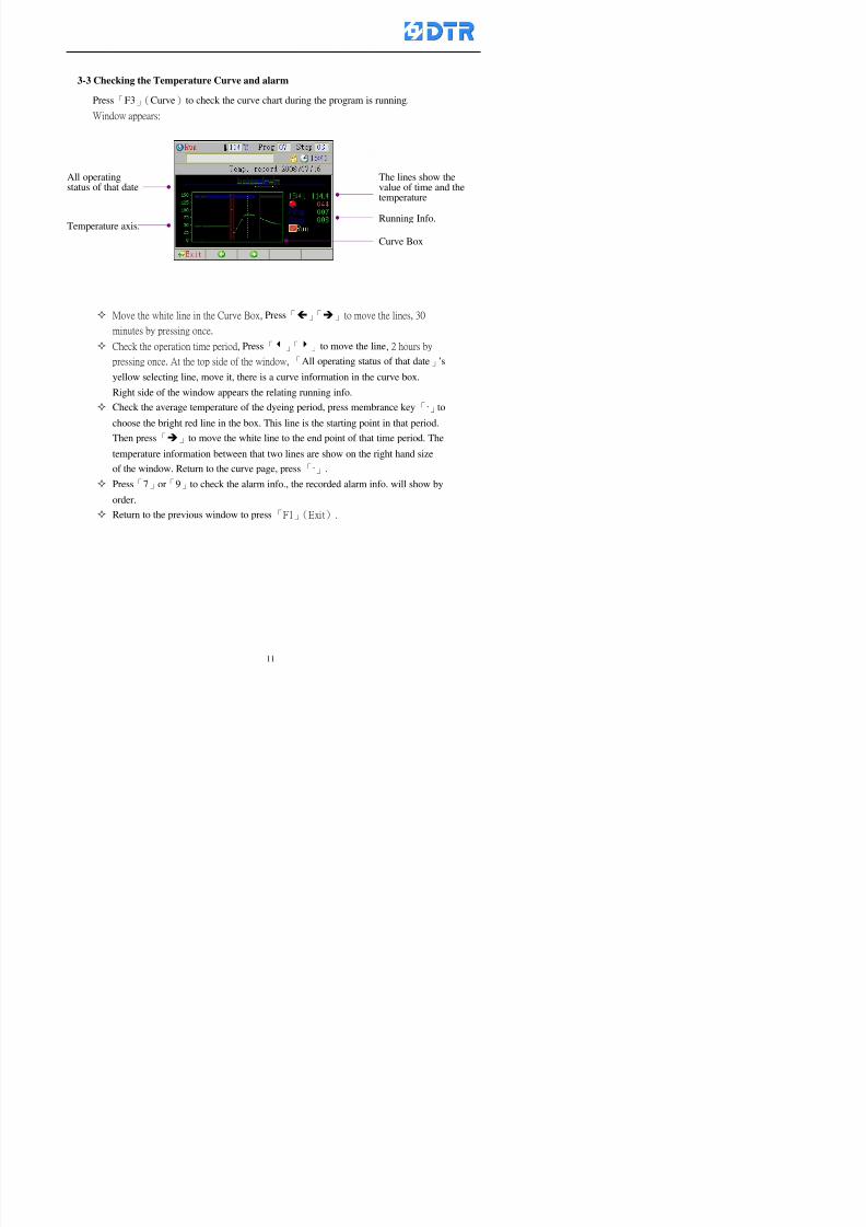
8132019 DTR 650 User Manual
httpslidepdfcomreaderfulldtr-650-user-manual 1170
8132019 DTR 650 User Manual
httpslidepdfcomreaderfulldtr-650-user-manual 1270
3-4 Schematic Diagram Mode Display
Schematic diagram mode displays the dye program operating the water level and
valve status and etc
During the dye program operating press membrance key「F4」to change the
display mode
When program stops it displays to Program list mode automatically from
Schematic diagram display mode Press membrance key「3」to view the
Schematic diagram mode again But if there is an alram occurred it stays at the
Program List mode Please release the alarm first
Press numeric key「9」(Exit)to return to the Program list mode
By setting factor can view the Schematic diagram mode displays directly during
operating (refer to the《6-4》「Display mode setting」for details)
8132019 DTR 650 User Manual
httpslidepdfcomreaderfulldtr-650-user-manual 1370
3-5 Icon Mode Display
During the dye program operating press membrance key「F4」to change to the
display mode
When program stops it displays to Program list mode automatically from Icon
Mode Display Press numeric key「6」to view the Icon mode again But if there is
an alram occurred it stays at the Program list mode Please release the alarm first
Press numeric key「9」(Exit)to return to the Program list display
By setting factor can view the Icon mode displays directly during operating (refer
to the《6-4》Display mode setting for details)
3-6 Running state of dyeing machine
There is totally 2 pages of the Running status information
To check the running status when the program is in operating press「F5」(State)「Inputoutput State」appears pess key「F5」 「Running Information」appears
8132019 DTR 650 User Manual
httpslidepdfcomreaderfulldtr-650-user-manual 1470
3-7 Keep continuing to run from the break point
Due to power sudden off or stop running the dye program it can keep continuing to
run from the break point when the power is retore Users can set the ldquoControl factorrdquo
which dye instruction allows (or prohitbit) to keep continuing to run from the breakpoint (refer to the charpter 6 for Setting)
When the power is restore the cursor stays at the step which stops suddenlybefore starting from the break point to press 「Run」 Window appears
Press「F4」(Yes)to keep going run from the break point
Press「F2」(No)to re-start that dye instruction
Press「F1 (Exit) to return
8132019 DTR 650 User Manual
httpslidepdfcomreaderfulldtr-650-user-manual 1570
3-8 Editing dye step temporary
Before dye program operating the ready-to-run dye step could be edit That edit will
not saved to the file and will not disappear by causing a sudden power inruption or
stop operating until a new dye program is selecting
Step
A Set the system factor as「22」first to allow editing the dye programs temporary
B Set the system factor as「23」 to allow the existing program can temporay
editing its range of step
C Item「19」of the system factor set the dye steps which allows or prohibits to edit
temporary (Refer to the Charpter 6 for details of 「Setting」the A-C )
D Press「F2」()「F3」()or「5」「6」at the Run window To move cursor
to the dye step intend to edit Press membrance key「2」「Edit instrunction
value」appears
E Press「F5」(Edit) then press()()or「5」「6」Programs names is listing
at the cursor or key in a value by the numeric keys Select and press「F5」(ok) to
confirm
F Press「F4」(Save)to confirm and go back to the Run window
G 〔Before pressing「F4」(Save)〕Press「F1」(Exit)to quit
8132019 DTR 650 User Manual
httpslidepdfcomreaderfulldtr-650-user-manual 1670
3-9 Creating an additon dye step during dye program running
Before and during the dye program running the users can creat an addition dye step in
the existing dye programs
3-9-1 Creating an addition dye step
To creat one addition dye step before running or during running step as follows
A Set the System Factor as「34」to allow to creat an addition step (Refer to the
Chartper 6 for details)
B In window「Run dye program」 press numeric key「8」to enter window of 「Edit
addition instruction」 to edit the single dye step first
C Press「」「」「5」
「6」to choose dye
steps press「F5」(OK)
D Press「F5」to edit the
content of dye step
E After complete editing the single dye
step Press「F4」(Run) to start running the
addition step
8132019 DTR 650 User Manual
httpslidepdfcomreaderfulldtr-650-user-manual 1770
3-9-2 Creating an addition treatment to a saved dye program
During and before the dye program running can creat an addition treatment to a
saved dye program or a dye step in a saved dye program
(1) Set the System factor as「34」to allow creating an addition step (Refer to the
Chartper 6 for details)
(2) In window「Run dye program」 press numeric key「8」to enter window of「Edit
single step」
(3) Press「」「」to choose「Sub Prog」 press「4」to move cursor and set itrsquos
dye program number and the step number by numeric keys Or stay at the
「Prog」and press「F3」(File) window appears
(4) Press「」「」to choose an addition dye program then press「F5」(OK)
(5) Press「F4」(Run)to run the addition dye program(sub-dye program)
(6) Finish to run the sub-dye program and return to the main dye program
8132019 DTR 650 User Manual
httpslidepdfcomreaderfulldtr-650-user-manual 1870
4 983120983137983155983155983155983159983151983154983140 DTR-650 provides four ranks of password for sercurity protection
(Refer to the ltTable 10gt Supplementary Table of the Password Usage for details)
First rank (User1 password) Edit delete dye programs control factors in output
testing etchellipall operating fuctions
Second rank (User2 password) Edit in output connecting table operating factors
Third rank (User3 password) Edit copy delete dye programs factors PLC run stop
Fourth rank (User4 password) Edit and modify dye programs
4-1 Entering the password
When the window of 「password」appears enter 6-digits number password by using
the numeric membrane keys then press「F5」(OK) If key-in an incorrect password
press「F3」(Del)and enter again
If the password is correct「」appears it allows to enter the relating operation
8132019 DTR 650 User Manual
httpslidepdfcomreaderfulldtr-650-user-manual 1970
4-2 Locking the data
After editing the programs and factors ensure to disable the password to protect all
programs and data of DTR-650 The way and step as follows
(1) Choose「8Others」at the main meun
(2) Choose「02Data Locking」at the sub-function field
(3) Press「F5」(OK)to confirm
(4) Return to the main menu「」disppears on the status bar that means the data
has been locking already
4-3 Setting and changing the Userrsquos password
There are four userrsquos password for setting and edit by the users themselves
User1 password Access to all operation setting
User2 password For edit in output connection table operating factors
User3 password Only for copy and delete dye programs factors PLC run stop
User4 password Only for edit and modify dye programs
Method of setting edit
(1) Choose「8Others」at main menu press「F5」(OK)
(2) Choose「7 Set Password 2」at the sub-function field press「F5」(OK)
(3) The cursor shows the default password now press「F3」(Clr)to delete Key in
a new password with 6-digit
(4) Press「F5」(OK)to complete the setting of User2 password Go back to the main
menu
8132019 DTR 650 User Manual
httpslidepdfcomreaderfulldtr-650-user-manual 2070
The four userrsquos password has to made from different group numbers Using
same password will affect the operating Please pay attention when update the
password
8132019 DTR 650 User Manual
httpslidepdfcomreaderfulldtr-650-user-manual 2170
5555 983109983140983145983156983145983150983143 983108983161983141 983120983154983151983143983154983137983149983155
5-1 Choosing a dye program
Press function key「F4」(Edit)or choose「1Dye Program」at the main menu press
「F5」(OK)
Choose「1Edit Dye prog」at the sub-function field press「F5」(OK)to enter to the
window「Sel dye program」During the dye program running it is allowed to edit asaved program or a new dye program or the current dye program in running
Method Press「」「」and「5」「6」「3」「4」to move cursor to choose
a dye program number Press「F5」(OK)to enter that dye program Press
「F1(Exit)to quit and return
Method
Directly key in the number selection box
appears at the right corner of the window
Select a program number and press「F5」
(OK) fi
8132019 DTR 650 User Manual
httpslidepdfcomreaderfulldtr-650-user-manual 2270
5-2 Creating a new dye program
Step
A Choose「1Dye Program」Press「F5」(OK)
B Choose「1Edit Dye prog」at the sub-function menu press「F5」(OK)to enter
to window「Sel dye program」
C At the window「Sel dye program」 choose an empty dye number (eg「002」)
press「F5」(OK)window《Fig 5-2-1》appears
《Fig 5-2-1》
D Press「F2」(Add) table of 「Edit dye instruction」《Fig 5-2-2》appears
E Press「F5」(Edit) the dye instruction appears at the cursor locates press「」「」
」and「5」「6」「3」「4」to move cursor to edit the instruction and its
factors
F All inserted new dye instructions would be listed in front of 「Program End」
8132019 DTR 650 User Manual
httpslidepdfcomreaderfulldtr-650-user-manual 2370
【Eg】Edit「CycRinse」
A Edit the main function step first Press「F2」
()「F3」()to move the cursor The dye
step is listing by orders Choose「CycRinse」
and press「」 there is a cursor at itrsquos value
B Move cursor to setting value「Cold」andchoose「Mix」by pressing()() Then
press「」to move cursor to「Time」and enter
itrsquos setting value as「2」Press「F5」(OK) to
complete the main function setting
C To move cursor to the parallel functionsetting field Press()()to choose the
dye step Press「」to confirm and move
cursor to choose itrsquos setting facor
D Press「F5」(OK)to move cursor to the next
parallel function
E Repeat above steps C-D until all parallel
functions setting are completed Each main
function can be operating with the
maximum 4 parallel functions
F Press「F4」(Save)to confirm and return to
the「Edit dye program」window
G Repeat the above step A E to keep on
8132019 DTR 650 User Manual
httpslidepdfcomreaderfulldtr-650-user-manual 2470
5-3 Setting the file name (for dye programs)
When a dye program is setting up it is saved by numbers automatically Optionally users
can save it by another names
Step
(1) Create a new dye program first (the Name is not available for empty dye
programs)
(2) At the window「Sel dye program」 press「F4」(File) Window《Fig5-3》appears
《Fig5-3》
(3) Use numeric 0~9「+」「-」「_」blank alphabet A~Z and symbols [ ] etchellip to
create a file name Each file name can type-in the max 8 unit Press 「3」「4」
「5」「6」to move the cursor to choose the unit It also can use the membrane
numbric key to type in The selected unit is showed in front of the cursor at the
「File」Press「OK」to confirm
(4) Quit to input to press「F3」(Clr)
(5) After complete the set up press「F5」(OK)to confirm and go back to the window
「Sel dye program」 Now the name behind the dye program number is created
8132019 DTR 650 User Manual
httpslidepdfcomreaderfulldtr-650-user-manual 2570
5-4 Inserting a program step
Insert the program step means to insert a step in the existing program step where youwant to insert a step All following steps are moved one step ahead The total number of
steps will be increased by itself Able to insert more than one step continusely at the
same time
【Example】《Fig5-4》 To insert a step「call」before「002 Rinse」
《Fig 5-4》
Step
A Enter to the dye program「002」at the window of 「Sel dye program」
(Example)
B Press「6」to move cursor to「002 Rinse」 then press「F2」(add)
C Press「F5」(Edit) then press「」「」or「5」「6」to choose program
step to modify Choose「call」and press「」to move cursor to modify itrsquos
value
8132019 DTR 650 User Manual
httpslidepdfcomreaderfulldtr-650-user-manual 2670
D Press「」「」 value of 「call」is listing at the table Choose「pH Check 」Press「F5」(OK)
E Press「F4」(Save)and press「F1」(Undo)to return to previous window Complete
to insert the「02 Call」The previous「02 Rinse」update to「03」 All following
steps are moved one step ahead Total number of steps will be increased ldquo1rdquo by
itself
Repeat the steps B-E can non-stop to insert more than one step
Quit the insert and modify ( before pressing「F4」) press「F1」(Undo) to exit
The original dye steps will be unchanged
To delete an inserted dye steps press key「F3」(Del) The step deletes
immediately
5-5 Deleting a program step
Delete the program step means to delete step which the cursor locates When that step is
deleted the step number will be updated automatically All following steps are moved up
one step It is allowed to delete more than one steps continuously at the same time
Step
A Enter to the「Edit dye program」《Fig5-5》at the window「Select dye program」
B Press「6」「5」move cursor to the want to delete
C Confirm and press「F3」(Del) Window「Confirm delete」appears Press
「F4」(Yes)
8132019 DTR 650 User Manual
httpslidepdfcomreaderfulldtr-650-user-manual 2770
D That step is deleted immediately and all following steps move up one step
Repeat the steps above can non-stop to delete more than one step
Press「F2」(No)to cancel the deletion
Press「F1」(Exit)to end
5-6 Modifying a program step
To modify the saved name and the setting value of the dyeing steps
Step
1 Choose a dye program which need to modify at the「Sel dye program」 press「F5」
(OK)
2 Press「6」「5」to move cursor to a step which need to modify Select and press
「F5」(Edit) Window of 「Edit dye instruction」appears
3 Press「F2」()「F3」()to choose the step list select it and press「」to move
the cursor to itrsquos value setting
4 Press numeric key to input the value or press「6」「5」to choose the item Press
「F5」(OK)when complete Cursor move to the next value (if need to set more
than one item)
5 Press「F4」(Save)when all setting is complete Return to「Edit dye program」
Method of parallel functionrsquos modification is same as above
Before pressing the key「「「「Save」」」」 press「F1」(Undo)to quit all modify Return
to the window of Edit dye program
All edit and modify functions mentioned of this charper are only available
for the dyeing files which already saved in the file and not being running It
8132019 DTR 650 User Manual
httpslidepdfcomreaderfulldtr-650-user-manual 2870
5-7 Copying a dye program
Copying a dye programs mean to make a copy of an dye programs to a blank dyeprogram This function is for creating new dye program rapidly
Choose「1Dye Program」at the main menu Press「F5」(OK)then press「F2」()to choose「2Copy dye prog」 Press「F5」(OK) 《Fig5-7-1》appears
《Fig 5-7-1》
《Fig 5-7-2》
【【【【Eg】】】】
Copy program 003 to program 012
Press「」「」to move cursor to theprogram「003」 press「F4」(Copy)
Program「003」shows at the top right side of
the bar
Press「」「」to move cursor to program「012」 Then press「F5」(Paste)「」appears behind the「012」That means it issuccessfully copying the program
If the target program is occupied
confirmation window「Overwrite」
When choose an program or a targetprogram can select them by using the
8132019 DTR 650 User Manual
httpslidepdfcomreaderfulldtr-650-user-manual 2970
5-8 Deleting a dye program
Choose「1Dye program」at the main menu Press「F5」(OK)then press「F2」()to choose「3Delete dye prog」 Press「F5」(OK) 《Fig5-8-1》appears
《Fig5-8-1》
《Fig5-8-2》
Press「」「」to move cursor to
choose program need to delete Eg
delete program「012」 press「F5」(Del) Confirmation window
「Confirm delete」appears
Press「F4」(Yes) to confirm delete
Repeat the above step can delete more
than one program at the same time
Press「F2」(No) to return to window
《Fig5-8-1》and not delete that program
Exit to press「F1」(Exit)and return to the
main menu
8132019 DTR 650 User Manual
httpslidepdfcomreaderfulldtr-650-user-manual 3070
6 983123983141983156983156983145983150983143DTR-650 has a built-in standard factor that can fulfill all different types of dyeing
machinesrsquos basic demand Users can also modify the factors base on their request to
fulfill their special control demand Before modify please refer to the table of each
range of Setting Factors (see the Supplementary Table)
6-1 ldquoEnable to use the program stepsrdquo setting
There are totally 64 program steps Parts of them are usually applying to the programs
In order to make more efficiently of editing programs it can「Disable」the other part
of program steps which are not usually applying or not applicable to the programs
For example dye machine with one tank it is only using step Tank B In this case itcan firstly「Disable」the program steps of Tank C When edit the program the
「Disable」rsquos steps will not appear at the cursor for choosing But this will not effect
and change the saved files The saved files can be kept as before
Step
(1) Choose「2 Factors」at the main menu Press「F5」(OK)(2) Choose「18 Dye Instruction」at the sub-function menu Then presss「F5」(OK)
Window「Edit dye ins」appears
「Enable」instruction can available to
use「Disable」instruction is temporarystop to use
Press「F2」()「F3」()to move
8132019 DTR 650 User Manual
httpslidepdfcomreaderfulldtr-650-user-manual 3170
6-2 ldquoAllow to modify dye program temporary during operatingrdquo Setting
During dye program running it can modify dye program temporary Thesemodification will not disappear by causing a sudden power interruption or power off
until select another new dye program to run
Please note that it is only for modifying the dye program temporary That program
file would not saved due to the modification If need to modify the program file and
save choose the function of Edit Dye Program to edit (Refer to the Charper 5 for the【Edit Dye Prograrm】)
6-2-1 ldquoAllow to modify all dye programsrdquo Setting
Step
(1) Choose「2 Factors」at the main menu Press「F5」(OK)
(2) Choose「02 System Factor」at the sub-function menu Then presss「F5」(OK)
Window「Edit System Factor」appears
Set to stop using temporary the「07
Rinse」press「F4」(Sel)to set it as Disable
Repeat above steps to complete all setting
Press 「F1」(Exit)to return to main menu
8132019 DTR 650 User Manual
httpslidepdfcomreaderfulldtr-650-user-manual 3270
6-2-2 ldquoAllow to modify part of dye programsrdquo Setting
【Eg】Set the number 08 or above (including number 08) is allowing to modify dye
programs during operating
Step
A Refer to【6-2-1】setting the factor as「22」to allow editing dye program
temporary during operating
(4) Press「3」「4」to edit the setting
as「Enable」 and press「F5」(OK)
Restore the standard factor by
pressing「F3」(Clr)
(5) Exit to press「F1」(Exit)and
return to window of 「Main Menu」
8132019 DTR 650 User Manual
httpslidepdfcomreaderfulldtr-650-user-manual 3370
6-2-3 ldquoAllow to modify dye steps temporaryrdquo Setting
After setting the dye programs are allowed to edit it also can set which dye steps are
allowed to edit temporary during operating
Step
(1) Choose「2 Factors」at the main menu Press「F5」(OK)
(2) Choose「19 Dye Ins control」at the sub-function menu Then presss「F5」
(OK) Window「Edit ins mode」appears
「Enable」 Allow to edit that dye step before
operating
「Disable」 Not allow to edit dye step before
operating
(3) Press「」「」to move cursor
to choose dye step Press「F4」
To enter to the「Edit dye program」from the
function menu there is a「」in front of the
file name「0-7」 means that program is not
allowing to edit during operating
8132019 DTR 650 User Manual
httpslidepdfcomreaderfulldtr-650-user-manual 3470
6-2-4 ldquoSet the dye step to keep running from the interrupt pointrdquo setting
When the dye program is operating it will disappear by causing power
interruption or sudden power off When start running again part of dye steps can
run again from the interrupt point part of them cannot
How to set
(1) Choose「2Factors」in the main menu and press「F5」(OK)
(2) Choose「20Continue mode」in the sub-function menu Press「F5」(OK) to
enter window of 「Continue Setting」
(3) Press「」「」to move cursor to choose dye steps Press「F4」(Sel)it
shows「Disable」or「Enable」for choosing Press「F5」(OK)to move cursorto the next setting
(4) Repeat above method until all setting is complete press「F1」(Exit)and
return to the main menu
8132019 DTR 650 User Manual
httpslidepdfcomreaderfulldtr-650-user-manual 3570
6-3 ldquoAllow to insert an addition dye stepsrdquo setting
During the program is running can temporary insert an addition dye step or a dye
program according to the operating actual situation Through this setting can set which
dye steps can apply or not to the program in operating
During to insert an addition step if sudden interruption or power off occurred it returns
to the main dye program automatically Before starting again should decide seriously
and set it again by actual needed
Step
(1) Choose「2Factors」at the main menu and press「F5」(OK)
(2) Choose「02System factor」and press「F5」(OK)
(3) Press「」「」to move cursor to the factor「34」and press「3」「4」to set
it as「Enable」 Press「F5」(OK)
(4) Press「F1」(Exit)to return to main menu Choose「21Addition Ins」at the
sub-function menu Press「F5」(OK)to enter the window「Addition Instruction」
(5) Press「」「」to move cursor to choose dye steps and press「F4」(Sel) Cursors
locates shows「Eable」or「Disable」 Press「F5」(OK)to move cursor to the
next dye step
(6) Repeat above method until to complete all setting press「F1」(Exit)and return
to the main menu
8132019 DTR 650 User Manual
httpslidepdfcomreaderfulldtr-650-user-manual 3670
6-4 Setting the display mode
DTR650 has three types of display mode during operating Program List mode
Schematic Diagram mode and Icon mode Users can set the display mode during
operating by factor setting
It goes back to a Program List mode when dye program ended
Step
(1) Choose「2Factors」at the main menu and press「F5」(OK)
(2) Choose「02System factor」and press「F5」(OK)
(3) Press「F2」()「F3」()to move cursor to choose「32Display mode」Press
「3」「4」 it shows「Online picture」「Instruction」「Big Icon」 choose
「Online picture」(eg) and press「F5」to confirm
8132019 DTR 650 User Manual
httpslidepdfcomreaderfulldtr-650-user-manual 3770
(4) Press「F1」(Exit)to return to the main menu
(5) The Schematic Diagram displays when the program is running (it stays at theProgram List mode when there is an alarm occurred)
Press「F4」to transfer to another display mode
It goes back to a Program List mode from Schematic Diagram Mode when dye
program ended Press numeric key「3」to view Schematic Diagram Mode again
Quit to press「F5」(Exit)
6-5 Adapt the digital input to another functions
DTR-650 has 32(0~31)input terminal it owns an standard setting when the
controller is initial According to the userrsquos demand they can change the DTR-650rsquos
anther functions of Input Terminal and PLC Input channel
The PLC Intputrsquos name can also define by the users (use IBM computer to edit and
download)
How to set
(1) Choose「2 Factor」at the main menu Press「F5」(OK)
(2) Choose「22 Input table」at the sub-function menu and press「F5」(OK)to enter
「Edit input table」
The actual input
terminal of theIBM computer
PLCrsquos input channel
8132019 DTR 650 User Manual
httpslidepdfcomreaderfulldtr-650-user-manual 3870
6-6 Adapt the digital output to another functions
DTR-650 has 32(0~31)output terminals it owns an standard setting when thecontroller is initial According to the userrsquos demand they can adapte the digital output
and the PLC outputrsquos channel to another functions The PLC Output channelrsquos name
can also define by users (use IBM computer to edit and download)
Step
(1) Choose「2 Factor」at the main menu Press「F5」(OK)
(2) Choose「23 Output table」at the main menu and press「F5」(OK)
(3) Press「F2」()「F3」()to move cursor to choose the output terminal atthe left side of the window Press「F5」(Add) the PLCrsquos output channelrsquos
name is listing at the right side of the window
(4) Press「F2」()「F3」()to move cursor to choose the PLC outputrsquos channel
If cursor moves to the PLC output channel which already linking「Add」is
not for choosing that means that output channel is already occupied
(5) Confirm the connection to press「F5」(Add) Quit to press「F4」(Del)Press「F1」(Exit)when complete all setting and return to main menu
The actual output
terminal of the
IBM computer
PLCrsquos output channel
8132019 DTR 650 User Manual
httpslidepdfcomreaderfulldtr-650-user-manual 3970
983095 983109983140983145983156983145983150983143 983156983144983141 983110983137983139983156983151983154983155DTR-650 has several kinds of control factors
Userrsquos factors System factors Temperature Control factors Speed factors Dosing
factors PID factors Analog Input Output factors standard factors etchellipPlease refer
to the supplementary table for the setting range and standard of the factors
DTR-650 has a built-in standard factor Users can edit by themselves if necessary
7-1 Modifying userrsquos factors
Userrsquos factors is setting with the Dyeing machinesrsquos PLC Programrsquos factor it is define by
the PLC Programmer
Step to edit
(1) Choose「2Factors」at main menu Press「F5」(OK)
(2) Choose「01User Factor」Press「F5」(OK)
(3) Press「F2」()「F3」()「6」「5」to move cursor up down and by page
Choose a factor need to edit then press「3」「4」to set itrsquos value Press「F5」(OK) Cursor moves to the next factor
(4) Some of factors can input numbers by the numeric membrance keys to edit If
the input is incorrect it turns to red and means the edit is not available
8132019 DTR 650 User Manual
httpslidepdfcomreaderfulldtr-650-user-manual 4070
Modifyrsquos method of the system factors temperature factors speed factors dosingfactors PID factors analog Input output factors standard factors etchellipare same asabove
If apply the library of DTR500 and DTR600 into the DTR650 the key「3」「4」may not valid to use Please use the numeric keys instead of it to key in factors itmay not effect the normal operation
Please pay a serious attention and read carefully at the factorrsquos table before modify the factors An incorrect value may effect the DTR-650 Dyeing
Machine Controllerrsquos operating After modifying factors must cancel the
password and secure data
7-2 Loading the standard factors
After modifying factors if need to restore a manufacturerrsquos standard factors of
DTR-650 The method as follows
1 Choose「2Factors」at main menu Press「F5」(OK)
「 「 ( ) 「
8132019 DTR 650 User Manual
httpslidepdfcomreaderfulldtr-650-user-manual 4170
7-3 Copying the factor
Users can build up a set of factor by themselves and make a copy and save
Step
1 Choose「2Factors」at main menu Press「F5」(OK)
2 Choose「13Restore Factor」 press「F5」(OK) window「factor will be
overwrite 」
3 Press「F4」(Yes)copy finished and saved Return to the main menu
4 Press「F2」(No)to not copy the factor and the existing factor is not change Return
to the main menu
7-4 Loading the backup factors
Users can build up a set of factor and backup files to load to DTR-650
Step1 Choose「14Backup factor」at the sub-function menu Press「F5」(OK)and
window「Factror will be overwrite」appears
2 Press「F3」(OK)to load the the backup factor them return to main menu
Press「F2」(No)to not copy the factor and the existing factor is not change
Return to the main menu
8132019 DTR 650 User Manual
httpslidepdfcomreaderfulldtr-650-user-manual 4270
983096 983119983157983156983152983157983156 983124983141983155983156983145983150983143
Before the output testing must be complete the steps as follows
A Cut off all connecting line of output terminal of DTR-650
B Stop running the PLC
C Check up the connections of all output channels to avoid damages from
incorrect connections
D Check up state of dyeing machines include the temperature pressure valves
onoff and pumpshellipetc ensure the safety for priority
8-1 Testing the Digital output
Step
1 Choose「3Output Testing」at the main menu Press「F5」(OK) 2 Choose「1Digital」at the sub function menu Press「F5」(OK) window「Digital
output testing」appears
3 Press「」「」「」to move cursor to each output channels Press「F5」(OK)
Output Name
8132019 DTR 650 User Manual
httpslidepdfcomreaderfulldtr-650-user-manual 4370
8-2 Testing the Analog output
(1) Choose「3Output Testing」at the main menu Press「F5」(OK)
(2) Choose「2Analog」at the sub function menu Press「F5」(OK) window「Analog output testing」appears
(3) Press「」「」「」to move cursor to each channels Then key in number by
the numeric membrance keys (range0~200= 0~20mA) Press「F5」(OK) there
is a output current relating to the output channel
(4) Press「F5」(OK) There is an output when the output channel with red light No
output without light onl(5) When complete the testing press「F1」(OK)to return to the main menu
8132019 DTR 650 User Manual
httpslidepdfcomreaderfulldtr-650-user-manual 4470
983097 983107983137983148983145983138983154983137983156983145983151983150
DTR-650 has Dosing and Temperature calibration
When enter to Dosing calibration must be set the Low Volume calibration first and
then High Volume calibration When enter to Temperature calibration must be set the
Low Temperature calibration first and then High Temperature calibration Must be
hightly follow this orders seriously
9-1 Calibration of Low Volume Tank
Step
A Choose「4Calibration」at the main menu Press「F5」(OK)
B Choose「Dosing 0 low vol」at the sub function menu Press「F5」(OK) window
appears
C Fill the Dosing Tank to a half level input value shows how much the water level
If it stays ldquo0rdquo check the connection and the factor setting is correct or not
And connect the pressure sensorrsquos output channel to the Current Meter to ensure
that sensor works or not
8132019 DTR 650 User Manual
httpslidepdfcomreaderfulldtr-650-user-manual 4570
D Fill the Dosing Tank to 50ml (Calcalate from the bottom side of the pressure
sensor steel tube) input value should show 4~6 (input value must between
0~10) Then enter the water volume The setting volume is relating the water
levelrsquos water value (litre as unit) input range 0~80 Set as「 「「 「0000 0000 0000 0000」」」」is strongly is strongly is strongly is strongly
receommend receommend receommend receommend Press「F5」(OK)to complete [Calibration of Low Volume Tank 1
is same as above method]
9-2 Calibration of High Volume Tank
Step
A Choose「4Calibration」at the main menu Press「F5」(OK)
B Choose「Dos 0 high vol」at the sub function menu Press「F5」(OK) window of
「Calibrate high 」appears
C Fill the Dosing Tank to a full level input value should be larger than 30 enter
the current water level which relates to the water volume Enter the range within
100~2500 Then press「F5」(OK) to complete the calibrate the high volume tank
8132019 DTR 650 User Manual
httpslidepdfcomreaderfulldtr-650-user-manual 4670
9-3 Temperature Calibration
Step
A This function is for adjusting the DTR650rsquos accuracy of Temperature Control It
must be using with the special terminal which is only for DTR650
B Choose「4Calibration」at the main function menu and press「F5」(OK)
C Choose「3Low Temp」at the sub-function menu Press「F5」(OK)and《Fig9-3》
appears insert the DTR650rsquos low temperature calibration terminal to the temperature
input terminal wait for the jumping value to stable down then press「F5」(OK) then
to adjust the high temperature calibration
D Adjusting the High Temperature Calibrationrsquos method is same as above But usersusersusersusers
must be using the High Temperature Terminalmust be using the High Temperature Terminalmust be using the High Temperature Terminalmust be using the High Temperature Terminal whichwhichwhichwhich is specially for DTR650 onlyis specially for DTR650 onlyis specially for DTR650 onlyis specially for DTR650 only
《Fig 9-3》
8132019 DTR 650 User Manual
httpslidepdfcomreaderfulldtr-650-user-manual 4770
10 983122983141983139983151983154983140983155 983151983142 983108983161983141 983120983154983151983143983154983137983149983155
It contains the past 15 days of temperature curves of running history
Checking method
(1) Choose「5Dye Record」at main menu press「F5」(OK)
(2) Sub-function menu shows the set up date of the past 15 days dye programs
Listing by the lastest set up date
(3) Choose a program date and press「F5」(OK) it appears window「Temp
record」
(4) Press「」「」to move the white line in the box one minute by moving once
(5) Press「3」「4」to move the line to check the time period 2 hours by moving once
The yellow selecting line of the「24 hours operating state」is repectively moving
The curve info is show in the curve box Left side of the widnow appears the
relating running info the time is the time value of the line locates at
(6) Check more details of the temperature info to press numeric key「middot」 a bright red line
appears in the selecting box this line is to check the starting point of the
temperature inforsquos time period Then press「」to move the white line to the end
point of the time period The temperature info between the starting point and end
point are appears at the right side of the window Press「middot」to return to the preious
curve page
(7) Check more details of the alarm infor To perss numeric key「7」「9」 the alarmrsquos
details is listing by orders
(8) Press「F1」(exit) to return
8132019 DTR 650 User Manual
httpslidepdfcomreaderfulldtr-650-user-manual 4870
11 983125983155983137983143983141 983151983142 983117983141983149983151983154983161 983107983137983154983140
DTR-650 supports 32MB or above Compact Flash Card which can transfer and save all
information for 4 sets of DTR-650 Including library files schematic diagram icon
image PLC program dye program factor and confiruration files etchellip Use the CF Card
to up download and swap the information of DTR-650 promptly install the relating
device and program updates
DTR-650 CF Card with bank 1 to bank 4 can save 4 sets information of Dyeing
Machines When download or save files should choose the BANK first
《Fig11-1》
8132019 DTR 650 User Manual
httpslidepdfcomreaderfulldtr-650-user-manual 4970
11-1 Downloading data
1 Firmly insert the CF card into the DTR-650rsquos PCMCIA connector Ensure it is
wholely and firmly inserted if the card is not totally inserted or the card do not
touch in all to the connector there will be an error occurred and cannot
updownload or interrupted during operation
2 Choose「6Memory Card」at the main menu and press「F5」(OK) 《Fig11-1》
appears Information of Bank「1」shows at the left hand side of the window press
number 1-4 by using numeric keys to choose the BANK Check the
information in the Bank seriously which is exactly need to download to the
DTR650
3 Press()()「6」「5」to move cursor to the sub-function menu to choose
the downloading items Press「F5」(OK) window appears「Stop PLC run before
access memory card Stop the PLC run」 Press「F5」(YES) to stop PLC
running
4 Press「F5」(OK) window appears Confirm to update or not the DTR-650rsquos
information As that downloading will be replace the DTR-650rsquos information
(that means the existing information of the DTR-650 will be removed and
replaced)
5 Press「F4」(YES)to download the information from the DTR-650 to the CF
Card Return to the main menu when finish
8132019 DTR 650 User Manual
httpslidepdfcomreaderfulldtr-650-user-manual 5070
Ensure inserting firmly the CF card into the DTR-650 unless it will cause
error or cannot Updownload data
Never remove CF card during transferring or updownloading data Until it
is all completed
DTR-650rsquos dyeing program is not compatible with DTR-500 and
DTR-600 Never use CF card to transfer data among them
11-2 Storing and transfering data
1 Insert the CF Card to the DTR-650
2 Choose「6Memory Card」at the main menu and press「F5」(OK) 《Fig11-1》
appears Left hand side of the window shows the data of BANK 1 press numeric
keys 1-4 to select the BANK To confirm the put the data in the DTR-650 to the CF
Card The existing data of that bank will be replaced and covered by the new data (if
that bank is already occuplied)
3 Choose「23Save Dye prog」(Example)at the sub-funciton menu press「F5」(OK)to confirm Window「Update memory card data」appears
4 Press「F5」(OK)to transfer the data to the CF card Return to the main menu
5 Put the CF card into another DTR-650 and follow the operating method of 「11-1
Downloading data」」」」can transfer and swap data with more than one set of
DTR-650
8132019 DTR 650 User Manual
httpslidepdfcomreaderfulldtr-650-user-manual 5170
12 983123983156983137983156983141 983137983150983140 983113983150983142983151983154983149983137983156983145983151983150
The state and information is including the Dyeing Machinersquos state of Digit Input output
Analog Input output Temperature control PID Dosing PID Pressure different PID
software system information and alarm record This information is for checking at any
time
12-1 Input Output state
Step
1 Choose「7Info and state」at main menu and press「F5」(OK)
2 Choose「01Digital IO put」at the sub-function menu then press「F5」(OK)
「Digital In Out State」0=None 1=Input
3 Press「F1」(Exit)to return to main menu
Same method for checking the temperature control analog dosing pressure
different etchellip
12-2 Checking the system information
Step
1 Choose「7Info and state」at main menu and press「F5」(OK)
2 Choose「11 System info」at sub-function field press「F5」(OK)Window
「System Information」appear
System information is including System info(software version) Library doc
Icon files Schematic file Definition file hardare state Config File Commandinstruction icon PLC file etc
8132019 DTR 650 User Manual
httpslidepdfcomreaderfulldtr-650-user-manual 5270
12-3 Checking the operating alarm record
Operating record shows the latest 40 operating items and alarm records including
the time and content of the alarm
A) Choose「7 Info and state」
and press「F5」(OK)
B) Choose「12Alarm logs」at
the sub-funciton menu then
press「F5」(OK)
8132019 DTR 650 User Manual
httpslidepdfcomreaderfulldtr-650-user-manual 5370
13 983105983140983146983157983155983156983145983150983143 983156983144983141 983107983151983150983156983154983137983155983156
The displaysrsquos brightness can be adjusted if necessary
Step
1 Choose「8Others」at main menu press「F5」(OK)
2 Choose「01Contrast」at sub-function menu press「F5」(OK) window「Set
Contrast」appears
3 Press「」「」to move the bar to set the brightness then press「F5」(OK)Window appears「Please reboot the system」
4 Press「F5」(OK)to return to main menu and re-boot the DTR-650 to complete
adjusting the brightness
8132019 DTR 650 User Manual
httpslidepdfcomreaderfulldtr-650-user-manual 5470
14 983123983156983151983152 983154983157983150983150983145983150983143 983156983144983141 983120983116983107 983120983154983151983143983154983137983149
Before testing the Input output testing transfer of the PLC program must stop the PLC
running
Step
1 Choose「8Others」at the main menu Press「F5」(OK)
2 Choose「04 PLC Stop」at sub-function menu Press「F5」(OK) window
「Password」appears
3 Enter password and press「F5」(OK) Window「Stop the PLC run」appears
4 Press「F4」(Yes)and window「PLC Stop」appear Press「F5」(OK) Now
the PLC is stop running and return to the main menu
All testing cannot operate when the PLC is running
Editing dye program and the relating operation can
perform with the PLC running together
8132019 DTR 650 User Manual
httpslidepdfcomreaderfulldtr-650-user-manual 5570
15 983123983141983156983156983145983150983143 983156983144983141 983156983145983149983141
Step
1 Press「8Others」at the main menu Press「F5」(OK)
2 Choose「10Set date time」at the sub-function menu Press「F5」(OK) window
「Set date time」appears
3 Press「F5」(Edit) to move cursor by 「3」「4」 enter the time value at the
cursor locates
4 Press「F5」(OK)to complete the modify Press「F1」(Exit)to return to main
menu
5 Press「F1」(Exit)if not modify and return to main menu
8132019 DTR 650 User Manual
httpslidepdfcomreaderfulldtr-650-user-manual 5670
1166 983123983123983157983157 983152 983152 983152 983152983148983148983141983141983149983149983141983141983150983150983156 983156 983137983137983154 983154 983161983161 983124 983124 983137983137983138983138983148983148983141983141
TTTTTTTTaaaaaaaabbbbbbbblllllllleeeeeeee 11111111 【Dye Instruction】
Code Icon Instruction Code Icon Instruction
000 End 016 Inject C
001 Start 017 Dosing BV
002 Heat 018 PH
003 Cool 019 Addsalt B
004 Flow Fill 020 Addsalt C
005 Level Fill 021 Ana Fill
006 Drian 022 Lock Fill007 Rinse 023 Lock Level
008 Run 024 Low Rinse
009 Call 025 Cyc Rinse
010 Prep B 026 Rinse B
011 Addsalt B 027 Rinse C
012 Dosing B 028 Temp
013 Inject B 029 Nozzle Pressure
014 Prep C 030 Main Pump
015 Dosing C 031 Pump Speed
8132019 DTR 650 User Manual
httpslidepdfcomreaderfulldtr-650-user-manual 5770
Table 2 【【【【Alarm】】】】
System Alarm Must stop operating and check up to solve problems before restarting
the machine
Running Alarm It is a reminder Not effect the operating of DTR-650
Userrsquos Alarm Total of 32 Users can define themselves and use it when edit the PLC
Program (do not listing below)
No System Alarm No Running Alarm
1 PLC program not running 16 Temp ctrl 0 Grad too slow
2 Main temp sensor error 17 Temp ctrl 0 Grad too fast
3 Not at Run window 18 Temp ctrl 0 Hold temp too low
4 Exceeding max temp 19 Temp ctrl 0 Hold temp too high
5 - 20 Temp ctrl 1 Grad too slow6 - 21 Temp ctrl 1 Grad too fast
7 - 22 Temp ctrl 1 Hold temp too low
8 Communication error 23 Temp ctrl 1 Hold temp too high
9 Slave not answer 24 Temp ctrl 2 Grad too slow
10 PLC 0 not answer 25 Temp ctrl 2 Grad too fast
11 PLC 1 not answer 26 Temp 2 Hold temp too low12 Display not answer 27 Temp 2 Hold temp too high
13 Lower power voltage 28 Temp ctrl 3 Grad too slow
14 - 29 Temp ctrl 3 Grad too fast
15 - 30 Temp3 Hold temp too low
31 Temp3 Hold temp too high
32 Dosing 0 injection too slow
33 Dosing 0 injection too fast
34 Dosing 1 injection too slow
35 Dosing 1 injection too fast
8132019 DTR 650 User Manual
httpslidepdfcomreaderfulldtr-650-user-manual 5870
TTTTTTTTaaaaaaaabbbbbbbblllllllleeeeeeee 33333333 【【【【System factor】】】】
No Description Std Range amp Definition
1 ID No 000 000- 100 Controller no
2 Communication Rate 4800Bps 2400 4800 9600 19200 38400
3 Display language Chinese English Chinese
4 Temp display mode and
5 Maxmium temperature 145 025 ~ 145 6 Type of external PLC Default PLC32DPLC32PLC16Default
7 Number of external PLC NANA 1 unit connect
2 unit connect
8Communication Rate of
PLC9600Bps 2400 4800 9600 19200
9 Set point 1 085 000 ~ 145
If signal source is temperaturethe setting value is thetemperature value If the signal
source is Analog Input 6~17 then
setting value for Analog input is 0 ndash
100 and relates Analog
Input14~020mA
10 Source 1 Sensor0Sensor 0 ~5
Analog input 0 ~1111 Set point 2 092 Same as 09
12 Source 2 PT100 1 Same as 10
13 Set point 3 085 Same as 09
14 Source 3 PT100 2 Same as 10
15 Set point 4 092 Same as 09
16 Source 4 PT100 3 Same as 1017 Set point 5 085 Same as 09
18 Source 5 PT100 4 Same as 10
19 Set point 6 092 Same as 09
8132019 DTR 650 User Manual
httpslidepdfcomreaderfulldtr-650-user-manual 5970
29 Min cyclic time of cloth 100sec 0 ~ 255 sec
30 Max cyclic time of cloth 240sec 0 ~255 sec
31Standard cyclic time of
cloth
180 000 ~ 255 sec
32 Display ModeProgram
List
Program list Schematic Diagram
Icon mode
33 CF card format Standard of
DTR CF
Card
Standard of DTR CF Card V20
Standard CF Card
34 Addition step Disable Disable Enable35 Mode Com 3
CouplingEsure Com 3 is the communication
port of the Central or Coupling
36Com 3 Communication
rate9600 Central communication speed
8132019 DTR 650 User Manual
httpslidepdfcomreaderfulldtr-650-user-manual 6070
TTTTTTTTaaaaaaaabbbbbbbblllllllleeeeeeee 44444444 【【【【Temperature Cotnrol Factor】】】】
No Factor Definition Standard Range and Definition
01 PT No PT-0 PT 0~5 PT-100 Input number
02 Max working temp 140 000~140
03 Output mode 0 0~2
04 Alarm time of gardient 240sec 000~255 sec
05 Alarm mode of gradient Always AlwaysOnceNone
06 Control mode of gradient Heating orCooling
interlocked
Heating and Cooling interlocked
No limitation
07 Alarm range of HoldTemp 03 01~20
08 Alarm time for HoldTemp 240sec 000~255sec
09 Alarm mode of HoldTemp Always AlwaysOnceNone
10 Control mode ofHoldTemp
Heating only Only heating and cooling Cooling whenalarm occurred Only heating andcooling No limitation when alarmHeating only
11 Porportional Band 100 000~250
12 Integral band 128 sec 000~255 sec
13 Differential time 04 sec 00~20 sec
14 Min transit gradient 02 00~50
15 Transit rate 20 times 00~50 times (020= 2 times)
16 PID initial output value 010 000~100
17 ONOFF cycle time 10 sec 05~25 sec
Onoff valve set as 010 sec
Proportional valve set as 020 sec
18 Time down count mode Mode 0 0~10 = The time down count range from「Factor 20 + target temp」to「Target
8132019 DTR 650 User Manual
httpslidepdfcomreaderfulldtr-650-user-manual 6170
TTTTTTTTaaaaaaaabbbbbbbblllllllleeeeeeee 55555555 【【【【Speed Factor】】】】
No Factor Definition Standard Range amp Definition
01 Input Number Speed input 0 Speed input 0~11
02 Average times 05 times 01~10
03 Sensor Number 008pcs 001~255
04 Roller Dimension 250mm 050~500
05 Max cloth speed 200mmin 001~25506 Min cloth speed 020mmin 001~255
07 Alarm delay time 240sec 001~255
08 Alarm mode Every oncenoneevery
09 Alarm range () 020 001~255
10 Proportional band 100 001~255
11 Integer band 128 001~25512 Differential time 000 001~200
13 Initial speed () 020 001~255
14 Control cycle ti(01sec) 05 01~30
15 First cycle time(01sec) 10 01~30
16 Speed increase limit () 010 001~100
17 Speed decrease limit () 010 001~100
18 Min speed() 005 001~100
19 Manual speed adjust () 005 001~100
20 Manual initial speed() 020 001~100
21 Stopping speed() 010 001~100
22 Switch speed() 020 001~100
23 Not used
24 Speed decrease turns 03turns 01~50
8132019 DTR 650 User Manual
httpslidepdfcomreaderfulldtr-650-user-manual 6270
Table 6 【【【【Dosing Factors】】】】
No Description Range Range and Explanation
1 Analog input no Analog input 0 Analog input no 0 ~11
2Alarm delay time for
dosing240 sec 000 ~255 sec
3 Alarm time for dosing Every Every Once None
4 Proportional band 100 000 ~255 sec Factor P
5 Integer band 128 000 ~255 sec Factor I6 Differential time 04 00 ~20 Factor D
7 Max adjust rate 150 50~ 255
8 Initial factor for dosing 10 000 ~100
9 User curve section 0 10 Gradient of sect1 for dosing curve9
10 User curve section 1 10 Gradient of sect2 for dosing curve9
11 User curve section 2 10 Gradient of sect3 for dosing curve9
12 User curve section 3 10 Gradient of sect4 for dosing curve9
13 User curve section 4 10 Gradient of sect5 for dosing curve9
14 User curve section 5 10 Gradient of sect6 for dosing curve9
15 User curve section 6 10 Gradient of sect7 for dosing curve9
16 User curve section 7 10 Gradient of sect8 for dosing curve9
17 User curve section 8 10 Gradient of sect9 for dosing curve9
18 User curve section 9 10 Gradient of sect10 for dosing curve9
19 Min water level 05 00~ 10 04~20mA percentagechange to the userrsquos factor setting
20 Output value for Tank
clean
100 000~ 100
Injected percentage of dosing valve
in dosing End period
This factor will be invalided if usingONOFF dosing valve
21 Full range 100 001~255 Self-adjustment cannotchange
22 Range ratio 001001~255 Self-adjustment cannot
change
8132019 DTR 650 User Manual
httpslidepdfcomreaderfulldtr-650-user-manual 6370
【【【【TTaabbllee 77 】】】】Pressure Deviation Factors
No Description Std Range amp Definition
1 Analog input number + Analog in 0 Analog in 0~11
2 Analog input number - Analog in 1 Analog in 0~11
3 Input mode Pressure Pressure Pressure deviation
4 Full range 050x01Kgcm
001~255
5 Range ratio 001 001~255
6 Alarm delay time 100sec 001~255
7 Alarm mode Every oncenone
8 Alarm range 010 001~255
9 Proportional band 100 001~255
10 Integer band 128 001~255
11 Differential time 00 00~20
12 PID Init output value 010 001~255
13 Cycle time 10 03~30
14 First cycle time 030 003~100
15 Max adjust rate 010 001~100
8132019 DTR 650 User Manual
httpslidepdfcomreaderfulldtr-650-user-manual 6470
【【【【TTaabbllee 88 】】】】Definition of Analog Input
No Description Standard Range and Explanation
01 PT 0 correction standard DIN std DIN std JIS std
02 PT 0 correction +0 +- 9
03 PT 1 correction standard DIN std DIN std JIS std
04 PT 1 correction +0 +- 9
05 PT 2 correction standard DIN std DIN std JIS std
06 PT 2 correction +0 +- 9
07 PT 3 correction standard DIN std DIN std JIS std
08 PT 3 correction +0 +- 9
09 PT 4 correction standard DIN std DIN std JIS std
10 PT 4 correction +0 +- 9
11 PT 5 correction standard DIN std DIN std JIS std
12 PT 5 correction +0 +- 9
13 Analog input 0 define 4 ~ 20mA 0 ndash 20mA 4 ndash 20mA
14 Analog input 0 average times 10 times 01- 20 times
15 Analog input 0 min value 0000 0000 - 1000
16 Analog input 0 max value 100 0001 - 9999
17-60 Analog input 1~11 Same as Analog input 0
【【【【 】】】】 fi i i f A O
8132019 DTR 650 User Manual
httpslidepdfcomreaderfulldtr-650-user-manual 6570
【【【【TTaabbllee 99 】】】】Definition of Analog Output
No Description Standard Range and explanation
61 Analog output 0 define Control byPLC
Control by PLC
Temperature control PID0 output
Temperature control PID1 output
Temperature control PID2 output
Speed PID3 output
Dosing PID0 output Dosing PID1output
Pressure different PID0 outputPressure different PID1 output
Main temperature output
62 Mode of Analog ouptput0 4 ~20mA 0 ndash20mA 4 ndash 20mA
63-84 Analog output 1~11 Same as Analog output 0
【【【【TTaabbllee 1100】】】】Value Table 0 amp 1
No Description Range Std Range and explanation
1 Analog input no 000~011 000 Analog input no
2 Data ratio 001~255 100 Multiple by factors
3~53 0~98 000~255 000-100 Analog input 0~98 data
【【【【 】】】】St t Li t
8132019 DTR 650 User Manual
httpslidepdfcomreaderfulldtr-650-user-manual 6670
【【【【TTaabbllee 1111】】】】State List
No Description Range Standard Range and explanation
1 Display setting 1 0~255 205 See remarks at next page
2 Display setting 2 0~255 208
3 Display setting 3 0~255 209
4 Display setting 4 0~255 017
5 Display setting 5 0~255 0186 Display setting 6 0~255 019
7 Display setting 7 0~255 020
8 Display setting 8 0~255 021
9 Display setting 9 0~255 000
10 Display setting 1 0~255 000
11 Display setting 2 0~255 000
12 Display setting 3 0~255 000
13 Display setting 4 0~255 000
14 Display setting 5 0~255 000
15 Display setting 6 0~255 000
16 Display setting 7 0~255 000
Remarks
8132019 DTR 650 User Manual
httpslidepdfcomreaderfulldtr-650-user-manual 6770
0 = No display 1~255 = Display type of number
1~16 Content of PLC VB0~15
No 1 corresponding to VB0
No 16 corresponding to VB15
17~32 Content of PLC DB0~15
No 17 corresponding to DB0
No 32 corresponding to DB15
33~46 Content of PLC CNT0~29
No 33 corresponding to CNT0
No 46 corresponding to CNT29 47~78 Content of dyeing instruction 0~31 CNT0
No 47 corresponding to system instruction to No 0 of CNT0
No 78 corresponding to system instruction to No 31 of CNT0rsquos content
79~110 Dyeing instruction 0~31 of CNT0rsquos setting
111~142 Content of Dyeing instruction 0~31 CNT1No 111 corresponding to dyeing instruction No 0 of CNT1
No 142 corresponding to dyeing instruction No 31 of CNT1rsquos content
143~174 Dyeing instruction 0~31 of CNT1rsquos setting
175~204 Content of PLC HTIM0~29
No 175 corresponding to HTIM0
No 204 corresponding to HTIM29
205 Loading
206 Ratio 1
207 Ratio 2208 Ratio 1 x Loading
209 Ratio 2 x Loading
210 Fix value
211 Value Table 1 matching result
212 Value Table 2 matching result
213 Value Table 1 setting214 Value Table 2 setting
215 Pressure control PID0 different pressure value
216 Pressure control PID1 different pressure value
TTTTTTTTaaaaaaaabbbbbbbblllllllleeeeeeee 1122 【【【【Usage of password】】】】
8132019 DTR 650 User Manual
httpslidepdfcomreaderfulldtr-650-user-manual 6870
No Main FunctionFactor Sub Function Factor Password Rank
1 Run None
2 Dye program User3 or above
3 Control factor
- User factor User 1
- System factor User 1
- Temp PID 0
- Temp PID 1 User 1- Speed PID 0 User 1
- Dosing PID 0 User 1
- Dosing PID 1 User 1
- Pressure PID 0 User 1
- Pressure PID 1 User 1
- Analog IO User 1
- Load standard factor User 2 or above- Load a copied factor User 2 or above
- Copy factor User 2 or above
- Value table 0 User 1
- Value table 1 User 1
- Information and state User 1
- Dye instruction User 1
- Edit dye instruction setting User 14 Output testing User 2 or above
5 Calibration User 2 or above
6 Dye record None
7 CF card User 1
8 Info and state None
9 Others
- Contrast User3 or above
- Data Locking None
- PLC Run User 1
- PLC Stop User 1
- Password setting User 1
TTTTTTTTaaaaaaaabbbbbbbblllllllleeeeeeee 1133 【【【【Technical Data】】】】
8132019 DTR 650 User Manual
httpslidepdfcomreaderfulldtr-650-user-manual 6970
TTTTTTTTaaaaaaaabbbbbbbblllllllleeeeeeee 1133 【【【【Technical Data】】】】
1 Temperature Control
- Range 10~145(plusmn1)
- Mode Proportional or PWM
- Sensor PT100 (JIS or DIN standard)
2 Input and output channel
- Digital Input 32 DC24V PNP- Digital Output 32 DC24V 054A Relay connect point
- Analog Input 4 04~20 mA
- Analog Output 4 0~20mA 或 4~20 mA
3 Communication port 3 RS-232 amp 0~20 mAx1 RS485x 2
4 Dye program
- Number 15000 Steps
- Standard step 61Heating Cooling Fill Drain RinseDosingetc
5LCD module and Display
langage
Chinese
English
320 x 240 TFT color display with
more language
6 CF card connector 1 PCMCIA standard
7 Membrane Keyboard- Number Key 10 [0]~[9] Input factors
- Function Key 5 [F1]~[F5] function selecting
- Operation Key 2 [Start] [Stop]
- Auxiliary Key 7 [][][][][Esc] [larr][OK] [bull]
8 Operating Condition
- Temperature 5~45
- Humidity ≦85 (25)
9 Power supply
V l DC 24V
8132019 DTR 650 User Manual
httpslidepdfcomreaderfulldtr-650-user-manual 7070
70
983108983124983122983085650 983113983150983152983157983156 983119983157983156983152983157983156 983120983151983154983156983145983150983143 (983138983137983139983147983155983145983140983141 983158983145983141983159)
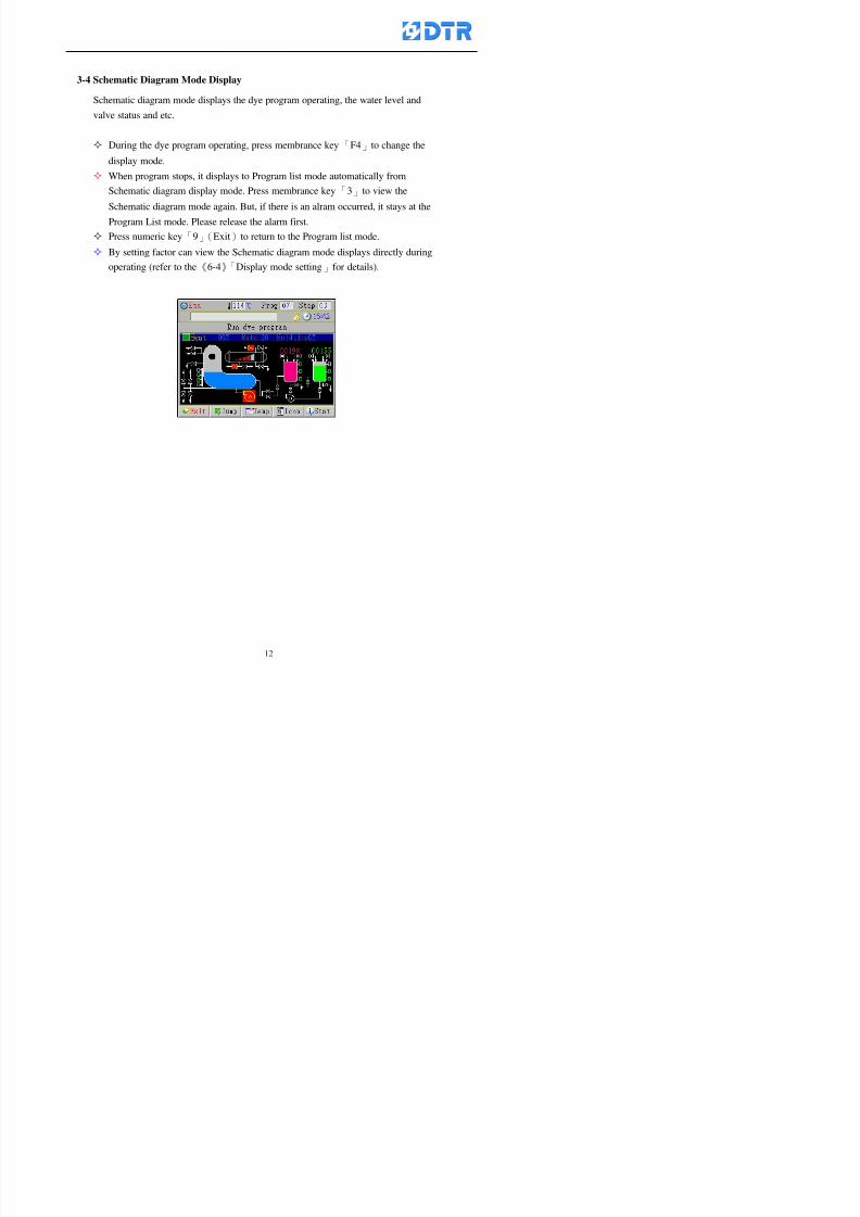
8132019 DTR 650 User Manual
httpslidepdfcomreaderfulldtr-650-user-manual 1270
3-4 Schematic Diagram Mode Display
Schematic diagram mode displays the dye program operating the water level and
valve status and etc
During the dye program operating press membrance key「F4」to change the
display mode
When program stops it displays to Program list mode automatically from
Schematic diagram display mode Press membrance key「3」to view the
Schematic diagram mode again But if there is an alram occurred it stays at the
Program List mode Please release the alarm first
Press numeric key「9」(Exit)to return to the Program list mode
By setting factor can view the Schematic diagram mode displays directly during
operating (refer to the《6-4》「Display mode setting」for details)
8132019 DTR 650 User Manual
httpslidepdfcomreaderfulldtr-650-user-manual 1370
3-5 Icon Mode Display
During the dye program operating press membrance key「F4」to change to the
display mode
When program stops it displays to Program list mode automatically from Icon
Mode Display Press numeric key「6」to view the Icon mode again But if there is
an alram occurred it stays at the Program list mode Please release the alarm first
Press numeric key「9」(Exit)to return to the Program list display
By setting factor can view the Icon mode displays directly during operating (refer
to the《6-4》Display mode setting for details)
3-6 Running state of dyeing machine
There is totally 2 pages of the Running status information
To check the running status when the program is in operating press「F5」(State)「Inputoutput State」appears pess key「F5」 「Running Information」appears
8132019 DTR 650 User Manual
httpslidepdfcomreaderfulldtr-650-user-manual 1470
3-7 Keep continuing to run from the break point
Due to power sudden off or stop running the dye program it can keep continuing to
run from the break point when the power is retore Users can set the ldquoControl factorrdquo
which dye instruction allows (or prohitbit) to keep continuing to run from the breakpoint (refer to the charpter 6 for Setting)
When the power is restore the cursor stays at the step which stops suddenlybefore starting from the break point to press 「Run」 Window appears
Press「F4」(Yes)to keep going run from the break point
Press「F2」(No)to re-start that dye instruction
Press「F1 (Exit) to return
8132019 DTR 650 User Manual
httpslidepdfcomreaderfulldtr-650-user-manual 1570
3-8 Editing dye step temporary
Before dye program operating the ready-to-run dye step could be edit That edit will
not saved to the file and will not disappear by causing a sudden power inruption or
stop operating until a new dye program is selecting
Step
A Set the system factor as「22」first to allow editing the dye programs temporary
B Set the system factor as「23」 to allow the existing program can temporay
editing its range of step
C Item「19」of the system factor set the dye steps which allows or prohibits to edit
temporary (Refer to the Charpter 6 for details of 「Setting」the A-C )
D Press「F2」()「F3」()or「5」「6」at the Run window To move cursor
to the dye step intend to edit Press membrance key「2」「Edit instrunction
value」appears
E Press「F5」(Edit) then press()()or「5」「6」Programs names is listing
at the cursor or key in a value by the numeric keys Select and press「F5」(ok) to
confirm
F Press「F4」(Save)to confirm and go back to the Run window
G 〔Before pressing「F4」(Save)〕Press「F1」(Exit)to quit
8132019 DTR 650 User Manual
httpslidepdfcomreaderfulldtr-650-user-manual 1670
3-9 Creating an additon dye step during dye program running
Before and during the dye program running the users can creat an addition dye step in
the existing dye programs
3-9-1 Creating an addition dye step
To creat one addition dye step before running or during running step as follows
A Set the System Factor as「34」to allow to creat an addition step (Refer to the
Chartper 6 for details)
B In window「Run dye program」 press numeric key「8」to enter window of 「Edit
addition instruction」 to edit the single dye step first
C Press「」「」「5」
「6」to choose dye
steps press「F5」(OK)
D Press「F5」to edit the
content of dye step
E After complete editing the single dye
step Press「F4」(Run) to start running the
addition step
8132019 DTR 650 User Manual
httpslidepdfcomreaderfulldtr-650-user-manual 1770
3-9-2 Creating an addition treatment to a saved dye program
During and before the dye program running can creat an addition treatment to a
saved dye program or a dye step in a saved dye program
(1) Set the System factor as「34」to allow creating an addition step (Refer to the
Chartper 6 for details)
(2) In window「Run dye program」 press numeric key「8」to enter window of「Edit
single step」
(3) Press「」「」to choose「Sub Prog」 press「4」to move cursor and set itrsquos
dye program number and the step number by numeric keys Or stay at the
「Prog」and press「F3」(File) window appears
(4) Press「」「」to choose an addition dye program then press「F5」(OK)
(5) Press「F4」(Run)to run the addition dye program(sub-dye program)
(6) Finish to run the sub-dye program and return to the main dye program
8132019 DTR 650 User Manual
httpslidepdfcomreaderfulldtr-650-user-manual 1870
4 983120983137983155983155983155983159983151983154983140 DTR-650 provides four ranks of password for sercurity protection
(Refer to the ltTable 10gt Supplementary Table of the Password Usage for details)
First rank (User1 password) Edit delete dye programs control factors in output
testing etchellipall operating fuctions
Second rank (User2 password) Edit in output connecting table operating factors
Third rank (User3 password) Edit copy delete dye programs factors PLC run stop
Fourth rank (User4 password) Edit and modify dye programs
4-1 Entering the password
When the window of 「password」appears enter 6-digits number password by using
the numeric membrane keys then press「F5」(OK) If key-in an incorrect password
press「F3」(Del)and enter again
If the password is correct「」appears it allows to enter the relating operation
8132019 DTR 650 User Manual
httpslidepdfcomreaderfulldtr-650-user-manual 1970
4-2 Locking the data
After editing the programs and factors ensure to disable the password to protect all
programs and data of DTR-650 The way and step as follows
(1) Choose「8Others」at the main meun
(2) Choose「02Data Locking」at the sub-function field
(3) Press「F5」(OK)to confirm
(4) Return to the main menu「」disppears on the status bar that means the data
has been locking already
4-3 Setting and changing the Userrsquos password
There are four userrsquos password for setting and edit by the users themselves
User1 password Access to all operation setting
User2 password For edit in output connection table operating factors
User3 password Only for copy and delete dye programs factors PLC run stop
User4 password Only for edit and modify dye programs
Method of setting edit
(1) Choose「8Others」at main menu press「F5」(OK)
(2) Choose「7 Set Password 2」at the sub-function field press「F5」(OK)
(3) The cursor shows the default password now press「F3」(Clr)to delete Key in
a new password with 6-digit
(4) Press「F5」(OK)to complete the setting of User2 password Go back to the main
menu
8132019 DTR 650 User Manual
httpslidepdfcomreaderfulldtr-650-user-manual 2070
The four userrsquos password has to made from different group numbers Using
same password will affect the operating Please pay attention when update the
password
8132019 DTR 650 User Manual
httpslidepdfcomreaderfulldtr-650-user-manual 2170
5555 983109983140983145983156983145983150983143 983108983161983141 983120983154983151983143983154983137983149983155
5-1 Choosing a dye program
Press function key「F4」(Edit)or choose「1Dye Program」at the main menu press
「F5」(OK)
Choose「1Edit Dye prog」at the sub-function field press「F5」(OK)to enter to the
window「Sel dye program」During the dye program running it is allowed to edit asaved program or a new dye program or the current dye program in running
Method Press「」「」and「5」「6」「3」「4」to move cursor to choose
a dye program number Press「F5」(OK)to enter that dye program Press
「F1(Exit)to quit and return
Method
Directly key in the number selection box
appears at the right corner of the window
Select a program number and press「F5」
(OK) fi
8132019 DTR 650 User Manual
httpslidepdfcomreaderfulldtr-650-user-manual 2270
5-2 Creating a new dye program
Step
A Choose「1Dye Program」Press「F5」(OK)
B Choose「1Edit Dye prog」at the sub-function menu press「F5」(OK)to enter
to window「Sel dye program」
C At the window「Sel dye program」 choose an empty dye number (eg「002」)
press「F5」(OK)window《Fig 5-2-1》appears
《Fig 5-2-1》
D Press「F2」(Add) table of 「Edit dye instruction」《Fig 5-2-2》appears
E Press「F5」(Edit) the dye instruction appears at the cursor locates press「」「」
」and「5」「6」「3」「4」to move cursor to edit the instruction and its
factors
F All inserted new dye instructions would be listed in front of 「Program End」
8132019 DTR 650 User Manual
httpslidepdfcomreaderfulldtr-650-user-manual 2370
【Eg】Edit「CycRinse」
A Edit the main function step first Press「F2」
()「F3」()to move the cursor The dye
step is listing by orders Choose「CycRinse」
and press「」 there is a cursor at itrsquos value
B Move cursor to setting value「Cold」andchoose「Mix」by pressing()() Then
press「」to move cursor to「Time」and enter
itrsquos setting value as「2」Press「F5」(OK) to
complete the main function setting
C To move cursor to the parallel functionsetting field Press()()to choose the
dye step Press「」to confirm and move
cursor to choose itrsquos setting facor
D Press「F5」(OK)to move cursor to the next
parallel function
E Repeat above steps C-D until all parallel
functions setting are completed Each main
function can be operating with the
maximum 4 parallel functions
F Press「F4」(Save)to confirm and return to
the「Edit dye program」window
G Repeat the above step A E to keep on
8132019 DTR 650 User Manual
httpslidepdfcomreaderfulldtr-650-user-manual 2470
5-3 Setting the file name (for dye programs)
When a dye program is setting up it is saved by numbers automatically Optionally users
can save it by another names
Step
(1) Create a new dye program first (the Name is not available for empty dye
programs)
(2) At the window「Sel dye program」 press「F4」(File) Window《Fig5-3》appears
《Fig5-3》
(3) Use numeric 0~9「+」「-」「_」blank alphabet A~Z and symbols [ ] etchellip to
create a file name Each file name can type-in the max 8 unit Press 「3」「4」
「5」「6」to move the cursor to choose the unit It also can use the membrane
numbric key to type in The selected unit is showed in front of the cursor at the
「File」Press「OK」to confirm
(4) Quit to input to press「F3」(Clr)
(5) After complete the set up press「F5」(OK)to confirm and go back to the window
「Sel dye program」 Now the name behind the dye program number is created
8132019 DTR 650 User Manual
httpslidepdfcomreaderfulldtr-650-user-manual 2570
5-4 Inserting a program step
Insert the program step means to insert a step in the existing program step where youwant to insert a step All following steps are moved one step ahead The total number of
steps will be increased by itself Able to insert more than one step continusely at the
same time
【Example】《Fig5-4》 To insert a step「call」before「002 Rinse」
《Fig 5-4》
Step
A Enter to the dye program「002」at the window of 「Sel dye program」
(Example)
B Press「6」to move cursor to「002 Rinse」 then press「F2」(add)
C Press「F5」(Edit) then press「」「」or「5」「6」to choose program
step to modify Choose「call」and press「」to move cursor to modify itrsquos
value
8132019 DTR 650 User Manual
httpslidepdfcomreaderfulldtr-650-user-manual 2670
D Press「」「」 value of 「call」is listing at the table Choose「pH Check 」Press「F5」(OK)
E Press「F4」(Save)and press「F1」(Undo)to return to previous window Complete
to insert the「02 Call」The previous「02 Rinse」update to「03」 All following
steps are moved one step ahead Total number of steps will be increased ldquo1rdquo by
itself
Repeat the steps B-E can non-stop to insert more than one step
Quit the insert and modify ( before pressing「F4」) press「F1」(Undo) to exit
The original dye steps will be unchanged
To delete an inserted dye steps press key「F3」(Del) The step deletes
immediately
5-5 Deleting a program step
Delete the program step means to delete step which the cursor locates When that step is
deleted the step number will be updated automatically All following steps are moved up
one step It is allowed to delete more than one steps continuously at the same time
Step
A Enter to the「Edit dye program」《Fig5-5》at the window「Select dye program」
B Press「6」「5」move cursor to the want to delete
C Confirm and press「F3」(Del) Window「Confirm delete」appears Press
「F4」(Yes)
8132019 DTR 650 User Manual
httpslidepdfcomreaderfulldtr-650-user-manual 2770
D That step is deleted immediately and all following steps move up one step
Repeat the steps above can non-stop to delete more than one step
Press「F2」(No)to cancel the deletion
Press「F1」(Exit)to end
5-6 Modifying a program step
To modify the saved name and the setting value of the dyeing steps
Step
1 Choose a dye program which need to modify at the「Sel dye program」 press「F5」
(OK)
2 Press「6」「5」to move cursor to a step which need to modify Select and press
「F5」(Edit) Window of 「Edit dye instruction」appears
3 Press「F2」()「F3」()to choose the step list select it and press「」to move
the cursor to itrsquos value setting
4 Press numeric key to input the value or press「6」「5」to choose the item Press
「F5」(OK)when complete Cursor move to the next value (if need to set more
than one item)
5 Press「F4」(Save)when all setting is complete Return to「Edit dye program」
Method of parallel functionrsquos modification is same as above
Before pressing the key「「「「Save」」」」 press「F1」(Undo)to quit all modify Return
to the window of Edit dye program
All edit and modify functions mentioned of this charper are only available
for the dyeing files which already saved in the file and not being running It
8132019 DTR 650 User Manual
httpslidepdfcomreaderfulldtr-650-user-manual 2870
5-7 Copying a dye program
Copying a dye programs mean to make a copy of an dye programs to a blank dyeprogram This function is for creating new dye program rapidly
Choose「1Dye Program」at the main menu Press「F5」(OK)then press「F2」()to choose「2Copy dye prog」 Press「F5」(OK) 《Fig5-7-1》appears
《Fig 5-7-1》
《Fig 5-7-2》
【【【【Eg】】】】
Copy program 003 to program 012
Press「」「」to move cursor to theprogram「003」 press「F4」(Copy)
Program「003」shows at the top right side of
the bar
Press「」「」to move cursor to program「012」 Then press「F5」(Paste)「」appears behind the「012」That means it issuccessfully copying the program
If the target program is occupied
confirmation window「Overwrite」
When choose an program or a targetprogram can select them by using the
8132019 DTR 650 User Manual
httpslidepdfcomreaderfulldtr-650-user-manual 2970
5-8 Deleting a dye program
Choose「1Dye program」at the main menu Press「F5」(OK)then press「F2」()to choose「3Delete dye prog」 Press「F5」(OK) 《Fig5-8-1》appears
《Fig5-8-1》
《Fig5-8-2》
Press「」「」to move cursor to
choose program need to delete Eg
delete program「012」 press「F5」(Del) Confirmation window
「Confirm delete」appears
Press「F4」(Yes) to confirm delete
Repeat the above step can delete more
than one program at the same time
Press「F2」(No) to return to window
《Fig5-8-1》and not delete that program
Exit to press「F1」(Exit)and return to the
main menu
8132019 DTR 650 User Manual
httpslidepdfcomreaderfulldtr-650-user-manual 3070
6 983123983141983156983156983145983150983143DTR-650 has a built-in standard factor that can fulfill all different types of dyeing
machinesrsquos basic demand Users can also modify the factors base on their request to
fulfill their special control demand Before modify please refer to the table of each
range of Setting Factors (see the Supplementary Table)
6-1 ldquoEnable to use the program stepsrdquo setting
There are totally 64 program steps Parts of them are usually applying to the programs
In order to make more efficiently of editing programs it can「Disable」the other part
of program steps which are not usually applying or not applicable to the programs
For example dye machine with one tank it is only using step Tank B In this case itcan firstly「Disable」the program steps of Tank C When edit the program the
「Disable」rsquos steps will not appear at the cursor for choosing But this will not effect
and change the saved files The saved files can be kept as before
Step
(1) Choose「2 Factors」at the main menu Press「F5」(OK)(2) Choose「18 Dye Instruction」at the sub-function menu Then presss「F5」(OK)
Window「Edit dye ins」appears
「Enable」instruction can available to
use「Disable」instruction is temporarystop to use
Press「F2」()「F3」()to move
8132019 DTR 650 User Manual
httpslidepdfcomreaderfulldtr-650-user-manual 3170
6-2 ldquoAllow to modify dye program temporary during operatingrdquo Setting
During dye program running it can modify dye program temporary Thesemodification will not disappear by causing a sudden power interruption or power off
until select another new dye program to run
Please note that it is only for modifying the dye program temporary That program
file would not saved due to the modification If need to modify the program file and
save choose the function of Edit Dye Program to edit (Refer to the Charper 5 for the【Edit Dye Prograrm】)
6-2-1 ldquoAllow to modify all dye programsrdquo Setting
Step
(1) Choose「2 Factors」at the main menu Press「F5」(OK)
(2) Choose「02 System Factor」at the sub-function menu Then presss「F5」(OK)
Window「Edit System Factor」appears
Set to stop using temporary the「07
Rinse」press「F4」(Sel)to set it as Disable
Repeat above steps to complete all setting
Press 「F1」(Exit)to return to main menu
8132019 DTR 650 User Manual
httpslidepdfcomreaderfulldtr-650-user-manual 3270
6-2-2 ldquoAllow to modify part of dye programsrdquo Setting
【Eg】Set the number 08 or above (including number 08) is allowing to modify dye
programs during operating
Step
A Refer to【6-2-1】setting the factor as「22」to allow editing dye program
temporary during operating
(4) Press「3」「4」to edit the setting
as「Enable」 and press「F5」(OK)
Restore the standard factor by
pressing「F3」(Clr)
(5) Exit to press「F1」(Exit)and
return to window of 「Main Menu」
8132019 DTR 650 User Manual
httpslidepdfcomreaderfulldtr-650-user-manual 3370
6-2-3 ldquoAllow to modify dye steps temporaryrdquo Setting
After setting the dye programs are allowed to edit it also can set which dye steps are
allowed to edit temporary during operating
Step
(1) Choose「2 Factors」at the main menu Press「F5」(OK)
(2) Choose「19 Dye Ins control」at the sub-function menu Then presss「F5」
(OK) Window「Edit ins mode」appears
「Enable」 Allow to edit that dye step before
operating
「Disable」 Not allow to edit dye step before
operating
(3) Press「」「」to move cursor
to choose dye step Press「F4」
To enter to the「Edit dye program」from the
function menu there is a「」in front of the
file name「0-7」 means that program is not
allowing to edit during operating
8132019 DTR 650 User Manual
httpslidepdfcomreaderfulldtr-650-user-manual 3470
6-2-4 ldquoSet the dye step to keep running from the interrupt pointrdquo setting
When the dye program is operating it will disappear by causing power
interruption or sudden power off When start running again part of dye steps can
run again from the interrupt point part of them cannot
How to set
(1) Choose「2Factors」in the main menu and press「F5」(OK)
(2) Choose「20Continue mode」in the sub-function menu Press「F5」(OK) to
enter window of 「Continue Setting」
(3) Press「」「」to move cursor to choose dye steps Press「F4」(Sel)it
shows「Disable」or「Enable」for choosing Press「F5」(OK)to move cursorto the next setting
(4) Repeat above method until all setting is complete press「F1」(Exit)and
return to the main menu
8132019 DTR 650 User Manual
httpslidepdfcomreaderfulldtr-650-user-manual 3570
6-3 ldquoAllow to insert an addition dye stepsrdquo setting
During the program is running can temporary insert an addition dye step or a dye
program according to the operating actual situation Through this setting can set which
dye steps can apply or not to the program in operating
During to insert an addition step if sudden interruption or power off occurred it returns
to the main dye program automatically Before starting again should decide seriously
and set it again by actual needed
Step
(1) Choose「2Factors」at the main menu and press「F5」(OK)
(2) Choose「02System factor」and press「F5」(OK)
(3) Press「」「」to move cursor to the factor「34」and press「3」「4」to set
it as「Enable」 Press「F5」(OK)
(4) Press「F1」(Exit)to return to main menu Choose「21Addition Ins」at the
sub-function menu Press「F5」(OK)to enter the window「Addition Instruction」
(5) Press「」「」to move cursor to choose dye steps and press「F4」(Sel) Cursors
locates shows「Eable」or「Disable」 Press「F5」(OK)to move cursor to the
next dye step
(6) Repeat above method until to complete all setting press「F1」(Exit)and return
to the main menu
8132019 DTR 650 User Manual
httpslidepdfcomreaderfulldtr-650-user-manual 3670
6-4 Setting the display mode
DTR650 has three types of display mode during operating Program List mode
Schematic Diagram mode and Icon mode Users can set the display mode during
operating by factor setting
It goes back to a Program List mode when dye program ended
Step
(1) Choose「2Factors」at the main menu and press「F5」(OK)
(2) Choose「02System factor」and press「F5」(OK)
(3) Press「F2」()「F3」()to move cursor to choose「32Display mode」Press
「3」「4」 it shows「Online picture」「Instruction」「Big Icon」 choose
「Online picture」(eg) and press「F5」to confirm
8132019 DTR 650 User Manual
httpslidepdfcomreaderfulldtr-650-user-manual 3770
(4) Press「F1」(Exit)to return to the main menu
(5) The Schematic Diagram displays when the program is running (it stays at theProgram List mode when there is an alarm occurred)
Press「F4」to transfer to another display mode
It goes back to a Program List mode from Schematic Diagram Mode when dye
program ended Press numeric key「3」to view Schematic Diagram Mode again
Quit to press「F5」(Exit)
6-5 Adapt the digital input to another functions
DTR-650 has 32(0~31)input terminal it owns an standard setting when the
controller is initial According to the userrsquos demand they can change the DTR-650rsquos
anther functions of Input Terminal and PLC Input channel
The PLC Intputrsquos name can also define by the users (use IBM computer to edit and
download)
How to set
(1) Choose「2 Factor」at the main menu Press「F5」(OK)
(2) Choose「22 Input table」at the sub-function menu and press「F5」(OK)to enter
「Edit input table」
The actual input
terminal of theIBM computer
PLCrsquos input channel
8132019 DTR 650 User Manual
httpslidepdfcomreaderfulldtr-650-user-manual 3870
6-6 Adapt the digital output to another functions
DTR-650 has 32(0~31)output terminals it owns an standard setting when thecontroller is initial According to the userrsquos demand they can adapte the digital output
and the PLC outputrsquos channel to another functions The PLC Output channelrsquos name
can also define by users (use IBM computer to edit and download)
Step
(1) Choose「2 Factor」at the main menu Press「F5」(OK)
(2) Choose「23 Output table」at the main menu and press「F5」(OK)
(3) Press「F2」()「F3」()to move cursor to choose the output terminal atthe left side of the window Press「F5」(Add) the PLCrsquos output channelrsquos
name is listing at the right side of the window
(4) Press「F2」()「F3」()to move cursor to choose the PLC outputrsquos channel
If cursor moves to the PLC output channel which already linking「Add」is
not for choosing that means that output channel is already occupied
(5) Confirm the connection to press「F5」(Add) Quit to press「F4」(Del)Press「F1」(Exit)when complete all setting and return to main menu
The actual output
terminal of the
IBM computer
PLCrsquos output channel
8132019 DTR 650 User Manual
httpslidepdfcomreaderfulldtr-650-user-manual 3970
983095 983109983140983145983156983145983150983143 983156983144983141 983110983137983139983156983151983154983155DTR-650 has several kinds of control factors
Userrsquos factors System factors Temperature Control factors Speed factors Dosing
factors PID factors Analog Input Output factors standard factors etchellipPlease refer
to the supplementary table for the setting range and standard of the factors
DTR-650 has a built-in standard factor Users can edit by themselves if necessary
7-1 Modifying userrsquos factors
Userrsquos factors is setting with the Dyeing machinesrsquos PLC Programrsquos factor it is define by
the PLC Programmer
Step to edit
(1) Choose「2Factors」at main menu Press「F5」(OK)
(2) Choose「01User Factor」Press「F5」(OK)
(3) Press「F2」()「F3」()「6」「5」to move cursor up down and by page
Choose a factor need to edit then press「3」「4」to set itrsquos value Press「F5」(OK) Cursor moves to the next factor
(4) Some of factors can input numbers by the numeric membrance keys to edit If
the input is incorrect it turns to red and means the edit is not available
8132019 DTR 650 User Manual
httpslidepdfcomreaderfulldtr-650-user-manual 4070
Modifyrsquos method of the system factors temperature factors speed factors dosingfactors PID factors analog Input output factors standard factors etchellipare same asabove
If apply the library of DTR500 and DTR600 into the DTR650 the key「3」「4」may not valid to use Please use the numeric keys instead of it to key in factors itmay not effect the normal operation
Please pay a serious attention and read carefully at the factorrsquos table before modify the factors An incorrect value may effect the DTR-650 Dyeing
Machine Controllerrsquos operating After modifying factors must cancel the
password and secure data
7-2 Loading the standard factors
After modifying factors if need to restore a manufacturerrsquos standard factors of
DTR-650 The method as follows
1 Choose「2Factors」at main menu Press「F5」(OK)
「 「 ( ) 「
8132019 DTR 650 User Manual
httpslidepdfcomreaderfulldtr-650-user-manual 4170
7-3 Copying the factor
Users can build up a set of factor by themselves and make a copy and save
Step
1 Choose「2Factors」at main menu Press「F5」(OK)
2 Choose「13Restore Factor」 press「F5」(OK) window「factor will be
overwrite 」
3 Press「F4」(Yes)copy finished and saved Return to the main menu
4 Press「F2」(No)to not copy the factor and the existing factor is not change Return
to the main menu
7-4 Loading the backup factors
Users can build up a set of factor and backup files to load to DTR-650
Step1 Choose「14Backup factor」at the sub-function menu Press「F5」(OK)and
window「Factror will be overwrite」appears
2 Press「F3」(OK)to load the the backup factor them return to main menu
Press「F2」(No)to not copy the factor and the existing factor is not change
Return to the main menu
8132019 DTR 650 User Manual
httpslidepdfcomreaderfulldtr-650-user-manual 4270
983096 983119983157983156983152983157983156 983124983141983155983156983145983150983143
Before the output testing must be complete the steps as follows
A Cut off all connecting line of output terminal of DTR-650
B Stop running the PLC
C Check up the connections of all output channels to avoid damages from
incorrect connections
D Check up state of dyeing machines include the temperature pressure valves
onoff and pumpshellipetc ensure the safety for priority
8-1 Testing the Digital output
Step
1 Choose「3Output Testing」at the main menu Press「F5」(OK) 2 Choose「1Digital」at the sub function menu Press「F5」(OK) window「Digital
output testing」appears
3 Press「」「」「」to move cursor to each output channels Press「F5」(OK)
Output Name
8132019 DTR 650 User Manual
httpslidepdfcomreaderfulldtr-650-user-manual 4370
8-2 Testing the Analog output
(1) Choose「3Output Testing」at the main menu Press「F5」(OK)
(2) Choose「2Analog」at the sub function menu Press「F5」(OK) window「Analog output testing」appears
(3) Press「」「」「」to move cursor to each channels Then key in number by
the numeric membrance keys (range0~200= 0~20mA) Press「F5」(OK) there
is a output current relating to the output channel
(4) Press「F5」(OK) There is an output when the output channel with red light No
output without light onl(5) When complete the testing press「F1」(OK)to return to the main menu
8132019 DTR 650 User Manual
httpslidepdfcomreaderfulldtr-650-user-manual 4470
983097 983107983137983148983145983138983154983137983156983145983151983150
DTR-650 has Dosing and Temperature calibration
When enter to Dosing calibration must be set the Low Volume calibration first and
then High Volume calibration When enter to Temperature calibration must be set the
Low Temperature calibration first and then High Temperature calibration Must be
hightly follow this orders seriously
9-1 Calibration of Low Volume Tank
Step
A Choose「4Calibration」at the main menu Press「F5」(OK)
B Choose「Dosing 0 low vol」at the sub function menu Press「F5」(OK) window
appears
C Fill the Dosing Tank to a half level input value shows how much the water level
If it stays ldquo0rdquo check the connection and the factor setting is correct or not
And connect the pressure sensorrsquos output channel to the Current Meter to ensure
that sensor works or not
8132019 DTR 650 User Manual
httpslidepdfcomreaderfulldtr-650-user-manual 4570
D Fill the Dosing Tank to 50ml (Calcalate from the bottom side of the pressure
sensor steel tube) input value should show 4~6 (input value must between
0~10) Then enter the water volume The setting volume is relating the water
levelrsquos water value (litre as unit) input range 0~80 Set as「 「「 「0000 0000 0000 0000」」」」is strongly is strongly is strongly is strongly
receommend receommend receommend receommend Press「F5」(OK)to complete [Calibration of Low Volume Tank 1
is same as above method]
9-2 Calibration of High Volume Tank
Step
A Choose「4Calibration」at the main menu Press「F5」(OK)
B Choose「Dos 0 high vol」at the sub function menu Press「F5」(OK) window of
「Calibrate high 」appears
C Fill the Dosing Tank to a full level input value should be larger than 30 enter
the current water level which relates to the water volume Enter the range within
100~2500 Then press「F5」(OK) to complete the calibrate the high volume tank
8132019 DTR 650 User Manual
httpslidepdfcomreaderfulldtr-650-user-manual 4670
9-3 Temperature Calibration
Step
A This function is for adjusting the DTR650rsquos accuracy of Temperature Control It
must be using with the special terminal which is only for DTR650
B Choose「4Calibration」at the main function menu and press「F5」(OK)
C Choose「3Low Temp」at the sub-function menu Press「F5」(OK)and《Fig9-3》
appears insert the DTR650rsquos low temperature calibration terminal to the temperature
input terminal wait for the jumping value to stable down then press「F5」(OK) then
to adjust the high temperature calibration
D Adjusting the High Temperature Calibrationrsquos method is same as above But usersusersusersusers
must be using the High Temperature Terminalmust be using the High Temperature Terminalmust be using the High Temperature Terminalmust be using the High Temperature Terminal whichwhichwhichwhich is specially for DTR650 onlyis specially for DTR650 onlyis specially for DTR650 onlyis specially for DTR650 only
《Fig 9-3》
8132019 DTR 650 User Manual
httpslidepdfcomreaderfulldtr-650-user-manual 4770
10 983122983141983139983151983154983140983155 983151983142 983108983161983141 983120983154983151983143983154983137983149983155
It contains the past 15 days of temperature curves of running history
Checking method
(1) Choose「5Dye Record」at main menu press「F5」(OK)
(2) Sub-function menu shows the set up date of the past 15 days dye programs
Listing by the lastest set up date
(3) Choose a program date and press「F5」(OK) it appears window「Temp
record」
(4) Press「」「」to move the white line in the box one minute by moving once
(5) Press「3」「4」to move the line to check the time period 2 hours by moving once
The yellow selecting line of the「24 hours operating state」is repectively moving
The curve info is show in the curve box Left side of the widnow appears the
relating running info the time is the time value of the line locates at
(6) Check more details of the temperature info to press numeric key「middot」 a bright red line
appears in the selecting box this line is to check the starting point of the
temperature inforsquos time period Then press「」to move the white line to the end
point of the time period The temperature info between the starting point and end
point are appears at the right side of the window Press「middot」to return to the preious
curve page
(7) Check more details of the alarm infor To perss numeric key「7」「9」 the alarmrsquos
details is listing by orders
(8) Press「F1」(exit) to return
8132019 DTR 650 User Manual
httpslidepdfcomreaderfulldtr-650-user-manual 4870
11 983125983155983137983143983141 983151983142 983117983141983149983151983154983161 983107983137983154983140
DTR-650 supports 32MB or above Compact Flash Card which can transfer and save all
information for 4 sets of DTR-650 Including library files schematic diagram icon
image PLC program dye program factor and confiruration files etchellip Use the CF Card
to up download and swap the information of DTR-650 promptly install the relating
device and program updates
DTR-650 CF Card with bank 1 to bank 4 can save 4 sets information of Dyeing
Machines When download or save files should choose the BANK first
《Fig11-1》
8132019 DTR 650 User Manual
httpslidepdfcomreaderfulldtr-650-user-manual 4970
11-1 Downloading data
1 Firmly insert the CF card into the DTR-650rsquos PCMCIA connector Ensure it is
wholely and firmly inserted if the card is not totally inserted or the card do not
touch in all to the connector there will be an error occurred and cannot
updownload or interrupted during operation
2 Choose「6Memory Card」at the main menu and press「F5」(OK) 《Fig11-1》
appears Information of Bank「1」shows at the left hand side of the window press
number 1-4 by using numeric keys to choose the BANK Check the
information in the Bank seriously which is exactly need to download to the
DTR650
3 Press()()「6」「5」to move cursor to the sub-function menu to choose
the downloading items Press「F5」(OK) window appears「Stop PLC run before
access memory card Stop the PLC run」 Press「F5」(YES) to stop PLC
running
4 Press「F5」(OK) window appears Confirm to update or not the DTR-650rsquos
information As that downloading will be replace the DTR-650rsquos information
(that means the existing information of the DTR-650 will be removed and
replaced)
5 Press「F4」(YES)to download the information from the DTR-650 to the CF
Card Return to the main menu when finish
8132019 DTR 650 User Manual
httpslidepdfcomreaderfulldtr-650-user-manual 5070
Ensure inserting firmly the CF card into the DTR-650 unless it will cause
error or cannot Updownload data
Never remove CF card during transferring or updownloading data Until it
is all completed
DTR-650rsquos dyeing program is not compatible with DTR-500 and
DTR-600 Never use CF card to transfer data among them
11-2 Storing and transfering data
1 Insert the CF Card to the DTR-650
2 Choose「6Memory Card」at the main menu and press「F5」(OK) 《Fig11-1》
appears Left hand side of the window shows the data of BANK 1 press numeric
keys 1-4 to select the BANK To confirm the put the data in the DTR-650 to the CF
Card The existing data of that bank will be replaced and covered by the new data (if
that bank is already occuplied)
3 Choose「23Save Dye prog」(Example)at the sub-funciton menu press「F5」(OK)to confirm Window「Update memory card data」appears
4 Press「F5」(OK)to transfer the data to the CF card Return to the main menu
5 Put the CF card into another DTR-650 and follow the operating method of 「11-1
Downloading data」」」」can transfer and swap data with more than one set of
DTR-650
8132019 DTR 650 User Manual
httpslidepdfcomreaderfulldtr-650-user-manual 5170
12 983123983156983137983156983141 983137983150983140 983113983150983142983151983154983149983137983156983145983151983150
The state and information is including the Dyeing Machinersquos state of Digit Input output
Analog Input output Temperature control PID Dosing PID Pressure different PID
software system information and alarm record This information is for checking at any
time
12-1 Input Output state
Step
1 Choose「7Info and state」at main menu and press「F5」(OK)
2 Choose「01Digital IO put」at the sub-function menu then press「F5」(OK)
「Digital In Out State」0=None 1=Input
3 Press「F1」(Exit)to return to main menu
Same method for checking the temperature control analog dosing pressure
different etchellip
12-2 Checking the system information
Step
1 Choose「7Info and state」at main menu and press「F5」(OK)
2 Choose「11 System info」at sub-function field press「F5」(OK)Window
「System Information」appear
System information is including System info(software version) Library doc
Icon files Schematic file Definition file hardare state Config File Commandinstruction icon PLC file etc
8132019 DTR 650 User Manual
httpslidepdfcomreaderfulldtr-650-user-manual 5270
12-3 Checking the operating alarm record
Operating record shows the latest 40 operating items and alarm records including
the time and content of the alarm
A) Choose「7 Info and state」
and press「F5」(OK)
B) Choose「12Alarm logs」at
the sub-funciton menu then
press「F5」(OK)
8132019 DTR 650 User Manual
httpslidepdfcomreaderfulldtr-650-user-manual 5370
13 983105983140983146983157983155983156983145983150983143 983156983144983141 983107983151983150983156983154983137983155983156
The displaysrsquos brightness can be adjusted if necessary
Step
1 Choose「8Others」at main menu press「F5」(OK)
2 Choose「01Contrast」at sub-function menu press「F5」(OK) window「Set
Contrast」appears
3 Press「」「」to move the bar to set the brightness then press「F5」(OK)Window appears「Please reboot the system」
4 Press「F5」(OK)to return to main menu and re-boot the DTR-650 to complete
adjusting the brightness
8132019 DTR 650 User Manual
httpslidepdfcomreaderfulldtr-650-user-manual 5470
14 983123983156983151983152 983154983157983150983150983145983150983143 983156983144983141 983120983116983107 983120983154983151983143983154983137983149
Before testing the Input output testing transfer of the PLC program must stop the PLC
running
Step
1 Choose「8Others」at the main menu Press「F5」(OK)
2 Choose「04 PLC Stop」at sub-function menu Press「F5」(OK) window
「Password」appears
3 Enter password and press「F5」(OK) Window「Stop the PLC run」appears
4 Press「F4」(Yes)and window「PLC Stop」appear Press「F5」(OK) Now
the PLC is stop running and return to the main menu
All testing cannot operate when the PLC is running
Editing dye program and the relating operation can
perform with the PLC running together
8132019 DTR 650 User Manual
httpslidepdfcomreaderfulldtr-650-user-manual 5570
15 983123983141983156983156983145983150983143 983156983144983141 983156983145983149983141
Step
1 Press「8Others」at the main menu Press「F5」(OK)
2 Choose「10Set date time」at the sub-function menu Press「F5」(OK) window
「Set date time」appears
3 Press「F5」(Edit) to move cursor by 「3」「4」 enter the time value at the
cursor locates
4 Press「F5」(OK)to complete the modify Press「F1」(Exit)to return to main
menu
5 Press「F1」(Exit)if not modify and return to main menu
8132019 DTR 650 User Manual
httpslidepdfcomreaderfulldtr-650-user-manual 5670
1166 983123983123983157983157 983152 983152 983152 983152983148983148983141983141983149983149983141983141983150983150983156 983156 983137983137983154 983154 983161983161 983124 983124 983137983137983138983138983148983148983141983141
TTTTTTTTaaaaaaaabbbbbbbblllllllleeeeeeee 11111111 【Dye Instruction】
Code Icon Instruction Code Icon Instruction
000 End 016 Inject C
001 Start 017 Dosing BV
002 Heat 018 PH
003 Cool 019 Addsalt B
004 Flow Fill 020 Addsalt C
005 Level Fill 021 Ana Fill
006 Drian 022 Lock Fill007 Rinse 023 Lock Level
008 Run 024 Low Rinse
009 Call 025 Cyc Rinse
010 Prep B 026 Rinse B
011 Addsalt B 027 Rinse C
012 Dosing B 028 Temp
013 Inject B 029 Nozzle Pressure
014 Prep C 030 Main Pump
015 Dosing C 031 Pump Speed
8132019 DTR 650 User Manual
httpslidepdfcomreaderfulldtr-650-user-manual 5770
Table 2 【【【【Alarm】】】】
System Alarm Must stop operating and check up to solve problems before restarting
the machine
Running Alarm It is a reminder Not effect the operating of DTR-650
Userrsquos Alarm Total of 32 Users can define themselves and use it when edit the PLC
Program (do not listing below)
No System Alarm No Running Alarm
1 PLC program not running 16 Temp ctrl 0 Grad too slow
2 Main temp sensor error 17 Temp ctrl 0 Grad too fast
3 Not at Run window 18 Temp ctrl 0 Hold temp too low
4 Exceeding max temp 19 Temp ctrl 0 Hold temp too high
5 - 20 Temp ctrl 1 Grad too slow6 - 21 Temp ctrl 1 Grad too fast
7 - 22 Temp ctrl 1 Hold temp too low
8 Communication error 23 Temp ctrl 1 Hold temp too high
9 Slave not answer 24 Temp ctrl 2 Grad too slow
10 PLC 0 not answer 25 Temp ctrl 2 Grad too fast
11 PLC 1 not answer 26 Temp 2 Hold temp too low12 Display not answer 27 Temp 2 Hold temp too high
13 Lower power voltage 28 Temp ctrl 3 Grad too slow
14 - 29 Temp ctrl 3 Grad too fast
15 - 30 Temp3 Hold temp too low
31 Temp3 Hold temp too high
32 Dosing 0 injection too slow
33 Dosing 0 injection too fast
34 Dosing 1 injection too slow
35 Dosing 1 injection too fast
8132019 DTR 650 User Manual
httpslidepdfcomreaderfulldtr-650-user-manual 5870
TTTTTTTTaaaaaaaabbbbbbbblllllllleeeeeeee 33333333 【【【【System factor】】】】
No Description Std Range amp Definition
1 ID No 000 000- 100 Controller no
2 Communication Rate 4800Bps 2400 4800 9600 19200 38400
3 Display language Chinese English Chinese
4 Temp display mode and
5 Maxmium temperature 145 025 ~ 145 6 Type of external PLC Default PLC32DPLC32PLC16Default
7 Number of external PLC NANA 1 unit connect
2 unit connect
8Communication Rate of
PLC9600Bps 2400 4800 9600 19200
9 Set point 1 085 000 ~ 145
If signal source is temperaturethe setting value is thetemperature value If the signal
source is Analog Input 6~17 then
setting value for Analog input is 0 ndash
100 and relates Analog
Input14~020mA
10 Source 1 Sensor0Sensor 0 ~5
Analog input 0 ~1111 Set point 2 092 Same as 09
12 Source 2 PT100 1 Same as 10
13 Set point 3 085 Same as 09
14 Source 3 PT100 2 Same as 10
15 Set point 4 092 Same as 09
16 Source 4 PT100 3 Same as 1017 Set point 5 085 Same as 09
18 Source 5 PT100 4 Same as 10
19 Set point 6 092 Same as 09
8132019 DTR 650 User Manual
httpslidepdfcomreaderfulldtr-650-user-manual 5970
29 Min cyclic time of cloth 100sec 0 ~ 255 sec
30 Max cyclic time of cloth 240sec 0 ~255 sec
31Standard cyclic time of
cloth
180 000 ~ 255 sec
32 Display ModeProgram
List
Program list Schematic Diagram
Icon mode
33 CF card format Standard of
DTR CF
Card
Standard of DTR CF Card V20
Standard CF Card
34 Addition step Disable Disable Enable35 Mode Com 3
CouplingEsure Com 3 is the communication
port of the Central or Coupling
36Com 3 Communication
rate9600 Central communication speed
8132019 DTR 650 User Manual
httpslidepdfcomreaderfulldtr-650-user-manual 6070
TTTTTTTTaaaaaaaabbbbbbbblllllllleeeeeeee 44444444 【【【【Temperature Cotnrol Factor】】】】
No Factor Definition Standard Range and Definition
01 PT No PT-0 PT 0~5 PT-100 Input number
02 Max working temp 140 000~140
03 Output mode 0 0~2
04 Alarm time of gardient 240sec 000~255 sec
05 Alarm mode of gradient Always AlwaysOnceNone
06 Control mode of gradient Heating orCooling
interlocked
Heating and Cooling interlocked
No limitation
07 Alarm range of HoldTemp 03 01~20
08 Alarm time for HoldTemp 240sec 000~255sec
09 Alarm mode of HoldTemp Always AlwaysOnceNone
10 Control mode ofHoldTemp
Heating only Only heating and cooling Cooling whenalarm occurred Only heating andcooling No limitation when alarmHeating only
11 Porportional Band 100 000~250
12 Integral band 128 sec 000~255 sec
13 Differential time 04 sec 00~20 sec
14 Min transit gradient 02 00~50
15 Transit rate 20 times 00~50 times (020= 2 times)
16 PID initial output value 010 000~100
17 ONOFF cycle time 10 sec 05~25 sec
Onoff valve set as 010 sec
Proportional valve set as 020 sec
18 Time down count mode Mode 0 0~10 = The time down count range from「Factor 20 + target temp」to「Target
8132019 DTR 650 User Manual
httpslidepdfcomreaderfulldtr-650-user-manual 6170
TTTTTTTTaaaaaaaabbbbbbbblllllllleeeeeeee 55555555 【【【【Speed Factor】】】】
No Factor Definition Standard Range amp Definition
01 Input Number Speed input 0 Speed input 0~11
02 Average times 05 times 01~10
03 Sensor Number 008pcs 001~255
04 Roller Dimension 250mm 050~500
05 Max cloth speed 200mmin 001~25506 Min cloth speed 020mmin 001~255
07 Alarm delay time 240sec 001~255
08 Alarm mode Every oncenoneevery
09 Alarm range () 020 001~255
10 Proportional band 100 001~255
11 Integer band 128 001~25512 Differential time 000 001~200
13 Initial speed () 020 001~255
14 Control cycle ti(01sec) 05 01~30
15 First cycle time(01sec) 10 01~30
16 Speed increase limit () 010 001~100
17 Speed decrease limit () 010 001~100
18 Min speed() 005 001~100
19 Manual speed adjust () 005 001~100
20 Manual initial speed() 020 001~100
21 Stopping speed() 010 001~100
22 Switch speed() 020 001~100
23 Not used
24 Speed decrease turns 03turns 01~50
8132019 DTR 650 User Manual
httpslidepdfcomreaderfulldtr-650-user-manual 6270
Table 6 【【【【Dosing Factors】】】】
No Description Range Range and Explanation
1 Analog input no Analog input 0 Analog input no 0 ~11
2Alarm delay time for
dosing240 sec 000 ~255 sec
3 Alarm time for dosing Every Every Once None
4 Proportional band 100 000 ~255 sec Factor P
5 Integer band 128 000 ~255 sec Factor I6 Differential time 04 00 ~20 Factor D
7 Max adjust rate 150 50~ 255
8 Initial factor for dosing 10 000 ~100
9 User curve section 0 10 Gradient of sect1 for dosing curve9
10 User curve section 1 10 Gradient of sect2 for dosing curve9
11 User curve section 2 10 Gradient of sect3 for dosing curve9
12 User curve section 3 10 Gradient of sect4 for dosing curve9
13 User curve section 4 10 Gradient of sect5 for dosing curve9
14 User curve section 5 10 Gradient of sect6 for dosing curve9
15 User curve section 6 10 Gradient of sect7 for dosing curve9
16 User curve section 7 10 Gradient of sect8 for dosing curve9
17 User curve section 8 10 Gradient of sect9 for dosing curve9
18 User curve section 9 10 Gradient of sect10 for dosing curve9
19 Min water level 05 00~ 10 04~20mA percentagechange to the userrsquos factor setting
20 Output value for Tank
clean
100 000~ 100
Injected percentage of dosing valve
in dosing End period
This factor will be invalided if usingONOFF dosing valve
21 Full range 100 001~255 Self-adjustment cannotchange
22 Range ratio 001001~255 Self-adjustment cannot
change
8132019 DTR 650 User Manual
httpslidepdfcomreaderfulldtr-650-user-manual 6370
【【【【TTaabbllee 77 】】】】Pressure Deviation Factors
No Description Std Range amp Definition
1 Analog input number + Analog in 0 Analog in 0~11
2 Analog input number - Analog in 1 Analog in 0~11
3 Input mode Pressure Pressure Pressure deviation
4 Full range 050x01Kgcm
001~255
5 Range ratio 001 001~255
6 Alarm delay time 100sec 001~255
7 Alarm mode Every oncenone
8 Alarm range 010 001~255
9 Proportional band 100 001~255
10 Integer band 128 001~255
11 Differential time 00 00~20
12 PID Init output value 010 001~255
13 Cycle time 10 03~30
14 First cycle time 030 003~100
15 Max adjust rate 010 001~100
8132019 DTR 650 User Manual
httpslidepdfcomreaderfulldtr-650-user-manual 6470
【【【【TTaabbllee 88 】】】】Definition of Analog Input
No Description Standard Range and Explanation
01 PT 0 correction standard DIN std DIN std JIS std
02 PT 0 correction +0 +- 9
03 PT 1 correction standard DIN std DIN std JIS std
04 PT 1 correction +0 +- 9
05 PT 2 correction standard DIN std DIN std JIS std
06 PT 2 correction +0 +- 9
07 PT 3 correction standard DIN std DIN std JIS std
08 PT 3 correction +0 +- 9
09 PT 4 correction standard DIN std DIN std JIS std
10 PT 4 correction +0 +- 9
11 PT 5 correction standard DIN std DIN std JIS std
12 PT 5 correction +0 +- 9
13 Analog input 0 define 4 ~ 20mA 0 ndash 20mA 4 ndash 20mA
14 Analog input 0 average times 10 times 01- 20 times
15 Analog input 0 min value 0000 0000 - 1000
16 Analog input 0 max value 100 0001 - 9999
17-60 Analog input 1~11 Same as Analog input 0
【【【【 】】】】 fi i i f A O
8132019 DTR 650 User Manual
httpslidepdfcomreaderfulldtr-650-user-manual 6570
【【【【TTaabbllee 99 】】】】Definition of Analog Output
No Description Standard Range and explanation
61 Analog output 0 define Control byPLC
Control by PLC
Temperature control PID0 output
Temperature control PID1 output
Temperature control PID2 output
Speed PID3 output
Dosing PID0 output Dosing PID1output
Pressure different PID0 outputPressure different PID1 output
Main temperature output
62 Mode of Analog ouptput0 4 ~20mA 0 ndash20mA 4 ndash 20mA
63-84 Analog output 1~11 Same as Analog output 0
【【【【TTaabbllee 1100】】】】Value Table 0 amp 1
No Description Range Std Range and explanation
1 Analog input no 000~011 000 Analog input no
2 Data ratio 001~255 100 Multiple by factors
3~53 0~98 000~255 000-100 Analog input 0~98 data
【【【【 】】】】St t Li t
8132019 DTR 650 User Manual
httpslidepdfcomreaderfulldtr-650-user-manual 6670
【【【【TTaabbllee 1111】】】】State List
No Description Range Standard Range and explanation
1 Display setting 1 0~255 205 See remarks at next page
2 Display setting 2 0~255 208
3 Display setting 3 0~255 209
4 Display setting 4 0~255 017
5 Display setting 5 0~255 0186 Display setting 6 0~255 019
7 Display setting 7 0~255 020
8 Display setting 8 0~255 021
9 Display setting 9 0~255 000
10 Display setting 1 0~255 000
11 Display setting 2 0~255 000
12 Display setting 3 0~255 000
13 Display setting 4 0~255 000
14 Display setting 5 0~255 000
15 Display setting 6 0~255 000
16 Display setting 7 0~255 000
Remarks
8132019 DTR 650 User Manual
httpslidepdfcomreaderfulldtr-650-user-manual 6770
0 = No display 1~255 = Display type of number
1~16 Content of PLC VB0~15
No 1 corresponding to VB0
No 16 corresponding to VB15
17~32 Content of PLC DB0~15
No 17 corresponding to DB0
No 32 corresponding to DB15
33~46 Content of PLC CNT0~29
No 33 corresponding to CNT0
No 46 corresponding to CNT29 47~78 Content of dyeing instruction 0~31 CNT0
No 47 corresponding to system instruction to No 0 of CNT0
No 78 corresponding to system instruction to No 31 of CNT0rsquos content
79~110 Dyeing instruction 0~31 of CNT0rsquos setting
111~142 Content of Dyeing instruction 0~31 CNT1No 111 corresponding to dyeing instruction No 0 of CNT1
No 142 corresponding to dyeing instruction No 31 of CNT1rsquos content
143~174 Dyeing instruction 0~31 of CNT1rsquos setting
175~204 Content of PLC HTIM0~29
No 175 corresponding to HTIM0
No 204 corresponding to HTIM29
205 Loading
206 Ratio 1
207 Ratio 2208 Ratio 1 x Loading
209 Ratio 2 x Loading
210 Fix value
211 Value Table 1 matching result
212 Value Table 2 matching result
213 Value Table 1 setting214 Value Table 2 setting
215 Pressure control PID0 different pressure value
216 Pressure control PID1 different pressure value
TTTTTTTTaaaaaaaabbbbbbbblllllllleeeeeeee 1122 【【【【Usage of password】】】】
8132019 DTR 650 User Manual
httpslidepdfcomreaderfulldtr-650-user-manual 6870
No Main FunctionFactor Sub Function Factor Password Rank
1 Run None
2 Dye program User3 or above
3 Control factor
- User factor User 1
- System factor User 1
- Temp PID 0
- Temp PID 1 User 1- Speed PID 0 User 1
- Dosing PID 0 User 1
- Dosing PID 1 User 1
- Pressure PID 0 User 1
- Pressure PID 1 User 1
- Analog IO User 1
- Load standard factor User 2 or above- Load a copied factor User 2 or above
- Copy factor User 2 or above
- Value table 0 User 1
- Value table 1 User 1
- Information and state User 1
- Dye instruction User 1
- Edit dye instruction setting User 14 Output testing User 2 or above
5 Calibration User 2 or above
6 Dye record None
7 CF card User 1
8 Info and state None
9 Others
- Contrast User3 or above
- Data Locking None
- PLC Run User 1
- PLC Stop User 1
- Password setting User 1
TTTTTTTTaaaaaaaabbbbbbbblllllllleeeeeeee 1133 【【【【Technical Data】】】】
8132019 DTR 650 User Manual
httpslidepdfcomreaderfulldtr-650-user-manual 6970
TTTTTTTTaaaaaaaabbbbbbbblllllllleeeeeeee 1133 【【【【Technical Data】】】】
1 Temperature Control
- Range 10~145(plusmn1)
- Mode Proportional or PWM
- Sensor PT100 (JIS or DIN standard)
2 Input and output channel
- Digital Input 32 DC24V PNP- Digital Output 32 DC24V 054A Relay connect point
- Analog Input 4 04~20 mA
- Analog Output 4 0~20mA 或 4~20 mA
3 Communication port 3 RS-232 amp 0~20 mAx1 RS485x 2
4 Dye program
- Number 15000 Steps
- Standard step 61Heating Cooling Fill Drain RinseDosingetc
5LCD module and Display
langage
Chinese
English
320 x 240 TFT color display with
more language
6 CF card connector 1 PCMCIA standard
7 Membrane Keyboard- Number Key 10 [0]~[9] Input factors
- Function Key 5 [F1]~[F5] function selecting
- Operation Key 2 [Start] [Stop]
- Auxiliary Key 7 [][][][][Esc] [larr][OK] [bull]
8 Operating Condition
- Temperature 5~45
- Humidity ≦85 (25)
9 Power supply
V l DC 24V
8132019 DTR 650 User Manual
httpslidepdfcomreaderfulldtr-650-user-manual 7070
70
983108983124983122983085650 983113983150983152983157983156 983119983157983156983152983157983156 983120983151983154983156983145983150983143 (983138983137983139983147983155983145983140983141 983158983145983141983159)
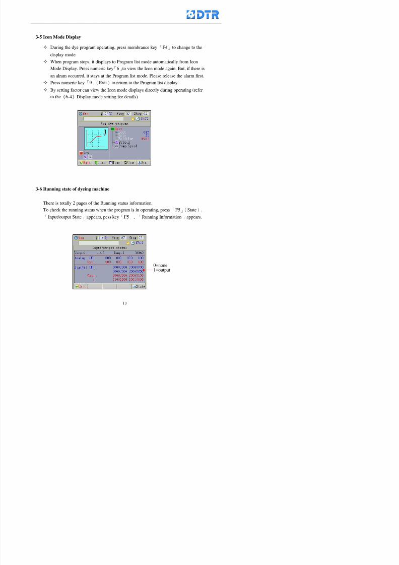
8132019 DTR 650 User Manual
httpslidepdfcomreaderfulldtr-650-user-manual 1370
3-5 Icon Mode Display
During the dye program operating press membrance key「F4」to change to the
display mode
When program stops it displays to Program list mode automatically from Icon
Mode Display Press numeric key「6」to view the Icon mode again But if there is
an alram occurred it stays at the Program list mode Please release the alarm first
Press numeric key「9」(Exit)to return to the Program list display
By setting factor can view the Icon mode displays directly during operating (refer
to the《6-4》Display mode setting for details)
3-6 Running state of dyeing machine
There is totally 2 pages of the Running status information
To check the running status when the program is in operating press「F5」(State)「Inputoutput State」appears pess key「F5」 「Running Information」appears
8132019 DTR 650 User Manual
httpslidepdfcomreaderfulldtr-650-user-manual 1470
3-7 Keep continuing to run from the break point
Due to power sudden off or stop running the dye program it can keep continuing to
run from the break point when the power is retore Users can set the ldquoControl factorrdquo
which dye instruction allows (or prohitbit) to keep continuing to run from the breakpoint (refer to the charpter 6 for Setting)
When the power is restore the cursor stays at the step which stops suddenlybefore starting from the break point to press 「Run」 Window appears
Press「F4」(Yes)to keep going run from the break point
Press「F2」(No)to re-start that dye instruction
Press「F1 (Exit) to return
8132019 DTR 650 User Manual
httpslidepdfcomreaderfulldtr-650-user-manual 1570
3-8 Editing dye step temporary
Before dye program operating the ready-to-run dye step could be edit That edit will
not saved to the file and will not disappear by causing a sudden power inruption or
stop operating until a new dye program is selecting
Step
A Set the system factor as「22」first to allow editing the dye programs temporary
B Set the system factor as「23」 to allow the existing program can temporay
editing its range of step
C Item「19」of the system factor set the dye steps which allows or prohibits to edit
temporary (Refer to the Charpter 6 for details of 「Setting」the A-C )
D Press「F2」()「F3」()or「5」「6」at the Run window To move cursor
to the dye step intend to edit Press membrance key「2」「Edit instrunction
value」appears
E Press「F5」(Edit) then press()()or「5」「6」Programs names is listing
at the cursor or key in a value by the numeric keys Select and press「F5」(ok) to
confirm
F Press「F4」(Save)to confirm and go back to the Run window
G 〔Before pressing「F4」(Save)〕Press「F1」(Exit)to quit
8132019 DTR 650 User Manual
httpslidepdfcomreaderfulldtr-650-user-manual 1670
3-9 Creating an additon dye step during dye program running
Before and during the dye program running the users can creat an addition dye step in
the existing dye programs
3-9-1 Creating an addition dye step
To creat one addition dye step before running or during running step as follows
A Set the System Factor as「34」to allow to creat an addition step (Refer to the
Chartper 6 for details)
B In window「Run dye program」 press numeric key「8」to enter window of 「Edit
addition instruction」 to edit the single dye step first
C Press「」「」「5」
「6」to choose dye
steps press「F5」(OK)
D Press「F5」to edit the
content of dye step
E After complete editing the single dye
step Press「F4」(Run) to start running the
addition step
8132019 DTR 650 User Manual
httpslidepdfcomreaderfulldtr-650-user-manual 1770
3-9-2 Creating an addition treatment to a saved dye program
During and before the dye program running can creat an addition treatment to a
saved dye program or a dye step in a saved dye program
(1) Set the System factor as「34」to allow creating an addition step (Refer to the
Chartper 6 for details)
(2) In window「Run dye program」 press numeric key「8」to enter window of「Edit
single step」
(3) Press「」「」to choose「Sub Prog」 press「4」to move cursor and set itrsquos
dye program number and the step number by numeric keys Or stay at the
「Prog」and press「F3」(File) window appears
(4) Press「」「」to choose an addition dye program then press「F5」(OK)
(5) Press「F4」(Run)to run the addition dye program(sub-dye program)
(6) Finish to run the sub-dye program and return to the main dye program
8132019 DTR 650 User Manual
httpslidepdfcomreaderfulldtr-650-user-manual 1870
4 983120983137983155983155983155983159983151983154983140 DTR-650 provides four ranks of password for sercurity protection
(Refer to the ltTable 10gt Supplementary Table of the Password Usage for details)
First rank (User1 password) Edit delete dye programs control factors in output
testing etchellipall operating fuctions
Second rank (User2 password) Edit in output connecting table operating factors
Third rank (User3 password) Edit copy delete dye programs factors PLC run stop
Fourth rank (User4 password) Edit and modify dye programs
4-1 Entering the password
When the window of 「password」appears enter 6-digits number password by using
the numeric membrane keys then press「F5」(OK) If key-in an incorrect password
press「F3」(Del)and enter again
If the password is correct「」appears it allows to enter the relating operation
8132019 DTR 650 User Manual
httpslidepdfcomreaderfulldtr-650-user-manual 1970
4-2 Locking the data
After editing the programs and factors ensure to disable the password to protect all
programs and data of DTR-650 The way and step as follows
(1) Choose「8Others」at the main meun
(2) Choose「02Data Locking」at the sub-function field
(3) Press「F5」(OK)to confirm
(4) Return to the main menu「」disppears on the status bar that means the data
has been locking already
4-3 Setting and changing the Userrsquos password
There are four userrsquos password for setting and edit by the users themselves
User1 password Access to all operation setting
User2 password For edit in output connection table operating factors
User3 password Only for copy and delete dye programs factors PLC run stop
User4 password Only for edit and modify dye programs
Method of setting edit
(1) Choose「8Others」at main menu press「F5」(OK)
(2) Choose「7 Set Password 2」at the sub-function field press「F5」(OK)
(3) The cursor shows the default password now press「F3」(Clr)to delete Key in
a new password with 6-digit
(4) Press「F5」(OK)to complete the setting of User2 password Go back to the main
menu
8132019 DTR 650 User Manual
httpslidepdfcomreaderfulldtr-650-user-manual 2070
The four userrsquos password has to made from different group numbers Using
same password will affect the operating Please pay attention when update the
password
8132019 DTR 650 User Manual
httpslidepdfcomreaderfulldtr-650-user-manual 2170
5555 983109983140983145983156983145983150983143 983108983161983141 983120983154983151983143983154983137983149983155
5-1 Choosing a dye program
Press function key「F4」(Edit)or choose「1Dye Program」at the main menu press
「F5」(OK)
Choose「1Edit Dye prog」at the sub-function field press「F5」(OK)to enter to the
window「Sel dye program」During the dye program running it is allowed to edit asaved program or a new dye program or the current dye program in running
Method Press「」「」and「5」「6」「3」「4」to move cursor to choose
a dye program number Press「F5」(OK)to enter that dye program Press
「F1(Exit)to quit and return
Method
Directly key in the number selection box
appears at the right corner of the window
Select a program number and press「F5」
(OK) fi
8132019 DTR 650 User Manual
httpslidepdfcomreaderfulldtr-650-user-manual 2270
5-2 Creating a new dye program
Step
A Choose「1Dye Program」Press「F5」(OK)
B Choose「1Edit Dye prog」at the sub-function menu press「F5」(OK)to enter
to window「Sel dye program」
C At the window「Sel dye program」 choose an empty dye number (eg「002」)
press「F5」(OK)window《Fig 5-2-1》appears
《Fig 5-2-1》
D Press「F2」(Add) table of 「Edit dye instruction」《Fig 5-2-2》appears
E Press「F5」(Edit) the dye instruction appears at the cursor locates press「」「」
」and「5」「6」「3」「4」to move cursor to edit the instruction and its
factors
F All inserted new dye instructions would be listed in front of 「Program End」
8132019 DTR 650 User Manual
httpslidepdfcomreaderfulldtr-650-user-manual 2370
【Eg】Edit「CycRinse」
A Edit the main function step first Press「F2」
()「F3」()to move the cursor The dye
step is listing by orders Choose「CycRinse」
and press「」 there is a cursor at itrsquos value
B Move cursor to setting value「Cold」andchoose「Mix」by pressing()() Then
press「」to move cursor to「Time」and enter
itrsquos setting value as「2」Press「F5」(OK) to
complete the main function setting
C To move cursor to the parallel functionsetting field Press()()to choose the
dye step Press「」to confirm and move
cursor to choose itrsquos setting facor
D Press「F5」(OK)to move cursor to the next
parallel function
E Repeat above steps C-D until all parallel
functions setting are completed Each main
function can be operating with the
maximum 4 parallel functions
F Press「F4」(Save)to confirm and return to
the「Edit dye program」window
G Repeat the above step A E to keep on
8132019 DTR 650 User Manual
httpslidepdfcomreaderfulldtr-650-user-manual 2470
5-3 Setting the file name (for dye programs)
When a dye program is setting up it is saved by numbers automatically Optionally users
can save it by another names
Step
(1) Create a new dye program first (the Name is not available for empty dye
programs)
(2) At the window「Sel dye program」 press「F4」(File) Window《Fig5-3》appears
《Fig5-3》
(3) Use numeric 0~9「+」「-」「_」blank alphabet A~Z and symbols [ ] etchellip to
create a file name Each file name can type-in the max 8 unit Press 「3」「4」
「5」「6」to move the cursor to choose the unit It also can use the membrane
numbric key to type in The selected unit is showed in front of the cursor at the
「File」Press「OK」to confirm
(4) Quit to input to press「F3」(Clr)
(5) After complete the set up press「F5」(OK)to confirm and go back to the window
「Sel dye program」 Now the name behind the dye program number is created
8132019 DTR 650 User Manual
httpslidepdfcomreaderfulldtr-650-user-manual 2570
5-4 Inserting a program step
Insert the program step means to insert a step in the existing program step where youwant to insert a step All following steps are moved one step ahead The total number of
steps will be increased by itself Able to insert more than one step continusely at the
same time
【Example】《Fig5-4》 To insert a step「call」before「002 Rinse」
《Fig 5-4》
Step
A Enter to the dye program「002」at the window of 「Sel dye program」
(Example)
B Press「6」to move cursor to「002 Rinse」 then press「F2」(add)
C Press「F5」(Edit) then press「」「」or「5」「6」to choose program
step to modify Choose「call」and press「」to move cursor to modify itrsquos
value
8132019 DTR 650 User Manual
httpslidepdfcomreaderfulldtr-650-user-manual 2670
D Press「」「」 value of 「call」is listing at the table Choose「pH Check 」Press「F5」(OK)
E Press「F4」(Save)and press「F1」(Undo)to return to previous window Complete
to insert the「02 Call」The previous「02 Rinse」update to「03」 All following
steps are moved one step ahead Total number of steps will be increased ldquo1rdquo by
itself
Repeat the steps B-E can non-stop to insert more than one step
Quit the insert and modify ( before pressing「F4」) press「F1」(Undo) to exit
The original dye steps will be unchanged
To delete an inserted dye steps press key「F3」(Del) The step deletes
immediately
5-5 Deleting a program step
Delete the program step means to delete step which the cursor locates When that step is
deleted the step number will be updated automatically All following steps are moved up
one step It is allowed to delete more than one steps continuously at the same time
Step
A Enter to the「Edit dye program」《Fig5-5》at the window「Select dye program」
B Press「6」「5」move cursor to the want to delete
C Confirm and press「F3」(Del) Window「Confirm delete」appears Press
「F4」(Yes)
8132019 DTR 650 User Manual
httpslidepdfcomreaderfulldtr-650-user-manual 2770
D That step is deleted immediately and all following steps move up one step
Repeat the steps above can non-stop to delete more than one step
Press「F2」(No)to cancel the deletion
Press「F1」(Exit)to end
5-6 Modifying a program step
To modify the saved name and the setting value of the dyeing steps
Step
1 Choose a dye program which need to modify at the「Sel dye program」 press「F5」
(OK)
2 Press「6」「5」to move cursor to a step which need to modify Select and press
「F5」(Edit) Window of 「Edit dye instruction」appears
3 Press「F2」()「F3」()to choose the step list select it and press「」to move
the cursor to itrsquos value setting
4 Press numeric key to input the value or press「6」「5」to choose the item Press
「F5」(OK)when complete Cursor move to the next value (if need to set more
than one item)
5 Press「F4」(Save)when all setting is complete Return to「Edit dye program」
Method of parallel functionrsquos modification is same as above
Before pressing the key「「「「Save」」」」 press「F1」(Undo)to quit all modify Return
to the window of Edit dye program
All edit and modify functions mentioned of this charper are only available
for the dyeing files which already saved in the file and not being running It
8132019 DTR 650 User Manual
httpslidepdfcomreaderfulldtr-650-user-manual 2870
5-7 Copying a dye program
Copying a dye programs mean to make a copy of an dye programs to a blank dyeprogram This function is for creating new dye program rapidly
Choose「1Dye Program」at the main menu Press「F5」(OK)then press「F2」()to choose「2Copy dye prog」 Press「F5」(OK) 《Fig5-7-1》appears
《Fig 5-7-1》
《Fig 5-7-2》
【【【【Eg】】】】
Copy program 003 to program 012
Press「」「」to move cursor to theprogram「003」 press「F4」(Copy)
Program「003」shows at the top right side of
the bar
Press「」「」to move cursor to program「012」 Then press「F5」(Paste)「」appears behind the「012」That means it issuccessfully copying the program
If the target program is occupied
confirmation window「Overwrite」
When choose an program or a targetprogram can select them by using the
8132019 DTR 650 User Manual
httpslidepdfcomreaderfulldtr-650-user-manual 2970
5-8 Deleting a dye program
Choose「1Dye program」at the main menu Press「F5」(OK)then press「F2」()to choose「3Delete dye prog」 Press「F5」(OK) 《Fig5-8-1》appears
《Fig5-8-1》
《Fig5-8-2》
Press「」「」to move cursor to
choose program need to delete Eg
delete program「012」 press「F5」(Del) Confirmation window
「Confirm delete」appears
Press「F4」(Yes) to confirm delete
Repeat the above step can delete more
than one program at the same time
Press「F2」(No) to return to window
《Fig5-8-1》and not delete that program
Exit to press「F1」(Exit)and return to the
main menu
8132019 DTR 650 User Manual
httpslidepdfcomreaderfulldtr-650-user-manual 3070
6 983123983141983156983156983145983150983143DTR-650 has a built-in standard factor that can fulfill all different types of dyeing
machinesrsquos basic demand Users can also modify the factors base on their request to
fulfill their special control demand Before modify please refer to the table of each
range of Setting Factors (see the Supplementary Table)
6-1 ldquoEnable to use the program stepsrdquo setting
There are totally 64 program steps Parts of them are usually applying to the programs
In order to make more efficiently of editing programs it can「Disable」the other part
of program steps which are not usually applying or not applicable to the programs
For example dye machine with one tank it is only using step Tank B In this case itcan firstly「Disable」the program steps of Tank C When edit the program the
「Disable」rsquos steps will not appear at the cursor for choosing But this will not effect
and change the saved files The saved files can be kept as before
Step
(1) Choose「2 Factors」at the main menu Press「F5」(OK)(2) Choose「18 Dye Instruction」at the sub-function menu Then presss「F5」(OK)
Window「Edit dye ins」appears
「Enable」instruction can available to
use「Disable」instruction is temporarystop to use
Press「F2」()「F3」()to move
8132019 DTR 650 User Manual
httpslidepdfcomreaderfulldtr-650-user-manual 3170
6-2 ldquoAllow to modify dye program temporary during operatingrdquo Setting
During dye program running it can modify dye program temporary Thesemodification will not disappear by causing a sudden power interruption or power off
until select another new dye program to run
Please note that it is only for modifying the dye program temporary That program
file would not saved due to the modification If need to modify the program file and
save choose the function of Edit Dye Program to edit (Refer to the Charper 5 for the【Edit Dye Prograrm】)
6-2-1 ldquoAllow to modify all dye programsrdquo Setting
Step
(1) Choose「2 Factors」at the main menu Press「F5」(OK)
(2) Choose「02 System Factor」at the sub-function menu Then presss「F5」(OK)
Window「Edit System Factor」appears
Set to stop using temporary the「07
Rinse」press「F4」(Sel)to set it as Disable
Repeat above steps to complete all setting
Press 「F1」(Exit)to return to main menu
8132019 DTR 650 User Manual
httpslidepdfcomreaderfulldtr-650-user-manual 3270
6-2-2 ldquoAllow to modify part of dye programsrdquo Setting
【Eg】Set the number 08 or above (including number 08) is allowing to modify dye
programs during operating
Step
A Refer to【6-2-1】setting the factor as「22」to allow editing dye program
temporary during operating
(4) Press「3」「4」to edit the setting
as「Enable」 and press「F5」(OK)
Restore the standard factor by
pressing「F3」(Clr)
(5) Exit to press「F1」(Exit)and
return to window of 「Main Menu」
8132019 DTR 650 User Manual
httpslidepdfcomreaderfulldtr-650-user-manual 3370
6-2-3 ldquoAllow to modify dye steps temporaryrdquo Setting
After setting the dye programs are allowed to edit it also can set which dye steps are
allowed to edit temporary during operating
Step
(1) Choose「2 Factors」at the main menu Press「F5」(OK)
(2) Choose「19 Dye Ins control」at the sub-function menu Then presss「F5」
(OK) Window「Edit ins mode」appears
「Enable」 Allow to edit that dye step before
operating
「Disable」 Not allow to edit dye step before
operating
(3) Press「」「」to move cursor
to choose dye step Press「F4」
To enter to the「Edit dye program」from the
function menu there is a「」in front of the
file name「0-7」 means that program is not
allowing to edit during operating
8132019 DTR 650 User Manual
httpslidepdfcomreaderfulldtr-650-user-manual 3470
6-2-4 ldquoSet the dye step to keep running from the interrupt pointrdquo setting
When the dye program is operating it will disappear by causing power
interruption or sudden power off When start running again part of dye steps can
run again from the interrupt point part of them cannot
How to set
(1) Choose「2Factors」in the main menu and press「F5」(OK)
(2) Choose「20Continue mode」in the sub-function menu Press「F5」(OK) to
enter window of 「Continue Setting」
(3) Press「」「」to move cursor to choose dye steps Press「F4」(Sel)it
shows「Disable」or「Enable」for choosing Press「F5」(OK)to move cursorto the next setting
(4) Repeat above method until all setting is complete press「F1」(Exit)and
return to the main menu
8132019 DTR 650 User Manual
httpslidepdfcomreaderfulldtr-650-user-manual 3570
6-3 ldquoAllow to insert an addition dye stepsrdquo setting
During the program is running can temporary insert an addition dye step or a dye
program according to the operating actual situation Through this setting can set which
dye steps can apply or not to the program in operating
During to insert an addition step if sudden interruption or power off occurred it returns
to the main dye program automatically Before starting again should decide seriously
and set it again by actual needed
Step
(1) Choose「2Factors」at the main menu and press「F5」(OK)
(2) Choose「02System factor」and press「F5」(OK)
(3) Press「」「」to move cursor to the factor「34」and press「3」「4」to set
it as「Enable」 Press「F5」(OK)
(4) Press「F1」(Exit)to return to main menu Choose「21Addition Ins」at the
sub-function menu Press「F5」(OK)to enter the window「Addition Instruction」
(5) Press「」「」to move cursor to choose dye steps and press「F4」(Sel) Cursors
locates shows「Eable」or「Disable」 Press「F5」(OK)to move cursor to the
next dye step
(6) Repeat above method until to complete all setting press「F1」(Exit)and return
to the main menu
8132019 DTR 650 User Manual
httpslidepdfcomreaderfulldtr-650-user-manual 3670
6-4 Setting the display mode
DTR650 has three types of display mode during operating Program List mode
Schematic Diagram mode and Icon mode Users can set the display mode during
operating by factor setting
It goes back to a Program List mode when dye program ended
Step
(1) Choose「2Factors」at the main menu and press「F5」(OK)
(2) Choose「02System factor」and press「F5」(OK)
(3) Press「F2」()「F3」()to move cursor to choose「32Display mode」Press
「3」「4」 it shows「Online picture」「Instruction」「Big Icon」 choose
「Online picture」(eg) and press「F5」to confirm
8132019 DTR 650 User Manual
httpslidepdfcomreaderfulldtr-650-user-manual 3770
(4) Press「F1」(Exit)to return to the main menu
(5) The Schematic Diagram displays when the program is running (it stays at theProgram List mode when there is an alarm occurred)
Press「F4」to transfer to another display mode
It goes back to a Program List mode from Schematic Diagram Mode when dye
program ended Press numeric key「3」to view Schematic Diagram Mode again
Quit to press「F5」(Exit)
6-5 Adapt the digital input to another functions
DTR-650 has 32(0~31)input terminal it owns an standard setting when the
controller is initial According to the userrsquos demand they can change the DTR-650rsquos
anther functions of Input Terminal and PLC Input channel
The PLC Intputrsquos name can also define by the users (use IBM computer to edit and
download)
How to set
(1) Choose「2 Factor」at the main menu Press「F5」(OK)
(2) Choose「22 Input table」at the sub-function menu and press「F5」(OK)to enter
「Edit input table」
The actual input
terminal of theIBM computer
PLCrsquos input channel
8132019 DTR 650 User Manual
httpslidepdfcomreaderfulldtr-650-user-manual 3870
6-6 Adapt the digital output to another functions
DTR-650 has 32(0~31)output terminals it owns an standard setting when thecontroller is initial According to the userrsquos demand they can adapte the digital output
and the PLC outputrsquos channel to another functions The PLC Output channelrsquos name
can also define by users (use IBM computer to edit and download)
Step
(1) Choose「2 Factor」at the main menu Press「F5」(OK)
(2) Choose「23 Output table」at the main menu and press「F5」(OK)
(3) Press「F2」()「F3」()to move cursor to choose the output terminal atthe left side of the window Press「F5」(Add) the PLCrsquos output channelrsquos
name is listing at the right side of the window
(4) Press「F2」()「F3」()to move cursor to choose the PLC outputrsquos channel
If cursor moves to the PLC output channel which already linking「Add」is
not for choosing that means that output channel is already occupied
(5) Confirm the connection to press「F5」(Add) Quit to press「F4」(Del)Press「F1」(Exit)when complete all setting and return to main menu
The actual output
terminal of the
IBM computer
PLCrsquos output channel
8132019 DTR 650 User Manual
httpslidepdfcomreaderfulldtr-650-user-manual 3970
983095 983109983140983145983156983145983150983143 983156983144983141 983110983137983139983156983151983154983155DTR-650 has several kinds of control factors
Userrsquos factors System factors Temperature Control factors Speed factors Dosing
factors PID factors Analog Input Output factors standard factors etchellipPlease refer
to the supplementary table for the setting range and standard of the factors
DTR-650 has a built-in standard factor Users can edit by themselves if necessary
7-1 Modifying userrsquos factors
Userrsquos factors is setting with the Dyeing machinesrsquos PLC Programrsquos factor it is define by
the PLC Programmer
Step to edit
(1) Choose「2Factors」at main menu Press「F5」(OK)
(2) Choose「01User Factor」Press「F5」(OK)
(3) Press「F2」()「F3」()「6」「5」to move cursor up down and by page
Choose a factor need to edit then press「3」「4」to set itrsquos value Press「F5」(OK) Cursor moves to the next factor
(4) Some of factors can input numbers by the numeric membrance keys to edit If
the input is incorrect it turns to red and means the edit is not available
8132019 DTR 650 User Manual
httpslidepdfcomreaderfulldtr-650-user-manual 4070
Modifyrsquos method of the system factors temperature factors speed factors dosingfactors PID factors analog Input output factors standard factors etchellipare same asabove
If apply the library of DTR500 and DTR600 into the DTR650 the key「3」「4」may not valid to use Please use the numeric keys instead of it to key in factors itmay not effect the normal operation
Please pay a serious attention and read carefully at the factorrsquos table before modify the factors An incorrect value may effect the DTR-650 Dyeing
Machine Controllerrsquos operating After modifying factors must cancel the
password and secure data
7-2 Loading the standard factors
After modifying factors if need to restore a manufacturerrsquos standard factors of
DTR-650 The method as follows
1 Choose「2Factors」at main menu Press「F5」(OK)
「 「 ( ) 「
8132019 DTR 650 User Manual
httpslidepdfcomreaderfulldtr-650-user-manual 4170
7-3 Copying the factor
Users can build up a set of factor by themselves and make a copy and save
Step
1 Choose「2Factors」at main menu Press「F5」(OK)
2 Choose「13Restore Factor」 press「F5」(OK) window「factor will be
overwrite 」
3 Press「F4」(Yes)copy finished and saved Return to the main menu
4 Press「F2」(No)to not copy the factor and the existing factor is not change Return
to the main menu
7-4 Loading the backup factors
Users can build up a set of factor and backup files to load to DTR-650
Step1 Choose「14Backup factor」at the sub-function menu Press「F5」(OK)and
window「Factror will be overwrite」appears
2 Press「F3」(OK)to load the the backup factor them return to main menu
Press「F2」(No)to not copy the factor and the existing factor is not change
Return to the main menu
8132019 DTR 650 User Manual
httpslidepdfcomreaderfulldtr-650-user-manual 4270
983096 983119983157983156983152983157983156 983124983141983155983156983145983150983143
Before the output testing must be complete the steps as follows
A Cut off all connecting line of output terminal of DTR-650
B Stop running the PLC
C Check up the connections of all output channels to avoid damages from
incorrect connections
D Check up state of dyeing machines include the temperature pressure valves
onoff and pumpshellipetc ensure the safety for priority
8-1 Testing the Digital output
Step
1 Choose「3Output Testing」at the main menu Press「F5」(OK) 2 Choose「1Digital」at the sub function menu Press「F5」(OK) window「Digital
output testing」appears
3 Press「」「」「」to move cursor to each output channels Press「F5」(OK)
Output Name
8132019 DTR 650 User Manual
httpslidepdfcomreaderfulldtr-650-user-manual 4370
8-2 Testing the Analog output
(1) Choose「3Output Testing」at the main menu Press「F5」(OK)
(2) Choose「2Analog」at the sub function menu Press「F5」(OK) window「Analog output testing」appears
(3) Press「」「」「」to move cursor to each channels Then key in number by
the numeric membrance keys (range0~200= 0~20mA) Press「F5」(OK) there
is a output current relating to the output channel
(4) Press「F5」(OK) There is an output when the output channel with red light No
output without light onl(5) When complete the testing press「F1」(OK)to return to the main menu
8132019 DTR 650 User Manual
httpslidepdfcomreaderfulldtr-650-user-manual 4470
983097 983107983137983148983145983138983154983137983156983145983151983150
DTR-650 has Dosing and Temperature calibration
When enter to Dosing calibration must be set the Low Volume calibration first and
then High Volume calibration When enter to Temperature calibration must be set the
Low Temperature calibration first and then High Temperature calibration Must be
hightly follow this orders seriously
9-1 Calibration of Low Volume Tank
Step
A Choose「4Calibration」at the main menu Press「F5」(OK)
B Choose「Dosing 0 low vol」at the sub function menu Press「F5」(OK) window
appears
C Fill the Dosing Tank to a half level input value shows how much the water level
If it stays ldquo0rdquo check the connection and the factor setting is correct or not
And connect the pressure sensorrsquos output channel to the Current Meter to ensure
that sensor works or not
8132019 DTR 650 User Manual
httpslidepdfcomreaderfulldtr-650-user-manual 4570
D Fill the Dosing Tank to 50ml (Calcalate from the bottom side of the pressure
sensor steel tube) input value should show 4~6 (input value must between
0~10) Then enter the water volume The setting volume is relating the water
levelrsquos water value (litre as unit) input range 0~80 Set as「 「「 「0000 0000 0000 0000」」」」is strongly is strongly is strongly is strongly
receommend receommend receommend receommend Press「F5」(OK)to complete [Calibration of Low Volume Tank 1
is same as above method]
9-2 Calibration of High Volume Tank
Step
A Choose「4Calibration」at the main menu Press「F5」(OK)
B Choose「Dos 0 high vol」at the sub function menu Press「F5」(OK) window of
「Calibrate high 」appears
C Fill the Dosing Tank to a full level input value should be larger than 30 enter
the current water level which relates to the water volume Enter the range within
100~2500 Then press「F5」(OK) to complete the calibrate the high volume tank
8132019 DTR 650 User Manual
httpslidepdfcomreaderfulldtr-650-user-manual 4670
9-3 Temperature Calibration
Step
A This function is for adjusting the DTR650rsquos accuracy of Temperature Control It
must be using with the special terminal which is only for DTR650
B Choose「4Calibration」at the main function menu and press「F5」(OK)
C Choose「3Low Temp」at the sub-function menu Press「F5」(OK)and《Fig9-3》
appears insert the DTR650rsquos low temperature calibration terminal to the temperature
input terminal wait for the jumping value to stable down then press「F5」(OK) then
to adjust the high temperature calibration
D Adjusting the High Temperature Calibrationrsquos method is same as above But usersusersusersusers
must be using the High Temperature Terminalmust be using the High Temperature Terminalmust be using the High Temperature Terminalmust be using the High Temperature Terminal whichwhichwhichwhich is specially for DTR650 onlyis specially for DTR650 onlyis specially for DTR650 onlyis specially for DTR650 only
《Fig 9-3》
8132019 DTR 650 User Manual
httpslidepdfcomreaderfulldtr-650-user-manual 4770
10 983122983141983139983151983154983140983155 983151983142 983108983161983141 983120983154983151983143983154983137983149983155
It contains the past 15 days of temperature curves of running history
Checking method
(1) Choose「5Dye Record」at main menu press「F5」(OK)
(2) Sub-function menu shows the set up date of the past 15 days dye programs
Listing by the lastest set up date
(3) Choose a program date and press「F5」(OK) it appears window「Temp
record」
(4) Press「」「」to move the white line in the box one minute by moving once
(5) Press「3」「4」to move the line to check the time period 2 hours by moving once
The yellow selecting line of the「24 hours operating state」is repectively moving
The curve info is show in the curve box Left side of the widnow appears the
relating running info the time is the time value of the line locates at
(6) Check more details of the temperature info to press numeric key「middot」 a bright red line
appears in the selecting box this line is to check the starting point of the
temperature inforsquos time period Then press「」to move the white line to the end
point of the time period The temperature info between the starting point and end
point are appears at the right side of the window Press「middot」to return to the preious
curve page
(7) Check more details of the alarm infor To perss numeric key「7」「9」 the alarmrsquos
details is listing by orders
(8) Press「F1」(exit) to return
8132019 DTR 650 User Manual
httpslidepdfcomreaderfulldtr-650-user-manual 4870
11 983125983155983137983143983141 983151983142 983117983141983149983151983154983161 983107983137983154983140
DTR-650 supports 32MB or above Compact Flash Card which can transfer and save all
information for 4 sets of DTR-650 Including library files schematic diagram icon
image PLC program dye program factor and confiruration files etchellip Use the CF Card
to up download and swap the information of DTR-650 promptly install the relating
device and program updates
DTR-650 CF Card with bank 1 to bank 4 can save 4 sets information of Dyeing
Machines When download or save files should choose the BANK first
《Fig11-1》
8132019 DTR 650 User Manual
httpslidepdfcomreaderfulldtr-650-user-manual 4970
11-1 Downloading data
1 Firmly insert the CF card into the DTR-650rsquos PCMCIA connector Ensure it is
wholely and firmly inserted if the card is not totally inserted or the card do not
touch in all to the connector there will be an error occurred and cannot
updownload or interrupted during operation
2 Choose「6Memory Card」at the main menu and press「F5」(OK) 《Fig11-1》
appears Information of Bank「1」shows at the left hand side of the window press
number 1-4 by using numeric keys to choose the BANK Check the
information in the Bank seriously which is exactly need to download to the
DTR650
3 Press()()「6」「5」to move cursor to the sub-function menu to choose
the downloading items Press「F5」(OK) window appears「Stop PLC run before
access memory card Stop the PLC run」 Press「F5」(YES) to stop PLC
running
4 Press「F5」(OK) window appears Confirm to update or not the DTR-650rsquos
information As that downloading will be replace the DTR-650rsquos information
(that means the existing information of the DTR-650 will be removed and
replaced)
5 Press「F4」(YES)to download the information from the DTR-650 to the CF
Card Return to the main menu when finish
8132019 DTR 650 User Manual
httpslidepdfcomreaderfulldtr-650-user-manual 5070
Ensure inserting firmly the CF card into the DTR-650 unless it will cause
error or cannot Updownload data
Never remove CF card during transferring or updownloading data Until it
is all completed
DTR-650rsquos dyeing program is not compatible with DTR-500 and
DTR-600 Never use CF card to transfer data among them
11-2 Storing and transfering data
1 Insert the CF Card to the DTR-650
2 Choose「6Memory Card」at the main menu and press「F5」(OK) 《Fig11-1》
appears Left hand side of the window shows the data of BANK 1 press numeric
keys 1-4 to select the BANK To confirm the put the data in the DTR-650 to the CF
Card The existing data of that bank will be replaced and covered by the new data (if
that bank is already occuplied)
3 Choose「23Save Dye prog」(Example)at the sub-funciton menu press「F5」(OK)to confirm Window「Update memory card data」appears
4 Press「F5」(OK)to transfer the data to the CF card Return to the main menu
5 Put the CF card into another DTR-650 and follow the operating method of 「11-1
Downloading data」」」」can transfer and swap data with more than one set of
DTR-650
8132019 DTR 650 User Manual
httpslidepdfcomreaderfulldtr-650-user-manual 5170
12 983123983156983137983156983141 983137983150983140 983113983150983142983151983154983149983137983156983145983151983150
The state and information is including the Dyeing Machinersquos state of Digit Input output
Analog Input output Temperature control PID Dosing PID Pressure different PID
software system information and alarm record This information is for checking at any
time
12-1 Input Output state
Step
1 Choose「7Info and state」at main menu and press「F5」(OK)
2 Choose「01Digital IO put」at the sub-function menu then press「F5」(OK)
「Digital In Out State」0=None 1=Input
3 Press「F1」(Exit)to return to main menu
Same method for checking the temperature control analog dosing pressure
different etchellip
12-2 Checking the system information
Step
1 Choose「7Info and state」at main menu and press「F5」(OK)
2 Choose「11 System info」at sub-function field press「F5」(OK)Window
「System Information」appear
System information is including System info(software version) Library doc
Icon files Schematic file Definition file hardare state Config File Commandinstruction icon PLC file etc
8132019 DTR 650 User Manual
httpslidepdfcomreaderfulldtr-650-user-manual 5270
12-3 Checking the operating alarm record
Operating record shows the latest 40 operating items and alarm records including
the time and content of the alarm
A) Choose「7 Info and state」
and press「F5」(OK)
B) Choose「12Alarm logs」at
the sub-funciton menu then
press「F5」(OK)
8132019 DTR 650 User Manual
httpslidepdfcomreaderfulldtr-650-user-manual 5370
13 983105983140983146983157983155983156983145983150983143 983156983144983141 983107983151983150983156983154983137983155983156
The displaysrsquos brightness can be adjusted if necessary
Step
1 Choose「8Others」at main menu press「F5」(OK)
2 Choose「01Contrast」at sub-function menu press「F5」(OK) window「Set
Contrast」appears
3 Press「」「」to move the bar to set the brightness then press「F5」(OK)Window appears「Please reboot the system」
4 Press「F5」(OK)to return to main menu and re-boot the DTR-650 to complete
adjusting the brightness
8132019 DTR 650 User Manual
httpslidepdfcomreaderfulldtr-650-user-manual 5470
14 983123983156983151983152 983154983157983150983150983145983150983143 983156983144983141 983120983116983107 983120983154983151983143983154983137983149
Before testing the Input output testing transfer of the PLC program must stop the PLC
running
Step
1 Choose「8Others」at the main menu Press「F5」(OK)
2 Choose「04 PLC Stop」at sub-function menu Press「F5」(OK) window
「Password」appears
3 Enter password and press「F5」(OK) Window「Stop the PLC run」appears
4 Press「F4」(Yes)and window「PLC Stop」appear Press「F5」(OK) Now
the PLC is stop running and return to the main menu
All testing cannot operate when the PLC is running
Editing dye program and the relating operation can
perform with the PLC running together
8132019 DTR 650 User Manual
httpslidepdfcomreaderfulldtr-650-user-manual 5570
15 983123983141983156983156983145983150983143 983156983144983141 983156983145983149983141
Step
1 Press「8Others」at the main menu Press「F5」(OK)
2 Choose「10Set date time」at the sub-function menu Press「F5」(OK) window
「Set date time」appears
3 Press「F5」(Edit) to move cursor by 「3」「4」 enter the time value at the
cursor locates
4 Press「F5」(OK)to complete the modify Press「F1」(Exit)to return to main
menu
5 Press「F1」(Exit)if not modify and return to main menu
8132019 DTR 650 User Manual
httpslidepdfcomreaderfulldtr-650-user-manual 5670
1166 983123983123983157983157 983152 983152 983152 983152983148983148983141983141983149983149983141983141983150983150983156 983156 983137983137983154 983154 983161983161 983124 983124 983137983137983138983138983148983148983141983141
TTTTTTTTaaaaaaaabbbbbbbblllllllleeeeeeee 11111111 【Dye Instruction】
Code Icon Instruction Code Icon Instruction
000 End 016 Inject C
001 Start 017 Dosing BV
002 Heat 018 PH
003 Cool 019 Addsalt B
004 Flow Fill 020 Addsalt C
005 Level Fill 021 Ana Fill
006 Drian 022 Lock Fill007 Rinse 023 Lock Level
008 Run 024 Low Rinse
009 Call 025 Cyc Rinse
010 Prep B 026 Rinse B
011 Addsalt B 027 Rinse C
012 Dosing B 028 Temp
013 Inject B 029 Nozzle Pressure
014 Prep C 030 Main Pump
015 Dosing C 031 Pump Speed
8132019 DTR 650 User Manual
httpslidepdfcomreaderfulldtr-650-user-manual 5770
Table 2 【【【【Alarm】】】】
System Alarm Must stop operating and check up to solve problems before restarting
the machine
Running Alarm It is a reminder Not effect the operating of DTR-650
Userrsquos Alarm Total of 32 Users can define themselves and use it when edit the PLC
Program (do not listing below)
No System Alarm No Running Alarm
1 PLC program not running 16 Temp ctrl 0 Grad too slow
2 Main temp sensor error 17 Temp ctrl 0 Grad too fast
3 Not at Run window 18 Temp ctrl 0 Hold temp too low
4 Exceeding max temp 19 Temp ctrl 0 Hold temp too high
5 - 20 Temp ctrl 1 Grad too slow6 - 21 Temp ctrl 1 Grad too fast
7 - 22 Temp ctrl 1 Hold temp too low
8 Communication error 23 Temp ctrl 1 Hold temp too high
9 Slave not answer 24 Temp ctrl 2 Grad too slow
10 PLC 0 not answer 25 Temp ctrl 2 Grad too fast
11 PLC 1 not answer 26 Temp 2 Hold temp too low12 Display not answer 27 Temp 2 Hold temp too high
13 Lower power voltage 28 Temp ctrl 3 Grad too slow
14 - 29 Temp ctrl 3 Grad too fast
15 - 30 Temp3 Hold temp too low
31 Temp3 Hold temp too high
32 Dosing 0 injection too slow
33 Dosing 0 injection too fast
34 Dosing 1 injection too slow
35 Dosing 1 injection too fast
8132019 DTR 650 User Manual
httpslidepdfcomreaderfulldtr-650-user-manual 5870
TTTTTTTTaaaaaaaabbbbbbbblllllllleeeeeeee 33333333 【【【【System factor】】】】
No Description Std Range amp Definition
1 ID No 000 000- 100 Controller no
2 Communication Rate 4800Bps 2400 4800 9600 19200 38400
3 Display language Chinese English Chinese
4 Temp display mode and
5 Maxmium temperature 145 025 ~ 145 6 Type of external PLC Default PLC32DPLC32PLC16Default
7 Number of external PLC NANA 1 unit connect
2 unit connect
8Communication Rate of
PLC9600Bps 2400 4800 9600 19200
9 Set point 1 085 000 ~ 145
If signal source is temperaturethe setting value is thetemperature value If the signal
source is Analog Input 6~17 then
setting value for Analog input is 0 ndash
100 and relates Analog
Input14~020mA
10 Source 1 Sensor0Sensor 0 ~5
Analog input 0 ~1111 Set point 2 092 Same as 09
12 Source 2 PT100 1 Same as 10
13 Set point 3 085 Same as 09
14 Source 3 PT100 2 Same as 10
15 Set point 4 092 Same as 09
16 Source 4 PT100 3 Same as 1017 Set point 5 085 Same as 09
18 Source 5 PT100 4 Same as 10
19 Set point 6 092 Same as 09
8132019 DTR 650 User Manual
httpslidepdfcomreaderfulldtr-650-user-manual 5970
29 Min cyclic time of cloth 100sec 0 ~ 255 sec
30 Max cyclic time of cloth 240sec 0 ~255 sec
31Standard cyclic time of
cloth
180 000 ~ 255 sec
32 Display ModeProgram
List
Program list Schematic Diagram
Icon mode
33 CF card format Standard of
DTR CF
Card
Standard of DTR CF Card V20
Standard CF Card
34 Addition step Disable Disable Enable35 Mode Com 3
CouplingEsure Com 3 is the communication
port of the Central or Coupling
36Com 3 Communication
rate9600 Central communication speed
8132019 DTR 650 User Manual
httpslidepdfcomreaderfulldtr-650-user-manual 6070
TTTTTTTTaaaaaaaabbbbbbbblllllllleeeeeeee 44444444 【【【【Temperature Cotnrol Factor】】】】
No Factor Definition Standard Range and Definition
01 PT No PT-0 PT 0~5 PT-100 Input number
02 Max working temp 140 000~140
03 Output mode 0 0~2
04 Alarm time of gardient 240sec 000~255 sec
05 Alarm mode of gradient Always AlwaysOnceNone
06 Control mode of gradient Heating orCooling
interlocked
Heating and Cooling interlocked
No limitation
07 Alarm range of HoldTemp 03 01~20
08 Alarm time for HoldTemp 240sec 000~255sec
09 Alarm mode of HoldTemp Always AlwaysOnceNone
10 Control mode ofHoldTemp
Heating only Only heating and cooling Cooling whenalarm occurred Only heating andcooling No limitation when alarmHeating only
11 Porportional Band 100 000~250
12 Integral band 128 sec 000~255 sec
13 Differential time 04 sec 00~20 sec
14 Min transit gradient 02 00~50
15 Transit rate 20 times 00~50 times (020= 2 times)
16 PID initial output value 010 000~100
17 ONOFF cycle time 10 sec 05~25 sec
Onoff valve set as 010 sec
Proportional valve set as 020 sec
18 Time down count mode Mode 0 0~10 = The time down count range from「Factor 20 + target temp」to「Target
8132019 DTR 650 User Manual
httpslidepdfcomreaderfulldtr-650-user-manual 6170
TTTTTTTTaaaaaaaabbbbbbbblllllllleeeeeeee 55555555 【【【【Speed Factor】】】】
No Factor Definition Standard Range amp Definition
01 Input Number Speed input 0 Speed input 0~11
02 Average times 05 times 01~10
03 Sensor Number 008pcs 001~255
04 Roller Dimension 250mm 050~500
05 Max cloth speed 200mmin 001~25506 Min cloth speed 020mmin 001~255
07 Alarm delay time 240sec 001~255
08 Alarm mode Every oncenoneevery
09 Alarm range () 020 001~255
10 Proportional band 100 001~255
11 Integer band 128 001~25512 Differential time 000 001~200
13 Initial speed () 020 001~255
14 Control cycle ti(01sec) 05 01~30
15 First cycle time(01sec) 10 01~30
16 Speed increase limit () 010 001~100
17 Speed decrease limit () 010 001~100
18 Min speed() 005 001~100
19 Manual speed adjust () 005 001~100
20 Manual initial speed() 020 001~100
21 Stopping speed() 010 001~100
22 Switch speed() 020 001~100
23 Not used
24 Speed decrease turns 03turns 01~50
8132019 DTR 650 User Manual
httpslidepdfcomreaderfulldtr-650-user-manual 6270
Table 6 【【【【Dosing Factors】】】】
No Description Range Range and Explanation
1 Analog input no Analog input 0 Analog input no 0 ~11
2Alarm delay time for
dosing240 sec 000 ~255 sec
3 Alarm time for dosing Every Every Once None
4 Proportional band 100 000 ~255 sec Factor P
5 Integer band 128 000 ~255 sec Factor I6 Differential time 04 00 ~20 Factor D
7 Max adjust rate 150 50~ 255
8 Initial factor for dosing 10 000 ~100
9 User curve section 0 10 Gradient of sect1 for dosing curve9
10 User curve section 1 10 Gradient of sect2 for dosing curve9
11 User curve section 2 10 Gradient of sect3 for dosing curve9
12 User curve section 3 10 Gradient of sect4 for dosing curve9
13 User curve section 4 10 Gradient of sect5 for dosing curve9
14 User curve section 5 10 Gradient of sect6 for dosing curve9
15 User curve section 6 10 Gradient of sect7 for dosing curve9
16 User curve section 7 10 Gradient of sect8 for dosing curve9
17 User curve section 8 10 Gradient of sect9 for dosing curve9
18 User curve section 9 10 Gradient of sect10 for dosing curve9
19 Min water level 05 00~ 10 04~20mA percentagechange to the userrsquos factor setting
20 Output value for Tank
clean
100 000~ 100
Injected percentage of dosing valve
in dosing End period
This factor will be invalided if usingONOFF dosing valve
21 Full range 100 001~255 Self-adjustment cannotchange
22 Range ratio 001001~255 Self-adjustment cannot
change
8132019 DTR 650 User Manual
httpslidepdfcomreaderfulldtr-650-user-manual 6370
【【【【TTaabbllee 77 】】】】Pressure Deviation Factors
No Description Std Range amp Definition
1 Analog input number + Analog in 0 Analog in 0~11
2 Analog input number - Analog in 1 Analog in 0~11
3 Input mode Pressure Pressure Pressure deviation
4 Full range 050x01Kgcm
001~255
5 Range ratio 001 001~255
6 Alarm delay time 100sec 001~255
7 Alarm mode Every oncenone
8 Alarm range 010 001~255
9 Proportional band 100 001~255
10 Integer band 128 001~255
11 Differential time 00 00~20
12 PID Init output value 010 001~255
13 Cycle time 10 03~30
14 First cycle time 030 003~100
15 Max adjust rate 010 001~100
8132019 DTR 650 User Manual
httpslidepdfcomreaderfulldtr-650-user-manual 6470
【【【【TTaabbllee 88 】】】】Definition of Analog Input
No Description Standard Range and Explanation
01 PT 0 correction standard DIN std DIN std JIS std
02 PT 0 correction +0 +- 9
03 PT 1 correction standard DIN std DIN std JIS std
04 PT 1 correction +0 +- 9
05 PT 2 correction standard DIN std DIN std JIS std
06 PT 2 correction +0 +- 9
07 PT 3 correction standard DIN std DIN std JIS std
08 PT 3 correction +0 +- 9
09 PT 4 correction standard DIN std DIN std JIS std
10 PT 4 correction +0 +- 9
11 PT 5 correction standard DIN std DIN std JIS std
12 PT 5 correction +0 +- 9
13 Analog input 0 define 4 ~ 20mA 0 ndash 20mA 4 ndash 20mA
14 Analog input 0 average times 10 times 01- 20 times
15 Analog input 0 min value 0000 0000 - 1000
16 Analog input 0 max value 100 0001 - 9999
17-60 Analog input 1~11 Same as Analog input 0
【【【【 】】】】 fi i i f A O
8132019 DTR 650 User Manual
httpslidepdfcomreaderfulldtr-650-user-manual 6570
【【【【TTaabbllee 99 】】】】Definition of Analog Output
No Description Standard Range and explanation
61 Analog output 0 define Control byPLC
Control by PLC
Temperature control PID0 output
Temperature control PID1 output
Temperature control PID2 output
Speed PID3 output
Dosing PID0 output Dosing PID1output
Pressure different PID0 outputPressure different PID1 output
Main temperature output
62 Mode of Analog ouptput0 4 ~20mA 0 ndash20mA 4 ndash 20mA
63-84 Analog output 1~11 Same as Analog output 0
【【【【TTaabbllee 1100】】】】Value Table 0 amp 1
No Description Range Std Range and explanation
1 Analog input no 000~011 000 Analog input no
2 Data ratio 001~255 100 Multiple by factors
3~53 0~98 000~255 000-100 Analog input 0~98 data
【【【【 】】】】St t Li t
8132019 DTR 650 User Manual
httpslidepdfcomreaderfulldtr-650-user-manual 6670
【【【【TTaabbllee 1111】】】】State List
No Description Range Standard Range and explanation
1 Display setting 1 0~255 205 See remarks at next page
2 Display setting 2 0~255 208
3 Display setting 3 0~255 209
4 Display setting 4 0~255 017
5 Display setting 5 0~255 0186 Display setting 6 0~255 019
7 Display setting 7 0~255 020
8 Display setting 8 0~255 021
9 Display setting 9 0~255 000
10 Display setting 1 0~255 000
11 Display setting 2 0~255 000
12 Display setting 3 0~255 000
13 Display setting 4 0~255 000
14 Display setting 5 0~255 000
15 Display setting 6 0~255 000
16 Display setting 7 0~255 000
Remarks
8132019 DTR 650 User Manual
httpslidepdfcomreaderfulldtr-650-user-manual 6770
0 = No display 1~255 = Display type of number
1~16 Content of PLC VB0~15
No 1 corresponding to VB0
No 16 corresponding to VB15
17~32 Content of PLC DB0~15
No 17 corresponding to DB0
No 32 corresponding to DB15
33~46 Content of PLC CNT0~29
No 33 corresponding to CNT0
No 46 corresponding to CNT29 47~78 Content of dyeing instruction 0~31 CNT0
No 47 corresponding to system instruction to No 0 of CNT0
No 78 corresponding to system instruction to No 31 of CNT0rsquos content
79~110 Dyeing instruction 0~31 of CNT0rsquos setting
111~142 Content of Dyeing instruction 0~31 CNT1No 111 corresponding to dyeing instruction No 0 of CNT1
No 142 corresponding to dyeing instruction No 31 of CNT1rsquos content
143~174 Dyeing instruction 0~31 of CNT1rsquos setting
175~204 Content of PLC HTIM0~29
No 175 corresponding to HTIM0
No 204 corresponding to HTIM29
205 Loading
206 Ratio 1
207 Ratio 2208 Ratio 1 x Loading
209 Ratio 2 x Loading
210 Fix value
211 Value Table 1 matching result
212 Value Table 2 matching result
213 Value Table 1 setting214 Value Table 2 setting
215 Pressure control PID0 different pressure value
216 Pressure control PID1 different pressure value
TTTTTTTTaaaaaaaabbbbbbbblllllllleeeeeeee 1122 【【【【Usage of password】】】】
8132019 DTR 650 User Manual
httpslidepdfcomreaderfulldtr-650-user-manual 6870
No Main FunctionFactor Sub Function Factor Password Rank
1 Run None
2 Dye program User3 or above
3 Control factor
- User factor User 1
- System factor User 1
- Temp PID 0
- Temp PID 1 User 1- Speed PID 0 User 1
- Dosing PID 0 User 1
- Dosing PID 1 User 1
- Pressure PID 0 User 1
- Pressure PID 1 User 1
- Analog IO User 1
- Load standard factor User 2 or above- Load a copied factor User 2 or above
- Copy factor User 2 or above
- Value table 0 User 1
- Value table 1 User 1
- Information and state User 1
- Dye instruction User 1
- Edit dye instruction setting User 14 Output testing User 2 or above
5 Calibration User 2 or above
6 Dye record None
7 CF card User 1
8 Info and state None
9 Others
- Contrast User3 or above
- Data Locking None
- PLC Run User 1
- PLC Stop User 1
- Password setting User 1
TTTTTTTTaaaaaaaabbbbbbbblllllllleeeeeeee 1133 【【【【Technical Data】】】】
8132019 DTR 650 User Manual
httpslidepdfcomreaderfulldtr-650-user-manual 6970
TTTTTTTTaaaaaaaabbbbbbbblllllllleeeeeeee 1133 【【【【Technical Data】】】】
1 Temperature Control
- Range 10~145(plusmn1)
- Mode Proportional or PWM
- Sensor PT100 (JIS or DIN standard)
2 Input and output channel
- Digital Input 32 DC24V PNP- Digital Output 32 DC24V 054A Relay connect point
- Analog Input 4 04~20 mA
- Analog Output 4 0~20mA 或 4~20 mA
3 Communication port 3 RS-232 amp 0~20 mAx1 RS485x 2
4 Dye program
- Number 15000 Steps
- Standard step 61Heating Cooling Fill Drain RinseDosingetc
5LCD module and Display
langage
Chinese
English
320 x 240 TFT color display with
more language
6 CF card connector 1 PCMCIA standard
7 Membrane Keyboard- Number Key 10 [0]~[9] Input factors
- Function Key 5 [F1]~[F5] function selecting
- Operation Key 2 [Start] [Stop]
- Auxiliary Key 7 [][][][][Esc] [larr][OK] [bull]
8 Operating Condition
- Temperature 5~45
- Humidity ≦85 (25)
9 Power supply
V l DC 24V
8132019 DTR 650 User Manual
httpslidepdfcomreaderfulldtr-650-user-manual 7070
70
983108983124983122983085650 983113983150983152983157983156 983119983157983156983152983157983156 983120983151983154983156983145983150983143 (983138983137983139983147983155983145983140983141 983158983145983141983159)
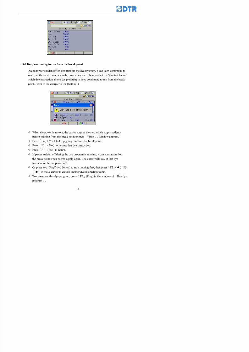
8132019 DTR 650 User Manual
httpslidepdfcomreaderfulldtr-650-user-manual 1470
3-7 Keep continuing to run from the break point
Due to power sudden off or stop running the dye program it can keep continuing to
run from the break point when the power is retore Users can set the ldquoControl factorrdquo
which dye instruction allows (or prohitbit) to keep continuing to run from the breakpoint (refer to the charpter 6 for Setting)
When the power is restore the cursor stays at the step which stops suddenlybefore starting from the break point to press 「Run」 Window appears
Press「F4」(Yes)to keep going run from the break point
Press「F2」(No)to re-start that dye instruction
Press「F1 (Exit) to return
8132019 DTR 650 User Manual
httpslidepdfcomreaderfulldtr-650-user-manual 1570
3-8 Editing dye step temporary
Before dye program operating the ready-to-run dye step could be edit That edit will
not saved to the file and will not disappear by causing a sudden power inruption or
stop operating until a new dye program is selecting
Step
A Set the system factor as「22」first to allow editing the dye programs temporary
B Set the system factor as「23」 to allow the existing program can temporay
editing its range of step
C Item「19」of the system factor set the dye steps which allows or prohibits to edit
temporary (Refer to the Charpter 6 for details of 「Setting」the A-C )
D Press「F2」()「F3」()or「5」「6」at the Run window To move cursor
to the dye step intend to edit Press membrance key「2」「Edit instrunction
value」appears
E Press「F5」(Edit) then press()()or「5」「6」Programs names is listing
at the cursor or key in a value by the numeric keys Select and press「F5」(ok) to
confirm
F Press「F4」(Save)to confirm and go back to the Run window
G 〔Before pressing「F4」(Save)〕Press「F1」(Exit)to quit
8132019 DTR 650 User Manual
httpslidepdfcomreaderfulldtr-650-user-manual 1670
3-9 Creating an additon dye step during dye program running
Before and during the dye program running the users can creat an addition dye step in
the existing dye programs
3-9-1 Creating an addition dye step
To creat one addition dye step before running or during running step as follows
A Set the System Factor as「34」to allow to creat an addition step (Refer to the
Chartper 6 for details)
B In window「Run dye program」 press numeric key「8」to enter window of 「Edit
addition instruction」 to edit the single dye step first
C Press「」「」「5」
「6」to choose dye
steps press「F5」(OK)
D Press「F5」to edit the
content of dye step
E After complete editing the single dye
step Press「F4」(Run) to start running the
addition step
8132019 DTR 650 User Manual
httpslidepdfcomreaderfulldtr-650-user-manual 1770
3-9-2 Creating an addition treatment to a saved dye program
During and before the dye program running can creat an addition treatment to a
saved dye program or a dye step in a saved dye program
(1) Set the System factor as「34」to allow creating an addition step (Refer to the
Chartper 6 for details)
(2) In window「Run dye program」 press numeric key「8」to enter window of「Edit
single step」
(3) Press「」「」to choose「Sub Prog」 press「4」to move cursor and set itrsquos
dye program number and the step number by numeric keys Or stay at the
「Prog」and press「F3」(File) window appears
(4) Press「」「」to choose an addition dye program then press「F5」(OK)
(5) Press「F4」(Run)to run the addition dye program(sub-dye program)
(6) Finish to run the sub-dye program and return to the main dye program
8132019 DTR 650 User Manual
httpslidepdfcomreaderfulldtr-650-user-manual 1870
4 983120983137983155983155983155983159983151983154983140 DTR-650 provides four ranks of password for sercurity protection
(Refer to the ltTable 10gt Supplementary Table of the Password Usage for details)
First rank (User1 password) Edit delete dye programs control factors in output
testing etchellipall operating fuctions
Second rank (User2 password) Edit in output connecting table operating factors
Third rank (User3 password) Edit copy delete dye programs factors PLC run stop
Fourth rank (User4 password) Edit and modify dye programs
4-1 Entering the password
When the window of 「password」appears enter 6-digits number password by using
the numeric membrane keys then press「F5」(OK) If key-in an incorrect password
press「F3」(Del)and enter again
If the password is correct「」appears it allows to enter the relating operation
8132019 DTR 650 User Manual
httpslidepdfcomreaderfulldtr-650-user-manual 1970
4-2 Locking the data
After editing the programs and factors ensure to disable the password to protect all
programs and data of DTR-650 The way and step as follows
(1) Choose「8Others」at the main meun
(2) Choose「02Data Locking」at the sub-function field
(3) Press「F5」(OK)to confirm
(4) Return to the main menu「」disppears on the status bar that means the data
has been locking already
4-3 Setting and changing the Userrsquos password
There are four userrsquos password for setting and edit by the users themselves
User1 password Access to all operation setting
User2 password For edit in output connection table operating factors
User3 password Only for copy and delete dye programs factors PLC run stop
User4 password Only for edit and modify dye programs
Method of setting edit
(1) Choose「8Others」at main menu press「F5」(OK)
(2) Choose「7 Set Password 2」at the sub-function field press「F5」(OK)
(3) The cursor shows the default password now press「F3」(Clr)to delete Key in
a new password with 6-digit
(4) Press「F5」(OK)to complete the setting of User2 password Go back to the main
menu
8132019 DTR 650 User Manual
httpslidepdfcomreaderfulldtr-650-user-manual 2070
The four userrsquos password has to made from different group numbers Using
same password will affect the operating Please pay attention when update the
password
8132019 DTR 650 User Manual
httpslidepdfcomreaderfulldtr-650-user-manual 2170
5555 983109983140983145983156983145983150983143 983108983161983141 983120983154983151983143983154983137983149983155
5-1 Choosing a dye program
Press function key「F4」(Edit)or choose「1Dye Program」at the main menu press
「F5」(OK)
Choose「1Edit Dye prog」at the sub-function field press「F5」(OK)to enter to the
window「Sel dye program」During the dye program running it is allowed to edit asaved program or a new dye program or the current dye program in running
Method Press「」「」and「5」「6」「3」「4」to move cursor to choose
a dye program number Press「F5」(OK)to enter that dye program Press
「F1(Exit)to quit and return
Method
Directly key in the number selection box
appears at the right corner of the window
Select a program number and press「F5」
(OK) fi
8132019 DTR 650 User Manual
httpslidepdfcomreaderfulldtr-650-user-manual 2270
5-2 Creating a new dye program
Step
A Choose「1Dye Program」Press「F5」(OK)
B Choose「1Edit Dye prog」at the sub-function menu press「F5」(OK)to enter
to window「Sel dye program」
C At the window「Sel dye program」 choose an empty dye number (eg「002」)
press「F5」(OK)window《Fig 5-2-1》appears
《Fig 5-2-1》
D Press「F2」(Add) table of 「Edit dye instruction」《Fig 5-2-2》appears
E Press「F5」(Edit) the dye instruction appears at the cursor locates press「」「」
」and「5」「6」「3」「4」to move cursor to edit the instruction and its
factors
F All inserted new dye instructions would be listed in front of 「Program End」
8132019 DTR 650 User Manual
httpslidepdfcomreaderfulldtr-650-user-manual 2370
【Eg】Edit「CycRinse」
A Edit the main function step first Press「F2」
()「F3」()to move the cursor The dye
step is listing by orders Choose「CycRinse」
and press「」 there is a cursor at itrsquos value
B Move cursor to setting value「Cold」andchoose「Mix」by pressing()() Then
press「」to move cursor to「Time」and enter
itrsquos setting value as「2」Press「F5」(OK) to
complete the main function setting
C To move cursor to the parallel functionsetting field Press()()to choose the
dye step Press「」to confirm and move
cursor to choose itrsquos setting facor
D Press「F5」(OK)to move cursor to the next
parallel function
E Repeat above steps C-D until all parallel
functions setting are completed Each main
function can be operating with the
maximum 4 parallel functions
F Press「F4」(Save)to confirm and return to
the「Edit dye program」window
G Repeat the above step A E to keep on
8132019 DTR 650 User Manual
httpslidepdfcomreaderfulldtr-650-user-manual 2470
5-3 Setting the file name (for dye programs)
When a dye program is setting up it is saved by numbers automatically Optionally users
can save it by another names
Step
(1) Create a new dye program first (the Name is not available for empty dye
programs)
(2) At the window「Sel dye program」 press「F4」(File) Window《Fig5-3》appears
《Fig5-3》
(3) Use numeric 0~9「+」「-」「_」blank alphabet A~Z and symbols [ ] etchellip to
create a file name Each file name can type-in the max 8 unit Press 「3」「4」
「5」「6」to move the cursor to choose the unit It also can use the membrane
numbric key to type in The selected unit is showed in front of the cursor at the
「File」Press「OK」to confirm
(4) Quit to input to press「F3」(Clr)
(5) After complete the set up press「F5」(OK)to confirm and go back to the window
「Sel dye program」 Now the name behind the dye program number is created
8132019 DTR 650 User Manual
httpslidepdfcomreaderfulldtr-650-user-manual 2570
5-4 Inserting a program step
Insert the program step means to insert a step in the existing program step where youwant to insert a step All following steps are moved one step ahead The total number of
steps will be increased by itself Able to insert more than one step continusely at the
same time
【Example】《Fig5-4》 To insert a step「call」before「002 Rinse」
《Fig 5-4》
Step
A Enter to the dye program「002」at the window of 「Sel dye program」
(Example)
B Press「6」to move cursor to「002 Rinse」 then press「F2」(add)
C Press「F5」(Edit) then press「」「」or「5」「6」to choose program
step to modify Choose「call」and press「」to move cursor to modify itrsquos
value
8132019 DTR 650 User Manual
httpslidepdfcomreaderfulldtr-650-user-manual 2670
D Press「」「」 value of 「call」is listing at the table Choose「pH Check 」Press「F5」(OK)
E Press「F4」(Save)and press「F1」(Undo)to return to previous window Complete
to insert the「02 Call」The previous「02 Rinse」update to「03」 All following
steps are moved one step ahead Total number of steps will be increased ldquo1rdquo by
itself
Repeat the steps B-E can non-stop to insert more than one step
Quit the insert and modify ( before pressing「F4」) press「F1」(Undo) to exit
The original dye steps will be unchanged
To delete an inserted dye steps press key「F3」(Del) The step deletes
immediately
5-5 Deleting a program step
Delete the program step means to delete step which the cursor locates When that step is
deleted the step number will be updated automatically All following steps are moved up
one step It is allowed to delete more than one steps continuously at the same time
Step
A Enter to the「Edit dye program」《Fig5-5》at the window「Select dye program」
B Press「6」「5」move cursor to the want to delete
C Confirm and press「F3」(Del) Window「Confirm delete」appears Press
「F4」(Yes)
8132019 DTR 650 User Manual
httpslidepdfcomreaderfulldtr-650-user-manual 2770
D That step is deleted immediately and all following steps move up one step
Repeat the steps above can non-stop to delete more than one step
Press「F2」(No)to cancel the deletion
Press「F1」(Exit)to end
5-6 Modifying a program step
To modify the saved name and the setting value of the dyeing steps
Step
1 Choose a dye program which need to modify at the「Sel dye program」 press「F5」
(OK)
2 Press「6」「5」to move cursor to a step which need to modify Select and press
「F5」(Edit) Window of 「Edit dye instruction」appears
3 Press「F2」()「F3」()to choose the step list select it and press「」to move
the cursor to itrsquos value setting
4 Press numeric key to input the value or press「6」「5」to choose the item Press
「F5」(OK)when complete Cursor move to the next value (if need to set more
than one item)
5 Press「F4」(Save)when all setting is complete Return to「Edit dye program」
Method of parallel functionrsquos modification is same as above
Before pressing the key「「「「Save」」」」 press「F1」(Undo)to quit all modify Return
to the window of Edit dye program
All edit and modify functions mentioned of this charper are only available
for the dyeing files which already saved in the file and not being running It
8132019 DTR 650 User Manual
httpslidepdfcomreaderfulldtr-650-user-manual 2870
5-7 Copying a dye program
Copying a dye programs mean to make a copy of an dye programs to a blank dyeprogram This function is for creating new dye program rapidly
Choose「1Dye Program」at the main menu Press「F5」(OK)then press「F2」()to choose「2Copy dye prog」 Press「F5」(OK) 《Fig5-7-1》appears
《Fig 5-7-1》
《Fig 5-7-2》
【【【【Eg】】】】
Copy program 003 to program 012
Press「」「」to move cursor to theprogram「003」 press「F4」(Copy)
Program「003」shows at the top right side of
the bar
Press「」「」to move cursor to program「012」 Then press「F5」(Paste)「」appears behind the「012」That means it issuccessfully copying the program
If the target program is occupied
confirmation window「Overwrite」
When choose an program or a targetprogram can select them by using the
8132019 DTR 650 User Manual
httpslidepdfcomreaderfulldtr-650-user-manual 2970
5-8 Deleting a dye program
Choose「1Dye program」at the main menu Press「F5」(OK)then press「F2」()to choose「3Delete dye prog」 Press「F5」(OK) 《Fig5-8-1》appears
《Fig5-8-1》
《Fig5-8-2》
Press「」「」to move cursor to
choose program need to delete Eg
delete program「012」 press「F5」(Del) Confirmation window
「Confirm delete」appears
Press「F4」(Yes) to confirm delete
Repeat the above step can delete more
than one program at the same time
Press「F2」(No) to return to window
《Fig5-8-1》and not delete that program
Exit to press「F1」(Exit)and return to the
main menu
8132019 DTR 650 User Manual
httpslidepdfcomreaderfulldtr-650-user-manual 3070
6 983123983141983156983156983145983150983143DTR-650 has a built-in standard factor that can fulfill all different types of dyeing
machinesrsquos basic demand Users can also modify the factors base on their request to
fulfill their special control demand Before modify please refer to the table of each
range of Setting Factors (see the Supplementary Table)
6-1 ldquoEnable to use the program stepsrdquo setting
There are totally 64 program steps Parts of them are usually applying to the programs
In order to make more efficiently of editing programs it can「Disable」the other part
of program steps which are not usually applying or not applicable to the programs
For example dye machine with one tank it is only using step Tank B In this case itcan firstly「Disable」the program steps of Tank C When edit the program the
「Disable」rsquos steps will not appear at the cursor for choosing But this will not effect
and change the saved files The saved files can be kept as before
Step
(1) Choose「2 Factors」at the main menu Press「F5」(OK)(2) Choose「18 Dye Instruction」at the sub-function menu Then presss「F5」(OK)
Window「Edit dye ins」appears
「Enable」instruction can available to
use「Disable」instruction is temporarystop to use
Press「F2」()「F3」()to move
8132019 DTR 650 User Manual
httpslidepdfcomreaderfulldtr-650-user-manual 3170
6-2 ldquoAllow to modify dye program temporary during operatingrdquo Setting
During dye program running it can modify dye program temporary Thesemodification will not disappear by causing a sudden power interruption or power off
until select another new dye program to run
Please note that it is only for modifying the dye program temporary That program
file would not saved due to the modification If need to modify the program file and
save choose the function of Edit Dye Program to edit (Refer to the Charper 5 for the【Edit Dye Prograrm】)
6-2-1 ldquoAllow to modify all dye programsrdquo Setting
Step
(1) Choose「2 Factors」at the main menu Press「F5」(OK)
(2) Choose「02 System Factor」at the sub-function menu Then presss「F5」(OK)
Window「Edit System Factor」appears
Set to stop using temporary the「07
Rinse」press「F4」(Sel)to set it as Disable
Repeat above steps to complete all setting
Press 「F1」(Exit)to return to main menu
8132019 DTR 650 User Manual
httpslidepdfcomreaderfulldtr-650-user-manual 3270
6-2-2 ldquoAllow to modify part of dye programsrdquo Setting
【Eg】Set the number 08 or above (including number 08) is allowing to modify dye
programs during operating
Step
A Refer to【6-2-1】setting the factor as「22」to allow editing dye program
temporary during operating
(4) Press「3」「4」to edit the setting
as「Enable」 and press「F5」(OK)
Restore the standard factor by
pressing「F3」(Clr)
(5) Exit to press「F1」(Exit)and
return to window of 「Main Menu」
8132019 DTR 650 User Manual
httpslidepdfcomreaderfulldtr-650-user-manual 3370
6-2-3 ldquoAllow to modify dye steps temporaryrdquo Setting
After setting the dye programs are allowed to edit it also can set which dye steps are
allowed to edit temporary during operating
Step
(1) Choose「2 Factors」at the main menu Press「F5」(OK)
(2) Choose「19 Dye Ins control」at the sub-function menu Then presss「F5」
(OK) Window「Edit ins mode」appears
「Enable」 Allow to edit that dye step before
operating
「Disable」 Not allow to edit dye step before
operating
(3) Press「」「」to move cursor
to choose dye step Press「F4」
To enter to the「Edit dye program」from the
function menu there is a「」in front of the
file name「0-7」 means that program is not
allowing to edit during operating
8132019 DTR 650 User Manual
httpslidepdfcomreaderfulldtr-650-user-manual 3470
6-2-4 ldquoSet the dye step to keep running from the interrupt pointrdquo setting
When the dye program is operating it will disappear by causing power
interruption or sudden power off When start running again part of dye steps can
run again from the interrupt point part of them cannot
How to set
(1) Choose「2Factors」in the main menu and press「F5」(OK)
(2) Choose「20Continue mode」in the sub-function menu Press「F5」(OK) to
enter window of 「Continue Setting」
(3) Press「」「」to move cursor to choose dye steps Press「F4」(Sel)it
shows「Disable」or「Enable」for choosing Press「F5」(OK)to move cursorto the next setting
(4) Repeat above method until all setting is complete press「F1」(Exit)and
return to the main menu
8132019 DTR 650 User Manual
httpslidepdfcomreaderfulldtr-650-user-manual 3570
6-3 ldquoAllow to insert an addition dye stepsrdquo setting
During the program is running can temporary insert an addition dye step or a dye
program according to the operating actual situation Through this setting can set which
dye steps can apply or not to the program in operating
During to insert an addition step if sudden interruption or power off occurred it returns
to the main dye program automatically Before starting again should decide seriously
and set it again by actual needed
Step
(1) Choose「2Factors」at the main menu and press「F5」(OK)
(2) Choose「02System factor」and press「F5」(OK)
(3) Press「」「」to move cursor to the factor「34」and press「3」「4」to set
it as「Enable」 Press「F5」(OK)
(4) Press「F1」(Exit)to return to main menu Choose「21Addition Ins」at the
sub-function menu Press「F5」(OK)to enter the window「Addition Instruction」
(5) Press「」「」to move cursor to choose dye steps and press「F4」(Sel) Cursors
locates shows「Eable」or「Disable」 Press「F5」(OK)to move cursor to the
next dye step
(6) Repeat above method until to complete all setting press「F1」(Exit)and return
to the main menu
8132019 DTR 650 User Manual
httpslidepdfcomreaderfulldtr-650-user-manual 3670
6-4 Setting the display mode
DTR650 has three types of display mode during operating Program List mode
Schematic Diagram mode and Icon mode Users can set the display mode during
operating by factor setting
It goes back to a Program List mode when dye program ended
Step
(1) Choose「2Factors」at the main menu and press「F5」(OK)
(2) Choose「02System factor」and press「F5」(OK)
(3) Press「F2」()「F3」()to move cursor to choose「32Display mode」Press
「3」「4」 it shows「Online picture」「Instruction」「Big Icon」 choose
「Online picture」(eg) and press「F5」to confirm
8132019 DTR 650 User Manual
httpslidepdfcomreaderfulldtr-650-user-manual 3770
(4) Press「F1」(Exit)to return to the main menu
(5) The Schematic Diagram displays when the program is running (it stays at theProgram List mode when there is an alarm occurred)
Press「F4」to transfer to another display mode
It goes back to a Program List mode from Schematic Diagram Mode when dye
program ended Press numeric key「3」to view Schematic Diagram Mode again
Quit to press「F5」(Exit)
6-5 Adapt the digital input to another functions
DTR-650 has 32(0~31)input terminal it owns an standard setting when the
controller is initial According to the userrsquos demand they can change the DTR-650rsquos
anther functions of Input Terminal and PLC Input channel
The PLC Intputrsquos name can also define by the users (use IBM computer to edit and
download)
How to set
(1) Choose「2 Factor」at the main menu Press「F5」(OK)
(2) Choose「22 Input table」at the sub-function menu and press「F5」(OK)to enter
「Edit input table」
The actual input
terminal of theIBM computer
PLCrsquos input channel
8132019 DTR 650 User Manual
httpslidepdfcomreaderfulldtr-650-user-manual 3870
6-6 Adapt the digital output to another functions
DTR-650 has 32(0~31)output terminals it owns an standard setting when thecontroller is initial According to the userrsquos demand they can adapte the digital output
and the PLC outputrsquos channel to another functions The PLC Output channelrsquos name
can also define by users (use IBM computer to edit and download)
Step
(1) Choose「2 Factor」at the main menu Press「F5」(OK)
(2) Choose「23 Output table」at the main menu and press「F5」(OK)
(3) Press「F2」()「F3」()to move cursor to choose the output terminal atthe left side of the window Press「F5」(Add) the PLCrsquos output channelrsquos
name is listing at the right side of the window
(4) Press「F2」()「F3」()to move cursor to choose the PLC outputrsquos channel
If cursor moves to the PLC output channel which already linking「Add」is
not for choosing that means that output channel is already occupied
(5) Confirm the connection to press「F5」(Add) Quit to press「F4」(Del)Press「F1」(Exit)when complete all setting and return to main menu
The actual output
terminal of the
IBM computer
PLCrsquos output channel
8132019 DTR 650 User Manual
httpslidepdfcomreaderfulldtr-650-user-manual 3970
983095 983109983140983145983156983145983150983143 983156983144983141 983110983137983139983156983151983154983155DTR-650 has several kinds of control factors
Userrsquos factors System factors Temperature Control factors Speed factors Dosing
factors PID factors Analog Input Output factors standard factors etchellipPlease refer
to the supplementary table for the setting range and standard of the factors
DTR-650 has a built-in standard factor Users can edit by themselves if necessary
7-1 Modifying userrsquos factors
Userrsquos factors is setting with the Dyeing machinesrsquos PLC Programrsquos factor it is define by
the PLC Programmer
Step to edit
(1) Choose「2Factors」at main menu Press「F5」(OK)
(2) Choose「01User Factor」Press「F5」(OK)
(3) Press「F2」()「F3」()「6」「5」to move cursor up down and by page
Choose a factor need to edit then press「3」「4」to set itrsquos value Press「F5」(OK) Cursor moves to the next factor
(4) Some of factors can input numbers by the numeric membrance keys to edit If
the input is incorrect it turns to red and means the edit is not available
8132019 DTR 650 User Manual
httpslidepdfcomreaderfulldtr-650-user-manual 4070
Modifyrsquos method of the system factors temperature factors speed factors dosingfactors PID factors analog Input output factors standard factors etchellipare same asabove
If apply the library of DTR500 and DTR600 into the DTR650 the key「3」「4」may not valid to use Please use the numeric keys instead of it to key in factors itmay not effect the normal operation
Please pay a serious attention and read carefully at the factorrsquos table before modify the factors An incorrect value may effect the DTR-650 Dyeing
Machine Controllerrsquos operating After modifying factors must cancel the
password and secure data
7-2 Loading the standard factors
After modifying factors if need to restore a manufacturerrsquos standard factors of
DTR-650 The method as follows
1 Choose「2Factors」at main menu Press「F5」(OK)
「 「 ( ) 「
8132019 DTR 650 User Manual
httpslidepdfcomreaderfulldtr-650-user-manual 4170
7-3 Copying the factor
Users can build up a set of factor by themselves and make a copy and save
Step
1 Choose「2Factors」at main menu Press「F5」(OK)
2 Choose「13Restore Factor」 press「F5」(OK) window「factor will be
overwrite 」
3 Press「F4」(Yes)copy finished and saved Return to the main menu
4 Press「F2」(No)to not copy the factor and the existing factor is not change Return
to the main menu
7-4 Loading the backup factors
Users can build up a set of factor and backup files to load to DTR-650
Step1 Choose「14Backup factor」at the sub-function menu Press「F5」(OK)and
window「Factror will be overwrite」appears
2 Press「F3」(OK)to load the the backup factor them return to main menu
Press「F2」(No)to not copy the factor and the existing factor is not change
Return to the main menu
8132019 DTR 650 User Manual
httpslidepdfcomreaderfulldtr-650-user-manual 4270
983096 983119983157983156983152983157983156 983124983141983155983156983145983150983143
Before the output testing must be complete the steps as follows
A Cut off all connecting line of output terminal of DTR-650
B Stop running the PLC
C Check up the connections of all output channels to avoid damages from
incorrect connections
D Check up state of dyeing machines include the temperature pressure valves
onoff and pumpshellipetc ensure the safety for priority
8-1 Testing the Digital output
Step
1 Choose「3Output Testing」at the main menu Press「F5」(OK) 2 Choose「1Digital」at the sub function menu Press「F5」(OK) window「Digital
output testing」appears
3 Press「」「」「」to move cursor to each output channels Press「F5」(OK)
Output Name
8132019 DTR 650 User Manual
httpslidepdfcomreaderfulldtr-650-user-manual 4370
8-2 Testing the Analog output
(1) Choose「3Output Testing」at the main menu Press「F5」(OK)
(2) Choose「2Analog」at the sub function menu Press「F5」(OK) window「Analog output testing」appears
(3) Press「」「」「」to move cursor to each channels Then key in number by
the numeric membrance keys (range0~200= 0~20mA) Press「F5」(OK) there
is a output current relating to the output channel
(4) Press「F5」(OK) There is an output when the output channel with red light No
output without light onl(5) When complete the testing press「F1」(OK)to return to the main menu
8132019 DTR 650 User Manual
httpslidepdfcomreaderfulldtr-650-user-manual 4470
983097 983107983137983148983145983138983154983137983156983145983151983150
DTR-650 has Dosing and Temperature calibration
When enter to Dosing calibration must be set the Low Volume calibration first and
then High Volume calibration When enter to Temperature calibration must be set the
Low Temperature calibration first and then High Temperature calibration Must be
hightly follow this orders seriously
9-1 Calibration of Low Volume Tank
Step
A Choose「4Calibration」at the main menu Press「F5」(OK)
B Choose「Dosing 0 low vol」at the sub function menu Press「F5」(OK) window
appears
C Fill the Dosing Tank to a half level input value shows how much the water level
If it stays ldquo0rdquo check the connection and the factor setting is correct or not
And connect the pressure sensorrsquos output channel to the Current Meter to ensure
that sensor works or not
8132019 DTR 650 User Manual
httpslidepdfcomreaderfulldtr-650-user-manual 4570
D Fill the Dosing Tank to 50ml (Calcalate from the bottom side of the pressure
sensor steel tube) input value should show 4~6 (input value must between
0~10) Then enter the water volume The setting volume is relating the water
levelrsquos water value (litre as unit) input range 0~80 Set as「 「「 「0000 0000 0000 0000」」」」is strongly is strongly is strongly is strongly
receommend receommend receommend receommend Press「F5」(OK)to complete [Calibration of Low Volume Tank 1
is same as above method]
9-2 Calibration of High Volume Tank
Step
A Choose「4Calibration」at the main menu Press「F5」(OK)
B Choose「Dos 0 high vol」at the sub function menu Press「F5」(OK) window of
「Calibrate high 」appears
C Fill the Dosing Tank to a full level input value should be larger than 30 enter
the current water level which relates to the water volume Enter the range within
100~2500 Then press「F5」(OK) to complete the calibrate the high volume tank
8132019 DTR 650 User Manual
httpslidepdfcomreaderfulldtr-650-user-manual 4670
9-3 Temperature Calibration
Step
A This function is for adjusting the DTR650rsquos accuracy of Temperature Control It
must be using with the special terminal which is only for DTR650
B Choose「4Calibration」at the main function menu and press「F5」(OK)
C Choose「3Low Temp」at the sub-function menu Press「F5」(OK)and《Fig9-3》
appears insert the DTR650rsquos low temperature calibration terminal to the temperature
input terminal wait for the jumping value to stable down then press「F5」(OK) then
to adjust the high temperature calibration
D Adjusting the High Temperature Calibrationrsquos method is same as above But usersusersusersusers
must be using the High Temperature Terminalmust be using the High Temperature Terminalmust be using the High Temperature Terminalmust be using the High Temperature Terminal whichwhichwhichwhich is specially for DTR650 onlyis specially for DTR650 onlyis specially for DTR650 onlyis specially for DTR650 only
《Fig 9-3》
8132019 DTR 650 User Manual
httpslidepdfcomreaderfulldtr-650-user-manual 4770
10 983122983141983139983151983154983140983155 983151983142 983108983161983141 983120983154983151983143983154983137983149983155
It contains the past 15 days of temperature curves of running history
Checking method
(1) Choose「5Dye Record」at main menu press「F5」(OK)
(2) Sub-function menu shows the set up date of the past 15 days dye programs
Listing by the lastest set up date
(3) Choose a program date and press「F5」(OK) it appears window「Temp
record」
(4) Press「」「」to move the white line in the box one minute by moving once
(5) Press「3」「4」to move the line to check the time period 2 hours by moving once
The yellow selecting line of the「24 hours operating state」is repectively moving
The curve info is show in the curve box Left side of the widnow appears the
relating running info the time is the time value of the line locates at
(6) Check more details of the temperature info to press numeric key「middot」 a bright red line
appears in the selecting box this line is to check the starting point of the
temperature inforsquos time period Then press「」to move the white line to the end
point of the time period The temperature info between the starting point and end
point are appears at the right side of the window Press「middot」to return to the preious
curve page
(7) Check more details of the alarm infor To perss numeric key「7」「9」 the alarmrsquos
details is listing by orders
(8) Press「F1」(exit) to return
8132019 DTR 650 User Manual
httpslidepdfcomreaderfulldtr-650-user-manual 4870
11 983125983155983137983143983141 983151983142 983117983141983149983151983154983161 983107983137983154983140
DTR-650 supports 32MB or above Compact Flash Card which can transfer and save all
information for 4 sets of DTR-650 Including library files schematic diagram icon
image PLC program dye program factor and confiruration files etchellip Use the CF Card
to up download and swap the information of DTR-650 promptly install the relating
device and program updates
DTR-650 CF Card with bank 1 to bank 4 can save 4 sets information of Dyeing
Machines When download or save files should choose the BANK first
《Fig11-1》
8132019 DTR 650 User Manual
httpslidepdfcomreaderfulldtr-650-user-manual 4970
11-1 Downloading data
1 Firmly insert the CF card into the DTR-650rsquos PCMCIA connector Ensure it is
wholely and firmly inserted if the card is not totally inserted or the card do not
touch in all to the connector there will be an error occurred and cannot
updownload or interrupted during operation
2 Choose「6Memory Card」at the main menu and press「F5」(OK) 《Fig11-1》
appears Information of Bank「1」shows at the left hand side of the window press
number 1-4 by using numeric keys to choose the BANK Check the
information in the Bank seriously which is exactly need to download to the
DTR650
3 Press()()「6」「5」to move cursor to the sub-function menu to choose
the downloading items Press「F5」(OK) window appears「Stop PLC run before
access memory card Stop the PLC run」 Press「F5」(YES) to stop PLC
running
4 Press「F5」(OK) window appears Confirm to update or not the DTR-650rsquos
information As that downloading will be replace the DTR-650rsquos information
(that means the existing information of the DTR-650 will be removed and
replaced)
5 Press「F4」(YES)to download the information from the DTR-650 to the CF
Card Return to the main menu when finish
8132019 DTR 650 User Manual
httpslidepdfcomreaderfulldtr-650-user-manual 5070
Ensure inserting firmly the CF card into the DTR-650 unless it will cause
error or cannot Updownload data
Never remove CF card during transferring or updownloading data Until it
is all completed
DTR-650rsquos dyeing program is not compatible with DTR-500 and
DTR-600 Never use CF card to transfer data among them
11-2 Storing and transfering data
1 Insert the CF Card to the DTR-650
2 Choose「6Memory Card」at the main menu and press「F5」(OK) 《Fig11-1》
appears Left hand side of the window shows the data of BANK 1 press numeric
keys 1-4 to select the BANK To confirm the put the data in the DTR-650 to the CF
Card The existing data of that bank will be replaced and covered by the new data (if
that bank is already occuplied)
3 Choose「23Save Dye prog」(Example)at the sub-funciton menu press「F5」(OK)to confirm Window「Update memory card data」appears
4 Press「F5」(OK)to transfer the data to the CF card Return to the main menu
5 Put the CF card into another DTR-650 and follow the operating method of 「11-1
Downloading data」」」」can transfer and swap data with more than one set of
DTR-650
8132019 DTR 650 User Manual
httpslidepdfcomreaderfulldtr-650-user-manual 5170
12 983123983156983137983156983141 983137983150983140 983113983150983142983151983154983149983137983156983145983151983150
The state and information is including the Dyeing Machinersquos state of Digit Input output
Analog Input output Temperature control PID Dosing PID Pressure different PID
software system information and alarm record This information is for checking at any
time
12-1 Input Output state
Step
1 Choose「7Info and state」at main menu and press「F5」(OK)
2 Choose「01Digital IO put」at the sub-function menu then press「F5」(OK)
「Digital In Out State」0=None 1=Input
3 Press「F1」(Exit)to return to main menu
Same method for checking the temperature control analog dosing pressure
different etchellip
12-2 Checking the system information
Step
1 Choose「7Info and state」at main menu and press「F5」(OK)
2 Choose「11 System info」at sub-function field press「F5」(OK)Window
「System Information」appear
System information is including System info(software version) Library doc
Icon files Schematic file Definition file hardare state Config File Commandinstruction icon PLC file etc
8132019 DTR 650 User Manual
httpslidepdfcomreaderfulldtr-650-user-manual 5270
12-3 Checking the operating alarm record
Operating record shows the latest 40 operating items and alarm records including
the time and content of the alarm
A) Choose「7 Info and state」
and press「F5」(OK)
B) Choose「12Alarm logs」at
the sub-funciton menu then
press「F5」(OK)
8132019 DTR 650 User Manual
httpslidepdfcomreaderfulldtr-650-user-manual 5370
13 983105983140983146983157983155983156983145983150983143 983156983144983141 983107983151983150983156983154983137983155983156
The displaysrsquos brightness can be adjusted if necessary
Step
1 Choose「8Others」at main menu press「F5」(OK)
2 Choose「01Contrast」at sub-function menu press「F5」(OK) window「Set
Contrast」appears
3 Press「」「」to move the bar to set the brightness then press「F5」(OK)Window appears「Please reboot the system」
4 Press「F5」(OK)to return to main menu and re-boot the DTR-650 to complete
adjusting the brightness
8132019 DTR 650 User Manual
httpslidepdfcomreaderfulldtr-650-user-manual 5470
14 983123983156983151983152 983154983157983150983150983145983150983143 983156983144983141 983120983116983107 983120983154983151983143983154983137983149
Before testing the Input output testing transfer of the PLC program must stop the PLC
running
Step
1 Choose「8Others」at the main menu Press「F5」(OK)
2 Choose「04 PLC Stop」at sub-function menu Press「F5」(OK) window
「Password」appears
3 Enter password and press「F5」(OK) Window「Stop the PLC run」appears
4 Press「F4」(Yes)and window「PLC Stop」appear Press「F5」(OK) Now
the PLC is stop running and return to the main menu
All testing cannot operate when the PLC is running
Editing dye program and the relating operation can
perform with the PLC running together
8132019 DTR 650 User Manual
httpslidepdfcomreaderfulldtr-650-user-manual 5570
15 983123983141983156983156983145983150983143 983156983144983141 983156983145983149983141
Step
1 Press「8Others」at the main menu Press「F5」(OK)
2 Choose「10Set date time」at the sub-function menu Press「F5」(OK) window
「Set date time」appears
3 Press「F5」(Edit) to move cursor by 「3」「4」 enter the time value at the
cursor locates
4 Press「F5」(OK)to complete the modify Press「F1」(Exit)to return to main
menu
5 Press「F1」(Exit)if not modify and return to main menu
8132019 DTR 650 User Manual
httpslidepdfcomreaderfulldtr-650-user-manual 5670
1166 983123983123983157983157 983152 983152 983152 983152983148983148983141983141983149983149983141983141983150983150983156 983156 983137983137983154 983154 983161983161 983124 983124 983137983137983138983138983148983148983141983141
TTTTTTTTaaaaaaaabbbbbbbblllllllleeeeeeee 11111111 【Dye Instruction】
Code Icon Instruction Code Icon Instruction
000 End 016 Inject C
001 Start 017 Dosing BV
002 Heat 018 PH
003 Cool 019 Addsalt B
004 Flow Fill 020 Addsalt C
005 Level Fill 021 Ana Fill
006 Drian 022 Lock Fill007 Rinse 023 Lock Level
008 Run 024 Low Rinse
009 Call 025 Cyc Rinse
010 Prep B 026 Rinse B
011 Addsalt B 027 Rinse C
012 Dosing B 028 Temp
013 Inject B 029 Nozzle Pressure
014 Prep C 030 Main Pump
015 Dosing C 031 Pump Speed
8132019 DTR 650 User Manual
httpslidepdfcomreaderfulldtr-650-user-manual 5770
Table 2 【【【【Alarm】】】】
System Alarm Must stop operating and check up to solve problems before restarting
the machine
Running Alarm It is a reminder Not effect the operating of DTR-650
Userrsquos Alarm Total of 32 Users can define themselves and use it when edit the PLC
Program (do not listing below)
No System Alarm No Running Alarm
1 PLC program not running 16 Temp ctrl 0 Grad too slow
2 Main temp sensor error 17 Temp ctrl 0 Grad too fast
3 Not at Run window 18 Temp ctrl 0 Hold temp too low
4 Exceeding max temp 19 Temp ctrl 0 Hold temp too high
5 - 20 Temp ctrl 1 Grad too slow6 - 21 Temp ctrl 1 Grad too fast
7 - 22 Temp ctrl 1 Hold temp too low
8 Communication error 23 Temp ctrl 1 Hold temp too high
9 Slave not answer 24 Temp ctrl 2 Grad too slow
10 PLC 0 not answer 25 Temp ctrl 2 Grad too fast
11 PLC 1 not answer 26 Temp 2 Hold temp too low12 Display not answer 27 Temp 2 Hold temp too high
13 Lower power voltage 28 Temp ctrl 3 Grad too slow
14 - 29 Temp ctrl 3 Grad too fast
15 - 30 Temp3 Hold temp too low
31 Temp3 Hold temp too high
32 Dosing 0 injection too slow
33 Dosing 0 injection too fast
34 Dosing 1 injection too slow
35 Dosing 1 injection too fast
8132019 DTR 650 User Manual
httpslidepdfcomreaderfulldtr-650-user-manual 5870
TTTTTTTTaaaaaaaabbbbbbbblllllllleeeeeeee 33333333 【【【【System factor】】】】
No Description Std Range amp Definition
1 ID No 000 000- 100 Controller no
2 Communication Rate 4800Bps 2400 4800 9600 19200 38400
3 Display language Chinese English Chinese
4 Temp display mode and
5 Maxmium temperature 145 025 ~ 145 6 Type of external PLC Default PLC32DPLC32PLC16Default
7 Number of external PLC NANA 1 unit connect
2 unit connect
8Communication Rate of
PLC9600Bps 2400 4800 9600 19200
9 Set point 1 085 000 ~ 145
If signal source is temperaturethe setting value is thetemperature value If the signal
source is Analog Input 6~17 then
setting value for Analog input is 0 ndash
100 and relates Analog
Input14~020mA
10 Source 1 Sensor0Sensor 0 ~5
Analog input 0 ~1111 Set point 2 092 Same as 09
12 Source 2 PT100 1 Same as 10
13 Set point 3 085 Same as 09
14 Source 3 PT100 2 Same as 10
15 Set point 4 092 Same as 09
16 Source 4 PT100 3 Same as 1017 Set point 5 085 Same as 09
18 Source 5 PT100 4 Same as 10
19 Set point 6 092 Same as 09
8132019 DTR 650 User Manual
httpslidepdfcomreaderfulldtr-650-user-manual 5970
29 Min cyclic time of cloth 100sec 0 ~ 255 sec
30 Max cyclic time of cloth 240sec 0 ~255 sec
31Standard cyclic time of
cloth
180 000 ~ 255 sec
32 Display ModeProgram
List
Program list Schematic Diagram
Icon mode
33 CF card format Standard of
DTR CF
Card
Standard of DTR CF Card V20
Standard CF Card
34 Addition step Disable Disable Enable35 Mode Com 3
CouplingEsure Com 3 is the communication
port of the Central or Coupling
36Com 3 Communication
rate9600 Central communication speed
8132019 DTR 650 User Manual
httpslidepdfcomreaderfulldtr-650-user-manual 6070
TTTTTTTTaaaaaaaabbbbbbbblllllllleeeeeeee 44444444 【【【【Temperature Cotnrol Factor】】】】
No Factor Definition Standard Range and Definition
01 PT No PT-0 PT 0~5 PT-100 Input number
02 Max working temp 140 000~140
03 Output mode 0 0~2
04 Alarm time of gardient 240sec 000~255 sec
05 Alarm mode of gradient Always AlwaysOnceNone
06 Control mode of gradient Heating orCooling
interlocked
Heating and Cooling interlocked
No limitation
07 Alarm range of HoldTemp 03 01~20
08 Alarm time for HoldTemp 240sec 000~255sec
09 Alarm mode of HoldTemp Always AlwaysOnceNone
10 Control mode ofHoldTemp
Heating only Only heating and cooling Cooling whenalarm occurred Only heating andcooling No limitation when alarmHeating only
11 Porportional Band 100 000~250
12 Integral band 128 sec 000~255 sec
13 Differential time 04 sec 00~20 sec
14 Min transit gradient 02 00~50
15 Transit rate 20 times 00~50 times (020= 2 times)
16 PID initial output value 010 000~100
17 ONOFF cycle time 10 sec 05~25 sec
Onoff valve set as 010 sec
Proportional valve set as 020 sec
18 Time down count mode Mode 0 0~10 = The time down count range from「Factor 20 + target temp」to「Target
8132019 DTR 650 User Manual
httpslidepdfcomreaderfulldtr-650-user-manual 6170
TTTTTTTTaaaaaaaabbbbbbbblllllllleeeeeeee 55555555 【【【【Speed Factor】】】】
No Factor Definition Standard Range amp Definition
01 Input Number Speed input 0 Speed input 0~11
02 Average times 05 times 01~10
03 Sensor Number 008pcs 001~255
04 Roller Dimension 250mm 050~500
05 Max cloth speed 200mmin 001~25506 Min cloth speed 020mmin 001~255
07 Alarm delay time 240sec 001~255
08 Alarm mode Every oncenoneevery
09 Alarm range () 020 001~255
10 Proportional band 100 001~255
11 Integer band 128 001~25512 Differential time 000 001~200
13 Initial speed () 020 001~255
14 Control cycle ti(01sec) 05 01~30
15 First cycle time(01sec) 10 01~30
16 Speed increase limit () 010 001~100
17 Speed decrease limit () 010 001~100
18 Min speed() 005 001~100
19 Manual speed adjust () 005 001~100
20 Manual initial speed() 020 001~100
21 Stopping speed() 010 001~100
22 Switch speed() 020 001~100
23 Not used
24 Speed decrease turns 03turns 01~50
8132019 DTR 650 User Manual
httpslidepdfcomreaderfulldtr-650-user-manual 6270
Table 6 【【【【Dosing Factors】】】】
No Description Range Range and Explanation
1 Analog input no Analog input 0 Analog input no 0 ~11
2Alarm delay time for
dosing240 sec 000 ~255 sec
3 Alarm time for dosing Every Every Once None
4 Proportional band 100 000 ~255 sec Factor P
5 Integer band 128 000 ~255 sec Factor I6 Differential time 04 00 ~20 Factor D
7 Max adjust rate 150 50~ 255
8 Initial factor for dosing 10 000 ~100
9 User curve section 0 10 Gradient of sect1 for dosing curve9
10 User curve section 1 10 Gradient of sect2 for dosing curve9
11 User curve section 2 10 Gradient of sect3 for dosing curve9
12 User curve section 3 10 Gradient of sect4 for dosing curve9
13 User curve section 4 10 Gradient of sect5 for dosing curve9
14 User curve section 5 10 Gradient of sect6 for dosing curve9
15 User curve section 6 10 Gradient of sect7 for dosing curve9
16 User curve section 7 10 Gradient of sect8 for dosing curve9
17 User curve section 8 10 Gradient of sect9 for dosing curve9
18 User curve section 9 10 Gradient of sect10 for dosing curve9
19 Min water level 05 00~ 10 04~20mA percentagechange to the userrsquos factor setting
20 Output value for Tank
clean
100 000~ 100
Injected percentage of dosing valve
in dosing End period
This factor will be invalided if usingONOFF dosing valve
21 Full range 100 001~255 Self-adjustment cannotchange
22 Range ratio 001001~255 Self-adjustment cannot
change
8132019 DTR 650 User Manual
httpslidepdfcomreaderfulldtr-650-user-manual 6370
【【【【TTaabbllee 77 】】】】Pressure Deviation Factors
No Description Std Range amp Definition
1 Analog input number + Analog in 0 Analog in 0~11
2 Analog input number - Analog in 1 Analog in 0~11
3 Input mode Pressure Pressure Pressure deviation
4 Full range 050x01Kgcm
001~255
5 Range ratio 001 001~255
6 Alarm delay time 100sec 001~255
7 Alarm mode Every oncenone
8 Alarm range 010 001~255
9 Proportional band 100 001~255
10 Integer band 128 001~255
11 Differential time 00 00~20
12 PID Init output value 010 001~255
13 Cycle time 10 03~30
14 First cycle time 030 003~100
15 Max adjust rate 010 001~100
8132019 DTR 650 User Manual
httpslidepdfcomreaderfulldtr-650-user-manual 6470
【【【【TTaabbllee 88 】】】】Definition of Analog Input
No Description Standard Range and Explanation
01 PT 0 correction standard DIN std DIN std JIS std
02 PT 0 correction +0 +- 9
03 PT 1 correction standard DIN std DIN std JIS std
04 PT 1 correction +0 +- 9
05 PT 2 correction standard DIN std DIN std JIS std
06 PT 2 correction +0 +- 9
07 PT 3 correction standard DIN std DIN std JIS std
08 PT 3 correction +0 +- 9
09 PT 4 correction standard DIN std DIN std JIS std
10 PT 4 correction +0 +- 9
11 PT 5 correction standard DIN std DIN std JIS std
12 PT 5 correction +0 +- 9
13 Analog input 0 define 4 ~ 20mA 0 ndash 20mA 4 ndash 20mA
14 Analog input 0 average times 10 times 01- 20 times
15 Analog input 0 min value 0000 0000 - 1000
16 Analog input 0 max value 100 0001 - 9999
17-60 Analog input 1~11 Same as Analog input 0
【【【【 】】】】 fi i i f A O
8132019 DTR 650 User Manual
httpslidepdfcomreaderfulldtr-650-user-manual 6570
【【【【TTaabbllee 99 】】】】Definition of Analog Output
No Description Standard Range and explanation
61 Analog output 0 define Control byPLC
Control by PLC
Temperature control PID0 output
Temperature control PID1 output
Temperature control PID2 output
Speed PID3 output
Dosing PID0 output Dosing PID1output
Pressure different PID0 outputPressure different PID1 output
Main temperature output
62 Mode of Analog ouptput0 4 ~20mA 0 ndash20mA 4 ndash 20mA
63-84 Analog output 1~11 Same as Analog output 0
【【【【TTaabbllee 1100】】】】Value Table 0 amp 1
No Description Range Std Range and explanation
1 Analog input no 000~011 000 Analog input no
2 Data ratio 001~255 100 Multiple by factors
3~53 0~98 000~255 000-100 Analog input 0~98 data
【【【【 】】】】St t Li t
8132019 DTR 650 User Manual
httpslidepdfcomreaderfulldtr-650-user-manual 6670
【【【【TTaabbllee 1111】】】】State List
No Description Range Standard Range and explanation
1 Display setting 1 0~255 205 See remarks at next page
2 Display setting 2 0~255 208
3 Display setting 3 0~255 209
4 Display setting 4 0~255 017
5 Display setting 5 0~255 0186 Display setting 6 0~255 019
7 Display setting 7 0~255 020
8 Display setting 8 0~255 021
9 Display setting 9 0~255 000
10 Display setting 1 0~255 000
11 Display setting 2 0~255 000
12 Display setting 3 0~255 000
13 Display setting 4 0~255 000
14 Display setting 5 0~255 000
15 Display setting 6 0~255 000
16 Display setting 7 0~255 000
Remarks
8132019 DTR 650 User Manual
httpslidepdfcomreaderfulldtr-650-user-manual 6770
0 = No display 1~255 = Display type of number
1~16 Content of PLC VB0~15
No 1 corresponding to VB0
No 16 corresponding to VB15
17~32 Content of PLC DB0~15
No 17 corresponding to DB0
No 32 corresponding to DB15
33~46 Content of PLC CNT0~29
No 33 corresponding to CNT0
No 46 corresponding to CNT29 47~78 Content of dyeing instruction 0~31 CNT0
No 47 corresponding to system instruction to No 0 of CNT0
No 78 corresponding to system instruction to No 31 of CNT0rsquos content
79~110 Dyeing instruction 0~31 of CNT0rsquos setting
111~142 Content of Dyeing instruction 0~31 CNT1No 111 corresponding to dyeing instruction No 0 of CNT1
No 142 corresponding to dyeing instruction No 31 of CNT1rsquos content
143~174 Dyeing instruction 0~31 of CNT1rsquos setting
175~204 Content of PLC HTIM0~29
No 175 corresponding to HTIM0
No 204 corresponding to HTIM29
205 Loading
206 Ratio 1
207 Ratio 2208 Ratio 1 x Loading
209 Ratio 2 x Loading
210 Fix value
211 Value Table 1 matching result
212 Value Table 2 matching result
213 Value Table 1 setting214 Value Table 2 setting
215 Pressure control PID0 different pressure value
216 Pressure control PID1 different pressure value
TTTTTTTTaaaaaaaabbbbbbbblllllllleeeeeeee 1122 【【【【Usage of password】】】】
8132019 DTR 650 User Manual
httpslidepdfcomreaderfulldtr-650-user-manual 6870
No Main FunctionFactor Sub Function Factor Password Rank
1 Run None
2 Dye program User3 or above
3 Control factor
- User factor User 1
- System factor User 1
- Temp PID 0
- Temp PID 1 User 1- Speed PID 0 User 1
- Dosing PID 0 User 1
- Dosing PID 1 User 1
- Pressure PID 0 User 1
- Pressure PID 1 User 1
- Analog IO User 1
- Load standard factor User 2 or above- Load a copied factor User 2 or above
- Copy factor User 2 or above
- Value table 0 User 1
- Value table 1 User 1
- Information and state User 1
- Dye instruction User 1
- Edit dye instruction setting User 14 Output testing User 2 or above
5 Calibration User 2 or above
6 Dye record None
7 CF card User 1
8 Info and state None
9 Others
- Contrast User3 or above
- Data Locking None
- PLC Run User 1
- PLC Stop User 1
- Password setting User 1
TTTTTTTTaaaaaaaabbbbbbbblllllllleeeeeeee 1133 【【【【Technical Data】】】】
8132019 DTR 650 User Manual
httpslidepdfcomreaderfulldtr-650-user-manual 6970
TTTTTTTTaaaaaaaabbbbbbbblllllllleeeeeeee 1133 【【【【Technical Data】】】】
1 Temperature Control
- Range 10~145(plusmn1)
- Mode Proportional or PWM
- Sensor PT100 (JIS or DIN standard)
2 Input and output channel
- Digital Input 32 DC24V PNP- Digital Output 32 DC24V 054A Relay connect point
- Analog Input 4 04~20 mA
- Analog Output 4 0~20mA 或 4~20 mA
3 Communication port 3 RS-232 amp 0~20 mAx1 RS485x 2
4 Dye program
- Number 15000 Steps
- Standard step 61Heating Cooling Fill Drain RinseDosingetc
5LCD module and Display
langage
Chinese
English
320 x 240 TFT color display with
more language
6 CF card connector 1 PCMCIA standard
7 Membrane Keyboard- Number Key 10 [0]~[9] Input factors
- Function Key 5 [F1]~[F5] function selecting
- Operation Key 2 [Start] [Stop]
- Auxiliary Key 7 [][][][][Esc] [larr][OK] [bull]
8 Operating Condition
- Temperature 5~45
- Humidity ≦85 (25)
9 Power supply
V l DC 24V
8132019 DTR 650 User Manual
httpslidepdfcomreaderfulldtr-650-user-manual 7070
70
983108983124983122983085650 983113983150983152983157983156 983119983157983156983152983157983156 983120983151983154983156983145983150983143 (983138983137983139983147983155983145983140983141 983158983145983141983159)
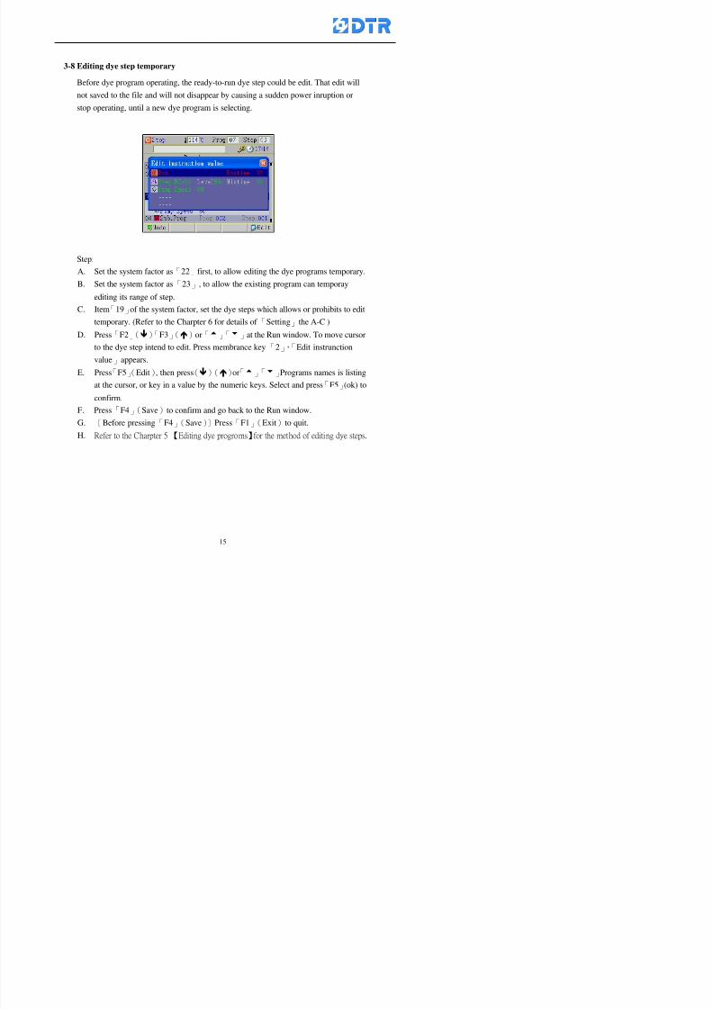
8132019 DTR 650 User Manual
httpslidepdfcomreaderfulldtr-650-user-manual 1570
3-8 Editing dye step temporary
Before dye program operating the ready-to-run dye step could be edit That edit will
not saved to the file and will not disappear by causing a sudden power inruption or
stop operating until a new dye program is selecting
Step
A Set the system factor as「22」first to allow editing the dye programs temporary
B Set the system factor as「23」 to allow the existing program can temporay
editing its range of step
C Item「19」of the system factor set the dye steps which allows or prohibits to edit
temporary (Refer to the Charpter 6 for details of 「Setting」the A-C )
D Press「F2」()「F3」()or「5」「6」at the Run window To move cursor
to the dye step intend to edit Press membrance key「2」「Edit instrunction
value」appears
E Press「F5」(Edit) then press()()or「5」「6」Programs names is listing
at the cursor or key in a value by the numeric keys Select and press「F5」(ok) to
confirm
F Press「F4」(Save)to confirm and go back to the Run window
G 〔Before pressing「F4」(Save)〕Press「F1」(Exit)to quit
8132019 DTR 650 User Manual
httpslidepdfcomreaderfulldtr-650-user-manual 1670
3-9 Creating an additon dye step during dye program running
Before and during the dye program running the users can creat an addition dye step in
the existing dye programs
3-9-1 Creating an addition dye step
To creat one addition dye step before running or during running step as follows
A Set the System Factor as「34」to allow to creat an addition step (Refer to the
Chartper 6 for details)
B In window「Run dye program」 press numeric key「8」to enter window of 「Edit
addition instruction」 to edit the single dye step first
C Press「」「」「5」
「6」to choose dye
steps press「F5」(OK)
D Press「F5」to edit the
content of dye step
E After complete editing the single dye
step Press「F4」(Run) to start running the
addition step
8132019 DTR 650 User Manual
httpslidepdfcomreaderfulldtr-650-user-manual 1770
3-9-2 Creating an addition treatment to a saved dye program
During and before the dye program running can creat an addition treatment to a
saved dye program or a dye step in a saved dye program
(1) Set the System factor as「34」to allow creating an addition step (Refer to the
Chartper 6 for details)
(2) In window「Run dye program」 press numeric key「8」to enter window of「Edit
single step」
(3) Press「」「」to choose「Sub Prog」 press「4」to move cursor and set itrsquos
dye program number and the step number by numeric keys Or stay at the
「Prog」and press「F3」(File) window appears
(4) Press「」「」to choose an addition dye program then press「F5」(OK)
(5) Press「F4」(Run)to run the addition dye program(sub-dye program)
(6) Finish to run the sub-dye program and return to the main dye program
8132019 DTR 650 User Manual
httpslidepdfcomreaderfulldtr-650-user-manual 1870
4 983120983137983155983155983155983159983151983154983140 DTR-650 provides four ranks of password for sercurity protection
(Refer to the ltTable 10gt Supplementary Table of the Password Usage for details)
First rank (User1 password) Edit delete dye programs control factors in output
testing etchellipall operating fuctions
Second rank (User2 password) Edit in output connecting table operating factors
Third rank (User3 password) Edit copy delete dye programs factors PLC run stop
Fourth rank (User4 password) Edit and modify dye programs
4-1 Entering the password
When the window of 「password」appears enter 6-digits number password by using
the numeric membrane keys then press「F5」(OK) If key-in an incorrect password
press「F3」(Del)and enter again
If the password is correct「」appears it allows to enter the relating operation
8132019 DTR 650 User Manual
httpslidepdfcomreaderfulldtr-650-user-manual 1970
4-2 Locking the data
After editing the programs and factors ensure to disable the password to protect all
programs and data of DTR-650 The way and step as follows
(1) Choose「8Others」at the main meun
(2) Choose「02Data Locking」at the sub-function field
(3) Press「F5」(OK)to confirm
(4) Return to the main menu「」disppears on the status bar that means the data
has been locking already
4-3 Setting and changing the Userrsquos password
There are four userrsquos password for setting and edit by the users themselves
User1 password Access to all operation setting
User2 password For edit in output connection table operating factors
User3 password Only for copy and delete dye programs factors PLC run stop
User4 password Only for edit and modify dye programs
Method of setting edit
(1) Choose「8Others」at main menu press「F5」(OK)
(2) Choose「7 Set Password 2」at the sub-function field press「F5」(OK)
(3) The cursor shows the default password now press「F3」(Clr)to delete Key in
a new password with 6-digit
(4) Press「F5」(OK)to complete the setting of User2 password Go back to the main
menu
8132019 DTR 650 User Manual
httpslidepdfcomreaderfulldtr-650-user-manual 2070
The four userrsquos password has to made from different group numbers Using
same password will affect the operating Please pay attention when update the
password
8132019 DTR 650 User Manual
httpslidepdfcomreaderfulldtr-650-user-manual 2170
5555 983109983140983145983156983145983150983143 983108983161983141 983120983154983151983143983154983137983149983155
5-1 Choosing a dye program
Press function key「F4」(Edit)or choose「1Dye Program」at the main menu press
「F5」(OK)
Choose「1Edit Dye prog」at the sub-function field press「F5」(OK)to enter to the
window「Sel dye program」During the dye program running it is allowed to edit asaved program or a new dye program or the current dye program in running
Method Press「」「」and「5」「6」「3」「4」to move cursor to choose
a dye program number Press「F5」(OK)to enter that dye program Press
「F1(Exit)to quit and return
Method
Directly key in the number selection box
appears at the right corner of the window
Select a program number and press「F5」
(OK) fi
8132019 DTR 650 User Manual
httpslidepdfcomreaderfulldtr-650-user-manual 2270
5-2 Creating a new dye program
Step
A Choose「1Dye Program」Press「F5」(OK)
B Choose「1Edit Dye prog」at the sub-function menu press「F5」(OK)to enter
to window「Sel dye program」
C At the window「Sel dye program」 choose an empty dye number (eg「002」)
press「F5」(OK)window《Fig 5-2-1》appears
《Fig 5-2-1》
D Press「F2」(Add) table of 「Edit dye instruction」《Fig 5-2-2》appears
E Press「F5」(Edit) the dye instruction appears at the cursor locates press「」「」
」and「5」「6」「3」「4」to move cursor to edit the instruction and its
factors
F All inserted new dye instructions would be listed in front of 「Program End」
8132019 DTR 650 User Manual
httpslidepdfcomreaderfulldtr-650-user-manual 2370
【Eg】Edit「CycRinse」
A Edit the main function step first Press「F2」
()「F3」()to move the cursor The dye
step is listing by orders Choose「CycRinse」
and press「」 there is a cursor at itrsquos value
B Move cursor to setting value「Cold」andchoose「Mix」by pressing()() Then
press「」to move cursor to「Time」and enter
itrsquos setting value as「2」Press「F5」(OK) to
complete the main function setting
C To move cursor to the parallel functionsetting field Press()()to choose the
dye step Press「」to confirm and move
cursor to choose itrsquos setting facor
D Press「F5」(OK)to move cursor to the next
parallel function
E Repeat above steps C-D until all parallel
functions setting are completed Each main
function can be operating with the
maximum 4 parallel functions
F Press「F4」(Save)to confirm and return to
the「Edit dye program」window
G Repeat the above step A E to keep on
8132019 DTR 650 User Manual
httpslidepdfcomreaderfulldtr-650-user-manual 2470
5-3 Setting the file name (for dye programs)
When a dye program is setting up it is saved by numbers automatically Optionally users
can save it by another names
Step
(1) Create a new dye program first (the Name is not available for empty dye
programs)
(2) At the window「Sel dye program」 press「F4」(File) Window《Fig5-3》appears
《Fig5-3》
(3) Use numeric 0~9「+」「-」「_」blank alphabet A~Z and symbols [ ] etchellip to
create a file name Each file name can type-in the max 8 unit Press 「3」「4」
「5」「6」to move the cursor to choose the unit It also can use the membrane
numbric key to type in The selected unit is showed in front of the cursor at the
「File」Press「OK」to confirm
(4) Quit to input to press「F3」(Clr)
(5) After complete the set up press「F5」(OK)to confirm and go back to the window
「Sel dye program」 Now the name behind the dye program number is created
8132019 DTR 650 User Manual
httpslidepdfcomreaderfulldtr-650-user-manual 2570
5-4 Inserting a program step
Insert the program step means to insert a step in the existing program step where youwant to insert a step All following steps are moved one step ahead The total number of
steps will be increased by itself Able to insert more than one step continusely at the
same time
【Example】《Fig5-4》 To insert a step「call」before「002 Rinse」
《Fig 5-4》
Step
A Enter to the dye program「002」at the window of 「Sel dye program」
(Example)
B Press「6」to move cursor to「002 Rinse」 then press「F2」(add)
C Press「F5」(Edit) then press「」「」or「5」「6」to choose program
step to modify Choose「call」and press「」to move cursor to modify itrsquos
value
8132019 DTR 650 User Manual
httpslidepdfcomreaderfulldtr-650-user-manual 2670
D Press「」「」 value of 「call」is listing at the table Choose「pH Check 」Press「F5」(OK)
E Press「F4」(Save)and press「F1」(Undo)to return to previous window Complete
to insert the「02 Call」The previous「02 Rinse」update to「03」 All following
steps are moved one step ahead Total number of steps will be increased ldquo1rdquo by
itself
Repeat the steps B-E can non-stop to insert more than one step
Quit the insert and modify ( before pressing「F4」) press「F1」(Undo) to exit
The original dye steps will be unchanged
To delete an inserted dye steps press key「F3」(Del) The step deletes
immediately
5-5 Deleting a program step
Delete the program step means to delete step which the cursor locates When that step is
deleted the step number will be updated automatically All following steps are moved up
one step It is allowed to delete more than one steps continuously at the same time
Step
A Enter to the「Edit dye program」《Fig5-5》at the window「Select dye program」
B Press「6」「5」move cursor to the want to delete
C Confirm and press「F3」(Del) Window「Confirm delete」appears Press
「F4」(Yes)
8132019 DTR 650 User Manual
httpslidepdfcomreaderfulldtr-650-user-manual 2770
D That step is deleted immediately and all following steps move up one step
Repeat the steps above can non-stop to delete more than one step
Press「F2」(No)to cancel the deletion
Press「F1」(Exit)to end
5-6 Modifying a program step
To modify the saved name and the setting value of the dyeing steps
Step
1 Choose a dye program which need to modify at the「Sel dye program」 press「F5」
(OK)
2 Press「6」「5」to move cursor to a step which need to modify Select and press
「F5」(Edit) Window of 「Edit dye instruction」appears
3 Press「F2」()「F3」()to choose the step list select it and press「」to move
the cursor to itrsquos value setting
4 Press numeric key to input the value or press「6」「5」to choose the item Press
「F5」(OK)when complete Cursor move to the next value (if need to set more
than one item)
5 Press「F4」(Save)when all setting is complete Return to「Edit dye program」
Method of parallel functionrsquos modification is same as above
Before pressing the key「「「「Save」」」」 press「F1」(Undo)to quit all modify Return
to the window of Edit dye program
All edit and modify functions mentioned of this charper are only available
for the dyeing files which already saved in the file and not being running It
8132019 DTR 650 User Manual
httpslidepdfcomreaderfulldtr-650-user-manual 2870
5-7 Copying a dye program
Copying a dye programs mean to make a copy of an dye programs to a blank dyeprogram This function is for creating new dye program rapidly
Choose「1Dye Program」at the main menu Press「F5」(OK)then press「F2」()to choose「2Copy dye prog」 Press「F5」(OK) 《Fig5-7-1》appears
《Fig 5-7-1》
《Fig 5-7-2》
【【【【Eg】】】】
Copy program 003 to program 012
Press「」「」to move cursor to theprogram「003」 press「F4」(Copy)
Program「003」shows at the top right side of
the bar
Press「」「」to move cursor to program「012」 Then press「F5」(Paste)「」appears behind the「012」That means it issuccessfully copying the program
If the target program is occupied
confirmation window「Overwrite」
When choose an program or a targetprogram can select them by using the
8132019 DTR 650 User Manual
httpslidepdfcomreaderfulldtr-650-user-manual 2970
5-8 Deleting a dye program
Choose「1Dye program」at the main menu Press「F5」(OK)then press「F2」()to choose「3Delete dye prog」 Press「F5」(OK) 《Fig5-8-1》appears
《Fig5-8-1》
《Fig5-8-2》
Press「」「」to move cursor to
choose program need to delete Eg
delete program「012」 press「F5」(Del) Confirmation window
「Confirm delete」appears
Press「F4」(Yes) to confirm delete
Repeat the above step can delete more
than one program at the same time
Press「F2」(No) to return to window
《Fig5-8-1》and not delete that program
Exit to press「F1」(Exit)and return to the
main menu
8132019 DTR 650 User Manual
httpslidepdfcomreaderfulldtr-650-user-manual 3070
6 983123983141983156983156983145983150983143DTR-650 has a built-in standard factor that can fulfill all different types of dyeing
machinesrsquos basic demand Users can also modify the factors base on their request to
fulfill their special control demand Before modify please refer to the table of each
range of Setting Factors (see the Supplementary Table)
6-1 ldquoEnable to use the program stepsrdquo setting
There are totally 64 program steps Parts of them are usually applying to the programs
In order to make more efficiently of editing programs it can「Disable」the other part
of program steps which are not usually applying or not applicable to the programs
For example dye machine with one tank it is only using step Tank B In this case itcan firstly「Disable」the program steps of Tank C When edit the program the
「Disable」rsquos steps will not appear at the cursor for choosing But this will not effect
and change the saved files The saved files can be kept as before
Step
(1) Choose「2 Factors」at the main menu Press「F5」(OK)(2) Choose「18 Dye Instruction」at the sub-function menu Then presss「F5」(OK)
Window「Edit dye ins」appears
「Enable」instruction can available to
use「Disable」instruction is temporarystop to use
Press「F2」()「F3」()to move
8132019 DTR 650 User Manual
httpslidepdfcomreaderfulldtr-650-user-manual 3170
6-2 ldquoAllow to modify dye program temporary during operatingrdquo Setting
During dye program running it can modify dye program temporary Thesemodification will not disappear by causing a sudden power interruption or power off
until select another new dye program to run
Please note that it is only for modifying the dye program temporary That program
file would not saved due to the modification If need to modify the program file and
save choose the function of Edit Dye Program to edit (Refer to the Charper 5 for the【Edit Dye Prograrm】)
6-2-1 ldquoAllow to modify all dye programsrdquo Setting
Step
(1) Choose「2 Factors」at the main menu Press「F5」(OK)
(2) Choose「02 System Factor」at the sub-function menu Then presss「F5」(OK)
Window「Edit System Factor」appears
Set to stop using temporary the「07
Rinse」press「F4」(Sel)to set it as Disable
Repeat above steps to complete all setting
Press 「F1」(Exit)to return to main menu
8132019 DTR 650 User Manual
httpslidepdfcomreaderfulldtr-650-user-manual 3270
6-2-2 ldquoAllow to modify part of dye programsrdquo Setting
【Eg】Set the number 08 or above (including number 08) is allowing to modify dye
programs during operating
Step
A Refer to【6-2-1】setting the factor as「22」to allow editing dye program
temporary during operating
(4) Press「3」「4」to edit the setting
as「Enable」 and press「F5」(OK)
Restore the standard factor by
pressing「F3」(Clr)
(5) Exit to press「F1」(Exit)and
return to window of 「Main Menu」
8132019 DTR 650 User Manual
httpslidepdfcomreaderfulldtr-650-user-manual 3370
6-2-3 ldquoAllow to modify dye steps temporaryrdquo Setting
After setting the dye programs are allowed to edit it also can set which dye steps are
allowed to edit temporary during operating
Step
(1) Choose「2 Factors」at the main menu Press「F5」(OK)
(2) Choose「19 Dye Ins control」at the sub-function menu Then presss「F5」
(OK) Window「Edit ins mode」appears
「Enable」 Allow to edit that dye step before
operating
「Disable」 Not allow to edit dye step before
operating
(3) Press「」「」to move cursor
to choose dye step Press「F4」
To enter to the「Edit dye program」from the
function menu there is a「」in front of the
file name「0-7」 means that program is not
allowing to edit during operating
8132019 DTR 650 User Manual
httpslidepdfcomreaderfulldtr-650-user-manual 3470
6-2-4 ldquoSet the dye step to keep running from the interrupt pointrdquo setting
When the dye program is operating it will disappear by causing power
interruption or sudden power off When start running again part of dye steps can
run again from the interrupt point part of them cannot
How to set
(1) Choose「2Factors」in the main menu and press「F5」(OK)
(2) Choose「20Continue mode」in the sub-function menu Press「F5」(OK) to
enter window of 「Continue Setting」
(3) Press「」「」to move cursor to choose dye steps Press「F4」(Sel)it
shows「Disable」or「Enable」for choosing Press「F5」(OK)to move cursorto the next setting
(4) Repeat above method until all setting is complete press「F1」(Exit)and
return to the main menu
8132019 DTR 650 User Manual
httpslidepdfcomreaderfulldtr-650-user-manual 3570
6-3 ldquoAllow to insert an addition dye stepsrdquo setting
During the program is running can temporary insert an addition dye step or a dye
program according to the operating actual situation Through this setting can set which
dye steps can apply or not to the program in operating
During to insert an addition step if sudden interruption or power off occurred it returns
to the main dye program automatically Before starting again should decide seriously
and set it again by actual needed
Step
(1) Choose「2Factors」at the main menu and press「F5」(OK)
(2) Choose「02System factor」and press「F5」(OK)
(3) Press「」「」to move cursor to the factor「34」and press「3」「4」to set
it as「Enable」 Press「F5」(OK)
(4) Press「F1」(Exit)to return to main menu Choose「21Addition Ins」at the
sub-function menu Press「F5」(OK)to enter the window「Addition Instruction」
(5) Press「」「」to move cursor to choose dye steps and press「F4」(Sel) Cursors
locates shows「Eable」or「Disable」 Press「F5」(OK)to move cursor to the
next dye step
(6) Repeat above method until to complete all setting press「F1」(Exit)and return
to the main menu
8132019 DTR 650 User Manual
httpslidepdfcomreaderfulldtr-650-user-manual 3670
6-4 Setting the display mode
DTR650 has three types of display mode during operating Program List mode
Schematic Diagram mode and Icon mode Users can set the display mode during
operating by factor setting
It goes back to a Program List mode when dye program ended
Step
(1) Choose「2Factors」at the main menu and press「F5」(OK)
(2) Choose「02System factor」and press「F5」(OK)
(3) Press「F2」()「F3」()to move cursor to choose「32Display mode」Press
「3」「4」 it shows「Online picture」「Instruction」「Big Icon」 choose
「Online picture」(eg) and press「F5」to confirm
8132019 DTR 650 User Manual
httpslidepdfcomreaderfulldtr-650-user-manual 3770
(4) Press「F1」(Exit)to return to the main menu
(5) The Schematic Diagram displays when the program is running (it stays at theProgram List mode when there is an alarm occurred)
Press「F4」to transfer to another display mode
It goes back to a Program List mode from Schematic Diagram Mode when dye
program ended Press numeric key「3」to view Schematic Diagram Mode again
Quit to press「F5」(Exit)
6-5 Adapt the digital input to another functions
DTR-650 has 32(0~31)input terminal it owns an standard setting when the
controller is initial According to the userrsquos demand they can change the DTR-650rsquos
anther functions of Input Terminal and PLC Input channel
The PLC Intputrsquos name can also define by the users (use IBM computer to edit and
download)
How to set
(1) Choose「2 Factor」at the main menu Press「F5」(OK)
(2) Choose「22 Input table」at the sub-function menu and press「F5」(OK)to enter
「Edit input table」
The actual input
terminal of theIBM computer
PLCrsquos input channel
8132019 DTR 650 User Manual
httpslidepdfcomreaderfulldtr-650-user-manual 3870
6-6 Adapt the digital output to another functions
DTR-650 has 32(0~31)output terminals it owns an standard setting when thecontroller is initial According to the userrsquos demand they can adapte the digital output
and the PLC outputrsquos channel to another functions The PLC Output channelrsquos name
can also define by users (use IBM computer to edit and download)
Step
(1) Choose「2 Factor」at the main menu Press「F5」(OK)
(2) Choose「23 Output table」at the main menu and press「F5」(OK)
(3) Press「F2」()「F3」()to move cursor to choose the output terminal atthe left side of the window Press「F5」(Add) the PLCrsquos output channelrsquos
name is listing at the right side of the window
(4) Press「F2」()「F3」()to move cursor to choose the PLC outputrsquos channel
If cursor moves to the PLC output channel which already linking「Add」is
not for choosing that means that output channel is already occupied
(5) Confirm the connection to press「F5」(Add) Quit to press「F4」(Del)Press「F1」(Exit)when complete all setting and return to main menu
The actual output
terminal of the
IBM computer
PLCrsquos output channel
8132019 DTR 650 User Manual
httpslidepdfcomreaderfulldtr-650-user-manual 3970
983095 983109983140983145983156983145983150983143 983156983144983141 983110983137983139983156983151983154983155DTR-650 has several kinds of control factors
Userrsquos factors System factors Temperature Control factors Speed factors Dosing
factors PID factors Analog Input Output factors standard factors etchellipPlease refer
to the supplementary table for the setting range and standard of the factors
DTR-650 has a built-in standard factor Users can edit by themselves if necessary
7-1 Modifying userrsquos factors
Userrsquos factors is setting with the Dyeing machinesrsquos PLC Programrsquos factor it is define by
the PLC Programmer
Step to edit
(1) Choose「2Factors」at main menu Press「F5」(OK)
(2) Choose「01User Factor」Press「F5」(OK)
(3) Press「F2」()「F3」()「6」「5」to move cursor up down and by page
Choose a factor need to edit then press「3」「4」to set itrsquos value Press「F5」(OK) Cursor moves to the next factor
(4) Some of factors can input numbers by the numeric membrance keys to edit If
the input is incorrect it turns to red and means the edit is not available
8132019 DTR 650 User Manual
httpslidepdfcomreaderfulldtr-650-user-manual 4070
Modifyrsquos method of the system factors temperature factors speed factors dosingfactors PID factors analog Input output factors standard factors etchellipare same asabove
If apply the library of DTR500 and DTR600 into the DTR650 the key「3」「4」may not valid to use Please use the numeric keys instead of it to key in factors itmay not effect the normal operation
Please pay a serious attention and read carefully at the factorrsquos table before modify the factors An incorrect value may effect the DTR-650 Dyeing
Machine Controllerrsquos operating After modifying factors must cancel the
password and secure data
7-2 Loading the standard factors
After modifying factors if need to restore a manufacturerrsquos standard factors of
DTR-650 The method as follows
1 Choose「2Factors」at main menu Press「F5」(OK)
「 「 ( ) 「
8132019 DTR 650 User Manual
httpslidepdfcomreaderfulldtr-650-user-manual 4170
7-3 Copying the factor
Users can build up a set of factor by themselves and make a copy and save
Step
1 Choose「2Factors」at main menu Press「F5」(OK)
2 Choose「13Restore Factor」 press「F5」(OK) window「factor will be
overwrite 」
3 Press「F4」(Yes)copy finished and saved Return to the main menu
4 Press「F2」(No)to not copy the factor and the existing factor is not change Return
to the main menu
7-4 Loading the backup factors
Users can build up a set of factor and backup files to load to DTR-650
Step1 Choose「14Backup factor」at the sub-function menu Press「F5」(OK)and
window「Factror will be overwrite」appears
2 Press「F3」(OK)to load the the backup factor them return to main menu
Press「F2」(No)to not copy the factor and the existing factor is not change
Return to the main menu
8132019 DTR 650 User Manual
httpslidepdfcomreaderfulldtr-650-user-manual 4270
983096 983119983157983156983152983157983156 983124983141983155983156983145983150983143
Before the output testing must be complete the steps as follows
A Cut off all connecting line of output terminal of DTR-650
B Stop running the PLC
C Check up the connections of all output channels to avoid damages from
incorrect connections
D Check up state of dyeing machines include the temperature pressure valves
onoff and pumpshellipetc ensure the safety for priority
8-1 Testing the Digital output
Step
1 Choose「3Output Testing」at the main menu Press「F5」(OK) 2 Choose「1Digital」at the sub function menu Press「F5」(OK) window「Digital
output testing」appears
3 Press「」「」「」to move cursor to each output channels Press「F5」(OK)
Output Name
8132019 DTR 650 User Manual
httpslidepdfcomreaderfulldtr-650-user-manual 4370
8-2 Testing the Analog output
(1) Choose「3Output Testing」at the main menu Press「F5」(OK)
(2) Choose「2Analog」at the sub function menu Press「F5」(OK) window「Analog output testing」appears
(3) Press「」「」「」to move cursor to each channels Then key in number by
the numeric membrance keys (range0~200= 0~20mA) Press「F5」(OK) there
is a output current relating to the output channel
(4) Press「F5」(OK) There is an output when the output channel with red light No
output without light onl(5) When complete the testing press「F1」(OK)to return to the main menu
8132019 DTR 650 User Manual
httpslidepdfcomreaderfulldtr-650-user-manual 4470
983097 983107983137983148983145983138983154983137983156983145983151983150
DTR-650 has Dosing and Temperature calibration
When enter to Dosing calibration must be set the Low Volume calibration first and
then High Volume calibration When enter to Temperature calibration must be set the
Low Temperature calibration first and then High Temperature calibration Must be
hightly follow this orders seriously
9-1 Calibration of Low Volume Tank
Step
A Choose「4Calibration」at the main menu Press「F5」(OK)
B Choose「Dosing 0 low vol」at the sub function menu Press「F5」(OK) window
appears
C Fill the Dosing Tank to a half level input value shows how much the water level
If it stays ldquo0rdquo check the connection and the factor setting is correct or not
And connect the pressure sensorrsquos output channel to the Current Meter to ensure
that sensor works or not
8132019 DTR 650 User Manual
httpslidepdfcomreaderfulldtr-650-user-manual 4570
D Fill the Dosing Tank to 50ml (Calcalate from the bottom side of the pressure
sensor steel tube) input value should show 4~6 (input value must between
0~10) Then enter the water volume The setting volume is relating the water
levelrsquos water value (litre as unit) input range 0~80 Set as「 「「 「0000 0000 0000 0000」」」」is strongly is strongly is strongly is strongly
receommend receommend receommend receommend Press「F5」(OK)to complete [Calibration of Low Volume Tank 1
is same as above method]
9-2 Calibration of High Volume Tank
Step
A Choose「4Calibration」at the main menu Press「F5」(OK)
B Choose「Dos 0 high vol」at the sub function menu Press「F5」(OK) window of
「Calibrate high 」appears
C Fill the Dosing Tank to a full level input value should be larger than 30 enter
the current water level which relates to the water volume Enter the range within
100~2500 Then press「F5」(OK) to complete the calibrate the high volume tank
8132019 DTR 650 User Manual
httpslidepdfcomreaderfulldtr-650-user-manual 4670
9-3 Temperature Calibration
Step
A This function is for adjusting the DTR650rsquos accuracy of Temperature Control It
must be using with the special terminal which is only for DTR650
B Choose「4Calibration」at the main function menu and press「F5」(OK)
C Choose「3Low Temp」at the sub-function menu Press「F5」(OK)and《Fig9-3》
appears insert the DTR650rsquos low temperature calibration terminal to the temperature
input terminal wait for the jumping value to stable down then press「F5」(OK) then
to adjust the high temperature calibration
D Adjusting the High Temperature Calibrationrsquos method is same as above But usersusersusersusers
must be using the High Temperature Terminalmust be using the High Temperature Terminalmust be using the High Temperature Terminalmust be using the High Temperature Terminal whichwhichwhichwhich is specially for DTR650 onlyis specially for DTR650 onlyis specially for DTR650 onlyis specially for DTR650 only
《Fig 9-3》
8132019 DTR 650 User Manual
httpslidepdfcomreaderfulldtr-650-user-manual 4770
10 983122983141983139983151983154983140983155 983151983142 983108983161983141 983120983154983151983143983154983137983149983155
It contains the past 15 days of temperature curves of running history
Checking method
(1) Choose「5Dye Record」at main menu press「F5」(OK)
(2) Sub-function menu shows the set up date of the past 15 days dye programs
Listing by the lastest set up date
(3) Choose a program date and press「F5」(OK) it appears window「Temp
record」
(4) Press「」「」to move the white line in the box one minute by moving once
(5) Press「3」「4」to move the line to check the time period 2 hours by moving once
The yellow selecting line of the「24 hours operating state」is repectively moving
The curve info is show in the curve box Left side of the widnow appears the
relating running info the time is the time value of the line locates at
(6) Check more details of the temperature info to press numeric key「middot」 a bright red line
appears in the selecting box this line is to check the starting point of the
temperature inforsquos time period Then press「」to move the white line to the end
point of the time period The temperature info between the starting point and end
point are appears at the right side of the window Press「middot」to return to the preious
curve page
(7) Check more details of the alarm infor To perss numeric key「7」「9」 the alarmrsquos
details is listing by orders
(8) Press「F1」(exit) to return
8132019 DTR 650 User Manual
httpslidepdfcomreaderfulldtr-650-user-manual 4870
11 983125983155983137983143983141 983151983142 983117983141983149983151983154983161 983107983137983154983140
DTR-650 supports 32MB or above Compact Flash Card which can transfer and save all
information for 4 sets of DTR-650 Including library files schematic diagram icon
image PLC program dye program factor and confiruration files etchellip Use the CF Card
to up download and swap the information of DTR-650 promptly install the relating
device and program updates
DTR-650 CF Card with bank 1 to bank 4 can save 4 sets information of Dyeing
Machines When download or save files should choose the BANK first
《Fig11-1》
8132019 DTR 650 User Manual
httpslidepdfcomreaderfulldtr-650-user-manual 4970
11-1 Downloading data
1 Firmly insert the CF card into the DTR-650rsquos PCMCIA connector Ensure it is
wholely and firmly inserted if the card is not totally inserted or the card do not
touch in all to the connector there will be an error occurred and cannot
updownload or interrupted during operation
2 Choose「6Memory Card」at the main menu and press「F5」(OK) 《Fig11-1》
appears Information of Bank「1」shows at the left hand side of the window press
number 1-4 by using numeric keys to choose the BANK Check the
information in the Bank seriously which is exactly need to download to the
DTR650
3 Press()()「6」「5」to move cursor to the sub-function menu to choose
the downloading items Press「F5」(OK) window appears「Stop PLC run before
access memory card Stop the PLC run」 Press「F5」(YES) to stop PLC
running
4 Press「F5」(OK) window appears Confirm to update or not the DTR-650rsquos
information As that downloading will be replace the DTR-650rsquos information
(that means the existing information of the DTR-650 will be removed and
replaced)
5 Press「F4」(YES)to download the information from the DTR-650 to the CF
Card Return to the main menu when finish
8132019 DTR 650 User Manual
httpslidepdfcomreaderfulldtr-650-user-manual 5070
Ensure inserting firmly the CF card into the DTR-650 unless it will cause
error or cannot Updownload data
Never remove CF card during transferring or updownloading data Until it
is all completed
DTR-650rsquos dyeing program is not compatible with DTR-500 and
DTR-600 Never use CF card to transfer data among them
11-2 Storing and transfering data
1 Insert the CF Card to the DTR-650
2 Choose「6Memory Card」at the main menu and press「F5」(OK) 《Fig11-1》
appears Left hand side of the window shows the data of BANK 1 press numeric
keys 1-4 to select the BANK To confirm the put the data in the DTR-650 to the CF
Card The existing data of that bank will be replaced and covered by the new data (if
that bank is already occuplied)
3 Choose「23Save Dye prog」(Example)at the sub-funciton menu press「F5」(OK)to confirm Window「Update memory card data」appears
4 Press「F5」(OK)to transfer the data to the CF card Return to the main menu
5 Put the CF card into another DTR-650 and follow the operating method of 「11-1
Downloading data」」」」can transfer and swap data with more than one set of
DTR-650
8132019 DTR 650 User Manual
httpslidepdfcomreaderfulldtr-650-user-manual 5170
12 983123983156983137983156983141 983137983150983140 983113983150983142983151983154983149983137983156983145983151983150
The state and information is including the Dyeing Machinersquos state of Digit Input output
Analog Input output Temperature control PID Dosing PID Pressure different PID
software system information and alarm record This information is for checking at any
time
12-1 Input Output state
Step
1 Choose「7Info and state」at main menu and press「F5」(OK)
2 Choose「01Digital IO put」at the sub-function menu then press「F5」(OK)
「Digital In Out State」0=None 1=Input
3 Press「F1」(Exit)to return to main menu
Same method for checking the temperature control analog dosing pressure
different etchellip
12-2 Checking the system information
Step
1 Choose「7Info and state」at main menu and press「F5」(OK)
2 Choose「11 System info」at sub-function field press「F5」(OK)Window
「System Information」appear
System information is including System info(software version) Library doc
Icon files Schematic file Definition file hardare state Config File Commandinstruction icon PLC file etc
8132019 DTR 650 User Manual
httpslidepdfcomreaderfulldtr-650-user-manual 5270
12-3 Checking the operating alarm record
Operating record shows the latest 40 operating items and alarm records including
the time and content of the alarm
A) Choose「7 Info and state」
and press「F5」(OK)
B) Choose「12Alarm logs」at
the sub-funciton menu then
press「F5」(OK)
8132019 DTR 650 User Manual
httpslidepdfcomreaderfulldtr-650-user-manual 5370
13 983105983140983146983157983155983156983145983150983143 983156983144983141 983107983151983150983156983154983137983155983156
The displaysrsquos brightness can be adjusted if necessary
Step
1 Choose「8Others」at main menu press「F5」(OK)
2 Choose「01Contrast」at sub-function menu press「F5」(OK) window「Set
Contrast」appears
3 Press「」「」to move the bar to set the brightness then press「F5」(OK)Window appears「Please reboot the system」
4 Press「F5」(OK)to return to main menu and re-boot the DTR-650 to complete
adjusting the brightness
8132019 DTR 650 User Manual
httpslidepdfcomreaderfulldtr-650-user-manual 5470
14 983123983156983151983152 983154983157983150983150983145983150983143 983156983144983141 983120983116983107 983120983154983151983143983154983137983149
Before testing the Input output testing transfer of the PLC program must stop the PLC
running
Step
1 Choose「8Others」at the main menu Press「F5」(OK)
2 Choose「04 PLC Stop」at sub-function menu Press「F5」(OK) window
「Password」appears
3 Enter password and press「F5」(OK) Window「Stop the PLC run」appears
4 Press「F4」(Yes)and window「PLC Stop」appear Press「F5」(OK) Now
the PLC is stop running and return to the main menu
All testing cannot operate when the PLC is running
Editing dye program and the relating operation can
perform with the PLC running together
8132019 DTR 650 User Manual
httpslidepdfcomreaderfulldtr-650-user-manual 5570
15 983123983141983156983156983145983150983143 983156983144983141 983156983145983149983141
Step
1 Press「8Others」at the main menu Press「F5」(OK)
2 Choose「10Set date time」at the sub-function menu Press「F5」(OK) window
「Set date time」appears
3 Press「F5」(Edit) to move cursor by 「3」「4」 enter the time value at the
cursor locates
4 Press「F5」(OK)to complete the modify Press「F1」(Exit)to return to main
menu
5 Press「F1」(Exit)if not modify and return to main menu
8132019 DTR 650 User Manual
httpslidepdfcomreaderfulldtr-650-user-manual 5670
1166 983123983123983157983157 983152 983152 983152 983152983148983148983141983141983149983149983141983141983150983150983156 983156 983137983137983154 983154 983161983161 983124 983124 983137983137983138983138983148983148983141983141
TTTTTTTTaaaaaaaabbbbbbbblllllllleeeeeeee 11111111 【Dye Instruction】
Code Icon Instruction Code Icon Instruction
000 End 016 Inject C
001 Start 017 Dosing BV
002 Heat 018 PH
003 Cool 019 Addsalt B
004 Flow Fill 020 Addsalt C
005 Level Fill 021 Ana Fill
006 Drian 022 Lock Fill007 Rinse 023 Lock Level
008 Run 024 Low Rinse
009 Call 025 Cyc Rinse
010 Prep B 026 Rinse B
011 Addsalt B 027 Rinse C
012 Dosing B 028 Temp
013 Inject B 029 Nozzle Pressure
014 Prep C 030 Main Pump
015 Dosing C 031 Pump Speed
8132019 DTR 650 User Manual
httpslidepdfcomreaderfulldtr-650-user-manual 5770
Table 2 【【【【Alarm】】】】
System Alarm Must stop operating and check up to solve problems before restarting
the machine
Running Alarm It is a reminder Not effect the operating of DTR-650
Userrsquos Alarm Total of 32 Users can define themselves and use it when edit the PLC
Program (do not listing below)
No System Alarm No Running Alarm
1 PLC program not running 16 Temp ctrl 0 Grad too slow
2 Main temp sensor error 17 Temp ctrl 0 Grad too fast
3 Not at Run window 18 Temp ctrl 0 Hold temp too low
4 Exceeding max temp 19 Temp ctrl 0 Hold temp too high
5 - 20 Temp ctrl 1 Grad too slow6 - 21 Temp ctrl 1 Grad too fast
7 - 22 Temp ctrl 1 Hold temp too low
8 Communication error 23 Temp ctrl 1 Hold temp too high
9 Slave not answer 24 Temp ctrl 2 Grad too slow
10 PLC 0 not answer 25 Temp ctrl 2 Grad too fast
11 PLC 1 not answer 26 Temp 2 Hold temp too low12 Display not answer 27 Temp 2 Hold temp too high
13 Lower power voltage 28 Temp ctrl 3 Grad too slow
14 - 29 Temp ctrl 3 Grad too fast
15 - 30 Temp3 Hold temp too low
31 Temp3 Hold temp too high
32 Dosing 0 injection too slow
33 Dosing 0 injection too fast
34 Dosing 1 injection too slow
35 Dosing 1 injection too fast
8132019 DTR 650 User Manual
httpslidepdfcomreaderfulldtr-650-user-manual 5870
TTTTTTTTaaaaaaaabbbbbbbblllllllleeeeeeee 33333333 【【【【System factor】】】】
No Description Std Range amp Definition
1 ID No 000 000- 100 Controller no
2 Communication Rate 4800Bps 2400 4800 9600 19200 38400
3 Display language Chinese English Chinese
4 Temp display mode and
5 Maxmium temperature 145 025 ~ 145 6 Type of external PLC Default PLC32DPLC32PLC16Default
7 Number of external PLC NANA 1 unit connect
2 unit connect
8Communication Rate of
PLC9600Bps 2400 4800 9600 19200
9 Set point 1 085 000 ~ 145
If signal source is temperaturethe setting value is thetemperature value If the signal
source is Analog Input 6~17 then
setting value for Analog input is 0 ndash
100 and relates Analog
Input14~020mA
10 Source 1 Sensor0Sensor 0 ~5
Analog input 0 ~1111 Set point 2 092 Same as 09
12 Source 2 PT100 1 Same as 10
13 Set point 3 085 Same as 09
14 Source 3 PT100 2 Same as 10
15 Set point 4 092 Same as 09
16 Source 4 PT100 3 Same as 1017 Set point 5 085 Same as 09
18 Source 5 PT100 4 Same as 10
19 Set point 6 092 Same as 09
8132019 DTR 650 User Manual
httpslidepdfcomreaderfulldtr-650-user-manual 5970
29 Min cyclic time of cloth 100sec 0 ~ 255 sec
30 Max cyclic time of cloth 240sec 0 ~255 sec
31Standard cyclic time of
cloth
180 000 ~ 255 sec
32 Display ModeProgram
List
Program list Schematic Diagram
Icon mode
33 CF card format Standard of
DTR CF
Card
Standard of DTR CF Card V20
Standard CF Card
34 Addition step Disable Disable Enable35 Mode Com 3
CouplingEsure Com 3 is the communication
port of the Central or Coupling
36Com 3 Communication
rate9600 Central communication speed
8132019 DTR 650 User Manual
httpslidepdfcomreaderfulldtr-650-user-manual 6070
TTTTTTTTaaaaaaaabbbbbbbblllllllleeeeeeee 44444444 【【【【Temperature Cotnrol Factor】】】】
No Factor Definition Standard Range and Definition
01 PT No PT-0 PT 0~5 PT-100 Input number
02 Max working temp 140 000~140
03 Output mode 0 0~2
04 Alarm time of gardient 240sec 000~255 sec
05 Alarm mode of gradient Always AlwaysOnceNone
06 Control mode of gradient Heating orCooling
interlocked
Heating and Cooling interlocked
No limitation
07 Alarm range of HoldTemp 03 01~20
08 Alarm time for HoldTemp 240sec 000~255sec
09 Alarm mode of HoldTemp Always AlwaysOnceNone
10 Control mode ofHoldTemp
Heating only Only heating and cooling Cooling whenalarm occurred Only heating andcooling No limitation when alarmHeating only
11 Porportional Band 100 000~250
12 Integral band 128 sec 000~255 sec
13 Differential time 04 sec 00~20 sec
14 Min transit gradient 02 00~50
15 Transit rate 20 times 00~50 times (020= 2 times)
16 PID initial output value 010 000~100
17 ONOFF cycle time 10 sec 05~25 sec
Onoff valve set as 010 sec
Proportional valve set as 020 sec
18 Time down count mode Mode 0 0~10 = The time down count range from「Factor 20 + target temp」to「Target
8132019 DTR 650 User Manual
httpslidepdfcomreaderfulldtr-650-user-manual 6170
TTTTTTTTaaaaaaaabbbbbbbblllllllleeeeeeee 55555555 【【【【Speed Factor】】】】
No Factor Definition Standard Range amp Definition
01 Input Number Speed input 0 Speed input 0~11
02 Average times 05 times 01~10
03 Sensor Number 008pcs 001~255
04 Roller Dimension 250mm 050~500
05 Max cloth speed 200mmin 001~25506 Min cloth speed 020mmin 001~255
07 Alarm delay time 240sec 001~255
08 Alarm mode Every oncenoneevery
09 Alarm range () 020 001~255
10 Proportional band 100 001~255
11 Integer band 128 001~25512 Differential time 000 001~200
13 Initial speed () 020 001~255
14 Control cycle ti(01sec) 05 01~30
15 First cycle time(01sec) 10 01~30
16 Speed increase limit () 010 001~100
17 Speed decrease limit () 010 001~100
18 Min speed() 005 001~100
19 Manual speed adjust () 005 001~100
20 Manual initial speed() 020 001~100
21 Stopping speed() 010 001~100
22 Switch speed() 020 001~100
23 Not used
24 Speed decrease turns 03turns 01~50
8132019 DTR 650 User Manual
httpslidepdfcomreaderfulldtr-650-user-manual 6270
Table 6 【【【【Dosing Factors】】】】
No Description Range Range and Explanation
1 Analog input no Analog input 0 Analog input no 0 ~11
2Alarm delay time for
dosing240 sec 000 ~255 sec
3 Alarm time for dosing Every Every Once None
4 Proportional band 100 000 ~255 sec Factor P
5 Integer band 128 000 ~255 sec Factor I6 Differential time 04 00 ~20 Factor D
7 Max adjust rate 150 50~ 255
8 Initial factor for dosing 10 000 ~100
9 User curve section 0 10 Gradient of sect1 for dosing curve9
10 User curve section 1 10 Gradient of sect2 for dosing curve9
11 User curve section 2 10 Gradient of sect3 for dosing curve9
12 User curve section 3 10 Gradient of sect4 for dosing curve9
13 User curve section 4 10 Gradient of sect5 for dosing curve9
14 User curve section 5 10 Gradient of sect6 for dosing curve9
15 User curve section 6 10 Gradient of sect7 for dosing curve9
16 User curve section 7 10 Gradient of sect8 for dosing curve9
17 User curve section 8 10 Gradient of sect9 for dosing curve9
18 User curve section 9 10 Gradient of sect10 for dosing curve9
19 Min water level 05 00~ 10 04~20mA percentagechange to the userrsquos factor setting
20 Output value for Tank
clean
100 000~ 100
Injected percentage of dosing valve
in dosing End period
This factor will be invalided if usingONOFF dosing valve
21 Full range 100 001~255 Self-adjustment cannotchange
22 Range ratio 001001~255 Self-adjustment cannot
change
8132019 DTR 650 User Manual
httpslidepdfcomreaderfulldtr-650-user-manual 6370
【【【【TTaabbllee 77 】】】】Pressure Deviation Factors
No Description Std Range amp Definition
1 Analog input number + Analog in 0 Analog in 0~11
2 Analog input number - Analog in 1 Analog in 0~11
3 Input mode Pressure Pressure Pressure deviation
4 Full range 050x01Kgcm
001~255
5 Range ratio 001 001~255
6 Alarm delay time 100sec 001~255
7 Alarm mode Every oncenone
8 Alarm range 010 001~255
9 Proportional band 100 001~255
10 Integer band 128 001~255
11 Differential time 00 00~20
12 PID Init output value 010 001~255
13 Cycle time 10 03~30
14 First cycle time 030 003~100
15 Max adjust rate 010 001~100
8132019 DTR 650 User Manual
httpslidepdfcomreaderfulldtr-650-user-manual 6470
【【【【TTaabbllee 88 】】】】Definition of Analog Input
No Description Standard Range and Explanation
01 PT 0 correction standard DIN std DIN std JIS std
02 PT 0 correction +0 +- 9
03 PT 1 correction standard DIN std DIN std JIS std
04 PT 1 correction +0 +- 9
05 PT 2 correction standard DIN std DIN std JIS std
06 PT 2 correction +0 +- 9
07 PT 3 correction standard DIN std DIN std JIS std
08 PT 3 correction +0 +- 9
09 PT 4 correction standard DIN std DIN std JIS std
10 PT 4 correction +0 +- 9
11 PT 5 correction standard DIN std DIN std JIS std
12 PT 5 correction +0 +- 9
13 Analog input 0 define 4 ~ 20mA 0 ndash 20mA 4 ndash 20mA
14 Analog input 0 average times 10 times 01- 20 times
15 Analog input 0 min value 0000 0000 - 1000
16 Analog input 0 max value 100 0001 - 9999
17-60 Analog input 1~11 Same as Analog input 0
【【【【 】】】】 fi i i f A O
8132019 DTR 650 User Manual
httpslidepdfcomreaderfulldtr-650-user-manual 6570
【【【【TTaabbllee 99 】】】】Definition of Analog Output
No Description Standard Range and explanation
61 Analog output 0 define Control byPLC
Control by PLC
Temperature control PID0 output
Temperature control PID1 output
Temperature control PID2 output
Speed PID3 output
Dosing PID0 output Dosing PID1output
Pressure different PID0 outputPressure different PID1 output
Main temperature output
62 Mode of Analog ouptput0 4 ~20mA 0 ndash20mA 4 ndash 20mA
63-84 Analog output 1~11 Same as Analog output 0
【【【【TTaabbllee 1100】】】】Value Table 0 amp 1
No Description Range Std Range and explanation
1 Analog input no 000~011 000 Analog input no
2 Data ratio 001~255 100 Multiple by factors
3~53 0~98 000~255 000-100 Analog input 0~98 data
【【【【 】】】】St t Li t
8132019 DTR 650 User Manual
httpslidepdfcomreaderfulldtr-650-user-manual 6670
【【【【TTaabbllee 1111】】】】State List
No Description Range Standard Range and explanation
1 Display setting 1 0~255 205 See remarks at next page
2 Display setting 2 0~255 208
3 Display setting 3 0~255 209
4 Display setting 4 0~255 017
5 Display setting 5 0~255 0186 Display setting 6 0~255 019
7 Display setting 7 0~255 020
8 Display setting 8 0~255 021
9 Display setting 9 0~255 000
10 Display setting 1 0~255 000
11 Display setting 2 0~255 000
12 Display setting 3 0~255 000
13 Display setting 4 0~255 000
14 Display setting 5 0~255 000
15 Display setting 6 0~255 000
16 Display setting 7 0~255 000
Remarks
8132019 DTR 650 User Manual
httpslidepdfcomreaderfulldtr-650-user-manual 6770
0 = No display 1~255 = Display type of number
1~16 Content of PLC VB0~15
No 1 corresponding to VB0
No 16 corresponding to VB15
17~32 Content of PLC DB0~15
No 17 corresponding to DB0
No 32 corresponding to DB15
33~46 Content of PLC CNT0~29
No 33 corresponding to CNT0
No 46 corresponding to CNT29 47~78 Content of dyeing instruction 0~31 CNT0
No 47 corresponding to system instruction to No 0 of CNT0
No 78 corresponding to system instruction to No 31 of CNT0rsquos content
79~110 Dyeing instruction 0~31 of CNT0rsquos setting
111~142 Content of Dyeing instruction 0~31 CNT1No 111 corresponding to dyeing instruction No 0 of CNT1
No 142 corresponding to dyeing instruction No 31 of CNT1rsquos content
143~174 Dyeing instruction 0~31 of CNT1rsquos setting
175~204 Content of PLC HTIM0~29
No 175 corresponding to HTIM0
No 204 corresponding to HTIM29
205 Loading
206 Ratio 1
207 Ratio 2208 Ratio 1 x Loading
209 Ratio 2 x Loading
210 Fix value
211 Value Table 1 matching result
212 Value Table 2 matching result
213 Value Table 1 setting214 Value Table 2 setting
215 Pressure control PID0 different pressure value
216 Pressure control PID1 different pressure value
TTTTTTTTaaaaaaaabbbbbbbblllllllleeeeeeee 1122 【【【【Usage of password】】】】
8132019 DTR 650 User Manual
httpslidepdfcomreaderfulldtr-650-user-manual 6870
No Main FunctionFactor Sub Function Factor Password Rank
1 Run None
2 Dye program User3 or above
3 Control factor
- User factor User 1
- System factor User 1
- Temp PID 0
- Temp PID 1 User 1- Speed PID 0 User 1
- Dosing PID 0 User 1
- Dosing PID 1 User 1
- Pressure PID 0 User 1
- Pressure PID 1 User 1
- Analog IO User 1
- Load standard factor User 2 or above- Load a copied factor User 2 or above
- Copy factor User 2 or above
- Value table 0 User 1
- Value table 1 User 1
- Information and state User 1
- Dye instruction User 1
- Edit dye instruction setting User 14 Output testing User 2 or above
5 Calibration User 2 or above
6 Dye record None
7 CF card User 1
8 Info and state None
9 Others
- Contrast User3 or above
- Data Locking None
- PLC Run User 1
- PLC Stop User 1
- Password setting User 1
TTTTTTTTaaaaaaaabbbbbbbblllllllleeeeeeee 1133 【【【【Technical Data】】】】
8132019 DTR 650 User Manual
httpslidepdfcomreaderfulldtr-650-user-manual 6970
TTTTTTTTaaaaaaaabbbbbbbblllllllleeeeeeee 1133 【【【【Technical Data】】】】
1 Temperature Control
- Range 10~145(plusmn1)
- Mode Proportional or PWM
- Sensor PT100 (JIS or DIN standard)
2 Input and output channel
- Digital Input 32 DC24V PNP- Digital Output 32 DC24V 054A Relay connect point
- Analog Input 4 04~20 mA
- Analog Output 4 0~20mA 或 4~20 mA
3 Communication port 3 RS-232 amp 0~20 mAx1 RS485x 2
4 Dye program
- Number 15000 Steps
- Standard step 61Heating Cooling Fill Drain RinseDosingetc
5LCD module and Display
langage
Chinese
English
320 x 240 TFT color display with
more language
6 CF card connector 1 PCMCIA standard
7 Membrane Keyboard- Number Key 10 [0]~[9] Input factors
- Function Key 5 [F1]~[F5] function selecting
- Operation Key 2 [Start] [Stop]
- Auxiliary Key 7 [][][][][Esc] [larr][OK] [bull]
8 Operating Condition
- Temperature 5~45
- Humidity ≦85 (25)
9 Power supply
V l DC 24V
8132019 DTR 650 User Manual
httpslidepdfcomreaderfulldtr-650-user-manual 7070
70
983108983124983122983085650 983113983150983152983157983156 983119983157983156983152983157983156 983120983151983154983156983145983150983143 (983138983137983139983147983155983145983140983141 983158983145983141983159)
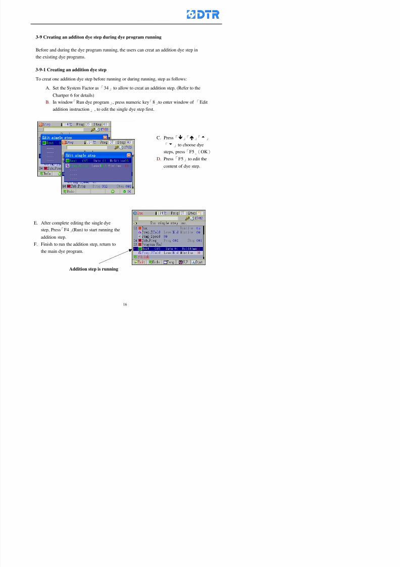
8132019 DTR 650 User Manual
httpslidepdfcomreaderfulldtr-650-user-manual 1670
3-9 Creating an additon dye step during dye program running
Before and during the dye program running the users can creat an addition dye step in
the existing dye programs
3-9-1 Creating an addition dye step
To creat one addition dye step before running or during running step as follows
A Set the System Factor as「34」to allow to creat an addition step (Refer to the
Chartper 6 for details)
B In window「Run dye program」 press numeric key「8」to enter window of 「Edit
addition instruction」 to edit the single dye step first
C Press「」「」「5」
「6」to choose dye
steps press「F5」(OK)
D Press「F5」to edit the
content of dye step
E After complete editing the single dye
step Press「F4」(Run) to start running the
addition step
8132019 DTR 650 User Manual
httpslidepdfcomreaderfulldtr-650-user-manual 1770
3-9-2 Creating an addition treatment to a saved dye program
During and before the dye program running can creat an addition treatment to a
saved dye program or a dye step in a saved dye program
(1) Set the System factor as「34」to allow creating an addition step (Refer to the
Chartper 6 for details)
(2) In window「Run dye program」 press numeric key「8」to enter window of「Edit
single step」
(3) Press「」「」to choose「Sub Prog」 press「4」to move cursor and set itrsquos
dye program number and the step number by numeric keys Or stay at the
「Prog」and press「F3」(File) window appears
(4) Press「」「」to choose an addition dye program then press「F5」(OK)
(5) Press「F4」(Run)to run the addition dye program(sub-dye program)
(6) Finish to run the sub-dye program and return to the main dye program
8132019 DTR 650 User Manual
httpslidepdfcomreaderfulldtr-650-user-manual 1870
4 983120983137983155983155983155983159983151983154983140 DTR-650 provides four ranks of password for sercurity protection
(Refer to the ltTable 10gt Supplementary Table of the Password Usage for details)
First rank (User1 password) Edit delete dye programs control factors in output
testing etchellipall operating fuctions
Second rank (User2 password) Edit in output connecting table operating factors
Third rank (User3 password) Edit copy delete dye programs factors PLC run stop
Fourth rank (User4 password) Edit and modify dye programs
4-1 Entering the password
When the window of 「password」appears enter 6-digits number password by using
the numeric membrane keys then press「F5」(OK) If key-in an incorrect password
press「F3」(Del)and enter again
If the password is correct「」appears it allows to enter the relating operation
8132019 DTR 650 User Manual
httpslidepdfcomreaderfulldtr-650-user-manual 1970
4-2 Locking the data
After editing the programs and factors ensure to disable the password to protect all
programs and data of DTR-650 The way and step as follows
(1) Choose「8Others」at the main meun
(2) Choose「02Data Locking」at the sub-function field
(3) Press「F5」(OK)to confirm
(4) Return to the main menu「」disppears on the status bar that means the data
has been locking already
4-3 Setting and changing the Userrsquos password
There are four userrsquos password for setting and edit by the users themselves
User1 password Access to all operation setting
User2 password For edit in output connection table operating factors
User3 password Only for copy and delete dye programs factors PLC run stop
User4 password Only for edit and modify dye programs
Method of setting edit
(1) Choose「8Others」at main menu press「F5」(OK)
(2) Choose「7 Set Password 2」at the sub-function field press「F5」(OK)
(3) The cursor shows the default password now press「F3」(Clr)to delete Key in
a new password with 6-digit
(4) Press「F5」(OK)to complete the setting of User2 password Go back to the main
menu
8132019 DTR 650 User Manual
httpslidepdfcomreaderfulldtr-650-user-manual 2070
The four userrsquos password has to made from different group numbers Using
same password will affect the operating Please pay attention when update the
password
8132019 DTR 650 User Manual
httpslidepdfcomreaderfulldtr-650-user-manual 2170
5555 983109983140983145983156983145983150983143 983108983161983141 983120983154983151983143983154983137983149983155
5-1 Choosing a dye program
Press function key「F4」(Edit)or choose「1Dye Program」at the main menu press
「F5」(OK)
Choose「1Edit Dye prog」at the sub-function field press「F5」(OK)to enter to the
window「Sel dye program」During the dye program running it is allowed to edit asaved program or a new dye program or the current dye program in running
Method Press「」「」and「5」「6」「3」「4」to move cursor to choose
a dye program number Press「F5」(OK)to enter that dye program Press
「F1(Exit)to quit and return
Method
Directly key in the number selection box
appears at the right corner of the window
Select a program number and press「F5」
(OK) fi
8132019 DTR 650 User Manual
httpslidepdfcomreaderfulldtr-650-user-manual 2270
5-2 Creating a new dye program
Step
A Choose「1Dye Program」Press「F5」(OK)
B Choose「1Edit Dye prog」at the sub-function menu press「F5」(OK)to enter
to window「Sel dye program」
C At the window「Sel dye program」 choose an empty dye number (eg「002」)
press「F5」(OK)window《Fig 5-2-1》appears
《Fig 5-2-1》
D Press「F2」(Add) table of 「Edit dye instruction」《Fig 5-2-2》appears
E Press「F5」(Edit) the dye instruction appears at the cursor locates press「」「」
」and「5」「6」「3」「4」to move cursor to edit the instruction and its
factors
F All inserted new dye instructions would be listed in front of 「Program End」
8132019 DTR 650 User Manual
httpslidepdfcomreaderfulldtr-650-user-manual 2370
【Eg】Edit「CycRinse」
A Edit the main function step first Press「F2」
()「F3」()to move the cursor The dye
step is listing by orders Choose「CycRinse」
and press「」 there is a cursor at itrsquos value
B Move cursor to setting value「Cold」andchoose「Mix」by pressing()() Then
press「」to move cursor to「Time」and enter
itrsquos setting value as「2」Press「F5」(OK) to
complete the main function setting
C To move cursor to the parallel functionsetting field Press()()to choose the
dye step Press「」to confirm and move
cursor to choose itrsquos setting facor
D Press「F5」(OK)to move cursor to the next
parallel function
E Repeat above steps C-D until all parallel
functions setting are completed Each main
function can be operating with the
maximum 4 parallel functions
F Press「F4」(Save)to confirm and return to
the「Edit dye program」window
G Repeat the above step A E to keep on
8132019 DTR 650 User Manual
httpslidepdfcomreaderfulldtr-650-user-manual 2470
5-3 Setting the file name (for dye programs)
When a dye program is setting up it is saved by numbers automatically Optionally users
can save it by another names
Step
(1) Create a new dye program first (the Name is not available for empty dye
programs)
(2) At the window「Sel dye program」 press「F4」(File) Window《Fig5-3》appears
《Fig5-3》
(3) Use numeric 0~9「+」「-」「_」blank alphabet A~Z and symbols [ ] etchellip to
create a file name Each file name can type-in the max 8 unit Press 「3」「4」
「5」「6」to move the cursor to choose the unit It also can use the membrane
numbric key to type in The selected unit is showed in front of the cursor at the
「File」Press「OK」to confirm
(4) Quit to input to press「F3」(Clr)
(5) After complete the set up press「F5」(OK)to confirm and go back to the window
「Sel dye program」 Now the name behind the dye program number is created
8132019 DTR 650 User Manual
httpslidepdfcomreaderfulldtr-650-user-manual 2570
5-4 Inserting a program step
Insert the program step means to insert a step in the existing program step where youwant to insert a step All following steps are moved one step ahead The total number of
steps will be increased by itself Able to insert more than one step continusely at the
same time
【Example】《Fig5-4》 To insert a step「call」before「002 Rinse」
《Fig 5-4》
Step
A Enter to the dye program「002」at the window of 「Sel dye program」
(Example)
B Press「6」to move cursor to「002 Rinse」 then press「F2」(add)
C Press「F5」(Edit) then press「」「」or「5」「6」to choose program
step to modify Choose「call」and press「」to move cursor to modify itrsquos
value
8132019 DTR 650 User Manual
httpslidepdfcomreaderfulldtr-650-user-manual 2670
D Press「」「」 value of 「call」is listing at the table Choose「pH Check 」Press「F5」(OK)
E Press「F4」(Save)and press「F1」(Undo)to return to previous window Complete
to insert the「02 Call」The previous「02 Rinse」update to「03」 All following
steps are moved one step ahead Total number of steps will be increased ldquo1rdquo by
itself
Repeat the steps B-E can non-stop to insert more than one step
Quit the insert and modify ( before pressing「F4」) press「F1」(Undo) to exit
The original dye steps will be unchanged
To delete an inserted dye steps press key「F3」(Del) The step deletes
immediately
5-5 Deleting a program step
Delete the program step means to delete step which the cursor locates When that step is
deleted the step number will be updated automatically All following steps are moved up
one step It is allowed to delete more than one steps continuously at the same time
Step
A Enter to the「Edit dye program」《Fig5-5》at the window「Select dye program」
B Press「6」「5」move cursor to the want to delete
C Confirm and press「F3」(Del) Window「Confirm delete」appears Press
「F4」(Yes)
8132019 DTR 650 User Manual
httpslidepdfcomreaderfulldtr-650-user-manual 2770
D That step is deleted immediately and all following steps move up one step
Repeat the steps above can non-stop to delete more than one step
Press「F2」(No)to cancel the deletion
Press「F1」(Exit)to end
5-6 Modifying a program step
To modify the saved name and the setting value of the dyeing steps
Step
1 Choose a dye program which need to modify at the「Sel dye program」 press「F5」
(OK)
2 Press「6」「5」to move cursor to a step which need to modify Select and press
「F5」(Edit) Window of 「Edit dye instruction」appears
3 Press「F2」()「F3」()to choose the step list select it and press「」to move
the cursor to itrsquos value setting
4 Press numeric key to input the value or press「6」「5」to choose the item Press
「F5」(OK)when complete Cursor move to the next value (if need to set more
than one item)
5 Press「F4」(Save)when all setting is complete Return to「Edit dye program」
Method of parallel functionrsquos modification is same as above
Before pressing the key「「「「Save」」」」 press「F1」(Undo)to quit all modify Return
to the window of Edit dye program
All edit and modify functions mentioned of this charper are only available
for the dyeing files which already saved in the file and not being running It
8132019 DTR 650 User Manual
httpslidepdfcomreaderfulldtr-650-user-manual 2870
5-7 Copying a dye program
Copying a dye programs mean to make a copy of an dye programs to a blank dyeprogram This function is for creating new dye program rapidly
Choose「1Dye Program」at the main menu Press「F5」(OK)then press「F2」()to choose「2Copy dye prog」 Press「F5」(OK) 《Fig5-7-1》appears
《Fig 5-7-1》
《Fig 5-7-2》
【【【【Eg】】】】
Copy program 003 to program 012
Press「」「」to move cursor to theprogram「003」 press「F4」(Copy)
Program「003」shows at the top right side of
the bar
Press「」「」to move cursor to program「012」 Then press「F5」(Paste)「」appears behind the「012」That means it issuccessfully copying the program
If the target program is occupied
confirmation window「Overwrite」
When choose an program or a targetprogram can select them by using the
8132019 DTR 650 User Manual
httpslidepdfcomreaderfulldtr-650-user-manual 2970
5-8 Deleting a dye program
Choose「1Dye program」at the main menu Press「F5」(OK)then press「F2」()to choose「3Delete dye prog」 Press「F5」(OK) 《Fig5-8-1》appears
《Fig5-8-1》
《Fig5-8-2》
Press「」「」to move cursor to
choose program need to delete Eg
delete program「012」 press「F5」(Del) Confirmation window
「Confirm delete」appears
Press「F4」(Yes) to confirm delete
Repeat the above step can delete more
than one program at the same time
Press「F2」(No) to return to window
《Fig5-8-1》and not delete that program
Exit to press「F1」(Exit)and return to the
main menu
8132019 DTR 650 User Manual
httpslidepdfcomreaderfulldtr-650-user-manual 3070
6 983123983141983156983156983145983150983143DTR-650 has a built-in standard factor that can fulfill all different types of dyeing
machinesrsquos basic demand Users can also modify the factors base on their request to
fulfill their special control demand Before modify please refer to the table of each
range of Setting Factors (see the Supplementary Table)
6-1 ldquoEnable to use the program stepsrdquo setting
There are totally 64 program steps Parts of them are usually applying to the programs
In order to make more efficiently of editing programs it can「Disable」the other part
of program steps which are not usually applying or not applicable to the programs
For example dye machine with one tank it is only using step Tank B In this case itcan firstly「Disable」the program steps of Tank C When edit the program the
「Disable」rsquos steps will not appear at the cursor for choosing But this will not effect
and change the saved files The saved files can be kept as before
Step
(1) Choose「2 Factors」at the main menu Press「F5」(OK)(2) Choose「18 Dye Instruction」at the sub-function menu Then presss「F5」(OK)
Window「Edit dye ins」appears
「Enable」instruction can available to
use「Disable」instruction is temporarystop to use
Press「F2」()「F3」()to move
8132019 DTR 650 User Manual
httpslidepdfcomreaderfulldtr-650-user-manual 3170
6-2 ldquoAllow to modify dye program temporary during operatingrdquo Setting
During dye program running it can modify dye program temporary Thesemodification will not disappear by causing a sudden power interruption or power off
until select another new dye program to run
Please note that it is only for modifying the dye program temporary That program
file would not saved due to the modification If need to modify the program file and
save choose the function of Edit Dye Program to edit (Refer to the Charper 5 for the【Edit Dye Prograrm】)
6-2-1 ldquoAllow to modify all dye programsrdquo Setting
Step
(1) Choose「2 Factors」at the main menu Press「F5」(OK)
(2) Choose「02 System Factor」at the sub-function menu Then presss「F5」(OK)
Window「Edit System Factor」appears
Set to stop using temporary the「07
Rinse」press「F4」(Sel)to set it as Disable
Repeat above steps to complete all setting
Press 「F1」(Exit)to return to main menu
8132019 DTR 650 User Manual
httpslidepdfcomreaderfulldtr-650-user-manual 3270
6-2-2 ldquoAllow to modify part of dye programsrdquo Setting
【Eg】Set the number 08 or above (including number 08) is allowing to modify dye
programs during operating
Step
A Refer to【6-2-1】setting the factor as「22」to allow editing dye program
temporary during operating
(4) Press「3」「4」to edit the setting
as「Enable」 and press「F5」(OK)
Restore the standard factor by
pressing「F3」(Clr)
(5) Exit to press「F1」(Exit)and
return to window of 「Main Menu」
8132019 DTR 650 User Manual
httpslidepdfcomreaderfulldtr-650-user-manual 3370
6-2-3 ldquoAllow to modify dye steps temporaryrdquo Setting
After setting the dye programs are allowed to edit it also can set which dye steps are
allowed to edit temporary during operating
Step
(1) Choose「2 Factors」at the main menu Press「F5」(OK)
(2) Choose「19 Dye Ins control」at the sub-function menu Then presss「F5」
(OK) Window「Edit ins mode」appears
「Enable」 Allow to edit that dye step before
operating
「Disable」 Not allow to edit dye step before
operating
(3) Press「」「」to move cursor
to choose dye step Press「F4」
To enter to the「Edit dye program」from the
function menu there is a「」in front of the
file name「0-7」 means that program is not
allowing to edit during operating
8132019 DTR 650 User Manual
httpslidepdfcomreaderfulldtr-650-user-manual 3470
6-2-4 ldquoSet the dye step to keep running from the interrupt pointrdquo setting
When the dye program is operating it will disappear by causing power
interruption or sudden power off When start running again part of dye steps can
run again from the interrupt point part of them cannot
How to set
(1) Choose「2Factors」in the main menu and press「F5」(OK)
(2) Choose「20Continue mode」in the sub-function menu Press「F5」(OK) to
enter window of 「Continue Setting」
(3) Press「」「」to move cursor to choose dye steps Press「F4」(Sel)it
shows「Disable」or「Enable」for choosing Press「F5」(OK)to move cursorto the next setting
(4) Repeat above method until all setting is complete press「F1」(Exit)and
return to the main menu
8132019 DTR 650 User Manual
httpslidepdfcomreaderfulldtr-650-user-manual 3570
6-3 ldquoAllow to insert an addition dye stepsrdquo setting
During the program is running can temporary insert an addition dye step or a dye
program according to the operating actual situation Through this setting can set which
dye steps can apply or not to the program in operating
During to insert an addition step if sudden interruption or power off occurred it returns
to the main dye program automatically Before starting again should decide seriously
and set it again by actual needed
Step
(1) Choose「2Factors」at the main menu and press「F5」(OK)
(2) Choose「02System factor」and press「F5」(OK)
(3) Press「」「」to move cursor to the factor「34」and press「3」「4」to set
it as「Enable」 Press「F5」(OK)
(4) Press「F1」(Exit)to return to main menu Choose「21Addition Ins」at the
sub-function menu Press「F5」(OK)to enter the window「Addition Instruction」
(5) Press「」「」to move cursor to choose dye steps and press「F4」(Sel) Cursors
locates shows「Eable」or「Disable」 Press「F5」(OK)to move cursor to the
next dye step
(6) Repeat above method until to complete all setting press「F1」(Exit)and return
to the main menu
8132019 DTR 650 User Manual
httpslidepdfcomreaderfulldtr-650-user-manual 3670
6-4 Setting the display mode
DTR650 has three types of display mode during operating Program List mode
Schematic Diagram mode and Icon mode Users can set the display mode during
operating by factor setting
It goes back to a Program List mode when dye program ended
Step
(1) Choose「2Factors」at the main menu and press「F5」(OK)
(2) Choose「02System factor」and press「F5」(OK)
(3) Press「F2」()「F3」()to move cursor to choose「32Display mode」Press
「3」「4」 it shows「Online picture」「Instruction」「Big Icon」 choose
「Online picture」(eg) and press「F5」to confirm
8132019 DTR 650 User Manual
httpslidepdfcomreaderfulldtr-650-user-manual 3770
(4) Press「F1」(Exit)to return to the main menu
(5) The Schematic Diagram displays when the program is running (it stays at theProgram List mode when there is an alarm occurred)
Press「F4」to transfer to another display mode
It goes back to a Program List mode from Schematic Diagram Mode when dye
program ended Press numeric key「3」to view Schematic Diagram Mode again
Quit to press「F5」(Exit)
6-5 Adapt the digital input to another functions
DTR-650 has 32(0~31)input terminal it owns an standard setting when the
controller is initial According to the userrsquos demand they can change the DTR-650rsquos
anther functions of Input Terminal and PLC Input channel
The PLC Intputrsquos name can also define by the users (use IBM computer to edit and
download)
How to set
(1) Choose「2 Factor」at the main menu Press「F5」(OK)
(2) Choose「22 Input table」at the sub-function menu and press「F5」(OK)to enter
「Edit input table」
The actual input
terminal of theIBM computer
PLCrsquos input channel
8132019 DTR 650 User Manual
httpslidepdfcomreaderfulldtr-650-user-manual 3870
6-6 Adapt the digital output to another functions
DTR-650 has 32(0~31)output terminals it owns an standard setting when thecontroller is initial According to the userrsquos demand they can adapte the digital output
and the PLC outputrsquos channel to another functions The PLC Output channelrsquos name
can also define by users (use IBM computer to edit and download)
Step
(1) Choose「2 Factor」at the main menu Press「F5」(OK)
(2) Choose「23 Output table」at the main menu and press「F5」(OK)
(3) Press「F2」()「F3」()to move cursor to choose the output terminal atthe left side of the window Press「F5」(Add) the PLCrsquos output channelrsquos
name is listing at the right side of the window
(4) Press「F2」()「F3」()to move cursor to choose the PLC outputrsquos channel
If cursor moves to the PLC output channel which already linking「Add」is
not for choosing that means that output channel is already occupied
(5) Confirm the connection to press「F5」(Add) Quit to press「F4」(Del)Press「F1」(Exit)when complete all setting and return to main menu
The actual output
terminal of the
IBM computer
PLCrsquos output channel
8132019 DTR 650 User Manual
httpslidepdfcomreaderfulldtr-650-user-manual 3970
983095 983109983140983145983156983145983150983143 983156983144983141 983110983137983139983156983151983154983155DTR-650 has several kinds of control factors
Userrsquos factors System factors Temperature Control factors Speed factors Dosing
factors PID factors Analog Input Output factors standard factors etchellipPlease refer
to the supplementary table for the setting range and standard of the factors
DTR-650 has a built-in standard factor Users can edit by themselves if necessary
7-1 Modifying userrsquos factors
Userrsquos factors is setting with the Dyeing machinesrsquos PLC Programrsquos factor it is define by
the PLC Programmer
Step to edit
(1) Choose「2Factors」at main menu Press「F5」(OK)
(2) Choose「01User Factor」Press「F5」(OK)
(3) Press「F2」()「F3」()「6」「5」to move cursor up down and by page
Choose a factor need to edit then press「3」「4」to set itrsquos value Press「F5」(OK) Cursor moves to the next factor
(4) Some of factors can input numbers by the numeric membrance keys to edit If
the input is incorrect it turns to red and means the edit is not available
8132019 DTR 650 User Manual
httpslidepdfcomreaderfulldtr-650-user-manual 4070
Modifyrsquos method of the system factors temperature factors speed factors dosingfactors PID factors analog Input output factors standard factors etchellipare same asabove
If apply the library of DTR500 and DTR600 into the DTR650 the key「3」「4」may not valid to use Please use the numeric keys instead of it to key in factors itmay not effect the normal operation
Please pay a serious attention and read carefully at the factorrsquos table before modify the factors An incorrect value may effect the DTR-650 Dyeing
Machine Controllerrsquos operating After modifying factors must cancel the
password and secure data
7-2 Loading the standard factors
After modifying factors if need to restore a manufacturerrsquos standard factors of
DTR-650 The method as follows
1 Choose「2Factors」at main menu Press「F5」(OK)
「 「 ( ) 「
8132019 DTR 650 User Manual
httpslidepdfcomreaderfulldtr-650-user-manual 4170
7-3 Copying the factor
Users can build up a set of factor by themselves and make a copy and save
Step
1 Choose「2Factors」at main menu Press「F5」(OK)
2 Choose「13Restore Factor」 press「F5」(OK) window「factor will be
overwrite 」
3 Press「F4」(Yes)copy finished and saved Return to the main menu
4 Press「F2」(No)to not copy the factor and the existing factor is not change Return
to the main menu
7-4 Loading the backup factors
Users can build up a set of factor and backup files to load to DTR-650
Step1 Choose「14Backup factor」at the sub-function menu Press「F5」(OK)and
window「Factror will be overwrite」appears
2 Press「F3」(OK)to load the the backup factor them return to main menu
Press「F2」(No)to not copy the factor and the existing factor is not change
Return to the main menu
8132019 DTR 650 User Manual
httpslidepdfcomreaderfulldtr-650-user-manual 4270
983096 983119983157983156983152983157983156 983124983141983155983156983145983150983143
Before the output testing must be complete the steps as follows
A Cut off all connecting line of output terminal of DTR-650
B Stop running the PLC
C Check up the connections of all output channels to avoid damages from
incorrect connections
D Check up state of dyeing machines include the temperature pressure valves
onoff and pumpshellipetc ensure the safety for priority
8-1 Testing the Digital output
Step
1 Choose「3Output Testing」at the main menu Press「F5」(OK) 2 Choose「1Digital」at the sub function menu Press「F5」(OK) window「Digital
output testing」appears
3 Press「」「」「」to move cursor to each output channels Press「F5」(OK)
Output Name
8132019 DTR 650 User Manual
httpslidepdfcomreaderfulldtr-650-user-manual 4370
8-2 Testing the Analog output
(1) Choose「3Output Testing」at the main menu Press「F5」(OK)
(2) Choose「2Analog」at the sub function menu Press「F5」(OK) window「Analog output testing」appears
(3) Press「」「」「」to move cursor to each channels Then key in number by
the numeric membrance keys (range0~200= 0~20mA) Press「F5」(OK) there
is a output current relating to the output channel
(4) Press「F5」(OK) There is an output when the output channel with red light No
output without light onl(5) When complete the testing press「F1」(OK)to return to the main menu
8132019 DTR 650 User Manual
httpslidepdfcomreaderfulldtr-650-user-manual 4470
983097 983107983137983148983145983138983154983137983156983145983151983150
DTR-650 has Dosing and Temperature calibration
When enter to Dosing calibration must be set the Low Volume calibration first and
then High Volume calibration When enter to Temperature calibration must be set the
Low Temperature calibration first and then High Temperature calibration Must be
hightly follow this orders seriously
9-1 Calibration of Low Volume Tank
Step
A Choose「4Calibration」at the main menu Press「F5」(OK)
B Choose「Dosing 0 low vol」at the sub function menu Press「F5」(OK) window
appears
C Fill the Dosing Tank to a half level input value shows how much the water level
If it stays ldquo0rdquo check the connection and the factor setting is correct or not
And connect the pressure sensorrsquos output channel to the Current Meter to ensure
that sensor works or not
8132019 DTR 650 User Manual
httpslidepdfcomreaderfulldtr-650-user-manual 4570
D Fill the Dosing Tank to 50ml (Calcalate from the bottom side of the pressure
sensor steel tube) input value should show 4~6 (input value must between
0~10) Then enter the water volume The setting volume is relating the water
levelrsquos water value (litre as unit) input range 0~80 Set as「 「「 「0000 0000 0000 0000」」」」is strongly is strongly is strongly is strongly
receommend receommend receommend receommend Press「F5」(OK)to complete [Calibration of Low Volume Tank 1
is same as above method]
9-2 Calibration of High Volume Tank
Step
A Choose「4Calibration」at the main menu Press「F5」(OK)
B Choose「Dos 0 high vol」at the sub function menu Press「F5」(OK) window of
「Calibrate high 」appears
C Fill the Dosing Tank to a full level input value should be larger than 30 enter
the current water level which relates to the water volume Enter the range within
100~2500 Then press「F5」(OK) to complete the calibrate the high volume tank
8132019 DTR 650 User Manual
httpslidepdfcomreaderfulldtr-650-user-manual 4670
9-3 Temperature Calibration
Step
A This function is for adjusting the DTR650rsquos accuracy of Temperature Control It
must be using with the special terminal which is only for DTR650
B Choose「4Calibration」at the main function menu and press「F5」(OK)
C Choose「3Low Temp」at the sub-function menu Press「F5」(OK)and《Fig9-3》
appears insert the DTR650rsquos low temperature calibration terminal to the temperature
input terminal wait for the jumping value to stable down then press「F5」(OK) then
to adjust the high temperature calibration
D Adjusting the High Temperature Calibrationrsquos method is same as above But usersusersusersusers
must be using the High Temperature Terminalmust be using the High Temperature Terminalmust be using the High Temperature Terminalmust be using the High Temperature Terminal whichwhichwhichwhich is specially for DTR650 onlyis specially for DTR650 onlyis specially for DTR650 onlyis specially for DTR650 only
《Fig 9-3》
8132019 DTR 650 User Manual
httpslidepdfcomreaderfulldtr-650-user-manual 4770
10 983122983141983139983151983154983140983155 983151983142 983108983161983141 983120983154983151983143983154983137983149983155
It contains the past 15 days of temperature curves of running history
Checking method
(1) Choose「5Dye Record」at main menu press「F5」(OK)
(2) Sub-function menu shows the set up date of the past 15 days dye programs
Listing by the lastest set up date
(3) Choose a program date and press「F5」(OK) it appears window「Temp
record」
(4) Press「」「」to move the white line in the box one minute by moving once
(5) Press「3」「4」to move the line to check the time period 2 hours by moving once
The yellow selecting line of the「24 hours operating state」is repectively moving
The curve info is show in the curve box Left side of the widnow appears the
relating running info the time is the time value of the line locates at
(6) Check more details of the temperature info to press numeric key「middot」 a bright red line
appears in the selecting box this line is to check the starting point of the
temperature inforsquos time period Then press「」to move the white line to the end
point of the time period The temperature info between the starting point and end
point are appears at the right side of the window Press「middot」to return to the preious
curve page
(7) Check more details of the alarm infor To perss numeric key「7」「9」 the alarmrsquos
details is listing by orders
(8) Press「F1」(exit) to return
8132019 DTR 650 User Manual
httpslidepdfcomreaderfulldtr-650-user-manual 4870
11 983125983155983137983143983141 983151983142 983117983141983149983151983154983161 983107983137983154983140
DTR-650 supports 32MB or above Compact Flash Card which can transfer and save all
information for 4 sets of DTR-650 Including library files schematic diagram icon
image PLC program dye program factor and confiruration files etchellip Use the CF Card
to up download and swap the information of DTR-650 promptly install the relating
device and program updates
DTR-650 CF Card with bank 1 to bank 4 can save 4 sets information of Dyeing
Machines When download or save files should choose the BANK first
《Fig11-1》
8132019 DTR 650 User Manual
httpslidepdfcomreaderfulldtr-650-user-manual 4970
11-1 Downloading data
1 Firmly insert the CF card into the DTR-650rsquos PCMCIA connector Ensure it is
wholely and firmly inserted if the card is not totally inserted or the card do not
touch in all to the connector there will be an error occurred and cannot
updownload or interrupted during operation
2 Choose「6Memory Card」at the main menu and press「F5」(OK) 《Fig11-1》
appears Information of Bank「1」shows at the left hand side of the window press
number 1-4 by using numeric keys to choose the BANK Check the
information in the Bank seriously which is exactly need to download to the
DTR650
3 Press()()「6」「5」to move cursor to the sub-function menu to choose
the downloading items Press「F5」(OK) window appears「Stop PLC run before
access memory card Stop the PLC run」 Press「F5」(YES) to stop PLC
running
4 Press「F5」(OK) window appears Confirm to update or not the DTR-650rsquos
information As that downloading will be replace the DTR-650rsquos information
(that means the existing information of the DTR-650 will be removed and
replaced)
5 Press「F4」(YES)to download the information from the DTR-650 to the CF
Card Return to the main menu when finish
8132019 DTR 650 User Manual
httpslidepdfcomreaderfulldtr-650-user-manual 5070
Ensure inserting firmly the CF card into the DTR-650 unless it will cause
error or cannot Updownload data
Never remove CF card during transferring or updownloading data Until it
is all completed
DTR-650rsquos dyeing program is not compatible with DTR-500 and
DTR-600 Never use CF card to transfer data among them
11-2 Storing and transfering data
1 Insert the CF Card to the DTR-650
2 Choose「6Memory Card」at the main menu and press「F5」(OK) 《Fig11-1》
appears Left hand side of the window shows the data of BANK 1 press numeric
keys 1-4 to select the BANK To confirm the put the data in the DTR-650 to the CF
Card The existing data of that bank will be replaced and covered by the new data (if
that bank is already occuplied)
3 Choose「23Save Dye prog」(Example)at the sub-funciton menu press「F5」(OK)to confirm Window「Update memory card data」appears
4 Press「F5」(OK)to transfer the data to the CF card Return to the main menu
5 Put the CF card into another DTR-650 and follow the operating method of 「11-1
Downloading data」」」」can transfer and swap data with more than one set of
DTR-650
8132019 DTR 650 User Manual
httpslidepdfcomreaderfulldtr-650-user-manual 5170
12 983123983156983137983156983141 983137983150983140 983113983150983142983151983154983149983137983156983145983151983150
The state and information is including the Dyeing Machinersquos state of Digit Input output
Analog Input output Temperature control PID Dosing PID Pressure different PID
software system information and alarm record This information is for checking at any
time
12-1 Input Output state
Step
1 Choose「7Info and state」at main menu and press「F5」(OK)
2 Choose「01Digital IO put」at the sub-function menu then press「F5」(OK)
「Digital In Out State」0=None 1=Input
3 Press「F1」(Exit)to return to main menu
Same method for checking the temperature control analog dosing pressure
different etchellip
12-2 Checking the system information
Step
1 Choose「7Info and state」at main menu and press「F5」(OK)
2 Choose「11 System info」at sub-function field press「F5」(OK)Window
「System Information」appear
System information is including System info(software version) Library doc
Icon files Schematic file Definition file hardare state Config File Commandinstruction icon PLC file etc
8132019 DTR 650 User Manual
httpslidepdfcomreaderfulldtr-650-user-manual 5270
12-3 Checking the operating alarm record
Operating record shows the latest 40 operating items and alarm records including
the time and content of the alarm
A) Choose「7 Info and state」
and press「F5」(OK)
B) Choose「12Alarm logs」at
the sub-funciton menu then
press「F5」(OK)
8132019 DTR 650 User Manual
httpslidepdfcomreaderfulldtr-650-user-manual 5370
13 983105983140983146983157983155983156983145983150983143 983156983144983141 983107983151983150983156983154983137983155983156
The displaysrsquos brightness can be adjusted if necessary
Step
1 Choose「8Others」at main menu press「F5」(OK)
2 Choose「01Contrast」at sub-function menu press「F5」(OK) window「Set
Contrast」appears
3 Press「」「」to move the bar to set the brightness then press「F5」(OK)Window appears「Please reboot the system」
4 Press「F5」(OK)to return to main menu and re-boot the DTR-650 to complete
adjusting the brightness
8132019 DTR 650 User Manual
httpslidepdfcomreaderfulldtr-650-user-manual 5470
14 983123983156983151983152 983154983157983150983150983145983150983143 983156983144983141 983120983116983107 983120983154983151983143983154983137983149
Before testing the Input output testing transfer of the PLC program must stop the PLC
running
Step
1 Choose「8Others」at the main menu Press「F5」(OK)
2 Choose「04 PLC Stop」at sub-function menu Press「F5」(OK) window
「Password」appears
3 Enter password and press「F5」(OK) Window「Stop the PLC run」appears
4 Press「F4」(Yes)and window「PLC Stop」appear Press「F5」(OK) Now
the PLC is stop running and return to the main menu
All testing cannot operate when the PLC is running
Editing dye program and the relating operation can
perform with the PLC running together
8132019 DTR 650 User Manual
httpslidepdfcomreaderfulldtr-650-user-manual 5570
15 983123983141983156983156983145983150983143 983156983144983141 983156983145983149983141
Step
1 Press「8Others」at the main menu Press「F5」(OK)
2 Choose「10Set date time」at the sub-function menu Press「F5」(OK) window
「Set date time」appears
3 Press「F5」(Edit) to move cursor by 「3」「4」 enter the time value at the
cursor locates
4 Press「F5」(OK)to complete the modify Press「F1」(Exit)to return to main
menu
5 Press「F1」(Exit)if not modify and return to main menu
8132019 DTR 650 User Manual
httpslidepdfcomreaderfulldtr-650-user-manual 5670
1166 983123983123983157983157 983152 983152 983152 983152983148983148983141983141983149983149983141983141983150983150983156 983156 983137983137983154 983154 983161983161 983124 983124 983137983137983138983138983148983148983141983141
TTTTTTTTaaaaaaaabbbbbbbblllllllleeeeeeee 11111111 【Dye Instruction】
Code Icon Instruction Code Icon Instruction
000 End 016 Inject C
001 Start 017 Dosing BV
002 Heat 018 PH
003 Cool 019 Addsalt B
004 Flow Fill 020 Addsalt C
005 Level Fill 021 Ana Fill
006 Drian 022 Lock Fill007 Rinse 023 Lock Level
008 Run 024 Low Rinse
009 Call 025 Cyc Rinse
010 Prep B 026 Rinse B
011 Addsalt B 027 Rinse C
012 Dosing B 028 Temp
013 Inject B 029 Nozzle Pressure
014 Prep C 030 Main Pump
015 Dosing C 031 Pump Speed
8132019 DTR 650 User Manual
httpslidepdfcomreaderfulldtr-650-user-manual 5770
Table 2 【【【【Alarm】】】】
System Alarm Must stop operating and check up to solve problems before restarting
the machine
Running Alarm It is a reminder Not effect the operating of DTR-650
Userrsquos Alarm Total of 32 Users can define themselves and use it when edit the PLC
Program (do not listing below)
No System Alarm No Running Alarm
1 PLC program not running 16 Temp ctrl 0 Grad too slow
2 Main temp sensor error 17 Temp ctrl 0 Grad too fast
3 Not at Run window 18 Temp ctrl 0 Hold temp too low
4 Exceeding max temp 19 Temp ctrl 0 Hold temp too high
5 - 20 Temp ctrl 1 Grad too slow6 - 21 Temp ctrl 1 Grad too fast
7 - 22 Temp ctrl 1 Hold temp too low
8 Communication error 23 Temp ctrl 1 Hold temp too high
9 Slave not answer 24 Temp ctrl 2 Grad too slow
10 PLC 0 not answer 25 Temp ctrl 2 Grad too fast
11 PLC 1 not answer 26 Temp 2 Hold temp too low12 Display not answer 27 Temp 2 Hold temp too high
13 Lower power voltage 28 Temp ctrl 3 Grad too slow
14 - 29 Temp ctrl 3 Grad too fast
15 - 30 Temp3 Hold temp too low
31 Temp3 Hold temp too high
32 Dosing 0 injection too slow
33 Dosing 0 injection too fast
34 Dosing 1 injection too slow
35 Dosing 1 injection too fast
8132019 DTR 650 User Manual
httpslidepdfcomreaderfulldtr-650-user-manual 5870
TTTTTTTTaaaaaaaabbbbbbbblllllllleeeeeeee 33333333 【【【【System factor】】】】
No Description Std Range amp Definition
1 ID No 000 000- 100 Controller no
2 Communication Rate 4800Bps 2400 4800 9600 19200 38400
3 Display language Chinese English Chinese
4 Temp display mode and
5 Maxmium temperature 145 025 ~ 145 6 Type of external PLC Default PLC32DPLC32PLC16Default
7 Number of external PLC NANA 1 unit connect
2 unit connect
8Communication Rate of
PLC9600Bps 2400 4800 9600 19200
9 Set point 1 085 000 ~ 145
If signal source is temperaturethe setting value is thetemperature value If the signal
source is Analog Input 6~17 then
setting value for Analog input is 0 ndash
100 and relates Analog
Input14~020mA
10 Source 1 Sensor0Sensor 0 ~5
Analog input 0 ~1111 Set point 2 092 Same as 09
12 Source 2 PT100 1 Same as 10
13 Set point 3 085 Same as 09
14 Source 3 PT100 2 Same as 10
15 Set point 4 092 Same as 09
16 Source 4 PT100 3 Same as 1017 Set point 5 085 Same as 09
18 Source 5 PT100 4 Same as 10
19 Set point 6 092 Same as 09
8132019 DTR 650 User Manual
httpslidepdfcomreaderfulldtr-650-user-manual 5970
29 Min cyclic time of cloth 100sec 0 ~ 255 sec
30 Max cyclic time of cloth 240sec 0 ~255 sec
31Standard cyclic time of
cloth
180 000 ~ 255 sec
32 Display ModeProgram
List
Program list Schematic Diagram
Icon mode
33 CF card format Standard of
DTR CF
Card
Standard of DTR CF Card V20
Standard CF Card
34 Addition step Disable Disable Enable35 Mode Com 3
CouplingEsure Com 3 is the communication
port of the Central or Coupling
36Com 3 Communication
rate9600 Central communication speed
8132019 DTR 650 User Manual
httpslidepdfcomreaderfulldtr-650-user-manual 6070
TTTTTTTTaaaaaaaabbbbbbbblllllllleeeeeeee 44444444 【【【【Temperature Cotnrol Factor】】】】
No Factor Definition Standard Range and Definition
01 PT No PT-0 PT 0~5 PT-100 Input number
02 Max working temp 140 000~140
03 Output mode 0 0~2
04 Alarm time of gardient 240sec 000~255 sec
05 Alarm mode of gradient Always AlwaysOnceNone
06 Control mode of gradient Heating orCooling
interlocked
Heating and Cooling interlocked
No limitation
07 Alarm range of HoldTemp 03 01~20
08 Alarm time for HoldTemp 240sec 000~255sec
09 Alarm mode of HoldTemp Always AlwaysOnceNone
10 Control mode ofHoldTemp
Heating only Only heating and cooling Cooling whenalarm occurred Only heating andcooling No limitation when alarmHeating only
11 Porportional Band 100 000~250
12 Integral band 128 sec 000~255 sec
13 Differential time 04 sec 00~20 sec
14 Min transit gradient 02 00~50
15 Transit rate 20 times 00~50 times (020= 2 times)
16 PID initial output value 010 000~100
17 ONOFF cycle time 10 sec 05~25 sec
Onoff valve set as 010 sec
Proportional valve set as 020 sec
18 Time down count mode Mode 0 0~10 = The time down count range from「Factor 20 + target temp」to「Target
8132019 DTR 650 User Manual
httpslidepdfcomreaderfulldtr-650-user-manual 6170
TTTTTTTTaaaaaaaabbbbbbbblllllllleeeeeeee 55555555 【【【【Speed Factor】】】】
No Factor Definition Standard Range amp Definition
01 Input Number Speed input 0 Speed input 0~11
02 Average times 05 times 01~10
03 Sensor Number 008pcs 001~255
04 Roller Dimension 250mm 050~500
05 Max cloth speed 200mmin 001~25506 Min cloth speed 020mmin 001~255
07 Alarm delay time 240sec 001~255
08 Alarm mode Every oncenoneevery
09 Alarm range () 020 001~255
10 Proportional band 100 001~255
11 Integer band 128 001~25512 Differential time 000 001~200
13 Initial speed () 020 001~255
14 Control cycle ti(01sec) 05 01~30
15 First cycle time(01sec) 10 01~30
16 Speed increase limit () 010 001~100
17 Speed decrease limit () 010 001~100
18 Min speed() 005 001~100
19 Manual speed adjust () 005 001~100
20 Manual initial speed() 020 001~100
21 Stopping speed() 010 001~100
22 Switch speed() 020 001~100
23 Not used
24 Speed decrease turns 03turns 01~50
8132019 DTR 650 User Manual
httpslidepdfcomreaderfulldtr-650-user-manual 6270
Table 6 【【【【Dosing Factors】】】】
No Description Range Range and Explanation
1 Analog input no Analog input 0 Analog input no 0 ~11
2Alarm delay time for
dosing240 sec 000 ~255 sec
3 Alarm time for dosing Every Every Once None
4 Proportional band 100 000 ~255 sec Factor P
5 Integer band 128 000 ~255 sec Factor I6 Differential time 04 00 ~20 Factor D
7 Max adjust rate 150 50~ 255
8 Initial factor for dosing 10 000 ~100
9 User curve section 0 10 Gradient of sect1 for dosing curve9
10 User curve section 1 10 Gradient of sect2 for dosing curve9
11 User curve section 2 10 Gradient of sect3 for dosing curve9
12 User curve section 3 10 Gradient of sect4 for dosing curve9
13 User curve section 4 10 Gradient of sect5 for dosing curve9
14 User curve section 5 10 Gradient of sect6 for dosing curve9
15 User curve section 6 10 Gradient of sect7 for dosing curve9
16 User curve section 7 10 Gradient of sect8 for dosing curve9
17 User curve section 8 10 Gradient of sect9 for dosing curve9
18 User curve section 9 10 Gradient of sect10 for dosing curve9
19 Min water level 05 00~ 10 04~20mA percentagechange to the userrsquos factor setting
20 Output value for Tank
clean
100 000~ 100
Injected percentage of dosing valve
in dosing End period
This factor will be invalided if usingONOFF dosing valve
21 Full range 100 001~255 Self-adjustment cannotchange
22 Range ratio 001001~255 Self-adjustment cannot
change
8132019 DTR 650 User Manual
httpslidepdfcomreaderfulldtr-650-user-manual 6370
【【【【TTaabbllee 77 】】】】Pressure Deviation Factors
No Description Std Range amp Definition
1 Analog input number + Analog in 0 Analog in 0~11
2 Analog input number - Analog in 1 Analog in 0~11
3 Input mode Pressure Pressure Pressure deviation
4 Full range 050x01Kgcm
001~255
5 Range ratio 001 001~255
6 Alarm delay time 100sec 001~255
7 Alarm mode Every oncenone
8 Alarm range 010 001~255
9 Proportional band 100 001~255
10 Integer band 128 001~255
11 Differential time 00 00~20
12 PID Init output value 010 001~255
13 Cycle time 10 03~30
14 First cycle time 030 003~100
15 Max adjust rate 010 001~100
8132019 DTR 650 User Manual
httpslidepdfcomreaderfulldtr-650-user-manual 6470
【【【【TTaabbllee 88 】】】】Definition of Analog Input
No Description Standard Range and Explanation
01 PT 0 correction standard DIN std DIN std JIS std
02 PT 0 correction +0 +- 9
03 PT 1 correction standard DIN std DIN std JIS std
04 PT 1 correction +0 +- 9
05 PT 2 correction standard DIN std DIN std JIS std
06 PT 2 correction +0 +- 9
07 PT 3 correction standard DIN std DIN std JIS std
08 PT 3 correction +0 +- 9
09 PT 4 correction standard DIN std DIN std JIS std
10 PT 4 correction +0 +- 9
11 PT 5 correction standard DIN std DIN std JIS std
12 PT 5 correction +0 +- 9
13 Analog input 0 define 4 ~ 20mA 0 ndash 20mA 4 ndash 20mA
14 Analog input 0 average times 10 times 01- 20 times
15 Analog input 0 min value 0000 0000 - 1000
16 Analog input 0 max value 100 0001 - 9999
17-60 Analog input 1~11 Same as Analog input 0
【【【【 】】】】 fi i i f A O
8132019 DTR 650 User Manual
httpslidepdfcomreaderfulldtr-650-user-manual 6570
【【【【TTaabbllee 99 】】】】Definition of Analog Output
No Description Standard Range and explanation
61 Analog output 0 define Control byPLC
Control by PLC
Temperature control PID0 output
Temperature control PID1 output
Temperature control PID2 output
Speed PID3 output
Dosing PID0 output Dosing PID1output
Pressure different PID0 outputPressure different PID1 output
Main temperature output
62 Mode of Analog ouptput0 4 ~20mA 0 ndash20mA 4 ndash 20mA
63-84 Analog output 1~11 Same as Analog output 0
【【【【TTaabbllee 1100】】】】Value Table 0 amp 1
No Description Range Std Range and explanation
1 Analog input no 000~011 000 Analog input no
2 Data ratio 001~255 100 Multiple by factors
3~53 0~98 000~255 000-100 Analog input 0~98 data
【【【【 】】】】St t Li t
8132019 DTR 650 User Manual
httpslidepdfcomreaderfulldtr-650-user-manual 6670
【【【【TTaabbllee 1111】】】】State List
No Description Range Standard Range and explanation
1 Display setting 1 0~255 205 See remarks at next page
2 Display setting 2 0~255 208
3 Display setting 3 0~255 209
4 Display setting 4 0~255 017
5 Display setting 5 0~255 0186 Display setting 6 0~255 019
7 Display setting 7 0~255 020
8 Display setting 8 0~255 021
9 Display setting 9 0~255 000
10 Display setting 1 0~255 000
11 Display setting 2 0~255 000
12 Display setting 3 0~255 000
13 Display setting 4 0~255 000
14 Display setting 5 0~255 000
15 Display setting 6 0~255 000
16 Display setting 7 0~255 000
Remarks
8132019 DTR 650 User Manual
httpslidepdfcomreaderfulldtr-650-user-manual 6770
0 = No display 1~255 = Display type of number
1~16 Content of PLC VB0~15
No 1 corresponding to VB0
No 16 corresponding to VB15
17~32 Content of PLC DB0~15
No 17 corresponding to DB0
No 32 corresponding to DB15
33~46 Content of PLC CNT0~29
No 33 corresponding to CNT0
No 46 corresponding to CNT29 47~78 Content of dyeing instruction 0~31 CNT0
No 47 corresponding to system instruction to No 0 of CNT0
No 78 corresponding to system instruction to No 31 of CNT0rsquos content
79~110 Dyeing instruction 0~31 of CNT0rsquos setting
111~142 Content of Dyeing instruction 0~31 CNT1No 111 corresponding to dyeing instruction No 0 of CNT1
No 142 corresponding to dyeing instruction No 31 of CNT1rsquos content
143~174 Dyeing instruction 0~31 of CNT1rsquos setting
175~204 Content of PLC HTIM0~29
No 175 corresponding to HTIM0
No 204 corresponding to HTIM29
205 Loading
206 Ratio 1
207 Ratio 2208 Ratio 1 x Loading
209 Ratio 2 x Loading
210 Fix value
211 Value Table 1 matching result
212 Value Table 2 matching result
213 Value Table 1 setting214 Value Table 2 setting
215 Pressure control PID0 different pressure value
216 Pressure control PID1 different pressure value
TTTTTTTTaaaaaaaabbbbbbbblllllllleeeeeeee 1122 【【【【Usage of password】】】】
8132019 DTR 650 User Manual
httpslidepdfcomreaderfulldtr-650-user-manual 6870
No Main FunctionFactor Sub Function Factor Password Rank
1 Run None
2 Dye program User3 or above
3 Control factor
- User factor User 1
- System factor User 1
- Temp PID 0
- Temp PID 1 User 1- Speed PID 0 User 1
- Dosing PID 0 User 1
- Dosing PID 1 User 1
- Pressure PID 0 User 1
- Pressure PID 1 User 1
- Analog IO User 1
- Load standard factor User 2 or above- Load a copied factor User 2 or above
- Copy factor User 2 or above
- Value table 0 User 1
- Value table 1 User 1
- Information and state User 1
- Dye instruction User 1
- Edit dye instruction setting User 14 Output testing User 2 or above
5 Calibration User 2 or above
6 Dye record None
7 CF card User 1
8 Info and state None
9 Others
- Contrast User3 or above
- Data Locking None
- PLC Run User 1
- PLC Stop User 1
- Password setting User 1
TTTTTTTTaaaaaaaabbbbbbbblllllllleeeeeeee 1133 【【【【Technical Data】】】】
8132019 DTR 650 User Manual
httpslidepdfcomreaderfulldtr-650-user-manual 6970
TTTTTTTTaaaaaaaabbbbbbbblllllllleeeeeeee 1133 【【【【Technical Data】】】】
1 Temperature Control
- Range 10~145(plusmn1)
- Mode Proportional or PWM
- Sensor PT100 (JIS or DIN standard)
2 Input and output channel
- Digital Input 32 DC24V PNP- Digital Output 32 DC24V 054A Relay connect point
- Analog Input 4 04~20 mA
- Analog Output 4 0~20mA 或 4~20 mA
3 Communication port 3 RS-232 amp 0~20 mAx1 RS485x 2
4 Dye program
- Number 15000 Steps
- Standard step 61Heating Cooling Fill Drain RinseDosingetc
5LCD module and Display
langage
Chinese
English
320 x 240 TFT color display with
more language
6 CF card connector 1 PCMCIA standard
7 Membrane Keyboard- Number Key 10 [0]~[9] Input factors
- Function Key 5 [F1]~[F5] function selecting
- Operation Key 2 [Start] [Stop]
- Auxiliary Key 7 [][][][][Esc] [larr][OK] [bull]
8 Operating Condition
- Temperature 5~45
- Humidity ≦85 (25)
9 Power supply
V l DC 24V
8132019 DTR 650 User Manual
httpslidepdfcomreaderfulldtr-650-user-manual 7070
70
983108983124983122983085650 983113983150983152983157983156 983119983157983156983152983157983156 983120983151983154983156983145983150983143 (983138983137983139983147983155983145983140983141 983158983145983141983159)
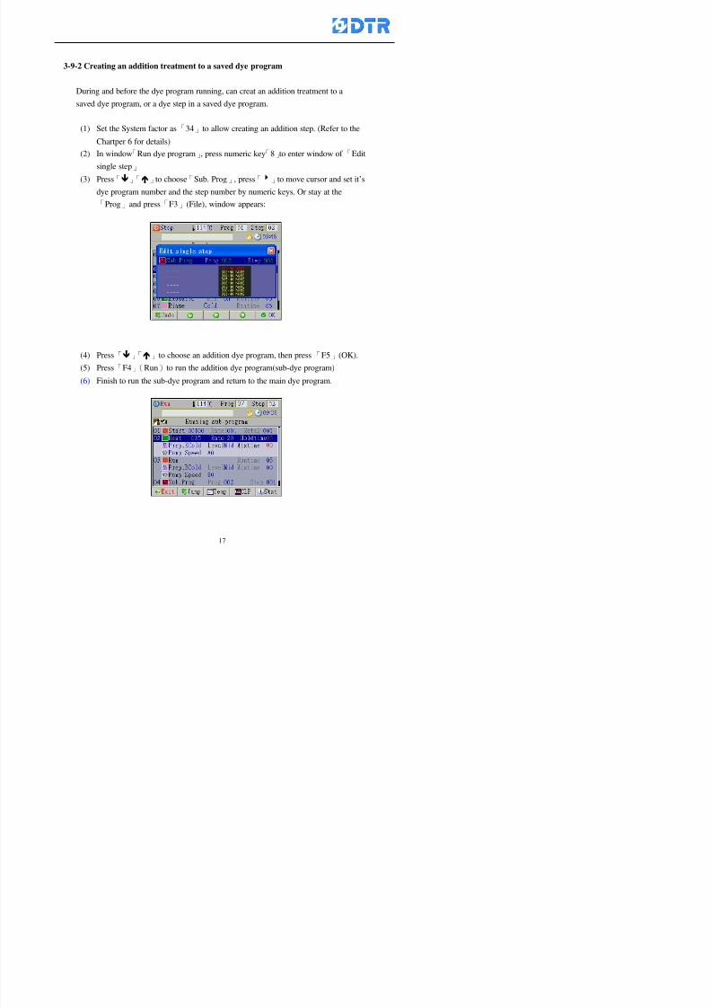
8132019 DTR 650 User Manual
httpslidepdfcomreaderfulldtr-650-user-manual 1770
3-9-2 Creating an addition treatment to a saved dye program
During and before the dye program running can creat an addition treatment to a
saved dye program or a dye step in a saved dye program
(1) Set the System factor as「34」to allow creating an addition step (Refer to the
Chartper 6 for details)
(2) In window「Run dye program」 press numeric key「8」to enter window of「Edit
single step」
(3) Press「」「」to choose「Sub Prog」 press「4」to move cursor and set itrsquos
dye program number and the step number by numeric keys Or stay at the
「Prog」and press「F3」(File) window appears
(4) Press「」「」to choose an addition dye program then press「F5」(OK)
(5) Press「F4」(Run)to run the addition dye program(sub-dye program)
(6) Finish to run the sub-dye program and return to the main dye program
8132019 DTR 650 User Manual
httpslidepdfcomreaderfulldtr-650-user-manual 1870
4 983120983137983155983155983155983159983151983154983140 DTR-650 provides four ranks of password for sercurity protection
(Refer to the ltTable 10gt Supplementary Table of the Password Usage for details)
First rank (User1 password) Edit delete dye programs control factors in output
testing etchellipall operating fuctions
Second rank (User2 password) Edit in output connecting table operating factors
Third rank (User3 password) Edit copy delete dye programs factors PLC run stop
Fourth rank (User4 password) Edit and modify dye programs
4-1 Entering the password
When the window of 「password」appears enter 6-digits number password by using
the numeric membrane keys then press「F5」(OK) If key-in an incorrect password
press「F3」(Del)and enter again
If the password is correct「」appears it allows to enter the relating operation
8132019 DTR 650 User Manual
httpslidepdfcomreaderfulldtr-650-user-manual 1970
4-2 Locking the data
After editing the programs and factors ensure to disable the password to protect all
programs and data of DTR-650 The way and step as follows
(1) Choose「8Others」at the main meun
(2) Choose「02Data Locking」at the sub-function field
(3) Press「F5」(OK)to confirm
(4) Return to the main menu「」disppears on the status bar that means the data
has been locking already
4-3 Setting and changing the Userrsquos password
There are four userrsquos password for setting and edit by the users themselves
User1 password Access to all operation setting
User2 password For edit in output connection table operating factors
User3 password Only for copy and delete dye programs factors PLC run stop
User4 password Only for edit and modify dye programs
Method of setting edit
(1) Choose「8Others」at main menu press「F5」(OK)
(2) Choose「7 Set Password 2」at the sub-function field press「F5」(OK)
(3) The cursor shows the default password now press「F3」(Clr)to delete Key in
a new password with 6-digit
(4) Press「F5」(OK)to complete the setting of User2 password Go back to the main
menu
8132019 DTR 650 User Manual
httpslidepdfcomreaderfulldtr-650-user-manual 2070
The four userrsquos password has to made from different group numbers Using
same password will affect the operating Please pay attention when update the
password
8132019 DTR 650 User Manual
httpslidepdfcomreaderfulldtr-650-user-manual 2170
5555 983109983140983145983156983145983150983143 983108983161983141 983120983154983151983143983154983137983149983155
5-1 Choosing a dye program
Press function key「F4」(Edit)or choose「1Dye Program」at the main menu press
「F5」(OK)
Choose「1Edit Dye prog」at the sub-function field press「F5」(OK)to enter to the
window「Sel dye program」During the dye program running it is allowed to edit asaved program or a new dye program or the current dye program in running
Method Press「」「」and「5」「6」「3」「4」to move cursor to choose
a dye program number Press「F5」(OK)to enter that dye program Press
「F1(Exit)to quit and return
Method
Directly key in the number selection box
appears at the right corner of the window
Select a program number and press「F5」
(OK) fi
8132019 DTR 650 User Manual
httpslidepdfcomreaderfulldtr-650-user-manual 2270
5-2 Creating a new dye program
Step
A Choose「1Dye Program」Press「F5」(OK)
B Choose「1Edit Dye prog」at the sub-function menu press「F5」(OK)to enter
to window「Sel dye program」
C At the window「Sel dye program」 choose an empty dye number (eg「002」)
press「F5」(OK)window《Fig 5-2-1》appears
《Fig 5-2-1》
D Press「F2」(Add) table of 「Edit dye instruction」《Fig 5-2-2》appears
E Press「F5」(Edit) the dye instruction appears at the cursor locates press「」「」
」and「5」「6」「3」「4」to move cursor to edit the instruction and its
factors
F All inserted new dye instructions would be listed in front of 「Program End」
8132019 DTR 650 User Manual
httpslidepdfcomreaderfulldtr-650-user-manual 2370
【Eg】Edit「CycRinse」
A Edit the main function step first Press「F2」
()「F3」()to move the cursor The dye
step is listing by orders Choose「CycRinse」
and press「」 there is a cursor at itrsquos value
B Move cursor to setting value「Cold」andchoose「Mix」by pressing()() Then
press「」to move cursor to「Time」and enter
itrsquos setting value as「2」Press「F5」(OK) to
complete the main function setting
C To move cursor to the parallel functionsetting field Press()()to choose the
dye step Press「」to confirm and move
cursor to choose itrsquos setting facor
D Press「F5」(OK)to move cursor to the next
parallel function
E Repeat above steps C-D until all parallel
functions setting are completed Each main
function can be operating with the
maximum 4 parallel functions
F Press「F4」(Save)to confirm and return to
the「Edit dye program」window
G Repeat the above step A E to keep on
8132019 DTR 650 User Manual
httpslidepdfcomreaderfulldtr-650-user-manual 2470
5-3 Setting the file name (for dye programs)
When a dye program is setting up it is saved by numbers automatically Optionally users
can save it by another names
Step
(1) Create a new dye program first (the Name is not available for empty dye
programs)
(2) At the window「Sel dye program」 press「F4」(File) Window《Fig5-3》appears
《Fig5-3》
(3) Use numeric 0~9「+」「-」「_」blank alphabet A~Z and symbols [ ] etchellip to
create a file name Each file name can type-in the max 8 unit Press 「3」「4」
「5」「6」to move the cursor to choose the unit It also can use the membrane
numbric key to type in The selected unit is showed in front of the cursor at the
「File」Press「OK」to confirm
(4) Quit to input to press「F3」(Clr)
(5) After complete the set up press「F5」(OK)to confirm and go back to the window
「Sel dye program」 Now the name behind the dye program number is created
8132019 DTR 650 User Manual
httpslidepdfcomreaderfulldtr-650-user-manual 2570
5-4 Inserting a program step
Insert the program step means to insert a step in the existing program step where youwant to insert a step All following steps are moved one step ahead The total number of
steps will be increased by itself Able to insert more than one step continusely at the
same time
【Example】《Fig5-4》 To insert a step「call」before「002 Rinse」
《Fig 5-4》
Step
A Enter to the dye program「002」at the window of 「Sel dye program」
(Example)
B Press「6」to move cursor to「002 Rinse」 then press「F2」(add)
C Press「F5」(Edit) then press「」「」or「5」「6」to choose program
step to modify Choose「call」and press「」to move cursor to modify itrsquos
value
8132019 DTR 650 User Manual
httpslidepdfcomreaderfulldtr-650-user-manual 2670
D Press「」「」 value of 「call」is listing at the table Choose「pH Check 」Press「F5」(OK)
E Press「F4」(Save)and press「F1」(Undo)to return to previous window Complete
to insert the「02 Call」The previous「02 Rinse」update to「03」 All following
steps are moved one step ahead Total number of steps will be increased ldquo1rdquo by
itself
Repeat the steps B-E can non-stop to insert more than one step
Quit the insert and modify ( before pressing「F4」) press「F1」(Undo) to exit
The original dye steps will be unchanged
To delete an inserted dye steps press key「F3」(Del) The step deletes
immediately
5-5 Deleting a program step
Delete the program step means to delete step which the cursor locates When that step is
deleted the step number will be updated automatically All following steps are moved up
one step It is allowed to delete more than one steps continuously at the same time
Step
A Enter to the「Edit dye program」《Fig5-5》at the window「Select dye program」
B Press「6」「5」move cursor to the want to delete
C Confirm and press「F3」(Del) Window「Confirm delete」appears Press
「F4」(Yes)
8132019 DTR 650 User Manual
httpslidepdfcomreaderfulldtr-650-user-manual 2770
D That step is deleted immediately and all following steps move up one step
Repeat the steps above can non-stop to delete more than one step
Press「F2」(No)to cancel the deletion
Press「F1」(Exit)to end
5-6 Modifying a program step
To modify the saved name and the setting value of the dyeing steps
Step
1 Choose a dye program which need to modify at the「Sel dye program」 press「F5」
(OK)
2 Press「6」「5」to move cursor to a step which need to modify Select and press
「F5」(Edit) Window of 「Edit dye instruction」appears
3 Press「F2」()「F3」()to choose the step list select it and press「」to move
the cursor to itrsquos value setting
4 Press numeric key to input the value or press「6」「5」to choose the item Press
「F5」(OK)when complete Cursor move to the next value (if need to set more
than one item)
5 Press「F4」(Save)when all setting is complete Return to「Edit dye program」
Method of parallel functionrsquos modification is same as above
Before pressing the key「「「「Save」」」」 press「F1」(Undo)to quit all modify Return
to the window of Edit dye program
All edit and modify functions mentioned of this charper are only available
for the dyeing files which already saved in the file and not being running It
8132019 DTR 650 User Manual
httpslidepdfcomreaderfulldtr-650-user-manual 2870
5-7 Copying a dye program
Copying a dye programs mean to make a copy of an dye programs to a blank dyeprogram This function is for creating new dye program rapidly
Choose「1Dye Program」at the main menu Press「F5」(OK)then press「F2」()to choose「2Copy dye prog」 Press「F5」(OK) 《Fig5-7-1》appears
《Fig 5-7-1》
《Fig 5-7-2》
【【【【Eg】】】】
Copy program 003 to program 012
Press「」「」to move cursor to theprogram「003」 press「F4」(Copy)
Program「003」shows at the top right side of
the bar
Press「」「」to move cursor to program「012」 Then press「F5」(Paste)「」appears behind the「012」That means it issuccessfully copying the program
If the target program is occupied
confirmation window「Overwrite」
When choose an program or a targetprogram can select them by using the
8132019 DTR 650 User Manual
httpslidepdfcomreaderfulldtr-650-user-manual 2970
5-8 Deleting a dye program
Choose「1Dye program」at the main menu Press「F5」(OK)then press「F2」()to choose「3Delete dye prog」 Press「F5」(OK) 《Fig5-8-1》appears
《Fig5-8-1》
《Fig5-8-2》
Press「」「」to move cursor to
choose program need to delete Eg
delete program「012」 press「F5」(Del) Confirmation window
「Confirm delete」appears
Press「F4」(Yes) to confirm delete
Repeat the above step can delete more
than one program at the same time
Press「F2」(No) to return to window
《Fig5-8-1》and not delete that program
Exit to press「F1」(Exit)and return to the
main menu
8132019 DTR 650 User Manual
httpslidepdfcomreaderfulldtr-650-user-manual 3070
6 983123983141983156983156983145983150983143DTR-650 has a built-in standard factor that can fulfill all different types of dyeing
machinesrsquos basic demand Users can also modify the factors base on their request to
fulfill their special control demand Before modify please refer to the table of each
range of Setting Factors (see the Supplementary Table)
6-1 ldquoEnable to use the program stepsrdquo setting
There are totally 64 program steps Parts of them are usually applying to the programs
In order to make more efficiently of editing programs it can「Disable」the other part
of program steps which are not usually applying or not applicable to the programs
For example dye machine with one tank it is only using step Tank B In this case itcan firstly「Disable」the program steps of Tank C When edit the program the
「Disable」rsquos steps will not appear at the cursor for choosing But this will not effect
and change the saved files The saved files can be kept as before
Step
(1) Choose「2 Factors」at the main menu Press「F5」(OK)(2) Choose「18 Dye Instruction」at the sub-function menu Then presss「F5」(OK)
Window「Edit dye ins」appears
「Enable」instruction can available to
use「Disable」instruction is temporarystop to use
Press「F2」()「F3」()to move
8132019 DTR 650 User Manual
httpslidepdfcomreaderfulldtr-650-user-manual 3170
6-2 ldquoAllow to modify dye program temporary during operatingrdquo Setting
During dye program running it can modify dye program temporary Thesemodification will not disappear by causing a sudden power interruption or power off
until select another new dye program to run
Please note that it is only for modifying the dye program temporary That program
file would not saved due to the modification If need to modify the program file and
save choose the function of Edit Dye Program to edit (Refer to the Charper 5 for the【Edit Dye Prograrm】)
6-2-1 ldquoAllow to modify all dye programsrdquo Setting
Step
(1) Choose「2 Factors」at the main menu Press「F5」(OK)
(2) Choose「02 System Factor」at the sub-function menu Then presss「F5」(OK)
Window「Edit System Factor」appears
Set to stop using temporary the「07
Rinse」press「F4」(Sel)to set it as Disable
Repeat above steps to complete all setting
Press 「F1」(Exit)to return to main menu
8132019 DTR 650 User Manual
httpslidepdfcomreaderfulldtr-650-user-manual 3270
6-2-2 ldquoAllow to modify part of dye programsrdquo Setting
【Eg】Set the number 08 or above (including number 08) is allowing to modify dye
programs during operating
Step
A Refer to【6-2-1】setting the factor as「22」to allow editing dye program
temporary during operating
(4) Press「3」「4」to edit the setting
as「Enable」 and press「F5」(OK)
Restore the standard factor by
pressing「F3」(Clr)
(5) Exit to press「F1」(Exit)and
return to window of 「Main Menu」
8132019 DTR 650 User Manual
httpslidepdfcomreaderfulldtr-650-user-manual 3370
6-2-3 ldquoAllow to modify dye steps temporaryrdquo Setting
After setting the dye programs are allowed to edit it also can set which dye steps are
allowed to edit temporary during operating
Step
(1) Choose「2 Factors」at the main menu Press「F5」(OK)
(2) Choose「19 Dye Ins control」at the sub-function menu Then presss「F5」
(OK) Window「Edit ins mode」appears
「Enable」 Allow to edit that dye step before
operating
「Disable」 Not allow to edit dye step before
operating
(3) Press「」「」to move cursor
to choose dye step Press「F4」
To enter to the「Edit dye program」from the
function menu there is a「」in front of the
file name「0-7」 means that program is not
allowing to edit during operating
8132019 DTR 650 User Manual
httpslidepdfcomreaderfulldtr-650-user-manual 3470
6-2-4 ldquoSet the dye step to keep running from the interrupt pointrdquo setting
When the dye program is operating it will disappear by causing power
interruption or sudden power off When start running again part of dye steps can
run again from the interrupt point part of them cannot
How to set
(1) Choose「2Factors」in the main menu and press「F5」(OK)
(2) Choose「20Continue mode」in the sub-function menu Press「F5」(OK) to
enter window of 「Continue Setting」
(3) Press「」「」to move cursor to choose dye steps Press「F4」(Sel)it
shows「Disable」or「Enable」for choosing Press「F5」(OK)to move cursorto the next setting
(4) Repeat above method until all setting is complete press「F1」(Exit)and
return to the main menu
8132019 DTR 650 User Manual
httpslidepdfcomreaderfulldtr-650-user-manual 3570
6-3 ldquoAllow to insert an addition dye stepsrdquo setting
During the program is running can temporary insert an addition dye step or a dye
program according to the operating actual situation Through this setting can set which
dye steps can apply or not to the program in operating
During to insert an addition step if sudden interruption or power off occurred it returns
to the main dye program automatically Before starting again should decide seriously
and set it again by actual needed
Step
(1) Choose「2Factors」at the main menu and press「F5」(OK)
(2) Choose「02System factor」and press「F5」(OK)
(3) Press「」「」to move cursor to the factor「34」and press「3」「4」to set
it as「Enable」 Press「F5」(OK)
(4) Press「F1」(Exit)to return to main menu Choose「21Addition Ins」at the
sub-function menu Press「F5」(OK)to enter the window「Addition Instruction」
(5) Press「」「」to move cursor to choose dye steps and press「F4」(Sel) Cursors
locates shows「Eable」or「Disable」 Press「F5」(OK)to move cursor to the
next dye step
(6) Repeat above method until to complete all setting press「F1」(Exit)and return
to the main menu
8132019 DTR 650 User Manual
httpslidepdfcomreaderfulldtr-650-user-manual 3670
6-4 Setting the display mode
DTR650 has three types of display mode during operating Program List mode
Schematic Diagram mode and Icon mode Users can set the display mode during
operating by factor setting
It goes back to a Program List mode when dye program ended
Step
(1) Choose「2Factors」at the main menu and press「F5」(OK)
(2) Choose「02System factor」and press「F5」(OK)
(3) Press「F2」()「F3」()to move cursor to choose「32Display mode」Press
「3」「4」 it shows「Online picture」「Instruction」「Big Icon」 choose
「Online picture」(eg) and press「F5」to confirm
8132019 DTR 650 User Manual
httpslidepdfcomreaderfulldtr-650-user-manual 3770
(4) Press「F1」(Exit)to return to the main menu
(5) The Schematic Diagram displays when the program is running (it stays at theProgram List mode when there is an alarm occurred)
Press「F4」to transfer to another display mode
It goes back to a Program List mode from Schematic Diagram Mode when dye
program ended Press numeric key「3」to view Schematic Diagram Mode again
Quit to press「F5」(Exit)
6-5 Adapt the digital input to another functions
DTR-650 has 32(0~31)input terminal it owns an standard setting when the
controller is initial According to the userrsquos demand they can change the DTR-650rsquos
anther functions of Input Terminal and PLC Input channel
The PLC Intputrsquos name can also define by the users (use IBM computer to edit and
download)
How to set
(1) Choose「2 Factor」at the main menu Press「F5」(OK)
(2) Choose「22 Input table」at the sub-function menu and press「F5」(OK)to enter
「Edit input table」
The actual input
terminal of theIBM computer
PLCrsquos input channel
8132019 DTR 650 User Manual
httpslidepdfcomreaderfulldtr-650-user-manual 3870
6-6 Adapt the digital output to another functions
DTR-650 has 32(0~31)output terminals it owns an standard setting when thecontroller is initial According to the userrsquos demand they can adapte the digital output
and the PLC outputrsquos channel to another functions The PLC Output channelrsquos name
can also define by users (use IBM computer to edit and download)
Step
(1) Choose「2 Factor」at the main menu Press「F5」(OK)
(2) Choose「23 Output table」at the main menu and press「F5」(OK)
(3) Press「F2」()「F3」()to move cursor to choose the output terminal atthe left side of the window Press「F5」(Add) the PLCrsquos output channelrsquos
name is listing at the right side of the window
(4) Press「F2」()「F3」()to move cursor to choose the PLC outputrsquos channel
If cursor moves to the PLC output channel which already linking「Add」is
not for choosing that means that output channel is already occupied
(5) Confirm the connection to press「F5」(Add) Quit to press「F4」(Del)Press「F1」(Exit)when complete all setting and return to main menu
The actual output
terminal of the
IBM computer
PLCrsquos output channel
8132019 DTR 650 User Manual
httpslidepdfcomreaderfulldtr-650-user-manual 3970
983095 983109983140983145983156983145983150983143 983156983144983141 983110983137983139983156983151983154983155DTR-650 has several kinds of control factors
Userrsquos factors System factors Temperature Control factors Speed factors Dosing
factors PID factors Analog Input Output factors standard factors etchellipPlease refer
to the supplementary table for the setting range and standard of the factors
DTR-650 has a built-in standard factor Users can edit by themselves if necessary
7-1 Modifying userrsquos factors
Userrsquos factors is setting with the Dyeing machinesrsquos PLC Programrsquos factor it is define by
the PLC Programmer
Step to edit
(1) Choose「2Factors」at main menu Press「F5」(OK)
(2) Choose「01User Factor」Press「F5」(OK)
(3) Press「F2」()「F3」()「6」「5」to move cursor up down and by page
Choose a factor need to edit then press「3」「4」to set itrsquos value Press「F5」(OK) Cursor moves to the next factor
(4) Some of factors can input numbers by the numeric membrance keys to edit If
the input is incorrect it turns to red and means the edit is not available
8132019 DTR 650 User Manual
httpslidepdfcomreaderfulldtr-650-user-manual 4070
Modifyrsquos method of the system factors temperature factors speed factors dosingfactors PID factors analog Input output factors standard factors etchellipare same asabove
If apply the library of DTR500 and DTR600 into the DTR650 the key「3」「4」may not valid to use Please use the numeric keys instead of it to key in factors itmay not effect the normal operation
Please pay a serious attention and read carefully at the factorrsquos table before modify the factors An incorrect value may effect the DTR-650 Dyeing
Machine Controllerrsquos operating After modifying factors must cancel the
password and secure data
7-2 Loading the standard factors
After modifying factors if need to restore a manufacturerrsquos standard factors of
DTR-650 The method as follows
1 Choose「2Factors」at main menu Press「F5」(OK)
「 「 ( ) 「
8132019 DTR 650 User Manual
httpslidepdfcomreaderfulldtr-650-user-manual 4170
7-3 Copying the factor
Users can build up a set of factor by themselves and make a copy and save
Step
1 Choose「2Factors」at main menu Press「F5」(OK)
2 Choose「13Restore Factor」 press「F5」(OK) window「factor will be
overwrite 」
3 Press「F4」(Yes)copy finished and saved Return to the main menu
4 Press「F2」(No)to not copy the factor and the existing factor is not change Return
to the main menu
7-4 Loading the backup factors
Users can build up a set of factor and backup files to load to DTR-650
Step1 Choose「14Backup factor」at the sub-function menu Press「F5」(OK)and
window「Factror will be overwrite」appears
2 Press「F3」(OK)to load the the backup factor them return to main menu
Press「F2」(No)to not copy the factor and the existing factor is not change
Return to the main menu
8132019 DTR 650 User Manual
httpslidepdfcomreaderfulldtr-650-user-manual 4270
983096 983119983157983156983152983157983156 983124983141983155983156983145983150983143
Before the output testing must be complete the steps as follows
A Cut off all connecting line of output terminal of DTR-650
B Stop running the PLC
C Check up the connections of all output channels to avoid damages from
incorrect connections
D Check up state of dyeing machines include the temperature pressure valves
onoff and pumpshellipetc ensure the safety for priority
8-1 Testing the Digital output
Step
1 Choose「3Output Testing」at the main menu Press「F5」(OK) 2 Choose「1Digital」at the sub function menu Press「F5」(OK) window「Digital
output testing」appears
3 Press「」「」「」to move cursor to each output channels Press「F5」(OK)
Output Name
8132019 DTR 650 User Manual
httpslidepdfcomreaderfulldtr-650-user-manual 4370
8-2 Testing the Analog output
(1) Choose「3Output Testing」at the main menu Press「F5」(OK)
(2) Choose「2Analog」at the sub function menu Press「F5」(OK) window「Analog output testing」appears
(3) Press「」「」「」to move cursor to each channels Then key in number by
the numeric membrance keys (range0~200= 0~20mA) Press「F5」(OK) there
is a output current relating to the output channel
(4) Press「F5」(OK) There is an output when the output channel with red light No
output without light onl(5) When complete the testing press「F1」(OK)to return to the main menu
8132019 DTR 650 User Manual
httpslidepdfcomreaderfulldtr-650-user-manual 4470
983097 983107983137983148983145983138983154983137983156983145983151983150
DTR-650 has Dosing and Temperature calibration
When enter to Dosing calibration must be set the Low Volume calibration first and
then High Volume calibration When enter to Temperature calibration must be set the
Low Temperature calibration first and then High Temperature calibration Must be
hightly follow this orders seriously
9-1 Calibration of Low Volume Tank
Step
A Choose「4Calibration」at the main menu Press「F5」(OK)
B Choose「Dosing 0 low vol」at the sub function menu Press「F5」(OK) window
appears
C Fill the Dosing Tank to a half level input value shows how much the water level
If it stays ldquo0rdquo check the connection and the factor setting is correct or not
And connect the pressure sensorrsquos output channel to the Current Meter to ensure
that sensor works or not
8132019 DTR 650 User Manual
httpslidepdfcomreaderfulldtr-650-user-manual 4570
D Fill the Dosing Tank to 50ml (Calcalate from the bottom side of the pressure
sensor steel tube) input value should show 4~6 (input value must between
0~10) Then enter the water volume The setting volume is relating the water
levelrsquos water value (litre as unit) input range 0~80 Set as「 「「 「0000 0000 0000 0000」」」」is strongly is strongly is strongly is strongly
receommend receommend receommend receommend Press「F5」(OK)to complete [Calibration of Low Volume Tank 1
is same as above method]
9-2 Calibration of High Volume Tank
Step
A Choose「4Calibration」at the main menu Press「F5」(OK)
B Choose「Dos 0 high vol」at the sub function menu Press「F5」(OK) window of
「Calibrate high 」appears
C Fill the Dosing Tank to a full level input value should be larger than 30 enter
the current water level which relates to the water volume Enter the range within
100~2500 Then press「F5」(OK) to complete the calibrate the high volume tank
8132019 DTR 650 User Manual
httpslidepdfcomreaderfulldtr-650-user-manual 4670
9-3 Temperature Calibration
Step
A This function is for adjusting the DTR650rsquos accuracy of Temperature Control It
must be using with the special terminal which is only for DTR650
B Choose「4Calibration」at the main function menu and press「F5」(OK)
C Choose「3Low Temp」at the sub-function menu Press「F5」(OK)and《Fig9-3》
appears insert the DTR650rsquos low temperature calibration terminal to the temperature
input terminal wait for the jumping value to stable down then press「F5」(OK) then
to adjust the high temperature calibration
D Adjusting the High Temperature Calibrationrsquos method is same as above But usersusersusersusers
must be using the High Temperature Terminalmust be using the High Temperature Terminalmust be using the High Temperature Terminalmust be using the High Temperature Terminal whichwhichwhichwhich is specially for DTR650 onlyis specially for DTR650 onlyis specially for DTR650 onlyis specially for DTR650 only
《Fig 9-3》
8132019 DTR 650 User Manual
httpslidepdfcomreaderfulldtr-650-user-manual 4770
10 983122983141983139983151983154983140983155 983151983142 983108983161983141 983120983154983151983143983154983137983149983155
It contains the past 15 days of temperature curves of running history
Checking method
(1) Choose「5Dye Record」at main menu press「F5」(OK)
(2) Sub-function menu shows the set up date of the past 15 days dye programs
Listing by the lastest set up date
(3) Choose a program date and press「F5」(OK) it appears window「Temp
record」
(4) Press「」「」to move the white line in the box one minute by moving once
(5) Press「3」「4」to move the line to check the time period 2 hours by moving once
The yellow selecting line of the「24 hours operating state」is repectively moving
The curve info is show in the curve box Left side of the widnow appears the
relating running info the time is the time value of the line locates at
(6) Check more details of the temperature info to press numeric key「middot」 a bright red line
appears in the selecting box this line is to check the starting point of the
temperature inforsquos time period Then press「」to move the white line to the end
point of the time period The temperature info between the starting point and end
point are appears at the right side of the window Press「middot」to return to the preious
curve page
(7) Check more details of the alarm infor To perss numeric key「7」「9」 the alarmrsquos
details is listing by orders
(8) Press「F1」(exit) to return
8132019 DTR 650 User Manual
httpslidepdfcomreaderfulldtr-650-user-manual 4870
11 983125983155983137983143983141 983151983142 983117983141983149983151983154983161 983107983137983154983140
DTR-650 supports 32MB or above Compact Flash Card which can transfer and save all
information for 4 sets of DTR-650 Including library files schematic diagram icon
image PLC program dye program factor and confiruration files etchellip Use the CF Card
to up download and swap the information of DTR-650 promptly install the relating
device and program updates
DTR-650 CF Card with bank 1 to bank 4 can save 4 sets information of Dyeing
Machines When download or save files should choose the BANK first
《Fig11-1》
8132019 DTR 650 User Manual
httpslidepdfcomreaderfulldtr-650-user-manual 4970
11-1 Downloading data
1 Firmly insert the CF card into the DTR-650rsquos PCMCIA connector Ensure it is
wholely and firmly inserted if the card is not totally inserted or the card do not
touch in all to the connector there will be an error occurred and cannot
updownload or interrupted during operation
2 Choose「6Memory Card」at the main menu and press「F5」(OK) 《Fig11-1》
appears Information of Bank「1」shows at the left hand side of the window press
number 1-4 by using numeric keys to choose the BANK Check the
information in the Bank seriously which is exactly need to download to the
DTR650
3 Press()()「6」「5」to move cursor to the sub-function menu to choose
the downloading items Press「F5」(OK) window appears「Stop PLC run before
access memory card Stop the PLC run」 Press「F5」(YES) to stop PLC
running
4 Press「F5」(OK) window appears Confirm to update or not the DTR-650rsquos
information As that downloading will be replace the DTR-650rsquos information
(that means the existing information of the DTR-650 will be removed and
replaced)
5 Press「F4」(YES)to download the information from the DTR-650 to the CF
Card Return to the main menu when finish
8132019 DTR 650 User Manual
httpslidepdfcomreaderfulldtr-650-user-manual 5070
Ensure inserting firmly the CF card into the DTR-650 unless it will cause
error or cannot Updownload data
Never remove CF card during transferring or updownloading data Until it
is all completed
DTR-650rsquos dyeing program is not compatible with DTR-500 and
DTR-600 Never use CF card to transfer data among them
11-2 Storing and transfering data
1 Insert the CF Card to the DTR-650
2 Choose「6Memory Card」at the main menu and press「F5」(OK) 《Fig11-1》
appears Left hand side of the window shows the data of BANK 1 press numeric
keys 1-4 to select the BANK To confirm the put the data in the DTR-650 to the CF
Card The existing data of that bank will be replaced and covered by the new data (if
that bank is already occuplied)
3 Choose「23Save Dye prog」(Example)at the sub-funciton menu press「F5」(OK)to confirm Window「Update memory card data」appears
4 Press「F5」(OK)to transfer the data to the CF card Return to the main menu
5 Put the CF card into another DTR-650 and follow the operating method of 「11-1
Downloading data」」」」can transfer and swap data with more than one set of
DTR-650
8132019 DTR 650 User Manual
httpslidepdfcomreaderfulldtr-650-user-manual 5170
12 983123983156983137983156983141 983137983150983140 983113983150983142983151983154983149983137983156983145983151983150
The state and information is including the Dyeing Machinersquos state of Digit Input output
Analog Input output Temperature control PID Dosing PID Pressure different PID
software system information and alarm record This information is for checking at any
time
12-1 Input Output state
Step
1 Choose「7Info and state」at main menu and press「F5」(OK)
2 Choose「01Digital IO put」at the sub-function menu then press「F5」(OK)
「Digital In Out State」0=None 1=Input
3 Press「F1」(Exit)to return to main menu
Same method for checking the temperature control analog dosing pressure
different etchellip
12-2 Checking the system information
Step
1 Choose「7Info and state」at main menu and press「F5」(OK)
2 Choose「11 System info」at sub-function field press「F5」(OK)Window
「System Information」appear
System information is including System info(software version) Library doc
Icon files Schematic file Definition file hardare state Config File Commandinstruction icon PLC file etc
8132019 DTR 650 User Manual
httpslidepdfcomreaderfulldtr-650-user-manual 5270
12-3 Checking the operating alarm record
Operating record shows the latest 40 operating items and alarm records including
the time and content of the alarm
A) Choose「7 Info and state」
and press「F5」(OK)
B) Choose「12Alarm logs」at
the sub-funciton menu then
press「F5」(OK)
8132019 DTR 650 User Manual
httpslidepdfcomreaderfulldtr-650-user-manual 5370
13 983105983140983146983157983155983156983145983150983143 983156983144983141 983107983151983150983156983154983137983155983156
The displaysrsquos brightness can be adjusted if necessary
Step
1 Choose「8Others」at main menu press「F5」(OK)
2 Choose「01Contrast」at sub-function menu press「F5」(OK) window「Set
Contrast」appears
3 Press「」「」to move the bar to set the brightness then press「F5」(OK)Window appears「Please reboot the system」
4 Press「F5」(OK)to return to main menu and re-boot the DTR-650 to complete
adjusting the brightness
8132019 DTR 650 User Manual
httpslidepdfcomreaderfulldtr-650-user-manual 5470
14 983123983156983151983152 983154983157983150983150983145983150983143 983156983144983141 983120983116983107 983120983154983151983143983154983137983149
Before testing the Input output testing transfer of the PLC program must stop the PLC
running
Step
1 Choose「8Others」at the main menu Press「F5」(OK)
2 Choose「04 PLC Stop」at sub-function menu Press「F5」(OK) window
「Password」appears
3 Enter password and press「F5」(OK) Window「Stop the PLC run」appears
4 Press「F4」(Yes)and window「PLC Stop」appear Press「F5」(OK) Now
the PLC is stop running and return to the main menu
All testing cannot operate when the PLC is running
Editing dye program and the relating operation can
perform with the PLC running together
8132019 DTR 650 User Manual
httpslidepdfcomreaderfulldtr-650-user-manual 5570
15 983123983141983156983156983145983150983143 983156983144983141 983156983145983149983141
Step
1 Press「8Others」at the main menu Press「F5」(OK)
2 Choose「10Set date time」at the sub-function menu Press「F5」(OK) window
「Set date time」appears
3 Press「F5」(Edit) to move cursor by 「3」「4」 enter the time value at the
cursor locates
4 Press「F5」(OK)to complete the modify Press「F1」(Exit)to return to main
menu
5 Press「F1」(Exit)if not modify and return to main menu
8132019 DTR 650 User Manual
httpslidepdfcomreaderfulldtr-650-user-manual 5670
1166 983123983123983157983157 983152 983152 983152 983152983148983148983141983141983149983149983141983141983150983150983156 983156 983137983137983154 983154 983161983161 983124 983124 983137983137983138983138983148983148983141983141
TTTTTTTTaaaaaaaabbbbbbbblllllllleeeeeeee 11111111 【Dye Instruction】
Code Icon Instruction Code Icon Instruction
000 End 016 Inject C
001 Start 017 Dosing BV
002 Heat 018 PH
003 Cool 019 Addsalt B
004 Flow Fill 020 Addsalt C
005 Level Fill 021 Ana Fill
006 Drian 022 Lock Fill007 Rinse 023 Lock Level
008 Run 024 Low Rinse
009 Call 025 Cyc Rinse
010 Prep B 026 Rinse B
011 Addsalt B 027 Rinse C
012 Dosing B 028 Temp
013 Inject B 029 Nozzle Pressure
014 Prep C 030 Main Pump
015 Dosing C 031 Pump Speed
8132019 DTR 650 User Manual
httpslidepdfcomreaderfulldtr-650-user-manual 5770
Table 2 【【【【Alarm】】】】
System Alarm Must stop operating and check up to solve problems before restarting
the machine
Running Alarm It is a reminder Not effect the operating of DTR-650
Userrsquos Alarm Total of 32 Users can define themselves and use it when edit the PLC
Program (do not listing below)
No System Alarm No Running Alarm
1 PLC program not running 16 Temp ctrl 0 Grad too slow
2 Main temp sensor error 17 Temp ctrl 0 Grad too fast
3 Not at Run window 18 Temp ctrl 0 Hold temp too low
4 Exceeding max temp 19 Temp ctrl 0 Hold temp too high
5 - 20 Temp ctrl 1 Grad too slow6 - 21 Temp ctrl 1 Grad too fast
7 - 22 Temp ctrl 1 Hold temp too low
8 Communication error 23 Temp ctrl 1 Hold temp too high
9 Slave not answer 24 Temp ctrl 2 Grad too slow
10 PLC 0 not answer 25 Temp ctrl 2 Grad too fast
11 PLC 1 not answer 26 Temp 2 Hold temp too low12 Display not answer 27 Temp 2 Hold temp too high
13 Lower power voltage 28 Temp ctrl 3 Grad too slow
14 - 29 Temp ctrl 3 Grad too fast
15 - 30 Temp3 Hold temp too low
31 Temp3 Hold temp too high
32 Dosing 0 injection too slow
33 Dosing 0 injection too fast
34 Dosing 1 injection too slow
35 Dosing 1 injection too fast
8132019 DTR 650 User Manual
httpslidepdfcomreaderfulldtr-650-user-manual 5870
TTTTTTTTaaaaaaaabbbbbbbblllllllleeeeeeee 33333333 【【【【System factor】】】】
No Description Std Range amp Definition
1 ID No 000 000- 100 Controller no
2 Communication Rate 4800Bps 2400 4800 9600 19200 38400
3 Display language Chinese English Chinese
4 Temp display mode and
5 Maxmium temperature 145 025 ~ 145 6 Type of external PLC Default PLC32DPLC32PLC16Default
7 Number of external PLC NANA 1 unit connect
2 unit connect
8Communication Rate of
PLC9600Bps 2400 4800 9600 19200
9 Set point 1 085 000 ~ 145
If signal source is temperaturethe setting value is thetemperature value If the signal
source is Analog Input 6~17 then
setting value for Analog input is 0 ndash
100 and relates Analog
Input14~020mA
10 Source 1 Sensor0Sensor 0 ~5
Analog input 0 ~1111 Set point 2 092 Same as 09
12 Source 2 PT100 1 Same as 10
13 Set point 3 085 Same as 09
14 Source 3 PT100 2 Same as 10
15 Set point 4 092 Same as 09
16 Source 4 PT100 3 Same as 1017 Set point 5 085 Same as 09
18 Source 5 PT100 4 Same as 10
19 Set point 6 092 Same as 09
8132019 DTR 650 User Manual
httpslidepdfcomreaderfulldtr-650-user-manual 5970
29 Min cyclic time of cloth 100sec 0 ~ 255 sec
30 Max cyclic time of cloth 240sec 0 ~255 sec
31Standard cyclic time of
cloth
180 000 ~ 255 sec
32 Display ModeProgram
List
Program list Schematic Diagram
Icon mode
33 CF card format Standard of
DTR CF
Card
Standard of DTR CF Card V20
Standard CF Card
34 Addition step Disable Disable Enable35 Mode Com 3
CouplingEsure Com 3 is the communication
port of the Central or Coupling
36Com 3 Communication
rate9600 Central communication speed
8132019 DTR 650 User Manual
httpslidepdfcomreaderfulldtr-650-user-manual 6070
TTTTTTTTaaaaaaaabbbbbbbblllllllleeeeeeee 44444444 【【【【Temperature Cotnrol Factor】】】】
No Factor Definition Standard Range and Definition
01 PT No PT-0 PT 0~5 PT-100 Input number
02 Max working temp 140 000~140
03 Output mode 0 0~2
04 Alarm time of gardient 240sec 000~255 sec
05 Alarm mode of gradient Always AlwaysOnceNone
06 Control mode of gradient Heating orCooling
interlocked
Heating and Cooling interlocked
No limitation
07 Alarm range of HoldTemp 03 01~20
08 Alarm time for HoldTemp 240sec 000~255sec
09 Alarm mode of HoldTemp Always AlwaysOnceNone
10 Control mode ofHoldTemp
Heating only Only heating and cooling Cooling whenalarm occurred Only heating andcooling No limitation when alarmHeating only
11 Porportional Band 100 000~250
12 Integral band 128 sec 000~255 sec
13 Differential time 04 sec 00~20 sec
14 Min transit gradient 02 00~50
15 Transit rate 20 times 00~50 times (020= 2 times)
16 PID initial output value 010 000~100
17 ONOFF cycle time 10 sec 05~25 sec
Onoff valve set as 010 sec
Proportional valve set as 020 sec
18 Time down count mode Mode 0 0~10 = The time down count range from「Factor 20 + target temp」to「Target
8132019 DTR 650 User Manual
httpslidepdfcomreaderfulldtr-650-user-manual 6170
TTTTTTTTaaaaaaaabbbbbbbblllllllleeeeeeee 55555555 【【【【Speed Factor】】】】
No Factor Definition Standard Range amp Definition
01 Input Number Speed input 0 Speed input 0~11
02 Average times 05 times 01~10
03 Sensor Number 008pcs 001~255
04 Roller Dimension 250mm 050~500
05 Max cloth speed 200mmin 001~25506 Min cloth speed 020mmin 001~255
07 Alarm delay time 240sec 001~255
08 Alarm mode Every oncenoneevery
09 Alarm range () 020 001~255
10 Proportional band 100 001~255
11 Integer band 128 001~25512 Differential time 000 001~200
13 Initial speed () 020 001~255
14 Control cycle ti(01sec) 05 01~30
15 First cycle time(01sec) 10 01~30
16 Speed increase limit () 010 001~100
17 Speed decrease limit () 010 001~100
18 Min speed() 005 001~100
19 Manual speed adjust () 005 001~100
20 Manual initial speed() 020 001~100
21 Stopping speed() 010 001~100
22 Switch speed() 020 001~100
23 Not used
24 Speed decrease turns 03turns 01~50
8132019 DTR 650 User Manual
httpslidepdfcomreaderfulldtr-650-user-manual 6270
Table 6 【【【【Dosing Factors】】】】
No Description Range Range and Explanation
1 Analog input no Analog input 0 Analog input no 0 ~11
2Alarm delay time for
dosing240 sec 000 ~255 sec
3 Alarm time for dosing Every Every Once None
4 Proportional band 100 000 ~255 sec Factor P
5 Integer band 128 000 ~255 sec Factor I6 Differential time 04 00 ~20 Factor D
7 Max adjust rate 150 50~ 255
8 Initial factor for dosing 10 000 ~100
9 User curve section 0 10 Gradient of sect1 for dosing curve9
10 User curve section 1 10 Gradient of sect2 for dosing curve9
11 User curve section 2 10 Gradient of sect3 for dosing curve9
12 User curve section 3 10 Gradient of sect4 for dosing curve9
13 User curve section 4 10 Gradient of sect5 for dosing curve9
14 User curve section 5 10 Gradient of sect6 for dosing curve9
15 User curve section 6 10 Gradient of sect7 for dosing curve9
16 User curve section 7 10 Gradient of sect8 for dosing curve9
17 User curve section 8 10 Gradient of sect9 for dosing curve9
18 User curve section 9 10 Gradient of sect10 for dosing curve9
19 Min water level 05 00~ 10 04~20mA percentagechange to the userrsquos factor setting
20 Output value for Tank
clean
100 000~ 100
Injected percentage of dosing valve
in dosing End period
This factor will be invalided if usingONOFF dosing valve
21 Full range 100 001~255 Self-adjustment cannotchange
22 Range ratio 001001~255 Self-adjustment cannot
change
8132019 DTR 650 User Manual
httpslidepdfcomreaderfulldtr-650-user-manual 6370
【【【【TTaabbllee 77 】】】】Pressure Deviation Factors
No Description Std Range amp Definition
1 Analog input number + Analog in 0 Analog in 0~11
2 Analog input number - Analog in 1 Analog in 0~11
3 Input mode Pressure Pressure Pressure deviation
4 Full range 050x01Kgcm
001~255
5 Range ratio 001 001~255
6 Alarm delay time 100sec 001~255
7 Alarm mode Every oncenone
8 Alarm range 010 001~255
9 Proportional band 100 001~255
10 Integer band 128 001~255
11 Differential time 00 00~20
12 PID Init output value 010 001~255
13 Cycle time 10 03~30
14 First cycle time 030 003~100
15 Max adjust rate 010 001~100
8132019 DTR 650 User Manual
httpslidepdfcomreaderfulldtr-650-user-manual 6470
【【【【TTaabbllee 88 】】】】Definition of Analog Input
No Description Standard Range and Explanation
01 PT 0 correction standard DIN std DIN std JIS std
02 PT 0 correction +0 +- 9
03 PT 1 correction standard DIN std DIN std JIS std
04 PT 1 correction +0 +- 9
05 PT 2 correction standard DIN std DIN std JIS std
06 PT 2 correction +0 +- 9
07 PT 3 correction standard DIN std DIN std JIS std
08 PT 3 correction +0 +- 9
09 PT 4 correction standard DIN std DIN std JIS std
10 PT 4 correction +0 +- 9
11 PT 5 correction standard DIN std DIN std JIS std
12 PT 5 correction +0 +- 9
13 Analog input 0 define 4 ~ 20mA 0 ndash 20mA 4 ndash 20mA
14 Analog input 0 average times 10 times 01- 20 times
15 Analog input 0 min value 0000 0000 - 1000
16 Analog input 0 max value 100 0001 - 9999
17-60 Analog input 1~11 Same as Analog input 0
【【【【 】】】】 fi i i f A O
8132019 DTR 650 User Manual
httpslidepdfcomreaderfulldtr-650-user-manual 6570
【【【【TTaabbllee 99 】】】】Definition of Analog Output
No Description Standard Range and explanation
61 Analog output 0 define Control byPLC
Control by PLC
Temperature control PID0 output
Temperature control PID1 output
Temperature control PID2 output
Speed PID3 output
Dosing PID0 output Dosing PID1output
Pressure different PID0 outputPressure different PID1 output
Main temperature output
62 Mode of Analog ouptput0 4 ~20mA 0 ndash20mA 4 ndash 20mA
63-84 Analog output 1~11 Same as Analog output 0
【【【【TTaabbllee 1100】】】】Value Table 0 amp 1
No Description Range Std Range and explanation
1 Analog input no 000~011 000 Analog input no
2 Data ratio 001~255 100 Multiple by factors
3~53 0~98 000~255 000-100 Analog input 0~98 data
【【【【 】】】】St t Li t
8132019 DTR 650 User Manual
httpslidepdfcomreaderfulldtr-650-user-manual 6670
【【【【TTaabbllee 1111】】】】State List
No Description Range Standard Range and explanation
1 Display setting 1 0~255 205 See remarks at next page
2 Display setting 2 0~255 208
3 Display setting 3 0~255 209
4 Display setting 4 0~255 017
5 Display setting 5 0~255 0186 Display setting 6 0~255 019
7 Display setting 7 0~255 020
8 Display setting 8 0~255 021
9 Display setting 9 0~255 000
10 Display setting 1 0~255 000
11 Display setting 2 0~255 000
12 Display setting 3 0~255 000
13 Display setting 4 0~255 000
14 Display setting 5 0~255 000
15 Display setting 6 0~255 000
16 Display setting 7 0~255 000
Remarks
8132019 DTR 650 User Manual
httpslidepdfcomreaderfulldtr-650-user-manual 6770
0 = No display 1~255 = Display type of number
1~16 Content of PLC VB0~15
No 1 corresponding to VB0
No 16 corresponding to VB15
17~32 Content of PLC DB0~15
No 17 corresponding to DB0
No 32 corresponding to DB15
33~46 Content of PLC CNT0~29
No 33 corresponding to CNT0
No 46 corresponding to CNT29 47~78 Content of dyeing instruction 0~31 CNT0
No 47 corresponding to system instruction to No 0 of CNT0
No 78 corresponding to system instruction to No 31 of CNT0rsquos content
79~110 Dyeing instruction 0~31 of CNT0rsquos setting
111~142 Content of Dyeing instruction 0~31 CNT1No 111 corresponding to dyeing instruction No 0 of CNT1
No 142 corresponding to dyeing instruction No 31 of CNT1rsquos content
143~174 Dyeing instruction 0~31 of CNT1rsquos setting
175~204 Content of PLC HTIM0~29
No 175 corresponding to HTIM0
No 204 corresponding to HTIM29
205 Loading
206 Ratio 1
207 Ratio 2208 Ratio 1 x Loading
209 Ratio 2 x Loading
210 Fix value
211 Value Table 1 matching result
212 Value Table 2 matching result
213 Value Table 1 setting214 Value Table 2 setting
215 Pressure control PID0 different pressure value
216 Pressure control PID1 different pressure value
TTTTTTTTaaaaaaaabbbbbbbblllllllleeeeeeee 1122 【【【【Usage of password】】】】
8132019 DTR 650 User Manual
httpslidepdfcomreaderfulldtr-650-user-manual 6870
No Main FunctionFactor Sub Function Factor Password Rank
1 Run None
2 Dye program User3 or above
3 Control factor
- User factor User 1
- System factor User 1
- Temp PID 0
- Temp PID 1 User 1- Speed PID 0 User 1
- Dosing PID 0 User 1
- Dosing PID 1 User 1
- Pressure PID 0 User 1
- Pressure PID 1 User 1
- Analog IO User 1
- Load standard factor User 2 or above- Load a copied factor User 2 or above
- Copy factor User 2 or above
- Value table 0 User 1
- Value table 1 User 1
- Information and state User 1
- Dye instruction User 1
- Edit dye instruction setting User 14 Output testing User 2 or above
5 Calibration User 2 or above
6 Dye record None
7 CF card User 1
8 Info and state None
9 Others
- Contrast User3 or above
- Data Locking None
- PLC Run User 1
- PLC Stop User 1
- Password setting User 1
TTTTTTTTaaaaaaaabbbbbbbblllllllleeeeeeee 1133 【【【【Technical Data】】】】
8132019 DTR 650 User Manual
httpslidepdfcomreaderfulldtr-650-user-manual 6970
TTTTTTTTaaaaaaaabbbbbbbblllllllleeeeeeee 1133 【【【【Technical Data】】】】
1 Temperature Control
- Range 10~145(plusmn1)
- Mode Proportional or PWM
- Sensor PT100 (JIS or DIN standard)
2 Input and output channel
- Digital Input 32 DC24V PNP- Digital Output 32 DC24V 054A Relay connect point
- Analog Input 4 04~20 mA
- Analog Output 4 0~20mA 或 4~20 mA
3 Communication port 3 RS-232 amp 0~20 mAx1 RS485x 2
4 Dye program
- Number 15000 Steps
- Standard step 61Heating Cooling Fill Drain RinseDosingetc
5LCD module and Display
langage
Chinese
English
320 x 240 TFT color display with
more language
6 CF card connector 1 PCMCIA standard
7 Membrane Keyboard- Number Key 10 [0]~[9] Input factors
- Function Key 5 [F1]~[F5] function selecting
- Operation Key 2 [Start] [Stop]
- Auxiliary Key 7 [][][][][Esc] [larr][OK] [bull]
8 Operating Condition
- Temperature 5~45
- Humidity ≦85 (25)
9 Power supply
V l DC 24V
8132019 DTR 650 User Manual
httpslidepdfcomreaderfulldtr-650-user-manual 7070
70
983108983124983122983085650 983113983150983152983157983156 983119983157983156983152983157983156 983120983151983154983156983145983150983143 (983138983137983139983147983155983145983140983141 983158983145983141983159)
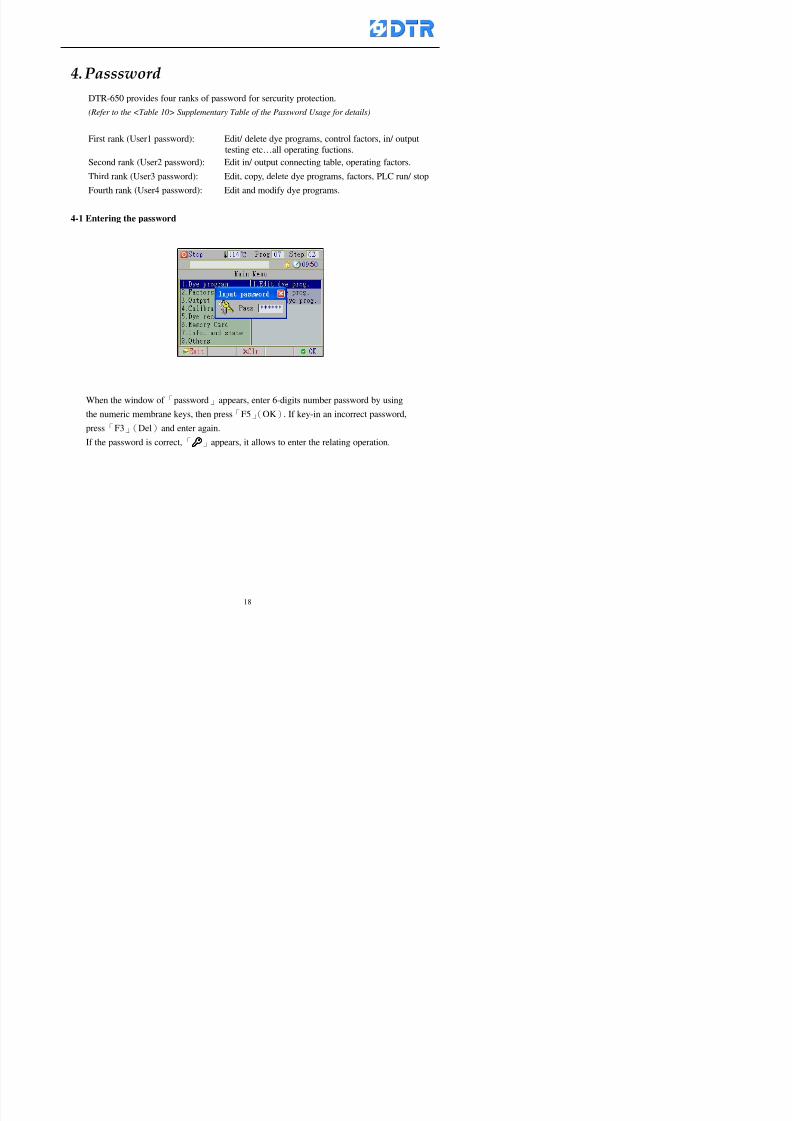
8132019 DTR 650 User Manual
httpslidepdfcomreaderfulldtr-650-user-manual 1870
4 983120983137983155983155983155983159983151983154983140 DTR-650 provides four ranks of password for sercurity protection
(Refer to the ltTable 10gt Supplementary Table of the Password Usage for details)
First rank (User1 password) Edit delete dye programs control factors in output
testing etchellipall operating fuctions
Second rank (User2 password) Edit in output connecting table operating factors
Third rank (User3 password) Edit copy delete dye programs factors PLC run stop
Fourth rank (User4 password) Edit and modify dye programs
4-1 Entering the password
When the window of 「password」appears enter 6-digits number password by using
the numeric membrane keys then press「F5」(OK) If key-in an incorrect password
press「F3」(Del)and enter again
If the password is correct「」appears it allows to enter the relating operation
8132019 DTR 650 User Manual
httpslidepdfcomreaderfulldtr-650-user-manual 1970
4-2 Locking the data
After editing the programs and factors ensure to disable the password to protect all
programs and data of DTR-650 The way and step as follows
(1) Choose「8Others」at the main meun
(2) Choose「02Data Locking」at the sub-function field
(3) Press「F5」(OK)to confirm
(4) Return to the main menu「」disppears on the status bar that means the data
has been locking already
4-3 Setting and changing the Userrsquos password
There are four userrsquos password for setting and edit by the users themselves
User1 password Access to all operation setting
User2 password For edit in output connection table operating factors
User3 password Only for copy and delete dye programs factors PLC run stop
User4 password Only for edit and modify dye programs
Method of setting edit
(1) Choose「8Others」at main menu press「F5」(OK)
(2) Choose「7 Set Password 2」at the sub-function field press「F5」(OK)
(3) The cursor shows the default password now press「F3」(Clr)to delete Key in
a new password with 6-digit
(4) Press「F5」(OK)to complete the setting of User2 password Go back to the main
menu
8132019 DTR 650 User Manual
httpslidepdfcomreaderfulldtr-650-user-manual 2070
The four userrsquos password has to made from different group numbers Using
same password will affect the operating Please pay attention when update the
password
8132019 DTR 650 User Manual
httpslidepdfcomreaderfulldtr-650-user-manual 2170
5555 983109983140983145983156983145983150983143 983108983161983141 983120983154983151983143983154983137983149983155
5-1 Choosing a dye program
Press function key「F4」(Edit)or choose「1Dye Program」at the main menu press
「F5」(OK)
Choose「1Edit Dye prog」at the sub-function field press「F5」(OK)to enter to the
window「Sel dye program」During the dye program running it is allowed to edit asaved program or a new dye program or the current dye program in running
Method Press「」「」and「5」「6」「3」「4」to move cursor to choose
a dye program number Press「F5」(OK)to enter that dye program Press
「F1(Exit)to quit and return
Method
Directly key in the number selection box
appears at the right corner of the window
Select a program number and press「F5」
(OK) fi
8132019 DTR 650 User Manual
httpslidepdfcomreaderfulldtr-650-user-manual 2270
5-2 Creating a new dye program
Step
A Choose「1Dye Program」Press「F5」(OK)
B Choose「1Edit Dye prog」at the sub-function menu press「F5」(OK)to enter
to window「Sel dye program」
C At the window「Sel dye program」 choose an empty dye number (eg「002」)
press「F5」(OK)window《Fig 5-2-1》appears
《Fig 5-2-1》
D Press「F2」(Add) table of 「Edit dye instruction」《Fig 5-2-2》appears
E Press「F5」(Edit) the dye instruction appears at the cursor locates press「」「」
」and「5」「6」「3」「4」to move cursor to edit the instruction and its
factors
F All inserted new dye instructions would be listed in front of 「Program End」
8132019 DTR 650 User Manual
httpslidepdfcomreaderfulldtr-650-user-manual 2370
【Eg】Edit「CycRinse」
A Edit the main function step first Press「F2」
()「F3」()to move the cursor The dye
step is listing by orders Choose「CycRinse」
and press「」 there is a cursor at itrsquos value
B Move cursor to setting value「Cold」andchoose「Mix」by pressing()() Then
press「」to move cursor to「Time」and enter
itrsquos setting value as「2」Press「F5」(OK) to
complete the main function setting
C To move cursor to the parallel functionsetting field Press()()to choose the
dye step Press「」to confirm and move
cursor to choose itrsquos setting facor
D Press「F5」(OK)to move cursor to the next
parallel function
E Repeat above steps C-D until all parallel
functions setting are completed Each main
function can be operating with the
maximum 4 parallel functions
F Press「F4」(Save)to confirm and return to
the「Edit dye program」window
G Repeat the above step A E to keep on
8132019 DTR 650 User Manual
httpslidepdfcomreaderfulldtr-650-user-manual 2470
5-3 Setting the file name (for dye programs)
When a dye program is setting up it is saved by numbers automatically Optionally users
can save it by another names
Step
(1) Create a new dye program first (the Name is not available for empty dye
programs)
(2) At the window「Sel dye program」 press「F4」(File) Window《Fig5-3》appears
《Fig5-3》
(3) Use numeric 0~9「+」「-」「_」blank alphabet A~Z and symbols [ ] etchellip to
create a file name Each file name can type-in the max 8 unit Press 「3」「4」
「5」「6」to move the cursor to choose the unit It also can use the membrane
numbric key to type in The selected unit is showed in front of the cursor at the
「File」Press「OK」to confirm
(4) Quit to input to press「F3」(Clr)
(5) After complete the set up press「F5」(OK)to confirm and go back to the window
「Sel dye program」 Now the name behind the dye program number is created
8132019 DTR 650 User Manual
httpslidepdfcomreaderfulldtr-650-user-manual 2570
5-4 Inserting a program step
Insert the program step means to insert a step in the existing program step where youwant to insert a step All following steps are moved one step ahead The total number of
steps will be increased by itself Able to insert more than one step continusely at the
same time
【Example】《Fig5-4》 To insert a step「call」before「002 Rinse」
《Fig 5-4》
Step
A Enter to the dye program「002」at the window of 「Sel dye program」
(Example)
B Press「6」to move cursor to「002 Rinse」 then press「F2」(add)
C Press「F5」(Edit) then press「」「」or「5」「6」to choose program
step to modify Choose「call」and press「」to move cursor to modify itrsquos
value
8132019 DTR 650 User Manual
httpslidepdfcomreaderfulldtr-650-user-manual 2670
D Press「」「」 value of 「call」is listing at the table Choose「pH Check 」Press「F5」(OK)
E Press「F4」(Save)and press「F1」(Undo)to return to previous window Complete
to insert the「02 Call」The previous「02 Rinse」update to「03」 All following
steps are moved one step ahead Total number of steps will be increased ldquo1rdquo by
itself
Repeat the steps B-E can non-stop to insert more than one step
Quit the insert and modify ( before pressing「F4」) press「F1」(Undo) to exit
The original dye steps will be unchanged
To delete an inserted dye steps press key「F3」(Del) The step deletes
immediately
5-5 Deleting a program step
Delete the program step means to delete step which the cursor locates When that step is
deleted the step number will be updated automatically All following steps are moved up
one step It is allowed to delete more than one steps continuously at the same time
Step
A Enter to the「Edit dye program」《Fig5-5》at the window「Select dye program」
B Press「6」「5」move cursor to the want to delete
C Confirm and press「F3」(Del) Window「Confirm delete」appears Press
「F4」(Yes)
8132019 DTR 650 User Manual
httpslidepdfcomreaderfulldtr-650-user-manual 2770
D That step is deleted immediately and all following steps move up one step
Repeat the steps above can non-stop to delete more than one step
Press「F2」(No)to cancel the deletion
Press「F1」(Exit)to end
5-6 Modifying a program step
To modify the saved name and the setting value of the dyeing steps
Step
1 Choose a dye program which need to modify at the「Sel dye program」 press「F5」
(OK)
2 Press「6」「5」to move cursor to a step which need to modify Select and press
「F5」(Edit) Window of 「Edit dye instruction」appears
3 Press「F2」()「F3」()to choose the step list select it and press「」to move
the cursor to itrsquos value setting
4 Press numeric key to input the value or press「6」「5」to choose the item Press
「F5」(OK)when complete Cursor move to the next value (if need to set more
than one item)
5 Press「F4」(Save)when all setting is complete Return to「Edit dye program」
Method of parallel functionrsquos modification is same as above
Before pressing the key「「「「Save」」」」 press「F1」(Undo)to quit all modify Return
to the window of Edit dye program
All edit and modify functions mentioned of this charper are only available
for the dyeing files which already saved in the file and not being running It
8132019 DTR 650 User Manual
httpslidepdfcomreaderfulldtr-650-user-manual 2870
5-7 Copying a dye program
Copying a dye programs mean to make a copy of an dye programs to a blank dyeprogram This function is for creating new dye program rapidly
Choose「1Dye Program」at the main menu Press「F5」(OK)then press「F2」()to choose「2Copy dye prog」 Press「F5」(OK) 《Fig5-7-1》appears
《Fig 5-7-1》
《Fig 5-7-2》
【【【【Eg】】】】
Copy program 003 to program 012
Press「」「」to move cursor to theprogram「003」 press「F4」(Copy)
Program「003」shows at the top right side of
the bar
Press「」「」to move cursor to program「012」 Then press「F5」(Paste)「」appears behind the「012」That means it issuccessfully copying the program
If the target program is occupied
confirmation window「Overwrite」
When choose an program or a targetprogram can select them by using the
8132019 DTR 650 User Manual
httpslidepdfcomreaderfulldtr-650-user-manual 2970
5-8 Deleting a dye program
Choose「1Dye program」at the main menu Press「F5」(OK)then press「F2」()to choose「3Delete dye prog」 Press「F5」(OK) 《Fig5-8-1》appears
《Fig5-8-1》
《Fig5-8-2》
Press「」「」to move cursor to
choose program need to delete Eg
delete program「012」 press「F5」(Del) Confirmation window
「Confirm delete」appears
Press「F4」(Yes) to confirm delete
Repeat the above step can delete more
than one program at the same time
Press「F2」(No) to return to window
《Fig5-8-1》and not delete that program
Exit to press「F1」(Exit)and return to the
main menu
8132019 DTR 650 User Manual
httpslidepdfcomreaderfulldtr-650-user-manual 3070
6 983123983141983156983156983145983150983143DTR-650 has a built-in standard factor that can fulfill all different types of dyeing
machinesrsquos basic demand Users can also modify the factors base on their request to
fulfill their special control demand Before modify please refer to the table of each
range of Setting Factors (see the Supplementary Table)
6-1 ldquoEnable to use the program stepsrdquo setting
There are totally 64 program steps Parts of them are usually applying to the programs
In order to make more efficiently of editing programs it can「Disable」the other part
of program steps which are not usually applying or not applicable to the programs
For example dye machine with one tank it is only using step Tank B In this case itcan firstly「Disable」the program steps of Tank C When edit the program the
「Disable」rsquos steps will not appear at the cursor for choosing But this will not effect
and change the saved files The saved files can be kept as before
Step
(1) Choose「2 Factors」at the main menu Press「F5」(OK)(2) Choose「18 Dye Instruction」at the sub-function menu Then presss「F5」(OK)
Window「Edit dye ins」appears
「Enable」instruction can available to
use「Disable」instruction is temporarystop to use
Press「F2」()「F3」()to move
8132019 DTR 650 User Manual
httpslidepdfcomreaderfulldtr-650-user-manual 3170
6-2 ldquoAllow to modify dye program temporary during operatingrdquo Setting
During dye program running it can modify dye program temporary Thesemodification will not disappear by causing a sudden power interruption or power off
until select another new dye program to run
Please note that it is only for modifying the dye program temporary That program
file would not saved due to the modification If need to modify the program file and
save choose the function of Edit Dye Program to edit (Refer to the Charper 5 for the【Edit Dye Prograrm】)
6-2-1 ldquoAllow to modify all dye programsrdquo Setting
Step
(1) Choose「2 Factors」at the main menu Press「F5」(OK)
(2) Choose「02 System Factor」at the sub-function menu Then presss「F5」(OK)
Window「Edit System Factor」appears
Set to stop using temporary the「07
Rinse」press「F4」(Sel)to set it as Disable
Repeat above steps to complete all setting
Press 「F1」(Exit)to return to main menu
8132019 DTR 650 User Manual
httpslidepdfcomreaderfulldtr-650-user-manual 3270
6-2-2 ldquoAllow to modify part of dye programsrdquo Setting
【Eg】Set the number 08 or above (including number 08) is allowing to modify dye
programs during operating
Step
A Refer to【6-2-1】setting the factor as「22」to allow editing dye program
temporary during operating
(4) Press「3」「4」to edit the setting
as「Enable」 and press「F5」(OK)
Restore the standard factor by
pressing「F3」(Clr)
(5) Exit to press「F1」(Exit)and
return to window of 「Main Menu」
8132019 DTR 650 User Manual
httpslidepdfcomreaderfulldtr-650-user-manual 3370
6-2-3 ldquoAllow to modify dye steps temporaryrdquo Setting
After setting the dye programs are allowed to edit it also can set which dye steps are
allowed to edit temporary during operating
Step
(1) Choose「2 Factors」at the main menu Press「F5」(OK)
(2) Choose「19 Dye Ins control」at the sub-function menu Then presss「F5」
(OK) Window「Edit ins mode」appears
「Enable」 Allow to edit that dye step before
operating
「Disable」 Not allow to edit dye step before
operating
(3) Press「」「」to move cursor
to choose dye step Press「F4」
To enter to the「Edit dye program」from the
function menu there is a「」in front of the
file name「0-7」 means that program is not
allowing to edit during operating
8132019 DTR 650 User Manual
httpslidepdfcomreaderfulldtr-650-user-manual 3470
6-2-4 ldquoSet the dye step to keep running from the interrupt pointrdquo setting
When the dye program is operating it will disappear by causing power
interruption or sudden power off When start running again part of dye steps can
run again from the interrupt point part of them cannot
How to set
(1) Choose「2Factors」in the main menu and press「F5」(OK)
(2) Choose「20Continue mode」in the sub-function menu Press「F5」(OK) to
enter window of 「Continue Setting」
(3) Press「」「」to move cursor to choose dye steps Press「F4」(Sel)it
shows「Disable」or「Enable」for choosing Press「F5」(OK)to move cursorto the next setting
(4) Repeat above method until all setting is complete press「F1」(Exit)and
return to the main menu
8132019 DTR 650 User Manual
httpslidepdfcomreaderfulldtr-650-user-manual 3570
6-3 ldquoAllow to insert an addition dye stepsrdquo setting
During the program is running can temporary insert an addition dye step or a dye
program according to the operating actual situation Through this setting can set which
dye steps can apply or not to the program in operating
During to insert an addition step if sudden interruption or power off occurred it returns
to the main dye program automatically Before starting again should decide seriously
and set it again by actual needed
Step
(1) Choose「2Factors」at the main menu and press「F5」(OK)
(2) Choose「02System factor」and press「F5」(OK)
(3) Press「」「」to move cursor to the factor「34」and press「3」「4」to set
it as「Enable」 Press「F5」(OK)
(4) Press「F1」(Exit)to return to main menu Choose「21Addition Ins」at the
sub-function menu Press「F5」(OK)to enter the window「Addition Instruction」
(5) Press「」「」to move cursor to choose dye steps and press「F4」(Sel) Cursors
locates shows「Eable」or「Disable」 Press「F5」(OK)to move cursor to the
next dye step
(6) Repeat above method until to complete all setting press「F1」(Exit)and return
to the main menu
8132019 DTR 650 User Manual
httpslidepdfcomreaderfulldtr-650-user-manual 3670
6-4 Setting the display mode
DTR650 has three types of display mode during operating Program List mode
Schematic Diagram mode and Icon mode Users can set the display mode during
operating by factor setting
It goes back to a Program List mode when dye program ended
Step
(1) Choose「2Factors」at the main menu and press「F5」(OK)
(2) Choose「02System factor」and press「F5」(OK)
(3) Press「F2」()「F3」()to move cursor to choose「32Display mode」Press
「3」「4」 it shows「Online picture」「Instruction」「Big Icon」 choose
「Online picture」(eg) and press「F5」to confirm
8132019 DTR 650 User Manual
httpslidepdfcomreaderfulldtr-650-user-manual 3770
(4) Press「F1」(Exit)to return to the main menu
(5) The Schematic Diagram displays when the program is running (it stays at theProgram List mode when there is an alarm occurred)
Press「F4」to transfer to another display mode
It goes back to a Program List mode from Schematic Diagram Mode when dye
program ended Press numeric key「3」to view Schematic Diagram Mode again
Quit to press「F5」(Exit)
6-5 Adapt the digital input to another functions
DTR-650 has 32(0~31)input terminal it owns an standard setting when the
controller is initial According to the userrsquos demand they can change the DTR-650rsquos
anther functions of Input Terminal and PLC Input channel
The PLC Intputrsquos name can also define by the users (use IBM computer to edit and
download)
How to set
(1) Choose「2 Factor」at the main menu Press「F5」(OK)
(2) Choose「22 Input table」at the sub-function menu and press「F5」(OK)to enter
「Edit input table」
The actual input
terminal of theIBM computer
PLCrsquos input channel
8132019 DTR 650 User Manual
httpslidepdfcomreaderfulldtr-650-user-manual 3870
6-6 Adapt the digital output to another functions
DTR-650 has 32(0~31)output terminals it owns an standard setting when thecontroller is initial According to the userrsquos demand they can adapte the digital output
and the PLC outputrsquos channel to another functions The PLC Output channelrsquos name
can also define by users (use IBM computer to edit and download)
Step
(1) Choose「2 Factor」at the main menu Press「F5」(OK)
(2) Choose「23 Output table」at the main menu and press「F5」(OK)
(3) Press「F2」()「F3」()to move cursor to choose the output terminal atthe left side of the window Press「F5」(Add) the PLCrsquos output channelrsquos
name is listing at the right side of the window
(4) Press「F2」()「F3」()to move cursor to choose the PLC outputrsquos channel
If cursor moves to the PLC output channel which already linking「Add」is
not for choosing that means that output channel is already occupied
(5) Confirm the connection to press「F5」(Add) Quit to press「F4」(Del)Press「F1」(Exit)when complete all setting and return to main menu
The actual output
terminal of the
IBM computer
PLCrsquos output channel
8132019 DTR 650 User Manual
httpslidepdfcomreaderfulldtr-650-user-manual 3970
983095 983109983140983145983156983145983150983143 983156983144983141 983110983137983139983156983151983154983155DTR-650 has several kinds of control factors
Userrsquos factors System factors Temperature Control factors Speed factors Dosing
factors PID factors Analog Input Output factors standard factors etchellipPlease refer
to the supplementary table for the setting range and standard of the factors
DTR-650 has a built-in standard factor Users can edit by themselves if necessary
7-1 Modifying userrsquos factors
Userrsquos factors is setting with the Dyeing machinesrsquos PLC Programrsquos factor it is define by
the PLC Programmer
Step to edit
(1) Choose「2Factors」at main menu Press「F5」(OK)
(2) Choose「01User Factor」Press「F5」(OK)
(3) Press「F2」()「F3」()「6」「5」to move cursor up down and by page
Choose a factor need to edit then press「3」「4」to set itrsquos value Press「F5」(OK) Cursor moves to the next factor
(4) Some of factors can input numbers by the numeric membrance keys to edit If
the input is incorrect it turns to red and means the edit is not available
8132019 DTR 650 User Manual
httpslidepdfcomreaderfulldtr-650-user-manual 4070
Modifyrsquos method of the system factors temperature factors speed factors dosingfactors PID factors analog Input output factors standard factors etchellipare same asabove
If apply the library of DTR500 and DTR600 into the DTR650 the key「3」「4」may not valid to use Please use the numeric keys instead of it to key in factors itmay not effect the normal operation
Please pay a serious attention and read carefully at the factorrsquos table before modify the factors An incorrect value may effect the DTR-650 Dyeing
Machine Controllerrsquos operating After modifying factors must cancel the
password and secure data
7-2 Loading the standard factors
After modifying factors if need to restore a manufacturerrsquos standard factors of
DTR-650 The method as follows
1 Choose「2Factors」at main menu Press「F5」(OK)
「 「 ( ) 「
8132019 DTR 650 User Manual
httpslidepdfcomreaderfulldtr-650-user-manual 4170
7-3 Copying the factor
Users can build up a set of factor by themselves and make a copy and save
Step
1 Choose「2Factors」at main menu Press「F5」(OK)
2 Choose「13Restore Factor」 press「F5」(OK) window「factor will be
overwrite 」
3 Press「F4」(Yes)copy finished and saved Return to the main menu
4 Press「F2」(No)to not copy the factor and the existing factor is not change Return
to the main menu
7-4 Loading the backup factors
Users can build up a set of factor and backup files to load to DTR-650
Step1 Choose「14Backup factor」at the sub-function menu Press「F5」(OK)and
window「Factror will be overwrite」appears
2 Press「F3」(OK)to load the the backup factor them return to main menu
Press「F2」(No)to not copy the factor and the existing factor is not change
Return to the main menu
8132019 DTR 650 User Manual
httpslidepdfcomreaderfulldtr-650-user-manual 4270
983096 983119983157983156983152983157983156 983124983141983155983156983145983150983143
Before the output testing must be complete the steps as follows
A Cut off all connecting line of output terminal of DTR-650
B Stop running the PLC
C Check up the connections of all output channels to avoid damages from
incorrect connections
D Check up state of dyeing machines include the temperature pressure valves
onoff and pumpshellipetc ensure the safety for priority
8-1 Testing the Digital output
Step
1 Choose「3Output Testing」at the main menu Press「F5」(OK) 2 Choose「1Digital」at the sub function menu Press「F5」(OK) window「Digital
output testing」appears
3 Press「」「」「」to move cursor to each output channels Press「F5」(OK)
Output Name
8132019 DTR 650 User Manual
httpslidepdfcomreaderfulldtr-650-user-manual 4370
8-2 Testing the Analog output
(1) Choose「3Output Testing」at the main menu Press「F5」(OK)
(2) Choose「2Analog」at the sub function menu Press「F5」(OK) window「Analog output testing」appears
(3) Press「」「」「」to move cursor to each channels Then key in number by
the numeric membrance keys (range0~200= 0~20mA) Press「F5」(OK) there
is a output current relating to the output channel
(4) Press「F5」(OK) There is an output when the output channel with red light No
output without light onl(5) When complete the testing press「F1」(OK)to return to the main menu
8132019 DTR 650 User Manual
httpslidepdfcomreaderfulldtr-650-user-manual 4470
983097 983107983137983148983145983138983154983137983156983145983151983150
DTR-650 has Dosing and Temperature calibration
When enter to Dosing calibration must be set the Low Volume calibration first and
then High Volume calibration When enter to Temperature calibration must be set the
Low Temperature calibration first and then High Temperature calibration Must be
hightly follow this orders seriously
9-1 Calibration of Low Volume Tank
Step
A Choose「4Calibration」at the main menu Press「F5」(OK)
B Choose「Dosing 0 low vol」at the sub function menu Press「F5」(OK) window
appears
C Fill the Dosing Tank to a half level input value shows how much the water level
If it stays ldquo0rdquo check the connection and the factor setting is correct or not
And connect the pressure sensorrsquos output channel to the Current Meter to ensure
that sensor works or not
8132019 DTR 650 User Manual
httpslidepdfcomreaderfulldtr-650-user-manual 4570
D Fill the Dosing Tank to 50ml (Calcalate from the bottom side of the pressure
sensor steel tube) input value should show 4~6 (input value must between
0~10) Then enter the water volume The setting volume is relating the water
levelrsquos water value (litre as unit) input range 0~80 Set as「 「「 「0000 0000 0000 0000」」」」is strongly is strongly is strongly is strongly
receommend receommend receommend receommend Press「F5」(OK)to complete [Calibration of Low Volume Tank 1
is same as above method]
9-2 Calibration of High Volume Tank
Step
A Choose「4Calibration」at the main menu Press「F5」(OK)
B Choose「Dos 0 high vol」at the sub function menu Press「F5」(OK) window of
「Calibrate high 」appears
C Fill the Dosing Tank to a full level input value should be larger than 30 enter
the current water level which relates to the water volume Enter the range within
100~2500 Then press「F5」(OK) to complete the calibrate the high volume tank
8132019 DTR 650 User Manual
httpslidepdfcomreaderfulldtr-650-user-manual 4670
9-3 Temperature Calibration
Step
A This function is for adjusting the DTR650rsquos accuracy of Temperature Control It
must be using with the special terminal which is only for DTR650
B Choose「4Calibration」at the main function menu and press「F5」(OK)
C Choose「3Low Temp」at the sub-function menu Press「F5」(OK)and《Fig9-3》
appears insert the DTR650rsquos low temperature calibration terminal to the temperature
input terminal wait for the jumping value to stable down then press「F5」(OK) then
to adjust the high temperature calibration
D Adjusting the High Temperature Calibrationrsquos method is same as above But usersusersusersusers
must be using the High Temperature Terminalmust be using the High Temperature Terminalmust be using the High Temperature Terminalmust be using the High Temperature Terminal whichwhichwhichwhich is specially for DTR650 onlyis specially for DTR650 onlyis specially for DTR650 onlyis specially for DTR650 only
《Fig 9-3》
8132019 DTR 650 User Manual
httpslidepdfcomreaderfulldtr-650-user-manual 4770
10 983122983141983139983151983154983140983155 983151983142 983108983161983141 983120983154983151983143983154983137983149983155
It contains the past 15 days of temperature curves of running history
Checking method
(1) Choose「5Dye Record」at main menu press「F5」(OK)
(2) Sub-function menu shows the set up date of the past 15 days dye programs
Listing by the lastest set up date
(3) Choose a program date and press「F5」(OK) it appears window「Temp
record」
(4) Press「」「」to move the white line in the box one minute by moving once
(5) Press「3」「4」to move the line to check the time period 2 hours by moving once
The yellow selecting line of the「24 hours operating state」is repectively moving
The curve info is show in the curve box Left side of the widnow appears the
relating running info the time is the time value of the line locates at
(6) Check more details of the temperature info to press numeric key「middot」 a bright red line
appears in the selecting box this line is to check the starting point of the
temperature inforsquos time period Then press「」to move the white line to the end
point of the time period The temperature info between the starting point and end
point are appears at the right side of the window Press「middot」to return to the preious
curve page
(7) Check more details of the alarm infor To perss numeric key「7」「9」 the alarmrsquos
details is listing by orders
(8) Press「F1」(exit) to return
8132019 DTR 650 User Manual
httpslidepdfcomreaderfulldtr-650-user-manual 4870
11 983125983155983137983143983141 983151983142 983117983141983149983151983154983161 983107983137983154983140
DTR-650 supports 32MB or above Compact Flash Card which can transfer and save all
information for 4 sets of DTR-650 Including library files schematic diagram icon
image PLC program dye program factor and confiruration files etchellip Use the CF Card
to up download and swap the information of DTR-650 promptly install the relating
device and program updates
DTR-650 CF Card with bank 1 to bank 4 can save 4 sets information of Dyeing
Machines When download or save files should choose the BANK first
《Fig11-1》
8132019 DTR 650 User Manual
httpslidepdfcomreaderfulldtr-650-user-manual 4970
11-1 Downloading data
1 Firmly insert the CF card into the DTR-650rsquos PCMCIA connector Ensure it is
wholely and firmly inserted if the card is not totally inserted or the card do not
touch in all to the connector there will be an error occurred and cannot
updownload or interrupted during operation
2 Choose「6Memory Card」at the main menu and press「F5」(OK) 《Fig11-1》
appears Information of Bank「1」shows at the left hand side of the window press
number 1-4 by using numeric keys to choose the BANK Check the
information in the Bank seriously which is exactly need to download to the
DTR650
3 Press()()「6」「5」to move cursor to the sub-function menu to choose
the downloading items Press「F5」(OK) window appears「Stop PLC run before
access memory card Stop the PLC run」 Press「F5」(YES) to stop PLC
running
4 Press「F5」(OK) window appears Confirm to update or not the DTR-650rsquos
information As that downloading will be replace the DTR-650rsquos information
(that means the existing information of the DTR-650 will be removed and
replaced)
5 Press「F4」(YES)to download the information from the DTR-650 to the CF
Card Return to the main menu when finish
8132019 DTR 650 User Manual
httpslidepdfcomreaderfulldtr-650-user-manual 5070
Ensure inserting firmly the CF card into the DTR-650 unless it will cause
error or cannot Updownload data
Never remove CF card during transferring or updownloading data Until it
is all completed
DTR-650rsquos dyeing program is not compatible with DTR-500 and
DTR-600 Never use CF card to transfer data among them
11-2 Storing and transfering data
1 Insert the CF Card to the DTR-650
2 Choose「6Memory Card」at the main menu and press「F5」(OK) 《Fig11-1》
appears Left hand side of the window shows the data of BANK 1 press numeric
keys 1-4 to select the BANK To confirm the put the data in the DTR-650 to the CF
Card The existing data of that bank will be replaced and covered by the new data (if
that bank is already occuplied)
3 Choose「23Save Dye prog」(Example)at the sub-funciton menu press「F5」(OK)to confirm Window「Update memory card data」appears
4 Press「F5」(OK)to transfer the data to the CF card Return to the main menu
5 Put the CF card into another DTR-650 and follow the operating method of 「11-1
Downloading data」」」」can transfer and swap data with more than one set of
DTR-650
8132019 DTR 650 User Manual
httpslidepdfcomreaderfulldtr-650-user-manual 5170
12 983123983156983137983156983141 983137983150983140 983113983150983142983151983154983149983137983156983145983151983150
The state and information is including the Dyeing Machinersquos state of Digit Input output
Analog Input output Temperature control PID Dosing PID Pressure different PID
software system information and alarm record This information is for checking at any
time
12-1 Input Output state
Step
1 Choose「7Info and state」at main menu and press「F5」(OK)
2 Choose「01Digital IO put」at the sub-function menu then press「F5」(OK)
「Digital In Out State」0=None 1=Input
3 Press「F1」(Exit)to return to main menu
Same method for checking the temperature control analog dosing pressure
different etchellip
12-2 Checking the system information
Step
1 Choose「7Info and state」at main menu and press「F5」(OK)
2 Choose「11 System info」at sub-function field press「F5」(OK)Window
「System Information」appear
System information is including System info(software version) Library doc
Icon files Schematic file Definition file hardare state Config File Commandinstruction icon PLC file etc
8132019 DTR 650 User Manual
httpslidepdfcomreaderfulldtr-650-user-manual 5270
12-3 Checking the operating alarm record
Operating record shows the latest 40 operating items and alarm records including
the time and content of the alarm
A) Choose「7 Info and state」
and press「F5」(OK)
B) Choose「12Alarm logs」at
the sub-funciton menu then
press「F5」(OK)
8132019 DTR 650 User Manual
httpslidepdfcomreaderfulldtr-650-user-manual 5370
13 983105983140983146983157983155983156983145983150983143 983156983144983141 983107983151983150983156983154983137983155983156
The displaysrsquos brightness can be adjusted if necessary
Step
1 Choose「8Others」at main menu press「F5」(OK)
2 Choose「01Contrast」at sub-function menu press「F5」(OK) window「Set
Contrast」appears
3 Press「」「」to move the bar to set the brightness then press「F5」(OK)Window appears「Please reboot the system」
4 Press「F5」(OK)to return to main menu and re-boot the DTR-650 to complete
adjusting the brightness
8132019 DTR 650 User Manual
httpslidepdfcomreaderfulldtr-650-user-manual 5470
14 983123983156983151983152 983154983157983150983150983145983150983143 983156983144983141 983120983116983107 983120983154983151983143983154983137983149
Before testing the Input output testing transfer of the PLC program must stop the PLC
running
Step
1 Choose「8Others」at the main menu Press「F5」(OK)
2 Choose「04 PLC Stop」at sub-function menu Press「F5」(OK) window
「Password」appears
3 Enter password and press「F5」(OK) Window「Stop the PLC run」appears
4 Press「F4」(Yes)and window「PLC Stop」appear Press「F5」(OK) Now
the PLC is stop running and return to the main menu
All testing cannot operate when the PLC is running
Editing dye program and the relating operation can
perform with the PLC running together
8132019 DTR 650 User Manual
httpslidepdfcomreaderfulldtr-650-user-manual 5570
15 983123983141983156983156983145983150983143 983156983144983141 983156983145983149983141
Step
1 Press「8Others」at the main menu Press「F5」(OK)
2 Choose「10Set date time」at the sub-function menu Press「F5」(OK) window
「Set date time」appears
3 Press「F5」(Edit) to move cursor by 「3」「4」 enter the time value at the
cursor locates
4 Press「F5」(OK)to complete the modify Press「F1」(Exit)to return to main
menu
5 Press「F1」(Exit)if not modify and return to main menu
8132019 DTR 650 User Manual
httpslidepdfcomreaderfulldtr-650-user-manual 5670
1166 983123983123983157983157 983152 983152 983152 983152983148983148983141983141983149983149983141983141983150983150983156 983156 983137983137983154 983154 983161983161 983124 983124 983137983137983138983138983148983148983141983141
TTTTTTTTaaaaaaaabbbbbbbblllllllleeeeeeee 11111111 【Dye Instruction】
Code Icon Instruction Code Icon Instruction
000 End 016 Inject C
001 Start 017 Dosing BV
002 Heat 018 PH
003 Cool 019 Addsalt B
004 Flow Fill 020 Addsalt C
005 Level Fill 021 Ana Fill
006 Drian 022 Lock Fill007 Rinse 023 Lock Level
008 Run 024 Low Rinse
009 Call 025 Cyc Rinse
010 Prep B 026 Rinse B
011 Addsalt B 027 Rinse C
012 Dosing B 028 Temp
013 Inject B 029 Nozzle Pressure
014 Prep C 030 Main Pump
015 Dosing C 031 Pump Speed
8132019 DTR 650 User Manual
httpslidepdfcomreaderfulldtr-650-user-manual 5770
Table 2 【【【【Alarm】】】】
System Alarm Must stop operating and check up to solve problems before restarting
the machine
Running Alarm It is a reminder Not effect the operating of DTR-650
Userrsquos Alarm Total of 32 Users can define themselves and use it when edit the PLC
Program (do not listing below)
No System Alarm No Running Alarm
1 PLC program not running 16 Temp ctrl 0 Grad too slow
2 Main temp sensor error 17 Temp ctrl 0 Grad too fast
3 Not at Run window 18 Temp ctrl 0 Hold temp too low
4 Exceeding max temp 19 Temp ctrl 0 Hold temp too high
5 - 20 Temp ctrl 1 Grad too slow6 - 21 Temp ctrl 1 Grad too fast
7 - 22 Temp ctrl 1 Hold temp too low
8 Communication error 23 Temp ctrl 1 Hold temp too high
9 Slave not answer 24 Temp ctrl 2 Grad too slow
10 PLC 0 not answer 25 Temp ctrl 2 Grad too fast
11 PLC 1 not answer 26 Temp 2 Hold temp too low12 Display not answer 27 Temp 2 Hold temp too high
13 Lower power voltage 28 Temp ctrl 3 Grad too slow
14 - 29 Temp ctrl 3 Grad too fast
15 - 30 Temp3 Hold temp too low
31 Temp3 Hold temp too high
32 Dosing 0 injection too slow
33 Dosing 0 injection too fast
34 Dosing 1 injection too slow
35 Dosing 1 injection too fast
8132019 DTR 650 User Manual
httpslidepdfcomreaderfulldtr-650-user-manual 5870
TTTTTTTTaaaaaaaabbbbbbbblllllllleeeeeeee 33333333 【【【【System factor】】】】
No Description Std Range amp Definition
1 ID No 000 000- 100 Controller no
2 Communication Rate 4800Bps 2400 4800 9600 19200 38400
3 Display language Chinese English Chinese
4 Temp display mode and
5 Maxmium temperature 145 025 ~ 145 6 Type of external PLC Default PLC32DPLC32PLC16Default
7 Number of external PLC NANA 1 unit connect
2 unit connect
8Communication Rate of
PLC9600Bps 2400 4800 9600 19200
9 Set point 1 085 000 ~ 145
If signal source is temperaturethe setting value is thetemperature value If the signal
source is Analog Input 6~17 then
setting value for Analog input is 0 ndash
100 and relates Analog
Input14~020mA
10 Source 1 Sensor0Sensor 0 ~5
Analog input 0 ~1111 Set point 2 092 Same as 09
12 Source 2 PT100 1 Same as 10
13 Set point 3 085 Same as 09
14 Source 3 PT100 2 Same as 10
15 Set point 4 092 Same as 09
16 Source 4 PT100 3 Same as 1017 Set point 5 085 Same as 09
18 Source 5 PT100 4 Same as 10
19 Set point 6 092 Same as 09
8132019 DTR 650 User Manual
httpslidepdfcomreaderfulldtr-650-user-manual 5970
29 Min cyclic time of cloth 100sec 0 ~ 255 sec
30 Max cyclic time of cloth 240sec 0 ~255 sec
31Standard cyclic time of
cloth
180 000 ~ 255 sec
32 Display ModeProgram
List
Program list Schematic Diagram
Icon mode
33 CF card format Standard of
DTR CF
Card
Standard of DTR CF Card V20
Standard CF Card
34 Addition step Disable Disable Enable35 Mode Com 3
CouplingEsure Com 3 is the communication
port of the Central or Coupling
36Com 3 Communication
rate9600 Central communication speed
8132019 DTR 650 User Manual
httpslidepdfcomreaderfulldtr-650-user-manual 6070
TTTTTTTTaaaaaaaabbbbbbbblllllllleeeeeeee 44444444 【【【【Temperature Cotnrol Factor】】】】
No Factor Definition Standard Range and Definition
01 PT No PT-0 PT 0~5 PT-100 Input number
02 Max working temp 140 000~140
03 Output mode 0 0~2
04 Alarm time of gardient 240sec 000~255 sec
05 Alarm mode of gradient Always AlwaysOnceNone
06 Control mode of gradient Heating orCooling
interlocked
Heating and Cooling interlocked
No limitation
07 Alarm range of HoldTemp 03 01~20
08 Alarm time for HoldTemp 240sec 000~255sec
09 Alarm mode of HoldTemp Always AlwaysOnceNone
10 Control mode ofHoldTemp
Heating only Only heating and cooling Cooling whenalarm occurred Only heating andcooling No limitation when alarmHeating only
11 Porportional Band 100 000~250
12 Integral band 128 sec 000~255 sec
13 Differential time 04 sec 00~20 sec
14 Min transit gradient 02 00~50
15 Transit rate 20 times 00~50 times (020= 2 times)
16 PID initial output value 010 000~100
17 ONOFF cycle time 10 sec 05~25 sec
Onoff valve set as 010 sec
Proportional valve set as 020 sec
18 Time down count mode Mode 0 0~10 = The time down count range from「Factor 20 + target temp」to「Target
8132019 DTR 650 User Manual
httpslidepdfcomreaderfulldtr-650-user-manual 6170
TTTTTTTTaaaaaaaabbbbbbbblllllllleeeeeeee 55555555 【【【【Speed Factor】】】】
No Factor Definition Standard Range amp Definition
01 Input Number Speed input 0 Speed input 0~11
02 Average times 05 times 01~10
03 Sensor Number 008pcs 001~255
04 Roller Dimension 250mm 050~500
05 Max cloth speed 200mmin 001~25506 Min cloth speed 020mmin 001~255
07 Alarm delay time 240sec 001~255
08 Alarm mode Every oncenoneevery
09 Alarm range () 020 001~255
10 Proportional band 100 001~255
11 Integer band 128 001~25512 Differential time 000 001~200
13 Initial speed () 020 001~255
14 Control cycle ti(01sec) 05 01~30
15 First cycle time(01sec) 10 01~30
16 Speed increase limit () 010 001~100
17 Speed decrease limit () 010 001~100
18 Min speed() 005 001~100
19 Manual speed adjust () 005 001~100
20 Manual initial speed() 020 001~100
21 Stopping speed() 010 001~100
22 Switch speed() 020 001~100
23 Not used
24 Speed decrease turns 03turns 01~50
8132019 DTR 650 User Manual
httpslidepdfcomreaderfulldtr-650-user-manual 6270
Table 6 【【【【Dosing Factors】】】】
No Description Range Range and Explanation
1 Analog input no Analog input 0 Analog input no 0 ~11
2Alarm delay time for
dosing240 sec 000 ~255 sec
3 Alarm time for dosing Every Every Once None
4 Proportional band 100 000 ~255 sec Factor P
5 Integer band 128 000 ~255 sec Factor I6 Differential time 04 00 ~20 Factor D
7 Max adjust rate 150 50~ 255
8 Initial factor for dosing 10 000 ~100
9 User curve section 0 10 Gradient of sect1 for dosing curve9
10 User curve section 1 10 Gradient of sect2 for dosing curve9
11 User curve section 2 10 Gradient of sect3 for dosing curve9
12 User curve section 3 10 Gradient of sect4 for dosing curve9
13 User curve section 4 10 Gradient of sect5 for dosing curve9
14 User curve section 5 10 Gradient of sect6 for dosing curve9
15 User curve section 6 10 Gradient of sect7 for dosing curve9
16 User curve section 7 10 Gradient of sect8 for dosing curve9
17 User curve section 8 10 Gradient of sect9 for dosing curve9
18 User curve section 9 10 Gradient of sect10 for dosing curve9
19 Min water level 05 00~ 10 04~20mA percentagechange to the userrsquos factor setting
20 Output value for Tank
clean
100 000~ 100
Injected percentage of dosing valve
in dosing End period
This factor will be invalided if usingONOFF dosing valve
21 Full range 100 001~255 Self-adjustment cannotchange
22 Range ratio 001001~255 Self-adjustment cannot
change
8132019 DTR 650 User Manual
httpslidepdfcomreaderfulldtr-650-user-manual 6370
【【【【TTaabbllee 77 】】】】Pressure Deviation Factors
No Description Std Range amp Definition
1 Analog input number + Analog in 0 Analog in 0~11
2 Analog input number - Analog in 1 Analog in 0~11
3 Input mode Pressure Pressure Pressure deviation
4 Full range 050x01Kgcm
001~255
5 Range ratio 001 001~255
6 Alarm delay time 100sec 001~255
7 Alarm mode Every oncenone
8 Alarm range 010 001~255
9 Proportional band 100 001~255
10 Integer band 128 001~255
11 Differential time 00 00~20
12 PID Init output value 010 001~255
13 Cycle time 10 03~30
14 First cycle time 030 003~100
15 Max adjust rate 010 001~100
8132019 DTR 650 User Manual
httpslidepdfcomreaderfulldtr-650-user-manual 6470
【【【【TTaabbllee 88 】】】】Definition of Analog Input
No Description Standard Range and Explanation
01 PT 0 correction standard DIN std DIN std JIS std
02 PT 0 correction +0 +- 9
03 PT 1 correction standard DIN std DIN std JIS std
04 PT 1 correction +0 +- 9
05 PT 2 correction standard DIN std DIN std JIS std
06 PT 2 correction +0 +- 9
07 PT 3 correction standard DIN std DIN std JIS std
08 PT 3 correction +0 +- 9
09 PT 4 correction standard DIN std DIN std JIS std
10 PT 4 correction +0 +- 9
11 PT 5 correction standard DIN std DIN std JIS std
12 PT 5 correction +0 +- 9
13 Analog input 0 define 4 ~ 20mA 0 ndash 20mA 4 ndash 20mA
14 Analog input 0 average times 10 times 01- 20 times
15 Analog input 0 min value 0000 0000 - 1000
16 Analog input 0 max value 100 0001 - 9999
17-60 Analog input 1~11 Same as Analog input 0
【【【【 】】】】 fi i i f A O
8132019 DTR 650 User Manual
httpslidepdfcomreaderfulldtr-650-user-manual 6570
【【【【TTaabbllee 99 】】】】Definition of Analog Output
No Description Standard Range and explanation
61 Analog output 0 define Control byPLC
Control by PLC
Temperature control PID0 output
Temperature control PID1 output
Temperature control PID2 output
Speed PID3 output
Dosing PID0 output Dosing PID1output
Pressure different PID0 outputPressure different PID1 output
Main temperature output
62 Mode of Analog ouptput0 4 ~20mA 0 ndash20mA 4 ndash 20mA
63-84 Analog output 1~11 Same as Analog output 0
【【【【TTaabbllee 1100】】】】Value Table 0 amp 1
No Description Range Std Range and explanation
1 Analog input no 000~011 000 Analog input no
2 Data ratio 001~255 100 Multiple by factors
3~53 0~98 000~255 000-100 Analog input 0~98 data
【【【【 】】】】St t Li t
8132019 DTR 650 User Manual
httpslidepdfcomreaderfulldtr-650-user-manual 6670
【【【【TTaabbllee 1111】】】】State List
No Description Range Standard Range and explanation
1 Display setting 1 0~255 205 See remarks at next page
2 Display setting 2 0~255 208
3 Display setting 3 0~255 209
4 Display setting 4 0~255 017
5 Display setting 5 0~255 0186 Display setting 6 0~255 019
7 Display setting 7 0~255 020
8 Display setting 8 0~255 021
9 Display setting 9 0~255 000
10 Display setting 1 0~255 000
11 Display setting 2 0~255 000
12 Display setting 3 0~255 000
13 Display setting 4 0~255 000
14 Display setting 5 0~255 000
15 Display setting 6 0~255 000
16 Display setting 7 0~255 000
Remarks
8132019 DTR 650 User Manual
httpslidepdfcomreaderfulldtr-650-user-manual 6770
0 = No display 1~255 = Display type of number
1~16 Content of PLC VB0~15
No 1 corresponding to VB0
No 16 corresponding to VB15
17~32 Content of PLC DB0~15
No 17 corresponding to DB0
No 32 corresponding to DB15
33~46 Content of PLC CNT0~29
No 33 corresponding to CNT0
No 46 corresponding to CNT29 47~78 Content of dyeing instruction 0~31 CNT0
No 47 corresponding to system instruction to No 0 of CNT0
No 78 corresponding to system instruction to No 31 of CNT0rsquos content
79~110 Dyeing instruction 0~31 of CNT0rsquos setting
111~142 Content of Dyeing instruction 0~31 CNT1No 111 corresponding to dyeing instruction No 0 of CNT1
No 142 corresponding to dyeing instruction No 31 of CNT1rsquos content
143~174 Dyeing instruction 0~31 of CNT1rsquos setting
175~204 Content of PLC HTIM0~29
No 175 corresponding to HTIM0
No 204 corresponding to HTIM29
205 Loading
206 Ratio 1
207 Ratio 2208 Ratio 1 x Loading
209 Ratio 2 x Loading
210 Fix value
211 Value Table 1 matching result
212 Value Table 2 matching result
213 Value Table 1 setting214 Value Table 2 setting
215 Pressure control PID0 different pressure value
216 Pressure control PID1 different pressure value
TTTTTTTTaaaaaaaabbbbbbbblllllllleeeeeeee 1122 【【【【Usage of password】】】】
8132019 DTR 650 User Manual
httpslidepdfcomreaderfulldtr-650-user-manual 6870
No Main FunctionFactor Sub Function Factor Password Rank
1 Run None
2 Dye program User3 or above
3 Control factor
- User factor User 1
- System factor User 1
- Temp PID 0
- Temp PID 1 User 1- Speed PID 0 User 1
- Dosing PID 0 User 1
- Dosing PID 1 User 1
- Pressure PID 0 User 1
- Pressure PID 1 User 1
- Analog IO User 1
- Load standard factor User 2 or above- Load a copied factor User 2 or above
- Copy factor User 2 or above
- Value table 0 User 1
- Value table 1 User 1
- Information and state User 1
- Dye instruction User 1
- Edit dye instruction setting User 14 Output testing User 2 or above
5 Calibration User 2 or above
6 Dye record None
7 CF card User 1
8 Info and state None
9 Others
- Contrast User3 or above
- Data Locking None
- PLC Run User 1
- PLC Stop User 1
- Password setting User 1
TTTTTTTTaaaaaaaabbbbbbbblllllllleeeeeeee 1133 【【【【Technical Data】】】】
8132019 DTR 650 User Manual
httpslidepdfcomreaderfulldtr-650-user-manual 6970
TTTTTTTTaaaaaaaabbbbbbbblllllllleeeeeeee 1133 【【【【Technical Data】】】】
1 Temperature Control
- Range 10~145(plusmn1)
- Mode Proportional or PWM
- Sensor PT100 (JIS or DIN standard)
2 Input and output channel
- Digital Input 32 DC24V PNP- Digital Output 32 DC24V 054A Relay connect point
- Analog Input 4 04~20 mA
- Analog Output 4 0~20mA 或 4~20 mA
3 Communication port 3 RS-232 amp 0~20 mAx1 RS485x 2
4 Dye program
- Number 15000 Steps
- Standard step 61Heating Cooling Fill Drain RinseDosingetc
5LCD module and Display
langage
Chinese
English
320 x 240 TFT color display with
more language
6 CF card connector 1 PCMCIA standard
7 Membrane Keyboard- Number Key 10 [0]~[9] Input factors
- Function Key 5 [F1]~[F5] function selecting
- Operation Key 2 [Start] [Stop]
- Auxiliary Key 7 [][][][][Esc] [larr][OK] [bull]
8 Operating Condition
- Temperature 5~45
- Humidity ≦85 (25)
9 Power supply
V l DC 24V
8132019 DTR 650 User Manual
httpslidepdfcomreaderfulldtr-650-user-manual 7070
70
983108983124983122983085650 983113983150983152983157983156 983119983157983156983152983157983156 983120983151983154983156983145983150983143 (983138983137983139983147983155983145983140983141 983158983145983141983159)
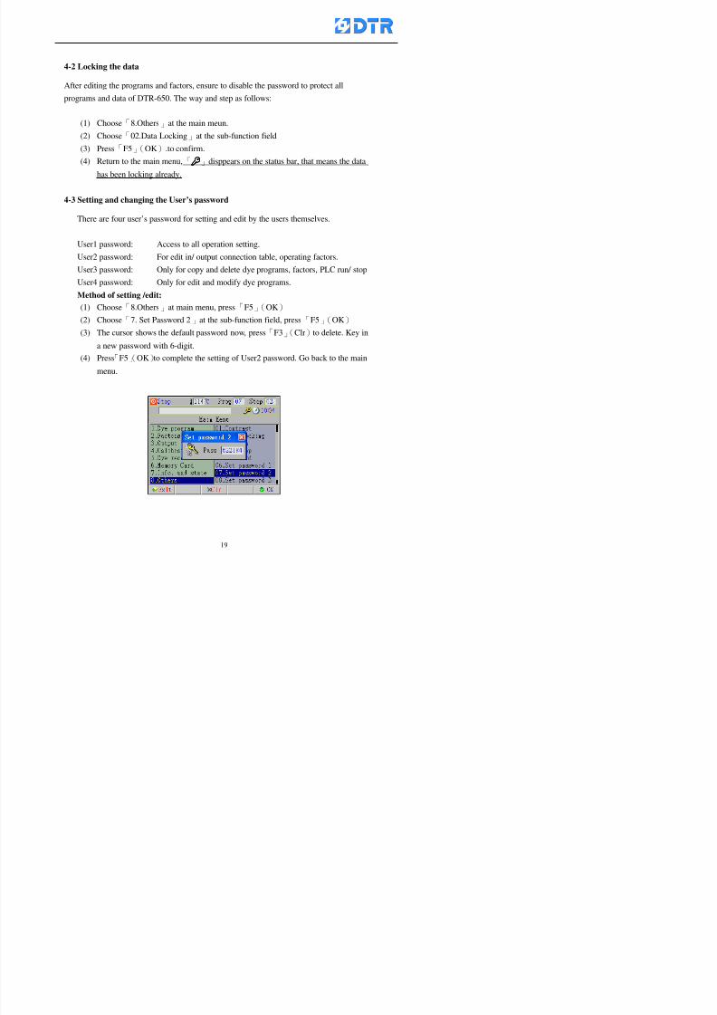
8132019 DTR 650 User Manual
httpslidepdfcomreaderfulldtr-650-user-manual 2070
The four userrsquos password has to made from different group numbers Using
same password will affect the operating Please pay attention when update the
password
8132019 DTR 650 User Manual
httpslidepdfcomreaderfulldtr-650-user-manual 2170
5555 983109983140983145983156983145983150983143 983108983161983141 983120983154983151983143983154983137983149983155
5-1 Choosing a dye program
Press function key「F4」(Edit)or choose「1Dye Program」at the main menu press
「F5」(OK)
Choose「1Edit Dye prog」at the sub-function field press「F5」(OK)to enter to the
window「Sel dye program」During the dye program running it is allowed to edit asaved program or a new dye program or the current dye program in running
Method Press「」「」and「5」「6」「3」「4」to move cursor to choose
a dye program number Press「F5」(OK)to enter that dye program Press
「F1(Exit)to quit and return
Method
Directly key in the number selection box
appears at the right corner of the window
Select a program number and press「F5」
(OK) fi
8132019 DTR 650 User Manual
httpslidepdfcomreaderfulldtr-650-user-manual 2270
5-2 Creating a new dye program
Step
A Choose「1Dye Program」Press「F5」(OK)
B Choose「1Edit Dye prog」at the sub-function menu press「F5」(OK)to enter
to window「Sel dye program」
C At the window「Sel dye program」 choose an empty dye number (eg「002」)
press「F5」(OK)window《Fig 5-2-1》appears
《Fig 5-2-1》
D Press「F2」(Add) table of 「Edit dye instruction」《Fig 5-2-2》appears
E Press「F5」(Edit) the dye instruction appears at the cursor locates press「」「」
」and「5」「6」「3」「4」to move cursor to edit the instruction and its
factors
F All inserted new dye instructions would be listed in front of 「Program End」
8132019 DTR 650 User Manual
httpslidepdfcomreaderfulldtr-650-user-manual 2370
【Eg】Edit「CycRinse」
A Edit the main function step first Press「F2」
()「F3」()to move the cursor The dye
step is listing by orders Choose「CycRinse」
and press「」 there is a cursor at itrsquos value
B Move cursor to setting value「Cold」andchoose「Mix」by pressing()() Then
press「」to move cursor to「Time」and enter
itrsquos setting value as「2」Press「F5」(OK) to
complete the main function setting
C To move cursor to the parallel functionsetting field Press()()to choose the
dye step Press「」to confirm and move
cursor to choose itrsquos setting facor
D Press「F5」(OK)to move cursor to the next
parallel function
E Repeat above steps C-D until all parallel
functions setting are completed Each main
function can be operating with the
maximum 4 parallel functions
F Press「F4」(Save)to confirm and return to
the「Edit dye program」window
G Repeat the above step A E to keep on
8132019 DTR 650 User Manual
httpslidepdfcomreaderfulldtr-650-user-manual 2470
5-3 Setting the file name (for dye programs)
When a dye program is setting up it is saved by numbers automatically Optionally users
can save it by another names
Step
(1) Create a new dye program first (the Name is not available for empty dye
programs)
(2) At the window「Sel dye program」 press「F4」(File) Window《Fig5-3》appears
《Fig5-3》
(3) Use numeric 0~9「+」「-」「_」blank alphabet A~Z and symbols [ ] etchellip to
create a file name Each file name can type-in the max 8 unit Press 「3」「4」
「5」「6」to move the cursor to choose the unit It also can use the membrane
numbric key to type in The selected unit is showed in front of the cursor at the
「File」Press「OK」to confirm
(4) Quit to input to press「F3」(Clr)
(5) After complete the set up press「F5」(OK)to confirm and go back to the window
「Sel dye program」 Now the name behind the dye program number is created
8132019 DTR 650 User Manual
httpslidepdfcomreaderfulldtr-650-user-manual 2570
5-4 Inserting a program step
Insert the program step means to insert a step in the existing program step where youwant to insert a step All following steps are moved one step ahead The total number of
steps will be increased by itself Able to insert more than one step continusely at the
same time
【Example】《Fig5-4》 To insert a step「call」before「002 Rinse」
《Fig 5-4》
Step
A Enter to the dye program「002」at the window of 「Sel dye program」
(Example)
B Press「6」to move cursor to「002 Rinse」 then press「F2」(add)
C Press「F5」(Edit) then press「」「」or「5」「6」to choose program
step to modify Choose「call」and press「」to move cursor to modify itrsquos
value
8132019 DTR 650 User Manual
httpslidepdfcomreaderfulldtr-650-user-manual 2670
D Press「」「」 value of 「call」is listing at the table Choose「pH Check 」Press「F5」(OK)
E Press「F4」(Save)and press「F1」(Undo)to return to previous window Complete
to insert the「02 Call」The previous「02 Rinse」update to「03」 All following
steps are moved one step ahead Total number of steps will be increased ldquo1rdquo by
itself
Repeat the steps B-E can non-stop to insert more than one step
Quit the insert and modify ( before pressing「F4」) press「F1」(Undo) to exit
The original dye steps will be unchanged
To delete an inserted dye steps press key「F3」(Del) The step deletes
immediately
5-5 Deleting a program step
Delete the program step means to delete step which the cursor locates When that step is
deleted the step number will be updated automatically All following steps are moved up
one step It is allowed to delete more than one steps continuously at the same time
Step
A Enter to the「Edit dye program」《Fig5-5》at the window「Select dye program」
B Press「6」「5」move cursor to the want to delete
C Confirm and press「F3」(Del) Window「Confirm delete」appears Press
「F4」(Yes)
8132019 DTR 650 User Manual
httpslidepdfcomreaderfulldtr-650-user-manual 2770
D That step is deleted immediately and all following steps move up one step
Repeat the steps above can non-stop to delete more than one step
Press「F2」(No)to cancel the deletion
Press「F1」(Exit)to end
5-6 Modifying a program step
To modify the saved name and the setting value of the dyeing steps
Step
1 Choose a dye program which need to modify at the「Sel dye program」 press「F5」
(OK)
2 Press「6」「5」to move cursor to a step which need to modify Select and press
「F5」(Edit) Window of 「Edit dye instruction」appears
3 Press「F2」()「F3」()to choose the step list select it and press「」to move
the cursor to itrsquos value setting
4 Press numeric key to input the value or press「6」「5」to choose the item Press
「F5」(OK)when complete Cursor move to the next value (if need to set more
than one item)
5 Press「F4」(Save)when all setting is complete Return to「Edit dye program」
Method of parallel functionrsquos modification is same as above
Before pressing the key「「「「Save」」」」 press「F1」(Undo)to quit all modify Return
to the window of Edit dye program
All edit and modify functions mentioned of this charper are only available
for the dyeing files which already saved in the file and not being running It
8132019 DTR 650 User Manual
httpslidepdfcomreaderfulldtr-650-user-manual 2870
5-7 Copying a dye program
Copying a dye programs mean to make a copy of an dye programs to a blank dyeprogram This function is for creating new dye program rapidly
Choose「1Dye Program」at the main menu Press「F5」(OK)then press「F2」()to choose「2Copy dye prog」 Press「F5」(OK) 《Fig5-7-1》appears
《Fig 5-7-1》
《Fig 5-7-2》
【【【【Eg】】】】
Copy program 003 to program 012
Press「」「」to move cursor to theprogram「003」 press「F4」(Copy)
Program「003」shows at the top right side of
the bar
Press「」「」to move cursor to program「012」 Then press「F5」(Paste)「」appears behind the「012」That means it issuccessfully copying the program
If the target program is occupied
confirmation window「Overwrite」
When choose an program or a targetprogram can select them by using the
8132019 DTR 650 User Manual
httpslidepdfcomreaderfulldtr-650-user-manual 2970
5-8 Deleting a dye program
Choose「1Dye program」at the main menu Press「F5」(OK)then press「F2」()to choose「3Delete dye prog」 Press「F5」(OK) 《Fig5-8-1》appears
《Fig5-8-1》
《Fig5-8-2》
Press「」「」to move cursor to
choose program need to delete Eg
delete program「012」 press「F5」(Del) Confirmation window
「Confirm delete」appears
Press「F4」(Yes) to confirm delete
Repeat the above step can delete more
than one program at the same time
Press「F2」(No) to return to window
《Fig5-8-1》and not delete that program
Exit to press「F1」(Exit)and return to the
main menu
8132019 DTR 650 User Manual
httpslidepdfcomreaderfulldtr-650-user-manual 3070
6 983123983141983156983156983145983150983143DTR-650 has a built-in standard factor that can fulfill all different types of dyeing
machinesrsquos basic demand Users can also modify the factors base on their request to
fulfill their special control demand Before modify please refer to the table of each
range of Setting Factors (see the Supplementary Table)
6-1 ldquoEnable to use the program stepsrdquo setting
There are totally 64 program steps Parts of them are usually applying to the programs
In order to make more efficiently of editing programs it can「Disable」the other part
of program steps which are not usually applying or not applicable to the programs
For example dye machine with one tank it is only using step Tank B In this case itcan firstly「Disable」the program steps of Tank C When edit the program the
「Disable」rsquos steps will not appear at the cursor for choosing But this will not effect
and change the saved files The saved files can be kept as before
Step
(1) Choose「2 Factors」at the main menu Press「F5」(OK)(2) Choose「18 Dye Instruction」at the sub-function menu Then presss「F5」(OK)
Window「Edit dye ins」appears
「Enable」instruction can available to
use「Disable」instruction is temporarystop to use
Press「F2」()「F3」()to move
8132019 DTR 650 User Manual
httpslidepdfcomreaderfulldtr-650-user-manual 3170
6-2 ldquoAllow to modify dye program temporary during operatingrdquo Setting
During dye program running it can modify dye program temporary Thesemodification will not disappear by causing a sudden power interruption or power off
until select another new dye program to run
Please note that it is only for modifying the dye program temporary That program
file would not saved due to the modification If need to modify the program file and
save choose the function of Edit Dye Program to edit (Refer to the Charper 5 for the【Edit Dye Prograrm】)
6-2-1 ldquoAllow to modify all dye programsrdquo Setting
Step
(1) Choose「2 Factors」at the main menu Press「F5」(OK)
(2) Choose「02 System Factor」at the sub-function menu Then presss「F5」(OK)
Window「Edit System Factor」appears
Set to stop using temporary the「07
Rinse」press「F4」(Sel)to set it as Disable
Repeat above steps to complete all setting
Press 「F1」(Exit)to return to main menu
8132019 DTR 650 User Manual
httpslidepdfcomreaderfulldtr-650-user-manual 3270
6-2-2 ldquoAllow to modify part of dye programsrdquo Setting
【Eg】Set the number 08 or above (including number 08) is allowing to modify dye
programs during operating
Step
A Refer to【6-2-1】setting the factor as「22」to allow editing dye program
temporary during operating
(4) Press「3」「4」to edit the setting
as「Enable」 and press「F5」(OK)
Restore the standard factor by
pressing「F3」(Clr)
(5) Exit to press「F1」(Exit)and
return to window of 「Main Menu」
8132019 DTR 650 User Manual
httpslidepdfcomreaderfulldtr-650-user-manual 3370
6-2-3 ldquoAllow to modify dye steps temporaryrdquo Setting
After setting the dye programs are allowed to edit it also can set which dye steps are
allowed to edit temporary during operating
Step
(1) Choose「2 Factors」at the main menu Press「F5」(OK)
(2) Choose「19 Dye Ins control」at the sub-function menu Then presss「F5」
(OK) Window「Edit ins mode」appears
「Enable」 Allow to edit that dye step before
operating
「Disable」 Not allow to edit dye step before
operating
(3) Press「」「」to move cursor
to choose dye step Press「F4」
To enter to the「Edit dye program」from the
function menu there is a「」in front of the
file name「0-7」 means that program is not
allowing to edit during operating
8132019 DTR 650 User Manual
httpslidepdfcomreaderfulldtr-650-user-manual 3470
6-2-4 ldquoSet the dye step to keep running from the interrupt pointrdquo setting
When the dye program is operating it will disappear by causing power
interruption or sudden power off When start running again part of dye steps can
run again from the interrupt point part of them cannot
How to set
(1) Choose「2Factors」in the main menu and press「F5」(OK)
(2) Choose「20Continue mode」in the sub-function menu Press「F5」(OK) to
enter window of 「Continue Setting」
(3) Press「」「」to move cursor to choose dye steps Press「F4」(Sel)it
shows「Disable」or「Enable」for choosing Press「F5」(OK)to move cursorto the next setting
(4) Repeat above method until all setting is complete press「F1」(Exit)and
return to the main menu
8132019 DTR 650 User Manual
httpslidepdfcomreaderfulldtr-650-user-manual 3570
6-3 ldquoAllow to insert an addition dye stepsrdquo setting
During the program is running can temporary insert an addition dye step or a dye
program according to the operating actual situation Through this setting can set which
dye steps can apply or not to the program in operating
During to insert an addition step if sudden interruption or power off occurred it returns
to the main dye program automatically Before starting again should decide seriously
and set it again by actual needed
Step
(1) Choose「2Factors」at the main menu and press「F5」(OK)
(2) Choose「02System factor」and press「F5」(OK)
(3) Press「」「」to move cursor to the factor「34」and press「3」「4」to set
it as「Enable」 Press「F5」(OK)
(4) Press「F1」(Exit)to return to main menu Choose「21Addition Ins」at the
sub-function menu Press「F5」(OK)to enter the window「Addition Instruction」
(5) Press「」「」to move cursor to choose dye steps and press「F4」(Sel) Cursors
locates shows「Eable」or「Disable」 Press「F5」(OK)to move cursor to the
next dye step
(6) Repeat above method until to complete all setting press「F1」(Exit)and return
to the main menu
8132019 DTR 650 User Manual
httpslidepdfcomreaderfulldtr-650-user-manual 3670
6-4 Setting the display mode
DTR650 has three types of display mode during operating Program List mode
Schematic Diagram mode and Icon mode Users can set the display mode during
operating by factor setting
It goes back to a Program List mode when dye program ended
Step
(1) Choose「2Factors」at the main menu and press「F5」(OK)
(2) Choose「02System factor」and press「F5」(OK)
(3) Press「F2」()「F3」()to move cursor to choose「32Display mode」Press
「3」「4」 it shows「Online picture」「Instruction」「Big Icon」 choose
「Online picture」(eg) and press「F5」to confirm
8132019 DTR 650 User Manual
httpslidepdfcomreaderfulldtr-650-user-manual 3770
(4) Press「F1」(Exit)to return to the main menu
(5) The Schematic Diagram displays when the program is running (it stays at theProgram List mode when there is an alarm occurred)
Press「F4」to transfer to another display mode
It goes back to a Program List mode from Schematic Diagram Mode when dye
program ended Press numeric key「3」to view Schematic Diagram Mode again
Quit to press「F5」(Exit)
6-5 Adapt the digital input to another functions
DTR-650 has 32(0~31)input terminal it owns an standard setting when the
controller is initial According to the userrsquos demand they can change the DTR-650rsquos
anther functions of Input Terminal and PLC Input channel
The PLC Intputrsquos name can also define by the users (use IBM computer to edit and
download)
How to set
(1) Choose「2 Factor」at the main menu Press「F5」(OK)
(2) Choose「22 Input table」at the sub-function menu and press「F5」(OK)to enter
「Edit input table」
The actual input
terminal of theIBM computer
PLCrsquos input channel
8132019 DTR 650 User Manual
httpslidepdfcomreaderfulldtr-650-user-manual 3870
6-6 Adapt the digital output to another functions
DTR-650 has 32(0~31)output terminals it owns an standard setting when thecontroller is initial According to the userrsquos demand they can adapte the digital output
and the PLC outputrsquos channel to another functions The PLC Output channelrsquos name
can also define by users (use IBM computer to edit and download)
Step
(1) Choose「2 Factor」at the main menu Press「F5」(OK)
(2) Choose「23 Output table」at the main menu and press「F5」(OK)
(3) Press「F2」()「F3」()to move cursor to choose the output terminal atthe left side of the window Press「F5」(Add) the PLCrsquos output channelrsquos
name is listing at the right side of the window
(4) Press「F2」()「F3」()to move cursor to choose the PLC outputrsquos channel
If cursor moves to the PLC output channel which already linking「Add」is
not for choosing that means that output channel is already occupied
(5) Confirm the connection to press「F5」(Add) Quit to press「F4」(Del)Press「F1」(Exit)when complete all setting and return to main menu
The actual output
terminal of the
IBM computer
PLCrsquos output channel
8132019 DTR 650 User Manual
httpslidepdfcomreaderfulldtr-650-user-manual 3970
983095 983109983140983145983156983145983150983143 983156983144983141 983110983137983139983156983151983154983155DTR-650 has several kinds of control factors
Userrsquos factors System factors Temperature Control factors Speed factors Dosing
factors PID factors Analog Input Output factors standard factors etchellipPlease refer
to the supplementary table for the setting range and standard of the factors
DTR-650 has a built-in standard factor Users can edit by themselves if necessary
7-1 Modifying userrsquos factors
Userrsquos factors is setting with the Dyeing machinesrsquos PLC Programrsquos factor it is define by
the PLC Programmer
Step to edit
(1) Choose「2Factors」at main menu Press「F5」(OK)
(2) Choose「01User Factor」Press「F5」(OK)
(3) Press「F2」()「F3」()「6」「5」to move cursor up down and by page
Choose a factor need to edit then press「3」「4」to set itrsquos value Press「F5」(OK) Cursor moves to the next factor
(4) Some of factors can input numbers by the numeric membrance keys to edit If
the input is incorrect it turns to red and means the edit is not available
8132019 DTR 650 User Manual
httpslidepdfcomreaderfulldtr-650-user-manual 4070
Modifyrsquos method of the system factors temperature factors speed factors dosingfactors PID factors analog Input output factors standard factors etchellipare same asabove
If apply the library of DTR500 and DTR600 into the DTR650 the key「3」「4」may not valid to use Please use the numeric keys instead of it to key in factors itmay not effect the normal operation
Please pay a serious attention and read carefully at the factorrsquos table before modify the factors An incorrect value may effect the DTR-650 Dyeing
Machine Controllerrsquos operating After modifying factors must cancel the
password and secure data
7-2 Loading the standard factors
After modifying factors if need to restore a manufacturerrsquos standard factors of
DTR-650 The method as follows
1 Choose「2Factors」at main menu Press「F5」(OK)
「 「 ( ) 「
8132019 DTR 650 User Manual
httpslidepdfcomreaderfulldtr-650-user-manual 4170
7-3 Copying the factor
Users can build up a set of factor by themselves and make a copy and save
Step
1 Choose「2Factors」at main menu Press「F5」(OK)
2 Choose「13Restore Factor」 press「F5」(OK) window「factor will be
overwrite 」
3 Press「F4」(Yes)copy finished and saved Return to the main menu
4 Press「F2」(No)to not copy the factor and the existing factor is not change Return
to the main menu
7-4 Loading the backup factors
Users can build up a set of factor and backup files to load to DTR-650
Step1 Choose「14Backup factor」at the sub-function menu Press「F5」(OK)and
window「Factror will be overwrite」appears
2 Press「F3」(OK)to load the the backup factor them return to main menu
Press「F2」(No)to not copy the factor and the existing factor is not change
Return to the main menu
8132019 DTR 650 User Manual
httpslidepdfcomreaderfulldtr-650-user-manual 4270
983096 983119983157983156983152983157983156 983124983141983155983156983145983150983143
Before the output testing must be complete the steps as follows
A Cut off all connecting line of output terminal of DTR-650
B Stop running the PLC
C Check up the connections of all output channels to avoid damages from
incorrect connections
D Check up state of dyeing machines include the temperature pressure valves
onoff and pumpshellipetc ensure the safety for priority
8-1 Testing the Digital output
Step
1 Choose「3Output Testing」at the main menu Press「F5」(OK) 2 Choose「1Digital」at the sub function menu Press「F5」(OK) window「Digital
output testing」appears
3 Press「」「」「」to move cursor to each output channels Press「F5」(OK)
Output Name
8132019 DTR 650 User Manual
httpslidepdfcomreaderfulldtr-650-user-manual 4370
8-2 Testing the Analog output
(1) Choose「3Output Testing」at the main menu Press「F5」(OK)
(2) Choose「2Analog」at the sub function menu Press「F5」(OK) window「Analog output testing」appears
(3) Press「」「」「」to move cursor to each channels Then key in number by
the numeric membrance keys (range0~200= 0~20mA) Press「F5」(OK) there
is a output current relating to the output channel
(4) Press「F5」(OK) There is an output when the output channel with red light No
output without light onl(5) When complete the testing press「F1」(OK)to return to the main menu
8132019 DTR 650 User Manual
httpslidepdfcomreaderfulldtr-650-user-manual 4470
983097 983107983137983148983145983138983154983137983156983145983151983150
DTR-650 has Dosing and Temperature calibration
When enter to Dosing calibration must be set the Low Volume calibration first and
then High Volume calibration When enter to Temperature calibration must be set the
Low Temperature calibration first and then High Temperature calibration Must be
hightly follow this orders seriously
9-1 Calibration of Low Volume Tank
Step
A Choose「4Calibration」at the main menu Press「F5」(OK)
B Choose「Dosing 0 low vol」at the sub function menu Press「F5」(OK) window
appears
C Fill the Dosing Tank to a half level input value shows how much the water level
If it stays ldquo0rdquo check the connection and the factor setting is correct or not
And connect the pressure sensorrsquos output channel to the Current Meter to ensure
that sensor works or not
8132019 DTR 650 User Manual
httpslidepdfcomreaderfulldtr-650-user-manual 4570
D Fill the Dosing Tank to 50ml (Calcalate from the bottom side of the pressure
sensor steel tube) input value should show 4~6 (input value must between
0~10) Then enter the water volume The setting volume is relating the water
levelrsquos water value (litre as unit) input range 0~80 Set as「 「「 「0000 0000 0000 0000」」」」is strongly is strongly is strongly is strongly
receommend receommend receommend receommend Press「F5」(OK)to complete [Calibration of Low Volume Tank 1
is same as above method]
9-2 Calibration of High Volume Tank
Step
A Choose「4Calibration」at the main menu Press「F5」(OK)
B Choose「Dos 0 high vol」at the sub function menu Press「F5」(OK) window of
「Calibrate high 」appears
C Fill the Dosing Tank to a full level input value should be larger than 30 enter
the current water level which relates to the water volume Enter the range within
100~2500 Then press「F5」(OK) to complete the calibrate the high volume tank
8132019 DTR 650 User Manual
httpslidepdfcomreaderfulldtr-650-user-manual 4670
9-3 Temperature Calibration
Step
A This function is for adjusting the DTR650rsquos accuracy of Temperature Control It
must be using with the special terminal which is only for DTR650
B Choose「4Calibration」at the main function menu and press「F5」(OK)
C Choose「3Low Temp」at the sub-function menu Press「F5」(OK)and《Fig9-3》
appears insert the DTR650rsquos low temperature calibration terminal to the temperature
input terminal wait for the jumping value to stable down then press「F5」(OK) then
to adjust the high temperature calibration
D Adjusting the High Temperature Calibrationrsquos method is same as above But usersusersusersusers
must be using the High Temperature Terminalmust be using the High Temperature Terminalmust be using the High Temperature Terminalmust be using the High Temperature Terminal whichwhichwhichwhich is specially for DTR650 onlyis specially for DTR650 onlyis specially for DTR650 onlyis specially for DTR650 only
《Fig 9-3》
8132019 DTR 650 User Manual
httpslidepdfcomreaderfulldtr-650-user-manual 4770
10 983122983141983139983151983154983140983155 983151983142 983108983161983141 983120983154983151983143983154983137983149983155
It contains the past 15 days of temperature curves of running history
Checking method
(1) Choose「5Dye Record」at main menu press「F5」(OK)
(2) Sub-function menu shows the set up date of the past 15 days dye programs
Listing by the lastest set up date
(3) Choose a program date and press「F5」(OK) it appears window「Temp
record」
(4) Press「」「」to move the white line in the box one minute by moving once
(5) Press「3」「4」to move the line to check the time period 2 hours by moving once
The yellow selecting line of the「24 hours operating state」is repectively moving
The curve info is show in the curve box Left side of the widnow appears the
relating running info the time is the time value of the line locates at
(6) Check more details of the temperature info to press numeric key「middot」 a bright red line
appears in the selecting box this line is to check the starting point of the
temperature inforsquos time period Then press「」to move the white line to the end
point of the time period The temperature info between the starting point and end
point are appears at the right side of the window Press「middot」to return to the preious
curve page
(7) Check more details of the alarm infor To perss numeric key「7」「9」 the alarmrsquos
details is listing by orders
(8) Press「F1」(exit) to return
8132019 DTR 650 User Manual
httpslidepdfcomreaderfulldtr-650-user-manual 4870
11 983125983155983137983143983141 983151983142 983117983141983149983151983154983161 983107983137983154983140
DTR-650 supports 32MB or above Compact Flash Card which can transfer and save all
information for 4 sets of DTR-650 Including library files schematic diagram icon
image PLC program dye program factor and confiruration files etchellip Use the CF Card
to up download and swap the information of DTR-650 promptly install the relating
device and program updates
DTR-650 CF Card with bank 1 to bank 4 can save 4 sets information of Dyeing
Machines When download or save files should choose the BANK first
《Fig11-1》
8132019 DTR 650 User Manual
httpslidepdfcomreaderfulldtr-650-user-manual 4970
11-1 Downloading data
1 Firmly insert the CF card into the DTR-650rsquos PCMCIA connector Ensure it is
wholely and firmly inserted if the card is not totally inserted or the card do not
touch in all to the connector there will be an error occurred and cannot
updownload or interrupted during operation
2 Choose「6Memory Card」at the main menu and press「F5」(OK) 《Fig11-1》
appears Information of Bank「1」shows at the left hand side of the window press
number 1-4 by using numeric keys to choose the BANK Check the
information in the Bank seriously which is exactly need to download to the
DTR650
3 Press()()「6」「5」to move cursor to the sub-function menu to choose
the downloading items Press「F5」(OK) window appears「Stop PLC run before
access memory card Stop the PLC run」 Press「F5」(YES) to stop PLC
running
4 Press「F5」(OK) window appears Confirm to update or not the DTR-650rsquos
information As that downloading will be replace the DTR-650rsquos information
(that means the existing information of the DTR-650 will be removed and
replaced)
5 Press「F4」(YES)to download the information from the DTR-650 to the CF
Card Return to the main menu when finish
8132019 DTR 650 User Manual
httpslidepdfcomreaderfulldtr-650-user-manual 5070
Ensure inserting firmly the CF card into the DTR-650 unless it will cause
error or cannot Updownload data
Never remove CF card during transferring or updownloading data Until it
is all completed
DTR-650rsquos dyeing program is not compatible with DTR-500 and
DTR-600 Never use CF card to transfer data among them
11-2 Storing and transfering data
1 Insert the CF Card to the DTR-650
2 Choose「6Memory Card」at the main menu and press「F5」(OK) 《Fig11-1》
appears Left hand side of the window shows the data of BANK 1 press numeric
keys 1-4 to select the BANK To confirm the put the data in the DTR-650 to the CF
Card The existing data of that bank will be replaced and covered by the new data (if
that bank is already occuplied)
3 Choose「23Save Dye prog」(Example)at the sub-funciton menu press「F5」(OK)to confirm Window「Update memory card data」appears
4 Press「F5」(OK)to transfer the data to the CF card Return to the main menu
5 Put the CF card into another DTR-650 and follow the operating method of 「11-1
Downloading data」」」」can transfer and swap data with more than one set of
DTR-650
8132019 DTR 650 User Manual
httpslidepdfcomreaderfulldtr-650-user-manual 5170
12 983123983156983137983156983141 983137983150983140 983113983150983142983151983154983149983137983156983145983151983150
The state and information is including the Dyeing Machinersquos state of Digit Input output
Analog Input output Temperature control PID Dosing PID Pressure different PID
software system information and alarm record This information is for checking at any
time
12-1 Input Output state
Step
1 Choose「7Info and state」at main menu and press「F5」(OK)
2 Choose「01Digital IO put」at the sub-function menu then press「F5」(OK)
「Digital In Out State」0=None 1=Input
3 Press「F1」(Exit)to return to main menu
Same method for checking the temperature control analog dosing pressure
different etchellip
12-2 Checking the system information
Step
1 Choose「7Info and state」at main menu and press「F5」(OK)
2 Choose「11 System info」at sub-function field press「F5」(OK)Window
「System Information」appear
System information is including System info(software version) Library doc
Icon files Schematic file Definition file hardare state Config File Commandinstruction icon PLC file etc
8132019 DTR 650 User Manual
httpslidepdfcomreaderfulldtr-650-user-manual 5270
12-3 Checking the operating alarm record
Operating record shows the latest 40 operating items and alarm records including
the time and content of the alarm
A) Choose「7 Info and state」
and press「F5」(OK)
B) Choose「12Alarm logs」at
the sub-funciton menu then
press「F5」(OK)
8132019 DTR 650 User Manual
httpslidepdfcomreaderfulldtr-650-user-manual 5370
13 983105983140983146983157983155983156983145983150983143 983156983144983141 983107983151983150983156983154983137983155983156
The displaysrsquos brightness can be adjusted if necessary
Step
1 Choose「8Others」at main menu press「F5」(OK)
2 Choose「01Contrast」at sub-function menu press「F5」(OK) window「Set
Contrast」appears
3 Press「」「」to move the bar to set the brightness then press「F5」(OK)Window appears「Please reboot the system」
4 Press「F5」(OK)to return to main menu and re-boot the DTR-650 to complete
adjusting the brightness
8132019 DTR 650 User Manual
httpslidepdfcomreaderfulldtr-650-user-manual 5470
14 983123983156983151983152 983154983157983150983150983145983150983143 983156983144983141 983120983116983107 983120983154983151983143983154983137983149
Before testing the Input output testing transfer of the PLC program must stop the PLC
running
Step
1 Choose「8Others」at the main menu Press「F5」(OK)
2 Choose「04 PLC Stop」at sub-function menu Press「F5」(OK) window
「Password」appears
3 Enter password and press「F5」(OK) Window「Stop the PLC run」appears
4 Press「F4」(Yes)and window「PLC Stop」appear Press「F5」(OK) Now
the PLC is stop running and return to the main menu
All testing cannot operate when the PLC is running
Editing dye program and the relating operation can
perform with the PLC running together
8132019 DTR 650 User Manual
httpslidepdfcomreaderfulldtr-650-user-manual 5570
15 983123983141983156983156983145983150983143 983156983144983141 983156983145983149983141
Step
1 Press「8Others」at the main menu Press「F5」(OK)
2 Choose「10Set date time」at the sub-function menu Press「F5」(OK) window
「Set date time」appears
3 Press「F5」(Edit) to move cursor by 「3」「4」 enter the time value at the
cursor locates
4 Press「F5」(OK)to complete the modify Press「F1」(Exit)to return to main
menu
5 Press「F1」(Exit)if not modify and return to main menu
8132019 DTR 650 User Manual
httpslidepdfcomreaderfulldtr-650-user-manual 5670
1166 983123983123983157983157 983152 983152 983152 983152983148983148983141983141983149983149983141983141983150983150983156 983156 983137983137983154 983154 983161983161 983124 983124 983137983137983138983138983148983148983141983141
TTTTTTTTaaaaaaaabbbbbbbblllllllleeeeeeee 11111111 【Dye Instruction】
Code Icon Instruction Code Icon Instruction
000 End 016 Inject C
001 Start 017 Dosing BV
002 Heat 018 PH
003 Cool 019 Addsalt B
004 Flow Fill 020 Addsalt C
005 Level Fill 021 Ana Fill
006 Drian 022 Lock Fill007 Rinse 023 Lock Level
008 Run 024 Low Rinse
009 Call 025 Cyc Rinse
010 Prep B 026 Rinse B
011 Addsalt B 027 Rinse C
012 Dosing B 028 Temp
013 Inject B 029 Nozzle Pressure
014 Prep C 030 Main Pump
015 Dosing C 031 Pump Speed
8132019 DTR 650 User Manual
httpslidepdfcomreaderfulldtr-650-user-manual 5770
Table 2 【【【【Alarm】】】】
System Alarm Must stop operating and check up to solve problems before restarting
the machine
Running Alarm It is a reminder Not effect the operating of DTR-650
Userrsquos Alarm Total of 32 Users can define themselves and use it when edit the PLC
Program (do not listing below)
No System Alarm No Running Alarm
1 PLC program not running 16 Temp ctrl 0 Grad too slow
2 Main temp sensor error 17 Temp ctrl 0 Grad too fast
3 Not at Run window 18 Temp ctrl 0 Hold temp too low
4 Exceeding max temp 19 Temp ctrl 0 Hold temp too high
5 - 20 Temp ctrl 1 Grad too slow6 - 21 Temp ctrl 1 Grad too fast
7 - 22 Temp ctrl 1 Hold temp too low
8 Communication error 23 Temp ctrl 1 Hold temp too high
9 Slave not answer 24 Temp ctrl 2 Grad too slow
10 PLC 0 not answer 25 Temp ctrl 2 Grad too fast
11 PLC 1 not answer 26 Temp 2 Hold temp too low12 Display not answer 27 Temp 2 Hold temp too high
13 Lower power voltage 28 Temp ctrl 3 Grad too slow
14 - 29 Temp ctrl 3 Grad too fast
15 - 30 Temp3 Hold temp too low
31 Temp3 Hold temp too high
32 Dosing 0 injection too slow
33 Dosing 0 injection too fast
34 Dosing 1 injection too slow
35 Dosing 1 injection too fast
8132019 DTR 650 User Manual
httpslidepdfcomreaderfulldtr-650-user-manual 5870
TTTTTTTTaaaaaaaabbbbbbbblllllllleeeeeeee 33333333 【【【【System factor】】】】
No Description Std Range amp Definition
1 ID No 000 000- 100 Controller no
2 Communication Rate 4800Bps 2400 4800 9600 19200 38400
3 Display language Chinese English Chinese
4 Temp display mode and
5 Maxmium temperature 145 025 ~ 145 6 Type of external PLC Default PLC32DPLC32PLC16Default
7 Number of external PLC NANA 1 unit connect
2 unit connect
8Communication Rate of
PLC9600Bps 2400 4800 9600 19200
9 Set point 1 085 000 ~ 145
If signal source is temperaturethe setting value is thetemperature value If the signal
source is Analog Input 6~17 then
setting value for Analog input is 0 ndash
100 and relates Analog
Input14~020mA
10 Source 1 Sensor0Sensor 0 ~5
Analog input 0 ~1111 Set point 2 092 Same as 09
12 Source 2 PT100 1 Same as 10
13 Set point 3 085 Same as 09
14 Source 3 PT100 2 Same as 10
15 Set point 4 092 Same as 09
16 Source 4 PT100 3 Same as 1017 Set point 5 085 Same as 09
18 Source 5 PT100 4 Same as 10
19 Set point 6 092 Same as 09
8132019 DTR 650 User Manual
httpslidepdfcomreaderfulldtr-650-user-manual 5970
29 Min cyclic time of cloth 100sec 0 ~ 255 sec
30 Max cyclic time of cloth 240sec 0 ~255 sec
31Standard cyclic time of
cloth
180 000 ~ 255 sec
32 Display ModeProgram
List
Program list Schematic Diagram
Icon mode
33 CF card format Standard of
DTR CF
Card
Standard of DTR CF Card V20
Standard CF Card
34 Addition step Disable Disable Enable35 Mode Com 3
CouplingEsure Com 3 is the communication
port of the Central or Coupling
36Com 3 Communication
rate9600 Central communication speed
8132019 DTR 650 User Manual
httpslidepdfcomreaderfulldtr-650-user-manual 6070
TTTTTTTTaaaaaaaabbbbbbbblllllllleeeeeeee 44444444 【【【【Temperature Cotnrol Factor】】】】
No Factor Definition Standard Range and Definition
01 PT No PT-0 PT 0~5 PT-100 Input number
02 Max working temp 140 000~140
03 Output mode 0 0~2
04 Alarm time of gardient 240sec 000~255 sec
05 Alarm mode of gradient Always AlwaysOnceNone
06 Control mode of gradient Heating orCooling
interlocked
Heating and Cooling interlocked
No limitation
07 Alarm range of HoldTemp 03 01~20
08 Alarm time for HoldTemp 240sec 000~255sec
09 Alarm mode of HoldTemp Always AlwaysOnceNone
10 Control mode ofHoldTemp
Heating only Only heating and cooling Cooling whenalarm occurred Only heating andcooling No limitation when alarmHeating only
11 Porportional Band 100 000~250
12 Integral band 128 sec 000~255 sec
13 Differential time 04 sec 00~20 sec
14 Min transit gradient 02 00~50
15 Transit rate 20 times 00~50 times (020= 2 times)
16 PID initial output value 010 000~100
17 ONOFF cycle time 10 sec 05~25 sec
Onoff valve set as 010 sec
Proportional valve set as 020 sec
18 Time down count mode Mode 0 0~10 = The time down count range from「Factor 20 + target temp」to「Target
8132019 DTR 650 User Manual
httpslidepdfcomreaderfulldtr-650-user-manual 6170
TTTTTTTTaaaaaaaabbbbbbbblllllllleeeeeeee 55555555 【【【【Speed Factor】】】】
No Factor Definition Standard Range amp Definition
01 Input Number Speed input 0 Speed input 0~11
02 Average times 05 times 01~10
03 Sensor Number 008pcs 001~255
04 Roller Dimension 250mm 050~500
05 Max cloth speed 200mmin 001~25506 Min cloth speed 020mmin 001~255
07 Alarm delay time 240sec 001~255
08 Alarm mode Every oncenoneevery
09 Alarm range () 020 001~255
10 Proportional band 100 001~255
11 Integer band 128 001~25512 Differential time 000 001~200
13 Initial speed () 020 001~255
14 Control cycle ti(01sec) 05 01~30
15 First cycle time(01sec) 10 01~30
16 Speed increase limit () 010 001~100
17 Speed decrease limit () 010 001~100
18 Min speed() 005 001~100
19 Manual speed adjust () 005 001~100
20 Manual initial speed() 020 001~100
21 Stopping speed() 010 001~100
22 Switch speed() 020 001~100
23 Not used
24 Speed decrease turns 03turns 01~50
8132019 DTR 650 User Manual
httpslidepdfcomreaderfulldtr-650-user-manual 6270
Table 6 【【【【Dosing Factors】】】】
No Description Range Range and Explanation
1 Analog input no Analog input 0 Analog input no 0 ~11
2Alarm delay time for
dosing240 sec 000 ~255 sec
3 Alarm time for dosing Every Every Once None
4 Proportional band 100 000 ~255 sec Factor P
5 Integer band 128 000 ~255 sec Factor I6 Differential time 04 00 ~20 Factor D
7 Max adjust rate 150 50~ 255
8 Initial factor for dosing 10 000 ~100
9 User curve section 0 10 Gradient of sect1 for dosing curve9
10 User curve section 1 10 Gradient of sect2 for dosing curve9
11 User curve section 2 10 Gradient of sect3 for dosing curve9
12 User curve section 3 10 Gradient of sect4 for dosing curve9
13 User curve section 4 10 Gradient of sect5 for dosing curve9
14 User curve section 5 10 Gradient of sect6 for dosing curve9
15 User curve section 6 10 Gradient of sect7 for dosing curve9
16 User curve section 7 10 Gradient of sect8 for dosing curve9
17 User curve section 8 10 Gradient of sect9 for dosing curve9
18 User curve section 9 10 Gradient of sect10 for dosing curve9
19 Min water level 05 00~ 10 04~20mA percentagechange to the userrsquos factor setting
20 Output value for Tank
clean
100 000~ 100
Injected percentage of dosing valve
in dosing End period
This factor will be invalided if usingONOFF dosing valve
21 Full range 100 001~255 Self-adjustment cannotchange
22 Range ratio 001001~255 Self-adjustment cannot
change
8132019 DTR 650 User Manual
httpslidepdfcomreaderfulldtr-650-user-manual 6370
【【【【TTaabbllee 77 】】】】Pressure Deviation Factors
No Description Std Range amp Definition
1 Analog input number + Analog in 0 Analog in 0~11
2 Analog input number - Analog in 1 Analog in 0~11
3 Input mode Pressure Pressure Pressure deviation
4 Full range 050x01Kgcm
001~255
5 Range ratio 001 001~255
6 Alarm delay time 100sec 001~255
7 Alarm mode Every oncenone
8 Alarm range 010 001~255
9 Proportional band 100 001~255
10 Integer band 128 001~255
11 Differential time 00 00~20
12 PID Init output value 010 001~255
13 Cycle time 10 03~30
14 First cycle time 030 003~100
15 Max adjust rate 010 001~100
8132019 DTR 650 User Manual
httpslidepdfcomreaderfulldtr-650-user-manual 6470
【【【【TTaabbllee 88 】】】】Definition of Analog Input
No Description Standard Range and Explanation
01 PT 0 correction standard DIN std DIN std JIS std
02 PT 0 correction +0 +- 9
03 PT 1 correction standard DIN std DIN std JIS std
04 PT 1 correction +0 +- 9
05 PT 2 correction standard DIN std DIN std JIS std
06 PT 2 correction +0 +- 9
07 PT 3 correction standard DIN std DIN std JIS std
08 PT 3 correction +0 +- 9
09 PT 4 correction standard DIN std DIN std JIS std
10 PT 4 correction +0 +- 9
11 PT 5 correction standard DIN std DIN std JIS std
12 PT 5 correction +0 +- 9
13 Analog input 0 define 4 ~ 20mA 0 ndash 20mA 4 ndash 20mA
14 Analog input 0 average times 10 times 01- 20 times
15 Analog input 0 min value 0000 0000 - 1000
16 Analog input 0 max value 100 0001 - 9999
17-60 Analog input 1~11 Same as Analog input 0
【【【【 】】】】 fi i i f A O
8132019 DTR 650 User Manual
httpslidepdfcomreaderfulldtr-650-user-manual 6570
【【【【TTaabbllee 99 】】】】Definition of Analog Output
No Description Standard Range and explanation
61 Analog output 0 define Control byPLC
Control by PLC
Temperature control PID0 output
Temperature control PID1 output
Temperature control PID2 output
Speed PID3 output
Dosing PID0 output Dosing PID1output
Pressure different PID0 outputPressure different PID1 output
Main temperature output
62 Mode of Analog ouptput0 4 ~20mA 0 ndash20mA 4 ndash 20mA
63-84 Analog output 1~11 Same as Analog output 0
【【【【TTaabbllee 1100】】】】Value Table 0 amp 1
No Description Range Std Range and explanation
1 Analog input no 000~011 000 Analog input no
2 Data ratio 001~255 100 Multiple by factors
3~53 0~98 000~255 000-100 Analog input 0~98 data
【【【【 】】】】St t Li t
8132019 DTR 650 User Manual
httpslidepdfcomreaderfulldtr-650-user-manual 6670
【【【【TTaabbllee 1111】】】】State List
No Description Range Standard Range and explanation
1 Display setting 1 0~255 205 See remarks at next page
2 Display setting 2 0~255 208
3 Display setting 3 0~255 209
4 Display setting 4 0~255 017
5 Display setting 5 0~255 0186 Display setting 6 0~255 019
7 Display setting 7 0~255 020
8 Display setting 8 0~255 021
9 Display setting 9 0~255 000
10 Display setting 1 0~255 000
11 Display setting 2 0~255 000
12 Display setting 3 0~255 000
13 Display setting 4 0~255 000
14 Display setting 5 0~255 000
15 Display setting 6 0~255 000
16 Display setting 7 0~255 000
Remarks
8132019 DTR 650 User Manual
httpslidepdfcomreaderfulldtr-650-user-manual 6770
0 = No display 1~255 = Display type of number
1~16 Content of PLC VB0~15
No 1 corresponding to VB0
No 16 corresponding to VB15
17~32 Content of PLC DB0~15
No 17 corresponding to DB0
No 32 corresponding to DB15
33~46 Content of PLC CNT0~29
No 33 corresponding to CNT0
No 46 corresponding to CNT29 47~78 Content of dyeing instruction 0~31 CNT0
No 47 corresponding to system instruction to No 0 of CNT0
No 78 corresponding to system instruction to No 31 of CNT0rsquos content
79~110 Dyeing instruction 0~31 of CNT0rsquos setting
111~142 Content of Dyeing instruction 0~31 CNT1No 111 corresponding to dyeing instruction No 0 of CNT1
No 142 corresponding to dyeing instruction No 31 of CNT1rsquos content
143~174 Dyeing instruction 0~31 of CNT1rsquos setting
175~204 Content of PLC HTIM0~29
No 175 corresponding to HTIM0
No 204 corresponding to HTIM29
205 Loading
206 Ratio 1
207 Ratio 2208 Ratio 1 x Loading
209 Ratio 2 x Loading
210 Fix value
211 Value Table 1 matching result
212 Value Table 2 matching result
213 Value Table 1 setting214 Value Table 2 setting
215 Pressure control PID0 different pressure value
216 Pressure control PID1 different pressure value
TTTTTTTTaaaaaaaabbbbbbbblllllllleeeeeeee 1122 【【【【Usage of password】】】】
8132019 DTR 650 User Manual
httpslidepdfcomreaderfulldtr-650-user-manual 6870
No Main FunctionFactor Sub Function Factor Password Rank
1 Run None
2 Dye program User3 or above
3 Control factor
- User factor User 1
- System factor User 1
- Temp PID 0
- Temp PID 1 User 1- Speed PID 0 User 1
- Dosing PID 0 User 1
- Dosing PID 1 User 1
- Pressure PID 0 User 1
- Pressure PID 1 User 1
- Analog IO User 1
- Load standard factor User 2 or above- Load a copied factor User 2 or above
- Copy factor User 2 or above
- Value table 0 User 1
- Value table 1 User 1
- Information and state User 1
- Dye instruction User 1
- Edit dye instruction setting User 14 Output testing User 2 or above
5 Calibration User 2 or above
6 Dye record None
7 CF card User 1
8 Info and state None
9 Others
- Contrast User3 or above
- Data Locking None
- PLC Run User 1
- PLC Stop User 1
- Password setting User 1
TTTTTTTTaaaaaaaabbbbbbbblllllllleeeeeeee 1133 【【【【Technical Data】】】】
8132019 DTR 650 User Manual
httpslidepdfcomreaderfulldtr-650-user-manual 6970
TTTTTTTTaaaaaaaabbbbbbbblllllllleeeeeeee 1133 【【【【Technical Data】】】】
1 Temperature Control
- Range 10~145(plusmn1)
- Mode Proportional or PWM
- Sensor PT100 (JIS or DIN standard)
2 Input and output channel
- Digital Input 32 DC24V PNP- Digital Output 32 DC24V 054A Relay connect point
- Analog Input 4 04~20 mA
- Analog Output 4 0~20mA 或 4~20 mA
3 Communication port 3 RS-232 amp 0~20 mAx1 RS485x 2
4 Dye program
- Number 15000 Steps
- Standard step 61Heating Cooling Fill Drain RinseDosingetc
5LCD module and Display
langage
Chinese
English
320 x 240 TFT color display with
more language
6 CF card connector 1 PCMCIA standard
7 Membrane Keyboard- Number Key 10 [0]~[9] Input factors
- Function Key 5 [F1]~[F5] function selecting
- Operation Key 2 [Start] [Stop]
- Auxiliary Key 7 [][][][][Esc] [larr][OK] [bull]
8 Operating Condition
- Temperature 5~45
- Humidity ≦85 (25)
9 Power supply
V l DC 24V
8132019 DTR 650 User Manual
httpslidepdfcomreaderfulldtr-650-user-manual 7070
70
983108983124983122983085650 983113983150983152983157983156 983119983157983156983152983157983156 983120983151983154983156983145983150983143 (983138983137983139983147983155983145983140983141 983158983145983141983159)
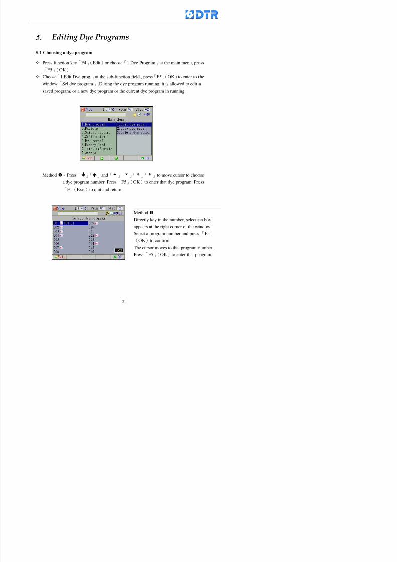
8132019 DTR 650 User Manual
httpslidepdfcomreaderfulldtr-650-user-manual 2170
5555 983109983140983145983156983145983150983143 983108983161983141 983120983154983151983143983154983137983149983155
5-1 Choosing a dye program
Press function key「F4」(Edit)or choose「1Dye Program」at the main menu press
「F5」(OK)
Choose「1Edit Dye prog」at the sub-function field press「F5」(OK)to enter to the
window「Sel dye program」During the dye program running it is allowed to edit asaved program or a new dye program or the current dye program in running
Method Press「」「」and「5」「6」「3」「4」to move cursor to choose
a dye program number Press「F5」(OK)to enter that dye program Press
「F1(Exit)to quit and return
Method
Directly key in the number selection box
appears at the right corner of the window
Select a program number and press「F5」
(OK) fi
8132019 DTR 650 User Manual
httpslidepdfcomreaderfulldtr-650-user-manual 2270
5-2 Creating a new dye program
Step
A Choose「1Dye Program」Press「F5」(OK)
B Choose「1Edit Dye prog」at the sub-function menu press「F5」(OK)to enter
to window「Sel dye program」
C At the window「Sel dye program」 choose an empty dye number (eg「002」)
press「F5」(OK)window《Fig 5-2-1》appears
《Fig 5-2-1》
D Press「F2」(Add) table of 「Edit dye instruction」《Fig 5-2-2》appears
E Press「F5」(Edit) the dye instruction appears at the cursor locates press「」「」
」and「5」「6」「3」「4」to move cursor to edit the instruction and its
factors
F All inserted new dye instructions would be listed in front of 「Program End」
8132019 DTR 650 User Manual
httpslidepdfcomreaderfulldtr-650-user-manual 2370
【Eg】Edit「CycRinse」
A Edit the main function step first Press「F2」
()「F3」()to move the cursor The dye
step is listing by orders Choose「CycRinse」
and press「」 there is a cursor at itrsquos value
B Move cursor to setting value「Cold」andchoose「Mix」by pressing()() Then
press「」to move cursor to「Time」and enter
itrsquos setting value as「2」Press「F5」(OK) to
complete the main function setting
C To move cursor to the parallel functionsetting field Press()()to choose the
dye step Press「」to confirm and move
cursor to choose itrsquos setting facor
D Press「F5」(OK)to move cursor to the next
parallel function
E Repeat above steps C-D until all parallel
functions setting are completed Each main
function can be operating with the
maximum 4 parallel functions
F Press「F4」(Save)to confirm and return to
the「Edit dye program」window
G Repeat the above step A E to keep on
8132019 DTR 650 User Manual
httpslidepdfcomreaderfulldtr-650-user-manual 2470
5-3 Setting the file name (for dye programs)
When a dye program is setting up it is saved by numbers automatically Optionally users
can save it by another names
Step
(1) Create a new dye program first (the Name is not available for empty dye
programs)
(2) At the window「Sel dye program」 press「F4」(File) Window《Fig5-3》appears
《Fig5-3》
(3) Use numeric 0~9「+」「-」「_」blank alphabet A~Z and symbols [ ] etchellip to
create a file name Each file name can type-in the max 8 unit Press 「3」「4」
「5」「6」to move the cursor to choose the unit It also can use the membrane
numbric key to type in The selected unit is showed in front of the cursor at the
「File」Press「OK」to confirm
(4) Quit to input to press「F3」(Clr)
(5) After complete the set up press「F5」(OK)to confirm and go back to the window
「Sel dye program」 Now the name behind the dye program number is created
8132019 DTR 650 User Manual
httpslidepdfcomreaderfulldtr-650-user-manual 2570
5-4 Inserting a program step
Insert the program step means to insert a step in the existing program step where youwant to insert a step All following steps are moved one step ahead The total number of
steps will be increased by itself Able to insert more than one step continusely at the
same time
【Example】《Fig5-4》 To insert a step「call」before「002 Rinse」
《Fig 5-4》
Step
A Enter to the dye program「002」at the window of 「Sel dye program」
(Example)
B Press「6」to move cursor to「002 Rinse」 then press「F2」(add)
C Press「F5」(Edit) then press「」「」or「5」「6」to choose program
step to modify Choose「call」and press「」to move cursor to modify itrsquos
value
8132019 DTR 650 User Manual
httpslidepdfcomreaderfulldtr-650-user-manual 2670
D Press「」「」 value of 「call」is listing at the table Choose「pH Check 」Press「F5」(OK)
E Press「F4」(Save)and press「F1」(Undo)to return to previous window Complete
to insert the「02 Call」The previous「02 Rinse」update to「03」 All following
steps are moved one step ahead Total number of steps will be increased ldquo1rdquo by
itself
Repeat the steps B-E can non-stop to insert more than one step
Quit the insert and modify ( before pressing「F4」) press「F1」(Undo) to exit
The original dye steps will be unchanged
To delete an inserted dye steps press key「F3」(Del) The step deletes
immediately
5-5 Deleting a program step
Delete the program step means to delete step which the cursor locates When that step is
deleted the step number will be updated automatically All following steps are moved up
one step It is allowed to delete more than one steps continuously at the same time
Step
A Enter to the「Edit dye program」《Fig5-5》at the window「Select dye program」
B Press「6」「5」move cursor to the want to delete
C Confirm and press「F3」(Del) Window「Confirm delete」appears Press
「F4」(Yes)
8132019 DTR 650 User Manual
httpslidepdfcomreaderfulldtr-650-user-manual 2770
D That step is deleted immediately and all following steps move up one step
Repeat the steps above can non-stop to delete more than one step
Press「F2」(No)to cancel the deletion
Press「F1」(Exit)to end
5-6 Modifying a program step
To modify the saved name and the setting value of the dyeing steps
Step
1 Choose a dye program which need to modify at the「Sel dye program」 press「F5」
(OK)
2 Press「6」「5」to move cursor to a step which need to modify Select and press
「F5」(Edit) Window of 「Edit dye instruction」appears
3 Press「F2」()「F3」()to choose the step list select it and press「」to move
the cursor to itrsquos value setting
4 Press numeric key to input the value or press「6」「5」to choose the item Press
「F5」(OK)when complete Cursor move to the next value (if need to set more
than one item)
5 Press「F4」(Save)when all setting is complete Return to「Edit dye program」
Method of parallel functionrsquos modification is same as above
Before pressing the key「「「「Save」」」」 press「F1」(Undo)to quit all modify Return
to the window of Edit dye program
All edit and modify functions mentioned of this charper are only available
for the dyeing files which already saved in the file and not being running It
8132019 DTR 650 User Manual
httpslidepdfcomreaderfulldtr-650-user-manual 2870
5-7 Copying a dye program
Copying a dye programs mean to make a copy of an dye programs to a blank dyeprogram This function is for creating new dye program rapidly
Choose「1Dye Program」at the main menu Press「F5」(OK)then press「F2」()to choose「2Copy dye prog」 Press「F5」(OK) 《Fig5-7-1》appears
《Fig 5-7-1》
《Fig 5-7-2》
【【【【Eg】】】】
Copy program 003 to program 012
Press「」「」to move cursor to theprogram「003」 press「F4」(Copy)
Program「003」shows at the top right side of
the bar
Press「」「」to move cursor to program「012」 Then press「F5」(Paste)「」appears behind the「012」That means it issuccessfully copying the program
If the target program is occupied
confirmation window「Overwrite」
When choose an program or a targetprogram can select them by using the
8132019 DTR 650 User Manual
httpslidepdfcomreaderfulldtr-650-user-manual 2970
5-8 Deleting a dye program
Choose「1Dye program」at the main menu Press「F5」(OK)then press「F2」()to choose「3Delete dye prog」 Press「F5」(OK) 《Fig5-8-1》appears
《Fig5-8-1》
《Fig5-8-2》
Press「」「」to move cursor to
choose program need to delete Eg
delete program「012」 press「F5」(Del) Confirmation window
「Confirm delete」appears
Press「F4」(Yes) to confirm delete
Repeat the above step can delete more
than one program at the same time
Press「F2」(No) to return to window
《Fig5-8-1》and not delete that program
Exit to press「F1」(Exit)and return to the
main menu
8132019 DTR 650 User Manual
httpslidepdfcomreaderfulldtr-650-user-manual 3070
6 983123983141983156983156983145983150983143DTR-650 has a built-in standard factor that can fulfill all different types of dyeing
machinesrsquos basic demand Users can also modify the factors base on their request to
fulfill their special control demand Before modify please refer to the table of each
range of Setting Factors (see the Supplementary Table)
6-1 ldquoEnable to use the program stepsrdquo setting
There are totally 64 program steps Parts of them are usually applying to the programs
In order to make more efficiently of editing programs it can「Disable」the other part
of program steps which are not usually applying or not applicable to the programs
For example dye machine with one tank it is only using step Tank B In this case itcan firstly「Disable」the program steps of Tank C When edit the program the
「Disable」rsquos steps will not appear at the cursor for choosing But this will not effect
and change the saved files The saved files can be kept as before
Step
(1) Choose「2 Factors」at the main menu Press「F5」(OK)(2) Choose「18 Dye Instruction」at the sub-function menu Then presss「F5」(OK)
Window「Edit dye ins」appears
「Enable」instruction can available to
use「Disable」instruction is temporarystop to use
Press「F2」()「F3」()to move
8132019 DTR 650 User Manual
httpslidepdfcomreaderfulldtr-650-user-manual 3170
6-2 ldquoAllow to modify dye program temporary during operatingrdquo Setting
During dye program running it can modify dye program temporary Thesemodification will not disappear by causing a sudden power interruption or power off
until select another new dye program to run
Please note that it is only for modifying the dye program temporary That program
file would not saved due to the modification If need to modify the program file and
save choose the function of Edit Dye Program to edit (Refer to the Charper 5 for the【Edit Dye Prograrm】)
6-2-1 ldquoAllow to modify all dye programsrdquo Setting
Step
(1) Choose「2 Factors」at the main menu Press「F5」(OK)
(2) Choose「02 System Factor」at the sub-function menu Then presss「F5」(OK)
Window「Edit System Factor」appears
Set to stop using temporary the「07
Rinse」press「F4」(Sel)to set it as Disable
Repeat above steps to complete all setting
Press 「F1」(Exit)to return to main menu
8132019 DTR 650 User Manual
httpslidepdfcomreaderfulldtr-650-user-manual 3270
6-2-2 ldquoAllow to modify part of dye programsrdquo Setting
【Eg】Set the number 08 or above (including number 08) is allowing to modify dye
programs during operating
Step
A Refer to【6-2-1】setting the factor as「22」to allow editing dye program
temporary during operating
(4) Press「3」「4」to edit the setting
as「Enable」 and press「F5」(OK)
Restore the standard factor by
pressing「F3」(Clr)
(5) Exit to press「F1」(Exit)and
return to window of 「Main Menu」
8132019 DTR 650 User Manual
httpslidepdfcomreaderfulldtr-650-user-manual 3370
6-2-3 ldquoAllow to modify dye steps temporaryrdquo Setting
After setting the dye programs are allowed to edit it also can set which dye steps are
allowed to edit temporary during operating
Step
(1) Choose「2 Factors」at the main menu Press「F5」(OK)
(2) Choose「19 Dye Ins control」at the sub-function menu Then presss「F5」
(OK) Window「Edit ins mode」appears
「Enable」 Allow to edit that dye step before
operating
「Disable」 Not allow to edit dye step before
operating
(3) Press「」「」to move cursor
to choose dye step Press「F4」
To enter to the「Edit dye program」from the
function menu there is a「」in front of the
file name「0-7」 means that program is not
allowing to edit during operating
8132019 DTR 650 User Manual
httpslidepdfcomreaderfulldtr-650-user-manual 3470
6-2-4 ldquoSet the dye step to keep running from the interrupt pointrdquo setting
When the dye program is operating it will disappear by causing power
interruption or sudden power off When start running again part of dye steps can
run again from the interrupt point part of them cannot
How to set
(1) Choose「2Factors」in the main menu and press「F5」(OK)
(2) Choose「20Continue mode」in the sub-function menu Press「F5」(OK) to
enter window of 「Continue Setting」
(3) Press「」「」to move cursor to choose dye steps Press「F4」(Sel)it
shows「Disable」or「Enable」for choosing Press「F5」(OK)to move cursorto the next setting
(4) Repeat above method until all setting is complete press「F1」(Exit)and
return to the main menu
8132019 DTR 650 User Manual
httpslidepdfcomreaderfulldtr-650-user-manual 3570
6-3 ldquoAllow to insert an addition dye stepsrdquo setting
During the program is running can temporary insert an addition dye step or a dye
program according to the operating actual situation Through this setting can set which
dye steps can apply or not to the program in operating
During to insert an addition step if sudden interruption or power off occurred it returns
to the main dye program automatically Before starting again should decide seriously
and set it again by actual needed
Step
(1) Choose「2Factors」at the main menu and press「F5」(OK)
(2) Choose「02System factor」and press「F5」(OK)
(3) Press「」「」to move cursor to the factor「34」and press「3」「4」to set
it as「Enable」 Press「F5」(OK)
(4) Press「F1」(Exit)to return to main menu Choose「21Addition Ins」at the
sub-function menu Press「F5」(OK)to enter the window「Addition Instruction」
(5) Press「」「」to move cursor to choose dye steps and press「F4」(Sel) Cursors
locates shows「Eable」or「Disable」 Press「F5」(OK)to move cursor to the
next dye step
(6) Repeat above method until to complete all setting press「F1」(Exit)and return
to the main menu
8132019 DTR 650 User Manual
httpslidepdfcomreaderfulldtr-650-user-manual 3670
6-4 Setting the display mode
DTR650 has three types of display mode during operating Program List mode
Schematic Diagram mode and Icon mode Users can set the display mode during
operating by factor setting
It goes back to a Program List mode when dye program ended
Step
(1) Choose「2Factors」at the main menu and press「F5」(OK)
(2) Choose「02System factor」and press「F5」(OK)
(3) Press「F2」()「F3」()to move cursor to choose「32Display mode」Press
「3」「4」 it shows「Online picture」「Instruction」「Big Icon」 choose
「Online picture」(eg) and press「F5」to confirm
8132019 DTR 650 User Manual
httpslidepdfcomreaderfulldtr-650-user-manual 3770
(4) Press「F1」(Exit)to return to the main menu
(5) The Schematic Diagram displays when the program is running (it stays at theProgram List mode when there is an alarm occurred)
Press「F4」to transfer to another display mode
It goes back to a Program List mode from Schematic Diagram Mode when dye
program ended Press numeric key「3」to view Schematic Diagram Mode again
Quit to press「F5」(Exit)
6-5 Adapt the digital input to another functions
DTR-650 has 32(0~31)input terminal it owns an standard setting when the
controller is initial According to the userrsquos demand they can change the DTR-650rsquos
anther functions of Input Terminal and PLC Input channel
The PLC Intputrsquos name can also define by the users (use IBM computer to edit and
download)
How to set
(1) Choose「2 Factor」at the main menu Press「F5」(OK)
(2) Choose「22 Input table」at the sub-function menu and press「F5」(OK)to enter
「Edit input table」
The actual input
terminal of theIBM computer
PLCrsquos input channel
8132019 DTR 650 User Manual
httpslidepdfcomreaderfulldtr-650-user-manual 3870
6-6 Adapt the digital output to another functions
DTR-650 has 32(0~31)output terminals it owns an standard setting when thecontroller is initial According to the userrsquos demand they can adapte the digital output
and the PLC outputrsquos channel to another functions The PLC Output channelrsquos name
can also define by users (use IBM computer to edit and download)
Step
(1) Choose「2 Factor」at the main menu Press「F5」(OK)
(2) Choose「23 Output table」at the main menu and press「F5」(OK)
(3) Press「F2」()「F3」()to move cursor to choose the output terminal atthe left side of the window Press「F5」(Add) the PLCrsquos output channelrsquos
name is listing at the right side of the window
(4) Press「F2」()「F3」()to move cursor to choose the PLC outputrsquos channel
If cursor moves to the PLC output channel which already linking「Add」is
not for choosing that means that output channel is already occupied
(5) Confirm the connection to press「F5」(Add) Quit to press「F4」(Del)Press「F1」(Exit)when complete all setting and return to main menu
The actual output
terminal of the
IBM computer
PLCrsquos output channel
8132019 DTR 650 User Manual
httpslidepdfcomreaderfulldtr-650-user-manual 3970
983095 983109983140983145983156983145983150983143 983156983144983141 983110983137983139983156983151983154983155DTR-650 has several kinds of control factors
Userrsquos factors System factors Temperature Control factors Speed factors Dosing
factors PID factors Analog Input Output factors standard factors etchellipPlease refer
to the supplementary table for the setting range and standard of the factors
DTR-650 has a built-in standard factor Users can edit by themselves if necessary
7-1 Modifying userrsquos factors
Userrsquos factors is setting with the Dyeing machinesrsquos PLC Programrsquos factor it is define by
the PLC Programmer
Step to edit
(1) Choose「2Factors」at main menu Press「F5」(OK)
(2) Choose「01User Factor」Press「F5」(OK)
(3) Press「F2」()「F3」()「6」「5」to move cursor up down and by page
Choose a factor need to edit then press「3」「4」to set itrsquos value Press「F5」(OK) Cursor moves to the next factor
(4) Some of factors can input numbers by the numeric membrance keys to edit If
the input is incorrect it turns to red and means the edit is not available
8132019 DTR 650 User Manual
httpslidepdfcomreaderfulldtr-650-user-manual 4070
Modifyrsquos method of the system factors temperature factors speed factors dosingfactors PID factors analog Input output factors standard factors etchellipare same asabove
If apply the library of DTR500 and DTR600 into the DTR650 the key「3」「4」may not valid to use Please use the numeric keys instead of it to key in factors itmay not effect the normal operation
Please pay a serious attention and read carefully at the factorrsquos table before modify the factors An incorrect value may effect the DTR-650 Dyeing
Machine Controllerrsquos operating After modifying factors must cancel the
password and secure data
7-2 Loading the standard factors
After modifying factors if need to restore a manufacturerrsquos standard factors of
DTR-650 The method as follows
1 Choose「2Factors」at main menu Press「F5」(OK)
「 「 ( ) 「
8132019 DTR 650 User Manual
httpslidepdfcomreaderfulldtr-650-user-manual 4170
7-3 Copying the factor
Users can build up a set of factor by themselves and make a copy and save
Step
1 Choose「2Factors」at main menu Press「F5」(OK)
2 Choose「13Restore Factor」 press「F5」(OK) window「factor will be
overwrite 」
3 Press「F4」(Yes)copy finished and saved Return to the main menu
4 Press「F2」(No)to not copy the factor and the existing factor is not change Return
to the main menu
7-4 Loading the backup factors
Users can build up a set of factor and backup files to load to DTR-650
Step1 Choose「14Backup factor」at the sub-function menu Press「F5」(OK)and
window「Factror will be overwrite」appears
2 Press「F3」(OK)to load the the backup factor them return to main menu
Press「F2」(No)to not copy the factor and the existing factor is not change
Return to the main menu
8132019 DTR 650 User Manual
httpslidepdfcomreaderfulldtr-650-user-manual 4270
983096 983119983157983156983152983157983156 983124983141983155983156983145983150983143
Before the output testing must be complete the steps as follows
A Cut off all connecting line of output terminal of DTR-650
B Stop running the PLC
C Check up the connections of all output channels to avoid damages from
incorrect connections
D Check up state of dyeing machines include the temperature pressure valves
onoff and pumpshellipetc ensure the safety for priority
8-1 Testing the Digital output
Step
1 Choose「3Output Testing」at the main menu Press「F5」(OK) 2 Choose「1Digital」at the sub function menu Press「F5」(OK) window「Digital
output testing」appears
3 Press「」「」「」to move cursor to each output channels Press「F5」(OK)
Output Name
8132019 DTR 650 User Manual
httpslidepdfcomreaderfulldtr-650-user-manual 4370
8-2 Testing the Analog output
(1) Choose「3Output Testing」at the main menu Press「F5」(OK)
(2) Choose「2Analog」at the sub function menu Press「F5」(OK) window「Analog output testing」appears
(3) Press「」「」「」to move cursor to each channels Then key in number by
the numeric membrance keys (range0~200= 0~20mA) Press「F5」(OK) there
is a output current relating to the output channel
(4) Press「F5」(OK) There is an output when the output channel with red light No
output without light onl(5) When complete the testing press「F1」(OK)to return to the main menu
8132019 DTR 650 User Manual
httpslidepdfcomreaderfulldtr-650-user-manual 4470
983097 983107983137983148983145983138983154983137983156983145983151983150
DTR-650 has Dosing and Temperature calibration
When enter to Dosing calibration must be set the Low Volume calibration first and
then High Volume calibration When enter to Temperature calibration must be set the
Low Temperature calibration first and then High Temperature calibration Must be
hightly follow this orders seriously
9-1 Calibration of Low Volume Tank
Step
A Choose「4Calibration」at the main menu Press「F5」(OK)
B Choose「Dosing 0 low vol」at the sub function menu Press「F5」(OK) window
appears
C Fill the Dosing Tank to a half level input value shows how much the water level
If it stays ldquo0rdquo check the connection and the factor setting is correct or not
And connect the pressure sensorrsquos output channel to the Current Meter to ensure
that sensor works or not
8132019 DTR 650 User Manual
httpslidepdfcomreaderfulldtr-650-user-manual 4570
D Fill the Dosing Tank to 50ml (Calcalate from the bottom side of the pressure
sensor steel tube) input value should show 4~6 (input value must between
0~10) Then enter the water volume The setting volume is relating the water
levelrsquos water value (litre as unit) input range 0~80 Set as「 「「 「0000 0000 0000 0000」」」」is strongly is strongly is strongly is strongly
receommend receommend receommend receommend Press「F5」(OK)to complete [Calibration of Low Volume Tank 1
is same as above method]
9-2 Calibration of High Volume Tank
Step
A Choose「4Calibration」at the main menu Press「F5」(OK)
B Choose「Dos 0 high vol」at the sub function menu Press「F5」(OK) window of
「Calibrate high 」appears
C Fill the Dosing Tank to a full level input value should be larger than 30 enter
the current water level which relates to the water volume Enter the range within
100~2500 Then press「F5」(OK) to complete the calibrate the high volume tank
8132019 DTR 650 User Manual
httpslidepdfcomreaderfulldtr-650-user-manual 4670
9-3 Temperature Calibration
Step
A This function is for adjusting the DTR650rsquos accuracy of Temperature Control It
must be using with the special terminal which is only for DTR650
B Choose「4Calibration」at the main function menu and press「F5」(OK)
C Choose「3Low Temp」at the sub-function menu Press「F5」(OK)and《Fig9-3》
appears insert the DTR650rsquos low temperature calibration terminal to the temperature
input terminal wait for the jumping value to stable down then press「F5」(OK) then
to adjust the high temperature calibration
D Adjusting the High Temperature Calibrationrsquos method is same as above But usersusersusersusers
must be using the High Temperature Terminalmust be using the High Temperature Terminalmust be using the High Temperature Terminalmust be using the High Temperature Terminal whichwhichwhichwhich is specially for DTR650 onlyis specially for DTR650 onlyis specially for DTR650 onlyis specially for DTR650 only
《Fig 9-3》
8132019 DTR 650 User Manual
httpslidepdfcomreaderfulldtr-650-user-manual 4770
10 983122983141983139983151983154983140983155 983151983142 983108983161983141 983120983154983151983143983154983137983149983155
It contains the past 15 days of temperature curves of running history
Checking method
(1) Choose「5Dye Record」at main menu press「F5」(OK)
(2) Sub-function menu shows the set up date of the past 15 days dye programs
Listing by the lastest set up date
(3) Choose a program date and press「F5」(OK) it appears window「Temp
record」
(4) Press「」「」to move the white line in the box one minute by moving once
(5) Press「3」「4」to move the line to check the time period 2 hours by moving once
The yellow selecting line of the「24 hours operating state」is repectively moving
The curve info is show in the curve box Left side of the widnow appears the
relating running info the time is the time value of the line locates at
(6) Check more details of the temperature info to press numeric key「middot」 a bright red line
appears in the selecting box this line is to check the starting point of the
temperature inforsquos time period Then press「」to move the white line to the end
point of the time period The temperature info between the starting point and end
point are appears at the right side of the window Press「middot」to return to the preious
curve page
(7) Check more details of the alarm infor To perss numeric key「7」「9」 the alarmrsquos
details is listing by orders
(8) Press「F1」(exit) to return
8132019 DTR 650 User Manual
httpslidepdfcomreaderfulldtr-650-user-manual 4870
11 983125983155983137983143983141 983151983142 983117983141983149983151983154983161 983107983137983154983140
DTR-650 supports 32MB or above Compact Flash Card which can transfer and save all
information for 4 sets of DTR-650 Including library files schematic diagram icon
image PLC program dye program factor and confiruration files etchellip Use the CF Card
to up download and swap the information of DTR-650 promptly install the relating
device and program updates
DTR-650 CF Card with bank 1 to bank 4 can save 4 sets information of Dyeing
Machines When download or save files should choose the BANK first
《Fig11-1》
8132019 DTR 650 User Manual
httpslidepdfcomreaderfulldtr-650-user-manual 4970
11-1 Downloading data
1 Firmly insert the CF card into the DTR-650rsquos PCMCIA connector Ensure it is
wholely and firmly inserted if the card is not totally inserted or the card do not
touch in all to the connector there will be an error occurred and cannot
updownload or interrupted during operation
2 Choose「6Memory Card」at the main menu and press「F5」(OK) 《Fig11-1》
appears Information of Bank「1」shows at the left hand side of the window press
number 1-4 by using numeric keys to choose the BANK Check the
information in the Bank seriously which is exactly need to download to the
DTR650
3 Press()()「6」「5」to move cursor to the sub-function menu to choose
the downloading items Press「F5」(OK) window appears「Stop PLC run before
access memory card Stop the PLC run」 Press「F5」(YES) to stop PLC
running
4 Press「F5」(OK) window appears Confirm to update or not the DTR-650rsquos
information As that downloading will be replace the DTR-650rsquos information
(that means the existing information of the DTR-650 will be removed and
replaced)
5 Press「F4」(YES)to download the information from the DTR-650 to the CF
Card Return to the main menu when finish
8132019 DTR 650 User Manual
httpslidepdfcomreaderfulldtr-650-user-manual 5070
Ensure inserting firmly the CF card into the DTR-650 unless it will cause
error or cannot Updownload data
Never remove CF card during transferring or updownloading data Until it
is all completed
DTR-650rsquos dyeing program is not compatible with DTR-500 and
DTR-600 Never use CF card to transfer data among them
11-2 Storing and transfering data
1 Insert the CF Card to the DTR-650
2 Choose「6Memory Card」at the main menu and press「F5」(OK) 《Fig11-1》
appears Left hand side of the window shows the data of BANK 1 press numeric
keys 1-4 to select the BANK To confirm the put the data in the DTR-650 to the CF
Card The existing data of that bank will be replaced and covered by the new data (if
that bank is already occuplied)
3 Choose「23Save Dye prog」(Example)at the sub-funciton menu press「F5」(OK)to confirm Window「Update memory card data」appears
4 Press「F5」(OK)to transfer the data to the CF card Return to the main menu
5 Put the CF card into another DTR-650 and follow the operating method of 「11-1
Downloading data」」」」can transfer and swap data with more than one set of
DTR-650
8132019 DTR 650 User Manual
httpslidepdfcomreaderfulldtr-650-user-manual 5170
12 983123983156983137983156983141 983137983150983140 983113983150983142983151983154983149983137983156983145983151983150
The state and information is including the Dyeing Machinersquos state of Digit Input output
Analog Input output Temperature control PID Dosing PID Pressure different PID
software system information and alarm record This information is for checking at any
time
12-1 Input Output state
Step
1 Choose「7Info and state」at main menu and press「F5」(OK)
2 Choose「01Digital IO put」at the sub-function menu then press「F5」(OK)
「Digital In Out State」0=None 1=Input
3 Press「F1」(Exit)to return to main menu
Same method for checking the temperature control analog dosing pressure
different etchellip
12-2 Checking the system information
Step
1 Choose「7Info and state」at main menu and press「F5」(OK)
2 Choose「11 System info」at sub-function field press「F5」(OK)Window
「System Information」appear
System information is including System info(software version) Library doc
Icon files Schematic file Definition file hardare state Config File Commandinstruction icon PLC file etc
8132019 DTR 650 User Manual
httpslidepdfcomreaderfulldtr-650-user-manual 5270
12-3 Checking the operating alarm record
Operating record shows the latest 40 operating items and alarm records including
the time and content of the alarm
A) Choose「7 Info and state」
and press「F5」(OK)
B) Choose「12Alarm logs」at
the sub-funciton menu then
press「F5」(OK)
8132019 DTR 650 User Manual
httpslidepdfcomreaderfulldtr-650-user-manual 5370
13 983105983140983146983157983155983156983145983150983143 983156983144983141 983107983151983150983156983154983137983155983156
The displaysrsquos brightness can be adjusted if necessary
Step
1 Choose「8Others」at main menu press「F5」(OK)
2 Choose「01Contrast」at sub-function menu press「F5」(OK) window「Set
Contrast」appears
3 Press「」「」to move the bar to set the brightness then press「F5」(OK)Window appears「Please reboot the system」
4 Press「F5」(OK)to return to main menu and re-boot the DTR-650 to complete
adjusting the brightness
8132019 DTR 650 User Manual
httpslidepdfcomreaderfulldtr-650-user-manual 5470
14 983123983156983151983152 983154983157983150983150983145983150983143 983156983144983141 983120983116983107 983120983154983151983143983154983137983149
Before testing the Input output testing transfer of the PLC program must stop the PLC
running
Step
1 Choose「8Others」at the main menu Press「F5」(OK)
2 Choose「04 PLC Stop」at sub-function menu Press「F5」(OK) window
「Password」appears
3 Enter password and press「F5」(OK) Window「Stop the PLC run」appears
4 Press「F4」(Yes)and window「PLC Stop」appear Press「F5」(OK) Now
the PLC is stop running and return to the main menu
All testing cannot operate when the PLC is running
Editing dye program and the relating operation can
perform with the PLC running together
8132019 DTR 650 User Manual
httpslidepdfcomreaderfulldtr-650-user-manual 5570
15 983123983141983156983156983145983150983143 983156983144983141 983156983145983149983141
Step
1 Press「8Others」at the main menu Press「F5」(OK)
2 Choose「10Set date time」at the sub-function menu Press「F5」(OK) window
「Set date time」appears
3 Press「F5」(Edit) to move cursor by 「3」「4」 enter the time value at the
cursor locates
4 Press「F5」(OK)to complete the modify Press「F1」(Exit)to return to main
menu
5 Press「F1」(Exit)if not modify and return to main menu
8132019 DTR 650 User Manual
httpslidepdfcomreaderfulldtr-650-user-manual 5670
1166 983123983123983157983157 983152 983152 983152 983152983148983148983141983141983149983149983141983141983150983150983156 983156 983137983137983154 983154 983161983161 983124 983124 983137983137983138983138983148983148983141983141
TTTTTTTTaaaaaaaabbbbbbbblllllllleeeeeeee 11111111 【Dye Instruction】
Code Icon Instruction Code Icon Instruction
000 End 016 Inject C
001 Start 017 Dosing BV
002 Heat 018 PH
003 Cool 019 Addsalt B
004 Flow Fill 020 Addsalt C
005 Level Fill 021 Ana Fill
006 Drian 022 Lock Fill007 Rinse 023 Lock Level
008 Run 024 Low Rinse
009 Call 025 Cyc Rinse
010 Prep B 026 Rinse B
011 Addsalt B 027 Rinse C
012 Dosing B 028 Temp
013 Inject B 029 Nozzle Pressure
014 Prep C 030 Main Pump
015 Dosing C 031 Pump Speed
8132019 DTR 650 User Manual
httpslidepdfcomreaderfulldtr-650-user-manual 5770
Table 2 【【【【Alarm】】】】
System Alarm Must stop operating and check up to solve problems before restarting
the machine
Running Alarm It is a reminder Not effect the operating of DTR-650
Userrsquos Alarm Total of 32 Users can define themselves and use it when edit the PLC
Program (do not listing below)
No System Alarm No Running Alarm
1 PLC program not running 16 Temp ctrl 0 Grad too slow
2 Main temp sensor error 17 Temp ctrl 0 Grad too fast
3 Not at Run window 18 Temp ctrl 0 Hold temp too low
4 Exceeding max temp 19 Temp ctrl 0 Hold temp too high
5 - 20 Temp ctrl 1 Grad too slow6 - 21 Temp ctrl 1 Grad too fast
7 - 22 Temp ctrl 1 Hold temp too low
8 Communication error 23 Temp ctrl 1 Hold temp too high
9 Slave not answer 24 Temp ctrl 2 Grad too slow
10 PLC 0 not answer 25 Temp ctrl 2 Grad too fast
11 PLC 1 not answer 26 Temp 2 Hold temp too low12 Display not answer 27 Temp 2 Hold temp too high
13 Lower power voltage 28 Temp ctrl 3 Grad too slow
14 - 29 Temp ctrl 3 Grad too fast
15 - 30 Temp3 Hold temp too low
31 Temp3 Hold temp too high
32 Dosing 0 injection too slow
33 Dosing 0 injection too fast
34 Dosing 1 injection too slow
35 Dosing 1 injection too fast
8132019 DTR 650 User Manual
httpslidepdfcomreaderfulldtr-650-user-manual 5870
TTTTTTTTaaaaaaaabbbbbbbblllllllleeeeeeee 33333333 【【【【System factor】】】】
No Description Std Range amp Definition
1 ID No 000 000- 100 Controller no
2 Communication Rate 4800Bps 2400 4800 9600 19200 38400
3 Display language Chinese English Chinese
4 Temp display mode and
5 Maxmium temperature 145 025 ~ 145 6 Type of external PLC Default PLC32DPLC32PLC16Default
7 Number of external PLC NANA 1 unit connect
2 unit connect
8Communication Rate of
PLC9600Bps 2400 4800 9600 19200
9 Set point 1 085 000 ~ 145
If signal source is temperaturethe setting value is thetemperature value If the signal
source is Analog Input 6~17 then
setting value for Analog input is 0 ndash
100 and relates Analog
Input14~020mA
10 Source 1 Sensor0Sensor 0 ~5
Analog input 0 ~1111 Set point 2 092 Same as 09
12 Source 2 PT100 1 Same as 10
13 Set point 3 085 Same as 09
14 Source 3 PT100 2 Same as 10
15 Set point 4 092 Same as 09
16 Source 4 PT100 3 Same as 1017 Set point 5 085 Same as 09
18 Source 5 PT100 4 Same as 10
19 Set point 6 092 Same as 09
8132019 DTR 650 User Manual
httpslidepdfcomreaderfulldtr-650-user-manual 5970
29 Min cyclic time of cloth 100sec 0 ~ 255 sec
30 Max cyclic time of cloth 240sec 0 ~255 sec
31Standard cyclic time of
cloth
180 000 ~ 255 sec
32 Display ModeProgram
List
Program list Schematic Diagram
Icon mode
33 CF card format Standard of
DTR CF
Card
Standard of DTR CF Card V20
Standard CF Card
34 Addition step Disable Disable Enable35 Mode Com 3
CouplingEsure Com 3 is the communication
port of the Central or Coupling
36Com 3 Communication
rate9600 Central communication speed
8132019 DTR 650 User Manual
httpslidepdfcomreaderfulldtr-650-user-manual 6070
TTTTTTTTaaaaaaaabbbbbbbblllllllleeeeeeee 44444444 【【【【Temperature Cotnrol Factor】】】】
No Factor Definition Standard Range and Definition
01 PT No PT-0 PT 0~5 PT-100 Input number
02 Max working temp 140 000~140
03 Output mode 0 0~2
04 Alarm time of gardient 240sec 000~255 sec
05 Alarm mode of gradient Always AlwaysOnceNone
06 Control mode of gradient Heating orCooling
interlocked
Heating and Cooling interlocked
No limitation
07 Alarm range of HoldTemp 03 01~20
08 Alarm time for HoldTemp 240sec 000~255sec
09 Alarm mode of HoldTemp Always AlwaysOnceNone
10 Control mode ofHoldTemp
Heating only Only heating and cooling Cooling whenalarm occurred Only heating andcooling No limitation when alarmHeating only
11 Porportional Band 100 000~250
12 Integral band 128 sec 000~255 sec
13 Differential time 04 sec 00~20 sec
14 Min transit gradient 02 00~50
15 Transit rate 20 times 00~50 times (020= 2 times)
16 PID initial output value 010 000~100
17 ONOFF cycle time 10 sec 05~25 sec
Onoff valve set as 010 sec
Proportional valve set as 020 sec
18 Time down count mode Mode 0 0~10 = The time down count range from「Factor 20 + target temp」to「Target
8132019 DTR 650 User Manual
httpslidepdfcomreaderfulldtr-650-user-manual 6170
TTTTTTTTaaaaaaaabbbbbbbblllllllleeeeeeee 55555555 【【【【Speed Factor】】】】
No Factor Definition Standard Range amp Definition
01 Input Number Speed input 0 Speed input 0~11
02 Average times 05 times 01~10
03 Sensor Number 008pcs 001~255
04 Roller Dimension 250mm 050~500
05 Max cloth speed 200mmin 001~25506 Min cloth speed 020mmin 001~255
07 Alarm delay time 240sec 001~255
08 Alarm mode Every oncenoneevery
09 Alarm range () 020 001~255
10 Proportional band 100 001~255
11 Integer band 128 001~25512 Differential time 000 001~200
13 Initial speed () 020 001~255
14 Control cycle ti(01sec) 05 01~30
15 First cycle time(01sec) 10 01~30
16 Speed increase limit () 010 001~100
17 Speed decrease limit () 010 001~100
18 Min speed() 005 001~100
19 Manual speed adjust () 005 001~100
20 Manual initial speed() 020 001~100
21 Stopping speed() 010 001~100
22 Switch speed() 020 001~100
23 Not used
24 Speed decrease turns 03turns 01~50
8132019 DTR 650 User Manual
httpslidepdfcomreaderfulldtr-650-user-manual 6270
Table 6 【【【【Dosing Factors】】】】
No Description Range Range and Explanation
1 Analog input no Analog input 0 Analog input no 0 ~11
2Alarm delay time for
dosing240 sec 000 ~255 sec
3 Alarm time for dosing Every Every Once None
4 Proportional band 100 000 ~255 sec Factor P
5 Integer band 128 000 ~255 sec Factor I6 Differential time 04 00 ~20 Factor D
7 Max adjust rate 150 50~ 255
8 Initial factor for dosing 10 000 ~100
9 User curve section 0 10 Gradient of sect1 for dosing curve9
10 User curve section 1 10 Gradient of sect2 for dosing curve9
11 User curve section 2 10 Gradient of sect3 for dosing curve9
12 User curve section 3 10 Gradient of sect4 for dosing curve9
13 User curve section 4 10 Gradient of sect5 for dosing curve9
14 User curve section 5 10 Gradient of sect6 for dosing curve9
15 User curve section 6 10 Gradient of sect7 for dosing curve9
16 User curve section 7 10 Gradient of sect8 for dosing curve9
17 User curve section 8 10 Gradient of sect9 for dosing curve9
18 User curve section 9 10 Gradient of sect10 for dosing curve9
19 Min water level 05 00~ 10 04~20mA percentagechange to the userrsquos factor setting
20 Output value for Tank
clean
100 000~ 100
Injected percentage of dosing valve
in dosing End period
This factor will be invalided if usingONOFF dosing valve
21 Full range 100 001~255 Self-adjustment cannotchange
22 Range ratio 001001~255 Self-adjustment cannot
change
8132019 DTR 650 User Manual
httpslidepdfcomreaderfulldtr-650-user-manual 6370
【【【【TTaabbllee 77 】】】】Pressure Deviation Factors
No Description Std Range amp Definition
1 Analog input number + Analog in 0 Analog in 0~11
2 Analog input number - Analog in 1 Analog in 0~11
3 Input mode Pressure Pressure Pressure deviation
4 Full range 050x01Kgcm
001~255
5 Range ratio 001 001~255
6 Alarm delay time 100sec 001~255
7 Alarm mode Every oncenone
8 Alarm range 010 001~255
9 Proportional band 100 001~255
10 Integer band 128 001~255
11 Differential time 00 00~20
12 PID Init output value 010 001~255
13 Cycle time 10 03~30
14 First cycle time 030 003~100
15 Max adjust rate 010 001~100
8132019 DTR 650 User Manual
httpslidepdfcomreaderfulldtr-650-user-manual 6470
【【【【TTaabbllee 88 】】】】Definition of Analog Input
No Description Standard Range and Explanation
01 PT 0 correction standard DIN std DIN std JIS std
02 PT 0 correction +0 +- 9
03 PT 1 correction standard DIN std DIN std JIS std
04 PT 1 correction +0 +- 9
05 PT 2 correction standard DIN std DIN std JIS std
06 PT 2 correction +0 +- 9
07 PT 3 correction standard DIN std DIN std JIS std
08 PT 3 correction +0 +- 9
09 PT 4 correction standard DIN std DIN std JIS std
10 PT 4 correction +0 +- 9
11 PT 5 correction standard DIN std DIN std JIS std
12 PT 5 correction +0 +- 9
13 Analog input 0 define 4 ~ 20mA 0 ndash 20mA 4 ndash 20mA
14 Analog input 0 average times 10 times 01- 20 times
15 Analog input 0 min value 0000 0000 - 1000
16 Analog input 0 max value 100 0001 - 9999
17-60 Analog input 1~11 Same as Analog input 0
【【【【 】】】】 fi i i f A O
8132019 DTR 650 User Manual
httpslidepdfcomreaderfulldtr-650-user-manual 6570
【【【【TTaabbllee 99 】】】】Definition of Analog Output
No Description Standard Range and explanation
61 Analog output 0 define Control byPLC
Control by PLC
Temperature control PID0 output
Temperature control PID1 output
Temperature control PID2 output
Speed PID3 output
Dosing PID0 output Dosing PID1output
Pressure different PID0 outputPressure different PID1 output
Main temperature output
62 Mode of Analog ouptput0 4 ~20mA 0 ndash20mA 4 ndash 20mA
63-84 Analog output 1~11 Same as Analog output 0
【【【【TTaabbllee 1100】】】】Value Table 0 amp 1
No Description Range Std Range and explanation
1 Analog input no 000~011 000 Analog input no
2 Data ratio 001~255 100 Multiple by factors
3~53 0~98 000~255 000-100 Analog input 0~98 data
【【【【 】】】】St t Li t
8132019 DTR 650 User Manual
httpslidepdfcomreaderfulldtr-650-user-manual 6670
【【【【TTaabbllee 1111】】】】State List
No Description Range Standard Range and explanation
1 Display setting 1 0~255 205 See remarks at next page
2 Display setting 2 0~255 208
3 Display setting 3 0~255 209
4 Display setting 4 0~255 017
5 Display setting 5 0~255 0186 Display setting 6 0~255 019
7 Display setting 7 0~255 020
8 Display setting 8 0~255 021
9 Display setting 9 0~255 000
10 Display setting 1 0~255 000
11 Display setting 2 0~255 000
12 Display setting 3 0~255 000
13 Display setting 4 0~255 000
14 Display setting 5 0~255 000
15 Display setting 6 0~255 000
16 Display setting 7 0~255 000
Remarks
8132019 DTR 650 User Manual
httpslidepdfcomreaderfulldtr-650-user-manual 6770
0 = No display 1~255 = Display type of number
1~16 Content of PLC VB0~15
No 1 corresponding to VB0
No 16 corresponding to VB15
17~32 Content of PLC DB0~15
No 17 corresponding to DB0
No 32 corresponding to DB15
33~46 Content of PLC CNT0~29
No 33 corresponding to CNT0
No 46 corresponding to CNT29 47~78 Content of dyeing instruction 0~31 CNT0
No 47 corresponding to system instruction to No 0 of CNT0
No 78 corresponding to system instruction to No 31 of CNT0rsquos content
79~110 Dyeing instruction 0~31 of CNT0rsquos setting
111~142 Content of Dyeing instruction 0~31 CNT1No 111 corresponding to dyeing instruction No 0 of CNT1
No 142 corresponding to dyeing instruction No 31 of CNT1rsquos content
143~174 Dyeing instruction 0~31 of CNT1rsquos setting
175~204 Content of PLC HTIM0~29
No 175 corresponding to HTIM0
No 204 corresponding to HTIM29
205 Loading
206 Ratio 1
207 Ratio 2208 Ratio 1 x Loading
209 Ratio 2 x Loading
210 Fix value
211 Value Table 1 matching result
212 Value Table 2 matching result
213 Value Table 1 setting214 Value Table 2 setting
215 Pressure control PID0 different pressure value
216 Pressure control PID1 different pressure value
TTTTTTTTaaaaaaaabbbbbbbblllllllleeeeeeee 1122 【【【【Usage of password】】】】
8132019 DTR 650 User Manual
httpslidepdfcomreaderfulldtr-650-user-manual 6870
No Main FunctionFactor Sub Function Factor Password Rank
1 Run None
2 Dye program User3 or above
3 Control factor
- User factor User 1
- System factor User 1
- Temp PID 0
- Temp PID 1 User 1- Speed PID 0 User 1
- Dosing PID 0 User 1
- Dosing PID 1 User 1
- Pressure PID 0 User 1
- Pressure PID 1 User 1
- Analog IO User 1
- Load standard factor User 2 or above- Load a copied factor User 2 or above
- Copy factor User 2 or above
- Value table 0 User 1
- Value table 1 User 1
- Information and state User 1
- Dye instruction User 1
- Edit dye instruction setting User 14 Output testing User 2 or above
5 Calibration User 2 or above
6 Dye record None
7 CF card User 1
8 Info and state None
9 Others
- Contrast User3 or above
- Data Locking None
- PLC Run User 1
- PLC Stop User 1
- Password setting User 1
TTTTTTTTaaaaaaaabbbbbbbblllllllleeeeeeee 1133 【【【【Technical Data】】】】
8132019 DTR 650 User Manual
httpslidepdfcomreaderfulldtr-650-user-manual 6970
TTTTTTTTaaaaaaaabbbbbbbblllllllleeeeeeee 1133 【【【【Technical Data】】】】
1 Temperature Control
- Range 10~145(plusmn1)
- Mode Proportional or PWM
- Sensor PT100 (JIS or DIN standard)
2 Input and output channel
- Digital Input 32 DC24V PNP- Digital Output 32 DC24V 054A Relay connect point
- Analog Input 4 04~20 mA
- Analog Output 4 0~20mA 或 4~20 mA
3 Communication port 3 RS-232 amp 0~20 mAx1 RS485x 2
4 Dye program
- Number 15000 Steps
- Standard step 61Heating Cooling Fill Drain RinseDosingetc
5LCD module and Display
langage
Chinese
English
320 x 240 TFT color display with
more language
6 CF card connector 1 PCMCIA standard
7 Membrane Keyboard- Number Key 10 [0]~[9] Input factors
- Function Key 5 [F1]~[F5] function selecting
- Operation Key 2 [Start] [Stop]
- Auxiliary Key 7 [][][][][Esc] [larr][OK] [bull]
8 Operating Condition
- Temperature 5~45
- Humidity ≦85 (25)
9 Power supply
V l DC 24V
8132019 DTR 650 User Manual
httpslidepdfcomreaderfulldtr-650-user-manual 7070
70
983108983124983122983085650 983113983150983152983157983156 983119983157983156983152983157983156 983120983151983154983156983145983150983143 (983138983137983139983147983155983145983140983141 983158983145983141983159)
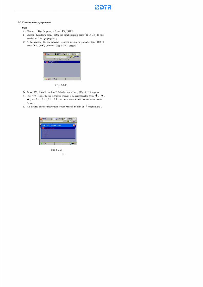
8132019 DTR 650 User Manual
httpslidepdfcomreaderfulldtr-650-user-manual 2270
5-2 Creating a new dye program
Step
A Choose「1Dye Program」Press「F5」(OK)
B Choose「1Edit Dye prog」at the sub-function menu press「F5」(OK)to enter
to window「Sel dye program」
C At the window「Sel dye program」 choose an empty dye number (eg「002」)
press「F5」(OK)window《Fig 5-2-1》appears
《Fig 5-2-1》
D Press「F2」(Add) table of 「Edit dye instruction」《Fig 5-2-2》appears
E Press「F5」(Edit) the dye instruction appears at the cursor locates press「」「」
」and「5」「6」「3」「4」to move cursor to edit the instruction and its
factors
F All inserted new dye instructions would be listed in front of 「Program End」
8132019 DTR 650 User Manual
httpslidepdfcomreaderfulldtr-650-user-manual 2370
【Eg】Edit「CycRinse」
A Edit the main function step first Press「F2」
()「F3」()to move the cursor The dye
step is listing by orders Choose「CycRinse」
and press「」 there is a cursor at itrsquos value
B Move cursor to setting value「Cold」andchoose「Mix」by pressing()() Then
press「」to move cursor to「Time」and enter
itrsquos setting value as「2」Press「F5」(OK) to
complete the main function setting
C To move cursor to the parallel functionsetting field Press()()to choose the
dye step Press「」to confirm and move
cursor to choose itrsquos setting facor
D Press「F5」(OK)to move cursor to the next
parallel function
E Repeat above steps C-D until all parallel
functions setting are completed Each main
function can be operating with the
maximum 4 parallel functions
F Press「F4」(Save)to confirm and return to
the「Edit dye program」window
G Repeat the above step A E to keep on
8132019 DTR 650 User Manual
httpslidepdfcomreaderfulldtr-650-user-manual 2470
5-3 Setting the file name (for dye programs)
When a dye program is setting up it is saved by numbers automatically Optionally users
can save it by another names
Step
(1) Create a new dye program first (the Name is not available for empty dye
programs)
(2) At the window「Sel dye program」 press「F4」(File) Window《Fig5-3》appears
《Fig5-3》
(3) Use numeric 0~9「+」「-」「_」blank alphabet A~Z and symbols [ ] etchellip to
create a file name Each file name can type-in the max 8 unit Press 「3」「4」
「5」「6」to move the cursor to choose the unit It also can use the membrane
numbric key to type in The selected unit is showed in front of the cursor at the
「File」Press「OK」to confirm
(4) Quit to input to press「F3」(Clr)
(5) After complete the set up press「F5」(OK)to confirm and go back to the window
「Sel dye program」 Now the name behind the dye program number is created
8132019 DTR 650 User Manual
httpslidepdfcomreaderfulldtr-650-user-manual 2570
5-4 Inserting a program step
Insert the program step means to insert a step in the existing program step where youwant to insert a step All following steps are moved one step ahead The total number of
steps will be increased by itself Able to insert more than one step continusely at the
same time
【Example】《Fig5-4》 To insert a step「call」before「002 Rinse」
《Fig 5-4》
Step
A Enter to the dye program「002」at the window of 「Sel dye program」
(Example)
B Press「6」to move cursor to「002 Rinse」 then press「F2」(add)
C Press「F5」(Edit) then press「」「」or「5」「6」to choose program
step to modify Choose「call」and press「」to move cursor to modify itrsquos
value
8132019 DTR 650 User Manual
httpslidepdfcomreaderfulldtr-650-user-manual 2670
D Press「」「」 value of 「call」is listing at the table Choose「pH Check 」Press「F5」(OK)
E Press「F4」(Save)and press「F1」(Undo)to return to previous window Complete
to insert the「02 Call」The previous「02 Rinse」update to「03」 All following
steps are moved one step ahead Total number of steps will be increased ldquo1rdquo by
itself
Repeat the steps B-E can non-stop to insert more than one step
Quit the insert and modify ( before pressing「F4」) press「F1」(Undo) to exit
The original dye steps will be unchanged
To delete an inserted dye steps press key「F3」(Del) The step deletes
immediately
5-5 Deleting a program step
Delete the program step means to delete step which the cursor locates When that step is
deleted the step number will be updated automatically All following steps are moved up
one step It is allowed to delete more than one steps continuously at the same time
Step
A Enter to the「Edit dye program」《Fig5-5》at the window「Select dye program」
B Press「6」「5」move cursor to the want to delete
C Confirm and press「F3」(Del) Window「Confirm delete」appears Press
「F4」(Yes)
8132019 DTR 650 User Manual
httpslidepdfcomreaderfulldtr-650-user-manual 2770
D That step is deleted immediately and all following steps move up one step
Repeat the steps above can non-stop to delete more than one step
Press「F2」(No)to cancel the deletion
Press「F1」(Exit)to end
5-6 Modifying a program step
To modify the saved name and the setting value of the dyeing steps
Step
1 Choose a dye program which need to modify at the「Sel dye program」 press「F5」
(OK)
2 Press「6」「5」to move cursor to a step which need to modify Select and press
「F5」(Edit) Window of 「Edit dye instruction」appears
3 Press「F2」()「F3」()to choose the step list select it and press「」to move
the cursor to itrsquos value setting
4 Press numeric key to input the value or press「6」「5」to choose the item Press
「F5」(OK)when complete Cursor move to the next value (if need to set more
than one item)
5 Press「F4」(Save)when all setting is complete Return to「Edit dye program」
Method of parallel functionrsquos modification is same as above
Before pressing the key「「「「Save」」」」 press「F1」(Undo)to quit all modify Return
to the window of Edit dye program
All edit and modify functions mentioned of this charper are only available
for the dyeing files which already saved in the file and not being running It
8132019 DTR 650 User Manual
httpslidepdfcomreaderfulldtr-650-user-manual 2870
5-7 Copying a dye program
Copying a dye programs mean to make a copy of an dye programs to a blank dyeprogram This function is for creating new dye program rapidly
Choose「1Dye Program」at the main menu Press「F5」(OK)then press「F2」()to choose「2Copy dye prog」 Press「F5」(OK) 《Fig5-7-1》appears
《Fig 5-7-1》
《Fig 5-7-2》
【【【【Eg】】】】
Copy program 003 to program 012
Press「」「」to move cursor to theprogram「003」 press「F4」(Copy)
Program「003」shows at the top right side of
the bar
Press「」「」to move cursor to program「012」 Then press「F5」(Paste)「」appears behind the「012」That means it issuccessfully copying the program
If the target program is occupied
confirmation window「Overwrite」
When choose an program or a targetprogram can select them by using the
8132019 DTR 650 User Manual
httpslidepdfcomreaderfulldtr-650-user-manual 2970
5-8 Deleting a dye program
Choose「1Dye program」at the main menu Press「F5」(OK)then press「F2」()to choose「3Delete dye prog」 Press「F5」(OK) 《Fig5-8-1》appears
《Fig5-8-1》
《Fig5-8-2》
Press「」「」to move cursor to
choose program need to delete Eg
delete program「012」 press「F5」(Del) Confirmation window
「Confirm delete」appears
Press「F4」(Yes) to confirm delete
Repeat the above step can delete more
than one program at the same time
Press「F2」(No) to return to window
《Fig5-8-1》and not delete that program
Exit to press「F1」(Exit)and return to the
main menu
8132019 DTR 650 User Manual
httpslidepdfcomreaderfulldtr-650-user-manual 3070
6 983123983141983156983156983145983150983143DTR-650 has a built-in standard factor that can fulfill all different types of dyeing
machinesrsquos basic demand Users can also modify the factors base on their request to
fulfill their special control demand Before modify please refer to the table of each
range of Setting Factors (see the Supplementary Table)
6-1 ldquoEnable to use the program stepsrdquo setting
There are totally 64 program steps Parts of them are usually applying to the programs
In order to make more efficiently of editing programs it can「Disable」the other part
of program steps which are not usually applying or not applicable to the programs
For example dye machine with one tank it is only using step Tank B In this case itcan firstly「Disable」the program steps of Tank C When edit the program the
「Disable」rsquos steps will not appear at the cursor for choosing But this will not effect
and change the saved files The saved files can be kept as before
Step
(1) Choose「2 Factors」at the main menu Press「F5」(OK)(2) Choose「18 Dye Instruction」at the sub-function menu Then presss「F5」(OK)
Window「Edit dye ins」appears
「Enable」instruction can available to
use「Disable」instruction is temporarystop to use
Press「F2」()「F3」()to move
8132019 DTR 650 User Manual
httpslidepdfcomreaderfulldtr-650-user-manual 3170
6-2 ldquoAllow to modify dye program temporary during operatingrdquo Setting
During dye program running it can modify dye program temporary Thesemodification will not disappear by causing a sudden power interruption or power off
until select another new dye program to run
Please note that it is only for modifying the dye program temporary That program
file would not saved due to the modification If need to modify the program file and
save choose the function of Edit Dye Program to edit (Refer to the Charper 5 for the【Edit Dye Prograrm】)
6-2-1 ldquoAllow to modify all dye programsrdquo Setting
Step
(1) Choose「2 Factors」at the main menu Press「F5」(OK)
(2) Choose「02 System Factor」at the sub-function menu Then presss「F5」(OK)
Window「Edit System Factor」appears
Set to stop using temporary the「07
Rinse」press「F4」(Sel)to set it as Disable
Repeat above steps to complete all setting
Press 「F1」(Exit)to return to main menu
8132019 DTR 650 User Manual
httpslidepdfcomreaderfulldtr-650-user-manual 3270
6-2-2 ldquoAllow to modify part of dye programsrdquo Setting
【Eg】Set the number 08 or above (including number 08) is allowing to modify dye
programs during operating
Step
A Refer to【6-2-1】setting the factor as「22」to allow editing dye program
temporary during operating
(4) Press「3」「4」to edit the setting
as「Enable」 and press「F5」(OK)
Restore the standard factor by
pressing「F3」(Clr)
(5) Exit to press「F1」(Exit)and
return to window of 「Main Menu」
8132019 DTR 650 User Manual
httpslidepdfcomreaderfulldtr-650-user-manual 3370
6-2-3 ldquoAllow to modify dye steps temporaryrdquo Setting
After setting the dye programs are allowed to edit it also can set which dye steps are
allowed to edit temporary during operating
Step
(1) Choose「2 Factors」at the main menu Press「F5」(OK)
(2) Choose「19 Dye Ins control」at the sub-function menu Then presss「F5」
(OK) Window「Edit ins mode」appears
「Enable」 Allow to edit that dye step before
operating
「Disable」 Not allow to edit dye step before
operating
(3) Press「」「」to move cursor
to choose dye step Press「F4」
To enter to the「Edit dye program」from the
function menu there is a「」in front of the
file name「0-7」 means that program is not
allowing to edit during operating
8132019 DTR 650 User Manual
httpslidepdfcomreaderfulldtr-650-user-manual 3470
6-2-4 ldquoSet the dye step to keep running from the interrupt pointrdquo setting
When the dye program is operating it will disappear by causing power
interruption or sudden power off When start running again part of dye steps can
run again from the interrupt point part of them cannot
How to set
(1) Choose「2Factors」in the main menu and press「F5」(OK)
(2) Choose「20Continue mode」in the sub-function menu Press「F5」(OK) to
enter window of 「Continue Setting」
(3) Press「」「」to move cursor to choose dye steps Press「F4」(Sel)it
shows「Disable」or「Enable」for choosing Press「F5」(OK)to move cursorto the next setting
(4) Repeat above method until all setting is complete press「F1」(Exit)and
return to the main menu
8132019 DTR 650 User Manual
httpslidepdfcomreaderfulldtr-650-user-manual 3570
6-3 ldquoAllow to insert an addition dye stepsrdquo setting
During the program is running can temporary insert an addition dye step or a dye
program according to the operating actual situation Through this setting can set which
dye steps can apply or not to the program in operating
During to insert an addition step if sudden interruption or power off occurred it returns
to the main dye program automatically Before starting again should decide seriously
and set it again by actual needed
Step
(1) Choose「2Factors」at the main menu and press「F5」(OK)
(2) Choose「02System factor」and press「F5」(OK)
(3) Press「」「」to move cursor to the factor「34」and press「3」「4」to set
it as「Enable」 Press「F5」(OK)
(4) Press「F1」(Exit)to return to main menu Choose「21Addition Ins」at the
sub-function menu Press「F5」(OK)to enter the window「Addition Instruction」
(5) Press「」「」to move cursor to choose dye steps and press「F4」(Sel) Cursors
locates shows「Eable」or「Disable」 Press「F5」(OK)to move cursor to the
next dye step
(6) Repeat above method until to complete all setting press「F1」(Exit)and return
to the main menu
8132019 DTR 650 User Manual
httpslidepdfcomreaderfulldtr-650-user-manual 3670
6-4 Setting the display mode
DTR650 has three types of display mode during operating Program List mode
Schematic Diagram mode and Icon mode Users can set the display mode during
operating by factor setting
It goes back to a Program List mode when dye program ended
Step
(1) Choose「2Factors」at the main menu and press「F5」(OK)
(2) Choose「02System factor」and press「F5」(OK)
(3) Press「F2」()「F3」()to move cursor to choose「32Display mode」Press
「3」「4」 it shows「Online picture」「Instruction」「Big Icon」 choose
「Online picture」(eg) and press「F5」to confirm
8132019 DTR 650 User Manual
httpslidepdfcomreaderfulldtr-650-user-manual 3770
(4) Press「F1」(Exit)to return to the main menu
(5) The Schematic Diagram displays when the program is running (it stays at theProgram List mode when there is an alarm occurred)
Press「F4」to transfer to another display mode
It goes back to a Program List mode from Schematic Diagram Mode when dye
program ended Press numeric key「3」to view Schematic Diagram Mode again
Quit to press「F5」(Exit)
6-5 Adapt the digital input to another functions
DTR-650 has 32(0~31)input terminal it owns an standard setting when the
controller is initial According to the userrsquos demand they can change the DTR-650rsquos
anther functions of Input Terminal and PLC Input channel
The PLC Intputrsquos name can also define by the users (use IBM computer to edit and
download)
How to set
(1) Choose「2 Factor」at the main menu Press「F5」(OK)
(2) Choose「22 Input table」at the sub-function menu and press「F5」(OK)to enter
「Edit input table」
The actual input
terminal of theIBM computer
PLCrsquos input channel
8132019 DTR 650 User Manual
httpslidepdfcomreaderfulldtr-650-user-manual 3870
6-6 Adapt the digital output to another functions
DTR-650 has 32(0~31)output terminals it owns an standard setting when thecontroller is initial According to the userrsquos demand they can adapte the digital output
and the PLC outputrsquos channel to another functions The PLC Output channelrsquos name
can also define by users (use IBM computer to edit and download)
Step
(1) Choose「2 Factor」at the main menu Press「F5」(OK)
(2) Choose「23 Output table」at the main menu and press「F5」(OK)
(3) Press「F2」()「F3」()to move cursor to choose the output terminal atthe left side of the window Press「F5」(Add) the PLCrsquos output channelrsquos
name is listing at the right side of the window
(4) Press「F2」()「F3」()to move cursor to choose the PLC outputrsquos channel
If cursor moves to the PLC output channel which already linking「Add」is
not for choosing that means that output channel is already occupied
(5) Confirm the connection to press「F5」(Add) Quit to press「F4」(Del)Press「F1」(Exit)when complete all setting and return to main menu
The actual output
terminal of the
IBM computer
PLCrsquos output channel
8132019 DTR 650 User Manual
httpslidepdfcomreaderfulldtr-650-user-manual 3970
983095 983109983140983145983156983145983150983143 983156983144983141 983110983137983139983156983151983154983155DTR-650 has several kinds of control factors
Userrsquos factors System factors Temperature Control factors Speed factors Dosing
factors PID factors Analog Input Output factors standard factors etchellipPlease refer
to the supplementary table for the setting range and standard of the factors
DTR-650 has a built-in standard factor Users can edit by themselves if necessary
7-1 Modifying userrsquos factors
Userrsquos factors is setting with the Dyeing machinesrsquos PLC Programrsquos factor it is define by
the PLC Programmer
Step to edit
(1) Choose「2Factors」at main menu Press「F5」(OK)
(2) Choose「01User Factor」Press「F5」(OK)
(3) Press「F2」()「F3」()「6」「5」to move cursor up down and by page
Choose a factor need to edit then press「3」「4」to set itrsquos value Press「F5」(OK) Cursor moves to the next factor
(4) Some of factors can input numbers by the numeric membrance keys to edit If
the input is incorrect it turns to red and means the edit is not available
8132019 DTR 650 User Manual
httpslidepdfcomreaderfulldtr-650-user-manual 4070
Modifyrsquos method of the system factors temperature factors speed factors dosingfactors PID factors analog Input output factors standard factors etchellipare same asabove
If apply the library of DTR500 and DTR600 into the DTR650 the key「3」「4」may not valid to use Please use the numeric keys instead of it to key in factors itmay not effect the normal operation
Please pay a serious attention and read carefully at the factorrsquos table before modify the factors An incorrect value may effect the DTR-650 Dyeing
Machine Controllerrsquos operating After modifying factors must cancel the
password and secure data
7-2 Loading the standard factors
After modifying factors if need to restore a manufacturerrsquos standard factors of
DTR-650 The method as follows
1 Choose「2Factors」at main menu Press「F5」(OK)
「 「 ( ) 「
8132019 DTR 650 User Manual
httpslidepdfcomreaderfulldtr-650-user-manual 4170
7-3 Copying the factor
Users can build up a set of factor by themselves and make a copy and save
Step
1 Choose「2Factors」at main menu Press「F5」(OK)
2 Choose「13Restore Factor」 press「F5」(OK) window「factor will be
overwrite 」
3 Press「F4」(Yes)copy finished and saved Return to the main menu
4 Press「F2」(No)to not copy the factor and the existing factor is not change Return
to the main menu
7-4 Loading the backup factors
Users can build up a set of factor and backup files to load to DTR-650
Step1 Choose「14Backup factor」at the sub-function menu Press「F5」(OK)and
window「Factror will be overwrite」appears
2 Press「F3」(OK)to load the the backup factor them return to main menu
Press「F2」(No)to not copy the factor and the existing factor is not change
Return to the main menu
8132019 DTR 650 User Manual
httpslidepdfcomreaderfulldtr-650-user-manual 4270
983096 983119983157983156983152983157983156 983124983141983155983156983145983150983143
Before the output testing must be complete the steps as follows
A Cut off all connecting line of output terminal of DTR-650
B Stop running the PLC
C Check up the connections of all output channels to avoid damages from
incorrect connections
D Check up state of dyeing machines include the temperature pressure valves
onoff and pumpshellipetc ensure the safety for priority
8-1 Testing the Digital output
Step
1 Choose「3Output Testing」at the main menu Press「F5」(OK) 2 Choose「1Digital」at the sub function menu Press「F5」(OK) window「Digital
output testing」appears
3 Press「」「」「」to move cursor to each output channels Press「F5」(OK)
Output Name
8132019 DTR 650 User Manual
httpslidepdfcomreaderfulldtr-650-user-manual 4370
8-2 Testing the Analog output
(1) Choose「3Output Testing」at the main menu Press「F5」(OK)
(2) Choose「2Analog」at the sub function menu Press「F5」(OK) window「Analog output testing」appears
(3) Press「」「」「」to move cursor to each channels Then key in number by
the numeric membrance keys (range0~200= 0~20mA) Press「F5」(OK) there
is a output current relating to the output channel
(4) Press「F5」(OK) There is an output when the output channel with red light No
output without light onl(5) When complete the testing press「F1」(OK)to return to the main menu
8132019 DTR 650 User Manual
httpslidepdfcomreaderfulldtr-650-user-manual 4470
983097 983107983137983148983145983138983154983137983156983145983151983150
DTR-650 has Dosing and Temperature calibration
When enter to Dosing calibration must be set the Low Volume calibration first and
then High Volume calibration When enter to Temperature calibration must be set the
Low Temperature calibration first and then High Temperature calibration Must be
hightly follow this orders seriously
9-1 Calibration of Low Volume Tank
Step
A Choose「4Calibration」at the main menu Press「F5」(OK)
B Choose「Dosing 0 low vol」at the sub function menu Press「F5」(OK) window
appears
C Fill the Dosing Tank to a half level input value shows how much the water level
If it stays ldquo0rdquo check the connection and the factor setting is correct or not
And connect the pressure sensorrsquos output channel to the Current Meter to ensure
that sensor works or not
8132019 DTR 650 User Manual
httpslidepdfcomreaderfulldtr-650-user-manual 4570
D Fill the Dosing Tank to 50ml (Calcalate from the bottom side of the pressure
sensor steel tube) input value should show 4~6 (input value must between
0~10) Then enter the water volume The setting volume is relating the water
levelrsquos water value (litre as unit) input range 0~80 Set as「 「「 「0000 0000 0000 0000」」」」is strongly is strongly is strongly is strongly
receommend receommend receommend receommend Press「F5」(OK)to complete [Calibration of Low Volume Tank 1
is same as above method]
9-2 Calibration of High Volume Tank
Step
A Choose「4Calibration」at the main menu Press「F5」(OK)
B Choose「Dos 0 high vol」at the sub function menu Press「F5」(OK) window of
「Calibrate high 」appears
C Fill the Dosing Tank to a full level input value should be larger than 30 enter
the current water level which relates to the water volume Enter the range within
100~2500 Then press「F5」(OK) to complete the calibrate the high volume tank
8132019 DTR 650 User Manual
httpslidepdfcomreaderfulldtr-650-user-manual 4670
9-3 Temperature Calibration
Step
A This function is for adjusting the DTR650rsquos accuracy of Temperature Control It
must be using with the special terminal which is only for DTR650
B Choose「4Calibration」at the main function menu and press「F5」(OK)
C Choose「3Low Temp」at the sub-function menu Press「F5」(OK)and《Fig9-3》
appears insert the DTR650rsquos low temperature calibration terminal to the temperature
input terminal wait for the jumping value to stable down then press「F5」(OK) then
to adjust the high temperature calibration
D Adjusting the High Temperature Calibrationrsquos method is same as above But usersusersusersusers
must be using the High Temperature Terminalmust be using the High Temperature Terminalmust be using the High Temperature Terminalmust be using the High Temperature Terminal whichwhichwhichwhich is specially for DTR650 onlyis specially for DTR650 onlyis specially for DTR650 onlyis specially for DTR650 only
《Fig 9-3》
8132019 DTR 650 User Manual
httpslidepdfcomreaderfulldtr-650-user-manual 4770
10 983122983141983139983151983154983140983155 983151983142 983108983161983141 983120983154983151983143983154983137983149983155
It contains the past 15 days of temperature curves of running history
Checking method
(1) Choose「5Dye Record」at main menu press「F5」(OK)
(2) Sub-function menu shows the set up date of the past 15 days dye programs
Listing by the lastest set up date
(3) Choose a program date and press「F5」(OK) it appears window「Temp
record」
(4) Press「」「」to move the white line in the box one minute by moving once
(5) Press「3」「4」to move the line to check the time period 2 hours by moving once
The yellow selecting line of the「24 hours operating state」is repectively moving
The curve info is show in the curve box Left side of the widnow appears the
relating running info the time is the time value of the line locates at
(6) Check more details of the temperature info to press numeric key「middot」 a bright red line
appears in the selecting box this line is to check the starting point of the
temperature inforsquos time period Then press「」to move the white line to the end
point of the time period The temperature info between the starting point and end
point are appears at the right side of the window Press「middot」to return to the preious
curve page
(7) Check more details of the alarm infor To perss numeric key「7」「9」 the alarmrsquos
details is listing by orders
(8) Press「F1」(exit) to return
8132019 DTR 650 User Manual
httpslidepdfcomreaderfulldtr-650-user-manual 4870
11 983125983155983137983143983141 983151983142 983117983141983149983151983154983161 983107983137983154983140
DTR-650 supports 32MB or above Compact Flash Card which can transfer and save all
information for 4 sets of DTR-650 Including library files schematic diagram icon
image PLC program dye program factor and confiruration files etchellip Use the CF Card
to up download and swap the information of DTR-650 promptly install the relating
device and program updates
DTR-650 CF Card with bank 1 to bank 4 can save 4 sets information of Dyeing
Machines When download or save files should choose the BANK first
《Fig11-1》
8132019 DTR 650 User Manual
httpslidepdfcomreaderfulldtr-650-user-manual 4970
11-1 Downloading data
1 Firmly insert the CF card into the DTR-650rsquos PCMCIA connector Ensure it is
wholely and firmly inserted if the card is not totally inserted or the card do not
touch in all to the connector there will be an error occurred and cannot
updownload or interrupted during operation
2 Choose「6Memory Card」at the main menu and press「F5」(OK) 《Fig11-1》
appears Information of Bank「1」shows at the left hand side of the window press
number 1-4 by using numeric keys to choose the BANK Check the
information in the Bank seriously which is exactly need to download to the
DTR650
3 Press()()「6」「5」to move cursor to the sub-function menu to choose
the downloading items Press「F5」(OK) window appears「Stop PLC run before
access memory card Stop the PLC run」 Press「F5」(YES) to stop PLC
running
4 Press「F5」(OK) window appears Confirm to update or not the DTR-650rsquos
information As that downloading will be replace the DTR-650rsquos information
(that means the existing information of the DTR-650 will be removed and
replaced)
5 Press「F4」(YES)to download the information from the DTR-650 to the CF
Card Return to the main menu when finish
8132019 DTR 650 User Manual
httpslidepdfcomreaderfulldtr-650-user-manual 5070
Ensure inserting firmly the CF card into the DTR-650 unless it will cause
error or cannot Updownload data
Never remove CF card during transferring or updownloading data Until it
is all completed
DTR-650rsquos dyeing program is not compatible with DTR-500 and
DTR-600 Never use CF card to transfer data among them
11-2 Storing and transfering data
1 Insert the CF Card to the DTR-650
2 Choose「6Memory Card」at the main menu and press「F5」(OK) 《Fig11-1》
appears Left hand side of the window shows the data of BANK 1 press numeric
keys 1-4 to select the BANK To confirm the put the data in the DTR-650 to the CF
Card The existing data of that bank will be replaced and covered by the new data (if
that bank is already occuplied)
3 Choose「23Save Dye prog」(Example)at the sub-funciton menu press「F5」(OK)to confirm Window「Update memory card data」appears
4 Press「F5」(OK)to transfer the data to the CF card Return to the main menu
5 Put the CF card into another DTR-650 and follow the operating method of 「11-1
Downloading data」」」」can transfer and swap data with more than one set of
DTR-650
8132019 DTR 650 User Manual
httpslidepdfcomreaderfulldtr-650-user-manual 5170
12 983123983156983137983156983141 983137983150983140 983113983150983142983151983154983149983137983156983145983151983150
The state and information is including the Dyeing Machinersquos state of Digit Input output
Analog Input output Temperature control PID Dosing PID Pressure different PID
software system information and alarm record This information is for checking at any
time
12-1 Input Output state
Step
1 Choose「7Info and state」at main menu and press「F5」(OK)
2 Choose「01Digital IO put」at the sub-function menu then press「F5」(OK)
「Digital In Out State」0=None 1=Input
3 Press「F1」(Exit)to return to main menu
Same method for checking the temperature control analog dosing pressure
different etchellip
12-2 Checking the system information
Step
1 Choose「7Info and state」at main menu and press「F5」(OK)
2 Choose「11 System info」at sub-function field press「F5」(OK)Window
「System Information」appear
System information is including System info(software version) Library doc
Icon files Schematic file Definition file hardare state Config File Commandinstruction icon PLC file etc
8132019 DTR 650 User Manual
httpslidepdfcomreaderfulldtr-650-user-manual 5270
12-3 Checking the operating alarm record
Operating record shows the latest 40 operating items and alarm records including
the time and content of the alarm
A) Choose「7 Info and state」
and press「F5」(OK)
B) Choose「12Alarm logs」at
the sub-funciton menu then
press「F5」(OK)
8132019 DTR 650 User Manual
httpslidepdfcomreaderfulldtr-650-user-manual 5370
13 983105983140983146983157983155983156983145983150983143 983156983144983141 983107983151983150983156983154983137983155983156
The displaysrsquos brightness can be adjusted if necessary
Step
1 Choose「8Others」at main menu press「F5」(OK)
2 Choose「01Contrast」at sub-function menu press「F5」(OK) window「Set
Contrast」appears
3 Press「」「」to move the bar to set the brightness then press「F5」(OK)Window appears「Please reboot the system」
4 Press「F5」(OK)to return to main menu and re-boot the DTR-650 to complete
adjusting the brightness
8132019 DTR 650 User Manual
httpslidepdfcomreaderfulldtr-650-user-manual 5470
14 983123983156983151983152 983154983157983150983150983145983150983143 983156983144983141 983120983116983107 983120983154983151983143983154983137983149
Before testing the Input output testing transfer of the PLC program must stop the PLC
running
Step
1 Choose「8Others」at the main menu Press「F5」(OK)
2 Choose「04 PLC Stop」at sub-function menu Press「F5」(OK) window
「Password」appears
3 Enter password and press「F5」(OK) Window「Stop the PLC run」appears
4 Press「F4」(Yes)and window「PLC Stop」appear Press「F5」(OK) Now
the PLC is stop running and return to the main menu
All testing cannot operate when the PLC is running
Editing dye program and the relating operation can
perform with the PLC running together
8132019 DTR 650 User Manual
httpslidepdfcomreaderfulldtr-650-user-manual 5570
15 983123983141983156983156983145983150983143 983156983144983141 983156983145983149983141
Step
1 Press「8Others」at the main menu Press「F5」(OK)
2 Choose「10Set date time」at the sub-function menu Press「F5」(OK) window
「Set date time」appears
3 Press「F5」(Edit) to move cursor by 「3」「4」 enter the time value at the
cursor locates
4 Press「F5」(OK)to complete the modify Press「F1」(Exit)to return to main
menu
5 Press「F1」(Exit)if not modify and return to main menu
8132019 DTR 650 User Manual
httpslidepdfcomreaderfulldtr-650-user-manual 5670
1166 983123983123983157983157 983152 983152 983152 983152983148983148983141983141983149983149983141983141983150983150983156 983156 983137983137983154 983154 983161983161 983124 983124 983137983137983138983138983148983148983141983141
TTTTTTTTaaaaaaaabbbbbbbblllllllleeeeeeee 11111111 【Dye Instruction】
Code Icon Instruction Code Icon Instruction
000 End 016 Inject C
001 Start 017 Dosing BV
002 Heat 018 PH
003 Cool 019 Addsalt B
004 Flow Fill 020 Addsalt C
005 Level Fill 021 Ana Fill
006 Drian 022 Lock Fill007 Rinse 023 Lock Level
008 Run 024 Low Rinse
009 Call 025 Cyc Rinse
010 Prep B 026 Rinse B
011 Addsalt B 027 Rinse C
012 Dosing B 028 Temp
013 Inject B 029 Nozzle Pressure
014 Prep C 030 Main Pump
015 Dosing C 031 Pump Speed
8132019 DTR 650 User Manual
httpslidepdfcomreaderfulldtr-650-user-manual 5770
Table 2 【【【【Alarm】】】】
System Alarm Must stop operating and check up to solve problems before restarting
the machine
Running Alarm It is a reminder Not effect the operating of DTR-650
Userrsquos Alarm Total of 32 Users can define themselves and use it when edit the PLC
Program (do not listing below)
No System Alarm No Running Alarm
1 PLC program not running 16 Temp ctrl 0 Grad too slow
2 Main temp sensor error 17 Temp ctrl 0 Grad too fast
3 Not at Run window 18 Temp ctrl 0 Hold temp too low
4 Exceeding max temp 19 Temp ctrl 0 Hold temp too high
5 - 20 Temp ctrl 1 Grad too slow6 - 21 Temp ctrl 1 Grad too fast
7 - 22 Temp ctrl 1 Hold temp too low
8 Communication error 23 Temp ctrl 1 Hold temp too high
9 Slave not answer 24 Temp ctrl 2 Grad too slow
10 PLC 0 not answer 25 Temp ctrl 2 Grad too fast
11 PLC 1 not answer 26 Temp 2 Hold temp too low12 Display not answer 27 Temp 2 Hold temp too high
13 Lower power voltage 28 Temp ctrl 3 Grad too slow
14 - 29 Temp ctrl 3 Grad too fast
15 - 30 Temp3 Hold temp too low
31 Temp3 Hold temp too high
32 Dosing 0 injection too slow
33 Dosing 0 injection too fast
34 Dosing 1 injection too slow
35 Dosing 1 injection too fast
8132019 DTR 650 User Manual
httpslidepdfcomreaderfulldtr-650-user-manual 5870
TTTTTTTTaaaaaaaabbbbbbbblllllllleeeeeeee 33333333 【【【【System factor】】】】
No Description Std Range amp Definition
1 ID No 000 000- 100 Controller no
2 Communication Rate 4800Bps 2400 4800 9600 19200 38400
3 Display language Chinese English Chinese
4 Temp display mode and
5 Maxmium temperature 145 025 ~ 145 6 Type of external PLC Default PLC32DPLC32PLC16Default
7 Number of external PLC NANA 1 unit connect
2 unit connect
8Communication Rate of
PLC9600Bps 2400 4800 9600 19200
9 Set point 1 085 000 ~ 145
If signal source is temperaturethe setting value is thetemperature value If the signal
source is Analog Input 6~17 then
setting value for Analog input is 0 ndash
100 and relates Analog
Input14~020mA
10 Source 1 Sensor0Sensor 0 ~5
Analog input 0 ~1111 Set point 2 092 Same as 09
12 Source 2 PT100 1 Same as 10
13 Set point 3 085 Same as 09
14 Source 3 PT100 2 Same as 10
15 Set point 4 092 Same as 09
16 Source 4 PT100 3 Same as 1017 Set point 5 085 Same as 09
18 Source 5 PT100 4 Same as 10
19 Set point 6 092 Same as 09
8132019 DTR 650 User Manual
httpslidepdfcomreaderfulldtr-650-user-manual 5970
29 Min cyclic time of cloth 100sec 0 ~ 255 sec
30 Max cyclic time of cloth 240sec 0 ~255 sec
31Standard cyclic time of
cloth
180 000 ~ 255 sec
32 Display ModeProgram
List
Program list Schematic Diagram
Icon mode
33 CF card format Standard of
DTR CF
Card
Standard of DTR CF Card V20
Standard CF Card
34 Addition step Disable Disable Enable35 Mode Com 3
CouplingEsure Com 3 is the communication
port of the Central or Coupling
36Com 3 Communication
rate9600 Central communication speed
8132019 DTR 650 User Manual
httpslidepdfcomreaderfulldtr-650-user-manual 6070
TTTTTTTTaaaaaaaabbbbbbbblllllllleeeeeeee 44444444 【【【【Temperature Cotnrol Factor】】】】
No Factor Definition Standard Range and Definition
01 PT No PT-0 PT 0~5 PT-100 Input number
02 Max working temp 140 000~140
03 Output mode 0 0~2
04 Alarm time of gardient 240sec 000~255 sec
05 Alarm mode of gradient Always AlwaysOnceNone
06 Control mode of gradient Heating orCooling
interlocked
Heating and Cooling interlocked
No limitation
07 Alarm range of HoldTemp 03 01~20
08 Alarm time for HoldTemp 240sec 000~255sec
09 Alarm mode of HoldTemp Always AlwaysOnceNone
10 Control mode ofHoldTemp
Heating only Only heating and cooling Cooling whenalarm occurred Only heating andcooling No limitation when alarmHeating only
11 Porportional Band 100 000~250
12 Integral band 128 sec 000~255 sec
13 Differential time 04 sec 00~20 sec
14 Min transit gradient 02 00~50
15 Transit rate 20 times 00~50 times (020= 2 times)
16 PID initial output value 010 000~100
17 ONOFF cycle time 10 sec 05~25 sec
Onoff valve set as 010 sec
Proportional valve set as 020 sec
18 Time down count mode Mode 0 0~10 = The time down count range from「Factor 20 + target temp」to「Target
8132019 DTR 650 User Manual
httpslidepdfcomreaderfulldtr-650-user-manual 6170
TTTTTTTTaaaaaaaabbbbbbbblllllllleeeeeeee 55555555 【【【【Speed Factor】】】】
No Factor Definition Standard Range amp Definition
01 Input Number Speed input 0 Speed input 0~11
02 Average times 05 times 01~10
03 Sensor Number 008pcs 001~255
04 Roller Dimension 250mm 050~500
05 Max cloth speed 200mmin 001~25506 Min cloth speed 020mmin 001~255
07 Alarm delay time 240sec 001~255
08 Alarm mode Every oncenoneevery
09 Alarm range () 020 001~255
10 Proportional band 100 001~255
11 Integer band 128 001~25512 Differential time 000 001~200
13 Initial speed () 020 001~255
14 Control cycle ti(01sec) 05 01~30
15 First cycle time(01sec) 10 01~30
16 Speed increase limit () 010 001~100
17 Speed decrease limit () 010 001~100
18 Min speed() 005 001~100
19 Manual speed adjust () 005 001~100
20 Manual initial speed() 020 001~100
21 Stopping speed() 010 001~100
22 Switch speed() 020 001~100
23 Not used
24 Speed decrease turns 03turns 01~50
8132019 DTR 650 User Manual
httpslidepdfcomreaderfulldtr-650-user-manual 6270
Table 6 【【【【Dosing Factors】】】】
No Description Range Range and Explanation
1 Analog input no Analog input 0 Analog input no 0 ~11
2Alarm delay time for
dosing240 sec 000 ~255 sec
3 Alarm time for dosing Every Every Once None
4 Proportional band 100 000 ~255 sec Factor P
5 Integer band 128 000 ~255 sec Factor I6 Differential time 04 00 ~20 Factor D
7 Max adjust rate 150 50~ 255
8 Initial factor for dosing 10 000 ~100
9 User curve section 0 10 Gradient of sect1 for dosing curve9
10 User curve section 1 10 Gradient of sect2 for dosing curve9
11 User curve section 2 10 Gradient of sect3 for dosing curve9
12 User curve section 3 10 Gradient of sect4 for dosing curve9
13 User curve section 4 10 Gradient of sect5 for dosing curve9
14 User curve section 5 10 Gradient of sect6 for dosing curve9
15 User curve section 6 10 Gradient of sect7 for dosing curve9
16 User curve section 7 10 Gradient of sect8 for dosing curve9
17 User curve section 8 10 Gradient of sect9 for dosing curve9
18 User curve section 9 10 Gradient of sect10 for dosing curve9
19 Min water level 05 00~ 10 04~20mA percentagechange to the userrsquos factor setting
20 Output value for Tank
clean
100 000~ 100
Injected percentage of dosing valve
in dosing End period
This factor will be invalided if usingONOFF dosing valve
21 Full range 100 001~255 Self-adjustment cannotchange
22 Range ratio 001001~255 Self-adjustment cannot
change
8132019 DTR 650 User Manual
httpslidepdfcomreaderfulldtr-650-user-manual 6370
【【【【TTaabbllee 77 】】】】Pressure Deviation Factors
No Description Std Range amp Definition
1 Analog input number + Analog in 0 Analog in 0~11
2 Analog input number - Analog in 1 Analog in 0~11
3 Input mode Pressure Pressure Pressure deviation
4 Full range 050x01Kgcm
001~255
5 Range ratio 001 001~255
6 Alarm delay time 100sec 001~255
7 Alarm mode Every oncenone
8 Alarm range 010 001~255
9 Proportional band 100 001~255
10 Integer band 128 001~255
11 Differential time 00 00~20
12 PID Init output value 010 001~255
13 Cycle time 10 03~30
14 First cycle time 030 003~100
15 Max adjust rate 010 001~100
8132019 DTR 650 User Manual
httpslidepdfcomreaderfulldtr-650-user-manual 6470
【【【【TTaabbllee 88 】】】】Definition of Analog Input
No Description Standard Range and Explanation
01 PT 0 correction standard DIN std DIN std JIS std
02 PT 0 correction +0 +- 9
03 PT 1 correction standard DIN std DIN std JIS std
04 PT 1 correction +0 +- 9
05 PT 2 correction standard DIN std DIN std JIS std
06 PT 2 correction +0 +- 9
07 PT 3 correction standard DIN std DIN std JIS std
08 PT 3 correction +0 +- 9
09 PT 4 correction standard DIN std DIN std JIS std
10 PT 4 correction +0 +- 9
11 PT 5 correction standard DIN std DIN std JIS std
12 PT 5 correction +0 +- 9
13 Analog input 0 define 4 ~ 20mA 0 ndash 20mA 4 ndash 20mA
14 Analog input 0 average times 10 times 01- 20 times
15 Analog input 0 min value 0000 0000 - 1000
16 Analog input 0 max value 100 0001 - 9999
17-60 Analog input 1~11 Same as Analog input 0
【【【【 】】】】 fi i i f A O
8132019 DTR 650 User Manual
httpslidepdfcomreaderfulldtr-650-user-manual 6570
【【【【TTaabbllee 99 】】】】Definition of Analog Output
No Description Standard Range and explanation
61 Analog output 0 define Control byPLC
Control by PLC
Temperature control PID0 output
Temperature control PID1 output
Temperature control PID2 output
Speed PID3 output
Dosing PID0 output Dosing PID1output
Pressure different PID0 outputPressure different PID1 output
Main temperature output
62 Mode of Analog ouptput0 4 ~20mA 0 ndash20mA 4 ndash 20mA
63-84 Analog output 1~11 Same as Analog output 0
【【【【TTaabbllee 1100】】】】Value Table 0 amp 1
No Description Range Std Range and explanation
1 Analog input no 000~011 000 Analog input no
2 Data ratio 001~255 100 Multiple by factors
3~53 0~98 000~255 000-100 Analog input 0~98 data
【【【【 】】】】St t Li t
8132019 DTR 650 User Manual
httpslidepdfcomreaderfulldtr-650-user-manual 6670
【【【【TTaabbllee 1111】】】】State List
No Description Range Standard Range and explanation
1 Display setting 1 0~255 205 See remarks at next page
2 Display setting 2 0~255 208
3 Display setting 3 0~255 209
4 Display setting 4 0~255 017
5 Display setting 5 0~255 0186 Display setting 6 0~255 019
7 Display setting 7 0~255 020
8 Display setting 8 0~255 021
9 Display setting 9 0~255 000
10 Display setting 1 0~255 000
11 Display setting 2 0~255 000
12 Display setting 3 0~255 000
13 Display setting 4 0~255 000
14 Display setting 5 0~255 000
15 Display setting 6 0~255 000
16 Display setting 7 0~255 000
Remarks
8132019 DTR 650 User Manual
httpslidepdfcomreaderfulldtr-650-user-manual 6770
0 = No display 1~255 = Display type of number
1~16 Content of PLC VB0~15
No 1 corresponding to VB0
No 16 corresponding to VB15
17~32 Content of PLC DB0~15
No 17 corresponding to DB0
No 32 corresponding to DB15
33~46 Content of PLC CNT0~29
No 33 corresponding to CNT0
No 46 corresponding to CNT29 47~78 Content of dyeing instruction 0~31 CNT0
No 47 corresponding to system instruction to No 0 of CNT0
No 78 corresponding to system instruction to No 31 of CNT0rsquos content
79~110 Dyeing instruction 0~31 of CNT0rsquos setting
111~142 Content of Dyeing instruction 0~31 CNT1No 111 corresponding to dyeing instruction No 0 of CNT1
No 142 corresponding to dyeing instruction No 31 of CNT1rsquos content
143~174 Dyeing instruction 0~31 of CNT1rsquos setting
175~204 Content of PLC HTIM0~29
No 175 corresponding to HTIM0
No 204 corresponding to HTIM29
205 Loading
206 Ratio 1
207 Ratio 2208 Ratio 1 x Loading
209 Ratio 2 x Loading
210 Fix value
211 Value Table 1 matching result
212 Value Table 2 matching result
213 Value Table 1 setting214 Value Table 2 setting
215 Pressure control PID0 different pressure value
216 Pressure control PID1 different pressure value
TTTTTTTTaaaaaaaabbbbbbbblllllllleeeeeeee 1122 【【【【Usage of password】】】】
8132019 DTR 650 User Manual
httpslidepdfcomreaderfulldtr-650-user-manual 6870
No Main FunctionFactor Sub Function Factor Password Rank
1 Run None
2 Dye program User3 or above
3 Control factor
- User factor User 1
- System factor User 1
- Temp PID 0
- Temp PID 1 User 1- Speed PID 0 User 1
- Dosing PID 0 User 1
- Dosing PID 1 User 1
- Pressure PID 0 User 1
- Pressure PID 1 User 1
- Analog IO User 1
- Load standard factor User 2 or above- Load a copied factor User 2 or above
- Copy factor User 2 or above
- Value table 0 User 1
- Value table 1 User 1
- Information and state User 1
- Dye instruction User 1
- Edit dye instruction setting User 14 Output testing User 2 or above
5 Calibration User 2 or above
6 Dye record None
7 CF card User 1
8 Info and state None
9 Others
- Contrast User3 or above
- Data Locking None
- PLC Run User 1
- PLC Stop User 1
- Password setting User 1
TTTTTTTTaaaaaaaabbbbbbbblllllllleeeeeeee 1133 【【【【Technical Data】】】】
8132019 DTR 650 User Manual
httpslidepdfcomreaderfulldtr-650-user-manual 6970
TTTTTTTTaaaaaaaabbbbbbbblllllllleeeeeeee 1133 【【【【Technical Data】】】】
1 Temperature Control
- Range 10~145(plusmn1)
- Mode Proportional or PWM
- Sensor PT100 (JIS or DIN standard)
2 Input and output channel
- Digital Input 32 DC24V PNP- Digital Output 32 DC24V 054A Relay connect point
- Analog Input 4 04~20 mA
- Analog Output 4 0~20mA 或 4~20 mA
3 Communication port 3 RS-232 amp 0~20 mAx1 RS485x 2
4 Dye program
- Number 15000 Steps
- Standard step 61Heating Cooling Fill Drain RinseDosingetc
5LCD module and Display
langage
Chinese
English
320 x 240 TFT color display with
more language
6 CF card connector 1 PCMCIA standard
7 Membrane Keyboard- Number Key 10 [0]~[9] Input factors
- Function Key 5 [F1]~[F5] function selecting
- Operation Key 2 [Start] [Stop]
- Auxiliary Key 7 [][][][][Esc] [larr][OK] [bull]
8 Operating Condition
- Temperature 5~45
- Humidity ≦85 (25)
9 Power supply
V l DC 24V
8132019 DTR 650 User Manual
httpslidepdfcomreaderfulldtr-650-user-manual 7070
70
983108983124983122983085650 983113983150983152983157983156 983119983157983156983152983157983156 983120983151983154983156983145983150983143 (983138983137983139983147983155983145983140983141 983158983145983141983159)
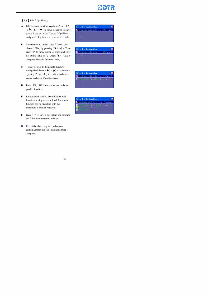
8132019 DTR 650 User Manual
httpslidepdfcomreaderfulldtr-650-user-manual 2370
【Eg】Edit「CycRinse」
A Edit the main function step first Press「F2」
()「F3」()to move the cursor The dye
step is listing by orders Choose「CycRinse」
and press「」 there is a cursor at itrsquos value
B Move cursor to setting value「Cold」andchoose「Mix」by pressing()() Then
press「」to move cursor to「Time」and enter
itrsquos setting value as「2」Press「F5」(OK) to
complete the main function setting
C To move cursor to the parallel functionsetting field Press()()to choose the
dye step Press「」to confirm and move
cursor to choose itrsquos setting facor
D Press「F5」(OK)to move cursor to the next
parallel function
E Repeat above steps C-D until all parallel
functions setting are completed Each main
function can be operating with the
maximum 4 parallel functions
F Press「F4」(Save)to confirm and return to
the「Edit dye program」window
G Repeat the above step A E to keep on
8132019 DTR 650 User Manual
httpslidepdfcomreaderfulldtr-650-user-manual 2470
5-3 Setting the file name (for dye programs)
When a dye program is setting up it is saved by numbers automatically Optionally users
can save it by another names
Step
(1) Create a new dye program first (the Name is not available for empty dye
programs)
(2) At the window「Sel dye program」 press「F4」(File) Window《Fig5-3》appears
《Fig5-3》
(3) Use numeric 0~9「+」「-」「_」blank alphabet A~Z and symbols [ ] etchellip to
create a file name Each file name can type-in the max 8 unit Press 「3」「4」
「5」「6」to move the cursor to choose the unit It also can use the membrane
numbric key to type in The selected unit is showed in front of the cursor at the
「File」Press「OK」to confirm
(4) Quit to input to press「F3」(Clr)
(5) After complete the set up press「F5」(OK)to confirm and go back to the window
「Sel dye program」 Now the name behind the dye program number is created
8132019 DTR 650 User Manual
httpslidepdfcomreaderfulldtr-650-user-manual 2570
5-4 Inserting a program step
Insert the program step means to insert a step in the existing program step where youwant to insert a step All following steps are moved one step ahead The total number of
steps will be increased by itself Able to insert more than one step continusely at the
same time
【Example】《Fig5-4》 To insert a step「call」before「002 Rinse」
《Fig 5-4》
Step
A Enter to the dye program「002」at the window of 「Sel dye program」
(Example)
B Press「6」to move cursor to「002 Rinse」 then press「F2」(add)
C Press「F5」(Edit) then press「」「」or「5」「6」to choose program
step to modify Choose「call」and press「」to move cursor to modify itrsquos
value
8132019 DTR 650 User Manual
httpslidepdfcomreaderfulldtr-650-user-manual 2670
D Press「」「」 value of 「call」is listing at the table Choose「pH Check 」Press「F5」(OK)
E Press「F4」(Save)and press「F1」(Undo)to return to previous window Complete
to insert the「02 Call」The previous「02 Rinse」update to「03」 All following
steps are moved one step ahead Total number of steps will be increased ldquo1rdquo by
itself
Repeat the steps B-E can non-stop to insert more than one step
Quit the insert and modify ( before pressing「F4」) press「F1」(Undo) to exit
The original dye steps will be unchanged
To delete an inserted dye steps press key「F3」(Del) The step deletes
immediately
5-5 Deleting a program step
Delete the program step means to delete step which the cursor locates When that step is
deleted the step number will be updated automatically All following steps are moved up
one step It is allowed to delete more than one steps continuously at the same time
Step
A Enter to the「Edit dye program」《Fig5-5》at the window「Select dye program」
B Press「6」「5」move cursor to the want to delete
C Confirm and press「F3」(Del) Window「Confirm delete」appears Press
「F4」(Yes)
8132019 DTR 650 User Manual
httpslidepdfcomreaderfulldtr-650-user-manual 2770
D That step is deleted immediately and all following steps move up one step
Repeat the steps above can non-stop to delete more than one step
Press「F2」(No)to cancel the deletion
Press「F1」(Exit)to end
5-6 Modifying a program step
To modify the saved name and the setting value of the dyeing steps
Step
1 Choose a dye program which need to modify at the「Sel dye program」 press「F5」
(OK)
2 Press「6」「5」to move cursor to a step which need to modify Select and press
「F5」(Edit) Window of 「Edit dye instruction」appears
3 Press「F2」()「F3」()to choose the step list select it and press「」to move
the cursor to itrsquos value setting
4 Press numeric key to input the value or press「6」「5」to choose the item Press
「F5」(OK)when complete Cursor move to the next value (if need to set more
than one item)
5 Press「F4」(Save)when all setting is complete Return to「Edit dye program」
Method of parallel functionrsquos modification is same as above
Before pressing the key「「「「Save」」」」 press「F1」(Undo)to quit all modify Return
to the window of Edit dye program
All edit and modify functions mentioned of this charper are only available
for the dyeing files which already saved in the file and not being running It
8132019 DTR 650 User Manual
httpslidepdfcomreaderfulldtr-650-user-manual 2870
5-7 Copying a dye program
Copying a dye programs mean to make a copy of an dye programs to a blank dyeprogram This function is for creating new dye program rapidly
Choose「1Dye Program」at the main menu Press「F5」(OK)then press「F2」()to choose「2Copy dye prog」 Press「F5」(OK) 《Fig5-7-1》appears
《Fig 5-7-1》
《Fig 5-7-2》
【【【【Eg】】】】
Copy program 003 to program 012
Press「」「」to move cursor to theprogram「003」 press「F4」(Copy)
Program「003」shows at the top right side of
the bar
Press「」「」to move cursor to program「012」 Then press「F5」(Paste)「」appears behind the「012」That means it issuccessfully copying the program
If the target program is occupied
confirmation window「Overwrite」
When choose an program or a targetprogram can select them by using the
8132019 DTR 650 User Manual
httpslidepdfcomreaderfulldtr-650-user-manual 2970
5-8 Deleting a dye program
Choose「1Dye program」at the main menu Press「F5」(OK)then press「F2」()to choose「3Delete dye prog」 Press「F5」(OK) 《Fig5-8-1》appears
《Fig5-8-1》
《Fig5-8-2》
Press「」「」to move cursor to
choose program need to delete Eg
delete program「012」 press「F5」(Del) Confirmation window
「Confirm delete」appears
Press「F4」(Yes) to confirm delete
Repeat the above step can delete more
than one program at the same time
Press「F2」(No) to return to window
《Fig5-8-1》and not delete that program
Exit to press「F1」(Exit)and return to the
main menu
8132019 DTR 650 User Manual
httpslidepdfcomreaderfulldtr-650-user-manual 3070
6 983123983141983156983156983145983150983143DTR-650 has a built-in standard factor that can fulfill all different types of dyeing
machinesrsquos basic demand Users can also modify the factors base on their request to
fulfill their special control demand Before modify please refer to the table of each
range of Setting Factors (see the Supplementary Table)
6-1 ldquoEnable to use the program stepsrdquo setting
There are totally 64 program steps Parts of them are usually applying to the programs
In order to make more efficiently of editing programs it can「Disable」the other part
of program steps which are not usually applying or not applicable to the programs
For example dye machine with one tank it is only using step Tank B In this case itcan firstly「Disable」the program steps of Tank C When edit the program the
「Disable」rsquos steps will not appear at the cursor for choosing But this will not effect
and change the saved files The saved files can be kept as before
Step
(1) Choose「2 Factors」at the main menu Press「F5」(OK)(2) Choose「18 Dye Instruction」at the sub-function menu Then presss「F5」(OK)
Window「Edit dye ins」appears
「Enable」instruction can available to
use「Disable」instruction is temporarystop to use
Press「F2」()「F3」()to move
8132019 DTR 650 User Manual
httpslidepdfcomreaderfulldtr-650-user-manual 3170
6-2 ldquoAllow to modify dye program temporary during operatingrdquo Setting
During dye program running it can modify dye program temporary Thesemodification will not disappear by causing a sudden power interruption or power off
until select another new dye program to run
Please note that it is only for modifying the dye program temporary That program
file would not saved due to the modification If need to modify the program file and
save choose the function of Edit Dye Program to edit (Refer to the Charper 5 for the【Edit Dye Prograrm】)
6-2-1 ldquoAllow to modify all dye programsrdquo Setting
Step
(1) Choose「2 Factors」at the main menu Press「F5」(OK)
(2) Choose「02 System Factor」at the sub-function menu Then presss「F5」(OK)
Window「Edit System Factor」appears
Set to stop using temporary the「07
Rinse」press「F4」(Sel)to set it as Disable
Repeat above steps to complete all setting
Press 「F1」(Exit)to return to main menu
8132019 DTR 650 User Manual
httpslidepdfcomreaderfulldtr-650-user-manual 3270
6-2-2 ldquoAllow to modify part of dye programsrdquo Setting
【Eg】Set the number 08 or above (including number 08) is allowing to modify dye
programs during operating
Step
A Refer to【6-2-1】setting the factor as「22」to allow editing dye program
temporary during operating
(4) Press「3」「4」to edit the setting
as「Enable」 and press「F5」(OK)
Restore the standard factor by
pressing「F3」(Clr)
(5) Exit to press「F1」(Exit)and
return to window of 「Main Menu」
8132019 DTR 650 User Manual
httpslidepdfcomreaderfulldtr-650-user-manual 3370
6-2-3 ldquoAllow to modify dye steps temporaryrdquo Setting
After setting the dye programs are allowed to edit it also can set which dye steps are
allowed to edit temporary during operating
Step
(1) Choose「2 Factors」at the main menu Press「F5」(OK)
(2) Choose「19 Dye Ins control」at the sub-function menu Then presss「F5」
(OK) Window「Edit ins mode」appears
「Enable」 Allow to edit that dye step before
operating
「Disable」 Not allow to edit dye step before
operating
(3) Press「」「」to move cursor
to choose dye step Press「F4」
To enter to the「Edit dye program」from the
function menu there is a「」in front of the
file name「0-7」 means that program is not
allowing to edit during operating
8132019 DTR 650 User Manual
httpslidepdfcomreaderfulldtr-650-user-manual 3470
6-2-4 ldquoSet the dye step to keep running from the interrupt pointrdquo setting
When the dye program is operating it will disappear by causing power
interruption or sudden power off When start running again part of dye steps can
run again from the interrupt point part of them cannot
How to set
(1) Choose「2Factors」in the main menu and press「F5」(OK)
(2) Choose「20Continue mode」in the sub-function menu Press「F5」(OK) to
enter window of 「Continue Setting」
(3) Press「」「」to move cursor to choose dye steps Press「F4」(Sel)it
shows「Disable」or「Enable」for choosing Press「F5」(OK)to move cursorto the next setting
(4) Repeat above method until all setting is complete press「F1」(Exit)and
return to the main menu
8132019 DTR 650 User Manual
httpslidepdfcomreaderfulldtr-650-user-manual 3570
6-3 ldquoAllow to insert an addition dye stepsrdquo setting
During the program is running can temporary insert an addition dye step or a dye
program according to the operating actual situation Through this setting can set which
dye steps can apply or not to the program in operating
During to insert an addition step if sudden interruption or power off occurred it returns
to the main dye program automatically Before starting again should decide seriously
and set it again by actual needed
Step
(1) Choose「2Factors」at the main menu and press「F5」(OK)
(2) Choose「02System factor」and press「F5」(OK)
(3) Press「」「」to move cursor to the factor「34」and press「3」「4」to set
it as「Enable」 Press「F5」(OK)
(4) Press「F1」(Exit)to return to main menu Choose「21Addition Ins」at the
sub-function menu Press「F5」(OK)to enter the window「Addition Instruction」
(5) Press「」「」to move cursor to choose dye steps and press「F4」(Sel) Cursors
locates shows「Eable」or「Disable」 Press「F5」(OK)to move cursor to the
next dye step
(6) Repeat above method until to complete all setting press「F1」(Exit)and return
to the main menu
8132019 DTR 650 User Manual
httpslidepdfcomreaderfulldtr-650-user-manual 3670
6-4 Setting the display mode
DTR650 has three types of display mode during operating Program List mode
Schematic Diagram mode and Icon mode Users can set the display mode during
operating by factor setting
It goes back to a Program List mode when dye program ended
Step
(1) Choose「2Factors」at the main menu and press「F5」(OK)
(2) Choose「02System factor」and press「F5」(OK)
(3) Press「F2」()「F3」()to move cursor to choose「32Display mode」Press
「3」「4」 it shows「Online picture」「Instruction」「Big Icon」 choose
「Online picture」(eg) and press「F5」to confirm
8132019 DTR 650 User Manual
httpslidepdfcomreaderfulldtr-650-user-manual 3770
(4) Press「F1」(Exit)to return to the main menu
(5) The Schematic Diagram displays when the program is running (it stays at theProgram List mode when there is an alarm occurred)
Press「F4」to transfer to another display mode
It goes back to a Program List mode from Schematic Diagram Mode when dye
program ended Press numeric key「3」to view Schematic Diagram Mode again
Quit to press「F5」(Exit)
6-5 Adapt the digital input to another functions
DTR-650 has 32(0~31)input terminal it owns an standard setting when the
controller is initial According to the userrsquos demand they can change the DTR-650rsquos
anther functions of Input Terminal and PLC Input channel
The PLC Intputrsquos name can also define by the users (use IBM computer to edit and
download)
How to set
(1) Choose「2 Factor」at the main menu Press「F5」(OK)
(2) Choose「22 Input table」at the sub-function menu and press「F5」(OK)to enter
「Edit input table」
The actual input
terminal of theIBM computer
PLCrsquos input channel
8132019 DTR 650 User Manual
httpslidepdfcomreaderfulldtr-650-user-manual 3870
6-6 Adapt the digital output to another functions
DTR-650 has 32(0~31)output terminals it owns an standard setting when thecontroller is initial According to the userrsquos demand they can adapte the digital output
and the PLC outputrsquos channel to another functions The PLC Output channelrsquos name
can also define by users (use IBM computer to edit and download)
Step
(1) Choose「2 Factor」at the main menu Press「F5」(OK)
(2) Choose「23 Output table」at the main menu and press「F5」(OK)
(3) Press「F2」()「F3」()to move cursor to choose the output terminal atthe left side of the window Press「F5」(Add) the PLCrsquos output channelrsquos
name is listing at the right side of the window
(4) Press「F2」()「F3」()to move cursor to choose the PLC outputrsquos channel
If cursor moves to the PLC output channel which already linking「Add」is
not for choosing that means that output channel is already occupied
(5) Confirm the connection to press「F5」(Add) Quit to press「F4」(Del)Press「F1」(Exit)when complete all setting and return to main menu
The actual output
terminal of the
IBM computer
PLCrsquos output channel
8132019 DTR 650 User Manual
httpslidepdfcomreaderfulldtr-650-user-manual 3970
983095 983109983140983145983156983145983150983143 983156983144983141 983110983137983139983156983151983154983155DTR-650 has several kinds of control factors
Userrsquos factors System factors Temperature Control factors Speed factors Dosing
factors PID factors Analog Input Output factors standard factors etchellipPlease refer
to the supplementary table for the setting range and standard of the factors
DTR-650 has a built-in standard factor Users can edit by themselves if necessary
7-1 Modifying userrsquos factors
Userrsquos factors is setting with the Dyeing machinesrsquos PLC Programrsquos factor it is define by
the PLC Programmer
Step to edit
(1) Choose「2Factors」at main menu Press「F5」(OK)
(2) Choose「01User Factor」Press「F5」(OK)
(3) Press「F2」()「F3」()「6」「5」to move cursor up down and by page
Choose a factor need to edit then press「3」「4」to set itrsquos value Press「F5」(OK) Cursor moves to the next factor
(4) Some of factors can input numbers by the numeric membrance keys to edit If
the input is incorrect it turns to red and means the edit is not available
8132019 DTR 650 User Manual
httpslidepdfcomreaderfulldtr-650-user-manual 4070
Modifyrsquos method of the system factors temperature factors speed factors dosingfactors PID factors analog Input output factors standard factors etchellipare same asabove
If apply the library of DTR500 and DTR600 into the DTR650 the key「3」「4」may not valid to use Please use the numeric keys instead of it to key in factors itmay not effect the normal operation
Please pay a serious attention and read carefully at the factorrsquos table before modify the factors An incorrect value may effect the DTR-650 Dyeing
Machine Controllerrsquos operating After modifying factors must cancel the
password and secure data
7-2 Loading the standard factors
After modifying factors if need to restore a manufacturerrsquos standard factors of
DTR-650 The method as follows
1 Choose「2Factors」at main menu Press「F5」(OK)
「 「 ( ) 「
8132019 DTR 650 User Manual
httpslidepdfcomreaderfulldtr-650-user-manual 4170
7-3 Copying the factor
Users can build up a set of factor by themselves and make a copy and save
Step
1 Choose「2Factors」at main menu Press「F5」(OK)
2 Choose「13Restore Factor」 press「F5」(OK) window「factor will be
overwrite 」
3 Press「F4」(Yes)copy finished and saved Return to the main menu
4 Press「F2」(No)to not copy the factor and the existing factor is not change Return
to the main menu
7-4 Loading the backup factors
Users can build up a set of factor and backup files to load to DTR-650
Step1 Choose「14Backup factor」at the sub-function menu Press「F5」(OK)and
window「Factror will be overwrite」appears
2 Press「F3」(OK)to load the the backup factor them return to main menu
Press「F2」(No)to not copy the factor and the existing factor is not change
Return to the main menu
8132019 DTR 650 User Manual
httpslidepdfcomreaderfulldtr-650-user-manual 4270
983096 983119983157983156983152983157983156 983124983141983155983156983145983150983143
Before the output testing must be complete the steps as follows
A Cut off all connecting line of output terminal of DTR-650
B Stop running the PLC
C Check up the connections of all output channels to avoid damages from
incorrect connections
D Check up state of dyeing machines include the temperature pressure valves
onoff and pumpshellipetc ensure the safety for priority
8-1 Testing the Digital output
Step
1 Choose「3Output Testing」at the main menu Press「F5」(OK) 2 Choose「1Digital」at the sub function menu Press「F5」(OK) window「Digital
output testing」appears
3 Press「」「」「」to move cursor to each output channels Press「F5」(OK)
Output Name
8132019 DTR 650 User Manual
httpslidepdfcomreaderfulldtr-650-user-manual 4370
8-2 Testing the Analog output
(1) Choose「3Output Testing」at the main menu Press「F5」(OK)
(2) Choose「2Analog」at the sub function menu Press「F5」(OK) window「Analog output testing」appears
(3) Press「」「」「」to move cursor to each channels Then key in number by
the numeric membrance keys (range0~200= 0~20mA) Press「F5」(OK) there
is a output current relating to the output channel
(4) Press「F5」(OK) There is an output when the output channel with red light No
output without light onl(5) When complete the testing press「F1」(OK)to return to the main menu
8132019 DTR 650 User Manual
httpslidepdfcomreaderfulldtr-650-user-manual 4470
983097 983107983137983148983145983138983154983137983156983145983151983150
DTR-650 has Dosing and Temperature calibration
When enter to Dosing calibration must be set the Low Volume calibration first and
then High Volume calibration When enter to Temperature calibration must be set the
Low Temperature calibration first and then High Temperature calibration Must be
hightly follow this orders seriously
9-1 Calibration of Low Volume Tank
Step
A Choose「4Calibration」at the main menu Press「F5」(OK)
B Choose「Dosing 0 low vol」at the sub function menu Press「F5」(OK) window
appears
C Fill the Dosing Tank to a half level input value shows how much the water level
If it stays ldquo0rdquo check the connection and the factor setting is correct or not
And connect the pressure sensorrsquos output channel to the Current Meter to ensure
that sensor works or not
8132019 DTR 650 User Manual
httpslidepdfcomreaderfulldtr-650-user-manual 4570
D Fill the Dosing Tank to 50ml (Calcalate from the bottom side of the pressure
sensor steel tube) input value should show 4~6 (input value must between
0~10) Then enter the water volume The setting volume is relating the water
levelrsquos water value (litre as unit) input range 0~80 Set as「 「「 「0000 0000 0000 0000」」」」is strongly is strongly is strongly is strongly
receommend receommend receommend receommend Press「F5」(OK)to complete [Calibration of Low Volume Tank 1
is same as above method]
9-2 Calibration of High Volume Tank
Step
A Choose「4Calibration」at the main menu Press「F5」(OK)
B Choose「Dos 0 high vol」at the sub function menu Press「F5」(OK) window of
「Calibrate high 」appears
C Fill the Dosing Tank to a full level input value should be larger than 30 enter
the current water level which relates to the water volume Enter the range within
100~2500 Then press「F5」(OK) to complete the calibrate the high volume tank
8132019 DTR 650 User Manual
httpslidepdfcomreaderfulldtr-650-user-manual 4670
9-3 Temperature Calibration
Step
A This function is for adjusting the DTR650rsquos accuracy of Temperature Control It
must be using with the special terminal which is only for DTR650
B Choose「4Calibration」at the main function menu and press「F5」(OK)
C Choose「3Low Temp」at the sub-function menu Press「F5」(OK)and《Fig9-3》
appears insert the DTR650rsquos low temperature calibration terminal to the temperature
input terminal wait for the jumping value to stable down then press「F5」(OK) then
to adjust the high temperature calibration
D Adjusting the High Temperature Calibrationrsquos method is same as above But usersusersusersusers
must be using the High Temperature Terminalmust be using the High Temperature Terminalmust be using the High Temperature Terminalmust be using the High Temperature Terminal whichwhichwhichwhich is specially for DTR650 onlyis specially for DTR650 onlyis specially for DTR650 onlyis specially for DTR650 only
《Fig 9-3》
8132019 DTR 650 User Manual
httpslidepdfcomreaderfulldtr-650-user-manual 4770
10 983122983141983139983151983154983140983155 983151983142 983108983161983141 983120983154983151983143983154983137983149983155
It contains the past 15 days of temperature curves of running history
Checking method
(1) Choose「5Dye Record」at main menu press「F5」(OK)
(2) Sub-function menu shows the set up date of the past 15 days dye programs
Listing by the lastest set up date
(3) Choose a program date and press「F5」(OK) it appears window「Temp
record」
(4) Press「」「」to move the white line in the box one minute by moving once
(5) Press「3」「4」to move the line to check the time period 2 hours by moving once
The yellow selecting line of the「24 hours operating state」is repectively moving
The curve info is show in the curve box Left side of the widnow appears the
relating running info the time is the time value of the line locates at
(6) Check more details of the temperature info to press numeric key「middot」 a bright red line
appears in the selecting box this line is to check the starting point of the
temperature inforsquos time period Then press「」to move the white line to the end
point of the time period The temperature info between the starting point and end
point are appears at the right side of the window Press「middot」to return to the preious
curve page
(7) Check more details of the alarm infor To perss numeric key「7」「9」 the alarmrsquos
details is listing by orders
(8) Press「F1」(exit) to return
8132019 DTR 650 User Manual
httpslidepdfcomreaderfulldtr-650-user-manual 4870
11 983125983155983137983143983141 983151983142 983117983141983149983151983154983161 983107983137983154983140
DTR-650 supports 32MB or above Compact Flash Card which can transfer and save all
information for 4 sets of DTR-650 Including library files schematic diagram icon
image PLC program dye program factor and confiruration files etchellip Use the CF Card
to up download and swap the information of DTR-650 promptly install the relating
device and program updates
DTR-650 CF Card with bank 1 to bank 4 can save 4 sets information of Dyeing
Machines When download or save files should choose the BANK first
《Fig11-1》
8132019 DTR 650 User Manual
httpslidepdfcomreaderfulldtr-650-user-manual 4970
11-1 Downloading data
1 Firmly insert the CF card into the DTR-650rsquos PCMCIA connector Ensure it is
wholely and firmly inserted if the card is not totally inserted or the card do not
touch in all to the connector there will be an error occurred and cannot
updownload or interrupted during operation
2 Choose「6Memory Card」at the main menu and press「F5」(OK) 《Fig11-1》
appears Information of Bank「1」shows at the left hand side of the window press
number 1-4 by using numeric keys to choose the BANK Check the
information in the Bank seriously which is exactly need to download to the
DTR650
3 Press()()「6」「5」to move cursor to the sub-function menu to choose
the downloading items Press「F5」(OK) window appears「Stop PLC run before
access memory card Stop the PLC run」 Press「F5」(YES) to stop PLC
running
4 Press「F5」(OK) window appears Confirm to update or not the DTR-650rsquos
information As that downloading will be replace the DTR-650rsquos information
(that means the existing information of the DTR-650 will be removed and
replaced)
5 Press「F4」(YES)to download the information from the DTR-650 to the CF
Card Return to the main menu when finish
8132019 DTR 650 User Manual
httpslidepdfcomreaderfulldtr-650-user-manual 5070
Ensure inserting firmly the CF card into the DTR-650 unless it will cause
error or cannot Updownload data
Never remove CF card during transferring or updownloading data Until it
is all completed
DTR-650rsquos dyeing program is not compatible with DTR-500 and
DTR-600 Never use CF card to transfer data among them
11-2 Storing and transfering data
1 Insert the CF Card to the DTR-650
2 Choose「6Memory Card」at the main menu and press「F5」(OK) 《Fig11-1》
appears Left hand side of the window shows the data of BANK 1 press numeric
keys 1-4 to select the BANK To confirm the put the data in the DTR-650 to the CF
Card The existing data of that bank will be replaced and covered by the new data (if
that bank is already occuplied)
3 Choose「23Save Dye prog」(Example)at the sub-funciton menu press「F5」(OK)to confirm Window「Update memory card data」appears
4 Press「F5」(OK)to transfer the data to the CF card Return to the main menu
5 Put the CF card into another DTR-650 and follow the operating method of 「11-1
Downloading data」」」」can transfer and swap data with more than one set of
DTR-650
8132019 DTR 650 User Manual
httpslidepdfcomreaderfulldtr-650-user-manual 5170
12 983123983156983137983156983141 983137983150983140 983113983150983142983151983154983149983137983156983145983151983150
The state and information is including the Dyeing Machinersquos state of Digit Input output
Analog Input output Temperature control PID Dosing PID Pressure different PID
software system information and alarm record This information is for checking at any
time
12-1 Input Output state
Step
1 Choose「7Info and state」at main menu and press「F5」(OK)
2 Choose「01Digital IO put」at the sub-function menu then press「F5」(OK)
「Digital In Out State」0=None 1=Input
3 Press「F1」(Exit)to return to main menu
Same method for checking the temperature control analog dosing pressure
different etchellip
12-2 Checking the system information
Step
1 Choose「7Info and state」at main menu and press「F5」(OK)
2 Choose「11 System info」at sub-function field press「F5」(OK)Window
「System Information」appear
System information is including System info(software version) Library doc
Icon files Schematic file Definition file hardare state Config File Commandinstruction icon PLC file etc
8132019 DTR 650 User Manual
httpslidepdfcomreaderfulldtr-650-user-manual 5270
12-3 Checking the operating alarm record
Operating record shows the latest 40 operating items and alarm records including
the time and content of the alarm
A) Choose「7 Info and state」
and press「F5」(OK)
B) Choose「12Alarm logs」at
the sub-funciton menu then
press「F5」(OK)
8132019 DTR 650 User Manual
httpslidepdfcomreaderfulldtr-650-user-manual 5370
13 983105983140983146983157983155983156983145983150983143 983156983144983141 983107983151983150983156983154983137983155983156
The displaysrsquos brightness can be adjusted if necessary
Step
1 Choose「8Others」at main menu press「F5」(OK)
2 Choose「01Contrast」at sub-function menu press「F5」(OK) window「Set
Contrast」appears
3 Press「」「」to move the bar to set the brightness then press「F5」(OK)Window appears「Please reboot the system」
4 Press「F5」(OK)to return to main menu and re-boot the DTR-650 to complete
adjusting the brightness
8132019 DTR 650 User Manual
httpslidepdfcomreaderfulldtr-650-user-manual 5470
14 983123983156983151983152 983154983157983150983150983145983150983143 983156983144983141 983120983116983107 983120983154983151983143983154983137983149
Before testing the Input output testing transfer of the PLC program must stop the PLC
running
Step
1 Choose「8Others」at the main menu Press「F5」(OK)
2 Choose「04 PLC Stop」at sub-function menu Press「F5」(OK) window
「Password」appears
3 Enter password and press「F5」(OK) Window「Stop the PLC run」appears
4 Press「F4」(Yes)and window「PLC Stop」appear Press「F5」(OK) Now
the PLC is stop running and return to the main menu
All testing cannot operate when the PLC is running
Editing dye program and the relating operation can
perform with the PLC running together
8132019 DTR 650 User Manual
httpslidepdfcomreaderfulldtr-650-user-manual 5570
15 983123983141983156983156983145983150983143 983156983144983141 983156983145983149983141
Step
1 Press「8Others」at the main menu Press「F5」(OK)
2 Choose「10Set date time」at the sub-function menu Press「F5」(OK) window
「Set date time」appears
3 Press「F5」(Edit) to move cursor by 「3」「4」 enter the time value at the
cursor locates
4 Press「F5」(OK)to complete the modify Press「F1」(Exit)to return to main
menu
5 Press「F1」(Exit)if not modify and return to main menu
8132019 DTR 650 User Manual
httpslidepdfcomreaderfulldtr-650-user-manual 5670
1166 983123983123983157983157 983152 983152 983152 983152983148983148983141983141983149983149983141983141983150983150983156 983156 983137983137983154 983154 983161983161 983124 983124 983137983137983138983138983148983148983141983141
TTTTTTTTaaaaaaaabbbbbbbblllllllleeeeeeee 11111111 【Dye Instruction】
Code Icon Instruction Code Icon Instruction
000 End 016 Inject C
001 Start 017 Dosing BV
002 Heat 018 PH
003 Cool 019 Addsalt B
004 Flow Fill 020 Addsalt C
005 Level Fill 021 Ana Fill
006 Drian 022 Lock Fill007 Rinse 023 Lock Level
008 Run 024 Low Rinse
009 Call 025 Cyc Rinse
010 Prep B 026 Rinse B
011 Addsalt B 027 Rinse C
012 Dosing B 028 Temp
013 Inject B 029 Nozzle Pressure
014 Prep C 030 Main Pump
015 Dosing C 031 Pump Speed
8132019 DTR 650 User Manual
httpslidepdfcomreaderfulldtr-650-user-manual 5770
Table 2 【【【【Alarm】】】】
System Alarm Must stop operating and check up to solve problems before restarting
the machine
Running Alarm It is a reminder Not effect the operating of DTR-650
Userrsquos Alarm Total of 32 Users can define themselves and use it when edit the PLC
Program (do not listing below)
No System Alarm No Running Alarm
1 PLC program not running 16 Temp ctrl 0 Grad too slow
2 Main temp sensor error 17 Temp ctrl 0 Grad too fast
3 Not at Run window 18 Temp ctrl 0 Hold temp too low
4 Exceeding max temp 19 Temp ctrl 0 Hold temp too high
5 - 20 Temp ctrl 1 Grad too slow6 - 21 Temp ctrl 1 Grad too fast
7 - 22 Temp ctrl 1 Hold temp too low
8 Communication error 23 Temp ctrl 1 Hold temp too high
9 Slave not answer 24 Temp ctrl 2 Grad too slow
10 PLC 0 not answer 25 Temp ctrl 2 Grad too fast
11 PLC 1 not answer 26 Temp 2 Hold temp too low12 Display not answer 27 Temp 2 Hold temp too high
13 Lower power voltage 28 Temp ctrl 3 Grad too slow
14 - 29 Temp ctrl 3 Grad too fast
15 - 30 Temp3 Hold temp too low
31 Temp3 Hold temp too high
32 Dosing 0 injection too slow
33 Dosing 0 injection too fast
34 Dosing 1 injection too slow
35 Dosing 1 injection too fast
8132019 DTR 650 User Manual
httpslidepdfcomreaderfulldtr-650-user-manual 5870
TTTTTTTTaaaaaaaabbbbbbbblllllllleeeeeeee 33333333 【【【【System factor】】】】
No Description Std Range amp Definition
1 ID No 000 000- 100 Controller no
2 Communication Rate 4800Bps 2400 4800 9600 19200 38400
3 Display language Chinese English Chinese
4 Temp display mode and
5 Maxmium temperature 145 025 ~ 145 6 Type of external PLC Default PLC32DPLC32PLC16Default
7 Number of external PLC NANA 1 unit connect
2 unit connect
8Communication Rate of
PLC9600Bps 2400 4800 9600 19200
9 Set point 1 085 000 ~ 145
If signal source is temperaturethe setting value is thetemperature value If the signal
source is Analog Input 6~17 then
setting value for Analog input is 0 ndash
100 and relates Analog
Input14~020mA
10 Source 1 Sensor0Sensor 0 ~5
Analog input 0 ~1111 Set point 2 092 Same as 09
12 Source 2 PT100 1 Same as 10
13 Set point 3 085 Same as 09
14 Source 3 PT100 2 Same as 10
15 Set point 4 092 Same as 09
16 Source 4 PT100 3 Same as 1017 Set point 5 085 Same as 09
18 Source 5 PT100 4 Same as 10
19 Set point 6 092 Same as 09
8132019 DTR 650 User Manual
httpslidepdfcomreaderfulldtr-650-user-manual 5970
29 Min cyclic time of cloth 100sec 0 ~ 255 sec
30 Max cyclic time of cloth 240sec 0 ~255 sec
31Standard cyclic time of
cloth
180 000 ~ 255 sec
32 Display ModeProgram
List
Program list Schematic Diagram
Icon mode
33 CF card format Standard of
DTR CF
Card
Standard of DTR CF Card V20
Standard CF Card
34 Addition step Disable Disable Enable35 Mode Com 3
CouplingEsure Com 3 is the communication
port of the Central or Coupling
36Com 3 Communication
rate9600 Central communication speed
8132019 DTR 650 User Manual
httpslidepdfcomreaderfulldtr-650-user-manual 6070
TTTTTTTTaaaaaaaabbbbbbbblllllllleeeeeeee 44444444 【【【【Temperature Cotnrol Factor】】】】
No Factor Definition Standard Range and Definition
01 PT No PT-0 PT 0~5 PT-100 Input number
02 Max working temp 140 000~140
03 Output mode 0 0~2
04 Alarm time of gardient 240sec 000~255 sec
05 Alarm mode of gradient Always AlwaysOnceNone
06 Control mode of gradient Heating orCooling
interlocked
Heating and Cooling interlocked
No limitation
07 Alarm range of HoldTemp 03 01~20
08 Alarm time for HoldTemp 240sec 000~255sec
09 Alarm mode of HoldTemp Always AlwaysOnceNone
10 Control mode ofHoldTemp
Heating only Only heating and cooling Cooling whenalarm occurred Only heating andcooling No limitation when alarmHeating only
11 Porportional Band 100 000~250
12 Integral band 128 sec 000~255 sec
13 Differential time 04 sec 00~20 sec
14 Min transit gradient 02 00~50
15 Transit rate 20 times 00~50 times (020= 2 times)
16 PID initial output value 010 000~100
17 ONOFF cycle time 10 sec 05~25 sec
Onoff valve set as 010 sec
Proportional valve set as 020 sec
18 Time down count mode Mode 0 0~10 = The time down count range from「Factor 20 + target temp」to「Target
8132019 DTR 650 User Manual
httpslidepdfcomreaderfulldtr-650-user-manual 6170
TTTTTTTTaaaaaaaabbbbbbbblllllllleeeeeeee 55555555 【【【【Speed Factor】】】】
No Factor Definition Standard Range amp Definition
01 Input Number Speed input 0 Speed input 0~11
02 Average times 05 times 01~10
03 Sensor Number 008pcs 001~255
04 Roller Dimension 250mm 050~500
05 Max cloth speed 200mmin 001~25506 Min cloth speed 020mmin 001~255
07 Alarm delay time 240sec 001~255
08 Alarm mode Every oncenoneevery
09 Alarm range () 020 001~255
10 Proportional band 100 001~255
11 Integer band 128 001~25512 Differential time 000 001~200
13 Initial speed () 020 001~255
14 Control cycle ti(01sec) 05 01~30
15 First cycle time(01sec) 10 01~30
16 Speed increase limit () 010 001~100
17 Speed decrease limit () 010 001~100
18 Min speed() 005 001~100
19 Manual speed adjust () 005 001~100
20 Manual initial speed() 020 001~100
21 Stopping speed() 010 001~100
22 Switch speed() 020 001~100
23 Not used
24 Speed decrease turns 03turns 01~50
8132019 DTR 650 User Manual
httpslidepdfcomreaderfulldtr-650-user-manual 6270
Table 6 【【【【Dosing Factors】】】】
No Description Range Range and Explanation
1 Analog input no Analog input 0 Analog input no 0 ~11
2Alarm delay time for
dosing240 sec 000 ~255 sec
3 Alarm time for dosing Every Every Once None
4 Proportional band 100 000 ~255 sec Factor P
5 Integer band 128 000 ~255 sec Factor I6 Differential time 04 00 ~20 Factor D
7 Max adjust rate 150 50~ 255
8 Initial factor for dosing 10 000 ~100
9 User curve section 0 10 Gradient of sect1 for dosing curve9
10 User curve section 1 10 Gradient of sect2 for dosing curve9
11 User curve section 2 10 Gradient of sect3 for dosing curve9
12 User curve section 3 10 Gradient of sect4 for dosing curve9
13 User curve section 4 10 Gradient of sect5 for dosing curve9
14 User curve section 5 10 Gradient of sect6 for dosing curve9
15 User curve section 6 10 Gradient of sect7 for dosing curve9
16 User curve section 7 10 Gradient of sect8 for dosing curve9
17 User curve section 8 10 Gradient of sect9 for dosing curve9
18 User curve section 9 10 Gradient of sect10 for dosing curve9
19 Min water level 05 00~ 10 04~20mA percentagechange to the userrsquos factor setting
20 Output value for Tank
clean
100 000~ 100
Injected percentage of dosing valve
in dosing End period
This factor will be invalided if usingONOFF dosing valve
21 Full range 100 001~255 Self-adjustment cannotchange
22 Range ratio 001001~255 Self-adjustment cannot
change
8132019 DTR 650 User Manual
httpslidepdfcomreaderfulldtr-650-user-manual 6370
【【【【TTaabbllee 77 】】】】Pressure Deviation Factors
No Description Std Range amp Definition
1 Analog input number + Analog in 0 Analog in 0~11
2 Analog input number - Analog in 1 Analog in 0~11
3 Input mode Pressure Pressure Pressure deviation
4 Full range 050x01Kgcm
001~255
5 Range ratio 001 001~255
6 Alarm delay time 100sec 001~255
7 Alarm mode Every oncenone
8 Alarm range 010 001~255
9 Proportional band 100 001~255
10 Integer band 128 001~255
11 Differential time 00 00~20
12 PID Init output value 010 001~255
13 Cycle time 10 03~30
14 First cycle time 030 003~100
15 Max adjust rate 010 001~100
8132019 DTR 650 User Manual
httpslidepdfcomreaderfulldtr-650-user-manual 6470
【【【【TTaabbllee 88 】】】】Definition of Analog Input
No Description Standard Range and Explanation
01 PT 0 correction standard DIN std DIN std JIS std
02 PT 0 correction +0 +- 9
03 PT 1 correction standard DIN std DIN std JIS std
04 PT 1 correction +0 +- 9
05 PT 2 correction standard DIN std DIN std JIS std
06 PT 2 correction +0 +- 9
07 PT 3 correction standard DIN std DIN std JIS std
08 PT 3 correction +0 +- 9
09 PT 4 correction standard DIN std DIN std JIS std
10 PT 4 correction +0 +- 9
11 PT 5 correction standard DIN std DIN std JIS std
12 PT 5 correction +0 +- 9
13 Analog input 0 define 4 ~ 20mA 0 ndash 20mA 4 ndash 20mA
14 Analog input 0 average times 10 times 01- 20 times
15 Analog input 0 min value 0000 0000 - 1000
16 Analog input 0 max value 100 0001 - 9999
17-60 Analog input 1~11 Same as Analog input 0
【【【【 】】】】 fi i i f A O
8132019 DTR 650 User Manual
httpslidepdfcomreaderfulldtr-650-user-manual 6570
【【【【TTaabbllee 99 】】】】Definition of Analog Output
No Description Standard Range and explanation
61 Analog output 0 define Control byPLC
Control by PLC
Temperature control PID0 output
Temperature control PID1 output
Temperature control PID2 output
Speed PID3 output
Dosing PID0 output Dosing PID1output
Pressure different PID0 outputPressure different PID1 output
Main temperature output
62 Mode of Analog ouptput0 4 ~20mA 0 ndash20mA 4 ndash 20mA
63-84 Analog output 1~11 Same as Analog output 0
【【【【TTaabbllee 1100】】】】Value Table 0 amp 1
No Description Range Std Range and explanation
1 Analog input no 000~011 000 Analog input no
2 Data ratio 001~255 100 Multiple by factors
3~53 0~98 000~255 000-100 Analog input 0~98 data
【【【【 】】】】St t Li t
8132019 DTR 650 User Manual
httpslidepdfcomreaderfulldtr-650-user-manual 6670
【【【【TTaabbllee 1111】】】】State List
No Description Range Standard Range and explanation
1 Display setting 1 0~255 205 See remarks at next page
2 Display setting 2 0~255 208
3 Display setting 3 0~255 209
4 Display setting 4 0~255 017
5 Display setting 5 0~255 0186 Display setting 6 0~255 019
7 Display setting 7 0~255 020
8 Display setting 8 0~255 021
9 Display setting 9 0~255 000
10 Display setting 1 0~255 000
11 Display setting 2 0~255 000
12 Display setting 3 0~255 000
13 Display setting 4 0~255 000
14 Display setting 5 0~255 000
15 Display setting 6 0~255 000
16 Display setting 7 0~255 000
Remarks
8132019 DTR 650 User Manual
httpslidepdfcomreaderfulldtr-650-user-manual 6770
0 = No display 1~255 = Display type of number
1~16 Content of PLC VB0~15
No 1 corresponding to VB0
No 16 corresponding to VB15
17~32 Content of PLC DB0~15
No 17 corresponding to DB0
No 32 corresponding to DB15
33~46 Content of PLC CNT0~29
No 33 corresponding to CNT0
No 46 corresponding to CNT29 47~78 Content of dyeing instruction 0~31 CNT0
No 47 corresponding to system instruction to No 0 of CNT0
No 78 corresponding to system instruction to No 31 of CNT0rsquos content
79~110 Dyeing instruction 0~31 of CNT0rsquos setting
111~142 Content of Dyeing instruction 0~31 CNT1No 111 corresponding to dyeing instruction No 0 of CNT1
No 142 corresponding to dyeing instruction No 31 of CNT1rsquos content
143~174 Dyeing instruction 0~31 of CNT1rsquos setting
175~204 Content of PLC HTIM0~29
No 175 corresponding to HTIM0
No 204 corresponding to HTIM29
205 Loading
206 Ratio 1
207 Ratio 2208 Ratio 1 x Loading
209 Ratio 2 x Loading
210 Fix value
211 Value Table 1 matching result
212 Value Table 2 matching result
213 Value Table 1 setting214 Value Table 2 setting
215 Pressure control PID0 different pressure value
216 Pressure control PID1 different pressure value
TTTTTTTTaaaaaaaabbbbbbbblllllllleeeeeeee 1122 【【【【Usage of password】】】】
8132019 DTR 650 User Manual
httpslidepdfcomreaderfulldtr-650-user-manual 6870
No Main FunctionFactor Sub Function Factor Password Rank
1 Run None
2 Dye program User3 or above
3 Control factor
- User factor User 1
- System factor User 1
- Temp PID 0
- Temp PID 1 User 1- Speed PID 0 User 1
- Dosing PID 0 User 1
- Dosing PID 1 User 1
- Pressure PID 0 User 1
- Pressure PID 1 User 1
- Analog IO User 1
- Load standard factor User 2 or above- Load a copied factor User 2 or above
- Copy factor User 2 or above
- Value table 0 User 1
- Value table 1 User 1
- Information and state User 1
- Dye instruction User 1
- Edit dye instruction setting User 14 Output testing User 2 or above
5 Calibration User 2 or above
6 Dye record None
7 CF card User 1
8 Info and state None
9 Others
- Contrast User3 or above
- Data Locking None
- PLC Run User 1
- PLC Stop User 1
- Password setting User 1
TTTTTTTTaaaaaaaabbbbbbbblllllllleeeeeeee 1133 【【【【Technical Data】】】】
8132019 DTR 650 User Manual
httpslidepdfcomreaderfulldtr-650-user-manual 6970
TTTTTTTTaaaaaaaabbbbbbbblllllllleeeeeeee 1133 【【【【Technical Data】】】】
1 Temperature Control
- Range 10~145(plusmn1)
- Mode Proportional or PWM
- Sensor PT100 (JIS or DIN standard)
2 Input and output channel
- Digital Input 32 DC24V PNP- Digital Output 32 DC24V 054A Relay connect point
- Analog Input 4 04~20 mA
- Analog Output 4 0~20mA 或 4~20 mA
3 Communication port 3 RS-232 amp 0~20 mAx1 RS485x 2
4 Dye program
- Number 15000 Steps
- Standard step 61Heating Cooling Fill Drain RinseDosingetc
5LCD module and Display
langage
Chinese
English
320 x 240 TFT color display with
more language
6 CF card connector 1 PCMCIA standard
7 Membrane Keyboard- Number Key 10 [0]~[9] Input factors
- Function Key 5 [F1]~[F5] function selecting
- Operation Key 2 [Start] [Stop]
- Auxiliary Key 7 [][][][][Esc] [larr][OK] [bull]
8 Operating Condition
- Temperature 5~45
- Humidity ≦85 (25)
9 Power supply
V l DC 24V
8132019 DTR 650 User Manual
httpslidepdfcomreaderfulldtr-650-user-manual 7070
70
983108983124983122983085650 983113983150983152983157983156 983119983157983156983152983157983156 983120983151983154983156983145983150983143 (983138983137983139983147983155983145983140983141 983158983145983141983159)
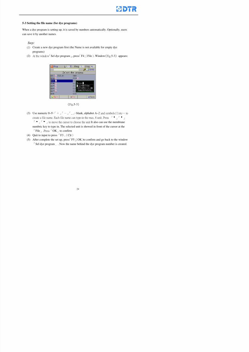
8132019 DTR 650 User Manual
httpslidepdfcomreaderfulldtr-650-user-manual 2470
5-3 Setting the file name (for dye programs)
When a dye program is setting up it is saved by numbers automatically Optionally users
can save it by another names
Step
(1) Create a new dye program first (the Name is not available for empty dye
programs)
(2) At the window「Sel dye program」 press「F4」(File) Window《Fig5-3》appears
《Fig5-3》
(3) Use numeric 0~9「+」「-」「_」blank alphabet A~Z and symbols [ ] etchellip to
create a file name Each file name can type-in the max 8 unit Press 「3」「4」
「5」「6」to move the cursor to choose the unit It also can use the membrane
numbric key to type in The selected unit is showed in front of the cursor at the
「File」Press「OK」to confirm
(4) Quit to input to press「F3」(Clr)
(5) After complete the set up press「F5」(OK)to confirm and go back to the window
「Sel dye program」 Now the name behind the dye program number is created
8132019 DTR 650 User Manual
httpslidepdfcomreaderfulldtr-650-user-manual 2570
5-4 Inserting a program step
Insert the program step means to insert a step in the existing program step where youwant to insert a step All following steps are moved one step ahead The total number of
steps will be increased by itself Able to insert more than one step continusely at the
same time
【Example】《Fig5-4》 To insert a step「call」before「002 Rinse」
《Fig 5-4》
Step
A Enter to the dye program「002」at the window of 「Sel dye program」
(Example)
B Press「6」to move cursor to「002 Rinse」 then press「F2」(add)
C Press「F5」(Edit) then press「」「」or「5」「6」to choose program
step to modify Choose「call」and press「」to move cursor to modify itrsquos
value
8132019 DTR 650 User Manual
httpslidepdfcomreaderfulldtr-650-user-manual 2670
D Press「」「」 value of 「call」is listing at the table Choose「pH Check 」Press「F5」(OK)
E Press「F4」(Save)and press「F1」(Undo)to return to previous window Complete
to insert the「02 Call」The previous「02 Rinse」update to「03」 All following
steps are moved one step ahead Total number of steps will be increased ldquo1rdquo by
itself
Repeat the steps B-E can non-stop to insert more than one step
Quit the insert and modify ( before pressing「F4」) press「F1」(Undo) to exit
The original dye steps will be unchanged
To delete an inserted dye steps press key「F3」(Del) The step deletes
immediately
5-5 Deleting a program step
Delete the program step means to delete step which the cursor locates When that step is
deleted the step number will be updated automatically All following steps are moved up
one step It is allowed to delete more than one steps continuously at the same time
Step
A Enter to the「Edit dye program」《Fig5-5》at the window「Select dye program」
B Press「6」「5」move cursor to the want to delete
C Confirm and press「F3」(Del) Window「Confirm delete」appears Press
「F4」(Yes)
8132019 DTR 650 User Manual
httpslidepdfcomreaderfulldtr-650-user-manual 2770
D That step is deleted immediately and all following steps move up one step
Repeat the steps above can non-stop to delete more than one step
Press「F2」(No)to cancel the deletion
Press「F1」(Exit)to end
5-6 Modifying a program step
To modify the saved name and the setting value of the dyeing steps
Step
1 Choose a dye program which need to modify at the「Sel dye program」 press「F5」
(OK)
2 Press「6」「5」to move cursor to a step which need to modify Select and press
「F5」(Edit) Window of 「Edit dye instruction」appears
3 Press「F2」()「F3」()to choose the step list select it and press「」to move
the cursor to itrsquos value setting
4 Press numeric key to input the value or press「6」「5」to choose the item Press
「F5」(OK)when complete Cursor move to the next value (if need to set more
than one item)
5 Press「F4」(Save)when all setting is complete Return to「Edit dye program」
Method of parallel functionrsquos modification is same as above
Before pressing the key「「「「Save」」」」 press「F1」(Undo)to quit all modify Return
to the window of Edit dye program
All edit and modify functions mentioned of this charper are only available
for the dyeing files which already saved in the file and not being running It
8132019 DTR 650 User Manual
httpslidepdfcomreaderfulldtr-650-user-manual 2870
5-7 Copying a dye program
Copying a dye programs mean to make a copy of an dye programs to a blank dyeprogram This function is for creating new dye program rapidly
Choose「1Dye Program」at the main menu Press「F5」(OK)then press「F2」()to choose「2Copy dye prog」 Press「F5」(OK) 《Fig5-7-1》appears
《Fig 5-7-1》
《Fig 5-7-2》
【【【【Eg】】】】
Copy program 003 to program 012
Press「」「」to move cursor to theprogram「003」 press「F4」(Copy)
Program「003」shows at the top right side of
the bar
Press「」「」to move cursor to program「012」 Then press「F5」(Paste)「」appears behind the「012」That means it issuccessfully copying the program
If the target program is occupied
confirmation window「Overwrite」
When choose an program or a targetprogram can select them by using the
8132019 DTR 650 User Manual
httpslidepdfcomreaderfulldtr-650-user-manual 2970
5-8 Deleting a dye program
Choose「1Dye program」at the main menu Press「F5」(OK)then press「F2」()to choose「3Delete dye prog」 Press「F5」(OK) 《Fig5-8-1》appears
《Fig5-8-1》
《Fig5-8-2》
Press「」「」to move cursor to
choose program need to delete Eg
delete program「012」 press「F5」(Del) Confirmation window
「Confirm delete」appears
Press「F4」(Yes) to confirm delete
Repeat the above step can delete more
than one program at the same time
Press「F2」(No) to return to window
《Fig5-8-1》and not delete that program
Exit to press「F1」(Exit)and return to the
main menu
8132019 DTR 650 User Manual
httpslidepdfcomreaderfulldtr-650-user-manual 3070
6 983123983141983156983156983145983150983143DTR-650 has a built-in standard factor that can fulfill all different types of dyeing
machinesrsquos basic demand Users can also modify the factors base on their request to
fulfill their special control demand Before modify please refer to the table of each
range of Setting Factors (see the Supplementary Table)
6-1 ldquoEnable to use the program stepsrdquo setting
There are totally 64 program steps Parts of them are usually applying to the programs
In order to make more efficiently of editing programs it can「Disable」the other part
of program steps which are not usually applying or not applicable to the programs
For example dye machine with one tank it is only using step Tank B In this case itcan firstly「Disable」the program steps of Tank C When edit the program the
「Disable」rsquos steps will not appear at the cursor for choosing But this will not effect
and change the saved files The saved files can be kept as before
Step
(1) Choose「2 Factors」at the main menu Press「F5」(OK)(2) Choose「18 Dye Instruction」at the sub-function menu Then presss「F5」(OK)
Window「Edit dye ins」appears
「Enable」instruction can available to
use「Disable」instruction is temporarystop to use
Press「F2」()「F3」()to move
8132019 DTR 650 User Manual
httpslidepdfcomreaderfulldtr-650-user-manual 3170
6-2 ldquoAllow to modify dye program temporary during operatingrdquo Setting
During dye program running it can modify dye program temporary Thesemodification will not disappear by causing a sudden power interruption or power off
until select another new dye program to run
Please note that it is only for modifying the dye program temporary That program
file would not saved due to the modification If need to modify the program file and
save choose the function of Edit Dye Program to edit (Refer to the Charper 5 for the【Edit Dye Prograrm】)
6-2-1 ldquoAllow to modify all dye programsrdquo Setting
Step
(1) Choose「2 Factors」at the main menu Press「F5」(OK)
(2) Choose「02 System Factor」at the sub-function menu Then presss「F5」(OK)
Window「Edit System Factor」appears
Set to stop using temporary the「07
Rinse」press「F4」(Sel)to set it as Disable
Repeat above steps to complete all setting
Press 「F1」(Exit)to return to main menu
8132019 DTR 650 User Manual
httpslidepdfcomreaderfulldtr-650-user-manual 3270
6-2-2 ldquoAllow to modify part of dye programsrdquo Setting
【Eg】Set the number 08 or above (including number 08) is allowing to modify dye
programs during operating
Step
A Refer to【6-2-1】setting the factor as「22」to allow editing dye program
temporary during operating
(4) Press「3」「4」to edit the setting
as「Enable」 and press「F5」(OK)
Restore the standard factor by
pressing「F3」(Clr)
(5) Exit to press「F1」(Exit)and
return to window of 「Main Menu」
8132019 DTR 650 User Manual
httpslidepdfcomreaderfulldtr-650-user-manual 3370
6-2-3 ldquoAllow to modify dye steps temporaryrdquo Setting
After setting the dye programs are allowed to edit it also can set which dye steps are
allowed to edit temporary during operating
Step
(1) Choose「2 Factors」at the main menu Press「F5」(OK)
(2) Choose「19 Dye Ins control」at the sub-function menu Then presss「F5」
(OK) Window「Edit ins mode」appears
「Enable」 Allow to edit that dye step before
operating
「Disable」 Not allow to edit dye step before
operating
(3) Press「」「」to move cursor
to choose dye step Press「F4」
To enter to the「Edit dye program」from the
function menu there is a「」in front of the
file name「0-7」 means that program is not
allowing to edit during operating
8132019 DTR 650 User Manual
httpslidepdfcomreaderfulldtr-650-user-manual 3470
6-2-4 ldquoSet the dye step to keep running from the interrupt pointrdquo setting
When the dye program is operating it will disappear by causing power
interruption or sudden power off When start running again part of dye steps can
run again from the interrupt point part of them cannot
How to set
(1) Choose「2Factors」in the main menu and press「F5」(OK)
(2) Choose「20Continue mode」in the sub-function menu Press「F5」(OK) to
enter window of 「Continue Setting」
(3) Press「」「」to move cursor to choose dye steps Press「F4」(Sel)it
shows「Disable」or「Enable」for choosing Press「F5」(OK)to move cursorto the next setting
(4) Repeat above method until all setting is complete press「F1」(Exit)and
return to the main menu
8132019 DTR 650 User Manual
httpslidepdfcomreaderfulldtr-650-user-manual 3570
6-3 ldquoAllow to insert an addition dye stepsrdquo setting
During the program is running can temporary insert an addition dye step or a dye
program according to the operating actual situation Through this setting can set which
dye steps can apply or not to the program in operating
During to insert an addition step if sudden interruption or power off occurred it returns
to the main dye program automatically Before starting again should decide seriously
and set it again by actual needed
Step
(1) Choose「2Factors」at the main menu and press「F5」(OK)
(2) Choose「02System factor」and press「F5」(OK)
(3) Press「」「」to move cursor to the factor「34」and press「3」「4」to set
it as「Enable」 Press「F5」(OK)
(4) Press「F1」(Exit)to return to main menu Choose「21Addition Ins」at the
sub-function menu Press「F5」(OK)to enter the window「Addition Instruction」
(5) Press「」「」to move cursor to choose dye steps and press「F4」(Sel) Cursors
locates shows「Eable」or「Disable」 Press「F5」(OK)to move cursor to the
next dye step
(6) Repeat above method until to complete all setting press「F1」(Exit)and return
to the main menu
8132019 DTR 650 User Manual
httpslidepdfcomreaderfulldtr-650-user-manual 3670
6-4 Setting the display mode
DTR650 has three types of display mode during operating Program List mode
Schematic Diagram mode and Icon mode Users can set the display mode during
operating by factor setting
It goes back to a Program List mode when dye program ended
Step
(1) Choose「2Factors」at the main menu and press「F5」(OK)
(2) Choose「02System factor」and press「F5」(OK)
(3) Press「F2」()「F3」()to move cursor to choose「32Display mode」Press
「3」「4」 it shows「Online picture」「Instruction」「Big Icon」 choose
「Online picture」(eg) and press「F5」to confirm
8132019 DTR 650 User Manual
httpslidepdfcomreaderfulldtr-650-user-manual 3770
(4) Press「F1」(Exit)to return to the main menu
(5) The Schematic Diagram displays when the program is running (it stays at theProgram List mode when there is an alarm occurred)
Press「F4」to transfer to another display mode
It goes back to a Program List mode from Schematic Diagram Mode when dye
program ended Press numeric key「3」to view Schematic Diagram Mode again
Quit to press「F5」(Exit)
6-5 Adapt the digital input to another functions
DTR-650 has 32(0~31)input terminal it owns an standard setting when the
controller is initial According to the userrsquos demand they can change the DTR-650rsquos
anther functions of Input Terminal and PLC Input channel
The PLC Intputrsquos name can also define by the users (use IBM computer to edit and
download)
How to set
(1) Choose「2 Factor」at the main menu Press「F5」(OK)
(2) Choose「22 Input table」at the sub-function menu and press「F5」(OK)to enter
「Edit input table」
The actual input
terminal of theIBM computer
PLCrsquos input channel
8132019 DTR 650 User Manual
httpslidepdfcomreaderfulldtr-650-user-manual 3870
6-6 Adapt the digital output to another functions
DTR-650 has 32(0~31)output terminals it owns an standard setting when thecontroller is initial According to the userrsquos demand they can adapte the digital output
and the PLC outputrsquos channel to another functions The PLC Output channelrsquos name
can also define by users (use IBM computer to edit and download)
Step
(1) Choose「2 Factor」at the main menu Press「F5」(OK)
(2) Choose「23 Output table」at the main menu and press「F5」(OK)
(3) Press「F2」()「F3」()to move cursor to choose the output terminal atthe left side of the window Press「F5」(Add) the PLCrsquos output channelrsquos
name is listing at the right side of the window
(4) Press「F2」()「F3」()to move cursor to choose the PLC outputrsquos channel
If cursor moves to the PLC output channel which already linking「Add」is
not for choosing that means that output channel is already occupied
(5) Confirm the connection to press「F5」(Add) Quit to press「F4」(Del)Press「F1」(Exit)when complete all setting and return to main menu
The actual output
terminal of the
IBM computer
PLCrsquos output channel
8132019 DTR 650 User Manual
httpslidepdfcomreaderfulldtr-650-user-manual 3970
983095 983109983140983145983156983145983150983143 983156983144983141 983110983137983139983156983151983154983155DTR-650 has several kinds of control factors
Userrsquos factors System factors Temperature Control factors Speed factors Dosing
factors PID factors Analog Input Output factors standard factors etchellipPlease refer
to the supplementary table for the setting range and standard of the factors
DTR-650 has a built-in standard factor Users can edit by themselves if necessary
7-1 Modifying userrsquos factors
Userrsquos factors is setting with the Dyeing machinesrsquos PLC Programrsquos factor it is define by
the PLC Programmer
Step to edit
(1) Choose「2Factors」at main menu Press「F5」(OK)
(2) Choose「01User Factor」Press「F5」(OK)
(3) Press「F2」()「F3」()「6」「5」to move cursor up down and by page
Choose a factor need to edit then press「3」「4」to set itrsquos value Press「F5」(OK) Cursor moves to the next factor
(4) Some of factors can input numbers by the numeric membrance keys to edit If
the input is incorrect it turns to red and means the edit is not available
8132019 DTR 650 User Manual
httpslidepdfcomreaderfulldtr-650-user-manual 4070
Modifyrsquos method of the system factors temperature factors speed factors dosingfactors PID factors analog Input output factors standard factors etchellipare same asabove
If apply the library of DTR500 and DTR600 into the DTR650 the key「3」「4」may not valid to use Please use the numeric keys instead of it to key in factors itmay not effect the normal operation
Please pay a serious attention and read carefully at the factorrsquos table before modify the factors An incorrect value may effect the DTR-650 Dyeing
Machine Controllerrsquos operating After modifying factors must cancel the
password and secure data
7-2 Loading the standard factors
After modifying factors if need to restore a manufacturerrsquos standard factors of
DTR-650 The method as follows
1 Choose「2Factors」at main menu Press「F5」(OK)
「 「 ( ) 「
8132019 DTR 650 User Manual
httpslidepdfcomreaderfulldtr-650-user-manual 4170
7-3 Copying the factor
Users can build up a set of factor by themselves and make a copy and save
Step
1 Choose「2Factors」at main menu Press「F5」(OK)
2 Choose「13Restore Factor」 press「F5」(OK) window「factor will be
overwrite 」
3 Press「F4」(Yes)copy finished and saved Return to the main menu
4 Press「F2」(No)to not copy the factor and the existing factor is not change Return
to the main menu
7-4 Loading the backup factors
Users can build up a set of factor and backup files to load to DTR-650
Step1 Choose「14Backup factor」at the sub-function menu Press「F5」(OK)and
window「Factror will be overwrite」appears
2 Press「F3」(OK)to load the the backup factor them return to main menu
Press「F2」(No)to not copy the factor and the existing factor is not change
Return to the main menu
8132019 DTR 650 User Manual
httpslidepdfcomreaderfulldtr-650-user-manual 4270
983096 983119983157983156983152983157983156 983124983141983155983156983145983150983143
Before the output testing must be complete the steps as follows
A Cut off all connecting line of output terminal of DTR-650
B Stop running the PLC
C Check up the connections of all output channels to avoid damages from
incorrect connections
D Check up state of dyeing machines include the temperature pressure valves
onoff and pumpshellipetc ensure the safety for priority
8-1 Testing the Digital output
Step
1 Choose「3Output Testing」at the main menu Press「F5」(OK) 2 Choose「1Digital」at the sub function menu Press「F5」(OK) window「Digital
output testing」appears
3 Press「」「」「」to move cursor to each output channels Press「F5」(OK)
Output Name
8132019 DTR 650 User Manual
httpslidepdfcomreaderfulldtr-650-user-manual 4370
8-2 Testing the Analog output
(1) Choose「3Output Testing」at the main menu Press「F5」(OK)
(2) Choose「2Analog」at the sub function menu Press「F5」(OK) window「Analog output testing」appears
(3) Press「」「」「」to move cursor to each channels Then key in number by
the numeric membrance keys (range0~200= 0~20mA) Press「F5」(OK) there
is a output current relating to the output channel
(4) Press「F5」(OK) There is an output when the output channel with red light No
output without light onl(5) When complete the testing press「F1」(OK)to return to the main menu
8132019 DTR 650 User Manual
httpslidepdfcomreaderfulldtr-650-user-manual 4470
983097 983107983137983148983145983138983154983137983156983145983151983150
DTR-650 has Dosing and Temperature calibration
When enter to Dosing calibration must be set the Low Volume calibration first and
then High Volume calibration When enter to Temperature calibration must be set the
Low Temperature calibration first and then High Temperature calibration Must be
hightly follow this orders seriously
9-1 Calibration of Low Volume Tank
Step
A Choose「4Calibration」at the main menu Press「F5」(OK)
B Choose「Dosing 0 low vol」at the sub function menu Press「F5」(OK) window
appears
C Fill the Dosing Tank to a half level input value shows how much the water level
If it stays ldquo0rdquo check the connection and the factor setting is correct or not
And connect the pressure sensorrsquos output channel to the Current Meter to ensure
that sensor works or not
8132019 DTR 650 User Manual
httpslidepdfcomreaderfulldtr-650-user-manual 4570
D Fill the Dosing Tank to 50ml (Calcalate from the bottom side of the pressure
sensor steel tube) input value should show 4~6 (input value must between
0~10) Then enter the water volume The setting volume is relating the water
levelrsquos water value (litre as unit) input range 0~80 Set as「 「「 「0000 0000 0000 0000」」」」is strongly is strongly is strongly is strongly
receommend receommend receommend receommend Press「F5」(OK)to complete [Calibration of Low Volume Tank 1
is same as above method]
9-2 Calibration of High Volume Tank
Step
A Choose「4Calibration」at the main menu Press「F5」(OK)
B Choose「Dos 0 high vol」at the sub function menu Press「F5」(OK) window of
「Calibrate high 」appears
C Fill the Dosing Tank to a full level input value should be larger than 30 enter
the current water level which relates to the water volume Enter the range within
100~2500 Then press「F5」(OK) to complete the calibrate the high volume tank
8132019 DTR 650 User Manual
httpslidepdfcomreaderfulldtr-650-user-manual 4670
9-3 Temperature Calibration
Step
A This function is for adjusting the DTR650rsquos accuracy of Temperature Control It
must be using with the special terminal which is only for DTR650
B Choose「4Calibration」at the main function menu and press「F5」(OK)
C Choose「3Low Temp」at the sub-function menu Press「F5」(OK)and《Fig9-3》
appears insert the DTR650rsquos low temperature calibration terminal to the temperature
input terminal wait for the jumping value to stable down then press「F5」(OK) then
to adjust the high temperature calibration
D Adjusting the High Temperature Calibrationrsquos method is same as above But usersusersusersusers
must be using the High Temperature Terminalmust be using the High Temperature Terminalmust be using the High Temperature Terminalmust be using the High Temperature Terminal whichwhichwhichwhich is specially for DTR650 onlyis specially for DTR650 onlyis specially for DTR650 onlyis specially for DTR650 only
《Fig 9-3》
8132019 DTR 650 User Manual
httpslidepdfcomreaderfulldtr-650-user-manual 4770
10 983122983141983139983151983154983140983155 983151983142 983108983161983141 983120983154983151983143983154983137983149983155
It contains the past 15 days of temperature curves of running history
Checking method
(1) Choose「5Dye Record」at main menu press「F5」(OK)
(2) Sub-function menu shows the set up date of the past 15 days dye programs
Listing by the lastest set up date
(3) Choose a program date and press「F5」(OK) it appears window「Temp
record」
(4) Press「」「」to move the white line in the box one minute by moving once
(5) Press「3」「4」to move the line to check the time period 2 hours by moving once
The yellow selecting line of the「24 hours operating state」is repectively moving
The curve info is show in the curve box Left side of the widnow appears the
relating running info the time is the time value of the line locates at
(6) Check more details of the temperature info to press numeric key「middot」 a bright red line
appears in the selecting box this line is to check the starting point of the
temperature inforsquos time period Then press「」to move the white line to the end
point of the time period The temperature info between the starting point and end
point are appears at the right side of the window Press「middot」to return to the preious
curve page
(7) Check more details of the alarm infor To perss numeric key「7」「9」 the alarmrsquos
details is listing by orders
(8) Press「F1」(exit) to return
8132019 DTR 650 User Manual
httpslidepdfcomreaderfulldtr-650-user-manual 4870
11 983125983155983137983143983141 983151983142 983117983141983149983151983154983161 983107983137983154983140
DTR-650 supports 32MB or above Compact Flash Card which can transfer and save all
information for 4 sets of DTR-650 Including library files schematic diagram icon
image PLC program dye program factor and confiruration files etchellip Use the CF Card
to up download and swap the information of DTR-650 promptly install the relating
device and program updates
DTR-650 CF Card with bank 1 to bank 4 can save 4 sets information of Dyeing
Machines When download or save files should choose the BANK first
《Fig11-1》
8132019 DTR 650 User Manual
httpslidepdfcomreaderfulldtr-650-user-manual 4970
11-1 Downloading data
1 Firmly insert the CF card into the DTR-650rsquos PCMCIA connector Ensure it is
wholely and firmly inserted if the card is not totally inserted or the card do not
touch in all to the connector there will be an error occurred and cannot
updownload or interrupted during operation
2 Choose「6Memory Card」at the main menu and press「F5」(OK) 《Fig11-1》
appears Information of Bank「1」shows at the left hand side of the window press
number 1-4 by using numeric keys to choose the BANK Check the
information in the Bank seriously which is exactly need to download to the
DTR650
3 Press()()「6」「5」to move cursor to the sub-function menu to choose
the downloading items Press「F5」(OK) window appears「Stop PLC run before
access memory card Stop the PLC run」 Press「F5」(YES) to stop PLC
running
4 Press「F5」(OK) window appears Confirm to update or not the DTR-650rsquos
information As that downloading will be replace the DTR-650rsquos information
(that means the existing information of the DTR-650 will be removed and
replaced)
5 Press「F4」(YES)to download the information from the DTR-650 to the CF
Card Return to the main menu when finish
8132019 DTR 650 User Manual
httpslidepdfcomreaderfulldtr-650-user-manual 5070
Ensure inserting firmly the CF card into the DTR-650 unless it will cause
error or cannot Updownload data
Never remove CF card during transferring or updownloading data Until it
is all completed
DTR-650rsquos dyeing program is not compatible with DTR-500 and
DTR-600 Never use CF card to transfer data among them
11-2 Storing and transfering data
1 Insert the CF Card to the DTR-650
2 Choose「6Memory Card」at the main menu and press「F5」(OK) 《Fig11-1》
appears Left hand side of the window shows the data of BANK 1 press numeric
keys 1-4 to select the BANK To confirm the put the data in the DTR-650 to the CF
Card The existing data of that bank will be replaced and covered by the new data (if
that bank is already occuplied)
3 Choose「23Save Dye prog」(Example)at the sub-funciton menu press「F5」(OK)to confirm Window「Update memory card data」appears
4 Press「F5」(OK)to transfer the data to the CF card Return to the main menu
5 Put the CF card into another DTR-650 and follow the operating method of 「11-1
Downloading data」」」」can transfer and swap data with more than one set of
DTR-650
8132019 DTR 650 User Manual
httpslidepdfcomreaderfulldtr-650-user-manual 5170
12 983123983156983137983156983141 983137983150983140 983113983150983142983151983154983149983137983156983145983151983150
The state and information is including the Dyeing Machinersquos state of Digit Input output
Analog Input output Temperature control PID Dosing PID Pressure different PID
software system information and alarm record This information is for checking at any
time
12-1 Input Output state
Step
1 Choose「7Info and state」at main menu and press「F5」(OK)
2 Choose「01Digital IO put」at the sub-function menu then press「F5」(OK)
「Digital In Out State」0=None 1=Input
3 Press「F1」(Exit)to return to main menu
Same method for checking the temperature control analog dosing pressure
different etchellip
12-2 Checking the system information
Step
1 Choose「7Info and state」at main menu and press「F5」(OK)
2 Choose「11 System info」at sub-function field press「F5」(OK)Window
「System Information」appear
System information is including System info(software version) Library doc
Icon files Schematic file Definition file hardare state Config File Commandinstruction icon PLC file etc
8132019 DTR 650 User Manual
httpslidepdfcomreaderfulldtr-650-user-manual 5270
12-3 Checking the operating alarm record
Operating record shows the latest 40 operating items and alarm records including
the time and content of the alarm
A) Choose「7 Info and state」
and press「F5」(OK)
B) Choose「12Alarm logs」at
the sub-funciton menu then
press「F5」(OK)
8132019 DTR 650 User Manual
httpslidepdfcomreaderfulldtr-650-user-manual 5370
13 983105983140983146983157983155983156983145983150983143 983156983144983141 983107983151983150983156983154983137983155983156
The displaysrsquos brightness can be adjusted if necessary
Step
1 Choose「8Others」at main menu press「F5」(OK)
2 Choose「01Contrast」at sub-function menu press「F5」(OK) window「Set
Contrast」appears
3 Press「」「」to move the bar to set the brightness then press「F5」(OK)Window appears「Please reboot the system」
4 Press「F5」(OK)to return to main menu and re-boot the DTR-650 to complete
adjusting the brightness
8132019 DTR 650 User Manual
httpslidepdfcomreaderfulldtr-650-user-manual 5470
14 983123983156983151983152 983154983157983150983150983145983150983143 983156983144983141 983120983116983107 983120983154983151983143983154983137983149
Before testing the Input output testing transfer of the PLC program must stop the PLC
running
Step
1 Choose「8Others」at the main menu Press「F5」(OK)
2 Choose「04 PLC Stop」at sub-function menu Press「F5」(OK) window
「Password」appears
3 Enter password and press「F5」(OK) Window「Stop the PLC run」appears
4 Press「F4」(Yes)and window「PLC Stop」appear Press「F5」(OK) Now
the PLC is stop running and return to the main menu
All testing cannot operate when the PLC is running
Editing dye program and the relating operation can
perform with the PLC running together
8132019 DTR 650 User Manual
httpslidepdfcomreaderfulldtr-650-user-manual 5570
15 983123983141983156983156983145983150983143 983156983144983141 983156983145983149983141
Step
1 Press「8Others」at the main menu Press「F5」(OK)
2 Choose「10Set date time」at the sub-function menu Press「F5」(OK) window
「Set date time」appears
3 Press「F5」(Edit) to move cursor by 「3」「4」 enter the time value at the
cursor locates
4 Press「F5」(OK)to complete the modify Press「F1」(Exit)to return to main
menu
5 Press「F1」(Exit)if not modify and return to main menu
8132019 DTR 650 User Manual
httpslidepdfcomreaderfulldtr-650-user-manual 5670
1166 983123983123983157983157 983152 983152 983152 983152983148983148983141983141983149983149983141983141983150983150983156 983156 983137983137983154 983154 983161983161 983124 983124 983137983137983138983138983148983148983141983141
TTTTTTTTaaaaaaaabbbbbbbblllllllleeeeeeee 11111111 【Dye Instruction】
Code Icon Instruction Code Icon Instruction
000 End 016 Inject C
001 Start 017 Dosing BV
002 Heat 018 PH
003 Cool 019 Addsalt B
004 Flow Fill 020 Addsalt C
005 Level Fill 021 Ana Fill
006 Drian 022 Lock Fill007 Rinse 023 Lock Level
008 Run 024 Low Rinse
009 Call 025 Cyc Rinse
010 Prep B 026 Rinse B
011 Addsalt B 027 Rinse C
012 Dosing B 028 Temp
013 Inject B 029 Nozzle Pressure
014 Prep C 030 Main Pump
015 Dosing C 031 Pump Speed
8132019 DTR 650 User Manual
httpslidepdfcomreaderfulldtr-650-user-manual 5770
Table 2 【【【【Alarm】】】】
System Alarm Must stop operating and check up to solve problems before restarting
the machine
Running Alarm It is a reminder Not effect the operating of DTR-650
Userrsquos Alarm Total of 32 Users can define themselves and use it when edit the PLC
Program (do not listing below)
No System Alarm No Running Alarm
1 PLC program not running 16 Temp ctrl 0 Grad too slow
2 Main temp sensor error 17 Temp ctrl 0 Grad too fast
3 Not at Run window 18 Temp ctrl 0 Hold temp too low
4 Exceeding max temp 19 Temp ctrl 0 Hold temp too high
5 - 20 Temp ctrl 1 Grad too slow6 - 21 Temp ctrl 1 Grad too fast
7 - 22 Temp ctrl 1 Hold temp too low
8 Communication error 23 Temp ctrl 1 Hold temp too high
9 Slave not answer 24 Temp ctrl 2 Grad too slow
10 PLC 0 not answer 25 Temp ctrl 2 Grad too fast
11 PLC 1 not answer 26 Temp 2 Hold temp too low12 Display not answer 27 Temp 2 Hold temp too high
13 Lower power voltage 28 Temp ctrl 3 Grad too slow
14 - 29 Temp ctrl 3 Grad too fast
15 - 30 Temp3 Hold temp too low
31 Temp3 Hold temp too high
32 Dosing 0 injection too slow
33 Dosing 0 injection too fast
34 Dosing 1 injection too slow
35 Dosing 1 injection too fast
8132019 DTR 650 User Manual
httpslidepdfcomreaderfulldtr-650-user-manual 5870
TTTTTTTTaaaaaaaabbbbbbbblllllllleeeeeeee 33333333 【【【【System factor】】】】
No Description Std Range amp Definition
1 ID No 000 000- 100 Controller no
2 Communication Rate 4800Bps 2400 4800 9600 19200 38400
3 Display language Chinese English Chinese
4 Temp display mode and
5 Maxmium temperature 145 025 ~ 145 6 Type of external PLC Default PLC32DPLC32PLC16Default
7 Number of external PLC NANA 1 unit connect
2 unit connect
8Communication Rate of
PLC9600Bps 2400 4800 9600 19200
9 Set point 1 085 000 ~ 145
If signal source is temperaturethe setting value is thetemperature value If the signal
source is Analog Input 6~17 then
setting value for Analog input is 0 ndash
100 and relates Analog
Input14~020mA
10 Source 1 Sensor0Sensor 0 ~5
Analog input 0 ~1111 Set point 2 092 Same as 09
12 Source 2 PT100 1 Same as 10
13 Set point 3 085 Same as 09
14 Source 3 PT100 2 Same as 10
15 Set point 4 092 Same as 09
16 Source 4 PT100 3 Same as 1017 Set point 5 085 Same as 09
18 Source 5 PT100 4 Same as 10
19 Set point 6 092 Same as 09
8132019 DTR 650 User Manual
httpslidepdfcomreaderfulldtr-650-user-manual 5970
29 Min cyclic time of cloth 100sec 0 ~ 255 sec
30 Max cyclic time of cloth 240sec 0 ~255 sec
31Standard cyclic time of
cloth
180 000 ~ 255 sec
32 Display ModeProgram
List
Program list Schematic Diagram
Icon mode
33 CF card format Standard of
DTR CF
Card
Standard of DTR CF Card V20
Standard CF Card
34 Addition step Disable Disable Enable35 Mode Com 3
CouplingEsure Com 3 is the communication
port of the Central or Coupling
36Com 3 Communication
rate9600 Central communication speed
8132019 DTR 650 User Manual
httpslidepdfcomreaderfulldtr-650-user-manual 6070
TTTTTTTTaaaaaaaabbbbbbbblllllllleeeeeeee 44444444 【【【【Temperature Cotnrol Factor】】】】
No Factor Definition Standard Range and Definition
01 PT No PT-0 PT 0~5 PT-100 Input number
02 Max working temp 140 000~140
03 Output mode 0 0~2
04 Alarm time of gardient 240sec 000~255 sec
05 Alarm mode of gradient Always AlwaysOnceNone
06 Control mode of gradient Heating orCooling
interlocked
Heating and Cooling interlocked
No limitation
07 Alarm range of HoldTemp 03 01~20
08 Alarm time for HoldTemp 240sec 000~255sec
09 Alarm mode of HoldTemp Always AlwaysOnceNone
10 Control mode ofHoldTemp
Heating only Only heating and cooling Cooling whenalarm occurred Only heating andcooling No limitation when alarmHeating only
11 Porportional Band 100 000~250
12 Integral band 128 sec 000~255 sec
13 Differential time 04 sec 00~20 sec
14 Min transit gradient 02 00~50
15 Transit rate 20 times 00~50 times (020= 2 times)
16 PID initial output value 010 000~100
17 ONOFF cycle time 10 sec 05~25 sec
Onoff valve set as 010 sec
Proportional valve set as 020 sec
18 Time down count mode Mode 0 0~10 = The time down count range from「Factor 20 + target temp」to「Target
8132019 DTR 650 User Manual
httpslidepdfcomreaderfulldtr-650-user-manual 6170
TTTTTTTTaaaaaaaabbbbbbbblllllllleeeeeeee 55555555 【【【【Speed Factor】】】】
No Factor Definition Standard Range amp Definition
01 Input Number Speed input 0 Speed input 0~11
02 Average times 05 times 01~10
03 Sensor Number 008pcs 001~255
04 Roller Dimension 250mm 050~500
05 Max cloth speed 200mmin 001~25506 Min cloth speed 020mmin 001~255
07 Alarm delay time 240sec 001~255
08 Alarm mode Every oncenoneevery
09 Alarm range () 020 001~255
10 Proportional band 100 001~255
11 Integer band 128 001~25512 Differential time 000 001~200
13 Initial speed () 020 001~255
14 Control cycle ti(01sec) 05 01~30
15 First cycle time(01sec) 10 01~30
16 Speed increase limit () 010 001~100
17 Speed decrease limit () 010 001~100
18 Min speed() 005 001~100
19 Manual speed adjust () 005 001~100
20 Manual initial speed() 020 001~100
21 Stopping speed() 010 001~100
22 Switch speed() 020 001~100
23 Not used
24 Speed decrease turns 03turns 01~50
8132019 DTR 650 User Manual
httpslidepdfcomreaderfulldtr-650-user-manual 6270
Table 6 【【【【Dosing Factors】】】】
No Description Range Range and Explanation
1 Analog input no Analog input 0 Analog input no 0 ~11
2Alarm delay time for
dosing240 sec 000 ~255 sec
3 Alarm time for dosing Every Every Once None
4 Proportional band 100 000 ~255 sec Factor P
5 Integer band 128 000 ~255 sec Factor I6 Differential time 04 00 ~20 Factor D
7 Max adjust rate 150 50~ 255
8 Initial factor for dosing 10 000 ~100
9 User curve section 0 10 Gradient of sect1 for dosing curve9
10 User curve section 1 10 Gradient of sect2 for dosing curve9
11 User curve section 2 10 Gradient of sect3 for dosing curve9
12 User curve section 3 10 Gradient of sect4 for dosing curve9
13 User curve section 4 10 Gradient of sect5 for dosing curve9
14 User curve section 5 10 Gradient of sect6 for dosing curve9
15 User curve section 6 10 Gradient of sect7 for dosing curve9
16 User curve section 7 10 Gradient of sect8 for dosing curve9
17 User curve section 8 10 Gradient of sect9 for dosing curve9
18 User curve section 9 10 Gradient of sect10 for dosing curve9
19 Min water level 05 00~ 10 04~20mA percentagechange to the userrsquos factor setting
20 Output value for Tank
clean
100 000~ 100
Injected percentage of dosing valve
in dosing End period
This factor will be invalided if usingONOFF dosing valve
21 Full range 100 001~255 Self-adjustment cannotchange
22 Range ratio 001001~255 Self-adjustment cannot
change
8132019 DTR 650 User Manual
httpslidepdfcomreaderfulldtr-650-user-manual 6370
【【【【TTaabbllee 77 】】】】Pressure Deviation Factors
No Description Std Range amp Definition
1 Analog input number + Analog in 0 Analog in 0~11
2 Analog input number - Analog in 1 Analog in 0~11
3 Input mode Pressure Pressure Pressure deviation
4 Full range 050x01Kgcm
001~255
5 Range ratio 001 001~255
6 Alarm delay time 100sec 001~255
7 Alarm mode Every oncenone
8 Alarm range 010 001~255
9 Proportional band 100 001~255
10 Integer band 128 001~255
11 Differential time 00 00~20
12 PID Init output value 010 001~255
13 Cycle time 10 03~30
14 First cycle time 030 003~100
15 Max adjust rate 010 001~100
8132019 DTR 650 User Manual
httpslidepdfcomreaderfulldtr-650-user-manual 6470
【【【【TTaabbllee 88 】】】】Definition of Analog Input
No Description Standard Range and Explanation
01 PT 0 correction standard DIN std DIN std JIS std
02 PT 0 correction +0 +- 9
03 PT 1 correction standard DIN std DIN std JIS std
04 PT 1 correction +0 +- 9
05 PT 2 correction standard DIN std DIN std JIS std
06 PT 2 correction +0 +- 9
07 PT 3 correction standard DIN std DIN std JIS std
08 PT 3 correction +0 +- 9
09 PT 4 correction standard DIN std DIN std JIS std
10 PT 4 correction +0 +- 9
11 PT 5 correction standard DIN std DIN std JIS std
12 PT 5 correction +0 +- 9
13 Analog input 0 define 4 ~ 20mA 0 ndash 20mA 4 ndash 20mA
14 Analog input 0 average times 10 times 01- 20 times
15 Analog input 0 min value 0000 0000 - 1000
16 Analog input 0 max value 100 0001 - 9999
17-60 Analog input 1~11 Same as Analog input 0
【【【【 】】】】 fi i i f A O
8132019 DTR 650 User Manual
httpslidepdfcomreaderfulldtr-650-user-manual 6570
【【【【TTaabbllee 99 】】】】Definition of Analog Output
No Description Standard Range and explanation
61 Analog output 0 define Control byPLC
Control by PLC
Temperature control PID0 output
Temperature control PID1 output
Temperature control PID2 output
Speed PID3 output
Dosing PID0 output Dosing PID1output
Pressure different PID0 outputPressure different PID1 output
Main temperature output
62 Mode of Analog ouptput0 4 ~20mA 0 ndash20mA 4 ndash 20mA
63-84 Analog output 1~11 Same as Analog output 0
【【【【TTaabbllee 1100】】】】Value Table 0 amp 1
No Description Range Std Range and explanation
1 Analog input no 000~011 000 Analog input no
2 Data ratio 001~255 100 Multiple by factors
3~53 0~98 000~255 000-100 Analog input 0~98 data
【【【【 】】】】St t Li t
8132019 DTR 650 User Manual
httpslidepdfcomreaderfulldtr-650-user-manual 6670
【【【【TTaabbllee 1111】】】】State List
No Description Range Standard Range and explanation
1 Display setting 1 0~255 205 See remarks at next page
2 Display setting 2 0~255 208
3 Display setting 3 0~255 209
4 Display setting 4 0~255 017
5 Display setting 5 0~255 0186 Display setting 6 0~255 019
7 Display setting 7 0~255 020
8 Display setting 8 0~255 021
9 Display setting 9 0~255 000
10 Display setting 1 0~255 000
11 Display setting 2 0~255 000
12 Display setting 3 0~255 000
13 Display setting 4 0~255 000
14 Display setting 5 0~255 000
15 Display setting 6 0~255 000
16 Display setting 7 0~255 000
Remarks
8132019 DTR 650 User Manual
httpslidepdfcomreaderfulldtr-650-user-manual 6770
0 = No display 1~255 = Display type of number
1~16 Content of PLC VB0~15
No 1 corresponding to VB0
No 16 corresponding to VB15
17~32 Content of PLC DB0~15
No 17 corresponding to DB0
No 32 corresponding to DB15
33~46 Content of PLC CNT0~29
No 33 corresponding to CNT0
No 46 corresponding to CNT29 47~78 Content of dyeing instruction 0~31 CNT0
No 47 corresponding to system instruction to No 0 of CNT0
No 78 corresponding to system instruction to No 31 of CNT0rsquos content
79~110 Dyeing instruction 0~31 of CNT0rsquos setting
111~142 Content of Dyeing instruction 0~31 CNT1No 111 corresponding to dyeing instruction No 0 of CNT1
No 142 corresponding to dyeing instruction No 31 of CNT1rsquos content
143~174 Dyeing instruction 0~31 of CNT1rsquos setting
175~204 Content of PLC HTIM0~29
No 175 corresponding to HTIM0
No 204 corresponding to HTIM29
205 Loading
206 Ratio 1
207 Ratio 2208 Ratio 1 x Loading
209 Ratio 2 x Loading
210 Fix value
211 Value Table 1 matching result
212 Value Table 2 matching result
213 Value Table 1 setting214 Value Table 2 setting
215 Pressure control PID0 different pressure value
216 Pressure control PID1 different pressure value
TTTTTTTTaaaaaaaabbbbbbbblllllllleeeeeeee 1122 【【【【Usage of password】】】】
8132019 DTR 650 User Manual
httpslidepdfcomreaderfulldtr-650-user-manual 6870
No Main FunctionFactor Sub Function Factor Password Rank
1 Run None
2 Dye program User3 or above
3 Control factor
- User factor User 1
- System factor User 1
- Temp PID 0
- Temp PID 1 User 1- Speed PID 0 User 1
- Dosing PID 0 User 1
- Dosing PID 1 User 1
- Pressure PID 0 User 1
- Pressure PID 1 User 1
- Analog IO User 1
- Load standard factor User 2 or above- Load a copied factor User 2 or above
- Copy factor User 2 or above
- Value table 0 User 1
- Value table 1 User 1
- Information and state User 1
- Dye instruction User 1
- Edit dye instruction setting User 14 Output testing User 2 or above
5 Calibration User 2 or above
6 Dye record None
7 CF card User 1
8 Info and state None
9 Others
- Contrast User3 or above
- Data Locking None
- PLC Run User 1
- PLC Stop User 1
- Password setting User 1
TTTTTTTTaaaaaaaabbbbbbbblllllllleeeeeeee 1133 【【【【Technical Data】】】】
8132019 DTR 650 User Manual
httpslidepdfcomreaderfulldtr-650-user-manual 6970
TTTTTTTTaaaaaaaabbbbbbbblllllllleeeeeeee 1133 【【【【Technical Data】】】】
1 Temperature Control
- Range 10~145(plusmn1)
- Mode Proportional or PWM
- Sensor PT100 (JIS or DIN standard)
2 Input and output channel
- Digital Input 32 DC24V PNP- Digital Output 32 DC24V 054A Relay connect point
- Analog Input 4 04~20 mA
- Analog Output 4 0~20mA 或 4~20 mA
3 Communication port 3 RS-232 amp 0~20 mAx1 RS485x 2
4 Dye program
- Number 15000 Steps
- Standard step 61Heating Cooling Fill Drain RinseDosingetc
5LCD module and Display
langage
Chinese
English
320 x 240 TFT color display with
more language
6 CF card connector 1 PCMCIA standard
7 Membrane Keyboard- Number Key 10 [0]~[9] Input factors
- Function Key 5 [F1]~[F5] function selecting
- Operation Key 2 [Start] [Stop]
- Auxiliary Key 7 [][][][][Esc] [larr][OK] [bull]
8 Operating Condition
- Temperature 5~45
- Humidity ≦85 (25)
9 Power supply
V l DC 24V
8132019 DTR 650 User Manual
httpslidepdfcomreaderfulldtr-650-user-manual 7070
70
983108983124983122983085650 983113983150983152983157983156 983119983157983156983152983157983156 983120983151983154983156983145983150983143 (983138983137983139983147983155983145983140983141 983158983145983141983159)
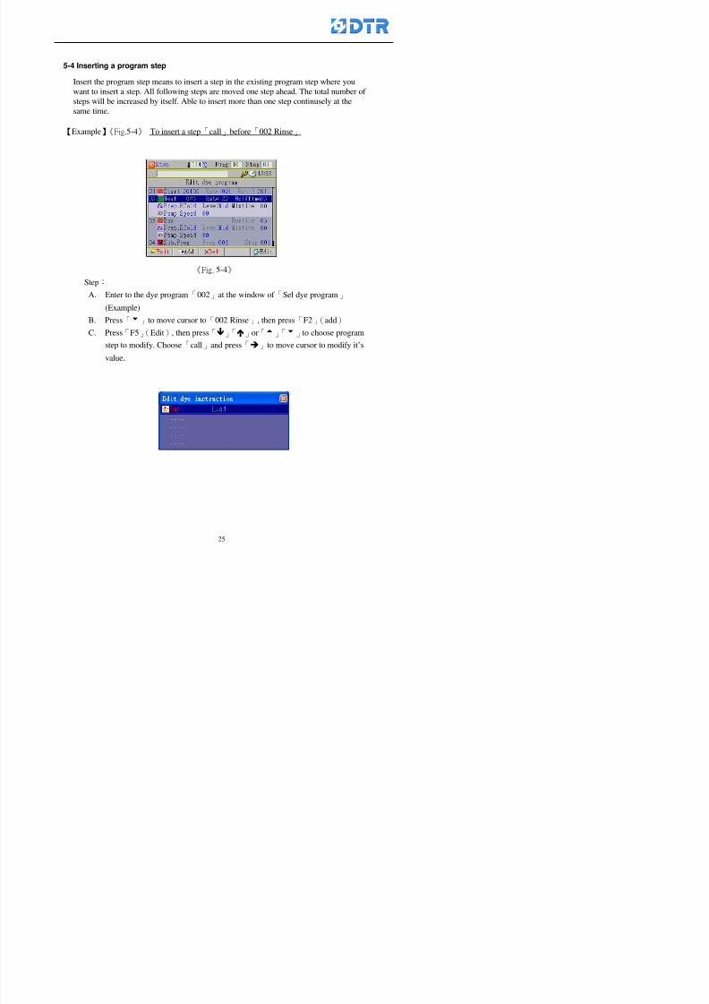
8132019 DTR 650 User Manual
httpslidepdfcomreaderfulldtr-650-user-manual 2570
5-4 Inserting a program step
Insert the program step means to insert a step in the existing program step where youwant to insert a step All following steps are moved one step ahead The total number of
steps will be increased by itself Able to insert more than one step continusely at the
same time
【Example】《Fig5-4》 To insert a step「call」before「002 Rinse」
《Fig 5-4》
Step
A Enter to the dye program「002」at the window of 「Sel dye program」
(Example)
B Press「6」to move cursor to「002 Rinse」 then press「F2」(add)
C Press「F5」(Edit) then press「」「」or「5」「6」to choose program
step to modify Choose「call」and press「」to move cursor to modify itrsquos
value
8132019 DTR 650 User Manual
httpslidepdfcomreaderfulldtr-650-user-manual 2670
D Press「」「」 value of 「call」is listing at the table Choose「pH Check 」Press「F5」(OK)
E Press「F4」(Save)and press「F1」(Undo)to return to previous window Complete
to insert the「02 Call」The previous「02 Rinse」update to「03」 All following
steps are moved one step ahead Total number of steps will be increased ldquo1rdquo by
itself
Repeat the steps B-E can non-stop to insert more than one step
Quit the insert and modify ( before pressing「F4」) press「F1」(Undo) to exit
The original dye steps will be unchanged
To delete an inserted dye steps press key「F3」(Del) The step deletes
immediately
5-5 Deleting a program step
Delete the program step means to delete step which the cursor locates When that step is
deleted the step number will be updated automatically All following steps are moved up
one step It is allowed to delete more than one steps continuously at the same time
Step
A Enter to the「Edit dye program」《Fig5-5》at the window「Select dye program」
B Press「6」「5」move cursor to the want to delete
C Confirm and press「F3」(Del) Window「Confirm delete」appears Press
「F4」(Yes)
8132019 DTR 650 User Manual
httpslidepdfcomreaderfulldtr-650-user-manual 2770
D That step is deleted immediately and all following steps move up one step
Repeat the steps above can non-stop to delete more than one step
Press「F2」(No)to cancel the deletion
Press「F1」(Exit)to end
5-6 Modifying a program step
To modify the saved name and the setting value of the dyeing steps
Step
1 Choose a dye program which need to modify at the「Sel dye program」 press「F5」
(OK)
2 Press「6」「5」to move cursor to a step which need to modify Select and press
「F5」(Edit) Window of 「Edit dye instruction」appears
3 Press「F2」()「F3」()to choose the step list select it and press「」to move
the cursor to itrsquos value setting
4 Press numeric key to input the value or press「6」「5」to choose the item Press
「F5」(OK)when complete Cursor move to the next value (if need to set more
than one item)
5 Press「F4」(Save)when all setting is complete Return to「Edit dye program」
Method of parallel functionrsquos modification is same as above
Before pressing the key「「「「Save」」」」 press「F1」(Undo)to quit all modify Return
to the window of Edit dye program
All edit and modify functions mentioned of this charper are only available
for the dyeing files which already saved in the file and not being running It
8132019 DTR 650 User Manual
httpslidepdfcomreaderfulldtr-650-user-manual 2870
5-7 Copying a dye program
Copying a dye programs mean to make a copy of an dye programs to a blank dyeprogram This function is for creating new dye program rapidly
Choose「1Dye Program」at the main menu Press「F5」(OK)then press「F2」()to choose「2Copy dye prog」 Press「F5」(OK) 《Fig5-7-1》appears
《Fig 5-7-1》
《Fig 5-7-2》
【【【【Eg】】】】
Copy program 003 to program 012
Press「」「」to move cursor to theprogram「003」 press「F4」(Copy)
Program「003」shows at the top right side of
the bar
Press「」「」to move cursor to program「012」 Then press「F5」(Paste)「」appears behind the「012」That means it issuccessfully copying the program
If the target program is occupied
confirmation window「Overwrite」
When choose an program or a targetprogram can select them by using the
8132019 DTR 650 User Manual
httpslidepdfcomreaderfulldtr-650-user-manual 2970
5-8 Deleting a dye program
Choose「1Dye program」at the main menu Press「F5」(OK)then press「F2」()to choose「3Delete dye prog」 Press「F5」(OK) 《Fig5-8-1》appears
《Fig5-8-1》
《Fig5-8-2》
Press「」「」to move cursor to
choose program need to delete Eg
delete program「012」 press「F5」(Del) Confirmation window
「Confirm delete」appears
Press「F4」(Yes) to confirm delete
Repeat the above step can delete more
than one program at the same time
Press「F2」(No) to return to window
《Fig5-8-1》and not delete that program
Exit to press「F1」(Exit)and return to the
main menu
8132019 DTR 650 User Manual
httpslidepdfcomreaderfulldtr-650-user-manual 3070
6 983123983141983156983156983145983150983143DTR-650 has a built-in standard factor that can fulfill all different types of dyeing
machinesrsquos basic demand Users can also modify the factors base on their request to
fulfill their special control demand Before modify please refer to the table of each
range of Setting Factors (see the Supplementary Table)
6-1 ldquoEnable to use the program stepsrdquo setting
There are totally 64 program steps Parts of them are usually applying to the programs
In order to make more efficiently of editing programs it can「Disable」the other part
of program steps which are not usually applying or not applicable to the programs
For example dye machine with one tank it is only using step Tank B In this case itcan firstly「Disable」the program steps of Tank C When edit the program the
「Disable」rsquos steps will not appear at the cursor for choosing But this will not effect
and change the saved files The saved files can be kept as before
Step
(1) Choose「2 Factors」at the main menu Press「F5」(OK)(2) Choose「18 Dye Instruction」at the sub-function menu Then presss「F5」(OK)
Window「Edit dye ins」appears
「Enable」instruction can available to
use「Disable」instruction is temporarystop to use
Press「F2」()「F3」()to move
8132019 DTR 650 User Manual
httpslidepdfcomreaderfulldtr-650-user-manual 3170
6-2 ldquoAllow to modify dye program temporary during operatingrdquo Setting
During dye program running it can modify dye program temporary Thesemodification will not disappear by causing a sudden power interruption or power off
until select another new dye program to run
Please note that it is only for modifying the dye program temporary That program
file would not saved due to the modification If need to modify the program file and
save choose the function of Edit Dye Program to edit (Refer to the Charper 5 for the【Edit Dye Prograrm】)
6-2-1 ldquoAllow to modify all dye programsrdquo Setting
Step
(1) Choose「2 Factors」at the main menu Press「F5」(OK)
(2) Choose「02 System Factor」at the sub-function menu Then presss「F5」(OK)
Window「Edit System Factor」appears
Set to stop using temporary the「07
Rinse」press「F4」(Sel)to set it as Disable
Repeat above steps to complete all setting
Press 「F1」(Exit)to return to main menu
8132019 DTR 650 User Manual
httpslidepdfcomreaderfulldtr-650-user-manual 3270
6-2-2 ldquoAllow to modify part of dye programsrdquo Setting
【Eg】Set the number 08 or above (including number 08) is allowing to modify dye
programs during operating
Step
A Refer to【6-2-1】setting the factor as「22」to allow editing dye program
temporary during operating
(4) Press「3」「4」to edit the setting
as「Enable」 and press「F5」(OK)
Restore the standard factor by
pressing「F3」(Clr)
(5) Exit to press「F1」(Exit)and
return to window of 「Main Menu」
8132019 DTR 650 User Manual
httpslidepdfcomreaderfulldtr-650-user-manual 3370
6-2-3 ldquoAllow to modify dye steps temporaryrdquo Setting
After setting the dye programs are allowed to edit it also can set which dye steps are
allowed to edit temporary during operating
Step
(1) Choose「2 Factors」at the main menu Press「F5」(OK)
(2) Choose「19 Dye Ins control」at the sub-function menu Then presss「F5」
(OK) Window「Edit ins mode」appears
「Enable」 Allow to edit that dye step before
operating
「Disable」 Not allow to edit dye step before
operating
(3) Press「」「」to move cursor
to choose dye step Press「F4」
To enter to the「Edit dye program」from the
function menu there is a「」in front of the
file name「0-7」 means that program is not
allowing to edit during operating
8132019 DTR 650 User Manual
httpslidepdfcomreaderfulldtr-650-user-manual 3470
6-2-4 ldquoSet the dye step to keep running from the interrupt pointrdquo setting
When the dye program is operating it will disappear by causing power
interruption or sudden power off When start running again part of dye steps can
run again from the interrupt point part of them cannot
How to set
(1) Choose「2Factors」in the main menu and press「F5」(OK)
(2) Choose「20Continue mode」in the sub-function menu Press「F5」(OK) to
enter window of 「Continue Setting」
(3) Press「」「」to move cursor to choose dye steps Press「F4」(Sel)it
shows「Disable」or「Enable」for choosing Press「F5」(OK)to move cursorto the next setting
(4) Repeat above method until all setting is complete press「F1」(Exit)and
return to the main menu
8132019 DTR 650 User Manual
httpslidepdfcomreaderfulldtr-650-user-manual 3570
6-3 ldquoAllow to insert an addition dye stepsrdquo setting
During the program is running can temporary insert an addition dye step or a dye
program according to the operating actual situation Through this setting can set which
dye steps can apply or not to the program in operating
During to insert an addition step if sudden interruption or power off occurred it returns
to the main dye program automatically Before starting again should decide seriously
and set it again by actual needed
Step
(1) Choose「2Factors」at the main menu and press「F5」(OK)
(2) Choose「02System factor」and press「F5」(OK)
(3) Press「」「」to move cursor to the factor「34」and press「3」「4」to set
it as「Enable」 Press「F5」(OK)
(4) Press「F1」(Exit)to return to main menu Choose「21Addition Ins」at the
sub-function menu Press「F5」(OK)to enter the window「Addition Instruction」
(5) Press「」「」to move cursor to choose dye steps and press「F4」(Sel) Cursors
locates shows「Eable」or「Disable」 Press「F5」(OK)to move cursor to the
next dye step
(6) Repeat above method until to complete all setting press「F1」(Exit)and return
to the main menu
8132019 DTR 650 User Manual
httpslidepdfcomreaderfulldtr-650-user-manual 3670
6-4 Setting the display mode
DTR650 has three types of display mode during operating Program List mode
Schematic Diagram mode and Icon mode Users can set the display mode during
operating by factor setting
It goes back to a Program List mode when dye program ended
Step
(1) Choose「2Factors」at the main menu and press「F5」(OK)
(2) Choose「02System factor」and press「F5」(OK)
(3) Press「F2」()「F3」()to move cursor to choose「32Display mode」Press
「3」「4」 it shows「Online picture」「Instruction」「Big Icon」 choose
「Online picture」(eg) and press「F5」to confirm
8132019 DTR 650 User Manual
httpslidepdfcomreaderfulldtr-650-user-manual 3770
(4) Press「F1」(Exit)to return to the main menu
(5) The Schematic Diagram displays when the program is running (it stays at theProgram List mode when there is an alarm occurred)
Press「F4」to transfer to another display mode
It goes back to a Program List mode from Schematic Diagram Mode when dye
program ended Press numeric key「3」to view Schematic Diagram Mode again
Quit to press「F5」(Exit)
6-5 Adapt the digital input to another functions
DTR-650 has 32(0~31)input terminal it owns an standard setting when the
controller is initial According to the userrsquos demand they can change the DTR-650rsquos
anther functions of Input Terminal and PLC Input channel
The PLC Intputrsquos name can also define by the users (use IBM computer to edit and
download)
How to set
(1) Choose「2 Factor」at the main menu Press「F5」(OK)
(2) Choose「22 Input table」at the sub-function menu and press「F5」(OK)to enter
「Edit input table」
The actual input
terminal of theIBM computer
PLCrsquos input channel
8132019 DTR 650 User Manual
httpslidepdfcomreaderfulldtr-650-user-manual 3870
6-6 Adapt the digital output to another functions
DTR-650 has 32(0~31)output terminals it owns an standard setting when thecontroller is initial According to the userrsquos demand they can adapte the digital output
and the PLC outputrsquos channel to another functions The PLC Output channelrsquos name
can also define by users (use IBM computer to edit and download)
Step
(1) Choose「2 Factor」at the main menu Press「F5」(OK)
(2) Choose「23 Output table」at the main menu and press「F5」(OK)
(3) Press「F2」()「F3」()to move cursor to choose the output terminal atthe left side of the window Press「F5」(Add) the PLCrsquos output channelrsquos
name is listing at the right side of the window
(4) Press「F2」()「F3」()to move cursor to choose the PLC outputrsquos channel
If cursor moves to the PLC output channel which already linking「Add」is
not for choosing that means that output channel is already occupied
(5) Confirm the connection to press「F5」(Add) Quit to press「F4」(Del)Press「F1」(Exit)when complete all setting and return to main menu
The actual output
terminal of the
IBM computer
PLCrsquos output channel
8132019 DTR 650 User Manual
httpslidepdfcomreaderfulldtr-650-user-manual 3970
983095 983109983140983145983156983145983150983143 983156983144983141 983110983137983139983156983151983154983155DTR-650 has several kinds of control factors
Userrsquos factors System factors Temperature Control factors Speed factors Dosing
factors PID factors Analog Input Output factors standard factors etchellipPlease refer
to the supplementary table for the setting range and standard of the factors
DTR-650 has a built-in standard factor Users can edit by themselves if necessary
7-1 Modifying userrsquos factors
Userrsquos factors is setting with the Dyeing machinesrsquos PLC Programrsquos factor it is define by
the PLC Programmer
Step to edit
(1) Choose「2Factors」at main menu Press「F5」(OK)
(2) Choose「01User Factor」Press「F5」(OK)
(3) Press「F2」()「F3」()「6」「5」to move cursor up down and by page
Choose a factor need to edit then press「3」「4」to set itrsquos value Press「F5」(OK) Cursor moves to the next factor
(4) Some of factors can input numbers by the numeric membrance keys to edit If
the input is incorrect it turns to red and means the edit is not available
8132019 DTR 650 User Manual
httpslidepdfcomreaderfulldtr-650-user-manual 4070
Modifyrsquos method of the system factors temperature factors speed factors dosingfactors PID factors analog Input output factors standard factors etchellipare same asabove
If apply the library of DTR500 and DTR600 into the DTR650 the key「3」「4」may not valid to use Please use the numeric keys instead of it to key in factors itmay not effect the normal operation
Please pay a serious attention and read carefully at the factorrsquos table before modify the factors An incorrect value may effect the DTR-650 Dyeing
Machine Controllerrsquos operating After modifying factors must cancel the
password and secure data
7-2 Loading the standard factors
After modifying factors if need to restore a manufacturerrsquos standard factors of
DTR-650 The method as follows
1 Choose「2Factors」at main menu Press「F5」(OK)
「 「 ( ) 「
8132019 DTR 650 User Manual
httpslidepdfcomreaderfulldtr-650-user-manual 4170
7-3 Copying the factor
Users can build up a set of factor by themselves and make a copy and save
Step
1 Choose「2Factors」at main menu Press「F5」(OK)
2 Choose「13Restore Factor」 press「F5」(OK) window「factor will be
overwrite 」
3 Press「F4」(Yes)copy finished and saved Return to the main menu
4 Press「F2」(No)to not copy the factor and the existing factor is not change Return
to the main menu
7-4 Loading the backup factors
Users can build up a set of factor and backup files to load to DTR-650
Step1 Choose「14Backup factor」at the sub-function menu Press「F5」(OK)and
window「Factror will be overwrite」appears
2 Press「F3」(OK)to load the the backup factor them return to main menu
Press「F2」(No)to not copy the factor and the existing factor is not change
Return to the main menu
8132019 DTR 650 User Manual
httpslidepdfcomreaderfulldtr-650-user-manual 4270
983096 983119983157983156983152983157983156 983124983141983155983156983145983150983143
Before the output testing must be complete the steps as follows
A Cut off all connecting line of output terminal of DTR-650
B Stop running the PLC
C Check up the connections of all output channels to avoid damages from
incorrect connections
D Check up state of dyeing machines include the temperature pressure valves
onoff and pumpshellipetc ensure the safety for priority
8-1 Testing the Digital output
Step
1 Choose「3Output Testing」at the main menu Press「F5」(OK) 2 Choose「1Digital」at the sub function menu Press「F5」(OK) window「Digital
output testing」appears
3 Press「」「」「」to move cursor to each output channels Press「F5」(OK)
Output Name
8132019 DTR 650 User Manual
httpslidepdfcomreaderfulldtr-650-user-manual 4370
8-2 Testing the Analog output
(1) Choose「3Output Testing」at the main menu Press「F5」(OK)
(2) Choose「2Analog」at the sub function menu Press「F5」(OK) window「Analog output testing」appears
(3) Press「」「」「」to move cursor to each channels Then key in number by
the numeric membrance keys (range0~200= 0~20mA) Press「F5」(OK) there
is a output current relating to the output channel
(4) Press「F5」(OK) There is an output when the output channel with red light No
output without light onl(5) When complete the testing press「F1」(OK)to return to the main menu
8132019 DTR 650 User Manual
httpslidepdfcomreaderfulldtr-650-user-manual 4470
983097 983107983137983148983145983138983154983137983156983145983151983150
DTR-650 has Dosing and Temperature calibration
When enter to Dosing calibration must be set the Low Volume calibration first and
then High Volume calibration When enter to Temperature calibration must be set the
Low Temperature calibration first and then High Temperature calibration Must be
hightly follow this orders seriously
9-1 Calibration of Low Volume Tank
Step
A Choose「4Calibration」at the main menu Press「F5」(OK)
B Choose「Dosing 0 low vol」at the sub function menu Press「F5」(OK) window
appears
C Fill the Dosing Tank to a half level input value shows how much the water level
If it stays ldquo0rdquo check the connection and the factor setting is correct or not
And connect the pressure sensorrsquos output channel to the Current Meter to ensure
that sensor works or not
8132019 DTR 650 User Manual
httpslidepdfcomreaderfulldtr-650-user-manual 4570
D Fill the Dosing Tank to 50ml (Calcalate from the bottom side of the pressure
sensor steel tube) input value should show 4~6 (input value must between
0~10) Then enter the water volume The setting volume is relating the water
levelrsquos water value (litre as unit) input range 0~80 Set as「 「「 「0000 0000 0000 0000」」」」is strongly is strongly is strongly is strongly
receommend receommend receommend receommend Press「F5」(OK)to complete [Calibration of Low Volume Tank 1
is same as above method]
9-2 Calibration of High Volume Tank
Step
A Choose「4Calibration」at the main menu Press「F5」(OK)
B Choose「Dos 0 high vol」at the sub function menu Press「F5」(OK) window of
「Calibrate high 」appears
C Fill the Dosing Tank to a full level input value should be larger than 30 enter
the current water level which relates to the water volume Enter the range within
100~2500 Then press「F5」(OK) to complete the calibrate the high volume tank
8132019 DTR 650 User Manual
httpslidepdfcomreaderfulldtr-650-user-manual 4670
9-3 Temperature Calibration
Step
A This function is for adjusting the DTR650rsquos accuracy of Temperature Control It
must be using with the special terminal which is only for DTR650
B Choose「4Calibration」at the main function menu and press「F5」(OK)
C Choose「3Low Temp」at the sub-function menu Press「F5」(OK)and《Fig9-3》
appears insert the DTR650rsquos low temperature calibration terminal to the temperature
input terminal wait for the jumping value to stable down then press「F5」(OK) then
to adjust the high temperature calibration
D Adjusting the High Temperature Calibrationrsquos method is same as above But usersusersusersusers
must be using the High Temperature Terminalmust be using the High Temperature Terminalmust be using the High Temperature Terminalmust be using the High Temperature Terminal whichwhichwhichwhich is specially for DTR650 onlyis specially for DTR650 onlyis specially for DTR650 onlyis specially for DTR650 only
《Fig 9-3》
8132019 DTR 650 User Manual
httpslidepdfcomreaderfulldtr-650-user-manual 4770
10 983122983141983139983151983154983140983155 983151983142 983108983161983141 983120983154983151983143983154983137983149983155
It contains the past 15 days of temperature curves of running history
Checking method
(1) Choose「5Dye Record」at main menu press「F5」(OK)
(2) Sub-function menu shows the set up date of the past 15 days dye programs
Listing by the lastest set up date
(3) Choose a program date and press「F5」(OK) it appears window「Temp
record」
(4) Press「」「」to move the white line in the box one minute by moving once
(5) Press「3」「4」to move the line to check the time period 2 hours by moving once
The yellow selecting line of the「24 hours operating state」is repectively moving
The curve info is show in the curve box Left side of the widnow appears the
relating running info the time is the time value of the line locates at
(6) Check more details of the temperature info to press numeric key「middot」 a bright red line
appears in the selecting box this line is to check the starting point of the
temperature inforsquos time period Then press「」to move the white line to the end
point of the time period The temperature info between the starting point and end
point are appears at the right side of the window Press「middot」to return to the preious
curve page
(7) Check more details of the alarm infor To perss numeric key「7」「9」 the alarmrsquos
details is listing by orders
(8) Press「F1」(exit) to return
8132019 DTR 650 User Manual
httpslidepdfcomreaderfulldtr-650-user-manual 4870
11 983125983155983137983143983141 983151983142 983117983141983149983151983154983161 983107983137983154983140
DTR-650 supports 32MB or above Compact Flash Card which can transfer and save all
information for 4 sets of DTR-650 Including library files schematic diagram icon
image PLC program dye program factor and confiruration files etchellip Use the CF Card
to up download and swap the information of DTR-650 promptly install the relating
device and program updates
DTR-650 CF Card with bank 1 to bank 4 can save 4 sets information of Dyeing
Machines When download or save files should choose the BANK first
《Fig11-1》
8132019 DTR 650 User Manual
httpslidepdfcomreaderfulldtr-650-user-manual 4970
11-1 Downloading data
1 Firmly insert the CF card into the DTR-650rsquos PCMCIA connector Ensure it is
wholely and firmly inserted if the card is not totally inserted or the card do not
touch in all to the connector there will be an error occurred and cannot
updownload or interrupted during operation
2 Choose「6Memory Card」at the main menu and press「F5」(OK) 《Fig11-1》
appears Information of Bank「1」shows at the left hand side of the window press
number 1-4 by using numeric keys to choose the BANK Check the
information in the Bank seriously which is exactly need to download to the
DTR650
3 Press()()「6」「5」to move cursor to the sub-function menu to choose
the downloading items Press「F5」(OK) window appears「Stop PLC run before
access memory card Stop the PLC run」 Press「F5」(YES) to stop PLC
running
4 Press「F5」(OK) window appears Confirm to update or not the DTR-650rsquos
information As that downloading will be replace the DTR-650rsquos information
(that means the existing information of the DTR-650 will be removed and
replaced)
5 Press「F4」(YES)to download the information from the DTR-650 to the CF
Card Return to the main menu when finish
8132019 DTR 650 User Manual
httpslidepdfcomreaderfulldtr-650-user-manual 5070
Ensure inserting firmly the CF card into the DTR-650 unless it will cause
error or cannot Updownload data
Never remove CF card during transferring or updownloading data Until it
is all completed
DTR-650rsquos dyeing program is not compatible with DTR-500 and
DTR-600 Never use CF card to transfer data among them
11-2 Storing and transfering data
1 Insert the CF Card to the DTR-650
2 Choose「6Memory Card」at the main menu and press「F5」(OK) 《Fig11-1》
appears Left hand side of the window shows the data of BANK 1 press numeric
keys 1-4 to select the BANK To confirm the put the data in the DTR-650 to the CF
Card The existing data of that bank will be replaced and covered by the new data (if
that bank is already occuplied)
3 Choose「23Save Dye prog」(Example)at the sub-funciton menu press「F5」(OK)to confirm Window「Update memory card data」appears
4 Press「F5」(OK)to transfer the data to the CF card Return to the main menu
5 Put the CF card into another DTR-650 and follow the operating method of 「11-1
Downloading data」」」」can transfer and swap data with more than one set of
DTR-650
8132019 DTR 650 User Manual
httpslidepdfcomreaderfulldtr-650-user-manual 5170
12 983123983156983137983156983141 983137983150983140 983113983150983142983151983154983149983137983156983145983151983150
The state and information is including the Dyeing Machinersquos state of Digit Input output
Analog Input output Temperature control PID Dosing PID Pressure different PID
software system information and alarm record This information is for checking at any
time
12-1 Input Output state
Step
1 Choose「7Info and state」at main menu and press「F5」(OK)
2 Choose「01Digital IO put」at the sub-function menu then press「F5」(OK)
「Digital In Out State」0=None 1=Input
3 Press「F1」(Exit)to return to main menu
Same method for checking the temperature control analog dosing pressure
different etchellip
12-2 Checking the system information
Step
1 Choose「7Info and state」at main menu and press「F5」(OK)
2 Choose「11 System info」at sub-function field press「F5」(OK)Window
「System Information」appear
System information is including System info(software version) Library doc
Icon files Schematic file Definition file hardare state Config File Commandinstruction icon PLC file etc
8132019 DTR 650 User Manual
httpslidepdfcomreaderfulldtr-650-user-manual 5270
12-3 Checking the operating alarm record
Operating record shows the latest 40 operating items and alarm records including
the time and content of the alarm
A) Choose「7 Info and state」
and press「F5」(OK)
B) Choose「12Alarm logs」at
the sub-funciton menu then
press「F5」(OK)
8132019 DTR 650 User Manual
httpslidepdfcomreaderfulldtr-650-user-manual 5370
13 983105983140983146983157983155983156983145983150983143 983156983144983141 983107983151983150983156983154983137983155983156
The displaysrsquos brightness can be adjusted if necessary
Step
1 Choose「8Others」at main menu press「F5」(OK)
2 Choose「01Contrast」at sub-function menu press「F5」(OK) window「Set
Contrast」appears
3 Press「」「」to move the bar to set the brightness then press「F5」(OK)Window appears「Please reboot the system」
4 Press「F5」(OK)to return to main menu and re-boot the DTR-650 to complete
adjusting the brightness
8132019 DTR 650 User Manual
httpslidepdfcomreaderfulldtr-650-user-manual 5470
14 983123983156983151983152 983154983157983150983150983145983150983143 983156983144983141 983120983116983107 983120983154983151983143983154983137983149
Before testing the Input output testing transfer of the PLC program must stop the PLC
running
Step
1 Choose「8Others」at the main menu Press「F5」(OK)
2 Choose「04 PLC Stop」at sub-function menu Press「F5」(OK) window
「Password」appears
3 Enter password and press「F5」(OK) Window「Stop the PLC run」appears
4 Press「F4」(Yes)and window「PLC Stop」appear Press「F5」(OK) Now
the PLC is stop running and return to the main menu
All testing cannot operate when the PLC is running
Editing dye program and the relating operation can
perform with the PLC running together
8132019 DTR 650 User Manual
httpslidepdfcomreaderfulldtr-650-user-manual 5570
15 983123983141983156983156983145983150983143 983156983144983141 983156983145983149983141
Step
1 Press「8Others」at the main menu Press「F5」(OK)
2 Choose「10Set date time」at the sub-function menu Press「F5」(OK) window
「Set date time」appears
3 Press「F5」(Edit) to move cursor by 「3」「4」 enter the time value at the
cursor locates
4 Press「F5」(OK)to complete the modify Press「F1」(Exit)to return to main
menu
5 Press「F1」(Exit)if not modify and return to main menu
8132019 DTR 650 User Manual
httpslidepdfcomreaderfulldtr-650-user-manual 5670
1166 983123983123983157983157 983152 983152 983152 983152983148983148983141983141983149983149983141983141983150983150983156 983156 983137983137983154 983154 983161983161 983124 983124 983137983137983138983138983148983148983141983141
TTTTTTTTaaaaaaaabbbbbbbblllllllleeeeeeee 11111111 【Dye Instruction】
Code Icon Instruction Code Icon Instruction
000 End 016 Inject C
001 Start 017 Dosing BV
002 Heat 018 PH
003 Cool 019 Addsalt B
004 Flow Fill 020 Addsalt C
005 Level Fill 021 Ana Fill
006 Drian 022 Lock Fill007 Rinse 023 Lock Level
008 Run 024 Low Rinse
009 Call 025 Cyc Rinse
010 Prep B 026 Rinse B
011 Addsalt B 027 Rinse C
012 Dosing B 028 Temp
013 Inject B 029 Nozzle Pressure
014 Prep C 030 Main Pump
015 Dosing C 031 Pump Speed
8132019 DTR 650 User Manual
httpslidepdfcomreaderfulldtr-650-user-manual 5770
Table 2 【【【【Alarm】】】】
System Alarm Must stop operating and check up to solve problems before restarting
the machine
Running Alarm It is a reminder Not effect the operating of DTR-650
Userrsquos Alarm Total of 32 Users can define themselves and use it when edit the PLC
Program (do not listing below)
No System Alarm No Running Alarm
1 PLC program not running 16 Temp ctrl 0 Grad too slow
2 Main temp sensor error 17 Temp ctrl 0 Grad too fast
3 Not at Run window 18 Temp ctrl 0 Hold temp too low
4 Exceeding max temp 19 Temp ctrl 0 Hold temp too high
5 - 20 Temp ctrl 1 Grad too slow6 - 21 Temp ctrl 1 Grad too fast
7 - 22 Temp ctrl 1 Hold temp too low
8 Communication error 23 Temp ctrl 1 Hold temp too high
9 Slave not answer 24 Temp ctrl 2 Grad too slow
10 PLC 0 not answer 25 Temp ctrl 2 Grad too fast
11 PLC 1 not answer 26 Temp 2 Hold temp too low12 Display not answer 27 Temp 2 Hold temp too high
13 Lower power voltage 28 Temp ctrl 3 Grad too slow
14 - 29 Temp ctrl 3 Grad too fast
15 - 30 Temp3 Hold temp too low
31 Temp3 Hold temp too high
32 Dosing 0 injection too slow
33 Dosing 0 injection too fast
34 Dosing 1 injection too slow
35 Dosing 1 injection too fast
8132019 DTR 650 User Manual
httpslidepdfcomreaderfulldtr-650-user-manual 5870
TTTTTTTTaaaaaaaabbbbbbbblllllllleeeeeeee 33333333 【【【【System factor】】】】
No Description Std Range amp Definition
1 ID No 000 000- 100 Controller no
2 Communication Rate 4800Bps 2400 4800 9600 19200 38400
3 Display language Chinese English Chinese
4 Temp display mode and
5 Maxmium temperature 145 025 ~ 145 6 Type of external PLC Default PLC32DPLC32PLC16Default
7 Number of external PLC NANA 1 unit connect
2 unit connect
8Communication Rate of
PLC9600Bps 2400 4800 9600 19200
9 Set point 1 085 000 ~ 145
If signal source is temperaturethe setting value is thetemperature value If the signal
source is Analog Input 6~17 then
setting value for Analog input is 0 ndash
100 and relates Analog
Input14~020mA
10 Source 1 Sensor0Sensor 0 ~5
Analog input 0 ~1111 Set point 2 092 Same as 09
12 Source 2 PT100 1 Same as 10
13 Set point 3 085 Same as 09
14 Source 3 PT100 2 Same as 10
15 Set point 4 092 Same as 09
16 Source 4 PT100 3 Same as 1017 Set point 5 085 Same as 09
18 Source 5 PT100 4 Same as 10
19 Set point 6 092 Same as 09
8132019 DTR 650 User Manual
httpslidepdfcomreaderfulldtr-650-user-manual 5970
29 Min cyclic time of cloth 100sec 0 ~ 255 sec
30 Max cyclic time of cloth 240sec 0 ~255 sec
31Standard cyclic time of
cloth
180 000 ~ 255 sec
32 Display ModeProgram
List
Program list Schematic Diagram
Icon mode
33 CF card format Standard of
DTR CF
Card
Standard of DTR CF Card V20
Standard CF Card
34 Addition step Disable Disable Enable35 Mode Com 3
CouplingEsure Com 3 is the communication
port of the Central or Coupling
36Com 3 Communication
rate9600 Central communication speed
8132019 DTR 650 User Manual
httpslidepdfcomreaderfulldtr-650-user-manual 6070
TTTTTTTTaaaaaaaabbbbbbbblllllllleeeeeeee 44444444 【【【【Temperature Cotnrol Factor】】】】
No Factor Definition Standard Range and Definition
01 PT No PT-0 PT 0~5 PT-100 Input number
02 Max working temp 140 000~140
03 Output mode 0 0~2
04 Alarm time of gardient 240sec 000~255 sec
05 Alarm mode of gradient Always AlwaysOnceNone
06 Control mode of gradient Heating orCooling
interlocked
Heating and Cooling interlocked
No limitation
07 Alarm range of HoldTemp 03 01~20
08 Alarm time for HoldTemp 240sec 000~255sec
09 Alarm mode of HoldTemp Always AlwaysOnceNone
10 Control mode ofHoldTemp
Heating only Only heating and cooling Cooling whenalarm occurred Only heating andcooling No limitation when alarmHeating only
11 Porportional Band 100 000~250
12 Integral band 128 sec 000~255 sec
13 Differential time 04 sec 00~20 sec
14 Min transit gradient 02 00~50
15 Transit rate 20 times 00~50 times (020= 2 times)
16 PID initial output value 010 000~100
17 ONOFF cycle time 10 sec 05~25 sec
Onoff valve set as 010 sec
Proportional valve set as 020 sec
18 Time down count mode Mode 0 0~10 = The time down count range from「Factor 20 + target temp」to「Target
8132019 DTR 650 User Manual
httpslidepdfcomreaderfulldtr-650-user-manual 6170
TTTTTTTTaaaaaaaabbbbbbbblllllllleeeeeeee 55555555 【【【【Speed Factor】】】】
No Factor Definition Standard Range amp Definition
01 Input Number Speed input 0 Speed input 0~11
02 Average times 05 times 01~10
03 Sensor Number 008pcs 001~255
04 Roller Dimension 250mm 050~500
05 Max cloth speed 200mmin 001~25506 Min cloth speed 020mmin 001~255
07 Alarm delay time 240sec 001~255
08 Alarm mode Every oncenoneevery
09 Alarm range () 020 001~255
10 Proportional band 100 001~255
11 Integer band 128 001~25512 Differential time 000 001~200
13 Initial speed () 020 001~255
14 Control cycle ti(01sec) 05 01~30
15 First cycle time(01sec) 10 01~30
16 Speed increase limit () 010 001~100
17 Speed decrease limit () 010 001~100
18 Min speed() 005 001~100
19 Manual speed adjust () 005 001~100
20 Manual initial speed() 020 001~100
21 Stopping speed() 010 001~100
22 Switch speed() 020 001~100
23 Not used
24 Speed decrease turns 03turns 01~50
8132019 DTR 650 User Manual
httpslidepdfcomreaderfulldtr-650-user-manual 6270
Table 6 【【【【Dosing Factors】】】】
No Description Range Range and Explanation
1 Analog input no Analog input 0 Analog input no 0 ~11
2Alarm delay time for
dosing240 sec 000 ~255 sec
3 Alarm time for dosing Every Every Once None
4 Proportional band 100 000 ~255 sec Factor P
5 Integer band 128 000 ~255 sec Factor I6 Differential time 04 00 ~20 Factor D
7 Max adjust rate 150 50~ 255
8 Initial factor for dosing 10 000 ~100
9 User curve section 0 10 Gradient of sect1 for dosing curve9
10 User curve section 1 10 Gradient of sect2 for dosing curve9
11 User curve section 2 10 Gradient of sect3 for dosing curve9
12 User curve section 3 10 Gradient of sect4 for dosing curve9
13 User curve section 4 10 Gradient of sect5 for dosing curve9
14 User curve section 5 10 Gradient of sect6 for dosing curve9
15 User curve section 6 10 Gradient of sect7 for dosing curve9
16 User curve section 7 10 Gradient of sect8 for dosing curve9
17 User curve section 8 10 Gradient of sect9 for dosing curve9
18 User curve section 9 10 Gradient of sect10 for dosing curve9
19 Min water level 05 00~ 10 04~20mA percentagechange to the userrsquos factor setting
20 Output value for Tank
clean
100 000~ 100
Injected percentage of dosing valve
in dosing End period
This factor will be invalided if usingONOFF dosing valve
21 Full range 100 001~255 Self-adjustment cannotchange
22 Range ratio 001001~255 Self-adjustment cannot
change
8132019 DTR 650 User Manual
httpslidepdfcomreaderfulldtr-650-user-manual 6370
【【【【TTaabbllee 77 】】】】Pressure Deviation Factors
No Description Std Range amp Definition
1 Analog input number + Analog in 0 Analog in 0~11
2 Analog input number - Analog in 1 Analog in 0~11
3 Input mode Pressure Pressure Pressure deviation
4 Full range 050x01Kgcm
001~255
5 Range ratio 001 001~255
6 Alarm delay time 100sec 001~255
7 Alarm mode Every oncenone
8 Alarm range 010 001~255
9 Proportional band 100 001~255
10 Integer band 128 001~255
11 Differential time 00 00~20
12 PID Init output value 010 001~255
13 Cycle time 10 03~30
14 First cycle time 030 003~100
15 Max adjust rate 010 001~100
8132019 DTR 650 User Manual
httpslidepdfcomreaderfulldtr-650-user-manual 6470
【【【【TTaabbllee 88 】】】】Definition of Analog Input
No Description Standard Range and Explanation
01 PT 0 correction standard DIN std DIN std JIS std
02 PT 0 correction +0 +- 9
03 PT 1 correction standard DIN std DIN std JIS std
04 PT 1 correction +0 +- 9
05 PT 2 correction standard DIN std DIN std JIS std
06 PT 2 correction +0 +- 9
07 PT 3 correction standard DIN std DIN std JIS std
08 PT 3 correction +0 +- 9
09 PT 4 correction standard DIN std DIN std JIS std
10 PT 4 correction +0 +- 9
11 PT 5 correction standard DIN std DIN std JIS std
12 PT 5 correction +0 +- 9
13 Analog input 0 define 4 ~ 20mA 0 ndash 20mA 4 ndash 20mA
14 Analog input 0 average times 10 times 01- 20 times
15 Analog input 0 min value 0000 0000 - 1000
16 Analog input 0 max value 100 0001 - 9999
17-60 Analog input 1~11 Same as Analog input 0
【【【【 】】】】 fi i i f A O
8132019 DTR 650 User Manual
httpslidepdfcomreaderfulldtr-650-user-manual 6570
【【【【TTaabbllee 99 】】】】Definition of Analog Output
No Description Standard Range and explanation
61 Analog output 0 define Control byPLC
Control by PLC
Temperature control PID0 output
Temperature control PID1 output
Temperature control PID2 output
Speed PID3 output
Dosing PID0 output Dosing PID1output
Pressure different PID0 outputPressure different PID1 output
Main temperature output
62 Mode of Analog ouptput0 4 ~20mA 0 ndash20mA 4 ndash 20mA
63-84 Analog output 1~11 Same as Analog output 0
【【【【TTaabbllee 1100】】】】Value Table 0 amp 1
No Description Range Std Range and explanation
1 Analog input no 000~011 000 Analog input no
2 Data ratio 001~255 100 Multiple by factors
3~53 0~98 000~255 000-100 Analog input 0~98 data
【【【【 】】】】St t Li t
8132019 DTR 650 User Manual
httpslidepdfcomreaderfulldtr-650-user-manual 6670
【【【【TTaabbllee 1111】】】】State List
No Description Range Standard Range and explanation
1 Display setting 1 0~255 205 See remarks at next page
2 Display setting 2 0~255 208
3 Display setting 3 0~255 209
4 Display setting 4 0~255 017
5 Display setting 5 0~255 0186 Display setting 6 0~255 019
7 Display setting 7 0~255 020
8 Display setting 8 0~255 021
9 Display setting 9 0~255 000
10 Display setting 1 0~255 000
11 Display setting 2 0~255 000
12 Display setting 3 0~255 000
13 Display setting 4 0~255 000
14 Display setting 5 0~255 000
15 Display setting 6 0~255 000
16 Display setting 7 0~255 000
Remarks
8132019 DTR 650 User Manual
httpslidepdfcomreaderfulldtr-650-user-manual 6770
0 = No display 1~255 = Display type of number
1~16 Content of PLC VB0~15
No 1 corresponding to VB0
No 16 corresponding to VB15
17~32 Content of PLC DB0~15
No 17 corresponding to DB0
No 32 corresponding to DB15
33~46 Content of PLC CNT0~29
No 33 corresponding to CNT0
No 46 corresponding to CNT29 47~78 Content of dyeing instruction 0~31 CNT0
No 47 corresponding to system instruction to No 0 of CNT0
No 78 corresponding to system instruction to No 31 of CNT0rsquos content
79~110 Dyeing instruction 0~31 of CNT0rsquos setting
111~142 Content of Dyeing instruction 0~31 CNT1No 111 corresponding to dyeing instruction No 0 of CNT1
No 142 corresponding to dyeing instruction No 31 of CNT1rsquos content
143~174 Dyeing instruction 0~31 of CNT1rsquos setting
175~204 Content of PLC HTIM0~29
No 175 corresponding to HTIM0
No 204 corresponding to HTIM29
205 Loading
206 Ratio 1
207 Ratio 2208 Ratio 1 x Loading
209 Ratio 2 x Loading
210 Fix value
211 Value Table 1 matching result
212 Value Table 2 matching result
213 Value Table 1 setting214 Value Table 2 setting
215 Pressure control PID0 different pressure value
216 Pressure control PID1 different pressure value
TTTTTTTTaaaaaaaabbbbbbbblllllllleeeeeeee 1122 【【【【Usage of password】】】】
8132019 DTR 650 User Manual
httpslidepdfcomreaderfulldtr-650-user-manual 6870
No Main FunctionFactor Sub Function Factor Password Rank
1 Run None
2 Dye program User3 or above
3 Control factor
- User factor User 1
- System factor User 1
- Temp PID 0
- Temp PID 1 User 1- Speed PID 0 User 1
- Dosing PID 0 User 1
- Dosing PID 1 User 1
- Pressure PID 0 User 1
- Pressure PID 1 User 1
- Analog IO User 1
- Load standard factor User 2 or above- Load a copied factor User 2 or above
- Copy factor User 2 or above
- Value table 0 User 1
- Value table 1 User 1
- Information and state User 1
- Dye instruction User 1
- Edit dye instruction setting User 14 Output testing User 2 or above
5 Calibration User 2 or above
6 Dye record None
7 CF card User 1
8 Info and state None
9 Others
- Contrast User3 or above
- Data Locking None
- PLC Run User 1
- PLC Stop User 1
- Password setting User 1
TTTTTTTTaaaaaaaabbbbbbbblllllllleeeeeeee 1133 【【【【Technical Data】】】】
8132019 DTR 650 User Manual
httpslidepdfcomreaderfulldtr-650-user-manual 6970
TTTTTTTTaaaaaaaabbbbbbbblllllllleeeeeeee 1133 【【【【Technical Data】】】】
1 Temperature Control
- Range 10~145(plusmn1)
- Mode Proportional or PWM
- Sensor PT100 (JIS or DIN standard)
2 Input and output channel
- Digital Input 32 DC24V PNP- Digital Output 32 DC24V 054A Relay connect point
- Analog Input 4 04~20 mA
- Analog Output 4 0~20mA 或 4~20 mA
3 Communication port 3 RS-232 amp 0~20 mAx1 RS485x 2
4 Dye program
- Number 15000 Steps
- Standard step 61Heating Cooling Fill Drain RinseDosingetc
5LCD module and Display
langage
Chinese
English
320 x 240 TFT color display with
more language
6 CF card connector 1 PCMCIA standard
7 Membrane Keyboard- Number Key 10 [0]~[9] Input factors
- Function Key 5 [F1]~[F5] function selecting
- Operation Key 2 [Start] [Stop]
- Auxiliary Key 7 [][][][][Esc] [larr][OK] [bull]
8 Operating Condition
- Temperature 5~45
- Humidity ≦85 (25)
9 Power supply
V l DC 24V
8132019 DTR 650 User Manual
httpslidepdfcomreaderfulldtr-650-user-manual 7070
70
983108983124983122983085650 983113983150983152983157983156 983119983157983156983152983157983156 983120983151983154983156983145983150983143 (983138983137983139983147983155983145983140983141 983158983145983141983159)
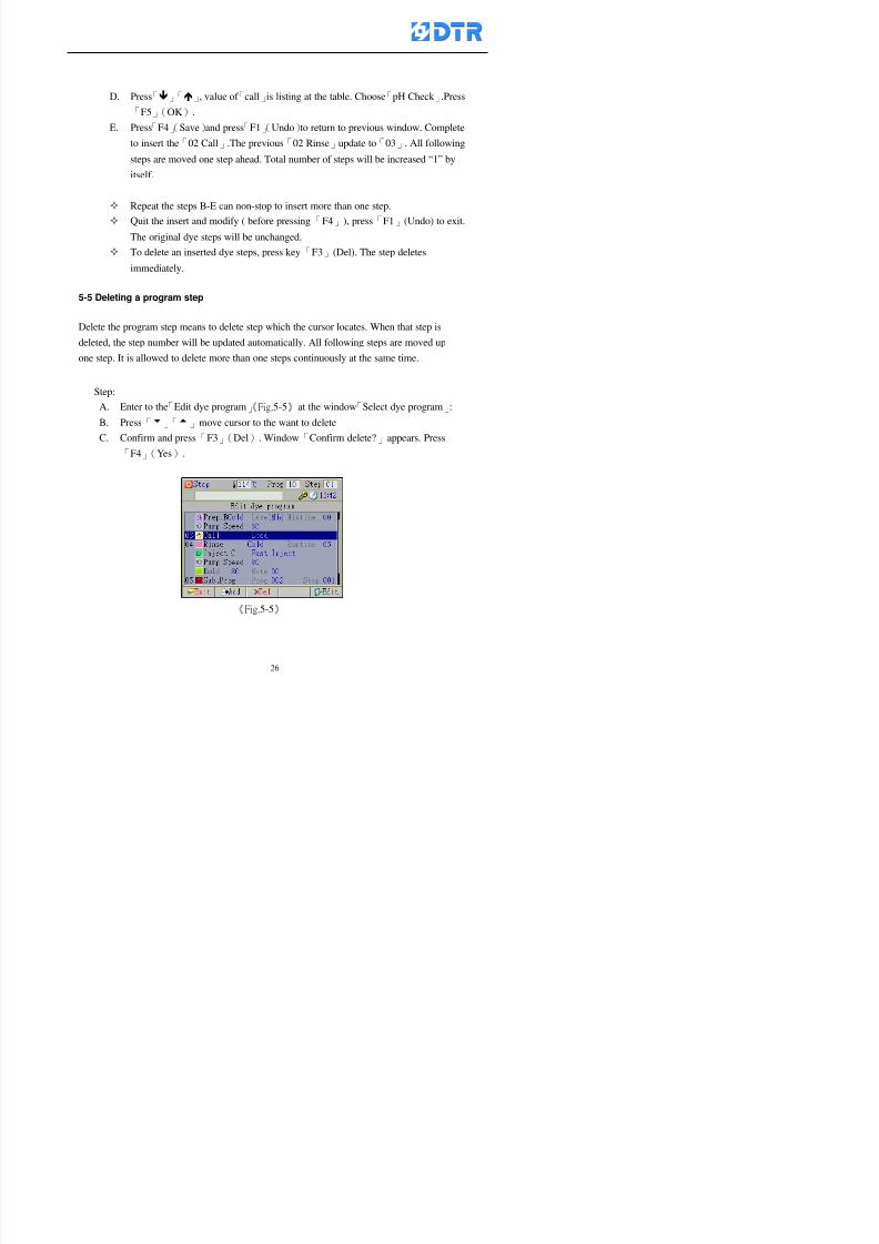
8132019 DTR 650 User Manual
httpslidepdfcomreaderfulldtr-650-user-manual 2670
D Press「」「」 value of 「call」is listing at the table Choose「pH Check 」Press「F5」(OK)
E Press「F4」(Save)and press「F1」(Undo)to return to previous window Complete
to insert the「02 Call」The previous「02 Rinse」update to「03」 All following
steps are moved one step ahead Total number of steps will be increased ldquo1rdquo by
itself
Repeat the steps B-E can non-stop to insert more than one step
Quit the insert and modify ( before pressing「F4」) press「F1」(Undo) to exit
The original dye steps will be unchanged
To delete an inserted dye steps press key「F3」(Del) The step deletes
immediately
5-5 Deleting a program step
Delete the program step means to delete step which the cursor locates When that step is
deleted the step number will be updated automatically All following steps are moved up
one step It is allowed to delete more than one steps continuously at the same time
Step
A Enter to the「Edit dye program」《Fig5-5》at the window「Select dye program」
B Press「6」「5」move cursor to the want to delete
C Confirm and press「F3」(Del) Window「Confirm delete」appears Press
「F4」(Yes)
8132019 DTR 650 User Manual
httpslidepdfcomreaderfulldtr-650-user-manual 2770
D That step is deleted immediately and all following steps move up one step
Repeat the steps above can non-stop to delete more than one step
Press「F2」(No)to cancel the deletion
Press「F1」(Exit)to end
5-6 Modifying a program step
To modify the saved name and the setting value of the dyeing steps
Step
1 Choose a dye program which need to modify at the「Sel dye program」 press「F5」
(OK)
2 Press「6」「5」to move cursor to a step which need to modify Select and press
「F5」(Edit) Window of 「Edit dye instruction」appears
3 Press「F2」()「F3」()to choose the step list select it and press「」to move
the cursor to itrsquos value setting
4 Press numeric key to input the value or press「6」「5」to choose the item Press
「F5」(OK)when complete Cursor move to the next value (if need to set more
than one item)
5 Press「F4」(Save)when all setting is complete Return to「Edit dye program」
Method of parallel functionrsquos modification is same as above
Before pressing the key「「「「Save」」」」 press「F1」(Undo)to quit all modify Return
to the window of Edit dye program
All edit and modify functions mentioned of this charper are only available
for the dyeing files which already saved in the file and not being running It
8132019 DTR 650 User Manual
httpslidepdfcomreaderfulldtr-650-user-manual 2870
5-7 Copying a dye program
Copying a dye programs mean to make a copy of an dye programs to a blank dyeprogram This function is for creating new dye program rapidly
Choose「1Dye Program」at the main menu Press「F5」(OK)then press「F2」()to choose「2Copy dye prog」 Press「F5」(OK) 《Fig5-7-1》appears
《Fig 5-7-1》
《Fig 5-7-2》
【【【【Eg】】】】
Copy program 003 to program 012
Press「」「」to move cursor to theprogram「003」 press「F4」(Copy)
Program「003」shows at the top right side of
the bar
Press「」「」to move cursor to program「012」 Then press「F5」(Paste)「」appears behind the「012」That means it issuccessfully copying the program
If the target program is occupied
confirmation window「Overwrite」
When choose an program or a targetprogram can select them by using the
8132019 DTR 650 User Manual
httpslidepdfcomreaderfulldtr-650-user-manual 2970
5-8 Deleting a dye program
Choose「1Dye program」at the main menu Press「F5」(OK)then press「F2」()to choose「3Delete dye prog」 Press「F5」(OK) 《Fig5-8-1》appears
《Fig5-8-1》
《Fig5-8-2》
Press「」「」to move cursor to
choose program need to delete Eg
delete program「012」 press「F5」(Del) Confirmation window
「Confirm delete」appears
Press「F4」(Yes) to confirm delete
Repeat the above step can delete more
than one program at the same time
Press「F2」(No) to return to window
《Fig5-8-1》and not delete that program
Exit to press「F1」(Exit)and return to the
main menu
8132019 DTR 650 User Manual
httpslidepdfcomreaderfulldtr-650-user-manual 3070
6 983123983141983156983156983145983150983143DTR-650 has a built-in standard factor that can fulfill all different types of dyeing
machinesrsquos basic demand Users can also modify the factors base on their request to
fulfill their special control demand Before modify please refer to the table of each
range of Setting Factors (see the Supplementary Table)
6-1 ldquoEnable to use the program stepsrdquo setting
There are totally 64 program steps Parts of them are usually applying to the programs
In order to make more efficiently of editing programs it can「Disable」the other part
of program steps which are not usually applying or not applicable to the programs
For example dye machine with one tank it is only using step Tank B In this case itcan firstly「Disable」the program steps of Tank C When edit the program the
「Disable」rsquos steps will not appear at the cursor for choosing But this will not effect
and change the saved files The saved files can be kept as before
Step
(1) Choose「2 Factors」at the main menu Press「F5」(OK)(2) Choose「18 Dye Instruction」at the sub-function menu Then presss「F5」(OK)
Window「Edit dye ins」appears
「Enable」instruction can available to
use「Disable」instruction is temporarystop to use
Press「F2」()「F3」()to move
8132019 DTR 650 User Manual
httpslidepdfcomreaderfulldtr-650-user-manual 3170
6-2 ldquoAllow to modify dye program temporary during operatingrdquo Setting
During dye program running it can modify dye program temporary Thesemodification will not disappear by causing a sudden power interruption or power off
until select another new dye program to run
Please note that it is only for modifying the dye program temporary That program
file would not saved due to the modification If need to modify the program file and
save choose the function of Edit Dye Program to edit (Refer to the Charper 5 for the【Edit Dye Prograrm】)
6-2-1 ldquoAllow to modify all dye programsrdquo Setting
Step
(1) Choose「2 Factors」at the main menu Press「F5」(OK)
(2) Choose「02 System Factor」at the sub-function menu Then presss「F5」(OK)
Window「Edit System Factor」appears
Set to stop using temporary the「07
Rinse」press「F4」(Sel)to set it as Disable
Repeat above steps to complete all setting
Press 「F1」(Exit)to return to main menu
8132019 DTR 650 User Manual
httpslidepdfcomreaderfulldtr-650-user-manual 3270
6-2-2 ldquoAllow to modify part of dye programsrdquo Setting
【Eg】Set the number 08 or above (including number 08) is allowing to modify dye
programs during operating
Step
A Refer to【6-2-1】setting the factor as「22」to allow editing dye program
temporary during operating
(4) Press「3」「4」to edit the setting
as「Enable」 and press「F5」(OK)
Restore the standard factor by
pressing「F3」(Clr)
(5) Exit to press「F1」(Exit)and
return to window of 「Main Menu」
8132019 DTR 650 User Manual
httpslidepdfcomreaderfulldtr-650-user-manual 3370
6-2-3 ldquoAllow to modify dye steps temporaryrdquo Setting
After setting the dye programs are allowed to edit it also can set which dye steps are
allowed to edit temporary during operating
Step
(1) Choose「2 Factors」at the main menu Press「F5」(OK)
(2) Choose「19 Dye Ins control」at the sub-function menu Then presss「F5」
(OK) Window「Edit ins mode」appears
「Enable」 Allow to edit that dye step before
operating
「Disable」 Not allow to edit dye step before
operating
(3) Press「」「」to move cursor
to choose dye step Press「F4」
To enter to the「Edit dye program」from the
function menu there is a「」in front of the
file name「0-7」 means that program is not
allowing to edit during operating
8132019 DTR 650 User Manual
httpslidepdfcomreaderfulldtr-650-user-manual 3470
6-2-4 ldquoSet the dye step to keep running from the interrupt pointrdquo setting
When the dye program is operating it will disappear by causing power
interruption or sudden power off When start running again part of dye steps can
run again from the interrupt point part of them cannot
How to set
(1) Choose「2Factors」in the main menu and press「F5」(OK)
(2) Choose「20Continue mode」in the sub-function menu Press「F5」(OK) to
enter window of 「Continue Setting」
(3) Press「」「」to move cursor to choose dye steps Press「F4」(Sel)it
shows「Disable」or「Enable」for choosing Press「F5」(OK)to move cursorto the next setting
(4) Repeat above method until all setting is complete press「F1」(Exit)and
return to the main menu
8132019 DTR 650 User Manual
httpslidepdfcomreaderfulldtr-650-user-manual 3570
6-3 ldquoAllow to insert an addition dye stepsrdquo setting
During the program is running can temporary insert an addition dye step or a dye
program according to the operating actual situation Through this setting can set which
dye steps can apply or not to the program in operating
During to insert an addition step if sudden interruption or power off occurred it returns
to the main dye program automatically Before starting again should decide seriously
and set it again by actual needed
Step
(1) Choose「2Factors」at the main menu and press「F5」(OK)
(2) Choose「02System factor」and press「F5」(OK)
(3) Press「」「」to move cursor to the factor「34」and press「3」「4」to set
it as「Enable」 Press「F5」(OK)
(4) Press「F1」(Exit)to return to main menu Choose「21Addition Ins」at the
sub-function menu Press「F5」(OK)to enter the window「Addition Instruction」
(5) Press「」「」to move cursor to choose dye steps and press「F4」(Sel) Cursors
locates shows「Eable」or「Disable」 Press「F5」(OK)to move cursor to the
next dye step
(6) Repeat above method until to complete all setting press「F1」(Exit)and return
to the main menu
8132019 DTR 650 User Manual
httpslidepdfcomreaderfulldtr-650-user-manual 3670
6-4 Setting the display mode
DTR650 has three types of display mode during operating Program List mode
Schematic Diagram mode and Icon mode Users can set the display mode during
operating by factor setting
It goes back to a Program List mode when dye program ended
Step
(1) Choose「2Factors」at the main menu and press「F5」(OK)
(2) Choose「02System factor」and press「F5」(OK)
(3) Press「F2」()「F3」()to move cursor to choose「32Display mode」Press
「3」「4」 it shows「Online picture」「Instruction」「Big Icon」 choose
「Online picture」(eg) and press「F5」to confirm
8132019 DTR 650 User Manual
httpslidepdfcomreaderfulldtr-650-user-manual 3770
(4) Press「F1」(Exit)to return to the main menu
(5) The Schematic Diagram displays when the program is running (it stays at theProgram List mode when there is an alarm occurred)
Press「F4」to transfer to another display mode
It goes back to a Program List mode from Schematic Diagram Mode when dye
program ended Press numeric key「3」to view Schematic Diagram Mode again
Quit to press「F5」(Exit)
6-5 Adapt the digital input to another functions
DTR-650 has 32(0~31)input terminal it owns an standard setting when the
controller is initial According to the userrsquos demand they can change the DTR-650rsquos
anther functions of Input Terminal and PLC Input channel
The PLC Intputrsquos name can also define by the users (use IBM computer to edit and
download)
How to set
(1) Choose「2 Factor」at the main menu Press「F5」(OK)
(2) Choose「22 Input table」at the sub-function menu and press「F5」(OK)to enter
「Edit input table」
The actual input
terminal of theIBM computer
PLCrsquos input channel
8132019 DTR 650 User Manual
httpslidepdfcomreaderfulldtr-650-user-manual 3870
6-6 Adapt the digital output to another functions
DTR-650 has 32(0~31)output terminals it owns an standard setting when thecontroller is initial According to the userrsquos demand they can adapte the digital output
and the PLC outputrsquos channel to another functions The PLC Output channelrsquos name
can also define by users (use IBM computer to edit and download)
Step
(1) Choose「2 Factor」at the main menu Press「F5」(OK)
(2) Choose「23 Output table」at the main menu and press「F5」(OK)
(3) Press「F2」()「F3」()to move cursor to choose the output terminal atthe left side of the window Press「F5」(Add) the PLCrsquos output channelrsquos
name is listing at the right side of the window
(4) Press「F2」()「F3」()to move cursor to choose the PLC outputrsquos channel
If cursor moves to the PLC output channel which already linking「Add」is
not for choosing that means that output channel is already occupied
(5) Confirm the connection to press「F5」(Add) Quit to press「F4」(Del)Press「F1」(Exit)when complete all setting and return to main menu
The actual output
terminal of the
IBM computer
PLCrsquos output channel
8132019 DTR 650 User Manual
httpslidepdfcomreaderfulldtr-650-user-manual 3970
983095 983109983140983145983156983145983150983143 983156983144983141 983110983137983139983156983151983154983155DTR-650 has several kinds of control factors
Userrsquos factors System factors Temperature Control factors Speed factors Dosing
factors PID factors Analog Input Output factors standard factors etchellipPlease refer
to the supplementary table for the setting range and standard of the factors
DTR-650 has a built-in standard factor Users can edit by themselves if necessary
7-1 Modifying userrsquos factors
Userrsquos factors is setting with the Dyeing machinesrsquos PLC Programrsquos factor it is define by
the PLC Programmer
Step to edit
(1) Choose「2Factors」at main menu Press「F5」(OK)
(2) Choose「01User Factor」Press「F5」(OK)
(3) Press「F2」()「F3」()「6」「5」to move cursor up down and by page
Choose a factor need to edit then press「3」「4」to set itrsquos value Press「F5」(OK) Cursor moves to the next factor
(4) Some of factors can input numbers by the numeric membrance keys to edit If
the input is incorrect it turns to red and means the edit is not available
8132019 DTR 650 User Manual
httpslidepdfcomreaderfulldtr-650-user-manual 4070
Modifyrsquos method of the system factors temperature factors speed factors dosingfactors PID factors analog Input output factors standard factors etchellipare same asabove
If apply the library of DTR500 and DTR600 into the DTR650 the key「3」「4」may not valid to use Please use the numeric keys instead of it to key in factors itmay not effect the normal operation
Please pay a serious attention and read carefully at the factorrsquos table before modify the factors An incorrect value may effect the DTR-650 Dyeing
Machine Controllerrsquos operating After modifying factors must cancel the
password and secure data
7-2 Loading the standard factors
After modifying factors if need to restore a manufacturerrsquos standard factors of
DTR-650 The method as follows
1 Choose「2Factors」at main menu Press「F5」(OK)
「 「 ( ) 「
8132019 DTR 650 User Manual
httpslidepdfcomreaderfulldtr-650-user-manual 4170
7-3 Copying the factor
Users can build up a set of factor by themselves and make a copy and save
Step
1 Choose「2Factors」at main menu Press「F5」(OK)
2 Choose「13Restore Factor」 press「F5」(OK) window「factor will be
overwrite 」
3 Press「F4」(Yes)copy finished and saved Return to the main menu
4 Press「F2」(No)to not copy the factor and the existing factor is not change Return
to the main menu
7-4 Loading the backup factors
Users can build up a set of factor and backup files to load to DTR-650
Step1 Choose「14Backup factor」at the sub-function menu Press「F5」(OK)and
window「Factror will be overwrite」appears
2 Press「F3」(OK)to load the the backup factor them return to main menu
Press「F2」(No)to not copy the factor and the existing factor is not change
Return to the main menu
8132019 DTR 650 User Manual
httpslidepdfcomreaderfulldtr-650-user-manual 4270
983096 983119983157983156983152983157983156 983124983141983155983156983145983150983143
Before the output testing must be complete the steps as follows
A Cut off all connecting line of output terminal of DTR-650
B Stop running the PLC
C Check up the connections of all output channels to avoid damages from
incorrect connections
D Check up state of dyeing machines include the temperature pressure valves
onoff and pumpshellipetc ensure the safety for priority
8-1 Testing the Digital output
Step
1 Choose「3Output Testing」at the main menu Press「F5」(OK) 2 Choose「1Digital」at the sub function menu Press「F5」(OK) window「Digital
output testing」appears
3 Press「」「」「」to move cursor to each output channels Press「F5」(OK)
Output Name
8132019 DTR 650 User Manual
httpslidepdfcomreaderfulldtr-650-user-manual 4370
8-2 Testing the Analog output
(1) Choose「3Output Testing」at the main menu Press「F5」(OK)
(2) Choose「2Analog」at the sub function menu Press「F5」(OK) window「Analog output testing」appears
(3) Press「」「」「」to move cursor to each channels Then key in number by
the numeric membrance keys (range0~200= 0~20mA) Press「F5」(OK) there
is a output current relating to the output channel
(4) Press「F5」(OK) There is an output when the output channel with red light No
output without light onl(5) When complete the testing press「F1」(OK)to return to the main menu
8132019 DTR 650 User Manual
httpslidepdfcomreaderfulldtr-650-user-manual 4470
983097 983107983137983148983145983138983154983137983156983145983151983150
DTR-650 has Dosing and Temperature calibration
When enter to Dosing calibration must be set the Low Volume calibration first and
then High Volume calibration When enter to Temperature calibration must be set the
Low Temperature calibration first and then High Temperature calibration Must be
hightly follow this orders seriously
9-1 Calibration of Low Volume Tank
Step
A Choose「4Calibration」at the main menu Press「F5」(OK)
B Choose「Dosing 0 low vol」at the sub function menu Press「F5」(OK) window
appears
C Fill the Dosing Tank to a half level input value shows how much the water level
If it stays ldquo0rdquo check the connection and the factor setting is correct or not
And connect the pressure sensorrsquos output channel to the Current Meter to ensure
that sensor works or not
8132019 DTR 650 User Manual
httpslidepdfcomreaderfulldtr-650-user-manual 4570
D Fill the Dosing Tank to 50ml (Calcalate from the bottom side of the pressure
sensor steel tube) input value should show 4~6 (input value must between
0~10) Then enter the water volume The setting volume is relating the water
levelrsquos water value (litre as unit) input range 0~80 Set as「 「「 「0000 0000 0000 0000」」」」is strongly is strongly is strongly is strongly
receommend receommend receommend receommend Press「F5」(OK)to complete [Calibration of Low Volume Tank 1
is same as above method]
9-2 Calibration of High Volume Tank
Step
A Choose「4Calibration」at the main menu Press「F5」(OK)
B Choose「Dos 0 high vol」at the sub function menu Press「F5」(OK) window of
「Calibrate high 」appears
C Fill the Dosing Tank to a full level input value should be larger than 30 enter
the current water level which relates to the water volume Enter the range within
100~2500 Then press「F5」(OK) to complete the calibrate the high volume tank
8132019 DTR 650 User Manual
httpslidepdfcomreaderfulldtr-650-user-manual 4670
9-3 Temperature Calibration
Step
A This function is for adjusting the DTR650rsquos accuracy of Temperature Control It
must be using with the special terminal which is only for DTR650
B Choose「4Calibration」at the main function menu and press「F5」(OK)
C Choose「3Low Temp」at the sub-function menu Press「F5」(OK)and《Fig9-3》
appears insert the DTR650rsquos low temperature calibration terminal to the temperature
input terminal wait for the jumping value to stable down then press「F5」(OK) then
to adjust the high temperature calibration
D Adjusting the High Temperature Calibrationrsquos method is same as above But usersusersusersusers
must be using the High Temperature Terminalmust be using the High Temperature Terminalmust be using the High Temperature Terminalmust be using the High Temperature Terminal whichwhichwhichwhich is specially for DTR650 onlyis specially for DTR650 onlyis specially for DTR650 onlyis specially for DTR650 only
《Fig 9-3》
8132019 DTR 650 User Manual
httpslidepdfcomreaderfulldtr-650-user-manual 4770
10 983122983141983139983151983154983140983155 983151983142 983108983161983141 983120983154983151983143983154983137983149983155
It contains the past 15 days of temperature curves of running history
Checking method
(1) Choose「5Dye Record」at main menu press「F5」(OK)
(2) Sub-function menu shows the set up date of the past 15 days dye programs
Listing by the lastest set up date
(3) Choose a program date and press「F5」(OK) it appears window「Temp
record」
(4) Press「」「」to move the white line in the box one minute by moving once
(5) Press「3」「4」to move the line to check the time period 2 hours by moving once
The yellow selecting line of the「24 hours operating state」is repectively moving
The curve info is show in the curve box Left side of the widnow appears the
relating running info the time is the time value of the line locates at
(6) Check more details of the temperature info to press numeric key「middot」 a bright red line
appears in the selecting box this line is to check the starting point of the
temperature inforsquos time period Then press「」to move the white line to the end
point of the time period The temperature info between the starting point and end
point are appears at the right side of the window Press「middot」to return to the preious
curve page
(7) Check more details of the alarm infor To perss numeric key「7」「9」 the alarmrsquos
details is listing by orders
(8) Press「F1」(exit) to return
8132019 DTR 650 User Manual
httpslidepdfcomreaderfulldtr-650-user-manual 4870
11 983125983155983137983143983141 983151983142 983117983141983149983151983154983161 983107983137983154983140
DTR-650 supports 32MB or above Compact Flash Card which can transfer and save all
information for 4 sets of DTR-650 Including library files schematic diagram icon
image PLC program dye program factor and confiruration files etchellip Use the CF Card
to up download and swap the information of DTR-650 promptly install the relating
device and program updates
DTR-650 CF Card with bank 1 to bank 4 can save 4 sets information of Dyeing
Machines When download or save files should choose the BANK first
《Fig11-1》
8132019 DTR 650 User Manual
httpslidepdfcomreaderfulldtr-650-user-manual 4970
11-1 Downloading data
1 Firmly insert the CF card into the DTR-650rsquos PCMCIA connector Ensure it is
wholely and firmly inserted if the card is not totally inserted or the card do not
touch in all to the connector there will be an error occurred and cannot
updownload or interrupted during operation
2 Choose「6Memory Card」at the main menu and press「F5」(OK) 《Fig11-1》
appears Information of Bank「1」shows at the left hand side of the window press
number 1-4 by using numeric keys to choose the BANK Check the
information in the Bank seriously which is exactly need to download to the
DTR650
3 Press()()「6」「5」to move cursor to the sub-function menu to choose
the downloading items Press「F5」(OK) window appears「Stop PLC run before
access memory card Stop the PLC run」 Press「F5」(YES) to stop PLC
running
4 Press「F5」(OK) window appears Confirm to update or not the DTR-650rsquos
information As that downloading will be replace the DTR-650rsquos information
(that means the existing information of the DTR-650 will be removed and
replaced)
5 Press「F4」(YES)to download the information from the DTR-650 to the CF
Card Return to the main menu when finish
8132019 DTR 650 User Manual
httpslidepdfcomreaderfulldtr-650-user-manual 5070
Ensure inserting firmly the CF card into the DTR-650 unless it will cause
error or cannot Updownload data
Never remove CF card during transferring or updownloading data Until it
is all completed
DTR-650rsquos dyeing program is not compatible with DTR-500 and
DTR-600 Never use CF card to transfer data among them
11-2 Storing and transfering data
1 Insert the CF Card to the DTR-650
2 Choose「6Memory Card」at the main menu and press「F5」(OK) 《Fig11-1》
appears Left hand side of the window shows the data of BANK 1 press numeric
keys 1-4 to select the BANK To confirm the put the data in the DTR-650 to the CF
Card The existing data of that bank will be replaced and covered by the new data (if
that bank is already occuplied)
3 Choose「23Save Dye prog」(Example)at the sub-funciton menu press「F5」(OK)to confirm Window「Update memory card data」appears
4 Press「F5」(OK)to transfer the data to the CF card Return to the main menu
5 Put the CF card into another DTR-650 and follow the operating method of 「11-1
Downloading data」」」」can transfer and swap data with more than one set of
DTR-650
8132019 DTR 650 User Manual
httpslidepdfcomreaderfulldtr-650-user-manual 5170
12 983123983156983137983156983141 983137983150983140 983113983150983142983151983154983149983137983156983145983151983150
The state and information is including the Dyeing Machinersquos state of Digit Input output
Analog Input output Temperature control PID Dosing PID Pressure different PID
software system information and alarm record This information is for checking at any
time
12-1 Input Output state
Step
1 Choose「7Info and state」at main menu and press「F5」(OK)
2 Choose「01Digital IO put」at the sub-function menu then press「F5」(OK)
「Digital In Out State」0=None 1=Input
3 Press「F1」(Exit)to return to main menu
Same method for checking the temperature control analog dosing pressure
different etchellip
12-2 Checking the system information
Step
1 Choose「7Info and state」at main menu and press「F5」(OK)
2 Choose「11 System info」at sub-function field press「F5」(OK)Window
「System Information」appear
System information is including System info(software version) Library doc
Icon files Schematic file Definition file hardare state Config File Commandinstruction icon PLC file etc
8132019 DTR 650 User Manual
httpslidepdfcomreaderfulldtr-650-user-manual 5270
12-3 Checking the operating alarm record
Operating record shows the latest 40 operating items and alarm records including
the time and content of the alarm
A) Choose「7 Info and state」
and press「F5」(OK)
B) Choose「12Alarm logs」at
the sub-funciton menu then
press「F5」(OK)
8132019 DTR 650 User Manual
httpslidepdfcomreaderfulldtr-650-user-manual 5370
13 983105983140983146983157983155983156983145983150983143 983156983144983141 983107983151983150983156983154983137983155983156
The displaysrsquos brightness can be adjusted if necessary
Step
1 Choose「8Others」at main menu press「F5」(OK)
2 Choose「01Contrast」at sub-function menu press「F5」(OK) window「Set
Contrast」appears
3 Press「」「」to move the bar to set the brightness then press「F5」(OK)Window appears「Please reboot the system」
4 Press「F5」(OK)to return to main menu and re-boot the DTR-650 to complete
adjusting the brightness
8132019 DTR 650 User Manual
httpslidepdfcomreaderfulldtr-650-user-manual 5470
14 983123983156983151983152 983154983157983150983150983145983150983143 983156983144983141 983120983116983107 983120983154983151983143983154983137983149
Before testing the Input output testing transfer of the PLC program must stop the PLC
running
Step
1 Choose「8Others」at the main menu Press「F5」(OK)
2 Choose「04 PLC Stop」at sub-function menu Press「F5」(OK) window
「Password」appears
3 Enter password and press「F5」(OK) Window「Stop the PLC run」appears
4 Press「F4」(Yes)and window「PLC Stop」appear Press「F5」(OK) Now
the PLC is stop running and return to the main menu
All testing cannot operate when the PLC is running
Editing dye program and the relating operation can
perform with the PLC running together
8132019 DTR 650 User Manual
httpslidepdfcomreaderfulldtr-650-user-manual 5570
15 983123983141983156983156983145983150983143 983156983144983141 983156983145983149983141
Step
1 Press「8Others」at the main menu Press「F5」(OK)
2 Choose「10Set date time」at the sub-function menu Press「F5」(OK) window
「Set date time」appears
3 Press「F5」(Edit) to move cursor by 「3」「4」 enter the time value at the
cursor locates
4 Press「F5」(OK)to complete the modify Press「F1」(Exit)to return to main
menu
5 Press「F1」(Exit)if not modify and return to main menu
8132019 DTR 650 User Manual
httpslidepdfcomreaderfulldtr-650-user-manual 5670
1166 983123983123983157983157 983152 983152 983152 983152983148983148983141983141983149983149983141983141983150983150983156 983156 983137983137983154 983154 983161983161 983124 983124 983137983137983138983138983148983148983141983141
TTTTTTTTaaaaaaaabbbbbbbblllllllleeeeeeee 11111111 【Dye Instruction】
Code Icon Instruction Code Icon Instruction
000 End 016 Inject C
001 Start 017 Dosing BV
002 Heat 018 PH
003 Cool 019 Addsalt B
004 Flow Fill 020 Addsalt C
005 Level Fill 021 Ana Fill
006 Drian 022 Lock Fill007 Rinse 023 Lock Level
008 Run 024 Low Rinse
009 Call 025 Cyc Rinse
010 Prep B 026 Rinse B
011 Addsalt B 027 Rinse C
012 Dosing B 028 Temp
013 Inject B 029 Nozzle Pressure
014 Prep C 030 Main Pump
015 Dosing C 031 Pump Speed
8132019 DTR 650 User Manual
httpslidepdfcomreaderfulldtr-650-user-manual 5770
Table 2 【【【【Alarm】】】】
System Alarm Must stop operating and check up to solve problems before restarting
the machine
Running Alarm It is a reminder Not effect the operating of DTR-650
Userrsquos Alarm Total of 32 Users can define themselves and use it when edit the PLC
Program (do not listing below)
No System Alarm No Running Alarm
1 PLC program not running 16 Temp ctrl 0 Grad too slow
2 Main temp sensor error 17 Temp ctrl 0 Grad too fast
3 Not at Run window 18 Temp ctrl 0 Hold temp too low
4 Exceeding max temp 19 Temp ctrl 0 Hold temp too high
5 - 20 Temp ctrl 1 Grad too slow6 - 21 Temp ctrl 1 Grad too fast
7 - 22 Temp ctrl 1 Hold temp too low
8 Communication error 23 Temp ctrl 1 Hold temp too high
9 Slave not answer 24 Temp ctrl 2 Grad too slow
10 PLC 0 not answer 25 Temp ctrl 2 Grad too fast
11 PLC 1 not answer 26 Temp 2 Hold temp too low12 Display not answer 27 Temp 2 Hold temp too high
13 Lower power voltage 28 Temp ctrl 3 Grad too slow
14 - 29 Temp ctrl 3 Grad too fast
15 - 30 Temp3 Hold temp too low
31 Temp3 Hold temp too high
32 Dosing 0 injection too slow
33 Dosing 0 injection too fast
34 Dosing 1 injection too slow
35 Dosing 1 injection too fast
8132019 DTR 650 User Manual
httpslidepdfcomreaderfulldtr-650-user-manual 5870
TTTTTTTTaaaaaaaabbbbbbbblllllllleeeeeeee 33333333 【【【【System factor】】】】
No Description Std Range amp Definition
1 ID No 000 000- 100 Controller no
2 Communication Rate 4800Bps 2400 4800 9600 19200 38400
3 Display language Chinese English Chinese
4 Temp display mode and
5 Maxmium temperature 145 025 ~ 145 6 Type of external PLC Default PLC32DPLC32PLC16Default
7 Number of external PLC NANA 1 unit connect
2 unit connect
8Communication Rate of
PLC9600Bps 2400 4800 9600 19200
9 Set point 1 085 000 ~ 145
If signal source is temperaturethe setting value is thetemperature value If the signal
source is Analog Input 6~17 then
setting value for Analog input is 0 ndash
100 and relates Analog
Input14~020mA
10 Source 1 Sensor0Sensor 0 ~5
Analog input 0 ~1111 Set point 2 092 Same as 09
12 Source 2 PT100 1 Same as 10
13 Set point 3 085 Same as 09
14 Source 3 PT100 2 Same as 10
15 Set point 4 092 Same as 09
16 Source 4 PT100 3 Same as 1017 Set point 5 085 Same as 09
18 Source 5 PT100 4 Same as 10
19 Set point 6 092 Same as 09
8132019 DTR 650 User Manual
httpslidepdfcomreaderfulldtr-650-user-manual 5970
29 Min cyclic time of cloth 100sec 0 ~ 255 sec
30 Max cyclic time of cloth 240sec 0 ~255 sec
31Standard cyclic time of
cloth
180 000 ~ 255 sec
32 Display ModeProgram
List
Program list Schematic Diagram
Icon mode
33 CF card format Standard of
DTR CF
Card
Standard of DTR CF Card V20
Standard CF Card
34 Addition step Disable Disable Enable35 Mode Com 3
CouplingEsure Com 3 is the communication
port of the Central or Coupling
36Com 3 Communication
rate9600 Central communication speed
8132019 DTR 650 User Manual
httpslidepdfcomreaderfulldtr-650-user-manual 6070
TTTTTTTTaaaaaaaabbbbbbbblllllllleeeeeeee 44444444 【【【【Temperature Cotnrol Factor】】】】
No Factor Definition Standard Range and Definition
01 PT No PT-0 PT 0~5 PT-100 Input number
02 Max working temp 140 000~140
03 Output mode 0 0~2
04 Alarm time of gardient 240sec 000~255 sec
05 Alarm mode of gradient Always AlwaysOnceNone
06 Control mode of gradient Heating orCooling
interlocked
Heating and Cooling interlocked
No limitation
07 Alarm range of HoldTemp 03 01~20
08 Alarm time for HoldTemp 240sec 000~255sec
09 Alarm mode of HoldTemp Always AlwaysOnceNone
10 Control mode ofHoldTemp
Heating only Only heating and cooling Cooling whenalarm occurred Only heating andcooling No limitation when alarmHeating only
11 Porportional Band 100 000~250
12 Integral band 128 sec 000~255 sec
13 Differential time 04 sec 00~20 sec
14 Min transit gradient 02 00~50
15 Transit rate 20 times 00~50 times (020= 2 times)
16 PID initial output value 010 000~100
17 ONOFF cycle time 10 sec 05~25 sec
Onoff valve set as 010 sec
Proportional valve set as 020 sec
18 Time down count mode Mode 0 0~10 = The time down count range from「Factor 20 + target temp」to「Target
8132019 DTR 650 User Manual
httpslidepdfcomreaderfulldtr-650-user-manual 6170
TTTTTTTTaaaaaaaabbbbbbbblllllllleeeeeeee 55555555 【【【【Speed Factor】】】】
No Factor Definition Standard Range amp Definition
01 Input Number Speed input 0 Speed input 0~11
02 Average times 05 times 01~10
03 Sensor Number 008pcs 001~255
04 Roller Dimension 250mm 050~500
05 Max cloth speed 200mmin 001~25506 Min cloth speed 020mmin 001~255
07 Alarm delay time 240sec 001~255
08 Alarm mode Every oncenoneevery
09 Alarm range () 020 001~255
10 Proportional band 100 001~255
11 Integer band 128 001~25512 Differential time 000 001~200
13 Initial speed () 020 001~255
14 Control cycle ti(01sec) 05 01~30
15 First cycle time(01sec) 10 01~30
16 Speed increase limit () 010 001~100
17 Speed decrease limit () 010 001~100
18 Min speed() 005 001~100
19 Manual speed adjust () 005 001~100
20 Manual initial speed() 020 001~100
21 Stopping speed() 010 001~100
22 Switch speed() 020 001~100
23 Not used
24 Speed decrease turns 03turns 01~50
8132019 DTR 650 User Manual
httpslidepdfcomreaderfulldtr-650-user-manual 6270
Table 6 【【【【Dosing Factors】】】】
No Description Range Range and Explanation
1 Analog input no Analog input 0 Analog input no 0 ~11
2Alarm delay time for
dosing240 sec 000 ~255 sec
3 Alarm time for dosing Every Every Once None
4 Proportional band 100 000 ~255 sec Factor P
5 Integer band 128 000 ~255 sec Factor I6 Differential time 04 00 ~20 Factor D
7 Max adjust rate 150 50~ 255
8 Initial factor for dosing 10 000 ~100
9 User curve section 0 10 Gradient of sect1 for dosing curve9
10 User curve section 1 10 Gradient of sect2 for dosing curve9
11 User curve section 2 10 Gradient of sect3 for dosing curve9
12 User curve section 3 10 Gradient of sect4 for dosing curve9
13 User curve section 4 10 Gradient of sect5 for dosing curve9
14 User curve section 5 10 Gradient of sect6 for dosing curve9
15 User curve section 6 10 Gradient of sect7 for dosing curve9
16 User curve section 7 10 Gradient of sect8 for dosing curve9
17 User curve section 8 10 Gradient of sect9 for dosing curve9
18 User curve section 9 10 Gradient of sect10 for dosing curve9
19 Min water level 05 00~ 10 04~20mA percentagechange to the userrsquos factor setting
20 Output value for Tank
clean
100 000~ 100
Injected percentage of dosing valve
in dosing End period
This factor will be invalided if usingONOFF dosing valve
21 Full range 100 001~255 Self-adjustment cannotchange
22 Range ratio 001001~255 Self-adjustment cannot
change
8132019 DTR 650 User Manual
httpslidepdfcomreaderfulldtr-650-user-manual 6370
【【【【TTaabbllee 77 】】】】Pressure Deviation Factors
No Description Std Range amp Definition
1 Analog input number + Analog in 0 Analog in 0~11
2 Analog input number - Analog in 1 Analog in 0~11
3 Input mode Pressure Pressure Pressure deviation
4 Full range 050x01Kgcm
001~255
5 Range ratio 001 001~255
6 Alarm delay time 100sec 001~255
7 Alarm mode Every oncenone
8 Alarm range 010 001~255
9 Proportional band 100 001~255
10 Integer band 128 001~255
11 Differential time 00 00~20
12 PID Init output value 010 001~255
13 Cycle time 10 03~30
14 First cycle time 030 003~100
15 Max adjust rate 010 001~100
8132019 DTR 650 User Manual
httpslidepdfcomreaderfulldtr-650-user-manual 6470
【【【【TTaabbllee 88 】】】】Definition of Analog Input
No Description Standard Range and Explanation
01 PT 0 correction standard DIN std DIN std JIS std
02 PT 0 correction +0 +- 9
03 PT 1 correction standard DIN std DIN std JIS std
04 PT 1 correction +0 +- 9
05 PT 2 correction standard DIN std DIN std JIS std
06 PT 2 correction +0 +- 9
07 PT 3 correction standard DIN std DIN std JIS std
08 PT 3 correction +0 +- 9
09 PT 4 correction standard DIN std DIN std JIS std
10 PT 4 correction +0 +- 9
11 PT 5 correction standard DIN std DIN std JIS std
12 PT 5 correction +0 +- 9
13 Analog input 0 define 4 ~ 20mA 0 ndash 20mA 4 ndash 20mA
14 Analog input 0 average times 10 times 01- 20 times
15 Analog input 0 min value 0000 0000 - 1000
16 Analog input 0 max value 100 0001 - 9999
17-60 Analog input 1~11 Same as Analog input 0
【【【【 】】】】 fi i i f A O
8132019 DTR 650 User Manual
httpslidepdfcomreaderfulldtr-650-user-manual 6570
【【【【TTaabbllee 99 】】】】Definition of Analog Output
No Description Standard Range and explanation
61 Analog output 0 define Control byPLC
Control by PLC
Temperature control PID0 output
Temperature control PID1 output
Temperature control PID2 output
Speed PID3 output
Dosing PID0 output Dosing PID1output
Pressure different PID0 outputPressure different PID1 output
Main temperature output
62 Mode of Analog ouptput0 4 ~20mA 0 ndash20mA 4 ndash 20mA
63-84 Analog output 1~11 Same as Analog output 0
【【【【TTaabbllee 1100】】】】Value Table 0 amp 1
No Description Range Std Range and explanation
1 Analog input no 000~011 000 Analog input no
2 Data ratio 001~255 100 Multiple by factors
3~53 0~98 000~255 000-100 Analog input 0~98 data
【【【【 】】】】St t Li t
8132019 DTR 650 User Manual
httpslidepdfcomreaderfulldtr-650-user-manual 6670
【【【【TTaabbllee 1111】】】】State List
No Description Range Standard Range and explanation
1 Display setting 1 0~255 205 See remarks at next page
2 Display setting 2 0~255 208
3 Display setting 3 0~255 209
4 Display setting 4 0~255 017
5 Display setting 5 0~255 0186 Display setting 6 0~255 019
7 Display setting 7 0~255 020
8 Display setting 8 0~255 021
9 Display setting 9 0~255 000
10 Display setting 1 0~255 000
11 Display setting 2 0~255 000
12 Display setting 3 0~255 000
13 Display setting 4 0~255 000
14 Display setting 5 0~255 000
15 Display setting 6 0~255 000
16 Display setting 7 0~255 000
Remarks
8132019 DTR 650 User Manual
httpslidepdfcomreaderfulldtr-650-user-manual 6770
0 = No display 1~255 = Display type of number
1~16 Content of PLC VB0~15
No 1 corresponding to VB0
No 16 corresponding to VB15
17~32 Content of PLC DB0~15
No 17 corresponding to DB0
No 32 corresponding to DB15
33~46 Content of PLC CNT0~29
No 33 corresponding to CNT0
No 46 corresponding to CNT29 47~78 Content of dyeing instruction 0~31 CNT0
No 47 corresponding to system instruction to No 0 of CNT0
No 78 corresponding to system instruction to No 31 of CNT0rsquos content
79~110 Dyeing instruction 0~31 of CNT0rsquos setting
111~142 Content of Dyeing instruction 0~31 CNT1No 111 corresponding to dyeing instruction No 0 of CNT1
No 142 corresponding to dyeing instruction No 31 of CNT1rsquos content
143~174 Dyeing instruction 0~31 of CNT1rsquos setting
175~204 Content of PLC HTIM0~29
No 175 corresponding to HTIM0
No 204 corresponding to HTIM29
205 Loading
206 Ratio 1
207 Ratio 2208 Ratio 1 x Loading
209 Ratio 2 x Loading
210 Fix value
211 Value Table 1 matching result
212 Value Table 2 matching result
213 Value Table 1 setting214 Value Table 2 setting
215 Pressure control PID0 different pressure value
216 Pressure control PID1 different pressure value
TTTTTTTTaaaaaaaabbbbbbbblllllllleeeeeeee 1122 【【【【Usage of password】】】】
8132019 DTR 650 User Manual
httpslidepdfcomreaderfulldtr-650-user-manual 6870
No Main FunctionFactor Sub Function Factor Password Rank
1 Run None
2 Dye program User3 or above
3 Control factor
- User factor User 1
- System factor User 1
- Temp PID 0
- Temp PID 1 User 1- Speed PID 0 User 1
- Dosing PID 0 User 1
- Dosing PID 1 User 1
- Pressure PID 0 User 1
- Pressure PID 1 User 1
- Analog IO User 1
- Load standard factor User 2 or above- Load a copied factor User 2 or above
- Copy factor User 2 or above
- Value table 0 User 1
- Value table 1 User 1
- Information and state User 1
- Dye instruction User 1
- Edit dye instruction setting User 14 Output testing User 2 or above
5 Calibration User 2 or above
6 Dye record None
7 CF card User 1
8 Info and state None
9 Others
- Contrast User3 or above
- Data Locking None
- PLC Run User 1
- PLC Stop User 1
- Password setting User 1
TTTTTTTTaaaaaaaabbbbbbbblllllllleeeeeeee 1133 【【【【Technical Data】】】】
8132019 DTR 650 User Manual
httpslidepdfcomreaderfulldtr-650-user-manual 6970
TTTTTTTTaaaaaaaabbbbbbbblllllllleeeeeeee 1133 【【【【Technical Data】】】】
1 Temperature Control
- Range 10~145(plusmn1)
- Mode Proportional or PWM
- Sensor PT100 (JIS or DIN standard)
2 Input and output channel
- Digital Input 32 DC24V PNP- Digital Output 32 DC24V 054A Relay connect point
- Analog Input 4 04~20 mA
- Analog Output 4 0~20mA 或 4~20 mA
3 Communication port 3 RS-232 amp 0~20 mAx1 RS485x 2
4 Dye program
- Number 15000 Steps
- Standard step 61Heating Cooling Fill Drain RinseDosingetc
5LCD module and Display
langage
Chinese
English
320 x 240 TFT color display with
more language
6 CF card connector 1 PCMCIA standard
7 Membrane Keyboard- Number Key 10 [0]~[9] Input factors
- Function Key 5 [F1]~[F5] function selecting
- Operation Key 2 [Start] [Stop]
- Auxiliary Key 7 [][][][][Esc] [larr][OK] [bull]
8 Operating Condition
- Temperature 5~45
- Humidity ≦85 (25)
9 Power supply
V l DC 24V
8132019 DTR 650 User Manual
httpslidepdfcomreaderfulldtr-650-user-manual 7070
70
983108983124983122983085650 983113983150983152983157983156 983119983157983156983152983157983156 983120983151983154983156983145983150983143 (983138983137983139983147983155983145983140983141 983158983145983141983159)
8132019 DTR 650 User Manual
httpslidepdfcomreaderfulldtr-650-user-manual 2770
D That step is deleted immediately and all following steps move up one step
Repeat the steps above can non-stop to delete more than one step
Press「F2」(No)to cancel the deletion
Press「F1」(Exit)to end
5-6 Modifying a program step
To modify the saved name and the setting value of the dyeing steps
Step
1 Choose a dye program which need to modify at the「Sel dye program」 press「F5」
(OK)
2 Press「6」「5」to move cursor to a step which need to modify Select and press
「F5」(Edit) Window of 「Edit dye instruction」appears
3 Press「F2」()「F3」()to choose the step list select it and press「」to move
the cursor to itrsquos value setting
4 Press numeric key to input the value or press「6」「5」to choose the item Press
「F5」(OK)when complete Cursor move to the next value (if need to set more
than one item)
5 Press「F4」(Save)when all setting is complete Return to「Edit dye program」
Method of parallel functionrsquos modification is same as above
Before pressing the key「「「「Save」」」」 press「F1」(Undo)to quit all modify Return
to the window of Edit dye program
All edit and modify functions mentioned of this charper are only available
for the dyeing files which already saved in the file and not being running It
8132019 DTR 650 User Manual
httpslidepdfcomreaderfulldtr-650-user-manual 2870
5-7 Copying a dye program
Copying a dye programs mean to make a copy of an dye programs to a blank dyeprogram This function is for creating new dye program rapidly
Choose「1Dye Program」at the main menu Press「F5」(OK)then press「F2」()to choose「2Copy dye prog」 Press「F5」(OK) 《Fig5-7-1》appears
《Fig 5-7-1》
《Fig 5-7-2》
【【【【Eg】】】】
Copy program 003 to program 012
Press「」「」to move cursor to theprogram「003」 press「F4」(Copy)
Program「003」shows at the top right side of
the bar
Press「」「」to move cursor to program「012」 Then press「F5」(Paste)「」appears behind the「012」That means it issuccessfully copying the program
If the target program is occupied
confirmation window「Overwrite」
When choose an program or a targetprogram can select them by using the
8132019 DTR 650 User Manual
httpslidepdfcomreaderfulldtr-650-user-manual 2970
5-8 Deleting a dye program
Choose「1Dye program」at the main menu Press「F5」(OK)then press「F2」()to choose「3Delete dye prog」 Press「F5」(OK) 《Fig5-8-1》appears
《Fig5-8-1》
《Fig5-8-2》
Press「」「」to move cursor to
choose program need to delete Eg
delete program「012」 press「F5」(Del) Confirmation window
「Confirm delete」appears
Press「F4」(Yes) to confirm delete
Repeat the above step can delete more
than one program at the same time
Press「F2」(No) to return to window
《Fig5-8-1》and not delete that program
Exit to press「F1」(Exit)and return to the
main menu
8132019 DTR 650 User Manual
httpslidepdfcomreaderfulldtr-650-user-manual 3070
6 983123983141983156983156983145983150983143DTR-650 has a built-in standard factor that can fulfill all different types of dyeing
machinesrsquos basic demand Users can also modify the factors base on their request to
fulfill their special control demand Before modify please refer to the table of each
range of Setting Factors (see the Supplementary Table)
6-1 ldquoEnable to use the program stepsrdquo setting
There are totally 64 program steps Parts of them are usually applying to the programs
In order to make more efficiently of editing programs it can「Disable」the other part
of program steps which are not usually applying or not applicable to the programs
For example dye machine with one tank it is only using step Tank B In this case itcan firstly「Disable」the program steps of Tank C When edit the program the
「Disable」rsquos steps will not appear at the cursor for choosing But this will not effect
and change the saved files The saved files can be kept as before
Step
(1) Choose「2 Factors」at the main menu Press「F5」(OK)(2) Choose「18 Dye Instruction」at the sub-function menu Then presss「F5」(OK)
Window「Edit dye ins」appears
「Enable」instruction can available to
use「Disable」instruction is temporarystop to use
Press「F2」()「F3」()to move
8132019 DTR 650 User Manual
httpslidepdfcomreaderfulldtr-650-user-manual 3170
6-2 ldquoAllow to modify dye program temporary during operatingrdquo Setting
During dye program running it can modify dye program temporary Thesemodification will not disappear by causing a sudden power interruption or power off
until select another new dye program to run
Please note that it is only for modifying the dye program temporary That program
file would not saved due to the modification If need to modify the program file and
save choose the function of Edit Dye Program to edit (Refer to the Charper 5 for the【Edit Dye Prograrm】)
6-2-1 ldquoAllow to modify all dye programsrdquo Setting
Step
(1) Choose「2 Factors」at the main menu Press「F5」(OK)
(2) Choose「02 System Factor」at the sub-function menu Then presss「F5」(OK)
Window「Edit System Factor」appears
Set to stop using temporary the「07
Rinse」press「F4」(Sel)to set it as Disable
Repeat above steps to complete all setting
Press 「F1」(Exit)to return to main menu
8132019 DTR 650 User Manual
httpslidepdfcomreaderfulldtr-650-user-manual 3270
6-2-2 ldquoAllow to modify part of dye programsrdquo Setting
【Eg】Set the number 08 or above (including number 08) is allowing to modify dye
programs during operating
Step
A Refer to【6-2-1】setting the factor as「22」to allow editing dye program
temporary during operating
(4) Press「3」「4」to edit the setting
as「Enable」 and press「F5」(OK)
Restore the standard factor by
pressing「F3」(Clr)
(5) Exit to press「F1」(Exit)and
return to window of 「Main Menu」
8132019 DTR 650 User Manual
httpslidepdfcomreaderfulldtr-650-user-manual 3370
6-2-3 ldquoAllow to modify dye steps temporaryrdquo Setting
After setting the dye programs are allowed to edit it also can set which dye steps are
allowed to edit temporary during operating
Step
(1) Choose「2 Factors」at the main menu Press「F5」(OK)
(2) Choose「19 Dye Ins control」at the sub-function menu Then presss「F5」
(OK) Window「Edit ins mode」appears
「Enable」 Allow to edit that dye step before
operating
「Disable」 Not allow to edit dye step before
operating
(3) Press「」「」to move cursor
to choose dye step Press「F4」
To enter to the「Edit dye program」from the
function menu there is a「」in front of the
file name「0-7」 means that program is not
allowing to edit during operating
8132019 DTR 650 User Manual
httpslidepdfcomreaderfulldtr-650-user-manual 3470
6-2-4 ldquoSet the dye step to keep running from the interrupt pointrdquo setting
When the dye program is operating it will disappear by causing power
interruption or sudden power off When start running again part of dye steps can
run again from the interrupt point part of them cannot
How to set
(1) Choose「2Factors」in the main menu and press「F5」(OK)
(2) Choose「20Continue mode」in the sub-function menu Press「F5」(OK) to
enter window of 「Continue Setting」
(3) Press「」「」to move cursor to choose dye steps Press「F4」(Sel)it
shows「Disable」or「Enable」for choosing Press「F5」(OK)to move cursorto the next setting
(4) Repeat above method until all setting is complete press「F1」(Exit)and
return to the main menu
8132019 DTR 650 User Manual
httpslidepdfcomreaderfulldtr-650-user-manual 3570
6-3 ldquoAllow to insert an addition dye stepsrdquo setting
During the program is running can temporary insert an addition dye step or a dye
program according to the operating actual situation Through this setting can set which
dye steps can apply or not to the program in operating
During to insert an addition step if sudden interruption or power off occurred it returns
to the main dye program automatically Before starting again should decide seriously
and set it again by actual needed
Step
(1) Choose「2Factors」at the main menu and press「F5」(OK)
(2) Choose「02System factor」and press「F5」(OK)
(3) Press「」「」to move cursor to the factor「34」and press「3」「4」to set
it as「Enable」 Press「F5」(OK)
(4) Press「F1」(Exit)to return to main menu Choose「21Addition Ins」at the
sub-function menu Press「F5」(OK)to enter the window「Addition Instruction」
(5) Press「」「」to move cursor to choose dye steps and press「F4」(Sel) Cursors
locates shows「Eable」or「Disable」 Press「F5」(OK)to move cursor to the
next dye step
(6) Repeat above method until to complete all setting press「F1」(Exit)and return
to the main menu
8132019 DTR 650 User Manual
httpslidepdfcomreaderfulldtr-650-user-manual 3670
6-4 Setting the display mode
DTR650 has three types of display mode during operating Program List mode
Schematic Diagram mode and Icon mode Users can set the display mode during
operating by factor setting
It goes back to a Program List mode when dye program ended
Step
(1) Choose「2Factors」at the main menu and press「F5」(OK)
(2) Choose「02System factor」and press「F5」(OK)
(3) Press「F2」()「F3」()to move cursor to choose「32Display mode」Press
「3」「4」 it shows「Online picture」「Instruction」「Big Icon」 choose
「Online picture」(eg) and press「F5」to confirm
8132019 DTR 650 User Manual
httpslidepdfcomreaderfulldtr-650-user-manual 3770
(4) Press「F1」(Exit)to return to the main menu
(5) The Schematic Diagram displays when the program is running (it stays at theProgram List mode when there is an alarm occurred)
Press「F4」to transfer to another display mode
It goes back to a Program List mode from Schematic Diagram Mode when dye
program ended Press numeric key「3」to view Schematic Diagram Mode again
Quit to press「F5」(Exit)
6-5 Adapt the digital input to another functions
DTR-650 has 32(0~31)input terminal it owns an standard setting when the
controller is initial According to the userrsquos demand they can change the DTR-650rsquos
anther functions of Input Terminal and PLC Input channel
The PLC Intputrsquos name can also define by the users (use IBM computer to edit and
download)
How to set
(1) Choose「2 Factor」at the main menu Press「F5」(OK)
(2) Choose「22 Input table」at the sub-function menu and press「F5」(OK)to enter
「Edit input table」
The actual input
terminal of theIBM computer
PLCrsquos input channel
8132019 DTR 650 User Manual
httpslidepdfcomreaderfulldtr-650-user-manual 3870
6-6 Adapt the digital output to another functions
DTR-650 has 32(0~31)output terminals it owns an standard setting when thecontroller is initial According to the userrsquos demand they can adapte the digital output
and the PLC outputrsquos channel to another functions The PLC Output channelrsquos name
can also define by users (use IBM computer to edit and download)
Step
(1) Choose「2 Factor」at the main menu Press「F5」(OK)
(2) Choose「23 Output table」at the main menu and press「F5」(OK)
(3) Press「F2」()「F3」()to move cursor to choose the output terminal atthe left side of the window Press「F5」(Add) the PLCrsquos output channelrsquos
name is listing at the right side of the window
(4) Press「F2」()「F3」()to move cursor to choose the PLC outputrsquos channel
If cursor moves to the PLC output channel which already linking「Add」is
not for choosing that means that output channel is already occupied
(5) Confirm the connection to press「F5」(Add) Quit to press「F4」(Del)Press「F1」(Exit)when complete all setting and return to main menu
The actual output
terminal of the
IBM computer
PLCrsquos output channel
8132019 DTR 650 User Manual
httpslidepdfcomreaderfulldtr-650-user-manual 3970
983095 983109983140983145983156983145983150983143 983156983144983141 983110983137983139983156983151983154983155DTR-650 has several kinds of control factors
Userrsquos factors System factors Temperature Control factors Speed factors Dosing
factors PID factors Analog Input Output factors standard factors etchellipPlease refer
to the supplementary table for the setting range and standard of the factors
DTR-650 has a built-in standard factor Users can edit by themselves if necessary
7-1 Modifying userrsquos factors
Userrsquos factors is setting with the Dyeing machinesrsquos PLC Programrsquos factor it is define by
the PLC Programmer
Step to edit
(1) Choose「2Factors」at main menu Press「F5」(OK)
(2) Choose「01User Factor」Press「F5」(OK)
(3) Press「F2」()「F3」()「6」「5」to move cursor up down and by page
Choose a factor need to edit then press「3」「4」to set itrsquos value Press「F5」(OK) Cursor moves to the next factor
(4) Some of factors can input numbers by the numeric membrance keys to edit If
the input is incorrect it turns to red and means the edit is not available
8132019 DTR 650 User Manual
httpslidepdfcomreaderfulldtr-650-user-manual 4070
Modifyrsquos method of the system factors temperature factors speed factors dosingfactors PID factors analog Input output factors standard factors etchellipare same asabove
If apply the library of DTR500 and DTR600 into the DTR650 the key「3」「4」may not valid to use Please use the numeric keys instead of it to key in factors itmay not effect the normal operation
Please pay a serious attention and read carefully at the factorrsquos table before modify the factors An incorrect value may effect the DTR-650 Dyeing
Machine Controllerrsquos operating After modifying factors must cancel the
password and secure data
7-2 Loading the standard factors
After modifying factors if need to restore a manufacturerrsquos standard factors of
DTR-650 The method as follows
1 Choose「2Factors」at main menu Press「F5」(OK)
「 「 ( ) 「
8132019 DTR 650 User Manual
httpslidepdfcomreaderfulldtr-650-user-manual 4170
7-3 Copying the factor
Users can build up a set of factor by themselves and make a copy and save
Step
1 Choose「2Factors」at main menu Press「F5」(OK)
2 Choose「13Restore Factor」 press「F5」(OK) window「factor will be
overwrite 」
3 Press「F4」(Yes)copy finished and saved Return to the main menu
4 Press「F2」(No)to not copy the factor and the existing factor is not change Return
to the main menu
7-4 Loading the backup factors
Users can build up a set of factor and backup files to load to DTR-650
Step1 Choose「14Backup factor」at the sub-function menu Press「F5」(OK)and
window「Factror will be overwrite」appears
2 Press「F3」(OK)to load the the backup factor them return to main menu
Press「F2」(No)to not copy the factor and the existing factor is not change
Return to the main menu
8132019 DTR 650 User Manual
httpslidepdfcomreaderfulldtr-650-user-manual 4270
983096 983119983157983156983152983157983156 983124983141983155983156983145983150983143
Before the output testing must be complete the steps as follows
A Cut off all connecting line of output terminal of DTR-650
B Stop running the PLC
C Check up the connections of all output channels to avoid damages from
incorrect connections
D Check up state of dyeing machines include the temperature pressure valves
onoff and pumpshellipetc ensure the safety for priority
8-1 Testing the Digital output
Step
1 Choose「3Output Testing」at the main menu Press「F5」(OK) 2 Choose「1Digital」at the sub function menu Press「F5」(OK) window「Digital
output testing」appears
3 Press「」「」「」to move cursor to each output channels Press「F5」(OK)
Output Name
8132019 DTR 650 User Manual
httpslidepdfcomreaderfulldtr-650-user-manual 4370
8-2 Testing the Analog output
(1) Choose「3Output Testing」at the main menu Press「F5」(OK)
(2) Choose「2Analog」at the sub function menu Press「F5」(OK) window「Analog output testing」appears
(3) Press「」「」「」to move cursor to each channels Then key in number by
the numeric membrance keys (range0~200= 0~20mA) Press「F5」(OK) there
is a output current relating to the output channel
(4) Press「F5」(OK) There is an output when the output channel with red light No
output without light onl(5) When complete the testing press「F1」(OK)to return to the main menu
8132019 DTR 650 User Manual
httpslidepdfcomreaderfulldtr-650-user-manual 4470
983097 983107983137983148983145983138983154983137983156983145983151983150
DTR-650 has Dosing and Temperature calibration
When enter to Dosing calibration must be set the Low Volume calibration first and
then High Volume calibration When enter to Temperature calibration must be set the
Low Temperature calibration first and then High Temperature calibration Must be
hightly follow this orders seriously
9-1 Calibration of Low Volume Tank
Step
A Choose「4Calibration」at the main menu Press「F5」(OK)
B Choose「Dosing 0 low vol」at the sub function menu Press「F5」(OK) window
appears
C Fill the Dosing Tank to a half level input value shows how much the water level
If it stays ldquo0rdquo check the connection and the factor setting is correct or not
And connect the pressure sensorrsquos output channel to the Current Meter to ensure
that sensor works or not
8132019 DTR 650 User Manual
httpslidepdfcomreaderfulldtr-650-user-manual 4570
D Fill the Dosing Tank to 50ml (Calcalate from the bottom side of the pressure
sensor steel tube) input value should show 4~6 (input value must between
0~10) Then enter the water volume The setting volume is relating the water
levelrsquos water value (litre as unit) input range 0~80 Set as「 「「 「0000 0000 0000 0000」」」」is strongly is strongly is strongly is strongly
receommend receommend receommend receommend Press「F5」(OK)to complete [Calibration of Low Volume Tank 1
is same as above method]
9-2 Calibration of High Volume Tank
Step
A Choose「4Calibration」at the main menu Press「F5」(OK)
B Choose「Dos 0 high vol」at the sub function menu Press「F5」(OK) window of
「Calibrate high 」appears
C Fill the Dosing Tank to a full level input value should be larger than 30 enter
the current water level which relates to the water volume Enter the range within
100~2500 Then press「F5」(OK) to complete the calibrate the high volume tank
8132019 DTR 650 User Manual
httpslidepdfcomreaderfulldtr-650-user-manual 4670
9-3 Temperature Calibration
Step
A This function is for adjusting the DTR650rsquos accuracy of Temperature Control It
must be using with the special terminal which is only for DTR650
B Choose「4Calibration」at the main function menu and press「F5」(OK)
C Choose「3Low Temp」at the sub-function menu Press「F5」(OK)and《Fig9-3》
appears insert the DTR650rsquos low temperature calibration terminal to the temperature
input terminal wait for the jumping value to stable down then press「F5」(OK) then
to adjust the high temperature calibration
D Adjusting the High Temperature Calibrationrsquos method is same as above But usersusersusersusers
must be using the High Temperature Terminalmust be using the High Temperature Terminalmust be using the High Temperature Terminalmust be using the High Temperature Terminal whichwhichwhichwhich is specially for DTR650 onlyis specially for DTR650 onlyis specially for DTR650 onlyis specially for DTR650 only
《Fig 9-3》
8132019 DTR 650 User Manual
httpslidepdfcomreaderfulldtr-650-user-manual 4770
10 983122983141983139983151983154983140983155 983151983142 983108983161983141 983120983154983151983143983154983137983149983155
It contains the past 15 days of temperature curves of running history
Checking method
(1) Choose「5Dye Record」at main menu press「F5」(OK)
(2) Sub-function menu shows the set up date of the past 15 days dye programs
Listing by the lastest set up date
(3) Choose a program date and press「F5」(OK) it appears window「Temp
record」
(4) Press「」「」to move the white line in the box one minute by moving once
(5) Press「3」「4」to move the line to check the time period 2 hours by moving once
The yellow selecting line of the「24 hours operating state」is repectively moving
The curve info is show in the curve box Left side of the widnow appears the
relating running info the time is the time value of the line locates at
(6) Check more details of the temperature info to press numeric key「middot」 a bright red line
appears in the selecting box this line is to check the starting point of the
temperature inforsquos time period Then press「」to move the white line to the end
point of the time period The temperature info between the starting point and end
point are appears at the right side of the window Press「middot」to return to the preious
curve page
(7) Check more details of the alarm infor To perss numeric key「7」「9」 the alarmrsquos
details is listing by orders
(8) Press「F1」(exit) to return
8132019 DTR 650 User Manual
httpslidepdfcomreaderfulldtr-650-user-manual 4870
11 983125983155983137983143983141 983151983142 983117983141983149983151983154983161 983107983137983154983140
DTR-650 supports 32MB or above Compact Flash Card which can transfer and save all
information for 4 sets of DTR-650 Including library files schematic diagram icon
image PLC program dye program factor and confiruration files etchellip Use the CF Card
to up download and swap the information of DTR-650 promptly install the relating
device and program updates
DTR-650 CF Card with bank 1 to bank 4 can save 4 sets information of Dyeing
Machines When download or save files should choose the BANK first
《Fig11-1》
8132019 DTR 650 User Manual
httpslidepdfcomreaderfulldtr-650-user-manual 4970
11-1 Downloading data
1 Firmly insert the CF card into the DTR-650rsquos PCMCIA connector Ensure it is
wholely and firmly inserted if the card is not totally inserted or the card do not
touch in all to the connector there will be an error occurred and cannot
updownload or interrupted during operation
2 Choose「6Memory Card」at the main menu and press「F5」(OK) 《Fig11-1》
appears Information of Bank「1」shows at the left hand side of the window press
number 1-4 by using numeric keys to choose the BANK Check the
information in the Bank seriously which is exactly need to download to the
DTR650
3 Press()()「6」「5」to move cursor to the sub-function menu to choose
the downloading items Press「F5」(OK) window appears「Stop PLC run before
access memory card Stop the PLC run」 Press「F5」(YES) to stop PLC
running
4 Press「F5」(OK) window appears Confirm to update or not the DTR-650rsquos
information As that downloading will be replace the DTR-650rsquos information
(that means the existing information of the DTR-650 will be removed and
replaced)
5 Press「F4」(YES)to download the information from the DTR-650 to the CF
Card Return to the main menu when finish
8132019 DTR 650 User Manual
httpslidepdfcomreaderfulldtr-650-user-manual 5070
Ensure inserting firmly the CF card into the DTR-650 unless it will cause
error or cannot Updownload data
Never remove CF card during transferring or updownloading data Until it
is all completed
DTR-650rsquos dyeing program is not compatible with DTR-500 and
DTR-600 Never use CF card to transfer data among them
11-2 Storing and transfering data
1 Insert the CF Card to the DTR-650
2 Choose「6Memory Card」at the main menu and press「F5」(OK) 《Fig11-1》
appears Left hand side of the window shows the data of BANK 1 press numeric
keys 1-4 to select the BANK To confirm the put the data in the DTR-650 to the CF
Card The existing data of that bank will be replaced and covered by the new data (if
that bank is already occuplied)
3 Choose「23Save Dye prog」(Example)at the sub-funciton menu press「F5」(OK)to confirm Window「Update memory card data」appears
4 Press「F5」(OK)to transfer the data to the CF card Return to the main menu
5 Put the CF card into another DTR-650 and follow the operating method of 「11-1
Downloading data」」」」can transfer and swap data with more than one set of
DTR-650
8132019 DTR 650 User Manual
httpslidepdfcomreaderfulldtr-650-user-manual 5170
12 983123983156983137983156983141 983137983150983140 983113983150983142983151983154983149983137983156983145983151983150
The state and information is including the Dyeing Machinersquos state of Digit Input output
Analog Input output Temperature control PID Dosing PID Pressure different PID
software system information and alarm record This information is for checking at any
time
12-1 Input Output state
Step
1 Choose「7Info and state」at main menu and press「F5」(OK)
2 Choose「01Digital IO put」at the sub-function menu then press「F5」(OK)
「Digital In Out State」0=None 1=Input
3 Press「F1」(Exit)to return to main menu
Same method for checking the temperature control analog dosing pressure
different etchellip
12-2 Checking the system information
Step
1 Choose「7Info and state」at main menu and press「F5」(OK)
2 Choose「11 System info」at sub-function field press「F5」(OK)Window
「System Information」appear
System information is including System info(software version) Library doc
Icon files Schematic file Definition file hardare state Config File Commandinstruction icon PLC file etc
8132019 DTR 650 User Manual
httpslidepdfcomreaderfulldtr-650-user-manual 5270
12-3 Checking the operating alarm record
Operating record shows the latest 40 operating items and alarm records including
the time and content of the alarm
A) Choose「7 Info and state」
and press「F5」(OK)
B) Choose「12Alarm logs」at
the sub-funciton menu then
press「F5」(OK)
8132019 DTR 650 User Manual
httpslidepdfcomreaderfulldtr-650-user-manual 5370
13 983105983140983146983157983155983156983145983150983143 983156983144983141 983107983151983150983156983154983137983155983156
The displaysrsquos brightness can be adjusted if necessary
Step
1 Choose「8Others」at main menu press「F5」(OK)
2 Choose「01Contrast」at sub-function menu press「F5」(OK) window「Set
Contrast」appears
3 Press「」「」to move the bar to set the brightness then press「F5」(OK)Window appears「Please reboot the system」
4 Press「F5」(OK)to return to main menu and re-boot the DTR-650 to complete
adjusting the brightness
8132019 DTR 650 User Manual
httpslidepdfcomreaderfulldtr-650-user-manual 5470
14 983123983156983151983152 983154983157983150983150983145983150983143 983156983144983141 983120983116983107 983120983154983151983143983154983137983149
Before testing the Input output testing transfer of the PLC program must stop the PLC
running
Step
1 Choose「8Others」at the main menu Press「F5」(OK)
2 Choose「04 PLC Stop」at sub-function menu Press「F5」(OK) window
「Password」appears
3 Enter password and press「F5」(OK) Window「Stop the PLC run」appears
4 Press「F4」(Yes)and window「PLC Stop」appear Press「F5」(OK) Now
the PLC is stop running and return to the main menu
All testing cannot operate when the PLC is running
Editing dye program and the relating operation can
perform with the PLC running together
8132019 DTR 650 User Manual
httpslidepdfcomreaderfulldtr-650-user-manual 5570
15 983123983141983156983156983145983150983143 983156983144983141 983156983145983149983141
Step
1 Press「8Others」at the main menu Press「F5」(OK)
2 Choose「10Set date time」at the sub-function menu Press「F5」(OK) window
「Set date time」appears
3 Press「F5」(Edit) to move cursor by 「3」「4」 enter the time value at the
cursor locates
4 Press「F5」(OK)to complete the modify Press「F1」(Exit)to return to main
menu
5 Press「F1」(Exit)if not modify and return to main menu
8132019 DTR 650 User Manual
httpslidepdfcomreaderfulldtr-650-user-manual 5670
1166 983123983123983157983157 983152 983152 983152 983152983148983148983141983141983149983149983141983141983150983150983156 983156 983137983137983154 983154 983161983161 983124 983124 983137983137983138983138983148983148983141983141
TTTTTTTTaaaaaaaabbbbbbbblllllllleeeeeeee 11111111 【Dye Instruction】
Code Icon Instruction Code Icon Instruction
000 End 016 Inject C
001 Start 017 Dosing BV
002 Heat 018 PH
003 Cool 019 Addsalt B
004 Flow Fill 020 Addsalt C
005 Level Fill 021 Ana Fill
006 Drian 022 Lock Fill007 Rinse 023 Lock Level
008 Run 024 Low Rinse
009 Call 025 Cyc Rinse
010 Prep B 026 Rinse B
011 Addsalt B 027 Rinse C
012 Dosing B 028 Temp
013 Inject B 029 Nozzle Pressure
014 Prep C 030 Main Pump
015 Dosing C 031 Pump Speed
8132019 DTR 650 User Manual
httpslidepdfcomreaderfulldtr-650-user-manual 5770
Table 2 【【【【Alarm】】】】
System Alarm Must stop operating and check up to solve problems before restarting
the machine
Running Alarm It is a reminder Not effect the operating of DTR-650
Userrsquos Alarm Total of 32 Users can define themselves and use it when edit the PLC
Program (do not listing below)
No System Alarm No Running Alarm
1 PLC program not running 16 Temp ctrl 0 Grad too slow
2 Main temp sensor error 17 Temp ctrl 0 Grad too fast
3 Not at Run window 18 Temp ctrl 0 Hold temp too low
4 Exceeding max temp 19 Temp ctrl 0 Hold temp too high
5 - 20 Temp ctrl 1 Grad too slow6 - 21 Temp ctrl 1 Grad too fast
7 - 22 Temp ctrl 1 Hold temp too low
8 Communication error 23 Temp ctrl 1 Hold temp too high
9 Slave not answer 24 Temp ctrl 2 Grad too slow
10 PLC 0 not answer 25 Temp ctrl 2 Grad too fast
11 PLC 1 not answer 26 Temp 2 Hold temp too low12 Display not answer 27 Temp 2 Hold temp too high
13 Lower power voltage 28 Temp ctrl 3 Grad too slow
14 - 29 Temp ctrl 3 Grad too fast
15 - 30 Temp3 Hold temp too low
31 Temp3 Hold temp too high
32 Dosing 0 injection too slow
33 Dosing 0 injection too fast
34 Dosing 1 injection too slow
35 Dosing 1 injection too fast
8132019 DTR 650 User Manual
httpslidepdfcomreaderfulldtr-650-user-manual 5870
TTTTTTTTaaaaaaaabbbbbbbblllllllleeeeeeee 33333333 【【【【System factor】】】】
No Description Std Range amp Definition
1 ID No 000 000- 100 Controller no
2 Communication Rate 4800Bps 2400 4800 9600 19200 38400
3 Display language Chinese English Chinese
4 Temp display mode and
5 Maxmium temperature 145 025 ~ 145 6 Type of external PLC Default PLC32DPLC32PLC16Default
7 Number of external PLC NANA 1 unit connect
2 unit connect
8Communication Rate of
PLC9600Bps 2400 4800 9600 19200
9 Set point 1 085 000 ~ 145
If signal source is temperaturethe setting value is thetemperature value If the signal
source is Analog Input 6~17 then
setting value for Analog input is 0 ndash
100 and relates Analog
Input14~020mA
10 Source 1 Sensor0Sensor 0 ~5
Analog input 0 ~1111 Set point 2 092 Same as 09
12 Source 2 PT100 1 Same as 10
13 Set point 3 085 Same as 09
14 Source 3 PT100 2 Same as 10
15 Set point 4 092 Same as 09
16 Source 4 PT100 3 Same as 1017 Set point 5 085 Same as 09
18 Source 5 PT100 4 Same as 10
19 Set point 6 092 Same as 09
8132019 DTR 650 User Manual
httpslidepdfcomreaderfulldtr-650-user-manual 5970
29 Min cyclic time of cloth 100sec 0 ~ 255 sec
30 Max cyclic time of cloth 240sec 0 ~255 sec
31Standard cyclic time of
cloth
180 000 ~ 255 sec
32 Display ModeProgram
List
Program list Schematic Diagram
Icon mode
33 CF card format Standard of
DTR CF
Card
Standard of DTR CF Card V20
Standard CF Card
34 Addition step Disable Disable Enable35 Mode Com 3
CouplingEsure Com 3 is the communication
port of the Central or Coupling
36Com 3 Communication
rate9600 Central communication speed
8132019 DTR 650 User Manual
httpslidepdfcomreaderfulldtr-650-user-manual 6070
TTTTTTTTaaaaaaaabbbbbbbblllllllleeeeeeee 44444444 【【【【Temperature Cotnrol Factor】】】】
No Factor Definition Standard Range and Definition
01 PT No PT-0 PT 0~5 PT-100 Input number
02 Max working temp 140 000~140
03 Output mode 0 0~2
04 Alarm time of gardient 240sec 000~255 sec
05 Alarm mode of gradient Always AlwaysOnceNone
06 Control mode of gradient Heating orCooling
interlocked
Heating and Cooling interlocked
No limitation
07 Alarm range of HoldTemp 03 01~20
08 Alarm time for HoldTemp 240sec 000~255sec
09 Alarm mode of HoldTemp Always AlwaysOnceNone
10 Control mode ofHoldTemp
Heating only Only heating and cooling Cooling whenalarm occurred Only heating andcooling No limitation when alarmHeating only
11 Porportional Band 100 000~250
12 Integral band 128 sec 000~255 sec
13 Differential time 04 sec 00~20 sec
14 Min transit gradient 02 00~50
15 Transit rate 20 times 00~50 times (020= 2 times)
16 PID initial output value 010 000~100
17 ONOFF cycle time 10 sec 05~25 sec
Onoff valve set as 010 sec
Proportional valve set as 020 sec
18 Time down count mode Mode 0 0~10 = The time down count range from「Factor 20 + target temp」to「Target
8132019 DTR 650 User Manual
httpslidepdfcomreaderfulldtr-650-user-manual 6170
TTTTTTTTaaaaaaaabbbbbbbblllllllleeeeeeee 55555555 【【【【Speed Factor】】】】
No Factor Definition Standard Range amp Definition
01 Input Number Speed input 0 Speed input 0~11
02 Average times 05 times 01~10
03 Sensor Number 008pcs 001~255
04 Roller Dimension 250mm 050~500
05 Max cloth speed 200mmin 001~25506 Min cloth speed 020mmin 001~255
07 Alarm delay time 240sec 001~255
08 Alarm mode Every oncenoneevery
09 Alarm range () 020 001~255
10 Proportional band 100 001~255
11 Integer band 128 001~25512 Differential time 000 001~200
13 Initial speed () 020 001~255
14 Control cycle ti(01sec) 05 01~30
15 First cycle time(01sec) 10 01~30
16 Speed increase limit () 010 001~100
17 Speed decrease limit () 010 001~100
18 Min speed() 005 001~100
19 Manual speed adjust () 005 001~100
20 Manual initial speed() 020 001~100
21 Stopping speed() 010 001~100
22 Switch speed() 020 001~100
23 Not used
24 Speed decrease turns 03turns 01~50
8132019 DTR 650 User Manual
httpslidepdfcomreaderfulldtr-650-user-manual 6270
Table 6 【【【【Dosing Factors】】】】
No Description Range Range and Explanation
1 Analog input no Analog input 0 Analog input no 0 ~11
2Alarm delay time for
dosing240 sec 000 ~255 sec
3 Alarm time for dosing Every Every Once None
4 Proportional band 100 000 ~255 sec Factor P
5 Integer band 128 000 ~255 sec Factor I6 Differential time 04 00 ~20 Factor D
7 Max adjust rate 150 50~ 255
8 Initial factor for dosing 10 000 ~100
9 User curve section 0 10 Gradient of sect1 for dosing curve9
10 User curve section 1 10 Gradient of sect2 for dosing curve9
11 User curve section 2 10 Gradient of sect3 for dosing curve9
12 User curve section 3 10 Gradient of sect4 for dosing curve9
13 User curve section 4 10 Gradient of sect5 for dosing curve9
14 User curve section 5 10 Gradient of sect6 for dosing curve9
15 User curve section 6 10 Gradient of sect7 for dosing curve9
16 User curve section 7 10 Gradient of sect8 for dosing curve9
17 User curve section 8 10 Gradient of sect9 for dosing curve9
18 User curve section 9 10 Gradient of sect10 for dosing curve9
19 Min water level 05 00~ 10 04~20mA percentagechange to the userrsquos factor setting
20 Output value for Tank
clean
100 000~ 100
Injected percentage of dosing valve
in dosing End period
This factor will be invalided if usingONOFF dosing valve
21 Full range 100 001~255 Self-adjustment cannotchange
22 Range ratio 001001~255 Self-adjustment cannot
change
8132019 DTR 650 User Manual
httpslidepdfcomreaderfulldtr-650-user-manual 6370
【【【【TTaabbllee 77 】】】】Pressure Deviation Factors
No Description Std Range amp Definition
1 Analog input number + Analog in 0 Analog in 0~11
2 Analog input number - Analog in 1 Analog in 0~11
3 Input mode Pressure Pressure Pressure deviation
4 Full range 050x01Kgcm
001~255
5 Range ratio 001 001~255
6 Alarm delay time 100sec 001~255
7 Alarm mode Every oncenone
8 Alarm range 010 001~255
9 Proportional band 100 001~255
10 Integer band 128 001~255
11 Differential time 00 00~20
12 PID Init output value 010 001~255
13 Cycle time 10 03~30
14 First cycle time 030 003~100
15 Max adjust rate 010 001~100
8132019 DTR 650 User Manual
httpslidepdfcomreaderfulldtr-650-user-manual 6470
【【【【TTaabbllee 88 】】】】Definition of Analog Input
No Description Standard Range and Explanation
01 PT 0 correction standard DIN std DIN std JIS std
02 PT 0 correction +0 +- 9
03 PT 1 correction standard DIN std DIN std JIS std
04 PT 1 correction +0 +- 9
05 PT 2 correction standard DIN std DIN std JIS std
06 PT 2 correction +0 +- 9
07 PT 3 correction standard DIN std DIN std JIS std
08 PT 3 correction +0 +- 9
09 PT 4 correction standard DIN std DIN std JIS std
10 PT 4 correction +0 +- 9
11 PT 5 correction standard DIN std DIN std JIS std
12 PT 5 correction +0 +- 9
13 Analog input 0 define 4 ~ 20mA 0 ndash 20mA 4 ndash 20mA
14 Analog input 0 average times 10 times 01- 20 times
15 Analog input 0 min value 0000 0000 - 1000
16 Analog input 0 max value 100 0001 - 9999
17-60 Analog input 1~11 Same as Analog input 0
【【【【 】】】】 fi i i f A O
8132019 DTR 650 User Manual
httpslidepdfcomreaderfulldtr-650-user-manual 6570
【【【【TTaabbllee 99 】】】】Definition of Analog Output
No Description Standard Range and explanation
61 Analog output 0 define Control byPLC
Control by PLC
Temperature control PID0 output
Temperature control PID1 output
Temperature control PID2 output
Speed PID3 output
Dosing PID0 output Dosing PID1output
Pressure different PID0 outputPressure different PID1 output
Main temperature output
62 Mode of Analog ouptput0 4 ~20mA 0 ndash20mA 4 ndash 20mA
63-84 Analog output 1~11 Same as Analog output 0
【【【【TTaabbllee 1100】】】】Value Table 0 amp 1
No Description Range Std Range and explanation
1 Analog input no 000~011 000 Analog input no
2 Data ratio 001~255 100 Multiple by factors
3~53 0~98 000~255 000-100 Analog input 0~98 data
【【【【 】】】】St t Li t
8132019 DTR 650 User Manual
httpslidepdfcomreaderfulldtr-650-user-manual 6670
【【【【TTaabbllee 1111】】】】State List
No Description Range Standard Range and explanation
1 Display setting 1 0~255 205 See remarks at next page
2 Display setting 2 0~255 208
3 Display setting 3 0~255 209
4 Display setting 4 0~255 017
5 Display setting 5 0~255 0186 Display setting 6 0~255 019
7 Display setting 7 0~255 020
8 Display setting 8 0~255 021
9 Display setting 9 0~255 000
10 Display setting 1 0~255 000
11 Display setting 2 0~255 000
12 Display setting 3 0~255 000
13 Display setting 4 0~255 000
14 Display setting 5 0~255 000
15 Display setting 6 0~255 000
16 Display setting 7 0~255 000
Remarks
8132019 DTR 650 User Manual
httpslidepdfcomreaderfulldtr-650-user-manual 6770
0 = No display 1~255 = Display type of number
1~16 Content of PLC VB0~15
No 1 corresponding to VB0
No 16 corresponding to VB15
17~32 Content of PLC DB0~15
No 17 corresponding to DB0
No 32 corresponding to DB15
33~46 Content of PLC CNT0~29
No 33 corresponding to CNT0
No 46 corresponding to CNT29 47~78 Content of dyeing instruction 0~31 CNT0
No 47 corresponding to system instruction to No 0 of CNT0
No 78 corresponding to system instruction to No 31 of CNT0rsquos content
79~110 Dyeing instruction 0~31 of CNT0rsquos setting
111~142 Content of Dyeing instruction 0~31 CNT1No 111 corresponding to dyeing instruction No 0 of CNT1
No 142 corresponding to dyeing instruction No 31 of CNT1rsquos content
143~174 Dyeing instruction 0~31 of CNT1rsquos setting
175~204 Content of PLC HTIM0~29
No 175 corresponding to HTIM0
No 204 corresponding to HTIM29
205 Loading
206 Ratio 1
207 Ratio 2208 Ratio 1 x Loading
209 Ratio 2 x Loading
210 Fix value
211 Value Table 1 matching result
212 Value Table 2 matching result
213 Value Table 1 setting214 Value Table 2 setting
215 Pressure control PID0 different pressure value
216 Pressure control PID1 different pressure value
TTTTTTTTaaaaaaaabbbbbbbblllllllleeeeeeee 1122 【【【【Usage of password】】】】
8132019 DTR 650 User Manual
httpslidepdfcomreaderfulldtr-650-user-manual 6870
No Main FunctionFactor Sub Function Factor Password Rank
1 Run None
2 Dye program User3 or above
3 Control factor
- User factor User 1
- System factor User 1
- Temp PID 0
- Temp PID 1 User 1- Speed PID 0 User 1
- Dosing PID 0 User 1
- Dosing PID 1 User 1
- Pressure PID 0 User 1
- Pressure PID 1 User 1
- Analog IO User 1
- Load standard factor User 2 or above- Load a copied factor User 2 or above
- Copy factor User 2 or above
- Value table 0 User 1
- Value table 1 User 1
- Information and state User 1
- Dye instruction User 1
- Edit dye instruction setting User 14 Output testing User 2 or above
5 Calibration User 2 or above
6 Dye record None
7 CF card User 1
8 Info and state None
9 Others
- Contrast User3 or above
- Data Locking None
- PLC Run User 1
- PLC Stop User 1
- Password setting User 1
TTTTTTTTaaaaaaaabbbbbbbblllllllleeeeeeee 1133 【【【【Technical Data】】】】
8132019 DTR 650 User Manual
httpslidepdfcomreaderfulldtr-650-user-manual 6970
TTTTTTTTaaaaaaaabbbbbbbblllllllleeeeeeee 1133 【【【【Technical Data】】】】
1 Temperature Control
- Range 10~145(plusmn1)
- Mode Proportional or PWM
- Sensor PT100 (JIS or DIN standard)
2 Input and output channel
- Digital Input 32 DC24V PNP- Digital Output 32 DC24V 054A Relay connect point
- Analog Input 4 04~20 mA
- Analog Output 4 0~20mA 或 4~20 mA
3 Communication port 3 RS-232 amp 0~20 mAx1 RS485x 2
4 Dye program
- Number 15000 Steps
- Standard step 61Heating Cooling Fill Drain RinseDosingetc
5LCD module and Display
langage
Chinese
English
320 x 240 TFT color display with
more language
6 CF card connector 1 PCMCIA standard
7 Membrane Keyboard- Number Key 10 [0]~[9] Input factors
- Function Key 5 [F1]~[F5] function selecting
- Operation Key 2 [Start] [Stop]
- Auxiliary Key 7 [][][][][Esc] [larr][OK] [bull]
8 Operating Condition
- Temperature 5~45
- Humidity ≦85 (25)
9 Power supply
V l DC 24V
8132019 DTR 650 User Manual
httpslidepdfcomreaderfulldtr-650-user-manual 7070
70
983108983124983122983085650 983113983150983152983157983156 983119983157983156983152983157983156 983120983151983154983156983145983150983143 (983138983137983139983147983155983145983140983141 983158983145983141983159)
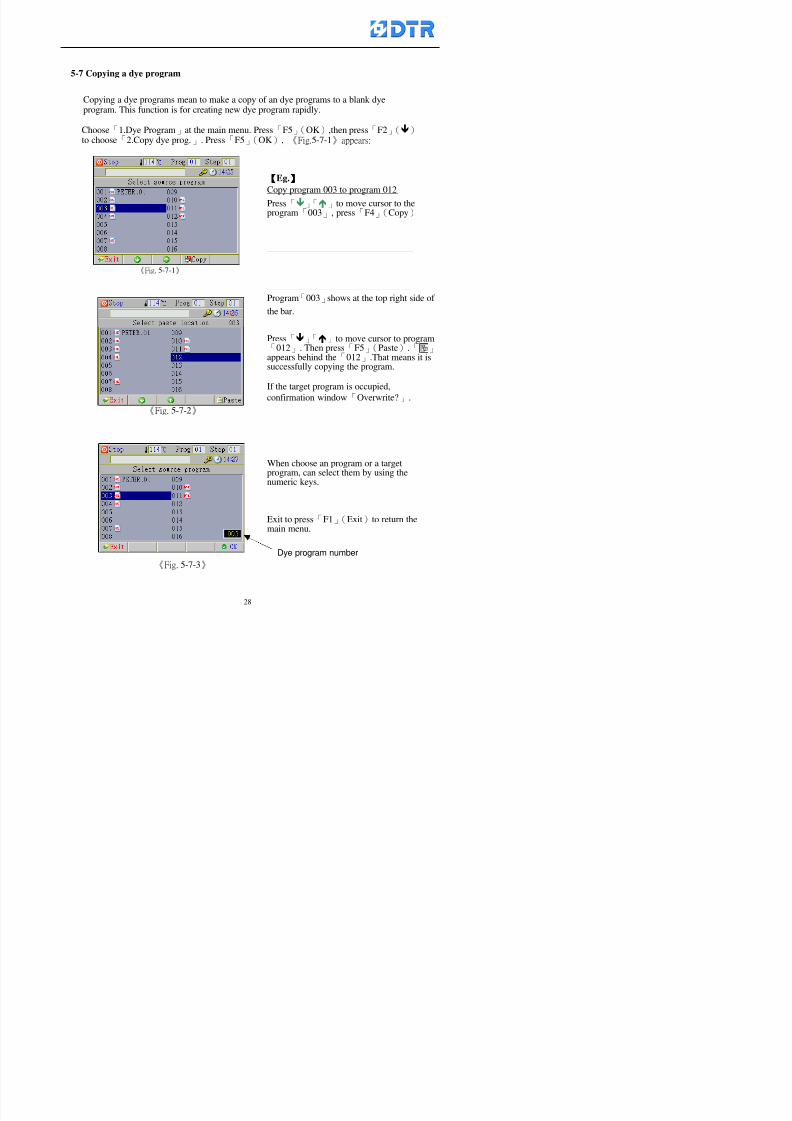
8132019 DTR 650 User Manual
httpslidepdfcomreaderfulldtr-650-user-manual 2870
5-7 Copying a dye program
Copying a dye programs mean to make a copy of an dye programs to a blank dyeprogram This function is for creating new dye program rapidly
Choose「1Dye Program」at the main menu Press「F5」(OK)then press「F2」()to choose「2Copy dye prog」 Press「F5」(OK) 《Fig5-7-1》appears
《Fig 5-7-1》
《Fig 5-7-2》
【【【【Eg】】】】
Copy program 003 to program 012
Press「」「」to move cursor to theprogram「003」 press「F4」(Copy)
Program「003」shows at the top right side of
the bar
Press「」「」to move cursor to program「012」 Then press「F5」(Paste)「」appears behind the「012」That means it issuccessfully copying the program
If the target program is occupied
confirmation window「Overwrite」
When choose an program or a targetprogram can select them by using the
8132019 DTR 650 User Manual
httpslidepdfcomreaderfulldtr-650-user-manual 2970
5-8 Deleting a dye program
Choose「1Dye program」at the main menu Press「F5」(OK)then press「F2」()to choose「3Delete dye prog」 Press「F5」(OK) 《Fig5-8-1》appears
《Fig5-8-1》
《Fig5-8-2》
Press「」「」to move cursor to
choose program need to delete Eg
delete program「012」 press「F5」(Del) Confirmation window
「Confirm delete」appears
Press「F4」(Yes) to confirm delete
Repeat the above step can delete more
than one program at the same time
Press「F2」(No) to return to window
《Fig5-8-1》and not delete that program
Exit to press「F1」(Exit)and return to the
main menu
8132019 DTR 650 User Manual
httpslidepdfcomreaderfulldtr-650-user-manual 3070
6 983123983141983156983156983145983150983143DTR-650 has a built-in standard factor that can fulfill all different types of dyeing
machinesrsquos basic demand Users can also modify the factors base on their request to
fulfill their special control demand Before modify please refer to the table of each
range of Setting Factors (see the Supplementary Table)
6-1 ldquoEnable to use the program stepsrdquo setting
There are totally 64 program steps Parts of them are usually applying to the programs
In order to make more efficiently of editing programs it can「Disable」the other part
of program steps which are not usually applying or not applicable to the programs
For example dye machine with one tank it is only using step Tank B In this case itcan firstly「Disable」the program steps of Tank C When edit the program the
「Disable」rsquos steps will not appear at the cursor for choosing But this will not effect
and change the saved files The saved files can be kept as before
Step
(1) Choose「2 Factors」at the main menu Press「F5」(OK)(2) Choose「18 Dye Instruction」at the sub-function menu Then presss「F5」(OK)
Window「Edit dye ins」appears
「Enable」instruction can available to
use「Disable」instruction is temporarystop to use
Press「F2」()「F3」()to move
8132019 DTR 650 User Manual
httpslidepdfcomreaderfulldtr-650-user-manual 3170
6-2 ldquoAllow to modify dye program temporary during operatingrdquo Setting
During dye program running it can modify dye program temporary Thesemodification will not disappear by causing a sudden power interruption or power off
until select another new dye program to run
Please note that it is only for modifying the dye program temporary That program
file would not saved due to the modification If need to modify the program file and
save choose the function of Edit Dye Program to edit (Refer to the Charper 5 for the【Edit Dye Prograrm】)
6-2-1 ldquoAllow to modify all dye programsrdquo Setting
Step
(1) Choose「2 Factors」at the main menu Press「F5」(OK)
(2) Choose「02 System Factor」at the sub-function menu Then presss「F5」(OK)
Window「Edit System Factor」appears
Set to stop using temporary the「07
Rinse」press「F4」(Sel)to set it as Disable
Repeat above steps to complete all setting
Press 「F1」(Exit)to return to main menu
8132019 DTR 650 User Manual
httpslidepdfcomreaderfulldtr-650-user-manual 3270
6-2-2 ldquoAllow to modify part of dye programsrdquo Setting
【Eg】Set the number 08 or above (including number 08) is allowing to modify dye
programs during operating
Step
A Refer to【6-2-1】setting the factor as「22」to allow editing dye program
temporary during operating
(4) Press「3」「4」to edit the setting
as「Enable」 and press「F5」(OK)
Restore the standard factor by
pressing「F3」(Clr)
(5) Exit to press「F1」(Exit)and
return to window of 「Main Menu」
8132019 DTR 650 User Manual
httpslidepdfcomreaderfulldtr-650-user-manual 3370
6-2-3 ldquoAllow to modify dye steps temporaryrdquo Setting
After setting the dye programs are allowed to edit it also can set which dye steps are
allowed to edit temporary during operating
Step
(1) Choose「2 Factors」at the main menu Press「F5」(OK)
(2) Choose「19 Dye Ins control」at the sub-function menu Then presss「F5」
(OK) Window「Edit ins mode」appears
「Enable」 Allow to edit that dye step before
operating
「Disable」 Not allow to edit dye step before
operating
(3) Press「」「」to move cursor
to choose dye step Press「F4」
To enter to the「Edit dye program」from the
function menu there is a「」in front of the
file name「0-7」 means that program is not
allowing to edit during operating
8132019 DTR 650 User Manual
httpslidepdfcomreaderfulldtr-650-user-manual 3470
6-2-4 ldquoSet the dye step to keep running from the interrupt pointrdquo setting
When the dye program is operating it will disappear by causing power
interruption or sudden power off When start running again part of dye steps can
run again from the interrupt point part of them cannot
How to set
(1) Choose「2Factors」in the main menu and press「F5」(OK)
(2) Choose「20Continue mode」in the sub-function menu Press「F5」(OK) to
enter window of 「Continue Setting」
(3) Press「」「」to move cursor to choose dye steps Press「F4」(Sel)it
shows「Disable」or「Enable」for choosing Press「F5」(OK)to move cursorto the next setting
(4) Repeat above method until all setting is complete press「F1」(Exit)and
return to the main menu
8132019 DTR 650 User Manual
httpslidepdfcomreaderfulldtr-650-user-manual 3570
6-3 ldquoAllow to insert an addition dye stepsrdquo setting
During the program is running can temporary insert an addition dye step or a dye
program according to the operating actual situation Through this setting can set which
dye steps can apply or not to the program in operating
During to insert an addition step if sudden interruption or power off occurred it returns
to the main dye program automatically Before starting again should decide seriously
and set it again by actual needed
Step
(1) Choose「2Factors」at the main menu and press「F5」(OK)
(2) Choose「02System factor」and press「F5」(OK)
(3) Press「」「」to move cursor to the factor「34」and press「3」「4」to set
it as「Enable」 Press「F5」(OK)
(4) Press「F1」(Exit)to return to main menu Choose「21Addition Ins」at the
sub-function menu Press「F5」(OK)to enter the window「Addition Instruction」
(5) Press「」「」to move cursor to choose dye steps and press「F4」(Sel) Cursors
locates shows「Eable」or「Disable」 Press「F5」(OK)to move cursor to the
next dye step
(6) Repeat above method until to complete all setting press「F1」(Exit)and return
to the main menu
8132019 DTR 650 User Manual
httpslidepdfcomreaderfulldtr-650-user-manual 3670
6-4 Setting the display mode
DTR650 has three types of display mode during operating Program List mode
Schematic Diagram mode and Icon mode Users can set the display mode during
operating by factor setting
It goes back to a Program List mode when dye program ended
Step
(1) Choose「2Factors」at the main menu and press「F5」(OK)
(2) Choose「02System factor」and press「F5」(OK)
(3) Press「F2」()「F3」()to move cursor to choose「32Display mode」Press
「3」「4」 it shows「Online picture」「Instruction」「Big Icon」 choose
「Online picture」(eg) and press「F5」to confirm
8132019 DTR 650 User Manual
httpslidepdfcomreaderfulldtr-650-user-manual 3770
(4) Press「F1」(Exit)to return to the main menu
(5) The Schematic Diagram displays when the program is running (it stays at theProgram List mode when there is an alarm occurred)
Press「F4」to transfer to another display mode
It goes back to a Program List mode from Schematic Diagram Mode when dye
program ended Press numeric key「3」to view Schematic Diagram Mode again
Quit to press「F5」(Exit)
6-5 Adapt the digital input to another functions
DTR-650 has 32(0~31)input terminal it owns an standard setting when the
controller is initial According to the userrsquos demand they can change the DTR-650rsquos
anther functions of Input Terminal and PLC Input channel
The PLC Intputrsquos name can also define by the users (use IBM computer to edit and
download)
How to set
(1) Choose「2 Factor」at the main menu Press「F5」(OK)
(2) Choose「22 Input table」at the sub-function menu and press「F5」(OK)to enter
「Edit input table」
The actual input
terminal of theIBM computer
PLCrsquos input channel
8132019 DTR 650 User Manual
httpslidepdfcomreaderfulldtr-650-user-manual 3870
6-6 Adapt the digital output to another functions
DTR-650 has 32(0~31)output terminals it owns an standard setting when thecontroller is initial According to the userrsquos demand they can adapte the digital output
and the PLC outputrsquos channel to another functions The PLC Output channelrsquos name
can also define by users (use IBM computer to edit and download)
Step
(1) Choose「2 Factor」at the main menu Press「F5」(OK)
(2) Choose「23 Output table」at the main menu and press「F5」(OK)
(3) Press「F2」()「F3」()to move cursor to choose the output terminal atthe left side of the window Press「F5」(Add) the PLCrsquos output channelrsquos
name is listing at the right side of the window
(4) Press「F2」()「F3」()to move cursor to choose the PLC outputrsquos channel
If cursor moves to the PLC output channel which already linking「Add」is
not for choosing that means that output channel is already occupied
(5) Confirm the connection to press「F5」(Add) Quit to press「F4」(Del)Press「F1」(Exit)when complete all setting and return to main menu
The actual output
terminal of the
IBM computer
PLCrsquos output channel
8132019 DTR 650 User Manual
httpslidepdfcomreaderfulldtr-650-user-manual 3970
983095 983109983140983145983156983145983150983143 983156983144983141 983110983137983139983156983151983154983155DTR-650 has several kinds of control factors
Userrsquos factors System factors Temperature Control factors Speed factors Dosing
factors PID factors Analog Input Output factors standard factors etchellipPlease refer
to the supplementary table for the setting range and standard of the factors
DTR-650 has a built-in standard factor Users can edit by themselves if necessary
7-1 Modifying userrsquos factors
Userrsquos factors is setting with the Dyeing machinesrsquos PLC Programrsquos factor it is define by
the PLC Programmer
Step to edit
(1) Choose「2Factors」at main menu Press「F5」(OK)
(2) Choose「01User Factor」Press「F5」(OK)
(3) Press「F2」()「F3」()「6」「5」to move cursor up down and by page
Choose a factor need to edit then press「3」「4」to set itrsquos value Press「F5」(OK) Cursor moves to the next factor
(4) Some of factors can input numbers by the numeric membrance keys to edit If
the input is incorrect it turns to red and means the edit is not available
8132019 DTR 650 User Manual
httpslidepdfcomreaderfulldtr-650-user-manual 4070
Modifyrsquos method of the system factors temperature factors speed factors dosingfactors PID factors analog Input output factors standard factors etchellipare same asabove
If apply the library of DTR500 and DTR600 into the DTR650 the key「3」「4」may not valid to use Please use the numeric keys instead of it to key in factors itmay not effect the normal operation
Please pay a serious attention and read carefully at the factorrsquos table before modify the factors An incorrect value may effect the DTR-650 Dyeing
Machine Controllerrsquos operating After modifying factors must cancel the
password and secure data
7-2 Loading the standard factors
After modifying factors if need to restore a manufacturerrsquos standard factors of
DTR-650 The method as follows
1 Choose「2Factors」at main menu Press「F5」(OK)
「 「 ( ) 「
8132019 DTR 650 User Manual
httpslidepdfcomreaderfulldtr-650-user-manual 4170
7-3 Copying the factor
Users can build up a set of factor by themselves and make a copy and save
Step
1 Choose「2Factors」at main menu Press「F5」(OK)
2 Choose「13Restore Factor」 press「F5」(OK) window「factor will be
overwrite 」
3 Press「F4」(Yes)copy finished and saved Return to the main menu
4 Press「F2」(No)to not copy the factor and the existing factor is not change Return
to the main menu
7-4 Loading the backup factors
Users can build up a set of factor and backup files to load to DTR-650
Step1 Choose「14Backup factor」at the sub-function menu Press「F5」(OK)and
window「Factror will be overwrite」appears
2 Press「F3」(OK)to load the the backup factor them return to main menu
Press「F2」(No)to not copy the factor and the existing factor is not change
Return to the main menu
8132019 DTR 650 User Manual
httpslidepdfcomreaderfulldtr-650-user-manual 4270
983096 983119983157983156983152983157983156 983124983141983155983156983145983150983143
Before the output testing must be complete the steps as follows
A Cut off all connecting line of output terminal of DTR-650
B Stop running the PLC
C Check up the connections of all output channels to avoid damages from
incorrect connections
D Check up state of dyeing machines include the temperature pressure valves
onoff and pumpshellipetc ensure the safety for priority
8-1 Testing the Digital output
Step
1 Choose「3Output Testing」at the main menu Press「F5」(OK) 2 Choose「1Digital」at the sub function menu Press「F5」(OK) window「Digital
output testing」appears
3 Press「」「」「」to move cursor to each output channels Press「F5」(OK)
Output Name
8132019 DTR 650 User Manual
httpslidepdfcomreaderfulldtr-650-user-manual 4370
8-2 Testing the Analog output
(1) Choose「3Output Testing」at the main menu Press「F5」(OK)
(2) Choose「2Analog」at the sub function menu Press「F5」(OK) window「Analog output testing」appears
(3) Press「」「」「」to move cursor to each channels Then key in number by
the numeric membrance keys (range0~200= 0~20mA) Press「F5」(OK) there
is a output current relating to the output channel
(4) Press「F5」(OK) There is an output when the output channel with red light No
output without light onl(5) When complete the testing press「F1」(OK)to return to the main menu
8132019 DTR 650 User Manual
httpslidepdfcomreaderfulldtr-650-user-manual 4470
983097 983107983137983148983145983138983154983137983156983145983151983150
DTR-650 has Dosing and Temperature calibration
When enter to Dosing calibration must be set the Low Volume calibration first and
then High Volume calibration When enter to Temperature calibration must be set the
Low Temperature calibration first and then High Temperature calibration Must be
hightly follow this orders seriously
9-1 Calibration of Low Volume Tank
Step
A Choose「4Calibration」at the main menu Press「F5」(OK)
B Choose「Dosing 0 low vol」at the sub function menu Press「F5」(OK) window
appears
C Fill the Dosing Tank to a half level input value shows how much the water level
If it stays ldquo0rdquo check the connection and the factor setting is correct or not
And connect the pressure sensorrsquos output channel to the Current Meter to ensure
that sensor works or not
8132019 DTR 650 User Manual
httpslidepdfcomreaderfulldtr-650-user-manual 4570
D Fill the Dosing Tank to 50ml (Calcalate from the bottom side of the pressure
sensor steel tube) input value should show 4~6 (input value must between
0~10) Then enter the water volume The setting volume is relating the water
levelrsquos water value (litre as unit) input range 0~80 Set as「 「「 「0000 0000 0000 0000」」」」is strongly is strongly is strongly is strongly
receommend receommend receommend receommend Press「F5」(OK)to complete [Calibration of Low Volume Tank 1
is same as above method]
9-2 Calibration of High Volume Tank
Step
A Choose「4Calibration」at the main menu Press「F5」(OK)
B Choose「Dos 0 high vol」at the sub function menu Press「F5」(OK) window of
「Calibrate high 」appears
C Fill the Dosing Tank to a full level input value should be larger than 30 enter
the current water level which relates to the water volume Enter the range within
100~2500 Then press「F5」(OK) to complete the calibrate the high volume tank
8132019 DTR 650 User Manual
httpslidepdfcomreaderfulldtr-650-user-manual 4670
9-3 Temperature Calibration
Step
A This function is for adjusting the DTR650rsquos accuracy of Temperature Control It
must be using with the special terminal which is only for DTR650
B Choose「4Calibration」at the main function menu and press「F5」(OK)
C Choose「3Low Temp」at the sub-function menu Press「F5」(OK)and《Fig9-3》
appears insert the DTR650rsquos low temperature calibration terminal to the temperature
input terminal wait for the jumping value to stable down then press「F5」(OK) then
to adjust the high temperature calibration
D Adjusting the High Temperature Calibrationrsquos method is same as above But usersusersusersusers
must be using the High Temperature Terminalmust be using the High Temperature Terminalmust be using the High Temperature Terminalmust be using the High Temperature Terminal whichwhichwhichwhich is specially for DTR650 onlyis specially for DTR650 onlyis specially for DTR650 onlyis specially for DTR650 only
《Fig 9-3》
8132019 DTR 650 User Manual
httpslidepdfcomreaderfulldtr-650-user-manual 4770
10 983122983141983139983151983154983140983155 983151983142 983108983161983141 983120983154983151983143983154983137983149983155
It contains the past 15 days of temperature curves of running history
Checking method
(1) Choose「5Dye Record」at main menu press「F5」(OK)
(2) Sub-function menu shows the set up date of the past 15 days dye programs
Listing by the lastest set up date
(3) Choose a program date and press「F5」(OK) it appears window「Temp
record」
(4) Press「」「」to move the white line in the box one minute by moving once
(5) Press「3」「4」to move the line to check the time period 2 hours by moving once
The yellow selecting line of the「24 hours operating state」is repectively moving
The curve info is show in the curve box Left side of the widnow appears the
relating running info the time is the time value of the line locates at
(6) Check more details of the temperature info to press numeric key「middot」 a bright red line
appears in the selecting box this line is to check the starting point of the
temperature inforsquos time period Then press「」to move the white line to the end
point of the time period The temperature info between the starting point and end
point are appears at the right side of the window Press「middot」to return to the preious
curve page
(7) Check more details of the alarm infor To perss numeric key「7」「9」 the alarmrsquos
details is listing by orders
(8) Press「F1」(exit) to return
8132019 DTR 650 User Manual
httpslidepdfcomreaderfulldtr-650-user-manual 4870
11 983125983155983137983143983141 983151983142 983117983141983149983151983154983161 983107983137983154983140
DTR-650 supports 32MB or above Compact Flash Card which can transfer and save all
information for 4 sets of DTR-650 Including library files schematic diagram icon
image PLC program dye program factor and confiruration files etchellip Use the CF Card
to up download and swap the information of DTR-650 promptly install the relating
device and program updates
DTR-650 CF Card with bank 1 to bank 4 can save 4 sets information of Dyeing
Machines When download or save files should choose the BANK first
《Fig11-1》
8132019 DTR 650 User Manual
httpslidepdfcomreaderfulldtr-650-user-manual 4970
11-1 Downloading data
1 Firmly insert the CF card into the DTR-650rsquos PCMCIA connector Ensure it is
wholely and firmly inserted if the card is not totally inserted or the card do not
touch in all to the connector there will be an error occurred and cannot
updownload or interrupted during operation
2 Choose「6Memory Card」at the main menu and press「F5」(OK) 《Fig11-1》
appears Information of Bank「1」shows at the left hand side of the window press
number 1-4 by using numeric keys to choose the BANK Check the
information in the Bank seriously which is exactly need to download to the
DTR650
3 Press()()「6」「5」to move cursor to the sub-function menu to choose
the downloading items Press「F5」(OK) window appears「Stop PLC run before
access memory card Stop the PLC run」 Press「F5」(YES) to stop PLC
running
4 Press「F5」(OK) window appears Confirm to update or not the DTR-650rsquos
information As that downloading will be replace the DTR-650rsquos information
(that means the existing information of the DTR-650 will be removed and
replaced)
5 Press「F4」(YES)to download the information from the DTR-650 to the CF
Card Return to the main menu when finish
8132019 DTR 650 User Manual
httpslidepdfcomreaderfulldtr-650-user-manual 5070
Ensure inserting firmly the CF card into the DTR-650 unless it will cause
error or cannot Updownload data
Never remove CF card during transferring or updownloading data Until it
is all completed
DTR-650rsquos dyeing program is not compatible with DTR-500 and
DTR-600 Never use CF card to transfer data among them
11-2 Storing and transfering data
1 Insert the CF Card to the DTR-650
2 Choose「6Memory Card」at the main menu and press「F5」(OK) 《Fig11-1》
appears Left hand side of the window shows the data of BANK 1 press numeric
keys 1-4 to select the BANK To confirm the put the data in the DTR-650 to the CF
Card The existing data of that bank will be replaced and covered by the new data (if
that bank is already occuplied)
3 Choose「23Save Dye prog」(Example)at the sub-funciton menu press「F5」(OK)to confirm Window「Update memory card data」appears
4 Press「F5」(OK)to transfer the data to the CF card Return to the main menu
5 Put the CF card into another DTR-650 and follow the operating method of 「11-1
Downloading data」」」」can transfer and swap data with more than one set of
DTR-650
8132019 DTR 650 User Manual
httpslidepdfcomreaderfulldtr-650-user-manual 5170
12 983123983156983137983156983141 983137983150983140 983113983150983142983151983154983149983137983156983145983151983150
The state and information is including the Dyeing Machinersquos state of Digit Input output
Analog Input output Temperature control PID Dosing PID Pressure different PID
software system information and alarm record This information is for checking at any
time
12-1 Input Output state
Step
1 Choose「7Info and state」at main menu and press「F5」(OK)
2 Choose「01Digital IO put」at the sub-function menu then press「F5」(OK)
「Digital In Out State」0=None 1=Input
3 Press「F1」(Exit)to return to main menu
Same method for checking the temperature control analog dosing pressure
different etchellip
12-2 Checking the system information
Step
1 Choose「7Info and state」at main menu and press「F5」(OK)
2 Choose「11 System info」at sub-function field press「F5」(OK)Window
「System Information」appear
System information is including System info(software version) Library doc
Icon files Schematic file Definition file hardare state Config File Commandinstruction icon PLC file etc
8132019 DTR 650 User Manual
httpslidepdfcomreaderfulldtr-650-user-manual 5270
12-3 Checking the operating alarm record
Operating record shows the latest 40 operating items and alarm records including
the time and content of the alarm
A) Choose「7 Info and state」
and press「F5」(OK)
B) Choose「12Alarm logs」at
the sub-funciton menu then
press「F5」(OK)
8132019 DTR 650 User Manual
httpslidepdfcomreaderfulldtr-650-user-manual 5370
13 983105983140983146983157983155983156983145983150983143 983156983144983141 983107983151983150983156983154983137983155983156
The displaysrsquos brightness can be adjusted if necessary
Step
1 Choose「8Others」at main menu press「F5」(OK)
2 Choose「01Contrast」at sub-function menu press「F5」(OK) window「Set
Contrast」appears
3 Press「」「」to move the bar to set the brightness then press「F5」(OK)Window appears「Please reboot the system」
4 Press「F5」(OK)to return to main menu and re-boot the DTR-650 to complete
adjusting the brightness
8132019 DTR 650 User Manual
httpslidepdfcomreaderfulldtr-650-user-manual 5470
14 983123983156983151983152 983154983157983150983150983145983150983143 983156983144983141 983120983116983107 983120983154983151983143983154983137983149
Before testing the Input output testing transfer of the PLC program must stop the PLC
running
Step
1 Choose「8Others」at the main menu Press「F5」(OK)
2 Choose「04 PLC Stop」at sub-function menu Press「F5」(OK) window
「Password」appears
3 Enter password and press「F5」(OK) Window「Stop the PLC run」appears
4 Press「F4」(Yes)and window「PLC Stop」appear Press「F5」(OK) Now
the PLC is stop running and return to the main menu
All testing cannot operate when the PLC is running
Editing dye program and the relating operation can
perform with the PLC running together
8132019 DTR 650 User Manual
httpslidepdfcomreaderfulldtr-650-user-manual 5570
15 983123983141983156983156983145983150983143 983156983144983141 983156983145983149983141
Step
1 Press「8Others」at the main menu Press「F5」(OK)
2 Choose「10Set date time」at the sub-function menu Press「F5」(OK) window
「Set date time」appears
3 Press「F5」(Edit) to move cursor by 「3」「4」 enter the time value at the
cursor locates
4 Press「F5」(OK)to complete the modify Press「F1」(Exit)to return to main
menu
5 Press「F1」(Exit)if not modify and return to main menu
8132019 DTR 650 User Manual
httpslidepdfcomreaderfulldtr-650-user-manual 5670
1166 983123983123983157983157 983152 983152 983152 983152983148983148983141983141983149983149983141983141983150983150983156 983156 983137983137983154 983154 983161983161 983124 983124 983137983137983138983138983148983148983141983141
TTTTTTTTaaaaaaaabbbbbbbblllllllleeeeeeee 11111111 【Dye Instruction】
Code Icon Instruction Code Icon Instruction
000 End 016 Inject C
001 Start 017 Dosing BV
002 Heat 018 PH
003 Cool 019 Addsalt B
004 Flow Fill 020 Addsalt C
005 Level Fill 021 Ana Fill
006 Drian 022 Lock Fill007 Rinse 023 Lock Level
008 Run 024 Low Rinse
009 Call 025 Cyc Rinse
010 Prep B 026 Rinse B
011 Addsalt B 027 Rinse C
012 Dosing B 028 Temp
013 Inject B 029 Nozzle Pressure
014 Prep C 030 Main Pump
015 Dosing C 031 Pump Speed
8132019 DTR 650 User Manual
httpslidepdfcomreaderfulldtr-650-user-manual 5770
Table 2 【【【【Alarm】】】】
System Alarm Must stop operating and check up to solve problems before restarting
the machine
Running Alarm It is a reminder Not effect the operating of DTR-650
Userrsquos Alarm Total of 32 Users can define themselves and use it when edit the PLC
Program (do not listing below)
No System Alarm No Running Alarm
1 PLC program not running 16 Temp ctrl 0 Grad too slow
2 Main temp sensor error 17 Temp ctrl 0 Grad too fast
3 Not at Run window 18 Temp ctrl 0 Hold temp too low
4 Exceeding max temp 19 Temp ctrl 0 Hold temp too high
5 - 20 Temp ctrl 1 Grad too slow6 - 21 Temp ctrl 1 Grad too fast
7 - 22 Temp ctrl 1 Hold temp too low
8 Communication error 23 Temp ctrl 1 Hold temp too high
9 Slave not answer 24 Temp ctrl 2 Grad too slow
10 PLC 0 not answer 25 Temp ctrl 2 Grad too fast
11 PLC 1 not answer 26 Temp 2 Hold temp too low12 Display not answer 27 Temp 2 Hold temp too high
13 Lower power voltage 28 Temp ctrl 3 Grad too slow
14 - 29 Temp ctrl 3 Grad too fast
15 - 30 Temp3 Hold temp too low
31 Temp3 Hold temp too high
32 Dosing 0 injection too slow
33 Dosing 0 injection too fast
34 Dosing 1 injection too slow
35 Dosing 1 injection too fast
8132019 DTR 650 User Manual
httpslidepdfcomreaderfulldtr-650-user-manual 5870
TTTTTTTTaaaaaaaabbbbbbbblllllllleeeeeeee 33333333 【【【【System factor】】】】
No Description Std Range amp Definition
1 ID No 000 000- 100 Controller no
2 Communication Rate 4800Bps 2400 4800 9600 19200 38400
3 Display language Chinese English Chinese
4 Temp display mode and
5 Maxmium temperature 145 025 ~ 145 6 Type of external PLC Default PLC32DPLC32PLC16Default
7 Number of external PLC NANA 1 unit connect
2 unit connect
8Communication Rate of
PLC9600Bps 2400 4800 9600 19200
9 Set point 1 085 000 ~ 145
If signal source is temperaturethe setting value is thetemperature value If the signal
source is Analog Input 6~17 then
setting value for Analog input is 0 ndash
100 and relates Analog
Input14~020mA
10 Source 1 Sensor0Sensor 0 ~5
Analog input 0 ~1111 Set point 2 092 Same as 09
12 Source 2 PT100 1 Same as 10
13 Set point 3 085 Same as 09
14 Source 3 PT100 2 Same as 10
15 Set point 4 092 Same as 09
16 Source 4 PT100 3 Same as 1017 Set point 5 085 Same as 09
18 Source 5 PT100 4 Same as 10
19 Set point 6 092 Same as 09
8132019 DTR 650 User Manual
httpslidepdfcomreaderfulldtr-650-user-manual 5970
29 Min cyclic time of cloth 100sec 0 ~ 255 sec
30 Max cyclic time of cloth 240sec 0 ~255 sec
31Standard cyclic time of
cloth
180 000 ~ 255 sec
32 Display ModeProgram
List
Program list Schematic Diagram
Icon mode
33 CF card format Standard of
DTR CF
Card
Standard of DTR CF Card V20
Standard CF Card
34 Addition step Disable Disable Enable35 Mode Com 3
CouplingEsure Com 3 is the communication
port of the Central or Coupling
36Com 3 Communication
rate9600 Central communication speed
8132019 DTR 650 User Manual
httpslidepdfcomreaderfulldtr-650-user-manual 6070
TTTTTTTTaaaaaaaabbbbbbbblllllllleeeeeeee 44444444 【【【【Temperature Cotnrol Factor】】】】
No Factor Definition Standard Range and Definition
01 PT No PT-0 PT 0~5 PT-100 Input number
02 Max working temp 140 000~140
03 Output mode 0 0~2
04 Alarm time of gardient 240sec 000~255 sec
05 Alarm mode of gradient Always AlwaysOnceNone
06 Control mode of gradient Heating orCooling
interlocked
Heating and Cooling interlocked
No limitation
07 Alarm range of HoldTemp 03 01~20
08 Alarm time for HoldTemp 240sec 000~255sec
09 Alarm mode of HoldTemp Always AlwaysOnceNone
10 Control mode ofHoldTemp
Heating only Only heating and cooling Cooling whenalarm occurred Only heating andcooling No limitation when alarmHeating only
11 Porportional Band 100 000~250
12 Integral band 128 sec 000~255 sec
13 Differential time 04 sec 00~20 sec
14 Min transit gradient 02 00~50
15 Transit rate 20 times 00~50 times (020= 2 times)
16 PID initial output value 010 000~100
17 ONOFF cycle time 10 sec 05~25 sec
Onoff valve set as 010 sec
Proportional valve set as 020 sec
18 Time down count mode Mode 0 0~10 = The time down count range from「Factor 20 + target temp」to「Target
8132019 DTR 650 User Manual
httpslidepdfcomreaderfulldtr-650-user-manual 6170
TTTTTTTTaaaaaaaabbbbbbbblllllllleeeeeeee 55555555 【【【【Speed Factor】】】】
No Factor Definition Standard Range amp Definition
01 Input Number Speed input 0 Speed input 0~11
02 Average times 05 times 01~10
03 Sensor Number 008pcs 001~255
04 Roller Dimension 250mm 050~500
05 Max cloth speed 200mmin 001~25506 Min cloth speed 020mmin 001~255
07 Alarm delay time 240sec 001~255
08 Alarm mode Every oncenoneevery
09 Alarm range () 020 001~255
10 Proportional band 100 001~255
11 Integer band 128 001~25512 Differential time 000 001~200
13 Initial speed () 020 001~255
14 Control cycle ti(01sec) 05 01~30
15 First cycle time(01sec) 10 01~30
16 Speed increase limit () 010 001~100
17 Speed decrease limit () 010 001~100
18 Min speed() 005 001~100
19 Manual speed adjust () 005 001~100
20 Manual initial speed() 020 001~100
21 Stopping speed() 010 001~100
22 Switch speed() 020 001~100
23 Not used
24 Speed decrease turns 03turns 01~50
8132019 DTR 650 User Manual
httpslidepdfcomreaderfulldtr-650-user-manual 6270
Table 6 【【【【Dosing Factors】】】】
No Description Range Range and Explanation
1 Analog input no Analog input 0 Analog input no 0 ~11
2Alarm delay time for
dosing240 sec 000 ~255 sec
3 Alarm time for dosing Every Every Once None
4 Proportional band 100 000 ~255 sec Factor P
5 Integer band 128 000 ~255 sec Factor I6 Differential time 04 00 ~20 Factor D
7 Max adjust rate 150 50~ 255
8 Initial factor for dosing 10 000 ~100
9 User curve section 0 10 Gradient of sect1 for dosing curve9
10 User curve section 1 10 Gradient of sect2 for dosing curve9
11 User curve section 2 10 Gradient of sect3 for dosing curve9
12 User curve section 3 10 Gradient of sect4 for dosing curve9
13 User curve section 4 10 Gradient of sect5 for dosing curve9
14 User curve section 5 10 Gradient of sect6 for dosing curve9
15 User curve section 6 10 Gradient of sect7 for dosing curve9
16 User curve section 7 10 Gradient of sect8 for dosing curve9
17 User curve section 8 10 Gradient of sect9 for dosing curve9
18 User curve section 9 10 Gradient of sect10 for dosing curve9
19 Min water level 05 00~ 10 04~20mA percentagechange to the userrsquos factor setting
20 Output value for Tank
clean
100 000~ 100
Injected percentage of dosing valve
in dosing End period
This factor will be invalided if usingONOFF dosing valve
21 Full range 100 001~255 Self-adjustment cannotchange
22 Range ratio 001001~255 Self-adjustment cannot
change
8132019 DTR 650 User Manual
httpslidepdfcomreaderfulldtr-650-user-manual 6370
【【【【TTaabbllee 77 】】】】Pressure Deviation Factors
No Description Std Range amp Definition
1 Analog input number + Analog in 0 Analog in 0~11
2 Analog input number - Analog in 1 Analog in 0~11
3 Input mode Pressure Pressure Pressure deviation
4 Full range 050x01Kgcm
001~255
5 Range ratio 001 001~255
6 Alarm delay time 100sec 001~255
7 Alarm mode Every oncenone
8 Alarm range 010 001~255
9 Proportional band 100 001~255
10 Integer band 128 001~255
11 Differential time 00 00~20
12 PID Init output value 010 001~255
13 Cycle time 10 03~30
14 First cycle time 030 003~100
15 Max adjust rate 010 001~100
8132019 DTR 650 User Manual
httpslidepdfcomreaderfulldtr-650-user-manual 6470
【【【【TTaabbllee 88 】】】】Definition of Analog Input
No Description Standard Range and Explanation
01 PT 0 correction standard DIN std DIN std JIS std
02 PT 0 correction +0 +- 9
03 PT 1 correction standard DIN std DIN std JIS std
04 PT 1 correction +0 +- 9
05 PT 2 correction standard DIN std DIN std JIS std
06 PT 2 correction +0 +- 9
07 PT 3 correction standard DIN std DIN std JIS std
08 PT 3 correction +0 +- 9
09 PT 4 correction standard DIN std DIN std JIS std
10 PT 4 correction +0 +- 9
11 PT 5 correction standard DIN std DIN std JIS std
12 PT 5 correction +0 +- 9
13 Analog input 0 define 4 ~ 20mA 0 ndash 20mA 4 ndash 20mA
14 Analog input 0 average times 10 times 01- 20 times
15 Analog input 0 min value 0000 0000 - 1000
16 Analog input 0 max value 100 0001 - 9999
17-60 Analog input 1~11 Same as Analog input 0
【【【【 】】】】 fi i i f A O
8132019 DTR 650 User Manual
httpslidepdfcomreaderfulldtr-650-user-manual 6570
【【【【TTaabbllee 99 】】】】Definition of Analog Output
No Description Standard Range and explanation
61 Analog output 0 define Control byPLC
Control by PLC
Temperature control PID0 output
Temperature control PID1 output
Temperature control PID2 output
Speed PID3 output
Dosing PID0 output Dosing PID1output
Pressure different PID0 outputPressure different PID1 output
Main temperature output
62 Mode of Analog ouptput0 4 ~20mA 0 ndash20mA 4 ndash 20mA
63-84 Analog output 1~11 Same as Analog output 0
【【【【TTaabbllee 1100】】】】Value Table 0 amp 1
No Description Range Std Range and explanation
1 Analog input no 000~011 000 Analog input no
2 Data ratio 001~255 100 Multiple by factors
3~53 0~98 000~255 000-100 Analog input 0~98 data
【【【【 】】】】St t Li t
8132019 DTR 650 User Manual
httpslidepdfcomreaderfulldtr-650-user-manual 6670
【【【【TTaabbllee 1111】】】】State List
No Description Range Standard Range and explanation
1 Display setting 1 0~255 205 See remarks at next page
2 Display setting 2 0~255 208
3 Display setting 3 0~255 209
4 Display setting 4 0~255 017
5 Display setting 5 0~255 0186 Display setting 6 0~255 019
7 Display setting 7 0~255 020
8 Display setting 8 0~255 021
9 Display setting 9 0~255 000
10 Display setting 1 0~255 000
11 Display setting 2 0~255 000
12 Display setting 3 0~255 000
13 Display setting 4 0~255 000
14 Display setting 5 0~255 000
15 Display setting 6 0~255 000
16 Display setting 7 0~255 000
Remarks
8132019 DTR 650 User Manual
httpslidepdfcomreaderfulldtr-650-user-manual 6770
0 = No display 1~255 = Display type of number
1~16 Content of PLC VB0~15
No 1 corresponding to VB0
No 16 corresponding to VB15
17~32 Content of PLC DB0~15
No 17 corresponding to DB0
No 32 corresponding to DB15
33~46 Content of PLC CNT0~29
No 33 corresponding to CNT0
No 46 corresponding to CNT29 47~78 Content of dyeing instruction 0~31 CNT0
No 47 corresponding to system instruction to No 0 of CNT0
No 78 corresponding to system instruction to No 31 of CNT0rsquos content
79~110 Dyeing instruction 0~31 of CNT0rsquos setting
111~142 Content of Dyeing instruction 0~31 CNT1No 111 corresponding to dyeing instruction No 0 of CNT1
No 142 corresponding to dyeing instruction No 31 of CNT1rsquos content
143~174 Dyeing instruction 0~31 of CNT1rsquos setting
175~204 Content of PLC HTIM0~29
No 175 corresponding to HTIM0
No 204 corresponding to HTIM29
205 Loading
206 Ratio 1
207 Ratio 2208 Ratio 1 x Loading
209 Ratio 2 x Loading
210 Fix value
211 Value Table 1 matching result
212 Value Table 2 matching result
213 Value Table 1 setting214 Value Table 2 setting
215 Pressure control PID0 different pressure value
216 Pressure control PID1 different pressure value
TTTTTTTTaaaaaaaabbbbbbbblllllllleeeeeeee 1122 【【【【Usage of password】】】】
8132019 DTR 650 User Manual
httpslidepdfcomreaderfulldtr-650-user-manual 6870
No Main FunctionFactor Sub Function Factor Password Rank
1 Run None
2 Dye program User3 or above
3 Control factor
- User factor User 1
- System factor User 1
- Temp PID 0
- Temp PID 1 User 1- Speed PID 0 User 1
- Dosing PID 0 User 1
- Dosing PID 1 User 1
- Pressure PID 0 User 1
- Pressure PID 1 User 1
- Analog IO User 1
- Load standard factor User 2 or above- Load a copied factor User 2 or above
- Copy factor User 2 or above
- Value table 0 User 1
- Value table 1 User 1
- Information and state User 1
- Dye instruction User 1
- Edit dye instruction setting User 14 Output testing User 2 or above
5 Calibration User 2 or above
6 Dye record None
7 CF card User 1
8 Info and state None
9 Others
- Contrast User3 or above
- Data Locking None
- PLC Run User 1
- PLC Stop User 1
- Password setting User 1
TTTTTTTTaaaaaaaabbbbbbbblllllllleeeeeeee 1133 【【【【Technical Data】】】】
8132019 DTR 650 User Manual
httpslidepdfcomreaderfulldtr-650-user-manual 6970
TTTTTTTTaaaaaaaabbbbbbbblllllllleeeeeeee 1133 【【【【Technical Data】】】】
1 Temperature Control
- Range 10~145(plusmn1)
- Mode Proportional or PWM
- Sensor PT100 (JIS or DIN standard)
2 Input and output channel
- Digital Input 32 DC24V PNP- Digital Output 32 DC24V 054A Relay connect point
- Analog Input 4 04~20 mA
- Analog Output 4 0~20mA 或 4~20 mA
3 Communication port 3 RS-232 amp 0~20 mAx1 RS485x 2
4 Dye program
- Number 15000 Steps
- Standard step 61Heating Cooling Fill Drain RinseDosingetc
5LCD module and Display
langage
Chinese
English
320 x 240 TFT color display with
more language
6 CF card connector 1 PCMCIA standard
7 Membrane Keyboard- Number Key 10 [0]~[9] Input factors
- Function Key 5 [F1]~[F5] function selecting
- Operation Key 2 [Start] [Stop]
- Auxiliary Key 7 [][][][][Esc] [larr][OK] [bull]
8 Operating Condition
- Temperature 5~45
- Humidity ≦85 (25)
9 Power supply
V l DC 24V
8132019 DTR 650 User Manual
httpslidepdfcomreaderfulldtr-650-user-manual 7070
70
983108983124983122983085650 983113983150983152983157983156 983119983157983156983152983157983156 983120983151983154983156983145983150983143 (983138983137983139983147983155983145983140983141 983158983145983141983159)
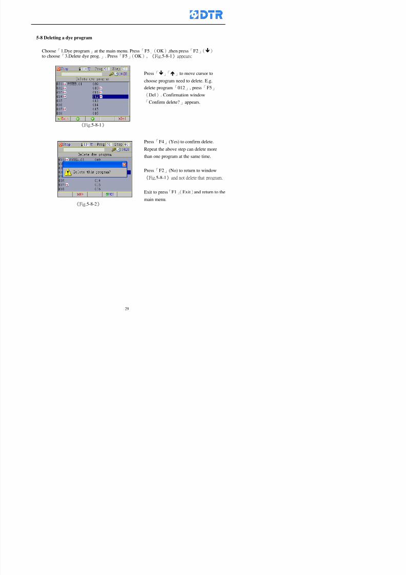
8132019 DTR 650 User Manual
httpslidepdfcomreaderfulldtr-650-user-manual 2970
5-8 Deleting a dye program
Choose「1Dye program」at the main menu Press「F5」(OK)then press「F2」()to choose「3Delete dye prog」 Press「F5」(OK) 《Fig5-8-1》appears
《Fig5-8-1》
《Fig5-8-2》
Press「」「」to move cursor to
choose program need to delete Eg
delete program「012」 press「F5」(Del) Confirmation window
「Confirm delete」appears
Press「F4」(Yes) to confirm delete
Repeat the above step can delete more
than one program at the same time
Press「F2」(No) to return to window
《Fig5-8-1》and not delete that program
Exit to press「F1」(Exit)and return to the
main menu
8132019 DTR 650 User Manual
httpslidepdfcomreaderfulldtr-650-user-manual 3070
6 983123983141983156983156983145983150983143DTR-650 has a built-in standard factor that can fulfill all different types of dyeing
machinesrsquos basic demand Users can also modify the factors base on their request to
fulfill their special control demand Before modify please refer to the table of each
range of Setting Factors (see the Supplementary Table)
6-1 ldquoEnable to use the program stepsrdquo setting
There are totally 64 program steps Parts of them are usually applying to the programs
In order to make more efficiently of editing programs it can「Disable」the other part
of program steps which are not usually applying or not applicable to the programs
For example dye machine with one tank it is only using step Tank B In this case itcan firstly「Disable」the program steps of Tank C When edit the program the
「Disable」rsquos steps will not appear at the cursor for choosing But this will not effect
and change the saved files The saved files can be kept as before
Step
(1) Choose「2 Factors」at the main menu Press「F5」(OK)(2) Choose「18 Dye Instruction」at the sub-function menu Then presss「F5」(OK)
Window「Edit dye ins」appears
「Enable」instruction can available to
use「Disable」instruction is temporarystop to use
Press「F2」()「F3」()to move
8132019 DTR 650 User Manual
httpslidepdfcomreaderfulldtr-650-user-manual 3170
6-2 ldquoAllow to modify dye program temporary during operatingrdquo Setting
During dye program running it can modify dye program temporary Thesemodification will not disappear by causing a sudden power interruption or power off
until select another new dye program to run
Please note that it is only for modifying the dye program temporary That program
file would not saved due to the modification If need to modify the program file and
save choose the function of Edit Dye Program to edit (Refer to the Charper 5 for the【Edit Dye Prograrm】)
6-2-1 ldquoAllow to modify all dye programsrdquo Setting
Step
(1) Choose「2 Factors」at the main menu Press「F5」(OK)
(2) Choose「02 System Factor」at the sub-function menu Then presss「F5」(OK)
Window「Edit System Factor」appears
Set to stop using temporary the「07
Rinse」press「F4」(Sel)to set it as Disable
Repeat above steps to complete all setting
Press 「F1」(Exit)to return to main menu
8132019 DTR 650 User Manual
httpslidepdfcomreaderfulldtr-650-user-manual 3270
6-2-2 ldquoAllow to modify part of dye programsrdquo Setting
【Eg】Set the number 08 or above (including number 08) is allowing to modify dye
programs during operating
Step
A Refer to【6-2-1】setting the factor as「22」to allow editing dye program
temporary during operating
(4) Press「3」「4」to edit the setting
as「Enable」 and press「F5」(OK)
Restore the standard factor by
pressing「F3」(Clr)
(5) Exit to press「F1」(Exit)and
return to window of 「Main Menu」
8132019 DTR 650 User Manual
httpslidepdfcomreaderfulldtr-650-user-manual 3370
6-2-3 ldquoAllow to modify dye steps temporaryrdquo Setting
After setting the dye programs are allowed to edit it also can set which dye steps are
allowed to edit temporary during operating
Step
(1) Choose「2 Factors」at the main menu Press「F5」(OK)
(2) Choose「19 Dye Ins control」at the sub-function menu Then presss「F5」
(OK) Window「Edit ins mode」appears
「Enable」 Allow to edit that dye step before
operating
「Disable」 Not allow to edit dye step before
operating
(3) Press「」「」to move cursor
to choose dye step Press「F4」
To enter to the「Edit dye program」from the
function menu there is a「」in front of the
file name「0-7」 means that program is not
allowing to edit during operating
8132019 DTR 650 User Manual
httpslidepdfcomreaderfulldtr-650-user-manual 3470
6-2-4 ldquoSet the dye step to keep running from the interrupt pointrdquo setting
When the dye program is operating it will disappear by causing power
interruption or sudden power off When start running again part of dye steps can
run again from the interrupt point part of them cannot
How to set
(1) Choose「2Factors」in the main menu and press「F5」(OK)
(2) Choose「20Continue mode」in the sub-function menu Press「F5」(OK) to
enter window of 「Continue Setting」
(3) Press「」「」to move cursor to choose dye steps Press「F4」(Sel)it
shows「Disable」or「Enable」for choosing Press「F5」(OK)to move cursorto the next setting
(4) Repeat above method until all setting is complete press「F1」(Exit)and
return to the main menu
8132019 DTR 650 User Manual
httpslidepdfcomreaderfulldtr-650-user-manual 3570
6-3 ldquoAllow to insert an addition dye stepsrdquo setting
During the program is running can temporary insert an addition dye step or a dye
program according to the operating actual situation Through this setting can set which
dye steps can apply or not to the program in operating
During to insert an addition step if sudden interruption or power off occurred it returns
to the main dye program automatically Before starting again should decide seriously
and set it again by actual needed
Step
(1) Choose「2Factors」at the main menu and press「F5」(OK)
(2) Choose「02System factor」and press「F5」(OK)
(3) Press「」「」to move cursor to the factor「34」and press「3」「4」to set
it as「Enable」 Press「F5」(OK)
(4) Press「F1」(Exit)to return to main menu Choose「21Addition Ins」at the
sub-function menu Press「F5」(OK)to enter the window「Addition Instruction」
(5) Press「」「」to move cursor to choose dye steps and press「F4」(Sel) Cursors
locates shows「Eable」or「Disable」 Press「F5」(OK)to move cursor to the
next dye step
(6) Repeat above method until to complete all setting press「F1」(Exit)and return
to the main menu
8132019 DTR 650 User Manual
httpslidepdfcomreaderfulldtr-650-user-manual 3670
6-4 Setting the display mode
DTR650 has three types of display mode during operating Program List mode
Schematic Diagram mode and Icon mode Users can set the display mode during
operating by factor setting
It goes back to a Program List mode when dye program ended
Step
(1) Choose「2Factors」at the main menu and press「F5」(OK)
(2) Choose「02System factor」and press「F5」(OK)
(3) Press「F2」()「F3」()to move cursor to choose「32Display mode」Press
「3」「4」 it shows「Online picture」「Instruction」「Big Icon」 choose
「Online picture」(eg) and press「F5」to confirm
8132019 DTR 650 User Manual
httpslidepdfcomreaderfulldtr-650-user-manual 3770
(4) Press「F1」(Exit)to return to the main menu
(5) The Schematic Diagram displays when the program is running (it stays at theProgram List mode when there is an alarm occurred)
Press「F4」to transfer to another display mode
It goes back to a Program List mode from Schematic Diagram Mode when dye
program ended Press numeric key「3」to view Schematic Diagram Mode again
Quit to press「F5」(Exit)
6-5 Adapt the digital input to another functions
DTR-650 has 32(0~31)input terminal it owns an standard setting when the
controller is initial According to the userrsquos demand they can change the DTR-650rsquos
anther functions of Input Terminal and PLC Input channel
The PLC Intputrsquos name can also define by the users (use IBM computer to edit and
download)
How to set
(1) Choose「2 Factor」at the main menu Press「F5」(OK)
(2) Choose「22 Input table」at the sub-function menu and press「F5」(OK)to enter
「Edit input table」
The actual input
terminal of theIBM computer
PLCrsquos input channel
8132019 DTR 650 User Manual
httpslidepdfcomreaderfulldtr-650-user-manual 3870
6-6 Adapt the digital output to another functions
DTR-650 has 32(0~31)output terminals it owns an standard setting when thecontroller is initial According to the userrsquos demand they can adapte the digital output
and the PLC outputrsquos channel to another functions The PLC Output channelrsquos name
can also define by users (use IBM computer to edit and download)
Step
(1) Choose「2 Factor」at the main menu Press「F5」(OK)
(2) Choose「23 Output table」at the main menu and press「F5」(OK)
(3) Press「F2」()「F3」()to move cursor to choose the output terminal atthe left side of the window Press「F5」(Add) the PLCrsquos output channelrsquos
name is listing at the right side of the window
(4) Press「F2」()「F3」()to move cursor to choose the PLC outputrsquos channel
If cursor moves to the PLC output channel which already linking「Add」is
not for choosing that means that output channel is already occupied
(5) Confirm the connection to press「F5」(Add) Quit to press「F4」(Del)Press「F1」(Exit)when complete all setting and return to main menu
The actual output
terminal of the
IBM computer
PLCrsquos output channel
8132019 DTR 650 User Manual
httpslidepdfcomreaderfulldtr-650-user-manual 3970
983095 983109983140983145983156983145983150983143 983156983144983141 983110983137983139983156983151983154983155DTR-650 has several kinds of control factors
Userrsquos factors System factors Temperature Control factors Speed factors Dosing
factors PID factors Analog Input Output factors standard factors etchellipPlease refer
to the supplementary table for the setting range and standard of the factors
DTR-650 has a built-in standard factor Users can edit by themselves if necessary
7-1 Modifying userrsquos factors
Userrsquos factors is setting with the Dyeing machinesrsquos PLC Programrsquos factor it is define by
the PLC Programmer
Step to edit
(1) Choose「2Factors」at main menu Press「F5」(OK)
(2) Choose「01User Factor」Press「F5」(OK)
(3) Press「F2」()「F3」()「6」「5」to move cursor up down and by page
Choose a factor need to edit then press「3」「4」to set itrsquos value Press「F5」(OK) Cursor moves to the next factor
(4) Some of factors can input numbers by the numeric membrance keys to edit If
the input is incorrect it turns to red and means the edit is not available
8132019 DTR 650 User Manual
httpslidepdfcomreaderfulldtr-650-user-manual 4070
Modifyrsquos method of the system factors temperature factors speed factors dosingfactors PID factors analog Input output factors standard factors etchellipare same asabove
If apply the library of DTR500 and DTR600 into the DTR650 the key「3」「4」may not valid to use Please use the numeric keys instead of it to key in factors itmay not effect the normal operation
Please pay a serious attention and read carefully at the factorrsquos table before modify the factors An incorrect value may effect the DTR-650 Dyeing
Machine Controllerrsquos operating After modifying factors must cancel the
password and secure data
7-2 Loading the standard factors
After modifying factors if need to restore a manufacturerrsquos standard factors of
DTR-650 The method as follows
1 Choose「2Factors」at main menu Press「F5」(OK)
「 「 ( ) 「
8132019 DTR 650 User Manual
httpslidepdfcomreaderfulldtr-650-user-manual 4170
7-3 Copying the factor
Users can build up a set of factor by themselves and make a copy and save
Step
1 Choose「2Factors」at main menu Press「F5」(OK)
2 Choose「13Restore Factor」 press「F5」(OK) window「factor will be
overwrite 」
3 Press「F4」(Yes)copy finished and saved Return to the main menu
4 Press「F2」(No)to not copy the factor and the existing factor is not change Return
to the main menu
7-4 Loading the backup factors
Users can build up a set of factor and backup files to load to DTR-650
Step1 Choose「14Backup factor」at the sub-function menu Press「F5」(OK)and
window「Factror will be overwrite」appears
2 Press「F3」(OK)to load the the backup factor them return to main menu
Press「F2」(No)to not copy the factor and the existing factor is not change
Return to the main menu
8132019 DTR 650 User Manual
httpslidepdfcomreaderfulldtr-650-user-manual 4270
983096 983119983157983156983152983157983156 983124983141983155983156983145983150983143
Before the output testing must be complete the steps as follows
A Cut off all connecting line of output terminal of DTR-650
B Stop running the PLC
C Check up the connections of all output channels to avoid damages from
incorrect connections
D Check up state of dyeing machines include the temperature pressure valves
onoff and pumpshellipetc ensure the safety for priority
8-1 Testing the Digital output
Step
1 Choose「3Output Testing」at the main menu Press「F5」(OK) 2 Choose「1Digital」at the sub function menu Press「F5」(OK) window「Digital
output testing」appears
3 Press「」「」「」to move cursor to each output channels Press「F5」(OK)
Output Name
8132019 DTR 650 User Manual
httpslidepdfcomreaderfulldtr-650-user-manual 4370
8-2 Testing the Analog output
(1) Choose「3Output Testing」at the main menu Press「F5」(OK)
(2) Choose「2Analog」at the sub function menu Press「F5」(OK) window「Analog output testing」appears
(3) Press「」「」「」to move cursor to each channels Then key in number by
the numeric membrance keys (range0~200= 0~20mA) Press「F5」(OK) there
is a output current relating to the output channel
(4) Press「F5」(OK) There is an output when the output channel with red light No
output without light onl(5) When complete the testing press「F1」(OK)to return to the main menu
8132019 DTR 650 User Manual
httpslidepdfcomreaderfulldtr-650-user-manual 4470
983097 983107983137983148983145983138983154983137983156983145983151983150
DTR-650 has Dosing and Temperature calibration
When enter to Dosing calibration must be set the Low Volume calibration first and
then High Volume calibration When enter to Temperature calibration must be set the
Low Temperature calibration first and then High Temperature calibration Must be
hightly follow this orders seriously
9-1 Calibration of Low Volume Tank
Step
A Choose「4Calibration」at the main menu Press「F5」(OK)
B Choose「Dosing 0 low vol」at the sub function menu Press「F5」(OK) window
appears
C Fill the Dosing Tank to a half level input value shows how much the water level
If it stays ldquo0rdquo check the connection and the factor setting is correct or not
And connect the pressure sensorrsquos output channel to the Current Meter to ensure
that sensor works or not
8132019 DTR 650 User Manual
httpslidepdfcomreaderfulldtr-650-user-manual 4570
D Fill the Dosing Tank to 50ml (Calcalate from the bottom side of the pressure
sensor steel tube) input value should show 4~6 (input value must between
0~10) Then enter the water volume The setting volume is relating the water
levelrsquos water value (litre as unit) input range 0~80 Set as「 「「 「0000 0000 0000 0000」」」」is strongly is strongly is strongly is strongly
receommend receommend receommend receommend Press「F5」(OK)to complete [Calibration of Low Volume Tank 1
is same as above method]
9-2 Calibration of High Volume Tank
Step
A Choose「4Calibration」at the main menu Press「F5」(OK)
B Choose「Dos 0 high vol」at the sub function menu Press「F5」(OK) window of
「Calibrate high 」appears
C Fill the Dosing Tank to a full level input value should be larger than 30 enter
the current water level which relates to the water volume Enter the range within
100~2500 Then press「F5」(OK) to complete the calibrate the high volume tank
8132019 DTR 650 User Manual
httpslidepdfcomreaderfulldtr-650-user-manual 4670
9-3 Temperature Calibration
Step
A This function is for adjusting the DTR650rsquos accuracy of Temperature Control It
must be using with the special terminal which is only for DTR650
B Choose「4Calibration」at the main function menu and press「F5」(OK)
C Choose「3Low Temp」at the sub-function menu Press「F5」(OK)and《Fig9-3》
appears insert the DTR650rsquos low temperature calibration terminal to the temperature
input terminal wait for the jumping value to stable down then press「F5」(OK) then
to adjust the high temperature calibration
D Adjusting the High Temperature Calibrationrsquos method is same as above But usersusersusersusers
must be using the High Temperature Terminalmust be using the High Temperature Terminalmust be using the High Temperature Terminalmust be using the High Temperature Terminal whichwhichwhichwhich is specially for DTR650 onlyis specially for DTR650 onlyis specially for DTR650 onlyis specially for DTR650 only
《Fig 9-3》
8132019 DTR 650 User Manual
httpslidepdfcomreaderfulldtr-650-user-manual 4770
10 983122983141983139983151983154983140983155 983151983142 983108983161983141 983120983154983151983143983154983137983149983155
It contains the past 15 days of temperature curves of running history
Checking method
(1) Choose「5Dye Record」at main menu press「F5」(OK)
(2) Sub-function menu shows the set up date of the past 15 days dye programs
Listing by the lastest set up date
(3) Choose a program date and press「F5」(OK) it appears window「Temp
record」
(4) Press「」「」to move the white line in the box one minute by moving once
(5) Press「3」「4」to move the line to check the time period 2 hours by moving once
The yellow selecting line of the「24 hours operating state」is repectively moving
The curve info is show in the curve box Left side of the widnow appears the
relating running info the time is the time value of the line locates at
(6) Check more details of the temperature info to press numeric key「middot」 a bright red line
appears in the selecting box this line is to check the starting point of the
temperature inforsquos time period Then press「」to move the white line to the end
point of the time period The temperature info between the starting point and end
point are appears at the right side of the window Press「middot」to return to the preious
curve page
(7) Check more details of the alarm infor To perss numeric key「7」「9」 the alarmrsquos
details is listing by orders
(8) Press「F1」(exit) to return
8132019 DTR 650 User Manual
httpslidepdfcomreaderfulldtr-650-user-manual 4870
11 983125983155983137983143983141 983151983142 983117983141983149983151983154983161 983107983137983154983140
DTR-650 supports 32MB or above Compact Flash Card which can transfer and save all
information for 4 sets of DTR-650 Including library files schematic diagram icon
image PLC program dye program factor and confiruration files etchellip Use the CF Card
to up download and swap the information of DTR-650 promptly install the relating
device and program updates
DTR-650 CF Card with bank 1 to bank 4 can save 4 sets information of Dyeing
Machines When download or save files should choose the BANK first
《Fig11-1》
8132019 DTR 650 User Manual
httpslidepdfcomreaderfulldtr-650-user-manual 4970
11-1 Downloading data
1 Firmly insert the CF card into the DTR-650rsquos PCMCIA connector Ensure it is
wholely and firmly inserted if the card is not totally inserted or the card do not
touch in all to the connector there will be an error occurred and cannot
updownload or interrupted during operation
2 Choose「6Memory Card」at the main menu and press「F5」(OK) 《Fig11-1》
appears Information of Bank「1」shows at the left hand side of the window press
number 1-4 by using numeric keys to choose the BANK Check the
information in the Bank seriously which is exactly need to download to the
DTR650
3 Press()()「6」「5」to move cursor to the sub-function menu to choose
the downloading items Press「F5」(OK) window appears「Stop PLC run before
access memory card Stop the PLC run」 Press「F5」(YES) to stop PLC
running
4 Press「F5」(OK) window appears Confirm to update or not the DTR-650rsquos
information As that downloading will be replace the DTR-650rsquos information
(that means the existing information of the DTR-650 will be removed and
replaced)
5 Press「F4」(YES)to download the information from the DTR-650 to the CF
Card Return to the main menu when finish
8132019 DTR 650 User Manual
httpslidepdfcomreaderfulldtr-650-user-manual 5070
Ensure inserting firmly the CF card into the DTR-650 unless it will cause
error or cannot Updownload data
Never remove CF card during transferring or updownloading data Until it
is all completed
DTR-650rsquos dyeing program is not compatible with DTR-500 and
DTR-600 Never use CF card to transfer data among them
11-2 Storing and transfering data
1 Insert the CF Card to the DTR-650
2 Choose「6Memory Card」at the main menu and press「F5」(OK) 《Fig11-1》
appears Left hand side of the window shows the data of BANK 1 press numeric
keys 1-4 to select the BANK To confirm the put the data in the DTR-650 to the CF
Card The existing data of that bank will be replaced and covered by the new data (if
that bank is already occuplied)
3 Choose「23Save Dye prog」(Example)at the sub-funciton menu press「F5」(OK)to confirm Window「Update memory card data」appears
4 Press「F5」(OK)to transfer the data to the CF card Return to the main menu
5 Put the CF card into another DTR-650 and follow the operating method of 「11-1
Downloading data」」」」can transfer and swap data with more than one set of
DTR-650
8132019 DTR 650 User Manual
httpslidepdfcomreaderfulldtr-650-user-manual 5170
12 983123983156983137983156983141 983137983150983140 983113983150983142983151983154983149983137983156983145983151983150
The state and information is including the Dyeing Machinersquos state of Digit Input output
Analog Input output Temperature control PID Dosing PID Pressure different PID
software system information and alarm record This information is for checking at any
time
12-1 Input Output state
Step
1 Choose「7Info and state」at main menu and press「F5」(OK)
2 Choose「01Digital IO put」at the sub-function menu then press「F5」(OK)
「Digital In Out State」0=None 1=Input
3 Press「F1」(Exit)to return to main menu
Same method for checking the temperature control analog dosing pressure
different etchellip
12-2 Checking the system information
Step
1 Choose「7Info and state」at main menu and press「F5」(OK)
2 Choose「11 System info」at sub-function field press「F5」(OK)Window
「System Information」appear
System information is including System info(software version) Library doc
Icon files Schematic file Definition file hardare state Config File Commandinstruction icon PLC file etc
8132019 DTR 650 User Manual
httpslidepdfcomreaderfulldtr-650-user-manual 5270
12-3 Checking the operating alarm record
Operating record shows the latest 40 operating items and alarm records including
the time and content of the alarm
A) Choose「7 Info and state」
and press「F5」(OK)
B) Choose「12Alarm logs」at
the sub-funciton menu then
press「F5」(OK)
8132019 DTR 650 User Manual
httpslidepdfcomreaderfulldtr-650-user-manual 5370
13 983105983140983146983157983155983156983145983150983143 983156983144983141 983107983151983150983156983154983137983155983156
The displaysrsquos brightness can be adjusted if necessary
Step
1 Choose「8Others」at main menu press「F5」(OK)
2 Choose「01Contrast」at sub-function menu press「F5」(OK) window「Set
Contrast」appears
3 Press「」「」to move the bar to set the brightness then press「F5」(OK)Window appears「Please reboot the system」
4 Press「F5」(OK)to return to main menu and re-boot the DTR-650 to complete
adjusting the brightness
8132019 DTR 650 User Manual
httpslidepdfcomreaderfulldtr-650-user-manual 5470
14 983123983156983151983152 983154983157983150983150983145983150983143 983156983144983141 983120983116983107 983120983154983151983143983154983137983149
Before testing the Input output testing transfer of the PLC program must stop the PLC
running
Step
1 Choose「8Others」at the main menu Press「F5」(OK)
2 Choose「04 PLC Stop」at sub-function menu Press「F5」(OK) window
「Password」appears
3 Enter password and press「F5」(OK) Window「Stop the PLC run」appears
4 Press「F4」(Yes)and window「PLC Stop」appear Press「F5」(OK) Now
the PLC is stop running and return to the main menu
All testing cannot operate when the PLC is running
Editing dye program and the relating operation can
perform with the PLC running together
8132019 DTR 650 User Manual
httpslidepdfcomreaderfulldtr-650-user-manual 5570
15 983123983141983156983156983145983150983143 983156983144983141 983156983145983149983141
Step
1 Press「8Others」at the main menu Press「F5」(OK)
2 Choose「10Set date time」at the sub-function menu Press「F5」(OK) window
「Set date time」appears
3 Press「F5」(Edit) to move cursor by 「3」「4」 enter the time value at the
cursor locates
4 Press「F5」(OK)to complete the modify Press「F1」(Exit)to return to main
menu
5 Press「F1」(Exit)if not modify and return to main menu
8132019 DTR 650 User Manual
httpslidepdfcomreaderfulldtr-650-user-manual 5670
1166 983123983123983157983157 983152 983152 983152 983152983148983148983141983141983149983149983141983141983150983150983156 983156 983137983137983154 983154 983161983161 983124 983124 983137983137983138983138983148983148983141983141
TTTTTTTTaaaaaaaabbbbbbbblllllllleeeeeeee 11111111 【Dye Instruction】
Code Icon Instruction Code Icon Instruction
000 End 016 Inject C
001 Start 017 Dosing BV
002 Heat 018 PH
003 Cool 019 Addsalt B
004 Flow Fill 020 Addsalt C
005 Level Fill 021 Ana Fill
006 Drian 022 Lock Fill007 Rinse 023 Lock Level
008 Run 024 Low Rinse
009 Call 025 Cyc Rinse
010 Prep B 026 Rinse B
011 Addsalt B 027 Rinse C
012 Dosing B 028 Temp
013 Inject B 029 Nozzle Pressure
014 Prep C 030 Main Pump
015 Dosing C 031 Pump Speed
8132019 DTR 650 User Manual
httpslidepdfcomreaderfulldtr-650-user-manual 5770
Table 2 【【【【Alarm】】】】
System Alarm Must stop operating and check up to solve problems before restarting
the machine
Running Alarm It is a reminder Not effect the operating of DTR-650
Userrsquos Alarm Total of 32 Users can define themselves and use it when edit the PLC
Program (do not listing below)
No System Alarm No Running Alarm
1 PLC program not running 16 Temp ctrl 0 Grad too slow
2 Main temp sensor error 17 Temp ctrl 0 Grad too fast
3 Not at Run window 18 Temp ctrl 0 Hold temp too low
4 Exceeding max temp 19 Temp ctrl 0 Hold temp too high
5 - 20 Temp ctrl 1 Grad too slow6 - 21 Temp ctrl 1 Grad too fast
7 - 22 Temp ctrl 1 Hold temp too low
8 Communication error 23 Temp ctrl 1 Hold temp too high
9 Slave not answer 24 Temp ctrl 2 Grad too slow
10 PLC 0 not answer 25 Temp ctrl 2 Grad too fast
11 PLC 1 not answer 26 Temp 2 Hold temp too low12 Display not answer 27 Temp 2 Hold temp too high
13 Lower power voltage 28 Temp ctrl 3 Grad too slow
14 - 29 Temp ctrl 3 Grad too fast
15 - 30 Temp3 Hold temp too low
31 Temp3 Hold temp too high
32 Dosing 0 injection too slow
33 Dosing 0 injection too fast
34 Dosing 1 injection too slow
35 Dosing 1 injection too fast
8132019 DTR 650 User Manual
httpslidepdfcomreaderfulldtr-650-user-manual 5870
TTTTTTTTaaaaaaaabbbbbbbblllllllleeeeeeee 33333333 【【【【System factor】】】】
No Description Std Range amp Definition
1 ID No 000 000- 100 Controller no
2 Communication Rate 4800Bps 2400 4800 9600 19200 38400
3 Display language Chinese English Chinese
4 Temp display mode and
5 Maxmium temperature 145 025 ~ 145 6 Type of external PLC Default PLC32DPLC32PLC16Default
7 Number of external PLC NANA 1 unit connect
2 unit connect
8Communication Rate of
PLC9600Bps 2400 4800 9600 19200
9 Set point 1 085 000 ~ 145
If signal source is temperaturethe setting value is thetemperature value If the signal
source is Analog Input 6~17 then
setting value for Analog input is 0 ndash
100 and relates Analog
Input14~020mA
10 Source 1 Sensor0Sensor 0 ~5
Analog input 0 ~1111 Set point 2 092 Same as 09
12 Source 2 PT100 1 Same as 10
13 Set point 3 085 Same as 09
14 Source 3 PT100 2 Same as 10
15 Set point 4 092 Same as 09
16 Source 4 PT100 3 Same as 1017 Set point 5 085 Same as 09
18 Source 5 PT100 4 Same as 10
19 Set point 6 092 Same as 09
8132019 DTR 650 User Manual
httpslidepdfcomreaderfulldtr-650-user-manual 5970
29 Min cyclic time of cloth 100sec 0 ~ 255 sec
30 Max cyclic time of cloth 240sec 0 ~255 sec
31Standard cyclic time of
cloth
180 000 ~ 255 sec
32 Display ModeProgram
List
Program list Schematic Diagram
Icon mode
33 CF card format Standard of
DTR CF
Card
Standard of DTR CF Card V20
Standard CF Card
34 Addition step Disable Disable Enable35 Mode Com 3
CouplingEsure Com 3 is the communication
port of the Central or Coupling
36Com 3 Communication
rate9600 Central communication speed
8132019 DTR 650 User Manual
httpslidepdfcomreaderfulldtr-650-user-manual 6070
TTTTTTTTaaaaaaaabbbbbbbblllllllleeeeeeee 44444444 【【【【Temperature Cotnrol Factor】】】】
No Factor Definition Standard Range and Definition
01 PT No PT-0 PT 0~5 PT-100 Input number
02 Max working temp 140 000~140
03 Output mode 0 0~2
04 Alarm time of gardient 240sec 000~255 sec
05 Alarm mode of gradient Always AlwaysOnceNone
06 Control mode of gradient Heating orCooling
interlocked
Heating and Cooling interlocked
No limitation
07 Alarm range of HoldTemp 03 01~20
08 Alarm time for HoldTemp 240sec 000~255sec
09 Alarm mode of HoldTemp Always AlwaysOnceNone
10 Control mode ofHoldTemp
Heating only Only heating and cooling Cooling whenalarm occurred Only heating andcooling No limitation when alarmHeating only
11 Porportional Band 100 000~250
12 Integral band 128 sec 000~255 sec
13 Differential time 04 sec 00~20 sec
14 Min transit gradient 02 00~50
15 Transit rate 20 times 00~50 times (020= 2 times)
16 PID initial output value 010 000~100
17 ONOFF cycle time 10 sec 05~25 sec
Onoff valve set as 010 sec
Proportional valve set as 020 sec
18 Time down count mode Mode 0 0~10 = The time down count range from「Factor 20 + target temp」to「Target
8132019 DTR 650 User Manual
httpslidepdfcomreaderfulldtr-650-user-manual 6170
TTTTTTTTaaaaaaaabbbbbbbblllllllleeeeeeee 55555555 【【【【Speed Factor】】】】
No Factor Definition Standard Range amp Definition
01 Input Number Speed input 0 Speed input 0~11
02 Average times 05 times 01~10
03 Sensor Number 008pcs 001~255
04 Roller Dimension 250mm 050~500
05 Max cloth speed 200mmin 001~25506 Min cloth speed 020mmin 001~255
07 Alarm delay time 240sec 001~255
08 Alarm mode Every oncenoneevery
09 Alarm range () 020 001~255
10 Proportional band 100 001~255
11 Integer band 128 001~25512 Differential time 000 001~200
13 Initial speed () 020 001~255
14 Control cycle ti(01sec) 05 01~30
15 First cycle time(01sec) 10 01~30
16 Speed increase limit () 010 001~100
17 Speed decrease limit () 010 001~100
18 Min speed() 005 001~100
19 Manual speed adjust () 005 001~100
20 Manual initial speed() 020 001~100
21 Stopping speed() 010 001~100
22 Switch speed() 020 001~100
23 Not used
24 Speed decrease turns 03turns 01~50
8132019 DTR 650 User Manual
httpslidepdfcomreaderfulldtr-650-user-manual 6270
Table 6 【【【【Dosing Factors】】】】
No Description Range Range and Explanation
1 Analog input no Analog input 0 Analog input no 0 ~11
2Alarm delay time for
dosing240 sec 000 ~255 sec
3 Alarm time for dosing Every Every Once None
4 Proportional band 100 000 ~255 sec Factor P
5 Integer band 128 000 ~255 sec Factor I6 Differential time 04 00 ~20 Factor D
7 Max adjust rate 150 50~ 255
8 Initial factor for dosing 10 000 ~100
9 User curve section 0 10 Gradient of sect1 for dosing curve9
10 User curve section 1 10 Gradient of sect2 for dosing curve9
11 User curve section 2 10 Gradient of sect3 for dosing curve9
12 User curve section 3 10 Gradient of sect4 for dosing curve9
13 User curve section 4 10 Gradient of sect5 for dosing curve9
14 User curve section 5 10 Gradient of sect6 for dosing curve9
15 User curve section 6 10 Gradient of sect7 for dosing curve9
16 User curve section 7 10 Gradient of sect8 for dosing curve9
17 User curve section 8 10 Gradient of sect9 for dosing curve9
18 User curve section 9 10 Gradient of sect10 for dosing curve9
19 Min water level 05 00~ 10 04~20mA percentagechange to the userrsquos factor setting
20 Output value for Tank
clean
100 000~ 100
Injected percentage of dosing valve
in dosing End period
This factor will be invalided if usingONOFF dosing valve
21 Full range 100 001~255 Self-adjustment cannotchange
22 Range ratio 001001~255 Self-adjustment cannot
change
8132019 DTR 650 User Manual
httpslidepdfcomreaderfulldtr-650-user-manual 6370
【【【【TTaabbllee 77 】】】】Pressure Deviation Factors
No Description Std Range amp Definition
1 Analog input number + Analog in 0 Analog in 0~11
2 Analog input number - Analog in 1 Analog in 0~11
3 Input mode Pressure Pressure Pressure deviation
4 Full range 050x01Kgcm
001~255
5 Range ratio 001 001~255
6 Alarm delay time 100sec 001~255
7 Alarm mode Every oncenone
8 Alarm range 010 001~255
9 Proportional band 100 001~255
10 Integer band 128 001~255
11 Differential time 00 00~20
12 PID Init output value 010 001~255
13 Cycle time 10 03~30
14 First cycle time 030 003~100
15 Max adjust rate 010 001~100
8132019 DTR 650 User Manual
httpslidepdfcomreaderfulldtr-650-user-manual 6470
【【【【TTaabbllee 88 】】】】Definition of Analog Input
No Description Standard Range and Explanation
01 PT 0 correction standard DIN std DIN std JIS std
02 PT 0 correction +0 +- 9
03 PT 1 correction standard DIN std DIN std JIS std
04 PT 1 correction +0 +- 9
05 PT 2 correction standard DIN std DIN std JIS std
06 PT 2 correction +0 +- 9
07 PT 3 correction standard DIN std DIN std JIS std
08 PT 3 correction +0 +- 9
09 PT 4 correction standard DIN std DIN std JIS std
10 PT 4 correction +0 +- 9
11 PT 5 correction standard DIN std DIN std JIS std
12 PT 5 correction +0 +- 9
13 Analog input 0 define 4 ~ 20mA 0 ndash 20mA 4 ndash 20mA
14 Analog input 0 average times 10 times 01- 20 times
15 Analog input 0 min value 0000 0000 - 1000
16 Analog input 0 max value 100 0001 - 9999
17-60 Analog input 1~11 Same as Analog input 0
【【【【 】】】】 fi i i f A O
8132019 DTR 650 User Manual
httpslidepdfcomreaderfulldtr-650-user-manual 6570
【【【【TTaabbllee 99 】】】】Definition of Analog Output
No Description Standard Range and explanation
61 Analog output 0 define Control byPLC
Control by PLC
Temperature control PID0 output
Temperature control PID1 output
Temperature control PID2 output
Speed PID3 output
Dosing PID0 output Dosing PID1output
Pressure different PID0 outputPressure different PID1 output
Main temperature output
62 Mode of Analog ouptput0 4 ~20mA 0 ndash20mA 4 ndash 20mA
63-84 Analog output 1~11 Same as Analog output 0
【【【【TTaabbllee 1100】】】】Value Table 0 amp 1
No Description Range Std Range and explanation
1 Analog input no 000~011 000 Analog input no
2 Data ratio 001~255 100 Multiple by factors
3~53 0~98 000~255 000-100 Analog input 0~98 data
【【【【 】】】】St t Li t
8132019 DTR 650 User Manual
httpslidepdfcomreaderfulldtr-650-user-manual 6670
【【【【TTaabbllee 1111】】】】State List
No Description Range Standard Range and explanation
1 Display setting 1 0~255 205 See remarks at next page
2 Display setting 2 0~255 208
3 Display setting 3 0~255 209
4 Display setting 4 0~255 017
5 Display setting 5 0~255 0186 Display setting 6 0~255 019
7 Display setting 7 0~255 020
8 Display setting 8 0~255 021
9 Display setting 9 0~255 000
10 Display setting 1 0~255 000
11 Display setting 2 0~255 000
12 Display setting 3 0~255 000
13 Display setting 4 0~255 000
14 Display setting 5 0~255 000
15 Display setting 6 0~255 000
16 Display setting 7 0~255 000
Remarks
8132019 DTR 650 User Manual
httpslidepdfcomreaderfulldtr-650-user-manual 6770
0 = No display 1~255 = Display type of number
1~16 Content of PLC VB0~15
No 1 corresponding to VB0
No 16 corresponding to VB15
17~32 Content of PLC DB0~15
No 17 corresponding to DB0
No 32 corresponding to DB15
33~46 Content of PLC CNT0~29
No 33 corresponding to CNT0
No 46 corresponding to CNT29 47~78 Content of dyeing instruction 0~31 CNT0
No 47 corresponding to system instruction to No 0 of CNT0
No 78 corresponding to system instruction to No 31 of CNT0rsquos content
79~110 Dyeing instruction 0~31 of CNT0rsquos setting
111~142 Content of Dyeing instruction 0~31 CNT1No 111 corresponding to dyeing instruction No 0 of CNT1
No 142 corresponding to dyeing instruction No 31 of CNT1rsquos content
143~174 Dyeing instruction 0~31 of CNT1rsquos setting
175~204 Content of PLC HTIM0~29
No 175 corresponding to HTIM0
No 204 corresponding to HTIM29
205 Loading
206 Ratio 1
207 Ratio 2208 Ratio 1 x Loading
209 Ratio 2 x Loading
210 Fix value
211 Value Table 1 matching result
212 Value Table 2 matching result
213 Value Table 1 setting214 Value Table 2 setting
215 Pressure control PID0 different pressure value
216 Pressure control PID1 different pressure value
TTTTTTTTaaaaaaaabbbbbbbblllllllleeeeeeee 1122 【【【【Usage of password】】】】
8132019 DTR 650 User Manual
httpslidepdfcomreaderfulldtr-650-user-manual 6870
No Main FunctionFactor Sub Function Factor Password Rank
1 Run None
2 Dye program User3 or above
3 Control factor
- User factor User 1
- System factor User 1
- Temp PID 0
- Temp PID 1 User 1- Speed PID 0 User 1
- Dosing PID 0 User 1
- Dosing PID 1 User 1
- Pressure PID 0 User 1
- Pressure PID 1 User 1
- Analog IO User 1
- Load standard factor User 2 or above- Load a copied factor User 2 or above
- Copy factor User 2 or above
- Value table 0 User 1
- Value table 1 User 1
- Information and state User 1
- Dye instruction User 1
- Edit dye instruction setting User 14 Output testing User 2 or above
5 Calibration User 2 or above
6 Dye record None
7 CF card User 1
8 Info and state None
9 Others
- Contrast User3 or above
- Data Locking None
- PLC Run User 1
- PLC Stop User 1
- Password setting User 1
TTTTTTTTaaaaaaaabbbbbbbblllllllleeeeeeee 1133 【【【【Technical Data】】】】
8132019 DTR 650 User Manual
httpslidepdfcomreaderfulldtr-650-user-manual 6970
TTTTTTTTaaaaaaaabbbbbbbblllllllleeeeeeee 1133 【【【【Technical Data】】】】
1 Temperature Control
- Range 10~145(plusmn1)
- Mode Proportional or PWM
- Sensor PT100 (JIS or DIN standard)
2 Input and output channel
- Digital Input 32 DC24V PNP- Digital Output 32 DC24V 054A Relay connect point
- Analog Input 4 04~20 mA
- Analog Output 4 0~20mA 或 4~20 mA
3 Communication port 3 RS-232 amp 0~20 mAx1 RS485x 2
4 Dye program
- Number 15000 Steps
- Standard step 61Heating Cooling Fill Drain RinseDosingetc
5LCD module and Display
langage
Chinese
English
320 x 240 TFT color display with
more language
6 CF card connector 1 PCMCIA standard
7 Membrane Keyboard- Number Key 10 [0]~[9] Input factors
- Function Key 5 [F1]~[F5] function selecting
- Operation Key 2 [Start] [Stop]
- Auxiliary Key 7 [][][][][Esc] [larr][OK] [bull]
8 Operating Condition
- Temperature 5~45
- Humidity ≦85 (25)
9 Power supply
V l DC 24V
8132019 DTR 650 User Manual
httpslidepdfcomreaderfulldtr-650-user-manual 7070
70
983108983124983122983085650 983113983150983152983157983156 983119983157983156983152983157983156 983120983151983154983156983145983150983143 (983138983137983139983147983155983145983140983141 983158983145983141983159)
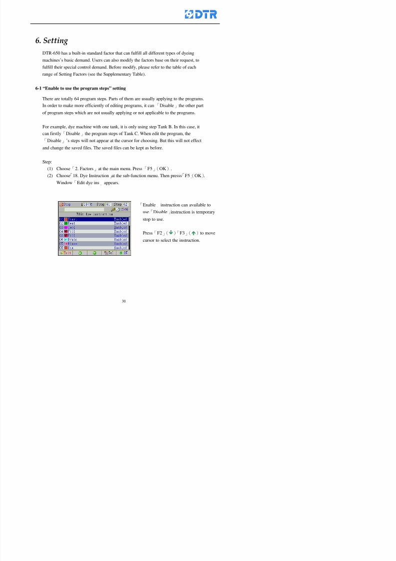
8132019 DTR 650 User Manual
httpslidepdfcomreaderfulldtr-650-user-manual 3070
6 983123983141983156983156983145983150983143DTR-650 has a built-in standard factor that can fulfill all different types of dyeing
machinesrsquos basic demand Users can also modify the factors base on their request to
fulfill their special control demand Before modify please refer to the table of each
range of Setting Factors (see the Supplementary Table)
6-1 ldquoEnable to use the program stepsrdquo setting
There are totally 64 program steps Parts of them are usually applying to the programs
In order to make more efficiently of editing programs it can「Disable」the other part
of program steps which are not usually applying or not applicable to the programs
For example dye machine with one tank it is only using step Tank B In this case itcan firstly「Disable」the program steps of Tank C When edit the program the
「Disable」rsquos steps will not appear at the cursor for choosing But this will not effect
and change the saved files The saved files can be kept as before
Step
(1) Choose「2 Factors」at the main menu Press「F5」(OK)(2) Choose「18 Dye Instruction」at the sub-function menu Then presss「F5」(OK)
Window「Edit dye ins」appears
「Enable」instruction can available to
use「Disable」instruction is temporarystop to use
Press「F2」()「F3」()to move
8132019 DTR 650 User Manual
httpslidepdfcomreaderfulldtr-650-user-manual 3170
6-2 ldquoAllow to modify dye program temporary during operatingrdquo Setting
During dye program running it can modify dye program temporary Thesemodification will not disappear by causing a sudden power interruption or power off
until select another new dye program to run
Please note that it is only for modifying the dye program temporary That program
file would not saved due to the modification If need to modify the program file and
save choose the function of Edit Dye Program to edit (Refer to the Charper 5 for the【Edit Dye Prograrm】)
6-2-1 ldquoAllow to modify all dye programsrdquo Setting
Step
(1) Choose「2 Factors」at the main menu Press「F5」(OK)
(2) Choose「02 System Factor」at the sub-function menu Then presss「F5」(OK)
Window「Edit System Factor」appears
Set to stop using temporary the「07
Rinse」press「F4」(Sel)to set it as Disable
Repeat above steps to complete all setting
Press 「F1」(Exit)to return to main menu
8132019 DTR 650 User Manual
httpslidepdfcomreaderfulldtr-650-user-manual 3270
6-2-2 ldquoAllow to modify part of dye programsrdquo Setting
【Eg】Set the number 08 or above (including number 08) is allowing to modify dye
programs during operating
Step
A Refer to【6-2-1】setting the factor as「22」to allow editing dye program
temporary during operating
(4) Press「3」「4」to edit the setting
as「Enable」 and press「F5」(OK)
Restore the standard factor by
pressing「F3」(Clr)
(5) Exit to press「F1」(Exit)and
return to window of 「Main Menu」
8132019 DTR 650 User Manual
httpslidepdfcomreaderfulldtr-650-user-manual 3370
6-2-3 ldquoAllow to modify dye steps temporaryrdquo Setting
After setting the dye programs are allowed to edit it also can set which dye steps are
allowed to edit temporary during operating
Step
(1) Choose「2 Factors」at the main menu Press「F5」(OK)
(2) Choose「19 Dye Ins control」at the sub-function menu Then presss「F5」
(OK) Window「Edit ins mode」appears
「Enable」 Allow to edit that dye step before
operating
「Disable」 Not allow to edit dye step before
operating
(3) Press「」「」to move cursor
to choose dye step Press「F4」
To enter to the「Edit dye program」from the
function menu there is a「」in front of the
file name「0-7」 means that program is not
allowing to edit during operating
8132019 DTR 650 User Manual
httpslidepdfcomreaderfulldtr-650-user-manual 3470
6-2-4 ldquoSet the dye step to keep running from the interrupt pointrdquo setting
When the dye program is operating it will disappear by causing power
interruption or sudden power off When start running again part of dye steps can
run again from the interrupt point part of them cannot
How to set
(1) Choose「2Factors」in the main menu and press「F5」(OK)
(2) Choose「20Continue mode」in the sub-function menu Press「F5」(OK) to
enter window of 「Continue Setting」
(3) Press「」「」to move cursor to choose dye steps Press「F4」(Sel)it
shows「Disable」or「Enable」for choosing Press「F5」(OK)to move cursorto the next setting
(4) Repeat above method until all setting is complete press「F1」(Exit)and
return to the main menu
8132019 DTR 650 User Manual
httpslidepdfcomreaderfulldtr-650-user-manual 3570
6-3 ldquoAllow to insert an addition dye stepsrdquo setting
During the program is running can temporary insert an addition dye step or a dye
program according to the operating actual situation Through this setting can set which
dye steps can apply or not to the program in operating
During to insert an addition step if sudden interruption or power off occurred it returns
to the main dye program automatically Before starting again should decide seriously
and set it again by actual needed
Step
(1) Choose「2Factors」at the main menu and press「F5」(OK)
(2) Choose「02System factor」and press「F5」(OK)
(3) Press「」「」to move cursor to the factor「34」and press「3」「4」to set
it as「Enable」 Press「F5」(OK)
(4) Press「F1」(Exit)to return to main menu Choose「21Addition Ins」at the
sub-function menu Press「F5」(OK)to enter the window「Addition Instruction」
(5) Press「」「」to move cursor to choose dye steps and press「F4」(Sel) Cursors
locates shows「Eable」or「Disable」 Press「F5」(OK)to move cursor to the
next dye step
(6) Repeat above method until to complete all setting press「F1」(Exit)and return
to the main menu
8132019 DTR 650 User Manual
httpslidepdfcomreaderfulldtr-650-user-manual 3670
6-4 Setting the display mode
DTR650 has three types of display mode during operating Program List mode
Schematic Diagram mode and Icon mode Users can set the display mode during
operating by factor setting
It goes back to a Program List mode when dye program ended
Step
(1) Choose「2Factors」at the main menu and press「F5」(OK)
(2) Choose「02System factor」and press「F5」(OK)
(3) Press「F2」()「F3」()to move cursor to choose「32Display mode」Press
「3」「4」 it shows「Online picture」「Instruction」「Big Icon」 choose
「Online picture」(eg) and press「F5」to confirm
8132019 DTR 650 User Manual
httpslidepdfcomreaderfulldtr-650-user-manual 3770
(4) Press「F1」(Exit)to return to the main menu
(5) The Schematic Diagram displays when the program is running (it stays at theProgram List mode when there is an alarm occurred)
Press「F4」to transfer to another display mode
It goes back to a Program List mode from Schematic Diagram Mode when dye
program ended Press numeric key「3」to view Schematic Diagram Mode again
Quit to press「F5」(Exit)
6-5 Adapt the digital input to another functions
DTR-650 has 32(0~31)input terminal it owns an standard setting when the
controller is initial According to the userrsquos demand they can change the DTR-650rsquos
anther functions of Input Terminal and PLC Input channel
The PLC Intputrsquos name can also define by the users (use IBM computer to edit and
download)
How to set
(1) Choose「2 Factor」at the main menu Press「F5」(OK)
(2) Choose「22 Input table」at the sub-function menu and press「F5」(OK)to enter
「Edit input table」
The actual input
terminal of theIBM computer
PLCrsquos input channel
8132019 DTR 650 User Manual
httpslidepdfcomreaderfulldtr-650-user-manual 3870
6-6 Adapt the digital output to another functions
DTR-650 has 32(0~31)output terminals it owns an standard setting when thecontroller is initial According to the userrsquos demand they can adapte the digital output
and the PLC outputrsquos channel to another functions The PLC Output channelrsquos name
can also define by users (use IBM computer to edit and download)
Step
(1) Choose「2 Factor」at the main menu Press「F5」(OK)
(2) Choose「23 Output table」at the main menu and press「F5」(OK)
(3) Press「F2」()「F3」()to move cursor to choose the output terminal atthe left side of the window Press「F5」(Add) the PLCrsquos output channelrsquos
name is listing at the right side of the window
(4) Press「F2」()「F3」()to move cursor to choose the PLC outputrsquos channel
If cursor moves to the PLC output channel which already linking「Add」is
not for choosing that means that output channel is already occupied
(5) Confirm the connection to press「F5」(Add) Quit to press「F4」(Del)Press「F1」(Exit)when complete all setting and return to main menu
The actual output
terminal of the
IBM computer
PLCrsquos output channel
8132019 DTR 650 User Manual
httpslidepdfcomreaderfulldtr-650-user-manual 3970
983095 983109983140983145983156983145983150983143 983156983144983141 983110983137983139983156983151983154983155DTR-650 has several kinds of control factors
Userrsquos factors System factors Temperature Control factors Speed factors Dosing
factors PID factors Analog Input Output factors standard factors etchellipPlease refer
to the supplementary table for the setting range and standard of the factors
DTR-650 has a built-in standard factor Users can edit by themselves if necessary
7-1 Modifying userrsquos factors
Userrsquos factors is setting with the Dyeing machinesrsquos PLC Programrsquos factor it is define by
the PLC Programmer
Step to edit
(1) Choose「2Factors」at main menu Press「F5」(OK)
(2) Choose「01User Factor」Press「F5」(OK)
(3) Press「F2」()「F3」()「6」「5」to move cursor up down and by page
Choose a factor need to edit then press「3」「4」to set itrsquos value Press「F5」(OK) Cursor moves to the next factor
(4) Some of factors can input numbers by the numeric membrance keys to edit If
the input is incorrect it turns to red and means the edit is not available
8132019 DTR 650 User Manual
httpslidepdfcomreaderfulldtr-650-user-manual 4070
Modifyrsquos method of the system factors temperature factors speed factors dosingfactors PID factors analog Input output factors standard factors etchellipare same asabove
If apply the library of DTR500 and DTR600 into the DTR650 the key「3」「4」may not valid to use Please use the numeric keys instead of it to key in factors itmay not effect the normal operation
Please pay a serious attention and read carefully at the factorrsquos table before modify the factors An incorrect value may effect the DTR-650 Dyeing
Machine Controllerrsquos operating After modifying factors must cancel the
password and secure data
7-2 Loading the standard factors
After modifying factors if need to restore a manufacturerrsquos standard factors of
DTR-650 The method as follows
1 Choose「2Factors」at main menu Press「F5」(OK)
「 「 ( ) 「
8132019 DTR 650 User Manual
httpslidepdfcomreaderfulldtr-650-user-manual 4170
7-3 Copying the factor
Users can build up a set of factor by themselves and make a copy and save
Step
1 Choose「2Factors」at main menu Press「F5」(OK)
2 Choose「13Restore Factor」 press「F5」(OK) window「factor will be
overwrite 」
3 Press「F4」(Yes)copy finished and saved Return to the main menu
4 Press「F2」(No)to not copy the factor and the existing factor is not change Return
to the main menu
7-4 Loading the backup factors
Users can build up a set of factor and backup files to load to DTR-650
Step1 Choose「14Backup factor」at the sub-function menu Press「F5」(OK)and
window「Factror will be overwrite」appears
2 Press「F3」(OK)to load the the backup factor them return to main menu
Press「F2」(No)to not copy the factor and the existing factor is not change
Return to the main menu
8132019 DTR 650 User Manual
httpslidepdfcomreaderfulldtr-650-user-manual 4270
983096 983119983157983156983152983157983156 983124983141983155983156983145983150983143
Before the output testing must be complete the steps as follows
A Cut off all connecting line of output terminal of DTR-650
B Stop running the PLC
C Check up the connections of all output channels to avoid damages from
incorrect connections
D Check up state of dyeing machines include the temperature pressure valves
onoff and pumpshellipetc ensure the safety for priority
8-1 Testing the Digital output
Step
1 Choose「3Output Testing」at the main menu Press「F5」(OK) 2 Choose「1Digital」at the sub function menu Press「F5」(OK) window「Digital
output testing」appears
3 Press「」「」「」to move cursor to each output channels Press「F5」(OK)
Output Name
8132019 DTR 650 User Manual
httpslidepdfcomreaderfulldtr-650-user-manual 4370
8-2 Testing the Analog output
(1) Choose「3Output Testing」at the main menu Press「F5」(OK)
(2) Choose「2Analog」at the sub function menu Press「F5」(OK) window「Analog output testing」appears
(3) Press「」「」「」to move cursor to each channels Then key in number by
the numeric membrance keys (range0~200= 0~20mA) Press「F5」(OK) there
is a output current relating to the output channel
(4) Press「F5」(OK) There is an output when the output channel with red light No
output without light onl(5) When complete the testing press「F1」(OK)to return to the main menu
8132019 DTR 650 User Manual
httpslidepdfcomreaderfulldtr-650-user-manual 4470
983097 983107983137983148983145983138983154983137983156983145983151983150
DTR-650 has Dosing and Temperature calibration
When enter to Dosing calibration must be set the Low Volume calibration first and
then High Volume calibration When enter to Temperature calibration must be set the
Low Temperature calibration first and then High Temperature calibration Must be
hightly follow this orders seriously
9-1 Calibration of Low Volume Tank
Step
A Choose「4Calibration」at the main menu Press「F5」(OK)
B Choose「Dosing 0 low vol」at the sub function menu Press「F5」(OK) window
appears
C Fill the Dosing Tank to a half level input value shows how much the water level
If it stays ldquo0rdquo check the connection and the factor setting is correct or not
And connect the pressure sensorrsquos output channel to the Current Meter to ensure
that sensor works or not
8132019 DTR 650 User Manual
httpslidepdfcomreaderfulldtr-650-user-manual 4570
D Fill the Dosing Tank to 50ml (Calcalate from the bottom side of the pressure
sensor steel tube) input value should show 4~6 (input value must between
0~10) Then enter the water volume The setting volume is relating the water
levelrsquos water value (litre as unit) input range 0~80 Set as「 「「 「0000 0000 0000 0000」」」」is strongly is strongly is strongly is strongly
receommend receommend receommend receommend Press「F5」(OK)to complete [Calibration of Low Volume Tank 1
is same as above method]
9-2 Calibration of High Volume Tank
Step
A Choose「4Calibration」at the main menu Press「F5」(OK)
B Choose「Dos 0 high vol」at the sub function menu Press「F5」(OK) window of
「Calibrate high 」appears
C Fill the Dosing Tank to a full level input value should be larger than 30 enter
the current water level which relates to the water volume Enter the range within
100~2500 Then press「F5」(OK) to complete the calibrate the high volume tank
8132019 DTR 650 User Manual
httpslidepdfcomreaderfulldtr-650-user-manual 4670
9-3 Temperature Calibration
Step
A This function is for adjusting the DTR650rsquos accuracy of Temperature Control It
must be using with the special terminal which is only for DTR650
B Choose「4Calibration」at the main function menu and press「F5」(OK)
C Choose「3Low Temp」at the sub-function menu Press「F5」(OK)and《Fig9-3》
appears insert the DTR650rsquos low temperature calibration terminal to the temperature
input terminal wait for the jumping value to stable down then press「F5」(OK) then
to adjust the high temperature calibration
D Adjusting the High Temperature Calibrationrsquos method is same as above But usersusersusersusers
must be using the High Temperature Terminalmust be using the High Temperature Terminalmust be using the High Temperature Terminalmust be using the High Temperature Terminal whichwhichwhichwhich is specially for DTR650 onlyis specially for DTR650 onlyis specially for DTR650 onlyis specially for DTR650 only
《Fig 9-3》
8132019 DTR 650 User Manual
httpslidepdfcomreaderfulldtr-650-user-manual 4770
10 983122983141983139983151983154983140983155 983151983142 983108983161983141 983120983154983151983143983154983137983149983155
It contains the past 15 days of temperature curves of running history
Checking method
(1) Choose「5Dye Record」at main menu press「F5」(OK)
(2) Sub-function menu shows the set up date of the past 15 days dye programs
Listing by the lastest set up date
(3) Choose a program date and press「F5」(OK) it appears window「Temp
record」
(4) Press「」「」to move the white line in the box one minute by moving once
(5) Press「3」「4」to move the line to check the time period 2 hours by moving once
The yellow selecting line of the「24 hours operating state」is repectively moving
The curve info is show in the curve box Left side of the widnow appears the
relating running info the time is the time value of the line locates at
(6) Check more details of the temperature info to press numeric key「middot」 a bright red line
appears in the selecting box this line is to check the starting point of the
temperature inforsquos time period Then press「」to move the white line to the end
point of the time period The temperature info between the starting point and end
point are appears at the right side of the window Press「middot」to return to the preious
curve page
(7) Check more details of the alarm infor To perss numeric key「7」「9」 the alarmrsquos
details is listing by orders
(8) Press「F1」(exit) to return
8132019 DTR 650 User Manual
httpslidepdfcomreaderfulldtr-650-user-manual 4870
11 983125983155983137983143983141 983151983142 983117983141983149983151983154983161 983107983137983154983140
DTR-650 supports 32MB or above Compact Flash Card which can transfer and save all
information for 4 sets of DTR-650 Including library files schematic diagram icon
image PLC program dye program factor and confiruration files etchellip Use the CF Card
to up download and swap the information of DTR-650 promptly install the relating
device and program updates
DTR-650 CF Card with bank 1 to bank 4 can save 4 sets information of Dyeing
Machines When download or save files should choose the BANK first
《Fig11-1》
8132019 DTR 650 User Manual
httpslidepdfcomreaderfulldtr-650-user-manual 4970
11-1 Downloading data
1 Firmly insert the CF card into the DTR-650rsquos PCMCIA connector Ensure it is
wholely and firmly inserted if the card is not totally inserted or the card do not
touch in all to the connector there will be an error occurred and cannot
updownload or interrupted during operation
2 Choose「6Memory Card」at the main menu and press「F5」(OK) 《Fig11-1》
appears Information of Bank「1」shows at the left hand side of the window press
number 1-4 by using numeric keys to choose the BANK Check the
information in the Bank seriously which is exactly need to download to the
DTR650
3 Press()()「6」「5」to move cursor to the sub-function menu to choose
the downloading items Press「F5」(OK) window appears「Stop PLC run before
access memory card Stop the PLC run」 Press「F5」(YES) to stop PLC
running
4 Press「F5」(OK) window appears Confirm to update or not the DTR-650rsquos
information As that downloading will be replace the DTR-650rsquos information
(that means the existing information of the DTR-650 will be removed and
replaced)
5 Press「F4」(YES)to download the information from the DTR-650 to the CF
Card Return to the main menu when finish
8132019 DTR 650 User Manual
httpslidepdfcomreaderfulldtr-650-user-manual 5070
Ensure inserting firmly the CF card into the DTR-650 unless it will cause
error or cannot Updownload data
Never remove CF card during transferring or updownloading data Until it
is all completed
DTR-650rsquos dyeing program is not compatible with DTR-500 and
DTR-600 Never use CF card to transfer data among them
11-2 Storing and transfering data
1 Insert the CF Card to the DTR-650
2 Choose「6Memory Card」at the main menu and press「F5」(OK) 《Fig11-1》
appears Left hand side of the window shows the data of BANK 1 press numeric
keys 1-4 to select the BANK To confirm the put the data in the DTR-650 to the CF
Card The existing data of that bank will be replaced and covered by the new data (if
that bank is already occuplied)
3 Choose「23Save Dye prog」(Example)at the sub-funciton menu press「F5」(OK)to confirm Window「Update memory card data」appears
4 Press「F5」(OK)to transfer the data to the CF card Return to the main menu
5 Put the CF card into another DTR-650 and follow the operating method of 「11-1
Downloading data」」」」can transfer and swap data with more than one set of
DTR-650
8132019 DTR 650 User Manual
httpslidepdfcomreaderfulldtr-650-user-manual 5170
12 983123983156983137983156983141 983137983150983140 983113983150983142983151983154983149983137983156983145983151983150
The state and information is including the Dyeing Machinersquos state of Digit Input output
Analog Input output Temperature control PID Dosing PID Pressure different PID
software system information and alarm record This information is for checking at any
time
12-1 Input Output state
Step
1 Choose「7Info and state」at main menu and press「F5」(OK)
2 Choose「01Digital IO put」at the sub-function menu then press「F5」(OK)
「Digital In Out State」0=None 1=Input
3 Press「F1」(Exit)to return to main menu
Same method for checking the temperature control analog dosing pressure
different etchellip
12-2 Checking the system information
Step
1 Choose「7Info and state」at main menu and press「F5」(OK)
2 Choose「11 System info」at sub-function field press「F5」(OK)Window
「System Information」appear
System information is including System info(software version) Library doc
Icon files Schematic file Definition file hardare state Config File Commandinstruction icon PLC file etc
8132019 DTR 650 User Manual
httpslidepdfcomreaderfulldtr-650-user-manual 5270
12-3 Checking the operating alarm record
Operating record shows the latest 40 operating items and alarm records including
the time and content of the alarm
A) Choose「7 Info and state」
and press「F5」(OK)
B) Choose「12Alarm logs」at
the sub-funciton menu then
press「F5」(OK)
8132019 DTR 650 User Manual
httpslidepdfcomreaderfulldtr-650-user-manual 5370
13 983105983140983146983157983155983156983145983150983143 983156983144983141 983107983151983150983156983154983137983155983156
The displaysrsquos brightness can be adjusted if necessary
Step
1 Choose「8Others」at main menu press「F5」(OK)
2 Choose「01Contrast」at sub-function menu press「F5」(OK) window「Set
Contrast」appears
3 Press「」「」to move the bar to set the brightness then press「F5」(OK)Window appears「Please reboot the system」
4 Press「F5」(OK)to return to main menu and re-boot the DTR-650 to complete
adjusting the brightness
8132019 DTR 650 User Manual
httpslidepdfcomreaderfulldtr-650-user-manual 5470
14 983123983156983151983152 983154983157983150983150983145983150983143 983156983144983141 983120983116983107 983120983154983151983143983154983137983149
Before testing the Input output testing transfer of the PLC program must stop the PLC
running
Step
1 Choose「8Others」at the main menu Press「F5」(OK)
2 Choose「04 PLC Stop」at sub-function menu Press「F5」(OK) window
「Password」appears
3 Enter password and press「F5」(OK) Window「Stop the PLC run」appears
4 Press「F4」(Yes)and window「PLC Stop」appear Press「F5」(OK) Now
the PLC is stop running and return to the main menu
All testing cannot operate when the PLC is running
Editing dye program and the relating operation can
perform with the PLC running together
8132019 DTR 650 User Manual
httpslidepdfcomreaderfulldtr-650-user-manual 5570
15 983123983141983156983156983145983150983143 983156983144983141 983156983145983149983141
Step
1 Press「8Others」at the main menu Press「F5」(OK)
2 Choose「10Set date time」at the sub-function menu Press「F5」(OK) window
「Set date time」appears
3 Press「F5」(Edit) to move cursor by 「3」「4」 enter the time value at the
cursor locates
4 Press「F5」(OK)to complete the modify Press「F1」(Exit)to return to main
menu
5 Press「F1」(Exit)if not modify and return to main menu
8132019 DTR 650 User Manual
httpslidepdfcomreaderfulldtr-650-user-manual 5670
1166 983123983123983157983157 983152 983152 983152 983152983148983148983141983141983149983149983141983141983150983150983156 983156 983137983137983154 983154 983161983161 983124 983124 983137983137983138983138983148983148983141983141
TTTTTTTTaaaaaaaabbbbbbbblllllllleeeeeeee 11111111 【Dye Instruction】
Code Icon Instruction Code Icon Instruction
000 End 016 Inject C
001 Start 017 Dosing BV
002 Heat 018 PH
003 Cool 019 Addsalt B
004 Flow Fill 020 Addsalt C
005 Level Fill 021 Ana Fill
006 Drian 022 Lock Fill007 Rinse 023 Lock Level
008 Run 024 Low Rinse
009 Call 025 Cyc Rinse
010 Prep B 026 Rinse B
011 Addsalt B 027 Rinse C
012 Dosing B 028 Temp
013 Inject B 029 Nozzle Pressure
014 Prep C 030 Main Pump
015 Dosing C 031 Pump Speed
8132019 DTR 650 User Manual
httpslidepdfcomreaderfulldtr-650-user-manual 5770
Table 2 【【【【Alarm】】】】
System Alarm Must stop operating and check up to solve problems before restarting
the machine
Running Alarm It is a reminder Not effect the operating of DTR-650
Userrsquos Alarm Total of 32 Users can define themselves and use it when edit the PLC
Program (do not listing below)
No System Alarm No Running Alarm
1 PLC program not running 16 Temp ctrl 0 Grad too slow
2 Main temp sensor error 17 Temp ctrl 0 Grad too fast
3 Not at Run window 18 Temp ctrl 0 Hold temp too low
4 Exceeding max temp 19 Temp ctrl 0 Hold temp too high
5 - 20 Temp ctrl 1 Grad too slow6 - 21 Temp ctrl 1 Grad too fast
7 - 22 Temp ctrl 1 Hold temp too low
8 Communication error 23 Temp ctrl 1 Hold temp too high
9 Slave not answer 24 Temp ctrl 2 Grad too slow
10 PLC 0 not answer 25 Temp ctrl 2 Grad too fast
11 PLC 1 not answer 26 Temp 2 Hold temp too low12 Display not answer 27 Temp 2 Hold temp too high
13 Lower power voltage 28 Temp ctrl 3 Grad too slow
14 - 29 Temp ctrl 3 Grad too fast
15 - 30 Temp3 Hold temp too low
31 Temp3 Hold temp too high
32 Dosing 0 injection too slow
33 Dosing 0 injection too fast
34 Dosing 1 injection too slow
35 Dosing 1 injection too fast
8132019 DTR 650 User Manual
httpslidepdfcomreaderfulldtr-650-user-manual 5870
TTTTTTTTaaaaaaaabbbbbbbblllllllleeeeeeee 33333333 【【【【System factor】】】】
No Description Std Range amp Definition
1 ID No 000 000- 100 Controller no
2 Communication Rate 4800Bps 2400 4800 9600 19200 38400
3 Display language Chinese English Chinese
4 Temp display mode and
5 Maxmium temperature 145 025 ~ 145 6 Type of external PLC Default PLC32DPLC32PLC16Default
7 Number of external PLC NANA 1 unit connect
2 unit connect
8Communication Rate of
PLC9600Bps 2400 4800 9600 19200
9 Set point 1 085 000 ~ 145
If signal source is temperaturethe setting value is thetemperature value If the signal
source is Analog Input 6~17 then
setting value for Analog input is 0 ndash
100 and relates Analog
Input14~020mA
10 Source 1 Sensor0Sensor 0 ~5
Analog input 0 ~1111 Set point 2 092 Same as 09
12 Source 2 PT100 1 Same as 10
13 Set point 3 085 Same as 09
14 Source 3 PT100 2 Same as 10
15 Set point 4 092 Same as 09
16 Source 4 PT100 3 Same as 1017 Set point 5 085 Same as 09
18 Source 5 PT100 4 Same as 10
19 Set point 6 092 Same as 09
8132019 DTR 650 User Manual
httpslidepdfcomreaderfulldtr-650-user-manual 5970
29 Min cyclic time of cloth 100sec 0 ~ 255 sec
30 Max cyclic time of cloth 240sec 0 ~255 sec
31Standard cyclic time of
cloth
180 000 ~ 255 sec
32 Display ModeProgram
List
Program list Schematic Diagram
Icon mode
33 CF card format Standard of
DTR CF
Card
Standard of DTR CF Card V20
Standard CF Card
34 Addition step Disable Disable Enable35 Mode Com 3
CouplingEsure Com 3 is the communication
port of the Central or Coupling
36Com 3 Communication
rate9600 Central communication speed
8132019 DTR 650 User Manual
httpslidepdfcomreaderfulldtr-650-user-manual 6070
TTTTTTTTaaaaaaaabbbbbbbblllllllleeeeeeee 44444444 【【【【Temperature Cotnrol Factor】】】】
No Factor Definition Standard Range and Definition
01 PT No PT-0 PT 0~5 PT-100 Input number
02 Max working temp 140 000~140
03 Output mode 0 0~2
04 Alarm time of gardient 240sec 000~255 sec
05 Alarm mode of gradient Always AlwaysOnceNone
06 Control mode of gradient Heating orCooling
interlocked
Heating and Cooling interlocked
No limitation
07 Alarm range of HoldTemp 03 01~20
08 Alarm time for HoldTemp 240sec 000~255sec
09 Alarm mode of HoldTemp Always AlwaysOnceNone
10 Control mode ofHoldTemp
Heating only Only heating and cooling Cooling whenalarm occurred Only heating andcooling No limitation when alarmHeating only
11 Porportional Band 100 000~250
12 Integral band 128 sec 000~255 sec
13 Differential time 04 sec 00~20 sec
14 Min transit gradient 02 00~50
15 Transit rate 20 times 00~50 times (020= 2 times)
16 PID initial output value 010 000~100
17 ONOFF cycle time 10 sec 05~25 sec
Onoff valve set as 010 sec
Proportional valve set as 020 sec
18 Time down count mode Mode 0 0~10 = The time down count range from「Factor 20 + target temp」to「Target
8132019 DTR 650 User Manual
httpslidepdfcomreaderfulldtr-650-user-manual 6170
TTTTTTTTaaaaaaaabbbbbbbblllllllleeeeeeee 55555555 【【【【Speed Factor】】】】
No Factor Definition Standard Range amp Definition
01 Input Number Speed input 0 Speed input 0~11
02 Average times 05 times 01~10
03 Sensor Number 008pcs 001~255
04 Roller Dimension 250mm 050~500
05 Max cloth speed 200mmin 001~25506 Min cloth speed 020mmin 001~255
07 Alarm delay time 240sec 001~255
08 Alarm mode Every oncenoneevery
09 Alarm range () 020 001~255
10 Proportional band 100 001~255
11 Integer band 128 001~25512 Differential time 000 001~200
13 Initial speed () 020 001~255
14 Control cycle ti(01sec) 05 01~30
15 First cycle time(01sec) 10 01~30
16 Speed increase limit () 010 001~100
17 Speed decrease limit () 010 001~100
18 Min speed() 005 001~100
19 Manual speed adjust () 005 001~100
20 Manual initial speed() 020 001~100
21 Stopping speed() 010 001~100
22 Switch speed() 020 001~100
23 Not used
24 Speed decrease turns 03turns 01~50
8132019 DTR 650 User Manual
httpslidepdfcomreaderfulldtr-650-user-manual 6270
Table 6 【【【【Dosing Factors】】】】
No Description Range Range and Explanation
1 Analog input no Analog input 0 Analog input no 0 ~11
2Alarm delay time for
dosing240 sec 000 ~255 sec
3 Alarm time for dosing Every Every Once None
4 Proportional band 100 000 ~255 sec Factor P
5 Integer band 128 000 ~255 sec Factor I6 Differential time 04 00 ~20 Factor D
7 Max adjust rate 150 50~ 255
8 Initial factor for dosing 10 000 ~100
9 User curve section 0 10 Gradient of sect1 for dosing curve9
10 User curve section 1 10 Gradient of sect2 for dosing curve9
11 User curve section 2 10 Gradient of sect3 for dosing curve9
12 User curve section 3 10 Gradient of sect4 for dosing curve9
13 User curve section 4 10 Gradient of sect5 for dosing curve9
14 User curve section 5 10 Gradient of sect6 for dosing curve9
15 User curve section 6 10 Gradient of sect7 for dosing curve9
16 User curve section 7 10 Gradient of sect8 for dosing curve9
17 User curve section 8 10 Gradient of sect9 for dosing curve9
18 User curve section 9 10 Gradient of sect10 for dosing curve9
19 Min water level 05 00~ 10 04~20mA percentagechange to the userrsquos factor setting
20 Output value for Tank
clean
100 000~ 100
Injected percentage of dosing valve
in dosing End period
This factor will be invalided if usingONOFF dosing valve
21 Full range 100 001~255 Self-adjustment cannotchange
22 Range ratio 001001~255 Self-adjustment cannot
change
8132019 DTR 650 User Manual
httpslidepdfcomreaderfulldtr-650-user-manual 6370
【【【【TTaabbllee 77 】】】】Pressure Deviation Factors
No Description Std Range amp Definition
1 Analog input number + Analog in 0 Analog in 0~11
2 Analog input number - Analog in 1 Analog in 0~11
3 Input mode Pressure Pressure Pressure deviation
4 Full range 050x01Kgcm
001~255
5 Range ratio 001 001~255
6 Alarm delay time 100sec 001~255
7 Alarm mode Every oncenone
8 Alarm range 010 001~255
9 Proportional band 100 001~255
10 Integer band 128 001~255
11 Differential time 00 00~20
12 PID Init output value 010 001~255
13 Cycle time 10 03~30
14 First cycle time 030 003~100
15 Max adjust rate 010 001~100
8132019 DTR 650 User Manual
httpslidepdfcomreaderfulldtr-650-user-manual 6470
【【【【TTaabbllee 88 】】】】Definition of Analog Input
No Description Standard Range and Explanation
01 PT 0 correction standard DIN std DIN std JIS std
02 PT 0 correction +0 +- 9
03 PT 1 correction standard DIN std DIN std JIS std
04 PT 1 correction +0 +- 9
05 PT 2 correction standard DIN std DIN std JIS std
06 PT 2 correction +0 +- 9
07 PT 3 correction standard DIN std DIN std JIS std
08 PT 3 correction +0 +- 9
09 PT 4 correction standard DIN std DIN std JIS std
10 PT 4 correction +0 +- 9
11 PT 5 correction standard DIN std DIN std JIS std
12 PT 5 correction +0 +- 9
13 Analog input 0 define 4 ~ 20mA 0 ndash 20mA 4 ndash 20mA
14 Analog input 0 average times 10 times 01- 20 times
15 Analog input 0 min value 0000 0000 - 1000
16 Analog input 0 max value 100 0001 - 9999
17-60 Analog input 1~11 Same as Analog input 0
【【【【 】】】】 fi i i f A O
8132019 DTR 650 User Manual
httpslidepdfcomreaderfulldtr-650-user-manual 6570
【【【【TTaabbllee 99 】】】】Definition of Analog Output
No Description Standard Range and explanation
61 Analog output 0 define Control byPLC
Control by PLC
Temperature control PID0 output
Temperature control PID1 output
Temperature control PID2 output
Speed PID3 output
Dosing PID0 output Dosing PID1output
Pressure different PID0 outputPressure different PID1 output
Main temperature output
62 Mode of Analog ouptput0 4 ~20mA 0 ndash20mA 4 ndash 20mA
63-84 Analog output 1~11 Same as Analog output 0
【【【【TTaabbllee 1100】】】】Value Table 0 amp 1
No Description Range Std Range and explanation
1 Analog input no 000~011 000 Analog input no
2 Data ratio 001~255 100 Multiple by factors
3~53 0~98 000~255 000-100 Analog input 0~98 data
【【【【 】】】】St t Li t
8132019 DTR 650 User Manual
httpslidepdfcomreaderfulldtr-650-user-manual 6670
【【【【TTaabbllee 1111】】】】State List
No Description Range Standard Range and explanation
1 Display setting 1 0~255 205 See remarks at next page
2 Display setting 2 0~255 208
3 Display setting 3 0~255 209
4 Display setting 4 0~255 017
5 Display setting 5 0~255 0186 Display setting 6 0~255 019
7 Display setting 7 0~255 020
8 Display setting 8 0~255 021
9 Display setting 9 0~255 000
10 Display setting 1 0~255 000
11 Display setting 2 0~255 000
12 Display setting 3 0~255 000
13 Display setting 4 0~255 000
14 Display setting 5 0~255 000
15 Display setting 6 0~255 000
16 Display setting 7 0~255 000
Remarks
8132019 DTR 650 User Manual
httpslidepdfcomreaderfulldtr-650-user-manual 6770
0 = No display 1~255 = Display type of number
1~16 Content of PLC VB0~15
No 1 corresponding to VB0
No 16 corresponding to VB15
17~32 Content of PLC DB0~15
No 17 corresponding to DB0
No 32 corresponding to DB15
33~46 Content of PLC CNT0~29
No 33 corresponding to CNT0
No 46 corresponding to CNT29 47~78 Content of dyeing instruction 0~31 CNT0
No 47 corresponding to system instruction to No 0 of CNT0
No 78 corresponding to system instruction to No 31 of CNT0rsquos content
79~110 Dyeing instruction 0~31 of CNT0rsquos setting
111~142 Content of Dyeing instruction 0~31 CNT1No 111 corresponding to dyeing instruction No 0 of CNT1
No 142 corresponding to dyeing instruction No 31 of CNT1rsquos content
143~174 Dyeing instruction 0~31 of CNT1rsquos setting
175~204 Content of PLC HTIM0~29
No 175 corresponding to HTIM0
No 204 corresponding to HTIM29
205 Loading
206 Ratio 1
207 Ratio 2208 Ratio 1 x Loading
209 Ratio 2 x Loading
210 Fix value
211 Value Table 1 matching result
212 Value Table 2 matching result
213 Value Table 1 setting214 Value Table 2 setting
215 Pressure control PID0 different pressure value
216 Pressure control PID1 different pressure value
TTTTTTTTaaaaaaaabbbbbbbblllllllleeeeeeee 1122 【【【【Usage of password】】】】
8132019 DTR 650 User Manual
httpslidepdfcomreaderfulldtr-650-user-manual 6870
No Main FunctionFactor Sub Function Factor Password Rank
1 Run None
2 Dye program User3 or above
3 Control factor
- User factor User 1
- System factor User 1
- Temp PID 0
- Temp PID 1 User 1- Speed PID 0 User 1
- Dosing PID 0 User 1
- Dosing PID 1 User 1
- Pressure PID 0 User 1
- Pressure PID 1 User 1
- Analog IO User 1
- Load standard factor User 2 or above- Load a copied factor User 2 or above
- Copy factor User 2 or above
- Value table 0 User 1
- Value table 1 User 1
- Information and state User 1
- Dye instruction User 1
- Edit dye instruction setting User 14 Output testing User 2 or above
5 Calibration User 2 or above
6 Dye record None
7 CF card User 1
8 Info and state None
9 Others
- Contrast User3 or above
- Data Locking None
- PLC Run User 1
- PLC Stop User 1
- Password setting User 1
TTTTTTTTaaaaaaaabbbbbbbblllllllleeeeeeee 1133 【【【【Technical Data】】】】
8132019 DTR 650 User Manual
httpslidepdfcomreaderfulldtr-650-user-manual 6970
TTTTTTTTaaaaaaaabbbbbbbblllllllleeeeeeee 1133 【【【【Technical Data】】】】
1 Temperature Control
- Range 10~145(plusmn1)
- Mode Proportional or PWM
- Sensor PT100 (JIS or DIN standard)
2 Input and output channel
- Digital Input 32 DC24V PNP- Digital Output 32 DC24V 054A Relay connect point
- Analog Input 4 04~20 mA
- Analog Output 4 0~20mA 或 4~20 mA
3 Communication port 3 RS-232 amp 0~20 mAx1 RS485x 2
4 Dye program
- Number 15000 Steps
- Standard step 61Heating Cooling Fill Drain RinseDosingetc
5LCD module and Display
langage
Chinese
English
320 x 240 TFT color display with
more language
6 CF card connector 1 PCMCIA standard
7 Membrane Keyboard- Number Key 10 [0]~[9] Input factors
- Function Key 5 [F1]~[F5] function selecting
- Operation Key 2 [Start] [Stop]
- Auxiliary Key 7 [][][][][Esc] [larr][OK] [bull]
8 Operating Condition
- Temperature 5~45
- Humidity ≦85 (25)
9 Power supply
V l DC 24V
8132019 DTR 650 User Manual
httpslidepdfcomreaderfulldtr-650-user-manual 7070
70
983108983124983122983085650 983113983150983152983157983156 983119983157983156983152983157983156 983120983151983154983156983145983150983143 (983138983137983139983147983155983145983140983141 983158983145983141983159)
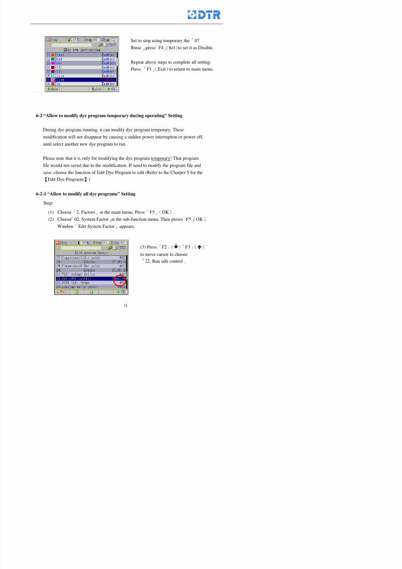
8132019 DTR 650 User Manual
httpslidepdfcomreaderfulldtr-650-user-manual 3170
6-2 ldquoAllow to modify dye program temporary during operatingrdquo Setting
During dye program running it can modify dye program temporary Thesemodification will not disappear by causing a sudden power interruption or power off
until select another new dye program to run
Please note that it is only for modifying the dye program temporary That program
file would not saved due to the modification If need to modify the program file and
save choose the function of Edit Dye Program to edit (Refer to the Charper 5 for the【Edit Dye Prograrm】)
6-2-1 ldquoAllow to modify all dye programsrdquo Setting
Step
(1) Choose「2 Factors」at the main menu Press「F5」(OK)
(2) Choose「02 System Factor」at the sub-function menu Then presss「F5」(OK)
Window「Edit System Factor」appears
Set to stop using temporary the「07
Rinse」press「F4」(Sel)to set it as Disable
Repeat above steps to complete all setting
Press 「F1」(Exit)to return to main menu
8132019 DTR 650 User Manual
httpslidepdfcomreaderfulldtr-650-user-manual 3270
6-2-2 ldquoAllow to modify part of dye programsrdquo Setting
【Eg】Set the number 08 or above (including number 08) is allowing to modify dye
programs during operating
Step
A Refer to【6-2-1】setting the factor as「22」to allow editing dye program
temporary during operating
(4) Press「3」「4」to edit the setting
as「Enable」 and press「F5」(OK)
Restore the standard factor by
pressing「F3」(Clr)
(5) Exit to press「F1」(Exit)and
return to window of 「Main Menu」
8132019 DTR 650 User Manual
httpslidepdfcomreaderfulldtr-650-user-manual 3370
6-2-3 ldquoAllow to modify dye steps temporaryrdquo Setting
After setting the dye programs are allowed to edit it also can set which dye steps are
allowed to edit temporary during operating
Step
(1) Choose「2 Factors」at the main menu Press「F5」(OK)
(2) Choose「19 Dye Ins control」at the sub-function menu Then presss「F5」
(OK) Window「Edit ins mode」appears
「Enable」 Allow to edit that dye step before
operating
「Disable」 Not allow to edit dye step before
operating
(3) Press「」「」to move cursor
to choose dye step Press「F4」
To enter to the「Edit dye program」from the
function menu there is a「」in front of the
file name「0-7」 means that program is not
allowing to edit during operating
8132019 DTR 650 User Manual
httpslidepdfcomreaderfulldtr-650-user-manual 3470
6-2-4 ldquoSet the dye step to keep running from the interrupt pointrdquo setting
When the dye program is operating it will disappear by causing power
interruption or sudden power off When start running again part of dye steps can
run again from the interrupt point part of them cannot
How to set
(1) Choose「2Factors」in the main menu and press「F5」(OK)
(2) Choose「20Continue mode」in the sub-function menu Press「F5」(OK) to
enter window of 「Continue Setting」
(3) Press「」「」to move cursor to choose dye steps Press「F4」(Sel)it
shows「Disable」or「Enable」for choosing Press「F5」(OK)to move cursorto the next setting
(4) Repeat above method until all setting is complete press「F1」(Exit)and
return to the main menu
8132019 DTR 650 User Manual
httpslidepdfcomreaderfulldtr-650-user-manual 3570
6-3 ldquoAllow to insert an addition dye stepsrdquo setting
During the program is running can temporary insert an addition dye step or a dye
program according to the operating actual situation Through this setting can set which
dye steps can apply or not to the program in operating
During to insert an addition step if sudden interruption or power off occurred it returns
to the main dye program automatically Before starting again should decide seriously
and set it again by actual needed
Step
(1) Choose「2Factors」at the main menu and press「F5」(OK)
(2) Choose「02System factor」and press「F5」(OK)
(3) Press「」「」to move cursor to the factor「34」and press「3」「4」to set
it as「Enable」 Press「F5」(OK)
(4) Press「F1」(Exit)to return to main menu Choose「21Addition Ins」at the
sub-function menu Press「F5」(OK)to enter the window「Addition Instruction」
(5) Press「」「」to move cursor to choose dye steps and press「F4」(Sel) Cursors
locates shows「Eable」or「Disable」 Press「F5」(OK)to move cursor to the
next dye step
(6) Repeat above method until to complete all setting press「F1」(Exit)and return
to the main menu
8132019 DTR 650 User Manual
httpslidepdfcomreaderfulldtr-650-user-manual 3670
6-4 Setting the display mode
DTR650 has three types of display mode during operating Program List mode
Schematic Diagram mode and Icon mode Users can set the display mode during
operating by factor setting
It goes back to a Program List mode when dye program ended
Step
(1) Choose「2Factors」at the main menu and press「F5」(OK)
(2) Choose「02System factor」and press「F5」(OK)
(3) Press「F2」()「F3」()to move cursor to choose「32Display mode」Press
「3」「4」 it shows「Online picture」「Instruction」「Big Icon」 choose
「Online picture」(eg) and press「F5」to confirm
8132019 DTR 650 User Manual
httpslidepdfcomreaderfulldtr-650-user-manual 3770
(4) Press「F1」(Exit)to return to the main menu
(5) The Schematic Diagram displays when the program is running (it stays at theProgram List mode when there is an alarm occurred)
Press「F4」to transfer to another display mode
It goes back to a Program List mode from Schematic Diagram Mode when dye
program ended Press numeric key「3」to view Schematic Diagram Mode again
Quit to press「F5」(Exit)
6-5 Adapt the digital input to another functions
DTR-650 has 32(0~31)input terminal it owns an standard setting when the
controller is initial According to the userrsquos demand they can change the DTR-650rsquos
anther functions of Input Terminal and PLC Input channel
The PLC Intputrsquos name can also define by the users (use IBM computer to edit and
download)
How to set
(1) Choose「2 Factor」at the main menu Press「F5」(OK)
(2) Choose「22 Input table」at the sub-function menu and press「F5」(OK)to enter
「Edit input table」
The actual input
terminal of theIBM computer
PLCrsquos input channel
8132019 DTR 650 User Manual
httpslidepdfcomreaderfulldtr-650-user-manual 3870
6-6 Adapt the digital output to another functions
DTR-650 has 32(0~31)output terminals it owns an standard setting when thecontroller is initial According to the userrsquos demand they can adapte the digital output
and the PLC outputrsquos channel to another functions The PLC Output channelrsquos name
can also define by users (use IBM computer to edit and download)
Step
(1) Choose「2 Factor」at the main menu Press「F5」(OK)
(2) Choose「23 Output table」at the main menu and press「F5」(OK)
(3) Press「F2」()「F3」()to move cursor to choose the output terminal atthe left side of the window Press「F5」(Add) the PLCrsquos output channelrsquos
name is listing at the right side of the window
(4) Press「F2」()「F3」()to move cursor to choose the PLC outputrsquos channel
If cursor moves to the PLC output channel which already linking「Add」is
not for choosing that means that output channel is already occupied
(5) Confirm the connection to press「F5」(Add) Quit to press「F4」(Del)Press「F1」(Exit)when complete all setting and return to main menu
The actual output
terminal of the
IBM computer
PLCrsquos output channel
8132019 DTR 650 User Manual
httpslidepdfcomreaderfulldtr-650-user-manual 3970
983095 983109983140983145983156983145983150983143 983156983144983141 983110983137983139983156983151983154983155DTR-650 has several kinds of control factors
Userrsquos factors System factors Temperature Control factors Speed factors Dosing
factors PID factors Analog Input Output factors standard factors etchellipPlease refer
to the supplementary table for the setting range and standard of the factors
DTR-650 has a built-in standard factor Users can edit by themselves if necessary
7-1 Modifying userrsquos factors
Userrsquos factors is setting with the Dyeing machinesrsquos PLC Programrsquos factor it is define by
the PLC Programmer
Step to edit
(1) Choose「2Factors」at main menu Press「F5」(OK)
(2) Choose「01User Factor」Press「F5」(OK)
(3) Press「F2」()「F3」()「6」「5」to move cursor up down and by page
Choose a factor need to edit then press「3」「4」to set itrsquos value Press「F5」(OK) Cursor moves to the next factor
(4) Some of factors can input numbers by the numeric membrance keys to edit If
the input is incorrect it turns to red and means the edit is not available
8132019 DTR 650 User Manual
httpslidepdfcomreaderfulldtr-650-user-manual 4070
Modifyrsquos method of the system factors temperature factors speed factors dosingfactors PID factors analog Input output factors standard factors etchellipare same asabove
If apply the library of DTR500 and DTR600 into the DTR650 the key「3」「4」may not valid to use Please use the numeric keys instead of it to key in factors itmay not effect the normal operation
Please pay a serious attention and read carefully at the factorrsquos table before modify the factors An incorrect value may effect the DTR-650 Dyeing
Machine Controllerrsquos operating After modifying factors must cancel the
password and secure data
7-2 Loading the standard factors
After modifying factors if need to restore a manufacturerrsquos standard factors of
DTR-650 The method as follows
1 Choose「2Factors」at main menu Press「F5」(OK)
「 「 ( ) 「
8132019 DTR 650 User Manual
httpslidepdfcomreaderfulldtr-650-user-manual 4170
7-3 Copying the factor
Users can build up a set of factor by themselves and make a copy and save
Step
1 Choose「2Factors」at main menu Press「F5」(OK)
2 Choose「13Restore Factor」 press「F5」(OK) window「factor will be
overwrite 」
3 Press「F4」(Yes)copy finished and saved Return to the main menu
4 Press「F2」(No)to not copy the factor and the existing factor is not change Return
to the main menu
7-4 Loading the backup factors
Users can build up a set of factor and backup files to load to DTR-650
Step1 Choose「14Backup factor」at the sub-function menu Press「F5」(OK)and
window「Factror will be overwrite」appears
2 Press「F3」(OK)to load the the backup factor them return to main menu
Press「F2」(No)to not copy the factor and the existing factor is not change
Return to the main menu
8132019 DTR 650 User Manual
httpslidepdfcomreaderfulldtr-650-user-manual 4270
983096 983119983157983156983152983157983156 983124983141983155983156983145983150983143
Before the output testing must be complete the steps as follows
A Cut off all connecting line of output terminal of DTR-650
B Stop running the PLC
C Check up the connections of all output channels to avoid damages from
incorrect connections
D Check up state of dyeing machines include the temperature pressure valves
onoff and pumpshellipetc ensure the safety for priority
8-1 Testing the Digital output
Step
1 Choose「3Output Testing」at the main menu Press「F5」(OK) 2 Choose「1Digital」at the sub function menu Press「F5」(OK) window「Digital
output testing」appears
3 Press「」「」「」to move cursor to each output channels Press「F5」(OK)
Output Name
8132019 DTR 650 User Manual
httpslidepdfcomreaderfulldtr-650-user-manual 4370
8-2 Testing the Analog output
(1) Choose「3Output Testing」at the main menu Press「F5」(OK)
(2) Choose「2Analog」at the sub function menu Press「F5」(OK) window「Analog output testing」appears
(3) Press「」「」「」to move cursor to each channels Then key in number by
the numeric membrance keys (range0~200= 0~20mA) Press「F5」(OK) there
is a output current relating to the output channel
(4) Press「F5」(OK) There is an output when the output channel with red light No
output without light onl(5) When complete the testing press「F1」(OK)to return to the main menu
8132019 DTR 650 User Manual
httpslidepdfcomreaderfulldtr-650-user-manual 4470
983097 983107983137983148983145983138983154983137983156983145983151983150
DTR-650 has Dosing and Temperature calibration
When enter to Dosing calibration must be set the Low Volume calibration first and
then High Volume calibration When enter to Temperature calibration must be set the
Low Temperature calibration first and then High Temperature calibration Must be
hightly follow this orders seriously
9-1 Calibration of Low Volume Tank
Step
A Choose「4Calibration」at the main menu Press「F5」(OK)
B Choose「Dosing 0 low vol」at the sub function menu Press「F5」(OK) window
appears
C Fill the Dosing Tank to a half level input value shows how much the water level
If it stays ldquo0rdquo check the connection and the factor setting is correct or not
And connect the pressure sensorrsquos output channel to the Current Meter to ensure
that sensor works or not
8132019 DTR 650 User Manual
httpslidepdfcomreaderfulldtr-650-user-manual 4570
D Fill the Dosing Tank to 50ml (Calcalate from the bottom side of the pressure
sensor steel tube) input value should show 4~6 (input value must between
0~10) Then enter the water volume The setting volume is relating the water
levelrsquos water value (litre as unit) input range 0~80 Set as「 「「 「0000 0000 0000 0000」」」」is strongly is strongly is strongly is strongly
receommend receommend receommend receommend Press「F5」(OK)to complete [Calibration of Low Volume Tank 1
is same as above method]
9-2 Calibration of High Volume Tank
Step
A Choose「4Calibration」at the main menu Press「F5」(OK)
B Choose「Dos 0 high vol」at the sub function menu Press「F5」(OK) window of
「Calibrate high 」appears
C Fill the Dosing Tank to a full level input value should be larger than 30 enter
the current water level which relates to the water volume Enter the range within
100~2500 Then press「F5」(OK) to complete the calibrate the high volume tank
8132019 DTR 650 User Manual
httpslidepdfcomreaderfulldtr-650-user-manual 4670
9-3 Temperature Calibration
Step
A This function is for adjusting the DTR650rsquos accuracy of Temperature Control It
must be using with the special terminal which is only for DTR650
B Choose「4Calibration」at the main function menu and press「F5」(OK)
C Choose「3Low Temp」at the sub-function menu Press「F5」(OK)and《Fig9-3》
appears insert the DTR650rsquos low temperature calibration terminal to the temperature
input terminal wait for the jumping value to stable down then press「F5」(OK) then
to adjust the high temperature calibration
D Adjusting the High Temperature Calibrationrsquos method is same as above But usersusersusersusers
must be using the High Temperature Terminalmust be using the High Temperature Terminalmust be using the High Temperature Terminalmust be using the High Temperature Terminal whichwhichwhichwhich is specially for DTR650 onlyis specially for DTR650 onlyis specially for DTR650 onlyis specially for DTR650 only
《Fig 9-3》
8132019 DTR 650 User Manual
httpslidepdfcomreaderfulldtr-650-user-manual 4770
10 983122983141983139983151983154983140983155 983151983142 983108983161983141 983120983154983151983143983154983137983149983155
It contains the past 15 days of temperature curves of running history
Checking method
(1) Choose「5Dye Record」at main menu press「F5」(OK)
(2) Sub-function menu shows the set up date of the past 15 days dye programs
Listing by the lastest set up date
(3) Choose a program date and press「F5」(OK) it appears window「Temp
record」
(4) Press「」「」to move the white line in the box one minute by moving once
(5) Press「3」「4」to move the line to check the time period 2 hours by moving once
The yellow selecting line of the「24 hours operating state」is repectively moving
The curve info is show in the curve box Left side of the widnow appears the
relating running info the time is the time value of the line locates at
(6) Check more details of the temperature info to press numeric key「middot」 a bright red line
appears in the selecting box this line is to check the starting point of the
temperature inforsquos time period Then press「」to move the white line to the end
point of the time period The temperature info between the starting point and end
point are appears at the right side of the window Press「middot」to return to the preious
curve page
(7) Check more details of the alarm infor To perss numeric key「7」「9」 the alarmrsquos
details is listing by orders
(8) Press「F1」(exit) to return
8132019 DTR 650 User Manual
httpslidepdfcomreaderfulldtr-650-user-manual 4870
11 983125983155983137983143983141 983151983142 983117983141983149983151983154983161 983107983137983154983140
DTR-650 supports 32MB or above Compact Flash Card which can transfer and save all
information for 4 sets of DTR-650 Including library files schematic diagram icon
image PLC program dye program factor and confiruration files etchellip Use the CF Card
to up download and swap the information of DTR-650 promptly install the relating
device and program updates
DTR-650 CF Card with bank 1 to bank 4 can save 4 sets information of Dyeing
Machines When download or save files should choose the BANK first
《Fig11-1》
8132019 DTR 650 User Manual
httpslidepdfcomreaderfulldtr-650-user-manual 4970
11-1 Downloading data
1 Firmly insert the CF card into the DTR-650rsquos PCMCIA connector Ensure it is
wholely and firmly inserted if the card is not totally inserted or the card do not
touch in all to the connector there will be an error occurred and cannot
updownload or interrupted during operation
2 Choose「6Memory Card」at the main menu and press「F5」(OK) 《Fig11-1》
appears Information of Bank「1」shows at the left hand side of the window press
number 1-4 by using numeric keys to choose the BANK Check the
information in the Bank seriously which is exactly need to download to the
DTR650
3 Press()()「6」「5」to move cursor to the sub-function menu to choose
the downloading items Press「F5」(OK) window appears「Stop PLC run before
access memory card Stop the PLC run」 Press「F5」(YES) to stop PLC
running
4 Press「F5」(OK) window appears Confirm to update or not the DTR-650rsquos
information As that downloading will be replace the DTR-650rsquos information
(that means the existing information of the DTR-650 will be removed and
replaced)
5 Press「F4」(YES)to download the information from the DTR-650 to the CF
Card Return to the main menu when finish
8132019 DTR 650 User Manual
httpslidepdfcomreaderfulldtr-650-user-manual 5070
Ensure inserting firmly the CF card into the DTR-650 unless it will cause
error or cannot Updownload data
Never remove CF card during transferring or updownloading data Until it
is all completed
DTR-650rsquos dyeing program is not compatible with DTR-500 and
DTR-600 Never use CF card to transfer data among them
11-2 Storing and transfering data
1 Insert the CF Card to the DTR-650
2 Choose「6Memory Card」at the main menu and press「F5」(OK) 《Fig11-1》
appears Left hand side of the window shows the data of BANK 1 press numeric
keys 1-4 to select the BANK To confirm the put the data in the DTR-650 to the CF
Card The existing data of that bank will be replaced and covered by the new data (if
that bank is already occuplied)
3 Choose「23Save Dye prog」(Example)at the sub-funciton menu press「F5」(OK)to confirm Window「Update memory card data」appears
4 Press「F5」(OK)to transfer the data to the CF card Return to the main menu
5 Put the CF card into another DTR-650 and follow the operating method of 「11-1
Downloading data」」」」can transfer and swap data with more than one set of
DTR-650
8132019 DTR 650 User Manual
httpslidepdfcomreaderfulldtr-650-user-manual 5170
12 983123983156983137983156983141 983137983150983140 983113983150983142983151983154983149983137983156983145983151983150
The state and information is including the Dyeing Machinersquos state of Digit Input output
Analog Input output Temperature control PID Dosing PID Pressure different PID
software system information and alarm record This information is for checking at any
time
12-1 Input Output state
Step
1 Choose「7Info and state」at main menu and press「F5」(OK)
2 Choose「01Digital IO put」at the sub-function menu then press「F5」(OK)
「Digital In Out State」0=None 1=Input
3 Press「F1」(Exit)to return to main menu
Same method for checking the temperature control analog dosing pressure
different etchellip
12-2 Checking the system information
Step
1 Choose「7Info and state」at main menu and press「F5」(OK)
2 Choose「11 System info」at sub-function field press「F5」(OK)Window
「System Information」appear
System information is including System info(software version) Library doc
Icon files Schematic file Definition file hardare state Config File Commandinstruction icon PLC file etc
8132019 DTR 650 User Manual
httpslidepdfcomreaderfulldtr-650-user-manual 5270
12-3 Checking the operating alarm record
Operating record shows the latest 40 operating items and alarm records including
the time and content of the alarm
A) Choose「7 Info and state」
and press「F5」(OK)
B) Choose「12Alarm logs」at
the sub-funciton menu then
press「F5」(OK)
8132019 DTR 650 User Manual
httpslidepdfcomreaderfulldtr-650-user-manual 5370
13 983105983140983146983157983155983156983145983150983143 983156983144983141 983107983151983150983156983154983137983155983156
The displaysrsquos brightness can be adjusted if necessary
Step
1 Choose「8Others」at main menu press「F5」(OK)
2 Choose「01Contrast」at sub-function menu press「F5」(OK) window「Set
Contrast」appears
3 Press「」「」to move the bar to set the brightness then press「F5」(OK)Window appears「Please reboot the system」
4 Press「F5」(OK)to return to main menu and re-boot the DTR-650 to complete
adjusting the brightness
8132019 DTR 650 User Manual
httpslidepdfcomreaderfulldtr-650-user-manual 5470
14 983123983156983151983152 983154983157983150983150983145983150983143 983156983144983141 983120983116983107 983120983154983151983143983154983137983149
Before testing the Input output testing transfer of the PLC program must stop the PLC
running
Step
1 Choose「8Others」at the main menu Press「F5」(OK)
2 Choose「04 PLC Stop」at sub-function menu Press「F5」(OK) window
「Password」appears
3 Enter password and press「F5」(OK) Window「Stop the PLC run」appears
4 Press「F4」(Yes)and window「PLC Stop」appear Press「F5」(OK) Now
the PLC is stop running and return to the main menu
All testing cannot operate when the PLC is running
Editing dye program and the relating operation can
perform with the PLC running together
8132019 DTR 650 User Manual
httpslidepdfcomreaderfulldtr-650-user-manual 5570
15 983123983141983156983156983145983150983143 983156983144983141 983156983145983149983141
Step
1 Press「8Others」at the main menu Press「F5」(OK)
2 Choose「10Set date time」at the sub-function menu Press「F5」(OK) window
「Set date time」appears
3 Press「F5」(Edit) to move cursor by 「3」「4」 enter the time value at the
cursor locates
4 Press「F5」(OK)to complete the modify Press「F1」(Exit)to return to main
menu
5 Press「F1」(Exit)if not modify and return to main menu
8132019 DTR 650 User Manual
httpslidepdfcomreaderfulldtr-650-user-manual 5670
1166 983123983123983157983157 983152 983152 983152 983152983148983148983141983141983149983149983141983141983150983150983156 983156 983137983137983154 983154 983161983161 983124 983124 983137983137983138983138983148983148983141983141
TTTTTTTTaaaaaaaabbbbbbbblllllllleeeeeeee 11111111 【Dye Instruction】
Code Icon Instruction Code Icon Instruction
000 End 016 Inject C
001 Start 017 Dosing BV
002 Heat 018 PH
003 Cool 019 Addsalt B
004 Flow Fill 020 Addsalt C
005 Level Fill 021 Ana Fill
006 Drian 022 Lock Fill007 Rinse 023 Lock Level
008 Run 024 Low Rinse
009 Call 025 Cyc Rinse
010 Prep B 026 Rinse B
011 Addsalt B 027 Rinse C
012 Dosing B 028 Temp
013 Inject B 029 Nozzle Pressure
014 Prep C 030 Main Pump
015 Dosing C 031 Pump Speed
8132019 DTR 650 User Manual
httpslidepdfcomreaderfulldtr-650-user-manual 5770
Table 2 【【【【Alarm】】】】
System Alarm Must stop operating and check up to solve problems before restarting
the machine
Running Alarm It is a reminder Not effect the operating of DTR-650
Userrsquos Alarm Total of 32 Users can define themselves and use it when edit the PLC
Program (do not listing below)
No System Alarm No Running Alarm
1 PLC program not running 16 Temp ctrl 0 Grad too slow
2 Main temp sensor error 17 Temp ctrl 0 Grad too fast
3 Not at Run window 18 Temp ctrl 0 Hold temp too low
4 Exceeding max temp 19 Temp ctrl 0 Hold temp too high
5 - 20 Temp ctrl 1 Grad too slow6 - 21 Temp ctrl 1 Grad too fast
7 - 22 Temp ctrl 1 Hold temp too low
8 Communication error 23 Temp ctrl 1 Hold temp too high
9 Slave not answer 24 Temp ctrl 2 Grad too slow
10 PLC 0 not answer 25 Temp ctrl 2 Grad too fast
11 PLC 1 not answer 26 Temp 2 Hold temp too low12 Display not answer 27 Temp 2 Hold temp too high
13 Lower power voltage 28 Temp ctrl 3 Grad too slow
14 - 29 Temp ctrl 3 Grad too fast
15 - 30 Temp3 Hold temp too low
31 Temp3 Hold temp too high
32 Dosing 0 injection too slow
33 Dosing 0 injection too fast
34 Dosing 1 injection too slow
35 Dosing 1 injection too fast
8132019 DTR 650 User Manual
httpslidepdfcomreaderfulldtr-650-user-manual 5870
TTTTTTTTaaaaaaaabbbbbbbblllllllleeeeeeee 33333333 【【【【System factor】】】】
No Description Std Range amp Definition
1 ID No 000 000- 100 Controller no
2 Communication Rate 4800Bps 2400 4800 9600 19200 38400
3 Display language Chinese English Chinese
4 Temp display mode and
5 Maxmium temperature 145 025 ~ 145 6 Type of external PLC Default PLC32DPLC32PLC16Default
7 Number of external PLC NANA 1 unit connect
2 unit connect
8Communication Rate of
PLC9600Bps 2400 4800 9600 19200
9 Set point 1 085 000 ~ 145
If signal source is temperaturethe setting value is thetemperature value If the signal
source is Analog Input 6~17 then
setting value for Analog input is 0 ndash
100 and relates Analog
Input14~020mA
10 Source 1 Sensor0Sensor 0 ~5
Analog input 0 ~1111 Set point 2 092 Same as 09
12 Source 2 PT100 1 Same as 10
13 Set point 3 085 Same as 09
14 Source 3 PT100 2 Same as 10
15 Set point 4 092 Same as 09
16 Source 4 PT100 3 Same as 1017 Set point 5 085 Same as 09
18 Source 5 PT100 4 Same as 10
19 Set point 6 092 Same as 09
8132019 DTR 650 User Manual
httpslidepdfcomreaderfulldtr-650-user-manual 5970
29 Min cyclic time of cloth 100sec 0 ~ 255 sec
30 Max cyclic time of cloth 240sec 0 ~255 sec
31Standard cyclic time of
cloth
180 000 ~ 255 sec
32 Display ModeProgram
List
Program list Schematic Diagram
Icon mode
33 CF card format Standard of
DTR CF
Card
Standard of DTR CF Card V20
Standard CF Card
34 Addition step Disable Disable Enable35 Mode Com 3
CouplingEsure Com 3 is the communication
port of the Central or Coupling
36Com 3 Communication
rate9600 Central communication speed
8132019 DTR 650 User Manual
httpslidepdfcomreaderfulldtr-650-user-manual 6070
TTTTTTTTaaaaaaaabbbbbbbblllllllleeeeeeee 44444444 【【【【Temperature Cotnrol Factor】】】】
No Factor Definition Standard Range and Definition
01 PT No PT-0 PT 0~5 PT-100 Input number
02 Max working temp 140 000~140
03 Output mode 0 0~2
04 Alarm time of gardient 240sec 000~255 sec
05 Alarm mode of gradient Always AlwaysOnceNone
06 Control mode of gradient Heating orCooling
interlocked
Heating and Cooling interlocked
No limitation
07 Alarm range of HoldTemp 03 01~20
08 Alarm time for HoldTemp 240sec 000~255sec
09 Alarm mode of HoldTemp Always AlwaysOnceNone
10 Control mode ofHoldTemp
Heating only Only heating and cooling Cooling whenalarm occurred Only heating andcooling No limitation when alarmHeating only
11 Porportional Band 100 000~250
12 Integral band 128 sec 000~255 sec
13 Differential time 04 sec 00~20 sec
14 Min transit gradient 02 00~50
15 Transit rate 20 times 00~50 times (020= 2 times)
16 PID initial output value 010 000~100
17 ONOFF cycle time 10 sec 05~25 sec
Onoff valve set as 010 sec
Proportional valve set as 020 sec
18 Time down count mode Mode 0 0~10 = The time down count range from「Factor 20 + target temp」to「Target
8132019 DTR 650 User Manual
httpslidepdfcomreaderfulldtr-650-user-manual 6170
TTTTTTTTaaaaaaaabbbbbbbblllllllleeeeeeee 55555555 【【【【Speed Factor】】】】
No Factor Definition Standard Range amp Definition
01 Input Number Speed input 0 Speed input 0~11
02 Average times 05 times 01~10
03 Sensor Number 008pcs 001~255
04 Roller Dimension 250mm 050~500
05 Max cloth speed 200mmin 001~25506 Min cloth speed 020mmin 001~255
07 Alarm delay time 240sec 001~255
08 Alarm mode Every oncenoneevery
09 Alarm range () 020 001~255
10 Proportional band 100 001~255
11 Integer band 128 001~25512 Differential time 000 001~200
13 Initial speed () 020 001~255
14 Control cycle ti(01sec) 05 01~30
15 First cycle time(01sec) 10 01~30
16 Speed increase limit () 010 001~100
17 Speed decrease limit () 010 001~100
18 Min speed() 005 001~100
19 Manual speed adjust () 005 001~100
20 Manual initial speed() 020 001~100
21 Stopping speed() 010 001~100
22 Switch speed() 020 001~100
23 Not used
24 Speed decrease turns 03turns 01~50
8132019 DTR 650 User Manual
httpslidepdfcomreaderfulldtr-650-user-manual 6270
Table 6 【【【【Dosing Factors】】】】
No Description Range Range and Explanation
1 Analog input no Analog input 0 Analog input no 0 ~11
2Alarm delay time for
dosing240 sec 000 ~255 sec
3 Alarm time for dosing Every Every Once None
4 Proportional band 100 000 ~255 sec Factor P
5 Integer band 128 000 ~255 sec Factor I6 Differential time 04 00 ~20 Factor D
7 Max adjust rate 150 50~ 255
8 Initial factor for dosing 10 000 ~100
9 User curve section 0 10 Gradient of sect1 for dosing curve9
10 User curve section 1 10 Gradient of sect2 for dosing curve9
11 User curve section 2 10 Gradient of sect3 for dosing curve9
12 User curve section 3 10 Gradient of sect4 for dosing curve9
13 User curve section 4 10 Gradient of sect5 for dosing curve9
14 User curve section 5 10 Gradient of sect6 for dosing curve9
15 User curve section 6 10 Gradient of sect7 for dosing curve9
16 User curve section 7 10 Gradient of sect8 for dosing curve9
17 User curve section 8 10 Gradient of sect9 for dosing curve9
18 User curve section 9 10 Gradient of sect10 for dosing curve9
19 Min water level 05 00~ 10 04~20mA percentagechange to the userrsquos factor setting
20 Output value for Tank
clean
100 000~ 100
Injected percentage of dosing valve
in dosing End period
This factor will be invalided if usingONOFF dosing valve
21 Full range 100 001~255 Self-adjustment cannotchange
22 Range ratio 001001~255 Self-adjustment cannot
change
8132019 DTR 650 User Manual
httpslidepdfcomreaderfulldtr-650-user-manual 6370
【【【【TTaabbllee 77 】】】】Pressure Deviation Factors
No Description Std Range amp Definition
1 Analog input number + Analog in 0 Analog in 0~11
2 Analog input number - Analog in 1 Analog in 0~11
3 Input mode Pressure Pressure Pressure deviation
4 Full range 050x01Kgcm
001~255
5 Range ratio 001 001~255
6 Alarm delay time 100sec 001~255
7 Alarm mode Every oncenone
8 Alarm range 010 001~255
9 Proportional band 100 001~255
10 Integer band 128 001~255
11 Differential time 00 00~20
12 PID Init output value 010 001~255
13 Cycle time 10 03~30
14 First cycle time 030 003~100
15 Max adjust rate 010 001~100
8132019 DTR 650 User Manual
httpslidepdfcomreaderfulldtr-650-user-manual 6470
【【【【TTaabbllee 88 】】】】Definition of Analog Input
No Description Standard Range and Explanation
01 PT 0 correction standard DIN std DIN std JIS std
02 PT 0 correction +0 +- 9
03 PT 1 correction standard DIN std DIN std JIS std
04 PT 1 correction +0 +- 9
05 PT 2 correction standard DIN std DIN std JIS std
06 PT 2 correction +0 +- 9
07 PT 3 correction standard DIN std DIN std JIS std
08 PT 3 correction +0 +- 9
09 PT 4 correction standard DIN std DIN std JIS std
10 PT 4 correction +0 +- 9
11 PT 5 correction standard DIN std DIN std JIS std
12 PT 5 correction +0 +- 9
13 Analog input 0 define 4 ~ 20mA 0 ndash 20mA 4 ndash 20mA
14 Analog input 0 average times 10 times 01- 20 times
15 Analog input 0 min value 0000 0000 - 1000
16 Analog input 0 max value 100 0001 - 9999
17-60 Analog input 1~11 Same as Analog input 0
【【【【 】】】】 fi i i f A O
8132019 DTR 650 User Manual
httpslidepdfcomreaderfulldtr-650-user-manual 6570
【【【【TTaabbllee 99 】】】】Definition of Analog Output
No Description Standard Range and explanation
61 Analog output 0 define Control byPLC
Control by PLC
Temperature control PID0 output
Temperature control PID1 output
Temperature control PID2 output
Speed PID3 output
Dosing PID0 output Dosing PID1output
Pressure different PID0 outputPressure different PID1 output
Main temperature output
62 Mode of Analog ouptput0 4 ~20mA 0 ndash20mA 4 ndash 20mA
63-84 Analog output 1~11 Same as Analog output 0
【【【【TTaabbllee 1100】】】】Value Table 0 amp 1
No Description Range Std Range and explanation
1 Analog input no 000~011 000 Analog input no
2 Data ratio 001~255 100 Multiple by factors
3~53 0~98 000~255 000-100 Analog input 0~98 data
【【【【 】】】】St t Li t
8132019 DTR 650 User Manual
httpslidepdfcomreaderfulldtr-650-user-manual 6670
【【【【TTaabbllee 1111】】】】State List
No Description Range Standard Range and explanation
1 Display setting 1 0~255 205 See remarks at next page
2 Display setting 2 0~255 208
3 Display setting 3 0~255 209
4 Display setting 4 0~255 017
5 Display setting 5 0~255 0186 Display setting 6 0~255 019
7 Display setting 7 0~255 020
8 Display setting 8 0~255 021
9 Display setting 9 0~255 000
10 Display setting 1 0~255 000
11 Display setting 2 0~255 000
12 Display setting 3 0~255 000
13 Display setting 4 0~255 000
14 Display setting 5 0~255 000
15 Display setting 6 0~255 000
16 Display setting 7 0~255 000
Remarks
8132019 DTR 650 User Manual
httpslidepdfcomreaderfulldtr-650-user-manual 6770
0 = No display 1~255 = Display type of number
1~16 Content of PLC VB0~15
No 1 corresponding to VB0
No 16 corresponding to VB15
17~32 Content of PLC DB0~15
No 17 corresponding to DB0
No 32 corresponding to DB15
33~46 Content of PLC CNT0~29
No 33 corresponding to CNT0
No 46 corresponding to CNT29 47~78 Content of dyeing instruction 0~31 CNT0
No 47 corresponding to system instruction to No 0 of CNT0
No 78 corresponding to system instruction to No 31 of CNT0rsquos content
79~110 Dyeing instruction 0~31 of CNT0rsquos setting
111~142 Content of Dyeing instruction 0~31 CNT1No 111 corresponding to dyeing instruction No 0 of CNT1
No 142 corresponding to dyeing instruction No 31 of CNT1rsquos content
143~174 Dyeing instruction 0~31 of CNT1rsquos setting
175~204 Content of PLC HTIM0~29
No 175 corresponding to HTIM0
No 204 corresponding to HTIM29
205 Loading
206 Ratio 1
207 Ratio 2208 Ratio 1 x Loading
209 Ratio 2 x Loading
210 Fix value
211 Value Table 1 matching result
212 Value Table 2 matching result
213 Value Table 1 setting214 Value Table 2 setting
215 Pressure control PID0 different pressure value
216 Pressure control PID1 different pressure value
TTTTTTTTaaaaaaaabbbbbbbblllllllleeeeeeee 1122 【【【【Usage of password】】】】
8132019 DTR 650 User Manual
httpslidepdfcomreaderfulldtr-650-user-manual 6870
No Main FunctionFactor Sub Function Factor Password Rank
1 Run None
2 Dye program User3 or above
3 Control factor
- User factor User 1
- System factor User 1
- Temp PID 0
- Temp PID 1 User 1- Speed PID 0 User 1
- Dosing PID 0 User 1
- Dosing PID 1 User 1
- Pressure PID 0 User 1
- Pressure PID 1 User 1
- Analog IO User 1
- Load standard factor User 2 or above- Load a copied factor User 2 or above
- Copy factor User 2 or above
- Value table 0 User 1
- Value table 1 User 1
- Information and state User 1
- Dye instruction User 1
- Edit dye instruction setting User 14 Output testing User 2 or above
5 Calibration User 2 or above
6 Dye record None
7 CF card User 1
8 Info and state None
9 Others
- Contrast User3 or above
- Data Locking None
- PLC Run User 1
- PLC Stop User 1
- Password setting User 1
TTTTTTTTaaaaaaaabbbbbbbblllllllleeeeeeee 1133 【【【【Technical Data】】】】
8132019 DTR 650 User Manual
httpslidepdfcomreaderfulldtr-650-user-manual 6970
TTTTTTTTaaaaaaaabbbbbbbblllllllleeeeeeee 1133 【【【【Technical Data】】】】
1 Temperature Control
- Range 10~145(plusmn1)
- Mode Proportional or PWM
- Sensor PT100 (JIS or DIN standard)
2 Input and output channel
- Digital Input 32 DC24V PNP- Digital Output 32 DC24V 054A Relay connect point
- Analog Input 4 04~20 mA
- Analog Output 4 0~20mA 或 4~20 mA
3 Communication port 3 RS-232 amp 0~20 mAx1 RS485x 2
4 Dye program
- Number 15000 Steps
- Standard step 61Heating Cooling Fill Drain RinseDosingetc
5LCD module and Display
langage
Chinese
English
320 x 240 TFT color display with
more language
6 CF card connector 1 PCMCIA standard
7 Membrane Keyboard- Number Key 10 [0]~[9] Input factors
- Function Key 5 [F1]~[F5] function selecting
- Operation Key 2 [Start] [Stop]
- Auxiliary Key 7 [][][][][Esc] [larr][OK] [bull]
8 Operating Condition
- Temperature 5~45
- Humidity ≦85 (25)
9 Power supply
V l DC 24V
8132019 DTR 650 User Manual
httpslidepdfcomreaderfulldtr-650-user-manual 7070
70
983108983124983122983085650 983113983150983152983157983156 983119983157983156983152983157983156 983120983151983154983156983145983150983143 (983138983137983139983147983155983145983140983141 983158983145983141983159)
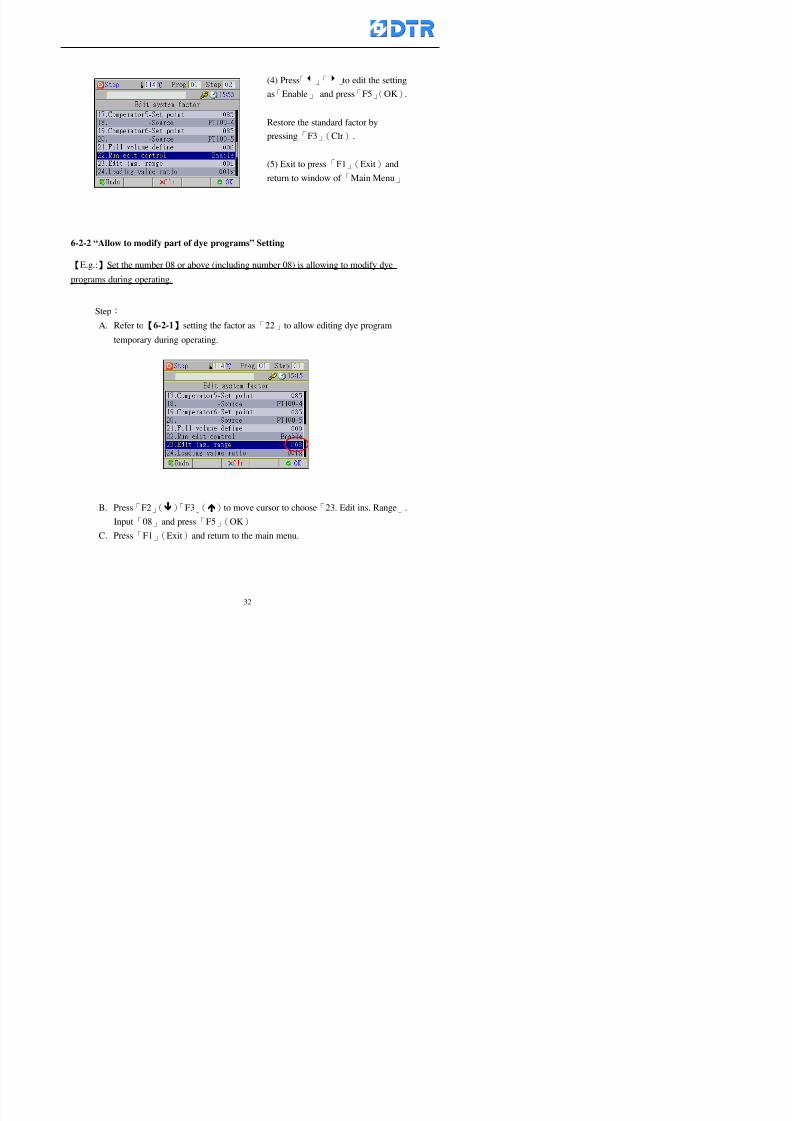
8132019 DTR 650 User Manual
httpslidepdfcomreaderfulldtr-650-user-manual 3270
6-2-2 ldquoAllow to modify part of dye programsrdquo Setting
【Eg】Set the number 08 or above (including number 08) is allowing to modify dye
programs during operating
Step
A Refer to【6-2-1】setting the factor as「22」to allow editing dye program
temporary during operating
(4) Press「3」「4」to edit the setting
as「Enable」 and press「F5」(OK)
Restore the standard factor by
pressing「F3」(Clr)
(5) Exit to press「F1」(Exit)and
return to window of 「Main Menu」
8132019 DTR 650 User Manual
httpslidepdfcomreaderfulldtr-650-user-manual 3370
6-2-3 ldquoAllow to modify dye steps temporaryrdquo Setting
After setting the dye programs are allowed to edit it also can set which dye steps are
allowed to edit temporary during operating
Step
(1) Choose「2 Factors」at the main menu Press「F5」(OK)
(2) Choose「19 Dye Ins control」at the sub-function menu Then presss「F5」
(OK) Window「Edit ins mode」appears
「Enable」 Allow to edit that dye step before
operating
「Disable」 Not allow to edit dye step before
operating
(3) Press「」「」to move cursor
to choose dye step Press「F4」
To enter to the「Edit dye program」from the
function menu there is a「」in front of the
file name「0-7」 means that program is not
allowing to edit during operating
8132019 DTR 650 User Manual
httpslidepdfcomreaderfulldtr-650-user-manual 3470
6-2-4 ldquoSet the dye step to keep running from the interrupt pointrdquo setting
When the dye program is operating it will disappear by causing power
interruption or sudden power off When start running again part of dye steps can
run again from the interrupt point part of them cannot
How to set
(1) Choose「2Factors」in the main menu and press「F5」(OK)
(2) Choose「20Continue mode」in the sub-function menu Press「F5」(OK) to
enter window of 「Continue Setting」
(3) Press「」「」to move cursor to choose dye steps Press「F4」(Sel)it
shows「Disable」or「Enable」for choosing Press「F5」(OK)to move cursorto the next setting
(4) Repeat above method until all setting is complete press「F1」(Exit)and
return to the main menu
8132019 DTR 650 User Manual
httpslidepdfcomreaderfulldtr-650-user-manual 3570
6-3 ldquoAllow to insert an addition dye stepsrdquo setting
During the program is running can temporary insert an addition dye step or a dye
program according to the operating actual situation Through this setting can set which
dye steps can apply or not to the program in operating
During to insert an addition step if sudden interruption or power off occurred it returns
to the main dye program automatically Before starting again should decide seriously
and set it again by actual needed
Step
(1) Choose「2Factors」at the main menu and press「F5」(OK)
(2) Choose「02System factor」and press「F5」(OK)
(3) Press「」「」to move cursor to the factor「34」and press「3」「4」to set
it as「Enable」 Press「F5」(OK)
(4) Press「F1」(Exit)to return to main menu Choose「21Addition Ins」at the
sub-function menu Press「F5」(OK)to enter the window「Addition Instruction」
(5) Press「」「」to move cursor to choose dye steps and press「F4」(Sel) Cursors
locates shows「Eable」or「Disable」 Press「F5」(OK)to move cursor to the
next dye step
(6) Repeat above method until to complete all setting press「F1」(Exit)and return
to the main menu
8132019 DTR 650 User Manual
httpslidepdfcomreaderfulldtr-650-user-manual 3670
6-4 Setting the display mode
DTR650 has three types of display mode during operating Program List mode
Schematic Diagram mode and Icon mode Users can set the display mode during
operating by factor setting
It goes back to a Program List mode when dye program ended
Step
(1) Choose「2Factors」at the main menu and press「F5」(OK)
(2) Choose「02System factor」and press「F5」(OK)
(3) Press「F2」()「F3」()to move cursor to choose「32Display mode」Press
「3」「4」 it shows「Online picture」「Instruction」「Big Icon」 choose
「Online picture」(eg) and press「F5」to confirm
8132019 DTR 650 User Manual
httpslidepdfcomreaderfulldtr-650-user-manual 3770
(4) Press「F1」(Exit)to return to the main menu
(5) The Schematic Diagram displays when the program is running (it stays at theProgram List mode when there is an alarm occurred)
Press「F4」to transfer to another display mode
It goes back to a Program List mode from Schematic Diagram Mode when dye
program ended Press numeric key「3」to view Schematic Diagram Mode again
Quit to press「F5」(Exit)
6-5 Adapt the digital input to another functions
DTR-650 has 32(0~31)input terminal it owns an standard setting when the
controller is initial According to the userrsquos demand they can change the DTR-650rsquos
anther functions of Input Terminal and PLC Input channel
The PLC Intputrsquos name can also define by the users (use IBM computer to edit and
download)
How to set
(1) Choose「2 Factor」at the main menu Press「F5」(OK)
(2) Choose「22 Input table」at the sub-function menu and press「F5」(OK)to enter
「Edit input table」
The actual input
terminal of theIBM computer
PLCrsquos input channel
8132019 DTR 650 User Manual
httpslidepdfcomreaderfulldtr-650-user-manual 3870
6-6 Adapt the digital output to another functions
DTR-650 has 32(0~31)output terminals it owns an standard setting when thecontroller is initial According to the userrsquos demand they can adapte the digital output
and the PLC outputrsquos channel to another functions The PLC Output channelrsquos name
can also define by users (use IBM computer to edit and download)
Step
(1) Choose「2 Factor」at the main menu Press「F5」(OK)
(2) Choose「23 Output table」at the main menu and press「F5」(OK)
(3) Press「F2」()「F3」()to move cursor to choose the output terminal atthe left side of the window Press「F5」(Add) the PLCrsquos output channelrsquos
name is listing at the right side of the window
(4) Press「F2」()「F3」()to move cursor to choose the PLC outputrsquos channel
If cursor moves to the PLC output channel which already linking「Add」is
not for choosing that means that output channel is already occupied
(5) Confirm the connection to press「F5」(Add) Quit to press「F4」(Del)Press「F1」(Exit)when complete all setting and return to main menu
The actual output
terminal of the
IBM computer
PLCrsquos output channel
8132019 DTR 650 User Manual
httpslidepdfcomreaderfulldtr-650-user-manual 3970
983095 983109983140983145983156983145983150983143 983156983144983141 983110983137983139983156983151983154983155DTR-650 has several kinds of control factors
Userrsquos factors System factors Temperature Control factors Speed factors Dosing
factors PID factors Analog Input Output factors standard factors etchellipPlease refer
to the supplementary table for the setting range and standard of the factors
DTR-650 has a built-in standard factor Users can edit by themselves if necessary
7-1 Modifying userrsquos factors
Userrsquos factors is setting with the Dyeing machinesrsquos PLC Programrsquos factor it is define by
the PLC Programmer
Step to edit
(1) Choose「2Factors」at main menu Press「F5」(OK)
(2) Choose「01User Factor」Press「F5」(OK)
(3) Press「F2」()「F3」()「6」「5」to move cursor up down and by page
Choose a factor need to edit then press「3」「4」to set itrsquos value Press「F5」(OK) Cursor moves to the next factor
(4) Some of factors can input numbers by the numeric membrance keys to edit If
the input is incorrect it turns to red and means the edit is not available
8132019 DTR 650 User Manual
httpslidepdfcomreaderfulldtr-650-user-manual 4070
Modifyrsquos method of the system factors temperature factors speed factors dosingfactors PID factors analog Input output factors standard factors etchellipare same asabove
If apply the library of DTR500 and DTR600 into the DTR650 the key「3」「4」may not valid to use Please use the numeric keys instead of it to key in factors itmay not effect the normal operation
Please pay a serious attention and read carefully at the factorrsquos table before modify the factors An incorrect value may effect the DTR-650 Dyeing
Machine Controllerrsquos operating After modifying factors must cancel the
password and secure data
7-2 Loading the standard factors
After modifying factors if need to restore a manufacturerrsquos standard factors of
DTR-650 The method as follows
1 Choose「2Factors」at main menu Press「F5」(OK)
「 「 ( ) 「
8132019 DTR 650 User Manual
httpslidepdfcomreaderfulldtr-650-user-manual 4170
7-3 Copying the factor
Users can build up a set of factor by themselves and make a copy and save
Step
1 Choose「2Factors」at main menu Press「F5」(OK)
2 Choose「13Restore Factor」 press「F5」(OK) window「factor will be
overwrite 」
3 Press「F4」(Yes)copy finished and saved Return to the main menu
4 Press「F2」(No)to not copy the factor and the existing factor is not change Return
to the main menu
7-4 Loading the backup factors
Users can build up a set of factor and backup files to load to DTR-650
Step1 Choose「14Backup factor」at the sub-function menu Press「F5」(OK)and
window「Factror will be overwrite」appears
2 Press「F3」(OK)to load the the backup factor them return to main menu
Press「F2」(No)to not copy the factor and the existing factor is not change
Return to the main menu
8132019 DTR 650 User Manual
httpslidepdfcomreaderfulldtr-650-user-manual 4270
983096 983119983157983156983152983157983156 983124983141983155983156983145983150983143
Before the output testing must be complete the steps as follows
A Cut off all connecting line of output terminal of DTR-650
B Stop running the PLC
C Check up the connections of all output channels to avoid damages from
incorrect connections
D Check up state of dyeing machines include the temperature pressure valves
onoff and pumpshellipetc ensure the safety for priority
8-1 Testing the Digital output
Step
1 Choose「3Output Testing」at the main menu Press「F5」(OK) 2 Choose「1Digital」at the sub function menu Press「F5」(OK) window「Digital
output testing」appears
3 Press「」「」「」to move cursor to each output channels Press「F5」(OK)
Output Name
8132019 DTR 650 User Manual
httpslidepdfcomreaderfulldtr-650-user-manual 4370
8-2 Testing the Analog output
(1) Choose「3Output Testing」at the main menu Press「F5」(OK)
(2) Choose「2Analog」at the sub function menu Press「F5」(OK) window「Analog output testing」appears
(3) Press「」「」「」to move cursor to each channels Then key in number by
the numeric membrance keys (range0~200= 0~20mA) Press「F5」(OK) there
is a output current relating to the output channel
(4) Press「F5」(OK) There is an output when the output channel with red light No
output without light onl(5) When complete the testing press「F1」(OK)to return to the main menu
8132019 DTR 650 User Manual
httpslidepdfcomreaderfulldtr-650-user-manual 4470
983097 983107983137983148983145983138983154983137983156983145983151983150
DTR-650 has Dosing and Temperature calibration
When enter to Dosing calibration must be set the Low Volume calibration first and
then High Volume calibration When enter to Temperature calibration must be set the
Low Temperature calibration first and then High Temperature calibration Must be
hightly follow this orders seriously
9-1 Calibration of Low Volume Tank
Step
A Choose「4Calibration」at the main menu Press「F5」(OK)
B Choose「Dosing 0 low vol」at the sub function menu Press「F5」(OK) window
appears
C Fill the Dosing Tank to a half level input value shows how much the water level
If it stays ldquo0rdquo check the connection and the factor setting is correct or not
And connect the pressure sensorrsquos output channel to the Current Meter to ensure
that sensor works or not
8132019 DTR 650 User Manual
httpslidepdfcomreaderfulldtr-650-user-manual 4570
D Fill the Dosing Tank to 50ml (Calcalate from the bottom side of the pressure
sensor steel tube) input value should show 4~6 (input value must between
0~10) Then enter the water volume The setting volume is relating the water
levelrsquos water value (litre as unit) input range 0~80 Set as「 「「 「0000 0000 0000 0000」」」」is strongly is strongly is strongly is strongly
receommend receommend receommend receommend Press「F5」(OK)to complete [Calibration of Low Volume Tank 1
is same as above method]
9-2 Calibration of High Volume Tank
Step
A Choose「4Calibration」at the main menu Press「F5」(OK)
B Choose「Dos 0 high vol」at the sub function menu Press「F5」(OK) window of
「Calibrate high 」appears
C Fill the Dosing Tank to a full level input value should be larger than 30 enter
the current water level which relates to the water volume Enter the range within
100~2500 Then press「F5」(OK) to complete the calibrate the high volume tank
8132019 DTR 650 User Manual
httpslidepdfcomreaderfulldtr-650-user-manual 4670
9-3 Temperature Calibration
Step
A This function is for adjusting the DTR650rsquos accuracy of Temperature Control It
must be using with the special terminal which is only for DTR650
B Choose「4Calibration」at the main function menu and press「F5」(OK)
C Choose「3Low Temp」at the sub-function menu Press「F5」(OK)and《Fig9-3》
appears insert the DTR650rsquos low temperature calibration terminal to the temperature
input terminal wait for the jumping value to stable down then press「F5」(OK) then
to adjust the high temperature calibration
D Adjusting the High Temperature Calibrationrsquos method is same as above But usersusersusersusers
must be using the High Temperature Terminalmust be using the High Temperature Terminalmust be using the High Temperature Terminalmust be using the High Temperature Terminal whichwhichwhichwhich is specially for DTR650 onlyis specially for DTR650 onlyis specially for DTR650 onlyis specially for DTR650 only
《Fig 9-3》
8132019 DTR 650 User Manual
httpslidepdfcomreaderfulldtr-650-user-manual 4770
10 983122983141983139983151983154983140983155 983151983142 983108983161983141 983120983154983151983143983154983137983149983155
It contains the past 15 days of temperature curves of running history
Checking method
(1) Choose「5Dye Record」at main menu press「F5」(OK)
(2) Sub-function menu shows the set up date of the past 15 days dye programs
Listing by the lastest set up date
(3) Choose a program date and press「F5」(OK) it appears window「Temp
record」
(4) Press「」「」to move the white line in the box one minute by moving once
(5) Press「3」「4」to move the line to check the time period 2 hours by moving once
The yellow selecting line of the「24 hours operating state」is repectively moving
The curve info is show in the curve box Left side of the widnow appears the
relating running info the time is the time value of the line locates at
(6) Check more details of the temperature info to press numeric key「middot」 a bright red line
appears in the selecting box this line is to check the starting point of the
temperature inforsquos time period Then press「」to move the white line to the end
point of the time period The temperature info between the starting point and end
point are appears at the right side of the window Press「middot」to return to the preious
curve page
(7) Check more details of the alarm infor To perss numeric key「7」「9」 the alarmrsquos
details is listing by orders
(8) Press「F1」(exit) to return
8132019 DTR 650 User Manual
httpslidepdfcomreaderfulldtr-650-user-manual 4870
11 983125983155983137983143983141 983151983142 983117983141983149983151983154983161 983107983137983154983140
DTR-650 supports 32MB or above Compact Flash Card which can transfer and save all
information for 4 sets of DTR-650 Including library files schematic diagram icon
image PLC program dye program factor and confiruration files etchellip Use the CF Card
to up download and swap the information of DTR-650 promptly install the relating
device and program updates
DTR-650 CF Card with bank 1 to bank 4 can save 4 sets information of Dyeing
Machines When download or save files should choose the BANK first
《Fig11-1》
8132019 DTR 650 User Manual
httpslidepdfcomreaderfulldtr-650-user-manual 4970
11-1 Downloading data
1 Firmly insert the CF card into the DTR-650rsquos PCMCIA connector Ensure it is
wholely and firmly inserted if the card is not totally inserted or the card do not
touch in all to the connector there will be an error occurred and cannot
updownload or interrupted during operation
2 Choose「6Memory Card」at the main menu and press「F5」(OK) 《Fig11-1》
appears Information of Bank「1」shows at the left hand side of the window press
number 1-4 by using numeric keys to choose the BANK Check the
information in the Bank seriously which is exactly need to download to the
DTR650
3 Press()()「6」「5」to move cursor to the sub-function menu to choose
the downloading items Press「F5」(OK) window appears「Stop PLC run before
access memory card Stop the PLC run」 Press「F5」(YES) to stop PLC
running
4 Press「F5」(OK) window appears Confirm to update or not the DTR-650rsquos
information As that downloading will be replace the DTR-650rsquos information
(that means the existing information of the DTR-650 will be removed and
replaced)
5 Press「F4」(YES)to download the information from the DTR-650 to the CF
Card Return to the main menu when finish
8132019 DTR 650 User Manual
httpslidepdfcomreaderfulldtr-650-user-manual 5070
Ensure inserting firmly the CF card into the DTR-650 unless it will cause
error or cannot Updownload data
Never remove CF card during transferring or updownloading data Until it
is all completed
DTR-650rsquos dyeing program is not compatible with DTR-500 and
DTR-600 Never use CF card to transfer data among them
11-2 Storing and transfering data
1 Insert the CF Card to the DTR-650
2 Choose「6Memory Card」at the main menu and press「F5」(OK) 《Fig11-1》
appears Left hand side of the window shows the data of BANK 1 press numeric
keys 1-4 to select the BANK To confirm the put the data in the DTR-650 to the CF
Card The existing data of that bank will be replaced and covered by the new data (if
that bank is already occuplied)
3 Choose「23Save Dye prog」(Example)at the sub-funciton menu press「F5」(OK)to confirm Window「Update memory card data」appears
4 Press「F5」(OK)to transfer the data to the CF card Return to the main menu
5 Put the CF card into another DTR-650 and follow the operating method of 「11-1
Downloading data」」」」can transfer and swap data with more than one set of
DTR-650
8132019 DTR 650 User Manual
httpslidepdfcomreaderfulldtr-650-user-manual 5170
12 983123983156983137983156983141 983137983150983140 983113983150983142983151983154983149983137983156983145983151983150
The state and information is including the Dyeing Machinersquos state of Digit Input output
Analog Input output Temperature control PID Dosing PID Pressure different PID
software system information and alarm record This information is for checking at any
time
12-1 Input Output state
Step
1 Choose「7Info and state」at main menu and press「F5」(OK)
2 Choose「01Digital IO put」at the sub-function menu then press「F5」(OK)
「Digital In Out State」0=None 1=Input
3 Press「F1」(Exit)to return to main menu
Same method for checking the temperature control analog dosing pressure
different etchellip
12-2 Checking the system information
Step
1 Choose「7Info and state」at main menu and press「F5」(OK)
2 Choose「11 System info」at sub-function field press「F5」(OK)Window
「System Information」appear
System information is including System info(software version) Library doc
Icon files Schematic file Definition file hardare state Config File Commandinstruction icon PLC file etc
8132019 DTR 650 User Manual
httpslidepdfcomreaderfulldtr-650-user-manual 5270
12-3 Checking the operating alarm record
Operating record shows the latest 40 operating items and alarm records including
the time and content of the alarm
A) Choose「7 Info and state」
and press「F5」(OK)
B) Choose「12Alarm logs」at
the sub-funciton menu then
press「F5」(OK)
8132019 DTR 650 User Manual
httpslidepdfcomreaderfulldtr-650-user-manual 5370
13 983105983140983146983157983155983156983145983150983143 983156983144983141 983107983151983150983156983154983137983155983156
The displaysrsquos brightness can be adjusted if necessary
Step
1 Choose「8Others」at main menu press「F5」(OK)
2 Choose「01Contrast」at sub-function menu press「F5」(OK) window「Set
Contrast」appears
3 Press「」「」to move the bar to set the brightness then press「F5」(OK)Window appears「Please reboot the system」
4 Press「F5」(OK)to return to main menu and re-boot the DTR-650 to complete
adjusting the brightness
8132019 DTR 650 User Manual
httpslidepdfcomreaderfulldtr-650-user-manual 5470
14 983123983156983151983152 983154983157983150983150983145983150983143 983156983144983141 983120983116983107 983120983154983151983143983154983137983149
Before testing the Input output testing transfer of the PLC program must stop the PLC
running
Step
1 Choose「8Others」at the main menu Press「F5」(OK)
2 Choose「04 PLC Stop」at sub-function menu Press「F5」(OK) window
「Password」appears
3 Enter password and press「F5」(OK) Window「Stop the PLC run」appears
4 Press「F4」(Yes)and window「PLC Stop」appear Press「F5」(OK) Now
the PLC is stop running and return to the main menu
All testing cannot operate when the PLC is running
Editing dye program and the relating operation can
perform with the PLC running together
8132019 DTR 650 User Manual
httpslidepdfcomreaderfulldtr-650-user-manual 5570
15 983123983141983156983156983145983150983143 983156983144983141 983156983145983149983141
Step
1 Press「8Others」at the main menu Press「F5」(OK)
2 Choose「10Set date time」at the sub-function menu Press「F5」(OK) window
「Set date time」appears
3 Press「F5」(Edit) to move cursor by 「3」「4」 enter the time value at the
cursor locates
4 Press「F5」(OK)to complete the modify Press「F1」(Exit)to return to main
menu
5 Press「F1」(Exit)if not modify and return to main menu
8132019 DTR 650 User Manual
httpslidepdfcomreaderfulldtr-650-user-manual 5670
1166 983123983123983157983157 983152 983152 983152 983152983148983148983141983141983149983149983141983141983150983150983156 983156 983137983137983154 983154 983161983161 983124 983124 983137983137983138983138983148983148983141983141
TTTTTTTTaaaaaaaabbbbbbbblllllllleeeeeeee 11111111 【Dye Instruction】
Code Icon Instruction Code Icon Instruction
000 End 016 Inject C
001 Start 017 Dosing BV
002 Heat 018 PH
003 Cool 019 Addsalt B
004 Flow Fill 020 Addsalt C
005 Level Fill 021 Ana Fill
006 Drian 022 Lock Fill007 Rinse 023 Lock Level
008 Run 024 Low Rinse
009 Call 025 Cyc Rinse
010 Prep B 026 Rinse B
011 Addsalt B 027 Rinse C
012 Dosing B 028 Temp
013 Inject B 029 Nozzle Pressure
014 Prep C 030 Main Pump
015 Dosing C 031 Pump Speed
8132019 DTR 650 User Manual
httpslidepdfcomreaderfulldtr-650-user-manual 5770
Table 2 【【【【Alarm】】】】
System Alarm Must stop operating and check up to solve problems before restarting
the machine
Running Alarm It is a reminder Not effect the operating of DTR-650
Userrsquos Alarm Total of 32 Users can define themselves and use it when edit the PLC
Program (do not listing below)
No System Alarm No Running Alarm
1 PLC program not running 16 Temp ctrl 0 Grad too slow
2 Main temp sensor error 17 Temp ctrl 0 Grad too fast
3 Not at Run window 18 Temp ctrl 0 Hold temp too low
4 Exceeding max temp 19 Temp ctrl 0 Hold temp too high
5 - 20 Temp ctrl 1 Grad too slow6 - 21 Temp ctrl 1 Grad too fast
7 - 22 Temp ctrl 1 Hold temp too low
8 Communication error 23 Temp ctrl 1 Hold temp too high
9 Slave not answer 24 Temp ctrl 2 Grad too slow
10 PLC 0 not answer 25 Temp ctrl 2 Grad too fast
11 PLC 1 not answer 26 Temp 2 Hold temp too low12 Display not answer 27 Temp 2 Hold temp too high
13 Lower power voltage 28 Temp ctrl 3 Grad too slow
14 - 29 Temp ctrl 3 Grad too fast
15 - 30 Temp3 Hold temp too low
31 Temp3 Hold temp too high
32 Dosing 0 injection too slow
33 Dosing 0 injection too fast
34 Dosing 1 injection too slow
35 Dosing 1 injection too fast
8132019 DTR 650 User Manual
httpslidepdfcomreaderfulldtr-650-user-manual 5870
TTTTTTTTaaaaaaaabbbbbbbblllllllleeeeeeee 33333333 【【【【System factor】】】】
No Description Std Range amp Definition
1 ID No 000 000- 100 Controller no
2 Communication Rate 4800Bps 2400 4800 9600 19200 38400
3 Display language Chinese English Chinese
4 Temp display mode and
5 Maxmium temperature 145 025 ~ 145 6 Type of external PLC Default PLC32DPLC32PLC16Default
7 Number of external PLC NANA 1 unit connect
2 unit connect
8Communication Rate of
PLC9600Bps 2400 4800 9600 19200
9 Set point 1 085 000 ~ 145
If signal source is temperaturethe setting value is thetemperature value If the signal
source is Analog Input 6~17 then
setting value for Analog input is 0 ndash
100 and relates Analog
Input14~020mA
10 Source 1 Sensor0Sensor 0 ~5
Analog input 0 ~1111 Set point 2 092 Same as 09
12 Source 2 PT100 1 Same as 10
13 Set point 3 085 Same as 09
14 Source 3 PT100 2 Same as 10
15 Set point 4 092 Same as 09
16 Source 4 PT100 3 Same as 1017 Set point 5 085 Same as 09
18 Source 5 PT100 4 Same as 10
19 Set point 6 092 Same as 09
8132019 DTR 650 User Manual
httpslidepdfcomreaderfulldtr-650-user-manual 5970
29 Min cyclic time of cloth 100sec 0 ~ 255 sec
30 Max cyclic time of cloth 240sec 0 ~255 sec
31Standard cyclic time of
cloth
180 000 ~ 255 sec
32 Display ModeProgram
List
Program list Schematic Diagram
Icon mode
33 CF card format Standard of
DTR CF
Card
Standard of DTR CF Card V20
Standard CF Card
34 Addition step Disable Disable Enable35 Mode Com 3
CouplingEsure Com 3 is the communication
port of the Central or Coupling
36Com 3 Communication
rate9600 Central communication speed
8132019 DTR 650 User Manual
httpslidepdfcomreaderfulldtr-650-user-manual 6070
TTTTTTTTaaaaaaaabbbbbbbblllllllleeeeeeee 44444444 【【【【Temperature Cotnrol Factor】】】】
No Factor Definition Standard Range and Definition
01 PT No PT-0 PT 0~5 PT-100 Input number
02 Max working temp 140 000~140
03 Output mode 0 0~2
04 Alarm time of gardient 240sec 000~255 sec
05 Alarm mode of gradient Always AlwaysOnceNone
06 Control mode of gradient Heating orCooling
interlocked
Heating and Cooling interlocked
No limitation
07 Alarm range of HoldTemp 03 01~20
08 Alarm time for HoldTemp 240sec 000~255sec
09 Alarm mode of HoldTemp Always AlwaysOnceNone
10 Control mode ofHoldTemp
Heating only Only heating and cooling Cooling whenalarm occurred Only heating andcooling No limitation when alarmHeating only
11 Porportional Band 100 000~250
12 Integral band 128 sec 000~255 sec
13 Differential time 04 sec 00~20 sec
14 Min transit gradient 02 00~50
15 Transit rate 20 times 00~50 times (020= 2 times)
16 PID initial output value 010 000~100
17 ONOFF cycle time 10 sec 05~25 sec
Onoff valve set as 010 sec
Proportional valve set as 020 sec
18 Time down count mode Mode 0 0~10 = The time down count range from「Factor 20 + target temp」to「Target
8132019 DTR 650 User Manual
httpslidepdfcomreaderfulldtr-650-user-manual 6170
TTTTTTTTaaaaaaaabbbbbbbblllllllleeeeeeee 55555555 【【【【Speed Factor】】】】
No Factor Definition Standard Range amp Definition
01 Input Number Speed input 0 Speed input 0~11
02 Average times 05 times 01~10
03 Sensor Number 008pcs 001~255
04 Roller Dimension 250mm 050~500
05 Max cloth speed 200mmin 001~25506 Min cloth speed 020mmin 001~255
07 Alarm delay time 240sec 001~255
08 Alarm mode Every oncenoneevery
09 Alarm range () 020 001~255
10 Proportional band 100 001~255
11 Integer band 128 001~25512 Differential time 000 001~200
13 Initial speed () 020 001~255
14 Control cycle ti(01sec) 05 01~30
15 First cycle time(01sec) 10 01~30
16 Speed increase limit () 010 001~100
17 Speed decrease limit () 010 001~100
18 Min speed() 005 001~100
19 Manual speed adjust () 005 001~100
20 Manual initial speed() 020 001~100
21 Stopping speed() 010 001~100
22 Switch speed() 020 001~100
23 Not used
24 Speed decrease turns 03turns 01~50
8132019 DTR 650 User Manual
httpslidepdfcomreaderfulldtr-650-user-manual 6270
Table 6 【【【【Dosing Factors】】】】
No Description Range Range and Explanation
1 Analog input no Analog input 0 Analog input no 0 ~11
2Alarm delay time for
dosing240 sec 000 ~255 sec
3 Alarm time for dosing Every Every Once None
4 Proportional band 100 000 ~255 sec Factor P
5 Integer band 128 000 ~255 sec Factor I6 Differential time 04 00 ~20 Factor D
7 Max adjust rate 150 50~ 255
8 Initial factor for dosing 10 000 ~100
9 User curve section 0 10 Gradient of sect1 for dosing curve9
10 User curve section 1 10 Gradient of sect2 for dosing curve9
11 User curve section 2 10 Gradient of sect3 for dosing curve9
12 User curve section 3 10 Gradient of sect4 for dosing curve9
13 User curve section 4 10 Gradient of sect5 for dosing curve9
14 User curve section 5 10 Gradient of sect6 for dosing curve9
15 User curve section 6 10 Gradient of sect7 for dosing curve9
16 User curve section 7 10 Gradient of sect8 for dosing curve9
17 User curve section 8 10 Gradient of sect9 for dosing curve9
18 User curve section 9 10 Gradient of sect10 for dosing curve9
19 Min water level 05 00~ 10 04~20mA percentagechange to the userrsquos factor setting
20 Output value for Tank
clean
100 000~ 100
Injected percentage of dosing valve
in dosing End period
This factor will be invalided if usingONOFF dosing valve
21 Full range 100 001~255 Self-adjustment cannotchange
22 Range ratio 001001~255 Self-adjustment cannot
change
8132019 DTR 650 User Manual
httpslidepdfcomreaderfulldtr-650-user-manual 6370
【【【【TTaabbllee 77 】】】】Pressure Deviation Factors
No Description Std Range amp Definition
1 Analog input number + Analog in 0 Analog in 0~11
2 Analog input number - Analog in 1 Analog in 0~11
3 Input mode Pressure Pressure Pressure deviation
4 Full range 050x01Kgcm
001~255
5 Range ratio 001 001~255
6 Alarm delay time 100sec 001~255
7 Alarm mode Every oncenone
8 Alarm range 010 001~255
9 Proportional band 100 001~255
10 Integer band 128 001~255
11 Differential time 00 00~20
12 PID Init output value 010 001~255
13 Cycle time 10 03~30
14 First cycle time 030 003~100
15 Max adjust rate 010 001~100
8132019 DTR 650 User Manual
httpslidepdfcomreaderfulldtr-650-user-manual 6470
【【【【TTaabbllee 88 】】】】Definition of Analog Input
No Description Standard Range and Explanation
01 PT 0 correction standard DIN std DIN std JIS std
02 PT 0 correction +0 +- 9
03 PT 1 correction standard DIN std DIN std JIS std
04 PT 1 correction +0 +- 9
05 PT 2 correction standard DIN std DIN std JIS std
06 PT 2 correction +0 +- 9
07 PT 3 correction standard DIN std DIN std JIS std
08 PT 3 correction +0 +- 9
09 PT 4 correction standard DIN std DIN std JIS std
10 PT 4 correction +0 +- 9
11 PT 5 correction standard DIN std DIN std JIS std
12 PT 5 correction +0 +- 9
13 Analog input 0 define 4 ~ 20mA 0 ndash 20mA 4 ndash 20mA
14 Analog input 0 average times 10 times 01- 20 times
15 Analog input 0 min value 0000 0000 - 1000
16 Analog input 0 max value 100 0001 - 9999
17-60 Analog input 1~11 Same as Analog input 0
【【【【 】】】】 fi i i f A O
8132019 DTR 650 User Manual
httpslidepdfcomreaderfulldtr-650-user-manual 6570
【【【【TTaabbllee 99 】】】】Definition of Analog Output
No Description Standard Range and explanation
61 Analog output 0 define Control byPLC
Control by PLC
Temperature control PID0 output
Temperature control PID1 output
Temperature control PID2 output
Speed PID3 output
Dosing PID0 output Dosing PID1output
Pressure different PID0 outputPressure different PID1 output
Main temperature output
62 Mode of Analog ouptput0 4 ~20mA 0 ndash20mA 4 ndash 20mA
63-84 Analog output 1~11 Same as Analog output 0
【【【【TTaabbllee 1100】】】】Value Table 0 amp 1
No Description Range Std Range and explanation
1 Analog input no 000~011 000 Analog input no
2 Data ratio 001~255 100 Multiple by factors
3~53 0~98 000~255 000-100 Analog input 0~98 data
【【【【 】】】】St t Li t
8132019 DTR 650 User Manual
httpslidepdfcomreaderfulldtr-650-user-manual 6670
【【【【TTaabbllee 1111】】】】State List
No Description Range Standard Range and explanation
1 Display setting 1 0~255 205 See remarks at next page
2 Display setting 2 0~255 208
3 Display setting 3 0~255 209
4 Display setting 4 0~255 017
5 Display setting 5 0~255 0186 Display setting 6 0~255 019
7 Display setting 7 0~255 020
8 Display setting 8 0~255 021
9 Display setting 9 0~255 000
10 Display setting 1 0~255 000
11 Display setting 2 0~255 000
12 Display setting 3 0~255 000
13 Display setting 4 0~255 000
14 Display setting 5 0~255 000
15 Display setting 6 0~255 000
16 Display setting 7 0~255 000
Remarks
8132019 DTR 650 User Manual
httpslidepdfcomreaderfulldtr-650-user-manual 6770
0 = No display 1~255 = Display type of number
1~16 Content of PLC VB0~15
No 1 corresponding to VB0
No 16 corresponding to VB15
17~32 Content of PLC DB0~15
No 17 corresponding to DB0
No 32 corresponding to DB15
33~46 Content of PLC CNT0~29
No 33 corresponding to CNT0
No 46 corresponding to CNT29 47~78 Content of dyeing instruction 0~31 CNT0
No 47 corresponding to system instruction to No 0 of CNT0
No 78 corresponding to system instruction to No 31 of CNT0rsquos content
79~110 Dyeing instruction 0~31 of CNT0rsquos setting
111~142 Content of Dyeing instruction 0~31 CNT1No 111 corresponding to dyeing instruction No 0 of CNT1
No 142 corresponding to dyeing instruction No 31 of CNT1rsquos content
143~174 Dyeing instruction 0~31 of CNT1rsquos setting
175~204 Content of PLC HTIM0~29
No 175 corresponding to HTIM0
No 204 corresponding to HTIM29
205 Loading
206 Ratio 1
207 Ratio 2208 Ratio 1 x Loading
209 Ratio 2 x Loading
210 Fix value
211 Value Table 1 matching result
212 Value Table 2 matching result
213 Value Table 1 setting214 Value Table 2 setting
215 Pressure control PID0 different pressure value
216 Pressure control PID1 different pressure value
TTTTTTTTaaaaaaaabbbbbbbblllllllleeeeeeee 1122 【【【【Usage of password】】】】
8132019 DTR 650 User Manual
httpslidepdfcomreaderfulldtr-650-user-manual 6870
No Main FunctionFactor Sub Function Factor Password Rank
1 Run None
2 Dye program User3 or above
3 Control factor
- User factor User 1
- System factor User 1
- Temp PID 0
- Temp PID 1 User 1- Speed PID 0 User 1
- Dosing PID 0 User 1
- Dosing PID 1 User 1
- Pressure PID 0 User 1
- Pressure PID 1 User 1
- Analog IO User 1
- Load standard factor User 2 or above- Load a copied factor User 2 or above
- Copy factor User 2 or above
- Value table 0 User 1
- Value table 1 User 1
- Information and state User 1
- Dye instruction User 1
- Edit dye instruction setting User 14 Output testing User 2 or above
5 Calibration User 2 or above
6 Dye record None
7 CF card User 1
8 Info and state None
9 Others
- Contrast User3 or above
- Data Locking None
- PLC Run User 1
- PLC Stop User 1
- Password setting User 1
TTTTTTTTaaaaaaaabbbbbbbblllllllleeeeeeee 1133 【【【【Technical Data】】】】
8132019 DTR 650 User Manual
httpslidepdfcomreaderfulldtr-650-user-manual 6970
TTTTTTTTaaaaaaaabbbbbbbblllllllleeeeeeee 1133 【【【【Technical Data】】】】
1 Temperature Control
- Range 10~145(plusmn1)
- Mode Proportional or PWM
- Sensor PT100 (JIS or DIN standard)
2 Input and output channel
- Digital Input 32 DC24V PNP- Digital Output 32 DC24V 054A Relay connect point
- Analog Input 4 04~20 mA
- Analog Output 4 0~20mA 或 4~20 mA
3 Communication port 3 RS-232 amp 0~20 mAx1 RS485x 2
4 Dye program
- Number 15000 Steps
- Standard step 61Heating Cooling Fill Drain RinseDosingetc
5LCD module and Display
langage
Chinese
English
320 x 240 TFT color display with
more language
6 CF card connector 1 PCMCIA standard
7 Membrane Keyboard- Number Key 10 [0]~[9] Input factors
- Function Key 5 [F1]~[F5] function selecting
- Operation Key 2 [Start] [Stop]
- Auxiliary Key 7 [][][][][Esc] [larr][OK] [bull]
8 Operating Condition
- Temperature 5~45
- Humidity ≦85 (25)
9 Power supply
V l DC 24V
8132019 DTR 650 User Manual
httpslidepdfcomreaderfulldtr-650-user-manual 7070
70
983108983124983122983085650 983113983150983152983157983156 983119983157983156983152983157983156 983120983151983154983156983145983150983143 (983138983137983139983147983155983145983140983141 983158983145983141983159)
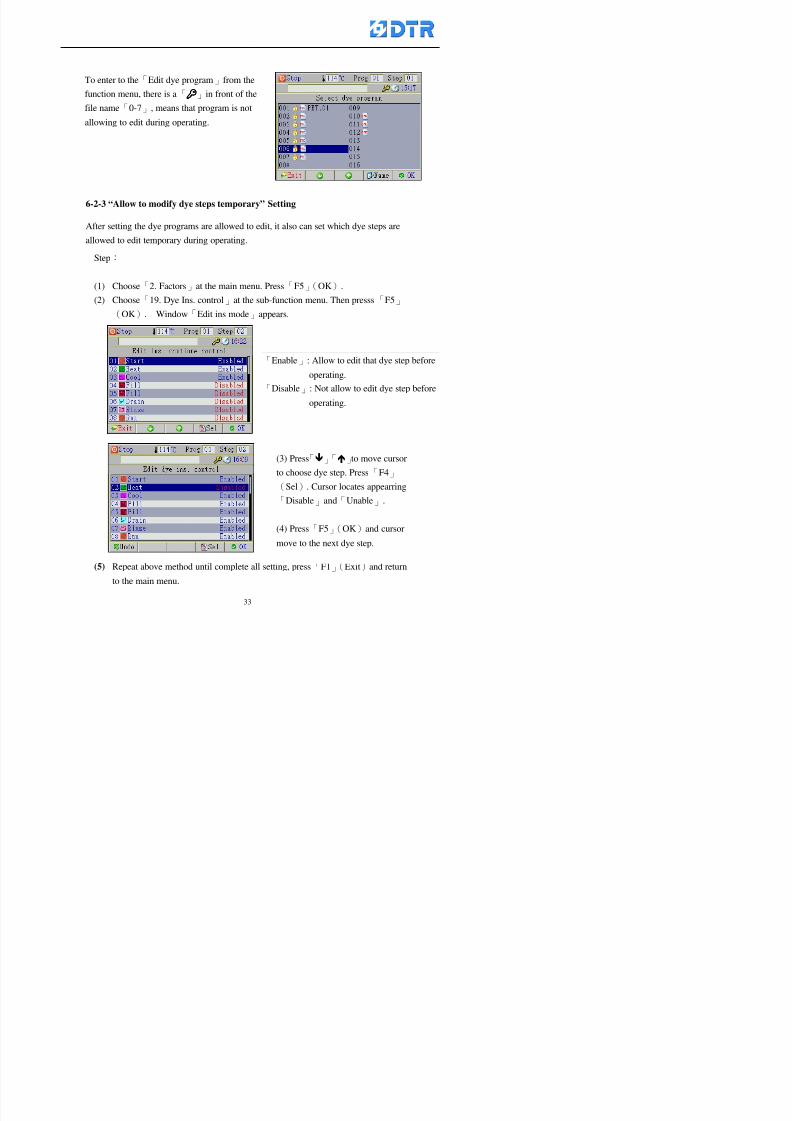
8132019 DTR 650 User Manual
httpslidepdfcomreaderfulldtr-650-user-manual 3370
6-2-3 ldquoAllow to modify dye steps temporaryrdquo Setting
After setting the dye programs are allowed to edit it also can set which dye steps are
allowed to edit temporary during operating
Step
(1) Choose「2 Factors」at the main menu Press「F5」(OK)
(2) Choose「19 Dye Ins control」at the sub-function menu Then presss「F5」
(OK) Window「Edit ins mode」appears
「Enable」 Allow to edit that dye step before
operating
「Disable」 Not allow to edit dye step before
operating
(3) Press「」「」to move cursor
to choose dye step Press「F4」
To enter to the「Edit dye program」from the
function menu there is a「」in front of the
file name「0-7」 means that program is not
allowing to edit during operating
8132019 DTR 650 User Manual
httpslidepdfcomreaderfulldtr-650-user-manual 3470
6-2-4 ldquoSet the dye step to keep running from the interrupt pointrdquo setting
When the dye program is operating it will disappear by causing power
interruption or sudden power off When start running again part of dye steps can
run again from the interrupt point part of them cannot
How to set
(1) Choose「2Factors」in the main menu and press「F5」(OK)
(2) Choose「20Continue mode」in the sub-function menu Press「F5」(OK) to
enter window of 「Continue Setting」
(3) Press「」「」to move cursor to choose dye steps Press「F4」(Sel)it
shows「Disable」or「Enable」for choosing Press「F5」(OK)to move cursorto the next setting
(4) Repeat above method until all setting is complete press「F1」(Exit)and
return to the main menu
8132019 DTR 650 User Manual
httpslidepdfcomreaderfulldtr-650-user-manual 3570
6-3 ldquoAllow to insert an addition dye stepsrdquo setting
During the program is running can temporary insert an addition dye step or a dye
program according to the operating actual situation Through this setting can set which
dye steps can apply or not to the program in operating
During to insert an addition step if sudden interruption or power off occurred it returns
to the main dye program automatically Before starting again should decide seriously
and set it again by actual needed
Step
(1) Choose「2Factors」at the main menu and press「F5」(OK)
(2) Choose「02System factor」and press「F5」(OK)
(3) Press「」「」to move cursor to the factor「34」and press「3」「4」to set
it as「Enable」 Press「F5」(OK)
(4) Press「F1」(Exit)to return to main menu Choose「21Addition Ins」at the
sub-function menu Press「F5」(OK)to enter the window「Addition Instruction」
(5) Press「」「」to move cursor to choose dye steps and press「F4」(Sel) Cursors
locates shows「Eable」or「Disable」 Press「F5」(OK)to move cursor to the
next dye step
(6) Repeat above method until to complete all setting press「F1」(Exit)and return
to the main menu
8132019 DTR 650 User Manual
httpslidepdfcomreaderfulldtr-650-user-manual 3670
6-4 Setting the display mode
DTR650 has three types of display mode during operating Program List mode
Schematic Diagram mode and Icon mode Users can set the display mode during
operating by factor setting
It goes back to a Program List mode when dye program ended
Step
(1) Choose「2Factors」at the main menu and press「F5」(OK)
(2) Choose「02System factor」and press「F5」(OK)
(3) Press「F2」()「F3」()to move cursor to choose「32Display mode」Press
「3」「4」 it shows「Online picture」「Instruction」「Big Icon」 choose
「Online picture」(eg) and press「F5」to confirm
8132019 DTR 650 User Manual
httpslidepdfcomreaderfulldtr-650-user-manual 3770
(4) Press「F1」(Exit)to return to the main menu
(5) The Schematic Diagram displays when the program is running (it stays at theProgram List mode when there is an alarm occurred)
Press「F4」to transfer to another display mode
It goes back to a Program List mode from Schematic Diagram Mode when dye
program ended Press numeric key「3」to view Schematic Diagram Mode again
Quit to press「F5」(Exit)
6-5 Adapt the digital input to another functions
DTR-650 has 32(0~31)input terminal it owns an standard setting when the
controller is initial According to the userrsquos demand they can change the DTR-650rsquos
anther functions of Input Terminal and PLC Input channel
The PLC Intputrsquos name can also define by the users (use IBM computer to edit and
download)
How to set
(1) Choose「2 Factor」at the main menu Press「F5」(OK)
(2) Choose「22 Input table」at the sub-function menu and press「F5」(OK)to enter
「Edit input table」
The actual input
terminal of theIBM computer
PLCrsquos input channel
8132019 DTR 650 User Manual
httpslidepdfcomreaderfulldtr-650-user-manual 3870
6-6 Adapt the digital output to another functions
DTR-650 has 32(0~31)output terminals it owns an standard setting when thecontroller is initial According to the userrsquos demand they can adapte the digital output
and the PLC outputrsquos channel to another functions The PLC Output channelrsquos name
can also define by users (use IBM computer to edit and download)
Step
(1) Choose「2 Factor」at the main menu Press「F5」(OK)
(2) Choose「23 Output table」at the main menu and press「F5」(OK)
(3) Press「F2」()「F3」()to move cursor to choose the output terminal atthe left side of the window Press「F5」(Add) the PLCrsquos output channelrsquos
name is listing at the right side of the window
(4) Press「F2」()「F3」()to move cursor to choose the PLC outputrsquos channel
If cursor moves to the PLC output channel which already linking「Add」is
not for choosing that means that output channel is already occupied
(5) Confirm the connection to press「F5」(Add) Quit to press「F4」(Del)Press「F1」(Exit)when complete all setting and return to main menu
The actual output
terminal of the
IBM computer
PLCrsquos output channel
8132019 DTR 650 User Manual
httpslidepdfcomreaderfulldtr-650-user-manual 3970
983095 983109983140983145983156983145983150983143 983156983144983141 983110983137983139983156983151983154983155DTR-650 has several kinds of control factors
Userrsquos factors System factors Temperature Control factors Speed factors Dosing
factors PID factors Analog Input Output factors standard factors etchellipPlease refer
to the supplementary table for the setting range and standard of the factors
DTR-650 has a built-in standard factor Users can edit by themselves if necessary
7-1 Modifying userrsquos factors
Userrsquos factors is setting with the Dyeing machinesrsquos PLC Programrsquos factor it is define by
the PLC Programmer
Step to edit
(1) Choose「2Factors」at main menu Press「F5」(OK)
(2) Choose「01User Factor」Press「F5」(OK)
(3) Press「F2」()「F3」()「6」「5」to move cursor up down and by page
Choose a factor need to edit then press「3」「4」to set itrsquos value Press「F5」(OK) Cursor moves to the next factor
(4) Some of factors can input numbers by the numeric membrance keys to edit If
the input is incorrect it turns to red and means the edit is not available
8132019 DTR 650 User Manual
httpslidepdfcomreaderfulldtr-650-user-manual 4070
Modifyrsquos method of the system factors temperature factors speed factors dosingfactors PID factors analog Input output factors standard factors etchellipare same asabove
If apply the library of DTR500 and DTR600 into the DTR650 the key「3」「4」may not valid to use Please use the numeric keys instead of it to key in factors itmay not effect the normal operation
Please pay a serious attention and read carefully at the factorrsquos table before modify the factors An incorrect value may effect the DTR-650 Dyeing
Machine Controllerrsquos operating After modifying factors must cancel the
password and secure data
7-2 Loading the standard factors
After modifying factors if need to restore a manufacturerrsquos standard factors of
DTR-650 The method as follows
1 Choose「2Factors」at main menu Press「F5」(OK)
「 「 ( ) 「
8132019 DTR 650 User Manual
httpslidepdfcomreaderfulldtr-650-user-manual 4170
7-3 Copying the factor
Users can build up a set of factor by themselves and make a copy and save
Step
1 Choose「2Factors」at main menu Press「F5」(OK)
2 Choose「13Restore Factor」 press「F5」(OK) window「factor will be
overwrite 」
3 Press「F4」(Yes)copy finished and saved Return to the main menu
4 Press「F2」(No)to not copy the factor and the existing factor is not change Return
to the main menu
7-4 Loading the backup factors
Users can build up a set of factor and backup files to load to DTR-650
Step1 Choose「14Backup factor」at the sub-function menu Press「F5」(OK)and
window「Factror will be overwrite」appears
2 Press「F3」(OK)to load the the backup factor them return to main menu
Press「F2」(No)to not copy the factor and the existing factor is not change
Return to the main menu
8132019 DTR 650 User Manual
httpslidepdfcomreaderfulldtr-650-user-manual 4270
983096 983119983157983156983152983157983156 983124983141983155983156983145983150983143
Before the output testing must be complete the steps as follows
A Cut off all connecting line of output terminal of DTR-650
B Stop running the PLC
C Check up the connections of all output channels to avoid damages from
incorrect connections
D Check up state of dyeing machines include the temperature pressure valves
onoff and pumpshellipetc ensure the safety for priority
8-1 Testing the Digital output
Step
1 Choose「3Output Testing」at the main menu Press「F5」(OK) 2 Choose「1Digital」at the sub function menu Press「F5」(OK) window「Digital
output testing」appears
3 Press「」「」「」to move cursor to each output channels Press「F5」(OK)
Output Name
8132019 DTR 650 User Manual
httpslidepdfcomreaderfulldtr-650-user-manual 4370
8-2 Testing the Analog output
(1) Choose「3Output Testing」at the main menu Press「F5」(OK)
(2) Choose「2Analog」at the sub function menu Press「F5」(OK) window「Analog output testing」appears
(3) Press「」「」「」to move cursor to each channels Then key in number by
the numeric membrance keys (range0~200= 0~20mA) Press「F5」(OK) there
is a output current relating to the output channel
(4) Press「F5」(OK) There is an output when the output channel with red light No
output without light onl(5) When complete the testing press「F1」(OK)to return to the main menu
8132019 DTR 650 User Manual
httpslidepdfcomreaderfulldtr-650-user-manual 4470
983097 983107983137983148983145983138983154983137983156983145983151983150
DTR-650 has Dosing and Temperature calibration
When enter to Dosing calibration must be set the Low Volume calibration first and
then High Volume calibration When enter to Temperature calibration must be set the
Low Temperature calibration first and then High Temperature calibration Must be
hightly follow this orders seriously
9-1 Calibration of Low Volume Tank
Step
A Choose「4Calibration」at the main menu Press「F5」(OK)
B Choose「Dosing 0 low vol」at the sub function menu Press「F5」(OK) window
appears
C Fill the Dosing Tank to a half level input value shows how much the water level
If it stays ldquo0rdquo check the connection and the factor setting is correct or not
And connect the pressure sensorrsquos output channel to the Current Meter to ensure
that sensor works or not
8132019 DTR 650 User Manual
httpslidepdfcomreaderfulldtr-650-user-manual 4570
D Fill the Dosing Tank to 50ml (Calcalate from the bottom side of the pressure
sensor steel tube) input value should show 4~6 (input value must between
0~10) Then enter the water volume The setting volume is relating the water
levelrsquos water value (litre as unit) input range 0~80 Set as「 「「 「0000 0000 0000 0000」」」」is strongly is strongly is strongly is strongly
receommend receommend receommend receommend Press「F5」(OK)to complete [Calibration of Low Volume Tank 1
is same as above method]
9-2 Calibration of High Volume Tank
Step
A Choose「4Calibration」at the main menu Press「F5」(OK)
B Choose「Dos 0 high vol」at the sub function menu Press「F5」(OK) window of
「Calibrate high 」appears
C Fill the Dosing Tank to a full level input value should be larger than 30 enter
the current water level which relates to the water volume Enter the range within
100~2500 Then press「F5」(OK) to complete the calibrate the high volume tank
8132019 DTR 650 User Manual
httpslidepdfcomreaderfulldtr-650-user-manual 4670
9-3 Temperature Calibration
Step
A This function is for adjusting the DTR650rsquos accuracy of Temperature Control It
must be using with the special terminal which is only for DTR650
B Choose「4Calibration」at the main function menu and press「F5」(OK)
C Choose「3Low Temp」at the sub-function menu Press「F5」(OK)and《Fig9-3》
appears insert the DTR650rsquos low temperature calibration terminal to the temperature
input terminal wait for the jumping value to stable down then press「F5」(OK) then
to adjust the high temperature calibration
D Adjusting the High Temperature Calibrationrsquos method is same as above But usersusersusersusers
must be using the High Temperature Terminalmust be using the High Temperature Terminalmust be using the High Temperature Terminalmust be using the High Temperature Terminal whichwhichwhichwhich is specially for DTR650 onlyis specially for DTR650 onlyis specially for DTR650 onlyis specially for DTR650 only
《Fig 9-3》
8132019 DTR 650 User Manual
httpslidepdfcomreaderfulldtr-650-user-manual 4770
10 983122983141983139983151983154983140983155 983151983142 983108983161983141 983120983154983151983143983154983137983149983155
It contains the past 15 days of temperature curves of running history
Checking method
(1) Choose「5Dye Record」at main menu press「F5」(OK)
(2) Sub-function menu shows the set up date of the past 15 days dye programs
Listing by the lastest set up date
(3) Choose a program date and press「F5」(OK) it appears window「Temp
record」
(4) Press「」「」to move the white line in the box one minute by moving once
(5) Press「3」「4」to move the line to check the time period 2 hours by moving once
The yellow selecting line of the「24 hours operating state」is repectively moving
The curve info is show in the curve box Left side of the widnow appears the
relating running info the time is the time value of the line locates at
(6) Check more details of the temperature info to press numeric key「middot」 a bright red line
appears in the selecting box this line is to check the starting point of the
temperature inforsquos time period Then press「」to move the white line to the end
point of the time period The temperature info between the starting point and end
point are appears at the right side of the window Press「middot」to return to the preious
curve page
(7) Check more details of the alarm infor To perss numeric key「7」「9」 the alarmrsquos
details is listing by orders
(8) Press「F1」(exit) to return
8132019 DTR 650 User Manual
httpslidepdfcomreaderfulldtr-650-user-manual 4870
11 983125983155983137983143983141 983151983142 983117983141983149983151983154983161 983107983137983154983140
DTR-650 supports 32MB or above Compact Flash Card which can transfer and save all
information for 4 sets of DTR-650 Including library files schematic diagram icon
image PLC program dye program factor and confiruration files etchellip Use the CF Card
to up download and swap the information of DTR-650 promptly install the relating
device and program updates
DTR-650 CF Card with bank 1 to bank 4 can save 4 sets information of Dyeing
Machines When download or save files should choose the BANK first
《Fig11-1》
8132019 DTR 650 User Manual
httpslidepdfcomreaderfulldtr-650-user-manual 4970
11-1 Downloading data
1 Firmly insert the CF card into the DTR-650rsquos PCMCIA connector Ensure it is
wholely and firmly inserted if the card is not totally inserted or the card do not
touch in all to the connector there will be an error occurred and cannot
updownload or interrupted during operation
2 Choose「6Memory Card」at the main menu and press「F5」(OK) 《Fig11-1》
appears Information of Bank「1」shows at the left hand side of the window press
number 1-4 by using numeric keys to choose the BANK Check the
information in the Bank seriously which is exactly need to download to the
DTR650
3 Press()()「6」「5」to move cursor to the sub-function menu to choose
the downloading items Press「F5」(OK) window appears「Stop PLC run before
access memory card Stop the PLC run」 Press「F5」(YES) to stop PLC
running
4 Press「F5」(OK) window appears Confirm to update or not the DTR-650rsquos
information As that downloading will be replace the DTR-650rsquos information
(that means the existing information of the DTR-650 will be removed and
replaced)
5 Press「F4」(YES)to download the information from the DTR-650 to the CF
Card Return to the main menu when finish
8132019 DTR 650 User Manual
httpslidepdfcomreaderfulldtr-650-user-manual 5070
Ensure inserting firmly the CF card into the DTR-650 unless it will cause
error or cannot Updownload data
Never remove CF card during transferring or updownloading data Until it
is all completed
DTR-650rsquos dyeing program is not compatible with DTR-500 and
DTR-600 Never use CF card to transfer data among them
11-2 Storing and transfering data
1 Insert the CF Card to the DTR-650
2 Choose「6Memory Card」at the main menu and press「F5」(OK) 《Fig11-1》
appears Left hand side of the window shows the data of BANK 1 press numeric
keys 1-4 to select the BANK To confirm the put the data in the DTR-650 to the CF
Card The existing data of that bank will be replaced and covered by the new data (if
that bank is already occuplied)
3 Choose「23Save Dye prog」(Example)at the sub-funciton menu press「F5」(OK)to confirm Window「Update memory card data」appears
4 Press「F5」(OK)to transfer the data to the CF card Return to the main menu
5 Put the CF card into another DTR-650 and follow the operating method of 「11-1
Downloading data」」」」can transfer and swap data with more than one set of
DTR-650
8132019 DTR 650 User Manual
httpslidepdfcomreaderfulldtr-650-user-manual 5170
12 983123983156983137983156983141 983137983150983140 983113983150983142983151983154983149983137983156983145983151983150
The state and information is including the Dyeing Machinersquos state of Digit Input output
Analog Input output Temperature control PID Dosing PID Pressure different PID
software system information and alarm record This information is for checking at any
time
12-1 Input Output state
Step
1 Choose「7Info and state」at main menu and press「F5」(OK)
2 Choose「01Digital IO put」at the sub-function menu then press「F5」(OK)
「Digital In Out State」0=None 1=Input
3 Press「F1」(Exit)to return to main menu
Same method for checking the temperature control analog dosing pressure
different etchellip
12-2 Checking the system information
Step
1 Choose「7Info and state」at main menu and press「F5」(OK)
2 Choose「11 System info」at sub-function field press「F5」(OK)Window
「System Information」appear
System information is including System info(software version) Library doc
Icon files Schematic file Definition file hardare state Config File Commandinstruction icon PLC file etc
8132019 DTR 650 User Manual
httpslidepdfcomreaderfulldtr-650-user-manual 5270
12-3 Checking the operating alarm record
Operating record shows the latest 40 operating items and alarm records including
the time and content of the alarm
A) Choose「7 Info and state」
and press「F5」(OK)
B) Choose「12Alarm logs」at
the sub-funciton menu then
press「F5」(OK)
8132019 DTR 650 User Manual
httpslidepdfcomreaderfulldtr-650-user-manual 5370
13 983105983140983146983157983155983156983145983150983143 983156983144983141 983107983151983150983156983154983137983155983156
The displaysrsquos brightness can be adjusted if necessary
Step
1 Choose「8Others」at main menu press「F5」(OK)
2 Choose「01Contrast」at sub-function menu press「F5」(OK) window「Set
Contrast」appears
3 Press「」「」to move the bar to set the brightness then press「F5」(OK)Window appears「Please reboot the system」
4 Press「F5」(OK)to return to main menu and re-boot the DTR-650 to complete
adjusting the brightness
8132019 DTR 650 User Manual
httpslidepdfcomreaderfulldtr-650-user-manual 5470
14 983123983156983151983152 983154983157983150983150983145983150983143 983156983144983141 983120983116983107 983120983154983151983143983154983137983149
Before testing the Input output testing transfer of the PLC program must stop the PLC
running
Step
1 Choose「8Others」at the main menu Press「F5」(OK)
2 Choose「04 PLC Stop」at sub-function menu Press「F5」(OK) window
「Password」appears
3 Enter password and press「F5」(OK) Window「Stop the PLC run」appears
4 Press「F4」(Yes)and window「PLC Stop」appear Press「F5」(OK) Now
the PLC is stop running and return to the main menu
All testing cannot operate when the PLC is running
Editing dye program and the relating operation can
perform with the PLC running together
8132019 DTR 650 User Manual
httpslidepdfcomreaderfulldtr-650-user-manual 5570
15 983123983141983156983156983145983150983143 983156983144983141 983156983145983149983141
Step
1 Press「8Others」at the main menu Press「F5」(OK)
2 Choose「10Set date time」at the sub-function menu Press「F5」(OK) window
「Set date time」appears
3 Press「F5」(Edit) to move cursor by 「3」「4」 enter the time value at the
cursor locates
4 Press「F5」(OK)to complete the modify Press「F1」(Exit)to return to main
menu
5 Press「F1」(Exit)if not modify and return to main menu
8132019 DTR 650 User Manual
httpslidepdfcomreaderfulldtr-650-user-manual 5670
1166 983123983123983157983157 983152 983152 983152 983152983148983148983141983141983149983149983141983141983150983150983156 983156 983137983137983154 983154 983161983161 983124 983124 983137983137983138983138983148983148983141983141
TTTTTTTTaaaaaaaabbbbbbbblllllllleeeeeeee 11111111 【Dye Instruction】
Code Icon Instruction Code Icon Instruction
000 End 016 Inject C
001 Start 017 Dosing BV
002 Heat 018 PH
003 Cool 019 Addsalt B
004 Flow Fill 020 Addsalt C
005 Level Fill 021 Ana Fill
006 Drian 022 Lock Fill007 Rinse 023 Lock Level
008 Run 024 Low Rinse
009 Call 025 Cyc Rinse
010 Prep B 026 Rinse B
011 Addsalt B 027 Rinse C
012 Dosing B 028 Temp
013 Inject B 029 Nozzle Pressure
014 Prep C 030 Main Pump
015 Dosing C 031 Pump Speed
8132019 DTR 650 User Manual
httpslidepdfcomreaderfulldtr-650-user-manual 5770
Table 2 【【【【Alarm】】】】
System Alarm Must stop operating and check up to solve problems before restarting
the machine
Running Alarm It is a reminder Not effect the operating of DTR-650
Userrsquos Alarm Total of 32 Users can define themselves and use it when edit the PLC
Program (do not listing below)
No System Alarm No Running Alarm
1 PLC program not running 16 Temp ctrl 0 Grad too slow
2 Main temp sensor error 17 Temp ctrl 0 Grad too fast
3 Not at Run window 18 Temp ctrl 0 Hold temp too low
4 Exceeding max temp 19 Temp ctrl 0 Hold temp too high
5 - 20 Temp ctrl 1 Grad too slow6 - 21 Temp ctrl 1 Grad too fast
7 - 22 Temp ctrl 1 Hold temp too low
8 Communication error 23 Temp ctrl 1 Hold temp too high
9 Slave not answer 24 Temp ctrl 2 Grad too slow
10 PLC 0 not answer 25 Temp ctrl 2 Grad too fast
11 PLC 1 not answer 26 Temp 2 Hold temp too low12 Display not answer 27 Temp 2 Hold temp too high
13 Lower power voltage 28 Temp ctrl 3 Grad too slow
14 - 29 Temp ctrl 3 Grad too fast
15 - 30 Temp3 Hold temp too low
31 Temp3 Hold temp too high
32 Dosing 0 injection too slow
33 Dosing 0 injection too fast
34 Dosing 1 injection too slow
35 Dosing 1 injection too fast
8132019 DTR 650 User Manual
httpslidepdfcomreaderfulldtr-650-user-manual 5870
TTTTTTTTaaaaaaaabbbbbbbblllllllleeeeeeee 33333333 【【【【System factor】】】】
No Description Std Range amp Definition
1 ID No 000 000- 100 Controller no
2 Communication Rate 4800Bps 2400 4800 9600 19200 38400
3 Display language Chinese English Chinese
4 Temp display mode and
5 Maxmium temperature 145 025 ~ 145 6 Type of external PLC Default PLC32DPLC32PLC16Default
7 Number of external PLC NANA 1 unit connect
2 unit connect
8Communication Rate of
PLC9600Bps 2400 4800 9600 19200
9 Set point 1 085 000 ~ 145
If signal source is temperaturethe setting value is thetemperature value If the signal
source is Analog Input 6~17 then
setting value for Analog input is 0 ndash
100 and relates Analog
Input14~020mA
10 Source 1 Sensor0Sensor 0 ~5
Analog input 0 ~1111 Set point 2 092 Same as 09
12 Source 2 PT100 1 Same as 10
13 Set point 3 085 Same as 09
14 Source 3 PT100 2 Same as 10
15 Set point 4 092 Same as 09
16 Source 4 PT100 3 Same as 1017 Set point 5 085 Same as 09
18 Source 5 PT100 4 Same as 10
19 Set point 6 092 Same as 09
8132019 DTR 650 User Manual
httpslidepdfcomreaderfulldtr-650-user-manual 5970
29 Min cyclic time of cloth 100sec 0 ~ 255 sec
30 Max cyclic time of cloth 240sec 0 ~255 sec
31Standard cyclic time of
cloth
180 000 ~ 255 sec
32 Display ModeProgram
List
Program list Schematic Diagram
Icon mode
33 CF card format Standard of
DTR CF
Card
Standard of DTR CF Card V20
Standard CF Card
34 Addition step Disable Disable Enable35 Mode Com 3
CouplingEsure Com 3 is the communication
port of the Central or Coupling
36Com 3 Communication
rate9600 Central communication speed
8132019 DTR 650 User Manual
httpslidepdfcomreaderfulldtr-650-user-manual 6070
TTTTTTTTaaaaaaaabbbbbbbblllllllleeeeeeee 44444444 【【【【Temperature Cotnrol Factor】】】】
No Factor Definition Standard Range and Definition
01 PT No PT-0 PT 0~5 PT-100 Input number
02 Max working temp 140 000~140
03 Output mode 0 0~2
04 Alarm time of gardient 240sec 000~255 sec
05 Alarm mode of gradient Always AlwaysOnceNone
06 Control mode of gradient Heating orCooling
interlocked
Heating and Cooling interlocked
No limitation
07 Alarm range of HoldTemp 03 01~20
08 Alarm time for HoldTemp 240sec 000~255sec
09 Alarm mode of HoldTemp Always AlwaysOnceNone
10 Control mode ofHoldTemp
Heating only Only heating and cooling Cooling whenalarm occurred Only heating andcooling No limitation when alarmHeating only
11 Porportional Band 100 000~250
12 Integral band 128 sec 000~255 sec
13 Differential time 04 sec 00~20 sec
14 Min transit gradient 02 00~50
15 Transit rate 20 times 00~50 times (020= 2 times)
16 PID initial output value 010 000~100
17 ONOFF cycle time 10 sec 05~25 sec
Onoff valve set as 010 sec
Proportional valve set as 020 sec
18 Time down count mode Mode 0 0~10 = The time down count range from「Factor 20 + target temp」to「Target
8132019 DTR 650 User Manual
httpslidepdfcomreaderfulldtr-650-user-manual 6170
TTTTTTTTaaaaaaaabbbbbbbblllllllleeeeeeee 55555555 【【【【Speed Factor】】】】
No Factor Definition Standard Range amp Definition
01 Input Number Speed input 0 Speed input 0~11
02 Average times 05 times 01~10
03 Sensor Number 008pcs 001~255
04 Roller Dimension 250mm 050~500
05 Max cloth speed 200mmin 001~25506 Min cloth speed 020mmin 001~255
07 Alarm delay time 240sec 001~255
08 Alarm mode Every oncenoneevery
09 Alarm range () 020 001~255
10 Proportional band 100 001~255
11 Integer band 128 001~25512 Differential time 000 001~200
13 Initial speed () 020 001~255
14 Control cycle ti(01sec) 05 01~30
15 First cycle time(01sec) 10 01~30
16 Speed increase limit () 010 001~100
17 Speed decrease limit () 010 001~100
18 Min speed() 005 001~100
19 Manual speed adjust () 005 001~100
20 Manual initial speed() 020 001~100
21 Stopping speed() 010 001~100
22 Switch speed() 020 001~100
23 Not used
24 Speed decrease turns 03turns 01~50
8132019 DTR 650 User Manual
httpslidepdfcomreaderfulldtr-650-user-manual 6270
Table 6 【【【【Dosing Factors】】】】
No Description Range Range and Explanation
1 Analog input no Analog input 0 Analog input no 0 ~11
2Alarm delay time for
dosing240 sec 000 ~255 sec
3 Alarm time for dosing Every Every Once None
4 Proportional band 100 000 ~255 sec Factor P
5 Integer band 128 000 ~255 sec Factor I6 Differential time 04 00 ~20 Factor D
7 Max adjust rate 150 50~ 255
8 Initial factor for dosing 10 000 ~100
9 User curve section 0 10 Gradient of sect1 for dosing curve9
10 User curve section 1 10 Gradient of sect2 for dosing curve9
11 User curve section 2 10 Gradient of sect3 for dosing curve9
12 User curve section 3 10 Gradient of sect4 for dosing curve9
13 User curve section 4 10 Gradient of sect5 for dosing curve9
14 User curve section 5 10 Gradient of sect6 for dosing curve9
15 User curve section 6 10 Gradient of sect7 for dosing curve9
16 User curve section 7 10 Gradient of sect8 for dosing curve9
17 User curve section 8 10 Gradient of sect9 for dosing curve9
18 User curve section 9 10 Gradient of sect10 for dosing curve9
19 Min water level 05 00~ 10 04~20mA percentagechange to the userrsquos factor setting
20 Output value for Tank
clean
100 000~ 100
Injected percentage of dosing valve
in dosing End period
This factor will be invalided if usingONOFF dosing valve
21 Full range 100 001~255 Self-adjustment cannotchange
22 Range ratio 001001~255 Self-adjustment cannot
change
8132019 DTR 650 User Manual
httpslidepdfcomreaderfulldtr-650-user-manual 6370
【【【【TTaabbllee 77 】】】】Pressure Deviation Factors
No Description Std Range amp Definition
1 Analog input number + Analog in 0 Analog in 0~11
2 Analog input number - Analog in 1 Analog in 0~11
3 Input mode Pressure Pressure Pressure deviation
4 Full range 050x01Kgcm
001~255
5 Range ratio 001 001~255
6 Alarm delay time 100sec 001~255
7 Alarm mode Every oncenone
8 Alarm range 010 001~255
9 Proportional band 100 001~255
10 Integer band 128 001~255
11 Differential time 00 00~20
12 PID Init output value 010 001~255
13 Cycle time 10 03~30
14 First cycle time 030 003~100
15 Max adjust rate 010 001~100
8132019 DTR 650 User Manual
httpslidepdfcomreaderfulldtr-650-user-manual 6470
【【【【TTaabbllee 88 】】】】Definition of Analog Input
No Description Standard Range and Explanation
01 PT 0 correction standard DIN std DIN std JIS std
02 PT 0 correction +0 +- 9
03 PT 1 correction standard DIN std DIN std JIS std
04 PT 1 correction +0 +- 9
05 PT 2 correction standard DIN std DIN std JIS std
06 PT 2 correction +0 +- 9
07 PT 3 correction standard DIN std DIN std JIS std
08 PT 3 correction +0 +- 9
09 PT 4 correction standard DIN std DIN std JIS std
10 PT 4 correction +0 +- 9
11 PT 5 correction standard DIN std DIN std JIS std
12 PT 5 correction +0 +- 9
13 Analog input 0 define 4 ~ 20mA 0 ndash 20mA 4 ndash 20mA
14 Analog input 0 average times 10 times 01- 20 times
15 Analog input 0 min value 0000 0000 - 1000
16 Analog input 0 max value 100 0001 - 9999
17-60 Analog input 1~11 Same as Analog input 0
【【【【 】】】】 fi i i f A O
8132019 DTR 650 User Manual
httpslidepdfcomreaderfulldtr-650-user-manual 6570
【【【【TTaabbllee 99 】】】】Definition of Analog Output
No Description Standard Range and explanation
61 Analog output 0 define Control byPLC
Control by PLC
Temperature control PID0 output
Temperature control PID1 output
Temperature control PID2 output
Speed PID3 output
Dosing PID0 output Dosing PID1output
Pressure different PID0 outputPressure different PID1 output
Main temperature output
62 Mode of Analog ouptput0 4 ~20mA 0 ndash20mA 4 ndash 20mA
63-84 Analog output 1~11 Same as Analog output 0
【【【【TTaabbllee 1100】】】】Value Table 0 amp 1
No Description Range Std Range and explanation
1 Analog input no 000~011 000 Analog input no
2 Data ratio 001~255 100 Multiple by factors
3~53 0~98 000~255 000-100 Analog input 0~98 data
【【【【 】】】】St t Li t
8132019 DTR 650 User Manual
httpslidepdfcomreaderfulldtr-650-user-manual 6670
【【【【TTaabbllee 1111】】】】State List
No Description Range Standard Range and explanation
1 Display setting 1 0~255 205 See remarks at next page
2 Display setting 2 0~255 208
3 Display setting 3 0~255 209
4 Display setting 4 0~255 017
5 Display setting 5 0~255 0186 Display setting 6 0~255 019
7 Display setting 7 0~255 020
8 Display setting 8 0~255 021
9 Display setting 9 0~255 000
10 Display setting 1 0~255 000
11 Display setting 2 0~255 000
12 Display setting 3 0~255 000
13 Display setting 4 0~255 000
14 Display setting 5 0~255 000
15 Display setting 6 0~255 000
16 Display setting 7 0~255 000
Remarks
8132019 DTR 650 User Manual
httpslidepdfcomreaderfulldtr-650-user-manual 6770
0 = No display 1~255 = Display type of number
1~16 Content of PLC VB0~15
No 1 corresponding to VB0
No 16 corresponding to VB15
17~32 Content of PLC DB0~15
No 17 corresponding to DB0
No 32 corresponding to DB15
33~46 Content of PLC CNT0~29
No 33 corresponding to CNT0
No 46 corresponding to CNT29 47~78 Content of dyeing instruction 0~31 CNT0
No 47 corresponding to system instruction to No 0 of CNT0
No 78 corresponding to system instruction to No 31 of CNT0rsquos content
79~110 Dyeing instruction 0~31 of CNT0rsquos setting
111~142 Content of Dyeing instruction 0~31 CNT1No 111 corresponding to dyeing instruction No 0 of CNT1
No 142 corresponding to dyeing instruction No 31 of CNT1rsquos content
143~174 Dyeing instruction 0~31 of CNT1rsquos setting
175~204 Content of PLC HTIM0~29
No 175 corresponding to HTIM0
No 204 corresponding to HTIM29
205 Loading
206 Ratio 1
207 Ratio 2208 Ratio 1 x Loading
209 Ratio 2 x Loading
210 Fix value
211 Value Table 1 matching result
212 Value Table 2 matching result
213 Value Table 1 setting214 Value Table 2 setting
215 Pressure control PID0 different pressure value
216 Pressure control PID1 different pressure value
TTTTTTTTaaaaaaaabbbbbbbblllllllleeeeeeee 1122 【【【【Usage of password】】】】
8132019 DTR 650 User Manual
httpslidepdfcomreaderfulldtr-650-user-manual 6870
No Main FunctionFactor Sub Function Factor Password Rank
1 Run None
2 Dye program User3 or above
3 Control factor
- User factor User 1
- System factor User 1
- Temp PID 0
- Temp PID 1 User 1- Speed PID 0 User 1
- Dosing PID 0 User 1
- Dosing PID 1 User 1
- Pressure PID 0 User 1
- Pressure PID 1 User 1
- Analog IO User 1
- Load standard factor User 2 or above- Load a copied factor User 2 or above
- Copy factor User 2 or above
- Value table 0 User 1
- Value table 1 User 1
- Information and state User 1
- Dye instruction User 1
- Edit dye instruction setting User 14 Output testing User 2 or above
5 Calibration User 2 or above
6 Dye record None
7 CF card User 1
8 Info and state None
9 Others
- Contrast User3 or above
- Data Locking None
- PLC Run User 1
- PLC Stop User 1
- Password setting User 1
TTTTTTTTaaaaaaaabbbbbbbblllllllleeeeeeee 1133 【【【【Technical Data】】】】
8132019 DTR 650 User Manual
httpslidepdfcomreaderfulldtr-650-user-manual 6970
TTTTTTTTaaaaaaaabbbbbbbblllllllleeeeeeee 1133 【【【【Technical Data】】】】
1 Temperature Control
- Range 10~145(plusmn1)
- Mode Proportional or PWM
- Sensor PT100 (JIS or DIN standard)
2 Input and output channel
- Digital Input 32 DC24V PNP- Digital Output 32 DC24V 054A Relay connect point
- Analog Input 4 04~20 mA
- Analog Output 4 0~20mA 或 4~20 mA
3 Communication port 3 RS-232 amp 0~20 mAx1 RS485x 2
4 Dye program
- Number 15000 Steps
- Standard step 61Heating Cooling Fill Drain RinseDosingetc
5LCD module and Display
langage
Chinese
English
320 x 240 TFT color display with
more language
6 CF card connector 1 PCMCIA standard
7 Membrane Keyboard- Number Key 10 [0]~[9] Input factors
- Function Key 5 [F1]~[F5] function selecting
- Operation Key 2 [Start] [Stop]
- Auxiliary Key 7 [][][][][Esc] [larr][OK] [bull]
8 Operating Condition
- Temperature 5~45
- Humidity ≦85 (25)
9 Power supply
V l DC 24V
8132019 DTR 650 User Manual
httpslidepdfcomreaderfulldtr-650-user-manual 7070
70
983108983124983122983085650 983113983150983152983157983156 983119983157983156983152983157983156 983120983151983154983156983145983150983143 (983138983137983139983147983155983145983140983141 983158983145983141983159)
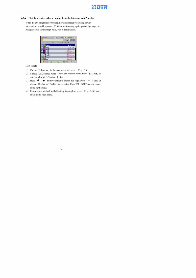
8132019 DTR 650 User Manual
httpslidepdfcomreaderfulldtr-650-user-manual 3470
6-2-4 ldquoSet the dye step to keep running from the interrupt pointrdquo setting
When the dye program is operating it will disappear by causing power
interruption or sudden power off When start running again part of dye steps can
run again from the interrupt point part of them cannot
How to set
(1) Choose「2Factors」in the main menu and press「F5」(OK)
(2) Choose「20Continue mode」in the sub-function menu Press「F5」(OK) to
enter window of 「Continue Setting」
(3) Press「」「」to move cursor to choose dye steps Press「F4」(Sel)it
shows「Disable」or「Enable」for choosing Press「F5」(OK)to move cursorto the next setting
(4) Repeat above method until all setting is complete press「F1」(Exit)and
return to the main menu
8132019 DTR 650 User Manual
httpslidepdfcomreaderfulldtr-650-user-manual 3570
6-3 ldquoAllow to insert an addition dye stepsrdquo setting
During the program is running can temporary insert an addition dye step or a dye
program according to the operating actual situation Through this setting can set which
dye steps can apply or not to the program in operating
During to insert an addition step if sudden interruption or power off occurred it returns
to the main dye program automatically Before starting again should decide seriously
and set it again by actual needed
Step
(1) Choose「2Factors」at the main menu and press「F5」(OK)
(2) Choose「02System factor」and press「F5」(OK)
(3) Press「」「」to move cursor to the factor「34」and press「3」「4」to set
it as「Enable」 Press「F5」(OK)
(4) Press「F1」(Exit)to return to main menu Choose「21Addition Ins」at the
sub-function menu Press「F5」(OK)to enter the window「Addition Instruction」
(5) Press「」「」to move cursor to choose dye steps and press「F4」(Sel) Cursors
locates shows「Eable」or「Disable」 Press「F5」(OK)to move cursor to the
next dye step
(6) Repeat above method until to complete all setting press「F1」(Exit)and return
to the main menu
8132019 DTR 650 User Manual
httpslidepdfcomreaderfulldtr-650-user-manual 3670
6-4 Setting the display mode
DTR650 has three types of display mode during operating Program List mode
Schematic Diagram mode and Icon mode Users can set the display mode during
operating by factor setting
It goes back to a Program List mode when dye program ended
Step
(1) Choose「2Factors」at the main menu and press「F5」(OK)
(2) Choose「02System factor」and press「F5」(OK)
(3) Press「F2」()「F3」()to move cursor to choose「32Display mode」Press
「3」「4」 it shows「Online picture」「Instruction」「Big Icon」 choose
「Online picture」(eg) and press「F5」to confirm
8132019 DTR 650 User Manual
httpslidepdfcomreaderfulldtr-650-user-manual 3770
(4) Press「F1」(Exit)to return to the main menu
(5) The Schematic Diagram displays when the program is running (it stays at theProgram List mode when there is an alarm occurred)
Press「F4」to transfer to another display mode
It goes back to a Program List mode from Schematic Diagram Mode when dye
program ended Press numeric key「3」to view Schematic Diagram Mode again
Quit to press「F5」(Exit)
6-5 Adapt the digital input to another functions
DTR-650 has 32(0~31)input terminal it owns an standard setting when the
controller is initial According to the userrsquos demand they can change the DTR-650rsquos
anther functions of Input Terminal and PLC Input channel
The PLC Intputrsquos name can also define by the users (use IBM computer to edit and
download)
How to set
(1) Choose「2 Factor」at the main menu Press「F5」(OK)
(2) Choose「22 Input table」at the sub-function menu and press「F5」(OK)to enter
「Edit input table」
The actual input
terminal of theIBM computer
PLCrsquos input channel
8132019 DTR 650 User Manual
httpslidepdfcomreaderfulldtr-650-user-manual 3870
6-6 Adapt the digital output to another functions
DTR-650 has 32(0~31)output terminals it owns an standard setting when thecontroller is initial According to the userrsquos demand they can adapte the digital output
and the PLC outputrsquos channel to another functions The PLC Output channelrsquos name
can also define by users (use IBM computer to edit and download)
Step
(1) Choose「2 Factor」at the main menu Press「F5」(OK)
(2) Choose「23 Output table」at the main menu and press「F5」(OK)
(3) Press「F2」()「F3」()to move cursor to choose the output terminal atthe left side of the window Press「F5」(Add) the PLCrsquos output channelrsquos
name is listing at the right side of the window
(4) Press「F2」()「F3」()to move cursor to choose the PLC outputrsquos channel
If cursor moves to the PLC output channel which already linking「Add」is
not for choosing that means that output channel is already occupied
(5) Confirm the connection to press「F5」(Add) Quit to press「F4」(Del)Press「F1」(Exit)when complete all setting and return to main menu
The actual output
terminal of the
IBM computer
PLCrsquos output channel
8132019 DTR 650 User Manual
httpslidepdfcomreaderfulldtr-650-user-manual 3970
983095 983109983140983145983156983145983150983143 983156983144983141 983110983137983139983156983151983154983155DTR-650 has several kinds of control factors
Userrsquos factors System factors Temperature Control factors Speed factors Dosing
factors PID factors Analog Input Output factors standard factors etchellipPlease refer
to the supplementary table for the setting range and standard of the factors
DTR-650 has a built-in standard factor Users can edit by themselves if necessary
7-1 Modifying userrsquos factors
Userrsquos factors is setting with the Dyeing machinesrsquos PLC Programrsquos factor it is define by
the PLC Programmer
Step to edit
(1) Choose「2Factors」at main menu Press「F5」(OK)
(2) Choose「01User Factor」Press「F5」(OK)
(3) Press「F2」()「F3」()「6」「5」to move cursor up down and by page
Choose a factor need to edit then press「3」「4」to set itrsquos value Press「F5」(OK) Cursor moves to the next factor
(4) Some of factors can input numbers by the numeric membrance keys to edit If
the input is incorrect it turns to red and means the edit is not available
8132019 DTR 650 User Manual
httpslidepdfcomreaderfulldtr-650-user-manual 4070
Modifyrsquos method of the system factors temperature factors speed factors dosingfactors PID factors analog Input output factors standard factors etchellipare same asabove
If apply the library of DTR500 and DTR600 into the DTR650 the key「3」「4」may not valid to use Please use the numeric keys instead of it to key in factors itmay not effect the normal operation
Please pay a serious attention and read carefully at the factorrsquos table before modify the factors An incorrect value may effect the DTR-650 Dyeing
Machine Controllerrsquos operating After modifying factors must cancel the
password and secure data
7-2 Loading the standard factors
After modifying factors if need to restore a manufacturerrsquos standard factors of
DTR-650 The method as follows
1 Choose「2Factors」at main menu Press「F5」(OK)
「 「 ( ) 「
8132019 DTR 650 User Manual
httpslidepdfcomreaderfulldtr-650-user-manual 4170
7-3 Copying the factor
Users can build up a set of factor by themselves and make a copy and save
Step
1 Choose「2Factors」at main menu Press「F5」(OK)
2 Choose「13Restore Factor」 press「F5」(OK) window「factor will be
overwrite 」
3 Press「F4」(Yes)copy finished and saved Return to the main menu
4 Press「F2」(No)to not copy the factor and the existing factor is not change Return
to the main menu
7-4 Loading the backup factors
Users can build up a set of factor and backup files to load to DTR-650
Step1 Choose「14Backup factor」at the sub-function menu Press「F5」(OK)and
window「Factror will be overwrite」appears
2 Press「F3」(OK)to load the the backup factor them return to main menu
Press「F2」(No)to not copy the factor and the existing factor is not change
Return to the main menu
8132019 DTR 650 User Manual
httpslidepdfcomreaderfulldtr-650-user-manual 4270
983096 983119983157983156983152983157983156 983124983141983155983156983145983150983143
Before the output testing must be complete the steps as follows
A Cut off all connecting line of output terminal of DTR-650
B Stop running the PLC
C Check up the connections of all output channels to avoid damages from
incorrect connections
D Check up state of dyeing machines include the temperature pressure valves
onoff and pumpshellipetc ensure the safety for priority
8-1 Testing the Digital output
Step
1 Choose「3Output Testing」at the main menu Press「F5」(OK) 2 Choose「1Digital」at the sub function menu Press「F5」(OK) window「Digital
output testing」appears
3 Press「」「」「」to move cursor to each output channels Press「F5」(OK)
Output Name
8132019 DTR 650 User Manual
httpslidepdfcomreaderfulldtr-650-user-manual 4370
8-2 Testing the Analog output
(1) Choose「3Output Testing」at the main menu Press「F5」(OK)
(2) Choose「2Analog」at the sub function menu Press「F5」(OK) window「Analog output testing」appears
(3) Press「」「」「」to move cursor to each channels Then key in number by
the numeric membrance keys (range0~200= 0~20mA) Press「F5」(OK) there
is a output current relating to the output channel
(4) Press「F5」(OK) There is an output when the output channel with red light No
output without light onl(5) When complete the testing press「F1」(OK)to return to the main menu
8132019 DTR 650 User Manual
httpslidepdfcomreaderfulldtr-650-user-manual 4470
983097 983107983137983148983145983138983154983137983156983145983151983150
DTR-650 has Dosing and Temperature calibration
When enter to Dosing calibration must be set the Low Volume calibration first and
then High Volume calibration When enter to Temperature calibration must be set the
Low Temperature calibration first and then High Temperature calibration Must be
hightly follow this orders seriously
9-1 Calibration of Low Volume Tank
Step
A Choose「4Calibration」at the main menu Press「F5」(OK)
B Choose「Dosing 0 low vol」at the sub function menu Press「F5」(OK) window
appears
C Fill the Dosing Tank to a half level input value shows how much the water level
If it stays ldquo0rdquo check the connection and the factor setting is correct or not
And connect the pressure sensorrsquos output channel to the Current Meter to ensure
that sensor works or not
8132019 DTR 650 User Manual
httpslidepdfcomreaderfulldtr-650-user-manual 4570
D Fill the Dosing Tank to 50ml (Calcalate from the bottom side of the pressure
sensor steel tube) input value should show 4~6 (input value must between
0~10) Then enter the water volume The setting volume is relating the water
levelrsquos water value (litre as unit) input range 0~80 Set as「 「「 「0000 0000 0000 0000」」」」is strongly is strongly is strongly is strongly
receommend receommend receommend receommend Press「F5」(OK)to complete [Calibration of Low Volume Tank 1
is same as above method]
9-2 Calibration of High Volume Tank
Step
A Choose「4Calibration」at the main menu Press「F5」(OK)
B Choose「Dos 0 high vol」at the sub function menu Press「F5」(OK) window of
「Calibrate high 」appears
C Fill the Dosing Tank to a full level input value should be larger than 30 enter
the current water level which relates to the water volume Enter the range within
100~2500 Then press「F5」(OK) to complete the calibrate the high volume tank
8132019 DTR 650 User Manual
httpslidepdfcomreaderfulldtr-650-user-manual 4670
9-3 Temperature Calibration
Step
A This function is for adjusting the DTR650rsquos accuracy of Temperature Control It
must be using with the special terminal which is only for DTR650
B Choose「4Calibration」at the main function menu and press「F5」(OK)
C Choose「3Low Temp」at the sub-function menu Press「F5」(OK)and《Fig9-3》
appears insert the DTR650rsquos low temperature calibration terminal to the temperature
input terminal wait for the jumping value to stable down then press「F5」(OK) then
to adjust the high temperature calibration
D Adjusting the High Temperature Calibrationrsquos method is same as above But usersusersusersusers
must be using the High Temperature Terminalmust be using the High Temperature Terminalmust be using the High Temperature Terminalmust be using the High Temperature Terminal whichwhichwhichwhich is specially for DTR650 onlyis specially for DTR650 onlyis specially for DTR650 onlyis specially for DTR650 only
《Fig 9-3》
8132019 DTR 650 User Manual
httpslidepdfcomreaderfulldtr-650-user-manual 4770
10 983122983141983139983151983154983140983155 983151983142 983108983161983141 983120983154983151983143983154983137983149983155
It contains the past 15 days of temperature curves of running history
Checking method
(1) Choose「5Dye Record」at main menu press「F5」(OK)
(2) Sub-function menu shows the set up date of the past 15 days dye programs
Listing by the lastest set up date
(3) Choose a program date and press「F5」(OK) it appears window「Temp
record」
(4) Press「」「」to move the white line in the box one minute by moving once
(5) Press「3」「4」to move the line to check the time period 2 hours by moving once
The yellow selecting line of the「24 hours operating state」is repectively moving
The curve info is show in the curve box Left side of the widnow appears the
relating running info the time is the time value of the line locates at
(6) Check more details of the temperature info to press numeric key「middot」 a bright red line
appears in the selecting box this line is to check the starting point of the
temperature inforsquos time period Then press「」to move the white line to the end
point of the time period The temperature info between the starting point and end
point are appears at the right side of the window Press「middot」to return to the preious
curve page
(7) Check more details of the alarm infor To perss numeric key「7」「9」 the alarmrsquos
details is listing by orders
(8) Press「F1」(exit) to return
8132019 DTR 650 User Manual
httpslidepdfcomreaderfulldtr-650-user-manual 4870
11 983125983155983137983143983141 983151983142 983117983141983149983151983154983161 983107983137983154983140
DTR-650 supports 32MB or above Compact Flash Card which can transfer and save all
information for 4 sets of DTR-650 Including library files schematic diagram icon
image PLC program dye program factor and confiruration files etchellip Use the CF Card
to up download and swap the information of DTR-650 promptly install the relating
device and program updates
DTR-650 CF Card with bank 1 to bank 4 can save 4 sets information of Dyeing
Machines When download or save files should choose the BANK first
《Fig11-1》
8132019 DTR 650 User Manual
httpslidepdfcomreaderfulldtr-650-user-manual 4970
11-1 Downloading data
1 Firmly insert the CF card into the DTR-650rsquos PCMCIA connector Ensure it is
wholely and firmly inserted if the card is not totally inserted or the card do not
touch in all to the connector there will be an error occurred and cannot
updownload or interrupted during operation
2 Choose「6Memory Card」at the main menu and press「F5」(OK) 《Fig11-1》
appears Information of Bank「1」shows at the left hand side of the window press
number 1-4 by using numeric keys to choose the BANK Check the
information in the Bank seriously which is exactly need to download to the
DTR650
3 Press()()「6」「5」to move cursor to the sub-function menu to choose
the downloading items Press「F5」(OK) window appears「Stop PLC run before
access memory card Stop the PLC run」 Press「F5」(YES) to stop PLC
running
4 Press「F5」(OK) window appears Confirm to update or not the DTR-650rsquos
information As that downloading will be replace the DTR-650rsquos information
(that means the existing information of the DTR-650 will be removed and
replaced)
5 Press「F4」(YES)to download the information from the DTR-650 to the CF
Card Return to the main menu when finish
8132019 DTR 650 User Manual
httpslidepdfcomreaderfulldtr-650-user-manual 5070
Ensure inserting firmly the CF card into the DTR-650 unless it will cause
error or cannot Updownload data
Never remove CF card during transferring or updownloading data Until it
is all completed
DTR-650rsquos dyeing program is not compatible with DTR-500 and
DTR-600 Never use CF card to transfer data among them
11-2 Storing and transfering data
1 Insert the CF Card to the DTR-650
2 Choose「6Memory Card」at the main menu and press「F5」(OK) 《Fig11-1》
appears Left hand side of the window shows the data of BANK 1 press numeric
keys 1-4 to select the BANK To confirm the put the data in the DTR-650 to the CF
Card The existing data of that bank will be replaced and covered by the new data (if
that bank is already occuplied)
3 Choose「23Save Dye prog」(Example)at the sub-funciton menu press「F5」(OK)to confirm Window「Update memory card data」appears
4 Press「F5」(OK)to transfer the data to the CF card Return to the main menu
5 Put the CF card into another DTR-650 and follow the operating method of 「11-1
Downloading data」」」」can transfer and swap data with more than one set of
DTR-650
8132019 DTR 650 User Manual
httpslidepdfcomreaderfulldtr-650-user-manual 5170
12 983123983156983137983156983141 983137983150983140 983113983150983142983151983154983149983137983156983145983151983150
The state and information is including the Dyeing Machinersquos state of Digit Input output
Analog Input output Temperature control PID Dosing PID Pressure different PID
software system information and alarm record This information is for checking at any
time
12-1 Input Output state
Step
1 Choose「7Info and state」at main menu and press「F5」(OK)
2 Choose「01Digital IO put」at the sub-function menu then press「F5」(OK)
「Digital In Out State」0=None 1=Input
3 Press「F1」(Exit)to return to main menu
Same method for checking the temperature control analog dosing pressure
different etchellip
12-2 Checking the system information
Step
1 Choose「7Info and state」at main menu and press「F5」(OK)
2 Choose「11 System info」at sub-function field press「F5」(OK)Window
「System Information」appear
System information is including System info(software version) Library doc
Icon files Schematic file Definition file hardare state Config File Commandinstruction icon PLC file etc
8132019 DTR 650 User Manual
httpslidepdfcomreaderfulldtr-650-user-manual 5270
12-3 Checking the operating alarm record
Operating record shows the latest 40 operating items and alarm records including
the time and content of the alarm
A) Choose「7 Info and state」
and press「F5」(OK)
B) Choose「12Alarm logs」at
the sub-funciton menu then
press「F5」(OK)
8132019 DTR 650 User Manual
httpslidepdfcomreaderfulldtr-650-user-manual 5370
13 983105983140983146983157983155983156983145983150983143 983156983144983141 983107983151983150983156983154983137983155983156
The displaysrsquos brightness can be adjusted if necessary
Step
1 Choose「8Others」at main menu press「F5」(OK)
2 Choose「01Contrast」at sub-function menu press「F5」(OK) window「Set
Contrast」appears
3 Press「」「」to move the bar to set the brightness then press「F5」(OK)Window appears「Please reboot the system」
4 Press「F5」(OK)to return to main menu and re-boot the DTR-650 to complete
adjusting the brightness
8132019 DTR 650 User Manual
httpslidepdfcomreaderfulldtr-650-user-manual 5470
14 983123983156983151983152 983154983157983150983150983145983150983143 983156983144983141 983120983116983107 983120983154983151983143983154983137983149
Before testing the Input output testing transfer of the PLC program must stop the PLC
running
Step
1 Choose「8Others」at the main menu Press「F5」(OK)
2 Choose「04 PLC Stop」at sub-function menu Press「F5」(OK) window
「Password」appears
3 Enter password and press「F5」(OK) Window「Stop the PLC run」appears
4 Press「F4」(Yes)and window「PLC Stop」appear Press「F5」(OK) Now
the PLC is stop running and return to the main menu
All testing cannot operate when the PLC is running
Editing dye program and the relating operation can
perform with the PLC running together
8132019 DTR 650 User Manual
httpslidepdfcomreaderfulldtr-650-user-manual 5570
15 983123983141983156983156983145983150983143 983156983144983141 983156983145983149983141
Step
1 Press「8Others」at the main menu Press「F5」(OK)
2 Choose「10Set date time」at the sub-function menu Press「F5」(OK) window
「Set date time」appears
3 Press「F5」(Edit) to move cursor by 「3」「4」 enter the time value at the
cursor locates
4 Press「F5」(OK)to complete the modify Press「F1」(Exit)to return to main
menu
5 Press「F1」(Exit)if not modify and return to main menu
8132019 DTR 650 User Manual
httpslidepdfcomreaderfulldtr-650-user-manual 5670
1166 983123983123983157983157 983152 983152 983152 983152983148983148983141983141983149983149983141983141983150983150983156 983156 983137983137983154 983154 983161983161 983124 983124 983137983137983138983138983148983148983141983141
TTTTTTTTaaaaaaaabbbbbbbblllllllleeeeeeee 11111111 【Dye Instruction】
Code Icon Instruction Code Icon Instruction
000 End 016 Inject C
001 Start 017 Dosing BV
002 Heat 018 PH
003 Cool 019 Addsalt B
004 Flow Fill 020 Addsalt C
005 Level Fill 021 Ana Fill
006 Drian 022 Lock Fill007 Rinse 023 Lock Level
008 Run 024 Low Rinse
009 Call 025 Cyc Rinse
010 Prep B 026 Rinse B
011 Addsalt B 027 Rinse C
012 Dosing B 028 Temp
013 Inject B 029 Nozzle Pressure
014 Prep C 030 Main Pump
015 Dosing C 031 Pump Speed
8132019 DTR 650 User Manual
httpslidepdfcomreaderfulldtr-650-user-manual 5770
Table 2 【【【【Alarm】】】】
System Alarm Must stop operating and check up to solve problems before restarting
the machine
Running Alarm It is a reminder Not effect the operating of DTR-650
Userrsquos Alarm Total of 32 Users can define themselves and use it when edit the PLC
Program (do not listing below)
No System Alarm No Running Alarm
1 PLC program not running 16 Temp ctrl 0 Grad too slow
2 Main temp sensor error 17 Temp ctrl 0 Grad too fast
3 Not at Run window 18 Temp ctrl 0 Hold temp too low
4 Exceeding max temp 19 Temp ctrl 0 Hold temp too high
5 - 20 Temp ctrl 1 Grad too slow6 - 21 Temp ctrl 1 Grad too fast
7 - 22 Temp ctrl 1 Hold temp too low
8 Communication error 23 Temp ctrl 1 Hold temp too high
9 Slave not answer 24 Temp ctrl 2 Grad too slow
10 PLC 0 not answer 25 Temp ctrl 2 Grad too fast
11 PLC 1 not answer 26 Temp 2 Hold temp too low12 Display not answer 27 Temp 2 Hold temp too high
13 Lower power voltage 28 Temp ctrl 3 Grad too slow
14 - 29 Temp ctrl 3 Grad too fast
15 - 30 Temp3 Hold temp too low
31 Temp3 Hold temp too high
32 Dosing 0 injection too slow
33 Dosing 0 injection too fast
34 Dosing 1 injection too slow
35 Dosing 1 injection too fast
8132019 DTR 650 User Manual
httpslidepdfcomreaderfulldtr-650-user-manual 5870
TTTTTTTTaaaaaaaabbbbbbbblllllllleeeeeeee 33333333 【【【【System factor】】】】
No Description Std Range amp Definition
1 ID No 000 000- 100 Controller no
2 Communication Rate 4800Bps 2400 4800 9600 19200 38400
3 Display language Chinese English Chinese
4 Temp display mode and
5 Maxmium temperature 145 025 ~ 145 6 Type of external PLC Default PLC32DPLC32PLC16Default
7 Number of external PLC NANA 1 unit connect
2 unit connect
8Communication Rate of
PLC9600Bps 2400 4800 9600 19200
9 Set point 1 085 000 ~ 145
If signal source is temperaturethe setting value is thetemperature value If the signal
source is Analog Input 6~17 then
setting value for Analog input is 0 ndash
100 and relates Analog
Input14~020mA
10 Source 1 Sensor0Sensor 0 ~5
Analog input 0 ~1111 Set point 2 092 Same as 09
12 Source 2 PT100 1 Same as 10
13 Set point 3 085 Same as 09
14 Source 3 PT100 2 Same as 10
15 Set point 4 092 Same as 09
16 Source 4 PT100 3 Same as 1017 Set point 5 085 Same as 09
18 Source 5 PT100 4 Same as 10
19 Set point 6 092 Same as 09
8132019 DTR 650 User Manual
httpslidepdfcomreaderfulldtr-650-user-manual 5970
29 Min cyclic time of cloth 100sec 0 ~ 255 sec
30 Max cyclic time of cloth 240sec 0 ~255 sec
31Standard cyclic time of
cloth
180 000 ~ 255 sec
32 Display ModeProgram
List
Program list Schematic Diagram
Icon mode
33 CF card format Standard of
DTR CF
Card
Standard of DTR CF Card V20
Standard CF Card
34 Addition step Disable Disable Enable35 Mode Com 3
CouplingEsure Com 3 is the communication
port of the Central or Coupling
36Com 3 Communication
rate9600 Central communication speed
8132019 DTR 650 User Manual
httpslidepdfcomreaderfulldtr-650-user-manual 6070
TTTTTTTTaaaaaaaabbbbbbbblllllllleeeeeeee 44444444 【【【【Temperature Cotnrol Factor】】】】
No Factor Definition Standard Range and Definition
01 PT No PT-0 PT 0~5 PT-100 Input number
02 Max working temp 140 000~140
03 Output mode 0 0~2
04 Alarm time of gardient 240sec 000~255 sec
05 Alarm mode of gradient Always AlwaysOnceNone
06 Control mode of gradient Heating orCooling
interlocked
Heating and Cooling interlocked
No limitation
07 Alarm range of HoldTemp 03 01~20
08 Alarm time for HoldTemp 240sec 000~255sec
09 Alarm mode of HoldTemp Always AlwaysOnceNone
10 Control mode ofHoldTemp
Heating only Only heating and cooling Cooling whenalarm occurred Only heating andcooling No limitation when alarmHeating only
11 Porportional Band 100 000~250
12 Integral band 128 sec 000~255 sec
13 Differential time 04 sec 00~20 sec
14 Min transit gradient 02 00~50
15 Transit rate 20 times 00~50 times (020= 2 times)
16 PID initial output value 010 000~100
17 ONOFF cycle time 10 sec 05~25 sec
Onoff valve set as 010 sec
Proportional valve set as 020 sec
18 Time down count mode Mode 0 0~10 = The time down count range from「Factor 20 + target temp」to「Target
8132019 DTR 650 User Manual
httpslidepdfcomreaderfulldtr-650-user-manual 6170
TTTTTTTTaaaaaaaabbbbbbbblllllllleeeeeeee 55555555 【【【【Speed Factor】】】】
No Factor Definition Standard Range amp Definition
01 Input Number Speed input 0 Speed input 0~11
02 Average times 05 times 01~10
03 Sensor Number 008pcs 001~255
04 Roller Dimension 250mm 050~500
05 Max cloth speed 200mmin 001~25506 Min cloth speed 020mmin 001~255
07 Alarm delay time 240sec 001~255
08 Alarm mode Every oncenoneevery
09 Alarm range () 020 001~255
10 Proportional band 100 001~255
11 Integer band 128 001~25512 Differential time 000 001~200
13 Initial speed () 020 001~255
14 Control cycle ti(01sec) 05 01~30
15 First cycle time(01sec) 10 01~30
16 Speed increase limit () 010 001~100
17 Speed decrease limit () 010 001~100
18 Min speed() 005 001~100
19 Manual speed adjust () 005 001~100
20 Manual initial speed() 020 001~100
21 Stopping speed() 010 001~100
22 Switch speed() 020 001~100
23 Not used
24 Speed decrease turns 03turns 01~50
8132019 DTR 650 User Manual
httpslidepdfcomreaderfulldtr-650-user-manual 6270
Table 6 【【【【Dosing Factors】】】】
No Description Range Range and Explanation
1 Analog input no Analog input 0 Analog input no 0 ~11
2Alarm delay time for
dosing240 sec 000 ~255 sec
3 Alarm time for dosing Every Every Once None
4 Proportional band 100 000 ~255 sec Factor P
5 Integer band 128 000 ~255 sec Factor I6 Differential time 04 00 ~20 Factor D
7 Max adjust rate 150 50~ 255
8 Initial factor for dosing 10 000 ~100
9 User curve section 0 10 Gradient of sect1 for dosing curve9
10 User curve section 1 10 Gradient of sect2 for dosing curve9
11 User curve section 2 10 Gradient of sect3 for dosing curve9
12 User curve section 3 10 Gradient of sect4 for dosing curve9
13 User curve section 4 10 Gradient of sect5 for dosing curve9
14 User curve section 5 10 Gradient of sect6 for dosing curve9
15 User curve section 6 10 Gradient of sect7 for dosing curve9
16 User curve section 7 10 Gradient of sect8 for dosing curve9
17 User curve section 8 10 Gradient of sect9 for dosing curve9
18 User curve section 9 10 Gradient of sect10 for dosing curve9
19 Min water level 05 00~ 10 04~20mA percentagechange to the userrsquos factor setting
20 Output value for Tank
clean
100 000~ 100
Injected percentage of dosing valve
in dosing End period
This factor will be invalided if usingONOFF dosing valve
21 Full range 100 001~255 Self-adjustment cannotchange
22 Range ratio 001001~255 Self-adjustment cannot
change
8132019 DTR 650 User Manual
httpslidepdfcomreaderfulldtr-650-user-manual 6370
【【【【TTaabbllee 77 】】】】Pressure Deviation Factors
No Description Std Range amp Definition
1 Analog input number + Analog in 0 Analog in 0~11
2 Analog input number - Analog in 1 Analog in 0~11
3 Input mode Pressure Pressure Pressure deviation
4 Full range 050x01Kgcm
001~255
5 Range ratio 001 001~255
6 Alarm delay time 100sec 001~255
7 Alarm mode Every oncenone
8 Alarm range 010 001~255
9 Proportional band 100 001~255
10 Integer band 128 001~255
11 Differential time 00 00~20
12 PID Init output value 010 001~255
13 Cycle time 10 03~30
14 First cycle time 030 003~100
15 Max adjust rate 010 001~100
8132019 DTR 650 User Manual
httpslidepdfcomreaderfulldtr-650-user-manual 6470
【【【【TTaabbllee 88 】】】】Definition of Analog Input
No Description Standard Range and Explanation
01 PT 0 correction standard DIN std DIN std JIS std
02 PT 0 correction +0 +- 9
03 PT 1 correction standard DIN std DIN std JIS std
04 PT 1 correction +0 +- 9
05 PT 2 correction standard DIN std DIN std JIS std
06 PT 2 correction +0 +- 9
07 PT 3 correction standard DIN std DIN std JIS std
08 PT 3 correction +0 +- 9
09 PT 4 correction standard DIN std DIN std JIS std
10 PT 4 correction +0 +- 9
11 PT 5 correction standard DIN std DIN std JIS std
12 PT 5 correction +0 +- 9
13 Analog input 0 define 4 ~ 20mA 0 ndash 20mA 4 ndash 20mA
14 Analog input 0 average times 10 times 01- 20 times
15 Analog input 0 min value 0000 0000 - 1000
16 Analog input 0 max value 100 0001 - 9999
17-60 Analog input 1~11 Same as Analog input 0
【【【【 】】】】 fi i i f A O
8132019 DTR 650 User Manual
httpslidepdfcomreaderfulldtr-650-user-manual 6570
【【【【TTaabbllee 99 】】】】Definition of Analog Output
No Description Standard Range and explanation
61 Analog output 0 define Control byPLC
Control by PLC
Temperature control PID0 output
Temperature control PID1 output
Temperature control PID2 output
Speed PID3 output
Dosing PID0 output Dosing PID1output
Pressure different PID0 outputPressure different PID1 output
Main temperature output
62 Mode of Analog ouptput0 4 ~20mA 0 ndash20mA 4 ndash 20mA
63-84 Analog output 1~11 Same as Analog output 0
【【【【TTaabbllee 1100】】】】Value Table 0 amp 1
No Description Range Std Range and explanation
1 Analog input no 000~011 000 Analog input no
2 Data ratio 001~255 100 Multiple by factors
3~53 0~98 000~255 000-100 Analog input 0~98 data
【【【【 】】】】St t Li t
8132019 DTR 650 User Manual
httpslidepdfcomreaderfulldtr-650-user-manual 6670
【【【【TTaabbllee 1111】】】】State List
No Description Range Standard Range and explanation
1 Display setting 1 0~255 205 See remarks at next page
2 Display setting 2 0~255 208
3 Display setting 3 0~255 209
4 Display setting 4 0~255 017
5 Display setting 5 0~255 0186 Display setting 6 0~255 019
7 Display setting 7 0~255 020
8 Display setting 8 0~255 021
9 Display setting 9 0~255 000
10 Display setting 1 0~255 000
11 Display setting 2 0~255 000
12 Display setting 3 0~255 000
13 Display setting 4 0~255 000
14 Display setting 5 0~255 000
15 Display setting 6 0~255 000
16 Display setting 7 0~255 000
Remarks
8132019 DTR 650 User Manual
httpslidepdfcomreaderfulldtr-650-user-manual 6770
0 = No display 1~255 = Display type of number
1~16 Content of PLC VB0~15
No 1 corresponding to VB0
No 16 corresponding to VB15
17~32 Content of PLC DB0~15
No 17 corresponding to DB0
No 32 corresponding to DB15
33~46 Content of PLC CNT0~29
No 33 corresponding to CNT0
No 46 corresponding to CNT29 47~78 Content of dyeing instruction 0~31 CNT0
No 47 corresponding to system instruction to No 0 of CNT0
No 78 corresponding to system instruction to No 31 of CNT0rsquos content
79~110 Dyeing instruction 0~31 of CNT0rsquos setting
111~142 Content of Dyeing instruction 0~31 CNT1No 111 corresponding to dyeing instruction No 0 of CNT1
No 142 corresponding to dyeing instruction No 31 of CNT1rsquos content
143~174 Dyeing instruction 0~31 of CNT1rsquos setting
175~204 Content of PLC HTIM0~29
No 175 corresponding to HTIM0
No 204 corresponding to HTIM29
205 Loading
206 Ratio 1
207 Ratio 2208 Ratio 1 x Loading
209 Ratio 2 x Loading
210 Fix value
211 Value Table 1 matching result
212 Value Table 2 matching result
213 Value Table 1 setting214 Value Table 2 setting
215 Pressure control PID0 different pressure value
216 Pressure control PID1 different pressure value
TTTTTTTTaaaaaaaabbbbbbbblllllllleeeeeeee 1122 【【【【Usage of password】】】】
8132019 DTR 650 User Manual
httpslidepdfcomreaderfulldtr-650-user-manual 6870
No Main FunctionFactor Sub Function Factor Password Rank
1 Run None
2 Dye program User3 or above
3 Control factor
- User factor User 1
- System factor User 1
- Temp PID 0
- Temp PID 1 User 1- Speed PID 0 User 1
- Dosing PID 0 User 1
- Dosing PID 1 User 1
- Pressure PID 0 User 1
- Pressure PID 1 User 1
- Analog IO User 1
- Load standard factor User 2 or above- Load a copied factor User 2 or above
- Copy factor User 2 or above
- Value table 0 User 1
- Value table 1 User 1
- Information and state User 1
- Dye instruction User 1
- Edit dye instruction setting User 14 Output testing User 2 or above
5 Calibration User 2 or above
6 Dye record None
7 CF card User 1
8 Info and state None
9 Others
- Contrast User3 or above
- Data Locking None
- PLC Run User 1
- PLC Stop User 1
- Password setting User 1
TTTTTTTTaaaaaaaabbbbbbbblllllllleeeeeeee 1133 【【【【Technical Data】】】】
8132019 DTR 650 User Manual
httpslidepdfcomreaderfulldtr-650-user-manual 6970
TTTTTTTTaaaaaaaabbbbbbbblllllllleeeeeeee 1133 【【【【Technical Data】】】】
1 Temperature Control
- Range 10~145(plusmn1)
- Mode Proportional or PWM
- Sensor PT100 (JIS or DIN standard)
2 Input and output channel
- Digital Input 32 DC24V PNP- Digital Output 32 DC24V 054A Relay connect point
- Analog Input 4 04~20 mA
- Analog Output 4 0~20mA 或 4~20 mA
3 Communication port 3 RS-232 amp 0~20 mAx1 RS485x 2
4 Dye program
- Number 15000 Steps
- Standard step 61Heating Cooling Fill Drain RinseDosingetc
5LCD module and Display
langage
Chinese
English
320 x 240 TFT color display with
more language
6 CF card connector 1 PCMCIA standard
7 Membrane Keyboard- Number Key 10 [0]~[9] Input factors
- Function Key 5 [F1]~[F5] function selecting
- Operation Key 2 [Start] [Stop]
- Auxiliary Key 7 [][][][][Esc] [larr][OK] [bull]
8 Operating Condition
- Temperature 5~45
- Humidity ≦85 (25)
9 Power supply
V l DC 24V
8132019 DTR 650 User Manual
httpslidepdfcomreaderfulldtr-650-user-manual 7070
70
983108983124983122983085650 983113983150983152983157983156 983119983157983156983152983157983156 983120983151983154983156983145983150983143 (983138983137983139983147983155983145983140983141 983158983145983141983159)
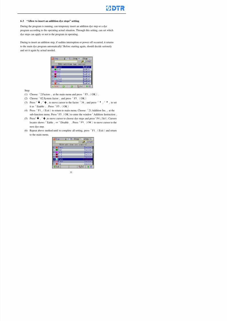
8132019 DTR 650 User Manual
httpslidepdfcomreaderfulldtr-650-user-manual 3570
6-3 ldquoAllow to insert an addition dye stepsrdquo setting
During the program is running can temporary insert an addition dye step or a dye
program according to the operating actual situation Through this setting can set which
dye steps can apply or not to the program in operating
During to insert an addition step if sudden interruption or power off occurred it returns
to the main dye program automatically Before starting again should decide seriously
and set it again by actual needed
Step
(1) Choose「2Factors」at the main menu and press「F5」(OK)
(2) Choose「02System factor」and press「F5」(OK)
(3) Press「」「」to move cursor to the factor「34」and press「3」「4」to set
it as「Enable」 Press「F5」(OK)
(4) Press「F1」(Exit)to return to main menu Choose「21Addition Ins」at the
sub-function menu Press「F5」(OK)to enter the window「Addition Instruction」
(5) Press「」「」to move cursor to choose dye steps and press「F4」(Sel) Cursors
locates shows「Eable」or「Disable」 Press「F5」(OK)to move cursor to the
next dye step
(6) Repeat above method until to complete all setting press「F1」(Exit)and return
to the main menu
8132019 DTR 650 User Manual
httpslidepdfcomreaderfulldtr-650-user-manual 3670
6-4 Setting the display mode
DTR650 has three types of display mode during operating Program List mode
Schematic Diagram mode and Icon mode Users can set the display mode during
operating by factor setting
It goes back to a Program List mode when dye program ended
Step
(1) Choose「2Factors」at the main menu and press「F5」(OK)
(2) Choose「02System factor」and press「F5」(OK)
(3) Press「F2」()「F3」()to move cursor to choose「32Display mode」Press
「3」「4」 it shows「Online picture」「Instruction」「Big Icon」 choose
「Online picture」(eg) and press「F5」to confirm
8132019 DTR 650 User Manual
httpslidepdfcomreaderfulldtr-650-user-manual 3770
(4) Press「F1」(Exit)to return to the main menu
(5) The Schematic Diagram displays when the program is running (it stays at theProgram List mode when there is an alarm occurred)
Press「F4」to transfer to another display mode
It goes back to a Program List mode from Schematic Diagram Mode when dye
program ended Press numeric key「3」to view Schematic Diagram Mode again
Quit to press「F5」(Exit)
6-5 Adapt the digital input to another functions
DTR-650 has 32(0~31)input terminal it owns an standard setting when the
controller is initial According to the userrsquos demand they can change the DTR-650rsquos
anther functions of Input Terminal and PLC Input channel
The PLC Intputrsquos name can also define by the users (use IBM computer to edit and
download)
How to set
(1) Choose「2 Factor」at the main menu Press「F5」(OK)
(2) Choose「22 Input table」at the sub-function menu and press「F5」(OK)to enter
「Edit input table」
The actual input
terminal of theIBM computer
PLCrsquos input channel
8132019 DTR 650 User Manual
httpslidepdfcomreaderfulldtr-650-user-manual 3870
6-6 Adapt the digital output to another functions
DTR-650 has 32(0~31)output terminals it owns an standard setting when thecontroller is initial According to the userrsquos demand they can adapte the digital output
and the PLC outputrsquos channel to another functions The PLC Output channelrsquos name
can also define by users (use IBM computer to edit and download)
Step
(1) Choose「2 Factor」at the main menu Press「F5」(OK)
(2) Choose「23 Output table」at the main menu and press「F5」(OK)
(3) Press「F2」()「F3」()to move cursor to choose the output terminal atthe left side of the window Press「F5」(Add) the PLCrsquos output channelrsquos
name is listing at the right side of the window
(4) Press「F2」()「F3」()to move cursor to choose the PLC outputrsquos channel
If cursor moves to the PLC output channel which already linking「Add」is
not for choosing that means that output channel is already occupied
(5) Confirm the connection to press「F5」(Add) Quit to press「F4」(Del)Press「F1」(Exit)when complete all setting and return to main menu
The actual output
terminal of the
IBM computer
PLCrsquos output channel
8132019 DTR 650 User Manual
httpslidepdfcomreaderfulldtr-650-user-manual 3970
983095 983109983140983145983156983145983150983143 983156983144983141 983110983137983139983156983151983154983155DTR-650 has several kinds of control factors
Userrsquos factors System factors Temperature Control factors Speed factors Dosing
factors PID factors Analog Input Output factors standard factors etchellipPlease refer
to the supplementary table for the setting range and standard of the factors
DTR-650 has a built-in standard factor Users can edit by themselves if necessary
7-1 Modifying userrsquos factors
Userrsquos factors is setting with the Dyeing machinesrsquos PLC Programrsquos factor it is define by
the PLC Programmer
Step to edit
(1) Choose「2Factors」at main menu Press「F5」(OK)
(2) Choose「01User Factor」Press「F5」(OK)
(3) Press「F2」()「F3」()「6」「5」to move cursor up down and by page
Choose a factor need to edit then press「3」「4」to set itrsquos value Press「F5」(OK) Cursor moves to the next factor
(4) Some of factors can input numbers by the numeric membrance keys to edit If
the input is incorrect it turns to red and means the edit is not available
8132019 DTR 650 User Manual
httpslidepdfcomreaderfulldtr-650-user-manual 4070
Modifyrsquos method of the system factors temperature factors speed factors dosingfactors PID factors analog Input output factors standard factors etchellipare same asabove
If apply the library of DTR500 and DTR600 into the DTR650 the key「3」「4」may not valid to use Please use the numeric keys instead of it to key in factors itmay not effect the normal operation
Please pay a serious attention and read carefully at the factorrsquos table before modify the factors An incorrect value may effect the DTR-650 Dyeing
Machine Controllerrsquos operating After modifying factors must cancel the
password and secure data
7-2 Loading the standard factors
After modifying factors if need to restore a manufacturerrsquos standard factors of
DTR-650 The method as follows
1 Choose「2Factors」at main menu Press「F5」(OK)
「 「 ( ) 「
8132019 DTR 650 User Manual
httpslidepdfcomreaderfulldtr-650-user-manual 4170
7-3 Copying the factor
Users can build up a set of factor by themselves and make a copy and save
Step
1 Choose「2Factors」at main menu Press「F5」(OK)
2 Choose「13Restore Factor」 press「F5」(OK) window「factor will be
overwrite 」
3 Press「F4」(Yes)copy finished and saved Return to the main menu
4 Press「F2」(No)to not copy the factor and the existing factor is not change Return
to the main menu
7-4 Loading the backup factors
Users can build up a set of factor and backup files to load to DTR-650
Step1 Choose「14Backup factor」at the sub-function menu Press「F5」(OK)and
window「Factror will be overwrite」appears
2 Press「F3」(OK)to load the the backup factor them return to main menu
Press「F2」(No)to not copy the factor and the existing factor is not change
Return to the main menu
8132019 DTR 650 User Manual
httpslidepdfcomreaderfulldtr-650-user-manual 4270
983096 983119983157983156983152983157983156 983124983141983155983156983145983150983143
Before the output testing must be complete the steps as follows
A Cut off all connecting line of output terminal of DTR-650
B Stop running the PLC
C Check up the connections of all output channels to avoid damages from
incorrect connections
D Check up state of dyeing machines include the temperature pressure valves
onoff and pumpshellipetc ensure the safety for priority
8-1 Testing the Digital output
Step
1 Choose「3Output Testing」at the main menu Press「F5」(OK) 2 Choose「1Digital」at the sub function menu Press「F5」(OK) window「Digital
output testing」appears
3 Press「」「」「」to move cursor to each output channels Press「F5」(OK)
Output Name
8132019 DTR 650 User Manual
httpslidepdfcomreaderfulldtr-650-user-manual 4370
8-2 Testing the Analog output
(1) Choose「3Output Testing」at the main menu Press「F5」(OK)
(2) Choose「2Analog」at the sub function menu Press「F5」(OK) window「Analog output testing」appears
(3) Press「」「」「」to move cursor to each channels Then key in number by
the numeric membrance keys (range0~200= 0~20mA) Press「F5」(OK) there
is a output current relating to the output channel
(4) Press「F5」(OK) There is an output when the output channel with red light No
output without light onl(5) When complete the testing press「F1」(OK)to return to the main menu
8132019 DTR 650 User Manual
httpslidepdfcomreaderfulldtr-650-user-manual 4470
983097 983107983137983148983145983138983154983137983156983145983151983150
DTR-650 has Dosing and Temperature calibration
When enter to Dosing calibration must be set the Low Volume calibration first and
then High Volume calibration When enter to Temperature calibration must be set the
Low Temperature calibration first and then High Temperature calibration Must be
hightly follow this orders seriously
9-1 Calibration of Low Volume Tank
Step
A Choose「4Calibration」at the main menu Press「F5」(OK)
B Choose「Dosing 0 low vol」at the sub function menu Press「F5」(OK) window
appears
C Fill the Dosing Tank to a half level input value shows how much the water level
If it stays ldquo0rdquo check the connection and the factor setting is correct or not
And connect the pressure sensorrsquos output channel to the Current Meter to ensure
that sensor works or not
8132019 DTR 650 User Manual
httpslidepdfcomreaderfulldtr-650-user-manual 4570
D Fill the Dosing Tank to 50ml (Calcalate from the bottom side of the pressure
sensor steel tube) input value should show 4~6 (input value must between
0~10) Then enter the water volume The setting volume is relating the water
levelrsquos water value (litre as unit) input range 0~80 Set as「 「「 「0000 0000 0000 0000」」」」is strongly is strongly is strongly is strongly
receommend receommend receommend receommend Press「F5」(OK)to complete [Calibration of Low Volume Tank 1
is same as above method]
9-2 Calibration of High Volume Tank
Step
A Choose「4Calibration」at the main menu Press「F5」(OK)
B Choose「Dos 0 high vol」at the sub function menu Press「F5」(OK) window of
「Calibrate high 」appears
C Fill the Dosing Tank to a full level input value should be larger than 30 enter
the current water level which relates to the water volume Enter the range within
100~2500 Then press「F5」(OK) to complete the calibrate the high volume tank
8132019 DTR 650 User Manual
httpslidepdfcomreaderfulldtr-650-user-manual 4670
9-3 Temperature Calibration
Step
A This function is for adjusting the DTR650rsquos accuracy of Temperature Control It
must be using with the special terminal which is only for DTR650
B Choose「4Calibration」at the main function menu and press「F5」(OK)
C Choose「3Low Temp」at the sub-function menu Press「F5」(OK)and《Fig9-3》
appears insert the DTR650rsquos low temperature calibration terminal to the temperature
input terminal wait for the jumping value to stable down then press「F5」(OK) then
to adjust the high temperature calibration
D Adjusting the High Temperature Calibrationrsquos method is same as above But usersusersusersusers
must be using the High Temperature Terminalmust be using the High Temperature Terminalmust be using the High Temperature Terminalmust be using the High Temperature Terminal whichwhichwhichwhich is specially for DTR650 onlyis specially for DTR650 onlyis specially for DTR650 onlyis specially for DTR650 only
《Fig 9-3》
8132019 DTR 650 User Manual
httpslidepdfcomreaderfulldtr-650-user-manual 4770
10 983122983141983139983151983154983140983155 983151983142 983108983161983141 983120983154983151983143983154983137983149983155
It contains the past 15 days of temperature curves of running history
Checking method
(1) Choose「5Dye Record」at main menu press「F5」(OK)
(2) Sub-function menu shows the set up date of the past 15 days dye programs
Listing by the lastest set up date
(3) Choose a program date and press「F5」(OK) it appears window「Temp
record」
(4) Press「」「」to move the white line in the box one minute by moving once
(5) Press「3」「4」to move the line to check the time period 2 hours by moving once
The yellow selecting line of the「24 hours operating state」is repectively moving
The curve info is show in the curve box Left side of the widnow appears the
relating running info the time is the time value of the line locates at
(6) Check more details of the temperature info to press numeric key「middot」 a bright red line
appears in the selecting box this line is to check the starting point of the
temperature inforsquos time period Then press「」to move the white line to the end
point of the time period The temperature info between the starting point and end
point are appears at the right side of the window Press「middot」to return to the preious
curve page
(7) Check more details of the alarm infor To perss numeric key「7」「9」 the alarmrsquos
details is listing by orders
(8) Press「F1」(exit) to return
8132019 DTR 650 User Manual
httpslidepdfcomreaderfulldtr-650-user-manual 4870
11 983125983155983137983143983141 983151983142 983117983141983149983151983154983161 983107983137983154983140
DTR-650 supports 32MB or above Compact Flash Card which can transfer and save all
information for 4 sets of DTR-650 Including library files schematic diagram icon
image PLC program dye program factor and confiruration files etchellip Use the CF Card
to up download and swap the information of DTR-650 promptly install the relating
device and program updates
DTR-650 CF Card with bank 1 to bank 4 can save 4 sets information of Dyeing
Machines When download or save files should choose the BANK first
《Fig11-1》
8132019 DTR 650 User Manual
httpslidepdfcomreaderfulldtr-650-user-manual 4970
11-1 Downloading data
1 Firmly insert the CF card into the DTR-650rsquos PCMCIA connector Ensure it is
wholely and firmly inserted if the card is not totally inserted or the card do not
touch in all to the connector there will be an error occurred and cannot
updownload or interrupted during operation
2 Choose「6Memory Card」at the main menu and press「F5」(OK) 《Fig11-1》
appears Information of Bank「1」shows at the left hand side of the window press
number 1-4 by using numeric keys to choose the BANK Check the
information in the Bank seriously which is exactly need to download to the
DTR650
3 Press()()「6」「5」to move cursor to the sub-function menu to choose
the downloading items Press「F5」(OK) window appears「Stop PLC run before
access memory card Stop the PLC run」 Press「F5」(YES) to stop PLC
running
4 Press「F5」(OK) window appears Confirm to update or not the DTR-650rsquos
information As that downloading will be replace the DTR-650rsquos information
(that means the existing information of the DTR-650 will be removed and
replaced)
5 Press「F4」(YES)to download the information from the DTR-650 to the CF
Card Return to the main menu when finish
8132019 DTR 650 User Manual
httpslidepdfcomreaderfulldtr-650-user-manual 5070
Ensure inserting firmly the CF card into the DTR-650 unless it will cause
error or cannot Updownload data
Never remove CF card during transferring or updownloading data Until it
is all completed
DTR-650rsquos dyeing program is not compatible with DTR-500 and
DTR-600 Never use CF card to transfer data among them
11-2 Storing and transfering data
1 Insert the CF Card to the DTR-650
2 Choose「6Memory Card」at the main menu and press「F5」(OK) 《Fig11-1》
appears Left hand side of the window shows the data of BANK 1 press numeric
keys 1-4 to select the BANK To confirm the put the data in the DTR-650 to the CF
Card The existing data of that bank will be replaced and covered by the new data (if
that bank is already occuplied)
3 Choose「23Save Dye prog」(Example)at the sub-funciton menu press「F5」(OK)to confirm Window「Update memory card data」appears
4 Press「F5」(OK)to transfer the data to the CF card Return to the main menu
5 Put the CF card into another DTR-650 and follow the operating method of 「11-1
Downloading data」」」」can transfer and swap data with more than one set of
DTR-650
8132019 DTR 650 User Manual
httpslidepdfcomreaderfulldtr-650-user-manual 5170
12 983123983156983137983156983141 983137983150983140 983113983150983142983151983154983149983137983156983145983151983150
The state and information is including the Dyeing Machinersquos state of Digit Input output
Analog Input output Temperature control PID Dosing PID Pressure different PID
software system information and alarm record This information is for checking at any
time
12-1 Input Output state
Step
1 Choose「7Info and state」at main menu and press「F5」(OK)
2 Choose「01Digital IO put」at the sub-function menu then press「F5」(OK)
「Digital In Out State」0=None 1=Input
3 Press「F1」(Exit)to return to main menu
Same method for checking the temperature control analog dosing pressure
different etchellip
12-2 Checking the system information
Step
1 Choose「7Info and state」at main menu and press「F5」(OK)
2 Choose「11 System info」at sub-function field press「F5」(OK)Window
「System Information」appear
System information is including System info(software version) Library doc
Icon files Schematic file Definition file hardare state Config File Commandinstruction icon PLC file etc
8132019 DTR 650 User Manual
httpslidepdfcomreaderfulldtr-650-user-manual 5270
12-3 Checking the operating alarm record
Operating record shows the latest 40 operating items and alarm records including
the time and content of the alarm
A) Choose「7 Info and state」
and press「F5」(OK)
B) Choose「12Alarm logs」at
the sub-funciton menu then
press「F5」(OK)
8132019 DTR 650 User Manual
httpslidepdfcomreaderfulldtr-650-user-manual 5370
13 983105983140983146983157983155983156983145983150983143 983156983144983141 983107983151983150983156983154983137983155983156
The displaysrsquos brightness can be adjusted if necessary
Step
1 Choose「8Others」at main menu press「F5」(OK)
2 Choose「01Contrast」at sub-function menu press「F5」(OK) window「Set
Contrast」appears
3 Press「」「」to move the bar to set the brightness then press「F5」(OK)Window appears「Please reboot the system」
4 Press「F5」(OK)to return to main menu and re-boot the DTR-650 to complete
adjusting the brightness
8132019 DTR 650 User Manual
httpslidepdfcomreaderfulldtr-650-user-manual 5470
14 983123983156983151983152 983154983157983150983150983145983150983143 983156983144983141 983120983116983107 983120983154983151983143983154983137983149
Before testing the Input output testing transfer of the PLC program must stop the PLC
running
Step
1 Choose「8Others」at the main menu Press「F5」(OK)
2 Choose「04 PLC Stop」at sub-function menu Press「F5」(OK) window
「Password」appears
3 Enter password and press「F5」(OK) Window「Stop the PLC run」appears
4 Press「F4」(Yes)and window「PLC Stop」appear Press「F5」(OK) Now
the PLC is stop running and return to the main menu
All testing cannot operate when the PLC is running
Editing dye program and the relating operation can
perform with the PLC running together
8132019 DTR 650 User Manual
httpslidepdfcomreaderfulldtr-650-user-manual 5570
15 983123983141983156983156983145983150983143 983156983144983141 983156983145983149983141
Step
1 Press「8Others」at the main menu Press「F5」(OK)
2 Choose「10Set date time」at the sub-function menu Press「F5」(OK) window
「Set date time」appears
3 Press「F5」(Edit) to move cursor by 「3」「4」 enter the time value at the
cursor locates
4 Press「F5」(OK)to complete the modify Press「F1」(Exit)to return to main
menu
5 Press「F1」(Exit)if not modify and return to main menu
8132019 DTR 650 User Manual
httpslidepdfcomreaderfulldtr-650-user-manual 5670
1166 983123983123983157983157 983152 983152 983152 983152983148983148983141983141983149983149983141983141983150983150983156 983156 983137983137983154 983154 983161983161 983124 983124 983137983137983138983138983148983148983141983141
TTTTTTTTaaaaaaaabbbbbbbblllllllleeeeeeee 11111111 【Dye Instruction】
Code Icon Instruction Code Icon Instruction
000 End 016 Inject C
001 Start 017 Dosing BV
002 Heat 018 PH
003 Cool 019 Addsalt B
004 Flow Fill 020 Addsalt C
005 Level Fill 021 Ana Fill
006 Drian 022 Lock Fill007 Rinse 023 Lock Level
008 Run 024 Low Rinse
009 Call 025 Cyc Rinse
010 Prep B 026 Rinse B
011 Addsalt B 027 Rinse C
012 Dosing B 028 Temp
013 Inject B 029 Nozzle Pressure
014 Prep C 030 Main Pump
015 Dosing C 031 Pump Speed
8132019 DTR 650 User Manual
httpslidepdfcomreaderfulldtr-650-user-manual 5770
Table 2 【【【【Alarm】】】】
System Alarm Must stop operating and check up to solve problems before restarting
the machine
Running Alarm It is a reminder Not effect the operating of DTR-650
Userrsquos Alarm Total of 32 Users can define themselves and use it when edit the PLC
Program (do not listing below)
No System Alarm No Running Alarm
1 PLC program not running 16 Temp ctrl 0 Grad too slow
2 Main temp sensor error 17 Temp ctrl 0 Grad too fast
3 Not at Run window 18 Temp ctrl 0 Hold temp too low
4 Exceeding max temp 19 Temp ctrl 0 Hold temp too high
5 - 20 Temp ctrl 1 Grad too slow6 - 21 Temp ctrl 1 Grad too fast
7 - 22 Temp ctrl 1 Hold temp too low
8 Communication error 23 Temp ctrl 1 Hold temp too high
9 Slave not answer 24 Temp ctrl 2 Grad too slow
10 PLC 0 not answer 25 Temp ctrl 2 Grad too fast
11 PLC 1 not answer 26 Temp 2 Hold temp too low12 Display not answer 27 Temp 2 Hold temp too high
13 Lower power voltage 28 Temp ctrl 3 Grad too slow
14 - 29 Temp ctrl 3 Grad too fast
15 - 30 Temp3 Hold temp too low
31 Temp3 Hold temp too high
32 Dosing 0 injection too slow
33 Dosing 0 injection too fast
34 Dosing 1 injection too slow
35 Dosing 1 injection too fast
8132019 DTR 650 User Manual
httpslidepdfcomreaderfulldtr-650-user-manual 5870
TTTTTTTTaaaaaaaabbbbbbbblllllllleeeeeeee 33333333 【【【【System factor】】】】
No Description Std Range amp Definition
1 ID No 000 000- 100 Controller no
2 Communication Rate 4800Bps 2400 4800 9600 19200 38400
3 Display language Chinese English Chinese
4 Temp display mode and
5 Maxmium temperature 145 025 ~ 145 6 Type of external PLC Default PLC32DPLC32PLC16Default
7 Number of external PLC NANA 1 unit connect
2 unit connect
8Communication Rate of
PLC9600Bps 2400 4800 9600 19200
9 Set point 1 085 000 ~ 145
If signal source is temperaturethe setting value is thetemperature value If the signal
source is Analog Input 6~17 then
setting value for Analog input is 0 ndash
100 and relates Analog
Input14~020mA
10 Source 1 Sensor0Sensor 0 ~5
Analog input 0 ~1111 Set point 2 092 Same as 09
12 Source 2 PT100 1 Same as 10
13 Set point 3 085 Same as 09
14 Source 3 PT100 2 Same as 10
15 Set point 4 092 Same as 09
16 Source 4 PT100 3 Same as 1017 Set point 5 085 Same as 09
18 Source 5 PT100 4 Same as 10
19 Set point 6 092 Same as 09
8132019 DTR 650 User Manual
httpslidepdfcomreaderfulldtr-650-user-manual 5970
29 Min cyclic time of cloth 100sec 0 ~ 255 sec
30 Max cyclic time of cloth 240sec 0 ~255 sec
31Standard cyclic time of
cloth
180 000 ~ 255 sec
32 Display ModeProgram
List
Program list Schematic Diagram
Icon mode
33 CF card format Standard of
DTR CF
Card
Standard of DTR CF Card V20
Standard CF Card
34 Addition step Disable Disable Enable35 Mode Com 3
CouplingEsure Com 3 is the communication
port of the Central or Coupling
36Com 3 Communication
rate9600 Central communication speed
8132019 DTR 650 User Manual
httpslidepdfcomreaderfulldtr-650-user-manual 6070
TTTTTTTTaaaaaaaabbbbbbbblllllllleeeeeeee 44444444 【【【【Temperature Cotnrol Factor】】】】
No Factor Definition Standard Range and Definition
01 PT No PT-0 PT 0~5 PT-100 Input number
02 Max working temp 140 000~140
03 Output mode 0 0~2
04 Alarm time of gardient 240sec 000~255 sec
05 Alarm mode of gradient Always AlwaysOnceNone
06 Control mode of gradient Heating orCooling
interlocked
Heating and Cooling interlocked
No limitation
07 Alarm range of HoldTemp 03 01~20
08 Alarm time for HoldTemp 240sec 000~255sec
09 Alarm mode of HoldTemp Always AlwaysOnceNone
10 Control mode ofHoldTemp
Heating only Only heating and cooling Cooling whenalarm occurred Only heating andcooling No limitation when alarmHeating only
11 Porportional Band 100 000~250
12 Integral band 128 sec 000~255 sec
13 Differential time 04 sec 00~20 sec
14 Min transit gradient 02 00~50
15 Transit rate 20 times 00~50 times (020= 2 times)
16 PID initial output value 010 000~100
17 ONOFF cycle time 10 sec 05~25 sec
Onoff valve set as 010 sec
Proportional valve set as 020 sec
18 Time down count mode Mode 0 0~10 = The time down count range from「Factor 20 + target temp」to「Target
8132019 DTR 650 User Manual
httpslidepdfcomreaderfulldtr-650-user-manual 6170
TTTTTTTTaaaaaaaabbbbbbbblllllllleeeeeeee 55555555 【【【【Speed Factor】】】】
No Factor Definition Standard Range amp Definition
01 Input Number Speed input 0 Speed input 0~11
02 Average times 05 times 01~10
03 Sensor Number 008pcs 001~255
04 Roller Dimension 250mm 050~500
05 Max cloth speed 200mmin 001~25506 Min cloth speed 020mmin 001~255
07 Alarm delay time 240sec 001~255
08 Alarm mode Every oncenoneevery
09 Alarm range () 020 001~255
10 Proportional band 100 001~255
11 Integer band 128 001~25512 Differential time 000 001~200
13 Initial speed () 020 001~255
14 Control cycle ti(01sec) 05 01~30
15 First cycle time(01sec) 10 01~30
16 Speed increase limit () 010 001~100
17 Speed decrease limit () 010 001~100
18 Min speed() 005 001~100
19 Manual speed adjust () 005 001~100
20 Manual initial speed() 020 001~100
21 Stopping speed() 010 001~100
22 Switch speed() 020 001~100
23 Not used
24 Speed decrease turns 03turns 01~50
8132019 DTR 650 User Manual
httpslidepdfcomreaderfulldtr-650-user-manual 6270
Table 6 【【【【Dosing Factors】】】】
No Description Range Range and Explanation
1 Analog input no Analog input 0 Analog input no 0 ~11
2Alarm delay time for
dosing240 sec 000 ~255 sec
3 Alarm time for dosing Every Every Once None
4 Proportional band 100 000 ~255 sec Factor P
5 Integer band 128 000 ~255 sec Factor I6 Differential time 04 00 ~20 Factor D
7 Max adjust rate 150 50~ 255
8 Initial factor for dosing 10 000 ~100
9 User curve section 0 10 Gradient of sect1 for dosing curve9
10 User curve section 1 10 Gradient of sect2 for dosing curve9
11 User curve section 2 10 Gradient of sect3 for dosing curve9
12 User curve section 3 10 Gradient of sect4 for dosing curve9
13 User curve section 4 10 Gradient of sect5 for dosing curve9
14 User curve section 5 10 Gradient of sect6 for dosing curve9
15 User curve section 6 10 Gradient of sect7 for dosing curve9
16 User curve section 7 10 Gradient of sect8 for dosing curve9
17 User curve section 8 10 Gradient of sect9 for dosing curve9
18 User curve section 9 10 Gradient of sect10 for dosing curve9
19 Min water level 05 00~ 10 04~20mA percentagechange to the userrsquos factor setting
20 Output value for Tank
clean
100 000~ 100
Injected percentage of dosing valve
in dosing End period
This factor will be invalided if usingONOFF dosing valve
21 Full range 100 001~255 Self-adjustment cannotchange
22 Range ratio 001001~255 Self-adjustment cannot
change
8132019 DTR 650 User Manual
httpslidepdfcomreaderfulldtr-650-user-manual 6370
【【【【TTaabbllee 77 】】】】Pressure Deviation Factors
No Description Std Range amp Definition
1 Analog input number + Analog in 0 Analog in 0~11
2 Analog input number - Analog in 1 Analog in 0~11
3 Input mode Pressure Pressure Pressure deviation
4 Full range 050x01Kgcm
001~255
5 Range ratio 001 001~255
6 Alarm delay time 100sec 001~255
7 Alarm mode Every oncenone
8 Alarm range 010 001~255
9 Proportional band 100 001~255
10 Integer band 128 001~255
11 Differential time 00 00~20
12 PID Init output value 010 001~255
13 Cycle time 10 03~30
14 First cycle time 030 003~100
15 Max adjust rate 010 001~100
8132019 DTR 650 User Manual
httpslidepdfcomreaderfulldtr-650-user-manual 6470
【【【【TTaabbllee 88 】】】】Definition of Analog Input
No Description Standard Range and Explanation
01 PT 0 correction standard DIN std DIN std JIS std
02 PT 0 correction +0 +- 9
03 PT 1 correction standard DIN std DIN std JIS std
04 PT 1 correction +0 +- 9
05 PT 2 correction standard DIN std DIN std JIS std
06 PT 2 correction +0 +- 9
07 PT 3 correction standard DIN std DIN std JIS std
08 PT 3 correction +0 +- 9
09 PT 4 correction standard DIN std DIN std JIS std
10 PT 4 correction +0 +- 9
11 PT 5 correction standard DIN std DIN std JIS std
12 PT 5 correction +0 +- 9
13 Analog input 0 define 4 ~ 20mA 0 ndash 20mA 4 ndash 20mA
14 Analog input 0 average times 10 times 01- 20 times
15 Analog input 0 min value 0000 0000 - 1000
16 Analog input 0 max value 100 0001 - 9999
17-60 Analog input 1~11 Same as Analog input 0
【【【【 】】】】 fi i i f A O
8132019 DTR 650 User Manual
httpslidepdfcomreaderfulldtr-650-user-manual 6570
【【【【TTaabbllee 99 】】】】Definition of Analog Output
No Description Standard Range and explanation
61 Analog output 0 define Control byPLC
Control by PLC
Temperature control PID0 output
Temperature control PID1 output
Temperature control PID2 output
Speed PID3 output
Dosing PID0 output Dosing PID1output
Pressure different PID0 outputPressure different PID1 output
Main temperature output
62 Mode of Analog ouptput0 4 ~20mA 0 ndash20mA 4 ndash 20mA
63-84 Analog output 1~11 Same as Analog output 0
【【【【TTaabbllee 1100】】】】Value Table 0 amp 1
No Description Range Std Range and explanation
1 Analog input no 000~011 000 Analog input no
2 Data ratio 001~255 100 Multiple by factors
3~53 0~98 000~255 000-100 Analog input 0~98 data
【【【【 】】】】St t Li t
8132019 DTR 650 User Manual
httpslidepdfcomreaderfulldtr-650-user-manual 6670
【【【【TTaabbllee 1111】】】】State List
No Description Range Standard Range and explanation
1 Display setting 1 0~255 205 See remarks at next page
2 Display setting 2 0~255 208
3 Display setting 3 0~255 209
4 Display setting 4 0~255 017
5 Display setting 5 0~255 0186 Display setting 6 0~255 019
7 Display setting 7 0~255 020
8 Display setting 8 0~255 021
9 Display setting 9 0~255 000
10 Display setting 1 0~255 000
11 Display setting 2 0~255 000
12 Display setting 3 0~255 000
13 Display setting 4 0~255 000
14 Display setting 5 0~255 000
15 Display setting 6 0~255 000
16 Display setting 7 0~255 000
Remarks
8132019 DTR 650 User Manual
httpslidepdfcomreaderfulldtr-650-user-manual 6770
0 = No display 1~255 = Display type of number
1~16 Content of PLC VB0~15
No 1 corresponding to VB0
No 16 corresponding to VB15
17~32 Content of PLC DB0~15
No 17 corresponding to DB0
No 32 corresponding to DB15
33~46 Content of PLC CNT0~29
No 33 corresponding to CNT0
No 46 corresponding to CNT29 47~78 Content of dyeing instruction 0~31 CNT0
No 47 corresponding to system instruction to No 0 of CNT0
No 78 corresponding to system instruction to No 31 of CNT0rsquos content
79~110 Dyeing instruction 0~31 of CNT0rsquos setting
111~142 Content of Dyeing instruction 0~31 CNT1No 111 corresponding to dyeing instruction No 0 of CNT1
No 142 corresponding to dyeing instruction No 31 of CNT1rsquos content
143~174 Dyeing instruction 0~31 of CNT1rsquos setting
175~204 Content of PLC HTIM0~29
No 175 corresponding to HTIM0
No 204 corresponding to HTIM29
205 Loading
206 Ratio 1
207 Ratio 2208 Ratio 1 x Loading
209 Ratio 2 x Loading
210 Fix value
211 Value Table 1 matching result
212 Value Table 2 matching result
213 Value Table 1 setting214 Value Table 2 setting
215 Pressure control PID0 different pressure value
216 Pressure control PID1 different pressure value
TTTTTTTTaaaaaaaabbbbbbbblllllllleeeeeeee 1122 【【【【Usage of password】】】】
8132019 DTR 650 User Manual
httpslidepdfcomreaderfulldtr-650-user-manual 6870
No Main FunctionFactor Sub Function Factor Password Rank
1 Run None
2 Dye program User3 or above
3 Control factor
- User factor User 1
- System factor User 1
- Temp PID 0
- Temp PID 1 User 1- Speed PID 0 User 1
- Dosing PID 0 User 1
- Dosing PID 1 User 1
- Pressure PID 0 User 1
- Pressure PID 1 User 1
- Analog IO User 1
- Load standard factor User 2 or above- Load a copied factor User 2 or above
- Copy factor User 2 or above
- Value table 0 User 1
- Value table 1 User 1
- Information and state User 1
- Dye instruction User 1
- Edit dye instruction setting User 14 Output testing User 2 or above
5 Calibration User 2 or above
6 Dye record None
7 CF card User 1
8 Info and state None
9 Others
- Contrast User3 or above
- Data Locking None
- PLC Run User 1
- PLC Stop User 1
- Password setting User 1
TTTTTTTTaaaaaaaabbbbbbbblllllllleeeeeeee 1133 【【【【Technical Data】】】】
8132019 DTR 650 User Manual
httpslidepdfcomreaderfulldtr-650-user-manual 6970
TTTTTTTTaaaaaaaabbbbbbbblllllllleeeeeeee 1133 【【【【Technical Data】】】】
1 Temperature Control
- Range 10~145(plusmn1)
- Mode Proportional or PWM
- Sensor PT100 (JIS or DIN standard)
2 Input and output channel
- Digital Input 32 DC24V PNP- Digital Output 32 DC24V 054A Relay connect point
- Analog Input 4 04~20 mA
- Analog Output 4 0~20mA 或 4~20 mA
3 Communication port 3 RS-232 amp 0~20 mAx1 RS485x 2
4 Dye program
- Number 15000 Steps
- Standard step 61Heating Cooling Fill Drain RinseDosingetc
5LCD module and Display
langage
Chinese
English
320 x 240 TFT color display with
more language
6 CF card connector 1 PCMCIA standard
7 Membrane Keyboard- Number Key 10 [0]~[9] Input factors
- Function Key 5 [F1]~[F5] function selecting
- Operation Key 2 [Start] [Stop]
- Auxiliary Key 7 [][][][][Esc] [larr][OK] [bull]
8 Operating Condition
- Temperature 5~45
- Humidity ≦85 (25)
9 Power supply
V l DC 24V
8132019 DTR 650 User Manual
httpslidepdfcomreaderfulldtr-650-user-manual 7070
70
983108983124983122983085650 983113983150983152983157983156 983119983157983156983152983157983156 983120983151983154983156983145983150983143 (983138983137983139983147983155983145983140983141 983158983145983141983159)
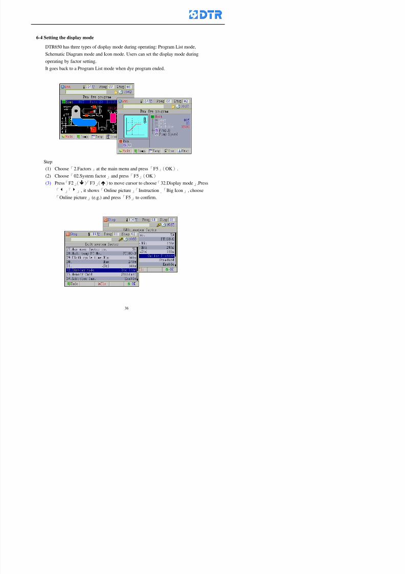
8132019 DTR 650 User Manual
httpslidepdfcomreaderfulldtr-650-user-manual 3670
6-4 Setting the display mode
DTR650 has three types of display mode during operating Program List mode
Schematic Diagram mode and Icon mode Users can set the display mode during
operating by factor setting
It goes back to a Program List mode when dye program ended
Step
(1) Choose「2Factors」at the main menu and press「F5」(OK)
(2) Choose「02System factor」and press「F5」(OK)
(3) Press「F2」()「F3」()to move cursor to choose「32Display mode」Press
「3」「4」 it shows「Online picture」「Instruction」「Big Icon」 choose
「Online picture」(eg) and press「F5」to confirm
8132019 DTR 650 User Manual
httpslidepdfcomreaderfulldtr-650-user-manual 3770
(4) Press「F1」(Exit)to return to the main menu
(5) The Schematic Diagram displays when the program is running (it stays at theProgram List mode when there is an alarm occurred)
Press「F4」to transfer to another display mode
It goes back to a Program List mode from Schematic Diagram Mode when dye
program ended Press numeric key「3」to view Schematic Diagram Mode again
Quit to press「F5」(Exit)
6-5 Adapt the digital input to another functions
DTR-650 has 32(0~31)input terminal it owns an standard setting when the
controller is initial According to the userrsquos demand they can change the DTR-650rsquos
anther functions of Input Terminal and PLC Input channel
The PLC Intputrsquos name can also define by the users (use IBM computer to edit and
download)
How to set
(1) Choose「2 Factor」at the main menu Press「F5」(OK)
(2) Choose「22 Input table」at the sub-function menu and press「F5」(OK)to enter
「Edit input table」
The actual input
terminal of theIBM computer
PLCrsquos input channel
8132019 DTR 650 User Manual
httpslidepdfcomreaderfulldtr-650-user-manual 3870
6-6 Adapt the digital output to another functions
DTR-650 has 32(0~31)output terminals it owns an standard setting when thecontroller is initial According to the userrsquos demand they can adapte the digital output
and the PLC outputrsquos channel to another functions The PLC Output channelrsquos name
can also define by users (use IBM computer to edit and download)
Step
(1) Choose「2 Factor」at the main menu Press「F5」(OK)
(2) Choose「23 Output table」at the main menu and press「F5」(OK)
(3) Press「F2」()「F3」()to move cursor to choose the output terminal atthe left side of the window Press「F5」(Add) the PLCrsquos output channelrsquos
name is listing at the right side of the window
(4) Press「F2」()「F3」()to move cursor to choose the PLC outputrsquos channel
If cursor moves to the PLC output channel which already linking「Add」is
not for choosing that means that output channel is already occupied
(5) Confirm the connection to press「F5」(Add) Quit to press「F4」(Del)Press「F1」(Exit)when complete all setting and return to main menu
The actual output
terminal of the
IBM computer
PLCrsquos output channel
8132019 DTR 650 User Manual
httpslidepdfcomreaderfulldtr-650-user-manual 3970
983095 983109983140983145983156983145983150983143 983156983144983141 983110983137983139983156983151983154983155DTR-650 has several kinds of control factors
Userrsquos factors System factors Temperature Control factors Speed factors Dosing
factors PID factors Analog Input Output factors standard factors etchellipPlease refer
to the supplementary table for the setting range and standard of the factors
DTR-650 has a built-in standard factor Users can edit by themselves if necessary
7-1 Modifying userrsquos factors
Userrsquos factors is setting with the Dyeing machinesrsquos PLC Programrsquos factor it is define by
the PLC Programmer
Step to edit
(1) Choose「2Factors」at main menu Press「F5」(OK)
(2) Choose「01User Factor」Press「F5」(OK)
(3) Press「F2」()「F3」()「6」「5」to move cursor up down and by page
Choose a factor need to edit then press「3」「4」to set itrsquos value Press「F5」(OK) Cursor moves to the next factor
(4) Some of factors can input numbers by the numeric membrance keys to edit If
the input is incorrect it turns to red and means the edit is not available
8132019 DTR 650 User Manual
httpslidepdfcomreaderfulldtr-650-user-manual 4070
Modifyrsquos method of the system factors temperature factors speed factors dosingfactors PID factors analog Input output factors standard factors etchellipare same asabove
If apply the library of DTR500 and DTR600 into the DTR650 the key「3」「4」may not valid to use Please use the numeric keys instead of it to key in factors itmay not effect the normal operation
Please pay a serious attention and read carefully at the factorrsquos table before modify the factors An incorrect value may effect the DTR-650 Dyeing
Machine Controllerrsquos operating After modifying factors must cancel the
password and secure data
7-2 Loading the standard factors
After modifying factors if need to restore a manufacturerrsquos standard factors of
DTR-650 The method as follows
1 Choose「2Factors」at main menu Press「F5」(OK)
「 「 ( ) 「
8132019 DTR 650 User Manual
httpslidepdfcomreaderfulldtr-650-user-manual 4170
7-3 Copying the factor
Users can build up a set of factor by themselves and make a copy and save
Step
1 Choose「2Factors」at main menu Press「F5」(OK)
2 Choose「13Restore Factor」 press「F5」(OK) window「factor will be
overwrite 」
3 Press「F4」(Yes)copy finished and saved Return to the main menu
4 Press「F2」(No)to not copy the factor and the existing factor is not change Return
to the main menu
7-4 Loading the backup factors
Users can build up a set of factor and backup files to load to DTR-650
Step1 Choose「14Backup factor」at the sub-function menu Press「F5」(OK)and
window「Factror will be overwrite」appears
2 Press「F3」(OK)to load the the backup factor them return to main menu
Press「F2」(No)to not copy the factor and the existing factor is not change
Return to the main menu
8132019 DTR 650 User Manual
httpslidepdfcomreaderfulldtr-650-user-manual 4270
983096 983119983157983156983152983157983156 983124983141983155983156983145983150983143
Before the output testing must be complete the steps as follows
A Cut off all connecting line of output terminal of DTR-650
B Stop running the PLC
C Check up the connections of all output channels to avoid damages from
incorrect connections
D Check up state of dyeing machines include the temperature pressure valves
onoff and pumpshellipetc ensure the safety for priority
8-1 Testing the Digital output
Step
1 Choose「3Output Testing」at the main menu Press「F5」(OK) 2 Choose「1Digital」at the sub function menu Press「F5」(OK) window「Digital
output testing」appears
3 Press「」「」「」to move cursor to each output channels Press「F5」(OK)
Output Name
8132019 DTR 650 User Manual
httpslidepdfcomreaderfulldtr-650-user-manual 4370
8-2 Testing the Analog output
(1) Choose「3Output Testing」at the main menu Press「F5」(OK)
(2) Choose「2Analog」at the sub function menu Press「F5」(OK) window「Analog output testing」appears
(3) Press「」「」「」to move cursor to each channels Then key in number by
the numeric membrance keys (range0~200= 0~20mA) Press「F5」(OK) there
is a output current relating to the output channel
(4) Press「F5」(OK) There is an output when the output channel with red light No
output without light onl(5) When complete the testing press「F1」(OK)to return to the main menu
8132019 DTR 650 User Manual
httpslidepdfcomreaderfulldtr-650-user-manual 4470
983097 983107983137983148983145983138983154983137983156983145983151983150
DTR-650 has Dosing and Temperature calibration
When enter to Dosing calibration must be set the Low Volume calibration first and
then High Volume calibration When enter to Temperature calibration must be set the
Low Temperature calibration first and then High Temperature calibration Must be
hightly follow this orders seriously
9-1 Calibration of Low Volume Tank
Step
A Choose「4Calibration」at the main menu Press「F5」(OK)
B Choose「Dosing 0 low vol」at the sub function menu Press「F5」(OK) window
appears
C Fill the Dosing Tank to a half level input value shows how much the water level
If it stays ldquo0rdquo check the connection and the factor setting is correct or not
And connect the pressure sensorrsquos output channel to the Current Meter to ensure
that sensor works or not
8132019 DTR 650 User Manual
httpslidepdfcomreaderfulldtr-650-user-manual 4570
D Fill the Dosing Tank to 50ml (Calcalate from the bottom side of the pressure
sensor steel tube) input value should show 4~6 (input value must between
0~10) Then enter the water volume The setting volume is relating the water
levelrsquos water value (litre as unit) input range 0~80 Set as「 「「 「0000 0000 0000 0000」」」」is strongly is strongly is strongly is strongly
receommend receommend receommend receommend Press「F5」(OK)to complete [Calibration of Low Volume Tank 1
is same as above method]
9-2 Calibration of High Volume Tank
Step
A Choose「4Calibration」at the main menu Press「F5」(OK)
B Choose「Dos 0 high vol」at the sub function menu Press「F5」(OK) window of
「Calibrate high 」appears
C Fill the Dosing Tank to a full level input value should be larger than 30 enter
the current water level which relates to the water volume Enter the range within
100~2500 Then press「F5」(OK) to complete the calibrate the high volume tank
8132019 DTR 650 User Manual
httpslidepdfcomreaderfulldtr-650-user-manual 4670
9-3 Temperature Calibration
Step
A This function is for adjusting the DTR650rsquos accuracy of Temperature Control It
must be using with the special terminal which is only for DTR650
B Choose「4Calibration」at the main function menu and press「F5」(OK)
C Choose「3Low Temp」at the sub-function menu Press「F5」(OK)and《Fig9-3》
appears insert the DTR650rsquos low temperature calibration terminal to the temperature
input terminal wait for the jumping value to stable down then press「F5」(OK) then
to adjust the high temperature calibration
D Adjusting the High Temperature Calibrationrsquos method is same as above But usersusersusersusers
must be using the High Temperature Terminalmust be using the High Temperature Terminalmust be using the High Temperature Terminalmust be using the High Temperature Terminal whichwhichwhichwhich is specially for DTR650 onlyis specially for DTR650 onlyis specially for DTR650 onlyis specially for DTR650 only
《Fig 9-3》
8132019 DTR 650 User Manual
httpslidepdfcomreaderfulldtr-650-user-manual 4770
10 983122983141983139983151983154983140983155 983151983142 983108983161983141 983120983154983151983143983154983137983149983155
It contains the past 15 days of temperature curves of running history
Checking method
(1) Choose「5Dye Record」at main menu press「F5」(OK)
(2) Sub-function menu shows the set up date of the past 15 days dye programs
Listing by the lastest set up date
(3) Choose a program date and press「F5」(OK) it appears window「Temp
record」
(4) Press「」「」to move the white line in the box one minute by moving once
(5) Press「3」「4」to move the line to check the time period 2 hours by moving once
The yellow selecting line of the「24 hours operating state」is repectively moving
The curve info is show in the curve box Left side of the widnow appears the
relating running info the time is the time value of the line locates at
(6) Check more details of the temperature info to press numeric key「middot」 a bright red line
appears in the selecting box this line is to check the starting point of the
temperature inforsquos time period Then press「」to move the white line to the end
point of the time period The temperature info between the starting point and end
point are appears at the right side of the window Press「middot」to return to the preious
curve page
(7) Check more details of the alarm infor To perss numeric key「7」「9」 the alarmrsquos
details is listing by orders
(8) Press「F1」(exit) to return
8132019 DTR 650 User Manual
httpslidepdfcomreaderfulldtr-650-user-manual 4870
11 983125983155983137983143983141 983151983142 983117983141983149983151983154983161 983107983137983154983140
DTR-650 supports 32MB or above Compact Flash Card which can transfer and save all
information for 4 sets of DTR-650 Including library files schematic diagram icon
image PLC program dye program factor and confiruration files etchellip Use the CF Card
to up download and swap the information of DTR-650 promptly install the relating
device and program updates
DTR-650 CF Card with bank 1 to bank 4 can save 4 sets information of Dyeing
Machines When download or save files should choose the BANK first
《Fig11-1》
8132019 DTR 650 User Manual
httpslidepdfcomreaderfulldtr-650-user-manual 4970
11-1 Downloading data
1 Firmly insert the CF card into the DTR-650rsquos PCMCIA connector Ensure it is
wholely and firmly inserted if the card is not totally inserted or the card do not
touch in all to the connector there will be an error occurred and cannot
updownload or interrupted during operation
2 Choose「6Memory Card」at the main menu and press「F5」(OK) 《Fig11-1》
appears Information of Bank「1」shows at the left hand side of the window press
number 1-4 by using numeric keys to choose the BANK Check the
information in the Bank seriously which is exactly need to download to the
DTR650
3 Press()()「6」「5」to move cursor to the sub-function menu to choose
the downloading items Press「F5」(OK) window appears「Stop PLC run before
access memory card Stop the PLC run」 Press「F5」(YES) to stop PLC
running
4 Press「F5」(OK) window appears Confirm to update or not the DTR-650rsquos
information As that downloading will be replace the DTR-650rsquos information
(that means the existing information of the DTR-650 will be removed and
replaced)
5 Press「F4」(YES)to download the information from the DTR-650 to the CF
Card Return to the main menu when finish
8132019 DTR 650 User Manual
httpslidepdfcomreaderfulldtr-650-user-manual 5070
Ensure inserting firmly the CF card into the DTR-650 unless it will cause
error or cannot Updownload data
Never remove CF card during transferring or updownloading data Until it
is all completed
DTR-650rsquos dyeing program is not compatible with DTR-500 and
DTR-600 Never use CF card to transfer data among them
11-2 Storing and transfering data
1 Insert the CF Card to the DTR-650
2 Choose「6Memory Card」at the main menu and press「F5」(OK) 《Fig11-1》
appears Left hand side of the window shows the data of BANK 1 press numeric
keys 1-4 to select the BANK To confirm the put the data in the DTR-650 to the CF
Card The existing data of that bank will be replaced and covered by the new data (if
that bank is already occuplied)
3 Choose「23Save Dye prog」(Example)at the sub-funciton menu press「F5」(OK)to confirm Window「Update memory card data」appears
4 Press「F5」(OK)to transfer the data to the CF card Return to the main menu
5 Put the CF card into another DTR-650 and follow the operating method of 「11-1
Downloading data」」」」can transfer and swap data with more than one set of
DTR-650
8132019 DTR 650 User Manual
httpslidepdfcomreaderfulldtr-650-user-manual 5170
12 983123983156983137983156983141 983137983150983140 983113983150983142983151983154983149983137983156983145983151983150
The state and information is including the Dyeing Machinersquos state of Digit Input output
Analog Input output Temperature control PID Dosing PID Pressure different PID
software system information and alarm record This information is for checking at any
time
12-1 Input Output state
Step
1 Choose「7Info and state」at main menu and press「F5」(OK)
2 Choose「01Digital IO put」at the sub-function menu then press「F5」(OK)
「Digital In Out State」0=None 1=Input
3 Press「F1」(Exit)to return to main menu
Same method for checking the temperature control analog dosing pressure
different etchellip
12-2 Checking the system information
Step
1 Choose「7Info and state」at main menu and press「F5」(OK)
2 Choose「11 System info」at sub-function field press「F5」(OK)Window
「System Information」appear
System information is including System info(software version) Library doc
Icon files Schematic file Definition file hardare state Config File Commandinstruction icon PLC file etc
8132019 DTR 650 User Manual
httpslidepdfcomreaderfulldtr-650-user-manual 5270
12-3 Checking the operating alarm record
Operating record shows the latest 40 operating items and alarm records including
the time and content of the alarm
A) Choose「7 Info and state」
and press「F5」(OK)
B) Choose「12Alarm logs」at
the sub-funciton menu then
press「F5」(OK)
8132019 DTR 650 User Manual
httpslidepdfcomreaderfulldtr-650-user-manual 5370
13 983105983140983146983157983155983156983145983150983143 983156983144983141 983107983151983150983156983154983137983155983156
The displaysrsquos brightness can be adjusted if necessary
Step
1 Choose「8Others」at main menu press「F5」(OK)
2 Choose「01Contrast」at sub-function menu press「F5」(OK) window「Set
Contrast」appears
3 Press「」「」to move the bar to set the brightness then press「F5」(OK)Window appears「Please reboot the system」
4 Press「F5」(OK)to return to main menu and re-boot the DTR-650 to complete
adjusting the brightness
8132019 DTR 650 User Manual
httpslidepdfcomreaderfulldtr-650-user-manual 5470
14 983123983156983151983152 983154983157983150983150983145983150983143 983156983144983141 983120983116983107 983120983154983151983143983154983137983149
Before testing the Input output testing transfer of the PLC program must stop the PLC
running
Step
1 Choose「8Others」at the main menu Press「F5」(OK)
2 Choose「04 PLC Stop」at sub-function menu Press「F5」(OK) window
「Password」appears
3 Enter password and press「F5」(OK) Window「Stop the PLC run」appears
4 Press「F4」(Yes)and window「PLC Stop」appear Press「F5」(OK) Now
the PLC is stop running and return to the main menu
All testing cannot operate when the PLC is running
Editing dye program and the relating operation can
perform with the PLC running together
8132019 DTR 650 User Manual
httpslidepdfcomreaderfulldtr-650-user-manual 5570
15 983123983141983156983156983145983150983143 983156983144983141 983156983145983149983141
Step
1 Press「8Others」at the main menu Press「F5」(OK)
2 Choose「10Set date time」at the sub-function menu Press「F5」(OK) window
「Set date time」appears
3 Press「F5」(Edit) to move cursor by 「3」「4」 enter the time value at the
cursor locates
4 Press「F5」(OK)to complete the modify Press「F1」(Exit)to return to main
menu
5 Press「F1」(Exit)if not modify and return to main menu
8132019 DTR 650 User Manual
httpslidepdfcomreaderfulldtr-650-user-manual 5670
1166 983123983123983157983157 983152 983152 983152 983152983148983148983141983141983149983149983141983141983150983150983156 983156 983137983137983154 983154 983161983161 983124 983124 983137983137983138983138983148983148983141983141
TTTTTTTTaaaaaaaabbbbbbbblllllllleeeeeeee 11111111 【Dye Instruction】
Code Icon Instruction Code Icon Instruction
000 End 016 Inject C
001 Start 017 Dosing BV
002 Heat 018 PH
003 Cool 019 Addsalt B
004 Flow Fill 020 Addsalt C
005 Level Fill 021 Ana Fill
006 Drian 022 Lock Fill007 Rinse 023 Lock Level
008 Run 024 Low Rinse
009 Call 025 Cyc Rinse
010 Prep B 026 Rinse B
011 Addsalt B 027 Rinse C
012 Dosing B 028 Temp
013 Inject B 029 Nozzle Pressure
014 Prep C 030 Main Pump
015 Dosing C 031 Pump Speed
8132019 DTR 650 User Manual
httpslidepdfcomreaderfulldtr-650-user-manual 5770
Table 2 【【【【Alarm】】】】
System Alarm Must stop operating and check up to solve problems before restarting
the machine
Running Alarm It is a reminder Not effect the operating of DTR-650
Userrsquos Alarm Total of 32 Users can define themselves and use it when edit the PLC
Program (do not listing below)
No System Alarm No Running Alarm
1 PLC program not running 16 Temp ctrl 0 Grad too slow
2 Main temp sensor error 17 Temp ctrl 0 Grad too fast
3 Not at Run window 18 Temp ctrl 0 Hold temp too low
4 Exceeding max temp 19 Temp ctrl 0 Hold temp too high
5 - 20 Temp ctrl 1 Grad too slow6 - 21 Temp ctrl 1 Grad too fast
7 - 22 Temp ctrl 1 Hold temp too low
8 Communication error 23 Temp ctrl 1 Hold temp too high
9 Slave not answer 24 Temp ctrl 2 Grad too slow
10 PLC 0 not answer 25 Temp ctrl 2 Grad too fast
11 PLC 1 not answer 26 Temp 2 Hold temp too low12 Display not answer 27 Temp 2 Hold temp too high
13 Lower power voltage 28 Temp ctrl 3 Grad too slow
14 - 29 Temp ctrl 3 Grad too fast
15 - 30 Temp3 Hold temp too low
31 Temp3 Hold temp too high
32 Dosing 0 injection too slow
33 Dosing 0 injection too fast
34 Dosing 1 injection too slow
35 Dosing 1 injection too fast
8132019 DTR 650 User Manual
httpslidepdfcomreaderfulldtr-650-user-manual 5870
TTTTTTTTaaaaaaaabbbbbbbblllllllleeeeeeee 33333333 【【【【System factor】】】】
No Description Std Range amp Definition
1 ID No 000 000- 100 Controller no
2 Communication Rate 4800Bps 2400 4800 9600 19200 38400
3 Display language Chinese English Chinese
4 Temp display mode and
5 Maxmium temperature 145 025 ~ 145 6 Type of external PLC Default PLC32DPLC32PLC16Default
7 Number of external PLC NANA 1 unit connect
2 unit connect
8Communication Rate of
PLC9600Bps 2400 4800 9600 19200
9 Set point 1 085 000 ~ 145
If signal source is temperaturethe setting value is thetemperature value If the signal
source is Analog Input 6~17 then
setting value for Analog input is 0 ndash
100 and relates Analog
Input14~020mA
10 Source 1 Sensor0Sensor 0 ~5
Analog input 0 ~1111 Set point 2 092 Same as 09
12 Source 2 PT100 1 Same as 10
13 Set point 3 085 Same as 09
14 Source 3 PT100 2 Same as 10
15 Set point 4 092 Same as 09
16 Source 4 PT100 3 Same as 1017 Set point 5 085 Same as 09
18 Source 5 PT100 4 Same as 10
19 Set point 6 092 Same as 09
8132019 DTR 650 User Manual
httpslidepdfcomreaderfulldtr-650-user-manual 5970
29 Min cyclic time of cloth 100sec 0 ~ 255 sec
30 Max cyclic time of cloth 240sec 0 ~255 sec
31Standard cyclic time of
cloth
180 000 ~ 255 sec
32 Display ModeProgram
List
Program list Schematic Diagram
Icon mode
33 CF card format Standard of
DTR CF
Card
Standard of DTR CF Card V20
Standard CF Card
34 Addition step Disable Disable Enable35 Mode Com 3
CouplingEsure Com 3 is the communication
port of the Central or Coupling
36Com 3 Communication
rate9600 Central communication speed
8132019 DTR 650 User Manual
httpslidepdfcomreaderfulldtr-650-user-manual 6070
TTTTTTTTaaaaaaaabbbbbbbblllllllleeeeeeee 44444444 【【【【Temperature Cotnrol Factor】】】】
No Factor Definition Standard Range and Definition
01 PT No PT-0 PT 0~5 PT-100 Input number
02 Max working temp 140 000~140
03 Output mode 0 0~2
04 Alarm time of gardient 240sec 000~255 sec
05 Alarm mode of gradient Always AlwaysOnceNone
06 Control mode of gradient Heating orCooling
interlocked
Heating and Cooling interlocked
No limitation
07 Alarm range of HoldTemp 03 01~20
08 Alarm time for HoldTemp 240sec 000~255sec
09 Alarm mode of HoldTemp Always AlwaysOnceNone
10 Control mode ofHoldTemp
Heating only Only heating and cooling Cooling whenalarm occurred Only heating andcooling No limitation when alarmHeating only
11 Porportional Band 100 000~250
12 Integral band 128 sec 000~255 sec
13 Differential time 04 sec 00~20 sec
14 Min transit gradient 02 00~50
15 Transit rate 20 times 00~50 times (020= 2 times)
16 PID initial output value 010 000~100
17 ONOFF cycle time 10 sec 05~25 sec
Onoff valve set as 010 sec
Proportional valve set as 020 sec
18 Time down count mode Mode 0 0~10 = The time down count range from「Factor 20 + target temp」to「Target
8132019 DTR 650 User Manual
httpslidepdfcomreaderfulldtr-650-user-manual 6170
TTTTTTTTaaaaaaaabbbbbbbblllllllleeeeeeee 55555555 【【【【Speed Factor】】】】
No Factor Definition Standard Range amp Definition
01 Input Number Speed input 0 Speed input 0~11
02 Average times 05 times 01~10
03 Sensor Number 008pcs 001~255
04 Roller Dimension 250mm 050~500
05 Max cloth speed 200mmin 001~25506 Min cloth speed 020mmin 001~255
07 Alarm delay time 240sec 001~255
08 Alarm mode Every oncenoneevery
09 Alarm range () 020 001~255
10 Proportional band 100 001~255
11 Integer band 128 001~25512 Differential time 000 001~200
13 Initial speed () 020 001~255
14 Control cycle ti(01sec) 05 01~30
15 First cycle time(01sec) 10 01~30
16 Speed increase limit () 010 001~100
17 Speed decrease limit () 010 001~100
18 Min speed() 005 001~100
19 Manual speed adjust () 005 001~100
20 Manual initial speed() 020 001~100
21 Stopping speed() 010 001~100
22 Switch speed() 020 001~100
23 Not used
24 Speed decrease turns 03turns 01~50
8132019 DTR 650 User Manual
httpslidepdfcomreaderfulldtr-650-user-manual 6270
Table 6 【【【【Dosing Factors】】】】
No Description Range Range and Explanation
1 Analog input no Analog input 0 Analog input no 0 ~11
2Alarm delay time for
dosing240 sec 000 ~255 sec
3 Alarm time for dosing Every Every Once None
4 Proportional band 100 000 ~255 sec Factor P
5 Integer band 128 000 ~255 sec Factor I6 Differential time 04 00 ~20 Factor D
7 Max adjust rate 150 50~ 255
8 Initial factor for dosing 10 000 ~100
9 User curve section 0 10 Gradient of sect1 for dosing curve9
10 User curve section 1 10 Gradient of sect2 for dosing curve9
11 User curve section 2 10 Gradient of sect3 for dosing curve9
12 User curve section 3 10 Gradient of sect4 for dosing curve9
13 User curve section 4 10 Gradient of sect5 for dosing curve9
14 User curve section 5 10 Gradient of sect6 for dosing curve9
15 User curve section 6 10 Gradient of sect7 for dosing curve9
16 User curve section 7 10 Gradient of sect8 for dosing curve9
17 User curve section 8 10 Gradient of sect9 for dosing curve9
18 User curve section 9 10 Gradient of sect10 for dosing curve9
19 Min water level 05 00~ 10 04~20mA percentagechange to the userrsquos factor setting
20 Output value for Tank
clean
100 000~ 100
Injected percentage of dosing valve
in dosing End period
This factor will be invalided if usingONOFF dosing valve
21 Full range 100 001~255 Self-adjustment cannotchange
22 Range ratio 001001~255 Self-adjustment cannot
change
8132019 DTR 650 User Manual
httpslidepdfcomreaderfulldtr-650-user-manual 6370
【【【【TTaabbllee 77 】】】】Pressure Deviation Factors
No Description Std Range amp Definition
1 Analog input number + Analog in 0 Analog in 0~11
2 Analog input number - Analog in 1 Analog in 0~11
3 Input mode Pressure Pressure Pressure deviation
4 Full range 050x01Kgcm
001~255
5 Range ratio 001 001~255
6 Alarm delay time 100sec 001~255
7 Alarm mode Every oncenone
8 Alarm range 010 001~255
9 Proportional band 100 001~255
10 Integer band 128 001~255
11 Differential time 00 00~20
12 PID Init output value 010 001~255
13 Cycle time 10 03~30
14 First cycle time 030 003~100
15 Max adjust rate 010 001~100
8132019 DTR 650 User Manual
httpslidepdfcomreaderfulldtr-650-user-manual 6470
【【【【TTaabbllee 88 】】】】Definition of Analog Input
No Description Standard Range and Explanation
01 PT 0 correction standard DIN std DIN std JIS std
02 PT 0 correction +0 +- 9
03 PT 1 correction standard DIN std DIN std JIS std
04 PT 1 correction +0 +- 9
05 PT 2 correction standard DIN std DIN std JIS std
06 PT 2 correction +0 +- 9
07 PT 3 correction standard DIN std DIN std JIS std
08 PT 3 correction +0 +- 9
09 PT 4 correction standard DIN std DIN std JIS std
10 PT 4 correction +0 +- 9
11 PT 5 correction standard DIN std DIN std JIS std
12 PT 5 correction +0 +- 9
13 Analog input 0 define 4 ~ 20mA 0 ndash 20mA 4 ndash 20mA
14 Analog input 0 average times 10 times 01- 20 times
15 Analog input 0 min value 0000 0000 - 1000
16 Analog input 0 max value 100 0001 - 9999
17-60 Analog input 1~11 Same as Analog input 0
【【【【 】】】】 fi i i f A O
8132019 DTR 650 User Manual
httpslidepdfcomreaderfulldtr-650-user-manual 6570
【【【【TTaabbllee 99 】】】】Definition of Analog Output
No Description Standard Range and explanation
61 Analog output 0 define Control byPLC
Control by PLC
Temperature control PID0 output
Temperature control PID1 output
Temperature control PID2 output
Speed PID3 output
Dosing PID0 output Dosing PID1output
Pressure different PID0 outputPressure different PID1 output
Main temperature output
62 Mode of Analog ouptput0 4 ~20mA 0 ndash20mA 4 ndash 20mA
63-84 Analog output 1~11 Same as Analog output 0
【【【【TTaabbllee 1100】】】】Value Table 0 amp 1
No Description Range Std Range and explanation
1 Analog input no 000~011 000 Analog input no
2 Data ratio 001~255 100 Multiple by factors
3~53 0~98 000~255 000-100 Analog input 0~98 data
【【【【 】】】】St t Li t
8132019 DTR 650 User Manual
httpslidepdfcomreaderfulldtr-650-user-manual 6670
【【【【TTaabbllee 1111】】】】State List
No Description Range Standard Range and explanation
1 Display setting 1 0~255 205 See remarks at next page
2 Display setting 2 0~255 208
3 Display setting 3 0~255 209
4 Display setting 4 0~255 017
5 Display setting 5 0~255 0186 Display setting 6 0~255 019
7 Display setting 7 0~255 020
8 Display setting 8 0~255 021
9 Display setting 9 0~255 000
10 Display setting 1 0~255 000
11 Display setting 2 0~255 000
12 Display setting 3 0~255 000
13 Display setting 4 0~255 000
14 Display setting 5 0~255 000
15 Display setting 6 0~255 000
16 Display setting 7 0~255 000
Remarks
8132019 DTR 650 User Manual
httpslidepdfcomreaderfulldtr-650-user-manual 6770
0 = No display 1~255 = Display type of number
1~16 Content of PLC VB0~15
No 1 corresponding to VB0
No 16 corresponding to VB15
17~32 Content of PLC DB0~15
No 17 corresponding to DB0
No 32 corresponding to DB15
33~46 Content of PLC CNT0~29
No 33 corresponding to CNT0
No 46 corresponding to CNT29 47~78 Content of dyeing instruction 0~31 CNT0
No 47 corresponding to system instruction to No 0 of CNT0
No 78 corresponding to system instruction to No 31 of CNT0rsquos content
79~110 Dyeing instruction 0~31 of CNT0rsquos setting
111~142 Content of Dyeing instruction 0~31 CNT1No 111 corresponding to dyeing instruction No 0 of CNT1
No 142 corresponding to dyeing instruction No 31 of CNT1rsquos content
143~174 Dyeing instruction 0~31 of CNT1rsquos setting
175~204 Content of PLC HTIM0~29
No 175 corresponding to HTIM0
No 204 corresponding to HTIM29
205 Loading
206 Ratio 1
207 Ratio 2208 Ratio 1 x Loading
209 Ratio 2 x Loading
210 Fix value
211 Value Table 1 matching result
212 Value Table 2 matching result
213 Value Table 1 setting214 Value Table 2 setting
215 Pressure control PID0 different pressure value
216 Pressure control PID1 different pressure value
TTTTTTTTaaaaaaaabbbbbbbblllllllleeeeeeee 1122 【【【【Usage of password】】】】
8132019 DTR 650 User Manual
httpslidepdfcomreaderfulldtr-650-user-manual 6870
No Main FunctionFactor Sub Function Factor Password Rank
1 Run None
2 Dye program User3 or above
3 Control factor
- User factor User 1
- System factor User 1
- Temp PID 0
- Temp PID 1 User 1- Speed PID 0 User 1
- Dosing PID 0 User 1
- Dosing PID 1 User 1
- Pressure PID 0 User 1
- Pressure PID 1 User 1
- Analog IO User 1
- Load standard factor User 2 or above- Load a copied factor User 2 or above
- Copy factor User 2 or above
- Value table 0 User 1
- Value table 1 User 1
- Information and state User 1
- Dye instruction User 1
- Edit dye instruction setting User 14 Output testing User 2 or above
5 Calibration User 2 or above
6 Dye record None
7 CF card User 1
8 Info and state None
9 Others
- Contrast User3 or above
- Data Locking None
- PLC Run User 1
- PLC Stop User 1
- Password setting User 1
TTTTTTTTaaaaaaaabbbbbbbblllllllleeeeeeee 1133 【【【【Technical Data】】】】
8132019 DTR 650 User Manual
httpslidepdfcomreaderfulldtr-650-user-manual 6970
TTTTTTTTaaaaaaaabbbbbbbblllllllleeeeeeee 1133 【【【【Technical Data】】】】
1 Temperature Control
- Range 10~145(plusmn1)
- Mode Proportional or PWM
- Sensor PT100 (JIS or DIN standard)
2 Input and output channel
- Digital Input 32 DC24V PNP- Digital Output 32 DC24V 054A Relay connect point
- Analog Input 4 04~20 mA
- Analog Output 4 0~20mA 或 4~20 mA
3 Communication port 3 RS-232 amp 0~20 mAx1 RS485x 2
4 Dye program
- Number 15000 Steps
- Standard step 61Heating Cooling Fill Drain RinseDosingetc
5LCD module and Display
langage
Chinese
English
320 x 240 TFT color display with
more language
6 CF card connector 1 PCMCIA standard
7 Membrane Keyboard- Number Key 10 [0]~[9] Input factors
- Function Key 5 [F1]~[F5] function selecting
- Operation Key 2 [Start] [Stop]
- Auxiliary Key 7 [][][][][Esc] [larr][OK] [bull]
8 Operating Condition
- Temperature 5~45
- Humidity ≦85 (25)
9 Power supply
V l DC 24V
8132019 DTR 650 User Manual
httpslidepdfcomreaderfulldtr-650-user-manual 7070
70
983108983124983122983085650 983113983150983152983157983156 983119983157983156983152983157983156 983120983151983154983156983145983150983143 (983138983137983139983147983155983145983140983141 983158983145983141983159)
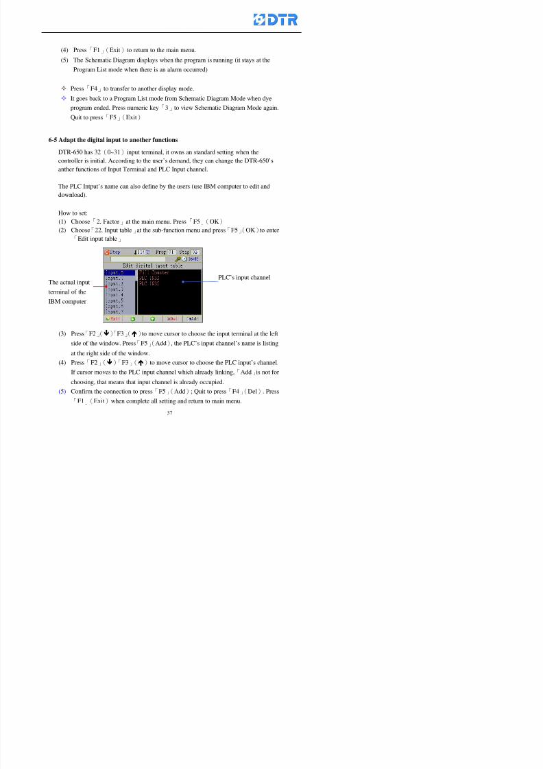
8132019 DTR 650 User Manual
httpslidepdfcomreaderfulldtr-650-user-manual 3770
(4) Press「F1」(Exit)to return to the main menu
(5) The Schematic Diagram displays when the program is running (it stays at theProgram List mode when there is an alarm occurred)
Press「F4」to transfer to another display mode
It goes back to a Program List mode from Schematic Diagram Mode when dye
program ended Press numeric key「3」to view Schematic Diagram Mode again
Quit to press「F5」(Exit)
6-5 Adapt the digital input to another functions
DTR-650 has 32(0~31)input terminal it owns an standard setting when the
controller is initial According to the userrsquos demand they can change the DTR-650rsquos
anther functions of Input Terminal and PLC Input channel
The PLC Intputrsquos name can also define by the users (use IBM computer to edit and
download)
How to set
(1) Choose「2 Factor」at the main menu Press「F5」(OK)
(2) Choose「22 Input table」at the sub-function menu and press「F5」(OK)to enter
「Edit input table」
The actual input
terminal of theIBM computer
PLCrsquos input channel
8132019 DTR 650 User Manual
httpslidepdfcomreaderfulldtr-650-user-manual 3870
6-6 Adapt the digital output to another functions
DTR-650 has 32(0~31)output terminals it owns an standard setting when thecontroller is initial According to the userrsquos demand they can adapte the digital output
and the PLC outputrsquos channel to another functions The PLC Output channelrsquos name
can also define by users (use IBM computer to edit and download)
Step
(1) Choose「2 Factor」at the main menu Press「F5」(OK)
(2) Choose「23 Output table」at the main menu and press「F5」(OK)
(3) Press「F2」()「F3」()to move cursor to choose the output terminal atthe left side of the window Press「F5」(Add) the PLCrsquos output channelrsquos
name is listing at the right side of the window
(4) Press「F2」()「F3」()to move cursor to choose the PLC outputrsquos channel
If cursor moves to the PLC output channel which already linking「Add」is
not for choosing that means that output channel is already occupied
(5) Confirm the connection to press「F5」(Add) Quit to press「F4」(Del)Press「F1」(Exit)when complete all setting and return to main menu
The actual output
terminal of the
IBM computer
PLCrsquos output channel
8132019 DTR 650 User Manual
httpslidepdfcomreaderfulldtr-650-user-manual 3970
983095 983109983140983145983156983145983150983143 983156983144983141 983110983137983139983156983151983154983155DTR-650 has several kinds of control factors
Userrsquos factors System factors Temperature Control factors Speed factors Dosing
factors PID factors Analog Input Output factors standard factors etchellipPlease refer
to the supplementary table for the setting range and standard of the factors
DTR-650 has a built-in standard factor Users can edit by themselves if necessary
7-1 Modifying userrsquos factors
Userrsquos factors is setting with the Dyeing machinesrsquos PLC Programrsquos factor it is define by
the PLC Programmer
Step to edit
(1) Choose「2Factors」at main menu Press「F5」(OK)
(2) Choose「01User Factor」Press「F5」(OK)
(3) Press「F2」()「F3」()「6」「5」to move cursor up down and by page
Choose a factor need to edit then press「3」「4」to set itrsquos value Press「F5」(OK) Cursor moves to the next factor
(4) Some of factors can input numbers by the numeric membrance keys to edit If
the input is incorrect it turns to red and means the edit is not available
8132019 DTR 650 User Manual
httpslidepdfcomreaderfulldtr-650-user-manual 4070
Modifyrsquos method of the system factors temperature factors speed factors dosingfactors PID factors analog Input output factors standard factors etchellipare same asabove
If apply the library of DTR500 and DTR600 into the DTR650 the key「3」「4」may not valid to use Please use the numeric keys instead of it to key in factors itmay not effect the normal operation
Please pay a serious attention and read carefully at the factorrsquos table before modify the factors An incorrect value may effect the DTR-650 Dyeing
Machine Controllerrsquos operating After modifying factors must cancel the
password and secure data
7-2 Loading the standard factors
After modifying factors if need to restore a manufacturerrsquos standard factors of
DTR-650 The method as follows
1 Choose「2Factors」at main menu Press「F5」(OK)
「 「 ( ) 「
8132019 DTR 650 User Manual
httpslidepdfcomreaderfulldtr-650-user-manual 4170
7-3 Copying the factor
Users can build up a set of factor by themselves and make a copy and save
Step
1 Choose「2Factors」at main menu Press「F5」(OK)
2 Choose「13Restore Factor」 press「F5」(OK) window「factor will be
overwrite 」
3 Press「F4」(Yes)copy finished and saved Return to the main menu
4 Press「F2」(No)to not copy the factor and the existing factor is not change Return
to the main menu
7-4 Loading the backup factors
Users can build up a set of factor and backup files to load to DTR-650
Step1 Choose「14Backup factor」at the sub-function menu Press「F5」(OK)and
window「Factror will be overwrite」appears
2 Press「F3」(OK)to load the the backup factor them return to main menu
Press「F2」(No)to not copy the factor and the existing factor is not change
Return to the main menu
8132019 DTR 650 User Manual
httpslidepdfcomreaderfulldtr-650-user-manual 4270
983096 983119983157983156983152983157983156 983124983141983155983156983145983150983143
Before the output testing must be complete the steps as follows
A Cut off all connecting line of output terminal of DTR-650
B Stop running the PLC
C Check up the connections of all output channels to avoid damages from
incorrect connections
D Check up state of dyeing machines include the temperature pressure valves
onoff and pumpshellipetc ensure the safety for priority
8-1 Testing the Digital output
Step
1 Choose「3Output Testing」at the main menu Press「F5」(OK) 2 Choose「1Digital」at the sub function menu Press「F5」(OK) window「Digital
output testing」appears
3 Press「」「」「」to move cursor to each output channels Press「F5」(OK)
Output Name
8132019 DTR 650 User Manual
httpslidepdfcomreaderfulldtr-650-user-manual 4370
8-2 Testing the Analog output
(1) Choose「3Output Testing」at the main menu Press「F5」(OK)
(2) Choose「2Analog」at the sub function menu Press「F5」(OK) window「Analog output testing」appears
(3) Press「」「」「」to move cursor to each channels Then key in number by
the numeric membrance keys (range0~200= 0~20mA) Press「F5」(OK) there
is a output current relating to the output channel
(4) Press「F5」(OK) There is an output when the output channel with red light No
output without light onl(5) When complete the testing press「F1」(OK)to return to the main menu
8132019 DTR 650 User Manual
httpslidepdfcomreaderfulldtr-650-user-manual 4470
983097 983107983137983148983145983138983154983137983156983145983151983150
DTR-650 has Dosing and Temperature calibration
When enter to Dosing calibration must be set the Low Volume calibration first and
then High Volume calibration When enter to Temperature calibration must be set the
Low Temperature calibration first and then High Temperature calibration Must be
hightly follow this orders seriously
9-1 Calibration of Low Volume Tank
Step
A Choose「4Calibration」at the main menu Press「F5」(OK)
B Choose「Dosing 0 low vol」at the sub function menu Press「F5」(OK) window
appears
C Fill the Dosing Tank to a half level input value shows how much the water level
If it stays ldquo0rdquo check the connection and the factor setting is correct or not
And connect the pressure sensorrsquos output channel to the Current Meter to ensure
that sensor works or not
8132019 DTR 650 User Manual
httpslidepdfcomreaderfulldtr-650-user-manual 4570
D Fill the Dosing Tank to 50ml (Calcalate from the bottom side of the pressure
sensor steel tube) input value should show 4~6 (input value must between
0~10) Then enter the water volume The setting volume is relating the water
levelrsquos water value (litre as unit) input range 0~80 Set as「 「「 「0000 0000 0000 0000」」」」is strongly is strongly is strongly is strongly
receommend receommend receommend receommend Press「F5」(OK)to complete [Calibration of Low Volume Tank 1
is same as above method]
9-2 Calibration of High Volume Tank
Step
A Choose「4Calibration」at the main menu Press「F5」(OK)
B Choose「Dos 0 high vol」at the sub function menu Press「F5」(OK) window of
「Calibrate high 」appears
C Fill the Dosing Tank to a full level input value should be larger than 30 enter
the current water level which relates to the water volume Enter the range within
100~2500 Then press「F5」(OK) to complete the calibrate the high volume tank
8132019 DTR 650 User Manual
httpslidepdfcomreaderfulldtr-650-user-manual 4670
9-3 Temperature Calibration
Step
A This function is for adjusting the DTR650rsquos accuracy of Temperature Control It
must be using with the special terminal which is only for DTR650
B Choose「4Calibration」at the main function menu and press「F5」(OK)
C Choose「3Low Temp」at the sub-function menu Press「F5」(OK)and《Fig9-3》
appears insert the DTR650rsquos low temperature calibration terminal to the temperature
input terminal wait for the jumping value to stable down then press「F5」(OK) then
to adjust the high temperature calibration
D Adjusting the High Temperature Calibrationrsquos method is same as above But usersusersusersusers
must be using the High Temperature Terminalmust be using the High Temperature Terminalmust be using the High Temperature Terminalmust be using the High Temperature Terminal whichwhichwhichwhich is specially for DTR650 onlyis specially for DTR650 onlyis specially for DTR650 onlyis specially for DTR650 only
《Fig 9-3》
8132019 DTR 650 User Manual
httpslidepdfcomreaderfulldtr-650-user-manual 4770
10 983122983141983139983151983154983140983155 983151983142 983108983161983141 983120983154983151983143983154983137983149983155
It contains the past 15 days of temperature curves of running history
Checking method
(1) Choose「5Dye Record」at main menu press「F5」(OK)
(2) Sub-function menu shows the set up date of the past 15 days dye programs
Listing by the lastest set up date
(3) Choose a program date and press「F5」(OK) it appears window「Temp
record」
(4) Press「」「」to move the white line in the box one minute by moving once
(5) Press「3」「4」to move the line to check the time period 2 hours by moving once
The yellow selecting line of the「24 hours operating state」is repectively moving
The curve info is show in the curve box Left side of the widnow appears the
relating running info the time is the time value of the line locates at
(6) Check more details of the temperature info to press numeric key「middot」 a bright red line
appears in the selecting box this line is to check the starting point of the
temperature inforsquos time period Then press「」to move the white line to the end
point of the time period The temperature info between the starting point and end
point are appears at the right side of the window Press「middot」to return to the preious
curve page
(7) Check more details of the alarm infor To perss numeric key「7」「9」 the alarmrsquos
details is listing by orders
(8) Press「F1」(exit) to return
8132019 DTR 650 User Manual
httpslidepdfcomreaderfulldtr-650-user-manual 4870
11 983125983155983137983143983141 983151983142 983117983141983149983151983154983161 983107983137983154983140
DTR-650 supports 32MB or above Compact Flash Card which can transfer and save all
information for 4 sets of DTR-650 Including library files schematic diagram icon
image PLC program dye program factor and confiruration files etchellip Use the CF Card
to up download and swap the information of DTR-650 promptly install the relating
device and program updates
DTR-650 CF Card with bank 1 to bank 4 can save 4 sets information of Dyeing
Machines When download or save files should choose the BANK first
《Fig11-1》
8132019 DTR 650 User Manual
httpslidepdfcomreaderfulldtr-650-user-manual 4970
11-1 Downloading data
1 Firmly insert the CF card into the DTR-650rsquos PCMCIA connector Ensure it is
wholely and firmly inserted if the card is not totally inserted or the card do not
touch in all to the connector there will be an error occurred and cannot
updownload or interrupted during operation
2 Choose「6Memory Card」at the main menu and press「F5」(OK) 《Fig11-1》
appears Information of Bank「1」shows at the left hand side of the window press
number 1-4 by using numeric keys to choose the BANK Check the
information in the Bank seriously which is exactly need to download to the
DTR650
3 Press()()「6」「5」to move cursor to the sub-function menu to choose
the downloading items Press「F5」(OK) window appears「Stop PLC run before
access memory card Stop the PLC run」 Press「F5」(YES) to stop PLC
running
4 Press「F5」(OK) window appears Confirm to update or not the DTR-650rsquos
information As that downloading will be replace the DTR-650rsquos information
(that means the existing information of the DTR-650 will be removed and
replaced)
5 Press「F4」(YES)to download the information from the DTR-650 to the CF
Card Return to the main menu when finish
8132019 DTR 650 User Manual
httpslidepdfcomreaderfulldtr-650-user-manual 5070
Ensure inserting firmly the CF card into the DTR-650 unless it will cause
error or cannot Updownload data
Never remove CF card during transferring or updownloading data Until it
is all completed
DTR-650rsquos dyeing program is not compatible with DTR-500 and
DTR-600 Never use CF card to transfer data among them
11-2 Storing and transfering data
1 Insert the CF Card to the DTR-650
2 Choose「6Memory Card」at the main menu and press「F5」(OK) 《Fig11-1》
appears Left hand side of the window shows the data of BANK 1 press numeric
keys 1-4 to select the BANK To confirm the put the data in the DTR-650 to the CF
Card The existing data of that bank will be replaced and covered by the new data (if
that bank is already occuplied)
3 Choose「23Save Dye prog」(Example)at the sub-funciton menu press「F5」(OK)to confirm Window「Update memory card data」appears
4 Press「F5」(OK)to transfer the data to the CF card Return to the main menu
5 Put the CF card into another DTR-650 and follow the operating method of 「11-1
Downloading data」」」」can transfer and swap data with more than one set of
DTR-650
8132019 DTR 650 User Manual
httpslidepdfcomreaderfulldtr-650-user-manual 5170
12 983123983156983137983156983141 983137983150983140 983113983150983142983151983154983149983137983156983145983151983150
The state and information is including the Dyeing Machinersquos state of Digit Input output
Analog Input output Temperature control PID Dosing PID Pressure different PID
software system information and alarm record This information is for checking at any
time
12-1 Input Output state
Step
1 Choose「7Info and state」at main menu and press「F5」(OK)
2 Choose「01Digital IO put」at the sub-function menu then press「F5」(OK)
「Digital In Out State」0=None 1=Input
3 Press「F1」(Exit)to return to main menu
Same method for checking the temperature control analog dosing pressure
different etchellip
12-2 Checking the system information
Step
1 Choose「7Info and state」at main menu and press「F5」(OK)
2 Choose「11 System info」at sub-function field press「F5」(OK)Window
「System Information」appear
System information is including System info(software version) Library doc
Icon files Schematic file Definition file hardare state Config File Commandinstruction icon PLC file etc
8132019 DTR 650 User Manual
httpslidepdfcomreaderfulldtr-650-user-manual 5270
12-3 Checking the operating alarm record
Operating record shows the latest 40 operating items and alarm records including
the time and content of the alarm
A) Choose「7 Info and state」
and press「F5」(OK)
B) Choose「12Alarm logs」at
the sub-funciton menu then
press「F5」(OK)
8132019 DTR 650 User Manual
httpslidepdfcomreaderfulldtr-650-user-manual 5370
13 983105983140983146983157983155983156983145983150983143 983156983144983141 983107983151983150983156983154983137983155983156
The displaysrsquos brightness can be adjusted if necessary
Step
1 Choose「8Others」at main menu press「F5」(OK)
2 Choose「01Contrast」at sub-function menu press「F5」(OK) window「Set
Contrast」appears
3 Press「」「」to move the bar to set the brightness then press「F5」(OK)Window appears「Please reboot the system」
4 Press「F5」(OK)to return to main menu and re-boot the DTR-650 to complete
adjusting the brightness
8132019 DTR 650 User Manual
httpslidepdfcomreaderfulldtr-650-user-manual 5470
14 983123983156983151983152 983154983157983150983150983145983150983143 983156983144983141 983120983116983107 983120983154983151983143983154983137983149
Before testing the Input output testing transfer of the PLC program must stop the PLC
running
Step
1 Choose「8Others」at the main menu Press「F5」(OK)
2 Choose「04 PLC Stop」at sub-function menu Press「F5」(OK) window
「Password」appears
3 Enter password and press「F5」(OK) Window「Stop the PLC run」appears
4 Press「F4」(Yes)and window「PLC Stop」appear Press「F5」(OK) Now
the PLC is stop running and return to the main menu
All testing cannot operate when the PLC is running
Editing dye program and the relating operation can
perform with the PLC running together
8132019 DTR 650 User Manual
httpslidepdfcomreaderfulldtr-650-user-manual 5570
15 983123983141983156983156983145983150983143 983156983144983141 983156983145983149983141
Step
1 Press「8Others」at the main menu Press「F5」(OK)
2 Choose「10Set date time」at the sub-function menu Press「F5」(OK) window
「Set date time」appears
3 Press「F5」(Edit) to move cursor by 「3」「4」 enter the time value at the
cursor locates
4 Press「F5」(OK)to complete the modify Press「F1」(Exit)to return to main
menu
5 Press「F1」(Exit)if not modify and return to main menu
8132019 DTR 650 User Manual
httpslidepdfcomreaderfulldtr-650-user-manual 5670
1166 983123983123983157983157 983152 983152 983152 983152983148983148983141983141983149983149983141983141983150983150983156 983156 983137983137983154 983154 983161983161 983124 983124 983137983137983138983138983148983148983141983141
TTTTTTTTaaaaaaaabbbbbbbblllllllleeeeeeee 11111111 【Dye Instruction】
Code Icon Instruction Code Icon Instruction
000 End 016 Inject C
001 Start 017 Dosing BV
002 Heat 018 PH
003 Cool 019 Addsalt B
004 Flow Fill 020 Addsalt C
005 Level Fill 021 Ana Fill
006 Drian 022 Lock Fill007 Rinse 023 Lock Level
008 Run 024 Low Rinse
009 Call 025 Cyc Rinse
010 Prep B 026 Rinse B
011 Addsalt B 027 Rinse C
012 Dosing B 028 Temp
013 Inject B 029 Nozzle Pressure
014 Prep C 030 Main Pump
015 Dosing C 031 Pump Speed
8132019 DTR 650 User Manual
httpslidepdfcomreaderfulldtr-650-user-manual 5770
Table 2 【【【【Alarm】】】】
System Alarm Must stop operating and check up to solve problems before restarting
the machine
Running Alarm It is a reminder Not effect the operating of DTR-650
Userrsquos Alarm Total of 32 Users can define themselves and use it when edit the PLC
Program (do not listing below)
No System Alarm No Running Alarm
1 PLC program not running 16 Temp ctrl 0 Grad too slow
2 Main temp sensor error 17 Temp ctrl 0 Grad too fast
3 Not at Run window 18 Temp ctrl 0 Hold temp too low
4 Exceeding max temp 19 Temp ctrl 0 Hold temp too high
5 - 20 Temp ctrl 1 Grad too slow6 - 21 Temp ctrl 1 Grad too fast
7 - 22 Temp ctrl 1 Hold temp too low
8 Communication error 23 Temp ctrl 1 Hold temp too high
9 Slave not answer 24 Temp ctrl 2 Grad too slow
10 PLC 0 not answer 25 Temp ctrl 2 Grad too fast
11 PLC 1 not answer 26 Temp 2 Hold temp too low12 Display not answer 27 Temp 2 Hold temp too high
13 Lower power voltage 28 Temp ctrl 3 Grad too slow
14 - 29 Temp ctrl 3 Grad too fast
15 - 30 Temp3 Hold temp too low
31 Temp3 Hold temp too high
32 Dosing 0 injection too slow
33 Dosing 0 injection too fast
34 Dosing 1 injection too slow
35 Dosing 1 injection too fast
8132019 DTR 650 User Manual
httpslidepdfcomreaderfulldtr-650-user-manual 5870
TTTTTTTTaaaaaaaabbbbbbbblllllllleeeeeeee 33333333 【【【【System factor】】】】
No Description Std Range amp Definition
1 ID No 000 000- 100 Controller no
2 Communication Rate 4800Bps 2400 4800 9600 19200 38400
3 Display language Chinese English Chinese
4 Temp display mode and
5 Maxmium temperature 145 025 ~ 145 6 Type of external PLC Default PLC32DPLC32PLC16Default
7 Number of external PLC NANA 1 unit connect
2 unit connect
8Communication Rate of
PLC9600Bps 2400 4800 9600 19200
9 Set point 1 085 000 ~ 145
If signal source is temperaturethe setting value is thetemperature value If the signal
source is Analog Input 6~17 then
setting value for Analog input is 0 ndash
100 and relates Analog
Input14~020mA
10 Source 1 Sensor0Sensor 0 ~5
Analog input 0 ~1111 Set point 2 092 Same as 09
12 Source 2 PT100 1 Same as 10
13 Set point 3 085 Same as 09
14 Source 3 PT100 2 Same as 10
15 Set point 4 092 Same as 09
16 Source 4 PT100 3 Same as 1017 Set point 5 085 Same as 09
18 Source 5 PT100 4 Same as 10
19 Set point 6 092 Same as 09
8132019 DTR 650 User Manual
httpslidepdfcomreaderfulldtr-650-user-manual 5970
29 Min cyclic time of cloth 100sec 0 ~ 255 sec
30 Max cyclic time of cloth 240sec 0 ~255 sec
31Standard cyclic time of
cloth
180 000 ~ 255 sec
32 Display ModeProgram
List
Program list Schematic Diagram
Icon mode
33 CF card format Standard of
DTR CF
Card
Standard of DTR CF Card V20
Standard CF Card
34 Addition step Disable Disable Enable35 Mode Com 3
CouplingEsure Com 3 is the communication
port of the Central or Coupling
36Com 3 Communication
rate9600 Central communication speed
8132019 DTR 650 User Manual
httpslidepdfcomreaderfulldtr-650-user-manual 6070
TTTTTTTTaaaaaaaabbbbbbbblllllllleeeeeeee 44444444 【【【【Temperature Cotnrol Factor】】】】
No Factor Definition Standard Range and Definition
01 PT No PT-0 PT 0~5 PT-100 Input number
02 Max working temp 140 000~140
03 Output mode 0 0~2
04 Alarm time of gardient 240sec 000~255 sec
05 Alarm mode of gradient Always AlwaysOnceNone
06 Control mode of gradient Heating orCooling
interlocked
Heating and Cooling interlocked
No limitation
07 Alarm range of HoldTemp 03 01~20
08 Alarm time for HoldTemp 240sec 000~255sec
09 Alarm mode of HoldTemp Always AlwaysOnceNone
10 Control mode ofHoldTemp
Heating only Only heating and cooling Cooling whenalarm occurred Only heating andcooling No limitation when alarmHeating only
11 Porportional Band 100 000~250
12 Integral band 128 sec 000~255 sec
13 Differential time 04 sec 00~20 sec
14 Min transit gradient 02 00~50
15 Transit rate 20 times 00~50 times (020= 2 times)
16 PID initial output value 010 000~100
17 ONOFF cycle time 10 sec 05~25 sec
Onoff valve set as 010 sec
Proportional valve set as 020 sec
18 Time down count mode Mode 0 0~10 = The time down count range from「Factor 20 + target temp」to「Target
8132019 DTR 650 User Manual
httpslidepdfcomreaderfulldtr-650-user-manual 6170
TTTTTTTTaaaaaaaabbbbbbbblllllllleeeeeeee 55555555 【【【【Speed Factor】】】】
No Factor Definition Standard Range amp Definition
01 Input Number Speed input 0 Speed input 0~11
02 Average times 05 times 01~10
03 Sensor Number 008pcs 001~255
04 Roller Dimension 250mm 050~500
05 Max cloth speed 200mmin 001~25506 Min cloth speed 020mmin 001~255
07 Alarm delay time 240sec 001~255
08 Alarm mode Every oncenoneevery
09 Alarm range () 020 001~255
10 Proportional band 100 001~255
11 Integer band 128 001~25512 Differential time 000 001~200
13 Initial speed () 020 001~255
14 Control cycle ti(01sec) 05 01~30
15 First cycle time(01sec) 10 01~30
16 Speed increase limit () 010 001~100
17 Speed decrease limit () 010 001~100
18 Min speed() 005 001~100
19 Manual speed adjust () 005 001~100
20 Manual initial speed() 020 001~100
21 Stopping speed() 010 001~100
22 Switch speed() 020 001~100
23 Not used
24 Speed decrease turns 03turns 01~50
8132019 DTR 650 User Manual
httpslidepdfcomreaderfulldtr-650-user-manual 6270
Table 6 【【【【Dosing Factors】】】】
No Description Range Range and Explanation
1 Analog input no Analog input 0 Analog input no 0 ~11
2Alarm delay time for
dosing240 sec 000 ~255 sec
3 Alarm time for dosing Every Every Once None
4 Proportional band 100 000 ~255 sec Factor P
5 Integer band 128 000 ~255 sec Factor I6 Differential time 04 00 ~20 Factor D
7 Max adjust rate 150 50~ 255
8 Initial factor for dosing 10 000 ~100
9 User curve section 0 10 Gradient of sect1 for dosing curve9
10 User curve section 1 10 Gradient of sect2 for dosing curve9
11 User curve section 2 10 Gradient of sect3 for dosing curve9
12 User curve section 3 10 Gradient of sect4 for dosing curve9
13 User curve section 4 10 Gradient of sect5 for dosing curve9
14 User curve section 5 10 Gradient of sect6 for dosing curve9
15 User curve section 6 10 Gradient of sect7 for dosing curve9
16 User curve section 7 10 Gradient of sect8 for dosing curve9
17 User curve section 8 10 Gradient of sect9 for dosing curve9
18 User curve section 9 10 Gradient of sect10 for dosing curve9
19 Min water level 05 00~ 10 04~20mA percentagechange to the userrsquos factor setting
20 Output value for Tank
clean
100 000~ 100
Injected percentage of dosing valve
in dosing End period
This factor will be invalided if usingONOFF dosing valve
21 Full range 100 001~255 Self-adjustment cannotchange
22 Range ratio 001001~255 Self-adjustment cannot
change
8132019 DTR 650 User Manual
httpslidepdfcomreaderfulldtr-650-user-manual 6370
【【【【TTaabbllee 77 】】】】Pressure Deviation Factors
No Description Std Range amp Definition
1 Analog input number + Analog in 0 Analog in 0~11
2 Analog input number - Analog in 1 Analog in 0~11
3 Input mode Pressure Pressure Pressure deviation
4 Full range 050x01Kgcm
001~255
5 Range ratio 001 001~255
6 Alarm delay time 100sec 001~255
7 Alarm mode Every oncenone
8 Alarm range 010 001~255
9 Proportional band 100 001~255
10 Integer band 128 001~255
11 Differential time 00 00~20
12 PID Init output value 010 001~255
13 Cycle time 10 03~30
14 First cycle time 030 003~100
15 Max adjust rate 010 001~100
8132019 DTR 650 User Manual
httpslidepdfcomreaderfulldtr-650-user-manual 6470
【【【【TTaabbllee 88 】】】】Definition of Analog Input
No Description Standard Range and Explanation
01 PT 0 correction standard DIN std DIN std JIS std
02 PT 0 correction +0 +- 9
03 PT 1 correction standard DIN std DIN std JIS std
04 PT 1 correction +0 +- 9
05 PT 2 correction standard DIN std DIN std JIS std
06 PT 2 correction +0 +- 9
07 PT 3 correction standard DIN std DIN std JIS std
08 PT 3 correction +0 +- 9
09 PT 4 correction standard DIN std DIN std JIS std
10 PT 4 correction +0 +- 9
11 PT 5 correction standard DIN std DIN std JIS std
12 PT 5 correction +0 +- 9
13 Analog input 0 define 4 ~ 20mA 0 ndash 20mA 4 ndash 20mA
14 Analog input 0 average times 10 times 01- 20 times
15 Analog input 0 min value 0000 0000 - 1000
16 Analog input 0 max value 100 0001 - 9999
17-60 Analog input 1~11 Same as Analog input 0
【【【【 】】】】 fi i i f A O
8132019 DTR 650 User Manual
httpslidepdfcomreaderfulldtr-650-user-manual 6570
【【【【TTaabbllee 99 】】】】Definition of Analog Output
No Description Standard Range and explanation
61 Analog output 0 define Control byPLC
Control by PLC
Temperature control PID0 output
Temperature control PID1 output
Temperature control PID2 output
Speed PID3 output
Dosing PID0 output Dosing PID1output
Pressure different PID0 outputPressure different PID1 output
Main temperature output
62 Mode of Analog ouptput0 4 ~20mA 0 ndash20mA 4 ndash 20mA
63-84 Analog output 1~11 Same as Analog output 0
【【【【TTaabbllee 1100】】】】Value Table 0 amp 1
No Description Range Std Range and explanation
1 Analog input no 000~011 000 Analog input no
2 Data ratio 001~255 100 Multiple by factors
3~53 0~98 000~255 000-100 Analog input 0~98 data
【【【【 】】】】St t Li t
8132019 DTR 650 User Manual
httpslidepdfcomreaderfulldtr-650-user-manual 6670
【【【【TTaabbllee 1111】】】】State List
No Description Range Standard Range and explanation
1 Display setting 1 0~255 205 See remarks at next page
2 Display setting 2 0~255 208
3 Display setting 3 0~255 209
4 Display setting 4 0~255 017
5 Display setting 5 0~255 0186 Display setting 6 0~255 019
7 Display setting 7 0~255 020
8 Display setting 8 0~255 021
9 Display setting 9 0~255 000
10 Display setting 1 0~255 000
11 Display setting 2 0~255 000
12 Display setting 3 0~255 000
13 Display setting 4 0~255 000
14 Display setting 5 0~255 000
15 Display setting 6 0~255 000
16 Display setting 7 0~255 000
Remarks
8132019 DTR 650 User Manual
httpslidepdfcomreaderfulldtr-650-user-manual 6770
0 = No display 1~255 = Display type of number
1~16 Content of PLC VB0~15
No 1 corresponding to VB0
No 16 corresponding to VB15
17~32 Content of PLC DB0~15
No 17 corresponding to DB0
No 32 corresponding to DB15
33~46 Content of PLC CNT0~29
No 33 corresponding to CNT0
No 46 corresponding to CNT29 47~78 Content of dyeing instruction 0~31 CNT0
No 47 corresponding to system instruction to No 0 of CNT0
No 78 corresponding to system instruction to No 31 of CNT0rsquos content
79~110 Dyeing instruction 0~31 of CNT0rsquos setting
111~142 Content of Dyeing instruction 0~31 CNT1No 111 corresponding to dyeing instruction No 0 of CNT1
No 142 corresponding to dyeing instruction No 31 of CNT1rsquos content
143~174 Dyeing instruction 0~31 of CNT1rsquos setting
175~204 Content of PLC HTIM0~29
No 175 corresponding to HTIM0
No 204 corresponding to HTIM29
205 Loading
206 Ratio 1
207 Ratio 2208 Ratio 1 x Loading
209 Ratio 2 x Loading
210 Fix value
211 Value Table 1 matching result
212 Value Table 2 matching result
213 Value Table 1 setting214 Value Table 2 setting
215 Pressure control PID0 different pressure value
216 Pressure control PID1 different pressure value
TTTTTTTTaaaaaaaabbbbbbbblllllllleeeeeeee 1122 【【【【Usage of password】】】】
8132019 DTR 650 User Manual
httpslidepdfcomreaderfulldtr-650-user-manual 6870
No Main FunctionFactor Sub Function Factor Password Rank
1 Run None
2 Dye program User3 or above
3 Control factor
- User factor User 1
- System factor User 1
- Temp PID 0
- Temp PID 1 User 1- Speed PID 0 User 1
- Dosing PID 0 User 1
- Dosing PID 1 User 1
- Pressure PID 0 User 1
- Pressure PID 1 User 1
- Analog IO User 1
- Load standard factor User 2 or above- Load a copied factor User 2 or above
- Copy factor User 2 or above
- Value table 0 User 1
- Value table 1 User 1
- Information and state User 1
- Dye instruction User 1
- Edit dye instruction setting User 14 Output testing User 2 or above
5 Calibration User 2 or above
6 Dye record None
7 CF card User 1
8 Info and state None
9 Others
- Contrast User3 or above
- Data Locking None
- PLC Run User 1
- PLC Stop User 1
- Password setting User 1
TTTTTTTTaaaaaaaabbbbbbbblllllllleeeeeeee 1133 【【【【Technical Data】】】】
8132019 DTR 650 User Manual
httpslidepdfcomreaderfulldtr-650-user-manual 6970
TTTTTTTTaaaaaaaabbbbbbbblllllllleeeeeeee 1133 【【【【Technical Data】】】】
1 Temperature Control
- Range 10~145(plusmn1)
- Mode Proportional or PWM
- Sensor PT100 (JIS or DIN standard)
2 Input and output channel
- Digital Input 32 DC24V PNP- Digital Output 32 DC24V 054A Relay connect point
- Analog Input 4 04~20 mA
- Analog Output 4 0~20mA 或 4~20 mA
3 Communication port 3 RS-232 amp 0~20 mAx1 RS485x 2
4 Dye program
- Number 15000 Steps
- Standard step 61Heating Cooling Fill Drain RinseDosingetc
5LCD module and Display
langage
Chinese
English
320 x 240 TFT color display with
more language
6 CF card connector 1 PCMCIA standard
7 Membrane Keyboard- Number Key 10 [0]~[9] Input factors
- Function Key 5 [F1]~[F5] function selecting
- Operation Key 2 [Start] [Stop]
- Auxiliary Key 7 [][][][][Esc] [larr][OK] [bull]
8 Operating Condition
- Temperature 5~45
- Humidity ≦85 (25)
9 Power supply
V l DC 24V
8132019 DTR 650 User Manual
httpslidepdfcomreaderfulldtr-650-user-manual 7070
70
983108983124983122983085650 983113983150983152983157983156 983119983157983156983152983157983156 983120983151983154983156983145983150983143 (983138983137983139983147983155983145983140983141 983158983145983141983159)
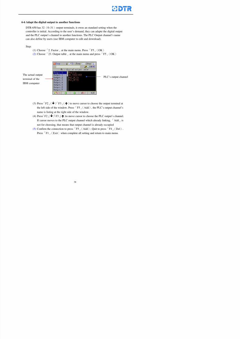
8132019 DTR 650 User Manual
httpslidepdfcomreaderfulldtr-650-user-manual 3870
6-6 Adapt the digital output to another functions
DTR-650 has 32(0~31)output terminals it owns an standard setting when thecontroller is initial According to the userrsquos demand they can adapte the digital output
and the PLC outputrsquos channel to another functions The PLC Output channelrsquos name
can also define by users (use IBM computer to edit and download)
Step
(1) Choose「2 Factor」at the main menu Press「F5」(OK)
(2) Choose「23 Output table」at the main menu and press「F5」(OK)
(3) Press「F2」()「F3」()to move cursor to choose the output terminal atthe left side of the window Press「F5」(Add) the PLCrsquos output channelrsquos
name is listing at the right side of the window
(4) Press「F2」()「F3」()to move cursor to choose the PLC outputrsquos channel
If cursor moves to the PLC output channel which already linking「Add」is
not for choosing that means that output channel is already occupied
(5) Confirm the connection to press「F5」(Add) Quit to press「F4」(Del)Press「F1」(Exit)when complete all setting and return to main menu
The actual output
terminal of the
IBM computer
PLCrsquos output channel
8132019 DTR 650 User Manual
httpslidepdfcomreaderfulldtr-650-user-manual 3970
983095 983109983140983145983156983145983150983143 983156983144983141 983110983137983139983156983151983154983155DTR-650 has several kinds of control factors
Userrsquos factors System factors Temperature Control factors Speed factors Dosing
factors PID factors Analog Input Output factors standard factors etchellipPlease refer
to the supplementary table for the setting range and standard of the factors
DTR-650 has a built-in standard factor Users can edit by themselves if necessary
7-1 Modifying userrsquos factors
Userrsquos factors is setting with the Dyeing machinesrsquos PLC Programrsquos factor it is define by
the PLC Programmer
Step to edit
(1) Choose「2Factors」at main menu Press「F5」(OK)
(2) Choose「01User Factor」Press「F5」(OK)
(3) Press「F2」()「F3」()「6」「5」to move cursor up down and by page
Choose a factor need to edit then press「3」「4」to set itrsquos value Press「F5」(OK) Cursor moves to the next factor
(4) Some of factors can input numbers by the numeric membrance keys to edit If
the input is incorrect it turns to red and means the edit is not available
8132019 DTR 650 User Manual
httpslidepdfcomreaderfulldtr-650-user-manual 4070
Modifyrsquos method of the system factors temperature factors speed factors dosingfactors PID factors analog Input output factors standard factors etchellipare same asabove
If apply the library of DTR500 and DTR600 into the DTR650 the key「3」「4」may not valid to use Please use the numeric keys instead of it to key in factors itmay not effect the normal operation
Please pay a serious attention and read carefully at the factorrsquos table before modify the factors An incorrect value may effect the DTR-650 Dyeing
Machine Controllerrsquos operating After modifying factors must cancel the
password and secure data
7-2 Loading the standard factors
After modifying factors if need to restore a manufacturerrsquos standard factors of
DTR-650 The method as follows
1 Choose「2Factors」at main menu Press「F5」(OK)
「 「 ( ) 「
8132019 DTR 650 User Manual
httpslidepdfcomreaderfulldtr-650-user-manual 4170
7-3 Copying the factor
Users can build up a set of factor by themselves and make a copy and save
Step
1 Choose「2Factors」at main menu Press「F5」(OK)
2 Choose「13Restore Factor」 press「F5」(OK) window「factor will be
overwrite 」
3 Press「F4」(Yes)copy finished and saved Return to the main menu
4 Press「F2」(No)to not copy the factor and the existing factor is not change Return
to the main menu
7-4 Loading the backup factors
Users can build up a set of factor and backup files to load to DTR-650
Step1 Choose「14Backup factor」at the sub-function menu Press「F5」(OK)and
window「Factror will be overwrite」appears
2 Press「F3」(OK)to load the the backup factor them return to main menu
Press「F2」(No)to not copy the factor and the existing factor is not change
Return to the main menu
8132019 DTR 650 User Manual
httpslidepdfcomreaderfulldtr-650-user-manual 4270
983096 983119983157983156983152983157983156 983124983141983155983156983145983150983143
Before the output testing must be complete the steps as follows
A Cut off all connecting line of output terminal of DTR-650
B Stop running the PLC
C Check up the connections of all output channels to avoid damages from
incorrect connections
D Check up state of dyeing machines include the temperature pressure valves
onoff and pumpshellipetc ensure the safety for priority
8-1 Testing the Digital output
Step
1 Choose「3Output Testing」at the main menu Press「F5」(OK) 2 Choose「1Digital」at the sub function menu Press「F5」(OK) window「Digital
output testing」appears
3 Press「」「」「」to move cursor to each output channels Press「F5」(OK)
Output Name
8132019 DTR 650 User Manual
httpslidepdfcomreaderfulldtr-650-user-manual 4370
8-2 Testing the Analog output
(1) Choose「3Output Testing」at the main menu Press「F5」(OK)
(2) Choose「2Analog」at the sub function menu Press「F5」(OK) window「Analog output testing」appears
(3) Press「」「」「」to move cursor to each channels Then key in number by
the numeric membrance keys (range0~200= 0~20mA) Press「F5」(OK) there
is a output current relating to the output channel
(4) Press「F5」(OK) There is an output when the output channel with red light No
output without light onl(5) When complete the testing press「F1」(OK)to return to the main menu
8132019 DTR 650 User Manual
httpslidepdfcomreaderfulldtr-650-user-manual 4470
983097 983107983137983148983145983138983154983137983156983145983151983150
DTR-650 has Dosing and Temperature calibration
When enter to Dosing calibration must be set the Low Volume calibration first and
then High Volume calibration When enter to Temperature calibration must be set the
Low Temperature calibration first and then High Temperature calibration Must be
hightly follow this orders seriously
9-1 Calibration of Low Volume Tank
Step
A Choose「4Calibration」at the main menu Press「F5」(OK)
B Choose「Dosing 0 low vol」at the sub function menu Press「F5」(OK) window
appears
C Fill the Dosing Tank to a half level input value shows how much the water level
If it stays ldquo0rdquo check the connection and the factor setting is correct or not
And connect the pressure sensorrsquos output channel to the Current Meter to ensure
that sensor works or not
8132019 DTR 650 User Manual
httpslidepdfcomreaderfulldtr-650-user-manual 4570
D Fill the Dosing Tank to 50ml (Calcalate from the bottom side of the pressure
sensor steel tube) input value should show 4~6 (input value must between
0~10) Then enter the water volume The setting volume is relating the water
levelrsquos water value (litre as unit) input range 0~80 Set as「 「「 「0000 0000 0000 0000」」」」is strongly is strongly is strongly is strongly
receommend receommend receommend receommend Press「F5」(OK)to complete [Calibration of Low Volume Tank 1
is same as above method]
9-2 Calibration of High Volume Tank
Step
A Choose「4Calibration」at the main menu Press「F5」(OK)
B Choose「Dos 0 high vol」at the sub function menu Press「F5」(OK) window of
「Calibrate high 」appears
C Fill the Dosing Tank to a full level input value should be larger than 30 enter
the current water level which relates to the water volume Enter the range within
100~2500 Then press「F5」(OK) to complete the calibrate the high volume tank
8132019 DTR 650 User Manual
httpslidepdfcomreaderfulldtr-650-user-manual 4670
9-3 Temperature Calibration
Step
A This function is for adjusting the DTR650rsquos accuracy of Temperature Control It
must be using with the special terminal which is only for DTR650
B Choose「4Calibration」at the main function menu and press「F5」(OK)
C Choose「3Low Temp」at the sub-function menu Press「F5」(OK)and《Fig9-3》
appears insert the DTR650rsquos low temperature calibration terminal to the temperature
input terminal wait for the jumping value to stable down then press「F5」(OK) then
to adjust the high temperature calibration
D Adjusting the High Temperature Calibrationrsquos method is same as above But usersusersusersusers
must be using the High Temperature Terminalmust be using the High Temperature Terminalmust be using the High Temperature Terminalmust be using the High Temperature Terminal whichwhichwhichwhich is specially for DTR650 onlyis specially for DTR650 onlyis specially for DTR650 onlyis specially for DTR650 only
《Fig 9-3》
8132019 DTR 650 User Manual
httpslidepdfcomreaderfulldtr-650-user-manual 4770
10 983122983141983139983151983154983140983155 983151983142 983108983161983141 983120983154983151983143983154983137983149983155
It contains the past 15 days of temperature curves of running history
Checking method
(1) Choose「5Dye Record」at main menu press「F5」(OK)
(2) Sub-function menu shows the set up date of the past 15 days dye programs
Listing by the lastest set up date
(3) Choose a program date and press「F5」(OK) it appears window「Temp
record」
(4) Press「」「」to move the white line in the box one minute by moving once
(5) Press「3」「4」to move the line to check the time period 2 hours by moving once
The yellow selecting line of the「24 hours operating state」is repectively moving
The curve info is show in the curve box Left side of the widnow appears the
relating running info the time is the time value of the line locates at
(6) Check more details of the temperature info to press numeric key「middot」 a bright red line
appears in the selecting box this line is to check the starting point of the
temperature inforsquos time period Then press「」to move the white line to the end
point of the time period The temperature info between the starting point and end
point are appears at the right side of the window Press「middot」to return to the preious
curve page
(7) Check more details of the alarm infor To perss numeric key「7」「9」 the alarmrsquos
details is listing by orders
(8) Press「F1」(exit) to return
8132019 DTR 650 User Manual
httpslidepdfcomreaderfulldtr-650-user-manual 4870
11 983125983155983137983143983141 983151983142 983117983141983149983151983154983161 983107983137983154983140
DTR-650 supports 32MB or above Compact Flash Card which can transfer and save all
information for 4 sets of DTR-650 Including library files schematic diagram icon
image PLC program dye program factor and confiruration files etchellip Use the CF Card
to up download and swap the information of DTR-650 promptly install the relating
device and program updates
DTR-650 CF Card with bank 1 to bank 4 can save 4 sets information of Dyeing
Machines When download or save files should choose the BANK first
《Fig11-1》
8132019 DTR 650 User Manual
httpslidepdfcomreaderfulldtr-650-user-manual 4970
11-1 Downloading data
1 Firmly insert the CF card into the DTR-650rsquos PCMCIA connector Ensure it is
wholely and firmly inserted if the card is not totally inserted or the card do not
touch in all to the connector there will be an error occurred and cannot
updownload or interrupted during operation
2 Choose「6Memory Card」at the main menu and press「F5」(OK) 《Fig11-1》
appears Information of Bank「1」shows at the left hand side of the window press
number 1-4 by using numeric keys to choose the BANK Check the
information in the Bank seriously which is exactly need to download to the
DTR650
3 Press()()「6」「5」to move cursor to the sub-function menu to choose
the downloading items Press「F5」(OK) window appears「Stop PLC run before
access memory card Stop the PLC run」 Press「F5」(YES) to stop PLC
running
4 Press「F5」(OK) window appears Confirm to update or not the DTR-650rsquos
information As that downloading will be replace the DTR-650rsquos information
(that means the existing information of the DTR-650 will be removed and
replaced)
5 Press「F4」(YES)to download the information from the DTR-650 to the CF
Card Return to the main menu when finish
8132019 DTR 650 User Manual
httpslidepdfcomreaderfulldtr-650-user-manual 5070
Ensure inserting firmly the CF card into the DTR-650 unless it will cause
error or cannot Updownload data
Never remove CF card during transferring or updownloading data Until it
is all completed
DTR-650rsquos dyeing program is not compatible with DTR-500 and
DTR-600 Never use CF card to transfer data among them
11-2 Storing and transfering data
1 Insert the CF Card to the DTR-650
2 Choose「6Memory Card」at the main menu and press「F5」(OK) 《Fig11-1》
appears Left hand side of the window shows the data of BANK 1 press numeric
keys 1-4 to select the BANK To confirm the put the data in the DTR-650 to the CF
Card The existing data of that bank will be replaced and covered by the new data (if
that bank is already occuplied)
3 Choose「23Save Dye prog」(Example)at the sub-funciton menu press「F5」(OK)to confirm Window「Update memory card data」appears
4 Press「F5」(OK)to transfer the data to the CF card Return to the main menu
5 Put the CF card into another DTR-650 and follow the operating method of 「11-1
Downloading data」」」」can transfer and swap data with more than one set of
DTR-650
8132019 DTR 650 User Manual
httpslidepdfcomreaderfulldtr-650-user-manual 5170
12 983123983156983137983156983141 983137983150983140 983113983150983142983151983154983149983137983156983145983151983150
The state and information is including the Dyeing Machinersquos state of Digit Input output
Analog Input output Temperature control PID Dosing PID Pressure different PID
software system information and alarm record This information is for checking at any
time
12-1 Input Output state
Step
1 Choose「7Info and state」at main menu and press「F5」(OK)
2 Choose「01Digital IO put」at the sub-function menu then press「F5」(OK)
「Digital In Out State」0=None 1=Input
3 Press「F1」(Exit)to return to main menu
Same method for checking the temperature control analog dosing pressure
different etchellip
12-2 Checking the system information
Step
1 Choose「7Info and state」at main menu and press「F5」(OK)
2 Choose「11 System info」at sub-function field press「F5」(OK)Window
「System Information」appear
System information is including System info(software version) Library doc
Icon files Schematic file Definition file hardare state Config File Commandinstruction icon PLC file etc
8132019 DTR 650 User Manual
httpslidepdfcomreaderfulldtr-650-user-manual 5270
12-3 Checking the operating alarm record
Operating record shows the latest 40 operating items and alarm records including
the time and content of the alarm
A) Choose「7 Info and state」
and press「F5」(OK)
B) Choose「12Alarm logs」at
the sub-funciton menu then
press「F5」(OK)
8132019 DTR 650 User Manual
httpslidepdfcomreaderfulldtr-650-user-manual 5370
13 983105983140983146983157983155983156983145983150983143 983156983144983141 983107983151983150983156983154983137983155983156
The displaysrsquos brightness can be adjusted if necessary
Step
1 Choose「8Others」at main menu press「F5」(OK)
2 Choose「01Contrast」at sub-function menu press「F5」(OK) window「Set
Contrast」appears
3 Press「」「」to move the bar to set the brightness then press「F5」(OK)Window appears「Please reboot the system」
4 Press「F5」(OK)to return to main menu and re-boot the DTR-650 to complete
adjusting the brightness
8132019 DTR 650 User Manual
httpslidepdfcomreaderfulldtr-650-user-manual 5470
14 983123983156983151983152 983154983157983150983150983145983150983143 983156983144983141 983120983116983107 983120983154983151983143983154983137983149
Before testing the Input output testing transfer of the PLC program must stop the PLC
running
Step
1 Choose「8Others」at the main menu Press「F5」(OK)
2 Choose「04 PLC Stop」at sub-function menu Press「F5」(OK) window
「Password」appears
3 Enter password and press「F5」(OK) Window「Stop the PLC run」appears
4 Press「F4」(Yes)and window「PLC Stop」appear Press「F5」(OK) Now
the PLC is stop running and return to the main menu
All testing cannot operate when the PLC is running
Editing dye program and the relating operation can
perform with the PLC running together
8132019 DTR 650 User Manual
httpslidepdfcomreaderfulldtr-650-user-manual 5570
15 983123983141983156983156983145983150983143 983156983144983141 983156983145983149983141
Step
1 Press「8Others」at the main menu Press「F5」(OK)
2 Choose「10Set date time」at the sub-function menu Press「F5」(OK) window
「Set date time」appears
3 Press「F5」(Edit) to move cursor by 「3」「4」 enter the time value at the
cursor locates
4 Press「F5」(OK)to complete the modify Press「F1」(Exit)to return to main
menu
5 Press「F1」(Exit)if not modify and return to main menu
8132019 DTR 650 User Manual
httpslidepdfcomreaderfulldtr-650-user-manual 5670
1166 983123983123983157983157 983152 983152 983152 983152983148983148983141983141983149983149983141983141983150983150983156 983156 983137983137983154 983154 983161983161 983124 983124 983137983137983138983138983148983148983141983141
TTTTTTTTaaaaaaaabbbbbbbblllllllleeeeeeee 11111111 【Dye Instruction】
Code Icon Instruction Code Icon Instruction
000 End 016 Inject C
001 Start 017 Dosing BV
002 Heat 018 PH
003 Cool 019 Addsalt B
004 Flow Fill 020 Addsalt C
005 Level Fill 021 Ana Fill
006 Drian 022 Lock Fill007 Rinse 023 Lock Level
008 Run 024 Low Rinse
009 Call 025 Cyc Rinse
010 Prep B 026 Rinse B
011 Addsalt B 027 Rinse C
012 Dosing B 028 Temp
013 Inject B 029 Nozzle Pressure
014 Prep C 030 Main Pump
015 Dosing C 031 Pump Speed
8132019 DTR 650 User Manual
httpslidepdfcomreaderfulldtr-650-user-manual 5770
Table 2 【【【【Alarm】】】】
System Alarm Must stop operating and check up to solve problems before restarting
the machine
Running Alarm It is a reminder Not effect the operating of DTR-650
Userrsquos Alarm Total of 32 Users can define themselves and use it when edit the PLC
Program (do not listing below)
No System Alarm No Running Alarm
1 PLC program not running 16 Temp ctrl 0 Grad too slow
2 Main temp sensor error 17 Temp ctrl 0 Grad too fast
3 Not at Run window 18 Temp ctrl 0 Hold temp too low
4 Exceeding max temp 19 Temp ctrl 0 Hold temp too high
5 - 20 Temp ctrl 1 Grad too slow6 - 21 Temp ctrl 1 Grad too fast
7 - 22 Temp ctrl 1 Hold temp too low
8 Communication error 23 Temp ctrl 1 Hold temp too high
9 Slave not answer 24 Temp ctrl 2 Grad too slow
10 PLC 0 not answer 25 Temp ctrl 2 Grad too fast
11 PLC 1 not answer 26 Temp 2 Hold temp too low12 Display not answer 27 Temp 2 Hold temp too high
13 Lower power voltage 28 Temp ctrl 3 Grad too slow
14 - 29 Temp ctrl 3 Grad too fast
15 - 30 Temp3 Hold temp too low
31 Temp3 Hold temp too high
32 Dosing 0 injection too slow
33 Dosing 0 injection too fast
34 Dosing 1 injection too slow
35 Dosing 1 injection too fast
8132019 DTR 650 User Manual
httpslidepdfcomreaderfulldtr-650-user-manual 5870
TTTTTTTTaaaaaaaabbbbbbbblllllllleeeeeeee 33333333 【【【【System factor】】】】
No Description Std Range amp Definition
1 ID No 000 000- 100 Controller no
2 Communication Rate 4800Bps 2400 4800 9600 19200 38400
3 Display language Chinese English Chinese
4 Temp display mode and
5 Maxmium temperature 145 025 ~ 145 6 Type of external PLC Default PLC32DPLC32PLC16Default
7 Number of external PLC NANA 1 unit connect
2 unit connect
8Communication Rate of
PLC9600Bps 2400 4800 9600 19200
9 Set point 1 085 000 ~ 145
If signal source is temperaturethe setting value is thetemperature value If the signal
source is Analog Input 6~17 then
setting value for Analog input is 0 ndash
100 and relates Analog
Input14~020mA
10 Source 1 Sensor0Sensor 0 ~5
Analog input 0 ~1111 Set point 2 092 Same as 09
12 Source 2 PT100 1 Same as 10
13 Set point 3 085 Same as 09
14 Source 3 PT100 2 Same as 10
15 Set point 4 092 Same as 09
16 Source 4 PT100 3 Same as 1017 Set point 5 085 Same as 09
18 Source 5 PT100 4 Same as 10
19 Set point 6 092 Same as 09
8132019 DTR 650 User Manual
httpslidepdfcomreaderfulldtr-650-user-manual 5970
29 Min cyclic time of cloth 100sec 0 ~ 255 sec
30 Max cyclic time of cloth 240sec 0 ~255 sec
31Standard cyclic time of
cloth
180 000 ~ 255 sec
32 Display ModeProgram
List
Program list Schematic Diagram
Icon mode
33 CF card format Standard of
DTR CF
Card
Standard of DTR CF Card V20
Standard CF Card
34 Addition step Disable Disable Enable35 Mode Com 3
CouplingEsure Com 3 is the communication
port of the Central or Coupling
36Com 3 Communication
rate9600 Central communication speed
8132019 DTR 650 User Manual
httpslidepdfcomreaderfulldtr-650-user-manual 6070
TTTTTTTTaaaaaaaabbbbbbbblllllllleeeeeeee 44444444 【【【【Temperature Cotnrol Factor】】】】
No Factor Definition Standard Range and Definition
01 PT No PT-0 PT 0~5 PT-100 Input number
02 Max working temp 140 000~140
03 Output mode 0 0~2
04 Alarm time of gardient 240sec 000~255 sec
05 Alarm mode of gradient Always AlwaysOnceNone
06 Control mode of gradient Heating orCooling
interlocked
Heating and Cooling interlocked
No limitation
07 Alarm range of HoldTemp 03 01~20
08 Alarm time for HoldTemp 240sec 000~255sec
09 Alarm mode of HoldTemp Always AlwaysOnceNone
10 Control mode ofHoldTemp
Heating only Only heating and cooling Cooling whenalarm occurred Only heating andcooling No limitation when alarmHeating only
11 Porportional Band 100 000~250
12 Integral band 128 sec 000~255 sec
13 Differential time 04 sec 00~20 sec
14 Min transit gradient 02 00~50
15 Transit rate 20 times 00~50 times (020= 2 times)
16 PID initial output value 010 000~100
17 ONOFF cycle time 10 sec 05~25 sec
Onoff valve set as 010 sec
Proportional valve set as 020 sec
18 Time down count mode Mode 0 0~10 = The time down count range from「Factor 20 + target temp」to「Target
8132019 DTR 650 User Manual
httpslidepdfcomreaderfulldtr-650-user-manual 6170
TTTTTTTTaaaaaaaabbbbbbbblllllllleeeeeeee 55555555 【【【【Speed Factor】】】】
No Factor Definition Standard Range amp Definition
01 Input Number Speed input 0 Speed input 0~11
02 Average times 05 times 01~10
03 Sensor Number 008pcs 001~255
04 Roller Dimension 250mm 050~500
05 Max cloth speed 200mmin 001~25506 Min cloth speed 020mmin 001~255
07 Alarm delay time 240sec 001~255
08 Alarm mode Every oncenoneevery
09 Alarm range () 020 001~255
10 Proportional band 100 001~255
11 Integer band 128 001~25512 Differential time 000 001~200
13 Initial speed () 020 001~255
14 Control cycle ti(01sec) 05 01~30
15 First cycle time(01sec) 10 01~30
16 Speed increase limit () 010 001~100
17 Speed decrease limit () 010 001~100
18 Min speed() 005 001~100
19 Manual speed adjust () 005 001~100
20 Manual initial speed() 020 001~100
21 Stopping speed() 010 001~100
22 Switch speed() 020 001~100
23 Not used
24 Speed decrease turns 03turns 01~50
8132019 DTR 650 User Manual
httpslidepdfcomreaderfulldtr-650-user-manual 6270
Table 6 【【【【Dosing Factors】】】】
No Description Range Range and Explanation
1 Analog input no Analog input 0 Analog input no 0 ~11
2Alarm delay time for
dosing240 sec 000 ~255 sec
3 Alarm time for dosing Every Every Once None
4 Proportional band 100 000 ~255 sec Factor P
5 Integer band 128 000 ~255 sec Factor I6 Differential time 04 00 ~20 Factor D
7 Max adjust rate 150 50~ 255
8 Initial factor for dosing 10 000 ~100
9 User curve section 0 10 Gradient of sect1 for dosing curve9
10 User curve section 1 10 Gradient of sect2 for dosing curve9
11 User curve section 2 10 Gradient of sect3 for dosing curve9
12 User curve section 3 10 Gradient of sect4 for dosing curve9
13 User curve section 4 10 Gradient of sect5 for dosing curve9
14 User curve section 5 10 Gradient of sect6 for dosing curve9
15 User curve section 6 10 Gradient of sect7 for dosing curve9
16 User curve section 7 10 Gradient of sect8 for dosing curve9
17 User curve section 8 10 Gradient of sect9 for dosing curve9
18 User curve section 9 10 Gradient of sect10 for dosing curve9
19 Min water level 05 00~ 10 04~20mA percentagechange to the userrsquos factor setting
20 Output value for Tank
clean
100 000~ 100
Injected percentage of dosing valve
in dosing End period
This factor will be invalided if usingONOFF dosing valve
21 Full range 100 001~255 Self-adjustment cannotchange
22 Range ratio 001001~255 Self-adjustment cannot
change
8132019 DTR 650 User Manual
httpslidepdfcomreaderfulldtr-650-user-manual 6370
【【【【TTaabbllee 77 】】】】Pressure Deviation Factors
No Description Std Range amp Definition
1 Analog input number + Analog in 0 Analog in 0~11
2 Analog input number - Analog in 1 Analog in 0~11
3 Input mode Pressure Pressure Pressure deviation
4 Full range 050x01Kgcm
001~255
5 Range ratio 001 001~255
6 Alarm delay time 100sec 001~255
7 Alarm mode Every oncenone
8 Alarm range 010 001~255
9 Proportional band 100 001~255
10 Integer band 128 001~255
11 Differential time 00 00~20
12 PID Init output value 010 001~255
13 Cycle time 10 03~30
14 First cycle time 030 003~100
15 Max adjust rate 010 001~100
8132019 DTR 650 User Manual
httpslidepdfcomreaderfulldtr-650-user-manual 6470
【【【【TTaabbllee 88 】】】】Definition of Analog Input
No Description Standard Range and Explanation
01 PT 0 correction standard DIN std DIN std JIS std
02 PT 0 correction +0 +- 9
03 PT 1 correction standard DIN std DIN std JIS std
04 PT 1 correction +0 +- 9
05 PT 2 correction standard DIN std DIN std JIS std
06 PT 2 correction +0 +- 9
07 PT 3 correction standard DIN std DIN std JIS std
08 PT 3 correction +0 +- 9
09 PT 4 correction standard DIN std DIN std JIS std
10 PT 4 correction +0 +- 9
11 PT 5 correction standard DIN std DIN std JIS std
12 PT 5 correction +0 +- 9
13 Analog input 0 define 4 ~ 20mA 0 ndash 20mA 4 ndash 20mA
14 Analog input 0 average times 10 times 01- 20 times
15 Analog input 0 min value 0000 0000 - 1000
16 Analog input 0 max value 100 0001 - 9999
17-60 Analog input 1~11 Same as Analog input 0
【【【【 】】】】 fi i i f A O
8132019 DTR 650 User Manual
httpslidepdfcomreaderfulldtr-650-user-manual 6570
【【【【TTaabbllee 99 】】】】Definition of Analog Output
No Description Standard Range and explanation
61 Analog output 0 define Control byPLC
Control by PLC
Temperature control PID0 output
Temperature control PID1 output
Temperature control PID2 output
Speed PID3 output
Dosing PID0 output Dosing PID1output
Pressure different PID0 outputPressure different PID1 output
Main temperature output
62 Mode of Analog ouptput0 4 ~20mA 0 ndash20mA 4 ndash 20mA
63-84 Analog output 1~11 Same as Analog output 0
【【【【TTaabbllee 1100】】】】Value Table 0 amp 1
No Description Range Std Range and explanation
1 Analog input no 000~011 000 Analog input no
2 Data ratio 001~255 100 Multiple by factors
3~53 0~98 000~255 000-100 Analog input 0~98 data
【【【【 】】】】St t Li t
8132019 DTR 650 User Manual
httpslidepdfcomreaderfulldtr-650-user-manual 6670
【【【【TTaabbllee 1111】】】】State List
No Description Range Standard Range and explanation
1 Display setting 1 0~255 205 See remarks at next page
2 Display setting 2 0~255 208
3 Display setting 3 0~255 209
4 Display setting 4 0~255 017
5 Display setting 5 0~255 0186 Display setting 6 0~255 019
7 Display setting 7 0~255 020
8 Display setting 8 0~255 021
9 Display setting 9 0~255 000
10 Display setting 1 0~255 000
11 Display setting 2 0~255 000
12 Display setting 3 0~255 000
13 Display setting 4 0~255 000
14 Display setting 5 0~255 000
15 Display setting 6 0~255 000
16 Display setting 7 0~255 000
Remarks
8132019 DTR 650 User Manual
httpslidepdfcomreaderfulldtr-650-user-manual 6770
0 = No display 1~255 = Display type of number
1~16 Content of PLC VB0~15
No 1 corresponding to VB0
No 16 corresponding to VB15
17~32 Content of PLC DB0~15
No 17 corresponding to DB0
No 32 corresponding to DB15
33~46 Content of PLC CNT0~29
No 33 corresponding to CNT0
No 46 corresponding to CNT29 47~78 Content of dyeing instruction 0~31 CNT0
No 47 corresponding to system instruction to No 0 of CNT0
No 78 corresponding to system instruction to No 31 of CNT0rsquos content
79~110 Dyeing instruction 0~31 of CNT0rsquos setting
111~142 Content of Dyeing instruction 0~31 CNT1No 111 corresponding to dyeing instruction No 0 of CNT1
No 142 corresponding to dyeing instruction No 31 of CNT1rsquos content
143~174 Dyeing instruction 0~31 of CNT1rsquos setting
175~204 Content of PLC HTIM0~29
No 175 corresponding to HTIM0
No 204 corresponding to HTIM29
205 Loading
206 Ratio 1
207 Ratio 2208 Ratio 1 x Loading
209 Ratio 2 x Loading
210 Fix value
211 Value Table 1 matching result
212 Value Table 2 matching result
213 Value Table 1 setting214 Value Table 2 setting
215 Pressure control PID0 different pressure value
216 Pressure control PID1 different pressure value
TTTTTTTTaaaaaaaabbbbbbbblllllllleeeeeeee 1122 【【【【Usage of password】】】】
8132019 DTR 650 User Manual
httpslidepdfcomreaderfulldtr-650-user-manual 6870
No Main FunctionFactor Sub Function Factor Password Rank
1 Run None
2 Dye program User3 or above
3 Control factor
- User factor User 1
- System factor User 1
- Temp PID 0
- Temp PID 1 User 1- Speed PID 0 User 1
- Dosing PID 0 User 1
- Dosing PID 1 User 1
- Pressure PID 0 User 1
- Pressure PID 1 User 1
- Analog IO User 1
- Load standard factor User 2 or above- Load a copied factor User 2 or above
- Copy factor User 2 or above
- Value table 0 User 1
- Value table 1 User 1
- Information and state User 1
- Dye instruction User 1
- Edit dye instruction setting User 14 Output testing User 2 or above
5 Calibration User 2 or above
6 Dye record None
7 CF card User 1
8 Info and state None
9 Others
- Contrast User3 or above
- Data Locking None
- PLC Run User 1
- PLC Stop User 1
- Password setting User 1
TTTTTTTTaaaaaaaabbbbbbbblllllllleeeeeeee 1133 【【【【Technical Data】】】】
8132019 DTR 650 User Manual
httpslidepdfcomreaderfulldtr-650-user-manual 6970
TTTTTTTTaaaaaaaabbbbbbbblllllllleeeeeeee 1133 【【【【Technical Data】】】】
1 Temperature Control
- Range 10~145(plusmn1)
- Mode Proportional or PWM
- Sensor PT100 (JIS or DIN standard)
2 Input and output channel
- Digital Input 32 DC24V PNP- Digital Output 32 DC24V 054A Relay connect point
- Analog Input 4 04~20 mA
- Analog Output 4 0~20mA 或 4~20 mA
3 Communication port 3 RS-232 amp 0~20 mAx1 RS485x 2
4 Dye program
- Number 15000 Steps
- Standard step 61Heating Cooling Fill Drain RinseDosingetc
5LCD module and Display
langage
Chinese
English
320 x 240 TFT color display with
more language
6 CF card connector 1 PCMCIA standard
7 Membrane Keyboard- Number Key 10 [0]~[9] Input factors
- Function Key 5 [F1]~[F5] function selecting
- Operation Key 2 [Start] [Stop]
- Auxiliary Key 7 [][][][][Esc] [larr][OK] [bull]
8 Operating Condition
- Temperature 5~45
- Humidity ≦85 (25)
9 Power supply
V l DC 24V
8132019 DTR 650 User Manual
httpslidepdfcomreaderfulldtr-650-user-manual 7070
70
983108983124983122983085650 983113983150983152983157983156 983119983157983156983152983157983156 983120983151983154983156983145983150983143 (983138983137983139983147983155983145983140983141 983158983145983141983159)
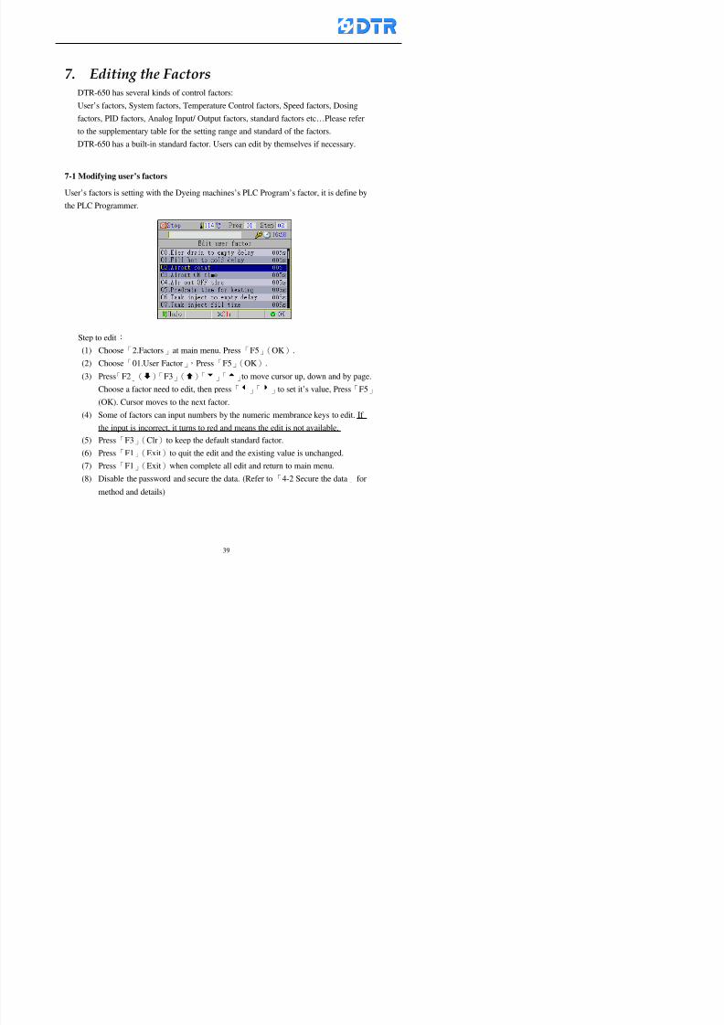
8132019 DTR 650 User Manual
httpslidepdfcomreaderfulldtr-650-user-manual 3970
983095 983109983140983145983156983145983150983143 983156983144983141 983110983137983139983156983151983154983155DTR-650 has several kinds of control factors
Userrsquos factors System factors Temperature Control factors Speed factors Dosing
factors PID factors Analog Input Output factors standard factors etchellipPlease refer
to the supplementary table for the setting range and standard of the factors
DTR-650 has a built-in standard factor Users can edit by themselves if necessary
7-1 Modifying userrsquos factors
Userrsquos factors is setting with the Dyeing machinesrsquos PLC Programrsquos factor it is define by
the PLC Programmer
Step to edit
(1) Choose「2Factors」at main menu Press「F5」(OK)
(2) Choose「01User Factor」Press「F5」(OK)
(3) Press「F2」()「F3」()「6」「5」to move cursor up down and by page
Choose a factor need to edit then press「3」「4」to set itrsquos value Press「F5」(OK) Cursor moves to the next factor
(4) Some of factors can input numbers by the numeric membrance keys to edit If
the input is incorrect it turns to red and means the edit is not available
8132019 DTR 650 User Manual
httpslidepdfcomreaderfulldtr-650-user-manual 4070
Modifyrsquos method of the system factors temperature factors speed factors dosingfactors PID factors analog Input output factors standard factors etchellipare same asabove
If apply the library of DTR500 and DTR600 into the DTR650 the key「3」「4」may not valid to use Please use the numeric keys instead of it to key in factors itmay not effect the normal operation
Please pay a serious attention and read carefully at the factorrsquos table before modify the factors An incorrect value may effect the DTR-650 Dyeing
Machine Controllerrsquos operating After modifying factors must cancel the
password and secure data
7-2 Loading the standard factors
After modifying factors if need to restore a manufacturerrsquos standard factors of
DTR-650 The method as follows
1 Choose「2Factors」at main menu Press「F5」(OK)
「 「 ( ) 「
8132019 DTR 650 User Manual
httpslidepdfcomreaderfulldtr-650-user-manual 4170
7-3 Copying the factor
Users can build up a set of factor by themselves and make a copy and save
Step
1 Choose「2Factors」at main menu Press「F5」(OK)
2 Choose「13Restore Factor」 press「F5」(OK) window「factor will be
overwrite 」
3 Press「F4」(Yes)copy finished and saved Return to the main menu
4 Press「F2」(No)to not copy the factor and the existing factor is not change Return
to the main menu
7-4 Loading the backup factors
Users can build up a set of factor and backup files to load to DTR-650
Step1 Choose「14Backup factor」at the sub-function menu Press「F5」(OK)and
window「Factror will be overwrite」appears
2 Press「F3」(OK)to load the the backup factor them return to main menu
Press「F2」(No)to not copy the factor and the existing factor is not change
Return to the main menu
8132019 DTR 650 User Manual
httpslidepdfcomreaderfulldtr-650-user-manual 4270
983096 983119983157983156983152983157983156 983124983141983155983156983145983150983143
Before the output testing must be complete the steps as follows
A Cut off all connecting line of output terminal of DTR-650
B Stop running the PLC
C Check up the connections of all output channels to avoid damages from
incorrect connections
D Check up state of dyeing machines include the temperature pressure valves
onoff and pumpshellipetc ensure the safety for priority
8-1 Testing the Digital output
Step
1 Choose「3Output Testing」at the main menu Press「F5」(OK) 2 Choose「1Digital」at the sub function menu Press「F5」(OK) window「Digital
output testing」appears
3 Press「」「」「」to move cursor to each output channels Press「F5」(OK)
Output Name
8132019 DTR 650 User Manual
httpslidepdfcomreaderfulldtr-650-user-manual 4370
8-2 Testing the Analog output
(1) Choose「3Output Testing」at the main menu Press「F5」(OK)
(2) Choose「2Analog」at the sub function menu Press「F5」(OK) window「Analog output testing」appears
(3) Press「」「」「」to move cursor to each channels Then key in number by
the numeric membrance keys (range0~200= 0~20mA) Press「F5」(OK) there
is a output current relating to the output channel
(4) Press「F5」(OK) There is an output when the output channel with red light No
output without light onl(5) When complete the testing press「F1」(OK)to return to the main menu
8132019 DTR 650 User Manual
httpslidepdfcomreaderfulldtr-650-user-manual 4470
983097 983107983137983148983145983138983154983137983156983145983151983150
DTR-650 has Dosing and Temperature calibration
When enter to Dosing calibration must be set the Low Volume calibration first and
then High Volume calibration When enter to Temperature calibration must be set the
Low Temperature calibration first and then High Temperature calibration Must be
hightly follow this orders seriously
9-1 Calibration of Low Volume Tank
Step
A Choose「4Calibration」at the main menu Press「F5」(OK)
B Choose「Dosing 0 low vol」at the sub function menu Press「F5」(OK) window
appears
C Fill the Dosing Tank to a half level input value shows how much the water level
If it stays ldquo0rdquo check the connection and the factor setting is correct or not
And connect the pressure sensorrsquos output channel to the Current Meter to ensure
that sensor works or not
8132019 DTR 650 User Manual
httpslidepdfcomreaderfulldtr-650-user-manual 4570
D Fill the Dosing Tank to 50ml (Calcalate from the bottom side of the pressure
sensor steel tube) input value should show 4~6 (input value must between
0~10) Then enter the water volume The setting volume is relating the water
levelrsquos water value (litre as unit) input range 0~80 Set as「 「「 「0000 0000 0000 0000」」」」is strongly is strongly is strongly is strongly
receommend receommend receommend receommend Press「F5」(OK)to complete [Calibration of Low Volume Tank 1
is same as above method]
9-2 Calibration of High Volume Tank
Step
A Choose「4Calibration」at the main menu Press「F5」(OK)
B Choose「Dos 0 high vol」at the sub function menu Press「F5」(OK) window of
「Calibrate high 」appears
C Fill the Dosing Tank to a full level input value should be larger than 30 enter
the current water level which relates to the water volume Enter the range within
100~2500 Then press「F5」(OK) to complete the calibrate the high volume tank
8132019 DTR 650 User Manual
httpslidepdfcomreaderfulldtr-650-user-manual 4670
9-3 Temperature Calibration
Step
A This function is for adjusting the DTR650rsquos accuracy of Temperature Control It
must be using with the special terminal which is only for DTR650
B Choose「4Calibration」at the main function menu and press「F5」(OK)
C Choose「3Low Temp」at the sub-function menu Press「F5」(OK)and《Fig9-3》
appears insert the DTR650rsquos low temperature calibration terminal to the temperature
input terminal wait for the jumping value to stable down then press「F5」(OK) then
to adjust the high temperature calibration
D Adjusting the High Temperature Calibrationrsquos method is same as above But usersusersusersusers
must be using the High Temperature Terminalmust be using the High Temperature Terminalmust be using the High Temperature Terminalmust be using the High Temperature Terminal whichwhichwhichwhich is specially for DTR650 onlyis specially for DTR650 onlyis specially for DTR650 onlyis specially for DTR650 only
《Fig 9-3》
8132019 DTR 650 User Manual
httpslidepdfcomreaderfulldtr-650-user-manual 4770
10 983122983141983139983151983154983140983155 983151983142 983108983161983141 983120983154983151983143983154983137983149983155
It contains the past 15 days of temperature curves of running history
Checking method
(1) Choose「5Dye Record」at main menu press「F5」(OK)
(2) Sub-function menu shows the set up date of the past 15 days dye programs
Listing by the lastest set up date
(3) Choose a program date and press「F5」(OK) it appears window「Temp
record」
(4) Press「」「」to move the white line in the box one minute by moving once
(5) Press「3」「4」to move the line to check the time period 2 hours by moving once
The yellow selecting line of the「24 hours operating state」is repectively moving
The curve info is show in the curve box Left side of the widnow appears the
relating running info the time is the time value of the line locates at
(6) Check more details of the temperature info to press numeric key「middot」 a bright red line
appears in the selecting box this line is to check the starting point of the
temperature inforsquos time period Then press「」to move the white line to the end
point of the time period The temperature info between the starting point and end
point are appears at the right side of the window Press「middot」to return to the preious
curve page
(7) Check more details of the alarm infor To perss numeric key「7」「9」 the alarmrsquos
details is listing by orders
(8) Press「F1」(exit) to return
8132019 DTR 650 User Manual
httpslidepdfcomreaderfulldtr-650-user-manual 4870
11 983125983155983137983143983141 983151983142 983117983141983149983151983154983161 983107983137983154983140
DTR-650 supports 32MB or above Compact Flash Card which can transfer and save all
information for 4 sets of DTR-650 Including library files schematic diagram icon
image PLC program dye program factor and confiruration files etchellip Use the CF Card
to up download and swap the information of DTR-650 promptly install the relating
device and program updates
DTR-650 CF Card with bank 1 to bank 4 can save 4 sets information of Dyeing
Machines When download or save files should choose the BANK first
《Fig11-1》
8132019 DTR 650 User Manual
httpslidepdfcomreaderfulldtr-650-user-manual 4970
11-1 Downloading data
1 Firmly insert the CF card into the DTR-650rsquos PCMCIA connector Ensure it is
wholely and firmly inserted if the card is not totally inserted or the card do not
touch in all to the connector there will be an error occurred and cannot
updownload or interrupted during operation
2 Choose「6Memory Card」at the main menu and press「F5」(OK) 《Fig11-1》
appears Information of Bank「1」shows at the left hand side of the window press
number 1-4 by using numeric keys to choose the BANK Check the
information in the Bank seriously which is exactly need to download to the
DTR650
3 Press()()「6」「5」to move cursor to the sub-function menu to choose
the downloading items Press「F5」(OK) window appears「Stop PLC run before
access memory card Stop the PLC run」 Press「F5」(YES) to stop PLC
running
4 Press「F5」(OK) window appears Confirm to update or not the DTR-650rsquos
information As that downloading will be replace the DTR-650rsquos information
(that means the existing information of the DTR-650 will be removed and
replaced)
5 Press「F4」(YES)to download the information from the DTR-650 to the CF
Card Return to the main menu when finish
8132019 DTR 650 User Manual
httpslidepdfcomreaderfulldtr-650-user-manual 5070
Ensure inserting firmly the CF card into the DTR-650 unless it will cause
error or cannot Updownload data
Never remove CF card during transferring or updownloading data Until it
is all completed
DTR-650rsquos dyeing program is not compatible with DTR-500 and
DTR-600 Never use CF card to transfer data among them
11-2 Storing and transfering data
1 Insert the CF Card to the DTR-650
2 Choose「6Memory Card」at the main menu and press「F5」(OK) 《Fig11-1》
appears Left hand side of the window shows the data of BANK 1 press numeric
keys 1-4 to select the BANK To confirm the put the data in the DTR-650 to the CF
Card The existing data of that bank will be replaced and covered by the new data (if
that bank is already occuplied)
3 Choose「23Save Dye prog」(Example)at the sub-funciton menu press「F5」(OK)to confirm Window「Update memory card data」appears
4 Press「F5」(OK)to transfer the data to the CF card Return to the main menu
5 Put the CF card into another DTR-650 and follow the operating method of 「11-1
Downloading data」」」」can transfer and swap data with more than one set of
DTR-650
8132019 DTR 650 User Manual
httpslidepdfcomreaderfulldtr-650-user-manual 5170
12 983123983156983137983156983141 983137983150983140 983113983150983142983151983154983149983137983156983145983151983150
The state and information is including the Dyeing Machinersquos state of Digit Input output
Analog Input output Temperature control PID Dosing PID Pressure different PID
software system information and alarm record This information is for checking at any
time
12-1 Input Output state
Step
1 Choose「7Info and state」at main menu and press「F5」(OK)
2 Choose「01Digital IO put」at the sub-function menu then press「F5」(OK)
「Digital In Out State」0=None 1=Input
3 Press「F1」(Exit)to return to main menu
Same method for checking the temperature control analog dosing pressure
different etchellip
12-2 Checking the system information
Step
1 Choose「7Info and state」at main menu and press「F5」(OK)
2 Choose「11 System info」at sub-function field press「F5」(OK)Window
「System Information」appear
System information is including System info(software version) Library doc
Icon files Schematic file Definition file hardare state Config File Commandinstruction icon PLC file etc
8132019 DTR 650 User Manual
httpslidepdfcomreaderfulldtr-650-user-manual 5270
12-3 Checking the operating alarm record
Operating record shows the latest 40 operating items and alarm records including
the time and content of the alarm
A) Choose「7 Info and state」
and press「F5」(OK)
B) Choose「12Alarm logs」at
the sub-funciton menu then
press「F5」(OK)
8132019 DTR 650 User Manual
httpslidepdfcomreaderfulldtr-650-user-manual 5370
13 983105983140983146983157983155983156983145983150983143 983156983144983141 983107983151983150983156983154983137983155983156
The displaysrsquos brightness can be adjusted if necessary
Step
1 Choose「8Others」at main menu press「F5」(OK)
2 Choose「01Contrast」at sub-function menu press「F5」(OK) window「Set
Contrast」appears
3 Press「」「」to move the bar to set the brightness then press「F5」(OK)Window appears「Please reboot the system」
4 Press「F5」(OK)to return to main menu and re-boot the DTR-650 to complete
adjusting the brightness
8132019 DTR 650 User Manual
httpslidepdfcomreaderfulldtr-650-user-manual 5470
14 983123983156983151983152 983154983157983150983150983145983150983143 983156983144983141 983120983116983107 983120983154983151983143983154983137983149
Before testing the Input output testing transfer of the PLC program must stop the PLC
running
Step
1 Choose「8Others」at the main menu Press「F5」(OK)
2 Choose「04 PLC Stop」at sub-function menu Press「F5」(OK) window
「Password」appears
3 Enter password and press「F5」(OK) Window「Stop the PLC run」appears
4 Press「F4」(Yes)and window「PLC Stop」appear Press「F5」(OK) Now
the PLC is stop running and return to the main menu
All testing cannot operate when the PLC is running
Editing dye program and the relating operation can
perform with the PLC running together
8132019 DTR 650 User Manual
httpslidepdfcomreaderfulldtr-650-user-manual 5570
15 983123983141983156983156983145983150983143 983156983144983141 983156983145983149983141
Step
1 Press「8Others」at the main menu Press「F5」(OK)
2 Choose「10Set date time」at the sub-function menu Press「F5」(OK) window
「Set date time」appears
3 Press「F5」(Edit) to move cursor by 「3」「4」 enter the time value at the
cursor locates
4 Press「F5」(OK)to complete the modify Press「F1」(Exit)to return to main
menu
5 Press「F1」(Exit)if not modify and return to main menu
8132019 DTR 650 User Manual
httpslidepdfcomreaderfulldtr-650-user-manual 5670
1166 983123983123983157983157 983152 983152 983152 983152983148983148983141983141983149983149983141983141983150983150983156 983156 983137983137983154 983154 983161983161 983124 983124 983137983137983138983138983148983148983141983141
TTTTTTTTaaaaaaaabbbbbbbblllllllleeeeeeee 11111111 【Dye Instruction】
Code Icon Instruction Code Icon Instruction
000 End 016 Inject C
001 Start 017 Dosing BV
002 Heat 018 PH
003 Cool 019 Addsalt B
004 Flow Fill 020 Addsalt C
005 Level Fill 021 Ana Fill
006 Drian 022 Lock Fill007 Rinse 023 Lock Level
008 Run 024 Low Rinse
009 Call 025 Cyc Rinse
010 Prep B 026 Rinse B
011 Addsalt B 027 Rinse C
012 Dosing B 028 Temp
013 Inject B 029 Nozzle Pressure
014 Prep C 030 Main Pump
015 Dosing C 031 Pump Speed
8132019 DTR 650 User Manual
httpslidepdfcomreaderfulldtr-650-user-manual 5770
Table 2 【【【【Alarm】】】】
System Alarm Must stop operating and check up to solve problems before restarting
the machine
Running Alarm It is a reminder Not effect the operating of DTR-650
Userrsquos Alarm Total of 32 Users can define themselves and use it when edit the PLC
Program (do not listing below)
No System Alarm No Running Alarm
1 PLC program not running 16 Temp ctrl 0 Grad too slow
2 Main temp sensor error 17 Temp ctrl 0 Grad too fast
3 Not at Run window 18 Temp ctrl 0 Hold temp too low
4 Exceeding max temp 19 Temp ctrl 0 Hold temp too high
5 - 20 Temp ctrl 1 Grad too slow6 - 21 Temp ctrl 1 Grad too fast
7 - 22 Temp ctrl 1 Hold temp too low
8 Communication error 23 Temp ctrl 1 Hold temp too high
9 Slave not answer 24 Temp ctrl 2 Grad too slow
10 PLC 0 not answer 25 Temp ctrl 2 Grad too fast
11 PLC 1 not answer 26 Temp 2 Hold temp too low12 Display not answer 27 Temp 2 Hold temp too high
13 Lower power voltage 28 Temp ctrl 3 Grad too slow
14 - 29 Temp ctrl 3 Grad too fast
15 - 30 Temp3 Hold temp too low
31 Temp3 Hold temp too high
32 Dosing 0 injection too slow
33 Dosing 0 injection too fast
34 Dosing 1 injection too slow
35 Dosing 1 injection too fast
8132019 DTR 650 User Manual
httpslidepdfcomreaderfulldtr-650-user-manual 5870
TTTTTTTTaaaaaaaabbbbbbbblllllllleeeeeeee 33333333 【【【【System factor】】】】
No Description Std Range amp Definition
1 ID No 000 000- 100 Controller no
2 Communication Rate 4800Bps 2400 4800 9600 19200 38400
3 Display language Chinese English Chinese
4 Temp display mode and
5 Maxmium temperature 145 025 ~ 145 6 Type of external PLC Default PLC32DPLC32PLC16Default
7 Number of external PLC NANA 1 unit connect
2 unit connect
8Communication Rate of
PLC9600Bps 2400 4800 9600 19200
9 Set point 1 085 000 ~ 145
If signal source is temperaturethe setting value is thetemperature value If the signal
source is Analog Input 6~17 then
setting value for Analog input is 0 ndash
100 and relates Analog
Input14~020mA
10 Source 1 Sensor0Sensor 0 ~5
Analog input 0 ~1111 Set point 2 092 Same as 09
12 Source 2 PT100 1 Same as 10
13 Set point 3 085 Same as 09
14 Source 3 PT100 2 Same as 10
15 Set point 4 092 Same as 09
16 Source 4 PT100 3 Same as 1017 Set point 5 085 Same as 09
18 Source 5 PT100 4 Same as 10
19 Set point 6 092 Same as 09
8132019 DTR 650 User Manual
httpslidepdfcomreaderfulldtr-650-user-manual 5970
29 Min cyclic time of cloth 100sec 0 ~ 255 sec
30 Max cyclic time of cloth 240sec 0 ~255 sec
31Standard cyclic time of
cloth
180 000 ~ 255 sec
32 Display ModeProgram
List
Program list Schematic Diagram
Icon mode
33 CF card format Standard of
DTR CF
Card
Standard of DTR CF Card V20
Standard CF Card
34 Addition step Disable Disable Enable35 Mode Com 3
CouplingEsure Com 3 is the communication
port of the Central or Coupling
36Com 3 Communication
rate9600 Central communication speed
8132019 DTR 650 User Manual
httpslidepdfcomreaderfulldtr-650-user-manual 6070
TTTTTTTTaaaaaaaabbbbbbbblllllllleeeeeeee 44444444 【【【【Temperature Cotnrol Factor】】】】
No Factor Definition Standard Range and Definition
01 PT No PT-0 PT 0~5 PT-100 Input number
02 Max working temp 140 000~140
03 Output mode 0 0~2
04 Alarm time of gardient 240sec 000~255 sec
05 Alarm mode of gradient Always AlwaysOnceNone
06 Control mode of gradient Heating orCooling
interlocked
Heating and Cooling interlocked
No limitation
07 Alarm range of HoldTemp 03 01~20
08 Alarm time for HoldTemp 240sec 000~255sec
09 Alarm mode of HoldTemp Always AlwaysOnceNone
10 Control mode ofHoldTemp
Heating only Only heating and cooling Cooling whenalarm occurred Only heating andcooling No limitation when alarmHeating only
11 Porportional Band 100 000~250
12 Integral band 128 sec 000~255 sec
13 Differential time 04 sec 00~20 sec
14 Min transit gradient 02 00~50
15 Transit rate 20 times 00~50 times (020= 2 times)
16 PID initial output value 010 000~100
17 ONOFF cycle time 10 sec 05~25 sec
Onoff valve set as 010 sec
Proportional valve set as 020 sec
18 Time down count mode Mode 0 0~10 = The time down count range from「Factor 20 + target temp」to「Target
8132019 DTR 650 User Manual
httpslidepdfcomreaderfulldtr-650-user-manual 6170
TTTTTTTTaaaaaaaabbbbbbbblllllllleeeeeeee 55555555 【【【【Speed Factor】】】】
No Factor Definition Standard Range amp Definition
01 Input Number Speed input 0 Speed input 0~11
02 Average times 05 times 01~10
03 Sensor Number 008pcs 001~255
04 Roller Dimension 250mm 050~500
05 Max cloth speed 200mmin 001~25506 Min cloth speed 020mmin 001~255
07 Alarm delay time 240sec 001~255
08 Alarm mode Every oncenoneevery
09 Alarm range () 020 001~255
10 Proportional band 100 001~255
11 Integer band 128 001~25512 Differential time 000 001~200
13 Initial speed () 020 001~255
14 Control cycle ti(01sec) 05 01~30
15 First cycle time(01sec) 10 01~30
16 Speed increase limit () 010 001~100
17 Speed decrease limit () 010 001~100
18 Min speed() 005 001~100
19 Manual speed adjust () 005 001~100
20 Manual initial speed() 020 001~100
21 Stopping speed() 010 001~100
22 Switch speed() 020 001~100
23 Not used
24 Speed decrease turns 03turns 01~50
8132019 DTR 650 User Manual
httpslidepdfcomreaderfulldtr-650-user-manual 6270
Table 6 【【【【Dosing Factors】】】】
No Description Range Range and Explanation
1 Analog input no Analog input 0 Analog input no 0 ~11
2Alarm delay time for
dosing240 sec 000 ~255 sec
3 Alarm time for dosing Every Every Once None
4 Proportional band 100 000 ~255 sec Factor P
5 Integer band 128 000 ~255 sec Factor I6 Differential time 04 00 ~20 Factor D
7 Max adjust rate 150 50~ 255
8 Initial factor for dosing 10 000 ~100
9 User curve section 0 10 Gradient of sect1 for dosing curve9
10 User curve section 1 10 Gradient of sect2 for dosing curve9
11 User curve section 2 10 Gradient of sect3 for dosing curve9
12 User curve section 3 10 Gradient of sect4 for dosing curve9
13 User curve section 4 10 Gradient of sect5 for dosing curve9
14 User curve section 5 10 Gradient of sect6 for dosing curve9
15 User curve section 6 10 Gradient of sect7 for dosing curve9
16 User curve section 7 10 Gradient of sect8 for dosing curve9
17 User curve section 8 10 Gradient of sect9 for dosing curve9
18 User curve section 9 10 Gradient of sect10 for dosing curve9
19 Min water level 05 00~ 10 04~20mA percentagechange to the userrsquos factor setting
20 Output value for Tank
clean
100 000~ 100
Injected percentage of dosing valve
in dosing End period
This factor will be invalided if usingONOFF dosing valve
21 Full range 100 001~255 Self-adjustment cannotchange
22 Range ratio 001001~255 Self-adjustment cannot
change
8132019 DTR 650 User Manual
httpslidepdfcomreaderfulldtr-650-user-manual 6370
【【【【TTaabbllee 77 】】】】Pressure Deviation Factors
No Description Std Range amp Definition
1 Analog input number + Analog in 0 Analog in 0~11
2 Analog input number - Analog in 1 Analog in 0~11
3 Input mode Pressure Pressure Pressure deviation
4 Full range 050x01Kgcm
001~255
5 Range ratio 001 001~255
6 Alarm delay time 100sec 001~255
7 Alarm mode Every oncenone
8 Alarm range 010 001~255
9 Proportional band 100 001~255
10 Integer band 128 001~255
11 Differential time 00 00~20
12 PID Init output value 010 001~255
13 Cycle time 10 03~30
14 First cycle time 030 003~100
15 Max adjust rate 010 001~100
8132019 DTR 650 User Manual
httpslidepdfcomreaderfulldtr-650-user-manual 6470
【【【【TTaabbllee 88 】】】】Definition of Analog Input
No Description Standard Range and Explanation
01 PT 0 correction standard DIN std DIN std JIS std
02 PT 0 correction +0 +- 9
03 PT 1 correction standard DIN std DIN std JIS std
04 PT 1 correction +0 +- 9
05 PT 2 correction standard DIN std DIN std JIS std
06 PT 2 correction +0 +- 9
07 PT 3 correction standard DIN std DIN std JIS std
08 PT 3 correction +0 +- 9
09 PT 4 correction standard DIN std DIN std JIS std
10 PT 4 correction +0 +- 9
11 PT 5 correction standard DIN std DIN std JIS std
12 PT 5 correction +0 +- 9
13 Analog input 0 define 4 ~ 20mA 0 ndash 20mA 4 ndash 20mA
14 Analog input 0 average times 10 times 01- 20 times
15 Analog input 0 min value 0000 0000 - 1000
16 Analog input 0 max value 100 0001 - 9999
17-60 Analog input 1~11 Same as Analog input 0
【【【【 】】】】 fi i i f A O
8132019 DTR 650 User Manual
httpslidepdfcomreaderfulldtr-650-user-manual 6570
【【【【TTaabbllee 99 】】】】Definition of Analog Output
No Description Standard Range and explanation
61 Analog output 0 define Control byPLC
Control by PLC
Temperature control PID0 output
Temperature control PID1 output
Temperature control PID2 output
Speed PID3 output
Dosing PID0 output Dosing PID1output
Pressure different PID0 outputPressure different PID1 output
Main temperature output
62 Mode of Analog ouptput0 4 ~20mA 0 ndash20mA 4 ndash 20mA
63-84 Analog output 1~11 Same as Analog output 0
【【【【TTaabbllee 1100】】】】Value Table 0 amp 1
No Description Range Std Range and explanation
1 Analog input no 000~011 000 Analog input no
2 Data ratio 001~255 100 Multiple by factors
3~53 0~98 000~255 000-100 Analog input 0~98 data
【【【【 】】】】St t Li t
8132019 DTR 650 User Manual
httpslidepdfcomreaderfulldtr-650-user-manual 6670
【【【【TTaabbllee 1111】】】】State List
No Description Range Standard Range and explanation
1 Display setting 1 0~255 205 See remarks at next page
2 Display setting 2 0~255 208
3 Display setting 3 0~255 209
4 Display setting 4 0~255 017
5 Display setting 5 0~255 0186 Display setting 6 0~255 019
7 Display setting 7 0~255 020
8 Display setting 8 0~255 021
9 Display setting 9 0~255 000
10 Display setting 1 0~255 000
11 Display setting 2 0~255 000
12 Display setting 3 0~255 000
13 Display setting 4 0~255 000
14 Display setting 5 0~255 000
15 Display setting 6 0~255 000
16 Display setting 7 0~255 000
Remarks
8132019 DTR 650 User Manual
httpslidepdfcomreaderfulldtr-650-user-manual 6770
0 = No display 1~255 = Display type of number
1~16 Content of PLC VB0~15
No 1 corresponding to VB0
No 16 corresponding to VB15
17~32 Content of PLC DB0~15
No 17 corresponding to DB0
No 32 corresponding to DB15
33~46 Content of PLC CNT0~29
No 33 corresponding to CNT0
No 46 corresponding to CNT29 47~78 Content of dyeing instruction 0~31 CNT0
No 47 corresponding to system instruction to No 0 of CNT0
No 78 corresponding to system instruction to No 31 of CNT0rsquos content
79~110 Dyeing instruction 0~31 of CNT0rsquos setting
111~142 Content of Dyeing instruction 0~31 CNT1No 111 corresponding to dyeing instruction No 0 of CNT1
No 142 corresponding to dyeing instruction No 31 of CNT1rsquos content
143~174 Dyeing instruction 0~31 of CNT1rsquos setting
175~204 Content of PLC HTIM0~29
No 175 corresponding to HTIM0
No 204 corresponding to HTIM29
205 Loading
206 Ratio 1
207 Ratio 2208 Ratio 1 x Loading
209 Ratio 2 x Loading
210 Fix value
211 Value Table 1 matching result
212 Value Table 2 matching result
213 Value Table 1 setting214 Value Table 2 setting
215 Pressure control PID0 different pressure value
216 Pressure control PID1 different pressure value
TTTTTTTTaaaaaaaabbbbbbbblllllllleeeeeeee 1122 【【【【Usage of password】】】】
8132019 DTR 650 User Manual
httpslidepdfcomreaderfulldtr-650-user-manual 6870
No Main FunctionFactor Sub Function Factor Password Rank
1 Run None
2 Dye program User3 or above
3 Control factor
- User factor User 1
- System factor User 1
- Temp PID 0
- Temp PID 1 User 1- Speed PID 0 User 1
- Dosing PID 0 User 1
- Dosing PID 1 User 1
- Pressure PID 0 User 1
- Pressure PID 1 User 1
- Analog IO User 1
- Load standard factor User 2 or above- Load a copied factor User 2 or above
- Copy factor User 2 or above
- Value table 0 User 1
- Value table 1 User 1
- Information and state User 1
- Dye instruction User 1
- Edit dye instruction setting User 14 Output testing User 2 or above
5 Calibration User 2 or above
6 Dye record None
7 CF card User 1
8 Info and state None
9 Others
- Contrast User3 or above
- Data Locking None
- PLC Run User 1
- PLC Stop User 1
- Password setting User 1
TTTTTTTTaaaaaaaabbbbbbbblllllllleeeeeeee 1133 【【【【Technical Data】】】】
8132019 DTR 650 User Manual
httpslidepdfcomreaderfulldtr-650-user-manual 6970
TTTTTTTTaaaaaaaabbbbbbbblllllllleeeeeeee 1133 【【【【Technical Data】】】】
1 Temperature Control
- Range 10~145(plusmn1)
- Mode Proportional or PWM
- Sensor PT100 (JIS or DIN standard)
2 Input and output channel
- Digital Input 32 DC24V PNP- Digital Output 32 DC24V 054A Relay connect point
- Analog Input 4 04~20 mA
- Analog Output 4 0~20mA 或 4~20 mA
3 Communication port 3 RS-232 amp 0~20 mAx1 RS485x 2
4 Dye program
- Number 15000 Steps
- Standard step 61Heating Cooling Fill Drain RinseDosingetc
5LCD module and Display
langage
Chinese
English
320 x 240 TFT color display with
more language
6 CF card connector 1 PCMCIA standard
7 Membrane Keyboard- Number Key 10 [0]~[9] Input factors
- Function Key 5 [F1]~[F5] function selecting
- Operation Key 2 [Start] [Stop]
- Auxiliary Key 7 [][][][][Esc] [larr][OK] [bull]
8 Operating Condition
- Temperature 5~45
- Humidity ≦85 (25)
9 Power supply
V l DC 24V
8132019 DTR 650 User Manual
httpslidepdfcomreaderfulldtr-650-user-manual 7070
70
983108983124983122983085650 983113983150983152983157983156 983119983157983156983152983157983156 983120983151983154983156983145983150983143 (983138983137983139983147983155983145983140983141 983158983145983141983159)
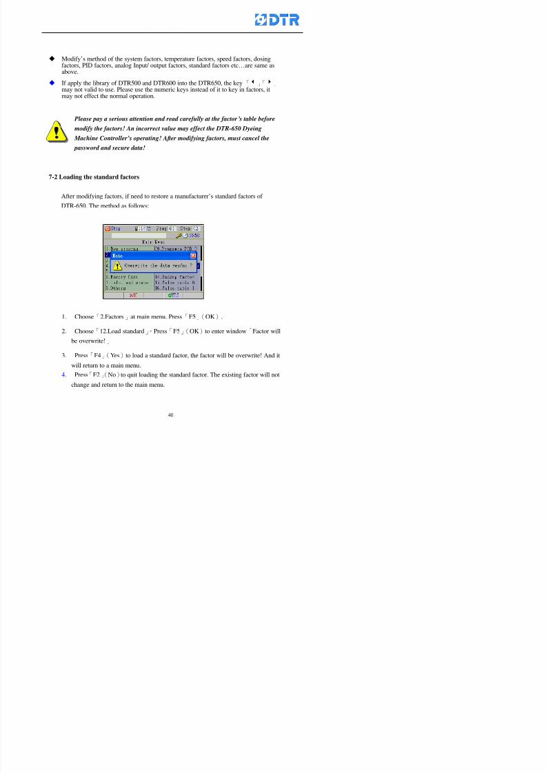
8132019 DTR 650 User Manual
httpslidepdfcomreaderfulldtr-650-user-manual 4070
Modifyrsquos method of the system factors temperature factors speed factors dosingfactors PID factors analog Input output factors standard factors etchellipare same asabove
If apply the library of DTR500 and DTR600 into the DTR650 the key「3」「4」may not valid to use Please use the numeric keys instead of it to key in factors itmay not effect the normal operation
Please pay a serious attention and read carefully at the factorrsquos table before modify the factors An incorrect value may effect the DTR-650 Dyeing
Machine Controllerrsquos operating After modifying factors must cancel the
password and secure data
7-2 Loading the standard factors
After modifying factors if need to restore a manufacturerrsquos standard factors of
DTR-650 The method as follows
1 Choose「2Factors」at main menu Press「F5」(OK)
「 「 ( ) 「
8132019 DTR 650 User Manual
httpslidepdfcomreaderfulldtr-650-user-manual 4170
7-3 Copying the factor
Users can build up a set of factor by themselves and make a copy and save
Step
1 Choose「2Factors」at main menu Press「F5」(OK)
2 Choose「13Restore Factor」 press「F5」(OK) window「factor will be
overwrite 」
3 Press「F4」(Yes)copy finished and saved Return to the main menu
4 Press「F2」(No)to not copy the factor and the existing factor is not change Return
to the main menu
7-4 Loading the backup factors
Users can build up a set of factor and backup files to load to DTR-650
Step1 Choose「14Backup factor」at the sub-function menu Press「F5」(OK)and
window「Factror will be overwrite」appears
2 Press「F3」(OK)to load the the backup factor them return to main menu
Press「F2」(No)to not copy the factor and the existing factor is not change
Return to the main menu
8132019 DTR 650 User Manual
httpslidepdfcomreaderfulldtr-650-user-manual 4270
983096 983119983157983156983152983157983156 983124983141983155983156983145983150983143
Before the output testing must be complete the steps as follows
A Cut off all connecting line of output terminal of DTR-650
B Stop running the PLC
C Check up the connections of all output channels to avoid damages from
incorrect connections
D Check up state of dyeing machines include the temperature pressure valves
onoff and pumpshellipetc ensure the safety for priority
8-1 Testing the Digital output
Step
1 Choose「3Output Testing」at the main menu Press「F5」(OK) 2 Choose「1Digital」at the sub function menu Press「F5」(OK) window「Digital
output testing」appears
3 Press「」「」「」to move cursor to each output channels Press「F5」(OK)
Output Name
8132019 DTR 650 User Manual
httpslidepdfcomreaderfulldtr-650-user-manual 4370
8-2 Testing the Analog output
(1) Choose「3Output Testing」at the main menu Press「F5」(OK)
(2) Choose「2Analog」at the sub function menu Press「F5」(OK) window「Analog output testing」appears
(3) Press「」「」「」to move cursor to each channels Then key in number by
the numeric membrance keys (range0~200= 0~20mA) Press「F5」(OK) there
is a output current relating to the output channel
(4) Press「F5」(OK) There is an output when the output channel with red light No
output without light onl(5) When complete the testing press「F1」(OK)to return to the main menu
8132019 DTR 650 User Manual
httpslidepdfcomreaderfulldtr-650-user-manual 4470
983097 983107983137983148983145983138983154983137983156983145983151983150
DTR-650 has Dosing and Temperature calibration
When enter to Dosing calibration must be set the Low Volume calibration first and
then High Volume calibration When enter to Temperature calibration must be set the
Low Temperature calibration first and then High Temperature calibration Must be
hightly follow this orders seriously
9-1 Calibration of Low Volume Tank
Step
A Choose「4Calibration」at the main menu Press「F5」(OK)
B Choose「Dosing 0 low vol」at the sub function menu Press「F5」(OK) window
appears
C Fill the Dosing Tank to a half level input value shows how much the water level
If it stays ldquo0rdquo check the connection and the factor setting is correct or not
And connect the pressure sensorrsquos output channel to the Current Meter to ensure
that sensor works or not
8132019 DTR 650 User Manual
httpslidepdfcomreaderfulldtr-650-user-manual 4570
D Fill the Dosing Tank to 50ml (Calcalate from the bottom side of the pressure
sensor steel tube) input value should show 4~6 (input value must between
0~10) Then enter the water volume The setting volume is relating the water
levelrsquos water value (litre as unit) input range 0~80 Set as「 「「 「0000 0000 0000 0000」」」」is strongly is strongly is strongly is strongly
receommend receommend receommend receommend Press「F5」(OK)to complete [Calibration of Low Volume Tank 1
is same as above method]
9-2 Calibration of High Volume Tank
Step
A Choose「4Calibration」at the main menu Press「F5」(OK)
B Choose「Dos 0 high vol」at the sub function menu Press「F5」(OK) window of
「Calibrate high 」appears
C Fill the Dosing Tank to a full level input value should be larger than 30 enter
the current water level which relates to the water volume Enter the range within
100~2500 Then press「F5」(OK) to complete the calibrate the high volume tank
8132019 DTR 650 User Manual
httpslidepdfcomreaderfulldtr-650-user-manual 4670
9-3 Temperature Calibration
Step
A This function is for adjusting the DTR650rsquos accuracy of Temperature Control It
must be using with the special terminal which is only for DTR650
B Choose「4Calibration」at the main function menu and press「F5」(OK)
C Choose「3Low Temp」at the sub-function menu Press「F5」(OK)and《Fig9-3》
appears insert the DTR650rsquos low temperature calibration terminal to the temperature
input terminal wait for the jumping value to stable down then press「F5」(OK) then
to adjust the high temperature calibration
D Adjusting the High Temperature Calibrationrsquos method is same as above But usersusersusersusers
must be using the High Temperature Terminalmust be using the High Temperature Terminalmust be using the High Temperature Terminalmust be using the High Temperature Terminal whichwhichwhichwhich is specially for DTR650 onlyis specially for DTR650 onlyis specially for DTR650 onlyis specially for DTR650 only
《Fig 9-3》
8132019 DTR 650 User Manual
httpslidepdfcomreaderfulldtr-650-user-manual 4770
10 983122983141983139983151983154983140983155 983151983142 983108983161983141 983120983154983151983143983154983137983149983155
It contains the past 15 days of temperature curves of running history
Checking method
(1) Choose「5Dye Record」at main menu press「F5」(OK)
(2) Sub-function menu shows the set up date of the past 15 days dye programs
Listing by the lastest set up date
(3) Choose a program date and press「F5」(OK) it appears window「Temp
record」
(4) Press「」「」to move the white line in the box one minute by moving once
(5) Press「3」「4」to move the line to check the time period 2 hours by moving once
The yellow selecting line of the「24 hours operating state」is repectively moving
The curve info is show in the curve box Left side of the widnow appears the
relating running info the time is the time value of the line locates at
(6) Check more details of the temperature info to press numeric key「middot」 a bright red line
appears in the selecting box this line is to check the starting point of the
temperature inforsquos time period Then press「」to move the white line to the end
point of the time period The temperature info between the starting point and end
point are appears at the right side of the window Press「middot」to return to the preious
curve page
(7) Check more details of the alarm infor To perss numeric key「7」「9」 the alarmrsquos
details is listing by orders
(8) Press「F1」(exit) to return
8132019 DTR 650 User Manual
httpslidepdfcomreaderfulldtr-650-user-manual 4870
11 983125983155983137983143983141 983151983142 983117983141983149983151983154983161 983107983137983154983140
DTR-650 supports 32MB or above Compact Flash Card which can transfer and save all
information for 4 sets of DTR-650 Including library files schematic diagram icon
image PLC program dye program factor and confiruration files etchellip Use the CF Card
to up download and swap the information of DTR-650 promptly install the relating
device and program updates
DTR-650 CF Card with bank 1 to bank 4 can save 4 sets information of Dyeing
Machines When download or save files should choose the BANK first
《Fig11-1》
8132019 DTR 650 User Manual
httpslidepdfcomreaderfulldtr-650-user-manual 4970
11-1 Downloading data
1 Firmly insert the CF card into the DTR-650rsquos PCMCIA connector Ensure it is
wholely and firmly inserted if the card is not totally inserted or the card do not
touch in all to the connector there will be an error occurred and cannot
updownload or interrupted during operation
2 Choose「6Memory Card」at the main menu and press「F5」(OK) 《Fig11-1》
appears Information of Bank「1」shows at the left hand side of the window press
number 1-4 by using numeric keys to choose the BANK Check the
information in the Bank seriously which is exactly need to download to the
DTR650
3 Press()()「6」「5」to move cursor to the sub-function menu to choose
the downloading items Press「F5」(OK) window appears「Stop PLC run before
access memory card Stop the PLC run」 Press「F5」(YES) to stop PLC
running
4 Press「F5」(OK) window appears Confirm to update or not the DTR-650rsquos
information As that downloading will be replace the DTR-650rsquos information
(that means the existing information of the DTR-650 will be removed and
replaced)
5 Press「F4」(YES)to download the information from the DTR-650 to the CF
Card Return to the main menu when finish
8132019 DTR 650 User Manual
httpslidepdfcomreaderfulldtr-650-user-manual 5070
Ensure inserting firmly the CF card into the DTR-650 unless it will cause
error or cannot Updownload data
Never remove CF card during transferring or updownloading data Until it
is all completed
DTR-650rsquos dyeing program is not compatible with DTR-500 and
DTR-600 Never use CF card to transfer data among them
11-2 Storing and transfering data
1 Insert the CF Card to the DTR-650
2 Choose「6Memory Card」at the main menu and press「F5」(OK) 《Fig11-1》
appears Left hand side of the window shows the data of BANK 1 press numeric
keys 1-4 to select the BANK To confirm the put the data in the DTR-650 to the CF
Card The existing data of that bank will be replaced and covered by the new data (if
that bank is already occuplied)
3 Choose「23Save Dye prog」(Example)at the sub-funciton menu press「F5」(OK)to confirm Window「Update memory card data」appears
4 Press「F5」(OK)to transfer the data to the CF card Return to the main menu
5 Put the CF card into another DTR-650 and follow the operating method of 「11-1
Downloading data」」」」can transfer and swap data with more than one set of
DTR-650
8132019 DTR 650 User Manual
httpslidepdfcomreaderfulldtr-650-user-manual 5170
12 983123983156983137983156983141 983137983150983140 983113983150983142983151983154983149983137983156983145983151983150
The state and information is including the Dyeing Machinersquos state of Digit Input output
Analog Input output Temperature control PID Dosing PID Pressure different PID
software system information and alarm record This information is for checking at any
time
12-1 Input Output state
Step
1 Choose「7Info and state」at main menu and press「F5」(OK)
2 Choose「01Digital IO put」at the sub-function menu then press「F5」(OK)
「Digital In Out State」0=None 1=Input
3 Press「F1」(Exit)to return to main menu
Same method for checking the temperature control analog dosing pressure
different etchellip
12-2 Checking the system information
Step
1 Choose「7Info and state」at main menu and press「F5」(OK)
2 Choose「11 System info」at sub-function field press「F5」(OK)Window
「System Information」appear
System information is including System info(software version) Library doc
Icon files Schematic file Definition file hardare state Config File Commandinstruction icon PLC file etc
8132019 DTR 650 User Manual
httpslidepdfcomreaderfulldtr-650-user-manual 5270
12-3 Checking the operating alarm record
Operating record shows the latest 40 operating items and alarm records including
the time and content of the alarm
A) Choose「7 Info and state」
and press「F5」(OK)
B) Choose「12Alarm logs」at
the sub-funciton menu then
press「F5」(OK)
8132019 DTR 650 User Manual
httpslidepdfcomreaderfulldtr-650-user-manual 5370
13 983105983140983146983157983155983156983145983150983143 983156983144983141 983107983151983150983156983154983137983155983156
The displaysrsquos brightness can be adjusted if necessary
Step
1 Choose「8Others」at main menu press「F5」(OK)
2 Choose「01Contrast」at sub-function menu press「F5」(OK) window「Set
Contrast」appears
3 Press「」「」to move the bar to set the brightness then press「F5」(OK)Window appears「Please reboot the system」
4 Press「F5」(OK)to return to main menu and re-boot the DTR-650 to complete
adjusting the brightness
8132019 DTR 650 User Manual
httpslidepdfcomreaderfulldtr-650-user-manual 5470
14 983123983156983151983152 983154983157983150983150983145983150983143 983156983144983141 983120983116983107 983120983154983151983143983154983137983149
Before testing the Input output testing transfer of the PLC program must stop the PLC
running
Step
1 Choose「8Others」at the main menu Press「F5」(OK)
2 Choose「04 PLC Stop」at sub-function menu Press「F5」(OK) window
「Password」appears
3 Enter password and press「F5」(OK) Window「Stop the PLC run」appears
4 Press「F4」(Yes)and window「PLC Stop」appear Press「F5」(OK) Now
the PLC is stop running and return to the main menu
All testing cannot operate when the PLC is running
Editing dye program and the relating operation can
perform with the PLC running together
8132019 DTR 650 User Manual
httpslidepdfcomreaderfulldtr-650-user-manual 5570
15 983123983141983156983156983145983150983143 983156983144983141 983156983145983149983141
Step
1 Press「8Others」at the main menu Press「F5」(OK)
2 Choose「10Set date time」at the sub-function menu Press「F5」(OK) window
「Set date time」appears
3 Press「F5」(Edit) to move cursor by 「3」「4」 enter the time value at the
cursor locates
4 Press「F5」(OK)to complete the modify Press「F1」(Exit)to return to main
menu
5 Press「F1」(Exit)if not modify and return to main menu
8132019 DTR 650 User Manual
httpslidepdfcomreaderfulldtr-650-user-manual 5670
1166 983123983123983157983157 983152 983152 983152 983152983148983148983141983141983149983149983141983141983150983150983156 983156 983137983137983154 983154 983161983161 983124 983124 983137983137983138983138983148983148983141983141
TTTTTTTTaaaaaaaabbbbbbbblllllllleeeeeeee 11111111 【Dye Instruction】
Code Icon Instruction Code Icon Instruction
000 End 016 Inject C
001 Start 017 Dosing BV
002 Heat 018 PH
003 Cool 019 Addsalt B
004 Flow Fill 020 Addsalt C
005 Level Fill 021 Ana Fill
006 Drian 022 Lock Fill007 Rinse 023 Lock Level
008 Run 024 Low Rinse
009 Call 025 Cyc Rinse
010 Prep B 026 Rinse B
011 Addsalt B 027 Rinse C
012 Dosing B 028 Temp
013 Inject B 029 Nozzle Pressure
014 Prep C 030 Main Pump
015 Dosing C 031 Pump Speed
8132019 DTR 650 User Manual
httpslidepdfcomreaderfulldtr-650-user-manual 5770
Table 2 【【【【Alarm】】】】
System Alarm Must stop operating and check up to solve problems before restarting
the machine
Running Alarm It is a reminder Not effect the operating of DTR-650
Userrsquos Alarm Total of 32 Users can define themselves and use it when edit the PLC
Program (do not listing below)
No System Alarm No Running Alarm
1 PLC program not running 16 Temp ctrl 0 Grad too slow
2 Main temp sensor error 17 Temp ctrl 0 Grad too fast
3 Not at Run window 18 Temp ctrl 0 Hold temp too low
4 Exceeding max temp 19 Temp ctrl 0 Hold temp too high
5 - 20 Temp ctrl 1 Grad too slow6 - 21 Temp ctrl 1 Grad too fast
7 - 22 Temp ctrl 1 Hold temp too low
8 Communication error 23 Temp ctrl 1 Hold temp too high
9 Slave not answer 24 Temp ctrl 2 Grad too slow
10 PLC 0 not answer 25 Temp ctrl 2 Grad too fast
11 PLC 1 not answer 26 Temp 2 Hold temp too low12 Display not answer 27 Temp 2 Hold temp too high
13 Lower power voltage 28 Temp ctrl 3 Grad too slow
14 - 29 Temp ctrl 3 Grad too fast
15 - 30 Temp3 Hold temp too low
31 Temp3 Hold temp too high
32 Dosing 0 injection too slow
33 Dosing 0 injection too fast
34 Dosing 1 injection too slow
35 Dosing 1 injection too fast
8132019 DTR 650 User Manual
httpslidepdfcomreaderfulldtr-650-user-manual 5870
TTTTTTTTaaaaaaaabbbbbbbblllllllleeeeeeee 33333333 【【【【System factor】】】】
No Description Std Range amp Definition
1 ID No 000 000- 100 Controller no
2 Communication Rate 4800Bps 2400 4800 9600 19200 38400
3 Display language Chinese English Chinese
4 Temp display mode and
5 Maxmium temperature 145 025 ~ 145 6 Type of external PLC Default PLC32DPLC32PLC16Default
7 Number of external PLC NANA 1 unit connect
2 unit connect
8Communication Rate of
PLC9600Bps 2400 4800 9600 19200
9 Set point 1 085 000 ~ 145
If signal source is temperaturethe setting value is thetemperature value If the signal
source is Analog Input 6~17 then
setting value for Analog input is 0 ndash
100 and relates Analog
Input14~020mA
10 Source 1 Sensor0Sensor 0 ~5
Analog input 0 ~1111 Set point 2 092 Same as 09
12 Source 2 PT100 1 Same as 10
13 Set point 3 085 Same as 09
14 Source 3 PT100 2 Same as 10
15 Set point 4 092 Same as 09
16 Source 4 PT100 3 Same as 1017 Set point 5 085 Same as 09
18 Source 5 PT100 4 Same as 10
19 Set point 6 092 Same as 09
8132019 DTR 650 User Manual
httpslidepdfcomreaderfulldtr-650-user-manual 5970
29 Min cyclic time of cloth 100sec 0 ~ 255 sec
30 Max cyclic time of cloth 240sec 0 ~255 sec
31Standard cyclic time of
cloth
180 000 ~ 255 sec
32 Display ModeProgram
List
Program list Schematic Diagram
Icon mode
33 CF card format Standard of
DTR CF
Card
Standard of DTR CF Card V20
Standard CF Card
34 Addition step Disable Disable Enable35 Mode Com 3
CouplingEsure Com 3 is the communication
port of the Central or Coupling
36Com 3 Communication
rate9600 Central communication speed
8132019 DTR 650 User Manual
httpslidepdfcomreaderfulldtr-650-user-manual 6070
TTTTTTTTaaaaaaaabbbbbbbblllllllleeeeeeee 44444444 【【【【Temperature Cotnrol Factor】】】】
No Factor Definition Standard Range and Definition
01 PT No PT-0 PT 0~5 PT-100 Input number
02 Max working temp 140 000~140
03 Output mode 0 0~2
04 Alarm time of gardient 240sec 000~255 sec
05 Alarm mode of gradient Always AlwaysOnceNone
06 Control mode of gradient Heating orCooling
interlocked
Heating and Cooling interlocked
No limitation
07 Alarm range of HoldTemp 03 01~20
08 Alarm time for HoldTemp 240sec 000~255sec
09 Alarm mode of HoldTemp Always AlwaysOnceNone
10 Control mode ofHoldTemp
Heating only Only heating and cooling Cooling whenalarm occurred Only heating andcooling No limitation when alarmHeating only
11 Porportional Band 100 000~250
12 Integral band 128 sec 000~255 sec
13 Differential time 04 sec 00~20 sec
14 Min transit gradient 02 00~50
15 Transit rate 20 times 00~50 times (020= 2 times)
16 PID initial output value 010 000~100
17 ONOFF cycle time 10 sec 05~25 sec
Onoff valve set as 010 sec
Proportional valve set as 020 sec
18 Time down count mode Mode 0 0~10 = The time down count range from「Factor 20 + target temp」to「Target
8132019 DTR 650 User Manual
httpslidepdfcomreaderfulldtr-650-user-manual 6170
TTTTTTTTaaaaaaaabbbbbbbblllllllleeeeeeee 55555555 【【【【Speed Factor】】】】
No Factor Definition Standard Range amp Definition
01 Input Number Speed input 0 Speed input 0~11
02 Average times 05 times 01~10
03 Sensor Number 008pcs 001~255
04 Roller Dimension 250mm 050~500
05 Max cloth speed 200mmin 001~25506 Min cloth speed 020mmin 001~255
07 Alarm delay time 240sec 001~255
08 Alarm mode Every oncenoneevery
09 Alarm range () 020 001~255
10 Proportional band 100 001~255
11 Integer band 128 001~25512 Differential time 000 001~200
13 Initial speed () 020 001~255
14 Control cycle ti(01sec) 05 01~30
15 First cycle time(01sec) 10 01~30
16 Speed increase limit () 010 001~100
17 Speed decrease limit () 010 001~100
18 Min speed() 005 001~100
19 Manual speed adjust () 005 001~100
20 Manual initial speed() 020 001~100
21 Stopping speed() 010 001~100
22 Switch speed() 020 001~100
23 Not used
24 Speed decrease turns 03turns 01~50
8132019 DTR 650 User Manual
httpslidepdfcomreaderfulldtr-650-user-manual 6270
Table 6 【【【【Dosing Factors】】】】
No Description Range Range and Explanation
1 Analog input no Analog input 0 Analog input no 0 ~11
2Alarm delay time for
dosing240 sec 000 ~255 sec
3 Alarm time for dosing Every Every Once None
4 Proportional band 100 000 ~255 sec Factor P
5 Integer band 128 000 ~255 sec Factor I6 Differential time 04 00 ~20 Factor D
7 Max adjust rate 150 50~ 255
8 Initial factor for dosing 10 000 ~100
9 User curve section 0 10 Gradient of sect1 for dosing curve9
10 User curve section 1 10 Gradient of sect2 for dosing curve9
11 User curve section 2 10 Gradient of sect3 for dosing curve9
12 User curve section 3 10 Gradient of sect4 for dosing curve9
13 User curve section 4 10 Gradient of sect5 for dosing curve9
14 User curve section 5 10 Gradient of sect6 for dosing curve9
15 User curve section 6 10 Gradient of sect7 for dosing curve9
16 User curve section 7 10 Gradient of sect8 for dosing curve9
17 User curve section 8 10 Gradient of sect9 for dosing curve9
18 User curve section 9 10 Gradient of sect10 for dosing curve9
19 Min water level 05 00~ 10 04~20mA percentagechange to the userrsquos factor setting
20 Output value for Tank
clean
100 000~ 100
Injected percentage of dosing valve
in dosing End period
This factor will be invalided if usingONOFF dosing valve
21 Full range 100 001~255 Self-adjustment cannotchange
22 Range ratio 001001~255 Self-adjustment cannot
change
8132019 DTR 650 User Manual
httpslidepdfcomreaderfulldtr-650-user-manual 6370
【【【【TTaabbllee 77 】】】】Pressure Deviation Factors
No Description Std Range amp Definition
1 Analog input number + Analog in 0 Analog in 0~11
2 Analog input number - Analog in 1 Analog in 0~11
3 Input mode Pressure Pressure Pressure deviation
4 Full range 050x01Kgcm
001~255
5 Range ratio 001 001~255
6 Alarm delay time 100sec 001~255
7 Alarm mode Every oncenone
8 Alarm range 010 001~255
9 Proportional band 100 001~255
10 Integer band 128 001~255
11 Differential time 00 00~20
12 PID Init output value 010 001~255
13 Cycle time 10 03~30
14 First cycle time 030 003~100
15 Max adjust rate 010 001~100
8132019 DTR 650 User Manual
httpslidepdfcomreaderfulldtr-650-user-manual 6470
【【【【TTaabbllee 88 】】】】Definition of Analog Input
No Description Standard Range and Explanation
01 PT 0 correction standard DIN std DIN std JIS std
02 PT 0 correction +0 +- 9
03 PT 1 correction standard DIN std DIN std JIS std
04 PT 1 correction +0 +- 9
05 PT 2 correction standard DIN std DIN std JIS std
06 PT 2 correction +0 +- 9
07 PT 3 correction standard DIN std DIN std JIS std
08 PT 3 correction +0 +- 9
09 PT 4 correction standard DIN std DIN std JIS std
10 PT 4 correction +0 +- 9
11 PT 5 correction standard DIN std DIN std JIS std
12 PT 5 correction +0 +- 9
13 Analog input 0 define 4 ~ 20mA 0 ndash 20mA 4 ndash 20mA
14 Analog input 0 average times 10 times 01- 20 times
15 Analog input 0 min value 0000 0000 - 1000
16 Analog input 0 max value 100 0001 - 9999
17-60 Analog input 1~11 Same as Analog input 0
【【【【 】】】】 fi i i f A O
8132019 DTR 650 User Manual
httpslidepdfcomreaderfulldtr-650-user-manual 6570
【【【【TTaabbllee 99 】】】】Definition of Analog Output
No Description Standard Range and explanation
61 Analog output 0 define Control byPLC
Control by PLC
Temperature control PID0 output
Temperature control PID1 output
Temperature control PID2 output
Speed PID3 output
Dosing PID0 output Dosing PID1output
Pressure different PID0 outputPressure different PID1 output
Main temperature output
62 Mode of Analog ouptput0 4 ~20mA 0 ndash20mA 4 ndash 20mA
63-84 Analog output 1~11 Same as Analog output 0
【【【【TTaabbllee 1100】】】】Value Table 0 amp 1
No Description Range Std Range and explanation
1 Analog input no 000~011 000 Analog input no
2 Data ratio 001~255 100 Multiple by factors
3~53 0~98 000~255 000-100 Analog input 0~98 data
【【【【 】】】】St t Li t
8132019 DTR 650 User Manual
httpslidepdfcomreaderfulldtr-650-user-manual 6670
【【【【TTaabbllee 1111】】】】State List
No Description Range Standard Range and explanation
1 Display setting 1 0~255 205 See remarks at next page
2 Display setting 2 0~255 208
3 Display setting 3 0~255 209
4 Display setting 4 0~255 017
5 Display setting 5 0~255 0186 Display setting 6 0~255 019
7 Display setting 7 0~255 020
8 Display setting 8 0~255 021
9 Display setting 9 0~255 000
10 Display setting 1 0~255 000
11 Display setting 2 0~255 000
12 Display setting 3 0~255 000
13 Display setting 4 0~255 000
14 Display setting 5 0~255 000
15 Display setting 6 0~255 000
16 Display setting 7 0~255 000
Remarks
8132019 DTR 650 User Manual
httpslidepdfcomreaderfulldtr-650-user-manual 6770
0 = No display 1~255 = Display type of number
1~16 Content of PLC VB0~15
No 1 corresponding to VB0
No 16 corresponding to VB15
17~32 Content of PLC DB0~15
No 17 corresponding to DB0
No 32 corresponding to DB15
33~46 Content of PLC CNT0~29
No 33 corresponding to CNT0
No 46 corresponding to CNT29 47~78 Content of dyeing instruction 0~31 CNT0
No 47 corresponding to system instruction to No 0 of CNT0
No 78 corresponding to system instruction to No 31 of CNT0rsquos content
79~110 Dyeing instruction 0~31 of CNT0rsquos setting
111~142 Content of Dyeing instruction 0~31 CNT1No 111 corresponding to dyeing instruction No 0 of CNT1
No 142 corresponding to dyeing instruction No 31 of CNT1rsquos content
143~174 Dyeing instruction 0~31 of CNT1rsquos setting
175~204 Content of PLC HTIM0~29
No 175 corresponding to HTIM0
No 204 corresponding to HTIM29
205 Loading
206 Ratio 1
207 Ratio 2208 Ratio 1 x Loading
209 Ratio 2 x Loading
210 Fix value
211 Value Table 1 matching result
212 Value Table 2 matching result
213 Value Table 1 setting214 Value Table 2 setting
215 Pressure control PID0 different pressure value
216 Pressure control PID1 different pressure value
TTTTTTTTaaaaaaaabbbbbbbblllllllleeeeeeee 1122 【【【【Usage of password】】】】
8132019 DTR 650 User Manual
httpslidepdfcomreaderfulldtr-650-user-manual 6870
No Main FunctionFactor Sub Function Factor Password Rank
1 Run None
2 Dye program User3 or above
3 Control factor
- User factor User 1
- System factor User 1
- Temp PID 0
- Temp PID 1 User 1- Speed PID 0 User 1
- Dosing PID 0 User 1
- Dosing PID 1 User 1
- Pressure PID 0 User 1
- Pressure PID 1 User 1
- Analog IO User 1
- Load standard factor User 2 or above- Load a copied factor User 2 or above
- Copy factor User 2 or above
- Value table 0 User 1
- Value table 1 User 1
- Information and state User 1
- Dye instruction User 1
- Edit dye instruction setting User 14 Output testing User 2 or above
5 Calibration User 2 or above
6 Dye record None
7 CF card User 1
8 Info and state None
9 Others
- Contrast User3 or above
- Data Locking None
- PLC Run User 1
- PLC Stop User 1
- Password setting User 1
TTTTTTTTaaaaaaaabbbbbbbblllllllleeeeeeee 1133 【【【【Technical Data】】】】
8132019 DTR 650 User Manual
httpslidepdfcomreaderfulldtr-650-user-manual 6970
TTTTTTTTaaaaaaaabbbbbbbblllllllleeeeeeee 1133 【【【【Technical Data】】】】
1 Temperature Control
- Range 10~145(plusmn1)
- Mode Proportional or PWM
- Sensor PT100 (JIS or DIN standard)
2 Input and output channel
- Digital Input 32 DC24V PNP- Digital Output 32 DC24V 054A Relay connect point
- Analog Input 4 04~20 mA
- Analog Output 4 0~20mA 或 4~20 mA
3 Communication port 3 RS-232 amp 0~20 mAx1 RS485x 2
4 Dye program
- Number 15000 Steps
- Standard step 61Heating Cooling Fill Drain RinseDosingetc
5LCD module and Display
langage
Chinese
English
320 x 240 TFT color display with
more language
6 CF card connector 1 PCMCIA standard
7 Membrane Keyboard- Number Key 10 [0]~[9] Input factors
- Function Key 5 [F1]~[F5] function selecting
- Operation Key 2 [Start] [Stop]
- Auxiliary Key 7 [][][][][Esc] [larr][OK] [bull]
8 Operating Condition
- Temperature 5~45
- Humidity ≦85 (25)
9 Power supply
V l DC 24V
8132019 DTR 650 User Manual
httpslidepdfcomreaderfulldtr-650-user-manual 7070
70
983108983124983122983085650 983113983150983152983157983156 983119983157983156983152983157983156 983120983151983154983156983145983150983143 (983138983137983139983147983155983145983140983141 983158983145983141983159)
8132019 DTR 650 User Manual
httpslidepdfcomreaderfulldtr-650-user-manual 4170
7-3 Copying the factor
Users can build up a set of factor by themselves and make a copy and save
Step
1 Choose「2Factors」at main menu Press「F5」(OK)
2 Choose「13Restore Factor」 press「F5」(OK) window「factor will be
overwrite 」
3 Press「F4」(Yes)copy finished and saved Return to the main menu
4 Press「F2」(No)to not copy the factor and the existing factor is not change Return
to the main menu
7-4 Loading the backup factors
Users can build up a set of factor and backup files to load to DTR-650
Step1 Choose「14Backup factor」at the sub-function menu Press「F5」(OK)and
window「Factror will be overwrite」appears
2 Press「F3」(OK)to load the the backup factor them return to main menu
Press「F2」(No)to not copy the factor and the existing factor is not change
Return to the main menu
8132019 DTR 650 User Manual
httpslidepdfcomreaderfulldtr-650-user-manual 4270
983096 983119983157983156983152983157983156 983124983141983155983156983145983150983143
Before the output testing must be complete the steps as follows
A Cut off all connecting line of output terminal of DTR-650
B Stop running the PLC
C Check up the connections of all output channels to avoid damages from
incorrect connections
D Check up state of dyeing machines include the temperature pressure valves
onoff and pumpshellipetc ensure the safety for priority
8-1 Testing the Digital output
Step
1 Choose「3Output Testing」at the main menu Press「F5」(OK) 2 Choose「1Digital」at the sub function menu Press「F5」(OK) window「Digital
output testing」appears
3 Press「」「」「」to move cursor to each output channels Press「F5」(OK)
Output Name
8132019 DTR 650 User Manual
httpslidepdfcomreaderfulldtr-650-user-manual 4370
8-2 Testing the Analog output
(1) Choose「3Output Testing」at the main menu Press「F5」(OK)
(2) Choose「2Analog」at the sub function menu Press「F5」(OK) window「Analog output testing」appears
(3) Press「」「」「」to move cursor to each channels Then key in number by
the numeric membrance keys (range0~200= 0~20mA) Press「F5」(OK) there
is a output current relating to the output channel
(4) Press「F5」(OK) There is an output when the output channel with red light No
output without light onl(5) When complete the testing press「F1」(OK)to return to the main menu
8132019 DTR 650 User Manual
httpslidepdfcomreaderfulldtr-650-user-manual 4470
983097 983107983137983148983145983138983154983137983156983145983151983150
DTR-650 has Dosing and Temperature calibration
When enter to Dosing calibration must be set the Low Volume calibration first and
then High Volume calibration When enter to Temperature calibration must be set the
Low Temperature calibration first and then High Temperature calibration Must be
hightly follow this orders seriously
9-1 Calibration of Low Volume Tank
Step
A Choose「4Calibration」at the main menu Press「F5」(OK)
B Choose「Dosing 0 low vol」at the sub function menu Press「F5」(OK) window
appears
C Fill the Dosing Tank to a half level input value shows how much the water level
If it stays ldquo0rdquo check the connection and the factor setting is correct or not
And connect the pressure sensorrsquos output channel to the Current Meter to ensure
that sensor works or not
8132019 DTR 650 User Manual
httpslidepdfcomreaderfulldtr-650-user-manual 4570
D Fill the Dosing Tank to 50ml (Calcalate from the bottom side of the pressure
sensor steel tube) input value should show 4~6 (input value must between
0~10) Then enter the water volume The setting volume is relating the water
levelrsquos water value (litre as unit) input range 0~80 Set as「 「「 「0000 0000 0000 0000」」」」is strongly is strongly is strongly is strongly
receommend receommend receommend receommend Press「F5」(OK)to complete [Calibration of Low Volume Tank 1
is same as above method]
9-2 Calibration of High Volume Tank
Step
A Choose「4Calibration」at the main menu Press「F5」(OK)
B Choose「Dos 0 high vol」at the sub function menu Press「F5」(OK) window of
「Calibrate high 」appears
C Fill the Dosing Tank to a full level input value should be larger than 30 enter
the current water level which relates to the water volume Enter the range within
100~2500 Then press「F5」(OK) to complete the calibrate the high volume tank
8132019 DTR 650 User Manual
httpslidepdfcomreaderfulldtr-650-user-manual 4670
9-3 Temperature Calibration
Step
A This function is for adjusting the DTR650rsquos accuracy of Temperature Control It
must be using with the special terminal which is only for DTR650
B Choose「4Calibration」at the main function menu and press「F5」(OK)
C Choose「3Low Temp」at the sub-function menu Press「F5」(OK)and《Fig9-3》
appears insert the DTR650rsquos low temperature calibration terminal to the temperature
input terminal wait for the jumping value to stable down then press「F5」(OK) then
to adjust the high temperature calibration
D Adjusting the High Temperature Calibrationrsquos method is same as above But usersusersusersusers
must be using the High Temperature Terminalmust be using the High Temperature Terminalmust be using the High Temperature Terminalmust be using the High Temperature Terminal whichwhichwhichwhich is specially for DTR650 onlyis specially for DTR650 onlyis specially for DTR650 onlyis specially for DTR650 only
《Fig 9-3》
8132019 DTR 650 User Manual
httpslidepdfcomreaderfulldtr-650-user-manual 4770
10 983122983141983139983151983154983140983155 983151983142 983108983161983141 983120983154983151983143983154983137983149983155
It contains the past 15 days of temperature curves of running history
Checking method
(1) Choose「5Dye Record」at main menu press「F5」(OK)
(2) Sub-function menu shows the set up date of the past 15 days dye programs
Listing by the lastest set up date
(3) Choose a program date and press「F5」(OK) it appears window「Temp
record」
(4) Press「」「」to move the white line in the box one minute by moving once
(5) Press「3」「4」to move the line to check the time period 2 hours by moving once
The yellow selecting line of the「24 hours operating state」is repectively moving
The curve info is show in the curve box Left side of the widnow appears the
relating running info the time is the time value of the line locates at
(6) Check more details of the temperature info to press numeric key「middot」 a bright red line
appears in the selecting box this line is to check the starting point of the
temperature inforsquos time period Then press「」to move the white line to the end
point of the time period The temperature info between the starting point and end
point are appears at the right side of the window Press「middot」to return to the preious
curve page
(7) Check more details of the alarm infor To perss numeric key「7」「9」 the alarmrsquos
details is listing by orders
(8) Press「F1」(exit) to return
8132019 DTR 650 User Manual
httpslidepdfcomreaderfulldtr-650-user-manual 4870
11 983125983155983137983143983141 983151983142 983117983141983149983151983154983161 983107983137983154983140
DTR-650 supports 32MB or above Compact Flash Card which can transfer and save all
information for 4 sets of DTR-650 Including library files schematic diagram icon
image PLC program dye program factor and confiruration files etchellip Use the CF Card
to up download and swap the information of DTR-650 promptly install the relating
device and program updates
DTR-650 CF Card with bank 1 to bank 4 can save 4 sets information of Dyeing
Machines When download or save files should choose the BANK first
《Fig11-1》
8132019 DTR 650 User Manual
httpslidepdfcomreaderfulldtr-650-user-manual 4970
11-1 Downloading data
1 Firmly insert the CF card into the DTR-650rsquos PCMCIA connector Ensure it is
wholely and firmly inserted if the card is not totally inserted or the card do not
touch in all to the connector there will be an error occurred and cannot
updownload or interrupted during operation
2 Choose「6Memory Card」at the main menu and press「F5」(OK) 《Fig11-1》
appears Information of Bank「1」shows at the left hand side of the window press
number 1-4 by using numeric keys to choose the BANK Check the
information in the Bank seriously which is exactly need to download to the
DTR650
3 Press()()「6」「5」to move cursor to the sub-function menu to choose
the downloading items Press「F5」(OK) window appears「Stop PLC run before
access memory card Stop the PLC run」 Press「F5」(YES) to stop PLC
running
4 Press「F5」(OK) window appears Confirm to update or not the DTR-650rsquos
information As that downloading will be replace the DTR-650rsquos information
(that means the existing information of the DTR-650 will be removed and
replaced)
5 Press「F4」(YES)to download the information from the DTR-650 to the CF
Card Return to the main menu when finish
8132019 DTR 650 User Manual
httpslidepdfcomreaderfulldtr-650-user-manual 5070
Ensure inserting firmly the CF card into the DTR-650 unless it will cause
error or cannot Updownload data
Never remove CF card during transferring or updownloading data Until it
is all completed
DTR-650rsquos dyeing program is not compatible with DTR-500 and
DTR-600 Never use CF card to transfer data among them
11-2 Storing and transfering data
1 Insert the CF Card to the DTR-650
2 Choose「6Memory Card」at the main menu and press「F5」(OK) 《Fig11-1》
appears Left hand side of the window shows the data of BANK 1 press numeric
keys 1-4 to select the BANK To confirm the put the data in the DTR-650 to the CF
Card The existing data of that bank will be replaced and covered by the new data (if
that bank is already occuplied)
3 Choose「23Save Dye prog」(Example)at the sub-funciton menu press「F5」(OK)to confirm Window「Update memory card data」appears
4 Press「F5」(OK)to transfer the data to the CF card Return to the main menu
5 Put the CF card into another DTR-650 and follow the operating method of 「11-1
Downloading data」」」」can transfer and swap data with more than one set of
DTR-650
8132019 DTR 650 User Manual
httpslidepdfcomreaderfulldtr-650-user-manual 5170
12 983123983156983137983156983141 983137983150983140 983113983150983142983151983154983149983137983156983145983151983150
The state and information is including the Dyeing Machinersquos state of Digit Input output
Analog Input output Temperature control PID Dosing PID Pressure different PID
software system information and alarm record This information is for checking at any
time
12-1 Input Output state
Step
1 Choose「7Info and state」at main menu and press「F5」(OK)
2 Choose「01Digital IO put」at the sub-function menu then press「F5」(OK)
「Digital In Out State」0=None 1=Input
3 Press「F1」(Exit)to return to main menu
Same method for checking the temperature control analog dosing pressure
different etchellip
12-2 Checking the system information
Step
1 Choose「7Info and state」at main menu and press「F5」(OK)
2 Choose「11 System info」at sub-function field press「F5」(OK)Window
「System Information」appear
System information is including System info(software version) Library doc
Icon files Schematic file Definition file hardare state Config File Commandinstruction icon PLC file etc
8132019 DTR 650 User Manual
httpslidepdfcomreaderfulldtr-650-user-manual 5270
12-3 Checking the operating alarm record
Operating record shows the latest 40 operating items and alarm records including
the time and content of the alarm
A) Choose「7 Info and state」
and press「F5」(OK)
B) Choose「12Alarm logs」at
the sub-funciton menu then
press「F5」(OK)
8132019 DTR 650 User Manual
httpslidepdfcomreaderfulldtr-650-user-manual 5370
13 983105983140983146983157983155983156983145983150983143 983156983144983141 983107983151983150983156983154983137983155983156
The displaysrsquos brightness can be adjusted if necessary
Step
1 Choose「8Others」at main menu press「F5」(OK)
2 Choose「01Contrast」at sub-function menu press「F5」(OK) window「Set
Contrast」appears
3 Press「」「」to move the bar to set the brightness then press「F5」(OK)Window appears「Please reboot the system」
4 Press「F5」(OK)to return to main menu and re-boot the DTR-650 to complete
adjusting the brightness
8132019 DTR 650 User Manual
httpslidepdfcomreaderfulldtr-650-user-manual 5470
14 983123983156983151983152 983154983157983150983150983145983150983143 983156983144983141 983120983116983107 983120983154983151983143983154983137983149
Before testing the Input output testing transfer of the PLC program must stop the PLC
running
Step
1 Choose「8Others」at the main menu Press「F5」(OK)
2 Choose「04 PLC Stop」at sub-function menu Press「F5」(OK) window
「Password」appears
3 Enter password and press「F5」(OK) Window「Stop the PLC run」appears
4 Press「F4」(Yes)and window「PLC Stop」appear Press「F5」(OK) Now
the PLC is stop running and return to the main menu
All testing cannot operate when the PLC is running
Editing dye program and the relating operation can
perform with the PLC running together
8132019 DTR 650 User Manual
httpslidepdfcomreaderfulldtr-650-user-manual 5570
15 983123983141983156983156983145983150983143 983156983144983141 983156983145983149983141
Step
1 Press「8Others」at the main menu Press「F5」(OK)
2 Choose「10Set date time」at the sub-function menu Press「F5」(OK) window
「Set date time」appears
3 Press「F5」(Edit) to move cursor by 「3」「4」 enter the time value at the
cursor locates
4 Press「F5」(OK)to complete the modify Press「F1」(Exit)to return to main
menu
5 Press「F1」(Exit)if not modify and return to main menu
8132019 DTR 650 User Manual
httpslidepdfcomreaderfulldtr-650-user-manual 5670
1166 983123983123983157983157 983152 983152 983152 983152983148983148983141983141983149983149983141983141983150983150983156 983156 983137983137983154 983154 983161983161 983124 983124 983137983137983138983138983148983148983141983141
TTTTTTTTaaaaaaaabbbbbbbblllllllleeeeeeee 11111111 【Dye Instruction】
Code Icon Instruction Code Icon Instruction
000 End 016 Inject C
001 Start 017 Dosing BV
002 Heat 018 PH
003 Cool 019 Addsalt B
004 Flow Fill 020 Addsalt C
005 Level Fill 021 Ana Fill
006 Drian 022 Lock Fill007 Rinse 023 Lock Level
008 Run 024 Low Rinse
009 Call 025 Cyc Rinse
010 Prep B 026 Rinse B
011 Addsalt B 027 Rinse C
012 Dosing B 028 Temp
013 Inject B 029 Nozzle Pressure
014 Prep C 030 Main Pump
015 Dosing C 031 Pump Speed
8132019 DTR 650 User Manual
httpslidepdfcomreaderfulldtr-650-user-manual 5770
Table 2 【【【【Alarm】】】】
System Alarm Must stop operating and check up to solve problems before restarting
the machine
Running Alarm It is a reminder Not effect the operating of DTR-650
Userrsquos Alarm Total of 32 Users can define themselves and use it when edit the PLC
Program (do not listing below)
No System Alarm No Running Alarm
1 PLC program not running 16 Temp ctrl 0 Grad too slow
2 Main temp sensor error 17 Temp ctrl 0 Grad too fast
3 Not at Run window 18 Temp ctrl 0 Hold temp too low
4 Exceeding max temp 19 Temp ctrl 0 Hold temp too high
5 - 20 Temp ctrl 1 Grad too slow6 - 21 Temp ctrl 1 Grad too fast
7 - 22 Temp ctrl 1 Hold temp too low
8 Communication error 23 Temp ctrl 1 Hold temp too high
9 Slave not answer 24 Temp ctrl 2 Grad too slow
10 PLC 0 not answer 25 Temp ctrl 2 Grad too fast
11 PLC 1 not answer 26 Temp 2 Hold temp too low12 Display not answer 27 Temp 2 Hold temp too high
13 Lower power voltage 28 Temp ctrl 3 Grad too slow
14 - 29 Temp ctrl 3 Grad too fast
15 - 30 Temp3 Hold temp too low
31 Temp3 Hold temp too high
32 Dosing 0 injection too slow
33 Dosing 0 injection too fast
34 Dosing 1 injection too slow
35 Dosing 1 injection too fast
8132019 DTR 650 User Manual
httpslidepdfcomreaderfulldtr-650-user-manual 5870
TTTTTTTTaaaaaaaabbbbbbbblllllllleeeeeeee 33333333 【【【【System factor】】】】
No Description Std Range amp Definition
1 ID No 000 000- 100 Controller no
2 Communication Rate 4800Bps 2400 4800 9600 19200 38400
3 Display language Chinese English Chinese
4 Temp display mode and
5 Maxmium temperature 145 025 ~ 145 6 Type of external PLC Default PLC32DPLC32PLC16Default
7 Number of external PLC NANA 1 unit connect
2 unit connect
8Communication Rate of
PLC9600Bps 2400 4800 9600 19200
9 Set point 1 085 000 ~ 145
If signal source is temperaturethe setting value is thetemperature value If the signal
source is Analog Input 6~17 then
setting value for Analog input is 0 ndash
100 and relates Analog
Input14~020mA
10 Source 1 Sensor0Sensor 0 ~5
Analog input 0 ~1111 Set point 2 092 Same as 09
12 Source 2 PT100 1 Same as 10
13 Set point 3 085 Same as 09
14 Source 3 PT100 2 Same as 10
15 Set point 4 092 Same as 09
16 Source 4 PT100 3 Same as 1017 Set point 5 085 Same as 09
18 Source 5 PT100 4 Same as 10
19 Set point 6 092 Same as 09
8132019 DTR 650 User Manual
httpslidepdfcomreaderfulldtr-650-user-manual 5970
29 Min cyclic time of cloth 100sec 0 ~ 255 sec
30 Max cyclic time of cloth 240sec 0 ~255 sec
31Standard cyclic time of
cloth
180 000 ~ 255 sec
32 Display ModeProgram
List
Program list Schematic Diagram
Icon mode
33 CF card format Standard of
DTR CF
Card
Standard of DTR CF Card V20
Standard CF Card
34 Addition step Disable Disable Enable35 Mode Com 3
CouplingEsure Com 3 is the communication
port of the Central or Coupling
36Com 3 Communication
rate9600 Central communication speed
8132019 DTR 650 User Manual
httpslidepdfcomreaderfulldtr-650-user-manual 6070
TTTTTTTTaaaaaaaabbbbbbbblllllllleeeeeeee 44444444 【【【【Temperature Cotnrol Factor】】】】
No Factor Definition Standard Range and Definition
01 PT No PT-0 PT 0~5 PT-100 Input number
02 Max working temp 140 000~140
03 Output mode 0 0~2
04 Alarm time of gardient 240sec 000~255 sec
05 Alarm mode of gradient Always AlwaysOnceNone
06 Control mode of gradient Heating orCooling
interlocked
Heating and Cooling interlocked
No limitation
07 Alarm range of HoldTemp 03 01~20
08 Alarm time for HoldTemp 240sec 000~255sec
09 Alarm mode of HoldTemp Always AlwaysOnceNone
10 Control mode ofHoldTemp
Heating only Only heating and cooling Cooling whenalarm occurred Only heating andcooling No limitation when alarmHeating only
11 Porportional Band 100 000~250
12 Integral band 128 sec 000~255 sec
13 Differential time 04 sec 00~20 sec
14 Min transit gradient 02 00~50
15 Transit rate 20 times 00~50 times (020= 2 times)
16 PID initial output value 010 000~100
17 ONOFF cycle time 10 sec 05~25 sec
Onoff valve set as 010 sec
Proportional valve set as 020 sec
18 Time down count mode Mode 0 0~10 = The time down count range from「Factor 20 + target temp」to「Target
8132019 DTR 650 User Manual
httpslidepdfcomreaderfulldtr-650-user-manual 6170
TTTTTTTTaaaaaaaabbbbbbbblllllllleeeeeeee 55555555 【【【【Speed Factor】】】】
No Factor Definition Standard Range amp Definition
01 Input Number Speed input 0 Speed input 0~11
02 Average times 05 times 01~10
03 Sensor Number 008pcs 001~255
04 Roller Dimension 250mm 050~500
05 Max cloth speed 200mmin 001~25506 Min cloth speed 020mmin 001~255
07 Alarm delay time 240sec 001~255
08 Alarm mode Every oncenoneevery
09 Alarm range () 020 001~255
10 Proportional band 100 001~255
11 Integer band 128 001~25512 Differential time 000 001~200
13 Initial speed () 020 001~255
14 Control cycle ti(01sec) 05 01~30
15 First cycle time(01sec) 10 01~30
16 Speed increase limit () 010 001~100
17 Speed decrease limit () 010 001~100
18 Min speed() 005 001~100
19 Manual speed adjust () 005 001~100
20 Manual initial speed() 020 001~100
21 Stopping speed() 010 001~100
22 Switch speed() 020 001~100
23 Not used
24 Speed decrease turns 03turns 01~50
8132019 DTR 650 User Manual
httpslidepdfcomreaderfulldtr-650-user-manual 6270
Table 6 【【【【Dosing Factors】】】】
No Description Range Range and Explanation
1 Analog input no Analog input 0 Analog input no 0 ~11
2Alarm delay time for
dosing240 sec 000 ~255 sec
3 Alarm time for dosing Every Every Once None
4 Proportional band 100 000 ~255 sec Factor P
5 Integer band 128 000 ~255 sec Factor I6 Differential time 04 00 ~20 Factor D
7 Max adjust rate 150 50~ 255
8 Initial factor for dosing 10 000 ~100
9 User curve section 0 10 Gradient of sect1 for dosing curve9
10 User curve section 1 10 Gradient of sect2 for dosing curve9
11 User curve section 2 10 Gradient of sect3 for dosing curve9
12 User curve section 3 10 Gradient of sect4 for dosing curve9
13 User curve section 4 10 Gradient of sect5 for dosing curve9
14 User curve section 5 10 Gradient of sect6 for dosing curve9
15 User curve section 6 10 Gradient of sect7 for dosing curve9
16 User curve section 7 10 Gradient of sect8 for dosing curve9
17 User curve section 8 10 Gradient of sect9 for dosing curve9
18 User curve section 9 10 Gradient of sect10 for dosing curve9
19 Min water level 05 00~ 10 04~20mA percentagechange to the userrsquos factor setting
20 Output value for Tank
clean
100 000~ 100
Injected percentage of dosing valve
in dosing End period
This factor will be invalided if usingONOFF dosing valve
21 Full range 100 001~255 Self-adjustment cannotchange
22 Range ratio 001001~255 Self-adjustment cannot
change
8132019 DTR 650 User Manual
httpslidepdfcomreaderfulldtr-650-user-manual 6370
【【【【TTaabbllee 77 】】】】Pressure Deviation Factors
No Description Std Range amp Definition
1 Analog input number + Analog in 0 Analog in 0~11
2 Analog input number - Analog in 1 Analog in 0~11
3 Input mode Pressure Pressure Pressure deviation
4 Full range 050x01Kgcm
001~255
5 Range ratio 001 001~255
6 Alarm delay time 100sec 001~255
7 Alarm mode Every oncenone
8 Alarm range 010 001~255
9 Proportional band 100 001~255
10 Integer band 128 001~255
11 Differential time 00 00~20
12 PID Init output value 010 001~255
13 Cycle time 10 03~30
14 First cycle time 030 003~100
15 Max adjust rate 010 001~100
8132019 DTR 650 User Manual
httpslidepdfcomreaderfulldtr-650-user-manual 6470
【【【【TTaabbllee 88 】】】】Definition of Analog Input
No Description Standard Range and Explanation
01 PT 0 correction standard DIN std DIN std JIS std
02 PT 0 correction +0 +- 9
03 PT 1 correction standard DIN std DIN std JIS std
04 PT 1 correction +0 +- 9
05 PT 2 correction standard DIN std DIN std JIS std
06 PT 2 correction +0 +- 9
07 PT 3 correction standard DIN std DIN std JIS std
08 PT 3 correction +0 +- 9
09 PT 4 correction standard DIN std DIN std JIS std
10 PT 4 correction +0 +- 9
11 PT 5 correction standard DIN std DIN std JIS std
12 PT 5 correction +0 +- 9
13 Analog input 0 define 4 ~ 20mA 0 ndash 20mA 4 ndash 20mA
14 Analog input 0 average times 10 times 01- 20 times
15 Analog input 0 min value 0000 0000 - 1000
16 Analog input 0 max value 100 0001 - 9999
17-60 Analog input 1~11 Same as Analog input 0
【【【【 】】】】 fi i i f A O
8132019 DTR 650 User Manual
httpslidepdfcomreaderfulldtr-650-user-manual 6570
【【【【TTaabbllee 99 】】】】Definition of Analog Output
No Description Standard Range and explanation
61 Analog output 0 define Control byPLC
Control by PLC
Temperature control PID0 output
Temperature control PID1 output
Temperature control PID2 output
Speed PID3 output
Dosing PID0 output Dosing PID1output
Pressure different PID0 outputPressure different PID1 output
Main temperature output
62 Mode of Analog ouptput0 4 ~20mA 0 ndash20mA 4 ndash 20mA
63-84 Analog output 1~11 Same as Analog output 0
【【【【TTaabbllee 1100】】】】Value Table 0 amp 1
No Description Range Std Range and explanation
1 Analog input no 000~011 000 Analog input no
2 Data ratio 001~255 100 Multiple by factors
3~53 0~98 000~255 000-100 Analog input 0~98 data
【【【【 】】】】St t Li t
8132019 DTR 650 User Manual
httpslidepdfcomreaderfulldtr-650-user-manual 6670
【【【【TTaabbllee 1111】】】】State List
No Description Range Standard Range and explanation
1 Display setting 1 0~255 205 See remarks at next page
2 Display setting 2 0~255 208
3 Display setting 3 0~255 209
4 Display setting 4 0~255 017
5 Display setting 5 0~255 0186 Display setting 6 0~255 019
7 Display setting 7 0~255 020
8 Display setting 8 0~255 021
9 Display setting 9 0~255 000
10 Display setting 1 0~255 000
11 Display setting 2 0~255 000
12 Display setting 3 0~255 000
13 Display setting 4 0~255 000
14 Display setting 5 0~255 000
15 Display setting 6 0~255 000
16 Display setting 7 0~255 000
Remarks
8132019 DTR 650 User Manual
httpslidepdfcomreaderfulldtr-650-user-manual 6770
0 = No display 1~255 = Display type of number
1~16 Content of PLC VB0~15
No 1 corresponding to VB0
No 16 corresponding to VB15
17~32 Content of PLC DB0~15
No 17 corresponding to DB0
No 32 corresponding to DB15
33~46 Content of PLC CNT0~29
No 33 corresponding to CNT0
No 46 corresponding to CNT29 47~78 Content of dyeing instruction 0~31 CNT0
No 47 corresponding to system instruction to No 0 of CNT0
No 78 corresponding to system instruction to No 31 of CNT0rsquos content
79~110 Dyeing instruction 0~31 of CNT0rsquos setting
111~142 Content of Dyeing instruction 0~31 CNT1No 111 corresponding to dyeing instruction No 0 of CNT1
No 142 corresponding to dyeing instruction No 31 of CNT1rsquos content
143~174 Dyeing instruction 0~31 of CNT1rsquos setting
175~204 Content of PLC HTIM0~29
No 175 corresponding to HTIM0
No 204 corresponding to HTIM29
205 Loading
206 Ratio 1
207 Ratio 2208 Ratio 1 x Loading
209 Ratio 2 x Loading
210 Fix value
211 Value Table 1 matching result
212 Value Table 2 matching result
213 Value Table 1 setting214 Value Table 2 setting
215 Pressure control PID0 different pressure value
216 Pressure control PID1 different pressure value
TTTTTTTTaaaaaaaabbbbbbbblllllllleeeeeeee 1122 【【【【Usage of password】】】】
8132019 DTR 650 User Manual
httpslidepdfcomreaderfulldtr-650-user-manual 6870
No Main FunctionFactor Sub Function Factor Password Rank
1 Run None
2 Dye program User3 or above
3 Control factor
- User factor User 1
- System factor User 1
- Temp PID 0
- Temp PID 1 User 1- Speed PID 0 User 1
- Dosing PID 0 User 1
- Dosing PID 1 User 1
- Pressure PID 0 User 1
- Pressure PID 1 User 1
- Analog IO User 1
- Load standard factor User 2 or above- Load a copied factor User 2 or above
- Copy factor User 2 or above
- Value table 0 User 1
- Value table 1 User 1
- Information and state User 1
- Dye instruction User 1
- Edit dye instruction setting User 14 Output testing User 2 or above
5 Calibration User 2 or above
6 Dye record None
7 CF card User 1
8 Info and state None
9 Others
- Contrast User3 or above
- Data Locking None
- PLC Run User 1
- PLC Stop User 1
- Password setting User 1
TTTTTTTTaaaaaaaabbbbbbbblllllllleeeeeeee 1133 【【【【Technical Data】】】】
8132019 DTR 650 User Manual
httpslidepdfcomreaderfulldtr-650-user-manual 6970
TTTTTTTTaaaaaaaabbbbbbbblllllllleeeeeeee 1133 【【【【Technical Data】】】】
1 Temperature Control
- Range 10~145(plusmn1)
- Mode Proportional or PWM
- Sensor PT100 (JIS or DIN standard)
2 Input and output channel
- Digital Input 32 DC24V PNP- Digital Output 32 DC24V 054A Relay connect point
- Analog Input 4 04~20 mA
- Analog Output 4 0~20mA 或 4~20 mA
3 Communication port 3 RS-232 amp 0~20 mAx1 RS485x 2
4 Dye program
- Number 15000 Steps
- Standard step 61Heating Cooling Fill Drain RinseDosingetc
5LCD module and Display
langage
Chinese
English
320 x 240 TFT color display with
more language
6 CF card connector 1 PCMCIA standard
7 Membrane Keyboard- Number Key 10 [0]~[9] Input factors
- Function Key 5 [F1]~[F5] function selecting
- Operation Key 2 [Start] [Stop]
- Auxiliary Key 7 [][][][][Esc] [larr][OK] [bull]
8 Operating Condition
- Temperature 5~45
- Humidity ≦85 (25)
9 Power supply
V l DC 24V
8132019 DTR 650 User Manual
httpslidepdfcomreaderfulldtr-650-user-manual 7070
70
983108983124983122983085650 983113983150983152983157983156 983119983157983156983152983157983156 983120983151983154983156983145983150983143 (983138983137983139983147983155983145983140983141 983158983145983141983159)
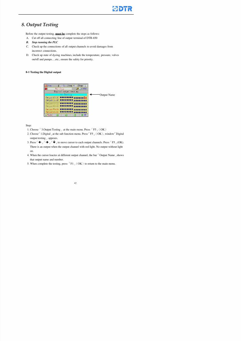
8132019 DTR 650 User Manual
httpslidepdfcomreaderfulldtr-650-user-manual 4270
983096 983119983157983156983152983157983156 983124983141983155983156983145983150983143
Before the output testing must be complete the steps as follows
A Cut off all connecting line of output terminal of DTR-650
B Stop running the PLC
C Check up the connections of all output channels to avoid damages from
incorrect connections
D Check up state of dyeing machines include the temperature pressure valves
onoff and pumpshellipetc ensure the safety for priority
8-1 Testing the Digital output
Step
1 Choose「3Output Testing」at the main menu Press「F5」(OK) 2 Choose「1Digital」at the sub function menu Press「F5」(OK) window「Digital
output testing」appears
3 Press「」「」「」to move cursor to each output channels Press「F5」(OK)
Output Name
8132019 DTR 650 User Manual
httpslidepdfcomreaderfulldtr-650-user-manual 4370
8-2 Testing the Analog output
(1) Choose「3Output Testing」at the main menu Press「F5」(OK)
(2) Choose「2Analog」at the sub function menu Press「F5」(OK) window「Analog output testing」appears
(3) Press「」「」「」to move cursor to each channels Then key in number by
the numeric membrance keys (range0~200= 0~20mA) Press「F5」(OK) there
is a output current relating to the output channel
(4) Press「F5」(OK) There is an output when the output channel with red light No
output without light onl(5) When complete the testing press「F1」(OK)to return to the main menu
8132019 DTR 650 User Manual
httpslidepdfcomreaderfulldtr-650-user-manual 4470
983097 983107983137983148983145983138983154983137983156983145983151983150
DTR-650 has Dosing and Temperature calibration
When enter to Dosing calibration must be set the Low Volume calibration first and
then High Volume calibration When enter to Temperature calibration must be set the
Low Temperature calibration first and then High Temperature calibration Must be
hightly follow this orders seriously
9-1 Calibration of Low Volume Tank
Step
A Choose「4Calibration」at the main menu Press「F5」(OK)
B Choose「Dosing 0 low vol」at the sub function menu Press「F5」(OK) window
appears
C Fill the Dosing Tank to a half level input value shows how much the water level
If it stays ldquo0rdquo check the connection and the factor setting is correct or not
And connect the pressure sensorrsquos output channel to the Current Meter to ensure
that sensor works or not
8132019 DTR 650 User Manual
httpslidepdfcomreaderfulldtr-650-user-manual 4570
D Fill the Dosing Tank to 50ml (Calcalate from the bottom side of the pressure
sensor steel tube) input value should show 4~6 (input value must between
0~10) Then enter the water volume The setting volume is relating the water
levelrsquos water value (litre as unit) input range 0~80 Set as「 「「 「0000 0000 0000 0000」」」」is strongly is strongly is strongly is strongly
receommend receommend receommend receommend Press「F5」(OK)to complete [Calibration of Low Volume Tank 1
is same as above method]
9-2 Calibration of High Volume Tank
Step
A Choose「4Calibration」at the main menu Press「F5」(OK)
B Choose「Dos 0 high vol」at the sub function menu Press「F5」(OK) window of
「Calibrate high 」appears
C Fill the Dosing Tank to a full level input value should be larger than 30 enter
the current water level which relates to the water volume Enter the range within
100~2500 Then press「F5」(OK) to complete the calibrate the high volume tank
8132019 DTR 650 User Manual
httpslidepdfcomreaderfulldtr-650-user-manual 4670
9-3 Temperature Calibration
Step
A This function is for adjusting the DTR650rsquos accuracy of Temperature Control It
must be using with the special terminal which is only for DTR650
B Choose「4Calibration」at the main function menu and press「F5」(OK)
C Choose「3Low Temp」at the sub-function menu Press「F5」(OK)and《Fig9-3》
appears insert the DTR650rsquos low temperature calibration terminal to the temperature
input terminal wait for the jumping value to stable down then press「F5」(OK) then
to adjust the high temperature calibration
D Adjusting the High Temperature Calibrationrsquos method is same as above But usersusersusersusers
must be using the High Temperature Terminalmust be using the High Temperature Terminalmust be using the High Temperature Terminalmust be using the High Temperature Terminal whichwhichwhichwhich is specially for DTR650 onlyis specially for DTR650 onlyis specially for DTR650 onlyis specially for DTR650 only
《Fig 9-3》
8132019 DTR 650 User Manual
httpslidepdfcomreaderfulldtr-650-user-manual 4770
10 983122983141983139983151983154983140983155 983151983142 983108983161983141 983120983154983151983143983154983137983149983155
It contains the past 15 days of temperature curves of running history
Checking method
(1) Choose「5Dye Record」at main menu press「F5」(OK)
(2) Sub-function menu shows the set up date of the past 15 days dye programs
Listing by the lastest set up date
(3) Choose a program date and press「F5」(OK) it appears window「Temp
record」
(4) Press「」「」to move the white line in the box one minute by moving once
(5) Press「3」「4」to move the line to check the time period 2 hours by moving once
The yellow selecting line of the「24 hours operating state」is repectively moving
The curve info is show in the curve box Left side of the widnow appears the
relating running info the time is the time value of the line locates at
(6) Check more details of the temperature info to press numeric key「middot」 a bright red line
appears in the selecting box this line is to check the starting point of the
temperature inforsquos time period Then press「」to move the white line to the end
point of the time period The temperature info between the starting point and end
point are appears at the right side of the window Press「middot」to return to the preious
curve page
(7) Check more details of the alarm infor To perss numeric key「7」「9」 the alarmrsquos
details is listing by orders
(8) Press「F1」(exit) to return
8132019 DTR 650 User Manual
httpslidepdfcomreaderfulldtr-650-user-manual 4870
11 983125983155983137983143983141 983151983142 983117983141983149983151983154983161 983107983137983154983140
DTR-650 supports 32MB or above Compact Flash Card which can transfer and save all
information for 4 sets of DTR-650 Including library files schematic diagram icon
image PLC program dye program factor and confiruration files etchellip Use the CF Card
to up download and swap the information of DTR-650 promptly install the relating
device and program updates
DTR-650 CF Card with bank 1 to bank 4 can save 4 sets information of Dyeing
Machines When download or save files should choose the BANK first
《Fig11-1》
8132019 DTR 650 User Manual
httpslidepdfcomreaderfulldtr-650-user-manual 4970
11-1 Downloading data
1 Firmly insert the CF card into the DTR-650rsquos PCMCIA connector Ensure it is
wholely and firmly inserted if the card is not totally inserted or the card do not
touch in all to the connector there will be an error occurred and cannot
updownload or interrupted during operation
2 Choose「6Memory Card」at the main menu and press「F5」(OK) 《Fig11-1》
appears Information of Bank「1」shows at the left hand side of the window press
number 1-4 by using numeric keys to choose the BANK Check the
information in the Bank seriously which is exactly need to download to the
DTR650
3 Press()()「6」「5」to move cursor to the sub-function menu to choose
the downloading items Press「F5」(OK) window appears「Stop PLC run before
access memory card Stop the PLC run」 Press「F5」(YES) to stop PLC
running
4 Press「F5」(OK) window appears Confirm to update or not the DTR-650rsquos
information As that downloading will be replace the DTR-650rsquos information
(that means the existing information of the DTR-650 will be removed and
replaced)
5 Press「F4」(YES)to download the information from the DTR-650 to the CF
Card Return to the main menu when finish
8132019 DTR 650 User Manual
httpslidepdfcomreaderfulldtr-650-user-manual 5070
Ensure inserting firmly the CF card into the DTR-650 unless it will cause
error or cannot Updownload data
Never remove CF card during transferring or updownloading data Until it
is all completed
DTR-650rsquos dyeing program is not compatible with DTR-500 and
DTR-600 Never use CF card to transfer data among them
11-2 Storing and transfering data
1 Insert the CF Card to the DTR-650
2 Choose「6Memory Card」at the main menu and press「F5」(OK) 《Fig11-1》
appears Left hand side of the window shows the data of BANK 1 press numeric
keys 1-4 to select the BANK To confirm the put the data in the DTR-650 to the CF
Card The existing data of that bank will be replaced and covered by the new data (if
that bank is already occuplied)
3 Choose「23Save Dye prog」(Example)at the sub-funciton menu press「F5」(OK)to confirm Window「Update memory card data」appears
4 Press「F5」(OK)to transfer the data to the CF card Return to the main menu
5 Put the CF card into another DTR-650 and follow the operating method of 「11-1
Downloading data」」」」can transfer and swap data with more than one set of
DTR-650
8132019 DTR 650 User Manual
httpslidepdfcomreaderfulldtr-650-user-manual 5170
12 983123983156983137983156983141 983137983150983140 983113983150983142983151983154983149983137983156983145983151983150
The state and information is including the Dyeing Machinersquos state of Digit Input output
Analog Input output Temperature control PID Dosing PID Pressure different PID
software system information and alarm record This information is for checking at any
time
12-1 Input Output state
Step
1 Choose「7Info and state」at main menu and press「F5」(OK)
2 Choose「01Digital IO put」at the sub-function menu then press「F5」(OK)
「Digital In Out State」0=None 1=Input
3 Press「F1」(Exit)to return to main menu
Same method for checking the temperature control analog dosing pressure
different etchellip
12-2 Checking the system information
Step
1 Choose「7Info and state」at main menu and press「F5」(OK)
2 Choose「11 System info」at sub-function field press「F5」(OK)Window
「System Information」appear
System information is including System info(software version) Library doc
Icon files Schematic file Definition file hardare state Config File Commandinstruction icon PLC file etc
8132019 DTR 650 User Manual
httpslidepdfcomreaderfulldtr-650-user-manual 5270
12-3 Checking the operating alarm record
Operating record shows the latest 40 operating items and alarm records including
the time and content of the alarm
A) Choose「7 Info and state」
and press「F5」(OK)
B) Choose「12Alarm logs」at
the sub-funciton menu then
press「F5」(OK)
8132019 DTR 650 User Manual
httpslidepdfcomreaderfulldtr-650-user-manual 5370
13 983105983140983146983157983155983156983145983150983143 983156983144983141 983107983151983150983156983154983137983155983156
The displaysrsquos brightness can be adjusted if necessary
Step
1 Choose「8Others」at main menu press「F5」(OK)
2 Choose「01Contrast」at sub-function menu press「F5」(OK) window「Set
Contrast」appears
3 Press「」「」to move the bar to set the brightness then press「F5」(OK)Window appears「Please reboot the system」
4 Press「F5」(OK)to return to main menu and re-boot the DTR-650 to complete
adjusting the brightness
8132019 DTR 650 User Manual
httpslidepdfcomreaderfulldtr-650-user-manual 5470
14 983123983156983151983152 983154983157983150983150983145983150983143 983156983144983141 983120983116983107 983120983154983151983143983154983137983149
Before testing the Input output testing transfer of the PLC program must stop the PLC
running
Step
1 Choose「8Others」at the main menu Press「F5」(OK)
2 Choose「04 PLC Stop」at sub-function menu Press「F5」(OK) window
「Password」appears
3 Enter password and press「F5」(OK) Window「Stop the PLC run」appears
4 Press「F4」(Yes)and window「PLC Stop」appear Press「F5」(OK) Now
the PLC is stop running and return to the main menu
All testing cannot operate when the PLC is running
Editing dye program and the relating operation can
perform with the PLC running together
8132019 DTR 650 User Manual
httpslidepdfcomreaderfulldtr-650-user-manual 5570
15 983123983141983156983156983145983150983143 983156983144983141 983156983145983149983141
Step
1 Press「8Others」at the main menu Press「F5」(OK)
2 Choose「10Set date time」at the sub-function menu Press「F5」(OK) window
「Set date time」appears
3 Press「F5」(Edit) to move cursor by 「3」「4」 enter the time value at the
cursor locates
4 Press「F5」(OK)to complete the modify Press「F1」(Exit)to return to main
menu
5 Press「F1」(Exit)if not modify and return to main menu
8132019 DTR 650 User Manual
httpslidepdfcomreaderfulldtr-650-user-manual 5670
1166 983123983123983157983157 983152 983152 983152 983152983148983148983141983141983149983149983141983141983150983150983156 983156 983137983137983154 983154 983161983161 983124 983124 983137983137983138983138983148983148983141983141
TTTTTTTTaaaaaaaabbbbbbbblllllllleeeeeeee 11111111 【Dye Instruction】
Code Icon Instruction Code Icon Instruction
000 End 016 Inject C
001 Start 017 Dosing BV
002 Heat 018 PH
003 Cool 019 Addsalt B
004 Flow Fill 020 Addsalt C
005 Level Fill 021 Ana Fill
006 Drian 022 Lock Fill007 Rinse 023 Lock Level
008 Run 024 Low Rinse
009 Call 025 Cyc Rinse
010 Prep B 026 Rinse B
011 Addsalt B 027 Rinse C
012 Dosing B 028 Temp
013 Inject B 029 Nozzle Pressure
014 Prep C 030 Main Pump
015 Dosing C 031 Pump Speed
8132019 DTR 650 User Manual
httpslidepdfcomreaderfulldtr-650-user-manual 5770
Table 2 【【【【Alarm】】】】
System Alarm Must stop operating and check up to solve problems before restarting
the machine
Running Alarm It is a reminder Not effect the operating of DTR-650
Userrsquos Alarm Total of 32 Users can define themselves and use it when edit the PLC
Program (do not listing below)
No System Alarm No Running Alarm
1 PLC program not running 16 Temp ctrl 0 Grad too slow
2 Main temp sensor error 17 Temp ctrl 0 Grad too fast
3 Not at Run window 18 Temp ctrl 0 Hold temp too low
4 Exceeding max temp 19 Temp ctrl 0 Hold temp too high
5 - 20 Temp ctrl 1 Grad too slow6 - 21 Temp ctrl 1 Grad too fast
7 - 22 Temp ctrl 1 Hold temp too low
8 Communication error 23 Temp ctrl 1 Hold temp too high
9 Slave not answer 24 Temp ctrl 2 Grad too slow
10 PLC 0 not answer 25 Temp ctrl 2 Grad too fast
11 PLC 1 not answer 26 Temp 2 Hold temp too low12 Display not answer 27 Temp 2 Hold temp too high
13 Lower power voltage 28 Temp ctrl 3 Grad too slow
14 - 29 Temp ctrl 3 Grad too fast
15 - 30 Temp3 Hold temp too low
31 Temp3 Hold temp too high
32 Dosing 0 injection too slow
33 Dosing 0 injection too fast
34 Dosing 1 injection too slow
35 Dosing 1 injection too fast
8132019 DTR 650 User Manual
httpslidepdfcomreaderfulldtr-650-user-manual 5870
TTTTTTTTaaaaaaaabbbbbbbblllllllleeeeeeee 33333333 【【【【System factor】】】】
No Description Std Range amp Definition
1 ID No 000 000- 100 Controller no
2 Communication Rate 4800Bps 2400 4800 9600 19200 38400
3 Display language Chinese English Chinese
4 Temp display mode and
5 Maxmium temperature 145 025 ~ 145 6 Type of external PLC Default PLC32DPLC32PLC16Default
7 Number of external PLC NANA 1 unit connect
2 unit connect
8Communication Rate of
PLC9600Bps 2400 4800 9600 19200
9 Set point 1 085 000 ~ 145
If signal source is temperaturethe setting value is thetemperature value If the signal
source is Analog Input 6~17 then
setting value for Analog input is 0 ndash
100 and relates Analog
Input14~020mA
10 Source 1 Sensor0Sensor 0 ~5
Analog input 0 ~1111 Set point 2 092 Same as 09
12 Source 2 PT100 1 Same as 10
13 Set point 3 085 Same as 09
14 Source 3 PT100 2 Same as 10
15 Set point 4 092 Same as 09
16 Source 4 PT100 3 Same as 1017 Set point 5 085 Same as 09
18 Source 5 PT100 4 Same as 10
19 Set point 6 092 Same as 09
8132019 DTR 650 User Manual
httpslidepdfcomreaderfulldtr-650-user-manual 5970
29 Min cyclic time of cloth 100sec 0 ~ 255 sec
30 Max cyclic time of cloth 240sec 0 ~255 sec
31Standard cyclic time of
cloth
180 000 ~ 255 sec
32 Display ModeProgram
List
Program list Schematic Diagram
Icon mode
33 CF card format Standard of
DTR CF
Card
Standard of DTR CF Card V20
Standard CF Card
34 Addition step Disable Disable Enable35 Mode Com 3
CouplingEsure Com 3 is the communication
port of the Central or Coupling
36Com 3 Communication
rate9600 Central communication speed
8132019 DTR 650 User Manual
httpslidepdfcomreaderfulldtr-650-user-manual 6070
TTTTTTTTaaaaaaaabbbbbbbblllllllleeeeeeee 44444444 【【【【Temperature Cotnrol Factor】】】】
No Factor Definition Standard Range and Definition
01 PT No PT-0 PT 0~5 PT-100 Input number
02 Max working temp 140 000~140
03 Output mode 0 0~2
04 Alarm time of gardient 240sec 000~255 sec
05 Alarm mode of gradient Always AlwaysOnceNone
06 Control mode of gradient Heating orCooling
interlocked
Heating and Cooling interlocked
No limitation
07 Alarm range of HoldTemp 03 01~20
08 Alarm time for HoldTemp 240sec 000~255sec
09 Alarm mode of HoldTemp Always AlwaysOnceNone
10 Control mode ofHoldTemp
Heating only Only heating and cooling Cooling whenalarm occurred Only heating andcooling No limitation when alarmHeating only
11 Porportional Band 100 000~250
12 Integral band 128 sec 000~255 sec
13 Differential time 04 sec 00~20 sec
14 Min transit gradient 02 00~50
15 Transit rate 20 times 00~50 times (020= 2 times)
16 PID initial output value 010 000~100
17 ONOFF cycle time 10 sec 05~25 sec
Onoff valve set as 010 sec
Proportional valve set as 020 sec
18 Time down count mode Mode 0 0~10 = The time down count range from「Factor 20 + target temp」to「Target
8132019 DTR 650 User Manual
httpslidepdfcomreaderfulldtr-650-user-manual 6170
TTTTTTTTaaaaaaaabbbbbbbblllllllleeeeeeee 55555555 【【【【Speed Factor】】】】
No Factor Definition Standard Range amp Definition
01 Input Number Speed input 0 Speed input 0~11
02 Average times 05 times 01~10
03 Sensor Number 008pcs 001~255
04 Roller Dimension 250mm 050~500
05 Max cloth speed 200mmin 001~25506 Min cloth speed 020mmin 001~255
07 Alarm delay time 240sec 001~255
08 Alarm mode Every oncenoneevery
09 Alarm range () 020 001~255
10 Proportional band 100 001~255
11 Integer band 128 001~25512 Differential time 000 001~200
13 Initial speed () 020 001~255
14 Control cycle ti(01sec) 05 01~30
15 First cycle time(01sec) 10 01~30
16 Speed increase limit () 010 001~100
17 Speed decrease limit () 010 001~100
18 Min speed() 005 001~100
19 Manual speed adjust () 005 001~100
20 Manual initial speed() 020 001~100
21 Stopping speed() 010 001~100
22 Switch speed() 020 001~100
23 Not used
24 Speed decrease turns 03turns 01~50
8132019 DTR 650 User Manual
httpslidepdfcomreaderfulldtr-650-user-manual 6270
Table 6 【【【【Dosing Factors】】】】
No Description Range Range and Explanation
1 Analog input no Analog input 0 Analog input no 0 ~11
2Alarm delay time for
dosing240 sec 000 ~255 sec
3 Alarm time for dosing Every Every Once None
4 Proportional band 100 000 ~255 sec Factor P
5 Integer band 128 000 ~255 sec Factor I6 Differential time 04 00 ~20 Factor D
7 Max adjust rate 150 50~ 255
8 Initial factor for dosing 10 000 ~100
9 User curve section 0 10 Gradient of sect1 for dosing curve9
10 User curve section 1 10 Gradient of sect2 for dosing curve9
11 User curve section 2 10 Gradient of sect3 for dosing curve9
12 User curve section 3 10 Gradient of sect4 for dosing curve9
13 User curve section 4 10 Gradient of sect5 for dosing curve9
14 User curve section 5 10 Gradient of sect6 for dosing curve9
15 User curve section 6 10 Gradient of sect7 for dosing curve9
16 User curve section 7 10 Gradient of sect8 for dosing curve9
17 User curve section 8 10 Gradient of sect9 for dosing curve9
18 User curve section 9 10 Gradient of sect10 for dosing curve9
19 Min water level 05 00~ 10 04~20mA percentagechange to the userrsquos factor setting
20 Output value for Tank
clean
100 000~ 100
Injected percentage of dosing valve
in dosing End period
This factor will be invalided if usingONOFF dosing valve
21 Full range 100 001~255 Self-adjustment cannotchange
22 Range ratio 001001~255 Self-adjustment cannot
change
8132019 DTR 650 User Manual
httpslidepdfcomreaderfulldtr-650-user-manual 6370
【【【【TTaabbllee 77 】】】】Pressure Deviation Factors
No Description Std Range amp Definition
1 Analog input number + Analog in 0 Analog in 0~11
2 Analog input number - Analog in 1 Analog in 0~11
3 Input mode Pressure Pressure Pressure deviation
4 Full range 050x01Kgcm
001~255
5 Range ratio 001 001~255
6 Alarm delay time 100sec 001~255
7 Alarm mode Every oncenone
8 Alarm range 010 001~255
9 Proportional band 100 001~255
10 Integer band 128 001~255
11 Differential time 00 00~20
12 PID Init output value 010 001~255
13 Cycle time 10 03~30
14 First cycle time 030 003~100
15 Max adjust rate 010 001~100
8132019 DTR 650 User Manual
httpslidepdfcomreaderfulldtr-650-user-manual 6470
【【【【TTaabbllee 88 】】】】Definition of Analog Input
No Description Standard Range and Explanation
01 PT 0 correction standard DIN std DIN std JIS std
02 PT 0 correction +0 +- 9
03 PT 1 correction standard DIN std DIN std JIS std
04 PT 1 correction +0 +- 9
05 PT 2 correction standard DIN std DIN std JIS std
06 PT 2 correction +0 +- 9
07 PT 3 correction standard DIN std DIN std JIS std
08 PT 3 correction +0 +- 9
09 PT 4 correction standard DIN std DIN std JIS std
10 PT 4 correction +0 +- 9
11 PT 5 correction standard DIN std DIN std JIS std
12 PT 5 correction +0 +- 9
13 Analog input 0 define 4 ~ 20mA 0 ndash 20mA 4 ndash 20mA
14 Analog input 0 average times 10 times 01- 20 times
15 Analog input 0 min value 0000 0000 - 1000
16 Analog input 0 max value 100 0001 - 9999
17-60 Analog input 1~11 Same as Analog input 0
【【【【 】】】】 fi i i f A O
8132019 DTR 650 User Manual
httpslidepdfcomreaderfulldtr-650-user-manual 6570
【【【【TTaabbllee 99 】】】】Definition of Analog Output
No Description Standard Range and explanation
61 Analog output 0 define Control byPLC
Control by PLC
Temperature control PID0 output
Temperature control PID1 output
Temperature control PID2 output
Speed PID3 output
Dosing PID0 output Dosing PID1output
Pressure different PID0 outputPressure different PID1 output
Main temperature output
62 Mode of Analog ouptput0 4 ~20mA 0 ndash20mA 4 ndash 20mA
63-84 Analog output 1~11 Same as Analog output 0
【【【【TTaabbllee 1100】】】】Value Table 0 amp 1
No Description Range Std Range and explanation
1 Analog input no 000~011 000 Analog input no
2 Data ratio 001~255 100 Multiple by factors
3~53 0~98 000~255 000-100 Analog input 0~98 data
【【【【 】】】】St t Li t
8132019 DTR 650 User Manual
httpslidepdfcomreaderfulldtr-650-user-manual 6670
【【【【TTaabbllee 1111】】】】State List
No Description Range Standard Range and explanation
1 Display setting 1 0~255 205 See remarks at next page
2 Display setting 2 0~255 208
3 Display setting 3 0~255 209
4 Display setting 4 0~255 017
5 Display setting 5 0~255 0186 Display setting 6 0~255 019
7 Display setting 7 0~255 020
8 Display setting 8 0~255 021
9 Display setting 9 0~255 000
10 Display setting 1 0~255 000
11 Display setting 2 0~255 000
12 Display setting 3 0~255 000
13 Display setting 4 0~255 000
14 Display setting 5 0~255 000
15 Display setting 6 0~255 000
16 Display setting 7 0~255 000
Remarks
8132019 DTR 650 User Manual
httpslidepdfcomreaderfulldtr-650-user-manual 6770
0 = No display 1~255 = Display type of number
1~16 Content of PLC VB0~15
No 1 corresponding to VB0
No 16 corresponding to VB15
17~32 Content of PLC DB0~15
No 17 corresponding to DB0
No 32 corresponding to DB15
33~46 Content of PLC CNT0~29
No 33 corresponding to CNT0
No 46 corresponding to CNT29 47~78 Content of dyeing instruction 0~31 CNT0
No 47 corresponding to system instruction to No 0 of CNT0
No 78 corresponding to system instruction to No 31 of CNT0rsquos content
79~110 Dyeing instruction 0~31 of CNT0rsquos setting
111~142 Content of Dyeing instruction 0~31 CNT1No 111 corresponding to dyeing instruction No 0 of CNT1
No 142 corresponding to dyeing instruction No 31 of CNT1rsquos content
143~174 Dyeing instruction 0~31 of CNT1rsquos setting
175~204 Content of PLC HTIM0~29
No 175 corresponding to HTIM0
No 204 corresponding to HTIM29
205 Loading
206 Ratio 1
207 Ratio 2208 Ratio 1 x Loading
209 Ratio 2 x Loading
210 Fix value
211 Value Table 1 matching result
212 Value Table 2 matching result
213 Value Table 1 setting214 Value Table 2 setting
215 Pressure control PID0 different pressure value
216 Pressure control PID1 different pressure value
TTTTTTTTaaaaaaaabbbbbbbblllllllleeeeeeee 1122 【【【【Usage of password】】】】
8132019 DTR 650 User Manual
httpslidepdfcomreaderfulldtr-650-user-manual 6870
No Main FunctionFactor Sub Function Factor Password Rank
1 Run None
2 Dye program User3 or above
3 Control factor
- User factor User 1
- System factor User 1
- Temp PID 0
- Temp PID 1 User 1- Speed PID 0 User 1
- Dosing PID 0 User 1
- Dosing PID 1 User 1
- Pressure PID 0 User 1
- Pressure PID 1 User 1
- Analog IO User 1
- Load standard factor User 2 or above- Load a copied factor User 2 or above
- Copy factor User 2 or above
- Value table 0 User 1
- Value table 1 User 1
- Information and state User 1
- Dye instruction User 1
- Edit dye instruction setting User 14 Output testing User 2 or above
5 Calibration User 2 or above
6 Dye record None
7 CF card User 1
8 Info and state None
9 Others
- Contrast User3 or above
- Data Locking None
- PLC Run User 1
- PLC Stop User 1
- Password setting User 1
TTTTTTTTaaaaaaaabbbbbbbblllllllleeeeeeee 1133 【【【【Technical Data】】】】
8132019 DTR 650 User Manual
httpslidepdfcomreaderfulldtr-650-user-manual 6970
TTTTTTTTaaaaaaaabbbbbbbblllllllleeeeeeee 1133 【【【【Technical Data】】】】
1 Temperature Control
- Range 10~145(plusmn1)
- Mode Proportional or PWM
- Sensor PT100 (JIS or DIN standard)
2 Input and output channel
- Digital Input 32 DC24V PNP- Digital Output 32 DC24V 054A Relay connect point
- Analog Input 4 04~20 mA
- Analog Output 4 0~20mA 或 4~20 mA
3 Communication port 3 RS-232 amp 0~20 mAx1 RS485x 2
4 Dye program
- Number 15000 Steps
- Standard step 61Heating Cooling Fill Drain RinseDosingetc
5LCD module and Display
langage
Chinese
English
320 x 240 TFT color display with
more language
6 CF card connector 1 PCMCIA standard
7 Membrane Keyboard- Number Key 10 [0]~[9] Input factors
- Function Key 5 [F1]~[F5] function selecting
- Operation Key 2 [Start] [Stop]
- Auxiliary Key 7 [][][][][Esc] [larr][OK] [bull]
8 Operating Condition
- Temperature 5~45
- Humidity ≦85 (25)
9 Power supply
V l DC 24V
8132019 DTR 650 User Manual
httpslidepdfcomreaderfulldtr-650-user-manual 7070
70
983108983124983122983085650 983113983150983152983157983156 983119983157983156983152983157983156 983120983151983154983156983145983150983143 (983138983137983139983147983155983145983140983141 983158983145983141983159)
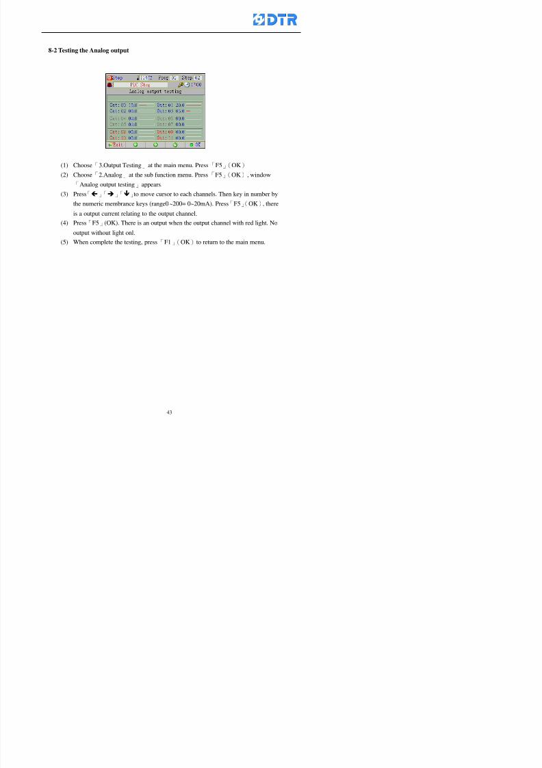
8132019 DTR 650 User Manual
httpslidepdfcomreaderfulldtr-650-user-manual 4370
8-2 Testing the Analog output
(1) Choose「3Output Testing」at the main menu Press「F5」(OK)
(2) Choose「2Analog」at the sub function menu Press「F5」(OK) window「Analog output testing」appears
(3) Press「」「」「」to move cursor to each channels Then key in number by
the numeric membrance keys (range0~200= 0~20mA) Press「F5」(OK) there
is a output current relating to the output channel
(4) Press「F5」(OK) There is an output when the output channel with red light No
output without light onl(5) When complete the testing press「F1」(OK)to return to the main menu
8132019 DTR 650 User Manual
httpslidepdfcomreaderfulldtr-650-user-manual 4470
983097 983107983137983148983145983138983154983137983156983145983151983150
DTR-650 has Dosing and Temperature calibration
When enter to Dosing calibration must be set the Low Volume calibration first and
then High Volume calibration When enter to Temperature calibration must be set the
Low Temperature calibration first and then High Temperature calibration Must be
hightly follow this orders seriously
9-1 Calibration of Low Volume Tank
Step
A Choose「4Calibration」at the main menu Press「F5」(OK)
B Choose「Dosing 0 low vol」at the sub function menu Press「F5」(OK) window
appears
C Fill the Dosing Tank to a half level input value shows how much the water level
If it stays ldquo0rdquo check the connection and the factor setting is correct or not
And connect the pressure sensorrsquos output channel to the Current Meter to ensure
that sensor works or not
8132019 DTR 650 User Manual
httpslidepdfcomreaderfulldtr-650-user-manual 4570
D Fill the Dosing Tank to 50ml (Calcalate from the bottom side of the pressure
sensor steel tube) input value should show 4~6 (input value must between
0~10) Then enter the water volume The setting volume is relating the water
levelrsquos water value (litre as unit) input range 0~80 Set as「 「「 「0000 0000 0000 0000」」」」is strongly is strongly is strongly is strongly
receommend receommend receommend receommend Press「F5」(OK)to complete [Calibration of Low Volume Tank 1
is same as above method]
9-2 Calibration of High Volume Tank
Step
A Choose「4Calibration」at the main menu Press「F5」(OK)
B Choose「Dos 0 high vol」at the sub function menu Press「F5」(OK) window of
「Calibrate high 」appears
C Fill the Dosing Tank to a full level input value should be larger than 30 enter
the current water level which relates to the water volume Enter the range within
100~2500 Then press「F5」(OK) to complete the calibrate the high volume tank
8132019 DTR 650 User Manual
httpslidepdfcomreaderfulldtr-650-user-manual 4670
9-3 Temperature Calibration
Step
A This function is for adjusting the DTR650rsquos accuracy of Temperature Control It
must be using with the special terminal which is only for DTR650
B Choose「4Calibration」at the main function menu and press「F5」(OK)
C Choose「3Low Temp」at the sub-function menu Press「F5」(OK)and《Fig9-3》
appears insert the DTR650rsquos low temperature calibration terminal to the temperature
input terminal wait for the jumping value to stable down then press「F5」(OK) then
to adjust the high temperature calibration
D Adjusting the High Temperature Calibrationrsquos method is same as above But usersusersusersusers
must be using the High Temperature Terminalmust be using the High Temperature Terminalmust be using the High Temperature Terminalmust be using the High Temperature Terminal whichwhichwhichwhich is specially for DTR650 onlyis specially for DTR650 onlyis specially for DTR650 onlyis specially for DTR650 only
《Fig 9-3》
8132019 DTR 650 User Manual
httpslidepdfcomreaderfulldtr-650-user-manual 4770
10 983122983141983139983151983154983140983155 983151983142 983108983161983141 983120983154983151983143983154983137983149983155
It contains the past 15 days of temperature curves of running history
Checking method
(1) Choose「5Dye Record」at main menu press「F5」(OK)
(2) Sub-function menu shows the set up date of the past 15 days dye programs
Listing by the lastest set up date
(3) Choose a program date and press「F5」(OK) it appears window「Temp
record」
(4) Press「」「」to move the white line in the box one minute by moving once
(5) Press「3」「4」to move the line to check the time period 2 hours by moving once
The yellow selecting line of the「24 hours operating state」is repectively moving
The curve info is show in the curve box Left side of the widnow appears the
relating running info the time is the time value of the line locates at
(6) Check more details of the temperature info to press numeric key「middot」 a bright red line
appears in the selecting box this line is to check the starting point of the
temperature inforsquos time period Then press「」to move the white line to the end
point of the time period The temperature info between the starting point and end
point are appears at the right side of the window Press「middot」to return to the preious
curve page
(7) Check more details of the alarm infor To perss numeric key「7」「9」 the alarmrsquos
details is listing by orders
(8) Press「F1」(exit) to return
8132019 DTR 650 User Manual
httpslidepdfcomreaderfulldtr-650-user-manual 4870
11 983125983155983137983143983141 983151983142 983117983141983149983151983154983161 983107983137983154983140
DTR-650 supports 32MB or above Compact Flash Card which can transfer and save all
information for 4 sets of DTR-650 Including library files schematic diagram icon
image PLC program dye program factor and confiruration files etchellip Use the CF Card
to up download and swap the information of DTR-650 promptly install the relating
device and program updates
DTR-650 CF Card with bank 1 to bank 4 can save 4 sets information of Dyeing
Machines When download or save files should choose the BANK first
《Fig11-1》
8132019 DTR 650 User Manual
httpslidepdfcomreaderfulldtr-650-user-manual 4970
11-1 Downloading data
1 Firmly insert the CF card into the DTR-650rsquos PCMCIA connector Ensure it is
wholely and firmly inserted if the card is not totally inserted or the card do not
touch in all to the connector there will be an error occurred and cannot
updownload or interrupted during operation
2 Choose「6Memory Card」at the main menu and press「F5」(OK) 《Fig11-1》
appears Information of Bank「1」shows at the left hand side of the window press
number 1-4 by using numeric keys to choose the BANK Check the
information in the Bank seriously which is exactly need to download to the
DTR650
3 Press()()「6」「5」to move cursor to the sub-function menu to choose
the downloading items Press「F5」(OK) window appears「Stop PLC run before
access memory card Stop the PLC run」 Press「F5」(YES) to stop PLC
running
4 Press「F5」(OK) window appears Confirm to update or not the DTR-650rsquos
information As that downloading will be replace the DTR-650rsquos information
(that means the existing information of the DTR-650 will be removed and
replaced)
5 Press「F4」(YES)to download the information from the DTR-650 to the CF
Card Return to the main menu when finish
8132019 DTR 650 User Manual
httpslidepdfcomreaderfulldtr-650-user-manual 5070
Ensure inserting firmly the CF card into the DTR-650 unless it will cause
error or cannot Updownload data
Never remove CF card during transferring or updownloading data Until it
is all completed
DTR-650rsquos dyeing program is not compatible with DTR-500 and
DTR-600 Never use CF card to transfer data among them
11-2 Storing and transfering data
1 Insert the CF Card to the DTR-650
2 Choose「6Memory Card」at the main menu and press「F5」(OK) 《Fig11-1》
appears Left hand side of the window shows the data of BANK 1 press numeric
keys 1-4 to select the BANK To confirm the put the data in the DTR-650 to the CF
Card The existing data of that bank will be replaced and covered by the new data (if
that bank is already occuplied)
3 Choose「23Save Dye prog」(Example)at the sub-funciton menu press「F5」(OK)to confirm Window「Update memory card data」appears
4 Press「F5」(OK)to transfer the data to the CF card Return to the main menu
5 Put the CF card into another DTR-650 and follow the operating method of 「11-1
Downloading data」」」」can transfer and swap data with more than one set of
DTR-650
8132019 DTR 650 User Manual
httpslidepdfcomreaderfulldtr-650-user-manual 5170
12 983123983156983137983156983141 983137983150983140 983113983150983142983151983154983149983137983156983145983151983150
The state and information is including the Dyeing Machinersquos state of Digit Input output
Analog Input output Temperature control PID Dosing PID Pressure different PID
software system information and alarm record This information is for checking at any
time
12-1 Input Output state
Step
1 Choose「7Info and state」at main menu and press「F5」(OK)
2 Choose「01Digital IO put」at the sub-function menu then press「F5」(OK)
「Digital In Out State」0=None 1=Input
3 Press「F1」(Exit)to return to main menu
Same method for checking the temperature control analog dosing pressure
different etchellip
12-2 Checking the system information
Step
1 Choose「7Info and state」at main menu and press「F5」(OK)
2 Choose「11 System info」at sub-function field press「F5」(OK)Window
「System Information」appear
System information is including System info(software version) Library doc
Icon files Schematic file Definition file hardare state Config File Commandinstruction icon PLC file etc
8132019 DTR 650 User Manual
httpslidepdfcomreaderfulldtr-650-user-manual 5270
12-3 Checking the operating alarm record
Operating record shows the latest 40 operating items and alarm records including
the time and content of the alarm
A) Choose「7 Info and state」
and press「F5」(OK)
B) Choose「12Alarm logs」at
the sub-funciton menu then
press「F5」(OK)
8132019 DTR 650 User Manual
httpslidepdfcomreaderfulldtr-650-user-manual 5370
13 983105983140983146983157983155983156983145983150983143 983156983144983141 983107983151983150983156983154983137983155983156
The displaysrsquos brightness can be adjusted if necessary
Step
1 Choose「8Others」at main menu press「F5」(OK)
2 Choose「01Contrast」at sub-function menu press「F5」(OK) window「Set
Contrast」appears
3 Press「」「」to move the bar to set the brightness then press「F5」(OK)Window appears「Please reboot the system」
4 Press「F5」(OK)to return to main menu and re-boot the DTR-650 to complete
adjusting the brightness
8132019 DTR 650 User Manual
httpslidepdfcomreaderfulldtr-650-user-manual 5470
14 983123983156983151983152 983154983157983150983150983145983150983143 983156983144983141 983120983116983107 983120983154983151983143983154983137983149
Before testing the Input output testing transfer of the PLC program must stop the PLC
running
Step
1 Choose「8Others」at the main menu Press「F5」(OK)
2 Choose「04 PLC Stop」at sub-function menu Press「F5」(OK) window
「Password」appears
3 Enter password and press「F5」(OK) Window「Stop the PLC run」appears
4 Press「F4」(Yes)and window「PLC Stop」appear Press「F5」(OK) Now
the PLC is stop running and return to the main menu
All testing cannot operate when the PLC is running
Editing dye program and the relating operation can
perform with the PLC running together
8132019 DTR 650 User Manual
httpslidepdfcomreaderfulldtr-650-user-manual 5570
15 983123983141983156983156983145983150983143 983156983144983141 983156983145983149983141
Step
1 Press「8Others」at the main menu Press「F5」(OK)
2 Choose「10Set date time」at the sub-function menu Press「F5」(OK) window
「Set date time」appears
3 Press「F5」(Edit) to move cursor by 「3」「4」 enter the time value at the
cursor locates
4 Press「F5」(OK)to complete the modify Press「F1」(Exit)to return to main
menu
5 Press「F1」(Exit)if not modify and return to main menu
8132019 DTR 650 User Manual
httpslidepdfcomreaderfulldtr-650-user-manual 5670
1166 983123983123983157983157 983152 983152 983152 983152983148983148983141983141983149983149983141983141983150983150983156 983156 983137983137983154 983154 983161983161 983124 983124 983137983137983138983138983148983148983141983141
TTTTTTTTaaaaaaaabbbbbbbblllllllleeeeeeee 11111111 【Dye Instruction】
Code Icon Instruction Code Icon Instruction
000 End 016 Inject C
001 Start 017 Dosing BV
002 Heat 018 PH
003 Cool 019 Addsalt B
004 Flow Fill 020 Addsalt C
005 Level Fill 021 Ana Fill
006 Drian 022 Lock Fill007 Rinse 023 Lock Level
008 Run 024 Low Rinse
009 Call 025 Cyc Rinse
010 Prep B 026 Rinse B
011 Addsalt B 027 Rinse C
012 Dosing B 028 Temp
013 Inject B 029 Nozzle Pressure
014 Prep C 030 Main Pump
015 Dosing C 031 Pump Speed
8132019 DTR 650 User Manual
httpslidepdfcomreaderfulldtr-650-user-manual 5770
Table 2 【【【【Alarm】】】】
System Alarm Must stop operating and check up to solve problems before restarting
the machine
Running Alarm It is a reminder Not effect the operating of DTR-650
Userrsquos Alarm Total of 32 Users can define themselves and use it when edit the PLC
Program (do not listing below)
No System Alarm No Running Alarm
1 PLC program not running 16 Temp ctrl 0 Grad too slow
2 Main temp sensor error 17 Temp ctrl 0 Grad too fast
3 Not at Run window 18 Temp ctrl 0 Hold temp too low
4 Exceeding max temp 19 Temp ctrl 0 Hold temp too high
5 - 20 Temp ctrl 1 Grad too slow6 - 21 Temp ctrl 1 Grad too fast
7 - 22 Temp ctrl 1 Hold temp too low
8 Communication error 23 Temp ctrl 1 Hold temp too high
9 Slave not answer 24 Temp ctrl 2 Grad too slow
10 PLC 0 not answer 25 Temp ctrl 2 Grad too fast
11 PLC 1 not answer 26 Temp 2 Hold temp too low12 Display not answer 27 Temp 2 Hold temp too high
13 Lower power voltage 28 Temp ctrl 3 Grad too slow
14 - 29 Temp ctrl 3 Grad too fast
15 - 30 Temp3 Hold temp too low
31 Temp3 Hold temp too high
32 Dosing 0 injection too slow
33 Dosing 0 injection too fast
34 Dosing 1 injection too slow
35 Dosing 1 injection too fast
8132019 DTR 650 User Manual
httpslidepdfcomreaderfulldtr-650-user-manual 5870
TTTTTTTTaaaaaaaabbbbbbbblllllllleeeeeeee 33333333 【【【【System factor】】】】
No Description Std Range amp Definition
1 ID No 000 000- 100 Controller no
2 Communication Rate 4800Bps 2400 4800 9600 19200 38400
3 Display language Chinese English Chinese
4 Temp display mode and
5 Maxmium temperature 145 025 ~ 145 6 Type of external PLC Default PLC32DPLC32PLC16Default
7 Number of external PLC NANA 1 unit connect
2 unit connect
8Communication Rate of
PLC9600Bps 2400 4800 9600 19200
9 Set point 1 085 000 ~ 145
If signal source is temperaturethe setting value is thetemperature value If the signal
source is Analog Input 6~17 then
setting value for Analog input is 0 ndash
100 and relates Analog
Input14~020mA
10 Source 1 Sensor0Sensor 0 ~5
Analog input 0 ~1111 Set point 2 092 Same as 09
12 Source 2 PT100 1 Same as 10
13 Set point 3 085 Same as 09
14 Source 3 PT100 2 Same as 10
15 Set point 4 092 Same as 09
16 Source 4 PT100 3 Same as 1017 Set point 5 085 Same as 09
18 Source 5 PT100 4 Same as 10
19 Set point 6 092 Same as 09
8132019 DTR 650 User Manual
httpslidepdfcomreaderfulldtr-650-user-manual 5970
29 Min cyclic time of cloth 100sec 0 ~ 255 sec
30 Max cyclic time of cloth 240sec 0 ~255 sec
31Standard cyclic time of
cloth
180 000 ~ 255 sec
32 Display ModeProgram
List
Program list Schematic Diagram
Icon mode
33 CF card format Standard of
DTR CF
Card
Standard of DTR CF Card V20
Standard CF Card
34 Addition step Disable Disable Enable35 Mode Com 3
CouplingEsure Com 3 is the communication
port of the Central or Coupling
36Com 3 Communication
rate9600 Central communication speed
8132019 DTR 650 User Manual
httpslidepdfcomreaderfulldtr-650-user-manual 6070
TTTTTTTTaaaaaaaabbbbbbbblllllllleeeeeeee 44444444 【【【【Temperature Cotnrol Factor】】】】
No Factor Definition Standard Range and Definition
01 PT No PT-0 PT 0~5 PT-100 Input number
02 Max working temp 140 000~140
03 Output mode 0 0~2
04 Alarm time of gardient 240sec 000~255 sec
05 Alarm mode of gradient Always AlwaysOnceNone
06 Control mode of gradient Heating orCooling
interlocked
Heating and Cooling interlocked
No limitation
07 Alarm range of HoldTemp 03 01~20
08 Alarm time for HoldTemp 240sec 000~255sec
09 Alarm mode of HoldTemp Always AlwaysOnceNone
10 Control mode ofHoldTemp
Heating only Only heating and cooling Cooling whenalarm occurred Only heating andcooling No limitation when alarmHeating only
11 Porportional Band 100 000~250
12 Integral band 128 sec 000~255 sec
13 Differential time 04 sec 00~20 sec
14 Min transit gradient 02 00~50
15 Transit rate 20 times 00~50 times (020= 2 times)
16 PID initial output value 010 000~100
17 ONOFF cycle time 10 sec 05~25 sec
Onoff valve set as 010 sec
Proportional valve set as 020 sec
18 Time down count mode Mode 0 0~10 = The time down count range from「Factor 20 + target temp」to「Target
8132019 DTR 650 User Manual
httpslidepdfcomreaderfulldtr-650-user-manual 6170
TTTTTTTTaaaaaaaabbbbbbbblllllllleeeeeeee 55555555 【【【【Speed Factor】】】】
No Factor Definition Standard Range amp Definition
01 Input Number Speed input 0 Speed input 0~11
02 Average times 05 times 01~10
03 Sensor Number 008pcs 001~255
04 Roller Dimension 250mm 050~500
05 Max cloth speed 200mmin 001~25506 Min cloth speed 020mmin 001~255
07 Alarm delay time 240sec 001~255
08 Alarm mode Every oncenoneevery
09 Alarm range () 020 001~255
10 Proportional band 100 001~255
11 Integer band 128 001~25512 Differential time 000 001~200
13 Initial speed () 020 001~255
14 Control cycle ti(01sec) 05 01~30
15 First cycle time(01sec) 10 01~30
16 Speed increase limit () 010 001~100
17 Speed decrease limit () 010 001~100
18 Min speed() 005 001~100
19 Manual speed adjust () 005 001~100
20 Manual initial speed() 020 001~100
21 Stopping speed() 010 001~100
22 Switch speed() 020 001~100
23 Not used
24 Speed decrease turns 03turns 01~50
8132019 DTR 650 User Manual
httpslidepdfcomreaderfulldtr-650-user-manual 6270
Table 6 【【【【Dosing Factors】】】】
No Description Range Range and Explanation
1 Analog input no Analog input 0 Analog input no 0 ~11
2Alarm delay time for
dosing240 sec 000 ~255 sec
3 Alarm time for dosing Every Every Once None
4 Proportional band 100 000 ~255 sec Factor P
5 Integer band 128 000 ~255 sec Factor I6 Differential time 04 00 ~20 Factor D
7 Max adjust rate 150 50~ 255
8 Initial factor for dosing 10 000 ~100
9 User curve section 0 10 Gradient of sect1 for dosing curve9
10 User curve section 1 10 Gradient of sect2 for dosing curve9
11 User curve section 2 10 Gradient of sect3 for dosing curve9
12 User curve section 3 10 Gradient of sect4 for dosing curve9
13 User curve section 4 10 Gradient of sect5 for dosing curve9
14 User curve section 5 10 Gradient of sect6 for dosing curve9
15 User curve section 6 10 Gradient of sect7 for dosing curve9
16 User curve section 7 10 Gradient of sect8 for dosing curve9
17 User curve section 8 10 Gradient of sect9 for dosing curve9
18 User curve section 9 10 Gradient of sect10 for dosing curve9
19 Min water level 05 00~ 10 04~20mA percentagechange to the userrsquos factor setting
20 Output value for Tank
clean
100 000~ 100
Injected percentage of dosing valve
in dosing End period
This factor will be invalided if usingONOFF dosing valve
21 Full range 100 001~255 Self-adjustment cannotchange
22 Range ratio 001001~255 Self-adjustment cannot
change
8132019 DTR 650 User Manual
httpslidepdfcomreaderfulldtr-650-user-manual 6370
【【【【TTaabbllee 77 】】】】Pressure Deviation Factors
No Description Std Range amp Definition
1 Analog input number + Analog in 0 Analog in 0~11
2 Analog input number - Analog in 1 Analog in 0~11
3 Input mode Pressure Pressure Pressure deviation
4 Full range 050x01Kgcm
001~255
5 Range ratio 001 001~255
6 Alarm delay time 100sec 001~255
7 Alarm mode Every oncenone
8 Alarm range 010 001~255
9 Proportional band 100 001~255
10 Integer band 128 001~255
11 Differential time 00 00~20
12 PID Init output value 010 001~255
13 Cycle time 10 03~30
14 First cycle time 030 003~100
15 Max adjust rate 010 001~100
8132019 DTR 650 User Manual
httpslidepdfcomreaderfulldtr-650-user-manual 6470
【【【【TTaabbllee 88 】】】】Definition of Analog Input
No Description Standard Range and Explanation
01 PT 0 correction standard DIN std DIN std JIS std
02 PT 0 correction +0 +- 9
03 PT 1 correction standard DIN std DIN std JIS std
04 PT 1 correction +0 +- 9
05 PT 2 correction standard DIN std DIN std JIS std
06 PT 2 correction +0 +- 9
07 PT 3 correction standard DIN std DIN std JIS std
08 PT 3 correction +0 +- 9
09 PT 4 correction standard DIN std DIN std JIS std
10 PT 4 correction +0 +- 9
11 PT 5 correction standard DIN std DIN std JIS std
12 PT 5 correction +0 +- 9
13 Analog input 0 define 4 ~ 20mA 0 ndash 20mA 4 ndash 20mA
14 Analog input 0 average times 10 times 01- 20 times
15 Analog input 0 min value 0000 0000 - 1000
16 Analog input 0 max value 100 0001 - 9999
17-60 Analog input 1~11 Same as Analog input 0
【【【【 】】】】 fi i i f A O
8132019 DTR 650 User Manual
httpslidepdfcomreaderfulldtr-650-user-manual 6570
【【【【TTaabbllee 99 】】】】Definition of Analog Output
No Description Standard Range and explanation
61 Analog output 0 define Control byPLC
Control by PLC
Temperature control PID0 output
Temperature control PID1 output
Temperature control PID2 output
Speed PID3 output
Dosing PID0 output Dosing PID1output
Pressure different PID0 outputPressure different PID1 output
Main temperature output
62 Mode of Analog ouptput0 4 ~20mA 0 ndash20mA 4 ndash 20mA
63-84 Analog output 1~11 Same as Analog output 0
【【【【TTaabbllee 1100】】】】Value Table 0 amp 1
No Description Range Std Range and explanation
1 Analog input no 000~011 000 Analog input no
2 Data ratio 001~255 100 Multiple by factors
3~53 0~98 000~255 000-100 Analog input 0~98 data
【【【【 】】】】St t Li t
8132019 DTR 650 User Manual
httpslidepdfcomreaderfulldtr-650-user-manual 6670
【【【【TTaabbllee 1111】】】】State List
No Description Range Standard Range and explanation
1 Display setting 1 0~255 205 See remarks at next page
2 Display setting 2 0~255 208
3 Display setting 3 0~255 209
4 Display setting 4 0~255 017
5 Display setting 5 0~255 0186 Display setting 6 0~255 019
7 Display setting 7 0~255 020
8 Display setting 8 0~255 021
9 Display setting 9 0~255 000
10 Display setting 1 0~255 000
11 Display setting 2 0~255 000
12 Display setting 3 0~255 000
13 Display setting 4 0~255 000
14 Display setting 5 0~255 000
15 Display setting 6 0~255 000
16 Display setting 7 0~255 000
Remarks
8132019 DTR 650 User Manual
httpslidepdfcomreaderfulldtr-650-user-manual 6770
0 = No display 1~255 = Display type of number
1~16 Content of PLC VB0~15
No 1 corresponding to VB0
No 16 corresponding to VB15
17~32 Content of PLC DB0~15
No 17 corresponding to DB0
No 32 corresponding to DB15
33~46 Content of PLC CNT0~29
No 33 corresponding to CNT0
No 46 corresponding to CNT29 47~78 Content of dyeing instruction 0~31 CNT0
No 47 corresponding to system instruction to No 0 of CNT0
No 78 corresponding to system instruction to No 31 of CNT0rsquos content
79~110 Dyeing instruction 0~31 of CNT0rsquos setting
111~142 Content of Dyeing instruction 0~31 CNT1No 111 corresponding to dyeing instruction No 0 of CNT1
No 142 corresponding to dyeing instruction No 31 of CNT1rsquos content
143~174 Dyeing instruction 0~31 of CNT1rsquos setting
175~204 Content of PLC HTIM0~29
No 175 corresponding to HTIM0
No 204 corresponding to HTIM29
205 Loading
206 Ratio 1
207 Ratio 2208 Ratio 1 x Loading
209 Ratio 2 x Loading
210 Fix value
211 Value Table 1 matching result
212 Value Table 2 matching result
213 Value Table 1 setting214 Value Table 2 setting
215 Pressure control PID0 different pressure value
216 Pressure control PID1 different pressure value
TTTTTTTTaaaaaaaabbbbbbbblllllllleeeeeeee 1122 【【【【Usage of password】】】】
8132019 DTR 650 User Manual
httpslidepdfcomreaderfulldtr-650-user-manual 6870
No Main FunctionFactor Sub Function Factor Password Rank
1 Run None
2 Dye program User3 or above
3 Control factor
- User factor User 1
- System factor User 1
- Temp PID 0
- Temp PID 1 User 1- Speed PID 0 User 1
- Dosing PID 0 User 1
- Dosing PID 1 User 1
- Pressure PID 0 User 1
- Pressure PID 1 User 1
- Analog IO User 1
- Load standard factor User 2 or above- Load a copied factor User 2 or above
- Copy factor User 2 or above
- Value table 0 User 1
- Value table 1 User 1
- Information and state User 1
- Dye instruction User 1
- Edit dye instruction setting User 14 Output testing User 2 or above
5 Calibration User 2 or above
6 Dye record None
7 CF card User 1
8 Info and state None
9 Others
- Contrast User3 or above
- Data Locking None
- PLC Run User 1
- PLC Stop User 1
- Password setting User 1
TTTTTTTTaaaaaaaabbbbbbbblllllllleeeeeeee 1133 【【【【Technical Data】】】】
8132019 DTR 650 User Manual
httpslidepdfcomreaderfulldtr-650-user-manual 6970
TTTTTTTTaaaaaaaabbbbbbbblllllllleeeeeeee 1133 【【【【Technical Data】】】】
1 Temperature Control
- Range 10~145(plusmn1)
- Mode Proportional or PWM
- Sensor PT100 (JIS or DIN standard)
2 Input and output channel
- Digital Input 32 DC24V PNP- Digital Output 32 DC24V 054A Relay connect point
- Analog Input 4 04~20 mA
- Analog Output 4 0~20mA 或 4~20 mA
3 Communication port 3 RS-232 amp 0~20 mAx1 RS485x 2
4 Dye program
- Number 15000 Steps
- Standard step 61Heating Cooling Fill Drain RinseDosingetc
5LCD module and Display
langage
Chinese
English
320 x 240 TFT color display with
more language
6 CF card connector 1 PCMCIA standard
7 Membrane Keyboard- Number Key 10 [0]~[9] Input factors
- Function Key 5 [F1]~[F5] function selecting
- Operation Key 2 [Start] [Stop]
- Auxiliary Key 7 [][][][][Esc] [larr][OK] [bull]
8 Operating Condition
- Temperature 5~45
- Humidity ≦85 (25)
9 Power supply
V l DC 24V
8132019 DTR 650 User Manual
httpslidepdfcomreaderfulldtr-650-user-manual 7070
70
983108983124983122983085650 983113983150983152983157983156 983119983157983156983152983157983156 983120983151983154983156983145983150983143 (983138983137983139983147983155983145983140983141 983158983145983141983159)
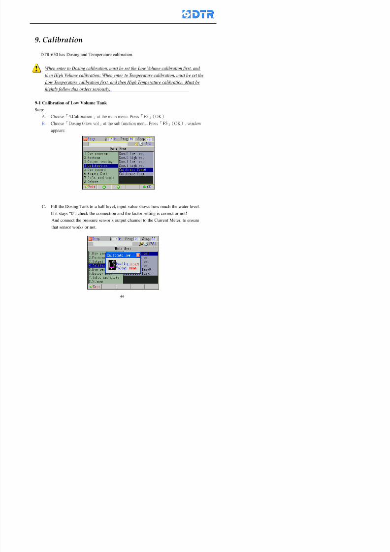
8132019 DTR 650 User Manual
httpslidepdfcomreaderfulldtr-650-user-manual 4470
983097 983107983137983148983145983138983154983137983156983145983151983150
DTR-650 has Dosing and Temperature calibration
When enter to Dosing calibration must be set the Low Volume calibration first and
then High Volume calibration When enter to Temperature calibration must be set the
Low Temperature calibration first and then High Temperature calibration Must be
hightly follow this orders seriously
9-1 Calibration of Low Volume Tank
Step
A Choose「4Calibration」at the main menu Press「F5」(OK)
B Choose「Dosing 0 low vol」at the sub function menu Press「F5」(OK) window
appears
C Fill the Dosing Tank to a half level input value shows how much the water level
If it stays ldquo0rdquo check the connection and the factor setting is correct or not
And connect the pressure sensorrsquos output channel to the Current Meter to ensure
that sensor works or not
8132019 DTR 650 User Manual
httpslidepdfcomreaderfulldtr-650-user-manual 4570
D Fill the Dosing Tank to 50ml (Calcalate from the bottom side of the pressure
sensor steel tube) input value should show 4~6 (input value must between
0~10) Then enter the water volume The setting volume is relating the water
levelrsquos water value (litre as unit) input range 0~80 Set as「 「「 「0000 0000 0000 0000」」」」is strongly is strongly is strongly is strongly
receommend receommend receommend receommend Press「F5」(OK)to complete [Calibration of Low Volume Tank 1
is same as above method]
9-2 Calibration of High Volume Tank
Step
A Choose「4Calibration」at the main menu Press「F5」(OK)
B Choose「Dos 0 high vol」at the sub function menu Press「F5」(OK) window of
「Calibrate high 」appears
C Fill the Dosing Tank to a full level input value should be larger than 30 enter
the current water level which relates to the water volume Enter the range within
100~2500 Then press「F5」(OK) to complete the calibrate the high volume tank
8132019 DTR 650 User Manual
httpslidepdfcomreaderfulldtr-650-user-manual 4670
9-3 Temperature Calibration
Step
A This function is for adjusting the DTR650rsquos accuracy of Temperature Control It
must be using with the special terminal which is only for DTR650
B Choose「4Calibration」at the main function menu and press「F5」(OK)
C Choose「3Low Temp」at the sub-function menu Press「F5」(OK)and《Fig9-3》
appears insert the DTR650rsquos low temperature calibration terminal to the temperature
input terminal wait for the jumping value to stable down then press「F5」(OK) then
to adjust the high temperature calibration
D Adjusting the High Temperature Calibrationrsquos method is same as above But usersusersusersusers
must be using the High Temperature Terminalmust be using the High Temperature Terminalmust be using the High Temperature Terminalmust be using the High Temperature Terminal whichwhichwhichwhich is specially for DTR650 onlyis specially for DTR650 onlyis specially for DTR650 onlyis specially for DTR650 only
《Fig 9-3》
8132019 DTR 650 User Manual
httpslidepdfcomreaderfulldtr-650-user-manual 4770
10 983122983141983139983151983154983140983155 983151983142 983108983161983141 983120983154983151983143983154983137983149983155
It contains the past 15 days of temperature curves of running history
Checking method
(1) Choose「5Dye Record」at main menu press「F5」(OK)
(2) Sub-function menu shows the set up date of the past 15 days dye programs
Listing by the lastest set up date
(3) Choose a program date and press「F5」(OK) it appears window「Temp
record」
(4) Press「」「」to move the white line in the box one minute by moving once
(5) Press「3」「4」to move the line to check the time period 2 hours by moving once
The yellow selecting line of the「24 hours operating state」is repectively moving
The curve info is show in the curve box Left side of the widnow appears the
relating running info the time is the time value of the line locates at
(6) Check more details of the temperature info to press numeric key「middot」 a bright red line
appears in the selecting box this line is to check the starting point of the
temperature inforsquos time period Then press「」to move the white line to the end
point of the time period The temperature info between the starting point and end
point are appears at the right side of the window Press「middot」to return to the preious
curve page
(7) Check more details of the alarm infor To perss numeric key「7」「9」 the alarmrsquos
details is listing by orders
(8) Press「F1」(exit) to return
8132019 DTR 650 User Manual
httpslidepdfcomreaderfulldtr-650-user-manual 4870
11 983125983155983137983143983141 983151983142 983117983141983149983151983154983161 983107983137983154983140
DTR-650 supports 32MB or above Compact Flash Card which can transfer and save all
information for 4 sets of DTR-650 Including library files schematic diagram icon
image PLC program dye program factor and confiruration files etchellip Use the CF Card
to up download and swap the information of DTR-650 promptly install the relating
device and program updates
DTR-650 CF Card with bank 1 to bank 4 can save 4 sets information of Dyeing
Machines When download or save files should choose the BANK first
《Fig11-1》
8132019 DTR 650 User Manual
httpslidepdfcomreaderfulldtr-650-user-manual 4970
11-1 Downloading data
1 Firmly insert the CF card into the DTR-650rsquos PCMCIA connector Ensure it is
wholely and firmly inserted if the card is not totally inserted or the card do not
touch in all to the connector there will be an error occurred and cannot
updownload or interrupted during operation
2 Choose「6Memory Card」at the main menu and press「F5」(OK) 《Fig11-1》
appears Information of Bank「1」shows at the left hand side of the window press
number 1-4 by using numeric keys to choose the BANK Check the
information in the Bank seriously which is exactly need to download to the
DTR650
3 Press()()「6」「5」to move cursor to the sub-function menu to choose
the downloading items Press「F5」(OK) window appears「Stop PLC run before
access memory card Stop the PLC run」 Press「F5」(YES) to stop PLC
running
4 Press「F5」(OK) window appears Confirm to update or not the DTR-650rsquos
information As that downloading will be replace the DTR-650rsquos information
(that means the existing information of the DTR-650 will be removed and
replaced)
5 Press「F4」(YES)to download the information from the DTR-650 to the CF
Card Return to the main menu when finish
8132019 DTR 650 User Manual
httpslidepdfcomreaderfulldtr-650-user-manual 5070
Ensure inserting firmly the CF card into the DTR-650 unless it will cause
error or cannot Updownload data
Never remove CF card during transferring or updownloading data Until it
is all completed
DTR-650rsquos dyeing program is not compatible with DTR-500 and
DTR-600 Never use CF card to transfer data among them
11-2 Storing and transfering data
1 Insert the CF Card to the DTR-650
2 Choose「6Memory Card」at the main menu and press「F5」(OK) 《Fig11-1》
appears Left hand side of the window shows the data of BANK 1 press numeric
keys 1-4 to select the BANK To confirm the put the data in the DTR-650 to the CF
Card The existing data of that bank will be replaced and covered by the new data (if
that bank is already occuplied)
3 Choose「23Save Dye prog」(Example)at the sub-funciton menu press「F5」(OK)to confirm Window「Update memory card data」appears
4 Press「F5」(OK)to transfer the data to the CF card Return to the main menu
5 Put the CF card into another DTR-650 and follow the operating method of 「11-1
Downloading data」」」」can transfer and swap data with more than one set of
DTR-650
8132019 DTR 650 User Manual
httpslidepdfcomreaderfulldtr-650-user-manual 5170
12 983123983156983137983156983141 983137983150983140 983113983150983142983151983154983149983137983156983145983151983150
The state and information is including the Dyeing Machinersquos state of Digit Input output
Analog Input output Temperature control PID Dosing PID Pressure different PID
software system information and alarm record This information is for checking at any
time
12-1 Input Output state
Step
1 Choose「7Info and state」at main menu and press「F5」(OK)
2 Choose「01Digital IO put」at the sub-function menu then press「F5」(OK)
「Digital In Out State」0=None 1=Input
3 Press「F1」(Exit)to return to main menu
Same method for checking the temperature control analog dosing pressure
different etchellip
12-2 Checking the system information
Step
1 Choose「7Info and state」at main menu and press「F5」(OK)
2 Choose「11 System info」at sub-function field press「F5」(OK)Window
「System Information」appear
System information is including System info(software version) Library doc
Icon files Schematic file Definition file hardare state Config File Commandinstruction icon PLC file etc
8132019 DTR 650 User Manual
httpslidepdfcomreaderfulldtr-650-user-manual 5270
12-3 Checking the operating alarm record
Operating record shows the latest 40 operating items and alarm records including
the time and content of the alarm
A) Choose「7 Info and state」
and press「F5」(OK)
B) Choose「12Alarm logs」at
the sub-funciton menu then
press「F5」(OK)
8132019 DTR 650 User Manual
httpslidepdfcomreaderfulldtr-650-user-manual 5370
13 983105983140983146983157983155983156983145983150983143 983156983144983141 983107983151983150983156983154983137983155983156
The displaysrsquos brightness can be adjusted if necessary
Step
1 Choose「8Others」at main menu press「F5」(OK)
2 Choose「01Contrast」at sub-function menu press「F5」(OK) window「Set
Contrast」appears
3 Press「」「」to move the bar to set the brightness then press「F5」(OK)Window appears「Please reboot the system」
4 Press「F5」(OK)to return to main menu and re-boot the DTR-650 to complete
adjusting the brightness
8132019 DTR 650 User Manual
httpslidepdfcomreaderfulldtr-650-user-manual 5470
14 983123983156983151983152 983154983157983150983150983145983150983143 983156983144983141 983120983116983107 983120983154983151983143983154983137983149
Before testing the Input output testing transfer of the PLC program must stop the PLC
running
Step
1 Choose「8Others」at the main menu Press「F5」(OK)
2 Choose「04 PLC Stop」at sub-function menu Press「F5」(OK) window
「Password」appears
3 Enter password and press「F5」(OK) Window「Stop the PLC run」appears
4 Press「F4」(Yes)and window「PLC Stop」appear Press「F5」(OK) Now
the PLC is stop running and return to the main menu
All testing cannot operate when the PLC is running
Editing dye program and the relating operation can
perform with the PLC running together
8132019 DTR 650 User Manual
httpslidepdfcomreaderfulldtr-650-user-manual 5570
15 983123983141983156983156983145983150983143 983156983144983141 983156983145983149983141
Step
1 Press「8Others」at the main menu Press「F5」(OK)
2 Choose「10Set date time」at the sub-function menu Press「F5」(OK) window
「Set date time」appears
3 Press「F5」(Edit) to move cursor by 「3」「4」 enter the time value at the
cursor locates
4 Press「F5」(OK)to complete the modify Press「F1」(Exit)to return to main
menu
5 Press「F1」(Exit)if not modify and return to main menu
8132019 DTR 650 User Manual
httpslidepdfcomreaderfulldtr-650-user-manual 5670
1166 983123983123983157983157 983152 983152 983152 983152983148983148983141983141983149983149983141983141983150983150983156 983156 983137983137983154 983154 983161983161 983124 983124 983137983137983138983138983148983148983141983141
TTTTTTTTaaaaaaaabbbbbbbblllllllleeeeeeee 11111111 【Dye Instruction】
Code Icon Instruction Code Icon Instruction
000 End 016 Inject C
001 Start 017 Dosing BV
002 Heat 018 PH
003 Cool 019 Addsalt B
004 Flow Fill 020 Addsalt C
005 Level Fill 021 Ana Fill
006 Drian 022 Lock Fill007 Rinse 023 Lock Level
008 Run 024 Low Rinse
009 Call 025 Cyc Rinse
010 Prep B 026 Rinse B
011 Addsalt B 027 Rinse C
012 Dosing B 028 Temp
013 Inject B 029 Nozzle Pressure
014 Prep C 030 Main Pump
015 Dosing C 031 Pump Speed
8132019 DTR 650 User Manual
httpslidepdfcomreaderfulldtr-650-user-manual 5770
Table 2 【【【【Alarm】】】】
System Alarm Must stop operating and check up to solve problems before restarting
the machine
Running Alarm It is a reminder Not effect the operating of DTR-650
Userrsquos Alarm Total of 32 Users can define themselves and use it when edit the PLC
Program (do not listing below)
No System Alarm No Running Alarm
1 PLC program not running 16 Temp ctrl 0 Grad too slow
2 Main temp sensor error 17 Temp ctrl 0 Grad too fast
3 Not at Run window 18 Temp ctrl 0 Hold temp too low
4 Exceeding max temp 19 Temp ctrl 0 Hold temp too high
5 - 20 Temp ctrl 1 Grad too slow6 - 21 Temp ctrl 1 Grad too fast
7 - 22 Temp ctrl 1 Hold temp too low
8 Communication error 23 Temp ctrl 1 Hold temp too high
9 Slave not answer 24 Temp ctrl 2 Grad too slow
10 PLC 0 not answer 25 Temp ctrl 2 Grad too fast
11 PLC 1 not answer 26 Temp 2 Hold temp too low12 Display not answer 27 Temp 2 Hold temp too high
13 Lower power voltage 28 Temp ctrl 3 Grad too slow
14 - 29 Temp ctrl 3 Grad too fast
15 - 30 Temp3 Hold temp too low
31 Temp3 Hold temp too high
32 Dosing 0 injection too slow
33 Dosing 0 injection too fast
34 Dosing 1 injection too slow
35 Dosing 1 injection too fast
8132019 DTR 650 User Manual
httpslidepdfcomreaderfulldtr-650-user-manual 5870
TTTTTTTTaaaaaaaabbbbbbbblllllllleeeeeeee 33333333 【【【【System factor】】】】
No Description Std Range amp Definition
1 ID No 000 000- 100 Controller no
2 Communication Rate 4800Bps 2400 4800 9600 19200 38400
3 Display language Chinese English Chinese
4 Temp display mode and
5 Maxmium temperature 145 025 ~ 145 6 Type of external PLC Default PLC32DPLC32PLC16Default
7 Number of external PLC NANA 1 unit connect
2 unit connect
8Communication Rate of
PLC9600Bps 2400 4800 9600 19200
9 Set point 1 085 000 ~ 145
If signal source is temperaturethe setting value is thetemperature value If the signal
source is Analog Input 6~17 then
setting value for Analog input is 0 ndash
100 and relates Analog
Input14~020mA
10 Source 1 Sensor0Sensor 0 ~5
Analog input 0 ~1111 Set point 2 092 Same as 09
12 Source 2 PT100 1 Same as 10
13 Set point 3 085 Same as 09
14 Source 3 PT100 2 Same as 10
15 Set point 4 092 Same as 09
16 Source 4 PT100 3 Same as 1017 Set point 5 085 Same as 09
18 Source 5 PT100 4 Same as 10
19 Set point 6 092 Same as 09
8132019 DTR 650 User Manual
httpslidepdfcomreaderfulldtr-650-user-manual 5970
29 Min cyclic time of cloth 100sec 0 ~ 255 sec
30 Max cyclic time of cloth 240sec 0 ~255 sec
31Standard cyclic time of
cloth
180 000 ~ 255 sec
32 Display ModeProgram
List
Program list Schematic Diagram
Icon mode
33 CF card format Standard of
DTR CF
Card
Standard of DTR CF Card V20
Standard CF Card
34 Addition step Disable Disable Enable35 Mode Com 3
CouplingEsure Com 3 is the communication
port of the Central or Coupling
36Com 3 Communication
rate9600 Central communication speed
8132019 DTR 650 User Manual
httpslidepdfcomreaderfulldtr-650-user-manual 6070
TTTTTTTTaaaaaaaabbbbbbbblllllllleeeeeeee 44444444 【【【【Temperature Cotnrol Factor】】】】
No Factor Definition Standard Range and Definition
01 PT No PT-0 PT 0~5 PT-100 Input number
02 Max working temp 140 000~140
03 Output mode 0 0~2
04 Alarm time of gardient 240sec 000~255 sec
05 Alarm mode of gradient Always AlwaysOnceNone
06 Control mode of gradient Heating orCooling
interlocked
Heating and Cooling interlocked
No limitation
07 Alarm range of HoldTemp 03 01~20
08 Alarm time for HoldTemp 240sec 000~255sec
09 Alarm mode of HoldTemp Always AlwaysOnceNone
10 Control mode ofHoldTemp
Heating only Only heating and cooling Cooling whenalarm occurred Only heating andcooling No limitation when alarmHeating only
11 Porportional Band 100 000~250
12 Integral band 128 sec 000~255 sec
13 Differential time 04 sec 00~20 sec
14 Min transit gradient 02 00~50
15 Transit rate 20 times 00~50 times (020= 2 times)
16 PID initial output value 010 000~100
17 ONOFF cycle time 10 sec 05~25 sec
Onoff valve set as 010 sec
Proportional valve set as 020 sec
18 Time down count mode Mode 0 0~10 = The time down count range from「Factor 20 + target temp」to「Target
8132019 DTR 650 User Manual
httpslidepdfcomreaderfulldtr-650-user-manual 6170
TTTTTTTTaaaaaaaabbbbbbbblllllllleeeeeeee 55555555 【【【【Speed Factor】】】】
No Factor Definition Standard Range amp Definition
01 Input Number Speed input 0 Speed input 0~11
02 Average times 05 times 01~10
03 Sensor Number 008pcs 001~255
04 Roller Dimension 250mm 050~500
05 Max cloth speed 200mmin 001~25506 Min cloth speed 020mmin 001~255
07 Alarm delay time 240sec 001~255
08 Alarm mode Every oncenoneevery
09 Alarm range () 020 001~255
10 Proportional band 100 001~255
11 Integer band 128 001~25512 Differential time 000 001~200
13 Initial speed () 020 001~255
14 Control cycle ti(01sec) 05 01~30
15 First cycle time(01sec) 10 01~30
16 Speed increase limit () 010 001~100
17 Speed decrease limit () 010 001~100
18 Min speed() 005 001~100
19 Manual speed adjust () 005 001~100
20 Manual initial speed() 020 001~100
21 Stopping speed() 010 001~100
22 Switch speed() 020 001~100
23 Not used
24 Speed decrease turns 03turns 01~50
8132019 DTR 650 User Manual
httpslidepdfcomreaderfulldtr-650-user-manual 6270
Table 6 【【【【Dosing Factors】】】】
No Description Range Range and Explanation
1 Analog input no Analog input 0 Analog input no 0 ~11
2Alarm delay time for
dosing240 sec 000 ~255 sec
3 Alarm time for dosing Every Every Once None
4 Proportional band 100 000 ~255 sec Factor P
5 Integer band 128 000 ~255 sec Factor I6 Differential time 04 00 ~20 Factor D
7 Max adjust rate 150 50~ 255
8 Initial factor for dosing 10 000 ~100
9 User curve section 0 10 Gradient of sect1 for dosing curve9
10 User curve section 1 10 Gradient of sect2 for dosing curve9
11 User curve section 2 10 Gradient of sect3 for dosing curve9
12 User curve section 3 10 Gradient of sect4 for dosing curve9
13 User curve section 4 10 Gradient of sect5 for dosing curve9
14 User curve section 5 10 Gradient of sect6 for dosing curve9
15 User curve section 6 10 Gradient of sect7 for dosing curve9
16 User curve section 7 10 Gradient of sect8 for dosing curve9
17 User curve section 8 10 Gradient of sect9 for dosing curve9
18 User curve section 9 10 Gradient of sect10 for dosing curve9
19 Min water level 05 00~ 10 04~20mA percentagechange to the userrsquos factor setting
20 Output value for Tank
clean
100 000~ 100
Injected percentage of dosing valve
in dosing End period
This factor will be invalided if usingONOFF dosing valve
21 Full range 100 001~255 Self-adjustment cannotchange
22 Range ratio 001001~255 Self-adjustment cannot
change
8132019 DTR 650 User Manual
httpslidepdfcomreaderfulldtr-650-user-manual 6370
【【【【TTaabbllee 77 】】】】Pressure Deviation Factors
No Description Std Range amp Definition
1 Analog input number + Analog in 0 Analog in 0~11
2 Analog input number - Analog in 1 Analog in 0~11
3 Input mode Pressure Pressure Pressure deviation
4 Full range 050x01Kgcm
001~255
5 Range ratio 001 001~255
6 Alarm delay time 100sec 001~255
7 Alarm mode Every oncenone
8 Alarm range 010 001~255
9 Proportional band 100 001~255
10 Integer band 128 001~255
11 Differential time 00 00~20
12 PID Init output value 010 001~255
13 Cycle time 10 03~30
14 First cycle time 030 003~100
15 Max adjust rate 010 001~100
8132019 DTR 650 User Manual
httpslidepdfcomreaderfulldtr-650-user-manual 6470
【【【【TTaabbllee 88 】】】】Definition of Analog Input
No Description Standard Range and Explanation
01 PT 0 correction standard DIN std DIN std JIS std
02 PT 0 correction +0 +- 9
03 PT 1 correction standard DIN std DIN std JIS std
04 PT 1 correction +0 +- 9
05 PT 2 correction standard DIN std DIN std JIS std
06 PT 2 correction +0 +- 9
07 PT 3 correction standard DIN std DIN std JIS std
08 PT 3 correction +0 +- 9
09 PT 4 correction standard DIN std DIN std JIS std
10 PT 4 correction +0 +- 9
11 PT 5 correction standard DIN std DIN std JIS std
12 PT 5 correction +0 +- 9
13 Analog input 0 define 4 ~ 20mA 0 ndash 20mA 4 ndash 20mA
14 Analog input 0 average times 10 times 01- 20 times
15 Analog input 0 min value 0000 0000 - 1000
16 Analog input 0 max value 100 0001 - 9999
17-60 Analog input 1~11 Same as Analog input 0
【【【【 】】】】 fi i i f A O
8132019 DTR 650 User Manual
httpslidepdfcomreaderfulldtr-650-user-manual 6570
【【【【TTaabbllee 99 】】】】Definition of Analog Output
No Description Standard Range and explanation
61 Analog output 0 define Control byPLC
Control by PLC
Temperature control PID0 output
Temperature control PID1 output
Temperature control PID2 output
Speed PID3 output
Dosing PID0 output Dosing PID1output
Pressure different PID0 outputPressure different PID1 output
Main temperature output
62 Mode of Analog ouptput0 4 ~20mA 0 ndash20mA 4 ndash 20mA
63-84 Analog output 1~11 Same as Analog output 0
【【【【TTaabbllee 1100】】】】Value Table 0 amp 1
No Description Range Std Range and explanation
1 Analog input no 000~011 000 Analog input no
2 Data ratio 001~255 100 Multiple by factors
3~53 0~98 000~255 000-100 Analog input 0~98 data
【【【【 】】】】St t Li t
8132019 DTR 650 User Manual
httpslidepdfcomreaderfulldtr-650-user-manual 6670
【【【【TTaabbllee 1111】】】】State List
No Description Range Standard Range and explanation
1 Display setting 1 0~255 205 See remarks at next page
2 Display setting 2 0~255 208
3 Display setting 3 0~255 209
4 Display setting 4 0~255 017
5 Display setting 5 0~255 0186 Display setting 6 0~255 019
7 Display setting 7 0~255 020
8 Display setting 8 0~255 021
9 Display setting 9 0~255 000
10 Display setting 1 0~255 000
11 Display setting 2 0~255 000
12 Display setting 3 0~255 000
13 Display setting 4 0~255 000
14 Display setting 5 0~255 000
15 Display setting 6 0~255 000
16 Display setting 7 0~255 000
Remarks
8132019 DTR 650 User Manual
httpslidepdfcomreaderfulldtr-650-user-manual 6770
0 = No display 1~255 = Display type of number
1~16 Content of PLC VB0~15
No 1 corresponding to VB0
No 16 corresponding to VB15
17~32 Content of PLC DB0~15
No 17 corresponding to DB0
No 32 corresponding to DB15
33~46 Content of PLC CNT0~29
No 33 corresponding to CNT0
No 46 corresponding to CNT29 47~78 Content of dyeing instruction 0~31 CNT0
No 47 corresponding to system instruction to No 0 of CNT0
No 78 corresponding to system instruction to No 31 of CNT0rsquos content
79~110 Dyeing instruction 0~31 of CNT0rsquos setting
111~142 Content of Dyeing instruction 0~31 CNT1No 111 corresponding to dyeing instruction No 0 of CNT1
No 142 corresponding to dyeing instruction No 31 of CNT1rsquos content
143~174 Dyeing instruction 0~31 of CNT1rsquos setting
175~204 Content of PLC HTIM0~29
No 175 corresponding to HTIM0
No 204 corresponding to HTIM29
205 Loading
206 Ratio 1
207 Ratio 2208 Ratio 1 x Loading
209 Ratio 2 x Loading
210 Fix value
211 Value Table 1 matching result
212 Value Table 2 matching result
213 Value Table 1 setting214 Value Table 2 setting
215 Pressure control PID0 different pressure value
216 Pressure control PID1 different pressure value
TTTTTTTTaaaaaaaabbbbbbbblllllllleeeeeeee 1122 【【【【Usage of password】】】】
8132019 DTR 650 User Manual
httpslidepdfcomreaderfulldtr-650-user-manual 6870
No Main FunctionFactor Sub Function Factor Password Rank
1 Run None
2 Dye program User3 or above
3 Control factor
- User factor User 1
- System factor User 1
- Temp PID 0
- Temp PID 1 User 1- Speed PID 0 User 1
- Dosing PID 0 User 1
- Dosing PID 1 User 1
- Pressure PID 0 User 1
- Pressure PID 1 User 1
- Analog IO User 1
- Load standard factor User 2 or above- Load a copied factor User 2 or above
- Copy factor User 2 or above
- Value table 0 User 1
- Value table 1 User 1
- Information and state User 1
- Dye instruction User 1
- Edit dye instruction setting User 14 Output testing User 2 or above
5 Calibration User 2 or above
6 Dye record None
7 CF card User 1
8 Info and state None
9 Others
- Contrast User3 or above
- Data Locking None
- PLC Run User 1
- PLC Stop User 1
- Password setting User 1
TTTTTTTTaaaaaaaabbbbbbbblllllllleeeeeeee 1133 【【【【Technical Data】】】】
8132019 DTR 650 User Manual
httpslidepdfcomreaderfulldtr-650-user-manual 6970
TTTTTTTTaaaaaaaabbbbbbbblllllllleeeeeeee 1133 【【【【Technical Data】】】】
1 Temperature Control
- Range 10~145(plusmn1)
- Mode Proportional or PWM
- Sensor PT100 (JIS or DIN standard)
2 Input and output channel
- Digital Input 32 DC24V PNP- Digital Output 32 DC24V 054A Relay connect point
- Analog Input 4 04~20 mA
- Analog Output 4 0~20mA 或 4~20 mA
3 Communication port 3 RS-232 amp 0~20 mAx1 RS485x 2
4 Dye program
- Number 15000 Steps
- Standard step 61Heating Cooling Fill Drain RinseDosingetc
5LCD module and Display
langage
Chinese
English
320 x 240 TFT color display with
more language
6 CF card connector 1 PCMCIA standard
7 Membrane Keyboard- Number Key 10 [0]~[9] Input factors
- Function Key 5 [F1]~[F5] function selecting
- Operation Key 2 [Start] [Stop]
- Auxiliary Key 7 [][][][][Esc] [larr][OK] [bull]
8 Operating Condition
- Temperature 5~45
- Humidity ≦85 (25)
9 Power supply
V l DC 24V
8132019 DTR 650 User Manual
httpslidepdfcomreaderfulldtr-650-user-manual 7070
70
983108983124983122983085650 983113983150983152983157983156 983119983157983156983152983157983156 983120983151983154983156983145983150983143 (983138983137983139983147983155983145983140983141 983158983145983141983159)
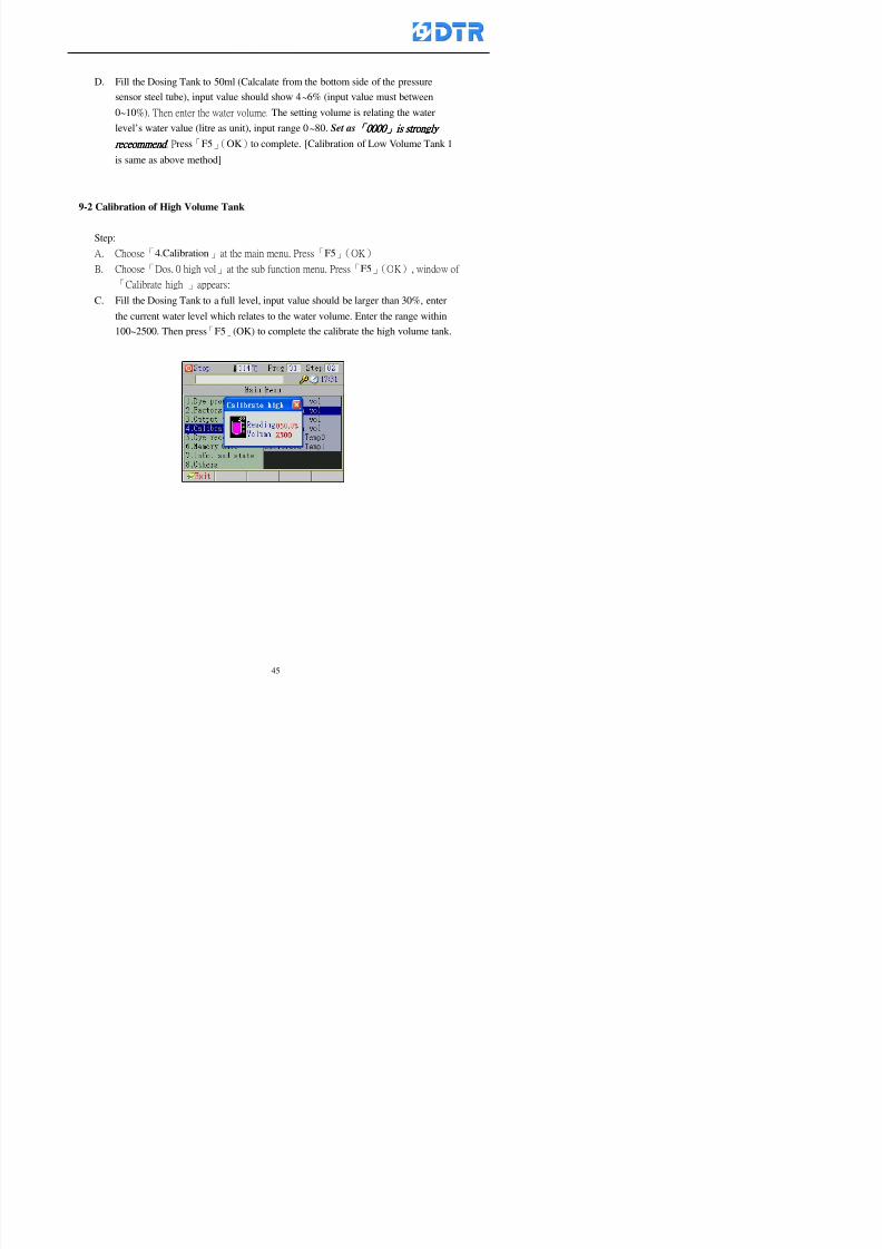
8132019 DTR 650 User Manual
httpslidepdfcomreaderfulldtr-650-user-manual 4570
D Fill the Dosing Tank to 50ml (Calcalate from the bottom side of the pressure
sensor steel tube) input value should show 4~6 (input value must between
0~10) Then enter the water volume The setting volume is relating the water
levelrsquos water value (litre as unit) input range 0~80 Set as「 「「 「0000 0000 0000 0000」」」」is strongly is strongly is strongly is strongly
receommend receommend receommend receommend Press「F5」(OK)to complete [Calibration of Low Volume Tank 1
is same as above method]
9-2 Calibration of High Volume Tank
Step
A Choose「4Calibration」at the main menu Press「F5」(OK)
B Choose「Dos 0 high vol」at the sub function menu Press「F5」(OK) window of
「Calibrate high 」appears
C Fill the Dosing Tank to a full level input value should be larger than 30 enter
the current water level which relates to the water volume Enter the range within
100~2500 Then press「F5」(OK) to complete the calibrate the high volume tank
8132019 DTR 650 User Manual
httpslidepdfcomreaderfulldtr-650-user-manual 4670
9-3 Temperature Calibration
Step
A This function is for adjusting the DTR650rsquos accuracy of Temperature Control It
must be using with the special terminal which is only for DTR650
B Choose「4Calibration」at the main function menu and press「F5」(OK)
C Choose「3Low Temp」at the sub-function menu Press「F5」(OK)and《Fig9-3》
appears insert the DTR650rsquos low temperature calibration terminal to the temperature
input terminal wait for the jumping value to stable down then press「F5」(OK) then
to adjust the high temperature calibration
D Adjusting the High Temperature Calibrationrsquos method is same as above But usersusersusersusers
must be using the High Temperature Terminalmust be using the High Temperature Terminalmust be using the High Temperature Terminalmust be using the High Temperature Terminal whichwhichwhichwhich is specially for DTR650 onlyis specially for DTR650 onlyis specially for DTR650 onlyis specially for DTR650 only
《Fig 9-3》
8132019 DTR 650 User Manual
httpslidepdfcomreaderfulldtr-650-user-manual 4770
10 983122983141983139983151983154983140983155 983151983142 983108983161983141 983120983154983151983143983154983137983149983155
It contains the past 15 days of temperature curves of running history
Checking method
(1) Choose「5Dye Record」at main menu press「F5」(OK)
(2) Sub-function menu shows the set up date of the past 15 days dye programs
Listing by the lastest set up date
(3) Choose a program date and press「F5」(OK) it appears window「Temp
record」
(4) Press「」「」to move the white line in the box one minute by moving once
(5) Press「3」「4」to move the line to check the time period 2 hours by moving once
The yellow selecting line of the「24 hours operating state」is repectively moving
The curve info is show in the curve box Left side of the widnow appears the
relating running info the time is the time value of the line locates at
(6) Check more details of the temperature info to press numeric key「middot」 a bright red line
appears in the selecting box this line is to check the starting point of the
temperature inforsquos time period Then press「」to move the white line to the end
point of the time period The temperature info between the starting point and end
point are appears at the right side of the window Press「middot」to return to the preious
curve page
(7) Check more details of the alarm infor To perss numeric key「7」「9」 the alarmrsquos
details is listing by orders
(8) Press「F1」(exit) to return
8132019 DTR 650 User Manual
httpslidepdfcomreaderfulldtr-650-user-manual 4870
11 983125983155983137983143983141 983151983142 983117983141983149983151983154983161 983107983137983154983140
DTR-650 supports 32MB or above Compact Flash Card which can transfer and save all
information for 4 sets of DTR-650 Including library files schematic diagram icon
image PLC program dye program factor and confiruration files etchellip Use the CF Card
to up download and swap the information of DTR-650 promptly install the relating
device and program updates
DTR-650 CF Card with bank 1 to bank 4 can save 4 sets information of Dyeing
Machines When download or save files should choose the BANK first
《Fig11-1》
8132019 DTR 650 User Manual
httpslidepdfcomreaderfulldtr-650-user-manual 4970
11-1 Downloading data
1 Firmly insert the CF card into the DTR-650rsquos PCMCIA connector Ensure it is
wholely and firmly inserted if the card is not totally inserted or the card do not
touch in all to the connector there will be an error occurred and cannot
updownload or interrupted during operation
2 Choose「6Memory Card」at the main menu and press「F5」(OK) 《Fig11-1》
appears Information of Bank「1」shows at the left hand side of the window press
number 1-4 by using numeric keys to choose the BANK Check the
information in the Bank seriously which is exactly need to download to the
DTR650
3 Press()()「6」「5」to move cursor to the sub-function menu to choose
the downloading items Press「F5」(OK) window appears「Stop PLC run before
access memory card Stop the PLC run」 Press「F5」(YES) to stop PLC
running
4 Press「F5」(OK) window appears Confirm to update or not the DTR-650rsquos
information As that downloading will be replace the DTR-650rsquos information
(that means the existing information of the DTR-650 will be removed and
replaced)
5 Press「F4」(YES)to download the information from the DTR-650 to the CF
Card Return to the main menu when finish
8132019 DTR 650 User Manual
httpslidepdfcomreaderfulldtr-650-user-manual 5070
Ensure inserting firmly the CF card into the DTR-650 unless it will cause
error or cannot Updownload data
Never remove CF card during transferring or updownloading data Until it
is all completed
DTR-650rsquos dyeing program is not compatible with DTR-500 and
DTR-600 Never use CF card to transfer data among them
11-2 Storing and transfering data
1 Insert the CF Card to the DTR-650
2 Choose「6Memory Card」at the main menu and press「F5」(OK) 《Fig11-1》
appears Left hand side of the window shows the data of BANK 1 press numeric
keys 1-4 to select the BANK To confirm the put the data in the DTR-650 to the CF
Card The existing data of that bank will be replaced and covered by the new data (if
that bank is already occuplied)
3 Choose「23Save Dye prog」(Example)at the sub-funciton menu press「F5」(OK)to confirm Window「Update memory card data」appears
4 Press「F5」(OK)to transfer the data to the CF card Return to the main menu
5 Put the CF card into another DTR-650 and follow the operating method of 「11-1
Downloading data」」」」can transfer and swap data with more than one set of
DTR-650
8132019 DTR 650 User Manual
httpslidepdfcomreaderfulldtr-650-user-manual 5170
12 983123983156983137983156983141 983137983150983140 983113983150983142983151983154983149983137983156983145983151983150
The state and information is including the Dyeing Machinersquos state of Digit Input output
Analog Input output Temperature control PID Dosing PID Pressure different PID
software system information and alarm record This information is for checking at any
time
12-1 Input Output state
Step
1 Choose「7Info and state」at main menu and press「F5」(OK)
2 Choose「01Digital IO put」at the sub-function menu then press「F5」(OK)
「Digital In Out State」0=None 1=Input
3 Press「F1」(Exit)to return to main menu
Same method for checking the temperature control analog dosing pressure
different etchellip
12-2 Checking the system information
Step
1 Choose「7Info and state」at main menu and press「F5」(OK)
2 Choose「11 System info」at sub-function field press「F5」(OK)Window
「System Information」appear
System information is including System info(software version) Library doc
Icon files Schematic file Definition file hardare state Config File Commandinstruction icon PLC file etc
8132019 DTR 650 User Manual
httpslidepdfcomreaderfulldtr-650-user-manual 5270
12-3 Checking the operating alarm record
Operating record shows the latest 40 operating items and alarm records including
the time and content of the alarm
A) Choose「7 Info and state」
and press「F5」(OK)
B) Choose「12Alarm logs」at
the sub-funciton menu then
press「F5」(OK)
8132019 DTR 650 User Manual
httpslidepdfcomreaderfulldtr-650-user-manual 5370
13 983105983140983146983157983155983156983145983150983143 983156983144983141 983107983151983150983156983154983137983155983156
The displaysrsquos brightness can be adjusted if necessary
Step
1 Choose「8Others」at main menu press「F5」(OK)
2 Choose「01Contrast」at sub-function menu press「F5」(OK) window「Set
Contrast」appears
3 Press「」「」to move the bar to set the brightness then press「F5」(OK)Window appears「Please reboot the system」
4 Press「F5」(OK)to return to main menu and re-boot the DTR-650 to complete
adjusting the brightness
8132019 DTR 650 User Manual
httpslidepdfcomreaderfulldtr-650-user-manual 5470
14 983123983156983151983152 983154983157983150983150983145983150983143 983156983144983141 983120983116983107 983120983154983151983143983154983137983149
Before testing the Input output testing transfer of the PLC program must stop the PLC
running
Step
1 Choose「8Others」at the main menu Press「F5」(OK)
2 Choose「04 PLC Stop」at sub-function menu Press「F5」(OK) window
「Password」appears
3 Enter password and press「F5」(OK) Window「Stop the PLC run」appears
4 Press「F4」(Yes)and window「PLC Stop」appear Press「F5」(OK) Now
the PLC is stop running and return to the main menu
All testing cannot operate when the PLC is running
Editing dye program and the relating operation can
perform with the PLC running together
8132019 DTR 650 User Manual
httpslidepdfcomreaderfulldtr-650-user-manual 5570
15 983123983141983156983156983145983150983143 983156983144983141 983156983145983149983141
Step
1 Press「8Others」at the main menu Press「F5」(OK)
2 Choose「10Set date time」at the sub-function menu Press「F5」(OK) window
「Set date time」appears
3 Press「F5」(Edit) to move cursor by 「3」「4」 enter the time value at the
cursor locates
4 Press「F5」(OK)to complete the modify Press「F1」(Exit)to return to main
menu
5 Press「F1」(Exit)if not modify and return to main menu
8132019 DTR 650 User Manual
httpslidepdfcomreaderfulldtr-650-user-manual 5670
1166 983123983123983157983157 983152 983152 983152 983152983148983148983141983141983149983149983141983141983150983150983156 983156 983137983137983154 983154 983161983161 983124 983124 983137983137983138983138983148983148983141983141
TTTTTTTTaaaaaaaabbbbbbbblllllllleeeeeeee 11111111 【Dye Instruction】
Code Icon Instruction Code Icon Instruction
000 End 016 Inject C
001 Start 017 Dosing BV
002 Heat 018 PH
003 Cool 019 Addsalt B
004 Flow Fill 020 Addsalt C
005 Level Fill 021 Ana Fill
006 Drian 022 Lock Fill007 Rinse 023 Lock Level
008 Run 024 Low Rinse
009 Call 025 Cyc Rinse
010 Prep B 026 Rinse B
011 Addsalt B 027 Rinse C
012 Dosing B 028 Temp
013 Inject B 029 Nozzle Pressure
014 Prep C 030 Main Pump
015 Dosing C 031 Pump Speed
8132019 DTR 650 User Manual
httpslidepdfcomreaderfulldtr-650-user-manual 5770
Table 2 【【【【Alarm】】】】
System Alarm Must stop operating and check up to solve problems before restarting
the machine
Running Alarm It is a reminder Not effect the operating of DTR-650
Userrsquos Alarm Total of 32 Users can define themselves and use it when edit the PLC
Program (do not listing below)
No System Alarm No Running Alarm
1 PLC program not running 16 Temp ctrl 0 Grad too slow
2 Main temp sensor error 17 Temp ctrl 0 Grad too fast
3 Not at Run window 18 Temp ctrl 0 Hold temp too low
4 Exceeding max temp 19 Temp ctrl 0 Hold temp too high
5 - 20 Temp ctrl 1 Grad too slow6 - 21 Temp ctrl 1 Grad too fast
7 - 22 Temp ctrl 1 Hold temp too low
8 Communication error 23 Temp ctrl 1 Hold temp too high
9 Slave not answer 24 Temp ctrl 2 Grad too slow
10 PLC 0 not answer 25 Temp ctrl 2 Grad too fast
11 PLC 1 not answer 26 Temp 2 Hold temp too low12 Display not answer 27 Temp 2 Hold temp too high
13 Lower power voltage 28 Temp ctrl 3 Grad too slow
14 - 29 Temp ctrl 3 Grad too fast
15 - 30 Temp3 Hold temp too low
31 Temp3 Hold temp too high
32 Dosing 0 injection too slow
33 Dosing 0 injection too fast
34 Dosing 1 injection too slow
35 Dosing 1 injection too fast
8132019 DTR 650 User Manual
httpslidepdfcomreaderfulldtr-650-user-manual 5870
TTTTTTTTaaaaaaaabbbbbbbblllllllleeeeeeee 33333333 【【【【System factor】】】】
No Description Std Range amp Definition
1 ID No 000 000- 100 Controller no
2 Communication Rate 4800Bps 2400 4800 9600 19200 38400
3 Display language Chinese English Chinese
4 Temp display mode and
5 Maxmium temperature 145 025 ~ 145 6 Type of external PLC Default PLC32DPLC32PLC16Default
7 Number of external PLC NANA 1 unit connect
2 unit connect
8Communication Rate of
PLC9600Bps 2400 4800 9600 19200
9 Set point 1 085 000 ~ 145
If signal source is temperaturethe setting value is thetemperature value If the signal
source is Analog Input 6~17 then
setting value for Analog input is 0 ndash
100 and relates Analog
Input14~020mA
10 Source 1 Sensor0Sensor 0 ~5
Analog input 0 ~1111 Set point 2 092 Same as 09
12 Source 2 PT100 1 Same as 10
13 Set point 3 085 Same as 09
14 Source 3 PT100 2 Same as 10
15 Set point 4 092 Same as 09
16 Source 4 PT100 3 Same as 1017 Set point 5 085 Same as 09
18 Source 5 PT100 4 Same as 10
19 Set point 6 092 Same as 09
8132019 DTR 650 User Manual
httpslidepdfcomreaderfulldtr-650-user-manual 5970
29 Min cyclic time of cloth 100sec 0 ~ 255 sec
30 Max cyclic time of cloth 240sec 0 ~255 sec
31Standard cyclic time of
cloth
180 000 ~ 255 sec
32 Display ModeProgram
List
Program list Schematic Diagram
Icon mode
33 CF card format Standard of
DTR CF
Card
Standard of DTR CF Card V20
Standard CF Card
34 Addition step Disable Disable Enable35 Mode Com 3
CouplingEsure Com 3 is the communication
port of the Central or Coupling
36Com 3 Communication
rate9600 Central communication speed
8132019 DTR 650 User Manual
httpslidepdfcomreaderfulldtr-650-user-manual 6070
TTTTTTTTaaaaaaaabbbbbbbblllllllleeeeeeee 44444444 【【【【Temperature Cotnrol Factor】】】】
No Factor Definition Standard Range and Definition
01 PT No PT-0 PT 0~5 PT-100 Input number
02 Max working temp 140 000~140
03 Output mode 0 0~2
04 Alarm time of gardient 240sec 000~255 sec
05 Alarm mode of gradient Always AlwaysOnceNone
06 Control mode of gradient Heating orCooling
interlocked
Heating and Cooling interlocked
No limitation
07 Alarm range of HoldTemp 03 01~20
08 Alarm time for HoldTemp 240sec 000~255sec
09 Alarm mode of HoldTemp Always AlwaysOnceNone
10 Control mode ofHoldTemp
Heating only Only heating and cooling Cooling whenalarm occurred Only heating andcooling No limitation when alarmHeating only
11 Porportional Band 100 000~250
12 Integral band 128 sec 000~255 sec
13 Differential time 04 sec 00~20 sec
14 Min transit gradient 02 00~50
15 Transit rate 20 times 00~50 times (020= 2 times)
16 PID initial output value 010 000~100
17 ONOFF cycle time 10 sec 05~25 sec
Onoff valve set as 010 sec
Proportional valve set as 020 sec
18 Time down count mode Mode 0 0~10 = The time down count range from「Factor 20 + target temp」to「Target
8132019 DTR 650 User Manual
httpslidepdfcomreaderfulldtr-650-user-manual 6170
TTTTTTTTaaaaaaaabbbbbbbblllllllleeeeeeee 55555555 【【【【Speed Factor】】】】
No Factor Definition Standard Range amp Definition
01 Input Number Speed input 0 Speed input 0~11
02 Average times 05 times 01~10
03 Sensor Number 008pcs 001~255
04 Roller Dimension 250mm 050~500
05 Max cloth speed 200mmin 001~25506 Min cloth speed 020mmin 001~255
07 Alarm delay time 240sec 001~255
08 Alarm mode Every oncenoneevery
09 Alarm range () 020 001~255
10 Proportional band 100 001~255
11 Integer band 128 001~25512 Differential time 000 001~200
13 Initial speed () 020 001~255
14 Control cycle ti(01sec) 05 01~30
15 First cycle time(01sec) 10 01~30
16 Speed increase limit () 010 001~100
17 Speed decrease limit () 010 001~100
18 Min speed() 005 001~100
19 Manual speed adjust () 005 001~100
20 Manual initial speed() 020 001~100
21 Stopping speed() 010 001~100
22 Switch speed() 020 001~100
23 Not used
24 Speed decrease turns 03turns 01~50
8132019 DTR 650 User Manual
httpslidepdfcomreaderfulldtr-650-user-manual 6270
Table 6 【【【【Dosing Factors】】】】
No Description Range Range and Explanation
1 Analog input no Analog input 0 Analog input no 0 ~11
2Alarm delay time for
dosing240 sec 000 ~255 sec
3 Alarm time for dosing Every Every Once None
4 Proportional band 100 000 ~255 sec Factor P
5 Integer band 128 000 ~255 sec Factor I6 Differential time 04 00 ~20 Factor D
7 Max adjust rate 150 50~ 255
8 Initial factor for dosing 10 000 ~100
9 User curve section 0 10 Gradient of sect1 for dosing curve9
10 User curve section 1 10 Gradient of sect2 for dosing curve9
11 User curve section 2 10 Gradient of sect3 for dosing curve9
12 User curve section 3 10 Gradient of sect4 for dosing curve9
13 User curve section 4 10 Gradient of sect5 for dosing curve9
14 User curve section 5 10 Gradient of sect6 for dosing curve9
15 User curve section 6 10 Gradient of sect7 for dosing curve9
16 User curve section 7 10 Gradient of sect8 for dosing curve9
17 User curve section 8 10 Gradient of sect9 for dosing curve9
18 User curve section 9 10 Gradient of sect10 for dosing curve9
19 Min water level 05 00~ 10 04~20mA percentagechange to the userrsquos factor setting
20 Output value for Tank
clean
100 000~ 100
Injected percentage of dosing valve
in dosing End period
This factor will be invalided if usingONOFF dosing valve
21 Full range 100 001~255 Self-adjustment cannotchange
22 Range ratio 001001~255 Self-adjustment cannot
change
8132019 DTR 650 User Manual
httpslidepdfcomreaderfulldtr-650-user-manual 6370
【【【【TTaabbllee 77 】】】】Pressure Deviation Factors
No Description Std Range amp Definition
1 Analog input number + Analog in 0 Analog in 0~11
2 Analog input number - Analog in 1 Analog in 0~11
3 Input mode Pressure Pressure Pressure deviation
4 Full range 050x01Kgcm
001~255
5 Range ratio 001 001~255
6 Alarm delay time 100sec 001~255
7 Alarm mode Every oncenone
8 Alarm range 010 001~255
9 Proportional band 100 001~255
10 Integer band 128 001~255
11 Differential time 00 00~20
12 PID Init output value 010 001~255
13 Cycle time 10 03~30
14 First cycle time 030 003~100
15 Max adjust rate 010 001~100
8132019 DTR 650 User Manual
httpslidepdfcomreaderfulldtr-650-user-manual 6470
【【【【TTaabbllee 88 】】】】Definition of Analog Input
No Description Standard Range and Explanation
01 PT 0 correction standard DIN std DIN std JIS std
02 PT 0 correction +0 +- 9
03 PT 1 correction standard DIN std DIN std JIS std
04 PT 1 correction +0 +- 9
05 PT 2 correction standard DIN std DIN std JIS std
06 PT 2 correction +0 +- 9
07 PT 3 correction standard DIN std DIN std JIS std
08 PT 3 correction +0 +- 9
09 PT 4 correction standard DIN std DIN std JIS std
10 PT 4 correction +0 +- 9
11 PT 5 correction standard DIN std DIN std JIS std
12 PT 5 correction +0 +- 9
13 Analog input 0 define 4 ~ 20mA 0 ndash 20mA 4 ndash 20mA
14 Analog input 0 average times 10 times 01- 20 times
15 Analog input 0 min value 0000 0000 - 1000
16 Analog input 0 max value 100 0001 - 9999
17-60 Analog input 1~11 Same as Analog input 0
【【【【 】】】】 fi i i f A O
8132019 DTR 650 User Manual
httpslidepdfcomreaderfulldtr-650-user-manual 6570
【【【【TTaabbllee 99 】】】】Definition of Analog Output
No Description Standard Range and explanation
61 Analog output 0 define Control byPLC
Control by PLC
Temperature control PID0 output
Temperature control PID1 output
Temperature control PID2 output
Speed PID3 output
Dosing PID0 output Dosing PID1output
Pressure different PID0 outputPressure different PID1 output
Main temperature output
62 Mode of Analog ouptput0 4 ~20mA 0 ndash20mA 4 ndash 20mA
63-84 Analog output 1~11 Same as Analog output 0
【【【【TTaabbllee 1100】】】】Value Table 0 amp 1
No Description Range Std Range and explanation
1 Analog input no 000~011 000 Analog input no
2 Data ratio 001~255 100 Multiple by factors
3~53 0~98 000~255 000-100 Analog input 0~98 data
【【【【 】】】】St t Li t
8132019 DTR 650 User Manual
httpslidepdfcomreaderfulldtr-650-user-manual 6670
【【【【TTaabbllee 1111】】】】State List
No Description Range Standard Range and explanation
1 Display setting 1 0~255 205 See remarks at next page
2 Display setting 2 0~255 208
3 Display setting 3 0~255 209
4 Display setting 4 0~255 017
5 Display setting 5 0~255 0186 Display setting 6 0~255 019
7 Display setting 7 0~255 020
8 Display setting 8 0~255 021
9 Display setting 9 0~255 000
10 Display setting 1 0~255 000
11 Display setting 2 0~255 000
12 Display setting 3 0~255 000
13 Display setting 4 0~255 000
14 Display setting 5 0~255 000
15 Display setting 6 0~255 000
16 Display setting 7 0~255 000
Remarks
8132019 DTR 650 User Manual
httpslidepdfcomreaderfulldtr-650-user-manual 6770
0 = No display 1~255 = Display type of number
1~16 Content of PLC VB0~15
No 1 corresponding to VB0
No 16 corresponding to VB15
17~32 Content of PLC DB0~15
No 17 corresponding to DB0
No 32 corresponding to DB15
33~46 Content of PLC CNT0~29
No 33 corresponding to CNT0
No 46 corresponding to CNT29 47~78 Content of dyeing instruction 0~31 CNT0
No 47 corresponding to system instruction to No 0 of CNT0
No 78 corresponding to system instruction to No 31 of CNT0rsquos content
79~110 Dyeing instruction 0~31 of CNT0rsquos setting
111~142 Content of Dyeing instruction 0~31 CNT1No 111 corresponding to dyeing instruction No 0 of CNT1
No 142 corresponding to dyeing instruction No 31 of CNT1rsquos content
143~174 Dyeing instruction 0~31 of CNT1rsquos setting
175~204 Content of PLC HTIM0~29
No 175 corresponding to HTIM0
No 204 corresponding to HTIM29
205 Loading
206 Ratio 1
207 Ratio 2208 Ratio 1 x Loading
209 Ratio 2 x Loading
210 Fix value
211 Value Table 1 matching result
212 Value Table 2 matching result
213 Value Table 1 setting214 Value Table 2 setting
215 Pressure control PID0 different pressure value
216 Pressure control PID1 different pressure value
TTTTTTTTaaaaaaaabbbbbbbblllllllleeeeeeee 1122 【【【【Usage of password】】】】
8132019 DTR 650 User Manual
httpslidepdfcomreaderfulldtr-650-user-manual 6870
No Main FunctionFactor Sub Function Factor Password Rank
1 Run None
2 Dye program User3 or above
3 Control factor
- User factor User 1
- System factor User 1
- Temp PID 0
- Temp PID 1 User 1- Speed PID 0 User 1
- Dosing PID 0 User 1
- Dosing PID 1 User 1
- Pressure PID 0 User 1
- Pressure PID 1 User 1
- Analog IO User 1
- Load standard factor User 2 or above- Load a copied factor User 2 or above
- Copy factor User 2 or above
- Value table 0 User 1
- Value table 1 User 1
- Information and state User 1
- Dye instruction User 1
- Edit dye instruction setting User 14 Output testing User 2 or above
5 Calibration User 2 or above
6 Dye record None
7 CF card User 1
8 Info and state None
9 Others
- Contrast User3 or above
- Data Locking None
- PLC Run User 1
- PLC Stop User 1
- Password setting User 1
TTTTTTTTaaaaaaaabbbbbbbblllllllleeeeeeee 1133 【【【【Technical Data】】】】
8132019 DTR 650 User Manual
httpslidepdfcomreaderfulldtr-650-user-manual 6970
TTTTTTTTaaaaaaaabbbbbbbblllllllleeeeeeee 1133 【【【【Technical Data】】】】
1 Temperature Control
- Range 10~145(plusmn1)
- Mode Proportional or PWM
- Sensor PT100 (JIS or DIN standard)
2 Input and output channel
- Digital Input 32 DC24V PNP- Digital Output 32 DC24V 054A Relay connect point
- Analog Input 4 04~20 mA
- Analog Output 4 0~20mA 或 4~20 mA
3 Communication port 3 RS-232 amp 0~20 mAx1 RS485x 2
4 Dye program
- Number 15000 Steps
- Standard step 61Heating Cooling Fill Drain RinseDosingetc
5LCD module and Display
langage
Chinese
English
320 x 240 TFT color display with
more language
6 CF card connector 1 PCMCIA standard
7 Membrane Keyboard- Number Key 10 [0]~[9] Input factors
- Function Key 5 [F1]~[F5] function selecting
- Operation Key 2 [Start] [Stop]
- Auxiliary Key 7 [][][][][Esc] [larr][OK] [bull]
8 Operating Condition
- Temperature 5~45
- Humidity ≦85 (25)
9 Power supply
V l DC 24V
8132019 DTR 650 User Manual
httpslidepdfcomreaderfulldtr-650-user-manual 7070
70
983108983124983122983085650 983113983150983152983157983156 983119983157983156983152983157983156 983120983151983154983156983145983150983143 (983138983137983139983147983155983145983140983141 983158983145983141983159)
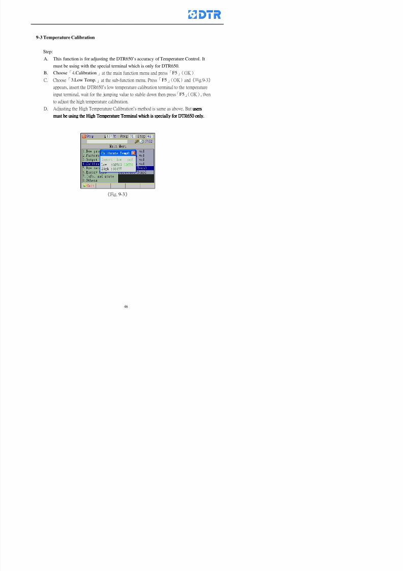
8132019 DTR 650 User Manual
httpslidepdfcomreaderfulldtr-650-user-manual 4670
9-3 Temperature Calibration
Step
A This function is for adjusting the DTR650rsquos accuracy of Temperature Control It
must be using with the special terminal which is only for DTR650
B Choose「4Calibration」at the main function menu and press「F5」(OK)
C Choose「3Low Temp」at the sub-function menu Press「F5」(OK)and《Fig9-3》
appears insert the DTR650rsquos low temperature calibration terminal to the temperature
input terminal wait for the jumping value to stable down then press「F5」(OK) then
to adjust the high temperature calibration
D Adjusting the High Temperature Calibrationrsquos method is same as above But usersusersusersusers
must be using the High Temperature Terminalmust be using the High Temperature Terminalmust be using the High Temperature Terminalmust be using the High Temperature Terminal whichwhichwhichwhich is specially for DTR650 onlyis specially for DTR650 onlyis specially for DTR650 onlyis specially for DTR650 only
《Fig 9-3》
8132019 DTR 650 User Manual
httpslidepdfcomreaderfulldtr-650-user-manual 4770
10 983122983141983139983151983154983140983155 983151983142 983108983161983141 983120983154983151983143983154983137983149983155
It contains the past 15 days of temperature curves of running history
Checking method
(1) Choose「5Dye Record」at main menu press「F5」(OK)
(2) Sub-function menu shows the set up date of the past 15 days dye programs
Listing by the lastest set up date
(3) Choose a program date and press「F5」(OK) it appears window「Temp
record」
(4) Press「」「」to move the white line in the box one minute by moving once
(5) Press「3」「4」to move the line to check the time period 2 hours by moving once
The yellow selecting line of the「24 hours operating state」is repectively moving
The curve info is show in the curve box Left side of the widnow appears the
relating running info the time is the time value of the line locates at
(6) Check more details of the temperature info to press numeric key「middot」 a bright red line
appears in the selecting box this line is to check the starting point of the
temperature inforsquos time period Then press「」to move the white line to the end
point of the time period The temperature info between the starting point and end
point are appears at the right side of the window Press「middot」to return to the preious
curve page
(7) Check more details of the alarm infor To perss numeric key「7」「9」 the alarmrsquos
details is listing by orders
(8) Press「F1」(exit) to return
8132019 DTR 650 User Manual
httpslidepdfcomreaderfulldtr-650-user-manual 4870
11 983125983155983137983143983141 983151983142 983117983141983149983151983154983161 983107983137983154983140
DTR-650 supports 32MB or above Compact Flash Card which can transfer and save all
information for 4 sets of DTR-650 Including library files schematic diagram icon
image PLC program dye program factor and confiruration files etchellip Use the CF Card
to up download and swap the information of DTR-650 promptly install the relating
device and program updates
DTR-650 CF Card with bank 1 to bank 4 can save 4 sets information of Dyeing
Machines When download or save files should choose the BANK first
《Fig11-1》
8132019 DTR 650 User Manual
httpslidepdfcomreaderfulldtr-650-user-manual 4970
11-1 Downloading data
1 Firmly insert the CF card into the DTR-650rsquos PCMCIA connector Ensure it is
wholely and firmly inserted if the card is not totally inserted or the card do not
touch in all to the connector there will be an error occurred and cannot
updownload or interrupted during operation
2 Choose「6Memory Card」at the main menu and press「F5」(OK) 《Fig11-1》
appears Information of Bank「1」shows at the left hand side of the window press
number 1-4 by using numeric keys to choose the BANK Check the
information in the Bank seriously which is exactly need to download to the
DTR650
3 Press()()「6」「5」to move cursor to the sub-function menu to choose
the downloading items Press「F5」(OK) window appears「Stop PLC run before
access memory card Stop the PLC run」 Press「F5」(YES) to stop PLC
running
4 Press「F5」(OK) window appears Confirm to update or not the DTR-650rsquos
information As that downloading will be replace the DTR-650rsquos information
(that means the existing information of the DTR-650 will be removed and
replaced)
5 Press「F4」(YES)to download the information from the DTR-650 to the CF
Card Return to the main menu when finish
8132019 DTR 650 User Manual
httpslidepdfcomreaderfulldtr-650-user-manual 5070
Ensure inserting firmly the CF card into the DTR-650 unless it will cause
error or cannot Updownload data
Never remove CF card during transferring or updownloading data Until it
is all completed
DTR-650rsquos dyeing program is not compatible with DTR-500 and
DTR-600 Never use CF card to transfer data among them
11-2 Storing and transfering data
1 Insert the CF Card to the DTR-650
2 Choose「6Memory Card」at the main menu and press「F5」(OK) 《Fig11-1》
appears Left hand side of the window shows the data of BANK 1 press numeric
keys 1-4 to select the BANK To confirm the put the data in the DTR-650 to the CF
Card The existing data of that bank will be replaced and covered by the new data (if
that bank is already occuplied)
3 Choose「23Save Dye prog」(Example)at the sub-funciton menu press「F5」(OK)to confirm Window「Update memory card data」appears
4 Press「F5」(OK)to transfer the data to the CF card Return to the main menu
5 Put the CF card into another DTR-650 and follow the operating method of 「11-1
Downloading data」」」」can transfer and swap data with more than one set of
DTR-650
8132019 DTR 650 User Manual
httpslidepdfcomreaderfulldtr-650-user-manual 5170
12 983123983156983137983156983141 983137983150983140 983113983150983142983151983154983149983137983156983145983151983150
The state and information is including the Dyeing Machinersquos state of Digit Input output
Analog Input output Temperature control PID Dosing PID Pressure different PID
software system information and alarm record This information is for checking at any
time
12-1 Input Output state
Step
1 Choose「7Info and state」at main menu and press「F5」(OK)
2 Choose「01Digital IO put」at the sub-function menu then press「F5」(OK)
「Digital In Out State」0=None 1=Input
3 Press「F1」(Exit)to return to main menu
Same method for checking the temperature control analog dosing pressure
different etchellip
12-2 Checking the system information
Step
1 Choose「7Info and state」at main menu and press「F5」(OK)
2 Choose「11 System info」at sub-function field press「F5」(OK)Window
「System Information」appear
System information is including System info(software version) Library doc
Icon files Schematic file Definition file hardare state Config File Commandinstruction icon PLC file etc
8132019 DTR 650 User Manual
httpslidepdfcomreaderfulldtr-650-user-manual 5270
12-3 Checking the operating alarm record
Operating record shows the latest 40 operating items and alarm records including
the time and content of the alarm
A) Choose「7 Info and state」
and press「F5」(OK)
B) Choose「12Alarm logs」at
the sub-funciton menu then
press「F5」(OK)
8132019 DTR 650 User Manual
httpslidepdfcomreaderfulldtr-650-user-manual 5370
13 983105983140983146983157983155983156983145983150983143 983156983144983141 983107983151983150983156983154983137983155983156
The displaysrsquos brightness can be adjusted if necessary
Step
1 Choose「8Others」at main menu press「F5」(OK)
2 Choose「01Contrast」at sub-function menu press「F5」(OK) window「Set
Contrast」appears
3 Press「」「」to move the bar to set the brightness then press「F5」(OK)Window appears「Please reboot the system」
4 Press「F5」(OK)to return to main menu and re-boot the DTR-650 to complete
adjusting the brightness
8132019 DTR 650 User Manual
httpslidepdfcomreaderfulldtr-650-user-manual 5470
14 983123983156983151983152 983154983157983150983150983145983150983143 983156983144983141 983120983116983107 983120983154983151983143983154983137983149
Before testing the Input output testing transfer of the PLC program must stop the PLC
running
Step
1 Choose「8Others」at the main menu Press「F5」(OK)
2 Choose「04 PLC Stop」at sub-function menu Press「F5」(OK) window
「Password」appears
3 Enter password and press「F5」(OK) Window「Stop the PLC run」appears
4 Press「F4」(Yes)and window「PLC Stop」appear Press「F5」(OK) Now
the PLC is stop running and return to the main menu
All testing cannot operate when the PLC is running
Editing dye program and the relating operation can
perform with the PLC running together
8132019 DTR 650 User Manual
httpslidepdfcomreaderfulldtr-650-user-manual 5570
15 983123983141983156983156983145983150983143 983156983144983141 983156983145983149983141
Step
1 Press「8Others」at the main menu Press「F5」(OK)
2 Choose「10Set date time」at the sub-function menu Press「F5」(OK) window
「Set date time」appears
3 Press「F5」(Edit) to move cursor by 「3」「4」 enter the time value at the
cursor locates
4 Press「F5」(OK)to complete the modify Press「F1」(Exit)to return to main
menu
5 Press「F1」(Exit)if not modify and return to main menu
8132019 DTR 650 User Manual
httpslidepdfcomreaderfulldtr-650-user-manual 5670
1166 983123983123983157983157 983152 983152 983152 983152983148983148983141983141983149983149983141983141983150983150983156 983156 983137983137983154 983154 983161983161 983124 983124 983137983137983138983138983148983148983141983141
TTTTTTTTaaaaaaaabbbbbbbblllllllleeeeeeee 11111111 【Dye Instruction】
Code Icon Instruction Code Icon Instruction
000 End 016 Inject C
001 Start 017 Dosing BV
002 Heat 018 PH
003 Cool 019 Addsalt B
004 Flow Fill 020 Addsalt C
005 Level Fill 021 Ana Fill
006 Drian 022 Lock Fill007 Rinse 023 Lock Level
008 Run 024 Low Rinse
009 Call 025 Cyc Rinse
010 Prep B 026 Rinse B
011 Addsalt B 027 Rinse C
012 Dosing B 028 Temp
013 Inject B 029 Nozzle Pressure
014 Prep C 030 Main Pump
015 Dosing C 031 Pump Speed
8132019 DTR 650 User Manual
httpslidepdfcomreaderfulldtr-650-user-manual 5770
Table 2 【【【【Alarm】】】】
System Alarm Must stop operating and check up to solve problems before restarting
the machine
Running Alarm It is a reminder Not effect the operating of DTR-650
Userrsquos Alarm Total of 32 Users can define themselves and use it when edit the PLC
Program (do not listing below)
No System Alarm No Running Alarm
1 PLC program not running 16 Temp ctrl 0 Grad too slow
2 Main temp sensor error 17 Temp ctrl 0 Grad too fast
3 Not at Run window 18 Temp ctrl 0 Hold temp too low
4 Exceeding max temp 19 Temp ctrl 0 Hold temp too high
5 - 20 Temp ctrl 1 Grad too slow6 - 21 Temp ctrl 1 Grad too fast
7 - 22 Temp ctrl 1 Hold temp too low
8 Communication error 23 Temp ctrl 1 Hold temp too high
9 Slave not answer 24 Temp ctrl 2 Grad too slow
10 PLC 0 not answer 25 Temp ctrl 2 Grad too fast
11 PLC 1 not answer 26 Temp 2 Hold temp too low12 Display not answer 27 Temp 2 Hold temp too high
13 Lower power voltage 28 Temp ctrl 3 Grad too slow
14 - 29 Temp ctrl 3 Grad too fast
15 - 30 Temp3 Hold temp too low
31 Temp3 Hold temp too high
32 Dosing 0 injection too slow
33 Dosing 0 injection too fast
34 Dosing 1 injection too slow
35 Dosing 1 injection too fast
8132019 DTR 650 User Manual
httpslidepdfcomreaderfulldtr-650-user-manual 5870
TTTTTTTTaaaaaaaabbbbbbbblllllllleeeeeeee 33333333 【【【【System factor】】】】
No Description Std Range amp Definition
1 ID No 000 000- 100 Controller no
2 Communication Rate 4800Bps 2400 4800 9600 19200 38400
3 Display language Chinese English Chinese
4 Temp display mode and
5 Maxmium temperature 145 025 ~ 145 6 Type of external PLC Default PLC32DPLC32PLC16Default
7 Number of external PLC NANA 1 unit connect
2 unit connect
8Communication Rate of
PLC9600Bps 2400 4800 9600 19200
9 Set point 1 085 000 ~ 145
If signal source is temperaturethe setting value is thetemperature value If the signal
source is Analog Input 6~17 then
setting value for Analog input is 0 ndash
100 and relates Analog
Input14~020mA
10 Source 1 Sensor0Sensor 0 ~5
Analog input 0 ~1111 Set point 2 092 Same as 09
12 Source 2 PT100 1 Same as 10
13 Set point 3 085 Same as 09
14 Source 3 PT100 2 Same as 10
15 Set point 4 092 Same as 09
16 Source 4 PT100 3 Same as 1017 Set point 5 085 Same as 09
18 Source 5 PT100 4 Same as 10
19 Set point 6 092 Same as 09
8132019 DTR 650 User Manual
httpslidepdfcomreaderfulldtr-650-user-manual 5970
29 Min cyclic time of cloth 100sec 0 ~ 255 sec
30 Max cyclic time of cloth 240sec 0 ~255 sec
31Standard cyclic time of
cloth
180 000 ~ 255 sec
32 Display ModeProgram
List
Program list Schematic Diagram
Icon mode
33 CF card format Standard of
DTR CF
Card
Standard of DTR CF Card V20
Standard CF Card
34 Addition step Disable Disable Enable35 Mode Com 3
CouplingEsure Com 3 is the communication
port of the Central or Coupling
36Com 3 Communication
rate9600 Central communication speed
8132019 DTR 650 User Manual
httpslidepdfcomreaderfulldtr-650-user-manual 6070
TTTTTTTTaaaaaaaabbbbbbbblllllllleeeeeeee 44444444 【【【【Temperature Cotnrol Factor】】】】
No Factor Definition Standard Range and Definition
01 PT No PT-0 PT 0~5 PT-100 Input number
02 Max working temp 140 000~140
03 Output mode 0 0~2
04 Alarm time of gardient 240sec 000~255 sec
05 Alarm mode of gradient Always AlwaysOnceNone
06 Control mode of gradient Heating orCooling
interlocked
Heating and Cooling interlocked
No limitation
07 Alarm range of HoldTemp 03 01~20
08 Alarm time for HoldTemp 240sec 000~255sec
09 Alarm mode of HoldTemp Always AlwaysOnceNone
10 Control mode ofHoldTemp
Heating only Only heating and cooling Cooling whenalarm occurred Only heating andcooling No limitation when alarmHeating only
11 Porportional Band 100 000~250
12 Integral band 128 sec 000~255 sec
13 Differential time 04 sec 00~20 sec
14 Min transit gradient 02 00~50
15 Transit rate 20 times 00~50 times (020= 2 times)
16 PID initial output value 010 000~100
17 ONOFF cycle time 10 sec 05~25 sec
Onoff valve set as 010 sec
Proportional valve set as 020 sec
18 Time down count mode Mode 0 0~10 = The time down count range from「Factor 20 + target temp」to「Target
8132019 DTR 650 User Manual
httpslidepdfcomreaderfulldtr-650-user-manual 6170
TTTTTTTTaaaaaaaabbbbbbbblllllllleeeeeeee 55555555 【【【【Speed Factor】】】】
No Factor Definition Standard Range amp Definition
01 Input Number Speed input 0 Speed input 0~11
02 Average times 05 times 01~10
03 Sensor Number 008pcs 001~255
04 Roller Dimension 250mm 050~500
05 Max cloth speed 200mmin 001~25506 Min cloth speed 020mmin 001~255
07 Alarm delay time 240sec 001~255
08 Alarm mode Every oncenoneevery
09 Alarm range () 020 001~255
10 Proportional band 100 001~255
11 Integer band 128 001~25512 Differential time 000 001~200
13 Initial speed () 020 001~255
14 Control cycle ti(01sec) 05 01~30
15 First cycle time(01sec) 10 01~30
16 Speed increase limit () 010 001~100
17 Speed decrease limit () 010 001~100
18 Min speed() 005 001~100
19 Manual speed adjust () 005 001~100
20 Manual initial speed() 020 001~100
21 Stopping speed() 010 001~100
22 Switch speed() 020 001~100
23 Not used
24 Speed decrease turns 03turns 01~50
8132019 DTR 650 User Manual
httpslidepdfcomreaderfulldtr-650-user-manual 6270
Table 6 【【【【Dosing Factors】】】】
No Description Range Range and Explanation
1 Analog input no Analog input 0 Analog input no 0 ~11
2Alarm delay time for
dosing240 sec 000 ~255 sec
3 Alarm time for dosing Every Every Once None
4 Proportional band 100 000 ~255 sec Factor P
5 Integer band 128 000 ~255 sec Factor I6 Differential time 04 00 ~20 Factor D
7 Max adjust rate 150 50~ 255
8 Initial factor for dosing 10 000 ~100
9 User curve section 0 10 Gradient of sect1 for dosing curve9
10 User curve section 1 10 Gradient of sect2 for dosing curve9
11 User curve section 2 10 Gradient of sect3 for dosing curve9
12 User curve section 3 10 Gradient of sect4 for dosing curve9
13 User curve section 4 10 Gradient of sect5 for dosing curve9
14 User curve section 5 10 Gradient of sect6 for dosing curve9
15 User curve section 6 10 Gradient of sect7 for dosing curve9
16 User curve section 7 10 Gradient of sect8 for dosing curve9
17 User curve section 8 10 Gradient of sect9 for dosing curve9
18 User curve section 9 10 Gradient of sect10 for dosing curve9
19 Min water level 05 00~ 10 04~20mA percentagechange to the userrsquos factor setting
20 Output value for Tank
clean
100 000~ 100
Injected percentage of dosing valve
in dosing End period
This factor will be invalided if usingONOFF dosing valve
21 Full range 100 001~255 Self-adjustment cannotchange
22 Range ratio 001001~255 Self-adjustment cannot
change
8132019 DTR 650 User Manual
httpslidepdfcomreaderfulldtr-650-user-manual 6370
【【【【TTaabbllee 77 】】】】Pressure Deviation Factors
No Description Std Range amp Definition
1 Analog input number + Analog in 0 Analog in 0~11
2 Analog input number - Analog in 1 Analog in 0~11
3 Input mode Pressure Pressure Pressure deviation
4 Full range 050x01Kgcm
001~255
5 Range ratio 001 001~255
6 Alarm delay time 100sec 001~255
7 Alarm mode Every oncenone
8 Alarm range 010 001~255
9 Proportional band 100 001~255
10 Integer band 128 001~255
11 Differential time 00 00~20
12 PID Init output value 010 001~255
13 Cycle time 10 03~30
14 First cycle time 030 003~100
15 Max adjust rate 010 001~100
8132019 DTR 650 User Manual
httpslidepdfcomreaderfulldtr-650-user-manual 6470
【【【【TTaabbllee 88 】】】】Definition of Analog Input
No Description Standard Range and Explanation
01 PT 0 correction standard DIN std DIN std JIS std
02 PT 0 correction +0 +- 9
03 PT 1 correction standard DIN std DIN std JIS std
04 PT 1 correction +0 +- 9
05 PT 2 correction standard DIN std DIN std JIS std
06 PT 2 correction +0 +- 9
07 PT 3 correction standard DIN std DIN std JIS std
08 PT 3 correction +0 +- 9
09 PT 4 correction standard DIN std DIN std JIS std
10 PT 4 correction +0 +- 9
11 PT 5 correction standard DIN std DIN std JIS std
12 PT 5 correction +0 +- 9
13 Analog input 0 define 4 ~ 20mA 0 ndash 20mA 4 ndash 20mA
14 Analog input 0 average times 10 times 01- 20 times
15 Analog input 0 min value 0000 0000 - 1000
16 Analog input 0 max value 100 0001 - 9999
17-60 Analog input 1~11 Same as Analog input 0
【【【【 】】】】 fi i i f A O
8132019 DTR 650 User Manual
httpslidepdfcomreaderfulldtr-650-user-manual 6570
【【【【TTaabbllee 99 】】】】Definition of Analog Output
No Description Standard Range and explanation
61 Analog output 0 define Control byPLC
Control by PLC
Temperature control PID0 output
Temperature control PID1 output
Temperature control PID2 output
Speed PID3 output
Dosing PID0 output Dosing PID1output
Pressure different PID0 outputPressure different PID1 output
Main temperature output
62 Mode of Analog ouptput0 4 ~20mA 0 ndash20mA 4 ndash 20mA
63-84 Analog output 1~11 Same as Analog output 0
【【【【TTaabbllee 1100】】】】Value Table 0 amp 1
No Description Range Std Range and explanation
1 Analog input no 000~011 000 Analog input no
2 Data ratio 001~255 100 Multiple by factors
3~53 0~98 000~255 000-100 Analog input 0~98 data
【【【【 】】】】St t Li t
8132019 DTR 650 User Manual
httpslidepdfcomreaderfulldtr-650-user-manual 6670
【【【【TTaabbllee 1111】】】】State List
No Description Range Standard Range and explanation
1 Display setting 1 0~255 205 See remarks at next page
2 Display setting 2 0~255 208
3 Display setting 3 0~255 209
4 Display setting 4 0~255 017
5 Display setting 5 0~255 0186 Display setting 6 0~255 019
7 Display setting 7 0~255 020
8 Display setting 8 0~255 021
9 Display setting 9 0~255 000
10 Display setting 1 0~255 000
11 Display setting 2 0~255 000
12 Display setting 3 0~255 000
13 Display setting 4 0~255 000
14 Display setting 5 0~255 000
15 Display setting 6 0~255 000
16 Display setting 7 0~255 000
Remarks
8132019 DTR 650 User Manual
httpslidepdfcomreaderfulldtr-650-user-manual 6770
0 = No display 1~255 = Display type of number
1~16 Content of PLC VB0~15
No 1 corresponding to VB0
No 16 corresponding to VB15
17~32 Content of PLC DB0~15
No 17 corresponding to DB0
No 32 corresponding to DB15
33~46 Content of PLC CNT0~29
No 33 corresponding to CNT0
No 46 corresponding to CNT29 47~78 Content of dyeing instruction 0~31 CNT0
No 47 corresponding to system instruction to No 0 of CNT0
No 78 corresponding to system instruction to No 31 of CNT0rsquos content
79~110 Dyeing instruction 0~31 of CNT0rsquos setting
111~142 Content of Dyeing instruction 0~31 CNT1No 111 corresponding to dyeing instruction No 0 of CNT1
No 142 corresponding to dyeing instruction No 31 of CNT1rsquos content
143~174 Dyeing instruction 0~31 of CNT1rsquos setting
175~204 Content of PLC HTIM0~29
No 175 corresponding to HTIM0
No 204 corresponding to HTIM29
205 Loading
206 Ratio 1
207 Ratio 2208 Ratio 1 x Loading
209 Ratio 2 x Loading
210 Fix value
211 Value Table 1 matching result
212 Value Table 2 matching result
213 Value Table 1 setting214 Value Table 2 setting
215 Pressure control PID0 different pressure value
216 Pressure control PID1 different pressure value
TTTTTTTTaaaaaaaabbbbbbbblllllllleeeeeeee 1122 【【【【Usage of password】】】】
8132019 DTR 650 User Manual
httpslidepdfcomreaderfulldtr-650-user-manual 6870
No Main FunctionFactor Sub Function Factor Password Rank
1 Run None
2 Dye program User3 or above
3 Control factor
- User factor User 1
- System factor User 1
- Temp PID 0
- Temp PID 1 User 1- Speed PID 0 User 1
- Dosing PID 0 User 1
- Dosing PID 1 User 1
- Pressure PID 0 User 1
- Pressure PID 1 User 1
- Analog IO User 1
- Load standard factor User 2 or above- Load a copied factor User 2 or above
- Copy factor User 2 or above
- Value table 0 User 1
- Value table 1 User 1
- Information and state User 1
- Dye instruction User 1
- Edit dye instruction setting User 14 Output testing User 2 or above
5 Calibration User 2 or above
6 Dye record None
7 CF card User 1
8 Info and state None
9 Others
- Contrast User3 or above
- Data Locking None
- PLC Run User 1
- PLC Stop User 1
- Password setting User 1
TTTTTTTTaaaaaaaabbbbbbbblllllllleeeeeeee 1133 【【【【Technical Data】】】】
8132019 DTR 650 User Manual
httpslidepdfcomreaderfulldtr-650-user-manual 6970
TTTTTTTTaaaaaaaabbbbbbbblllllllleeeeeeee 1133 【【【【Technical Data】】】】
1 Temperature Control
- Range 10~145(plusmn1)
- Mode Proportional or PWM
- Sensor PT100 (JIS or DIN standard)
2 Input and output channel
- Digital Input 32 DC24V PNP- Digital Output 32 DC24V 054A Relay connect point
- Analog Input 4 04~20 mA
- Analog Output 4 0~20mA 或 4~20 mA
3 Communication port 3 RS-232 amp 0~20 mAx1 RS485x 2
4 Dye program
- Number 15000 Steps
- Standard step 61Heating Cooling Fill Drain RinseDosingetc
5LCD module and Display
langage
Chinese
English
320 x 240 TFT color display with
more language
6 CF card connector 1 PCMCIA standard
7 Membrane Keyboard- Number Key 10 [0]~[9] Input factors
- Function Key 5 [F1]~[F5] function selecting
- Operation Key 2 [Start] [Stop]
- Auxiliary Key 7 [][][][][Esc] [larr][OK] [bull]
8 Operating Condition
- Temperature 5~45
- Humidity ≦85 (25)
9 Power supply
V l DC 24V
8132019 DTR 650 User Manual
httpslidepdfcomreaderfulldtr-650-user-manual 7070
70
983108983124983122983085650 983113983150983152983157983156 983119983157983156983152983157983156 983120983151983154983156983145983150983143 (983138983137983139983147983155983145983140983141 983158983145983141983159)
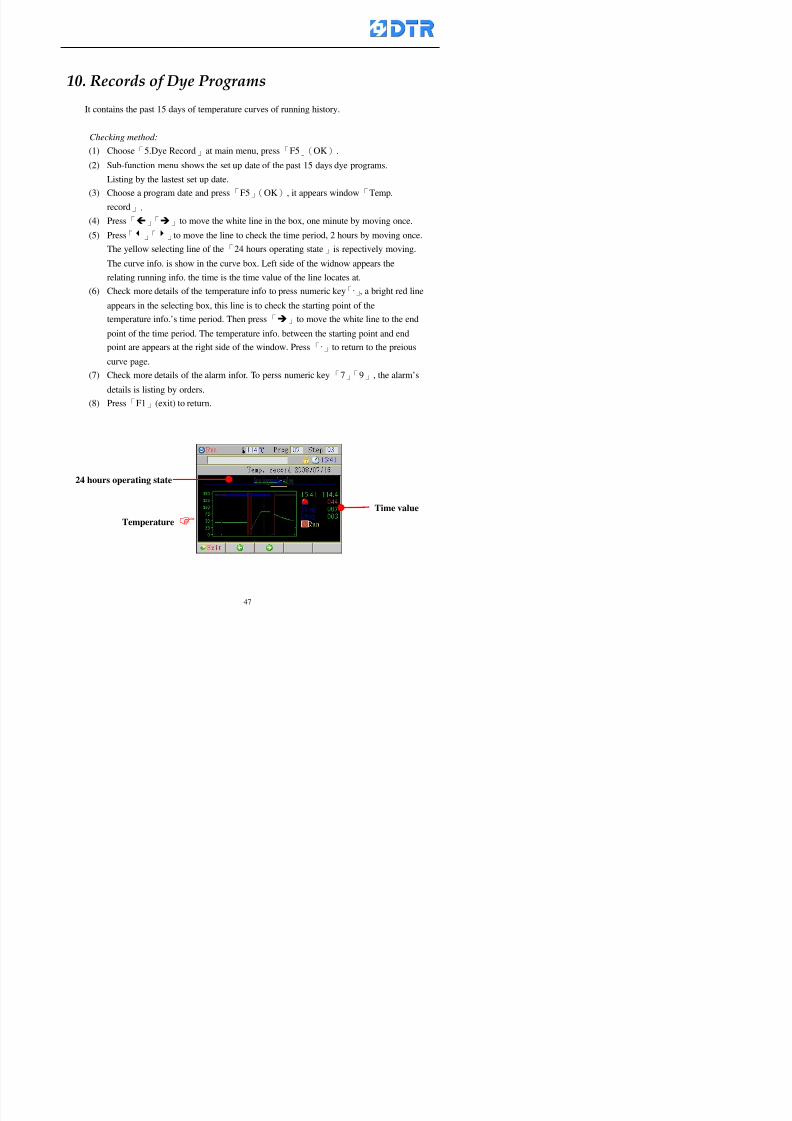
8132019 DTR 650 User Manual
httpslidepdfcomreaderfulldtr-650-user-manual 4770
10 983122983141983139983151983154983140983155 983151983142 983108983161983141 983120983154983151983143983154983137983149983155
It contains the past 15 days of temperature curves of running history
Checking method
(1) Choose「5Dye Record」at main menu press「F5」(OK)
(2) Sub-function menu shows the set up date of the past 15 days dye programs
Listing by the lastest set up date
(3) Choose a program date and press「F5」(OK) it appears window「Temp
record」
(4) Press「」「」to move the white line in the box one minute by moving once
(5) Press「3」「4」to move the line to check the time period 2 hours by moving once
The yellow selecting line of the「24 hours operating state」is repectively moving
The curve info is show in the curve box Left side of the widnow appears the
relating running info the time is the time value of the line locates at
(6) Check more details of the temperature info to press numeric key「middot」 a bright red line
appears in the selecting box this line is to check the starting point of the
temperature inforsquos time period Then press「」to move the white line to the end
point of the time period The temperature info between the starting point and end
point are appears at the right side of the window Press「middot」to return to the preious
curve page
(7) Check more details of the alarm infor To perss numeric key「7」「9」 the alarmrsquos
details is listing by orders
(8) Press「F1」(exit) to return
8132019 DTR 650 User Manual
httpslidepdfcomreaderfulldtr-650-user-manual 4870
11 983125983155983137983143983141 983151983142 983117983141983149983151983154983161 983107983137983154983140
DTR-650 supports 32MB or above Compact Flash Card which can transfer and save all
information for 4 sets of DTR-650 Including library files schematic diagram icon
image PLC program dye program factor and confiruration files etchellip Use the CF Card
to up download and swap the information of DTR-650 promptly install the relating
device and program updates
DTR-650 CF Card with bank 1 to bank 4 can save 4 sets information of Dyeing
Machines When download or save files should choose the BANK first
《Fig11-1》
8132019 DTR 650 User Manual
httpslidepdfcomreaderfulldtr-650-user-manual 4970
11-1 Downloading data
1 Firmly insert the CF card into the DTR-650rsquos PCMCIA connector Ensure it is
wholely and firmly inserted if the card is not totally inserted or the card do not
touch in all to the connector there will be an error occurred and cannot
updownload or interrupted during operation
2 Choose「6Memory Card」at the main menu and press「F5」(OK) 《Fig11-1》
appears Information of Bank「1」shows at the left hand side of the window press
number 1-4 by using numeric keys to choose the BANK Check the
information in the Bank seriously which is exactly need to download to the
DTR650
3 Press()()「6」「5」to move cursor to the sub-function menu to choose
the downloading items Press「F5」(OK) window appears「Stop PLC run before
access memory card Stop the PLC run」 Press「F5」(YES) to stop PLC
running
4 Press「F5」(OK) window appears Confirm to update or not the DTR-650rsquos
information As that downloading will be replace the DTR-650rsquos information
(that means the existing information of the DTR-650 will be removed and
replaced)
5 Press「F4」(YES)to download the information from the DTR-650 to the CF
Card Return to the main menu when finish
8132019 DTR 650 User Manual
httpslidepdfcomreaderfulldtr-650-user-manual 5070
Ensure inserting firmly the CF card into the DTR-650 unless it will cause
error or cannot Updownload data
Never remove CF card during transferring or updownloading data Until it
is all completed
DTR-650rsquos dyeing program is not compatible with DTR-500 and
DTR-600 Never use CF card to transfer data among them
11-2 Storing and transfering data
1 Insert the CF Card to the DTR-650
2 Choose「6Memory Card」at the main menu and press「F5」(OK) 《Fig11-1》
appears Left hand side of the window shows the data of BANK 1 press numeric
keys 1-4 to select the BANK To confirm the put the data in the DTR-650 to the CF
Card The existing data of that bank will be replaced and covered by the new data (if
that bank is already occuplied)
3 Choose「23Save Dye prog」(Example)at the sub-funciton menu press「F5」(OK)to confirm Window「Update memory card data」appears
4 Press「F5」(OK)to transfer the data to the CF card Return to the main menu
5 Put the CF card into another DTR-650 and follow the operating method of 「11-1
Downloading data」」」」can transfer and swap data with more than one set of
DTR-650
8132019 DTR 650 User Manual
httpslidepdfcomreaderfulldtr-650-user-manual 5170
12 983123983156983137983156983141 983137983150983140 983113983150983142983151983154983149983137983156983145983151983150
The state and information is including the Dyeing Machinersquos state of Digit Input output
Analog Input output Temperature control PID Dosing PID Pressure different PID
software system information and alarm record This information is for checking at any
time
12-1 Input Output state
Step
1 Choose「7Info and state」at main menu and press「F5」(OK)
2 Choose「01Digital IO put」at the sub-function menu then press「F5」(OK)
「Digital In Out State」0=None 1=Input
3 Press「F1」(Exit)to return to main menu
Same method for checking the temperature control analog dosing pressure
different etchellip
12-2 Checking the system information
Step
1 Choose「7Info and state」at main menu and press「F5」(OK)
2 Choose「11 System info」at sub-function field press「F5」(OK)Window
「System Information」appear
System information is including System info(software version) Library doc
Icon files Schematic file Definition file hardare state Config File Commandinstruction icon PLC file etc
8132019 DTR 650 User Manual
httpslidepdfcomreaderfulldtr-650-user-manual 5270
12-3 Checking the operating alarm record
Operating record shows the latest 40 operating items and alarm records including
the time and content of the alarm
A) Choose「7 Info and state」
and press「F5」(OK)
B) Choose「12Alarm logs」at
the sub-funciton menu then
press「F5」(OK)
8132019 DTR 650 User Manual
httpslidepdfcomreaderfulldtr-650-user-manual 5370
13 983105983140983146983157983155983156983145983150983143 983156983144983141 983107983151983150983156983154983137983155983156
The displaysrsquos brightness can be adjusted if necessary
Step
1 Choose「8Others」at main menu press「F5」(OK)
2 Choose「01Contrast」at sub-function menu press「F5」(OK) window「Set
Contrast」appears
3 Press「」「」to move the bar to set the brightness then press「F5」(OK)Window appears「Please reboot the system」
4 Press「F5」(OK)to return to main menu and re-boot the DTR-650 to complete
adjusting the brightness
8132019 DTR 650 User Manual
httpslidepdfcomreaderfulldtr-650-user-manual 5470
14 983123983156983151983152 983154983157983150983150983145983150983143 983156983144983141 983120983116983107 983120983154983151983143983154983137983149
Before testing the Input output testing transfer of the PLC program must stop the PLC
running
Step
1 Choose「8Others」at the main menu Press「F5」(OK)
2 Choose「04 PLC Stop」at sub-function menu Press「F5」(OK) window
「Password」appears
3 Enter password and press「F5」(OK) Window「Stop the PLC run」appears
4 Press「F4」(Yes)and window「PLC Stop」appear Press「F5」(OK) Now
the PLC is stop running and return to the main menu
All testing cannot operate when the PLC is running
Editing dye program and the relating operation can
perform with the PLC running together
8132019 DTR 650 User Manual
httpslidepdfcomreaderfulldtr-650-user-manual 5570
15 983123983141983156983156983145983150983143 983156983144983141 983156983145983149983141
Step
1 Press「8Others」at the main menu Press「F5」(OK)
2 Choose「10Set date time」at the sub-function menu Press「F5」(OK) window
「Set date time」appears
3 Press「F5」(Edit) to move cursor by 「3」「4」 enter the time value at the
cursor locates
4 Press「F5」(OK)to complete the modify Press「F1」(Exit)to return to main
menu
5 Press「F1」(Exit)if not modify and return to main menu
8132019 DTR 650 User Manual
httpslidepdfcomreaderfulldtr-650-user-manual 5670
1166 983123983123983157983157 983152 983152 983152 983152983148983148983141983141983149983149983141983141983150983150983156 983156 983137983137983154 983154 983161983161 983124 983124 983137983137983138983138983148983148983141983141
TTTTTTTTaaaaaaaabbbbbbbblllllllleeeeeeee 11111111 【Dye Instruction】
Code Icon Instruction Code Icon Instruction
000 End 016 Inject C
001 Start 017 Dosing BV
002 Heat 018 PH
003 Cool 019 Addsalt B
004 Flow Fill 020 Addsalt C
005 Level Fill 021 Ana Fill
006 Drian 022 Lock Fill007 Rinse 023 Lock Level
008 Run 024 Low Rinse
009 Call 025 Cyc Rinse
010 Prep B 026 Rinse B
011 Addsalt B 027 Rinse C
012 Dosing B 028 Temp
013 Inject B 029 Nozzle Pressure
014 Prep C 030 Main Pump
015 Dosing C 031 Pump Speed
8132019 DTR 650 User Manual
httpslidepdfcomreaderfulldtr-650-user-manual 5770
Table 2 【【【【Alarm】】】】
System Alarm Must stop operating and check up to solve problems before restarting
the machine
Running Alarm It is a reminder Not effect the operating of DTR-650
Userrsquos Alarm Total of 32 Users can define themselves and use it when edit the PLC
Program (do not listing below)
No System Alarm No Running Alarm
1 PLC program not running 16 Temp ctrl 0 Grad too slow
2 Main temp sensor error 17 Temp ctrl 0 Grad too fast
3 Not at Run window 18 Temp ctrl 0 Hold temp too low
4 Exceeding max temp 19 Temp ctrl 0 Hold temp too high
5 - 20 Temp ctrl 1 Grad too slow6 - 21 Temp ctrl 1 Grad too fast
7 - 22 Temp ctrl 1 Hold temp too low
8 Communication error 23 Temp ctrl 1 Hold temp too high
9 Slave not answer 24 Temp ctrl 2 Grad too slow
10 PLC 0 not answer 25 Temp ctrl 2 Grad too fast
11 PLC 1 not answer 26 Temp 2 Hold temp too low12 Display not answer 27 Temp 2 Hold temp too high
13 Lower power voltage 28 Temp ctrl 3 Grad too slow
14 - 29 Temp ctrl 3 Grad too fast
15 - 30 Temp3 Hold temp too low
31 Temp3 Hold temp too high
32 Dosing 0 injection too slow
33 Dosing 0 injection too fast
34 Dosing 1 injection too slow
35 Dosing 1 injection too fast
8132019 DTR 650 User Manual
httpslidepdfcomreaderfulldtr-650-user-manual 5870
TTTTTTTTaaaaaaaabbbbbbbblllllllleeeeeeee 33333333 【【【【System factor】】】】
No Description Std Range amp Definition
1 ID No 000 000- 100 Controller no
2 Communication Rate 4800Bps 2400 4800 9600 19200 38400
3 Display language Chinese English Chinese
4 Temp display mode and
5 Maxmium temperature 145 025 ~ 145 6 Type of external PLC Default PLC32DPLC32PLC16Default
7 Number of external PLC NANA 1 unit connect
2 unit connect
8Communication Rate of
PLC9600Bps 2400 4800 9600 19200
9 Set point 1 085 000 ~ 145
If signal source is temperaturethe setting value is thetemperature value If the signal
source is Analog Input 6~17 then
setting value for Analog input is 0 ndash
100 and relates Analog
Input14~020mA
10 Source 1 Sensor0Sensor 0 ~5
Analog input 0 ~1111 Set point 2 092 Same as 09
12 Source 2 PT100 1 Same as 10
13 Set point 3 085 Same as 09
14 Source 3 PT100 2 Same as 10
15 Set point 4 092 Same as 09
16 Source 4 PT100 3 Same as 1017 Set point 5 085 Same as 09
18 Source 5 PT100 4 Same as 10
19 Set point 6 092 Same as 09
8132019 DTR 650 User Manual
httpslidepdfcomreaderfulldtr-650-user-manual 5970
29 Min cyclic time of cloth 100sec 0 ~ 255 sec
30 Max cyclic time of cloth 240sec 0 ~255 sec
31Standard cyclic time of
cloth
180 000 ~ 255 sec
32 Display ModeProgram
List
Program list Schematic Diagram
Icon mode
33 CF card format Standard of
DTR CF
Card
Standard of DTR CF Card V20
Standard CF Card
34 Addition step Disable Disable Enable35 Mode Com 3
CouplingEsure Com 3 is the communication
port of the Central or Coupling
36Com 3 Communication
rate9600 Central communication speed
8132019 DTR 650 User Manual
httpslidepdfcomreaderfulldtr-650-user-manual 6070
TTTTTTTTaaaaaaaabbbbbbbblllllllleeeeeeee 44444444 【【【【Temperature Cotnrol Factor】】】】
No Factor Definition Standard Range and Definition
01 PT No PT-0 PT 0~5 PT-100 Input number
02 Max working temp 140 000~140
03 Output mode 0 0~2
04 Alarm time of gardient 240sec 000~255 sec
05 Alarm mode of gradient Always AlwaysOnceNone
06 Control mode of gradient Heating orCooling
interlocked
Heating and Cooling interlocked
No limitation
07 Alarm range of HoldTemp 03 01~20
08 Alarm time for HoldTemp 240sec 000~255sec
09 Alarm mode of HoldTemp Always AlwaysOnceNone
10 Control mode ofHoldTemp
Heating only Only heating and cooling Cooling whenalarm occurred Only heating andcooling No limitation when alarmHeating only
11 Porportional Band 100 000~250
12 Integral band 128 sec 000~255 sec
13 Differential time 04 sec 00~20 sec
14 Min transit gradient 02 00~50
15 Transit rate 20 times 00~50 times (020= 2 times)
16 PID initial output value 010 000~100
17 ONOFF cycle time 10 sec 05~25 sec
Onoff valve set as 010 sec
Proportional valve set as 020 sec
18 Time down count mode Mode 0 0~10 = The time down count range from「Factor 20 + target temp」to「Target
8132019 DTR 650 User Manual
httpslidepdfcomreaderfulldtr-650-user-manual 6170
TTTTTTTTaaaaaaaabbbbbbbblllllllleeeeeeee 55555555 【【【【Speed Factor】】】】
No Factor Definition Standard Range amp Definition
01 Input Number Speed input 0 Speed input 0~11
02 Average times 05 times 01~10
03 Sensor Number 008pcs 001~255
04 Roller Dimension 250mm 050~500
05 Max cloth speed 200mmin 001~25506 Min cloth speed 020mmin 001~255
07 Alarm delay time 240sec 001~255
08 Alarm mode Every oncenoneevery
09 Alarm range () 020 001~255
10 Proportional band 100 001~255
11 Integer band 128 001~25512 Differential time 000 001~200
13 Initial speed () 020 001~255
14 Control cycle ti(01sec) 05 01~30
15 First cycle time(01sec) 10 01~30
16 Speed increase limit () 010 001~100
17 Speed decrease limit () 010 001~100
18 Min speed() 005 001~100
19 Manual speed adjust () 005 001~100
20 Manual initial speed() 020 001~100
21 Stopping speed() 010 001~100
22 Switch speed() 020 001~100
23 Not used
24 Speed decrease turns 03turns 01~50
8132019 DTR 650 User Manual
httpslidepdfcomreaderfulldtr-650-user-manual 6270
Table 6 【【【【Dosing Factors】】】】
No Description Range Range and Explanation
1 Analog input no Analog input 0 Analog input no 0 ~11
2Alarm delay time for
dosing240 sec 000 ~255 sec
3 Alarm time for dosing Every Every Once None
4 Proportional band 100 000 ~255 sec Factor P
5 Integer band 128 000 ~255 sec Factor I6 Differential time 04 00 ~20 Factor D
7 Max adjust rate 150 50~ 255
8 Initial factor for dosing 10 000 ~100
9 User curve section 0 10 Gradient of sect1 for dosing curve9
10 User curve section 1 10 Gradient of sect2 for dosing curve9
11 User curve section 2 10 Gradient of sect3 for dosing curve9
12 User curve section 3 10 Gradient of sect4 for dosing curve9
13 User curve section 4 10 Gradient of sect5 for dosing curve9
14 User curve section 5 10 Gradient of sect6 for dosing curve9
15 User curve section 6 10 Gradient of sect7 for dosing curve9
16 User curve section 7 10 Gradient of sect8 for dosing curve9
17 User curve section 8 10 Gradient of sect9 for dosing curve9
18 User curve section 9 10 Gradient of sect10 for dosing curve9
19 Min water level 05 00~ 10 04~20mA percentagechange to the userrsquos factor setting
20 Output value for Tank
clean
100 000~ 100
Injected percentage of dosing valve
in dosing End period
This factor will be invalided if usingONOFF dosing valve
21 Full range 100 001~255 Self-adjustment cannotchange
22 Range ratio 001001~255 Self-adjustment cannot
change
8132019 DTR 650 User Manual
httpslidepdfcomreaderfulldtr-650-user-manual 6370
【【【【TTaabbllee 77 】】】】Pressure Deviation Factors
No Description Std Range amp Definition
1 Analog input number + Analog in 0 Analog in 0~11
2 Analog input number - Analog in 1 Analog in 0~11
3 Input mode Pressure Pressure Pressure deviation
4 Full range 050x01Kgcm
001~255
5 Range ratio 001 001~255
6 Alarm delay time 100sec 001~255
7 Alarm mode Every oncenone
8 Alarm range 010 001~255
9 Proportional band 100 001~255
10 Integer band 128 001~255
11 Differential time 00 00~20
12 PID Init output value 010 001~255
13 Cycle time 10 03~30
14 First cycle time 030 003~100
15 Max adjust rate 010 001~100
8132019 DTR 650 User Manual
httpslidepdfcomreaderfulldtr-650-user-manual 6470
【【【【TTaabbllee 88 】】】】Definition of Analog Input
No Description Standard Range and Explanation
01 PT 0 correction standard DIN std DIN std JIS std
02 PT 0 correction +0 +- 9
03 PT 1 correction standard DIN std DIN std JIS std
04 PT 1 correction +0 +- 9
05 PT 2 correction standard DIN std DIN std JIS std
06 PT 2 correction +0 +- 9
07 PT 3 correction standard DIN std DIN std JIS std
08 PT 3 correction +0 +- 9
09 PT 4 correction standard DIN std DIN std JIS std
10 PT 4 correction +0 +- 9
11 PT 5 correction standard DIN std DIN std JIS std
12 PT 5 correction +0 +- 9
13 Analog input 0 define 4 ~ 20mA 0 ndash 20mA 4 ndash 20mA
14 Analog input 0 average times 10 times 01- 20 times
15 Analog input 0 min value 0000 0000 - 1000
16 Analog input 0 max value 100 0001 - 9999
17-60 Analog input 1~11 Same as Analog input 0
【【【【 】】】】 fi i i f A O
8132019 DTR 650 User Manual
httpslidepdfcomreaderfulldtr-650-user-manual 6570
【【【【TTaabbllee 99 】】】】Definition of Analog Output
No Description Standard Range and explanation
61 Analog output 0 define Control byPLC
Control by PLC
Temperature control PID0 output
Temperature control PID1 output
Temperature control PID2 output
Speed PID3 output
Dosing PID0 output Dosing PID1output
Pressure different PID0 outputPressure different PID1 output
Main temperature output
62 Mode of Analog ouptput0 4 ~20mA 0 ndash20mA 4 ndash 20mA
63-84 Analog output 1~11 Same as Analog output 0
【【【【TTaabbllee 1100】】】】Value Table 0 amp 1
No Description Range Std Range and explanation
1 Analog input no 000~011 000 Analog input no
2 Data ratio 001~255 100 Multiple by factors
3~53 0~98 000~255 000-100 Analog input 0~98 data
【【【【 】】】】St t Li t
8132019 DTR 650 User Manual
httpslidepdfcomreaderfulldtr-650-user-manual 6670
【【【【TTaabbllee 1111】】】】State List
No Description Range Standard Range and explanation
1 Display setting 1 0~255 205 See remarks at next page
2 Display setting 2 0~255 208
3 Display setting 3 0~255 209
4 Display setting 4 0~255 017
5 Display setting 5 0~255 0186 Display setting 6 0~255 019
7 Display setting 7 0~255 020
8 Display setting 8 0~255 021
9 Display setting 9 0~255 000
10 Display setting 1 0~255 000
11 Display setting 2 0~255 000
12 Display setting 3 0~255 000
13 Display setting 4 0~255 000
14 Display setting 5 0~255 000
15 Display setting 6 0~255 000
16 Display setting 7 0~255 000
Remarks
8132019 DTR 650 User Manual
httpslidepdfcomreaderfulldtr-650-user-manual 6770
0 = No display 1~255 = Display type of number
1~16 Content of PLC VB0~15
No 1 corresponding to VB0
No 16 corresponding to VB15
17~32 Content of PLC DB0~15
No 17 corresponding to DB0
No 32 corresponding to DB15
33~46 Content of PLC CNT0~29
No 33 corresponding to CNT0
No 46 corresponding to CNT29 47~78 Content of dyeing instruction 0~31 CNT0
No 47 corresponding to system instruction to No 0 of CNT0
No 78 corresponding to system instruction to No 31 of CNT0rsquos content
79~110 Dyeing instruction 0~31 of CNT0rsquos setting
111~142 Content of Dyeing instruction 0~31 CNT1No 111 corresponding to dyeing instruction No 0 of CNT1
No 142 corresponding to dyeing instruction No 31 of CNT1rsquos content
143~174 Dyeing instruction 0~31 of CNT1rsquos setting
175~204 Content of PLC HTIM0~29
No 175 corresponding to HTIM0
No 204 corresponding to HTIM29
205 Loading
206 Ratio 1
207 Ratio 2208 Ratio 1 x Loading
209 Ratio 2 x Loading
210 Fix value
211 Value Table 1 matching result
212 Value Table 2 matching result
213 Value Table 1 setting214 Value Table 2 setting
215 Pressure control PID0 different pressure value
216 Pressure control PID1 different pressure value
TTTTTTTTaaaaaaaabbbbbbbblllllllleeeeeeee 1122 【【【【Usage of password】】】】
8132019 DTR 650 User Manual
httpslidepdfcomreaderfulldtr-650-user-manual 6870
No Main FunctionFactor Sub Function Factor Password Rank
1 Run None
2 Dye program User3 or above
3 Control factor
- User factor User 1
- System factor User 1
- Temp PID 0
- Temp PID 1 User 1- Speed PID 0 User 1
- Dosing PID 0 User 1
- Dosing PID 1 User 1
- Pressure PID 0 User 1
- Pressure PID 1 User 1
- Analog IO User 1
- Load standard factor User 2 or above- Load a copied factor User 2 or above
- Copy factor User 2 or above
- Value table 0 User 1
- Value table 1 User 1
- Information and state User 1
- Dye instruction User 1
- Edit dye instruction setting User 14 Output testing User 2 or above
5 Calibration User 2 or above
6 Dye record None
7 CF card User 1
8 Info and state None
9 Others
- Contrast User3 or above
- Data Locking None
- PLC Run User 1
- PLC Stop User 1
- Password setting User 1
TTTTTTTTaaaaaaaabbbbbbbblllllllleeeeeeee 1133 【【【【Technical Data】】】】
8132019 DTR 650 User Manual
httpslidepdfcomreaderfulldtr-650-user-manual 6970
TTTTTTTTaaaaaaaabbbbbbbblllllllleeeeeeee 1133 【【【【Technical Data】】】】
1 Temperature Control
- Range 10~145(plusmn1)
- Mode Proportional or PWM
- Sensor PT100 (JIS or DIN standard)
2 Input and output channel
- Digital Input 32 DC24V PNP- Digital Output 32 DC24V 054A Relay connect point
- Analog Input 4 04~20 mA
- Analog Output 4 0~20mA 或 4~20 mA
3 Communication port 3 RS-232 amp 0~20 mAx1 RS485x 2
4 Dye program
- Number 15000 Steps
- Standard step 61Heating Cooling Fill Drain RinseDosingetc
5LCD module and Display
langage
Chinese
English
320 x 240 TFT color display with
more language
6 CF card connector 1 PCMCIA standard
7 Membrane Keyboard- Number Key 10 [0]~[9] Input factors
- Function Key 5 [F1]~[F5] function selecting
- Operation Key 2 [Start] [Stop]
- Auxiliary Key 7 [][][][][Esc] [larr][OK] [bull]
8 Operating Condition
- Temperature 5~45
- Humidity ≦85 (25)
9 Power supply
V l DC 24V
8132019 DTR 650 User Manual
httpslidepdfcomreaderfulldtr-650-user-manual 7070
70
983108983124983122983085650 983113983150983152983157983156 983119983157983156983152983157983156 983120983151983154983156983145983150983143 (983138983137983139983147983155983145983140983141 983158983145983141983159)
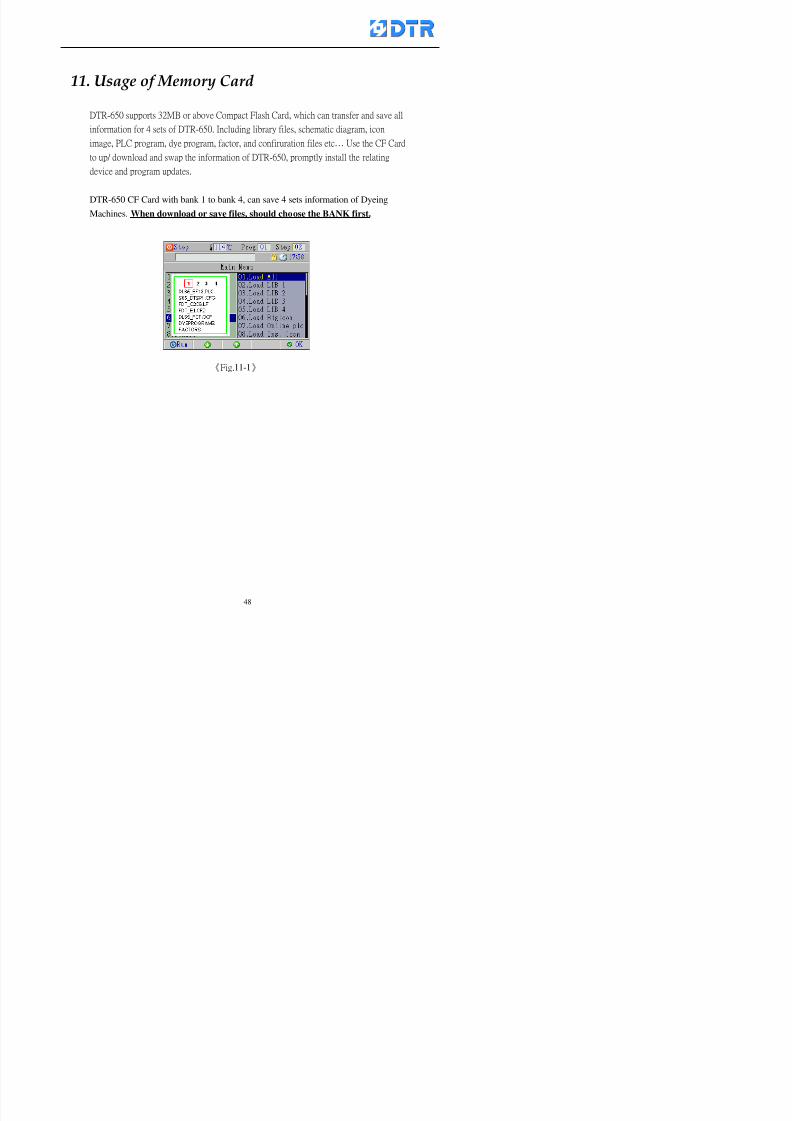
8132019 DTR 650 User Manual
httpslidepdfcomreaderfulldtr-650-user-manual 4870
11 983125983155983137983143983141 983151983142 983117983141983149983151983154983161 983107983137983154983140
DTR-650 supports 32MB or above Compact Flash Card which can transfer and save all
information for 4 sets of DTR-650 Including library files schematic diagram icon
image PLC program dye program factor and confiruration files etchellip Use the CF Card
to up download and swap the information of DTR-650 promptly install the relating
device and program updates
DTR-650 CF Card with bank 1 to bank 4 can save 4 sets information of Dyeing
Machines When download or save files should choose the BANK first
《Fig11-1》
8132019 DTR 650 User Manual
httpslidepdfcomreaderfulldtr-650-user-manual 4970
11-1 Downloading data
1 Firmly insert the CF card into the DTR-650rsquos PCMCIA connector Ensure it is
wholely and firmly inserted if the card is not totally inserted or the card do not
touch in all to the connector there will be an error occurred and cannot
updownload or interrupted during operation
2 Choose「6Memory Card」at the main menu and press「F5」(OK) 《Fig11-1》
appears Information of Bank「1」shows at the left hand side of the window press
number 1-4 by using numeric keys to choose the BANK Check the
information in the Bank seriously which is exactly need to download to the
DTR650
3 Press()()「6」「5」to move cursor to the sub-function menu to choose
the downloading items Press「F5」(OK) window appears「Stop PLC run before
access memory card Stop the PLC run」 Press「F5」(YES) to stop PLC
running
4 Press「F5」(OK) window appears Confirm to update or not the DTR-650rsquos
information As that downloading will be replace the DTR-650rsquos information
(that means the existing information of the DTR-650 will be removed and
replaced)
5 Press「F4」(YES)to download the information from the DTR-650 to the CF
Card Return to the main menu when finish
8132019 DTR 650 User Manual
httpslidepdfcomreaderfulldtr-650-user-manual 5070
Ensure inserting firmly the CF card into the DTR-650 unless it will cause
error or cannot Updownload data
Never remove CF card during transferring or updownloading data Until it
is all completed
DTR-650rsquos dyeing program is not compatible with DTR-500 and
DTR-600 Never use CF card to transfer data among them
11-2 Storing and transfering data
1 Insert the CF Card to the DTR-650
2 Choose「6Memory Card」at the main menu and press「F5」(OK) 《Fig11-1》
appears Left hand side of the window shows the data of BANK 1 press numeric
keys 1-4 to select the BANK To confirm the put the data in the DTR-650 to the CF
Card The existing data of that bank will be replaced and covered by the new data (if
that bank is already occuplied)
3 Choose「23Save Dye prog」(Example)at the sub-funciton menu press「F5」(OK)to confirm Window「Update memory card data」appears
4 Press「F5」(OK)to transfer the data to the CF card Return to the main menu
5 Put the CF card into another DTR-650 and follow the operating method of 「11-1
Downloading data」」」」can transfer and swap data with more than one set of
DTR-650
8132019 DTR 650 User Manual
httpslidepdfcomreaderfulldtr-650-user-manual 5170
12 983123983156983137983156983141 983137983150983140 983113983150983142983151983154983149983137983156983145983151983150
The state and information is including the Dyeing Machinersquos state of Digit Input output
Analog Input output Temperature control PID Dosing PID Pressure different PID
software system information and alarm record This information is for checking at any
time
12-1 Input Output state
Step
1 Choose「7Info and state」at main menu and press「F5」(OK)
2 Choose「01Digital IO put」at the sub-function menu then press「F5」(OK)
「Digital In Out State」0=None 1=Input
3 Press「F1」(Exit)to return to main menu
Same method for checking the temperature control analog dosing pressure
different etchellip
12-2 Checking the system information
Step
1 Choose「7Info and state」at main menu and press「F5」(OK)
2 Choose「11 System info」at sub-function field press「F5」(OK)Window
「System Information」appear
System information is including System info(software version) Library doc
Icon files Schematic file Definition file hardare state Config File Commandinstruction icon PLC file etc
8132019 DTR 650 User Manual
httpslidepdfcomreaderfulldtr-650-user-manual 5270
12-3 Checking the operating alarm record
Operating record shows the latest 40 operating items and alarm records including
the time and content of the alarm
A) Choose「7 Info and state」
and press「F5」(OK)
B) Choose「12Alarm logs」at
the sub-funciton menu then
press「F5」(OK)
8132019 DTR 650 User Manual
httpslidepdfcomreaderfulldtr-650-user-manual 5370
13 983105983140983146983157983155983156983145983150983143 983156983144983141 983107983151983150983156983154983137983155983156
The displaysrsquos brightness can be adjusted if necessary
Step
1 Choose「8Others」at main menu press「F5」(OK)
2 Choose「01Contrast」at sub-function menu press「F5」(OK) window「Set
Contrast」appears
3 Press「」「」to move the bar to set the brightness then press「F5」(OK)Window appears「Please reboot the system」
4 Press「F5」(OK)to return to main menu and re-boot the DTR-650 to complete
adjusting the brightness
8132019 DTR 650 User Manual
httpslidepdfcomreaderfulldtr-650-user-manual 5470
14 983123983156983151983152 983154983157983150983150983145983150983143 983156983144983141 983120983116983107 983120983154983151983143983154983137983149
Before testing the Input output testing transfer of the PLC program must stop the PLC
running
Step
1 Choose「8Others」at the main menu Press「F5」(OK)
2 Choose「04 PLC Stop」at sub-function menu Press「F5」(OK) window
「Password」appears
3 Enter password and press「F5」(OK) Window「Stop the PLC run」appears
4 Press「F4」(Yes)and window「PLC Stop」appear Press「F5」(OK) Now
the PLC is stop running and return to the main menu
All testing cannot operate when the PLC is running
Editing dye program and the relating operation can
perform with the PLC running together
8132019 DTR 650 User Manual
httpslidepdfcomreaderfulldtr-650-user-manual 5570
15 983123983141983156983156983145983150983143 983156983144983141 983156983145983149983141
Step
1 Press「8Others」at the main menu Press「F5」(OK)
2 Choose「10Set date time」at the sub-function menu Press「F5」(OK) window
「Set date time」appears
3 Press「F5」(Edit) to move cursor by 「3」「4」 enter the time value at the
cursor locates
4 Press「F5」(OK)to complete the modify Press「F1」(Exit)to return to main
menu
5 Press「F1」(Exit)if not modify and return to main menu
8132019 DTR 650 User Manual
httpslidepdfcomreaderfulldtr-650-user-manual 5670
1166 983123983123983157983157 983152 983152 983152 983152983148983148983141983141983149983149983141983141983150983150983156 983156 983137983137983154 983154 983161983161 983124 983124 983137983137983138983138983148983148983141983141
TTTTTTTTaaaaaaaabbbbbbbblllllllleeeeeeee 11111111 【Dye Instruction】
Code Icon Instruction Code Icon Instruction
000 End 016 Inject C
001 Start 017 Dosing BV
002 Heat 018 PH
003 Cool 019 Addsalt B
004 Flow Fill 020 Addsalt C
005 Level Fill 021 Ana Fill
006 Drian 022 Lock Fill007 Rinse 023 Lock Level
008 Run 024 Low Rinse
009 Call 025 Cyc Rinse
010 Prep B 026 Rinse B
011 Addsalt B 027 Rinse C
012 Dosing B 028 Temp
013 Inject B 029 Nozzle Pressure
014 Prep C 030 Main Pump
015 Dosing C 031 Pump Speed
8132019 DTR 650 User Manual
httpslidepdfcomreaderfulldtr-650-user-manual 5770
Table 2 【【【【Alarm】】】】
System Alarm Must stop operating and check up to solve problems before restarting
the machine
Running Alarm It is a reminder Not effect the operating of DTR-650
Userrsquos Alarm Total of 32 Users can define themselves and use it when edit the PLC
Program (do not listing below)
No System Alarm No Running Alarm
1 PLC program not running 16 Temp ctrl 0 Grad too slow
2 Main temp sensor error 17 Temp ctrl 0 Grad too fast
3 Not at Run window 18 Temp ctrl 0 Hold temp too low
4 Exceeding max temp 19 Temp ctrl 0 Hold temp too high
5 - 20 Temp ctrl 1 Grad too slow6 - 21 Temp ctrl 1 Grad too fast
7 - 22 Temp ctrl 1 Hold temp too low
8 Communication error 23 Temp ctrl 1 Hold temp too high
9 Slave not answer 24 Temp ctrl 2 Grad too slow
10 PLC 0 not answer 25 Temp ctrl 2 Grad too fast
11 PLC 1 not answer 26 Temp 2 Hold temp too low12 Display not answer 27 Temp 2 Hold temp too high
13 Lower power voltage 28 Temp ctrl 3 Grad too slow
14 - 29 Temp ctrl 3 Grad too fast
15 - 30 Temp3 Hold temp too low
31 Temp3 Hold temp too high
32 Dosing 0 injection too slow
33 Dosing 0 injection too fast
34 Dosing 1 injection too slow
35 Dosing 1 injection too fast
8132019 DTR 650 User Manual
httpslidepdfcomreaderfulldtr-650-user-manual 5870
TTTTTTTTaaaaaaaabbbbbbbblllllllleeeeeeee 33333333 【【【【System factor】】】】
No Description Std Range amp Definition
1 ID No 000 000- 100 Controller no
2 Communication Rate 4800Bps 2400 4800 9600 19200 38400
3 Display language Chinese English Chinese
4 Temp display mode and
5 Maxmium temperature 145 025 ~ 145 6 Type of external PLC Default PLC32DPLC32PLC16Default
7 Number of external PLC NANA 1 unit connect
2 unit connect
8Communication Rate of
PLC9600Bps 2400 4800 9600 19200
9 Set point 1 085 000 ~ 145
If signal source is temperaturethe setting value is thetemperature value If the signal
source is Analog Input 6~17 then
setting value for Analog input is 0 ndash
100 and relates Analog
Input14~020mA
10 Source 1 Sensor0Sensor 0 ~5
Analog input 0 ~1111 Set point 2 092 Same as 09
12 Source 2 PT100 1 Same as 10
13 Set point 3 085 Same as 09
14 Source 3 PT100 2 Same as 10
15 Set point 4 092 Same as 09
16 Source 4 PT100 3 Same as 1017 Set point 5 085 Same as 09
18 Source 5 PT100 4 Same as 10
19 Set point 6 092 Same as 09
8132019 DTR 650 User Manual
httpslidepdfcomreaderfulldtr-650-user-manual 5970
29 Min cyclic time of cloth 100sec 0 ~ 255 sec
30 Max cyclic time of cloth 240sec 0 ~255 sec
31Standard cyclic time of
cloth
180 000 ~ 255 sec
32 Display ModeProgram
List
Program list Schematic Diagram
Icon mode
33 CF card format Standard of
DTR CF
Card
Standard of DTR CF Card V20
Standard CF Card
34 Addition step Disable Disable Enable35 Mode Com 3
CouplingEsure Com 3 is the communication
port of the Central or Coupling
36Com 3 Communication
rate9600 Central communication speed
8132019 DTR 650 User Manual
httpslidepdfcomreaderfulldtr-650-user-manual 6070
TTTTTTTTaaaaaaaabbbbbbbblllllllleeeeeeee 44444444 【【【【Temperature Cotnrol Factor】】】】
No Factor Definition Standard Range and Definition
01 PT No PT-0 PT 0~5 PT-100 Input number
02 Max working temp 140 000~140
03 Output mode 0 0~2
04 Alarm time of gardient 240sec 000~255 sec
05 Alarm mode of gradient Always AlwaysOnceNone
06 Control mode of gradient Heating orCooling
interlocked
Heating and Cooling interlocked
No limitation
07 Alarm range of HoldTemp 03 01~20
08 Alarm time for HoldTemp 240sec 000~255sec
09 Alarm mode of HoldTemp Always AlwaysOnceNone
10 Control mode ofHoldTemp
Heating only Only heating and cooling Cooling whenalarm occurred Only heating andcooling No limitation when alarmHeating only
11 Porportional Band 100 000~250
12 Integral band 128 sec 000~255 sec
13 Differential time 04 sec 00~20 sec
14 Min transit gradient 02 00~50
15 Transit rate 20 times 00~50 times (020= 2 times)
16 PID initial output value 010 000~100
17 ONOFF cycle time 10 sec 05~25 sec
Onoff valve set as 010 sec
Proportional valve set as 020 sec
18 Time down count mode Mode 0 0~10 = The time down count range from「Factor 20 + target temp」to「Target
8132019 DTR 650 User Manual
httpslidepdfcomreaderfulldtr-650-user-manual 6170
TTTTTTTTaaaaaaaabbbbbbbblllllllleeeeeeee 55555555 【【【【Speed Factor】】】】
No Factor Definition Standard Range amp Definition
01 Input Number Speed input 0 Speed input 0~11
02 Average times 05 times 01~10
03 Sensor Number 008pcs 001~255
04 Roller Dimension 250mm 050~500
05 Max cloth speed 200mmin 001~25506 Min cloth speed 020mmin 001~255
07 Alarm delay time 240sec 001~255
08 Alarm mode Every oncenoneevery
09 Alarm range () 020 001~255
10 Proportional band 100 001~255
11 Integer band 128 001~25512 Differential time 000 001~200
13 Initial speed () 020 001~255
14 Control cycle ti(01sec) 05 01~30
15 First cycle time(01sec) 10 01~30
16 Speed increase limit () 010 001~100
17 Speed decrease limit () 010 001~100
18 Min speed() 005 001~100
19 Manual speed adjust () 005 001~100
20 Manual initial speed() 020 001~100
21 Stopping speed() 010 001~100
22 Switch speed() 020 001~100
23 Not used
24 Speed decrease turns 03turns 01~50
8132019 DTR 650 User Manual
httpslidepdfcomreaderfulldtr-650-user-manual 6270
Table 6 【【【【Dosing Factors】】】】
No Description Range Range and Explanation
1 Analog input no Analog input 0 Analog input no 0 ~11
2Alarm delay time for
dosing240 sec 000 ~255 sec
3 Alarm time for dosing Every Every Once None
4 Proportional band 100 000 ~255 sec Factor P
5 Integer band 128 000 ~255 sec Factor I6 Differential time 04 00 ~20 Factor D
7 Max adjust rate 150 50~ 255
8 Initial factor for dosing 10 000 ~100
9 User curve section 0 10 Gradient of sect1 for dosing curve9
10 User curve section 1 10 Gradient of sect2 for dosing curve9
11 User curve section 2 10 Gradient of sect3 for dosing curve9
12 User curve section 3 10 Gradient of sect4 for dosing curve9
13 User curve section 4 10 Gradient of sect5 for dosing curve9
14 User curve section 5 10 Gradient of sect6 for dosing curve9
15 User curve section 6 10 Gradient of sect7 for dosing curve9
16 User curve section 7 10 Gradient of sect8 for dosing curve9
17 User curve section 8 10 Gradient of sect9 for dosing curve9
18 User curve section 9 10 Gradient of sect10 for dosing curve9
19 Min water level 05 00~ 10 04~20mA percentagechange to the userrsquos factor setting
20 Output value for Tank
clean
100 000~ 100
Injected percentage of dosing valve
in dosing End period
This factor will be invalided if usingONOFF dosing valve
21 Full range 100 001~255 Self-adjustment cannotchange
22 Range ratio 001001~255 Self-adjustment cannot
change
8132019 DTR 650 User Manual
httpslidepdfcomreaderfulldtr-650-user-manual 6370
【【【【TTaabbllee 77 】】】】Pressure Deviation Factors
No Description Std Range amp Definition
1 Analog input number + Analog in 0 Analog in 0~11
2 Analog input number - Analog in 1 Analog in 0~11
3 Input mode Pressure Pressure Pressure deviation
4 Full range 050x01Kgcm
001~255
5 Range ratio 001 001~255
6 Alarm delay time 100sec 001~255
7 Alarm mode Every oncenone
8 Alarm range 010 001~255
9 Proportional band 100 001~255
10 Integer band 128 001~255
11 Differential time 00 00~20
12 PID Init output value 010 001~255
13 Cycle time 10 03~30
14 First cycle time 030 003~100
15 Max adjust rate 010 001~100
8132019 DTR 650 User Manual
httpslidepdfcomreaderfulldtr-650-user-manual 6470
【【【【TTaabbllee 88 】】】】Definition of Analog Input
No Description Standard Range and Explanation
01 PT 0 correction standard DIN std DIN std JIS std
02 PT 0 correction +0 +- 9
03 PT 1 correction standard DIN std DIN std JIS std
04 PT 1 correction +0 +- 9
05 PT 2 correction standard DIN std DIN std JIS std
06 PT 2 correction +0 +- 9
07 PT 3 correction standard DIN std DIN std JIS std
08 PT 3 correction +0 +- 9
09 PT 4 correction standard DIN std DIN std JIS std
10 PT 4 correction +0 +- 9
11 PT 5 correction standard DIN std DIN std JIS std
12 PT 5 correction +0 +- 9
13 Analog input 0 define 4 ~ 20mA 0 ndash 20mA 4 ndash 20mA
14 Analog input 0 average times 10 times 01- 20 times
15 Analog input 0 min value 0000 0000 - 1000
16 Analog input 0 max value 100 0001 - 9999
17-60 Analog input 1~11 Same as Analog input 0
【【【【 】】】】 fi i i f A O
8132019 DTR 650 User Manual
httpslidepdfcomreaderfulldtr-650-user-manual 6570
【【【【TTaabbllee 99 】】】】Definition of Analog Output
No Description Standard Range and explanation
61 Analog output 0 define Control byPLC
Control by PLC
Temperature control PID0 output
Temperature control PID1 output
Temperature control PID2 output
Speed PID3 output
Dosing PID0 output Dosing PID1output
Pressure different PID0 outputPressure different PID1 output
Main temperature output
62 Mode of Analog ouptput0 4 ~20mA 0 ndash20mA 4 ndash 20mA
63-84 Analog output 1~11 Same as Analog output 0
【【【【TTaabbllee 1100】】】】Value Table 0 amp 1
No Description Range Std Range and explanation
1 Analog input no 000~011 000 Analog input no
2 Data ratio 001~255 100 Multiple by factors
3~53 0~98 000~255 000-100 Analog input 0~98 data
【【【【 】】】】St t Li t
8132019 DTR 650 User Manual
httpslidepdfcomreaderfulldtr-650-user-manual 6670
【【【【TTaabbllee 1111】】】】State List
No Description Range Standard Range and explanation
1 Display setting 1 0~255 205 See remarks at next page
2 Display setting 2 0~255 208
3 Display setting 3 0~255 209
4 Display setting 4 0~255 017
5 Display setting 5 0~255 0186 Display setting 6 0~255 019
7 Display setting 7 0~255 020
8 Display setting 8 0~255 021
9 Display setting 9 0~255 000
10 Display setting 1 0~255 000
11 Display setting 2 0~255 000
12 Display setting 3 0~255 000
13 Display setting 4 0~255 000
14 Display setting 5 0~255 000
15 Display setting 6 0~255 000
16 Display setting 7 0~255 000
Remarks
8132019 DTR 650 User Manual
httpslidepdfcomreaderfulldtr-650-user-manual 6770
0 = No display 1~255 = Display type of number
1~16 Content of PLC VB0~15
No 1 corresponding to VB0
No 16 corresponding to VB15
17~32 Content of PLC DB0~15
No 17 corresponding to DB0
No 32 corresponding to DB15
33~46 Content of PLC CNT0~29
No 33 corresponding to CNT0
No 46 corresponding to CNT29 47~78 Content of dyeing instruction 0~31 CNT0
No 47 corresponding to system instruction to No 0 of CNT0
No 78 corresponding to system instruction to No 31 of CNT0rsquos content
79~110 Dyeing instruction 0~31 of CNT0rsquos setting
111~142 Content of Dyeing instruction 0~31 CNT1No 111 corresponding to dyeing instruction No 0 of CNT1
No 142 corresponding to dyeing instruction No 31 of CNT1rsquos content
143~174 Dyeing instruction 0~31 of CNT1rsquos setting
175~204 Content of PLC HTIM0~29
No 175 corresponding to HTIM0
No 204 corresponding to HTIM29
205 Loading
206 Ratio 1
207 Ratio 2208 Ratio 1 x Loading
209 Ratio 2 x Loading
210 Fix value
211 Value Table 1 matching result
212 Value Table 2 matching result
213 Value Table 1 setting214 Value Table 2 setting
215 Pressure control PID0 different pressure value
216 Pressure control PID1 different pressure value
TTTTTTTTaaaaaaaabbbbbbbblllllllleeeeeeee 1122 【【【【Usage of password】】】】
8132019 DTR 650 User Manual
httpslidepdfcomreaderfulldtr-650-user-manual 6870
No Main FunctionFactor Sub Function Factor Password Rank
1 Run None
2 Dye program User3 or above
3 Control factor
- User factor User 1
- System factor User 1
- Temp PID 0
- Temp PID 1 User 1- Speed PID 0 User 1
- Dosing PID 0 User 1
- Dosing PID 1 User 1
- Pressure PID 0 User 1
- Pressure PID 1 User 1
- Analog IO User 1
- Load standard factor User 2 or above- Load a copied factor User 2 or above
- Copy factor User 2 or above
- Value table 0 User 1
- Value table 1 User 1
- Information and state User 1
- Dye instruction User 1
- Edit dye instruction setting User 14 Output testing User 2 or above
5 Calibration User 2 or above
6 Dye record None
7 CF card User 1
8 Info and state None
9 Others
- Contrast User3 or above
- Data Locking None
- PLC Run User 1
- PLC Stop User 1
- Password setting User 1
TTTTTTTTaaaaaaaabbbbbbbblllllllleeeeeeee 1133 【【【【Technical Data】】】】
8132019 DTR 650 User Manual
httpslidepdfcomreaderfulldtr-650-user-manual 6970
TTTTTTTTaaaaaaaabbbbbbbblllllllleeeeeeee 1133 【【【【Technical Data】】】】
1 Temperature Control
- Range 10~145(plusmn1)
- Mode Proportional or PWM
- Sensor PT100 (JIS or DIN standard)
2 Input and output channel
- Digital Input 32 DC24V PNP- Digital Output 32 DC24V 054A Relay connect point
- Analog Input 4 04~20 mA
- Analog Output 4 0~20mA 或 4~20 mA
3 Communication port 3 RS-232 amp 0~20 mAx1 RS485x 2
4 Dye program
- Number 15000 Steps
- Standard step 61Heating Cooling Fill Drain RinseDosingetc
5LCD module and Display
langage
Chinese
English
320 x 240 TFT color display with
more language
6 CF card connector 1 PCMCIA standard
7 Membrane Keyboard- Number Key 10 [0]~[9] Input factors
- Function Key 5 [F1]~[F5] function selecting
- Operation Key 2 [Start] [Stop]
- Auxiliary Key 7 [][][][][Esc] [larr][OK] [bull]
8 Operating Condition
- Temperature 5~45
- Humidity ≦85 (25)
9 Power supply
V l DC 24V
8132019 DTR 650 User Manual
httpslidepdfcomreaderfulldtr-650-user-manual 7070
70
983108983124983122983085650 983113983150983152983157983156 983119983157983156983152983157983156 983120983151983154983156983145983150983143 (983138983137983139983147983155983145983140983141 983158983145983141983159)
8132019 DTR 650 User Manual
httpslidepdfcomreaderfulldtr-650-user-manual 4970
11-1 Downloading data
1 Firmly insert the CF card into the DTR-650rsquos PCMCIA connector Ensure it is
wholely and firmly inserted if the card is not totally inserted or the card do not
touch in all to the connector there will be an error occurred and cannot
updownload or interrupted during operation
2 Choose「6Memory Card」at the main menu and press「F5」(OK) 《Fig11-1》
appears Information of Bank「1」shows at the left hand side of the window press
number 1-4 by using numeric keys to choose the BANK Check the
information in the Bank seriously which is exactly need to download to the
DTR650
3 Press()()「6」「5」to move cursor to the sub-function menu to choose
the downloading items Press「F5」(OK) window appears「Stop PLC run before
access memory card Stop the PLC run」 Press「F5」(YES) to stop PLC
running
4 Press「F5」(OK) window appears Confirm to update or not the DTR-650rsquos
information As that downloading will be replace the DTR-650rsquos information
(that means the existing information of the DTR-650 will be removed and
replaced)
5 Press「F4」(YES)to download the information from the DTR-650 to the CF
Card Return to the main menu when finish
8132019 DTR 650 User Manual
httpslidepdfcomreaderfulldtr-650-user-manual 5070
Ensure inserting firmly the CF card into the DTR-650 unless it will cause
error or cannot Updownload data
Never remove CF card during transferring or updownloading data Until it
is all completed
DTR-650rsquos dyeing program is not compatible with DTR-500 and
DTR-600 Never use CF card to transfer data among them
11-2 Storing and transfering data
1 Insert the CF Card to the DTR-650
2 Choose「6Memory Card」at the main menu and press「F5」(OK) 《Fig11-1》
appears Left hand side of the window shows the data of BANK 1 press numeric
keys 1-4 to select the BANK To confirm the put the data in the DTR-650 to the CF
Card The existing data of that bank will be replaced and covered by the new data (if
that bank is already occuplied)
3 Choose「23Save Dye prog」(Example)at the sub-funciton menu press「F5」(OK)to confirm Window「Update memory card data」appears
4 Press「F5」(OK)to transfer the data to the CF card Return to the main menu
5 Put the CF card into another DTR-650 and follow the operating method of 「11-1
Downloading data」」」」can transfer and swap data with more than one set of
DTR-650
8132019 DTR 650 User Manual
httpslidepdfcomreaderfulldtr-650-user-manual 5170
12 983123983156983137983156983141 983137983150983140 983113983150983142983151983154983149983137983156983145983151983150
The state and information is including the Dyeing Machinersquos state of Digit Input output
Analog Input output Temperature control PID Dosing PID Pressure different PID
software system information and alarm record This information is for checking at any
time
12-1 Input Output state
Step
1 Choose「7Info and state」at main menu and press「F5」(OK)
2 Choose「01Digital IO put」at the sub-function menu then press「F5」(OK)
「Digital In Out State」0=None 1=Input
3 Press「F1」(Exit)to return to main menu
Same method for checking the temperature control analog dosing pressure
different etchellip
12-2 Checking the system information
Step
1 Choose「7Info and state」at main menu and press「F5」(OK)
2 Choose「11 System info」at sub-function field press「F5」(OK)Window
「System Information」appear
System information is including System info(software version) Library doc
Icon files Schematic file Definition file hardare state Config File Commandinstruction icon PLC file etc
8132019 DTR 650 User Manual
httpslidepdfcomreaderfulldtr-650-user-manual 5270
12-3 Checking the operating alarm record
Operating record shows the latest 40 operating items and alarm records including
the time and content of the alarm
A) Choose「7 Info and state」
and press「F5」(OK)
B) Choose「12Alarm logs」at
the sub-funciton menu then
press「F5」(OK)
8132019 DTR 650 User Manual
httpslidepdfcomreaderfulldtr-650-user-manual 5370
13 983105983140983146983157983155983156983145983150983143 983156983144983141 983107983151983150983156983154983137983155983156
The displaysrsquos brightness can be adjusted if necessary
Step
1 Choose「8Others」at main menu press「F5」(OK)
2 Choose「01Contrast」at sub-function menu press「F5」(OK) window「Set
Contrast」appears
3 Press「」「」to move the bar to set the brightness then press「F5」(OK)Window appears「Please reboot the system」
4 Press「F5」(OK)to return to main menu and re-boot the DTR-650 to complete
adjusting the brightness
8132019 DTR 650 User Manual
httpslidepdfcomreaderfulldtr-650-user-manual 5470
14 983123983156983151983152 983154983157983150983150983145983150983143 983156983144983141 983120983116983107 983120983154983151983143983154983137983149
Before testing the Input output testing transfer of the PLC program must stop the PLC
running
Step
1 Choose「8Others」at the main menu Press「F5」(OK)
2 Choose「04 PLC Stop」at sub-function menu Press「F5」(OK) window
「Password」appears
3 Enter password and press「F5」(OK) Window「Stop the PLC run」appears
4 Press「F4」(Yes)and window「PLC Stop」appear Press「F5」(OK) Now
the PLC is stop running and return to the main menu
All testing cannot operate when the PLC is running
Editing dye program and the relating operation can
perform with the PLC running together
8132019 DTR 650 User Manual
httpslidepdfcomreaderfulldtr-650-user-manual 5570
15 983123983141983156983156983145983150983143 983156983144983141 983156983145983149983141
Step
1 Press「8Others」at the main menu Press「F5」(OK)
2 Choose「10Set date time」at the sub-function menu Press「F5」(OK) window
「Set date time」appears
3 Press「F5」(Edit) to move cursor by 「3」「4」 enter the time value at the
cursor locates
4 Press「F5」(OK)to complete the modify Press「F1」(Exit)to return to main
menu
5 Press「F1」(Exit)if not modify and return to main menu
8132019 DTR 650 User Manual
httpslidepdfcomreaderfulldtr-650-user-manual 5670
1166 983123983123983157983157 983152 983152 983152 983152983148983148983141983141983149983149983141983141983150983150983156 983156 983137983137983154 983154 983161983161 983124 983124 983137983137983138983138983148983148983141983141
TTTTTTTTaaaaaaaabbbbbbbblllllllleeeeeeee 11111111 【Dye Instruction】
Code Icon Instruction Code Icon Instruction
000 End 016 Inject C
001 Start 017 Dosing BV
002 Heat 018 PH
003 Cool 019 Addsalt B
004 Flow Fill 020 Addsalt C
005 Level Fill 021 Ana Fill
006 Drian 022 Lock Fill007 Rinse 023 Lock Level
008 Run 024 Low Rinse
009 Call 025 Cyc Rinse
010 Prep B 026 Rinse B
011 Addsalt B 027 Rinse C
012 Dosing B 028 Temp
013 Inject B 029 Nozzle Pressure
014 Prep C 030 Main Pump
015 Dosing C 031 Pump Speed
8132019 DTR 650 User Manual
httpslidepdfcomreaderfulldtr-650-user-manual 5770
Table 2 【【【【Alarm】】】】
System Alarm Must stop operating and check up to solve problems before restarting
the machine
Running Alarm It is a reminder Not effect the operating of DTR-650
Userrsquos Alarm Total of 32 Users can define themselves and use it when edit the PLC
Program (do not listing below)
No System Alarm No Running Alarm
1 PLC program not running 16 Temp ctrl 0 Grad too slow
2 Main temp sensor error 17 Temp ctrl 0 Grad too fast
3 Not at Run window 18 Temp ctrl 0 Hold temp too low
4 Exceeding max temp 19 Temp ctrl 0 Hold temp too high
5 - 20 Temp ctrl 1 Grad too slow6 - 21 Temp ctrl 1 Grad too fast
7 - 22 Temp ctrl 1 Hold temp too low
8 Communication error 23 Temp ctrl 1 Hold temp too high
9 Slave not answer 24 Temp ctrl 2 Grad too slow
10 PLC 0 not answer 25 Temp ctrl 2 Grad too fast
11 PLC 1 not answer 26 Temp 2 Hold temp too low12 Display not answer 27 Temp 2 Hold temp too high
13 Lower power voltage 28 Temp ctrl 3 Grad too slow
14 - 29 Temp ctrl 3 Grad too fast
15 - 30 Temp3 Hold temp too low
31 Temp3 Hold temp too high
32 Dosing 0 injection too slow
33 Dosing 0 injection too fast
34 Dosing 1 injection too slow
35 Dosing 1 injection too fast
8132019 DTR 650 User Manual
httpslidepdfcomreaderfulldtr-650-user-manual 5870
TTTTTTTTaaaaaaaabbbbbbbblllllllleeeeeeee 33333333 【【【【System factor】】】】
No Description Std Range amp Definition
1 ID No 000 000- 100 Controller no
2 Communication Rate 4800Bps 2400 4800 9600 19200 38400
3 Display language Chinese English Chinese
4 Temp display mode and
5 Maxmium temperature 145 025 ~ 145 6 Type of external PLC Default PLC32DPLC32PLC16Default
7 Number of external PLC NANA 1 unit connect
2 unit connect
8Communication Rate of
PLC9600Bps 2400 4800 9600 19200
9 Set point 1 085 000 ~ 145
If signal source is temperaturethe setting value is thetemperature value If the signal
source is Analog Input 6~17 then
setting value for Analog input is 0 ndash
100 and relates Analog
Input14~020mA
10 Source 1 Sensor0Sensor 0 ~5
Analog input 0 ~1111 Set point 2 092 Same as 09
12 Source 2 PT100 1 Same as 10
13 Set point 3 085 Same as 09
14 Source 3 PT100 2 Same as 10
15 Set point 4 092 Same as 09
16 Source 4 PT100 3 Same as 1017 Set point 5 085 Same as 09
18 Source 5 PT100 4 Same as 10
19 Set point 6 092 Same as 09
8132019 DTR 650 User Manual
httpslidepdfcomreaderfulldtr-650-user-manual 5970
29 Min cyclic time of cloth 100sec 0 ~ 255 sec
30 Max cyclic time of cloth 240sec 0 ~255 sec
31Standard cyclic time of
cloth
180 000 ~ 255 sec
32 Display ModeProgram
List
Program list Schematic Diagram
Icon mode
33 CF card format Standard of
DTR CF
Card
Standard of DTR CF Card V20
Standard CF Card
34 Addition step Disable Disable Enable35 Mode Com 3
CouplingEsure Com 3 is the communication
port of the Central or Coupling
36Com 3 Communication
rate9600 Central communication speed
8132019 DTR 650 User Manual
httpslidepdfcomreaderfulldtr-650-user-manual 6070
TTTTTTTTaaaaaaaabbbbbbbblllllllleeeeeeee 44444444 【【【【Temperature Cotnrol Factor】】】】
No Factor Definition Standard Range and Definition
01 PT No PT-0 PT 0~5 PT-100 Input number
02 Max working temp 140 000~140
03 Output mode 0 0~2
04 Alarm time of gardient 240sec 000~255 sec
05 Alarm mode of gradient Always AlwaysOnceNone
06 Control mode of gradient Heating orCooling
interlocked
Heating and Cooling interlocked
No limitation
07 Alarm range of HoldTemp 03 01~20
08 Alarm time for HoldTemp 240sec 000~255sec
09 Alarm mode of HoldTemp Always AlwaysOnceNone
10 Control mode ofHoldTemp
Heating only Only heating and cooling Cooling whenalarm occurred Only heating andcooling No limitation when alarmHeating only
11 Porportional Band 100 000~250
12 Integral band 128 sec 000~255 sec
13 Differential time 04 sec 00~20 sec
14 Min transit gradient 02 00~50
15 Transit rate 20 times 00~50 times (020= 2 times)
16 PID initial output value 010 000~100
17 ONOFF cycle time 10 sec 05~25 sec
Onoff valve set as 010 sec
Proportional valve set as 020 sec
18 Time down count mode Mode 0 0~10 = The time down count range from「Factor 20 + target temp」to「Target
8132019 DTR 650 User Manual
httpslidepdfcomreaderfulldtr-650-user-manual 6170
TTTTTTTTaaaaaaaabbbbbbbblllllllleeeeeeee 55555555 【【【【Speed Factor】】】】
No Factor Definition Standard Range amp Definition
01 Input Number Speed input 0 Speed input 0~11
02 Average times 05 times 01~10
03 Sensor Number 008pcs 001~255
04 Roller Dimension 250mm 050~500
05 Max cloth speed 200mmin 001~25506 Min cloth speed 020mmin 001~255
07 Alarm delay time 240sec 001~255
08 Alarm mode Every oncenoneevery
09 Alarm range () 020 001~255
10 Proportional band 100 001~255
11 Integer band 128 001~25512 Differential time 000 001~200
13 Initial speed () 020 001~255
14 Control cycle ti(01sec) 05 01~30
15 First cycle time(01sec) 10 01~30
16 Speed increase limit () 010 001~100
17 Speed decrease limit () 010 001~100
18 Min speed() 005 001~100
19 Manual speed adjust () 005 001~100
20 Manual initial speed() 020 001~100
21 Stopping speed() 010 001~100
22 Switch speed() 020 001~100
23 Not used
24 Speed decrease turns 03turns 01~50
8132019 DTR 650 User Manual
httpslidepdfcomreaderfulldtr-650-user-manual 6270
Table 6 【【【【Dosing Factors】】】】
No Description Range Range and Explanation
1 Analog input no Analog input 0 Analog input no 0 ~11
2Alarm delay time for
dosing240 sec 000 ~255 sec
3 Alarm time for dosing Every Every Once None
4 Proportional band 100 000 ~255 sec Factor P
5 Integer band 128 000 ~255 sec Factor I6 Differential time 04 00 ~20 Factor D
7 Max adjust rate 150 50~ 255
8 Initial factor for dosing 10 000 ~100
9 User curve section 0 10 Gradient of sect1 for dosing curve9
10 User curve section 1 10 Gradient of sect2 for dosing curve9
11 User curve section 2 10 Gradient of sect3 for dosing curve9
12 User curve section 3 10 Gradient of sect4 for dosing curve9
13 User curve section 4 10 Gradient of sect5 for dosing curve9
14 User curve section 5 10 Gradient of sect6 for dosing curve9
15 User curve section 6 10 Gradient of sect7 for dosing curve9
16 User curve section 7 10 Gradient of sect8 for dosing curve9
17 User curve section 8 10 Gradient of sect9 for dosing curve9
18 User curve section 9 10 Gradient of sect10 for dosing curve9
19 Min water level 05 00~ 10 04~20mA percentagechange to the userrsquos factor setting
20 Output value for Tank
clean
100 000~ 100
Injected percentage of dosing valve
in dosing End period
This factor will be invalided if usingONOFF dosing valve
21 Full range 100 001~255 Self-adjustment cannotchange
22 Range ratio 001001~255 Self-adjustment cannot
change
8132019 DTR 650 User Manual
httpslidepdfcomreaderfulldtr-650-user-manual 6370
【【【【TTaabbllee 77 】】】】Pressure Deviation Factors
No Description Std Range amp Definition
1 Analog input number + Analog in 0 Analog in 0~11
2 Analog input number - Analog in 1 Analog in 0~11
3 Input mode Pressure Pressure Pressure deviation
4 Full range 050x01Kgcm
001~255
5 Range ratio 001 001~255
6 Alarm delay time 100sec 001~255
7 Alarm mode Every oncenone
8 Alarm range 010 001~255
9 Proportional band 100 001~255
10 Integer band 128 001~255
11 Differential time 00 00~20
12 PID Init output value 010 001~255
13 Cycle time 10 03~30
14 First cycle time 030 003~100
15 Max adjust rate 010 001~100
8132019 DTR 650 User Manual
httpslidepdfcomreaderfulldtr-650-user-manual 6470
【【【【TTaabbllee 88 】】】】Definition of Analog Input
No Description Standard Range and Explanation
01 PT 0 correction standard DIN std DIN std JIS std
02 PT 0 correction +0 +- 9
03 PT 1 correction standard DIN std DIN std JIS std
04 PT 1 correction +0 +- 9
05 PT 2 correction standard DIN std DIN std JIS std
06 PT 2 correction +0 +- 9
07 PT 3 correction standard DIN std DIN std JIS std
08 PT 3 correction +0 +- 9
09 PT 4 correction standard DIN std DIN std JIS std
10 PT 4 correction +0 +- 9
11 PT 5 correction standard DIN std DIN std JIS std
12 PT 5 correction +0 +- 9
13 Analog input 0 define 4 ~ 20mA 0 ndash 20mA 4 ndash 20mA
14 Analog input 0 average times 10 times 01- 20 times
15 Analog input 0 min value 0000 0000 - 1000
16 Analog input 0 max value 100 0001 - 9999
17-60 Analog input 1~11 Same as Analog input 0
【【【【 】】】】 fi i i f A O
8132019 DTR 650 User Manual
httpslidepdfcomreaderfulldtr-650-user-manual 6570
【【【【TTaabbllee 99 】】】】Definition of Analog Output
No Description Standard Range and explanation
61 Analog output 0 define Control byPLC
Control by PLC
Temperature control PID0 output
Temperature control PID1 output
Temperature control PID2 output
Speed PID3 output
Dosing PID0 output Dosing PID1output
Pressure different PID0 outputPressure different PID1 output
Main temperature output
62 Mode of Analog ouptput0 4 ~20mA 0 ndash20mA 4 ndash 20mA
63-84 Analog output 1~11 Same as Analog output 0
【【【【TTaabbllee 1100】】】】Value Table 0 amp 1
No Description Range Std Range and explanation
1 Analog input no 000~011 000 Analog input no
2 Data ratio 001~255 100 Multiple by factors
3~53 0~98 000~255 000-100 Analog input 0~98 data
【【【【 】】】】St t Li t
8132019 DTR 650 User Manual
httpslidepdfcomreaderfulldtr-650-user-manual 6670
【【【【TTaabbllee 1111】】】】State List
No Description Range Standard Range and explanation
1 Display setting 1 0~255 205 See remarks at next page
2 Display setting 2 0~255 208
3 Display setting 3 0~255 209
4 Display setting 4 0~255 017
5 Display setting 5 0~255 0186 Display setting 6 0~255 019
7 Display setting 7 0~255 020
8 Display setting 8 0~255 021
9 Display setting 9 0~255 000
10 Display setting 1 0~255 000
11 Display setting 2 0~255 000
12 Display setting 3 0~255 000
13 Display setting 4 0~255 000
14 Display setting 5 0~255 000
15 Display setting 6 0~255 000
16 Display setting 7 0~255 000
Remarks
8132019 DTR 650 User Manual
httpslidepdfcomreaderfulldtr-650-user-manual 6770
0 = No display 1~255 = Display type of number
1~16 Content of PLC VB0~15
No 1 corresponding to VB0
No 16 corresponding to VB15
17~32 Content of PLC DB0~15
No 17 corresponding to DB0
No 32 corresponding to DB15
33~46 Content of PLC CNT0~29
No 33 corresponding to CNT0
No 46 corresponding to CNT29 47~78 Content of dyeing instruction 0~31 CNT0
No 47 corresponding to system instruction to No 0 of CNT0
No 78 corresponding to system instruction to No 31 of CNT0rsquos content
79~110 Dyeing instruction 0~31 of CNT0rsquos setting
111~142 Content of Dyeing instruction 0~31 CNT1No 111 corresponding to dyeing instruction No 0 of CNT1
No 142 corresponding to dyeing instruction No 31 of CNT1rsquos content
143~174 Dyeing instruction 0~31 of CNT1rsquos setting
175~204 Content of PLC HTIM0~29
No 175 corresponding to HTIM0
No 204 corresponding to HTIM29
205 Loading
206 Ratio 1
207 Ratio 2208 Ratio 1 x Loading
209 Ratio 2 x Loading
210 Fix value
211 Value Table 1 matching result
212 Value Table 2 matching result
213 Value Table 1 setting214 Value Table 2 setting
215 Pressure control PID0 different pressure value
216 Pressure control PID1 different pressure value
TTTTTTTTaaaaaaaabbbbbbbblllllllleeeeeeee 1122 【【【【Usage of password】】】】
8132019 DTR 650 User Manual
httpslidepdfcomreaderfulldtr-650-user-manual 6870
No Main FunctionFactor Sub Function Factor Password Rank
1 Run None
2 Dye program User3 or above
3 Control factor
- User factor User 1
- System factor User 1
- Temp PID 0
- Temp PID 1 User 1- Speed PID 0 User 1
- Dosing PID 0 User 1
- Dosing PID 1 User 1
- Pressure PID 0 User 1
- Pressure PID 1 User 1
- Analog IO User 1
- Load standard factor User 2 or above- Load a copied factor User 2 or above
- Copy factor User 2 or above
- Value table 0 User 1
- Value table 1 User 1
- Information and state User 1
- Dye instruction User 1
- Edit dye instruction setting User 14 Output testing User 2 or above
5 Calibration User 2 or above
6 Dye record None
7 CF card User 1
8 Info and state None
9 Others
- Contrast User3 or above
- Data Locking None
- PLC Run User 1
- PLC Stop User 1
- Password setting User 1
TTTTTTTTaaaaaaaabbbbbbbblllllllleeeeeeee 1133 【【【【Technical Data】】】】
8132019 DTR 650 User Manual
httpslidepdfcomreaderfulldtr-650-user-manual 6970
TTTTTTTTaaaaaaaabbbbbbbblllllllleeeeeeee 1133 【【【【Technical Data】】】】
1 Temperature Control
- Range 10~145(plusmn1)
- Mode Proportional or PWM
- Sensor PT100 (JIS or DIN standard)
2 Input and output channel
- Digital Input 32 DC24V PNP- Digital Output 32 DC24V 054A Relay connect point
- Analog Input 4 04~20 mA
- Analog Output 4 0~20mA 或 4~20 mA
3 Communication port 3 RS-232 amp 0~20 mAx1 RS485x 2
4 Dye program
- Number 15000 Steps
- Standard step 61Heating Cooling Fill Drain RinseDosingetc
5LCD module and Display
langage
Chinese
English
320 x 240 TFT color display with
more language
6 CF card connector 1 PCMCIA standard
7 Membrane Keyboard- Number Key 10 [0]~[9] Input factors
- Function Key 5 [F1]~[F5] function selecting
- Operation Key 2 [Start] [Stop]
- Auxiliary Key 7 [][][][][Esc] [larr][OK] [bull]
8 Operating Condition
- Temperature 5~45
- Humidity ≦85 (25)
9 Power supply
V l DC 24V
8132019 DTR 650 User Manual
httpslidepdfcomreaderfulldtr-650-user-manual 7070
70
983108983124983122983085650 983113983150983152983157983156 983119983157983156983152983157983156 983120983151983154983156983145983150983143 (983138983137983139983147983155983145983140983141 983158983145983141983159)
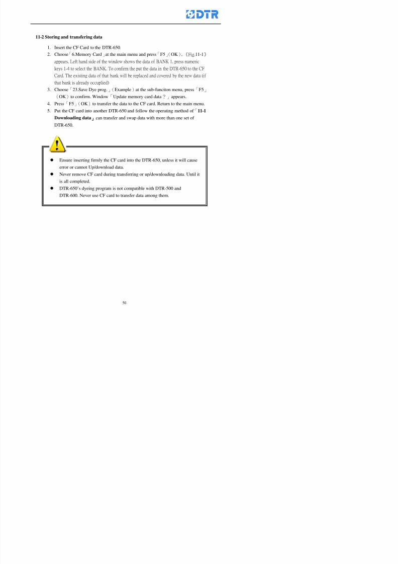
8132019 DTR 650 User Manual
httpslidepdfcomreaderfulldtr-650-user-manual 5070
Ensure inserting firmly the CF card into the DTR-650 unless it will cause
error or cannot Updownload data
Never remove CF card during transferring or updownloading data Until it
is all completed
DTR-650rsquos dyeing program is not compatible with DTR-500 and
DTR-600 Never use CF card to transfer data among them
11-2 Storing and transfering data
1 Insert the CF Card to the DTR-650
2 Choose「6Memory Card」at the main menu and press「F5」(OK) 《Fig11-1》
appears Left hand side of the window shows the data of BANK 1 press numeric
keys 1-4 to select the BANK To confirm the put the data in the DTR-650 to the CF
Card The existing data of that bank will be replaced and covered by the new data (if
that bank is already occuplied)
3 Choose「23Save Dye prog」(Example)at the sub-funciton menu press「F5」(OK)to confirm Window「Update memory card data」appears
4 Press「F5」(OK)to transfer the data to the CF card Return to the main menu
5 Put the CF card into another DTR-650 and follow the operating method of 「11-1
Downloading data」」」」can transfer and swap data with more than one set of
DTR-650
8132019 DTR 650 User Manual
httpslidepdfcomreaderfulldtr-650-user-manual 5170
12 983123983156983137983156983141 983137983150983140 983113983150983142983151983154983149983137983156983145983151983150
The state and information is including the Dyeing Machinersquos state of Digit Input output
Analog Input output Temperature control PID Dosing PID Pressure different PID
software system information and alarm record This information is for checking at any
time
12-1 Input Output state
Step
1 Choose「7Info and state」at main menu and press「F5」(OK)
2 Choose「01Digital IO put」at the sub-function menu then press「F5」(OK)
「Digital In Out State」0=None 1=Input
3 Press「F1」(Exit)to return to main menu
Same method for checking the temperature control analog dosing pressure
different etchellip
12-2 Checking the system information
Step
1 Choose「7Info and state」at main menu and press「F5」(OK)
2 Choose「11 System info」at sub-function field press「F5」(OK)Window
「System Information」appear
System information is including System info(software version) Library doc
Icon files Schematic file Definition file hardare state Config File Commandinstruction icon PLC file etc
8132019 DTR 650 User Manual
httpslidepdfcomreaderfulldtr-650-user-manual 5270
12-3 Checking the operating alarm record
Operating record shows the latest 40 operating items and alarm records including
the time and content of the alarm
A) Choose「7 Info and state」
and press「F5」(OK)
B) Choose「12Alarm logs」at
the sub-funciton menu then
press「F5」(OK)
8132019 DTR 650 User Manual
httpslidepdfcomreaderfulldtr-650-user-manual 5370
13 983105983140983146983157983155983156983145983150983143 983156983144983141 983107983151983150983156983154983137983155983156
The displaysrsquos brightness can be adjusted if necessary
Step
1 Choose「8Others」at main menu press「F5」(OK)
2 Choose「01Contrast」at sub-function menu press「F5」(OK) window「Set
Contrast」appears
3 Press「」「」to move the bar to set the brightness then press「F5」(OK)Window appears「Please reboot the system」
4 Press「F5」(OK)to return to main menu and re-boot the DTR-650 to complete
adjusting the brightness
8132019 DTR 650 User Manual
httpslidepdfcomreaderfulldtr-650-user-manual 5470
14 983123983156983151983152 983154983157983150983150983145983150983143 983156983144983141 983120983116983107 983120983154983151983143983154983137983149
Before testing the Input output testing transfer of the PLC program must stop the PLC
running
Step
1 Choose「8Others」at the main menu Press「F5」(OK)
2 Choose「04 PLC Stop」at sub-function menu Press「F5」(OK) window
「Password」appears
3 Enter password and press「F5」(OK) Window「Stop the PLC run」appears
4 Press「F4」(Yes)and window「PLC Stop」appear Press「F5」(OK) Now
the PLC is stop running and return to the main menu
All testing cannot operate when the PLC is running
Editing dye program and the relating operation can
perform with the PLC running together
8132019 DTR 650 User Manual
httpslidepdfcomreaderfulldtr-650-user-manual 5570
15 983123983141983156983156983145983150983143 983156983144983141 983156983145983149983141
Step
1 Press「8Others」at the main menu Press「F5」(OK)
2 Choose「10Set date time」at the sub-function menu Press「F5」(OK) window
「Set date time」appears
3 Press「F5」(Edit) to move cursor by 「3」「4」 enter the time value at the
cursor locates
4 Press「F5」(OK)to complete the modify Press「F1」(Exit)to return to main
menu
5 Press「F1」(Exit)if not modify and return to main menu
8132019 DTR 650 User Manual
httpslidepdfcomreaderfulldtr-650-user-manual 5670
1166 983123983123983157983157 983152 983152 983152 983152983148983148983141983141983149983149983141983141983150983150983156 983156 983137983137983154 983154 983161983161 983124 983124 983137983137983138983138983148983148983141983141
TTTTTTTTaaaaaaaabbbbbbbblllllllleeeeeeee 11111111 【Dye Instruction】
Code Icon Instruction Code Icon Instruction
000 End 016 Inject C
001 Start 017 Dosing BV
002 Heat 018 PH
003 Cool 019 Addsalt B
004 Flow Fill 020 Addsalt C
005 Level Fill 021 Ana Fill
006 Drian 022 Lock Fill007 Rinse 023 Lock Level
008 Run 024 Low Rinse
009 Call 025 Cyc Rinse
010 Prep B 026 Rinse B
011 Addsalt B 027 Rinse C
012 Dosing B 028 Temp
013 Inject B 029 Nozzle Pressure
014 Prep C 030 Main Pump
015 Dosing C 031 Pump Speed
8132019 DTR 650 User Manual
httpslidepdfcomreaderfulldtr-650-user-manual 5770
Table 2 【【【【Alarm】】】】
System Alarm Must stop operating and check up to solve problems before restarting
the machine
Running Alarm It is a reminder Not effect the operating of DTR-650
Userrsquos Alarm Total of 32 Users can define themselves and use it when edit the PLC
Program (do not listing below)
No System Alarm No Running Alarm
1 PLC program not running 16 Temp ctrl 0 Grad too slow
2 Main temp sensor error 17 Temp ctrl 0 Grad too fast
3 Not at Run window 18 Temp ctrl 0 Hold temp too low
4 Exceeding max temp 19 Temp ctrl 0 Hold temp too high
5 - 20 Temp ctrl 1 Grad too slow6 - 21 Temp ctrl 1 Grad too fast
7 - 22 Temp ctrl 1 Hold temp too low
8 Communication error 23 Temp ctrl 1 Hold temp too high
9 Slave not answer 24 Temp ctrl 2 Grad too slow
10 PLC 0 not answer 25 Temp ctrl 2 Grad too fast
11 PLC 1 not answer 26 Temp 2 Hold temp too low12 Display not answer 27 Temp 2 Hold temp too high
13 Lower power voltage 28 Temp ctrl 3 Grad too slow
14 - 29 Temp ctrl 3 Grad too fast
15 - 30 Temp3 Hold temp too low
31 Temp3 Hold temp too high
32 Dosing 0 injection too slow
33 Dosing 0 injection too fast
34 Dosing 1 injection too slow
35 Dosing 1 injection too fast
8132019 DTR 650 User Manual
httpslidepdfcomreaderfulldtr-650-user-manual 5870
TTTTTTTTaaaaaaaabbbbbbbblllllllleeeeeeee 33333333 【【【【System factor】】】】
No Description Std Range amp Definition
1 ID No 000 000- 100 Controller no
2 Communication Rate 4800Bps 2400 4800 9600 19200 38400
3 Display language Chinese English Chinese
4 Temp display mode and
5 Maxmium temperature 145 025 ~ 145 6 Type of external PLC Default PLC32DPLC32PLC16Default
7 Number of external PLC NANA 1 unit connect
2 unit connect
8Communication Rate of
PLC9600Bps 2400 4800 9600 19200
9 Set point 1 085 000 ~ 145
If signal source is temperaturethe setting value is thetemperature value If the signal
source is Analog Input 6~17 then
setting value for Analog input is 0 ndash
100 and relates Analog
Input14~020mA
10 Source 1 Sensor0Sensor 0 ~5
Analog input 0 ~1111 Set point 2 092 Same as 09
12 Source 2 PT100 1 Same as 10
13 Set point 3 085 Same as 09
14 Source 3 PT100 2 Same as 10
15 Set point 4 092 Same as 09
16 Source 4 PT100 3 Same as 1017 Set point 5 085 Same as 09
18 Source 5 PT100 4 Same as 10
19 Set point 6 092 Same as 09
8132019 DTR 650 User Manual
httpslidepdfcomreaderfulldtr-650-user-manual 5970
29 Min cyclic time of cloth 100sec 0 ~ 255 sec
30 Max cyclic time of cloth 240sec 0 ~255 sec
31Standard cyclic time of
cloth
180 000 ~ 255 sec
32 Display ModeProgram
List
Program list Schematic Diagram
Icon mode
33 CF card format Standard of
DTR CF
Card
Standard of DTR CF Card V20
Standard CF Card
34 Addition step Disable Disable Enable35 Mode Com 3
CouplingEsure Com 3 is the communication
port of the Central or Coupling
36Com 3 Communication
rate9600 Central communication speed
8132019 DTR 650 User Manual
httpslidepdfcomreaderfulldtr-650-user-manual 6070
TTTTTTTTaaaaaaaabbbbbbbblllllllleeeeeeee 44444444 【【【【Temperature Cotnrol Factor】】】】
No Factor Definition Standard Range and Definition
01 PT No PT-0 PT 0~5 PT-100 Input number
02 Max working temp 140 000~140
03 Output mode 0 0~2
04 Alarm time of gardient 240sec 000~255 sec
05 Alarm mode of gradient Always AlwaysOnceNone
06 Control mode of gradient Heating orCooling
interlocked
Heating and Cooling interlocked
No limitation
07 Alarm range of HoldTemp 03 01~20
08 Alarm time for HoldTemp 240sec 000~255sec
09 Alarm mode of HoldTemp Always AlwaysOnceNone
10 Control mode ofHoldTemp
Heating only Only heating and cooling Cooling whenalarm occurred Only heating andcooling No limitation when alarmHeating only
11 Porportional Band 100 000~250
12 Integral band 128 sec 000~255 sec
13 Differential time 04 sec 00~20 sec
14 Min transit gradient 02 00~50
15 Transit rate 20 times 00~50 times (020= 2 times)
16 PID initial output value 010 000~100
17 ONOFF cycle time 10 sec 05~25 sec
Onoff valve set as 010 sec
Proportional valve set as 020 sec
18 Time down count mode Mode 0 0~10 = The time down count range from「Factor 20 + target temp」to「Target
8132019 DTR 650 User Manual
httpslidepdfcomreaderfulldtr-650-user-manual 6170
TTTTTTTTaaaaaaaabbbbbbbblllllllleeeeeeee 55555555 【【【【Speed Factor】】】】
No Factor Definition Standard Range amp Definition
01 Input Number Speed input 0 Speed input 0~11
02 Average times 05 times 01~10
03 Sensor Number 008pcs 001~255
04 Roller Dimension 250mm 050~500
05 Max cloth speed 200mmin 001~25506 Min cloth speed 020mmin 001~255
07 Alarm delay time 240sec 001~255
08 Alarm mode Every oncenoneevery
09 Alarm range () 020 001~255
10 Proportional band 100 001~255
11 Integer band 128 001~25512 Differential time 000 001~200
13 Initial speed () 020 001~255
14 Control cycle ti(01sec) 05 01~30
15 First cycle time(01sec) 10 01~30
16 Speed increase limit () 010 001~100
17 Speed decrease limit () 010 001~100
18 Min speed() 005 001~100
19 Manual speed adjust () 005 001~100
20 Manual initial speed() 020 001~100
21 Stopping speed() 010 001~100
22 Switch speed() 020 001~100
23 Not used
24 Speed decrease turns 03turns 01~50
8132019 DTR 650 User Manual
httpslidepdfcomreaderfulldtr-650-user-manual 6270
Table 6 【【【【Dosing Factors】】】】
No Description Range Range and Explanation
1 Analog input no Analog input 0 Analog input no 0 ~11
2Alarm delay time for
dosing240 sec 000 ~255 sec
3 Alarm time for dosing Every Every Once None
4 Proportional band 100 000 ~255 sec Factor P
5 Integer band 128 000 ~255 sec Factor I6 Differential time 04 00 ~20 Factor D
7 Max adjust rate 150 50~ 255
8 Initial factor for dosing 10 000 ~100
9 User curve section 0 10 Gradient of sect1 for dosing curve9
10 User curve section 1 10 Gradient of sect2 for dosing curve9
11 User curve section 2 10 Gradient of sect3 for dosing curve9
12 User curve section 3 10 Gradient of sect4 for dosing curve9
13 User curve section 4 10 Gradient of sect5 for dosing curve9
14 User curve section 5 10 Gradient of sect6 for dosing curve9
15 User curve section 6 10 Gradient of sect7 for dosing curve9
16 User curve section 7 10 Gradient of sect8 for dosing curve9
17 User curve section 8 10 Gradient of sect9 for dosing curve9
18 User curve section 9 10 Gradient of sect10 for dosing curve9
19 Min water level 05 00~ 10 04~20mA percentagechange to the userrsquos factor setting
20 Output value for Tank
clean
100 000~ 100
Injected percentage of dosing valve
in dosing End period
This factor will be invalided if usingONOFF dosing valve
21 Full range 100 001~255 Self-adjustment cannotchange
22 Range ratio 001001~255 Self-adjustment cannot
change
8132019 DTR 650 User Manual
httpslidepdfcomreaderfulldtr-650-user-manual 6370
【【【【TTaabbllee 77 】】】】Pressure Deviation Factors
No Description Std Range amp Definition
1 Analog input number + Analog in 0 Analog in 0~11
2 Analog input number - Analog in 1 Analog in 0~11
3 Input mode Pressure Pressure Pressure deviation
4 Full range 050x01Kgcm
001~255
5 Range ratio 001 001~255
6 Alarm delay time 100sec 001~255
7 Alarm mode Every oncenone
8 Alarm range 010 001~255
9 Proportional band 100 001~255
10 Integer band 128 001~255
11 Differential time 00 00~20
12 PID Init output value 010 001~255
13 Cycle time 10 03~30
14 First cycle time 030 003~100
15 Max adjust rate 010 001~100
8132019 DTR 650 User Manual
httpslidepdfcomreaderfulldtr-650-user-manual 6470
【【【【TTaabbllee 88 】】】】Definition of Analog Input
No Description Standard Range and Explanation
01 PT 0 correction standard DIN std DIN std JIS std
02 PT 0 correction +0 +- 9
03 PT 1 correction standard DIN std DIN std JIS std
04 PT 1 correction +0 +- 9
05 PT 2 correction standard DIN std DIN std JIS std
06 PT 2 correction +0 +- 9
07 PT 3 correction standard DIN std DIN std JIS std
08 PT 3 correction +0 +- 9
09 PT 4 correction standard DIN std DIN std JIS std
10 PT 4 correction +0 +- 9
11 PT 5 correction standard DIN std DIN std JIS std
12 PT 5 correction +0 +- 9
13 Analog input 0 define 4 ~ 20mA 0 ndash 20mA 4 ndash 20mA
14 Analog input 0 average times 10 times 01- 20 times
15 Analog input 0 min value 0000 0000 - 1000
16 Analog input 0 max value 100 0001 - 9999
17-60 Analog input 1~11 Same as Analog input 0
【【【【 】】】】 fi i i f A O
8132019 DTR 650 User Manual
httpslidepdfcomreaderfulldtr-650-user-manual 6570
【【【【TTaabbllee 99 】】】】Definition of Analog Output
No Description Standard Range and explanation
61 Analog output 0 define Control byPLC
Control by PLC
Temperature control PID0 output
Temperature control PID1 output
Temperature control PID2 output
Speed PID3 output
Dosing PID0 output Dosing PID1output
Pressure different PID0 outputPressure different PID1 output
Main temperature output
62 Mode of Analog ouptput0 4 ~20mA 0 ndash20mA 4 ndash 20mA
63-84 Analog output 1~11 Same as Analog output 0
【【【【TTaabbllee 1100】】】】Value Table 0 amp 1
No Description Range Std Range and explanation
1 Analog input no 000~011 000 Analog input no
2 Data ratio 001~255 100 Multiple by factors
3~53 0~98 000~255 000-100 Analog input 0~98 data
【【【【 】】】】St t Li t
8132019 DTR 650 User Manual
httpslidepdfcomreaderfulldtr-650-user-manual 6670
【【【【TTaabbllee 1111】】】】State List
No Description Range Standard Range and explanation
1 Display setting 1 0~255 205 See remarks at next page
2 Display setting 2 0~255 208
3 Display setting 3 0~255 209
4 Display setting 4 0~255 017
5 Display setting 5 0~255 0186 Display setting 6 0~255 019
7 Display setting 7 0~255 020
8 Display setting 8 0~255 021
9 Display setting 9 0~255 000
10 Display setting 1 0~255 000
11 Display setting 2 0~255 000
12 Display setting 3 0~255 000
13 Display setting 4 0~255 000
14 Display setting 5 0~255 000
15 Display setting 6 0~255 000
16 Display setting 7 0~255 000
Remarks
8132019 DTR 650 User Manual
httpslidepdfcomreaderfulldtr-650-user-manual 6770
0 = No display 1~255 = Display type of number
1~16 Content of PLC VB0~15
No 1 corresponding to VB0
No 16 corresponding to VB15
17~32 Content of PLC DB0~15
No 17 corresponding to DB0
No 32 corresponding to DB15
33~46 Content of PLC CNT0~29
No 33 corresponding to CNT0
No 46 corresponding to CNT29 47~78 Content of dyeing instruction 0~31 CNT0
No 47 corresponding to system instruction to No 0 of CNT0
No 78 corresponding to system instruction to No 31 of CNT0rsquos content
79~110 Dyeing instruction 0~31 of CNT0rsquos setting
111~142 Content of Dyeing instruction 0~31 CNT1No 111 corresponding to dyeing instruction No 0 of CNT1
No 142 corresponding to dyeing instruction No 31 of CNT1rsquos content
143~174 Dyeing instruction 0~31 of CNT1rsquos setting
175~204 Content of PLC HTIM0~29
No 175 corresponding to HTIM0
No 204 corresponding to HTIM29
205 Loading
206 Ratio 1
207 Ratio 2208 Ratio 1 x Loading
209 Ratio 2 x Loading
210 Fix value
211 Value Table 1 matching result
212 Value Table 2 matching result
213 Value Table 1 setting214 Value Table 2 setting
215 Pressure control PID0 different pressure value
216 Pressure control PID1 different pressure value
TTTTTTTTaaaaaaaabbbbbbbblllllllleeeeeeee 1122 【【【【Usage of password】】】】
8132019 DTR 650 User Manual
httpslidepdfcomreaderfulldtr-650-user-manual 6870
No Main FunctionFactor Sub Function Factor Password Rank
1 Run None
2 Dye program User3 or above
3 Control factor
- User factor User 1
- System factor User 1
- Temp PID 0
- Temp PID 1 User 1- Speed PID 0 User 1
- Dosing PID 0 User 1
- Dosing PID 1 User 1
- Pressure PID 0 User 1
- Pressure PID 1 User 1
- Analog IO User 1
- Load standard factor User 2 or above- Load a copied factor User 2 or above
- Copy factor User 2 or above
- Value table 0 User 1
- Value table 1 User 1
- Information and state User 1
- Dye instruction User 1
- Edit dye instruction setting User 14 Output testing User 2 or above
5 Calibration User 2 or above
6 Dye record None
7 CF card User 1
8 Info and state None
9 Others
- Contrast User3 or above
- Data Locking None
- PLC Run User 1
- PLC Stop User 1
- Password setting User 1
TTTTTTTTaaaaaaaabbbbbbbblllllllleeeeeeee 1133 【【【【Technical Data】】】】
8132019 DTR 650 User Manual
httpslidepdfcomreaderfulldtr-650-user-manual 6970
TTTTTTTTaaaaaaaabbbbbbbblllllllleeeeeeee 1133 【【【【Technical Data】】】】
1 Temperature Control
- Range 10~145(plusmn1)
- Mode Proportional or PWM
- Sensor PT100 (JIS or DIN standard)
2 Input and output channel
- Digital Input 32 DC24V PNP- Digital Output 32 DC24V 054A Relay connect point
- Analog Input 4 04~20 mA
- Analog Output 4 0~20mA 或 4~20 mA
3 Communication port 3 RS-232 amp 0~20 mAx1 RS485x 2
4 Dye program
- Number 15000 Steps
- Standard step 61Heating Cooling Fill Drain RinseDosingetc
5LCD module and Display
langage
Chinese
English
320 x 240 TFT color display with
more language
6 CF card connector 1 PCMCIA standard
7 Membrane Keyboard- Number Key 10 [0]~[9] Input factors
- Function Key 5 [F1]~[F5] function selecting
- Operation Key 2 [Start] [Stop]
- Auxiliary Key 7 [][][][][Esc] [larr][OK] [bull]
8 Operating Condition
- Temperature 5~45
- Humidity ≦85 (25)
9 Power supply
V l DC 24V
8132019 DTR 650 User Manual
httpslidepdfcomreaderfulldtr-650-user-manual 7070
70
983108983124983122983085650 983113983150983152983157983156 983119983157983156983152983157983156 983120983151983154983156983145983150983143 (983138983137983139983147983155983145983140983141 983158983145983141983159)
8132019 DTR 650 User Manual
httpslidepdfcomreaderfulldtr-650-user-manual 5170
12 983123983156983137983156983141 983137983150983140 983113983150983142983151983154983149983137983156983145983151983150
The state and information is including the Dyeing Machinersquos state of Digit Input output
Analog Input output Temperature control PID Dosing PID Pressure different PID
software system information and alarm record This information is for checking at any
time
12-1 Input Output state
Step
1 Choose「7Info and state」at main menu and press「F5」(OK)
2 Choose「01Digital IO put」at the sub-function menu then press「F5」(OK)
「Digital In Out State」0=None 1=Input
3 Press「F1」(Exit)to return to main menu
Same method for checking the temperature control analog dosing pressure
different etchellip
12-2 Checking the system information
Step
1 Choose「7Info and state」at main menu and press「F5」(OK)
2 Choose「11 System info」at sub-function field press「F5」(OK)Window
「System Information」appear
System information is including System info(software version) Library doc
Icon files Schematic file Definition file hardare state Config File Commandinstruction icon PLC file etc
8132019 DTR 650 User Manual
httpslidepdfcomreaderfulldtr-650-user-manual 5270
12-3 Checking the operating alarm record
Operating record shows the latest 40 operating items and alarm records including
the time and content of the alarm
A) Choose「7 Info and state」
and press「F5」(OK)
B) Choose「12Alarm logs」at
the sub-funciton menu then
press「F5」(OK)
8132019 DTR 650 User Manual
httpslidepdfcomreaderfulldtr-650-user-manual 5370
13 983105983140983146983157983155983156983145983150983143 983156983144983141 983107983151983150983156983154983137983155983156
The displaysrsquos brightness can be adjusted if necessary
Step
1 Choose「8Others」at main menu press「F5」(OK)
2 Choose「01Contrast」at sub-function menu press「F5」(OK) window「Set
Contrast」appears
3 Press「」「」to move the bar to set the brightness then press「F5」(OK)Window appears「Please reboot the system」
4 Press「F5」(OK)to return to main menu and re-boot the DTR-650 to complete
adjusting the brightness
8132019 DTR 650 User Manual
httpslidepdfcomreaderfulldtr-650-user-manual 5470
14 983123983156983151983152 983154983157983150983150983145983150983143 983156983144983141 983120983116983107 983120983154983151983143983154983137983149
Before testing the Input output testing transfer of the PLC program must stop the PLC
running
Step
1 Choose「8Others」at the main menu Press「F5」(OK)
2 Choose「04 PLC Stop」at sub-function menu Press「F5」(OK) window
「Password」appears
3 Enter password and press「F5」(OK) Window「Stop the PLC run」appears
4 Press「F4」(Yes)and window「PLC Stop」appear Press「F5」(OK) Now
the PLC is stop running and return to the main menu
All testing cannot operate when the PLC is running
Editing dye program and the relating operation can
perform with the PLC running together
8132019 DTR 650 User Manual
httpslidepdfcomreaderfulldtr-650-user-manual 5570
15 983123983141983156983156983145983150983143 983156983144983141 983156983145983149983141
Step
1 Press「8Others」at the main menu Press「F5」(OK)
2 Choose「10Set date time」at the sub-function menu Press「F5」(OK) window
「Set date time」appears
3 Press「F5」(Edit) to move cursor by 「3」「4」 enter the time value at the
cursor locates
4 Press「F5」(OK)to complete the modify Press「F1」(Exit)to return to main
menu
5 Press「F1」(Exit)if not modify and return to main menu
8132019 DTR 650 User Manual
httpslidepdfcomreaderfulldtr-650-user-manual 5670
1166 983123983123983157983157 983152 983152 983152 983152983148983148983141983141983149983149983141983141983150983150983156 983156 983137983137983154 983154 983161983161 983124 983124 983137983137983138983138983148983148983141983141
TTTTTTTTaaaaaaaabbbbbbbblllllllleeeeeeee 11111111 【Dye Instruction】
Code Icon Instruction Code Icon Instruction
000 End 016 Inject C
001 Start 017 Dosing BV
002 Heat 018 PH
003 Cool 019 Addsalt B
004 Flow Fill 020 Addsalt C
005 Level Fill 021 Ana Fill
006 Drian 022 Lock Fill007 Rinse 023 Lock Level
008 Run 024 Low Rinse
009 Call 025 Cyc Rinse
010 Prep B 026 Rinse B
011 Addsalt B 027 Rinse C
012 Dosing B 028 Temp
013 Inject B 029 Nozzle Pressure
014 Prep C 030 Main Pump
015 Dosing C 031 Pump Speed
8132019 DTR 650 User Manual
httpslidepdfcomreaderfulldtr-650-user-manual 5770
Table 2 【【【【Alarm】】】】
System Alarm Must stop operating and check up to solve problems before restarting
the machine
Running Alarm It is a reminder Not effect the operating of DTR-650
Userrsquos Alarm Total of 32 Users can define themselves and use it when edit the PLC
Program (do not listing below)
No System Alarm No Running Alarm
1 PLC program not running 16 Temp ctrl 0 Grad too slow
2 Main temp sensor error 17 Temp ctrl 0 Grad too fast
3 Not at Run window 18 Temp ctrl 0 Hold temp too low
4 Exceeding max temp 19 Temp ctrl 0 Hold temp too high
5 - 20 Temp ctrl 1 Grad too slow6 - 21 Temp ctrl 1 Grad too fast
7 - 22 Temp ctrl 1 Hold temp too low
8 Communication error 23 Temp ctrl 1 Hold temp too high
9 Slave not answer 24 Temp ctrl 2 Grad too slow
10 PLC 0 not answer 25 Temp ctrl 2 Grad too fast
11 PLC 1 not answer 26 Temp 2 Hold temp too low12 Display not answer 27 Temp 2 Hold temp too high
13 Lower power voltage 28 Temp ctrl 3 Grad too slow
14 - 29 Temp ctrl 3 Grad too fast
15 - 30 Temp3 Hold temp too low
31 Temp3 Hold temp too high
32 Dosing 0 injection too slow
33 Dosing 0 injection too fast
34 Dosing 1 injection too slow
35 Dosing 1 injection too fast
8132019 DTR 650 User Manual
httpslidepdfcomreaderfulldtr-650-user-manual 5870
TTTTTTTTaaaaaaaabbbbbbbblllllllleeeeeeee 33333333 【【【【System factor】】】】
No Description Std Range amp Definition
1 ID No 000 000- 100 Controller no
2 Communication Rate 4800Bps 2400 4800 9600 19200 38400
3 Display language Chinese English Chinese
4 Temp display mode and
5 Maxmium temperature 145 025 ~ 145 6 Type of external PLC Default PLC32DPLC32PLC16Default
7 Number of external PLC NANA 1 unit connect
2 unit connect
8Communication Rate of
PLC9600Bps 2400 4800 9600 19200
9 Set point 1 085 000 ~ 145
If signal source is temperaturethe setting value is thetemperature value If the signal
source is Analog Input 6~17 then
setting value for Analog input is 0 ndash
100 and relates Analog
Input14~020mA
10 Source 1 Sensor0Sensor 0 ~5
Analog input 0 ~1111 Set point 2 092 Same as 09
12 Source 2 PT100 1 Same as 10
13 Set point 3 085 Same as 09
14 Source 3 PT100 2 Same as 10
15 Set point 4 092 Same as 09
16 Source 4 PT100 3 Same as 1017 Set point 5 085 Same as 09
18 Source 5 PT100 4 Same as 10
19 Set point 6 092 Same as 09
8132019 DTR 650 User Manual
httpslidepdfcomreaderfulldtr-650-user-manual 5970
29 Min cyclic time of cloth 100sec 0 ~ 255 sec
30 Max cyclic time of cloth 240sec 0 ~255 sec
31Standard cyclic time of
cloth
180 000 ~ 255 sec
32 Display ModeProgram
List
Program list Schematic Diagram
Icon mode
33 CF card format Standard of
DTR CF
Card
Standard of DTR CF Card V20
Standard CF Card
34 Addition step Disable Disable Enable35 Mode Com 3
CouplingEsure Com 3 is the communication
port of the Central or Coupling
36Com 3 Communication
rate9600 Central communication speed
8132019 DTR 650 User Manual
httpslidepdfcomreaderfulldtr-650-user-manual 6070
TTTTTTTTaaaaaaaabbbbbbbblllllllleeeeeeee 44444444 【【【【Temperature Cotnrol Factor】】】】
No Factor Definition Standard Range and Definition
01 PT No PT-0 PT 0~5 PT-100 Input number
02 Max working temp 140 000~140
03 Output mode 0 0~2
04 Alarm time of gardient 240sec 000~255 sec
05 Alarm mode of gradient Always AlwaysOnceNone
06 Control mode of gradient Heating orCooling
interlocked
Heating and Cooling interlocked
No limitation
07 Alarm range of HoldTemp 03 01~20
08 Alarm time for HoldTemp 240sec 000~255sec
09 Alarm mode of HoldTemp Always AlwaysOnceNone
10 Control mode ofHoldTemp
Heating only Only heating and cooling Cooling whenalarm occurred Only heating andcooling No limitation when alarmHeating only
11 Porportional Band 100 000~250
12 Integral band 128 sec 000~255 sec
13 Differential time 04 sec 00~20 sec
14 Min transit gradient 02 00~50
15 Transit rate 20 times 00~50 times (020= 2 times)
16 PID initial output value 010 000~100
17 ONOFF cycle time 10 sec 05~25 sec
Onoff valve set as 010 sec
Proportional valve set as 020 sec
18 Time down count mode Mode 0 0~10 = The time down count range from「Factor 20 + target temp」to「Target
8132019 DTR 650 User Manual
httpslidepdfcomreaderfulldtr-650-user-manual 6170
TTTTTTTTaaaaaaaabbbbbbbblllllllleeeeeeee 55555555 【【【【Speed Factor】】】】
No Factor Definition Standard Range amp Definition
01 Input Number Speed input 0 Speed input 0~11
02 Average times 05 times 01~10
03 Sensor Number 008pcs 001~255
04 Roller Dimension 250mm 050~500
05 Max cloth speed 200mmin 001~25506 Min cloth speed 020mmin 001~255
07 Alarm delay time 240sec 001~255
08 Alarm mode Every oncenoneevery
09 Alarm range () 020 001~255
10 Proportional band 100 001~255
11 Integer band 128 001~25512 Differential time 000 001~200
13 Initial speed () 020 001~255
14 Control cycle ti(01sec) 05 01~30
15 First cycle time(01sec) 10 01~30
16 Speed increase limit () 010 001~100
17 Speed decrease limit () 010 001~100
18 Min speed() 005 001~100
19 Manual speed adjust () 005 001~100
20 Manual initial speed() 020 001~100
21 Stopping speed() 010 001~100
22 Switch speed() 020 001~100
23 Not used
24 Speed decrease turns 03turns 01~50
8132019 DTR 650 User Manual
httpslidepdfcomreaderfulldtr-650-user-manual 6270
Table 6 【【【【Dosing Factors】】】】
No Description Range Range and Explanation
1 Analog input no Analog input 0 Analog input no 0 ~11
2Alarm delay time for
dosing240 sec 000 ~255 sec
3 Alarm time for dosing Every Every Once None
4 Proportional band 100 000 ~255 sec Factor P
5 Integer band 128 000 ~255 sec Factor I6 Differential time 04 00 ~20 Factor D
7 Max adjust rate 150 50~ 255
8 Initial factor for dosing 10 000 ~100
9 User curve section 0 10 Gradient of sect1 for dosing curve9
10 User curve section 1 10 Gradient of sect2 for dosing curve9
11 User curve section 2 10 Gradient of sect3 for dosing curve9
12 User curve section 3 10 Gradient of sect4 for dosing curve9
13 User curve section 4 10 Gradient of sect5 for dosing curve9
14 User curve section 5 10 Gradient of sect6 for dosing curve9
15 User curve section 6 10 Gradient of sect7 for dosing curve9
16 User curve section 7 10 Gradient of sect8 for dosing curve9
17 User curve section 8 10 Gradient of sect9 for dosing curve9
18 User curve section 9 10 Gradient of sect10 for dosing curve9
19 Min water level 05 00~ 10 04~20mA percentagechange to the userrsquos factor setting
20 Output value for Tank
clean
100 000~ 100
Injected percentage of dosing valve
in dosing End period
This factor will be invalided if usingONOFF dosing valve
21 Full range 100 001~255 Self-adjustment cannotchange
22 Range ratio 001001~255 Self-adjustment cannot
change
8132019 DTR 650 User Manual
httpslidepdfcomreaderfulldtr-650-user-manual 6370
【【【【TTaabbllee 77 】】】】Pressure Deviation Factors
No Description Std Range amp Definition
1 Analog input number + Analog in 0 Analog in 0~11
2 Analog input number - Analog in 1 Analog in 0~11
3 Input mode Pressure Pressure Pressure deviation
4 Full range 050x01Kgcm
001~255
5 Range ratio 001 001~255
6 Alarm delay time 100sec 001~255
7 Alarm mode Every oncenone
8 Alarm range 010 001~255
9 Proportional band 100 001~255
10 Integer band 128 001~255
11 Differential time 00 00~20
12 PID Init output value 010 001~255
13 Cycle time 10 03~30
14 First cycle time 030 003~100
15 Max adjust rate 010 001~100
8132019 DTR 650 User Manual
httpslidepdfcomreaderfulldtr-650-user-manual 6470
【【【【TTaabbllee 88 】】】】Definition of Analog Input
No Description Standard Range and Explanation
01 PT 0 correction standard DIN std DIN std JIS std
02 PT 0 correction +0 +- 9
03 PT 1 correction standard DIN std DIN std JIS std
04 PT 1 correction +0 +- 9
05 PT 2 correction standard DIN std DIN std JIS std
06 PT 2 correction +0 +- 9
07 PT 3 correction standard DIN std DIN std JIS std
08 PT 3 correction +0 +- 9
09 PT 4 correction standard DIN std DIN std JIS std
10 PT 4 correction +0 +- 9
11 PT 5 correction standard DIN std DIN std JIS std
12 PT 5 correction +0 +- 9
13 Analog input 0 define 4 ~ 20mA 0 ndash 20mA 4 ndash 20mA
14 Analog input 0 average times 10 times 01- 20 times
15 Analog input 0 min value 0000 0000 - 1000
16 Analog input 0 max value 100 0001 - 9999
17-60 Analog input 1~11 Same as Analog input 0
【【【【 】】】】 fi i i f A O
8132019 DTR 650 User Manual
httpslidepdfcomreaderfulldtr-650-user-manual 6570
【【【【TTaabbllee 99 】】】】Definition of Analog Output
No Description Standard Range and explanation
61 Analog output 0 define Control byPLC
Control by PLC
Temperature control PID0 output
Temperature control PID1 output
Temperature control PID2 output
Speed PID3 output
Dosing PID0 output Dosing PID1output
Pressure different PID0 outputPressure different PID1 output
Main temperature output
62 Mode of Analog ouptput0 4 ~20mA 0 ndash20mA 4 ndash 20mA
63-84 Analog output 1~11 Same as Analog output 0
【【【【TTaabbllee 1100】】】】Value Table 0 amp 1
No Description Range Std Range and explanation
1 Analog input no 000~011 000 Analog input no
2 Data ratio 001~255 100 Multiple by factors
3~53 0~98 000~255 000-100 Analog input 0~98 data
【【【【 】】】】St t Li t
8132019 DTR 650 User Manual
httpslidepdfcomreaderfulldtr-650-user-manual 6670
【【【【TTaabbllee 1111】】】】State List
No Description Range Standard Range and explanation
1 Display setting 1 0~255 205 See remarks at next page
2 Display setting 2 0~255 208
3 Display setting 3 0~255 209
4 Display setting 4 0~255 017
5 Display setting 5 0~255 0186 Display setting 6 0~255 019
7 Display setting 7 0~255 020
8 Display setting 8 0~255 021
9 Display setting 9 0~255 000
10 Display setting 1 0~255 000
11 Display setting 2 0~255 000
12 Display setting 3 0~255 000
13 Display setting 4 0~255 000
14 Display setting 5 0~255 000
15 Display setting 6 0~255 000
16 Display setting 7 0~255 000
Remarks
8132019 DTR 650 User Manual
httpslidepdfcomreaderfulldtr-650-user-manual 6770
0 = No display 1~255 = Display type of number
1~16 Content of PLC VB0~15
No 1 corresponding to VB0
No 16 corresponding to VB15
17~32 Content of PLC DB0~15
No 17 corresponding to DB0
No 32 corresponding to DB15
33~46 Content of PLC CNT0~29
No 33 corresponding to CNT0
No 46 corresponding to CNT29 47~78 Content of dyeing instruction 0~31 CNT0
No 47 corresponding to system instruction to No 0 of CNT0
No 78 corresponding to system instruction to No 31 of CNT0rsquos content
79~110 Dyeing instruction 0~31 of CNT0rsquos setting
111~142 Content of Dyeing instruction 0~31 CNT1No 111 corresponding to dyeing instruction No 0 of CNT1
No 142 corresponding to dyeing instruction No 31 of CNT1rsquos content
143~174 Dyeing instruction 0~31 of CNT1rsquos setting
175~204 Content of PLC HTIM0~29
No 175 corresponding to HTIM0
No 204 corresponding to HTIM29
205 Loading
206 Ratio 1
207 Ratio 2208 Ratio 1 x Loading
209 Ratio 2 x Loading
210 Fix value
211 Value Table 1 matching result
212 Value Table 2 matching result
213 Value Table 1 setting214 Value Table 2 setting
215 Pressure control PID0 different pressure value
216 Pressure control PID1 different pressure value
TTTTTTTTaaaaaaaabbbbbbbblllllllleeeeeeee 1122 【【【【Usage of password】】】】
8132019 DTR 650 User Manual
httpslidepdfcomreaderfulldtr-650-user-manual 6870
No Main FunctionFactor Sub Function Factor Password Rank
1 Run None
2 Dye program User3 or above
3 Control factor
- User factor User 1
- System factor User 1
- Temp PID 0
- Temp PID 1 User 1- Speed PID 0 User 1
- Dosing PID 0 User 1
- Dosing PID 1 User 1
- Pressure PID 0 User 1
- Pressure PID 1 User 1
- Analog IO User 1
- Load standard factor User 2 or above- Load a copied factor User 2 or above
- Copy factor User 2 or above
- Value table 0 User 1
- Value table 1 User 1
- Information and state User 1
- Dye instruction User 1
- Edit dye instruction setting User 14 Output testing User 2 or above
5 Calibration User 2 or above
6 Dye record None
7 CF card User 1
8 Info and state None
9 Others
- Contrast User3 or above
- Data Locking None
- PLC Run User 1
- PLC Stop User 1
- Password setting User 1
TTTTTTTTaaaaaaaabbbbbbbblllllllleeeeeeee 1133 【【【【Technical Data】】】】
8132019 DTR 650 User Manual
httpslidepdfcomreaderfulldtr-650-user-manual 6970
TTTTTTTTaaaaaaaabbbbbbbblllllllleeeeeeee 1133 【【【【Technical Data】】】】
1 Temperature Control
- Range 10~145(plusmn1)
- Mode Proportional or PWM
- Sensor PT100 (JIS or DIN standard)
2 Input and output channel
- Digital Input 32 DC24V PNP- Digital Output 32 DC24V 054A Relay connect point
- Analog Input 4 04~20 mA
- Analog Output 4 0~20mA 或 4~20 mA
3 Communication port 3 RS-232 amp 0~20 mAx1 RS485x 2
4 Dye program
- Number 15000 Steps
- Standard step 61Heating Cooling Fill Drain RinseDosingetc
5LCD module and Display
langage
Chinese
English
320 x 240 TFT color display with
more language
6 CF card connector 1 PCMCIA standard
7 Membrane Keyboard- Number Key 10 [0]~[9] Input factors
- Function Key 5 [F1]~[F5] function selecting
- Operation Key 2 [Start] [Stop]
- Auxiliary Key 7 [][][][][Esc] [larr][OK] [bull]
8 Operating Condition
- Temperature 5~45
- Humidity ≦85 (25)
9 Power supply
V l DC 24V
8132019 DTR 650 User Manual
httpslidepdfcomreaderfulldtr-650-user-manual 7070
70
983108983124983122983085650 983113983150983152983157983156 983119983157983156983152983157983156 983120983151983154983156983145983150983143 (983138983137983139983147983155983145983140983141 983158983145983141983159)
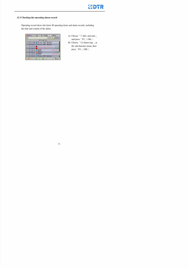
8132019 DTR 650 User Manual
httpslidepdfcomreaderfulldtr-650-user-manual 5370
13 983105983140983146983157983155983156983145983150983143 983156983144983141 983107983151983150983156983154983137983155983156
The displaysrsquos brightness can be adjusted if necessary
Step
1 Choose「8Others」at main menu press「F5」(OK)
2 Choose「01Contrast」at sub-function menu press「F5」(OK) window「Set
Contrast」appears
3 Press「」「」to move the bar to set the brightness then press「F5」(OK)Window appears「Please reboot the system」
4 Press「F5」(OK)to return to main menu and re-boot the DTR-650 to complete
adjusting the brightness
8132019 DTR 650 User Manual
httpslidepdfcomreaderfulldtr-650-user-manual 5470
14 983123983156983151983152 983154983157983150983150983145983150983143 983156983144983141 983120983116983107 983120983154983151983143983154983137983149
Before testing the Input output testing transfer of the PLC program must stop the PLC
running
Step
1 Choose「8Others」at the main menu Press「F5」(OK)
2 Choose「04 PLC Stop」at sub-function menu Press「F5」(OK) window
「Password」appears
3 Enter password and press「F5」(OK) Window「Stop the PLC run」appears
4 Press「F4」(Yes)and window「PLC Stop」appear Press「F5」(OK) Now
the PLC is stop running and return to the main menu
All testing cannot operate when the PLC is running
Editing dye program and the relating operation can
perform with the PLC running together
8132019 DTR 650 User Manual
httpslidepdfcomreaderfulldtr-650-user-manual 5570
15 983123983141983156983156983145983150983143 983156983144983141 983156983145983149983141
Step
1 Press「8Others」at the main menu Press「F5」(OK)
2 Choose「10Set date time」at the sub-function menu Press「F5」(OK) window
「Set date time」appears
3 Press「F5」(Edit) to move cursor by 「3」「4」 enter the time value at the
cursor locates
4 Press「F5」(OK)to complete the modify Press「F1」(Exit)to return to main
menu
5 Press「F1」(Exit)if not modify and return to main menu
8132019 DTR 650 User Manual
httpslidepdfcomreaderfulldtr-650-user-manual 5670
1166 983123983123983157983157 983152 983152 983152 983152983148983148983141983141983149983149983141983141983150983150983156 983156 983137983137983154 983154 983161983161 983124 983124 983137983137983138983138983148983148983141983141
TTTTTTTTaaaaaaaabbbbbbbblllllllleeeeeeee 11111111 【Dye Instruction】
Code Icon Instruction Code Icon Instruction
000 End 016 Inject C
001 Start 017 Dosing BV
002 Heat 018 PH
003 Cool 019 Addsalt B
004 Flow Fill 020 Addsalt C
005 Level Fill 021 Ana Fill
006 Drian 022 Lock Fill007 Rinse 023 Lock Level
008 Run 024 Low Rinse
009 Call 025 Cyc Rinse
010 Prep B 026 Rinse B
011 Addsalt B 027 Rinse C
012 Dosing B 028 Temp
013 Inject B 029 Nozzle Pressure
014 Prep C 030 Main Pump
015 Dosing C 031 Pump Speed
8132019 DTR 650 User Manual
httpslidepdfcomreaderfulldtr-650-user-manual 5770
Table 2 【【【【Alarm】】】】
System Alarm Must stop operating and check up to solve problems before restarting
the machine
Running Alarm It is a reminder Not effect the operating of DTR-650
Userrsquos Alarm Total of 32 Users can define themselves and use it when edit the PLC
Program (do not listing below)
No System Alarm No Running Alarm
1 PLC program not running 16 Temp ctrl 0 Grad too slow
2 Main temp sensor error 17 Temp ctrl 0 Grad too fast
3 Not at Run window 18 Temp ctrl 0 Hold temp too low
4 Exceeding max temp 19 Temp ctrl 0 Hold temp too high
5 - 20 Temp ctrl 1 Grad too slow6 - 21 Temp ctrl 1 Grad too fast
7 - 22 Temp ctrl 1 Hold temp too low
8 Communication error 23 Temp ctrl 1 Hold temp too high
9 Slave not answer 24 Temp ctrl 2 Grad too slow
10 PLC 0 not answer 25 Temp ctrl 2 Grad too fast
11 PLC 1 not answer 26 Temp 2 Hold temp too low12 Display not answer 27 Temp 2 Hold temp too high
13 Lower power voltage 28 Temp ctrl 3 Grad too slow
14 - 29 Temp ctrl 3 Grad too fast
15 - 30 Temp3 Hold temp too low
31 Temp3 Hold temp too high
32 Dosing 0 injection too slow
33 Dosing 0 injection too fast
34 Dosing 1 injection too slow
35 Dosing 1 injection too fast
8132019 DTR 650 User Manual
httpslidepdfcomreaderfulldtr-650-user-manual 5870
TTTTTTTTaaaaaaaabbbbbbbblllllllleeeeeeee 33333333 【【【【System factor】】】】
No Description Std Range amp Definition
1 ID No 000 000- 100 Controller no
2 Communication Rate 4800Bps 2400 4800 9600 19200 38400
3 Display language Chinese English Chinese
4 Temp display mode and
5 Maxmium temperature 145 025 ~ 145 6 Type of external PLC Default PLC32DPLC32PLC16Default
7 Number of external PLC NANA 1 unit connect
2 unit connect
8Communication Rate of
PLC9600Bps 2400 4800 9600 19200
9 Set point 1 085 000 ~ 145
If signal source is temperaturethe setting value is thetemperature value If the signal
source is Analog Input 6~17 then
setting value for Analog input is 0 ndash
100 and relates Analog
Input14~020mA
10 Source 1 Sensor0Sensor 0 ~5
Analog input 0 ~1111 Set point 2 092 Same as 09
12 Source 2 PT100 1 Same as 10
13 Set point 3 085 Same as 09
14 Source 3 PT100 2 Same as 10
15 Set point 4 092 Same as 09
16 Source 4 PT100 3 Same as 1017 Set point 5 085 Same as 09
18 Source 5 PT100 4 Same as 10
19 Set point 6 092 Same as 09
8132019 DTR 650 User Manual
httpslidepdfcomreaderfulldtr-650-user-manual 5970
29 Min cyclic time of cloth 100sec 0 ~ 255 sec
30 Max cyclic time of cloth 240sec 0 ~255 sec
31Standard cyclic time of
cloth
180 000 ~ 255 sec
32 Display ModeProgram
List
Program list Schematic Diagram
Icon mode
33 CF card format Standard of
DTR CF
Card
Standard of DTR CF Card V20
Standard CF Card
34 Addition step Disable Disable Enable35 Mode Com 3
CouplingEsure Com 3 is the communication
port of the Central or Coupling
36Com 3 Communication
rate9600 Central communication speed
8132019 DTR 650 User Manual
httpslidepdfcomreaderfulldtr-650-user-manual 6070
TTTTTTTTaaaaaaaabbbbbbbblllllllleeeeeeee 44444444 【【【【Temperature Cotnrol Factor】】】】
No Factor Definition Standard Range and Definition
01 PT No PT-0 PT 0~5 PT-100 Input number
02 Max working temp 140 000~140
03 Output mode 0 0~2
04 Alarm time of gardient 240sec 000~255 sec
05 Alarm mode of gradient Always AlwaysOnceNone
06 Control mode of gradient Heating orCooling
interlocked
Heating and Cooling interlocked
No limitation
07 Alarm range of HoldTemp 03 01~20
08 Alarm time for HoldTemp 240sec 000~255sec
09 Alarm mode of HoldTemp Always AlwaysOnceNone
10 Control mode ofHoldTemp
Heating only Only heating and cooling Cooling whenalarm occurred Only heating andcooling No limitation when alarmHeating only
11 Porportional Band 100 000~250
12 Integral band 128 sec 000~255 sec
13 Differential time 04 sec 00~20 sec
14 Min transit gradient 02 00~50
15 Transit rate 20 times 00~50 times (020= 2 times)
16 PID initial output value 010 000~100
17 ONOFF cycle time 10 sec 05~25 sec
Onoff valve set as 010 sec
Proportional valve set as 020 sec
18 Time down count mode Mode 0 0~10 = The time down count range from「Factor 20 + target temp」to「Target
8132019 DTR 650 User Manual
httpslidepdfcomreaderfulldtr-650-user-manual 6170
TTTTTTTTaaaaaaaabbbbbbbblllllllleeeeeeee 55555555 【【【【Speed Factor】】】】
No Factor Definition Standard Range amp Definition
01 Input Number Speed input 0 Speed input 0~11
02 Average times 05 times 01~10
03 Sensor Number 008pcs 001~255
04 Roller Dimension 250mm 050~500
05 Max cloth speed 200mmin 001~25506 Min cloth speed 020mmin 001~255
07 Alarm delay time 240sec 001~255
08 Alarm mode Every oncenoneevery
09 Alarm range () 020 001~255
10 Proportional band 100 001~255
11 Integer band 128 001~25512 Differential time 000 001~200
13 Initial speed () 020 001~255
14 Control cycle ti(01sec) 05 01~30
15 First cycle time(01sec) 10 01~30
16 Speed increase limit () 010 001~100
17 Speed decrease limit () 010 001~100
18 Min speed() 005 001~100
19 Manual speed adjust () 005 001~100
20 Manual initial speed() 020 001~100
21 Stopping speed() 010 001~100
22 Switch speed() 020 001~100
23 Not used
24 Speed decrease turns 03turns 01~50
8132019 DTR 650 User Manual
httpslidepdfcomreaderfulldtr-650-user-manual 6270
Table 6 【【【【Dosing Factors】】】】
No Description Range Range and Explanation
1 Analog input no Analog input 0 Analog input no 0 ~11
2Alarm delay time for
dosing240 sec 000 ~255 sec
3 Alarm time for dosing Every Every Once None
4 Proportional band 100 000 ~255 sec Factor P
5 Integer band 128 000 ~255 sec Factor I6 Differential time 04 00 ~20 Factor D
7 Max adjust rate 150 50~ 255
8 Initial factor for dosing 10 000 ~100
9 User curve section 0 10 Gradient of sect1 for dosing curve9
10 User curve section 1 10 Gradient of sect2 for dosing curve9
11 User curve section 2 10 Gradient of sect3 for dosing curve9
12 User curve section 3 10 Gradient of sect4 for dosing curve9
13 User curve section 4 10 Gradient of sect5 for dosing curve9
14 User curve section 5 10 Gradient of sect6 for dosing curve9
15 User curve section 6 10 Gradient of sect7 for dosing curve9
16 User curve section 7 10 Gradient of sect8 for dosing curve9
17 User curve section 8 10 Gradient of sect9 for dosing curve9
18 User curve section 9 10 Gradient of sect10 for dosing curve9
19 Min water level 05 00~ 10 04~20mA percentagechange to the userrsquos factor setting
20 Output value for Tank
clean
100 000~ 100
Injected percentage of dosing valve
in dosing End period
This factor will be invalided if usingONOFF dosing valve
21 Full range 100 001~255 Self-adjustment cannotchange
22 Range ratio 001001~255 Self-adjustment cannot
change
8132019 DTR 650 User Manual
httpslidepdfcomreaderfulldtr-650-user-manual 6370
【【【【TTaabbllee 77 】】】】Pressure Deviation Factors
No Description Std Range amp Definition
1 Analog input number + Analog in 0 Analog in 0~11
2 Analog input number - Analog in 1 Analog in 0~11
3 Input mode Pressure Pressure Pressure deviation
4 Full range 050x01Kgcm
001~255
5 Range ratio 001 001~255
6 Alarm delay time 100sec 001~255
7 Alarm mode Every oncenone
8 Alarm range 010 001~255
9 Proportional band 100 001~255
10 Integer band 128 001~255
11 Differential time 00 00~20
12 PID Init output value 010 001~255
13 Cycle time 10 03~30
14 First cycle time 030 003~100
15 Max adjust rate 010 001~100
8132019 DTR 650 User Manual
httpslidepdfcomreaderfulldtr-650-user-manual 6470
【【【【TTaabbllee 88 】】】】Definition of Analog Input
No Description Standard Range and Explanation
01 PT 0 correction standard DIN std DIN std JIS std
02 PT 0 correction +0 +- 9
03 PT 1 correction standard DIN std DIN std JIS std
04 PT 1 correction +0 +- 9
05 PT 2 correction standard DIN std DIN std JIS std
06 PT 2 correction +0 +- 9
07 PT 3 correction standard DIN std DIN std JIS std
08 PT 3 correction +0 +- 9
09 PT 4 correction standard DIN std DIN std JIS std
10 PT 4 correction +0 +- 9
11 PT 5 correction standard DIN std DIN std JIS std
12 PT 5 correction +0 +- 9
13 Analog input 0 define 4 ~ 20mA 0 ndash 20mA 4 ndash 20mA
14 Analog input 0 average times 10 times 01- 20 times
15 Analog input 0 min value 0000 0000 - 1000
16 Analog input 0 max value 100 0001 - 9999
17-60 Analog input 1~11 Same as Analog input 0
【【【【 】】】】 fi i i f A O
8132019 DTR 650 User Manual
httpslidepdfcomreaderfulldtr-650-user-manual 6570
【【【【TTaabbllee 99 】】】】Definition of Analog Output
No Description Standard Range and explanation
61 Analog output 0 define Control byPLC
Control by PLC
Temperature control PID0 output
Temperature control PID1 output
Temperature control PID2 output
Speed PID3 output
Dosing PID0 output Dosing PID1output
Pressure different PID0 outputPressure different PID1 output
Main temperature output
62 Mode of Analog ouptput0 4 ~20mA 0 ndash20mA 4 ndash 20mA
63-84 Analog output 1~11 Same as Analog output 0
【【【【TTaabbllee 1100】】】】Value Table 0 amp 1
No Description Range Std Range and explanation
1 Analog input no 000~011 000 Analog input no
2 Data ratio 001~255 100 Multiple by factors
3~53 0~98 000~255 000-100 Analog input 0~98 data
【【【【 】】】】St t Li t
8132019 DTR 650 User Manual
httpslidepdfcomreaderfulldtr-650-user-manual 6670
【【【【TTaabbllee 1111】】】】State List
No Description Range Standard Range and explanation
1 Display setting 1 0~255 205 See remarks at next page
2 Display setting 2 0~255 208
3 Display setting 3 0~255 209
4 Display setting 4 0~255 017
5 Display setting 5 0~255 0186 Display setting 6 0~255 019
7 Display setting 7 0~255 020
8 Display setting 8 0~255 021
9 Display setting 9 0~255 000
10 Display setting 1 0~255 000
11 Display setting 2 0~255 000
12 Display setting 3 0~255 000
13 Display setting 4 0~255 000
14 Display setting 5 0~255 000
15 Display setting 6 0~255 000
16 Display setting 7 0~255 000
Remarks
8132019 DTR 650 User Manual
httpslidepdfcomreaderfulldtr-650-user-manual 6770
0 = No display 1~255 = Display type of number
1~16 Content of PLC VB0~15
No 1 corresponding to VB0
No 16 corresponding to VB15
17~32 Content of PLC DB0~15
No 17 corresponding to DB0
No 32 corresponding to DB15
33~46 Content of PLC CNT0~29
No 33 corresponding to CNT0
No 46 corresponding to CNT29 47~78 Content of dyeing instruction 0~31 CNT0
No 47 corresponding to system instruction to No 0 of CNT0
No 78 corresponding to system instruction to No 31 of CNT0rsquos content
79~110 Dyeing instruction 0~31 of CNT0rsquos setting
111~142 Content of Dyeing instruction 0~31 CNT1No 111 corresponding to dyeing instruction No 0 of CNT1
No 142 corresponding to dyeing instruction No 31 of CNT1rsquos content
143~174 Dyeing instruction 0~31 of CNT1rsquos setting
175~204 Content of PLC HTIM0~29
No 175 corresponding to HTIM0
No 204 corresponding to HTIM29
205 Loading
206 Ratio 1
207 Ratio 2208 Ratio 1 x Loading
209 Ratio 2 x Loading
210 Fix value
211 Value Table 1 matching result
212 Value Table 2 matching result
213 Value Table 1 setting214 Value Table 2 setting
215 Pressure control PID0 different pressure value
216 Pressure control PID1 different pressure value
TTTTTTTTaaaaaaaabbbbbbbblllllllleeeeeeee 1122 【【【【Usage of password】】】】
8132019 DTR 650 User Manual
httpslidepdfcomreaderfulldtr-650-user-manual 6870
No Main FunctionFactor Sub Function Factor Password Rank
1 Run None
2 Dye program User3 or above
3 Control factor
- User factor User 1
- System factor User 1
- Temp PID 0
- Temp PID 1 User 1- Speed PID 0 User 1
- Dosing PID 0 User 1
- Dosing PID 1 User 1
- Pressure PID 0 User 1
- Pressure PID 1 User 1
- Analog IO User 1
- Load standard factor User 2 or above- Load a copied factor User 2 or above
- Copy factor User 2 or above
- Value table 0 User 1
- Value table 1 User 1
- Information and state User 1
- Dye instruction User 1
- Edit dye instruction setting User 14 Output testing User 2 or above
5 Calibration User 2 or above
6 Dye record None
7 CF card User 1
8 Info and state None
9 Others
- Contrast User3 or above
- Data Locking None
- PLC Run User 1
- PLC Stop User 1
- Password setting User 1
TTTTTTTTaaaaaaaabbbbbbbblllllllleeeeeeee 1133 【【【【Technical Data】】】】
8132019 DTR 650 User Manual
httpslidepdfcomreaderfulldtr-650-user-manual 6970
TTTTTTTTaaaaaaaabbbbbbbblllllllleeeeeeee 1133 【【【【Technical Data】】】】
1 Temperature Control
- Range 10~145(plusmn1)
- Mode Proportional or PWM
- Sensor PT100 (JIS or DIN standard)
2 Input and output channel
- Digital Input 32 DC24V PNP- Digital Output 32 DC24V 054A Relay connect point
- Analog Input 4 04~20 mA
- Analog Output 4 0~20mA 或 4~20 mA
3 Communication port 3 RS-232 amp 0~20 mAx1 RS485x 2
4 Dye program
- Number 15000 Steps
- Standard step 61Heating Cooling Fill Drain RinseDosingetc
5LCD module and Display
langage
Chinese
English
320 x 240 TFT color display with
more language
6 CF card connector 1 PCMCIA standard
7 Membrane Keyboard- Number Key 10 [0]~[9] Input factors
- Function Key 5 [F1]~[F5] function selecting
- Operation Key 2 [Start] [Stop]
- Auxiliary Key 7 [][][][][Esc] [larr][OK] [bull]
8 Operating Condition
- Temperature 5~45
- Humidity ≦85 (25)
9 Power supply
V l DC 24V
8132019 DTR 650 User Manual
httpslidepdfcomreaderfulldtr-650-user-manual 7070
70
983108983124983122983085650 983113983150983152983157983156 983119983157983156983152983157983156 983120983151983154983156983145983150983143 (983138983137983139983147983155983145983140983141 983158983145983141983159)
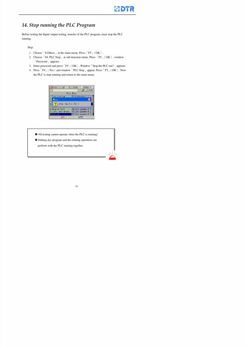
8132019 DTR 650 User Manual
httpslidepdfcomreaderfulldtr-650-user-manual 5470
14 983123983156983151983152 983154983157983150983150983145983150983143 983156983144983141 983120983116983107 983120983154983151983143983154983137983149
Before testing the Input output testing transfer of the PLC program must stop the PLC
running
Step
1 Choose「8Others」at the main menu Press「F5」(OK)
2 Choose「04 PLC Stop」at sub-function menu Press「F5」(OK) window
「Password」appears
3 Enter password and press「F5」(OK) Window「Stop the PLC run」appears
4 Press「F4」(Yes)and window「PLC Stop」appear Press「F5」(OK) Now
the PLC is stop running and return to the main menu
All testing cannot operate when the PLC is running
Editing dye program and the relating operation can
perform with the PLC running together
8132019 DTR 650 User Manual
httpslidepdfcomreaderfulldtr-650-user-manual 5570
15 983123983141983156983156983145983150983143 983156983144983141 983156983145983149983141
Step
1 Press「8Others」at the main menu Press「F5」(OK)
2 Choose「10Set date time」at the sub-function menu Press「F5」(OK) window
「Set date time」appears
3 Press「F5」(Edit) to move cursor by 「3」「4」 enter the time value at the
cursor locates
4 Press「F5」(OK)to complete the modify Press「F1」(Exit)to return to main
menu
5 Press「F1」(Exit)if not modify and return to main menu
8132019 DTR 650 User Manual
httpslidepdfcomreaderfulldtr-650-user-manual 5670
1166 983123983123983157983157 983152 983152 983152 983152983148983148983141983141983149983149983141983141983150983150983156 983156 983137983137983154 983154 983161983161 983124 983124 983137983137983138983138983148983148983141983141
TTTTTTTTaaaaaaaabbbbbbbblllllllleeeeeeee 11111111 【Dye Instruction】
Code Icon Instruction Code Icon Instruction
000 End 016 Inject C
001 Start 017 Dosing BV
002 Heat 018 PH
003 Cool 019 Addsalt B
004 Flow Fill 020 Addsalt C
005 Level Fill 021 Ana Fill
006 Drian 022 Lock Fill007 Rinse 023 Lock Level
008 Run 024 Low Rinse
009 Call 025 Cyc Rinse
010 Prep B 026 Rinse B
011 Addsalt B 027 Rinse C
012 Dosing B 028 Temp
013 Inject B 029 Nozzle Pressure
014 Prep C 030 Main Pump
015 Dosing C 031 Pump Speed
8132019 DTR 650 User Manual
httpslidepdfcomreaderfulldtr-650-user-manual 5770
Table 2 【【【【Alarm】】】】
System Alarm Must stop operating and check up to solve problems before restarting
the machine
Running Alarm It is a reminder Not effect the operating of DTR-650
Userrsquos Alarm Total of 32 Users can define themselves and use it when edit the PLC
Program (do not listing below)
No System Alarm No Running Alarm
1 PLC program not running 16 Temp ctrl 0 Grad too slow
2 Main temp sensor error 17 Temp ctrl 0 Grad too fast
3 Not at Run window 18 Temp ctrl 0 Hold temp too low
4 Exceeding max temp 19 Temp ctrl 0 Hold temp too high
5 - 20 Temp ctrl 1 Grad too slow6 - 21 Temp ctrl 1 Grad too fast
7 - 22 Temp ctrl 1 Hold temp too low
8 Communication error 23 Temp ctrl 1 Hold temp too high
9 Slave not answer 24 Temp ctrl 2 Grad too slow
10 PLC 0 not answer 25 Temp ctrl 2 Grad too fast
11 PLC 1 not answer 26 Temp 2 Hold temp too low12 Display not answer 27 Temp 2 Hold temp too high
13 Lower power voltage 28 Temp ctrl 3 Grad too slow
14 - 29 Temp ctrl 3 Grad too fast
15 - 30 Temp3 Hold temp too low
31 Temp3 Hold temp too high
32 Dosing 0 injection too slow
33 Dosing 0 injection too fast
34 Dosing 1 injection too slow
35 Dosing 1 injection too fast
8132019 DTR 650 User Manual
httpslidepdfcomreaderfulldtr-650-user-manual 5870
TTTTTTTTaaaaaaaabbbbbbbblllllllleeeeeeee 33333333 【【【【System factor】】】】
No Description Std Range amp Definition
1 ID No 000 000- 100 Controller no
2 Communication Rate 4800Bps 2400 4800 9600 19200 38400
3 Display language Chinese English Chinese
4 Temp display mode and
5 Maxmium temperature 145 025 ~ 145 6 Type of external PLC Default PLC32DPLC32PLC16Default
7 Number of external PLC NANA 1 unit connect
2 unit connect
8Communication Rate of
PLC9600Bps 2400 4800 9600 19200
9 Set point 1 085 000 ~ 145
If signal source is temperaturethe setting value is thetemperature value If the signal
source is Analog Input 6~17 then
setting value for Analog input is 0 ndash
100 and relates Analog
Input14~020mA
10 Source 1 Sensor0Sensor 0 ~5
Analog input 0 ~1111 Set point 2 092 Same as 09
12 Source 2 PT100 1 Same as 10
13 Set point 3 085 Same as 09
14 Source 3 PT100 2 Same as 10
15 Set point 4 092 Same as 09
16 Source 4 PT100 3 Same as 1017 Set point 5 085 Same as 09
18 Source 5 PT100 4 Same as 10
19 Set point 6 092 Same as 09
8132019 DTR 650 User Manual
httpslidepdfcomreaderfulldtr-650-user-manual 5970
29 Min cyclic time of cloth 100sec 0 ~ 255 sec
30 Max cyclic time of cloth 240sec 0 ~255 sec
31Standard cyclic time of
cloth
180 000 ~ 255 sec
32 Display ModeProgram
List
Program list Schematic Diagram
Icon mode
33 CF card format Standard of
DTR CF
Card
Standard of DTR CF Card V20
Standard CF Card
34 Addition step Disable Disable Enable35 Mode Com 3
CouplingEsure Com 3 is the communication
port of the Central or Coupling
36Com 3 Communication
rate9600 Central communication speed
8132019 DTR 650 User Manual
httpslidepdfcomreaderfulldtr-650-user-manual 6070
TTTTTTTTaaaaaaaabbbbbbbblllllllleeeeeeee 44444444 【【【【Temperature Cotnrol Factor】】】】
No Factor Definition Standard Range and Definition
01 PT No PT-0 PT 0~5 PT-100 Input number
02 Max working temp 140 000~140
03 Output mode 0 0~2
04 Alarm time of gardient 240sec 000~255 sec
05 Alarm mode of gradient Always AlwaysOnceNone
06 Control mode of gradient Heating orCooling
interlocked
Heating and Cooling interlocked
No limitation
07 Alarm range of HoldTemp 03 01~20
08 Alarm time for HoldTemp 240sec 000~255sec
09 Alarm mode of HoldTemp Always AlwaysOnceNone
10 Control mode ofHoldTemp
Heating only Only heating and cooling Cooling whenalarm occurred Only heating andcooling No limitation when alarmHeating only
11 Porportional Band 100 000~250
12 Integral band 128 sec 000~255 sec
13 Differential time 04 sec 00~20 sec
14 Min transit gradient 02 00~50
15 Transit rate 20 times 00~50 times (020= 2 times)
16 PID initial output value 010 000~100
17 ONOFF cycle time 10 sec 05~25 sec
Onoff valve set as 010 sec
Proportional valve set as 020 sec
18 Time down count mode Mode 0 0~10 = The time down count range from「Factor 20 + target temp」to「Target
8132019 DTR 650 User Manual
httpslidepdfcomreaderfulldtr-650-user-manual 6170
TTTTTTTTaaaaaaaabbbbbbbblllllllleeeeeeee 55555555 【【【【Speed Factor】】】】
No Factor Definition Standard Range amp Definition
01 Input Number Speed input 0 Speed input 0~11
02 Average times 05 times 01~10
03 Sensor Number 008pcs 001~255
04 Roller Dimension 250mm 050~500
05 Max cloth speed 200mmin 001~25506 Min cloth speed 020mmin 001~255
07 Alarm delay time 240sec 001~255
08 Alarm mode Every oncenoneevery
09 Alarm range () 020 001~255
10 Proportional band 100 001~255
11 Integer band 128 001~25512 Differential time 000 001~200
13 Initial speed () 020 001~255
14 Control cycle ti(01sec) 05 01~30
15 First cycle time(01sec) 10 01~30
16 Speed increase limit () 010 001~100
17 Speed decrease limit () 010 001~100
18 Min speed() 005 001~100
19 Manual speed adjust () 005 001~100
20 Manual initial speed() 020 001~100
21 Stopping speed() 010 001~100
22 Switch speed() 020 001~100
23 Not used
24 Speed decrease turns 03turns 01~50
8132019 DTR 650 User Manual
httpslidepdfcomreaderfulldtr-650-user-manual 6270
Table 6 【【【【Dosing Factors】】】】
No Description Range Range and Explanation
1 Analog input no Analog input 0 Analog input no 0 ~11
2Alarm delay time for
dosing240 sec 000 ~255 sec
3 Alarm time for dosing Every Every Once None
4 Proportional band 100 000 ~255 sec Factor P
5 Integer band 128 000 ~255 sec Factor I6 Differential time 04 00 ~20 Factor D
7 Max adjust rate 150 50~ 255
8 Initial factor for dosing 10 000 ~100
9 User curve section 0 10 Gradient of sect1 for dosing curve9
10 User curve section 1 10 Gradient of sect2 for dosing curve9
11 User curve section 2 10 Gradient of sect3 for dosing curve9
12 User curve section 3 10 Gradient of sect4 for dosing curve9
13 User curve section 4 10 Gradient of sect5 for dosing curve9
14 User curve section 5 10 Gradient of sect6 for dosing curve9
15 User curve section 6 10 Gradient of sect7 for dosing curve9
16 User curve section 7 10 Gradient of sect8 for dosing curve9
17 User curve section 8 10 Gradient of sect9 for dosing curve9
18 User curve section 9 10 Gradient of sect10 for dosing curve9
19 Min water level 05 00~ 10 04~20mA percentagechange to the userrsquos factor setting
20 Output value for Tank
clean
100 000~ 100
Injected percentage of dosing valve
in dosing End period
This factor will be invalided if usingONOFF dosing valve
21 Full range 100 001~255 Self-adjustment cannotchange
22 Range ratio 001001~255 Self-adjustment cannot
change
8132019 DTR 650 User Manual
httpslidepdfcomreaderfulldtr-650-user-manual 6370
【【【【TTaabbllee 77 】】】】Pressure Deviation Factors
No Description Std Range amp Definition
1 Analog input number + Analog in 0 Analog in 0~11
2 Analog input number - Analog in 1 Analog in 0~11
3 Input mode Pressure Pressure Pressure deviation
4 Full range 050x01Kgcm
001~255
5 Range ratio 001 001~255
6 Alarm delay time 100sec 001~255
7 Alarm mode Every oncenone
8 Alarm range 010 001~255
9 Proportional band 100 001~255
10 Integer band 128 001~255
11 Differential time 00 00~20
12 PID Init output value 010 001~255
13 Cycle time 10 03~30
14 First cycle time 030 003~100
15 Max adjust rate 010 001~100
8132019 DTR 650 User Manual
httpslidepdfcomreaderfulldtr-650-user-manual 6470
【【【【TTaabbllee 88 】】】】Definition of Analog Input
No Description Standard Range and Explanation
01 PT 0 correction standard DIN std DIN std JIS std
02 PT 0 correction +0 +- 9
03 PT 1 correction standard DIN std DIN std JIS std
04 PT 1 correction +0 +- 9
05 PT 2 correction standard DIN std DIN std JIS std
06 PT 2 correction +0 +- 9
07 PT 3 correction standard DIN std DIN std JIS std
08 PT 3 correction +0 +- 9
09 PT 4 correction standard DIN std DIN std JIS std
10 PT 4 correction +0 +- 9
11 PT 5 correction standard DIN std DIN std JIS std
12 PT 5 correction +0 +- 9
13 Analog input 0 define 4 ~ 20mA 0 ndash 20mA 4 ndash 20mA
14 Analog input 0 average times 10 times 01- 20 times
15 Analog input 0 min value 0000 0000 - 1000
16 Analog input 0 max value 100 0001 - 9999
17-60 Analog input 1~11 Same as Analog input 0
【【【【 】】】】 fi i i f A O
8132019 DTR 650 User Manual
httpslidepdfcomreaderfulldtr-650-user-manual 6570
【【【【TTaabbllee 99 】】】】Definition of Analog Output
No Description Standard Range and explanation
61 Analog output 0 define Control byPLC
Control by PLC
Temperature control PID0 output
Temperature control PID1 output
Temperature control PID2 output
Speed PID3 output
Dosing PID0 output Dosing PID1output
Pressure different PID0 outputPressure different PID1 output
Main temperature output
62 Mode of Analog ouptput0 4 ~20mA 0 ndash20mA 4 ndash 20mA
63-84 Analog output 1~11 Same as Analog output 0
【【【【TTaabbllee 1100】】】】Value Table 0 amp 1
No Description Range Std Range and explanation
1 Analog input no 000~011 000 Analog input no
2 Data ratio 001~255 100 Multiple by factors
3~53 0~98 000~255 000-100 Analog input 0~98 data
【【【【 】】】】St t Li t
8132019 DTR 650 User Manual
httpslidepdfcomreaderfulldtr-650-user-manual 6670
【【【【TTaabbllee 1111】】】】State List
No Description Range Standard Range and explanation
1 Display setting 1 0~255 205 See remarks at next page
2 Display setting 2 0~255 208
3 Display setting 3 0~255 209
4 Display setting 4 0~255 017
5 Display setting 5 0~255 0186 Display setting 6 0~255 019
7 Display setting 7 0~255 020
8 Display setting 8 0~255 021
9 Display setting 9 0~255 000
10 Display setting 1 0~255 000
11 Display setting 2 0~255 000
12 Display setting 3 0~255 000
13 Display setting 4 0~255 000
14 Display setting 5 0~255 000
15 Display setting 6 0~255 000
16 Display setting 7 0~255 000
Remarks
8132019 DTR 650 User Manual
httpslidepdfcomreaderfulldtr-650-user-manual 6770
0 = No display 1~255 = Display type of number
1~16 Content of PLC VB0~15
No 1 corresponding to VB0
No 16 corresponding to VB15
17~32 Content of PLC DB0~15
No 17 corresponding to DB0
No 32 corresponding to DB15
33~46 Content of PLC CNT0~29
No 33 corresponding to CNT0
No 46 corresponding to CNT29 47~78 Content of dyeing instruction 0~31 CNT0
No 47 corresponding to system instruction to No 0 of CNT0
No 78 corresponding to system instruction to No 31 of CNT0rsquos content
79~110 Dyeing instruction 0~31 of CNT0rsquos setting
111~142 Content of Dyeing instruction 0~31 CNT1No 111 corresponding to dyeing instruction No 0 of CNT1
No 142 corresponding to dyeing instruction No 31 of CNT1rsquos content
143~174 Dyeing instruction 0~31 of CNT1rsquos setting
175~204 Content of PLC HTIM0~29
No 175 corresponding to HTIM0
No 204 corresponding to HTIM29
205 Loading
206 Ratio 1
207 Ratio 2208 Ratio 1 x Loading
209 Ratio 2 x Loading
210 Fix value
211 Value Table 1 matching result
212 Value Table 2 matching result
213 Value Table 1 setting214 Value Table 2 setting
215 Pressure control PID0 different pressure value
216 Pressure control PID1 different pressure value
TTTTTTTTaaaaaaaabbbbbbbblllllllleeeeeeee 1122 【【【【Usage of password】】】】
8132019 DTR 650 User Manual
httpslidepdfcomreaderfulldtr-650-user-manual 6870
No Main FunctionFactor Sub Function Factor Password Rank
1 Run None
2 Dye program User3 or above
3 Control factor
- User factor User 1
- System factor User 1
- Temp PID 0
- Temp PID 1 User 1- Speed PID 0 User 1
- Dosing PID 0 User 1
- Dosing PID 1 User 1
- Pressure PID 0 User 1
- Pressure PID 1 User 1
- Analog IO User 1
- Load standard factor User 2 or above- Load a copied factor User 2 or above
- Copy factor User 2 or above
- Value table 0 User 1
- Value table 1 User 1
- Information and state User 1
- Dye instruction User 1
- Edit dye instruction setting User 14 Output testing User 2 or above
5 Calibration User 2 or above
6 Dye record None
7 CF card User 1
8 Info and state None
9 Others
- Contrast User3 or above
- Data Locking None
- PLC Run User 1
- PLC Stop User 1
- Password setting User 1
TTTTTTTTaaaaaaaabbbbbbbblllllllleeeeeeee 1133 【【【【Technical Data】】】】
8132019 DTR 650 User Manual
httpslidepdfcomreaderfulldtr-650-user-manual 6970
TTTTTTTTaaaaaaaabbbbbbbblllllllleeeeeeee 1133 【【【【Technical Data】】】】
1 Temperature Control
- Range 10~145(plusmn1)
- Mode Proportional or PWM
- Sensor PT100 (JIS or DIN standard)
2 Input and output channel
- Digital Input 32 DC24V PNP- Digital Output 32 DC24V 054A Relay connect point
- Analog Input 4 04~20 mA
- Analog Output 4 0~20mA 或 4~20 mA
3 Communication port 3 RS-232 amp 0~20 mAx1 RS485x 2
4 Dye program
- Number 15000 Steps
- Standard step 61Heating Cooling Fill Drain RinseDosingetc
5LCD module and Display
langage
Chinese
English
320 x 240 TFT color display with
more language
6 CF card connector 1 PCMCIA standard
7 Membrane Keyboard- Number Key 10 [0]~[9] Input factors
- Function Key 5 [F1]~[F5] function selecting
- Operation Key 2 [Start] [Stop]
- Auxiliary Key 7 [][][][][Esc] [larr][OK] [bull]
8 Operating Condition
- Temperature 5~45
- Humidity ≦85 (25)
9 Power supply
V l DC 24V
8132019 DTR 650 User Manual
httpslidepdfcomreaderfulldtr-650-user-manual 7070
70
983108983124983122983085650 983113983150983152983157983156 983119983157983156983152983157983156 983120983151983154983156983145983150983143 (983138983137983139983147983155983145983140983141 983158983145983141983159)
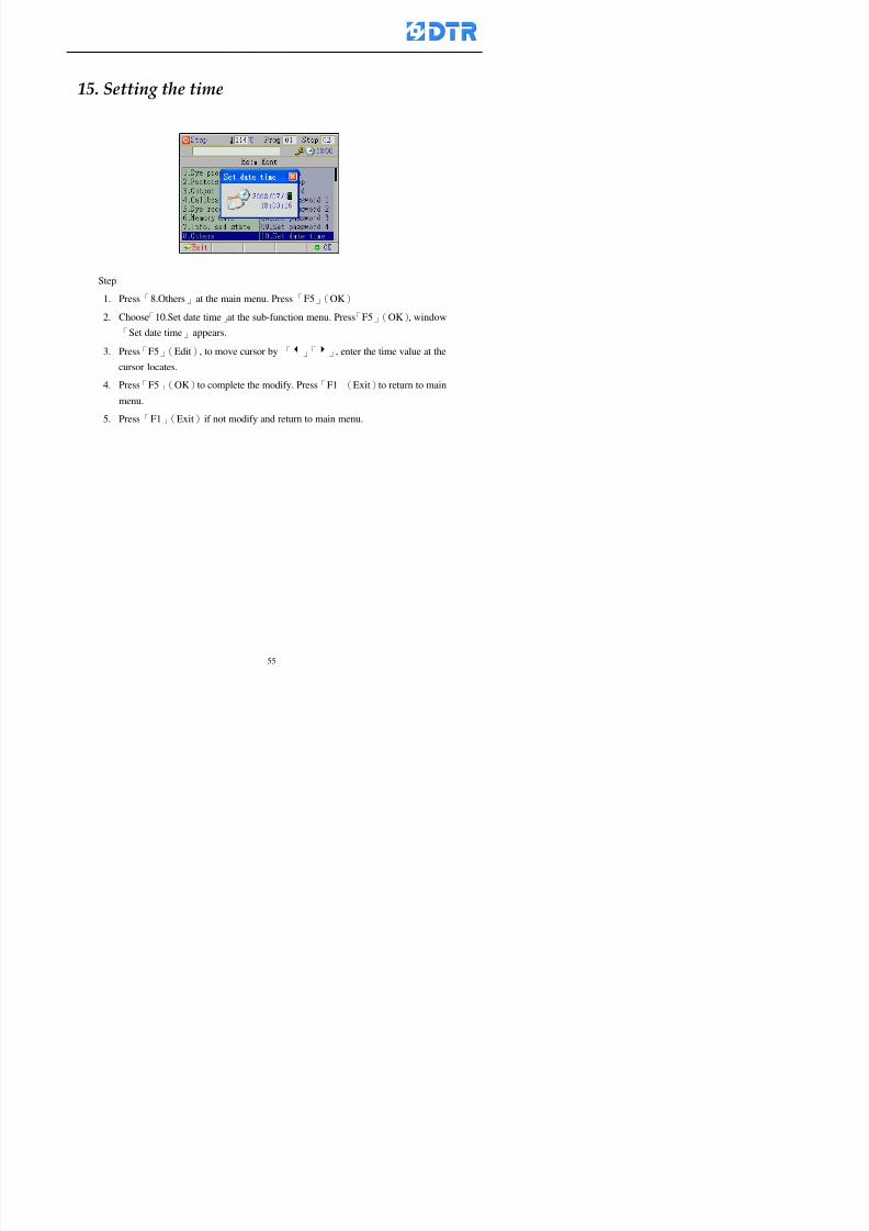
8132019 DTR 650 User Manual
httpslidepdfcomreaderfulldtr-650-user-manual 5570
15 983123983141983156983156983145983150983143 983156983144983141 983156983145983149983141
Step
1 Press「8Others」at the main menu Press「F5」(OK)
2 Choose「10Set date time」at the sub-function menu Press「F5」(OK) window
「Set date time」appears
3 Press「F5」(Edit) to move cursor by 「3」「4」 enter the time value at the
cursor locates
4 Press「F5」(OK)to complete the modify Press「F1」(Exit)to return to main
menu
5 Press「F1」(Exit)if not modify and return to main menu
8132019 DTR 650 User Manual
httpslidepdfcomreaderfulldtr-650-user-manual 5670
1166 983123983123983157983157 983152 983152 983152 983152983148983148983141983141983149983149983141983141983150983150983156 983156 983137983137983154 983154 983161983161 983124 983124 983137983137983138983138983148983148983141983141
TTTTTTTTaaaaaaaabbbbbbbblllllllleeeeeeee 11111111 【Dye Instruction】
Code Icon Instruction Code Icon Instruction
000 End 016 Inject C
001 Start 017 Dosing BV
002 Heat 018 PH
003 Cool 019 Addsalt B
004 Flow Fill 020 Addsalt C
005 Level Fill 021 Ana Fill
006 Drian 022 Lock Fill007 Rinse 023 Lock Level
008 Run 024 Low Rinse
009 Call 025 Cyc Rinse
010 Prep B 026 Rinse B
011 Addsalt B 027 Rinse C
012 Dosing B 028 Temp
013 Inject B 029 Nozzle Pressure
014 Prep C 030 Main Pump
015 Dosing C 031 Pump Speed
8132019 DTR 650 User Manual
httpslidepdfcomreaderfulldtr-650-user-manual 5770
Table 2 【【【【Alarm】】】】
System Alarm Must stop operating and check up to solve problems before restarting
the machine
Running Alarm It is a reminder Not effect the operating of DTR-650
Userrsquos Alarm Total of 32 Users can define themselves and use it when edit the PLC
Program (do not listing below)
No System Alarm No Running Alarm
1 PLC program not running 16 Temp ctrl 0 Grad too slow
2 Main temp sensor error 17 Temp ctrl 0 Grad too fast
3 Not at Run window 18 Temp ctrl 0 Hold temp too low
4 Exceeding max temp 19 Temp ctrl 0 Hold temp too high
5 - 20 Temp ctrl 1 Grad too slow6 - 21 Temp ctrl 1 Grad too fast
7 - 22 Temp ctrl 1 Hold temp too low
8 Communication error 23 Temp ctrl 1 Hold temp too high
9 Slave not answer 24 Temp ctrl 2 Grad too slow
10 PLC 0 not answer 25 Temp ctrl 2 Grad too fast
11 PLC 1 not answer 26 Temp 2 Hold temp too low12 Display not answer 27 Temp 2 Hold temp too high
13 Lower power voltage 28 Temp ctrl 3 Grad too slow
14 - 29 Temp ctrl 3 Grad too fast
15 - 30 Temp3 Hold temp too low
31 Temp3 Hold temp too high
32 Dosing 0 injection too slow
33 Dosing 0 injection too fast
34 Dosing 1 injection too slow
35 Dosing 1 injection too fast
8132019 DTR 650 User Manual
httpslidepdfcomreaderfulldtr-650-user-manual 5870
TTTTTTTTaaaaaaaabbbbbbbblllllllleeeeeeee 33333333 【【【【System factor】】】】
No Description Std Range amp Definition
1 ID No 000 000- 100 Controller no
2 Communication Rate 4800Bps 2400 4800 9600 19200 38400
3 Display language Chinese English Chinese
4 Temp display mode and
5 Maxmium temperature 145 025 ~ 145 6 Type of external PLC Default PLC32DPLC32PLC16Default
7 Number of external PLC NANA 1 unit connect
2 unit connect
8Communication Rate of
PLC9600Bps 2400 4800 9600 19200
9 Set point 1 085 000 ~ 145
If signal source is temperaturethe setting value is thetemperature value If the signal
source is Analog Input 6~17 then
setting value for Analog input is 0 ndash
100 and relates Analog
Input14~020mA
10 Source 1 Sensor0Sensor 0 ~5
Analog input 0 ~1111 Set point 2 092 Same as 09
12 Source 2 PT100 1 Same as 10
13 Set point 3 085 Same as 09
14 Source 3 PT100 2 Same as 10
15 Set point 4 092 Same as 09
16 Source 4 PT100 3 Same as 1017 Set point 5 085 Same as 09
18 Source 5 PT100 4 Same as 10
19 Set point 6 092 Same as 09
8132019 DTR 650 User Manual
httpslidepdfcomreaderfulldtr-650-user-manual 5970
29 Min cyclic time of cloth 100sec 0 ~ 255 sec
30 Max cyclic time of cloth 240sec 0 ~255 sec
31Standard cyclic time of
cloth
180 000 ~ 255 sec
32 Display ModeProgram
List
Program list Schematic Diagram
Icon mode
33 CF card format Standard of
DTR CF
Card
Standard of DTR CF Card V20
Standard CF Card
34 Addition step Disable Disable Enable35 Mode Com 3
CouplingEsure Com 3 is the communication
port of the Central or Coupling
36Com 3 Communication
rate9600 Central communication speed
8132019 DTR 650 User Manual
httpslidepdfcomreaderfulldtr-650-user-manual 6070
TTTTTTTTaaaaaaaabbbbbbbblllllllleeeeeeee 44444444 【【【【Temperature Cotnrol Factor】】】】
No Factor Definition Standard Range and Definition
01 PT No PT-0 PT 0~5 PT-100 Input number
02 Max working temp 140 000~140
03 Output mode 0 0~2
04 Alarm time of gardient 240sec 000~255 sec
05 Alarm mode of gradient Always AlwaysOnceNone
06 Control mode of gradient Heating orCooling
interlocked
Heating and Cooling interlocked
No limitation
07 Alarm range of HoldTemp 03 01~20
08 Alarm time for HoldTemp 240sec 000~255sec
09 Alarm mode of HoldTemp Always AlwaysOnceNone
10 Control mode ofHoldTemp
Heating only Only heating and cooling Cooling whenalarm occurred Only heating andcooling No limitation when alarmHeating only
11 Porportional Band 100 000~250
12 Integral band 128 sec 000~255 sec
13 Differential time 04 sec 00~20 sec
14 Min transit gradient 02 00~50
15 Transit rate 20 times 00~50 times (020= 2 times)
16 PID initial output value 010 000~100
17 ONOFF cycle time 10 sec 05~25 sec
Onoff valve set as 010 sec
Proportional valve set as 020 sec
18 Time down count mode Mode 0 0~10 = The time down count range from「Factor 20 + target temp」to「Target
8132019 DTR 650 User Manual
httpslidepdfcomreaderfulldtr-650-user-manual 6170
TTTTTTTTaaaaaaaabbbbbbbblllllllleeeeeeee 55555555 【【【【Speed Factor】】】】
No Factor Definition Standard Range amp Definition
01 Input Number Speed input 0 Speed input 0~11
02 Average times 05 times 01~10
03 Sensor Number 008pcs 001~255
04 Roller Dimension 250mm 050~500
05 Max cloth speed 200mmin 001~25506 Min cloth speed 020mmin 001~255
07 Alarm delay time 240sec 001~255
08 Alarm mode Every oncenoneevery
09 Alarm range () 020 001~255
10 Proportional band 100 001~255
11 Integer band 128 001~25512 Differential time 000 001~200
13 Initial speed () 020 001~255
14 Control cycle ti(01sec) 05 01~30
15 First cycle time(01sec) 10 01~30
16 Speed increase limit () 010 001~100
17 Speed decrease limit () 010 001~100
18 Min speed() 005 001~100
19 Manual speed adjust () 005 001~100
20 Manual initial speed() 020 001~100
21 Stopping speed() 010 001~100
22 Switch speed() 020 001~100
23 Not used
24 Speed decrease turns 03turns 01~50
8132019 DTR 650 User Manual
httpslidepdfcomreaderfulldtr-650-user-manual 6270
Table 6 【【【【Dosing Factors】】】】
No Description Range Range and Explanation
1 Analog input no Analog input 0 Analog input no 0 ~11
2Alarm delay time for
dosing240 sec 000 ~255 sec
3 Alarm time for dosing Every Every Once None
4 Proportional band 100 000 ~255 sec Factor P
5 Integer band 128 000 ~255 sec Factor I6 Differential time 04 00 ~20 Factor D
7 Max adjust rate 150 50~ 255
8 Initial factor for dosing 10 000 ~100
9 User curve section 0 10 Gradient of sect1 for dosing curve9
10 User curve section 1 10 Gradient of sect2 for dosing curve9
11 User curve section 2 10 Gradient of sect3 for dosing curve9
12 User curve section 3 10 Gradient of sect4 for dosing curve9
13 User curve section 4 10 Gradient of sect5 for dosing curve9
14 User curve section 5 10 Gradient of sect6 for dosing curve9
15 User curve section 6 10 Gradient of sect7 for dosing curve9
16 User curve section 7 10 Gradient of sect8 for dosing curve9
17 User curve section 8 10 Gradient of sect9 for dosing curve9
18 User curve section 9 10 Gradient of sect10 for dosing curve9
19 Min water level 05 00~ 10 04~20mA percentagechange to the userrsquos factor setting
20 Output value for Tank
clean
100 000~ 100
Injected percentage of dosing valve
in dosing End period
This factor will be invalided if usingONOFF dosing valve
21 Full range 100 001~255 Self-adjustment cannotchange
22 Range ratio 001001~255 Self-adjustment cannot
change
8132019 DTR 650 User Manual
httpslidepdfcomreaderfulldtr-650-user-manual 6370
【【【【TTaabbllee 77 】】】】Pressure Deviation Factors
No Description Std Range amp Definition
1 Analog input number + Analog in 0 Analog in 0~11
2 Analog input number - Analog in 1 Analog in 0~11
3 Input mode Pressure Pressure Pressure deviation
4 Full range 050x01Kgcm
001~255
5 Range ratio 001 001~255
6 Alarm delay time 100sec 001~255
7 Alarm mode Every oncenone
8 Alarm range 010 001~255
9 Proportional band 100 001~255
10 Integer band 128 001~255
11 Differential time 00 00~20
12 PID Init output value 010 001~255
13 Cycle time 10 03~30
14 First cycle time 030 003~100
15 Max adjust rate 010 001~100
8132019 DTR 650 User Manual
httpslidepdfcomreaderfulldtr-650-user-manual 6470
【【【【TTaabbllee 88 】】】】Definition of Analog Input
No Description Standard Range and Explanation
01 PT 0 correction standard DIN std DIN std JIS std
02 PT 0 correction +0 +- 9
03 PT 1 correction standard DIN std DIN std JIS std
04 PT 1 correction +0 +- 9
05 PT 2 correction standard DIN std DIN std JIS std
06 PT 2 correction +0 +- 9
07 PT 3 correction standard DIN std DIN std JIS std
08 PT 3 correction +0 +- 9
09 PT 4 correction standard DIN std DIN std JIS std
10 PT 4 correction +0 +- 9
11 PT 5 correction standard DIN std DIN std JIS std
12 PT 5 correction +0 +- 9
13 Analog input 0 define 4 ~ 20mA 0 ndash 20mA 4 ndash 20mA
14 Analog input 0 average times 10 times 01- 20 times
15 Analog input 0 min value 0000 0000 - 1000
16 Analog input 0 max value 100 0001 - 9999
17-60 Analog input 1~11 Same as Analog input 0
【【【【 】】】】 fi i i f A O
8132019 DTR 650 User Manual
httpslidepdfcomreaderfulldtr-650-user-manual 6570
【【【【TTaabbllee 99 】】】】Definition of Analog Output
No Description Standard Range and explanation
61 Analog output 0 define Control byPLC
Control by PLC
Temperature control PID0 output
Temperature control PID1 output
Temperature control PID2 output
Speed PID3 output
Dosing PID0 output Dosing PID1output
Pressure different PID0 outputPressure different PID1 output
Main temperature output
62 Mode of Analog ouptput0 4 ~20mA 0 ndash20mA 4 ndash 20mA
63-84 Analog output 1~11 Same as Analog output 0
【【【【TTaabbllee 1100】】】】Value Table 0 amp 1
No Description Range Std Range and explanation
1 Analog input no 000~011 000 Analog input no
2 Data ratio 001~255 100 Multiple by factors
3~53 0~98 000~255 000-100 Analog input 0~98 data
【【【【 】】】】St t Li t
8132019 DTR 650 User Manual
httpslidepdfcomreaderfulldtr-650-user-manual 6670
【【【【TTaabbllee 1111】】】】State List
No Description Range Standard Range and explanation
1 Display setting 1 0~255 205 See remarks at next page
2 Display setting 2 0~255 208
3 Display setting 3 0~255 209
4 Display setting 4 0~255 017
5 Display setting 5 0~255 0186 Display setting 6 0~255 019
7 Display setting 7 0~255 020
8 Display setting 8 0~255 021
9 Display setting 9 0~255 000
10 Display setting 1 0~255 000
11 Display setting 2 0~255 000
12 Display setting 3 0~255 000
13 Display setting 4 0~255 000
14 Display setting 5 0~255 000
15 Display setting 6 0~255 000
16 Display setting 7 0~255 000
Remarks
8132019 DTR 650 User Manual
httpslidepdfcomreaderfulldtr-650-user-manual 6770
0 = No display 1~255 = Display type of number
1~16 Content of PLC VB0~15
No 1 corresponding to VB0
No 16 corresponding to VB15
17~32 Content of PLC DB0~15
No 17 corresponding to DB0
No 32 corresponding to DB15
33~46 Content of PLC CNT0~29
No 33 corresponding to CNT0
No 46 corresponding to CNT29 47~78 Content of dyeing instruction 0~31 CNT0
No 47 corresponding to system instruction to No 0 of CNT0
No 78 corresponding to system instruction to No 31 of CNT0rsquos content
79~110 Dyeing instruction 0~31 of CNT0rsquos setting
111~142 Content of Dyeing instruction 0~31 CNT1No 111 corresponding to dyeing instruction No 0 of CNT1
No 142 corresponding to dyeing instruction No 31 of CNT1rsquos content
143~174 Dyeing instruction 0~31 of CNT1rsquos setting
175~204 Content of PLC HTIM0~29
No 175 corresponding to HTIM0
No 204 corresponding to HTIM29
205 Loading
206 Ratio 1
207 Ratio 2208 Ratio 1 x Loading
209 Ratio 2 x Loading
210 Fix value
211 Value Table 1 matching result
212 Value Table 2 matching result
213 Value Table 1 setting214 Value Table 2 setting
215 Pressure control PID0 different pressure value
216 Pressure control PID1 different pressure value
TTTTTTTTaaaaaaaabbbbbbbblllllllleeeeeeee 1122 【【【【Usage of password】】】】
8132019 DTR 650 User Manual
httpslidepdfcomreaderfulldtr-650-user-manual 6870
No Main FunctionFactor Sub Function Factor Password Rank
1 Run None
2 Dye program User3 or above
3 Control factor
- User factor User 1
- System factor User 1
- Temp PID 0
- Temp PID 1 User 1- Speed PID 0 User 1
- Dosing PID 0 User 1
- Dosing PID 1 User 1
- Pressure PID 0 User 1
- Pressure PID 1 User 1
- Analog IO User 1
- Load standard factor User 2 or above- Load a copied factor User 2 or above
- Copy factor User 2 or above
- Value table 0 User 1
- Value table 1 User 1
- Information and state User 1
- Dye instruction User 1
- Edit dye instruction setting User 14 Output testing User 2 or above
5 Calibration User 2 or above
6 Dye record None
7 CF card User 1
8 Info and state None
9 Others
- Contrast User3 or above
- Data Locking None
- PLC Run User 1
- PLC Stop User 1
- Password setting User 1
TTTTTTTTaaaaaaaabbbbbbbblllllllleeeeeeee 1133 【【【【Technical Data】】】】
8132019 DTR 650 User Manual
httpslidepdfcomreaderfulldtr-650-user-manual 6970
TTTTTTTTaaaaaaaabbbbbbbblllllllleeeeeeee 1133 【【【【Technical Data】】】】
1 Temperature Control
- Range 10~145(plusmn1)
- Mode Proportional or PWM
- Sensor PT100 (JIS or DIN standard)
2 Input and output channel
- Digital Input 32 DC24V PNP- Digital Output 32 DC24V 054A Relay connect point
- Analog Input 4 04~20 mA
- Analog Output 4 0~20mA 或 4~20 mA
3 Communication port 3 RS-232 amp 0~20 mAx1 RS485x 2
4 Dye program
- Number 15000 Steps
- Standard step 61Heating Cooling Fill Drain RinseDosingetc
5LCD module and Display
langage
Chinese
English
320 x 240 TFT color display with
more language
6 CF card connector 1 PCMCIA standard
7 Membrane Keyboard- Number Key 10 [0]~[9] Input factors
- Function Key 5 [F1]~[F5] function selecting
- Operation Key 2 [Start] [Stop]
- Auxiliary Key 7 [][][][][Esc] [larr][OK] [bull]
8 Operating Condition
- Temperature 5~45
- Humidity ≦85 (25)
9 Power supply
V l DC 24V
8132019 DTR 650 User Manual
httpslidepdfcomreaderfulldtr-650-user-manual 7070
70
983108983124983122983085650 983113983150983152983157983156 983119983157983156983152983157983156 983120983151983154983156983145983150983143 (983138983137983139983147983155983145983140983141 983158983145983141983159)
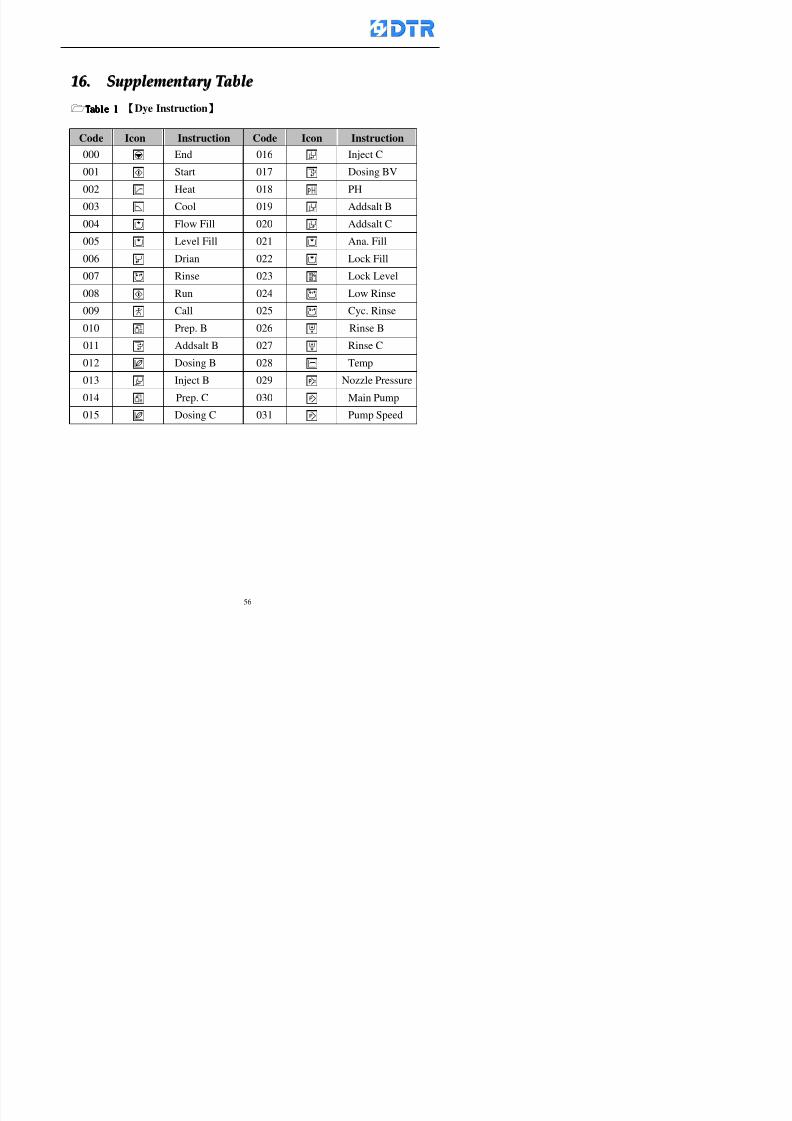
8132019 DTR 650 User Manual
httpslidepdfcomreaderfulldtr-650-user-manual 5670
1166 983123983123983157983157 983152 983152 983152 983152983148983148983141983141983149983149983141983141983150983150983156 983156 983137983137983154 983154 983161983161 983124 983124 983137983137983138983138983148983148983141983141
TTTTTTTTaaaaaaaabbbbbbbblllllllleeeeeeee 11111111 【Dye Instruction】
Code Icon Instruction Code Icon Instruction
000 End 016 Inject C
001 Start 017 Dosing BV
002 Heat 018 PH
003 Cool 019 Addsalt B
004 Flow Fill 020 Addsalt C
005 Level Fill 021 Ana Fill
006 Drian 022 Lock Fill007 Rinse 023 Lock Level
008 Run 024 Low Rinse
009 Call 025 Cyc Rinse
010 Prep B 026 Rinse B
011 Addsalt B 027 Rinse C
012 Dosing B 028 Temp
013 Inject B 029 Nozzle Pressure
014 Prep C 030 Main Pump
015 Dosing C 031 Pump Speed
8132019 DTR 650 User Manual
httpslidepdfcomreaderfulldtr-650-user-manual 5770
Table 2 【【【【Alarm】】】】
System Alarm Must stop operating and check up to solve problems before restarting
the machine
Running Alarm It is a reminder Not effect the operating of DTR-650
Userrsquos Alarm Total of 32 Users can define themselves and use it when edit the PLC
Program (do not listing below)
No System Alarm No Running Alarm
1 PLC program not running 16 Temp ctrl 0 Grad too slow
2 Main temp sensor error 17 Temp ctrl 0 Grad too fast
3 Not at Run window 18 Temp ctrl 0 Hold temp too low
4 Exceeding max temp 19 Temp ctrl 0 Hold temp too high
5 - 20 Temp ctrl 1 Grad too slow6 - 21 Temp ctrl 1 Grad too fast
7 - 22 Temp ctrl 1 Hold temp too low
8 Communication error 23 Temp ctrl 1 Hold temp too high
9 Slave not answer 24 Temp ctrl 2 Grad too slow
10 PLC 0 not answer 25 Temp ctrl 2 Grad too fast
11 PLC 1 not answer 26 Temp 2 Hold temp too low12 Display not answer 27 Temp 2 Hold temp too high
13 Lower power voltage 28 Temp ctrl 3 Grad too slow
14 - 29 Temp ctrl 3 Grad too fast
15 - 30 Temp3 Hold temp too low
31 Temp3 Hold temp too high
32 Dosing 0 injection too slow
33 Dosing 0 injection too fast
34 Dosing 1 injection too slow
35 Dosing 1 injection too fast
8132019 DTR 650 User Manual
httpslidepdfcomreaderfulldtr-650-user-manual 5870
TTTTTTTTaaaaaaaabbbbbbbblllllllleeeeeeee 33333333 【【【【System factor】】】】
No Description Std Range amp Definition
1 ID No 000 000- 100 Controller no
2 Communication Rate 4800Bps 2400 4800 9600 19200 38400
3 Display language Chinese English Chinese
4 Temp display mode and
5 Maxmium temperature 145 025 ~ 145 6 Type of external PLC Default PLC32DPLC32PLC16Default
7 Number of external PLC NANA 1 unit connect
2 unit connect
8Communication Rate of
PLC9600Bps 2400 4800 9600 19200
9 Set point 1 085 000 ~ 145
If signal source is temperaturethe setting value is thetemperature value If the signal
source is Analog Input 6~17 then
setting value for Analog input is 0 ndash
100 and relates Analog
Input14~020mA
10 Source 1 Sensor0Sensor 0 ~5
Analog input 0 ~1111 Set point 2 092 Same as 09
12 Source 2 PT100 1 Same as 10
13 Set point 3 085 Same as 09
14 Source 3 PT100 2 Same as 10
15 Set point 4 092 Same as 09
16 Source 4 PT100 3 Same as 1017 Set point 5 085 Same as 09
18 Source 5 PT100 4 Same as 10
19 Set point 6 092 Same as 09
8132019 DTR 650 User Manual
httpslidepdfcomreaderfulldtr-650-user-manual 5970
29 Min cyclic time of cloth 100sec 0 ~ 255 sec
30 Max cyclic time of cloth 240sec 0 ~255 sec
31Standard cyclic time of
cloth
180 000 ~ 255 sec
32 Display ModeProgram
List
Program list Schematic Diagram
Icon mode
33 CF card format Standard of
DTR CF
Card
Standard of DTR CF Card V20
Standard CF Card
34 Addition step Disable Disable Enable35 Mode Com 3
CouplingEsure Com 3 is the communication
port of the Central or Coupling
36Com 3 Communication
rate9600 Central communication speed
8132019 DTR 650 User Manual
httpslidepdfcomreaderfulldtr-650-user-manual 6070
TTTTTTTTaaaaaaaabbbbbbbblllllllleeeeeeee 44444444 【【【【Temperature Cotnrol Factor】】】】
No Factor Definition Standard Range and Definition
01 PT No PT-0 PT 0~5 PT-100 Input number
02 Max working temp 140 000~140
03 Output mode 0 0~2
04 Alarm time of gardient 240sec 000~255 sec
05 Alarm mode of gradient Always AlwaysOnceNone
06 Control mode of gradient Heating orCooling
interlocked
Heating and Cooling interlocked
No limitation
07 Alarm range of HoldTemp 03 01~20
08 Alarm time for HoldTemp 240sec 000~255sec
09 Alarm mode of HoldTemp Always AlwaysOnceNone
10 Control mode ofHoldTemp
Heating only Only heating and cooling Cooling whenalarm occurred Only heating andcooling No limitation when alarmHeating only
11 Porportional Band 100 000~250
12 Integral band 128 sec 000~255 sec
13 Differential time 04 sec 00~20 sec
14 Min transit gradient 02 00~50
15 Transit rate 20 times 00~50 times (020= 2 times)
16 PID initial output value 010 000~100
17 ONOFF cycle time 10 sec 05~25 sec
Onoff valve set as 010 sec
Proportional valve set as 020 sec
18 Time down count mode Mode 0 0~10 = The time down count range from「Factor 20 + target temp」to「Target
8132019 DTR 650 User Manual
httpslidepdfcomreaderfulldtr-650-user-manual 6170
TTTTTTTTaaaaaaaabbbbbbbblllllllleeeeeeee 55555555 【【【【Speed Factor】】】】
No Factor Definition Standard Range amp Definition
01 Input Number Speed input 0 Speed input 0~11
02 Average times 05 times 01~10
03 Sensor Number 008pcs 001~255
04 Roller Dimension 250mm 050~500
05 Max cloth speed 200mmin 001~25506 Min cloth speed 020mmin 001~255
07 Alarm delay time 240sec 001~255
08 Alarm mode Every oncenoneevery
09 Alarm range () 020 001~255
10 Proportional band 100 001~255
11 Integer band 128 001~25512 Differential time 000 001~200
13 Initial speed () 020 001~255
14 Control cycle ti(01sec) 05 01~30
15 First cycle time(01sec) 10 01~30
16 Speed increase limit () 010 001~100
17 Speed decrease limit () 010 001~100
18 Min speed() 005 001~100
19 Manual speed adjust () 005 001~100
20 Manual initial speed() 020 001~100
21 Stopping speed() 010 001~100
22 Switch speed() 020 001~100
23 Not used
24 Speed decrease turns 03turns 01~50
8132019 DTR 650 User Manual
httpslidepdfcomreaderfulldtr-650-user-manual 6270
Table 6 【【【【Dosing Factors】】】】
No Description Range Range and Explanation
1 Analog input no Analog input 0 Analog input no 0 ~11
2Alarm delay time for
dosing240 sec 000 ~255 sec
3 Alarm time for dosing Every Every Once None
4 Proportional band 100 000 ~255 sec Factor P
5 Integer band 128 000 ~255 sec Factor I6 Differential time 04 00 ~20 Factor D
7 Max adjust rate 150 50~ 255
8 Initial factor for dosing 10 000 ~100
9 User curve section 0 10 Gradient of sect1 for dosing curve9
10 User curve section 1 10 Gradient of sect2 for dosing curve9
11 User curve section 2 10 Gradient of sect3 for dosing curve9
12 User curve section 3 10 Gradient of sect4 for dosing curve9
13 User curve section 4 10 Gradient of sect5 for dosing curve9
14 User curve section 5 10 Gradient of sect6 for dosing curve9
15 User curve section 6 10 Gradient of sect7 for dosing curve9
16 User curve section 7 10 Gradient of sect8 for dosing curve9
17 User curve section 8 10 Gradient of sect9 for dosing curve9
18 User curve section 9 10 Gradient of sect10 for dosing curve9
19 Min water level 05 00~ 10 04~20mA percentagechange to the userrsquos factor setting
20 Output value for Tank
clean
100 000~ 100
Injected percentage of dosing valve
in dosing End period
This factor will be invalided if usingONOFF dosing valve
21 Full range 100 001~255 Self-adjustment cannotchange
22 Range ratio 001001~255 Self-adjustment cannot
change
8132019 DTR 650 User Manual
httpslidepdfcomreaderfulldtr-650-user-manual 6370
【【【【TTaabbllee 77 】】】】Pressure Deviation Factors
No Description Std Range amp Definition
1 Analog input number + Analog in 0 Analog in 0~11
2 Analog input number - Analog in 1 Analog in 0~11
3 Input mode Pressure Pressure Pressure deviation
4 Full range 050x01Kgcm
001~255
5 Range ratio 001 001~255
6 Alarm delay time 100sec 001~255
7 Alarm mode Every oncenone
8 Alarm range 010 001~255
9 Proportional band 100 001~255
10 Integer band 128 001~255
11 Differential time 00 00~20
12 PID Init output value 010 001~255
13 Cycle time 10 03~30
14 First cycle time 030 003~100
15 Max adjust rate 010 001~100
8132019 DTR 650 User Manual
httpslidepdfcomreaderfulldtr-650-user-manual 6470
【【【【TTaabbllee 88 】】】】Definition of Analog Input
No Description Standard Range and Explanation
01 PT 0 correction standard DIN std DIN std JIS std
02 PT 0 correction +0 +- 9
03 PT 1 correction standard DIN std DIN std JIS std
04 PT 1 correction +0 +- 9
05 PT 2 correction standard DIN std DIN std JIS std
06 PT 2 correction +0 +- 9
07 PT 3 correction standard DIN std DIN std JIS std
08 PT 3 correction +0 +- 9
09 PT 4 correction standard DIN std DIN std JIS std
10 PT 4 correction +0 +- 9
11 PT 5 correction standard DIN std DIN std JIS std
12 PT 5 correction +0 +- 9
13 Analog input 0 define 4 ~ 20mA 0 ndash 20mA 4 ndash 20mA
14 Analog input 0 average times 10 times 01- 20 times
15 Analog input 0 min value 0000 0000 - 1000
16 Analog input 0 max value 100 0001 - 9999
17-60 Analog input 1~11 Same as Analog input 0
【【【【 】】】】 fi i i f A O
8132019 DTR 650 User Manual
httpslidepdfcomreaderfulldtr-650-user-manual 6570
【【【【TTaabbllee 99 】】】】Definition of Analog Output
No Description Standard Range and explanation
61 Analog output 0 define Control byPLC
Control by PLC
Temperature control PID0 output
Temperature control PID1 output
Temperature control PID2 output
Speed PID3 output
Dosing PID0 output Dosing PID1output
Pressure different PID0 outputPressure different PID1 output
Main temperature output
62 Mode of Analog ouptput0 4 ~20mA 0 ndash20mA 4 ndash 20mA
63-84 Analog output 1~11 Same as Analog output 0
【【【【TTaabbllee 1100】】】】Value Table 0 amp 1
No Description Range Std Range and explanation
1 Analog input no 000~011 000 Analog input no
2 Data ratio 001~255 100 Multiple by factors
3~53 0~98 000~255 000-100 Analog input 0~98 data
【【【【 】】】】St t Li t
8132019 DTR 650 User Manual
httpslidepdfcomreaderfulldtr-650-user-manual 6670
【【【【TTaabbllee 1111】】】】State List
No Description Range Standard Range and explanation
1 Display setting 1 0~255 205 See remarks at next page
2 Display setting 2 0~255 208
3 Display setting 3 0~255 209
4 Display setting 4 0~255 017
5 Display setting 5 0~255 0186 Display setting 6 0~255 019
7 Display setting 7 0~255 020
8 Display setting 8 0~255 021
9 Display setting 9 0~255 000
10 Display setting 1 0~255 000
11 Display setting 2 0~255 000
12 Display setting 3 0~255 000
13 Display setting 4 0~255 000
14 Display setting 5 0~255 000
15 Display setting 6 0~255 000
16 Display setting 7 0~255 000
Remarks
8132019 DTR 650 User Manual
httpslidepdfcomreaderfulldtr-650-user-manual 6770
0 = No display 1~255 = Display type of number
1~16 Content of PLC VB0~15
No 1 corresponding to VB0
No 16 corresponding to VB15
17~32 Content of PLC DB0~15
No 17 corresponding to DB0
No 32 corresponding to DB15
33~46 Content of PLC CNT0~29
No 33 corresponding to CNT0
No 46 corresponding to CNT29 47~78 Content of dyeing instruction 0~31 CNT0
No 47 corresponding to system instruction to No 0 of CNT0
No 78 corresponding to system instruction to No 31 of CNT0rsquos content
79~110 Dyeing instruction 0~31 of CNT0rsquos setting
111~142 Content of Dyeing instruction 0~31 CNT1No 111 corresponding to dyeing instruction No 0 of CNT1
No 142 corresponding to dyeing instruction No 31 of CNT1rsquos content
143~174 Dyeing instruction 0~31 of CNT1rsquos setting
175~204 Content of PLC HTIM0~29
No 175 corresponding to HTIM0
No 204 corresponding to HTIM29
205 Loading
206 Ratio 1
207 Ratio 2208 Ratio 1 x Loading
209 Ratio 2 x Loading
210 Fix value
211 Value Table 1 matching result
212 Value Table 2 matching result
213 Value Table 1 setting214 Value Table 2 setting
215 Pressure control PID0 different pressure value
216 Pressure control PID1 different pressure value
TTTTTTTTaaaaaaaabbbbbbbblllllllleeeeeeee 1122 【【【【Usage of password】】】】
8132019 DTR 650 User Manual
httpslidepdfcomreaderfulldtr-650-user-manual 6870
No Main FunctionFactor Sub Function Factor Password Rank
1 Run None
2 Dye program User3 or above
3 Control factor
- User factor User 1
- System factor User 1
- Temp PID 0
- Temp PID 1 User 1- Speed PID 0 User 1
- Dosing PID 0 User 1
- Dosing PID 1 User 1
- Pressure PID 0 User 1
- Pressure PID 1 User 1
- Analog IO User 1
- Load standard factor User 2 or above- Load a copied factor User 2 or above
- Copy factor User 2 or above
- Value table 0 User 1
- Value table 1 User 1
- Information and state User 1
- Dye instruction User 1
- Edit dye instruction setting User 14 Output testing User 2 or above
5 Calibration User 2 or above
6 Dye record None
7 CF card User 1
8 Info and state None
9 Others
- Contrast User3 or above
- Data Locking None
- PLC Run User 1
- PLC Stop User 1
- Password setting User 1
TTTTTTTTaaaaaaaabbbbbbbblllllllleeeeeeee 1133 【【【【Technical Data】】】】
8132019 DTR 650 User Manual
httpslidepdfcomreaderfulldtr-650-user-manual 6970
TTTTTTTTaaaaaaaabbbbbbbblllllllleeeeeeee 1133 【【【【Technical Data】】】】
1 Temperature Control
- Range 10~145(plusmn1)
- Mode Proportional or PWM
- Sensor PT100 (JIS or DIN standard)
2 Input and output channel
- Digital Input 32 DC24V PNP- Digital Output 32 DC24V 054A Relay connect point
- Analog Input 4 04~20 mA
- Analog Output 4 0~20mA 或 4~20 mA
3 Communication port 3 RS-232 amp 0~20 mAx1 RS485x 2
4 Dye program
- Number 15000 Steps
- Standard step 61Heating Cooling Fill Drain RinseDosingetc
5LCD module and Display
langage
Chinese
English
320 x 240 TFT color display with
more language
6 CF card connector 1 PCMCIA standard
7 Membrane Keyboard- Number Key 10 [0]~[9] Input factors
- Function Key 5 [F1]~[F5] function selecting
- Operation Key 2 [Start] [Stop]
- Auxiliary Key 7 [][][][][Esc] [larr][OK] [bull]
8 Operating Condition
- Temperature 5~45
- Humidity ≦85 (25)
9 Power supply
V l DC 24V
8132019 DTR 650 User Manual
httpslidepdfcomreaderfulldtr-650-user-manual 7070
70
983108983124983122983085650 983113983150983152983157983156 983119983157983156983152983157983156 983120983151983154983156983145983150983143 (983138983137983139983147983155983145983140983141 983158983145983141983159)
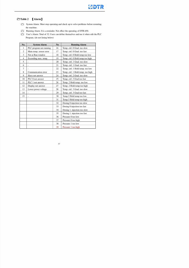
8132019 DTR 650 User Manual
httpslidepdfcomreaderfulldtr-650-user-manual 5770
Table 2 【【【【Alarm】】】】
System Alarm Must stop operating and check up to solve problems before restarting
the machine
Running Alarm It is a reminder Not effect the operating of DTR-650
Userrsquos Alarm Total of 32 Users can define themselves and use it when edit the PLC
Program (do not listing below)
No System Alarm No Running Alarm
1 PLC program not running 16 Temp ctrl 0 Grad too slow
2 Main temp sensor error 17 Temp ctrl 0 Grad too fast
3 Not at Run window 18 Temp ctrl 0 Hold temp too low
4 Exceeding max temp 19 Temp ctrl 0 Hold temp too high
5 - 20 Temp ctrl 1 Grad too slow6 - 21 Temp ctrl 1 Grad too fast
7 - 22 Temp ctrl 1 Hold temp too low
8 Communication error 23 Temp ctrl 1 Hold temp too high
9 Slave not answer 24 Temp ctrl 2 Grad too slow
10 PLC 0 not answer 25 Temp ctrl 2 Grad too fast
11 PLC 1 not answer 26 Temp 2 Hold temp too low12 Display not answer 27 Temp 2 Hold temp too high
13 Lower power voltage 28 Temp ctrl 3 Grad too slow
14 - 29 Temp ctrl 3 Grad too fast
15 - 30 Temp3 Hold temp too low
31 Temp3 Hold temp too high
32 Dosing 0 injection too slow
33 Dosing 0 injection too fast
34 Dosing 1 injection too slow
35 Dosing 1 injection too fast
8132019 DTR 650 User Manual
httpslidepdfcomreaderfulldtr-650-user-manual 5870
TTTTTTTTaaaaaaaabbbbbbbblllllllleeeeeeee 33333333 【【【【System factor】】】】
No Description Std Range amp Definition
1 ID No 000 000- 100 Controller no
2 Communication Rate 4800Bps 2400 4800 9600 19200 38400
3 Display language Chinese English Chinese
4 Temp display mode and
5 Maxmium temperature 145 025 ~ 145 6 Type of external PLC Default PLC32DPLC32PLC16Default
7 Number of external PLC NANA 1 unit connect
2 unit connect
8Communication Rate of
PLC9600Bps 2400 4800 9600 19200
9 Set point 1 085 000 ~ 145
If signal source is temperaturethe setting value is thetemperature value If the signal
source is Analog Input 6~17 then
setting value for Analog input is 0 ndash
100 and relates Analog
Input14~020mA
10 Source 1 Sensor0Sensor 0 ~5
Analog input 0 ~1111 Set point 2 092 Same as 09
12 Source 2 PT100 1 Same as 10
13 Set point 3 085 Same as 09
14 Source 3 PT100 2 Same as 10
15 Set point 4 092 Same as 09
16 Source 4 PT100 3 Same as 1017 Set point 5 085 Same as 09
18 Source 5 PT100 4 Same as 10
19 Set point 6 092 Same as 09
8132019 DTR 650 User Manual
httpslidepdfcomreaderfulldtr-650-user-manual 5970
29 Min cyclic time of cloth 100sec 0 ~ 255 sec
30 Max cyclic time of cloth 240sec 0 ~255 sec
31Standard cyclic time of
cloth
180 000 ~ 255 sec
32 Display ModeProgram
List
Program list Schematic Diagram
Icon mode
33 CF card format Standard of
DTR CF
Card
Standard of DTR CF Card V20
Standard CF Card
34 Addition step Disable Disable Enable35 Mode Com 3
CouplingEsure Com 3 is the communication
port of the Central or Coupling
36Com 3 Communication
rate9600 Central communication speed
8132019 DTR 650 User Manual
httpslidepdfcomreaderfulldtr-650-user-manual 6070
TTTTTTTTaaaaaaaabbbbbbbblllllllleeeeeeee 44444444 【【【【Temperature Cotnrol Factor】】】】
No Factor Definition Standard Range and Definition
01 PT No PT-0 PT 0~5 PT-100 Input number
02 Max working temp 140 000~140
03 Output mode 0 0~2
04 Alarm time of gardient 240sec 000~255 sec
05 Alarm mode of gradient Always AlwaysOnceNone
06 Control mode of gradient Heating orCooling
interlocked
Heating and Cooling interlocked
No limitation
07 Alarm range of HoldTemp 03 01~20
08 Alarm time for HoldTemp 240sec 000~255sec
09 Alarm mode of HoldTemp Always AlwaysOnceNone
10 Control mode ofHoldTemp
Heating only Only heating and cooling Cooling whenalarm occurred Only heating andcooling No limitation when alarmHeating only
11 Porportional Band 100 000~250
12 Integral band 128 sec 000~255 sec
13 Differential time 04 sec 00~20 sec
14 Min transit gradient 02 00~50
15 Transit rate 20 times 00~50 times (020= 2 times)
16 PID initial output value 010 000~100
17 ONOFF cycle time 10 sec 05~25 sec
Onoff valve set as 010 sec
Proportional valve set as 020 sec
18 Time down count mode Mode 0 0~10 = The time down count range from「Factor 20 + target temp」to「Target
8132019 DTR 650 User Manual
httpslidepdfcomreaderfulldtr-650-user-manual 6170
TTTTTTTTaaaaaaaabbbbbbbblllllllleeeeeeee 55555555 【【【【Speed Factor】】】】
No Factor Definition Standard Range amp Definition
01 Input Number Speed input 0 Speed input 0~11
02 Average times 05 times 01~10
03 Sensor Number 008pcs 001~255
04 Roller Dimension 250mm 050~500
05 Max cloth speed 200mmin 001~25506 Min cloth speed 020mmin 001~255
07 Alarm delay time 240sec 001~255
08 Alarm mode Every oncenoneevery
09 Alarm range () 020 001~255
10 Proportional band 100 001~255
11 Integer band 128 001~25512 Differential time 000 001~200
13 Initial speed () 020 001~255
14 Control cycle ti(01sec) 05 01~30
15 First cycle time(01sec) 10 01~30
16 Speed increase limit () 010 001~100
17 Speed decrease limit () 010 001~100
18 Min speed() 005 001~100
19 Manual speed adjust () 005 001~100
20 Manual initial speed() 020 001~100
21 Stopping speed() 010 001~100
22 Switch speed() 020 001~100
23 Not used
24 Speed decrease turns 03turns 01~50
8132019 DTR 650 User Manual
httpslidepdfcomreaderfulldtr-650-user-manual 6270
Table 6 【【【【Dosing Factors】】】】
No Description Range Range and Explanation
1 Analog input no Analog input 0 Analog input no 0 ~11
2Alarm delay time for
dosing240 sec 000 ~255 sec
3 Alarm time for dosing Every Every Once None
4 Proportional band 100 000 ~255 sec Factor P
5 Integer band 128 000 ~255 sec Factor I6 Differential time 04 00 ~20 Factor D
7 Max adjust rate 150 50~ 255
8 Initial factor for dosing 10 000 ~100
9 User curve section 0 10 Gradient of sect1 for dosing curve9
10 User curve section 1 10 Gradient of sect2 for dosing curve9
11 User curve section 2 10 Gradient of sect3 for dosing curve9
12 User curve section 3 10 Gradient of sect4 for dosing curve9
13 User curve section 4 10 Gradient of sect5 for dosing curve9
14 User curve section 5 10 Gradient of sect6 for dosing curve9
15 User curve section 6 10 Gradient of sect7 for dosing curve9
16 User curve section 7 10 Gradient of sect8 for dosing curve9
17 User curve section 8 10 Gradient of sect9 for dosing curve9
18 User curve section 9 10 Gradient of sect10 for dosing curve9
19 Min water level 05 00~ 10 04~20mA percentagechange to the userrsquos factor setting
20 Output value for Tank
clean
100 000~ 100
Injected percentage of dosing valve
in dosing End period
This factor will be invalided if usingONOFF dosing valve
21 Full range 100 001~255 Self-adjustment cannotchange
22 Range ratio 001001~255 Self-adjustment cannot
change
8132019 DTR 650 User Manual
httpslidepdfcomreaderfulldtr-650-user-manual 6370
【【【【TTaabbllee 77 】】】】Pressure Deviation Factors
No Description Std Range amp Definition
1 Analog input number + Analog in 0 Analog in 0~11
2 Analog input number - Analog in 1 Analog in 0~11
3 Input mode Pressure Pressure Pressure deviation
4 Full range 050x01Kgcm
001~255
5 Range ratio 001 001~255
6 Alarm delay time 100sec 001~255
7 Alarm mode Every oncenone
8 Alarm range 010 001~255
9 Proportional band 100 001~255
10 Integer band 128 001~255
11 Differential time 00 00~20
12 PID Init output value 010 001~255
13 Cycle time 10 03~30
14 First cycle time 030 003~100
15 Max adjust rate 010 001~100
8132019 DTR 650 User Manual
httpslidepdfcomreaderfulldtr-650-user-manual 6470
【【【【TTaabbllee 88 】】】】Definition of Analog Input
No Description Standard Range and Explanation
01 PT 0 correction standard DIN std DIN std JIS std
02 PT 0 correction +0 +- 9
03 PT 1 correction standard DIN std DIN std JIS std
04 PT 1 correction +0 +- 9
05 PT 2 correction standard DIN std DIN std JIS std
06 PT 2 correction +0 +- 9
07 PT 3 correction standard DIN std DIN std JIS std
08 PT 3 correction +0 +- 9
09 PT 4 correction standard DIN std DIN std JIS std
10 PT 4 correction +0 +- 9
11 PT 5 correction standard DIN std DIN std JIS std
12 PT 5 correction +0 +- 9
13 Analog input 0 define 4 ~ 20mA 0 ndash 20mA 4 ndash 20mA
14 Analog input 0 average times 10 times 01- 20 times
15 Analog input 0 min value 0000 0000 - 1000
16 Analog input 0 max value 100 0001 - 9999
17-60 Analog input 1~11 Same as Analog input 0
【【【【 】】】】 fi i i f A O
8132019 DTR 650 User Manual
httpslidepdfcomreaderfulldtr-650-user-manual 6570
【【【【TTaabbllee 99 】】】】Definition of Analog Output
No Description Standard Range and explanation
61 Analog output 0 define Control byPLC
Control by PLC
Temperature control PID0 output
Temperature control PID1 output
Temperature control PID2 output
Speed PID3 output
Dosing PID0 output Dosing PID1output
Pressure different PID0 outputPressure different PID1 output
Main temperature output
62 Mode of Analog ouptput0 4 ~20mA 0 ndash20mA 4 ndash 20mA
63-84 Analog output 1~11 Same as Analog output 0
【【【【TTaabbllee 1100】】】】Value Table 0 amp 1
No Description Range Std Range and explanation
1 Analog input no 000~011 000 Analog input no
2 Data ratio 001~255 100 Multiple by factors
3~53 0~98 000~255 000-100 Analog input 0~98 data
【【【【 】】】】St t Li t
8132019 DTR 650 User Manual
httpslidepdfcomreaderfulldtr-650-user-manual 6670
【【【【TTaabbllee 1111】】】】State List
No Description Range Standard Range and explanation
1 Display setting 1 0~255 205 See remarks at next page
2 Display setting 2 0~255 208
3 Display setting 3 0~255 209
4 Display setting 4 0~255 017
5 Display setting 5 0~255 0186 Display setting 6 0~255 019
7 Display setting 7 0~255 020
8 Display setting 8 0~255 021
9 Display setting 9 0~255 000
10 Display setting 1 0~255 000
11 Display setting 2 0~255 000
12 Display setting 3 0~255 000
13 Display setting 4 0~255 000
14 Display setting 5 0~255 000
15 Display setting 6 0~255 000
16 Display setting 7 0~255 000
Remarks
8132019 DTR 650 User Manual
httpslidepdfcomreaderfulldtr-650-user-manual 6770
0 = No display 1~255 = Display type of number
1~16 Content of PLC VB0~15
No 1 corresponding to VB0
No 16 corresponding to VB15
17~32 Content of PLC DB0~15
No 17 corresponding to DB0
No 32 corresponding to DB15
33~46 Content of PLC CNT0~29
No 33 corresponding to CNT0
No 46 corresponding to CNT29 47~78 Content of dyeing instruction 0~31 CNT0
No 47 corresponding to system instruction to No 0 of CNT0
No 78 corresponding to system instruction to No 31 of CNT0rsquos content
79~110 Dyeing instruction 0~31 of CNT0rsquos setting
111~142 Content of Dyeing instruction 0~31 CNT1No 111 corresponding to dyeing instruction No 0 of CNT1
No 142 corresponding to dyeing instruction No 31 of CNT1rsquos content
143~174 Dyeing instruction 0~31 of CNT1rsquos setting
175~204 Content of PLC HTIM0~29
No 175 corresponding to HTIM0
No 204 corresponding to HTIM29
205 Loading
206 Ratio 1
207 Ratio 2208 Ratio 1 x Loading
209 Ratio 2 x Loading
210 Fix value
211 Value Table 1 matching result
212 Value Table 2 matching result
213 Value Table 1 setting214 Value Table 2 setting
215 Pressure control PID0 different pressure value
216 Pressure control PID1 different pressure value
TTTTTTTTaaaaaaaabbbbbbbblllllllleeeeeeee 1122 【【【【Usage of password】】】】
8132019 DTR 650 User Manual
httpslidepdfcomreaderfulldtr-650-user-manual 6870
No Main FunctionFactor Sub Function Factor Password Rank
1 Run None
2 Dye program User3 or above
3 Control factor
- User factor User 1
- System factor User 1
- Temp PID 0
- Temp PID 1 User 1- Speed PID 0 User 1
- Dosing PID 0 User 1
- Dosing PID 1 User 1
- Pressure PID 0 User 1
- Pressure PID 1 User 1
- Analog IO User 1
- Load standard factor User 2 or above- Load a copied factor User 2 or above
- Copy factor User 2 or above
- Value table 0 User 1
- Value table 1 User 1
- Information and state User 1
- Dye instruction User 1
- Edit dye instruction setting User 14 Output testing User 2 or above
5 Calibration User 2 or above
6 Dye record None
7 CF card User 1
8 Info and state None
9 Others
- Contrast User3 or above
- Data Locking None
- PLC Run User 1
- PLC Stop User 1
- Password setting User 1
TTTTTTTTaaaaaaaabbbbbbbblllllllleeeeeeee 1133 【【【【Technical Data】】】】
8132019 DTR 650 User Manual
httpslidepdfcomreaderfulldtr-650-user-manual 6970
TTTTTTTTaaaaaaaabbbbbbbblllllllleeeeeeee 1133 【【【【Technical Data】】】】
1 Temperature Control
- Range 10~145(plusmn1)
- Mode Proportional or PWM
- Sensor PT100 (JIS or DIN standard)
2 Input and output channel
- Digital Input 32 DC24V PNP- Digital Output 32 DC24V 054A Relay connect point
- Analog Input 4 04~20 mA
- Analog Output 4 0~20mA 或 4~20 mA
3 Communication port 3 RS-232 amp 0~20 mAx1 RS485x 2
4 Dye program
- Number 15000 Steps
- Standard step 61Heating Cooling Fill Drain RinseDosingetc
5LCD module and Display
langage
Chinese
English
320 x 240 TFT color display with
more language
6 CF card connector 1 PCMCIA standard
7 Membrane Keyboard- Number Key 10 [0]~[9] Input factors
- Function Key 5 [F1]~[F5] function selecting
- Operation Key 2 [Start] [Stop]
- Auxiliary Key 7 [][][][][Esc] [larr][OK] [bull]
8 Operating Condition
- Temperature 5~45
- Humidity ≦85 (25)
9 Power supply
V l DC 24V
8132019 DTR 650 User Manual
httpslidepdfcomreaderfulldtr-650-user-manual 7070
70
983108983124983122983085650 983113983150983152983157983156 983119983157983156983152983157983156 983120983151983154983156983145983150983143 (983138983137983139983147983155983145983140983141 983158983145983141983159)
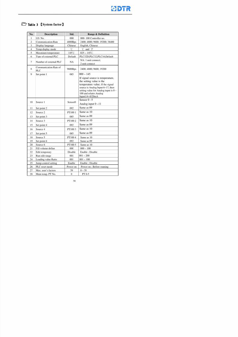
8132019 DTR 650 User Manual
httpslidepdfcomreaderfulldtr-650-user-manual 5870
TTTTTTTTaaaaaaaabbbbbbbblllllllleeeeeeee 33333333 【【【【System factor】】】】
No Description Std Range amp Definition
1 ID No 000 000- 100 Controller no
2 Communication Rate 4800Bps 2400 4800 9600 19200 38400
3 Display language Chinese English Chinese
4 Temp display mode and
5 Maxmium temperature 145 025 ~ 145 6 Type of external PLC Default PLC32DPLC32PLC16Default
7 Number of external PLC NANA 1 unit connect
2 unit connect
8Communication Rate of
PLC9600Bps 2400 4800 9600 19200
9 Set point 1 085 000 ~ 145
If signal source is temperaturethe setting value is thetemperature value If the signal
source is Analog Input 6~17 then
setting value for Analog input is 0 ndash
100 and relates Analog
Input14~020mA
10 Source 1 Sensor0Sensor 0 ~5
Analog input 0 ~1111 Set point 2 092 Same as 09
12 Source 2 PT100 1 Same as 10
13 Set point 3 085 Same as 09
14 Source 3 PT100 2 Same as 10
15 Set point 4 092 Same as 09
16 Source 4 PT100 3 Same as 1017 Set point 5 085 Same as 09
18 Source 5 PT100 4 Same as 10
19 Set point 6 092 Same as 09
8132019 DTR 650 User Manual
httpslidepdfcomreaderfulldtr-650-user-manual 5970
29 Min cyclic time of cloth 100sec 0 ~ 255 sec
30 Max cyclic time of cloth 240sec 0 ~255 sec
31Standard cyclic time of
cloth
180 000 ~ 255 sec
32 Display ModeProgram
List
Program list Schematic Diagram
Icon mode
33 CF card format Standard of
DTR CF
Card
Standard of DTR CF Card V20
Standard CF Card
34 Addition step Disable Disable Enable35 Mode Com 3
CouplingEsure Com 3 is the communication
port of the Central or Coupling
36Com 3 Communication
rate9600 Central communication speed
8132019 DTR 650 User Manual
httpslidepdfcomreaderfulldtr-650-user-manual 6070
TTTTTTTTaaaaaaaabbbbbbbblllllllleeeeeeee 44444444 【【【【Temperature Cotnrol Factor】】】】
No Factor Definition Standard Range and Definition
01 PT No PT-0 PT 0~5 PT-100 Input number
02 Max working temp 140 000~140
03 Output mode 0 0~2
04 Alarm time of gardient 240sec 000~255 sec
05 Alarm mode of gradient Always AlwaysOnceNone
06 Control mode of gradient Heating orCooling
interlocked
Heating and Cooling interlocked
No limitation
07 Alarm range of HoldTemp 03 01~20
08 Alarm time for HoldTemp 240sec 000~255sec
09 Alarm mode of HoldTemp Always AlwaysOnceNone
10 Control mode ofHoldTemp
Heating only Only heating and cooling Cooling whenalarm occurred Only heating andcooling No limitation when alarmHeating only
11 Porportional Band 100 000~250
12 Integral band 128 sec 000~255 sec
13 Differential time 04 sec 00~20 sec
14 Min transit gradient 02 00~50
15 Transit rate 20 times 00~50 times (020= 2 times)
16 PID initial output value 010 000~100
17 ONOFF cycle time 10 sec 05~25 sec
Onoff valve set as 010 sec
Proportional valve set as 020 sec
18 Time down count mode Mode 0 0~10 = The time down count range from「Factor 20 + target temp」to「Target
8132019 DTR 650 User Manual
httpslidepdfcomreaderfulldtr-650-user-manual 6170
TTTTTTTTaaaaaaaabbbbbbbblllllllleeeeeeee 55555555 【【【【Speed Factor】】】】
No Factor Definition Standard Range amp Definition
01 Input Number Speed input 0 Speed input 0~11
02 Average times 05 times 01~10
03 Sensor Number 008pcs 001~255
04 Roller Dimension 250mm 050~500
05 Max cloth speed 200mmin 001~25506 Min cloth speed 020mmin 001~255
07 Alarm delay time 240sec 001~255
08 Alarm mode Every oncenoneevery
09 Alarm range () 020 001~255
10 Proportional band 100 001~255
11 Integer band 128 001~25512 Differential time 000 001~200
13 Initial speed () 020 001~255
14 Control cycle ti(01sec) 05 01~30
15 First cycle time(01sec) 10 01~30
16 Speed increase limit () 010 001~100
17 Speed decrease limit () 010 001~100
18 Min speed() 005 001~100
19 Manual speed adjust () 005 001~100
20 Manual initial speed() 020 001~100
21 Stopping speed() 010 001~100
22 Switch speed() 020 001~100
23 Not used
24 Speed decrease turns 03turns 01~50
8132019 DTR 650 User Manual
httpslidepdfcomreaderfulldtr-650-user-manual 6270
Table 6 【【【【Dosing Factors】】】】
No Description Range Range and Explanation
1 Analog input no Analog input 0 Analog input no 0 ~11
2Alarm delay time for
dosing240 sec 000 ~255 sec
3 Alarm time for dosing Every Every Once None
4 Proportional band 100 000 ~255 sec Factor P
5 Integer band 128 000 ~255 sec Factor I6 Differential time 04 00 ~20 Factor D
7 Max adjust rate 150 50~ 255
8 Initial factor for dosing 10 000 ~100
9 User curve section 0 10 Gradient of sect1 for dosing curve9
10 User curve section 1 10 Gradient of sect2 for dosing curve9
11 User curve section 2 10 Gradient of sect3 for dosing curve9
12 User curve section 3 10 Gradient of sect4 for dosing curve9
13 User curve section 4 10 Gradient of sect5 for dosing curve9
14 User curve section 5 10 Gradient of sect6 for dosing curve9
15 User curve section 6 10 Gradient of sect7 for dosing curve9
16 User curve section 7 10 Gradient of sect8 for dosing curve9
17 User curve section 8 10 Gradient of sect9 for dosing curve9
18 User curve section 9 10 Gradient of sect10 for dosing curve9
19 Min water level 05 00~ 10 04~20mA percentagechange to the userrsquos factor setting
20 Output value for Tank
clean
100 000~ 100
Injected percentage of dosing valve
in dosing End period
This factor will be invalided if usingONOFF dosing valve
21 Full range 100 001~255 Self-adjustment cannotchange
22 Range ratio 001001~255 Self-adjustment cannot
change
8132019 DTR 650 User Manual
httpslidepdfcomreaderfulldtr-650-user-manual 6370
【【【【TTaabbllee 77 】】】】Pressure Deviation Factors
No Description Std Range amp Definition
1 Analog input number + Analog in 0 Analog in 0~11
2 Analog input number - Analog in 1 Analog in 0~11
3 Input mode Pressure Pressure Pressure deviation
4 Full range 050x01Kgcm
001~255
5 Range ratio 001 001~255
6 Alarm delay time 100sec 001~255
7 Alarm mode Every oncenone
8 Alarm range 010 001~255
9 Proportional band 100 001~255
10 Integer band 128 001~255
11 Differential time 00 00~20
12 PID Init output value 010 001~255
13 Cycle time 10 03~30
14 First cycle time 030 003~100
15 Max adjust rate 010 001~100
8132019 DTR 650 User Manual
httpslidepdfcomreaderfulldtr-650-user-manual 6470
【【【【TTaabbllee 88 】】】】Definition of Analog Input
No Description Standard Range and Explanation
01 PT 0 correction standard DIN std DIN std JIS std
02 PT 0 correction +0 +- 9
03 PT 1 correction standard DIN std DIN std JIS std
04 PT 1 correction +0 +- 9
05 PT 2 correction standard DIN std DIN std JIS std
06 PT 2 correction +0 +- 9
07 PT 3 correction standard DIN std DIN std JIS std
08 PT 3 correction +0 +- 9
09 PT 4 correction standard DIN std DIN std JIS std
10 PT 4 correction +0 +- 9
11 PT 5 correction standard DIN std DIN std JIS std
12 PT 5 correction +0 +- 9
13 Analog input 0 define 4 ~ 20mA 0 ndash 20mA 4 ndash 20mA
14 Analog input 0 average times 10 times 01- 20 times
15 Analog input 0 min value 0000 0000 - 1000
16 Analog input 0 max value 100 0001 - 9999
17-60 Analog input 1~11 Same as Analog input 0
【【【【 】】】】 fi i i f A O
8132019 DTR 650 User Manual
httpslidepdfcomreaderfulldtr-650-user-manual 6570
【【【【TTaabbllee 99 】】】】Definition of Analog Output
No Description Standard Range and explanation
61 Analog output 0 define Control byPLC
Control by PLC
Temperature control PID0 output
Temperature control PID1 output
Temperature control PID2 output
Speed PID3 output
Dosing PID0 output Dosing PID1output
Pressure different PID0 outputPressure different PID1 output
Main temperature output
62 Mode of Analog ouptput0 4 ~20mA 0 ndash20mA 4 ndash 20mA
63-84 Analog output 1~11 Same as Analog output 0
【【【【TTaabbllee 1100】】】】Value Table 0 amp 1
No Description Range Std Range and explanation
1 Analog input no 000~011 000 Analog input no
2 Data ratio 001~255 100 Multiple by factors
3~53 0~98 000~255 000-100 Analog input 0~98 data
【【【【 】】】】St t Li t
8132019 DTR 650 User Manual
httpslidepdfcomreaderfulldtr-650-user-manual 6670
【【【【TTaabbllee 1111】】】】State List
No Description Range Standard Range and explanation
1 Display setting 1 0~255 205 See remarks at next page
2 Display setting 2 0~255 208
3 Display setting 3 0~255 209
4 Display setting 4 0~255 017
5 Display setting 5 0~255 0186 Display setting 6 0~255 019
7 Display setting 7 0~255 020
8 Display setting 8 0~255 021
9 Display setting 9 0~255 000
10 Display setting 1 0~255 000
11 Display setting 2 0~255 000
12 Display setting 3 0~255 000
13 Display setting 4 0~255 000
14 Display setting 5 0~255 000
15 Display setting 6 0~255 000
16 Display setting 7 0~255 000
Remarks
8132019 DTR 650 User Manual
httpslidepdfcomreaderfulldtr-650-user-manual 6770
0 = No display 1~255 = Display type of number
1~16 Content of PLC VB0~15
No 1 corresponding to VB0
No 16 corresponding to VB15
17~32 Content of PLC DB0~15
No 17 corresponding to DB0
No 32 corresponding to DB15
33~46 Content of PLC CNT0~29
No 33 corresponding to CNT0
No 46 corresponding to CNT29 47~78 Content of dyeing instruction 0~31 CNT0
No 47 corresponding to system instruction to No 0 of CNT0
No 78 corresponding to system instruction to No 31 of CNT0rsquos content
79~110 Dyeing instruction 0~31 of CNT0rsquos setting
111~142 Content of Dyeing instruction 0~31 CNT1No 111 corresponding to dyeing instruction No 0 of CNT1
No 142 corresponding to dyeing instruction No 31 of CNT1rsquos content
143~174 Dyeing instruction 0~31 of CNT1rsquos setting
175~204 Content of PLC HTIM0~29
No 175 corresponding to HTIM0
No 204 corresponding to HTIM29
205 Loading
206 Ratio 1
207 Ratio 2208 Ratio 1 x Loading
209 Ratio 2 x Loading
210 Fix value
211 Value Table 1 matching result
212 Value Table 2 matching result
213 Value Table 1 setting214 Value Table 2 setting
215 Pressure control PID0 different pressure value
216 Pressure control PID1 different pressure value
TTTTTTTTaaaaaaaabbbbbbbblllllllleeeeeeee 1122 【【【【Usage of password】】】】
8132019 DTR 650 User Manual
httpslidepdfcomreaderfulldtr-650-user-manual 6870
No Main FunctionFactor Sub Function Factor Password Rank
1 Run None
2 Dye program User3 or above
3 Control factor
- User factor User 1
- System factor User 1
- Temp PID 0
- Temp PID 1 User 1- Speed PID 0 User 1
- Dosing PID 0 User 1
- Dosing PID 1 User 1
- Pressure PID 0 User 1
- Pressure PID 1 User 1
- Analog IO User 1
- Load standard factor User 2 or above- Load a copied factor User 2 or above
- Copy factor User 2 or above
- Value table 0 User 1
- Value table 1 User 1
- Information and state User 1
- Dye instruction User 1
- Edit dye instruction setting User 14 Output testing User 2 or above
5 Calibration User 2 or above
6 Dye record None
7 CF card User 1
8 Info and state None
9 Others
- Contrast User3 or above
- Data Locking None
- PLC Run User 1
- PLC Stop User 1
- Password setting User 1
TTTTTTTTaaaaaaaabbbbbbbblllllllleeeeeeee 1133 【【【【Technical Data】】】】
8132019 DTR 650 User Manual
httpslidepdfcomreaderfulldtr-650-user-manual 6970
TTTTTTTTaaaaaaaabbbbbbbblllllllleeeeeeee 1133 【【【【Technical Data】】】】
1 Temperature Control
- Range 10~145(plusmn1)
- Mode Proportional or PWM
- Sensor PT100 (JIS or DIN standard)
2 Input and output channel
- Digital Input 32 DC24V PNP- Digital Output 32 DC24V 054A Relay connect point
- Analog Input 4 04~20 mA
- Analog Output 4 0~20mA 或 4~20 mA
3 Communication port 3 RS-232 amp 0~20 mAx1 RS485x 2
4 Dye program
- Number 15000 Steps
- Standard step 61Heating Cooling Fill Drain RinseDosingetc
5LCD module and Display
langage
Chinese
English
320 x 240 TFT color display with
more language
6 CF card connector 1 PCMCIA standard
7 Membrane Keyboard- Number Key 10 [0]~[9] Input factors
- Function Key 5 [F1]~[F5] function selecting
- Operation Key 2 [Start] [Stop]
- Auxiliary Key 7 [][][][][Esc] [larr][OK] [bull]
8 Operating Condition
- Temperature 5~45
- Humidity ≦85 (25)
9 Power supply
V l DC 24V
8132019 DTR 650 User Manual
httpslidepdfcomreaderfulldtr-650-user-manual 7070
70
983108983124983122983085650 983113983150983152983157983156 983119983157983156983152983157983156 983120983151983154983156983145983150983143 (983138983137983139983147983155983145983140983141 983158983145983141983159)
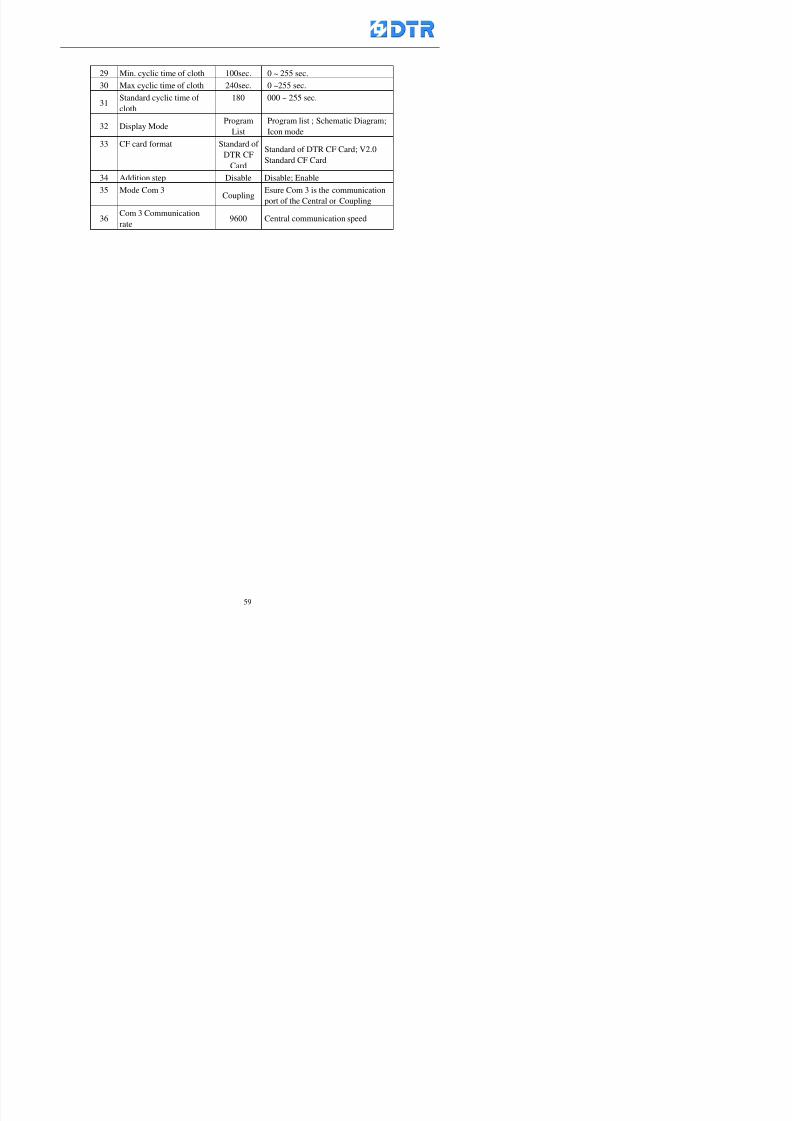
8132019 DTR 650 User Manual
httpslidepdfcomreaderfulldtr-650-user-manual 5970
29 Min cyclic time of cloth 100sec 0 ~ 255 sec
30 Max cyclic time of cloth 240sec 0 ~255 sec
31Standard cyclic time of
cloth
180 000 ~ 255 sec
32 Display ModeProgram
List
Program list Schematic Diagram
Icon mode
33 CF card format Standard of
DTR CF
Card
Standard of DTR CF Card V20
Standard CF Card
34 Addition step Disable Disable Enable35 Mode Com 3
CouplingEsure Com 3 is the communication
port of the Central or Coupling
36Com 3 Communication
rate9600 Central communication speed
8132019 DTR 650 User Manual
httpslidepdfcomreaderfulldtr-650-user-manual 6070
TTTTTTTTaaaaaaaabbbbbbbblllllllleeeeeeee 44444444 【【【【Temperature Cotnrol Factor】】】】
No Factor Definition Standard Range and Definition
01 PT No PT-0 PT 0~5 PT-100 Input number
02 Max working temp 140 000~140
03 Output mode 0 0~2
04 Alarm time of gardient 240sec 000~255 sec
05 Alarm mode of gradient Always AlwaysOnceNone
06 Control mode of gradient Heating orCooling
interlocked
Heating and Cooling interlocked
No limitation
07 Alarm range of HoldTemp 03 01~20
08 Alarm time for HoldTemp 240sec 000~255sec
09 Alarm mode of HoldTemp Always AlwaysOnceNone
10 Control mode ofHoldTemp
Heating only Only heating and cooling Cooling whenalarm occurred Only heating andcooling No limitation when alarmHeating only
11 Porportional Band 100 000~250
12 Integral band 128 sec 000~255 sec
13 Differential time 04 sec 00~20 sec
14 Min transit gradient 02 00~50
15 Transit rate 20 times 00~50 times (020= 2 times)
16 PID initial output value 010 000~100
17 ONOFF cycle time 10 sec 05~25 sec
Onoff valve set as 010 sec
Proportional valve set as 020 sec
18 Time down count mode Mode 0 0~10 = The time down count range from「Factor 20 + target temp」to「Target
8132019 DTR 650 User Manual
httpslidepdfcomreaderfulldtr-650-user-manual 6170
TTTTTTTTaaaaaaaabbbbbbbblllllllleeeeeeee 55555555 【【【【Speed Factor】】】】
No Factor Definition Standard Range amp Definition
01 Input Number Speed input 0 Speed input 0~11
02 Average times 05 times 01~10
03 Sensor Number 008pcs 001~255
04 Roller Dimension 250mm 050~500
05 Max cloth speed 200mmin 001~25506 Min cloth speed 020mmin 001~255
07 Alarm delay time 240sec 001~255
08 Alarm mode Every oncenoneevery
09 Alarm range () 020 001~255
10 Proportional band 100 001~255
11 Integer band 128 001~25512 Differential time 000 001~200
13 Initial speed () 020 001~255
14 Control cycle ti(01sec) 05 01~30
15 First cycle time(01sec) 10 01~30
16 Speed increase limit () 010 001~100
17 Speed decrease limit () 010 001~100
18 Min speed() 005 001~100
19 Manual speed adjust () 005 001~100
20 Manual initial speed() 020 001~100
21 Stopping speed() 010 001~100
22 Switch speed() 020 001~100
23 Not used
24 Speed decrease turns 03turns 01~50
8132019 DTR 650 User Manual
httpslidepdfcomreaderfulldtr-650-user-manual 6270
Table 6 【【【【Dosing Factors】】】】
No Description Range Range and Explanation
1 Analog input no Analog input 0 Analog input no 0 ~11
2Alarm delay time for
dosing240 sec 000 ~255 sec
3 Alarm time for dosing Every Every Once None
4 Proportional band 100 000 ~255 sec Factor P
5 Integer band 128 000 ~255 sec Factor I6 Differential time 04 00 ~20 Factor D
7 Max adjust rate 150 50~ 255
8 Initial factor for dosing 10 000 ~100
9 User curve section 0 10 Gradient of sect1 for dosing curve9
10 User curve section 1 10 Gradient of sect2 for dosing curve9
11 User curve section 2 10 Gradient of sect3 for dosing curve9
12 User curve section 3 10 Gradient of sect4 for dosing curve9
13 User curve section 4 10 Gradient of sect5 for dosing curve9
14 User curve section 5 10 Gradient of sect6 for dosing curve9
15 User curve section 6 10 Gradient of sect7 for dosing curve9
16 User curve section 7 10 Gradient of sect8 for dosing curve9
17 User curve section 8 10 Gradient of sect9 for dosing curve9
18 User curve section 9 10 Gradient of sect10 for dosing curve9
19 Min water level 05 00~ 10 04~20mA percentagechange to the userrsquos factor setting
20 Output value for Tank
clean
100 000~ 100
Injected percentage of dosing valve
in dosing End period
This factor will be invalided if usingONOFF dosing valve
21 Full range 100 001~255 Self-adjustment cannotchange
22 Range ratio 001001~255 Self-adjustment cannot
change
8132019 DTR 650 User Manual
httpslidepdfcomreaderfulldtr-650-user-manual 6370
【【【【TTaabbllee 77 】】】】Pressure Deviation Factors
No Description Std Range amp Definition
1 Analog input number + Analog in 0 Analog in 0~11
2 Analog input number - Analog in 1 Analog in 0~11
3 Input mode Pressure Pressure Pressure deviation
4 Full range 050x01Kgcm
001~255
5 Range ratio 001 001~255
6 Alarm delay time 100sec 001~255
7 Alarm mode Every oncenone
8 Alarm range 010 001~255
9 Proportional band 100 001~255
10 Integer band 128 001~255
11 Differential time 00 00~20
12 PID Init output value 010 001~255
13 Cycle time 10 03~30
14 First cycle time 030 003~100
15 Max adjust rate 010 001~100
8132019 DTR 650 User Manual
httpslidepdfcomreaderfulldtr-650-user-manual 6470
【【【【TTaabbllee 88 】】】】Definition of Analog Input
No Description Standard Range and Explanation
01 PT 0 correction standard DIN std DIN std JIS std
02 PT 0 correction +0 +- 9
03 PT 1 correction standard DIN std DIN std JIS std
04 PT 1 correction +0 +- 9
05 PT 2 correction standard DIN std DIN std JIS std
06 PT 2 correction +0 +- 9
07 PT 3 correction standard DIN std DIN std JIS std
08 PT 3 correction +0 +- 9
09 PT 4 correction standard DIN std DIN std JIS std
10 PT 4 correction +0 +- 9
11 PT 5 correction standard DIN std DIN std JIS std
12 PT 5 correction +0 +- 9
13 Analog input 0 define 4 ~ 20mA 0 ndash 20mA 4 ndash 20mA
14 Analog input 0 average times 10 times 01- 20 times
15 Analog input 0 min value 0000 0000 - 1000
16 Analog input 0 max value 100 0001 - 9999
17-60 Analog input 1~11 Same as Analog input 0
【【【【 】】】】 fi i i f A O
8132019 DTR 650 User Manual
httpslidepdfcomreaderfulldtr-650-user-manual 6570
【【【【TTaabbllee 99 】】】】Definition of Analog Output
No Description Standard Range and explanation
61 Analog output 0 define Control byPLC
Control by PLC
Temperature control PID0 output
Temperature control PID1 output
Temperature control PID2 output
Speed PID3 output
Dosing PID0 output Dosing PID1output
Pressure different PID0 outputPressure different PID1 output
Main temperature output
62 Mode of Analog ouptput0 4 ~20mA 0 ndash20mA 4 ndash 20mA
63-84 Analog output 1~11 Same as Analog output 0
【【【【TTaabbllee 1100】】】】Value Table 0 amp 1
No Description Range Std Range and explanation
1 Analog input no 000~011 000 Analog input no
2 Data ratio 001~255 100 Multiple by factors
3~53 0~98 000~255 000-100 Analog input 0~98 data
【【【【 】】】】St t Li t
8132019 DTR 650 User Manual
httpslidepdfcomreaderfulldtr-650-user-manual 6670
【【【【TTaabbllee 1111】】】】State List
No Description Range Standard Range and explanation
1 Display setting 1 0~255 205 See remarks at next page
2 Display setting 2 0~255 208
3 Display setting 3 0~255 209
4 Display setting 4 0~255 017
5 Display setting 5 0~255 0186 Display setting 6 0~255 019
7 Display setting 7 0~255 020
8 Display setting 8 0~255 021
9 Display setting 9 0~255 000
10 Display setting 1 0~255 000
11 Display setting 2 0~255 000
12 Display setting 3 0~255 000
13 Display setting 4 0~255 000
14 Display setting 5 0~255 000
15 Display setting 6 0~255 000
16 Display setting 7 0~255 000
Remarks
8132019 DTR 650 User Manual
httpslidepdfcomreaderfulldtr-650-user-manual 6770
0 = No display 1~255 = Display type of number
1~16 Content of PLC VB0~15
No 1 corresponding to VB0
No 16 corresponding to VB15
17~32 Content of PLC DB0~15
No 17 corresponding to DB0
No 32 corresponding to DB15
33~46 Content of PLC CNT0~29
No 33 corresponding to CNT0
No 46 corresponding to CNT29 47~78 Content of dyeing instruction 0~31 CNT0
No 47 corresponding to system instruction to No 0 of CNT0
No 78 corresponding to system instruction to No 31 of CNT0rsquos content
79~110 Dyeing instruction 0~31 of CNT0rsquos setting
111~142 Content of Dyeing instruction 0~31 CNT1No 111 corresponding to dyeing instruction No 0 of CNT1
No 142 corresponding to dyeing instruction No 31 of CNT1rsquos content
143~174 Dyeing instruction 0~31 of CNT1rsquos setting
175~204 Content of PLC HTIM0~29
No 175 corresponding to HTIM0
No 204 corresponding to HTIM29
205 Loading
206 Ratio 1
207 Ratio 2208 Ratio 1 x Loading
209 Ratio 2 x Loading
210 Fix value
211 Value Table 1 matching result
212 Value Table 2 matching result
213 Value Table 1 setting214 Value Table 2 setting
215 Pressure control PID0 different pressure value
216 Pressure control PID1 different pressure value
TTTTTTTTaaaaaaaabbbbbbbblllllllleeeeeeee 1122 【【【【Usage of password】】】】
8132019 DTR 650 User Manual
httpslidepdfcomreaderfulldtr-650-user-manual 6870
No Main FunctionFactor Sub Function Factor Password Rank
1 Run None
2 Dye program User3 or above
3 Control factor
- User factor User 1
- System factor User 1
- Temp PID 0
- Temp PID 1 User 1- Speed PID 0 User 1
- Dosing PID 0 User 1
- Dosing PID 1 User 1
- Pressure PID 0 User 1
- Pressure PID 1 User 1
- Analog IO User 1
- Load standard factor User 2 or above- Load a copied factor User 2 or above
- Copy factor User 2 or above
- Value table 0 User 1
- Value table 1 User 1
- Information and state User 1
- Dye instruction User 1
- Edit dye instruction setting User 14 Output testing User 2 or above
5 Calibration User 2 or above
6 Dye record None
7 CF card User 1
8 Info and state None
9 Others
- Contrast User3 or above
- Data Locking None
- PLC Run User 1
- PLC Stop User 1
- Password setting User 1
TTTTTTTTaaaaaaaabbbbbbbblllllllleeeeeeee 1133 【【【【Technical Data】】】】
8132019 DTR 650 User Manual
httpslidepdfcomreaderfulldtr-650-user-manual 6970
TTTTTTTTaaaaaaaabbbbbbbblllllllleeeeeeee 1133 【【【【Technical Data】】】】
1 Temperature Control
- Range 10~145(plusmn1)
- Mode Proportional or PWM
- Sensor PT100 (JIS or DIN standard)
2 Input and output channel
- Digital Input 32 DC24V PNP- Digital Output 32 DC24V 054A Relay connect point
- Analog Input 4 04~20 mA
- Analog Output 4 0~20mA 或 4~20 mA
3 Communication port 3 RS-232 amp 0~20 mAx1 RS485x 2
4 Dye program
- Number 15000 Steps
- Standard step 61Heating Cooling Fill Drain RinseDosingetc
5LCD module and Display
langage
Chinese
English
320 x 240 TFT color display with
more language
6 CF card connector 1 PCMCIA standard
7 Membrane Keyboard- Number Key 10 [0]~[9] Input factors
- Function Key 5 [F1]~[F5] function selecting
- Operation Key 2 [Start] [Stop]
- Auxiliary Key 7 [][][][][Esc] [larr][OK] [bull]
8 Operating Condition
- Temperature 5~45
- Humidity ≦85 (25)
9 Power supply
V l DC 24V
8132019 DTR 650 User Manual
httpslidepdfcomreaderfulldtr-650-user-manual 7070
70
983108983124983122983085650 983113983150983152983157983156 983119983157983156983152983157983156 983120983151983154983156983145983150983143 (983138983137983139983147983155983145983140983141 983158983145983141983159)
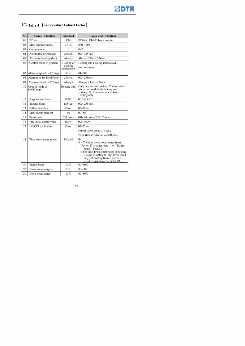
8132019 DTR 650 User Manual
httpslidepdfcomreaderfulldtr-650-user-manual 6070
TTTTTTTTaaaaaaaabbbbbbbblllllllleeeeeeee 44444444 【【【【Temperature Cotnrol Factor】】】】
No Factor Definition Standard Range and Definition
01 PT No PT-0 PT 0~5 PT-100 Input number
02 Max working temp 140 000~140
03 Output mode 0 0~2
04 Alarm time of gardient 240sec 000~255 sec
05 Alarm mode of gradient Always AlwaysOnceNone
06 Control mode of gradient Heating orCooling
interlocked
Heating and Cooling interlocked
No limitation
07 Alarm range of HoldTemp 03 01~20
08 Alarm time for HoldTemp 240sec 000~255sec
09 Alarm mode of HoldTemp Always AlwaysOnceNone
10 Control mode ofHoldTemp
Heating only Only heating and cooling Cooling whenalarm occurred Only heating andcooling No limitation when alarmHeating only
11 Porportional Band 100 000~250
12 Integral band 128 sec 000~255 sec
13 Differential time 04 sec 00~20 sec
14 Min transit gradient 02 00~50
15 Transit rate 20 times 00~50 times (020= 2 times)
16 PID initial output value 010 000~100
17 ONOFF cycle time 10 sec 05~25 sec
Onoff valve set as 010 sec
Proportional valve set as 020 sec
18 Time down count mode Mode 0 0~10 = The time down count range from「Factor 20 + target temp」to「Target
8132019 DTR 650 User Manual
httpslidepdfcomreaderfulldtr-650-user-manual 6170
TTTTTTTTaaaaaaaabbbbbbbblllllllleeeeeeee 55555555 【【【【Speed Factor】】】】
No Factor Definition Standard Range amp Definition
01 Input Number Speed input 0 Speed input 0~11
02 Average times 05 times 01~10
03 Sensor Number 008pcs 001~255
04 Roller Dimension 250mm 050~500
05 Max cloth speed 200mmin 001~25506 Min cloth speed 020mmin 001~255
07 Alarm delay time 240sec 001~255
08 Alarm mode Every oncenoneevery
09 Alarm range () 020 001~255
10 Proportional band 100 001~255
11 Integer band 128 001~25512 Differential time 000 001~200
13 Initial speed () 020 001~255
14 Control cycle ti(01sec) 05 01~30
15 First cycle time(01sec) 10 01~30
16 Speed increase limit () 010 001~100
17 Speed decrease limit () 010 001~100
18 Min speed() 005 001~100
19 Manual speed adjust () 005 001~100
20 Manual initial speed() 020 001~100
21 Stopping speed() 010 001~100
22 Switch speed() 020 001~100
23 Not used
24 Speed decrease turns 03turns 01~50
8132019 DTR 650 User Manual
httpslidepdfcomreaderfulldtr-650-user-manual 6270
Table 6 【【【【Dosing Factors】】】】
No Description Range Range and Explanation
1 Analog input no Analog input 0 Analog input no 0 ~11
2Alarm delay time for
dosing240 sec 000 ~255 sec
3 Alarm time for dosing Every Every Once None
4 Proportional band 100 000 ~255 sec Factor P
5 Integer band 128 000 ~255 sec Factor I6 Differential time 04 00 ~20 Factor D
7 Max adjust rate 150 50~ 255
8 Initial factor for dosing 10 000 ~100
9 User curve section 0 10 Gradient of sect1 for dosing curve9
10 User curve section 1 10 Gradient of sect2 for dosing curve9
11 User curve section 2 10 Gradient of sect3 for dosing curve9
12 User curve section 3 10 Gradient of sect4 for dosing curve9
13 User curve section 4 10 Gradient of sect5 for dosing curve9
14 User curve section 5 10 Gradient of sect6 for dosing curve9
15 User curve section 6 10 Gradient of sect7 for dosing curve9
16 User curve section 7 10 Gradient of sect8 for dosing curve9
17 User curve section 8 10 Gradient of sect9 for dosing curve9
18 User curve section 9 10 Gradient of sect10 for dosing curve9
19 Min water level 05 00~ 10 04~20mA percentagechange to the userrsquos factor setting
20 Output value for Tank
clean
100 000~ 100
Injected percentage of dosing valve
in dosing End period
This factor will be invalided if usingONOFF dosing valve
21 Full range 100 001~255 Self-adjustment cannotchange
22 Range ratio 001001~255 Self-adjustment cannot
change
8132019 DTR 650 User Manual
httpslidepdfcomreaderfulldtr-650-user-manual 6370
【【【【TTaabbllee 77 】】】】Pressure Deviation Factors
No Description Std Range amp Definition
1 Analog input number + Analog in 0 Analog in 0~11
2 Analog input number - Analog in 1 Analog in 0~11
3 Input mode Pressure Pressure Pressure deviation
4 Full range 050x01Kgcm
001~255
5 Range ratio 001 001~255
6 Alarm delay time 100sec 001~255
7 Alarm mode Every oncenone
8 Alarm range 010 001~255
9 Proportional band 100 001~255
10 Integer band 128 001~255
11 Differential time 00 00~20
12 PID Init output value 010 001~255
13 Cycle time 10 03~30
14 First cycle time 030 003~100
15 Max adjust rate 010 001~100
8132019 DTR 650 User Manual
httpslidepdfcomreaderfulldtr-650-user-manual 6470
【【【【TTaabbllee 88 】】】】Definition of Analog Input
No Description Standard Range and Explanation
01 PT 0 correction standard DIN std DIN std JIS std
02 PT 0 correction +0 +- 9
03 PT 1 correction standard DIN std DIN std JIS std
04 PT 1 correction +0 +- 9
05 PT 2 correction standard DIN std DIN std JIS std
06 PT 2 correction +0 +- 9
07 PT 3 correction standard DIN std DIN std JIS std
08 PT 3 correction +0 +- 9
09 PT 4 correction standard DIN std DIN std JIS std
10 PT 4 correction +0 +- 9
11 PT 5 correction standard DIN std DIN std JIS std
12 PT 5 correction +0 +- 9
13 Analog input 0 define 4 ~ 20mA 0 ndash 20mA 4 ndash 20mA
14 Analog input 0 average times 10 times 01- 20 times
15 Analog input 0 min value 0000 0000 - 1000
16 Analog input 0 max value 100 0001 - 9999
17-60 Analog input 1~11 Same as Analog input 0
【【【【 】】】】 fi i i f A O
8132019 DTR 650 User Manual
httpslidepdfcomreaderfulldtr-650-user-manual 6570
【【【【TTaabbllee 99 】】】】Definition of Analog Output
No Description Standard Range and explanation
61 Analog output 0 define Control byPLC
Control by PLC
Temperature control PID0 output
Temperature control PID1 output
Temperature control PID2 output
Speed PID3 output
Dosing PID0 output Dosing PID1output
Pressure different PID0 outputPressure different PID1 output
Main temperature output
62 Mode of Analog ouptput0 4 ~20mA 0 ndash20mA 4 ndash 20mA
63-84 Analog output 1~11 Same as Analog output 0
【【【【TTaabbllee 1100】】】】Value Table 0 amp 1
No Description Range Std Range and explanation
1 Analog input no 000~011 000 Analog input no
2 Data ratio 001~255 100 Multiple by factors
3~53 0~98 000~255 000-100 Analog input 0~98 data
【【【【 】】】】St t Li t
8132019 DTR 650 User Manual
httpslidepdfcomreaderfulldtr-650-user-manual 6670
【【【【TTaabbllee 1111】】】】State List
No Description Range Standard Range and explanation
1 Display setting 1 0~255 205 See remarks at next page
2 Display setting 2 0~255 208
3 Display setting 3 0~255 209
4 Display setting 4 0~255 017
5 Display setting 5 0~255 0186 Display setting 6 0~255 019
7 Display setting 7 0~255 020
8 Display setting 8 0~255 021
9 Display setting 9 0~255 000
10 Display setting 1 0~255 000
11 Display setting 2 0~255 000
12 Display setting 3 0~255 000
13 Display setting 4 0~255 000
14 Display setting 5 0~255 000
15 Display setting 6 0~255 000
16 Display setting 7 0~255 000
Remarks
8132019 DTR 650 User Manual
httpslidepdfcomreaderfulldtr-650-user-manual 6770
0 = No display 1~255 = Display type of number
1~16 Content of PLC VB0~15
No 1 corresponding to VB0
No 16 corresponding to VB15
17~32 Content of PLC DB0~15
No 17 corresponding to DB0
No 32 corresponding to DB15
33~46 Content of PLC CNT0~29
No 33 corresponding to CNT0
No 46 corresponding to CNT29 47~78 Content of dyeing instruction 0~31 CNT0
No 47 corresponding to system instruction to No 0 of CNT0
No 78 corresponding to system instruction to No 31 of CNT0rsquos content
79~110 Dyeing instruction 0~31 of CNT0rsquos setting
111~142 Content of Dyeing instruction 0~31 CNT1No 111 corresponding to dyeing instruction No 0 of CNT1
No 142 corresponding to dyeing instruction No 31 of CNT1rsquos content
143~174 Dyeing instruction 0~31 of CNT1rsquos setting
175~204 Content of PLC HTIM0~29
No 175 corresponding to HTIM0
No 204 corresponding to HTIM29
205 Loading
206 Ratio 1
207 Ratio 2208 Ratio 1 x Loading
209 Ratio 2 x Loading
210 Fix value
211 Value Table 1 matching result
212 Value Table 2 matching result
213 Value Table 1 setting214 Value Table 2 setting
215 Pressure control PID0 different pressure value
216 Pressure control PID1 different pressure value
TTTTTTTTaaaaaaaabbbbbbbblllllllleeeeeeee 1122 【【【【Usage of password】】】】
8132019 DTR 650 User Manual
httpslidepdfcomreaderfulldtr-650-user-manual 6870
No Main FunctionFactor Sub Function Factor Password Rank
1 Run None
2 Dye program User3 or above
3 Control factor
- User factor User 1
- System factor User 1
- Temp PID 0
- Temp PID 1 User 1- Speed PID 0 User 1
- Dosing PID 0 User 1
- Dosing PID 1 User 1
- Pressure PID 0 User 1
- Pressure PID 1 User 1
- Analog IO User 1
- Load standard factor User 2 or above- Load a copied factor User 2 or above
- Copy factor User 2 or above
- Value table 0 User 1
- Value table 1 User 1
- Information and state User 1
- Dye instruction User 1
- Edit dye instruction setting User 14 Output testing User 2 or above
5 Calibration User 2 or above
6 Dye record None
7 CF card User 1
8 Info and state None
9 Others
- Contrast User3 or above
- Data Locking None
- PLC Run User 1
- PLC Stop User 1
- Password setting User 1
TTTTTTTTaaaaaaaabbbbbbbblllllllleeeeeeee 1133 【【【【Technical Data】】】】
8132019 DTR 650 User Manual
httpslidepdfcomreaderfulldtr-650-user-manual 6970
TTTTTTTTaaaaaaaabbbbbbbblllllllleeeeeeee 1133 【【【【Technical Data】】】】
1 Temperature Control
- Range 10~145(plusmn1)
- Mode Proportional or PWM
- Sensor PT100 (JIS or DIN standard)
2 Input and output channel
- Digital Input 32 DC24V PNP- Digital Output 32 DC24V 054A Relay connect point
- Analog Input 4 04~20 mA
- Analog Output 4 0~20mA 或 4~20 mA
3 Communication port 3 RS-232 amp 0~20 mAx1 RS485x 2
4 Dye program
- Number 15000 Steps
- Standard step 61Heating Cooling Fill Drain RinseDosingetc
5LCD module and Display
langage
Chinese
English
320 x 240 TFT color display with
more language
6 CF card connector 1 PCMCIA standard
7 Membrane Keyboard- Number Key 10 [0]~[9] Input factors
- Function Key 5 [F1]~[F5] function selecting
- Operation Key 2 [Start] [Stop]
- Auxiliary Key 7 [][][][][Esc] [larr][OK] [bull]
8 Operating Condition
- Temperature 5~45
- Humidity ≦85 (25)
9 Power supply
V l DC 24V
8132019 DTR 650 User Manual
httpslidepdfcomreaderfulldtr-650-user-manual 7070
70
983108983124983122983085650 983113983150983152983157983156 983119983157983156983152983157983156 983120983151983154983156983145983150983143 (983138983137983139983147983155983145983140983141 983158983145983141983159)
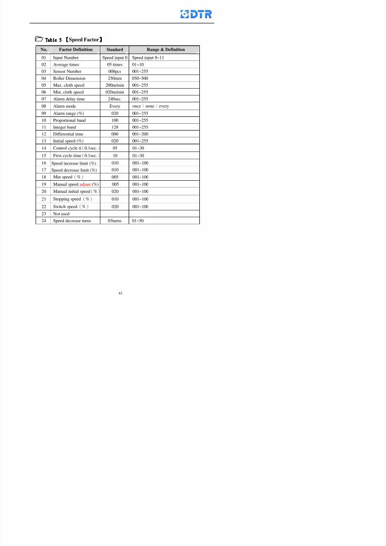
8132019 DTR 650 User Manual
httpslidepdfcomreaderfulldtr-650-user-manual 6170
TTTTTTTTaaaaaaaabbbbbbbblllllllleeeeeeee 55555555 【【【【Speed Factor】】】】
No Factor Definition Standard Range amp Definition
01 Input Number Speed input 0 Speed input 0~11
02 Average times 05 times 01~10
03 Sensor Number 008pcs 001~255
04 Roller Dimension 250mm 050~500
05 Max cloth speed 200mmin 001~25506 Min cloth speed 020mmin 001~255
07 Alarm delay time 240sec 001~255
08 Alarm mode Every oncenoneevery
09 Alarm range () 020 001~255
10 Proportional band 100 001~255
11 Integer band 128 001~25512 Differential time 000 001~200
13 Initial speed () 020 001~255
14 Control cycle ti(01sec) 05 01~30
15 First cycle time(01sec) 10 01~30
16 Speed increase limit () 010 001~100
17 Speed decrease limit () 010 001~100
18 Min speed() 005 001~100
19 Manual speed adjust () 005 001~100
20 Manual initial speed() 020 001~100
21 Stopping speed() 010 001~100
22 Switch speed() 020 001~100
23 Not used
24 Speed decrease turns 03turns 01~50
8132019 DTR 650 User Manual
httpslidepdfcomreaderfulldtr-650-user-manual 6270
Table 6 【【【【Dosing Factors】】】】
No Description Range Range and Explanation
1 Analog input no Analog input 0 Analog input no 0 ~11
2Alarm delay time for
dosing240 sec 000 ~255 sec
3 Alarm time for dosing Every Every Once None
4 Proportional band 100 000 ~255 sec Factor P
5 Integer band 128 000 ~255 sec Factor I6 Differential time 04 00 ~20 Factor D
7 Max adjust rate 150 50~ 255
8 Initial factor for dosing 10 000 ~100
9 User curve section 0 10 Gradient of sect1 for dosing curve9
10 User curve section 1 10 Gradient of sect2 for dosing curve9
11 User curve section 2 10 Gradient of sect3 for dosing curve9
12 User curve section 3 10 Gradient of sect4 for dosing curve9
13 User curve section 4 10 Gradient of sect5 for dosing curve9
14 User curve section 5 10 Gradient of sect6 for dosing curve9
15 User curve section 6 10 Gradient of sect7 for dosing curve9
16 User curve section 7 10 Gradient of sect8 for dosing curve9
17 User curve section 8 10 Gradient of sect9 for dosing curve9
18 User curve section 9 10 Gradient of sect10 for dosing curve9
19 Min water level 05 00~ 10 04~20mA percentagechange to the userrsquos factor setting
20 Output value for Tank
clean
100 000~ 100
Injected percentage of dosing valve
in dosing End period
This factor will be invalided if usingONOFF dosing valve
21 Full range 100 001~255 Self-adjustment cannotchange
22 Range ratio 001001~255 Self-adjustment cannot
change
8132019 DTR 650 User Manual
httpslidepdfcomreaderfulldtr-650-user-manual 6370
【【【【TTaabbllee 77 】】】】Pressure Deviation Factors
No Description Std Range amp Definition
1 Analog input number + Analog in 0 Analog in 0~11
2 Analog input number - Analog in 1 Analog in 0~11
3 Input mode Pressure Pressure Pressure deviation
4 Full range 050x01Kgcm
001~255
5 Range ratio 001 001~255
6 Alarm delay time 100sec 001~255
7 Alarm mode Every oncenone
8 Alarm range 010 001~255
9 Proportional band 100 001~255
10 Integer band 128 001~255
11 Differential time 00 00~20
12 PID Init output value 010 001~255
13 Cycle time 10 03~30
14 First cycle time 030 003~100
15 Max adjust rate 010 001~100
8132019 DTR 650 User Manual
httpslidepdfcomreaderfulldtr-650-user-manual 6470
【【【【TTaabbllee 88 】】】】Definition of Analog Input
No Description Standard Range and Explanation
01 PT 0 correction standard DIN std DIN std JIS std
02 PT 0 correction +0 +- 9
03 PT 1 correction standard DIN std DIN std JIS std
04 PT 1 correction +0 +- 9
05 PT 2 correction standard DIN std DIN std JIS std
06 PT 2 correction +0 +- 9
07 PT 3 correction standard DIN std DIN std JIS std
08 PT 3 correction +0 +- 9
09 PT 4 correction standard DIN std DIN std JIS std
10 PT 4 correction +0 +- 9
11 PT 5 correction standard DIN std DIN std JIS std
12 PT 5 correction +0 +- 9
13 Analog input 0 define 4 ~ 20mA 0 ndash 20mA 4 ndash 20mA
14 Analog input 0 average times 10 times 01- 20 times
15 Analog input 0 min value 0000 0000 - 1000
16 Analog input 0 max value 100 0001 - 9999
17-60 Analog input 1~11 Same as Analog input 0
【【【【 】】】】 fi i i f A O
8132019 DTR 650 User Manual
httpslidepdfcomreaderfulldtr-650-user-manual 6570
【【【【TTaabbllee 99 】】】】Definition of Analog Output
No Description Standard Range and explanation
61 Analog output 0 define Control byPLC
Control by PLC
Temperature control PID0 output
Temperature control PID1 output
Temperature control PID2 output
Speed PID3 output
Dosing PID0 output Dosing PID1output
Pressure different PID0 outputPressure different PID1 output
Main temperature output
62 Mode of Analog ouptput0 4 ~20mA 0 ndash20mA 4 ndash 20mA
63-84 Analog output 1~11 Same as Analog output 0
【【【【TTaabbllee 1100】】】】Value Table 0 amp 1
No Description Range Std Range and explanation
1 Analog input no 000~011 000 Analog input no
2 Data ratio 001~255 100 Multiple by factors
3~53 0~98 000~255 000-100 Analog input 0~98 data
【【【【 】】】】St t Li t
8132019 DTR 650 User Manual
httpslidepdfcomreaderfulldtr-650-user-manual 6670
【【【【TTaabbllee 1111】】】】State List
No Description Range Standard Range and explanation
1 Display setting 1 0~255 205 See remarks at next page
2 Display setting 2 0~255 208
3 Display setting 3 0~255 209
4 Display setting 4 0~255 017
5 Display setting 5 0~255 0186 Display setting 6 0~255 019
7 Display setting 7 0~255 020
8 Display setting 8 0~255 021
9 Display setting 9 0~255 000
10 Display setting 1 0~255 000
11 Display setting 2 0~255 000
12 Display setting 3 0~255 000
13 Display setting 4 0~255 000
14 Display setting 5 0~255 000
15 Display setting 6 0~255 000
16 Display setting 7 0~255 000
Remarks
8132019 DTR 650 User Manual
httpslidepdfcomreaderfulldtr-650-user-manual 6770
0 = No display 1~255 = Display type of number
1~16 Content of PLC VB0~15
No 1 corresponding to VB0
No 16 corresponding to VB15
17~32 Content of PLC DB0~15
No 17 corresponding to DB0
No 32 corresponding to DB15
33~46 Content of PLC CNT0~29
No 33 corresponding to CNT0
No 46 corresponding to CNT29 47~78 Content of dyeing instruction 0~31 CNT0
No 47 corresponding to system instruction to No 0 of CNT0
No 78 corresponding to system instruction to No 31 of CNT0rsquos content
79~110 Dyeing instruction 0~31 of CNT0rsquos setting
111~142 Content of Dyeing instruction 0~31 CNT1No 111 corresponding to dyeing instruction No 0 of CNT1
No 142 corresponding to dyeing instruction No 31 of CNT1rsquos content
143~174 Dyeing instruction 0~31 of CNT1rsquos setting
175~204 Content of PLC HTIM0~29
No 175 corresponding to HTIM0
No 204 corresponding to HTIM29
205 Loading
206 Ratio 1
207 Ratio 2208 Ratio 1 x Loading
209 Ratio 2 x Loading
210 Fix value
211 Value Table 1 matching result
212 Value Table 2 matching result
213 Value Table 1 setting214 Value Table 2 setting
215 Pressure control PID0 different pressure value
216 Pressure control PID1 different pressure value
TTTTTTTTaaaaaaaabbbbbbbblllllllleeeeeeee 1122 【【【【Usage of password】】】】
8132019 DTR 650 User Manual
httpslidepdfcomreaderfulldtr-650-user-manual 6870
No Main FunctionFactor Sub Function Factor Password Rank
1 Run None
2 Dye program User3 or above
3 Control factor
- User factor User 1
- System factor User 1
- Temp PID 0
- Temp PID 1 User 1- Speed PID 0 User 1
- Dosing PID 0 User 1
- Dosing PID 1 User 1
- Pressure PID 0 User 1
- Pressure PID 1 User 1
- Analog IO User 1
- Load standard factor User 2 or above- Load a copied factor User 2 or above
- Copy factor User 2 or above
- Value table 0 User 1
- Value table 1 User 1
- Information and state User 1
- Dye instruction User 1
- Edit dye instruction setting User 14 Output testing User 2 or above
5 Calibration User 2 or above
6 Dye record None
7 CF card User 1
8 Info and state None
9 Others
- Contrast User3 or above
- Data Locking None
- PLC Run User 1
- PLC Stop User 1
- Password setting User 1
TTTTTTTTaaaaaaaabbbbbbbblllllllleeeeeeee 1133 【【【【Technical Data】】】】
8132019 DTR 650 User Manual
httpslidepdfcomreaderfulldtr-650-user-manual 6970
TTTTTTTTaaaaaaaabbbbbbbblllllllleeeeeeee 1133 【【【【Technical Data】】】】
1 Temperature Control
- Range 10~145(plusmn1)
- Mode Proportional or PWM
- Sensor PT100 (JIS or DIN standard)
2 Input and output channel
- Digital Input 32 DC24V PNP- Digital Output 32 DC24V 054A Relay connect point
- Analog Input 4 04~20 mA
- Analog Output 4 0~20mA 或 4~20 mA
3 Communication port 3 RS-232 amp 0~20 mAx1 RS485x 2
4 Dye program
- Number 15000 Steps
- Standard step 61Heating Cooling Fill Drain RinseDosingetc
5LCD module and Display
langage
Chinese
English
320 x 240 TFT color display with
more language
6 CF card connector 1 PCMCIA standard
7 Membrane Keyboard- Number Key 10 [0]~[9] Input factors
- Function Key 5 [F1]~[F5] function selecting
- Operation Key 2 [Start] [Stop]
- Auxiliary Key 7 [][][][][Esc] [larr][OK] [bull]
8 Operating Condition
- Temperature 5~45
- Humidity ≦85 (25)
9 Power supply
V l DC 24V
8132019 DTR 650 User Manual
httpslidepdfcomreaderfulldtr-650-user-manual 7070
70
983108983124983122983085650 983113983150983152983157983156 983119983157983156983152983157983156 983120983151983154983156983145983150983143 (983138983137983139983147983155983145983140983141 983158983145983141983159)
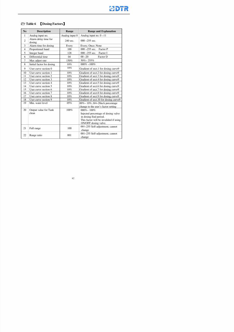
8132019 DTR 650 User Manual
httpslidepdfcomreaderfulldtr-650-user-manual 6270
Table 6 【【【【Dosing Factors】】】】
No Description Range Range and Explanation
1 Analog input no Analog input 0 Analog input no 0 ~11
2Alarm delay time for
dosing240 sec 000 ~255 sec
3 Alarm time for dosing Every Every Once None
4 Proportional band 100 000 ~255 sec Factor P
5 Integer band 128 000 ~255 sec Factor I6 Differential time 04 00 ~20 Factor D
7 Max adjust rate 150 50~ 255
8 Initial factor for dosing 10 000 ~100
9 User curve section 0 10 Gradient of sect1 for dosing curve9
10 User curve section 1 10 Gradient of sect2 for dosing curve9
11 User curve section 2 10 Gradient of sect3 for dosing curve9
12 User curve section 3 10 Gradient of sect4 for dosing curve9
13 User curve section 4 10 Gradient of sect5 for dosing curve9
14 User curve section 5 10 Gradient of sect6 for dosing curve9
15 User curve section 6 10 Gradient of sect7 for dosing curve9
16 User curve section 7 10 Gradient of sect8 for dosing curve9
17 User curve section 8 10 Gradient of sect9 for dosing curve9
18 User curve section 9 10 Gradient of sect10 for dosing curve9
19 Min water level 05 00~ 10 04~20mA percentagechange to the userrsquos factor setting
20 Output value for Tank
clean
100 000~ 100
Injected percentage of dosing valve
in dosing End period
This factor will be invalided if usingONOFF dosing valve
21 Full range 100 001~255 Self-adjustment cannotchange
22 Range ratio 001001~255 Self-adjustment cannot
change
8132019 DTR 650 User Manual
httpslidepdfcomreaderfulldtr-650-user-manual 6370
【【【【TTaabbllee 77 】】】】Pressure Deviation Factors
No Description Std Range amp Definition
1 Analog input number + Analog in 0 Analog in 0~11
2 Analog input number - Analog in 1 Analog in 0~11
3 Input mode Pressure Pressure Pressure deviation
4 Full range 050x01Kgcm
001~255
5 Range ratio 001 001~255
6 Alarm delay time 100sec 001~255
7 Alarm mode Every oncenone
8 Alarm range 010 001~255
9 Proportional band 100 001~255
10 Integer band 128 001~255
11 Differential time 00 00~20
12 PID Init output value 010 001~255
13 Cycle time 10 03~30
14 First cycle time 030 003~100
15 Max adjust rate 010 001~100
8132019 DTR 650 User Manual
httpslidepdfcomreaderfulldtr-650-user-manual 6470
【【【【TTaabbllee 88 】】】】Definition of Analog Input
No Description Standard Range and Explanation
01 PT 0 correction standard DIN std DIN std JIS std
02 PT 0 correction +0 +- 9
03 PT 1 correction standard DIN std DIN std JIS std
04 PT 1 correction +0 +- 9
05 PT 2 correction standard DIN std DIN std JIS std
06 PT 2 correction +0 +- 9
07 PT 3 correction standard DIN std DIN std JIS std
08 PT 3 correction +0 +- 9
09 PT 4 correction standard DIN std DIN std JIS std
10 PT 4 correction +0 +- 9
11 PT 5 correction standard DIN std DIN std JIS std
12 PT 5 correction +0 +- 9
13 Analog input 0 define 4 ~ 20mA 0 ndash 20mA 4 ndash 20mA
14 Analog input 0 average times 10 times 01- 20 times
15 Analog input 0 min value 0000 0000 - 1000
16 Analog input 0 max value 100 0001 - 9999
17-60 Analog input 1~11 Same as Analog input 0
【【【【 】】】】 fi i i f A O
8132019 DTR 650 User Manual
httpslidepdfcomreaderfulldtr-650-user-manual 6570
【【【【TTaabbllee 99 】】】】Definition of Analog Output
No Description Standard Range and explanation
61 Analog output 0 define Control byPLC
Control by PLC
Temperature control PID0 output
Temperature control PID1 output
Temperature control PID2 output
Speed PID3 output
Dosing PID0 output Dosing PID1output
Pressure different PID0 outputPressure different PID1 output
Main temperature output
62 Mode of Analog ouptput0 4 ~20mA 0 ndash20mA 4 ndash 20mA
63-84 Analog output 1~11 Same as Analog output 0
【【【【TTaabbllee 1100】】】】Value Table 0 amp 1
No Description Range Std Range and explanation
1 Analog input no 000~011 000 Analog input no
2 Data ratio 001~255 100 Multiple by factors
3~53 0~98 000~255 000-100 Analog input 0~98 data
【【【【 】】】】St t Li t
8132019 DTR 650 User Manual
httpslidepdfcomreaderfulldtr-650-user-manual 6670
【【【【TTaabbllee 1111】】】】State List
No Description Range Standard Range and explanation
1 Display setting 1 0~255 205 See remarks at next page
2 Display setting 2 0~255 208
3 Display setting 3 0~255 209
4 Display setting 4 0~255 017
5 Display setting 5 0~255 0186 Display setting 6 0~255 019
7 Display setting 7 0~255 020
8 Display setting 8 0~255 021
9 Display setting 9 0~255 000
10 Display setting 1 0~255 000
11 Display setting 2 0~255 000
12 Display setting 3 0~255 000
13 Display setting 4 0~255 000
14 Display setting 5 0~255 000
15 Display setting 6 0~255 000
16 Display setting 7 0~255 000
Remarks
8132019 DTR 650 User Manual
httpslidepdfcomreaderfulldtr-650-user-manual 6770
0 = No display 1~255 = Display type of number
1~16 Content of PLC VB0~15
No 1 corresponding to VB0
No 16 corresponding to VB15
17~32 Content of PLC DB0~15
No 17 corresponding to DB0
No 32 corresponding to DB15
33~46 Content of PLC CNT0~29
No 33 corresponding to CNT0
No 46 corresponding to CNT29 47~78 Content of dyeing instruction 0~31 CNT0
No 47 corresponding to system instruction to No 0 of CNT0
No 78 corresponding to system instruction to No 31 of CNT0rsquos content
79~110 Dyeing instruction 0~31 of CNT0rsquos setting
111~142 Content of Dyeing instruction 0~31 CNT1No 111 corresponding to dyeing instruction No 0 of CNT1
No 142 corresponding to dyeing instruction No 31 of CNT1rsquos content
143~174 Dyeing instruction 0~31 of CNT1rsquos setting
175~204 Content of PLC HTIM0~29
No 175 corresponding to HTIM0
No 204 corresponding to HTIM29
205 Loading
206 Ratio 1
207 Ratio 2208 Ratio 1 x Loading
209 Ratio 2 x Loading
210 Fix value
211 Value Table 1 matching result
212 Value Table 2 matching result
213 Value Table 1 setting214 Value Table 2 setting
215 Pressure control PID0 different pressure value
216 Pressure control PID1 different pressure value
TTTTTTTTaaaaaaaabbbbbbbblllllllleeeeeeee 1122 【【【【Usage of password】】】】
8132019 DTR 650 User Manual
httpslidepdfcomreaderfulldtr-650-user-manual 6870
No Main FunctionFactor Sub Function Factor Password Rank
1 Run None
2 Dye program User3 or above
3 Control factor
- User factor User 1
- System factor User 1
- Temp PID 0
- Temp PID 1 User 1- Speed PID 0 User 1
- Dosing PID 0 User 1
- Dosing PID 1 User 1
- Pressure PID 0 User 1
- Pressure PID 1 User 1
- Analog IO User 1
- Load standard factor User 2 or above- Load a copied factor User 2 or above
- Copy factor User 2 or above
- Value table 0 User 1
- Value table 1 User 1
- Information and state User 1
- Dye instruction User 1
- Edit dye instruction setting User 14 Output testing User 2 or above
5 Calibration User 2 or above
6 Dye record None
7 CF card User 1
8 Info and state None
9 Others
- Contrast User3 or above
- Data Locking None
- PLC Run User 1
- PLC Stop User 1
- Password setting User 1
TTTTTTTTaaaaaaaabbbbbbbblllllllleeeeeeee 1133 【【【【Technical Data】】】】
8132019 DTR 650 User Manual
httpslidepdfcomreaderfulldtr-650-user-manual 6970
TTTTTTTTaaaaaaaabbbbbbbblllllllleeeeeeee 1133 【【【【Technical Data】】】】
1 Temperature Control
- Range 10~145(plusmn1)
- Mode Proportional or PWM
- Sensor PT100 (JIS or DIN standard)
2 Input and output channel
- Digital Input 32 DC24V PNP- Digital Output 32 DC24V 054A Relay connect point
- Analog Input 4 04~20 mA
- Analog Output 4 0~20mA 或 4~20 mA
3 Communication port 3 RS-232 amp 0~20 mAx1 RS485x 2
4 Dye program
- Number 15000 Steps
- Standard step 61Heating Cooling Fill Drain RinseDosingetc
5LCD module and Display
langage
Chinese
English
320 x 240 TFT color display with
more language
6 CF card connector 1 PCMCIA standard
7 Membrane Keyboard- Number Key 10 [0]~[9] Input factors
- Function Key 5 [F1]~[F5] function selecting
- Operation Key 2 [Start] [Stop]
- Auxiliary Key 7 [][][][][Esc] [larr][OK] [bull]
8 Operating Condition
- Temperature 5~45
- Humidity ≦85 (25)
9 Power supply
V l DC 24V
8132019 DTR 650 User Manual
httpslidepdfcomreaderfulldtr-650-user-manual 7070
70
983108983124983122983085650 983113983150983152983157983156 983119983157983156983152983157983156 983120983151983154983156983145983150983143 (983138983137983139983147983155983145983140983141 983158983145983141983159)
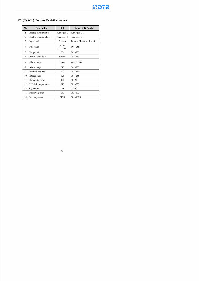
8132019 DTR 650 User Manual
httpslidepdfcomreaderfulldtr-650-user-manual 6370
【【【【TTaabbllee 77 】】】】Pressure Deviation Factors
No Description Std Range amp Definition
1 Analog input number + Analog in 0 Analog in 0~11
2 Analog input number - Analog in 1 Analog in 0~11
3 Input mode Pressure Pressure Pressure deviation
4 Full range 050x01Kgcm
001~255
5 Range ratio 001 001~255
6 Alarm delay time 100sec 001~255
7 Alarm mode Every oncenone
8 Alarm range 010 001~255
9 Proportional band 100 001~255
10 Integer band 128 001~255
11 Differential time 00 00~20
12 PID Init output value 010 001~255
13 Cycle time 10 03~30
14 First cycle time 030 003~100
15 Max adjust rate 010 001~100
8132019 DTR 650 User Manual
httpslidepdfcomreaderfulldtr-650-user-manual 6470
【【【【TTaabbllee 88 】】】】Definition of Analog Input
No Description Standard Range and Explanation
01 PT 0 correction standard DIN std DIN std JIS std
02 PT 0 correction +0 +- 9
03 PT 1 correction standard DIN std DIN std JIS std
04 PT 1 correction +0 +- 9
05 PT 2 correction standard DIN std DIN std JIS std
06 PT 2 correction +0 +- 9
07 PT 3 correction standard DIN std DIN std JIS std
08 PT 3 correction +0 +- 9
09 PT 4 correction standard DIN std DIN std JIS std
10 PT 4 correction +0 +- 9
11 PT 5 correction standard DIN std DIN std JIS std
12 PT 5 correction +0 +- 9
13 Analog input 0 define 4 ~ 20mA 0 ndash 20mA 4 ndash 20mA
14 Analog input 0 average times 10 times 01- 20 times
15 Analog input 0 min value 0000 0000 - 1000
16 Analog input 0 max value 100 0001 - 9999
17-60 Analog input 1~11 Same as Analog input 0
【【【【 】】】】 fi i i f A O
8132019 DTR 650 User Manual
httpslidepdfcomreaderfulldtr-650-user-manual 6570
【【【【TTaabbllee 99 】】】】Definition of Analog Output
No Description Standard Range and explanation
61 Analog output 0 define Control byPLC
Control by PLC
Temperature control PID0 output
Temperature control PID1 output
Temperature control PID2 output
Speed PID3 output
Dosing PID0 output Dosing PID1output
Pressure different PID0 outputPressure different PID1 output
Main temperature output
62 Mode of Analog ouptput0 4 ~20mA 0 ndash20mA 4 ndash 20mA
63-84 Analog output 1~11 Same as Analog output 0
【【【【TTaabbllee 1100】】】】Value Table 0 amp 1
No Description Range Std Range and explanation
1 Analog input no 000~011 000 Analog input no
2 Data ratio 001~255 100 Multiple by factors
3~53 0~98 000~255 000-100 Analog input 0~98 data
【【【【 】】】】St t Li t
8132019 DTR 650 User Manual
httpslidepdfcomreaderfulldtr-650-user-manual 6670
【【【【TTaabbllee 1111】】】】State List
No Description Range Standard Range and explanation
1 Display setting 1 0~255 205 See remarks at next page
2 Display setting 2 0~255 208
3 Display setting 3 0~255 209
4 Display setting 4 0~255 017
5 Display setting 5 0~255 0186 Display setting 6 0~255 019
7 Display setting 7 0~255 020
8 Display setting 8 0~255 021
9 Display setting 9 0~255 000
10 Display setting 1 0~255 000
11 Display setting 2 0~255 000
12 Display setting 3 0~255 000
13 Display setting 4 0~255 000
14 Display setting 5 0~255 000
15 Display setting 6 0~255 000
16 Display setting 7 0~255 000
Remarks
8132019 DTR 650 User Manual
httpslidepdfcomreaderfulldtr-650-user-manual 6770
0 = No display 1~255 = Display type of number
1~16 Content of PLC VB0~15
No 1 corresponding to VB0
No 16 corresponding to VB15
17~32 Content of PLC DB0~15
No 17 corresponding to DB0
No 32 corresponding to DB15
33~46 Content of PLC CNT0~29
No 33 corresponding to CNT0
No 46 corresponding to CNT29 47~78 Content of dyeing instruction 0~31 CNT0
No 47 corresponding to system instruction to No 0 of CNT0
No 78 corresponding to system instruction to No 31 of CNT0rsquos content
79~110 Dyeing instruction 0~31 of CNT0rsquos setting
111~142 Content of Dyeing instruction 0~31 CNT1No 111 corresponding to dyeing instruction No 0 of CNT1
No 142 corresponding to dyeing instruction No 31 of CNT1rsquos content
143~174 Dyeing instruction 0~31 of CNT1rsquos setting
175~204 Content of PLC HTIM0~29
No 175 corresponding to HTIM0
No 204 corresponding to HTIM29
205 Loading
206 Ratio 1
207 Ratio 2208 Ratio 1 x Loading
209 Ratio 2 x Loading
210 Fix value
211 Value Table 1 matching result
212 Value Table 2 matching result
213 Value Table 1 setting214 Value Table 2 setting
215 Pressure control PID0 different pressure value
216 Pressure control PID1 different pressure value
TTTTTTTTaaaaaaaabbbbbbbblllllllleeeeeeee 1122 【【【【Usage of password】】】】
8132019 DTR 650 User Manual
httpslidepdfcomreaderfulldtr-650-user-manual 6870
No Main FunctionFactor Sub Function Factor Password Rank
1 Run None
2 Dye program User3 or above
3 Control factor
- User factor User 1
- System factor User 1
- Temp PID 0
- Temp PID 1 User 1- Speed PID 0 User 1
- Dosing PID 0 User 1
- Dosing PID 1 User 1
- Pressure PID 0 User 1
- Pressure PID 1 User 1
- Analog IO User 1
- Load standard factor User 2 or above- Load a copied factor User 2 or above
- Copy factor User 2 or above
- Value table 0 User 1
- Value table 1 User 1
- Information and state User 1
- Dye instruction User 1
- Edit dye instruction setting User 14 Output testing User 2 or above
5 Calibration User 2 or above
6 Dye record None
7 CF card User 1
8 Info and state None
9 Others
- Contrast User3 or above
- Data Locking None
- PLC Run User 1
- PLC Stop User 1
- Password setting User 1
TTTTTTTTaaaaaaaabbbbbbbblllllllleeeeeeee 1133 【【【【Technical Data】】】】
8132019 DTR 650 User Manual
httpslidepdfcomreaderfulldtr-650-user-manual 6970
TTTTTTTTaaaaaaaabbbbbbbblllllllleeeeeeee 1133 【【【【Technical Data】】】】
1 Temperature Control
- Range 10~145(plusmn1)
- Mode Proportional or PWM
- Sensor PT100 (JIS or DIN standard)
2 Input and output channel
- Digital Input 32 DC24V PNP- Digital Output 32 DC24V 054A Relay connect point
- Analog Input 4 04~20 mA
- Analog Output 4 0~20mA 或 4~20 mA
3 Communication port 3 RS-232 amp 0~20 mAx1 RS485x 2
4 Dye program
- Number 15000 Steps
- Standard step 61Heating Cooling Fill Drain RinseDosingetc
5LCD module and Display
langage
Chinese
English
320 x 240 TFT color display with
more language
6 CF card connector 1 PCMCIA standard
7 Membrane Keyboard- Number Key 10 [0]~[9] Input factors
- Function Key 5 [F1]~[F5] function selecting
- Operation Key 2 [Start] [Stop]
- Auxiliary Key 7 [][][][][Esc] [larr][OK] [bull]
8 Operating Condition
- Temperature 5~45
- Humidity ≦85 (25)
9 Power supply
V l DC 24V
8132019 DTR 650 User Manual
httpslidepdfcomreaderfulldtr-650-user-manual 7070
70
983108983124983122983085650 983113983150983152983157983156 983119983157983156983152983157983156 983120983151983154983156983145983150983143 (983138983137983139983147983155983145983140983141 983158983145983141983159)
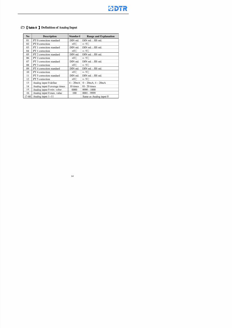
8132019 DTR 650 User Manual
httpslidepdfcomreaderfulldtr-650-user-manual 6470
【【【【TTaabbllee 88 】】】】Definition of Analog Input
No Description Standard Range and Explanation
01 PT 0 correction standard DIN std DIN std JIS std
02 PT 0 correction +0 +- 9
03 PT 1 correction standard DIN std DIN std JIS std
04 PT 1 correction +0 +- 9
05 PT 2 correction standard DIN std DIN std JIS std
06 PT 2 correction +0 +- 9
07 PT 3 correction standard DIN std DIN std JIS std
08 PT 3 correction +0 +- 9
09 PT 4 correction standard DIN std DIN std JIS std
10 PT 4 correction +0 +- 9
11 PT 5 correction standard DIN std DIN std JIS std
12 PT 5 correction +0 +- 9
13 Analog input 0 define 4 ~ 20mA 0 ndash 20mA 4 ndash 20mA
14 Analog input 0 average times 10 times 01- 20 times
15 Analog input 0 min value 0000 0000 - 1000
16 Analog input 0 max value 100 0001 - 9999
17-60 Analog input 1~11 Same as Analog input 0
【【【【 】】】】 fi i i f A O
8132019 DTR 650 User Manual
httpslidepdfcomreaderfulldtr-650-user-manual 6570
【【【【TTaabbllee 99 】】】】Definition of Analog Output
No Description Standard Range and explanation
61 Analog output 0 define Control byPLC
Control by PLC
Temperature control PID0 output
Temperature control PID1 output
Temperature control PID2 output
Speed PID3 output
Dosing PID0 output Dosing PID1output
Pressure different PID0 outputPressure different PID1 output
Main temperature output
62 Mode of Analog ouptput0 4 ~20mA 0 ndash20mA 4 ndash 20mA
63-84 Analog output 1~11 Same as Analog output 0
【【【【TTaabbllee 1100】】】】Value Table 0 amp 1
No Description Range Std Range and explanation
1 Analog input no 000~011 000 Analog input no
2 Data ratio 001~255 100 Multiple by factors
3~53 0~98 000~255 000-100 Analog input 0~98 data
【【【【 】】】】St t Li t
8132019 DTR 650 User Manual
httpslidepdfcomreaderfulldtr-650-user-manual 6670
【【【【TTaabbllee 1111】】】】State List
No Description Range Standard Range and explanation
1 Display setting 1 0~255 205 See remarks at next page
2 Display setting 2 0~255 208
3 Display setting 3 0~255 209
4 Display setting 4 0~255 017
5 Display setting 5 0~255 0186 Display setting 6 0~255 019
7 Display setting 7 0~255 020
8 Display setting 8 0~255 021
9 Display setting 9 0~255 000
10 Display setting 1 0~255 000
11 Display setting 2 0~255 000
12 Display setting 3 0~255 000
13 Display setting 4 0~255 000
14 Display setting 5 0~255 000
15 Display setting 6 0~255 000
16 Display setting 7 0~255 000
Remarks
8132019 DTR 650 User Manual
httpslidepdfcomreaderfulldtr-650-user-manual 6770
0 = No display 1~255 = Display type of number
1~16 Content of PLC VB0~15
No 1 corresponding to VB0
No 16 corresponding to VB15
17~32 Content of PLC DB0~15
No 17 corresponding to DB0
No 32 corresponding to DB15
33~46 Content of PLC CNT0~29
No 33 corresponding to CNT0
No 46 corresponding to CNT29 47~78 Content of dyeing instruction 0~31 CNT0
No 47 corresponding to system instruction to No 0 of CNT0
No 78 corresponding to system instruction to No 31 of CNT0rsquos content
79~110 Dyeing instruction 0~31 of CNT0rsquos setting
111~142 Content of Dyeing instruction 0~31 CNT1No 111 corresponding to dyeing instruction No 0 of CNT1
No 142 corresponding to dyeing instruction No 31 of CNT1rsquos content
143~174 Dyeing instruction 0~31 of CNT1rsquos setting
175~204 Content of PLC HTIM0~29
No 175 corresponding to HTIM0
No 204 corresponding to HTIM29
205 Loading
206 Ratio 1
207 Ratio 2208 Ratio 1 x Loading
209 Ratio 2 x Loading
210 Fix value
211 Value Table 1 matching result
212 Value Table 2 matching result
213 Value Table 1 setting214 Value Table 2 setting
215 Pressure control PID0 different pressure value
216 Pressure control PID1 different pressure value
TTTTTTTTaaaaaaaabbbbbbbblllllllleeeeeeee 1122 【【【【Usage of password】】】】
8132019 DTR 650 User Manual
httpslidepdfcomreaderfulldtr-650-user-manual 6870
No Main FunctionFactor Sub Function Factor Password Rank
1 Run None
2 Dye program User3 or above
3 Control factor
- User factor User 1
- System factor User 1
- Temp PID 0
- Temp PID 1 User 1- Speed PID 0 User 1
- Dosing PID 0 User 1
- Dosing PID 1 User 1
- Pressure PID 0 User 1
- Pressure PID 1 User 1
- Analog IO User 1
- Load standard factor User 2 or above- Load a copied factor User 2 or above
- Copy factor User 2 or above
- Value table 0 User 1
- Value table 1 User 1
- Information and state User 1
- Dye instruction User 1
- Edit dye instruction setting User 14 Output testing User 2 or above
5 Calibration User 2 or above
6 Dye record None
7 CF card User 1
8 Info and state None
9 Others
- Contrast User3 or above
- Data Locking None
- PLC Run User 1
- PLC Stop User 1
- Password setting User 1
TTTTTTTTaaaaaaaabbbbbbbblllllllleeeeeeee 1133 【【【【Technical Data】】】】
8132019 DTR 650 User Manual
httpslidepdfcomreaderfulldtr-650-user-manual 6970
TTTTTTTTaaaaaaaabbbbbbbblllllllleeeeeeee 1133 【【【【Technical Data】】】】
1 Temperature Control
- Range 10~145(plusmn1)
- Mode Proportional or PWM
- Sensor PT100 (JIS or DIN standard)
2 Input and output channel
- Digital Input 32 DC24V PNP- Digital Output 32 DC24V 054A Relay connect point
- Analog Input 4 04~20 mA
- Analog Output 4 0~20mA 或 4~20 mA
3 Communication port 3 RS-232 amp 0~20 mAx1 RS485x 2
4 Dye program
- Number 15000 Steps
- Standard step 61Heating Cooling Fill Drain RinseDosingetc
5LCD module and Display
langage
Chinese
English
320 x 240 TFT color display with
more language
6 CF card connector 1 PCMCIA standard
7 Membrane Keyboard- Number Key 10 [0]~[9] Input factors
- Function Key 5 [F1]~[F5] function selecting
- Operation Key 2 [Start] [Stop]
- Auxiliary Key 7 [][][][][Esc] [larr][OK] [bull]
8 Operating Condition
- Temperature 5~45
- Humidity ≦85 (25)
9 Power supply
V l DC 24V
8132019 DTR 650 User Manual
httpslidepdfcomreaderfulldtr-650-user-manual 7070
70
983108983124983122983085650 983113983150983152983157983156 983119983157983156983152983157983156 983120983151983154983156983145983150983143 (983138983137983139983147983155983145983140983141 983158983145983141983159)
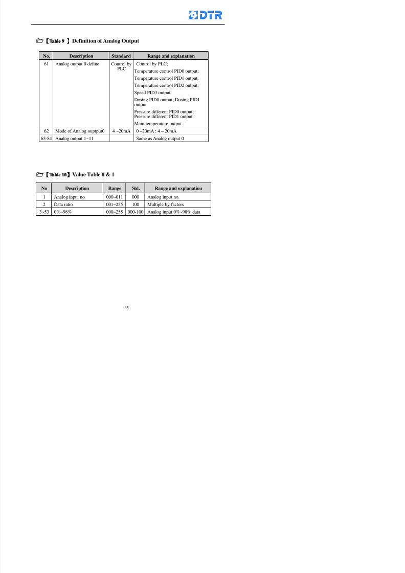
8132019 DTR 650 User Manual
httpslidepdfcomreaderfulldtr-650-user-manual 6570
【【【【TTaabbllee 99 】】】】Definition of Analog Output
No Description Standard Range and explanation
61 Analog output 0 define Control byPLC
Control by PLC
Temperature control PID0 output
Temperature control PID1 output
Temperature control PID2 output
Speed PID3 output
Dosing PID0 output Dosing PID1output
Pressure different PID0 outputPressure different PID1 output
Main temperature output
62 Mode of Analog ouptput0 4 ~20mA 0 ndash20mA 4 ndash 20mA
63-84 Analog output 1~11 Same as Analog output 0
【【【【TTaabbllee 1100】】】】Value Table 0 amp 1
No Description Range Std Range and explanation
1 Analog input no 000~011 000 Analog input no
2 Data ratio 001~255 100 Multiple by factors
3~53 0~98 000~255 000-100 Analog input 0~98 data
【【【【 】】】】St t Li t
8132019 DTR 650 User Manual
httpslidepdfcomreaderfulldtr-650-user-manual 6670
【【【【TTaabbllee 1111】】】】State List
No Description Range Standard Range and explanation
1 Display setting 1 0~255 205 See remarks at next page
2 Display setting 2 0~255 208
3 Display setting 3 0~255 209
4 Display setting 4 0~255 017
5 Display setting 5 0~255 0186 Display setting 6 0~255 019
7 Display setting 7 0~255 020
8 Display setting 8 0~255 021
9 Display setting 9 0~255 000
10 Display setting 1 0~255 000
11 Display setting 2 0~255 000
12 Display setting 3 0~255 000
13 Display setting 4 0~255 000
14 Display setting 5 0~255 000
15 Display setting 6 0~255 000
16 Display setting 7 0~255 000
Remarks
8132019 DTR 650 User Manual
httpslidepdfcomreaderfulldtr-650-user-manual 6770
0 = No display 1~255 = Display type of number
1~16 Content of PLC VB0~15
No 1 corresponding to VB0
No 16 corresponding to VB15
17~32 Content of PLC DB0~15
No 17 corresponding to DB0
No 32 corresponding to DB15
33~46 Content of PLC CNT0~29
No 33 corresponding to CNT0
No 46 corresponding to CNT29 47~78 Content of dyeing instruction 0~31 CNT0
No 47 corresponding to system instruction to No 0 of CNT0
No 78 corresponding to system instruction to No 31 of CNT0rsquos content
79~110 Dyeing instruction 0~31 of CNT0rsquos setting
111~142 Content of Dyeing instruction 0~31 CNT1No 111 corresponding to dyeing instruction No 0 of CNT1
No 142 corresponding to dyeing instruction No 31 of CNT1rsquos content
143~174 Dyeing instruction 0~31 of CNT1rsquos setting
175~204 Content of PLC HTIM0~29
No 175 corresponding to HTIM0
No 204 corresponding to HTIM29
205 Loading
206 Ratio 1
207 Ratio 2208 Ratio 1 x Loading
209 Ratio 2 x Loading
210 Fix value
211 Value Table 1 matching result
212 Value Table 2 matching result
213 Value Table 1 setting214 Value Table 2 setting
215 Pressure control PID0 different pressure value
216 Pressure control PID1 different pressure value
TTTTTTTTaaaaaaaabbbbbbbblllllllleeeeeeee 1122 【【【【Usage of password】】】】
8132019 DTR 650 User Manual
httpslidepdfcomreaderfulldtr-650-user-manual 6870
No Main FunctionFactor Sub Function Factor Password Rank
1 Run None
2 Dye program User3 or above
3 Control factor
- User factor User 1
- System factor User 1
- Temp PID 0
- Temp PID 1 User 1- Speed PID 0 User 1
- Dosing PID 0 User 1
- Dosing PID 1 User 1
- Pressure PID 0 User 1
- Pressure PID 1 User 1
- Analog IO User 1
- Load standard factor User 2 or above- Load a copied factor User 2 or above
- Copy factor User 2 or above
- Value table 0 User 1
- Value table 1 User 1
- Information and state User 1
- Dye instruction User 1
- Edit dye instruction setting User 14 Output testing User 2 or above
5 Calibration User 2 or above
6 Dye record None
7 CF card User 1
8 Info and state None
9 Others
- Contrast User3 or above
- Data Locking None
- PLC Run User 1
- PLC Stop User 1
- Password setting User 1
TTTTTTTTaaaaaaaabbbbbbbblllllllleeeeeeee 1133 【【【【Technical Data】】】】
8132019 DTR 650 User Manual
httpslidepdfcomreaderfulldtr-650-user-manual 6970
TTTTTTTTaaaaaaaabbbbbbbblllllllleeeeeeee 1133 【【【【Technical Data】】】】
1 Temperature Control
- Range 10~145(plusmn1)
- Mode Proportional or PWM
- Sensor PT100 (JIS or DIN standard)
2 Input and output channel
- Digital Input 32 DC24V PNP- Digital Output 32 DC24V 054A Relay connect point
- Analog Input 4 04~20 mA
- Analog Output 4 0~20mA 或 4~20 mA
3 Communication port 3 RS-232 amp 0~20 mAx1 RS485x 2
4 Dye program
- Number 15000 Steps
- Standard step 61Heating Cooling Fill Drain RinseDosingetc
5LCD module and Display
langage
Chinese
English
320 x 240 TFT color display with
more language
6 CF card connector 1 PCMCIA standard
7 Membrane Keyboard- Number Key 10 [0]~[9] Input factors
- Function Key 5 [F1]~[F5] function selecting
- Operation Key 2 [Start] [Stop]
- Auxiliary Key 7 [][][][][Esc] [larr][OK] [bull]
8 Operating Condition
- Temperature 5~45
- Humidity ≦85 (25)
9 Power supply
V l DC 24V
8132019 DTR 650 User Manual
httpslidepdfcomreaderfulldtr-650-user-manual 7070
70
983108983124983122983085650 983113983150983152983157983156 983119983157983156983152983157983156 983120983151983154983156983145983150983143 (983138983137983139983147983155983145983140983141 983158983145983141983159)
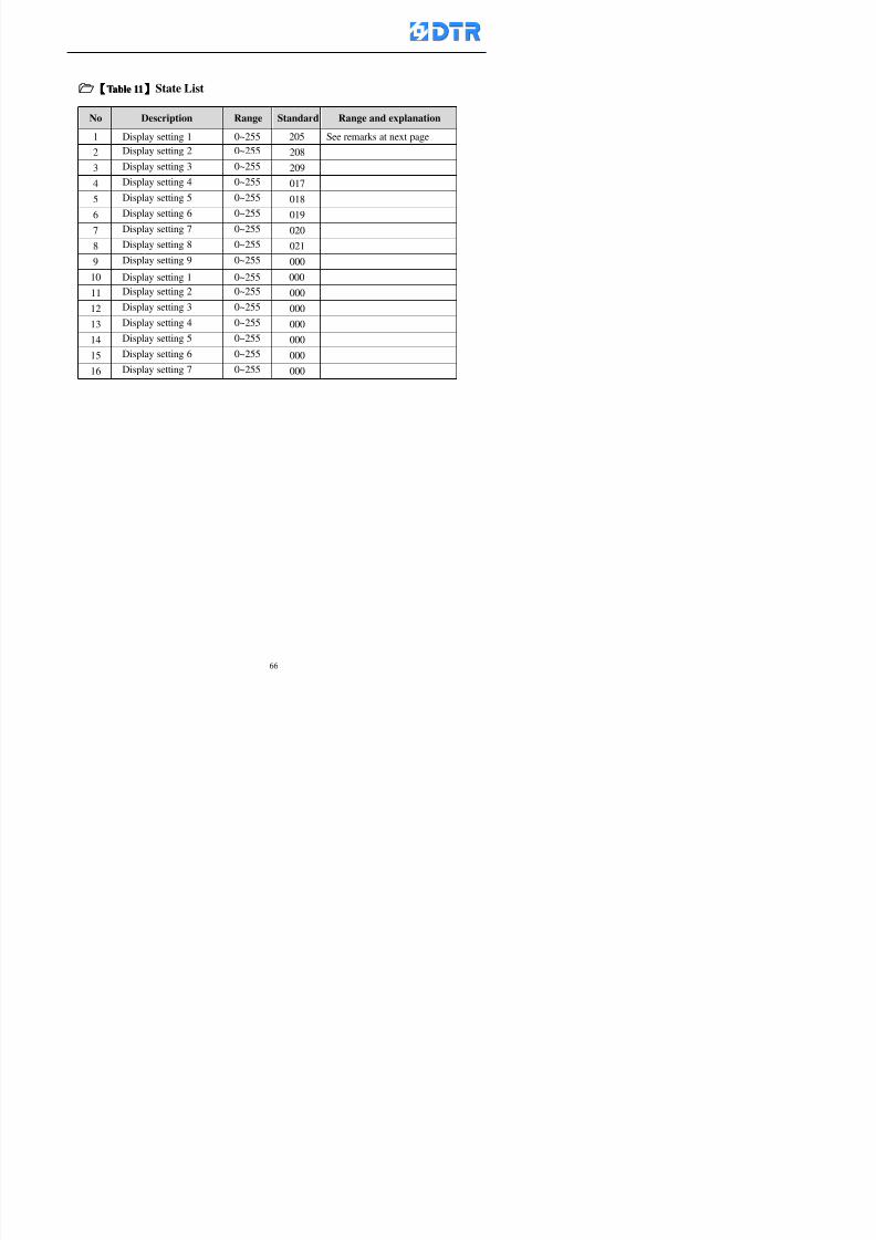
8132019 DTR 650 User Manual
httpslidepdfcomreaderfulldtr-650-user-manual 6670
【【【【TTaabbllee 1111】】】】State List
No Description Range Standard Range and explanation
1 Display setting 1 0~255 205 See remarks at next page
2 Display setting 2 0~255 208
3 Display setting 3 0~255 209
4 Display setting 4 0~255 017
5 Display setting 5 0~255 0186 Display setting 6 0~255 019
7 Display setting 7 0~255 020
8 Display setting 8 0~255 021
9 Display setting 9 0~255 000
10 Display setting 1 0~255 000
11 Display setting 2 0~255 000
12 Display setting 3 0~255 000
13 Display setting 4 0~255 000
14 Display setting 5 0~255 000
15 Display setting 6 0~255 000
16 Display setting 7 0~255 000
Remarks
8132019 DTR 650 User Manual
httpslidepdfcomreaderfulldtr-650-user-manual 6770
0 = No display 1~255 = Display type of number
1~16 Content of PLC VB0~15
No 1 corresponding to VB0
No 16 corresponding to VB15
17~32 Content of PLC DB0~15
No 17 corresponding to DB0
No 32 corresponding to DB15
33~46 Content of PLC CNT0~29
No 33 corresponding to CNT0
No 46 corresponding to CNT29 47~78 Content of dyeing instruction 0~31 CNT0
No 47 corresponding to system instruction to No 0 of CNT0
No 78 corresponding to system instruction to No 31 of CNT0rsquos content
79~110 Dyeing instruction 0~31 of CNT0rsquos setting
111~142 Content of Dyeing instruction 0~31 CNT1No 111 corresponding to dyeing instruction No 0 of CNT1
No 142 corresponding to dyeing instruction No 31 of CNT1rsquos content
143~174 Dyeing instruction 0~31 of CNT1rsquos setting
175~204 Content of PLC HTIM0~29
No 175 corresponding to HTIM0
No 204 corresponding to HTIM29
205 Loading
206 Ratio 1
207 Ratio 2208 Ratio 1 x Loading
209 Ratio 2 x Loading
210 Fix value
211 Value Table 1 matching result
212 Value Table 2 matching result
213 Value Table 1 setting214 Value Table 2 setting
215 Pressure control PID0 different pressure value
216 Pressure control PID1 different pressure value
TTTTTTTTaaaaaaaabbbbbbbblllllllleeeeeeee 1122 【【【【Usage of password】】】】
8132019 DTR 650 User Manual
httpslidepdfcomreaderfulldtr-650-user-manual 6870
No Main FunctionFactor Sub Function Factor Password Rank
1 Run None
2 Dye program User3 or above
3 Control factor
- User factor User 1
- System factor User 1
- Temp PID 0
- Temp PID 1 User 1- Speed PID 0 User 1
- Dosing PID 0 User 1
- Dosing PID 1 User 1
- Pressure PID 0 User 1
- Pressure PID 1 User 1
- Analog IO User 1
- Load standard factor User 2 or above- Load a copied factor User 2 or above
- Copy factor User 2 or above
- Value table 0 User 1
- Value table 1 User 1
- Information and state User 1
- Dye instruction User 1
- Edit dye instruction setting User 14 Output testing User 2 or above
5 Calibration User 2 or above
6 Dye record None
7 CF card User 1
8 Info and state None
9 Others
- Contrast User3 or above
- Data Locking None
- PLC Run User 1
- PLC Stop User 1
- Password setting User 1
TTTTTTTTaaaaaaaabbbbbbbblllllllleeeeeeee 1133 【【【【Technical Data】】】】
8132019 DTR 650 User Manual
httpslidepdfcomreaderfulldtr-650-user-manual 6970
TTTTTTTTaaaaaaaabbbbbbbblllllllleeeeeeee 1133 【【【【Technical Data】】】】
1 Temperature Control
- Range 10~145(plusmn1)
- Mode Proportional or PWM
- Sensor PT100 (JIS or DIN standard)
2 Input and output channel
- Digital Input 32 DC24V PNP- Digital Output 32 DC24V 054A Relay connect point
- Analog Input 4 04~20 mA
- Analog Output 4 0~20mA 或 4~20 mA
3 Communication port 3 RS-232 amp 0~20 mAx1 RS485x 2
4 Dye program
- Number 15000 Steps
- Standard step 61Heating Cooling Fill Drain RinseDosingetc
5LCD module and Display
langage
Chinese
English
320 x 240 TFT color display with
more language
6 CF card connector 1 PCMCIA standard
7 Membrane Keyboard- Number Key 10 [0]~[9] Input factors
- Function Key 5 [F1]~[F5] function selecting
- Operation Key 2 [Start] [Stop]
- Auxiliary Key 7 [][][][][Esc] [larr][OK] [bull]
8 Operating Condition
- Temperature 5~45
- Humidity ≦85 (25)
9 Power supply
V l DC 24V
8132019 DTR 650 User Manual
httpslidepdfcomreaderfulldtr-650-user-manual 7070
70
983108983124983122983085650 983113983150983152983157983156 983119983157983156983152983157983156 983120983151983154983156983145983150983143 (983138983137983139983147983155983145983140983141 983158983145983141983159)
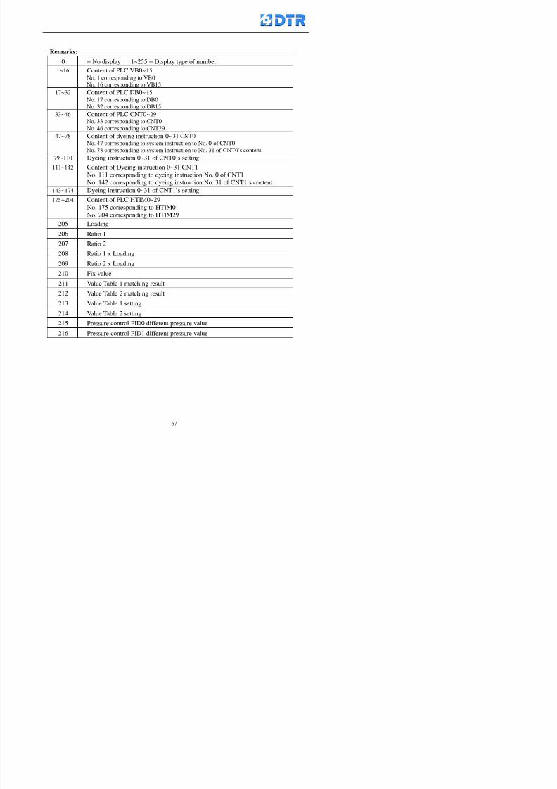
8132019 DTR 650 User Manual
httpslidepdfcomreaderfulldtr-650-user-manual 6770
0 = No display 1~255 = Display type of number
1~16 Content of PLC VB0~15
No 1 corresponding to VB0
No 16 corresponding to VB15
17~32 Content of PLC DB0~15
No 17 corresponding to DB0
No 32 corresponding to DB15
33~46 Content of PLC CNT0~29
No 33 corresponding to CNT0
No 46 corresponding to CNT29 47~78 Content of dyeing instruction 0~31 CNT0
No 47 corresponding to system instruction to No 0 of CNT0
No 78 corresponding to system instruction to No 31 of CNT0rsquos content
79~110 Dyeing instruction 0~31 of CNT0rsquos setting
111~142 Content of Dyeing instruction 0~31 CNT1No 111 corresponding to dyeing instruction No 0 of CNT1
No 142 corresponding to dyeing instruction No 31 of CNT1rsquos content
143~174 Dyeing instruction 0~31 of CNT1rsquos setting
175~204 Content of PLC HTIM0~29
No 175 corresponding to HTIM0
No 204 corresponding to HTIM29
205 Loading
206 Ratio 1
207 Ratio 2208 Ratio 1 x Loading
209 Ratio 2 x Loading
210 Fix value
211 Value Table 1 matching result
212 Value Table 2 matching result
213 Value Table 1 setting214 Value Table 2 setting
215 Pressure control PID0 different pressure value
216 Pressure control PID1 different pressure value
TTTTTTTTaaaaaaaabbbbbbbblllllllleeeeeeee 1122 【【【【Usage of password】】】】
8132019 DTR 650 User Manual
httpslidepdfcomreaderfulldtr-650-user-manual 6870
No Main FunctionFactor Sub Function Factor Password Rank
1 Run None
2 Dye program User3 or above
3 Control factor
- User factor User 1
- System factor User 1
- Temp PID 0
- Temp PID 1 User 1- Speed PID 0 User 1
- Dosing PID 0 User 1
- Dosing PID 1 User 1
- Pressure PID 0 User 1
- Pressure PID 1 User 1
- Analog IO User 1
- Load standard factor User 2 or above- Load a copied factor User 2 or above
- Copy factor User 2 or above
- Value table 0 User 1
- Value table 1 User 1
- Information and state User 1
- Dye instruction User 1
- Edit dye instruction setting User 14 Output testing User 2 or above
5 Calibration User 2 or above
6 Dye record None
7 CF card User 1
8 Info and state None
9 Others
- Contrast User3 or above
- Data Locking None
- PLC Run User 1
- PLC Stop User 1
- Password setting User 1
TTTTTTTTaaaaaaaabbbbbbbblllllllleeeeeeee 1133 【【【【Technical Data】】】】
8132019 DTR 650 User Manual
httpslidepdfcomreaderfulldtr-650-user-manual 6970
TTTTTTTTaaaaaaaabbbbbbbblllllllleeeeeeee 1133 【【【【Technical Data】】】】
1 Temperature Control
- Range 10~145(plusmn1)
- Mode Proportional or PWM
- Sensor PT100 (JIS or DIN standard)
2 Input and output channel
- Digital Input 32 DC24V PNP- Digital Output 32 DC24V 054A Relay connect point
- Analog Input 4 04~20 mA
- Analog Output 4 0~20mA 或 4~20 mA
3 Communication port 3 RS-232 amp 0~20 mAx1 RS485x 2
4 Dye program
- Number 15000 Steps
- Standard step 61Heating Cooling Fill Drain RinseDosingetc
5LCD module and Display
langage
Chinese
English
320 x 240 TFT color display with
more language
6 CF card connector 1 PCMCIA standard
7 Membrane Keyboard- Number Key 10 [0]~[9] Input factors
- Function Key 5 [F1]~[F5] function selecting
- Operation Key 2 [Start] [Stop]
- Auxiliary Key 7 [][][][][Esc] [larr][OK] [bull]
8 Operating Condition
- Temperature 5~45
- Humidity ≦85 (25)
9 Power supply
V l DC 24V
8132019 DTR 650 User Manual
httpslidepdfcomreaderfulldtr-650-user-manual 7070
70
983108983124983122983085650 983113983150983152983157983156 983119983157983156983152983157983156 983120983151983154983156983145983150983143 (983138983137983139983147983155983145983140983141 983158983145983141983159)
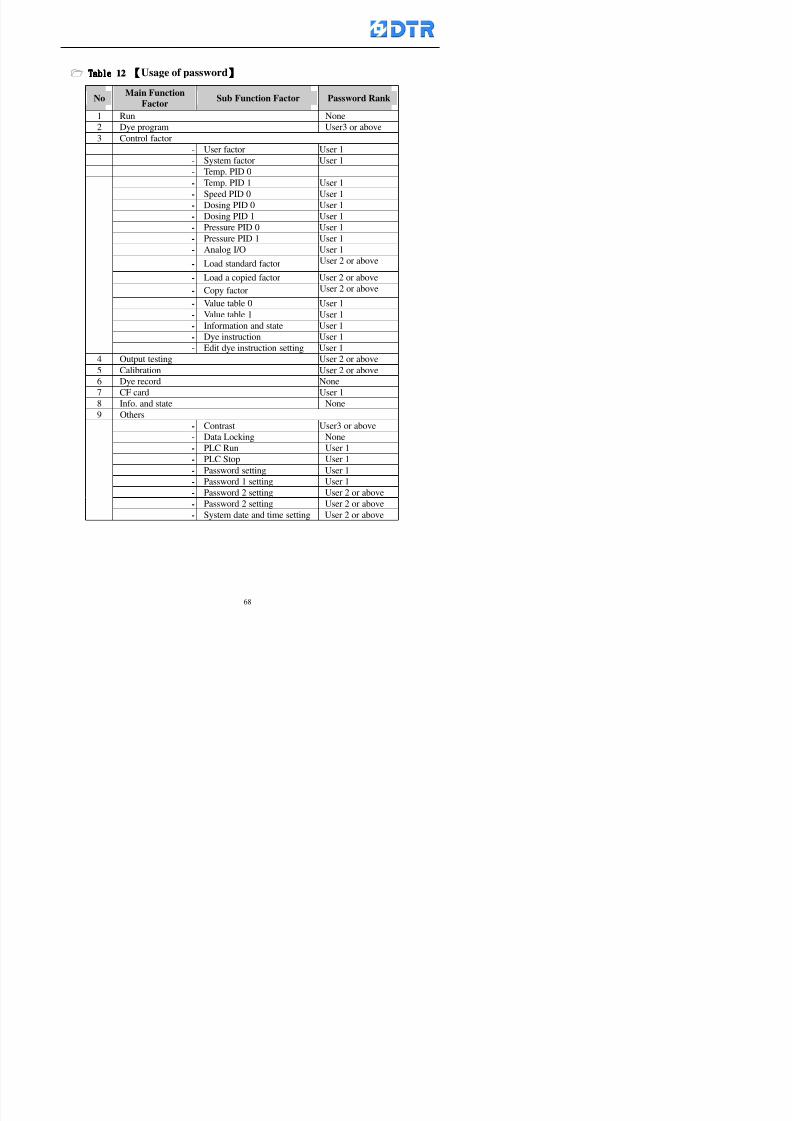
8132019 DTR 650 User Manual
httpslidepdfcomreaderfulldtr-650-user-manual 6870
No Main FunctionFactor Sub Function Factor Password Rank
1 Run None
2 Dye program User3 or above
3 Control factor
- User factor User 1
- System factor User 1
- Temp PID 0
- Temp PID 1 User 1- Speed PID 0 User 1
- Dosing PID 0 User 1
- Dosing PID 1 User 1
- Pressure PID 0 User 1
- Pressure PID 1 User 1
- Analog IO User 1
- Load standard factor User 2 or above- Load a copied factor User 2 or above
- Copy factor User 2 or above
- Value table 0 User 1
- Value table 1 User 1
- Information and state User 1
- Dye instruction User 1
- Edit dye instruction setting User 14 Output testing User 2 or above
5 Calibration User 2 or above
6 Dye record None
7 CF card User 1
8 Info and state None
9 Others
- Contrast User3 or above
- Data Locking None
- PLC Run User 1
- PLC Stop User 1
- Password setting User 1
TTTTTTTTaaaaaaaabbbbbbbblllllllleeeeeeee 1133 【【【【Technical Data】】】】
8132019 DTR 650 User Manual
httpslidepdfcomreaderfulldtr-650-user-manual 6970
TTTTTTTTaaaaaaaabbbbbbbblllllllleeeeeeee 1133 【【【【Technical Data】】】】
1 Temperature Control
- Range 10~145(plusmn1)
- Mode Proportional or PWM
- Sensor PT100 (JIS or DIN standard)
2 Input and output channel
- Digital Input 32 DC24V PNP- Digital Output 32 DC24V 054A Relay connect point
- Analog Input 4 04~20 mA
- Analog Output 4 0~20mA 或 4~20 mA
3 Communication port 3 RS-232 amp 0~20 mAx1 RS485x 2
4 Dye program
- Number 15000 Steps
- Standard step 61Heating Cooling Fill Drain RinseDosingetc
5LCD module and Display
langage
Chinese
English
320 x 240 TFT color display with
more language
6 CF card connector 1 PCMCIA standard
7 Membrane Keyboard- Number Key 10 [0]~[9] Input factors
- Function Key 5 [F1]~[F5] function selecting
- Operation Key 2 [Start] [Stop]
- Auxiliary Key 7 [][][][][Esc] [larr][OK] [bull]
8 Operating Condition
- Temperature 5~45
- Humidity ≦85 (25)
9 Power supply
V l DC 24V
8132019 DTR 650 User Manual
httpslidepdfcomreaderfulldtr-650-user-manual 7070
70
983108983124983122983085650 983113983150983152983157983156 983119983157983156983152983157983156 983120983151983154983156983145983150983143 (983138983137983139983147983155983145983140983141 983158983145983141983159)
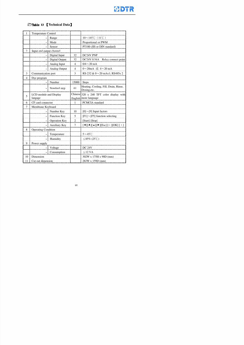
8132019 DTR 650 User Manual
httpslidepdfcomreaderfulldtr-650-user-manual 6970
TTTTTTTTaaaaaaaabbbbbbbblllllllleeeeeeee 1133 【【【【Technical Data】】】】
1 Temperature Control
- Range 10~145(plusmn1)
- Mode Proportional or PWM
- Sensor PT100 (JIS or DIN standard)
2 Input and output channel
- Digital Input 32 DC24V PNP- Digital Output 32 DC24V 054A Relay connect point
- Analog Input 4 04~20 mA
- Analog Output 4 0~20mA 或 4~20 mA
3 Communication port 3 RS-232 amp 0~20 mAx1 RS485x 2
4 Dye program
- Number 15000 Steps
- Standard step 61Heating Cooling Fill Drain RinseDosingetc
5LCD module and Display
langage
Chinese
English
320 x 240 TFT color display with
more language
6 CF card connector 1 PCMCIA standard
7 Membrane Keyboard- Number Key 10 [0]~[9] Input factors
- Function Key 5 [F1]~[F5] function selecting
- Operation Key 2 [Start] [Stop]
- Auxiliary Key 7 [][][][][Esc] [larr][OK] [bull]
8 Operating Condition
- Temperature 5~45
- Humidity ≦85 (25)
9 Power supply
V l DC 24V
8132019 DTR 650 User Manual
httpslidepdfcomreaderfulldtr-650-user-manual 7070
70
983108983124983122983085650 983113983150983152983157983156 983119983157983156983152983157983156 983120983151983154983156983145983150983143 (983138983137983139983147983155983145983140983141 983158983145983141983159)
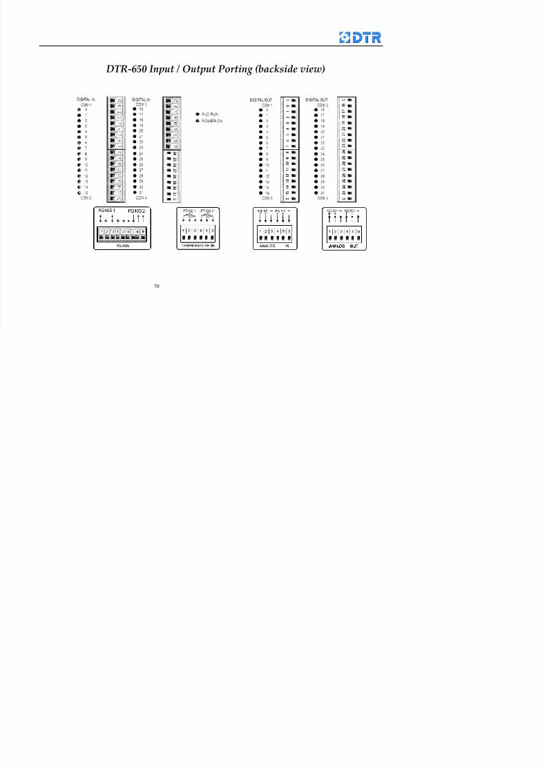
8132019 DTR 650 User Manual
httpslidepdfcomreaderfulldtr-650-user-manual 7070
70
983108983124983122983085650 983113983150983152983157983156 983119983157983156983152983157983156 983120983151983154983156983145983150983143 (983138983137983139983147983155983145983140983141 983158983145983141983159)